Americas Headquarters Cisco Systems, Inc. 170 West Tasman Drive San Jose, CA 95134-1706 USA http://www.cisco.com Tel: 408 526-4000 800 553-NETS (6387) Fax: 408 527-0883 Cisco uBR10012 Universal Broadband Router Hardware Troubleshooting Guide for Cisco IOS Release 12.2SC November 2010 Text Part Number: OL-24078-01
THE SPECIFICATIONS AND INFORMATION REGARDING THE PRODUCTS IN THIS MANUAL ARE SUBJECT TO CHANGE WITHOUT NOTICE. ALL STATEMENTS, INFORMATION, AND RECOMMENDATIONS IN THIS MANUAL ARE BELIEVED TO BE ACCURATE BUT ARE PRESENTED WITHOUT WARRANTY OF ANY KIND, EXPRESSED OR IMPLIED. USERS MUST TAKE FULL RESPONSIBILITY FOR THEIR APPLICATION OF ANY PRODUCTS.
THE SOFTWARE LICENSE AND LIMITED WARRANTY FOR THE ACCOMPANYING PRODUCT ARE SET FORTH IN THE INFORMATION PACKET THAT SHIPPED WITH THE PRODUCT AND ARE INCORPORATED HEREIN BY THIS REFERENCE. IF YOU ARE UNABLE TO LOCATE THE SOFTWARE LICENSE OR LIMITED WARRANTY, CONTACT YOUR CISCO REPRESENTATIVE FOR A COPY.
The following information is for FCC compliance of Class A devices: This equipment has been tested and found to comply with the limits for a Class A digital device, pursuant to part 15 of the FCC rules. These limits are designed to provide reasonable protection against harmful interference when the equipment is operated in a commercial environment. This equipment generates, uses, and can radiate radio-frequency energy and, if not installed and used in accordance with the instruction manual, may cause harmful interference to radio communications. Operation of this equipment in a residential area is likely to cause harmful interference, in which case users will be required to correct the interference at their own expense.
The following information is for FCC compliance of Class B devices: The equipment described in this manual generates and may radiate radio-frequency energy. If it is not installed in accordance with Cisco’s installation instructions, it may cause interference with radio and television reception. This equipment has been tested and found to comply with the limits for a Class B digital device in accordance with the specifications in part 15 of the FCC rules. These specifications are designed to provide reasonable protection against such interference in a residential installation. However, there is no guarantee that interference will not occur in a particular installation.
Modifying the equipment without Cisco’s written authorization may result in the equipment no longer complying with FCC requirements for Class A or Class B digital devices. In that event, your right to use the equipment may be limited by FCC regulations, and you may be required to correct any interference to radio or television communications at your own expense.
You can determine whether your equipment is causing interference by turning it off. If the interference stops, it was probably caused by the Cisco equipment or one of its peripheral devices. If the equipment causes interference to radio or television reception, try to correct the interference by using one or more of the following measures:
• Turn the television or radio antenna until the interference stops.
• Move the equipment to one side or the other of the television or radio.
• Move the equipment farther away from the television or radio.
• Plug the equipment into an outlet that is on a different circuit from the television or radio. (That is, make certain the equipment and the television or radio are on circuits controlled by different circuit breakers or fuses.)
Modifications to this product not authorized by Cisco Systems, Inc. could void the FCC approval and negate your authority to operate the product.
NOTWITHSTANDING ANY OTHER WARRANTY HEREIN, ALL DOCUMENT FILES AND SOFTWARE OF THESE SUPPLIERS ARE PROVIDED “AS IS” WITH ALL FAULTS. CISCO AND THE ABOVE-NAMED SUPPLIERS DISCLAIM ALL WARRANTIES, EXPRESSED OR IMPLIED, INCLUDING, WITHOUT LIMITATION, THOSE OF MERCHANTABILITY, FITNESS FOR A PARTICULAR PURPOSE AND NONINFRINGEMENT OR ARISING FROM A COURSE OF DEALING, USAGE, OR TRADE PRACTICE.
IN NO EVENT SHALL CISCO OR ITS SUPPLIERS BE LIABLE FOR ANY INDIRECT, SPECIAL, CONSEQUENTIAL, OR INCIDENTAL DAMAGES, INCLUDING, WITHOUT LIMITATION, LOST PROFITS OR LOSS OR DAMAGE TO DATA ARISING OUT OF THE USE OR INABILITY TO USE THIS MANUAL, EVEN IF CISCO OR ITS SUPPLIERS HAVE BEEN ADVISED OF THE POSSIBILITY OF SUCH DAMAGES.
Cisco and the Cisco Logo are trademarks of Cisco Systems, Inc. and/or its affiliates in the U.S. and other countries. A listing of Cisco's trademarks can be found at www.cisco.com/go/trademarks. Third party trademarks mentioned are the property of their respective owners. The use of the word partner does not imply a partnership relationship between Cisco and any other company. (1005R)
This guide documents processes and procedures for user-level hardware troubleshooting on Cisco uBR10012 universal broadband routers that support Cisco IOS Release 12.2SC and future releases. For complete configuration instructions, please refer to the Cisco uBR10012 Universal Broadband Router Software Configuration Guide and the documents listed in the “Related Documentation” section on page viii.
• Purpose, page vii
• Audience, page vii
• Document Organization, page viii
• Related Documentation, page viii
• Obtaining Documentation and Submitting a Service Request, page ix
Note For information about troubleshooting Cisco uBR10012 universal broadband routers that support Cisco IOS Release 12.3BC and further BC releases, refer to the Cisco uBR10012 Universal Broadband Router Troubleshooting Guide
PurposeThe Cisco uBR10012 router provides data and Voice over IP (VoIP) services to cable modems (CMs) and customer premises equipment (CPE) devices over a cable TV (CATV) network, supplying high-speed Internet and voice connectivity over the coaxial cable that provides TV and other signals. Many of the Cisco uBR10012 modules are available in redundant configurations, so that the failure of one module does not affect systems operations. This guide provides troubleshooting steps for a failed component that you can take before system failure occurs and before intervention from higher level support agencies becomes necessary.
AudienceTo benefit from this guide, you must be experienced using Cisco IOS and have some responsibility for installing, configuring, or operating the Cisco uBR10012 router. Knowledge of basic cable data network operations and of the Data-Over-Cable Service Interface Specifications (DOCSIS), which define the transmission of data and other services over a coaxial cable TV network.
Document OrganizationThe sections of this guide are as follows:
Related DocumentationWhen troubleshooting the Cisco uBR10012 router, you should use the Cisco uBR10012 Universal Broadband Router Troubleshooting Guide with the following documents:
• Cross-Platform Release Notes for Cisco Universal Broadband Routers in Cisco IOS Release 12.2SC—Provides the most up-to-date information about software version requirements for using the router. It also provides information about bugs and workarounds. See the following URL:
• Cisco uBR10012 Universal Broadband Router Software Configuration Guide—Contains detailed information on the configuration and administration of the Cisco uBR10012 router. See the following URL:
• Cisco uBR10012 Universal Broadband Router Hardware Installation Guide—Contains information about the hardware of the Cisco uBR10012 router, how to install the router, connect its cables, and start the system up for the first time. See the following URL:
For more information about the IOS software that runs on the Cisco uBR10012 router, see the Cisco IOS command reference books and configuration guides:
• Cisco Broadband Cable Command Reference Guide—Describes the cable specific commands used on the Cisco uBR10012 router. See the following URL:
Chapter 1, “Basic Troubleshooting Tasks and Startup Issues”
Basic procedures that users should perform before undertaking a detailed troubleshooting analysis of the Cisco uBR10012 router or logging a case with the Cisco Technical Assistance Center (TAC).
Chapter 2, “PEM Faults and Fan Assembly Failures”
Methods for troubleshooting faults involving the Cisco uBR10012 Power Entry Modules (PEMs) and blower modules.
Chapter 3, “Troubleshooting PRE Modules” How to troubleshoot Performance Routing Engine (PRE) modules. It provides information on troubleshooting PRE fault states, the management Ethernet port, and the serial port.
Chapter 4, “Troubleshooting Line Cards and Interface Modules”
Troubleshooting faults for cable interface line cards, TCC+ card, DTCC card, HHGE line card, and SIP and SPA interface modules.
Chapter 5, “Replacing or Recovering Passwords”
How to recover a lost enable or console login password, and how to replace a lost enable secret password on the Cisco uBR10012 router.
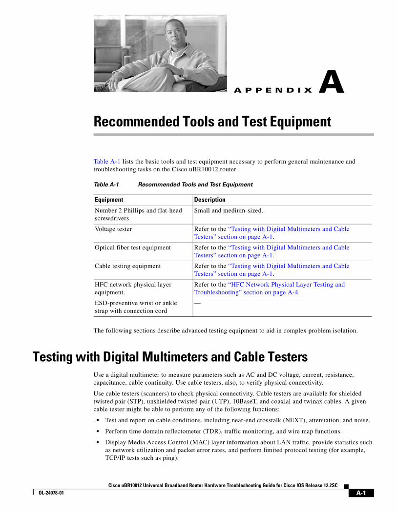
Appendix A, “Recommended Tools and Test Equipment”
A list of basic tools and test equipment necessary to perform maintenance and troubleshooting tasks on the Cisco uBR10012 router.
• Cisco IOS Release 12.2 Configuration Guides and Command References—Describes the commands and configuration used in Cisco IOS Release 12.2. See the following URL:
Obtaining Documentation and Submitting a Service Request For information on obtaining documentation, submitting a service request, and gathering additional information, see the monthly What’s New in Cisco Product Documentation, which also lists all new and revised Cisco technical documentation, at:
Subscribe to the What’s New in Cisco Product Documentation as a Really Simple Syndication (RSS) feed and set content to be delivered directly to your desktop using a reader application. The RSS feeds are a free service and Cisco currently supports RSS version 2.0.
This section describes the basic procedures that users should perform before undertaking a detailed troubleshooting analysis of the Cisco uBR10012 router or logging a case with the Cisco Technical Assistance Center (TAC).
These basic troubleshooting checks are organized as follows:
• Basic Troubleshooting Checklist, page 1-1
• Displaying the Cisco IOS Software Version, page 1-2
• Displaying System Environment Information, page 1-3
• Hardware Troubleshooting Flowchart, page 1-4
• Cisco uBR10012 System Startup Sequence, page 1-4
Basic Troubleshooting ChecklistIf you encounter a problem after you install the Cisco uBR10012 router, go through the following troubleshooting checklist to check for the most common error conditions before you contact the Cisco Technical Assistance Center (TAC) or before you perform a detailed troubleshooting analysis:
1. Is the power on?
2. Is each Power Entry Module (PEM) securely inserted into the router? Is each PEM connected to a power source that is supplying voltage in the proper AC or DC range? Are all power leads and cables firmly connected at both ends?
3. Is the fan assembly module installed in the chassis and operating? Can you hear the fans operating, and when you put your hand in front of the fan blowers, can you feel the air flow? Are all empty slots covered with blank front panels, to ensure the correct air flow through the chassis for cooling?
4. Is each Performance Routing Engine (PRE) module firmly seated and securely inserted in the chassis?
5. Is at least one Timing, Communication and Control Plus (TCC+) card installed in the router?
6. Are the other line cards firmly seated and securely screwed to the chassis?
7. Are all data cables firmly connected at both ends?
8. Are the ports properly configured?
After going through this checklist, go through the remaining sections in this chapter to verify the installation and to perform basic troubleshooting.
1-1roubleshooting Guide for Cisco IOS Release 12.2SC
Chapter 1 Basic Troubleshooting Tasks and Startup IssuesDisplaying the Cisco IOS Software Version
Displaying the Cisco IOS Software VersionUse the show version command to confirm that the router is running the proper version of Cisco IOS software and has a sufficient amount of system memory. The command also reports the system uptime and the method by which the system was powered up.
In the following sample of output from the show version command, some of the information that may be useful for troubleshooting appears in bold type:
Router#show ver
Cisco IOS Software, 10000 Software (UBR10K4-K9P6U2-M), Version 12.2(32.8.12)SCE Copyright (c) 1986-2010 by Cisco Systems, Inc.
Compiled Sun 21-Nov-10 15:58 by jdkerr
ROM: System Bootstrap, Version 12.2(20071113:194412) [shalpin-rom-1_2 101], DEVELOPMENT SOFTWARE
Router uptime is 5 hours, 13 minutesUptime for this control processor is 5 hours, 14 minutesSystem returned to ROM by reload at 01:27:43 UTC Thu Nov 25 2010System restarted at 20:29:12 SGT Wed Nov 24 2010System image file is "disk0:ubr10k4-k9p6u2-mz.122-32.8.12.SCE"Last reload type: Normal ReloadLast reload reason: Reload command
This product contains cryptographic features and is subject to United States and local country laws governing import, export, transfer and use. Delivery of Cisco cryptographic products does not imply third-party authority to import, export, distribute or use encryption.Importers, exporters, distributors and users are responsible for compliance with U.S. and local country laws. By using this product you agree to comply with applicable laws and regulations. If you are unable to comply with U.S. and local laws, return this product immediately.
A summary of U.S. laws governing Cisco cryptographic products may be found at:http://www.cisco.com/wwl/export/crypto/tool/stqrg.html
If you require further assistance please contact us by sending email to [email protected].
Cisco uBR10000 (PRE4-RP) processor with 2588671K/163839K bytes of memory.Processor board ID SPE10310CUHSB-1 CPU at 800Mhz, Implementation 0x410, Rev 5.0, 512KB L2 CacheBackplane version 1.1, 8 slot
Last reset from software resetPXF processor tmc0 is running.PXF processor tmc1 is running.PXF processor tmc2 is running.PXF processor tmc3 is running.1 DTCC card(s)1 Jacket card(s): 3 SPA card(s)1 FastEthernet interface6 Gigabit Ethernet interfaces1 Ten Gigabit Ethernet interface15 Cable Modem interfaces7039K bytes of non-volatile configuration memory.
125440K bytes of ATA compact flash in bootflash (Sector size 512 bytes).500472K bytes of ATA compact flash in disk0 (Sector size 512 bytes).
Chapter 1 Basic Troubleshooting Tasks and Startup IssuesDisplaying System Environment Information
Standby is upStandby has 2752512K bytes of memoryConfiguration register is 0x2
Router#
Displaying System Environment InformationUse the show environment command to display the basic system environment status, to verify the following:
• Make sure that the system operating temperature is always between 41 degrees F or 5 degrees C at the inlet and 104 degrees F or 40 degrees C at the core.
• That the fan assembly module is installed in the chassis and operating properly.
• Report that the operational status of the PEMs and blower is OK.
If the operating temperature is not between 41 degrees F or 5 degrees C and 104 degrees F or 40 degrees C, refer to the “Fan Assembly Module Faults” section on page 2-6.
The following example is sample output from the show environment command for a system with PRE4 and two DC PEMs and installed:
Router# show environment Load for five secs: 0%/0%; one minute: 0%; five minutes: 0%Time source is hardware calendar, *02:43:21.219 EDT Mon May 31 2010
Temperature information: Temperature normal: Inlet sensor measured at 33C/91F Temperature normal: Outlet sensor measured at 46C/114F
Voltage information: RP Voltage readings : Channel Margin ADC Value ====================================== 2.5v Normal 2.49v 1.8v N/A 1.80v 1.5v Normal 1.49v 1.8vFPGA Normal 1.79v 1.2v Normal 1.19v 3.3v Normal 3.28v
Fan: OKPower Entry Module 0 type DC status: OKPower Entry Module 1 type DC status: Output Disabled
The following example is sample output from the show environment command for a system with PRE2 and two DC PEMs and installed:
Router# show environment Temperature normal: chassis inlet measured at 34C/93FFan: OKPower Entry Module 0 type DC status: OKPower Entry Module 0 Power: 432wPower Entry Module 0 Voltage: 54vPower Entry Module 1 type DC status: OKPower Entry Module 1 Power: 486wPower Entry Module 1 Voltage: 54v
Chapter 1 Basic Troubleshooting Tasks and Startup IssuesHardware Troubleshooting Flowchart
Hardware Troubleshooting FlowchartUse Figure 1-1 to determine which component of your Cisco uBR10012 router is malfunctioning. Figure 1-1 describes a series of hardware dependent startup events that must take place for a Cisco uBR10012 router to allow the passage of IP traffic. At each main point of the flowchart, there are pointers to the chapters in this guide that describe how to troubleshoot individual pieces of hardware.
Note This flowchart does not address software configuration problems.
Figure 1-1 Hardware Troubleshooting Flowchart
Cisco uBR10012 System Startup SequenceTable 1-1 describes the visible sequence of events that occur during a typical Cisco uBR10012 power up.
Chapter 1 Basic Troubleshooting Tasks and Startup IssuesCisco uBR10012 System Startup Sequence
Table 1-1 Cisco\uBR10000 Series System Startup Sequence
Startup Event Event Description
PEM is powered off The Fault LED on each PEM is lit yellow to indicate that power is being supplied to the PEM but that the router is not turned on.
Power on the Cisco uBR10012 router
1. The Power LED on each PEM is lit green.
2. The yellow Critical, Major, and Minor alarm and Fail LEDs illuminate for about 2 seconds.
3. The alphanumeric display on the active PRE module counts up through a range of numbers from 1111 to 9999 (1111, 2222, and so on).
4. The alpha numeric display counts up through a sequence of letters from AAA to CCC (AAA, BBB, and CCC).
5. The message ROM DONE appears on the alphanumeric display.
Note If the system is not configured to auto boot, it stops at the ROM DONE message. The console displays a rommon> prompt.
6. The Power LED on each TCC+ card turns green. The Status LED on each TCC+ lights yellow. After a few seconds, the Status LED on the primary TCC+ card lights green, and the Status LED on the backup TCC+ card begins blinking green.
Cisco IOS software loads 1. If the system is set to boot from the slot0: file system, the green slot LED lights.
2. The message BOOT IMGE appears on the alphanumeric display on the active PRE module.
3. The console displays a series of pound signs (#) as the IOS software image is decompressed.
4. The following messages appear on the alphanumeric display on the active PRE module.
• IOS STRT
• IOS EXC
• IOS FPGA
• IOS FPOK
• IOS FILE
• IOS STBY
• IOS DRVR
• IOS LIB
• IOS MGMT
• IOS CONF
5. The console displays the bootup screen, followed by the prompt:
Press RETURN to get started!
6. The message IOS RUN appears in the alphanumeric display on the active PRE module. In a redundant configuration, the message IOS STBY appears on the alphanumeric display of the standby PRE module.
If the boot process fails, no console access is available. If you cannot boot the Cisco uBR10012 router, call Cisco TAC.
The following sections provide methods for troubleshooting faults involving the Cisco uBR10012 Power Entry Modules (PEMs), the optional external AC-input power shelf, and fan assembly module. This chapter contains the following major sections:
• AC PEM Faults, page 2-1
• DC PEM Faults, page 2-3
• External AC-Input Power Shelf, page 2-5
• Other Electrical Problems, page 2-6
• Fan Assembly Module Faults, page 2-6
AC PEM FaultsOn the Cisco uBR10012 router, two AC PEMs are installed in a redundant configuration, which allows one AC PEM to fail without affecting system operations. A single PEM can power the router for sufficient time to request and install a new PEM to replace the one that failed.
Tip To quickly check the functional status of your PEMs, use the show environment command.
AC PEM faults can occur for the following reasons:
• PEM failure
• Invalid AC-input power being supplied by the power source
• Backplane interface failures or damage
Figure 2-1 illustrates the AC PEM and its indicators. Table 2-1 describes the indicators.
2-1roubleshooting Guide for Cisco IOS Release 12.2SC
Chapter 2 PEM Faults and Fan Assembly FailuresAC PEM Faults
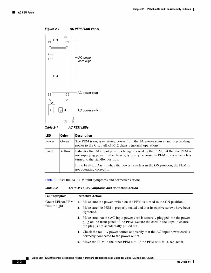
Figure 2-1 AC PEM Front Panel
Table 2-2 lists the AC PEM fault symptoms and corrective actions.
Table 2-1 AC PEM LEDs
LED Color Description
Power Green The PEM is on, is receiving power from the AC power source, and is providing power to the Cisco uBR10012 chassis (normal operations).
Fault Yellow Indicates that AC-input power is being received by the PEM, but that the PEM is not supplying power to the chassis, typically because the PEM’s power switch is turned to the standby position.
If the Fault LED is lit when the power switch is in the ON position, the PEM is not operating correctly.
6252
0
POWER
FAULTAC powercord clips
AC power switch
AC power plug
Table 2-2 AC PEM Fault Symptoms and Corrective Action
Fault Symptom Corrective Action
Green LED on PEM fails to light
1. Make sure the power switch on the PEM is turned to the ON position.
2. Make sure the PEM is properly seated and that its captive screws have been tightened.
3. Make sure that the AC-input power cord is securely plugged into the power plug on the front panel of the PEM. Secure the cord in the clips to ensure the plug is not accidentally pulled out.
4. Check the facility power source and verify that the AC-input power cord is correctly connected to the power outlet.
5. Move the PEM to the other PEM slot. If the PEM still fails, replace it.
Chapter 2 PEM Faults and Fan Assembly FailuresDC PEM Faults
Tip Securely tighten the captive screws on your PEMs to prevent heightened levels of electromagnetic interference.
DC PEM FaultsOn the Cisco uBR10012 router, two DC PEMs are in a redundant configuration, which allows one DC PEM to fail without affecting system operations. A single PEM can usually power the router for sufficient time to request and install a new PEM to replace the one that failed.
Tip To quickly check the functional status of your PEMs, use the show environment command.
DC PEM faults can occur for the following reasons:
• PEM failure
• Reversed power cables
• Backplane interface failures or damage
Figure 2-2 shows the front panel of the UBR10-PWR-DC Module.
PEM experiences problems in one slot but operates normally in a different slot
1. Ensure that the input power to both slots is correct.
2. Verify that no connections have been made to the DC-power connectors underneath each PEM.
3. If the problem persists, contact Cisco TAC.
Fault LED is lit yellow
1. Verify that no connections have been made to the DC-power connectors underneath each PEM.
2. Verify that the PEM is fully inserted into the power bay and that its captive screws have been tightened.
3. Check to see if the power switch is set to the standby position. If so, set the switch to the ON position.
4. If the problem persists, flip the power switch on the PEM to the standby position, wait several seconds, and then back to the ON position.
5. Replace PEM with a known good replacement.
6. Contact Cisco TAC.
Table 2-2 AC PEM Fault Symptoms and Corrective Action (continued)
Chapter 2 PEM Faults and Fan Assembly FailuresDC PEM Faults
Figure 2-2 Power Entry Module (UBR10-PWR-DC)
Table 2-4 lists the DC PEM fault symptoms and corrective actions.
Table 2-3 DC PEM LEDs
LED Description
Power (green) The DC PEM is powered on, receiving power from the external DC power source, and is providing power to the Cisco uBR10012 chassis (normal operation).
Fault (yellow) External DC power is being received by the DC PEM but that the PEM is not supplying power to the chassis, typically because the PEM's power switch is turned off.
If the power switch is in the ON position, and the Fault LED lights, the PEM is not operating correctly
Miswire (yellow) Input DC power cables are wired incorrectly and should be reversed.
Chapter 2 PEM Faults and Fan Assembly FailuresExternal AC-Input Power Shelf
Tip Securely tighten the captive screws on your PEMs to prevent heightened levels of electromagnetic interference.
External AC-Input Power ShelfThe Cisco uBR10012 Router uses the optional external AC-input power shelves when 100–120 VAC is the only available power source. The AC-input power shelf converts AC power from an external AC power supply source into DC power that is suitable for powering the Cisco uBR10012 router.
2400W AC-Input Power ShelfThe 2400W AC-input power shelf converts AC-output power from an external AC power source into DC power that is suitable for powering the Cisco uBR10012 router. The power shelf supplies –54 VDC output power to the two DC PEMs in the Cisco uBR10012 chassis.
The power shelf includes three 1200-watt (W) AC-input power modules that plug into a common power backplane in the 2400W AC-input power shelf. Two 1200W AC-input power modules are capable of powering a fully configured Cisco uBR10012 router. The third power module provides full redundancy.
Table 2-4 DC PEM Fault Symptoms and Corrective Action
Fault Symptom Corrective Action
Green LED on PEM fails to light
1. Make sure the circuit breaker on the PEM is turned on.
2. Make sure the PEM is properly seated and screwed in place.
3. Make sure power leads are properly connected to power connectors on the backplane. If connections are loose or their polarity is reversed, the chassis does not receive power.
4. Check the external power source.
5. Move the PEM to the other PEM slot. If the PEM still fails, replace it.
PEM experiences problems in one slot but operates normally in a different slot
1. Ensure that the input power to both slots is correct.
2. If the problem persists, contact Cisco TAC.
Fault LED is lit yellow
1. Check to see if the circuit breaker (on/off switch) has tripped. If it has, return the switch to the ON position.
2. Replace PEM with a known good replacement.
3. Contact Cisco TAC.
Miswire LED is lit yellow
If the MISWIRE LED is on, the power cables are reversed. Power off the PEM and the external power source and reconnect the wires correctly. See the Cisco uBR10012 Universal Broadband Router Hardware Installation Guide.
Chapter 2 PEM Faults and Fan Assembly FailuresOther Electrical Problems
During normal operation, the three AC-input power modules provide automatic load-sharing with each power module supporting 33 percent of the power load. When you remove one of the AC-input power modules, the remaining power modules immediately ramp up to full power and maintain uninterrupted system power for a limited time. This allows you to replace the affected module without impacting system operations.
Note The optional AC-input shelf monitoring cable (UBR10-PWR-MON-CAB=) is used to connect the AC-input power shelf to the DC PEMs. This cable allows the DC PEM to monitor the health of the AC-input power shelf and sends a signal to the IOS whenever there is a failure in one of the AC-input power shelf's power supplies. This cable should be connected to the external alarm connector on the DC PEM if 2400W AC-input power shelf is used. The following PEM status message is observed in the show environment command output: “Power Entry Module 0 type DC status: External AC Supply Fault.”
Faults on the 2400W AC-input power shelf can occur for the following reasons:
• The AC-input power to one or more power modules has failed.
• The AC power plug to one or more power modules has been removed or unplugged.
• One or more power modules has failed and must be replaced.
For more details on the AC shelf, see the 2400W AC-Input Power Shelf for the Cisco uBR10012 Universal Broadband Router guide.
Other Electrical ProblemsIf the electrical problem cannot be traced to a PEM, check the unit for:
• Improper power cable connections to the Cisco uBR10012 router
• Improper installation of other field-replaceable units (FRUs)
Check the site for:
• Improperly grounded equipment, particularly equipment racks and power grounds
• Fluctuating voltage, which can result from excessive power drains caused by other equipment (such as air conditioning units)
• Cable corrosion or defective power panels, circuit breakers or fuses, or cable connections
• Undersized power cables or excessive power cable lengths
• Excessive power demand on backup power systems or batteries when alternate power sources are used
Fan Assembly Module FaultsThe fan assembly module is critical to the operation of the Cisco uBR10012 router because it allows the router to maintain proper operating temperatures. Severe overheating can result in system failure, so a fan assembly module must always be present in the chassis while the router is operating.
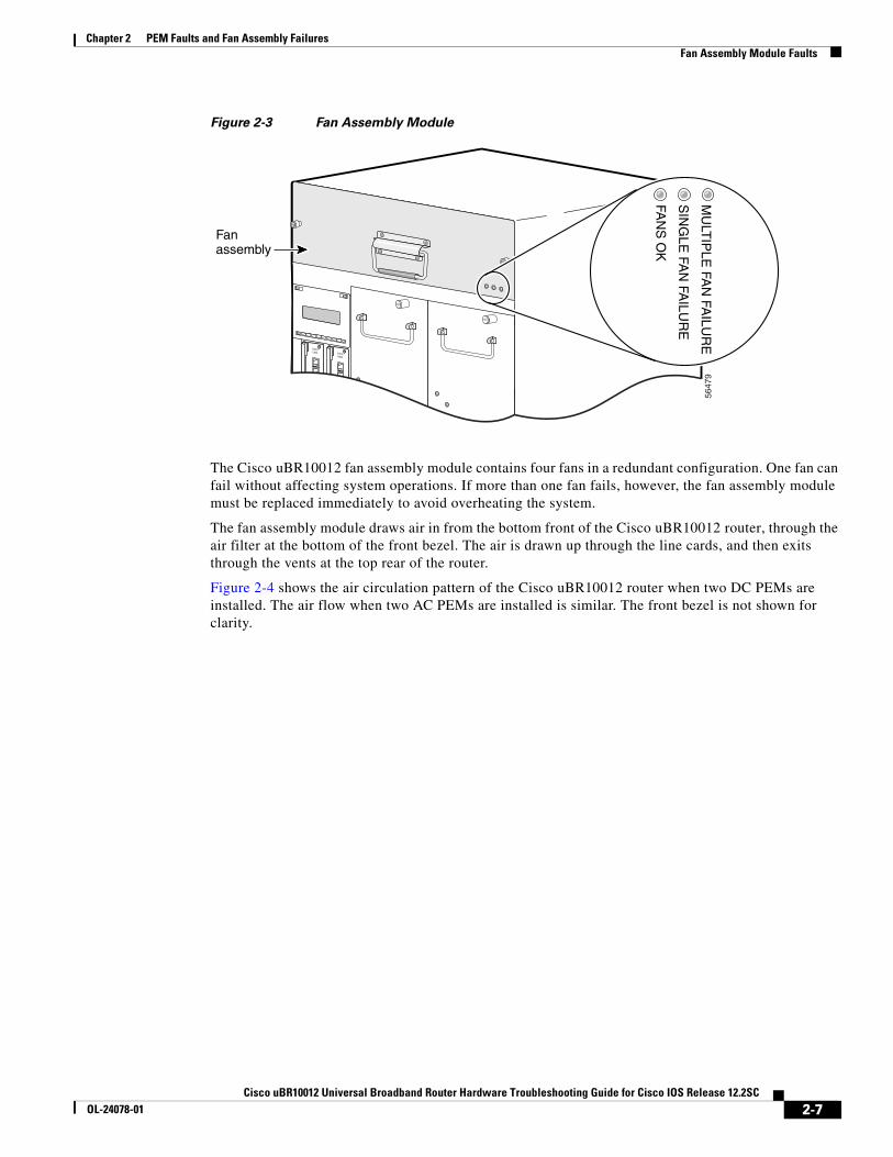
Figure 2-3 shows the fan assembly module front panel and its LED indicators.
Chapter 2 PEM Faults and Fan Assembly FailuresFan Assembly Module Faults
Figure 2-3 Fan Assembly Module
The Cisco uBR10012 fan assembly module contains four fans in a redundant configuration. One fan can fail without affecting system operations. If more than one fan fails, however, the fan assembly module must be replaced immediately to avoid overheating the system.
The fan assembly module draws air in from the bottom front of the Cisco uBR10012 router, through the air filter at the bottom of the front bezel. The air is drawn up through the line cards, and then exits through the vents at the top rear of the router.
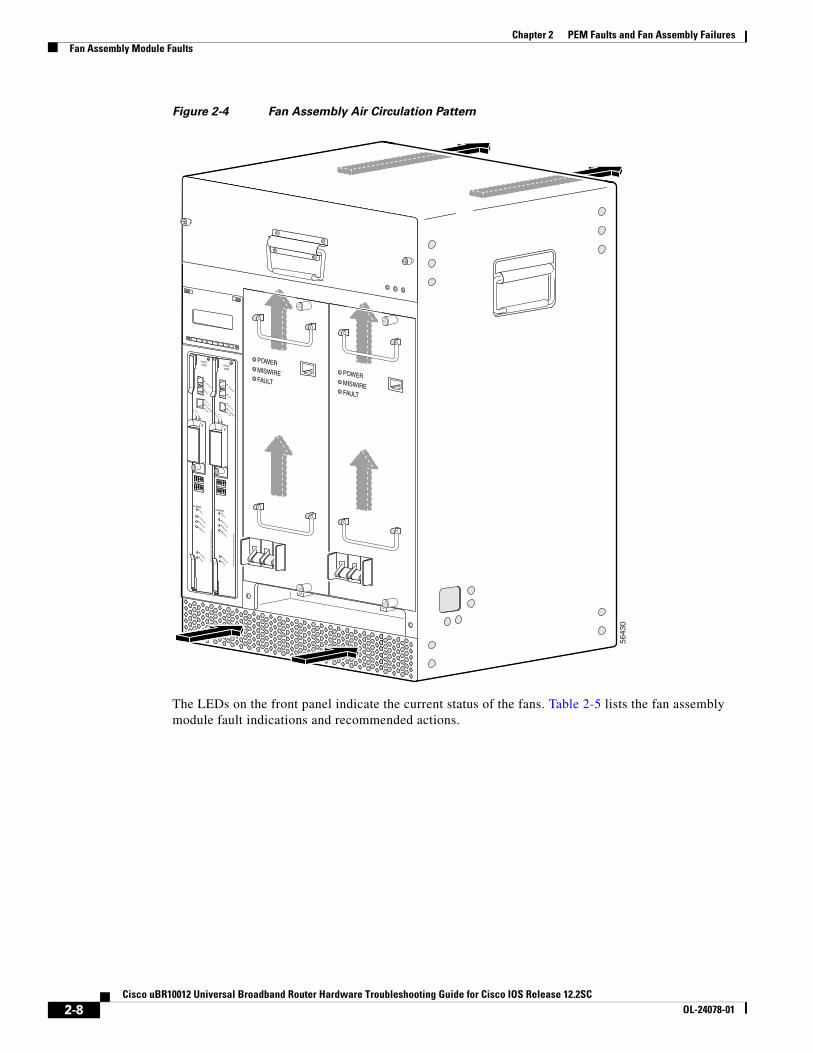
Figure 2-4 shows the air circulation pattern of the Cisco uBR10012 router when two DC PEMs are installed. The air flow when two AC PEMs are installed is similar. The front bezel is not shown for clarity.
Chapter 2 PEM Faults and Fan Assembly FailuresFan Assembly Module Faults
Figure 2-4 Fan Assembly Air Circulation Pattern
The LEDs on the front panel indicate the current status of the fans. Table 2-5 lists the fan assembly module fault indications and recommended actions.
Chapter 2 PEM Faults and Fan Assembly FailuresFan Assembly Module Faults
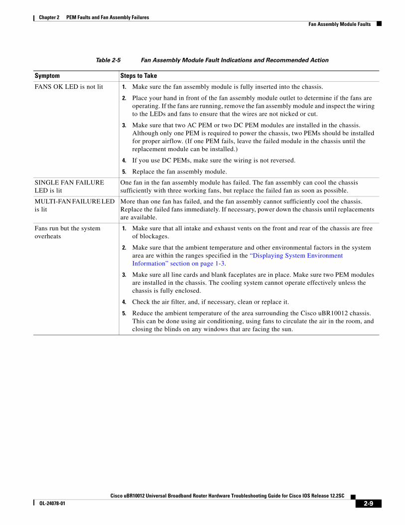
Table 2-5 Fan Assembly Module Fault Indications and Recommended Action
Symptom Steps to Take
FANS OK LED is not lit 1. Make sure the fan assembly module is fully inserted into the chassis.
2. Place your hand in front of the fan assembly module outlet to determine if the fans are operating. If the fans are running, remove the fan assembly module and inspect the wiring to the LEDs and fans to ensure that the wires are not nicked or cut.
3. Make sure that two AC PEM or two DC PEM modules are installed in the chassis. Although only one PEM is required to power the chassis, two PEMs should be installed for proper airflow. (If one PEM fails, leave the failed module in the chassis until the replacement module can be installed.)
4. If you use DC PEMs, make sure the wiring is not reversed.
5. Replace the fan assembly module.
SINGLE FAN FAILURE LED is lit
One fan in the fan assembly module has failed. The fan assembly can cool the chassis sufficiently with three working fans, but replace the failed fan as soon as possible.
MULTI-FAN FAILURE LED is lit
More than one fan has failed, and the fan assembly cannot sufficiently cool the chassis. Replace the failed fans immediately. If necessary, power down the chassis until replacements are available.
Fans run but the system overheats
1. Make sure that all intake and exhaust vents on the front and rear of the chassis are free of blockages.
2. Make sure that the ambient temperature and other environmental factors in the system area are within the ranges specified in the “Displaying System Environment Information” section on page 1-3.
3. Make sure all line cards and blank faceplates are in place. Make sure two PEM modules are installed in the chassis. The cooling system cannot operate effectively unless the chassis is fully enclosed.
4. Check the air filter, and, if necessary, clean or replace it.
5. Reduce the ambient temperature of the area surrounding the Cisco uBR10012 chassis. This can be done using air conditioning, using fans to circulate the air in the room, and closing the blinds on any windows that are facing the sun.
This chapter describes how to troubleshoot Performance Routing Engine (PRE) modules. It provides information on troubleshooting PRE fault states, the management Ethernet port, and the serial port.
• Information Required for Troubleshooting PRE Modules, page 3-1
• Upgrading the Primary PRE1 to PRE2 or PRE4 Modules, page 3-2
• PRE Module Status Screen, page 3-2
• Booting Up with Redundant PRE Modules, page 3-4
• PRE Module Faults, page 3-4
• Ethernet Connection Problems, page 3-5
• Console Port Serial Connection Problems, page 3-6
• Troubleshooting Common System Problems, page 3-7
Information Required for Troubleshooting PRE ModulesThe PRE2 module is the primary processor for the Cisco uBR10012 router running the Cisco IOS Release 12.2(33)SC train, and any problems with the PRE2 module affect all operations. However starting from Cisco IOS Release 12.2(33)SCB, PRE4 is widely used in the Cisco uBR10012 routers.
Note Cisco uBR3GX60V cable interface line card is not compatible with PRE2. You must use PRE4 with the Cisco uBR3GX60V cable interface line card.
If you suspect a problem with the PRE2 or PRE4 module, please collect the following information before proceeding further, to aid in troubleshooting the problem:
Step 1 Capture all console logs and system messages.
Step 2 Capture the output of the show tech-support command. Registered users on Cisco.com can decode the output of this command by using the Output Interpreter tool, which is at the following URL:
Chapter 3 Troubleshooting PRE ModulesUpgrading the Primary PRE1 to PRE2 or PRE4 Modules
Step 4 If the router is unresponsive, or if it refuses to boot to the Cisco IOS prompt, reboot the router to the ROMMON prompt and capture a stack trace, using the stack ROMMON command. For more information on this procedure, see the Obtaining a Stack Trace from ROM Monitor section in the Troubleshooting Router Hangs document, at the following URL:
Upgrading the Primary PRE1 to PRE2 or PRE4 ModulesThe Cisco uBR10012 routers running Cisco IOS Release 12.2SC supports only the PRE2 module in Cisco IOS Release 12.2(33)SCA, and later releases and PRE4 module in Cisco IOS Release 12.2(33)SCB, and later releases.
Upgrading a system that currently uses a PRE1 (or earlier processor) requires a hardware upgrade to a PRE2 to run Cisco IOS Release 12.2(33)SCA or later releases. For hardware installation instructions, see the Cisco Performance Routing Engine (ESR-PRE2) Upgrade Installation document at the following URL:
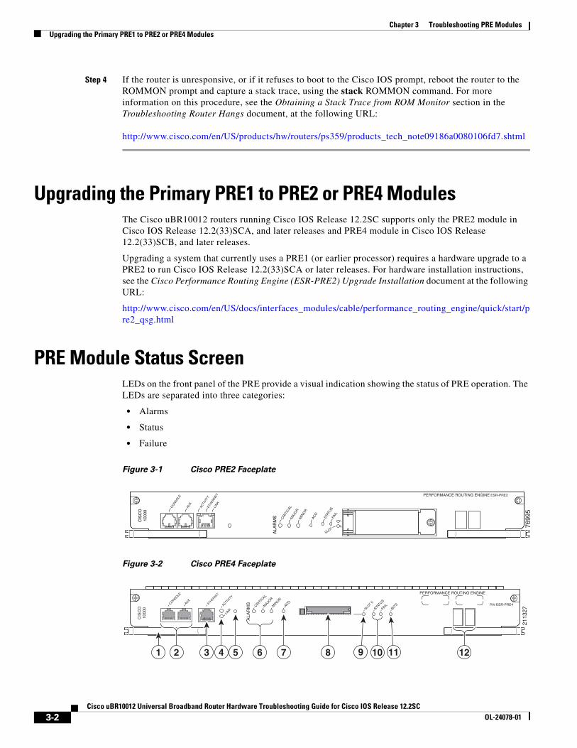
PRE Module Status ScreenLEDs on the front panel of the PRE provide a visual indication showing the status of PRE operation. The LEDs are separated into three categories:
Chapter 3 Troubleshooting PRE ModulesPRE Module Status Screen
Alarm relay contacts on the Cisco uBR10012 router connect the router to a site alarm maintenance system. This allows critical, major, and minor alarms generated by the Cisco uBR10012 router to be displayed on both the PRE front panel and to external visual or audible alarms connected to the system. For more information, refer to the Cisco uBR10012 Universal Broadband Router Hardware Installation Guide at the following URL:
Pressing the ACO button on the (primary) PRE during an alarm condition shuts off the external alarm, but does not deactivate the alarm LEDs on the PRE front panel. Alarm LEDs on the front panel are deactivated only after the condition that caused the alarm is corrected.
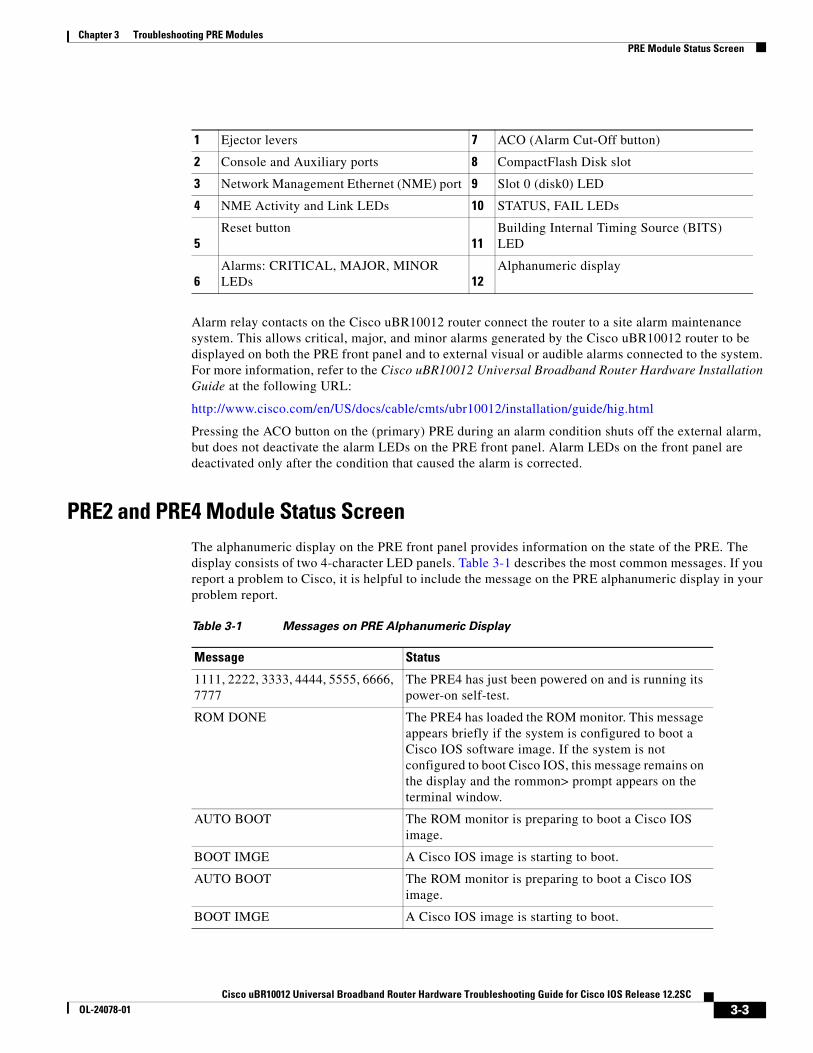
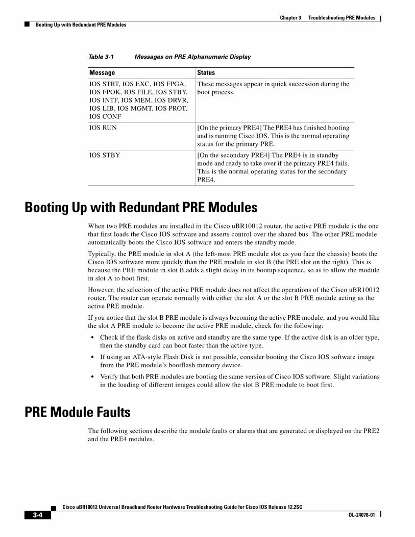
PRE2 and PRE4 Module Status ScreenThe alphanumeric display on the PRE front panel provides information on the state of the PRE. The display consists of two 4-character LED panels. Table 3-1 describes the most common messages. If you report a problem to Cisco, it is helpful to include the message on the PRE alphanumeric display in your problem report.
1 Ejector levers 7 ACO (Alarm Cut-Off button)
2 Console and Auxiliary ports 8 CompactFlash Disk slot
3 Network Management Ethernet (NME) port 9 Slot 0 (disk0) LED
4 NME Activity and Link LEDs 10 STATUS, FAIL LEDs
5Reset button
11Building Internal Timing Source (BITS) LED
6Alarms: CRITICAL, MAJOR, MINOR LEDs 12
Alphanumeric display
Table 3-1 Messages on PRE Alphanumeric Display
Message Status
1111, 2222, 3333, 4444, 5555, 6666, 7777
The PRE4 has just been powered on and is running its power-on self-test.
ROM DONE The PRE4 has loaded the ROM monitor. This message appears briefly if the system is configured to boot a Cisco IOS software image. If the system is not configured to boot Cisco IOS, this message remains on the display and the rommon> prompt appears on the terminal window.
AUTO BOOT The ROM monitor is preparing to boot a Cisco IOS image.
BOOT IMGE A Cisco IOS image is starting to boot.
AUTO BOOT The ROM monitor is preparing to boot a Cisco IOS image.
Chapter 3 Troubleshooting PRE ModulesBooting Up with Redundant PRE Modules
Booting Up with Redundant PRE ModulesWhen two PRE modules are installed in the Cisco uBR10012 router, the active PRE module is the one that first loads the Cisco IOS software and asserts control over the shared bus. The other PRE module automatically boots the Cisco IOS software and enters the standby mode.
Typically, the PRE module in slot A (the left-most PRE module slot as you face the chassis) boots the Cisco IOS software more quickly than the PRE module in slot B (the PRE slot on the right). This is because the PRE module in slot B adds a slight delay in its bootup sequence, so as to allow the module in slot A to boot first.
However, the selection of the active PRE module does not affect the operations of the Cisco uBR10012 router. The router can operate normally with either the slot A or the slot B PRE module acting as the active PRE module.
If you notice that the slot B PRE module is always becoming the active PRE module, and you would like the slot A PRE module to become the active PRE module, check for the following:
• Check if the flask disks on active and standby are the same type. If the active disk is an older type, then the standby card can boot faster than the active type.
• If using an ATA-style Flash Disk is not possible, consider booting the Cisco IOS software image from the PRE module’s bootflash memory device.
• Verify that both PRE modules are booting the same version of Cisco IOS software. Slight variations in the loading of different images could allow the slot B PRE module to boot first.
PRE Module FaultsThe following sections describe the module faults or alarms that are generated or displayed on the PRE2 and the PRE4 modules.
These messages appear in quick succession during the boot process.
IOS RUN [On the primary PRE4] The PRE4 has finished booting and is running Cisco IOS. This is the normal operating status for the primary PRE.
IOS STBY [On the secondary PRE4] The PRE4 is in standby mode and ready to take over if the primary PRE4 fails. This is the normal operating status for the secondary PRE4.
Chapter 3 Troubleshooting PRE ModulesEthernet Connection Problems
PRE2 and PRE4 Module FaultsTable 3-2 describes the LEDs and buttons on the PRE front panel (see Figure 3-1 and Figure 3-2). The slot and some of the LEDs are specific to the PRE4 front panel.
Ethernet Connection ProblemsIf the management Fast Ethernet interface (F0/0/0) on the PRE fails to work properly, and the corresponding Link LED is not lit (steady green,) do the following::
• Visually check that an Ethernet cable is connected to the correct Ethernet port on the Cisco uBR10012 router.
Table 3-2 LED Status and Button Descriptions
LEDs and Button Status Description
ACTIVITY Green
Off
Packets are being transmitted and received.
No packet activity
LINK Green
Off
Carrier detected; the port is able to pass traffic.
No carrier detected; the port is not able to pass traffic.
ALARMS—CRITICAL, MAJOR, and MINOR LEDs
Off
Yellow
No alarm.
Indicates an alarm condition.
Alarm cutoff (ACO) switch — Pressing this switch disables an audible alarm.
CompactFlash Disk0 Green Disk0 is active. This slot is present only on the PRE4.
STATUS Flashing Yellow
Green
Off
System is booting.
PRE is ready.
No power to the PRE, or the PRE is acting as the secondary PRE.
FAIL Off
Yellow
The PRE is operating properly.
A major failure has disabled the PRE.
BITS
Green
Yellow
Off
This LED is specific to the PRE4.
BITS input to the PRE is configured and functioning normally.
BITS input to the PRE is configured, but not functional. For example, the framer may have detected a Loss of Signal (LOS).
BITS input to the PRE4 is not configured.
PC media card slot 0 Green Media card in Slot 0 is active.
PC media card slot 1 Green Media card in Slot 1 is active.
Chapter 3 Troubleshooting PRE ModulesConsole Port Serial Connection Problems
• Verify that you are using the correct type of cable for a 100BaseT Ethernet.
• Check to see if the cable is bad or broken.
• Make sure the primary PRE module booted up properly by checking the Status LED on its faceplate. This LED on the primary PRE module should be steady green. If a redundant PRE module is installed, its STATUS LED should be flashing green. If this is not the case with either PRE module, remove and reinsert the module and boot it up again.
Note The show interface command also shows that there is an Ethernet interface (E0/0/0) on the PRE module, but this is an internal interface that the router uses to communicate between PRE modules and line cards. This Ethernet interface is not configurable and can be used only by the router’s internal subsystems.
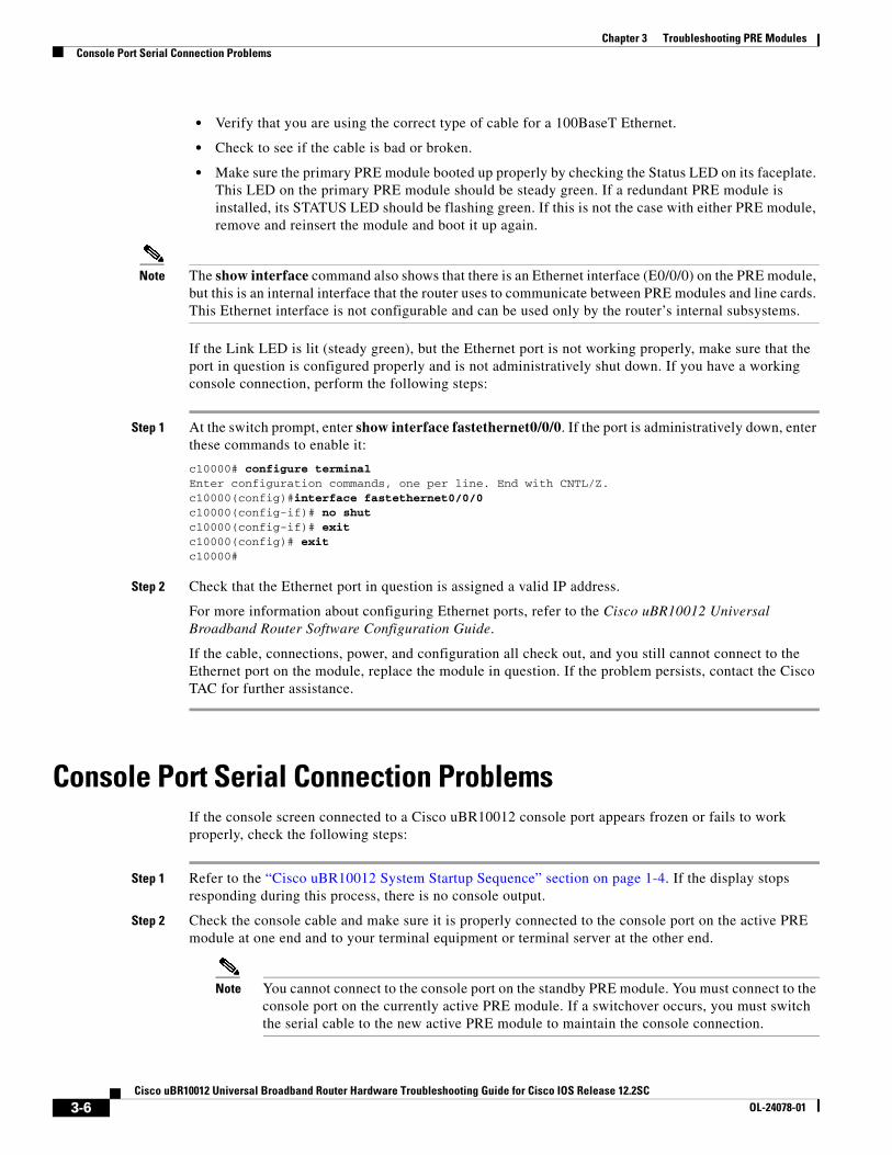
If the Link LED is lit (steady green), but the Ethernet port is not working properly, make sure that the port in question is configured properly and is not administratively shut down. If you have a working console connection, perform the following steps:
Step 1 At the switch prompt, enter show interface fastethernet0/0/0. If the port is administratively down, enter these commands to enable it:
c10000# configure terminalEnter configuration commands, one per line. End with CNTL/Z.c10000(config)#interface fastethernet0/0/0c10000(config-if)# no shutc10000(config-if)# exitc10000(config)# exitc10000#
Step 2 Check that the Ethernet port in question is assigned a valid IP address.
For more information about configuring Ethernet ports, refer to the Cisco uBR10012 Universal Broadband Router Software Configuration Guide.
If the cable, connections, power, and configuration all check out, and you still cannot connect to the Ethernet port on the module, replace the module in question. If the problem persists, contact the Cisco TAC for further assistance.
Console Port Serial Connection ProblemsIf the console screen connected to a Cisco uBR10012 console port appears frozen or fails to work properly, check the following steps:
Step 1 Refer to the “Cisco uBR10012 System Startup Sequence” section on page 1-4. If the display stops responding during this process, there is no console output.
Step 2 Check the console cable and make sure it is properly connected to the console port on the active PRE module at one end and to your terminal equipment or terminal server at the other end.
Note You cannot connect to the console port on the standby PRE module. You must connect to the console port on the currently active PRE module. If a switchover occurs, you must switch the serial cable to the new active PRE module to maintain the console connection.
Chapter 3 Troubleshooting PRE ModulesTroubleshooting Common System Problems
Step 3 Verify that you are using the right type of cable and adapter. For information about pin-out connections and installation instructions, refer to the Cisco uBR10012 Universal Broadband Router Hardware Installation Guide.
Step 4 Make sure the cable is not defective or broken. Replace the cable with another high quality cable if possible, and check to see if the console port starts working.
Step 5 Check that the terminal equipment is configured with the correct settings for the console port. The default console port settings are:
• 9600 baud
• 8 data bits
• 1 stop bit
• No parity
• No flow control
Step 6 Check the LEDs on the PRE faceplate to make sure it has powered up properly. If necessary, remove and reinsert both PRE modules to power them up again. Also, make sure the terminal equipment is working properly.
Step 7 The console can appear frozen if the PRE processor is busy performing other tasks, such as parsing a large configuration file or passing a large burst of traffic. These periods are usually only temporary, and normal reaction resumes after a few moments.
Step 8 The console can be frozen if the PRE process is generating a large volume of debug messages. If this is the case, hit the return key a couple of times and type no debug all to attempt to turn off the debug messages. This will not work if the router is in global configuration mode, but try typing do no debug all to execute this EXEC mode command in global configuration mode.
If the cable, connections, power, and terminal settings all check out and you still cannot connect to the console port on the module, replace the module in question. If the problem persists, contact the Cisco TAC for further assistance.
Troubleshooting Common System ProblemsThis section describes how to troubleshoot the following common system problems on the Cisco uBR10012 router:
• Troubleshooting System Crashes, page 3-7
• High CPU Utilization Problems, page 3-8
• Bus Errors, page 3-13
• Memory Problems, page 3-14
Troubleshooting System CrashesSystem crashes occur when the router experiences an unexpected situation from which it cannot recover. In response, the router stops all processes and reloads. Crashes can result from either hardware or software problems.
Chapter 3 Troubleshooting PRE ModulesTroubleshooting Common System Problems
When the router crashes, it is extremely important to gather as much information as possible about the crash before doing a manual reload or power-cycling the router. All information about the crash, except that which has been stored in the crashinfo file, is lost after a manual reload or power-cycle.
In particular, use the following commands to gather more information about the crash:
• All console, system, and message logs.
• Crashinfo file, if one was generated at the time of the crash.
• All output from the following commands:
– show version
– show context
– show stacks
– show tech-support
Note Registered Cisco.com users can decode the output of these show commands by using the Output Interpreter tool, which is at the following URL:
High CPU Utilization ProblemsThe PRE module can experience high CPU utilization, where the CPU processor approaches 100% usage for extended periods of time, for several reasons. See the following sections for possible causes and solutions.
• ARP Traffic, page 3-9
• CPUHOG Errors, page 3-10
• Debug and System Messages, page 3-10
• Exec and Virtual Exec Processes, page 3-11
• Interrupts are Consuming a Large Amount of Resources, page 3-11
Chapter 3 Troubleshooting PRE ModulesTroubleshooting Common System Problems
ARP Traffic
High volumes of Address Resolution Protocol (ARP) requests and responses can occupy a significant portion of the CPU time, because the router cannot use fast-switching to process ARP packets, but must instead forward them to the route processor (RP). Because of this, processing a large volume of ARP traffic can also prevent the router from handling normal traffic.
Theft-of-service and denial-of-service (DoS) attacks also often generate a large number of ARP packets on the network. Many viruses also use ARP requests to discover computers that might be vulnerable to attack, and if these computers become infected, they are used to propagate the virus, generating even more ARP traffic on the network.
ARP requests are broadcast packets, so they are broadcast to all devices on that particular network segment. In some cases, a router can also forward ARP broadcasts to an ARP proxy for further processing. Some low-end routers commonly used by subscribers for home networks can also incorrectly respond to all ARP requests, which generates even more traffic.
In addition, the Cisco CMTS router automatically monitors ARP traffic and enters the IP addresses found in ARP requests into its own ARP table, in the expectation that a device will eventually be found with that IP address. Unacknowledged IP addresses remain in the router’s ARP table for 60 seconds, which means that a large volume of ARP traffic can fill the router’s ARP table.
If ARP traffic is excessive, you can try the following ways to limit this traffic:
Step 1 Disable the forwarding of ARP requests on a cable interface by using the no cable arp command in interface configuration mode.
Step 2 Disable the use of proxy-ARP on a cable interface by using the no cable proxy-arp command in interface configuration mode.
Note Using the no cable arp and no cable proxy-arp commands shifts all responsibility for the management of the IP addresses used by CMs and CPE devices to the DHCP server and provisioning system.
Another approach would be to identify the cable modems and customer premises equipment (CPE) that are generating the ARP traffic. A simple way of doing this is by using an access list to log requests for an unassigned IP address in the subnet being used on a cable interface.
Step 1 Reserve at least one IP address on each cable interface’s subnet and ensure that it is not being assigned to any cable modems or CPE devices. For example, if a cable interface is using the subnet 192.168.100.0/24, you could choose to reserve IP address 192.168.100.253 for this purpose. Ensure that the IP addresses you have chosen are not assigned to devices by your provisioning system.
Step 2 If you currently have an access list applied to the cable interface, add a line that logs requests for this particular IP address. If you are not currently using an access list on the cable interface, create one for this purpose. In both cases, the relevant line would be:
Router(config)# access-list number permit ip any host 192.168.100.253 log
where number is the number for the access-list. Change the IP address to whatever address you have selected to be reserved for this cable interface.
Chapter 3 Troubleshooting PRE ModulesTroubleshooting Common System Problems
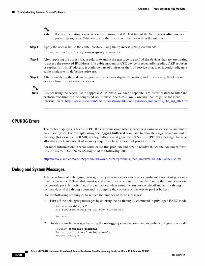
Note If you are creating a new access list, ensure that the last line of the list is access-list number permit ip any any. Otherwise, all other traffic will be blocked on the interface.
Step 3 Apply the access list to the cable interface using the ip access-group command:
Router(config-if)# ip access-group number in
Step 4 After applying the access list, regularly examine the message log to find the devices that are attempting to access the reserved IP address. If a cable modem or CPE device is repeatedly sending ARP requests or replies for this IP address, it could be part of a virus or theft-of-service attack, or it could indicate a cable modem with defective software.
Step 5 After identifying these devices, you can further investigate the matter, and if necessary, block these devices from further network access.
Note Besides using the access list to suppress ARP traffic, we have a separate "arp-filter" feature to filter and perform rate-limit for the congested ARP traffic. See Cable ARP Filtering feature guide for more information at: http://www.cisco.com/en/US/docs/ios/cable/configuration/guide/cmts_cbl_arp_fltr.html
CPUHOG Errors
The router displays a %SYS-3-CPUHOG error message when a process is using an excessive amount of processor cycles. For example, using the logging buffered command to allocate a significant amount of memory (for example, 200 MB) for log buffers could generate a %SYS-3-CPUHOG message, because allocating such an amount of memory requires a large amount of processor time.
For more information on what could cause this problem and how to resolve it, see the document What Causes %SYS-3-CPUHOG Messages, at the following URL:
A large volume of debugging messages or system messages can take a significant amount of processor time, because the PRE module must spend a significant amount of time displaying these messages on the console port. In particular, this can happen when using the verbose or detail mode of a debug command, or if the debug command is dumping the contents of packets or packet buffers.
Use the following techniques to reduce the number of these messages:
1. Turn off the debugging messages by entering the no debug all command in privileged EXEC mode:
Router# no debug all All possible debugging has been turned off
Router#
2. Disable console messages by using the no logging console command in global configuration mode:
Router# configure terminal Router(config)# no logging console Router(config)#
Chapter 3 Troubleshooting PRE ModulesTroubleshooting Common System Problems
To keep the logging of console messages, but to limit the number of messages that can be displayed, use the logging rate-limit command. You can rate-limit all messages (including debug messages), or just the console messages, using one of the following commands:
Router(config)# logging rate-limit all number-of-messages-per-second
3. If you have logged into the router using a Telnet connection, you can disable debug messages using the terminal default monitor command in privileged EXEC mode:
Router# terminal default monitor Router#
You can also filter the log messages that will be dumped to console using the logging console command in the global configuration mode.
Router(config)#logg console ?0-7 Logging severity levelalerts Immediate action needed (severity=1)critical Critical conditions (severity=2)debugging Debugging messages (severity=7)discriminator Establish MD-Console associationemergencies System is unusable (severity=0)errors Error conditions (severity=3)guaranteed Guarantee console messagesinformational Informational messages (severity=6)notifications Normal but significant conditions (severity=5)warnings Warning conditions (severity=4)xml Enable logging in XML
Exec and Virtual Exec Processes
The Exec process is the Cisco IOS process that handles the TTY serial lines (console, auxiliary, asynchronous), and the Virtual Exec process handles the Virtual TTY (VTY) Telnet sessions. These processes run as mid-level processes, so if either one is exceptionally busy, it could generate a high CPU usage level.
For information on resolving problems with high CPU usage caused by the Exec and Virtual EXEC processes, see the High CPU Utilization in Exec and Virtual Exec Processes document, at the following URL:
Interrupts are Consuming a Large Amount of Resources
Interrupts allow software processes to request resources when needed, as opposed to waiting for time to be allocated to the process. If a process requests too many interrupts, however, it could impact CPU usage, resulting in less time available to other processes.
For more information, see the Troubleshooting High CPU Utilization Due to Interrupts document, at the following URL:
Chapter 3 Troubleshooting PRE ModulesTroubleshooting Common System Problems
Invalid Scheduler Allocate Configuration
The scheduler allocate command guarantees the minimum amount of time that can be allocated for fast-switching during each network interrupt context, and the minimum amount of time that can be allocated for non-interrupt-driven processes. An incorrect configuration for the scheduler allocate command can cause high CPU usage, especially when too much time is allocated for non-interrupt processes. This could result in messages such as %IPCGRP-6-NOKEEP: Too long since a keepalive was received from the PRE.
We recommend using the default configuration, which can be restored by giving the default scheduler allocate command in global configuration mode:
The Cisco IOS software uses a process named IP input to process IP packets that cannot be processed using the fast-switching process. If the router is process-switching a lot of IP traffic, it could result in excessively high CPU usage.
The most common reasons for excessive IP Input processing are that fast-switching has been disabled on one or more interfaces, and that the router is receiving a large volume of traffic that must be process-switched. For more information on resolving problems with the IP Input process, see the Troubleshooting High CPU Utilization in IP Input Process document at the following URL:
One or More Processes is Consuming an Excessive Amount of Resources
High CPU usage could occur if one or more processes is consuming an excessive amount of resources. For example, the router might have an excessive number of TCP connections open, or the TTY background process is busy displaying logging or debugging messages.
For more information, see the Troubleshooting High CPU Utilization Due to Processes document, at the following URL:
The PRE module could experience high CPU usage if the router has been configured with an access list (ACL) that is too complex or inefficiently written. Access lists are processed for top-down, starting with the first entry in the list and continuing through each entry until a match is found. The router can easily reach high CPU usage if it has to process dozens or hundreds of ACL entries for each packet it receives or transmits.
To resolve the problem, reorganize the list so that the most frequently matched entries are listed first. Also examine the list to see if multiple statements can be consolidated into a single entry. For example, instead of listing multiple addresses on the same subnet, use one entry with a wildcard mask that matches all of the individual addresses.
Consider using the Turbo ACL feature, which compiles the access lists so that they can be searched more efficiently. Enable the use of Turbo ACLs by giving the access-list compiled command in global configuration mode.
Chapter 3 Troubleshooting PRE ModulesTroubleshooting Common System Problems
For more information on access lists, see the Configuring IP Services chapter in the IP Addressing and Services section of the Cisco IOS IP Configuration Guide, Release 12.2, at the following URL:
Tip If you are using Ciscoworks to manage your network, consider using the Ciscoworks Access Control List Manager to manage access lists.
SNMP Traffic
High volumes of Simple Network Management Protocol (SNMP) traffic can occupy a significant portion of the CPU time, as the processor receives SNMP requests and sets the appropriate attributes on the router, or sends the appropriate information back to the SNMP manager. For information on controlling SNMP traffic, see the Application Note, IP Simple Network Management Protocol (SNMP) Causes High CPU Utilization, at the following URL:
Bus ErrorsBus errors occur when the router tries to access a memory location that either does not exist (which indicates a software error) or that does not respond (which indicates a hardware error). Bus errors generated by the PRE module typically cause a crash and force the router to reload.
Use the following procedure to determine the cause of a bus error and to resolve the problem. Perform these steps as soon as possible after the bus error, before manually reloading or power cycling the router.
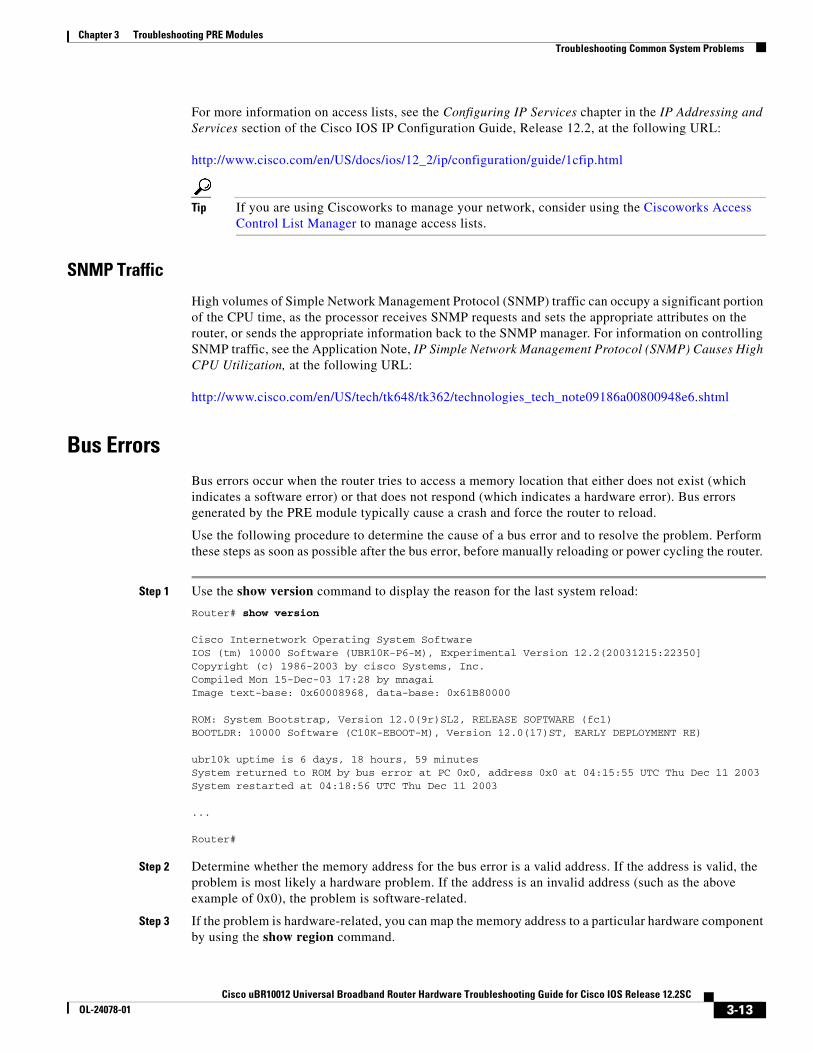
Step 1 Use the show version command to display the reason for the last system reload:
Router# show version
Cisco Internetwork Operating System Software IOS (tm) 10000 Software (UBR10K-P6-M), Experimental Version 12.2(20031215:22350]Copyright (c) 1986-2003 by cisco Systems, Inc.Compiled Mon 15-Dec-03 17:28 by mnagaiImage text-base: 0x60008968, data-base: 0x61B80000
ROM: System Bootstrap, Version 12.0(9r)SL2, RELEASE SOFTWARE (fc1)BOOTLDR: 10000 Software (C10K-EBOOT-M), Version 12.0(17)ST, EARLY DEPLOYMENT RE)
ubr10k uptime is 6 days, 18 hours, 59 minutesSystem returned to ROM by bus error at PC 0x0, address 0x0 at 04:15:55 UTC Thu Dec 11 2003 System restarted at 04:18:56 UTC Thu Dec 11 2003
...
Router#
Step 2 Determine whether the memory address for the bus error is a valid address. If the address is valid, the problem is most likely a hardware problem. If the address is an invalid address (such as the above example of 0x0), the problem is software-related.
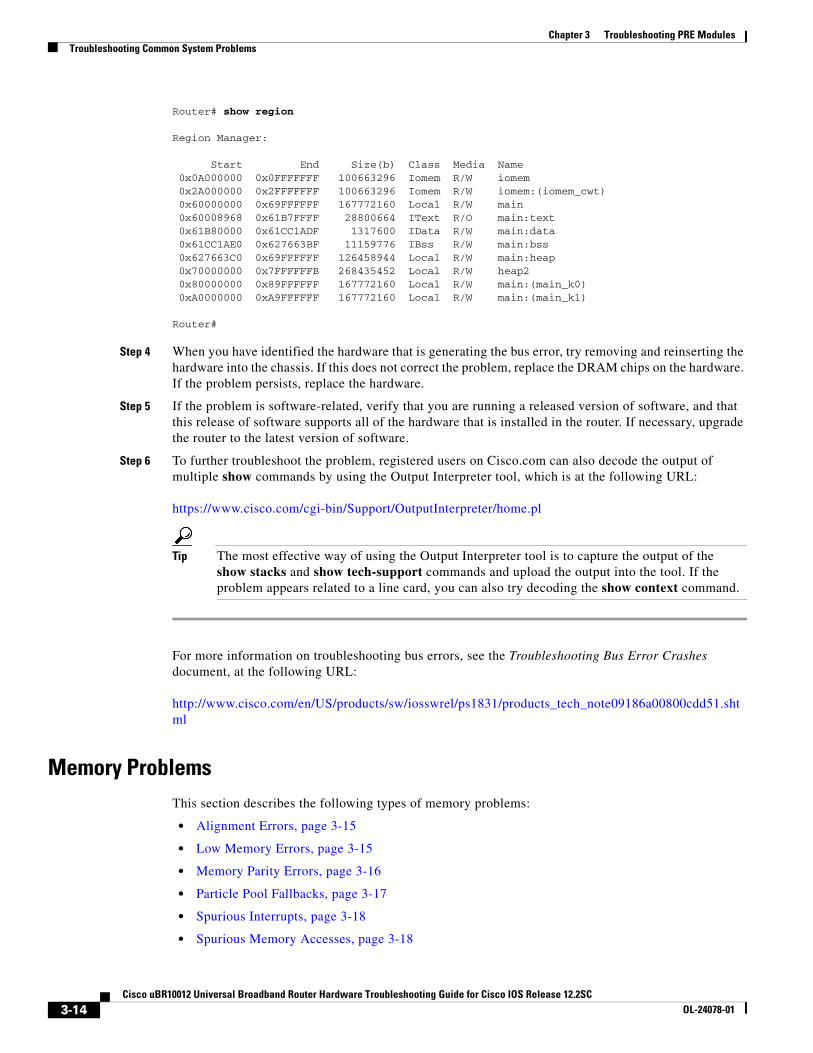
Step 3 If the problem is hardware-related, you can map the memory address to a particular hardware component by using the show region command.
Chapter 3 Troubleshooting PRE ModulesTroubleshooting Common System Problems
Router# show region
Region Manager:
Start End Size(b) Class Media Name 0x0A000000 0x0FFFFFFF 100663296 Iomem R/W iomem 0x2A000000 0x2FFFFFFF 100663296 Iomem R/W iomem:(iomem_cwt) 0x60000000 0x69FFFFFF 167772160 Local R/W main 0x60008968 0x61B7FFFF 28800664 IText R/O main:text 0x61B80000 0x61CC1ADF 1317600 IData R/W main:data 0x61CC1AE0 0x627663BF 11159776 IBss R/W main:bss 0x627663C0 0x69FFFFFF 126458944 Local R/W main:heap 0x70000000 0x7FFFFFFB 268435452 Local R/W heap2 0x80000000 0x89FFFFFF 167772160 Local R/W main:(main_k0) 0xA0000000 0xA9FFFFFF 167772160 Local R/W main:(main_k1)
Router#
Step 4 When you have identified the hardware that is generating the bus error, try removing and reinserting the hardware into the chassis. If this does not correct the problem, replace the DRAM chips on the hardware. If the problem persists, replace the hardware.
Step 5 If the problem is software-related, verify that you are running a released version of software, and that this release of software supports all of the hardware that is installed in the router. If necessary, upgrade the router to the latest version of software.
Step 6 To further troubleshoot the problem, registered users on Cisco.com can also decode the output of multiple show commands by using the Output Interpreter tool, which is at the following URL:
Tip The most effective way of using the Output Interpreter tool is to capture the output of the show stacks and show tech-support commands and upload the output into the tool. If the problem appears related to a line card, you can also try decoding the show context command.
For more information on troubleshooting bus errors, see the Troubleshooting Bus Error Crashes document, at the following URL:
Chapter 3 Troubleshooting PRE ModulesTroubleshooting Common System Problems
Alignment Errors
Alignment errors occur when the software attempts to read or write data using a data size that is not aligned with the memory address being used. For example, an alignment error occurs when attempting to read two bytes from a memory address that is not an even multiple of two bytes.
Alignment errors are always caused by a software bug, and can be either correctable or fatal. See the following sections for more information. Also see the document Troubleshooting Spurious Accesses, Alignment Errors, and Spurious Interrupts, at the following URL:
The Cisco IOS software can automatically correct most alignment errors. When it does so, the router generates a system error message similar to the following:
%ALIGN-3-CORRECT: Alignment correction made at 0x60262478 reading/writing 0x60A9FF5C
Occasional alignment errors do not necessarily require operator intervention, because the Cisco IOS software can correct these errors and continue with normal operations. However, correcting alignment errors consumes processor resources and could impact performance if the errors continuously repeat.
Fatal Alignment Errors
If the alignment error was a fatal error, it displays a message similar to the following:
%ALIGN-1-FATAL: Corrupted program counter error. ERROR: Slot 0, NPE300/IOFE2/VXR, CACHE, External Data Cache Memory Test:
*** Data Expected= 0x99999999 ***
Fatal alignment errors are most likely a hardware fault on the processor card. The card itself could be faulty, or the memory on the card could be faulty. Try replacing the processor card and rebooting the router. If a replacement card is not available, try replacing the memory on the processor card, making sure that the new memory meets the specifications that are required by the card.
Low Memory Errors
The router can experience low memory errors for a number of reasons, including the following possible causes:
• The router is handling an excessively large volume of traffic. In particular, the router could be experiencing a large volume of traffic that requires special handling, such as ARP requests.
• Abnormal processes are using excessive amounts of memory.
• Large amounts of memory are still allocated to dead processes.
• Software errors could have resulted in memory leaks.
• Hardware problems with the memory on the processor card or line card.
• Hardware problems on the processor card or line card.
Low memory problems are usually indicated by one or more system messages (for example, SYS-2-MALLOCFAIL). For troubleshooting steps to resolve problems with low memory, see the Tech Note titled Troubleshooting Memory Problems, at the following URL:
A memory parity error means that one or more bits at a memory location were unexpectedly changed after they were originally written. This error could indicate a potential problem with the Dynamic Random Access Memory (DRAM) that is onboard the PRE module.
Parity errors are not expected during normal operations and might force the router to reload. If the router did reload because of a parity error, the show version command displays a message such as “System restarted by processor memory parity error” or “System restarted by shared memory parity error.” For example:
Router# show version
Cisco Internetwork Operating System Software IOS (tm) 10000 Software (UBR10K-P6-M), Experimental Version 12.2(20031215:22350]Copyright (c) 1986-2003 by cisco Systems, Inc.Compiled Mon 15-Dec-03 17:28 by mnagaiImage text-base: 0x60008968, data-base: 0x61B80000
ROM: System Bootstrap, Version 12.0(9r)SL2, RELEASE SOFTWARE (fc1)BOOTLDR: 10000 Software (C10K-EBOOT-M), Version 12.0(17)ST, EARLY DEPLOYMENT RE)
ubr10k uptime is 6 days, 18 hours, 59 minutesSystem returned to ROM by processor memory parity error at PC 0x60301298, address 0x0 at 17:19:47 PDT Mon Dec 15 2003System restarted at 17:19:47 PDT Mon Dec 15 2003
...
Router#
Parity errors can be categorized in two different ways:
• Soft parity errors occur when an energy level within the DRAM memory changes a bit from a one to a zero, or a zero to a one. Soft errors are rare and are most often the result of normal background radiation. When the CPU detects a soft parity error, it attempts to recover by restarting the affected subsystem, if possible. If the error is in a portion of memory that is not recoverable, it could cause the system to crash. Although soft parity errors can cause a system crash, you do not need to swap the board or any of the components, because the problem is not defective hardware.
• Hard parity errors occur when a hardware defect in the DRAM or processor board causes data to be repeatedly corrupted at the same address. In general, a hard parity error occurs when more than one parity error in a particular memory region occurs in a relatively short period of time (several weeks to months).
When parity occurs, take the following steps to resolve the problem:
Step 1 Determine whether this is a soft parity error or a hard parity error. Soft parity errors are 10 to 100 times more frequent than hard parity errors. Therefore, wait for a second parity error before taking any action. Monitor the router for several weeks after the first incident, and if the problem reoccurs, assume that the problem is a hard parity error and proceed to the next step.
Step 2 When a hard parity error occurs (two or more parity errors at the same memory location), try removing and reinserting the PRE module, making sure to fully insert the card and to securely tighten the restraining screws on the front panel.
Private particle pools are buffers in I/O memory that store packets while they are being processed. The Cisco IOS software allocates a fixed number of private particle pools during system initialization, and these buffers are reserved for packet use, so as to minimize system contention for memory resources.
The system uses buffer control structures called “rings” to manage the entries in the particle pools. Each ring is a circular linked-list of pointers to each packet in the particle pool. The system creates a pair of rings for each interface, with one ring for packets waiting to be transmitted and another ring for packets that are being received.
The system also allocates public pools in a number of different sizes for more general use. If a packet requires special handling, or if a packet cannot be completely processed at interrupt time, the system copies the packet into a portion of contiguous memory in the public pool, so it can be processed switched.
Tip Use the show buffers command to display the current status of the router’s particle pools.
Fallbacks with particle pools occur when bursts of traffic produce more packets than would fit in the available buffer space. When an interface runs out of space in the private particle pools, it falls back to using the normal public memory. Fallbacks are expected during periods of bursty traffic, and the router should be considered to be operating normally in these situations.
If fallbacks occur more frequently, however, it could indicate a problem. In particular, if the private particle pools are consistently producing fallbacks, it could result in the router using excessive amounts of public memory for packet processing, reducing the resources that are available to the other router processes. If this is the case, look for the following possible causes.
• Extremely fast interfaces are handling large volumes of traffic with a high rate of throughput that is approaching the maximum rate on the interface.
• The Fast Ethernet interfaces on the processor card could be heavily loaded.
• The Cisco IOS software has a memory leak that is not releasing the memory in the private particle pool after the interface has finished processing a packet.
For more information on resolving problems with particle pool buffers, see the document Buffer Tuning, at the following URL:
A spurious interrupt occurs when the Cisco IOS software generates an unnecessary interrupt for packet that has been processed already. This is a software error that is usually caused by an improper initialization of interrupt handling routines, or by a race condition where two processes compete to handle the same process.
Spurious interrupts can occasionally be expected during normal operations, and the occasional spurious interrupt has no discernible impact on the router’s performance. However, action might be needed if the number of spurious interrupts is high or increasing, and performance is being degraded, with packets being dropped.
For information on resolving the problem with spurious interrupts, see the document Troubleshooting Spurious Accesses, Alignment Errors, and Spurious Interrupts, at the following URL:
A spurious memory access occurs when a Cisco IOS software process attempts to access memory in the lowest 16 KB region of memory, which is a restricted location. Typically, such errors display a system error message similar to the following:
%ALIGN-3-SPURIOUS: Spurious memory access made at 0x60968C44 reading 0x0%ALIGN-3-TRACE: -Traceback= 60968C44 60269808 602389D8 00000000 00000000 00000000 00000000 00000000
Where possible, the Cisco IOS software handles spurious memory accesses by returning a value of zero to the calling routine, and then displaying the above error message. If this is not possible, the router crashes with a Segment Violation (SegV) error. In either case, the cause of the error is almost always a bug in the Cisco IOS software.
If possible, upgrade to the latest release of the Cisco IOS software. If the bug still exists on the router, see the section Spurious Accesses in the document Troubleshooting Spurious Accesses, Alignment Errors, and Spurious Interrupts, at the following URL:
This chapter discusses troubleshooting faults on the following Cisco uBR10012 line cards:
• General Information for Troubleshooting Line Card Crashes, page 4-1
• Troubleshooting the Timing, Communication, and Control Plus Card, page 4-7
• Troubleshooting the DOCSIS Timing, Communication, and Control Card, page 4-7
• Troubleshooting the Gigabit Ethernet Line Card, page 4-8
• Troubleshooting the Cable Interface Line Cards, page 4-8
• Troubleshooting the SIP and SPA Interface Modules, page 4-9
General Information for Troubleshooting Line Card CrashesLine card crashes occur when the hardware or software encounter unexpected situations that are not expected in the current design. As a general rule, they usually indicate a configuration error, a software error, or a hardware problem.
Table 4-1 lists the show commands that are most useful in collecting information to troubleshoot line card crashes.
Table 4-1 Relevant Show Commands for Line Card Crashes
Command Description
show version Provides general information about the system's hardware and software configurations
show logging Displays the general logs of the router
show diag [slot/subslot] Provides specific information about a particular slot: type of engine, hardware revision, firmware revision, memory configuration, and so on.
show context [summary | slot [slot/subslot] ]
Provides context information about the most recent crashes. This is often the most useful command for troubleshooting line card crashes.
4-1roubleshooting Guide for Cisco IOS Release 12.2SC
Chapter 4 Troubleshooting Line Cards and Interface ModulesGeneral Information for Troubleshooting Line Card Crashes
Use the following procedure if you suspect that a line card has crashed.
Step 1 If you can identify the particular card that has crashed or is experiencing problems, first use the other sections in this chapter to perform basic troubleshooting. In particular, ensure that the line card is fully inserted into the proper slot, and that all cables are properly connected.
Step 2 If any system messages were displayed on the console or in the SYSLOG logs at the time of the crash, consult the Cisco IOS System Messages Guide for possible suggestions on the source of the problem.
Step 3 Line cards can crash or appear to crash when an excessive number of debug messages are being generated. In particular, this can happen when using the verbose or detail mode of a debug command, or if the debug command is dumping the contents of packets or packet buffers. If the console contains a large volume of debug output, turn off all debugging with the no debug all command.
Step 4 If the system message log contains messages that indicate the line card is not responding (for example, %IPCOIR-3-TIMEOUT), and the card’s LEDs are not lit, the line card might have shut down because of overheating. Ensure that all chassis slots either have the proper card or module installed in them. If a slot is blank, ensure that the slot has a blank front panel installed, so that proper airflow and cooling can be maintained in the chassis.
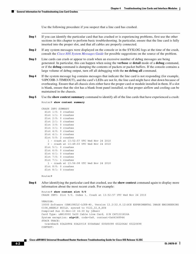
Step 5 Use the show context summary command to identify all of the line cards that have experienced a crash:
Router# show context summary
CRASH INFO SUMMARY Slot 1/0: 0 crashes Slot 1/1: 0 crashes Slot 2/0: 0 crashes Slot 2/1: 0 crashes Slot 3/0: 0 crashes Slot 3/1: 0 crashes Slot 4/0: 0 crashes Slot 4/1: 0 crashes Slot 5/0: 2 crashes 1 - crash at 13:52:57 UTC Wed Nov 24 2010 2 - crash at 13:49:03 UTC Wed Nov 24 2010 Slot 5/1: 0 crashes Slot 6/0: 0 crashes Slot 6/1: 0 crashes Slot 7/0: 0 crashes Slot 7/1: 1 crashes 1 - crash at 13:56:08 UTC Wed Nov 24 2010 Slot 8/0: 0 crashes Slot 8/1: 0 crashes
Router#
Step 6 After identifying the particular card that crashed, use the show context command again to display more information about the most recent crash. For example:
Router# show context slot 5/0 CRASH INFO: Slot 5/0, Index 1, Crash at 13:52:57 UTC Wed Nov 24 2010
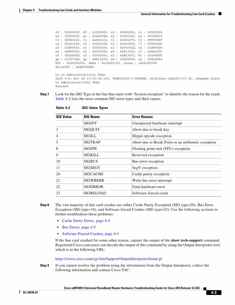
VERSION:10000 Software (UBR10KCLC-LCK8-M), Version 12.2(32.8.12)SCE EXPERIMENTAL IMAGE ENGINEERING C10K_WEEKLY BUILD, synced to V122_32_8_SCECompiled Sun 21-Nov-10 16:30 by jdkerrCard Type: uBR10000 5x20 Cable Line Card, S/N CAT1221E16ASystem exception: sig=10, code=0x8, context=0x64348944STACK TRACE: traceback 60A2D984 60A2CC18 600A8AAC 600D5098 602206AC 60220698 CONTEXT:
te to administratively downSLOT 5/0: Nov 24 13:50:34.143: %UBR10000-5-UPDOWN: Interface Cable5/0/3 U2, changed state to administratively downRouter#
Step 7 Look for the SIG Type in the line that starts with “System exception” to identify the reason for the crash. Table 4-2 lists the most common SIG error types and their causes.
Step 8 The vast majority of line card crashes are either Cache Parity Exception (SIG type=20), Bus Error Exception (SIG type=10), and Software-forced Crashes (SIG type=23). Use the following sections to further troubleshoot these problems:
• Cache Parity Errors, page 4-4
• Bus Errors, page 4-5
• Software-Forced Crashes, page 4-5
If the line card crashed for some other reason, capture the output of the show tech-support command. Registered Cisco.com users can decode the output of this command by using the Output Interpreter tool, which is at the following URL:
Chapter 4 Troubleshooting Line Cards and Interface ModulesGeneral Information for Troubleshooting Line Card Crashes
• All relevant information about the problem that you have available, including any troubleshooting you have performed.
• Any console output that was generated at the time of the problem.
• Output of the show tech-support command.
• Output of the show log command (or the log that was captured by your SYSLOG server, if available).
Cache Parity ErrorsA cache parity error (SIG type is 20) means that one or more bits at a memory location were unexpectedly changed after they were originally written. This error could indicate a potential problem with the Dynamic Random Access Memory (DRAM) that is onboard the line card.
Parity errors are not expected during normal operations and could force the line card to crash or reload. These memory errors can be categorized in two different ways:
• Soft parity errors occur when an energy level within the DRAM memory changes a bit from a one to a zero, or a zero to a one. Soft errors are rare and are most often the result of normal background radiation. When the CPU detects a soft parity error, it attempts to recover by restarting the affected subsystem, if possible. If the error is in a portion of memory that is not recoverable, it could cause the system to crash. Although soft parity errors can cause a system crash, you do not need to swap the board or any of the components, because the problem is not defective hardware.
• Hard parity errors occur when a hardware defect in the DRAM or processor board causes data to be repeatedly corrupted at the same address. In general, a hard parity error occurs when more than one parity error in a particular memory region occurs in a relatively short period of time (several weeks to months).
When parity occurs, take the following steps to resolve the problem:
Step 1 Determine whether this is a soft parity error or a hard parity error. Soft parity errors are 10 to 100 times more frequent than hard parity errors. Therefore, wait for a second parity error before taking any action. Monitor the router for several weeks after the first incident, and if the problem reoccurs, assume that the problem is a hard parity error and proceed to the next step.
Step 2 When a hard parity error occurs (two or more parity errors at the same memory location), try removing and reinserting the line card, making sure to fully insert the card and to securely tighten the restraining screws on the front panel.
Step 3 If this does not resolve the problem, remove and reseat the DRAM chips. If the problem continues, replace the DRAM chips.
Step 4 If parity errors occur, the problem is either with the line card or the router chassis. Try removing the line card and reinserting it. If the problem persists, try removing the line card from its current slot and reinserting it in another slot, if one is available. If that does not fix the problem, replace the line card.
Step 5 If the problems continue, collect the following information and contact Cisco TAC:
• All relevant information about the problem that you have available, including any troubleshooting you have performed.
• Any console output that was generated at the time of the problem.
Chapter 4 Troubleshooting Line Cards and Interface ModulesGeneral Information for Troubleshooting Line Card Crashes
• Output of the show log command (or the log that was captured by your SYSLOG server, if available).
Bus ErrorsBus errors (SIG type is 10) occur when the line card tries to access a memory location that either does not exist (which indicates a software error) or that does not respond (which indicates a hardware error). Use the following procedure to determine the cause of a bus error and to resolve the problem.
Perform these steps as soon as possible after the bus error. In particular, perform these steps before manually reloading or power cycling the router, or before performing an Online Insertion/Removal (OIR) of the line card, because doing so eliminates much of the information that is useful in debugging line card crashes.
Step 1 Capture the output of the show stacks, show context, and show tech-support commands. Registered Cisco.com users can decode the output of this command by using the Output Interpreter tool, which is at the following URL:
Step 2 If the results from the Output Interpreter indicate a hardware-related problem, try removing and reinserting the hardware into the chassis. If this does not correct the problem, replace the DRAM chips on the hardware. If the problem persists, replace the hardware.
Step 3 If the problem appears software-related, verify that you are running a released version of software, and that this release of software supports all of the hardware that is installed in the router. If necessary, upgrade the router to the latest version of software.
Tip The most effective way of using the Output Interpreter tool is to capture the output of the show stacks and show tech-support commands and upload the output into the tool. If the problem appears related to a line card, you can also try decoding the show context command.
Upgrading to the latest version of the Cisco IOS software eliminates all fixed bugs that can cause line card bus errors. If the crash is still present after the upgrade, collect the relevant information from the above troubleshooting, as well as any information about recent network changes, and contact Cisco TAC.
Software-Forced CrashesSoftware-forced crashes (SIG type is 23) occur when the Cisco IOS software encounters a problem with the line card and determines that it can no longer continue, so it forces the line card to crash. The original problem could be either hardware-based or software-based.
The most common reason for a software-forced crash on a line card is a “Fabric Ping Timeout,” which occurs when the PRE module sends five keepalive messages (fabric pings) to the line card and does not receive a reply. If this occurs, you should see error messages similar to the following in the router’s console log:
%GRP-3-FABRIC_UNI: Unicast send timed out (4) %GRP-3-COREDUMP: Core dump incident on slot 4, error: Fabric ping failure
Fabric ping timeouts are usually caused by one of the following problems:
Chapter 4 Troubleshooting Line Cards and Interface ModulesGeneral Information for Troubleshooting Line Card Crashes
• High CPU Utilization—Either the PRE module or line card is experiencing high CPU utilization. The PRE module or line card could be so busy that either the ping request or ping reply message was dropped. Use the show processes cpu command to determine whether CPU usage is exceptionally high (at 95 percent or more). If so, see the “High CPU Utilization Problems” section on page 3-8 for information on troubleshooting the problem.
• CEF-Related Problems—If the crash is accompanied by system messages that begin with “%FIB,” it could indicate a problem with Cisco-Express Forwarding (CEF) on one of the line card’s interfaces. For more information, see Troubleshooting CEF-Related Error Messages, at the following URL:
• IPC Timeout—The InterProcess Communication (IPC) message that carried the original ping request or the ping reply was lost. This could be caused by a software bug that is disabling interrupts for an excessive period of time, high CPU usage on the PRE module, or by excessive traffic on the line card that is filling up all available IPC buffers.
If the router is not running the most current Cisco IOS software, upgrade the router to the latest software release, so that any known IPC bugs are fixed. If the show processes cpu shows that CPU usage is exceptionally high (at 95 percent or more), or if traffic on the line card is excessive, see the “High CPU Utilization Problems” section on page 3-8.
If the crash is accompanied by %IPC-3-NOBUFF messages, see Troubleshooting IPC-3-NOBUFF Messages on the Cisco 12000, 10000 and 7500 Series, at the following URL:
• Hardware Problem—The card might not be fully inserted into its slot, or the card hardware itself could have failed. In particular, if the problem began occurring after the card was moved or after a power outage, the card could have been damaged by static electricity or a power surge. Only a small number of fabric ping timeouts are caused by hardware failures, so check for the following before replacing the card:
– Reload the software on the line card, using the hw-module slot reset command.
– Remove and reinsert the line card in its slot.
– Try moving the card to another slot, if one is available.
If software-forced crashes continue, collect the following information and contact Cisco TAC:
• All relevant information about the problem that you have available, including any troubleshooting you have performed.
• Any console output that was generated at the time of the problem.
• Output of the show tech-support command.
• Output of the show log command (or the log that was captured by your SYSLOG server, if available).
Chapter 4 Troubleshooting Line Cards and Interface ModulesTroubleshooting the Timing, Communication, and Control Plus Card
Troubleshooting the Timing, Communication, and Control Plus Card
At least one working Timing, Communication, and Control Plus (TCC+) card must be installed in the Cisco uBR10012 router for normal operations. The TCC+ card acts as a secondary processor that performs the following functions:
• Generates and distributes 10.24 MHz clock references to each cable interface line card.
• Generates and distributes 32-bit time stamp references to each cable interface line card.
• Allows software to independently power off any or all cable interface line cards.
• Provides support for Online Insertion/Removal (OIR) operations of line cards.
• Drives the LCD panel used to display system configuration and status information.
• Monitors the supply power usage of the chassis.
• Provides two redundant RJ-45 ports for external timing clock reference inputs such as a Global Positioning System (GPS) or BITS clock.
If the Cisco uBR10012 router does not have a working TCC+ card installed, the WAN and cable interface line cards will experience excessive packet drops, or all traffic will be dropped, because of an invalid timing signal. Also, if no TCC+ card is installed, the cable power command is disabled, because this function is performed by the TCC+ card.
Note Because the TCC+ card is considered a half-height card, use slot numbers 1/1 or 2/1 to display information for the TCC+ card using the show diag command. The show cable clock and show controllers clock-reference commands also use these slot numbers when displaying clock-related information.
For more information about the TCC+ card, refer to the troubleshooting section in the Cisco uBR10012 Universal Broadband Router TCC+ Card guide.
Troubleshooting the DOCSIS Timing, Communication, and Control Card
The DOCSIS Timing, Communication, and Control (DTCC) card performs the following functions:
• In the default DTI mode, a 10.24 MHz clock and 32-bit DOCSIS timestamp is generated by the DTI Server, propagated to DTI client using DTI protocol, and distributed by DTI client to each cable interface line card.
• Allows software to independently power off any or all cable interface line cards.
• Drives the LCD panel used to display system configuration and status information.
• Monitors the supply power usage of the chassis.
• Two RJ-45 cables with the DTI server, which, in turn, can generate the clock using its own oscillator or external timing reference inputs such as GPS or network clock.
Chapter 4 Troubleshooting Line Cards and Interface ModulesTroubleshooting the Gigabit Ethernet Line Card
Note In Cisco IOS Release 12.2(33)SCB and later releases, you must ensure that two DTCC cards are installed and configured on the Cisco uBR10012 router before installing the line cards or the shared port adaptor (SPA). Installing and configuring a single DTCC card on a Cisco uBR10012 router is not supported in Cisco IOS Release 12.2(33)SCB and later.
For more information about the DTCC card, refer to the troubleshooting section in the Cisco uBR10012 Universal Broadband Router DTCC Card guide.
Troubleshooting the Gigabit Ethernet Line CardThe Cisco Half-Height Gigabit Ethernet (HHGE) line card contains a single Gigabit Ethernet port that provides a trunk uplink to switches and core routers. The Cisco HHGE line card provides the Cisco uBR10012 universal broadband router with an IEEE 802.3z- compliant Ethernet interface that can run up to 1 Gbps in full duplex mode. The line card uses a small form-factor pluggable (SFP) Gigabit Interface Converter (GBIC) module that supports a variety of Gigabit Ethernet interface types (SX, LX/LH, and ZX), which you can change or upgrade at any time.
For more information about the HHGE line card, refer to the troubleshooting section in the Cisco uBR10012 Universal Broadband Router Gigabit Ethernet Half-Height Line Card Installation guide.
Troubleshooting the Cable Interface Line CardsThe cable interface line cards, together with external IF-to-RF upconverters, serve as the RF interface between the cable headend and DOCSIS/EuroDOCSIS-based cable modems.
Note For troubleshooting information about obsolete line cards, see Cisco uBR10012 Universal Broadband Router Troubleshooting Guide.
Troubleshooting the Cisco uBR10-MC5X20U/H Cable Interface Line Card The Cisco uBR10-MC5X20 U and H cable interface line cards are 20 by 16 inch cards designed specifically for the Cisco uBR10012 router. These cards transmit and receive RF signals between the subscriber and the headend over hybrid fiber-coaxial (HFC) system.
For more information about this interface processor, refer to the troubleshooting sections in the following guides:
• Cisco uBR10-MC5X20U/H Cable Interface Line Card Hardware Installation Guide
• Configuring the Cisco uBR10-MC5X20U/H Broadband Processing Engine
Troubleshooting the Cisco UBR-MC20X20V Cable Interface Line CardThe Cisco UBR-MC20X20V cable interface line card is a 20 by 16 inch card designed specifically for the Cisco uBR10012 universal broadband router. This card transmits and receives RF signals between the subscriber and the headend over hybrid fiber-coaxial (HFC) system.
Chapter 4 Troubleshooting Line Cards and Interface ModulesTroubleshooting the SIP and SPA Interface Modules
For more information about this line card, refer to the troubleshooting sections in the following guides:
• Cisco UBR-MC20X20V Cable Interface Line Card Hardware Installation Guide
• Configuring the Cisco UBR-MC20X20V Cable Interface Line Card
Troubleshooting the Cisco uBR-MC3GX60V Cable Interface Line CardThe Cisco uBR-MC3GX60V line card is a high density Modular CMTS line card that provides 72 Annex B downstream and 60 upstream channels and is introduced to provide increased bandwidth to the cable modems.
It’s front panel has a four-character alphanumeric display that shows the licensing status information of the upstream and downstream ports. The first two characters represent the downstream license count and the last two characters represent the upstream license count of the line card.
For more information about this line card, refer to the troubleshooting sections in the following guides:
• Cisco uBR-MC3GX60V Cable Interface Line Card Hardware Installation Guide
• Configuring the Cisco uBR-MC3GX60V Cable Interface Line Card
Troubleshooting the SIP and SPA Interface ModulesSIPs and SPAs are a carrier card and port adapter architecture that increases modularity, flexibility, and density across Cisco routers for network connectivity. A SIP is a carrier card that inserts into a router slot like a line card. It provides no network connectivity on its own. A SPA is a modular type of port adapter that inserts into a bay (subslot) of a compatible SIP carrier card to provide network connectivity and increased interface port density. A SIP can hold one or more SPAs, depending on the SIP type.
Cisco Wideband SIPOn a Cisco uBR10012 router, the Cisco Wideband SIP occupies two full-height line card slots: either slots 1/0 and 2/0, or slots 3/0 and 4/0.
For more information about this interface processor, refer to the troubleshooting sections in the following guides:
Cisco Wideband SPAThe Cisco Wideband SPA is a single-wide, half-height shared port adapter that provides Cisco Wideband Protocol for a DOCSIS network formatting to the downstream data packets. The Cisco Wideband SPA is used for downstream data traffic only.
For more information about this shared port adapter, refer to the troubleshooting sections in the following guides:
This section describes how to recover a lost enable or console login password, and how to replace a lost enable secret password on the Cisco uBR10012 router.
Note It is possible to recover the enable or console login password. The enable secret password is encrypted, however, and must be replaced with a new enable secret password.
Password Recovery Procedure OverviewThe following is an overview of the steps in the password recovery procedure.
• If you can log in to the router, enter the show version command to determine the existing configuration register value.
• Press the Break key to go to the bootstrap program prompt (ROM monitor). You might need to reload the system image by power-cycling the router.
• Change the configuration register to 0x2142 so that the router ignores the startup configuration file during bootup. This allows you to log in without using a password and to display the startup configuration password.
• Reload the cycle the router by typing reset at the rommon> prompt.
• Log in to the router and enter the privileged EXEC mode.
• Enter the show startup-config command to display the passwords.
• Recover or replace the displayed passwords.
• Change the configuration register back to its original setting.
Note To recover a lost password if the break function is disabled on the router, you must have physical access to the router.
Password Recovery ProcedureTo recover or replace a lost enable, enable secret, or console login password, use this procedure:
Step 1 Attach an ASCII terminal to the console port on the router.
5-1roubleshooting Guide for Cisco IOS Release 12.2SC
Chapter 5 Replacing or Recovering PasswordsPassword Recovery Procedure
Step 2 Configure the terminal to operate at 9600 baud, 8 data bits, no parity, and 1 stop bit.
Step 3 If you can log in to the router as a nonprivileged user, enter the show version command to display the existing configuration register value, then go to Step 6. If you cannot log in to the router at all, go to the next step.
Step 4 Press the Break key or send a break signal from the console terminal.
• If break is enabled, the router enters the ROM monitor, indicated by the ROM monitor prompt (rommon>). Go to Step 6.
• If break is disabled, power cycle the router (turn off the router or unplug the power cord, and then restore power). Then go to Step 5.
Step 5 Within 60 seconds of restoring the power to the router, press the break key or send a break signal. This action causes the router to enter the ROM monitor and display the ROM monitor prompt (rommon>).
Step 6 Set the configuration register using the configuration register utility. Enter the confreg command at the ROM monitor prompt as follows:
rommon> confreg
Answer yes to the enable “ignore system config info?” Press the return key at all other prompts to accept the existing value.
Step 7 Reboot the router by entering the reset command:
rommon> reset
The router initializes, the configuration register is set to 0x2142, and the router boots the system image from Flash memory and enters the system configuration dialog (setup):
--- System Configuration Dialog --
Step 8 Enter no in response to the system configuration dialog prompts until the following message appears:
Press RETURN to get started!
Step 9 Press Return. The user EXEC prompt appears:
Router>
Step 10 Enter the enable command to enter privileged EXEC mode. Then enter the show startup-config command to display the passwords in the configuration file as follows:
Router# show startup-config
Step 11 Scan the configuration file display, looking for the passwords (the enable passwords are usually located near the beginning of the file, and the console login or user EXEC password is near the end). The passwords displayed appear similar to the following:
enable secret 5 $1$ORPP$s9syZt4uKn3SnpuLDrhueienable password 23skiddoo..line con 0password onramp
The enable secret password is encrypted and cannot be recovered; it must be replaced. Go to the next step to replace an enable secret, console login, or enable password. If there is no enable secret password, note the enable and console login passwords. If the enable and console login passwords are not encrypted, go to Step 16.
Chapter 5 Replacing or Recovering PasswordsPassword Recovery Procedure
Caution Do not execute the next step unless you have determined you must change or replace the enable, enable secret, or console login passwords. Failure to follow the steps as shown might cause you to erase the router configuration.
Step 12 Enter the copy startup-config running-config command to load the startup configuration file into running memory. This action allows you to modify or replace passwords in the configuration.
Router# copy startup-config running-config
Step 13 Enter the privileged EXEC command configure terminal to enter configuration mode:
Router# configure terminal
Step 14 Change all three passwords using the following commands:
Router(config)# enable secret newpassword1Router(config)# enable password newpassword2Router(config)# line con 0Router(config-line)# password newpassword3
Change only the passwords necessary for your configuration. You can remove individual passwords by using the no form of the above commands. For example, entering the no enable secret command removes the enable secret password.
Step 15 You must configure all interfaces to avoid having the system be administratively shut down:
Router(config)# interface fastethernet 0/0Router(config-int)# no shutdown
Enter the equivalent commands for all interfaces that were originally configured. If you omit this step, all interfaces are administratively shut down and unavailable when the router is restarted.
Step 16 Use the config-register command to set the configuration register to the original value noted in Step 3 or Step 7, or to the factory default value 0x2102.
Router(config)# config-register 0x2102
Step 17 Press Ctrl-Z (hold down the Control key while you press Z) or enter end to exit configuration mode and return to the EXEC command interpreter.
Caution Do not execute the next step unless you have changed or replaced a password. If you skipped Step 12 through Step 15, go to Step 19. Failure to observe this caution causes you to erase the router configuration file.
Step 18 Enter the copy running-config startup-config command to save the new configuration to NVRAM.
Step 19 Enter the reload command to reboot the router.
Step 20 Log in to the router using the new or recovered passwords.
P P E N D I X A Recommended Tools and Test Equipment
Table A-1 lists the basic tools and test equipment necessary to perform general maintenance and troubleshooting tasks on the Cisco uBR10012 router.
The following sections describe advanced testing equipment to aid in complex problem isolation.
Testing with Digital Multimeters and Cable TestersUse a digital multimeter to measure parameters such as AC and DC voltage, current, resistance, capacitance, cable continuity. Use cable testers, also, to verify physical connectivity.
Use cable testers (scanners) to check physical connectivity. Cable testers are available for shielded twisted pair (STP), unshielded twisted pair (UTP), 10BaseT, and coaxial and twinax cables. A given cable tester might be able to perform any of the following functions:
• Test and report on cable conditions, including near-end crosstalk (NEXT), attenuation, and noise.
• Perform time domain reflectometer (TDR), traffic monitoring, and wire map functions.
• Display Media Access Control (MAC) layer information about LAN traffic, provide statistics such as network utilization and packet error rates, and perform limited protocol testing (for example, TCP/IP tests such as ping).
Table A-1 Recommended Tools and Test Equipment
Equipment Description
Number 2 Phillips and flat-head screwdrivers
Small and medium-sized.
Voltage tester Refer to the “Testing with Digital Multimeters and Cable Testers” section on page A-1.
Optical fiber test equipment Refer to the “Testing with Digital Multimeters and Cable Testers” section on page A-1.
Cable testing equipment Refer to the “Testing with Digital Multimeters and Cable Testers” section on page A-1.
HFC network physical layer equipment.
Refer to the “HFC Network Physical Layer Testing and Troubleshooting” section on page A-4.
ESD-preventive wrist or ankle strap with connection cord
—
A-1shooting Guide for Cisco IOS Release 12.2SC
Appendix A Recommended Tools and Test EquipmentTesting with TDRs and OTDRs
Test fiber-optic cable both before installation (on-the-reel testing) and after installation. Continuity testing of the fiber requires either a visible light source or a reflectometer. Light sources capable of providing light at the three predominant wavelengths, 850 nanometers (nm), 1310 nm, and 1550 nm, are used with power meters that can measure the same wavelengths and test attenuation and return loss in the fiber.
Testing with TDRs and OTDRsThis section describes time domain reflectometers (TDRs) and optical time domain reflectometers (OTDRs), which are typically used to detect cable defects.
TDR, also known as a metallic time domain reflectometer is used to characterize and troubleshoot metallic transmission lines such as twisted pair and coaxial cables. The TDR transmits pulses into one end of the line being tested and impedance mismatches in that line will reflect some or all of each transmitted pulse back to the instrument. Units with graphical displays can also plot a signature of the line being tested, allowing the operator to measure line length, identify splices, passives, actives, and locate damage to the line. TDRs are mainly useful for troubleshooting buried and hidden cables.
OTDR is used to characterize and troubleshoot optical fiber. The OTDR transmits pulses into one end of a fiber being tested and optical events in that fiber will cause backscatter of some or all of the transmitted pulses. OTDR measures the time from when each pulse is transmitted to when the backscatter is returned. As such, the OTDR can be used to measure fiber and event loss, identify specific events, and measure the distance to those events. There are two broad categories of optical events: reflective and non-reflective. Reflective events include the end of the fiber, connectors, mechanical splices, and breaks in the fiber (air/glass gap). Non-reflective events include fusion splices, breaks in the fiber (no air/glass gap), macrobends, and microbends.
Testing with TDRsUse time domain reflectometers to test for the following cable defects:
• Open and short circuits
• Crimps, kinks, and sharp bends
• Impedance mismatches
• Other defects
A TDR works by “bouncing” a signal off the end of the cable. Open circuits, short circuits and other problems reflect the signal back at different amplitudes, depending on the problem.
A TDR measures:
• the amount of time it takes for the signal to reflect
• The physical distance to a fault in the cable
• The length of a cable
Some TDRs can also calculate the propagation rate based on a configured cable length.
Testing with OTDRsUse optical time domain reflectometers to:
Appendix A Recommended Tools and Test EquipmentTesting with Breakout Boxes, Fox Boxes, and BERTs/BLERTs
• Locate fiber breaks
• Measure attenuation
• Measure the length of a fiber
• Measure splice or connector losses
An OTDR can be used to identify the “signature” of a particular installation, noting attenuation and splice losses. This baseline measurement can then be compared with future signatures if you suspect a problem in the system.
Testing with Breakout Boxes, Fox Boxes, and BERTs/BLERTsUse breakout boxes, fox boxes, and bit/block error rate testers (BERTs/BLERTs) to measure the digital signals present at:
• PCs
• Printers
• Modems
• CSU/DSUs
These devices can monitor data line conditions, analyze and trap data, and diagnose problems common to data communication systems. Traffic from data terminal equipment (DTE) through data communications equipment (DCE) can be examined to:
• Isolate problems
• Identify bit patterns
• Ensure that the correct cabling is installed
These devices cannot test media signals such as Ethernet, Token Ring, or FDDI.
Testing with Network MonitorsUse network monitors to:
• Track packets crossing a network
• Provide an accurate picture of network activity at any moment
• Provide a historical record of network activity over a period of time
Network monitors do not decode the contents of frames. Monitors are useful for baselining, in which the activity on a network is sampled over a period of time to establish a normal performance profile, or baseline.
Monitors collect information such as packet sizes, the number of packets, error packets, overall usage of a connection, the number of hosts and their MAC addresses, and details about communications between hosts and other devices. This data can be used to:
Appendix A Recommended Tools and Test EquipmentTesting with Network Analyzers
• Establish baseline performance
• Distribute traffic more efficiently
Testing with Network AnalyzersUse network analyzers (also called protocol analyzers) to decode protocol layers in a recorded frame and present the layers as readable abbreviations or summaries, detailing which layer is involved (physical, data link, and so forth) and the function each byte or byte content serves.
Most network analyzers can perform many of the following functions:
• Filter traffic that meets certain criteria so that, for example, all traffic to and from a particular device can be captured.
• Time-stamp captured data.
• Present protocol layers in an easily readable form.
• Generate frames and transmit them onto the network.
• Incorporate an “expert” system in which the analyzer uses a set of rules, combined with information about the network configuration and operation, to diagnose and solve, or offer potential solutions to, network problems.
DOCSIS 3.0 RF Protocol AnalyzerDOCSIS 3.0 RF Protocol Analyzer is the industry standard for functional DOCSIS network analysis. This device is optimized for real-time signal processing with FPGA technology and can analyze up to four single or bonded upstream and downstream channels.
HFC Network Physical Layer Testing and TroubleshootingThis section provides an overview of test equipment commonly used to maintain and troubleshoot the Hybrid fibre-coaxial (HFC) network physical layer. It is not intended to be an exhaustive list, nor to provide how-to instructions, which are available from the respective test equipment manufacturers. General test and measurement guidelines are also available in publications such as the latest edition of Recommended Practices for Measurements on Cable Television Systems, available from the Society of Cable Telecommunications Engineers.
A properly designed, constructed, and maintained HFC network is capable of supporting reliable high-speed data, voice and video services, as long as the entire network-headend, distribution plant, and subscriber drops-meets or exceeds certain minimum technical performance criteria. Those criteria include compliance with relevant government technical regulations applicable to cable, such as Part 76 of the Electronic Code of Federal Regulations; and the assumed downstream and upstream RF channel transmission characteristics summarized in the DOCSIS® Radio Frequency Interface Specification.
Most of the test equipment described here are intended to be used to test and troubleshoot the HFC network itself, regardless of the types of signals carried on the network. Certain instruments, such as digital signal analyzers, are designed specifically to measure digitally modulated signals such as the quadrature amplitude modulation (QAM) signals at the downstream output of the CMTS or edge-QAM modulator.
Appendix A Recommended Tools and Test EquipmentHFC Network Physical Layer Testing and Troubleshooting
Broadband SweepTypically comprising a sweep transmitter and a sweep receiver, this class of test equipment is used to characterize the cable network's frequency response specifically its amplitude-versus-frequency response. Sweep equipment may use a transmitted continuous low-level sweep signal (30 dB to 40 dB below analog TV channel visual carrier levels), sweep insertion points (carriers briefly inserted at specific frequencies, typically between channels), or sweepless sweep, in which the sweep receiver measures the amplitude of each operating carrier on the network and to produce a coarse indication of frequency response. Sweep equipment is available for downstream and upstream applications, and works well for initial and periodic alignment of the network, identifying improperly adjusted actives, missing or damaged plant components, and other problems that degrade the network's frequency response from an ideal situation.
Cable Modem Upstream Adaptive Pre-equalization CoefficientsCableLabs® and its proactive Network Maintenance Working Group in 2010 published a best practices document and reference implementation that describe the use of cable modem upstream pre-equalization coefficients to troubleshoot certain outside plant impairments. Though not technically a test equipment, the cable modems connected to an HFC network can be powerful tools for troubleshooting plant problems. The best practices document and reference implementation can be downloaded from the following URLs.
• DOCSIS Proactive Network Maintenance Using Pre-equalization
• Reference Implementations and the associated demo package
http://www.cablelabs.com/cablemodem/ri/
Digital MultimeterMost Digital multimeters (DMM) support measurement of AC and DC voltage and current, resistance, and continuity. The use of a true root mean square (RMS) DMM is recommended, since the latter provides more accurate measurement of the quasi-square wave AC voltage (nominally 60 or 90 volts) used to operate an HFC network's outside plant active devices. Lower cost non-true RMS DMMs generally read about 10% high when measuring the latter.
Examples of typical uses for DMMs include measurement of the:
• AC plant voltage
• commercial utility AC mains voltage
• regulated DC voltages inside amplifiers and nodes
• opto-electronic DC voltage test points that correspond to optical power levels
and identifying specific cables that go to specific outlets at the subscriber premises, and basic continuity testing of wiring and cabling.
Appendix A Recommended Tools and Test EquipmentHFC Network Physical Layer Testing and Troubleshooting
Digital Signal AnalyzerDigital signal analyzer is also known as a QAM analyzer. It is impossible to fully evaluate a QAM signal merely by measuring its digital channel power or looking at it on a spectrum analyzer. It is necessary to look further inside the signal to see what is going on. This is where the digital signal analyzer plays an important role.
In addition to incorporating signal level meter-type functionality for the measurement of analog TV channel signal level and digital channel power, most digital signal analyzers support several functions that can be used to characterize the health and performance of downstream QAM signals such as:
• Constellation display
• Modulation error ratio (MER)
• Pre- and post-FEC (forward error correction)
• BER (bit error ratio)
Depending on the make/model, some digital signal analyzers also have the ability to characterize linear distortions such as amplitude ripple and tilt (poor in-channel frequency response), micro-reflections (using the analyzer's adaptive equalizer graph), and group delay. Most digital signal analyzers can be used to troubleshoot transient impairments such as sweep transmitter interference and downstream laser clipping. Tracking down some types of in-channel ingress is even possible with most digital signal analyzers A digital signal analyzer's constellation display can be used to identify a variety of impairments based on how the constellation is distorted by those impairments.
Some digital signal analyzers are also designed to troubleshoot upstream problems.
Optical Power MeterThis is used to measure the optical power at the output of downstream laser transmitters and node upstream transmitters, the input of upstream receivers and node downstream receivers, optical amplifier inputs and outputs, and fiber loss. Optical power meter measurements are out-of-service measurements, which means service will be disrupted during this type of testing. Optical power meters are often used at the time fiber links are installed and commissioned, and sometimes when troubleshooting catastrophic link failures such as cut fibers.
OscilloscopeIt is an instrument that provides a graphical display of baseband or RF signals in the time domain (amplitude-versus-time.) The display on older oscilloscopes is a cathode ray tube, while modern versions are often LCD-based display. Battery operated portable oscilloscopes have been available for many years, and are useful for troubleshooting and measuring the amount of AC ripple in DC power supply outputs, including those in outside plant amplifiers. When properly terminated in the characteristic impedance of the circuit being measured, an oscilloscope can be used to accurately measure baseband analog video or audio signals. High bandwidth, high-speed oscilloscopes can be used to display and measure complex baseband data signals, as well as individual QAM signals in the RF domain.
Appendix A Recommended Tools and Test EquipmentHFC Network Physical Layer Testing and Troubleshooting
Signal Leakage DetectorIn theory, HFC networks are supposed to be closed RF transmission systems. This allows what is called frequency reuse, where frequencies inside the cables can be used to carry signals that are different from signals that exist on the same frequencies in the over-the-air environment. If the shielding integrity of the HFC network is compromised for any reason (such as cracked cable shield, loose or damaged connectors, rodent or environmental damage, direct connection of the subscriber drop to poorly shielded TVs and VCRs, etc.) signals inside the cable can leak out and cause interference to over-the-air services and vice versa. Signal leakage detectors are used by cable operators to measure and troubleshoot problems that cause signals inside the cable network to leak out. If signal leakage exists, it is likely that ingress (over-the-air signals leaking into the HFC network) also exists, so leakage detectors can be used for both leakage and ingress troubleshooting. Leakage detectors are also used to ensure compliance with government regulations that mandate the maximum allowable field strength caused by cable signal leakage.
Signal Level Meter The most basic signal level meter (SLM) is used to measure the amplitude, specifically the peak envelope power of analog TV channel visual and aural carriers. Newer SLMs generally include the ability to also measure digital channel power (average power) of QAM signals. Additional features available in some models include measurement of parameters such as analog TV channel carrier-to-noise ratio and hum modulation, and can perform various types of channel amplitude scans across the operating spectrum. In some instances, SLMs have the ability to conduct limited QAM signal analysis.
Spectrum Analyzer An instrument that provides a graphical display of RF signals (and sometimes baseband signals if suitably designed for this purpose) in the frequency domain (amplitude-versus-frequency.) The display on older spectrum analyzers is a cathode ray tube, while modern versions are often LCD-based display. Battery operated spectrum analyzers are available for portability. Some spectrum analyzers incorporate digital signal analysis functionality. Conventional spectrum analyzers are useful for measurement of signal levels of analog TV channels and often also digitally modulated signals, carrier-to-noise and carrier-to-distortion ratios, analog TV channel visual carrier depth of modulation and aural carrier frequency deviation, hum modulation, and a variety of other metrics and impairments. Many spectrum analyzers are able to operate in zero span mode, which facilitates an amplitude-versus-time display. The latter may be useful for viewing and measuring bursty upstream time division multiple access (TDMA) signals. Certain types of impairments such as linear distortions-micro-reflections, amplitude ripple/tilt, and group delay cannot be seen on a spectrum analyzer, unless the instrument is a combination spectrum analyzer and digital signal analyzer. A spectrum analyzer can be used to maintain and troubleshoot most of the HFC network elements such as the headend, most opto-electronics (RF inputs and outputs), hardline coax distribution plant, and subscriber drops.