CISCO UCS B230 M2 BLADE SERVER: UNCOMPROMISED VIRTUAL DESKTOP PERFORMANCE DECEMBER 2011 A PRINCIPLED TECHNOLOGIES TEST REPORT Commissioned by Cisco Systems, Inc. When deploying your virtual desktop solution, choosing hardware powerful enough to support a large number of virtual desktops is crucial. The more virtual desktops your server can support, the fewer servers you need to buy to provide virtual desktops to your desired number of users. To find the virtual desktop capacity of a single Cisco UCS B230 M2 Blade Server, we used the Login Consultants Virtual Session Indexer (Login VSI) 3.0 benchmark. The Login VSI workload we used performs a range of tasks to simulate a typical knowledge worker. The benchmark results show the maximum number of virtual desktops that a server can support by measuring response times throughout the test. Testing we conducted in the Principled Technologies lab revealed that a single Cisco UCS B230 M2 Blade Server running VMware vSphere 5 could support up to 175 concurrent VMware View 5 virtual desktops while still providing an excellent desktop experience for the end-user. This workload only used 5 percent of the available UCS bandwidth, leaving significant headroom for additional blades in the chassis for scalability, demonstrating the extensive bandwidth capacity afforded by the Cisco UCS architecture.
MORE VDI SESSIONS ARE BETTER Choosing the right combination of hardware and software for your virtual desktop
solution can significantly affect your bottom line. A robust hypervisor, top-of-the-line virtual
desktop software, and a server built on powerful processors with an expansive memory
footprint all work together to ensure you can meet the needs of your employees without your
spending money, space, and time on additional hardware. The greater your virtual desktop
density, the fewer physical servers you need. This reduces your electricity usage and power
costs, and results in a greener datacenter.
We set out to examine such a virtual desktop solution, one that consisted of the
following components:
Cisco Unified Computing System™ (UCS) B230 M2 Blade Server with Intel® Xeon® processor E7-4870s (Note: In our testing, we used the E7-4870 processors, the functional and performance equivalent of the E7-2870. Cisco officially supports the 2800 series of Intel Xeon processors for the B230 M2 blade.)1
vSphere 5
A VMware View 5 virtual desktop linked clone pool consisting of 175 Microsoft® Windows® 7 x64 VMs
175 virtual desktops, all provisioned with 1 vCPU and 2 GB of reserved memory2
EMC® VNX 5500 storage array
RESPONSE TIME MATTERS Login VSI measures the total response times of seven typical office operations and from
that calculates the VSI Index and average response times. Completion of these tasks within
4,000 milliseconds makes for an acceptable user experience. Figure 1 shows the VSI index
average and average response times for all active sessions recorded during the test. The Cisco
UCS B230 M2 Blade Server was able to support 175 concurrent virtual desktops without crossing
the response-time threshold. User response time degraded only when all 20 processor cores
were nearly saturated. For details, see Appendix D.
To initiate our test, we enabled our VMware View 5 pool of 175 Windows 7 VMs to start
up and reach a ready state. We monitored our test bed and perceived no bottlenecks in server
CPU, network, or storage I/O at the VMware View default startup rate of five VMs at a time.
1 See http://www.intel.com/content/www/us/en/processors/xeon/xeon-e7-8800-4800-2800-families-vol-1-datasheet.html.
2 We used 2 GB of RAM because Microsoft Windows 7 64-bit requires it. See http://windows.microsoft.com/en-US/windows7/products/system-
Figure 2: Bandwidth usage for 175 virtual desktop sessions over the hour-long test. Lower numbers are better. In our testing, the aggregate workload never exceeded 5 percent of available compute fabric bandwidth.
For information about Login VSI and the pieces of the solution we tested, see the What
we tested section below. For server and storage configuration information, see Appendix A. To
see the step-by-step process we used for testing, see Appendix B.
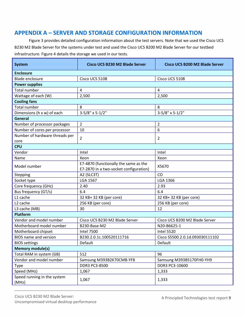
APPENDIX A – SERVER AND STORAGE CONFIGURATION INFORMATION Figure 3 provides detailed configuration information about the test servers. Note that we used the Cisco UCS
B230 M2 Blade Server for the systems under test and used the Cisco UCS B200 M2 Blade Server for our testbed
infrastructure. Figure 4 details the storage we used in our tests.
System Cisco UCS B230 M2 Blade Server Cisco UCS B200 M2 Blade Server
Enclosure
Blade enclosure Cisco UCS 5108 Cisco UCS 5108
Power supplies
Total number 4 4
Wattage of each (W) 2,500 2,500
Cooling fans
Total number 8 8
Dimensions (h x w) of each 3-5/8" x 5-1/2" 3-5/8" x 5-1/2"
General
Number of processor packages 2 2
Number of cores per processor 10 6
Number of hardware threads per core
2 2
CPU
Vendor Intel Intel
Name Xeon Xeon
Model number E7-4870 (functionally the same as the E7-2870 in a two-socket configuration)
Setting up the infrastructure server (infra), and server under test (SUT) BIOS settings
We used Cisco UCS firmware manager to set all UCS firmware to version 2.0(1s).
Installing VMware vSphere 5 (ESXi) on the Cisco UCS B200 M2 (infra)
1. Insert the ESXi 5.0 disk, and select Boot from disk. 2. On the Welcome screen, press Enter. 3. On the End User License Agreement (EULA) screen, press F11. 4. On the Select a Disk to install or Upgrade screen, select the relevant volume to install ESXi on, and press Enter. 5. On the Please Select a Keyboard Layout screen, press Enter. 6. On the Enter a Root Password screen, assign a root password, and confirm it by entering it again. Press Enter to
continue. 7. On the Confirm Install screen, press F11 to install. 8. On the Installation Complete screen, press Enter to reboot.
Configuring ESXi after installation (network)
1. On the ESXi 5.0 screen, press F2, enter the root password, and press Enter. 2. On the System Customization screen, select Troubleshooting Options, and press Enter. 3. On the Troubleshooting Mode Options screen, select Enable ESXi Shell, and press Enter.
4. Select Enable SSH, press Enter, and press Esc. 5. On the System Customization screen, select Configure Management Network. 6. On the Configure Management Network screen, select IP Configuration. 7. On the IP Configuration screen, select Set static IP; enter an IP address, subnet mask, and default gateway; and
press Enter. 8. On the Configure Management Network screen, press Esc. When asked if you want to apply the changes, press
Y. 9. Log into infra as root with the vSphere client. 10. Select the Configuration tab, and click Networking. 11. Configure vSwitch0 by clicking Add Networking… 12. Click the Network Adaptors tab. 13. Click Add… 14. Select vmnic1, and click Next. 15. Position vmnic0 as active and vmnic1 as a standby, and click OK. 16. Click the Ports tab, and edit the vSwitch. 17. Change the MTU of vSwitch0 to 9,000, and click OK. 18. In the vSwitch0 properties, Click Add… 19. Create a virtual machine network called VDI, with a VLAN ID of 100, click Next, and click Finish. 20. In the vSwitch0 properties, Click Add… 21. Create a VMkernel network called NFS with VLAN a ID of 222 select the checkbox next to Use this port group
for management traffic. Click Next twice.
22. Address the VMkernel as 192.168.22.101 with a subnet mask of 255.255.255.0 click Next, and click Finish.
23. In the vSwitch0 properties, select NFS, and click Edit. 24. Change the NFS MTU from 1,500 to 9,000, and click OK.
Configuring ESXi after installation (storage)
1. Select the Configuration tab, and click Storage. 2. Select Network File System, and click Next.
3. In the locate NFS properties enter Server= 192.168.22.22 folder=/NFS/infra Data store name=NFS-Infra click Next.
Configuring ESXi after installation (DNS, and NTP)
1. Select the Configuration tab, and click Time configuration. 2. Select Properties, and click Options. 3. In the General settings, select Start automatically if any ports are open, and Stop when all ports are closed. 4. In the NTP settings, add a reliable NTP server, or use DC1.view5.com. 5. Close NTP settings. 6. Select the Configuration tab, and click DNS and routing. 7. Type infra for name, and view5.com for domain.
8. Enter 172.0.0.10 for preferred DNS. 9. Close DNS.
Installing VMware vSphere 5 (ESXi) on the Cisco UCS B230 M2 (SUT)
1. Insert the ESXi 5.0 disk, and select Boot from disk. 2. On the Welcome screen, press Enter. 3. On the End User License Agreement (EULA) screen, press F11. 4. On the Select a Disk to install or Upgrade screen, select the relevant volume to install ESXi on, and press Enter. 5. On the Please Select a Keyboard Layout screen, press Enter.
6. On the Enter a Root Password screen, assign a root password, and confirm it by entering it again. Press Enter to continue.
7. On the Confirm Install screen, press F11 to install. 8. On the Installation Complete screen, press Enter to reboot.
Configuring ESXi after installation (network)
1. On the ESXi 5.0 screen, press F2, enter the root password, and press Enter. 2. On the System Customization screen, select Troubleshooting Options, and press Enter. 3. On the Troubleshooting Mode Options screen, select Enable ESXi Shell, and press Enter. 4. Select Enable SSH, press Enter, and press Esc. 5. On the System Customization screen, select Configure Management Network. 6. On the Configure Management Network screen, select IP Configuration. 7. On the IP Configuration screen, select Set static IP; enter an IP address, subnet mask, and default gateway; and
press Enter. 8. On the Configure Management Network screen, press Esc. When asked if you want to apply the changes, press
Y. 9. Log into infra as root with the vSphere client. 10. Select the Configuration tab, and click Networking. 11. Configure vSwitch0 by clicking Add Networking… 12. Click the Network Adaptors tab. 13. Click Add… 14. Select vmnic1, and click Next. 15. Position vmnic0 as active and vmnic1 as a standby, and click OK. 16. Click the Ports tab and edit the vSwitch. 17. Change the number of ports to 512. 18. Change the MTU of vSwitch0 to 9,000, and click OK. 19. In the vSwitch0 properties, click Add…
20. Create a virtual machine network called VDI with a VLAN ID of 100 click Next, and click Finish. 21. In the vSwitch0 properties, click Add… 22. Create a VMkernel network called NFS with a VLAN ID of 222 and select the checkbox next to Use this port
group for management traffic. Click Next twice.
23. Address the VMKernel as 192.168.22.102 with a subnet mask of 255.255.255.0 click Next, and click Finish.
24. In the vSwitch0 properties, select NFS and click Edit. 25. Change the NFS MTU from 1,500 to 9,000, and click OK.
Configuring ESXi after installation (storage)
1. Select the Configuration tab, and click Storage. 2. Select Network File System, and click Next. 3. In the locate NFS properties enter Server= 192.168.22.22 folder=/NFS/infra Data store name=NFS-
VDT and click Next.
Configuring ESXi after installation (DNS, and NTP)
1. Select the Configuration tab, and click Time configuration. 2. Select Properties, and click Options. 3. In the General settings, select Start automatically if any ports are open, and Stop when all ports are closed. 4. In the NTP settings, add a reliable NTP server, or use DC1.view5.com. 5. Close NTP settings. 6. Select the Configuration tab, and click DNS and routing.
8. Enter 172.0.0.10 for preferred DNS. 9. Close DNS.
Setting up a VM to host Microsoft Windows Active Directory® server (DC1) 1. From a Microsoft Windows server or workstation, connect to the infra server via the VMware vSphere client. 2. Log in as root to the infra server. 3. In the vSphere client, connect to the vCenter Server, and browse to the ESXi host. 4. Click the Virtual Machines tab. 5. Right-click, and choose New Virtual Machine. 6. Choose Custom, and click Next. 7. Assign the name DC1 to the virtual machine, and click Next. 8. Select NFS-infra data store, and click Next. 9. Choose Virtual Machine Version 8, and click Next. 10. Choose Windows, choose Microsoft Windows Server 2008 R2 (64-bit), and click Next. 11. Choose two virtual processors, and click Next. 12. Choose 4GB RAM, and click Next. 13. Click 1 for the number of NICs, select E1000, connect to the data network, and click Next. 14. Leave the default virtual storage controller, and click Next. 15. Choose to create a new virtual disk, and click Next. 16. Make the OS virtual disk size 20 GB, choose thick-provisioned lazy zeroed, specify the OS datastore on the
external storage, and click Next. 17. Keep the default virtual device node (0:0), and click Next. 18. Click Finish. 19. Right-click the VM, and choose Edit Settings. 20. On the Hardware tab, click Add… 21. Click Hard Disk, and click Next. 22. Click Create a new virtual disk, and click Next. 23. Specify 20GB for the virtual disk size, choose thick-provisioned lazy zeroed, and specify datastore1. 24. Choose SCSI (1:2) for the device node, and click Next. 25. On the Hardware tab, click Add… 26. Click Finish, and click OK. 27. Click the Resources tab, and click Memory. 28. Connect the VM virtual CD-ROM to the Microsoft Windows Server 2008 R2 installation disk. 29. Start the VM.
Installing the Microsoft Windows Server 2008 R2 operating system on the VM
1. Choose the language, time and currency, and keyboard input. Click Next. 2. Click Install Now. 3. Choose Windows Server 2008 R2 Enterprise (Full Installation), and click Next. 4. Accept the license terms, and click Next. 5. Click Custom. 6. Click the Disk, and click Drive options (advanced). 7. Click NewApplyFormat, and click Next. 8. After the installation completes, click OK to set the Administrator password. 9. Enter the administrator password twice, and click OK. 10. Connect the machine to the Internet, and install all available Windows updates. Restart as necessary. 11. Enable remote desktop access. 12. Change the hostname to DC1 and reboot when prompted.
14. Select the 20 GB secondary volume, format it NTFS, and assign it drive letter E 15. Set up networking for the data network:
a. Click StartControl Panel, right-click Network Connections, and choose Open. b. Right-click the VM traffic NIC, and choose Properties. c. Uncheck TCP/IP (v6). d. Select TCP/IP (v4), and choose Properties. e. Set the IP address, subnet, gateway, and DNS server.
Installing Active Directory and DNS services on DC1
1. Click StartRun, type dcpromo and click OK. 2. At the Active Directory Domain Services Installation Wizard welcome screen, check the Use advanced mode
installation option, and click Next. 3. In the Choose a Deployment Configuration dialog box, select Create a new domain in a new forest, and click
Next. 4. At the FQDN page, type View5.com and click Next. 5. At the NetBIOS name prompt, leave the name View5, and click Next. 6. At the Forest Functionality level, select Windows Server 2008 R2, and click Next. 7. At the additional Domain Controller Options, leave DNS server selected, and click Next. 8. At the System Folder Location screen, change to E:\ leave the default options, and click Next. 9. Assign a Directory Services Restore Mode Administrator account password, and click Next. 10. At the Summary screen, review your selections, and click Next. 11. Once Active Directory Domain Services finishes installing, click Finish, and restart the system. 12. Run dnsmgmt.msc. 13. Create a reverse lookup zone for DC1. 14. Create static entries for infra and SUT. 15. Open Windows Explorer and create a file called e:\profiles 16. Assign permissions of read/write to the view5\everyone group.
Configuring the Windows time service on DC1
To ensure reliable time, we pointed our Active Directory server to a physical NTP server. 1. Open a command prompt. 2. Type the following:
32tm /config /syncfromflags:manual /manualpeerlist:"<ip address of a NTP
server>"
W32tm /config /reliable:yes
W32tm /config /update
W32tm /resync
Net stop w32time
Net start w32time
Configuring PCoIP GPO for performance
We turned off Build to lossless, and adjusted maximum frame rate for more information. To learn more, please see: http://www.vmware.com/files/pdf/view/VMware-View-5-PCoIP-Network-Optimization-Guide.pdf.
1. Log into DC1 as administrator 2. Open the Group Policy editor. 3. Edit the default domain policy. 4. Click Administrative templates, and click Add/remove templates… 5. Browse to the pcoip.adm on the View 5 install DVD, and click Open.
6. In the GPO, browse to Computer ConfigurationAdministrative TemplateClassic Administrative Template (ADM)PCoIP Session Variables Not Overridable Administrative settings, and click Turn off Build-to-lossless feature. Right click, and click Edit.
7. Select the radio button for Enabled, and tick the box next to I accept to turn off the Build-to-lossless feature. 8. In the GPO, browse to Computer ConfigurationAdministrative TemplateClassic Administrative Template
(ADM)PCoIP Session Variables Not Overridable Administrative settings, and click Configure PCoIP image quality levels. Right click, and click Edit.
9. Set the Minimum Image Quality value to 50, Maximum Image Quality to 90, and the Maximum Frame Rate to 15.
10. Click OK. 11. Close the Group Policy editor.
Setting up the Login VSI share and Active Directory users
For Login VSI we configured a CIFS share, Active Directory OU, and Active directory. All user profiles will be AD
roaming. For more information on Login VSI, see http://www.loginvsi.com/en/admin-guide/installation.html.
1. Open Windows Explorer and create a file called share 2. Assign permissions of read/write to the view5/everyone group. 3. Copy the Login VSI install media and a valid Login VSI license file into the share. 4. From the Login VSI 3.0 Release 6 media, run the Login VSI AD Setup. 5. Keep the defaults, and click Start. 6. Open Active Directory users and computers, and verify the Login VSI users. 7. Select all Login VSI users and change the users profile to be //dc1/share/%username%
Setting up a VM to host the vCenter server 1. From a Microsoft Windows server or workstation, connect to the infra server via the vSphere client. 2. Log into infra with the VMware vSphere client. 3. In the vSphere client, connect to the vCenter Server, and browse to the ESXi host. 4. Click the Virtual Machines tab. 5. Right-click, and choose New Virtual Machine. 6. Choose Custom, and click Next. 7. Assign the name vCenter5 to the virtual machine, and click Next. 8. Select the NFS-infra datastore, and click Next. 9. Choose Virtual Machine Version 8, and click Next. 10. Choose Windows, choose Microsoft Windows Server 2008 R2 (64-bit), and click Next. 11. Choose two virtual processors, and click Next. 12. Choose 4GB RAM, and click Next. 13. Click 1 for the number of NICs, select E1000, connect to the data network, and click Next. 14. Leave the default virtual storage controller, and click Next. 15. Choose to create a new virtual disk, and click Next. 16. Make the OS virtual disk size 40 GB, choose thick-provisioned lazy zeroed, specify the OS datastore on the
external storage, and click Next. 17. Keep the default virtual device node (0:0), and click Next. 18. Connect the VM virtual CD-ROM to the Microsoft Windows 2008 R2 installation disk. 19. Click Finish. 20. Start the VM.
Installing the Microsoft Windows Server 2008 R2 operating system on the VM
1. Choose the language, time and currency, and keyboard input. Click Next. 2. Click Install Now.
3. Choose Windows Server 2008 R2 Enterprise (Full Installation), and click Next. 4. Accept the license terms, and click Next. 5. Click Custom. 6. Click the Disk, and click Drive options (advanced). 7. Click NewApplyFormat, and click Next. 8. After the installation completes, click OK to set the Administrator password. 9. Enter the administrator password twice, and click OK. 10. Connect the machine to the Internet, and install all available Windows updates. Restart as necessary. 11. Enable remote desktop access. 12. Change the hostname to vCenter and reboot when prompted. 13. Set up networking for the data network:
a. Click StartControl Panel, right-click Network Connections, and choose Open. b. Right-click the VM traffic NIC, and choose Properties. c. Uncheck TCP/IP (v6). d. Select TCP/IP (v4), and choose Properties. e. Set the IP address, subnet, gateway, and DNS server.
14. Join the View5 domain. 15. Reboot the system.
Installing vCenter 5
1. Log onto the vCenter 5 as View5\administrator 2. From the VMware vCenter5 install media, click Autorun. 3. Click Run to start the install wizard. 4. Click the install button on the VMware vSphere 5.0 wizard. 5. Select the install wizard language as English, and click OK. 6. At the install wizard welcome screen, click Next. 7. Agree to the license agreement, and click Next. 8. Enter user information and a license key, and click Next. 9. Select Install the SQL express instance, and click Next. 10. Select the system account for the vCenter Server service account, and click Next. 11. Keep the installation directory as C:\Program Files\VMware\Infrastructure\, and click Next. 12. Select Create a standalone VMware vCenter Server instance, and click Next. 13. Keep the vCenter default ports, and click Next. 14. Select ,1024 MB for the JVM memory, and click Next. 15. Click Install to finish the vCenter server installation. 16. When the installation completes, restart the server.
17. Using the vSphere client, log into vCenter5 as view5\administrator 18. Right-click the root of vCenter5, and click New Data center. 19. Name the New datacenter datacenter 20. Add the server named infra.view5.com to the datacenter.
21. Add the server named SUT.view5.com to the datacenter. 22. Log out.
Installing VMware Composer
1. Open the ODBC administrator. 2. Add a system DSN named composer, use the VCENTER\VIM_SQLEXP server. 3. Run the vmware composer.exe. 4. Accept the file agreement, and click Next. 5. Accept the destination folder path, and click Next.
6. Enter composer for the name of the ODBC name with the View5\administrator User id and password, and click Next.
7. Accept the default SOAP port, and click Next. 8. Click Install.
Setting up a VM to host the VMware View 5 connection server 1. Log into vCenter with the VMware vSphere client. 2. In the vSphere client, browse to the ESXi host named infra. 3. Click the Virtual Machines tab. 4. Right-click, and choose New Virtual Machine. 5. Choose Custom, and click Next. 6. Assign the name View5 to the virtual machine, and click Next. 7. Select the Datastore NFS-infra, and click Next. 8. Choose Virtual Machine Version 8, and click Next. 9. Choose Windows, choose Microsoft Windows Server 2008 R2 (64-bit), and click Next. 10. Choose two virtual processors, and click Next. 11. Choose 4GB RAM, and click Next. 12. Click 1 for the number of NICs, select E1000, connect to the data network, and click Next. 13. Leave the default virtual storage controller, and click Next. 14. Choose to create a new virtual disk, and click Next. 15. Make the OS virtual disk size 40 GB, choose thick-provisioned lazy zeroed, specify the OS datastore on the
external storage, and click Next. 16. Keep the default virtual device node (0:0), and click Next. 17. Connect the VM virtual CD-ROM to the Microsoft Windows Server 2008 R2 installation disk. 18. Click Finish. 19. Start the VM.
Installing the Microsoft Windows Server2008 R2 operating system on the VM
1. Choose the language, time and currency, and keyboard input. Click Next. 2. Click Install Now. 3. Choose Windows Server 2008 R2 Enterprise (Full Installation), and click Next. 4. Accept the license terms, and click Next. 5. Click Custom. 6. Click the Disk, and click Drive options (advanced). 7. Click NewApplyFormat, and click Next. 8. After the installation completes, click OK to set the Administrator password. 9. Enter the administrator password twice, and click OK. 10. Connect the machine to the Internet, and install all available Windows updates. Restart as necessary. 11. Enable remote desktop access. 12. Change the hostname to view5 and reboot when prompted. 13. Set up networking for the data network:
a. Click StartControl Panel, right-click Network Connections, and choose Open. b. Right-click the VM traffic NIC, and choose Properties. c. Uncheck TCP/IP (v6). d. Select TCP/IP (v4), and choose Properties. e. Set the IP address, subnet, gateway, and DNS server.
1. Log into the server named view5. 2. Click Install Media for View Connection Server. 3. To begin the install wizard, click Next. 4. Agree to the license agreement, and click Next. 5. Keep the destination directory as C:\Program Files\VMware View\Server\, and click Next. 6. Select View Standard Server, and click Next. 7. Allow View Server to configure the firewall, and click Next. 8. Click Next. 9. Click Finish. 10. Open a command window, and type gpupdate /force 11. Reboot the View 5 server. 12. Log out of View 5.
Setting up a Windows 7 Enterprise x64 image for VMware View 5 linked clone “gold image” and VSI Launchers
Using the vSphere client, we created a Windows 7 Enterprise x64 VM with the Login VSI launcher software, and
cloned it to create six Login VSI launchers. We also created a single optimized Windows 7 Enterprise x64 VM on the SUT
server as the gold image for View 5 linked clone deployment.
Installing the Windows 7 Enterprise (x64) Login VSI launcher
1. Log into the appropriate vCenter. 2. In the vSphere client, connect to the vCenter Server, and browse to the ESXi host named infra. 3. Click the Virtual Machines tab. 4. Right-click, and choose New Virtual Machine. 5. Choose Custom, and click Next. 6. Assign the name Launcher to the virtual machine, and click Next.
7. Select NFS-infra, and click Next. 8. Choose Virtual Machine Version 8, and click Next. 9. Choose Windows, choose Microsoft Windows 7 (64-bit), and click Next. 10. Choose two virtual processors, and click Next. 11. Choose 12 GB RAM, and click Next. 12. Click 1 for the number of NICs, select E1000, and click Next. 13. Leave the default virtual storage controller, and click Next. 14. Choose to create a new virtual disk, and click Next. 15. Make the OS virtual disk size 20 GB, choose thick-provisioned lazy zeroed, and click Next. 16. Keep the default virtual device node (0:0), and click Next. 17. Click Finish. 18. Click Finish, and click OK. 19. Click the Resources tab, and click Memory. 20. Connect the VM virtual CD-ROM to the Microsoft Windows 7 x64 installation disk. 21. Start the VM. 22. When the installation prompts you, press any key to begin setup. 23. Enter your language preferences, and click Next. 24. Click Install. 25. Accept the license terms, and click Next. 26. Select Custom, and select the drive that will contain the OS.
28. Type user for the username and change the computer name, and click Next. 29. Enter no password, and click Next. 30. For system protection, select Use recommended settings, and click Next. 31. Enter your time zone, and click Next. 32. Select the Work Network setting, and click Next. 33. Use Windows Update to patch the Windows 7 installation. 34. Install VMware tools. For more information, see
http://kb.vmware.com/selfservice/microsites/search.do?language=en_US&cmd=displayKC&externalId=340 35. Reboot. 36. Join the View.com domain, and reboot.
Adjusting page file on the launcher
1. Log in as administrator 2. Right-click ComputerPropertiesChange settingsAdvancedPerformanceSettings. 3. In Performance settings, select the Advanced tab, and select Change for Virtual Memory. 4. Deselect Automatically manage page file. 5. Select Custom size, type 2048 for both values, and select Set.
Disabling Windows Firewall
The domain GPO automatically disables the Windows Firewall.
Installing Microsoft Office 2007 Professional on the launcher
1. From the Office 2007 media, run Setup. 2. Enter the product key for Office 2007, and click Continue. 3. Accept the licensing agreement. 4. Select default installs. 5. Click Install. 6. Download and run Office 2007 Service Pack 2. 7. Reboot the system.
Installing Login VSI target software on the launcher
1. Browse to \\vsi-install\Target setup. 2. Run the setup.exe. 3. In the Target Setup wizard, specify the VSI share (\\dc1\share). 4. Click Start. 5. When prompted with security warnings, click OK. 6. Reboot the system.
Clone the launcher
We created a template from the VM named launcher and deployed six Launchers using the sysprep functionality
built into vCenter. For more information on how to clone virtual machines in VMware vCenter, please read
Installing the Windows 7 Enterprise (x64) VMware View 5 gold image
1. Log into vCenter. 2. In the vSphere client, connect to the vCenter Server, and browse to the ESXi host named SUT. 3. Click the Virtual Machines tab. 4. Right-click, and choose New Virtual Machine. 5. Choose Custom, and click Next.
6. Assign the name gold_image to the virtual machine, and click Next.
7. Select NFS-VDT, and click Next. 8. Choose Virtual Machine Version 8, and click Next. 9. Choose Windows, choose Microsoft Windows 7 (64-bit), and click Next. 10. Choose one virtual processor, and click Next. 11. Choose 2 GB RAM, and click Next. 12. Click 1 for the number of NICs, select E1000, and click Next. 13. Leave the default virtual storage controller, and click Next. 14. Choose to create a new virtual disk, and click Next. 15. Make the OS virtual disk size 20 GB, choose thin-provisioned, click Next. 16. Keep the default virtual device node (0:0), and click Next. 17. Click Finish, and click OK. 18. Edit the gold_image VM. 19. Remove the virtual floppy, and click OK. 20. In the Options tabGeneral, deselect Enable logging, and click OK. 21. Click the Resources tab, click Memory, click the box next to Reserve all guest memory, and click OK. 22. Connect the VM virtual CD-ROM to the Microsoft Windows 7 x64 installation disk. 23. Start the VM. 24. When the installation prompts you, press any key to begin setup. 25. Enter your language preferences, and click Next. 26. Click Install. 27. Accept the license terms, and click Next. 28. Select Custom, and select the drive that will contain the OS. 29. Click Install, and the setup begins. 30. Type user for the username and change the computer name, and click Next. 31. Enter no password, and click Next. 32. For system protection, select Use recommended settings, and click Next. 33. Enter your time zone, and click Next. 34. Select the Work Network setting, and click Next. 35. Use Windows Update to patch the Windows 7 installation. 36. Install VMware Tools. For more information, see
http://kb.vmware.com/selfservice/microsites/search.do?language=en_US&cmd=displayKC&externalId=340 37. Reboot. 38. Join the View5.com domain, and reboot.
Installing Windows 7 Enterprise, (x64) optimizing Windows 7 Adjusting page file
1. Log in as administrator 2. Right-click ComputerPropertiesChange settingsAdvancedPerformanceSettings. 3. In Performance settings, select the Advanced tab, and select Change for Virtual Memory. 4. Deselect Automatically manage page file. 5. Select Custom size, type 2048 for both values, and select Set.
Disabling Windows Firewall
The domain GPO automatically disables the Windows Firewall.
Installing the Login VSI Target software on gold_image
1. Log in as View5\administrator 2. Browse to \\dc1\share\vsi_install\setup\target setup\setup-x64.setup
3. In the target setup wizard, type \\dc1\share 4. Wait for the install to complete.
Installing the VMware View agent on gold_image
1. Log into the gold_image. 2. Browse to the VMware View agent media. 3. At the Welcome screen and License agreement, accept the terms, and click Next. 4. Accept install defaults, and click Next. 5. Select Do not enable the remote desktop capability on this computer, and click Next. 6. Keep default install directory, and click Install. 7. Start the Windows Registry Editor, and navigate to this registry
key:HKEY_LOCAL_MACHINE\SYSTEM\CurrentControlSet\Services\vmware-viewcomposer-ga. 8. Navigate to the SkipLicenseActivation registry value. The default value is 0. 9. Set the value to 1. 10. Reboot the VM gold_image.
Cleaning up the VM on Windows 7 virtual desktop
1. Click StartRunservices.msc. 2. In the Services menu, select Windows Search, and change it from Disabled to Automatic (delayed start). 3. Close the Services menu. 4. Click StartControl PanelView Devices and Printers. 5. In the Services and Printers window, delete the XPS printers and document writers.
Optimizing the Windows 7 virtual desktop, and final preparation of the gold image
For our testing, we optimized the Windows 7 gold image for performance using the commands.bat: http://www.vmware.com/files/pdf/VMware-View-OptimizationGuideWindows7-EN.pdf.
1. Run commands.bat. 2. Shut down the VM. 3. Log into vCenter with the vSphere client. 4. Take a snapshot of the gold_image VM called view5_ready.
Configuring the View 5 server - creating a pool and adding entitlements for Login VSI users
1. Open the View Administrator.
2. Log in as View5\administrator 3. Click Pools, and in the right window, click Add… 4. Select Automatic pool, and click Next. 5. Select Floating, and click Next. 6. Select View Composer Linked clones, and click Next. 7. Use the vcenter(administrator) as the source, and click Next.
8. Type pool for the pool ID and display name, and click Next. 9. Leave the pool settings as defaults, and click Next. 10. Keep the disposable disk size as 4,096, and click Next.
11. Type a naming pattern of View- and type 175 for both max number of desktops, and number of spares. 12. Enter the virtual machine settings as follows:
14. Click Finish to create the pool. 15. Highlight the pool named Pool, and click Entitlements. 16. Click Add, select login_VSI/view5.com, and click OK. 17. Ensure all 175 desktops have a status of ready.
Running the Login VSI benchmark
We used six launchers configured in parallel to run a medium workload of 175 user sessions on the VMware
View 5 pool. For more information on how to run a Login VSI test see: http://www.loginvsi.com/en/admin-
APPENDIX D – PROCESSER UTILIZATION DETAILS Figure 6 shows the processor utilization throughout the 1-hour test. With 175 simultaneous users, nearly all 20-
processor cores were at 100 percent utilization. The graph line below represents the average utilization across all 20
cores (40 threads).
0
10
20
30
40
50
60
70
80
90
100
0:0
0:0
0
0:0
1:4
5
0:0
3:3
0
0:0
5:1
5
0:0
7:0
0
0:0
8:4
5
0:1
0:3
0
0:1
2:1
5
0:1
4:0
0
0:1
5:4
5
0:1
7:3
0
0:1
9:1
5
0:2
1:0
0
0:2
2:4
5
0:2
4:3
0
0:2
6:1
5
0:2
8:0
0
0:2
9:4
5
0:3
1:3
0
0:3
3:1
5
0:3
5:0
0
0:3
6:4
5
0:3
8:3
0
0:4
0:1
5
0:4
2:0
0
0:4
3:4
5
0:4
5:3
0
0:4
7:1
5
0:4
9:0
0
0:5
0:4
5
0:5
2:3
0
0:5
4:1
5
0:5
6:0
0
0:5
7:4
5
0:5
9:3
0
CP
U p
erc
en
tage
use
d
Average processor utilization
Figure 6: Processor utilization throughout the 1-hour test.
Principled Technologies, Inc. 1007 Slater Road, Suite 300 Durham, NC, 27703 www.principledtechnologies.com
We provide industry-leading technology assessment and fact-based marketing services. We bring to every assignment extensive experience with and expertise in all aspects of technology testing and analysis, from researching new technologies, to developing new methodologies, to testing with existing and new tools. When the assessment is complete, we know how to present the results to a broad range of target audiences. We provide our clients with the materials they need, from market-focused data to use in their own collateral to custom sales aids, such as test reports, performance assessments, and white papers. Every document reflects the results of our trusted independent analysis. We provide customized services that focus on our clients’ individual requirements. Whether the technology involves hardware, software, Web sites, or services, we offer the experience, expertise, and tools to help our clients assess how it will fare against its competition, its performance, its market readiness, and its quality and reliability. Our founders, Mark L. Van Name and Bill Catchings, have worked together in technology assessment for over 20 years. As journalists, they published over a thousand articles on a wide array of technology subjects. They created and led the Ziff-Davis Benchmark Operation, which developed such industry-standard benchmarks as Ziff Davis Media’s Winstone and WebBench. They founded and led eTesting Labs, and after the acquisition of that company by Lionbridge Technologies were the head and CTO of VeriTest.
Principled Technologies is a registered trademark of Principled Technologies, Inc. All other product names are the trademarks of their respective owners.
Disclaimer of Warranties; Limitation of Liability: PRINCIPLED TECHNOLOGIES, INC. HAS MADE REASONABLE EFFORTS TO ENSURE THE ACCURACY AND VALIDITY OF ITS TESTING, HOWEVER, PRINCIPLED TECHNOLOGIES, INC. SPECIFICALLY DISCLAIMS ANY WARRANTY, EXPRESSED OR IMPLIED, RELATING TO THE TEST RESULTS AND ANALYSIS, THEIR ACCURACY, COMPLETENESS OR QUALITY, INCLUDING ANY IMPLIED WARRANTY OF FITNESS FOR ANY PARTICULAR PURPOSE. ALL PERSONS OR ENTITIES RELYING ON THE RESULTS OF ANY TESTING DO SO AT THEIR OWN RISK, AND AGREE THAT PRINCIPLED TECHNOLOGIES, INC., ITS EMPLOYEES AND ITS SUBCONTRACTORS SHALL HAVE NO LIABILITY WHATSOEVER FROM ANY CLAIM OF LOSS OR DAMAGE ON ACCOUNT OF ANY ALLEGED ERROR OR DEFECT IN ANY TESTING PROCEDURE OR RESULT. IN NO EVENT SHALL PRINCIPLED TECHNOLOGIES, INC. BE LIABLE FOR INDIRECT, SPECIAL, INCIDENTAL, OR CONSEQUENTIAL DAMAGES IN CONNECTION WITH ITS TESTING, EVEN IF ADVISED OF THE POSSIBILITY OF SUCH DAMAGES. IN NO EVENT SHALL PRINCIPLED TECHNOLOGIES, INC.’S LIABILITY, INCLUDING FOR DIRECT DAMAGES, EXCEED THE AMOUNTS PAID IN CONNECTION WITH PRINCIPLED TECHNOLOGIES, INC.’S TESTING. CUSTOMER’S SOLE AND EXCLUSIVE REMEDIES ARE AS SET FORTH HEREIN.