CISCO SYSTEMS PUBLICATION HISTORY 170 WEST TASMAN DR. SAN JOSE, CA, 95134 REV B.12 APRIL 27, 2017 WWW.CISCO.COM Spec Sheet This product has been discontinued Cisco UCS B260 M4 Blade Server (with Intel® Xeon E7 v2 CPU)
Transcript
CISCO SYSTEMS PUBLICATION HISTORY 170 WEST TASMAN DR. SAN JOSE, CA, 95134 REV B.12 APRIL 27, 2017 WWW.CISCO.COM
OVERVIEWThe Cisco® UCS B260 M4 High-Performance Blade Server (Figure 1) is a two-socket, full-width blade server supporting the Intel® Xeon® E7-8800 v2, E7-4800 v2, and E7-2800 v2 series processor family CPUs, with up to 3 terabytes1 (TB) of double-data-rate 3 (DDR3) memory in 48 slots, up to two small form factor (SFF), hot-swappable2 drive bays for hard disk drives (HDDs) or solid state drives (SSDs), two dual-port and one quad-port mezzanine slots. These slots leverage the UCS virtual interface card (VIC) technology for up to 160 Gbps aggregate I/O bandwidth. The Cisco UCS B260 M4 server is designed to power the most demanding enterprise applications.
As shown in Figure 1, the B260 M4 server consists of one Scalable M4 Blade Module and a Scalability Terminator.
The server is controlled with UCS Manager (UCSM) version 2.2(2).
Figure 1 Cisco UCS B260 M4 Blade Server
Notes . . .
1. A maximum of 3 TB memory is available using 64 GB DIMMs.2. Hot-swap replacement means that you do not have to precondition or shut down the component in software
Chassis Front ViewFigure 2 shows the front of the Cisco UCS B260 M4 Blade Server.
Figure 2 Chassis Front View
1 Drive bay 1 7 Network link status LED
2 Drive bay 2 8 Power button and LED
3 Reset button access 9 Right ejector handle
4 Beaconing button and LED 10 UCS scalability terminator
5 Local console connection1
Notes . . .1. See SUPPLEMENTAL MATERIAL on page 40 for more information about the KVM cable that plugs into the
console port.
11 Left ejector handle
6 Blade health LED 12 Asset tag.
Each server has a blank plastic tag that pulls out of the front panel so you can add your own asset tracking label without interfering with the intended airflow.
BASE SERVER STANDARD CAPABILITIES and FEATURESTable 1 lists the capabilities and features of the base server. Details about how to configure the server for a particular feature or capability (for example, number of processors, disk drives, or amount of memory) are provided in CONFIGURING the SERVER on page 7.
Table 1 Capabilities and Features
Capability/Feature Description
Chassis The B260 M4 Blade Server mounts in a Cisco UCS 5100 series chassis and occupies two chassis slots (each chassis slot is a half-width slot).
CPU Two Intel® Xeon® E7-8800 v2, E7-4800 v2, or E7-2800 v2 series processor family CPUs.
Chipset Intel® C602J chipset
Memory 48 slots for registered DIMMs. Maximum memory capacity is 3 TB1. This is accomplished with 48 DIMMs, consisting of 24 DIMM kits (2 64 GB matched DIMMs per kit).
Expansion slots Two dual-port slots and one quad-port mezzanine slot are provided that can accommodate PCIe compatible adapters.
One of the dual-port slots is dedicated for the VIC 1240 or VIC 1340 adapter which provides Ethernet and Fibre Channel over Ethernet (FCoE)
The other dual-port slot and the quad-port slot are used for various types of Cisco adapters and Cisco UCS Storage Accelerator adapters. The VIC 1280 and VIC 1380 can only be plugged into the quad-port slot.
Storage controller LSI SAS3008 12G SAS RAID controller, providing 12 Gbps SAS connectivity. Provides RAID 0, 1, and JBOD capability.
Internal storage devices ■ Up to two optional front-accessible, hot-swappable hard disk drives (HDDs) or solid state drives (SSDs).
■ One optional USB flash drive, mounted inside the chassis
■ Dual sockets for optional Flexible Flash cards on the front left side of the server
NOTE: The Cisco VIC 1200 Series (1240 and 1280) is compatible in UCS domains that implement both 6100 and 6200 Series Fabric Interconnects. However, the Cisco VIC 1300 Series (1340 and 1380) is compatible only with the 6200 Series Fabric Interconnects.
Video The Cisco Integrated Management Controller (CIMC) provides video using the Matrox G200e video/graphics controller:
■ Integrated 2D graphics core with hardware acceleration
■ DDR2/3 memory interface supports up to 512 MB of addressable memory (8 MB is allocated by default to video memory)
■ Supports display resolutions up to 1920 x 1200 16bpp @ 60Hz
■ High-speed integrated 24-bit RAMDAC
■ Single lane PCI-Express host interface running at Gen 1 speed
Interfaces One front-accessible console connector (see SUPPLEMENTAL MATERIAL on page 40)
Power subsystem Integrated in the Cisco UCS 5100 series chassis
Fans Integrated in the Cisco UCS 5100 series chassis
Integrated management processor
The built-in Cisco Integrated Management Controller (CIMC) GUI or CLI interface enables you to monitor the server inventory, health, and system event logs.
Notes . . .1. A maximum of 3 TB memory is available using 64 GB DIMMs
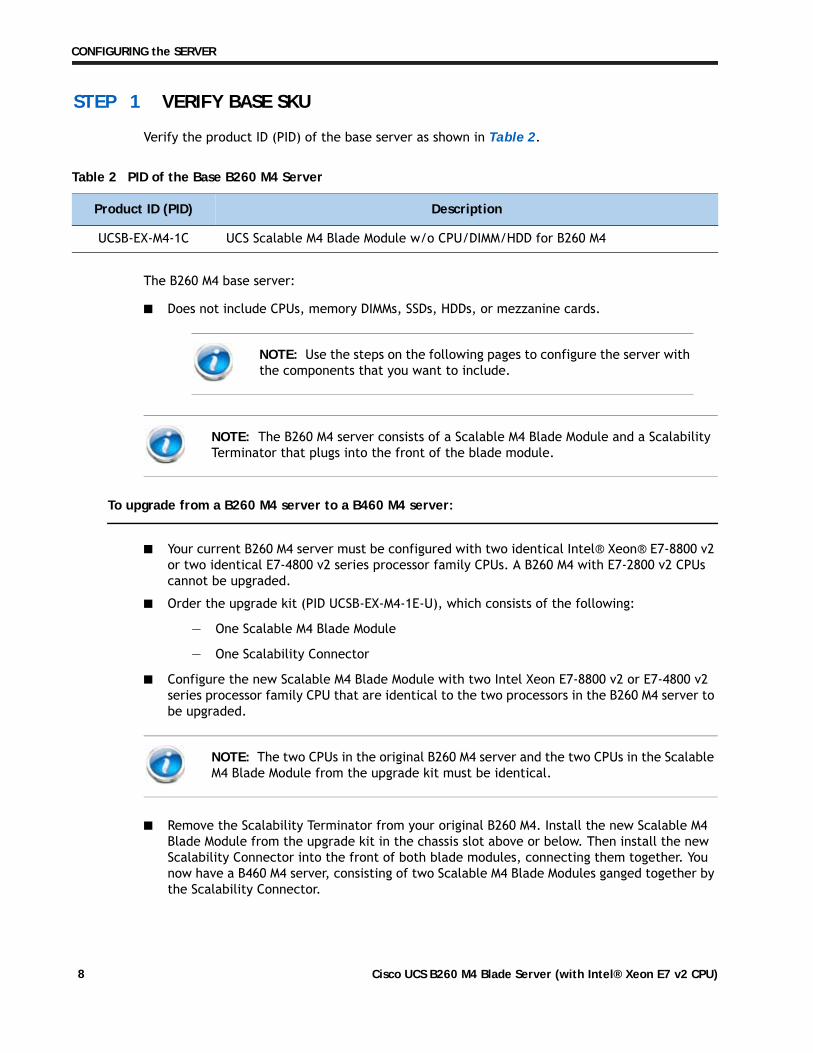
Verify the product ID (PID) of the base server as shown in Table 2.
The B260 M4 base server:
■ Does not include CPUs, memory DIMMs, SSDs, HDDs, or mezzanine cards.
To upgrade from a B260 M4 server to a B460 M4 server:
■ Your current B260 M4 server must be configured with two identical Intel® Xeon® E7-8800 v2 or two identical E7-4800 v2 series processor family CPUs. A B260 M4 with E7-2800 v2 CPUs cannot be upgraded.
■ Order the upgrade kit (PID UCSB-EX-M4-1E-U), which consists of the following:
— One Scalable M4 Blade Module
— One Scalability Connector
■ Configure the new Scalable M4 Blade Module with two Intel Xeon E7-8800 v2 or E7-4800 v2 series processor family CPU that are identical to the two processors in the B260 M4 server to be upgraded.
■ Remove the Scalability Terminator from your original B260 M4. Install the new Scalable M4 Blade Module from the upgrade kit in the chassis slot above or below. Then install the new Scalability Connector into the front of both blade modules, connecting them together. You now have a B460 M4 server, consisting of two Scalable M4 Blade Modules ganged together by the Scalability Connector.
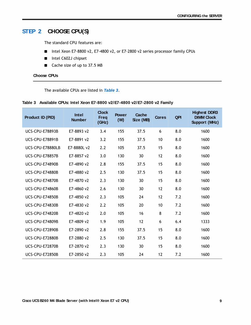
■ Choose two identical CPUs from any one row in Table 3.
Caveats
■ You must choose two identical CPUs.
NOTE: The B260 M4 server consists of a Scalable M4 Blade Module and a Scalability Terminator that plugs into the front of the blade module. You can upgrade a B260 M4 blade server later to a B460 M4 server; however, each B260 M4 server must be configured with two identical Intel Xeon E7-8800 v2 or E7-4800 v2 series processor family CPUs. A B260 M4 with E7-2800 v2 CPUs cannot be upgraded. See To upgrade from a B260 M4 server to a B460 M4 server: on page 8 for details on upgrading.
— Ranks per DIMM: 4 (for 32 GB DIMMs), 2 (for 8 or 16 GB DIMMs), or 8 (for 64 GB DIMMs)
— Operational voltage: 1.5 V or 1.35 V
— Registered DIMM (RDIMM) or load-reduced DIMM (LRDIMM)
■ Each CPU controls four serial memory interface 2 (SMI-2) channels. Memory buffers convert each SMI-2 channel into two DDR3 subchannels. Memory is organized as 3 DIMMs per subchannel, totaling 6 DIMMs per SMI-2 channel. See Figure 3
NOTE: You cannot mix RDIMMs with LRDIMMs
NOTE: Memory mirroring is supported and settable using the UCSM Service Profile “Memory RAS Configuration” setting.
DIMMs are available as two-DIMM kits. Each of the product IDs in Table 4 specifies two DIMMs.
Approved Configurations
■ 48 DIMMs capacity total, up to 24 DIMMs per CPU
■ Select a minimum of 1 DIMM kit (2 DIMMs) or a maximum of 12 DIMM kits (24 DIMMs) per CPU The DIMMs for each CPU will be placed by the factory as shown in Table 5. DIMM labels shown in parentheses are DIMM pairs. Refer also to Figure 3 on page 12 and DIMM and CPU Layout on page 43 for more information about DIMM placement and labeling.
Table 4 Available DDR3 DIMMs
Product ID (PID) PID Description Voltage Ranks/ DIMM
DIMM Pair Kit Options (2 DIMMs per kit)
UCS-ML-2X648RY-E 2x64GB DDR3-1600-MHz LRDIMM/PC-12800/octal rank/x4 1.5 V 8
UCS-ML-2X324RY-E 2x32GB DDR3-1600-MHz LRDIMM/PC-12800/quad rank /x4 1.5/1.35 V 4
UCS-MR-2X162RY-E 2X16GB DDR3-1600-MHz RDIMM/PC-12800/dual rank/x4 1.5/1.35 V 2
UCS-MR-2X082RY-E 2X8GB DDR3-1600-MHz RDIMM/PC-12800/dual rank/x2 1.5/1.35 V 2
Memory Mirroring Option
N01-MMIRROR Memory mirroring option
Table 5 DIMM Population Order
DIMMs per CPU
CPU 1 DIMMs CPU 2 DIMMs
2 (A1, B1) - blue slots (O1, P1) - blue slots
4 (A1, B1) (C1, D1) - blue slots (O1, P1) (L1, K1) - blue slots
6 (A1, B1) (C1, D1) (E1, F1) - blue slots (O1, P1) (L1, K1) (M1, N1) - blue slots
■ Memory Mode. System speed is dependent on how many DIMMs are populated per channel, the CPU DIMM speed support, and the BIOS memory mode. The BIOS default memory mode is performance mode. However, the BIOS can be changed to support lockstep mode.
— Memory Performance Mode. In this mode, the main memory channel from the CPU to the memory buffer runs at double the clock rate of each of the two memory subchannels from the buffer to the DIMMs, and each DIMM subchannel is accessed sequentially. For example, if the CPU channel clock speed is 2667 MHz, each of the DIMM subchannels operates at 1333 MHz. For this reason, performance mode is referred to as 2:1. Performance mode does not provide data protection, but can yield up to 1.5 times the performance of lockstep mode and is the best choice for high throughput requirements.
— Memory Lockstep Mode. In this mode, the main memory channel from the CPU to the memory buffer runs at the same clock rate of each of the two memory subchannels from the buffer to the DIMMs, and both DIMM subchannels are accessed simultaneously for a double-width access. For example, if the CPU channel clock speed is 1600 MHz, each of the DIMM subchannels operates at 1600 MHz. For this reason, lockstep mode is referred to as 1:1. Memory lockstep mode provides protection against both single-bit and multi-bit errors. Memory lockstep lets two memory channels work as a single channel, moving a data word two channels wide and providing eight bits of memory correction.
14 (A1, B1) (C1, D1) (E1, F1) (G1, H1) - blue slots(A2, B2) (C2, D2) (E2, F2)- black slots
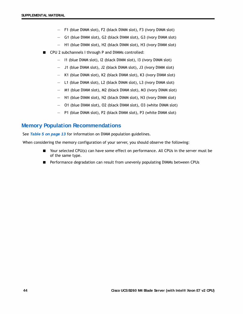
(O1, P1) (L1, K1) (M1, N1) (J1, I1) - blue slots(O2, P2) (L2, K2) (M2, N2) - black slots
■ The only supported DIMM configurations are shown in Table 5 on page 13. Although the DIMMs are sold in matched pairs, exact pairing is not required. For best results, follow the DIMM population rules.
■ The B260 M4 server needs at least one two-DIMM kit installed for each CPU.
■ Memory DIMMs must be installed evenly across the installed CPUs.
■ Do not mix RDIMMs and LRDIMMs.
■ Your selected CPU(s) can have some effect on performance. The CPUs must be of the same type.
■ For DIMM size mixing rules, see Table 26 on page 45.
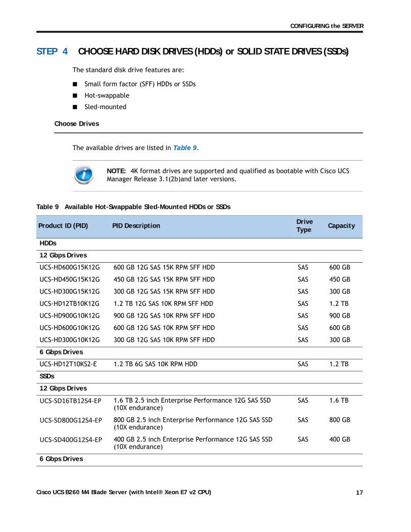
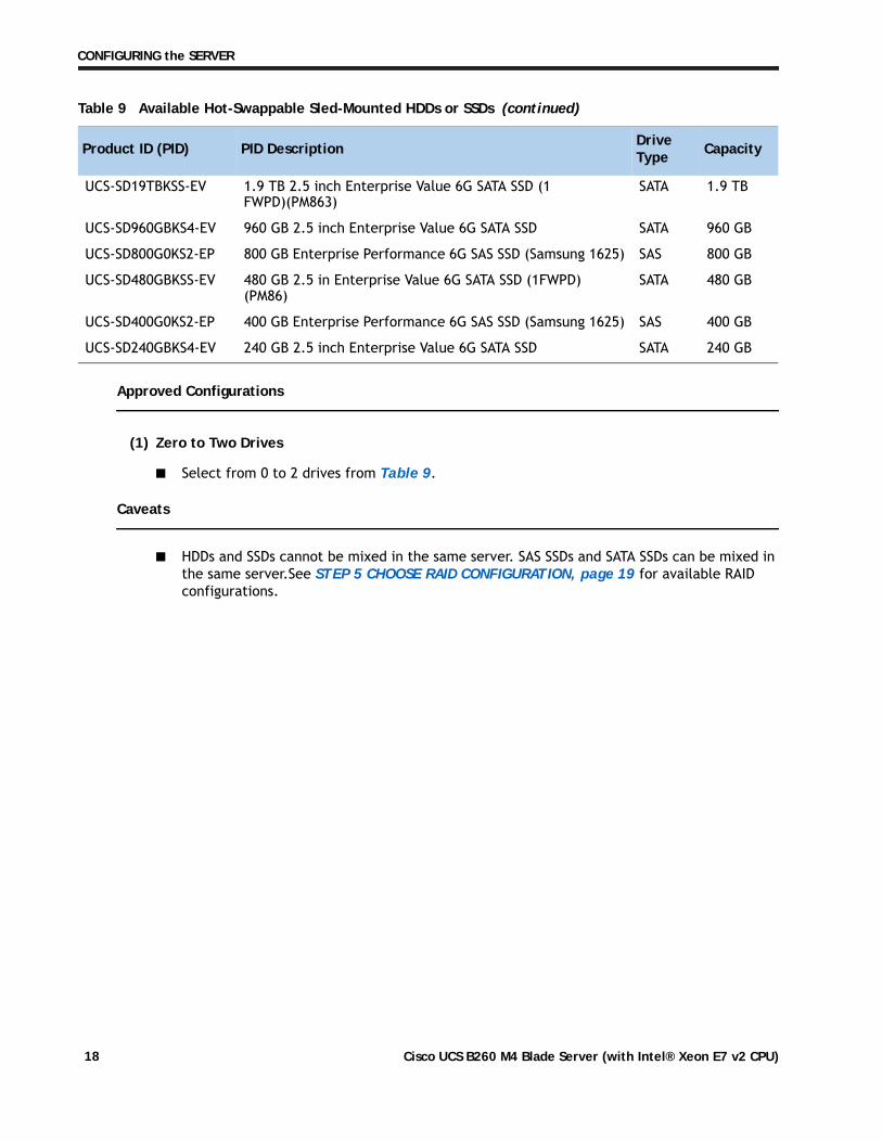
■ HDDs and SSDs cannot be mixed in the same server. SAS SSDs and SATA SSDs can be mixed in the same server.See STEP 5 CHOOSE RAID CONFIGURATION, page 19 for available RAID configurations.
UCS-SD19TBKSS-EV 1.9 TB 2.5 inch Enterprise Value 6G SATA SSD (1 FWPD)(PM863)
SATA 1.9 TB
UCS-SD960GBKS4-EV 960 GB 2.5 inch Enterprise Value 6G SATA SSD SATA 960 GB
UCS-SD800G0KS2-EP 800 GB Enterprise Performance 6G SAS SSD (Samsung 1625) SAS 800 GB
UCS-SD480GBKSS-EV 480 GB 2.5 in Enterprise Value 6G SATA SSD (1FWPD) (PM86)
SATA 480 GB
UCS-SD400G0KS2-EP 400 GB Enterprise Performance 6G SAS SSD (Samsung 1625) SAS 400 GB
UCS-SD240GBKS4-EV 240 GB 2.5 inch Enterprise Value 6G SATA SSD SATA 240 GB
Table 9 Available Hot-Swappable Sled-Mounted HDDs or SSDs (continued)
Product ID (PID) PID Description Drive Type Capacity
Cisco developed 1200 Series and 1300 Series Virtual Interface Cards (VICs) to provide flexibility to create multiple NIC and HBA devices. The VICs also support adapter Fabric Extender and Virtual Machine Fabric Extender technologies. The VIC features are listed here:
— 1200 Series VICs enable advanced networking features including Netflow for network statistics, and DPDK, USNIC for low-latency computing applications.
— 1300 Series VICs include all of the 1200 Series features plus additional enhancements including network overlay offload support for NVGRE and VXLAN, and RoCE services.
— In addition, 1300 Series VICs support PCIe Gen 3.0 for greater bandwidth than 1200 Series VICs
— Two Converged Network Adapter (CNA) ports, supporting both Ethernet and FCoE
— Delivers 80 Gbps total I/O throughput to the server
— Creates up to 256 fully functional unique and independent PCIe adapters and interfaces (NICs or HBAs) without requiring single-root I/O virtualization (SR-IOV) support from operating systems or hypervisors
— Provides virtual machine visibility from the physical network and a consistent network operations model for physical and virtual servers
— Supports customer requirements for a wide range of operating systems and hypervisors
■ Cisco UCS Storage Accelerator Adapters
Cisco UCS Storage Accelerator adapters are designed specifically for the Cisco UCS B-series M4 blade servers and integrate seamlessly to allow improvement in performance and relief of I/O bottlenecks.
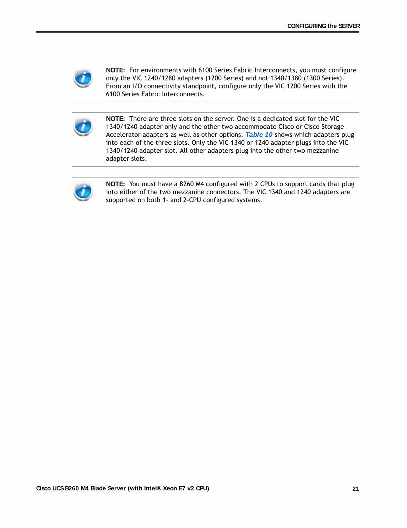
NOTE: For environments with 6100 Series Fabric Interconnects, you must configure only the VIC 1240/1280 adapters (1200 Series) and not 1340/1380 (1300 Series). From an I/O connectivity standpoint, configure only the VIC 1200 Series with the 6100 Series Fabric Interconnects.
NOTE: There are three slots on the server. One is a dedicated slot for the VIC 1340/1240 adapter only and the other two accommodate Cisco or Cisco Storage Accelerator adapters as well as other options. Table 10 shows which adapters plug into each of the three slots. Only the VIC 1340 or 1240 adapter plugs into the VIC 1340/1240 adapter slot. All other adapters plug into the other two mezzanine adapter slots.
NOTE: You must have a B260 M4 configured with 2 CPUs to support cards that plug into either of the two mezzanine connectors. The VIC 1340 and 1240 adapters are supported on both 1- and 2-CPU configured systems.
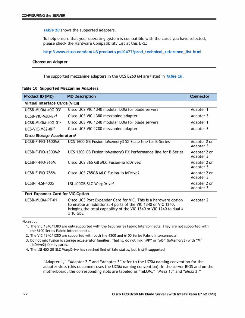
The supported mezzanine adapters in the UCS B260 M4 are listed in Table 10.
“Adapter 1,” “Adapter 2,” and “Adapter 3” refer to the UCSM naming convention for the adapter slots (this document uses the UCSM naming convention). In the server BIOS and on the motherboard, the corresponding slots are labeled as “mLOM,” “Mezz 1,” and “Mezz 2,”
Table 10 Supported Mezzanine Adapters
Product ID (PID) PID Description Connector
Virtual Interface Cards (VICs)
UCSB-MLOM-40G-031
Notes . . .1. The VIC 1340/1380 are only supported with the 6200 Series Fabric Interconnects. They are not supported with
4. The LSI 400 GB SLC WarpDrive has reached End of Sale status, but is still supported
Adapter 2 or Adapter 3
Port Expander Card for VIC Option
UCSB-MLOM-PT-01 Cisco UCS Port Expander Card for VIC. This is a hardware option to enable an additional 4 ports of the VIC 1340 or VIC 1240, bringing the total capability of the VIC 1340 or VIC 1240 to dual 4 x 10 GbE
Table 12 and Table 13 show the supported adapter combinations. The configuration rules are summarized as follows:
■ Adapter slot 1 is dedicated for the VIC 1240 or VIC 1340 only. No other mezzanine card can fit in Adapter Slot 1.
■ The Port Expander Card can only be selected if the VIC 1240 or VIC 1340 is also selected for the server.
■ You must select at least one VIC or CNA. You may select up to two VICs or CNAs. However, you cannot mix a VIC and a CNA in the same server.
■ You cannot select more than one VIC 1240 or VIC 1340. You cannot select more than one VIC 1280 or VIC 1380. A VIC 1240 and a VIC 1280 can be mixed in the same server. A VIC 1340 and VIC1380 can also be mixed.
■ You can select up to two Storage Acceleration adapters. A Fusion-io adapter cannot be mixed with an LSI WarpDrive adapter in the same server.
Table 11 Adapter Slot Naming and Bandwidth
Server BIOS and Motherboard Slot Naming UCSM Slot Naming Available Bandwidth
mLOM (VIC 1240 or VIC 1340 only) Adapter 1 20 Gbps per Fabric ExtenderMezz1 Adapter 2 20 Gbps per Fabric ExtenderMezz2 Adapter 3 40 Gbps per Fabric Extender
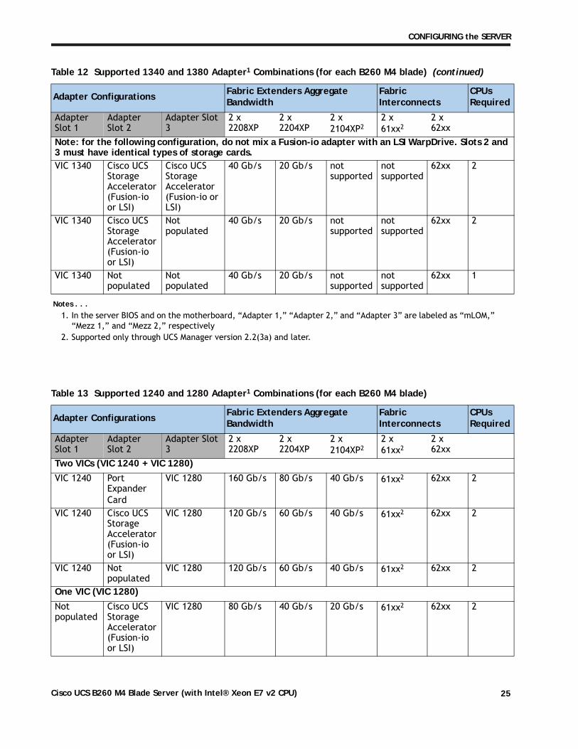
Note: for the following configuration, do not mix a Fusion-io adapter with an LSI WarpDrive. Slots 2 and 3 must have identical types of storage cards.VIC 1340 Cisco UCS
Storage Accelerator (Fusion-io or LSI)
Cisco UCS Storage Accelerator (Fusion-io or LSI)
40 Gb/s 20 Gb/s not supported
not supported
62xx 2
VIC 1340 Cisco UCS Storage Accelerator (Fusion-io or LSI)
Not populated
40 Gb/s 20 Gb/s not supported
not supported
62xx 2
VIC 1340 Not populated
Not populated
40 Gb/s 20 Gb/s not supported
not supported
62xx 1
Notes . . .1. In the server BIOS and on the motherboard, “Adapter 1,” “Adapter 2,” and “Adapter 3” are labeled as “mLOM,”
“Mezz 1,” and “Mezz 2,” respectively2. Supported only through UCS Manager version 2.2(3a) and later.
Table 13 Supported 1240 and 1280 Adapter1 Combinations (for each B260 M4 blade)
Note: for the following configuration, do not mix a Fusion-io adapter with an LSI WarpDrive. Slots 2 and 3 must have identical types of storage cards.VIC 1240 Cisco UCS
Storage Accelerator (Fusion-io or LSI)
Cisco UCS Storage Accelerator (Fusion-io or LSI)
40 Gb/s 20 Gb/s 20 Gb/s 61xx2 62xx 2
VIC 1240 Cisco UCS Storage Accelerator (Fusion-io or LSI)
Not populated
40 Gb/s 20 Gb/s 20 Gb/s 61xx2 62xx 2
VIC 1240 Not populated
Not populated
40 Gb/s 20 Gb/s 20 Gb/s 61xx2 62xx 1
Notes . . .1. In the server BIOS and on the motherboard, “Adapter 1,” “Adapter 2,” and “Adapter 3” are labeled as “mLOM,”
“Mezz 1,” and “Mezz 2,” respectively2. Supported only through UCS Manager version 2.2(3a) and later.
Table 13 Supported 1240 and 1280 Adapter1 Combinations (for each B260 M4 blade) (continued)
Trusted Platform Module (TPM) is a computer chip (microcontroller) that can securely store artifacts used to authenticate the platform (server). These artifacts can include passwords, certificates, or encryption keys. A TPM can also be used to store platform measurements that help ensure that the platform remains trustworthy. Authentication (ensuring that the platform can prove that it is what it claims to be) and attestation (a process helping to prove that a platform is trustworthy and has not been breached) are necessary steps to ensure safer computing in all environments.
The TPM ordering information is listed in Table 14.
Table 14 Trusted Platform Module
Product ID (PID) PID Description
UCSX-TPM1-001 Trusted Platform Module for UCS
NOTE: The module used in this server conforms to TPM v1.2/1.3, as defined by the Trusted Computing Group (TCG).
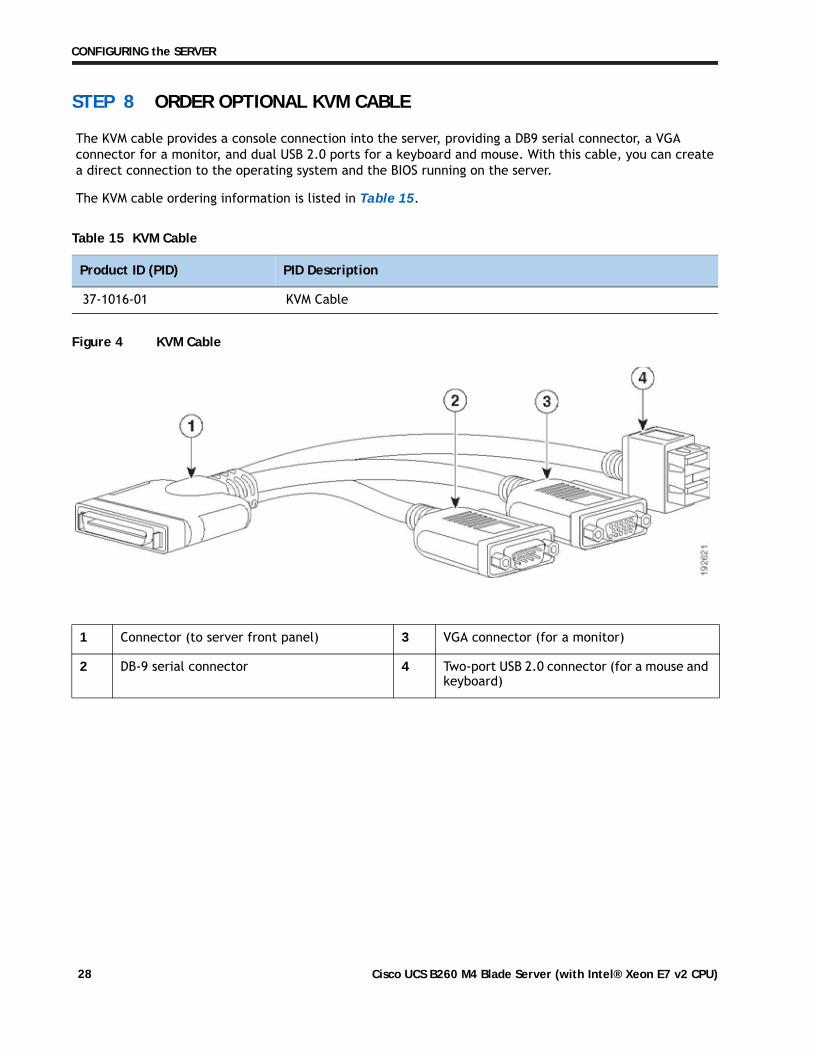
The KVM cable provides a console connection into the server, providing a DB9 serial connector, a VGA connector for a monitor, and dual USB 2.0 ports for a keyboard and mouse. With this cable, you can create a direct connection to the operating system and the BIOS running on the server.
The KVM cable ordering information is listed in Table 15.
Figure 4 KVM Cable
Table 15 KVM Cable
Product ID (PID) PID Description
37-1016-01 KVM Cable
1 Connector (to server front panel) 3 VGA connector (for a monitor)
2 DB-9 serial connector 4 Two-port USB 2.0 connector (for a mouse and keyboard)
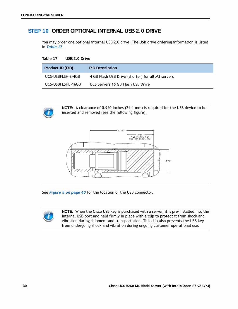
You may order one optional internal USB 2.0 drive. The USB drive ordering information is listed in Table 17.
See Figure 5 on page 40 for the location of the USB connector.
Table 17 USB 2.0 Drive
Product ID (PID) PID Description
UCS-USBFLSH-S-4GB 4 GB Flash USB Drive (shorter) for all M3 servers
UCS-USBFLSHB-16GB UCS Servers 16 GB Flash USB Drive
NOTE: A clearance of 0.950 inches (24.1 mm) is required for the USB device to be inserted and removed (see the following figure).
NOTE: When the Cisco USB key is purchased with a server, it is pre-installed into the internal USB port and held firmly in place with a clip to protect it from shock and vibration during shipment and transportation. This clip also prevents the USB key from undergoing shock and vibration during ongoing customer operational use.
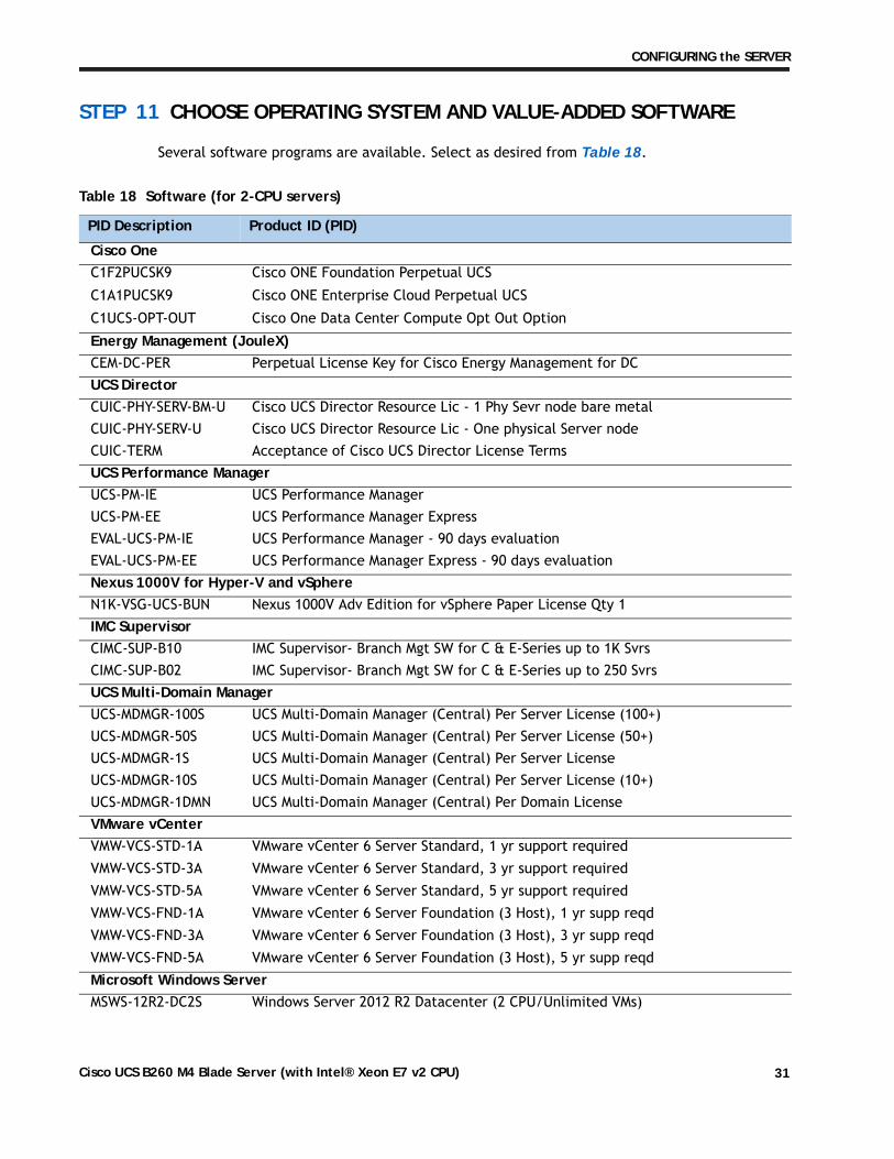
STEP 11 CHOOSE OPERATING SYSTEM AND VALUE-ADDED SOFTWARE
Several software programs are available. Select as desired from Table 18.
Table 18 Software (for 2-CPU servers)
PID Description Product ID (PID)
Cisco OneC1F2PUCSK9 Cisco ONE Foundation Perpetual UCS
C1A1PUCSK9 Cisco ONE Enterprise Cloud Perpetual UCS
C1UCS-OPT-OUT Cisco One Data Center Compute Opt Out Option
Energy Management (JouleX)CEM-DC-PER Perpetual License Key for Cisco Energy Management for DC UCS DirectorCUIC-PHY-SERV-BM-U Cisco UCS Director Resource Lic - 1 Phy Sevr node bare metal CUIC-PHY-SERV-U Cisco UCS Director Resource Lic - One physical Server node CUIC-TERM Acceptance of Cisco UCS Director License Terms UCS Performance ManagerUCS-PM-IE UCS Performance Manager UCS-PM-EE UCS Performance Manager Express EVAL-UCS-PM-IE UCS Performance Manager - 90 days evaluation EVAL-UCS-PM-EE UCS Performance Manager Express - 90 days evaluation Nexus 1000V for Hyper-V and vSphereN1K-VSG-UCS-BUN Nexus 1000V Adv Edition for vSphere Paper License Qty 1 IMC SupervisorCIMC-SUP-B10 IMC Supervisor- Branch Mgt SW for C & E-Series up to 1K Svrs CIMC-SUP-B02 IMC Supervisor- Branch Mgt SW for C & E-Series up to 250 Svrs UCS Multi-Domain ManagerUCS-MDMGR-100S UCS Multi-Domain Manager (Central) Per Server License (100+) UCS-MDMGR-50S UCS Multi-Domain Manager (Central) Per Server License (50+) UCS-MDMGR-1S UCS Multi-Domain Manager (Central) Per Server License UCS-MDMGR-10S UCS Multi-Domain Manager (Central) Per Server License (10+) UCS-MDMGR-1DMN UCS Multi-Domain Manager (Central) Per Domain License VMware vCenterVMW-VCS-STD-1A VMware vCenter 6 Server Standard, 1 yr support required VMW-VCS-STD-3A VMware vCenter 6 Server Standard, 3 yr support required VMW-VCS-STD-5A VMware vCenter 6 Server Standard, 5 yr support required VMW-VCS-FND-1A VMware vCenter 6 Server Foundation (3 Host), 1 yr supp reqd VMW-VCS-FND-3A VMware vCenter 6 Server Foundation (3 Host), 3 yr supp reqd VMW-VCS-FND-5A VMware vCenter 6 Server Foundation (3 Host), 5 yr supp reqd Microsoft Windows ServerMSWS-12R2-DC2S Windows Server 2012 R2 Datacenter (2 CPU/Unlimited VMs)
MSWS-12-ST2S Windows Server 2012 Standard (2 CPU/2 VMs)MSWS-12-DC2S Windows Server 2012 Datacenter (2 CPU/Unlimited VMs)MSWS-12-ST2S-NS Windows Server 2012 Standard (2 CPU/2 VMs) No Cisco SVC MSWS-12R2-DC2S-NS Windows Server 2012 R2 Datacen (2 CPU/Unlim VM) No Cisco Svc MSWS-12R2-ST2S Windows Server 2012 R2 Standard (2 CPU/2 VMs) MSWS-12-DC2S-NS Windows Server 2012 Datacenter (2 CPU/Unlim VM) No Cisco Svc MSWS-12R2-ST2S-NS Windows Server 2012 R2 Standard (2 CPU/2 VMs) No Cisco SVC Red HatRHEL-2S2V-3A Red Hat Enterprise Linux (1-2 CPU,1-2 VN); 3-Yr Support Req
RHEL-2S2V-1A Red Hat Enterprise Linux (1-2 CPU,1-2 VN); 1-Yr Support Req
VMwareVMW-VSP-EPL-5A VMware vSphere 6 Ent Plus (1 CPU), 5-yr, Support Required
VMW-VSP-STD-1A VMware vSphere 6 Standard (1 CPU), 1-yr, Support Required
VMW-VSP-STD-3A VMware vSphere 6 Standard (1 CPU), 3-yr, Support Required
VMW-VSP-EPL-3A VMware vSphere 6 Ent Plus (1 CPU), 3-yr, Support Required
VMW-VSP-EPL-1A VMware vSphere 6 Ent Plus (1 CPU), 1-yr, Support Required
VMW-VSP-STD-5A VMware vSphere 6 Standard (1 CPU), 5-yr, Support Required
SLES SAPSLES-SAP-2S2V-1S SLES for SAP Apps (1-2 CPU, 1-2 VM); Priority 1-Yr SnS
SLES-SAP-2SUV-1S SLES for SAP Apps (1-2 CPU, Unl VM); Priority 1-Yr SnS
SLES-SAP-2S2V-3S SLES for SAP Apps (1-2 CPU, 1-2 VM); Priority 3-Yr SnS
SLES-SAP-2SUV-3S SLES for SAP Apps (1-2 CPU, Unl VM); Priority 3-Yr SnS
SLES-SAP-2S2V-5S SLES for SAP Apps (1-2 CPU, 1-2 VM); Priority 5-Yr SnS
SLES-SAP-2SUV-5S SLES for SAP Apps (1-2 CPU, Unl VM); Priority 5-Yr SnS
SLES-SAP-2S2V-5A SLES for SAP Apps (1-2 CPU, 1-2 VM); 5-Yr Support Reqd
SLES-SAP-2SUV-3A SLES for SAP Apps (1-2 CPU, Unl VM); 3-Yr Support Reqd
SLES-SAP-2S2V-3A SLES for SAP Apps (1-2 CPU, 1-2 VM); 3-Yr Support Reqd
SLES-SAP-2SUV-5A SLES for SAP Apps (1-2 CPU, Unl VM); 5-Yr Support Reqd
SLES-SAP-2S2V-1A SLES for SAP Apps (1-2 CPU, 1-2 VM); 1-Yr Support Reqd
SLES-SAP-2SUV-1A SLES for SAP Apps (1-2 CPU, Unl VM); 1-Yr Support Reqd
SUSESLES-2S2V-1A SUSE Linux Enterprise Svr (1-2 CPU,1-2 VM); 1-Yr Support Req SLES-2SUV-1A SUSE Linux Enterprise Svr (1-2 CPU,Unl VM); 1-Yr Support Req SLES-2S2V-3A SUSE Linux Enterprise Svr (1-2 CPU,1-2 VM); 3-Yr Support Req SLES-2SUV-3A SUSE Linux Enterprise Svr (1-2 CPU,Unl VM); 3-Yr Support Req SLES-2S2V-5A SUSE Linux Enterprise Svr (1-2 CPU,1-2 VM); 5-Yr Support Req SLES-2SUV-5A SUSE Linux Enterprise Svr (1-2 CPU,Unl VM); 5-Yr Support Req SLES-2S2V-1S SUSE Linux Enterprise Svr (1-2 CPU,1-2 VM); Prio 1-Yr SnS
A variety of service options are available, as described in this section.
Unified Computing Warranty, No Contract
If you have noncritical implementations and choose to have no service contract, the following coverage is supplied:
■ Three-year parts coverage.
■ Next business day (NBD) onsite parts replacement eight hours a day, five days a week.
■ 90-day software warranty on media.
■ Ongoing downloads of BIOS, drivers, and firmware updates.
■ UCSM updates for systems with Unified Computing System Manager. These updates include minor enhancements and bug fixes that are designed to maintain the compliance of UCSM with published specifications, release notes, and industry standards.
SMARTnet for UCS
For support of the entire Unified Computing System, Cisco offers the Cisco SMARTnet for UCS Service. This service provides expert software and hardware support to help sustain performance and high availability of the unified computing environment. Access to Cisco Technical Assistance Center (TAC) is provided around the clock, from anywhere in the world.
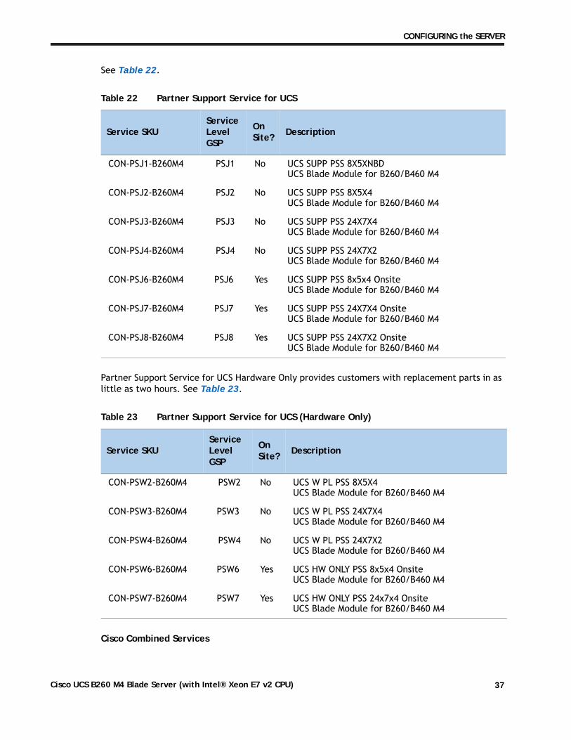
For UCS blade servers, there is Smart Call Home, which provides proactive, embedded diagnostics and real-time alerts. For systems that include Unified Computing System Manager, the support service includes downloads of UCSM upgrades. The Cisco SMARTnet for UCS Service includes flexible hardware replacement options, including replacement in as little as two hours. There is also access to Cisco's extensive online technical resources to help maintain optimal efficiency and uptime of the unified computing environment. You can choose a desired service listed in Table 20.
Table 20 Cisco SMARTnet for UCS Service
Service SKU On Site? Description
CON-PREM-B260M4 Yes ONSITE 24X7X2 UCS Blade Module for B260/B460 M4
CON-OSP-B260M4 Yes ONSITE 24X7X4 UCS Blade Module for B260/B460 M4
CON-OSE-B260M4 Yes ONSITE 8X5X4 UCS Blade Module for B260/B460 M4
CON-OS-B260M4 Yes ONSITE 8X5XNBD UCS Blade Module for B260/B460 M4
CON-S2P-B260M4 No SMARTNET 24X7X2 UCS Blade Module for B260/B460 M4
CON-SNTP-B260M4 No SMARTNET 24X7X4 UCS Blade Module for B260/B460 M4
CON-SNTE-B260M4 No SMARTNET 8X5X4 UCS Blade Module for B260/B460 M4
CON-SNT-B260M4 No SMARTNET 8X5XNBD UCS Blade Module for B260/B460 M4
For faster parts replacement than is provided with the standard Cisco Unified Computing System warranty, Cisco offers the Cisco SMARTnet for UCS Hardware Only Service. You can choose from two levels of advanced onsite parts replacement coverage in as little as four hours. SMARTnet for UCS Hardware Only Service provides remote access any time to Cisco support professionals who can determine if a return materials authorization (RMA) is required. You can choose a service listed in Table 21.
Unified Computing Partner Support Service
Cisco Partner Support Service (PSS) is a Cisco Collaborative Services service offering that is designed for partners to deliver their own branded support and managed services to enterprise customers. Cisco PSS provides partners with access to Cisco's support infrastructure and assets to help them:
■ Expand their service portfolios to support the most complex network environments
■ Lower delivery costs
■ Deliver services that increase customer loyalty
Partner Unified Computing Support Options enable eligible Cisco partners to develop and consistently deliver high-value technical support that capitalizes on Cisco intellectual assets. This helps partners to realize higher margins and expand their practice.
Partner Unified Computing Support Options are available to Cisco PSS partners. For additional information, see the following URL:
www.cisco.com/go/partnerucssupport
The two Partner Unified Computing Support Options include:
■ Partner Support Service for UCS
■ Partner Support Service for UCS Hardware Only
Partner Support Service for UCS provides hardware and software support, including triage support for third party software, backed by Cisco technical resources and level three support.
Table 21 SMARTnet for UCS Hardware Only Service
Service SKU Service Level GSP
On Site? Description
CON-UCW7-B260M4 UCW7 Yes UC PLUS 24X7X4OS UCS Blade Module for B260/B460 M4
CON-UCW5-B260M4 UCW5 Yes UC PLUS 8X5XNBDOS UCS Blade Module for B260/B460 M4
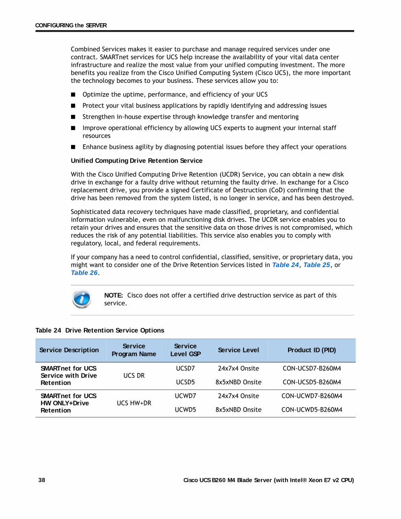
Combined Services makes it easier to purchase and manage required services under one contract. SMARTnet services for UCS help increase the availability of your vital data center infrastructure and realize the most value from your unified computing investment. The more benefits you realize from the Cisco Unified Computing System (Cisco UCS), the more important the technology becomes to your business. These services allow you to:
■ Optimize the uptime, performance, and efficiency of your UCS
■ Protect your vital business applications by rapidly identifying and addressing issues
■ Strengthen in-house expertise through knowledge transfer and mentoring
■ Improve operational efficiency by allowing UCS experts to augment your internal staff resources
■ Enhance business agility by diagnosing potential issues before they affect your operations
Unified Computing Drive Retention Service
With the Cisco Unified Computing Drive Retention (UCDR) Service, you can obtain a new disk drive in exchange for a faulty drive without returning the faulty drive. In exchange for a Cisco replacement drive, you provide a signed Certificate of Destruction (CoD) confirming that the drive has been removed from the system listed, is no longer in service, and has been destroyed.
Sophisticated data recovery techniques have made classified, proprietary, and confidential information vulnerable, even on malfunctioning disk drives. The UCDR service enables you to retain your drives and ensures that the sensitive data on those drives is not compromised, which reduces the risk of any potential liabilities. This service also enables you to comply with regulatory, local, and federal requirements.
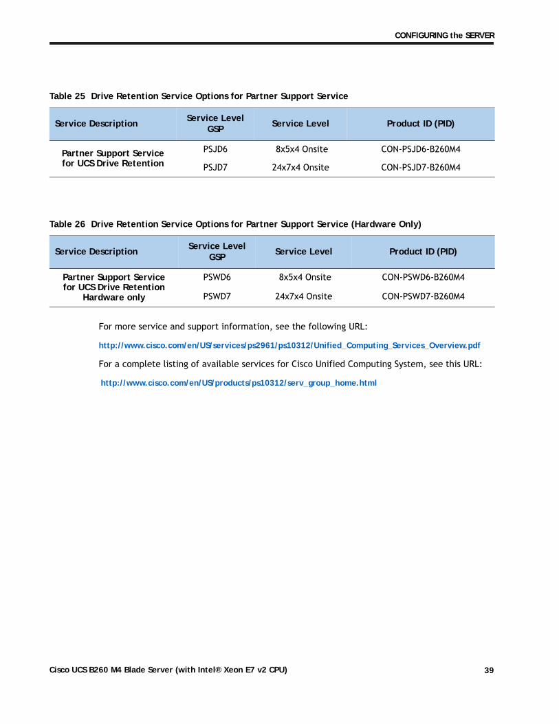
If your company has a need to control confidential, classified, sensitive, or proprietary data, you might want to consider one of the Drive Retention Services listed in Table 24, Table 25, or Table 26.
NOTE: Cisco does not offer a certified drive destruction service as part of this service.
8 Memory buffer for subchannels A and B 22 DIMM slots O1-O3 and P1-P3
9 DIMM slots A1-A3 and B1-B3 23 Memory buffer for subchannels O and P
10 DIMM slots C1-C3 and D1-D3 24 mLOM card
This slot is shown in Cisco UCS manager as “Adapter 1” but the BIOS lists it as “mLOM.” The VIC 1340/1240 is a type of adapter with a specific footprint that can only be used in this slot.
11 Memory buffer for DIMM subchannels C and D 25 Adapter card
This slot is shown in Cisco UCS manager as “Adapter 2” but the BIOS lists it as “Mezz 1.” Mixing adapter types is supported.
12 Memory buffer for subchannels E and F 26 Adapter card
This slot is shown in Cisco UCS manager as “Adapter 3” but the BIOS lists it as “Mezz 2.” Mixing adapter types is supported.
13 DIMM slots E1-E3 and F1-F3 27 Internal USB connector
DIMM and CPU LayoutThe DIMM and CPU layout is shown in Figure 7.
Figure 7 DIMM and CPU Layout
Each CPU controls four memory channels, and each memory channel controls two subchannels each through individual memory buffers placed around the motherboard (shown as black rectangles on Figure 7). Each subchannel controls 3 DIMMs as follows (refer also to Figure 3 on page 12):
■ CPU 1 subchannels A through H and DIMMs controlled:
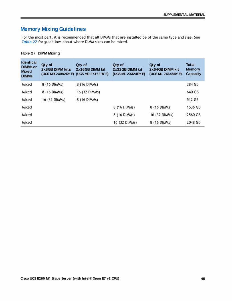
Memory Mixing GuidelinesFor the most part, it is recommended that all DIMMs that are installed be of the same type and size. See Table 27 for guidelines about where DIMM sizes can be mixed.
Upgrade and Servicing-Related PartsThis section lists the upgrade and servicing-related parts you may need during the life of your server. Some of these parts are configured with every server or with every UCS 5108 blade server chassis, and some may be ordered when needed or may be ordered and kept on hand as spares for future use. See Table 28.
Drive and Blade Server Blanking Panels
A drive blanking panel (N20-BBLKD=) must be installed if you remove a disk drive from a UCS server. These panels are required to maintain system temperatures at safe operating levels, and to keep dust away from system components.
Replacing a CPU (with CPU heat sink)
Instructions for replacing a CPU and heat sink can be found at the following link:
Thermal Grease (with syringe applicator) for CPU to Heatsink Seal
Thermal grease must be applied to the top of the CPU where it comes in contact with the heat sink. Instructions for applying thermal grease are found at:
NOTE: When you purchase a spare CPU, the Pick n Place Toolkit is included.
CAUTION: DO NOT use thermal grease available for purchase at any commercial electronics store. If these instructions are not followed, the CPU may overheat and be destroyed.
NOTE: When you purchase a spare CPU, the thermal grease with syringe applicator is included.
The cleaning kit is used to remove the existing thermal compound from the bottom of the heat sink during a CPU replacement process. Instructions for cleaning are found at the following link:
Network ConnectivityThis section shows how the supported adapter card configurations for the B260 M4 connect to the Fabric Extender modules in the 5108 blade server chassis.
There are three configurable adapter slots on the B260 M4. One slot supports only the VIC 1340/1240 adapter, and two additional slots accommodate Cisco adapters, as well as Cisco UCS Storage Accelerator adapters. Table 12 on page 24 shows supported adapter configurations. You must install at least one VIC or CNA adapter in one of the three adapter slots.
“Adapter 1,” “Adapter 2,” and “Adapter 3” refer to the UCSM naming convention for the adapter slots (this document uses the UCSM naming convention). In the server BIOS and on the motherboard, the corresponding slots are labeled as “mLOM,” “Mezz 1,” and “Mezz 2,” respectively. See Table 29.
Total bandwidth is a function of the Fabric Extender, the adapter, and the adapter slot, as shown in Table 30 and Table 31.
Table 29 Adapter Slot Naming
Server BIOS and Motherboard Slot Naming UCSM Slot Naming Available Bandwidth
mLOM (VIC 1340/1240 only) Adapter 1 20 Gbps per Fabric ExtenderMezz1 Adapter 2 20 Gbps per Fabric ExtenderMezz2 Adapter 3 40 Gbps per Fabric Extender
Table 30 Maximum Bandwidth Using Dual Fabric Extenders (FEXs)
FEX Model Maximum Bandwidth Using Dual FEXs
2208XP 160 Gb
2204XP 160 Gb
2104XP 40 Gb
Table 31 Maximum Bandwidth for Each of the Three Adapter Slots
Figure 8 shows the configuration for maximum bandwidth, where the following ports are routed to Fabric Extender Modules A and B inside the 5108 blade server chassis:
■ Two 2 x 10G KR ports from the VIC 1340/1240 adapter
■ Two 2 x 10G KR ports from the Port Expander
■ Two 4 x 10G KR ports from the VIC 1380/1280 adapter
The resulting aggregate bandwidth is 160 Gb (80 Gb to each Fabric Extender).
Figure 8 UCS B260 M4 Connections to the Fabric Extenders
VIC 1340Adapter Card
Port Expander
VIC 1380Adapter
CPU 1CPU 2
PCIe x16PCIe x16PCIe x16
4 x 10G KR
4 x
10G
KR
4 x
10G
KR
2 x
10G
KR
2 x
10G
KR
2 x
10G
KR
2 x
10G
KR
adapter slot #1 for VIC 1340adapter slot #2adapter slot #3
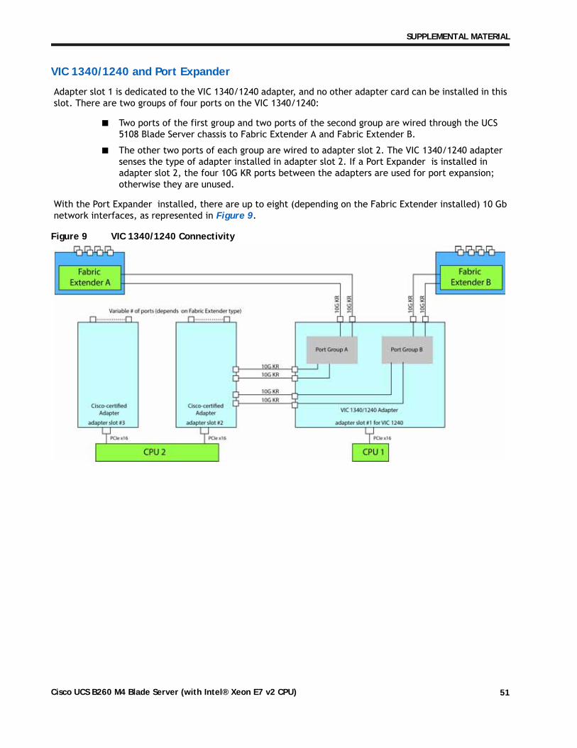
Adapter slot 1 is dedicated to the VIC 1340/1240 adapter, and no other adapter card can be installed in this slot. There are two groups of four ports on the VIC 1340/1240:
■ Two ports of the first group and two ports of the second group are wired through the UCS 5108 Blade Server chassis to Fabric Extender A and Fabric Extender B.
■ The other two ports of each group are wired to adapter slot 2. The VIC 1340/1240 adapter senses the type of adapter installed in adapter slot 2. If a Port Expander is installed in adapter slot 2, the four 10G KR ports between the adapters are used for port expansion; otherwise they are unused.
With the Port Expander installed, there are up to eight (depending on the Fabric Extender installed) 10 Gb network interfaces, as represented in Figure 9.
Figure 13 on page 54Not populated Not populated VIC 1380/1280 80/40 Gb
Figure 14 on page 55VIC 1340/1240 Port Expander Card Cisco UCS Storage Accelerator 80/40 Gb
Figure 15 on page 55VIC 1340/1240 Port Expander Card Not populated 80/40 Gb
Figure 16 on page 56Note: for the following configuration, do not mix a Cisco Storage Accelerator with an LSI WarpDrive. Slots 2 and 3 must have identical types of storage cards.VIC 1340/1240 Cisco UCS Storage Accelerator Cisco UCS Storage Accelerator 40/20 Gb
Figure 17 on page 56VIC 1340/1240 Cisco UCS Storage Accelerator Not populated 40/20 Gb
Figure 18 on page 57VIC 1340/1240 Not populated Not populated 40/20 Gb
In Figure 10, two ports from the VIC 1340/1240 are channeled to Fabric Extender A and two are channeled to Fabric Extender B. The Port Expander Card for the VIC 1340/1240 installed in adapter slot 2 acts as a pass-through device, channeling two ports to each of the Fabric Extenders. In addition, the VIC 1380/1280 channels four ports to each Fabric Extender. The result is 80 Gb of bandwidth to each Fabric Extender.
Figure 10 VIC 1340/1240, Port Expander in adapter slot 2, and VIC 1380/1280 in adapter slot 3
In Figure 11, two ports from the VIC 1340/1240 are channeled to Fabric Extender A and two are channeled to Fabric Extender B. A Cisco UCS Storage Accelerator adapter is installed in slot 2, but provides no network connectivity. The VIC 1380/1280 installed in adapter slot 3 channels four ports to each of the Fabric Extenders. The result is 60 Gb of bandwidth to each Fabric Extender.
Figure 11 VIC 1340/1240, Cisco UCS SA adapter slot 2, and VIC 1380/1280 adapter slot 3
In Figure 12, two ports from the VIC 1340/1240 are channeled to Fabric Extender A and two are channeled to Fabric Extender B. Adapter slot 2 is empty. The VIC 1380/1280 installed in adapter slot 3 channels four ports to each of the Fabric Extenders. The result is 60 Gb of bandwidth to each Fabric Extender.
In Figure 13, no VIC 1340/1240 is installed. A Cisco UCS Storage Accelerator adapter is installed in slot 2, but provides no network connectivity. The VIC 1380/1280 installed in adapter slot 3 channels four ports to each of the Fabric Extenders. The result is 40 Gb of bandwidth to each Fabric Extender.
Figure 13 No VIC 1340/1240 installed, UCS Storage Accelerator in slot 2 and VIC 1380/1280 in slot 3
In Figure 14, no VIC 1340/1240 is installed. Adapter 2 slot is also not occupied. The VIC 1380/1280 installed in adapter slot 3 channels four ports to each of the Fabric Extenders. The result is 40 Gb of bandwidth to each Fabric Extender.
Figure 14 No VIC 1340/1240 installed, no adapter installed in slot 2, and VIC 1380/1280 in slot 3
In Figure 15, two ports from the VIC 1340/1240 are channeled to Fabric Extender A and two are channeled to Fabric Extender B. The Port Expander Card installed in adapter slot 2 acts as a pass-through device, channeling two ports to each of the Fabric Extenders. A Cisco UCS storage accelerator is installed in slot 3, but provides no network connectivity. The result is 40 Gb of bandwidth to each Fabric Extender.
Figure 15 VIC 1340/1240 and Port Expander in Adapter Slot 2 with UCS storage accelerator in slot 3
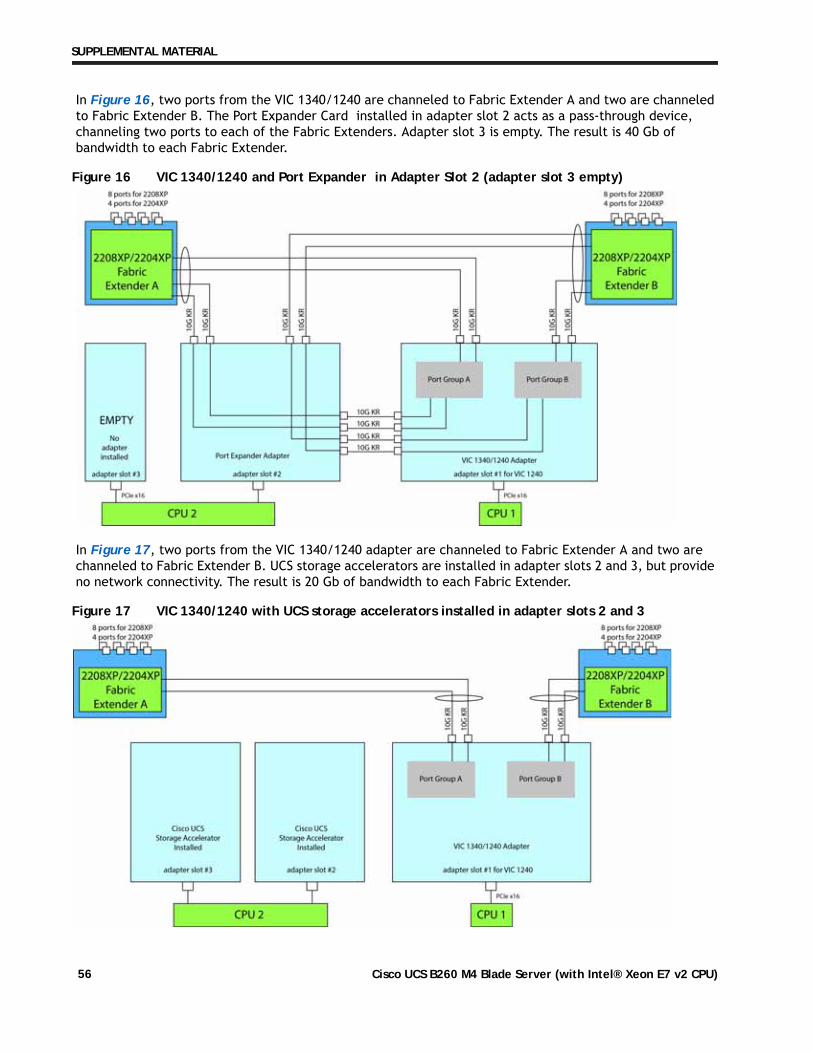
In Figure 16, two ports from the VIC 1340/1240 are channeled to Fabric Extender A and two are channeled to Fabric Extender B. The Port Expander Card installed in adapter slot 2 acts as a pass-through device, channeling two ports to each of the Fabric Extenders. Adapter slot 3 is empty. The result is 40 Gb of bandwidth to each Fabric Extender.
Figure 16 VIC 1340/1240 and Port Expander in Adapter Slot 2 (adapter slot 3 empty)
In Figure 17, two ports from the VIC 1340/1240 adapter are channeled to Fabric Extender A and two are channeled to Fabric Extender B. UCS storage accelerators are installed in adapter slots 2 and 3, but provide no network connectivity. The result is 20 Gb of bandwidth to each Fabric Extender.
Figure 17 VIC 1340/1240 with UCS storage accelerators installed in adapter slots 2 and 3
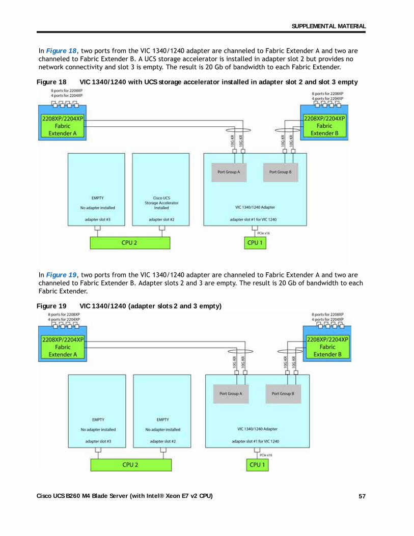
In Figure 18, two ports from the VIC 1340/1240 adapter are channeled to Fabric Extender A and two are channeled to Fabric Extender B. A UCS storage accelerator is installed in adapter slot 2 but provides no network connectivity and slot 3 is empty. The result is 20 Gb of bandwidth to each Fabric Extender.
Figure 18 VIC 1340/1240 with UCS storage accelerator installed in adapter slot 2 and slot 3 empty
In Figure 19, two ports from the VIC 1340/1240 adapter are channeled to Fabric Extender A and two are channeled to Fabric Extender B. Adapter slots 2 and 3 are empty. The result is 20 Gb of bandwidth to each Fabric Extender.
Figure 19 VIC 1340/1240 (adapter slots 2 and 3 empty)
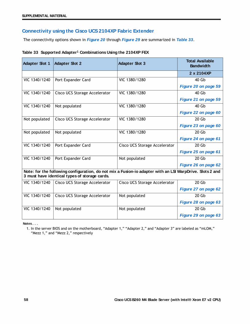
In Figure 20, one port from the VIC 1340/1240 is connected to Fabric Extender A and one is connected to Fabric Extender B. The Port Expander Card for the VIC 1340/1240 installed in adapter slot 2 has no role in this case. In addition, the VIC 1380/1280 channels one port to each Fabric Extender. The result is 20 Gb of bandwidth to each Fabric Extender.
Figure 20 VIC 1340/1240, Port Expander in adapter slot 2, and VIC 1380/1280 in adapter slot 3
In Figure 21, two ports from the VIC 1340/1240 are connected, one to each Fabric Extender. A Cisco UCS Storage Accelerator adapter is installed in slot 2, but provides no network connectivity. The VIC 1380/1280 installed in adapter slot 3 connects two ports, one to each of the Fabric Extenders. The result is 20 Gb of bandwidth to each Fabric Extender.
Figure 21 VIC 1340/1240, Cisco UCS SA adapter slot 2, and VIC 1380/1280 in adapter slot 3
In Figure 22, two ports from the VIC 1340/1240 are connected, one to each Fabric Extender. Adapter slot 2 is empty. The VIC 1380/1280 installed in adapter slot 3 connects two ports, one to each of the Fabric Extenders. The result is 20 Gb of bandwidth to each Fabric Extender.
In Figure 23, no VIC 1340/1240 is installed. A Cisco UCS Storage Accelerator adapter is installed in slot 2, but provides no network connectivity. The VIC 1380/1280 installed in adapter slot 3 connects two ports, one to each of the Fabric Extenders. The result is 10 Gb of bandwidth to each Fabric Extender.
Figure 23 No VIC 1340/1240 installed, UCS Storage Accelerator in slot 2 and VIC 1380/1280 in slot 3
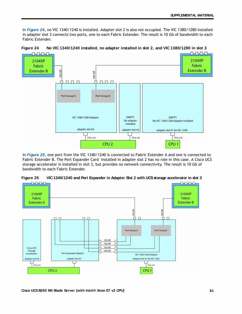
In Figure 24, no VIC 1340/1240 is installed. Adapter slot 2 is also not occupied. The VIC 1380/1280 installed in adapter slot 3 connects two ports, one to each Fabric Extender. The result is 10 Gb of bandwidth to each Fabric Extender.
Figure 24 No VIC 1340/1240 installed, no adapter installed in slot 2, and VIC 1380/1280 in slot 3
In Figure 25, one port from the VIC 1340/1240 is connected to Fabric Extender A and one is connected to Fabric Extender B. The Port Expander Card installed in adapter slot 2 has no role in this case. A Cisco UCS storage accelerator is installed in slot 3, but provides no network connectivity. The result is 10 Gb of bandwidth to each Fabric Extender.
Figure 25 VIC 1340/1240 and Port Expander in Adapter Slot 2 with UCS storage accelerator in slot 3
In Figure 26, one port from the VIC 1340/1240 is connected to Fabric Extender A and one is connected to Fabric Extender B. The Port Expander Card installed in adapter slot 2 has no role in this case. Adapter slot 3 is empty. The result is 10 Gb of bandwidth to each Fabric Extender.
Figure 26 VIC 1340/1240 and Port Expander in Adapter Slot 2 (adapter 3 empty)
In Figure 27, two ports from the VIC 1340/1240 adapter are connected, one to each Fabric Extender. UCS storage accelerators are installed in adapter slots 2 and 3, but provide no network connectivity. The result is 10 Gb of bandwidth to each Fabric Extender.
Figure 27 VIC 1340/1240 with UCS storage accelerators installed in adapter slots 2 and 3
In Figure 28, two ports from the VIC 1340/1240 adapter are connected, one to each Fabric Extender. A UCS storage accelerator is installed in adapter slot 2 but provides no network connectivity and slot 3 is empty. The result is 10 Gb of bandwidth to each Fabric Extender.
Figure 28 VIC 1340/1240 with UCS storage accelerator installed in adapter slot 2 and slot 3 empty
In Figure 29, two ports from the VIC 1340/1240 adapter are connected, one to each to Fabric Extender. Adapter slots 2 and 3 are empty. The result is 10 Gb of bandwidth to each Fabric Extender.
Figure 29 VIC 1340/1240 (adapter slots 2 and 3 empty)