46
CISCO SYSTEMS PUBLICATION HISTORY 170 WEST TASMAN DR. SAN JOSE, CA, 95134 REV A.18 JUNE 15, 2017 WWW.CISCO.COM Spec Sheet Cisco UCS Mini Blade Server Chassis
| Date post: | 26-Jun-2018 |
| Category: |
Documents |
| Upload: | truongnguyet |
| View: | 224 times |
| Download: | 0 times |
CISCO SYSTEMS PUBLICATION HISTORY 170 WEST TASMAN DR. SAN JOSE, CA, 95134 REV A.18 JUNE 15, 2017 WWW.CISCO.COM
Spec Sheet
Cisco UCS MiniBlade Server Chassis
Cisco UCS Mini Blade Server Chassis2
CONTENTS
OVERVIEW . . . . . . . . . . . . . . . . . . . . . . . . . . . . . . . . . . . . . . . . . . . . . . . 3DETAILED VIEWS . . . . . . . . . . . . . . . . . . . . . . . . . . . . . . . . . . . . . . . . . . . 4
Chassis Front Views . . . . . . . . . . . . . . . . . . . . . . . . . . . . . . . . . . . . . . . . . . . . . . . . . .4Chassis Rear View . . . . . . . . . . . . . . . . . . . . . . . . . . . . . . . . . . . . . . . . . . . . . . . . . . .6Fabric Interconnect Module . . . . . . . . . . . . . . . . . . . . . . . . . . . . . . . . . . . . . . . . . . . . .7
BASE CHASSIS STANDARD CAPABILITIES and FEATURES . . . . . . . . . . . . . . . . . 8SUPPORTED FEATURES AND CONFIGURATIONS . . . . . . . . . . . . . . . . . . . . . 10CONFIGURING the CHASSIS . . . . . . . . . . . . . . . . . . . . . . . . . . . . . . . . . . . 11
STEP 1 VERIFY BASE CHASSIS SKU . . . . . . . . . . . . . . . . . . . . . . . . . . . . . . . . . . . . . . . 12STEP 2 SELECT FABRIC INTERCONNECTS . . . . . . . . . . . . . . . . . . . . . . . . . . . . . . . . . . 14STEP 3 CHOOSE ADDITIONAL COMPONENTS (OPTIONAL) . . . . . . . . . . . . . . . . . . . . . . . . 15STEP 4 CHOOSE POWER SUPPLIES . . . . . . . . . . . . . . . . . . . . . . . . . . . . . . . . . . . . . . 19STEP 5 SELECT AC POWER CORD(s) . . . . . . . . . . . . . . . . . . . . . . . . . . . . . . . . . . . . . 21STEP 6 CHOOSE SERVICE and SUPPORT LEVEL . . . . . . . . . . . . . . . . . . . . . . . . . . . . . . 22UCS Mini Chassis . . . . . . . . . . . . . . . . . . . . . . . . . . . . . . . . . . . . . . . . . . . . . . . . . . .22UCS 6324 Fabric Interconnect . . . . . . . . . . . . . . . . . . . . . . . . . . . . . . . . . . . . . . . . . .27
SUPPLEMENTAL MATERIAL . . . . . . . . . . . . . . . . . . . . . . . . . . . . . . . . . . . 31System Overview . . . . . . . . . . . . . . . . . . . . . . . . . . . . . . . . . . . . . . . . . . . . . . . . . . .31Connectivity Between Blades and UCS 6324 FI . . . . . . . . . . . . . . . . . . . . . . . . . . . . . . . . 36
B200 M3 Example . . . . . . . . . . . . . . . . . . . . . . . . . . . . . . . . . . . . . . . . . . . . . . . 36B420 M3/M4 Example . . . . . . . . . . . . . . . . . . . . . . . . . . . . . . . . . . . . . . . . . . . . 38B200 M4 Example . . . . . . . . . . . . . . . . . . . . . . . . . . . . . . . . . . . . . . . . . . . . . . . 39
TECHNICAL SPECIFICATIONS . . . . . . . . . . . . . . . . . . . . . . . . . . . . . . . . . . 41UCS Mini Specifications . . . . . . . . . . . . . . . . . . . . . . . . . . . . . . . . . . . . . . . . . . . . . . .41UCS 6324 Specifications . . . . . . . . . . . . . . . . . . . . . . . . . . . . . . . . . . . . . . . . . . . . . .42Power Specifications . . . . . . . . . . . . . . . . . . . . . . . . . . . . . . . . . . . . . . . . . . . . . . . .43Environmental Specifications . . . . . . . . . . . . . . . . . . . . . . . . . . . . . . . . . . . . . . . . . . .45

OVERVIEW
OVERVIEWThe UCS Mini chassis is a 6RU chassis that can accommodate up to 8 half-width blades, 4 full-width blades, or combinations of half and full-width blades. The chassis is a Cisco UCS 5108 Blade Server Chassis that allows the two I/O bays at the rear of the chassis to accommodate the UCS 6324 Fabric Interconnect modules.
Figure 1 shows the front and rear views of a UCS Mini chassis filled with various blade servers:
Figure 1 Cisco UCS Mini Blade Server Chassis (front view)
Figure 2 Cisco UCS Mini Server Chassis (rear view showing two UCS 6324 FIs installed)
Cisco UCS Mini Blade Server Chassis 3

DETAILED VIEWS
DETAILED VIEWS
Chassis Front ViewsFigure 3 is a detailed front view of the Cisco UCS Mini Blade Server Chassis with eight half-width blade servers installed.
Figure 3 UCS Mini Chassis Front View With Eight Half-Width Blade Servers Installed
Slot 1
Slot 3
Slot 5
Slot 7
Power Supply 1 Power Supply 2 Power Supply 3 Power Supply 4
Slot 2
Slot 4
Slot 6
Slot 8
Table 1 Front View Callouts
Callout Description
Slot 1 - 8 Slot numbering for half-width blade servers
Power Supply 1 - 4 4x Power Supplies: 2500W output at 200 - 240V and 1300W output at 100 - 120V
Cisco UCS Mini Blade Server Chassis4
DETAILED VIEWS
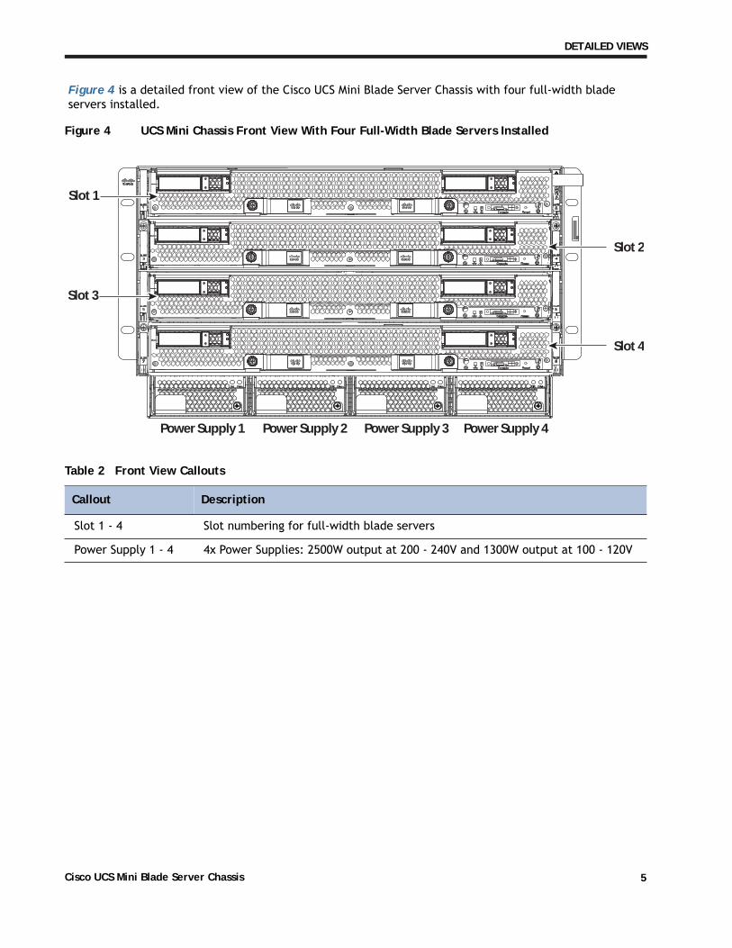
Figure 4 is a detailed front view of the Cisco UCS Mini Blade Server Chassis with four full-width blade servers installed.
Figure 4 UCS Mini Chassis Front View With Four Full-Width Blade Servers Installed
Slot 1
Slot 3
Power Supply 1 Power Supply 2 Power Supply 3 Power Supply 4
Slot 2
Slot 4
Table 2 Front View Callouts
Callout Description
Slot 1 - 4 Slot numbering for full-width blade servers
Power Supply 1 - 4 4x Power Supplies: 2500W output at 200 - 240V and 1300W output at 100 - 120V
Cisco UCS Mini Blade Server Chassis 5
DETAILED VIEWS
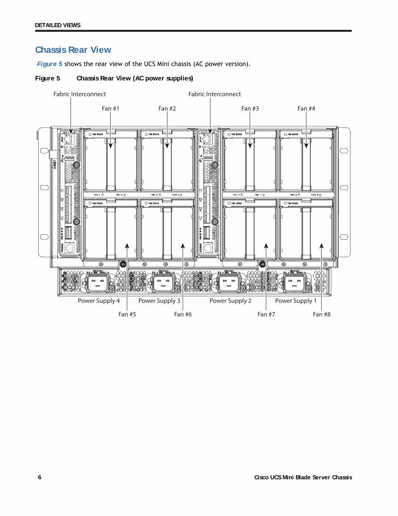
Chassis Rear ViewFigure 5 shows the rear view of the UCS Mini chassis (AC power version).
Figure 5 Chassis Rear View (AC power supplies)
Power Supply 1Power Supply 2Power Supply 3Power Supply 4
Fabric Interconnect
Fan #1
Fabric Interconnect
Fan #5 Fan #6 Fan #7 Fan #8
Fan #2 Fan #3 Fan #4
Cisco UCS Mini Blade Server Chassis6
DETAILED VIEWS
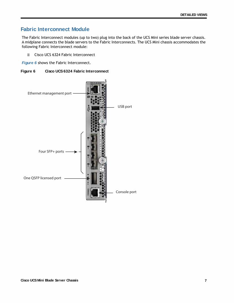
Fabric Interconnect ModuleThe Fabric Interconnect modules (up to two) plug into the back of the UCS Mini series blade server chassis. A midplane connects the blade servers to the Fabric Interconnects. The UCS Mini chassis accommodates the following Fabric Interconnect module:
� Cisco UCS 6324 Fabric Interconnect
Figure 6 shows the Fabric Interconnect.
Figure 6 Cisco UCS 6324 Fabric Interconnect
Ethernet management port
Four SFP+ ports
One QSFP licensed port
USB port
Console port
Cisco UCS Mini Blade Server Chassis 7
BASE CHASSIS STANDARD CAPABILITIES and FEATURES
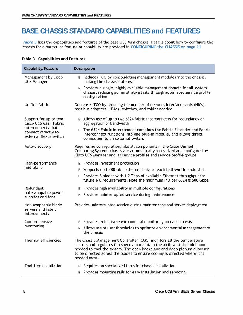
BASE CHASSIS STANDARD CAPABILITIES and FEATURESTable 3 lists the capabilities and features of the base UCS Mini chassis. Details about how to configure the chassis for a particular feature or capability are provided in CONFIGURING the CHASSIS on page 11.
Table 3 Capabilities and Features
Capability/Feature Description
Management by Cisco UCS Manager
� Reduces TCO by consolidating management modules into the chassis, making the chassis stateless
� Provides a single, highly available management domain for all system chassis, reducing administrative tasks through automated service profile configuration
Unified fabric Decreases TCO by reducing the number of network interface cards (NICs), host bus adapters (HBAs), switches, and cables needed
Support for up to two Cisco UCS 6324 Fabric Interconnects that connect directly to external Nexus switch
� Allows use of up to two 6324 fabric interconnects for redundancy or aggregation of bandwidth
� The 6324 Fabric Interconnect combines the Fabric Extender and Fabric Interconnect functions into one plug-in module, and allows direct connection to an external switch.
Auto-discovery Requires no configuration; like all components in the Cisco Unified Computing System, chassis are automatically recognized and configured by Cisco UCS Manager and its service profiles and service profile groups
High-performance mid-plane
� Provides investment protection
� Supports up to 80 Gbit Ethernet links to each half-width blade slot
� Provides 8 blades with 1.2 Tbps of available Ethernet throughput for future I/O requirements. Note the maximum I/O per 6324 is 500 Gbps.
Redundant hot-swappable power supplies and fans
� Provides high availability in multiple configurations
� Provides uninterrupted service during maintenance
Hot-swappable blade servers and fabric interconnects
Provides uninterrupted service during maintenance and server deployment
Comprehensive monitoring
� Provides extensive environmental monitoring on each chassis
� Allows use of user thresholds to optimize environmental management of the chassis
Thermal efficiencies The Chassis Management Controller (CMC) monitors all the temperature sensors and regulates fan speeds to maintain the airflow at the minimum needed to cool the system. The open backplane and deep plenum allow air to be directed across the blades to ensure cooling is directed where it is needed most.
Tool-free installation � Requires no specialized tools for chassis installation
� Provides mounting rails for easy installation and servicing
Cisco UCS Mini Blade Server Chassis8
BASE CHASSIS STANDARD CAPABILITIES and FEATURES
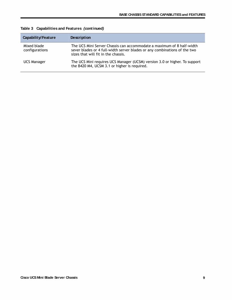
Mixed blade configurations
The UCS Mini Server Chassis can accommodate a maximum of 8 half-width sever blades or 4 full-width server blades or any combinations of the two sizes that will fit in the chassis.
UCS Manager The UCS Mini requires UCS Manager (UCSM) version 3.0 or higher. To support the B420 M4, UCSM 3.1 or higher is required.
Table 3 Capabilities and Features (continued)
Capability/Feature Description
Cisco UCS Mini Blade Server Chassis 9

SUPPORTED FEATURES AND CONFIGURATIONS
SUPPORTED FEATURES AND CONFIGURATIONSTable 4 lists the supported features and configurations of the UCS Mini.
Table 4 Supported Features and Configurations
Capability/Feature Description
Blade Servers The UCS Mini supports the B200 M4, B200 M3, B420 M3, and B420 M4 servers. It also supports the B260 M4 and B460 M4 servers (v3 and v4 CPU versions only).
Port Usage The UCS Mini has four SFP+ ports and one QSFP port.
The four SFP+ ports can be configured as:
� Uplink ports
� 1 Gbit ports
� 10 Gbit ports
� FCoE ports
� 2/4/8 Gbit Fibre Channel ports
The QSFP port can only be used to connect to a secondary chassis, rack servers, or storage.
NOTE: one SFP+ port must be used as a uplink
Rack Servers In a single-chassis configuration, up to seven C220 M3, C240 M3, C220 M4,and C240 M4 rack servers are supported.
To connect the maximum of seven rack mount servers:
� Four servers can connect to the 6324 FI QSFP port (primary chassis)
� Three servers can connect to the 6324 FI SFP+ ports (primary chassis)
� The remaining 6324 FI SFP+ port is reserved for use as an uplink
In a dual chassis configuration, a maximum of four C220 M3, C240 M3, C220 M4,and C240 M4 rack servers can be connected using the 6324 FI QSFP and SFP ports in the primary chassis.
Number of UCS Mini Chassis
Two UCS mini chassis can be connected together. The primary chassis utilizes two 6324 Fabric Interconnects and the secondary chassis utilizes two 2208XP or 2204XP Fabric Extenders (the 2204XP is recommended).
Licensing The QSFP port must have a scalability license in order to be put into service.
Cisco UCS 6324 Fabric Interconnect
One or two Cisco UCS 6324 FIs can be installed in the UCS Mini
Fabric Extenders Fabric Extenders (such as the 2204XP or 2208XP) are only supported in the secondary chassis and cannot be installed in the primary chassis.
Cisco UCS Mini Blade Server Chassis10
CONFIGURING the CHASSIS
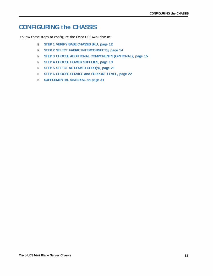
CONFIGURING the CHASSISFollow these steps to configure the Cisco UCS Mini chassis:
� STEP 1 VERIFY BASE CHASSIS SKU, page 12
� STEP 2 SELECT FABRIC INTERCONNECTS, page 14
� STEP 3 CHOOSE ADDITIONAL COMPONENTS (OPTIONAL), page 15
� STEP 4 CHOOSE POWER SUPPLIES, page 19
� STEP 5 SELECT AC POWER CORD(s), page 21
� STEP 6 CHOOSE SERVICE and SUPPORT LEVEL, page 22
� SUPPLEMENTAL MATERIAL on page 31
Cisco UCS Mini Blade Server Chassis 11

CONFIGURING the CHASSIS
STEP 1 VERIFY BASE CHASSIS SKU
Verify the product ID (PID) of the base UCS Mini chassis as shown in Table 5.
Table 5 PID of the Base UCS Mini Chassis
Product ID (PID) Description Usage
UCSB-5108-AC2 UCS 5108 Blade Server AC2 Chassis, 0 PSU/8 fans/0 FEX
Used as part of the N20-Z0001 and UCS-MINI-Z0001 bundle to include Fabric Interconnects, blades, power supplies (PSUs) and fabric extender (FEX) modules as a configured system.
UCSB-5108-AC2-UPG UCS 5108 Blade Server AC2 Chassis, 0 PSU/8 fans/0 FEX
Can only be used to order a chassis configured with blades, power supplies, and FEX modules. May not be used to order an empty chassis.
UCSB-5108-AC2= UCS 5108 Blade Server AC2 Chassis, 0 PSU/8 fans/0 FEX
Used to order an empty chassis, cannot be configured with blades. Power supplies and FEX modules may be installed.
UCSB-5108-DC2 UCS 5108 Blade Server DC2 Chassis/0 PSU/8 fans/0 FEX
Used as part of the N20-Z0001 and UCS-MINI-Z0001 bundle to include Fabric Interconnects, blades, power supplies (PSUs) and fabric extender (FEX) modules as a configured system.
UCSB-5108-DC2-UPG UCS 5108 Blade Server DC2 Chassis/0 PSU/8 fans/0 FEX
Can only be used to order a chassis configured with blades, power supplies, and FEX modules. May not be used to order an empty chassis.
UCSB-5108-DC2= UCS 5108 Blade Server DC2 Chassis/0 PSU/8 fans/0 FEX
Used to order an empty chassis, cannot be configured with blades. Power supplies and FEX modules may be installed.
Included with the chassis:
� N20-CAK: Chassis Accessory Kit, consisting of:
— N20-CRMK2: One Rail kit that supports square-holed racks (or round hole racks with an optional adapter - see below)
— N20-BKVM=: KVM local console connector dongle cable that connects to the front of any UCS blade server, and documentation
— N20-FAN5: Eight redundant and hot-swappable fan modules
Not included with the chassis (but may be ordered separately):
� N20-CRMK2=: Additional or spare rail kit for the Cisco UCS Mini chassis
Cisco UCS Mini Blade Server Chassis12
CONFIGURING the CHASSIS
� N20-CRMK2-RHA=: Round hole adapter kit (for threaded and non-threaded holes) for the rail kit (N20-CRMK2) included with the chassis.
NOTE: The adapter kit only works with the N20-CRMK2 rail kit
� N20-CBLKB1=: Blade slot blanking panel for UCS 5108/single slot
� N20-CDIVH=: Horizontal divider for UCS 5108
Caveats
� You must select either an AC or -48 VDC version of the chassis.
� There is no mixing allowed of AC and -48 VDC power supplies within the same 5108 chassis.
Cisco UCS Mini Blade Server Chassis 13
CONFIGURING the CHASSIS
STEP 2 SELECT FABRIC INTERCONNECTS
The Fabric Interconnect options are:
� Cisco UCS 6324 Fabric Interconnect
Choose Fabric Interconnects
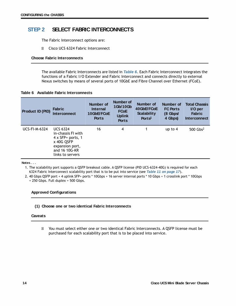
The available Fabric Interconnects are listed in Table 6. Each Fabric Interconnect integrates the functions of a Fabric I/O Extender and Fabric Interconnect and connects directly to external Nexus switches by means of several ports of 10GbE and Fibre Channel over Ethernet (FCoE).
Table 6 Available Fabric Interconnects
Product ID (PID) Fabric Interconnect
Number of Internal
10GbE/FCoE Ports
Number of 1Gb/10Gb
FCoE Uplink Ports
Number of 40GbE/FCoE Scalability
Ports1
UCS-FI-M-6324 UCS 6324 in-chassis FI with 4 x SFP+ ports, 1 x 40G QSFP expansion port, and 16 10G-KR links to servers
16 4 1 up to 4 500 Gbs2
Approved Configurations
(1) Choose one or two identical Fabric Interconnects
Caveats
� You must select either one or two identical Fabric Interconnects. A QSFP license must be purchased for each scalability port that is to be placed into service.
Notes . . .1. The scalability port supports a QSFP breakout cable. A QSFP license (PID UCS-6324-40G) is required for each
6324 Fabric Interconnect scalability port that is to be put into service (see Table 11 on page 17).
Number of FC Ports (8 Gbps/4 Gbps)
Total Chassis I/O per Fabric
Interconnect
2. 40 Gbps QSFP port + 4 uplink SFP+ ports * 10Gbps + 16 server internal ports * 10 Gbps + 1 crosslink port * 10Gbps = 250 Gbps. Full duplex = 500 Gbps.
Cisco UCS Mini Blade Server Chassis14

CONFIGURING the CHASSIS
STEP 3 CHOOSE ADDITIONAL COMPONENTS (OPTIONAL)
A variety of optical and copper Small Form-Factor Pluggable (SFP) transceivers and copper twinax cables are available for use with the Fabric Interconnects.
Choose 10 GbE SFP+ Optical Transceivers
You can choose up to four SFP+ optical transceivers for each 6324, as shown in Table 7.
Table 7 10GbE Transceivers
Product ID (PID) PID Description
SFP-10G-LR 10GBASE-LR SFP Module
SFP-10G-LR-X 10GBASE-LR SFP Module for extended temp range
SFP-10G-SR 10GBASE-SR SFP Module
SFP-10G-SR-X 10GBASE-SR SFP Module for extended temp range
Choose 1 GbE and 8 GbE Transceivers
You may choose up to four transceivers for each 6324, as shown in Table 8.
Table 8 SFP Optical Transceivers
Product ID (PID) PID Description
1GbE Transceivers
GLC-SX-MM GE SFP, LC connector SX transceiver
GLC-LH-SM GE SFP, LC connector LX/LH transceiver
GLC-T (V03 or higher) 1000BASE-T SFP
Cisco UCS Mini Blade Server Chassis 15
CONFIGURING the CHASSIS
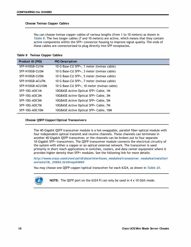
Choose Twinax Copper Cables
You can choose twinax copper cables of various lengths (from 1 to 10 meters) as shown in Table 9. The two longer cables (7 and 10 meters) are active, which means that they contain active components within the SFP+ connector housing to improve signal quality. The ends of these cables are connectorized to plug directly into SFP receptacles.
Table 9 Twinax Copper Cables
Product ID (PID) PID Description
SFP-H10GB-CU1M 10 G Base-CU SFP+, 1 meter (twinax cable)
SFP-H10GB-CU3M 10 G Base-CU SFP+, 3 meter (twinax cable)
SFP-H10GB-CU5M 10 G Base-CU SFP+, 5 meter (twinax cable)
SFP-H10GB-ACU7M 10 G Base-CU SFP+, 7 meter (twinax cable)
SFP-H10GB-ACU10M 10 G Base-CU SFP+, 10 meter (twinax cable)
SFP-10G-AOC1M 10GBASE Active Optical SFP+ Cable, 1M
SFP-10G-AOC3M 10GBASE Active Optical SFP+ Cable, 3M
SFP-10G-AOC5M 10GBASE Active Optical SFP+ Cable, 5M
SFP-10G-AOC7M 10GBASE Active Optical SFP+ Cable, 7M
SFP-10G-AOC10M 10GBASE Active Optical SFP+ Cable, 10M
Choose QSFP Copper/Optical Transceivers
The 40-Gigabit QSFP transceiver module is a hot-swappable, parallel fiber-optical module with four independent optical transmit and receive channels. These channels can terminate in another 40-Gigabit QSFP transceiver, or the channels can be broken out to four separate 10-Gigabit SFP+ transceivers. The QSFP transceiver module connects the electrical circuitry of the system with either a copper or an optical external network. The transceiver is used primarily in short reach applications in switches, routers, and data center equipment where it provides higher density than SFP+ modules. See the following link for more details:
http://www.cisco.com/c/en/us/td/docs/interfaces_modules/transceiver_modules/installation/note/OL_24862.html#wp44860
You may choose one QSFP copper/optical transceiver for each 6324, as shown in Table 10.
NOTE: The QSFP port on the 6324 FI can only be used in 4 x 10 Gbit mode.
Cisco UCS Mini Blade Server Chassis16
CONFIGURING the CHASSIS
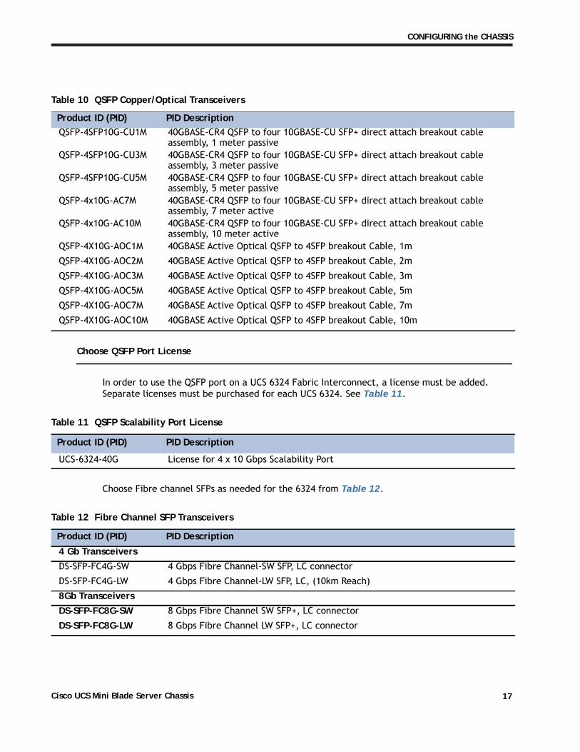
Table 10 QSFP Copper/Optical Transceivers
Product ID (PID) PID DescriptionQSFP-4SFP10G-CU1M 40GBASE-CR4 QSFP to four 10GBASE-CU SFP+ direct attach breakout cable
assembly, 1 meter passiveQSFP-4SFP10G-CU3M 40GBASE-CR4 QSFP to four 10GBASE-CU SFP+ direct attach breakout cable
assembly, 3 meter passiveQSFP-4SFP10G-CU5M 40GBASE-CR4 QSFP to four 10GBASE-CU SFP+ direct attach breakout cable
assembly, 5 meter passiveQSFP-4x10G-AC7M 40GBASE-CR4 QSFP to four 10GBASE-CU SFP+ direct attach breakout cable
assembly, 7 meter activeQSFP-4x10G-AC10M 40GBASE-CR4 QSFP to four 10GBASE-CU SFP+ direct attach breakout cable
assembly, 10 meter activeQSFP-4X10G-AOC1M 40GBASE Active Optical QSFP to 4SFP breakout Cable, 1m
QSFP-4X10G-AOC2M 40GBASE Active Optical QSFP to 4SFP breakout Cable, 2m
QSFP-4X10G-AOC3M 40GBASE Active Optical QSFP to 4SFP breakout Cable, 3m
QSFP-4X10G-AOC5M 40GBASE Active Optical QSFP to 4SFP breakout Cable, 5m
QSFP-4X10G-AOC7M 40GBASE Active Optical QSFP to 4SFP breakout Cable, 7m
QSFP-4X10G-AOC10M 40GBASE Active Optical QSFP to 4SFP breakout Cable, 10m
Choose QSFP Port License
In order to use the QSFP port on a UCS 6324 Fabric Interconnect, a license must be added. Separate licenses must be purchased for each UCS 6324. See Table 11.
Table 11 QSFP Scalability Port License
Product ID (PID) PID Description
UCS-6324-40G License for 4 x 10 Gbps Scalability Port
Choose Fibre channel SFPs as needed for the 6324 from Table 12.
Table 12 Fibre Channel SFP Transceivers
Product ID (PID) PID Description
4 Gb TransceiversDS-SFP-FC4G-SW 4 Gbps Fibre Channel-SW SFP, LC connector
DS-SFP-FC4G-LW 4 Gbps Fibre Channel-LW SFP, LC, (10km Reach)
8Gb TransceiversDS-SFP-FC8G-SW 8 Gbps Fibre Channel SW SFP+, LC connector
DS-SFP-FC8G-LW 8 Gbps Fibre Channel LW SFP+, LC connector
Cisco UCS Mini Blade Server Chassis 17

CONFIGURING the CHASSIS
Approved Configurations
(1) Choose the number of transceivers or copper twinax cables according to the number of Fabric Interconnect ports that are active that or will be become active in the future.
Caveats
� You should order enough SFPs, QSFPs, and cables to accommodate your maximum forseeable needs.
� If you selected a QSFP transceiver, make sure you choose a QSFP port license.
� For the 6324, observe the following:
— The maximum number of SFP+ transceivers, SFP optical transceivers, copper transceivers, or twinax cables must be less than or equal to four. A minimum of one of these must be installed for the 6324 to have network connectivity.
— The maximum number of Fibre Channel SFPs must be less than or equal to three. The reason for this is that at least one SFP+ port on the 6324 must be free so the 6324 can connect to a network.
� The QSFP port can only be used for connection to a secondary chassis, C-series servers, and storage devices. It cannot be used as an uplink.
Cisco UCS Mini Blade Server Chassis18

CONFIGURING the CHASSIS
STEP 4 CHOOSE POWER SUPPLIES
The UCS Mini chassis accommodates up to four power supplies.
Choose Power Supplies
The available power supplies are listed in Table 13
Table 13 Available Power Supplies
Product ID (PID) PID Description
UCSB-PSU-2500ACDV 2500 W Platinum AC Hot Plug Power Supply - DV
UCSB-PSU-2500DC48 2500 W DC -48 V power supply
.
Approved Configurations
(1) Choose from 2 to 4 power supplies
Caveats
� Be aware of the blade power up limitations when using 110 V power supplies. See Table 14
Table 14 Blade Power Up Limitations when Using 110 V Power Supplies1 2
Power ConfigurationNumber of
Power Supplies
Power Available Number of Powered Up Blades
High Power Blades
Medium Power Blades
Low Power Blades
Non-redundant (2+0) 2 2600 W 4 5 6
Non-redundant (3+0) 3 3900 W 6 7 8
Non-redundant (4+0) 4 5200 W 8 8 8
N+1 (2+1) 3 2600 W 4 5 7
N+1 (3+1) 4 3900 W 6 7 8
Grid (2+2) 4 2600 W 4 5 6
.
Notes . . .1. The actual number of blades that will power up depends on the exact configuration and blade mix.2. There are no restrictions on blades powering up when the 5108 chassis runs on 200-240 VAC or -48 V DC power
supplies.
Cisco UCS Mini Blade Server Chassis 19
CONFIGURING the CHASSIS
Example configurations for B200 M3 and B200 M4 blades (low, medium, and high powered) are listed here:
� Low Power Server = 2X 80 W E5-2600 CPUs, 4x 8 GB DIMMs, 1X HDD, and 1X VIC1240
� Medium Power Server = 2X 10⁵ W E5-2600 CPUs, 12x 8 GB DIMMs, 2X HDDs, and 1X VIC1240
� High Power Server = 2X 130 W E5-2600 CPUs, 24x 8 GB DIMMs, 2X HDDs, 1X VIC1240, and 1x VIC1280
Caveats
� Do not mix AC and DC power supplies
� Use only a -48 VDC power supply in a -48 VDC chassis
� Use only an AC power supply in an AC chassis
Cisco UCS Mini Blade Server Chassis20
CONFIGURING the CHASSIS
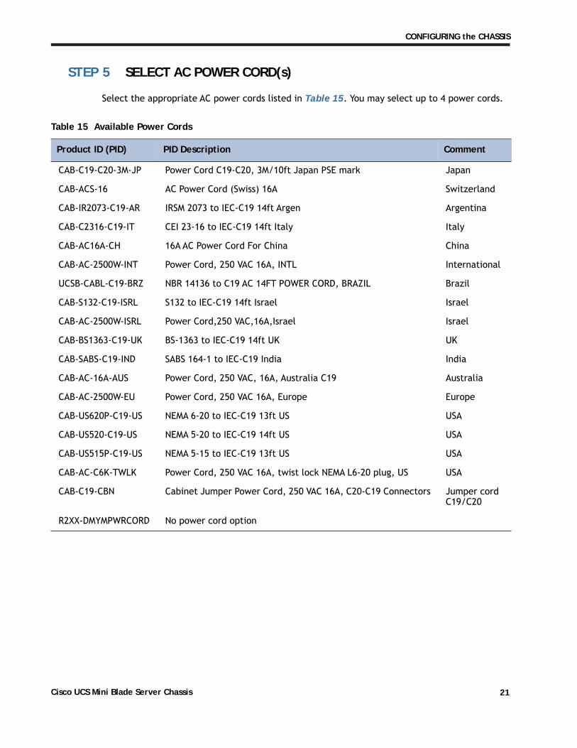
STEP 5 SELECT AC POWER CORD(s)
Select the appropriate AC power cords listed in Table 15. You may select up to 4 power cords.
Table 15 Available Power Cords
Product ID (PID) PID Description Comment
CAB-C19-C20-3M-JP Power Cord C19-C20, 3M/10ft Japan PSE mark Japan
CAB-ACS-16 AC Power Cord (Swiss) 16A Switzerland
CAB-IR2073-C19-AR IRSM 2073 to IEC-C19 14ft Argen Argentina
CAB-C2316-C19-IT CEI 23-16 to IEC-C19 14ft Italy Italy
CAB-AC16A-CH 16A AC Power Cord For China China
CAB-AC-2500W-INT Power Cord, 250 VAC 16A, INTL International
UCSB-CABL-C19-BRZ NBR 14136 to C19 AC 14FT POWER CORD, BRAZIL Brazil
CAB-S132-C19-ISRL S132 to IEC-C19 14ft Israel Israel
CAB-AC-2500W-ISRL Power Cord,250 VAC,16A,Israel Israel
CAB-BS1363-C19-UK BS-1363 to IEC-C19 14ft UK UK
CAB-SABS-C19-IND SABS 164-1 to IEC-C19 India India
CAB-AC-16A-AUS Power Cord, 250 VAC, 16A, Australia C19 Australia
CAB-AC-2500W-EU Power Cord, 250 VAC 16A, Europe Europe
CAB-US620P-C19-US NEMA 6-20 to IEC-C19 13ft US USA
CAB-US520-C19-US NEMA 5-20 to IEC-C19 14ft US USA
CAB-US515P-C19-US NEMA 5-15 to IEC-C19 13ft US USA
CAB-AC-C6K-TWLK Power Cord, 250 VAC 16A, twist lock NEMA L6-20 plug, US USA
CAB-C19-CBN Cabinet Jumper Power Cord, 250 VAC 16A, C20-C19 Connectors Jumper cord C19/C20
R2XX-DMYMPWRCORD No power cord option
Cisco UCS Mini Blade Server Chassis 21

CONFIGURING the CHASSIS
STEP 6 CHOOSE SERVICE and SUPPORT LEVEL
A variety of service options are available for the UCS Mini chassis and the UCS 6324 Fabric Interconnect module, as described in this section.
UCS Mini ChassisUnified Computing Warranty, No Contract
If you have noncritical implementations and choose to have no service contract, the following coverage is supplied:
� Three-year parts coverage.
� Next business day (NBD) onsite parts replacement eight hours a day, five days a week.
� 90-day software warranty on media.
� Ongoing downloads of BIOS, drivers, and firmware updates.
� UCSM updates for systems with Unified Computing System Manager. These updates include minor enhancements and bug fixes that are designed to maintain the compliance of UCSM with published specifications, release notes, and industry standards.
Cisco UCS Mini Blade Server Chassis22
CONFIGURING the CHASSIS
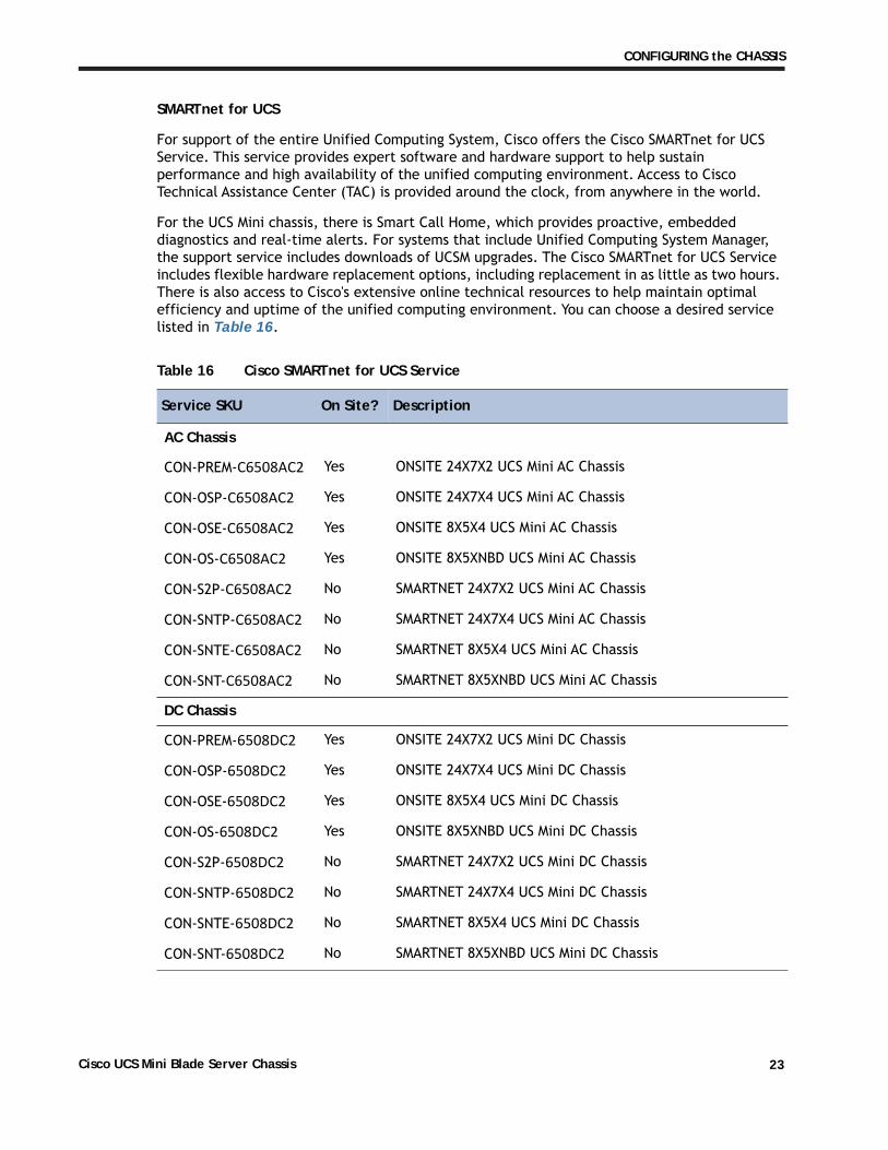
SMARTnet for UCS
For support of the entire Unified Computing System, Cisco offers the Cisco SMARTnet for UCS Service. This service provides expert software and hardware support to help sustain performance and high availability of the unified computing environment. Access to Cisco Technical Assistance Center (TAC) is provided around the clock, from anywhere in the world.
For the UCS Mini chassis, there is Smart Call Home, which provides proactive, embedded diagnostics and real-time alerts. For systems that include Unified Computing System Manager, the support service includes downloads of UCSM upgrades. The Cisco SMARTnet for UCS Service includes flexible hardware replacement options, including replacement in as little as two hours. There is also access to Cisco's extensive online technical resources to help maintain optimal efficiency and uptime of the unified computing environment. You can choose a desired service listed in Table 16.
Table 16 Cisco SMARTnet for UCS Service
Service SKU On Site? Description
AC Chassis
CON-PREM-C6508AC2 Yes ONSITE 24X7X2 UCS Mini AC Chassis
CON-OSP-C6508AC2 Yes ONSITE 24X7X4 UCS Mini AC Chassis
CON-OSE-C6508AC2 Yes ONSITE 8X5X4 UCS Mini AC Chassis
CON-OS-C6508AC2 Yes ONSITE 8X5XNBD UCS Mini AC Chassis
CON-S2P-C6508AC2 No SMARTNET 24X7X2 UCS Mini AC Chassis
CON-SNTP-C6508AC2 No SMARTNET 24X7X4 UCS Mini AC Chassis
CON-SNTE-C6508AC2 No SMARTNET 8X5X4 UCS Mini AC Chassis
CON-SNT-C6508AC2 No SMARTNET 8X5XNBD UCS Mini AC Chassis
DC Chassis
CON-PREM-6508DC2 Yes ONSITE 24X7X2 UCS Mini DC Chassis
CON-OSP-6508DC2 Yes ONSITE 24X7X4 UCS Mini DC Chassis
CON-OSE-6508DC2 Yes ONSITE 8X5X4 UCS Mini DC Chassis
CON-OS-6508DC2 Yes ONSITE 8X5XNBD UCS Mini DC Chassis
CON-S2P-6508DC2 No SMARTNET 24X7X2 UCS Mini DC Chassis
CON-SNTP-6508DC2 No SMARTNET 24X7X4 UCS Mini DC Chassis
CON-SNTE-6508DC2 No SMARTNET 8X5X4 UCS Mini DC Chassis
CON-SNT-6508DC2 No SMARTNET 8X5XNBD UCS Mini DC Chassis
Cisco UCS Mini Blade Server Chassis 23

CONFIGURING the CHASSIS
SMARTnet for UCS Hardware Only Service
For faster parts replacement than is provided with the standard Cisco Unified Computing System warranty, Cisco offers the Cisco SMARTnet for UCS Hardware Only Service. You can choose from two levels of advanced onsite parts replacement coverage in as little as four hours. SMARTnet for UCS Hardware Only Service provides remote access any time to Cisco support professionals who can determine if a return materials authorization (RMA) is required. You can choose a service listed in Table 17.
Table 17 SMARTnet for UCS Hardware Only Service
Service SKU Service Level GSP
On Site? Description
AC Chassis
CON-UCW7-C6508AC2 UCW7 Yes UC PLUS 24X7X4OS UCS Mini AC Chassis
CON-UCW5-C6508AC2 UCW5 Yes UC PLUS 8X5XNBDOS UCS Mini AC Chassis
DC Chassis
CON-UCW7-C6508DC2 UCW7 Yes UC PLUS 24X7X4OS UCS Mini DC Chassis
CON-UCW5-C6508DC2 UCW5 Yes UC PLUS 8X5XNBDOS UCS Mini DC Chassis
Cisco UCS Mini Blade Server Chassis24

CONFIGURING the CHASSIS
Unified Computing Partner Support Service
Cisco Partner Support Service (PSS) is a Cisco Collaborative Services service offering that is designed for partners to deliver their own branded support and managed services to enterprise customers. Cisco PSS provides partners with access to Cisco's support infrastructure and assets to help them:
� Expand their service portfolios to support the most complex network environments
� Lower delivery costs
� Deliver services that increase customer loyalty
Partner Unified Computing Support Options enable eligible Cisco partners to develop and consistently deliver high-value technical support that capitalizes on Cisco intellectual assets. This helps partners to realize higher margins and expand their practice.
Partner Unified Computing Support Options are available to Cisco PSS partners. For additional information, see the following URL:
www.cisco.com/go/partnerucssupport
The two Partner Unified Computing Support Options include:
� Partner Support Service for UCS
� Partner Support Service for UCS Hardware Only
Partner Support Service for UCS provides hardware and software support, including triage support for third party software, backed by Cisco technical resources and level three support. See Table 18.
Table 18 Partner Support Service for UCS
Service SKUService Level GSP
On Site? Description
AC Chassis
CON-PSJ1-C6508AC2 PSJ1 No UCS SUPP PSS 8X5XNBD UCS Mini AC Chassis
CON-PSJ2-C6508AC2 PSJ2 No UCS SUPP PSS 8X5X4 UCS Mini AC Chassis
CON-PSJ3-C6508AC2 PSJ3 No UCS SUPP PSS 24X7X4 UCS Mini AC Chassis
CON-PSJ4-C6508AC2 PSJ4 No UCS SUPP PSS 24X7X2 UCS Mini AC Chassis
CON-PSJ6-C6508AC2 PSJ6 Yes UCS SUPP PSS 8x5x4 Onsite UCS Mini AC Chassis
CON-PSJ7-C6508AC2 PSJ7 Yes UCS SUPP PSS 24X7X4 Onsite UCS Mini AC Chassis
Cisco UCS Mini Blade Server Chassis 25
CONFIGURING the CHASSIS
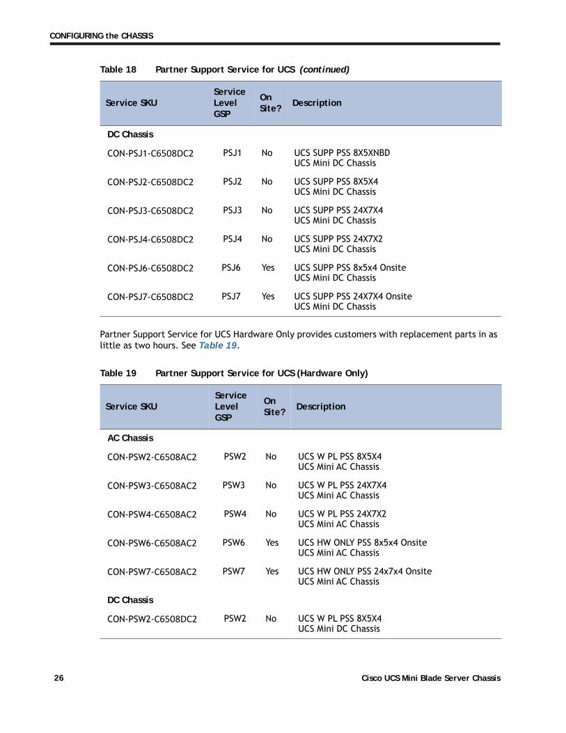
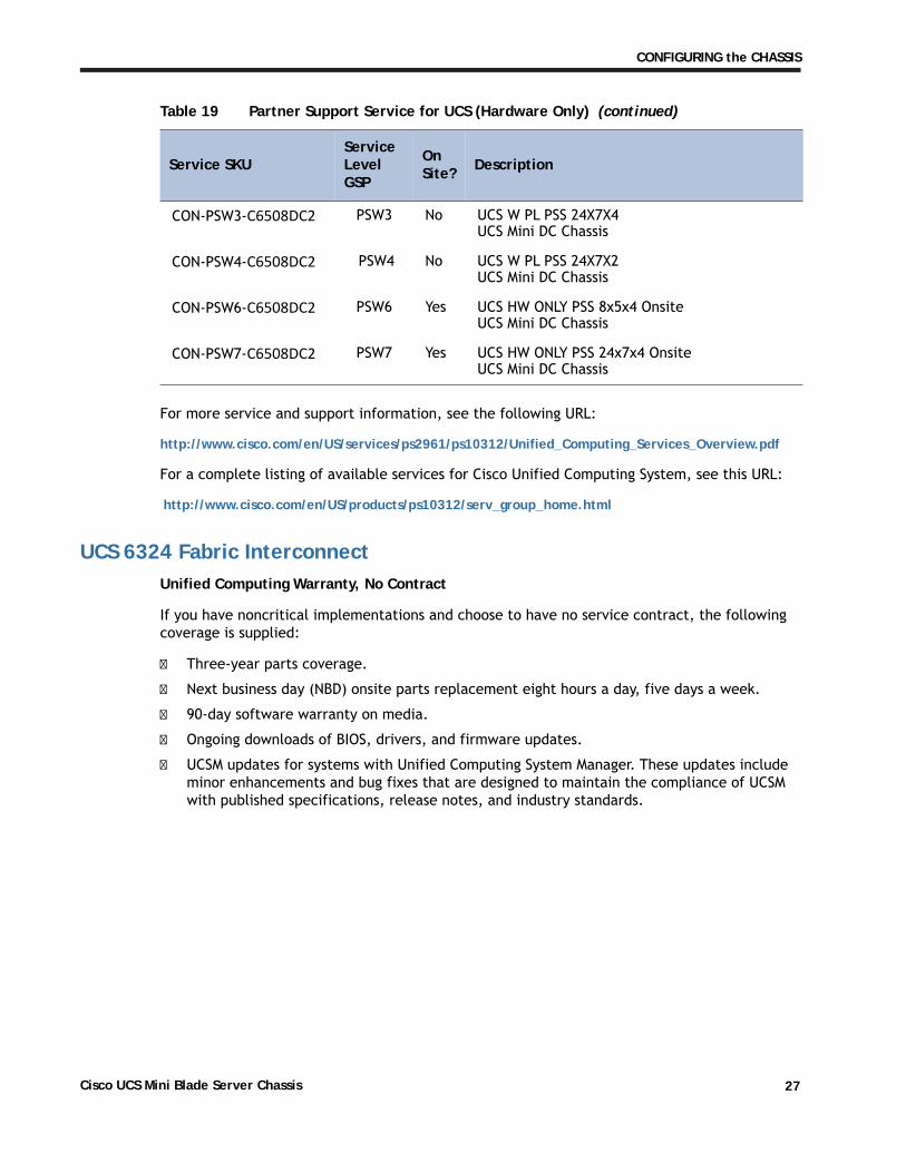
Partner Support Service for UCS Hardware Only provides customers with replacement parts in as little as two hours. See Table 19.
DC Chassis
CON-PSJ1-C6508DC2 PSJ1 No UCS SUPP PSS 8X5XNBD UCS Mini DC Chassis
CON-PSJ2-C6508DC2 PSJ2 No UCS SUPP PSS 8X5X4 UCS Mini DC Chassis
CON-PSJ3-C6508DC2 PSJ3 No UCS SUPP PSS 24X7X4 UCS Mini DC Chassis
CON-PSJ4-C6508DC2 PSJ4 No UCS SUPP PSS 24X7X2 UCS Mini DC Chassis
CON-PSJ6-C6508DC2 PSJ6 Yes UCS SUPP PSS 8x5x4 Onsite UCS Mini DC Chassis
CON-PSJ7-C6508DC2 PSJ7 Yes UCS SUPP PSS 24X7X4 Onsite UCS Mini DC Chassis
Table 19 Partner Support Service for UCS (Hardware Only)
Service SKUService Level GSP
On Site? Description
AC Chassis
CON-PSW2-C6508AC2 PSW2 No UCS W PL PSS 8X5X4 UCS Mini AC Chassis
CON-PSW3-C6508AC2 PSW3 No UCS W PL PSS 24X7X4 UCS Mini AC Chassis
CON-PSW4-C6508AC2 PSW4 No UCS W PL PSS 24X7X2 UCS Mini AC Chassis
CON-PSW6-C6508AC2 PSW6 Yes UCS HW ONLY PSS 8x5x4 Onsite UCS Mini AC Chassis
CON-PSW7-C6508AC2 PSW7 Yes UCS HW ONLY PSS 24x7x4 Onsite UCS Mini AC Chassis
DC Chassis
CON-PSW2-C6508DC2 PSW2 No UCS W PL PSS 8X5X4 UCS Mini DC Chassis
Table 18 Partner Support Service for UCS (continued)
Service SKUService Level GSP
On Site? Description
Cisco UCS Mini Blade Server Chassis26
CONFIGURING the CHASSIS
For more service and support information, see the following URL:
http://www.cisco.com/en/US/services/ps2961/ps10312/Unified_Computing_Services_Overview.pdf
For a complete listing of available services for Cisco Unified Computing System, see this URL:
http://www.cisco.com/en/US/products/ps10312/serv_group_home.html
UCS 6324 Fabric InterconnectUnified Computing Warranty, No Contract
If you have noncritical implementations and choose to have no service contract, the following coverage is supplied:
� Three-year parts coverage.
� Next business day (NBD) onsite parts replacement eight hours a day, five days a week.
� 90-day software warranty on media.
� Ongoing downloads of BIOS, drivers, and firmware updates.
� UCSM updates for systems with Unified Computing System Manager. These updates include minor enhancements and bug fixes that are designed to maintain the compliance of UCSM with published specifications, release notes, and industry standards.
CON-PSW3-C6508DC2 PSW3 No UCS W PL PSS 24X7X4 UCS Mini DC Chassis
CON-PSW4-C6508DC2 PSW4 No UCS W PL PSS 24X7X2 UCS Mini DC Chassis
CON-PSW6-C6508DC2 PSW6 Yes UCS HW ONLY PSS 8x5x4 Onsite UCS Mini DC Chassis
CON-PSW7-C6508DC2 PSW7 Yes UCS HW ONLY PSS 24x7x4 Onsite UCS Mini DC Chassis
Table 19 Partner Support Service for UCS (Hardware Only) (continued)
Service SKUService Level GSP
On Site? Description
Cisco UCS Mini Blade Server Chassis 27
CONFIGURING the CHASSIS
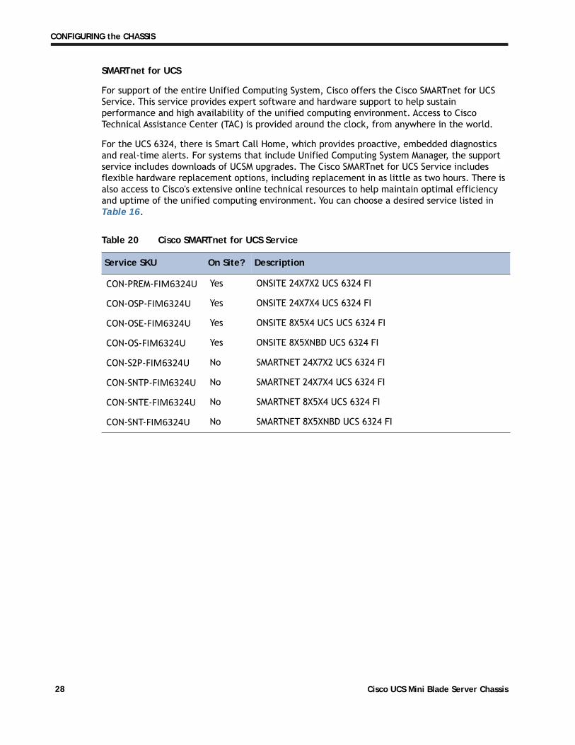
SMARTnet for UCS
For support of the entire Unified Computing System, Cisco offers the Cisco SMARTnet for UCS Service. This service provides expert software and hardware support to help sustain performance and high availability of the unified computing environment. Access to Cisco Technical Assistance Center (TAC) is provided around the clock, from anywhere in the world.
For the UCS 6324, there is Smart Call Home, which provides proactive, embedded diagnostics and real-time alerts. For systems that include Unified Computing System Manager, the support service includes downloads of UCSM upgrades. The Cisco SMARTnet for UCS Service includes flexible hardware replacement options, including replacement in as little as two hours. There is also access to Cisco's extensive online technical resources to help maintain optimal efficiency and uptime of the unified computing environment. You can choose a desired service listed in Table 16.
Table 20 Cisco SMARTnet for UCS Service
Service SKU On Site? Description
CON-PREM-FIM6324U Yes ONSITE 24X7X2 UCS 6324 FI
CON-OSP-FIM6324U Yes ONSITE 24X7X4 UCS 6324 FI
CON-OSE-FIM6324U Yes ONSITE 8X5X4 UCS UCS 6324 FI
CON-OS-FIM6324U Yes ONSITE 8X5XNBD UCS 6324 FI
CON-S2P-FIM6324U No SMARTNET 24X7X2 UCS 6324 FI
CON-SNTP-FIM6324U No SMARTNET 24X7X4 UCS 6324 FI
CON-SNTE-FIM6324U No SMARTNET 8X5X4 UCS 6324 FI
CON-SNT-FIM6324U No SMARTNET 8X5XNBD UCS 6324 FI
Cisco UCS Mini Blade Server Chassis28
CONFIGURING the CHASSIS
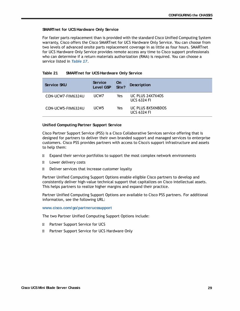
SMARTnet for UCS Hardware Only Service
For faster parts replacement than is provided with the standard Cisco Unified Computing System warranty, Cisco offers the Cisco SMARTnet for UCS Hardware Only Service. You can choose from two levels of advanced onsite parts replacement coverage in as little as four hours. SMARTnet for UCS Hardware Only Service provides remote access any time to Cisco support professionals who can determine if a return materials authorization (RMA) is required. You can choose a service listed in Table 17.
Table 21 SMARTnet for UCS Hardware Only Service
Service SKU Service Level GSP
On Site? Description
CON-UCW7-FIM6324U UCW7 Yes UC PLUS 24X7X4OS UCS 6324 FI
CON-UCW5-FIM6324U UCW5 Yes UC PLUS 8X5XNBDOS UCS 6324 FI
Unified Computing Partner Support Service
Cisco Partner Support Service (PSS) is a Cisco Collaborative Services service offering that is designed for partners to deliver their own branded support and managed services to enterprise customers. Cisco PSS provides partners with access to Cisco's support infrastructure and assets to help them:
� Expand their service portfolios to support the most complex network environments
� Lower delivery costs
� Deliver services that increase customer loyalty
Partner Unified Computing Support Options enable eligible Cisco partners to develop and consistently deliver high-value technical support that capitalizes on Cisco intellectual assets. This helps partners to realize higher margins and expand their practice.
Partner Unified Computing Support Options are available to Cisco PSS partners. For additional information, see the following URL:
www.cisco.com/go/partnerucssupport
The two Partner Unified Computing Support Options include:
� Partner Support Service for UCS
� Partner Support Service for UCS Hardware Only
Cisco UCS Mini Blade Server Chassis 29

CONFIGURING the CHASSIS
Partner Support Service for UCS provides hardware and software support, including triage support for third party software, backed by Cisco technical resources and level three support. See Table 18.
Table 22 Partner Support Service for UCS
Service SKUService Level GSP
On Site? Description
CON-PSJ1-FIM6324U PSJ1 No UCS SUPP PSS 8X5XNBD UCS 6324 FI
CON-PSJ2-FIM6324U PSJ2 No UCS SUPP PSS 8X5X4 UCS 6324 FI
CON-PSJ3-FIM6324U PSJ3 No UCS SUPP PSS 24X7X4 UCS 6324 FI
CON-PSJ4-FIM6324U PSJ4 No UCS SUPP PSS 24X7X2 UCS 6324 FI
CON-PSJ6-FIM6324U PSJ6 Yes UCS SUPP PSS 8x5x4 Onsite UCS 6324 FI
CON-PSJ7-FIM6324U PSJ7 Yes UCS SUPP PSS 24X7X4 Onsite UCS 6324 FI
Partner Support Service for UCS Hardware Only provides customers with replacement parts in as little as two hours. See Table 19.
Table 23 Partner Support Service for UCS (Hardware Only)
Service SKUService Level GSP
On Site? Description
CON-PSW2-FIM6324U PSW2 No UCS W PL PSS 8X5X4 UCS 6324 FI
CON-PSW3-FIM6324U PSW3 No UCS W PL PSS 24X7X4 UCS 6324 FI
CON-PSW4-FIM6324U PSW4 No UCS W PL PSS 24X7X2 UCS 6324 FI
CON-PSW6-FIM6324U PSW6 Yes UCS HW ONLY PSS 8x5x4 Onsite UCS 6324 FI
CON-PSW7-FIM6324U PSW7 Yes UCS HW ONLY PSS 24x7x4 Onsite UCS 6324 FI
For more service and support information, see the following URL:
http://www.cisco.com/en/US/services/ps2961/ps10312/Unified_Computing_Services_Overview.pdf
For a complete listing of available services for Cisco Unified Computing System, see this URL:
http://www.cisco.com/en/US/products/ps10312/serv_group_home.html
Cisco UCS Mini Blade Server Chassis30
SUPPLEMENTAL MATERIAL
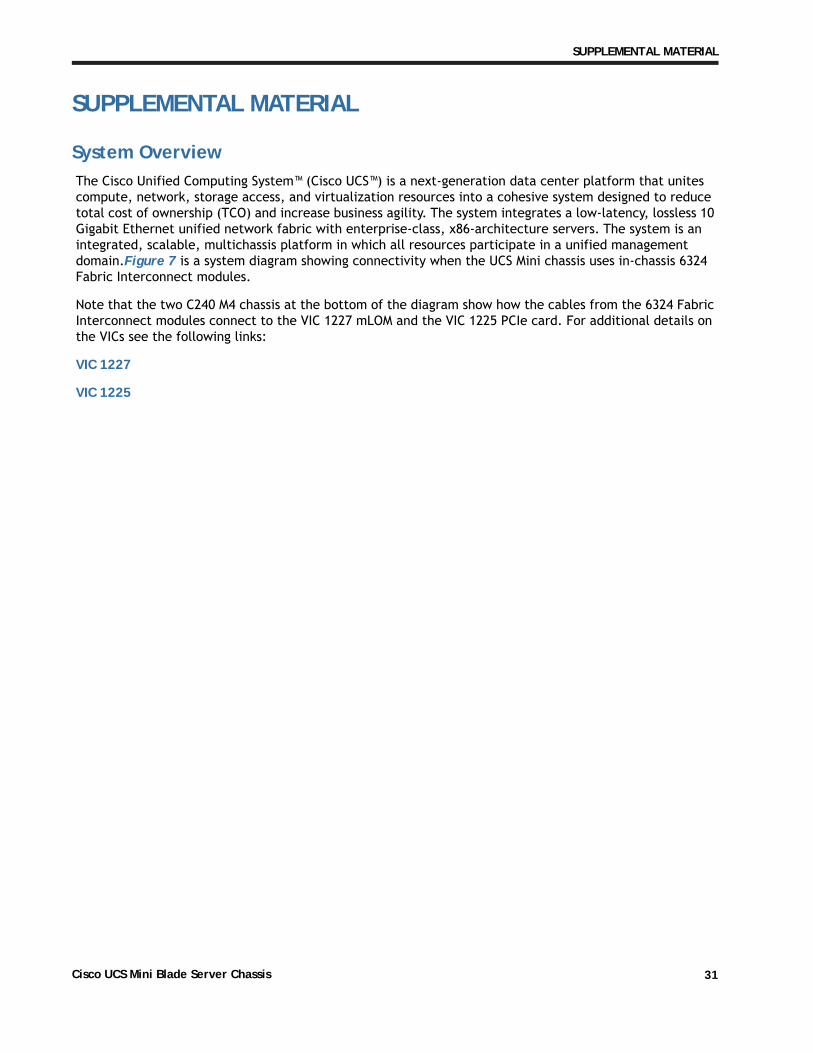
SUPPLEMENTAL MATERIAL
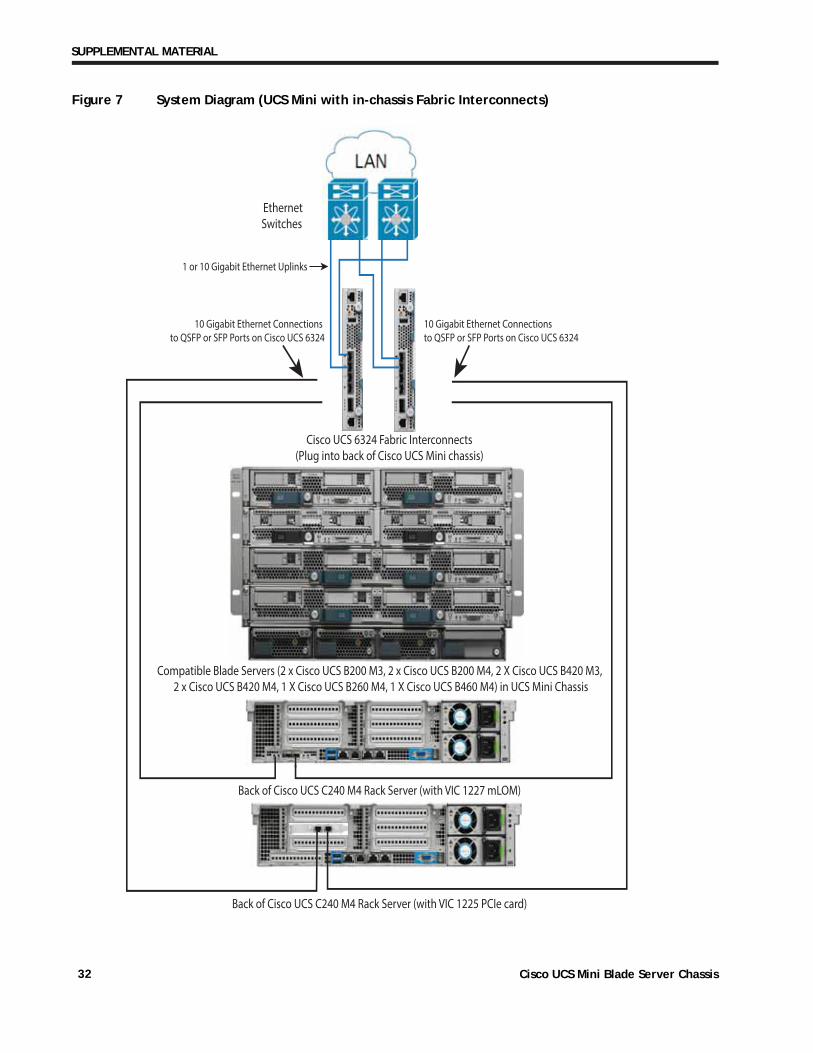
System OverviewThe Cisco Unified Computing System™ (Cisco UCS™) is a next-generation data center platform that unites compute, network, storage access, and virtualization resources into a cohesive system designed to reduce total cost of ownership (TCO) and increase business agility. The system integrates a low-latency, lossless 10 Gigabit Ethernet unified network fabric with enterprise-class, x86-architecture servers. The system is an integrated, scalable, multichassis platform in which all resources participate in a unified management domain.Figure 7 is a system diagram showing connectivity when the UCS Mini chassis uses in-chassis 6324 Fabric Interconnect modules.
Note that the two C240 M4 chassis at the bottom of the diagram show how the cables from the 6324 Fabric Interconnect modules connect to the VIC 1227 mLOM and the VIC 1225 PCIe card. For additional details on the VICs see the following links:
VIC 1227
VIC 1225
Cisco UCS Mini Blade Server Chassis 31
SUPPLEMENTAL MATERIAL
Figure 7 System Diagram (UCS Mini with in-chassis Fabric Interconnects)
Cisco UCS 6324 Fabric Interconnects(Plug into back of Cisco UCS Mini chassis)
Compatible Blade Servers (2 x Cisco UCS B200 M3, 2 x Cisco UCS B200 M4, 2 X Cisco UCS B420 M3, 2 x Cisco UCS B420 M4, 1 X Cisco UCS B260 M4, 1 X Cisco UCS B460 M4) in UCS Mini Chassis
Back of Cisco UCS C240 M4 Rack Server (with VIC 1227 mLOM)
Back of Cisco UCS C240 M4 Rack Server (with VIC 1225 PCIe card)
EthernetSwitches
1 or 10 Gigabit Ethernet Uplinks
10 Gigabit Ethernet Connections to QSFP or SFP Ports on Cisco UCS 6324
10 Gigabit Ethernet Connections to QSFP or SFP Ports on Cisco UCS 6324
Cisco UCS Mini Blade Server Chassis32
SUPPLEMENTAL MATERIAL
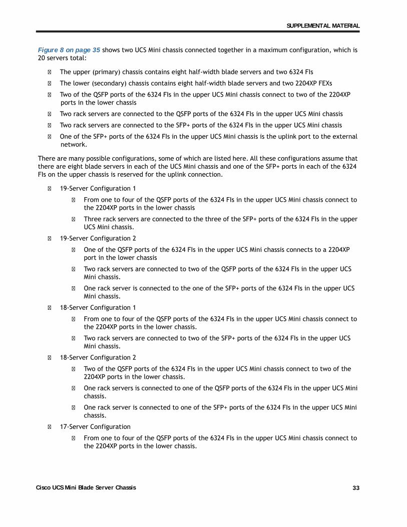
Figure 8 on page 35 shows two UCS Mini chassis connected together in a maximum configuration, which is 20 servers total:
� The upper (primary) chassis contains eight half-width blade servers and two 6324 FIs
� The lower (secondary) chassis contains eight half-width blade servers and two 2204XP FEXs
� Two of the QSFP ports of the 6324 FIs in the upper UCS Mini chassis connect to two of the 2204XP ports in the lower chassis
� Two rack servers are connected to the QSFP ports of the 6324 FIs in the upper UCS Mini chassis
� Two rack servers are connected to the SFP+ ports of the 6324 FIs in the upper UCS Mini chassis
� One of the SFP+ ports of the 6324 FIs in the upper UCS Mini chassis is the uplink port to the external network.
There are many possible configurations, some of which are listed here. All these configurations assume that there are eight blade servers in each of the UCS Mini chassis and one of the SFP+ ports in each of the 6324 FIs on the upper chassis is reserved for the uplink connection.
� 19-Server Configuration 1
� From one to four of the QSFP ports of the 6324 FIs in the upper UCS Mini chassis connect to the 2204XP ports in the lower chassis
� Three rack servers are connected to the three of the SFP+ ports of the 6324 FIs in the upper UCS Mini chassis.
� 19-Server Configuration 2
� One of the QSFP ports of the 6324 FIs in the upper UCS Mini chassis connects to a 2204XP port in the lower chassis
� Two rack servers are connected to two of the QSFP ports of the 6324 FIs in the upper UCS Mini chassis.
� One rack server is connected to the one of the SFP+ ports of the 6324 FIs in the upper UCS Mini chassis.
� 18-Server Configuration 1
� From one to four of the QSFP ports of the 6324 FIs in the upper UCS Mini chassis connect to the 2204XP ports in the lower chassis.
� Two rack servers are connected to two of the SFP+ ports of the 6324 FIs in the upper UCS Mini chassis.
� 18-Server Configuration 2
� Two of the QSFP ports of the 6324 FIs in the upper UCS Mini chassis connect to two of the 2204XP ports in the lower chassis.
� One rack servers is connected to one of the QSFP ports of the 6324 FIs in the upper UCS Mini chassis.
� One rack server is connected to one of the SFP+ ports of the 6324 FIs in the upper UCS Mini chassis.
� 17-Server Configuration
� From one to four of the QSFP ports of the 6324 FIs in the upper UCS Mini chassis connect to the 2204XP ports in the lower chassis.
Cisco UCS Mini Blade Server Chassis 33
SUPPLEMENTAL MATERIAL
� One rack server is connected to one of the SFP+ ports of the 6324 FIs in the upper UCS Mini chassis.
� 16-Server Configuration
� From one to four of the QSFP ports of the 6324 FIs in the upper UCS Mini chassis connect to the 2204XP ports in the lower chassis.
� No rack servers are connected.
The main guidelines are as follows:
� Only the QSFP port on the 6324 FI can connect to the lower UCS Mini chassis.
� The QSFP ports on the 6324 FI can connect to external rack servers.
� A maximum of three of the SFP+ ports on the upper UCS Mini can connect to external rack servers (at least one of these ports must be reserved for an uplink to the external network).
� Only the 10-Gbps ports on the 6324 FI can be used as uplinks to the external network.
� The 6324 FI QSFP and SFP+ ports can be used to connect iSCSI, NAS, and FCoE storage.
� The maximum number of servers (blade and rack) connections is 20.
Cisco UCS Mini Blade Server Chassis34

SUPPLEMENTAL MATERIAL
Figure 8 System Diagram (Two UCS Minis in Maximum 20-Server Configuration)
C220 M4 Rack Server
5108 Blade Chassis with 8 Servers and Two 6324 FIs
5108 Blade Chassis with 8 Servers and Two 2204XP FEXs
C220 M4 Rack Server
C220 M4 Rack Server
C240 M4 Rack Server
QSF
P to
10
Gb/
s SF
P br
eako
ut c
able
SFP
10 G
b/s
cabl
e
SFP
10 G
b/s
cabl
e
Upstream Upstream
Cisco UCS Mini Blade Server Chassis 35
SUPPLEMENTAL MATERIAL
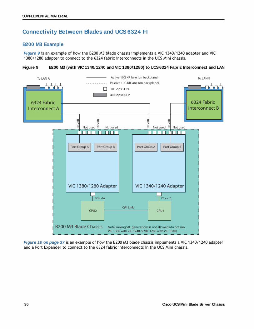
Connectivity Between Blades and UCS 6324 FI
B200 M3 Example
Figure 9 is an example of how the B200 M3 blade chassis implements a VIC 1340/1240 adapter and VIC 1380/1280 adapter to connect to the 6324 fabric interconnects in the UCS Mini chassis.
Figure 9 B200 M3 (with VIC 1340/1240 and VIC 1380/1280) to UCS 6324 Fabric Interconnect and LAN
Figure 10 on page 37 is an example of how the B200 M3 blade chassis implements a VIC 1340/1240 adapter and a Port Expander to connect to the 6324 fabric interconnects in the UCS Mini chassis.
Active 10G KR lane (on backplane)
Passive 10G KR lane (on backplane)
10 Gbps SFP+
40 Gbps QSFP
To LAN A To LAN B
PCIe x16 PCIe x16
6324 Fabric Interconnect B
6324 Fabric Interconnect A
10G
KR
10G
KR
Not used 10G
KR
10G
KR
Not used Not used Not used
VIC 1340/1240 AdapterVIC 1380/1280 Adapter
B200 M3 Blade Chassis
CPU1CPU2QPI Link
Port Group APort Group A Port Group BPort Group B
Note: mixing VIC generations is not allowed (do not mixVIC 1380 with VIC 1240 or VIC 1280 with VIC 1340)
Cisco UCS Mini Blade Server Chassis36

SUPPLEMENTAL MATERIAL
Figure 10 B200 M3 (with VIC 1340/1240 and Port Expander) to UCS 6324 Fabric Interconnect and LAN
Active 10G KR lane (on backplane)
Passive 10G KR lane (on backplane)
10 Gbps SFP+
40 Gbps QSFP
To LAN A To LAN B
PCIe x16
6324 Fabric Interconnect B
6324 Fabric Interconnect A
10G
KR
10G
KR
Not used 10G
KR
10G
KR
Not used Not used Not used
VIC 1340/1240 AdapterPort Expander
B200 M3 Blade Chassis
CPU1
Port Group A Port Group B
10G KR
10G KR
Cisco UCS Mini Blade Server Chassis 37
SUPPLEMENTAL MATERIAL
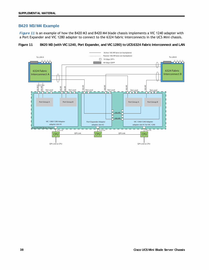
B420 M3/M4 Example
Figure 11 is an example of how the B420 M3 and B420 M4 blade chassis implements a VIC 1240 adapter with a Port Expander and VIC 1280 adapter to connect to the 6324 fabric interconnects in the UCS Mini chassis.
Figure 11 B420 M3 (with VIC 1240, Port Expander, and VIC 1280) to UCS 6324 Fabric Interconnect and LAN
VIC 1340/1240 AdapterPort Expander Adapter
Port Group A Port Group B
CPU
PCIe x16 PCIe x16
CPU
10G
KR
10G
KR
10G
KR
10G
KR
10G
KR
Not used Not usedNot used Not used Not used Not used10G
KR
10G
KR
10G KR
10G KR
10G
KR
adapter slot #2 adapter slot #1 for VIC 1240
VIC 1380/1280 Adapter
QPI Link
QPI Link to CPU QPI Link to CPU
QPI Link
adapter slot #3
PCIe x16
CPU
Port Group A Port Group B
B420 M3/M4 Blade Chassis
To LAN A
6324 Fabric Interconnect A
To LAN B
6324 Fabric Interconnect B
Active 10G KR lane (on backplane)
Passive 10G KR lane (on backplane)
10 Gbps SFP+
40 Gbps QSFP
Cisco UCS Mini Blade Server Chassis38

SUPPLEMENTAL MATERIAL
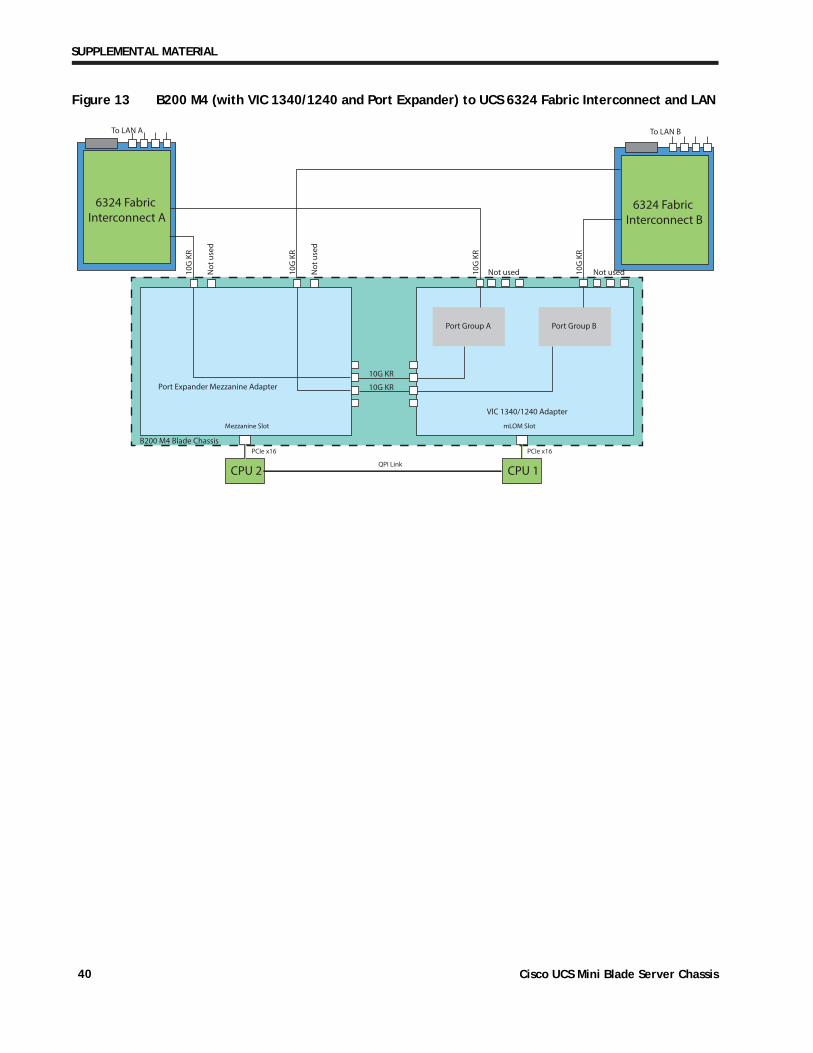
B200 M4 Example
Figure 12 is an example of how the B200 M4 blade chassis implements a VIC 1340/1240 adapter and VIC 1380/1280 adapter to connect to the 6324 fabric interconnects in the UCS Mini chassis.
Figure 12 B200 M4 (with VIC 1340/1240 and VIC 1380/1280) to UCS 6324 Fabric Interconnect and LAN
Figure 13 on page 40 is an example of how the B200 M4 blade chassis implements a VIC 1340/1240 adapter and a Port Expander to connect to the 6324 fabric interconnects in the UCS Mini chassis.
To LAN A
6324 Fabric Interconnect A
To LAN B
6324 Fabric Interconnect B
VIC 1340/1240 AdapterVIC 1380/1280 Adapter
Port Group A Port Group B
CPU 1CPU 2
PCIe x16 PCIe x16
Mezzanine Slot mLOM Slot
QPI Link
10G
KR
10G
KR
Not used10G
KR
10G
KR
Port Group A Port Group B
Not used Not used Not used
Note: mixing VIC generations is not allowed (do not mixVIC 1380 with VIC 1240 or VIC 1280 with VIC 1340)
B200 M4 Blade Chassis
Active 10G KR lane (on backplane)
Passive 10G KR lane (on backplane)
10 Gbps SFP+
40 Gbps QSFP
Cisco UCS Mini Blade Server Chassis 39
SUPPLEMENTAL MATERIAL
Figure 13 B200 M4 (with VIC 1340/1240 and Port Expander) to UCS 6324 Fabric Interconnect and LAN
To LAN B
6324 Fabric Interconnect B
To LAN A
6324 Fabric Interconnect A
VIC 1340/1240 Adapter
Port Expander Mezzanine Adapter
Port Group A Port Group B
CPU 1CPU 2
PCIe x16 PCIe x16
mLOM Slot
QPI Link
Mezzanine Slot
10G
KR
10G
KR
10G
KR
Not
use
d
Not
use
d
Not used Not used
10G KR
10G KR
10G
KR
B200 M4 Blade Chassis
Cisco UCS Mini Blade Server Chassis40
TECHNICAL SPECIFICATIONS
TECHNICAL SPECIFICATIONS
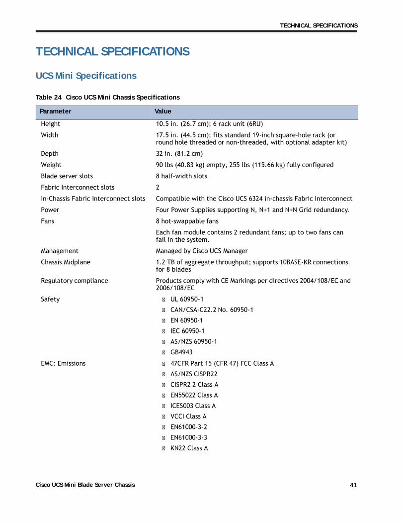
UCS Mini Specifications
Table 24 Cisco UCS Mini Chassis Specifications
Parameter Value
Height 10.5 in. (26.7 cm); 6 rack unit (6RU)
Width 17.5 in. (44.5 cm); fits standard 19-inch square-hole rack (or round hole threaded or non-threaded, with optional adapter kit)
Depth 32 in. (81.2 cm)
Weight 90 lbs (40.83 kg) empty, 255 lbs (115.66 kg) fully configured
Blade server slots 8 half-width slots
Fabric Interconnect slots 2
In-Chassis Fabric Interconnect slots Compatible with the Cisco UCS 6324 in-chassis Fabric Interconnect
Power Four Power Supplies supporting N, N+1 and N+N Grid redundancy.
Fans 8 hot-swappable fans
Each fan module contains 2 redundant fans; up to two fans can fail in the system.
Management Managed by Cisco UCS Manager
Chassis Midplane 1.2 TB of aggregate throughput; supports 10BASE-KR connections for 8 blades
Regulatory compliance Products comply with CE Markings per directives 2004/108/EC and 2006/108/EC
Safety � UL 60950-1
� CAN/CSA-C22.2 No. 60950-1
� EN 60950-1
� IEC 60950-1
� AS/NZS 60950-1
� GB4943
EMC: Emissions � 47CFR Part 15 (CFR 47) FCC Class A
� AS/NZS CISPR22
� CISPR2 2 Class A
� EN55022 Class A
� ICES003 Class A
� VCCI Class A
� EN61000-3-2
� EN61000-3-3
� KN22 Class A
Cisco UCS Mini Blade Server Chassis 41
TECHNICAL SPECIFICATIONS
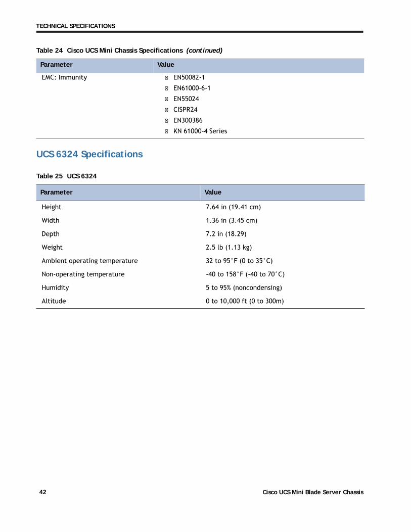
UCS 6324 Specifications
Table 25 UCS 6324
Parameter Value
Height 7.64 in (19.41 cm)
Width 1.36 in (3.45 cm)
Depth 7.2 in (18.29)
Weight 2.5 lb (1.13 kg)
Ambient operating temperature 32 to 95°F (0 to 35°C)
Non-operating temperature -40 to 158°F (-40 to 70°C)
Humidity 5 to 95% (noncondensing)
Altitude 0 to 10,000 ft (0 to 300m)
EMC: Immunity � EN50082-1
� EN61000-6-1
� EN55024
� CISPR24
� EN300386
� KN 61000-4 Series
Table 24 Cisco UCS Mini Chassis Specifications (continued)
Parameter Value
Cisco UCS Mini Blade Server Chassis42
TECHNICAL SPECIFICATIONS
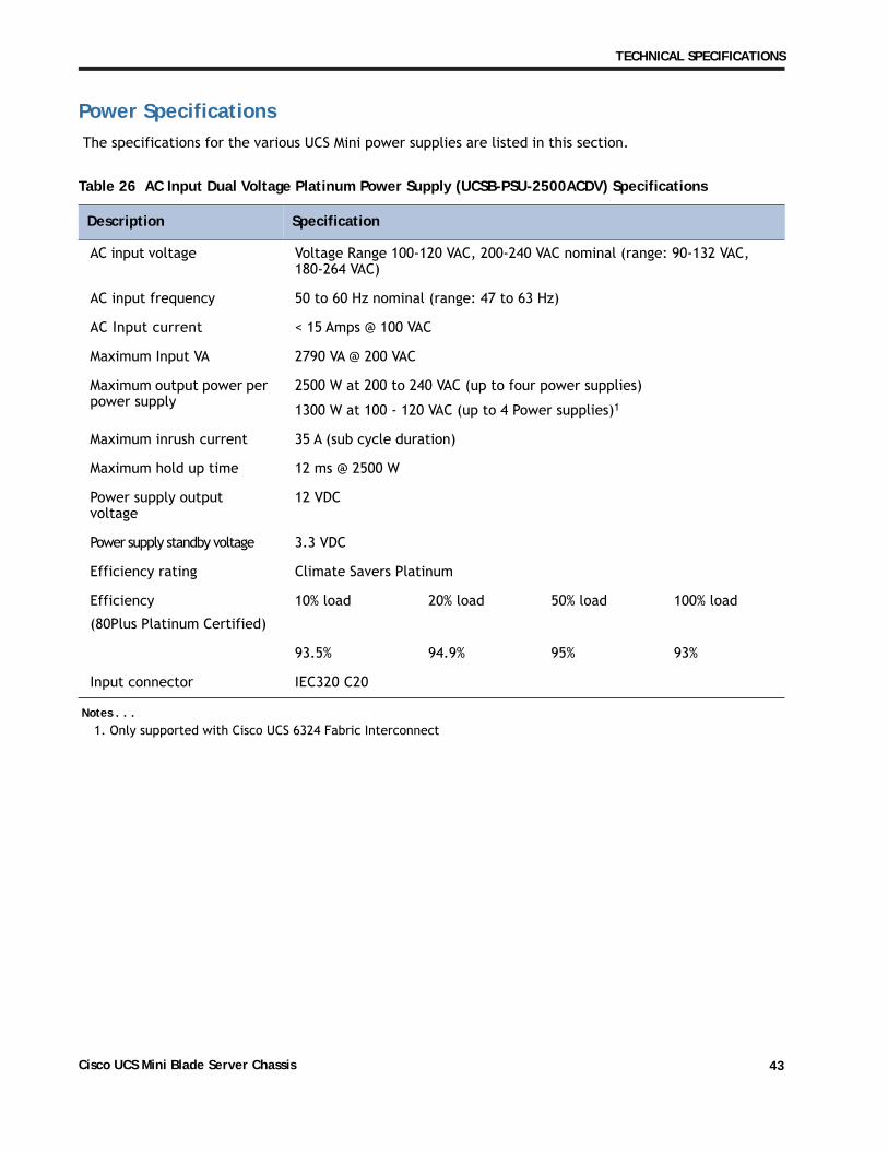
Power SpecificationsThe specifications for the various UCS Mini power supplies are listed in this section.
Table 26 AC Input Dual Voltage Platinum Power Supply (UCSB-PSU-2500ACDV) Specifications
Description Specification
AC input voltage Voltage Range 100-120 VAC, 200-240 VAC nominal (range: 90-132 VAC, 180-264 VAC)
AC input frequency 50 to 60 Hz nominal (range: 47 to 63 Hz)
AC Input current < 15 Amps @ 100 VAC
Maximum Input VA 2790 VA @ 200 VAC
Maximum output power per power supply
2500 W at 200 to 240 VAC (up to four power supplies)
1300 W at 100 - 120 VAC (up to 4 Power supplies)1
Maximum inrush current 35 A (sub cycle duration)
Maximum hold up time 12 ms @ 2500 W
Power supply output voltage
12 VDC
Power supply standby voltage 3.3 VDC
Efficiency rating Climate Savers Platinum
Efficiency
(80Plus Platinum Certified)
10% load 20% load 50% load 100% load
93.5% 94.9% 95% 93%
Input connector IEC320 C20
Notes . . .1. Only supported with Cisco UCS 6324 Fabric Interconnect
Cisco UCS Mini Blade Server Chassis 43
TECHNICAL SPECIFICATIONS
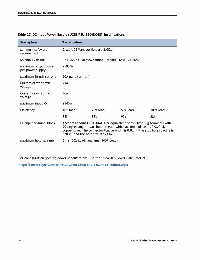
Table 27 DC Input Power Supply (UCSB-PSU-2500DC48) Specifications
Description Specification
Minimum software requirement
Cisco UCS Manager Release 3.0(2c)
DC input voltage -48 VDC to -60 VDC nominal (range: -40 to -72 VDC)
Maximum output power per power supply
2500 W
Maximum inrush current 90A (cold turn-on)
Current draw at min voltage
71A
Current draw at max voltage
40A
Maximum input VA 2840W
Efficiency 10% load 20% load 50% load 100% load
88% 88% 92% 88%
DC input terminal block Accepts Panduit LCD4-14AF-L or equivalent barrel-type lug terminals with 90-degree angle, two- hole tongue, which accommodates 1/0 AWG size copper wire. The connector tongue width is 0.82 in, the stud hole spacing is 5/8 in, and the hole size is 1/4 in.
Maximum hold up time 8 ms (50% Load) and 4ms (100% Load)
For configuration-specific power specifications, use the Cisco UCS Power Calculator at:
https://mainstayadvisor.com/Go/Cisco/Cisco-UCS-Power-Calculator.aspx
Cisco UCS Mini Blade Server Chassis44

TECHNICAL SPECIFICATIONS
Environmental SpecificationsThe environmental specifications for the UCS Mini chassis are listed in Table 28.
Table 28 UCS Mini Blade Server Environmental Specifications
Parameter Minimum
Temperature operating 10°C to 35°C (50°F to 95°F)
Temperature nonoperating -40°C to 65°C (-40°F to 149°F)
Altitude operating 0 to 3, 000 m (0 to 10,000 ft.); maximum ambient temperature decreases by 1° per 300 m
Humidity operating 10 to 90%, non-condensing
Humidity nonoperating 5 to 93%, non-condensing
Vibration nonoperating 2.2 Grms, 10 minutes per axis on each of the three axes
Shock operating Half-sine 2 G, 11 ms pulse, 100 pulses in each direction, on each of the three axes
Shock nonoperating Trapezoidal, 25 G, two drops on each of six faces ΔV: 175 inches per second each corner on bottom face drop, 90 inches per second each corner on other five faces
Safety UL60 950-1 No. 21CFR1040, CAN/CSA-C22.2 No. 60950-1, IRAM IEC60950-1, CB IEC60950-1, EN
60950-1, IEC 60950-1, GOST IEC60950-1, SABS/CB IEC6095-1, CCC*/CB GB4943-1995, CNS14336, CB IEC60950-1, AS/NZS 60950-1, GB4943
Emissions 47CFR Part 15 (CFR 47) Class A, AS/NZS CISPR22 Class A, CISPR2 2 Class A, EN55022 Class A, ICES003 Class A, VCCI Class A, EN61000-3-2, EN61000-3-3, KN22 Class A, CNS13438 Class A
Immunity Verified to comply with EN55024, CISPR 24, KN 61000-4 Series, KN 24
Electrostatic discharge Tested to ESD levels up to 15 kilovolts (kV) air discharge and up to 8 kV contact discharge without physical damage
Acoustic � Sound power: 68.8 dBA at ambient temperature 23° C measured using the Dome Method
� GOST MsanPiN 001-96
Cisco UCS Mini Blade Server Chassis 45

TECHNICAL SPECIFICATIONS
Cisco UCS Mini Blade Server Chassis46


