Americas Headquarters Cisco Systems, Inc. 170 West Tasman Drive San Jose, CA 95134-1706 USA http://www.cisco.com Tel: 408 526-4000 800 553-NETS (6387) Fax: 408 527-0883 Cisco Unified Web and E-Mail Interaction Manager Deployment and Maintenance Guide For Unified Contact Center Enterprise and Hosted and Unified ICM Release 4.3(1) November 2009
Transcript
Cisco Unified Web and E-Mail Interaction Manager Deployment and Maintenance GuideFor Unified Contact Center Enterprise and Hosted and Unified ICM
Release 4.3(1)November 2009
Americas HeadquartersCisco Systems, Inc.170 West Tasman DriveSan Jose, CA 95134-1706 USAhttp://www.cisco.comTel: 408 526-4000
THE SPECIFICATIONS AND INFORMATION REGARDING THE PRODUCTS IN THIS MANUAL ARE SUBJECT TO CHANGE WITHOUT NOTICE. ALL STATEMENTS, INFORMATION, AND RECOMMENDATIONS IN THIS MANUAL ARE BELIEVED TO BE ACCURATE BUT ARE PRESENTED WITHOUT WARRANTY OF ANY KIND, EXPRESS OR IMPLIED. USERS MUST TAKE FULL RESPONSIBILITY FOR THEIR APPLICATION OF ANY PRODUCTS.
THE SOFTWARE LICENSE AND LIMITED WARRANTY FOR THE ACCOMPANYING PRODUCT ARE SET FORTH IN THE INFORMATION PACKET THAT SHIPPED WITH THE PRODUCT AND ARE INCORPORATED HEREIN BY THIS REFERENCE. IF YOU ARE UNABLE TO LOCATE THE SOFTWARE LICENSE OR LIMITED WARRANTY, CONTACT YOUR CISCO REPRESENTATIVE FOR A COPY.
NOTWITHSTANDING ANY OTHER WARRANTY HEREIN, ALL DOCUMENT FILES AND SOFTWARE OF THESE SUPPLIERS ARE PROVIDED “AS IS” WITH ALL FAULTS. CISCO AND THE ABOVE-NAMED SUPPLIERS DISCLAIM ALL WARRANTIES, EXPRESSED OR IMPLIED, INCLUDING, WITHOUT LIMITATION, THOSE OF MERCHANTABILITY, FITNESS FOR A PARTICULAR PURPOSE AND NONINFRINGEMENT OR ARISING FROM A COURSE OF DEALING, USAGE, OR TRADE PRACTICE.
IN NO EVENT SHALL CISCO OR ITS SUPPLIERS BE LIABLE FOR ANY INDIRECT, SPECIAL, CONSEQUENTIAL, OR INCIDENTAL DAMAGES, INCLUDING, WITHOUT LIMITATION, LOST PROFITS OR LOSS OR DAMAGE TO DATA ARISING OUT OF THE USE OR INABILITY TO USE THIS MANUAL, EVEN IF CISCO OR ITS SUPPLIERS HAVE BEEN ADVISED OF THE POSSIBILITY OF SUCH DAMAGES.
CCDE, CCENT, CCSI, Cisco Eos, Cisco HealthPresence, Cisco IronPort, the Cisco logo, Cisco Lumin, Cisco Nexus, Cisco Nurse Connect, Cisco StackPower, Cisco StadiumVision, Cisco TelePresence, Cisco Unified Computing System, Cisco WebEx, DCE, Flip Channels, Flip for Good, Flip Mino, Flip Video, Flip Video (Design), Flipshare (Design), Flip Ultra, and Welcome to the Human Network are trademarks; Changing the Way We Work, Live, Play, and Learn, Cisco Store, and Flip Gift Card are service marks; and Access Registrar, Aironet, AsyncOS, Bringing the Meeting To You, Catalyst, CCDA, CCDP, CCIE, CCIP, CCNA, CCNP, CCSP, CCVP, Cisco, the Cisco Certified Internetwork Expert logo, Cisco IOS, Cisco Press, Cisco Systems, Cisco Systems Capital, the Cisco Systems logo, Cisco Unity, Collaboration Without Limitation, EtherFast, EtherSwitch, Event Center, Fast Step, Follow Me Browsing, FormShare, GigaDrive, HomeLink, Internet Quotient, IOS, iPhone, iQuick Study, IronPort, the IronPort logo, LightStream, Linksys, MediaTone, MeetingPlace, MeetingPlace Chime Sound, MGX, Networkers, Networking Academy, Network Registrar, PCNow, PIX, PowerPanels, ProConnect, ScriptShare, SenderBase, SMARTnet, Spectrum Expert, StackWise, The Fastest Way to Increase Your Internet Quotient, TransPath, WebEx, and the WebEx logo are registered trademarks of Cisco Systems, Inc. and/or its affiliates in the United States and certain other countries.
All other trademarks mentioned in this document or website are the property of their respective owners. The use of the word partner does not imply a partnership relationship between Cisco and any other company. (0907R)
Any Internet Protocol (IP) addresses used in this document are not intended to be actual addresses. Any examples, command display output, and figures included in the document are shown for illustrative purposes only. Any use of actual IP addresses in illustrative content is unintentional and coincidental.
Welcome to Cisco® Interaction Manager™, multichannel interaction software used by businesses all over the world to build and sustain customer relationships. A unified suite of the industry’s best applications for web and email interaction management, it is the backbone of many innovative contact centers and customer service organizations.
Cisco Interaction Manager includes a common platform and one or both of the following applications:
Cisco Unified Web Interaction Manager (Unified WIM)
Cisco Unified Web and E-Mail Interaction Manager Deployment and Maintenance Guide discusses best practices for maintaining your Unified EIM and WIM installation. Intended for system and database administrators, this guide will help you keep the installation in good health and to fine tune it to improve its performance.
This version of the guide is for installations that are integrated with Cisco Unified Contact Center Enterprise (Unified CCE).
Document Conventions
This guide uses the following typographical conventions.
Document conventions
Convention Indicates
Italic Emphasis.
Or the title of a published document.
Bold Labels of items on the user interface, such as buttons, boxes, and lists.
Or text that must be typed by the user.
Monospace The name of a file or folder, a database table column or value, or a command.
Variable User-specific text; varies from one user or installation to another.
7
Other Learning Resources
Various learning tools are available within the product, as well as on the product CD and our web site. You can also request formal end-user or technical training.
Online HelpThe product includes topic-based as well as context-sensitive help.
Online help options
Documentation The latest versions of all Cisco documentation can be found online at http://www.cisco.com
All Unified EIM documentation can be found online at http://www.cisco.com/en/US/products/ps7236/tsd_products_support_series_home.html
All Unified WIM documentation can be found online at http://www.cisco.com/en/US/products/ps7233/tsd_products_support_series_home.html
In particular, Release Notes for these products can be found at http://www.cisco.com/en/US/products/ps7236/prod_release_notes_list.html
For general access to Cisco Voice and Unified Communications documentation, go to http://www.cisco.com/en/US/products/sw/voicesw/tsd_products_support_category_home.html
The document set contains the following guides:
Hardware and System Software Specification for Cisco Unified Web and E-Mail Interaction Manager
Cisco Unified Web and E-mail Interaction Manager Installation Guide
Cisco Unified Web and E-Mail Interaction Manager Browser Settings Guide
User Guides for agents and supervisors
Cisco Unified Web and E-Mail Interaction Manager Agent’s Guide
Cisco Unified Web and E-Mail Interaction Manager Supervisor’s Guide
User guides for Knowledge Base managers and authors
Cisco Unified Web and E-Mail Interaction Manager Author’s Guide
Use To view
Help button Topics in Cisco Unified Web and E-Mail Interaction Manager Help; the Help button appears in the console toolbar on every screen.
F1 keypad button Context-sensitive information about the item selected on the screen.
8 Cisco Unified Web and E-Mail Interaction Manager Deployment and Maintenance Guide
Cisco Unified Web and E-Mail Interaction Manager Administrator’s Guide to Administration Console
Cisco Unified Web and E-Mail Interaction Manager Administrator’s Guide to Routing and Workflows
Cisco Unified Web and E-Mail Interaction Manager Administrator’s Guide to Chat and Collaboration Resources
Cisco Unified Web and E-Mail Interaction Manager Administrator’s Guide to Email Resources
Cisco Unified Web and E-Mail Interaction Manager Administrator’s Guide to Data Adapter
Cisco Unified Web and E-Mail Interaction Manager Administrator’s Guide to Reports Console
Cisco Unified Web and E-Mail Interaction Manager Administrator’s Guide to System Console
Cisco Unified Web and E-Mail Interaction Manager Administrator’s Guide to Tools Console
9
Preparing Unified CCE for the Integration
Relationship Between Objects in Unified CCE and Unified WIM and EIM
Designing Your Installation
Obtaining Unified EIM and WIM Licenses
Installing Unified CCE
Setting up Agent Desktops for Voice Call Routing
Configuring Cisco Unified Communication Manager for Routing Voice Calls
Planning Unified CCE Configuration
Configuring Unified CCE
Configuring Avaya G3 Installations
Installing Unified EIM and WIM and the Integration
Preparing Cisco Media Blender for the Integration
This chapter provides an overview of the process of setting up an integrated Unified WIM and EIM–Unified CCE system. It includes a note about the relationship between objects in the two systems.
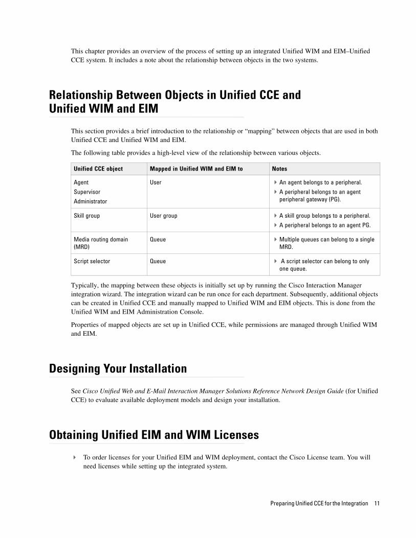
Relationship Between Objects in Unified CCE and Unified WIM and EIM
This section provides a brief introduction to the relationship or “mapping” between objects that are used in both Unified CCE and Unified WIM and EIM.
The following table provides a high-level view of the relationship between various objects.
Typically, the mapping between these objects is initially set up by running the Cisco Interaction Manager integration wizard. The integration wizard can be run once for each department. Subsequently, additional objects can be created in Unified CCE and manually mapped to Unified WIM and EIM objects. This is done from the Unified WIM and EIM Administration Console.
Properties of mapped objects are set up in Unified CCE, while permissions are managed through Unified WIM and EIM.
Designing Your Installation
See Cisco Unified Web and E-Mail Interaction Manager Solutions Reference Network Design Guide (for Unified CCE) to evaluate available deployment models and design your installation.
Obtaining Unified EIM and WIM Licenses
To order licenses for your Unified EIM and WIM deployment, contact the Cisco License team. You will need licenses while setting up the integrated system.
Unified CCE object Mapped in Unified WIM and EIM to Notes
Agent
Supervisor
Administrator
User An agent belongs to a peripheral.
A peripheral belongs to an agent peripheral gateway (PG).
Skill group User group A skill group belongs to a peripheral.
A peripheral belongs to an agent PG.
Media routing domain (MRD)
Queue Multiple queues can belong to a single MRD.
Script selector Queue A script selector can belong to only one queue.
Preparing Unified CCE for the Integration 11
Installing Unified CCE
Ensure that Unified CCE is installed and available for use. Verify that the following items are installed:
Unified CCE Instance
Call Router Side A
Call Router Side B (optional)
Logger Side A
Logger Side B (optional)
Primary Admin Workstation
Secondary Admin Workstation (optional)
Historic Data Server
Network Interface Controllers (NIC) (Only required for Pre-routing)
Cisco Media Blender (CMB) (Only required for callback, delayed callback, and blended collaboration activities.)
Computer Telephony Integration Object Server (CTIOS) (Only required for callback, delayed callback, and blended collaboration activities.)
See the following documents for help with installing and configuring the system:
Getting Started with Cisco Unified Contact Center Enterprise
Cisco Unified Contact Center Enterprise Installation Guide
Setting up Agent Desktops for Voice Call Routing
Install IP Communicator on each agent’s desktop, or configure an IP phone that communicates with Cisco Unified Communication Manager for the agent. Look at the following links for detailed instructions on installing and configuring IP Communicator and IP phones.
IP Communicator: http://www.cisco.com/en/US/products/sw/voicesw/ps5475/index.html
IP Phone: http://www.cisco.com/en/US/products/hw/phones/ps379/index.html
12 Cisco Unified Web and E-Mail Interaction Manager Deployment and Maintenance Guide
Configuring Cisco Unified Communication Manager for Routing Voice Calls
This section talks about how to configure phones, directory numbers, and end users from the Cisco Unified Communication Manager Administration user interface.
To configure Cisco Unified Communication Manager for routing voice calls:
1. Open a web browser and launch the URL: http://Cisco Unified Communication Manager Server Name
2. On the page, click the link Cisco Unified Communications Manager Administration.
3. On the login page, provide the administrator username and password and click the Login button.
Login as an administrator
4. On the next page, from the Device menu, select Phone.
5. On the Find and List Phones page, click the Add New button.
Click the Add New button
Preparing Unified CCE for the Integration 13
6. On the Add a New Phone page, in the Phone Type field, select Cisco IP Communicator or the IP phone you configured earlier on page 12. Click Next.
Select the phone type
7. On the Phone Configuration page, in the Select the device protocol field, select SCCP. Click Next.
Select the device protocol
14 Cisco Unified Web and E-Mail Interaction Manager Deployment and Maintenance Guide
8. On the Phone Configuration page, provide the details for the new phone. Refer to Help (menu) > This Page for details about the fields. After providing all the required information, click the Save button.
Configure the phone properties
9. Next, from the Call Routing menu, select Directory Number.
10. On the Find and List Directory Numbers page, click the Add New button.
Click the Add New button
Preparing Unified CCE for the Integration 15
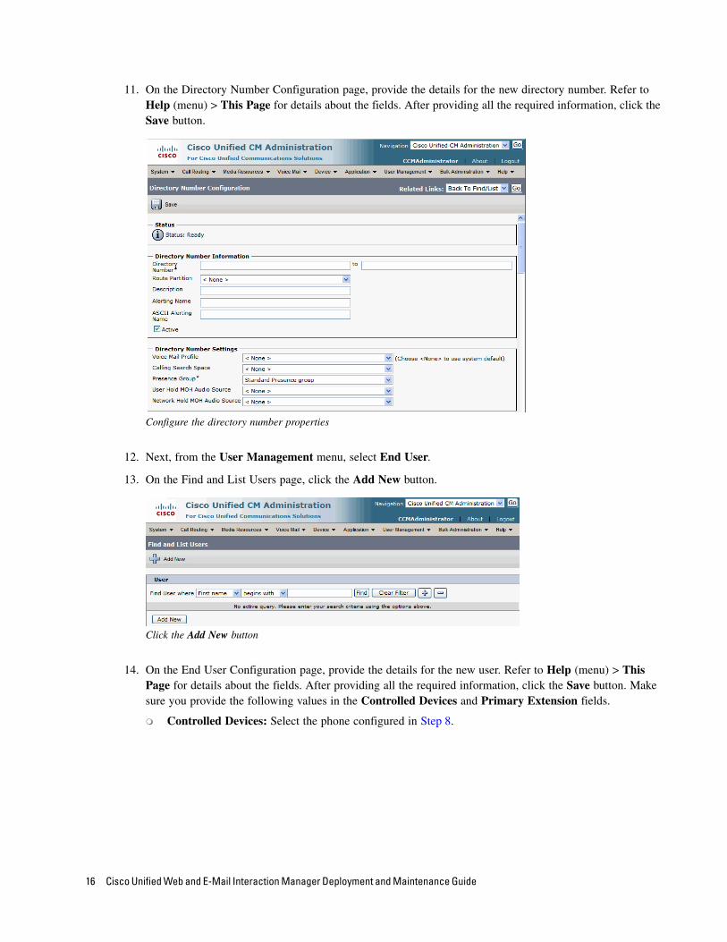
11. On the Directory Number Configuration page, provide the details for the new directory number. Refer to Help (menu) > This Page for details about the fields. After providing all the required information, click the Save button.
Configure the directory number properties
12. Next, from the User Management menu, select End User.
13. On the Find and List Users page, click the Add New button.
Click the Add New button
14. On the End User Configuration page, provide the details for the new user. Refer to Help (menu) > This Page for details about the fields. After providing all the required information, click the Save button. Make sure you provide the following values in the Controlled Devices and Primary Extension fields.
Controlled Devices: Select the phone configured in Step 8.
16 Cisco Unified Web and E-Mail Interaction Manager Deployment and Maintenance Guide
Primary Extension: Select the directory number configured in Step 11.
Create a new user
Planning Unified CCE Configuration
To integrate Unified CCE with Unified WIM and EIM, multiple objects have to be configured in Unified CCE. The specific objects that have to configured will depend on the activities (email, chat etc.) supported by the integrated installation. This section describes the objects required for each activity type—inbound email, outbound email, chat, blended collaboration, callback, and delayed callback.
The following objects must be configured in the order in which they are presented here. For configuration details, refer to the following section: “Configuring Unified CCE” on page 18.
1. Application instance (page 18)
2. Media classes (page 19)
3. Media routing domains (MRD) (page 21)
4. Network voice response unit (Network VRU) (Not required for outbound email activities) (page 22)
5. Call type (page 23)
6. Media routing peripheral gateway (MR PG) (page 24)
7. Agent desk settings (page 28)
8. Agent peripheral gateway (Agent PG) (page 29)
9. Network trunk group (page 32)
Preparing Unified CCE for the Integration 17
10. Application path (page 33)
11. Agents (page 35)
12. Services (page 36)
13. Skill Groups
IPTA skill groups (page 38)
Non-IPTA skill group (Not required for callback and delayed callback activities.) (page 39)
14. Script selector (page 43)
15. Scripts (Not required for outbound email activities) (page 45)
16. Device target (Not required for inbound email, outbound email, and chat activities) (page 48)
In this section, we describe the process of configuring the Unified CCE objects required for the integration with Unified WIM and EIM. These objects must be configured in the order in which they are presented here. For details of these objects refer to the Online Help and accompanied documentation for Unified CCE.
Configuring Application InstanceAn application instance identifies the IP address of a Unified WIM and EIM deployment that is integrated with Unified CCE. It is required for downloading configuration objects from Unified CCE and mapping these to Unified WIM and EIM objects.
Configure a single application instance for integrating with Unified WIM and EIM. This application instance is used for inbound email, outbound email, chat, blended collaboration, callback, and delayed callback activities.
To configure an application instance:
1. Go to Start > All Programs > ICM Admin Workstation > Configuration Manager.
2. In the Configuration Manager window, browse to Tools > List Tools > Application Instance List.
3. Double-click Application Instance List.
4. In the Application Instance List window, in the Select filter data section, click Retrieve. Then, in the Application Instance section, click Add.
A new entry is created in the Application Instance section and the Attributes tab becomes editable.
5. On the Attributes tab, provide the following details:
Name: Provide a name for the application instance.
Important: If your installation uses an Avaya G3 switch, see the procedures described in the
section “Configuring Avaya G3 Installations” on page 51.
18 Cisco Unified Web and E-Mail Interaction Manager Deployment and Maintenance Guide
Application key: Click the Change Application Key button and provide a unique value for the key. Please note that Unified WIM and EIM uses the application instance name and not the application key to connect to Unified CCE.
Application type: Set it to <Other>.
Permission level: Set it to Read only.
Click Save.
Configure the application instance
Configuring Media ClassesA media class defines the type of requests you want to set up for routing on Unified CCE. You should configure a media class for each media supported by your Unified WIM and EIM deployment. A media class is required for creating MRDs. It helps categorize the MRDs based on media type (email, for example).
Create the following media classes:
An email media class for inbound emails.
An email media class for outbound emails.
A chat media class for chat.
A BC media class for blended collaboration (BC).
Callback and Delayed callback use the existing Cisco_Voice media class, which is already created by the system.
To configure a media class:
1. Go to Start > All Programs > ICM Admin Workstation > Configuration Manager.
2. In the Configuration Manager window, browse to Tools > List Tools > Media Class List.
Preparing Unified CCE for the Integration 19
3. Double-click Media Class List.
4. In the Media Class List window, in the Select filter data section, click Retrieve. Then, in the Media Class section, click Add.
A new entry is created in the Media Class section and the Attributes tab becomes editable.
5. On the Attributes tab, provide the following details:
Name: Provide a name for the media class. If the media class is meant to be used in Unified WIM and EIM, use one of the following names. Note that the names of media classes are case sensitive. Make sure that you use the exact names as provided here.
CIM_EIM (for inbound email)
CIM_OUTBOUND (for outbound email)
CIM_WIM (for chat)
CIM_BC (for blended collaboration)
Media classes are set in the Cisco_Home\eService\config\ipcc\egicm_media_class_mappings.properties file as CIM_EIM, CIM_OUTBOUND, CIM_WIM, and CIM_BC. If you use names other than these, you must change them in the file and then restart Cisco Service. Note that the names of media classes are case sensitive.
In the Task section, set the following.
Life: Set the value to 300 seconds.
Start timeout: Set the value to 30 seconds.
Max Duration: Set the value to 28800 seconds.
6. Click Save.
Configure media classes
20 Cisco Unified Web and E-Mail Interaction Manager Deployment and Maintenance Guide
Configuring Media Routing Domains (MRDs)An MRD is a collection of skill groups and services that are associated with a common communication medium. Unified CCE uses an MRD to route tasks to agents who are associated with a skill group and a particular medium. A media routing domain is created in Unified CCE for mapping to queues in Unified WIM and EIM.
You need to create the following media routing domains:
For inbound email media class, configure an email media routing domain.
For outbound email media class, create an email media routing domain.
For chat, create a chat media routing domain.
For blended collaboration, create a BC media routing domain.
For callback and delayed callback, use the existing voice media routing domain (Cisco_Voice) created by the system.
To configure a media routing domain:
1. Go to Start > All Programs > ICM Admin Workstation > Configuration Manager.
2. In the Configuration Manager window, browse to Tools > List Tools > Media Routing Domain List.
3. Double-click Media Routing Domain List.
4. In the Media Routing Domain List window, in the Select filter data section, click Retrieve. Then, in the Media Routing Domain section, click Add.
A new entry is created and the Attributes tab becomes editable.
5. On the Attributes tab, provide the following details:
Name: Provide a name for the media routing domain.
Media class: Select a media class created for Cisco Unified Web and E-Mail Interaction Manager (page 19). Make sure that you select the correct media class for the MRD. For example:
For inbound email MRD, select the CIM_EIM media class.
For outbound email MRD, the CIM_OUTBOUND media class.
For chat MRD, select the CIM_WIM media class.
For blended collaboration MRD, select the CIM_BC media class.
Interruptible: Select this option while creating MRDs for inbound and outbound emails.
In the Calls in Queue section, set the following:
Max: Defines the maximum number of activities to be queued for the MRD. The recommended value is 5000. If the field is left blank, infinite number of activities can wait in the queue.
6. Click Save.
Preparing Unified CCE for the Integration 21
Configure media routing domains
Configuring Network VRUA Network VRU is required for supporting incoming activities to Unified CCE. Note that this Network VRU configuration has no relationship with any physical Network VRU existing in your environment.
Configure a single Network VRU for Unified WIM and EIM. This network VRU is used by inbound email, chat, blended collaboration, callback, and delayed callback activities. It is not required for outbound email activities.
To configure a Network VRU:
1. Go to Start > All Programs > ICM Admin Workstation > Configuration Manager.
2. In the Configuration Manager window, browse to Tools > Explorer Tools > Network VRU Explorer.
3. Double-click Network VRU Explorer.
4. In the Network VRU window, in the Select filter data section, click Retrieve. Then, click [1] Add Network VRU.
A new entry is created and a new set of tabs appear.
5. On the Network VRU tab, provide the following details:
Name: Provide a name for the network VRU.
Type: Set it to Type 2.
22 Cisco Unified Web and E-Mail Interaction Manager Deployment and Maintenance Guide
Configure network VRU
6. Click Save.
Configuring Call TypesA call type is required to categorize a dialed number (for voice) or a script selector (for email). Call types are used in configuring routing scripts.
Individual call types are required for the following activities: inbound email, outbound email, chat, blended collaboration, callback, and delayed callback activities. Make sure you complete these steps for each type of activity.
To configure a call type:
1. Go to Start > All Programs > ICM Admin Workstation > Configuration Manager.
2. In the Configuration Manager window, browse to Tools > List Tools > Call Type List.
3. Double-click Call Type List.
4. In the Call Type List window, in the Select filter data section, click Retrieve. Then, in the Call Type section, click Add.
A new entry is created and the Attributes tab becomes editable.
5. On the Attributes tab, in the Name field, provide a name for the call type. Click Save.
Preparing Unified CCE for the Integration 23
Provide the name of the call type
Configuring Media Routing Peripheral Gateways (MR PGs)An MR PG handles new activity routing requests initiated by Unified WIM and EIM, over the connection established by the embedded MR PIM (side A or side B). The MR PG provides routing instructions to Unified WIM and EIM, while the Agent PG is used to report agent state and status to Unified CCE. Also note that agents are not configured on MR PG. They are always configured on Agent PG.
Configure a single MR PG for Unified WIM and EIM. This MR PG is used for inbound email, outbound email, chat, blended collaboration, callback, and delayed callback activities.
The MR PG configuration involves three steps:
Configuring MR PG using the Configuration Manager: The details are described in this section.
Installing MR PG: For details, see the Unified CCE Installation Guide.
Creating MR PIM for the installed MR PG: You need to create a single MR PIM for Unified WIM and EIM. For details, see the Unified CCE Installation Guide. While creating the MR PIM, you would be asked to provide the Application Connection Port number. As a best practice it is recommend that you use a port number greater than 2000. Note down the Application Connection Port number that you provide here. You would need it while configuring EAAS (page 89).
To configure a media routing peripheral gateway (MR PG):
1. Go to Start > All Programs > ICM Admin Workstation > Configuration Manager.
2. In the Configuration Manager window, browse to Tools > Explorer Tools > PG Explorer.
3. Double-click PG Explorer.
4. In the PG Explorer window, in the Select filter data section, click Retrieve. Then, click [1] Add PG.
24 Cisco Unified Web and E-Mail Interaction Manager Deployment and Maintenance Guide
5. On the Logical Controller tab, provide the following details:
Name: Provide a name for the media routing peripheral gateway.
Client type: Set it to MR PG.
Configure an MR PG
6. Click [2] Add Peripheral.
A new set of tabs appear.
7. On the Peripheral tab, provide the following details:
Client type: Select MR PG.
Default desk settings: Select None.
Preparing Unified CCE for the Integration 25
Enable Post Routing: Select the option.
Enable post routing
8. On the Advanced tab, in the Network VRU field, from the dropdown list, select the Network VRU configured for Unified WIM and EIM (page 22).
Select a network VRU
9. On the Routing client tab, provide the following details:
Name: Provide a name for the routing client.
26 Cisco Unified Web and E-Mail Interaction Manager Deployment and Maintenance Guide
Default media routing domain: From the dropdown list, select None.
Default call type: From the dropdown list, select None.
Client type: Set it to MR PG.
Click Save.
Configure routing client
10. On the Default route tab, in the Media Routing Domain field, from the dropdown list, select an MRD configured for Unified WIM and EIM (page 21).
Preparing Unified CCE for the Integration 27
11. Click Save. Note down the Logical controller ID generated in the Logical Controller tab. It is needed while configuring MR PIM.
Configure an MR PG
Configuring Agent Desk SettingsAgent desk settings are a common set of properties for a group of agents working on voice call requests.
This is required for configuring an Agent PG. You need to configure atleast one Agent Desk Setting for Unified WIM and EIM.
To configure agent desk settings:
1. Go to Start > All Programs > ICM Admin Workstation > Configuration Manager.
2. In the Configuration Manager window, browse to Tools > List Tools > Agent Desk Settings List.
3. Double-click Agent Desk Settings List.
4. In the Agent Desk Settings List window, in the Select filter data section, click Retrieve. Then, in the Agent Desk Settings section, click Add.
A new entry is created and the Attributes tab becomes editable.
5. On the Attributes tab, in the Name field, provide a name for the agent desk setting group. Click Save.
Important: Now install the MR PG and configure the MR PIM. For more information, see the
Unified CCE Installation Guide.
28 Cisco Unified Web and E-Mail Interaction Manager Deployment and Maintenance Guide
Provide the name of the agent desk settings group
Configuring Agent Peripheral Gateway (Agent PG)An Agent PG is required for creating one or more peripherals that manage agent distribution within Unified CCE. Configure an Agent PG using the Configuration Manager and then install it on the appropriate machine.
Configure a single Agent PG for Unified WIM and EIM. This Agent PG is used for inbound email, outbound email, chat, blended collaboration, callback, and delayed callback activities.
Note that you can also use an existing Agent PG if it is of the type Call Manger/Soft ACD.
To configure an agent peripheral gateway:
1. Go to Start > All Programs > ICM Admin Workstation > Configuration Manager.
2. In the Configuration Manager window, browse to Tools > Explorer Tools > PG Explorer.
3. Double-click PG Explorer.
4. In the PG Explorer window, in the Select filter data section, click Retrieve. Then, click [1] Add PG.
5. On the Logical Controller tab, provide the following details:
Name: Provide a name for the agent peripheral gateway.
Client type: Set it to CallManager/SoftACD or PG Generic.
Primary CTI address: Provide the address of the primary CTI server in the format IP_Address:Port_Number. You can either provide the IP address, or the host name.
Preparing Unified CCE for the Integration 29
Secondary CTI address: Provide the address of the secondary CTI server in the format IP_Address:Port_Number. You can either provide the IP address, or the host name. The secondary CTI address is needed only if the Unified CCE system is duplexed.
Configure agent PG
6. Click [2] Add Peripheral.
A new set of tabs appear.
7. On the Peripheral tab, do the following:
Default desk settings: From the dropdown list, select the agent desk settings configured for Unified WIM and EIM (page 28).
30 Cisco Unified Web and E-Mail Interaction Manager Deployment and Maintenance Guide
Enable post routing: Select the option.
Select agent desk settings
8. On the Routing client tab, in the Name field, provide a name for the routing client.
9. On the Agent Distribution tab, do the following:
a. Click New.
b. Select the Enable agent reporting option.
c. Select the Agent event detail option.
d. In the Currently Selected Site section, set the following:
Distributor site name: Provide the host name of the machine where distributor is installed.
Enable: Select the option.
Preparing Unified CCE for the Integration 31
10. Click Save.
Configure agent distribution
Configuring Network Trunk GroupIndividual network trunk groups are required for the following activities: inbound email, outbound email, chat, blended collaboration, callback, and delayed callback activities. Make sure you complete these steps for each type of activity.
To configure a network trunk group:
1. Go to Start > All Programs > ICM Admin Workstation > Configuration Manager.
2. In the Configuration Manager window, browse to Tools > Explorer Tools > Network Trunk Group Explorer.
3. In the Network Trunk Group window, in the Select filter data section, in the PG field select an agent peripheral. Click Retrieve.
4. Click the [1] Add Network trunk group button.
5. On the Network Trunk Group tab, in the Name field, provide the name of the network trunk group.
6. Click the [2] Add Trunk group button.
7. On the trunk Group tab, set the following.
Peripheral: From the dropdown list, select an agent peripheral configured for Unified WIM and EIM (page 29).
Peripheral number: Provide a unique peripheral number.
Peripheral name: Provide a unique peripheral name.
Name: This field is auto-populated.
32 Cisco Unified Web and E-Mail Interaction Manager Deployment and Maintenance Guide
8. Click the [3] Add Trunk button.
9. On the Trunk tab, in the Trunk type field, select DND/DNIS.
10. Click Save.
Configure a network trunk group
Configuring Application PathAn application path is required to open a communication channel with a CTI server associated with an Agent PG. It is used for agent and task status reporting. For each agent PG, create an application path, which Unified WIM and EIM will use to connect to the agent PG.
Create a single application path and add all the MRD-peripheral combinations for the Agent PG to the application path member list. You do not need to add the voice MRD (Cisco_Voice) to this list. The application path is used for inbound email, outbound email, chat, blended collaboration, callback, and delayed callback activities.
Access to the application object filter is restricted. You must use the superuser password (case sensitive) to enable or disable the application object filter. Check with your System Administrator for the password.
To configure an application path:
1. Go to Start > All Programs > ICM Admin Workstation > Configuration Manager.
2. In the Configuration Manager window, go to Options (menu) > Application Object Filter.
Important: For configuring an application path, you need to log in as a superuser.
Preparing Unified CCE for the Integration 33
3. In the Application Object Filter window, in the Disable / Enable application object filter section, in the Superuser password field, provide the password of the superuser and click the Disable button. Click OK.
Provide the password of the superuser
4. In the Configuration Manager window, browse to Tools > List Tools > Application Path List.
5. Double-click Application Path List.
6. In the Application Path List window, in the Select filter data section, in the Application Instance field select the application instance configured for Unified WIM and EIM (page 18). Click Retrieve.
7. In the Application Path section, click Add.
A new entry is created and the Attributes tab becomes editable.
8. On the Attributes tab, provide the following details:
Application Instance: From the dropdown list, select the application instance configured for Unified WIM and EIM (page 18).
Peripheral Gateway: From the dropdown list, select an agent peripheral gateway configured for Unified WIM and EIM (page 29).
Name: This field is auto-populated.
In the Application Path Members section, click the Add button and set the following:
Peripheral: From the dropdown list, select the agent peripheral configured for Unified WIM and EIM (page 29).
Media routing domain: From the dropdown list, select an MRD configured for Unified WIM and EIM (page 21).
Add all the MRD-peripheral combinations for the Agent PG to the application path member list. You do not need to add the voice MRD (Cisco_Voice) to this list.
34 Cisco Unified Web and E-Mail Interaction Manager Deployment and Maintenance Guide
Click Save.
Configure application path
9. In the Configuration Manager window, go to Options (menu) > Application Object Filter.
10. In the Application Object Filter window, in the Disable / Enable application object filter section, click the Enable button. Click OK.
Configuring AgentsAn agent is created in Unified CCE for mapping to users in Unified WIM and EIM. Create all IPTA and Non-IPTA agents for whom routing or reporting is done in Unified CCE.
You need to create agents for handling inbound email, outbound email, chat, blended collaboration, callback, and delayed callback activities.
To configure an agent:
1. Go to Start > All Programs > ICM Admin Workstation > Configuration Manager.
2. In the Configuration Manager window, browse to Tools > Explorer Tools > Agent Explorer.
3. Double-click Agent Explorer.
4. In the Agent Explorer window, in the Select filter data section, in the Peripheral field select an agent peripheral. Click Retrieve.
5. Click the [1]Add Agent button.
A new entry is created and a new set of tabs appear.
6. On the Agent tab, provide the following details:
First name: Provide the first name.
Preparing Unified CCE for the Integration 35
Last name: Provide the last name.
Login name: Provide the login name for the agent. For blended collaboration, callback, and delayed callback agents, the login name should match the User ID provided while configuring End users from the Cisco Unified Communication Manager Administration user interface (page 16).
Login enabled: Select the option.
Password: Provide the password for the agent.
Enterprise name: This field is auto-populated.
7. Click Save.
Configure an agent
Configuring ServicesA service is defined for a peripheral to describe the category of requests being processed by skill groups that belong to the peripheral. For example, billing, inventory, etc. Services are not required; but optional depending on routing and reporting requirements.
Services can be used for routing inbound emails, outbound emails, chats, blended collaboration, callback, and delayed callback activities.
To configure a service:
1. Go to Start > All Programs > ICM Admin Workstation > Configuration Manager.
2. In the Configuration Manager window, browse to Tools > Explorer Tools > Service Explorer.
3. Double-click Service Explorer.
4. In the Service Explorer window, in the Select filter data section, in the Peripheral field select an agent peripheral. Click Retrieve.
36 Cisco Unified Web and E-Mail Interaction Manager Deployment and Maintenance Guide
5. Click the Add Service button.
A new entry is created and a new set of tabs appear.
6. On the Service tab, provide the following details:
Media routing domain: From the dropdown list, select an MRD configured for Unified WIM and EIM (page 21).
Peripheral number: Provide a unique peripheral number.
Name: Provide a name for the service.
7. Click Save.
Configure a service
Configuring Skill GroupsA skill group is created in Unified CCE for mapping to user groups in Unified WIM and EIM. You can create two types of skill groups:
ICM-picks-the-agent (IPTA): For an IPTA skill group, the skill group members (agents) are administered and managed in Unified CCE. An IPTA skill group (with associated skill group members) is used in scripts to facilitate routing through Unified CCE to the skill group. This is relevant for inbound email, outbound email, chat, blended collaboration, callback, and delayed callback activities.
Unified EIM and WIM picks the agent (Non-IPTA): For a Non-IPTA skill group, the skill group members (agents) are administered and managed in Unified WIM and EIM. A Non-IPTA skill group is created for routing activities in cases where a label is returned by Unified CCE to Unified WIM and EIM.
Preparing Unified CCE for the Integration 37
When a label is returned, Unified WIM and EIM load balances the activity to a group of agents defined in the user group (that maps to the Non-IPTA skill group) identified by the suffix of the label. This is relevant for inbound email, outbound email, chat, and blended collaboration activities.
To configure an IPTA skill group:
1. Go to Start > All Programs > ICM Admin Workstation > Configuration Manager.
2. In the Configuration Manager window, browse to Tools > Explorer Tools > Skill Group Explorer.
3. Double-click Skill Group Explorer.
4. In the Skill Group Explorer window, in the Select filter data section, select an agent peripheral. Click Retrieve.
5. Click the [1]Add Skill group button.
A new entry is created and a new set of tabs appear.
6. On the Skill Group tab, provide the following details:
Media routing domain: From the dropdown list, select an MRD configured for Unified WIM and EIM (page 21).
Peripheral number: Provide a unique peripheral number.
Peripheral name: Provide a name for the skill group.
Name: This field is auto-populated.
ICM picks the agent: Select the option.
Configure the properties of an IPTA skill group
Important: The LABEL must be configured in the following format: LBL_Enterprise_Name_of_Non-
IPTA_Skill_Group. Also note that the names of labels are case sensitive.
38 Cisco Unified Web and E-Mail Interaction Manager Deployment and Maintenance Guide
7. On the Skill Group Members tab, do the following:
a. Click the Add button.
b. From the Add Skill Group Member window, select the agents to be added in the skill group. Click OK.
Select members for the skill group
8. Click the Add Route button.
A new tab appears.
9. On the Route tab, in the Name field provide the name for the route and click Save.
Provide the name of the route
To configure a non-IPTA skill group:
1. Go to Start > All Programs > ICM Admin Workstation > Configuration Manager.
2. In the Configuration Manager window, browse to Tools > Explorer Tools > Skill Group Explorer.
3. Double-click Skill Group Explorer.
4. In the Skill Group Explorer window, in the Select filter data section, select an agent peripheral. Click Retrieve.
Preparing Unified CCE for the Integration 39
5. Click the [1]Add Skill group button.
A new entry is created and a new set of tabs appear.
6. On the Skill Group tab, provide the following details:
Media Routing Domain: From the dropdown list, select an MRD configured for Unified WIM and EIM (page 21).
Peripheral Name: Provide a name for the skill group.
Name: This field is auto-populated.
ICM picks the agent: Clear the option.
Click Save.
Configure a non-IPTA skill group
7. Click the Add Route button.
A new tab appears.
8. On the Route tab, do the following:
Name: Provide the name for the route.
Service name: From the dropdown list, select a service configured for Unified WIM and EIM (page 36).
Click Save.
40 Cisco Unified Web and E-Mail Interaction Manager Deployment and Maintenance Guide
Provide the name of the route
9. Click the Add Peripheral Target button.
A new tab appears.
10. On the Peripheral target tab, set the following:
DNIS: Provide a DNIS.
Preparing Unified CCE for the Integration 41
Network trunk group: From the dropdown list, select a network trunk group to be associated with the DNIS. Select the network trunk group you configured in “Configuring Network Trunk Group” on page 32.
Provide the peripheral target details
11. Click the Add Label button.
A new tab appears.
12. On the Label tab, set the following:
Routing client: From the dropdown list, select the routing client you configured in “Configuring Media Routing Peripheral Gateways (MR PGs)” on page 24.
42 Cisco Unified Web and E-Mail Interaction Manager Deployment and Maintenance Guide
Label: Provide a name for the label that can be used in a script for Non-IPTA routing. The label must be configured in the following format: LBL_Enterprise_Name_of_Skill_Group. Also note that the names of the labels are case sensitive.
Configure the label
13. Click Save.
Configuring Script SelectorsA script selector is a keyword that identifies the routing script for an activity request from Unified WIM and EIM to Unified CCE. Script selectors are used in routing scripts as part of the Dialed Number node.
Individual script selectors are required for the following activities: inbound email, outbound email, chat, blended collaboration, callback, and delayed callback activities. Make sure you complete these steps for each type of activity.
To configure a script selector:
1. Go to Start > All Programs > ICM Admin Workstation > Configuration Manager.
2. In the Configuration Manager window, browse to Tools > List Tools > Dialed Number/ Script Selector List.
4. In the Dialed Number/ Script Selector List window, in the Select filter data section, in the Routing client field select the routing client configured for MR PG (page 26). Click Retrieve.
5. In the Dialed Number/ Script Selector section, click Add.
A new entry is created and the Attributes tab becomes editable.
6. On the Attributes tab, provide the following details:
Preparing Unified CCE for the Integration 43
Routing client: From the dropdown list, select the routing client configured for the MR PG in step 9 in “Configuring Media Routing Peripheral Gateways (MR PGs)” on page 24.
Media routing domain: From the dropdown list, select the MRD configured for Unified WIM and EIM (page 21).
Name: Provide a name for the script selector.
Default label: Select the label configured for non-IPTA skill groups (page 43). You need to set this only for script selectors for inbound email, outbound email, chat, and blended collaboration activities.
Configure script selector
7. Click the Dialed Number Mapping tab. Click Add.
8. On the Dialed Number Map Entry window, associate the script selector with a call type.
Map call type
9. Click OK to save the entry. Then click Save to save the script selector configuration.
44 Cisco Unified Web and E-Mail Interaction Manager Deployment and Maintenance Guide
Creating ScriptsA routing script determines the path and target object for an activity routed from Unified WIM and EIM to Unified CCE.
Individual routing scripts are required for the following activities: inbound email, chat, blended collaboration, callback, and delayed callback activities. Make sure you complete these steps for all these activities. You do not need routing scripts for outbound email activities.
The following procedure shows you how to set up a particular script. To find out more about setting up different types of scripts to meet your routing requirements, see the Unified CCE Scripting Guide.
To create a script:
1. Go to Start > All Programs > ICM Admin Workstation > Script Editor.
2. In the Script Editor window, click the New button.
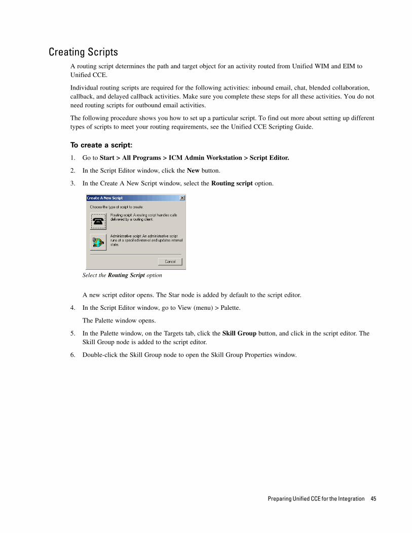
3. In the Create A New Script window, select the Routing script option.
Select the Routing Script option
A new script editor opens. The Star node is added by default to the script editor.
4. In the Script Editor window, go to View (menu) > Palette.
The Palette window opens.
5. In the Palette window, on the Targets tab, click the Skill Group button, and click in the script editor. The Skill Group node is added to the script editor.
6. Double-click the Skill Group node to open the Skill Group Properties window.
Preparing Unified CCE for the Integration 45
7. In the Skill Group Properties window, on the Routing Target tab, in the Skill Group column, select an IPTA skill group.
Select an IPTA skill group
8. Next, in the Palette window, on the Targets tab, click the Label button, and click in the script editor. The Label node is added to the script editor.
9. Double-click the Label node to open the Label window.
10. In the Label window, on the Label tab, set the following:
a. Select the label type as Configured.
b. From the available labels select a label and click the Add button. Click OK.
Select the label type and a label
11. Next, in the Palette window, on the General tab click the Line Connector button, and configure the success and error paths for each node. This creates the routing path of the script.
12. Click the Validate Script button to check if the script is created properly. If there are any errors, fix them.
46 Cisco Unified Web and E-Mail Interaction Manager Deployment and Maintenance Guide
13. Click the Save button to save the script.
A sample script
After creating a script, map the script to a call type, MRD, and script selector. Also, set the schedule when the script should run.
14. In the Script Editor window, go to Script (menu) > Call Type Manager.
15. In the Call Type Manager window, in the Call Directory tab, do the following:
a. In the Media Routing Domain field, from the dropdown list, select the MRD configured for Unified WIM and EIM (page 21).
b. In the Script Type Selector field, from the dropdown list, select the script selector created for the MRD (page 43).
c. Next, click the Add button. The Add Call Type Selector Entry window appears. In the Call type field, select the call type configured for Unified WIM and EIM (page 23). Click OK.
Map the script to a call type, MRD, and script selector
Preparing Unified CCE for the Integration 47
16. In the Call Type Manager window, in the Schedule tab, do the following:
a. In the Call type field, from the dropdown list, select the same call type you selected in Step 15.
b. Next, click the Add button. In the Add Call Type Schedule window that appears, do the following:
i. In the Script tab, select the script configured for Unified WIM and EIM (page 45).
ii. In the Period tab, set a schedule for the script.
iii. Click OK.
Set a schedule for the script
17. Click OK to close the Call Type Manager window.
Configuring Device TargetsIndividual device targets are required for routing voice calls for blended collaboration, callback, and delayed callback activities. Make sure you complete these steps for all these activities. You do not need device targets for inbound email, outbound email, and chat activities.
To configure a device target:
1. Go to Start > All Programs > ICM Admin Workstation > Configuration Manager.
2. In the Configuration Manager window, browse to Tools > Explorer Tools > Device Target Explorer.
3. Double-click Device Target Explorer.
4. In the Device Target Explorer window, click Add Device Target.
5. Provide the name and global address, which is the host name of the Unified CCE server followed by the agent extension, in the following format: Unified_CCE_Server Agent_Extension
6. Provide the configuration parameter in the following format. The string before the agent extension must be exactly as specified: /devtype CiscoPhone /dn Agent_Extension
7. Click the Add Label button.
The Label tab appears.
8. On the Label tab, set the following:
48 Cisco Unified Web and E-Mail Interaction Manager Deployment and Maintenance Guide
Routing client: From the dropdown list, select the MR PG configured for Unified WIM and EIM (page 24).
Label: Provide the name of the label. The label name must be the Agent_Extension.
9. Click Save.
Configure a device target
Configuring Expanded Call Context (ECC) VariablesECC variables are used in Unified CCE scripts to facilitate and influence routing. ECC variables have a maximum length of 256 characters. Both Scalar and Array ECC variables are supported.
ECC variables are required for inbound email, outbound email, chat, blended collaboration, callback, and delayed callback activities. Create the following ECC variables:
For inbound and outbound email activities: user.cim.activity.id
For chat activities: user.cim.activity.id, user.wim.customer.name
For blended collaboration, callback and delayed callback activities: user.cim.activity.id, user.wim.customer.name, user.cisco.cmb, user.cisco.cmb.callclass
To configure an ECC variable:
1. Go to Start > All Programs > ICM Admin Workstation > Configuration Manager.
2. In the Configuration Manager window, browse to Tools > Miscellaneous Tools > System Information.
Preparing Unified CCE for the Integration 49
3. In the System Information window, in the General section, select the Expanded call context enabled option. Click Save.
Enable ECC variables
4. In the Configuration Manager window, browse to Tools > List Tools > Expanded Call Variable List.
5. Double-click Expanded Call Variable List.
6. In the Expanded Call Variable List window, in the Select filter data section, click Retrieve. Then, in the Expanded Call Variable section, click the Add button.
7. Type the name and length of the ECC variable. A maximum of 256 characters are allowed. Make sure that you use the exact names as provided here.
user.cim.activity.id (needed for all types of activities)
user.wim.customer.name (needed for chat, blended collaboration, callback, and delayed callback activities)
user.cisco.cmb (needed for blended collaboration, callback, and delayed callback activities)
user.cisco.cmb.callclass (needed for blended collaboration, callback, and delayed callback activities)
50 Cisco Unified Web and E-Mail Interaction Manager Deployment and Maintenance Guide
8. Click Save.
Configure ECC variables
Configuring Avaya G3 Installations
In this section, we describe procedures for configuring Unified CCE installations that use Avaya G3 switches. Skip this section if you are not using Avaya G3 switches.
Collecting DetailsGet the following information from the G3 switch administrator:
The IP address of the G3 PG machine.
The Adjunct Switch Application Interface (ASAI) port on the switch. For e.g., Link 5.
For each agent, collect the following details:
Agent ID
Agent extension
Skill group
Skill group extension
Service (VDN)
Preparing Unified CCE for the Integration 51
Configuring Application Instance To configure an application instance, follow the steps described in “Configuring Application Instance” on
page 18.
Configuring Media Classes To configure media classes, follow the steps described in “Configuring Media Classes” on page 19.
Configuring Media Routing Domains To configure media routing domains, follow the steps described in “Configuring Media Routing Domains
(MRDs)” on page 21.
Configuring Network VRU To configure a Network VRU, follow the steps described in “Configuring Network VRU” on page 22.
Configuring Call Types To configure call types, follow the steps described in “Configuring Call Types” on page 23.
Configuring Script Selectors To configure script selectors, follow the steps described in “Configuring Script Selectors” on page 43.
Configuring Media Routing Peripheral Gateways (MR PGs) To configure media routing peripheral gateways (MR PGs), follow the steps described in “Configuring
Media Routing Peripheral Gateways (MR PGs)” on page 24.
Configuring Agent Peripheral Gateway (Agent PG)An agent peripheral gateway (PG) is required for creating of one or more peripherals that manage agent distribution within Unified CCE. Configure an agent PG using the Configuration Manager and then install it on the appropriate machine.
This is required for inbound email, outbound email, chat, blended collaboration, callback, and delayed callback activities. Configure a single Agent PG for Unified WIM and EIM.
To configure an agent peripheral gateway:
1. Go to Start > All Programs > ICM Admin Workstation > Configuration Manager.
2. In the Configuration Manager window, browse to Tools > Explorer Tools > PG Explorer.
52 Cisco Unified Web and E-Mail Interaction Manager Deployment and Maintenance Guide
3. Double-click PG Explorer.
4. In the PG Explorer window, in the Select filter data section, click Retrieve. Then, click [1] Add PG.
5. On the Logical Controller tab, provide the following details:
Name: Provide a name for the agent peripheral gateway.
Client type: Set it to Definity ECS EAS.
Primary CTI address: Provide the IP address of the primary CTI server in the format IP_Address:Port_Number. It is required if agents are integrated through a CTI server.
Secondary CTI address: Provide the IP address of the secondary CTI server in the format IP_Address:Port_Number. This is optional; it is required if the Unified CCE installation is a duplex one.
6. Click [2] Add Peripheral.
A new set of tabs appear.
7. On the Peripheral tab, do the following:
Default desk settings: From the dropdown list, select the agent desk settings configured for Unified WIM and EIM (page 28).
Enable post routing: Select the option.
Configure agent PG
8. On the Routing client tab, in the Name field, provide a name for the routing client.
9. On the Advanced tab, set the following values:
a. Available holdoff delay: 0
b. Default route: NONE
c. Answered short calls threshold: 0
d. Network VRU: Select the network VRU configured earlier (page 52)
e. Select the Agent Auto-Configuration option.
Preparing Unified CCE for the Integration 53
Configure advanced properties
10. On the Peripheral Monitor tab, set the following values:
a. Parameter
b. Type: VDN
Configure peripheral monitor
11. In the PG Explorer window, go to the Agent Distribution tab and do the following:
a. Click the New button.
b. Select the Enable agent reporting option.
c. Select the Agent event detail option.
d. In the Currently Selected Sites section, set the following:
i. Distributor site name: Provide the host name of the machine where distributor is installed.
ii. Enable: Select the option.
54 Cisco Unified Web and E-Mail Interaction Manager Deployment and Maintenance Guide
Click Save.
Configure agent distribution
Installing Definity PG
To install the Definity PG:
1. In the ICM_Home/bin directory on the ICM server, double-click ICMSetup.exe to launch the installation program.
2. On the Peripheral Gateway Properties window, select Definity as the Client Type.
Select client type
3. On the Peripheral Gateway Component Properties window, do the following:
a. Add a Peripheral Interface manager (PIM).
Preparing Unified CCE for the Integration 55
b. Click the Advanced button. Verify that the system ID matches the PG’s system ID.
Verify system ID
c. Definity ECS Setting: Select EAS Mode.
d. Select the Using MAPD option.
Configure peripheral gateway component properties
4. On the Definity ECS PIM Configuration window, do the following in the CVLAN/MAPD Configuration section:
a. Enable Host 1.
b. Hostname: Specify the IP address of Host 1.
56 Cisco Unified Web and E-Mail Interaction Manager Deployment and Maintenance Guide
c. Monitor ASAI links: Select the ASAI port link assigned.
Configure PIM
Configuring Network Trunk Group To configure network trunk groups, follow the steps described in “Configuring Network Trunk Group” on
page 32.
Creating Voice Skill GroupsBlended collaboration activities in systems that use Avaya G3 switches activities can be used only with non-IPTA routing.
Create a voice skill group with the following properties:
Peripheral Number: Skill Group Number on switch.
Extension: Skill Group Extension number on switch.
Preparing Unified CCE for the Integration 57
ICM picks the agent: Clear the option.
Configure a voice skill group
Creating Voice AgentsAn agent is created in Unified CCE for mapping to users in Unified WIM and EIM. This is required for email, chat, blended collaboration, callback, and delayed callback activities. A person record is personal information about a given agent. The person list tool lists the persons currently defined in the Unified CCE database, allows you to define new persons, and view, edit, or delete existing person records.
Note: You do not need to configure a Route for voice skill groups.
58 Cisco Unified Web and E-Mail Interaction Manager Deployment and Maintenance Guide
Use the person List tool to create a person in the Person List with the login name exactly as specified in the G3 switch. E.g., suppose agent 5501 is the agent created in the G3 switch, create a person with login name as 5501 via the Person List tool.
Create a person
Configuring Voice Agents
To configure an agent:
1. Go to Start > All Programs > ICM Admin Workstation > Configuration Manager.
2. In the Configuration Manager window, browse to Tools > Explorer Tools > Agent Explorer.
3. Double-click Agent Explorer.
4. In the Agent Explorer window, in the Select filter data section, click Retrieve. Then, click the [1]Add Agent button.
A new entry is created and a new set of tabs appear.
5. Creating an agent using the Agent Explorer tool with the same login name as the person record, e.g., if agent 5501 is the agent created in the G3 switch, create the agent by choosing the person having the login name.
Preparing Unified CCE for the Integration 59
Click Save.
Configure an agent
Configuring ServicesA service is defined for a peripheral to describe the category of requests being processed by skill groups that belong to the peripheral. For example, billing, inventory, etc. A service is required for creating skill groups.
This is required for inbound email, outbound email, chat, blended collaboration, callback, and delayed callback activities.
To configure a service:
1. Go to Start > All Programs > ICM Admin Workstation > Configuration Manager.
2. In the Configuration Manager window, browse to Tools > Explorer Tools > Service Explorer.
3. Double-click Service Explorer.
4. In the Service Explorer window, in the Select filter data section, click Retrieve. Then, click the Add Service button. Set the following properties:
Peripheral Number: Use the VDN Number in the G3 switch.
DNIS: Use the VDN Number in the G3 switch.
Network Trunk Group: Use the dummy Network Trunk Group created earlier.
Label: Provide a name for the label. The label must be configured in the following format: CIM_Primary_Application_Server_Name, ACD_Queue_Name, Skill_Group_Extension.
Route: any_name.
60 Cisco Unified Web and E-Mail Interaction Manager Deployment and Maintenance Guide
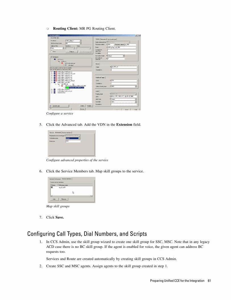
Routing Client: MR PG Routing Client.
Configure a service
5. Click the Advanced tab. Add the VDN in the Extension field.
Configure advanced properties of the service
6. Click the Service Members tab. Map skill groups to the service.
Map skill groups
7. Click Save.
Configuring Call Types, Dial Numbers, and Scripts1. In CCS Admin, use the skill group wizard to create one skill group for SSC, MSC. Note that in any legacy
ACD case there is no BC skill group. If the agent is enabled for voice, the given agent can address BC requests too.
Services and Route are created automatically by creating skill groups in CCS Admin.
2. Create SSC and MSC agents. Assign agents to the skill group created in step 1.
Preparing Unified CCE for the Integration 61
3. On AW, create a call type:
a. Go to Configuration Manager > List > Call type list.
b. Select customer. Click Retrieve. (The Unified CCE instance is the customer.)
c. Add a call type. Provide a unique name and your Unified CCE instance as customer. Leave everything else at default.
d. Save and close.
4. On AW, create dialed numbers:
a. Go to Configuration Manager > List > Dialed Number list.
b. Select your routing client (your MR PG).
c. Select your Unified CCE instance for customer. Click Retrieve.
d. Add a DN.
e. Select the appropriate Routing Client (same as above).
f. Fill in Dial Number string field with unique value. (This field will be used as the script selector field on the caller login form.)
g. Select the appropriate MRD in which the skill groups your agent is associated with reside.
h. Select your Unified CCE instance as the customer (value depends on which lab you are in).
i. Select the call type mapping tab on top.
j. Click Add, and select the call type that was created earlier in the previous section. Leave everything else default.
k. Click OK.
l. Save and close.
5. On AW, Create a script in Script Editor and schedule it:
a. Open script editor on AW.
b. Start a new script.
c. Drag and drop the Queue (this is ‘queue to skill group’) icon from the Queue tab.
d. Drag the End icon from the General tab.
e. Double-click the Queue box in the script. Click inside column 1, skill group row, and you should see drop down with your corresponding skill group and route that you created in previous steps.
f. Drag and drop a Wait node.
g. Set 1000 seconds by double-clicking (this will allow calls to queue until an agent is available).
h. Click and drag cursor from Start-Queue node, Queue (check mark) node to Wait and Queue (X mark) to End.
i. Save this script with a unique name. Save directory defaults to default directory.
j. Validate script by clicking the check mark button.
k. Now go to the Script menu and select Calltype Manager.
l. In the call directory tab, select your MRD.
62 Cisco Unified Web and E-Mail Interaction Manager Deployment and Maintenance Guide
m. Under the schedules tab, select your call type.
n. Now add a script to your call type by clicking Add.
o. Click OK.
p. Now, run Call Tracer against your script as a double check of its integrity (IUnified CCE Admin Workstation - Call tracer). Select appropriate MRD, Routing Client, Dialed Number (DN) and click Send Call.
q. In the script editor, select Script Menu - Monitor Script to watch trace go through.
Creating Expanded Call Context (ECC) Variables Create the following ECC variables:
For inbound and outbound email activities: user.cim.activity.id
For chat activities: user.cim.activity.id, user.wim.customer.name
For blended collaboration, callback and delayed callback activities: user.cim.activity.id, user.wim.customer.name, user.cisco.cmb, user.cisco.cmb.callclass
To configure Expanded Call Context (ECC) Variables, follow the steps described in “Configuring Expanded Call Context (ECC) Variables” on page 49.
Installing Unified EIM and WIM and the Integration
To install Unified EIM and WIM and the integration with Unified CCE:
1. Ensure that Microsoft SQL Server 2005 is installed and running on the machine on which you will be installing the Unified EIM and WIM databases.
2. From the Unified EIM and WIM Environment CD, copy the JBoss folder to a local directory on the Unified EIM and WIM messaging server and all application servers.
3. From the JBoss folder inside the local directory, extract the files from the jboss-4.2.3.GA.zip file to the location where JBoss is to be installed. Create a new instance of JBoss.
4. In distributed-server installations, install Sun JDK 1.5.0_12 on all machines where the services server, messaging server, and application servers are to be installed. The installation program for JDK is included in the Environment folder of the installation package.
5. On the web server machines, install Microsoft IIS.
6. Install Unified EIM and WIM. Refer to the Cisco Unified Web and E-Mail Interaction Manager Installation Guide for Unified CCE for a detailed list of deployment options and installation steps corresponding to each deployment.
The document also guides you through the procedure of setting up the integration. See the section “Integrating Cisco Interaction Manager with Unified CCE.”
7. From the Windows Services panel, start the Unified EIM and WIM service, and wait for 2–3 minutes before launching the URL to allow all the application services to start.
Preparing Unified CCE for the Integration 63
8. On the user desktops, install Sun JRE 1.6.0 (Update 10 or higher). Version 1.6.0_13 is included on the product CD.
9. Configure the browser on user desktops according to the procedures detailed in the Cisco Unified Web and E-Mail Interaction Manager Browser Settings Guide.
Preparing Cisco Media Blender for the Integration
The Cisco Media Blender (CMB) integrates with Unified CCE to blend chat and voice into a blended collaboration session for an agent and a customer. The interface interacts with the Agent PG (Call Manager PG or Avaya PG) to facilitate voice call generation and voice monitoring within Unified CCE.
Installing Cisco Media Blender
To install Cisco Media Blender:
1. Run the Cisco Media Blender Setup.exe. For more details, refer to the Cisco Media Blender Installation Guide.
2. Apply patches, if any.
3. Restart the server after installation is complete.
Configuring Cisco Media BlenderRefer to the Cisco Media Blender Administration Guide for Cisco ICM/IPCC Enterprise & Hosted Editions for more information about configuring Cisco Media Blender.
Configuring Cisco Media Blender for Unified CCE
To configure Cisco Media Blender for Unified CCE:
1. On the Cisco Media Blender server machine, navigate to the CiscoMB\servlet\Properties\Blender folder. Open theACD.ciscocti.properties file and make the following changes:
signoffreleaseready=true [Uncomment this, and set to false for Unified CCE.]
peripheral.type=IPCC
peripheral.id=Peripheral ID
peripheral.hostname=CTI_server_hostname
peripheral.hostport=CTI_server_hostport [This should be the port of the CTI Server.]
64 Cisco Unified Web and E-Mail Interaction Manager Deployment and Maintenance Guide
peripheral.username= cmb-hostname [Uncomment this, and set the value to be the hostname of the Cisco Media Blender server. The recommended form is cmb-hostname of Cisco Media Blender machine, but it works by just defining the hostname of the Cisco Media Blender machine]
2. On the Cisco Media Blender server, open CiscoMB\servlet\Properties\Blender folder. Open Collaboration.properties, and make the following changes:
remoteregistryport=1099
remotepassword=Password [The remote password should be the same as the encrypted password defined in the Cisco_Home\eService\config\cmb\CMB_IP_address_Remote_Registry_Port.properties file on the Unified EIM and WIM file server.]
LocalPassword=Password [The local password should be the same as the encrypted password defined in the Cisco_Home\eService\config\cmb\CMB_IP_address_Remote_Registry_Port.properties file on the Unified EIM and WIM file server.]
3. On the Cisco Media Blender server, open CiscoMB\servlet\Properties\Blender open callclasses.properties, and check if the following line is commented:
#default=Predictive
4. Copy the CiscoMB folder from the Cisco Media Blender server and paste it on the Unified EIM and WIM file server. Make sure you paste the CiscoMB folder on the same drive on the file server where it existed on the Cisco Media Blender server. For example, if the CiscoMB folder on the Cisco Media Blender server was on C drive, then paste it on the C drive of the Unified EIM and WIM file server.
5. On the Unified EIM and WIM file server, open Cisco_Home\eService\config\cmb folder. Open CMB_IP_address_Remote_Registry_Port.properties, and make the following changes:
RemoteHost=CMB_Server_IP_Address [This should be the IP address of the Cisco Media Blender server.]
Configuring Cisco Media Blender for Avaya G3
To configure Cisco Media Blender for Avaya G3:
1. On the Cisco Media Blender server machine, navigate to the CiscoMB\servlet\Properties\Blender folder. Open theACD.ciscocti.properties file and make the following changes:
signoffreleaseready=true [Uncomment this, and set to false for IPCC.]
peripheral.type=Lucent
peripheral.id=Peripheral ID
peripheral.hostname=CTI_server_hostname
peripheral.hostport=CTI_server_hostport [This should be the host port of the CTI Server.]
For details on how to configure CMB for phantom agents, refer to the CMB configuration guide available in the CMB folder of the product CD.
Preparing Unified CCE for the Integration 65
peripheral.username=cmb-hostname [Uncomment this, and set the value to be the hostname of the Cisco Media Blender server. The recommended form is cmb-hostname of Cisco Media Blender machine, but it works by just defining the hostname of the Cisco Media Blender machine.]
2. On the Cisco Media Blender server, open CiscoMB\servlet\Properties\Blender folder. Open Collaboration.properties, and make the following changes:
remoteregistryport=1099
remotepassword =Password [The remote password should be the same as the encrypted password defined in the Cisco_Home\eService\config\cmb\CMB_IP_address_Remote_Registry_Port.properties file on the Unified EIM and WIM file server.]
LocalPassword=Password [The local password should be the same as the encrypted password defined in the Cisco_Home\eService\config\cmb\CMB_IP_address_Remote_Registry_Port.properties file on the Unified EIM and WIM file server.]
3. On the Cisco Media Blender server, open CiscoMB\servlet\Properties\Blender open callclasses.properties, and uncomment the following line:
#default=Predictive [Uncomment this]
4. Copy the CiscoMB folder from the Cisco Media Blender server and paste it on the Unified EIM and WIM file server. Make sure you paste the CiscoMB folder on the same drive on the file server where it existed on the Cisco Media Blender server. For example, if the CiscoMB folder on the Cisco Media Blender server was on C drive, then paste it on the C drive of the Unified EIM and WIM file server.
5. On the Unified EIM and WIM file server, open Cisco_Home\eService\config\cmb folder. Open CMB_IP_address_Remote_Registry_Port.properties, and make the following changes:
RemoteHost=CMB_Server_IP_Address [This should be the IP address of the Cisco Media Blender server.]
6. Open CiscoMB\servlet\Properties\Blender\ACD.ciscocti.properties and note down the names of the CTI strategies available in the file.
7. Open Cisco_Home\eService\config\ipcc\callclassmapping.properties. From the file, note down the names of values associated with the CTI strategies.
8. Now, open CiscoMB\servlet\Properties\Blender\callclass.properties. Add the list of values noted in Step 7, as keys, followed by the actual CTI strategy names noted in Step 6. For example, bcwaitrelease=PhantomWaitNoRelease. You need to add only the CTI strategies that are to be used in entry points to be configured for routing blended collaboration type of activities and that use the routing type as ACD.
Important: For details on how to configure CMB for phantom agents, refer to the CMB
configuration guide available in the CMB folder of the product CD.
66 Cisco Unified Web and E-Mail Interaction Manager Deployment and Maintenance Guide
Setting Up Integrated
Objects
Configuring Variables in Unified EIM and WIM
Verifying Mapping of Objects in the Administration Console
Setting Up Knowledge Base Articles for Unified EIM
Setting Up Services in the System Console
Setting Up Web Links for Chat and Collaboration
Handling Email Assignment
Related Documentation
This chapter provides an overview of the process of setting up Unified WIM and EIM–Unified CCE objects.
Configuring Variables in Unified EIM and WIM
While sending new activity requests from a queue to Unified CCE, EAAS sends call variables and ECC variables to Unified CCE as task context. By default, the following activity attributes are sent to Unified CCE as ECC variables.
For inbound and outbound email activities: activity_id
For chat activities: activity_id, customer_name
For callback and delayed callback activities: activity_id, customer_name, cmb_param, cti_strategy
For blended collaboration activities: activity_id, customer_name, cmb_param, cti_strategy
If you need to pass on other attributes of the activity as call variables or ECC variables to Unified CCE, you need to configure them in Unified EIM and WIM. These variables can then be used in Unified CCE scripts to configure conditions. For details, see the Unified CCE scripts documentation. If you plan to configure these variables as ECC variables in Unified EIM and WIM, you need to first create the ECC variables in Unified CCE. For details, see the Unified CCE documentation.
You can also create variables for custom activity attributes. These custom attributes are created from the Tools Console of Unified EIM and WIM. For details, see the Cisco Unified Web and E-Mail Interaction Manager Administrator’s Guide to Tools Console.
To configure variables in Unified EIM and WIM:
Perform all these tasks on the Unified EIM and WIM Active database.
1. Run the following query on the egpl_casemgmt_activity table to get all the activity attributes available in the table.
sp_help egpl_casemgmt_activity
2. Identify the activity attributes for which you want to create the call variables and note down the exact names of the activity attribute (column_name) for your reference. Also, note the case of the attributes, as call variables are case sensitive and need to match the case of the attributes.
3. Run the following query on the egicm_call_variable table to identify the call variable IDs that are already in use.
select call_variable_id from egicm_call_variable
Run the following query on the egicm_call_variable table to add the new call variables.
Insert into EGICM_CALL_VARIABLE VALUES (Call_Variable_ID, ‘Call_Variable_Name’, ‘Call_Variable_Description’)
Where:
Call_Variable_ID: The ID of the call variable. Make sure that you do not use the call variable IDs that are already in use.
Call_Variable_Name: This name should match the exact name (including case, as call variables names are case sensitive) of the activity attribute you got from the egpl_casemgmt_activity table in Step 2. Call variables have a maximum length of 40 characters.
68 Cisco Unified Web and E-Mail Interaction Manager Deployment and Maintenance Guide
Call_Variable_Description: The description of the call variable. This is optional information.
For example, the query will look like:
Insert into egicm_call_variable values (1003,'subject','Subject of the email’)
Now, you can use these newly added variables as call variables and ECC variables in queues.
Verifying Mapping of Objects in the Administration Console
To verify that Unified CCE objects have been mapped correctly in the Unified EIM and
WIM Administration Console:
1. Launch the URL: http://Unified EIM and WIM_Server/Default_Partition.
2. Log in as the partition administrator (user name and password that were configured during the installation of Unified EIM and WIM).
Log in as partition administrator
3. Select the Administration Console.
Select the Administration Console
Click
Setting Up Integrated Objects 69
4. Under Partition, browse to Settings. Locate the Application Instance communication setting. Verify that it is set to the value chosen at the time of running the Unified CCE integration wizard.
Verify that Application Instance setting is correctly configured
5. Under the appropriate department, browse to the User > Users node in the Administration tree, to verify that all users mapping to the administrators, supervisors, and agents, which were selected at the time of running the integration wizard, are displayed. Note that after the integration wizard is run, additional mapped users can be created from the Administration Console. For details, see the Cisco Unified Web and E-Mail Interaction Manager Administrator’s Guide to Administration Console.
Review mapped users
70 Cisco Unified Web and E-Mail Interaction Manager Deployment and Maintenance Guide
6. Under the appropriate department, click the User > Groups node in the Administration tree to verify that all user groups mapping to the skill groups, which were selected at the time of running the integration wizard, are displayed. Note that after the integration wizard is run, additional mapped user groups can be created from the Administration Console. For details, see the Cisco Unified Web and E-Mail Interaction Manager Administrator’s Guide to Administration Console.
Review mapped user groups
7. If you are integrating Unified EIM and WIM with Avaya G3, configure the following for Blended Collaboration:
For chat, add agents to the user groups in Unified EIM and WIM that map to a Non-IPTA chat skill group in Unified CCE.
For voice, associate the agents with the voice skill groups in Unified CCE using the ICM Configuration Manager.
8. Under the appropriate department, click the Workflow > Queues node in the Administration tree, and verify that all queues mapping to the MRDs, which were selected at the time of running the Unified CCE integration wizard, are displayed. Also verify that for all the non-IPTA skill groups that were imported using the Unified CCE integration wizard, the corresponding queues have been automatically created under the
Setting Up Integrated Objects 71
Queues node. Note that after the integration wizard is run, additional mapped queues can be created from the Administration Console. For details, see the Cisco Unified Web and E-Mail Interaction Manager Administrator’s Guide to Routing and Workflows.
Review mapped queues
Setting Up Knowledge Base Articles for Unified EIM
The knowledge base (KB) consists of articles organized into folders. It includes certain standard folders to hold articles meant for specific use in emails, such as headers, greetings, signatures, and footers. Folders for articles of other types are created by KB managers and authors.
See the Cisco Unified Web and E-Mail Interaction Manager Knowledge Base Author’s Guide for the details of the procedures mentioned in this section.
To set up KB articles for Unified EIM:
1. Launch the URL: http://Unified EIM and WIM_Server/Default_Partition.
2. Log in as the partition administrator.
3. Open the Knowledge Base Console.
72 Cisco Unified Web and E-Mail Interaction Manager Deployment and Maintenance Guide
4. In the Knowledge Base tree, browse to Departments > Department_Name > Content > Shared > Standard > Email. Create an article in each of the sub-nodes to set up one option each for a header, greeting, signature, and footer that can be used in responses to incoming activities in the department. Set up macros for the articles to make it easy to insert them into other articles or email responses.
Create a header, greeting, signature, and footer
5. Browse to the Department > Shared folder. Create a folder for auto-acknowledgements.
Create a folder for auto-acknowledgements
Setting Up Integrated Objects 73
6. In the newly created folder, create an article for use in auto-acknowledgement emails. Use macros to insert the header, greeting, signature, and footer created earlier. These macros expand to the actual content at runtime.
Create a KB article to use in auto-acknowledgement emails
This article will be used later in a workflow (see page 77).
Setting up Business Objects in the Administration Console
Unified EIM ObjectsSee the Cisco Unified Web and E-Mail Interaction Manager Administrator’s Guide to Email Resources and the Cisco Unified Web and E-Mail Interaction Manager Administrator’s Guide to Routing and Workflows for the details of the procedures mentioned in this section.
To set up Unified EIM business objects in the Administration Console:
1. Launch the URL: http://Unified EIM and WIM_Server/Default_Partition.
2. Log in as the partition administrator.
3. Open the Administration Console.
74 Cisco Unified Web and E-Mail Interaction Manager Deployment and Maintenance Guide
4. In the Administration tree, browse to the Administration > Departments > Department_Name > Classifications > Categories node. Create categories.
Create categories
These categories will be used later in a workflow (see page 77).
Setting Up Integrated Objects 75
5. Now, browse to the Email > Aliases node. Create an alias to serve as the entry point for emails into the system.
Create an email alias
6. Next, browse to the Workflow > Queues node to create an email queue. Skip this step if you want to use an auto-configured queue (see page 71).
76 Cisco Unified Web and E-Mail Interaction Manager Deployment and Maintenance Guide
7. Then, browse to the Workflow > Workflows > Inbound node to create an inbound workflow for this alias. The workflow will route incoming emails. Add the alias created in Step 5 to the Start node. Add the auto-configured queues or use the queues created in Step 6 to the Queue node. Select the auto-acknowledgement KB article created earlier (see page 74) for the Auto-acknowledgement node. Select the categories created in Step 4 for the Classifications node.
Create an inbound workflow
Unified WIM ObjectsSee Cisco Unified Web and E-Mail Interaction Manager Administrator’s Guide to Chat and Collaboration Resources for the details of the procedures mentioned in this section.
To set up Unified WIM business objects in the Administration Console:
1. Launch the URL: http://Unified EIM and WIM_Server/Default_Partition.
2. Log in as the partition administrator.
3. Open the Administration Console.
4. Browse to the Workflow > Queues node and create chat, blended collaboration, callback, and delayed callback queues. Skip this step if you want to use auto-configured queues (see page 71).
Setting Up Integrated Objects 77
5. Browse to the Chat > Templates node. Create a new template set, and provide default messages for different states associated with a chat, blended collaboration, or callback session, e.g., abandon, exit, error, and so on.
Create a custom template set for chat
6. Browse to the Chat > Entry points node. Create new entry points by assigning the appropriate templates. To route chats, blended collaboration, and call back activities that enter from this entry point, use an auto-configured queue or the queue created in Step 4. Make the entry points active. The configuration steps for entry points are different for different types of activities and routing options.
The activity types for which you need to create entry points are: Chat, Blended Collaboration, Callback, Delayed callback.
The three routing options available are: Cisco Interaction Manager, Automatic Call Distribution, Unified CCE.
For blended collaboration, callback, and delayed callback activities routed through Automatic Call Distribution, the following CTI strategies are available: Predictive, PhantomWaitRelease, PhantomWaitNoRelease, PhantomNoCallRelease, PhantomNoCallNoRelease, PhantomNoCallNoHold
Important: You need to add the CTI strategies, which are used in entry points configured for
routing blended collaboration type of activities and that use the routing type as ACD, to a
properties file on the CMB server. For details, see “Configuring Cisco Media Blender” on page 64.
78 Cisco Unified Web and E-Mail Interaction Manager Deployment and Maintenance Guide
A sample entry point for chat activities
A sample entry point for blended collaboration activities
Setting Up Integrated Objects 79
A sample entry point for callback and delayed callback activities
A sample entry point for delayed callback activities
80 Cisco Unified Web and E-Mail Interaction Manager Deployment and Maintenance Guide
A sample entry points for blended collaboration activities using ACD routing type
A sample entry points for callback activities using ACD routing type
7. In the Properties pane, click the Show HTML button. The code used to generate a chat hyperlink to that entry point is displayed. Copy this link code into a Notepad file. Edit the code as explained in the Cisco Unified Web and E-Mail Interaction Manager Administrator’s Guide to Chat and Collaboration Resources.
Setting Up Services in the System Console
Service processes are managed at the system level as shared resources across partitions. Service instances are managed within partitions.
See Cisco Unified Web and E-Mail Interaction Manager Administrator's Guide to System Console for the details of the procedures mentioned in this section.
Setting Up Integrated Objects 81
Unified EIM ServicesThis section helps you set up processes and instances for the following services:
Retriever: Gets incoming emails from configured aliases and parses them.
Workflow Cache: Maintains the files that store information about objects used in workflows.
Workflow Engine: Applies workflows on emails to automate their routing and handling.
Dispatcher: Sends outgoing emails out of the system.
External Agent Assignment Service (EAAS): Identifies new activities that arrive into an external assignment queue, and routes requests for each of these activities to Unified CCE for routing to take place through Unified CCE.
Listener: Assigns activities to target agents or user groups (skill groups) identified by Unified CCE, and reports the status of both the activity and the agent to Unified CCE throughout the life cycle of the given activity.
To set up Unified EIM services in the System Console:
1. Open a new browser window, and launch the URL: http://Unified EIM and WIM_Server/system. Log in as the system administrator (user name and password that were configured during the installation of Unified EIM and WIM).
Log in as system administrator into system area
2. Select the System Console.
Select the System Console
Click
82 Cisco Unified Web and E-Mail Interaction Manager Deployment and Maintenance Guide
3. Browse to the Partitions > Partition > Services > Email > Retriever node. Click the Retriever instance to use in the partition, and select the email alias that you had created earlier in the Administration Console (see page 76).
Associate a Retriever instance with the email alias created earlier
4. Restart the Retriever process and instance based on the notification message that appears. Browse to Shared Resource > Services > Retriever, and stop and start the Retriever process for the system. Also ensure that the start type for the service process is set to automatic.
Start the Retriever process
Setting Up Integrated Objects 83
5. Navigate back to the Partitions > Partition > Services > Retriever node. Ensure that the start type for the service instance is set to automatic. Stop and start the Retriever instance.
Start the Retriever instance
6. Browse to Shared Resource > Services > Workflow > Workflow Cache and verify that the Workflow Cache process is running. If the process is in a stopped state, start the process by clicking the Run button. Also ensure that the start type for the service process is set to automatic.
Start the workflow cache process
84 Cisco Unified Web and E-Mail Interaction Manager Deployment and Maintenance Guide
7. Browse to Partitions > Partition > Services > Workflow > Workflow Cache and ensure that the start type for the service instance is set to automatic. Start the Workflow Cache instance.
Start the workflow cache instance
8. Browse to Shared Resource > Services > Workflow > Workflow Engine and verify that the Workflow Engine process is running. If the process is in a stopped state, start the process by clicking the Run button. Also ensure that the start type for the service process is set to automatic.
Verify that the Workflow Engine process is running
Setting Up Integrated Objects 85
9. Browse to Partitions > Partition > Services > Workflow > Workflow Engine and ensure that the start type for the service instance is set to automatic. Start the Workflow Engine instance.
Start the Workflow Engine instance
10. Browse to Shared Resource > Services > Email > Dispatcher and verify that the Dispatcher process is running. If the process is in a stopped state, start the process by clicking the Run button. Also ensure that the start type for the service process is set to automatic.
Verify that the Dispatcher process is running
86 Cisco Unified Web and E-Mail Interaction Manager Deployment and Maintenance Guide
11. Browse to Partitions > Partition > Services > Email > Dispatcher and ensure that the start type for the service instance is set to automatic. Start the Dispatcher instance.
Start the Dispatcher instance
12. Browse to Shared Resource > Services > Listener > Listener and verify that the Listener process is running. If the process is in a stopped state, start the process by clicking the Run button. Also ensure that the start type for the service process is set to automatic.
Verify that the Listener process is running
Setting Up Integrated Objects 87
13. Browse to Partitions > Partition > Services > Listener > Listener. Verify that the Listener instance for the Agent PG is automatically created. Also ensure that the start type for the instance is set to automatic. Then start the Listener instance.
Configure and start the Listener instance
14. Browse to Shared Resource > Services > EAAS > EAAS and verify that the EAAS process is running. If the process is in a stopped state, start the process by clicking the Run button. Also ensure that the start type for the service process is set to automatic.
Verify that the EAAS process is running
88 Cisco Unified Web and E-Mail Interaction Manager Deployment and Maintenance Guide
15. Browse to Partitions > Partition > Services > EAAS > EAAS. Configure the EAAS instance by providing the MR Connection port number you provided while creating the MR PIM (page 24). Also ensure that the start type for the instance is set to automatic. Start the EAAS instance.
Start the EAAS instance
Unified EIM is now ready for use. To verify, log in as an agent, supervisor, or administrator and perform basic tasks.
Unified WIM ServicesThis section helps you set up processes and instances for the following service:
Agent Assignment: Used to initiate chat and collaboration sessions.
External Agent Assignment Service (EAAS): Identifies new activities that arrive into an external assignment queue, and routes requests for each of these activities to Unified CCE for routing to take place through Unified CCE.
Listener: Assigns activities to target agents or user groups (skill groups) identified by Unified CCE, and reports the status of both the activity and the agent to Unified CCE throughout the life cycle of the given activity.
To set up Unified WIM services in the System Console:
1. Log in to the system as the system administrator from the following URL: http://Unified EIM and WIM_Server/system.
2. Select the System console.
Setting Up Integrated Objects 89
3. Browse to Shared Resource > Services > Chat > Agent Assignment and verify that the Agent Assignment process is running. If the process is in a stopped state, start the process by clicking the Run button.
Start the Agent Assignment process
4. Browse to Partitions > Partition > Services > Chat > Agent Assignment and configure the instance to start automatically. Then start the Agent Assignment instance.
Start the Agent Assignment instance
5. Then, follow the instructions in steps 12-15 in “Unified EIM Services” on page 82. In addition to the fields mentioned in the Step 13, configure the CMB parameters fields for each listener service instance.
90 Cisco Unified Web and E-Mail Interaction Manager Deployment and Maintenance Guide
Setting Up Web Links for Chat and Collaboration
To create a chat and collaboration link on your web site:
Open the code view of the host web page and add the edited link code (see page 78) from the entry point properties at the appropriate point. You may need to ask your web master to perform this task.
Unified WIM is now ready for use. To verify, log in as an agent or supervisor, and perform basic tasks.
Handling Email Assignment
After activities are processed by Unified EIM, EAAS changes the activity substatus to 4105 (Ready for Unified CCE routing) and sends a request to Unified CCE for further processing. If the same activities continue to remain in this substatus for a delayed period, various options exist to have EAAS retry routing of such activities through Unified CCE. The options available are:
Option 1: A maximum wait time for each mapped queue can be set. When an activity belonging to that queue reaches that time, and it has not been assigned to an agent or to an exception queue, EAAS requeues the activity again and sends a NEW_TASK request for that activity to MR PIM.
Option 2: This option can only be used when Unified CCE scripts are linear in nature. When an activity is picked for assignment, EAAS checks to see if there are any activities older than the currently picked activity that are not yet assigned to an agent or to the exception queue. If any such activities are found, EAAS requeues those activities again and send a NEW_TASK requests for them to MR PIM.
To enable option 1:
1. On the Unified EIM active database, run the following query to get the queue_ID of integrated email queues.
Select queue_ID, queue_name from EGPL_ROUTING_QUEUE
2. For each integrated email queue, run the following query to set the MAX_WAIT_TIME column value in seconds. This should be the maximum time in which you want MR PIM to respond back to a NEW_TASK request.
UPDATE EGICM_QUEUE SET MAX_WAIT_TIME = Value in seconds WHERE QUEUE_ID = Queue_ID of Integrated email queue
To enable option 2:
1. On the file server, open the Cisco_Home\eService\config\ipcc\egicm_configuration.properties file in a text editor.
2. In the file, locate the setting FIFO_ALGO_TO_SAVE_EMAIL_ENABLE and set its value to True.
Setting Up Integrated Objects 91
Related Documentation
Refer to the following Unified EIM and WIM User’s Guides (for the Unified CCE integration) for more information about configuring and using Unified EIM and WIM.
Cisco Unified Web and E-Mail Interaction Manager Administrator’s Guide to Administration Console helps administrators set up and manage business objects.
Cisco Unified Web and E-Mail Interaction Manager Administrator’s Guide to Chat and Collaboration Resources helps administrators set up template sets, entry points, business rules, and cobrowse rules.
Cisco Unified Web and E-Mail Interaction Manager Administrator’s Guide to Email Resources helps administrators set up aliases, blocked addresses, delivery exceptions, and blocked file extensions.
Cisco Unified Web and E-Mail Interaction Manager Administrator’s Guide to Routing and Workflows helps administrators set up service levels, queues, and workflows.
Cisco Unified Web and E-Mail Interaction Manager Administrator’s Guide to Data Adapters helps administrators set up data links to connect to external sources.
Cisco Unified Web and E-Mail Interaction Manager Administrator’s Guide to System Console helps system administrators set up and manage services, loggers, and system monitors.
Cisco Unified Web and E-Mail Interaction Manager Administrator’s Guide to Tools Console helps business analysts extend the system by adding custom attributes. The Tools Console also enables administrators to configure screens and views for users and groups.
Cisco Unified Web and E-Mail Interaction Manager Supervisor’s Guide helps supervisors set up and use agent and queue monitors.
Cisco Unified Web and E-Mail Interaction Manager Administrator’s Guide to Reports Console helps managers and supervisors to set up and run reports to analyze various aspects of the system.
Cisco Unified Web and E-Mail Interaction Manager Knowledge Base Author’s Guide helps knowledge base (KB) managers and authors to create and publish KB articles.
Cisco Unified Web and E-Mail Interaction Manager Agent’s Guide helps agents handle email and chat interactions.
92 Cisco Unified Web and E-Mail Interaction Manager Deployment and Maintenance Guide
Managing and Maintaining Servers
Best Practices for Configuring Servers
Routine Maintenance Tasks
Performance Tuning Considerations
This chapter will assist you in understanding how to configure and maintain your Unified EIM and WIM servers.
Best Practices for Configuring Servers
For All ServersThis section describes the best practices for configuring all the Unified EIM and WIM servers. For database server, there are some additional best practices that are listed in the section “Additional Best Practices for Database Servers” on page 94.
Allocating Adequate Virtual Memory Virtual memory setting should be set to 1.5 times the physical memory. To ensure that adequate space is
available during run time, distribute the virtual memory across disk volumes.
Setting Up Disk Space All the system volumes should have more than 10% of their actual space free for application and other
operating system (OS) related activities at any given time.
Configuring Anti-virus Protection As email attachments are prone to virus attacks, set up scanning of email attachments on your mail exchange
server. On the database server, some special files need to be excluded from the virus scanner. For details, see the section “Additional Best Practices for Database Servers” on page 94.
Additional Best Practices for Database ServersIn addition to the best practices that apply to all the Unified EIM and WIM servers, there are some special best practices for the database server that are described in this section.
Installation and Settings If you are using RAID configuration, ensure that the RAID strip size is set to 64 kilobytes for SQL Server
data and log file array.
Ensure that the Data and Log drive array is formatted as NTFS with 64 kilobytes in each allocation unit.
Check the values set for fill factor and max degree of parallelism. To reduce I/O (disk input output) on SQL server, the fill factor should be set to 80%. This ensures that 20% free space is available in the data pages of indexes, and it reduces page splitting. The max degree of parallelism should be set to the number of physical processors. For example, if you have two processors, set max degree of parallelism to 2; and if you have five processors, set max degree of parallelism to 5.
a. On the database server, run the following stored procedure.
94 Cisco Unified Web and E-Mail Interaction Manager Deployment and Maintenance Guide
exec sp_configure
b. If the fill factor and max degree of parallelism is not configured correctly, run the following stored procedure on the database.
exec sp_configure 'fill factor (%)', 80
exec sp_configure 'max degree of parallelism', Number_Of_Physical_Processors
reconfigure with override
Temp Database
Set the temp database properties as follows:
Data file size should be set to 1.5 GB. Autogrowth should be set to 1 GB.
Transaction log file size should be set to 1 GB. Autogrowth should be set to 1 GB.
Master Database
Set the master database properties as follows:
Data file size should be set to 50 MB. Autogrowth should be set to 50 MB.
Transaction log file size should be set to 50 MB. Autogrowth should be set to 50 MB.
Active Database
While installing the application, ensure that data and log files of the active database reside on a disk volume with a good amount of free disk space. To calculate the required free disk space, see the Cisco Unified Web and E-Mail Interaction Manager Solutions Reference Network Design Guide.
Set the active database properties as follows:
Data file size should be set to 20 GB. Autogrowth should be set to 1 GB.
Transaction log file size should be set to 2 GB. Autogrowth should be set to 1 GB.
Archive Database
Set the archive database properties as follows:
Properties of Datafile: Data file size should be set to 5 GB. Autogrowth should be set to 500 MB.
Transaction log file size should be set to 2 GB. Autogrowth should be set to 2 GB.
Reports Database
Set the reports database properties as follows:
Data file size should be set to 20 GB. Autogrowth should be set to 1 GB.
Transaction log file size should be set to 2 GB. Autogrowth should be set to 1 GB.
Managing and Maintaining Servers 95
Optimal Configuration Settings
Configuring Anti-Virus ProtectionAnti-virus protection is necessary, but enabling all files for virus scan may cause performance issues.
Exclude .mdf, .ldf, .ndf, and .dat files from virus scan.
Routine Maintenance Tasks
For All ServersThis section describes the routine maintenance tasks for the Unified EIM and WIM servers. For database server, there are some additional tasks that are listed in the section “Additional Tasks for Database Servers” on page 97.
Monitoring Disk Space Monitor and free space on disk volumes periodically by deleting the unnecessary files. Installation
programs, application logs, user profiles, Dr. Watson logs, temp files are known to occupy the space unnecessarily. It is recommended that such files are deleted on a regular basis. However, if it is not possible to free disk space further because of the size of the data, the administrator should plan archiving of old data, or migration of the system to a larger capacity server.
Applying Microsoft Security Patches Apply the security patches released by Microsoft to plug vulnerabilities in the operating system and various
programs.
Database configuration setting Recommended value
auto_close off
auto_create_statistics on
auto_update_statistics on
auto_shrink off
read_only off
torn_page_detection on
database auto grow on
transaction log auto grow on
96 Cisco Unified Web and E-Mail Interaction Manager Deployment and Maintenance Guide
Creating Backup Copies Back up the Cisco_Home folder on the file, application, messaging, and services servers regularly. Exclude
the log folder under Cisco_Home from the backup. The process of backing up the database is different. For details, see the section “Additional Tasks for Database Servers” on page 97.
Additional Tasks for Database ServersIn addition to the routine maintenance tasks that apply to all the Unified EIM and WIM servers, there are some special tasks for the database server that are described in this section.
Rebuilding IndexesRebuilding of indexes enhances database performance.
Rebuild indexes on a weekly basis during off peak hours.
Performing Disk Defragmentation Weekly defragmentation is recommended. Note that it requires downtime.
Creating Backup CopiesBackups are critical in case of hardware failure. The following backup policy ensures that you won’t lose more than one hour of data. SQL supports full recovery model and hence this policy is strongly recommended. When the recovery mode is set to full it is necessary to backup transactional logs periodically. Otherwise it may lead to a disk space issue because of transaction logs growing indefinitely.
Perform a weekly complete backup, daily differential backup, and hourly transactional log backups.
ArchivingRegular archiving helps to keep the size of the database manageable. The maximum size of the database should be kept under 20 GB in most cases.
Schedule archive jobs to run during your off-peak hours to avoid database performance bottlenecks.
Purge archived activities to create more available disk space.
Performance Tuning Considerations
One of the first steps towards tuning an application is to determine evolving requirements, which is not easy as requirements are likely to vary across different types of users. Administrators, typically, want the system to be easily configurable for various user loads, security needs, and application uptime. Business managers tend to care about issues such as security considerations for critical data that is passed between various components
Managing and Maintaining Servers 97
within the application, response times, reliability, availability, and scalability. For agents, response time is the most important factor that defines a finely tuned system.
Cisco Unified Web and E-Mail Interaction Manager Solutions Reference Network Design Guide helps you plan your configuration when you first set it up. In this section, we provide a quick overview of some of the factors that you should consider as the system grows.
Peak Concurrent UsageThe application will need to be tuned if there is a need to meet specific concurrent usage requirements. Concurrent usage includes usage by email and chat agents as well as chat sessions. The general guideline is that the greater the number of concurrent users, the likelier it is for the system to be stressed resulting in longer response times.
Email VolumeThe email volume that the application handles determines the amount of disk space used by the database, size of active and master databases, and the capacity of the database engine to provide optimal response times to data requests. Active usage of email attachments and Knowledge Base (KB) articles also affect disk space requirements.
Server ConfigurationIt is a well known fact that the specifications for servers that run critical business application are constantly changing and, therefore, the application needs to account for such periodic changes. The server configuration and environment must be tailored to allow application to take advantage of it and vice versa. Therefore, if the server configuration is either downsized (less likely to occur) or increased (more likely), then the application needs to be tuned to the current server configuration. In addition, other applications that might be running on the same hardware also affect the tuning of the application.
Security RequirementsOften security requirements dictate that the application data should be accessed in a secure way. For this reason secure sockets layer (SSL) mode of access to information is set up. Likewise, sharing and access to critical information such as customer data require that data is stored and retrieved in a secure way by extra access control and beyond.
Additional security requirements do lead to some delay in response times for users accessing the application. This should be clearly understood by administrators setting up SSL mode of access on web servers or trying to access information stored on remote and highly secure resources like remotely mounted file systems or disks.
See Cisco Unified Web and E-Mail Interaction Manager Installation Guide for information about how to set up the SSL mode of communication on the web server.
98 Cisco Unified Web and E-Mail Interaction Manager Deployment and Maintenance Guide