CHAPTER 13-1 Enterprise Mobility 4.1 Design Guide OL-14435-01 13 Cisco Unified Wireless Location-Based Services Introduction With integrated location tracking, enterprise wireless LANs become more valuable as a corporate business asset. By identifying and tracking the location of wireless users, companies can improve the accuracy of WLAN planning and deployment to optimize ongoing network performance, enhance wireless security, and improve both the usefulness and value of important business applications. Location tracking provides visibility and control of the RF environment, and helps IT staff deploy wireless networks that are easier to manage and deploy. Enterprise network administrators, security personnel, users, and asset owners have expressed great interest in location-based services to allow them to better address requirements such as the following: • Quickly and efficiently locating valuable assets and key personnel • Improving productivity via effective asset and personnel allocation • Reducing loss because of the unauthorized removal of high-value assets from company premises • Improving customer satisfaction by rapidly locating critical service-impacting assets • Improving WLAN planning and tuning capabilities • Improving workflow automation • Coordinating Wi-Fi device location with security policy enforcement This chapter discusses the location-aware Cisco Unified Wireless Network (UWN). It focuses primarily on design considerations but mentions topics meriting special consideration during deployment as well. These areas are described in brief and references are made to a comprehensive white paper entitled Wi-Fi Location-Based Services 4.1 Design Guide, which contains in-depth discussion and analysis and is available at the following URL: http://www.cisco.com/en/US/docs/solutions/Enterprise/Mobility/WiFiLBS-DG.html. The following topics are addressed in this chapter: • The fundamentals of positioning technologies including lateration, angulation, and location patterning approaches • Cisco RF Fingerprinting and its advantages over traditional positioning techniques • Cisco Location Control Protocol (LOCP) • Chokepoints (and the use of chokepoint triggers) to further enhance location granularity within the Cisco UWN • Various RFID tag technologies including active, passive, and multimode • External third-party location client application interfaces to the Cisco Wireless Location Appliance
Transcript
OL-14435-01
C H A P T E R13
Cisco Unified Wireless Location-Based Services
IntroductionWith integrated location tracking, enterprise wireless LANs become more valuable as a corporate business asset. By identifying and tracking the location of wireless users, companies can improve the accuracy of WLAN planning and deployment to optimize ongoing network performance, enhance wireless security, and improve both the usefulness and value of important business applications. Location tracking provides visibility and control of the RF environment, and helps IT staff deploy wireless networks that are easier to manage and deploy.
Enterprise network administrators, security personnel, users, and asset owners have expressed great interest in location-based services to allow them to better address requirements such as the following:
• Quickly and efficiently locating valuable assets and key personnel
• Improving productivity via effective asset and personnel allocation
• Reducing loss because of the unauthorized removal of high-value assets from company premises
• Improving customer satisfaction by rapidly locating critical service-impacting assets
• Improving WLAN planning and tuning capabilities
• Improving workflow automation
• Coordinating Wi-Fi device location with security policy enforcement
This chapter discusses the location-aware Cisco Unified Wireless Network (UWN). It focuses primarily on design considerations but mentions topics meriting special consideration during deployment as well. These areas are described in brief and references are made to a comprehensive white paper entitled Wi-Fi Location-Based Services 4.1 Design Guide, which contains in-depth discussion and analysis and is available at the following URL: http://www.cisco.com/en/US/docs/solutions/Enterprise/Mobility/WiFiLBS-DG.html.
The following topics are addressed in this chapter:
• The fundamentals of positioning technologies including lateration, angulation, and location patterning approaches
• Cisco RF Fingerprinting and its advantages over traditional positioning techniques
• Cisco Location Control Protocol (LOCP)
• Chokepoints (and the use of chokepoint triggers) to further enhance location granularity within the Cisco UWN
• Various RFID tag technologies including active, passive, and multimode
• External third-party location client application interfaces to the Cisco Wireless Location Appliance
• Cisco Wireless Control System Release Notes, Release 4.0— http://www.cisco.com/en/US/docs/wireless/wcs/release/notes/wcsrn_MR2.html
• Cisco Wireless Control System Configuration Guide, Release 4.0— http://www.cisco.com/en/US/docs/wireless/wcs/4.0/configuration/guide/wcscfg40.html
• Cisco 4400 Series WLAN Controller Support Documentation for Release 4.1— http://www.cisco.com/en/US/products/ps6366/tsd_products_support_series_home.html
• Cisco 2100 Series WLAN Controller Support Documentation for Release 4.1— http://www.cisco.com/en/US/products/ps7206/index.html
• Cisco Catalyst 3750 Series Integrated Wireless LAN Controllers Support Documentation— http://www.cisco.com/en/US/products/ps6915/index.html
• Cisco Wireless LAN Controller Module Support Documentation— http://www.cisco.com/en/US/products/ps6730/tsd_products_support_model_home.html
• Cisco Catalyst 6500 Series Wireless Services Module (WiSM) Support Documentation— http://www.cisco.com/en/US/products/ps6526/tsd_products_support_model_home.html
For design considerations concerning the use of the InnerWireless Vision (formerly PanGo) Locator location client in the location-aware Cisco UWN, refer to the following white paper:
• Design Considerations for Cisco–PanGo Asset Tracking— http://www.cisco.com/en/US/docs/solutions/Enterprise/Mobility/pango/PanGoEx.html.
Note Software Release 3.0 of the Cisco Location Appliance is intended to be included in any reference made to software Release 4.1 of the Cisco Unified Wireless Network (UWN) within this document, unless otherwise noted.
Positioning TechnologiesLocation tracking and positioning systems can be classified by the measurement techniques employed to determine mobile device location (localization). These approaches differ in terms of the specific technique used to sense and measure the position of the mobile device in the environment under observation. Typically, real-time location systems (RTLS) can be grouped into four basic categories of systems that determine position on the basis of the following:
• Cell of origin (nearest cell)
• Distance (lateration)
• Angle (angulation)
• Location patterning (pattern recognition)
An RTLS system designer can choose to implement one or more of these techniques. This may clearly be seen in some approaches attempting to optimize performance in two or more environments with very different propagation characteristics. It is not unusual to hear arguments supporting the case for a fifth category that encompasses RTLS systems that sense and measure position using a combination of at least two of these methods.
Keep in mind that regardless of the underlying positioning technology, the “real-time” nature of an RTLS is only as real-time as its most current timestamps, signal strength readings, or angle-of-incidence measurements. The timing of probe responses, tag beacons, and location server polling intervals can introduce discrepancies between the actual and reported device position observed during each reporting interval.
The “Location Tracking Approaches” section of Wi-Fi Location-Based Services 4.1 Design Guide provides a foundation in the technical aspects of traditional location tracking and positioning systems. This section is recommended reading for a better understanding of the differences between traditional approaches and RF Fingerprinting. It thoroughly explains the concepts of cell of origin, time of arrival (ToA), time difference of arrival (TDoA), angle of arrival (AoA), and location patterning.
What is RF Fingerprinting?Cisco RF Fingerprinting refers to an innovative localization approach that significantly improves the accuracy and precision over that available from traditional signal strength lateration techniques. Cisco RF Fingerprinting offers the simplicity of an received signal strength indication (RSSI)-based lateration approach with customized calibration capabilities and improved performance over traditional approaches.
RF Fingerprinting significantly enhances received signal strength (RSS) lateration through the use of RF propagation models developed from data gathered in the target or similar environments. RF Fingerprinting offers the ability to calibrate an RF model to a particular environment in a fashion analogous to (but more expeditious than) that of location patterning. But unlike location patterning, RF Fingerprinting allows for the reuse of calibration models in situations where multiple floors of similar construction, contents, and layout are deployed.
In addition, Cisco RF Fingerprinting offers the following key advantages over the traditional approaches described in the “Location Tracking Approaches” section of Wi-Fi Location-Based Services 4.1 Design Guide:
• Uses existing LWAPP-enabled Cisco Unified Networking components—Unlike some other solutions, the location-aware Cisco UWN with RF Fingerprinting does not require added-cost specialized receivers or other hardware that must be mounted alongside each access point. This helps keep the capital and ongoing maintenance costs of the location-aware Cisco UWN low in comparison to solutions requiring a dedicated overlay location infrastructure. The Cisco Location Appliance is added as a centralized component to support location and statistics history and serves as a location positioning engine for the simultaneous tracking of up to 2500 devices per appliance.
• No proprietary client hardware or software required—Location-based services in the Cisco UWN are implemented as a network-side model, not client-side. Because of this, Cisco RF Fingerprinting can provide location tracking for a wide variety of industry-standard Wi-Fi clients without the need to load proprietary tracking software or location-enabling drivers in each client. Any IEEE 802.11 client can be located in most cases, with WLAN enhanced client localization for clients compatible with the Cisco Compatible Extensions for WLAN clients specification version 2 or higher. This includes popular VoWLAN handsets such as the Cisco 792x series and others for which proprietary location tracking client software is neither readily available or installable.
• Support of Wi-Fi active RFID asset tags compliant with the Cisco Compatible Extensions for Wi-Fi Tags specification—Because the location-aware Cisco UWN solution implements RF Fingerprinting as a network-side model, there is no requirement for proprietary software in asset tags to detect access point RSSI and relay this information back to the network in order for the asset tag to be successfully localized. This enables the location-aware Cisco UWN to interoperate with active RFID asset tags from various vendors meeting the Cisco Compatible Extensions for Wi-Fi Tags specification, such as AeroScout, WhereNet, G2 Microsystems, InnerWireless (formerly PanGo Networks) and others. RFID asset tags that support the Cisco Compatible Extensions for Wi-Fi Tags specification allow for improved performance and the support of advanced features such as:
– Telemetry and sensor information
– Battery, panic, and tampering alerts
– Motion sensing notification
– High fidelity deterministic location using chokepoint triggers
• Better accuracy and precision—Cisco RF Fingerprinting yields significantly better performance than solutions employing only pure triangulation or signal strength lateration techniques. These techniques typically do not account for the effects of attenuation in the environment, making them highly susceptible to performance reductions. The advantages of Cisco RF Fingerprinting technology start where traditional approaches leave off. Cisco RF Fingerprinting begins with a significantly better understanding of RF propagation as it relates specifically to the environment in question. Except for the calibration phase in location patterning approaches, traditional lateration or angulation techniques typically do not take such environmental considerations directly into account. RF Fingerprinting goes a step further and applies statistical analysis techniques to the set of collected calibration data. This allows the Cisco Location Appliance to further refine predicted location possibilities for mobile clients, culling out illogical or improbable data and further refining accuracy. The net result of these methods is not only better accuracy but significantly improved precision over traditional solutions.
• Reduced calibration effort—Cisco RF Fingerprinting technology offers the key advantages of a location patterning solution but with significantly less calibration effort. Although both approaches support on-site calibration, the Cisco RF Fingerprinting approach requires less frequent re-calibration and can operate with larger inter-access point spacing. Cisco RF Fingerprinting can also share calibration models among similar types of environments and includes several pre-packaged models that can facilitate rapid deployment in typical indoor environments.
Additional information on these and other key advantages of Cisco RF Fingerprinting can be found in the “Location-Based Services Architecture” section of Wi-Fi Location-Based Services 4.1 Design Guide.
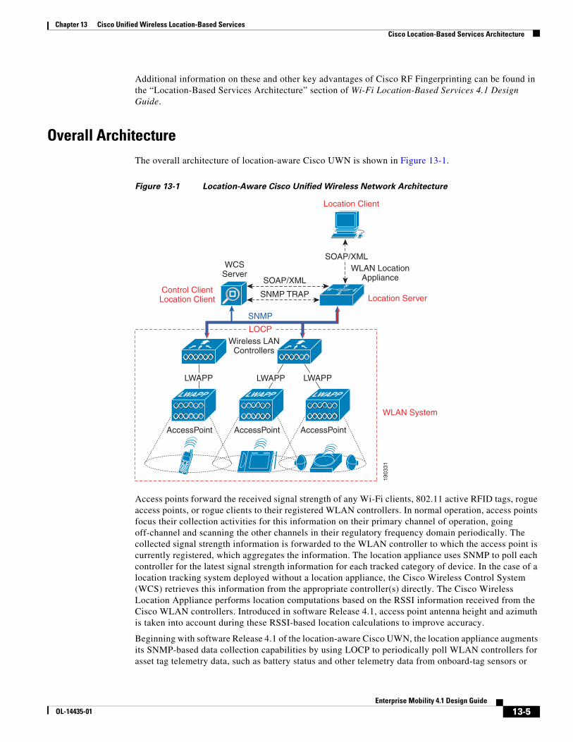
Overall ArchitectureThe overall architecture of location-aware Cisco UWN is shown in Figure 13-1.
Access points forward the received signal strength of any Wi-Fi clients, 802.11 active RFID tags, rogue access points, or rogue clients to their registered WLAN controllers. In normal operation, access points focus their collection activities for this information on their primary channel of operation, going off-channel and scanning the other channels in their regulatory frequency domain periodically. The collected signal strength information is forwarded to the WLAN controller to which the access point is currently registered, which aggregates the information. The location appliance uses SNMP to poll each controller for the latest signal strength information for each tracked category of device. In the case of a location tracking system deployed without a location appliance, the Cisco Wireless Control System (WCS) retrieves this information from the appropriate controller(s) directly. The Cisco Wireless Location Appliance performs location computations based on the RSSI information received from the Cisco WLAN controllers. Introduced in software Release 4.1, access point antenna height and azimuth is taken into account during these RSSI-based location calculations to improve accuracy.
Beginning with software Release 4.1 of the location-aware Cisco UWN, the location appliance augments its SNMP-based data collection capabilities by using LOCP to periodically poll WLAN controllers for asset tag telemetry data, such as battery status and other telemetry data from onboard-tag sensors or
external environmental sensors. LOCP is also used for priority forwarding of chokepoint proximity and emergency notifications that WLAN controllers receive from tags that are compliant with the Cisco Compatible Extensions for Wi-Fi Tags specification.
WCS and the location appliance exchange information (such as calibration maps and network designs) during a process known as synchronization, where the “up-to-date” partner updates the design and calibration information of the “out-of-date” partner. Synchronization occurs either on-demand or as a scheduled task, the timing of which is determined by the Administration > Scheduled Tasks menu option under the WCS main menu bar.
Information about device location information is made available to the end user using a location client application. Typically, this role is fulfilled by the Cisco WCS, which displays location information visually and provides a readily available location client application for customers who want to enhance their basic RF capacity management, perform rogue access point and client detection, and have asset visibility for WLAN devices.
For important information regarding compatibility between versions of WCS and the Cisco Wireless Location Appliance, see Release Notes for Cisco Wireless Location Appliance 3.0 at the following URL: http://www.cisco.com/en/US/products/ps6386/prod_release_notes_list.html.
This location information is also made available to optional third-party location client applications through a Simple Object Access Protocol/Extensible Markup Language (SOAP/XML) API on the appliance. Using the SOAP/XML protocol, these third-party applications may offer extended location client capabilities more specific to particular vertical applications such as healthcare, retail, manufacturing, and logistics.
The Cisco Location Appliance is also capable of issuing notifications to external systems. This provides the ability to proactively send location notifications based on device movement, device absence, zone entry and exit of tracked devices, tag battery level, device position change, emergency groups, and chokepoint information. All of these notifications can be delivered over multiple transport types: UDP-Syslog, Simple Network Management Protocol (SNMP) traps, e-mail (SMTP), and SOAP/XML.
Additional information regarding the architecture of the Cisco LBS solution can be found in the “Location-Based Services Architecture” section of the Wi-Fi Location-Based Services 4.1 DesignGuide at the following URL: http://www.cisco.com/en/US/docs/solutions/Enterprise/Mobility/WiFiLBS-DG.html.
Role of the Cisco Wireless Location ApplianceWhen a Cisco Location Appliance is added to a Cisco Unified Wireless Network with an appropriately licensed version of WCS, the location appliance assumes responsibility for several important tasks, including the following:
• Execution of positioning algorithms
• Maintenance of calibration information
• Triggering and dispatch of location notifications
• Processing of statistics and historical location
WCS acts in concert with the location appliance by serving as both the control client as well as the location client user interface (UI) for the services the location appliance provides, as shown in Figure 13-1. Although it is possible to access the location appliance directly via SSH or a console session for maintenance and diagnostic purposes, all operator and user interaction with the location appliance is typically via WCS or a third-party location client application.
The integration of a Cisco Location Appliance into a Cisco Unified Wireless Network architecture immediately enables improvements to base-level location capabilities. These improvements include:
• Scalability—Adding a Cisco Location Appliance increases the scalability of the Cisco UWN from on-demand tracking of a single device at a time to a maximum tracking capacity of 2500 simultaneous devices (WLAN clients, RFID tags, rogue access points, and rogue clients) per location appliance. For deployments requiring support of greater numbers of devices, additional location appliances can be deployed and managed under one or more WCS servers.
• Historical and statistics trending—The appliance records and maintains historical location and statistics information, which is available for viewing via WCS or other location clients. This historical information can be used for location trending, asset loss investigation, RF capacity management, and to facilitate network problem resolution.
• Chokepoint location—Beginning with Release 4.1 of the UWN, the inclusion of a location appliance allows for granular and deterministic localization based on the passage of an asset through a constrained physical area known as a chokepoint. Chokepoint triggers located within these areas and in proximity to tagged assets stimulate the tags using low-frequency (125 kHz) signalling. The asset tags in turn transmit the identity of the chokepoint trigger to the location-aware Cisco UWN. This provides for accurate proximity location, which can range from a radius of under one foot to over twenty feet, depending on the capabilities of the chokepoint trigger. Applications for chokepoint location vary from general purpose uses such as theft prevention of high value assets to industry-specific process control events such as those used in manufacturing plants.
• Cisco Extensions for Wi-Fi Tags telemetry information and emergency notifications- Beginning with Release 4.1 of the Cisco UWN, Cisco has partnered with a variety of asset tag vendors to create an extensible specification for 802.11Wi-Fi based active asset tags. The Cisco Compatible Extensions Wi-Fi Tag specification defines a common transmission format that tag vendors can use to interoperate with the location-aware Cisco UWN. This includes a baseline feature set that encompasses telemetry, tag transmit power level, battery information, and advanced fields for emergency groups and chokepoints. The addition of a location appliance allows the location-aware UWN to take advantage of these newly introduced capabilities and benefits customers by providing the ability to “mix and match” compliant asset tags from different vendors in the same network. Complete details on the Cisco Compatible Extensions for Wi-Fi Tags program can be found at http://www.cisco.com/web/partners/pr46/pr147/ccx_wifi_tags.html.
Note At this time, chokepoint triggers and asset tags are compatible with one another only if they are supplied by the same vendor.
• Location notifications—The Cisco Location Appliance can dispatch location-based event notifications via e-mail, Syslog, SNMP traps, and SOAP/XML directly to specified destinations. These notifications can be triggered under the following conditions:
– Location of a client or asset changes
– Battery level of an RFID tag drops below a preset value
– Client or tagged asset strays beyond set distances from pre-determined marker locations
– Asset enters the proximity of a chokepoint
– Client or tagged asset becomes missing
– Asset tag signals that a detachment, tamper, or panic emergency has occurred
• SOAP/XML Location Application Programming Interface (API)—The Location Appliance API allows customers and partners to create customized location-based applications that interface with the Cisco Wireless Location Appliance. For further details, see SOAP/XML Application Programming Interface.
Accuracy and PrecisionWhen discussing the performance of any positioning system, the metric that is usually the most familiar to use is accuracy, which typically refers to the quality of the information being received. Location accuracy refers specifically to the quantifiable error distance between the estimated location and the actual location of the mobile device.
However, in most real-world applications, any notion of location accuracy has little merit without the ability of the solution to repeatedly and reliably perform at this level. Precision is a direct measure of the reproducibility of the stated location accuracy. Any indication of location accuracy should therefore include an indication of the repeatability or confidence level of successful location detection, otherwise known as the location precision.
When deployed in accordance with the best practices described in this chapter as well as those contained within the documents referenced in Reference Publications, page 13-2, the location-aware Cisco UWN is capable of excellent accuracy and precision. The Cisco Wireless Location Appliance allows the system to deliver overall baseline performance of 10 meters accuracy with 90 percent precision. The use of chokepoint location capabilities allow the level of accuracy to be even further refined, in some cases to a resolution radius of a foot or less.
These baseline performance levels can be reached using the design, calibration, and deployment tools included with the system. Included are predictive pre-deployment tools such as the Location Planning and Location Readiness tools, as well as post-deployment verification tools such as the Location Inspector.
The Location Planning tool provides recommendations for access point placement and density to create a WLAN deployment that supports location accuracy within the specifications of the location appliance. In software Release 4.1, support for irregularly-shaped polygonal buildings has been added to help organizations address the requirements of such structures. The Location Readiness tool allows network engineers to identify beforehand whether their currently planned access point deployment will support location accuracy within the specifications of the location appliance.
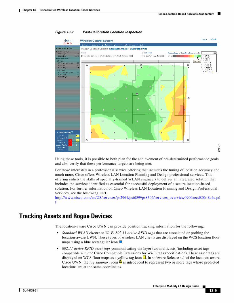
By using the Location Inspection tool shown in Figure 13-2, the system designer can evaluate post-calibration baseline accuracy and precision levels in their actual environment. After an accuracy level is selected, the Location Inspection tool displays, in color-coded format, the level of precision at any point from 0–5 percent all the way to a maximum of 95–100 percent. After viewing the output, the system architect can then work with the installation team to take the necessary steps to ensure that the system's performance is sufficient.
Using these tools, it is possible to both plan for the achievement of pre-determined performance goals and also verify that these performance targets are being met.
For those interested in a professional service offering that includes the tuning of location accuracy and much more, Cisco offers Wireless LAN Location Planning and Design professional services. This offering enlists the skills of specially-trained WLAN engineers to deliver an integrated solution that includes the services identified as essential for successful deployment of a secure location-based solution. For further information on Cisco Wireless LAN Location Planning and Design Professional Services, see the following URL: http://www.cisco.com/en/US/services/ps2961/ps6899/ps8306/services_overview0900aecd80648a4c.pdf.
Tracking Assets and Rogue DevicesThe location-aware Cisco UWN can provide position tracking information for the following:
• Standard WLAN clients or Wi-Fi 802.11 active RFID tags that are associated or probing the location-aware UWN. These types of wireless LAN clients are displayed on the WCS location floor maps using a blue rectangular icon .
• 802.11 active RFID asset tags communicating via layer two multicasts (including asset tags compatible with the Cisco Compatible Extensions for Wi-Fi tags specification). These asset tags are displayed on WCS floor maps as a yellow tag icon . In software Release 4.1 of the location-aware Cisco UWN, the tag summary icon is introduced to represent two or more tags whose predicted locations are at the same coordinates.
• Rogue access points, which are access points that are detected by the wireless LAN infrastructure and determined not to be members of the same mobility group or WLAN system. These are indicated on WCS location floor maps using a skull-and-crossbones within a black circle .
• Rogue clients, which are clients associated to rogue access points. Rogue clients are displayed on the WCS location floor maps using a black rectangle icon with a skull-and-crossbones .
The location-aware Cisco UWN also displays the location of any chokepoints that have been pre-defined to WCS and the location appliance. Chokepoints are indicated on WCS location floor maps using a blue star within a grey circle . A concentric band of grey around the icon is used to give a relative indication of the chokepoint range that has been defined in WCS. Note that chokepoint range indication on WCS floor maps is for display purposes only. The actual chokepoint trigger’s transmission power and range is configured using the vendor's specific utilities.
Note Comprehensive information regarding each class of device that can be tracked by the location-aware Cisco UWN is found in the “Location-Based Services Architecture” section of Wi-Fi Location-Based Services 4.1 Design Guide, which contains in-depth discussion and analysis and is available at the following URL: http://www.cisco.com/en/US/docs/solutions/Enterprise/Mobility/WiFiLBS-DG.html.
Cisco Location Control ProtocolThe Cisco Location Control Protocol (LOCP), introduced in software Release 4.1 of the Cisco UWN, represents a significant step forward in the support of new capabilities between the location appliance and other components of the Unified Wireless Network. In this release, LOCP augments the traditional SNMP polling of WLAN controllers and serves as the transport for the telemetry, chokepoint, and emergency notification features associated with the newly-introduced Cisco Compatible Extensions for Wi-Fi Tags program.
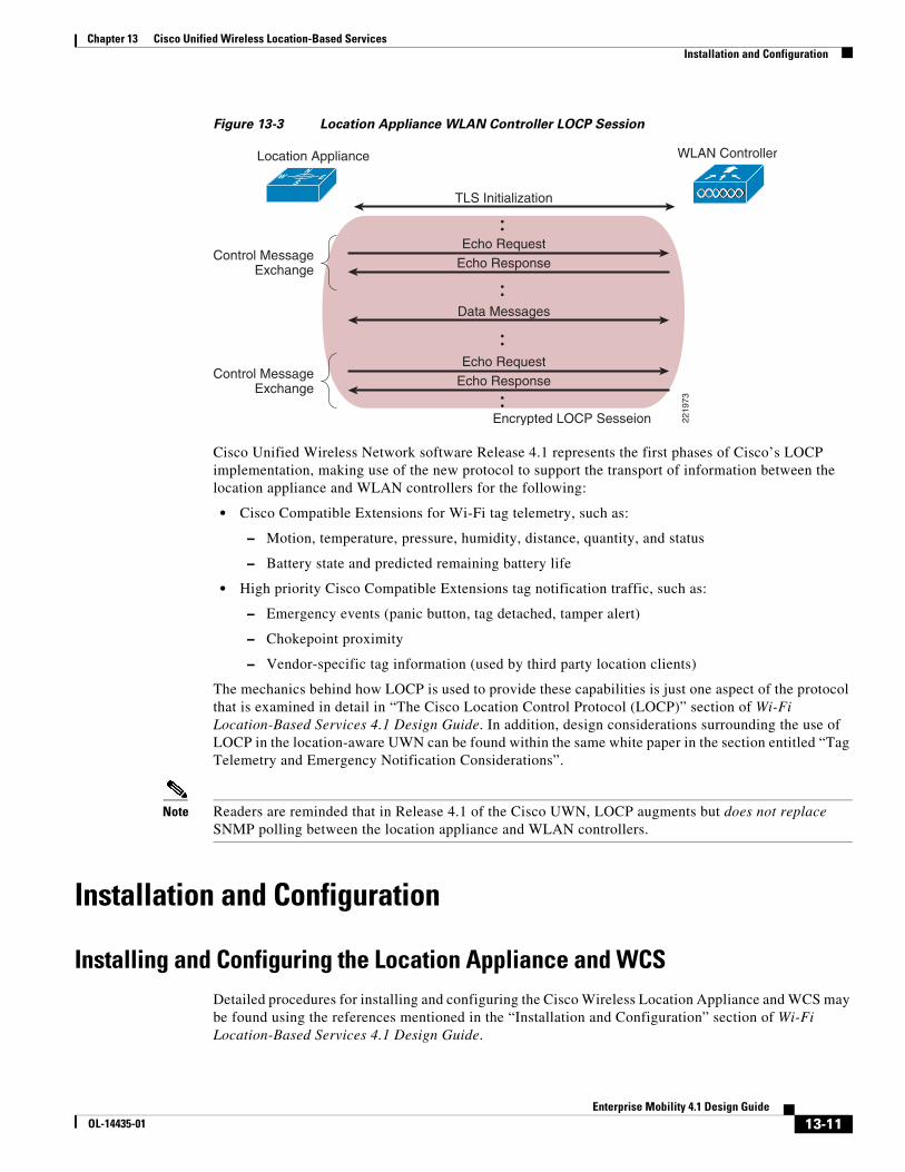
LOCP is a bi-directional protocol that can be run over a connection-oriented or connectionless transport and can be secured using Transport Layer Security (TLS). It provides for an ongoing exchange of control messages that allows either endpoint to determine whether its partner endpoint is still active, as shown in Figure 13-3, which illustrates a rudimentary LOCP packet exchange between the location appliance and a WLAN controller.
Cisco Unified Wireless Network software Release 4.1 represents the first phases of Cisco’s LOCP implementation, making use of the new protocol to support the transport of information between the location appliance and WLAN controllers for the following:
• Cisco Compatible Extensions for Wi-Fi tag telemetry, such as:
– Motion, temperature, pressure, humidity, distance, quantity, and status
– Battery state and predicted remaining battery life
• High priority Cisco Compatible Extensions tag notification traffic, such as:
– Emergency events (panic button, tag detached, tamper alert)
– Chokepoint proximity
– Vendor-specific tag information (used by third party location clients)
The mechanics behind how LOCP is used to provide these capabilities is just one aspect of the protocol that is examined in detail in “The Cisco Location Control Protocol (LOCP)” section of Wi-Fi Location-Based Services 4.1 Design Guide. In addition, design considerations surrounding the use of LOCP in the location-aware UWN can be found within the same white paper in the section entitled “Tag Telemetry and Emergency Notification Considerations”.
Note Readers are reminded that in Release 4.1 of the Cisco UWN, LOCP augments but does not replace SNMP polling between the location appliance and WLAN controllers.
Installation and Configuration
Installing and Configuring the Location Appliance and WCSDetailed procedures for installing and configuring the Cisco Wireless Location Appliance and WCS may be found using the references mentioned in the “Installation and Configuration” section of Wi-Fi Location-Based Services 4.1 Design Guide.
2219
73
NW E
S
TLS Initialization
Data Messages
Echo Request
Encrypted LOCP Sesseion
Control MessageExchange
Control MessageExchange
Location Appliance WLAN Controller
Echo Response
Echo RequestEcho Response
13-11Enterprise Mobility 4.1 Design Guide
OL-14435-01
Chapter 13 Cisco Unified Wireless Location-Based Services Installation and Configuration
Configuration of the parameters listed under the WCS Location Server > Administration menu are discussed in the document entitled Cisco Location Appliance Configuration Guide: Editing Location Server Properties at the following URL: http://www.cisco.com/en/US/docs/wireless/location/2700/3.0/configuration/guide/lacg30.html.
However, there are additional ramifications associated with making changes to the factory defaults that need to be carefully considered. This and other valuable information that a designer of a location-enabled wireless LAN should consider can be found in the “Installation and Configuration” section in Wi-Fi Location-Based Services 4.1 Design Guide, including the following:
Chapter 13 Cisco Unified Wireless Location-Based Services Deployment Best Practices
Deployment Best Practices
Location-Aware WLAN Design ConsiderationsIn the past decade, the design best practices for enterprise-ready wireless LANs have evolved from coverage-centric and minimum access point models to those where coverage uniformity and proper cell-to-cell overlap are the predominant requirements. This has been driven by increased interest in deploying new wireless applications that are typically not as tolerant as traditional data-only deployments toward large amounts of dropped packets and roaming delays.
In a similar fashion, the deployment of location-aware WLAN applications requires modification to traditional approaches. This includes the design of “greenfield” location-aware installations as well as the augmentation or retrofitting of existing deployments. For location tracking to function optimally, the correct number of access points along with proper access point placement is a key requirement.
The “Deployment Best Practices” section of Wi-Fi Location-Based Services 4.1 Design Guide discusses in great detail several best-practice recommendations for location-aware WLAN deployments, such as the following:
• Minimum received signal thresholds—For mobile devices to be tracked properly, it is highly recommended that access points report mobile device RSSI to their respective controllers at levels meeting or exceeding the RSSI cutoff value that is configured in WCS. A minimum of three access points (and preferably four or more for optimum accuracy) should be reporting this level of signal strength or better for any device being localized. Mobile device RSSI reported below this level is eligible for discard by the location appliance.
• Correct access point placement—Proper placement of access points is critical if the system is expected to fully deliver on its performance potential. In many office wireless LANs, access points are distributed throughout interior spaces, providing more than adequate coverage to surrounding work areas. These locations are usually selected on the basis of coverage, WLAN bandwidth, channel re-use, cell-to-cell overlap, security, aesthetics, and deployment feasibility. In a location-aware WLAN design, however, access points must not be located based solely on these criteria but must strike a balance between them and location placement requirements. Although there is no single rule that consistently yields the proper access point density for every environment, the signal threshold and placement suggestions made in the “Deployment Best Practices” section of Wi-Fi Location-Based Services 4.1 Design Guide should be followed as a starting point of any location-aware design. Among these recommendations is the adherence to an inter-access point separation of 50 to 70 feet.
• Validating location performance—Although adherence to design and deployment best practices provides the necessary foundation for success, tools that provide corrective feedback to the designer (as well as the installer) play a major role in optimizing performance. The use of predictive tools such as the Location Planning and the Location Readiness tools can identify performance shortcomings early when they are most easily (and most cost-effectively) addressed. Post-deployment tools such as Location Inspection can offer a comprehensive “reality-check” of an entire calibration area by comparing known calibration positions to predictions and calculating the degree of location error. When location accuracy does not conform to specifications, the location debug feature can be enabled to allow for more in-depth investigation. This feature displays the access points that contributed to the location calculations for a specific tracked device, the signal strength of these devices, as well as a timestamp of when the signal strength measurement was last received. Newly added in software Release 4.1 of the Cisco UWN, the use of location test points allows for impromptu location accuracy checks to be performed by comparing predicted location against the actual physical position of devices bearing selected MAC addresses.
13-13Enterprise Mobility 4.1 Design Guide
OL-14435-01
Chapter 13 Cisco Unified Wireless Location-Based Services RFID Tag Considerations
• Minimizing excessive co-channel interference—In many cases, location-based services are added or retrofitted to an existing wireless design, some of which encompass VoWLAN handheld devices (such as the Cisco 792x). When designing a location-aware solution to be used in conjunction with latency-sensitive devices, special care needs to be taken to ensure that excessive co-channel interference is not introduced into the environment. In cases such as this, the needs of an optimal location-aware design must be carefully balanced against the requirements of a properly designed wireless voice infrastructure.
• Avoiding location display “jitter”—At times, devices appear to move on location displays even though they are known to physically be at rest. This can be due to a variety of factors, including the movement of surrounding objects in the environment and slight changes in the orientation of the client and the client’s antenna system over time. Location smoothing is used to assist in counteracting this phenomena and stabilize location jitter for clients that are not in constant motion.
• Multi-domain design considerations—The Cisco Wireless Location Appliance can provide simultaneous tracking for up to 2500 total devices, which includes WLAN clients, asset tags, rogue access points, and rogue clients. In most cases, a single location appliance and WCS management system should suffice for the majority of applications. However, in larger networks, it may be necessary to use either a single WCS server with multiple location appliances or multiple WCS servers with one or more location appliances.
• Antenna considerations—A discussion of supported antenna combinations for use with the location-aware Cisco UWN, tips on third-party antennas, and antenna orientation best practices. This section includes information on the newly-introduced (in Release 4.1 of the Cisco UWN) antenna vertical height and azimuth capability, which allows the vertical height and x-axis angular offset of access point antennas to be specified in WCS when placing access points on WCS floor maps.
• Site calibration—Post-deployment location calibration can be performed if location accuracy using one of the included calibration models is lower than expected or if the target environment is complex and not well represented by one of the included models. During this calibration, an 802.11 wireless client device is used to take RSSI measurements in the environment. The measured RSSI is then used by the location appliance to fine-tune the path loss model assigned to the environment, which typically leads to improved accuracy and precision. This section contains important tips on performing site calibrations, calibration validity, choosing a calibration client, and improving overall calibration performance. The benefits of performing calibrations using clients compatible with the Cisco Compatible Extensions for WLAN clients specification version 2 or higher are also discussed in detail in this section.
RFID Tag ConsiderationsThe majority of RFID tags currently produced commercially are passive RFID tags, consisting basically of a micro-circuit and an antenna. They are referred to as passive tags because they are actively communicating only when they are within the electromagnetic field of a passive RFID tag reader or interrogator.
Another type of common RFID tag in the current marketplace is known as the active RFID tag, which usually contains a battery that directly powers RF communication. This onboard power source allows an active RFID tag to transmit information about itself at great range, either by constantly beaconing this information to a RFID tag reader or by transmitting only when it is prompted to do so. Active tags are usually larger in size and can contain substantially more information (because of higher amounts of memory) than do pure passive tag designs.
The “RFID Tag Considerations” section of Wi-Fi Location-Based Services 4.1 Design Guide provides readers who are new to RFID with a foundation in both active and passive tag technologies. Among other areas, this section comprehensively discusses the following:
• Passive RFID technology-Passive and semi-passive RFID tags
• Active RFID technology-Beaconing, transponder, and 802.11 (Wi-Fi) RFID tags
• Multimode RFID technology-A relatively new category offering multiple tag technologies in a single device.
• Chokepoint triggers-Proximity communication devices (often referred to simply as “chokepoints”) that trigger tags to alter their configuration or behavior when the tag enters their area of operation.
• Using RFID tags with the Location Appliance-Compatible RFID tags, enabling asset tag tracking, configuring asset tags, and using 802.11b tags on 802.11g networks
• Tag telemetry and notification considerations-Provides initial best practice recommendations and other valuable information pertinent to the design of solutions dependent on telemetry and emergency notification functions.
• Chokepoint design considerations- Provides best practice recommendations and other information pertinent to the design of solutions augmenting the location capabilities of the Cisco UWN with chokepoint-based proximity localization.
SOAP/XML Application Programming InterfaceTo facilitate the deployment of location-based applications in the enterprise, the Cisco Wireless Location Appliance is equipped with a SOAP/XML API. Applications can make use of the location information contained within the location appliance by importing components via the API such as entire network maps including buildings, floors, access points, chokepoints, coverage areas, and device lists. Actionable data can also be imported, such as recent and historical location as well as statistical device information. Location-based alarms and notifications can be triggered in applications through area boundary definitions, chokepoint proximity, tag emergency or missing status, tag battery status, allowed areas, and allowed distances. All these capabilities allow the SOAP/XML API interface to the Cisco Wireless Location Appliance API to be used for integration with external software applications such as location-enabled asset management, enterprise-resource-planning (ERP) tools, and workflow automation systems.
From a high-level perspective, a third-party application system can use the SOAP/XML API to participate as a member of a location-aware system consisting of the following four basic components:
• Location client—The primary role of the location client is to serve as the interface to the location and asset information contained on the location server.
• Control client—The primary role of the control client is to populate the server with information about the physical environment (network designs, floors maps, calibration models, access point locations, and so on) as well as the network elements that should be monitored.
• Location server— The location server provides general location services for the Cisco UWN and is responsible for running the algorithms that predict device location.
• WLAN system—All the monitored mobile devices (tags, mobile stations, rogue clients, and access points) as well as supporting devices (such as chokepoint triggers) that serve as key components of the wireless network, as well as the embedded software contained within WLAN controllers.
An in-depth examination of a location client implementation by a Cisco Technology Partner can be found in the document entitled Design Considerations for Cisco – PanGo Asset Tracking, which is located at the following URL: http://www.cisco.com/en/US/docs/solutions/Enterprise/Mobility/pango/PanGoEx.html.
The location appliance API is available and licensable to the Cisco development community along with tools to facilitate solution development. Integration support is available via the Cisco Developer Services Program. For complete details on this program, see the following URL: http://www.cisco.com/go/developersupport.