CHAPTER 5-1 Enterprise Mobility 8.1 Design Guide 5 Cisco Unified Wireless QoS and AVC This chapter describes quality of service (QoS) and Application Visibility and Control (AVC) in the context of WLAN implementations. This chapter describes WLAN QoS and AVC in general, but does not provide in-depth coverage on topics such as security, segmentation, and voice over WLAN (VoWLAN), although these topics have a QoS component. This chapter is intended for those who are tasked with designing and implementing enterprise WLAN deployments using Cisco Unified Wireless Network technology. QoS and AVC Overview QoS refers to the capability of a network to provide differentiated service to selected network traffic over various network technologies. QoS technologies provide the following benefits: • Provide building blocks for business multimedia and audio applications used in campus, WAN, and service provider networks • Allow network managers to establish service-level agreements (SLAs) with network users • Enable network resources to be shared more efficiently and expedite the handling of mission-critical applications • Manage time-sensitive multimedia and audio application traffic to ensure that this traffic receives higher priority, greater bandwidth, and less delay than best-effort data traffic With QoS, bandwidth can be managed more efficiently across WLANs, LANs and WANs. QoS provides enhanced and reliable network service by doing the following: • Supporting dedicated bandwidth for critical users and applications • Controlling jitter and latency (required by real-time traffic) • Managing and minimizing network congestion • Shaping network traffic to smooth the traffic flow • Setting network traffic priorities AVC provides application-aware control on a wireless network and enhances manageability and productivity. AVC is already supported on various ASR and WLC platforms. The support of AVC embedded within the FlexConnect AP extends as this is an end-to-end solution. This gives a complete visibility of applications in the network and allows the administrator to take some action on the application. AVC has the following functionality and components:
Transcript
C H A P T E R 5
Cisco Unified Wireless QoS and AVC
This chapter describes quality of service (QoS) and Application Visibility and Control (AVC) in the context of WLAN implementations. This chapter describes WLAN QoS and AVC in general, but does not provide in-depth coverage on topics such as security, segmentation, and voice over WLAN (VoWLAN), although these topics have a QoS component.
This chapter is intended for those who are tasked with designing and implementing enterprise WLAN deployments using Cisco Unified Wireless Network technology.
QoS and AVC OverviewQoS refers to the capability of a network to provide differentiated service to selected network traffic over various network technologies. QoS technologies provide the following benefits:
• Provide building blocks for business multimedia and audio applications used in campus, WAN, and service provider networks
• Allow network managers to establish service-level agreements (SLAs) with network users
• Enable network resources to be shared more efficiently and expedite the handling of mission-critical applications
• Manage time-sensitive multimedia and audio application traffic to ensure that this traffic receives higher priority, greater bandwidth, and less delay than best-effort data traffic
With QoS, bandwidth can be managed more efficiently across WLANs, LANs and WANs. QoS provides enhanced and reliable network service by doing the following:
• Supporting dedicated bandwidth for critical users and applications
• Controlling jitter and latency (required by real-time traffic)
• Managing and minimizing network congestion
• Shaping network traffic to smooth the traffic flow
• Setting network traffic priorities
AVC provides application-aware control on a wireless network and enhances manageability and productivity. AVC is already supported on various ASR and WLC platforms. The support of AVC embedded within the FlexConnect AP extends as this is an end-to-end solution. This gives a complete visibility of applications in the network and allows the administrator to take some action on the application.
AVC has the following functionality and components:
• Next-generation Deep Packet Inspection (DPI) technology, called as Network Based Application Recognition (NBAR2), allows for identification and classification of applications. NBAR is a deep-packet inspection technology available on Cisco IOS based platforms, which supports stateful L4 – L7 classification. NBAR2 is based on NBAR and has extra requirements such as having a common flow table for all IOS features that use NBAR. NBAR2 recognizes application and passes this information to other features such as Quality of Service (QoS) and Access Control List (ACL), which can take action based on this classification.
• Ability to Apply Mark using QoS, Drop and Rate-limit applications.
The key use cases for NBAR AVC are capacity planning, network usage base lining, and better understanding of the applications that are consuming bandwidth. Trending of application usage helps the network administrator to plan for network infrastructure upgrade, improve quality of experience by protecting key applications from bandwidth-hungry applications when there is congestion on the network, capability to prioritize or de-prioritize, and drop certain application traffic.
AVC is supported on the 5520, 8540, 2500, 5508, 7500, 8500, and WiSM2 controllers on Local and FlexConnect modes (for WLANs configured for central switching only) since release 7.4. Release 8.1 introduces support for Application Visibility and Control (AVC) for locally switched WLANs on FlexConnect APs on 5508, 5500 series, 8500 series, 7500, WiSM2, and vWLC.
With AVC, applications can be viewed, managed, and controlled on the WLAN or per user. Network administrator can see, in GUI presentation, what application are being used on the wireless network and where and by whom the bandwidth being used. Administrator can view if the wireless network is being abused by a user browsing private or restricted sites, using very high bandwidth consuming applications such as Netflix or YouTube. With Network Based Application Recognition (NBAR2) engine running on the WLC, AVC provides application-aware control of over 1000 applications. Protocol Pack files that contain the algorithms to discover those applications come preloaded on the controller or can be upgraded to the latest versions dynamically.
Wireless QoS Deployment SchemesIn the past, WLANs were mainly used to transport low-bandwidth, data-application traffic. Currently, with the expansion of WLANs into vertical (such as retail, finance, and education) and enterprise environments, WLANs are used to transport high-bandwidth data applications, in conjunction with time-sensitive multimedia applications. This requirement led to the necessity for wireless QoS.
Several vendors, including Cisco, support proprietary wireless QoS schemes for audio applications. To speed up the rate of QoS adoption and to support multi-vendor time-sensitive applications, a unified approach to wireless QoS is necessary. The IEEE 802.11e working group within the IEEE 802.11 standards committee has completed the standard definition, and adoption of the 802.11e standard is completed. As with many standards, there are many optional components. Just as occurred with 802.11 security in 802.11i, industry groups such as the Wi-Fi Alliance and industry leaders such as Cisco are defining the key requirements in WLAN QoS through their WMM and Cisco Compatible Extensions programs, ensuring the delivery of key features and interoperation through their certification programs.
Cisco Unified Wireless products support Wi-Fi MultiMedia (WMM), a QoS system based on IEEE 802.11e that has been published by the Wi-Fi Alliance and WMM Power Save, as well as Admission Control.
Figure 5-1 illustrates an example of the deployment of wireless QoS based on Cisco Unified Wireless technology features.
QoS ParametersQoS is defined as the measure of performance for a transmission system that reflects its transmission quality and service availability. Service availability is a crucial component of QoS. Before QoS can be successfully implemented, the network infrastructure must be highly available.
Network transmission quality is determined by the elements of latency, jitter, and loss, as shown in Table 5-1.
3509
83
CAPWAP
IP
Si
WMM Downstream QoS
WMM Upstream and Downstream QoS
CAPWAP
Table 5-1 QoS Transmission Quality
Element Description
Latency Latency (or delay) is the amount of time it takes for a packet to reach the receiving endpoint after being transmitted from the sending endpoint. This time period is called the end-to-end delay and can be divided into two areas:
• Fixed network delay—Includes encoding and decoding time (for audio and video), and the finite amount of time required for the electrical or optical pulses to traverse the media en route to their destination.
• Variable network delay—Generally refers to network conditions, such as queuing and congestion, that can affect the overall time required for transit.
Jitter Jitter (or delay-variance) is the difference in the end-to-end latency between packets. For example, if one packet requires 100 ms to traverse the network from the source endpoint to the destination endpoint, and the next packet requires 125 ms to make the same trip, the jitter is calculated as 25 ms.
Loss Loss (or packet loss) is a comparative measure of packets successfully transmitted and received to the total number that were transmitted. Loss is expressed as the percentage of packets that were dropped.
Radio Upstream and Downstream QoSFigure 5-2 illustrates the concepts of radio upstream and radio downstream QoS.
Figure 5-2 Upstream and Downstream QoS
As illustrated in Figure 5-2:
• Radio downstream QoS—Traffic leaving the AP and traveling to the WLAN clients. Radio downstream QoS is the primary focus of this chapter, because this is still the most common deployment. The radio client upstream QoS depends on the client implementation.
• Radio upstream QoS—Traffic leaving the WLAN clients and traveling to the AP. WMM provides upstream QoS for WLAN clients supporting WMM.
3509
84
SiCAPWAP
Network Upstream
Network Downstream Radio Downstream
Radio Upstream
CAPWAP
5-4Enterprise Mobility 8.1 Design Guide
Chapter 5 Cisco Unified Wireless QoS and AVC 802.11 Distributed Coordination Function
• Network downstream—Traffic leaving the wireless LAN controller (WLC) traveling to the AP. QoS can be applied at this point to prioritize and rate-limit traffic to the AP
Note Configuration of Ethernet downstream QoS is not described in this guide.
• Network upstream—Traffic leaving the AP, traveling to the WLC. The AP classifies traffic from the AP to the upstream network according to the traffic classification rules of the AP.
QoS and Network PerformanceThe application of QoS features could be difficult to detect on a lightly loaded network. If latency, jitter, and loss are noticeable when the media is lightly loaded, it indicates either a system fault, poor network design, or that the latency, jitter, and loss requirements of the application are not a good match for the network. QoS features start to be applied to application performance as the load on the network increases. QoS works to keep latency, jitter, and loss for selected traffic types within acceptable boundaries. When providing only radio downstream QoS from the AP, radio upstream client traffic is treated as best-effort. A client must compete with other clients for upstream transmission as well as competing with best-effort transmission from the AP. Under certain load conditions, a client can experience upstream congestion, and the performance of QoS-sensitive applications might be unacceptable despite the QoS features on the AP. Ideally, upstream and downstream QoS can be operated either by using WMM on both the AP and WLAN client, or by using WMM and a client proprietary implementation.
Note WLAN client support for WMM does not mean that the client traffic automatically benefits from WMM. The applications looking for the benefits of WMM assign an appropriate priority classification to their traffic and the operating system needs to pass that classification to the WLAN interface. In purpose-built devices, such as VoWLAN handsets, this is done as part of the design. However, if implementing on a general purpose platform such as a PC, application traffic classification and OS support must be implemented before the WMM features can be used to good effect.
Even without WMM support on the WLAN client, the Cisco Unified Wireless Network solution is able to provide network prioritization in both network upstream and network downstream situations.
802.11 Distributed Coordination FunctionData frames in 802.11 are sent using the distributed coordination function (DCF), which is composed of the following main components:
• Interframe spaces (IFS including SIFS, PIFS, and DIFS, which are described below)
• Random backoff (contention window)
DCF is used in 802.11 networks to manage access to the RF medium. A baseline understanding of DCF is necessary to deploy 802.11e-based enhanced distributed channel access (EDCA). For more information on DCF, see the IEEE 802.11 specification at:
http://www.ieee802.org/11/
These 802.11 DCF components are discussed further in the following sections.
Chapter 5 Cisco Unified Wireless QoS and AVC 802.11 Distributed Coordination Function
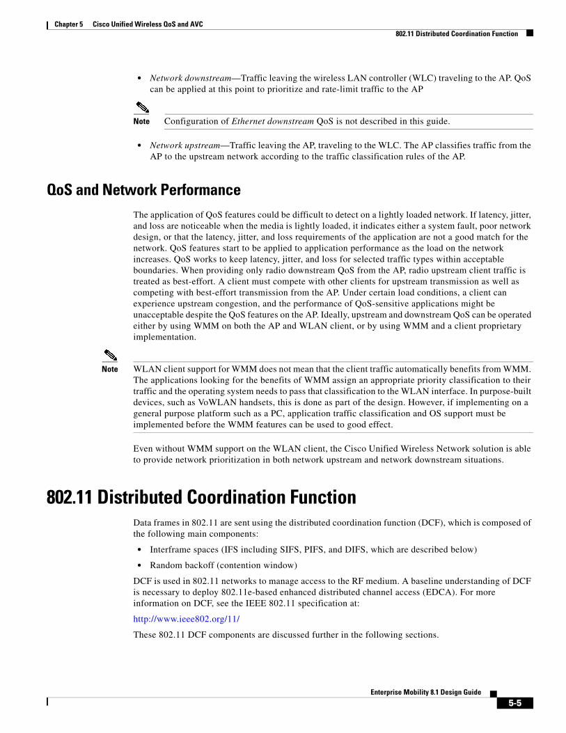
Interframe SpacesThe 802.11 standard defines interframe spaces (IFS) as:
• Short interframe space (SIFS)—10 µs
• PCF interframe space (PIFS)—SIFS + 1 x slot time = 30 µs
• DCF interframe space (DIFS)—50 µs SIFS + 2 x slot time = 50 µs
Note The base timing used in the IFS example shown in Figure 5-3 is for 802.11b. The timing in 802.11g and 802.11a are different, but the principles applied are the same.
IFS allow 802.11 to control which traffic gets first access to the channel after carrier sense declares the channel to be free. Generally, 802.11 management frames and frames not expecting contention (a frame that is part of a sequence of frames) use SIFS, and data frames use DIFS, as shown in Figure 5-3.
Figure 5-3 Interframe Spaces
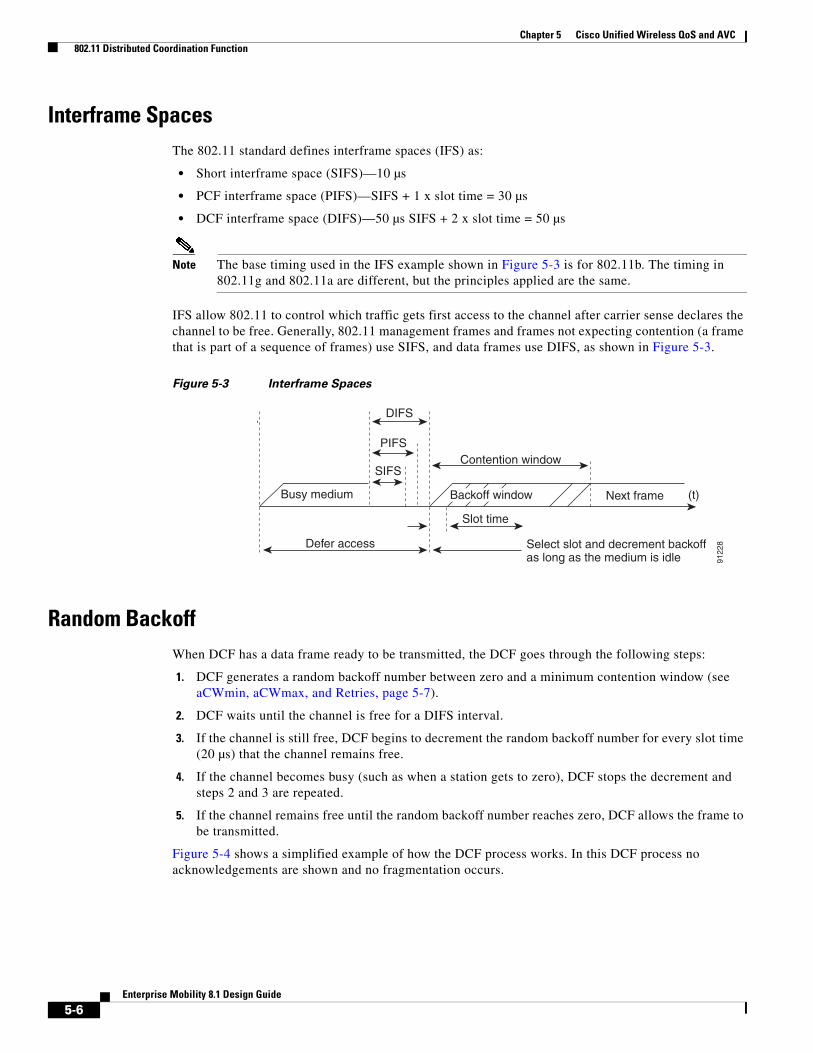
Random BackoffWhen DCF has a data frame ready to be transmitted, the DCF goes through the following steps:
1. DCF generates a random backoff number between zero and a minimum contention window (see aCWmin, aCWmax, and Retries, page 5-7).
2. DCF waits until the channel is free for a DIFS interval.
3. If the channel is still free, DCF begins to decrement the random backoff number for every slot time (20 µs) that the channel remains free.
4. If the channel becomes busy (such as when a station gets to zero), DCF stops the decrement and steps 2 and 3 are repeated.
5. If the channel remains free until the random backoff number reaches zero, DCF allows the frame to be transmitted.
Figure 5-4 shows a simplified example of how the DCF process works. In this DCF process no acknowledgements are shown and no fragmentation occurs.
Defer access
Slot time
Contention window
DIFS
PIFS
SIFS
Busy medium Next frame
Select slot and decrement backoffas long as the medium is idle
(t)Backoff window
9122
8
5-6Enterprise Mobility 8.1 Design Guide
Chapter 5 Cisco Unified Wireless QoS and AVC 802.11 Distributed Coordination Function
Figure 5-4 Distributed Coordination Function Example
The DCF steps illustrated in Figure 5-4 are:
1. Station A successfully transmits a frame. Three other stations want to transmit frames but must defer to Station A traffic.
2. After Station A completes the transmission, the stations must still defer to the DIFS.
3. When the DIFS completes, stations waiting to transmit a frame can begin to decrement their backoff counters, once for every slot time.
4. The backoff counter of Station B reaches zero before Stations C and D, and therefore Station B begins transmitting its frame.
5. When Station C and D detect that Station B is transmitting, they must stop decrementing their backoff counters and defer until the frame is transmitted and a DIFS has passed.
6. During the time that Station B is transmitting a frame, Station E receives a frame to transmit, but because Station B is transmitting a frame, it must defer in the same manner as Stations C and D.
7. When Station B completes transmission and the DIFS has passed, stations with frames to transmit begin to decrement their backoff counters. In this case, the Station D backoff counter reaches zero first and so Station D begins transmission of its frame.
The process continues as traffic arrives on the different stations.
aCWmin, aCWmax, and RetriesDCF uses a contention window (CW) parameters to control the size of the random backoff. The CW is defined by the parameters:
• aCWmin—Minimum contention window
• aCWmax—Maximum contention window
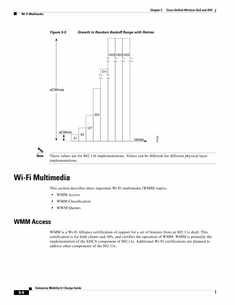
The random number used in the random backoff is initially a number between 0 and aCWmin. If the initial random backoff expires without successfully transmitting the frame, the station or AP increments the retry counter and doubles the value random backoff window size. This doubling in size continues until the size equals aCWmax. The retries continue until the maximum retries or time to live (TTL) is reached. This process of doubling the backoff window is often referred to as a binary exponential backoff, and is illustrated in Figure 5-5 where the aCWmin if 25-1, and increases to 26-1, on the next backoff level, up to the aCWmax value of 210-1.
DIFS DIFS DIFS
Station A
Station B
Station C
Station D
Station E
Frame
Frame
Frame
Frame
Defer
Defer Defer Defer
Defer
Defer
Defer
Defer
Backoff time
Backoff time remaining
9122
9
5-7Enterprise Mobility 8.1 Design Guide
Chapter 5 Cisco Unified Wireless QoS and AVC Wi-Fi Multimedia
Figure 5-5 Growth in Random Backoff Range with Retries
Note These values are for 802.11b implementations. Values can be different for different physical layer implementations.
Wi-Fi MultimediaThis section describes three important Wi-Fi multimedia (WMM) topics:
• WMM Access
• WMM Classification
• WWM Queues
WMM AccessWMM is a Wi-Fi Alliance certification of support for a set of features from an 802.11e draft. This certification is for both clients and APs, and certifies the operation of WMM. WMM is primarily the implementation of the EDCA component of 802.11e. Additional Wi-Fi certifications are planned to address other components of the 802.11e.
aCWmin
aCWmax
3163
127
255
511
1023 1023 1023
retries
9123
0
5-8Enterprise Mobility 8.1 Design Guide
Chapter 5 Cisco Unified Wireless QoS and AVC Wi-Fi Multimedia
WMM ClassificationWMM uses the 802.1P classification scheme (part of the IEEE 802.1D MAC Bridges standard). This classification scheme has eight priorities that WMM maps to four access categories with WMM designations:
• AC_BK—Background
• AC_BE—Best effort
• AC_VI—Video
• AC_VO—Voice
As shown in Table 5-2, these access categories map to the four queues (see WMM Queues, page 5-10) required by WMM devices.
Figure 5-6 shows the WMM data frame format. Note that even though WMM maps the eight 802.1P classifications to four access categories, the 802.11D classification is sent in the frame.
Acknowledge ------- 00Do not acknowledge ------- 01 End of service
period802.1Dpriority
5-9Enterprise Mobility 8.1 Design Guide
Chapter 5 Cisco Unified Wireless QoS and AVC Wi-Fi Multimedia
The WMM and IEEE 802.11e classifications are different from the classifications recommended and used in the Cisco Unified Wireless Network, which are based on IETF recommendations. The primary difference in classification is the changing of audio and video traffic to 5 and 4 user priorities (UPs), respectively. This allows the 6 classification to be used for Layer 3 network control. To be compliant with both standards, the Cisco Unified Wireless Network solution performs a conversion between the various classification standards when the traffic crosses the wireless-wired boundary.
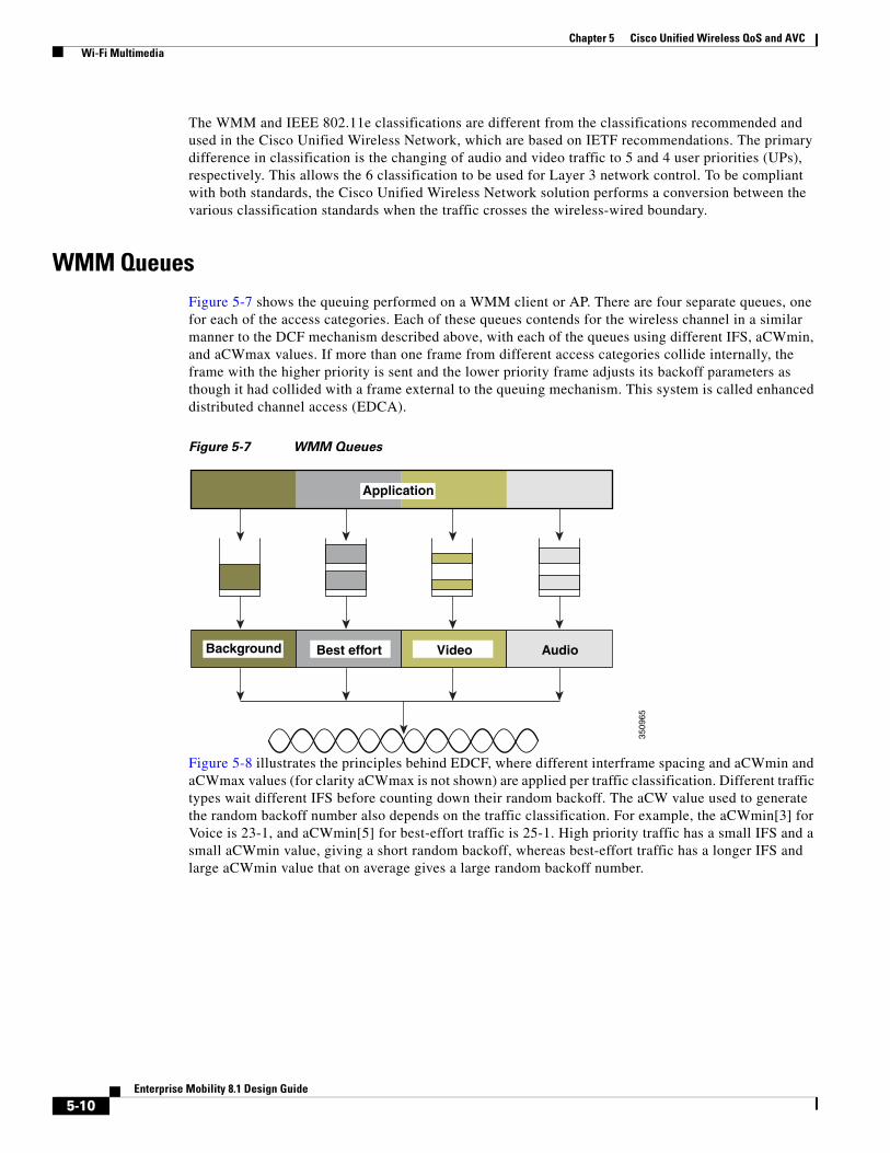
WMM QueuesFigure 5-7 shows the queuing performed on a WMM client or AP. There are four separate queues, one for each of the access categories. Each of these queues contends for the wireless channel in a similar manner to the DCF mechanism described above, with each of the queues using different IFS, aCWmin, and aCWmax values. If more than one frame from different access categories collide internally, the frame with the higher priority is sent and the lower priority frame adjusts its backoff parameters as though it had collided with a frame external to the queuing mechanism. This system is called enhanced distributed channel access (EDCA).
Figure 5-7 WMM Queues
Figure 5-8 illustrates the principles behind EDCF, where different interframe spacing and aCWmin and aCWmax values (for clarity aCWmax is not shown) are applied per traffic classification. Different traffic types wait different IFS before counting down their random backoff. The aCW value used to generate the random backoff number also depends on the traffic classification. For example, the aCWmin[3] for Voice is 23-1, and aCWmin[5] for best-effort traffic is 25-1. High priority traffic has a small IFS and a small aCWmin value, giving a short random backoff, whereas best-effort traffic has a longer IFS and large aCWmin value that on average gives a large random backoff number.
3509
65
Application
Background Best effort Video Audio
5-10Enterprise Mobility 8.1 Design Guide
Chapter 5 Cisco Unified Wireless QoS and AVC Wi-Fi Multimedia
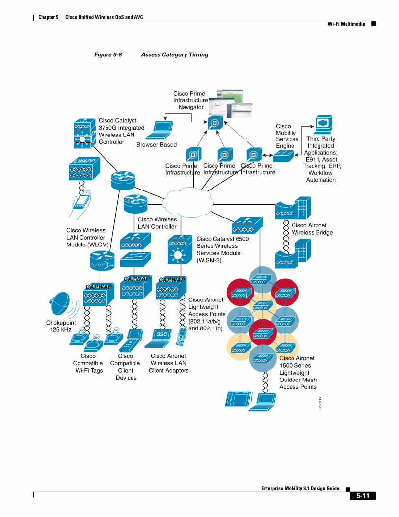
Figure 5-8 Access Category Timing
Browser-Based
CiscoMobilityServicesEngine
Third PartyIntegrated
Applications:E911, Asset
Tracking, ERP,Workflow
Automation
Cisco PrimeInfrastructure
Navigator
Cisco AironetLightweight Access Points(802.11a/b/g and 802.11n)
Cisco Aironet 1500 Series Lightweight Outdoor Mesh Access Points
Cisco Catalyst 6500 Series Wireless Services Module (WiSM-2)
Cisco Aironet Wireless LAN
Client Adapters
Cisco PrimeInfrastructure
W ESN
3510
17
Cisco PrimeInfrastructure
Cisco PrimeInfrastructure
CAPWAPCAPWAP CAPWAP
5-11Enterprise Mobility 8.1 Design Guide
Chapter 5 Cisco Unified Wireless QoS and AVC Wi-Fi Multimedia
Enhanced Distributed Channel Access
Figure 5-9 illustrates an example of the enhanced distributed channel access (EDCA) process.
Figure 5-9 EDCA Example
The EDCA process follows the sequence:
1. While Station X is transmitting its frame, three other stations determine that they must transmit a frame. Each station defers because a frame was already being transmitted, and each station generates a random backoff.
2. Because the Voice station has a traffic classification of voice (audio), it has an arbitrated interframe space (AIFS) of two and uses an initial aCWmin of three. Therefore the station must defer the countdown of its random backoff for two slot times. It also has a short random backoff value.
3. The best-effort station has an AIFS of three and a longer random backoff time, because its aCWmin value is five.
4. The Voice station has the shortest random backoff time and therefore starts transmitting first. When Voice starts transmitting all other stations defer.
5. After the Voice station finishes transmitting, all stations wait their AIFS then begin to decrement their random backoff counters again.
6. The best-effort station then completes decrementing its random backoff counter and begins transmission. All other stations defer.
This can happen even though there might be a Voice station waiting to transmit. This shows that best-effort traffic is not diminished by Voice traffic because the random backoff decrementing process eventually brings the best-effort backoff down to similar sizes as high priority traffic, and that the random process might, on occasion, generate a small random backoff number for best-effort traffic.
7. The process continues as other traffic enters the system.
The access category settings shown in Table 5-3 and Table 5-4 are, by default, the same for an 802.11a radio and are based on formulas defined in WMM.
Note Table 5-3 refers to the parameter settings on a client, which are slightly different from the settings for an AP. The AP has a larger AIFS[n] for audio and video admission controls (ACs).
1326
01
AIFS[0]
Best effort
Voice
Frame
Frame
Defer
Frame
Defer
AIFS[0] AIFS[0] AIFS[0]
AIFS[6] AIFS[6] AIFS[6] AIFS[6]
DeferDefer
Defer
5-12Enterprise Mobility 8.1 Design Guide
Chapter 5 Cisco Unified Wireless QoS and AVC Wi-Fi Multimedia
The overall impact of the different AIFS, CWmin, and aCWmax values is difficult to illustrate in timing diagrams because their impact is more statistical in nature. It is easier to compare the AIFS and the size of the random backoff windows, as shown in Figure 5-8.
When comparing Voice and Background frames as examples, these traffic categories have CWmin values of 23-1 (7) and 25-1 (31), and AIFS of 2 and 7, respectively. This is an average delay of 5 (2+7/1) slot times before transmitting an audio frame, and an average of 22 slot (7+31/2) times for Background frame. Therefore, Voice frames are statistically much more likely to be sent before Background frames.
Figure 5-10 shows the WMM information in a probe response. Apart from the WMM access-category information contained in this element, the client also learns which WMM categories require admission control. As can be seen in this example, the Voice admission control (AC) is set to mandatory. This requires the client to transmit the request to the AP, and have the request accepted, before it can use this AC. Admission control is further discussed in different parts of this chapter.
Table 5-3 WMM Client Parameters
AC CWmin aCWmax AIFS[n]TXOP Limit (802.11b)
TXOP Limit (802.11a/g)
AC_BK CWmin aCWmax 7 0 0
AC_BE CWmin 4*(aCQmin+1)-1 3 0 0
AC_VI (CWmin+1)/2-1 CWmin 1 6.016 ms 3.008 ms
AC_VO (CWmin+1)/4-1 (CWmin+1)/2-1 1 3.264 ms 1.504 ms
Table 5-4 WMM AP Parameters
Access Category CWmin aCWmax AIFS[n]
TXOP Limit (802.11b
TXOP Limit (802.11a/g)
AC_BK CWmin aCWmax 7 0 0
AC_BE CWmin 4*(aCQmin+1)-1 3 0 0
AC_VI (CWmin+1)/2-1 CWmin 2 6.016 ms 3.008 ms
AC_VO (CWmin+1)/4-1 (CWmin+1)/2-1 2 3.264 ms 1.504 ms
5-13Enterprise Mobility 8.1 Design Guide
Chapter 5 Cisco Unified Wireless QoS and AVC Wi-Fi Multimedia
Figure 5-10 Probe Response WMM Element Information
Unscheduled-Automatic Power-save Delivery
Unscheduled-automatic power-save delivery (U-APSD) is a feature of WMM that has two key benefits:
• The primary benefit of U-APSD is that it allows the audio client to synchronize the transmission and reception of audio frames with the AP, thereby allowing the client to go into power-save mode between the transmission/reception of each audio frame tuple. The WLAN client frame transmission in the access categories supporting U-APSD triggers the AP to transmit any data frames queued for that WLAN client in that access category. A U-APSD client continues listening to the AP until it receives a frame from the AP with an end-of-service period (EOSP) bit set. This tells the client that it can now go back into its power-save mode. This triggering mechanism is considered a more
5-14Enterprise Mobility 8.1 Design Guide
Chapter 5 Cisco Unified Wireless QoS and AVC Wi-Fi Multimedia
efficient use of client power than the regular listening for beacons method, at a period controlled by the delivery traffic indication message (DTIM) interval. This is because the latency and jitter requirements of audio are such that a wireless VoIP client would either not be in power-save mode during a call, resulting in reduced talk times, or would use a short DTIM interval that results in reduced standby times. The use of U-APSD allows the use of long DTIM intervals to maximize standby time without sacrificing call quality. The U-APSD feature can be applied individually across access categories, allowing U-APSD can be applied to the audio ACs in the AP, but the other ACs still use the standard power-save mode feature.
• The secondary benefit of this feature is increased call capacity. The coupling of transmission buffered data frames from the AP with the triggering data frame from the WLAN client allows the frames from the AP to be sent without the accompanying IFS and random backoff, thereby reducing the contention experience by call.
Figure 5-11 shows a sample frame exchange for the standard 802.11 power save delivery process.
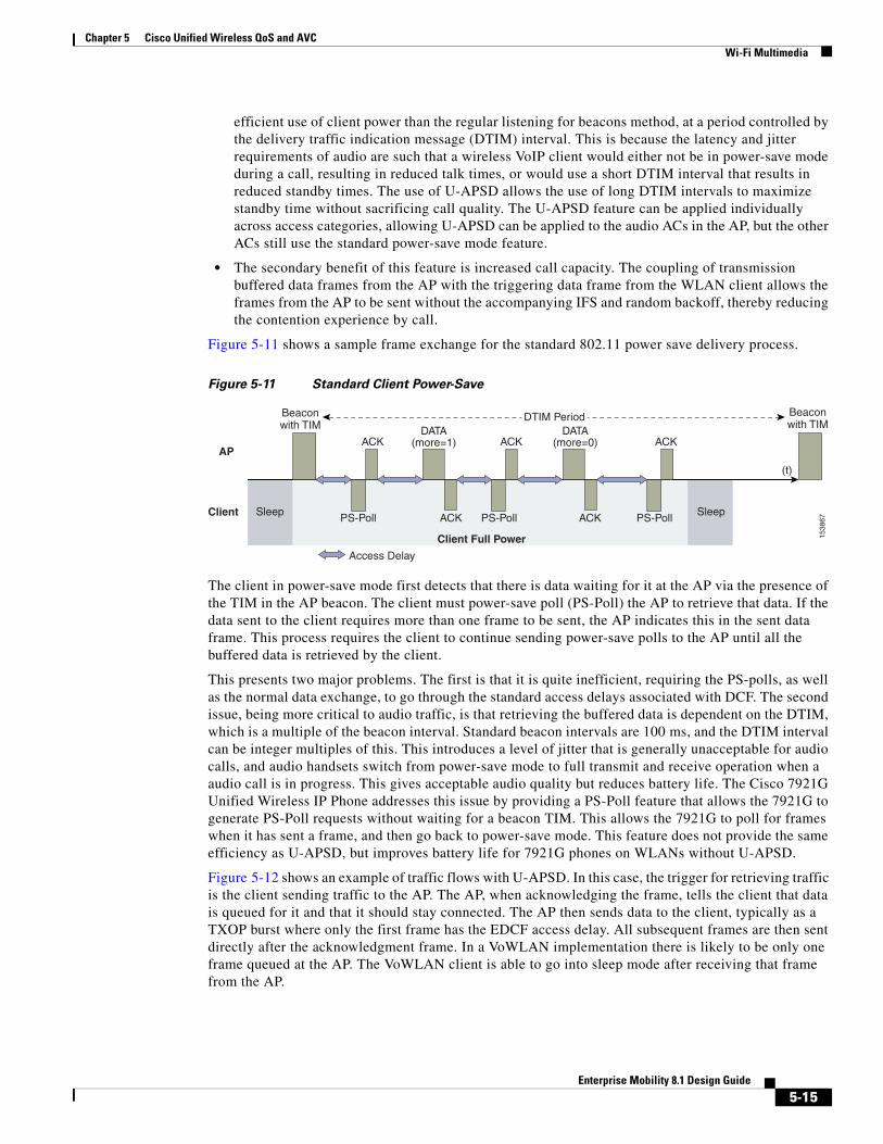
Figure 5-11 Standard Client Power-Save
The client in power-save mode first detects that there is data waiting for it at the AP via the presence of the TIM in the AP beacon. The client must power-save poll (PS-Poll) the AP to retrieve that data. If the data sent to the client requires more than one frame to be sent, the AP indicates this in the sent data frame. This process requires the client to continue sending power-save polls to the AP until all the buffered data is retrieved by the client.
This presents two major problems. The first is that it is quite inefficient, requiring the PS-polls, as well as the normal data exchange, to go through the standard access delays associated with DCF. The second issue, being more critical to audio traffic, is that retrieving the buffered data is dependent on the DTIM, which is a multiple of the beacon interval. Standard beacon intervals are 100 ms, and the DTIM interval can be integer multiples of this. This introduces a level of jitter that is generally unacceptable for audio calls, and audio handsets switch from power-save mode to full transmit and receive operation when a audio call is in progress. This gives acceptable audio quality but reduces battery life. The Cisco 7921G Unified Wireless IP Phone addresses this issue by providing a PS-Poll feature that allows the 7921G to generate PS-Poll requests without waiting for a beacon TIM. This allows the 7921G to poll for frames when it has sent a frame, and then go back to power-save mode. This feature does not provide the same efficiency as U-APSD, but improves battery life for 7921G phones on WLANs without U-APSD.
Figure 5-12 shows an example of traffic flows with U-APSD. In this case, the trigger for retrieving traffic is the client sending traffic to the AP. The AP, when acknowledging the frame, tells the client that data is queued for it and that it should stay connected. The AP then sends data to the client, typically as a TXOP burst where only the first frame has the EDCF access delay. All subsequent frames are then sent directly after the acknowledgment frame. In a VoWLAN implementation there is likely to be only one frame queued at the AP. The VoWLAN client is able to go into sleep mode after receiving that frame from the AP.
1538
67
Beaconwith TIM
Beaconwith TIM
AP
Client
ACK ACK ACK
ACKACKSleep
PS-Poll PS-Poll PS-PollSleep
Client Full Power
DATA(more=0)
(t)
DTIM Period
Access Delay
DATA(more=1)
5-15Enterprise Mobility 8.1 Design Guide
Chapter 5 Cisco Unified Wireless QoS and AVC Wi-Fi Multimedia
Figure 5-12 U-APSD
This approach overcomes both the disadvantages of the previous scheme, in that it is much more efficient. The timing of the polling is controlled by way of the client traffic, which in the case of audio is symmetric, so if the client is transmitting a frame every 20 ms, it would be expecting to receive a frame every 20 ms as well. This would introduce a maximum jitter of 20 ms, rather than an n * 100 ms jitter.
TSpec Admission Control
Traffic Specification (TSpec) allows an 802.11e client to signal its traffic requirements to the AP. In the 802.11e MAC definition, two mechanisms provide prioritized access: the contention-based EDCA option and the controlled access option provided by the transmit opportunity (TXOP). When describing TSpec features where a client can specify its traffic characteristics, it is easy to assume that this would automatically result in the use of the controlled access mechanism, and have the client granted a specific TXOP to match the TSpec request. However, this does not have to be the case; a TSpec request can be used to control the use of the various access categories (ACs) in EDCA. Before a client can send traffic of a certain priority type, it must have requested to do so by way of the TSpec mechanism. For example, a WLAN client device wanting to use the audio access categories must first make a request for use of that AC. Whether or not AC use is controlled by TSpec requests is configurable with audio and audio ACs controlled by TSpec requests, and best-effort and background ACs can be open for use without a TSpec request. The use of EDCA ACs, rather than the 802.11e Hybrid Coordinated Channel Access (HCCA), to meet TSpec requests is possible in many cases because the traffic parameters are sufficiently simple to allow them to be met by allocating capacity, rather than creating a specific TXOP to meet the application requirements.
Add Traffic Stream
The Add Traffic Stream (ADDTS) function is used by WLAN client to send an admission request to an AP. Signaling its TSpec request to the AP, an admission request is in one of two forms:
• ADDTS action frame—Created when a phone call is originated or terminated by a client associated to the AP. The ADDTS contains TSpec and could contain a traffic stream rate set (TSRS) information element (IE).
• Association and re-association message—The association message might contain one or more TSpecs and one TSRS IE if the station wants to establish the traffic stream as part of the association. The re-association message might contain one or more TSpecs and one TSRS IE if an station roams to another AP.
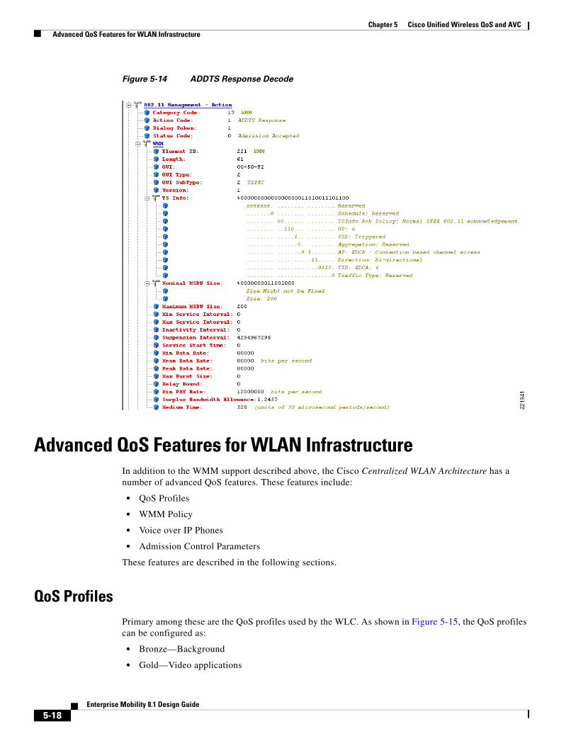
The ADDTS contains the TSpec element that describes the traffic request. See Figure 5-13 and Figure 5-14 for examples of an ADDTS request and response between a Cisco 7921 WLAN handset and a Cisco AP. Apart from key data describing the traffic requirements, such as data rates and frame sizes, the TSpec element also tells the AP the minimum physical rate that the client device will use. This allows the calculation of how much time that station can potentially consume in transmitting and receiving in this TSpec, and therefore allowing the AP to calculate whether it has the resources to meet the TSpec.
1538
68
AP
Client
ACK ACK
ACKSleep
Trigger Frame+ data
Sleep
Client Full Power
DATA(more=0)
(t)
EDCA Delay
DATA(more=1)
ACKSleep
Trigger Frame+ data
DATA(more=0)
ACK
Client Full Power
5-16Enterprise Mobility 8.1 Design Guide
Chapter 5 Cisco Unified Wireless QoS and AVC Wi-Fi Multimedia
TSpec admission control is used by the WLAN client (target clients are VoIP handsets) when a call is initiated and during a roam request. During a roam, the TSpec request is appended to the re-association request.
TSpec support is not required by clients. But when a WLAN is configured with call admission control (CAC) for either audio or video that client that is not in support of TSpec is must send the audio and video packets at a Best effort QoS level (see QoS Profiles, page 5-18). So, if the WLAN is set at QoS level of audio or video and CAC is enabled then the correct behavior for a client without ADDTS logic is to send the audio and video traffic with Best effort markings. If a TSpec capable clients has its ADDTS request reject be the Wi-Fi channel utilization is high than the configured CAC limit. That client per specification is supposed to mark the audio and video packets at Best effort.
Figure 5-13 ADDTS Request Decode
5-17Enterprise Mobility 8.1 Design Guide
Chapter 5 Cisco Unified Wireless QoS and AVC Advanced QoS Features for WLAN Infrastructure
Figure 5-14 ADDTS Response Decode
Advanced QoS Features for WLAN InfrastructureIn addition to the WMM support described above, the Cisco Centralized WLAN Architecture has a number of advanced QoS features. These features include:
• QoS Profiles
• WMM Policy
• Voice over IP Phones
• Admission Control Parameters
These features are described in the following sections.
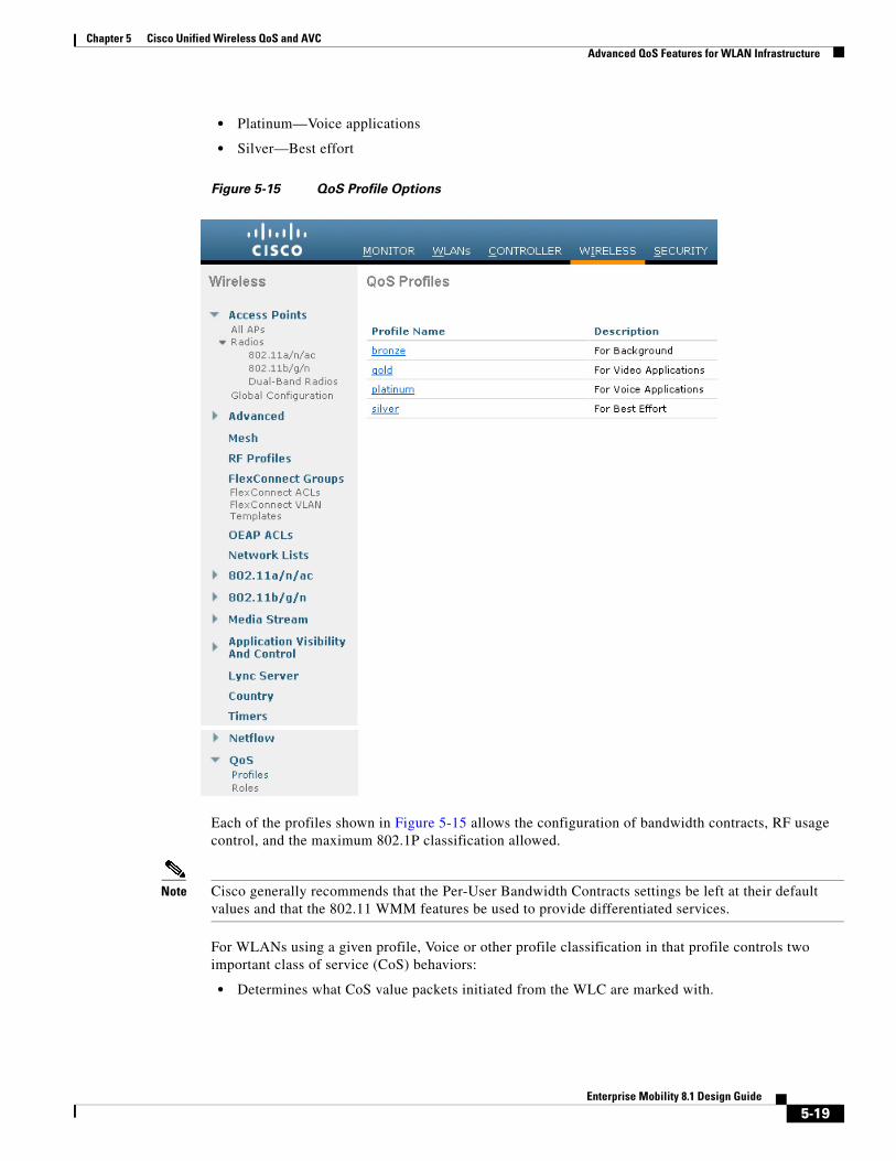
QoS ProfilesPrimary among these are the QoS profiles used by the WLC. As shown in Figure 5-15, the QoS profiles can be configured as:
• Bronze—Background
• Gold—Video applications
5-18Enterprise Mobility 8.1 Design Guide
Chapter 5 Cisco Unified Wireless QoS and AVC Advanced QoS Features for WLAN Infrastructure
• Platinum—Voice applications
• Silver—Best effort
Figure 5-15 QoS Profile Options
Each of the profiles shown in Figure 5-15 allows the configuration of bandwidth contracts, RF usage control, and the maximum 802.1P classification allowed.
Note Cisco generally recommends that the Per-User Bandwidth Contracts settings be left at their default values and that the 802.11 WMM features be used to provide differentiated services.
For WLANs using a given profile, Voice or other profile classification in that profile controls two important class of service (CoS) behaviors:
• Determines what CoS value packets initiated from the WLC are marked with.
5-19Enterprise Mobility 8.1 Design Guide
Chapter 5 Cisco Unified Wireless QoS and AVC Advanced QoS Features for WLAN Infrastructure
The value of the CoS parameter is used to mark the CoS of all CAPWAP (Control And Provisioning of Wireless Access Points) packets for the WLAN using that profile. So a WLAN with a platinum QoS profile, and the 802.1P mark of 6, will have its CAPWAP packets from the application manager interface of the controller marked with CoS of 5. The WLC adjusts the CoS to be compliant with Cisco QoS baseline recommendations. The reason why it is important to maintain the IEEE CoS marking in the configuration is below. If the WLAN is configured to trust CoS rather than DSCP at the network connection to the WLC, the CoS value is used for the DSCP of the CAPWAP packets received by the AP; and eventually the WMM classification and queuing for WLAN traffic. This is because the WLAN WMM classification of a frame is derived from the DSCP value of the CAPWAP packet carrying that frame.
• Determines the maximum CoS value that can be used by clients connected to that WLAN.
The 802.1P classification sets the maximum CoS value that is admitted on a WLAN with that profile.
WMM audio traffic arrives with a CoS of 6 at the AP, and the AP automatically performs a CoS-to-DSCP mapping for this traffic based on a CoS of 6. If the CoS value in the WLC configuration is set to a value less than 6, this changed value is used by the WLAN QoS profile at the AP to set the maximum CoS marking used and therefore which WMM admission control (AC) to use.
The key point is that with the Cisco Unified Wireless Network, you should always think in terms of IEEE 802.11e classifications and allow the Unified Wireless Network Solution to take responsibility for converting between IEEE classification and the Cisco QoS baseline.
The WLAN can be configured with various default QoS profiles, as shown in Figure 5-16. Each of the QoS profiles are annotated with their typical use. In addition, clients can be assigned a QoS profile based on their identity, through authentication, authorization and accounting (AAA). For a typical enterprise, WLAN deployment parameters such as per-user bandwidth contracts and over-the-air QoS, should be left at their default values, and standard QoS mechanisms, such as WMM and wired QoS, should be used to provide optimum QoS to clients.
5-20Enterprise Mobility 8.1 Design Guide
Chapter 5 Cisco Unified Wireless QoS and AVC Advanced QoS Features for WLAN Infrastructure
Figure 5-16 WLAN QoS Profile
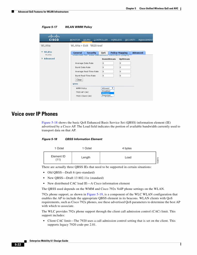
WMM PolicyIn addition to QoS profiles, WMM Policy for the WLAN allows you to control additional WMM options, as shown in Figure 5-17. The WMM options are:
• Disabled—The WLAN does not advertise WMM capabilities nor allow WMM negotiations
• Allowed—The WLAN does allow WMM and non-WMM clients
• Required—Only WMM-enabled clients can be associated with this WLAN
5-21Enterprise Mobility 8.1 Design Guide
Chapter 5 Cisco Unified Wireless QoS and AVC Advanced QoS Features for WLAN Infrastructure
Figure 5-17 WLAN WMM Policy
Voice over IP PhonesFigure 5-18 shows the basic QoS Enhanced Basis Service Set (QBSS) information element (IE) advertised by a Cisco AP. The Load field indicates the portion of available bandwidth currently used to transport data on that AP.
Figure 5-18 QBSS Information Element
There are actually three QBSS IEs that need to be supported in certain situations:
• Old QBSS—Draft 6 (pre-standard)
• New QBSS—Draft 13 802.11e (standard)
• New distributed CAC load IE—A Cisco information element
The QBSS used depends on the WMM and Cisco 792x VoIP phone settings on the WLAN.
792x phone support, as shown in Figure 5-19, is a component of the WLC WLAN configuration that enables the AP to include the appropriate QBSS element in its beacons. WLAN clients with QoS requirements, such as Cisco 792x phones, use these advertised QoS parameters to determine the best AP with which to associate.
The WLC provides 792x phone support through the client call admission control (CAC) limit. This support includes:
• Client CAC limit—The 7920 uses a call admission control setting that is set on the client. This supports legacy 7920 code-pre 2.01.
1538
73
1 Octet 1 Octet 4 bytes
Element ID(11)
Length Load
5-22Enterprise Mobility 8.1 Design Guide
Chapter 5 Cisco Unified Wireless QoS and AVC Advanced QoS Features for WLAN Infrastructure
• AP CAC limit—The 7920 uses CAC settings learned from WLAN advertisement.
The various combinations of WMM, client CAC limit, and AP CAC limit settings result in different QBSS IEs being sent:
• If only WMM is enabled, IE number 2 (802.11e standard) QBSS Load IE is sent out in the beacons and probe responses.
• If 7920 client CAC limit is to be supported, IE number 1 (the pre-standard QBSS IE) is sent out in the beacons and probe responses on the 802.11b/g radios.
• If 7920 AP CAC limit is to be supported, the number 3 QBSS IE is sent in the beacons and probe responses for bg radios.
Note The various QBSS IEs use the same ID, and therefore the three QBSSs are mutually exclusive. For example, the beacons and probe responses can contain only one QBSS IE.
Admission Control ParametersFigure 5-19 shows an example of the configuration window for setting the Voice, Video, and Media parameters on the controller.
5-23Enterprise Mobility 8.1 Design Guide
Chapter 5 Cisco Unified Wireless QoS and AVC Advanced QoS Features for WLAN Infrastructure
Figure 5-19 Voice Parameter Setting
The CAC parameters include the Max RF Bandwidth (%) that a radio can be using and still accept the initiation of a VoWLAN call through a normal ADDTS request. The range of that value is 5 to 85 percent of the channel bandwidth.
The Reserved Roaming Bandwidth (%) parameter specifies how much capacity is reserved to be able to respond to ADDTS requests during association or re-association, and which are VoWLAN clients with calls in progress that are trying to roam to that AP.
To enable AC based upon these parameters, select the Admission Control (ACM) check box. This enables AC based upon the capacity of the AP but it does not take into account the possible channel loading impact of other APs in the area. To include this channel loading in capacity calculations, select the both Load-Based AC and Admission Control (ACM) check boxes.
Note Voice and video load-based CAC applies to non-mesh APs. For mesh APs, only static CAC is applicable.
5-24Enterprise Mobility 8.1 Design Guide
Chapter 5 Cisco Unified Wireless QoS and AVC Advanced QoS Features for WLAN Infrastructure
SIP CAC support requires either static or load-based CAC. If you are using Static CAC then SIP CAC support allows the configuration of the of the number of calls on the AP. Generally the dynamic the load-balanced approach is the better way of managing quantity of calls to prevent the quality from suffering from over subscription of calls on the Wi-Fi channel.
In the Voice Parameters window (Figure 5-19), the Metrics Collection option specifies whether data is collected on audio or video calls for use by Cisco Prime Infrastructure.
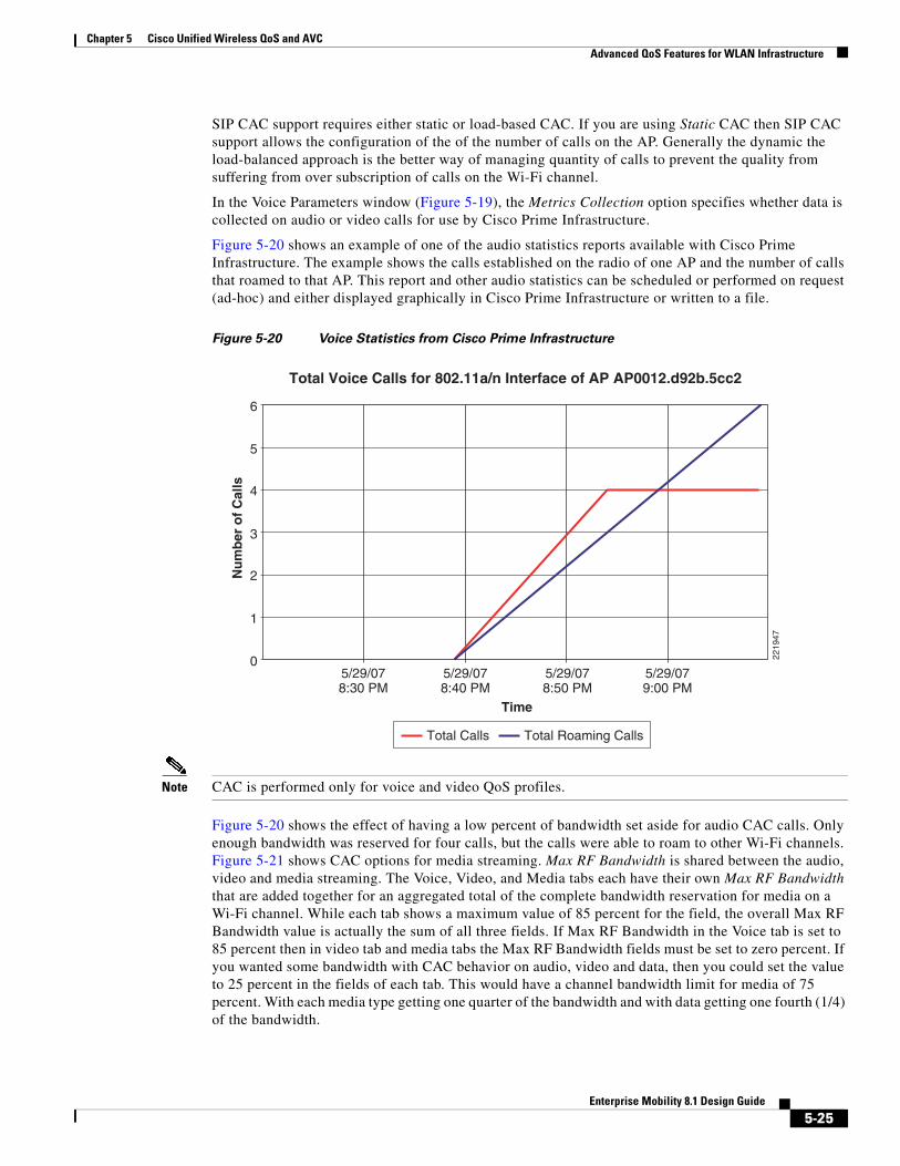
Figure 5-20 shows an example of one of the audio statistics reports available with Cisco Prime Infrastructure. The example shows the calls established on the radio of one AP and the number of calls that roamed to that AP. This report and other audio statistics can be scheduled or performed on request (ad-hoc) and either displayed graphically in Cisco Prime Infrastructure or written to a file.
Figure 5-20 Voice Statistics from Cisco Prime Infrastructure
Note CAC is performed only for voice and video QoS profiles.
Figure 5-20 shows the effect of having a low percent of bandwidth set aside for audio CAC calls. Only enough bandwidth was reserved for four calls, but the calls were able to roam to other Wi-Fi channels. Figure 5-21 shows CAC options for media streaming. Max RF Bandwidth is shared between the audio, video and media streaming. The Voice, Video, and Media tabs each have their own Max RF Bandwidth that are added together for an aggregated total of the complete bandwidth reservation for media on a Wi-Fi channel. While each tab shows a maximum value of 85 percent for the field, the overall Max RF Bandwidth value is actually the sum of all three fields. If Max RF Bandwidth in the Voice tab is set to 85 percent then in video tab and media tabs the Max RF Bandwidth fields must be set to zero percent. If you wanted some bandwidth with CAC behavior on audio, video and data, then you could set the value to 25 percent in the fields of each tab. This would have a channel bandwidth limit for media of 75 percent. With each media type getting one quarter of the bandwidth and with data getting one fourth (1/4) of the bandwidth.
6
5
4
Nu
mb
er o
f C
alls
3
2
1
05/29/078:30 PM
5/29/078:40 PM
Total Calls
Time
Total Voice Calls for 802.11a/n Interface of AP AP0012.d92b.5cc2
5/29/078:50 PM
5/29/079:00 PM
Total Roaming Calls
2219
47
5-25Enterprise Mobility 8.1 Design Guide
Chapter 5 Cisco Unified Wireless QoS and AVC Advanced QoS Features for WLAN Infrastructure
Figure 5-21 WLC 802.11a(5 GHz) Media Window
CAC for video behaves like audio CAC. The purpose of CAC for video is to limit the amount of video calling so that the quality of active video calls is not negatively impacted by additional video being added to the Wi-Fi channel.
Note See the WLC configuration guide for more details on these and the other configuration options.
Impact of TSpec Admission Control
The purpose of TSpec admission control is to protect the high priority resources and not to deny clients access to the WLAN. Therefore, a client that has not used TSpec admission control does not have its traffic blocked; it simply has its traffic re-classified if it tries to transmit (which it should not do if the client is transmitting WMM-compliant traffic in a protected admission control).
Table 5-5 and Table 5-6 describe the impact on classification if admission control is enabled or not and whether or not a traffic stream has been established.
5-26Enterprise Mobility 8.1 Design Guide
Chapter 5 Cisco Unified Wireless QoS and AVC 802.11e, 802.1P and DSCP Mapping
802.11e, 802.1P and DSCP MappingWLAN data in a Unified Wireless Network is tunneled by way of CAPWAP (IP UDP packets). To maintain the QoS classification that has been applied to WLAN frames, the WLC uses a process of mapping classifications to and from DSCP and CoS. For example, when WMM classified traffic is sent by a WLAN client, it has an 802.1P classification in its frame. The AP needs to translate this classification into a DSCP value for the CAPWAP packet carrying the frame to ensure that the packet is treated with the appropriate priority on its way to the WLC. A similar process must occur on the WLC for CAPWAP packets going to the AP.
A mechanism to classify traffic from non-WMM clients is also required so that their CAPWAP packets can also be given an appropriate DSCP classification (see Classification Considerations, page 5-33) by the AP and the WLC.
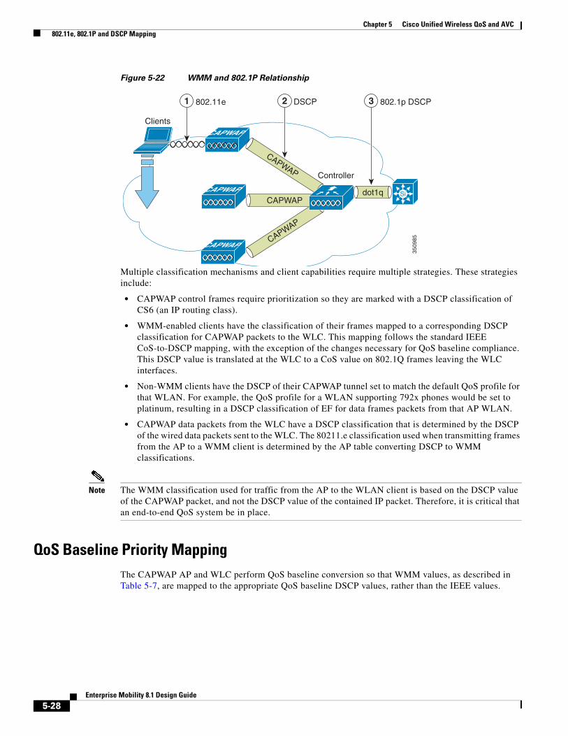
Figure 5-22 shows the various classification mechanisms in the CAPWAP WLAN network.
Table 5-5 Upstream Traffic
AC Enabled Traffic Stream Established No Traffic Stream
No No change in behavior; the packets go into the network as they do today- user priority (UP) is limited to max= WLAN QoS setting.
No change in behavior; the packets go into the network as they do today- UP is limited to max= WLAN QoS setting.
Yes No change in behavior; the packets go into the network as they do today- UP is limited to max= WLAN QoS setting.
Packets are remarked to BE (both CoS and DSCP) before they enter the network for WMM clients. For non-WMM clients, packets are sent with WLAN QoS.
Table 5-6 Downstream Traffic
AC Enabled Traffic Stream Established No Traffic Stream
No No change No change
Yes No change Remark UP to BE for WMM client. For non-WMM clients, use WLAN QoS.
5-27Enterprise Mobility 8.1 Design Guide
Chapter 5 Cisco Unified Wireless QoS and AVC 802.11e, 802.1P and DSCP Mapping
Figure 5-22 WMM and 802.1P Relationship
Multiple classification mechanisms and client capabilities require multiple strategies. These strategies include:
• CAPWAP control frames require prioritization so they are marked with a DSCP classification of CS6 (an IP routing class).
• WMM-enabled clients have the classification of their frames mapped to a corresponding DSCP classification for CAPWAP packets to the WLC. This mapping follows the standard IEEE CoS-to-DSCP mapping, with the exception of the changes necessary for QoS baseline compliance. This DSCP value is translated at the WLC to a CoS value on 802.1Q frames leaving the WLC interfaces.
• Non-WMM clients have the DSCP of their CAPWAP tunnel set to match the default QoS profile for that WLAN. For example, the QoS profile for a WLAN supporting 792x phones would be set to platinum, resulting in a DSCP classification of EF for data frames packets from that AP WLAN.
• CAPWAP data packets from the WLC have a DSCP classification that is determined by the DSCP of the wired data packets sent to the WLC. The 80211.e classification used when transmitting frames from the AP to a WMM client is determined by the AP table converting DSCP to WMM classifications.
Note The WMM classification used for traffic from the AP to the WLAN client is based on the DSCP value of the CAPWAP packet, and not the DSCP value of the contained IP packet. Therefore, it is critical that an end-to-end QoS system be in place.
QoS Baseline Priority MappingThe CAPWAP AP and WLC perform QoS baseline conversion so that WMM values, as described in Table 5-7, are mapped to the appropriate QoS baseline DSCP values, rather than the IEEE values.
Clients
Controller
802.11e1 DSCP2 802.1p DSCP3
3509
85
CAPWAP
CAPWAP
SiCAPWAP
CAPWAP
CAPWAP
CAPWAP
dot1q
5-28Enterprise Mobility 8.1 Design Guide
Chapter 5 Cisco Unified Wireless QoS and AVC 802.11e, 802.1P and DSCP Mapping
Deploying QoS Features on CAPWAP-based APs
When deploying WLAN QoS features on the APs, consider the following:
• The wired CAPWAP AP interface reads or writes Layer 2 CoS (802.1P) information. The WLC and the APs depend on Layer 3 classification (DSCP) information to communicate WLAN client traffic classification. This DSCP value could be subject to modification by intermediate routers, and therefore the Layer 2 classification received by the destination might not reflect the Layer 2 classification marked by the source of the CAPWAP traffic.
• The APs no longer use NULL VLAN ID. As a consequence, Layer 2 CAPWAP does not effectively support QoS because the AP does not send the 802.1P/Q tags and in Layer 2 CAPWAP there is no outer DSCP on which to fall back.
• APs do not re-classify frames; they prioritize them based on CoS value or WLAN profile.
• APs carry out EDCF-like queuing on the radio egress port only.
• APs do FIFO queuing only on the Ethernet egress port.
WAN QoS and FlexConnect
For WLANs that have data traffic forwarded to the WLC, the behavior is same as non-hybrid remote edge FlexConnect APs. For locally-switched WLANs with WMM traffic, FlexConnect APs mark the dot1p value in the dot1q VLAN tag for upstream traffic. This occurs only on tagged non-native VLANs.
Table 5-7 Access Point QoS Translation Values1
1. The IEEE 802.11e UP (user priority) value for DSCP values that are not mentioned in the table is calculated by considering 3 MSB bits of DSCP. For example, the IEEE 802.11e UP value for DSCP 32 (100 000 in binary), would be the decimal converted value of the MSB (100) which is 4. The 802.11e UP value of DSCP 32 is 4.
AVVID 802.1 UP-Based Traffic Type AVVID IP DSCP AVVID 802.1p UP IEEE 802.11e UP
Network control 56 7 —
Inter-network control (CAPWAP control, 802,11 management
48 6 7
Voice 46 (EF) 5 6
Video 34 (AF41) 4 5
Voice Control 26 (AF31) 3 4
Background (gold) 18 (AF21) 2 2
Background (gold) 20 (AF22) 2 2
Background (gold) 22 (AF23) 2 2
Background (silver) 10 (AF11) 1 1
Background (silver) 12 (AF12) 1 1
Background (silver) 14 (AF13) 1 1
Best Effort 0 (BE) 0 0, 3
Background 2 0 1
Background 4 0 1
Background 6 0 1
5-29Enterprise Mobility 8.1 Design Guide
Chapter 5 Cisco Unified Wireless QoS and AVC Guidelines for Deploying Wireless QoS
For downstream traffic, FlexConnect APs use the incoming dot1q tag from the Ethernet side and then use this to queue and mark the WMM values on the radio of the locally-switched VLAN.
The WLAN QoS profile is applied to both upstream and downstream packets. For downstream traffic, if an 802.1P value that is higher than the default WLAN value is received, the default WLAN value is used. For upstream traffic, if the client sends an WMM value that is higher than the default WLAN value, the default WLAN value is used. For non-WMM traffic there is no CoS marking on the client frames from the AP.
Guidelines for Deploying Wireless QoSThe same rules for deploying QoS in a wired network apply to deploying QoS in a WLAN. The first and most important guideline in QoS deployment is to know your traffic. Know your protocols, the sensitivity to delay of your application, and traffic bandwidth. QoS does not create additional bandwidth, it simply gives more control over where the bandwidth is allocated.
QoS LAN Switch Configuration Example
AP Switch Configuration
The QoS configuration of the AP switch is minor because the switch must trust the DSCP of the CAPWAP packets that are passed to it from the AP. There is no CoS marking on the CAPWAP frames coming from the AP. Below is an example of this configuration. Note that this configuration addresses only the classification and that queuing commands can be added depending on local QoS policy.
In trusting the AP DSCP values, the access switch is trusting the policy set for that AP by the WLC. The maximum DSCP value assigned to client traffic is based on the QoS policy applied to the WLAN on that AP.
WLC Switch Configuration
The QoS classification decision at the WLC-connected switch is slightly more complicated than at the AP-connected switch because the choice can be to either trust the DSCP or the CoS of traffic coming from the WLC. When making this decision, consider the following:
• Traffic leaving the WLC can be either upstream (to the WLC or network) or downstream (to the AP and WLAN client). The downstream traffic is CAPWAP encapsulated, and the upstream traffic is either CAPWAP encapsulated or decapsulated WLAN client traffic leaving the WLC.
• DSCP values of CAPWAP packets are controlled by the QoS policies on the WLC; the DSCP values set on the WLAN client traffic (encapsulated by the CAPWAP tunnel header) has not been altered from those set by the WLAN client.
• CoS values of frames leaving the WLC are set by the WLC QoS policies, regardless of whether they are upstream, downstream, encapsulated, or decapsulated.
5-30Enterprise Mobility 8.1 Design Guide
Chapter 5 Cisco Unified Wireless QoS and AVC CAPWAP over WAN Connections
The following example chooses to trust the CoS settings of the WLC because this allows a central location for the management of WLAN QoS rather than having to manage the WLC configuration and an additional policy at the WLC switch connection.
If you want to have a more precise degree of control you can implement QoS classification policies on the WLAN-client VLANs.
Traffic Shaping, Over the Air QoS, and WMM ClientsTraffic shaping and over-the-air QoS are useful tools in the absence of WLAN WMM features, but they do not address the prioritization of 802.11 traffic directly. For WLANs that support WMM clients or 792x handsets, the WLAN QoS mechanisms of these clients should be relied on; no traffic shaping or over-the-air QoS should be applied to these WLANs.
WLAN Voice and Cisco PhonesThe data sheets for Cisco Unified Communication Endpoints can be found at:
Chapter 5 Cisco Unified Wireless QoS and AVC CAPWAP over WAN Connections
CAPWAP Traffic ClassificationCAPWAP APs can be generally separated into the following two types:
• CAPWAP control traffic—Identified by UDP port 5246
• CAPWAP 802.11 traffic—Identified by UPD port 5247
CAPWAP Control Traffic
CAPWAP control traffic can be generally divided into the following two additional types:
• Initialization traffic—Generated when a CAPWAP AP is booted and joins a CAPWAP system. For example, initialization traffic could be generated by controller discovery, AP configuration, and AP firmware updates.
Note CAPWAP image packets from the controller are marked best effort, but their acknowledgement is marked CS6. Note that no sliding window protocol is used and each additional packet is sent only after an acknowledgement. This type of handshaking minimizes the impact of downloading files over a WLAN.
• Background traffic—Generated by an CAPWAP AP when it is an operating member of a WLAN network. Examples included CAPWAP heartbeat, radio resource management (RRM), and rogue AP measurements. Background CAPWAP control traffic is marked CS6.
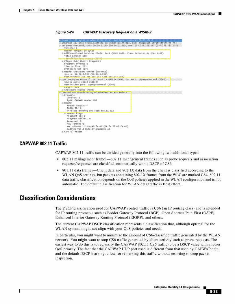
Figure 5-23 show an example of an initial CAPWAP control message. The list of initial CAPWAP control messages includes:
• CAPWAP discovery messages
• CAPWAP join messages
• CAPWAP configuration messages
• Initial CAPWAP RRM messages
5-32Enterprise Mobility 8.1 Design Guide
Chapter 5 Cisco Unified Wireless QoS and AVC CAPWAP over WAN Connections
Figure 5-24 CAPWAP Discovery Request on a WISM-2
CAPWAP 802.11 Traffic
CAPWAP 802.11 traffic can be divided generally into the following two additional types:
• 802.11 management frames—802.11 management frames such as probe requests and association requests/responses are classified automatically with a DSCP of CS6.
• 801.11 data frames—Client data and 802.1X data from the client is classified according to the WLAN QoS settings, but packets containing 802.1X frames from the WLC are marked CS4. 802.11 data traffic classification depends on the QoS policies applied in the WLAN configuration and is not automatic. The default classification for WLAN data traffic is Best effort.
Classification ConsiderationsThe DSCP classification used for CAPWAP control traffic is CS6 (an IP routing class) and is intended for IP routing protocols such as Border Gateway Protocol (BGP), Open Shortest Path First (OSPF), Enhanced Interior Gateway Routing Protocol (EIGRP), and others.
The current CAPWAP DSCP classification represents a classification that, although optimal for the WLAN system, might not align with your QoS policies and needs.
In particular, you might want to minimize the amount of CS6-classified traffic generated by the WLAN network. You might want to stop CS6 traffic generated by client activity such as probe requests. The easiest way to do this is to reclassify the CAPWAP 802.11 CS6 traffic to be a DSCP value with a lower QoS priority. The fact that the CAPWAP UDP port used is different from that used by CAPWAP data, and the default DSCP marking, allow for remarking this traffic without resorting to deep packet inspection.
5-33Enterprise Mobility 8.1 Design Guide
Chapter 5 Cisco Unified Wireless QoS and AVC CAPWAP over WAN Connections
In addition, you might want to ensure that CAPWAP initialization traffic does not impact routing traffic. The easiest way to ensure this is to mark with a lower priority the CAPWAP control traffic that is in excess of the background rate.
Router Configuration Examples
This section provides examples of router configurations that you can use as guides when addressing CS6 remarking or CAPWAP control traffic load.
The examples use CAPWAP APs on the 192.168.101.0/24 subnet and two WLCs with AP managers at 192.168.60.11 and 192.168.62.11.
Remarking Client Generated CS6 Packets
The following example shows a router configuration for remarking CAPWAP data packets marked as CS6 to a more appropriate value of CS3. This moves the traffic to a more suitable classification, at the level of call control, rather than at the level of network control.
Changing the DSCP of CAPWAP Control Traffic above a predefined rate
The following is an example of rate limiting the CAPWAP control traffic from the WAN site to minimize the impact of the CS6-marked control traffic on routing traffic. Note that the rate limit configuration does not drop non-conforming traffic, but simply reclassifies that traffic.
Note The following is an example and not a recommendation. Under normal circumstances, and following the design guidelines for deploying APs over a WAN connection, it is unlikely that CAPWAP control traffic would impact the WAN routing protocol connection.
Chapter 5 Cisco Unified Wireless QoS and AVC QoS Mapping in Release 8.1 MR1
For more information on WLAN QoS and 802.11e, see the IEEE 802.11 Handbook: A Designer’s Companion, 2nd Edition, by Bob O’Hara and Al Petrick. ISBN: 978-0-7381-4449-8
QoS Mapping in Release 8.1 MR1Currently, there is a misalignment between the Differentiated Services Code Point (DSCP) and User Priority (UP) mappings between different vendors of clients and APs. This leads to confusion as different DSCP values imply different UP in different hardware. So, the same packet sent by two different clients (A) and (B) with the same DSCP can have different UP, depending on the internal DSCP – UP map that client uses. Similarly, when a packet leaves the AP to the client, the DSCP – UP map can be different. So, a particular DSCP does not guarantee a particular UP across the same network.
The solution, proposed as part of 802.11u standard, is available in 8.1MR1 code and above:
• Provide a way for user to configure DSCP to UP mapping in the WLC.
• When a capable client joins, transmit the QoS map from an AP to a non-AP STA in a Reassociation Response frame.
• If a change is made to this map when an AP is already associated, the map is transmitted as an unsolicited frame.
With this enhancement, when sending packets, all clients will use the same QoS map. This results in the same UP being used, independent of the manufacturer of the client.
Clients not compatible with 802.11u standard will not receive the frames with QoS map. However, the packets sent by these clients will follow the new DSCP – UP map that has been configured.
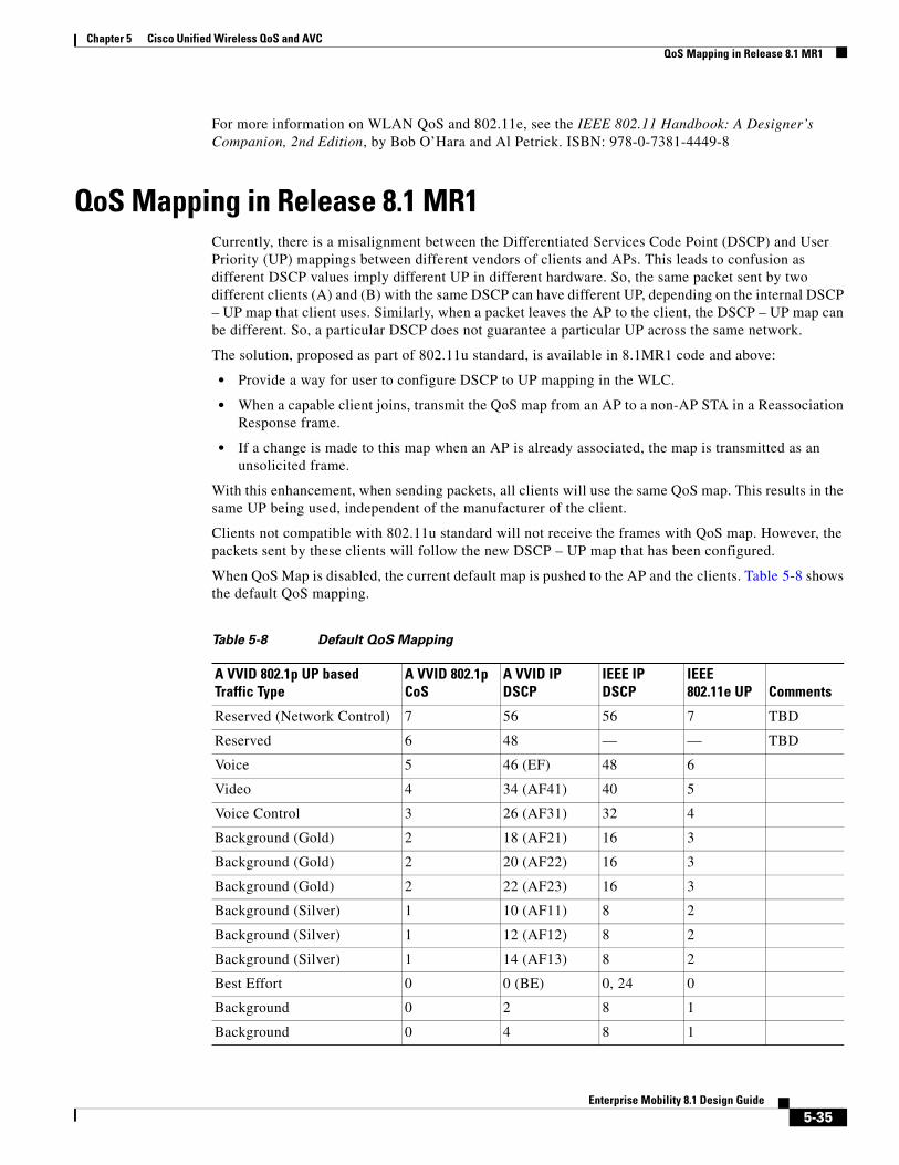
When QoS Map is disabled, the current default map is pushed to the AP and the clients. Table 5-8 shows the default QoS mapping.
Table 5-8 Default QoS Mapping
A VVID 802.1p UP based Traffic Type
A VVID 802.1p CoS
A VVID IP DSCP
IEEE IP DSCP
IEEE 802.11e UP Comments
Reserved (Network Control) 7 56 56 7 TBD
Reserved 6 48 — — TBD
Voice 5 46 (EF) 48 6
Video 4 34 (AF41) 40 5
Voice Control 3 26 (AF31) 32 4
Background (Gold) 2 18 (AF21) 16 3
Background (Gold) 2 20 (AF22) 16 3
Background (Gold) 2 22 (AF23) 16 3
Background (Silver) 1 10 (AF11) 8 2
Background (Silver) 1 12 (AF12) 8 2
Background (Silver) 1 14 (AF13) 8 2
Best Effort 0 0 (BE) 0, 24 0
Background 0 2 8 1
Background 0 4 8 1
5-35Enterprise Mobility 8.1 Design Guide
Chapter 5 Cisco Unified Wireless QoS and AVC QoS Mapping in Release 8.1 MR1
Configuring QoS Mapping by Controller administratorThe controller administrator can configure QoS mapping:
• Lower to Upper DSCP ranges for all UP from 0 to 7. The QoS Map Set has a DSCP Range field corresponding to each of the 8 user priorities. The DSCP Range value is between 0 and 63 inclusive, or 255.
– The DSCP range for each user priority is non-overlapping.
– The DSCP high value is greater than or equal to the DSCP low value.
– If the DSCP range high value and low value are both equal to 255, then the corresponding UP is not used.
• DSCP exceptions to explicitly mark certain DSCPs to a certain UP. DSCP Exception fields are optionally included in the QoS Map Set. If included, the QoS Map Set has a maximum of 21 DSCP Exception fields.
• Enable/ Disable QoS Map.
• User configured mapping is transmitted to clients and used for both Up Stream and Down Stream traffic.
Note Currently, we cap an incoming DSCP packet based on the configured QoS profile. There exists a default DSCP value for each QoS profile. Any packet with DSCP value greater than this is capped to this default value.
With QoS Map, the capping values need to be dynamic. All UPs are configured with a lower to higher DSCP range. The capping values should be the upper DSCP of the QoS Profile UP. For example, UP 5 is configured with 30 to 40. So, Gold QoS Profile should be capped with DSCP 40.
Configuring QoS Mapping from CLITo compensate for the possible incorrect or unexpected markings, AireOS controller code 8.1MR1 offers the possibility to configure a customized DSCP to UP, and UP to DSCP translation table. You can also trust the DSCP marking on the client 802.11 upstream frames, instead of the 802.11e UP marking.
Trusting DSCP upstream is enabled from the controller command line with two commands:
When you enable this feature, DSCP is used instead of UP. DSCP is already used to determine the CAPWAP outer header QoS marking downstream. Therefore, the logic of downstream marking is unchanged. In the upstream direction though, trusting DSCP compensates for unexpected or missing UP
Background 0 6 8 1
Unknown DSCP from Wired Access Port D Do Not Care
D >> 3 On the AP
Table 5-8 Default QoS Mapping
A VVID 802.1p UP based Traffic Type
A VVID 802.1p CoS
A VVID IP DSCP
IEEE IP DSCP
IEEE 802.11e UP Comments
5-36Enterprise Mobility 8.1 Design Guide
Chapter 5 Cisco Unified Wireless QoS and AVC QoS Mapping in Release 8.1 MR1
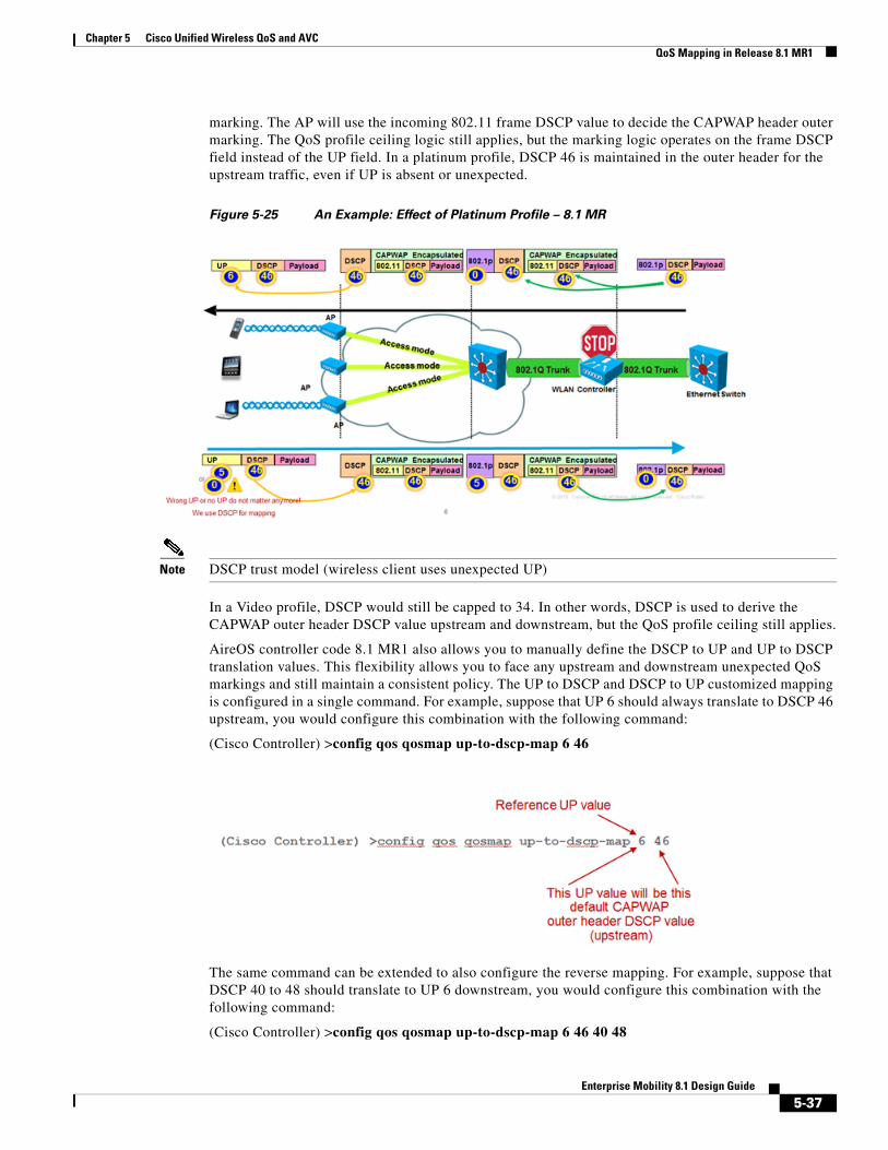
marking. The AP will use the incoming 802.11 frame DSCP value to decide the CAPWAP header outer marking. The QoS profile ceiling logic still applies, but the marking logic operates on the frame DSCP field instead of the UP field. In a platinum profile, DSCP 46 is maintained in the outer header for the upstream traffic, even if UP is absent or unexpected.
Figure 5-25 An Example: Effect of Platinum Profile – 8.1 MR
Note DSCP trust model (wireless client uses unexpected UP)
In a Video profile, DSCP would still be capped to 34. In other words, DSCP is used to derive the CAPWAP outer header DSCP value upstream and downstream, but the QoS profile ceiling still applies.
AireOS controller code 8.1 MR1 also allows you to manually define the DSCP to UP and UP to DSCP translation values. This flexibility allows you to face any upstream and downstream unexpected QoS markings and still maintain a consistent policy. The UP to DSCP and DSCP to UP customized mapping is configured in a single command. For example, suppose that UP 6 should always translate to DSCP 46 upstream, you would configure this combination with the following command:
The same command can be extended to also configure the reverse mapping. For example, suppose that DSCP 40 to 48 should translate to UP 6 downstream, you would configure this combination with the following command:
Chapter 5 Cisco Unified Wireless QoS and AVC QoS Mapping in Release 8.1 MR1
Note that the above configuration is not intended to be a recommended configuration, but is just an example. You would configure with the same logic the 7 UPs and their DSCP mapping. Also, note that the default value upstream (46 in the example above) does not need to be in the range defined for the downstream direction (40 to 48 in the example above). For example, suppose that you decided that UP 6 should translate upstream to DSCP 34, but also that downstream DSCP 40 to 48 should translate to UP 6, you could enter the following command (this is a possibility, not a recommended configuration):
You can also configure exceptions in the range for the downstream traffic DSCP to UP mapping. For example, suppose that a specific traffic marked DSCP 44 should translate to UP 5 in your network, you could configure the 40 to 48 range to translate to UP 6, with an exception for DSCP 44, as follows:
Note that this exception applies to the downstream mapping, not to the upstream mapping. The upstream mapping will follow the rules determined by the up to DSCP map.
Configuring QOS Maps on Cisco AireOS Release 8.1 MR1
To configure QoS maps, perform the following steps:
Step 1 To configure the manual mapping, make sure that your target networks are disabled, as you are going to change the way these networks forward frames:
The first line achieves two objectives: map UP 0 to DSCP 0, but also maps all DSCP values to UP 0. This allows you to be compliant with IETF RFC 4594 section 3.1 and reset all unspecified DSCP values to 0.
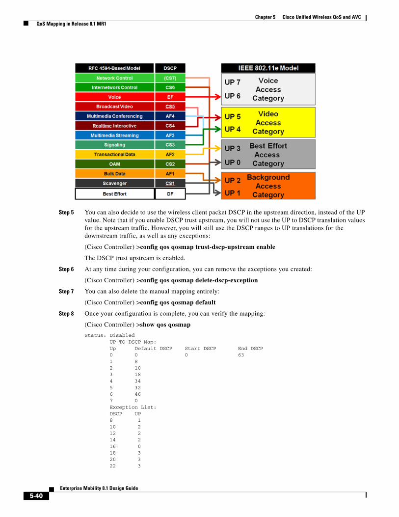
Step 4 Configure exceptions for standard traffic, for example as follows:
These exceptions map standard DSCP values to the appropriate UP values. Note that this command allows you to configure up to 21 exceptions.
The above configuration reflects Cisco recommended mapping depicted in the following illustration.
5-39Enterprise Mobility 8.1 Design Guide
Chapter 5 Cisco Unified Wireless QoS and AVC QoS Mapping in Release 8.1 MR1
Step 5 You can also decide to use the wireless client packet DSCP in the upstream direction, instead of the UP value. Note that if you enable DSCP trust upstream, you will not use the UP to DSCP translation values for the upstream traffic. However, you will still use the DSCP ranges to UP translations for the downstream traffic, as well as any exceptions:
Step 9 Once the configuration is completed, you can activate the manual mapping, and re-enable your networks:
(Cisco Controller) >config qos qosmap enable
QoS map is now enabled.
(Cisco Controller) >config 802.11a enable network
(Cisco Controller) >config 802.11b enable network
Application Visibility and ControlThe key use cases for NBAR are capacity planning, network usage base lining, and better understanding of the applications that are consuming bandwidth. Trending of application usage helps network administrator to plan for network infrastructure upgrade, improve quality of experience by protecting key applications from bandwidth-hungry applications when there is congestion on the network, capability to prioritize or de-prioritize, and drop certain application traffic.
NBAR is supported on 2500, 5500 series, 7500, 8500 series and WiSM2 controllers on Local, Mesh, and Flex Connect Mode APs.
5-41Enterprise Mobility 8.1 Design Guide
Chapter 5 Cisco Unified Wireless QoS and AVC Application Visibility and Control
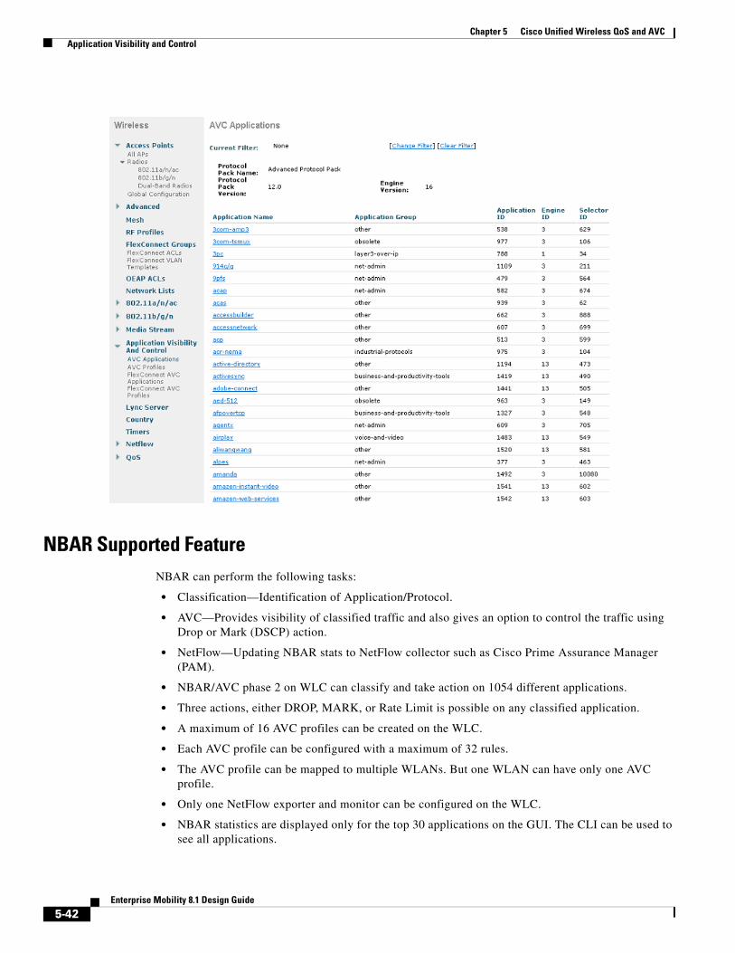
NBAR Supported FeatureNBAR can perform the following tasks:
• Classification—Identification of Application/Protocol.
• AVC—Provides visibility of classified traffic and also gives an option to control the traffic using Drop or Mark (DSCP) action.
• NetFlow—Updating NBAR stats to NetFlow collector such as Cisco Prime Assurance Manager (PAM).
• NBAR/AVC phase 2 on WLC can classify and take action on 1054 different applications.
• Three actions, either DROP, MARK, or Rate Limit is possible on any classified application.
• A maximum of 16 AVC profiles can be created on the WLC.
• Each AVC profile can be configured with a maximum of 32 rules.
• The AVC profile can be mapped to multiple WLANs. But one WLAN can have only one AVC profile.
• Only one NetFlow exporter and monitor can be configured on the WLC.
• NBAR statistics are displayed only for the top 30 applications on the GUI. The CLI can be used to see all applications.
5-42Enterprise Mobility 8.1 Design Guide
Chapter 5 Cisco Unified Wireless QoS and AVC Application Visibility and Control
• NBAR is supported on WLANs configured for central switching only.
• If the AVC profile mapped to the WLAN has a rule for MARK action, that application will get precedence as per QOS profile configured in the AVC rule overriding the QOS profile configured on the WLAN.
• Directional Marking can only be applied either Bidirectional, Upstream or Downstream on a particular application.
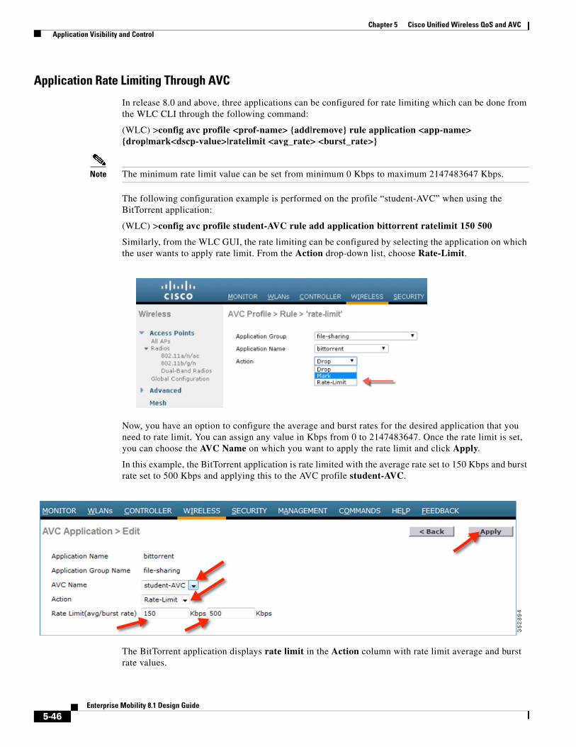
• Currently, Rate Limit can only be applied to three applications.
• Any application that is not supported/recognized by the NBAR engine on the WLC is captured under bucket of UNCLASSFIED traffic.
• IPv6 traffic cannot be classified.
• AAA override of AVC profiles is supported in 8.0 release.
• The AVC profile can be configured per WLAN and applied per user basis.
• NBAR is not supported in vWLC and SRE WLC.
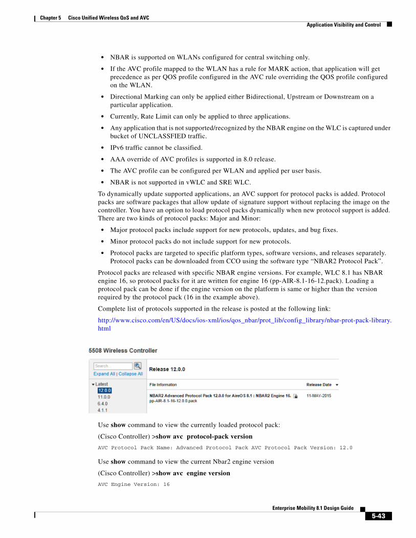
To dynamically update supported applications, an AVC support for protocol packs is added. Protocol packs are software packages that allow update of signature support without replacing the image on the controller. You have an option to load protocol packs dynamically when new protocol support is added. There are two kinds of protocol packs: Major and Minor:
• Major protocol packs include support for new protocols, updates, and bug fixes.
• Minor protocol packs do not include support for new protocols.
• Protocol packs are targeted to specific platform types, software versions, and releases separately. Protocol packs can be downloaded from CCO using the software type “NBAR2 Protocol Pack”.
Protocol packs are released with specific NBAR engine versions. For example, WLC 8.1 has NBAR engine 16, so protocol packs for it are written for engine 16 (pp-AIR-8.1-16-12.pack). Loading a protocol pack can be done if the engine version on the platform is same or higher than the version required by the protocol pack (16 in the example above).
Complete list of protocols supported in the release is posted at the following link:
Chapter 5 Cisco Unified Wireless QoS and AVC Application Visibility and Control
AVC Configuration OptionsWhen Application Visibility is enabled on the specific WLAN and the associated wireless client starts different types of applications such as Cisco Jabber/WebEx Connect, Skype, Yahoo Messenger, HTTP, HTTPS/SSL, Microsoft Messenger, YouTube, Ping, Trace route, and so on, visibility of different traffic from those applications can be observed globally for all WLANs, per client basis, and per WLAN basis. This provides a good overview to the administrator of the network bandwidth utilization and type of traffic in the network per client, per WLAN, and globally.
AVC discovered applications can be dropped or marked with DSCP Platinum, Gold, Silver, and Bronze values.
The administrator has flexibility while configuring Action as MARK to choose the Differentiated Services Code Point (DSCP) value as Custom instead of selecting “Platinum/Gold/Silver/Bronze”. Once Custom is selected as DSCP value, a text file is visible where administrator can enter a custom DSCP value in range of 0 – 63.
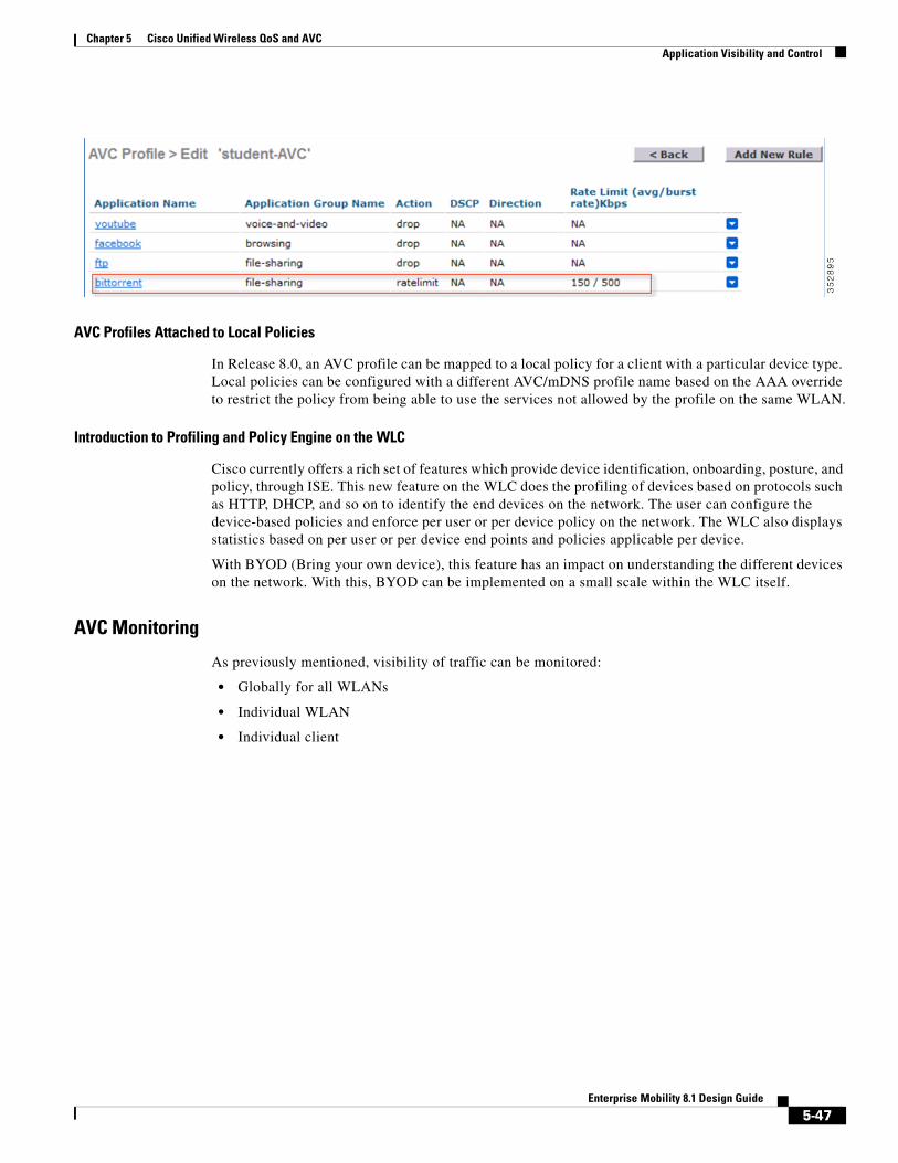
As shown in the following screen shot, two rules are created for AVC profile. The administrator can configure up to 32 rules in the same AVC profile. Individual rules can be configured for action MARK or DROP in the same profile. A single rule can only be configured with a single action, that is, either MARK or DROP.
5-44Enterprise Mobility 8.1 Design Guide
Chapter 5 Cisco Unified Wireless QoS and AVC Application Visibility and Control
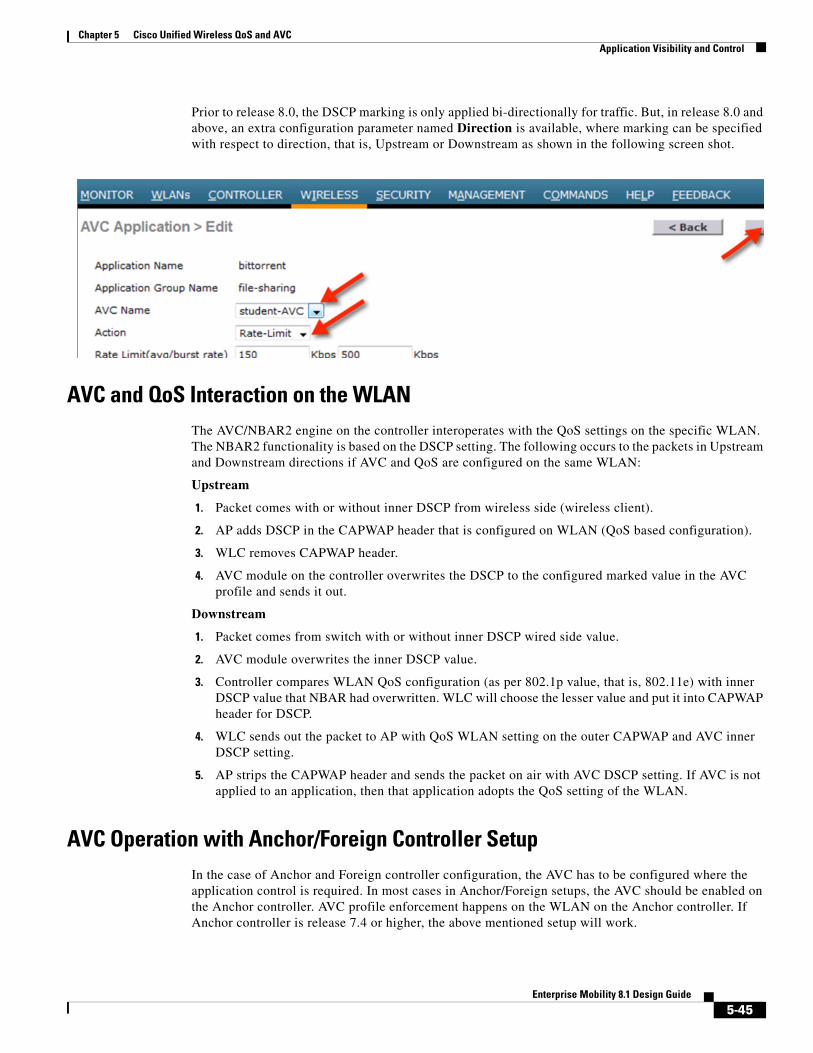
Prior to release 8.0, the DSCP marking is only applied bi-directionally for traffic. But, in release 8.0 and above, an extra configuration parameter named Direction is available, where marking can be specified with respect to direction, that is, Upstream or Downstream as shown in the following screen shot.
AVC and QoS Interaction on the WLANThe AVC/NBAR2 engine on the controller interoperates with the QoS settings on the specific WLAN. The NBAR2 functionality is based on the DSCP setting. The following occurs to the packets in Upstream and Downstream directions if AVC and QoS are configured on the same WLAN:
Upstream
1. Packet comes with or without inner DSCP from wireless side (wireless client).
2. AP adds DSCP in the CAPWAP header that is configured on WLAN (QoS based configuration).
3. WLC removes CAPWAP header.
4. AVC module on the controller overwrites the DSCP to the configured marked value in the AVC profile and sends it out.
Downstream
1. Packet comes from switch with or without inner DSCP wired side value.
2. AVC module overwrites the inner DSCP value.
3. Controller compares WLAN QoS configuration (as per 802.1p value, that is, 802.11e) with inner DSCP value that NBAR had overwritten. WLC will choose the lesser value and put it into CAPWAP header for DSCP.
4. WLC sends out the packet to AP with QoS WLAN setting on the outer CAPWAP and AVC inner DSCP setting.
5. AP strips the CAPWAP header and sends the packet on air with AVC DSCP setting. If AVC is not applied to an application, then that application adopts the QoS setting of the WLAN.
AVC Operation with Anchor/Foreign Controller SetupIn the case of Anchor and Foreign controller configuration, the AVC has to be configured where the application control is required. In most cases in Anchor/Foreign setups, the AVC should be enabled on the Anchor controller. AVC profile enforcement happens on the WLAN on the Anchor controller. If Anchor controller is release 7.4 or higher, the above mentioned setup will work.
5-45Enterprise Mobility 8.1 Design Guide
Chapter 5 Cisco Unified Wireless QoS and AVC Application Visibility and Control
Application Rate Limiting Through AVC
In release 8.0 and above, three applications can be configured for rate limiting which can be done from the WLC CLI through the following command:
Similarly, from the WLC GUI, the rate limiting can be configured by selecting the application on which the user wants to apply rate limit. From the Action drop-down list, choose Rate-Limit.
Now, you have an option to configure the average and burst rates for the desired application that you need to rate limit. You can assign any value in Kbps from 0 to 2147483647. Once the rate limit is set, you can choose the AVC Name on which you want to apply the rate limit and click Apply.
In this example, the BitTorrent application is rate limited with the average rate set to 150 Kbps and burst rate set to 500 Kbps and applying this to the AVC profile student-AVC.
The BitTorrent application displays rate limit in the Action column with rate limit average and burst rate values.
5-46Enterprise Mobility 8.1 Design Guide
Chapter 5 Cisco Unified Wireless QoS and AVC Application Visibility and Control
AVC Profiles Attached to Local Policies
In Release 8.0, an AVC profile can be mapped to a local policy for a client with a particular device type. Local policies can be configured with a different AVC/mDNS profile name based on the AAA override to restrict the policy from being able to use the services not allowed by the profile on the same WLAN.
Introduction to Profiling and Policy Engine on the WLC
Cisco currently offers a rich set of features which provide device identification, onboarding, posture, and policy, through ISE. This new feature on the WLC does the profiling of devices based on protocols such as HTTP, DHCP, and so on to identify the end devices on the network. The user can configure the device-based policies and enforce per user or per device policy on the network. The WLC also displays statistics based on per user or per device end points and policies applicable per device.
With BYOD (Bring your own device), this feature has an impact on understanding the different devices on the network. With this, BYOD can be implemented on a small scale within the WLC itself.
AVC Monitoring
As previously mentioned, visibility of traffic can be monitored:
• Globally for all WLANs
• Individual WLAN
• Individual client
5-47Enterprise Mobility 8.1 Design Guide
Chapter 5 Cisco Unified Wireless QoS and AVC Application Visibility and Control
Application Visibility and Control for FlexConnectThe key use cases for NBAR AVC are capacity planning, network usage base lining, and better understanding of the applications that are consuming bandwidth. Trending of application usage helps the network administrator to plan for network infrastructure upgrade, improve quality of experience by protecting key applications from bandwidth-hungry applications when there is congestion on the network, capability to prioritize or de-prioritize, and drop certain application traffic.
AVC is supported on the 5520, 8540, 2500, 5508, 7500, 8500, and WiSM2 controllers on Local and FlexConnect modes (for WLANs configured for central switching only) since release 7.4. Release 8.1 introduces support for Application Visibility and Control (AVC) for locally switched WLANs on FlexConnect APs. For more information on Flex AVC, see Chapter 7, “FlexConnect”.
How AVC Works on FlexConnect AP
• NBAR2 engine runs on the FlexConnect AP.
• Classification of applications happens at the access point using the DPI engine (NBAR2) to identify applications using L7 signatures.
• AP collects application information and exports it to controller every 90 seconds.
• Real-time applications are monitored on the controller user interface.
• Ability to take actions, drop, mark or rate-limit, is possible on any classified application on the FlexConnect access point.
5-48Enterprise Mobility 8.1 Design Guide
Chapter 5 Cisco Unified Wireless QoS and AVC Application Visibility and Control
AVC FlexConnect Facts and Limitations
• AVC on the FlexConnect AP can classify and take action on 1000+ different applications.
• The protocol pack running on the FlexConnect APs is different from the one running on the WLC.
• AVC stats on the GUI are displayed for the top 10 applications by default. This can be changed to top 20 or 30 applications as well.
• Intra FlexConnect Group roaming support.
• IPv6 traffic cannot be classified.
• AAA override of AVC profiles is not supported.
• Multicast traffic is not supported by AVC application.
• Netflow export for FlexConnect AVC is not supported in 8.1.
NBAR NetFlow MonitorA NetFlow monitor can also be configured on the WLC to collect all the stats generated on a WLC and these stats can be exported to the NetFlow collector. In the following example, Cisco Performance Application Manager (PAM) is used as a NetFlow collector. PAM is a licensed application running on Cisco Prime Infrastructure.
5-49Enterprise Mobility 8.1 Design Guide
Chapter 5 Cisco Unified Wireless QoS and AVC Application Visibility and Control
Once the monitor entry is created and the exporter entry is mapped to the same, it should be mapped to the WLAN.
To map the exporter entry to WLAN:
1. Click WLANs
2. Click the specific WLAN ID.
3. Click the QoS tab
4. Choose the created monitor entry from the NetFlow Monitor drop-down list.
5. Click Apply.
Cisco Prime has to be preconfigured with PAM. After PAM is configured with WLAN and wireless client has traffic going with specific preconfigured applications, administrator should see application usage per WLAN. Navigate to Home > Detail Dashboards > End User Experience. In the Filters area, select Network Aware as WLAN, that is, 10.10.10.56 client in the following example, and then click GO.