CHAPTER 2-1 Enterprise Mobility 8.1 Design Guide 2 Cisco Unified Wireless Technology and Architecture This chapter discusses the key design and operational considerations associated with the deployment of Cisco Unified Wireless Networks enterprise. This chapter discusses: • CAPWAP • Core Components • Roaming • Broadcast and Multicast on the WLC • Design Considerations • Operation and Maintenance Much of the material in this chapter is explained in more detail in later chapters of this design guide. For more information on Cisco Unified Wireless Technology, see the Cisco White Paper on deployment strategies related to the Cisco 5500 Series Wireless LAN Controller at: http://www.cisco.com/en/US/products/ps10315/prod_white_papers_list.html CAPWAP The Internet Engineering Task Force (IETF) standard Control and Provisioning of Wireless Access Points Protocol (CAPWAP) is the underlying protocol used in the Cisco Centralized WLAN Architecture (functional architecture of the Cisco Unified Wireless Network solution). CAPWAP provides the configuration and management of APs and WLANs in addition to encapsulation and forwarding of WLAN client traffic between an AP and a WLAN controller (WLC). CAPWAP is based on the Lightweight Access Point Protocol (LWAPP) but adds additional security with Datagram Transport Layer Security (DTLS). CAPWAP uses the User Datagram Protocol (UDP) and can operate either over Internet Protocol version 4 (IPv4) or Internet Protocol version 6 (IPv6). Table 2-1 lists the protocol and ports implemented for each CAPWAP version:
Transcript
C H A P T E R 2
Cisco Unified Wireless Technology and Architecture
This chapter discusses the key design and operational considerations associated with the deployment of Cisco Unified Wireless Networks enterprise.
This chapter discusses:
• CAPWAP
• Core Components
• Roaming
• Broadcast and Multicast on the WLC
• Design Considerations
• Operation and Maintenance
Much of the material in this chapter is explained in more detail in later chapters of this design guide. For more information on Cisco Unified Wireless Technology, see the Cisco White Paper on deployment strategies related to the Cisco 5500 Series Wireless LAN Controller at:
CAPWAPThe Internet Engineering Task Force (IETF) standard Control and Provisioning of Wireless Access Points Protocol (CAPWAP) is the underlying protocol used in the Cisco Centralized WLAN Architecture (functional architecture of the Cisco Unified Wireless Network solution). CAPWAP provides the configuration and management of APs and WLANs in addition to encapsulation and forwarding of WLAN client traffic between an AP and a WLAN controller (WLC).
CAPWAP is based on the Lightweight Access Point Protocol (LWAPP) but adds additional security with Datagram Transport Layer Security (DTLS). CAPWAP uses the User Datagram Protocol (UDP) and can operate either over Internet Protocol version 4 (IPv4) or Internet Protocol version 6 (IPv6). Table 2-1 lists the protocol and ports implemented for each CAPWAP version:
Chapter 2 Cisco Unified Wireless Technology and ArchitectureCAPWAP
IPv6 mandates a complete payload checksum for User Datagram Protocol (UDP) which impacts the performance of the AP and the WLC. To maximize performance for IPv6 deployments, the AP and WLC implements UDP Lite that only performs a checksum on the header rather than the full payload.
Note In the Releases 5.2 and later, LWAPP has been depreciated and has been replaced by CAPWAP. Older LWAPP APs joining a WLC running on 5.2 or later will be automatically upgraded to support CAPWAP.
Figure 2-1 shows a high-level diagram of a basic centralized WLAN deployment, where CAPWAP APs connect to a WLC via the CAPWAP protocol. In Releases 8.0 and later, CAPWAP can operate either in an IPv4 or IPv6 transport modes. By default, IPv4 is preferred but is configurable (discussed later in this section).
Figure 2-1 CAPWAP APs connected to a WLC
Note Although CAPWAP is made up of a number of functional components, only those that influence the design and operation of a centralized WLAN network are discussed in this design guide.
Table 2-1 CAPWAP Protocol and Ports
Internet Protocol IP Protocol DST Port Description
Version 4 17 (UDP) 5,246 CAPWAPv4 Control Channel
17 (UDP) 5,247 CAPWAPv4 Data Channel
Version 6 136 (UDP Lite) 5,246 CAPWAPv6Control Channel
136 (UDP Lite) 5,247 CAPWAPv6 Data Channel
2-2Enterprise Mobility 8.1 Design Guide
Chapter 2 Cisco Unified Wireless Technology and ArchitectureCAPWAP
Cisco recommends the following guidelines when implementing CAPWAP:
• IP Addressing—APs must be assigned a static or dynamic IPv4 / IPv6 address to be able to successfully discover and communicate with a WLC. Layer 2 mode is not supported by CAPWAP.
• Firewall Rules and ACLs—All firewall rules and ACLs defined on devices placed between the APs and WLCs must be configured to permit the CAPWAP protocol (see Table 2-1).
• IPv6 Deployments—At least one WLC should be configured for both IPv4 and IPv6 to support APs with older firmware that does not support IPv6.
The key features of CAPWAP include:
• Split MAC Architecture
• Encryption
• Layer 3 Tunnels
• WLC Discovery & Selection
Split MAC ArchitectureA key component of CAPWAP is the concept of a split MAC, where part of the 802.11 protocol operation is managed by the CAPWAP AP, while the remaining parts are managed by the WLC. Figure 2-2 shows the split MAC concept.
Figure 2-2 Split MAC Architecture
A generic 802.11 AP, at the simplest level as shown in Figure 2-3, is nothing more than an 802.11 MAC-layer radio that bridges WLAN clients to a wired-network, based on association to a Basic Service Set Identifier (BSSID). The 802.11 standard extends the single AP concept (above) to allow multiple APs to provide an Extended Service Set (ESS), as shown in Figure 2-4, where multiple APs use the same ESS Identifier (ESSID, commonly referred to as an SSID) to allow a WLAN client to connect to a common network through more than one AP.
The CAPWAP split MAC concept in Figure 2-5 does all of the functions normally performed by individual APs and distributes them between two functional components:
2-3Enterprise Mobility 8.1 Design Guide
Chapter 2 Cisco Unified Wireless Technology and ArchitectureCAPWAP
• CAPWAP AP
• WLC
The two are linked across a network by the CAPWAP protocol and together provide equivalent radio/bridging services in a manner that is simpler to deploy and manage than individual APs.
Note Although split MAC facilitates Layer 2 connectivity between the WLAN clients and the wired interface of the WLC, this does not mean that the CAPWAP tunnel will pass all traffic. The WLC forwards only IP EtherType frames, and its default behavior is to not forward broadcast and multicast traffic. This is important to keep in mind when considering multicast and broadcast requirements in a WLAN deployment.
Figure 2-3 Single AP
Figure 2-4 APs combined into a ESS
Figure 2-5 CAPWAP Split-MAC ESS
The simple, timing-dependent operations are generally managed locally on the CAPWAP AP, while more complex, less time-dependent operations are managed on the WLC.
2-4Enterprise Mobility 8.1 Design Guide
Chapter 2 Cisco Unified Wireless Technology and ArchitectureCAPWAP
For example, the CAPWAP AP handles:
• Frame exchange handshake between a client and AP.
• Transmission of beacon frames.
• Buffering and transmission of frames for clients in power save mode.
• Response to probe request frames from clients; the probe requests are also sent to the WLC for processing.
• Forwarding notification of received probe requests to the WLC.
• Provision of real-time signal quality information to the switch with every received frame.
• Monitoring each of the radio channels for noise, interference, and other WLANs.
• Monitoring for the presence of other APs.
• Encryption and decryption of 802.11 frames.
Other functionalities are also handled by the WLC. MAC layer functions provided by the WLC include:
• 802.11 authentication
• 802.11 association and re-association (mobility)
• 802.11 frame translation and bridging
• 802.1X/EAP/RADIUS processing
• Termination of 802.11 traffic on a wired interface, except in the case of FlexConnect APs (discussed later in this guide)
A CAPWAP tunnel supports two categories of traffic:
• CAPWAP control messages—Used to convey control, configuration, and management information between the WLC and APs.
• Wireless client data encapsulation—Transports Layer 2 wireless client traffic in IP EtherType encapsulated packets from the AP to the WLC.
When the encapsulated client traffic reaches the WLC, it is mapped to a corresponding interface (VLAN) or interface group (VLAN pool) at the WLC. This interface mapping is defined as part of the WLAN configuration settings on the WLC. The interface mapping is usually static, however a WLAN client may also be dynamically mapped to a specific VLAN based on the local policies defined on the WLC or RADIUS return attributes forwarded from an upstream AAA server upon successful authentication.
In addition to the VLAN assignment, other common WLAN configuration parameters include:
• SSID Name
• Operational State
• Radio Policies
• Authentication and Security Methods
• QoS / Application Visibility & Control
• Policy Mappings
EncryptionReleases 6.0 and later provide support for encrypting CAPWAP control and data packets exchanged between an AP and a WLC using DTLS. DTLS is an IETF protocol based on TLS. All Cisco access points and controllers are shipped with a Manufacturing Installed Certificate (MIC) which are used by
2-5Enterprise Mobility 8.1 Design Guide
Chapter 2 Cisco Unified Wireless Technology and ArchitectureCAPWAP
an AP and WLC by default for mutual authentication and encryption key generation. Cisco also supports Locally Significant Certificates (LSC) to provide additional security for enterprises who wish to issue certificates from their own Certificate Authority (CA).
Note By default, DTLS uses a RSA 128-bit AES / SHA-1 cipher suite which is globally defined using the config ap dtls-cipher-suite command. Alternative ciphers include 256-bit AES with SHA-1 or SHA-256.
DTLS is enabled by default to secure the CAPWAP control channel but is disabled by default for the data channel. No DTLS license is required to secure the control channel. All CAPWAP management and control traffic exchanged between an AP and WLC is encrypted and secured by default to provide control plane privacy and prevent Man-In-the-Middle (MIM) attacks.
CAPWAP data encryption is optional and is enabled per AP. Data encryption requires a DTLS license to be installed on the WLC prior to being enabled on an AP. When enabled, all WLAN client traffic is encrypted at the AP before being forwarded to the WLC and vice versa. DTLS data encryption is automatically enabled for OfficeExtend APs but is disabled by default for all other APs. Most APs are deployed in a secure network where data encryption is not necessary. In contrast, traffic exchanged between an OfficeExtend AP and WLC is forwarded over an unsecured public network, where data encryption is important.
Note Please consult your Local Government regulations to ensure that DTLS encryption is permitted. For example, DTLS data encryption is currently prohibited in Russia.
The availability of DTLS data encryption on WLCs is as follows:
• Cisco 5508—Orderable with and without DTLS data support. Separate firmware images are provided on cisco.com with and without DTLS support.
• Cisco 2500, 5520, 8540, WiSM2, vWLC—Requires a separate license to activate DTLS data support.
• Cisco Flex 7500 and 8510—Includes DTLS data support built-in. You are not required to purchase or install a separate license to enable DTLS data support.
The availability of DTLS data encryption on APs is as follows:
• Cisco 1130, 1240 series—DTLS data encryption is performed in software.
• Cisco 1040, 1140, 1250, 1522, 1530, 1550, 1552, 1600, 1700, 1850, 2600, 2700, 3500, 3600 and 3700 series—DTLS data encryption is performed in hardware.
Note Enabling DTLS data encryption will impact the performance of both the APs and WLCs. Therefore DTLS data encryption should only be enabled on APs deployed over an unsecured network.
Layer 3 TunnelsUnlike LWAPP which operated in either a Layer 2 or Layer 3 mode, CAPWAP only operates in Layer 3 and requires IP addresses to be present on both the AP and WLC. CAPWAP uses UDP for IPv4 deployments and UDP or UDP Lite (default) for IPv6 deployments to facilitate communication between
2-6Enterprise Mobility 8.1 Design Guide
Chapter 2 Cisco Unified Wireless Technology and ArchitectureCAPWAP
an AP and WLC over an intermediate network. CAPWAP is able to perform fragmentation and reassembly of tunnel packets allowing WLAN client traffic to make use of a full 1500 byte MTU without having to adjust for any tunnel overhead.
Note In order to optimize the fragmentation and reassembly process, the number of fragments that the WLC or AP expect to receive is limited. The ideally supported MTU size for deploying the Cisco Unified Wireless Network is 1500 bytes, but the solution operates successfully over networks where the MTU is as small as 500 bytes.
The figures below are of CAPWAP packet captures used to illustrate CAPWAP operation over an IPv4 network. The sample decodes were captured using a Wireshark packet analyzer.
Figure 2-6 shows a partial decode of a CAPWAP control packet. This packet originates from the WLC using UDP destination port 5246 (as do all CAPWAP control packets from the WLC). Control Type 12 represents a configuration command used to pass AP configuration information to the CAPWAP AP by the WLC. CAPWAP control packet payloads are AES encrypted by default using DTLS when an AP joins the WLC.
Figure 2-6 CAPWAP Control Packet
Figure 2-7shows a partial decode of a CAPWAP packet containing an 802.11 probe request. This packet originates from the CAPWAP AP to the WLC using UDP destination port 5246 (as do all CAPWAP encapsulated 802.11 frames). In this example, Received Signal Strength Indication (RSSI) and Signal-to-Noise Ratio (SNR) values are also included in the CAPWAP packet to provide RF information to the WLC. Note that DTLS data encryption is not enabled in this example.
2-7Enterprise Mobility 8.1 Design Guide
Chapter 2 Cisco Unified Wireless Technology and ArchitectureCAPWAP
Figure 2-7 CAPWAP 802.11 Probe Request
Figure 2-8 shows another CAPWAP-encapsulated 802.11 frame, but in this case it is an 802.11 data frame, similar to that shown in Figure 2-7. It contains a complete 802.11 frame, as well as RSSI and SNR information for the WLC. This figure is shown to illustrate that an 802.11 data frame is treated the same by CAPWAP as the other 802.11 frames. Figure 2-8 highlights that fragmentation is supported for CAPWAP packets to accommodate the minimum MTU size between the AP and the WLC.
Note In the Wireshark decode, the frame control decode bytes have been swapped; this is accomplished during the Wireshark protocol analysis of the CAPWAP packet to take into account that some APs swap these bytes. DTLS data encryption is not enabled in this example.
2-8Enterprise Mobility 8.1 Design Guide
Chapter 2 Cisco Unified Wireless Technology and ArchitectureCAPWAP
Figure 2-8 CAPWAP Data Frame
CAPWAP ModesIn the Releases 8.0 and later, Cisco Unified Wireless Network (CUWN) supports access points and controllers using IPv4 and/or IPv6 addressing. Network administrators can deploy APs and WLCs over a pure IPv4 or IPv6 network as well as dual-stack network to facilitate the transition from an IPv4 to IPv6. As part of the 8.0 Release, the CAPWAP protocol and discovery mechanisms have been enhanced to support IPv6. CAPWAP can now operate in IPv4 (CAPWAPv4) or IPv6 (CAPWAPv6) modes to suit the specific network environment.
To support both IP protocol versions, network administrators can configure a preferred CAPWAP mode (CAPWAPv4 or CAPWAPv6) through which an AP joins the WLC. The prefer-mode can be defined at two levels:
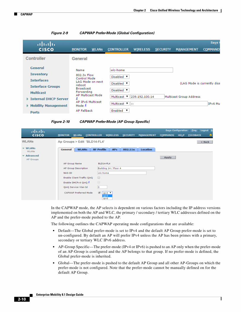
• Global Configuration (Figure 2-9)
• AP Group Specific (Figure 2-10
2-9Enterprise Mobility 8.1 Design Guide
Chapter 2 Cisco Unified Wireless Technology and ArchitectureCAPWAP
Figure 2-10 CAPWAP Prefer-Mode (AP Group Specific)
In the CAPWAP mode, the AP selects is dependent on various factors including the IP address versions implemented on both the AP and WLC, the primary / secondary / tertiary WLC addresses defined on the AP and the prefer-mode pushed to the AP.
The following outlines the CAPWAP operating mode configurations that are available:
• Default—The Global prefer-mode is set to IPv4 and the default AP Group prefer-mode is set to un-configured. By default an AP will prefer IPv4 unless the AP has been primes with a primary, secondary or tertiary WLC IPv6 address.
• AP-Group Specific—The prefer-mode (IPv4 or IPv6) is pushed to an AP only when the prefer-mode of an AP-Group is configured and the AP belongs to that group. If no prefer-mode is defined, the Global prefer-mode is inherited.
• Global—The prefer-mode is pushed to the default AP Group and all other AP-Groups on which the prefer-mode is not configured. Note that the prefer-mode cannot be manually defined on for the default AP Group.
2-10Enterprise Mobility 8.1 Design Guide
Chapter 2 Cisco Unified Wireless Technology and ArchitectureCAPWAP
• Join Failure—If an AP with a configured prefer-mode attempts to join the controller and fails, it will fall back to the other mode and attempt to join the same controller. When both modes fail, AP will move to the next discovery response.
• Static Configuration—Static IP configuration will take precedence over the Global or AP Group Specific prefer-mode. For example, if the Global prefer-mode is set to IPv4 and the AP has a static Primary Controller IPv6 address defined, the AP will join the WLC using the CAPWAPv6 mode.
AP Group Specific prefer-mode provides flexibility as it allows the administrator to specifically influence the CAPWAP transport mode utilized by different groups of APs. This allows APs deployed across different buildings or sites to operate using different CAPWAP modes. For example, APs within a campus that have already migrated to IPv6 can join a WLC using CAPWAPv6 while APs at remote sites that are yet to transition to IPv6 can join a WLC using CAPWAPv4. An individual WLC with a dual-stack configuration can support CAPWAP APs operating in both CAPWAPv4 and CAPWAPv6 modes.
Note An AP running an older image that is not IPv6 capable can join an IPv6 capable WLC only if the WLC has an IPv4 address assigned. The same is true for an IPv6 capable AP joining an IPv4 capable WLC (assuming the AP has an IPv4 address assigned). For IPv6 deployments, it is recommended that at least one discoverable WLC be configured to support IPv4.
For a full overview of the IPv6 enhancements introduced in 8.0, see the Cisco Wireless LAN Controller IPv6 Deployment Guide.
WLC Discovery & SelectionIn a CAPWAP environment, a lightweight AP discovers a WLC by using a CAPWAP discovery mechanism and then sends the controller, a CAPWAP join request. When an AP joins a WLC, the WLC manages its configuration, firmware, control transactions, and data transactions. A CAPWAP AP must discover and join a WLC before it can become an active part of the Cisco Unifies Wireless Network.
Each Cisco AP supports the following discovery processes:
Step 1 Broadcast Discovery—The AP sends a CAPWAP discovery message to the IPv4 broadcast address (255.255.255.255). Any WLC connected to the same VLAN will see the discovery message and will in turn reply with a unicast IPv4 discovery response.
Step 2 Multicast Discovery—The AP sends a CAPWAP discovery message to the all controllers multicast group address (FF01::18C). Any WLC connected to the same VLAN will see the discovery message and will in turn reply with IPv6 discovery response.
Step 3 Locally Stored Controller IPv4 or IPv6 Address Discovery—If the AP was previously associated to a WLC, the IPv4 or IPv6 addresses of the primary, secondary, and tertiary controllers are stored in the APs non-volatile memory (NVRAM). This process of storing controller IPv4 or IPv6 addresses on an AP for later deployment is called priming the access point.
Step 4 DHCP Discovery—DHCPv4 and/or DHCPv6 servers are configured to advertise WLC IP addresses to APs using vendor-specific options:
– DHCPv4 Discovery using Option 43—DHCPv4 servers use option 43 to provide one or more WLC management IPv4 addresses to the AP. Option 43 values are supplied to an AP in the DHCPv4 offer and acknowledgment packets.
Chapter 2 Cisco Unified Wireless Technology and ArchitectureCAPWAP
– DHCPv6 Discovery using Option 52—DHCPv6 servers use option 52 to provide one or more WLC management IPv6 addresses to the AP. Option 52 values are supplied to an AP in the DHCPv6 advertise and reply packets.
Step 5 DNS Discovery—The AP sends a DNS query to the DNSv4 and/or DNSv6 servers to attempt to resolve cisco-capwap-controller.localdomain (where localdomain is the AP domain name provided by DHCP):
– DNSv4 Discovery—Address records are defined on the name servers for the cisco-capwap-controller hostname for each WLC managed IPv4 address to be supplied to the AP. When queried, the name server will respond with a list of IPv4 addresses for each A record that was defined.
– DNSv6 Discovery—Address records are defined on the name server for the cisco-capwap-controller hostname for each WLC managed IPv6 address to be supplied to the AP. When queried, the name server will respond with a list of IPv6 addresses for each AAAA record that was defined.
Up to three address records can be defined on the DNSv4 or DNSv6 name servers to be supplied to an AP. Each record corresponds to the primary, secondary and tertiary WLC IPv4 or IPv6 addresses.
Step 6 If after steps 1 – 5 no CAPWAP discovery response is received, the AP resets and restarts the discovery process.
Once the AP selects a WLC, the AP chooses to join through CAPWAPv4 or CAPWAPv6, depending on the CAPWAP prefer-mode pushed to the AP.
2-12Enterprise Mobility 8.1 Design Guide
Chapter 2 Cisco Unified Wireless Technology and ArchitectureCAPWAP
Figure 2-11 AP CAPWAP Discovery Diagram
AP Priming
For most deployments, DHCP or DNS discovery is used to provide one or more seed WLC addresses. A subsequent WLC discovery response provides the AP with a full list of WLC mobility group members. An AP is normally configured with a list of one to three WLC management IP addresses (Primary, Secondary and Tertiary) that represent the preferred WLCs.
If the preferred WLCs become unavailable or are over-subscribed, the AP chooses another WLC from the list of WLCs learned in the CAPWAP discover responsei.e., the least-loaded WLC.
2-13Enterprise Mobility 8.1 Design Guide
Chapter 2 Cisco Unified Wireless Technology and ArchitectureCAPWAP
Figure 2-12 AP Priming Example
Note When priming an AP, the Primary Controller, Secondary Controller and Tertiary Controller management addresses can either be IPv4 or IPv6. It does not matter as long as the defined address is reachable by the AP. However, it is not possible to define both IPv4 and IPv6 addresses for a single entry. Each entry can contain only one IPv4 or IPv6 address.
2-14Enterprise Mobility 8.1 Design Guide
Chapter 2 Cisco Unified Wireless Technology and ArchitectureCore Components
Core ComponentsThe Cisco Unified Wireless Network (CUWN) is designed to provide a high performance and scalable 802.11ac wireless services for enterprises and service providers. A Cisco wireless solution simplifies the deployment and management of large-scale wireless LANs in centralized or distributed deployments while providing a best-in-class security, user experience and services.
The Cisco Unified Wireless Network consists of:
• Cisco Wireless LAN Controllers (WLCs)
• Cisco Aironet Access Points (APs)
• Cisco Prime Infrastructure (PI)
• Cisco Mobility Services Engine (MSE)
This section describes available product options for the WLCs, APs and PI. For additional information, see the Cisco Mobility Services Engine.
Note For convenience and consistency, this document refers to all Cisco Wireless LAN Controllers as WLCs, Aironet Access Points as APs and Cisco Prime Infrastructure as PI.
Chapter 2 Cisco Unified Wireless Technology and ArchitectureCore Components
Cisco Wireless LAN ControllersCisco Wireless LAN Controllers are enterprise-class, high-performance, wireless switching platforms that support 802.11a/n/ac and 802.11b/g/n protocols. They operate under control of the operating system, which includes the Radio Resource Management (RRM), creating a CUWN solution that can automatically adjust to real-time changes in the 802.11 RF environment. Controllers are built around high-performance network and security hardware, resulting in highly reliable 802.11 enterprise networks with unparalleled security.
This section describes the various models of Cisco WLCs and their capabilities supported in the 8.1 Release.
Table 2-2 Summary of Cisco Wireless Controllers
Cisco 2504 Wireless Controller
Cisco 5508 Wireless Controller
Cisco 5520 Wireless Controller
Cisco Flex 7510 Wireless Controller
Cisco 8510 Wireless Controller
Cisco 8540 Wireless Controller
Wireless Services Module 2 (WISM2)
Virtual Wireless Controller
Form Factor 1U Appliance
1U Appliance
1U Appliance
1U Appliance
1U Appliance
2U Appliance
Module Software
Platform Integration
N/A N/A N/A N/A N/A N/A N/A N/A
Scalability 75 x Access Points
1,000 x Clients
1 Gbps Throughput
500 x Access Points
7,000 x Clients
8 Gbps Throughput
1500 x Access Points
20,000 x Clients
20 Gbps Throughput
6000 x Access Points
64,000 x Clients
2000 x FlexConnect Groups
6000 x Access Points
64,000 x Clients
10 Gbps Throughput
6000 x Access Points
64,000 x Clients
40 Gbps Throughput
1000 x Access Points
15,000 x Clients
8 Gbps Throughput
200 x Access Points
6,000 x Clients
200 x FlexConnect Groups
Base AP Licenses
0.5, 15, 25 and 50 APs
0, 12, 25, 50, 100 and 250 AP Increments (CISL Based)
0 and 50 APs
0, 300, 500, 1000, 2000, 3000 and 6000 APs
0, 300, 500, 1000, 2000, 3000 and 6000 APs
0 and 1000 APs
0, 100, 300, 500 and 1000 APs
5 APs
AP Adder Licenses
1.5 and 25 AP Increments (CISL Based)
5, 25, 50, 100 and 250 AP Increments (CISL Based)
1 AP Increment (Right to Use)
100, 200, 500 and 1000 AP Increments (Right to Use)
100, 200, 500 and 1000 AP Increments (Right to Use)
Chapter 2 Cisco Unified Wireless Technology and ArchitectureCore Components
Power External AC Power Supply
AC (Redundant PSU Option)
AC (Redundant PSU Option)
AC/DC (Dual Redundant)
AC/DC (Dual Redundant)
AC/DC (Dual Redundant)
AC/DC (Catalyst Chassis)
Host Dependant
Positioning Branch, Small Office
Enterprise, Campus & Full service branch
Enterprise, Campus & Full service branch
Central Site Controller for Large Number of Distributed Controller- less Branches
Enterprise, Large Campus, SP Wi-Fi, Full Scale Branch
Enterprise Large Campus, SP Wi-Fi, Full Scale Branch
Enterprise Campus
SP-Wi-Fi, Controller less branches, Small Office.
Table 2-2 Summary of Cisco Wireless Controllers (continued)
Cisco 2504 Wireless Controller
Cisco 5508 Wireless Controller
Cisco 5520 Wireless Controller
Cisco Flex 7510 Wireless Controller
Cisco 8510 Wireless Controller
Cisco 8540 Wireless Controller
Wireless Services Module 2 (WISM2)
Virtual Wireless Controller
2-17Enterprise Mobility 8.1 Design Guide
Chapter 2 Cisco Unified Wireless Technology and ArchitectureCore Components
Cisco 2504 Wireless Controller
The Cisco 2504 Wireless Controller enables system-wide wireless functions for small to medium-sized enterprises and branch offices. Designed for 802.11n and 802.11ac performance, the Cisco 2504 Wireless Controllers are entry-level controllers that provide real-time communications between Cisco Aironet access points to simplify the deployment and operation of wireless networks.
For more information on Cisco 2504 Wireless Controller, see the Cisco 2500 Series Wireless Controllers.
Chapter 2 Cisco Unified Wireless Technology and ArchitectureCore Components
Cisco 5508 Wireless Controller
Cisco 5508 Wireless Controllers deliver reliable performance, enhanced flexibility, and zero service-loss for mission-critical wireless. Interactive multimedia applications, such as voice and video, can now perform flawlessly over the wireless network, and clients can conveniently roam with no service interruption. Flexible licensing allows you to easily add access point support or premium software features.
For more information about the Cisco 5508 Wireless Controller, see the Cisco 5500 Series Wireless Controllers.
Cisco 5508 Wireless Controller
Deployment Type Enterprise Campus and Full Service Branch
Chapter 2 Cisco Unified Wireless Technology and ArchitectureCore Components
Cisco 5520 Wireless Controller
The Cisco 5520 Series Wireless LAN Controller is a highly scalable, service-rich, resilient, and flexible platform that is ideal for medium-sized to large enterprise and campus deployments. As part of the Cisco Unified Access Solution, the 5520 is optimized for the next generation of wireless networks, 802.11ac Wave 2.
For more information about the Cisco 5520 Wireless Controller, see the Cisco 5500 Series Wireless Controller.
Cisco 5520 Wireless Controller
Deployment Type Enterprise Campus and Full Service Branch
Chapter 2 Cisco Unified Wireless Technology and ArchitectureCore Components
Cisco Flex 7500 Wireless Controller
The Cisco Flex 7500 Wireless Controller is available in a model designed to meet the scaling requirements to deploy the FlexConnect solution in branch networks. FlexConnect is designed to support wireless branch networks by allowing the data to be switched locally within the branch site, while the access points are being controlled and managed by a centralized controller. The Cisco Flex 7500 Series Cloud Controller aims to deliver a cost effective FlexConnect solution on a large scale.
For more information, see the Cisco Flex 7500 Series Wireless Controllers.
Cisco 5520 Wireless Controller
Deployment Type Central Site Controller for Large Number of Distributed, Controller-less Branches
Operational Modes FlexConnect, Flex+Bridge
Maximum Scale 6,000 APs
64,000 Clients
AP Count Range 300 – 6,000
License Entitlement Right to Use (EULA)
Connectivity 2 x 10G Ethernet Ports (SFP+) / 1 Active
Chapter 2 Cisco Unified Wireless Technology and ArchitectureCore Components
Cisco 8510 Wireless Controllers
The Cisco 8510 Wireless Controller is a highly scalable and flexible platform that enables mission-critical wireless networking for enterprise and service provider deployments.
For more information about the Cisco 8510 Wireless Controller, see the Cisco 8500 Series Wireless Controllers.
Cisco 8510 Wireless Controller
Deployment Type Enterprise Large Campus, SP Wi-Fi, Full Scale Branch
Operational Modes All AP Modes
Maximum Scale 6,000 APs
64,000 Clients
AP Count Range 300 – 6,000
License Entitlement Right to Use (EULA)
Connectivity 2 x 10G Ethernet Ports (SFP+) / 1 Active
Chapter 2 Cisco Unified Wireless Technology and ArchitectureCore Components
Cisco 8540 Wireless Controller
Optimized for 802.11ac Wave2 performance, the Cisco 8540 Wireless Controller is a highly scalable, service-rich, resilient, and flexible platform that enables next-generation wireless networks for medium-sized to large enterprise and campus deployments.
For more information about the Cisco 8540 Wireless Controller, see the Cisco 8500 Series Wireless Controllers.
Cisco 8540 Wireless Controller
Deployment Type Enterprise Large Campus, SP Wi-Fi, Full Scale Branch
Chapter 2 Cisco Unified Wireless Technology and ArchitectureCore Components
Cisco Wireless Services Module 2
The Cisco Wireless Services Module 2 (WiSM2) for the Catalyst 6500 Series switches ideal for mission-critical wireless networking for medium-sized to large single-site WLAN environments where an integrated solution is preferred. The WiSM2 helps to lower hardware costs and offers flexible configuration options that can reduce the total cost of operations and ownership for wireless networks.
For more information, see the Cisco Wireless Services Module 2.
Cisco Wireless Services Module 2 (WiSM2)
Deployment Type Enterprise Campus
Operational Modes All AP Modes
Maximum Scale 1,000 APs
15,000 Clients
AP Count Range 100 – 1,000
License Entitlement CISL Based
Connectivity Internal to Catalyst Backplane
Power AC/DC (Catalyst Chassis with Redundant PSU Option)
Chapter 2 Cisco Unified Wireless Technology and ArchitectureCore Components
Virtual Wireless LAN Controller
The controller allows IT managers to configure, manage, and troubleshoot up to 200 access points and 6000 clients. The Cisco Virtual Wireless Controller supports secure guest access, rogue detection for Payment Card Industry (PCI) compliance, and in-branch (locally switched) Wi-Fi voice and video.
For more information, see the Cisco Virtual Wireless Controller.
Note The Cisco Virtual Wireless Controller is supported on industry-standard virtualization infrastructure including VMWare’s ESXi (4.x/5.x) and KVM, in addition to the Cisco Unified Computing System Express (UCS Express) platform for the second generation of Integrated Services Routers.
Cisco Virtual Wireless Controller (vWLC)
Deployment Type SP Wi-Fi, Controller-less Branches, Small Office
Chapter 2 Cisco Unified Wireless Technology and ArchitectureCore Components
Cisco Aironet Access PointsCisco Aironet Series wireless access points can be deployed in a distributed or centralized network for a branch office, campus, or large enterprise. To ensure an exceptional end-user experience on the wireless network, these wireless access points provide a variety of capabilities, including:
• Cisco CleanAir Technology—For a self-healing, self-optimizing network that avoids RF interference.
• Cisco ClientLink 2.0 or 3.0—To improve reliability and coverage for clients.
• Cisco VideoStream—Leverages multicast to improve multimedia applications.
Note Cisco 1500 series MESH APs are mentioned briefly below, but this design guide does not address wireless MESH applications or MESH deployment guidelines. For more information about the Cisco MESH solution, see the Cisco Mesh Networking Solution Deployment Guide.
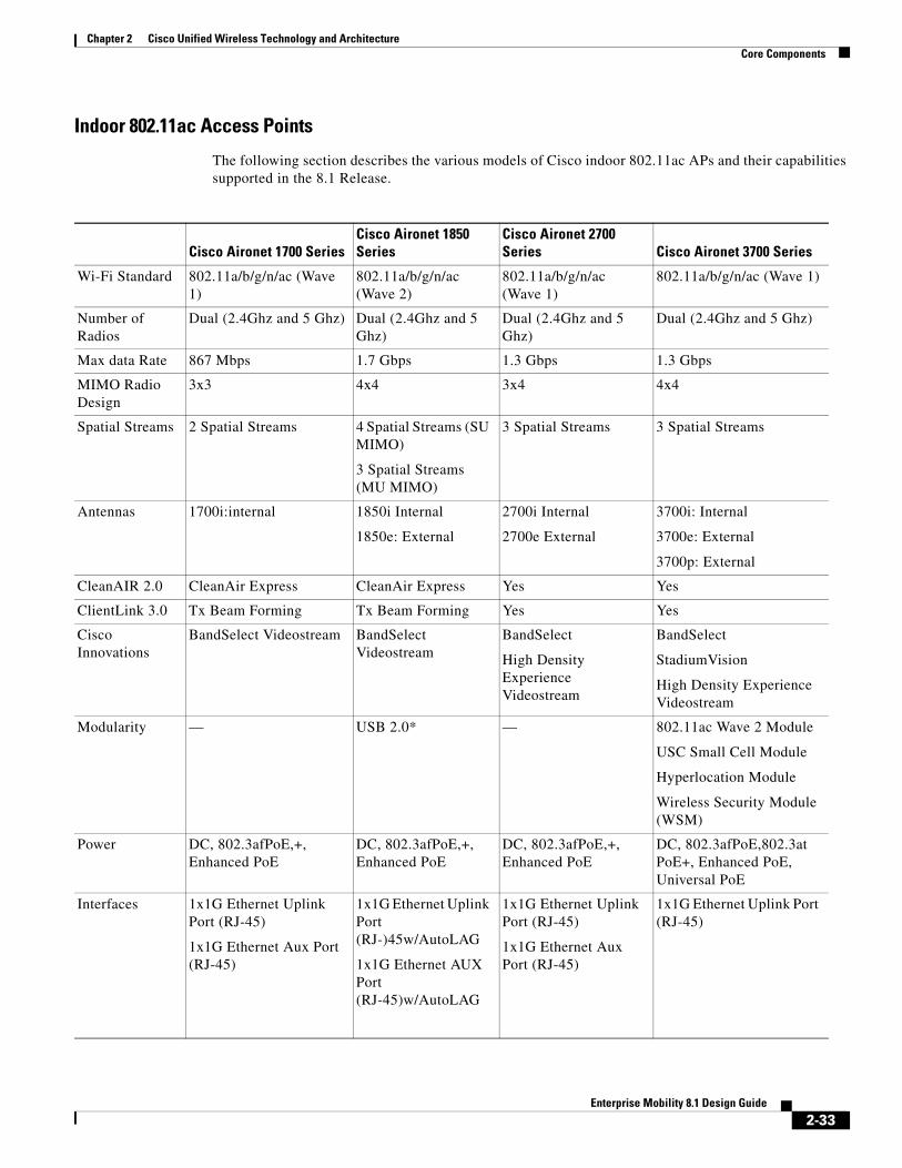
Indoor 802.11n Access Points
The following section describes the various models of Cisco indoor 802.11n APs and their capabilities supported in the 8.1 release.
Cisco Aironet 600 Series
Cisco Aironet 700W Series Cisco Aironet
1600 SeriesCisco Aironet 2600 Series
Cisco Aironet 3600 Series
Wi-Fi Standard 802.11a/b/g/n 802.11a/b/g/n 802.11a/b/g/n 802.11a/b/g/n 802.11a/b/g/n/ac
Number of Radios
Dual (2.4Ghz and 5 Ghz)
Dual (2.4Ghz and 5 Ghz)
Dual (2.4Ghz and 5 Ghz)
Dual (2.4Ghz and 5 Ghz)
Tri (2.4Ghz and 5 Ghz)
Max data Rate 300 Mbps 300 Mbps 300 Mbps 450 Mbps 450 Mbps (802.11n)
Chapter 2 Cisco Unified Wireless Technology and ArchitectureCore Components
Cisco Aironet 600 Series OfficeExtend
The Cisco Aironet 600 Series OfficeExtend Access Points provide highly secure enterprise wireless coverage to home. These dual-band, 802.11n access points extend the corporate network to home tele-workers and mobile contractors. The access point connects to the home’s broadband internet access and establishes a highly secure tunnel to the corporate network so that remote employees can access data, voice, video, and cloud services for a mobility experience consistent with that at the corporate office. The dual-band, simultaneous support for 2.4 GHz and 5 GHz radio frequencies helps assure that corporate devices are not affected by congestion caused by common household devices that use the 2.4 GHz band. The Cisco Aironet 600 Series OfficeExtend Access Points are purposely designed for the teleworker by supporting secure corporate data access and maintaining connectivity for personal home devices with segmented home traffic.
For more information about the Cisco Aironet 600 Series, see the Cisco Aironet 600 Series OfficeExtend Access Point.
Chapter 2 Cisco Unified Wireless Technology and ArchitectureCore Components
Cisco Aironet 700W Series
The Cisco Aironet 700W Series offers a compact wall-plate mountable access point for hospitality and education-focused customers looking to modernize their networks to handle today’s increasingly complex wireless access demands.
With 802.11n dual-radio 2 x 2 Multiple-Input Multiple-Output (MIMO) technology providing at least six times the throughput of existing 802.11a/g networks, the Cisco Aironet 700W Series offers the performance advantage of 802.11n quality at a competitive price.
As part of the Cisco Unified Wireless Network, the 700W Series Access Point provides low total cost of ownership and investment protection by integrating seamlessly with the existing network.
For more information, see the Cisco Aironet 700W Series.
Chapter 2 Cisco Unified Wireless Technology and ArchitectureCore Components
Cisco Aironet 1600 Series
The new Cisco Aironet 1600 Series Access Point is an enterprise-class, entry-level, 802.11n based access point designed to address the wireless connectivity needs of small and medium-sized enterprise networks.
The Aironet 1600 Series delivers great performance at an attractive price for customers, while providing advanced functionality such as CleanAir Express for better cover through spectrum intelligence and Clientlink 2.0 for entry level networks that have a mixed client base. In addition to these features, the Aironet 1600 series includes 802.11n based 3x3 MIMO technology with two spatial streams, making it ideal for small and medium-sized enterprises.
The Aironet 1600 Series also provides at least six times the throughput of existing 802.11a/g networks. As part of the Cisco Aironet Wireless portfolio, the Cisco Aironet 1600 Series access point provides low total cost of ownership and investment protection by integrating seamlessly with the existing network. With an entry-level path to 802.11n migration, the Aironet 1600 Series can add capacity to the network for future growth for expanding applications and bandwidth.
Designed with rapidly evolving mobility needs in mind, the Cisco Aironet 1600 Series Access Point addresses the Bring-Your-Own-Device (BYOD) trend by providing advanced functionality at the right price point.
For more information, see the Cisco Aironet 1600 Series.
Chapter 2 Cisco Unified Wireless Technology and ArchitectureCore Components
Cisco Aironet 2600 Series
The Cisco Aironet 2600 Series Access Point delivers the most advanced features in its class with great performance, functionality, and reliability at a great price. The 802.11n based Aironet 2600 Series includes 3x4 MIMO, with three spatial streams, Cisco CleanAir, ClientLink 2.0, and VideoStream technologies, to help ensure an interference-free, high-speed wireless application experience. Next to the Cisco Aironet 3600 Series in performance and features, the Aironet 2600 Series sets the new standard for enterprise wireless technology.
Designed with rapidly evolving mobility needs in mind, the Aironet 2600 Series access point is packed with more BYOD-enhancing functionality than any other access point at its price point. The new Cisco Aironet 2600 Series sustains reliable connections at higher speeds farther from the access point than competing solutions resulting in more availability of 450 Mbps data rates. Optimized for consumer devices, the Aironet 2600 Series accelerates client connections and consumes less mobile device battery power than competing solutions.
For more information, see the Cisco Aironet 2600 Series.
Chapter 2 Cisco Unified Wireless Technology and ArchitectureCore Components
Cisco Aironet 3600 Series
Delivering up to three times more coverage versus competition for tablets, smartphones, and high- performance laptops, the industry’s first 4x4 MIMO, three-spatial-stream access point delivers mission critical reliability. Current solutions struggle to scale to meet demands on the wireless networks from the influx of diverse mobile devices and mobile applications. The Cisco Aironet 3600 Series sustains reliable connections at higher speeds further from the access point than competing solutions, resulting in up to three times more availability of 450 Mbps rates, and optimizing the performance of more mobile devices. Cisco Aironet 3600 Series is an innovative, modular platform that offers unparalleled investment protection with future module expansion to support incoming 802.11ac clients with 1.3 Gbps rates, or offer comprehensive security and spectrum monitoring and control.
Cisco Aironet 3600 Series includes Cisco ClientLink 2.0 to boost performance and range for clients and includes Cisco CleanAir spectrum intelligence for a self-healing, self-optimizing network.
For more information, see the Cisco Aironet 3600 Series.
Chapter 2 Cisco Unified Wireless Technology and ArchitectureCore Components
Cisco Aironet 1700 Series
If you operate a small or medium-sized enterprise network, deploy the Cisco Aironet 1700 Series Access Point for the latest 802.11ac Wi-Fi technology at an attractive price. The 1700 Series meets the growing requirements of wireless networks by delivering better performance than 802.11n and providing key RF management features for improved wireless experiences.
The 1700 Series supports 802.11ac Wave 1 standard capabilities. That includes a theoretical connection rate up to 867 Mbps.
For more information, see the Cisco Aironet 1700 Series.
Chapter 2 Cisco Unified Wireless Technology and ArchitectureCore Components
Cisco Aironet 1850 Series
Ideal for small and medium-sized networks, the Cisco Aironet 1850 Series delivers industry-leading performance for enterprise and service provider markets through enterprise-class 4x4 MIMO, four-spatial-stream access points that support the IEEE’s new 802.11ac Wave 2 specification. The Aironet 1850 Series extends support to a new generation of Wi-Fi clients, such as smartphones, tablets, and high-performance laptops that have integrated 802.11ac Wave 1 or Wave 2 support.
For more information, see the Cisco Aironet 1850 Series.
Chapter 2 Cisco Unified Wireless Technology and ArchitectureCore Components
Cisco Aironet 2700 Series
The Cisco Aironet 2700 Series of Wi-Fi access points (APs) delivers industry-leading 802.11ac performance at a price point ideal for plugging capacity and coverage gaps in dense indoor environments. The Aironet 2700 Series extends 802.11ac speed and features to a new generation of smartphones, tablets, and high-performance laptops now shipping with the faster, 802.11ac Wi-Fi radios.
The Aironet 2700 series supports 802.11ac Wave 1 in its first implementation, providing a theoretical connection rate of up to 1.3 Gbps. That’s roughly triple the rates offered by today’s high-end 802.11n APs. The boost helps you stay ahead of the performance and bandwidth expectations of today’s mobile worker, who usually uses multiple Wi-Fi devices instead of just one. As such, users are adding proportionally larger traffic loads to the wireless LAN, which has outpaced ethernet as the default enterprise access network.
For more information, see the Cisco Aironet 2700 Series Access Point.
Chapter 2 Cisco Unified Wireless Technology and ArchitectureCore Components
Cisco Aironet 3700 Series
With the industry’s only enterprise class 4x4 MIMO, three-spatial-stream access points that support the IEEE’s 802.11ac Wave 1 specification, the Cisco Aironet 3700 Series delivers industry-leading performance and a High Density (HD) experience for both the enterprise and service provider markets. The Aironet 3700 Series extends support to a new generation of Wi-Fi clients, such as smartphones, tablets, and high-performance laptops that have integrated 802.11ac support.
In its first implementation, 802.11ac wave 1 provides a rate of up to 1.3 Gbps, roughly triple the rates offered by today’s high-end 802.11n access points. This provides the necessary foundation for enterprise and service provider networks alike to stay ahead of the performance and bandwidth expectations and needs of their wireless users.
Due to its convenience, wireless access is increasingly the preferred form of network connectivity for corporate users. Along with this shift, there is an expectation that wireless should not slow down user’s day-to-day work, but should enable a high-performance experience while allowing users to move freely around the corporate environment by utilizing a purpose-built innovative Chipset with the best-in-class RF Architecture for a HD experience.
For more information, see the Cisco Aironet 3700 Series.
Chapter 2 Cisco Unified Wireless Technology and ArchitectureCore Components
Cisco Prime InfrastructureChange is the new phenomenon. Mobile device proliferation, pervasive voice and video collaboration, and cloud and data center virtualization are transforming the network as never before. Yet along with the new opportunities comes a host of new challenges. There's the need for higher service levels, assured application delivery, and simplified end-user experiences, while maintaining business continuity and controlling operating expenses.
To address these challenges, IT professionals need a comprehensive solution that enables them to manage the network from a single graphical interface and the solution is Cisco Prime Infrastructure. It provides lifecycle management and service assurance networkwide, from the wireless user in the branch office, across the WAN, through the access layer, and now to the data center. We call it One Management (Figure 2-13).
Figure 2-13 Cisco Prime Infrastructure: One Management
Cisco Prime Infrastructure is a network management that connects the network to the device to the user to the application, end-to-end and all in one. Its capabilities permit:
• Single-pane-of-glass management—Delivers a single, unified platform for day-0 and day-1 provisioning and day-n assurance. It accelerates device and services deployment and helps you to rapidly resolve problems that can affect the end-user experience. Minimize the amount of time you spend managing the network so you can maximize the time you spend using it to grow your business.
• Simplified deployment of Cisco value-added features—Makes the design and fulfillment of Cisco differentiated features and services fast and efficient. With support for technologies such as Intelligent WAN (IWAN), Distributed Wireless with Converged Access, Application Visibility and Control (AVC), Zone-Based Firewall, and Cisco TrustSec 2.0 Identity-Based Networking Services, it helps you get the most from the intelligence built-in to your Cisco devices as quickly as possible.
• Application visibility—Configures and used as a source of performance data embedded Cisco instrumentation and industry-standard technologies to deliver networkwide, application-aware visibility. These technologies include NetFlow, Network-Based Application Recognition 2 (NBAR2), Cisco Medianet technologies, Simple Network Management Protocol (SNMP), and more. The innovative coupling of application visibility and lifecycle management of Cisco Prime Infrastructure makes it easier to find and resolve problems by providing insight into the health of applications and services in the context of the health of the underlying infrastructure.
2-38Enterprise Mobility 8.1 Design Guide
Chapter 2 Cisco Unified Wireless Technology and ArchitectureCore Components
• Management for mobile collaboration—Answers the who, what, when, where, and how of wireless access. It includes 802.11ac support, correlated wired-wireless client visibility, unified access infrastructure visibility, spatial maps, converged security and policy monitoring and troubleshooting with Cisco Identity Services Engine (ISE) integration, location-based tracking of interferers, rogues, and Wi-Fi clients with Cisco Mobility Services Engine (MSE) and Cisco CleanAir integration, lifecycle management, RF prediction tools, and more.
• Management across network and compute—Delivers powerful lifecycle management and service assurance to help you manage and maintain the many devices and services running on your branch-office, campus, and data center networks. It provides key capabilities such as discovery, inventory, configuration, monitoring, troubleshooting, reporting, and administration. With a single view and point of control, it lets you reap the benefits of One Management across both network and computer.
• Centralized visibility of distributed networks—Large or global organizations often distribute network management by domain, region, or country. Cisco Prime Infrastructure Operations Center lets you visualize up to 10 Cisco Prime Infrastructure instances, scaling your network-management infrastructure while maintaining central visibility and control.
Licensing Options
Cisco Prime Infrastructure is a single installable software package with licensing options to expand and grow functions and coverage as needed.
• Lifecycle—Simplifies the day-to-day operational tasks associated with managing the network infrastructure across all lifecycle phases (design, deploy, operation, and report) for Cisco devices including routers, switches, access points, and more.
• Assurance—Provides application performance visibility using device instrumentation as a source of rich performance data to help assure consistent application delivery and an optimal end-user experience.
• Cisco UCS Server Management—Offers lifecycle and assurance management for Cisco UCS B- and C-Series Servers.
• Operations center—Enables visualization of up to 10 Cisco Prime Infrastructure instances from one central management console. One license is required for each Cisco Prime Infrastructure supported instance.
• High-Availability Right to Use (RTU)—Permits high-availability configuration with one primary and one secondary instance in a high-availability pair.
• Collector—Increases the NetFlow processing limit on the Cisco Prime Infrastructure management node. This license is used in conjunction with the Assurance license.
• Ready-to-use gateway RTU—Entitles you to deploy a separate gateway for use with the ready-to-use feature, where new devices can call in to the gateway to receive their configuration and software image.
Note Cisco Prime Infrastructure 2.2 is available for new customers, and upgrade options are available for existing customers running on prior versions. Upgrade options are also available for Cisco Network Control System (NCS), Cisco Wireless Control System (WCS), and Cisco Prime LAN Management Solution (LMS) customers. For details refer to: http://www.cisco.com/c/en/us/products/cloud-systems-management/prime-infrastructure/datasheet-listing.html.
Chapter 2 Cisco Unified Wireless Technology and ArchitectureCore Components
Scaling
Cisco Prime Infrastructure 2.2 is available for purchase as a virtual or physical appliance. The virtual appliance can be installed on top of VMware’s industry-standard hypervisor and is available in multiple versions to support networks of different sizes. A physical appliance is also available for large network deployments, when dedicated CPU and memory resources are required.
• Physical Appliance (Second Generation)—Based on the Cisco UCS C220 M4 Rack Server.
• Virtual Appliance—ESXi Version 5.0, 5.1 or 5.5.
Table 2-3 provides a scaling matrix for Cisco Prime Infrastructure 2.2 for both the virtual and physical appliances:
Table 2-3 Cisco Prime Infrastructure 2.2 Scaling Matrix
Parameter
Express Virtual Appliance
Express Plus Virtual Appliance
Standard Virtual Appliance
Pro Virtual Appliance
Physical Appliance (Gen 1)
Physical Appliance (Gen 2)
Devices Max Unified APs
300 2,500 5,000 20,000 5,000 20,000
Max Autonomous APs
300 500 3,000 3,000 3,000 3,000
Max WLAN Controllers
5 25 500 1,000 500 1,000
Max Wired 300 1,000 6,000 13,000 6,000 13,000
Max NAMs 5
Max Devices 1,000 4,000 15,000 20,000 15,000 20,000
Clients Max Wired Clients
6,000 50,000 50,000 5=20,000 15,000 20,000
Max Wireless Clients
4,000 30,000 75,000 200,000 75,000 200,000
Transient Wireless Clients (Clients / 5 min Interval)
1,000 5,000 25,000 40,000 25,000 40,000
Monitoring
Sustained Events/Sec
100 100 300 1,000 300 1,000
Netflow (Flows/Sec)
3,000 3,000 16,000 80,000 16,000 80,000
Max Interfaces 12,000 50,000 250,000 350,000 250,000 350,000
Max. NAM Data Poling Enabled
5 5 20 40 20 40
2-40Enterprise Mobility 8.1 Design Guide
Chapter 2 Cisco Unified Wireless Technology and ArchitectureCore Components
System Max Sites / Campus
200 500 2,500 2,500 2,500 2,500
Max Groups 50 100 150 150 150 150
Max Virtual Domains
100 500 1,200 1,200 1,200 1,200
Max GUI Clients
5 10 25 50 25 50
Max API Clients 2 2 5 5 5 5
Table 2-3 Cisco Prime Infrastructure 2.2 Scaling Matrix
Parameter
Express Virtual Appliance
Express Plus Virtual Appliance
Standard Virtual Appliance
Pro Virtual Appliance
Physical Appliance (Gen 1)
Physical Appliance (Gen 2)
2-41Enterprise Mobility 8.1 Design Guide
Chapter 2 Cisco Unified Wireless Technology and ArchitectureHigh Availability
High AvailabilityThe following section provides an overview of the High Availability (HA) deployment options available for a Cisco Unified Wireless Network.
AP / Client Failover
N+1 Wireless Controller Redundancy
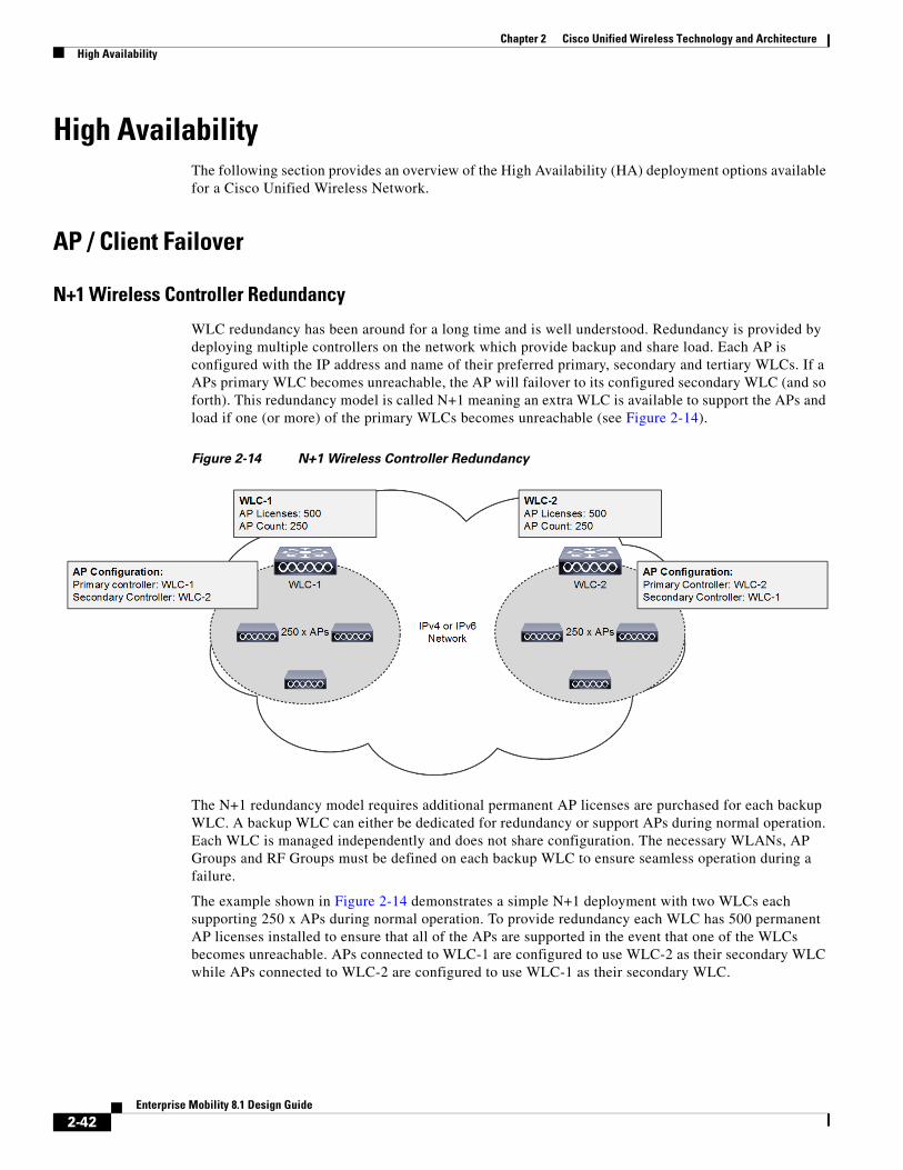
WLC redundancy has been around for a long time and is well understood. Redundancy is provided by deploying multiple controllers on the network which provide backup and share load. Each AP is configured with the IP address and name of their preferred primary, secondary and tertiary WLCs. If a APs primary WLC becomes unreachable, the AP will failover to its configured secondary WLC (and so forth). This redundancy model is called N+1 meaning an extra WLC is available to support the APs and load if one (or more) of the primary WLCs becomes unreachable (see Figure 2-14).
Figure 2-14 N+1 Wireless Controller Redundancy
The N+1 redundancy model requires additional permanent AP licenses are purchased for each backup WLC. A backup WLC can either be dedicated for redundancy or support APs during normal operation. Each WLC is managed independently and does not share configuration. The necessary WLANs, AP Groups and RF Groups must be defined on each backup WLC to ensure seamless operation during a failure.
The example shown in Figure 2-14 demonstrates a simple N+1 deployment with two WLCs each supporting 250 x APs during normal operation. To provide redundancy each WLC has 500 permanent AP licenses installed to ensure that all of the APs are supported in the event that one of the WLCs becomes unreachable. APs connected to WLC-1 are configured to use WLC-2 as their secondary WLC while APs connected to WLC-2 are configured to use WLC-1 as their secondary WLC.
2-42Enterprise Mobility 8.1 Design Guide
Chapter 2 Cisco Unified Wireless Technology and ArchitectureHigh Availability
Note For large deployments, if the preferred WLCs are unavailable or over-subscribed, the AP chooses another WLC from the list of WLCs within the mobility group learned in the CAPWAP discover response that is the least-loaded WLC.
N+1 HA Wireless Controller Redundancy
The N+1 HA feature builds upon the N+1 redundancy model by allowing a single WLC to be deployed as a backup for multiple primary WLCs. As previously mentioned an N+1 deployment requires additional AP licenses to be purchased for the backup WLCs which are unused during normal operation. With an N+1 HA deployment a HA-SKU WLC is deployed as the backup WLC for multiple primary WLCs without any additional permanent AP licenses being required (seeFigure 2-15).
Figure 2-15 N+1 HA Wireless Controller Redundancy
The N+1 HA architecture can provide redundancy for both centralized and FlexConnect AP deployments. WLC redundancy can be provided within the same campus/site or between geographically separate data centers. The HA WLC is managed independently and does not share configuration with the primary WLCs. Each WLC needs to be configured and managed separately. The necessary WLANs, AP Groups and RF Groups must be defined on the HA WLC to ensure seamless operation during a failover.
If a primary WLC becomes unreachable or fails, the affected APs failover to the HA WLC. A HA WLC is only licensed to support APs for up to 90-days. As soon as an AP joins the HA WLC a 90-day timer will start. A warning message will be displayed if APs are still present on the HA WLC after the 90-day interval expires. A HA WLC can only be used as a secondary WLC for 90 days without a warning message.
The example shown in Figure 2-15 demonstrates a simple N+1 HA deployment for a 500 AP deployment. Both of the primary WLCs have 250 permanent AP licenses installed. The HA WLC model is selected to initially support 500 APs and provide room for future growth. APs connected to WLC-1 and WLC-2 are configured to use WLC-BACKUP as their secondary WLC.
2-43Enterprise Mobility 8.1 Design Guide
Chapter 2 Cisco Unified Wireless Technology and ArchitectureHigh Availability
Note HA-SKUs are available for the 2500 series, 5500 series, 7500 series, 8500 series wireless controllers as well as the WiSM2. An N+1 HA deployment can consist of WLCs of different models (for example 5508 WLCs operating as primary and a 5520 WLC HA-SKU operating as a backup.
HA Stateful Switchover Wireless Controller Redundancy
Both the N+1 and N+1 HA redundancy architectures discussed in the previous sections provide AP failover in the event that a primary WLC becomes unreachable. Both architectures impact wireless services while APs detect that their primary WLC is unreachable and failover to their secondary or tertiary WLC. To provide HA without impacting service, there needs to be support for seamless transition of both APs and clients between WLCs. The WLCs implement both AP stateful switchover (AP SSO) and client stateful switchover (Client SSO) to provide zero client service downtime and prevent SSID outages during a WLC failover.
HA stateful switchover (SSO) is the recommended HA deployment architecture for a CUWN. This design builds upon the N+1 HA architecture where two WLCs are deployed as a 1:1 primary / secondary pair. The current configuration as well as AP and client state information is automatically synchronized between the primary and secondary peers. For most deployments the primary WLC has the permanent AP licenses installed while the secondary WLC is a HA-SKU (see Figure 2-16).
During normal operation the primary WLC assumes an active role while the secondary WLC assumes a standby-hot role. After a switchover, the secondary WLC assumes the active role and the primary WLC assumes the standby-hot role. After subsequent switchovers, the roles are interchanged between the primary and secondary WLCs. The WLCs exchange UDP keep-alive packets through their redundancy management interfaces (RMI) to check peer and management gateway reachability.
Once HA-SSO is enabled all configuration is performed on the active WLC which is automatically synchronized to the standby-hot WLC. No configuration can be performed on the CLI or Web-UI on the standby-hot WLC. Firmware images are also distributed to the standby-hot WLC.
2-44Enterprise Mobility 8.1 Design Guide
Chapter 2 Cisco Unified Wireless Technology and ArchitectureHigh Availability
Figure 2-16 HA-SSO Wireless Controller Redundancy
Note For additional details please see the “High Availability (SSO) deployment guide” at: http://www.cisco.com/c/en/us/td/docs/wireless/controller/technotes/8-1/HA_SSO_DG/High_Availability_DG.html.
The HA-SSO architecture consists of both AP and client SSO which combine to provide sub-second failure detection and failover without impacting wireless services to clients. AP SSO was initially introduced in release 7.3 while client SSO was introduced in release 7.5:
• AP SSO – Allows the APs to establish a CAPWAP tunnel with the active WLC and share a mirror copy of the AP database with the standby-hot WLC. The APs do not go into a CAPWAP discovery state during a failover. There is only one CAPWAP tunnel maintained at a time between the APs and the WLC that is in an active state. The overall goal for AP SSO is to reduce downtime in wireless networks due to failure conditions that may occur such as a WLC or network failover.
• Client SSO – To provide seamless failover without impacting service, there needs to be support for seamless transition of both clients and APs from the active WLC to the standby-hot WLC. With Client SSO, a client's information is synchronized to the standby-hot WLC when the client associates to the active WLC or the client’s parameters change. All fully authenticated clients are synced to the standby-hot WLC and thus, client re-association is avoided during a switch over making the failover seamless for the APs as well as for the clients. This results in zero client service downtime and no SSID outages.
Chapter 2 Cisco Unified Wireless Technology and ArchitectureHigh Availability
AP and client SSO is supported by the 5500 series, 7500 series and 8500 series WLCs as well as the Wireless Services Module 2. Each appliance based WLC supports a dedicated redundancy port while the WiSM2 implements a redundancy VLAN. The redundancy port is used to exchange keep-alive messages as well as synchronize configuration and state information. Redundancy ports are either be directly connected or indirectly connected through an intermediate layer 2 network. Table 2-4 provides a summary of HA SSO support for each model of WLC:
Note The implementation of AP and Client SSO is dependent on the software release operating on the primary and secondary WLCs and cannot be independently configured. For example if HA is enabled and both WLCs support 8.1, both AP SSO and Client SSO will be implemented.
Redundancy Port / VLAN Configurations
A redundancy port / VLAN is mandatory for HA-SSO deployments and are used to synchronize configuration / state as well as exchange keep-alive packets. A redundancy port / VLAN is also used for role negotiation. Appliance based WLCs such as the 5500 series, 7500 series and 8500 series controllers implement a dedicated Ethernet redundancy port while the WiSM2 implements a redundancy VLAN.
In release 7.5 and above, the redundancy ports for appliance based WLCs can be interconnected via a dedicated Ethernet cable or indirectly connected at layer 2 over intermediate switches using a dedicated non-routable VLAN. Direct connections with fiber over media converters is also supported. Figure 2-17 demonstrates the supported redundancy port connection options.
Table 2-4 HA-SSO Support by Controller Platform
Platform Redundancy Port AP SSO Client SSO
Cisco 2504 Wireless Controller
No No No
Cisco 5508 Wireless Controller
Yes Yes (7.3 and above) Yes (7.5 and above)
Cisco 5520 Wireless Controller
Yes Yes (8.1 and above) Yes (8.1 and above)
Cisco Flex 7500 Wireless Controller
Yes Yes (7.3 and above) Yes (7.5 and above)
Cisco 8510 Wireless Controller
Yes Yes (7.3 and above) Yes (7.5 and above)
Cisco 8540 Wireless Controller
Yes Yes (8.1 and above) Yes (8.1 and above)
Cisco Wireless Services Module 2
Yes-VLAN Yes Yes
Virtual Wireless Controller (vWLC)
No No No
2-46Enterprise Mobility 8.1 Design Guide
Chapter 2 Cisco Unified Wireless Technology and ArchitectureHigh Availability
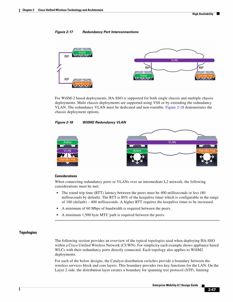
Figure 2-17 Redundancy Port Interconnections
For WiSM-2 based deployments, HA-SSO is supported for both single chassis and multiple chassis deployments. Multi chassis deployments are supported using VSS or by extending the redundancy VLAN. The redundancy VLAN must be dedicated and non-routable. Figure 2-18 demonstrates the chassis deployment options.
Figure 2-18 WiSM2 Redundancy VLAN
Considerations
When connecting redundancy ports or VLANs over an intermediate L2 network, the following considerations must be met:
• The round trip time (RTT) latency between the peers must be 400 milliseconds or less (80 milliseconds by default). The RTT is 80% of the keepalive timer which is configurable in the range of 100 (default) – 400 milliseconds. A higher RTT requires the keepalive timer to be increased.
• A minimum of 60 Mbps of bandwidth is required between the peers.
• A minimum 1,500 byte MTU path is required between the peers.
Topologies
The following section provides an overview of the typical topologies used when deploying HA-SSO within a Cisco Unified Wireless Network (CUWN). For simplicity each example shows appliance based WLCs with their redundancy ports directly connected. Each topology also applies to WiSM2 deployments.
For each of the below designs, the Catalyst distribution switches provide a boundary between the wireless services block and core layers. This boundary provides two key functions for the LAN. On the Layer 2 side, the distribution layer creates a boundary for spanning tree protocol (STP), limiting
2-47Enterprise Mobility 8.1 Design Guide
Chapter 2 Cisco Unified Wireless Technology and ArchitectureHigh Availability
propagation of Layer 2 faults. On the Layer 3 side, the distribution layer provides a logical point to summarize IP routing information when it enters the network. The summarization reduces IP route tables for easier troubleshooting and reduces protocol overhead for faster recovery from failures.
Standalone Distribution Switch
The topology shown in Figure 2-19 demonstrates a HA-SSO pair of WLCs that are connected to a standalone Catalyst switch within the wireless services block. Redundancy is provided by deploying multiple line cards or switches to form a resilient stack. This design provides minimum protection against network and hardware failures as a complete chassis or stack failure will result in the HA-SSO WLCs being isolated from the rest of the network.
Figure 2-19 HA-SSO with a Standalone Distribution Switch
Note The above architecture also applies to WiSM2 deployments. The equivalent WISM2 design consisting of a single Catalyst 6500 series chassis with two WiSM2 modules installed.
Multilayer Distribution Switches
The topology shown in Figure 2-20 demonstrates a HA-SSO pair of WLCs that are connected to a pair of Catalyst switches within the wireless services block implementing a multilayer design. As the Catalyst switches in this topology example are layer 3 connected, this results in a more complex design
2-48Enterprise Mobility 8.1 Design Guide
Chapter 2 Cisco Unified Wireless Technology and ArchitectureHigh Availability
as the wireless management and wireless user VLANs must be extended between the Catalyst switches. This results in a looped multilayer architecture that requires a spanning tree protocol and a first-hop routing protocol:
• With this architecture you cannot implement routed ports or a routed port-channel between the Catalyst switches. Instead a link-local VLAN with switched virtual interfaces (SVIs) must be used. This allows the wireless VLANs to be extended between the Catalyst switches while maintaining a multilayer design.
• For loop prevention spanning tree protocol (STP) must be enabled for each of the wireless VLANs. The Catalyst switch connected to the primary WLC must be configured as the STP root bridge for each VLAN.
• First-hop router redundancy such as HSRP must be enabled and configured for each wireless VLAN. The distribution switch connected to the primary WLC must be configured as the HSRP master for each VLAN.
During normal operation the Catalyst switch connecting to the active WLC is the first-hop router for each of the wireless management and wireless user VLANs. This minimizes the traffic that crosses the link between the pair of Catalysts switches as it is both the STP root and the HSRP master. If the primary Catalyst switch fails, HA-SSO will failover to the standby-hot WLC. If the primary Catalyst switch loses connectivity to the core network, a HA-SSO failover will not occur as the primary WLC can still communicate with the standby-hot WLC through the port-channel established between the two Catalyst switches.
Figure 2-20 HA-SSO with Multilayer Distribution Switches
Note The above architecture also applies to WiSM2 deployments. The equivalent WISM2 design consisting of two Catalyst 6500 series chassis configured for multilayer operation each with a WiSM2 module installed.
2-49Enterprise Mobility 8.1 Design Guide
Chapter 2 Cisco Unified Wireless Technology and ArchitectureHigh Availability
VSS Distribution Switches
The topology shown in Figure 2-21 demonstrates a HA-SSO pair of WLCs that are connected to a VSS pair of distribution switches within the wireless services block and is the recommended design. This design minimizes the traffic that crosses the virtual switch link between the Catalyst switches in the VSS pair during normal operation, because both the active and standby-hot WLCs have ports connected to both switches. This design also avoids a switchover from the active WLC to the standby-hot WLC in the event of a switch failure within the VSS pair. However, in the event of a switch failure within the VSS pair, the number of ports connected to the active WLC would be reduced by half.
Figure 2-21 HA-SSO using VSS
Note The above architecture also applies to WiSM2 deployments. The equivalent WISM2 design consisting of two Catalyst 6500 series chassis in a VSS configuration each with a WiSM2 module installed.
Considerations
When implementing HA-SSO, the following considerations should be made:
• The Catalyst switches should be configured and deployed following Cisco recommended best practices as outlined in the published Cisco Validated Designs (CVDs) available at: http://www.cisco.com/c/en/us/solutions/enterprise/design-zone/index.html.
• HA-SSO failover times are dependent on the convergence times introduced by routing protocol, spanning tree protocol and first-hop router redundancy protocol.
• The wireless management, wireless user VLANs should be 802.1Q tagged between the Catalyst switches and the WLCs.
• It is recommended that the HA-SSO WLCs be connected to the Catalyst switches using link aggregation (LAG). The WLC ports should be distributed between ports on different line cards within a chassis or switches within a resilient stack. If VSS is deployed the WLC ports can be distributed between both Catalyst switches.
Chapter 2 Cisco Unified Wireless Technology and ArchitectureHigh Availability
• The channel mode for the port-channel on the neighboring Catalyst switch or VSS connecting to the WLCs must be set to mode on (static). The WLC software release 8.1 does not support LACP or PaGP protocols.
• When connecting HA-SSO WLCs to multilayer distribution switches:
• The wireless management and user VLANs are 802.1Q tagged between the Catalyst distribution switches. This will result in a multilayer looped design.
• For loop prevention it is recommended that rapid spanning tree protocol be enabled for the wireless management and wireless user VLANs. The Catalyst switch is connected to the primary WLC during normal operation should be configured as the STP root bridge for each wireless VLAN.
• A first-hop routing protocol such as HSRP must be enabled for the wireless management and user VLANs. The Catalyst switch that is connected to the primary WLC during normal operation should be configured as the HSRP master for each wireless VLAN.
• Appliance based WLC redundancy ports can be directly connected or indirectly connected at layer 2. If indirectly connected it is recommended that you extend a dedicated non-routable 2 VLAN between each of the Catalyst switches.
• If the redundancy ports are extended over an intermediate L2 network, the latency, bandwidth and MTU requirements outlined in the previous section must be followed.
HA-SSO and N+1 Redundancy
For large Cisco Unified Wireless Network (CUWN) deployments both HA-SSO and N+1 redundancy can be combined to provide AP failover in the event that SSO-HA WLCs become unreachable (Figure 2-22). This is the recommended design for a large CUWN deployment where different HA-SSO pairs are assigned to service APs within a defined geography such as buildings or floors.
The configuration works exactly the same as an N+1 HA deployment where the APs are configured with primary, secondary and tertiary WLCs. The APs primary WLC is configured as their assigned HA-SSO WLC pair, while the secondary (and optionally the tertiary) WLC can be configured as a separate HA-SSO WLC pair or a standalone WLC. The APs will only failover to the secondary WLC if both the active and standby-hot WLCs in the primary HA-SSO pair become unreachable. Failover to the secondary or tertiary WLCs is stateless.
2-51Enterprise Mobility 8.1 Design Guide
Chapter 2 Cisco Unified Wireless Technology and ArchitectureHigh Availability
Figure 2-22 HA-SSO and N+1 Redundancy
Fast RestartThe Fast restart enhancement aims to reduce network and service downtime by up to 73% when making changes to the following features:
• LAG Configuration Change
• Mobility Mode Change
• Web-Auth Certificate Change
• Clear Configuration
Without fast restart, the above changes required a full system restart. Fast restart feature is supported on the Cisco WLC 5520, 7510, 8510, 8540 and vWLC starting release 8.1. It can be invoked using the CLI by issuing the Restart command or by clicking Save and Restart within the Web-UI.
Link Aggregation (LAG)Link aggregation (LAG) is a partial implementation of the 802.3ad port aggregation standard. When enabled LAG bundles all of the WLCs Ethernet ports into a single 802.3ad port-channel providing additional bandwidth and fault-tolerance between the WLC and its neighboring switch. If any of the WLC ports or connections fail, traffic is automatically migrated to one of the other remaining Ethernet ports in the bundle. As long as at least one Ethernet port is functioning, the wireless system continues to operate, APs remain and clients are able to send and receive data.
LAG is a globally enabled on the WLC (Figure 2-23) and is supported by the Cisco WLC 2504, 5508, 5520 and 8540. When you enable LAG all Ethernet ports will participate in the bundle. The WLC requires an immediate full system reboot or fast restart to enable LAG.
2-52Enterprise Mobility 8.1 Design Guide
Chapter 2 Cisco Unified Wireless Technology and ArchitectureHigh Availability
Figure 2-23 LAG Mode
Considerations
When implementing LAG, the following considerations should be made:
• A Cisco WLC does not send CDP advertisements on a LAG interface.
• All WLC Ethernet ports in the LAG must operate at the same speed. You cannot mix Gigabit and 10Gigabit ports.
• The channel mode for the port-channel on the neighboring Catalyst switch or VSS connecting to the WLCs must be set to mode on (static). The WLC software release 8.1 does not support LACP or PaGP protocols.
• You cannot separate the WLC Ethernet ports into separate LAG groups.
• Only one AP-manager interface is supported as all Ethernet ports are bundled into a single logical port.
• When you enable LAG, all dynamic AP-manager interfaces and untagged interfaces are deleted, and all WLANs are disabled and mapped to the management interface. The management, static AP-manager, and VLAN-tagged dynamic interfaces are assigned to the LAG port.
• When you enable LAG, the WLC sends packets out on the same port on which it received them. If a CAPWAP packet from an AP enters the controller on physical port 1, the WLC removes the CAPWAP wrapper, processes the packet, and forwards it to the network on physical port 1.
2-53Enterprise Mobility 8.1 Design Guide
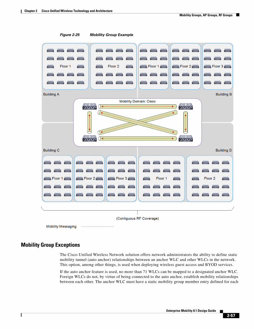
Chapter 2 Cisco Unified Wireless Technology and ArchitectureMobility Groups, AP Groups, RF Groups
Mobility Groups, AP Groups, RF GroupsWithin the Cisco Unified Wireless Network there are three important group concepts:
• Mobility groups
• AP groups
• RF groups
The following sections describe the purpose and application of these groups within the Cisco Unified Wireless Network.
Mobility GroupsA mobility group is a set of controllers, identified by the same mobility group name that defines the realm of seamless roaming for wireless clients. By creating a mobility group, you can enable multiple WLCs in a network to dynamically share essential client, AP and RF information as well as forward data traffic when inter-controller or inter-subnet roaming occurs. WLCs in the same mobility group can share the context and state of client devices as well as their list of access points so that they do not consider each other’s access points as rogue devices. With this information, the network can support inter-controller wireless LAN roaming and controller redundancy.
A mobility group forms a mesh of authenticated tunnels between member WLCs, thereby allowing any WLC to directly contact another WLC within the group, as shown in Figure 2-24.
2-54Enterprise Mobility 8.1 Design Guide
Chapter 2 Cisco Unified Wireless Technology and ArchitectureMobility Groups, AP Groups, RF Groups
Figure 2-24 WLC Mobility Group
In release 8.0 and above, mobility tunnels can be established between WLC peers using either Internet Protocol version 4 (IPv4) or Internet Protocol version 6 (IPv6). The implementation of IPv4 or IPv6 tunnels is driven by the mobility configuration defined for each peer. Table 2-5 lists the protocol and ports implemented for each mobility tunnel version:
Table 2-5 Mobility Tunnel Protocols and Ports
Internet Protocol IP Protocol DST Port Description
Version 4 17 (UDP) 16,666 IPv4 Mobility Tunnel Control Channel
97 (EITHERIP) - IPv4 Mobility Tunnel Data Channel
Version 6 17 (UDP) 16,666 IPv6 Mobility Tunnel Control Channel
17 (UDP) 16,667 IPv6 Mobility Tunnel Data Channel
2-55Enterprise Mobility 8.1 Design Guide
Chapter 2 Cisco Unified Wireless Technology and ArchitectureMobility Groups, AP Groups, RF Groups
Mobility Group Considerations
Creating a mobility group is simple and well documented. However, there are a few important considerations to keep in mind:
• Up to 24 x WLCs (any model) can be assigned to a single mobility group. A maximum of 144,000 APs are supported in a single mobility group (24 WLCs x 6,000 APs = 144,000 APs). An enterprise deployment can consist of more WLCs and APs, however they must be configured as members of a different mobility group.
• The WLCs do not have to be of the same model or type to be a member of a mobility group, however each member should be running the same software version.
• While mobility groups can function with software differences between members, Cisco strongly recommends you use a common software version to ensure feature and functional parity across the Cisco Unified Wireless Network deployment.
• If WLCs with switchover (SSO) are deployed, each WLC SSO pair is considered a single mobility peer.
• A mobility group requires all WLCs in the group to use the same virtual IP address.
• Each WLC must use the same Mobility Domain name and be defined as a peer in each other’s Static Mobility Members list. The exception to this rule are when guest anchors are deployed where Cisco recommends deploying a separate Mobility Group for the guest anchors.
• For a wireless client to seamlessly roam between mobility group members (WLCs), a given WLAN SSID and security configuration must be consistent across all WLCs comprising the mobility group.
• As a Cisco best practice it is recommended that you enable the Multicast Mobility feature on all members of the mobility group. This feature requires a common Local Group Multicast IPv4 Address to be defined on each mobility group member.
Mobility Group Applications
Mobility groups are used to help facilitate seamless client roaming between APs that are joined to different WLCs. The primary purpose of a mobility group is to create a virtual WLAN domain (across multiple WLCs) in order to provide a comprehensive view of a wireless coverage area.
The use of mobility groups are beneficial only when a deployment comprises of overlapping coverage established by two or more APs that are connected to different WLCs. A mobility group provides no benefit when two APs, associated with different WLCs, are in different physical locations with no overlapping (contiguous) coverage between them. For example roaming between a campus and branch or between two or more branches.
2-56Enterprise Mobility 8.1 Design Guide
Chapter 2 Cisco Unified Wireless Technology and ArchitectureMobility Groups, AP Groups, RF Groups
Figure 2-25 Mobility Group Example
Mobility Group Exceptions
The Cisco Unified Wireless Network solution offers network administrators the ability to define static mobility tunnel (auto anchor) relationships between an anchor WLC and other WLCs in the network. This option, among other things, is used when deploying wireless guest access and BYOD services.
If the auto anchor feature is used, no more than 71 WLCs can be mapped to a designated anchor WLC. Foreign WLCs do not, by virtue of being connected to the auto anchor, establish mobility relationships between each other. The anchor WLC must have a static mobility group member entry defined for each
2-57Enterprise Mobility 8.1 Design Guide
Chapter 2 Cisco Unified Wireless Technology and ArchitectureMobility Groups, AP Groups, RF Groups
foreign WLC where a static mobility tunnel is needed. The same is true for each foreign WLC where a static mobility tunnel is being configured; the anchor WLC must be defined as a static mobility group member in the foreign WLC.
A WLC can be member of only one mobility group for the purpose of supporting dynamic inter-controller client roaming. A WLC that is configured as an auto anchor does not have to be in the same mobility group as the foreign WLCs. It is possible for a WLC to be a member of one mobility group while at the same time, act as an auto anchor for a WLAN originating from foreign WLCs that are members of other mobility groups. For a discussion on mobility anchor configuration, see, Chapter 10, “Cisco Unified Wireless Network Guest Access Services.”
AP GroupsAn AP group is logical grouping of APs within a geographic area such as a building, floor or remote branch office that share common WLAN, RF, Hotspot 2.0 and location configurations. AP groups are useful in a Cisco Unified Wireless Network deployment as they allow administrators to assign specific configurations to different groups of APs. For example AP groups can be used to control which WLANs are advertised in different buildings in a campus, the interface or interface groups WLAN clients are assigned or the RRM and 802.11 radio parameters for radios in specific coverage areas to support high-density designs.
Supported AP group specific configurations include:
• CAPWAP Preferred Mode – Used to determine if the AP prefers IPv4 or IPv6 CAPWAP modes.
• NAS-ID – Used by the WLC for RADIUS authentication and accounting.
• WLAN – WLAN assignments, interface / interface group mappings and NAC state
• RF Profile Assignments – 802.11, RRM, high density and client load balancing configurations.
• Hotspot 2.0 – 802.11u venue configuration and languages.
• Location – HyperLocation configuration.
By default each AP is automatically assigned to a default AP group named “default-group” and WLANs IDs (1-16) map to this default group. WLANs with IDs greater than 16 require a custom AP group to be defined. When customized AP groups are defined on a WLC, the APs must be manually assigned to the AP group.
Note AP groups do not allow multicast roaming across group boundaries. For more information, see: http://www.cisco.com/c/en/us/td/docs/solutions/Enterprise/Mobility/emob41dg/emob41dg-wrapper/ch5_QoS.html.
Table 2-6 Cisco Wireless Controller AP Group scaling (by platform)
Controller Platform Max AP Groups Max APs per AP Group
Chapter 2 Cisco Unified Wireless Technology and ArchitectureMobility Groups, AP Groups, RF Groups
AP Group Considerations
Creating an AP group is simple and well documented. However, there are a few important considerations to keep in mind:
• If an AP does not belong to an AP group, it is assigned to the default AP group named “default-group” and will inherit any configurations applied to that group.
• As a Cisco best practice it is recommended that the customized AP group configurations on the primary, secondary and tertiary WLCs be consistent. If an AP joins a WLC with an undefined AP group name, the AP maintains its assigned AP group (NVRAM) but will inherit any configurations applied to the default-group. This can result in misconfigured APs and an undesirable user experience.
• Suppose that the interface mapping for a WLAN in the AP group table is the same as the WLAN interface. If the WLAN interface is changed, the interface mapping for the WLAN in the AP group table also changes to reflect the new WLAN interface.
• Suppose that the interface mapping for a WLAN in the AP group table is different from the one defined for the WLAN. If the WLAN interface is changed, then the interface mapping for the WLAN in the AP group table does not change to the new WLAN interface.
• If you clear the configuration on a controller, all of the AP groups (except the AP group named “default-group”) will disappear.
• The default access point group can have up to 16 WLANs associated with it. The WLAN IDs for the default access point group must be less than or equal to 16. If a WLAN with an ID greater than 16 is created in the default access point group, the WLAN SSID will not be broadcasted. All WLAN IDs in the default access point group must have an ID that is less than or equal to 16. WLANs with IDs greater than 16 require a custom AP group to be defined.
• The OfficeExtend 600 Series access point supports a maximum of two WLANs and one remote LAN. If you have configured more than two WLANs and a remote LAN on the WLC, you must assign the Office Extend 600 Series APs to a customized AP group. The support for two WLANs and one remote LAN still applies to the default AP group. Additionally the WLAN/remote LAN ids must be lower than 8.
• All OfficeExtend access points should be in the same AP group, and that AP group should contain no more than 15 WLANs. A controller with OfficeExtend access points in an access point group publishes only up to 15 WLANs to each connected OfficeExtend access point because it reserves one WLAN for the personal SSID.
• Cisco recommends that you configure all FlexConnect APs (in the same branch / site) in the same AP group and FlexConnect group. This ensures that all the APs at a site inherit the correct WLAN-VLAN mappings.
Cisco 8540 Wireless Controller 6,000 6,000
Cisco Wireless Services Module 2 1,000 1,000
Cisco Virtual Wireless Controller 200 200
Table 2-6 Cisco Wireless Controller AP Group scaling (by platform)
Controller Platform Max AP Groups Max APs per AP Group
2-59Enterprise Mobility 8.1 Design Guide
Chapter 2 Cisco Unified Wireless Technology and ArchitectureMobility Groups, AP Groups, RF Groups
AP Group Applications
AP groups can be used to solve several business challenges within a Cisco Unified Wireless Network. This section provides some common use-cases where AP groups can solve these problems:
• Controlling which WLANs are advertised by APs within specific geographic locations. For example in a campus deployment separate AP groups can be employed to only advertise a guest WLAN in public areas vs. campus wide. For retail deployments AP groups can be employed to advertise unique SSIDs for different brands stores (mergers and acquisitions) or to provide guest Wi-Fi services to subsets of retail stores.
As shown in Figure 2-26 a WLC supporting remote FlexConnect APs has been configured with three separate AP groups to support remote retail stores of different brands and client support. Stores 1 and 3 are the same brand and both share a common corporate SSID, however a separate AP group is required for store 3 as this store it offers guest Wi-Fi to patrons which is not yet available in store 1.
Store 2 is a different brand that implements a different corporate SSID. A separate AP group is required to support store 2 as the client devices in the store have not yet been migrated to the standard corporate SSID.
Figure 2-26 AP Groups for WLAN Assignments
• Reducing broadcast domain sizes by mapping WLAN clients to different interfaces or interface groups within a WLC. For example in a campus deployment, AP groups can be employed to map WLAN clients in separate buildings or floors to separate interfaces or interface groups on a single WLC.
2-60Enterprise Mobility 8.1 Design Guide
Chapter 2 Cisco Unified Wireless Technology and ArchitectureMobility Groups, AP Groups, RF Groups
As shown in Figure 2-27, a WLC has three dynamic interfaces configured, each with a site-specific VLAN (VLANs 22, 32 and 42). Each site-specific VLAN and associated APs are mapped to the same WLAN SSID using AP groups. A corporate user associating to the WLAN on an AP in the AP group corresponding to VLAN 22 is assigned an IP address on the VLAN 22 subnet. Likewise, a corporate user associating to the WLAN on an AP in the AP group corresponding to VLAN 32 is assigned an IP address on the VLAN 32 subnet and so on. Roaming between the site-specific VLANs is handled internally by the WLC as a Layer 3 roaming event and because of this the wireless LAN client maintains its original IP address.
Figure 2-27 AP Groups for Interface / Interface Group Assignments
• Optimizing the RF environment within geographic locations to support different client densities. APs in coverage areas can be assigned different RF profiles optimized to support different client needs or densities.
2-61Enterprise Mobility 8.1 Design Guide
Chapter 2 Cisco Unified Wireless Technology and ArchitectureMobility Groups, AP Groups, RF Groups
As shown in Figure 2-28, a WLC has been configured with two AP groups to support different AP and client densities. One AP group is configured for APs and clients deployed in a typical density while the second AP group is configured to support APs and clients in a high density.
Figure 2-28 \AP Groups for RF Optimization & Client Densities
• Migrating APs from Internet Protocol version 4 (IPv4) to Internet Protocol version 6 (IPv6). AP groups can be employed to switch the APs CAPWAP preferred mode from IPv4 to IPv6 as individual buildings or sites are transitioned.
As shown in Figure 2-29, a WLC has been configured with two AP groups to aid in the transition from IPv4 to IPv6. Each AP group is configured with a specific CAPWAP preferred mode that determines the IP Protocol used by the APs when joining a WLC.
2-62Enterprise Mobility 8.1 Design Guide
Chapter 2 Cisco Unified Wireless Technology and ArchitectureMobility Groups, AP Groups, RF Groups
Figure 2-29 AP Groups for IPv6 Migrations
RF GroupsAn RF group is a logical collection of Cisco WLCs that coordinate to perform RRM in a globally optimized manner to perform network calculations on a per-radio basis. An RF group exists for each 802.11 network type. Clustering Cisco WLCs into a single RF group enable the RRM algorithms to scale beyond the capabilities of a single Cisco WLC. Controller software can scale to support up to 20 WLCs and 6,000 APs in an RF group.
RF Groups and RRM is discussed in more detail in Chapter 3, WLAN RF Design Considerations” but can be summarized as follows:
• CAPWAP APs periodically send out neighbor messages over the air that includes the WLC IP address and a hashed message integrity check (MIC) derived from a timestamp and the BSSID of the AP.
• The hashing algorithm uses a shared secret (the RF Group Name) that is configured on the WLC and is pushed out to each AP. APs sharing the same secret are able to validate messages from each other using the MIC. When APs belonging to other WLCs hear validated neighbor messages at a signal strength of -80 dBm or stronger, their WLCs dynamically become members of the RF group.
• Members of an RF group elect an RF domain leader to maintain a master power and channel scheme for the RF group.
• The RF group leader analyzes real-time radio data collected by the system and calculates a master power and channel plan.
2-63Enterprise Mobility 8.1 Design Guide
Chapter 2 Cisco Unified Wireless Technology and ArchitectureMobility Groups, AP Groups, RF Groups
• The RRM algorithms attempt to:
– Achieve a uniform (optimal) signal strength of -65 dBm across all APs
– Avoid 802.11 co-channel interference and contention
– Avoid non-802.11 interference.
• The RRM algorithms employ dampening calculations to minimize system-wide dynamic changes. The end result is dynamically calculated, near-optimal power and channel planning that is responsive to an ever changing RF environment.
• The RF group leader and members exchange RRM messages at a specified update interval, which is 600 seconds by default. Between update intervals the RF group leader sends keep alive messages to each of the RF group members and collects real-time RF data. Note that the maximum number of WLCs per RF group is 20.
Note RF groups and mobility groups are similar in that they both define clusters of WLCs, but they are different in terms of their use. An RF group facilitates scalable, system-wide dynamic RF management while a mobility group facilitates scalable, system-wide mobility and WLC redundancy.
2-64Enterprise Mobility 8.1 Design Guide
Chapter 2 Cisco Unified Wireless Technology and ArchitectureRoaming
RoamingMobility, or roaming, is the ability of a WLAN client to maintain its association seamlessly from one AP to another securely and with as little latency as possible. This section explains how mobility works when WLCs are included in a Cisco Unified Wireless Network.
When a WLAN client associates and authenticates to an AP, the WLC places an entry for that client in its client database. This entry includes the client MAC and IP addresses, security context and associations, quality of service (QoS) contexts, the WLAN, SSID and the associated AP. The WLC uses this information to forward frames and manage traffic to and from the wireless client. Figure 2-30 shows a wireless client that roams from one AP to another when both APs are joined to the same controller.
Figure 2-30 Intra-Controller Roaming
2-65Enterprise Mobility 8.1 Design Guide
Chapter 2 Cisco Unified Wireless Technology and ArchitectureRoaming
When the WLAN client moves its association from one AP to another, the WLC simply updates the client database with the newly associated AP. If necessary, new security context and associations are established as well.
The process becomes more complicated, however, when a client roams from an AP joined to one WLC to an AP joined to a different WLC. It also varies based on whether the WLCs are operating on the same VLAN. Figure 2-31 shows inter-controller roaming, which occurs when the WLCs interfaces or interface groups are support the same VLAN.
Figure 2-31 Inter-Controller Roaming
When the client associates to an AP joined to a new controller, the new WLC exchanges mobility messages with the original WLC, and the client database entry is moved to the new WLC. New security context and associations are established if necessary, and the client database entry is updated for the new AP. This process remains transparent to the user.
Figure 2-32 shows inter-subnet roaming, which occurs when the WLCs interfaces are on different VLANs.
2-66Enterprise Mobility 8.1 Design Guide
Chapter 2 Cisco Unified Wireless Technology and ArchitectureRoaming
Figure 2-32 Inter-Subnet Roaming
Inter-subnet roaming is similar to inter-controller roaming in that the WLCs exchange mobility messages on the client roam. However, instead of moving the client database entry to the new WLC, the original controller marks the client with an Anchor entry in its own client database. The database entry is copied to the new controller client database and marked with a Foreign entry in the new WLC. The roam remains transparent to the wireless client, and the client maintains its VLAN membership and original IP address.
In inter-subnet roaming, WLANs on both anchor and foreign WLCs need to have the same network access privileges and no source-based routing or source-based firewalls in place. Otherwise, the clients may experience connectivity issues after the handoff.
Note If a client roams in web authentication state, the client is considered as a new client on another controller instead of considering it as a mobile client.
2-67Enterprise Mobility 8.1 Design Guide
Chapter 2 Cisco Unified Wireless Technology and ArchitectureRoaming
IPv6 Client MobilityIn order to accommodate roaming for IPv6 clients across WLCs, the ICMPv6 messages such as Neighbor Solicitations (NS), Neighbor Advertisements (NA), Router Advertisements (RA), and Router Solicitations (RS) must be dealt with to ensure that an IPv6 client remains on the same Layer 3 network. The configuration for IPv6 mobility is the same as for IPv4 mobility and requires no separate software on the client side to achieve seamless roaming. The only required configuration is the WLCs must be part of the same mobility group.
The process of IPv6 client mobility across WLCs is as follows:
• If both WLCs have access to the same VLAN the client was originally on, the roam is simply a Layer 2 roaming event where the client record is copied to the new WLC and no traffic is tunneled back to the anchor WLC.
• If the second WLC does not have access to the original VLAN the client was on, a Layer 3 roaming event will occur. All traffic from the client must be tunneled using a mobility tunnel to the anchor controller. In a mixed WLC deployment with release 7.x and 8.x, the mobility tunnels will be IPv4 based using EitherIP. In a pure 8.0 deployment, the mobility tunnels can be IPv4 or IPv6 based and will use EtherIP (IPv4) or CAPWAP (IPv6).
– To ensure that the client retains its original IPv6 address, the RA’s from the original VLAN are sent by the anchor WLC to the foreign WLC where they are delivered to the client using L2 unicast from the AP.
– When the roamed client renews its address via DHCPv6 or generates a new address via SLAAC, the RS, NA, and NS packets continue to be tunneled to the original VLAN so that the client receives an IPv6 address that is applicable to its assigned VLAN.
Figure 2-33 shows inter-subnet roaming for IPv6 clients, which occurs when the WLCs interfaces are on different VLANs. The process is identical to inter-subnet roaming shown in Figure 2-32 where the roamed client’s traffic is tunneled to the anchor WLC. All ICMPv6 RS, NA and NS packets are tunneled to the anchor WLC so that the IPv6 client can maintain its original VLAN and IPv6 address providing a seamless roaming experience.
Figure 2-33 IPv6 Inter-Subnet Roaming
2-68Enterprise Mobility 8.1 Design Guide
Chapter 2 Cisco Unified Wireless Technology and ArchitectureRoaming
Fast Secure RoamingBefore discussing the various fast roaming methods supported by a Cisco Unified Wireless Network (CUWN), it is important to understand how clients are authenticated and validated when connecting to a WPA2 WLAN using PSK or 802.1X key management. This information is important to provide additional context when understanding how fast secure roaming is implemented for each method.
Even though WPA/WPA2-PSK and WPA/WPA2-EAP methods authenticate and validate the WLAN clients in different ways, both use the same rules for the key management process. Whether the key management of a WPA2 WLAN is PSK or 802.1X, the process known as the 4-way handshake begins the key negotiation between the WLC/AP and the client with a Master Session Key (MSK) being used as the original key material once the client is validated with the specific authentication method used.
Here is a summary of the process:
• An MSK is derived from the EAP authentication phase when WPA/WPA2 with 802.1X key management is used, or from the pre-shared key when WPA/WPA2 with PSK is used.
• From the MSK, the client and WLC/AP derive the Pairwise Master Key (PMK).
• Once these two Master Keys have been derived, the client and the WLC/AP initiate the 4-Way handshake with the Master Keys as the seeds to negotiate the actual encryption keys:
– Pairwise Transient Key (PTK) – The PTK is derived from the PMK and used in order to encrypt unicast frames with the client.
– Group Transient Key (GTK) – The Group Transient Key (GTK) is derived from the GMK, and is used in order to encrypt multicast/broadcast on this specific SSID/AP.
Fast secure roaming aims to reduce the amount of time it takes a client to roam between APs in a CUWN. Fast roaming is achieved by implementing clever key management and distribution techniques that can avoid subsequent EAP authentications and/or the 4-way handshakes during a roam. Avoiding these phases reduces the amount of time it takes a client to reassociate to a new AP limiting the perceptible delay for time sensitive applications such as Voice over IP (VoIP).
The following section provides a brief overview of each of the supported fast secure roaming method available in the 8.0 release.
Note For more detailed information on each of the fast secure roaming methods described in this section (including packet captures and debugs), see the Cisco troubleshooting technote titled “802.11 WLAN Roaming and Fast-Secure roaming” at: http://www.cisco.com/c/en/us/support/docs/wireless-mobility/wireless-lan-wlan/116493-technote-technology-00.html.
Cisco Centralized Key Management
Cisco Centralized Key Management (CCKM) is the first fast secure roaming method developed by Cisco for enterprise WLANs, as the solution to mitigate roaming delays when 802.1X/EAP security is enabled on a WLAN. As this is a Cisco proprietary protocol, it is only supported by Cisco and third-party clients that are Cisco Compatible Extension (CCX) compatible.
CCKM can be implemented with all of the different encryption methods available for WLANs including WEP, TKIP, and AES. It is also supports multiple EAP methods (dependent upon the CCX version supported by the client devices).
Chapter 2 Cisco Unified Wireless Technology and ArchitectureRoaming
With CCKM, the initial association to the WLAN is similar to WPA/WPA2, where an MSK (also known here as the Network Session Key) is mutually derived from a successful authentication with a RADIUS server. This master key is sent from the server to the WLC after a successful authentication, and is cached as the basis for derivation of all subsequent keys for the lifetime of the client session. The WLC and client derive the seed information that is used for fast secure roaming based on CCKM, performing a 4-way handshake (similar to WPA/WPA2), in order to derive the unicast (PTK) and multicast/broadcast (GTK) encryption keys.
When a CCKM client roams to a new AP, it sends a single Reassociation Request frame to the CAPWAP AP (including an MIC and a sequentially incrementing Random Number), and provides enough information (including the new BSSID MAC address) in order to derive the new PTK. With this Reassociation Request, the WLC and new AP also have enough information in order to derive the new PTK, so they simply respond with a Reassociation Response, avoiding both the EAP authentication and 4-way handshake.
Summary:
• Is supported by Cisco and third-party clients that are CCX compatible.
• Supports different encryption and EAP methods (depending on CCX version).
• Fast roaming is performed by avoiding the 802.1X/EAP authentications and 4-way handshakes.
• Supported for both Centralized and FlexConnect deployments (locally or centrally switched):
– Centralized – Works across APs and WLCs in the same Mobility group
– FlexConnect – Works across APs in the same FlexConnect group
• FlexConnect WLANs can be configured for local or centralized authentication using central or local switching.
• FlexConnect APs are supported in connected or standalone modes – however there are restrictions as to how the MSK is shared in standalone mode.
Pairwise Master Key Caching
Pairwise Master Key (PMK) caching or Sticky Key Caching (SKC) is the first fast secure roaming method suggested by the IEEE 802.11 standard within the 802.11i security amendment. PMK caching allows the client to associate with an AP and upon a successful 802.1X/EAP authentication and 4-way handshake store the PMK in a cache. Should the client roam away from the AP and back again, the client can avoid the 802.1X/EAP authentication.
PMK caching is supported on WPA2 WLANs using 802.1X or PSK key management and requires both WLAN infrastructure and client support:
• The initial association to any AP is just like a regular first-time authentication to the WLAN, where a successful 802.1X or PSK authentication and the 4-way handshake must occur before the client is able to send data frames.
• If the wireless client roams to a new AP (where it has never previously associated), the client must perform a full 802.1X or PSK authentication and 4-way handshake again.
If the wireless client roams back to an AP (where it has previously associated), the client sends a Reassociation Request frame that lists multiple PMKIDs, which informs the AP of the PMKs cached from all of the APs where the client has previously authenticated. As the client is roaming back to an AP that also has a PMK cached for this client, it does not need to reauthenticate to derive a new PMK. The
2-70Enterprise Mobility 8.1 Design Guide
Chapter 2 Cisco Unified Wireless Technology and ArchitectureRoaming
client simply goes through the WPA2 4-way handshake in order to derive the new transient encryption keys. The roam back has to occur within a limited time window configurable on the client (default 720 minutes in Windows).
In a CUWN centralized deployment, the cached PMKs for each CAPWAP AP are managed and maintained by the WLC. As separate PMKs are generated for each client per AP, scaling is limited. As such PMK caching is not recommended for large scale enterprise deployments and is not widely adopted.
Summary:
• Is referred to as Sticky Key Caching (SKC) in Cisco documentation.
• Is only supported for WPA2 WLANs using 802.1X or PSK key management.
• Due to the inefficient key management has severe scaling limitations which makes it unsuitable for large scale enterprise deployments. A WLC can only cache PMK entries for up to eight APs per client. Old cache entries are removed to store newly created entries if a client roams between more than 8 APs.
• Fast roaming is performed by avoiding 802.1X or PSK authentication during a roam. A fast roam is only provided if:
– The client roams to an AP it has previously associated with.
– The AP/WLC has the PMK cache entries for the client. In other words the cache entries have not been removed due to successive roams.
• Does not function across WLCs in a mobility domain. WLCs do not exchange PMKs with mobility peers.
• Not supported for FlexConnect deployments.
Proactive Key Caching
Proactive Key Caching (PKC) or pre-authentication is the second fast secure roaming method suggested by the IEEE 802.11 standard within the 802.11i security amendment. PKC was intended to be deployed with autonomous APs but has been adapted to work more efficiently in a CUWN (explained in more detail later).
PKC as it was intended to be implemented, allows a WPA2 802.1X client to carry out an 802.1X/EAP authentication with neighboring APs prior to roaming. The WPA2 client can perform the 802.1X authentication while connected to its current AP. Pre-authentication is achieved by the current AP relaying the EAPOL packets to neighboring APs which in turn query the RADIUS server and cache the PMK. The main challenge with pre-authentication is that there was no detection mechanism to determine how the neighboring APs were selected. As a result an initial client association could result in as many RADIUS authentications and PMKs as there were APs in the system.
A CUWN provides a more intelligent and efficient implementation by centrally caching and managing the clients PMKs. For this to function the APs must be under common administrative control, with a centralized device that caches and distributes the PMKs to all of the APs in the WLAN system. For a CUWN, the WLC performs this task for all the CAPWAP APs under its control and uses mobility messaging to exchange PMKs between other WLCs within its Mobility group. The clients cached PMK is used for the lifetime of the client’s session.
This fast secure roaming method avoids 80.1X/EAP authentication when roaming because it reutilizes the original PMK cached by the client and the WLCs. The client only has to perform a WPA2 4-way handshake in order to derive new encryption keys.
2-71Enterprise Mobility 8.1 Design Guide
Chapter 2 Cisco Unified Wireless Technology and ArchitectureRoaming
• Each time the wireless client connects to a specific AP, a PMKID is hashed based on: the client MAC address, the AP MAC address (BSSID of the WLAN), and the PMK derived with that AP. As PKC caches the same original PMK for all of the APs and the specific client, when a client roams to another AP, the only value that changes in order to hash the new PMKID is the new APs MAC address.
• When the client initiates roaming to a new AP and sends the Reassociation Request frame, it adds the PMKID on the WPA2 RSN Information Element if it wants to inform the AP that a cached PMK is used for fast secure roaming. As it already knows the MAC address of the BSSID (AP) for where it roams, then the client simply hashes the new PMKID that is used on this Reassociation Request. When the AP receives this request from the client, it also hashes the PMKID with the values that it already has (the cached PMK, the client MAC address, and its own AP MAC address), and responds with the successful Reassociation Response that confirms the PMKIDs matched. The cached PMK can be used as the seed that starts a WPA2 4-way handshake in order to derive the new encryption keys thus avoiding the EAP authentication phase.
Summary:
• Is referred to as Proactive Key Caching (PKC) in Cisco documentation but is not the same implementation as what has been defined as part of the 802.11i amendment.
• Is enabled by default for WPA2 WLANs using 802.1X key management.
• Fast roaming is performed by avoiding 802.1X/EAP authentications during a roam.
• Supported for centralized deployments.
• Provides scaling making it suitable for large scale enterprise deployments.
• Functions across WLCs in a mobility domain.
• Not supported for FlexConnect deployments.
Opportunistic Key Caching
Opportunistic Key Caching (OKC) and Proactive Key Caching (PKC) are used interchangeably by WLAN vendors but are not the same thing. The main difference between the two methods is that OKC is not defined by IEEE 802.11 and is therefore not a standard. OKC also operates differently PKC in how the PMKs are managed and distributed between the APs.
As previously discussed the main limitation of PKC (pre-authentication) was there was no mechanism in place to determine which neighboring APs pre-authenticated the client. A WPA2 client connection would result in as many RADIUS authentications and PMKs as there were APs in the system.
Vendors attempted to solve these inefficiencies with OKC by distributing the clients initial PMK to all the APs in a defined mobility zone. When a client connects it performs an 802.1X/EAP authentication and 4-way handshake and the derived PMK is distributed to all the APs in the zone the client is connected to. In affect the client is pre-authenticated on neighboring APs without each of the neighboring APs having to perform a RADIUS authentication. Fast roaming is performed when a client roams to another AP in the mobility zone by avoiding the 802.1X/EAP exchange.
The main disadvantage to OKC is in how the PMKs are distributed to the APs in the mobility zone. Unless the AP management / control protocol is secured using a mechanism such as Datagram Transport Layer Security (DTLS), the PMKs are distributed insecurely.
2-72Enterprise Mobility 8.1 Design Guide
Chapter 2 Cisco Unified Wireless Technology and ArchitectureRoaming
In a CUWN, OKC is supported by default on WPA2 WLANs using 802.1X key management for FlexConnect deployments. In a FlexConnect deployment the mobility zone that defines the APs the PMKs are distributed to is the FlexConnect group. When client successfully authentications, the WLC distributes the PMK to all the APs in the FlexConnect group. As Cisco’s implementation of CAPWAP is secured using DTLS, the PMK key distribution is secure.
As the PMK distribution is managed by the WLC it requires all of the FlexConnect APs to be in connected mode. If the FlexConnect APs at a site transition into standalone mode, fast secure roaming can only be provided for existing clients.
Summary:
• Opportunistic Key Caching (OKC) is used interchangeably with Proactive Key Caching (PKC), however they are not the same thing.
• Is not defined as an IEEE 802.11 standard.
• Is enabled by default for WPA2 WLANs using 802.1X key management for FlexConnect deployments.
• Fast roaming is performed by avoiding 802.1X/EAP authentications during a roam.
• Supported for FlexConnect only (locally or centrally switched).
• FlexConnect APs must be in connected mode when the PMK is initially derived.
• Functions across APs in the same FlexConnect group that are associated to the same WLC.
Fast Secure Roaming with 802.11r
802.11r (officially named Fast BSS Transition by the 802.11 standard, and known as FT), is the first fast secure roaming method officially ratified by the IEEE as the solution to perform fast transitions between APs. The 802.11r amendment was officially ratified in 2008 and clearly defines the key hierarchy that is used to handle and cache keys on a WLAN.
This technique is more complex to explain than the other methods, as it introduces new concepts and multiple layers of PMKs that are cached on different devices (each device with a different role), and provides even more options for fast secure roaming. Therefore, a brief summary is provided about this method and the way it is implemented with each option available.
• Handshake messaging (PMKID, ANonce, and SNonce exchange, for example) happens in 802.11 Authentication frames or in Action frames instead of Reassociation frames. Unlike PMKID caching methods, the separate 4-way handshake phase, which is carried after the (re)association message exchange, is avoided. The key handshake with the new AP begins before the client fully roams/reassociates with this new AP.
• It provides two methods for the fast roaming handshake: over the AIR, and over the Distribution System (DS).
• 802.11r has more layers of key hierarchy.
• As this protocol avoids the 4-way handshake for the key management when a client roams (generates new encryption keys PTK and GTK without the need of this handshake), it can also be applied for WPA2 setups with a PSK, and not only when 802.1X/EAP is used for the authentication. This accelerates the roaming even more for these setups, where no EAP or 4-way handshake exchanges occur.
With 802.11r, the wireless client performs just one initial authentication against the WLAN infrastructure when a connection is established to the first AP, and performs fast secure roaming while roaming between APs within the same FT mobility domain. APs that use the same SSID (known as an Extended Service Set or ESS) handle the same FT keys. The way the APs handle the FT mobility domain
2-73Enterprise Mobility 8.1 Design Guide
Chapter 2 Cisco Unified Wireless Technology and ArchitectureRoaming
keys is identical to PKC/OKC. For a CUWN, the WLC performs this task for all the CAPWAP APs under its control and uses mobility messaging in order to exchange FT keys between other WLC peers within its Mobility group.
Here is a summary of the key hierarchy:
• An MSK is still derived on the client supplicant and RADIUS server from the initial 802.1X/EAP authentication phase (transferred from the RADIUS server to the WLC once the authentication is successful). This MSK is used as the seed for the FT key hierarchy. When you use WPA2-PSK instead of an EAP authentication method, the PSK is the MSK.
• A Pairwise Master Key R0 (PMK-R0) is derived from the MSK, which is the first-level key of the FT key hierarchy. The key holders for this PMK-R0 are the WLC and the client.
• A second-level key, called a Pairwise Master Key R1 (PMK-R1), is derived from the PMK-R0, and the key holders are the client and the APs managed by the WLC that holds the PMK-R0.
• The third and final level key of the FT key hierarchy is the PTK, which is the final key used in order to encrypt the 802.11 unicast data frames (similar to the other methods that use WPA/TKIP or WPA2/AES). This PTK is derived on FT from the PMK-R1, and the key holders are the client and the APs managed by the WLC.
802.11r is supported by default for both Centralized and FlexConnect deployments (centralized or local switching). To be supported by FlexConnect the WLAN authentication must be centralized. 802.11r is not supported on FlexConnect APs using local authentication or FlexConnect APs operating in standalone mode. FlexConnect APs within a given 802.11r roaming domain should belong to the same FlexConnect group.
Summary:
1. Only supported on WPA2 WLANs using PSK or 802.1X key management.
2. Fast roaming is performed by avoiding 802.1X/EAP authentications and 4-way handshakes during a roam.
3. Supported for both Centralized and FlexConnect (centralized or locally switched) deployments:
a. Centralized – Works across WLCs in the same Mobility group.
b. FlexConnect – Works across APs in the same FlexConnect group.
4. FlexConnect requires WLANs to be configured for centralized authentication, local authentication is not supported. Fast secure roaming is not supported on FlexConnect APs operating in standalone mode.
Note For Additional details on IEEE 802.11r and other 802.11 amendments, please see 802.11r Fast Transition Roaming
Considerations
The following provides some considerations that need to be made when selecting a fast secure roaming method for WLANs:
• It is very important to understand that fast secure roaming methods are developed in order to accelerate the roaming process when clients move between APs on WPA2 WLANs with security enabled. When no WLAN security is in place, there is no 802.1X/EAP authentication or 4-way handshake that can be avoided to accelerate the roam.
• 802.11r is the only fast secure roaming method that supports WPA2-PSK. 802.11r accelerates WPA2-PSK roaming events avoiding the 4-way handshake.
2-74Enterprise Mobility 8.1 Design Guide
Chapter 2 Cisco Unified Wireless Technology and ArchitectureRoaming
• None of the fast secure roaming methods will work in FlexConnect deployments when WLANs are configured for local authentication. If local authentication is enabled, the clients will perform a full authentication during a roam.
• All of the fast secure roaming methods have their advantages and disadvantages, but in the end, you must verify that the wireless client stations support the specific method that you want to implement. You must select the best method that is supported by the wireless clients that connect to the specific WLAN/SSID. For example, in some deployments you might create a WLAN with CCKM for Cisco wireless IP Phones (which support WPA2/AES with CCKM, but not 802.11r), and then another WLAN with WPA2/AES via 802.11r/FT for wireless clients that support 802.11r (or use OKC/PKC, if this is what is supported).
• If the 802.1X clients do not support any of the fast secure roaming methods available, those clients will always experience delays when roaming between APs. The 802.1X clients will need to perform a full 802.1X/EAP authentication and 4-way handshake during a roaming event. This can cause disruptions to applications and services.
• All fast secure roaming methods (except PMKID/SKC) are supported between APs managed by different WLCs (inter-controller roaming), as long as the WLCs are members of the same Mobility group.
2-75Enterprise Mobility 8.1 Design Guide
Chapter 2 Cisco Unified Wireless Technology and ArchitectureBroadcast and Multicast on the WLC
Broadcast and Multicast on the WLCThe section discusses the handling of broadcast and multicast traffic by a WLC and its impact on design. Figure 2-34 depicts basic 802.11 broadcast/multicast behavior. In this example, when Client 1 sends an 802.11 broadcast frame it is unicasted to the AP. The AP then sends the frame as a broadcast out both of its wireless and wired interfaces. If there are other APs on the same wired VLAN as the AP, they also forward the wired broadcast packet out their wireless interface.
Figure 2-34 802.11 Broadcast / Multicast Behavior
The WLC CAPWAP split MAC method treats broadcast traffic differently, as shown in Figure 2-35. In this case, when a broadcast packet is sent by a client, the AP/WLC does not forward it back out the WLAN, and only a subset of all possible broadcast messages are forwarded out a given WLAN's wired interface at the WLC.
Figure 2-35 Default WLC Broadcast Behavior
2-76Enterprise Mobility 8.1 Design Guide
Chapter 2 Cisco Unified Wireless Technology and ArchitectureBroadcast and Multicast on the WLC
Note The protocols forwarded under which situations is discussed in the following section.
WLC Broadcast and Multicast DetailsBroadcast and multicast traffic often require special treatment within a WLAN network because of the additional load placed on the WLAN as a result of this traffic having to be sent at the lowest common data rate. This is done to ensure that all associated wireless devices are able to receive the broadcast / multicast information.
The default behavior of the WLC is to block broadcast and multicast traffic from being sent out the WLAN to other wireless client devices. The WLC can do this without impacting client operation because most IP clients do not send broadcast / multicast type traffic for any reason other than to obtain network information (DHCP).
DHCP
The WLC acts as a DHCP relay agent for associated WLAN clients. The WLC unicasts client DHCP requests to a locally configured or upstream DHCP server except during Layer 3 client roaming (discussed in more detail below). DHCP server definitions are configured for each dynamic interface, which in turn is associated with one or more WLANs. DHCP relay requests are forwarded by way of the dynamic interfaces using the source IP address of a given dynamic interface. Because the WLC knows which DHCP server to use for a given interface/WLAN, there is no need to broadcast client DHCP requests out its wired and wireless interfaces.
This method accomplishes the following:
• It eliminates the need for DHCP requests to be broadcasted beyond the WLC.
• The WLC becomes part of the DHCP process, thereby allowing it to learn the MAC/IP address relationships of connected WLAN clients, which in turn allows the WLC to enforce DHCP policies and mitigate against IP spoofing or denial-of-service (DoS) attacks.
VideoStream
The VideoStream feature makes the IP multicast stream delivery reliable over the air, by converting the broadcast frame over the air to a unicast frame. Each VideoStream client acknowledges receiving a video IP multicast stream. VideoStream is supported on all Cisco APs.
The following are the recommended guidelines for configuring VideoStream on the controller:
• The AP1100 and AP1200 do not support the reliable multicast feature.
• Ensure that the multicast feature is enabled. As a best practice Cisco recommends configuring IP multicast on the controller with multicast-multicast mode.
• Check for the IP address on the client device. The device should have an IP address from the respective VLAN.
• Verify that the AP has joined the controllers.
• Ensure that the clients are able to associate to the configured WLAN at 802.11a/n/ac speed.
2-77Enterprise Mobility 8.1 Design Guide
Chapter 2 Cisco Unified Wireless Technology and ArchitectureBroadcast and Multicast on the WLC
Other Broadcast and Multicast Traffic
As mentioned earlier, the WLC (by default) does not forward broadcasts or multicasts toward the wireless users. If multicast forwarding is explicitly enabled, as described in Chapter 6, “Chapter 6, “Cisco Unified Wireless Multicast Design””, steps should be taken to minimize the multicast traffic generated on those interfaces that the WLC connects to.
All normal precautions should be taken to limit the multicast address groups explicitly supported by a WLAN. When multicast is enabled, it is global in nature, meaning it is enabled for every WLAN configured regardless if multicast is needed by that WLAN or not. The Cisco Unified Wireless Network solution is not able to distinguish between data link layer and network layer multicast traffic, nor is the WLC capable of filtering specific multicast traffic. Therefore, the following additional steps should be considered:
• Disable CDP on interfaces connecting to WLCs.
• Port filter incoming CDP and HSRP traffic on VLANs connecting to the WLCs.
• Keep in mind that multicast is enabled for all WLANs on the WLC, including the guest WLAN; therefore multicast security including link layer multicast security must be considered.
2-78Enterprise Mobility 8.1 Design Guide
Chapter 2 Cisco Unified Wireless Technology and ArchitectureDesign Considerations
Design ConsiderationsFor a Cisco Unified Wireless Network deployment, the primary design considerations are WLC location and AP/WLC connectivity. This section will briefly discuss these topics for centralized (local-mode) AP deployments and make general recommendations where appropriate. Recommendations and design considerations for FlexConnect AP deployments are not covered in this section and are instead discussed in Chapter 7, “FlexConnect”.
WLC LocationA Cisco Unified Wireless Network allows the WLCs to be centrally located or distributed within a campus depending on the size and type of the deployment. The different deployment types and considerations are described in the following sections.
Distributed WLC Deployment
Figure 2-36 illustrates a distributed WLC deployment. In this model the WLCs are located throughout the campus network, typically on a per building basis, to manage the APs that are resident in the given building. The WLCs are connected to the campus network by way of the distribution layer switches within each building. In this scenario the CAPWAP tunnels between the APs and the WLC stay within each building.
2-79Enterprise Mobility 8.1 Design Guide
Chapter 2 Cisco Unified Wireless Technology and ArchitectureDesign Considerations
Figure 2-36 FWLCs in Distributed Deployment
Centralized WLC Deployment
Figure 2-37 illustrates a centralized WLC deployment. In this model, WLCs are placed at a centralized location in the campus network. This deployment model requires the CAPWAP tunnels to traverse the campus backbone network. Note in the illustration that the centralized WLCs are not shown in a specific building. The centralized pool of WLCs are connected by way of a dedicated switch block to the campus core, which is typically located in the same building as the data center. The WLCs should not be connected directly to the data center switching block because network and security requirements within data center are generally different than that of the WLC pool.
2-80Enterprise Mobility 8.1 Design Guide
Chapter 2 Cisco Unified Wireless Technology and ArchitectureDesign Considerations
Figure 2-37 Centralized WLCs in a Campus
Reference Architectures
Cisco’s recommendation for the WLC placement is dependent on the size and scale of the Cisco Unified Wireless Network deployment. The following section provides reference architectures with recommended WLC placement and redundancy configuration for small, medium, large and very large campus networks each based on Cisco’s hierarchical design principles. A reference architecture for a remote branch office deployment using local-mode APs is also provided at the end this section.
Note Additional details for Cisco validated designs and best practices can be viewed at: http://www.cisco.com/c/en/us/solutions/enterprise/design-zone/index.html
Small Campus
Figure 2-38 shows the recommended WLC placement for a CUWN deployment for a small campus network implementing a distribution layer operating as a collapsed core. The distribution layer provides connectivity to the WLCs, WAN and Internet edge. Depending on the size of the LAN, the WLCs may connect directly to distribution layer or be connected by means of a dedicated switch block (as shown). The small campus in this example is a single building with multiple access layer switches.
Chapter 2 Cisco Unified Wireless Technology and ArchitectureDesign Considerations
Figure 2-38 Small Campus Reference Design
Figure 2-39 shows additional details for the wireless services block for a small campus network deployment. In this example a pair of WLCs are connected to a dedicated services switch block (Catalyst chassis or resilient stack) that connects to the distribution layer. The services switch block can be dedicated to services or connect both the data center and services blocks. The switch block is connected to the distribution layer using layer 3 links implementing EIGRP or OSPF for route aggregation. The WLCs in this example are considered to be centralized.
The WLCs connect to the services switch block using static port-channels configured for 802.1Q VLAN tagging. The wireless management, data and voice VLANs are all 802.1Q tagged between the WLCs and the services switch block. The services switch block provides first-hop unicast and multicast routing for each of the wireless VLANs.
2-82Enterprise Mobility 8.1 Design Guide
Chapter 2 Cisco Unified Wireless Technology and ArchitectureDesign Considerations
Figure 2-39 Small Campus / Wireless Services Block Detail
For a small campus deployment Cisco recommends a pair of Cisco 5508 or Cisco 5520 WLCs configured for HA-SSO. The WLC model you select will depend on the specific throughput that is required for the site. The redundancy ports for both WLCs are directly connected as both WLCs reside in the same physical data center. The APs are configured to use the HA-SSO pair as their primary WLC. All configuration is automatically synchronized between the active and standby-hot WLC.
Medium Campus
Figure 2-40 shows the recommended WLC placement for a CUWN deployment for a medium campus network implementing a dedicated distribution layer. The benefits for deploying a dedicated distribution layer for larger networks is well documented and understood. The WLCs in this architecture connect directly to the core layer by means of a dedicated switch block. The medium campus in this example is a single building with multiple floors each with multiple access layer switches.
2-83Enterprise Mobility 8.1 Design Guide
Chapter 2 Cisco Unified Wireless Technology and ArchitectureDesign Considerations
Figure 2-40 Campus WLC Deployment Details
Figure 2-41 shows additional details for the wireless services block for a medium campus deployment. In this example a pair of WLCs are connected to a dedicated services switch block that connects to the core layer. The services switch block is a pair of Catalyst switches configured for multilayer or VSS. The services switch block is connected to the core layer using layer 3 links implementing EIGRP or OSPF for route aggregation. The WLCs in this example are considered to be centralized.
The WLCs connect to the services switch block using static port-channels configured for 802.1Q VLAN tagging. The wireless management, data and voice VLANs are all 802.1Q tagged between the WLCs and the services switch block. The services switch block provides first-hop unicast and multicast routing for each of the wireless VLANs.
2-84Enterprise Mobility 8.1 Design Guide
Chapter 2 Cisco Unified Wireless Technology and ArchitectureDesign Considerations
Figure 2-41 Medium Campus / Wireless Services Block Detail
For a medium campus deployment Cisco recommends a pair of Cisco 5508 or Cisco 5520 WLCs configured for HA-SSO. The WLC model you select will depend on the specific throughput that is required for the site. The redundancy ports for both WLCs are directly connected as both WLCs reside in the same physical data center. The APs are configured to use the HA-SSO pair as their primary WLC. All configuration is automatically synchronized between the active and standby-hot WLC.
Large Campus
Figure 2-42 shows the recommended WLC placement for a CUWN deployment for a large campus network consisting of multiple buildings connected to a campus core. The WLCs in this architecture are distributed between the buildings where each pair of WLCs manages the APs within their given building. The WLCs in this architecture connect directly to the distribution layer within each building.
As multiple pairs of WLCs are distributed throughout the campus, each WLC is assigned as a member of the same Mobility group to provide seamless mobility to clients as they roam throughout the campus. The WLCs in each building are assigned different wireless management and user VLANs that terminate at the distribution layer within each given building. Mobility tunnels are used to forward roam user’s traffic between the foreign and anchor WLCs through the campus core.
2-85Enterprise Mobility 8.1 Design Guide
Chapter 2 Cisco Unified Wireless Technology and ArchitectureDesign Considerations
Figure 2-42 Large Campus Reference Design
Distributing the WLCs between the buildings provides several scaling advantages as the number of wireless clients supported by a CUWN increases. As more devices are added to the wireless network, the number of layer 2 and layer 3 table entries that are processed and maintained by the service block switches increases exponentially. This results in a higher CPU load on the service block switches.
Why is this consideration important? The current generation of WLCs can scale to support up to 6,000 APs and 64,000 clients. In a pure IPv4 environment, this can result in a 128,000 entries being processed and maintained by the service block switches. As most wireless clients also support a dual-stack, the number of entries that are processed and maintained increase further.
As a best practice Cisco recommends distributing the WLCs for large campus deployments supporting 25,000 or more wireless clients. Distributing the WLCs spreads the MAC, ARP and ND processing and table maintenance between the distribution layer switches reducing CPU load. This architecture also allows for faster convergence during a distribution layer failure as only a subset of the entries need to be re-learned by the affected distribution layer. If the campus deployment supports fewer than 25,000 clients, a centralized WLC architecture can be employed where the WLCs are connected to the core by means of a dedicated switch block (see medium campus).
Figure 2-43 shows additional details for the wireless services block for a large campus deployment. In this example each pair of WLCs are connected to the distribution layer switches within each building. The distribution layer switches are Catalyst switches configured as multilayer or VSS that connect to the core layer using layer 3 links. EIGRP or OSPF is used for route aggregation.
The WLCs connect to the distribution switches using static port-channels configured for 802.1Q VLAN tagging. The wireless management, data and voice VLANs are all 802.1Q tagged between the WLCs and the distribution switches. The distribution switches provides first-hop unicast and multicast routing for each wireless VLAN.
2-86Enterprise Mobility 8.1 Design Guide
Chapter 2 Cisco Unified Wireless Technology and ArchitectureDesign Considerations
Figure 2-43 Large Campus / Wireless Services Block Detail
For large campus deployments Cisco recommends a pair of Cisco 5520 or 8540 WLCs within each distribution layer configured for HA-SSO. The WLC model that you select for each building will depend on the number of APs and the throughput required for each building. The redundancy ports for both WLCs can be directly connected or extended over a dedicated layer 2 VLAN depending on the physical location of the distribution layer switches.
The APs within each building are configured to use their local HA-SSO pair as their primary WLC. Additional redundancy is provided using N+1 redundancy by configuring a different buildings HA-SSO pair as the secondary WLC. The necessary WLANs, AP groups and RF groups are defined on both the primary and secondary HA-SSO pairs.
Note The configuration requirements of the distribution layer switches different depending on if they are configured as multilayer or VSS. A detailed overview of the requirements for each implementation is provided in the High Availability, page 2-42 section of this chapter.
Very Large Campus
Figure 2-44shows the recommended WLC placement for a CUWN deployment for a very large campus network supporting hundreds of buildings that connect to a distributed core layer. Each distributed core switch acting as a distribution layer within the campus core. Large buildings in the campus implement their own distribution and access layers while smaller buildings implement only an access layer.
The WLCs in this architecture are distributed between the core layer switches where each pair of WLCs manages the APs for groups of buildings. Each wireless services block can support up to 6,000 APs, 25,000 and 40Gbps of throughput. The WLCs in each wireless services block are assigned different wireless management and user VLANs that terminate at the distributed / core layer servicing each group of buildings. The number of required wireless services blocks being determined by the number of wireless devices that need to be supported.
2-87Enterprise Mobility 8.1 Design Guide
Chapter 2 Cisco Unified Wireless Technology and ArchitectureDesign Considerations
The example campus network shown in Figure 2-44 implements four separate wireless services blocks, each block supporting groups of buildings placed into a specific zone. This CUWN design comfortably scaling to support up to 24,000 APs and 100,000 clients.
Figure 2-44 Very Large Campus Reference Design
The Mobility group design for a very large campus is also an important consideration and is dependent on the wireless coverage provided between the buildings and zones. Ideally the buildings placed into each zone representing a wireless coverage area.
• If continuous wireless coverage is provided within each zone and between zones, a single Mobility group can be defined. Each pair of WLCs configured as members of the same Mobility group. Wireless clients will be able to seamlessly roam throughout the campus while maintaining their original network membership.
• If continuous wireless coverage is only provided within each zone, separate Mobility groups must be deployed. Each pair of WLCs configured with a separate Mobility group. Wireless clients will be able to maintain their network membership within the zone and be assigned to a new network when they connect to an AP in a separate zone.
• If continuous wireless coverage is provided between some of the zones, the WLCs servicing those zones maybe assigned to the same Mobility group. Wireless clients will be able to maintain their network membership within those zones and be assigned to a new network when they connect to an AP in a separate zone.
2-88Enterprise Mobility 8.1 Design Guide
Chapter 2 Cisco Unified Wireless Technology and ArchitectureDesign Considerations
Figure 2-45 shows additional details for the wireless services block for a very large campus deployment. In this example each pair of WLCs are connected to the distribution / core layer switches servicing each group of buildings. The distribution / core layer switches are Catalyst switches configured as multilayer or VSS that are interconnected using layer 3 links. EIGRP, OSPF or BGP is used for route aggregation.
The WLCs connect to the distributed core switches using static port-channels configured for 802.1Q VLAN tagging. The wireless management, data and voice VLANs are all 802.1Q tagged between the WLCs and the distributed / core switches. The distribution / core switches provides first-hop unicast and multicast routing for each wireless VLAN.
Figure 2-45 Very Large Campus / Wireless Services Block Detail
For very large campus deployments Cisco recommends a pair of Cisco 8540 WLCs within each distribution layer configured for HA-SSO. The redundancy ports for both WLCs can be directly connected or extended over a dedicated layer 2 VLAN depending on the physical location of the distribution layer switches.
The APs within each zone are configured to use their designated HA-SSO pair as their primary WLC. Additional redundancy is provided using N+1 redundancy by configuring a different zones HA-SSO pair as the secondary WLC. The necessary WLANs, AP groups and RF groups are defined on both the primary and secondary HA-SSO pairs.
Note The configuration requirements of the distribution layer switches different depending on if they are configured as multilayer or VSS. A detailed overview of the requirements for each implementation is provided in the High Availability, page 2-42 section of this chapter.
Branch
A Cisco Unified Wireless Network provides two architectures to support remote branch offices connected over a wide area network (WAN). For branch sites network administrators can implement APs operating in local or FlexConnect modes. Both CUWN architectures operate differently and solve
2-89Enterprise Mobility 8.1 Design Guide
Chapter 2 Cisco Unified Wireless Technology and ArchitectureDesign Considerations
different business needs. This section provides details for local mode AP deployments only. Additional details and recommendations for FlexConnect AP deployments is discussed in Chapter 7, “FlexConnect”.
A branch site implementing local mode APs follows the small campus architecture where a WLC is placed directly within a branch. All CAPWAP tunnels stay within the branch. If multiple branch sites with local mode APs are deployed, it is considered a distributed architecture as WLCs are deployed in one or more branches connected by means of a WAN.
Figure 2-46 shows the recommended WLC placement for a CUWN deployment for a small branch network implementing a distribution layer operating as a collapsed core. The distribution layer provides connectivity to the WLCs, WAN and Internet edge. Depending on the size of the branch, the WLCs may connect directly to distribution layer (as shown) or be connected by means of a dedicated switch block. The branch network in this example is a single building with one distribution layer two access layer switches.
Figure 2-46 Small Branch Reference Design
Figure 2-47 shows additional details for the wireless services block for a branch network deployment. In this example a pair of WLCs are connected directly to the distribution layer using static port-channels configured for 802.1Q VLAN tagging. The wireless management, data and voice VLANs are all 802.1Q tagged between the WLCs and the distribution layer. The distribution layer provides first-hop unicast and multicast routing for each of the wireless VLANs.
2-90Enterprise Mobility 8.1 Design Guide
Chapter 2 Cisco Unified Wireless Technology and ArchitectureDesign Considerations
Figure 2-47 Small Branch / Wireless Services Block Detail
For a branch office deployment Cisco recommends a pair of Cisco 2504 WLCs configured for N+1 HA. The Cisco 2504 WLC is designed specifically for branch office deployments and can scale to support up to 75 APs. Both WLCs are configured are assigned to the same Mobility group and are configured to support the same interfaces / interface groups, WLANs, AP groups and RF groups. The APs are configured to use the permanently licensed WLC as their primary WLC and the HA-SKU WLC as their secondary WLC.
Note Cisco does not support deploying local mode APs using a centralized WLC over a wide area network. If remote APs need to be supported over a WAN, Cisco recommends implementing the FlexConnect architecture.
Traffic Load and Wired Network PerformanceWhen deploying a Cisco Unified Wireless Network solution, topics of discussion often include:
• CAPWAP traffic impact/load across the wired backbone.
• Minimum performance requirements to support a unified wireless deployment.
• Relative benefits of a distributed versus centralized WLC deployment in the context of traffic load on the network.
In examining the impact of the CAPWAP traffic in relation to overall network traffic volume, there are three main points to consider:
• Volume of CAPWAP control traffic
• Overhead introduced by tunneling
• Traffic engineering
2-91Enterprise Mobility 8.1 Design Guide
Chapter 2 Cisco Unified Wireless Technology and ArchitectureDesign Considerations
Volume of CAPWAP Control Traffic
The volume of traffic associated with CAPWAP control can vary depending on the actual state of the network. For example, traffic volume is usually higher during a software upgrade or WLC reboot situations. Traffic studies have found that the average load CAPWAP control traffic places on the network is approximately 0.35 Kbps. In most campuses, this would be considered negligible and would be of no consequence when considering a centralized deployment model over a distributed one.
Overhead Introduced by Tunneling
A CAPWAP tunnel adds 44 bytes to a typical IP packet to and from a WLAN client. Given that average packets sizes found on typical enterprises are approximately 300 bytes, this represents an overhead of approximately 15 percent. In most campuses, this overhead would be considered negligible and again would be of no consequence when considering a centralized deployment model over a distributed one.
Traffic Engineering
Any WLAN traffic that is tunneled to a centralized WLC is then routed from the location of the WLC to its end destination in the network. Depending on the distance of the tunnel and location of the WLC, WLAN client traffic might not otherwise follow an optimal path to a given destination. In the case of a traditional access topology or distributed WLC deployment, client traffic enters the network at the edge and is optimally routed from that point based on destination address.
The longer tunnels and potentially inefficient traffic flows associated with a centralized deployment model can be partially mitigated by positioning the WLCs in that part of the network where most of the client traffic is destined (for example, a data center). Given the fact that most enterprise client traffic goes to servers in the data center and the enterprise backbone network is of low latency, any overhead associated with inefficient traffic flow would be negligible and would be of no consequence when considering a centralized deployment model over a distributed one.
For most enterprises, the introduction of a WLAN does not result in the introduction of new applications, at least not immediately. Therefore, the addition of a Cisco Unified Wireless Network alone is not likely to have a significant impact on the volume of campus backbone traffic.
AP ConnectivityAPs should be on different subnets from the end users (802.11 clients). This is consistent with general best-practice guidelines that specify that infrastructure management interfaces should be on a separate subnet from end users. Additionally, Cisco recommends that Catalyst Integrated Security Features (CISF) be enabled on the CAPWAP AP switch ports to provide additional protection to the WLAN infrastructure. (FlexConnect AP connectivity is discussed in Chapter 7, “FlexConnect”).
DHCP is generally the recommended method for AP address assignment, because it provides a simple mechanism for providing current WLC address information for ease of deployment. A static IP address can be assigned to APs, but requires more planning and individual configuration. Only APs with console ports permit static IP address configuration.
In order to effectively offer WLAN QoS within the Cisco Unified Wireless Network, QoS should also be enabled throughout the wired network that provides connectivity between CAPWAP APs and the WLCs.
2-92Enterprise Mobility 8.1 Design Guide
Chapter 2 Cisco Unified Wireless Technology and ArchitectureOperation and Maintenance
Operation and MaintenanceThis section focuses on general deployment considerations and recommendations for easy operation and maintenance of a Cisco Unified Wireless Network deployment.
WLC DiscoveryThe different WLC discovery mechanisms for APs (discussed earlier) make initial deployment of CAPWAP APs very simple. Options include:
• Staging (priming) CAPWAP APs in advance using a WLC in a controlled environment
• Deploying them right out of the box by using one of the auto discovery mechanisms (DHCP or DNS)
Although auto discovery is highly useful, a network administrator will generally want to be able to control which WLC an AP will join once it is connected to the network for the first time. Subsequently, an administrator will want to define which WLC will be the primary for a given AP during normal operation in addition to configuring secondary and tertiary WLCs for backup purposes.
AP DistributionIn a typical initial WLAN deployment, the APs automatically distribute themselves across the available WLCs based on the load of each WLC. Although this process makes for an easy deployment, there are a number of operational reasons not to use the auto distribution method.
APs in the same physical location should be joined to the same WLC. This makes it easier for general management, operations and maintenance, allowing staff to control the impact that various operational tasks will have on a given location, and to be able to quickly associate WLAN issues with specific WLCs, whether it be roaming within a WLC, or roaming between WLCs.
The elements used to control AP distribution across multiple WLCs are:
• Primary, secondary, and tertiary WLC names – Each AP can be configured with a primary, secondary, and tertiary WLC name, which in turn determines the first three WLCs in the mobility group that the AP will prefer to join regardless of the load variations across WLCs in the mobility group.
• Master WLC – When an AP joins a WLC for the first time in a mobility group, it is not yet configured with a preferred primary, secondary, and tertiary WLC; therefore, it will be eligible to partner with any WLC (within the mobility group) depending upon the perceived WLC load. If a WLC is configured as a master WLC, all APs without primary, secondary, and tertiary WLC definitions will join with the master WLC. This allows operations staff to easily find newly joined APs and control when they go into production by defining the primary, secondary, and tertiary WLCs name parameters.
Best PracticesFor convenience of network deployment engineers, starting with CUWN software release 8.1, a best practices checklist is available within the dashboard for WLAN controllers (Figure 2-48). The checklist is used to fine tune WLC configuration to match the best practices as suggested by Cisco. The checklist compares the local configuration on the WLC with recommended best practices and highlights all of the features that differ. The check also provides a simple configuration panel to turn on the best practices. Use of best practices is highly recommended for all CUWN deployments.
2-93Enterprise Mobility 8.1 Design Guide
Chapter 2 Cisco Unified Wireless Technology and ArchitectureOperation and Maintenance
Figure 2-48 Best Practices Dashboard
The dashboard checks the adherence for each recommended feature and provides feedback about the compliance of each one. A best practice score is displayed based on the number of recommended features that are enabled. Each recommended features is categorized as either Infrastructure, Security or RF Management and the majority can be enabled directly within the dashboard using a single mouse click. Additional information about a specific feature as well as the benefits are also provided in the dashboard.
The dashboard checks the adherence for each recommended feature and provides feedback about the compliance of each one. A best practice score is displayed based on the number of recommended features that are enabled. Each recommended features is categorized as either Infrastructure, Security or RF Management and the majority can be enabled directly within the dashboard using a single mouse click. Additional information about a specific feature as well as the benefits are also provided in the dashboard.
2-94Enterprise Mobility 8.1 Design Guide
Chapter 2 Cisco Unified Wireless Technology and ArchitectureOperation and Maintenance
Note A full list of each of the current best practices provided in the dashboard is available at: http://www.cisco.com/c/en/us/td/docs/wireless/controller/best-practices/base/b_bp_wlc.html