Americas Headquarters Cisco Systems, Inc. 170 West Tasman Drive San Jose, CA 95134-1706 USA http://www.cisco.com Tel: 408 526-4000 800 553-NETS (6387) Fax: 408 527-0883 Cisco Video Surveillance 6020 IP Camera Installation Guide Text Part Number: OL-28120-02
Transcript
Americas HeadquartersCisco Systems, Inc.170 West Tasman DriveSan Jose, CA 95134-1706 USAhttp://www.cisco.comTel: 408 526-4000
800 553-NETS (6387)Fax: 408 527-0883
Cisco Video Surveillance 6020 IP Camera Installation Guide
NOTICE. ALL STATEMENTS, INFORMATION, AND RECOMMENDATIONS IN THIS MANUAL ARE BELIEVED TO BE ACCURATE BUT ARE PRESENTED WITHOUT WARRANTY OF ANY KIND, EXPRESS OR IMPLIED. USERS MUST TAKE FULL RESPONSIBILITY FOR THEIR APPLICATION OF ANY PRODUCTS.
THE SOFTWARE LICENSE AND LIMITED WARRANTY FOR THE ACCOMPANYING PRODUCT ARE SET FORTH IN THE INFORMATION PACKET THAT SHIPPED WITH THE PRODUCT AND ARE INCORPORATED HEREIN BY THIS REFERENCE. IF YOU ARE UNABLE TO LOCATE THE SOFTWARE LICENSE OR LIMITED WARRANTY, CONTACT YOUR CISCO REPRESENTATIVE FOR A COPY.
NOTWITHSTANDING ANY OTHER WARRANTY HEREIN, ALL DOCUMENT FILES AND SOFTWARE OF THESE SUPPLIERS ARE PROVIDED “AS IS” WITH ALL FAULTS. CISCO AND THE ABOVE-NAMED SUPPLIERS DISCLAIM ALL WARRANTIES, EXPRESSED OR IMPLIED, INCLUDING, WITHOUT LIMITATION, THOSE OF MERCHANTABILITY, FITNESS FOR A PARTICULAR PURPOSE AND NONINFRINGEMENT OR ARISING FROM A COURSE OF DEALING, USAGE, OR TRADE PRACTICE.
IN NO EVENT SHALL CISCO OR ITS SUPPLIERS BE LIABLE FOR ANY INDIRECT, SPECIAL, CONSEQUENTIAL, OR INCIDENTAL DAMAGES, INCLUDING, WITHOUT LIMITATION, LOST PROFITS OR LOSS OR DAMAGE TO DATA ARISING OUT OF THE USE OR INABILITY TO USE THIS MANUAL, EVEN IF CISCO OR ITS SUPPLIERS HAVE BEEN ADVISED OF THE POSSIBILITY OF SUCH DAMAGES.
Cisco and the Cisco Logo are trademarks of Cisco Systems, Inc. and/or its affiliates in the U.S. and other countries. A listing of Cisco's trademarks can be found at www.cisco.com/go/trademarks. Third party trademarks mentioned are the property of their respective owners. The use of the word partner does not imply a partnership relationship between Cisco and any other company. (1005R)
Obtaining Documentation, Obtaining Support, and Security Guidelines v
C H A P T E R 1 Overview 1-1
Introduction 1-1
Package Contents 1-2
IP Camera Physical Details 1-3
General Purpose I/O Terminal Block 1-5
C H A P T E R 2 Camera Installation 2-1
Installation Guidelines 2-1
Warnings Before Installation 2-1
IP Camera Installation 2-4
Mounting the IP Camera Directly to a Surface 2-4
Mounting the IP Camera Flush with a Surface 2-7
Mounting the IP camera with a Vandal Resistant Enclosure 2-10
C H A P T E R 3 Performing the Initial Setup of the IP Camera 3-1
C H A P T E R 4 Camera Management 4-1
Understanding the IP Camera User Interface 4-1
IP Camera Window Links 4-1
IP Camera Windows 4-2
Adjusting the IP Camera Focus and Zoom 4-3
Powering the IP Camera On or Off 4-4
Resetting the IP Camera 4-4
Viewing Live Video 4-4
Managing the Local Storage 4-12
Downloading and Installing the Cisco SD Utility 4-13
Formatting the SD Memory Card 4-13
Downloading Encrypted Video Files from the SD Memory Card 4-14
iiiCisco Video Surveillance 6020 IP Camera Installation Guide
Contents
Deleting Encrypted Video Files from the SD Memory Card 4-14
Decrypting Encrypted Video Files 4-15
I N D E X
ivCisco Video Surveillance 6020 IP Camera Installation Guide
OL-28120-02
Preface
OverviewThis document, Cisco Video Surveillance 6020 IP Camera Installation Guide, provides information about installing and deploying the Cisco Video Surveillance 6020 IP Camera.
OrganizationThis manual is organized as follows:
Obtaining Documentation, Obtaining Support, and Security Guidelines
For information about obtaining documentation, submitting a service request, and gathering additional information, see the monthly What’s New in Cisco Product Documentation, which also lists all new and revised Cisco technical documentation, at:
Subscribe to the What’s New in Cisco Product Documentation as a Really Simple Syndication (RSS) feed and set content to be delivered directly to your desktop using a reader application. The RSS feeds are a free service and Cisco currently supports RSS version 2.0.
Chapter 1, “Overview” Provides an overview of the IP camera and its features.
Chapter 2, “Camera Installation” Provides instructions for physically installing the IP camera.
Chapter 3, “Performing the Initial Setup of the IP Camera”
Provides instructions for performing the initial network setup of the IP camera.
Chapter 4, “Camera Management” Provides instructions for accessing and understanding the IP camera user interface, adjusting its focus and, powering the IP camera on and off, and resetting the IP camera.
vCisco Video Surveillance 6020 IP Camera Installation Guide
viCisco Video Surveillance 6020 IP Camera Installation Guide
OL-28120-02
Cisco ViOL-28120-02
C H A P T E R 1
Overview
This chapter describes the Cisco Video Surveillance 6020 IP Camera, and includes the following topics:
• Introduction, page 1-1
• Package Contents, page 1-2
• IP Camera Physical Details, page 1-3
IntroductionThe Cisco Video Surveillance 6020 IP camera is an indoor, high definition, professional fixed dome IP camera with industry-leading image quality and processing power. The 2 megapixel (MP) IP camera offers 1080p full HD resolution with superb image quality up to 30 frames per second (fps) while optimizing network usage with either H.264 or MJPEG compression. It can capture a much more comprehensive area than a standard VGA model, significantly reducing the number of units required. It is especially suitable for monitoring indoor spaces such as building entrances, retail spaces or applications requiring accurate identification.
For installers, properly adjusting the focus of an HD IP camera can be difficult due to the image detail. To make installation and adjustment easier, the 6020 IP camera incorporates built-in stepping motors that the installer can use to remotely control the focal length and precisely adjust the camera focus, offering hassle-free installation and maintenance.
For complete installation and tampering prevention, the 6020 IP camera also allows for different mounting options such as surface, vandal-resistant, and flush mount. Additionally, the metal vandal-resistant housing option effectively provides robust protection against vandalism.
With other advanced features such as 802.3af compliant PoE, micro SD/SDHC card for local storage, and e-PTZ functionality, the 6020 IP camera provides the most robust solution suitable for any demanding indoor environment.
1-1deo Surveillance 6020 IP Camera Installation Guide
Chapter 1 OverviewPackage Contents
Package ContentsThe Cisco Video Surveillance 6020 IP Camera package includes the following items:
• Cisco Video Surveillance 6020 IP Camera (1)
• Installation template and alignment sticker (1)
• Wall anchors (3)
• Screws (3)
• Black cover (1)
• Ethernet cable (1)
• RJ45 coupler (1)
• Extra set of labels (3)
• Cisco documentation pointer card (1)
• Cisco RoHS document (1)
1-2Cisco Video Surveillance 6020 IP Camera Installation Guide
OL-28120-02
Chapter 1 OverviewIP Camera Physical Details
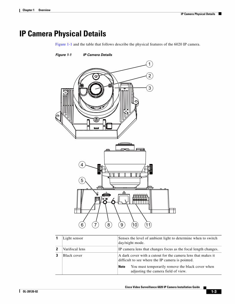
IP Camera Physical DetailsFigure 1-1 and the table that follows describe the physical features of the 6020 IP camera.
Figure 1-1 IP Camera Details
1 Light sensor Senses the level of ambient light to determine when to switch day/night mode.
2 Varifocal lens IP camera lens that changes focus as the focal length changes.
3 Black cover A dark cover with a cutout for the camera lens that makes it difficult to see where the IP camera is pointed.
Note You must temporarily remove the black cover when adjusting the camera field of view.
3
2
1
6 7 8
5
9
4
10 11
1-3Cisco Video Surveillance 6020 IP Camera Installation Guide
OL-28120-02
Chapter 1 OverviewIP Camera Physical Details
4 Tilt adjustment screw Used when tilting the camera to set the field of view.
5 Recessed Reset button Recessed button that reboots the IP camera or resets it to a default state. You can use a pin or paper clip to depress it. It can be used any time that the IP camera is on and can have various effects, as described in the “Resetting the IP Camera” section on page 4-4.
6 Microphone and Video Output switches
Microphone
• Off (up)—Disables an external microphone connected to the IP camera.
• On (down)—Enables an external microphone connected to the IP camera.
Video Output
• NTSC 60Hz (up)—Switches camera operation to the National Television System Committee (NTSC) standard.
• PAL 50Hz (down)—Switches camera operation to the Phase Alternating Line (PAL) standard.
7 micro SD card slot Supports up to 8 GB of video data on a micro SD memory card when the camera loses network connectivity.
8 Audio/Video out (green) Allows the connection of an optional Y cable or mini cable with BNC connector. You can connect a video monitor to the mini cable with BNC connector. Both cables are included in the optional audio/video cables accessory kit can be purchased from Cisco (Cisco part number CIVS-AVCABLE).
9 Microphone In (pink) Connection for an external microphone.
10 Ethernet 10/100 RJ45 socket Accepts a standard LAN cable to connect the IP camera to a 10/100BaseT router or switch.
11 GPIO Terminal Block General purpose input/output (GPIO) terminal block that is used to connect external input and output devices. For more information, see Figure 1-2.
1-4Cisco Video Surveillance 6020 IP Camera Installation Guide
OL-28120-02
Chapter 1 OverviewIP Camera Physical Details
General Purpose I/O Terminal Block
Figure 1-2 shows the pin locations and descriptions.
Figure 1-2 GPIO Terminal Block Pin Locations and Descriptions
Note The maximum output load from pins 7 and 8 is 400mA.
Pin Description
1 DC 12V-
2 DC 12V+
3 AC 24V_2
4 AC 24V_1
5 DI- (GND)
6 DI+
7 DO-
8 DO+ (+12V)
87654321
1-5Cisco Video Surveillance 6020 IP Camera Installation Guide
OL-28120-02
Chapter 1 OverviewIP Camera Physical Details
1-6Cisco Video Surveillance 6020 IP Camera Installation Guide
OL-28120-02
Cisco ViOL-28120-02
C H A P T E R 2
Camera Installation
This chapter provides information and instructions for installing the Cisco Video Surveillance 6020 IP Camera, and includes the following topics:
• Installation Guidelines, page 2-1
• Warnings Before Installation, page 2-1
• IP Camera Installation, page 2-4
Installation GuidelinesThis section describes how to install the IP camera. Before installing, review these guidelines:
• The IP camera requires a network cable and a connection to a standard 10/100BaseT router or switch. To power the IP camera with Power over Ethernet (PoE), a switch must be 802.3af compliant.
• If you are using the IP camera on a network connection that does not provide PoE, you must use a Cisco 12 VDC power adapter (Cisco part number CIVS-PWRPAC-12V) or a third-party 24 VAC power adapter.
• If you are using an external speaker, microphone, input device, output device, or pan/tilt control device, you must configure additional settings after installing and performing the initial set up of the IP camera before the external device can fully operate. For detailed information about these settings, see the Cisco Video Surveillance 6000 Series IP Camera Configuration Guide.
• If you do not connect an external device (speaker, microphone, input, output, or pan/tilt control) when you perform the following installation procedure, you can install any of these devices later.
Warnings Before Installation • Power off the IP Camera as soon as smoke
or unusual odors are detected.
Contact your distributor in the event of this happening.
• Keep the IP Camera away from water. If the IP Camera becomes wet, power off immediately.
Contact your distributor in the event of this happening.
2-1deo Surveillance 6020 IP Camera Installation Guide
Chapter 2 Camera InstallationWarnings Before Installation
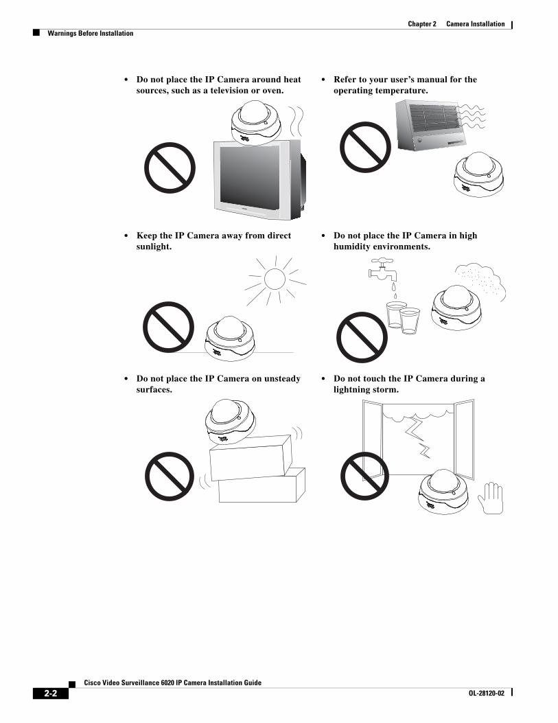
• Do not place the IP Camera around heat sources, such as a television or oven.
• Refer to your user’s manual for the operating temperature.
• Keep the IP Camera away from direct sunlight.
• Do not place the IP Camera in high humidity environments.
• Do not place the IP Camera on unsteady surfaces.
• Do not touch the IP Camera during a lightning storm.
2-2Cisco Video Surveillance 6020 IP Camera Installation Guide
OL-28120-02
Chapter 2 Camera InstallationWarnings Before Installation
Warning Installation of the equipment must comply with local and national electrical codes. Statement 1074
Warning The power supply must be placed indoors. Statement 331
Note If you use the IP camera outdoors, place the camera and the power supply in a suitable NEMA enclosure.
Warning This product must be connected to a power-over-ethernet (PoE) IEEE 802.3af compliant power source or an IEC60950 compliant limited power source. Statement 353
Caution Inline power circuits provide current through the communication cable. Use the Cisco provided cable or a minimum 24AWG communication cable.
Note The power adapter that you use with the IP camera must provide power that is within +/–10% of the required power.
Note The equipment is to be connected to a Listed class 2, limited power source.
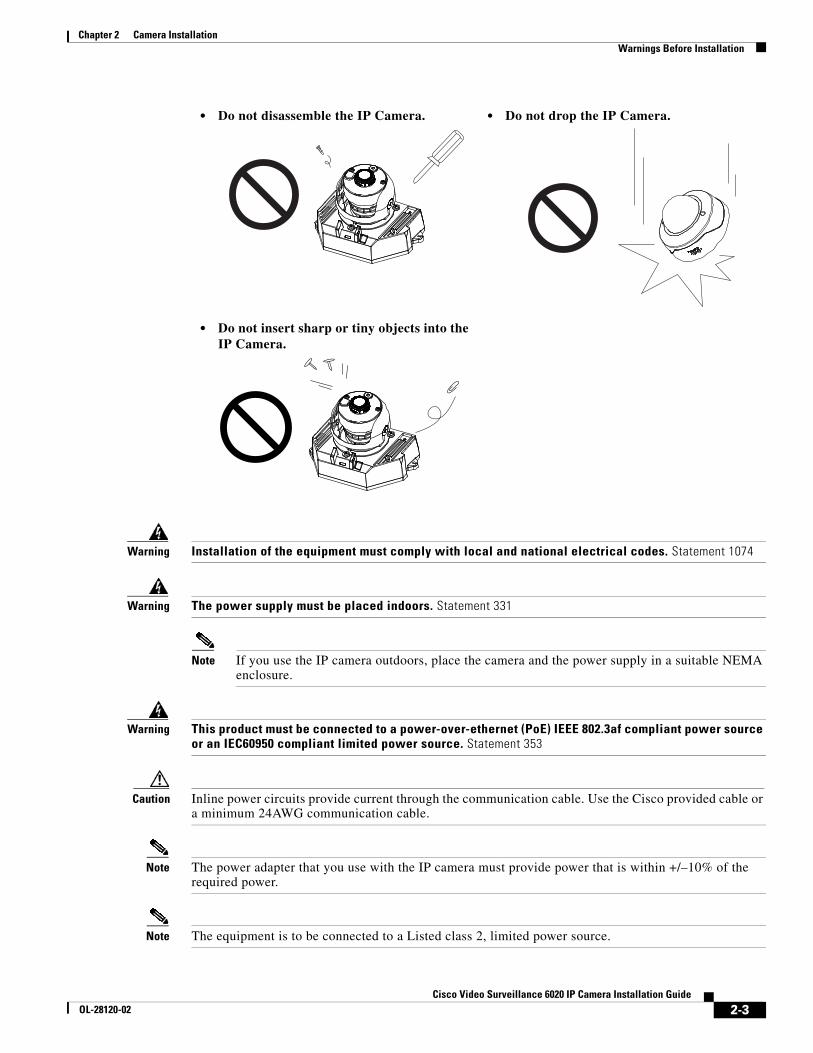
• Do not disassemble the IP Camera. • Do not drop the IP Camera.
• Do not insert sharp or tiny objects into the IP Camera.
2-3Cisco Video Surveillance 6020 IP Camera Installation Guide
OL-28120-02
Chapter 2 Camera InstallationIP Camera Installation
IP Camera InstallationInstall the 6020 IP camera using one of the following procedures:
• Mounting the IP Camera Directly to a Surface, page 2-4
• Mounting the IP Camera Flush with a Surface, page 2-7
• Mounting the IP camera with a Vandal Resistant Enclosure, page 2-10
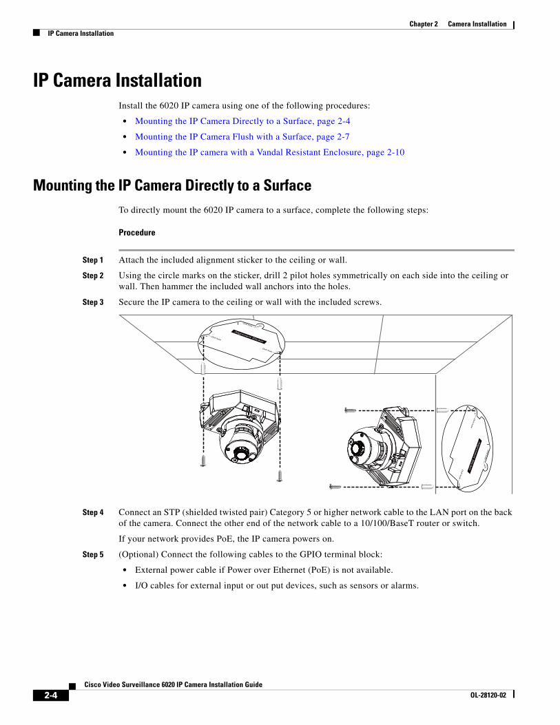
Mounting the IP Camera Directly to a SurfaceTo directly mount the 6020 IP camera to a surface, complete the following steps:
Procedure
Step 1 Attach the included alignment sticker to the ceiling or wall.
Step 2 Using the circle marks on the sticker, drill 2 pilot holes symmetrically on each side into the ceiling or wall. Then hammer the included wall anchors into the holes.
Step 3 Secure the IP camera to the ceiling or wall with the included screws.
Step 4 Connect an STP (shielded twisted pair) Category 5 or higher network cable to the LAN port on the back of the camera. Connect the other end of the network cable to a 10/100/BaseT router or switch.
If your network provides PoE, the IP camera powers on.
Step 5 (Optional) Connect the following cables to the GPIO terminal block:
• External power cable if Power over Ethernet (PoE) is not available.
• I/O cables for external input or out put devices, such as sensors or alarms.
2-4Cisco Video Surveillance 6020 IP Camera Installation Guide
OL-28120-02
Chapter 2 Camera InstallationIP Camera Installation
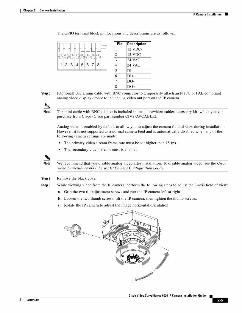
The GPIO terminal block pin locations and descriptions are as follows:
Step 6 (Optional) Use a mini cable with BNC connector to temporarily attach an NTSC or PAL compliant analog video display device to the analog video out port on the IP camera.
Note The mini cable with BNC adapter is included in the audio/video cables accessory kit, which you can purchase from Cisco (Cisco part number CIVS-AVCABLE).
Analog video is enabled by default to allow you to adjust the camera field of view during installation. However, it is not supported as a normal camera feed and is automatically disabled when any of the following camera settings are made:
• The primary video stream frame rate must be set higher than 15 fps.
• The secondary video stream must is enabled.
Note We recommend that you disable analog video after installation. To disable analog video, see the Cisco Video Surveillance 6000 Series IP Camera Configuration Guide.
Step 7 Remove the black cover.
Step 8 While viewing video from the IP camera, perform the following steps to adjust the 3-axis field of view:
a. Grip the two tilt adjustment screws and pan the IP camera left or right.
b. Loosen the two thumb screws, tilt the IP camera, then tighten the thumb screws.
c. Rotate the IP camera to adjust the image horizontal orientation.
2-5Cisco Video Surveillance 6020 IP Camera Installation Guide
OL-28120-02
Chapter 2 Camera InstallationIP Camera Installation
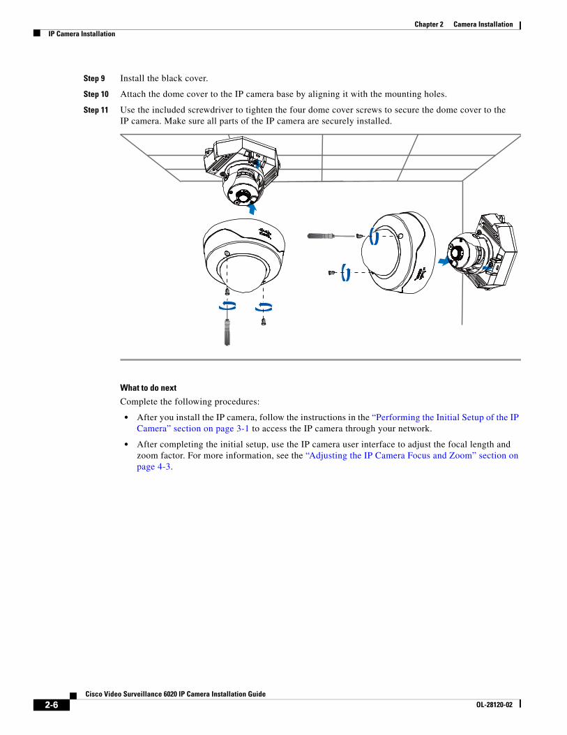
Step 9 Install the black cover.
Step 10 Attach the dome cover to the IP camera base by aligning it with the mounting holes.
Step 11 Use the included screwdriver to tighten the four dome cover screws to secure the dome cover to the IP camera. Make sure all parts of the IP camera are securely installed.
What to do next
Complete the following procedures:
• After you install the IP camera, follow the instructions in the “Performing the Initial Setup of the IP Camera” section on page 3-1 to access the IP camera through your network.
• After completing the initial setup, use the IP camera user interface to adjust the focal length and zoom factor. For more information, see the “Adjusting the IP Camera Focus and Zoom” section on page 4-3.
2-6Cisco Video Surveillance 6020 IP Camera Installation Guide
OL-28120-02
Chapter 2 Camera InstallationIP Camera Installation
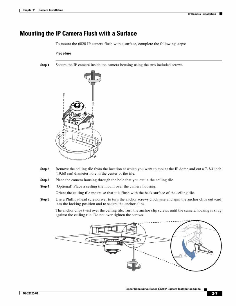
Mounting the IP Camera Flush with a SurfaceTo mount the 6020 IP camera flush with a surface, complete the following steps:
Procedure
Step 1 Secure the IP camera inside the camera housing using the two included screws.
Step 2 Remove the ceiling tile from the location at which you want to mount the IP dome and cut a 7-3/4 inch (19.68 cm) diameter hole in the center of the tile.
Step 3 Place the camera housing through the hole that you cut in the ceiling tile.
Step 4 (Optional) Place a ceiling tile mount over the camera housing.
Orient the ceiling tile mount so that it is flush with the back surface of the ceiling tile.
Step 5 Use a Phillips-head screwdriver to turn the anchor screws clockwise and spin the anchor clips outward into the locking position and to secure the anchor clips.
The anchor clips twist over the ceiling tile. Turn the anchor clip screws until the camera housing is snug against the ceiling tile. Do not over tighten the screws.
2-7Cisco Video Surveillance 6020 IP Camera Installation Guide
OL-28120-02
Chapter 2 Camera InstallationIP Camera Installation
Step 6 Connect a shielded twisted pair (STP) Category 5 or higher network cable to the LAN port on the back of the camera through the cutout in the camera housing. Connect the other end of the network cable to a 10/100/BaseT router or switch.
If your network provides PoE, the IP camera powers on.
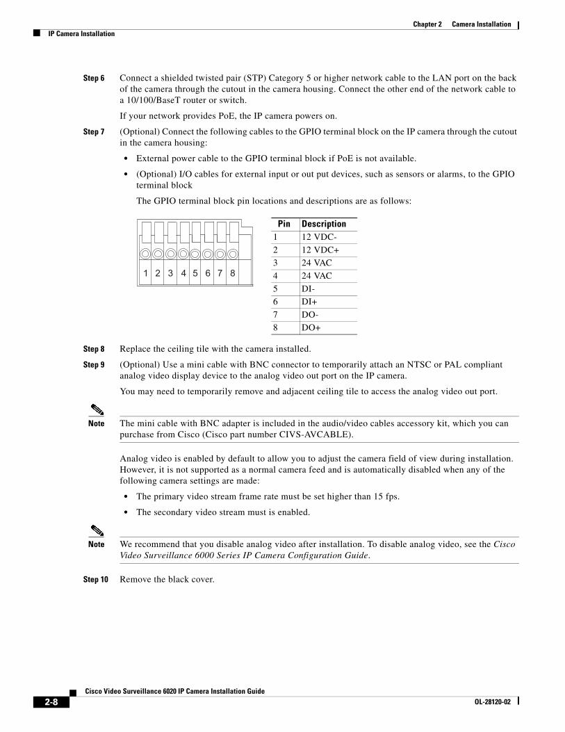
Step 7 (Optional) Connect the following cables to the GPIO terminal block on the IP camera through the cutout in the camera housing:
• External power cable to the GPIO terminal block if PoE is not available.
• (Optional) I/O cables for external input or out put devices, such as sensors or alarms, to the GPIO terminal block
The GPIO terminal block pin locations and descriptions are as follows:
Step 8 Replace the ceiling tile with the camera installed.
Step 9 (Optional) Use a mini cable with BNC connector to temporarily attach an NTSC or PAL compliant analog video display device to the analog video out port on the IP camera.
You may need to temporarily remove and adjacent ceiling tile to access the analog video out port.
Note The mini cable with BNC adapter is included in the audio/video cables accessory kit, which you can purchase from Cisco (Cisco part number CIVS-AVCABLE).
Analog video is enabled by default to allow you to adjust the camera field of view during installation. However, it is not supported as a normal camera feed and is automatically disabled when any of the following camera settings are made:
• The primary video stream frame rate must be set higher than 15 fps.
• The secondary video stream must is enabled.
Note We recommend that you disable analog video after installation. To disable analog video, see the Cisco Video Surveillance 6000 Series IP Camera Configuration Guide.
Step 10 Remove the black cover.
Pin Description1 12 VDC-
2 12 VDC+
3 24 VAC
4 24 VAC
5 DI-
6 DI+
7 DO-
8 DO+
87654321
2-8Cisco Video Surveillance 6020 IP Camera Installation Guide
OL-28120-02
Chapter 2 Camera InstallationIP Camera Installation
Step 11 While viewing video from the IP camera, perform the following steps to adjust the 3-axis field of view:
a. Grip the two tilt adjustment screws and pan the IP camera left or right.
b. Loosen the two thumb screws, tilt the IP camera, then tighten the thumb screws.
c. Rotate the IP camera to adjust the image horizontal orientation.
Step 12 Install the black cover. Make sure to adjust the it inside the dome and trim ring assembly so that it does not block the lens from capturing video.
Step 13 Attach the security strap from the dome and trim ring assembly to the camera housing using the included screw.
Step 14 Attach the dome and trim ring assembly by positioning its pegs in the slots of the camera housing and twisting clockwise.
2-9Cisco Video Surveillance 6020 IP Camera Installation Guide
OL-28120-02
Chapter 2 Camera InstallationIP Camera Installation
What to do next
Complete the following procedures:
• After you install the IP camera, follow the instructions in the “Performing the Initial Setup of the IP Camera” section on page 3-1 to access the IP camera through your network.
• After completing the initial setup, use the IP camera user interface to adjust the focal length and zoom factor. For more information, see the “Adjusting the IP Camera Focus and Zoom” section on page 4-3.
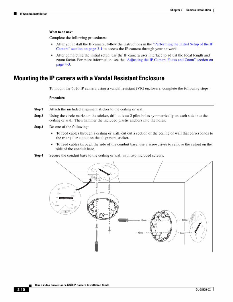
Mounting the IP camera with a Vandal Resistant EnclosureTo mount the 6020 IP camera using a vandal resistant (VR) enclosure, complete the following steps:
Procedure
Step 1 Attach the included alignment sticker to the ceiling or wall.
Step 2 Using the circle marks on the sticker, drill at least 2 pilot holes symmetrically on each side into the ceiling or wall. Then hammer the included plastic anchors into the holes.
Step 3 Do one of the following:
• To feed cables through a ceiling or wall, cut out a section of the ceiling or wall that corresponds to the triangular cutout on the alignment sticker.
• To feed cables through the side of the conduit base, use a screwdriver to remove the cutout on the side of the conduit base.
Step 4 Secure the conduit base to the ceiling or wall with two included screws.
2-10Cisco Video Surveillance 6020 IP Camera Installation Guide
OL-28120-02
Chapter 2 Camera InstallationIP Camera Installation
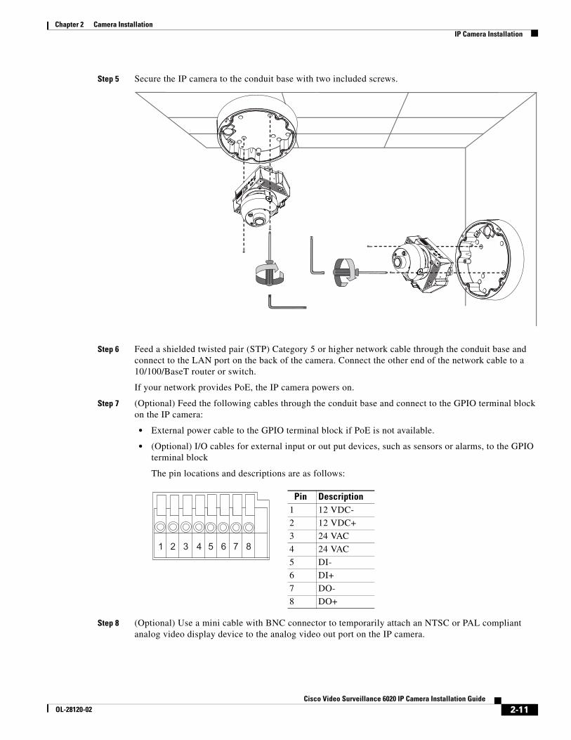
Step 5 Secure the IP camera to the conduit base with two included screws.
Step 6 Feed a shielded twisted pair (STP) Category 5 or higher network cable through the conduit base and connect to the LAN port on the back of the camera. Connect the other end of the network cable to a 10/100/BaseT router or switch.
If your network provides PoE, the IP camera powers on.
Step 7 (Optional) Feed the following cables through the conduit base and connect to the GPIO terminal block on the IP camera:
• External power cable to the GPIO terminal block if PoE is not available.
• (Optional) I/O cables for external input or out put devices, such as sensors or alarms, to the GPIO terminal block
The pin locations and descriptions are as follows:
Step 8 (Optional) Use a mini cable with BNC connector to temporarily attach an NTSC or PAL compliant analog video display device to the analog video out port on the IP camera.
Pin Description1 12 VDC-
2 12 VDC+
3 24 VAC
4 24 VAC
5 DI-
6 DI+
7 DO-
8 DO+
87654321
2-11Cisco Video Surveillance 6020 IP Camera Installation Guide
OL-28120-02
Chapter 2 Camera InstallationIP Camera Installation
Note The mini cable with BNC adapter is included in the audio/video cables accessory kit, which you can purchase from Cisco (Cisco part number CIVS-AVCABLE).
Analog video is enabled by default to allow you to adjust the camera field of view during installation. However, it is not supported as a normal camera feed and is automatically disabled when any of the following camera settings are made:
• The primary video stream frame rate must be set higher than 15 fps.
• The secondary video stream must is enabled.
Note We recommend that you disable analog video after installation. To disable analog video, see the Cisco Video Surveillance 6000 Series IP Camera Configuration Guide.
Step 9 Remove the black cover.
Step 10 While viewing video from the IP camera, perform the following steps to adjust the 3-axis field of view:
a. Grip the two tilt adjustment screws and pan the IP camera left or right.
b. Loosen the two thumb screws, tilt the IP camera, then tighten the thumb screws.
c. Rotate the IP camera to adjust the image horizontal orientation.
Step 11 After you have adjusted the field of view, focal length, and zoom factor, install the black cover. Make sure to adjust the it so that it does not block the lens from capturing video.
Step 12 Attach the dome cover to the conduit base by aligning it with the mounting holes.
2-12Cisco Video Surveillance 6020 IP Camera Installation Guide
OL-28120-02
Chapter 2 Camera InstallationIP Camera Installation
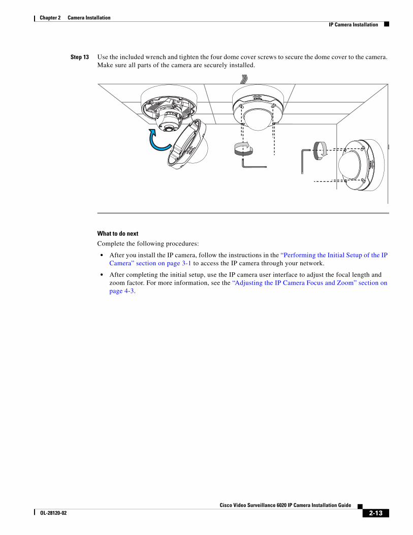
Step 13 Use the included wrench and tighten the four dome cover screws to secure the dome cover to the camera. Make sure all parts of the camera are securely installed.
What to do next
Complete the following procedures:
• After you install the IP camera, follow the instructions in the “Performing the Initial Setup of the IP Camera” section on page 3-1 to access the IP camera through your network.
• After completing the initial setup, use the IP camera user interface to adjust the focal length and zoom factor. For more information, see the “Adjusting the IP Camera Focus and Zoom” section on page 4-3.
2-13Cisco Video Surveillance 6020 IP Camera Installation Guide
OL-28120-02
Chapter 2 Camera InstallationIP Camera Installation
2-14Cisco Video Surveillance 6020 IP Camera Installation Guide
OL-28120-02
Cisco ViOL-28120-02
C H A P T E R 3
Performing the Initial Setup of the IP Camera
After you install IP camera as described in the Chapter 2, “Camera Installation,” or after you perform a factory reset procedure, you must access the IP camera and make initial configuration settings. These settings include administrator and root passwords, and whether the IP camera can be accessed through an HTTP connection in addition to the default HTTPS (HTTP secure) connection.
To make these configuration settings, you connect to the IP camera from any PC that is on the same network as the IP camera. The PC must meet these requirements:
• Operating system—Microsoft Windows 7 (32-bit and 64-bit)
• Browser—Internet Explorer 8.0 (32-bit only)
In addition, you must know the IP address and default login credentials of the IP camera. By default, when the IP camera powers on, it attempts to obtain an IP address from a DHCP server in your network. If the camera cannot obtain an IP address through DCHP within 90 seconds, it uses a default IP address of 192.168.0.100. The default login credentials (Username/Password) are admin/admin.
To connect to the IP camera for the first time and make initial configuration settings, perform the following steps. You can change these configuration settings in the future as described in the Cisco Video Surveillance 6000 Series IP Camera Configuration Guide.
Before you Begin
The Microsoft .NET Framework version 2.0 or later must be installed on the PC that you use to connect to the IP camera. You can download the .NET Framework from the Microsoft website.
Procedure
Step 1 Start Internet Explorer, enter HTTPS://ip_address in the address field, and press Enter.
Replace ip_address with the IP address that the IP camera obtained through DHCP or, if the camera was unable to obtain this IP address, enter 192.168.0.100.
The Login window appears.
Step 2 Enter the default login credentials:
Username: admin
Password: admin
The Initialization window appears.
3-1deo Surveillance 6020 IP Camera Installation Guide
Chapter 3 Performing the Initial Setup of the IP Camera
Step 3 In the Password and Confirm Password fields of the admin row, enter a password for the IP camera administrator.
You must enter the same password in both fields. The password is case sensitive and must contain at least eight characters, which can be letters, numbers, and special characters, but no spaces. Special characters are: ! " # $ % & ' ( ) * + , - . : ; < = > ? @ [ \ ] ^ _ ` { | } ~.
Step 4 In the Password and Confirm Password fields of the Root row, enter a password that is used when accessing the IP camera through a Secure Shell (SSH) connection.
You must enter the same password in both fields. The password is case sensitive and must contain at least eight characters, which can be letters, numbers, and special characters, but no spaces. Special characters are: ! " # $ % & ' ( ) * + , - . : ; < = > ? @ [ \ ] ^ _ ` { | } ~.
You use the root password if you need to troubleshoot the IP camera through a SSH connection with the assistance of the Cisco Technical Assistance Center.
Step 5 In the Access Protocols area, check the Enable HTTP check box if you want to allow both HTTP and HTTPS connections to the IP camera.
By default, only the Enable HTTPS check box is checked, which allows only HTTPS (secure) connections to the IP camera.
Step 6 Click Apply.
The IP camera reboots and the Login window appears.
Step 7 After the IP camera reboots, start Internet Explorer and, in the Address field, enter the following:
protocol://ip_address
where:
• protocol is HTTPS or HTTP. (You can use HTTP only if you enabled it in Step 5.)
• ip_address is the IP address that you used in Step 1.
Step 8 If you are prompted to install ActiveX controls, which are required to view video from the IP camera, follow the on-screen prompts to do so.
The Home window appears.
3-2Cisco Video Surveillance 6020 IP Camera Installation Guide
OL-28120-02
Cisco ViOL-28120-02
C H A P T E R 4
Camera Management
This chapter provides information and instructions for managing the Cisco Video Surveillance 6020 IP Camera, and includes the following topics:
• Understanding the IP Camera User Interface, page 4-1
• Adjusting the IP Camera Focus and Zoom, page 4-3
• Powering the IP Camera On or Off, page 4-4
• Resetting the IP Camera, page 4-4
• Viewing Live Video, page 4-4
• Managing the Local Storage, page 4-12
Understanding the IP Camera User InterfaceAfter you log in to the IP camera, you can access the IP camera windows and perform a variety of administrative and user procedures.
The links and activities that you can see and access in the IP camera windows depend on your IP camera privilege level.
• Administrator—Can access all IP camera windows, features, and functions.
• Viewer—Can access the Camera Video & Control window with limited controls, and can access the Refresh, Logout, About, and Help links from that window.
IP Camera Window LinksThe IP Camera user interface includes links that you use to access various windows and perform other activities. Table 4-1 describes each link and lists the IP camera privilege level that you must have to access the link.
Table 4-1 Links in the IP Camera Windows
Link Description Privilege Level
Refresh Updates the information in the window that is currently displayed. Administrator
User
Home Displays the Home window. Administrator
4-1deo Surveillance 6020 IP Camera Installation Guide
Chapter 4 Camera ManagementUnderstanding the IP Camera User Interface
IP Camera WindowsThe IP camera user interface includes these main windows:
• Home window—Displays the system information that is described in Table 4-2.
• Setup window—Provides access to the IP camera configuration windows.
• Camera Video & Control window—Displays live video from the camera and lets you control a variety of camera and display functions.
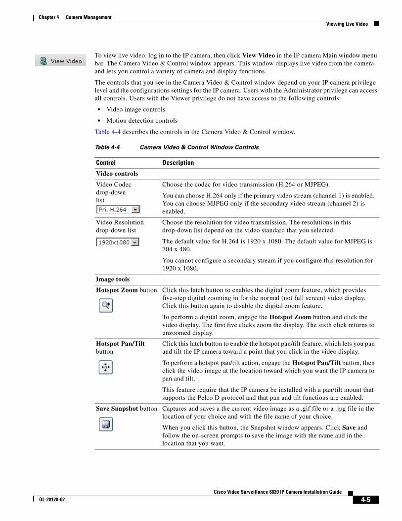
View Video Displays the Camera Video & Control window.
You may be prompted to install ActiveX controls when trying to access this window for the first time. ActiveX controls are required to view video from the IP camera. Follow the on-screen prompts to install ActiveX controls.
Administrator
User
Setup Provides access to the configuration menus for the IP camera. Administrator
Logout Logs you out from the IP camera. Administrator
User
About Displays a pop-up window with model, version, and copyright information for the IP camera.
Administrator
User
Help Displays reference information for the window that is currently displayed.
Administrator
User
Table 4-1 Links in the IP Camera Windows (continued)
Link Description Privilege Level
Table 4-2 Home Window Information
Field Description
General Information
ID Identifier of the IP camera.
Name Name of the IP camera.
Current Time Current date and time of the IP camera.
S/N Serial number of the IP camera.
Firmware Version of the firmware that is installed on the IP camera.
Codec Version of the codec that is running on the IP camera.
Part Number Cisco manufacturing part number of the IP camera.
Top Assembly Revision Cisco assembly revision number.
Network Status
MAC Address MAC address of the IP camera.
Configuration Type Method by which the IP camera obtains its IP address.
LAN IP IP address of the LAN to which the IP camera is connected.
Subnet Mask Subnet mask of the LAN to which the IP camera is connected.
4-2Cisco Video Surveillance 6020 IP Camera Installation Guide
OL-28120-02
Chapter 4 Camera ManagementAdjusting the IP Camera Focus and Zoom
Adjusting the IP Camera Focus and ZoomTo adjust the IP camera focus and zoom, perform the following steps while viewing video from the camera. For information about viewing video, see “Viewing Live Video” section on page 4-4.
Procedure
Step 1 Login to the IP camera.
The Home window appears.
Step 2 Click the View Video link.
The Camera Video & Control window appears.
Step 3 Verify that the field of view is correctly set.
Step 4 Click the Focus/Zoom toggle button located below the video pane.
Step 5 The focus and zoom controls appear.
Step 6 While watching the video pane, perform the following steps:
a. Move the Zoom slider until you achieve the desired zoom level.
b. Move the Focus slider until the video image is at its sharpest.
Step 7 (Optional) Click Auto Focus to have the IP camera automatically adjust its focus. To automatically adjust the focus to a particular region in the field of view, check the Specify Region check box and draw or select a region before clicking Auto Focus.
Gateway Address IP address of the gateway through which the IP camera is connected.
Primary DNS IP address of the primary DNS server, if configured for the IP camera.
Secondary DNS IP address of the secondary DNS server, if configured for the IP camera.
IO Port Status
Input Port 1 Current state of input port 1 on the IP camera.
Output Port 1 Current state of output port 1 on the IP camera.
Stream 1 and Stream 2
User IP camera user name of each user who is accessing the primary video stream (Stream 1) or the secondary video stream (Stream 2) through a client PC or a third-party device.
Be default, users appear in order of start time. To displays users in ascending order of any information in any corresponding column, click the column heading. Click a column heading again to reverse the display order.
IP Address IP address of the client device.
Start Time Time and date that the client accessed the video stream for this session.
Elapsed Time Length of time that the client has been accessing the video stream.
Table 4-2 Home Window Information (continued)
Field Description
4-3Cisco Video Surveillance 6020 IP Camera Installation Guide
OL-28120-02
Chapter 4 Camera ManagementPowering the IP Camera On or Off
Powering the IP Camera On or OffThe IP camera does not include an on/off switch. You power it on or off by connecting it to or disconnecting it from a power source. When you power off the IP camera, configuration settings are retained.
To power on the IP camera, take either of these actions:
• Use an STP (shielded twisted pair) Category 5 or higher network cable to connect the IP camera to a network switch that provides 802.3af compliant PoE.
• Use an optional 12 VDC or 24VAC power adapter to connect the IP camera to a wall outlet
To power off the IP camera, take either of these actions:
• If the IP camera is receiving PoE, disconnect the network cable
• If the IP camera is receiving power through the power adapter, unplug the adapter from the wall or disconnect it from the camera
Resetting the IP CameraYou reset the IP camera by pressing the Reset button on the IP Camera (see Figure 1-1 on page 1-3). There are various reset types, as described in Table 4-3.
You also can also perform these reset operations from the Maintenance Settings window as described in the Cisco Video Surveillance 6000 Series IP Camera Configuration Guide.
Viewing Live VideoAfter you install and set up the Cisco Video Surveillance IP Camera, you can connect to the IP camera through Internet Explorer and access the Camera Video & Control window to view live video.
The Camera Video & Control window also provides for controlling the video display, configuring preset positions, and controlling certain IP camera functions. Available controls depend on the privilege level of the user.
Table 4-3 Resetting the IP Camera
Reset Type Procedure Remarks
Reboot. Press and immediately release the Reset button.
This action is equivalent to powering the IP camera down and then powering it up. Settings that are configured for the IP camera are retained.
Factory reset. Press and hold the button for at least 15 seconds.
Sets all IP camera options to their default values. After you perform this procedure, follow the steps in the “Performing the Initial Setup of the IP Camera” section on page 3-1.
4-4Cisco Video Surveillance 6020 IP Camera Installation Guide
OL-28120-02
Chapter 4 Camera ManagementViewing Live Video
To view live video, log in to the IP camera, then click View Video in the IP camera Main window menu bar. The Camera Video & Control window appears. This window displays live video from the camera and lets you control a variety of camera and display functions.
The controls that you see in the Camera Video & Control window depend on your IP camera privilege level and the configurations settings for the IP camera. Users with the Administrator privilege can access all controls. Users with the Viewer privilege do not have access to the following controls:
• Video image controls
• Motion detection controls
Table 4-4 describes the controls in the Camera Video & Control window.
Table 4-4 Camera Video & Control Window Controls
Control Description
Video controls
Video Codec drop-down list
Choose the codec for video transmission (H.264 or MJPEG).
You can choose H.264 only if the primary video stream (channel 1) is enabled. You can choose MJPEG only if the secondary video stream (channel 2) is enabled.
Video Resolution drop-down list
Choose the resolution for video transmission. The resolutions in this drop-down list depend on the video standard that you selected.
The default value for H.264 is 1920 x 1080. The default value for MJPEG is 704 x 480.
You cannot configure a secondary stream if you configure this resolution for 1920 x 1080.
Image tools
Hotspot Zoom button Click this latch button to enables the digital zoom feature, which provides five-step digital zooming in for the normal (not full screen) video display. Click this button again to disable the digital zoom feature.
To perform a digital zoom, engage the Hotspot Zoom button and click the video display. The first five clicks zoom the display. The sixth click returns to unzoomed display.
Hotspot Pan/Tilt button
Click this latch button to enable the hotspot pan/tilt feature, which lets you pan and tilt the IP camera toward a point that you click in the video display.
To perform a hotspot pan/tilt action, engage the Hotspot Pan/Tilt button, then click the video image at the location toward which you want the IP camera to pan and tilt.
This feature require that the IP camera be installed with a pan/tilt mount that supports the Pelco D protocol and that pan and tilt functions are enabled.
Save Snapshot button Captures and saves a the current video image as a .gif file or a .jpg file in the location of your choice and with the file name of your choice.
When you click this button, the Snapshot window appears. Click Save and follow the on-screen prompts to save the image with the name and in the location that you want.
4-5Cisco Video Surveillance 6020 IP Camera Installation Guide
OL-28120-02
Chapter 4 Camera ManagementViewing Live Video
Flip button Rotates the video image by 180 degrees.
Mirror button Reverses the video image.
Restore button Displays the default video image, which is not rotated and not reversed.
Full Screen button Displays the video image in full screen mode.
To return to normal display mode, click the full screen image.
Audio Control
Disable Speaker toggle button
Click the Disable Speaker button to mute audio that is sent from the IP camera to the PC that you are using. The button changes to the Enable Speaker button. Click the Enable Speaker button to unmute audio. The button changes to the Disable button.
Enable Speaker toggle button
Mute Microphone toggle button
Click the Mute Microphone button to mute the audio stream that is captured and sent to the IP camera from the internal or external microphone of the PC that you are using. When you click this button, the speaker that is attached to the IP camera does not play audio that is transmitted from your PC.
Note If you are simultaneously accessing other IP cameras in different browser sessions on the same PC, clicking this button in one browser session does not mute the audio that the PC sends to the other IP cameras.
When you click the Mute Microphone button, it changes to the Unmute Microphone button. Click the Unmute Microphone button to unmute audio that is sent to the IP camera. The button changes to the Mute Microphone button.
Unmute Microphone toggle button
Restore button Resets audio controls to their default values.
Table 4-4 Camera Video & Control Window Controls (continued)
Control Description
4-6Cisco Video Surveillance 6020 IP Camera Installation Guide
OL-28120-02
Chapter 4 Camera ManagementViewing Live Video
Speaker Volume slider and field
When the speaker is unmuted, drag this slider to adjust the volume at which your PC speakers play the audio from the IP camera, or enter a value from 0 through 100 and press the Enter key.
The default value is 50.
Microphone Sensitivity slider and field
Drag this slider to adjust the gain of the PC microphone (that is, how sensitive it is to the audio that it picks up and that is sent to the IP camera), or enter a value from 0 through 100 and press the Enter key.
The default value is 50.
Camera Settings
Up Arrow toggle button
Click the Up Arrow to display the camera settings. The button changes to the Down Arrow button
Click the Down Arrow button to hide the camera settings. The button changes to the Up Arrow button.
When the Up Arrow is clicked to display the camera settings, three drawers appear to the right of the video image. The camera settings are grouped into the three drawers as follows:
• Picture Adjustments
• Exposure Control
• Advanced Settings
To view the settings within a drawer, click on it to expand it. To hide the settings, click on the drawer to collapse it.
Down Arrow toggle button
Save button Saves the current camera settings configuration.
Picture Adjustments
Note These controls appear when you click Camera Settings Up Arrow > Picture Adjustments drawer.
Brightness slider To control the brightness of the video image, drag the slider, or enter a value from 1 through 10 and press the Enter key. A higher value increases the brightness and a lower value decreases the brightness. For example, if the IP camera is facing a bright light and the video appears too dark, you can increase the brightness.
The default value is 5.
Contrast slider To control contrast of the video image, drag the slider, or enter a value from 1 through 10 and press the Enter key. A higher value increases the contrast and a lower value decreases the contrast.
The default value is 5.
Table 4-4 Camera Video & Control Window Controls (continued)
Control Description
4-7Cisco Video Surveillance 6020 IP Camera Installation Guide
OL-28120-02
Chapter 4 Camera ManagementViewing Live Video
Sharpness slider To control the sharpness of the video from the IP camera, drag the slider, or enter a value from 1 through 100 and press the Enter key. A higher value increases the sharpness and a lower value decreases the sharpness.
The default value is 50.
Saturation slider To control the saturation of the video from the IP camera, drag the slider, or enter a value from 1 through 100 and press the Enter key. A higher value increases the saturation and a lower value decreases the saturation.
High saturation provides a vivid, intense color for a video image. With less saturation, the video image appears more muted and gray.
The default value is 50.
White Balance Mode Choose one the following White Balance modes from the drop-down list:
• Manual—Choose this option if you want to set the white balance by setting RGain (Red Gain) and BGain (Blue Gain) manually.
• Auto—White balance is automatically set by camera, which is suitable for most conditions.
The default setting is Auto.
Exposure Control
Note These controls appear when you click Camera Settings Up Arrow > Exposure Control drawer.
Exposure Level Increases or decreases the exposure level. For example, if you want to add light (overexpose) to properly expose the image, set the value to +1. If you need to underexposure the scene, set value to -1.
Default value is 0.0
Exposure Mode Choose one of the following Exposure modes:
• Auto—Automatically sets the exposure level, which is suitable for most conditions.
• Manual—Choose this option if you want to set Exposure time and Gain control manually.
Default setting is Auto.
Exposure Time The Exposure time option is available only when the Exposure mode is set to Manual. Specifies the range of shutter speed settings to be used by the IP camera. Shutter speed is measured in fractions of a second. You can adjust both ends of the shutter speed range.
Default range is 1/5 sec to 1/32000 sec in Manual mode.
Gain Control The Gain control option is available only when the Exposure mode is set to Manual. Specifies the range of gain (amount of amplification applied to pixel values) settings to be used by the IP camera. You can adjust both ends of the gain control range.
Default range is to 0 to 100.
Table 4-4 Camera Video & Control Window Controls (continued)
Control Description
4-8Cisco Video Surveillance 6020 IP Camera Installation Guide
OL-28120-02
Chapter 4 Camera ManagementViewing Live Video
Iris Mode The Iris mode is available only when the Exposure mode is set to Auto. Choose one of the following Iris modes:
• Indoor—Suitable for Indoor conditions.
• Outdoor—Suitable for Outdoor conditions.
Default mode is Indoor.
Measurement Window Exposure is calculated based on video data from one of the following measurement windows:
• Full View—Exposure is calculated based on full view.
• Custom—You can designate specific regions (areas within the field of view) to use for exposure calculation. Inclusion regions designate areas that are used to calculate the exposure value. Exclusion regions designate a areas that are ignored when calculating the exposure value. You can draw up to four inclusion regions and four exclusion regions.
To create a region, right-click on the video image and choose Draw Region. Drag the region to the desired area and drag an edge or corner of the region to resize it. To remove region, right-click on it and choose Delete Region. Inclusion regions are created by default. To toggle between inclusion and exclusion regions, right-click on a region and change the Region Properties > Region Type setting.
• BLC—Back Light Compensation (BLC) window adds a weighted region in the middle of the image view to give necessary exposure compensation.
Advanced Settings
Note These controls appear when you click Camera Settings Up Arrow > Advanced Settings drawer.
Enable Low Light Compensation
This option is useful in low light situations.
Enable DRX Check this check box to enable the Dynamic Range Enhanced (DRX) feature. DRX helps recover washed out details when there is extreme contrast lighting conditions. To reach better image quality adjust Sensitivity (Low and High) and Strength (Low, Medium and High).
Sensitivity The Sensitivity option is available only when DRX is enabled. Choose how sensitive (low or high) DRX is to extreme contrast lighting conditions.
Strength The Strength option is available only when DRX is enabled. Choose how much DRX processing (low, medium, or high) to use for recovering washed out details.
Gamma Curve Choose the value that provides the optimal gray-scale intensity. Larger gamma curve values make shadows darker and larger values make dark regions lighter.
Motion detection
Table 4-4 Camera Video & Control Window Controls (continued)
Control Description
4-9Cisco Video Surveillance 6020 IP Camera Installation Guide
OL-28120-02
Chapter 4 Camera ManagementViewing Live Video
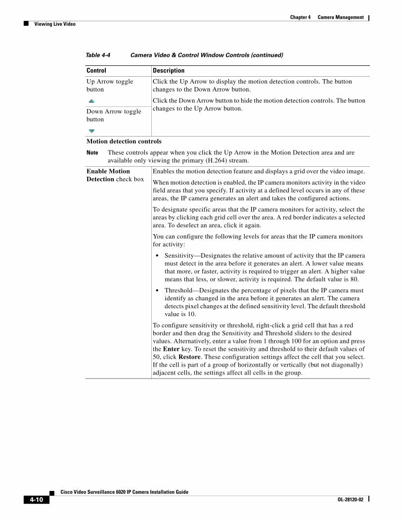
Up Arrow toggle button
Click the Up Arrow to display the motion detection controls. The button changes to the Down Arrow button.
Click the Down Arrow button to hide the motion detection controls. The button changes to the Up Arrow button.Down Arrow toggle
button
Motion detection controls
Note These controls appear when you click the Up Arrow in the Motion Detection area and are available only viewing the primary (H.264) stream.
Enable Motion Detection check box
Enables the motion detection feature and displays a grid over the video image.
When motion detection is enabled, the IP camera monitors activity in the video field areas that you specify. If activity at a defined level occurs in any of these areas, the IP camera generates an alert and takes the configured actions.
To designate specific areas that the IP camera monitors for activity, select the areas by clicking each grid cell over the area. A red border indicates a selected area. To deselect an area, click it again.
You can configure the following levels for areas that the IP camera monitors for activity:
• Sensitivity—Designates the relative amount of activity that the IP camera must detect in the area before it generates an alert. A lower value means that more, or faster, activity is required to trigger an alert. A higher value means that less, or slower, activity is required. The default value is 80.
• Threshold—Designates the percentage of pixels that the IP camera must identify as changed in the area before it generates an alert. The camera detects pixel changes at the defined sensitivity level. The default threshold value is 10.
To configure sensitivity or threshold, right-click a grid cell that has a red border and then drag the Sensitivity and Threshold sliders to the desired values. Alternatively, enter a value from 1 through 100 for an option and press the Enter key. To reset the sensitivity and threshold to their default values of 50, click Restore. These configuration settings affect the cell that you select. If the cell is part of a group of horizontally or vertically (but not diagonally) adjacent cells, the settings affect all cells in the group.
Table 4-4 Camera Video & Control Window Controls (continued)
Control Description
4-10Cisco Video Surveillance 6020 IP Camera Installation Guide
OL-28120-02
Chapter 4 Camera ManagementViewing Live Video
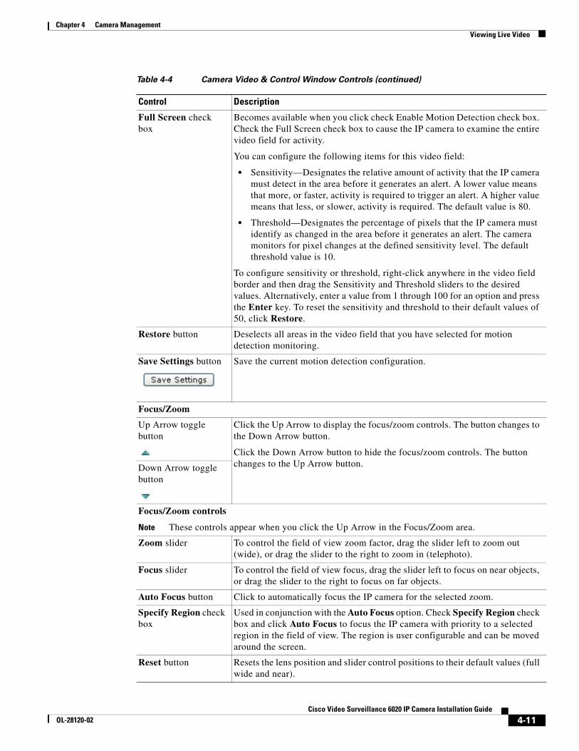
Full Screen check box
Becomes available when you click check Enable Motion Detection check box. Check the Full Screen check box to cause the IP camera to examine the entire video field for activity.
You can configure the following items for this video field:
• Sensitivity—Designates the relative amount of activity that the IP camera must detect in the area before it generates an alert. A lower value means that more, or faster, activity is required to trigger an alert. A higher value means that less, or slower, activity is required. The default value is 80.
• Threshold—Designates the percentage of pixels that the IP camera must identify as changed in the area before it generates an alert. The camera monitors for pixel changes at the defined sensitivity level. The default threshold value is 10.
To configure sensitivity or threshold, right-click anywhere in the video field border and then drag the Sensitivity and Threshold sliders to the desired values. Alternatively, enter a value from 1 through 100 for an option and press the Enter key. To reset the sensitivity and threshold to their default values of 50, click Restore.
Restore button Deselects all areas in the video field that you have selected for motion detection monitoring.
Save Settings button Save the current motion detection configuration.
Focus/Zoom
Up Arrow toggle button
Click the Up Arrow to display the focus/zoom controls. The button changes to the Down Arrow button.
Click the Down Arrow button to hide the focus/zoom controls. The button changes to the Up Arrow button.Down Arrow toggle
button
Focus/Zoom controls
Note These controls appear when you click the Up Arrow in the Focus/Zoom area.
Zoom slider To control the field of view zoom factor, drag the slider left to zoom out (wide), or drag the slider to the right to zoom in (telephoto).
Focus slider To control the field of view focus, drag the slider left to focus on near objects, or drag the slider to the right to focus on far objects.
Auto Focus button Click to automatically focus the IP camera for the selected zoom.
Specify Region check box
Used in conjunction with the Auto Focus option. Check Specify Region check box and click Auto Focus to focus the IP camera with priority to a selected region in the field of view. The region is user configurable and can be moved around the screen.
Reset button Resets the lens position and slider control positions to their default values (full wide and near).
Table 4-4 Camera Video & Control Window Controls (continued)
Control Description
4-11Cisco Video Surveillance 6020 IP Camera Installation Guide
OL-28120-02
Chapter 4 Camera ManagementManaging the Local Storage
Managing the Local StorageThe 6000 Series IP cameras have an SD card slot that can support an optional SD memory card (up to 8 GB) for local storage purposes. If local storage is available on an IP camera and the camera loses network connectivity, video data storage switches to the local SD memory card.
For security purposes, video data stored on the SD memory card is encrypted. To view the encrypted video, you must decrypt it to H.264 or MP4 format. Encrypted files cannot be decrypted directly from an SD memory card on an IP camera; before they can be decrypted, they must either be downloaded to your PC, or the SD memory card must be moved from the IP camera to your PC.
The Cisco SD Utility allows you to manage the SD memory card and to decrypt the encrypted video data on the card. The utility can be downloaded from Cisco.com and installed on your PC. For more information see the “Downloading and Installing the Cisco SD Utility” section on page 4-13.
Note Note You cannot manage an SD memory card using the camera firmware or Cisco Video Surveillance Manager (VSM); you must use the Cisco SD Utility.
Privacy Zone
Up Arrow toggle button
Click the Up Arrow to display the privacy zone controls. The button changes to the Down Arrow button.
Click the Down Arrow button to hide the privacy zone controls. The button changes to the Up Arrow button.Down Arrow toggle
button
Privacy Zone controls
Note These controls appear when you click the Up Arrow in the Privacy Zone area.
Enable Privacy Region
Check this check box to enable the privacy zone feature that allows you to create to four user-defined privacy regions. Any video within a privacy region is masked in the video stream.
To create a region, right-click on the video image and choose Draw Region. Drag the region to the desired area and drag an edge or corner of the region to resize it. To remove region, right-click on it and choose Delete Region.
Foe each region listed under the Privacy Zone Properties area, you can configure the following properties:
• Current Region—You can enter a name of up to 12 characters for a region.
• IsActive—Specifies whether the region is active (enabled) or not active (disabled). Chose true to enable a region; choose False to disable a region.
Region Color Choose a color from the Region Color drop-down list to specify the color that will be used to mask the actual video in all privacy regions.
Save button Saves the current privacy zone configuration.
Table 4-4 Camera Video & Control Window Controls (continued)
Control Description
4-12Cisco Video Surveillance 6020 IP Camera Installation Guide
OL-28120-02
Chapter 4 Camera ManagementManaging the Local Storage
This section includes the following local storage management topics:
• Downloading and Installing the Cisco SD Utility, page 4-13
• Formatting the SD Memory Card, page 4-13
• Downloading Encrypted Video Files from the SD Memory Card, page 4-14
• Deleting Encrypted Video Files from the SD Memory Card, page 4-14
• Decrypting Encrypted Video Files, page 4-15
Downloading and Installing the Cisco SD Utility
Procedure
Step 1 Perform the following steps to obtain the Cisco SD Utility:
a. Go to the Cisco Video Surveillance 6000 Series IP Cameras support page:
c. Choose your IP camera model from the list on the right.
d. Click the Download button for the Cisco Video Surveillance 3000, 6000 and 7000 Series camera SD Utility (CiscoSDUtilityInstallerV1.0.0.zip).
e. Log in and follow the on-screen prompts to download the file to your PC.
f. Close your Web browser.
Step 2 Double-click the CiscoSDUtilityInstallerV1.0.0.zip file that you downloaded in Step 1 and follow the on-screen prompts to install the utility on your PC.
During the installation process, the installer adds the Cisco SD Utility icon to your desktop.
Formatting the SD Memory Card
Before you begin
• Obtain and insert an SD memory card into the SD card slot on the IP camera. SD memory cards up to 8 GB in size are supported.
• Ensure that SSH is enabled on the IP camera that you are accessing, and ensure that a root password has been set.
Procedure
Step 1 Double-click the Cisco SD Utility icon to open the utility.
Step 2 Enter the IP address and root password for the IP camera and click Connect.
Step 3 Click Format MMC.
Step 4 Click Yes twice to verify that you are sure that you want to format the SD card.
4-13Cisco Video Surveillance 6020 IP Camera Installation Guide
Chapter 4 Camera ManagementManaging the Local Storage
The SD memory card is formatted using a FAT32 partition. If the SD memory card was previously formatted using a different partition type, such as NTFS, you are prompted to verify that you want to format the SD memory card using the FAT32 partition.
Downloading Encrypted Video Files from the SD Memory Card
Procedure
Step 1 Double-click the Cisco SD Utility icon to open the utility.
Step 2 Enter the IP address and root password for the IP camera and click Connect.
When the utility successfully connects to the IP camera, SD memory card capacity information and a list of the encrypted video files are displayed.
Step 3 Click Browse.
The Browse For Folder dialog box appears.
Step 4 Navigate to the folder where you want to save the video file(s) and click OK.
Step 5 Do one of the following to choose the encrypted files that are to be downloaded to your PC:
• To choose all encrypted video files on the SD memory card, click Select all.
• To choose some of the encrypted video files on the SD memory card, click on the ones you want to download from the file list.
Step 6 Click Save.
The selected files are copied to the specified folder, leaving the original files on the SD memory card.
What to Do Next
To view the encrypted video files that have been downloaded, you must decrypt them. For more information, see the “Decrypting Encrypted Video Files” section on page 4-15.
Deleting Encrypted Video Files from the SD Memory CardProcedure
Step 1 Double-click the Cisco SD Utility icon to open the utility.
Step 2 Enter the IP address and root password for the IP camera and click Connect.
When the utility successfully connects to the IP camera, SD memory card capacity information and a list of the encrypted video files are displayed.
Step 3 Do one of the following to choose the encrypted files that are to be deleted from the SD memory card:
• To choose all encrypted video files on the SD memory card, click Select all.
• To choose some of the encrypted video files on the SD memory card, click on the ones you want to delete from the file list.
Step 4 Click Delete.
4-14Cisco Video Surveillance 6020 IP Camera Installation Guide
OL-28120-02
Chapter 4 Camera ManagementManaging the Local Storage
The selected files are deleted from the SD memory card.
Decrypting Encrypted Video FilesBefore you begin
• Download the encrypted video files to your PC, or move the SD memory card containing the encrypted video files from the IP camera to your PC. For more information about downloading the encrypted video files, see the “Downloading Encrypted Video Files from the SD Memory Card” section on page 4-14.
• Note the root password of the IP camera that created the encrypted video files.
Procedure
Step 1 Double-click the Cisco SD Utility icon to open the utility.
Step 2 Click the Decrypt tab.
Step 3 Do one of the following to specify the encrypted files that are to be decrypted:
• In the Input file(s) text box, enter the full path and filename for each file to be encrypted. Separate multiple entries with a semicolon.
• Click the Browse button for the Input file(s) field, navigate to and choose the files to be encrypted, and click Open.
Step 4 Do one of the following to specify the output directory where the decrypted files are to be saved:
• In the Output directory text box, enter the full path for the output directory.
• Click the Browse button for the Output directory field, navigate to and choose the output directory, and click OK.
Step 5 In the Conversion Type field, choose the format to which the files are to be converted (H.264 or MP4).
Step 6 In the password text box, enter the root password for the IP camera that created the encrypted files.
Step 7 Click Convert.
The selected files are decrypted, and for each file, the Status text box indicates whether the decryption process failed or succeeded.
4-15Cisco Video Surveillance 6020 IP Camera Installation Guide
OL-28120-02
Chapter 4 Camera ManagementManaging the Local Storage
4-16Cisco Video Surveillance 6020 IP Camera Installation Guide
OL-28120-02
Cisco ViOL-28120-02
I N D E X
A
About link 4-2
ActiveX controls 4-2
audio
controls in Camera Video & Control window 4-6
B
brightness 4-7
C
camera
See IP camera
camera settings
picture adjustments
brightness 4-7
contrast 4-7
saturation 4-8
sharpness 4-8
white balance 4-8
Camera Video/Control window
accessing 4-5
description 4-2
displaying 4-2
Cisco SD utility, downloading 4-13
connecting, to the IP camera
for the first time 3-1
PC requirements for 3-1
contrast 4-7
D
decrypting video files 4-15
deleting files from SD memory card 4-14
DHCP, obtaining IP address through 3-1
downloading video files from SD memory card 4-14
F
factory reset 4-4
focus/zoom
accessing controls 4-11
controls 4-11
formatting SD memory card 4-13
H
help, for IP camera windows 4-2
Home window
description 4-2
displaying 4-1
HTTP
allowing access through 3-2
I
installing
IP camera 2-1
mounting to ceiling or wall 2-10
warnings 2-1
IP address
default for IP camera 3-1
obtaining from DCHP server 3-1
IN-1deo Surveillance 6020 IP Camera Installation Guide
Index
IP camera
accessing through a web browser 3-1
connecting to for the first time 3-1
installation 2-1
mounting to ceiling or wall 2-10
warnings 2-1
logging out of 4-2
panning 4-5
powering off 4-4
powering on 4-4
tilting 4-5
windows 4-2
L
live video
viewing
through home window 4-4
through third-party device or software 4-4
See also video
local storage
Cisco SD utility, downloading 4-13
decrypting video files 4-15
managing 4-12
SD memory card
deleting video files from 4-14
downloading video files from 4-14
formatting 4-13
log out, of IP camera 4-2
M
microphone
muting PC 4-6
PC 4-6
sensitivity 4-7
motion detection
accessing controls 4-7, 4-10, 4-12
IN-2Cisco Video Surveillance 6020 IP Camera Installation Guide
enabling 4-10
sensitivity 4-10, 4-11
threshold 4-10, 4-11
Motion detection controls 4-10, 4-12
mounting to ceiling or wall 2-10
muting
PC microphone 4-6
PC speaker 4-6
P
panning 4-5
password
requirements for 3-2
picture adjustments
brightness 4-7
contrast 4-7
saturation 4-8
sharpness 4-8
white balance 4-8
power
adapter 2-1
powering off the IP camera 4-4
powering on the IP camera 4-4
Power over Ethernet (PoE) 2-1
Power over Ethernet (PoE) 2-1
R
rebooting, IP camera 4-4
Refresh link 4-1
reset
factory default values 4-4
reboot 4-4
S
saturation 4-8
OL-28120-02
Index
SD memory card
deleting video files from 4-14
downloading video files from 4-14
formatting 4-13
sensitivity, for motion detection 4-10, 4-11
Setup window
description 4-2
displaying 4-2
sharpness 4-8
speaker
volume 4-7
storage
Cisco SD utility, downloading 4-13
decrypting video files 4-15
managing 4-12
SD memory card
deleting video files from 4-14
downloading video files from 4-14
formatting 4-13
T
threshold, for motion detection 4-10, 4-11
tilting 4-5
V
video
viewing live
through Home window 4-4
through third-party device or software 4-4
See also live video
video codec
controls in Camera Video/Control window 4-5
video resolution
controls in Camera Video/Control window 4-5
View Video link 4-2
OL-28120-02
W
warnings before installation 2-1
white balance mode 4-8
Z
zoom
accessing controls 4-11
zoom controls 4-11
IN-3Cisco Video Surveillance 6020 IP Camera Installation Guide
Index
IN-4Cisco Video Surveillance 6020 IP Camera Installation Guide