Cisco WT-2750 Multipoint Broadband Wireless System Frequently Asked Questions Document ID: 14240 Contents Introduction General ConfigurationHeadend Subscriber Unit (SU) Related Information Introduction This document contains frequently asked questions (FAQs) about the Cisco WT-2750 Multipoint Broadband Wireless System. For a diagram of components of the Multipoint Broadband Wireless network, see the What are subchannels? question in this document. Refer to Cisco Technical Tips Conventions for more information on document conventions. General Q. What are the necessary components for the Multipoint Broadband Wireless System? A. Headend (HE): Cisco uBR7223/7246/7246VXR Universal Broadband router ♦ WT-2751 Multipoint Headend Line Card - up to four for each HE; supports up to 1024 simultaneous users ♦ WT-2781 Multipoint Quad Power Feed Panel - one for up to two line cards ♦ Power supply (-48VDC) ♦ HE transverter (outdoor unit (ODU)) - one or two for each line card, depending upon whether diversity is employed ♦ HE duplexer - one for each ODU Note: The orientation of the installed duplexer determines transmit (TX) high or receive (RX) high frequency in configuration. ♦ Antenna(s) - either omnidirectional or sectorized ♦ Lightning arrestors ♦ Subscriber Unit (SU): Cisco 2600/3600 Series routers (2610, 2611, 2612, 2613, 2620, 2621, 3620, 3640, 3661, 3662) ♦ WT-2755 Multipoint Subscriber Network Module (NM) Note: NMs must be installed when router is powered off, except on the Cisco 3660 router. ♦
This document contains frequently asked questions (FAQs) about the Cisco WT−2750 Multipoint BroadbandWireless System. For a diagram of components of the Multipoint Broadband Wireless network, see the Whatare subchannels? question in this document.
Refer to Cisco Technical Tips Conventions for more information on document conventions.
General
Q. What are the necessary components for the Multipoint BroadbandWireless System?
A. Headend (HE):
Cisco uBR7223/7246/7246VXR Universal Broadband router♦ WT−2751 Multipoint Headend Line Card − up to four for each HE; supports up to1024 simultaneous users
♦
WT−2781 Multipoint Quad Power Feed Panel − one for up to two line cards♦ Power supply (−48VDC)♦ HE transverter (outdoor unit (ODU)) − one or two for each line card, depending uponwhether diversity is employed
♦
HE duplexer − one for each ODU
Note: The orientation of the installed duplexer determines transmit (TX) high orreceive (RX) high frequency in configuration.
♦
Antenna(s) − either omnidirectional or sectorized♦ Lightning arrestors♦
Note: NMs must be installed when router is powered off, except on the Cisco 3660router.
♦
DC Power Injector (−48VDC for high−power ODU or +24VDC for standard powerODU) with power supply
♦
SU Transverter (ODU) − two needed if using diversity; available either integratedwith antenna or nonintegrated, and either providing high or standard power
Note: Diversity antenna is RX only.
♦
SU Directional Antenna (if not using integrated ODU)♦ Lightning arrestors♦
Q. How are point−to−multipoint networks typically designed?
Supercell:
Up to 20 miles in diameter (10 mile radius)◊ Single HE◊
♦
Minicell:
Four to 10 miles in diameter (two to five mile radius)◊ Can employ frequency reuse◊
♦
Microcell:
Up to two miles in diameter (one mile radius)◊ SUs can use lower TX power◊ Allows maximum number of SUs within given area◊ Allows for frequency reuse◊
♦
Q. What are the frequency bands used for this system?
MMDS: 2.500 − 2.690 GHz♦ MDS: 2.150 − 2.162 GHz (used for upstream only)♦ ETSI: 3.400 − 3.600 GHz (ODU will be available second half of 2001)♦ U−NII: 5.725 − 5.825 GHz (ODU will be available first quarter of 2001)♦
Q. What is the modulation scheme that the Cisco WT−2750 MultipointBroadband Wireless System uses?
A. 64QAM over Vector Orthogonal Frequency Division Multiplexing (VOFDM)
Q. What is Vector Orthogonal Frequency Division Multiplexing (VOFDM),and why is VOFDM so compelling?
A. VOFDM leverages multi−path phenomenon�a key deterrent in microwavetransmission�into real life deployment advantages. VOFDM technology increasestransmission signal strength through a combination of multiple signals at the receiving end.VOFDM increases the overall wireless system performance, link quality, and availability.VOFDM also dramatically increases the market coverage of service providers throughnon−line−of−sight transmission.
Q. What is the maximum coverage range?
A. You can have 3, 4, and 6−sector designs, based on different off−the−shelf antenna designs.
Q. What is non−line−of−sight transmission?
A. The coverage range of non−line−of−sight transmission depends on these parameters:
Path loss assumption�How much signal is lost along the transmission path.♦ Link reliability and availability requirement�How many 9s service providers mustguarantee over the wireless link.
♦
Customer premises equipment (CPE) ODU transmission power�Standard powerODU or high power ODU at the CPE end.
♦
Antenna gain�The type of antenna used at the CPE end.♦ Channelization and performance requirement�What type of channelization andperformance required for each sector.
♦
Number of receiving antennae�One or two.♦ With a standard power ODU with high gain antenna, the WT−2750 Multipoint BroadbandWireless System can achieve six miles in non−Loss of Signal (LOS) transmission with twoantennae/ODUs for each CPE, and three miles with a single antenna/ODU, when it meets99.9% link availability requirement, and uses 6 MHz channel downstream, and 3 MHzchannel upstream for each sector at normal path loss.
Q. What are the intermediate frequency (Ifs) for the Headend (HE) andSubscriber Unit (SU)?
Q. What downstream frequency bandwidths are allowed? Can I changethis?
A. Bandwidths of 6 MHz, 3 MHz, 1.5 MHz are allowed. The HE line card is configured touse a single channel 6 MHz wide, unless there are Radio Frequency (RF) variables that do notallow this configuration.
Q. What are the different upstream frequency bandwidths that I canconfigure?
A. The bandwidths are 6 MHz, 3 MHz, and 1.5 MHz. Because subchannelization is possible,you can use combinations of each of these channelization schemes. For example, if you usethree upstream ports, you can have one upstream set for 3 MHz and the other two set for 1.5MHz. You cannot exceed 6 MHz total with these combinations.
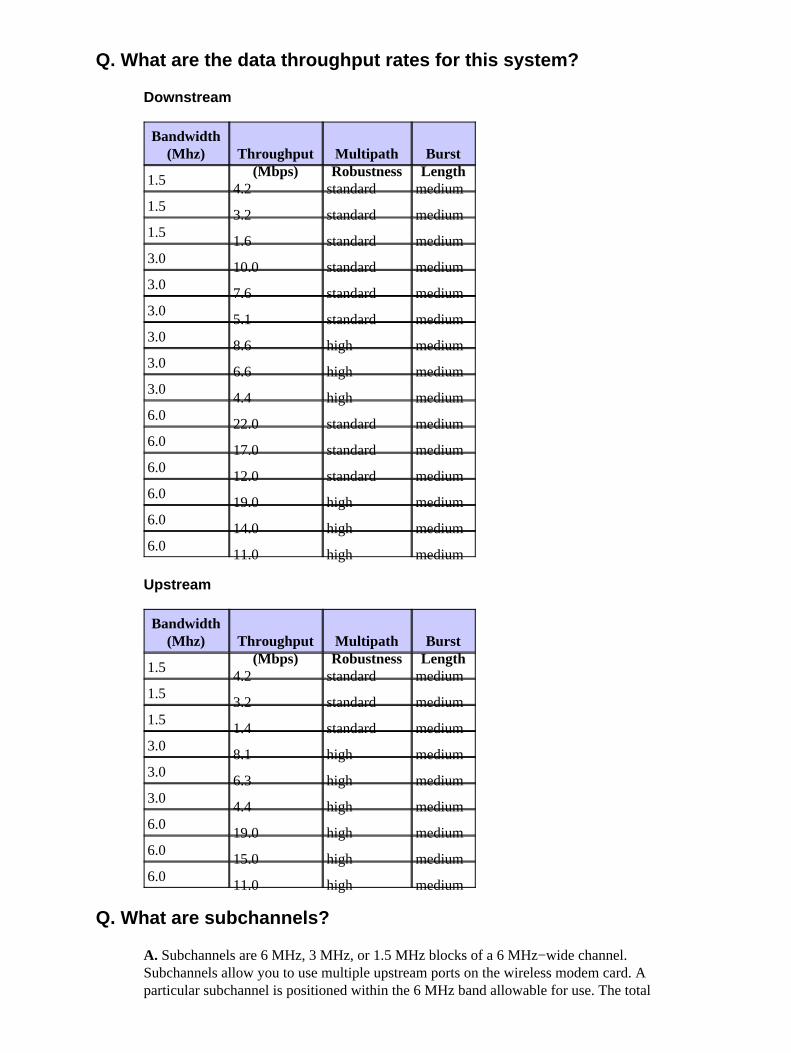
Q. What are the data throughput rates for this system?
Downstream
Bandwidth(Mhz) Throughput
(Mbps)MultipathRobustness
BurstLength
1.54.2 standard medium
1.53.2 standard medium
1.51.6 standard medium
3.010.0 standard medium
3.07.6 standard medium
3.05.1 standard medium
3.08.6 high medium
3.06.6 high medium
3.04.4 high medium
6.022.0 standard medium
6.017.0 standard medium
6.012.0 standard medium
6.019.0 high medium
6.014.0 high medium
6.011.0 high medium
Upstream
Bandwidth(Mhz) Throughput
(Mbps)MultipathRobustness
BurstLength
1.54.2 standard medium
1.53.2 standard medium
1.51.4 standard medium
3.08.1 high medium
3.06.3 high medium
3.04.4 high medium
6.019.0 high medium
6.015.0 high medium
6.011.0 high medium
Q. What are subchannels?
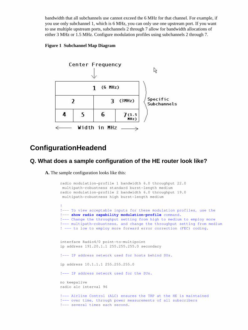
A. Subchannels are 6 MHz, 3 MHz, or 1.5 MHz blocks of a 6 MHz−wide channel.Subchannels allow you to use multiple upstream ports on the wireless modem card. Aparticular subchannel is positioned within the 6 MHz band allowable for use. The total
bandwidth that all subchannels use cannot exceed the 6 MHz for that channel. For example, ifyou use only subchannel 1, which is 6 MHz, you can only use one upstream port. If you wantto use multiple upstream ports, subchannels 2 through 7 allow for bandwidth allocations ofeither 3 MHz or 1.5 MHz. Configure modulation profiles using subchannels 2 through 7.
Figure 1 � Subchannel Map Diagram
Configuration�Headend
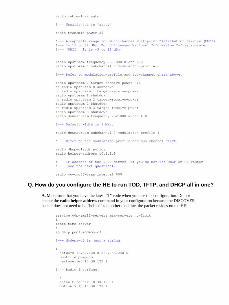
Q. What does a sample configuration of the HE router look like?
A. The sample configuration looks like this:
radio modulation−profile 1 bandwidth 6.0 throughput 22.0 multipath−robustness standard burst−length medium radio modulation−profile 2 bandwidth 6.0 throughput 19.0 multipath−robustness high burst−length medium
! !−−− To view acceptable inputs for these modulation profiles, use the !−−− show radio capability modulation−profile command. !−−− Change the throughput setting from high to medium to employ more !−−− multipath−robustness, and change the throughput setting from medium! −−− to low to employ more forward error correction (FEC) coding.
interface Radio4/0 point−to−multipoint ip address 191.20.1.1 255.255.255.0 secondary
!−−− IP address network used for hosts behind SUs.
ip address 10.1.1.1 255.255.255.0
!−−− IP address network used for the SUs.
no keepalive radio alc interval 96
!−−− Airline Control (ALC) ensures the TRP at the HE is maintained!−−− over time, through power measurements of all subscribers !−−− several times each second.
radio cable−loss auto
!−−− Usually set to "auto."
radio transmit−power 20
!−−− Acceptable range for Multichannel Multipoint Distribution Service (MMDS)!−−− is 15 to 38 dBm. For Unlicensed National Information Infrastructure!−−− (UNII), it is −5 to 15 dBm.
radio upstream frequency 2677000 width 6.0 radio upstream 0 subchannel 1 modulation−profile 2
!−−− Refer to modulation−profile and sub−channel chart above.
radio upstream 0 target−receive−power −65 no radio upstream 0 shutdown no radio upstream 1 target−receive−power radio upstream 1 shutdown no radio upstream 2 target−receive−power radio upstream 2 shutdown no radio upstream 3 target−receive−power radio upstream 3 shutdown radio downstream frequency 2521000 width 6.0
!−−− Default width is 6 MHz.
radio downstream subchannel 1 modulation−profile 1
!−−− Refer to the modulation−profile and sub−channel chart.
radio dhcp−giaddr policy radio helper−address 10.1.1.5
!−−− IP address of the DHCP server, if you do not use DHCP on HE router!−−− (see the next question).
radio su−onoff−trap interval 600
Q. How do you configure the HE to run TOD, TFTP, and DHCP all in one?
A. Make sure that you have the latest "T" code when you use this configuration. Do notenable the radio helper address command in your configuration because the DISCOVERpacket does not need to be "helped" to another machine, the packet resides on the HE.
service udp−small−servers max−servers no−limit ! radio time−server ! ip dhcp pool modems−c3
! default−router 10.30.128.1 option 7 ip 10.30.128.1
option 4 ip 10.30.128.1 option 2 hex 0000.0000 ! interface Radio3/0 point−to−multipoint ip address 10.30.128.1 255.255.240.0 ! tftp server slot0:p2mp.cm alias p2mp.cm
!−−− Use this statement when .cm file is stored in "flash,"!−−− not in the TFTP server.
Complete these steps to put the .cm file in flash:
Copy tftp slot:0, and press ENTER.1. When the parser queries for a name of a remote host, type the address of the TFTPserver.
2.
When the parser queries for a source filename, type the .cm filename, and pressENTER.
3.
You can also configure a DOCSIS configuration file that resides on the HE instead of theTFTP server:
radio config−file p2mp.cmcpe max 4service−class 1 priority 2service−class 1 max−upstream 128service−class 1 max−downstream 1000timestamp
Note: You do not need the statement "tftp server slot0:p2mp.cm alias p2mp.cm" becausethere is no .cm file. It resides within the configuration.
Q. How do you configure Baseline Privacy?
A. Complete these steps to configure the Baseline Privacy:
Load K1 images on the HE and SUs.1. Use a Configuration File Editor to open DOCSIS configuration file.2. Click Expand in the Class of Service Group tab.3. Enable a 1 under the Class−of−Service Privacy Enable (0/1): 1 field. By default thisis a 0, so change the value to 1.
4.
Save the DOCSIS configuration file the TFTP boot file, which resides on the TFTPserver connected to the Fast Ethernet (FE) port of the HE. After a reboot, the SUloads your new DOCSIS configuration file with the above parameters.
5.
The SU negotiates Baseline Privacy Interface (BPI) with the HE. Use the show radiosubscriber command to see that the SU is registered as "online(PT)" instead of asjust "online". If you do not see "(PT)" check to see if you have K1 images on SU andthe HE, and check to see if you have enabled "Class−of−Service Privacy" to equal 1in the .cm file.
6.
Q. What is the difference between a DOCSIS configuration file and anIOS configuration file?
A. A DOCSIS configuration file is a binary file, and has the parameters for radio SUs to comeonline in accordance to what the ISP provisions, for example, Maximum Downstream andUpstream Rates, Maximum Upstream Burst Rate, Class of Service or Baseline Privacy, MIBsand many other parameters.
A Cisco IOS configuration file is a text file that can contain specific configurations, such asaccess lists, passwords, and NAT configurations, that you can download within the DOCSISconfiguration file.
Q. What are some helpful commands to monitor and troubleshoot theHeadend?
show radio interface slot number/port number [{if | rf}]♦ show radio subscribers �Shows all the radio subscribers and current states.♦ show radio flap−list �Displays the radio flap−list of a wireless modem card.♦ show interfaces radio slot number/port number hist−data�Shows signal−to−noiseratio (SNR). You must have histograms configured on the radio interface to see anyoutput. This is the only command that shows SNR.
♦
show interfaces radio slot number/port number link−metrics �Shows all codeworderrors on a link over a specific period.
♦
show controllers radio slot number/port number [{if | rf}]�Displays all or a subsetof attributes of a particular modem card.
♦
show controllers radio slot/downstream−port downstream�Displays downstreamport information for a wireless modem card.
♦
show controllers radio slot/upstream−port upstream�Displays upstream portinformation for a wireless modem card.
♦
radio loopback local main if �Shows if the line card is faulty.♦ radio loopback local main rf �Shows if there is a cable problem between the cardand the ODU.
♦
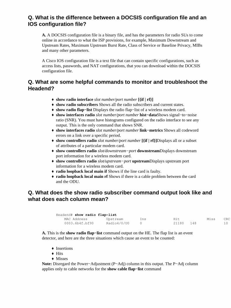
Q. What does the show radio subscriber command output look like andwhat does each column mean?
Headend# show radio flap−list MAC Address Upstream Ins Hit Miss CRC P−Adj Flap Time 0003.6b4f.bf90 Radio4/0/U0 0 21180 148 10 0 9 Oct 3 17:34:23
A. This is the show radio flap−list command output on the HE. The flap list is an eventdetector, and here are the three situations which cause an event to be counted:
Insertions♦ Hits♦ Misses♦
Note: Disregard the Power−Adjustment (P−Adj) column in this output. The P−Adj columnapplies only to cable networks for the show cable flap−list command
Insertions
First, you can see flaps along with insertions if a SU has a registration problem and repeatedlytries to quickly reregister. The P−Adj column can be low. When the time between two initialmaintenance re−registrations by the SU is less than 180 seconds, you get "flaps" along with"insertions," and the flap detector counts it. You can change this default value of 180 secondsif you want:
Headend(config)# radio flap−list insertion−time ? <60−86400> Insertion time interval in seconds
Hits / Misses
Second, the flap detector counts a flap when you see a "miss" followed by a "hit." The eventdetection is counted in the Flap column only. These polls are hello packets that are sent every30 seconds. If you get a "miss" followed by a "miss," then the polls are sent every second for16 seconds. If you get a "hit" before the 16 seconds are up, you get a flap, but if you don't geta "hit" for 16 polls, the modem goes off−line in order to begin initial maintenance again. Ifthe SU finally comes back online, you'll get an "insertion" because the SU inserted itself backinto an active state. The flap count increments if there are six consecutive misses. This defaultvalue can be changed if desired:
Headend(config)# radio flap miss−threshold ? <1−12> missing consecutive polling messages
Note: Currently the P−Adj column is not used for the point−to−multipoint system.
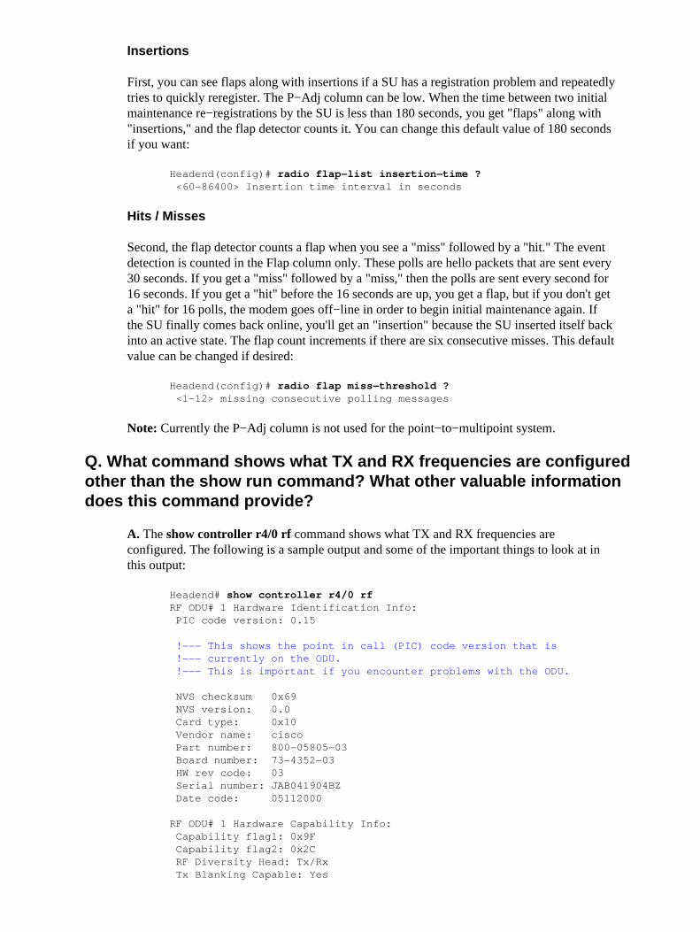
Q. What command shows what TX and RX frequencies are configuredother than the show run command? What other valuable informationdoes this command provide?
A. The show controller r4/0 rf command shows what TX and RX frequencies areconfigured. The following is a sample output and some of the important things to look at inthis output:
RF Power Level Mode Capable: Yes RF Power Gain Mode Capable: Yes RF Loopback Capable: Yes Tx Predistortor Capable: No Antenna Alignment Capable: No PA Temp Sensor Capable: Yes Tx Spectral Inversion: No Rx Spectral Inversion: No Rx Blanking Capable: Yes Rx Gain Cal. Capable: Yes Variable Gain Info Available: No Duplexor Field Replaceble: Yes Max chan. BW: 6 Mhz Tx frequency bands: 1, step: 600 Khz min: 2500000 Khz, max: 2686000 Khz
!−−− These TX and RX values show the ODU bandpass. !−−− With this information, you will know what center !−−− frequencies are available for use.
!−−− These are the IF, TX, and RX frequencies that you can measure !−−− for verification purposes from the front of the board out of !−−− the monitor port.
IF Rx freq: 426000 Khz Freq reference: 24 Mhz Tx power range min: 15 dbm, max: 41 dbm, step: 1 dbm Tx fixed gain min: 0 db, max: 0 db, step: 0 db Rx fixed gain min: 0 db, max: 0 db, step: 0 db Tx var gain min: 48 db, max: 56 db, step: 1 * 0.125 db Rx var gain min: 30 db, max: 36 db, step: 1 * 0.125 db Temp. threshold low: 95 deg. C, high: 98 deg. C BW adjusted max tx pwr: full:0 dbm half:0 dbm quarter:0 dbm
RF ODU# 1 Status: TX Frequency: 2521000 Khz
!−−− These are the TX and RX frequencies that are actually !−−− configured on the HE.
RX Frequency: 2677000 Khz TX Output Power: 20 dbm
!−−− As well as the output power that is configured on the HE.
TX Cable Loss: 15 db
Q. How do you configure histograms and get the data output from them?
A. Histograms are configured on the Radio Interface. There are several different types ofhistograms to configure; the most commonly used ones are the ones forsignal−to−interference plus noise ratio (SINR) and RF RX Power. A few of the availablehistograms are listed below:
radio histogram sinr−ant1 0 bin−range 10 50 duration 5 tone average update 5 sum false width coarse radio histogram timing−offset 0 bin−range −10 10 duration 5 update 5 sum false width coarse radio histogram rf−rx−power−ant1 0 bin−range −100 0 duration
5 update 5 sum false width coarse radio histogram chan−delay−spread−ant1 0 bin−range 0 22 duration 5 update 5 sum false width coarse radio histogram power−amb 0 bin−range −101 −21 duration 5 update 5 sum false width coarse
When the histogram is configured on the radio interface, you can view the data from it withthe show interface slot number/port number hist−data <particular histogram> globalcommand. See the next question for an example.
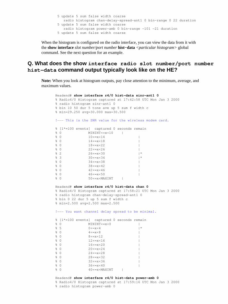
Q. What does the show interface radio slot number/port numberhist−data command output typically look like on the HE?
Note: When you look at histogram outputs, pay close attention to the minimum, average, andmaximum values.
Headend# show interface r4/0 hist−data sinr−ant1 0 % Radio4/0 Histogram captured at 17:42:58 UTC Mon Jan 3 2000 % radio histogram sinr−ant1 0 % bin 10 50 dur 5 tone ave up 5 sum f width c % min=29.250 avg=30.000 max=30.500
!−−− This is the SNR value for the wireless modem card.
Headend# show interface r4/0 hist−data chan 0 % Radio4/0 Histogram captured at 17:58:21 UTC Mon Jan 3 2000 % radio histogram chan−delay−spread−ant1 0 % bin 0 22 dur 5 up 5 sum f width c % min=2.500 avg=2.500 max=2.500
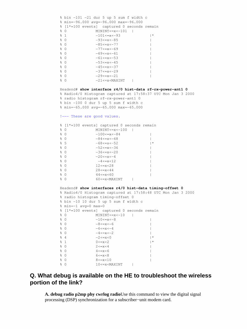
Headend# show interface r4/0 hist−data rf−rx−power−ant1 0 % Radio4/0 Histogram captured at 17:58:37 UTC Mon Jan 3 2000 % radio histogram rf−rx−power−ant1 0 % bin −100 0 dur 5 up 5 sum f width c % min=−65.000 avg=−65.000 max=−65.000
Headend# show interfaces r4/0 hist−data timing−offset 0% Radio4/0 Histogram captured at 17:58:48 UTC Mon Jan 3 2000 % radio histogram timing−offset 0 % bin −10 10 dur 5 up 5 sum f width c % min=−1 avg=0 max=0 % [1*=100 events] captured 0 seconds remain % 0 MININT<=x<−10 | % 0 −10<=x<−8 | % 0 −8<=x<−6 | % 0 −6<=x<−4 | % 0 −4<=x<−2 | % 4 −2<=x<0 |* % 1 0<=x<2 |* % 0 2<=x<4 | % 0 4<=x<6 | % 0 6<=x<8 | % 0 8<=x<10 | % 0 10<=x<MAXINT |
Q. What debug is available on the HE to troubleshoot the wirelessportion of the link?
A. debug radio p2mp phy cwrlog radio�Use this command to view the digital signalprocessing (DSP) synchronization for a subscriber−unit modem card.
Subscriber Unit (SU)
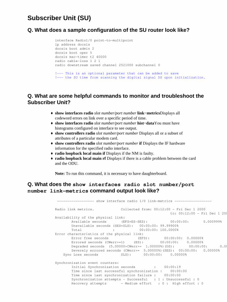
Q. What does a sample configuration of the SU router look like?
interface Radio1/0 point−to−multipoint ip address docsis docsis boot admin 2 docsis boot oper 5 docsis mac−timer t2 40000 radio cable−loss 1 2 1 radio downstream saved channel 2521000 subchannel 0
!−−− This is an optional parameter that can be added to save !−−− the SU time from scanning the digital signal DS upon initialization.
Q. What are some helpful commands to monitor and troubleshoot theSubscriber Unit?
show interfaces radio slot number/port number link−metrics�Displays allcodeword errors on link over a specific period of time.
♦
show interfaces radio slot number/port number hist−data�You must havehistograms configured on interface to see output.
♦
show controllers radio slot number/port number �Displays all or a subset ofattributes of a particular modem card.
♦
show controllers radio slot number/port number if �Displays the IF hardwareinformation for the specified radio interface.
♦
radio loopback local main if �Displays if the NM is faulty.♦ radio loopback local main rf �Displays if there is a cable problem between the cardand the ODU.
Note: To run this command, it is necessary to have daughterboard.
♦
Q. What does the show interfaces radio slot number/portnumber link−metrics command output look like?
−−−−−−−−−−−−−−−−−− show interface radio 1/0 link−metrics −−−−−−−−−−−−−−−−−−
Radio link metrics. Collected from: 00:12:00 − Fri Dec 1 2000 to: 00:12:00 − Fri Dec 1 2000 Availability of the physical link: Available seconds (EFS+ES−SES): 00:00:00: 0.000999% Unavailable seconds (SES+SLS): 00:00:00: 99.99900% Total : 00:00:00: 100.0000% Error characteristics of the physical link: Error free seconds (EFS): 00:00:00: 0.00000% Errored seconds (CWerr>=1) (ES): 00:00:00: 0.00000% Degraded seconds (5.00000>CWerr>= 1.00000%)(DS): 00:00:00: 0.00000% Severely errored seconds (CWerr>= 5.00000%)(SES): 00:00:00: 0.00000% Sync Loss seconds SLS): 00:00:00: 0.00000%
Synchronization event counters: Initial Synchronization seconds : 00:00:19 Time since last successful synchronization : 00:00:00 Time since last synchronization failure : 00:00:00 Synchronization attempts − Successful : 1 : Unsuccessful : 0 Recovery attempts − Medium effort : 0 : High effort : 0
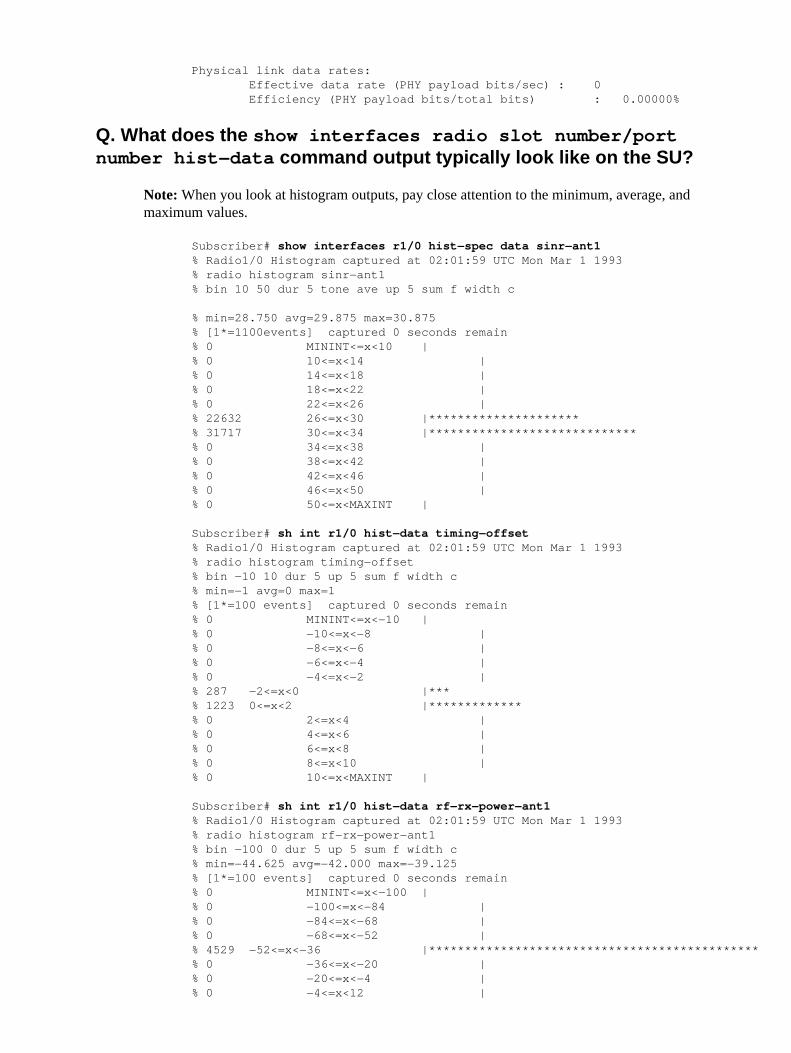
Physical link data rates: Effective data rate (PHY payload bits/sec) : 0 Efficiency (PHY payload bits/total bits) : 0.00000%
Q. What does the show interfaces radio slot number/portnumber hist−data command output typically look like on the SU?
Note: When you look at histogram outputs, pay close attention to the minimum, average, andmaximum values.
Subscriber# show interfaces r1/0 hist−spec data sinr−ant1% Radio1/0 Histogram captured at 02:01:59 UTC Mon Mar 1 1993 % radio histogram sinr−ant1 % bin 10 50 dur 5 tone ave up 5 sum f width c
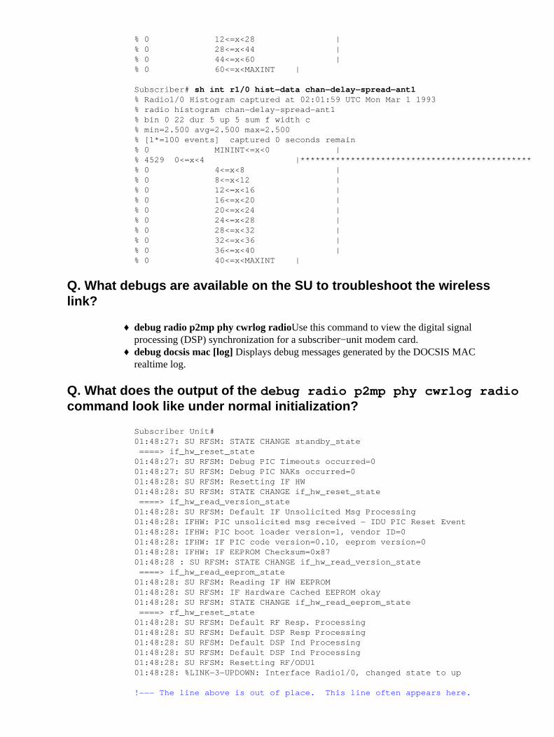
Subscriber# sh int r1/0 hist−data chan−delay−spread−ant1 % Radio1/0 Histogram captured at 02:01:59 UTC Mon Mar 1 1993 % radio histogram chan−delay−spread−ant1 % bin 0 22 dur 5 up 5 sum f width c % min=2.500 avg=2.500 max=2.500 % [1*=100 events] captured 0 seconds remain % 0 MININT<=x<0 | % 4529 0<=x<4 |********************************************** % 0 4<=x<8 | % 0 8<=x<12 | % 0 12<=x<16 | % 0 16<=x<20 | % 0 20<=x<24 | % 0 24<=x<28 | % 0 28<=x<32 | % 0 32<=x<36 | % 0 36<=x<40 | % 0 40<=x<MAXINT |
Q. What debugs are available on the SU to troubleshoot the wirelesslink?
debug radio p2mp phy cwrlog radio�Use this command to view the digital signalprocessing (DSP) synchronization for a subscriber−unit modem card.
♦
debug docsis mac [log] �Displays debug messages generated by the DOCSIS MACrealtime log.
♦
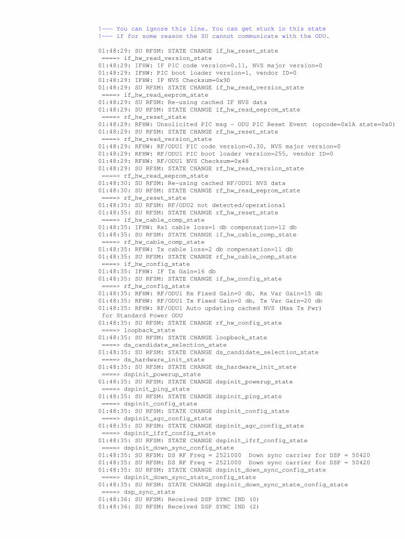
Q. What does the output of the debug radio p2mp phy cwrlog radiocommand look like under normal initialization?
Subscriber Unit# 01:48:27: SU RFSM: STATE CHANGE standby_state ====> if_hw_reset_state 01:48:27: SU RFSM: Debug PIC Timeouts occurred=0 01:48:27: SU RFSM: Debug PIC NAKs occurred=0 01:48:28: SU RFSM: Resetting IF HW 01:48:28: SU RFSM: STATE CHANGE if_hw_reset_state ====> if_hw_read_version_state 01:48:28: SU RFSM: Default IF Unsolicited Msg Processing 01:48:28: IFHW: PIC unsolicited msg received − IDU PIC Reset Event 01:48:28: IFHW: PIC boot loader version=1, vendor ID=0 01:48:28: IFHW: IF PIC code version=0.10, eeprom version=0 01:48:28: IFHW: IF EEPROM Checksum=0x87 01:48:28 : SU RFSM: STATE CHANGE if_hw_read_version_state ====> if_hw_read_eeprom_state 01:48:28: SU RFSM: Reading IF HW EEPROM 01:48:28: SU RFSM: IF Hardware Cached EEPROM okay 01:48:28: SU RFSM: STATE CHANGE if_hw_read_eeprom_state ====> rf_hw_reset_state 01:48:28: SU RFSM: Default RF Resp. Processing 01:48:28: SU RFSM: Default DSP Resp Processing 01:48:28: SU RFSM: Default DSP Ind Processing 01:48:28: SU RFSM: Default DSP Ind Processing 01:48:28: SU RFSM: Resetting RF/ODU1 01:48:28: %LINK−3−UPDOWN: Interface Radio1/0, changed state to up
!−−− The line above is out of place. This line often appears here.
!−−− You can ignore this line. You can get stuck in this state !−−− if for some reason the SU cannot communicate with the ODU.
01:48:29: SU RFSM: STATE CHANGE if_hw_reset_state ====> if_hw_read_version_state 01:48:29: IFHW: IF PIC code version=0.11, NVS major version=0 01:48:29: IFHW: PIC boot loader version=1, vendor ID=0 01:48:29: IFHW: IF NVS Checksum=0x9D 01:48:29: SU RFSM: STATE CHANGE if_hw_read_version_state ====> if_hw_read_eeprom_state 01:48:29: SU RFSM: Re−using cached IF NVS data 01:48:29: SU RFSM: STATE CHANGE if_hw_read_eeprom_state ====> rf_hw_reset_state 01:48:29: RFHW: Unsolicited PIC msg − ODU PIC Reset Event (opcode=0x1A state=0x0) 01:48:29: SU RFSM: STATE CHANGE rf_hw_reset_state ====> rf_hw_read_version_state 01:48:29: RFHW: RF/ODU1 PIC code version=0.30, NVS major version=0 01:48:29: RFHW: RF/ODU1 PIC boot loader version=255, vendor ID=0 01:48:29: RFHW: RF/ODU1 NVS Checksum=0x48 01:48:29: SU RFSM: STATE CHANGE rf_hw_read_version_state ====> rf_hw_read_eeprom_state 01:48:30: SU RFSM: Re−using cached RF/ODU1 NVS data 01:48:30: SU RFSM: STATE CHANGE rf_hw_read_eeprom_state ====> rf_hw_reset_state 01:48:35: SU RFSM: RF/ODU2 not detected/operational 01:48:35: SU RFSM: STATE CHANGE rf_hw_reset_state ====> if_hw_cable_comp_state 01:48:35: IFHW: Rx1 cable loss=1 db compensation=12 db 01:48:35: SU RFSM: STATE CHANGE if_hw_cable_comp_state ====> rf_hw_cable_comp_state 01:48:35: RFHW: Tx cable loss=2 db compensation=11 db 01:48:35: SU RFSM: STATE CHANGE rf_hw_cable_comp_state ====> if_hw_config_state 01:48:35: IFHW: IF Tx Gain=16 db 01:48:35: SU RFSM: STATE CHANGE if_hw_config_state ====> rf_hw_config_state 01:48:35: RFHW: RF/ODU1 Rx Fixed Gain=0 db, Rx Var Gain=15 db 01:48:35: RFHW: RF/ODU1 Tx Fixed Gain=0 db, Tx Var Gain=20 db 01:48:35: RFHW: RF/ODU1 Auto updating cached NVS (Max Tx Pwr) for Standard Power ODU 01:48:35: SU RFSM: STATE CHANGE rf_hw_config_state ====> loopback_state 01:48:35: SU RFSM: STATE CHANGE loopback_state ====> ds_candidate_selection_state 01:48:35: SU RFSM: STATE CHANGE ds_candidate_selection_state ====> ds_hardware_init_state 01:48:35: SU RFSM: STATE CHANGE ds_hardware_init_state ====> dspinit_powerup_state 01:48:35: SU RFSM: STATE CHANGE dspinit_powerup_state ====> dspinit_ping_state 01:48:35: SU RFSM: STATE CHANGE dspinit_ping_state ====> dspinit_config_state 01:48:35: SU RFSM: STATE CHANGE dspinit_config_state ====> dspinit_agc_config_state 01:48:35: SU RFSM: STATE CHANGE dspinit_agc_config_state ====> dspinit_ifrf_config_state 01:48:35: SU RFSM: STATE CHANGE dspinit_ifrf_config_state ====> dspinit_down_sync_config_state 01:48:35: SU RFSM: DS RF Freq = 2521000 Down sync carrier for DSP = 50420 01:48:35: SU RFSM: DS RF Freq = 2521000 Down sync carrier for DSP = 50420 01:48:35: SU RFSM: STATE CHANGE dspinit_down_sync_config_state ====> dspinit_down_sync_state_config_state 01:48:35: SU RFSM: STATE CHANGE dspinit_down_sync_state_config_state ====> dsp_sync_state 01:48:36: SU RFSM: Received DSP SYNC IND (0) 01:48:36: SU RFSM: Received DSP SYNC IND (2)
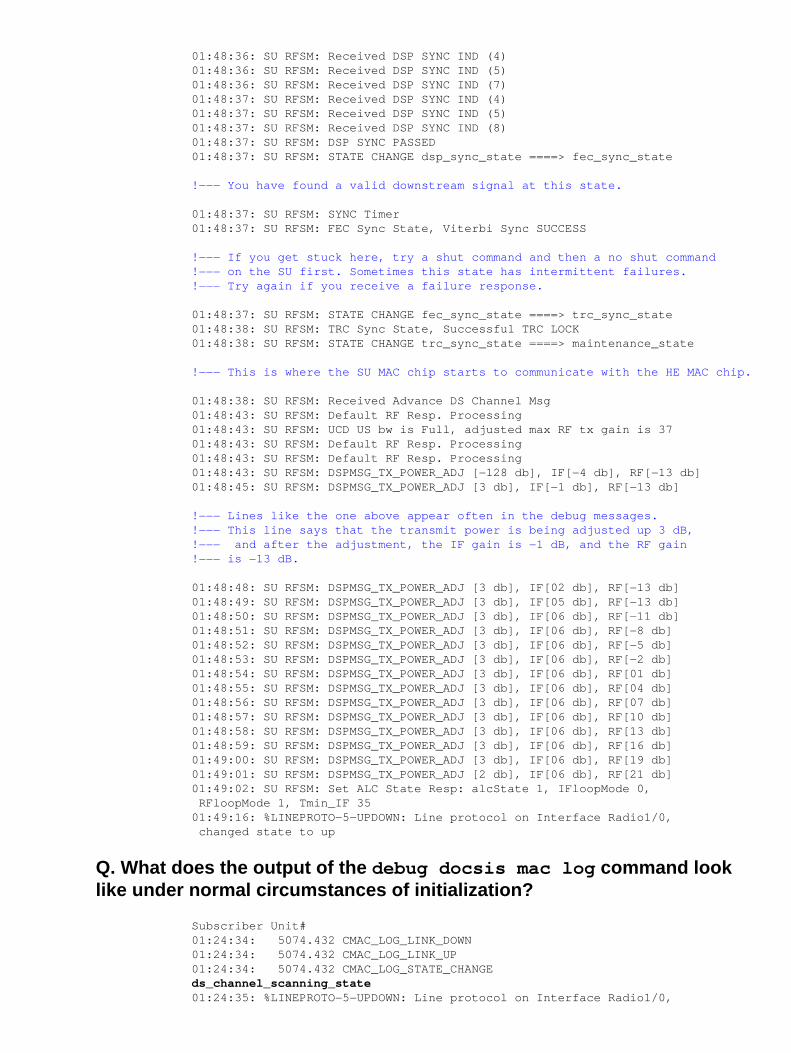
01:48:36: SU RFSM: Received DSP SYNC IND (4) 01:48:36: SU RFSM: Received DSP SYNC IND (5) 01:48:36: SU RFSM: Received DSP SYNC IND (7) 01:48:37: SU RFSM: Received DSP SYNC IND (4) 01:48:37: SU RFSM: Received DSP SYNC IND (5) 01:48:37: SU RFSM: Received DSP SYNC IND (8) 01:48:37: SU RFSM: DSP SYNC PASSED 01:48:37: SU RFSM: STATE CHANGE dsp_sync_state ====> fec_sync_state
!−−− You have found a valid downstream signal at this state.
01:48:37: SU RFSM: SYNC Timer 01:48:37: SU RFSM: FEC Sync State, Viterbi Sync SUCCESS
!−−− If you get stuck here, try a shut command and then a no shut command!−−− on the SU first. Sometimes this state has intermittent failures. !−−− Try again if you receive a failure response.
01:48:37: SU RFSM: STATE CHANGE fec_sync_state ====> trc_sync_state 01:48:38: SU RFSM: TRC Sync State, Successful TRC LOCK 01:48:38: SU RFSM: STATE CHANGE trc_sync_state ====> maintenance_state
!−−− This is where the SU MAC chip starts to communicate with the HE MAC chip.
01:48:38: SU RFSM: Received Advance DS Channel Msg 01:48:43: SU RFSM: Default RF Resp. Processing 01:48:43: SU RFSM: UCD US bw is Full, adjusted max RF tx gain is 37 01:48:43: SU RFSM: Default RF Resp. Processing 01:48:43: SU RFSM: Default RF Resp. Processing 01:48:43: SU RFSM: DSPMSG_TX_POWER_ADJ [−128 db], IF[−4 db], RF[−13 db] 01:48:45: SU RFSM: DSPMSG_TX_POWER_ADJ [3 db], IF[−1 db], RF[−13 db]
!−−− Lines like the one above appear often in the debug messages. !−−− This line says that the transmit power is being adjusted up 3 dB,!−−− and after the adjustment, the IF gain is −1 dB, and the RF gain!−−− is −13 dB.
01:48:48: SU RFSM: DSPMSG_TX_POWER_ADJ [3 db], IF[02 db], RF[−13 db] 01:48:49: SU RFSM: DSPMSG_TX_POWER_ADJ [3 db], IF[05 db], RF[−13 db] 01:48:50: SU RFSM: DSPMSG_TX_POWER_ADJ [3 db], IF[06 db], RF[−11 db] 01:48:51: SU RFSM: DSPMSG_TX_POWER_ADJ [3 db], IF[06 db], RF[−8 db] 01:48:52: SU RFSM: DSPMSG_TX_POWER_ADJ [3 db], IF[06 db], RF[−5 db] 01:48:53: SU RFSM: DSPMSG_TX_POWER_ADJ [3 db], IF[06 db], RF[−2 db] 01:48:54: SU RFSM: DSPMSG_TX_POWER_ADJ [3 db], IF[06 db], RF[01 db] 01:48:55: SU RFSM: DSPMSG_TX_POWER_ADJ [3 db], IF[06 db], RF[04 db] 01:48:56: SU RFSM: DSPMSG_TX_POWER_ADJ [3 db], IF[06 db], RF[07 db] 01:48:57: SU RFSM: DSPMSG_TX_POWER_ADJ [3 db], IF[06 db], RF[10 db] 01:48:58: SU RFSM: DSPMSG_TX_POWER_ADJ [3 db], IF[06 db], RF[13 db] 01:48:59: SU RFSM: DSPMSG_TX_POWER_ADJ [3 db], IF[06 db], RF[16 db] 01:49:00: SU RFSM: DSPMSG_TX_POWER_ADJ [3 db], IF[06 db], RF[19 db] 01:49:01: SU RFSM: DSPMSG_TX_POWER_ADJ [2 db], IF[06 db], RF[21 db] 01:49:02: SU RFSM: Set ALC State Resp: alcState 1, IFloopMode 0, RFloopMode 1, Tmin_IF 35 01:49:16: %LINEPROTO−5−UPDOWN: Line protocol on Interface Radio1/0, changed state to up
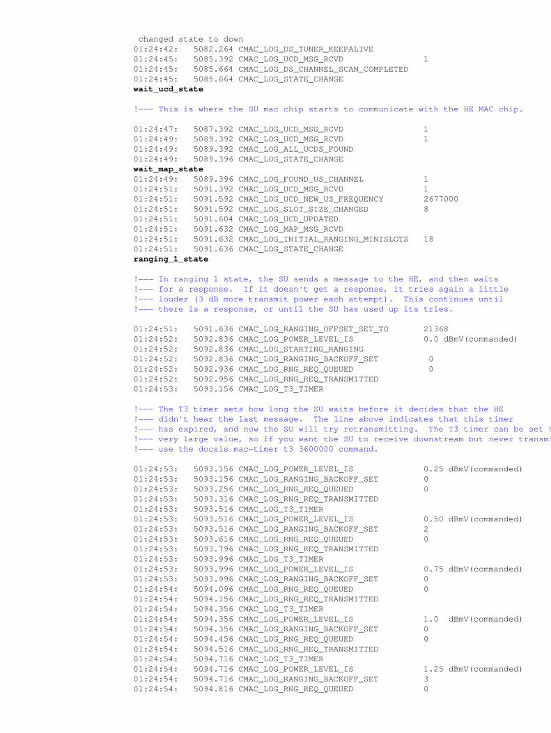
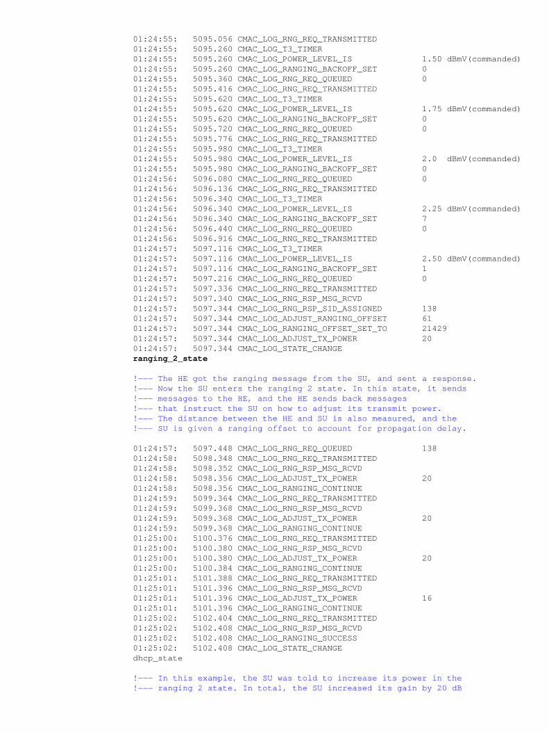
Q. What does the output of the debug docsis mac log command looklike under normal circumstances of initialization?
Subscriber Unit#01:24:34: 5074.432 CMAC_LOG_LINK_DOWN 01:24:34: 5074.432 CMAC_LOG_LINK_UP 01:24:34: 5074.432 CMAC_LOG_STATE_CHANGE ds_channel_scanning_state 01:24:35: %LINEPROTO−5−UPDOWN: Line protocol on Interface Radio1/0,
changed state to down 01:24:42: 5082.264 CMAC_LOG_DS_TUNER_KEEPALIVE 01:24:45: 5085.392 CMAC_LOG_UCD_MSG_RCVD 1 01:24:45: 5085.664 CMAC_LOG_DS_CHANNEL_SCAN_COMPLETED 01:24:45: 5085.664 CMAC_LOG_STATE_CHANGE wait_ucd_state
!−−− This is where the SU mac chip starts to communicate with the HE MAC chip.
!−−− In ranging 1 state, the SU sends a message to the HE, and then waits !−−− for a response. If it doesn't get a response, it tries again a little !−−− louder (3 dB more transmit power each attempt). This continues until !−−− there is a response, or until the SU has used up its tries.
!−−− The T3 timer sets how long the SU waits before it decides that the HE !−−− didn't hear the last message. The line above indicates that this timer !−−− has expired, and now the SU will try retransmitting. The T3 timer can be set to a !−−− very large value, so if you want the SU to receive downstream but never transmit anything, !−−− use the docsis mac−timer t3 3600000 command.
!−−− The HE got the ranging message from the SU, and sent a response. !−−− Now the SU enters the ranging 2 state. In this state, it sends !−−− messages to the HE, and the HE sends back messages!−−− that instruct the SU on how to adjust its transmit power. !−−− The distance between the HE and SU is also measured, and the!−−− SU is given a ranging offset to account for propagation delay.
!−−− In this example, the SU was told to increase its power in the !−−− ranging 2 state. In total, the SU increased its gain by 20 dB
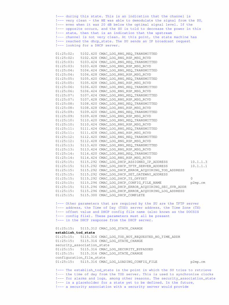
!−−− during this state. This is an indication that the channel is !−−− very clean − the HE was able to demodulate the signal from the SU, !−−− even when it was 20 dB below the optimal signal level. If the !−−− opposite occurs, and the SU is told to decrease the power in this!−−− state, then that is an indication that the upstream !−−− channel is not very clean. At this point, the state machine has!−−− reached the dhcp_state. The SU sends an IP broadcast request !−−− looking for a DHCP server.
!−−− Other parameters that are required by the SU are the TFTP server !−−− address, the Time of Day (TOD) server address, the Time Zone (TX)!−−− offset value and DHCP config file name (also known as the DOCSIS!−−− config file). These parameters must all be present!−−− in the DHCP response from the DHCP server.
!−−− The establish_tod_state is the point in which the SU tries to retrieve !−−− the time of day from the TOD server. This is used to synchronize clocks !−−− for alarms and logs, among other reasons. The security_association_state!−−− is a placeholder for a state yet to be defined. In the future, !−−− a security association with a security server would provide
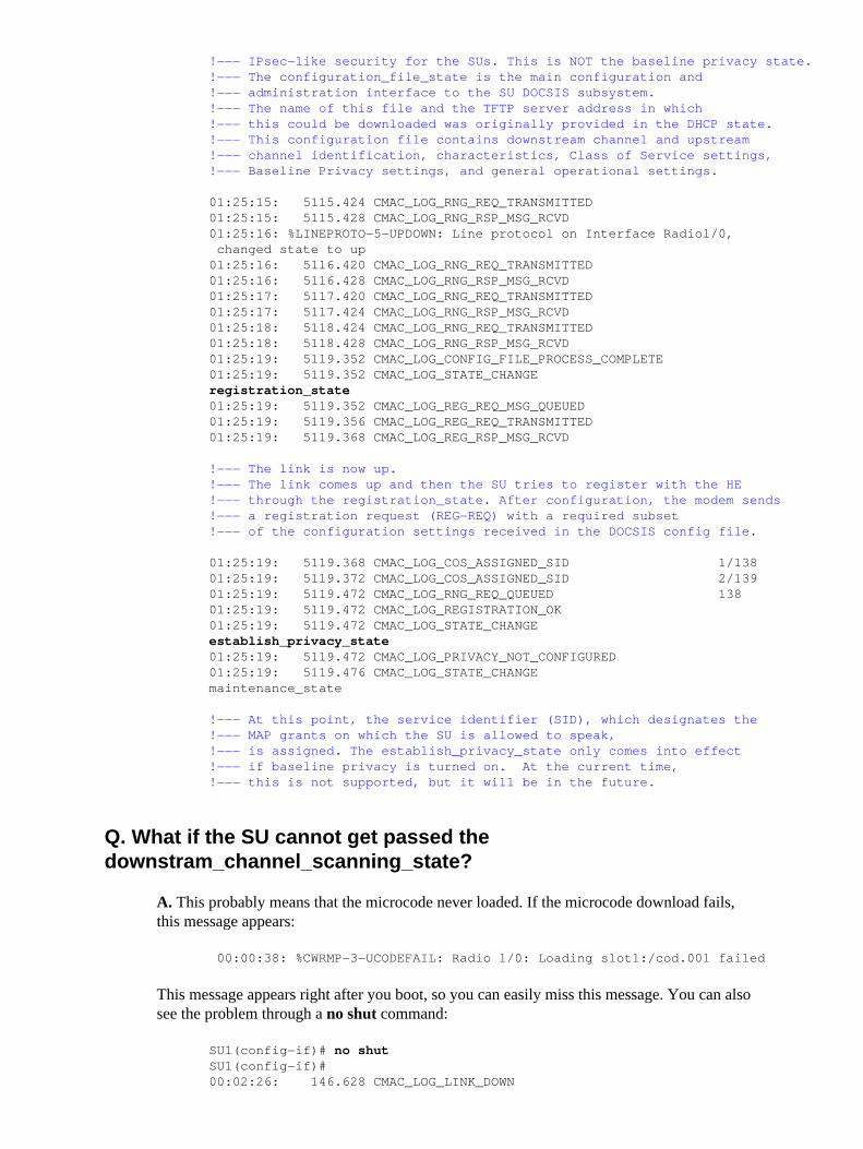
!−−− IPsec−like security for the SUs. This is NOT the baseline privacy state.!−−− The configuration_file_state is the main configuration and!−−− administration interface to the SU DOCSIS subsystem. !−−− The name of this file and the TFTP server address in which !−−− this could be downloaded was originally provided in the DHCP state.!−−− This configuration file contains downstream channel and upstream!−−− channel identification, characteristics, Class of Service settings,!−−− Baseline Privacy settings, and general operational settings.
!−−− The link is now up. !−−− The link comes up and then the SU tries to register with the HE!−−− through the registration_state. After configuration, the modem sends!−−− a registration request (REG−REQ) with a required subset !−−− of the configuration settings received in the DOCSIS config file.
!−−− At this point, the service identifier (SID), which designates the!−−− MAP grants on which the SU is allowed to speak,!−−− is assigned. The establish_privacy_state only comes into effect!−−− if baseline privacy is turned on. At the current time, !−−− this is not supported, but it will be in the future.
Q. What if the SU cannot get passed thedownstram_channel_scanning_state?
A. This probably means that the microcode never loaded. If the microcode download fails,this message appears:
00:00:38: %CWRMP−3−UCODEFAIL: Radio 1/0: Loading slot1:/cod.001 failed
This message appears right after you boot, so you can easily miss this message. You can alsosee the problem through a no shut command:
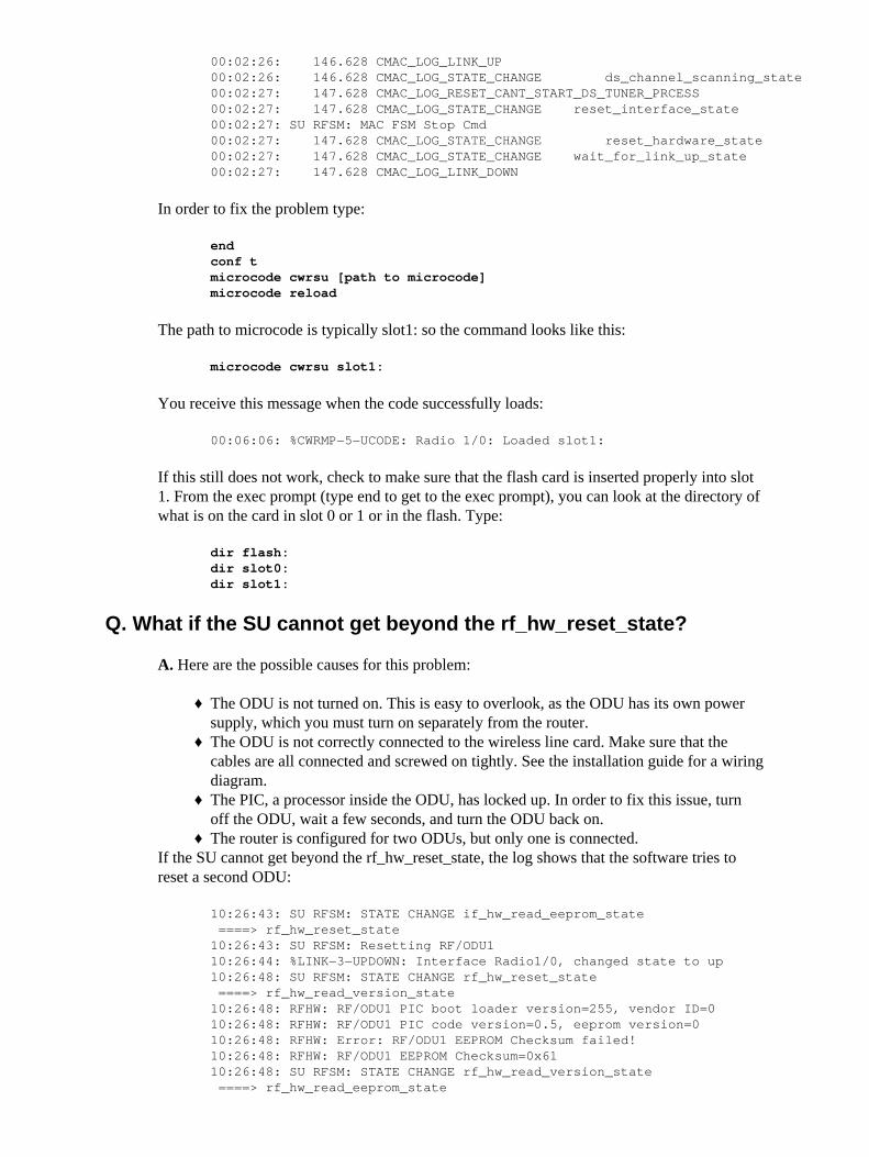
SU1(config−if)# no shutSU1(config−if)# 00:02:26: 146.628 CMAC_LOG_LINK_DOWN
end conf t microcode cwrsu [path to microcode] microcode reload
The path to microcode is typically slot1: so the command looks like this:
microcode cwrsu slot1:
You receive this message when the code successfully loads:
00:06:06: %CWRMP−5−UCODE: Radio 1/0: Loaded slot1:
If this still does not work, check to make sure that the flash card is inserted properly into slot1. From the exec prompt (type end to get to the exec prompt), you can look at the directory ofwhat is on the card in slot 0 or 1 or in the flash. Type:
dir flash: dir slot0: dir slot1:
Q. What if the SU cannot get beyond the rf_hw_reset_state?
A. Here are the possible causes for this problem:
The ODU is not turned on. This is easy to overlook, as the ODU has its own powersupply, which you must turn on separately from the router.
♦
The ODU is not correctly connected to the wireless line card. Make sure that thecables are all connected and screwed on tightly. See the installation guide for a wiringdiagram.
♦
The PIC, a processor inside the ODU, has locked up. In order to fix this issue, turnoff the ODU, wait a few seconds, and turn the ODU back on.
♦
The router is configured for two ODUs, but only one is connected.♦ If the SU cannot get beyond the rf_hw_reset_state, the log shows that the software tries toreset a second ODU:
10:26:43: SU RFSM: STATE CHANGE if_hw_read_eeprom_state ====> rf_hw_reset_state 10:26:43: SU RFSM: Resetting RF/ODU1 10:26:44: %LINK−3−UPDOWN: Interface Radio1/0, changed state to up 10:26:48: SU RFSM: STATE CHANGE rf_hw_reset_state ====> rf_hw_read_version_state 10:26:48: RFHW: RF/ODU1 PIC boot loader version=255, vendor ID=0 10:26:48: RFHW: RF/ODU1 PIC code version=0.5, eeprom version=0 10:26:48: RFHW: Error: RF/ODU1 EEPROM Checksum failed! 10:26:48: RFHW: RF/ODU1 EEPROM Checksum=0x61 10:26:48: SU RFSM: STATE CHANGE rf_hw_read_version_state ====> rf_hw_read_eeprom_state
10:26:48: SU RFSM: Reading RF HW EEPROM 10:26:48: SU RFSM: Loading RF/ODU1 HW EEPROM data... 10:26:52: SU RFSM: Re−using RF/ODU1 HW EEPROM cached data 10:26:52: SU RFSM: RF/ODU1 HW EEPROM load complete 10:26:52: SU RFSM: STATE CHANGE rf_hw_read_eeprom_state ====> rf_hw_reset_state 10:26:52: SU RFSM: Resetting RF/ODU2 10:27:00: SU RFSM: PIC RESP Timeout 10:27:00: SU RFSM: Error: PIC msg timeout during SU RFSM rf_hw_reset_state 10:27:00: %CWRMP−4−RF_IF_COMM: Radio1/0, IF−to−RF/ODU2 comm error (ODU Controller Reset cmd)10:27:00: SU RFSM: STATE CHANGE rf_hw_reset_state ====> standby_state
In order to fix this problem, either connect a second ODU, or configure the system to use onlyone. In order to configure for one ODU, type the radio receive−antennas 1 command fromthe radio interface prompt.
Q. What if the SU cannot get beyond the dsp_sync_state?
A. In this state, the DSP attempts to find a valid downstream signal, lock to the frequency ofthat signal, and begin demodulating the signal. If there is anything wrong with thedownstream signal that arrives, then the problem is likely to show up here. In order to helpyou troubleshoot, the DSP sends messages as it progresses through the synchronizationprocess. If everything works, then these messages are sent:
09:55:54: SU RFSM: STATE CHANGE dspinit_down_sync_state_config_state ====> dsp_sync_state09:55:54: SU RFSM: Received DSP SYNC IND (0) 09:55:54: SU RFSM: Received DSP SYNC IND (2) 09:55:54: SU RFSM: Received DSP SYNC IND (4) 09:55:54: SU RFSM: Received DSP SYNC IND (5) 09:55:54: SU RFSM: Received DSP SYNC IND (8) 09:55:54: SU RFSM: DSP SYNC PASSED
or
09:55:54: SU RFSM: STATE CHANGE dspinit_down_sync_state_config_state ====> dsp_sync_state 09:55:54: SU RFSM: Received DSP SYNC IND (0) 09:55:54: SU RFSM: Received DSP SYNC IND (2) 09:55:54: SU RFSM: Received DSP SYNC IND (4) 09:55:54: SU RFSM: Received DSP SYNC IND (5)09:55:54: SU RFSM: Received DSP SYNC IND (7)09:55:54: SU RFSM: Received DSP SYNC IND (4)09:55:54: SU RFSM: Received DSP SYNC IND (5)09:55:54: SU RFSM: Received DSP SYNC IND (8)09:55:54: SU RFSM: DSP SYNC PASSED
The possible DSP sync indicators are:
0 AGC_PASS�The DSP sees some power in the received signal.♦ 1 AGC_FAIL�The DSP does not see power in the received signal. This indicator ishard to get. Make sure the downstream frequency is set correctly.
♦
2 BURST_SIZE_PASS�The DSP assumes the presence of a valid downstreamsignal. If this is the last DSP indicator you receive, the DSP cannot lock to thefrequency of the downstream. Power cycle everything and try again. If that does notwork, replace the SU IF card.
♦
3 BURST_SIZE_FAIL�The DSP is unable to find a valid downstream signal. Thisproblem can occur due to either too weak or too strong a signal. Make sure the HE is
♦
turned on and transmits properly, the antenna points in the right direction, and thedownstream frequency is set correctly. Problems with any of these settings meansthere is no signal, or a very weak signal, to receive. The other possibility is that thereis too much signal. If this is the case, the amplifiers in the ODU can saturate. Use aspectrum analyzer and a splitter to look at the signal between the ODU and the linecard. The downstream signal must be between 423 and 429 MHz, and the signalpower must be between 64 and 15 dBm. If the signal looks too strong, check forsaturation. Consider an antenna with lower gain. Another possibility is that thecable−comp is set incorrectly.4 TIME_D_PASS�The DSP has synchronized to the timing of the received signal.♦ 5 COARSE_FREQ_PASS�This indicator always follows the indicator number 4. Itis essentially meaningless.
♦
6�This number is unused.♦ 7 OSC_ADJ_PASS�The DSP needed to make a large frequency adjustment. After alarge frequency adjustment, the DSP returns to the TIME_D state, so the onlymessage that can follow this one is indicator number 4. If you see this message manytimes, it is likely that the IF module is miscalibrated. Replace the IF card.
♦
8 DEMOD_TT_PASS�The DSP has found all the modulation parameters of thedownstream signal, and is ready to begin data demodulation.
♦
If you get into the dsp_sync_state, but do not see any of the indicator messages from the DSP,the microcode probably did not download correctly. Type these commands:
shut end configure terminal microcode reload
Q. What if the SU cannot get beyond the fec_sync_state?
A. This problem usually occurs due to a low SNR. The DSP can sync on a much lower SNRsignal than it can be demodulated. In order to fix this problem, you need to get a cleanersignal into the subscriber. Make sure that the cable−comp values are set correctly, and that allthe cables are connected tightly. Redirect the antenna.
Note: This state sometimes fails for no apparent reason. Before you look for the error, tryagain and see if it works the second time.
Q. What if the SU cannot get beyond the trc_sync_state?
A. This problem often indicates a problem with the HE, rather than with the subscriber.Power cycle the subscriber and try again, just to be sure. If you encounter the same problem,check whether any other subscribers are successfully connected to this HE card. If not, try ashut/no shut command on the HE. If that does not work, power cycle the HE. The problem isthat sometimes the HE appears to have no shut, but in fact the MAC chip never got started.Thus, there is a downstream signal being transmitted, but there is not data on the signal.
Q. What if the SU cannot get beyond the wait_ucd_state?
A. There are two possibilities here. The first is that the DOCSIS initial−ranging−offset is setincorrectly. This is present in the running configuration, which you can view from the execprompt with the show run command. In order to fix this issue, go into the interface promptand type docsis initial−ranging−offset 27000. The second possibility is the HE has aproblem. See the "What if the SU cannot get beyond the trc_sync_state?" question for moreinformation.
Q. What if the SU cannot get beyond the ranging_1_state?
A. The initial−ranging−offset can be set incorrectly. See the above question and answer. Theother possibility is that something is wrong with the upstream signal. Check that the upstreamfrequency is set correctly. Make sure that ALC is turned on. This is the default mode, but youcan also set the transmit gain manually, which disables ALC. In general, you must not disablethe ALC. In order to insure that ALC is turned on, type the no radio diag transmit−gaincommand from the interface prompt.
Q. What if the SU cannot get beyond the ranging_2_state?
A. This probably means that the HE sees either too much or too little power from the SU, orthat the signal from the subscriber is too poor to demodulate consistently. There are messagesthat tell you to what the transmit gain is being set. Here is a command, which means that theSU was told to reduce the gain by 3 dB [−3 db], and so the SU set the IF gain to −4 dB andthe RF gain to 0 dB:
10:54:26: SU RFSM: DSPMSG_TX_POWER_ADJ [−3 db], IF[−4 db], RF[00 db]
In order to see the legal range of transmit gain settings, type these commands from the execprompt:
show cont r1/0 rf
show cont r1/0 if
These commands show a lot of information about the IF and RF cards, and one of the fieldsthey display is the range of the Time Zone (TX) variable gain. If the subscriber only usesgains near the bottom of the range, probably the HE receives too much power. Switch to alower power ODU, align the antenna differently, or put an attenuator between the ODU andthe antenna.
On the other hand, if the SU is set to full gain and the HE continues to instruct the SU toincrease the power, this is an indication that the HE does not receive enough power. Check towhat value the RF receive power of the HE is set, and check the alignment of the antenna. Ahigher gain antenna can help. Alternatively, move the antenna around, or mount it higher.
Q. What if the SU gets to the dhcp_state but never gets an IP address?
A. If you see the dhcp_state message and never see an IP address get assigned to the SU, thisgenerally points to incorrect configuration of the DHCP server, or the lack of an IP path to theDHCP server. Verify the configuration of the DHCP server and if you run an external DHCPserver, verify that the correct radio helper−address command is configured under the radiointerface through the show running command.
Q. What if the SU gets to dhcp_state, receives an IP address but fails onother parameters?
A. Other parameters that the SU requires are the TFTP server address, the Time of Day(TOD) server address, the Time Zone (TX) offset value, and the DHCP config file name (alsocalled the DOCSIS config file). These parameters must all be present in the DHCP responsefrom the DHCP server.
Note: You can configure the HE to play the part of the DHCP/TFTP server. If the HE is notconfigured to be the DHCP/TFTP server, make sure that there is a radio helper−addresscommand configured under the HE radio interface. This ensures that DHCP broadcasts areforwarded to the correct server. If you use an external DHCP/TFTP server, the server mustalso contain a route or default gateway that instructs how to send packets back to the SUnetwork.
These error messages point to the absence of optional parameters in the DHCP response:
Configure the secondary server and log server address on the DHCP server to eliminate theseerrors.
Q. What if the SU gets to the establish_tod_state but never gets toTOD_REPLY_RECEIVED?
A. A common reason for failure at this state is that a TOD server is not present eitherexternally or on the HE. You can configure the HE to act as the TOD server. Issue the radiotime−server command from the global configuration mode. Once again, to use an externalTOD server, a route must be present for the TOD server to send the response back to the SU.
Q. What if the SU fails on the configuration_file_state?
A. The configuration_file_state is the main configuration and administration interface to theSU DOCSIS subsystem. The name of this file and the TFTP server address in which this canbe downloaded were originally provided in the DHCP state. This configuration file contains:
Downstream channel and upstream channel identification♦ Characteristics♦ Class of Service settings♦ Baseline Privacy settings♦ General operational settings♦
Common reasons for failure at this state are missing files, wrong file permissions, anunreachable TFTP server, files in the wrong format, files with missing required options,incorrectly configured required options, or incorrect options (unknown or invalidType−Length−Values (TLVs)).
Q. What if the SU fails at the registration_state?
A. Problems with the registration state almost always point to a configuration file error. Makesure the SU and the HE both support the settings in the configuration file. Make sure the HEallows the creation of class of service profiles or use a profile that the HE creates. Check theauthentication strings in the HE radio interface configuration and in the DOCSISconfiguration file.
Q. What if the SU fails at the establish_privacy_state?
A. This situation probably means that the HE or the SU tries to establish Baseline Privacy(BPI) and the other one is not. Verify whether the DOCSIS config file has BPI turned on. Onthe HE, verify whether the QoS profile also shows BPI turned on. Use the show radio qosprofile command. Also, make sure both the HE and SU use K images.
Q. What if the SU gets to the maintenance_state, but does not ping?
A. Check that the SU radio line card has a valid IP address. If you have to try a few times toget beyond the ranging_2_state, this is a sign that something else is wrong. This means thatsomehow the SNR is too low. If the unicast retry counter in the SU is set to non−zero, this isan indication of low SNR. In order to see the SNR value, use the show controller r1/0 maccommand.
Related Information
Cisco Aironet Wireless LAN Client Adapters• Multipoint Wireless Support for the Cisco uBR7200 Series Universal Broadband Router• Technical Support & Documentation − Cisco Systems•