CISSP Common Body of Knowledge Review by Alfred Ouyang is licensed under the Creative Commons Attribution-NonCommercial-ShareAlike 3.0 Unported License. To view a copy of this license, visit http://creativecommons.org/licenses/by-nc-sa/3.0/ or send a letter to Creative Commons, 444 Castro Street, Suite 900, Mountain View, California, 94041, USA. CISSP ® Common Body of Knowledge Review: Telecommunications & Network Security Domain – Part 1 Version: 5.9.2
Transcript
CISSP Common Body of Knowledge Review by Alfred Ouyang is licensed under the Creative Commons Attribution-NonCommercial-ShareAlike 3.0 Unported License. To view a copy of this license, visit http://creativecommons.org/licenses/by-nc-sa/3.0/ or send a letter to Creative Commons, 444 Castro Street, Suite 900, Mountain View, California, 94041, USA.
CISSP® Common Body of Knowledge Review:
Telecommunications & Network Security Domain –
Part 1
Version: 5.9.2
Learning Objectives Telecommunications & Network Security Domain – Part 1
“The Telecommunications and Network Security domain encompasses the structures, techniques, transport protocols, and security measures used to provide integrity, availability, confidentiality, and authentication for transmissions over private and public communication networks.” “The candidate is expected to demonstrate an understanding of communications and network security as it relates to data communications in local area and wide area networks, remote access, internet/intranet/extranet configurations. Candidates should be knowledgeable with network equipment such as switches, bridges, and routers, as well as networking protocols (e.g., TCP/IP, IPSec,) and VPNs.”
- 2 - Reference: CISSP CIB, January 2012 (Rev. 5)
- 3 -
Topics
Telecommunications & Network Security Domain – Part 1
• Security Principles & Internet Protocol (IP) Architecture
• Terms & Definitions – Types of Data Network Structure – Methods & Modes of Data Network Communications – Types of Data Networks – Types of Data Networks Topology
• OSI Reference Model and TCP/IP Model – Physical Layer (Layer 1) – Data-Link Layer (Layer 2) – Network Layer (Layer 3) – Transport Layer (Layer 4) – Session Layer (Layer 5) – Presentation Layer (Layer 6) – Application Layer (Layer 7)
- 4 -
Learning Objectives Telecommunications & Network Security Domain – Part 2
“The candidate is expected to demonstrate an understanding of communications and network security as relates to data communications in local area and wide area networks; remote access; Internet/intranet/extranet configurations, use of firewalls, network equipment and protocols (such as TCP/IP), VPNs, and techniques for preventing and detecting network based attacks.”
Reference: CISSP CIB, January 2012 (Rev. 2)
- 5 -
Topics
Telecommunications & Network Security Domain – Part 2
– Physical Layer – Data-Link Layer – IP Network Layer – Transport Layer – Application Layer
- 6 -
Information Security Concepts
Security Objectives • Confidentiality
– “Preserving authorized restriction on information access and disclosure, including means for protecting personal privacy and proprietary information.” (44 USC Sec. 3542)
• Network access control & data transport encryption, and network security protocols.
• Integrity
– “Guarding against improper information modification or destruction, and includes ensuring information non-repudiation and authenticity.” (44 USC Sec. 3542)
• Firewall, IDS, IPS Services, and network security management.
• Availability – “Ensuring timely and reliable access and use of information.”
(44 USC Sec. 3542) • Fault tolerant network & services, and reliable network
– Users should only have access to information (or systems) that enable them to perform their assigned job functions.
• Least privilege – Users should only have sufficient
access privilege that allow them to perform their assigned work.
• Separation of duties – No person should be responsible for
completing a task involving sensitive, valuable or critical information from the beginning to end.
– No single person should be responsible for approving his/her own work.
Benchmarks and Guidelines:• NIST National Checklist, DISA STIGs, CIS
Benchmarks, etc.
Law, Regulations, and Policies:• FISMA, SOX, GBL, National Security Act,
USA PATRIOT ACT, etc.• OMB A-130, A-11, etc.
• E.O. 13292, 12968, etc.• DoD 5200.1-R, etc.
Standards and Best Practices• NIST FIPS, SP 800-x, etc.
• COBIT, ITIL, Common Criteria• ISO/IEC 27001, 21827, etc.
• DoDI 8500.2, 8510.01
Security Objectives:• Confidentiality
• Integrity• Availability
Security Implementation Principles:
• Confidentiality, Integrity, Availability
• Need-to-Know• Least Privilege
• Separation of Duties
- 8 -
OSI Reference Model & TCP/IP Protocol Architecture
People
Do
Not
Throw
Sausage
Pizza
Away
Memorization
DEFENSE-IN-DEPTH
Tech
nica
l Cou
nter
mea
sure
sSe
curit
y m
echa
nism
,Sy
stem
Arc
hite
ctur
e,
Secu
rity
Ope
ratio
nsSe
curit
y C
ON
OPs
,Se
curit
y O
pera
tions
Pr
oces
s &
Pro
cedu
re
Phys
ical
Sec
.Fa
cilit
y Se
curit
y,
Prot
ectio
n of
Crit
ical
Infr
astr
uctu
re
Defense Information Infrastructure (DII) & Security Mechanisms
Routers + KGs
Firewall + Network-based IDS + Switchs
Domain Controller + Active Directory
Service + DIICOE APM (+ Directory Services + X.509-based PKI/KMI/
CA)
OS +Host-based IDS +
Secure Messaging + Trusted RDBMS
Information Assurance Technical Framework
(IATF)
Defending the Network & Infrastructure
Defending the Enclave
Supporting the Infrastructure
Defending the Computing
Environment
Cer
tific
atio
n an
d A
ccre
dita
tion
Internet Protocol Suite
ARP, RARP
IP
UDP
RPC
TCP
FTP, Telnet, SMTP,HTTP,
SNMP… etc.
XDR
NFS
Routing Protocols ICMP
Physical
Data-Link
Network
Transport
Session
Presentation
Application
OSI Reference Model
Network Access Layer
Internet Layer
Host-to-Host Transport
Layer
Application Layer
TCP/IP ProtocolArchitecture
- 9 -
Topics
Telecommunications & Network Security Domain – Part 1
• Security Principles & Internet Protocol (IP) Architecture
• Terms & Definitions – Types of Data Network Structure – Methods & Modes of Data Network Communications – Types of Data Networks – Types of Data Networks Topology
• OSI Reference Model and TCP/IP Model – Physical Layer (Layer 1) – Data-Link Layer (Layer 2) – Network Layer (Layer 3) – Transport Layer (Layer 4) – Session Layer (Layer 5) – Presentation Layer (Layer 6) – Application Layer (Layer 7)
- 10 -
Terms & Definitions
Types of Data Network Structures • Local Area Network (LAN). Primarily limited to a small
geographical area or a single site (i.e. an office building). • Personal Area Network (PAN). Data communications network
for short distance (e.g. Bluetooth, Infra-Red). • Wide Area Network (WAN). Data communications network to
multiple long range geographic area. • Metropolitan Area Network (MAN). Data communications
network for a large city (e.g. Washington Metropolitan, New York City, or Boston, etc.)
• Campus Area Network. Data communications network for a campus of buildings (e.g. college campus, military base)
• Internet. Worldwide system of interconnected networks. • Intranet. A type of network that services internal clients (/users)
over diverse range of telecommunication networks. • Extranet. A type of network that services to external clients
(/customers) over diverse range of telecommunication networks.
- 11 -
Terms & Definitions
Methods & Modes of Data Network Communications
• Methods of Data Network Communications – Analog Communications. A method of internetworking
utilizing analog signal through combination of signal amplitude, frequency, and phase. (e.g. voice, fax, modem, analog radio, etc.)
– Digital Communications. A method of internetworking utilizing digital signal through binary of 1/0s.
• Modes of Data Network Communications – Synchronous Communications. A mode of communication
relying on a set of synchronized clocking systems to determine sender and receiver communication signals.
– Asynchronous Communications. A mode of communication controlled by a set of start & stop bits at each end of data signals (headers & footers) to discreet pieces of data. (i.e. encapsulation)
Source: Official (ISC)2® Guide to the CISSP® Exam
- 12 -
Terms & Definitions
Types of Data Network
• Circuit-switched network. Data is send through a dedicated circuit between two endpoints. (e.g. public switched telephone network (PSTN))
• Packet-switched network. Data is segmented into packets and sent across a circuit shared by multiple subscribers. – Virtual circuit. Data is send through a logical circuit created
over a packet-switched network. • Switched virtual circuit (SVC). • Permanent virtual circuit (PVC).
- 13 -
Terms & Definitions
Types of Data Networks Topology
There are five types of physical network topologies: • Bus Topology • Tree Topology • Star Topology • Ring Topology • Mesh Topology
- 14 -
Terms & Definitions
Types of Data Networks Topology – Bus Topology
• Bus Topology – Each device handles its own communications control. A bus is low cost and widely used in the start of PC era. (e.g. Thick-, Thin-Ethernet, and AppleTalk)
` ` ` `
Data Packet
- 15 -
Terms & Definitions
Types of Data Networks Topology – Tree Topology
• Tree Topology – Is a generalized bus topology. Tree root is the head-end. Cable starts at the head-end, each of which can have many branches. Branches may have additional branches which can form a complex structure.
`
`
`
`
FWRTR
Switch
Switch
- 16 -
Terms & Definitions
Types of Data Networks Topology – Star Topology
• Star Topology – Nodes are connected to a single host. All communications pass through this host which is usually a large mainframe or a network hub.
`
``
`
Hub
`
`
- 17 -
Terms & Definitions
Types of Data Networks Topology – Ring Topology
• Ring Topology – A ring topology has all the network nodes connected by a unidirectional transmission link to form a closed loop. FDDI and Token Ring use this topology.
`
``
`
`
`
- 18 -
Terms & Definitions
Types of Data Networks Topology – Mesh Topology
• Mesh Topology – A mesh topology has all the network nodes connected to each other. Network can be full mesh or partial mesh.
• Number of connections for a full mesh network = n (n-1) / 2.
MUX
MUXMUX
MUX MUX
Reference: Metcalfe’s law (http://en.wikipedia.org/wiki/Metcalfe%27s_law)
Questions:
• Name the type of network is used primarily for short distance data communication? –
• Name the type of network is used primarily for data
communications at an office building? –
• Name the type of network is used for data
communications between multiple long range geographic area? –
- 19 -
Answers:
• Name the type of network is used primarily for short distance data communication? – Personal Area Network (PAN)
• Name the type of network is used primarily for data
communications at an office building? – Local Area Network (LAN)
• Name the type of network is used for data
communications between multiple long range geographic area? – Wide Area Network (WAN)
- 20 -
Questions:
• A type of network that services to internal clients (/users) over diverse range of networks & services? –
• A type of network that services to external clients
(/customers) over diverse range of networks & services? –
• What type of network topology has all the network
nodes connected to each other? –
- 21 -
Answers:
• A type of network that services to internal clients (/users) over diverse range of networks & services? – Intranet
• A type of network that services to external clients
(/customers) over diverse range of networks & services? – Extranet
• What type of network topology has all the network
nodes connected to each other? – Meshed Topology
- 22 -
Questions:
• What are the five types of physical network topologies? – – – – –
• What are two methods of data network communications? – –
• What are two modes of data network communications? – –
- 23 -
Answers:
• What are the five types of physical network topologies? – Bus Topology – Tree Topology – Star Topology – Ring Topology – Mesh Topology
• What are two methods of data network communications? – Analog – Digital
• What are two modes of data network communications? – Synchronous – Asynchronous
- 24 -
- 25 -
Topics
Telecommunications & Network Security Domain – Part 1
• Security Principles & Internet Protocol (IP) Architecture
• Terms & Definitions – Types of Data Network Structure – Methods & Modes of Data Network Communications – Types of Data Networks – Types of Data Networks Topology
• OSI Reference Model and TCP/IP Model – Physical Layer (Layer 1) – Data-Link Layer (Layer 2) – Network Layer (Layer 3) – Transport Layer (Layer 4) – Session Layer (Layer 5) – Presentation Layer (Layer 6) – Application Layer (Layer 7)
- 26 -
OSI Reference Model & TCP/IP Protocol Architecture
People
Do
Not
Throw
Sausage
Pizza
Away
Memorization
DEFENSE-IN-DEPTH
Tech
nica
l Cou
nter
mea
sure
sSe
curit
y m
echa
nism
,Sy
stem
Arc
hite
ctur
e,
Secu
rity
Ope
ratio
nsSe
curit
y C
ON
OPs
,Se
curit
y O
pera
tions
Pr
oces
s &
Pro
cedu
re
Phys
ical
Sec
.Fa
cilit
y Se
curit
y,
Prot
ectio
n of
Crit
ical
Infr
astr
uctu
re
Defense Information Infrastructure (DII) & Security Mechanisms
Routers + KGs
Firewall + Network-based IDS + Switchs
Domain Controller + Active Directory
Service + DIICOE APM (+ Directory Services + X.509-based PKI/KMI/
CA)
OS +Host-based IDS +
Secure Messaging + Trusted RDBMS
Information Assurance Technical Framework
(IATF)
Defending the Network & Infrastructure
Defending the Enclave
Supporting the Infrastructure
Defending the Computing
Environment
Cer
tific
atio
n an
d A
ccre
dita
tion
Internet Protocol Suite
ARP, RARP
IP
UDP
RPC
TCP
FTP, Telnet, SMTP,HTTP,
SNMP… etc.
XDR
NFS
Routing Protocols ICMP
Physical
Data-Link
Network
Transport
Session
Presentation
Application
OSI Reference Model
Network Access Layer
Internet Layer
Host-to-Host Transport
Layer
Application Layer
TCP/IP ProtocolArchitecture
- 27 -
OSI Reference Model
Physical Layer (Layer 1)
• Physical layer concerns the physical interface between devices and the rules by which bits are passed between devices. – Mechanical, Electrical, Functional, Procedural – Physical layer has two responsibilities sending and
• Twisted Pair – Inexpensive and very easy to install – Consists of two copper wires twisted together which reduces
electrical interference. Can be shielded or unshielded. – Shielded is more expensive but has less crosstalk and more
resistant to EMI. – Can be used for analog or digital transmissions. – Can be used up to 100 Mbps
• Six levels: – Category 1: Analog and digital voice – Category 2: ISDN and medium-speed data up to 4 Mbps – Category 3: High-speed data and LAN traffic up to 10 Mbps – Category 4: LAN traffic up to 16 Mbps – Category 5: 100-Mbps UTP LAN technologies – Category 5e: Enhanced performance spec. for CAT5 – Category 6: Gigabit Ethernet (1000-Mbps) and 10-Gigabit
Ethernet
Physical
Data-Link
Network
Transport
Session
Presentation
Application
OSI Reference Model
- 29 -
Physical Layer (Layer 1)
Network Cabling • Coaxial Cable
– Provides a good combination of high bandwidth and excellent noise immunity but is more expensive.
– Two transmission methods are Baseband and Broadband.
• Baseband carries only a single channel. • Broadband carries multiple channels, i.e. video,
RF Network – Microwave • Microwaves are electromagnetic waves:
– Frequencies: 300MHz – 300GHz • Includes: ultra high frequency (UHF), super high frequency (SHF),
and extremely high frequency (EHF). – Wave lengths: 1 mm to 1 meter
• Usually used for: – Wide area communications: Satcom, TV broadcasts, etc. – Metropolitan area communications: IEEE 802.16 (WiMAX),
cellular communications – Local area communications: IEEE 802.11 a/b/g, etc. – Personal area communications: Bluetooth
• Line of sight (LOS) communication technology – Signal relay over long distance: land, sea, space. – Operating constrains: Ice, snow, heavy rain, and dust storm,
solar flare, strong electro-magnetic interference (EMI), high altitude electro-magnetic pulse (HEMP), etc.
- 32 -
- 33 -
Physical Layer (Layer 1) +
RF Network – Spread Spectrum
• Spread-spectrum is a communication method that spreads (or distributes) one or more discrete frequencies in time or frequency domains
• Two types of multiplex methods: – Circuit – Constant bandwidth – Statistical – Variable bandwidth
• Two popular methods: – Direct-sequence spread spectrum (DSSS)
variation of CDMA) – 802.11g uses OFDM, so it’s just as fast as 802.11a
Reference: http://en.wikipedia.org/wiki/Wi-Fi
Physical Layer (Layer 1) +
RF Network – Bluetooth • Bluetooth is a RF network communications protocol
design primarily for low power consumption – Operates in the open 2.4GHz band – Uses frequency-hopping spread spectrum (FHSS) – Bluetooth operating range are based on three power classes:
– Data rate varies: • Bluetooth 1.2: 1Mbit/sec. • Bluetooth 2.0 + EDR: 3 Mbit/sec.
– Usually used for personal area network (PAN) devices: • Hands-free headset for cell phones, mouse, keyboard, and printers • Game consoles: Nintendo Wii, Sony PlayStation 3
- 36 -
Class Maximum Power mW (dBm) Range (approximate) Class 1 100 mW (20 dBm) ~ 100 meters Class 2 2.5 mW (4 dBm) ~ 10 meters Class 3 1 mW (0 dBm) ~ 1 meter
Reference: http://en.wikipedia.org/wiki/Bluetooth
Questions:
• What are the two transmission methods for coaxial cable? – –
• What are the two modes of transmission for fiber
optic cable? – –
• What are the two popular methods for spread
spectrum radio frequency communications? – –
- 37 -
Questions:
• What are the two transmission methods for coaxial cable? – Baseband (single channel) – Broadband (multiple channels)
• What are the two modes of transmission for fiber
spectrum radio frequency communications? – Direct-sequence spread spectrum (DSSS) – Frequency-hopping spread spectrum (FHSS)
- 38 -
- 39 -
Topics
Telecommunications & Network Security Domain – Part 1
• Security Principles & Internet Protocol (IP) Architecture
• Terms & Definitions – Types of Data Network Structure – Methods & Modes of Data Network Communications – Types of Data Networks – Types of Data Networks Topology
• OSI Reference Model and TCP/IP Model – Physical Layer (Layer 1) – Data-Link Layer (Layer 2) – Network Layer (Layer 3) – Transport Layer (Layer 4) – Session Layer (Layer 5) – Presentation Layer (Layer 6) – Application Layer (Layer 7)
- 40 -
OSI Reference Model
Data-Link Layer (Layer 2)
• Data-link layer defines the protocol that computers must follow in order to access the network for transmitting and receiving messages. – Protocols that control LAN transmission are:
• MAC (Media Access Control) • LLC (Logical Link Control)
– Popular protocols that control WAN transmissions are: • X.25 • Frame Relay • ISDN (Integrated Services Digital Network) • SDLC (Synchronous Data Link Control) • HDLC (High-level Data Link Control) • ATM (Asynchronous Transfer Mode) • HSSI (High Speed Serial Interface)
Physical
Data-Link
Network
Transport
Session
Presentation
Application
OSI Reference Model
- 41 -
Data-Link Layer (Layer 2)
Media Access Control (MAC)
• Data-Link layer addressing or a physical hardware address (MAC) is an unique address that is burned into each NIC card by the manufacturer – The hardware address is a 48-bit address expressed as
6 bytes. The first 3 bytes are the vendor code and the second 3 bytes are the serial numbers made up by the manufacturer
– MAC sub-layer is responsible for media access. It controls how the workstations communicate over the network.
– There are generally three types of media access. • Carrier Sense Multiple Access (CSMA) • Token Passing • Polling
Physical
Data-Link
Network
Transport
Session
Presentation
Application
OSI Reference Model
24 Bits (3 Bytes)Vendor Code
Example: 00-0F-1F
24 Bits (3 Bytes)Serial Number
Example: C1-21-B8
MAC Address of a NIC: 00-0F-1F-C1-21-B8
- 42 -
Data-Link Layer (Layer 2)
Logical Link Control (LLC)
• The Logical Link Control (LLC) runs between the Network Layer (Layer 3) and MAC sub-layer
• Enables the network layer and physical layers to act independently. Network layer uses IP addresses and physical layer uses MAC addresses
Physical
Data-Link
Network
Transport
Session
Presentation
Application
OSI Reference Model
- 43 -
Data-Link Layer (Layer 2)
Media Access Methods
Three types of media access methods are used by packets to access the physical network medium: • Carrier Sense Multiple Access (CSMA)
– Carrier Sense: When an internetworking device connected to a network. It first checks to make sure the network interface has a carrier on which to send its data
– Multiple Access: All internetworking devices on the network are free to use the network whenever they like so long as no one else is transmitting
– With Collision Avoidance (CSMA/CA) – With Collision Detection (CSMA/CD)
• Polling • Token Passing
Physical
Data-Link
Network
Transport
Session
Presentation
Application
OSI Reference Model
- 44 -
Data-Link Layer (Layer 2)
CSMA/CD
• Carrier Sense Multiple Access with Collision Detection (CSMA/CD). – Requires that all devices on the LAN listen before they
transmit. This contention method is often known as Ethernet
– If two devices transmit at the same time, a collision occurs
– After the collision, devices on the LAN will wait a random amount of time before retransmitting data
Physical
Data-Link
Network
Transport
Session
Presentation
Application
OSI Reference Model
- 45 -
Data-Link Layer (Layer 2)
CSMA/CA
• Carrier Sense Multiple Access with Collision Avoidance (CSMA/CA) – CSMA/CA is a network contention protocol that listens to
a network in order to avoid collisions – Contributes to network traffic because, before any real
data is transmitted, it has to broadcast a signal onto the network in order to listen for collision scenarios and to tell other devices not to broadcast
– Example of CSMA/CA is IEEE 802.11b RF Network
Physical
Data-Link
Network
Transport
Session
Presentation
Application
OSI Reference Model
- 46 -
Data-Link Layer (Layer 2)
Polling & Token Passing
• Polling – Primary station checks a secondary station regularly at
predetermined times to see if it has data to transmit. – Secondary stations are not permitted to transmit until
given permission from the primary – Used in large mainframe environments – Polling is very inexpensive.
unless they receive a special frame called a token. – If the node does not have anything to transmit, it passes
the token to the next station. – Token Ring and IEEE 802.5 are examples of token
passing networks – Deterministic, transmission delay predictable, and robust
Physical
Data-Link
Network
Transport
Session
Presentation
Application
OSI Reference Model
- 47 -
Data-Link Layer (Layer 2)
Wide Area Network (WAN)
• Circuit Switching – Circuit-switching is a type of network switching in
which a physical path is obtained for and dedicated to a single connection between two end-points in the network for the duration of the connection
– Ordinary voice phone service is circuit-switched. – The telephone company reserves a specific physical
path to the number you are calling for the duration of your call. During that time, no one else can use the physical lines involved
– Example: ISDN (Integrated Services Digital Network)
Physical
Data-Link
Network
Transport
Session
Presentation
Application
OSI Reference Model
- 48 -
Data-Link Layer (Layer 2)
Wide Area Network (WAN)
• Packet Switching – Packet-switching describes the type of network in
which relatively small units of data called packets are routed through a network based on the destination address contained within each packet
– Breaking communication down into packets allows the same data path to be shared among many users in the network.
– Example: X.25, Frame Relay
Physical
Data-Link
Network
Transport
Session
Presentation
Application
OSI Reference Model
- 49 -
Data-Link Layer (Layer 2)
Wide Area Network (WAN)
• Virtual Circuit – A virtual circuit is a circuit or path between points in a
network that appears to be a discrete, physical path but is actually a managed pool of circuit resources from which specific circuits are allocated as needed to meet traffic requirements
– Permanent virtual circuit (PVC) – A PVC is a virtual circuit that is permanently available to the user just as though it were a dedicated or leased line continuously reserved for that user
– Switched Virtual Circuit. (SVC) – A SVC is a virtual circuit in which a connection can be dynamically established.
Physical
Data-Link
Network
Transport
Session
Presentation
Application
OSI Reference Model
- 50 -
Data-Link Layer (Layer 2)
WAN Protocols • X.25
– X.25 is a protocol standard that defines how WAN connections between user devices and network devices are established, maintained, and effectively operate
– X.25 devices include DTEs, DCEs, and PSTNs. X.25 connections contain both SVCs and PVCs within the physical circuit
• Frame Relay
– Frame relay is an upgrade from X.25 and a high-performance WAN protocol that operates at the physical and data link layers of the OSI reference model
– Frame relay achieves high throughput with low delay by eliminating the overhead of error detection and correction Physical
Data-Link
Network
Transport
Session
Presentation
Application
OSI Reference Model
- 51 -
Data-Link Layer (Layer 2)
WAN Protocols
• ISDN (Integrated Services Digital Network) is a world-wide standard for transmitting voice, video, data, or packets over the PSTN (public switched telephone network) – Carriers offers 2 types of services:
• BRI (Basic Rate Interface) – 2 x 64kbps B channels for user data – 1 x 16kbps D channel for control & mgmt. signals – 144 kbps
• PRI (Primary Rate Interface) – 23 x 64kbps B channels for user data – 1 x 64k bps D channel for control & mgmt. signals – 1.54 Mbps
– B Channel = Bearer Channel (for user data) – D Channel = Data Channel (for control & mgmt signals)
Physical
Data-Link
Network
Transport
Session
Presentation
Application
OSI Reference Model
- 52 -
Data-Link Layer (Layer 2)
WAN Protocols
• Asynchronous Transfer Mode (ATM) – ATM is a dedicated-connection switching technology
that organizes digital data into 53-byte cell units and transmits them over a physical medium using digital signal technology. Requires a high speed medium like fiber optics
– Carriers offer 4 types of services: • CBR (Constant Bit Rate) • VBR (Variable Bit Rate) • UBR (Unspecified Bit Rate) • ABR (Available Bit Rate)
Physical
Data-Link
Network
Transport
Session
Presentation
Application
OSI Reference Model
- 53 -
Data-Link Layer (Layer 2)
WAN Protocols
• Synchronous Data Link Control (SDLC). – IBM developed the Synchronous Data Link Control
(SDLC) protocol in the mid-1970’s for use in Systems Network Architecture (SNA) environments. SDLC was the first link layer protocol based on synchronous, bit-oriented operation
• HDLC. – High-level Data Link Control (HDLC) was derived
from SDLC. – HDLC specifies the data encapsulation method on
synchronous serial links using frame characters and checksums.
• HSSI. – High Speed Serial Interface (HSSI) is a DTE/DCE
interface that was developed by Cisco Systems. – Physical layer of the standard is defined by EIA-613
and EIA-612.
Physical
Data-Link
Network
Transport
Session
Presentation
Application
OSI Reference Model
- 54 -
Data-Link Layer (Layer 2)
Wireless Protocols
• WAP (Wireless Application Protocol) – For internetworking between IP and Cellular service. – WAP is a protocol suite from Data-Link to Application
layers.
• Cellular – TDMA (Time Division Multiple Access). Supports data
transmission – CDMA (Code Division Multiple Access). Supports data
transmission – GSM (Global System for Mobile communications).
Supports data transmission using GPRS (General Packet Radio Services)
• IEEE 802.11 a/b/g – Beacon frame announce its presence and provide
Service Set Identification (SSID).
Physical
Data-Link
Network
Transport
Session
Presentation
Application
OSI Reference Model
- 55 -
Common Digital Network Services • T Carrier Signals
– T-1: 24 x voice or data channels – T-3: 672 voice or data channels – Typically used in large organizations to ISP
• ISDN (Integrated Services Digital Network) – BRI (Basic Rate Interface) – PRI (Primary Rate Interface)
• DSL (Digital Subscriber Line) – Unlike ISDN, DSL is an “always on” digital service – ADSL (Asymmetric DSL): uplink speed ≠ downlink speed – SDSL (Symmetric DSL): uplink speed = downlink speed
• Frame Relay – A packet switched-based shared WAN service. Originally
designed for ISDN, now it is also used in T-1, T-3 circuit switched network services
• ATM (Asynchronous Transfer Mode) – Cell Relay service (based on 53-Bytecells) – multiplex voice, video and data
• SONET (Synchronous Optical Network) – Up to 129k channels on a single fiber cable
Physical
Data-Link
Network
Transport
Session
Presentation
Application
OSI Reference Model
- 56 -
T Carrier Signal Levels vs. Digital Signal Levels • Digital Signal (DS) Levels
(e.g. DS-1, DS-3) defines the electrical characteristics of T-1 signal
• T Carrier Signals Levels (e.g. T1, T3), in U.S. uses Time Division Multiplexing (TDM) defining the speed and number of voice and data channels
Level U.S. / N. America Europe
DS-1 T1 24 Circuits 1.544 Mbps
E1 30 Circuits 2.048 Mbps
DS-2 Not used in U.S. E2 120 Circuits 34.368 Mbps
DS-3 T3 672 Circuits 44.7 Mbps
E3 480 Circuits 34.368 Mbps
DS-4 Not used in U.S. E4 1920 Circuits 139.3 Mbps
- 57 -
Optical Carrier Levels
Optical Carrier (OC) Level Megabits # of 64kbps
Channels SONET
Channels SDH Channels
(European)
OC-1 52Mbps 672 28 x DS-1 / 1 x DS-3
STM-0
OC-3 155Mbps 2,016 84 x DS-1 / 3 x DS-3
STM-1
OC-9 466Mbps 6,048 N/A N/A
OC-12 622Mbps 8,064 336 x DS-1 / 12 x DS-3
STM-4
OC-18 933Mbps 12,096 N/A N/A
OC-24 1,244Mbps 16,128 N/A N/A
OC-36 1,866Mbps 24,192 N/A N/A
OC-48 2,488Mbps 32,256 1344 x DS-1 /
48 x DS-3 STM-16
OC-96 4,976Mbps = 4.9Gbps 64,512 N/A N/A
OC-192 10,000Mbps = 10Gbps 129,024
5376 x DS-1 / 192 DS-3
STM-64
- 58 -
Network Layer (Layer 2)
WAN Devices • Modem
– A device that interprets digital and analog signals, enabling data to be transmitted over voice-grade telephone lines
• Channel Service Unit/Digital Service Unit (CSU/DSU) – A digital-interface device used to connect a router to
a digital circuit like a T1. The CSU/DSU also provides signal timing for these two devices
• Multiplexer (MUX) – MUX allows more than one signal to be sent out
simultaneously over a physical circuit • WAN Switch
– An internetworking device used in carrier networks. This device typically operates at the data-link layer
• Access Server – A concentration point for dial-in and dial-out
connections.
- 59 -
Network Layer (Layer 3)
WAN Devices
• Gateway – Allow different types of network to communicate – Three main types of gateways are: address, protocol, and
application – Example: Gateway between RF and IP, Infrared and IP, etc.
• Multi-Service Switch – Layer 2/3 Devices that provide interoperability between data-link
• Routers – Devices that operate at the network layer of the OSI model – A LAN or WAN devices determines the best path to send network
traffic based on costs and other network information – A router also has to share information with other routers. (Static or
dynamic routing.)
- 60 -
Data-Link Layer (Layer 2)
LAN Devices
• Repeaters (Layer 1) – Repeats electrical/radio signals to extend the length of the
network • Hubs (Layer 1)
– Hubs are a central point of connection for cable segments in a physical star topology
• Bridges (Layer 2) – Bridges are intermediate systems, or switches, that forward
MAC frames to destinations based on MAC addresses • Switches (Layer 2 + Layer 3)
– Essentially a multi-port bridges that function at the data link layer. Each port of the switch makes a decision to forward data packets to the attached network based on MAC addresses that maps to IP Addresses (i.e. ARP Table)
– Each port on a switch is a separate collision domain reducing traffic on the network
- 61 -
Data-Link & Network Layers (Layer 2+3)
Virtual Local Area Network (VLAN)
• VLANS – VLAN allows ports on a switch to be grouped into single
broadcast domain. This allows devices to be logically configured as if they are on the same network without regard to their physical location
• Why Use a VLAN? – Performance – In networks where traffic consists of a high
percentage of broadcasts and multicasts, VLAN's can reduce the need to send such traffic to unnecessary destinations
– Formation of Virtual Workgroups – contain broadcasts and multicasts within the workgroup
– Simplified Administration – 70% of network costs are a result of adds, moves, and changes of users in the network
– Reduced Costs and Improve Security – Reduces and limits broadcasts
- 62 -
Data-Link & Network Layers (Layer 2+3)
Virtual Local Area Network (VLAN)
• VLAN membership can be classified by port, MAC address, and protocol type – Membership by Port – The main disadvantage of this
method is that it does not allow for user mobility. If a user moves to a different location away from the assigned VLAN, the network manager must reconfigure the VLAN
– Membership by MAC Address – The main problem with this method is that VLAN membership must be assigned initially. In networks with thousands of users, this is no easy task
– Membership by Protocol Type – The network IP subnet address can be used to classify VLAN membership users can move their workstations without reconfiguring their network addresses. The only problem is that it generally takes longer to forward packets using Layer 3 information than using MAC addresses
– VLAN membership can also be based on application or service, or any combination
Reference: IEEE STD 802.1Q, Virtual Bridged Local Area Networks, 2006.
Questions:
• What are the two data link layer protocols that control LAN transmissions: – –
• What are the three media access methods used by
packets to access the network medium? – – –
• What are the two types of network switching
commonly used in WAN? – –
- 63 -
Answers:
• What are the two data link layer protocols that control LAN transmissions: – Media Access Control (MAC) – Logical Link Control (LLC)
• What are the three media access methods used by
packets to access the network medium? – Carrier Sensing Multiple Access (CSMA) – Token Passing – Polling
• What are the two types of network switching
commonly used in WAN? – Circuit switching – Packet switching
- 64 -
Questions:
• What type of WAN device facilitates communications between two types of networks? –
• What type of WAN device enables multiple signals to
be sent out simultaneously over a physical circuit? –
• VLAN membership can be organized by:
– – –
- 65 -
Answers:
• What type of WAN device facilitates communications between two types of networks? – Gateway
• What type of WAN device enables multiple signals to
be sent out simultaneously over a physical circuit? – Multiplexer (MUX)
• VLAN membership can be organized by:
– Port – MAC Address – Protocol Type
- 66 -
- 67 -
Topics
Telecommunications & Network Security Domain – Part 1
• Security Principles & Internet Protocol (IP) Architecture
• Terms & Definitions – Types of Data Network Structure – Methods & Modes of Data Network Communications – Types of Data Networks – Types of Data Networks Topology
• OSI Reference Model and TCP/IP Model – Physical Layer (Layer 1) – Data-Link Layer (Layer 2) – Network Layer (Layer 3) – Transport Layer (Layer 4) – Session Layer (Layer 5) – Presentation Layer (Layer 6) – Application Layer (Layer 7)
- 68 -
OSI Reference Model Network Layer (Layer 3)
• Network layer is responsible for the addressing and delivery of packets – Knows the address of the neighboring nodes in
the network – Packages output with the correct network address
information – Selects routes – Recognizes and forwards to the transport layer
incoming messages for local host domains – Example: Internet Protocol (IP) and Netware
Physical
Data-Link
Network
Transport
Session
Presentation
Application
OSI Reference Model
Network Access Layer
Internet Layer
Host-to-Host Transport
Layer
Application Layer
TCP/IP ProtocolArchitecture
- 69 -
Network Layer (Layer 3)
TCP/IP
• DoD created TCP/IP to provide robust communication during wartime
• TCP/IP protocol suite is the standard for computer communications in today's networked world
• Internet Layer is the OSI Network layer (Layer 3) that contains: – Addressing information – Control information that enables packets to be
routed • ICMP– Provides control and messaging
capabilities • ARP– Determines MAC Address for known IP
Address • Reverse ARP – Determines IP address from
known MAC Address
Physical
Data-Link
Network
Transport
Session
Presentation
Application
OSI Reference Model
Network Access Layer
Internet Layer
Host-to-Host Transport
Layer
Application Layer
TCP/IP ProtocolArchitecture
- 70 -
Network Layer (Layer 3)
Structure of an IP It is all about the “structured” encapsulation of data…
Version IHL Type of Service Total Length
Identification Flags Fragmentation Offset
Time to Live Protocol Header Checksum
Source Address
Destination Address
Options Padding
Data begins here...
40 8 12 16 20 24 28 31
1
2
3
4
5
6
Wor
ds
Bits
Hea
der
Header
Header
Header
Header Header Data
Header Data
Data
Data
Network Access Layer
Internet Layer
Transport Layer
Application Layer
Send Receive
- 71 -
Network Layer (Layer 3)
IP Addressing (IPv4)
• Internet Protocol Addresses (IPv4) – 32-bit IP Addresses are logical addresses and not
physical – Includes a network ID and a host ID – Every host must have an unique IP address – IP addresses are assigned by a central authority
Class A (0) 1.0.0.0 – 127.255.255.255 Class B (10) 128.0.0.0 – 191.255.255.255 Class C (110) 192.0.0.0 – 223.255.255.255 Class D (1110) 224.0.0.0 – 239.255.255.255 (Multicast) Class E (11110) 240.0.0.0 – 254.255.255.255 (Experimental)
Physical
Data-Link
Network
Transport
Session
Presentation
Application
OSI Reference Model
Network Access Layer
Internet Layer
Host-to-Host Transport
Layer
Application Layer
TCP/IP ProtocolArchitecture
- 72 -
Network Layer (Layer 3)
IP Addressing (IPv4)
Physical
Data-Link
Network
Transport
Session
Presentation
Application
OSI Reference Model
Network Access Layer
Internet Layer
Host-to-Host Transport
Layer
Application Layer
TCP/IP ProtocolArchitecture
- 73 -
Network Layer (Layer 3)
IP Addressing (IPv4)
• Network Address Translation (NAT) is a method of connecting multiple computers to the Internet (or any other IP network) using one IP address. (RFC 3022) – The increased use of NAT comes from several
factors: • Shortage of IP addresses • Security needs • Ease and flexibility of network administration
– RFC 1918 reserves the following private IP addresses for NAT
• Class A: 10.0.0.0 – 10.255.255.255 • Class B: 172.16.0.0 – 172.31.255.255 • Class C: 192.168.0.0 – 192.168.255.255
Physical
Data-Link
Network
Transport
Session
Presentation
Application
OSI Reference Model
Network Access Layer
Internet Layer
Host-to-Host Transport
Layer
Application Layer
TCP/IP ProtocolArchitecture
Reference: RFC 1918, Address Allocation for Private Internets
- 74 -
Network Layer (Layer 3)
Internet Protocol Version 6 (IPv6)
• Internet Protocol Version 6 (IPv6) is the "next generation" protocol designed by the IETF to replace the current version Internet Protocol, IP Version 4 (IPv4) – Larger IP Addressing Space. IPv6 is 128-bit, designed
primarily to address shortage of IPv4 addresses – Auto configuration. With IPv6, a "stateless host auto
configuration" mechanism is mandatory. This is much simpler than IPv4 DHCP
– Security. With IPv6, IPsec support is mandatory – QoS flow label. IPv6 was designed to support for traffic
engineering like diffserv. or intserv. (RSVP) – Multicast. Multicast is mandatory in IPv6. IPv4 uses IGMP
- 75 -
Network Layer (Layer 3)
Internet Protocol Version 6 (IPv6) • Priority: Enable a source to identify the desired delivery priority
of the datagram • Flow Label: Used by a source to label those products for which
it requests special handling by the IPv6 router • Payload Length: Length of payload (in octets) • Next Header: Identifies the type of header immediately following
the IPv6 header • Hop Limit: An 8-bit integer decremented by one by each node
that forwards the datagram • Source & Destination Addresses: 128-bit IP addresses
Version Priority Flow Label
Payload Length Next Header Hop Length
Source Address
Destination Address
40 8 12 16 20 24 28 31
1
2
3 - 7
8 - 12
Wor
ds
Bits
Network Layer (Layer 3)
Internet Protocol Version 6 (IPv6) – Addressing
– The general format for IPv6 global unicast addresses: +------------------------+-----------+----------------------------+
where the global routing prefix is a (typically hierarchically-structured) value assigned to a site (a cluster of subnets/links), the subnet ID is an identifier of a link within the site.
Address Type Binary Prefix IPv6 Notation
Unspecified 00…0 (128 bits) ::/128
Loopback 00…1 (128 bits) ::1/128
Multicast 11111111 FF00::/8
Link-Local Unicast 1111111010 FF80::/10
Global Unicast (everything else)
- 76 -
• RFC 4291 specifies the IPv6 addressing architecture
Network Layer (Layer 3)
Implementing IPv6 – Compatibility to IPv4
• IPv6 can be compatible to IPv4 in two ways: – IPv4-compatible IPv6 address
• Routed Protocols – Protocols that are encapsulated within the routing
protocols and being routed by the routing protocols
• Example: HTTP, FTP, Telnet, SNMP, etc.
- 84 -
Network Layer (Layer 3)
Static Routing
Routing can be either static or dynamic • Static routing is performed using a
preconfigured routing table which remains in effect indefinitely, unless it is changed manually by the user – This is the most basic form of routing, and it
usually requires that all machines have statically configured addresses. If there is a change, the user must manually alter the routing tables on one or more machines to reflect the change in network topology or addressing
– Static routing does not scale well. Calculation of static routing grows exponentially to the number of static routes in the route table
Physical
Data-Link
Network
Transport
Session
Presentation
Application
OSI Reference Model
Network Access Layer
Internet Layer
Host-to-Host Transport
Layer
Application Layer
TCP/IP ProtocolArchitecture
- 85 -
Network Layer (Layer 3)
Dynamic Routing
• Dynamic routing uses special routing information protocols to automatically update the routing table with routes known by peer routers – These protocols are grouped according to whether they are
Interior Gateway Protocols (IGP’s) or Exterior Gateway Protocols (EGP’s)
– IGP’s are used to distribute routing information inside of an Autonomous System (AS). An AS is a set of routers inside the domain administered by one authority. Examples of interior gateway protocols are OSPF and RIP
– EGP’s are used for inter-AS routing, so that each AS may be aware of how to reach others throughout the Internet. Examples of exterior gateway protocols are EGP and BGP
• Link-State Routing Protocols – Open Shortest Path First (OSPF) protocol is a link state
routing algorithm that is more robust than RIP – OSPF converges faster, scales to larger enterprise networks – Requires less network bandwidth. Using OSPF, a router
broadcasts only changes in its links' status rather than entire routing tables
– OSPF Version 2, is described in RFC 1583, and is rapidly replacing RIP in the Internet
• Border Gateway Protocol version 4 (BGP-4) is an exterior gateway protocol because it is used to provide routing information between Internet routing domains (i.e. inter-AS) – BGP is a path vector protocol, unlike other distance vector
protocols, BGP tables store the actual route to the destination network
– BGP-4 also supports policy-based routing, which allows a network administrator to create routing policies based on political, security, legal, or economic issues rather than technical ones
Questions:
• Why IPv4 requires Class D IP addresses and IGMP, but IPv6 does not? –
• What is the length of an IPv4 address?
–
• What is the length of an IPv6 address? –
• What is the difference between routing and routed
protocols? –
- 89 -
Answers:
• Why IPv4 requires Class D IP addresses and IGMP, but IPv6 does not? – Multicast is build-in to IPv6
• What is the length of an IPv4 address?
– 32-bit
• What is the length of an IPv6 address? – 128-bit
• What is the difference between routing and routed
protocols? – Routing protocols instruct a router where and how to send
the routed protocols
- 90 -
Questions:
• What is the difference between static routing and dynamic routing? –
• Name the two types of routing protocols?
– –
• What is the default routing protocol for Internet?
–
- 91 -
Answers:
• What is the difference between static routing and dynamic routing? – Routing table changes in dynamic routing
• What is the default routing protocol for Internet?
– Border Gateway Protocol (BGP)
- 92 -
- 93 -
Topics
Telecommunications & Network Security Domain – Part 1 • Security Principles & Internet Protocol (IP) Architecture • Terms & Definitions
– Types of Data Network Structure – Methods & Modes of Data Network Communications – Types of Data Networks – Types of Data Networks Topology
• OSI Reference Model and TCP/IP Model – Physical Layer (Layer 1) – Data-Link Layer (Layer 2) – Network Layer (Layer 3) – Transport Layer (Layer 4) – Session Layer (Layer 5) – Presentation Layer (Layer 6) – Application Layer (Layer 7)
- 94 -
OSI Reference Model
Transport Layer (Layer 4) – TCP vs. UDP • Transmission Control Protocol (TCP)
– Provide reliable data transmission – Connection-oriented with flow control – Maintains status and state: Stateful
• User Datagram Protocol (UDP) – Provide best effort data transmission – Connection-less without flow control – Does not maintain status and state – Does not offer error correction, nor retransmission
Network Access Layer
Internet Layer
Transport Layer
Application Layer TCP
datagram
segment
stream
frame
UDP
datagram
packet
message
frame
Physical
Data-Link
Network
Transport
Session
Presentation
Application
OSI Reference Model
Network Access Layer
Internet Layer
Host-to-Host Transport
Layer
Application Layer
TCP/IP ProtocolArchitecture
- 95 -
Transport Layer (Layer 4)
Transmission Control Protocol (TCP)
• TCP is a connection-oriented transmission that maintains status and state information of each user data stream flowing into and out of the TCP module – Connection-oriented data management – Reliable stream-oriented data transfer – Segments are resent if a segment is unrecognizable or is not
received – Connection-oriented protocols are sometimes described as
stateful because they can keep track of a conversation
Source Port Destination Port
Sequence Number
Acknowledgment Number
Offset Reserved Control Bits Window
Checksum Urgent Pointer
Options Padding
Data Begins Here...
40 8 12 16 20 24 28 31
Bits
1
2
3
4
5
6
Wor
ds
- 96 -
Transport Layer (Layer 4)
User Datagram Protocol (UDP)
• UDP is a connectionless transmissions do not require the receiver to acknowledge receipt of a packet, instead the sending device assumes that the packet arrived – Much faster. Less overhead than TCP – Less reliable. UDP does not offer error correction,
retransmission or protection from lost, duplicated, or re-ordered packets
– Connectionless protocols are usually described as stateless because each end has no protocol-defined way to remember where they are in a "conversation" of message exchanges
Source Port Destination Port
Data Begins Here...
40 8 12 16 20 24 28 31
Bits
Length Checksum
Transport Layer (Layer 4)
TCP/UDP Examples Transmission Control Protocol Higher communication protocols that use TCP • FTP (File Transfer Protocol) • Telnet • SMTP (Simple Mail Transfer
Protocol) • SSH (Security Shell) • SSL (Secure Socket Layer) • HTTP (Hyper Text Transfer
Protocol)
User Datagram Protocol Higher communication protocols that use UDP • RPC (Remote Procedural
Session Layer provides services to establish a session-connection between two presentation entities and support orderly data exchange interactions, and to release the connection in an orderly manner. • Connections: duplex, half-duplex mode • Session-connection synchronization • (For CISSP…) Examples of Session Layer protocols
are: – Network File System (NFS) – Remote Procedure Call (RPC) – Network Basic Input/Output System (NetBIOS) names – Structured Query Language (SQL)
Reference: • ISO/IEC 7498-1:1994(E), Open Systems Interconnection – Basic Reference Model: The Basic Model, 1996. • CISSP All-in-One Exam Guide, S. Harris, 2008.
- 99 -
OSI Reference Model
Presentation Layer (Layer 6) Presentation Layer ensures that the communications passing through are in the appropriate form for the recipient. Programs in the presentation layer address three aspects of presentation: • Syntactical compatibility. Data coding and conversion
send from the application layer of one system will be readable by the application layer of another system
• Encapsulation of data into message "envelopes" for transmission through the network. (i.e. EBCDIC binary ASCII.)
• (For CISSP…) Example of data formats are: – ASCII (American Standard Code for Information Interchange) – EBCDIC (Extended Binary Coded Decimal Interchange Code) – Tagged Image File Format (TIFF) – Joint Photographic Experts Group (JPEG) – Motion Picture Experts Group (MPEG)
Reference: http://en.wikipedia.org/wiki/Presentation_layer • ISO/IEC 7498-1:1994(E), Open Systems Interconnection – Basic Reference Model: The Basic Model, 1996. • CISSP All-in-One Exam Guide, S. Harris, 2008.
- 100 -
OSI Reference Model
Application Layer (Layer 7) Application Layer provides services for application program that ensure that communication is possible. • Makes sure that necessary communication resources exist • Ensures agreement at both ends about error recovery
procedures, data integrity, and privacy • Determines protocol and data syntax rules at the
application level • (For CISSP…) Example of application services are:
– File Transfers Protocol (FTP) – Trivial File Transfer Protocol (TFTP) – Simple Mail Transfer Protocol (SMTP) – Simple Network Management Protocol (SNMP) – Telnet – Hypertext Transfer Protocol (HTTP)
Reference: • ISO/IEC 7498-1:1994(E), Open Systems Interconnection – Basic Reference Model: The Basic Model, 1996. • CISSP All-in-One Exam Guide, S. Harris, 2008.
– Physical Layer – Data-Link Layer – IP Network Layer – Transport Layer – Application Layer
CISSP Common Body of Knowledge Review by Alfred Ouyang is licensed under the Creative Commons Attribution-NonCommercial-ShareAlike 3.0 Unported License. To view a copy of this license, visit http://creativecommons.org/licenses/by-nc-sa/3.0/ or send a letter to Creative Commons, 444 Castro Street, Suite 900, Mountain View, California, 94041, USA.
CISSP® Common Body of Knowledge Review:
Telecommunications & Network Security Domain –
Part 2
Version: 5.9.2
Learning Objectives Telecommunications & Network Security Domain – Part 2
The Telecommunications and Network Security domain encompasses the structures, techniques, transport protocols, and security measures used to provide integrity, availability, confidentiality, and authentication for transmissions over private and public communication networks. The candidate is expected to demonstrate an understanding of communications and network security as it relates to data communications in local area and wide area networks, remote access, internet/intranet/extranet configurations. Candidates should be knowledgeable with network equipment such as switches, bridges, and routers, as well as networking protocols (e.g., TCP/IP, IPSec,) and VPNs.
- 2 -
Reference: CISSP CIB, January 2012 (Rev. 5)
Question:
• Name the seven layers of OSI reference model? – – – – – – –
Hint: “People do not throw sausage pizza away”
- 3 -
Question:
• Name the seven layers of OSI reference model? – Physical (people) – Data-Link (do) – Network (not) – Transport (throw) – Session (sausage) – Presentation (pizza) – Application (away)
- 4 -
- 5 -
Topics
Telecommunications & Network Security Domain – Part 2
• Security Countermeasures and Controls – Physical Layer – Data-Link Layer – IP Network Layer – Transport Layer – Application Layer
• VPN • NAS
- 6 -
Implementation of Technical Countermeasures Example implementation of
technical countermeasures in Network and Internetworking Services:
• Physical protection of transport media – Cables/ Fibers: Casings (Concrete, Steel pipe, Plastic, etc.) – RF: Allocation of radio spectrum, power of RF, selection of
line-of-sight (LOS), protection from element (rain, ice, air) – Optical: Selection of transport medium, light wave spectrum
(multi-mode), LOS and strength of light beam (e.g. LASER, single-mode)
• Path Diversity of transport media – Cables / Fibers: Geographic diversity – RF: Utilization of radio channels, coverage area – Optical: Multi-mode
- 10 -
Security of Physical Layer
Transport Media
Security considerations for transport media… • EMI (Electromagnetic Interference)
• RFI (Radio Frequency Interference) – UWB (Ultra Wide Band): > 500MHz, FCC authorizes the
unlicensed use in 3.1 – 10.6GHz – Household microwave oven: 2.45GHz
• Transient. Disturbance of power traveling across transport medium
• Attenuation. Loss of signal strength over distance
- 11 -
Security of Physical Layer
Transport Interfaces (I/Fs)
• Physical protection of transport I/Fs – Access control of network equipment
• Telco Demarcation / Telecommunication Room • Data Center / Server Room • Network Closet
• Logical protection of transport I/Fs
– Disable All Interfaces Not In-Use – Enable Interface only when Ready-To-Use – Designate specific I/Fs for management – Designate specific I/Fs for monitor
- 12 -
Security of Physical Layer
Network Equipment • Enable service password-encryption on all
routers. • Use enable secret command and not with the enable password command
• Each router shall have different enable and user password
• Access routers only from “secured or trusted” server or console
• Reconfigure the connect, telnet, rlogin, show ip access-lists, and show logging command to privilege level 15 (secret)
• Add Warning Banner
Reference: DISA FSO Network STIG
Questions:
• Why household microwave oven may interfere with your Wi-Fi (IEEE 802.11b/g)? –
• Loss of signal strength over distance is?
–
• Disturbance of power traveling across a transport
medium is? –
- 13 -
Answers:
• Why household microwave oven may interfere with your Wi-Fi (IEEE 802.11b/g)? – The microwave oven operates in 2.45GHz and Wi-Fi
operates in 2.4GHz
• Loss of signal strength over distance is?
– Attenuation
• Disturbance of power traveling across a transport
medium is? – Transient
- 14 -
- 15 -
Topics
Telecommunications & Network Security Domain – Part 2
• Security Countermeasures and Controls
– Physical Layer – Data-Link Layer – IP Network Layer – Transport Layer – Application Layer
• VPN • NAS
Physical
Data-Link
Network
Transport
Session
Presentation
Application
OSI Reference Model
Network Access Layer
Internet Layer
Host-to-Host Transport
Layer
Application Layer
TCP/IP ProtocolArchitecture
People
Do
Not
Throw
Sausage
Pizza
Away
Memorization
- 16 -
Security Countermeasures & Controls
Security of Data-Link Layer – Review
• Data-Link Layer – MAC (LAN & WAN) – LLC (LAN)
• LAN Data-Link Layer Protocols – Ethernet (CSMA/CD) – Token Ring (Token Passing) – IEEE 802.11 a/b/g (CSMA/CA)
• WAN Data-Link Layer Protocols – X.25 – Frame Relay – SMDS (Switched Multi-gigabit Data Services) – ISDN (Integrated Services Digital Network) – HDLC (High-level Data Link Control) – ATM (Asynchronous Transfer Mode)
Physical
Data-Link
Network
Transport
Session
Presentation
Application
OSI Reference Model
Network Access Layer
Internet Layer
Host-to-Host Transport
Layer
Application Layer
TCP/IP ProtocolArchitecture
- 17 -
Security Countermeasures & Controls
Security of Data-Link Layer
Confidentiality and Integrity of Data-Link Layer • SLIP (Serial Line Internet Protocol) • PPP (Point-to-Point Protocol) • L2TP (Layer 2 Tunnel Protocol) • Link Encryption (i.e. Link / Bulk Encryptor) : ISDN,
– WAN: AN/PSC-5 Radio (w/ embedded encryption for SATCOM, DAMA, LOS communications), TADIL-J (Link-16) (w/ embedded encryption for LOS communications)
- 18 -
Security of Data-Link Layer
Serial Line Internet Protocol (SLIP)
• SLIP (Serial Line Internet Protocol) is a packet framing protocol that encapsulates IP packets on a serial line
• Runs over variety of network media: – LAN: Ethernet, Token Ring – WAN: X.25, Satellite links, and serial lines
• Supports only one network protocol at a time. • No error correction • No security
- 19 -
Security of Data-Link Layer
Point-to-Point Protocol (PPP)
• PPP (Point-to-Point Protocol) is a encapsulation mechanism for transporting multi-protocol packets across Layer 2 point-to-point links. (RFC 1661) – ISDN, Frame Relay, ATM, etc.
• Protection against playback attack by using 3-way handshake: 1. After link established, authenticator sends a authentication
request message to the peer 2. Peer send response with a set of values that matches
authentication mechanism of the authenticator 3. Authenticator calculates the expected value and match
against the response
- 22 -
Security of Data-Link Layer
Layer 2 Tunnel Protocol (L2TP)
• L2TP (Layer 2 Tunnel Protocol) (RFC 2661) extends the PPP model by allowing the L2 and PPP endpoints to reside on different devices (e.g. workstation to router) interconnected by a packet-switched network
Physical Layer Packet Transport (Frame Relay, ATM, ISDN, etc.)
L2TP Data Channel (unreliable) L2TP Control Channel (reliable)
L2TP Data Message L2TP Control Message
PPP Frames
- 23 -
Security of Data-Link Layer
Wired Equivalent Privacy (WEP)
• WEP (Wired Equivalent Privacy) is an optional IEEE 802.11 encryption standard. – Implemented at the MAC sub-layer – Use RSA’s RC4 stream cipher with variable key-size – Shared symmetric key, 40-bit! (104-bit is not a standard!)
with 24-bit IV (Initialization Vector)
• Security issue with WEP… – Size of IV (24-bit) + – Shared static symmetric key (40-bit or 104-bit) – Hacker can collect enough frames in same IV and find out
the symmetric key (i.e. related key attack)
• Mitigation: – IPsec over 802.11 – IEEE 802.11i and IEEE 802.1X
AP sends a single use random numeric value (Nonce) to STA
ANonce
STA returns a “single use nonce” along with Message Integrity Code (MIC)
STA constructs a Pair-wise Transient Key (PTK)*
AP constructs a PTK*
SNonce + MIC
AP returns a Group Temporal Key (GTK) along with MIC to STA
GTK + MIC
STA send an acknowledgement to AP
ACK
* As soon as the PTK is obtained it is divided into 3 separate keys:• EAP-KCK (Extended Authentication Protocol-Key Confirmation Key)• EAP-KEK (Key Encryption Key)• TK (Temporal Key) – The key used to encrypt the wireless traffic.
Reference: - Q&A, Wi-Fi Protected Access, WPA2 and IEEE 802.11i, Cisco Systems - http://en.wikipedia.org/wiki/IEEE_802.11i
ARP Table is vulnerable to… • Denial-of-Services (DoS) Attack
– A hacker can easily associate an operationally significant IP address to a false MAC address. Then your router begin to send packets into a non-existing I/F.
• Man-in-the Middle Attack – A hacker can exploit ARP Cache Poisoning to intercept
network traffic between two devices in your network.
• MAC Flooding Attack – MAC Flooding is an ARP Cache Poisoning technique aimed
at network switches. By flooding a switch's ARP table with a ton of spoofed ARP replies, a hacker can overload network switch and put it in “hub” mode. Then the hacker can packet sniff your network while the switch is in "hub" mode.
To preserve integrity of ARP table… • Logical Access Control:
– Static ARP table. Not scalable, but very effective. – Enable port security using sticky MAC address. Write the
dynamically learned MAC addresses into memory. – Disable all un-necessary protocols & services.
• Physical Access Control: – Disable all Interfaces Not In-Use. – Enable Interface only when Ready-To-Use. – Designate specific I/Fs for management. – Designate specific I/Fs for monitor.
Reference: DISA FSO Network STIG
Questions:
• Why Point-to-point protocol (PPP) is better than Serial Line Internet Protocol (SLIP)? – –
• Both Challenge handshake authentication protocol
(CHAP) and Extensible authentication protocol (EAP) uses 3-way handshake. What is the advantage using EAP instead of CHAP? –
- 29 -
Answers:
• Why Point-to-point protocol (PPP) is better than Serial Line Internet Protocol (SLIP)? – PPP supports multiple internetworking protocols in a session – SLIP has no security feature
• Both Challenge handshake authentication protocol
(CHAP) and Extensible authentication protocol (EAP) uses 3-way handshake. What is the advantage using EAP instead of CHAP? – EAP supports multiple authentication mechanisms: MD5,
One-time password (OTP), and Token card.
- 30 -
Questions:
• What is the size of the shared static symmetric key for 128-bit Wired Equivalent Privacy (WEP)? –
• What is the relationship between IEEE 802.1X and
IEEE 802.11i? –
• Is IEEE 802.1X a security standard?
–
• What is the primary security issue for Layer 2 switches? –
- 31 -
Answers:
• What is the size of the shared static symmetric key for 128-bit Wired Equivalent Privacy (WEP)? – 104-bit. 24-bit of Initialization vector (IV)
• What is the relationship between IEEE 802.1X and
NAT (Network Address Translation) is a method of connecting multiple computers to the Internet (or any other IP network) using one IP address. • The increased use of NAT comes from several
factors: – Shortage of IP addresses – Security needs – Ease and flexibility of network administration
• RFC 1918 reserves the following private IP addresses for NAT – Class A: 10.0.0.0 – 10.255.255.255 – Class B: 172.16.0.0 – 172.31.255.255 – Class C: 192.168.0.0 – 192.168.255.255
Reference: http://www.ietf.org/rfc/rfc1918.txt
- 36 -
Security of Network Layer
Virtual IP Address (VIP)
VIP (Virtual IP Address) is a method that maps a virtual internetworking entity into many computing hosts. • One-to-Many:
– Used for Load-Balance / Sharing – Used limit exposure of multiple IP addresses or multiple
network I/Fs. (one-to-many)
• Many-to-one: – One network I/F to many IP addresses. – Used for Application sharing
- 37 -
Security of Network Layer
Routing: Static vs. Dynamic
Preserving integrity of route table is the key to security of routing topology. • Static routing is the most secure routing
configuration. However, scalability is a major drawback. – Static Route Table, no automatic updates.
• Dynamic routing is scalable, but need to establish security policy to preserve integrity of route table – Automatic updates. – Need to set thresholds. – Authenticate neighbors and peers.
Security of Network Layer
Dynamic Routing
There are two types of routing protocols: • Interior Gateway Protocols (IGPs)
– Routing Information Protocols (RIP) – Interior Gateway Routing Protocol (IGRP) – Enhanced IGRP (EIGRP, Cisco proprietary) – Open Shortest Path First (OSPF) – Intermediate System to Intermediate System (IS-IS)
• Exterior Gateway Protocols (EGPs) – Exterior Gateway Protocol (EGP, RFC 827). EGP is no
longer in use for Internet – Border Gateway Protocol (BGP). BGP is the standard
• Router uses distance vector routing protocols mathematically compare routes using some measurement of distance (or # of hops) and send all or a portion of route table in a routing update message at regular intervals to each of neighbor routers. – RIP (Routing Information Protocol) – IGRP (Interior Gateway Routing Protocol) – EIGRP (Enhanced IGRP, Cisco proprietary)
• Security issues: – Integrity of routing tables: Automatic distribution of route
table updates. – Operational stability: The routing updates create chain-
reaction of route table recalculations to every neighbor routers.
Reference: Routing TCP/IP Volume I, by J. Doyle, et. al., Cisco Press
• Router uses link-state routing protocols sends only link-state advertisements (LSAs) to each of its neighbor routers. – OSPF (Open Shortest Path First) – IS-IS (Integrated intermediate system-to-intermediate
system)
• Security issues: – Integrity of routing tables: Automatic distribution of LSAs. – Operational stability: After the adjacencies are established,
the router may begin sending out LSAs. the LSAs create chain-reaction of recalculations of route paths to every neighbor routers (i.e. Link-state Flooding).
Reference: Routing TCP/IP Volume I, by J. Doyle, et. al., Cisco Press
• To preserve integrity of route table: Use MD-5 authentication between neighbor routers.
• To improve operational stability of routers running link-state IGP’s: – Set sequence number for each link-state advertisement
(LSA). The sequence numbers are stored along with the LSAs, so when a router receives the same LSA that is already in the database and the sequence number is the same, the received information is discarded.
Reference: Routing TCP/IP Volume I, by J. Doyle, et. al., Cisco Press
• Exterior gateway protocols are design for routing between multiple AS’ (Autonomous Systems). – EGP (Exterior Gateway Protocol). – BGP (Border Gateway Protocol).
BGP is THE routing protocol for Internet. BGP peers exchange full routing information when a new peer is introduced, then send only updates for route change. BGP is a path vector routing protocol, because the router does its own path calculation, and advertises only the optimal path to a destination network.
• Security issues: – Integrity of routing tables: Automatic distribution of route table
updates. – Operational stability: The router running BGP is vulnerable to
“route-flap”. Where a unstable routing path to an unreachable network may cause dynamic updates to all peering routers and this impacts performance of entire Internet!
• To preserve integrity of route table: Use MD-5 authentication between peering routers.
• To preserve operational stability of edge routers running BGP: – Enable BGP route-flap damping on all edge routers. For
example: Prefix length: /24 /19 /16 Suppress time: 3hr. 45-60min. <30min. – Set ACL to deny all “Bogon” IP addresses. For Edge routers
peering on Internet.
Note: “Bogon” IP addresses are the un-used or not been assigned IP addresses on the Internet. The list can be obtained at http://www.cymru.com/Documents/bogon-list.html.
- 45 -
Security of Network Layer
Packet-filtering Firewall
• Router ACL’s = Packet-filtering firewall
• Firewall Policy: Deny by default, Permit by exception. – Understand the data-flow (i.e.
source, destination, protocols, and routing methods), so the security engineer knows how to apply IP filtering.
– Knows the specific inbound and outbound I/F’s
– Disable all un-necessary protocols & services.
Physical
Data-Link
Network
Transport
Session
Presentation
Application
Physical
Data-Link
Network
Physical
Data-Link
Network
Transport
Session
Presentation
Application
Source Firewall(RTR w/ ACL) Destination
Reference: DISA FSO Network STIG
- 46 -
Security of Network Layer
Packet-filtering Firewall • Use distribute-list <ACL> out to control
outbound routing information. • Use distribute-list <ACL> in to control
inbound routing information. • Global Filtering:
1. Create ACLs that defines what network information is allowed in/out.
2. Configure distribute-list in the appropriate direction under the router’s routing protocol configuration.
• Per-interface Filtering: – Apply distribute-list <ACL> <in/out> to a <specific interface>
Physical
Data-Link
Network
Transport
Session
Presentation
Application
OSI Reference Model
Reference: DISA FSO Network STIG
- 47 -
Security of Network Layer
Security of Network Equipment
• Physical Access Control – Dedicated access ports for management
• Time synchronization – Use multiple time sources. – Use NTP for all Layer 3 equipment to synchronize their time. – Use NTP authentication between clients, servers, and peers
to ensure that time is synchronized to approved servers only.
• Event Logging – Configure key ACLs to record access violations. – Example: Anti-spoofing violations, VTY access attempts,
Router filter violations, ICMP, HTTP, SNMP…etc.
Reference: DISA FSO Network STIG
Questions:
• What are the two primary security issues associated with the use of dynamic routing protocols? – –
• What is the difference between Interior gateway
protocols (IGPs) and Exterior gateway protocols (EGPs)? –
- 49 -
Answers:
• What are the two primary security issues associated with the use of dynamic routing protocols? – Integrity of routing tables – Operational stability
• What is the difference between Interior gateway
protocols (IGPs) and Exterior gateway protocols (EGPs)? – IGPs are used within autonomous systems. EGPs are used
between autonomous systems
- 50 -
- 51 -
Topics
Telecommunications & Network Security Domain – Part 2
• Security Countermeasures and Controls
– Physical Layer – Data-Link Layer – IP Network Layer – Transport Layer – Application Layer
• VPN • NAS
Physical
Data-Link
Network
Transport
Session
Presentation
Application
OSI Reference Model
Network Access Layer
Internet Layer
Host-to-Host Transport
Layer
Application Layer
TCP/IP ProtocolArchitecture
People
Do
Not
Throw
Sausage
Pizza
Away
Memorization
- 52 -
Security of Transport & Application Layers
Firewalls
• Packet-filtering firewall (i.e. Router ACLs) – Do not examine Layer 4-7 data. Therefore it cannot prevent
application-specific attacks
• Proxy firewall – It supports selected IP protocols (I.e. DNS, Finger, FTP,
HTTP, LDAP, NNTP, SMTP, Telnet). For multicast protocols (PIM, IGMP…etc) must be TUNNEL through the firewall
• Stateful inspection firewall – It’s faster than proxy firewall and more flexible because it
examines TCP/IP protocols not the data – Unlike proxy firewall, it does not rewrite every packets and
does not “talk” on application server’s behalf
- 53 -
Security of Transport & Application Layers
Firewalls
Hybrid Firewalls… • Circuit-level proxy firewall
– IETF created SOCKS proxy protocol (RFC 1928) for secure communications
– SOCKS creates a circuit between client and server without requiring knowledge about the internetworking service. (No application specific controls)
– It supports user authentication
• Application proxy firewall – Application proxy + Stateful inspection – A different proxy is needed for each service – It supports user authentication for each supported services. – e.g. Checkpoint Firewall-1 NG
- 54 -
Security of Transport & Application Layers
Packet-filtering firewalls
• Router ACL’s ~ Packet-filter firewall
• Firewall Policy: Deny by default, Permit by exception – Understand the data-flow (i.e.
source, destination, protocols, and routing methods), so the security engineer knows how to apply IP filtering
– Knows the specific inbound and outbound I/F’s
– Disable all un-necessary protocols & services
Physical
Data-Link
Network
Transport
Session
Presentation
Application
Physical
Data-Link
Network
Physical
Data-Link
Network
Transport
Session
Presentation
Application
Source Firewall(RTR w/ ACL) Destination
Source: DISA FSO Network STIG
- 55 -
Security of Transport & Application Layers
Proxy firewalls
• Do not allow any direct connections between internal and external computing hosts
• Able to analyze application commands inside the payload (datagram)
• Supports user-level authentications. Able to keep a comprehensive logs of traffic and specific user activities
Physical
Data-Link
Network
Transport
Session
Presentation
Application
Physical
Data-Link
Network
Transport
Session
Presentation
Application
Physical
Data-Link
Network
Transport
Session
Presentation
Application
Source Firewall Destination
TCP
/IP A
pplic
atio
n La
yer
- 56 -
Physical
Data-Link
Network
Transport
Session
Presentation
Application
Physical
Data-Link
Network
Transport
Session
Presentation
Application
Physical
Data-Link
Network
Transport
Session
Presentation
Application
Source Firewall Destination
Sta
tefu
l Ins
pect
ion
Security of Transport & Application Layers
Stateful inspection firewalls
• Supports all TCP/IP-based services, including UDP (by some)
• Inspects TCP/IP packets and keep track of states of each packets. Low overhead and high throughput
• Allows direct TCP/IP sessions between internal computing hosts and external clients
• Offers no user authentication
- 57 -
Security of Transport & Application Layers
Firewall Policy
In principal, firewall performs three actions: • Accept: where the firewall passes the IP packets
through the firewall as matched by the specific rule
• Deny: where the firewall drops the IP packets when not matched by the specific rule and return an error message to the source system. (log entries are generated)
• Discard: where the firewall drops the IP packets, and not return an error message to the source system. (i.e., Like a “black hole”)
Physical
Data-Link
Network
Transport
Session
Presentation
Application
OSI Reference Model
- 58 -
Security of Transport & Application Layers
Network Design with Firewalls
ISP
Redundant Routers using diverse path uplinks to external networks
Internet
Exterior Firewalls
Multi-Service Switches
Content Switch for load balacing
`
Public users(Citizen and LoB)
DOI Intranets
DOI IntranetsIntranet
Federated Enterprise
`ISP`
Employee UserVPNHTTP /
HTTPSVPN or
dedicated circuit
Primary Backup
Web Application Srvrs
DMZ
FTP Srvr.
Proxy-edDirectory Srvr.
(Virtual)
Proxy-edCertificate Srvr.
(Virtual)
Proxy-edE-mail Srvr.
(Virtual)
External DNS
Web Srvrs Web Application Srvrs
DMZ
FTP Srvr.
Proxy-edDirectory Srvr.
(Virtual)
Proxy-edCertificate Srvr.
(Virtual)
Proxy-edE-mail Srvr.
(Virtual)
External DNS
Web Srvrs
Business Specific VLAN Business Specific VLAN
- 59 -
Security of Transport & Application Layers
Intrusion Detection System (IDS) & Intrusion Prevention System (IPS)
• Network-IDS (Intrusion Detection System) is a “passive” device – To detect attacks and other security violations – To detect and deal with pre-ambles to attacks (i.e.,
“doorknob rattling”/ probing / scanning) – To document the threat to a network, and improve diagnosis,
recovery and correction of an unauthorized intrusion
• Network-IPS (Intrusion Prevention System) is a “in-line” device – Has all the same service features of a N-IDS, plus – Inference the internetworking “behavior” to PREVENT further
damage to internetworking services
- 60 -
Security of Transport & Application Layers
Intrusion Detection System (IDS) & Intrusion Prevention System (IPS)
• N-IDS (and Host-IDS) use “knowledge-based” (a.k.a. “signature-based”) methodology to detect intrusions – Uses a database of known attacks and vulnerabilities called
signatures – Only as good as the last signature update – Can be difficult to tune – false positives, acceptable
behavior.
• N-IPS uses “behavior-based” methodology to detect and prevent intrusions. – Learns normal network or host behavior – Alerts when behavior deviates from the norm such as
malformed packets, abnormal network utilization, or memory usage
- 61 -
Security of Transport & Application Layers
Network-based Intrusion Detection System (N-IDS)
• Network-IDS (intrusion detection system) is a “passive” device – There are two way to setup the listening interfaces:
Network TAP and VLAN Port Spanning on L2 switch – N-IDS is composted of two components: Pre-processor
(Sensor) and Event Collector/Analyzer • Pre-processor assembles the packets and match them against
a pre-defined signature database • Event Collector/Analyzer collects the events from all the
sensors, correlate and present intrusion pattern
N-IDS Sensor
Business Specific VLAN
Listening I/F
Reporting I/FMonitor & Management VLAN
N-IDS Sensor
Business Specific VLAN
Listening I/F
Reporting I/FMonitor & Management VLAN
L2 Switch with Port Span on VLAN
- 62 -
Security of Transport & Application Layers
Network-based Intrusion Prevention System (N-IPS)
• Network-IPS (intrusion prevention system) is an “in-line” device – Examines network traffic and automatically blocks
inappropriate or malicious traffic – However, it may block some “normal” enterprise
internetworking LAN traffic. So, it’s best to use it between the edge router and exterior perimeter firewall
Redundant Routers using diverse path uplinks to external networks
Exterior Firewalls
Multi-Service Switches
Content Switch for load balacing
Primary Backup
DMZ DMZ
N-IPS
Questions:
• What are the five common types of firewall? – – – – –
• What are the three policy actions a firewall can take?
– – –
- 63 -
Answers:
• What are the five common types of firewall? – Packet filtering – Proxy – Stateful inspection – Circuit-level proxy (i.e., SOCKS) – Application proxy
• What are the three policy actions a firewall can take?
– Accept – Deny – Discard
- 64 -
Questions:
• If 1 is a router, 4 is located in a DMZ. What is 2? –
• If 3 is a switch, 5 is a N-IDS, and 6 is a
computing platform. What does one have to do to the switch ports connected to 5 and 6? –
- 65 -
1 2
3
4
5 6
Answers:
• If 1 is a router, 4 is located in a DMZ. What is 2? – Firewall
• If 3 is a switch, 5 is a N-IDS, and 6 is a
computing platform. What does one have to do to the switch ports connnected to 5 and 6? – Provision a port span
- 66 -
1 2
3
4
5 6
- 67 -
Topics
Telecommunications & Network Security Domain – Part 2
• Security Countermeasures and Controls
– Physical Layer – Data-Link Layer – IP Network Layer – Transport Layer – Application Layer
• VPN • NAS
Physical
Data-Link
Network
Transport
Session
Presentation
Application
OSI Reference Model
Network Access Layer
Internet Layer
Host-to-Host Transport
Layer
Application Layer
TCP/IP ProtocolArchitecture
People
Do
Not
Throw
Sausage
Pizza
Away
Memorization
- 68 -
Security Countermeasures & Controls
Security of Application Layers – S-HTTP vs. HTTPS
• S-HTTP (Secure HTTP) (RFC 2660) is an experimental protocol designed for use in conjunction with HTTP – S-HTTP is a Message-oriented secure communication
protocol
• HTTPS is HTTP over SSL (Secure Socket Layer).
– SSL works at the Transport Layer level – HTTP message is encapsulated within the SSL
- 69 -
Security Countermeasures & Controls
Security of Application Layers – SET
Secure Electronic Transaction (SET) is a system for ensuring the security of financial transactions on the Internet. It was supported initially by MasterCard, Visa, Microsoft, Netscape, and others
• A user is given an electronic wallet (digital certificate) and a transaction is conducted and verified using a combination of digital certificates and digital signature among the purchaser, a merchant, and the purchaser's bank in a way that ensures privacy and confidentiality
• SET uses Netscape's SSL, Microsoft's STT (Secure Transaction Technology), and Terisa System's S-HTTP
• SET uses some but not all aspects of a PKI
Security Countermeasures & Controls
Security of Application Layers – DNS
• Domain Name System (DNS) translates hostnames to IP addresses. BIND (Berkeley Internet Name Domain) is the most commonly used DNS server on the Internet – DNS server. It supplies domain name to IP address conversion – DNS resolver. When it can not resolve DNS request. It send a
DNS query to another known DNS server • Security issues with DNS:
– DNS cache poisoning, where the legitimate IP addresses are replaced
– DNS spoofing, where the attacker spoofs the DNS server’s answer with it’s own IP address in source-address field
• Countermeasures: – Forbid recursive queries to prevent spoofing – Setup multiple DNS servers (External, internal) – Keep your BIND up to date
PPTP (Point-to-Point Tunneling Protocol) operates at Layer 2. (RFC 2637) • A protocol which allows PPP (Point-to-Point Protocol)
to be tunneled through an IP-based network. – PPTP packages data within PPP packets, then encapsulates
the PPP packets within IP packets for transmission through an Internet-based VPN tunnel
• PPTP supports data encryption and compression • PPTP also uses a form of GRE to get data to and
from its final destination
- 76 -
Virtual Private Network (VPN)
Layer 2 Tunneling Protocol (L2TP)
L2TP (Layer 2 Tunneling Protocol) operates at Layer 2. (RFC 2661) • A protocol which allows PPP (Point-to-Point Protocol)
to be tunneled through an IP-based network. • It is a hybrid of PPTP and L2F can support multiple
protocols • Often combined with IPsec for security
- 77 -
Virtual Private Network (VPN)
Multi-Protocol Label Switching (MPLS)
MPLS (Multi-Protocol Label Switching) (a.k.a. Tag Switching), operates at Layer 2 • a data-carrying mechanism, operating at data-link
layer. It was designed to provide a unified data-carrying service for both circuit-based clients and packet-switching clients which provide a datagram service model
• It can be used to carry many different kinds of traffic, including both voice telephone traffic and IP packets.
• It does not rely on encapsulation and encryption to maintain high-level of security
- 78 -
Virtual Private Network (VPN)
Generic Routing Encapsulation (GRE)
GRE (Generic Routing Encapsulation) (RFC 2784) • GRE is a Network Layer tunnel that allows any
network protocol to be transmitted over a network running some other protocol such as: – Transmitting multicast datagrams over a unicast network. – Transmitting non-TCP/IP routing protocols such as:
AppleTalk, IPX, etc.
• GRE can be a security issue (i.e. packet-filtering), so recommended that GRE be created in front of a firewall.
- 79 -
Virtual Private Network (VPN)
IPsec… (1/6)
IPsec is a protocol suite (RFC 2401 4301, 2411). • Transport Layer:
– ESP (Encapsulating Security Payload) provides confidentiality through encryption.
• Application Layer: (RFC 4306) – IKE (Internet Key Exchange) is performed using ISAKMP
(Internet Security Association and Key Management Protocol).
Security Association Database
ISAKMP
IPSP
IPsec Module 1
Security Association Database
Security Association Database
ISAKMP
IPSP
IPsec Module 2
Security Association Database
IPsec Key Exchange (IKE)
Security Association (SA)
AH protectionESP protection
Application Layer
Transport Layer
Virtual Private Network (VPN)
IPsec… (2/6)
• Authentication Header (AH) (RFC 4302) – AH follows right after IP header – Next Header: Identifies the protocol of transferred data – Payload Length: Size of AH packet – SPI: Identifies the security parameters, which in combination
with the IP address, identify the security association implemented with this packet
– Sequence Number: Used to prevent replay attacks – Authentication Data: Contains the integrity check value
(ICV) to authenticate the packet
- 80 -
Next Header Payload Length Reserved
Security Parameters Index (SPI)
Sequence Number
Authentication Data (variable)
40 8 12 16 20 24 28 31
1
2
3
4
Wor
ds
Bits
Virtual Private Network (VPN)
IPsec… (3/6)
• Encapsulating Security Payload (ESP) (RFC 4303) – ESP operates directly on top of IP header – SPI: Identifies the security parameters in combination with
the IP address – Sequence Number: Used to prevent replay attacks – Payload Data: The encapsulated data – Padding: Used to pad the data for block cipher – Pad Length: Necessary to indicate the size of padding – Next Header: Identifies the protocol of the transferred data – Authentication Data: Contains the integrity check value (ICV)
to authenticate the packet
- 81 -
Security Parameters Index (SPI)
Sequence Number
Payload Data (variable)
40 8 12 16 20 24 28 31
1
2
3
5
Wor
ds
Bits
Authentication Data (variable)
Pad Length Next HeaderPayload Data...4 Padding...
- 82 -
Virtual Private Network (VPN)
IPsec… (4/6)
IPsec imposes computational performance costs on the host or security gateways. • Memory needed for IPSec code and
data structures • Computation of integrity check
values. • Encryption and decryption. • Added per-packet handling-
manifested by increased latency and possibly, reduced throughput
• Use of SA/key management protocols, especially those that employ public key cryptography, also adds computational costs to use of IPSec
IPsec Architecture
ESP Protocol AH Protocol
Domain of Interpritation
(DOI)
Key Management
Encryption Algorithm
Encryption Algorithm
Encryption Algorithm
Authentication Algorithm
Authentication Algorithm
Authentication Algorithm
Reference: http://tools.ietf.org/html/rfc2411
- 83 -
Virtual Private Network (VPN)
IPsec… (5/6)
IPsec operates in two modes: • Transport mode:
– Only the payload is protected (i.e., encryption & hash) – IP headers are not encrypted – If AH is used then IP address can not be translated (i.e., NAT) – For host-to-host communications only
• Tunnel mode: – The payload and header are protected (i.e., encryption & hash) – Used for network-to-network, host-to-network, and host-to-host
communications
Reference: http://en.wikipedia.org/wiki/IPsec
- 84 -
Virtual Private Network (VPN)
IPsec... (6/6)
IPsec is implemented in the following “popular” ways… • Network-to-Network
– IPsec tunnel between two security gateways – GRE/IPsec in established Layer 3 tunnel – L2TP/IPsec in established Layer 2 tunnel
• Host-to-Network – L2TP/IPsec in established Layer 2 tunnel via VPN client on
remote client (i.e. your laptop or PC) – IPsec tunnel between VPN client to security gateway
• Host-to-Host – IPsec in transport mode or tunnel mode between two
computing machines
Reference: • http://en.wikipedia.org/wiki/IPsec • http://en.wikipedia.org/wiki/L2TP • http://www.cisco.com/en/US/tech/tk583/tk372/tech_configuration_examples_list.html • http://www.cisco.com/univercd/cc/td/doc/product/software/ios120/12cgcr/secur_c/scprt4/scipsec.htm • RFC 4301, Security Architecture for the Internet Protocol (http://tools.ietf.org/html/rfc4301)
- 85 -
Virtual Private Network (VPN)
Secure Sockets Layer (SSL)
SSL (Secure Sockets Layer) • Runs between the Application Layer
TACACS (Terminal Access Controller Access Control System) (RFC 1492) • TACACS+ is a significant improvement of old version.
Unlike RADIUS, TACACS is stateful, TCP-based. • TACACS is not supported by all vendors. In addition,
TACACS protocol does not support authentication proxies, which means user authentication can only be stored centrally in a Cisco ACS. (However, Cisco ACS does support authentication proxy to both UNIX and Windows servers.)
• Unlike RADIUS, TACACS encrypts entire TCP packet, not just the authentication messages.


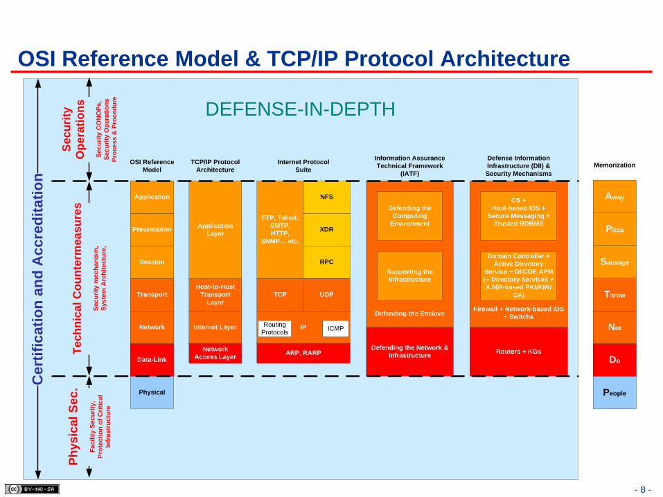


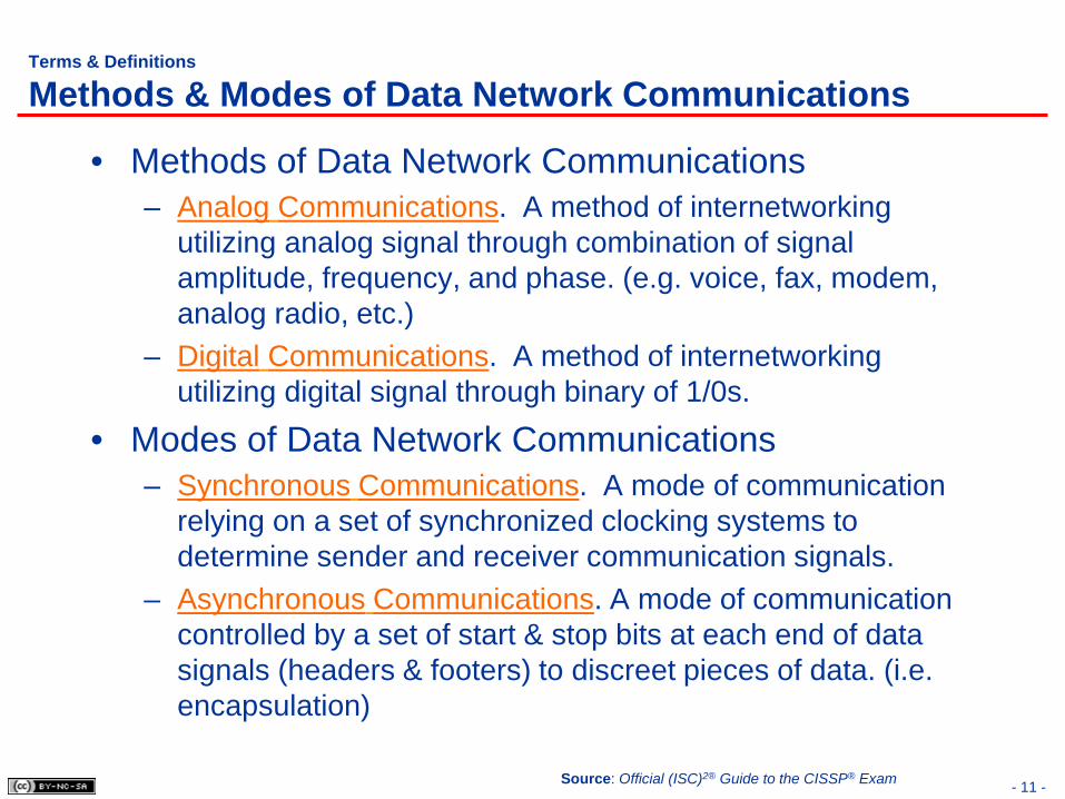


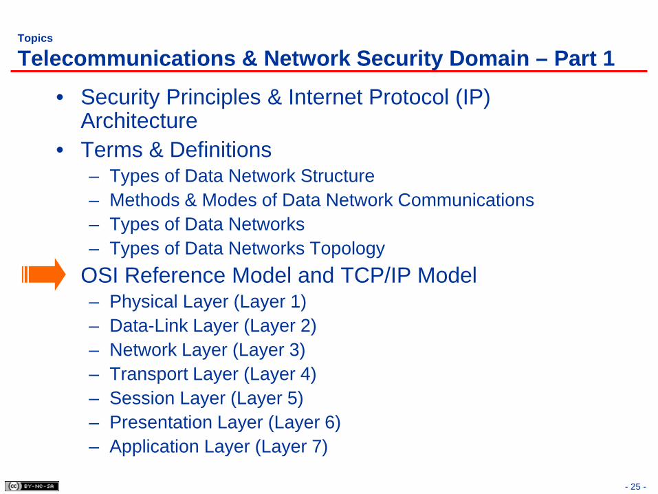


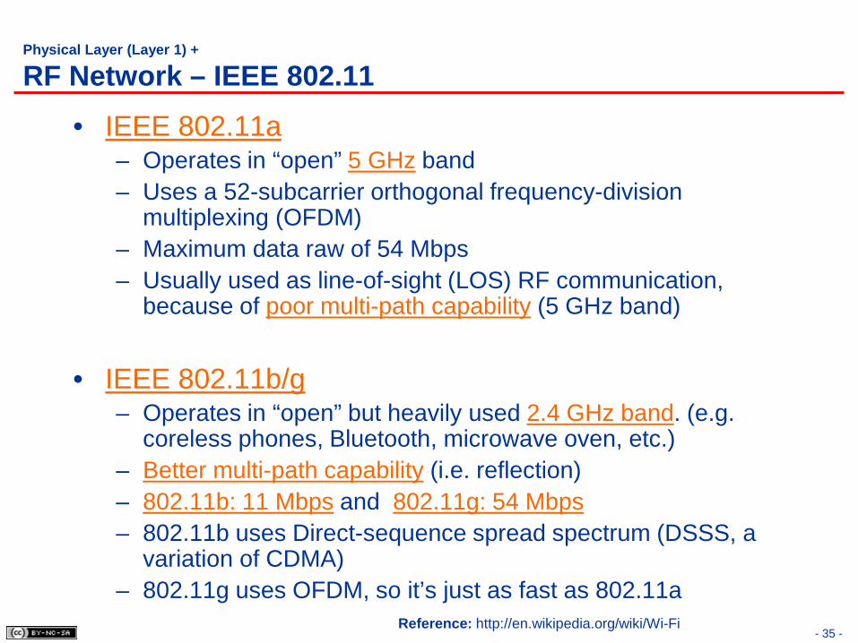


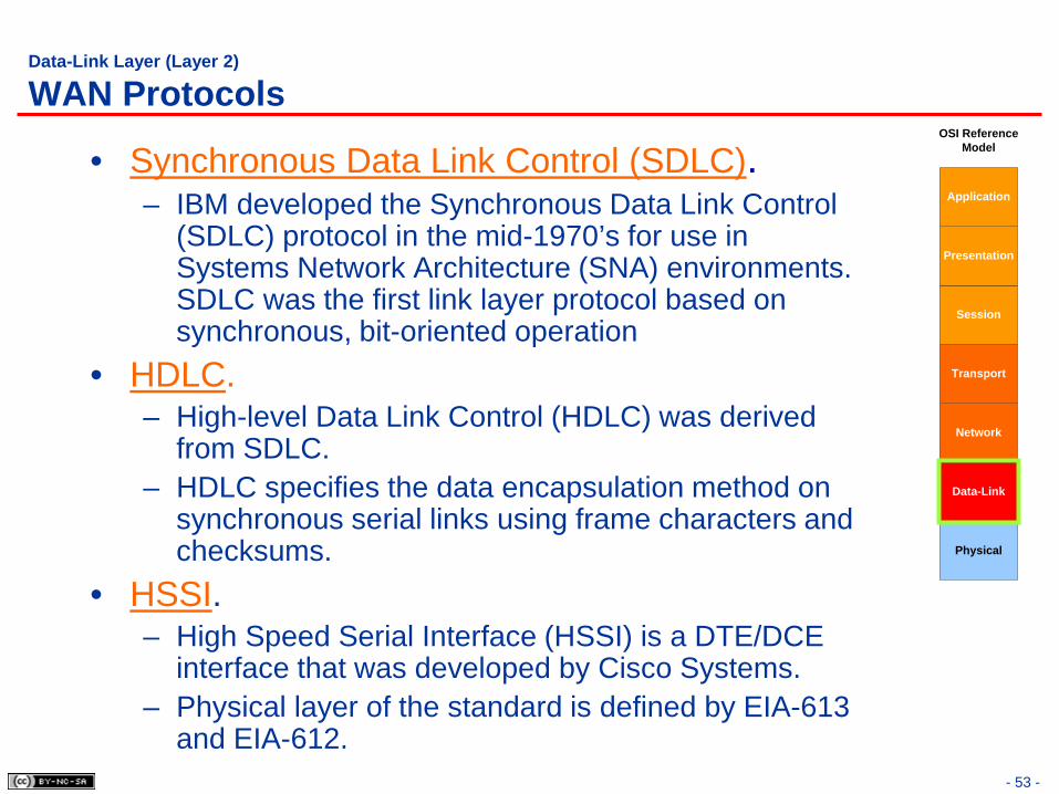


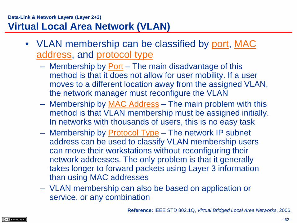


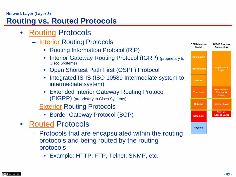


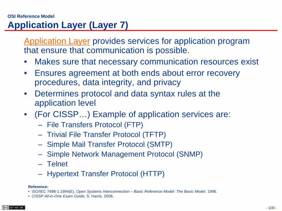


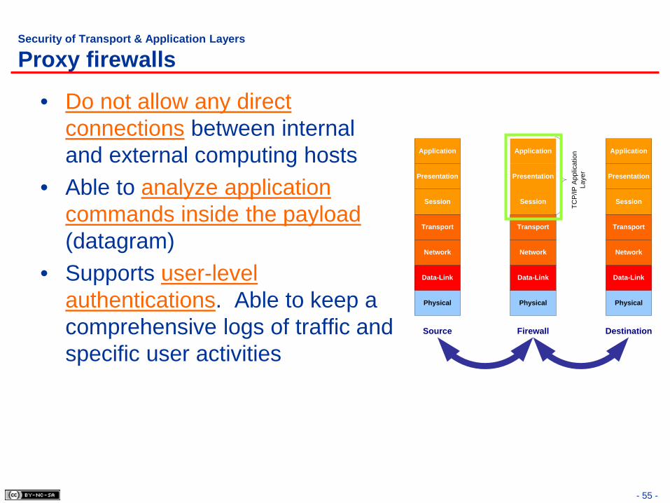


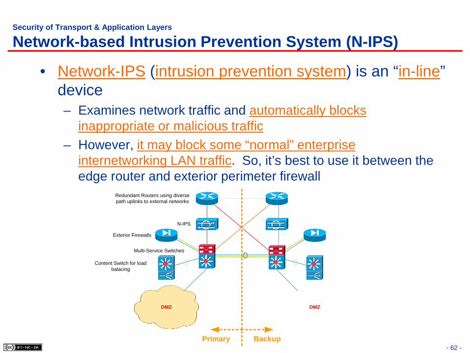


![CISSP Planning Kit - [SAFEWAY]safewayconsultoria.com/wp-content/uploads/2017/06/global-cissp... · CISSP ® Planning Kit. Have questions? ... CISSP Study Guide, 7th Edition CISSP](https://static.documents.pub/doc/80x56/5b7bf36b7f8b9a4c4a8daafb/cissp-planning-kit-safeway-cissp-planning-kit-have-questions-cissp.jpg)


