37
Team Project Guide Created By: Mathew 1/29/2009

8/14/2019 Cita 370 Project Guilds
http://slidepdf.com/reader/full/cita-370-project-guilds 1/37
Team Project Guide
Created By:
Mathew
1/29/2009
8/14/2019 Cita 370 Project Guilds
http://slidepdf.com/reader/full/cita-370-project-guilds 2/37
Contents
Section 1: SNMP TRAP..................................................................................................................4Overview......................................................................................................................................4
Procedures....................................................................................................................................4
1.1 Visio Diagram...................................................................................................................4
1.2 Setup Switch.....................................................................................................................5
1.3 Setup Router ......................................................................................................................5
1.4 Setup SNMP......................................................................................................................6
1.5 Testing Connections & traps.............................................................................................6
Errors, Difficulties, and Observations.........................................................................................7
Best Practices...............................................................................................................................8
Reference:....................................................................................................................................8
Section 2: HSRP setup.....................................................................................................................8
Overview......................................................................................................................................8
Procedures....................................................................................................................................9
2.1 Visio Flow Diagram..........................................................................................................9
2.2 Configuration Router 1.....................................................................................................9
2.3 Configuration Router 2...................................................................................................10
2.4 Configuration Backuprouter ............................................................................................11
2.5 Configuration Switch 1...................................................................................................12
2.6 Configuration Switch 2...................................................................................................13
2.7 Setup RIP........................................................................................................................14
2.8 Setup HSRP.....................................................................................................................15
Errors, Difficulties, and Observations.......................................................................................15
Best Practices.............................................................................................................................15
Reference:..................................................................................................................................15
Section 3: Extended ACL setup.....................................................................................................16Overview....................................................................................................................................16
Procedures..................................................................................................................................16
3.1 Visio Flow Diagram........................................................................................................16
3.2 Configuration Router 1...................................................................................................16
3.3 Configuration Router 2...................................................................................................17

8/14/2019 Cita 370 Project Guilds
http://slidepdf.com/reader/full/cita-370-project-guilds 3/37
3.4 Setup ACL.......................................................................................................................18
3.5.1 Router 1.......................................................................................................................19
3.5.2 Router 2......................................................................................................................19
3.6 WAMP setup...................................................................................................................193.7 Testing ACLs.......................................................................................................................19
Errors, Difficulties, and Observations.......................................................................................20
Best Practices.............................................................................................................................21
Reference:..................................................................................................................................21
Section 1: SNMP TRAP................................................................................................................21
Overview....................................................................................................................................21
Procedures..................................................................................................................................22
4.1 Visio Diagram.................................................................................................................22
4.2 Setup Switch / NYC........................................................................................................22
4.3 Setup Router / RIP v2.....................................................................................................26
4.3.1 NYC Router ..................................................................................................................26
4.3.2 Router HAM.................................................................................................................27
4.4 Setup Server DNS...........................................................................................................29
4.5 Setup Server DHCP........................................................................................................29
Errors, Difficulties, and Observations.......................................................................................29
Best Practices.............................................................................................................................29
Reference:..................................................................................................................................29

8/14/2019 Cita 370 Project Guilds
http://slidepdf.com/reader/full/cita-370-project-guilds 4/37
Section 1: SNMP TRAP
Overview
In this lab we will be setting up SNMP traps specifically tty, linkup, and linkdown traps on a
router which will then be connected to a switch. This switch will use one VLAN in which we
will connect our client to. Our client will be using free MIB software that will receive any trap
logs that are set off. By the end of this lab we should be able to ping from the client to the vlan
from the client to the router and vice versa. Also by the end of this lab we should be able toreceive syslogs of when an interface is brought to the upstate or to the down state.
Procedures
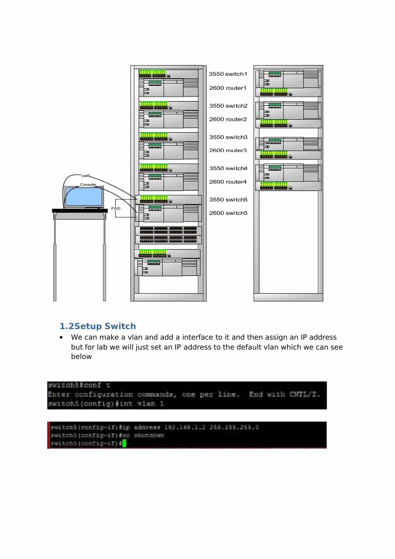
1.1Visio Diagram
This is the basic setup of our lab
8/14/2019 Cita 370 Project Guilds
http://slidepdf.com/reader/full/cita-370-project-guilds 5/37
3550 switch1
2600 router1
3550 switch2
2600 router2
3550 switch3
2600 router3
3550 switch4
2600 router4
3550 switch5
2600 switch5
Console
cat5
F0/0
1.2Setup Switch
• We can make a vlan and add a interface to it and then assign an IP address
but for lab we will just set an IP address to the default vlan which we can see
below

8/14/2019 Cita 370 Project Guilds
http://slidepdf.com/reader/full/cita-370-project-guilds 6/37
1.3Setup Router
• In the Router we will need to setup the fast Ethernet interface first as you can
see below
1.4Setup SNMP
• We will setup the following SNMP traps. tty or (telnet) which will alert the host
computer when a person telnets into the router and config or (configure
terminal) this will send an alert when someone attempts to enter theconfiguration terminal. Both of these traps will be enabled to be sent to the
host computer that kiwi is configured on.
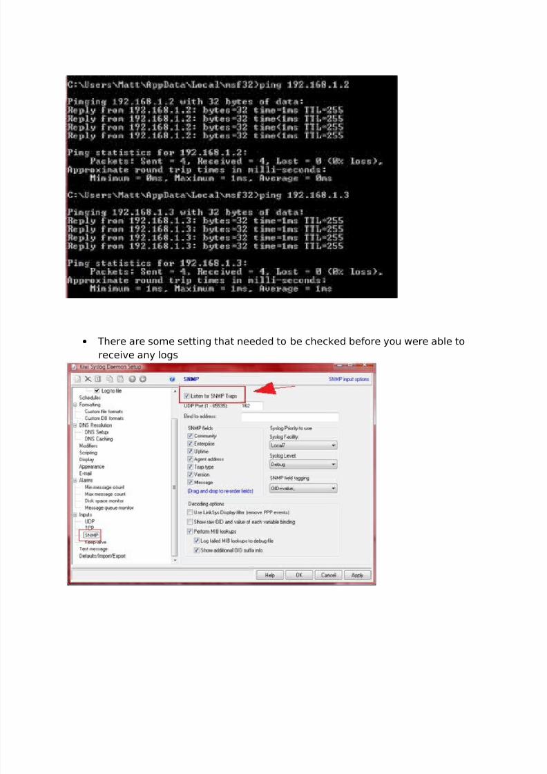
1.5Testing Connections & traps• To test the connections we will need to be able to ping from the host
computer which is 192.168.1.1 to the switches vlan which is 192.168.1.2 and
the F0/0 on the router which was 192.168.1.3. as we can see all pings were
successful.
8/14/2019 Cita 370 Project Guilds
http://slidepdf.com/reader/full/cita-370-project-guilds 7/37
• There are some setting that needed to be checked before you were able to
receive any logs

8/14/2019 Cita 370 Project Guilds
http://slidepdf.com/reader/full/cita-370-project-guilds 8/37
• As you can see once we telneted into the router and logged out an alert wassent. Also there was an alert sent when we ran the configuration terminal
command in the router
Errors, Difficulties, and Observations
• The first difficulty that we ran in to was that we did not plan well enough
• We forgot commands like “no shutdown” and didn’t think to check the
simplest things first as to why we didn’t have connectivity.
• Always check for unplugged cables
Best Practices
• Make a diagram before beginning any project
• Attempt to outline the procedure before implementing
• Organize the projects in to steps to avoid repeating or not completing
commands.
Reference:

8/14/2019 Cita 370 Project Guilds
http://slidepdf.com/reader/full/cita-370-project-guilds 9/37
Section 2: HSRP setup
OverviewIn this lab we will be setting up HSRP or hot standby routing protocol with RIP V2 enabled as
the routing protocol. This will allow us to make a redundant backup link from router 1 and router
2. If router 1 were to be disconnected the backup router would come online and provide us with a
redundant link to our destination. We will look at the visio setup of our network, rip setups and
the hsrp configs.
Procedures
2.1 Visio Flow Diagram
Router backup
Client 1
Client 2
RIP V2
HSRP
DCEDTE
192.168.1.1
192.168.1.3
192.168.2.1
Serial 0
Clock rate 500000
192.168.2.2
Serial 0
192.168.3.1
192.168.3.2
192.168.1.2
192.168.3.3
DCE
DTE
192.168.4.1
Serial 0
Clock rate 500000
192.168.4.2
Serial 1
192.168.1.4
pingping
X
Ping
Redirect
Ping
Redirect
ping pingXrouter1 router2
1.0 2.0 3.0
4.0
8/14/2019 Cita 370 Project Guilds
http://slidepdf.com/reader/full/cita-370-project-guilds 10/37
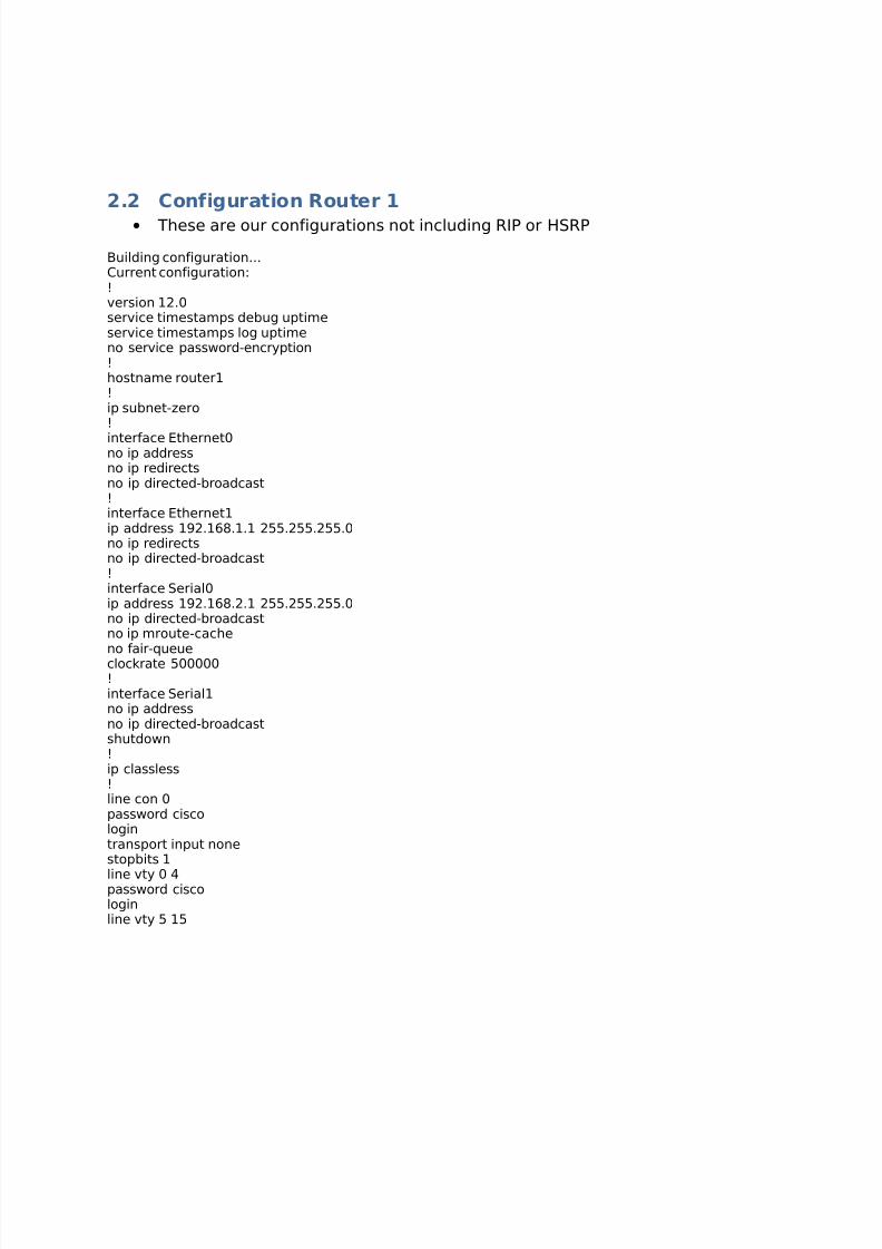
2.2 Configuration Router 1
• These are our configurations not including RIP or HSRP
Building configuration...Current configuration:!version 12.0service timestamps debug uptimeservice timestamps log uptimeno service password-encryption!hostname router1!ip subnet-zero!
interface Ethernet0no ip addressno ip redirectsno ip directed-broadcast!interface Ethernet1ip address 192.168.1.1 255.255.255.0no ip redirectsno ip directed-broadcast!interface Serial0ip address 192.168.2.1 255.255.255.0no ip directed-broadcastno ip mroute-cacheno fair-queueclockrate 500000!interface Serial1no ip addressno ip directed-broadcastshutdown!ip classless!line con 0password ciscologintransport input nonestopbits 1
line vty 0 4password ciscologinline vty 5 15
8/14/2019 Cita 370 Project Guilds
http://slidepdf.com/reader/full/cita-370-project-guilds 11/37
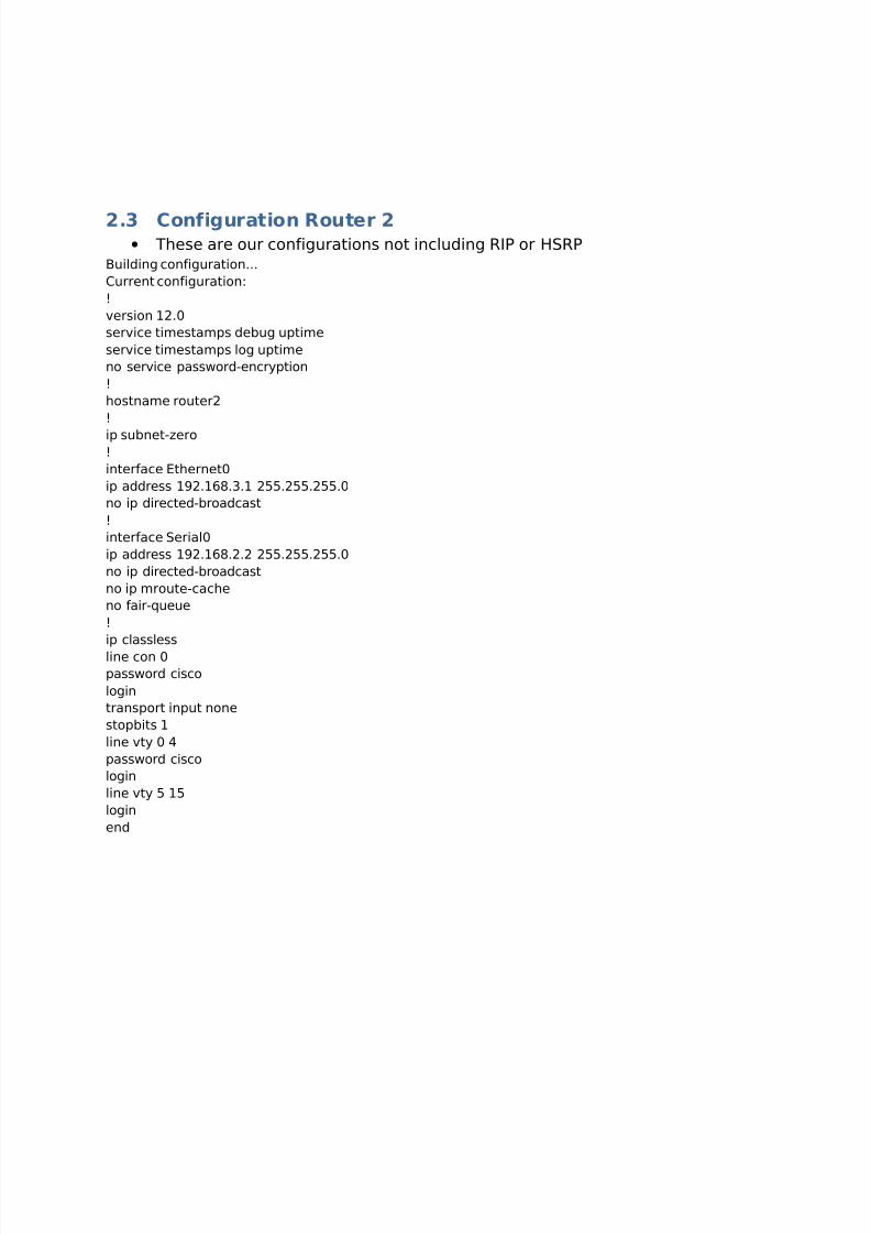
2.3 Configuration Router 2• These are our configurations not including RIP or HSRP
Building configuration...
Current configuration:
!
version 12.0
service timestamps debug uptime
service timestamps log uptime
no service password-encryption
!
hostname router2
!
ip subnet-zero!
interface Ethernet0
ip address 192.168.3.1 255.255.255.0
no ip directed-broadcast
!
interface Serial0
ip address 192.168.2.2 255.255.255.0
no ip directed-broadcast
no ip mroute-cache
no fair-queue
!
ip classless
line con 0
password cisco
login
transport input none
stopbits 1
line vty 0 4
password cisco
login
line vty 5 15
login
end

8/14/2019 Cita 370 Project Guilds
http://slidepdf.com/reader/full/cita-370-project-guilds 12/37
2.4 Configuration Backuprouter
• These are our configurations not including RIP or HSRP
Building configuration...Current configuration:
!version 12.0service timestamps debug uptimeservice timestamps log uptimeno service password-encryption!hostname backuprouter !ip subnet-zero!isdn voice-call-failure 0!interface Ethernet0ip address 192.168.1.4 255.255.255.0no ip redirects
no ip directed-broadcaststandby 1 timers 1 3standby 1 priority 110 preempt delay 1800standby 1 ip 192.168.1.10!interface Serial0ip address 192.168.4.1 255.255.255.0no ip directed-broadcastno ip mroute-cacheno fair-queueclockrate 500000!interface Serial1no ip addressno ip directed-broadcastshutdown
!interface BRI0no ip addressno ip directed-broadcastshutdownisdn guard-timer 0 on-expiry accept!router ripversion 2network 192.168.1.0network 192.168.4.0!ip classlessno ip http server !
line con 0 password ciscologintransport input nonestopbits 1line vty 0 4
password ciscologinline vty 5 15login

8/14/2019 Cita 370 Project Guilds
http://slidepdf.com/reader/full/cita-370-project-guilds 13/37
2.5 Configuration Switch 1
• This shows the vlan setup on switch 1
Building configuration...
Current configuration:!version 12.0no service padservice timestamps debug uptimeservice timestamps log uptimeno service password-encryption!hostname switch1!enable secret 5 $1$VTH3$QtPMIkcc.LsBtEig4/csG/!ip subnet-zero
!!!interface FastEthernet0/1!interface FastEthernet0/2!interface FastEthernet0/3!interface FastEthernet0/4!interface VLAN1ip address 192.168.1.2 255.255.255.0no ip directed-broadcastno ip route-cache
!!line con 0
password ciscologintransport input nonestopbits 1line vty 0 4
password ciscologinline vty 5 15login!end
2.6 Configuration Switch 2
• This shows the vlan setup on switch 2
Building configuration...
Current configuration:!version 12.0no service pad
8/14/2019 Cita 370 Project Guilds
http://slidepdf.com/reader/full/cita-370-project-guilds 14/37
service timestamps debug uptimeservice timestamps log uptimeno service password-encryption!hostname switch2!
enable secret 5 $1$VTH3$QtPMIkcc.LsBtEig4/csG/!ip subnet-zero!!!interface FastEthernet0/1!interface FastEthernet0/2!interface FastEthernet0/3!interface FastEthernet0/4!interface VLAN1ip address 192.168.3.2 255.255.255.0no ip directed-broadcastno ip route-cache!!line con 0
password ciscologintransport input nonestopbits 1line vty 0 4
password ciscologinline vty 5 15login!
end
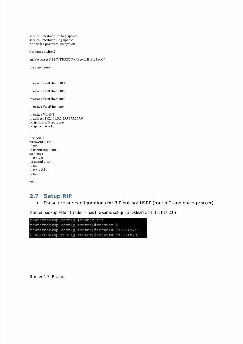
2.7 Setup RIP
• These are our configurations for RIP but not HSRP (router 2 and backuprouter)
Router backup setup (router 1 has the same setup up instead of 4.0 it has 2.0)
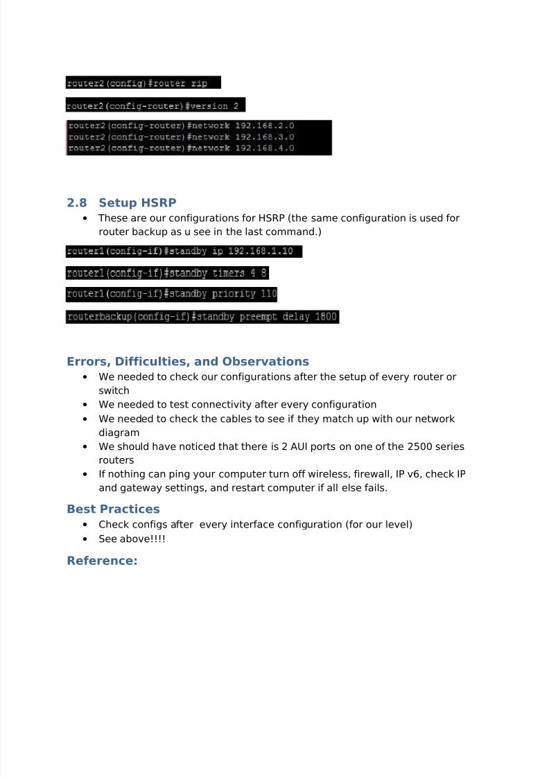
Router 2 RIP setup
8/14/2019 Cita 370 Project Guilds
http://slidepdf.com/reader/full/cita-370-project-guilds 15/37
2.8 Setup HSRP
• These are our configurations for HSRP (the same configuration is used for
router backup as u see in the last command.)
Errors, Difficulties, and Observations
• We needed to check our configurations after the setup of every router or
switch
•
We needed to test connectivity after every configuration• We needed to check the cables to see if they match up with our network
diagram
• We should have noticed that there is 2 AUI ports on one of the 2500 series
routers
• If nothing can ping your computer turn off wireless, firewall, IP v6, check IP
and gateway settings, and restart computer if all else fails.
Best Practices
• Check configs after every interface configuration (for our level)
• See above!!!!
Reference:

8/14/2019 Cita 370 Project Guilds
http://slidepdf.com/reader/full/cita-370-project-guilds 16/37
Section 3: Extended ACL setup
Overview
In this lab we will be setting up Extended Access-Control Lists or ACL we will be
running EIGRP as our routing protocol. This will allow us to restrict specific protocols likeICMP or HTTP or UDP. In this lab we will be setting up routers and two clients connected to the
routers we will have a WAMP server on the router 2 side and we will have a client on the other.
We will be testing HTTP connectivity from client to server then we will be blocking ICMP traffic
from the server to the client

8/14/2019 Cita 370 Project Guilds
http://slidepdf.com/reader/full/cita-370-project-guilds 17/37
Procedures
3.1 Visio Flow Diagram
192.168.1.0
10.0.0.0
192.168.2.0
F0/0
IP:192.168.1.1
Client Permit
IP:192.168.1.2 WAMP server IP:192.168.2.2
F0/0
IP:192.168.2.1
S0/0
IP:10.0.1.1
DCE CR 500000
S0/0
IP:10.0.1.2
Permit: TCP
Deny:
1 Access Layer
2 EIGRP 101
2 Core / D istribut ion Layer
Symbol Count Description
Legend Subtitle
Legend
RIP v2
HTTP
HTTP REQUEST
HTTP
ICMP
ICMP REQUEST X
Deny
Permit
3.2 Configuration Router 1
• Here is the configuration that we used on router one not including the ACL
Building configuration...
Current configuration:!version 12.0service timestamps debug uptime
service timestamps log uptimeno service password-encryption!hostname Router1!ip subnet-zero!interface Ethernet0ip address 192.168.1.1 255.255.255.0no ip directed-broadcast
8/14/2019 Cita 370 Project Guilds
http://slidepdf.com/reader/full/cita-370-project-guilds 18/37
!interface Serial0ip address 10.0.0.1 255.0.0.0no ip directed-broadcastno ip mroute-cachefair-queue 64 256 0
clockrate 500000!interface Serial1no ip addressno ip directed-broadcastshutdown!interface BRI0no ip addressno ip directed-broadcastshutdownno isdn guard-timer 0 on-expiry accept!router rip
version 2network 192.168.1.0network 10.0.0.0!ip classless!!line con 0password ciscologintransport input nonestopbits 1line vty 0 4password ciscologin
!end
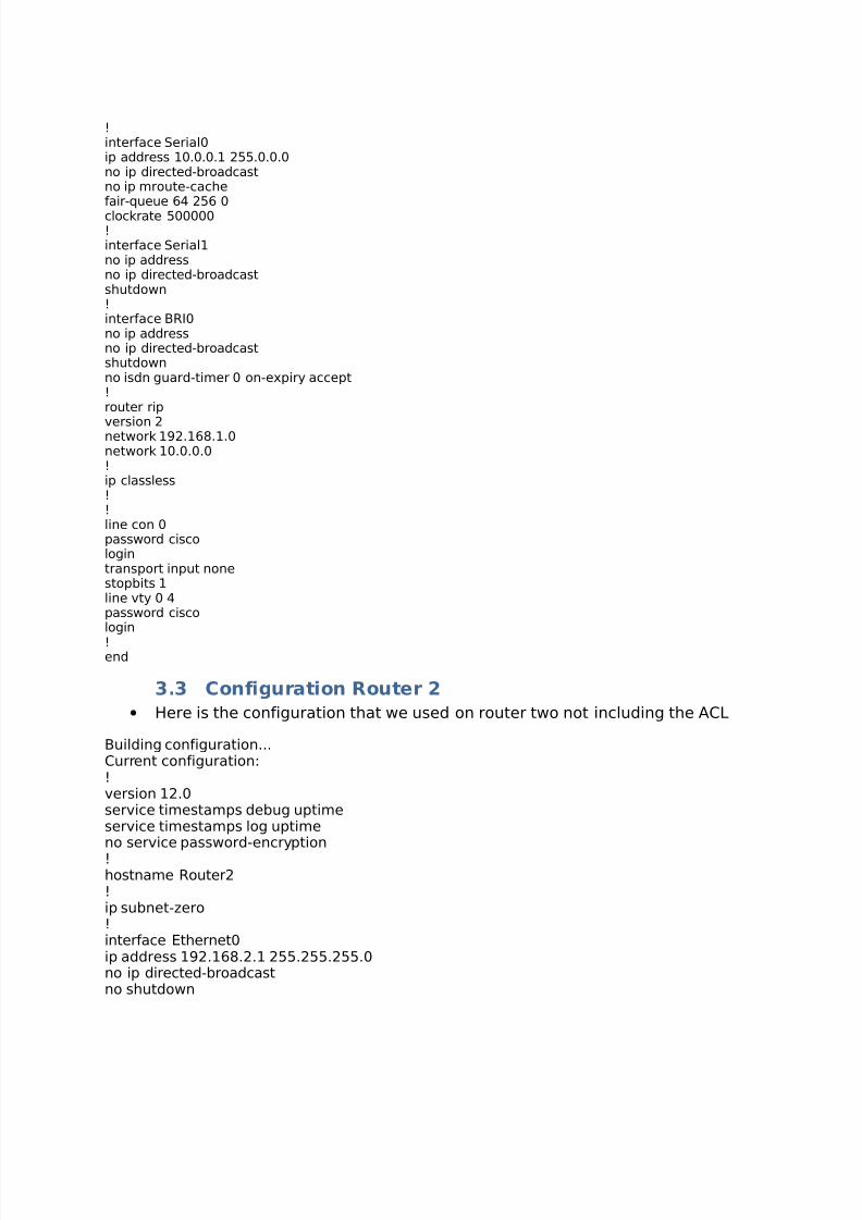
3.3 Configuration Router 2
• Here is the configuration that we used on router two not including the ACL
Building configuration...Current configuration:!version 12.0service timestamps debug uptimeservice timestamps log uptimeno service password-encryption
!hostname Router2!ip subnet-zero!interface Ethernet0ip address 192.168.2.1 255.255.255.0no ip directed-broadcastno shutdown
8/14/2019 Cita 370 Project Guilds
http://slidepdf.com/reader/full/cita-370-project-guilds 19/37
!interface Serial0bandwidth 50000ip address 10.0.0.2 255.0.0.0no ip directed-broadcast
no ip mroute-cacheno fair-queueno shutdown!interface Serial1no ip addressno ip directed-broadcastshutdown!router ripversion 2network 192.168.2.0network 10.0.0.0
!ip classless!!line con 0password ciscologintransport input nonestopbits 1line vty 0 4password ciscologin!
end
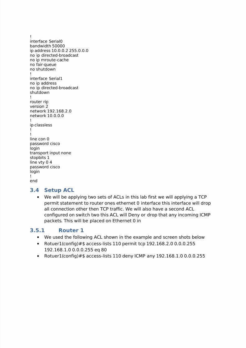
3.4 Setup ACL
• We will be applying two sets of ACLs in this lab first we will applying a TCP
permit statement to router ones ethernet 0 interface this interface will drop
all connection other then TCP traffic. We will also have a second ACL
configured on switch two this ACL will Deny or drop that any incoming ICMP
packets. This will be placed on Ethernet 0 in
3.5.1 Router 1
• We used the following ACL shown in the example and screen shots below
• Rotuer1(config)#$ access-lists 110 permit tcp 192.168.2.0 0.0.0.255192.168.1.0 0.0.0.255 eq 80
• Rotuer1(config)#$ access-lists 110 deny ICMP any 192.168.1.0 0.0.0.255

8/14/2019 Cita 370 Project Guilds
http://slidepdf.com/reader/full/cita-370-project-guilds 20/37
3.5.2 Router 2
• We used the following ACL shown in the example and screen shots below
• Rotuer2(config)#$ access-lists 110 deny tcp any 192.168.2.0 0.0.0.255
3.6 WAMP setup
• WAMP can be downloaded in the following:
○ http://www.wampserver.com/en/download.php
• Once downloaded we can install it in its default directory and the webpage
files can be placed in C:\wamp\www or in your predetermined location
• After that you can start the service by l-clicking on the icon on the system
tray and click put online and the service should start
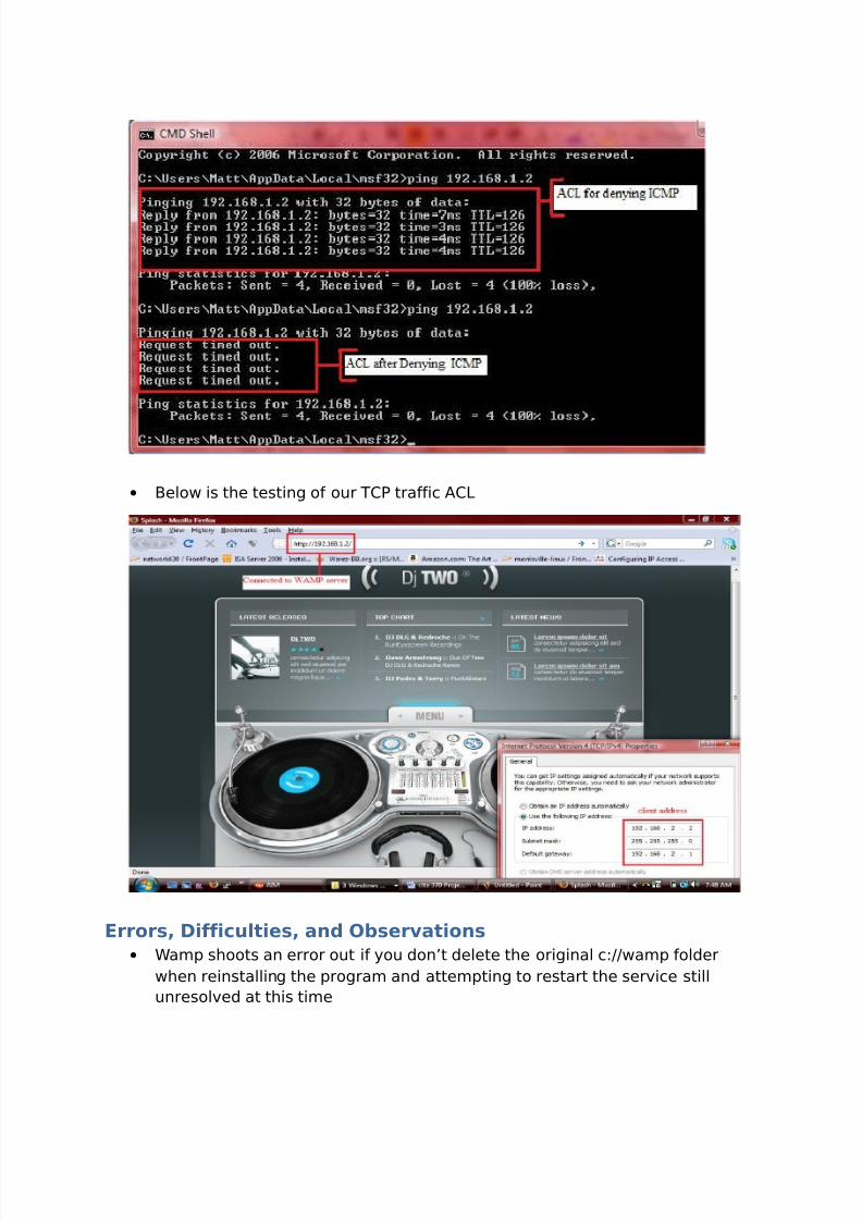
3.7 Testing ACLs
• Right below is a PING test that we ran for the ICMP ACL
8/14/2019 Cita 370 Project Guilds
http://slidepdf.com/reader/full/cita-370-project-guilds 21/37
• Below is the testing of our TCP traffic ACL
Errors, Difficulties, and Observations
• Wamp shoots an error out if you don’t delete the original c://wamp folder
when reinstalling the program and attempting to restart the service still
unresolved at this time
8/14/2019 Cita 370 Project Guilds
http://slidepdf.com/reader/full/cita-370-project-guilds 22/37
• Issues with the source and destination fields in the ACLs
Best Practices
• Test configuration before applying ACLs and throughout the initial
configuration.• Document all
Reference:
Section 1: Core Network
Overview
In this lab I will be configuring a core network this network will be running RIP v2 over the
emulated WAN link. It will have switches on both networks the switch on the NYC side will
have

8/14/2019 Cita 370 Project Guilds
http://slidepdf.com/reader/full/cita-370-project-guilds 23/37
Procedures
4.1 Visio Diagram
NYC-RT
s0 172.16.18.2
e0 172.16.2.1
Ham-RT
s0 172.16.18.3
e0 172.16.16.1
RIP Routing v2
NYC-SW
172.16.2.2
Ham-SW
172.16.16.2
Sales
Admin
Engineering
Servers
NYCServ1
Vbox-DHCP/DNS
172.16.10.5
Vlan Information
Servers 172.16.2.0
Sales 172.16.4.0
Administration 172.16.6.0
Engineering 172.16.8.0
Distribution
CORE
Access
CORE Network
Created By Mathew Lastra
Distribution
4.2 Setup Switch / NYCBuilding configuration...
Current configuration : 2558 bytes
!
version 12.1
no service pad

8/14/2019 Cita 370 Project Guilds
http://slidepdf.com/reader/full/cita-370-project-guilds 24/37
service timestamps debug uptime
service timestamps log uptime
no service password-encryption
!
hostname NYC-SW
!
!
ip subnet-zero
!
!
spanning-tree mode pvst
spanning-tree extend system-id
!
!
!
!
interface FastEthernet0/1
description uplink to NYC router
switchport trunk encapsulation dot1q
switchport trunk allowed vlan 1-5
switchport mode trunk
!
interface FastEthernet0/2
switchport mode dynamic desirable
!
interface FastEthernet0/3
switchport access vlan 2
switchport mode dynamic desirable
!
interface FastEthernet0/4
switchport access vlan 2
switchport mode dynamic desirable
!
interface FastEthernet0/5

8/14/2019 Cita 370 Project Guilds
http://slidepdf.com/reader/full/cita-370-project-guilds 25/37
switchport access vlan 3
switchport mode dynamic desirable
!
interface FastEthernet0/6
switchport access vlan 3
switchport mode dynamic desirable
!
interface FastEthernet0/7
switchport access vlan 4
switchport mode dynamic desirable
!
interface FastEthernet0/8
switchport access vlan 4
switchport mode dynamic desirable
!
interface FastEthernet0/9
switchport access vlan 5
switchport mode dynamic desirable
!
interface FastEthernet0/10
switchport access vlan 5
switchport mode dynamic desirable
!
interface FastEthernet0/11
switchport mode dynamic desirable
!
interface FastEthernet0/12
switchport mode dynamic desirable
!
interface FastEthernet0/13
switchport mode dynamic desirable
!
interface FastEthernet0/14
switchport mode dynamic desirable

8/14/2019 Cita 370 Project Guilds
http://slidepdf.com/reader/full/cita-370-project-guilds 26/37
!
interface FastEthernet0/15
switchport mode dynamic desirable
!
interface FastEthernet0/16
switchport mode dynamic desirable
!
interface FastEthernet0/17
switchport mode dynamic desirable
!
interface FastEthernet0/18
switchport mode dynamic desirable
!
interface FastEthernet0/19
switchport mode dynamic desirable
!
interface FastEthernet0/20
switchport mode dynamic desirable
!
interface FastEthernet0/21
switchport mode dynamic desirable
!
interface FastEthernet0/22
switchport mode dynamic desirable
!
interface FastEthernet0/23
switchport mode dynamic desirable
!
interface FastEthernet0/24
switchport mode dynamic desirable
!
interface GigabitEthernet0/1
switchport mode dynamic desirable
!

8/14/2019 Cita 370 Project Guilds
http://slidepdf.com/reader/full/cita-370-project-guilds 27/37
interface GigabitEthernet0/2
switchport mode dynamic desirable
!
interface Vlan1
ip address 172.16.2.2 255.255.254.0
!
interface Vlan2
ip address 172.16.4.2 255.255.254.0
!
interface Vlan3
ip address 172.16.8.2 255.255.254.0
!
interface Vlan4
ip address 172.16.6.2 255.255.254.0
!
interface Vlan5
ip address 172.16.10.2 255.255.254.0
!
ip classless
ip http server
!
!
line con 0
line vty 0 4
login
line vty 5 15
login
!
!
end
4.3 Setup Router / RIP v2
• One router will be NYC and the other will be

8/14/2019 Cita 370 Project Guilds
http://slidepdf.com/reader/full/cita-370-project-guilds 28/37
4.3.1 NYC Router
Building configuration...
Current configuration : 1349 bytes
!
version 12.2
service timestamps debug uptime
service timestamps log uptime
no service password-encryption
!
hostname NYC-RT
!
!
memory-size iomem 15
ip subnet-zero
!
!
!

8/14/2019 Cita 370 Project Guilds
http://slidepdf.com/reader/full/cita-370-project-guilds 29/37
call rsvp-sync
!
!
!
!
!
!
!
!
interface FastEthernet0/0
no ip address
duplex auto
speed auto
!
interface FastEthernet0/0.1
description defualt vlan
encapsulation dot1Q 1
ip address 172.16.2.1 255.255.254.0
ip helper-address 172.16.10.5
!
interface FastEthernet0/0.2
description sales vlan
encapsulation dot1Q 2
ip address 172.16.4.1 255.255.254.0
ip helper-address 172.16.10.5
!
interface FastEthernet0/0.3
description engineer
encapsulation dot1Q 3
ip address 172.16.8.1 255.255.254.0
ip helper-address 172.16.10.5
!
interface FastEthernet0/0.4
description administration

8/14/2019 Cita 370 Project Guilds
http://slidepdf.com/reader/full/cita-370-project-guilds 30/37
encapsulation dot1Q 4
ip address 172.16.6.1 255.255.254.0
ip helper-address 172.16.10.5
!
interface FastEthernet0/0.5
description Server
encapsulation dot1Q 5 native
ip address 172.16.10.1 255.255.254.0
ip helper-address 172.16.10.5
!
interface Serial0/0
description link to HAM-RT
ip address 172.16.18.2 255.255.254.0
clockrate 1000000
!
interface FastEthernet0/1
no ip address
shutdown
duplex auto
speed auto
!
router rip
version 2
network 172.16.0.0
!
ip classless
no ip http server
!
!
dial-peer cor custom
!
!
!
!
8/14/2019 Cita 370 Project Guilds
http://slidepdf.com/reader/full/cita-370-project-guilds 31/37
line con 0
line aux 0
line vty 0 4
!
End
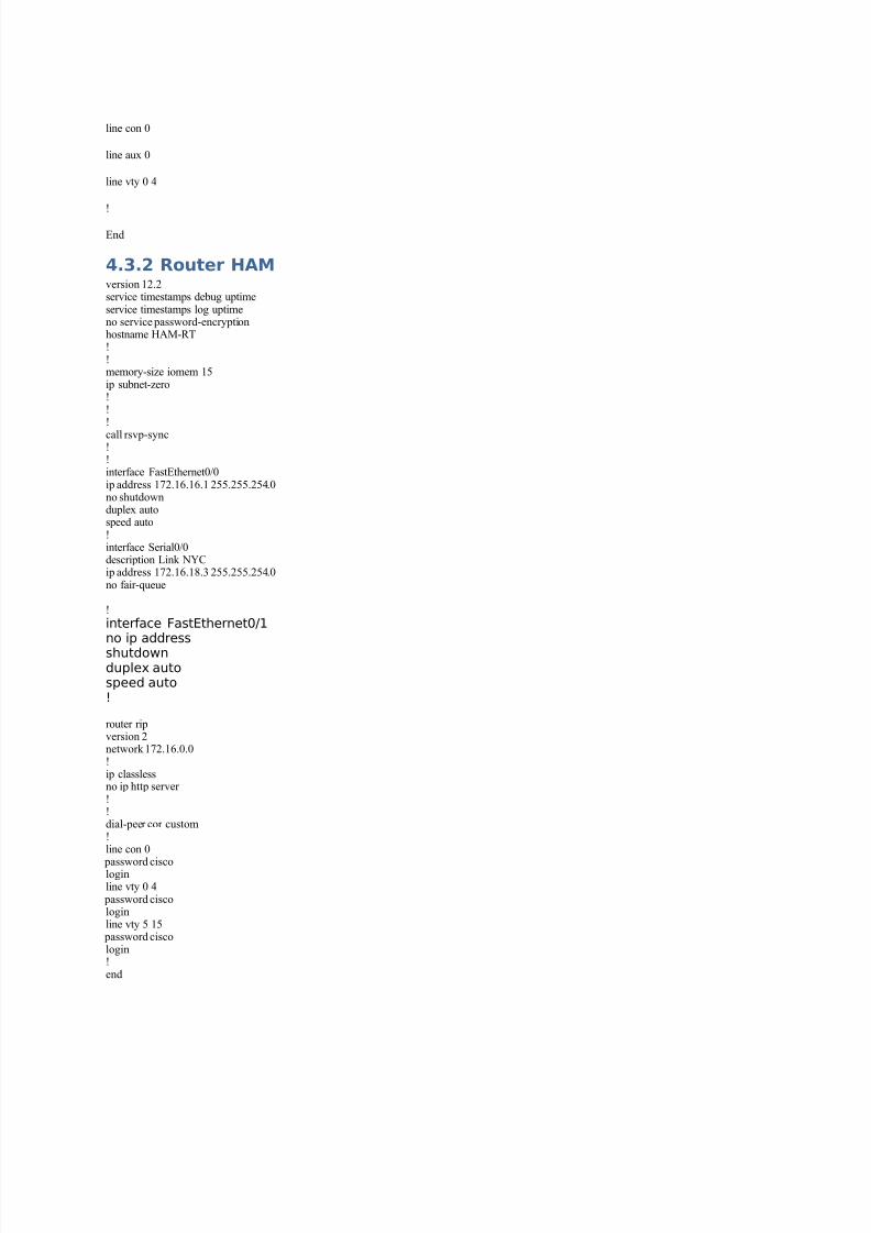
4.3.2 Router HAMversion 12.2service timestamps debug uptimeservice timestamps log uptimeno service password-encryptionhostname HAM-RT!!memory-size iomem 15ip subnet-zero!!!
call rsvp-sync!!interface FastEthernet0/0ip address 172.16.16.1 255.255.254.0no shutdownduplex autospeed auto!interface Serial0/0description Link NYCip address 172.16.18.3 255.255.254.0no fair-queue
!
interface FastEthernet0/1no ip addressshutdownduplex autospeed auto!
router ripversion 2network 172.16.0.0!ip classlessno ip http server !!dial-peer cor custom!line con 0
password ciscologinline vty 0 4
password ciscologinline vty 5 15
password ciscologin!end
8/14/2019 Cita 370 Project Guilds
http://slidepdf.com/reader/full/cita-370-project-guilds 32/37
4.4 Setup Server DNS
• The first thing that we will need to do is install DNS for the NYC
• We will be installing active directory for the DNS just because AD enables this
by default when it is installed
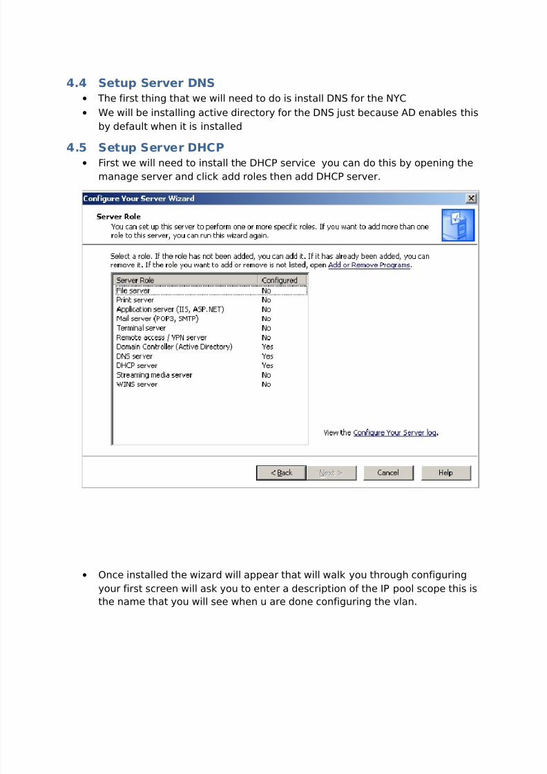
4.5 Setup Server DHCP
• First we will need to install the DHCP service you can do this by opening the
manage server and click add roles then add DHCP server.
• Once installed the wizard will appear that will walk you through configuring
your first screen will ask you to enter a description of the IP pool scope this is
the name that you will see when u are done configuring the vlan.

8/14/2019 Cita 370 Project Guilds
http://slidepdf.com/reader/full/cita-370-project-guilds 33/37
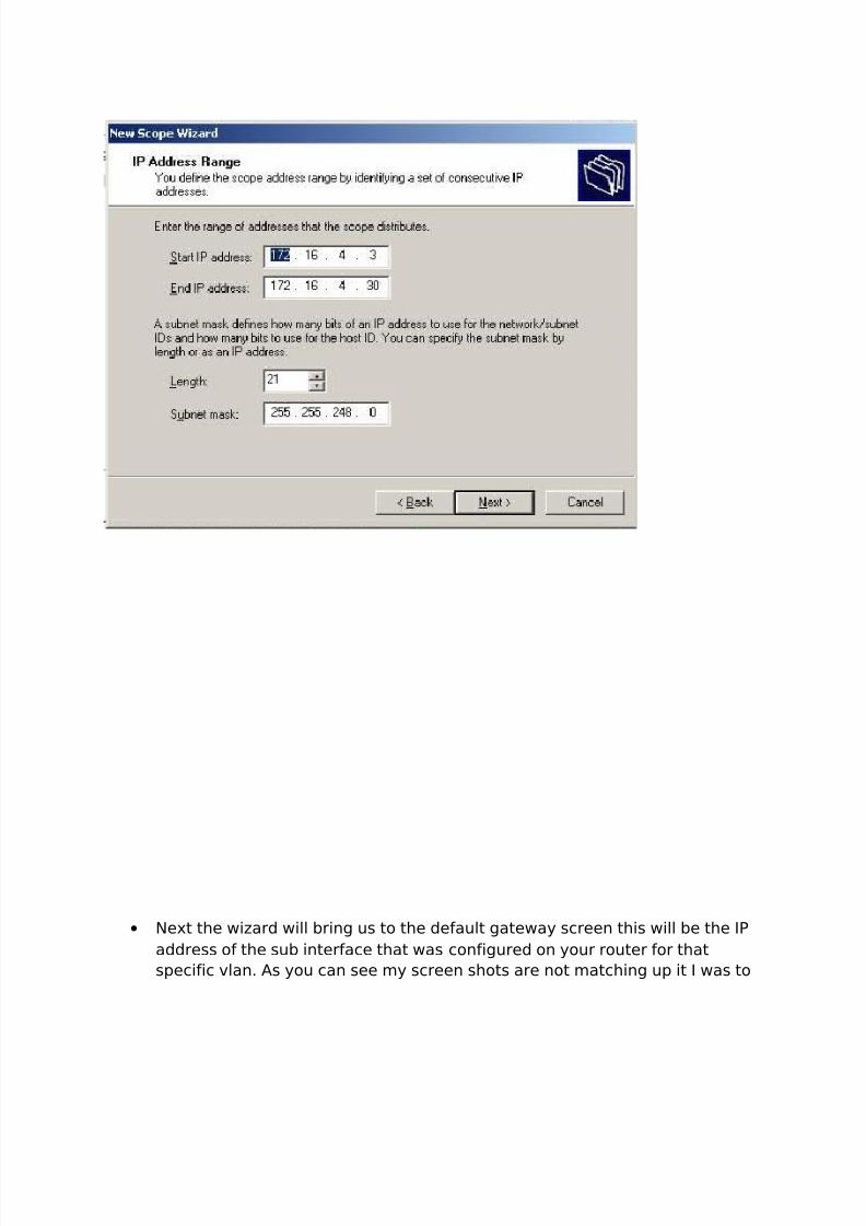
• Then u will get a screen that will ask you to configure a address range for
your DHCP pool it is key that we don’t include the IP addresses that are
configured for static servers. You can us the exclusion menu on the next
screen. Be sure to check to make sure the subnet mask is correct like on this
one it’s not thank god I’m writing this it should be 255.255.254.0 not .248
8/14/2019 Cita 370 Project Guilds
http://slidepdf.com/reader/full/cita-370-project-guilds 34/37
• Next the wizard will bring us to the default gateway screen this will be the IP
address of the sub interface that was configured on your router for that
specific vlan. As you can see my screen shots are not matching up it I was to

8/14/2019 Cita 370 Project Guilds
http://slidepdf.com/reader/full/cita-370-project-guilds 35/37
use a screen shot that matched the picture above the default gateway would
be 172.16.2.1.
• Next we will be presented with a screen that will ask use to configure DNS
server settings you will add your domain which on this server we have AD
installed and the domain is mattsdomain.com you will need to add the name
of the computer and also the IP of the server.

8/14/2019 Cita 370 Project Guilds
http://slidepdf.com/reader/full/cita-370-project-guilds 36/37
• Lastly it will ask you if you a few more option like lease duration that can be
set and that will be the end of the DHCP configuration.
• We will then need to authorize the DHCP server to lease IP addresses on the
network we can do this by clicking the action menu in the DHCP MMC and
click authorize this will activate the DHCP pools that we have configured as
seen below
• My configuration consists of the following
8/14/2019 Cita 370 Project Guilds
http://slidepdf.com/reader/full/cita-370-project-guilds 37/37
○ Default VLAN = 172.16.2.3 - 172.16.2.10 255.255.254.0
○ Sales VLAN = 172.16.4.3 - 172.16.4.10 255.255.254.0
○ Engineer VLAN = 172.16.8.3 - 172.16.8.10 255.255.254.0
○ Administrative VLAN = 172.16.6.3 - 172.16.6.10 255.255.254.0
○ Engineer VLAN = 172.16.8.3 - 172.16.8.10 255.255.254.0○ Server VLAN = 172.16.10.6 – 172.16.10.12 255.255.254.0
4.6 Successful Test
•
Errors, Difficulties, and Observations
Best Practices
Reference:


