38
CITY OF CRESWELL Public Works Design Standards Division 5 Water Distribution
| Date post: | 10-Jul-2018 |
| Category: |
Documents |
| Upload: | truongnguyet |
| View: | 213 times |
| Download: | 0 times |

CITY OF CRESWELL Public Works Design Standards
Division 5
Water Distribution

DIVISION 5 WATER DISTRIBUTION
5.1 PURPOSE
a. In addition to the purposes outlined under Division 1 of these Design Standards, the purpose of these Standards is to ensure the development of a water distribution system which will:
1) be of adequate design to meet all expected domestic, commercial and industrial demands including fire flows within the design life;
2) have sufficient structural strength to withstand all external loads which may be imposed;
3) be of materials resistant to both corrosion and erosion with a minimum design life of 75 years;
4) be economical and safe to build and maintain;
5) meet all design requirements of the Oregon Health Division (OHD).
Alternate materials and methods will be considered for approval on the basis of these objectives.
b. These Standards cannot provide for all situations. They are intended to assist but not to substitute for competent work by professional design engineers.
5.2 APPLICABILITY
a. These Standards shall govern all construction and upgrading of all public water distribution facilities in the City of Creswell and applicable work within its service areas.
b. Permanent water distribution facilities shall be provided to all properties within the City of Creswell in accordance with these Standards. This shall generally be interpreted to mean that permanent water distribution facilities shall be provided for existing legal lots of record at the time development occurs, and for new legal lots of record created by a major or minor partitioning or subdivision of land at the time of partitioning or subdivision.
PWDS (8/2015) Creswell, Oregon
Division 5-1 Water Distribution
Copyright 2014
W estech Engineering, Inc
5.3 SPECIAL ITEMS
a. The design of the following are considered special items and are not covered in detail in these Standards:
1) Water Distribution Pump Stations
2) Reservoirs
3) Wells
4) Treatment Plants
5) Pressure Regulating Devices
6) Flow Measurement Devices
7) Relining of the Existing Water Mains
8) Chemical Addition or pH Adjustment
9) Bridge Crossings
10) Creek or Stream Crossings
b. Review and approval of the above special items by the City Engineer and Public Works Director shall be required. When requested by the City, full design calculations shall be submitted for review prior to approval. Special items may also require review and approval by the Oregon Health Division.
5.4 APPROVAL OF ALTERNATE MATERIALS AND METHODS
a. Any alternate material or method not explicitly approved herein will be considered for approval on the basis of the objectives set forth in Paragraph 5.1, Purpose. Persons seeking such approval shall make application in writing to the City Engineer and Public Works Director. Approval of any major deviation from these Standards shall be in written form. Approval of minor matters will be made in writing, if requested.
b. Any alternate must meet or exceed the minimum requirements set forth in these Design Standards.
c. The written application is to include, but is not limited to, the manufacturer's specifications and testing results, design drawings, calculations and other pertinent information.
d. Any deviations or special problems shall be reviewed on a case-by-case basis and approved by the City Engineer and Public Works Director. When requested by the City,
PWDS (8/2015) Creswell, Oregon
Division 5-2 Water Distribution
Copyright 2014
W estech Engineering, Inc

full design calculations shall be submitted for review with the request for approval.
5.5 CONSTRUCTION DRAWINGS
a. Construction drawings shall conform to the requirements of Division 1 of these Design Standards.
b. Detail drawings shall be included on the construction drawings for all water system appurtenances including valves, blowoffs, hydrants, service connections, couplings, etc.
5.6 STANDARD DETAILS
a. Standard details included in the appendix are supplemental to the text of these design standards and show the City's minimum requirements for the construction of standard structures and facilities.
b. In the case of conflicts between the text of these design standards and the standard details, the more stringent as determined by the City Engineer and Public Works Director shall apply.
c. As required by Division 1 of these standards, all applicable standard details shall be included on the construction drawings.
5.7 DEFINITIONS AND TERMS
a. In addition to the definitions contained in Division 1 of these Standards, the following definitions may apply particularly to water distribution systems. Unless otherwise defined in these Design Standards, the following definitions and abbreviations shall apply whenever used. Other definitions as outlined in the Oregon Plumbing Specialty Code (OPSC) shall also apply.
1) Abbreviations: Acceptable abbreviations for showing types of new and existing pipe materials on the plans are as follows:
a) CI - Cast Iron
b) DI - Ductile Iron
c) PVC - Polyvinyl Chloride
d) STL- Steel
e) AC - Asbestos Cement
2) Air Gap Separation: A physical vertical separation between the free-flowing discharge end of a potable water supply and the rim of any open, nonpressurized receiving vessel.
PWDS (8/2015) Creswell, Oregon
Division 5-3 Water Distribution
Copyright 2014
Westech Engineering, Inc

3) Approved Backflow Prevention Assembly: An assembly that has been investigated and approved by the Oregon Health Division for preventing back:flow.
4) Back:flow: The flow of water or other fluids in a direction opposite to the normal flow. (See Back-Siphonage.)
5) Back-Siphonage: The flowing back of used, contaminated, or polluted water from a plumbing fixture or vessel into a water supply pipe due to a negative or reduced pressure in such pipe.
6) Building Supply: The pipe carrying potable water from the water meter or other source of water supply to a building or other point of use or distribution on the lot. Building supply shall also mean customer line.
7) Cross Connection: Any connection or arrangement, physical or otherwise, between a potable water supply system and any plumbing fixture or any tank, receptacle, equipment or devise, through which it may be possible for nonpotable, used, unclean, polluted and contaminated water, or other substances, to enter into any part of such potable water system under any condition.
8) Customer Water Supply System: The water supply system of a building, premises or private system consists of the all supply pipe from the customer side of the water meter, including water service pipes, and the necessary connecting fittings, control valves, pipe and all appurtenances carrying or supplying potable water in or adjacent to the building premises served.
9) Distribution Mains: All mains which are not designated as transmission mains, and which are used for supply the individual consumer. As a general rule these are the smaller mains in the water supply system.
10) Distribution System: Distribution main pipelines, pumping stations, valves and ancillary equipment used to transmit water from the supply source to the service line.
11) Double Check Valve Assembly: An assembly composed of two single, independently acting check valves, including tightly closing shut-off valves located at each end of the assembly and fitted with properly located test ports.
12) Double Detector Check Valve Assembly: A line-sized approved double check valve assembly with a parallel meter and meter-sized approved double check valve assembly. The purpose of this assembly is to provide double check valve protection for the distribution system and at the same time provide partial metering of the fire system showing any system leakage or unauthorized use of water.
13) Fire Hydrant Assembly: Fire hydrant, hydrant lead, mainline hydrant valve, mainline tee, and thrust restraint at the hydrant and the mainline tee.
PWDS (8/2015) Creswell, Oregon
Division 5-4 Water Distribution
Copyright 2014
W estech Engineering, Inc

14) Fire Protection Services: A connection to the public water main intended only for the extinguishment of fires and flushing necessary for its proper maintenance. All fire services connected to building sprinkler systems shall have a double check detector assembly. The connection of the fire protection service to the public mainline shall be the service connection, and the entire portion of the fire protection service from the public mainline to the building shall be the sole responsibility of the property owner for maintenance and/or repair (ie. a private service line).
15) Fixture Unit Equivalents: The unit flow or demand equivalent of plumbing fixtures as tabulated in the Oregon Plumbing Specialty Code (OPSC).
16) Health Division: Oregon Department of Human Resources Health Division.
17) Hydrant Lead: The line connecting the fire hydrant to the City main or private fire line.
18) Irrigation Service: A metered connection intended for seasonal use and delivering water which is not discharged to the sanitary sewer.
19) ISO: Insurance Service Office.
20) Mainline Hydrant Valve: The isolation valve between the City water main or private fire line and the fire hydrant.
21) Potable Water: Water which satisfactory for drinking, culinary and domestic purposes and meets the requirements of the health authority having jurisdiction.
22) Private Distribution System: A privately owned and maintained water distribution system serving an industrial or commercial subdivision or a multibuilding development on a single lot served through a master meter installed at the approved location. Private distribution systems must have a single entity responsible for the system. Resale of water without written approval of the City shall be prohibited.
23) Service Line: The waterline or pipe extending from the distribution main to the water meter, backflow prevention device, or private fire system double check valve.
24) Transmission Mains (Supply Lines): Mains which are used for transporting water from the source of supply and storage reservoirs to the centralized point of distribution and distribution reservoirs. Transmission mains may or may not supply individual consumers, but they are sized and located to transport water from centralized points of distribution to various points of interconnection with the grid system and centralized points of consumption.
25) Uniform Plumbing Code: The Uniform Plumbing Code adopted by the International Association of Plumbing and Mechanical Officials, current edition
PWDS (8/2015) Creswell, Oregon
Division 5-5 Water Distribution
Copyright 2014
W estech Engineering, Inc

as revised by the State of Oregon, called the "Oregon Plumbing Specialty Code."
26) Water Main: A water-supply pipe for public or community use.
27) Water Master Plan: The Water System Evaluation and Master Plan for the City of Creswell, Oregon, most recent revisions.
5.8 MATERIALS
a. General
1) Unless otherwise approved by the City Engineer, materials shall conform to the minimum requirements outlined herein and as shown on the Standard Details. This listing is not intended to be complete nor designed to replace the City's Public Works Construction Standards (PWS).
2) In the case of conflicts between the provisions of these design standards and the PWS, the more stringent as determined by the City Engineer and Public Works Director shall apply. Acceptable materials shall be as outlined in these Design Standards.
3) It is not intended that materials listed herein are to be considered acceptable for all applications. The design engineer shall determine the materials suitable for the project to the satisfaction of the City Engineer.
4) All materials or products which will come in contact with or which will be used on material or products which will come in contact with potable water shall conform to the requirements of OAR 333-61-087, Product Acceptability Criteria or the National Sanitation Foundation (NSF) Standard 61, Drinking Water System Components - Health Effects as approved by the Oregon Health Division.
b. Pipe
1) 4-inch Through 12-inch PVC (A WW A C-900)
PWDS (8/2015) Creswell, Oregon
a) PVC pressure pipe 4-inches through 12-inches in diameter shall conform to the requirements of A WW A C-900 (design stress of 4000 psi), NSF approved, with cast iron pipe equivalent (CI) outside diameter dimensions. Pipe shall be PVC pipe with wall thickness equivalent to a standard dimension ratio (SDR) of 18, Pressure Class 235 (per C900-07).
Division 5-6 Water Distribution
Copyright 2014
W estech Engineering, Inc

2) 14-inch Through 24-inch PVC (A WW A C-905)
a) PVC pressure pipe 14-inches through 24-inches in diameter shall conform to the requirements of A WW A C-905 (design stress of 4000 psi), NSF approved, with cast iron pipe equivalent (CI) outside diameter dimensions. Pipe shall be PVC pipe with wall thickness equivalent to a standard dimension ratio (SDR) of 25, Pressure Class 165 (per C905-10).
3) Ductile Iron
a) Where ductile iron pipe is used for water distribution, pipe shall be Class 52 ductile iron pipe conforming to A WW A C-151, and cement-mortar lined and seal coated in accordance with A WW A C-104.
b) All ductile iron pipe and fittings buried underground shall be coated on the outside with a standard coating of black bituminous paint a minimum of 1 mil thick unless otherwise specified.
c. Bolts & Nuts for MJ Joints & Flanged Joints
1) Mechanical Joints
a) As a minimum, MJ joints shall be provided with zinc plated tee bolts and nuts (low alloy steel conforming with A WW A C-111 ).
2) Flanged Joints
a) All flange joints shall be provided with bolts and nuts (low alloy steel conforming with AWWA C-111).
b) As a minimum, all nuts and bolts used for flanged joints shall conform to the requirements of ASME/ANSI Bl8.2.1 and shall be low carbon steel conforming to the requirements of ASTM A-307 Grade B, zinc plated steel.
3) ' Areas with Corrosion Concerns
PWDS (8/2015) Creswell, Oregon
a) For any areas where required by Public Works, MJ and flanged joints shall be provided with bolts and nuts (low alloy steel conforming with A WW A C-111) coated with a zinc base coat and a Xylan fluoropolymer top coating (or approved equal) for corrosion control and to control thread friction torque during tightening (Romac R-Blue, TriPac 2000 Blue or approved equal).
Division 5-7 Water Distribution
Copyright 2014
W estech Engineering, Inc

d. Fittings
1) Mechanical Joint Fittings
a) All MJ tees, crosses, elbows, reducers, adapters, combinations thereof, and other miscellaneous fittings 4-inches through 24-inches in diameter shall be ductile iron compact fittings in conformance with A WW A C-153.
b) The minimum working pressure for all MJ cast iron or ductile iron fittings 4-inches through 24-inch in diameter shall be 350 psi.
c) Retainer Glands for MJ Joints
( 1) Retainer gland casting bodies shall have all surfaces fusion bond powder coated (polyester or nylon based) after pretreatment with a phosphate wash, rinse & sealer coating (Mega-Bond or approved equal).
(2) Retainer gland set wedge bolts and set wedge assemblies shall have all surfaces coated with a minimum of two coats of fluoropolymer coating or approved equal coating (to control thread friction torque during tightening of set wedges).
(3) Retainer glands for use on MJ joints shall be "Mega-Lug" as manufactured by EBAA Iron Inc. (color coded based on the type of compatible pipe), or approved equal.
2) Flanged Fittings
a) All flanged tees, crosses, elbows, reducers, adapters, combinations thereof, and other miscellaneous fittings 4-inches through 48-inches in diameter shall be cast iron or ductile iron fittings in conformance with AWWAC-110.
b) The minimum working pressure for all flanged cast iron or ductile iron fittings shall be 250 psi.
e. Couplings
1) Couplings shall be limited in their application to connection of new pipe work to existing waterlines, temporary installations, and where specifically approved by the City Engineer.
2) Mechanical joint couplings shall have minimum pressure ratings that will accommodate maximum pressures which will be experienced during hydrostatic and leakage testing.
PWDS (8/2015) Creswell, Oregon
Division 5-8 Water Distribution
Copyright 2014
Westech Engineering, Inc
3) Unrestrained Couplings. Unrestrained mechanical joint couplings and adapters shall be long-style solid sleeve type couplings consisting of a ductile iron sleeve, ductile iron follower rings, rubber gaskets, and corrosion-resistant bolts and hex nuts (zinc plated). Unrestrained solid sleeve couplings shall be Tyler Pipe, UFCO, Star, Sigma or approved equal.
4) Restrained Couplings. Unless otherwise specifically specified or noted on the drawings, restrained sleeve couplings up to 12-inch diameter shall be Alpha Wide Range Restrain Couplings by Romac, or approved equal, consisting of a two bolt coupling with all cast components (end rings, center ring, bolt guides, grippers) of ductile iron, NBR gaskets, stainless steel draw hook fasteners, stainless steel bolts & e-coated nuts.
5) Dresser type couplings are not an approved option unless specifically approved by the Public Works Director. Applications shall be limited to transitions between pipe types for which mechanical joint couplings are not available.
f. Mainline Valves
1) General
a) All mainline valves and appurtenances shall have the name, monogram, or initials of the manufacturer cast thereon. They shall be built and equipped for the type of operation as specified herein or as shown on the drawings.
2) Valve Operators
a) All valve operators shall be totally enclosed traveling nut type manual operators, sealed and lubricated for underground service.
b) All buried valves shall be supplied with a 2-inch square operating nut. Nuts shall have a flanged base on which shall be cast an arrow at least 2-inch long with the word "OPEN" cast on the nut to clearly indicate the direction of opening.
c) Extension stems shall be provided for buried valves when the operating nut is four ( 4) feet or more below finished grade. Extension stem shall extend to within twelve (12) inches (maximum) of the finished ground surface and shall be provided with spacers which will center the stem in the valve box.
3) Valve Boxes (VB)
PWDS (8/2015) Creswell, Oregon
a) All buried valves shall be provided with valve boxes as shown on the Standard Details. All valve boxes shall be provided with VC212 self centering valve box bases as manufactured by 3 Dimensional Contracting, or approved equivalent.
Division 5-9 Water Distribution
Copyright 2014
W estech Engineering, Inc

4) Gate Valves (GV)
a) For criteria regarding acceptable location for use of gate valves, see Section 5.16.
b) All gate valves shall be resilient wedge gate valves conforming to the requirements of A WW A C-509, except as herein modified.
c) Gate valves shall be epoxy coated iron-body, resilient wedge non-rising stem gate valves. The wedge shall be cast iron completely encapsulated in a elastomer covering with polymer guide bearing caps on each side. The valves shall have a full diameter waterway with no grooves or recesses at the valve seat location. Flanges, where required, shall be 125 pound, f.ull faced, drilled per ANSI B 16 .1.
d) Valves shall be tested and certified by the manufacturer for shut-off at a working pressure of 200 psi and a minimum test pressure of 300 psi.
e) Gate valves shall be Mueller A-2360, Waterous Series 500 or approved equivalent.
5) Butterfly Valves (BFV)
a) For criteria regarding acceptable location for use of butterfly valves, see Section 5.16.
b) All butterfly valves shall conform to A WW A C-504, except as herein modified.
c) Butterfly valves shall be epoxy coated short body type A WW A Type-B valves. Flanges, where required, shall be 125 pound, full faced, drilled per ANSI B16.1.
d) Valve operators shall be enclosed traveling nut type manual operators, sealed and lubricated for underground service, and shall be rated Jor submerged operation up to 10 psi (±23 feet).
e) Valves shall be tested and certified by the manufacturer for shut-off at a working pressure of 150 psi and a minimum test pressure of 300 psi.
f) Butterfly valves shall be Pratt Groundhog series, or approved equivalent.
6) Shop Painting
PWDS (8/2015) Creswell, Oregon
a) All valves shall be furnished with a fusion-bonded epoxy coating inside and outside conforming to the requirements of A WW A C-550.
Division 5-10 Water Distribution
Copyright 2014
W estech Engineering, Inc
g. Sen-ice Pipe and Fittings
I) For criteria regarding tapping requirements, see Section 5. I 9.
2) All services that are saddle tapped shall use ductile iron service saddles with stainless steel bolts and double strap clamps. All ductile iron service saddles shall be furnished with a fusion bonded epoxy or nylon coating conforming to the requirements of A WW A C-550, Romac 202NS, Ford FC202 or approved equal.
3) Unless otherwise required by the City Engineer or the Public Works Director, single residential service pipe shall be a minimum of I-inch in diameter.
4) Unless otherwise approved by the City Engineer or the Public Works Director, commercial or industrial service pipe shall be a minimum of I Vi-inches in diameter (reducers to be installed at meter location as applicable).
5) All service connections to HDPE service pipe shall be compression fittings, with 2-3/8" long inserts provided for all HDPE connections per manufacturer's recommendations (AY McDonald 6133T CTS insert stiffener or equal). Any service connections to copper pipe shall be compression fittings.
6) 1-inch Seniices
PWDS (8/2015) Creswell, Oregon
a) Unless otherwise specified herein, water service lines shall be blue HDPE tubing (CTS, SDR 9, 200 psi rated) conforming to A WW A C90I (ASTM D2239 & D2737), with long style compression inserts and Q style compression fittings (Cencore or approved equal). All water services shall be continuous HDPE without splices.
b) All corporation stops shall be brass ball valve corporation stops rated to 300 psi with iron pipe thread inlet and compression outlet to adapt to HDPE copper tube size (CTS) pipe. Corporation stops shall be Ford FBI I 00-4Q or approved equivalent.
c) Each individual water service line shall be equipped with a full size locking ball valve meter stop assembly at the inlet to the meter. All meter stop assemblies shall be brass with copper pipe connector as appropriate and outlet for meter coupling.
d) Meter stops for 3/4-inch and I-inch meters shall be I-inch locking angle ball valves with compression inlet. I-inch meter stops shall be Ford KV43-444WQ, or approved equivalent. Provide all services with a I" x 3/4" adapter on the meter stop for each I" service.
e) Where permitted, service line couplings shall be compression style couplings. Couplings (where approved by Public Works) shall be Ford
Division 5-11 Water Distribution
Copyright 2014
Westech Engineering, Inc
C44-44Q coupling or approved equivalent, with long style compression inserts.
7) 1 Yz-inch and 2-inch Services
a) 1 Y2-inch water service lines for shall be blue HDPE tubing (CTS, SDR 9, 200 psi rated) conforming to A WWA C901 (ASTM D2239 & D2737), with long style compression inserts and Q style compression fittings (Cencore or approved equal). All water services shall be continuous HDPE without splices.
b) 2-inch water service lines shall be blue HDPE tubing (CTS, SDR 9, 200 psi rated) conforming to A WWA C901 (ASTM D2239 & D2737), with long style compression inserts and Q style compression fittings (Cencore or approved equal). All water services shall be continuous HDPE without splices.
c) 1 Y2-inch and 2-inch water services shall be provided with high bypass copper-setters for flanged meters, Ford VBB76-12HB-11-66 (1 Y2") or VBB77-12HB-11-77 (2") high locking bypass or approved equivalent conforming to standard details.
(1) The copper-setter shall be provided with ball valves on the inlet and outlet, with inlet valve provided with a lock.wing and the outlet valve provided with a handle.
(2) The bypass line shall be 1-inch diameter minimum, and shall be provided with a lockwing ball valve.
d) 2-inch and larger services shall have a mainline tee with flanged side outlet and flange x MJ resilient wedge gate valve conforming the requirements specified herein.
8) 3-inch and Larger Services
PWDS (8/2015) Creswell, Oregon
a) 3-inch and larger water service lines shall be reviewed on a case-by-case basis. Pipe and fittings shall be as required by the City Engineer and the Public Works Director.
b) All services 3-inch and larger shall be Class 52 ductile iron pipe, with ductile iron fittings. Provide retainer glands on all MJ joints, and fieldlock type gaskets on all push-on joints.
c) 3-inch and larger services shall have a mainline tee with flanged side outlet and a flange x MJ resilient wedge gate valve conforming to the requirements specified herein.
d) The· meter assembly shall include a lockable bypass and may require a
Division 5-12 Water Distribution
Copyright2014 W estech Engineering, Inc
I
backflow preventer if required by Public Works.
9) Fire Services
a) All fire service lines shall be reviewed on a case-by-case basis. Pipe and fittings shall be as required by the City Engineer and the Public Works Director.
b) The portion of all fire services within the public right-of-way or within utility easements to the City shall be Class 52 ductile iron pipe, with ductile iron fittings. Provide retainer glands on all MJ joints, and field-lock type gaskets on all push-on joints.
c) All fire service connections shall have a minimum 4-inch mainline tee with flanged side outlet and a flange x MJ resilient wedge gate valve conforming to the requirements specified herein.
d) Each fire service connection shall be provided with a double check detector assembly with a City approved meter on the detector loop.
h. Water Meter Boxes
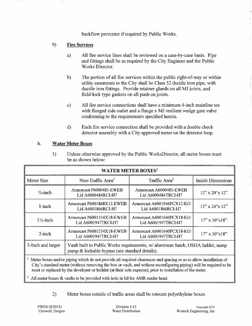
1) Unless otherwise approved by the Public WorksDirector, all meter boxes must be as shown below:
WATER METER BOXES1
Meter Size Non-Traffic Area2 Traffic Area2 Inside Dimensions
%-inch Armorcast P6000485-EWEB Armorcast A6000485-EWEB
12" x 20"x 12" Lid A6000484RCI-H7 Lid A6000484TRCI-H7
1-inch Armorcast P6001868X12-EWEB Armorcast A6001946PCX12-KO
13" x 24"x 12" Lid A6001866RCI-H7 Lid A6001866RCI-H7
1 Vi-inch Armorcast P6001534Xl 8-EWEB Armorcast A6001640PCX18-KO
17" x 30"xl 8" Lid A6001947TRCI-H7 Lid A600194 7TRCI-H7
2-inch Armorcast P6001534Xl 8-EWEB Armorcast A6001640PCX18-KO
17" x 30"x18" Lid A600194 7TRCI-H7 Lid A600194 7TRCI-H7
3-Inch and larger Vault built to Public Works requirements, w/ aluminum hatch, OSHA ladder, sump pump & lockable bypass (see standard details).
1 Meter boxes and/or piping which do not provide all required clearances and spacing so as to allow installation of City's standard meter (without removing the box or vault, and without reconfiguring piping) will be required to be reset or replaced by the developer or builder (at their sole expense), prior to installation of the meter.
2 All meter boxes & vaults to be provided with hole in lid for AMR reader head.
2) Meter boxes outside of traffic areas shall be rotocast polyethylene boxes
PWDS (8/2015) Creswell, Oregon
Division 5-13 Water Distribution
Copyright 2014
W estech Engineering, Inc
I

provided with non-skid polymer concrete covers with cast iron reader lids and AMR holes as specified.
3) Meter boxes within traffic areas shall be polymer concrete boxes provided with traffic-rated non-skid polymer concrete covers with cast iron reader lids and AMR holes as specified.
4) All meter boxes and vaults shall be provided with knockouts in lid as applicable for radio-read AMR sensors.
1. Fire Hydrants
1) Unless otherwise required by the Creswell Fire District, all fire hydrants shall conform to the following:
a) All fire hydrants shall be improved, dry barrel, 5114-inch compression type valve, traffic model.
b) Fire hydrants shall be equipped with two 2Y2-inch hose ports (NST), one 4Y2-inch pumper port (NST) with Storz adapter as specified, 1 Yz-inch pentagon nut, and barrel drains.
c) Fire hydrants shall be oriented so as to optimize access to ports, or as directed by the City Engineer or Fire Chief.
d) Fire hydrants shall be Kennedy Guardian K81D or Waterous Pacer, and shall be yellow with a factory epoxy coating.
e) All hydrants within a single project (including within all phases of a project) shall be of the same manufacturer.
J. Mainline Blow offs
1) Minimum allowable blowoff size shall be as outlined und~r Section 5 .12. Blowoffs shall be sized to provide adequate flushing velocities as approved by the City Engineer.
2) Unless otherwise shown or authorized by the City Engineer, all blowoffs shall be provided with valve boxes and/or meter boxes as shown in the Standard Details.
k. Mainline Tapping Tees
1) Tapping tees used for making connections to existing, in-service lines shall be all stainless steel construction (including stainless steel flange) with full perimeter gasket, and shall have Class 125 outlet flanges. In all cases, the tapping tee shall be designed for use with the existing pipe materials and O.D. equivalent.
2) All tapping valves shall be resilient wedge gate valves furnished with a fusion
PWDS (8/2015) Creswell, Oregon
Division 5-14 Water Distribution
Copyright 2014
W estech Engineering, Inc
bonded epoxy coating inside & outside conforming to the requirements of AWWAC-550.
3) Any company performing mainline taps shall be prequalified with the City prior to performing any work on a project.
4) Contractors shall coordinate all taps with City Public Works and perform work with Public Works staff present.
1. Underground Warning Tape
1) Underground warning tape shall be detectable or non-detectable acid and alkali resistant safety warning tape. The tape shall consist of a minimum 4.0 mil (0.004") thick, virgin low density polyethylene plastic film formulated for extended use underground. The tape shall be in accordance with the APW A national color code and shall be permanently imprinted in lead free black pigments suitable for direct burial.
2) The tape shall be safety blue and shall be provided with the legend "CAUTION BURIED WATER LINE BELOW" or approved equivalent printed continuously down the length of the tape.
m. Toning Wire
1) A continuous insulated 12 gauge solid core copper toning wire shall be supplied with non-metallic pipe. Insulation shall be blue in color for potable water piping.
2) Additional wire shall be supplied as necessary to allow the toning wire to be looped up at all valve boxes on all lines.
n. Concrete (Cast-in-Place) Thrust Restraint.
1) All concrete shall conform to the requirements of OSSC (ODOT/APWA) 00440, Commercial Grade Concrete, 3300 psi (5" slump or stiffer). Concrete mix design shall be submitted to the City for review and approval prior to use.
2) If hand mixed sack-crete type concrete is proposed, it shall be a 4000 psi minimum mix (approved by the City prior to use), mixed with the minimum amount of water necessary for workability (5" slump or stiffer).
3) In no case will .dry sack-crete (either in bags or as loose mix) be considered as an acceptable substitute for an approved concrete mix, placed as specified herein or on the drawing details.
o. Bore Casings and Accessories
1) Carrier pipe used in bore casings shall meet the minimum specifications
PWDS (8/2015) Creswell, Oregon
Division 5-15 Water Distribution
Copyright 2014
W estech Engineering, Inc
contained herein. Casing pipe shall be of a size to permit proper construction of the carrier pipe to the required lines and grades.
2) Casing shall be welded smooth steel pipe conforming to the requirements of ASTM A-53 or approved equal, with a minimum yield strength of35,000 psi.
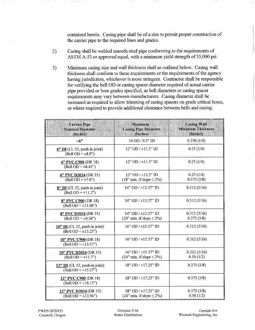
3) Minimum casing size and wall thickness shall as outlined below. Casing wall thickness shall conform to these requirements or the requirements of the agency having jurisdiction, whichever is more stringent. Contractor shall be responsible for verifying the bell OD or casing spacer diameter required of actual carrier pipe provided or bore grades specified, as bell diameters or casing spacer requirements may vary between manufacturers. Casing diameter shall be increased as required to allow trimming of casing spacers on grade critical bores, or where required to provide additional clearance between bells and casing.
<6" 10 OD I 9.5" ID 0.250 (1/4)
6" DI (CL 52, push-injoint) 12" OD I ±11.5'' ID 0.25 (1/4) (Bell OD = ±8.9")
6" PVC C900 (DR 18) 12" OD I ±11.5" ID 0.25 (1/4) (Bell OD = ±8.43")
6" PVC D3034 (DR 35) 12" OD I ±11.5'' ID 0.25 (1/4) (Bell OD= ±7.0") (18" min. if slope :S 2%) 0.375 (3/8)
8" DI (CL 52, push-in joint) 14" OD I ±13.37" ID 0.312 (5116) (Bell OD= ±11.2")
8" PVC C900(DR18) 14" OD I ±13.37" ID 0.312 (5/16) (Bell OD= ±11.06")
8" PVC D3034 (DR 35) 14" OD I ±13.37" ID 0.312 (5/16) (Bell OD= ±9.36") (20" min. if slope :S 2%) 0.375 (3/8)
10" DI (CL 52, push-injoint) 16" OD I ±15.37" ID 0.312 (5/16) (Bell OD= ±13.25")
10" PVC C900 (DR 18) 16" OD I ±15.37" ID 0.312 (5/16) (Bell OD= ±13.57")
10" PVC D3034 (DR 35) 16" OD I ±15.37" ID 0.312 (5/16) (Bell OD= ±11.7'') (24" min. if slope :S 2%) 0.50 (1/2)
12" DI (CL 52, push-in joint) 18" OD I ±17.25" ID 0.375 (3/8) (Bell OD= ±15.37")
12" PVC C900 (DR 18) 18" OD I ±17.25" ID 0.375 (3/8) (Bell OD= ±16.13")
12" PVC D3034 (DR 35) 18" OD I ±17.25" ID 0.375 (3/8) (Bell OD= ±13.94") (24" min. if slope :S 2%) 0.50 (1/2)
PWDS (8/2015) Division 5-16 Copyright 2014
Creswell, Oregon Water Distribution W estech Engineering, Inc

14" DI (CL 52, push-in joint) (Bell OD= ±17.85")
14" PVC C900 (DR25) (Bell OD= ±17.94")
15" PVC D3034 (DR 35) (Bell OD= ±17.05")
16" DI (CL 52, push-in joint) (Bell OD = ±20")
16" PVC C905 (DR 25) (Bell OD= ±20.41 ")
18" DI (CL 52, push-injoint) . (Bell OD = ±22.2")
18" PVC C905 (DR 25) (Bell OD = ±22.87")
18" PVC F679 (PS46) (Bell OD= ±20.85")
20" DI (CL 52, push-in joint) (Bell OD= ±24.3")
20" PVC C905 (DR 25) (Bell OD= ±25.34")
21" PVC F679 (PS46) (Bell OD = ±24.58")
24" DI (CL 52, push-in joint) (Bell OD = ±28.5")
24" PVC C905 (DR 25) (Bell OD = ±30.27")
24" PVC F679 (PS46) (Bell OD= ±27.65")
27" PVC F679 (PS46) ·(Bell OD= ±31.16")
30" DI (CL 52, push-in joint) (Bell OD = ±34.95")
30" PVC C905 (DR 25) (Bell OD= ±37.12")
30" PVC F679 (PS46) (Bell OD= ±35.61")
36" DI (CL 52, push-in joint) (Bell OD= ±41.4")
PWDS (8/2015) Creswell, Oregon
22" OD I ±21" ID
22" OD I ±21" ID
22" OD I ±21.2" ID (24" min. if slope :S 2%)
24" OD I ±23" ID
24" OD I ±23" ID
26" OD I ±25" ID
26" OD I ±25" ID
24" OD I ±23" ID (28" min. if slope :S 2%)
28" OD I 27" ID
28" OD I 27" ID
28" OD I 27" ID (3 O" min. if slope :S 2%)
32" OD I ±31" ID
34" OD I 33" ID
32" OD I 3 l" ID (34" min. if slope :S 2%)
36" OD I ±34.75 ID
38" OD I ±36.75" ID
42" OD I ±40.75" ID
42" OD I ±40.75" ID ( 44" min. if slope :S 2%)
46" OD I ±44.75" ID
Division 5-17 Water Distribution
0.50 (1/2)
0.50 (1/2)
0.50 (1/2) 0.50 (1/2)
0.50 (1/2)
0.50 (1/2)
0.50 (1/2) 0.50 (1/2)
0.50 (1/2) 0.50 (1/2)
0.50 (1/2)
0.50 (1/2)
0.50 (1/2)
0.50 (1/2)
0.50 (1/2)
0.50 (1/2)
0.50 (1/2)
0.625 (5/8)
0.625 (5/8)
0.625 (5/8)
0.625 (5/8)
0.625 (5/8)
Copyright 2014
W estech Engineering, Inc
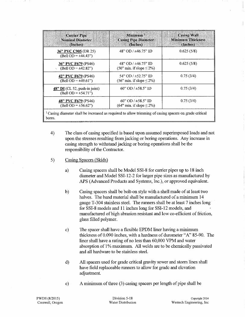
36" PVC C905 (DR 25) 48" OD I ±46.75" ID 0.625 (5/8) (Bell OD = ±44.43")
36" PVC F679 (PS46) 48" OD I ±46.75" ID 0.625 (5/8) \ (Bell OD = ±42.82") ( 50" min. if slope :::; 2%)
42" PVC F679 (PS46) 54" OD I ±52.75" ID 0.75 (3/4) (Bell OD= ±49.61") (56" min. if slope:::; 2%)
48" DI (CL 52, push-in joint) 60" OD I ±58.5'' ID 0.75 (3/4) (Bell OD= ±54.71")
48" PVC F679 (PS46) 60" OD I ±58.5'' ID 0.75 (3/4) (Bell OD = ±56.62"} ( 64" min. if slope :::; 2%)
1 Casing diameter shall be increased as required to allow trimming of casing spacers on grade critical bores.
4) The class of casing specified is based upon assumed superimposed loads and not upon the stresses resulting from jacking or boring operations. Any increase in casing strength to withstand jacking or boring operations shall be the responsibility of the Contractor.
5) Casing Spacers (Skids)
PWDS (8/2015) Creswell, Oregon
a) Casing spacers shall be Model SSI-8 for carrier pipes up to 18 inch diameter and Model SSI-12-2 for larger pipe sizes as manufactured by APS (Advanced Products and Systems, Inc.), or approved equivalent.
b) Casing spacers shall be bolt-on style with a shell made of at least two halves. The band material shall be manufactured of a minimum 14 gauge T-304 stainless steel. The runners shall be at least 7 inches long· for SSI-8 models and 11 inches long for SSI-12 models, and manufactured of high abrasion resistant and low co-efficient of friction, glass filled polymer.
c) The spacer shall have a flexible EPDM liner having a minimum thickness of0.090 inches, with a hardness of durometer "A" 85-90. The liner shall have a rating of no less than 60,000 VPM and water absorption of 1 % maximum. All welds are to be chemically passivated and all hardware to be stainless steel.
d) All spacers used for grade critical gravity sewer and storm lines shall have field replaceable runners to allow for grade and elevation adjustment.
e) A minimum of three (3) casing spacers per length of pipe shall be
Division 5-18 Water Distribution
Copyright 2014
W estech Engineering, Inc

required, or 6-foot on center maximum spacing, whichever is greater.
6) End Seals.
a) Where casings are filled with sand (gravity or non-pressure pipelines), end seals shall be grout/masonry end caps with 4" minimum diameter sand feed and vent tubes at each end. The vent tubes shall be plugged with grout after the casing is filled with sand.
b) Where casings are not filled with sand (pressure pipelines), end seals shall be Model AC (pull-on) or Model AW (wrap-around with pressure sensitive butyl mastic strips) end seals as manufactured by APS, or approved equivalent, fastened to the casing and carrier pipe with stainless steel bands.
5.9 GENERAL DESIGN CONSIDERATIONS
a. The water system shall have sufficient capacity to maintain 40 psi at the building entrance for one and two family dwellings. For other development, the system shall have sufficient capacity to provide minimum pressure of35 psi at the building side of the meter during periods of maximum use, and to provide sufficient volumes of water at adequate pressures to satisfy the maximum expected daily consumption plus fire flows.
b. Normal working pressure in the distribution system should be approximately 70 psi with a range of 40 psi to 100 psi.
c. Head loss shall be determined by the Hazen-Williams equation based on the following coefficients.
I Hazen-Williams Coefficients I I Pipe Diameter I C Value I
8 Inches and Less 100
10 to 12 Inches 110
Greater than 12 Inches 120
d. Velocities in mains shall normally range from three (3) to six (6) feet per second for average demand to a maximum velocity of ten (10) feet per second for maximum day demand plus fire flow.
e. A 20 psi residual pressure under fire flow conditions shall be maintained at all points in the distribution system. Generally, a maximum velocity of ten (10) feet per second will govern for sizing mains at all other locations of the service level where this criteria does not govern.
PWDS (8/2015) Creswell, Oregon
Division 5-19 Water Distribution
Copyright 2014
W estech Engineering, Inc

f. Private systems shall limit velocities as required by the Oregon Plumbing Specialty Code, Installation Standards.
g. Providing for Future Development
1) As a condition of water service, all developments will be required to provide public water mains of sufficient size for fire protection to adjacent parcels, as well as connection (to the new system) of existing water lines, hydrants or services crossed or intercepted by or adjacent to the new waterlines, at locations as required by the City Engineer and Public Works Director (see PWDS also 1.6.e). This shall include the extension of water mains in easements across the property to adjoining properties and across the street frontage of the property to adjoining properties when the main is located in the street right-of-way. This shall include extension to the far side of streets fronting or adjacent to the development as required to avoid work within or under these streets in the future. This shall include waterlines that are oversized to provide capacity for required fire flows.
2) In general, water distribution systems should be designed for maximum development of the service area with recognition of possible urban renewal, industrial expansion, etc.
5.10 WATER SYSTEM CAPACITY
a. General:
1) In areas not addressed in the Water Master Plan, design capacities shall be determined by consideration of the following factors and assumptions:
a) Area to be serviced, both immediate and adjacent.
b) Current and projected population within the areas to be served.
c) Current and projected land use within the areas to be served.
d) Commercial, industrial, or institutional users to be served.
e) Changes in any of the above factors which are likely to occur within a foreseeable time period.
2) In the absence of consumption data or other reliable information, the following factors may be assumed:
PWDS (8/2015) Creswell, Oregon
a) Peak hour demands as follows:
(1) 5 gpm per single family residential
(2) 2.5 gpm per dwelling unit for multiple family residential
Division 5-20 Water Distribution
Copyright 2014
W estech Engineering, Inc

(3) 5,000 gal/ac/day for commercial development
(4) 10,000 gal/ac/day for industrial development
b) Demand for unique commercial installations, industrial users, PUD's, multiple and institutional developments shall be calculated on an individual basis.
b. Fire Flow Requirements
1) Unless otherwise approved or required by the City Engineer and the local Fire Marshall, minimum fire flows shall be as follows:
MINIMUM FIRE FLOW REQUIREMENTS**
Location Recommended Duration Fire Flow (gpm) (hours)
Residential R-1 1,000 2
R-2 1,500 2
R-3 2,000 2
Commercial Residential CR 2,500 3
Public (Schools & Institutions) 4,000 4
Commercial/Industrial ( C, I) New Facilities 3,250 3 Existing Facilities up to 4,000 4
** These values do not supersede or take the place of OFC or OBC fire flow requirements. Higher values may be necessary based on Fire Code, Fire Marshall or ISO requirements. Reductions may be allowed by the Fire Chief for buildings with fire sprinkler systems.
2) In all cases, all new fire hydrants shall be capable of delivering a minimum of 1,000 gpm at 20 psi residual system pressure. This requirement will apply independently to each phase of multi-phase projects.
5.11 LOOPING
a. The distribution system mains shall be looped at all possible locations.
b. All water lines shall be looped and valved such that the removal of any single line segment from service will not result in more than one fire hydrant being taken out of service.
c. The installation of permanent dead-end mains upon which fire protection depends and areas of large demands on single mains will not be permitted.
PWDS (8/2015) Creswell, Oregon
Division 5-21 Water Distribution
Copyright 2014
W estech Engineering, Inc

5.12 BLOWOFFS
a. All dead-end mains shall terminate with a blowoff assembly or a fire hydrant.
b. Permanent dead-ends shall have a permanent blow-off assembly and a permanent thrust restraint system. Permanent blowoffs in cul-de-sacs shall be located in front of the curb within five ( 5) feet from the curb face.
c. Mains which can conceivably be extended at some later date shall have a mainline valve (same size as mainline) in front of the blowoff assembly, and a thrust restraint system which allows the mainline valve to be connected to without taking the line out of service.
d. Blowoffs shall be sized to ensure that the water mains can be flushed at a minimum velocity of 21/2 feet per second in accordance with A WW A C-650. The following table may be used as a minimum guideline assuming 40 psi minimum residual system pressure under flushing conditions.
I MAINLINE BLOWOFF SIZES I Water Main Diameter Minimum Blowoff Diameter
6 and 8-inch 2-inch
10 and 12-inch 4-inch
>12 As required
e. The design engineer shall submit calculations showing that these flushing velocities can be satisfied.
f. Temporary blowoffs larger than 2-inches in diameter shall have a valve conforming to the requirements contained herein for mainline valves.
g. Temporary blowoffs, where required for cleaning new water mains, shall be located at the lower end of the line to be flushed whenever possible.
5.13 MINIMUM DEPTH
a. The standard minimum cover over buried water mains within the street right-of-way or easements shall be thirty six (36) inches from the finished grade, except that a minimum of 40 inches cover shall be required for waterlines in fill slopes.
PWDS (8/2015) Creswell, Oregon
Division 5-22 Water Distribution
Copyright 2014
W estech Engineering, Inc

I
I
b. Finish grade shall normally be determined as follows:
I FINISH GRADE I Mainline Location Reference Finish Grade
Waterline under sidewalk in right-of-way Top of curb
Waterline in front of curb Gutter
Waterline in cut slope (ie. waterline located Top of curb (ie. cover depth measured behind and parallel with curb/sidewalk) from top of curb grade)
Waterline in cut slope other than parallel with Perpendicular from pipe to surface curb line
Fill slopes Perpendicular from pipe to surface
Easement Finish grade at pipe centerline
c. Where the waterline is located in the cut side slope, in an undeveloped right-of-way, or along a roadway developed at less than ultimate width (including sidewalks), the waterline shall be placed at a depth sufficient to ensure that 36-inches of cover is maintained at the time of final construction of the roadway.
5.14 MINIMUM MAINLINE SIZE
a. Minimum sizes for water mains shall be as follows:
Minimum Diameter
6-inch
8-inch
8-inch
10-inch & Larger
PWDS (8/2015) Creswell, Oregon
MAINLINE SIZE REQUIREMENTS
I Type of Mainline
Public lines in cul-de-sacs which cannot be looped in the future and which are beyond the fire hydrant envelope of250 feet to the furthest point on any existing or future structure. Private fire line supplying either a single fire hydrant or a building fire suppression system. Looping of private fire lines which supply hydrants will be required.
Minimum size water main for the public water system. Looping back into the distribution grid shall be at intervals as required by the City, but shall generally not exceed ±600 feet.
Public water distribution mains, and permanently dead-end mains supplying fire hydrants with a required fire flow of 1,500 gpm of less.
As required for transmission mains, distribution mains in industrial subdivisions, and fire lines supplying more than 1,500 gpm.
Division 5-23 Water Distribution
Copyright 2014
W estech Engineering, Inc
I
I
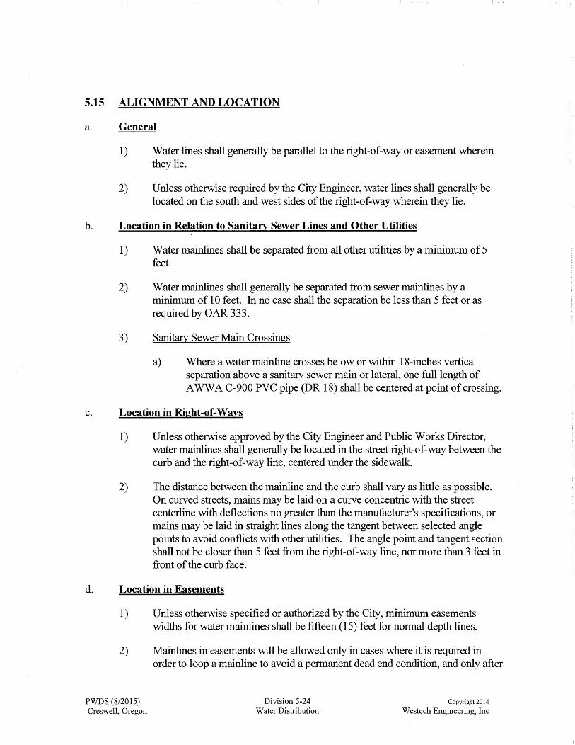
5.15 ALIGNMENT AND LOCATION
a. General
1) Water lines shall generally be parallel to the right-of-way or easement wherein they lie.
2) Unless otherwise required by the City Engineer, water lines shall generally be located on the south and west sides of the right-of-way wherein they lie.
b. Location in Relation to Sanitary Sewer Lines and Other Utilities
1) Water mainlines shall be separated from all other utilities by a minimum of 5 feet.
2) Water mainlines shall generally be separated from sewer mainlines by a minimum of 10 feet. In no case shall the separation be less than 5 feet or as required by OAR 333.
3) Sanitary Sewer Main Crossings
a) Where a water mainline crosses below or within 18-inches vertical separation above a sanitary sewer main or lateral, one full length of A WW A C-900 PVC pipe (DR 18) shall be centered at point of crossing.
c. Location in Right-of-Ways
1) Unless otherwise approved by the City Engineer and Public Works Director, water mainlines shall generally be located in the street right-of-way between the curb and the right-of-way line, centered under the sidewalk.
2) The distance between the mainline and the curb shall vary as little as possible. On curved streets, mains may be laid on a curve concentric with the street centerline with deflections no greater than the manufacturer's specifications, or mains may be laid in straight lines along the tangent between selected angle points to avoid conflicts with other utilities. The angle point and tangent section shall not be closer than 5 feet from the right-of-way line, nor more than 3 feet in front of the curb face.
d. Location in Easements
1) Unless otherwise specified or authorized by the City, minimum easements widths for water mainlines shall be fifteen (15) feet for normal depth lines.
2) Mainlines in easements will be allowed only in cases where it is required in order to loop a mainline to avoid a permanent dead end condition, and only after
PWDS (8/2015) Creswell, Oregon
Division 5-24 Water Distribution
Copyright 2014
W estech Engineering, Inc

all reasonable attempts to loop the mainlines in a right-of-way have been exhausted.
3) When water mainlines in easements are approved by the City, the easement shall be centered on the mainline, and the mainline shall be offset a minimum of 6 feet from any property line.
4) The conditions of the easement shall be such that the easement shall not be used for any purpose which would interfere with the unrestricted use for water mainline purposes. Under no circumstances shall a building or structure, trees or ornamental landscaping be placed over a water mainline or easement, nor shall any parallel fences be constructed within the easement (access gates acceptable to the City shall be installed in fences which the City allows to be constructed across City easements). Prohibited structures shall include decks, as well as footingsor overhanging portions of structures located outside the easement.
5) Easement locations for public water mainlines serving a PUD, apartment complex or commercial/industrial development shall be in parking lots, private drives or similar open areas which will permit an unobstructed vehicle access for maintenance by City forces.
6) Water mainlines with inside diameters larger than 12-inches will require wider easements.
7) Common placement in the easement of water and sewer or storm drain line may be allowed under certain conditions subject to approval by the City Engineer and Public Works Director. Easements wider than the minimum will be required.
8) Common easements will be reviewed on a case-by-case basis. Separation of utilities must meet Oregon State Health Division (OHD) requirements.
9) All easements must be furnished to the City for review and approval prior to recording.
e. Phased Construction
1) Water mains installed by phased construction, which will be extended in the future, shall terminate with a mainline valve, blow off and permanent thrust restraint system which allows the mainline valve to be connected to without taking the line out of service.
2) All developments will be required to extend mains across existing or proposed streets for future extensions by the City or other developments. All terminations shall be planned and located such that new or existing pavement will not have to be cut in the future when the main is extended.
3) The construction plans for each phase shall be capable of standing alone,
PWDS (8/2015) Creswell, Oregon
Division 5-25 Water Distribution
Copyright 2014
W estech Engineering, Inc
including provisions for looping and minimum fire flows.
f. Location in Relation to Ditches and Drainage Channels
1) Surface water crossings of mains shall be in accordance with OAR 333 and the requirements outlined herein.
2) Mains crossing ditches or drainage channels shall be designed to cross as nearly perpendicular to the channel as possible.
3) The following surface water crossings will be treated on a case-by-case basis:
a) Ditch or drainage channel crossing for pipes of 12-inch diameter and greater.
b) River or creek crossings requiring special approval from the Division of State Lands.
4) The minimum cover from the bottom of the ditch or drainage channel to the top of pipe shall be a minimum of thirty-six (36) inches unless otherwise approved by the City Engineer, Public Works Director and the Oregon Health Division.
5) A scour pad centered on the water line will be required for mains where the potential for erosion exists as determined by the City Engineer and Public Works Director. The size and design of scour pads will be reviewed on a case-by-case basis by the City Engineer.
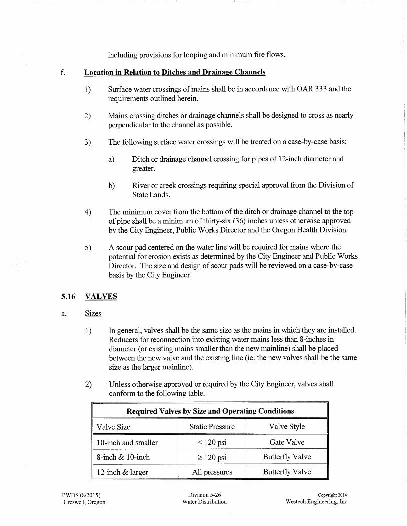
5.16 VALVES
a. Sizes
1) In general, valves shall be the same size as the mains in which they are installed. Reducers for reconnection into existing water mains less than 8-inches in. diameter (or existing mains smaller than the new mainline) shall be placed between the new valve and the existing line (ie. the new valves shall be the same size as the larger mainline).
2) Unless otherwise approved or required by the City Engineer, valves shall conform to the following table.
Required Valves by Size and Operating Conditions
I Valve Size
10-inch and smaller
8-inch & 10-inch
12-inch & larger
PWDS (8/2015) Creswell, Oregon
I Static Pressure
< 120 psi
~ 120 psi
All pressures
Division 5-26 Water Distribution
I Valve Style I Gate Valve
Butterfly Valve
Butterfly Valve
Copyright 2014
W estech Engineering, Inc
I.
3) Valve types and materials shall conform to the requirements of these Design Standards and the Standard Construction Specifications.
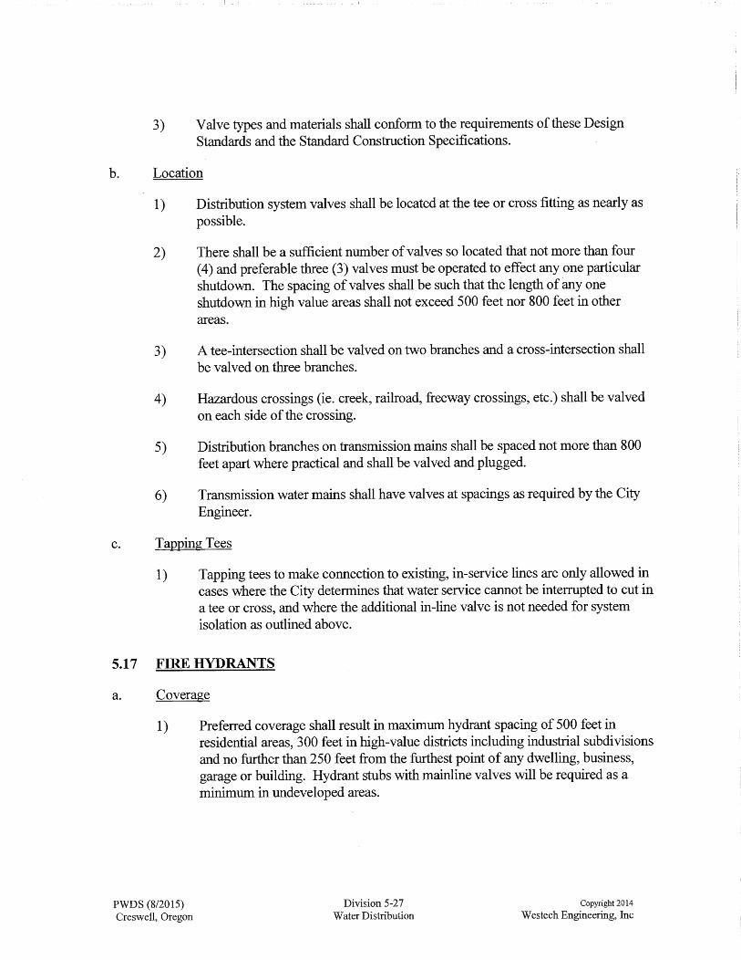
b. Location
1) Distribution system valves shall be located at the tee or cross fitting as nearly as possible.
2) There shall be a sufficient number of valves so located that not more than four (4) and preferable three (3) valves must be operated to effect any one particular shutdown. The spacing of valves shall be such that the length of any one shutdown in high value areas shall not exceed 500 feet nor 800 feet in other areas.
3) A tee-intersection shall be valved on two branches and a cross-intersection shall be valved on three branches.
4) Hazardous crossings (ie. creek, railroad, freeway crossings, etc.) shall be valved on each side of the crossing.
5) Distribution branches on transmission mains shall be spaced not more than 800 feet apart where practical and shall be valved and plugged.
6) Transmission water mains shall have valves at spacings as required by the City Engineer.
c. Tapping Tees
1) Tapping tees to make connection to existing, in-service lines are only allowed in cases where the City determines that water service cannot be interrupted to cut in a tee or cross, and where the additional in-line valve is not needed for system isolation as outlined above.
5.17 FIRE HYDRANTS
a. Coverage
1) Preferred coverage shall result in maximum hydrant spacing of 500 feet in residential areas, 300 feet in high-value districts including industrial subdivisions and no further than 250 feet from the furthest point of any dwelling, business, garage or building. Hydrant stubs with mainline valves will be required as a minimum in undeveloped areas.
PWDS (8/2015) Creswell, Oregon
Division 5-27 Water Distribution
Copyright 2014
W estech Engineering, Inc

b. Location
1) No fire hydrant shall be installed on a main ofless than 8-inch diameter unless it is in a looped system of 6-inch mains. The hydrant lead shall be a minimum of 6-inches in diameter.
2) Hydrants shall be placed in locations approved by the City Engineer and the Fire Chief.
3) In general, hydrants shall be located at comer of each public & private street intersection where possible (unless otherwise approved by the City Engineer and the Fire Chief). Hydrants located at points other than intersections shall be located at the extension of property lines (offset as required only to avoid conflict with survey monuments per ORS 92.044. 7).
4) Unless otherwise approved by the City, hydrants shall be placed between the sidewalk and the property line.
5) No hydrant shall be installed within five (5) feet of an existing utility pole or guy wire nor shall a utility or guy wire be placed within five ( 5) feet of an existing hydrant.
c. Hydrant Valves
1) Each fire hydrant shall have a hydrant valve and valve box at the mainline hydrant tee which will permit removal and repair of the hydrant without shutting down the water main supplying the hydrant.
2) Hydrant valves shall be resilient wedge gate valves.
3) The hydrant valve shall be connected directly to the mainline tee using a flange joint.
4) If the length of the hydrant lead is greater than 30 feet, an additional gate valve shall be provided within 3 feet of the hydrant.
d. Hydrant Leads.
1) All hydrant leads shall be Class 52 ductile iron, 6" minimum diameter, with retainer glands at both ends.
2) Unless specifically approved in writing by Public Works for long hydrant leads, all hydrant leads shall consist of a single piece of pipe without joints. Any joints allowed on hydrant leads shall be provided with fully restrained gaskets (Field-Lok or equivalent).
3) Service taps on hydrant leads are prohibited.
PWDS (8/2015) Creswell, Oregon
Division 5-28 Water Distribution
Copyright 2014
W estech Engineering, Inc

e. Hydrant Bury & Exposure
1) Hydrant bury shall be sufficient to provide a minimum of 36-inches of cover over the hydrant lead. In no case shall the bury be less than the depth of the waterline from which the hydrant is served.
2) The hydrant shall be set such that the base of bottom flange bolts are a minimum of 2-inches and a maximum of 6-inches above finish grade following all landscaping and surface restoration.
5.18 AIR RELEASE VALVES
a. General
1) Provisions for air relief shall be provided at all high points of waterlines. Where possible, location of service taps at high points in the line is preferable to the installation of an air relief valve.
2) Where service taps cannot be used, an air release valve shall be permanently installed at high points on all water mains at all location where air can accumulate. An automatic air release valve shall be installed in a manhole off of the street where flooding of the manhole or chamber will not occur.
b. Air Release Valve Piping
1) The open end of an air release pipe from automatic valves shall extend to the top of the manhole at least twelve inches above grade and provided with a screened, downward facing tee vent. Grade shall mean the existing ground elevation adjoining the meter box or vault.
5.19 WATER SERVICE LINES
a. General
1) The use of pumps on a water service line (between the mainline and the meter) to provide adequate pressure to a subdivision lot or property located above the pressure level of the supply main shall be prohibited. Booster pumps installed on private property shall require the installation of a backflow device meeting City and state standards.
2) Each legal lot of record shall be provided with a separate water service line connected to the public or approved private water main. Combined water service lines will be permitted only when the property cannot legally be further divided. An example of this is a residential lot with a house and unattached garage or shop with plumbing fixtures.
3) Separate water services and separate meters shall be installed to serve each
PWDS (8/2015) Creswell, Oregon
Division 5-29 Water Distribution
Copyright 2014
W estech Engineering, Inc

side of duplex lots, and each unit of triplex residential buildings unless otherwise approved by Public Works. Separate water services and separate meters shall be installed to serve each unit of condominiums or developments with separate detached dwelling units (except where otherwise approved by City for manufactured home parks).
4) Additional water service lines must be stubbed into the property lines sufficient to serve all residential parcels which can be further partitioned in the future where such future partition would require that the streets be cut to install such services.
b. Sizes
1) Standard service line sizes are 1-inch, 1 Yz-inch, 2-inch, 3-inch, 4-inch, 6-inch and 8-inch. Service lines will be reviewed for effects on the distribution system and shall not be greater in size than the distribution main.
I MINIMUM SERVICE SIZE I I Type of Service I Minimum Service Size I
Single residential service 1 1-inch
Triple residential service (triplexes only) 1 Yz-inch
Commercial Service 2 1 Yz" minimum
Notes: 1 . The next larger service size may be required for residential lots large enough to be
partitioned into additional lots without a water main extension. 2 . Commercial service pipe smaller than 1 W' require prior approval by the City Engineer
& Public Works Director. As an alternative to smaller service lines (with approval from Public Works), reducers can be installed at meter location as applicable if smaller meters are desired, and where maximum demand flows are demonstrated to be within operating limits of the smaller meter.
2) The water service line on the private side of the meter may not be larger than one nominal pipe size larger than the service line size.
3) Commercial services shall not be smaller than 1 Yz-inch (reducers may be installed at the meter location to accommodate a smaller meter). For new streets or streets being cut for service installation, far side commercial services shall be installed in a 4-inch minimum size PVC sleeve.
4) Service piping shall be equal to or greater than the meter size.
5) For 3-inch and larger meters, calculations, documentation and drawings as
PWDS (8/2015) Creswell, Oregon
applicable must be submitted with the expected flow requirements and proposed usage.
Division 5-30 Water Distribution
Copyright 2014
W estech Engineering, Inc

I
c. Tapping requirements
1) Tapping requirements for water service lines shall be as outlined below.
WATER SERVICE TAPPING REQUIREMENTS
Service Size Mainline Type Tapping Requirements
1" All pipe types Service Saddle
11/z" All pipe types Service Saddle
2" & larger All pipe types Mainline tee (or tapping saddle) with flanged valve
d. Location
1) Domestic
a) The service lines shall normally extend from the main to the location shown on the standard details. A curb stop and meter box shall be located at the termination of the service line.
b) The meter stop shall be located such that the front of the meter box is the distance behind the curb or sidewalk as shown on the standard details.
c) In general, individual service connections shall terminate in front of the property to be served. Double services shall be located on each side of a common side property line.
d) Domestic service lines shall not be connected to fire protection services, including hydrant leads.
2) Fire Service
PWDS (8/2015) Creswell, Oregon
a) A backflow prevention assembly (with detector loop & detector meter) shall be placed on fire service lines as required by the City.
b) Plans for fire service lines shall meet the requirements outlined in PWDS Division 1, and shall be stamped by a licensed Civil Engineer. The portion of the fire service within the right-of-way shall conform with PWDS 5.8.£9 (ie. Cl 52 DI pipe), and the remainder (on private property) shall conform with the Oregon Fire Code and referenced standards, and shall be acceptable to the Fire Chief.
c) Drawings for fire services shall include vicinity map, adjoining street name, width, curb and property line, location of existing water line referenced to the property line, existing hydrant locations and the
Division 5-31 Water Distribution
Copyright 2014
W estech Engineering, Inc
I

distance to property pins where the service crosses the property line (offset as required to avoid conflict with survey monuments per ORS 92.044.7).
5.20 WATERMETERS
a. General
1) Except as otherwise required, all water meters within the service area of the City of Creswell will be furnished and installed by City forces at the request and expense of the customer. The service line, meter box and all piping & fittings within the meter box must be installed by the developer.
2) Unless otherwise required or approved by Public Works, meters 1 y;-inches and larger shall be installed by a contractor retained by the developer, under the inspection and subject to the approval of Public Works.
3) A backflow preventer shall be provided if required by Public Works.
b. Location
1) General
a) Meters shall be located at the termination of the City service line. Unless otherwise approved by the Public Works Director, meters shall be located within or immediately adjacent to the right-of-way or easement containing the water mainline.
b) Water meters shall be located outside of buildings being served (including meters on fire service detector loops), at a location approved by the Public Works Director.
c) A public utility and access easement to the City shall be provided to and around any meter boxes or meter vaults set on private property. The easement shall be sized to provide a minimum of five ( 5) foot clear around the meter box or vault on all sides.
2) 3/4-inch through 2-inch Meters
a) In the right-of-way in a location that allows for easy reading and maintenance , at the location specified herein or shown on the standard details.
3) 3 Inch and Larger Meter:
PWDS (8/2015) Creswell, Oregon
a) On private property adjacent to the public right-of-way to allow reading and maintenance. It must be accessible with a crane truck to within ten feet of the installation with a ten foot vertical clearance.
Division 5-32 Water Distribution
Copyright 2014
W estech Engineering, Inc

b) The meter, vault and piping are to be protected from freezing, vandals and vehicles. The area around the vault must be sloped in such a manner to prevent storm water from ponding over or running into the vault.
c) A minimum three foot clear space must be provided around the vault to provide ample working space for maintenance.
d) All 3-inch and larger meters shall be provided with a remote readout head approved by Public Works which is located such that it can be read without entering the meter vault.
e) A sump pump shall be installed and maintained in the meter vault (of all meters larger than 2-inch) by the property owner, discharging to a storm drain or other location approved by Public Works. Owner shall be responsible for all permits & costs associated with providing power to the meter vault for the sump pump.
f) The configuration of the lockable bypass shall be acceptable to Public Works.
4) The meter, with approval by the City, may be located in the same vault with a backflow prevention device, provided a completed dimensioned design is submitted with a request for variance.
c. Meter Boxes
1) Meter boxes shall be provided by the Developer for each water service and meter location. Double set meters (2 meters in 1 box) are not allowed.
2) Meter boxes shall be set level to finish grade. The Developer or builder shall be responsible for setting meter boxes and services to finish grade prior to installation of water meters by the City.
3) Meter boxes that do not provide all required clearances and spacing so as to allow the City to install a standard meter without removing the box, will be required to be reset or replaced by the developer or builder (at their sole expense), prior to installation of the meter by the City.
5.21 PRIVATE WATER SYSTEMS
a. General design considerations for private water systems shall conform to requirements set forth by the Oregon Health Division, by the Oregon Plumbing Specialty Code (Chapter 10), and these Design Standards.
b. All public water mains within private developments shall be in public right-of-way or exclusive easements to the City of Creswell and shall conform to these design standards. Each connection of the private water system to the City system shall be through an approved backflow prevention assembly and meter.
PWDS (8/2015) Creswell, Oregon
Division 5-33 Water Distribution
Copyright 2014
W estech Engineering, Inc

c. Requirements for capacity, materials, looping, valves, fire protection, service lines and meters shall also be applicable to design within PUD areas.
d. The resale of water without written approval of the City shall be prohibited. Written authorization from the City shall be required for each service connection and for any sale of water.
5.22 BACKFLOW PREVENTION
a. General
1) All backflow assemblies shall be testable and include provisions for testing by a certified backflow testing person or organization.
2) An approved backflow prevention assembly with an approved metering system shall be required for each use in the following instances:
a) When a private line must be extended from or looped between two (2) or more City mains in order to obtain the required flow and the resultant loop is no benefit to the City grid system.
b) On all fire services, which shall also include a detector loop & detector meter configuration as approved by Public Works.
c) On all private water lines or private distribution system attached to the City's distribution system, with or without a master meter.
d) When an auxiliary water supply exists on the property being served.
e) As determined by the City Cross-connection Control Inspector and Oregon State Health Division requirements.
3) An approved reduced pressure backflow prevention assembly with an approved metering system shall be required for service connections in high hazard areas as determined by the City Engineer and Public Works Director.
4) The backflow assemblies must meet the City approved assembly standards, which standards are taken from the current approved list of assemblies maintained by the Oregon Health Division.
5) All backflow assemblies shall be installed in a box or vault approved by Public Works.
b. Location
1) The approved backflow prevention assembly shall be installed on the property being served in place accessible for City inspector and testing and located as follows:
PWDS (8/2015) Creswell, Oregon
Division 5-34 Water Distribution
Copyright 2014
W estech Engineering, Inc

a) Before any branch, immediately downstream of the meter; or
b) If no meter, at the property line; or
c) If in the building, before the first branch or hazard being controlled or as determined by the City Cross-connection Control Inspector; or
2) If installed outside the building being served, it shall be placed at or adjacent to the property line or easement line in a vault or structure in accordance with the manufacturer's recommendations and as approved by the Public Works Director. Vaults must have a sump and be watertight.
a) A public utility and access easement to the City shall be provided to and around any backflow assembly set on private property (ie. when installed outside of the building being served). The easement shall be sized to provide a minimum of five ( 5) foot clear around the box or vault on all sides.
c. Fire Department Connections CFDC)
1) The distance from a fire hydrant to the fire department connection (FDC) shall not exceed 40 feet unless otherwise approved in writing by the Fire Chief, but in no case shall a distance of greater than 60 feet be allowed.
2) FDCs connections/risers and FDC supply lines shall be installed in conformance with provisions of the Oregon Fire Code and applicable NFP A standards (including but not limited to installation of accessible ball drip valves, cover depths for freeze protection, etc.), with specific location and configuration subject to approval by the Fire Chief.
5.23 UNDERGROUND WARNING TAPE & TRACER WIRE
a. Detectable or non-detectable acid and alkali resistant safety warning tape shall be provided along all mainlines not located under sidewalks or paved portions of public streets.
b. Underground warning tape shall be placed a minimum of 12-inches and a maximum of 18-inches below the finish ground surface, and shall be continuous the entire length of the mainline as specified.
c. All water pipe (both public lines and private lines within right-of-way or easements) shall have an electrically conductive tracer wire, 12 gauge minimum size single strand insulated copper with blue sheathing, installed in the trench for the purpose of locating the pipe in the future. The tracer wire shall run the full length of the installed pipe, with each end extended to within 12-inches of the surface through a valve box or meter box.
PWDS (8/2015) Creswell, Oregon
Division 5-35 Water Distribution
Copyright 2014
W estech Engineering, Inc

5.24 MAINLINE BORED CROSSINGS
a. Casing size shall adequate to permit proper construction of the carrier pipe to the required lines and grades. Carrier pipe used in bore casings shall be as specified herein.
b. All bore crossings shall be provided with casing spacers and end seals. Casing spacer configuration shall conform to the manufacturer's recommendations, but in no case shall less t~an 3 spacers per length of pipe be used.
c. In order to prevent over-belling of PVC or other flexible pipe while installing it through the casing, provide a method for restricting movement between the assembled bell and spigot conforming with the manufacturer's recommendations.
d. The design of the bore crossing shall include the following as a minimum:
1) Casing and carrier pipe materials and dimensions, including outside bell diameters of the carrier pipe.
2) Details for any part of the system which must be changed as a result of the boring operation (manhole, headwall, etc.).
3) Bore and receiving pit backfill material and compaction requirements.
PWDS (8/2015) Creswell, Oregon
Division 5-36 Water Distribution
Copyright 2014
W estech Engineering, Inc


