28
CIVIL ENGINEERING DEPARTMENT SEM 1
| Date post: | 16-May-2018 |
| Category: |
Documents |
| Upload: | nguyencong |
| View: | 215 times |
| Download: | 0 times |

CIVIL ENGINEERING DEPARTMENT
SEM 1


Group : 2
Patel Pranay(09)
Ahir Mudra(10)
Khatri Mayuri(11)
Jardosh Chandni(12)
Sheta Nidhi(14)
Rana Sagar(15)
Viradiya Pruthika(16)
Dhola Kishan(17)


In Compass survey chain or tape is used for linear
measurements and compass is used for fixing
direction.
In compass freely suspended magnetic needle
directs to north- south and the bearing of line is
obtained by line of sight.

The principle of compass surveying is traversing;which
involves a series of connected lines.(as shown in above
fig.)
The magnetic bearings of the lines are measured by
prismatic compass and the distances of the lines (i.e.
AB,BC,CD,DE,EA) are measured by chain.
Such survey does not require the formation of a network
of triangles.

Traverse

When large area are involved, compass surveying is
used.
Traversing is that type of survey in which a number of
connecting survey lines form the frame work and the
directions and lengths of the survey lines are
measured with the help of an angle measuring
instrument and a tape respectively.
When the lines form a circuit which ends at the starting
point, it is known as a closed traverse.
If the circuit ends elsewhere, it is said to be an open
traverse.
Traversing


The compass is used with a tripod to ensure
that the compass card remains steady and in
focus when readings are being taken.
The tripod should be totally ‘Non-Magnetic’
and should have a male fitting that will
interface with the female socket at the base of
the compass.
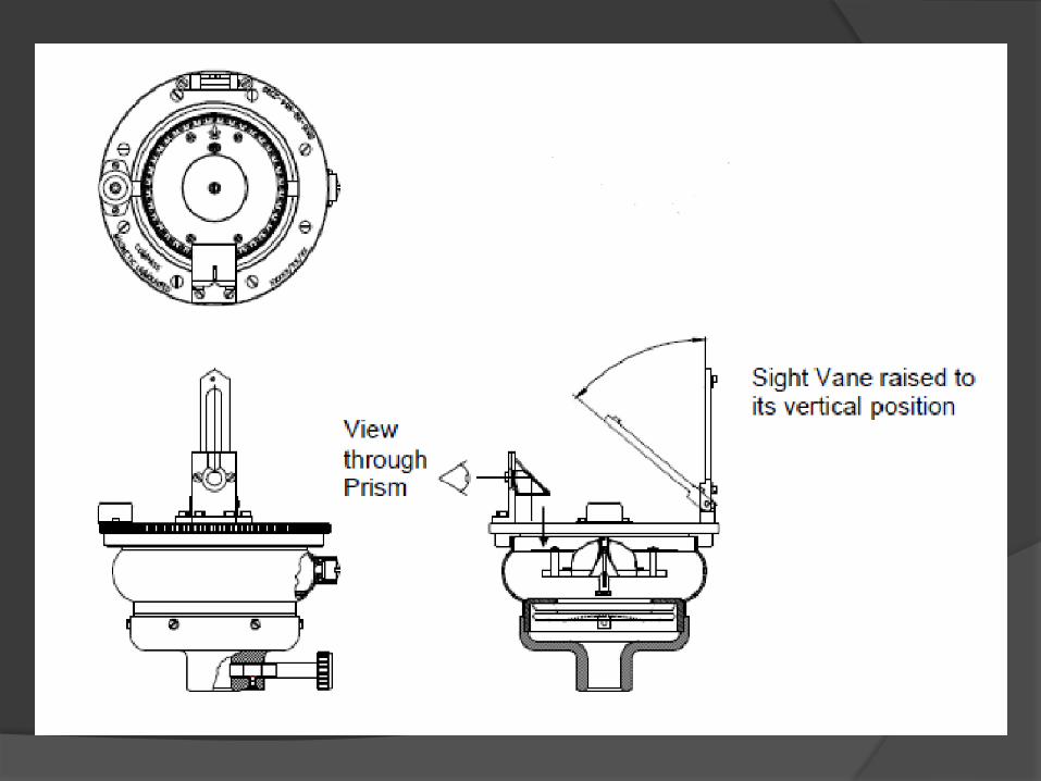
The process of operation is as
follows….
Mount the compass onto the Tripod.
Level the compass.
Raise the ‘Sighting Vane’ to the vertical position View
through the ‘Prism’ and align the ‘Sighting Vane’ and ‘Prism
Bracket’ slot with the object to be viewed.
The sight vane will cut the divisions of the compass card.
The point at which the compass card is cut represents the
magnetic heading.
A calibration chart will be provided with the compass
to indicate the errors of the compass and the
corrections to be made for each 15degree heading
(the compass should be re-calibrated annually)
To take a second bearing from the same location,
the compass can be rotated on the tripod by
loosening the Tripod Clamp screw and rotating the
body about the mounting spigot.
The compass should be replaced into its stowage
box after use.

Surveyor’s Compass

This surveyor's compass consists of a long, thin,
pointed needle of magnetized steel with a small
conical-shaped bearing of agate material at the
centre.
The agate bearing works on a pointed pivot of hard
steel carried at the centre of the low cylindrical metal
box (140mm in diameter).
Attached to the opposite ends of this box are two
sighting vanes with two slow motion screws and
clamps which enable a definite line of sight to be
defined or laid out.

The instrument can either be screwed on to a tripod or
remain hand-held for the purpose of measuring magnetic
bearings.
The metal box carries inside it, three graduated
horizontal circles: top and lower circles 0-360 degrees,
third circle in quadrants 0-90 degrees, with the N and S
directions identified as zero points and the E and W
directions are labelled as 90 degrees each.
The lower horizontal circle can read to 3 minutes directly
on the vernier.
A disc of glass, fitting on top of the metal case, protects
the needle and graduated circles.

In this instrument, the
needle remains in
a fixed position (the
position of the magnetic
south to north line), while
the two upper graduated
circles, together with the
line of sight, rotate about
the vertical axis.

The compass centered over station A of the line AB and is
leveled.
Having turned vertically the prism and sighting vane, raise
or lower the prism until the graduations on the rings are
clear and look through the prism.
Turn the compass box until the ranging rod at the station
B is bisected by hair when looked through the prism.
Turn the compass box above the prism and note the
reading at which the hair line produced appears to cut the
images of the graduated ring which gives the bearing of
line AB.

There are two systems
commonly used to express
the bearing.
WHOLE CIRCLE BEARING:
In this system the bearing of a line measured with the
magnetic north in clockwise direction. The value of bearing
thus varies from 0o to 360o.
QUADRANTAL SYSTEM:
In this system the bearing of a line is measured eastward or
westward from north or south whichever is near. The
directions can be either clock wise or anti clockwise
depending upon the position of the line.

Every line has two bearings one observed at each
end of the line.
The bearing of the line in the direction of progress
of the survey is called Fore Bearing (FB), while the
bearing in the opposite direction is called Back
Bearing (BB).
Therefore BB of a line differs from FB by exactly
180o.

The errors may be classified as
Instrumental errors
Personal errors
Errors due to natural causes

They are those which rise due to the faulty
adjustments of the instruments. They may be
due to the following reasons:
• The needle not being perfectly straight.
• Pivot being bent
• Sluggish needle
• Blunt pivot point
• Improper balancing weight
• Plane of sight not being vertical
• Line of sight not passing through the center of
graduated ring
They may be due to the following reasons:
Inaccurate leveling of the compass box.
Inaccurate centering.
Inaccurate bisection of signals.
Carelessness in reading and recording.

• They may be due to following reasons:
• Variation in declination
• Local attraction due to proximity of local attraction
forces.
• Magnetic changes in the atmosphere due to
clouds and storms.
• Irregular variations due to magnetic storms etc.
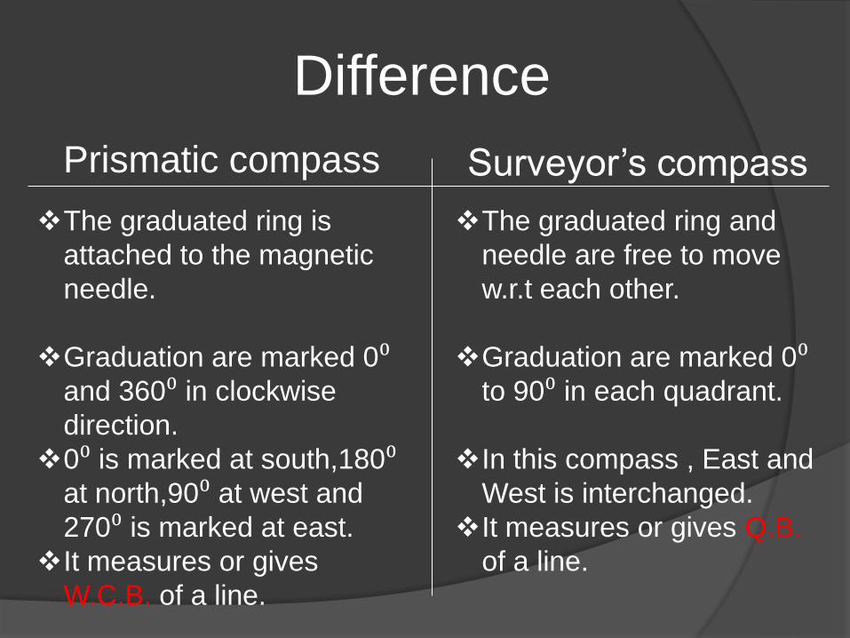
Difference
Prismatic compass Surveyor’s compass
The graduated ring is
attached to the magnetic
needle.
Graduation are marked 0⁰ and 360⁰ in clockwise
direction.
0⁰ is marked at south,180⁰ at north,90⁰ at west and
270⁰ is marked at east.
It measures or gives
W.C.B. of a line.
The graduated ring and
needle are free to move
w.r.t each other.
Graduation are marked 0⁰ to 90⁰ in each quadrant.
In this compass , East and
West is interchanged.
It measures or gives Q.B.
of a line.


Patel Pranay 09
Ahir Mudra 10
Khatri Mayuri 11
Jardosh Chandni 12
Sheta Nidhi 14
Rana Sagar 15
Viradiya Pruthika 16
Dhola Kishan 17


