FAA APPROVED525FMA-01 Configuration AA U.S. 2-1/2-2
SECTION II - OPERATING LIMITATIONSMODEL 525
OPERATING LIMITATIONS
CERTIFICATION STATUS
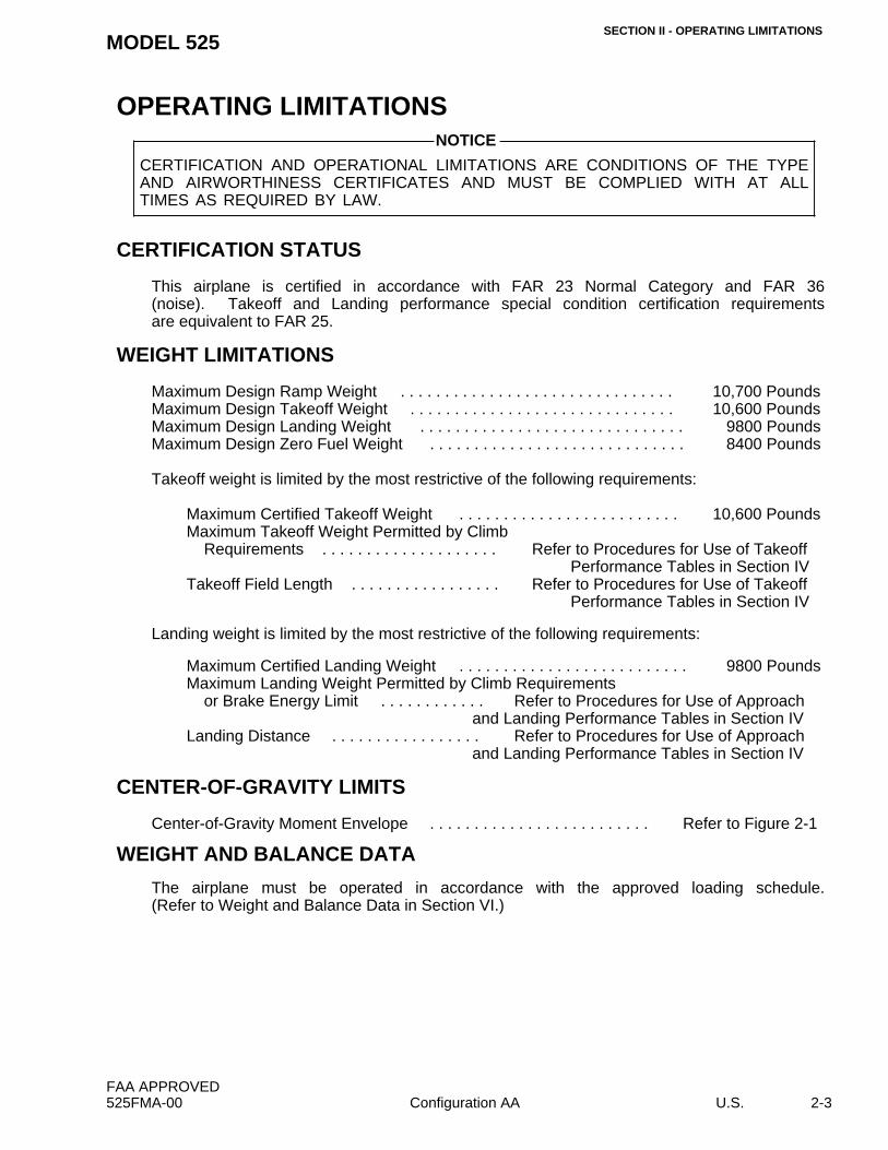
This airplane is certified in accordance with FAR 23 Normal Category and FAR 36(noise). Takeoff and Landing performance special condition certification requirementsare equivalent to FAR 25.
The airplane must be operated in accordance with the approved loading schedule.(Refer to Weight and Balance Data in Section VI.)
CERTIFICATION AND OPERATIONAL LIMITATIONS ARE CONDITIONS OF THE TYPEAND AIRWORTHINESS CERTIFICATES AND MUST BE COMPLIED WITH AT ALLTIMES AS REQUIRED BY LAW.
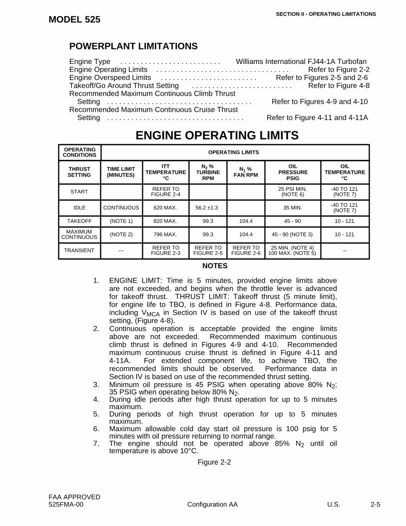
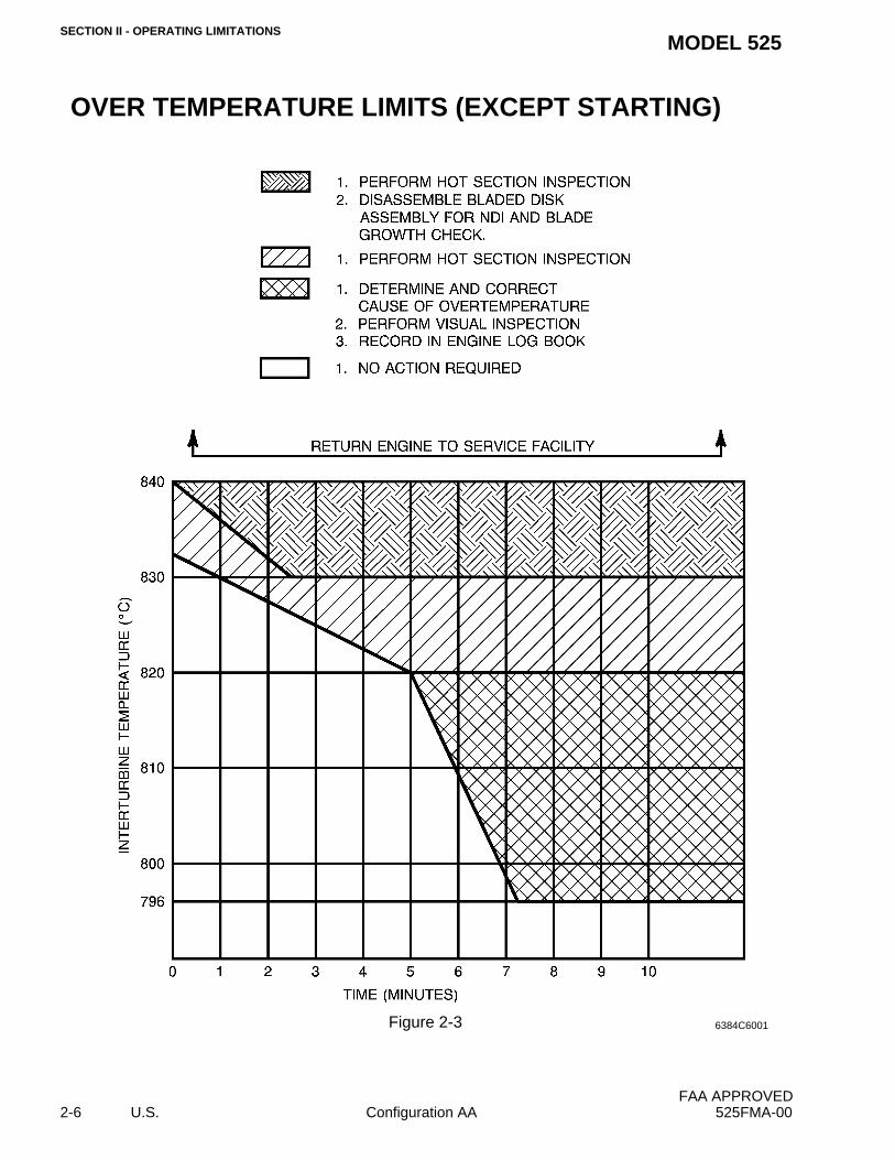
1. ENGINE LIMIT: Time is 5 minutes, provided engine limits aboveare not exceeded, and begins when the throttle lever is advancedfor takeoff thrust. THRUST LIMIT: Takeoff thrust (5 minute limit),for engine life to TBO, is defined in Figure 4-8. Performance data,including VMCA in Section IV is based on use of the takeoff thrustsetting, (Figure 4-8).
2. Continuous operation is acceptable provided the engine limitsabove are not exceeded. Recommended maximum continuousclimb thrust is defined in Figures 4-9 and 4-10. Recommendedmaximum continuous cruise thrust is defined in Figure 4-11 and4-11A. For extended component life, to achieve TBO, therecommended limits should be observed. Performance data inSection IV is based on use of the recommended thrust setting.
3. Minimum oil pressure is 45 PSIG when operating above 80% N2;35 PSIG when operating below 80% N2.
4. During idle periods after high thrust operation for up to 5 minutesmaximum.
5. During periods of high thrust operation for up to 5 minutesmaximum.
6. Maximum allowable cold day start oil pressure is 100 psig for 5minutes with oil pressure returning to normal range.
7. The engine should not be operated above 85% N2 until oiltemperature is above 10°C.
Figure 2-2
OPERATINGCONDITIONS OPERATING LIMITS
THRUSTSETTING
TIME LIMIT(MINUTES)
ITTTEMPERATURE
°C
N2 %TURBINE
RPM
N1 %FAN RPM
OILPRESSURE
PSIG
OILTEMPERATURE
°C
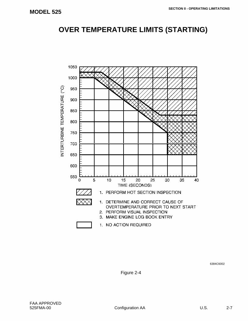
START REFER TOFIGURE 2-4
25 PSI MIN.(NOTE 6)
-40 TO 121(NOTE 7)
IDLE CONTINUOUS 620 MAX. 56.2 ±1.3 35 MIN. -40 TO 121(NOTE 7)
Time to light-off is defined as the time after the throttle lever is moved fromOFF to IDLE position until light-off is indicated.
(Continued Next Page)
6384C6004
FAA APPROVED525FMA-01 Configuration AA U.S. 2-9
SECTION II - OPERATING LIMITATIONSMODEL 525
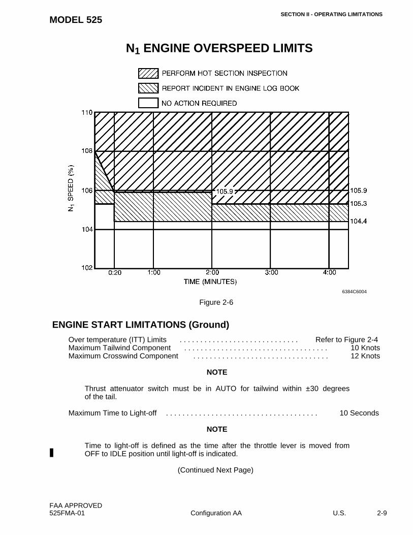
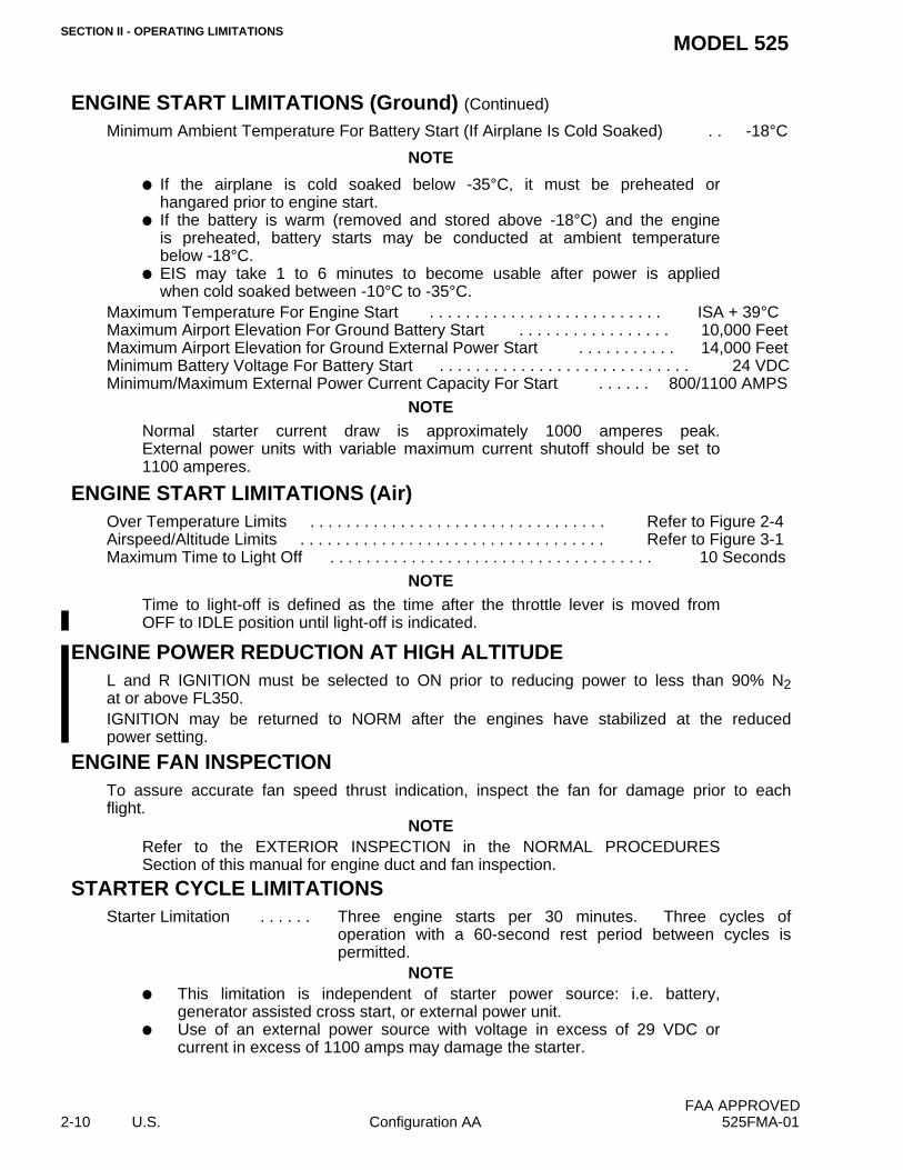
ENGINE START LIMITATIONS (Ground) (Continued)
Minimum Ambient Temperature For Battery Start (If Airplane Is Cold Soaked) . . -18°C
NOTE
f If the airplane is cold soaked below -35°C, it must be preheated orhangared prior to engine start.
f If the battery is warm (removed and stored above -18°C) and the engineis preheated, battery starts may be conducted at ambient temperaturebelow -18°C.
f EIS may take 1 to 6 minutes to become usable after power is appliedwhen cold soaked between -10°C to -35°C.
NOTENormal starter current draw is approximately 1000 amperes peak.External power units with variable maximum current shutoff should be set to1100 amperes.
NOTETime to light-off is defined as the time after the throttle lever is moved fromOFF to IDLE position until light-off is indicated.
ENGINE POWER REDUCTION AT HIGH ALTITUDEL and R IGNITION must be selected to ON prior to reducing power to less than 90% N2at or above FL350.IGNITION may be returned to NORM after the engines have stabilized at the reducedpower setting.
ENGINE FAN INSPECTIONTo assure accurate fan speed thrust indication, inspect the fan for damage prior to eachflight.
NOTERefer to the EXTERIOR INSPECTION in the NORMAL PROCEDURESSection of this manual for engine duct and fan inspection.
STARTER CYCLE LIMITATIONSStarter Limitation . . . . . . Three engine starts per 30 minutes. Three cycles of
operation with a 60-second rest period between cycles ispermitted.
NOTEf This limitation is independent of starter power source: i.e. battery,
generator assisted cross start, or external power unit.f Use of an external power source with voltage in excess of 29 VDC or
current in excess of 1100 amps may damage the starter.
FAA APPROVED2-10 U.S. Configuration AA 525FMA-01
SECTION II - OPERATING LIMITATIONSMODEL 525
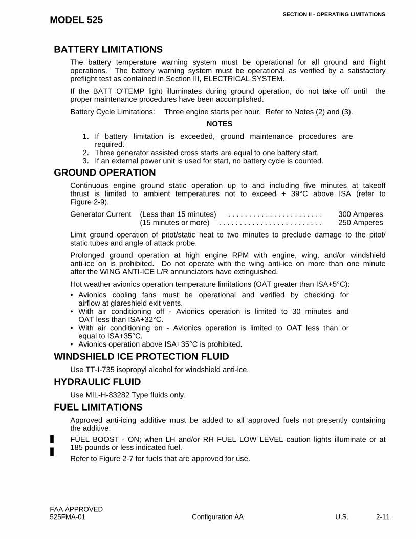
BATTERY LIMITATIONSThe battery temperature warning system must be operational for all ground and flightoperations. The battery warning system must be operational as verified by a satisfactorypreflight test as contained in Section III, ELECTRICAL SYSTEM.
If the BATT O'TEMP light illuminates during ground operation, do not take off until theproper maintenance procedures have been accomplished.
Battery Cycle Limitations: Three engine starts per hour. Refer to Notes (2) and (3).
NOTES
1. If battery limitation is exceeded, ground maintenance procedures arerequired.
2. Three generator assisted cross starts are equal to one battery start.3. If an external power unit is used for start, no battery cycle is counted.
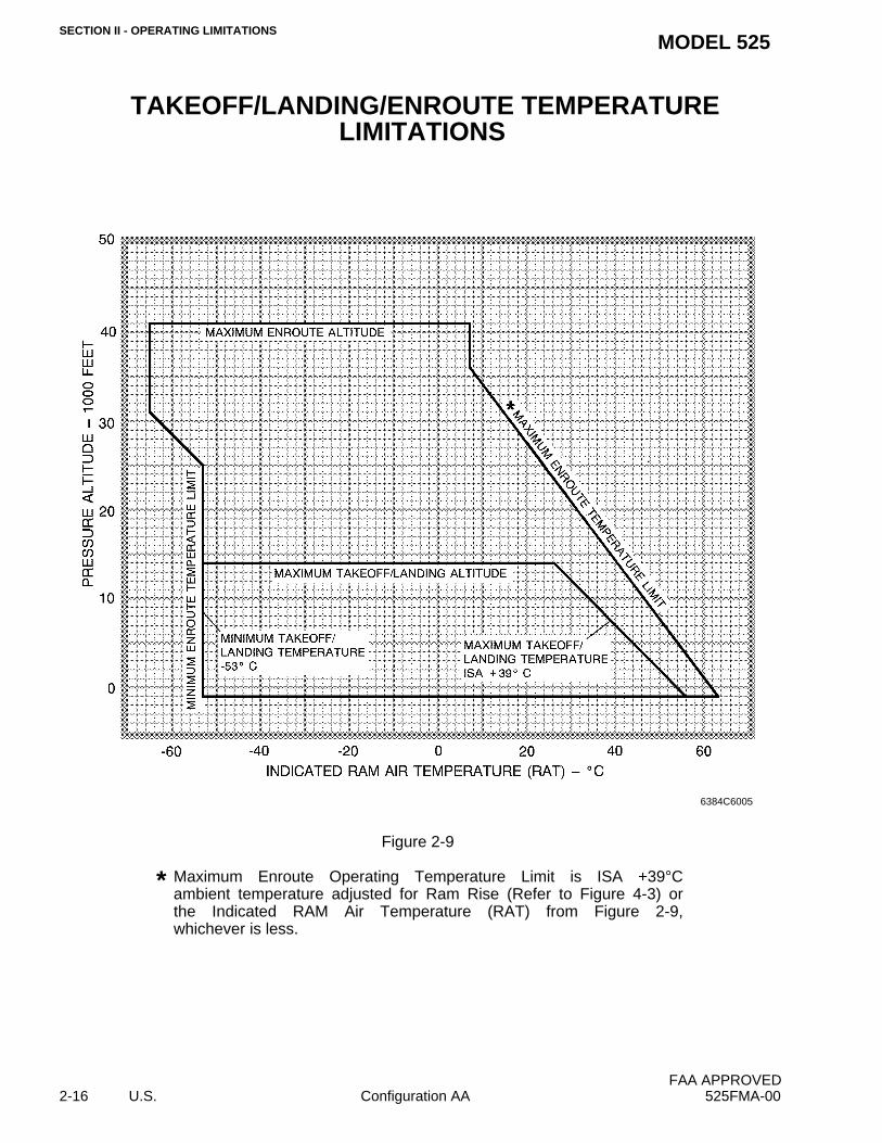
GROUND OPERATIONContinuous engine ground static operation up to and including five minutes at takeoffthrust is limited to ambient temperatures not to exceed + 39°C above ISA (refer toFigure 2-9).
Limit ground operation of pitot/static heat to two minutes to preclude damage to the pitot/static tubes and angle of attack probe.
Prolonged ground operation at high engine RPM with engine, wing, and/or windshieldanti-ice on is prohibited. Do not operate with the wing anti-ice on more than one minuteafter the WING ANTI-ICE L/R annunciators have extinguished.
Hot weather avionics operation temperature limitations (OAT greater than ISA+5°C):
• Avionics cooling fans must be operational and verified by checking forairflow at glareshield exit vents.
• With air conditioning off - Avionics operation is limited to 30 minutes andOAT less than ISA+32°C.
• With air conditioning on - Avionics operation is limited to OAT less than orequal to ISA+35°C.
• Avionics operation above ISA+35°C is prohibited.
WINDSHIELD ICE PROTECTION FLUIDUse TT-I-735 isopropyl alcohol for windshield anti-ice.
HYDRAULIC FLUIDUse MIL-H-83282 Type fluids only.
FUEL LIMITATIONSApproved anti-icing additive must be added to all approved fuels not presently containingthe additive.
FUEL BOOST - ON; when LH and/or RH FUEL LOW LEVEL caution lights illuminate or at185 pounds or less indicated fuel.
Refer to Figure 2-7 for fuels that are approved for use.
FAA APPROVED525FMA-01 Configuration AA U.S. 2-11
SECTION II - OPERATING LIMITATIONSMODEL 525
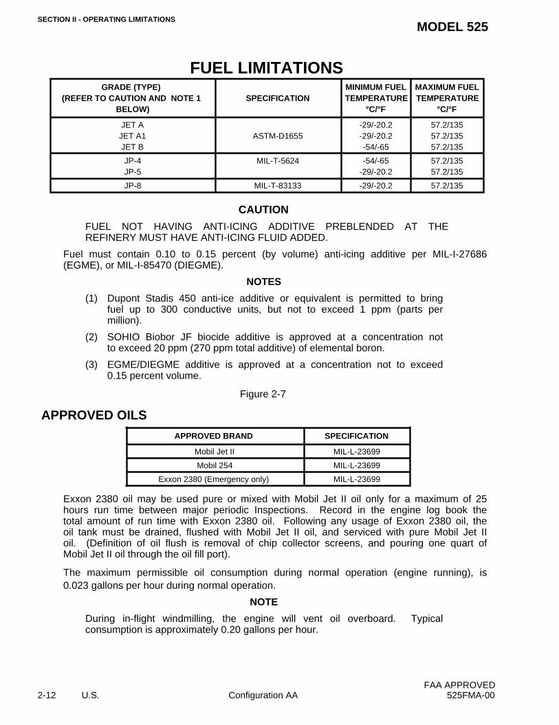
FUEL LIMITATIONS
CAUTION
FUEL NOT HAVING ANTI-ICING ADDITIVE PREBLENDED AT THEREFINERY MUST HAVE ANTI-ICING FLUID ADDED.
Fuel must contain 0.10 to 0.15 percent (by volume) anti-icing additive per MIL-I-27686(EGME), or MIL-I-85470 (DIEGME).
NOTES
(1) Dupont Stadis 450 anti-ice additive or equivalent is permitted to bringfuel up to 300 conductive units, but not to exceed 1 ppm (parts permillion).
(2) SOHIO Biobor JF biocide additive is approved at a concentration notto exceed 20 ppm (270 ppm total additive) of elemental boron.
(3) EGME/DIEGME additive is approved at a concentration not to exceed0.15 percent volume.
Figure 2-7
APPROVED OILS
Exxon 2380 oil may be used pure or mixed with Mobil Jet II oil only for a maximum of 25hours run time between major periodic Inspections. Record in the engine log book thetotal amount of run time with Exxon 2380 oil. Following any usage of Exxon 2380 oil, theoil tank must be drained, flushed with Mobil Jet II oil, and serviced with pure Mobil Jet IIoil. (Definition of oil flush is removal of chip collector screens, and pouring one quart ofMobil Jet II oil through the oil fill port).
The maximum permissible oil consumption during normal operation (engine running), is0.023 gallons per hour during normal operation.
NOTE
During in-flight windmilling, the engine will vent oil overboard. Typicalconsumption is approximately 0.20 gallons per hour.
GRADE (TYPE) (REFER TO CAUTION AND NOTE 1
BELOW)SPECIFICATION
MINIMUM FUELTEMPERATURE
°C/°F
MAXIMUM FUELTEMPERATURE
°C/°F
JET AJET A1JET B
ASTM-D1655-29/-20.2-29/-20.2-54/-65
57.2/13557.2/13557.2/135
JP-4JP-5
MIL-T-5624 -54/-65-29/-20.2
57.2/13557.2/135
JP-8 MIL-T-83133 -29/-20.2 57.2/135
APPROVED BRAND SPECIFICATION
Mobil Jet II MIL-L-23699
Mobil 254 MIL-L-23699
Exxon 2380 (Emergency only) MIL-L-23699
FAA APPROVED2-12 U.S. Configuration AA 525FMA-00
SECTION II - OPERATING LIMITATIONSMODEL 525
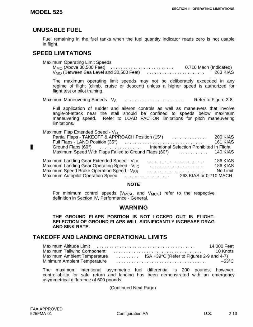
UNUSABLE FUEL
Fuel remaining in the fuel tanks when the fuel quantity indicator reads zero is not usablein flight.
The maximum operating limit speeds may not be deliberately exceeded in anyregime of flight (climb, cruise or descent) unless a higher speed is authorized forflight test or pilot training.
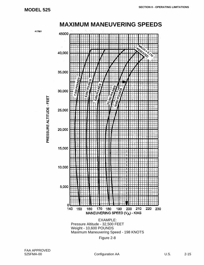
Full application of rudder and aileron controls as well as maneuvers that involveangle-of-attack near the stall should be confined to speeds below maximummaneuvering speed. Refer to LOAD FACTOR limitations for pitch maneuveringlimitations.
The maximum intentional asymmetric fuel differential is 200 pounds, however,controllability for safe return and landing has been demonstrated with an emergencyasymmetrical difference of 600 pounds.
(Continued Next Page)
FAA APPROVED525FMA-01 Configuration AA U.S. 2-13
SECTION II - OPERATING LIMITATIONSMODEL 525
TAKEOFF AND LANDING OPERATIONAL LIMITS (Continued)
Takeoff with thrust attenuators stowed is prohibited for flaps 0° and for flaps 15°corrected takeoff field lengths greater than 4500 feet.
The autopilot and yaw damper must be OFF for takeoff and landing.
Engine synchronizer must be OFF for takeoff and landing.
Cabin must be depressurized for takeoff and landing.
Speed brakes must be retracted prior to 50 feet on landing.
Touch and Go landings utilizing ground flaps are prohibited.
Goodyear tire part number 184F68-1, and tire part numbers 030-611-0 and 031-613-8(manufactured by BFGoodrich/Michelin) are the only nose tires approved. The nose tiremust be inflated to 120 PSI +5 or –5 PSI.
This airplane is approved for day and night, VFR, IFR flight and flight into known icingwhen the required equipment is installed as defined within the KINDS OF OPERATIONSEQUIPMENT LIST.
Acrobatic maneuvers, including spins, are prohibited. Intentional stalls with flaps at otherthan zero or with gear down are prohibited above 18,000 feet.
MINIMUM CREW
Except where otherwise prescribed by applicable operating limitations,
Minimum crew for all operations:1 Pilot, provided:
a. The pilot holds a CE525(S), single pilot, type rating.b. The airplane is equipped for single pilot operation as specified in the Kinds of
Operations Equipment List.c. The pilot must occupy the left pilot’s seat.
Or:1 Pilot and 1 Copilot provided:
a. The pilot in command holds a CE525(S) or CE525 (second-in-commandrequired) type rating.
* Maximum Enroute Operating Temperature Limit is ISA +39°Cambient temperature adjusted for Ram Rise (Refer to Figure 4-3) orthe Indicated RAM Air Temperature (RAT) from Figure 2-9,whichever is less.
6384C6005
FAA APPROVED2-16 U.S. Configuration AA 525FMA-00
SECTION II - OPERATING LIMITATIONSMODEL 525
LOAD FACTOR
In FlightFlaps UP Position (0°) . . . . . . . . . . . . . . . . . . . –1.52 to +3.6G at 10,600 PoundsFlaps TAKEOFF & APPROACH to LAND Position
For all takeoffs and landings, adjustable seats must be fully upright and outboard.
Maximum passenger seating, not including 2 crew seats, is five (six with optional beltedtoilet installed).
AUDIO CONTROL PANEL
Operation of the audio panel in the passenger speaker (PASS SPKR) mode is limited torequired passenger briefings or emergencies.
NOTE
• The same side cockpit speaker is muted when PASS SPKR is selectedwith the audio control panel rotary switch. All incoming transmissionsand auxiliary audio warnings (GPWS and TCAS, if installed) will bereceived only through the opposite side speaker. If both audio controlswitches are selected to PASS SPKR, both cockpit speakers becomemuted. Avoid selecting both switches to PASS SPKR at the same time.
• With passenger speaker mode selected and microphone selector switchselected to oxygen mask, the cockpit speaker will not receive voiceinterphone communications from the oxygen mask microphone of theopposite side pilot.
• Headset audio is not affected when PASS SPKR mode is selected.
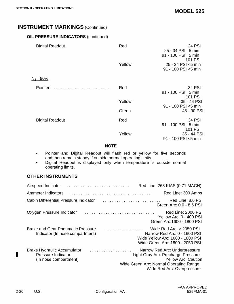
Wide Green Arc: Normal Operating RangeWide Red Arc: Overpressure
FAA APPROVED2-20 U.S. Configuration AA 525FMA-01
SECTION II - OPERATING LIMITATIONSMODEL 525
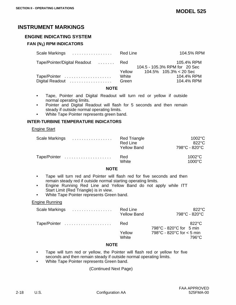
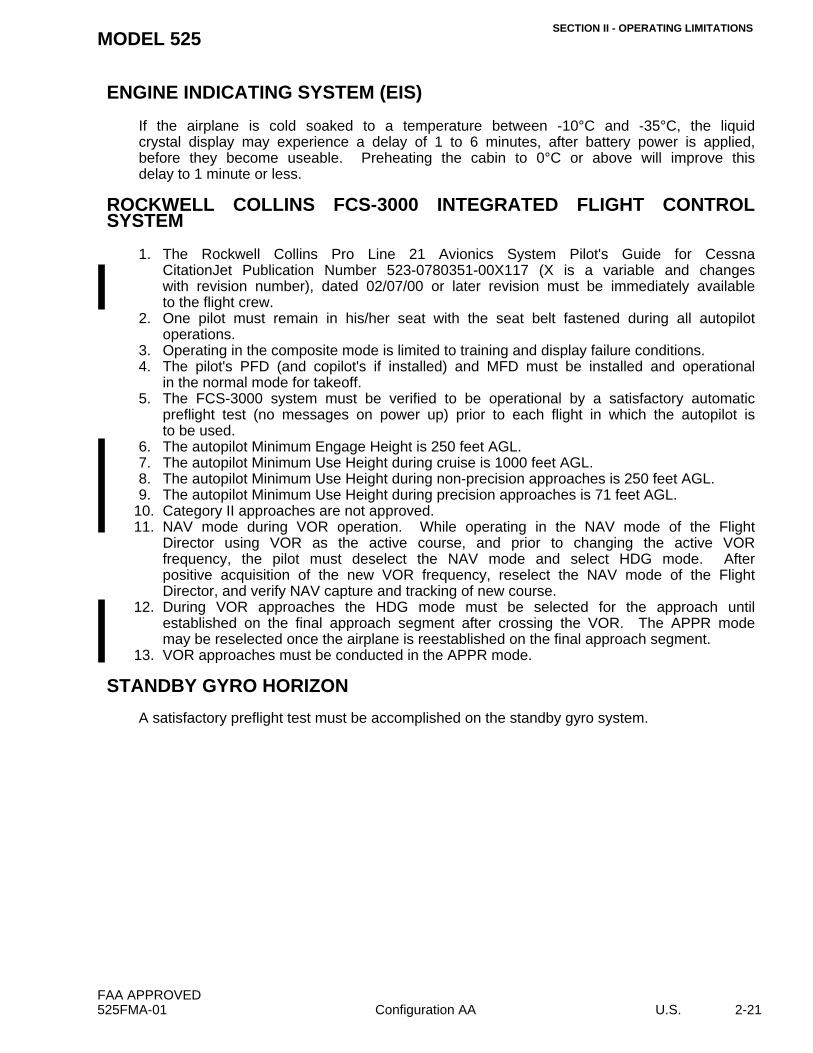
ENGINE INDICATING SYSTEM (EIS)
If the airplane is cold soaked to a temperature between -10°C and -35°C, the liquidcrystal display may experience a delay of 1 to 6 minutes, after battery power is applied,before they become useable. Preheating the cabin to 0°C or above will improve thisdelay to 1 minute or less.
1. The Rockwell Collins Pro Line 21 Avionics System Pilot's Guide for CessnaCitationJet Publication Number 523-0780351-00X117 (X is a variable and changeswith revision number), dated 02/07/00 or later revision must be immediately availableto the flight crew.
2. One pilot must remain in his/her seat with the seat belt fastened during all autopilotoperations.
3. Operating in the composite mode is limited to training and display failure conditions.4. The pilot's PFD (and copilot's if installed) and MFD must be installed and operational
in the normal mode for takeoff.5. The FCS-3000 system must be verified to be operational by a satisfactory automatic
preflight test (no messages on power up) prior to each flight in which the autopilot isto be used.
6. The autopilot Minimum Engage Height is 250 feet AGL.7. The autopilot Minimum Use Height during cruise is 1000 feet AGL.8. The autopilot Minimum Use Height during non-precision approaches is 250 feet AGL.9. The autopilot Minimum Use Height during precision approaches is 71 feet AGL.
10. Category II approaches are not approved.11. NAV mode during VOR operation. While operating in the NAV mode of the Flight
Director using VOR as the active course, and prior to changing the active VORfrequency, the pilot must deselect the NAV mode and select HDG mode. Afterpositive acquisition of the new VOR frequency, reselect the NAV mode of the FlightDirector, and verify NAV capture and tracking of new course.
12. During VOR approaches the HDG mode must be selected for the approach untilestablished on the final approach segment after crossing the VOR. The APPR modemay be reselected once the airplane is reestablished on the final approach segment.
13. VOR approaches must be conducted in the APPR mode.
STANDBY GYRO HORIZON
A satisfactory preflight test must be accomplished on the standby gyro system.
FAA APPROVED525FMA-01 Configuration AA U.S. 2-21
SECTION II - OPERATING LIMITATIONSMODEL 525
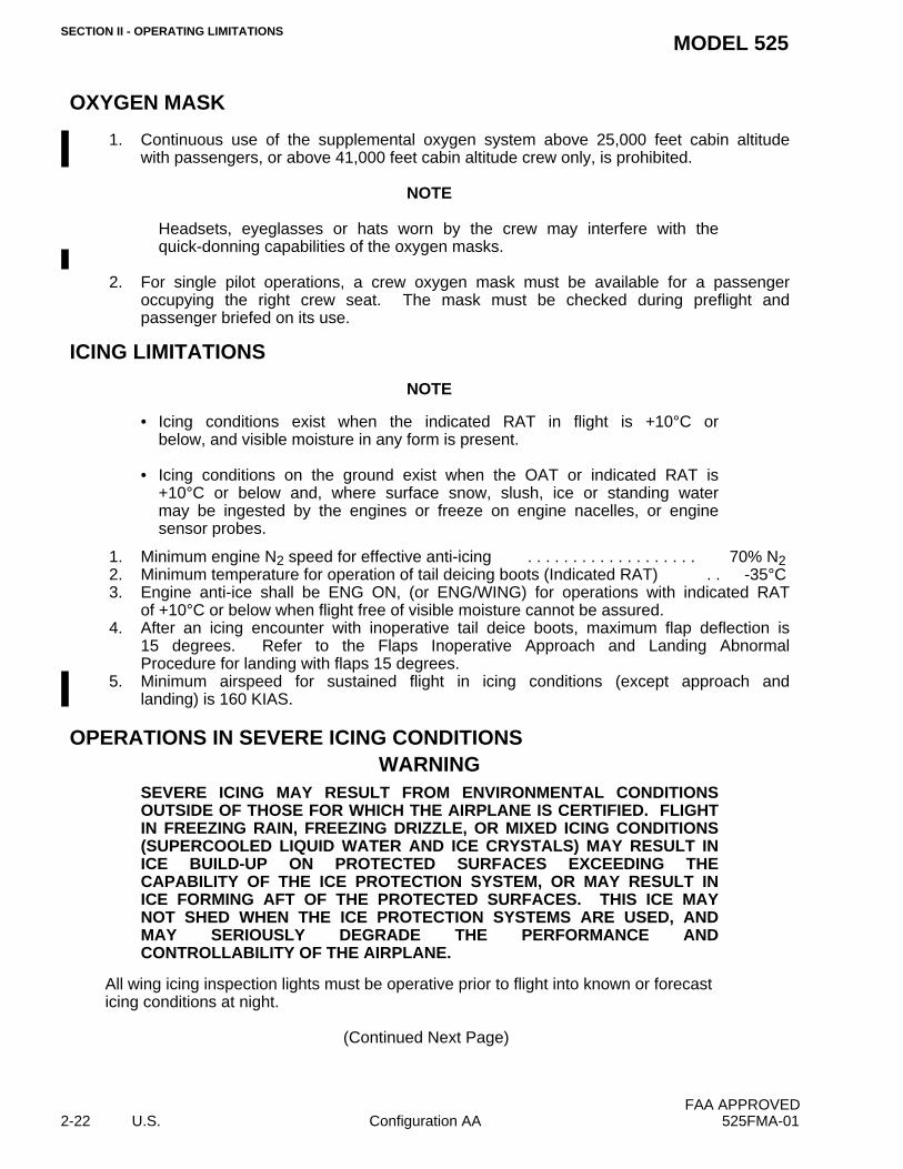
OXYGEN MASK
1. Continuous use of the supplemental oxygen system above 25,000 feet cabin altitudewith passengers, or above 41,000 feet cabin altitude crew only, is prohibited.
NOTE
Headsets, eyeglasses or hats worn by the crew may interfere with thequick-donning capabilities of the oxygen masks.
2. For single pilot operations, a crew oxygen mask must be available for a passengeroccupying the right crew seat. The mask must be checked during preflight andpassenger briefed on its use.
ICING LIMITATIONS
NOTE
• Icing conditions exist when the indicated RAT in flight is +10°C orbelow, and visible moisture in any form is present.
• Icing conditions on the ground exist when the OAT or indicated RAT is+10°C or below and, where surface snow, slush, ice or standing watermay be ingested by the engines or freeze on engine nacelles, or enginesensor probes.
1. Minimum engine N2 speed for effective anti-icing . . . . . . . . . . . . . . . . . . . 70% N22. Minimum temperature for operation of tail deicing boots (Indicated RAT) . . -35°C3. Engine anti-ice shall be ENG ON, (or ENG/WING) for operations with indicated RAT
of +10°C or below when flight free of visible moisture cannot be assured.4. After an icing encounter with inoperative tail deice boots, maximum flap deflection is
15 degrees. Refer to the Flaps Inoperative Approach and Landing AbnormalProcedure for landing with flaps 15 degrees.
5. Minimum airspeed for sustained flight in icing conditions (except approach andlanding) is 160 KIAS.
OPERATIONS IN SEVERE ICING CONDITIONSWARNING
SEVERE ICING MAY RESULT FROM ENVIRONMENTAL CONDITIONSOUTSIDE OF THOSE FOR WHICH THE AIRPLANE IS CERTIFIED. FLIGHTIN FREEZING RAIN, FREEZING DRIZZLE, OR MIXED ICING CONDITIONS(SUPERCOOLED LIQUID WATER AND ICE CRYSTALS) MAY RESULT INICE BUILD-UP ON PROTECTED SURFACES EXCEEDING THECAPABILITY OF THE ICE PROTECTION SYSTEM, OR MAY RESULT INICE FORMING AFT OF THE PROTECTED SURFACES. THIS ICE MAYNOT SHED WHEN THE ICE PROTECTION SYSTEMS ARE USED, ANDMAY SERIOUSLY DEGRADE THE PERFORMANCE ANDCONTROLLABILITY OF THE AIRPLANE.
All wing icing inspection lights must be operative prior to flight into known or forecast icing conditions at night.
(Continued Next Page)
FAA APPROVED2-22 U.S. Configuration AA 525FMA-01
SECTION II - OPERATING LIMITATIONSMODEL 525
OPERATIONS IN SEVERE ICING CONDITIONS (Continued)
NOTE
This supersedes relief provided by the Master Minimum Equipment List.
Severe icing conditions that exceed those for which the airplane is certificated shall bedetermined by the following visual cues:1. Unusually extensive ice accumulation on the airframe and windshield in areas not
normally observed to collect ice.2. Accumulation of ice on the upper surface of the wing aft of the protected area.
If one or more of these visual cues exist:1. Use of the autopilot is prohibited.2. Immediately request priority handling from Air Traffic Control to facilitate a route or
altitude change to exit the icing conditions.3. Leave flaps in current position, do not extend or retract.4. Avoid abrupt and excessive maneuvering that may exacerbate control difficulties.5. If unusual or uncommanded roll control movement is observed, reduce
angle-of-attack.
Since the autopilot, when installed and operating , may mask tactile cues that indicateadverse changes in handling characteristics, use of the autopilot is prohibited when:1. Unusual lateral trim is required while the airplane is in icing conditions.2. Autopilot trim warnings are encountered while the airplane is in icing
conditions.
KINDS OF OPERATIONS EQUIPMENT LIST
This airplane may be operated in day or night VFR or IFR and flight into known icingconditions when the appropriate equipment is installed.
The following equipment list identifies the systems and equipment upon which typecertification for each kind of operation was predicated. The systems and items ofequipment listed must be installed and operable unless:
1. The airplane is approved to be operated in accordance with a current MinimumEquipment List (MEL) issued by the FAA.
Or;(Continued Next Page)
FAA APPROVED525FMA-00 Configuration AA U.S. 2-23
SECTION II - OPERATING LIMITATIONSMODEL 525
KINDS OF OPERATIONS EQUIPMENT LIST (Continued)
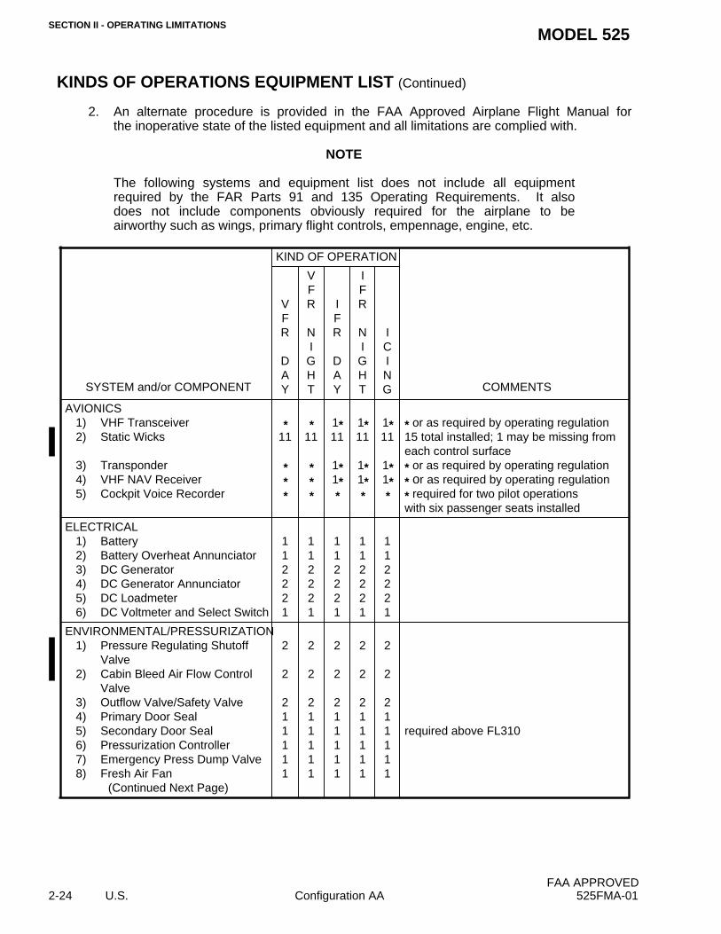
2. An alternate procedure is provided in the FAA Approved Airplane Flight Manual forthe inoperative state of the listed equipment and all limitations are complied with.
NOTE
The following systems and equipment list does not include all equipmentrequired by the FAR Parts 91 and 135 Operating Requirements. It alsodoes not include components obviously required for the airplane to beairworthy such as wings, primary flight controls, empennage, engine, etc.
SYSTEM and/or COMPONENT
KIND OF OPERATION
VFR
DAY
VFR
NIGHT
IFR
DAY
IFR
NIGHT
ICING COMMENTS
AVIONICS1) VHF Transceiver2) Static Wicks
3) Transponder4) VHF NAV Receiver5) Cockpit Voice Recorder
*11
***
*11
***
1*11
1*1**
1*11
1*1**
1*11
1*1**
* or as required by operating regulation15 total installed; 1 may be missing fromeach control surface* or as required by operating regulation* or as required by operating regulation* required for two pilot operationswith six passenger seats installed
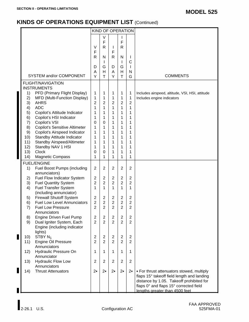
ELECTRICAL1) Battery2) Battery Overheat Annunciator3) DC Generator4) DC Generator Annunciator5) DC Loadmeter6) DC Voltmeter and Select Switch
Annunciators8) Engine Driven Fuel Pump9) Dual Igniter System, Each
Engine (including indicatorlights)
10) STBY N111) Engine Oil Pressure
Annunciators12) Hydraulic Pressure On
Annunciator13) Hydraulic Flow Low
Annunciators14) Thrust Attenuators
2
221
222
22
22
1
2
2*
2
221
222
22
22
1
2
2*
2
221
222
22
22
1
2
2*
2
221
222
22
22
1
2
2*
2
221
222
22
22
1
2
2* * For thrust attenuators stowed, multiplyflaps 15° takeoff field length and landingdistance by 1.05. Takeoff prohibited forflaps 0° and flaps 15° corrected fieldlengths greater than 4500 feet.
FAA APPROVEDI2-26 U.S. Configuration AB 525FMA-01
SECTION II - OPERATING LIMITATIONSMODEL 525
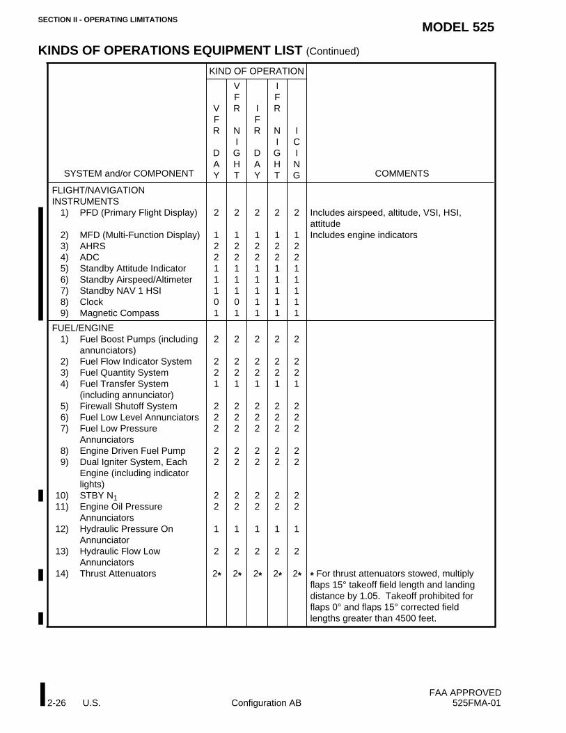
KINDS OF OPERATIONS EQUIPMENT LIST (Continued)
SYSTEM and/or COMPONENT
KIND OF OPERATION
VFR
DAY
VFR
NIGHT
IFR
DAY
IFR
NIGHT
ICING COMMENTS
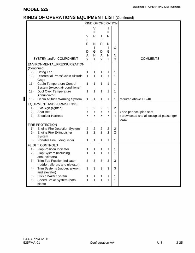
ENVIRONMENTAL/PRESSURIZATION(Continued)
9) Defog Fan10) Differential Press/Cabin Altitude
Gage11) Cabin Temperature Control
System (except air conditioner)12) Duct Over Temperature
Annunciator13) Cabin Altitude Warning System
11
1
1
1
11
1
1
1
11
1
1
1
11
1
1
1
11
1
1
1 required above FL240
EQUIPMENT AND FURNISHINGS1) Exit Sign (lighted)2) Seat Belt3) Shoulder Harness
2**
2**
2**
2**
2**
* one per occupied seat* crew seats and all occupied passengerseats
FIRE PROTECTION1) Engine Fire Detection System2) Engine Fire Extinguisher
System3) Portable Fire Extinguisher
22
1
22
1
22
1
22
1
22
1
FLIGHT CONTROLS1) Flap Position Indicator2) Flap System (including
annunciators)3) Trim Tab Position Indicator
(rudder, aileron, and elevator)4) Trim Systems (rudder, aileron,
and elevator)5) Stick Shaker System6) Speed Brake System (both
Annunciators8) Engine Driven Fuel Pump9) Dual Igniter System, Each
Engine (including indicatorlights)
10) STBY N111) Engine Oil Pressure
Annunciators12) Hydraulic Pressure On
Annunciator13) Hydraulic Flow Low
Annunciators14) Thrust Attenuators
2
221
222
22
22
1
2
2*
2
221
222
22
22
1
2
2*
2
221
222
22
22
1
2
2*
2
221
222
22
22
1
2
2*
2
221
222
22
22
1
2
2* * For thrust attenuators stowed, multiplyflaps 15° takeoff field length and landingdistance by 1.05. Takeoff prohibited forflaps 0° and flaps 15° corrected fieldlengths greater than 4500 feet
FAA APPROVEDI2-26.1 U.S. Configuration AC 525FMA-01
SECTION II - OPERATING LIMITATIONSMODEL 525
KINDS OF OPERATIONS EQUIPMENT LIST (Continued)
SYSTEM and/or COMPONENT
KIND OF OPERATION
VFR
DAY
VFR
NIGHT
IFR
DAY
IFR
NIGHT
ICING COMMENTS
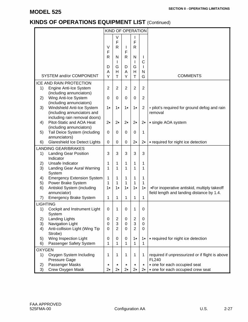
ICE AND RAIN PROTECTION1) Engine Anti-Ice System
(including annunciators)2) Wing Anti-Ice System
(including annunciators)3) Windshield Anti-Ice System
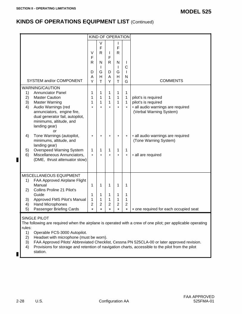
Guide3) Approved FMS Pilot’s Manual4) Hand Microphones5) Passenger Briefing Cards
1
112
*
1
112
*
1
112
*
1
112
*
1
112
* * one required for each occupied seat
SINGLE PILOTThe following are required when the airplane is operated with a crew of one pilot; per applicable operatingrules:
1) Operable FCS-3000 Autopilot.2) Headset with microphone (must be worn).3) FAA Approved Pilots’ Abbreviated Checklist, Cessna PN 525CLA-00 or later approved revision.4) Provisions for storage and retention of navigation charts, accessible to the pilot from the pilot


![[374]W340 E1 11 CS1 CJ1 M Instruction Reference Version 3](https://static.documents.pub/doc/80x56/54801c965906b5e5288b4699/374w340-e1-11-cs1-cj1-m-instruction-reference-version-3.jpg)


