594
OPERATION MANUAL Cat. No. W393-E1-04 SYSMAC CJ Series CJ1G/H-CPU@@H, CJ1M-CPU@@, CJ1G-CPU@@ Programmable Controllers
| Date post: | 21-Apr-2015 |
| Category: |
Documents |
| Upload: | pawanmandeep2012 |
| View: | 272 times |
| Download: | 8 times |

OPERATION MANUAL
Cat. No. W393-E1-04
SYSMAC CJ SeriesCJ1G/H-CPU@@H, CJ1M-CPU@@, CJ1G-CPU@@
Programmable Controllers

SYSMAC CJ SeriesCJ1G/H-CPU@@H, CJ1M-CPU@@, CJ1G-CPU@@ Programmable ControllersOperation ManualRevised February 2003

iv

v
Notice:OMRON products are manufactured for use according to proper procedures by a qualified operatorand only for the purposes described in this manual.
The following conventions are used to indicate and classify precautions in this manual. Always heedthe information provided with them. Failure to heed precautions can result in injury to people or dam-age to property.
!DANGER Indicates an imminently hazardous situation which, if not avoided, will result in death orserious injury.
!WARNING Indicates a potentially hazardous situation which, if not avoided, could result in death orserious injury.
!Caution Indicates a potentially hazardous situation which, if not avoided, may result in minor ormoderate injury, or property damage.
OMRON Product ReferencesAll OMRON products are capitalized in this manual. The word “Unit” is also capitalized when it refers toan OMRON product, regardless of whether or not it appears in the proper name of the product.
The abbreviation “Ch,” which appears in some displays and on some OMRON products, often means“word” and is abbreviated “Wd” in documentation in this sense.
The abbreviation “PLC” means Programmable Controller. “PC” is used, however, in some Program-ming Device displays to mean Programmable Controller.
Visual AidsThe following headings appear in the left column of the manual to help you locate different types ofinformation.
Note Indicates information of particular interest for efficient and convenient opera-tion of the product.
1,2,3... 1. Indicates lists of one sort or another, such as procedures, checklists, etc.
OMRON, 2001All rights reserved. No part of this publication may be reproduced, stored in a retrieval system, or transmitted, in any form, orby any means, mechanical, electronic, photocopying, recording, or otherwise, without the prior written permission ofOMRON.
No patent liability is assumed with respect to the use of the information contained herein. Moreover, because OMRON is con-stantly striving to improve its high-quality products, the information contained in this manual is subject to change withoutnotice. Every precaution has been taken in the preparation of this manual. Nevertheless, OMRON assumes no responsibilityfor errors or omissions. Neither is any liability assumed for damages resulting from the use of the information contained inthis publication.

vi

vii
TABLE OF CONTENTS
PRECAUTIONS . . . . . . . . . . . . . . . . . . . . . . . . . . . . . . . . . . . xiii1 Intended Audience . . . . . . . . . . . . . . . . . . . . . . . . . . . . . . . . . . . . . . . . . . . . . . . . . . . . . . . . xiv
2 General Precautions . . . . . . . . . . . . . . . . . . . . . . . . . . . . . . . . . . . . . . . . . . . . . . . . . . . . . . . xiv
3 Safety Precautions. . . . . . . . . . . . . . . . . . . . . . . . . . . . . . . . . . . . . . . . . . . . . . . . . . . . . . . . . xiv
4 Operating Environment Precautions . . . . . . . . . . . . . . . . . . . . . . . . . . . . . . . . . . . . . . . . . . . xvi
5 Application Precautions . . . . . . . . . . . . . . . . . . . . . . . . . . . . . . . . . . . . . . . . . . . . . . . . . . . . xvii
6 Conformance to EC Directives . . . . . . . . . . . . . . . . . . . . . . . . . . . . . . . . . . . . . . . . . . . . . . . xx
SECTION 1Introduction . . . . . . . . . . . . . . . . . . . . . . . . . . . . . . . . . . . . . . 1
1-1 Overview . . . . . . . . . . . . . . . . . . . . . . . . . . . . . . . . . . . . . . . . . . . . . . . . . . . . . . . . . . . . . . . . 2
1-2 CJ-series Features . . . . . . . . . . . . . . . . . . . . . . . . . . . . . . . . . . . . . . . . . . . . . . . . . . . . . . . . . 3
1-3 CJ1-H and CJ1M CPU Unit Features . . . . . . . . . . . . . . . . . . . . . . . . . . . . . . . . . . . . . . . . . . 12
1-4 CJ1 and CJ1-H CPU Unit Comparison. . . . . . . . . . . . . . . . . . . . . . . . . . . . . . . . . . . . . . . . . 18
1-5 Function Tables . . . . . . . . . . . . . . . . . . . . . . . . . . . . . . . . . . . . . . . . . . . . . . . . . . . . . . . . . . . 23
1-6 CJ1-H Functions Arranged by Purpose . . . . . . . . . . . . . . . . . . . . . . . . . . . . . . . . . . . . . . . . 32
1-7 CJ1M Functions Arranged by Purpose . . . . . . . . . . . . . . . . . . . . . . . . . . . . . . . . . . . . . . . . . 35
1-8 Comparison to CS-series PLCs. . . . . . . . . . . . . . . . . . . . . . . . . . . . . . . . . . . . . . . . . . . . . . . 40
SECTION 2Specifications and System Configuration. . . . . . . . . . . . . . . 43
2-1 Specifications . . . . . . . . . . . . . . . . . . . . . . . . . . . . . . . . . . . . . . . . . . . . . . . . . . . . . . . . . . . . 44
2-2 CPU Unit Components and Functions . . . . . . . . . . . . . . . . . . . . . . . . . . . . . . . . . . . . . . . . . 55
2-3 Basic System Configuration . . . . . . . . . . . . . . . . . . . . . . . . . . . . . . . . . . . . . . . . . . . . . . . . . 59
2-4 I/O Units . . . . . . . . . . . . . . . . . . . . . . . . . . . . . . . . . . . . . . . . . . . . . . . . . . . . . . . . . . . . . . . . 67
2-5 Expanded System Configuration. . . . . . . . . . . . . . . . . . . . . . . . . . . . . . . . . . . . . . . . . . . . . . 72
2-6 Unit Current Consumption . . . . . . . . . . . . . . . . . . . . . . . . . . . . . . . . . . . . . . . . . . . . . . . . . . 85
2-7 CPU Bus Unit Setting Area Capacity . . . . . . . . . . . . . . . . . . . . . . . . . . . . . . . . . . . . . . . . . . 89
2-8 I/O Table Settings List . . . . . . . . . . . . . . . . . . . . . . . . . . . . . . . . . . . . . . . . . . . . . . . . . . . . . 89
SECTION 3Nomenclature, Functions, and Dimensions . . . . . . . . . . . . . 93
3-1 CPU Units . . . . . . . . . . . . . . . . . . . . . . . . . . . . . . . . . . . . . . . . . . . . . . . . . . . . . . . . . . . . . . . 94
3-2 File Memory . . . . . . . . . . . . . . . . . . . . . . . . . . . . . . . . . . . . . . . . . . . . . . . . . . . . . . . . . . . . . 103
3-3 Programming Devices . . . . . . . . . . . . . . . . . . . . . . . . . . . . . . . . . . . . . . . . . . . . . . . . . . . . . . 110
3-4 Power Supply Units. . . . . . . . . . . . . . . . . . . . . . . . . . . . . . . . . . . . . . . . . . . . . . . . . . . . . . . . 120
3-5 I/O Control Units and I/O Interface Units. . . . . . . . . . . . . . . . . . . . . . . . . . . . . . . . . . . . . . . 123
3-6 CJ-series Basic I/O Units . . . . . . . . . . . . . . . . . . . . . . . . . . . . . . . . . . . . . . . . . . . . . . . . . . . 124
3-7 B7A Interface Unit . . . . . . . . . . . . . . . . . . . . . . . . . . . . . . . . . . . . . . . . . . . . . . . . . . . . . . . . 137

viii
TABLE OF CONTENTS
SECTION 4Operating Procedures . . . . . . . . . . . . . . . . . . . . . . . . . . . . . . 149
4-1 Introduction . . . . . . . . . . . . . . . . . . . . . . . . . . . . . . . . . . . . . . . . . . . . . . . . . . . . . . . . . . . . . . 150
4-2 Examples . . . . . . . . . . . . . . . . . . . . . . . . . . . . . . . . . . . . . . . . . . . . . . . . . . . . . . . . . . . . . . . . 152
SECTION 5Installation and Wiring . . . . . . . . . . . . . . . . . . . . . . . . . . . . . 163
5-1 Fail-safe Circuits . . . . . . . . . . . . . . . . . . . . . . . . . . . . . . . . . . . . . . . . . . . . . . . . . . . . . . . . . . 164
5-2 Installation. . . . . . . . . . . . . . . . . . . . . . . . . . . . . . . . . . . . . . . . . . . . . . . . . . . . . . . . . . . . . . . 166
5-3 Wiring . . . . . . . . . . . . . . . . . . . . . . . . . . . . . . . . . . . . . . . . . . . . . . . . . . . . . . . . . . . . . . . . . . 191
SECTION 6DIP Switch Settings . . . . . . . . . . . . . . . . . . . . . . . . . . . . . . . . 213
6-1 Overview . . . . . . . . . . . . . . . . . . . . . . . . . . . . . . . . . . . . . . . . . . . . . . . . . . . . . . . . . . . . . . . . 214
6-2 Details . . . . . . . . . . . . . . . . . . . . . . . . . . . . . . . . . . . . . . . . . . . . . . . . . . . . . . . . . . . . . . . . . . 215
SECTION 7PLC Setup . . . . . . . . . . . . . . . . . . . . . . . . . . . . . . . . . . . . . . . . 217
7-1 PLC Setup . . . . . . . . . . . . . . . . . . . . . . . . . . . . . . . . . . . . . . . . . . . . . . . . . . . . . . . . . . . . . . . 218
7-2 Explanations of PLC Setup Settings . . . . . . . . . . . . . . . . . . . . . . . . . . . . . . . . . . . . . . . . . . . 252
SECTION 8I/O Allocations and Data Exchange . . . . . . . . . . . . . . . . . . . 263
8-1 I/O Allocations . . . . . . . . . . . . . . . . . . . . . . . . . . . . . . . . . . . . . . . . . . . . . . . . . . . . . . . . . . . 264
8-2 Data Exchange with Special I/O Units and CPU Bus Units . . . . . . . . . . . . . . . . . . . . . . . . . 278
SECTION 9Memory Areas . . . . . . . . . . . . . . . . . . . . . . . . . . . . . . . . . . . . 283
9-1 Introduction . . . . . . . . . . . . . . . . . . . . . . . . . . . . . . . . . . . . . . . . . . . . . . . . . . . . . . . . . . . . . . 284
9-2 I/O Memory Areas . . . . . . . . . . . . . . . . . . . . . . . . . . . . . . . . . . . . . . . . . . . . . . . . . . . . . . . . 285
9-3 I/O Area. . . . . . . . . . . . . . . . . . . . . . . . . . . . . . . . . . . . . . . . . . . . . . . . . . . . . . . . . . . . . . . . . 293
9-4 Data Link Area . . . . . . . . . . . . . . . . . . . . . . . . . . . . . . . . . . . . . . . . . . . . . . . . . . . . . . . . . . . 298
9-5 CPU Bus Unit Area. . . . . . . . . . . . . . . . . . . . . . . . . . . . . . . . . . . . . . . . . . . . . . . . . . . . . . . . 299
9-6 Special I/O Unit Area . . . . . . . . . . . . . . . . . . . . . . . . . . . . . . . . . . . . . . . . . . . . . . . . . . . . . . 300
9-7 Serial PLC Link Area . . . . . . . . . . . . . . . . . . . . . . . . . . . . . . . . . . . . . . . . . . . . . . . . . . . . . . 302
9-8 DeviceNet Area. . . . . . . . . . . . . . . . . . . . . . . . . . . . . . . . . . . . . . . . . . . . . . . . . . . . . . . . . . . 303
9-9 Internal I/O Area . . . . . . . . . . . . . . . . . . . . . . . . . . . . . . . . . . . . . . . . . . . . . . . . . . . . . . . . . . 304
9-10 Holding Area. . . . . . . . . . . . . . . . . . . . . . . . . . . . . . . . . . . . . . . . . . . . . . . . . . . . . . . . . . . . . 305
9-11 Auxiliary Area. . . . . . . . . . . . . . . . . . . . . . . . . . . . . . . . . . . . . . . . . . . . . . . . . . . . . . . . . . . . 306
9-12 TR (Temporary Relay) Area . . . . . . . . . . . . . . . . . . . . . . . . . . . . . . . . . . . . . . . . . . . . . . . . . 329
9-13 Timer Area . . . . . . . . . . . . . . . . . . . . . . . . . . . . . . . . . . . . . . . . . . . . . . . . . . . . . . . . . . . . . . 330

ix
TABLE OF CONTENTS9-14 Counter Area . . . . . . . . . . . . . . . . . . . . . . . . . . . . . . . . . . . . . . . . . . . . . . . . . . . . . . . . . . . . . 332
9-15 Data Memory (DM) Area . . . . . . . . . . . . . . . . . . . . . . . . . . . . . . . . . . . . . . . . . . . . . . . . . . . 332
9-16 Extended Data Memory (EM) Area . . . . . . . . . . . . . . . . . . . . . . . . . . . . . . . . . . . . . . . . . . . 334
9-17 Index Registers . . . . . . . . . . . . . . . . . . . . . . . . . . . . . . . . . . . . . . . . . . . . . . . . . . . . . . . . . . . 335
9-18 Data Registers . . . . . . . . . . . . . . . . . . . . . . . . . . . . . . . . . . . . . . . . . . . . . . . . . . . . . . . . . . . . 341
9-19 Task Flags . . . . . . . . . . . . . . . . . . . . . . . . . . . . . . . . . . . . . . . . . . . . . . . . . . . . . . . . . . . . . . . 342
9-20 Condition Flags . . . . . . . . . . . . . . . . . . . . . . . . . . . . . . . . . . . . . . . . . . . . . . . . . . . . . . . . . . . 343
9-21 Clock Pulses . . . . . . . . . . . . . . . . . . . . . . . . . . . . . . . . . . . . . . . . . . . . . . . . . . . . . . . . . . . . . 345
9-22 Parameter Areas . . . . . . . . . . . . . . . . . . . . . . . . . . . . . . . . . . . . . . . . . . . . . . . . . . . . . . . . . . 346
SECTION 10CPU Unit Operation and the Cycle Time. . . . . . . . . . . . . . . 349
10-1 CPU Unit Operation . . . . . . . . . . . . . . . . . . . . . . . . . . . . . . . . . . . . . . . . . . . . . . . . . . . . . . . 351
10-2 CPU Unit Operating Modes . . . . . . . . . . . . . . . . . . . . . . . . . . . . . . . . . . . . . . . . . . . . . . . . . 355
10-3 Power OFF Operation . . . . . . . . . . . . . . . . . . . . . . . . . . . . . . . . . . . . . . . . . . . . . . . . . . . . . . 357
10-4 Computing the Cycle Time . . . . . . . . . . . . . . . . . . . . . . . . . . . . . . . . . . . . . . . . . . . . . . . . . . 361
10-5 Instruction Execution Times and Number of Steps . . . . . . . . . . . . . . . . . . . . . . . . . . . . . . . 375
SECTION 11Troubleshooting . . . . . . . . . . . . . . . . . . . . . . . . . . . . . . . . . . . 403
11-1 Error Log. . . . . . . . . . . . . . . . . . . . . . . . . . . . . . . . . . . . . . . . . . . . . . . . . . . . . . . . . . . . . . . . 404
11-2 Error Processing . . . . . . . . . . . . . . . . . . . . . . . . . . . . . . . . . . . . . . . . . . . . . . . . . . . . . . . . . . 405
11-3 Troubleshooting Racks and Units . . . . . . . . . . . . . . . . . . . . . . . . . . . . . . . . . . . . . . . . . . . . . 427
SECTION 12Inspection and Maintenance . . . . . . . . . . . . . . . . . . . . . . . . . 431
12-1 Inspections . . . . . . . . . . . . . . . . . . . . . . . . . . . . . . . . . . . . . . . . . . . . . . . . . . . . . . . . . . . . . . 432
12-2 Replacing User-serviceable Parts . . . . . . . . . . . . . . . . . . . . . . . . . . . . . . . . . . . . . . . . . . . . . 434
AppendicesA Specifications of Basic I/O Units . . . . . . . . . . . . . . . . . . . . . . . . . . . . . . . . . . . . . . . . . . . . . 439
B CJ1M CPU Unit Built-in I/O Specifications . . . . . . . . . . . . . . . . . . . . . . . . . . . . . . . . . . . . 485
C Auxiliary Area . . . . . . . . . . . . . . . . . . . . . . . . . . . . . . . . . . . . . . . . . . . . . . . . . . . . . . . . . . . 489
D Memory Map of PLC Memory Addresses . . . . . . . . . . . . . . . . . . . . . . . . . . . . . . . . . . . . . . 529
E PLC Setup Coding Sheets for Programming Console . . . . . . . . . . . . . . . . . . . . . . . . . . . . . 531
F Connecting to the RS-232C Port on the CPU Unit . . . . . . . . . . . . . . . . . . . . . . . . . . . . . . . 545
G CJ1W-CIF11 RS-422A Converter . . . . . . . . . . . . . . . . . . . . . . . . . . . . . . . . . . . . . . . . . . . . 555
Index . . . . . . . . . . . . . . . . . . . . . . . . . . . . . . . . . . . . . . . . . . . . 561
Revision History . . . . . . . . . . . . . . . . . . . . . . . . . . . . . . . . . . . 571

xi
About this Manual:
This manual describes the installation and operation of the CJ-series Programmable Controllers(PLCs) and includes the sections described on the following page. The CS Series and CJ Series aresubdivided as shown in the following table.
Please read this manual and all related manuals listed in the following table and be sure you under-stand information provided before attempting to install or use CJ-series CPU Units CPU Units in a PLCSystem.
Unit CS Series CJ Series
CPU Units CS1-H CPU Units: CS1H-CPU@@HCS1G-CPU@@H
CJ1-H CPU Units: CJ1H-CPU@@HCJ1G-CPU@@H
CS1 CPU Units: CS1H-CPU@@-EV1CS1G-CPU@@-EV1
CJ1 CPU Units: CJ1G-CPU@@-EV1CJ1M-CPU@@
Basic I/O Units CS-series Basic I/O Units CJ-series Basic I/O Units
Special I/O Units CS-series Special I/O Units CJ-series Special I/O Units
CPU Bus Units CS-series CPU Bus Units CJ-series CPU Bus Units
Power Supply Units CS-series Power Supply Units CJ-series Power Supply Units
Name Cat. No. Contents
SYSMAC CJ Series CJ1G/H-CPU@@HCJ1G-CPU@@ Programmable Controllers Operation Manual
W393 Provides an outlines of and describes the design, installation, maintenance, and other basic opera-tions for the CJ-series PLCs. (This manual)
SYSMAC CS Series CS1G/H-CPU@@-EV1, CS1G/H-CPU@@HProgrammable Controllers Operation Manual
W339 Provides an outlines of and describes the design, installation, maintenance, and other basic opera-tions for the CS-series PLCs.
SYSMAC CS/CJ Series CS1G/H-CPU@@-EV1, CS1G/H-CPU@@H, CJ1G-CPU@@, CJ1G/H-CPU@@HProgrammable Controllers Programming Manual
W394 This manual describes programming and other methods to use the functions of the CS/CJ-series PLCs.
SYSMAC CJ SeriesBuilt-in I/O Operation Manual
W395 Describes the functions of the built-in I/O for CJ1M CPU Units.
SYSMAC CS/CJ Series CS1G/H-CPU@@H, CS1G/H-CPU@@-EV1, CJ1G-CPU@@, CJ1G/H-CPU@@HProgrammable Controllers Programming Manual
W340 Describes the ladder diagram programming instructions supported by CS/CJ-series PLCs.
SYSMAC CS/CJ Series CQM1H-PRO01-E, C200H-PRO27-E, CQM1-PRO01-EProgramming Consoles Operation Manual
W341 Provides information on how to program and operate CS/CJ-series PLCs using a Programming Console.
SYSMAC CS/CJ Series CS1G/H-CPU@@H, CS1G/H-CPU@@-EV1, CJ1G-CPU@@, CJ1G/H-CPU@@HCS1W-SCB21/41, CS1W-SCU21, CJ1W-SCU41Communications Commands Reference Manual
W342 Describes the C-series (Host Link) and FINS communications commands used with CS/CJ-series PLCs.
SYSMAC WS02-CXP@@-ECX-Programmer User Manual Version 3.0
W361 Provide information on how to use the CX-Pro-grammer, a programming device that supports the CS/CJ-series PLCs, and the CX-Net con-tained within CX-Programmer.
SYSMAC WS02-CXP@@-ECX-Server User Manual
W362
SYSMAC CS/CJ Series CS1W-SCB21/41, CS1W-SCU21, CJ1W-SCU41Serial Communications Boards/Units Operation Manual
W336 Describes the use of Serial Communications Unit and Boards to perform serial communications with external devices, including the usage of stan-dard system protocols for OMRON products.

xii
This manual contains the following sections.
Section 1 introduces the special features and functions of the CJ-series PLCs and describes the dif-ferences between these PLCs and the earlier CS-series and C200HX/HG/HE PLCs.
Section 2 provides tables of standard models, Unit specifications, system configurations, and a com-parison between different Units.
Section 3 provides names of Unit components and their functions. Dimensions are also provided.
Section 4 outlines the steps required to assemble and operate a CJ PLC system.
Section 5 describes how to install a PLC System, including mounting and wiring Units. Follow instruc-tions carefully. Improper installation can cause the PLC to malfunction, resulting in very dangerous sit-uations.
Section 6 describes DIP switch settings.
Section 7 describes initial hardware and software settings in the PLC Setup.
Section 8 describes I/O allocation to Basic I/O Units, Special I/O Units, and CPU Bus Units, as well asand data exchange with CPU Bus Units.
Section 9 describes the structure and functions of the I/O Memory Areas and Parameter Areas.
Section 10 describes the internal operation of CPU Units and the cycle used for internal processing.
Section 11 provides information on hardware and software errors that occur during PLC operation.
Section 12 provides information on hardware maintenance and inspections.
The Appendices provide Unit specifications, current/power consumptions, Auxiliary Area words andbits, internal I/O addresses, and PLC Setup settings, and information on RS-232C ports,.
SYSMAC WS02-PSTC1-ECX-Protocol Operation Manual
W344 Describes the use of the CX-Protocol to create protocol macros as communications sequences to communicate with external devices.
SYSMAC CS/CJ Series CJ1W-ETN01/ENT11, CJ1W-ETN11 Ethernet Unit Operation Manual
W343 Describes the installation and operation of CJ1W-ETN01, CJ1W-ENT11, and CJ1W-ETN11 Ether-net Units.
Name Cat. No. Contents

xiii
PRECAUTIONS
This section provides general precautions for using the CJ-series Programmable Controllers (PLCs) and related devices.
The information contained in this section is important for the safe and reliable application of ProgrammableControllers. You must read this section and understand the information contained before attempting to set up oroperate a PLC system.
1 Intended Audience . . . . . . . . . . . . . . . . . . . . . . . . . . . . . . . . . . . . . . . . . . . . . xiv
2 General Precautions . . . . . . . . . . . . . . . . . . . . . . . . . . . . . . . . . . . . . . . . . . . . xiv
3 Safety Precautions. . . . . . . . . . . . . . . . . . . . . . . . . . . . . . . . . . . . . . . . . . . . . . xiv
4 Operating Environment Precautions . . . . . . . . . . . . . . . . . . . . . . . . . . . . . . . . xvi
5 Application Precautions . . . . . . . . . . . . . . . . . . . . . . . . . . . . . . . . . . . . . . . . . xvii
6 Conformance to EC Directives . . . . . . . . . . . . . . . . . . . . . . . . . . . . . . . . . . . . xx
6-1 Applicable Directives . . . . . . . . . . . . . . . . . . . . . . . . . . . . . . . . . . . . xx
6-2 Concepts . . . . . . . . . . . . . . . . . . . . . . . . . . . . . . . . . . . . . . . . . . . . . . xx
6-3 Conformance to EC Directives . . . . . . . . . . . . . . . . . . . . . . . . . . . . . xxi
6-4 Relay Output Noise Reduction Methods . . . . . . . . . . . . . . . . . . . . . xxi

xiv
Intended Audience 1
1 Intended AudienceThis manual is intended for the following personnel, who must also haveknowledge of electrical systems (an electrical engineer or the equivalent).
• Personnel in charge of installing FA systems.
• Personnel in charge of designing FA systems.
• Personnel in charge of managing FA systems and facilities.
2 General PrecautionsThe user must operate the product according to the performance specifica-tions described in the operation manuals.
Before using the product under conditions which are not described in themanual or applying the product to nuclear control systems, railroad systems,aviation systems, vehicles, combustion systems, medical equipment, amuse-ment machines, safety equipment, and other systems, machines, and equip-ment that may have a serious influence on lives and property if usedimproperly, consult your OMRON representative.
Make sure that the ratings and performance characteristics of the product aresufficient for the systems, machines, and equipment, and be sure to providethe systems, machines, and equipment with double safety mechanisms.
This manual provides information for programming and operating the Unit. Besure to read this manual before attempting to use the Unit and keep this man-ual close at hand for reference during operation.
!WARNING It is extremely important that a PLC and all PLC Units be used for the speci-fied purpose and under the specified conditions, especially in applications thatcan directly or indirectly affect human life. You must consult with your OMRONrepresentative before applying a PLC System to the above-mentioned appli-cations.
3 Safety Precautions
!WARNING The CPU Unit refreshes I/O even when the program is stopped (i.e., even inPROGRAM mode). Confirm safety thoroughly in advance before changing thestatus of any part of memory allocated to I/O Units, Special I/O Units, or CPUBus Units. Any changes to the data allocated to any Unit may result in unex-pected operation of the loads connected to the Unit. Any of the following oper-ation may result in changes to memory status.
• Transferring I/O memory data to the CPU Unit from a ProgrammingDevice.
• Changing present values in memory from a Programming Device.
• Force-setting/-resetting bits from a Programming Device.
• Transferring I/O memory files from a Memory Card or EM file memory tothe CPU Unit.
• Transferring I/O memory from a host computer or from another PLC on anetwork.
!WARNING Do not attempt to take any Unit apart while the power is being supplied. Doingso may result in electric shock.

xv
Safety Precautions 3
!WARNING Do not touch any of the terminals or terminal blocks while the power is beingsupplied. Doing so may result in electric shock.
!WARNING Do not attempt to disassemble, repair, or modify any Units. Any attempt to doso may result in malfunction, fire, or electric shock.
!WARNING Do not touch the Power Supply Unit while power is being supplied or immedi-ately after power has been turned OFF. Doing so may result in electric shock.
!WARNING Provide safety measures in external circuits (i.e., not in the ProgrammableController), including the following items, to ensure safety in the system if anabnormality occurs due to malfunction of the PLC or another external factoraffecting the PLC operation. Not doing so may result in serious accidents.
• Emergency stop circuits, interlock circuits, limit circuits, and similar safetymeasures must be provided in external control circuits.
• The PLC will turn OFF all outputs when its self-diagnosis function detectsany error or when a severe failure alarm (FALS) instruction is executed.As a countermeasure for such errors, external safety measures must beprovided to ensure safety in the system.
• The PLC outputs may remain ON or OFF due to deposition or burning ofthe output relays or destruction of the output transistors. As a counter-measure for such problems, external safety measures must be providedto ensure safety in the system.
• When the 24-V DC output (service power supply to the PLC) is over-loaded or short-circuited, the voltage may drop and result in the outputsbeing turned OFF. As a countermeasure for such problems, externalsafety measures must be provided to ensure safety in the system.
!Caution Confirm safety before transferring data files stored in the file memory (Mem-ory Card or EM file memory) to the I/O area (CIO) of the CPU Unit using aProgramming Device. Otherwise, the devices connected to the output unitmay malfunction regardless of the operation mode of the CPU Unit.
!Caution Execute online edit only after confirming that no adverse effects will becaused by extending the cycle time. Otherwise, the input signals may not bereadable.
!Caution Confirm safety at the destination node before transferring a program toanother node or changing contents of the I/O memory area. Doing either ofthese without confirming safety may result in injury.
!Caution Tighten the screws on the terminal block of the AC Power Supply Unit to thetorque specified in the operation manual. The loose screws may result inburning or malfunction.

xvi
Operating Environment Precautions 4
!Caution A CJ1-H or CJ1M CPU Unit automatically back up the user program andparameter data to flash memory when these are written to the CPU Unit. I/Omemory (including the DM, EM, and HR Areas), however, is not written toflash memory. The DM, EM, and HR Areas can be held during power interrup-tions with a battery. If there is a battery error, the contents of these areas maynot be accurate after a power interruption. If the contents of the DM, EM, andHR Areas are used to control external outputs, prevent inappropriate outputsfrom being made whenever the Battery Error Flag (A40204) is ON. Areassuch as the DM, EM, and HR Areas, the contents of which can be held duringpower interrupts, is backed up by a battery. If a battery error occurs, the con-tents of the areas that are set to be held may not be accurate even though amemory error will not occur to stop operation. If necessary for the safety of thesystem, take appropriate measures in the ladder program whenever the Bat-tery Error Flag (A40204) turns ON, such as resetting the data in these areas.
4 Operating Environment Precautions
!Caution Do not operate the control system in the following locations:
• Locations subject to direct sunlight.
• Locations subject to temperatures or humidity outside the range specifiedin the specifications.
• Locations subject to condensation as the result of severe changes in tem-perature.
• Locations subject to corrosive or flammable gases.
• Locations subject to dust (especially iron dust) or salts.
• Locations subject to exposure to water, oil, or chemicals.
• Locations subject to shock or vibration.
!Caution Take appropriate and sufficient countermeasures when installing systems inthe following locations:
• Locations subject to static electricity or other forms of noise.
• Locations subject to strong electromagnetic fields.
• Locations subject to possible exposure to radioactivity.
• Locations close to power supplies.
!Caution The operating environment of the PLC System can have a large effect on thelongevity and reliability of the system. Improper operating environments canlead to malfunction, failure, and other unforeseeable problems with the PLCSystem. Be sure that the operating environment is within the specified condi-tions at installation and remains within the specified conditions during the lifeof the system.

xvii
Application Precautions 5
5 Application PrecautionsObserve the following precautions when using the PLC System.
• You must use the CX-Programmer (programming software that runs onWindows) if you need to program more than one task. A ProgrammingConsole can be used to program only one cyclic task plus interrupt tasks.A Programming Console can, however, be used to edit multitask pro-grams originally created with the CX-Programmer.
!WARNING Always heed these precautions. Failure to abide by the following precautionscould lead to serious or possibly fatal injury.
• Always connect to a ground of 100 Ω or less when installing the Units. Notconnecting to a ground of 100 Ω or less may result in electric shock.
• A ground of 100 Ω or less must be installed when shorting the GR and LGterminals on the Power Supply Unit.
• Always turn OFF the power supply to the PLC before attempting any ofthe following. Not turning OFF the power supply may result in malfunctionor electric shock.
• Mounting or dismounting Power Supply Units, I/O Units, CPU Units, orany other Units.
• Assembling the Units.
• Setting DIP switches or rotary switches.
• Connecting cables or wiring the system.
• Connecting or disconnecting the connectors.
!Caution Failure to abide by the following precautions could lead to faulty operation ofthe PLC or the system, or could damage the PLC or PLC Units. Always heedthese precautions.
• A CJ-series CPU Unit is shipped with the battery installed and the timealready set on the internal clock. It is not necessary to clear memory orset the clock before application, as it is for the CS-series CPU Units.
• The user program and parameter area data in CJ1-H CPU Units isbacked up in the built-in flash memory. The BKUP indicator will light onthe front of the CPU Unit when the backup operation is in progress. Donot turn OFF the power supply to the CPU Unit when the BKUP indicatoris lit. The data will not be backed up if power is turned OFF.
• If, when using a CJ1-H CPU Unit, the PLC Setup is set to specify usingthe mode set on the Programming Console and a Programming Consoleis not connected, the CPU Unit will start in RUN mode. This is the defaultsetting in the PLC Setup. (A CS1 CPU Unit will start in PROGRAM modeunder the same conditions.)
• When creating an AUTOEXEC.IOM file from a Programming Device (aProgramming Console or the CX-Programmer) to automatically transferdata at startup, set the first write address to D20000 and be sure that thesize of data written does not exceed the size of the DM Area. When thedata file is read from the Memory Card at startup, data will be written inthe CPU Unit starting at D20000 even if another address was set whenthe AUTOEXEC.IOM file was created. Also, if the DM Area is exceeded(which is possible when the CX-Programmer is used), the remaining datawill be written to the EM Area.

xviii
Application Precautions 5
• Always turn ON power to the PLC before turning ON power to the controlsystem. If the PLC power supply is turned ON after the control power sup-ply, temporary errors may result in control system signals because theoutput terminals on DC Output Units and other Units will momentarily turnON when power is turned ON to the PLC.
• Fail-safe measures must be taken by the customer to ensure safety in theevent that outputs from Output Units remain ON as a result of internal cir-cuit failures, which can occur in relays, transistors, and other elements.
• Fail-safe measures must be taken by the customer to ensure safety in theevent of incorrect, missing, or abnormal signals caused by broken signallines, momentary power interruptions, or other causes.
• Interlock circuits, limit circuits, and similar safety measures in external cir-cuits (i.e., not in the Programmable Controller) must be provided by thecustomer.
• Do not turn OFF the power supply to the PLC when data is being trans-ferred. In particular, do not turn OFF the power supply when reading orwriting a Memory Card. Also, do not remove the Memory Card when theBUSY indicator is lit. To remove a Memory Card, first press the memorycard power supply switch and then wait for the BUSY indicator to go outbefore removing the Memory Card.
• If the I/O Hold Bit is turned ON, the outputs from the PLC will not beturned OFF and will maintain their previous status when the PLC isswitched from RUN or MONITOR mode to PROGRAM mode. Make surethat the external loads will not produce dangerous conditions when thisoccurs. (When operation stops for a fatal error, including those producedwith the FALS(007) instruction, all outputs from Output Unit will be turnedOFF and only the internal output status will be maintained.)
• The contents of the DM, EM, and HR Areas in the CPU Unit are backedup by a Battery. If the Battery voltage drops, this data may be lost. Providecountermeasures in the program using the Battery Error Flag (A40204) tore-initialize data or take other actions if the Battery voltage drops.
• Always use the power supply voltages specified in the operation manuals.An incorrect voltage may result in malfunction or burning.
• Take appropriate measures to ensure that the specified power with therated voltage and frequency is supplied. Be particularly careful in placeswhere the power supply is unstable. An incorrect power supply may resultin malfunction.
• Install external breakers and take other safety measures against short-cir-cuiting in external wiring. Insufficient safety measures against short-cir-cuiting may result in burning.
• Do not apply voltages to the Input Units in excess of the rated input volt-age. Excess voltages may result in burning.
• Do not apply voltages or connect loads to the Output Units in excess ofthe maximum switching capacity. Excess voltage or loads may result inburning.
• Disconnect the functional ground terminal when performing withstandvoltage tests. Not disconnecting the functional ground terminal may resultin burning.
• Install the Units properly as specified in the operation manuals. Improperinstallation of the Units may result in malfunction.

xix
Application Precautions 5
• Be sure that all the terminal screws, and cable connector screws are tight-ened to the torque specified in the relevant manuals. Incorrect tighteningtorque may result in malfunction.
• Leave the label attached to the Unit when wiring. Removing the label mayresult in malfunction if foreign matter enters the Unit.
• Remove the label after the completion of wiring to ensure proper heat dis-sipation. Leaving the label attached may result in malfunction.
• Use crimp terminals for wiring. Do not connect bare stranded wiresdirectly to terminals. Connection of bare stranded wires may result inburning.
• Wire all connections correctly.
• Double-check all wiring and switch settings before turning ON the powersupply. Incorrect wiring may result in burning.
• Mount Units only after checking terminal blocks and connectors com-pletely.
• Be sure that the terminal blocks, Memory Units, expansion cables, andother items with locking devices are properly locked into place. Improperlocking may result in malfunction.
• Check switch settings, the contents of the DM Area, and other prepara-tions before starting operation. Starting operation without the proper set-tings or data may result in an unexpected operation.
• Check the user program for proper execution before actually running it onthe Unit. Not checking the program may result in an unexpected opera-tion.
• Confirm that no adverse effect will occur in the system before attemptingany of the following. Not doing so may result in an unexpected operation.
• Changing the operating mode of the PLC.
• Force-setting/force-resetting any bit in memory.
• Changing the present value of any word or any set value in memory.
• Resume operation only after transferring to the new CPU Unit the con-tents of the DM Area, HR Area, and other data required for resumingoperation. Not doing so may result in an unexpected operation.
• Do not pull on the cables or bend the cables beyond their natural limit.Doing either of these may break the cables.
• Do not place objects on top of the cables or other wiring lines. Doing somay break the cables.
• Do not use commercially available RS-232C personal computer cables.Always use the special cables listed in this manual or make cablesaccording to manual specifications. Using commercially available cablesmay damage the external devices or CPU Unit.
• Do not connect pin 6 (+5 V power supply line) of the RS-232C port on theCPU Unit to any external device except the CJ1W-CIF11 RS-422AAdapter or NT-AL001 RS-232C/RS-422A Adapter. Doing so may damagethe external device or CPU Unit.
• When replacing parts, be sure to confirm that the rating of a new part iscorrect. Not doing so may result in malfunction or burning.
• Before touching a Unit, be sure to first touch a grounded metallic object inorder to discharge any static build-up. Not doing so may result in malfunc-tion or damage.

xx
Conformance to EC Directives 6
• When transporting or storing circuit boards, cover them in antistatic mate-rial to protect them from static electricity and maintain the proper storagetemperature.
• Do not touch circuit boards or the components mounted to them with yourbare hands. There are sharp leads and other parts on the boards thatmay cause injury if handled improperly.
• Do not short the battery terminals or charge, disassemble, heat, or incin-erate the battery. Do not subject the battery to strong shocks. Doing anyof these may result in leakage, rupture, heat generation, or ignition of thebattery. Dispose of any battery that has been dropped on the floor or oth-erwise subjected to excessive shock. Batteries that have been subjectedto shock may leak if they are used.
• UL standards required that batteries be replaced only by experiencedtechnicians. Do not allow unqualified persons to replace batteries.
• After connecting Power Supply Units, CPU Units, I/O Units, Special I/OUnits, or CPU Bus Units together, secure the Units by sliding the sliders atthe top and bottom of the Units until they click into place. Correct opera-tion may not be possible if the Units are not securely properly. Be sure toattach the end cover provided with the CPU Unit to the rightmost Unit. CJ-series PLCs will not operate properly if the end cover is not attached.
• Unexpected operation may result if inappropriate data link tables orparameters are set. Even if appropriate data link tables and parametershave been set, confirm that the controlled system will not be adverselyaffected before starting or stopping data links.
• CPU Bus Units will be restarted when routing tables are transferred froma Programming Device to the CPU Unit. Restarting these Units is requiredto read and enable the new routing tables. Confirm that the system willnot be adversely affected before allowing the CPU Bus Units to be reset.
6 Conformance to EC Directives
6-1 Applicable Directives• EMC Directives
• Low Voltage Directive
6-2 ConceptsEMC DirectivesOMRON devices that comply with EC Directives also conform to the relatedEMC standards so that they can be more easily built into other devices or theoverall machine. The actual products have been checked for conformity toEMC standards (see the following note). Whether the products conform to thestandards in the system used by the customer, however, must be checked bythe customer.
EMC-related performance of the OMRON devices that comply with EC Direc-tives will vary depending on the configuration, wiring, and other conditions ofthe equipment or control panel on which the OMRON devices are installed.The customer must, therefore, perform the final check to confirm that devicesand the overall machine conform to EMC standards.
Note Applicable EMC (Electromagnetic Compatibility) standards are as follows:

xxi
Conformance to EC Directives 6
EMS (Electromagnetic Susceptibility): EN61000-6-2EMI (Electromagnetic Interference): EN50081-2
(Radiated emission: 10-m regulations)
Low Voltage DirectiveAlways ensure that devices operating at voltages of 50 to 1,000 V AC and 75to 1,500 V DC meet the required safety standards for the PLC (EN61131-2).
6-3 Conformance to EC DirectivesThe CJ-series PLCs comply with EC Directives. To ensure that the machine ordevice in which the CJ-series PLC is used complies with EC Directives, thePLC must be installed as follows:
1,2,3... 1. The CJ-series PLC must be installed within a control panel.
2. You must use reinforced insulation or double insulation for the DC powersupplies used for the communications power supply and I/O power sup-plies.
3. CJ-series PLCs complying with EC Directives also conform to the Com-mon Emission Standard (EN50081-2). Radiated emission characteristics(10-m regulations) may vary depending on the configuration of the controlpanel used, other devices connected to the control panel, wiring, and otherconditions. You must therefore confirm that the overall machine or equip-ment complies with EC Directives.
6-4 Relay Output Noise Reduction MethodsThe CJ-series PLCs conforms to the Common Emission Standards(EN50081-2) of the EMC Directives. However, noise generated by relay out-put switching may not satisfy these Standards. In such a case, a noise filtermust be connected to the load side or other appropriate countermeasuresmust be provided external to the PLC.
Countermeasures taken to satisfy the standards vary depending on thedevices on the load side, wiring, configuration of machines, etc. Following areexamples of countermeasures for reducing the generated noise.
Countermeasures(Refer to EN50081-2 for more details.)
Countermeasures are not required if the frequency of load switching for thewhole system with the PLC included is less than 5 times per minute.
Countermeasures are required if the frequency of load switching for the wholesystem with the PLC included is more than 5 times per minute.

xxii
Conformance to EC Directives 6
Countermeasure ExamplesWhen switching an inductive load, connect an surge protector, diodes, etc., inparallel with the load or contact as shown below.
When switching a load with a high inrush current such as an incandescentlamp, suppress the inrush current as shown below.
Circuit Current Characteristic Required element
AC DC
Yes Yes If the load is a relay or solenoid, there is a time lag between the moment the cir-cuit is opened and the moment the load is reset.If the supply voltage is 24 or 48 V, insert the surge protector in parallel with the load. If the supply voltage is 100 to 200 V, insert the surge protector between the contacts.
The capacitance of the capacitor must be 1 to 0.5 µF per contact current of 1 A and resistance of the resistor must be 0.5 to 1 Ω per contact voltage of 1 V. These values, however, vary with the load and the characteristics of the relay. Decide these values from experi-ments, and take into consideration that the capacitance suppresses spark dis-charge when the contacts are sepa-rated and the resistance limits the current that flows into the load when the circuit is closed again.The dielectric strength of the capacitor must be 200 to 300 V. If the circuit is an AC circuit, use a capacitor with no polarity.
No Yes The diode connected in parallel with the load changes energy accumulated by the coil into a current, which then flows into the coil so that the current will be converted into Joule heat by the resistance of the inductive load.This time lag, between the moment the circuit is opened and the moment the load is reset, caused by this method is longer than that caused by the CR method.
The reversed dielectric strength value of the diode must be at least 10 times as large as the circuit voltage value. The forward current of the diode must be the same as or larger than the load current.The reversed dielectric strength value of the diode may be two to three times larger than the supply voltage if the surge protector is applied to electronic circuits with low circuit voltages.
Yes Yes The varistor method prevents the impo-sition of high voltage between the con-tacts by using the constant voltage characteristic of the varistor. There is time lag between the moment the cir-cuit is opened and the moment the load is reset.
If the supply voltage is 24 or 48 V, insert the varistor in parallel with the load. If the supply voltage is 100 to 200 V, insert the varistor between the con-tacts.
---
CR method
Power supply
Indu
ctiv
elo
ad
Diode method
Power supply
Indu
ctiv
elo
ad
Varistor method
Power supply
Indu
ctiv
elo
ad
OUT
COM
ROUT
COM
R
Countermeasure 1
Providing a dark current of approx. one-third of the rated value through an incandescent
Countermeasure 2
Providing a limiting resistor
lamp

1
SECTION 1Introduction
This section introduces the special features and functions of the CJ-series PLCs and describes the differences between thesePLCs and the earlier C200HX/HG/HE PLCs.
1-1 Overview . . . . . . . . . . . . . . . . . . . . . . . . . . . . . . . . . . . . . . . . . . . . . . . . . . . . . 2
1-2 CJ-series Features . . . . . . . . . . . . . . . . . . . . . . . . . . . . . . . . . . . . . . . . . . . . . . 3
1-2-1 Special Features . . . . . . . . . . . . . . . . . . . . . . . . . . . . . . . . . . . . . . . . 3
1-2-2 Versatile Functions . . . . . . . . . . . . . . . . . . . . . . . . . . . . . . . . . . . . . . 8
1-3 CJ1-H and CJ1M CPU Unit Features . . . . . . . . . . . . . . . . . . . . . . . . . . . . . . . 12
1-3-1 CJ1-H CPU Unit Features . . . . . . . . . . . . . . . . . . . . . . . . . . . . . . . . 12
1-3-2 CJ1M CPU Unit Features . . . . . . . . . . . . . . . . . . . . . . . . . . . . . . . . . 14
1-3-3 High-speed Structured Programming . . . . . . . . . . . . . . . . . . . . . . . . 16
1-3-4 More Instructions for Specific Applications. . . . . . . . . . . . . . . . . . . 16
1-3-5 Battery-free Operation with Flash Memory . . . . . . . . . . . . . . . . . . . 17
1-3-6 Better Compatibility with Other SYSMAC PLCs . . . . . . . . . . . . . . 17
1-4 CJ1 and CJ1-H CPU Unit Comparison. . . . . . . . . . . . . . . . . . . . . . . . . . . . . . 18
1-5 Function Tables . . . . . . . . . . . . . . . . . . . . . . . . . . . . . . . . . . . . . . . . . . . . . . . . 23
1-5-1 Functions Arranged by Purpose . . . . . . . . . . . . . . . . . . . . . . . . . . . . 23
1-5-2 Communications Functions (Serial/Network) . . . . . . . . . . . . . . . . . 30
1-6 CJ1-H Functions Arranged by Purpose . . . . . . . . . . . . . . . . . . . . . . . . . . . . . 32
1-7 CJ1M Functions Arranged by Purpose . . . . . . . . . . . . . . . . . . . . . . . . . . . . . . 35
1-7-1 High-speed Processing . . . . . . . . . . . . . . . . . . . . . . . . . . . . . . . . . . . 35
1-7-2 Controlling Pulse Outputs. . . . . . . . . . . . . . . . . . . . . . . . . . . . . . . . . 36
1-7-3 Receiving Pulse Inputs . . . . . . . . . . . . . . . . . . . . . . . . . . . . . . . . . . . 38
1-7-4 Serial PLC Link . . . . . . . . . . . . . . . . . . . . . . . . . . . . . . . . . . . . . . . . 39
1-7-5 Comparison with the CJ1W-NC Pulse Outputs . . . . . . . . . . . . . . . . 39
1-8 Comparison to CS-series PLCs. . . . . . . . . . . . . . . . . . . . . . . . . . . . . . . . . . . . 40

2
Overview Section 1-1
1-1 OverviewThe CJ-series PLCs are very small-sized Programmable Controllers that fea-ture high speed and advanced functions with the same architecture as theCS-series PLCs.
• Only 90 x 65 mm (H x D) for mounting in small spaces in machines andon the same DIN Track as components, contributing to machine downsiz-ing, increased functionality, and modularization.
• Basic instructions executed at 0.02 µs min. and special instructions at0.06 µs min (for the CJ1-H CPU Units).
• Support the DeviceNet open network and protocol macros (for serial com-munications) to enable information sharing in machines. Machine-to-machine connections with Controller Link and host connections withEthernet are also supported for even more advanced information sharing,including seamless message communications across Ethernet, ControllerLink, and DeviceNet networks.
Same Advanced Performance as CS-series PCs
Structured ProgrammingThe program is divided into tasks.Symbols can be used in programming.The overall performance of the system is im-proved by executing only the required tasks.Modification and debugging are simplified.The program arrangement can be changed.Step control and block programming instruc-tions can be used.Comments can be added to make the pro-gram easier to understand.
Program Task
Task
Task
Remote Programming, Monitoring and Seamless Links between Net-worksFINS commands allow communications be-tween nodes in different networks: Ethernet,
Remote programming and monitoring can be performed.
Protocol Macro Function Serves Multiple PortsUp to 32 ports can be connected (SerialCommunications Units).Different Protocol Macros can be allocated to each port.
CJ-series PC
Minimum (fixed) cycle time function
I/O refreshing method selection
PC Setup functionsUse Windows tools to create multiple environments in a single personal computer.
Basic instructions: 0.02 µsSpecial instructions: 0.06 µsSame high-speed CPU bus as CS Series.Large data memory: 256 KwordsProgram compatibility with CS-series PCs
Controller Link, and DeviceNet
CPU Unit
Memory Card
Other Units
CONTROLLER
CJ1G-CPU44SYSMAC
PROGRAMMABLEERR/ALM
RUN
COMM
INHPRPHL
OPEN
PERIPHERAL
BUSY
MCPWR
PORT
Personal computer
Programmable Terminal or other device
Programming Console
General-purpose I/O device
Full Complement of Versatile FunctionsMemory Card and file processing functionsSimplify programs with specialized instructions such as the table data and text string processing instructionsTroubleshooting functionsData tracing function

3
CJ-series Features Section 1-2
The CJ-series PLCs support the same task-based programming structure,instructions, high-speed instruction execution, I/O memory, functionality, andmessage communications as the CS-series PLCs. The main differences ofthe CJ-series in comparison to the CS-series PLCs are as follows (refer topage 35 for details):
• No Backplanes are required.• Screw mounting is not supported (only DIN Track mounting).• Smaller size (30% to 35% in terms of volume).• Inner Boards are not supported.• I/O interrupt tasks and external interrupt tasks are not supported by CJ1
CPU Units. (They are supported by CJ1-H CPU Units.) • C200H Special I/O Units are not supported (e.g., SYSMAC BUS Remote
I/O Units).• It is not necessary to create I/O tables unless desired, i.e., I/O tables can
be created automatically when power is turned ON.• The startup mode when a Programming Console is not connected is RUN
mode (rather than PROGRAM mode, as it is for CS1 CPU Units).• Only version 2.04 or later versions of CX-Programmer can be connected
for CJ1 CPU Units, version 2.1 or later for CJ1-H CPU Units, and version3.0 or later for CJ1M CPU Units.
1-2 CJ-series Features
1-2-1 Special Features
Improvements in Basic PerformanceThe CJ Series provides high speed, high capacity, and more functions inmicro-size PLCs.
Only 30% to 35% of the Volume of CS-series PLCs
At 90 x 65 mm (height x depth), the CJ-series Units have on 70% the heightand half the depth of CS-series Units, contributing to machine downsizing.
Mount to DIN Track The CJ-series PLCs can be mounted to DIN Track along with power suppliesand other components when there is limited installation space in a machine(e.g., limited space between top and bottom ducts).
Faster Instruction Execution and Peripheral Servicing
The cycle time has been greatly reduced as a result of faster instruction exe-cution (basic instructions: 0.02, 0.08, or 0.10 µs min.; special instructions:0.06, 0.12, or 0.15 µs min.; and floating-point instructions: 8.0, 10.2, or13.3 µs min. for CJ1, CJ1-H, or CJ1M CPU Units) and faster processing foroverhead, I/O refreshes, and peripheral servicing.
Ample Programming Capacity
With up to 120 Ksteps of program capacity, 256 Kwords of DM Memory, and2,560 I/O points, there is sufficient capacity for added-value programs includ-ing machine interfaces, communications, data processing, etc.
Program and PLC Setup Compatibility with CS-series CPU Units
There is almost 100% compatibility with CS-series CPU Units for program-ming and internal settings (PLC Setup).
Note Because of physical differences in the CJ-series PLCs, they do notsupport all of the features of the CS-series PLC.
No Backplanes for Greater Space Efficiency
A flexible system configuration that requires less space is made possiblebecause Backplanes are not required for CJ-series PLCs.

4
CJ-series Features Section 1-2
Up to 3 Expansion Racks and 40 Units
By connecting an I/O Control Unit to the CPU Rack and I/O Interface Units toExpansion Racks, up to three Expansion Racks (but only one for CJ1M CPUUnits) can be connected. The CPU Rack can contain up to 10 Units, as caneach of the three Expansion Racks, enabling a total of up to 40 Units.
Two I/O Allocation Methods
The need for Backplanes was eliminated, enabling the following two methodsfor allocating I/O.
1. Automatic I/O Allocation at StartupI/O is allocated to the connected Units each time the power is turned ON(same as CQM1H PLCs).
2. User-set I/O AllocationIf desired, the user can set I/O tables in the same way as for the CS-seriesPLCs.
The default setting is for automatic I/O allocation at startup, but the user canset the PLC to automatically use I/O tables to enable checking for Unit con-nection errors or to allocate unused words.
Allocate Unused Words The CX-Programmer can be used to allocate unused words in I/O tables fortransfer to the CPU Unit. This enables keeping words unallocated for futureuse or to enable system standardization/modularization.
Structured Programming
Division of the Program into Tasks
When the program is divided into tasks that handle separate functions, controlsystems, or processes, several programmers can develop these separatetasks simultaneously.
There can be up to 32 regular (cyclically executed) tasks and 256 interrupttasks. There are two types of interrupts: Power OFF Interrupts and ScheduledInterrupts.
When a new program is being created, standard programs can be combinedas tasks to create an entire program.
Earlier program
Task
Task
Task
Task
Standard programs
Program ABC Program ABD
Task 1 (A)
Task 2 (B)
Task 3 (C)
Task 1 (A)
Task 2 (B)
Task 3 (D)

5
CJ-series Features Section 1-2
Using Symbols Arbitrary symbols (names up to 32 characters) that are independent of I/O ter-minal allocations can be used in programming. Standard programs createdwith symbols are more general and easier to reuse as tasks in different pro-grams.
Global and Local Symbols Supported
I/O names are handled as symbols which can be defined as global symbols,which apply to all of the programs in all tasks, or as local symbols, which applyto just the local task.
When the symbols are defined, you can choose to have the local symbolsallocated to addresses automatically.
Improve Overall System Response Performance
The response performance of the system can be improved by dividing theprogram into a system-management task and tasks used for control, and exe-cuting only those control tasks that need to be executed.
Simplify Program Modification• Debugging is more efficient when the job of modifying and debugging the
tasks can be divided among several individuals.• Program maintenance is easier because only the tasks affected by
changes have to be modified when there are changes (such as changesin specifications).
• Several consecutive program lines can be modified with online editing.• The amount the cycle time is extended during online editing has been
reduced.
Change Program Arrangement Easily
When separate tasks have been programmed for different production models,the task control instructions can be used to switch the program quickly fromproduction of one model to another.
Step Control and Block Programming
The step control and block programming instructions can be used to controlrepetitive processes that are difficult to program with ladder programmingalone.
Comments Several types of comments can be added to the program to make it easier tounderstand, including Rung comments, and I/O comments.
Symbols specified for bit address:
SW1 VALVE

6
CJ-series Features Section 1-2
Port-specific Protocol Macros
Create Protocol Macros for All Ports
Protocol macros can be used to create versatile communications functions forany of the PLC’s communications ports. The communications functions canhave host link, NT Link, or protocol macro configurations and can be directedto RS-232C and RS-422/485 ports on any of the Units.
All together, a CPU Unit can support a maximum of 32 ports. In addition, up to16 ASCII Units can be connected. The ASCII Units can be used to create pro-tocol functions with BASIC programs.
Standard Serial Communications with External DevicesMessages can be transferred to and from standard serial devices with the pro-tocol macro function (according to preset parameter settings). The protocolmacro function supports processing options such as retries, timeout monitor-ing, and error checks.
Symbols that read and write data to the CPU Unit can be included in the com-munications frames, so data can be exchanged with the CPU Unit very easily.
OMRON components (such as Temperature Controllers, ID System Devices,Bar Code Readers, and Modems) can be connected to a Serial Communica-tions Unit with the standard system protocol. It is also possible to change thesettings if necessary.
Note The Serial Communications Unit must be purchased separately to takeadvantage of this function.
Host Computer Programming Device
CPU UnitSerial Communications Unit
Up to 32 ports are possible
PT
External device with serial port
Transmit or receive data with just one instruction.
External device

7
CJ-series Features Section 1-2
Multilevel Network ConfigurationsDifferent network levels can be connected as shown in the following diagram.The multilevel configuration provides more flexibility in networking from themanufacturing site to production management.
OA network: EthernetFA network: Controller LinkOpen network: DeviceNet (CompoBus/D)
Remote Monitoring and Programming
1,2,3... 1. The host link function can operate through a modem, which allows moni-toring of a distant PLC’s operation, data transfers, or even online editing ofa distant PLC’s program by phone.
2. PLCs in a network can be programmed and monitored through the HostLink.
3. It is possible to communicate through 3 network levels even with differenttypes of networks.
CS-series PLC
Message communications possible among Ethernet, Controller Link, and DeviceNet.
Ethernet
CJ-series PLC CJ-series PLC
Controller Link
DeviceNet
CJ-series PLC
Robot, etc.Temperature Controller
I/O Terminal
Remote programming/monitoring of a distant PLC
Remote programming/monitoring of a PLC on the network through Host Link
Modem Modem
Controller Link Network

8
CJ-series Features Section 1-2
Note NT Link communications between an NT31/NT631-V2 PT and a CJ-seriesPLC are now possible at high speed.
1-2-2 Versatile Functions
Memory Card and File Management Functions
Transfer Data to and from Memory Cards
Data area data, program data, and PLC Setup data can be transferred as filesbetween the Memory Card (compact flash memory) and a ProgrammingDevice, program instructions, a host computer, or via FINS commands. Mem-ory Cards are available with capacities 8, 15, 30, and 48 Mbytes.
Convert EM Area Banks to File Memory (CJ1-H and CJ1 CPU Units Only)
Part of the EM Area can be converted to file memory to provide file manage-ment capabilities without a Memory Card and with much faster access timethan a Memory Card. (The EM Area can be very useful for storing data suchas trend data as files.)
Automatic File Transfer at Start-up
The PLC can be set up to transfer the program and/or PLC Setup files fromthe Memory Card when the PLC is turned ON. With this function, the MemoryCard provides a flash-ROM transfer. This function can also be used to storeand change PLC configurations quickly and easily.
Network 3
Network 2
Network 1
Remote programming/monitoring of a PLC on a network up to 3 levels away (including the local net-work) for the same or different types of networks is possible through Host Link.
Network 1
Network 2
Network 3
Message transfer between PLCs on a network 3 levels away (including the local network) for the same or different types of networks.
Seamless message communications are possible across Ethernet, Controller Link, and DeviceNet networks, enabling easy information integration on machine, machine-to-machine, and machine-to-host levels.
I/O Memory, program, and parameter areas stored as files.

9
CJ-series Features Section 1-2
I/O Memory Files in CSV and Text Format
It is now possible to save production results and other data (hexadecimal)from the CPU Unit I/O memory in a Memory Card in CSV or text format. Thedata can then be read and edited using personal computer spreadsheet soft-ware by means of a Memory Card Adapter.
File Operations (Format, Delete, etc.) from Ladder Programs
It is possible to format files, delete, copy, change file names, create new direc-tories, and perform similar operations on a Memory Card from the ladder pro-gram during PLC operation.
Program Replacement During Operation
It is now possible to replace the entire user program in the CPU Unit from theMemory Card during operation. In this way, it is possible to switch PLC opera-tion without stopping the PLC.
Easy Backups It is now possible to back up all data (user programs, parameters, and I/Omemory) to the Memory Card by pressing the Memory Card power supplyswitch. In this way, if a malfunction arises, it is possible to back up all data inthe CPU Unit at the time without using a Programming Device.
Specialized Instructions Simplify Programming
Text String Instructions The text string instructions allow text processing to be performed easily fromthe ladder program. These instructions simplify the processing required whencreating messages for transmission or processing messages received fromexternal devices with the protocol macro function.
Loop Instructions The FOR(512), NEXT(513), and BREAK(514) instructions provide a verypowerful programming tool that takes up little program capacity.
Index Registers Sixteen Index Registers are provided for use as pointers in instructions. AnIndex Register can be used to indirectly address any word in I/O memory. TheCJ-series PLCs also support the auto-increment, auto-decrement, and offsetfunctions.
The Index Registers can be a powerful tool for repetitive processing (loops)when combined with the auto-increment, auto-decrement, and offset func-tions. Index Registers can also be useful for table processing operations suchas changing the order of characters in text strings.
I/O memory data stored in CSV or text format
FWRITVia Memory Card Adapter
Memory Card
Spread sheet software
.OBJPLC operation
Replacement
Processing of text string data
External device with standard serial port

10
CJ-series Features Section 1-2
Table Data Processing Instructions
Stack Instructions
A region of I/O memory can be defined as a stack region. Words in the stackare specified by a stack pointer for easy FIFO (first-in first-out) or LIFO (last-infirst-out) data processing.
Range Instructions
These instructions operate on a specified range of words to find the maximumvalue or minimum value, search for a particular value, calculate the sum orFCS, or swap the contents of the leftmost and rightmost bytes in the words.
Record-table Instructions
Record-table instructions operate on specially defined data tables. The recordtable must be defined in advance with DIM(631), which declares the numberof words in a record and the number of records in the table. Up to 16 recordtables can be defined.
Record tables are useful when data is organized in records. As an example, iftemperatures, pressures, or other set values for various models have beencombined into a table, the record-table format makes it easy to store and readthe set values for each model.
The SETR(635) can be used to store the first address of the desired record inan Index Register. Index Registers can then be used to simplify complicatedprocesses such as changing the order of records in the record table, search-ing for data, or comparing data.
Troubleshooting Functions
Failure Diagnosis: FAL(006) and FALS(007)
The FAL(006) and FALS(007) can be used to generate a non-fatal or fatalerror when the user-defined conditions are met. Records of these errors arestored in the error log just like system-generated errors.
Stack region
Pointer
Range specified in the instruction
Data
Search, find maximum, find minimum, etc.
Table
Record 2
Record 3
Record 2Set values for model A
Temperature setting
Time setting
Pressure setting
User-defined error condition
FAL(006) or FALS(007) error

11
CJ-series Features Section 1-2
Failure Point Detection:FPD(269)
Diagnoses a failure in an instruction block by monitoring the time betweenexecution of FPD(269) and execution of a diagnostic output and finding whichinput is preventing an output from being turned ON.
Error Log Functions The error log contains the error code and time of occurrence for the mostrecent 20 errors (user-defined or system-generated errors).
Maintenance Functions The CJ-series PLCs record information useful for maintenance, such as thenumber of power interruptions and the total PLC ON time.
Other Functions
Data Trace Function The content of the specified word or bit in I/O memory can be stored in tracememory by one of the following methods: scheduled sampling, cyclic sam-pling, or sampling at execution of TRSM(045).
Fixed Cycle Time Function A fixed (minimum) cycle time can be set to minimize variations in I/O responsetimes.
I/O Refreshing Methods I/O refreshing can be performed cyclically and immediately by programmingthe immediate-refreshing variation of the instruction.
Peripheral Servicing Priority Mode
The CPU Unit can be set to execute peripheral servicing periodically andmore than once in each cycle. Up to five items can be set for priority servicing,including the RS-232C port, peripheral port, CPU Bus Units, and Special I/OUnits. This feature supports applications that require giving priority to servic-ing peripheral devices over program execution, such as for host monitoringsystems for process control where response speed is important.
PLC Setup Functions PLC operation can be customized with PLC Setup settings, such as the maxi-mum cycle time setting (watch cycle time) and the instruction error operationsetting, which determines whether instruction processing errors and accesserrors are treated as non-fatal or fatal errors.
Input preventing diagnostic output from going ON
FPD
Trace memory
Specified address in I/O memory
The PLC’s initial settings can be customized with the PLC Setup.

12
CJ1-H and CJ1M CPU Unit Features Section 1-3
Binary Refreshing of Timer/Counter Instruction PVs
Present values of timer/counter instructions can now be refreshed in binary, inaddition to the existing BCD capability. (Binary refreshing, however, can bespecified with only CX-Programmer Ver. 3.0 and later.) This allows the timer/counter setting time to be expanded to a range of 0 to 65535 (from the exist-ing 0 to 9,999). Also, results calculated by other instructions can be used as isfor timer/counter set values.
Windows-based Support Software
The single-port multiple-access (SPMA) function can be used to program andmonitor other CPU Bus Units on the same bus (CPU Rack or ExpansionRacks) or other CPU Units on the same network from a serial port on the CPUUnit.
1-3 CJ1-H and CJ1M CPU Unit Features
1-3-1 CJ1-H CPU Unit FeaturesUltra High-speed Cycle Time
The CJ1-H CPU Units provide a cycle time that is three to four times fasterthan that of the CJ1 CPU Units.
For example, a program consisting of 38 Ksteps of only basic instructions with128 inputs and 128 outputs executes in 1 ms (4.9 ms for the CJ1 CPU Units);a program consisting of 20 Ksteps of basic and special instructions in a 1:1ratio with 128 inputs and 128 outputs executes in 1 ms (2.7 ms for the CJ1CPU Units); and a program consisting of 8 Ksteps of basic and specialinstructions in a 1:2 ratio with 64 inputs and 64 outputs executes in 0.5 ms(1.4 ms for the CJ1 CPU Units).
The following factors give the CJ1-H CPU Units their high speed.
1,2,3... 1. Instruction execution times: Only about 1/2 the time required for basic in-structions, and only about 1/3 the time required for special instructions.
2. Better bus performance: Data transfers between the CPU Unit and SpecialI/O or Communications Units is about twice as fast, providing greater over-all system performance.
3. Instruction execution is performed in parallel with peripheral servicing.
4. Other factors, including background execution of text string processing andtable data processing instructions.
Controller Link
Programming Device
Several CPU Bus Units on the same bus or other CPU Units on the same network can be accessed from a single port.

13
CJ1-H and CJ1M CPU Unit Features Section 1-3
Faster Execution of Common Instructions
Extensive research on applications of CJ1 CPU Units was used to identify the20 most commonly used instructions of the more than 400 supported instruc-tions (see below), and execution speed for these instructions was increasedby 10 to 20 times previous performance.
CPS (SIGNED BINARY COMPARE)JMP (JUMP)CPSL (DOUBLE SIGNED BINARY COMPARE)CJP (CONDITIONAL JUMP)XFER (BLOCK TRANSFER)BCNT (BIT COUNTER)MOVB (MOVE BIT)MLPX (DATA DECODER)MOVD (MOVE DIGITS)BCD (BINARY-TO-BCD)BSET (BLOCK SET)SBS/RET (SUBROUTINE CALL/RETURN)
System Bus Speed Doubled
The speed of transferring data between the CPU Unit and CPU Bus Units hasbeen doubled to increase overall system performance.
Parallel Processing of Instructions and Peripheral Servicing
A special mode is supported that enables parallel processing of instructionexecution and peripheral device servicing to support the following types ofapplication.
• Extensive data exchange with a host not restricted by the program capac-ity in the CJ1-H CPU Unit
• Consistently timed data exchange with SCADA software• Eliminating the effects on cycle time of future system expansion or
increases in communications
Less Cycle Time Fluctuation for Data Processing
Table data processing and text string processing, which often require time,can be separated over several cycles to minimize fluctuations in the cycle timeand achieve stable I/O response.
Better Data Link and Remote I/O Refreshing
CPU Bus Unit refresh response has been increased both by reductions in thecycle time itself and by the addition of an immediate I/O refresh instruction forCPU Bus Units (DLNK(226)). This instruction will refresh data links,DeviceNet remote I/O, protocol macros, and other special data for CPU BusUnits.
The response of a CJ1-H CPU Unit is approximately 2.4 times that of a CJ1CPU Unit. And, for a cycle time of approximately 100 ms or higher, theincrease in the data link response is comparable to that for the cycle time.
Immediate Refreshing for CPU Bus Units
Although previously, I/O refreshing for CPU Bus Units was possible only afterprogram executions, a CPU BUS I/O REFRESH instruction (DLNK(226)) hasbeen added to enable immediate I/O refreshing for CPU Bus Units. Data links,DeviceNet remote I/O, an other unique CPU Bus Unit refreshing can berefreshed along with words allocated to the CPU Bus Unit in the CIO and DMAreas whenever DLNK(226) is executed. This is particularly effective forlonger cycle times (e.g., 100 ms or longer). (Data exchange for data links,DeviceNet remote I/O, and other network communications are also affectedby the communications cycle time, i.e., DLNK(226) refreshes data onlybetween the CPU Bus Units and the CPU Unit, not the data on the individualnetworks.)

14
CJ1-H and CJ1M CPU Unit Features Section 1-3
1-3-2 CJ1M CPU Unit Features
Built-in I/OThe CJ1M CPU Units are high-speed, advanced, micro-sized PLCs equippedwith built-in I/O. The built-in I/O have the following features.
General-purpose I/O
Immediate Refreshing
The CPU Unit's built-in inputs and outputs can be used as general-purposeinputs and outputs. In particular, immediate I/O refreshing can be performedon the I/O in the middle of a PLC cycle when a relevant instruction is exe-cuted.
Stabilizing Input Filter Function
The input time constant for the CPU Unit's 10 built-in inputs can be set to 0 ms(no filter), 0.5 ms, 1 ms, 2 ms, 4 ms, 8 ms, 16 ms, or 32 ms. Chattering andthe effects of external noise can be reduced by increasing the input time con-stant.
Interrupt Inputs
High-speed Interrupt Input Processing
The CPU Unit's 4 built-in inputs can be used for high-speed processing asregular interrupt inputs in direct mode or interrupt inputs in counter mode. Aninterrupt task can be started at the interrupt input's rising or falling edge (up ordown differentiation.) In counter mode, the interrupt task can be started whenthe input count reaches the set value (up-differentiated or down-differentiatedtransitions.)
High-speed Counters
High-speed Counter Function
A rotary encoder can be connected to a built-in input to accept high-speedcounter inputs.
Trigger Interrupts at a Target Value or in a Specified Range
Interrupts can be triggered when the high-speed counter’s PV matches a tar-get value or is within a specified range.
Measure the Frequency of High-speed Counter Inputs
The PRV(887) instruction can be used to measure the input pulse frequency(one input only.)
Maintain or Refresh (Selectable) High-speed Counter PVs
The High-speed Counter Gate Bit can be turned ON/OFF from the ladder pro-gram to select whether the high-speed counter PVs will be maintained orrefreshed.
Pulse OutputsFixed duty ratio pulses can be output from the CPU Unit's built-in outputs toperform positioning or speed control with a servo driver that accepts pulseinputs.
CW/CCW Pulse Outputs or Pulse + Direction Outputs
The pulse output mode can be set to match the motor driver's pulse inputspecifications.

15
CJ1-H and CJ1M CPU Unit Features Section 1-3
Automatic Direction Selection for Easy Positioning with Absolute Coordinates
When operating in absolute coordinates (origin defined or PV changed withthe INI(880) instruction), the CW/CCW direction will be selected automaticallywhen the pulse output instruction is executed. (The CW/CCW direction isselected by determining whether the number of pulses specified in theinstruction is greater than or less than the pulse output PV.)
Triangular Control
Triangular control (trapezoidal control without a constant-speed plateau) willbe performed during positioning executed by an ACC(888) instruction (inde-pendent) or PLS2(887) instruction if the number of output pulses required foracceleration/deceleration exceeds the specified target pulse Output Amount.Previously, an error would have occurred under these conditions and theinstruction would not have been executed.
Change Target Position during Positioning (Multiple Start)
When positioning was started with a PULSE OUTPUT (PLS2(887)) instruc-tion and the positioning operation is still in progress, another PLS2(887)instruction can be executed to change the target position, target speed, accel-eration rate, and deceleration rate.
Switch from Speed Control to Positioning (Fixed Distance Feed Interrupt)
A PLS2(887) instruction can be executed during a speed control operation tochange to positioning mode. This feature allows a fixed distance feed interrupt(moving a specified amount) to be executed when specific conditions occur.
Change Target Speed and Acceleration/Deceleration Rate during Acceleration or Deceleration
When trapezoidal acceleration/deceleration is being executed according to apulse output instruction (speed control or positioning), the target speed andacceleration/deceleration rate can be changed during acceleration or deceler-ation.
Use Variable Duty Ratio Pulse Outputs for Lighting, Power Control, Etc.
The PULSE WITH VARIABLE DUTY RATIO instruction (PWM(891)) can beused to output variable duty ratio pulses from the CPU Unit's built-in outputsfor applications such as lighting and power control.
Origin Search
Use a Single Instruction for Origin Search and Origin Return Operations
A precise origin search can be executed with one instruction that uses variousI/O signals, such as the Origin Proximity Input Signal, Origin Input Signal,Positioning Completed Signal, and Error Counter Reset Output.
Also, an origin return operation can be performed to move directly to theestablished origin.
Quick-response Inputs
Receive Input Signals Shorter than the Cycle Time
With quick-response inputs, inputs to the CPU Unit's built-in inputs (4 inputsmax.) with an input signal width as short as 30 µs can be received reliablyregardless of the cycle time.

16
CJ1-H and CJ1M CPU Unit Features Section 1-3
Serial PLC Link FunctionData links (9 max.) can be set up between PLCs using the CPU Unit’s RS-232C port. NT Link (1:N connection) can also be incorporated in a Serial PLCLink network, allowing the existing NT Link (1:N mode) and the Serial PLCLink to be used together.Note 1: PTs are included in the number of links.Note 2: The Serial PLC Link cannot be used for PT data links.
Scheduled Interrupt Function Used as High-precision TimerScheduled interrupts in units of 0.1 ms have been added for CJ1M CPU Units.An internal PV reset start function for scheduled interrupts has also beenadded, so it is possible to standardize the time to the first interrupt withoutusing the CLI instruction. It is also possible to read the elapsed time fromeither a scheduled interrupt start or from the previous interrupt. This allowsthe interval timer (STIM instruction) in the CQM1H Series to be easily used forthe CJ Series.
1-3-3 High-speed Structured ProgrammingTo further aid standardized programming, program structuring functions havebeen improved, as has program execution speed.
More Cyclic Tasks Tasks provide better efficiency by enabling programs to be separated by func-tion or for development by different engineers. The CJ1-H CPU Units supportup to 288 cyclic tasks, an incredible increase over the previous maximum of32 tasks.
Common Processing from Multiple Tasks
Global subroutines that can be called by any task are now supported. Thesecan be used for common processing from more than one task, for greaterstandardization.
Faster Subroutine Instructions
Subroutine instruction are executed approximately 9 or 17 times faster toenable greater program modularization without having to be concerned aboutincreasing the cycle time.
Shared Index and Data Registers between Tasks
Although separate index and data registers can still be used in each task, theyhave been joined by shared index and data registers that can be usedbetween tasks to reduce the time required to switch between tasks.
1-3-4 More Instructions for Specific ApplicationsVery specific control can be easily programmed for a much wider range ofapplications with the many new special instructions added to the CJ1-H CPUUnits.
High-speed Positioning for XY Tables
Double-precision floating-point calculations are supported for the CJ1-H CPUUnits to provide even better precision for position control operations.
Convert between Floating Point and Text String Data
To display floating-point data on PTs, the CJ1-H CPU Units provide conver-sion instructions from floating-point data to text strings (ASCII). Conversionbetween ASCII and floating-point data is also possible so that ASCII data fromserial communications with measurement devices can be used in calcula-tions.
Accurate Line Approximations
Unsigned 16-bit binary/BCD data, signed 16/32-bit binary data, or floating-point data can be used for line data, enabling precise (high data resolution)conversions, such as from a level meter (mm) to tank capacity (l) based on theshape of the tank.

17
CJ1-H and CJ1M CPU Unit Features Section 1-3
Realtime Workpiece Data Management
When loading and unloading workpieces from conveyor lines, workpiece infor-mation can be managed in realtime in table format.
PID Autotuning Autotuning is now supported for PID constants with the PID CONTROLinstruction. The limit cycle method is used to ensure rapid autotuning. Veryeffective for multiloop PID control.
System Debugging through Error Simulation
A specified error status can be created with the FAL/FALS instructions. Thiscan be used effectively when depending systems. For example, errors can besimulated to produce corresponding displays on a PT to confirm that the cor-rect messages are being displayed.
Program Simplification with More Specific Basic Instructions
Programs that use a high quantity of basic instructions can be simplifiedthough the use of differentiated forms of the LD NOT, AND NOT and OR NOTinstructions, and through the use of OUT, SET, and RSET instructions thatcan manipulate individual bits in the DM or EM Area.
Delayed Power OFF Processing for Specified Program Areas
The DI and EI instructions can be used to disable interrupts during specificportions of the program, for example, to prevent the power OFF interrupt frombeing executed until a specific instruction has been executed.
1-3-5 Battery-free Operation with Flash MemoryAny user program or parameter area data transferred to the CPU Unit is auto-matically backed up in flash memory in the CPU Unit to enable battery-freeoperation without using a Memory Card.
Note Refer to information on flash memory in the CS/CJ Series Programming Man-ual (W394) for precautions on this function.
1-3-6 Better Compatibility with Other SYSMAC PLCsC200HE/HG/HX PLCs The AREA RANGE COMPARE (ZCP) and DOUBLE AREA RANGE COM-
PARE (ZCPL) instructions are supported in the CJ1-H CPU Units to providebetter compatibility with the C200HE/HG/HX PLCs.
CVM1/CV-series PLCs The CONVERT ADDRESS FROM CV instruction allows real I/O memoryaddresses for the CVM1/CV-series PLCs to be converted to addresses for theCJ-series PLCs, enabling programs with CVM1/CV-series addresses to bequickly converted for use with a CJ-series CPU Unit.

18
CJ1 and CJ1-H CPU Unit Comparison Section 1-4
1-4 CJ1 and CJ1-H CPU Unit ComparisonItem CJ1-H CPU Unit
(CJ1H-CPU6@H)CJ1M CPU Unit
(CJ1M-CPU@@@)CJ1 CPU Unit
(CJ1G-CPU4@)
Instruc-tion exe-cutions times
Basic instructions LD: 0.02 µs LD: 0.10 µs 0.08 µs
OUT: 0.02 µs OUT: 0.35 µs 0.21 µs
Special instructions Examples
XFER: 300 µs (for 1,000 words)
XFER: 650 µs (for 1,000 words)
XFER: 633 µs (for 1,000 words)
BSET: 200 µs (for 1,000 words)
BSET: 400 µs (for 1,000 words)
BSET:278 µs (for 1,000 words)
BCD arithmetic: 8.2 µs min.
BCD arithmetic: 18.9 µs min.
14 µs min.
Binary arithmetic: 0.18 µs min.
Binary arithmetic: 0.30 µs min.
0.37 µs min.
Floating-point math: 8 µs min.
Floating-point math: 13.3 µs min.
10 µs min.
SBS/RET: 2.1 µs SBS/RET: 3.8 µs 37 µs
Overseeing processing time Normal mode: 0.3 msParallel mode: 0.2 ms
Normal mode: 0.5 ms 0.5 ms
Execu-tion timing
CPU execution pro-cessing modes
Any of the following four modes:Normal (instructions and peripheral servicing per-formed consecutively)Peripheral Servicing Prior-ity Mode (instruction exe-cution interrupted to service peripherals at a specific cycle and time; consecutive refreshing also performed)Parallel Processing Mode with Synchronous Memory Access (instruction exe-cuted and peripheral ser-vices in parallel while synchronizing access to I/O memory)Parallel Processing Mode with Asynchronous Mem-ory Access (instruction executed and peripheral services in parallel without synchronizing access to I/O memory)
Either of following two modes:Normal (instructions and peripheral servicing per-formed consecutively)Peripheral Servicing Prior-ity Mode (instruction exe-cution interrupted to service peripherals at a specific cycle and time; consecutive refreshing also performed)
Either of following two modes:Normal (instructions and peripheral servicing per-formed consecutively)Peripheral Servicing Prior-ity Mode (instruction execu-tion interrupted to service peripherals at a specific cycle and time; consecutive refreshing also performed) (Add for CPU Units with lot number No. 001201@@@@ or later.)
CPU Bus Unit spe-cial refresh-ing
Data links During I/O refresh period or via special CPU BUS UNIT I/O REFRESH instruction (DLNK(226))
During I/O refresh period or via special CPU BUS UNIT I/O REFRESH instruction (DLNK(226))
During I/O refresh period
DeviceNet remote I/O
Protocol macro send/receive data
Refreshing of CIO and DM Areas words allo-cated to CPU Bus Unit

19
CJ1 and CJ1-H CPU Unit Comparison Section 1-4
Tasks Cyclic execution of interrupt tasks via TKON instruction (called “extra cyclic tasks”)
Supported.(Up to 256 extra cyclic tasks, increasing the total number of cyclic tasks to 288 max.)
Supported.(Up to 256 extra cyclic tasks, increasing the total number of cyclic tasks to 288 max.)
Not supported.(No extra cyclic tasks; 32 cyclic tasks max.)
Independent/shared specifications for index and data regis-ters
Supported.The time to switch between tasks can be reduced if shared registers are used.
Supported.The time to switch between tasks can be reduced if shared registers are used.
Not supported.(Only independent registers for each task.)
Initialization when tasks are started
Supported.Task Startup Flags sup-ported.
Supported.Task Startup Flags sup-ported.
Only Task Flag for first exe-cution.
Starting subroutines from multiple tasks
Global subroutines can be defined that can be called from more than one task.
Global subroutines can be defined that can be called from more than one task.
Not supported.
Scheduled interrupt interval for scheduled interrupt tasks
1 ms to 9,999 ms, or 10 ms to 99,990 ms, in units of 1 ms or 10 ms.
In addition to the previ-ously supported intervals (1 ms to 9,999 ms, or 10 ms to 99,990 ms, in units of 1 ms or 10 ms), an inter-val of 0.5 ms to 999.9 ms in units of 0.1 ms is also sup-ported.
1 ms to 9,999 ms, or 10 ms to 99,990 ms, in units of 1 ms or 10 ms.
Interrupt task exe-cution timing during instruc-tion exe-cution
For instruc-tions other than the following ones
Any instruction that is being executed is interrupted when interrupt task conditions are met to start the interrupt task. If the cyclic task (including extra cyclic tasks) access the same data area words as the instruction that was interrupted, data may not be concurrent. To ensure data concurrency, the DI and EI instructions must be used to disable and enable interrupts during a specific part of the program.
For BIT COUNTER (BCNT) or BLOCK TRANS-FER (XFER) instruc-tions
Interrupt tasks are started only after execution of the instruction has been completed, ensuring data concur-rency even when the same data area words are accessed from the instruction and the interrupt task.
Debug-ging
Backup to Memory Cards (simple backup function)
In addition to the data listed at the right, data from Units mounted to the CPU Rack or Expansion Racks can also be backed up to the Memory Card (via pushbutton on front panel). This is very effective when replacing Units. Backup data includes scan lists for DeviceNet Units, protocol macros for Serial Commu-nications Units, etc.
In addition to the data listed at the right, data from Units mounted to the CPU Rack or Expansion Racks can also be backed up to the Memory Card (via pushbutton on front panel). This is very effective when replacing Units. Backup data includes scan lists for DeviceNet Units, protocol macros for Serial Commu-nications Units, etc.
Only the user program parameters, and I/O mem-ory in the CPU Unit.
Automatic user pro-gram and parameter area backup to flash memory
Supported (enabling bat-tery-free operation without a Memory Card)
The user program and parameter area data are automatically backed up the flash memory when-ever they are transferred to the CPU Unit from the CX-Programmer, file memory, etc.
Supported (enabling bat-tery-free operation without a Memory Card)
The user program and parameter area data are automatically backed up the flash memory when-ever they are transferred to the CPU Unit from the CX-Programmer, file memory, etc.
Not supported.
Item CJ1-H CPU Unit (CJ1H-CPU6@H)
CJ1M CPU Unit(CJ1M-CPU@@@)
CJ1 CPU Unit (CJ1G-CPU4@)

20
CJ1 and CJ1-H CPU Unit Comparison Section 1-4
I/O tables Detailed information on I/O table creation errors
Detailed I/O table error information is stored in A261 whenever the I/O tables cannot be created for any reason.
Detailed I/O table error information is stored in A261 whenever the I/O tables cannot be created for any reason.
Not supported.
Displaying presence of first rack word set-ting on Programming Console
It’s possible to confirm if the first rack word has been specified for the sys-tem on the Programming Console display.The first rack word is speci-fied from the CX-Program-mer, making it previously impossible to confirm the setting from the Program-ming Console.
It’s possible to confirm if the first rack word has been specified for the sys-tem on the Programming Console display.The first rack word is speci-fied from the CX-Program-mer, making it previously impossible to confirm the setting from the Program-ming Console.
Not supported.
Sequence instruc-tions
Differentiated LD NOT, AND NOT, and OR NOT instructions
Supported. Supported. Not supported.(The same results can be achieved by combining dif-ferentiated LD, AND, and OR instructions with the NOT instruction.)
OUTB, SETB, and RSTB instructions to manipulate individual bits in DM and EM Area words
Supported. Supported. Not supported.
Timer/counter instruc-tions
Format for updating PVs for TIM, TIMH, TMHH, TTIM, TIML, MTIM, CNT, CNTR, CNR, TIMW, TMHW, CNTW instructions
Either BCD or binary can be selected (with CX-Pro-grammer Ver. 3.0 or later).
Either BCD or binary can be selected (with CX-Pro-grammer Ver. 3.0 or later).
BCD only.
Special math instruc-tions
32-bit signed data line coordinates and X axis starting point specification for APR instruction
Supported. Supported. Not supported.
Floating-point deci-mal instruc-tions
Single-precision cal-culations and conver-sions
Supported (enabling stan-dard deviation calcula-tions).
Supported (enabling stan-dard deviation calcula-tions).
Not supported.
Conversions between single-precision float-ing point and ASCII
Supported.
Floating point can be con-verted to ASCII for display on PTs.
ASCII text strings from measurement devices can be converted to floating-point decimal for use in cal-culations.
Supported.
Floating point can be con-verted to ASCII for display on PTs.
ASCII text strings from measurement devices can be converted to floating-point decimal for use in cal-culations.
Not supported.
Double-precision cal-culations and conver-sions
Supported (enabling high-precision positioning).
Supported (enabling high-precision positioning).
Not supported.
Item CJ1-H CPU Unit (CJ1H-CPU6@H)
CJ1M CPU Unit(CJ1M-CPU@@@)
CJ1 CPU Unit (CJ1G-CPU4@)

21
CJ1 and CJ1-H CPU Unit Comparison Section 1-4
Text string, table data, and data shift instruc-tions
Text string and table data processing instruction execution
Data processing can be performed normally or in the background (specified for each instruction).
(Using time slices to pro-cess instruction over sev-eral cycles reduces the effect of these instructions on the cycle time.).
Data processing can be performed normally or in the background (specified for each instruction).
(Using time slices to pro-cess instruction over sev-eral cycles reduces the effect of these instructions on the cycle time.).
Normal processing only.
Stack insertions/dele-tions/replacements and stack counts with table processing instructions
Supported.Effective for tracking work-pieces on conveyor lines.
Supported.Effective for tracking work-pieces on conveyor lines.
Not supported.
Data con-trol instruc-tions
PID with autotuning Supported (eliminating the need to adjust PID con-stants).
Supported (eliminating the need to adjust PID con-stants).
Not supported.
Subrou-tine instruc-tions
Global subroutines Supported (GSBS, GSBN, and GRET instructions)Enables easier structuring of subroutines.
Supported (GSBS, GSBN, and GRET instructions)Enables easier structuring of subroutines.
Not supported.
Failure diagnosis instruc-tions
Error log storage for FAL
Supported.FAL can be executed with-out placing an entry in the error log. (Only system FAL errors will be placed in the error log.)
Supported.FAL can be executed with-out placing an entry in the error log. (Only system FAL errors will be placed in the error log.)
Not supported.
Error simulation with FAL/FALS
Supported.Fatal and nonfatal errors can be simulated in the system to aid in debug-ging.
Supported.Fatal and nonfatal errors can be simulated in the system to aid in debug-ging.
Not supported.
Data com-parison instruc-tions
AREA RANGE COM-PARE (ZCP) and DOUBLE RANGE COMPARE (ZCPL)
Supported. Supported. Not supported.
Index reg-ister real I/O address conver-sion for CVM1/CV
Program and real I/O memory address com-patibility with CVM1/CV-series PLCs
CVM1/CV-series real I/O memory addresses can be converted to CJ-series addresses and placed in index registers or CJ-series real I/O memory addresses in index regis-ters can be converted to CVM1/CV-series addresses.
CVM1/CV-series real I/O memory addresses can be converted to CJ-series addresses and placed in index registers or CJ-series real I/O memory addresses in index regis-ters can be converted to CVM1/CV-series addresses.
Not supported.
Condition Flag sav-ing and loading
Compatibility with CVM1/CV-series PLCs
Condition Flag status can be saved or loading using the SAVE CONDITION FLAGS (CCS) and LOAD CONDITION FLAGS (CCL) instructions, enabling applications where Condition Flag sta-tus must be passed between different program locations, tasks, or cycles.
Condition Flag status can be saved or loading using the SAVE CONDITION FLAGS (CCS) and LOAD CONDITION FLAGS (CCL) instructions, enabling applications where Condition Flag sta-tus must be passed between different program locations, tasks, or cycles.
Not supported.
Item CJ1-H CPU Unit (CJ1H-CPU6@H)
CJ1M CPU Unit(CJ1M-CPU@@@)
CJ1 CPU Unit (CJ1G-CPU4@)

22
CJ1 and CJ1-H CPU Unit Comparison Section 1-4
Opera-tion after Unit star-tup pro-cessing
CPU Unit startup Starting or not starting (standby) the CPU Unit in MONITOR or RUN mode even if a Unit has not com-pleted startup processing can be specified in the PLC Setup.
Starting or not starting (standby) the CPU Unit in MONITOR or RUN mode even if a Unit has not com-pleted startup processing can be specified in the PLC Setup.
CPU Unit standby (fixed)
Disabling power interruptions in program sections
Supported.Instructions between DI and EI are executed with-out performing power OFF processing even if a power interruption has been detected and confirmed.
Supported.Instructions between DI and EI are executed with-out performing power OFF processing even if a power interruption has been detected and confirmed.
Not supported.
Condition Flag operation The statuses of the Equals, Negative, and Error Flags are maintained for execu-tion of the following instruc-tions.TIM, TIMH, TMHH, CNT, IL, ILC, JMP0, JME0, XCHG, XCGL, MOVR, input comparison instruc-tions, CMP, CMPL, CPS, CPSL, TST, TSTN, STC, and CLC.
The statuses of the Equals, Negative, and Error Flags are maintained for execu-tion of the following instruc-tions.TIM, TIMH, TMHH, CNT, IL, ILC, JMP0, JME0, XCHG, XCGL, MOVR, input comparison instruc-tions, CMP, CMPL, CPS, CPSL, TST, TSTN, STC, and CLC.
The Equals, Negative, and Error Flags are turned OFF after executing the following instructions.
TIM, TIMH, TMHH, CNT, IL, ILC, JMP0, JME0, XCHG, XCGL, MOVR, input com-parison instructions, CMP, CMPL, CPS, CPSL, TST, TSTN, STC, and CLC.
Built-in I/O Not supported. CJ1M-CPU2@ Not supported.
Serial PLC Link Not supported. Supported. Not supported.
0.1-ms scheduled interrupts Not supported. Supported. Not supported.
Battery CPM2A-BAT01 CJ1W-BAT01 CPM2A-BAT01
Item CJ1-H CPU Unit (CJ1H-CPU6@H)
CJ1M CPU Unit(CJ1M-CPU@@@)
CJ1 CPU Unit (CJ1G-CPU4@)

23
Function Tables Section 1-5
1-5 Function TablesThe following tables list functions for the CJ-series CPU Units (including theCJ1, CJ1M, and CJ1-H CPU Units).
1-5-1 Functions Arranged by PurposePurpose Function Manual Reference
Basic Opera-tion and Sys-tem Design
Studying system configura-tion
--- Operation Manual
SECTION 2 Specifica-tions and System Configura-tion
Studying I/O allocations --- SECTION 8 I/O Alloca-tions and Data Exchange
Installation size --- 5-2-3 Assembled Appear-ance and Dimensions
Installation methods --- 5-2 Installa-tion
Setting DIP switches --- 3-1-2 Com-ponents
Setting the PLC Setup --- 7-1 PLC Setup
Using Auxiliary Bits --- Appendix B CJ1M CPU Unit Built-in I/O Specifi-cations and 9-11 Auxil-iary Area
Studying the cycle time --- Parallel Processing Mode (CJ-H CPU Units Only)
Troubleshooting --- 11-2-5 Error Messages
Structured Programming
Standardizing programs as modules.
Program with tasks to divide the pro-gram, specify symbols, and define local and global symbols.
Programming Manual (W394)
4-1 Tasks
Developing a program with several programmers work-ing in parallel.
Making the program easier to understand.
Creating step programs. Use the step instructions. Instructions Reference Manual (W340)
Step Pro-gramming Instructions
Using BASIC-like mne-monic instructions to pro-gram processes that are difficult to enter in the lad-der diagram format (such as conditional branches and loops).
Use the block programming instruc-tions.
Block Pro-gramming Instructions

24
Function Tables Section 1-5
Simplifying the Program
Creating looped program sections.
Use FOR(512) and NEXT(513) or JMP(004) and JME(005).
Instructions Reference Manual (W340)
Sequence Control Instructions
Indirectly addressing DM words.
All words in the DM and EM Areas can be indirectly addressed.
Programming Manual (W394)
6-2 Index Registers
Simplifying the program by switching to PLC memory address specification.
Use Index Registers as pointers to indirectly address data area addresses.The Index Registers are very useful in combination with loops, increment instructions, and table data process-ing instructions. The auto-increment, auto-decrement, and offset functions are also supported.
Consolidating instruction blocks with the same pat-tern but different addresses into a single instruction block.
Use MCRO(099). Instructions Reference Manual (W340)
MCRO(099) in the Sub-routine Instructions
Purpose Function Manual Reference

25
Function Tables Section 1-5
Managing the Cycle Time
Reducing the cycle time. • Use tasks to put parts of the pro-gram that don’t need to be executedinto “standby” status.
• Use JMP(004) and JME(005) tojump parts of the task that don’tneed to be executed.
• Convert parts of the task to subrou-tines if they are executed only underparticular conditions.
• Disable a Unit’s Special I/O Unitrefreshing in the PLC Setup if it isn’tnecessary to exchange data withthat Special I/O Unit every cycle.
Programming Manual (W394)
6-1 Cycle Time/High-speed Pro-cessing
Setting a fixed (minimum) cycle time.
Set a minimum cycle time in the PLC Setup.
Setting a maximum cycle time. (Generating an error for a cycle time exceeding the maximum.)
Set a maximum cycle time (watch cycle time) in the PLC Setup. If the cycle time exceeds this value, the Cycle Time Too Long Flag (A40108) will be turned ON and PLC operation will be stopped.
Operation Manual
7-1 PLC Setup
Reducing the I/O response time for particular I/O points.
Use immediate refreshing or IORF(097).
Programming Manual (W394)
6-1 Cycle Time/High-speed Pro-cessing
Finding I/O refresh times for individual Units
--- Operation Manual
Parallel Processing Mode (CJ-H CPU Units Only)
Studying the I/O response time
--- 10-4-6 I/O Response Time
Finding the increase in the cycle time for online editing
--- 10-4-5 Online Edit-ing Cycle Time Exten-sion
Giving peripheral servicing priority over instruction exe-cution
Use the Peripheral Servicing Priority Mode
Programming Manual (W394)
6-6 Periph-eral Servic-ing Priority Mode
Purpose Function Manual Reference

26
Function Tables Section 1-5
Using Inter-rupt Tasks
Monitoring operating sta-tus at regular intervals.
Use a scheduled interrupt task. Programming Manual (W394)
4-3 Inter-rupt Tasks
Issuing an interrupt to the CPU when data is received through serial communica-tions.
Use a Serial Communications Units and external interrupt task.
Performing interrupt pro-cessing when an input goes ON.
Use an I/O interrupt task.
Executing an emergency interrupt program when the power supply fails.
Use a power OFF interrupt task. Enable the power OFF interrupt task in the PLC Setup.
Studying the interrupt response time
--- Operation Manual
10-4-7 Inter-rupt Response Times
Knowing the priority of interrupt tasks
--- Programming Manual (W394)
4-3-2 Inter-rupt Task Priority
Data Pro-cessing
Operating a FIFO or LIFO stack.
Use the stack instructions (FIFO(633) and LIFO(634)).
Instructions Reference Manual (W340)
Table Pro-cessing InstructionsPerforming basic opera-
tions on tables made up of 1-word records.
Use range instructions such as MAX(182), MIN(183), and SRCH(181).
Performing complex opera-tions on tables made up of 1-word records.
Use Index Registers as pointers in special instructions.
Performing operations on tables made up of records longer than 1 word.
(For example, the tempera-ture, pressure, and other manufacturing settings for different models of a prod-uct could be stored in sepa-rate records.)
Use Index Registers and the record-table instructions.
Programming Manual (W394)
6-2 Index Registers
System Configura-tion and Serial Com-munications
Monitoring several differ-ent kinds of devices through the RS-232C port.
Multiple serial ports can be installed with Serial Communications Units (protocol macros).
Operation Manual
2-5 Expanded System Configura-tion
Changing protocol during operation (from a modem connection to host link, for example).
Use STUP(237), the CHANGE SERIAL PORT SETUP instruction.
Instructions Reference Manual (W340)
Serial Com-munica-tions Instructions
Purpose Function Manual Reference

27
Function Tables Section 1-5
Connecting Program-ming Devices
Connecting a Programming Console.
Connect to the peripheral port with pin 4 of the CPU Unit’s DIP switch OFF.
Operation Manual
3-3 Pro-gramming DevicesConnecting a Programming
Device (e.g., the CX-Pro-grammer).
Connect to the peripheral port with pin 4 of the CPU Unit’s DIP switch OFF or with pin 4 ON and the communica-tions mode set to “peripheral bus” under Peripheral Port settings in the PLC Setup.Connect to the RS-232C port with pin 5 of the CPU Unit’s DIP switch ON or with pin 5 OFF and the communica-tions mode set to “peripheral bus” under RS-232C Port settings in the PLC Setup.
Connecting a host com-puter.
Connect to the RS-232C port or peripheral port. (Set the communica-tions mode to “host link” in the PLC Setup.)
2-5 Expanded System Configura-tionConnecting a PT. Connect to the RS-232C port or
peripheral port. (Set the communica-tions mode to “NT Link” in the PLC Setup.)Set the PT communications settings for a 1:N NT Link.
Connecting a standard serial device to the CPU Unit (no-protocol mode).
Connect to the RS-232C port.(Set the communications mode to “no-protocol” in the PLC Setup.)
Controlling Outputs
Turning OFF all outputs on basic Output Units and High-density Output Units (a type of Special I/O Unit).
Turn ON the Output OFF Bit (A50015).
Programming Manual (W394)
6-4-2 Load OFF Func-tions
Maintaining the status of all outputs on Output Units when PLC operation stops (hot start).
Turn ON the IOM Hold BIt (A50012). 6-4-1 Hot Start/Hot Stop Func-tions
ControllingI/O Memory
Maintaining the previous contents of all I/O Memory at the start of PLC opera-tion (hot start).
Turn ON the IOM Hold BIt (A50012). Programming Manual (W394)
6-4-1 Hot Start/Hot Stop Func-tions
Maintaining the previous contents of all I/O Memory when the PLC is turned on.
Turn ON the IOM Hold BIt (A50012) and set the PLC Setup to maintain the status of the IOM Hold Bit at start-up.(IOM Hold Bit Status at Startup)
Purpose Function Manual Reference

28
Function Tables Section 1-5
File Memory Automatically transferring the program, I/O Memory, and PLC Setup from the Memory Card when the PLC is turned on.
Enable the “automatic transfer at start-up” function by turning ON pin 2 of the CPU Unit’s DIP switch and cre-ate an AUTOEXEC file.
Programming Manual (W394)
SECTION 5 File Memory Functions
Creating a library of pro-grams for different pro-gram arrangements.
Memory Card functions (Program Files)
Creating a library of param-eter settings for various PLC Racks and models.
Memory Card functions (Parameter Files)
Creating a library of data files with settings for vari-ous PLC Racks and CPU Bus Units.
Memory Card functions (Data Files)
Storing I/O Comment data within the Memory Card.
Memory Card functions(Symbol Table Files)
Storing operating data (trend and quality data) within the CPU Unit during program execution.
EM File Memory Functions and the FREAD(700)/FWRIT(701) instructions
Switching PLC operation. Memory Card functions (Program Replacement during PLC Operation)
Reading and writing I/O memory data with a spreadsheet.
Read/write data files using instruc-tions in CSV or text format.
Text string processing
Performing string process-ing at the PLC which was performed at the host com-puter previously and reduc-ing the program load at the host computer (operations such as read, insert, search, replace, and exchange).
Combine the Host Link function with the text string processing instructions.
Instructions Reference Manual (W340)
Text String Processing Instructions
Performing string process-ing operations such as rearranging text strings.
Use the string comparison instructions and index registers.
Receiving data from exter-nal devices (such as bar code readers) through serial communications, storing the data in DM, and reading just the required string when it is needed.
Combine the protocol macro function with the text string processing instruc-tions.
Purpose Function Manual Reference

29
Function Tables Section 1-5
Maintenance and Debug-ging
Changing the program while it is being executed.
Use the online editing function from a Programming Device.
(Several instruction blocks can be changed with CX-Programmer.)
Programming Manual (W394)
7-2-3 Online Editing
Sampling I/O Memory data.• Periodic sampling• Sampling at the end of
each cycle• Sampling at execution of
TRSM(045)
Data trace at regular intervalsData trace at the end of each cycle
Data trace each time that TRSM(045) is executed
7-2-4 Data Tracing
Specifying the start-up operating mode.
Set the PLC Setup to specify the desired operating mode at start-up.(Startup Mode)
6-4 Startup Settings and Mainte-nance
Recording the time that power was turned on, the last time that power was interrupted, the number of power interruptions, and the total PLC ON time.
These items are recorded automati-cally in the Auxiliary Area.
6-4-5 Clock Functions
Stopping the program for instruction execution errors.
Set the PLC Setup so that instruction errors are treated as fatal errors.(Instruction Error Operation)
2-3-3 Checking Programs
Programming/monitoring the PLC remotely.
• Programming or monitor-ing a PLC on the networkthrough Host Link.
• Programming or monitor-ing a PLC throughmodems.
Host Link → Network Gateway func-tion
Host Link through modems
Operation Manual
2-5 Expanded System Configura-tion
Programming/monitoring PLCs in other networks
Communicate with PLCs up to two network levels away through Control-ler Link or Ethernet.
Error Pro-cessing and Troubleshoot-ing
Generating a non-fatal or fatal error for user-defined conditions.
• Non-fatal errors (PLCoperation continues.)
• Fatal errors (PLC opera-tion stops.)
FAILURE ALARM: FAL(006)
SEVERE FAILURE ALARM: FALS(007)
Programming Manual (W394)
6-5 Diag-nostic and Debugging Functions
Analyzing time and logic in execution of an instruction block.
FAILURE POINT DETECTION: FPD(269)
Record information about errors, including user-defined errors, in the error log.
Use the error log function. Up to 20 error records can be stored.
Purpose Function Manual Reference

30
Function Tables Section 1-5
1-5-2 Communications Functions (Serial/Network)
Other Func-tions
Protecting the program. Write-protect the user program mem-ory.
Programming Manual (W394)
6-4 Startup Settings and Mainte-nance
Allocating words in the I/O Area by specifying the first word allocated to each Rack.
Set the first word allocated to each Rack by registering the I/O table from the CX-Programmer. (Words must be allocated to Racks in the order that the Racks are connected.)
6-7 Other Functions
Reducing input chattering and the effects of noise.
Specify the input response times for Basic I/O Units in the PLC Setup.(Basic I/O Unit Input Response Time)
Purpose Protocol: Required Equipment Reference
Monitoring from the Host Com-puter
RS-232C or RS-422/485 Host Link:Port in the CPU Unit or Serial Com-munications Unit
2-5 Expanded System Con-figuration
Host Link communications from the PLC
Enclose a FINS command with a Host Link header and terminator and issue it from the PLC as a network communications instruction.
Network communications through RS-232C or RS-422/485
Controller Link and Ethernet commu-nications are possible through the Host Link. (Enclose a FINS command with a Host Link header and termina-tor and issue it from the PLC as a net-work communications instruction.)
Network Control system Controller Link:Controller Link Unit
Information sys-tem
Ethernet: Ethernet Unit
Connecting to a Standard Serial Device
Creating a simple protocol Protocol Macros:Serial Communications Unit
High-speed data exchange
No protocol No protocol:CPU Unit’s RS-232C port, or Protocol Macro
Communicating with a PT
Direct access NT Link:Port in the CPU Unit or Serial Com-munications Unit
Data Link between PLCs
High capacity or free word allocation Controller Link: Controller Link Unit
Data Link between PLC and computer Controller Link:Controller Link Unit
Message communications between PLCs
Normal or high capacity Controller Link: Controller Link Unit
Information system Ethernet: Ethernet Unit
Message communications between PLC and computer
Control system Controller Link:Controller Link Unit
Information system Ethernet: Ethernet Unit
Purpose Function Manual Reference

31
Function Tables Section 1-5
Remote I/O between PLC and Slaves
High-density I/O DeviceNet:DeviceNet Master Unit and required Slave Units
2-5-3 Com-munications Network Sys-tem
Free word allocation
Multi-vendor capability
Analog I/O capability
Multi-level architecture
High-speed Remote I/O CompoBus/S:CompoBus/S Master Unit and required Slave Units
Purpose Protocol: Required Equipment Reference

32
CJ1-H Functions Arranged by Purpose Section 1-6
1-6 CJ1-H Functions Arranged by PurposePurpose Function
Increas-ing speed
Increasing the speed of both the instruction execution cycle and peripheral servicing.• Fast large-scale data exchange with the
host is needed even though the PLC pro-gram is very large.
• Consistently timed data exchange with SCADA software is needed.
• Faster message communications and con-trol is needed between distributed PLCs.
• It is necessary to minimize the effects on the cycle time of future system expansion or increases in communications.
Use the Parallel Processing Mode with Synchronous Memory Access or Parallel Processing Mode with Asynchronous Memory Access.Using parallel processing enables the following savings.
For example, if the program consists of basic instructions with a cycle time of approximately 10 ms and one Ethernet Unit is being used, the cycle time will be reduced to approximately 90% of the time for the normal mode. and the peripheral servicing time will be reduced to approximately 40% of the time for the normal mode.
Maintaining concurrency in the I/O mem-ory data accessed for instruction execution and for peripheral servicing (for data larger than one word).
Use the Parallel Processing Mode with Synchronous Memory Access.
Not necessarily maintaining concurrency in the I/O memory data accessed for instruction execution and for peripheral servicing (for data larger than one word).
Use the Parallel Processing Mode with Asynchronous Memory Access.
Giving priority to peripheral servicing over the instruction execution cycle (For example, to give priority to the read/write response of CPU Unit data from SCADA software for process control).
The response of peripheral servicing can be adjusted by using the following modes (listed in order from highest response):Parallel Processing Mode with Asynchronous Memory Access, Peripheral Servicing Priority Mode (with a long instruction execu-tion cycle), Parallel Processing Mode with Synchronous Memory Access, Normal Mode
Specifying where index and data registers are used independently by task for shared by tasks.
Set the program properties from the CX-Programmer to indepen-dent (default) or shared registers.
Minimizing cycle time fluctuations and main-taining consistent I/O response even when extensive table data and text string data is being processed.
Table data processing and text string processing, which often require time, can be set in the PLC Setup so that they are pro-cessed in the background. The default is for no background exe-cution. (For background execution, time slicing is used to separate processing over several cycles.)
If background execution is used, the effect on the cycle time can be limited to 4% or less (PLC Setup default setting).
Improving data link response with a long cycle time.
The CPU BUS UNIT I/O REFRESH instruction (DLNK(226)) can be used at one or more locations in the ladder program. This enables refreshing data links for specified Controller Link or SYS-MAC LINK Units, whenever necessary, as well as during the I/O refresh period. (The actual data that is refreshed depends on the communications cycle time.)
Improving DeviceNet remote I/O response. The CPU BUS UNIT I/O REFRESH instruction (DLNK(226)) can be used at one or more locations in the ladder program. This enables refreshing remote I/O for DeviceNet Units, whenever nec-essary, as well as during the I/O refresh period. (The actual data that is refreshed depends on the communications cycle time.)
Improving the response of protocol macro data transfers for Serial Communications Units.
The CPU BUS UNIT I/O REFRESH instruction (DLNK(226)) can be used at one or more locations in the ladder program. This enables refreshing data transferred for protocol macros executed by Serial Communications Units, whenever necessary, as well as during the I/O refresh period. (The actual data that is refreshed depends on the communications cycle time.)
Immediately refreshing status data and other words allocated to CPU Bus Units in the CIO Area whenever necessary (includ-ing Ethernet Units, Serial Communications Units, Controller Link Units, etc.).
The CPU BUS UNIT I/O REFRESH instruction (DLNK(226)) can be used at one or more locations in the ladder program. This enables refreshing words allocated to CPU Bus Units in the CIO Area (25 words) whenever necessary, in the same way that the IORF instruction is used for other Units.

33
CJ1-H Functions Arranged by Purpose Section 1-6
Increas-ing struc-ture
Using more tasks. Define interrupt tasks as cyclic tasks (called “extra cyclic tasks”).
Reducing the cycle time even with structured programs using many tasks.
Use shared index and data registers.
Using the same index or data registers in dif-ferent tasks without saving and loading reg-ister contents.
Initializing processing when a task is started. Use the Task Start Flags.
Using standard processing shared by more than one task.
Use a global subroutine (GSBN to GRET) in interrupt task num-ber 0.
Standardization and program structure based on subroutines.
Increase speed using subroutine instructions (SBS, SBN, and RET) and global subroutine instructions (GSBS, GSBN, and GRET)
Special applica-tions
Displaying floating-point decimal data on a PT.
Use the FLOATING- POINT TO ASCII instruction.
Using text string data from measurement devices in calculations.
Use the ASCII TO FLOATING-POINT instruction.
Performing high-precision positioning, e.g., for XY tables.
Use the Double-precision Floating-point instructions.
Managing information on workpieces flowing on a conveyer in realtime in table form, e.g., when workpieces are added or removed from the conveyor during processing.
Use the stack instructions.STACK DATA READ, STACK DATA OVERWRITE, STACK DATA INSERT, and STACK DATA DELETE (Operate on a specified ele-ment in the stack.)STACK SIZE READ (Counts the number of elements in the stack.)
Performing high-precision linear approxima-tions, e.g., converting a level meter reading in mm to a capacity value in liters according to the shape of a tank.
Use the ARITHMETIC PROCESS instruction (unsigned 16-bit binary/BCD data, signed 16/32-bit binary data, or single-precision floating-point data can be used for line data).
Autotuning PID constants (particularly to automatically tune PID constants and start the system faster when using multiloop PID).
Use the PID CONTROL WITH AUTO TUNING instruction.
Saving and loading execution results (e.g., from comparison instructions) at different locations in a task or in different tasks.
Use the SAVE CONDITION FLAGS (CCS) and LOAD CONDI-TION FLAGS (CCL) instructions to save the current status of the Condition Flags or load the previous status.
Using a CVM1/CV-series program contain-ing real I/O memory addresses in a CJ-series CPU Unit.
Use the CONVERT ADDRESS FROM CV (FRMCV) instruction.
Using I/O memory tables containing CVM1/CV-series real I/O memory addresses (e.g., to return the data to a CVM1/CV-series CPU Unit after processing by the CJ-series CPU Unit).
Use the CONVERT ADDRESS TO CV (TOCV) instruction.
Disabling power interruptions during specific regions of the program.
Create program sections for which power interrupts have been disabled with the DI and EI instructions (set A530 to A5A5 hex).
Purpose Function

34
CJ1-H Functions Arranged by Purpose Section 1-6
Debug-ging and mainte-nance
Not including user-defined FAL errors in the error log, e.g., when monitoring errors on a PT. (System FAL errors will be included.)
Set the PLC Setup to not include user-defined FAL errors in the error log.
Simulating errors in the CPU Unit when debugging the system, e.g., to check error messages displayed on a PT.
Use FAL/FALS to simulate fatal and nonfatal system errors.
Backing up data from Units other than the CPU Unit, e.g., DeviceNet Units, Serial Communications Units, etc.
Use the simple backup operation, which includes data from spe-cific Units (including device parameters from DeviceNet Units, protocol macro data from Serial Communications Units, etc.).
Finding errors occurring when creating I/O tables.
Use the detailed error information for I/O table creation stored in the AR Area.
Using battery-free operation (ROM opera-tion) without a Memory Card.
Use the automatic program/parameter area backup function to flash memory in the CPU Unit.
Starting CPU Unit operation without waiting for Units with long startup times to complete startup processing.
Use the startup condition settings (allowing the CPU Unit to star-tup immediately in RUN or MONITOR mode even when startup processing has not been completed for other Units).
Purpose Function

35
CJ1M Functions Arranged by Purpose Section 1-7
1-7 CJ1M Functions Arranged by PurposeIn general, CJ1M CPU Units have basically the same functions as CJ1-HCPU Units. The functions described in the following tables are unique to theCJ1M.
1-7-1 High-speed ProcessingPurpose I/O used Function Description
Execute a special process very quickly when the correspond-ing input goes ON (up differen-tiation) or OFF (down differentiation).
(For example, operating a cut-ter when an interrupt input is received from a Proximity Sen-sor or Photoelectric Sensor.)
Built-in Inputs
Interrupt inputs 0 to 3
Interrupt inputs (Direct mode)
Executes an interrupt task at the rising or falling edge of the corresponding built-in input (CIO 2960 bits 00 to 03).Use the MSKS(690) instruction to specify up or down differentiation and unmask the interrupt.
Count the input signals and execute a special process very quickly when the count reaches the preset value.
(For example, stopping the supply feed when a preset number of workpieces have passed through the system.)
Built-in Inputs
Interrupt inputs 0 to 3
Interrupt inputs (Counter mode)
Decrements the PV for each rising or fall-ing edge signal at the built-in input (CIO 296 bits 00 to 03) and executes the corresponding interrupt task when the count reaches 0. (The counter can also be set to increment up to a preset SV.)Use the MSKS(690) instruction to refresh the counter mode SV and unmask the interrupt.
Execute a special process at a preset count value.(For example, cutting material very precisely at a given length.)
Built-in Inputs
High-speed counters 0 and 1
High-speed counter inter-rupt (Target value compari-son)
Executes an interrupt task when the high-speed counter's PV matches a target value in the registered table.
Use the CTBL(882) or INI(880) instruction to start target value comparison.
Execute a special process when the count is within a pre-set range.
(For example, sorting material very quickly when it is within a given length range.)
Built-in Inputs
High-speed counters 0 and 1
High-speed counter inter-rupt (Range comparison)
Executes an interrupt task when the high-speed counter's PV is within a certain range in the registered table.
Use the CTBL(882) or INI(880) instruction to start range comparison.
Reliably read pulses with an ON time shorter than the cycle time, such as inputs from a photomicrosensor.
Built-in Inputs
Quick-response inputs 0 to 3
Quick-response inputs
Reads pulses with an ON time shorter than the cycle time (as short as 30 µs) and keeps the corresponding bit in I/O memory ON for one cycle.Use the PLC Setup to enable the quick-response function for a built-in input (CIO 2960 bits 0 to 3).

36
CJ1M Functions Arranged by Purpose Section 1-7
1-7-2 Controlling Pulse OutputsPurpose I/O used Function Description
Perform simple posi-tioning by outputting pulses to a motor driver that accepts pulse-train inputs.
Built-in Outputs
Pulse out-puts 0 and 1
Pulse output functions• Single-phase pulse
output without accel-eration/decelerationControlled by SPED.
• Single-phase pulse output with accelera-tion/deceleration (equal acceleration and deceleration rates for trapezoidal form)Controlled by ACC.
• Single-phase pulse output with trapezoi-dal for (Supports a startup frequency and different acceler-ation /deceleration rates.)Controlled by PLS2(887).
The built-in outputs (bits 00 to 03 of CIO 2961) can be used as pulse outputs 0 and 1.
Target frequency: 0 Hz to 100 kHzDuty ratio: 50%The pulse output mode can be set to CW/CCW pulse control or Pulse plus direction control, but the same output mode must be used for pulse outputs 0 and 1.
Note The PV for pulse output 0 is stored in A276 and A277. The PV for pulse output 1 is stored in A278 and A279.
Perform origin search and origin return opera-tions.
Built-in Outputs
Pulse out-puts 0 and 1
Origin functions (Origin search and origin return)
Origin search and origin return operations can be executed through pulse outputs.• Origin search:
To start the origin search, set the PLCSetup to enable the origin search opera-tion, set the various origin search parame-ters, and execute the ORIGIN SEARCHinstruction (ORG(889)). The Unit willdetermine the location of the origin basedon the Origin Proximity Input Signal andOrigin Input Signal. The coordinates of thepulse output's PV will automatically be setas the absolute coordinates.
• Origin return:To return to the predetermined origin, setthe various origin return parameters andexecute the ORIGIN SEARCH instruction(ORG(889)).
Change the target posi-tion during positioning.(For example, perform an emergency avoid operation with the Multi-ple Start feature.)
Built-in Outputs
Pulse out-puts 0 and 1
Positioning with the PLS2(887) instruction
When a positioning operation started with the PULSE OUTPUT (PLS2(887)) instruction is in progress, another PLS2(887) instruction can be executed to change the target posi-tion, target speed, acceleration rate, and deceleration rate.
Change speed in steps (polyline approxima-tion) during speed con-trol.
Built-in Outputs
Pulse out-puts 0 and 1
Use the ACC(888) instruction (continuous) to change the accelera-tion rate or decelera-tion rate.
When a speed control operation started with the ACC(888) instruction (continuous) is in progress, another ACC(888) instruction (con-tinuous) can be executed to change the acceleration rate or deceleration rate.
Change speed in steps (polyline approxima-tion) during positioning.
Built-in Outputs
Pulse out-puts 0 and 1
Use the ACC(888) instruction (indepen-dent) or PLS2(887) to change the acceleration rate or deceleration rate.
When a positioning operation started with the ACC(888) instruction (independent) or PLS2(887) instruction is in progress, another ACC(888) (independent) or PLS2(887) instruction can be executed to change the acceleration rate or deceleration rate.

37
CJ1M Functions Arranged by Purpose Section 1-7
Perform fixed distance feed interrupt.
Built-in Outputs
Pulse out-puts 0 and 1
Execute positioning with the PLS2(887) instruction during an operation started with SPED(885) (continu-ous) or ACC(888) (con-tinuous).
When a speed control operation started with the SPED(885) instruction (continuous) or ACC(888) instruction (continuous) is in progress, the PLS2(887) instruction can be executed to switch to positioning, output a fixed number of pulses, and stop.
After determining the origin, perform position-ing simply in absolute coordinates without regard to the direction of the current position or target position.
Built-in Outputs
Pulse out-puts 0 and 1
The positioning direc-tion is selected auto-matically in the absolute coordinate system.
When operating in absolute coordinates (with the origin determined or INI(880) instruction executed to change the PV), the CW or CCW direction is selected automati-cally based on the relationship between the pulse output PV and the pulse Output Amount specified when the pulse output instruction is executed.
Perform triangular con-trol.
Built-in Outputs
Pulse out-puts 0 and 1
Positioning with the ACC(888) instruction (independent) or PLS2(887) instruction.
When a positioning operation started with the ACC(888) instruction (independent) or PLS2(887) instruction is in progress, triangu-lar control (trapezoidal control without the constant-speed plateau) will be performed if the number of output pulses required for acceleration/deceleration exceeds the speci-fied target pulse Output Amount.(The number of pulses required for accelera-tion/deceleration equals the time required to reach the target frequency x the target fre-quency.)
Use variable duty ratio outputs for time-propor-tional temperature con-trol.
Built-in Outputs
PWM(891) outputs 0 and 1
Control with analog inputs and the variable duty ratio pulse output function (PWM(891))
Two of the built-in outputs (bits 04 and 05 of CIO 2961) can be used as PWM(891) out-puts 0 and 1 by executing the PWM(891) instruction.
Purpose I/O used Function Description

38
CJ1M Functions Arranged by Purpose Section 1-7
1-7-3 Receiving Pulse InputsPurpose I/O
usedFunction Description
Receive incremental rotary encoder inputs to calculate length or position.
• Counting at low-speed frequen-cies (1 kHz max.)
Built-in Inputs
Interrupt inputs 0 to 3
Interrupt inputs (Counter mode)Max. count frequency of 1 kHz (single-phase pulses only) in increment mode or decrement mode
Built-in inputs (bits 00 to 03 of CIO 2960) can be used as counter inputs.
The interrupt inputs must be set to counter mode.The PVs for interrupt inputs 0 through 3 are stored in A536 through A539, respectively.
• Counting at high-speed frequen-cies (30 kHz or60 kHz max.)
Built-in Inputs
High-speed counters 0 and 1
High-speed counter func-tions• Differential phase input
(4x multiplication)30 kHz (50 kHz)
• Pulse + direction input60 kHz (100 kHz)
• Up/down pulse input60 kHz (100 kHz)
• Increment input60 kHz (100 kHz)
Note The figures in parentheses are for line driver inputs.
Built-in inputs (bits 02, 03, and 06 to 09 of CIO 2960) can be used as high-speed counter inputs.The PV for high-speed counter 0 is stored in A270 and A271. The PV for high-speed counter 1 is stored in A272 and A273.
The counters can be operated in ring mode or linear mode.
Measure a workpiece's length or position.(Start counting when a certain condition is established or pause counting when a certain condition is estab-lished.)
Built-in Inputs
High-speed counters 0 and 1
High-speed Counter Gate Bits (bits A53102 and A53103)
The high-speed counter can be started or stopped (PV held) from the Unit's pro-gram by turning ON/OFF the High-speed Counter Gate Bits (bits A53102 and A53103) when the desired condi-tions are met.
Measure a workpiece's speed from its position data (frequency mea-surement.)
Built-in Inputs
High-speed counter 0
PRV(881) (HIGH-SPEED COUNTER PV READ) instruction
The PRV(881) instruction can be used to measure the pulse frequency.• Range with differential phase inputs:
0 to 50 kHz• Range with all other input modes:
0 to 100 kHz

39
CJ1M Functions Arranged by Purpose Section 1-7
1-7-4 Serial PLC Link
1-7-5 Comparison with the CJ1W-NC Pulse Outputs
Purpose I/O used Function Description
Share alarm information among multiple CJ1M CPU Units.
None. Serial PLC Links Use the PLC Setup to set the serial communica-tions mode for the RS-232C communications port to Serial PLC Link Polling Unit or Polled Unit.Connect a CJ1W-CIF11 Converter to the built-in RS-232C port to connect multiple CPU Units via RS-422A/485. (RS-232C can also be used for a 1:1 connection.)In this way, up to 10 words of data can be exchanged per CPU Unit.
When an OMRON PT is connected to a CJ1M CPU Unit by NT Link (1:N mode), share the connection for the above Serial PLC Link.
The PT can be connected via RS-422A/485 at the Serial PLC Link, and made to communicate with the CPU Unit through a 1:N NT Link.
Item CJ1M CJ1W-NC Position Control Unit
Control method Controlled with the ladder program's Pulse Output instructions (SPED(885), ACC(888), and PLS2(887)).
Controlled with the Start Command Bit (Rel-ative Movement Command Bit or Absolute Movement Command Bit).
Changing the speed during positioning
When the SPED(885) instruction (indepen-dent), ACC(888) instruction (independent), or PLS2(887) instruction is in progress, each instruction can be executed again to change the speed.
Override
Changing the speed during speed control
When the SPED(885) instruction (continu-ous) or ACC(888) instruction (continuous) is in progress, each instruction can be exe-cuted again to change the speed.
Override
Jog operation External inputs can be used in the ladder program to start and stop operation with the ACC(888) instruction (continuous) and SPED(885) instruction (continuous).
Controlled with the Jog Start Bit, Jog Stop Bit, and Direction Specification Bit.
Origin search Controlled with the ladder program's ORG(889) instruction.
Performed with the Origin Search Bit.
Origin return Controlled with the ladder program's ORG(889) instruction.
Performed with the Origin Return Bit.
Teaching Not supported. Performed with the Teaching Start Bit.
Fixed distance feed interrupt(Continuous output with posi-tioning)
Execute positioning with the PLS2(887) instruction during a speed control operation started with SPED(885) (continuous) or ACC(888) (continuous).
Performed with the Fixed Distance Feed Interrupt Start Bit.
Change the target position during positioning.(Multiple Start)
When a PLS2(887) instruction is being exe-cuted, another PLS2(887) instruction can be started.
Performed with the Start Command Bit (Rel-ative Movement Command Bit or Absolute Movement Command Bit) during direct operation.
Decelerate to a stop during positioning.
Execute an ACC(888) (independent) instruction during a positioning operation started with ACC(888) (independent) or PLS2(887).
Performed with the Decelerate to Stop Bit.
Decelerate to a stop during speed control.
Execute an ACC(888) (continuous) instruc-tion during a speed control operation started with SPED(885) (continuous) or ACC(888) (continuous).
Performed with the Decelerate to Stop Bit.

40
Comparison to CS-series PLCs Section 1-8
1-8 Comparison to CS-series PLCsThe CS-series and CJ-series PLCs use the same architecture and are basi-cally the same in terms of program structure (tasks), instruction system, I/Omemory, and other functionality. They do differ, however in that the CJ-seriesPLCs have a different Unit structure, support different Units, do not supportInner Boards, have different Expansion Racks, have a different I/O allocationmethod, etc. These differences are outlined in the following table.
External I/O
Origin Input Sig-nal
A built-in input is used. Input through the Position Control Unit's input terminal.
Origin Proximity Input Signal
A built-in input is used. Input through the Position Control Unit's input terminal.
Positioning Com-pleted Signal
A built-in input is used. Input through the Position Control Unit's input terminal.
Error Counter Reset Output
A built-in output is used. Output through the Position Control Unit's output terminal.
CW/CCW Limit Input
A separate Input Unit is used and an Auxil-iary Area bit is controlled from the program.
Input through the Position Control Unit's input terminal.
Item CJ1M CJ1W-NC Position Control Unit
Item CJ-series PLCs, CJ1-H CPU Units CS-series PLCs, CS1-H CPU Units
Dimensions: Height x width 90 x 65 mm 130 x 123 mm
Unit connections Connected to each other via connectors. End Cover connected to right end to indi-cate end of Rack.
Mounted to Backplanes.
Maximum I/O capacity 2,560 I/O points 5,120 I/O points
Maximum program capacity 120 Ksteps 250 Ksteps
Maximum data memory (DM and EM Areas combined)
256 Kwords 448 Kwords
Instructions system Same
I/O memory Same
PLC Setup Same
Cyclic task functionality Same
Interrupt tasks Same (Power OFF interrupt task, schedule interrupt tasks, I/O interrupt, and external interrupt tasks)
Programming Devices CX-Programmer (versions 2.1 or later) and Programming Consoles
Instruction execution time
Basic instructions 0.02 µs min. Special instruc-tions
0.06 µs min
Overhead time 0.3 msMounting DIN Track (not mountable with screws) DIN Track or screws
Inner Boards Not supported. Supported.
Special I/O Units and CPU Bus Units
Structure of allocations is the same.Special I/O Units: 96 Units max. (restrictions on mounting positions)CPU Bus Units: 16 Units max.
CPU Rack mounting positions 10 Units max. (11 Units or more will cause an error)
3, 5, 8, or 10 slots
Expansion Rack mounting posi-tions
10 Units max. (11 Units or more will cause an error)
2, 3, 5, 8, or 10 slots
Expansion Racks One I/O Control Unit required on CPU Rack and one I/O Interface Unit required on each Expansion Rack.
Either C200H or CS-series Expansion Racks can be connected without an I/O Control Unit or I/O Interface Units.
Maximum number of Expansion Racks
3 7

41
Comparison to CS-series PLCs Section 1-8
Note Use a CJ1W-BAT01 Battery for the CJ1M CPU Unit.
Maximum total cable length to Expansion Racks
12 m
Maximum number of Units 40 80
SYSMAC BUS Remote I/O Not supported. Supported.
File Memory (Memory Cards or EM Area)
Same
Trace Memory Same
I/O allocation Automatic allocation from right to left starting at Unit closest to CPU Unit and then right to left on Expansion Racks.
Automatic allocation from right to left starting at Unit closest to CPU Unit and then right to left on Expansion Racks.
Registered I/O tables
Support Supported (but operation is possible with-out creating I/O tables from a Program-ming Device).
Supported (must be created from Pro-gramming Device).
Modes Either user-set I/O tables or automatic I/O allocation at startup (no I/O table verifica-tion).
The default setting is for Automatic I/O Allocation at Startup. User-set I/O tables can be automatically used by setting and transferring I/O tables (or parameter file). If the I/O tables are deleted from a CPU Unit from the CX-Programmer, Automatic I/O Allocation at Startup will be used again.
Only user-specified I/O tables (I/O tables can be verified against actual I/O).
Allocating unused words
Possible only by using user-set I/O tables (set by editing I/O tables on the CX-Pro-grammer and transferring them to the CPU Unit).
Always possible. (Set by editing I/O tables on the CX-Programmer and transferring them to the CPU Unit.)
Discrepancies between regis-tered I/O tables and actual I/O
I/O setting error occurs (fatal error). (With-out Backplanes and due to the physical connection method, it is essentially impossible for a Unit to fall off or for an empty position to be created. Discrepan-cies between the registered I/O tables and actual I/O are thus considered to be far more serious.)
I/O verify error occurs (non-fatal error).
Setting first word on each Rack Supported. Supported.
Startup Mode when a Program-ming Console is not mounted and the PLC Setup is set to use oper-ating mode specified on the Pro-gramming Console
RUN mode
Serial communications ports One peripheral port and one RS-232C port.
Serial com-munications modes
Peripheral port Same: Peripheral bus, Programming Console, Host Link, 1:N NT Link
RS-232C port Same: Peripheral bus, Host Link, 1:N NT Link, no protocol
Communications commands FINS commands, Host Link commands
Index registers Same
Diagnostic functions Same
Error log function Same
Debugging functions Same (Force-set/reset, differential monitor, data traces, instruction error traces)
I/O response time setting func-tions
Same
Battery (See note.) CPM2A-BAT01 CS1W-BAT01
Item CJ-series PLCs, CJ1-H CPU Units CS-series PLCs, CS1-H CPU Units

43
SECTION 2Specifications and System Configuration
This section provides tables of standard models, Unit specifications, system configurations, and a comparison betweendifferent Units.
2-1 Specifications . . . . . . . . . . . . . . . . . . . . . . . . . . . . . . . . . . . . . . . . . . . . . . . . . 44
2-1-1 Performance Specifications . . . . . . . . . . . . . . . . . . . . . . . . . . . . . . . 44
2-1-2 General Specifications . . . . . . . . . . . . . . . . . . . . . . . . . . . . . . . . . . . 54
2-2 CPU Unit Components and Functions . . . . . . . . . . . . . . . . . . . . . . . . . . . . . . 55
2-2-1 CPU Unit Components . . . . . . . . . . . . . . . . . . . . . . . . . . . . . . . . . . . 55
2-2-2 CPU Unit Capabilities . . . . . . . . . . . . . . . . . . . . . . . . . . . . . . . . . . . 57
2-2-3 Units Classifications . . . . . . . . . . . . . . . . . . . . . . . . . . . . . . . . . . . . . 58
2-2-4 Data Communications . . . . . . . . . . . . . . . . . . . . . . . . . . . . . . . . . . . 58
2-3 Basic System Configuration . . . . . . . . . . . . . . . . . . . . . . . . . . . . . . . . . . . . . . 59
2-3-1 Overview. . . . . . . . . . . . . . . . . . . . . . . . . . . . . . . . . . . . . . . . . . . . . . 59
2-3-2 CJ-series CPU Rack . . . . . . . . . . . . . . . . . . . . . . . . . . . . . . . . . . . . . 60
2-3-3 CJ-series Expansion Racks . . . . . . . . . . . . . . . . . . . . . . . . . . . . . . . . 65
2-3-4 Connectable Units. . . . . . . . . . . . . . . . . . . . . . . . . . . . . . . . . . . . . . . 66
2-3-5 Maximum Number of Units . . . . . . . . . . . . . . . . . . . . . . . . . . . . . . . 66
2-4 I/O Units . . . . . . . . . . . . . . . . . . . . . . . . . . . . . . . . . . . . . . . . . . . . . . . . . . . . . 67
2-4-1 CJ-series Basic I/O Units . . . . . . . . . . . . . . . . . . . . . . . . . . . . . . . . . 67
2-4-2 CJ-series Special I/O Units . . . . . . . . . . . . . . . . . . . . . . . . . . . . . . . . 70
2-4-3 CJ-series CPU Bus Units . . . . . . . . . . . . . . . . . . . . . . . . . . . . . . . . . 71
2-5 Expanded System Configuration. . . . . . . . . . . . . . . . . . . . . . . . . . . . . . . . . . . 72
2-5-1 Serial Communications System . . . . . . . . . . . . . . . . . . . . . . . . . . . . 72
2-5-2 Systems . . . . . . . . . . . . . . . . . . . . . . . . . . . . . . . . . . . . . . . . . . . . . . . 73
2-5-3 Communications Network System . . . . . . . . . . . . . . . . . . . . . . . . . . 81
2-6 Unit Current Consumption . . . . . . . . . . . . . . . . . . . . . . . . . . . . . . . . . . . . . . . 85
2-6-1 CJ-series CPU Racks and Expansion Racks. . . . . . . . . . . . . . . . . . . 85
2-6-2 Example Calculations . . . . . . . . . . . . . . . . . . . . . . . . . . . . . . . . . . . . 86
2-6-3 Current Consumption Tables . . . . . . . . . . . . . . . . . . . . . . . . . . . . . . 87
2-7 CPU Bus Unit Setting Area Capacity . . . . . . . . . . . . . . . . . . . . . . . . . . . . . . . 89
2-8 I/O Table Settings List . . . . . . . . . . . . . . . . . . . . . . . . . . . . . . . . . . . . . . . . . . 89
2-8-1 CJ-series Basic I/O Units . . . . . . . . . . . . . . . . . . . . . . . . . . . . . . . . . 89
2-8-2 CJ-series Special I/O Units . . . . . . . . . . . . . . . . . . . . . . . . . . . . . . . . 90
2-8-3 CJ-series CPU Bus Units . . . . . . . . . . . . . . . . . . . . . . . . . . . . . . . . . 91

44
Specifications Section 2-1
2-1 Specifications
2-1-1 Performance SpecificationsCJ1-H CPU Units
CJ1M CPU Units
CJ1 CPU Units
Note The number of steps in a program is not the same as the number of instruc-tions. For example, LD and OUT require 1 step each, but MOV(021) requires3 steps. The program capacity indicates the total number of steps for allinstructions in the program. Refer to 10-5 Instruction Execution Times andNumber of Steps for the number of steps required for each instruction.
Common Specifications
CPU CJ1H-CPU66H CJ1H-CPU65H CJ1G-CPU45H CJ1G-CPU44H
CJ1G-CPU43H
CJ1G-CPU42H
I/O bits 2,560 1,280 960
User program memory (See note.)
120 Ksteps 60 Ksteps 60 Ksteps 30 Ksteps 20 Ksteps 10 Ksteps
Data Memory 32 Kwords
Extended Data Memory 32Kwords x 7 banksE0_00000 to E6_32767
32Kwords x 3 banksE0_00000 to E2_32767
32Kwords x 3 banksE0_00000 to E2_32767
32Kwords x 1 banksE0_00000 to E0_32767
Current consumption 0.82 A at 5 V DC 0.78 A at 5 V DC
CPU CJ1M-CPU23 CJ1M-CPU22 CJ1M-CPU13 CJ1M-CPU12
I/O bits 640 320 640 320
User program memory (See note.)
20 Ksteps 10 Ksteps 20 Ksteps 10 Ksteps
Data Memory 32 Kwords
Extended Data Memory Not supported.
Built-in I/O Supported. Not supported.
Current consumption 0.64 A at 5 V DC 0.58 A at 5 V DC
CPU CJ1G-CPU45 CJ1G-CPU44
I/O bits 1,280
User program memory (See note.)
60 Ksteps 30 Ksteps
Data Memory 32 Kwords
Extended Data Memory 32 Kwords x 3 banksE0_00000 to E2_32767
32 Kwords x 1 bankE0_00000 to E0_32767
Current consumption 0.91 A at 5 V DC
Item Specifications Reference
Control method Stored program ---
I/O control method Cyclic scan and immediate processing are both possible. ---
Programming Ladder diagram ---
CPU processing mode CJ1-H CPU Units: Normal Mode, Parallel Processing Mode with Asyn-chronous Memory Access, Parallel Processing Mode with Asynchro-nous Memory Access, or Peripheral Servicing Priority Mode
CJ1M CPU Units: Normal Mode or Peripheral Servicing Priority ModeCJ1 CPU Units: Normal Mode or Peripheral Servicing Priority Mode
---
Instruction length 1 to 7 steps per instruction 10-5 Instruction Execu-tion Times and Num-ber of Steps

45
Specifications Section 2-1
Ladder instructions Approx. 400 (3-digit function codes) ---
Execution time CJ1-H CPU Units: Basic instructions: 0.02 µs min.Special instructions: 0.06 µs min.
CJ1M CPU Units: Basic instructions: 0.10 µs min.Special instructions: 0.15 µs min.
CJ1 CPU Units: Basic instructions: 0.08 µs min.Special instructions: 0.12 µs min.
10-5 Instruction Execu-tion Times and Num-ber of Steps
Overhead time CJ1-H CPU Units: Normal mode: 0.3 ms min.Parallel processing: 0.3 ms min.
CJ1M CPU Units: 0.5 ms min.
CJ1 CPU Units: 0.5 ms min.
---
Unit connection method
No Backplane: Units connected directly to each other. ---
Mounting method DIN Track (screw mounting not possible) 5-2-6 DIN Track Instal-lation
Maximum number of connectable Units
• CJ1-H and CJ1 CPU Units:Per CPU or Expansion Rack: 10 Units including Basic I/O Units,Special I/O Units, and CPU Bus Units.Total per PLC: 10 Units on CPU Rack and 10 Units each on 3Expansion Racks = 40 Units total
• CJ1M CPU Units: Total of 20 Units in the System, including 10 Units on CPU Rack and10 Units on one Expansion Rack.
---
Maximum number of Expansion Racks
• CJ1-H and CJ1 CPU Units:3 max. (An I/O Control Unit is required on the CPU Rack and an I/OInterface Unit is required on each Expansion Rack.)
• CJ1M CPU Units: 1 max. (An I/O Control Unit is required on the CPU Rack and an I/OInterface Unit is required on the Expansion Rack.)
2-3-3 CJ-series Expan-sion Racks
Number of tasks 288 (cyclic tasks: 32, interrupt tasks: 256)
With CJ1-H or CJ1M CPU Units, interrupt tasks can be defined ascyclic tasks called “extra cyclic tasks.” Including these, up to 288 cyclictasks can be used.
Note Cyclic tasks are executed each cycle and are controlled with TKON(820) and TKOF(821) instructions.
Note The following 2 types of interrupt tasks are supported.The following 4 types of interrupt tasks are supported.Power OFF interrupt tasks: 1 max.Scheduled interrupt tasks: 2 max.I/O interrupt tasks: 32 max.External interrupt tasks: 256 max.
Programming Manual: 1-3 Programs and TasksProgramming Manual:SECTION 4: Tasks
Item Specifications Reference

46
Specifications Section 2-1
Interrupt types Scheduled Interrupts:Interrupts generated at a time scheduled by the CPU Unit’s built-in timer. (See note.)I/O Interrupts:Interrupts from Interrupt Input Units.
Power OFF Interrupts:Interrupts executed when the CPU Unit’s power is turned OFF.External I/O Interrupts:Interrupts from the Special I/O Units or CPU Bus Units.
Note CJ1-H and CJ1 CPU Units: Scheduled interrupt time interval is either 1 ms to 9,999 ms or 10 ms to 99,990 ms, in units of 1 ms or 10 ms.CJ1M CPU Units: In addition to the above, a scheduled inter-rupt time interval of 0.5 ms to 999.9 ms, in units of 0.1 ms, is also possible.
Programming Manual: 4-3 Interrupt Tasks
Calling subroutines from more than one task
CJ1-H CPU Units: Supported (called “global subroutines).
CJ1 CPU Units: Not supported.
Tasks: Programming Manual (W394)
Item Specifications Reference

47
Specifications Section 2-1
CIO (Core I/O) Area
I/O Area 1,280: CIO 000000 to CIO 007915 (80 words from CIO 0000 to CIO 0079)
The setting of the first word can be changed from the default (CIO 0000) so that CIO 0000 to CIO 0999 can be used.
I/O bits are allocated to Basic I/O Units.
The CIO Area can be used as work bits if the the bits are not used as shown here.
9-3 I/O Area
Link Area 3,200 (200 words): CIO 10000 to CIO 119915 (words CIO 1000 to CIO 1199)Link bits are used for data links and are allocated to Units in Controller Link Systems.
9-4 Data Link Area
2-5-3 Communications Network SystemController Link Unit Operation Manual (W309)
CPU Bus Unit Area
6,400 (400 words): CIO 150000 to CIO 189915 (words CIO 1500 to CIO 1899)CPU Bus Unit bits store the operating status of CPU Bus Units.
(25 words per Unit, 16 Units max.)
9-5 CPU Bus Unit Area
Operation Manual for each CPU Bus Unit
Special I/O Unit Area
15,360 (960 words): CIO 200000 to CIO 295915 (words CIO 2000 to CIO 2959)Special I/O Unit bits are allocated to Special I/O Units. (10 words per Unit, 96 Units max.)
Note Special I/O Units are I/O Units that belong to a spe-cial group called “Special I/O Units.” Example: CJ1W-AD081 Analog Input Unit
9-6 Special I/O Unit AreaOperation Manual for each Special I/O Unit
Serial PLC Link Area (CJ1M CPU Units only)
1,440 (90 words): CIO 310000 to CIO 318915 (words CIO 3100 to CIO 3189)
9-7 Serial PLC Link Area
DeviceNet Area 9,600 (600 words): CIO 320000 to CIO 379915 (words CIO 3200 to CIO 3799)DeviceNet bits are allocated to Slaves for DeviceNet Unit remote I/O communications when the Master function is used with fixed allocations.
The following words are allocated to the Master function even when the DeviceNet Unit is used as a Slave.
DeviceNet Unit Opera-tion Manual (W380)
Internal I/O Area
4,800 (300 words): CIO 120000 to CIO 149915 (words CIO 1200 to CIO 1499)37,504 (2,344 words): CIO 380000 to CIO 614315 (words CIO 3800 to CIO 6143)These bits in the CIO Area are used as work bits in programming to control program execution. They cannot be used for external I/O.
9-2-2 Overview of the Data Areas
Item Specifications Reference
Fixed allocation setting 1
Outputs: CIO 3200 to CIO 3263Inputs: CIO 3300 to CIO 3363
Fixed allocation setting 2
Outputs: CIO 3400 to CIO 3463Inputs: CIO 3500 to CIO 3563
Fixed allocation setting 3
Outputs: CIO 3600 to CIO 3663Inputs: CIO 3700 to CIO 3763
Fixed allocation setting 1
Outputs: CIO 3370 (Slave to Master)Inputs: CIO 3270 (Master to Slave)
Fixed allocation setting 2
Outputs: CIO 3570 (Slave to Master)Inputs: CIO 3470 (Master to Slave)
Fixed allocation setting 3
Outputs: CIO 3770 (Slave to Master)Inputs: CIO 3670 (Master to Slave)

48
Specifications Section 2-1
Work Area 8,192 bits (512 words): W00000 to W51115 (W000 to W511)Controls the programs only. (I/O from external I/O terminals is not pos-sible.)
Note When using work bits in programming, use the bits in the Work Area first before using bits from other areas.
9-2-2 Overview of the Data Areas9-7 Serial PLC Link Area
Holding Area 8,192 bits (512 words): H00000 to H51115 (H000 to H511)Holding bits are used to control the execution of the program, and maintain their ON/OFF status when the PLC is turned OFF or the operating mode is changed.
9-2-2 Overview of the Data Areas9-10 Holding Area
Auxiliary Area Read only: 7,168 bits (448 words): A00000 to A44715 (words A000 to A447)Read/write: 8,192 bits (512 words): A44800 to A95915 (words A448 to A959)
Auxiliary bits are allocated specific functions.
9-2-2 Overview of the Data Areas9-11 Auxiliary Area
Temporary Area 16 bits (TR0 to TR15)
Temporary bits are used to temporarily store the ON/OFF execution conditions at program branches.
9-2-2 Overview of the Data Areas9-12 TR (Temporary Relay) Area
Timer Area 4,096: T0000 to T4095 (used for timers only) 9-2-2 Overview of the Data Areas9-13 Timer Area
Counter Area 4,096: C0000 to C4095 (used for counters only) 9-2-2 Overview of the Data Areas9-14 Counter Area
DM Area 32K words: D00000 to D32767Used as a general-purpose data area for reading and writing data in word units (16 bits). Words in the DM Area maintain their status when the PLC is turned OFF or the operating mode is changed.
Internal Special I/O Unit DM Area: D20000 to D29599 (100 words × 96 Units) Used to set parameters for Special I/O Units.
CPU Bus Unit DM Area: D30000 to D31599 (100 words × 16 Units)Used to set parameters for CPU Bus Units.
9-2-2 Overview of the Data Areas9-15 Data Memory (DM) Area
EM Area (CJ1-H and CJ1 CPU Units only)
32K words per bank, 3 banks max.: E0_00000 to E2_32767 max. (depending on model of CPU Unit)Used as a general-purpose data area for reading and writing data in word units (16 bits). Words in the EM Area maintain their status when the PLC is turned OFF or the operating mode is changed.The EM Area is divided into banks, and the addresses can be set by either of the following methods.
Changing the current bank using the EMBC(281) instruction and set-ting addresses for the current bank.Setting bank numbers and addresses directly.
EM data can be stored in files by specifying the number of the first bank.
9-2-2 Overview of the Data Areas9-16 Extended Data Memory (EM) Area
Index Registers IR0 to IR15Store PLC memory addresses for indirect addressing. Index registers can be used independently in each task. One register is 32 bits (2 words).CJ1-H and CJ1M CPU Units: Setting to use index registers either independently in each task or to share them between tasks.
CJ1 CPU Units: Index registers used independently in each task.
9-17 Index RegistersProgramming Manual: 6-2 Index Registers
Task Flag Area 32 (TK0000 to TK0031)Task Flags are read-only flags that are ON when the corresponding cyclic task is executable and OFF when the corresponding task is not executable or in standby status.
9-19 Task FlagsProgramming Manual: 4-2-3 Flags Related to Cyclic Tasks
Item Specifications Reference

49
Specifications Section 2-1
Function Specifications
Trace Memory 4,000 words (trace data: 31 bits, 6 words) Programming Manual: 7-2-4 Tracing Data
File Memory Memory Cards: Compact flash memory cards can be used (MS-DOS format).
EM file memory (CJ1-H and CJ1 CPU Units only): Part of the EM Area can be converted to file memory (MS-DOS format).OMRON Memory Cards can be used.
Programming Manual: SECTION 5: File Mem-ory Functions
Item Specifications Reference
Constant cycle time 1 to 32,000 ms (Unit: 1 ms)When a Parallel Processing Mode is used for a CJ1-H CPU Unit, the cycle time for executing instructions is constant.
10-4 Computing the Cycle TimeProgramming Manual: 6-1-1 Minimum Cycle Time
Cycle time monitoring Possible (Unit stops operating if the cycle is too long): 10 to 40,000 ms (Unit: 10 ms)When a Parallel Processing Mode is used for a CJ1-H CPU Unit, the instruction execution cycle is monitored. CPU Unit operation will stop if the peripheral servicing cycle time exceeds 2 s (fixed).
10-4 Computing the Cycle TimeProgramming Manual: 6-1-2 Maximum Cycle Time (Watch Cycle Time) and 6-1-3 Cycle Time Monitoring
I/O refreshing Cyclic refreshing, immediate refreshing, refreshing by IORF(097).
IORF(097) refreshes I/O bits allocated to Basic I/O Units and Special I/O Units.With the CJ1-H and CJ1M CPU Units, the CPU BUS UNIT I/O REFRESH (DLNK(226)) instruction can be used to refresh bits allocated to CPU Bus Units in the CIO and DM Areas.
10-4 Computing the Cycle Time
Programming Manual: 6-1-6 I/O Refresh Meth-ods
Timing of special refreshing for CPU Bus Units
Data links for Controller Link Units and SYSMAC LINK Units, remote I/O for DeviceNet Units, and other special refreshing for CPU Bus Units is performed at the following times:
CJ1 and CJ1M CPU Units: I/O refresh periodCJ1-H CPU Units: I/O refresh period and when the CPU BUS UNIT I/O REFRESH (DLNK(226)) instruction is executed.
10-4 Computing the Cycle Time
I/O memory holding when changing operating modes
Depends on the ON/OFF status of the IOM Hold Bit in the Auxiliary Area.
SECTION 9 Memory Areas9-2-3 Data Area Prop-ertiesProgramming Manual: 6-4-1 Hot Start/Cold Start Function
Load OFF All outputs on Output Units can be turned OFF when the CPU Unit is operating in RUN, MONITOR, or PROGRAM mode.
Programming Manual: 6-5-2 Load OFF Func-tion and 7-2-3 Online Editing
Timer/Counter PV refresh method
CJ1-H and CJ1M CPU Units: BCD or binary (CX-Program-mer Ver. 3.0 or later).CJ1 CPU Units: BCD only.
Programming Manual: 6-4 Changing the Timer/Counter PV Refresh Mode
Input response time setting Time constants can be set for inputs from Basic I/O Units. The time constant can be increased to reduce the influence of noise and chattering or it can be decreased to detect shorter pulses on the inputs.
10-4-6 I/O Response TimeProgramming Manual: 6-6-1 I/O Response Time Settings
Item Specifications Reference

50
Specifications Section 2-1
Mode setting at power-up Possible (By default, the CPU Unit will start in RUN mode if a Programming Console is not connected.)
7-1-2 PLC Setup Set-tings
Programming Manual: 1-2 Operating Modes and 1-2-3 Startup Mode
Flash memory (CJ1-H and CJ1M CPU Units only)
The user program and parameter area data (e.g., PLC Setup) are always backed up automatically in flash memory. (automatic backup and restore.)
---
Memory Card functions Automatically reading pro-grams (autoboot) from the Memory Card when the power is turned ON.
Possible 3-2 File MemoryProgramming Manual: SECTION 5 File Mem-ory Functions, 5-1-3 Files, and 5-2-2 CMND Instruction
Program replacement during PLC operation
Possible Programming Manual: 5-2-3 Using Instruction in User Program
Format in which data is stored in Memory Card
User program: Program file formatPLC Setup and other param-eters: Data file format
I/O memory: Data file format (binary format), text format, or CSV format
Programming Manual: 5-1 File Memory
Functions for which Memory Card read/write is supported
User program instructions, Programming Devices (including CX-Programmer and Programming Con-soles), Host Link computers, AR Area control bits, easy backup operation
Programming Manual: 5-2 File Memory Oper-ations
Filing Memory Card data and the EM (Extended Data Memory) Area can be handled as files.
Programming Manual: SECTION 5 File Mem-ory Functions
Debugging Control set/reset, differential monitoring, data tracing (sched-uled, each cycle, or when instruction is executed), instruction error tracing, storing location generating error when a pro-gram error occurs.
Programming Manual: 7-2 Trial Operation and Debugging
Online editing User programs can be overwritten in program-block units when the CPU Unit is in MONITOR or PROGRAM mode. This function is not available for block programming areas. With the CX-Programmer, more than one program block can be edited at the same time.
Programming Manual: 1-2 Operating Modes and 7-2-3 Online Edit-ing
Program protection Overwrite protection: Set using DIP switch.Copy protection: Password set using CX-Programmer or Pro-gramming Consoles.
Programming Manual: 6-4-6 Program Protec-tion
Error check User-defined errors (i.e., user can define fatal errors and non-fatal errors)The FPD(269) instruction can be used to check the execution time and logic of each programming block.
FAL and FALS instructions can be used with the CJ1-H and CJ1M CPU Units to simulate errors.
11-2-5 Error Messages
Programming Manual: 6-5 Diagnostic Func-tions and 6-5-3 Failure Alarm Functions
Error log Up to 20 errors are stored in the error log. Information includes the error code, error details, and the time the error occurred.A CJ1-H or CJ1M CPU Unit can be set so that user-defined FAL errors are not stored in the error log.
Programming Manual: 6-4-1 Error Log
Item Specifications Reference

51
Specifications Section 2-1
Serial communications Built-in peripheral port: Programming Device (including Pro-gramming Console) connections, Host Links, NT Links
Built-in RS-232C port: Programming Device (excluding Pro-gramming Console) connections, Host Links, no-protocol communications, NT Links
2-5-1 Serial Communi-cations System
Programming Manual: 6-3 Serial Communica-tions Functions
Serial Communications Unit (sold separately): Protocol mac-ros, Host Links, NT Links
Clock Provided on all models. Accuracy: Ambient temperature Monthly error
55°C −3.5 min to +0.5 min25°C −1.5 min to +1.5 min0°C −3 min to +1 min
Note Used to store the time when power is turned ON and when errors occur.
Programming Manual: 6-4-5 Clock Functions
Power OFF detection time 10 to 25 ms (not fixed) 10-3 Power OFF Oper-ation
Power OFF detection delay time
0 to 10 ms (user-defined, default: 0 ms) Programming Manual: 6-4-4 Power OFF Detection Delay Time
Memory protection Held Areas: Holding bits, contents of Data Memory and Extended Data Memory, and status of the counter Comple-tion Flags and present values.
Note If the IOM Hold Bit in the Auxiliary Area is turned ON, and the PLC Setup is set to maintain the IOM Hold Bit status when power to the PLC is turned ON, the con-tents of the CIO Area, the Work Area, part of the Auxil-iary Area, timer Completion Flag and PVs, Index Registers, and the Data Registers will be saved for up to 20 days.
9-2-3 Data Area Prop-erties
Sending commands to a Host Link computer
FINS commands can be sent to a computer connected via the Host Link System by executing Network Communications Instructions from the PLC.
2-5-2 Systems
Remote programming and monitoring
Host Link communications can be used for remote program-ming and remote monitoring through a Controller Link Sys-tem or Ethernet network.
2-5-3 Communications Network System
Programming Manual: 6-4-7 Remote Program-ming and Monitoring
Three-level communications Host Link communications can be used for remote program-ming and remote monitoring from devices on networks up to two levels away (Controller Link Network, Ethernet Network, or other network).
2-5-2 Systems
Storing comments in CPU Unit I/O comments can be stored in the CPU Unit in Memory Cards or EM file memory (CJ1-H or CJ1M only).
Programming Manual: 5-1-5 ApplicationsCX-Programmer User Manual: I/O Comments
Program check Program checks are performed at the beginning of operation for items such as no END instruction and instruction errors.
CX-Programmer can also be used to check programs.
Programming Manual: 2-3 Checking Programs
Control output signals RUN output: The internal contacts will turn ON (close) while the CPU Unit is operating (CJ1W-PA205R).
Programming Manual: 6-4-3 RUN Output
Battery life Refer to 12-2 Replacing User-serviceable Parts.Battery Set for CJ1-H and CJ1 CPU Units: CPM2A-BAT01Battery Set for CJ1M CPU Units: CJ1W-BAT01
12-1-2 Unit Replace-ment Precautions
Self-diagnostics CPU errors (watchdog timer), I/O bus errors, memory errors, and battery errors.
11-2-5 Error Messages
Other functions Storage of number of times power has been interrupted. (Stored in A514.)
10-3 Power OFF Oper-ation
Item Specifications Reference

52
Specifications Section 2-1
Functions Provided by CJ1M CPU Units Only
Item Specifications Reference
Built-in I/O
Built-in inputs
General-pur-pose inputs
As with Input Units, ordinary input signals are handled according to the I/O refresh timing, and are reflected in I/O memory.
Built-in I/O Operation Manual: 5-1-2 General-purpose Inputs
Interrupt inputs
Interrupt inputs (Direct mode):Interrupt task numbers 140 to 143 are started at the ris-ing or falling edge of bits 00 to 03 of CIO 2960.Response time: 0.3 ms
Interrupt inputs (Counter mode):Interrupt task numbers 140 to 143 are started by incre-menting or decrementing counters for bits 00 to 03 of CIO 2960).Response frequency: 1 kHz
Built-in I/O Operation Manual: 5-1-3 Interrupt Inputs
High-speed counters
The signal inputs to the built-in input terminals are counted. The following four types of high-speed counter inputs can be used:Phase-differential pulse inputs:30 kHz (for open collector) and 50 kHz (for line driver)Pulse + direction inputs:60 kHz (for open collector) and 100 kHz (for line driver)
Up/down pulse inputs:60 kHz (for open collector) and 100 kHz (for line driver)Increment pulse inputs:60 kHz (for open collector) and 100 kHz (for line driver)The interrupt task can be started when the comparison condition for the count of the high-speed counter is met. There are two methods of comparison with the PV of the high-speed counter:1) Target value comparison2) Range comparisonIt is also possible to prohibit counting input signals (gate function).
Built-in I/O Operation Manual: 5-1-4High-speed Counter Inputs
Quick-response inputs
Read, as input signals, pulse signals shorter than the cycle time (minimum pulse width: 50 µs).
Built-in I/O Operation Manual: 5-1-5 Quick-response Inputs
Built-in outputs
General-pur-pose outputs
As with Output Units, the contents of I/O memory are output according to the I/O refresh timing.
Built-in I/O Operation Manual: 5-2-2 General-purpose Out-puts
Pulse out-puts
Fixed duty ratio pulse signals (duty ratio: 50%) are out-put from the built-in output terminal. Speed control (continuous output of pulses at a specified frequency) and positioning (output of a specified number of pulses at a specified frequency, and then stopping) are possi-ble.
Built-in I/O Operation Manual: 5-2-3 Pulse Outputs
Variable duty pulse out-puts (PWM(891) outputs)
Execute pulse outputs with a set duty ratio (the ratio of ON time and OFF time in one pulse cycle).
Built-in I/O Operation Manual: 5-2-4 Variable Duty Ratio Pulse Outputs (PWM(891) Outputs)
Estab-lishing the ori-gin
Origin search
Establishes the mechanical origin by pulse outputs based on a pattern specified in the origin search parameters.
Built-in I/O Operation Manual: 5-3-2 Origin Search
Origin return Moves to the origin from any position. Built-in I/O Operation Manual: 5-3-5 Origin Return
Serial PLC Link Uses the built-in RS-232C port to exchange data among CPU Units with no need for a program. PTs set for NT Link (1:N mode)
Programming Manual: 6-4-3 Serial PLC Links

53
Specifications Section 2-1
Sched-uled inter-rupts
Scheduled interrupts in units of 0.1 ms
Starts scheduled interrupt tasks with a minimum inter-val of 0.5 ms, at a precision of 0.1 ms. (Set in the PLC Setup.)
Programming Manual: 6-5 Using a Scheduled Inter-rupt as a High-speed Timer
Reset start by MSKS instruction
When MSKS is executed, reset starts the internal timer and standardizes the time to first interrupt.
Internal timer PV reading by MSKS instruction
When MSKS is executed, reads the time elapsed from the start of the scheduled interrupt or the previous scheduled interrupt.
Item Specifications Reference

54
Specifications Section 2-1
2-1-2 General Specifications
Note 1. Disconnect the Power Supply Unit’s LG terminal from the GR terminalwhen testing insulation and dielectric strength. Testing the insulation anddielectric strength with the LG terminal and the GR terminals connectedwill damage internal circuits in the CPU Unit.
2. Supported only when mounted to CPU Rack.
3. The inrush current is given for a cold start at room temperature. The inrushcontrol circuit uses a thermistor element with a low-temperature currentcontrol characteristic. If the ambient temperature is high or the PLC is hot-started, the thermistor will not be sufficiently cool, and the inrush currentsgiven in the table may be exceeded by up to twice the given values. When
Item SpecificationsPower Supply Unit CJ1W-PA205R CJ1W-PA202 CJ1W-PD025
Supply voltage 100 to 240 V AC (wide-range), 50/60 Hz 24 V DC
Operating voltage and frequency ranges
85 to 264 V AC, 47 to 63 Hz 19.2 to 28.8 V DC
Power consumption 100 VA max. 50 VA max. 50 W max.
Inrush current (See note 3.)
At 100 to 120 V AC: 15 A/8 ms max. for cold start at room temperatureAt 200 to 240 V AC: 30 A/8 ms max. for cold start at room temperature
At 100 to 120 V AC: 20 A/8 ms max. for cold start at room temperatureAt 200 to 240 V AC: 40 A/8 ms max. for cold start at room temperature
At 24 V DC: 30 A/2 ms max. for cold start at room temperature
Output capacity 5.0 A, 5 V DC (including supply to CPU Unit)
2.8 A, 5 V DC (including supply to CPU Unit)
5.0 A, 5 V DC (including supply to CPU Unit)
0.8 A, 24 V DCTotal: 25 W max.
0.4 A, 24 V DCTotal: 14 W max.
0.8 A, 24 V DCTotal: 25 W max.
Output terminal (ser-vice supply)
Not provided
RUN output (See note 2.)
Contact configuration: SPST-NOSwitch capacity: 250 V AC, 2 A (resis-tive load)120 V AC, 0.5 A (inductive load), 24 V DC, 2A (resistive load)24 V DC, 2 A (inductive load)
Not provided.
Insulation resistance 20 MΩ min. (at 500 V DC) between AC external and GR terminals (See note 1.)
20 MΩ min. (at 500 V DC) between DC external and GR terminals (See note 1.)
Dielectric strength 2,300 V AC 50/60 Hz for 1 min between AC external and GR terminals (See note 1.)Leakage current: 10 mA max.
1,000 V AC 50/60 Hz for 1 min between AC external and GR terminals (See note 1.)Leakage current: 10 mA max.
Noise immunity 2 kV on power supply line (conforming to IEC61000-4-4)
Vibration resistance 10 to 57 Hz, 0.075-mm amplitude, 57 to 150 Hz, acceleration: 9.8 m/s2 in X, Y, and Z directions for 80 minutes (Time coefficient: 8 minutes ×coefficient factor 10 = total time 80 min.) (according to JIS C0040)
Shock resistance 147 m/s2 3 times each in X, Y, and Z directions (Relay Output Unit: 100 m/s2) (according to JIS C0041)
Ambient operating temperature
0 to 55°C
Ambient operating humidity
10% to 90% (with no condensation)
Atmosphere Must be free from corrosive gases.
Ambient storage tem-perature
–20 to 70°C (excluding battery)
Grounding Less than 100 ΩEnclosure Mounted in a panel.
Weight All models are each 5 kg max.
CPU Rack dimen-sions
90.7 to 466.7 × 90 × 65 mm (W x H x D) (not including cables)Note: W = a + b +20 x n + 31 x m + 14.7a: Power Supply Unit: PA205R = 80; PA202 = 45; PD025 = 60b: CPU Unit: CJ1-H or CJ1 = 62; CJ1M-CPU1@ = 31; CJ1M-CPU2@ = 49The total width is given by the following: W = 156.7 + n × 20 + m × 31, where n is the number of 32-point I/O Units or I/O Control Units and m is the number of other Units.
Safety measures Conforms to cULus and EC Directives.

55
CPU Unit Components and Functions Section 2-2
selecting fuses or breakers for external circuits, allow sufficient margin inshut-off performance.
2-2 CPU Unit Components and Functions
2-2-1 CPU Unit Components
PERIFHERAL
ERR/ALMRUN
INH
COMM
PRPHLCONTROLLER
CJ1G-CPU44SYSMAC
PROGRAMMABLE
PORT
OPEN
BUSYMCPWR
Peripheral Port
ConnectorConnected to the next Unit.
Memory Card Eject ButtonPress the eject button to remove the Memory Card from the CPU Unit.
RS-232C Port
Memory Card
Memory CardConnectorConnects the Memory Card to the CPU Unit
LED IndicatorsRefer to following table.
Memory Card IndicatorsMCPWR (green): Lit when power is supplied to Memory Card.BUSY (orange): Lit when Memory Card is being accessed.
Slider
Secures the next Unit.
Inside the battery compartment
DIP SwitchRefer to following table.
Memory Card Power Supply Switch
Press the power supply switch to disconnect power before removing the Memory Card. Also, press the Memory Card Power Supply Switch to perform an easy backup operation.
8
7
6
5
4
3
2
1
ON
Connected to Programming Devices, such as a Programming Console or host computers. Refer to 3-1 CPU Units for details.
Connected to Programming Devices (excluding Programming Consoles), Host Computers, general-purpose external devices, Programmable Terminals, and other devices. Refer to 3-1 CPU Units for details.

56
CPU Unit Components and Functions Section 2-2
Indicators The following table describes the LED indicators on the front panel of the CPUUnit.
DIP Switch The CJ-series CPU Unit has an 8-pin DIP switch that is used to set basicoperational parameters for the CPU Unit. The DIP switch is located under thecover of the battery compartment. The DIP switch pin settings are describedin the following table.
Indicator Meaning
RUN (green) Lights when the PLC is operating normally in MONITOR or RUN mode.
ERR/ALM (red) Flashes if a non-fatal error occurs that does not stop the CPU Unit. If a non-fatal error occurs, the CPU Unit will continue operating.Lights if a fatal error occurs that stops the CPU Unit or if a hardware error occurs. If a fatal or hardware error occurs, the CPU Unit will stop operating, and the outputs from all Output Units will turn OFF.
INH (orange) Lights when the Output OFF Bit (A50015) turns ON. If the Output OFF Bit is turned ON, the outputs from all Output Units will turn OFF.
PRPHL (orange)
Flashes when the CPU Unit is communicating via the periph-eral port.
BKUP (orange; CJ1-H and CJ1M CPU Units only)
Lights when data is being backed up from RAM to the flash memory.Do not turn OFF the CPU Unit when this indicator is lit.
COMM (orange) Flashes when the CPU Unit is communicating via the RS-232C port.
MCPWR (green)
Lit while power is supplied to the Memory Card.
BUSY Lit while the Memory Card is being accessed.
Pin Setting Function
1 ON Writing disabled for user program memory.
OFF Writing enabled for user program memory.
2 ON User program automatically transferred when power is turned ON.
OFF User program not automatically transferred when power is turned ON.
3 ON Not used.
4 ON Use peripheral port parameters set in the PLC Setup.
OFF Auto-detect Programming Console or CX-Programmer parameters at the peripheral port.
5 ON Auto-detect CX-Programmer parameters at the RS-232C port.
OFF Use RS-232C port parameters set in the PLC Setup.
6 ON User-defined pin. Turns OFF the User DIP Switch Pin Flag (A39512).
OFF User-defined pin. Turns ON the User DIP Switch Pin Flag (A39512).
7 ON Easy backup: Read/write to Memory Card.
OFF Easy backup: Verify contents of Memory Card.
8 OFF Always OFF.

57
CPU Unit Components and Functions Section 2-2
2-2-2 CPU Unit Capabilities
CJ1 CPU Units
CJ1M CPU Units
CJ1-H CPU Units
Note The available data memory capacity is the sum of the Data Memory (DM) andthe Extended Data Memory (EM) Areas.
Model I/O bits Program capacity
Data Memory capacity
(See Note.)
Ladder instruction processing
speed
Internal com-munications
ports
Optional products
CJ1G-CPU45 1,280 bits
(Up to 3 Expansion Racks)
60 Ksteps 128 Kwords 0.08 µs Peripheral port and RS-232C port (one each)
Memory Cards
CJ1G-CPU44 30 Ksteps 64 Kwords
Model I/O bits Program capacity
Data Mem-ory capacity(See Note.)
Ladder instruction processing
speed
Internal communica-tions ports
Optional products
Pulse I/O
CJ1M-CPU23
640 bits (1 Expansion Rack)
20 Ksteps 32 Kwords (No EM)
0.1 µs Peripheral port and RS-232C port
Memory Cards
Supported.
CJ1M-CPU22
320 bits (No Expansion Racks)
10 Ksteps
CJ1M-CPU13
640 bits (1 Expansion Rack)
20 Ksteps Not sup-ported.
CJ1M-CPU12
320 bits (No Expansion Racks)
10 Ksteps
Model I/O bits Program capacity
Data Memory capacity
(See note.)
Ladder instruction processing
speed
Internal com-munications
ports
Optional products
CJ1H-CPU66H 2,560 bits(Up to 3 Expansion Racks)
120 Ksteps 256 Kwords 0.02 µs Peripheral port and RS-232C port
Memory Cards
CJ1H-CPU65H 60 Ksteps 128 Kwords
CJ1G-CPU45H 1280 bits(Up to 3 Expansion Racks)
60 Ksteps 128 Kwords 0.04 µs
CJ1G-CPU44H 30 Ksteps 64 Kwords
CJ1G-CPU43H 960 bits(Up to 2 Expansion Racks)
20 Ksteps 64 Kwords
CJ1G-CPU42H 1 0Ksteps 64 Kwords

58
CPU Unit Components and Functions Section 2-2
2-2-3 Units ClassificationsThe CJ-series CPU Units can exchange data with CJ-series Basic I/O Units,CJ-series Special I/O Units, and CJ-series CPU Bus Units, as shown in thefollowing diagram.
2-2-4 Data CommunicationsCPU Unit Data Communications
CPU Unit Connections
Note 1. The maximum number of Units on CPU Rack and Expansion Racks is 40.There are other restrictions for the number of I/O points.
2. The maximum number of Units that can be connected is 40.
3. Some CPU Bus Units cannot be mounted to an Expansion Rack.
Unit Data exchange during cyclic servicing (allocations) Event service data communications
(IORD/IOWR instruction)
I/O refreshing using IORF instruction
CJ-series Basic I/O Units
According to I/O allocations (Words are allocated in order according to the position the Unit is mounted.)
I/O refreshing Not provided. Yes
CJ-series Special I/O Units
Unit No. allocations Special I/O Unit Area(CIO): 10 words/Unit
Special I/O Unit Area (DM): 100 words/Unit
Yes(Not available for some Units.)
Yes(Not available for some Units.)
CJ-series CPU Bus Units
CJ-series CPU Bus Unit Area (CIO): 25 words/ UnitCJ-series CPU Bus Unit Area (DM): 100 words/Unit
Not provided. No
Unit Maximum number of Units on CPU Racks and
Expansion Racks
Racks to which Unit can be mounted
CJ-series CPU Rack
CJ-series Expan-sion Racks
CJ-series Basic I/O Units 40 (20 for CJ1M CPU Units)(See Note 1.)
Yes Yes
CJ-series Special I/O Units 40 (20 for CJ1M CPU Units)(See Note 2.)
Yes Yes
CJ-series CPU Bus Units 16 Yes Yes (See Note 3.)
CJ-series CPU Unit
CJ-series Basic I/O Units
CJ-series Special I/O Units
CJ-series CPU Bus Units

59
Basic System Configuration Section 2-3
2-3 Basic System Configuration
2-3-1 OverviewCJ-series CPU Rack A CJ-series CPU Rack can consist of a CPU Unit, a Power Supply Unit, Basic
I/O Units, Special I/O Units, CPU Bus Units, and an End Cover. A MemoryCard is optional. An I/O Control Unit is required to connect an ExpansionRack.
CJ-series Expansion Racks
A CJ-series Expansion Rack can be connected to the CPU Rack or other CJ-series Expansion Racks. An Expansion Rack can consist of an I/O InterfaceUnit, a Power Supply Unit, Basic I/O Units, Special I/O Units, and CPU BusUnits, and an End Cover.
Note Although the CJ-series PLCs do not require Backplanes, the term “slot” is stillused to refer to the relative position of a Unit in the Racks. The slot numberimmediately to the left of the CPU Unit is slot 1, and slot numbers increasetoward the right side of the Rack.
CPU RackPower Supply Unit CPU Unit (I/O Control Unit)
I/O Units(Basic I/O Units, Special I/O Units, CPU Bus Units)
I/O Units(Basic I/O Units, Special I/O Units, CPU Bus Units)
Expansion RackPower Supply Unit (I/O Interface Unit)
End Cover
End CoverMemory Card

60
Basic System Configuration Section 2-3
2-3-2 CJ-series CPU RackA CJ-series CPU Rack consists of a CPU Unit, a Power Supply Unit, various I/O Units, and an End Cover. Up to 10 I/O Units can be connected.
Note The I/O Control Unit is required only to connect an Expansion Rack. It mustbe connected next to the CPU Unit.
Name Configuration Remarks
CJ-series CPU Rack
CJ-series CPU Unit One of each Unit required for every CPU Rack.Refer to the following table for details on applicable models.
CJ-series Power Supply Unit
CJ-series Basic I/O Units A total of up to 10 Units can be connected. (An error will occur if 11 or more Units are connected.)
CJ-series Special I/O Units
CJ-series CPU Bus Units
End Cover (CJ1W-TER01) Must be connected to the right end of the CPU Rack. One End Cover is provided with the CPU Unit.
A fatal error will occur if the End Cover is not connected.
Memory Card Install as required.Refer to the following table for details on applicable models.
I/O Control Unit (CJ1W-IC101) Required to connect an Expansion Rack. Must be connected next to the CPU Unit.
POWER
PA205R
DC24VAC240V
OUTPUTRUN
INPAC100-24
Memory Card
I/O Units (10 max.)(Basic I/O Units, Special I/O Units, CPU Bus Units)
CONTROLLER
CJ1G-CPU44SYSMAC
PROGRAMMABLEERR/ALM
RUN
COMM
INHPRPHL
OPEN
PERIPHERAL
BUSY
MCPWR
PORT
CPU UnitPower Supply Unit End Cover
(I/O Control Unit, See note.)

61
Basic System Configuration Section 2-3
Units
Name Model Specifications
CJ1-H CPU Units CJ1H-CPU66H I/O bits: 2,560, Program capacity: 120 KstepsData Memory: 256 Kwords (DM: 32 Kwords, EM: 32 Kwords × 7 banks)
CJ1H-CPU65H I/O bits: 2,560, Program capacity: 60 KstepsData Memory: 128 Kwords (DM: 32 Kwords, EM: 32 Kwords × 3 banks)
CJ1G-CPU45H I/O bits: 1,280, Program capacity: 60 KstepsData Memory: 128 Kwords (DM: 32 Kwords, EM: 32 Kwords × 3 banks)
CJ1G-CPU44H I/O bits: 1,280, Program capacity: 30 KstepsData Memory: 64 K words (DM: 32 Kwords, EM: 32 Kwords × 1 banks)
CJ1G-CPU43H I/O bits: 960, Program capacity: 20 Ksteps
Data Memory: 32 Kwords (DM: 32 Kwords, EM: 32 Kwords × 1 banks)
CJ1G-CPU42H I/O bits: 960, Program capacity: 10 Ksteps
Data Memory: 32 Kwords (DM: 32 Kwords, EM: 32 Kwords × 1 banks)
CJ1M CPU Units CJ1M-CPU23 I/O bits: 640, Program capacity: 20 KstepsData Memory: 32 Kwords (DM: 32 Kwords, EM: None), built-in pulse I/O
CJ1M-CPU22 I/O bits: 320, Program capacity: 10 KstepsData Memory: 32 Kwords (DM: 32 Kwords, EM: None), built-in pulse I/O
CJ1M-CPU13 I/O bits: 640, Program capacity: 20 KstepsData Memory: 32 Kwords (DM: 32 Kwords, EM: None)
CJ1M-CPU12 I/O bits: 320, Program capacity: 10 KstepsData Memory: 32 Kwords (DM: 32 Kwords, EM: None)
CJ1 CPU Units CJ1G-CPU45 I/O bits: 1,280, Program capacity: 60 Ksteps
Data Memory: 128 Kwords (DM: 32 Kwords, EM: 32 Kwords × 3 banks)
CJ1G-CPU44 I/O bits: 1,280, Program capacity: 30 Ksteps
Data Memory: 64 Kwords (DM: 32 Kwords, EM: 32 Kwords × 1 banks)
CJ-series Power Supply Units
CJ1W-PA205R 100 to 240 V AC (with RUN output), Output capacity: 5 A at 5 V DC
CJ1W-PA202 100 to 240 V AC, Output capacity: 2.8A at 5 V DC
CJ1W-PD025 24 V DC, Output capacity: 5 A at 5 V DC
Memory Cards HMC-EF172 Flash memory, 15 MB
HMC-EF372 Flash memory, 30 MB
HMC-EF672 Flash memory, 64 MB
HMC-AP001 Memory Card Adapter
I/O Control Unit CJ1W-IC101 Required to connect an Expansion Rack. Must be connected next to the CPU Unit. Connect to the I/O Interface Unit (CJ1W-II101) on the first Expansion Rack with a CS/CJ-series I/O Connecting Cable.
End Cover CJ1W-TER01 Must be connected to the right end of the CPU Rack. One End Cover is provided with the CPU Unit and with an I/O Interface Unit.
A fatal error will occur if the End Cover is not connected.
DIN Track PFP-50N Track length: 50 cm, height: 7.3 mm
PFP-100N Track length: 1 m, height: 7.3 mm
PFP-100N2 Track length: 1 m, height: 16 mm
PFP-M Stopper to prevent Units from moving on the track. Two each are pro-vided with the CPU Unit and with an I/O Interface Unit.
Programming Con-soles
CQM1H-PRO01-E An English Keyboard Sheet (CS1W-KS001-E) is required.
CQM1-PRO01-E
C200H-PRO27-E
Programming Con-sole Keyboard Sheet
CS1W-KS001-E For CQM1H-PRO01-E, CQM1-PRO01-E, or C200H-PRO27-E.

62
Basic System Configuration Section 2-3
Note A peripheral bus connection is not possible when connecting the CX-Pro-grammer via an RS-232C Connecting Cable. Use the Host Link (SYSMACWAY) connection.
Programming Con-sole Connecting Cables
CS1W-CN114 Connects the CQM1-PRO01-E Programming Console. (Length: 0.05 m)
CS1W-CN224 Connects the CQM1-PRO27-E Programming Console. (Length: 2.0 m)
CS1W-CN624 Connects the CQM1-PRO27-E Programming Console. (Length: 6.0 m)
Programming Device Connecting Cables (for peripheral port)
CS1W-CN118 Connects DOS computersD-Sub 9-pin receptacle (For converting between RS-232C cable and peripherals)(Length: 0.1 m)
CS1W-CN226 Connects DOS computersD-Sub 9-pin (Length: 2.0 m)
CS1W-CN626 Connects DOS computersD-Sub 9-pin (Length: 6.0 m)
Programming Device Connecting Cables (for RS-232C port)
XW2Z-200S-CV Connects DOS computersD-Sub 9-pin (Length: 2.0 m), Static-resistant connector used.
XW2Z-500S-CV Connects DOS computersD-Sub 9-pin (Length: 5.0 m), Static-resistant connector used.
XW2Z-200S-V Connects DOS computers
D-Sub 9-pin (Length: 2.0 m) (see note)
XW2Z-500S-V Connects DOS computers
D-Sub 9-pin (Length: 5.0 m) (see note)
Battery Set CPM2A-BAT01 Used for CJ1-H and CJ1 CPU Units, and also for CPM2A and CQM1H. (Cannot be used with CS-series CPU Units.)
CJ1W-BAT01 Used for CJ1M CPU Units. (Cannot be used with CJ1-H and CJ1 CPU CPU Units.)
Name Model Specifications

63
Basic System Configuration Section 2-3
Connecting Programming Devices
Programming Console When using a Programming Console, connect the Programming Console tothe peripheral port of the CPU Unit and set pin 4 of the DIP switch on the frontpanel of the Unit to OFF (automatically uses default communications parame-ters for the peripheral port).
CQM1H-PRO01-E/CQM1-PRO01-E
The Programming Console can be connected only to the peripheral port.
C200H-PRO27-E
The Programming Console can be connected only to the peripheral port.
Note When an OMRON Programmable Terminal (PT) is connected to the RS-232Cport and Programming Console functions are being used, do not connect theProgramming Console at the same time.
CQM1H-PRO01-E, CQM1-PRO01-E Programming Console
The following cable is included with the CQM1-PRO01-E Programming Console
Programming Console
CQM1-PRO01-E
CQM1H-PRO01-E
CableCS1W-CN114
Not required.
Length0.05 m
---
Note Set pin 4 of the DIP switch on the front panel of the CPU Unit to OFF.
Peripheral port
CS1W-KS001-E English Keyboard Sheet required.
C200H-PRO27-E Programming Console
Note Set pin 4 of the DIP switch on the front panel of the CPU Unit to OFF.
Peripheral port
Programming Console
CQM1-PRO27-E Cable Length
CS1W-CN224CS1W-CN624
2.0 m6.0 m
CS1W-KS001-E English Keyboard Sheet required.

64
Basic System Configuration Section 2-3
Connecting Personal Computers Running Support Software
Connecting to Peripheral Port
Connecting to RS-232C Port
Programming Software
DOS computer (RS-232C, 9-pin)
RS-232C
Peripheral port
Connecting Cables for Peripheral Port
Computer Cable Length Computer connector
DOS CS1W-CN118
CS1W-CN226
CS1W-CN626
Note The CS1W-CN118 Cable is used with an RS-232C cable to connect to the peripheral port on the CPU Unit as shown below. The CS1W-CN118 Cable cannot be used with an RS-232C cable whose model number ends in -V for a peripheral bus connection and must be used for a Host Link (SYSMAC WAY) connection.
D-Sub, 9-pin
0.1 m
2.0 m
6.0 m
RS-232C Cable
XW2Z-200S-@@: 2 m XW2Z-500S-@@: 5 m
CS1W-CN118 Cable
Peripheral port
DOS version (RS-232C, 9-pin)
RS-232C Cable
XW2Z-200S-CV or XW2Z-200S-V: 2 m
XW2Z-500S-CV or XW2Z-500S-V: 5 m
RS-232C port
Connecting Cables for RS-232C Port
Computer Cable Length Computer connector
DOS XW2Z-200S-CV or XW2Z-200S-V
XW2Z-500S-CV or XW2Z-500S-V
D-Sub, 9-pin
2.0 m
5.0 m
Note The XW2Z-200S-CV and XW2Z-500S-CV use static-resistant connectors and can be connected to the peripheral bus or the Host Link. The XW2Z-200S-V and XW2Z-500S-V, however, can only be connected to the Host Link, not the peripheral bus.
OS Name
Windows CX-Programmer CJ1 CPU Units: Version 2.04 or laterCJ1-H CPU Units: Version 2.1 or laterCJ1M CPU Units: Version 3.0 or later
CD-ROM

65
Basic System Configuration Section 2-3
2-3-3 CJ-series Expansion RacksTo expand the number of Units in the system, CJ-series Expansion Racks canbe connected to CPU Racks. Up to 10 I/O Units can be mounted to eachExpansion Rack and a total of 3 Expansion Racks can be connected. (Onlyone Expansion Rack can be connected to a CJ1M CPU Unit.) The maximumnumber of I/O Units that can be connected in one PLC is thus 40 (or 20 forCJ1M CPU Units).
Note 1. Connect the I/O Control Unit directly to the CPU Unit. Proper operationmay not be possible if it is connected any other location.
2. Connect the I/O Interface Unit directly to the Power Supply Unit. Proper op-eration may not be possible if it is connected any other location.
3. The total length of CS/CJ-series I/O Connecting cable between all Racksmust be 12 m or less.
Maximum Expansion Racks
Pow
er Supply U
nit
CP
U U
nitCJ-series Expansion Rack
CPU Rack
Pow
er Supply U
nitP
ower S
upply Unit
CS/CJ I/O Connecting CablesCableCS1W-CN313CS1W-CN713CS1W-CN223CS1W-CN323CS1W-CN523CS1W-CN133CS1W-CN133B2
Length0.3 m0.7 m2 m3 m5 m
10 m12 m
CJ-series Expansion Rack
CS/CJ-series I/O Connecting Cable(See note 3.)30 cm, 70 cm, 2 m, 3 m, 5 m, 10 m, 12 m
Expansion Racks3 maximum
Total cable length:12 m
End Cover
10 I/O Units max.
I/O Control Unit (See note 1.)
I/O Interface Unit (See note 2.)
I/O Interface Unit (See note 2.)
10 I/O Units max.
CS/CJ-series I/OConnecting Cable(See note 3.)30 cm, 70 cm, 2 m, 3 m, 5 m, 10 m, 12 m
Expansion pattern Rack Maximum No. of Racks Remarks
CJ-series CPU Rack with CJ-series Expansion Racks
CJ-series Expansion Racks 3 Racks (1 Rack for CJ1M CPU Units)
The total cable length must be 12 m or less.

66
Basic System Configuration Section 2-3
Rack Configurations
Configuration Device List
2-3-4 Connectable UnitsThe following table shows the Units that can be connected to CPU Racks andExpansion Racks. Refer to 2-4 I/O Units for details on the limitations on eachparticular Unit.
2-3-5 Maximum Number of UnitsThe maximum number of I/O Units that can be connected to the CPU Rackand Expansion Racks is 40, i.e., 10 each for the CPU Rack and up to threeExpansion Racks. (With CJ1M CPU Units, however, the maximum number ofUnits is 20, i.e., 10 each for the CPU Rack and one Expansion Rack.) Thetotal number of each type of Unit is not limited according to connection loca-tions.
Rack Configuration Remarks
CJ-series Expansion Racks
CJ-series Power Supply Unit One of each Unit required for every CPU Rack.Refer to the following table for details on applicable models.I/O Interface Unit (one End
Cover included.)
CJ-series Basic I/O Units A total of up to 10 Units can be connected. (An error will occur if 11 or more Units are connected.)CJ-series Special I/O Units
CJ-series CPU Bus Units
End Cover (CJ1W-TER01) Must be connected to the right end of the Expansion Rack. One End Cover is provided with the I/O Interface Unit.
A fatal error will occur if the End Cover is not connected.
CS/CJ-series I/O Connecting Cable
Required to connect the I/O Interface Unit to the I/O Control Unit or previous I/O Interface Unit. Proper operation may not be possible if the total length of I/O Connecting Cable between all Racks is more than 12 m.
Name Model Specifications Cable length
CJ-series Power Supply Unit
CJ1W-PA205R 100 to 240 V AC (with RUN output), Output capacity: 5 A at 5 V DC ---
CJ1W-PA202 100 to 240 V AC, Output capacity: 2.8A at 5 V DC
CJ1W-PD025 24 V DC, Output capacity: 5 A at 5 V DC
I/O Interface Unit
CJ1W-II101 One Interface Unit is required for each CJ-series Expansion Rack. One End Cover is provided with each Unit. (Connect to an I/O Control Unit mounted on a CJ-series CPU Rack or an Interface Unit mounted on an Expansion Rack using an I/O connecting cable.)
End Cover CJ1W-TER01 Must be connected to the right end of the CPU Rack. One End Cover is provided with the CPU Unit and with an I/O Interface Unit.
A fatal error will occur if the End Cover is not connected.
CS/CJ-series I/O Connecting Cables
CS1W-CN313 Connects Expansion Racks to CPU Racks or other Expansion Racks. 0.3 m
CS1W-CN713 0.7 m
CS1W-CN223 2 m
CS1W-CN323 3 m
CS1W-CN523 5 m
CS1W-CN133 10 m
CS1W-CN133B2 12 m
Unit CJ-series Basic I/O Units
CJ-series Special I/O Units
CJ-series CPU Bus Units
CJ-series CPU Rack Yes Yes Yes
CJ-series Expansion Racks Yes Yes Yes

67
I/O Units Section 2-4
Note A fatal error will occur and the CPU Unit will not operate if more than 10 I/OUnits are connected to the CPU Rack or any Expansion Rack.
2-4 I/O Units
2-4-1 CJ-series Basic I/O Units Basic Input Units
Basic Output Units
Name Specifications Model Number of bits
allocated
Mountable Racks
CJ-series CPU Rack
CJ-series Expansion
Racks
DC Input Units Terminal block 24 V DC, 16 inputs
CJ1W-ID211 16 Yes Yes
Fujitsu-compatible connector24 V DC, 32 inputs (See note 1.)
CJ1W-ID231 32 Yes Yes
MIL connector24 V DC, 32 inputs (See note 1.)
CJ1W-ID232 32 Yes Yes
Fujitsu-compatible connector24 V DC, 64 inputs (See note 1.)
CJ1W-ID261 64 Yes Yes
MIL connector24 V DC, 64 inputs (See note 1.)
CJ1W-ID262 64 Yes Yes
AC Input Units 200 to 240 V DC, 8 inputs CJ1W-IA201 16 (See note 2.)
Yes Yes
100 to 120 V DC, 16 inputs CJ1W-IA111 16 Yes Yes
Interrupt Input Units
24 V DC, 16 inputs CJ1W-INT01 16 Yes (See note 3.)
No
Quick-response Input Units
24 V DC, 16 inputs CJ1W-IDP01 16 Yes Yes
B7A Interface Units
64 inputs CJ1W-B7A14 64 Yes Yes
Name Specifications Model Number of bits
allocated
Mountable Racks
CJ-series CPU Rack
CJ-series Expansion
Racks
Relay Output Units Terminal block, 250 V AC/24 V DC, 2 A; 8 points, independent contacts
CJ1W-OC201 16 (See note 2.)
Yes Yes
Terminal block, 250 V AC, 0.6 A; 8 points CJ1W-OC211 16 Yes Yes
Triac Output Unit Terminal block, 250 V AC, 0.6 A/24 V DC, 2 A; 8 points, independent contacts
CJ1W-OA201 16 (See note 2.)
Yes Yes

68
I/O Units Section 2-4
Mixed I/O Units
Note 1. The cable-side connector is not provided with Units equipped with cables.Purchase the cable separately (see page 198), or use an OMRON Con-nector-Terminal Block Conversion Unit or I/O Terminal (see page 201).
2. Although 16 output bits are allocated, only 8 of these can be used for ex-ternal outputs. This Unit is also treated as a 16-point Output Unit in the I/Otables.
3. The Unit must be connected in one of the five positions (for CJ1-H CPUUnits) or three positions (for CJ1M CPU Units) next to the CPU Unit on the
Transis-tor Out-put Units
Sinking outputs
Terminal block, 12 to 24 V DC, 2 A, 8 outputs CJ1W-OD201 16 (See note 2.)
Yes Yes
Terminal block, 12 to 24 V DC, 0.5 A, 16 outputs
CJ1W-OD211 16 Yes Yes
Fujitsu-compatible connector, 12 to 24 V DC, 0.5 A, 32 outputs (See note 1.)
CJ1W-OD231 32 Yes Yes
MIL connector, 12 to 24 V DC, 0.3 A, 32 outputs (See note 1.)
CJ1W-OD233 32 Yes Yes
Fujitsu-compatible connector, 12 to 24 V DC, 0.3 A, 64 outputs (See note 1.)
CJ1W-OD261 64 Yes Yes
MIL connector, 12 to 24 V DC, 0.3 A, 64 outputs (See note 1.)
CJ1W-OD263 64 Yes Yes
Sourcing outputs
Terminal block, 24 V DC, 2 A, 8 outputs, load short-circuit protection
CJ1W-OD202 16 (See note 2.)
Yes Yes
Terminal block, 24 V DC, 0.5 A, 16 outputs, load short-circuit protection and discon-nected line detection
CJ1W-OD212 16 Yes Yes
MIL connector, 24 V DC, 0.5 A, 32 outputs, load short-circuit protection (See note 1.)
CJ1W-OD232 32 Yes Yes
B7A Interface Units 64 outputs CJ1W-B7A04 64 Yes Yes
Name Specifications Model Number of bits
allocated
Mountable Racks
CJ-series CPU Rack
CJ-series Expansion
Racks
24-V DC Input/Transistor Out-put Units
Fujitsu-compatible connectorInputs: 24 V DC,16 inputsOutputs: 12 to 24 V DC, 0.5 A, 16 outputs
CJ1W-MD231 32 Yes Yes
Fujitsu-compatible connectorInputs: 24 V DC, 32 inputsOutputs: 12 to 24 V DC, 0.3 A, 32 outputs
CJ1W-MD261 64 Yes Yes
MIL connectorInputs: 24 V DC,16 inputsOutputs: 12 to 24 V DC, 0.5 A, 16 outputs
CJ1W-MD233 32 Yes Yes
MIL connectorInputs: 24 V DC, 32 inputsOutputs: 12 to 24 V DC, 0.3 A, 32 outputs
CJ1W-MD263 64 Yes Yes
TTL I/O Units MIL connectorInputs: TTL (5 V DC), 32 inputsOutputs: TTL (5 V DC, 35 mA), 32 outputs
CJ1W-MD563 64 Yes Yes
B7A Interface Units
32 inputs, 32 outputs CJ1W-B7A22 64 Yes Yes
Name Specifications Model Number of bits
allocated
Mountable Racks
CJ-series CPU Rack
CJ-series Expansion
Racks

69
I/O Units Section 2-4
CPU Rack. An I/O setting error will occur if the Unit is connected to otherpositions on the CPU Rack or to any position on an Expansion Rack.

70
I/O Units Section 2-4
2-4-2 CJ-series Special I/O UnitsName Specifications Model Number of
words allocated (CIO 2000
to CIO 2959)
Number of words allocated (D20000
to D29599)
Mountable Racks Unit No.
CJ-series CPU Rack
CJ-series Expansion
Racks
Analog Input Unit
8 inputs (4 to 20 mA, 1 to 5 V, etc.)
CJ1W-AD081 (-V)
10 words 100 words
Yes Yes 0 to 95
4 inputs (4 to 20 mA, 1 to 5 V, etc.)
CJ1W-AD041 10 words 100 words
Yes Yes 0 to 95
Analog Output Unit
4 outputs (1 to 5 V, 4 to 20 mA, etc.)
CJ1W-DA041 10 words 100 words
Yes Yes 0 to 95
2 outputs (1 to 5 V, 4 to 20 mA, etc.)
CJ1W-DA021 10 words 100 words
Yes Yes 0 to 95
Temper-ature Control Units
4 control loops, thermocouple inputs, NPN outputs
CJ1W-TC001 20 words 200 words
Yes Yes 0 to 94 (uses words for 2 unit numbers)
4 control loops, thermocouple inputs, PNP outputs
CJ1W-TC002 20 words 200 words
Yes Yes 0 to 94 (uses words for 2 unit numbers)
2 control loops, thermocouple inputs, NPN outputs, heater burnout detection
CJ1W-TC003 20 words 200 words
Yes Yes 0 to 94 (uses words for 2 unit numbers)
2 control loops, thermocouple inputs, NPN outputs, heater burnout detection
CJ1W-TC004 20 words 200 words
Yes Yes 0 to 94 (uses words for 2 unit numbers)
4 control loops, temperature-resistance thermometer inputs, NPN outputs
CJ1W-TC101 20 words 200 words
Yes Yes 0 to 94 (uses words for 2 unit numbers)
4 control loops, temperature-resistance thermometer inputs, PNP outputs
CJ1W-TC102 20 words 200 words
Yes Yes 0 to 94 (uses words for 2 unit numbers)
2 control loops, temperature-resistance thermometer inputs, NPN outputs, heater burnout detection
CJ1W-TC103 20 words 200 words
Yes Yes 0 to 94 (uses words for 2 unit numbers)
2 control loops, temperature-resistance thermometer inputs, PNP outputs, heater burnout detection
CJ1W-TC104 20 words 200 words
Yes Yes 0 to 94 (uses words for 2 unit numbers)

71
I/O Units Section 2-4
2-4-3 CJ-series CPU Bus Units
Note 1. Slave I/O are allocated in DeviceNet Area (CIO 3200 to CIO 3799).
2. Some CJ-series CPU Bus Units are allocated words in the CPU Bus UnitSetting Area. The system must be designed so that the number of wordsallocated in the CPU Bus Unit Setting Area does not exceed its capacity.Refer to 2-7 CPU Bus Unit Setting Area Capacity for details.
Position Control Units
1 axis, pulse output; open col-lector output
CJ1W-NC113 10 words 100 words
Yes Yes 0 to 95
2 axes, pulse outputs; open collector outputs
CJ1W-NC213 10 words 100 words
Yes Yes 0 to 95
4 axes, pulse outputs; open collector outputs
CJ1W-NC413 20 words 200 words
Yes Yes 0 to 94 (uses words for 2 unit numbers)
1 axis, pulse output; line driver output
CJ1W-NC133 10 words 100 words
Yes Yes 0 to 95
2 axes, pulse outputs; line driver outputs
CJ1W-NC233 10 words 100 words
Yes Yes 0 to 95
4 axes, pulse outputs; line driver outputs
CJ1W-NC433 20 words 200 words
Yes Yes 0 to 94 (uses words for 2 unit numbers)
High-speed Counter Unit
Two-axis pulse input, count-ing rate: 500 kcps max., line driver compatible
CJ1W-CT021 40 words 400 words
Yes Yes 0 to 92 (uses words for 4 unit numbers)
Compo-Bus/S Master Units
CompoBus/S Remote I/O, 256 bits max.
CJ1W-SRM21 10 words or 20 words
None Yes Yes 0 to 95 or 0 to 94
Name Specifications Model Numberof wordsallocated
(CIO 1500 to CIO 1899)
Mountable Racks Unit No.
CJ-series CPU Rack
CJ-series Expansion
Racks
Controller Link Units Wired CJ1W-CLK21 25 words Yes Yes 0 to F (4 Units max.)
Serial Communications Unit
One RS-232C port and one RS-422A/485 port
CJ1W-SCU41 25 words Yes Yes 0 to F
Two RS-232C ports CJ1W-SCU21
Ethernet Unit 10Base-T, FINS commu-nications, socket service, FTP server, and mail communications
CJ1W-ETN11 25 words Yes Yes 0 to F (4 Units max.)
DeviceNet Unit DeviceNet remote I/O, 2,048 points; Both Master and Slave functions, Automatic allocation pos-sible without Configurator
CJ1W-DRM21 25 words(See note 1.)
Yes Yes 0 to F
Name Specifications Model Number of words
allocated (CIO 2000
to CIO 2959)
Number of words allocated (D20000
to D29599)
Mountable Racks Unit No.
CJ-series CPU Rack
CJ-series Expansion
Racks

72
Expanded System Configuration Section 2-5
2-5 Expanded System Configuration
2-5-1 Serial Communications SystemThe CJ-series system configuration can be expanded by using the followingserial communications ports.
• CPU Unit built-in ports × 2 (peripheral port and RS-232C port)
• Serial Communications Unit ports × 2 (RS-232C and RS-422A/485)
1,2,3... 1. If the CPU Unit built-in ports or Serial Communications Unit ports are used,various protocols can be allocated, such as Host Link and protocol macros.
2. Up to 16 Serial Communications Units can be connected for one CPU Unit.The system configuration can then be expanded by connecting deviceswith RS-232C or RS-422/485 ports, such as Temperature Sensor Units,Bar Code Readers, ID Systems, personal computers, Board Computers,Racks, and other companies’ PLCs.
Expanding the system configuration as shown above allows a greater numberof serial communications ports, and greater flexible and simpler support fordifferent protocols.
CPU Unit
Serial Communications Units (16 max.)
Peripheral port
RS-232C port
Communications port 1
Communications port 2
• • • • •

73
Expanded System Configuration Section 2-5
System Configuration Example
Refer to page 77 for a table showing which communications protocols aresupported by each Unit.
2-5-2 SystemsThe serial communications port mode (protocol) can be switched in the CPUUnit’s PLC Setup. Depending on the protocol selected, the following systemscan be configured.
Protocols The following protocols support serial communications.
CPU Unit
Serial Communications Unit
Peripheral port
RS-232C portHost Link
Communications settingsautomatically detected
CX-Programmer
RS-232C port
General-purpose external devices (such as Temperature Sensor Units, Bar Code Readers)
Programming Console
Host computer
PT
NT Link
OR
Protocol macro
Protocol Main connection Use Applicable commands, communications
instructions
Host Link (SYSMAC WAY) Personal computerOMRON Programmable Ter-minals
Communications between the Host computer and the PLC. Commands can be sent to a computer from the PLC.
Host Link commands/ FINS commands. Commands can be sent to a computer from the PLC.
No-protocol (customer) com-munications
General-purpose external devices
No-protocol communica-tions with general-purpose devices.
TXD(236) instruction, RXD(235) instruction
Protocol macro General-purpose external devices
Sending and receiving mes-sages (communications frames) according to the communications specifica-tions of external devices. (SYSMAC-PST is used to create protocols by setting various parameters.)
PMCR(260) instruction

74
Expanded System Configuration Section 2-5
Note The Peripheral Bus Mode is used for Programming Devices excluding Pro-gramming Console. If Programming Console is to be used, set pin 4 of theDIP switch on the front panel of the Unit to OFF so that the default peripheralport communications parameters are used instead of those specified in thePLC Setup.
Host Link System(SYSMAC WAY Mode 1:N)
The Host Link System allows the I/O memory of the PLC to be read/written,and the operating mode to be changed from a Host computer (personal com-puter or Programmable Terminal) by executing Host Link commands or FINScommands that are preceded by a header and followed by a terminator. Alter-natively, FINS commands (preceded by a header and followed by a termina-tor) can be sent to a computer connected via the Host Link System byexecuting Network Communications Instructions (SEND(090)/RECV(098)/CMND(490)) from the PLC.
Note 1. Set pin 4 of the DIP switch on the front panel of the CPU Unit to ON, andset the serial communications mode in the PLC Setup to Host Link.
2. Set pin 5 of the DIP switch on the front panel of the CPU Unit to OFF, andset the serial communications mode in the PLC Setup to Host Link.
NT Links (1: N) OMRON Programmable Ter-minals
High-speed communica-tions with Programmable Terminals via direct access.
None
Peripheral bus (See note.) Programming Devices CX-Programmer
Communications between Programming Devices and the PLC from the computer.
None
Protocol Main connection Use Applicable commands, communications
instructions
Host computer
FINS commands sent via SEND/RECV/CMND instructions from the PLC
RS-232C
Host Link commands or FINS commands
Applicable port
Peripheral port
Yes(See note 1.)
RS-232C port
Yes(See note 2.)
Serial Communi-cationsUnit
CPU Unit
Yes

75
Expanded System Configuration Section 2-5
No-protocol (Custom) Communications System
No-protocol communications allow simple data transmissions, such as input-ting bar code data and outputting printer data using communications port I/Oinstructions TXD(236) and RXD(235). The start and completion codes can beset and, RS and CS signal control is also possible with no-protocol communi-cations.
Note Set pin 5 of the DIP switch on the front panel of the CPU Unit to OFF, and setthe serial communications mode in the PLC Setup to no-protocol communica-tions.
NT Link System (1:N Mode)
If the PLC and Programmable Terminal (PT) are connected together usingRS-232C ports, the allocations for the PT’s status control area, status notifyarea, objects such as touch switches, indicators, and memory maps can beallocated in the I/O memory of the PLC. The NT Link System allows the PT tobe controlled by the PLC, and the PT can periodically read data from the sta-tus control area of the PLC, and perform necessary operations if there are anychanges in the area. The PT can communicate with the PLC by writing data tothe status notify area of the PLC from the PT. The NT Link system allows thePT status to be controlled and monitored without using PLC ladder programs.The ratio of PLCs to PTs is 1: n (n ≥ 1).
RS-232C
RXD(235) instruction
General-purpose external deviceTXD(236) instruction
Applicable port
Peripheral portNo
RS-232C portYes
(See note)
Serial Communi-cations Unit
CPU Unit
No

76
Expanded System Configuration Section 2-5
Set the PT communications settings for a 1:N NT Link. Either one or up toeight PTs can be connected to each PLC.
Note 1. The PLC can be connected to any PT port that supports 1:N NT Links. Itcannot be connected to the RS-232C ports on the NT30 or NT30C, be-cause these ports support only 1:1 NT Links.
2. The NT20S, NT600S, NT30, NT30C, NT620S, NT620C, and NT625C can-not be used if the CPU Unit’s cycle time is 800 ms or longer (even if onlyone of these PTs is connected).
3. The Programming Console functionality of a PT (Expansion Function) canbe used only when the PT is connected to the RS-232C or peripheral porton the CPU Unit. It cannot be used when connected to an RS-232C or RS-422A/485 port on a Serial Communications Unit.
4. A PT implementing Programming Console functionality and a PT imple-menting normal PT functionality cannot be used at the same time.
5. When more than one PT is connected to the same PLC, be sure that eachPT is assigned a unique unit number. Malfunctions will occur if the sameunit number is set on more than one PT.
6. The 1:1 and 1:N NT Link protocols are not compatible with each other, i.e.,they are separate serial communications protocols.
Protocol Macros The CX-Protocol is used to create data transmission procedures (protocols)for general-purpose external devices according to the communications speci-fications (half-duplex or full-duplex, asynchronous) of the general-purposeexternal devices. The protocols that have been created are then recorded in aSerial Communications Unit, enabling data to be sent to and received fromthe external devices by simply executing the PMCR(260) instruction in theCPU Unit. Protocols for data communications with OMRON devices, such as
RS-232C
1:N Mode
RS-232C to RS-422/485 Conversion Adapter
RS-422A/485
PT
Applicable port
Peripheral port
Yes(See note 1.)
RS-232CYes
(See note 2.)
Serial Communi-
cations UnitYes
CPU Unit
Note 1. Turn ON pin 4 on the DIP switch on the front of the CPU Unit and set the serial communications mode in the PC Setup for an NT Link.
2. Turn OFF pin 5 on the DIP switch on the front of the CPU Unit and set the serial communications mode in the PC Setup for an NT Link.PT PT
RS-232C
1:N Mode
PT

77
Expanded System Configuration Section 2-5
Temperature Controller, Intelligent Signal Processors, Bar Code Readers, andModems, are supported as standard protocols. (See note.)
Note The standard protocols are provided with the CX-Protocol and Serial Commu-nications Unit.
CompoWay/F(Host Function)
The CJ-series CPU Unit can operate as a host to send CompoWay/F com-mands to OMRON components connected in the system. CompoWay/F com-mands are executed by using the CompoWay/F send/receive sequences inthe standard protocols of the protocol macro function.
Unit/Protocol Compatibility
Messages
General-purpose external device Messages
Applicable port
Peripheral port
NoRS-232C port
No
Serial Communi-
cations UnitYes
CPU Unit
Host computer
CX-Protocol or PSS Support software for protocol macro function
+Protocol
CompoWay/F command
Protocol macro
CompoWay/F
OMRON components
Unit Model Port Peripheral bus
(See note.)
Host Link No-protocol (customer)
communica-tions
Protocol macro
NT Link (1:N Mode)
CPU Units CJ1G/H-CPU@@H
CJ1M-CPU@@CJ1G-CPU@@
Peripheral Yes Yes --- --- Yes
RS-232C Yes Yes Yes --- Yes
Serial Communications Unit
CJ1W-SCU41CJ1W-SCU21
RS-422A/485 --- Yes --- Yes Yes
RS-232C --- Yes --- Yes Yes

78
Expanded System Configuration Section 2-5
Note The Peripheral Bus Mode is used for Programming Devices excluding Pro-gramming Consoles. If Programming Console is to be used, set pin 4 of theDIP switch on the front panel of the Unit to OFF so that the communicationssettings are automatically detected instead of using those specified in thePLC Setup.
Host Link System
The following system configurations are possible for a Host Link System.
C-mode Commands
FINS Commands
Note In Host Link mode, FINS commands contained between a header and termi-nator can be sent from the host computer to any PLC on the Network. Com-munications are possible with PLCs on the same or different types ofinterconnected Networks up to two levels away (three levels including thelocal level but not including the Host Link connection).
Host Link
Host Link commands
Host Link header
Host Link terminator
Host Link
FINS
Host Link
Host Link terminator
Host Link header
FINS FINS
Controller Link Network or Ethernet
Controller Link Network
Host LinkBridge
Controller Link Network Gateway
Ethernet

79
Expanded System Configuration Section 2-5
Communications from Host Computer
Note In Host Link mode, FINS commands contained between a header and termi-nator can be sent from the host computer to any PLC on the Network. Com-munications are possible with PLCs on the same or different types ofinterconnected Networks up to two levels away (three levels including thelocal level but not including the Host Link connection).
FINS Messages FINS (Factory Interface Network Service) messages are commands andresponses that are used as a message service in an OMRON Network. FINSmessages enable the user to control operations such as sending and receiv-ing data and changing operating modes when necessary. The features ofFINS messages are as follows:
Host Link
SEND(090): Sends data to the Host computer.RECV(098): Receives data from the Host computer.CMND(490): Executes a specified FINS command.
SEND/RECVCMND
Host Link header
Host Link terminator
FINS
Host Link
FINS
Controller Link Network
SEND(090)/RECV(098)CMND(490)
Host Link header
Host Link terminator
FINS
Host Link
Controller Link Network
Controller Link Network
BridgeEthernet
Gateway
SEND(090)/RECV(098)CMND(490)

80
Expanded System Configuration Section 2-5
Flexible Communications
FINS messages are defined in the application layer and do not rely on thephysical layer, data link layer, or other lower-level layers. This enables flexiblecommunications on the CPU bus and different types of networks. Basically,communications with Ethernet, Controller Link, or Host Link Networks, andbetween the CPU Unit and CPU Bus Units is possible via the CPU bus.
Note A TCP/IP header must be attached to the FINS command for an Ethernet Net-work, and a Host Link header must be attached to the FINS command for aHost Link Network
Supports Network Relay
Up to three network levels, including the local network, can be bypassed toaccess other Racks.
Access to CPU Unit Plus Other Devices on Racks
The CPU Unit, CPU Bus Units, personal computers (boards), and otherdevices can be identified and specified using unit addresses.
FINS
Controller Link
Host Link
TCP/IP
FINSEthernet
CPU Bus Unit
FINS
FINS
Network 1
Network 2
Network 3
CPU Bus Unit
Personal computer boardCPU Unit

81
Expanded System Configuration Section 2-5
2-5-3 Communications Network System
Communications NetworksThe following network systems can be configured when using CJ-series Units.
Ethernet
Message CommunicationsHost computer to PLCPLC to PLC or Host computer
FTP Server FunctionHost computer to PLCTransmission of files to Memory Card installed in CPU Unit
Ethernet Unit
Socket ServiceSends/receives data using TCP or UDP protocol
Controller Link Unit
Controller Link Support Board
Controller Link
Simple Network configuration(twisted-pair cables/ optical fiber cables)
Data link and message communications
Large-capacity, flexible, and effective data links
Message communications and large-capacity data transmission
Links between PC and personal computer
Optical Controller Link Units provide a bypass function when a node fails.
Device Net(CompoBus/D)
Multi-vendor network DeviceNet
Remote I/O message communications
Remote I/O: Many points, free allocation
Message communications between PLCs, DeviceNet and Explicit messages
Multi-level network
Various connection methods
Superior SlavesRemote I/O Terminals, Remote Adapters, Analog I/O Terminals, Sensor Terminals, I/O Link Units, Temperature Input Terminal, High-density I/O Terminals
Configurator
Info
rmat
ion
Sys
tem
sC
ontr
ol S
yste
ms
(CompoBus/D)
High-speed remote I/O
Various connection methods
Many Master Units: Communications Unit and CPU Units with Master function
Superior SlavesRemote I/O Terminals, Remote I/O Modules, Sensor AmplifierTerminals, Sensor Terminals,Bit Chain Terminals

82
Expanded System Configuration Section 2-5
Ethernet If an Ethernet Unit is connected to the system, FINS messages can be usedto communicate between the Host computer connected to the Ethernet andthe PLC, or between PLCs. By executing FTP commands for the PLC fromthe Host computer connected to the Ethernet, the contents of the files on theMemory Card installed in the CPU Unit can be read or written (transferred).Data can be sent and received using UDP and TCP protocols. These func-tions enable a greater compatibility with information networks.
Controller Link The Controller Link Network is the basic framework of the OMRON PLC FANetwork. Connecting a Controller Link Unit to the network enables data linksbetween PLCs, so that data can be shared without programming, and FINSmessage communications between PLCs, which enable separate control anddata transfer when required. The Controller Link Network connections useeither twisted-pair cables or optical fiber cables. Data links and message com-munications are also possible between the PLC and personal computer. Datalinks enable large-capacity and free allocations. FINS message communica-tions also allow large-capacity data transfer.
Host computer
FTP command
FINS FINS
Ethernet Unit Ethernet Unit
Ethernet
Controller Link Unit Controller Link Unit
Control-ler Link Support BoardMessages
Controller Link
Data link
Free allocation

83
Expanded System Configuration Section 2-5
DeviceNet (CompoBus/D) DeviceNet is a multi-vendor network consisting of multi-bit control and infor-mation systems and conforms to the Open Field DeviceNet specification.Connecting a DeviceNet Master Unit to the network enables remote I/O com-munications between the PLC and the Slaves on the network. Remote I/Ocommunications enable large-capacity I/O and user-set allocations. Analog I/O Terminals are used for the Slaves. Message communications are possiblebetween PLCs and between the PLC and DeviceNet devices manufactured byother companies.
CompoBus/SCompoBus/S is a high-speed ON/OFF bus for remote I/O communications.Connecting a CompoBus/S Master Unit to the network allows remote I/Ocommunications between the PLC and Slaves. High-speed communicationsare performed with 256 points in a cycle time of 1 ms max.
DeviceNet Master Unit
Messages
Remote I/O DeviceNet Slaves
DeviceNet Master Unit
CompoBus/S Master Unit
CompoBus/S
Remote I/O

84
Expanded System Configuration Section 2-5
Communications Network Overview
Communications Specifications
System Network Function Communications Communications Device
Information networks
Ethernet Between Host computer and PLC.
FINS message communica-tions
Ethernet Unit
Between PLCs.
Between Host computer and Memory Card installed in CPU Unit.
FTP server
Between PLC and nodes with socket service, such as UNIX computers.
Socket service
Controller Link Between PLC and personal computer directly con-nected to the Network.
FINS message communica-tions
Controller Link Unit
Data link (offset, simple set-tings)
RS-232C → Control-ler Link
Between Host Link com-puter and PLC on the Net-work.
Host Link commands and gateway.
RS-232C cables and Controller Link Unit
Control net-works
Controller Link Between PLCs. FINS message communica-tions
Controller Link Unit
DeviceNet (Compo-Bus/D)
FINS message communica-tions in an open network.
DeviceNet Master Unit and Configurator
DeviceNet (Compo-Bus/D)
PLC and Network devices (Slaves).
Large-capacity remote I/O (fixed or free allocation) in an open network
CompoBus/S High-speed remote I/O in a network with OMRON devices only (fixed alloca-tions).
CompoBus/S Master Unit
Network Communications Max. baud rate
Commu-nica-tions
distance
Max. No. of Units
Commu-nica-tions
medium
Data link capacity (per net-
work)
Max. remote
I/O points
Connect-able
devicesMes-
sagesData link
Re-mote I/O
Ethernet Yes --- --- 10 Mbps 2.5 km --- Twisted-pair
--- --- Host com-puter-to-PLC, PLC-to-PLC
Controller Link Yes Yes --- 2 Mbps Twisted-pair cables: 500 m
32 Special (twisted-pair) cables
32000 words
--- PLC-to-PLC, personal computer-to-PLC

85
Unit Current Consumption Section 2-6
2-6 Unit Current ConsumptionThe amount of current/power that can be supplied to the Units mounted in aRack is limited by the capacity of the Rack’s Power Supply Unit. Refer to thefollowing tables when designing your system so that the total current con-sumption of the mounted Units does not exceed the maximum current foreach voltage group and the total power consumption does not exceed themaximum for the Power Supply Unit.
2-6-1 CJ-series CPU Racks and Expansion RacksThe following table shows the maximum currents and power that can be sup-plied by Power Supply Units in CPU Racks and Expansion Racks.
When calculating current/power consumption in a CPU Rack, be sure toinclude the power required by the CPU Unit itself, as well as the I/O ControlUnit if one or more Expansion Racks is connected. Likewise, be sure toinclude the power required by the I/O Interface Unit when calculating current/power consumption in an Expansion Rack.
DeviceNet (CompoBus/D)
Yes --- Yes 500 Kbps
Communi-cations cycle: Approx. 5 ms (128 inputs, 128 out-puts)
100 m 63 Special cables
--- 2,048 PLC-to-Slave (Slaves: Remote I/O Terminals, Remote Adapters. Sensor Ter-minals, CQM1 I/O Link Units, Analog Out-put Termi-nals, Analog Input Termi-nals)
CompoBus/S --- --- Yes 750 KbpsCommuni-cations cycle: Approx. 1 ms max. (128 inputs, 128 out-puts)
100 m 32 Two-core wires, special flat cables
--- 256 PLC-to-Slave(Slaves: Remote I/O Terminals, Remote I/O Modules, Sensor Ter-minals, Sen-sor Amp Terminals, Bit Chain Terminals)
Network Communications Max. baud rate
Commu-nica-tions
distance
Max. No. of Units
Commu-nica-tions
medium
Data link capacity (per net-
work)
Max. remote
I/O points
Connect-able
devicesMes-
sagesData link
Re-mote I/O
Power Supply Unit
Max. Current Consumption Max. Total Power
Consumption5-V group
(Internal logic)24-V group
(Relays)24-V group(Service)
CJ1W-PA205R 5.0 A 0.8 A None 25 W
CJ1W-PA202 2.8 A 0.4 A None 14 W
CJ1W-PD025 5.0 A 0.8 A None 25 W

86
Unit Current Consumption Section 2-6
2-6-2 Example CalculationsExample 1: CPU Rack In this example, the following Units are mounted to a CPU Rack with a CJ1W-
PA205R Power Supply Unit.
Current Consumption
Power Consumption
1.92 A × 5 V + 0.096 A × 24 V= 9.60 W + 2.304 W= 11.904 W (≤25 W)
Example 2: Expansion Rack
In this example, the following Units are mounted to a CJ-series ExpansionRack with a CJ1W-PA205R Power Supply Unit.
Current Consumption
Power Consumption
1.41 A × 5 V = 7.05 W (≤25 W)
Unit Model Quantity Voltage group
5-V DC 24-V DC
CPU Unit CJ1G-CPU45 1 0.910 A ---
I/O Control Unit CJ1W-IC101 1 0.020 A
Input Units CJ1W-ID211 2 0.080 A ---
CJ1W-ID231 2 0.090 A ---
Output Units CJ1W-OC201 2 0.090 A 0.048 A
Special I/O Unit CJ1W-DA041 1 0.120 A ---
CPU Bus Unit CJ1W-CLK21 1 0.350 A ---
Group Current consumption
5 V DC 0.910 A + 0.020 A + 0.080 × 2 + 0.090 A × 2 + 0.090 A × 2 + 0.120 A + 0.350 A = 1.92 A (≤5.0 A)
24 V DC 0.048 A x 2 = 0.096 (≤0.8 A)
Unit Model Quantity Voltage group
5-V DC 24-V DC
I/O Interface Unit CJ1W-II101 1 0.130 A ---
Input Units CJ1W-ID211 2 0.080 A ---
Output Units CJ1W-OD231 8 0.140 A ---
Group Current consumption
5 V DC 0.130 A + 0.080 A × 2 + 0.140 A × 8 = 1.41 A (≤5.0 A)
24 V DC ---

87
Unit Current Consumption Section 2-6
2-6-3 Current Consumption Tables
5-V DC Voltage Group
Note The NT-AL001 Link Adapter consumes 0.15 A/Unit when used.
CJ-series Basic I/O Units
Name Model Current consumption (A)
CPU Units (including power supplied to CX/Programmer or Programming Console)
CJ1H-CPU66H 0.99 (See note.)
CJ1H-CPU65H 0.99 (See note.)
CJ1G-CPU45H 0.91 (See note.)
CJ1G-CPU44H 0.91 (See note.)
CJ1G-CPU43H 0.91 (See note.)
CJ1G-CPU42H 0.91 (See note.)
CJ1M-CPU23 0.64 (See note.)
CJ1M-CPU22 0.64 (See note.)
CJ1M-CPU13 0.58 (See note.)
CJ1M-CPU12 0.58 (See note.)
CJ1G-CPU45 0.91 (See note.)
CJ1G-CPU44 0.91 (See note.)
I/O Control Unit CJ1W-IC101 0.02
I/O Interface Unit CJ1W-II101 0.13
End Cover CJ1W-TER01 Included with CPU Unit or I/O Inter-face Unit power supply.
Category Name Model Current consumption (A)
Basic Input Units DC Input Units CJ1W-ID211 0.08
CJ1W-ID231 0.09
CJ1W-ID232 0.09
CJ1W-ID261 0.09
CJ1W-ID262 0.09
AC Input Units CJ1W-IA111 0.09
CJ1W-IA201 0.08
Interrupt Input Unit CJ1W-INT01 0.08
Quick-response Input Unit
CJ1W-IDP01 0.08
B7A Interface Unit CJ1W-B7A14 0.07
Basic Output Units Transistor Output Units
CJ1W-OD201 0.09
CJ1W-OD202 0.11
CJ1W-OD211 0.10
CJ1W-OD212 0.10
CJ1W-OD231 0.14
CJ1W-OD232 0.15
CJ1W-OD233 0.14
CJ1W-OD261 0.17
CJ1W-OD263 0.17
Relay Output Units CJ1W-OC201 0.09
CJ1W-OC211 0.11
Triac Output Units CJ1W-OA201 0.22
B7A Interface Unit CJ1W-B7A04 0.07

88
Unit Current Consumption Section 2-6
CJ-series Special I/O Units
CJ-series CPU Bus Units
Note NT-AL001 Link Adapters consume 0.15/Unit when used.
CJ-series Communications Adapters
Note NT-AL001 Link Adapters consume 0.15/Unit when used.
Current Consumptions for 24-V Supply
Basic Mixed I/O Units 24-V DC Input/Tran-sistor Output Units
CJ1W-MD231 0.13
CJ1W-MD233 0.13
CJ1W-MD261 0.14
CJ1W-MD263 0.14
TTL I/O Unit CJ1W-MD563 0.19
B7A Interface Unit CJ1W-B7A22 0.07
Category Name Model Current consumption (A)
Category Name Model Current consumption (A)
Special I/O Units Analog Input Units CJ1W-AD081/ AD081-V1
0.42
CJ1W-AD041-V1 0.42
Analog Output Units
CJ1W-DA041 0.12
CJ1W-DA021 0.12
Temperature Con-trol Unit
CJ1W-TC@@@ 0.25
Position Control Units
CJ1W-NC113/NC133/NC213/CN233
0.25
CJ1W-NC413/NC433 0.36
High-speed Counter Unit
CJ1W-CT021 0.28
CompoBus/S Mas-ter Unit
CJ1W-SRM21 0.15
Category Name Model Current consumption (A)
CPU Bus Units Controller Link Unit
CJ1W-CLK21 0.35
Serial Communi-cations Unit
CJ1W-SCU41 0.38 (See note.)
CJ1W-SCU21 0.28 (See note.)
Ethernet Unit CJ1W-ETN11 0.38
DeviceNet Unit CJ1W-DRM21 0.29
Category Name Model Current consump-tion (A)
Communica-tions Adapters
RS-422A Converter CJ1W-CIF11 0.04
Category Name Model Current consumption (A)
Basis Output Units
Relay Contact Output Units
CJ1W-OC201 0.048 (0.006 x number of ON points)
CJ1W-OC211 0.096 (0.006 x number of ON points)

89
CPU Bus Unit Setting Area Capacity Section 2-7
2-7 CPU Bus Unit Setting Area CapacitySettings for most CPU Bus Units are stored in the CPU Bus Unit Setting Areain the CPU Unit. Refer to 9-22 Parameter Areas for details. The CPU BusUnits are allocated the required number of works for settings from this area.
There is a limit to the capacity of the CPU Bus Unit Setting Area of 10,752bytes (10 Kbytes). The system must be designed so that the number of wordsused in the CPU Bus Unit Setting Area by all of the CPU Bus Units not exceedthis capacity. If the wrong combination of Units is used, the capacity will beexceeded and either Units will operate from default settings only or will notoperate at all.
The following table shows the number of bytes required in the CPU Bus UnitSetting Area by each Unit. Any Unit with a usage of “0” does not use the CPUBus Unit Setting Area at all.
2-8 I/O Table Settings ListThe setting contents when editing I/O tables with CX-Programmer are asshown below.
2-8-1 CJ-series Basic I/O Units
Classification Name Model number Capacity in bytes
CPU Bus Units Controller Link Unit CJ1W-CLK21 512
Serial Communica-tions Unit
CJ1W-SCU41CJ1W-SCU21
0
Ethernet Unit CJ1W-ETN11 412
DeviceNet Unit CJ1W-DRM21 0
Unit name Model Unit type Number of allocated Units
Number of allocated words
Input Output
DC Input Units CJ1W-ID211 16-point Input Unit --- --- ---
CJ1W-ID231 32-point Input Unit --- --- ---
CJ1W-ID232 32-point Input Unit --- --- ---
CJ1W-ID261 64-point Input Unit --- --- ---
CJ1W-ID262 64-point Input Unit --- --- ---
AC Input Units CJ1W-IA111 16-point Output Unit --- --- ---
CJ1W-IA201 16-point Output Unit --- --- ---
24-V DC Input/Transistor Output Units
CJ1W-MD231 16-point Input/16-point Output Unit
--- --- ---
CJ1W-MD233 --- --- ---
CJ1W-MD261 32-point Input/32-point Output Unit
--- --- ---
CJ1W-MD263 --- --- ---
TTL I/O Unit CJ1W-MD563 TTL I/O Unit (32 inputs/32 outputs)
--- --- ---
B7A Interface Unit CJ1W-B7A14 64-point Input Unit --- --- ---
CJ1W-B7A04 64-point Output Unit --- --- ---
CJ1W-B7A22 32 inputs/32 outputs --- --- ---
Interrupt Input Unit CJ1W-INT01 16-point Output Unit (16 interrupt points)
--- --- ---
Quick-response Input Units
CJ1W-IDP01 16-point Input Unit --- --- ---
Relay Output Units CJ1W-OC201 16-point Output Unit --- --- ---
CJ1W-OC211 16-point Output Unit --- --- ---
Triac Output Unit CJ1W-OA201 16-point Output Unit --- --- ---

90
I/O Table Settings List Section 2-8
Note If the selected Unit is incorrect, an I/O Table Setting error will be generated.
2-8-2 CJ-series Special I/O Units
Note If the selected Unit, the number of input words, or the number of output wordsis incorrect, a Special I/O Unit Setup error will be generated.
Transistor Output Units with sinking outputs
CJ1W-OD201 16-point Output Unit --- --- ---
CJ1W-OD211 16-point Output Unit --- --- ---
CJ1W-OD231 32-point Output Unit --- --- ---
CJ1W-OD233 32-point Output Unit --- --- ---
CJ1W-OD261 64-point Output Unit --- --- ---
CJ1W-OD263 64-point Output Unit --- --- ---
Transistor Output Units with sourcing outputs
CJ1W-OD202 16-point Output Unit --- --- ---
CJ1W-OD212 16-point Output Unit --- --- ---
CJ1W-OD232 32-point Output Unit --- --- ---
Unit name Model Unit type Number of allocated Units
Number of allocated words
Input Output
Analog Input Unit CJ1W-AD041 SIOU (Special I/O Unit)
1 9 1
CJ1W-AD081 (-V1)
1 9 1
Analog Output Unit
CJ1W-DA021 1 1 9
CJ1W-DA041 1 1 9
Temperature Control Units
CJ1W-TC001 2 14 6
CJ1W-TC002 2 14 6
CJ1W-TC003 2 14 6
CJ1W-TC004 2 14 6
CJ1W-TC101 2 14 6
CJ1W-TC102 2 14 6
CJ1W-TC103 2 14 6
CJ1W-TC104 2 14 6
Position Control Units
CJ1W-NC113 1 3 2
CJ1W-NC213 1 6 4
CJ1W-NC413 2 12 8
CJ1W-NC133 1 3 2
CJ1W-NC233 1 6 4
CJ1W-NC433 2 12 8
High-speed Counter Unit
CJ1W-CT021 4 26 14
CompoBus/S Master Unit
CJ1W-SRM21 1 6 4
2 12 8
Unit name Model Unit type Number of allocated Units
Number of allocated words
Input Output

91
I/O Table Settings List Section 2-8
2-8-3 CJ-series CPU Bus Units
Note The DeviceNet Unit is not only compatible with versions 2.0 and earlier ver-sions of CX-Programmer and so it cannot be registered in the I/O table. Cre-ate an I/O table online.
Unit name Model Unit type Number of allocated Units
Number of allocated words
Input Output
Controller Link Unit CJ1W-CLK21 Controller Link Unit --- --- ---
Serial Communications Unit
CJ1W-SCU41CJ1W-SCU21
Serial Communications Unit
--- --- ---
Ethernet Unit CJ1W-ETN11 Ethernet Unit --- --- ---
DeviceNet Unit CJ1W-DRM21 Registration not possible --- --- ---

92
I/O Table Settings List Section 2-8

93
SECTION 3Nomenclature, Functions, and Dimensions
This section provides the names of components and their functions for various Units. Unit dimensions are also provided.
3-1 CPU Units . . . . . . . . . . . . . . . . . . . . . . . . . . . . . . . . . . . . . . . . . . . . . . . . . . . . 943-1-1 Models . . . . . . . . . . . . . . . . . . . . . . . . . . . . . . . . . . . . . . . . . . . . . . . 943-1-2 Components . . . . . . . . . . . . . . . . . . . . . . . . . . . . . . . . . . . . . . . . . . . 953-1-3 CPU Unit Memory Block Map. . . . . . . . . . . . . . . . . . . . . . . . . . . . . 993-1-4 Dimensions . . . . . . . . . . . . . . . . . . . . . . . . . . . . . . . . . . . . . . . . . . . . 101
3-2 File Memory . . . . . . . . . . . . . . . . . . . . . . . . . . . . . . . . . . . . . . . . . . . . . . . . . . 1033-2-1 Files Handled by CPU Unit . . . . . . . . . . . . . . . . . . . . . . . . . . . . . . . 1033-2-2 Initializing File Memory. . . . . . . . . . . . . . . . . . . . . . . . . . . . . . . . . . 1043-2-3 Using File Memory. . . . . . . . . . . . . . . . . . . . . . . . . . . . . . . . . . . . . . 1043-2-4 Memory Card Dimensions . . . . . . . . . . . . . . . . . . . . . . . . . . . . . . . . 1073-2-5 Installing and Removing the Memory Card . . . . . . . . . . . . . . . . . . . 107
3-3 Programming Devices . . . . . . . . . . . . . . . . . . . . . . . . . . . . . . . . . . . . . . . . . . . 1103-3-1 Overview. . . . . . . . . . . . . . . . . . . . . . . . . . . . . . . . . . . . . . . . . . . . . . 1103-3-2 Programming Consoles. . . . . . . . . . . . . . . . . . . . . . . . . . . . . . . . . . . 1123-3-3 CX-Programmer . . . . . . . . . . . . . . . . . . . . . . . . . . . . . . . . . . . . . . . . 1133-3-4 Peripheral Port Specifications. . . . . . . . . . . . . . . . . . . . . . . . . . . . . . 1173-3-5 RS-232C Port Specifications . . . . . . . . . . . . . . . . . . . . . . . . . . . . . . 117
3-4 Power Supply Units. . . . . . . . . . . . . . . . . . . . . . . . . . . . . . . . . . . . . . . . . . . . . 1203-4-1 Power Supply Units Models . . . . . . . . . . . . . . . . . . . . . . . . . . . . . . . 1203-4-2 Components and Switch Settings . . . . . . . . . . . . . . . . . . . . . . . . . . . 1203-4-3 Dimensions . . . . . . . . . . . . . . . . . . . . . . . . . . . . . . . . . . . . . . . . . . . . 1213-4-4 Power Supply Confirmation . . . . . . . . . . . . . . . . . . . . . . . . . . . . . . . 122
3-5 I/O Control Units and I/O Interface Units. . . . . . . . . . . . . . . . . . . . . . . . . . . . 1233-5-1 Models . . . . . . . . . . . . . . . . . . . . . . . . . . . . . . . . . . . . . . . . . . . . . . . 1233-5-2 System Configuration . . . . . . . . . . . . . . . . . . . . . . . . . . . . . . . . . . . . 1233-5-3 Component Names . . . . . . . . . . . . . . . . . . . . . . . . . . . . . . . . . . . . . . 1233-5-4 Dimensions . . . . . . . . . . . . . . . . . . . . . . . . . . . . . . . . . . . . . . . . . . . . 124
3-6 CJ-series Basic I/O Units . . . . . . . . . . . . . . . . . . . . . . . . . . . . . . . . . . . . . . . . 1243-6-1 CJ-series Basic I/O Units with Terminal Blocks . . . . . . . . . . . . . . . 1243-6-2 CJ-series 32/64-point Basic I/O Units with Connectors. . . . . . . . . . 127
3-7 B7A Interface Unit . . . . . . . . . . . . . . . . . . . . . . . . . . . . . . . . . . . . . . . . . . . . . 1373-7-1 Overview. . . . . . . . . . . . . . . . . . . . . . . . . . . . . . . . . . . . . . . . . . . . . . 1373-7-2 System Configuration . . . . . . . . . . . . . . . . . . . . . . . . . . . . . . . . . . . . 1373-7-3 Models . . . . . . . . . . . . . . . . . . . . . . . . . . . . . . . . . . . . . . . . . . . . . . . 1373-7-4 B7A Communications Specifications. . . . . . . . . . . . . . . . . . . . . . . . 1383-7-5 Common Specifications . . . . . . . . . . . . . . . . . . . . . . . . . . . . . . . . . . 1393-7-6 I/O Memory Allocations. . . . . . . . . . . . . . . . . . . . . . . . . . . . . . . . . . 1393-7-7 Transmission Error Processing . . . . . . . . . . . . . . . . . . . . . . . . . . . . . 1403-7-8 Parts and Names . . . . . . . . . . . . . . . . . . . . . . . . . . . . . . . . . . . . . . . . 1413-7-9 Preparing and Connecting Cables. . . . . . . . . . . . . . . . . . . . . . . . . . . 1433-7-10 Connection Diagrams . . . . . . . . . . . . . . . . . . . . . . . . . . . . . . . . . . . . 1453-7-11 Dimensions (Unit: mm) . . . . . . . . . . . . . . . . . . . . . . . . . . . . . . . . . . 147

94
CPU Units Section 3-1
3-1 CPU Units
3-1-1 Models
CJ1-H CPU Units
CJ1M CPU Units
CJ1 CPU Units
I/O points Expansion Racks
Program capacity
Data Memory (DM + EM)
LD instruction processing
time
Model Weight
2,560 3 max. 120 Ksteps 256 Kwords 0.02 µs CJ1H-CPU66H 200 g max.60 Ksteps 128 Kwords CJ1H-CPU65H
60 Ksteps 128 Kwords 0.04 µs CJ1G-CPU45H 190 g max.1,280 3 max. 30 Ksteps 64 Kwords CJ1G-CPU44H
960 2 max. 20 Ksteps 64 Kwords CJ1G-CPU43H
10 Ksteps 64 Kwords CJ1G-CPU42H
I/O points Expansion Racks
Program capacity
Data Memory (DM + EM)
LD instruction processing
time
Pulse I/O Model Weight
640 1 20 Ksteps 32 Kwords 0.1 µs Yes CJ1M-CPU23
170 g max.
320 None 10 Ksteps CJ1M-CPU22
640 1 20 Ksteps No CJ1M-CPU13
120 g max.
320 None 10 Ksteps CJ1M-CPU12
I/O points Expansion Racks
Program capacity
Data Memory (DM + EM)
LD instruction processing
time
Model Weight
1,280 3 max. 60 Ksteps 128 Kwords 0.08 µs CJ1G-CPU45 200 g max.30 Ksteps 64 Kwords CJ1G-CPU44

95
CPU Units Section 3-1
3-1-2 Components
CJ1 and CJ1-H CPU Units
Note Always connect the connector covers to protect them from dust when notusing the peripheral or RS-232C port.
CONTROLLER
CJ1G-CPU44SYSMAC
PROGRAMMABLEERR/ALM
RUN
COMM
INHPRPHL
OPEN
PERIPHERAL
BUSY
MCPWR
PORT
LED Indicators
DIP Switch (Inside the battery compartment)Used for initial settings.
Battery Compartment
Memory Card Power Supply SwitchPress the power supply switch to disconnect power before removing the Memory Card. Also, press the Memory Card Power Supply Switch to perform an easy backup operation.
Memory Card Eject ButtonPress the eject button to remove the Memory Card from the CPU Unit.
Memory Card IndicatorsMCPWR (green): Lit when power is supplied to Memory Card.BUSY (orange): Lit when Memory Card is being accessed.
Peripheral PortConnected to Programming Devices, such as a Programming Console or host computers.
Memory Card ConnectorConnects the Memory Card to the CPU Unit
RS-232C PortConnected to Programming Devices (excluding Programming Consoles), Host Computers, general-purpose external devices, Programmable Terminals, and other devices.

96
CPU Units Section 3-1
CJ1M CPU Units
Models without Built-in I/O (CJ1M-CPU1@)
Note The nomenclature and functions are the same as for the CJ1 and CJ1-H CPUUnits above.
Models with Built-in I/O (CJ1M-CPU2@)
COMM
BATTERY
SW SETTINGOPEN
CONTROLLER
CPU12BKUP
SYSMAC
PROGRAMMABLE INH
PRPHL
CJM1 ERR/ALM
RUN
PERIPHERAL
PORT
MCPWR
BUSY
PERIPHERAL
PORT
MCPWR
BUSY
IN
OUT
01234012
5
89345
67
SYSMAC
PROGRAMMABLE
ERR/ALM
RUN
COMM
INH
PRPHL
BKUPCPU22
CONTROLLER
OPEN
CJ1M
SW SETTING
BATTERY
OUT
IN
I/O IndicatorIndicates ON/OFF status of signals to actual built-in inputs and outputs.
Built-in I/OMIL connector (40 pins)

97
CPU Units Section 3-1
Note All nomenclature and functions other than those shown in the above diagramare the same as for CJ1 and CJ1-H CPU Units.
Indicators The following table describes the LED indicators located on the front panel ofthe CPU Units.
Indicator Color Status Meaning
RUN Green ON PLC is operating normally in MONITOR or RUN mode.
Flashing System download mode error or DIP switch settings error.
OFF PLC has stopped operating while in PROGRAM mode, or has stopped operating due to a fatal error, or is downloading data from the system.
ERR/ALM Red ON A fatal error has occurred (including FALS instruction execution), or a hardware error (watchdog timer error) has occurred.
The CPU Unit will stop operating, and the outputs from all Output Units will turn OFF.
Flashing A non-fatal error has occurred (including FAL instruction execution) The CPU Unit will continue operating.
OFF CPU Unit is operating normally.
INH Orange ON Output OFF Bit (A50015) has been turned ON. The outputs from all Output Units will turn OFF.
OFF Output OFF Bit (A50015) has been turned OFF.
PRPHL Orange Flashing CPU Unit is communicating (sending or receiving) via the peripheral port.
OFF CPU Unit is not communicating via the peripheral port.
COMM Orange Flashing CPU Unit is communicating (sending or receiving) via the RS-232C port.
OFF CPU Unit is not communicating via the RS-232C port.
BKUP (CJ1-H CPU Units only)
Orange ON User program and parameter area data is being backed up to flash memory in the CPU Unit or being restored from flash memory.Note Do not turn OFF the power supply to the PLC while this indicator is lit.
OFF Data is not being written to flash memory.
ERR/ALMRUN
COMM
INHPRPHL
BKUP
Indicator Color Status Meaning
MCPWR Green ON Power is being supplied to the Memory Card.
Flashing Flashes once: Easy backup read, write, or verify normalFlashes five times: Easy backup write malfunctionFlashes three times: Easy backup write warningFlashes continuously: Easy backup read or verify malfunction
OFF Power is not being supplied to the Memory Card.
BUSY Orange Flashing Memory Card is being accessed.
OFF Memory Card is not being accessed.
OPEN
PERIPHERAL
BUSY
MCPWR

98
CPU Units Section 3-1
DIP Switch The CJ-series CPU Unit has an 8-pin DIP switch that is used to set basicoperational parameters for the CPU Unit. The DIP switch is located under thecover of the battery compartment. The DIP switch pin settings are describedin the following table.
Note 1. The following data cannot be overwritten when pin 1 is ON:
• All parts of the user program (programs in all tasks)
• All data in the parameter area (such as the PLC Setup and I/O table)
When pin 1 is ON, the user program and parameter area will not be clearedwhen the memory clear operation is performed from a Programming De-vice.
2. The CPU Unit will not enter any mode except PROGRAM mode after back-ing up data to a Memory Card using DIP switch pin 7. To enter RUN orMONITOR mode, turn OFF the power supply, turn OFF pin 7, and then re-start the PLC. This will enable changing the operating mode as normal.
Pin no. Setting Function Usage Default
1 ON Writing disabled for user program memory. (See note.)
Used to prevent programs from being acci-dently overwritten from Programming Devices (including Programming Console).
OFF
OFF Writing enabled for user program memory.
2 ON The user program is automatically trans-ferred from the Memory Card when power is turned ON.
Used to store the programs in the Memory Card to switch operations, or to automatically transfer programs at power-up (Memory Card ROM operation).
Note When pin 7 is ON and pin 8 is OFF, easy backup reading from the Memory Card is given priority, so even if pin 2 is ON, the user program is not automati-cally transferred from the Memory Card when power is turned ON.
OFF
OFF The user program is not automatically trans-ferred from the Memory Card when power is turned ON.
3 --- Not used. --- OFF
4 ON Peripheral port communications parameters set in the PLC Setup are used.
Turn ON to use the peripheral port for a device other than Programming Console or CX-Programmer (Peripheral bus only).
OFF
OFF Peripheral port communications parameters set using Programming Console or CX-Pro-grammer (Peripheral bus only) are used.
5 ON RS-232C port communications parameters set using a CX-Programmer (Peripheral bus only) are used.
Turn ON to use the RS-232C port for a Pro-gramming Device.
OFF
OFF RS-232C port communications parameters set in the PLC Setup are used.
6 ON User-defined pin. Turns OFF the User DIP Switch Pin Flag (A39512).
Set pin 6 to ON or OFF and use A39512 in the program to create a user-defined condi-tion without using an I/O Unit.
OFF
OFF User-defined pin. Turns ON the User DIP Switch Pin Flag (A39512).
7 ON Writing from the CPU Unit to the Memory Card.
Press and hold the Memory Card Power Supply Switch for three seconds.
OFF
Restoring from the Memory Card to the CPU Unit.
To read from the Memory Card to the CPU Unit, turn ON the PLC power.
This operation is given priority over automatic transfer (pin 2 is ON) when power is ON.
OFF Verifying contents of Memory Card. Press and hold the Memory Card Power Supply Switch for three seconds.
8 OFF Always OFF. OFF

99
CPU Units Section 3-1
Note The language displayed for the CJ-series CPU Units is not set on the DIPswitch, but rather is set using Programming Console keys.
3-1-3 CPU Unit Memory Block MapThe memory of CJ-series CPU Units is configured in the following blocks.
• I/O Memory: The data areas accessible from the user program
• User Memory: The user program and parameter areas (See Note 1.)
CPU Unit memory is backed up as shown in the following table.
Areas Backed-up by BatteryIf the battery voltage is low, the data in these areas will be lost. The CPM2A-BAT01 Battery is used for CJ1 and CJ1-H CPU Units and the CJ1W-BAT01Battery is used for CJ1M CPU Units.
Areas Backed-up by Flash MemoryThe data in these areas will not be lost even if the battery voltage is low. TheCJ1-H and CJ1M CPU Units have a built-in flash memory to which the userprogram and parameter area data are backed up whenever the user memoryis written to, including data transfers and online editing from a ProgrammingDevice (CX-Programmer or Programming Console), data transfers from aMemory Card, etc. The user program and the parameter area data will thusnot be lost when using a CJ1-H or CJ1M CPU Unit.
CONTROLLER
CJ1G-CPU44SYSMAC
PROGRAMMABLEERR/ALM
RUN
COMM
INHPRPHL
OPEN
BUSY
MCPWR
ON
Area CJ1 CPU Units CJ1-H CPU Units CJ1M CPU Units
User memory Battery Flash memory Flash memory
I/O memory Battery Battery Battery

100
CPU Units Section 3-1
Note 1. The Parameter Area stores system information for the CPU Unit, such asthe PLC Setup. An attempt to access the Parameter Area by an instructionwill generate an illegal access error.
2. Part of the EM (Extended Data Memory) Area can be converted to filememory to handle data files and program files in RAM memory format,which has the same format as Memory Cards. Both EM file memory ormemory cards can be treated as file memory (i.e., can be used to storefiles).
Opening the Battery Compartment Cover
Insert a small flat-blade screwdriver into the opening at the bottom of the bat-tery compartment cover and lift open the cover.
CJ1-H or CJ1M CPU Unit
Built-in RAM
Parameter Area (See Note 1.)
I/O Memory Area
Drive 1: EM file memory (See Note 2.)
BatteryBackup
Drive 0: Memory Card (flash memory)
File memory
User program
User program
Parameter Area
Data is automatically backed up to flash memory when the user program or parameters are written from a Programming Device. (CJ1-H and CJ1M CPU Units only.)
Flash memory (CJ1-H and CJ1M CPU Units only)
Auto write
Auto read
The battery life is 5 years at an ambient temperature of 25°C.
CJ1 CPU Unit
Built-in RAM
Parameter Area (See Note 1.)
I/O Memory Area
Drive 1: EM file memory (See Note 2.)
BatteryBackup
Drive 0: Memory Card (flash memory)
File memory
User program
The battery life is 5 years at an ambient temperature of 25°C.
Insert a small flat-blade screwdriver into the opening at the bottom of the battery compartment cover and lift open the cover.

101
CPU Units Section 3-1
3-1-4 Dimensions
CJ1 and CJ1-H CPU Units
ON
Orient the battery as shown below.
Place the cable so that it is at an angle to the upper right.
8
7 6
5
4
3
2
1
DIP switch
Battery
CONTROLLER
CJ1G-CPU44SYSMAC
PROGRAMMABLEERR/ALM
RUN
COMM
INHPRPHL
OPEN
PERIPHERAL
BUSY
MCPWR
PORT
6562 73.9
2.7
2.7
90

102
CPU Units Section 3-1
CJ1M CPU Units
CPU Units without Built-in I/O (CJ1M-CPU1@)
CPU Units with Built-in I/O (CJ1M-CPU2@)
902.
72.
7
3165
73.9
2.7
2.7
9
48.75
83.7
6
83.6

103
File Memory Section 3-2
3-2 File MemoryFor CJ-series CPU Units, the Memory Card and a specified part of the EMArea can be used to store files. All user programs, the I/O Memory Area, andthe Parameter Area can be stored as files.
Note 1. A Memory Card can be written up to approximately 100,000 times.
2. The HMC-AP001 Memory Card Adapter is shown below.
3-2-1 Files Handled by CPU UnitFiles are ordered and stored in the Memory Card or EM file memory accord-ing to the file name and the extension attached to it.
General-use Files
Files Transferred Automatically at Startup
File memory Memory type
Memory capacity Model
Flash memory
15 Mbytes HMC-EF172
30 Mbytes HMC-EF372
64 Mbytes HMC-EF7672
RAM The maximum capac-ity of the CPU Unit’s EM Area (e.g., the maximum capacity for a CPU66 is 448 Kbytes)
The specified bank (set in the PLC Setup) to the last bank of the EM Area in the I/O Memory.
Memory Card
EM file memoryBank 0Bank n
Bank 6
EM file memory
(CJ1 and CJ1-H CPU Units only.)
File type Contents File name Extension
Data files Specified range in I/O memory
Binary ********
(See note 1.)
.IOM
Text .TXT
CSV .CSV
Program files All user programs .OBJ
Parameter files
PLC Setup, registered I/O tables, routing tables, CPU Bus Unit settings, and Controller Link data link tables
.STD
File type Contents File name Extension
Data files DM area data (stores data for specified number of words start-ing from D20000)
AUTOEXEC .IOM
DM area data (stores data for specified number of words start-ing from D00000)
ATEXECDM .IOM
EM area for bank No. @ (stores data for specified number of words starting from E@_00000)
ATEXECE@ .IOM

104
File Memory Section 3-2
Easy Backup Files
Note 1. Specify 8 ASCII characters. For a file name with less than 8 characters,add spaces (20 hex).
2. Always specify the name of files to be transferred automatically at power-up as AUTOEXEC.
3. Easy backup file names must be named BACKUP@@.
3-2-2 Initializing File Memory
3-2-3 Using File MemoryNote For details on using file memory, refer to the CS/CJ Series Programming Man-
ual.
Program files All user programs AUTOEXEC .OBJ
Parameter files PLC Setup, registered I/O tables, routing tables, CPU Bus Unit set-tings, and Controller Link data link tables
AUTOEXEC .STD
File type Contents File name Extension
File type Contents File name Extension
Data files Words allocated to Special I/O Units, and CPU Bus Units in the DM area
BACKUP .IOM
CIO area BACKUPIO .IOR
General-purpose DM area BACKUPDM .IOM
General-purpose EM area BACKUPE@ .IOM
Program files All user programs BACKUP .OBJ
Parameter files PLC Setup, registered I/O tables, routing tables, CJ-series CPU Bus Unit settings, and Controller Link link tables
.STD
Unit backup files (CJ1-H CPU Units only)
Data from specific Units (e.g., protocol macro data for a Serial Communications Unit)
BACKUP@@ .PRM
File memory Initializing procedure Data capacity after initialization
Memory Card 1.Install Memory Card into CPU Unit.
2.Initialize the Memory Card using a Program-ming Device (including the CX-Programmer and Pro-gramming Consoles).
Essentially the specific capacity of the Memory Card
EM file memory 1.Convert the part of the EM Area from the specified bank No. to the last bank No. to file memory in the PLC Setup.2.Initialize the EM file memory using a Program-ming Device (including the CX-Programmer and Pro-gramming Consoles).
1 bank: Approx. 61 KB7 banks: Approx. 445 KB

105
File Memory Section 3-2
Memory Card
Reading/Writing Files Using Programming Device (CX-Programmer or Programming Console)
1,2,3... 1. Install the Memory Card into the CPU Unit.
2. Initialize the Memory Card if necessary.
3. Name the file containing the data in the CPU Unit and save the contents inthe Memory Card.
4. Read the file that is saved in the Memory Card to the CPU Unit.
Automatically Transferring Memory Card Files to the CPU Unit at Power-up
1,2,3... 1. Install the Memory Card into the CPU Unit.
2. Set pin 2 of the DIP switch to ON.
3. The files are read automatically when the power is turned ON.
Reading/Writing Data Files Using FREAD(700)and FWRIT(701)
1,2,3... 1. Install the Memory Card into the CPU Unit.
2. Initialize the Memory Card using a Programming Device.
3. Using the FWRIT(701) instruction, name the file of the specified I/O mem-ory area, and save to the Memory Card.
4. Using the FREAD(700) instruction, read the I/O memory files from theMemory Card to the I/O memory in the CPU Unit.
Note When using spreadsheet software to read data that has been written to theMemory Card in CSV or text format, it is now possible to read the data usingWindows applications by mounting a Memory Card in the personal computercard slot using a HMC-AP001 Memory Card Adapter.
Reading and Replacing Program Files during Operation
1,2,3... 1. Install a Memory Card into the CPU Unit.
2. Set the following information: Program File Name (A654 to A657) and Pro-gram Password (A651).
3. Next, from the program, turn ON the Replacement Start Bit (A65015).
File File name and extension Data transfer direction
Program files ∗∗∗∗∗∗∗∗ .OBJ Between CPU Unit and Mem-ory Card,Data files ∗∗∗∗∗∗∗∗ .IOM
Parameter files ∗∗∗∗∗∗∗∗ .STD
File File name and extension Data transfer direction
Program files AUTOEXEC.OBJ From Memory Card to CPU Unit
Data files [email protected]
Parameter files AUTOEXEC.STD
File File name and extension Data transfer direction
Data files ∗∗∗∗∗∗∗∗ .IOM∗∗∗∗∗∗∗∗ .TXT∗∗∗∗∗∗∗∗ .CSV
Between CPU Unit and Memory Card
File File name and extension Data transfer direction
Program files ∗∗∗∗∗∗∗∗ .OBJ Memory Card to CPU Unit

106
File Memory Section 3-2
Backing Up or Restoring CPU Unit Data and (for CJ1-H and CJ1M CPU Units only) Special Data for CPU Bus Units
1,2,3... 1. Install a Memory Card into the CPU Unit.
2. Turn ON pin 7 on the DIP switch.
3. To back up data, press and hold the Memory Card Power Supply Switchfor three seconds. To restore data, turn ON the PLC power.
Transferring Files between Memory Cards and the CX-Programmer
The following files can be transferred between a Memory Card and the CX-Programmer.
1,2,3... 1. Insert a formatted Memory Card into the CPU Unit.
2. Place the CX-Programmer online and use the file transfer operations totransfer the above files from the personal computer to the PLC or from thePLC to the personal computer.
Reading/Writing EM File Memory Files Using Programming Device (CJ1 and CJ1-H CPU Units Only)(CX-Programmer or Programming Console)
1,2,3... 1. Convert the part of the EM Area specified by the first bank number into filememory in the PLC Setup.
2. Initialize the EM file memory using a Programming Device.
3. Name the data in the CPU Unit and save in the EM file memory using theProgramming Device.
4. Read the EM file memory files to the CPU Unit using the Programming De-vice.
Reading/Writing Data Files in EM File Memory Using FREAD(700)and FWRIT(701)
1,2,3... 1. Convert the part of the EM Area specified by the first bank number into filememory in the PLC Setup.
2. Initialize the EM file memory using a Programming Device.
3. Using the FWRIT(701) instruction, name the specified area in I/O memorywith a file name and save in the EM file memory.
File File name and extension Data transfer direction
Program files BACKUP.OBJ CPU Unit to Memory Card (when backing up)Memory Card to CPU Unit (when restoring)
Data files BACKUP.IOM
BACKUPIO.IOR
BACKUPDM.IOM
Parameter files BACKUP.STD
Unit backup files (CJ1-H CPU Units only)
BACKUP@@.PRM
File File name and extension Data transfer direction
Symbols file SYMBOLS.SYM Between CX-Programmer and Memory CardComment file COMMENTS.CNT
File File name and extension Data transfer direction
Program files ∗∗∗∗∗∗∗∗ .OBJ Between CPU Unit and EM file memoryData files ∗∗∗∗∗∗∗∗ .IOM
Parameter files ∗∗∗∗∗∗∗∗ .STD
File File name and extension Data transfer direction
Data files ∗∗∗∗∗∗∗∗ .IOM Between CPU Unit and EM file memory

107
File Memory Section 3-2
4. Using the FREAD(700) instruction, read the I/O memory files from the EMfile memory to the I/O memory in the CPU Unit.
Note The following files can be transferred between EM file memory and the CX-Programmer.
1,2,3... 1. Format the EM Area in the CPU Units as file memory.
2. Place the CX-Programmer online and use the file transfer operations totransfer the above files from the personal computer to the PLC or from thePLC to the personal computer.
3-2-4 Memory Card Dimensions
3-2-5 Installing and Removing the Memory CardInstalling the Memory Card
1,2,3... 1. Pull the top end of the Memory Card cover forward and remove from theUnit.
File File name and extension Data transfer direction
Symbols file SYMBOLS.SYM Between CX-Programmer and EM file memoryComment file COMMENTS.CNT

108
File Memory Section 3-2
2. Insert the Memory Card with the label facing to the right. (Insert with the ∆on the Memory Card label and the ∆ on the CPU Unit facing each other.)
3. Push the Memory Card securely into the compartment. If the Memory Cardis inserted correctly, the Memory Card eject button will be pushed out.
Removing the Memory Card
1,2,3... 1. Press the Memory Card power supply switch.
Product label
OPEN
MCPWR
BUSY
Memory Card power supply switch

109
File Memory Section 3-2
2. Press the Memory Card eject button after the BUSY indicator is no longerlit.
3. The Memory Card will eject from the compartment.
4. Remove the Memory Card cover when a Memory Card is not being used.
Note 1. Never turn OFF the PLC while the CPU is accessing the Memory Card.
2. Never remove the Memory Card while the CPU is accessing the MemoryCard. Press the Memory Card power supply switch and wait for the BUSYindicator to go OFF before removing the Memory Card. In the worst case,the Memory Card may become unusable if the PLC is turned OFF or theMemory Card is removed while the Card is being accessed by the CPU.
3. Never insert the Memory Card facing the wrong way. If the Memory Cardis inserted forcibly, it may become unusable.
MCPWR
BUSY
Memory Card eject button
BUSY indicator

110
Programming Devices Section 3-3
Installing the Memory Card into a Personal Computer
Note 1. When a Memory Card is inserted into a computer using a Memory CardAdapter, it can be used as a standard storage device, like a floppy disk orhard disk.
2. When deleting all of the data in a Memory Card or formatting it in any way,always place it in the CPU Unit and perform the operation from the CX-Pro-grammer or a Programming Console.
3-3 Programming Devices
3-3-1 OverviewThere are 2 types of Programming Devices that can be used: Any of threemodels of Hand-held Programming Consoles or the CX-Programmer, which isoperated on a Windows computer. The CX-Programmer is usually used towrite the programs, and a Programming Console is then used to change theoperating modes, edit the programs, and monitor a limited number of points.
The following table provides a comparison between the CX-Programmer func-tions and the Programming Console functions.
HMC-AP001 Memory Card Adapter
Memory Card
Personal computer PC card slot
Function Programming Console CX-Programmer
Editing and referencing I/O tables Yes Yes
Deleting I/O tables No Yes
Selecting tasks Yes Yes
Writing pro-grams
Inputting instructions Writes instructions one at a time using mnemonics
Writes multiple blocks using mnemon-ics or ladder programs
Inputting addresses Addresses only Addresses or symbols
I/O comment, rung com-ment
No Yes
Setting global/local sym-bols
No Yes (Automatic allocation of local sym-bols)
Editing programs Inserts instructions and searches for program addresses
Yes(Cutting, pasting, inserting within pro-grams; searching/exchanging instruc-tions, addresses, and symbols; displaying cross-references)
Checking programs No Yes

111
Programming Devices Section 3-3
Monitoring programs Monitors in program address units Monitors multiple blocks
Monitoring I/O memory Simultaneous, 2 points max. Monitors multiple points
Changing I/O memory present values Changes 1 point at a time Yes
Online editing Edits in instruction units Edits multiple adjacent blocks
Debugging Changing timer and counter settings
Yes Yes
Control set/ reset Executes 1 point at a time (or resets all at once)
Yes
Differentiation monitoring Yes Yes
Reading cycle time Yes Yes
Data tracing No Yes
Time chart monitoring No Yes
Reading error information Yes (error message display) Yes
Reading error log No Yes
Reading/setting timer information Yes Yes
Reading/setting PLC parameters Yes Yes
Setting CPU Bus Unit parameters No Yes
File mem-ory opera-tions
Initializing Memory Card Yes Yes
Initializing EM file mem-ory
Yes Yes
Transferring files between CPU Unit and file mem-ory
Yes Yes
Remote pro-gramming and monitor-ing
Between Host Link and Network PLC
No Yes
Via modem No Yes
Setting password protection No Yes
Managing files No Manages files by project.
Printing No Yes
Function Programming Console CX-Programmer

112
Programming Devices Section 3-3
3-3-2 Programming ConsolesThere are three Programming Consoles that can be used with the CJ-seriesCPU Units: The CQM1H-PRO01-E, CQM1-PRO01-E, and C200H-PRO27-E.These Programming Consoles are shown here.
CQM1H-PRO01-E Programming Console
CQM1-PRO01-E Programming Console
PRO01PRO01PROGRAMMING CONSOLEPROGRAMMING CONSOLE
LCD area
Connection
Mode selector switch
Operation keys (Install the CS1W-KS001-E Key Sheet
Cable included with CQM1H-PRO01-E Programming Console
CQM1H-PRO01-E Programming Console
RUNMONITOR
PROGRAM
PRO01PRO01PROGRAMMING CONSOLEPROGRAMMING CONSOLE
LCD area
Connection
Mode selector switch
Operation keys (Install the CS1W-KS001-E Key Sheet
CS1W-CN114 (cable length: 0.05 m)
Cable included with CQM1-PRO01-E Programming Console
CQM1-PRO01-E Programming Console
Connect the CPU Unit to the Programming Console with the following cables.CS1W-CN114 (Cable length: 0.05 m)
RUNMONITOR
PROGRAM
RUNMONITOR
PROGRAM

113
Programming Devices Section 3-3
C200H-PRO27-E Programming Console
Note The cassette jacks are not used with CJ-series CPU Units.
3-3-3 CX-Programmer
Note 1. The following versions of CX-Programmer are required for the differentCPU Units
Item Details
Applicable PLC CS/CJ-series (See note 1.), CV-series, C200HX/HG/HE (-Z), C200HS, CQM1, CPM1, CPM1A, SRM1, C1000H/2000H
Operating system Microsoft Windows 95 (See note 2.), 98, Me, 2000, XP, or NT 4.0
Personal computer DOS version, IBM PC/AT or compatible
Connection method CPU Unit’s peripheral port or built-in RS-232C port
Communications protocol with PLC
Peripheral bus or Host Link
Offline operation Programming, I/O memory editing, creating I/O tables, setting PLC parameters, printing, program changing
Online operation Transmitting, referencing, monitoring, creating I/O tables, setting PLC parame-ters
Basic functions 1.Programming: Creates and edits ladder programs and mnemonic programs for the applicable PLC.2.Creating and referencing I/O tables.3.Changing the CPU Unit operating mode.
4.Transferring: Transfers programs, I/O memory data, I/O tables, PLC Setup, and I/O comments between the personal computer and the CPU Unit.5.Program execution monitoring: Monitors I/O status/present values on ladder displays, I/O status/present values on mnemonic displays, and present values on I/O memory displays
PRO27PRO27PROGRAMMING CONSOLEPROGRAMMING CONSOLE
EAR MIC
RUNMONITOR
PROGRAM
LCD area
Mode selector switch
Operation keys (Install the CS1W-KS001-E Key Sheet
Casette jacks (See note.)
CS1W-CN224 (Cable length: 2.0 m) CS1W-CN624 (Cable length: 6.0 m)
C200H-PRO27-E
Connect the CPU Unit to the Programming Console with the following cables.CS1W-CN224 (Cable length: 2.0 m)CS1W-CN624 (Cable length: 6.0 m)
CPU Unit CX-Programmer version
CS1 CPU Units Version 1.0 or later
CJ1 CPU Units Version 2.04 or later
CS1-H CPU Units Version 2.10 or later

114
Programming Devices Section 3-3
2. Windows 95 cannot be used when the CX-Programmer is connected via aController Link or SYSMAC LINK Support Board (PCI Bus).
Connections
Note 1. The CJ1W-CN118 Cable is used with one of the RS-232C Cables shownon the right (XW2Z-@@@@-@@) to connect to the peripheral port on theCPU Unit.
2. If cables with model numbers ending in -V instead of -CV are used to con-nect the computer running the CX-Programmer to the RS-232C port (in-cluding when using a CJ1W-CN118 Cable), a peripheral bus connectioncannot be used. Use a Host Link (SYSMAC WAY) connection. To connectto the port using a peripheral bus connection, prepare an RS-232C cableas described in 3-3-5 RS-232C Port Specifications.
CJ1-H CPU Units Version 2.10 or later
CJ1M CPU Units Version 3.0 or later
CPU Unit CX-Programmer version
Personal computer Peripheral port connection RS-232C port connection
IBM PC/AT or com-patible
NEC
PC-9801BX
10-pin
9-pin male9-pin female
CS1W-CN118 (0.1 m) (See note 1)CS1W-CN226 (2.0 m)CS1W-CN626 (6.0 m)
CS1W-CN118 (See note 1)CS1W-CN226CS1W-CN626
Peripheral port 10-pin female
9-pin female
NEC
PC-9801BX
9-pin female
9-pin male
9-pin male
9-pin female
RS-232C port 9-pin female
XW2Z-200S-CV/200S-V (2.0 m) (See note 2)XW2Z-500S-CV/500S-V (5.0 m) (See note 2)
XW2Z-200S-CV/200S-V or XW2Z-500S-CV/500S-V
NEC
PC-9801BX
CS1W-CN118 Cable
Peripheral port
RS-232C Cable

115
Programming Devices Section 3-3
CX-Programmer Connecting Cables
Note Before connecting a connector from the above table to the RS-232C port,touch a grounded metal object to discharge static electricity from your body.
The XW2Z-@@@S-CV Cables have been strengthened against staticbecause they use a static-resistant connector hood (XM2S-0911-E). Even so,always discharge static electricity before touching the connectors.
Do not use commercially available RS-232C personal computer cables.Always use the special cables listed in this manual or make cables accordingto manual specifications. Using commercially available cables may damagethe external devices or CPU Unit.
RS-232C Cables for a Peripheral Port
Using a CQM1-CIF01/02 Cable for a Peripheral Port
Unit Unit port Com-puter
Computer port
Serial communications
mode
Model Length Cable notes
CPU Units Built-in peripheral port
DOS D-Sub, 9-pin, male
Peripheral Bus or Host Link
CJ1W-CN226 2.0 m ---
CJ1W-CN626 6.0 m
Built-in RS-232C portD-Sub, 9-pin, female
DOS D-Sub, 9-pin, male
Peripheral Bus or Host Link
XW2Z-200S-CV 2 m Use a static-resistant con-nector.
XW2Z-500S-CV 5 m
Serial Com-munications Units
RS-232C Port
D-Sub, 9-pin, female
DOS D-Sub, 9-pin, male
Host Link XW2Z-200S-CV 2 m Use a static-resistant con-nector.
XW2Z-500S-CV 5 m
Unit Unit port Com-puter
Computer port
Serial communications
mode
Model Length Cable notes
CPU Units Built-in periph-eral port
DOS D-Sub, 9-pin, male
Peripheral Bus or Host Link
CJ1W-CN118 + XW2Z-200S-CV/500S-CV
0.1 m+ (2 m or 5 m)
XW2Z-@@@S-CV models use a static -resis-tant connector
Unit Unit port Com-puter
Computer port
Serial communications
mode
Model Length Cable notes
CPU Units Built-in periph-eral port
DOS D-Sub, 9-pin, male
Host Link CJ1W-CN114 + CQM1-CIF02
0.05 m + 3.3 m
---

116
Programming Devices Section 3-3
Using a RS-232C Cable for a IBM PC/AT or Compatible
Communications Modes when Connecting a CX-Programmer to a CJ-series CPU Unit
Note The CX-Programmer can be used for remote programming and monitoring. Itcan be used to program and monitor not only the PLC to which it is directlyconnected, but also to program and monitor any PLC connected through aController Link or Ethernet network to which the PLC that the CX-Programmeris connected to is a part of. All programming and monitoring functionality forthe directly connected PLC is supported for remote programming and moni-toring, the PLC can be connected though either the peripheral or an RS-232Cport, and either the peripheral bus or Host Link bus can be used. Remote pro-gramming is possible for up to three levels of networks (counting the local net-work but not counting the peripheral bus or Host Link connection between theCX-Programmer and the local PLC).
Unit Unit port Com-puter
Computer port
Serial communications
mode
Model Length Cable notes
CPU Units Built-in RS-232C port
D-Sub, 9-pin, female
DOS D-Sub, 9-pin, male
Host Link XW2Z-200S-V 2 m ---
XW2Z-500S-V 5 m
Serial Communi-cations Units
RS-232C port
D-Sub, 9-pin, female
DOS D-Sub, 9-pin, male
Host Link XW2Z-200S-V 2 m
XW2Z-500S-V 5 m
Serial communications mode Characteristics
Peripheral Bus High-speed communications are possible. Conse-quently, connecting via a peripheral bus is recom-mended when using a CX-Programmer.
Only 1:1 connection is possible.When using a CJ-series CPU Unit, the baud rate of the communications devices can be automatically recognized for connection.
Host Link This is a communications protocol with a general-purpose host computer.
Either 1:1 or 1:N connections are possible.Host Link communications are slow compared with the Peripheral Bus communications.
The following connections are possible: Via a modem or optical fiber adapter, over long distance using a RS-422A/485, and 1:N.

117
Programming Devices Section 3-3
3-3-4 Peripheral Port SpecificationsProtocol PLC Setup and DIP Switch Settings
3-3-5 RS-232C Port SpecificationsConnector Pin Arrangement
CX-Programmer
Peripheral bus or Host Link
Peripheral port or RS-232C port
FINS
Controller Link or Ethernet Network
Remote programming and monitoring
CX-Programmer
Peripheral bus or Host Link Bridge Ethernet Network
Controller Link Network
Controller Link NetworkGateway
Pin No. 4 Peripheral port settings (in PLC Setup)
Default value: 0 hex NT Link: 2 hex Peripheral bus: 4 hex Host Link: 5 hex
OFF Programming Console or other CX-Programmer through peripheral bus (automatically detects the Pro-gramming Device’s communications parameters)
ON Host computer or CX-Programmer(Host Link)
PT(NT Link))
CX-Programmer(Peripheral bus)
Host computer or CX-Programmer(Host Link)
Pin No. Signal Name Direction
1 FG Protection earth ---
2 SD (TXD) Send data Output
3 RD (RXD) Receive data Input
4 RS (RTS) Request to send Output
5 CS (CTS) Clear to send Input
6 5 V Power supply ---
7 DR (DSR) Data set ready Input
8 ER (DTR) Data terminal ready Output
1
5
6
9

118
Programming Devices Section 3-3
Connection between CJ-series CPU Unit and Personal ComputerThe following connections are in Host Link serial communications mode.
The following connections are in Peripheral Bus serial communications mode.
Applicable Connectors CPU Unit Connector
9 SG (0 V) Signal ground ---
Connector hood FG Protection earth ---
Pin No. Signal Name Direction
Personal computer
RS-232C interface
Pin No.12 3 4 5 6 7 8 9
Signal
CDRDSDERSGDRRSCSCI
CPU Unit
D-SUB, 9-pin connector Female connector on cable
D-sub, 9-pin connector Male connector on cable
Pin No.12 3 4 5 6 7 8 9
RS-232C interface
Signal
FGSDRDRSCS5VDRERSG
SignalPin No. Signal
Pin No.
CPU Unit Personal computer
RS-232C interface
RS-232C interface
D-Sub, 9-pin connector Male connector on cable
D-Sub, 9-pin connector Female connector on cable
Item Model Specifications
Plug XM2A-0901 9-pin male Used together (One of each provided with CPU Unit.)
Hood XM2S-0911-E 9-pin, millimeter screws, static-resis-tant

119
Programming Devices Section 3-3
Personal Computer Connector
Note Use the special cables provided from OMRON for all connections wheneverpossible. If cables are produced in-house, be sure they are wired correctly.External devices and the CPU Unit may be damaged if general purpose (e.g.,computer to modem) cables are used or if wiring is not correct.
Recommended Cables Fujikura Ltd.: UL2464 AWG28 × 5P IFS-RVV-SB (UL product)AWG 28 × 5P IFVV-SB (non-UL product)
Hitachi Cable, Ltd.: UL2464-SB(MA) 5P × 28AWG (7/0.127) (UL product)CO-MA-VV-SB 5P × 28AWG (7/0.127) (non-UL product)
RS-232C Port Specifications
Note Baud rates for the RS-232C are specified only up to 19.2 kbps. The CJ Seriessupports serial communications from 38.4 kbps to 115.2 kbps, but some com-puters cannot support these speeds. Lower the baud rate if necessary.
Protocol PLC Setup and DIP Switch Settings
Item Model Specifications
Plug XM2D-0901 9-pin female Used together
Hood XM2S-0913 9-pin, inch screws
IBM PC/AT or compatible (9-pin male connector)
Plug: XM2D-0901 (9-pin female)
CJ-series CPU Unit
Hood: XM2S-0913Recommended cable
Provided with CPU Unit
Hood: XM2S-0911-E Plug: XM2A-0901 (9-pin male)
RS-232C port
Item Specification
Communications method Half duplex
Synchronization Start-stop
Baud rate 0.3/0.6/1.2/2.4/4.8/9.6/19.2/38.4/57.6/115.2 kbps (See note.)
Transmission distance 15 m max.
Interface EIA RS-232C
Protocol Host Link, NT Link, 1:N, No-protocol, or Peripheral Bus
Pin No. 5 RS-232C port settings (in PLC Setup)
Default value:0 hex
NT Link:2 hex
No protocol:3 hex
Peripheral bus:4 hex
Host Link:5 hex
OFF Host computer(Host Link)
PT(NT Link)
General-purpose external devices
(No protocol)
CX-Programmer(Peripheral bus)
Host computer or CX-Programmer
(Host Link)
ON CX-Programmer (not a Programming Console) connected through the peripheral bus. (The Programming Device’s communications parameters are detected automatically.)

120
Power Supply Units Section 3-4
3-4 Power Supply Units
3-4-1 Power Supply Units Models
3-4-2 Components and Switch Settings
AC Input Supply 100 to 240 V AC (allowable: 85 to 264 V AC). (Voltage selection is notrequired.)
DC Input Supply 24 V DC (allowable:19.2 to 28.8 V DC).
LG Ground to a resistance of 100 Ω or less to increase noise resistance andavoid electric shock.
GR Ground to a resistance of 100 Ω or less to avoid electric shock.
RUN Output (CJ1W-PA205R Only)
The internal contact turns ON when the CPU Unit is operating (RUN or MON-ITOR mode). The Power Supply Unit must be in the CPU Rack to use this out-put.
Power supply voltage Output Power output terminals
RUN output
Model Weight
100 to 240 V AC(allowable: 85 to 264 V AC)50/60 Hz(allowable: 47 to 63 Hz)
5 A at 5 V DC0.8 A at 24 V DCTotal: 25 W
No Yes CJ1W-PA205R 350 g max.
2.8 A at 5 V DC0.4 A at 24 V DCTotal: 14 W
No No CJ1W-PA202 200 g max.
24 V DC(allowable:19.2 to 28.8 V DC)
5 A at 5 V DC0.8 A at 24 V DCTotal: 25 W
No No CJ1W-PD025 300 g max.
POWER
PA205R
DC24VAC240V
OUTPUTRUN
L1
POWER IndicatorLit when 5 V are being output from the Power Supply Unit.
AC input
LG
GR
RUN output
External connection terminals

121
Power Supply Units Section 3-4
3-4-3 Dimensions
CJ1W-PA205R
CJ1W-PA202
POWER
PA205R
DC24VAC240V
OUTPUTRUN
L1
658081.6
90
654581.6
90
POWER
PA202
INPUT
NC
NC
AC100-240V
L2/N
L1

122
Power Supply Units Section 3-4
CJ1W-PD025
3-4-4 Power Supply ConfirmationAfter determining what power supply voltage is required, calculate the currentand power requirements for each Rack.
Condition 1:Current Requirements
There are two voltage groups for internal power consumption: 5 V DC and24 V DC.
Current Consumption at 5 V DC (Internal Logic Power Supply)
The following table shows the current that can be supplied to Units (includingthe CPU Unit) that use 5-V DC power.
Current Consumption at 24 V DC (Relay Driving Power Supply)
The following table shows the current that can be supplied to Units that use24-V DC power.
Condition 2:Power Requirements
The following table shows the maximum total power that can be supplied at5 V DC and 24 V DC.
Refer to 2-6 Unit Current Consumption for tables showing the current con-sumed by each particular Unit as well as example calculations.
656081.6
90
POWER
PD025
DC24V+INPUT
NC
NC
Power Supply Unit Maximum current at 5 V DC
CJ1W-PA205R 5.0 A
CJ1W-PA202 2.8 A
CJ1W-PA025 5.0 A
Power Supply Unit Maximum current at 24 V DC
CJ1W-PA205R 0.8 A
CJ1W-PA202 0.4 A
CJ1W-PA025 0.8 A
Power Supply Unit Maximum total power output
CJ1W-PA205R 25 W
CJ1W-PA202 14 W
CJ1W-PA025 25 W

123
I/O Control Units and I/O Interface Units Section 3-5
3-5 I/O Control Units and I/O Interface UnitsAn I/O Control Unit and I/O Interface Units are used to connect ExpansionRacks to expand the system.
3-5-1 Models
3-5-2 System ConfigurationThe I/O Control Unit is connected directly to the CPU Unit. If it is not immedi-ately to the right of the CPU Unit, correct operation may not be possible.
The I/O Interface Unit is connected directly to the Power Supply Unit. If it is notimmediately to the right of the Power Supply Unit, correct operation may notbe possible.
3-5-3 Component Names
Name Model number Number required Weight
I/O Control Unit CJ1W-IC101 1 on the CPU Rack 70 g max.
I/O Interface Unit CJ1W-II101 1 on each Expansion Rack 130 g max. (including End Cover)
Power Supply Unit
CPU Unit CJ1W-IC101 I/O Control Unit
CJ1W-II101 I/O Interface Unit
Power Supply Unit
CPU Rack
Expansion Rack
I/O Connecting Cable
CJ1W-II101 I/O Interface Unit
I/O Connecting CablePower Supply Unit
OUTIC101
Output connector for I/O Connecting Cable
OUT IN
II101
Output connector for I/O Connecting Cable
Input connector for I/O Connecting Cable
CJ1W-IC101 I/O Control Unit
CJ1W-II101 I/O Interface Unit

124
CJ-series Basic I/O Units Section 3-6
3-5-4 Dimensions
Note Attached the enclosed cover to the I/O Connecting Cable connector on the I/OInterface Unit when it is not being used to protect it from dust.
3-6 CJ-series Basic I/O Units
3-6-1 CJ-series Basic I/O Units with Terminal BlocksClassification Name Specifications Number
of bits allocated
Model Page
Basic Input Unit with Terminal Block
DC Input Units 24 V DC 16 CJ1W-ID211 441
AC Input Units 200 to 240 V DC 8 CJ1W-IA201 449
100 to 120 V DC 16 CJ1W-IA111 450
Quick-response Units
24 V DC 16 CJ1W-IDP01 452
Interrupt Input Unit
24 V DC 16 CJ1W-INT01 451
Basic Output Units with Terminal Blocks
Relay Output Units
250 V AC/24 V DC, 2 A; 8 independent contacts
8 CJ1W-OC201 464
250 V AC/24 V DC, 2 A; 16 outputs 16 CJ1W-OC211 465
Triac Output Unit 250 V AC, 0.5 A 8 CJ1W-OA201 466
Transistor Out-put Unit with Sinking Outputs
12 to 24 V DC, 2.0 A 8 CJ1W-OD201 467
12 to 24 V DC, 0.5 A 16 CJ1W-OD211 468
Transistor Out-put Unit with Sourcing Out-puts
24 V DC, 2 A, 8 outputs, load short-circuit protection and line disconnec-tion detection
8 CJ1W-OD202 475
24 V DC, 0.5 A, 16 outputs, load short-circuit protection
16 CJ1W-OD212 476
2.7
2.7
90
69.3
6568
(140)
OUT INII101
31
OUTOUTIC101IC101
2.7
2.7
90
69.3
6568
(140)
20
CJ1W-IC101 I/O Control Unit
CJ1W-II101 I/O Interface Unit

125
CJ-series Basic I/O Units Section 3-6
Part Names of Units with 18-point Terminal Blocks
Note The CJ1W-OD202 and CJ1W-OD212 also have an ERR indicator for the loadshort-circuit alarm.
Dimensions of Units with 18-point Terminal Blocks
Interrupt Input Units
Functions Interrupt Input Units are used to execute interrupt programs on the rising orfalling edge of an input signal. When the specified interrupt input turns ON (orOFF), execution of the cyclic program in the CPU Unit is interrupted and an I/O interrupt task (task number 100 to 131) is executed. When execution of theI/O interrupt task has been completed, the cyclic program is again executedstarting from the instruction after which it was interrupted.
OD2110 1 2 3 4 5 6 7 8 9 10 11 12 13 14 15 Connector
Connect to the connector on the next Unit.
OD2110 1 2 3 4 5 6 7
8 9 10 11 12 13 14 15
CJ1W-ID211CJ1W-IA201CJ1W-IA111CJ1W-INT01CJ1W-IDP01 CJ1W-OC201CJ1W-OC211CJ1W-OA201CJ1W-OD201CJ1W-0D202 (See note.)CJ1W-OD211CJ1W-OD212 (See note.)
I/O indicators
31
2.7
2.7
90
6589
ID211ID2110 1 2 3 4 5 6 7
8 9 10 11 12 13 14 15
01
32
45
76
89
1110
1213
1415
DC24V7mA
COMCOM
CJ1W-ID211CJ1W-IA201CJ1W-IA111CJ1W-INT01CJ1W-IDP01CJ1W-OC201CJ1W-OC211CJ1W-OA201CJ1W-OD201CJ1W-OD211CJ1W-OD202CJ1W-OD212

126
CJ-series Basic I/O Units Section 3-6
Applicable Units Either of the following Interrupt Input Units can be used with a CJ1-H or CJ1MCPU Unit. (Interrupt Input Units cannot be mounted to CJ1 CPU Units.)
Application Precautions1. Interrupt Input Units must be mounted in the locations described below.
• CJ1-H and CJ1 CPU UnitsAll Interrupt Input Units must be connected in the CPU Rack and must beconnected in any of the five positions immediately to the right of the CPUUnit. The interrupt input function will not be supported if an Interrupt InputUnit is mounted to an Expansion Rack. If connected in any other positionor to an Expansion Rack, and I/O setting error (fatal) will occur.
• CJ1M CPU UnitsAll Interrupt Input Units must be connected in the CPU Rack and must beconnected in any of the three positions immediately to the right of theCPU Unit. The interrupt input function will not be supported if an InterruptInput Unit is mounted to an Expansion Rack. If connected in any otherposition or to an Expansion Rack, and I/O setting error (fatal) will occur.
2. If the Interrupt Input Units are not connected in the correct positions, an er-ror will occur when the I/O tables are generated from the CX-Programmer.A40110 will turn ON to indicate an I/O setting error and A40508 will turnON to indicate that an Interrupt Input Unit is in the wrong position.
Note Even if a Unit is physically in one of the correct positions, a Dummy Unit canbe registered in the I/O table, causing a Unit to be defined in a position differ-ent from its physical position.
There are limits to the number of Interrupt Input Units that can be mounted.(See table, above.)
Interrupt Input Unit
Input (rising or falling edge)
Immediate interrupt
CPU Unit
1 cyclic taskI/O interrupt task is executed when the input turns ON (or OFF).
I/O interrupt task
MSKS(690)
Model Specifications No. of Units mountable to CPU Rack
Page
CJ1W-INT01 24 V DC, 16 inputs 2 max. 451
0 1 2 3 4 5 6 7 8 9Slot No.
CPUPSU
Connect here. Cannot be used.

127
CJ-series Basic I/O Units Section 3-6
The input response time cannot be changed for the CJ1W-INT01, and therelated portions of the Basic I/O Unit input time constants in the PLC Setup,and the setting status in A220 to A259 will not be valid.
Input Signal Width Input signals must meet the following conditions.
3-6-2 CJ-series 32/64-point Basic I/O Units with ConnectorsUnits are available with either Fujitsu-compatible connectors (CJ1W-@D@@1)or MIL connectors (CJ1W-@D@@2/3).
Unit ON time OFF time
CJ1W-INT01 0.05 ms min. 0.5 ms min.
ON OFF
Name Specifications Model Number of bits
allocated
Page
DC Input Units Fujitsu-compatible connector24 V DC, 32 inputs
CJ1W-ID231 32 442
Fujitsu-compatible connector24 V DC, 64 inputs
CJ1W-ID261 64 446
MIL connector24 V DC, 32 inputs
CJ1W-ID232 32 444
MIL connector24 V DC, 64 inputs
CJ1W-ID262 64 447
Transistor Output Units with Sinking Outputs
Fujitsu-compatible connector12 to 24 V DC, 0.5 A, 32 outputs
CJ1W-OD231 32 469
Fujitsu-compatible connector12 to 24 V DC, 0.3 A, 64 outputs
CJ1W-OD261 64 472
MIL connector12 to 24 V DC, 0.5 A, 32 outputs
CJ1W-OD233 32 471
MIL connector12 to 24 V DC, 0.3 A, 64 outputs
CJ1W-OD263 64 474
Transistor Output Units with Sourcing Outputs
MIL connector24 V DC, 0.5 A, 32 outputs, load short-circuit protec-tion
CJ1W-OD232 32 477
24-V DC Input/Tran-sistor Output Units
Fujitsu-compatible connector24 V DC, 16 inputs12 to 24 VDC, 0.5 A, 16 outputs
CJ1W-MD231 32 454
Fujitsu-compatible connector24 V DC, 32 inputs12 to 24 VDC, 0.3 A, 32 outputs
CJ1W-MD261 64 458
MIL connector24 V DC, 16 inputs 12 to 24 VDC, 0.5 A, 16 outputs
CJ1W-MD233 32 456
MIL connector24 V DC, 32 inputs 12 to 24 VDC, 0.3 A, 32 outputs
CJ1W-MD263 64 460
TTL I/O Units MIL connectorInputs: TTL (5 V DC), 32 inputsOutputs: TTL (5 V DC, 35 mA), 32 outputs
CJ1W-MD563 64 462

128
CJ-series Basic I/O Units Section 3-6
Part Names32-point Units (CJ1W-@D23@)
64-point Units (CJ1W-@D@6@)
Model number
I/O wiring connector (40-pin x 1)
Unit with Fujitsu-compatible Connector (CJ1W-@D231)
Unit with MIL Connector (CJ1W-@D232 andCJ1W-@D233)
ID231 ID232
Changes the 16 I/O displayed on the I/O indicators.
Indicator Switch
ConnectorConnected to the connector on the next Unit.
I/O indicators
Word m or m+1
0 1 2 34 5 6 78 912 13 14 15
10 11
ERR
Note: Only the CJ1W-OD232 has an ERR indicator for the load short-circuit alarm.
Setting Fujitsu connector MIL connector
1: Wd m Row A on connector Bottom of connector
2: Wd m+1 Row B on connector Top of connector
ID261
0 1 2 3 4 5 6 78 9 12 13 14 1510 110 1 2 3 4 5 6 78 9 12 13 14 1510 11
I
II
ID261
Indicator Switch
Changes the 32 I/O displayed on the I/O indicators.
Unit with MIL Connector (CJ1W-@D262, CJ1W-@D263, and CJ1W-@D563)
ConnectorConnected to the connector on the next Unit.
Unit with Fujitsu-compatible Connector (CJ1W-@D261)
I/O wiring connector (40-pin x 2)
I/O indicators
Word m or m+2
Word m+1 or m+3
Setting Fujitsu connector
1 Wd m and m+1: CN1
2 Wd m+2 and m+3: CN2

129
CJ-series Basic I/O Units Section 3-6
Dimensions
32-point Units (Input Units and Output Units)
Units with Fujitsu-compatible Connector (40-pin x 1)
CJ1W-ID231 (32 inputs: 24 V DC)CJ1W-OD231 (32 outputs: 12 to 24 V DC, 0.5 A)
Units with MIL Connector (40-pin x 1)
CJ1W-ID232 (Inputs: 24 V DC, 32 inputs)CJ1W-OD232 (32 outputs: 24 V DC, 0.5 A, load short-circuit protection)CJ1W-OD233 (32 outputs: 12 to 24 V DC, 0.5 A)
2.7
2.7
90
6566.5
(112.5)
ID2310
0
1
20
A B
20
1
1
1 2 34 5 6 78 9 10 1112 13 14 15
DC
24V
4.1
mA
20
2.7
2.7
90
6583.6
ID2310
0 1
1ch
0ch
1 2 34 5 6 78 9 10 1112 13 14 15
DC
24V
4.1
mA
20

130
CJ-series Basic I/O Units Section 3-6
32-point Units (24-V DC Input/Transistor Output Units)
Units with Fujitsu-compatible Connector (24-pin x 2)
CJ1W-MD231(16 inputs: 24 V DC, 16 outputs: 12 to 24 V DC, 0.5 A)
Units with MIL Connector (20-pin x 2)
CJ1W-MD233(16 inputs: 24 V DC, 16 outputs: 12 to 24 V DC, 0.5 A)
24 V
DC
7.0
mA
AB A B
1 12
12 1
INOUT
15
0
9 10
MD231
121
CN2
11
CN1
13 148
1 2 3 4 5 6 708 9 10 11 12 13 14 15
1 2 3 4 5 6 70
24 V
DC
0.5
A
(112.5)
65
66.5
902.
72.
7
31
OUT
24 V
DC
7.0
mA
1
0
13 15
0 ch 1 ch
MD233
24 V
DC
0.5
A
1412
1 2 3 4 5 6 708 9 10 11 12 13 14 15
1 2 3 4 5 6 708 9 10 11
IN
83.6
65
902.
72.
7
31

131
CJ-series Basic I/O Units Section 3-6
64-point Units (Input Units, Output Units, 24-V DC Input/Transistor Output Units, TTL I/O Units)
Units with Fujitsu-compatible Connector (40-pin x 2)
CJ1W-ID261 (64 inputs: 24 V DC)CJ1W-OD261 (64 outputs: 12 to 24 V DC, 0.3 A)CJ1W-MD261 (32 inputs: 24 V DC, 32 outputs: 12 to 24 V DC, 0.3 A)
Units with MIL Connector (40-pin x 2)
CJ1W-ID262 (64 inputs: 24 V DC)CJ1W-OD263 (64 outputs: 12 to 24 V DC, 0.3 A)CJ1W-MD263 (32 inputs: 24 V DC, 32 outputs: 12 to 24 V DC, 0.3 A)CJ1W-MD563 (32 TTL inputs, 32 TTL outputs (5 V DC, 35 mA))
AB A B
1 20
120
24 V
DC
0.3
A
INOUT
15
1
24 V
DC
4.1
mA
MD261
CN1
0
CN2
23
1 2 3 4 5 6 708 9 10 11 12 13 14 15
1 2 3 4 5 6 708 9 10 11 12 13 14
65
66.5
(112.5)
902.
72.
7
31
OUT
5 V
DC
3.5
mA
0 ch
1 ch 2 ch
3 ch
5 V
DC
3.5
mA
1 2 3 4 5 6 708 9 10 11 12 13 14 15
1 2 3 4 5 6 708 9 10 11 12 13 14 15
31
MD563
20
IN
83.6
65
902.
72.
7
31

132
CJ-series Basic I/O Units Section 3-6
Connecting to Connector-Terminal Block UnitsThe CJ-series 32/64-point Basic I/O Units can be connected to Connector-Terminal Block Conversion Units as shown in the following table.
Units with Fujitsu-compatible ConnectorsBasic I/O Unit Connecting
CableConnector-Terminal Block Conversion Unit Required for
connectionModel number
Specifications Model number Specifications
CJ1W-ID231
32-point 24-V DC Input Unit
XW2Z-@@@B XW2B-40G5 Standard, M3.5 screw terminal block 1 Connecting Cable and 1 Conversion UnitXW2B-40G4 Standard, M3 screw terminal block
XW2D-40G6 Slim, M3 screw terminal block
XW2D-40G6-RF Slim, M3 screw terminal block, built-in breeder resistor
XW2Z-@@@D XW2C-20G5-IN16 16-point input common, M3.5 screw terminal block
1 Connecting Cable and 2 Conversion Units
CJ1W-ID261
64-point 24-V DC Input Unit
XW2Z-@@@B XW2B-40G5 Standard, M3.5 screw terminal block 2 Connecting Cables and 2 Conversion UnitsXW2B-40G4 Standard, M3 screw terminal block
XW2D-40G6 Slim, M3 screw terminal block
XW2D-40G6-RF Slim, M3 screw terminal block, built-in breeder resistor
XW2Z-@@@D XW2C-20G5-IN16 16-point input common, M3.5 screw terminal block
2 Connecting Cables and 4 Conversion Units
CJ1W-OD231
32-point Transistor Out-put Unit with Sinking Outputs
XW2Z-@@@B XW2B-40G5 Standard, M3.5 screw terminal block 1 Connecting Cable and 1 Conversion UnitXW2B-40G4 Standard, M3 screw terminal block
XW2D-40G6 Slim, M3 screw terminal block
CJ1W-OD261
64-point Transistor Out-put Unit with Sinking Outputs
XW2Z-@@@B XW2B-40G5 Standard, M3.5 screw terminal block 2 Connecting Cables and 2 Conversion UnitsXW2B-40G4 Standard, M3 screw terminal block
XW2D-40G6 Slim, M3 screw terminal block
CJ1W-MD231
16-point 24-V DC Input/16-point Transistor Out-put Unit
Inputs: XW2Z-@@@A
XW2B-20G4 Standard, M3 screw terminal block 1 Connecting Cable and 1 Conversion UnitXW2B-20G5 Standard, M3.5 screw terminal block
XW2D-20G6 Slim, M3 screw terminal block
XW2C-20G5-IN16 2-tier, M3.5 screw terminal block
Outputs: XW2Z@@@A
XW2B-20G4 Standard, M3 screw terminal block
XW2B-20G5 Standard, M3.5 screw terminal block
XW2D-20G6 Slim, M3 screw terminal block
CJ1W-MD261
32-point 24-V DC Input/32-point Transistor Out-put Unit
Inputs: XW2Z-@@@B
XW2B-40G4 Standard, M3 screw terminal block 1 Connecting Cable and 1 Conversion UnitXW2B-40G5 Standard, M3.5 screw terminal block
XW2D-40G6 Slim, M3 screw terminal block
XW2D-40G6-RF Slim, M3 screw terminal block, built-in bleeder resistor
Inputs: XW2Z-@@@D
XW2C-20G5-IN16 2-tier, M3.5 screw terminal block 1 Connecting Cable and 2 Conversion Units
Outputs: XW2Z-@@@B
XW2B-40G4 Standard, M3 screw terminal block 1 Connecting Cable and 1 Conversion UnitXW2B-40G5 Standard, M3.5 screw terminal block
XW2D-40G6 Slim, M3 screw terminal block

133
CJ-series Basic I/O Units Section 3-6
Units with MIL ConnectorsBasic I/O Unit Connecting
CableConnector-Terminal Block Conversion Unit Required for
connectionModel number
Specifications Model number Specifications
CJ1W-ID232
32-point 24-V DC Input Unit
XW2Z-@@@K XW2B-40G5 Standard, M3.5 screw terminal block 1 Connecting Cable and 1 Conversion UnitXW2B-40G4 Standard, M3 screw terminal block
XW2D-40G6 Slim, M3 screw terminal block
XW2D-40G6-RM Slim, M3 screw terminal block, built-in breeder resistor
XW2Z-@@@N XW2C-20G5-IN16 16-point input common, M3.5 screw terminal block
1 Connecting Cable and 2 Conversion Units
XW2C-20G6-IO16 16-point I/O common, M3.5 screw terminal block
CJ1W-ID262
64-point 24-V DC Input Unit
XW2Z-@@@K XW2B-40G5 Standard, M3.5 screw terminal block 2 Connecting Cable and 2 Conversion UnitXW2B-40G4 Standard, M3 screw terminal block
XW2D-40G6 Slim, M3 screw terminal block
XW2D-40G6-RM Slim, M3 screw terminal block, built-in breeder resistor
XW2Z-@@@N XW2C-20G5-IN16 16-point input common, M3.5 screw terminal block
2 Connecting Cable and 4 Conversion Units
XW2C-20G6-IO16 16-point I/O common, M3.5 screw terminal block
CJ1W-OD232
32-point Transistor Output Unit, Sourcing
XW2Z-@@@K XW2B-40G5 Standard, M3.5 screw terminal block 1 Connecting Cable and 1 Conversion UnitXW2B-40G4 Standard, M3 screw terminal block
XW2D-40G6 Slim, M3 screw terminal block
XW2Z-@@@N XW2C-20G6-IO16 16-point I/O common, M3.5 screw terminal block
1 Connecting Cable and 2 Conversion Units
CJ1W-OD233
32-point Transistor Output Unit, Sinking
XW2Z-@@@K XW2B-40G5 Standard, M3.5 screw terminal block 1 Connecting Cable and 1 Conversion UnitXW2B-40G4 Standard, M3 screw terminal block
XW2D-40G6 Slim, M3 screw terminal block
XW2Z-@@@N XW2C-20G6-IO16 16-point I/O common, M3.5 screw terminal block
1 Connecting Cable and 2 Conversion Units
CJ1W-OD263
64-point Transistor Output Unit, Sinking
XW2Z-@@@K XW2B-40G5 Standard, M3.5 screw terminal block 2 Connecting Cable and 2 Conversion UnitXW2B-40G4 Standard, M3 screw terminal block
XW2D-40G6 Slim, M3 screw terminal block
XW2Z-@@@N XW2C-20G6-IO16 16-point I/O common, M3.5 screw terminal block
2 Connecting Cable and 4 Conversion Units
CJ1W-MD233
16-point 24-V DC Input/16-point Tran-sistor Output Unit
Inputs: G79-O@@C
XW2B-20G4 Standard, M3 screw terminal block 1 Connecting Cable and 1 Conversion UnitXW2B-20G5 Standard, M3.5 screw terminal block
XW2D-20G6 Slim, M3 screw terminal block
Outputs: G79-O@@C
XW2B-20G4 Standard, M3 screw terminal block
XW2B-20G5 Standard, M3.5 screw terminal block
XW2D-20G6 Slim, M3 screw terminal block
CJ1W-MD263
32-point 24-V DC Input/32-point Tran-sistor Output Unit
Inputs: XW2Z-@@@K
XW2B-40G4 Standard, M3 screw terminal block 1 Connecting Cable and 1 Conversion UnitXW2B-40G5 Standard, M3.5 screw terminal block
XW2D-40G6 Slim, M3 screw terminal block
XW2D-40G6-RM Slim, M3 screw terminal block, built-in bleeder resistor
Inputs: XW2Z-@@@N
XW2C-20G5-IN16 16-point input common, M3.5 screw terminal block
1 Connecting Cable and 2 Conversion Unit
XW2C-20G6-IO16 16-point I/O common, M3.5 screw terminal block
Outputs: XW2Z-@@@K
XW2B-40G4 Standard, M3 screw terminal block 1 Connecting Cable and 1 Conversion UnitXW2B-40G5 Standard, M3.5 screw terminal block
XW2D-40G6 Slim, M3 screw terminal block
Outputs: XW2Z-@@@N
XW2C-20G6-IO16 16-point I/O common, M3 screw ter-minal block
1 Connecting Cable and 2 Conversion Unit

134
CJ-series Basic I/O Units Section 3-6
Connecting to I/O TerminalsThe CJ-series 32/64-point Basic I/O Units can be connected to I/O Terminalsas shown in the following table.
Units with Fujitsu-compatible Connectors
CJ1W-MD563
32-point TTL Input/32-point TTL Output Unit
Inputs: XW2Z-@@@K
XW2B-40G4 Standard, M3 screw terminal block 1 Connecting Cable and 1 Conversion UnitXW2B-40G5 Standard, M3.5 screw terminal block
XW2D-40G6 Slim, M3 screw terminal block
Inputs: XW2Z-@@@N
XW2C-20G5-IN16 16-point input common, M3.5 screw terminal block
1 Connecting Cable and 2 Conversion Unit
XW2C-20G6-IO16 16-point I/O common, M3.5 screw terminal block
Outputs: XW2Z-@@@K
XW2B-40G4 Standard, M3 screw terminal block 1 Connecting Cable and 1 Conversion UnitXW2B-40G5 Standard, M3.5 screw terminal block
XW2D-40G6 Slim, M3 screw terminal block
Outputs: XW2Z-@@@N
XW2C-20G6-IO16 16-point I/O common, M3.5 screw terminal block
1 Connecting Cable and 2 Conversion Unit
Basic I/O Unit Connecting Cable
Connector-Terminal Block Conversion Unit Required for connectionModel
numberSpecifications Model number Specifications
Basic I/O Unit Connecting Cable
I/O Terminal Required for connectionModel
numberSpecifications Model number Type Input voltage/
output type
CJ1W-ID231
32-point 24-V DC Input Unit
G79-I@C-@ G7TC-ID16 Input Block Input: 24 V DCOutput: Relay
1 Connecting Cable and 2 I/O Terminals
G7TC-IA16 Input: 100/200 V ACOutput: Relay
CJ1W-ID261
64-point 24-V DC Input Unit
G79-I@C-@ G7TC-ID16 Input: 24 V DCOutput: Relay
2 Connecting Cables and 4 I/O Terminals
G7TC-IA16 Input: 100/200 V ACOutput: Relay
CJ1W-OD231
32-point Transistor Out-put Unit with Sinking Outputs
G79-O@C-@ G7TC-OC16 Output Block Input: 24 V DCOutput: Relay
1 Connecting Cable and 2 I/O Terminals
G70D-SOC16/VSOC16
Output Termi-nal (Slim)
Input: 24 V DCOutput: Relay
G70D-FOM16/VFOM16
Output Termi-nal (Slim)
Input: 24 V DCOutput: MOS FET
G70A-ZOC16-3 + Relays
Relay Terminal Socket (NPN) + Relays
Input: 24 V DCOutput: Mechani-cal relay, SSR, MOS FET (via relay)
CJ1W-OD261
64-point Transistor Out-put Unit with Sinking Outputs
G79-O@C-@ G7TC-OC16 Output Block Input: 24 V DCOutput: Relay
2 Connecting Cables and 4 I/O Terminals
G70D-SOC16/VSOC16
Output Termi-nal (Slim)
Input: 24 V DCOutput: Relay
G70D-FOM16/VFOM16
Output Termi-nal (Slim)
Input: 24 V DCOutput: MOS FET
G70A-ZOC16-3 + Relays
Relay Terminal Socket (NPN) + Relays
Input: 24 V DCOutput: Mechani-cal relay, SSR, MOS FET (via relay)

135
CJ-series Basic I/O Units Section 3-6
Units with MIL Connectors
CJ1W-MD231
16-point 24-V DC Input/16-point Transistor Out-put Unit
Inputs: G79-@C
G7TC-ID16 Input Block Input: 24 V DCOutput: Relay
1 Connecting Cable and 1 I/O Terminal
G7TC-IA16 Input: 100/200 V ACOutput: Relay
Outputs: G79-@C
G7TC-OC16 Output Block Input: 24 V DCOutput: Relay
1 Connecting Cable and 1 I/O Terminal
G70D-SOC16/VSOC16
Output Termi-nal (Slim)
Input: 24 V DCOutput: Relay
G70D-FOM16/VFOM16
Output Termi-nal (Slim)
Input: 24 V DCOutput: MOS FET
G70A-ZOC16-3 Relay Terminal Socket (NPN) + Relays
Input: 24 V DCOutput: Mechani-cal relay, SSR, MOS FET (via relay)
CJ1W-MD261
32-point 24-V DC Input/32-point Transistor Out-put Unit
Inputs: G79-I@C-@
G7TC-ID16 Input Block Input: 24 V DCOutput: Relay
1 Connecting Cable and 2 I/O Terminals
G7TC-IA16 Input: 100/200 V ACOutput: Relay
Outputs: G79-O@C-@
G7TC-OC16 Output Block Input: 24 V DCOutput: Relay
1 Connecting Cable and 2 I/O Terminals
G70D-SOC16/VSOC16
Output Termi-nal (Slim)
Input: 24 V DCOutput: Relay
G70D-FOM16/VFOM16
Output Termi-nal (Slim)
Input: 24 V DCOutput: MOS FET
G70A-ZOC16-3 Relay Terminal Socket (NPN) + Relays
Input: 24 V DCOutput: Mechani-cal relay, SSR, MOS FET (via relay)
Basic I/O Unit Connecting Cable
I/O Terminal Required for connectionModel
numberSpecifications Model number Type Input voltage/
output type
CJ1W-ID232
32-point 24-V DC Input Unit
G79-O@-@-DI G7TC-ID16 Input Block Input: 24 V DCOutput: Relay
1 Connecting Cable and 2 I/O Terminals
G7TC-IA16 Input: 100/200 V ACOutput: Relay
CJ1W-ID262
64-point 24-V DC Input Unit
G79-O@-@-DI G7TC-ID16 Input Block Input: 24 V DCOutput: Relay
2 Connecting Cables and 4 I/O TerminalsG7TC-IA16 Input: 100/
200 V ACOutput: Relay
CJ1W-OD232
32-point Transistor Output Unit, Sourcing
G79-I@-@-DI G70D-SOC16-1 Output Terminal (Slim)
Input: 24 V DCOutput: Relay
1 Connecting Cable and 2 I/O Terminals
G70D-FOM16-1 Input: 24 V DCOutput: MOS FET
G70A-ZOC16-4 + Relays
Relay Terminal Socket (PNP) + Relays
Input: 24 V DCOutput: Mechanical relay, SSR, MOS FET (via relay)
CJ1W-OD233
32-point Transistor Output Unit, Sinking
G79-O@-@-DI G7TC-OC16 Output Block Input: 24 V DCOutput: Relay
1 Connecting Cable and 2 I/O Terminals
G70D-SOC16/VSOC16
Output Terminal (Slim)
Input: 24 V DCOutput: Relay
G70D-FOM16/VFOM16
Input: 24 V DCOutput: MOS FET
G70A-ZOC16-3 + Relays
Relay Terminal Socket (NPN) + Relays
Input: 24 V DCOutput: Mechanical relay, SSR, MOS FET (via relay)
Basic I/O Unit Connecting Cable
I/O Terminal Required for connectionModel
numberSpecifications Model number Type Input voltage/
output type

136
CJ-series Basic I/O Units Section 3-6
CJ1W-OD263
64-point Transistor Output Unit, Sinking
G79-O@-@-DI G7TC-OC16 Output Block Input: 24 V DCOutput: Relay
2 Connecting Cables and 4 I/O TerminalsG70D-SOC16/
VSOC16Output Terminal (Slim)
Input: 24 V DCOutput: Relay
G70D-FOM16/VFOM16
Input: 24 V DCOutput: MOS FET
G70A-ZOC16-3 + Relays
Relay Terminal Socket (NPN) + Relays
Input: 24 V DCOutput: Mechanical relay, SSR, MOS FET (via relay)
CJ1W-MD233
16-point 24-V DC Input/16-point Tran-sistor Output Unit
Inputs: G79-O@@C
G7TC-ID16 Input Block Input: 24 V DCOutput: Relay
1 Connecting Cable and 1 I/O Terminal
G7TC-IA16 Input: 100/200 V ACOutput: Relay
Outputs: G79-O@@C
G7TC-OC16 Output Block Input: 24 V DCOutput: Relay
1 Connecting Cable and 1 I/O Terminal
G70D-SOC16/VSOC16
Output Terminal (Slim)
Input: 24 V DCOutput: Relay
G70D-FOM16/VFOM16
Output Terminal (Slim)
Input: 24 V DCOutput: MOS FET
G70A-ZOC16-3 Relay Terminal Socket (NPN) + Relays
Input: 24 V DCOutput: Mechanical relay, SSR, MOS FET (via relay)
CJ1W-MD263
32-point 24-V DC Input/32-point Tran-sistor Output Unit
Inputs: G79-O@-@-D1
G7TC-ID16 Input Block Input: 24 V DCOutput: Relay
1 Connecting Cable and 2 I/O Terminals
G7TC-IA16 Input: 24 V DCOutput: Relay
Outputs: G79-O@-@-D1
G7TC-OC16 Output Block Input: 24 V DCOutput: Relay
1 Connecting Cable and 2 I/O Terminals
G70D-SOC16/VSOC16
Output Terminal (Slim)
Input: 24 V DCOutput: Relay
G70D-FOM16/VFOM16
Output Terminal (Slim)
Input: 24 V DCOutput: MOS FET
G70A-ZOC16-3 Relay Terminal Socket (NPN) + Relays
Input: 24 V DCOutput: Mechanical relay, SSR, MOS FET (via relay)
CJ1W-MD563
32-point TTL Input/32-point TTL Output Unit
Inputs: G79-O@-@-D1
G7TC-ID16 Input Block Input: 24 V DCOutput: Relay
1 Connecting Cable and 2 I/O Terminals
G7TC-IA16 Input: 100/200 V ACOutput: Relay
Outputs: G79-O@-@-D1
G7TC-OC16 Output Block Input: 24 V DCOutput: Relay
1 Connecting Cable and 2 I/O Terminals
G70D-SOC16/VSOC16
Output Terminal (Slim)
Input: 24 V DCOutput: Relay
G70D-FOM16/VFOM16
Output Terminal (Slim)
Input: 24 V DCOutput: MOS FET
G70A-ZOC16-3 Relay Terminal Socket (NPN) + Relays
Input: 24 V DCOutput: Mechanical relay, SSR, MOS FET (via relay)
Basic I/O Unit Connecting Cable
I/O Terminal Required for connectionModel
numberSpecifications Model number Type Input voltage/
output type

137
B7A Interface Unit Section 3-7
3-7 B7A Interface Unit
3-7-1 OverviewThe B7A is a 1:1 transmission path that does not require a master. A total of16 signals are transmitted using a two-conductor or three-conductor VCTFcable (maximum length: 500 m). The CJ1W-B7A@@ B7A Interface Unit is aCJ-series Basic I/O Unit that exchanges up to 64 points of I/O data mainlywith B7A Link Terminals using a B7A transmission path.
The B7A Interface Unit and B7A Link Terminal can be used in the same wayas a standard Basic I/O Unit and I/O Terminal without any need to worry aboutcommunications. This characteristic reduces the wiring when using more thanone relatively remote sensor or actuator.
3-7-2 System Configuration
3-7-3 Models
Note 1. A 10-point B7A Link Terminal cannot be connected to a B7A Interface Unit.B7A Interface Units can be connected together.
2. Wireless transmissions are possible if B7AP Power Couplers are used ona B7A transmission path, reducing the wiring required for moving objectsand rotating objects.
B7A Interface Unit Specifications I/O words allocated to Unit
Connectable B7A Link Terminals (See note 1.)
CJ1W-B7A14 64 inputs(four B7A ports)
4 input words Inputs: Four 16-point Input Terminals, two 32-point Input Terminals, or two 16-point Input Terminals and one 32-point Input Terminal
CJ1W-B7A04 64 outputs
(four B7A ports)
4 output words Outputs: Four 16-point Output Terminals or two 32-point Output Terminals
CJ1W-B7A22 32 inputs, 32 outputs(four B7A ports)
2 input words and 2 output words
Inputs: Two 16-point Input Terminals or one 32-point Input TerminalOutputs: Two 16-point Output Terminals or one 32-point Output Terminal or
Two Mixed I/O Terminals (16 inputs/16 outputs)
CJ1W-B7A@@ B7A Interface Unit
Three-conductor VCTF connecting cable × 4
Power Supply Unit
CJ-series CPU Unit
12 to 24 V DC power supply (when using a common power supply)
B7A Link Terminals

138
B7A Interface Unit Section 3-7
3-7-4 B7A Communications Specifications
Note 1. When separate power supplies are used, the B7A Interface Unit and B7ALink Terminal are supplied by separate external power supplies.
2. When a common power supply is used, the B7A Interface Unit and B7ALink Terminal are supplied by the same external power supply.
3. We recommend OMRON S8@@-series Power Supply Units for the exter-nal power supplies.
4. The capacity of the external supply current does not include the capacityrequired by the B7A Link Terminal.
5. The minimum input time is the minimum time required by the B7A InterfaceUnit to read the input signals from the CPU Unit.
Item Specifications
Transmission method
One-way time-sharing multiplex transmissions
Transmission delay(communications delay on transmission path)
High-speed 3 ms typical, 5 ms max.
Standard 19.2 ms typical, 31 ms max.
Transmission points CJ1W-B7A14 64 inputs (4 ports)
CJ1W-B7A04 64 outputs (4 ports)
CJ1W-B7A22 32 inputs (2 ports), 32 outputs (2 ports)
External power supply voltage (See note 3.)
12 to 24 V DC (allowable voltage range: 10.8 to 26.4 V)
External supply current (See note 4.)
CJ1W-B7A14 40 mA min.
CJ1W-B7A04 150 mA min.
CJ1W-B7A22 80 mA min.
Minimum input time (See note 5.)
High-speed 16 ms
Standard 2.4 ms
Transmission distance
High-speed Power supply on one side(common power supply)
10 m max.
50 m max. (with shielded cable)
Power supply on both sides(separate power supplies)
10 m max.
100 m max. (with shielded cable)
Standard Power supply on one side(common power supply)
100 m max.
Power supply on both sides(separate power supplies)
500 m max.
Cables VCTF, 0.75 mm2, 3 conductors (power supply on one side (common power supply))
VCTF, 0.75 mm2, 2 conductors (power supply on both sides (separate power supplies))
Shielded cable, 0.75 mm2, 3 conductors (power supply on one side (common power supply))
Shielded cable, 0.75 mm2, 2 conductors (power supply on both sides (separate power supplies))

139
B7A Interface Unit Section 3-7
3-7-5 Common Specifications
3-7-6 I/O Memory AllocationsThe B7A Interface Unit is a Basic I/O Unit. Each Unit is allocated four words inthe I/O Area (which starts at CIO 0000). The words are allocated according tothe mounting position of the Unit as shown in the following table.
Item Specifications
Applicable PLCs CJ Series
Unit classification CJ-series Basic I/O Unit
Transmission delay Standard (19.2 ms typical) or high-speed (3 ms typical), switchable(Switchable by using the setting switch on the front panel. Settings are read when power is turned ON or Unit is restarted.)Factory setting: Standard (19.2 ms typical)
Note A transmission error will occur if B7A Link Terminalswith different transmission delay times are con-nected to each other.
Transmission error input status processing
HOLD (The bit status from immediately before the transmis-sion error is held.)
Settings Front panelSetting switch: Standard (19.2 ms typical) or high-speed (3 ms typical), switchable
Indicators 5 LED indicators: RUN (B7A operating status), ERR1 (port 1 communications error), ERR2 (port 2 communications error), ERR3 (port 3 communications error), ERR4 (port 4 communications error)
Front panel connection Connector with clamps
Current consumption 5 V DC:70 mA max. (supplied from Power Supply Unit)
Weight 80 g max.
Port Input/output Allocated word(n: First word
allocated to Unit)CJ1W-B7A14 CJ1W-B7A04 CJ1W-B7A22
1 Input Output Output Word n
2 Input Output Output Word n+1
3 Input Output Input Word n+2
4 Input Output Input Word n+3

140
B7A Interface Unit Section 3-7
3-7-7 Transmission Error Processing
Input PortsThe B7A Interface Unit detects transmission errors at the input ports. When atransmission error is detected at an input port, the corresponding indicatorand Transmission Error Flag turn ON.
IndicatorsWhen a transmission occurs at an input port, indicators ERR1 to ERR4 on thefront panel will turn ON according to the port where the error occurred.
Transmission Error Flag The corresponding Transmission Error Flag in the first word allocated to theUnit in the CPU Unit's Auxiliary Area will turn ON for each input port, asshown in the following table. Words A050 to A080 are allocated to Basic I/OUnit as information words.
Example: Rack 0, Slot 0
Example: Rack 0, Slot 1
Transmission Error Input Status ProcessingIf an error occurs at an input port, the Unit will hold the status of the input bit inthe CPU Unit's I/O memory from immediately before the transmission erroroccurred. When transmission returns to normal, the signals that have beennormally received will be input to the input bit.
Output Ports The B7A Interface Unit does not detect transmission errors at output ports.Detect output port transmission errors at the B7A Link Terminal that is con-nected to the B7A Interface Unit.
Port where error
occurred
LED error indicators
CJ1W-B7A14 CJ1W-B7A04 CJ1W-B7A22
Port 1 ERR1 --- ---
Port 2 ERR2 --- ---
Port 3 ERR3 --- ERR1
Port 4 ERR4 --- ERR2
Port where error
occurred
Transmission Error Flag
CJ1W-B7A14 CJ1W-B7A04 CJ1W-B7A22
Port 1 A05000 --- ---
Port 2 A05001 --- ---
Port 3 A05002 --- A05000
Port 4 A05003 --- A05001
Port where error
occurred
Transmission Error Flag
CJ1W-B7A14 CJ1W-B7A04 CJ1W-B7A22
Port 1 A05008 --- ---
Port 2 A05009 --- ---
Port 3 A05010 --- A05008
Port 4 A05011 --- A05009

141
B7A Interface Unit Section 3-7
3-7-8 Parts and Names
Indicators
CJ1W-B7A14
ERR4
ERR1ERR2
RUN
ERR3
3ms 19ms
SIG
SIG
SIG
SIG
+
−
+
−
+
−
+
−
+
−
IN4
IN1
IN2
IN3
B7A14
Indicators
Transmissiondelay switch
Connection terminals (Screwless connectors)
Display Name Color Status Condition
RUN B7A operating status
Green ON The B7A Unit is operating.
OFF The B7A Unit is stopped.
ERR1 Port 1 trans-mission error
Red ON A transmission error has occurred at port 1 of the B7A Unit.
OFF The Unit is operating normally.
ERR2 Port 2 trans-mission error
Red ON A transmission error has occurred at port 2 of the B7A Unit.
OFF The Unit is operating normally.
ERR3 Port 3 trans-mission error
Red ON A transmission error has occurred at port 3 of the B7A Unit .
OFF The Unit is operating normally.
ERR4 Port 4 trans-mission error
Red ON A transmission error has occurred at port 4 of the B7A Unit.
OFF The Unit is operating normally.
B 7A 14 CJ
R U N E R R 1 E R R 2 E R R 3 E R R 4

142
B7A Interface Unit Section 3-7
CJ1W-B7A04
CJ1W-B7A22
Transmission Delay Switch
Note The switch setting is read when the power is turned ON or the Unit isrestarted. If the switch setting is changed after turning ON the power orrestarting the Unit, the setting will not be read.
Display Name Color Status Condition
RUN B7A operating status
Green ON The B7A Unit is operating.
OFF The B7A Unit is stopped.
B 7A04 CJ
R U N
Display Name Color Status Condition
RUN B7A operating status
Green ON The B7A Unit is operating.
OFF The B7A Unit is stopped.
ERR1 Port 3 trans-mission error
Red ON A transmission error has occurred at port 3 of the B7A Unit.
OFF The Unit is operating normally.
ERR2 Port 4 trans-mission error
Red ON A transmission error has occurred at port 4 of the B7A Unit.
OFF The Unit is operating normally.
B 7A22 CJ
R U N E R R 1 E R R 2
Name Function Factory setting
Transmission delay switch
The same baud rate is set for all ports using this one switch.Right: Standard (19.2 ms typical)Left: High-speed (3 ms typical)
Standard
3 ms 19 ms

143
B7A Interface Unit Section 3-7
Terminal Arrangement
Note Terminals V1, V2, V3, V4, and V are connected internally in the Unit, and ter-minals G1, G2, G3, G4, and G are connected internally in the Unit.
3-7-9 Preparing and Connecting CablesUse the following procedure to prepare and connect the cables.
Note Always turn OFF the Unit's power supply and communications power supplybefore attaching or removing connectors.
1) Preparing the Covering First, use the following procedure to prepare the cable.
1,2,3... 1. Strip approximately 10 mm of the sheath covering the signal lines to matchthe crimp terminals. Next, twist together the wires of each signal line firmly.
Terminal Name Function Word Appearance
A Port 1 power supply: V1 Connect to the + terminal of the B7A Link Termi-nal to be connected to port 1 (only when using a common power supply).
n Connector with clamps
B Port 1 signal: SIG1 Connect to the SIG terminal of the B7A Link Ter-minal to be connected to port 1.
C Port 1 ground: G1 Connect to the − terminal of the B7A Link Termi-nal to be connected to port 1.
D Port 2 power supply: V2 Connect to the + terminal of the B7A Link Termi-nal to be connected to port 2 (only when using a common power supply).
n+1
E Port 2 signal: SIG2 Connect to the SIG terminal of the B7A Link Ter-minal to be connected to port 2.
F Port 2 ground: G2 Connect to the − terminal of the B7A Link Termi-nal to be connected to port 2.
G Port 3 power supply: V3 Connect to the + terminal of the B7A Link Termi-nal to be connected to port 3 (only when using a common power supply).
n+2
H Port 3 signal: SIG3 Connect to the SIG terminal of the B7A Link Ter-minal to be connected to port 3.
I Port 3 ground: G3 Connect to the − terminal of the B7A Link Termi-nal to be connected to port 3.
J Port 4 power supply: V4 Connect to the + terminal of the B7A Link Termi-nal to be connected to port 4 (only when using a common power supply).
n+4
K Port 4 signal: SIG4 Connect to the SIG terminal of the B7A Link Ter-minal to be connected to port 4.
L Port 4 ground: G4 Connect to the − terminal of the B7A Link Termi-nal to be connected to port 4.
M + power supply: V Connect to the + terminal of the external power supply.
---
N − power supply: G Connect to the − terminal of the external power supply.
A V 1B S I G 1C G 1D V 2E S I G 2F G 2G V 3H S I G 3I G 3J V 4K S I G 4L G 4M VN G
SIG
SIG
SIG
SIG
+
−
+
−
+
−
+
−
+
−
IN4
IN1
IN2
IN3
Approx. 10 mm

144
B7A Interface Unit Section 3-7
2. Use vinyl tape or a heat-shrink tube to cover the end of the VCTF cablesheath, as shown in the following diagram.
2) Preparing Cable Signal Lines
Attach the crimp terminals to the cable's signal lines.
1,2,3... 1. Attaching Crimp TerminalsInsert the end of the cable into the terminal and crimp.
Recommended Crimp Terminals for Cables
Note Always use the specified crimp tool to attach the crimp terminals. Ifa crimp tool is not used, the cable will not be crimped properly, whichmay cause the cable to become detached from the terminal. The following crimp tools are available.
2. Insulate the stripped end of each signal line with vinyl tape or heat-shrinktubing.
3) Connecting Cables Use the following procedure to connect cables to the connection terminals.
Orient the connector properly, and then insert the signal lines fully into theback of each terminal hole in the connector, as shown in the following dia-gram. (The signal lines are secured in this way, without requiring the use of atool.) If crimp terminals are not used on the signal lines, use a small flat-bladescrewdriver to press down on the orange tab to insert the signal lines.
Cover with vinyl tape or heat-shrink tube.
Model Manufacturer
AI-series AI0.75-8GY
(Product code: 3200519)
PHOENIX CONTACT
H0.75/14
(Product code: 046290)
Nihon Weidmuller Co., Ltd.
TE-0.75 NICHIFU Co., Ltd.
Crimp terminal Signal line
Sleeve
Model Manufacturer
UD6 (Product code: 1204436)or ZA3 Series
PHOENIX CONTACT
Crimper PZ1.5(Product code: 900599)
Nihon Weidmuller Co., Ltd.
NH77 NICHIFU Co., Ltd.

145
B7A Interface Unit Section 3-7
• Power Supply on One Side (Common Power Supply)
• Power Supply on Both Sides (Separate Power Supplies)
Note To remove the signal lines from the connector, press down on the orange tabwhile pulling out the signal line, as shown in the following diagram.
Note To remove the connector from the Unit, fully unscrew the set screws from bothsides of the connector, and then remove the connector. Forcibly pulling the connector while the set screws are still attached may dam-age the connector.
3-7-10 Connection Diagrams
Note 1. Confirm that terminals are connected correctly. If connections are incor-rect, the internal components of the B7A Interface Unit and B7A Link Ter-minal may be damaged.
2. Route the signal lines in separate ducts both inside and outside the controlpanel to isolate them from power lines.
3. Connect cables at a distance that is within the range given in the specifi-cations.
4. Always turn OFF the power to the CPU Unit and all other Units before con-necting the communications cables.
5. Always lay communications cables within ducts.
V1SIG1G1
SIG1G1
Small, flat- blade screwdriver
1
2

146
B7A Interface Unit Section 3-7
Standard Mode
Power Supply on One Side (Common Power Supply)
Power Supply on Both Sides (Separate Power Supplies)
High-speed Mode
Note If shielded cable is not used, the maximum transmission distance is 10 mregardless of whether a common or separate power supplies are used. (UseVCTF cable of 0.75 mm2 or higher.)
Power Supply on One Side (Common Power Supply)
V1SIG1G1V2SIG2G2V3SIG3G3V4SIG4G4VG
B7A Interface Unit
12 to 24 V DC+
Transmission distance: 100 m max.
Transmission cable: VCTF 0.75mm2 min.
B7A Link Terminal
B7A Link Terminal
−
V1SIG1G1V2SIG2G2V3SIG3G3V4SIG4G4VG
−
SIG
−
+
+
+−
B7A Interface Unit
12 to 24 V DC
Transmission cable: VCTF 0.75mm2 min.
B7A Link Terminal
B7A Link Terminal
12 to 24 V DC
12 to 24 V DCTransmission distance: 500 m max.
V1SIG1G1V2SIG2G2V3SIG3G3V4SIG4G4VG
Ground
Shielded cable: VCTF 0.75mm2 min.
Transmission distance: 50 m max.
Ground
Shielded cable: VCTF 0.75mm2 min.
+−
B7A Interface Unit
12 to 24 V DC
B7A Link Terminal
B7A Link Terminal

147
B7A Interface Unit Section 3-7
Power Supply on Both Sides (Separate Power Supplies)
3-7-11 Dimensions (Unit: mm)
V1SIG1G1V2SIG2G2V3SIG3G3V4SIG4G4VG
+
+
Ground
Shielded cable: VCTF 0.75mm2 min.
Transmission distance: 100 m max.
Ground
Shielded cable: VCTF 0.75mm2 min.
B7A Interface Unit
12 to 24 V DC
B7A Link Terminal
B7A Link Terminal
12 to 24 V DC
12 to 24 V DC
20
902.
72.
7
6579.5

148
B7A Interface Unit Section 3-7

149
SECTION 4Operating Procedures
This section outlines the steps required to assemble and operate a CJ-series PLC System.
4-1 Introduction . . . . . . . . . . . . . . . . . . . . . . . . . . . . . . . . . . . . . . . . . . . . . . . . . . . 150
4-2 Examples . . . . . . . . . . . . . . . . . . . . . . . . . . . . . . . . . . . . . . . . . . . . . . . . . . . . . 152

150
Introduction Section 4-1
4-1 IntroductionThe following procedure outlines the recommended steps to follow when pre-paring CJ-series PLCs for operation.
1,2,3... 1. Installation
Set the DIP switches on the front of each Unit as required.Connect the CPU Unit, Power Supply Unit, I/O Units, and End Cover. In-stall a Memory Card if required.
See 5-2 Installation for details.
2. Wiring
Connect the power supply wiring, I/O wiring, and Programming Device(CX-Programmer or Programming Console). Connect communicationswiring as required.
See 5-3 Wiring for details on power supply and I/O wiring.See 2-3 Basic System Configuration for details on connecting Program-ming Devices.
3. Initial Settings (Hardware)
Set the DIP switches and Rotary switches on the CPU Unit and otherUnits.
4. Checking Initial Operation
a) Set the operating mode to PROGRAM mode and connect the Pro-gramming Console.
b) Turn the power ON after checking the power supply wiring and volt-age. Check the Power Supply Unit’s POWER indicator and Program-ming Console’s display.
5. Registering the I/O Tables (If Required.)
Check the Units to verify that they are installed in the right slots. With thePLC in PROGRAM mode, register the I/O tables from the CX-Programmer(online) or Programming Console. (Another method is to create the I/O ta-bles in CX-Programmer (offline) and transfer them to the CPU Unit.)
See 8-1 I/O Allocations for details.
6. PLC Setup Settings
With the PLC in PROGRAM mode, change the settings in the PLC Setupas necessary from the CX-Programmer (online) or Programming Console.(Another method is to change the PLC Setup in CX-Programmer (offline)and transfer it to the CPU Unit.)
7. DM Area Settings
a) Use a Programming Device (CX-Programmer or Programming Con-sole) to make any necessary settings in the parts of the DM Area thatare allocated to Special I/O Units and CPU Bus Units.
b) Reset the power (ON → OFF → ON) or toggle the Restart Bit for eachUnit. See the Unit’s operation manual for details.
8. Writing the Program
Write the program with a Programming Device (CX-Programmer or Pro-gramming Console).
9. Transferring the Program (CX-Programmer Only)
With the PLC in PROGRAM mode, transfer the program from CX-Pro-grammer to the CPU Unit.

151
Introduction Section 4-1
10. Testing Operation
a) Checking I/O Wiring
b) Auxiliary Area Settings (As Required)Check operation of special Auxiliary Area Settings such as the follow-ing:
c) Trial OperationTest PLC operation by switching the PLC to MONITOR mode.
d) Monitoring and DebuggingMonitor operation from the Programming Device. Use functions suchas force-setting/force-resetting bits, tracing, and online editing to de-bug the program.
11. Saving and Printing the Program
12. Running the Program
Switch the PLC to RUN mode to run the program.
Output wiring With the PLC in PROGRAM mode, force-set output bits and check the status of the corresponding outputs.
Input wiring Activate sensors and switches and either check the status of the indicators on the Input Unit or check the status of the corresponding input bits with the Programming Device’s Bit/Word Monitor operation.
Output OFF Bit
When necessary, turn ON the Output OFF Bit (A50015) from the program and test operation with the outputs forced OFF.
Hot Start Set-tings
When you want to start operation (switch to RUN mode) without changing the contents of I/O memory, turn ON the IOM Hold Bit (A50012).

152
Examples Section 4-2
4-2 Examples
1. InstallationConnect the Units. When necessary, install a Memory Card.
Make sure that the total power consumption of the Units is less than the max-imum capacity of the Power Supply Unit.
2. WiringConnect the power supply and I/O wiring.
3. Initial Settings (Hardware)Make necessary hardware settings such as the DIP switch settings on theCPU Unit. In particular, be sure that the settings for the peripheral port andRS-232C port are correct.
In the following example, a Programming Console is connected to the periph-eral port so pin 4 is turned OFF. A Programming Device other than a Pro-gramming Console is connected to the RS-232C port, so pin 5 is turned ON.
PA205R
POWER
AC100-240V
L2/N
L1
DC24VAC240V
OUTPUTRUN
PERIPHERAL
RUN
INH
COMM
PRPHLCONTROLLER
PROGRAMMABLE
PORT
OPEN
ERCRUNSCU41RD1 TER1SD1
PA205R
POWER
AC100-240V
L2/N
L1
DC24VAC240V
OUTPUTRUN
PERIPHERAL
RUN
INH
COMM
PRPHLCONTROLLER
PROGRAMMABLE
PORT
OPEN

153
Examples Section 4-2
Note When devices other than a Programming Console and Programming Deviceare connected to the peripheral port and RS-232C port, turn ON pin 4 andturn OFF pin 5.
4. Checking Initial OperationUse the following procedure to turn ON the PLC and check initial operationusing a Programming Console.
1,2,3... 1. Connect the Programming Console to the CPU Unit’s peripheral port (theupper port).
2. Set the Programming Console’s Mode Switch to PROGRAM mode.
3. Check the power supply wiring and voltage and turn on the power.
Note If power is turned ON with a new CPU Unit without connecting a Pro-gramming Console, the CPU Unit will attempt to enter RUN mode(the default setting), but an error will occur because there is no pro-gram.
NEC
PC-9801BX
Programming Device
Programming Console
CONTROLLER
CJ1G-CPU44SYSMAC
PROGRAMMABLEERR/ALM
RUN
COMM
INHPRPHL
OPEN
PERIPHERAL
BUSY
MCPWR
PORT
ON
EAR MIC
Programming Console CX-Programmer
ORNEC
PC-9801BX
MONITOR

154
Examples Section 4-2
4. Check that the Power Supply Unit’s POWER indicator is lit.
5. Check that the Programming Console has the following display.
6. Press the password (the Clear and Monitor Keys) and check that the Pro-gramming Console has the following display.
5. Registering the I/O Tables (If Required)Registering the I/O tables allocates I/O memory to the Units actually installedin the PLC. It is not necessary to create I/O tables with CJ-series CPU Unitsbecause by default they will be automatically generated when the CPU Unit isstarted. I/O tables can be created by the user to detect mistakes in connectedUnits or to enable allocating unused words (such as is possible with CS-series CPU Units).
Note The user program and parameter area data in CJ1-H and CJ1M CPU Units isbacked up in the built-in flash memory. The BKUP indicator will light on thefront of the CPU Unit when the backup operation is in progress. Do not turnOFF the power supply to the CPU Unit when the BKUP indicator is lit. Thedata will not be backed up if power is turned OFF.
Using the CX-Programmer Online
Use the following procedure to register the I/O table with the CX-Programmerthat is connected to the PLC.
1,2,3... 1. Install all of the Units in the PLC.
2. Connect the CX-Programmer to the peripheral port or RS-232C port.(The power must be OFF.)
Note If the host computer is being connected to the RS-232C port, pin 5of the CPU Unit’s DIP switch must be set to ON.
3. Double-click I/O Table on the project tree in the main window. The I/O Ta-ble Window will be displayed.
4. Select Options and then Create. The models and positions of Unitsmounted to the Racks will be written to the Registered I/O Table in the CPUUnit.
POWER
PA205R
<PRG> 3:JPN~ENG
PASSWORD!
CLR MON<PRG> BZ
3:JPN~ENG
Install the Units.
NEC
PC-9801BX

155
Examples Section 4-2
Using the CX-Programmer Offline
Use the following procedure to create the I/O table offline with the CX-Pro-grammer and later transfer the I/O table from to the CPU Unit.
1,2,3... 1. Double-click I/O Table on the project tree in the main window. The I/O Ta-ble Window will be displayed.
2. Double-click the Rack to be edited. The slots for that Rack will be dis-played.
3. Right-click the slots to be edited and select the desired Units from the pull-down menu.
4. Select Options and then Transfer to PLC to transfer the I/O table to theCPU Unit.
Note The first word allocated to each Rack can be set from the ProgrammingDevice.
Using a Programming Console
Use the following procedure to register the I/O table with a Programming Con-sole.
1,2,3... 1. Install all of the Units in the PLC.
2. Connect the Programming Console to the peripheral port.(It can be connected with the power on.)
3. Register the I/O table.
Write the I/O table.
Programming Console
Install the Units.
CLR000000 CT00
FUN SHIFTCH*DM
000000 I/O TBL ?
CHG000000 I/O TBLWRIT ????
000000 I/O TBLWRIT ????
Password (9713)
WRITE000000CPU BU ST?0:CLR 1:KEEP

156
Examples Section 4-2
6. PLC Setup SettingsThese settings are the CPU Unit’s software configuration.
The PLC Setup settings are arranged by word addresses when a Program-ming Console is used to make PLC Setup settings. This example shows aProgramming Console used to make the following settings:
• Set a Minimum Cycle Time in 1-ms units.• Set a Watch Cycle Time (maximum cycle time) in 10-ms units.
Note When a host computer or PT is connected to the peripheral port or RS-232Cport, the port must be set for Host Link or NT Link communications in the PLCSetup. When a standard serial device is connected, the port must be set forno-protocol communications in the PLC Setup.
Specifying a word address in the PLC Setup.(Example: 209)
or
Specify holding or clearing
CPU Bus Unit information.
000000 I/O TBLWRIT OK
CLR000000 CT00
Address Bits Setting Setting range
208 0 to 15 Minimum cycle time setting 0001 to 7D00
209 15 Enable for Watch Cycle Time setting
0: Use default1: Use setting in
bits 0 to 14.
0 to 14 Watch Cycle Time setting 0001 to 0FA0
Setting with a Programming Console
CLR000000 CT00
FUN VRFYPC SETUP0:MODE1:PC SETUP
1PC SETUP+000 0000
2 0 9PC SETUP +209
↓ ↑PC SETUP +209 0000
CHGPC SETUP? +209 0000 0000

157
Examples Section 4-2
Example: Input 8064.
7. DM Area SettingsThe following table shows the parts of the DM Area are allocated to Special I/O Units and CPU Bus Units for initial settings. The actual settings depend onthe model of Unit being used.
After writing the initial settings to the DM Area, be sure to restart the Units byturning the PLC OFF and then ON again or toggling the Restart Bits for theaffected Units.
8. Writing the ProgramWrite the program with a Programming Device (CX-Programmer or Program-ming Console).
The CJ-series PLC’s program can be divided into independently executabletasks. A single cyclic task can be written for program execution like earlierPLCs or several cyclic tasks can be written for a more flexible and efficientprogram. The following table shows the differences when programming withCX-Programmer or a Programming Console.
Note When writing the program with a Programming Console, specify whetherthere are interrupt tasks during the memory clear operation.
9. Transferring the ProgramWhen the program has been created in the CX-Programmer, it must be trans-ferred to the PLC’s CPU Unit.
8 0 6 4 WRITE
+209 8064PC SETUP
Unit Allocated words
Special I/O Units D20000 to D29599 (100 words × 96 Units)
CPU Bus Units D30000 to D31599 (100 words × 16 Units)
Special I/O Unit or CPU Bus Unit
Restart
Programming Device
Relationship between Tasks and Program
Writing a new program Editing an existing program
Cyclic tasks Interrupt tasks
Cyclic tasks Interrupt tasks
Programming Con-sole
Task = program(Cyclic task 0 is the main pro-gram)
Only one can be written.(Cyclic task 0)
Several can be written.(Interrupt tasks 1 to 3, 100 to 131)
All can be edited.
All can be edited.
CX-Programmer Specify the type of task and task number for each program.
All can be writ-ten.(Cyclic tasks 0 to 31)
All can be writ-ten.(Interrupt tasks 0 to 255)
All can be edited.
All can be edited.

158
Examples Section 4-2
10. Testing OperationBefore performing a Trial Operation in MONITOR mode, check the I/O wiring.
10-a) I/O Wiring Checks
Check Output Wiring
With the PLC in PROGRAM mode, force-set and force-reset output bits andverify that the corresponding outputs operate properly.
Check Input Wiring
Activate input devices such as sensors and switches and verify that the corre-sponding indicators on the Input Units light. Also, use the Bit/Word Monitoroperation in the Programming Device to verify the operation of the corre-sponding input bits.
10-b) Auxiliary Area SettingsMake any required Auxiliary Area settings, such as the ones shown below.These settings can be made from a Programming Device (including a Pro-gramming Console or the CX-Programmer) or instructions in the program.
IOM Hold Bit (A50012)
Turning ON the IOM Hold Bit protects the contents of I/O memory (the CIOArea, Work Area, Timer Completion Flags and PVs, Index Registers, andData Registers) that would otherwise be cleared when the operating mode isswitched from PROGRAM mode to RUN/MONITOR mode or vice-versa.
Force-reset
Input Unit
Retained
I/O memory

159
Examples Section 4-2
IOM Hold Bit Status at Startup
When the IOM Hold Bit has been turned ON and the PLC Setup is set to pro-tect the status of the IOM Hold BIt at startup (PLC Setup address 80 bit 15turned ON), the contents of I/O memory that would otherwise be cleared willbe retained when the PLC is turned on.
Output OFF Bit (A50015)
Turning ON the Output OFF Bit causes all outputs on Basic I/O Units andSpecial I/O Units to be turned OFF. The outputs will be turned OFF regardlessof the PLC’s operating mode.
10-c) Trial OperationUse the Programming Console or Programming Device (CX-Programmer) toswitch the CPU Unit to MONITOR mode.
Using a Programming Console
Turn the Mode Switch to MONITOR for the Trial Operation. (Turn the switchto RUN for full-scale PLC operation.)
Retained
I/O memory
Out
put U
nit
Out
put U
nit
Trial Operation
Actual operation
Programming Console

160
Examples Section 4-2
Using a Programming Console
The PLC can be put into MONITOR mode with a host computer running CX-Programmer.
10-d) Monitoring and DebuggingThere are several ways to monitor and debug PLC operation, including theforce-set and force-reset operations, differentiation monitoring, time chartmonitoring, data tracing, and online editing.
Force-Set and Force-Reset
When necessary, the force-set and force-reset operations can be used toforce the status of bits and check program execution.
When a Programming Console is being used, monitor the bits with Bit/WordMonitor or 3-word Monitor. Press the SHIFT+SET Keys to force-set a bit orpress the SHIFT+RESET Keys to force-reset a bit. The forced status can becleared by pressing the NOT Key.
When CX-Programmer is being used, click the bit to be force-set or force-reset and then select Force On or Off from the PLC menu.
Differentiation Monitor
The differentiation monitor operation can be used to monitor the up or downdifferentiation of particular bits.
When a Programming Console is being used, monitor the bit with Bit/WordMonitor. Press the SHIFT+Up Arrow Keys to specify up differentiation or pressthe SHIFT+Down Arrow Keys to specify down differentiation.
When CX-Programmer is being used, follow the procedure shown below.
1,2,3... 1. Click the bit for differential monitoring.
2. Click Differential Monitor from the PLC Menu. The Differential Monitor Di-alog Box will be displayed.
3. Click Rising or Falling.
4. Click the Start button. The buzzer will sound when the specified change isdetected and the count will be incremented.
5. Click the Stop button. Differential monitoring will stop.
Trial Operation
Actual operation
Select PC, Mode, MONITOR.
Select PC, Mode, RUN.CX-Programmer
NEC
PC-9801BX
SHIFT SET
Bit/Word Monitor display
3-word Monitor display
Force-set:
Force-reset:
Clear:
SHIFT RESET
NOT
↓
↑Bit/Word Monitor display
Detect up-differentiation:
Detect down-differentiation:
SHIFT
SHIFT

161
Examples Section 4-2
Time Chart Monitoring
The CX-Programmer’s time chart monitor operation can be used to check anddebug program execution.
Data Tracing
The CX-Programmer’s data trace operation can be used to check and debugprogram execution.
Online Editing
When a few lines of the program in the CPU Unit have to be modified, theycan be edited online with the PLC in MONITOR mode or PROGRAM modefrom a Programming Console. When more extensive modifications areneeded, upload the program from the CPU Unit to the CX-Programmer, makethe necessary changes, and transfer the edited program back to the CPUUnit.
When a Programming Console is being used, display the desired programaddress, input the new instruction, and press the WRITE Key twice. A singleprogram address (instruction) can be edited.
When CX-Programmer is being used, several instruction blocks can beedited.
11. Save and Print the ProgramTo save the program, select File and then Save (or Save As) from the CX-Programmer menus.
To print the program, select File and then Print from the CX-Programmermenus.
12. Run the ProgramSwitch the PLC to RUN mode to run the program.
Program address display Input instruction WRITE WRITE


163
SECTION 5Installation and Wiring
This section describes how to install a PLC System, including mounting the various Units and wiring the System. Be sureto follow the instructions carefully. Improper installation can cause the PLC to malfunction, resulting in very dangeroussituations.
5-1 Fail-safe Circuits . . . . . . . . . . . . . . . . . . . . . . . . . . . . . . . . . . . . . . . . . . . . . . . 164
5-2 Installation. . . . . . . . . . . . . . . . . . . . . . . . . . . . . . . . . . . . . . . . . . . . . . . . . . . . 166
5-2-1 Installation and Wiring Precautions . . . . . . . . . . . . . . . . . . . . . . . . . 166
5-2-2 Installation in a Control Panel . . . . . . . . . . . . . . . . . . . . . . . . . . . . . 168
5-2-3 Assembled Appearance and Dimensions . . . . . . . . . . . . . . . . . . . . . 170
5-2-4 CJ-series Unit Weights . . . . . . . . . . . . . . . . . . . . . . . . . . . . . . . . . . . 182
5-2-5 Connecting PLC Components . . . . . . . . . . . . . . . . . . . . . . . . . . . . . 183
5-2-6 DIN Track Installation . . . . . . . . . . . . . . . . . . . . . . . . . . . . . . . . . . . 185
5-2-7 Connecting CJ-series Expansion Racks . . . . . . . . . . . . . . . . . . . . . . 188
5-3 Wiring . . . . . . . . . . . . . . . . . . . . . . . . . . . . . . . . . . . . . . . . . . . . . . . . . . . . . . . 191
5-3-1 Power Supply Wiring . . . . . . . . . . . . . . . . . . . . . . . . . . . . . . . . . . . . 191
5-3-2 Wiring CJ-series Basic I/O Units with Terminal Blocks . . . . . . . . . 195
5-3-3 Wiring I/O Units with Connectors . . . . . . . . . . . . . . . . . . . . . . . . . . 197
5-3-4 Connecting I/O Devices . . . . . . . . . . . . . . . . . . . . . . . . . . . . . . . . . . 206
5-3-5 Reducing Electrical Noise . . . . . . . . . . . . . . . . . . . . . . . . . . . . . . . . 210

164
Fail-safe Circuits Section 5-1
5-1 Fail-safe CircuitsBe sure to set up safety circuits outside of the PLC to prevent dangerous con-ditions in the event of errors in the PLC or external power supply.
Supply Power to the PLC before Outputs
If the PLC’s power supply is turned on after the controlled system’s powersupply, outputs in Units such as DC Output Units may malfunction momen-tarily. To prevent any malfunction, add an external circuit that prevents thepower supply to the controlled system from going on before the power supplyto the PLC itself.
Managing PLC Errors When any of the following errors occurs, PLC operation will stop and all out-puts from Output Units will be turned OFF.
• Operation of the Power Supply Unit’s overcurrent protection circuit
• A CPU error (watchdog timer error) or CPU on standby
• A fatal error* (memory error, I/O bus error, duplicate number error, toomany I/O points error, program error, cycle time too long error, orFALS(007) error)
Be sure to add any circuits necessary outside of the PLC to ensure the safetyof the system in the event of an error that stops PLC operation.
Note *When a fatal error occurs, all outputs from Output Units will be turned OFFeven if the IOM Hold Bit has been turned ON to protect the contents of I/Omemory. (When the IOM Hold Bit is ON, the outputs will retain their previousstatus after the PLC has been switched from RUN/MONITOR mode to PRO-GRAM mode.)
Managing Output Malfunctions
It is possible for an output to remain ON due to a malfunction in the internalcircuitry of the Output Unit, such as a relay or transistor malfunction. Be sureto add any circuits necessary outside of the PLC to ensure the safety of thesystem in the event that an output fails to go OFF.
Emergency Stop Circuit The following emergency stop circuit controls the power supply to the con-trolled system so that power is supplied to the controlled system only whenthe PLC is operating and the RUN output is ON.

165
Fail-safe Circuits Section 5-1
An external relay (CR1) is connected to the RUN output from the Power Sup-ply Unit as shown in the following diagram.
Note When a Power Supply Unit without a RUN output is used, program the AlwaysON Flag (A1) as the execution condition for an output point from an OutputUnit.
Interlock Circuits When the PLC controls an operation such as the clockwise and counterclock-wise operation of a motor, provide an external interlock such as the oneshown below to prevent both the forward and reverse outputs from turning ONat the same time.
This circuit prevents outputs MC1 and MC2 from both being ON at the sametime even if both CIO 000500 and CIO 000501 are both ON, so the motor isprotected even if the PLC is programmed improperly or malfunctions.
MCB1
MCB2
CR1
Power supply
Controlled system
DC voltage regulator
Transformer or noise filter
Twisted-pair wires
PLC RUN output*
+ DC input/output
CR1 Surge suppressor
CJ-series PLC
–
PLC
MC2
MC1
000501
000502
MC1
MC2
Motor clockwise
Motor counterclockwise
Interlock circuit

166
Installation Section 5-2
5-2 Installation5-2-1 Installation and Wiring Precautions
Be sure to consider the following factors when installing and wiring the PLC toimprove the reliability of the system and make the most of the PLC’s functions.
Ambient Conditions Do not install the PLC in any of the following locations.
• Locations subject to ambient temperatures lower than 0°C or higher than55°C.
• Locations subject to drastic temperature changes or condensation.
• Locations subject to ambient humidity lower than 10% or higher than90%.
• Locations subject to corrosive or flammable gases.
• Locations subject to excessive dust, salt, or metal filings.
• Locations that would subject the PLC to direct shock or vibration.
• Locations exposed to direct sunlight.
• Locations that would subject the PLC to water, oil, or chemical reagents.
Be sure to enclose or protect the PLC sufficiently in the following locations.
• Locations subject to static electricity or other forms of noise.
• Locations subject to strong electromagnetic fields.
• Locations subject to possible exposure to radioactivity.
• Locations close to power lines.
Installation in Cabinets or Control Panels
When the PLC is being installed in a cabinet or control panel, be sure to pro-vide proper ambient conditions as well as access for operation and mainte-nance.
Temperature Control
The ambient temperature within the enclosure must be within the operatingrange of 0°C to 55°C. When necessary, take the following steps to maintainthe proper temperature.
• Provide enough space for good air flow.
• Do not install the PLC above equipment that generates a large amount ofheat such as heaters, transformers, or high-capacity resistors.
• If the ambient temperature exceeds 55°C, install a cooling fan or air con-ditioner.
• If a Programming Console will be left on the PLC, the ambient tempera-ture must be within the Programming Console’s operating range of 0°C to45°C.
PC
Fan
Louver
Control panel

167
Installation Section 5-2
Accessibility for Operation and Maintenance
• To ensure safe access for operation and maintenance, separate the PLCas much as possible from high-voltage equipment and moving machinery.
• The PLC will be easiest to install and operate if it is mounted at a height ofabout 1.3 m (4 feet).
Improving Noise Resistance
• Do not mount the PLC in a control panel containing high-voltage equip-ment.
• Install the PLC at least 200 mm (6.5 feet) from power lines.
• Ground the mounting plate between the PLC and the mounting surface.
• When I/O Connecting Cables are 10 m or longer, connect the control pan-els in which Racks are mounted with heavier power wires (3 wires at least2 mm2 in cross-sectional area).
PLC Orientation
• Each Rack must be mounted in an upright position to provide proper cool-ing.
PC
200 mm min.
200 mm min.
Power lines

168
Installation Section 5-2
• Do not install a Rack in any of the following positions.
5-2-2 Installation in a Control PanelA CJ-series PLC must be mounted inside a control panel on DIN Track. Nor-mally the CPU Rack is installed on top and the Expansion Racks under it.
Note ACJ-series PLC must be mounted on DIN Track. It cannot be mounted withscrews.
• Consider the width of wiring ducts, wiring, ventilation, and Unit replace-ment when determining the space between Racks.
• Up to three Expansion Racks can be connected (but only one can be con-nected for CP1M CPU Units).Each I/O Connecting Cable can be up to 12 m long, but the sum total ofall cables between the CPU Rack and Expansion Racks must be 12 m orless.
DIN Track

169
Installation Section 5-2
• Whenever possible, route I/O wiring through wiring ducts or raceways.Install the duct so that it is easy to fish wire from the I/O Units through theduct. It is handy to have the duct at the same height as the Racks.
Wiring Ducts The following example shows the proper installation of wiring duct.
Note Tighten terminal block screws and cable screws to the following torques.
Terminal ScrewsM3.5: 0.8 N • mM3: 0.5 N • m
Cable Connector ScrewsM2.6: 0.2 N • m
Duct
Duct
Unit
20 mm min.
20 mm min.
DIN Track
40 mmDuct
81.6 to 89 mm
CPU Rack
Expansion Rack
Mounting bracket
30 mm30 mm

170
Installation Section 5-2
Routing Wiring Ducts Install the wiring ducts at least 20 mm between the tops of the Racks and anyother objects, (e.g., ceiling, wiring ducts, structural supports, devices, etc.) toprovide enough space for air circulation and replacement of Units.
5-2-3 Assembled Appearance and DimensionsThe CJ-series Units, including the Power Supply Unit, the CPU Unit, and I/OUnits, are connected to each other and an End Cover is connected to the rightend.
Breakers, fuses
Power equipment such as transformers and magnetic relays
Terminal blocks for power equipment
Terminal blocks for PC
Fuses, relays, timers, etc. (NOT heat-generating equip-ment, power equipment, etc.)
Expansion Rack
CPU Rack
Input duct Output duct
200 mm min.
Power duct

171
Installation Section 5-2
Dimensions (Unit: mm)
The width the CJ-series Power Supply Unit depends on the model. The widthof the Power Supply Unit when computing the width of a Rack, is “a.”
CPU Unit width: b
Other than the CPU Units and Power Supply Units, CJ-series Units come intwo widths: 20 mm and 31 mm. When computing the width of a Rack, thenumber of 20-mm Units is “n.”
Name Model number Specifications Unit width
Power Supply Unit CJ1W-PA205R 100 to 240 V AC, 25 W 80 mm
CJ1W-PA202 100 to 240 V AC, 14 W 45 mm
CJ1W-PD025 100 to 240 V DC, 25 W 60 mm
Name Model number Specifications Unit width
CPU Unit CJ1H-CPU66H I/O points: 2,560Program capacity: 120 Ksteps
62 mm
CJ1H-CPU65H I/O points: 2,560Program capacity: 60 Ksteps
CJ1G-CPU45H I/O points: 1,280Program capacity: 60 Ksteps
CJ1G-CPU44H I/O points: 1,280Program capacity: 30 Ksteps
CJ1G-CPU43H I/O points: 960Program capacity: 20 Ksteps
CJ1G-CPU42H I/O points: 960Program capacity: 10 Ksteps
CJ1G-CPU45 I/O points: 1,280Program capacity: 60 Ksteps
CJ1G-CPU44 I/O points: 1,280Program capacity: 30 Ksteps
CJ1M-CPU23 I/O points: 640Program capacity: 20 KstepsBuilt-in pulse I/O
49 mm
CJ1M-CPU22 I/O points: 320Program capacity: 10 KstepsBuilt-in pulse I/O
CJ1M-CPU13 I/O points: 640Program capacity: 20 Ksteps
31 mm
CJ1M-CPU12 I/O points: 320Program capacity: 10 Ksteps
Name Model number Unit width
I/O Control Unit CJ1W-IC101 20 mm
32-point Basic I/O Units CJ1W-ID231/ID232CJ1W-OD231/OD232
B7A Interface Units CJ1W-B7A14/04/22
CompoBus/S Master Unit CJ1W-SRM21
27
35.4
27.6
90
65W

172
Installation Section 5-2
When computing the width of a Rack, the number of 31-mm Units is “m.”
W = a (Power Supply Unit) + b (CPU Unit) + 20 x n + 31 x m + 14.7 (EndCover) mm
Example: CJ1W-PA205R Power Supply Unit, CJ1H-CPU66H CPU Unit, two32-point Basic I/O Units and eight 31-mm Units.W = 80 + 62 + 20 x 2 + 31 x 8 +14.7 = 444.7 mm
Installation Dimensions (Unit: mm)
Name Model number Unit width
I/O Interface Unit CJ1W-II101 31 mm
16-point Basic I/O Units CJ1W-ID211CJ1W-IA111/201CJ1W-INT01CJ1W-OD201/202/211/212CJ1W-OC201/211CJ1W-OA201CJ1W-IDP01
32-point Basic Mixed I/O Units CJ1W-MD231/233
64-point Basic I/O Units and 64-point Basic Mixed I/O Units
CJ1W-ID261/262CJ1W-OD261/263CJ1W-MD261/263/563
Analog I/O Units CJ1W-AD081 (-V1)CJ1W-DA021/041
Temperature Control Units CJ1W-TC@@@Position Control Units CJ1W-NC@@@High-speed Counter Unit CJ1W-CT021
DeviceNet Unit CJ1W-DRM21
Controller Link Unit CJ1W-CLK21
Serial Communications Unit CJ1W-SCU41CJ1W-SCU21
Ethernet Unit CJ1W-ETN11
27
35.4
27.6
90
A
68.8
DIN Track A
PFP-100N2 16 mm
PFP-100N 7.3 mm
PFP-50N 7.3 mm

173
Installation Section 5-2
Installation HeightThe installation height of the CJ-series CPU Rack and Expansion Racks var-ies from 81.6 to 89.0, depending on the I/O Units that are mounted. When aProgramming Device (CX-Programmer or Programming Console) is con-nected, however, even greater height is required. Allow sufficient depth in thecontrol panel containing the PLC.
81.6 to 89.0 mm
Approx. 100 to 150 mm

174
Installation Section 5-2
Unit Dimensions
CJ-series CPU Unit
CJ1G/H-CPU@@HCJ1G-CPU@@
6573.9
14.7
2.7
2.7
90
CONTROLLER
CJ1G-CPU44SYSMAC
PROGRAMMABLEERR/ALM
RUN
COMM
INHPRPHL
OPEN
PERIPHERAL
BUSY
MCPWR
PORT
62
2.7
2.7
90
End Cover
The depth is the same for all Units.
CPU Unit
Unit Depth

175
Installation Section 5-2
CJ1M-CPU1@
CJ1M-CPU2@
902.
72.
7
3165
73.9
PERIPHEARL
PORT
MCPWR
BUSY
IN
OUT
01234012
5
89345
67
SYSMAC
PROGRAMMABLE
RUN
COMM
INH
PRPHL
BKUPCPU22
CONTROLLER
OPEN
CJ1M
SW SETTING
BATTERY
OUT
IN
2.7
2.7
90
48.75
83.7
65
83.6
ERR/ALM

176
Installation Section 5-2
End Cover
CJ-series Power Supply Units
CJ1W-PA205R
14.7
2.7
2.7
90
POWER
PA205R
DC24VAC240V
OUTPUTRUN
L1
658081.6
90

177
Installation Section 5-2
CJ1W-PA202
CJ1W-PD025
CJ1W-IC101 I/O Control Unit
654581.6
90
POWER
PA202
INPUT
NC
NC
AC100-240V
L2/N
L1
656081.6
90
POWER
PD025
DC24V+INPUT
NC
NC
2.7
2.7
90
69.3
6568
(140)

178
Installation Section 5-2
CJ1W-II101 I/O Interface Unit
CJ-series Basic I/O Units
Note Refer to individual Unit operation manuals for the dimensions of CJ-seriesSpecial I/O Units and CJ-series CPU Bus Units.
8/16-point Basic I/O Units
CJ1W-ID211 (16 inputs)CJ1W-IA201 (8 inputs)CJ1W-IA111 (16 inputs)CJ1W-INT01 (16 interrupt inputs)CJ1W-IDP01 (16 quick-response inputs)CJ1W-OD201 (8 sinking outputsCJ1W-OD202 (8 sourcing outputs)CJ1W-OD211 (16 sinking outputs)CJ1W-OD212 (16 sourcing outputs)CJ1W-OC201 (8 relay outputs)CJ1W-OC211 (16 relay outputs)CJ1W-OA201 (8 triac outputs)
2.7
2.7
90
69.3
6568
(140)
2.7
2.7
90
6589
ID2110 1 2 3 4 5 6 7
8 9 10 11 12 13 14 15
01
32
45
76
89
1110
1213
1415
DC24V7mA
COMCOM
31

179
Installation Section 5-2
32-point Basic I/O Units, Fujitsu-compatible Connector
CJ1W-ID231 (32 inputs)CJ1W-OD231 (32 outputs)
32-point Basic I/O Units, MIL Connector
CJ1W-ID232 (32 inputs)CJ1W-OD232 (32 outputs)CJ1W-OD233 (32 outputs)
32-point Basic Mixed I/O Units, Fujitsu-compatible Connector
CJ1W-MD231 (16 inputs/16 outputs)
2.7
2.7
90
6566.5
(112.5)
ID2310
0
1
20
A B
20
1
1
1 2 34 5 6 78 9 10 1112 13 14 15
DC
24V
4.1
mA
20
2.7
2.7
90
6583.6
ID2310
0 1
1ch
0ch
1 2 34 5 6 78 9 10 1112 13 14 15
DC
24V
4.1
mA
20
24 V
DC
7.0
mA
AB A B
1 12
12 1
INOUT
15
0
9 10
MD231
121
CN2
11
CN1
13 148
1 2 3 4 5 6 708 9 10 11 12 13 14 15
1 2 3 4 5 6 70
24 V
DC
0.5
A
(112.5)
65
66.5
902.
72.
7
31

180
Installation Section 5-2
32-point Basic I/O Units, MIL Connector
CJ1W-MD233 (16 inputs/16 outputs)
64-point Basic I/O Units, Fujitsu-compatible Connector
CJ1W-ID261 (64 inputs)CJ1W-OD261 (64 outputs)
64-point Basic I/O Units, MIL Connector
CJ1W-ID262 (64 inputs)CJ1W-OD263 (64 outputs)
OUT
24 V
DC
7.0
mA
1
0
13 15
0 ch 1 ch
MD233
24 V
DC
0.5
A
1412
1 2 3 4 5 6 708 9 10 11 12 13 14 15
1 2 3 4 5 6 708 9 10 11
IN
83.6
65
902.
72.
7
31
2.7
2.7
90
6566.5
(112.5)
ID2320
0I
I
II
II
23
1
CN2
20
A B
1
CN1
20
1
819
210
311
412
513
614
715
08
19
210
311
412
513
614
715
DC
24V
4.1
mA
B A
31
2.7
31
2.7
90
6583.6
ID2620I
II8
19
210
311
412
513
614
715
08
19
210
311
412
513
614
715
0III
231

181
Installation Section 5-2
64-point Basic Mixed I/O Units, Fujitsu-compatible Connector
CJ1W-MD261 (32 inputs/32 outputs)
64-point Basic I/O Units, MIL Connector
CJ1W-MD263 (32 inputs/32 outputs)CJ1W-MD563 (32 TTL inputs/32 TTL outputs)
AB A B
1 20
120
24 V
DC
0.3
A
INOUT
15
1
24 V
DC
4.1
mA
MD261
CN1
0
CN2
23
1 2 3 4 5 6 708 9 10 11 12 13 14 15
1 2 3 4 5 6 708 9 10 11 12 13 14
65
66.5
(112.5)
902.
72.
7
31
OUT
5 V
DC
3.5
mA
0 ch
1 ch 2 ch
3 ch
5 V
DC
3.5
mA
1 2 3 4 5 6 708 9 10 11 12 13 14 15
1 2 3 4 5 6 708 9 10 11 12 13 14 15
31
MD563
20
IN
83.6
65
902.
72.
7
31

182
Installation Section 5-2
B7A Interface Units
CJ1W-B7A14 (64 inputs (4 B7A ports))CJ1W-B7A04 (64 outputs (4 B7A ports))CJ1W-B7A22 (32 inputs/32 outputs (4 B7A ports))
5-2-4 CJ-series Unit Weights
20
902.
72.
7
6579.5
Name Model number WeightCJ-series Power Supply Unit CJ1W-PA205R 250 g max.
CJ1W-PA202 200 g max.CJ1W-PD025 300 g max.
CJ-series CPU Units CJ1H-CPU66H 200 g max.(See note.)
CJ1H-CPU65H 200 g max.(See note.)
CJ1G-CPU45H 190 g max.(See note.)
CJ1G-CPU44H 190 g max.(See note.)
CJ1G-CPU43H 190 g max.(See note.)
CJ1G-CPU42H 190 g max.(See note.)
CJ1M-CPU23 170 g max.(See note.)
CJ1M-CPU22 170 g max.(See note.)
CJ1M-CPU13 120 g max.(See note.)
CJ1M-CPU12 120 g max.(See note.)
CJ1G-CPU45 200 g max.(See note.)
CJ1G-CPU44 200 g max.(See note.)
I/O Control Unit CJ1W-IC101 70 g max.I/O Interface Unit CJ1W-II101 130 g max.
(See note.)

183
Installation Section 5-2
Note The CPU Unit and I/O Interface Unit weights include the weight of the EndCover.
5-2-5 Connecting PLC ComponentsThe Units that make up a CJ-series PLC can be connected simply by pressingthe Units together and locking the sliders by moving them toward the back ofthe Units. The End Cover is connected in the same way to the Unit on the farright side of the PLC. Follow the procedure listed below to connect PLC com-ponents.
CJ-series Basic I/O Units Input Units CJ1W-ID211 110 g max.CJ1W-ID231 70 g max.CJ1W-ID232 70 g max.CJ1W-ID261 110 g max.CJ1W-ID262 110 g max.CJ1W-IA201 130 g max.CJ1W-IA111 130 g max.CJ1W-INT01 110 g max.CJ1W-IDP01 110 g max.CJ1W-B7A14 80 g max.
Output Units CJ1W-OD201 110 g max.CJ1W-OD202 120 g max.CJ1W-OD211 110 g max.CJ1W-OD212 120 g max.CJ1W-OD231 70 g max.CJ1W-OD232 80 g max.CJ1W-OD261 110 g max.CJ1W-OD263 110 g max.CJ1W-OC201 140 g max.CJ1W-OC211 170 g max.CJ1W-OA201 150 g max.CJ1W-B7A04 80 g max.
Mixed I/O Units CJ1W-MD231 90 g max.CJ1W-MD261 110 g max.CJ1W-MD233 90 g max.CJ1W-MD263 110 g max.CJ1W-MD563 110 g max.CJ1W-B7A22 80 g max.
Name Model number Weight

184
Installation Section 5-2
1,2,3... 1. The following diagram shows the connection of two Units that make up aCJ-series PLC. Join the Units so that the connectors fit exactly.
2. The yellow sliders at the top and bottom of each Unit lock the Units togeth-er. Move the sliders toward the back of the Units as shown below until theyclick into place.
Note If the locking tabs are not secured properly, the CJ-series may notfunction properly. Be sure to slide the locking tabs until they are se-curely in place.
3. Attach the End Cover to the Unit on the far right side of the Rack.
CPU Rack
Note Connect the I/O Control Unit directly to the CPU Unit to enable connectingExpansion Racks.
PA205R
POWER
INPUTAC100-240V
L2/N
L1
DC24VAC240V
OUTPU
PERIPHERAL
ERR/ALMRUN
COMM
PRPHLCONTROLLER
CJ1G-CPU44SYSMAC
PROGRAMMABLE
PORT
OPEN
BUSYMCPWR
ConnectorHook Hook holes
PA205R
POWER
INPUTAC100-240V
L2/N
L1
DC24VAC240V
OUTPU
PERIPHERAL
ERR/ALMRUN
COMM
PRPHLCONTROLLER
PROGRAMMABLE
PORT
OPEN
BUSYMCPWR
Lock
Release
Slider
Move the sliders toward the back until they lock into place.
Power Supply Unit
CPU Unit (I/O Control Unit)I/O Units (10 max.)
End Cover (included with CPU Unit)

185
Installation Section 5-2
Expansion Rack
Note Connect the I/O Interface Unit directly to the Power Supply Unit.
There is no Backplane for the CJ-series. The PLC is constructed by connect-ing Units together using the connectors on the sides.
!Caution Attach the End Cover to the Unit on the far right side of the Rack. An I/O buserror will occur and the PLC will not operate in either RUN or MONITOR modeif the End Cover is not connected. If this occurs, the following information willbe set in memory.
Note 1. Always turn OFF the power supply before connecting Units to each other.
2. Always turn OFF the power supply to the entire system before replacing aUnit.
3. A maximum of 10 I/O Units can be connected to a CPU Rack or an Expan-sion Rack. If 11 or more I/O Units are connected, and I/O overflow error willoccur and the PLC will not operate in either RUN or MONITOR mode. Ifthis occurs, The I/O Overflow Flag (A40111) will turn ON and A40713 toA40715 (I/O Overflow Details 2) will turn ON.
5-2-6 DIN Track InstallationUse the following procedure to install a CJ-series PLC on DIN Track.
1,2,3... 1. Release the pins on the backs of the CJ-series Units.
I/O Interface UnitI/O Units (10 max.)
End Cover (included with CPU Unit)
Power Supply Unit
Name Address Status
I/O Bus Error Flag A 40114 ON
I/O Bus Error Slot Number A40400 to A40407 0E hex
I/O Bus Error Rack Number A40408 to A40415 0E hex
Release
DIN Track mounting pins

186
Installation Section 5-2
2. Fit the back of the PLC onto the DIN Track by inserting the top of the trackand then pressing in at the bottom of the PLC, as shown below.
3. Lock the pins on the backs of the CJ-series Units.
4. Install a DIN Track End Plate on each end of the PLC. To install an EndPlate, hook the bottom on the bottom of the track, rotate the Plate to hookthe top of the Plate on the top of the track, and then tighten the screw tolock the Plate in place.
DIN Track
1
2
DIN Track mounting pins
1
2
End Plates

187
Installation Section 5-2
DIN Track and Accessories
Use the DIN Track and DIN Track End Plates shown below.
Secure the DIN Track to the control panel using M4 screws separated by210 mm (6 holes) or less and using at least 3 screws. The tightening torque is1.2 N·m.
PFP-100N2 DIN Track
PFP-100N/50N DIN Track
DIN Track End Plates (2 required)
DIN TrackModel numbers: PFP-50N (50 cm), PFP-100N (100 cm), PFP-100N2 (100 cm)
1510
4.5
25 25 2510
25 151000
16
1.51
29.22427
28-15x4.5 oblong holes
30±0.3
1000 (500)*15
10
4.5
25 25 2510
25 15 (5)* 1
7.3±0.15
35±0.3 27±0.15
* PFP-50N dimensions are given in parentheses.
Model number: PFP-M

188
Installation Section 5-2
5-2-7 Connecting CJ-series Expansion RacksCS/CJ-series I/O Connecting Cables are used to connect the CPU Rack andExpansion Racks.
CS/CJ-series I/O Connecting CablesThe CS/CJ-series I/O Connecting Cables have connectors with a simple lockmechanism are used to connect the CPU Rack to an Expansion Rack or toconnect two Expansion Racks.
• Install the Racks and select I/O Connecting Cables so that the total lengthof all I/O Connecting Cables does not exceed 12 m.
• The following diagram shows where each I/O Connecting Cable must beconnected on each Rack. The Rack will not operate if the cables aren’tconnected properly. (The “up” direction is towards the CPU Unit and“down” is away from the CPU Unit.)
• The following diagram shows examples of proper Rack connections. Con-nect the simple lock connectors to the I/O Control Unit on the CJ-seriesCPU Rack and the I/O Interface Unit on the CJ-series Expansion Rack.
Model number Cablelength
0.3 m
0.7 m
2 m
3 m
5 m
10 m
12 m
CS1W-CN313
CS1W-CN713
CS1W-CN223
CS1W-CN323
CS1W-CN523
CS1W-CN133
CS1W-CN133B2
CS/CJ-series I/OConnecting Cables
Power Supply Unit
CPU Unit I/O Interface UnitPower Supply Unit
CPU Rack Expansion Rack
Down
Up
Down

189
Installation Section 5-2
• The top and bottom of the connector are different. Be sure the connectoris facing the correct direction before connecting it.
Connecting the Simple Locking Connectors
Press the tabs on the end of the connector and insert the connector until itlocks in place. The PLC will not operate properly if the connector isn’t insertedcompletely.
Power Supply Unit
CPU Unit I/O Control Unit
I/O Interface Unit
Power Supply Unit
CPU Rack
Expansion Rack
Expansion Rack
I/O Connecting Cable
I/O Connecting CableI/O Interface Unit
Power Supply Unit
I/O Interface Unit
Power Supply Unit
Expansion Rack
I/O Connecting Cable
Total cable length: 12 m max.
CPU Rack
I/O Control Unit
I/O Connecting Cable
Expansion Rack
Expansion Rack
I/O Interface Unit
I/O Interface Unit
Simple lock connector
Simple lock connector

190
Installation Section 5-2
Note 1. When using an I/O Connecting Cable with a locking connector, be sure thatthe connector is firmly locked in place before using it.
2. Always turn OFF the power supply to the PLC before connecting a cable.
3. Do not route the I/O Connecting Cables through ducts that contain the I/Oor power wiring.
4. An I/O bus error will occur and the PLC will stop if an I/O Connecting Ca-ble’s connector separates from the Rack. Be sure that the connectors aresecure.
5. A 63-mm hole will be required if the I/O Connecting Cable must passthrough a hole when connecting an Expansion Rack.
6. The cables can withstand a pulling force up to 49 N (11 lbs), so be surethat they aren’t pulled too forcefully.
7. The I/O Connecting Cables mustn’t be bent too severely. The minimumbending radii are shown in the following diagram.
8. Always attach the cover to the output connector (left side) on the last I/OInterface Unit on the last Expansion Rack to protect it from dust.
R R = 69 min.
Cable outer diameter: 8.6 mm
OUT IN
II101
CJ1W-II101 I/O Interface Unit
Output connector cover

191
Wiring Section 5-3
5-3 Wiring
5-3-1 Power Supply Wiring
CJ1W-PA205R Power Supply Unit (AC)
Note The RUN output function is enabled only when mounted to a CPU Rack.
AC Power Source• Supply 100 to 240 V AC.
• Keep voltage fluctuations within the specified range:
• If one power supply phase of the equipment is grounded, connect thegrounded phase side to the L2/N terminal.
Isolation Transformer The PLC’s internal noise isolation circuits are sufficient to control typical noisein power supply lines, but noise between the PLC and ground can be signifi-cantly reduced by connecting a 1-to-1 isolation transformer. Do not ground thesecondary coil of the transformer.
Power Supply Capacity The power consumption will be 100 VA max. per Rack for the CJ1W-PA205Rand 50 VA for the CJ1W-PA202, but there will be a surge current of at least 5times the max. current when power is turned ON.
RUN Output This output is ON whenever the CPU Unit is operating in RUN or MONITORmode; it is OFF when the CPU Unit is in PROGRAM mode or a fatal error hasoccurred.The RUN output can be used to control external systems, such as in an emer-gency stop circuit that turns off the power supply to external systems whenthe PLC is not operating. (See 5-1 Fail-safe Circuits for more details on theemergency stop circuit.)
POWER
PA205R
DC24VAC240V
OUTPUTRUN
L1 Isolation transformer
1:1
AC power supply100 to 240 V
AC power supply
M3.5 self-raising screw terminals
Power supply
RUN outputON when CPU Unit is in RUN or MONITOR mode. OFF when CPU Unit is in PROGRAM mode or stopped for a fatal error.
Supply voltage Allowable voltage fluctuations
100 to 240 V AC 85 to 264 V AC
Item CJ1W-PA205R
Contact form SPST-NO
Maximum switching capacity 240 V AC: 2 A for resistive loads120 V AC 0.5 A for inductive loads
24 V DC: 2 A for resistive loads24 V AC 2 A for inductive loads

192
Wiring Section 5-3
Crimp Terminals The terminals on the Power Supply Unit are M3.5, self-raising terminals withscrews. Use crimp terminals for wiring. Do not connect bare stranded wiresdirectly to terminals. Tighten the terminal block screws to the torque of0.8 N • m. Use round-type crimp terminals (M3.5) having the dimensionsshown below.
!Caution Tighten the AC power supply terminal block screws to the torque of 0.8 N • m.Loose screws may result in short-circuit, malfunction, or fire.
Note 1. Supply power to all of the Power Supply Units from the same source.
2. Do not remove the protective label from the top of the Unit until wiring hasbeen completed. This label prevents wire strands and other foreign matterfrom entering the Unit during wiring procedures.
3. Do not forget to remove the label from the top of the Power Supply Unit af-ter wiring the Unit. The label will block air circulation needed for cooling.
7 mm max.
M3.5 self-raising terminals
Torque to 0.8 N•m
20 mm max.

193
Wiring Section 5-3
DC Power Supplies
CJ1W-PD025 Power Supply Unit
DC Power Source Supply 24 V DC. Keep voltage fluctuations within the specified range (19.2 to28.8 V DC).
Power Supply Capacity The maximum power consumption is 50 W per Rack, but there will be a surgecurrent of about five times that level when the power is turned ON.
Crimp Terminals The terminals on the Power Supply Unit are M3.5, self-raising terminals withscrews. Use crimp terminals for wiring. Do not connect bare stranded wiresdirectly to terminals. Tighten the terminal block screws to the torque of 0.8 N·m. Use crimp terminals (M3.5) having the dimensions shown below.
Note 1. Be sure not to reverse the positive and negative leads when wiring thepower supply terminals.
2. Supply power to all of the Power Supply Units from the same source.
3. Do not remove the protective label from the top of the Unit until wiring hasbeen completed. This label prevents wire strands and other foreign matterfrom entering the Unit during wiring procedures.
4. Do not forget to remove the label from the top of the Power Supply Unit af-ter wiring the Unit. The label will block air circulation needed for cooling.
POWER
PD025
DC24V+INPUT
NC
NC
Screw (M3.5 head with self-raising pressure plate)
DC power source
7 mm max.7 mm max.

194
Wiring Section 5-3
GroundingThe diagram below shows the location of the ground and line ground termi-nals.
• To help prevent electrical shock, ground the ground terminal (GR: ) witha ground resistance of less than 100 Ω using a 14-gauge wire (minimumcross-sectional area of 2 mm2).
• The line ground terminal (LG: ) is a noise-filtered neutral terminal. Ifnoise is a significant source of errors or electrical shocks are a problem,connect the line ground terminal to the ground terminal and ground bothwith a ground resistance of less than 100 Ω.
• The ground wire should not be more than 20 m long.
• The following grounding configurations are acceptable.
• The CJ-series PLCs are designed to be mounted so that they are isolated(separated) from the mounting surface to protect them from the effects ofnoise in the installation environment (e.g., the control panel).
LG (Noise-filter neutral terminal)Ground this terminal to less than 100 Ω to improve noise resistance and prevent electric shock.
GR (Ground terminal)Ground this terminal to less than 100 Ω to prevent electric shock.
POWER
PA205R
DC24VAC240V
OUTPUTRUN
L1
GR terminal on CPU Rack
GR terminal on Expansion Rack 1
GR terminal on Expansion Rack 2
GR terminal on Expansion Rack 3
Do not ground multiple control panels separately, but connect the GR terminals of each Rack and ground to a resistance of less than 100 Ω.
Control panel 1 Control panel 2
GR crossover

195
Wiring Section 5-3
• Do not share a ground line with other equipment.
• Do not share the PLC’s ground with other equipment or ground the PLCto the metal structure of a building. The configuration shown in the follow-ing diagram may worsen operation.
Crimp Terminals The terminals on the Power Supply Unit are M3.5, self-raising terminals withscrews. Use crimp terminals for wiring. Do not connect bare stranded wiresdirectly to terminals. Tighten the terminal block screws to the torque of0.8 N• m. Use crimp terminals (M3.5) having the dimensions shown below.
5-3-2 Wiring CJ-series Basic I/O Units with Terminal BlocksI/O Unit Specifications Double-check the specifications for the I/O Units. In particular, do not apply a
voltage that exceeds the input voltage for Input Units or the maximum switch-ing capacity for Output Units. Doing so may result in breakdown, damage, orfire.
When the power supply has positive and negative terminals, be sure to wirethem correctly.
CJ-series PC Other equipment
Ground(100 Ω or less)
Ground(100 Ω or less)
CJ-series PC Other equipment
Ground(100 Ω or less)
Ground(100 Ω or less)
CJ-series PC Other equipment
7 mm max.7 mm max.

196
Wiring Section 5-3
Electric Wires The following wire gauges are recommended.
Note The current capacity of electric wire depends on factors such as the ambienttemperature and insulation thickness as well as the gauge of the conductor.
Crimp Terminals The terminals on the Power Supply Unit are M3, self-raising terminals withscrews. Use crimp terminals for wiring. Do not connect bare stranded wiresdirectly to terminals. Tighten the terminal block screws to the torque of0.5 N·m. Use crimp terminals (M3) having the dimensions shown below.
Wiring Do not remove the protective label from the top of the Unit until wiring hasbeen completed. This label prevents wire strands and other foreign matterfrom entering the Unit during wiring procedures. (Remove the label after wir-ing has been completed to allow air circulation needed for cooling.)
• Wire the Units so that they can be easily replaced. In addition, make surethat the I/O indicators are not covered by the wiring.
• Do not place the wiring for I/O Units in the same duct or raceway as powerlines. Inductive noise can cause errors in operation.
• Tighten the terminal screws to the torque of 0.5 N·m.
• The terminals have screws with 3.5-mm diameter heads and self-raisingpressure plates. Connect the lead wires to the terminals as shown below.
Terminal Block Connector Wire Size
18-terminal AWG 22 to 18 (0.32 to 0.82 mm2)
6.2 mm max.6.2 mm max.
After wiringDuring wiring
Remove the label.
Screw (3.5 mm screw with self-raising pressure plate)
17.5 mm

197
Wiring Section 5-3
Terminal Blocks The I/O Units are equipped with removable terminal blocks. The lead wires donot have to be removed from the terminal block to remove it from an I/O Unit.
5-3-3 Wiring I/O Units with ConnectorsThis section describes wiring for the following Units:
• CJ-series Basic I/O Units with Connectors (32- and 64-point Units)
CJ-series Basic I/O Units with connectors use special connectors to connec-tor to external I/O devices. The user can combine a special connector withcable or use a preassembled OMRON cable to connect to a terminal block orI/O Terminal. The available OMRON cables are described later in this section.
• Be sure not to apply a voltage that exceeds the input voltage for InputUnits or the maximum switching capacity for Output Units.
• When the power supply has positive and negative terminals, be sure towire them correctly. Loads connected to Output Units may malfunction ifthe polarity is reversed.
• Use reinforced insulation or double insulation on the DC power supplyconnected to DC I/O Units when required by EC Directives (low voltage).
• When connecting the connector to the I/O Unit, tighten the connectorscrews to a torque of 0.2 N • m.
• Turn on the power after checking the connector’s wiring. Do not pull thecable. Doing so will damage the cable.
• Bending the cable too sharply can damage or break wiring in the cable.
Note CJ-series Basic I/O Units with connectors have the same connector pin allo-cations as the C200H High-density I/O Units and CS-series I/O Units withconnectors to make them compatible.
OD211
Terminal block lever
CJ-series Basic I/O Unit

198
Wiring Section 5-3
Available ConnectorsUse the following connectors when assembling a connector and cable.
CJ-series 32- and 64-point I/O Units with Fujitsu-compatible ConnectorsApplicable Units
Applicable Cable-side Connectors
CJ-series 32- and 64-point I/O Units with MIL ConnectorsApplicable Units
Applicable Cable-side Connectors
Wire SizeWe recommend using cable with wire gauges of AWG 24 or AWG 28(0.2 mm2 to 0.08 mm2). Use cable with external wire diameters of 1.61 mmmax.
Model Specifications Pins
CJ1W-ID231 Input Unit, 24 V DC, 32 inputs 40
CJ1W-ID261 Input Unit, 24 V DC, 64 inputs
CJ1W-OD231 Transistor Output Unit with Sinking Outputs, 32 outputs
CJ1W-OD261 Transistor Output Unit with Sinking Outputs, 32 outputs
CJ1W-MD261 24-V DC Input/Transistor Output Units, 32 Inputs, 32 Outputs
CJ1W-MD231 24-V DC Input/Transistor Output Units, 16 Inputs, 16 Outputs
24
Connection Pins OMRON set Fujitsu parts
Solder-type 40 C500-CE404 Socket: FCN-361J040-AUConnector cover: FCN-360C040-J2
24 C500-CE241 Socket: FCN-361J024-AUConnector cover: FCN-360C024-J2
Crimped 40 C500-CE405 Socket: FCN-363J040Connector cover: FCN-360C040-J2Contacts: FCN-363J-AU
24 C500-CE242 Socket: FCN-363J024Connector cover: FCN-360C024-J2Contacts: FCN-363J-AU
Pressure-welded 40 C500-CE403 FCN-367J040-AU
24 C500-CE243 FCN-367J024-AU
Model Specifications Pins
CJ1W-ID232 Input Unit, 24 V DC, 32 inputs 40
CJ1W-ID262 Input Unit, 24 V DC, 64 inputs
CJ1W-OD232 Transistor Output Unit with sourcing outputs, 32 outputs
CJ1W-OD233 Transistor Output Unit with sinking outputs, 32 outputs
CJ1W-OD263 Transistor Output Unit with sinking outputs, 64 outputs
CJ1W-MD263 24-V DC Input/Transistor Output Units, 32 Inputs, 32 Outputs
CJ1W-MD563 TTL Input/TTL Output Units, 32 Inputs, 32 Outputs
CJ1W-MD233 24-V DC Input/Transistor Output Units, 16 Inputs, 16 Outputs
24
Connection Pins OMRON set Daiichi Denko Industries part
Pressure-welded 40 XG4M-4030-T FRC5-A040-3T0S
20 XG4M-2030-T FRC5-A020-3T0S

199
Wiring Section 5-3
Wiring Procedure
1,2,3... 1. Check that each Unit is installed securely.
Note Do not force the cables.
2. Do not remove the protective label from the top of the Unit until wiring hasbeen completed. This label prevents wire strands and other foreign matterfrom entering the Unit during wiring. (Remove the label after wiring hasbeen completed to allow air circulation needed for cooling.)
3. When solder-type connectors are being used, be sure not to accidentallyshort adjacent terminals. Cover the solder joint with heat-shrink tubing.
Note Double-check to make sure that the Output Unit’s power supply leads haven’tbeen reversed. If the leads are reversed, the Unit’s internal fuse will blow andthe Unit will not operate.
0 1 2 3 4 5 6 78 9 12 13 14 1510 110 1 2 3 4 5 6 78 9 12 13 14 1510 11
I
II
ID261
After wiring
Remove label after wiring
0 1 2 3 4 5 6 78 9 12 13 14 1510 110 1 2 3 4 5 6 78 9 12 13 14 1510 11
I
II
ID261
Before wiring
Solder-type connector
Heat-shrink tubing
Wire (0.2 to 0.13 mm2)

200
Wiring Section 5-3
4. Assemble the connector (purchased separately).
5. Insert the wired connector.
6. Remove the protective label after wiring has been completed to allow aircirculation needed for cooling.
Tighten the connector-attaching screws to a torque of 0.2 N•m.
Connector barSmall screws (3)
Small screws (2)
Connector-attaching screws
Cable-securing bracket
Nuts (2)
Nuts (3)
Socket
Connector
ConnectorI/O Unit
I/O Unit
0 1 2 3 4 5 6 78 9 12 13 14 1510 110 1 2 3 4 5 6 78 9 12 13 14 1510 11
I
II
ID261
0 1 2 3 4 5 6 78 9 12 13 14 1510 110 1 2 3 4 5 6 78 9 12 13 14 1510 11
I
II
ID261
After wiring
Remove label after wiring.Connector lock screws

201
Wiring Section 5-3
Connecting to Connector-Terminal Block Conversion Units or I/O TerminalsBasic I/O Units with Connectors can be connected to OMRON Connector-Ter-minal Block Conversion Units or OMRON I/O Terminals. Refer to CJ-series32/64-point Basic I/O Units with Connectors on page 127 for a list of models.
Connecting to Terminal BlocksThe following Connecting Cables and Connector-Terminal Block ConversionUnits are required to connect to terminal blocks.
CJ-series 32-point Basic I/O Units CJ1W-ID231 (Input Unit, Fujitsu connector) CJ1W-OD231 (Output Unit, Fujitsu connector) CJ1W-ID232 (Input Unit, MIL connector) CJ1W-OD232 (Output Unit, MIL connector) CJ1W-OD233 (Output Unit, MIL connector)
Connecting Cable XW2Z-@@@B (Fujitsu connector) XW2Z-@@@K (MIL connector)
Connector-Terminal Block Conversion Unit XW2B-40G4 XW2B-40G5 XW2D-40G6 XW2D-40G6-RF (CJ1W-ID231 only) XW2D-40G6-RM (CJ1W-ID232 only)
CJ-series 64-point Basic I/O Units CJ1W-ID261 (Input Unit, Fujitsu connector) CJ1W-OD261 (Output Unit, Fujitsu connector) CJ1W-ID262 (Input Unit, MIL connector) CJ1W-OD263 (Output Unit, MILconnector)
Connecting Cable XW2Z-@@@B (Fujitsu connector) XW2Z-@@@K (MIL connector)
Connector-Terminal Block Conversion Unit XW2B-40G4 XW2B-40G5 XW2D-40G6 XW2D-40G6-RF (CJ1W-ID261 only) XW2D-40G6-RM (CJ1W-ID262 only)
Two sets required.
CJ-series 32-point Basic I/O Units CJ1W-ID231 (Input Unit, Fujitsu connector)
Connecting Cable XW2Z-@@@D (Fujitsu connector)
Connector-Terminal Block Conversion Unit XW2C-20G5-IN16
Two sets required.
CJ-series 64-point Basic I/O Units CJ1W-ID261 (Input Unit, Fujitsu connector)
Connecting Cable XW2Z-@@@D (Fujitsu connector)
Connector-Terminal Block Conversion Unit XW2C-20G5-IN16

202
Wiring Section 5-3
CJ-series 32-point Basic I/O Units CJ1W-ID232 (Input Unit, MIL connector) CJ1W-OD232 (Output Unit, MIL connector) CJ1W-OD233 (Output Unit, MIL connector)
Connecting Cable XW2Z-@@@N (MIL connector)
Connector-Terminal Block Conversion Unit XW2C-20G5-IN16 (CJ1W-ID232 only) XW2C-20G6-IO16
CJ-series 64-point Basic I/O Units CJ1W-ID262 (Input Unit, MIL connectors) CJ1W-OD263 (Output Unit, MIL connectors)
Connecting Cable XW2Z-@@@N (MIL connector)
Connector-Terminal Block Conversion Unit XW2C-20G5-IN16 (CJ1W-ID262 only) XW2C-20G6-IO16
Two sets required.
CJ-series 64-point Basic I/O Units (32 inputs/32 outputs) CJ1W-MD261 (Mixed I/O Units, Fujitsu connectors,
24-V DC inputs/transistor outputs)
Connecting Cable XW2Z-@@@B
Connector-Terminal Block Conversion Unit XW2B-40G4 XW2B-40G5 XW2D-40G6 XW2D-40G6-RF16
OutputInput
Connector-Terminal Block Conversion Unit XW2B-40G4 XW2B-40G5 XW2D-40G6
Note: Two sets of an XW2Z-@@@D Connecting Cable and an XW2C-20G5-IN16 Connector-Terminal Block Conversion Unit can also be used.
CJ-series 32-point Basic I/O Unit (16 inputs, 16 outputs) CJ1W-MD231 (Mixed I/O Units, MIL connectors,
24-V DC inputs/transistor outputs)
Connecting Cable XW2Z-@@@A
Connector-Terminal Block Conversion Unit XW2B-20G4 XW2B-20G5 XW2D-20G6 XW2C-20G5-IN16
Output Input
Connector-Terminal Block Conversion Unit XW2B-20G4 XW2B-20G5 XW2D-20G6

203
Wiring Section 5-3
CJ-series 64-point Basic I/O Units (32 inputs, 32 outputs) CJ1W-MD263 (Mixed I/O Units, MIL connectors,
24-V DC inputs/transistor outputs) CJ1W-MD563 (Mixed I/O Units, MIL connectors,
TTL inputs/TTL outputs)
Connecting Cable XW2Z-@@@K
Connector-Terminal Block Conversion Unit XW2B-40G4 XW2B-40G5 XW2D-40G6 XW2D-40G6-RM
Output Input
Connector-Terminal Block Conversion Unit XW2B-40G4 XW2B-40G5 XW2D-40G6
Note: Two sets of an XW2Z-@@@N Connecting Cable and an XW2C-20G5-IN16 or XW2C-20G6-IO16 Connector-Terminal Block Conversion Unit can also be used.
Note: Two sets of an XW2Z-@@@N Connecting Cable and an XW2C-20G6-IO16 Connector-Terminal Block Conversion Unit can also be used.
CJ-series 32-point Basic I/O Units (16 inputs, 16 outputs) CJ1W-MD233 (Mixed I/O Units, MIL connectors,
24-V DC inputs/transistor outputs)
Connecting Cable G79-O@@COutput
Input
Connector-Terminal Block Conversion Unit XW2B-20G4 XW2B-20G5 XW2D-20G6

204
Wiring Section 5-3
Connecting to I/O TerminalsThe following Connecting Cables and I/O Terminals are required to connect toterminal blocks.
Connecting Cable G79-I@C-@ (for Input Unit, Fujitsu connector) G79-O@C-@ (for Output Unit, Fujitsu connector) G79-O@-@-D1 (for Input Unit, MIL connector) G79-O@-@-D1 (for Output Unit except OD232, MIL connector) G79-I@-@-D1 (for OD232, MIL connector)
Input Blocks G7TC-ID16 G7TC-IA16Output Blocks/Terminals G7TC-OC16 G70D-SOC16/VSOC16 G70D-FOM16/VFOM16 G70A-ZOC16-3 + Relays (CJ1W-OD231/233 only) G70D-SOC16-1 (CJ1W-OD232 only) G70D-FOM16-1 (CJ1W-OD232 only) G70A-ZOC16-4 + Relays (CJ1W-OD232 only)
CJ-series 32-point Basic I/O Units CJ1W-ID231 (Input Unit, Fujitsu connector) CJ1W-OD231 (Output Unit, Fujitsu connector) CJ1W-ID232 (Input Unit, MIL connector) CJ1W-OD232 (Output Unit, MIL connector) CJ1W-OD233 (Output Unit, MIL connector)
Connecting Cable G79-I@C-@ (for Input Unit, Fujitsu connector) G79-O@C-@ (for Output Unit, Fujitsu connector) G79-O@-@ (for Input Unit, MIL connector) G79-O@-@ (for Output Unit, MILconnector)
Input Blocks G7TC-ID16 G7TC-IA16Output Blocks/Terminals G7TC-OC16 G70D-SOC16/VSOC16 G70D-FOM16/VFOM16 G70A-ZOC16-3 + Relays
CJ-series 64-point Basic I/O Units CJ1W-ID261 (Input Unit, Fujitsu connector) CJ1W-OD261 (Output Unit, Fujitsu connector) CJ1W-ID262 (Input Unit, MIL connector) CJ1W-OD263 (Output Unit, MIL connector)
Two sets required.
Connecting Cable G79-@C
Output Input
I/O Block G7TC-ID16 G7TC-IA16
I/O Block, I/O Terminals G7TC-OC16 G70D-SOC16/VSOC16 G70D-FOM16/VFOM16 G70A-ZOC16-3 + Relays
Connecting Cable G79-@C
CJ-series 32-point Basic I/O Units, 16 inputs, 16 outputsCJ1W-MD231 (Mixed I/O Units, Fujitsu connectors, 24-V DC inputs/transistor outputs)
Connecting Cable G79-I@C-@
OutputInput
I/O Blocks G7TC-ID16 G7TC-IA16
I/O Blocks, I/O Terminals G7TC-OC16 G70D-SOC16/VSOC16 G70D-FOM16/VFOM16 G70A-ZOC16-3 + Relays
Connecting Cable G79-O@C-@
CJ-series 64-point Basic I/O Units, 32 inputs, 32 outputsCJ1W-MD261 (Mixed I/O Units, Fujitsu connectors,24-V DC inputs/transistor outputs)

205
Wiring Section 5-3
CJ-series 32-point Basic I/O Units, 16 inputs, 16 outputs CJ1W-MD233 (Mixed I/O Units, MIL connectors,
24-V DC inputs/transistor outputs)
Output Input
I/O Blocks G7TC-ID16 G7TC-IA16
I/O Blocks, I/O Terminals G7TC-OC16 G70D-SOC16/VSOC16 G70D-FOM16/VFOM16 G70A-ZOC16-3 + Relays
Connecting Cable G79-O@@C
Connecting Cable G79-O@@C
CJ-series 64-point Basic I/O Units, 32 inputs, 32 outputs CJ1W-MD263 (Mixed I/O Units, MIL connectors,
24-V DC inputs/transistor outputs) CJ1W-MD563 (Mixed I/O Units, MIL connectors,
TTL inputs/TTL outputs)
Output Input
I/O Blocks G7TC-ID16 G7TC-IA16
I/O Blocks, I/O Terminals G7TC-OC16 G70D-SOC16/VSOC16 G70D-FOM16/VFOM16 G70A-ZOC16-3 + Relays
Connecting Cable G79-O@-@-D1
Connecting Cable G79-O@-@-D1

206
Wiring Section 5-3
5-3-4 Connecting I/O Devices
Input DevicesUse the following information for reference when selecting or connecting inputdevices.
DC Input Units The following types of DC input devices can be connected.
Two-wire DC output
IN DC Input Unit
Sensor Power Supply
COM+
+
COM
NPN open-collector output
Sensor Power Supply
IN DC Input Unit
0 V
Output
7 mA
COM
Contact output
IN DC Input Unit

207
Wiring Section 5-3
The circuit below should NOT be used for I/O devices having a voltage output.
+
COM
NPN current output
IN DC Input Unit
0 V
Output
7 mA Sensor Power Supply
Current regulator
+
COM
PNP current output
Sensor Power Supply
IN AC/DC Input Unit
0 V
Output
7 mA
0 V
Output
+COM
Voltage current output
Sensor Power Supply
IN DC Input Unit
0 V
Output
+
COM
Voltage output
IN DC Input Unit
Sensor Power Supply

208
Wiring Section 5-3
AC Input Units The following types of AC input devices can be connected.
Note When using a reed switch as the input contact for an AC Input Unit, use aswitch with an allowable current of 1 A or greater. If Reed switches withsmaller allowable currents are used, the contacts may fuse due to surge cur-rents.
Precautions when Connecting a Two-wire DC Sensor
When using a two-wire sensor with a 12-V DC or 24-V DC input device, checkthat the following conditions have been met. Failure to meet these conditionsmay result in operating errors.
1,2,3... 1. Relation between voltage when the PLC is ON and the sensor residualvoltage:
VON ≤ VCC – VR
2. Relation between voltage when the PLC is ON and sensor control output(load current):
IOUT (min) ≤ ION ≤ IOUT (max.)ION = (VCC – VR – 1.5 [PLC internal residual voltage])/RIN
When ION is smaller than IOUT (min), connect a bleeder resistor R. Thebleeder resistor constant can be calculated as follows:
R ≤ (VCC – VR)/(IOUT (min.) – ION)
Power W ≥ (VCC – VR)2/R × 4 [allowable margin]
3. Relation between current when the PLC is OFF and sensor leakage cur-rent:
IOFF ≥ Ileak
Connect a breeder resistor if Ileak is greater than IOFF. Use the followingequation to calculate the breeder resistance constant.
COM
Contact output
IN AC Input Unit
COM
AC Switching
IN AC Input UnitProximity switch maincircuit

209
Wiring Section 5-3
R ≤ (RIN × VOFF)/(Ileak × RIN – VOFF)
Power W ≥ (VCC – VR)2/R × 4 [allowable margin]
4. Precautions on Sensor Surge Current
An incorrect input may occur if a sensor is turned ON after the PLC hasstarted up to the point where inputs are possible. Determine the time re-quired for sensor operation to stabilize after the sensor is turned ON andtake appropriate measures, such as inserting into the program a timer de-lay after turning ON the sensor.
ExampleIn this example, the sensor’s power supply voltage is used as the input toCIO 000000 and a 100-ms timer delay (the time required for an OMRONProximity Sensor to stabilize) is created in the program. After the Comple-tion Flag for the timer turns ON, the sensor input on CIO 000001 will causeoutput bit CIO 000100 to turn ON.
Output Wiring Precautions
Output Short-circuit Protection
If a load connected to the output terminals is short-circuited, output compo-nents and the and printed circuit boards may be damaged. To guard againstthis, incorporate a fuse in the external circuit. Use a fuse with a capacity ofabout twice the rated output.
Transistor Output Residual Voltage
A TTL circuit cannot be connected directly to a transistor output because ofthe transistor’s residual voltage. It is necessary to connect a pull-up resistorand a CMOS IC between the two.
Output Surge Current When connecting a transistor or triac output to an output device having a highsurge current (such as an incandescent lamp), steps must be taken to avoiddamage to the transistor or triac. Use either of the following methods toreduce the surge current.
Two-wire sensor
DC Input Unit
VCC: Power voltageVON: PLC ON voltage
ION: PLC ON currentIOFF: PLC OFF currentRIN: PLC input impedance
VR: Sensor output residual currentIOUT: Sensor control current (load current)Ileak: Sensor leakage currentR: Bleeder resistance
VR R
VCC
RIN
VOFF: PLC OFF voltage
TIM
0000
#0001
000000
000100
TIM0000 000001

210
Wiring Section 5-3
Method 1
Add a resistor that draws about 1/3 of the current consumed by the bulb.
Method 2
Add a control resistor as shown in the following diagram.
5-3-5 Reducing Electrical NoiseI/O Signal Wiring Whenever possible, place I/O signal lines and power lines in separate ducts or
raceways both inside and outside of the control panel.
If the I/O wiring and power wiring must be routed in the same duct, useshielded cable and connect the shield to the GR terminal to reduce noise.
Inductive Loads When an inductive load is connected to an I/O Unit, connect a surge suppres-sor or diode in parallel with the load as shown below.
OUT
COM
L
R+
LOUT
COM
+
R
Suspended duct In-floor duct Conduits
1 = I/O cables2 = Power cables
L
IN
COM
Diode DC input
OUT
COM
Relay output or triac output
OUT
COM
Relay output or transistor output Diode
L
L
+
Surge suppressor

211
Wiring Section 5-3
Note Use surge suppressors and diodes with the following specifications.
External Wiring Observe the following precautions for external wiring.
• When multi-conductor signal cable is being used, avoid combining I/Owires and other control wires in the same cable.
• If wiring racks are parallel, allow at least 300 mm (12 inches) between theracks.
If the I/O wiring and power cables must be placed in the same duct, they mustbe shielded from each other using grounded steel sheet metal.
Surge suppressor specifications Diode specifications
Resistor: 50 ΩCapacitor: 0.47 µFVoltage: 200 V
Breakdown voltage: 3 times load voltage min.
Mean rectification current: 1 A
Low-current cables
Control cables
Power cables
300 mm min.
300 mm min.
Ground to 100 Ω or less
PLC I/O wiring
PLC power supply and general control circuit wiring
Power lines
Steel sheet metal
200 mm min.
Ground to 100 Ω or less
Power lines
PLC power supply and general control wiringPLC I/O wiring

212
Wiring Section 5-3

213
SECTION 6DIP Switch Settings
This section describes the initial hardware settings made on the CPU Unit’s DIP switch.
6-1 Overview . . . . . . . . . . . . . . . . . . . . . . . . . . . . . . . . . . . . . . . . . . . . . . . . . . . . . 214
6-2 Details . . . . . . . . . . . . . . . . . . . . . . . . . . . . . . . . . . . . . . . . . . . . . . . . . . . . . . . 215

214
Overview Section 6-1
6-1 OverviewThere are two kinds of initial settings for a CJ-series PLC: Hardware settingsand software settings. Hardware settings are made with the CPU Unit’s DIPswitch and software settings are made in the PLC Setup (using a Program-ming Device).
The DIP switch can be reached by opening the battery compartment cover onthe front of the CPU Unit.
Note Before touching or setting the DIP switch while the power is being supplied tothe CPU Unit, always touch a grounded piece of metal to release static elec-tricity from your body.
Note The display language for the Programming Console is not set on the DIPswitch for CJ-series CPU Units, but rather is set using a Programming Con-sole key sequence.
Appearance Pin No. Setting Function
1 ON Writing disabled for user program memory.
OFF Writing enabled for user program memory.
2 ON The user program is automatically transferred and executed when power is turned ON.
OFF The user program is automatically transferred but not executed when power is turned ON.
3 --- Not used.
4 ON Use default peripheral port communications parameters.
OFF Use peripheral port communications parameters set in the PLC Setup.
5 ON Use default RS-232C port communications parameters.
OFF Use RS-232C port communications parameters set in the PLC Setup.
6 ON User-defined pin. Turns OFF the User DIP Switch Pin Flag (A39512).
OFF User-defined pin. Turns ON the User DIP Switch Pin Flag (A39512).
7 ON Writing data from the CPU Unit to the Memory Card or restoring data from the Memory Card to the CPU Unit.
OFF Verifying contents of Memory Card.
8 OFF Always OFF.
1 2 3 4 5 6 7 8
ON

215
Details Section 6-2
6-2 Details
Note 1. The following data is write-protected when pin 1 is ON: the user programand all data in the parameter area such as the PLC Setup and registeredI/O table. Furthermore when pin 1 is ON, the user program and parameterarea won’t be cleared even when the memory clear operation is performedfrom a Programming Device.
2. The auto-detect goes through baud rates in the following order: Program-ming Console → Peripheral bus at 9,600 bps, 19,200 bps, 38,400 bps, and115,200 bps. Programming Devices that aren’t in Peripheral Bus Modeand devices in Peripheral Bus Mode operating at 51,200 bps will not be de-tected.
Pin Function Setting Description
1 Write-protection for user program memory (UM) (See note 1.)
ON Write-protected User program memory is write-protected when this pin is ON. Turn ON to prevent the program from being changed accidentally.
OFF Read/write
2 Automatic transfer of the program at start-up
ON Yes The program (AUTOEXEC.OBJ) and PLC Setup (AUTOEXEC.STD) will be transferred from the Memory Card to the CPU Unit automatically at start-up when this pin is ON. (See note 4.)A PLC’s software (program and PLC Setup) can be completely initialized just by inserting a new Memory Card and turning on the power. This can be used to switch the system to a new arrangement very quickly.Note When pin 7 is ON and pin 8 is OFF, reading from
the Memory Card for easy backup is givenpriority; even if pin 2 is ON, the program will notbe automatically transferred.
OFF No
3 Not used. --- --- ---
4 Peripheral port communications parameters
ON Use parameters set in the PLC Setup.
• Leave this pin OFF when using a Programming Con-sole or CX-Programmer (peripheral bus setting) con-nected to the peripheral port.
• Turn this pin ON when the peripheral port is beingused for a device other than a Programming Consoleor CX-Programmer (peripheral bus setting).
OFF (default)
Auto-detect Program-ming Device(See note 2.)
5 RS-232C port com-munications parameters
ON Auto-detect Program-ming Device(See note 3.)
• Leave this pin OFF when the RS-232C port is beingused for a device other CX-Programmer (peripheralbus setting) such as a Programmable Terminal orhost computer.
• Turn this pin ON when using CX-Programmer(peripheral bus setting) connected to the RS-232Cport.
OFF (default)
Use parameters set in the PLC Setup.
6 User-defined pin ON A39512 ON The ON/OFF status of this pin is reflected in A39512. Use this function when you want to create an Always-ON or Always-OFF condition in the program without using an Input Unit.
OFF (default)
A39512 OFF
7 Easy backup set-ting
ON Writing from the CPU Unit to the Memory Card
Press and hold the Memory Card Power Supply Switch for three seconds.
Restoring from the Mem-ory Card to the CPU Unit.
To read from the Memory Card to the CPU Unit, turn ON the PLC power. This operation is given priority over automatic transfer (pin 2 is ON) when power is ON.
OFF (default)
Verifying contents of Memory Card.
Press and hold the Memory Card Power Supply Switch for three seconds.
8 Not used OFF (default)
Always OFF.

216
Details Section 6-2
3. The auto-detect operation goes through baud rates in the following order:Peripheral bus at 9,600 bps, 19,200 bps, 38,400 bps, and 115,200 bps.Programming Devices that aren’t in Peripheral Bus Mode and devices inPeripheral Bus Mode operating at any other speeds will not be detected.
4. When pin 2 is ON and the power is turned ON, any I/O Memory file (AU-TOEXEC.IOM, ATEXEC@@.IOM) (refer to Section 12) will also be trans-ferred automatically. Both the program (AUTOEXEC.OBJ) and theparameter area (AUTOEXEC.STD) must exist in the Memory Card. I/OMemory files (AUTOEXEC.IOM, ATEXEC@@.IOM) are optional.
5. The CPU Unit will remain in PROGRAM mode after the simple backup op-eration has been performed and cannot be changed to MONITOR or RUNmode until the power supply has been cycled. After completing the backupoperation, turn OFF the power supply to the CPU Unit, change the settingsof pin 7, and then turn the power supply back ON.
Note Use the following settings for the network on the CX-Programmer and pin 4on the DIP switch when connecting the CX-Programmer via the peripheral orRS-232C port.
When CX-Programmer is set to host link mode, it won’t be possible to com-municate (go online) in the following cases:
• The computer is connected to the CPU Unit’s peripheral port and pin 4 isOFF.
• The computer is connected to the CPU Unit’s RS-232C port and pin 5 isON.
To go online, set CX-Programmer to Peripheral Bus Mode, turn pin 4 ON (turnpin 5 OFF for the RS-232C port), and set the communications mode to hostlink mode in the PLC Setup.
DIP switch settings
PLC Setup settings
Peripheral port settings(Address 144 bits 8 to 11)
RS-232C port settings(Address 160 bits 8 to 11)
Default(0)
NT Link(2)
Peripheral bus (4)
Host Link (5)
Default(0)
NT Link (2)
No-protocol (3)
Peripheral bus (4)
Host Link (5)
Pin 4
OFF Programming Console or CX-Programmer in Peripheral Bus Mode(Auto-detect connected device’s baud rate)
---
ON Host computer or CX-Program-mer in host link mode
PT
(NT Link)
CX-Pro-grammer in Peripheral Bus Mode
Host com-puter or CX-Pro-grammer in host link mode
---
Pin 5
OFF --- Host computer or CX-Program-mer in host link mode
PT(NT Link)
Standard external device
CX-Pro-grammer in Peripheral Bus Mode
Host com-puter or CX-Pro-grammer in host link mode
ON --- CX-Programmer in Peripheral Bus Mode(Auto-detect connected device’s baud rate)
CX-Programmer network setting
Peripheral port connections
RS-232C port connection
PLC Setup
Toolbus (peripheral bus) Turn OFF pin 4. Turn ON pin 5. None
SYSMAC WAY (Host Link) Turn ON pin 4. Turn OFF pin 5. Set to Host Link.

217
SECTION 7PLC Setup
This section describes initial software settings made in the PLC Setup.
7-1 PLC Setup . . . . . . . . . . . . . . . . . . . . . . . . . . . . . . . . . . . . . . . . . . . . . . . . . . . . 218
7-1-1 Overview of the PLC Setup . . . . . . . . . . . . . . . . . . . . . . . . . . . . . . . 218
7-1-2 PLC Setup Settings . . . . . . . . . . . . . . . . . . . . . . . . . . . . . . . . . . . . . . 220
7-2 Explanations of PLC Setup Settings . . . . . . . . . . . . . . . . . . . . . . . . . . . . . . . . 252

218
PLC Setup Section 7-1
7-1 PLC Setup
7-1-1 Overview of the PLC SetupThe PLC Setup contains basic CPU Unit software settings that the user canchange to customize PLC operation. These settings can be changed from aProgramming Console or other Programming Device.
The following table lists cases in which the PLC Setup must be changed. Inother cases, the PLC can be operated with the default settings.
Cases when settings must be changed Setting(s) to be changed
The input response time settings for CJ-series Basic I/O Units must be changed in the following cases: • Chattering or noise occur in Basic I/O Units.• Short pulse inputs are being received for intervals longer than
the cycle time.
Basic I/O Unit Input Response Time
Data in all regions of I/O Memory (including the CIO Area, Work Areas, Timer Flags and PVs, Task Flags, Index Registers, and Data Registers) must be retained when the PLC’s power is turned on.
IOM Hold Bit Status at Startup
The status of bits force-set or force-reset from a Programming Device (including Programming Consoles) must be retained when the PLC’s power is turned on.
Forced Status Hold Bit Status at Startup
• You do not want the operating mode to be determined by theProgramming Console’s mode switch setting at startup.
• You want the PLC to go into RUN mode or MONITOR mode andstart operating immediately after startup.
• You want the operating mode to be other than PROGRAM modewhen the power is turned ON.
Startup Mode
Detection of low-battery errors is not required when using battery-free operation.
Detect Low Battery
Detection of interrupt-task errors is not required. Detect Interrupt Task Error
Data files are required but a Memory Card cannot be used or the files are written frequently. (Part of the EM Area will be used as file memory.)
EM File Memory
The peripheral port will not be used with the Programming Console or CX-Programmer (peripheral bus) communications speed auto-detection and will not used the default host link communications settings such as 9,600 bps.
Note Pin 4 of the DIP switch on the front of the CPU Unit must beOFF to change the PLC Setup settings.
Peripheral Port Settings
The RS-232C port will not be used with the Programming Console or CX-Programmer (peripheral bus) communications speed auto-detection and will not use the default host link communications set-tings such as 9,600 bps.Note Pin 5 of the DIP switch on the front of the CPU Unit must be
OFF to change the PLC Setup settings.
RS-232C Port Settings
You want to speed up communications with a PT via an NT Link. Set the peripheral port or the RS-232C port commu-nications port baud rate to “high-speed NT Link.”
You want the intervals for scheduled interrupts to be set in units of 1 ms (or 0.1 ms) rather than 10 ms.
Scheduled Interrupt Time Units
You want CPU Unit operation to be stopped for instruction errors, i.e., when the ER Flag or AER Flag is turned ON. (You want instruc-tion errors to be fatal errors.)You want to find the instructions where instruction errors are occur-ring (where the ER Flag is turning ON.
Instruction Error Operation
You want a minimum cycle time setting to create a consistent I/O refresh cycle.
Minimum Cycle Time
You want to set a maximum cycle time other than 1 second (10 ms to 40,000 ms).
Watch Cycle Time

219
PLC Setup Section 7-1
Note 1. CJ1-H CPU Units only.
2. CJ1-H and CJ1M CPU Units only.
3. CJ1-H and CJ1 CPU Units only.
4. CJ1M CPU Units only.
You want to delay peripheral servicing so that it is executed over several cycles.
Fixed Peripheral Servicing Time
You want to give priority to servicing peripherals over program exe-cution. Here, “peripherals” include CPU Bus Units, Special I/O Units, the built-in RS-232C port, and the peripheral port.
Peripheral Servicing Priority Mode
Performing special processing when power is interrupted. Power OFF Interrupt Task
You want to delay the detection of a power interruption. Power OFF Detection Delay Time
You want to execute IORF in an interrupt task.You want to shorten the average cycle time when a lot of Special I/O Units are being used.You want to extend the I/O refreshing interval for Special I/O Units.
Special I/O Unit Cyclic Refreshing
You want to improve both program execution and peripheral servic-ing response.
CPU Processing Mode (CJ1-H CPU Units only)
You do not want to record user-defined errors for FAL(006) and FPD(269) in the error log.
FAL Error Log Registration (CJ1-H CPU Units only)
You want to reduce fluctuation in the cycle time caused by text string processing
Background Execution for Table Data, Text String, and Data Shift Instructions (CJ1-H CPU Units only)
You do not want to wait for Units to complete startup processing to start CPU Unit operation.
Startup Condition (CJ1-H CPU Units only)
You want to use high-speed counters with the built-in I/O. (See note 4.)
Use/Don’t use high-speed counter 0.Use/Don’t use high-speed counter 1.
You want to use interrupt inputs with the built-in I/O. (See note 4.) IN0 to IN3 input operation settings.
You want to use quick-response inputs with the built-in I/O. (See note 4.)
IN0 to IN3 input operation settings.
You want to use general-purpose inputs for the input filter function with the built-in I/O. (See note 4.)
General purpose IN0 to IN9 input time constants.
You want to use the origin search function with the built-in I/O. (See note 4.)
Pulse outputs 0/1: Origin search operation setting
You want to set the various parameters for the origin search func-tion. (See note 4.)
• Pulse outputs 0/1: Origin search, origin return ini-tial speed
• Pulse outputs 0/1: Origin search high speed• Pulse outputs 0/1: Origin search proximity speed• Pulse outputs 0/1: Origin compensation value• Pulse outputs 0/1: Origin search acceleration rate• Pulse outputs 0/1: Origin search deceleration rate• Pulse outputs 0/1: Limit input signal type• Pulse outputs 0/1: Origin proximity input signal
type• Pulse outputs 0/1: Origin input signal type• Pulse outputs 0/1: Positioning monitor time• Pulse outputs 0/1: Origin return target speed• Pulse outputs 0/1: Origin return acceleration rate• Pulse outputs 0/1: Origin return deceleration rate
You want to use the Serial PLC Link. (See note 4.) • RS-232C Communications Port: Serial Communi-cations Mode
• Serial PLC Link: Format• Serial PLC Link: Number of words to send• Serial PLC Link: Maximum unit number• Serial PLC Link: Polled Unit unit number
Cases when settings must be changed Setting(s) to be changed

220
PLC Setup Section 7-1
7-1-2 PLC Setup SettingsAll non-binary settings in the following tables are hexadecimal unless other-wise specified.
7-1-2-1 Startup Tab (on CX-Programmer)
Startup Hold Settings
Forced Status Hold Bit
IOM Hold Bit
Mode Setting
Address in Programming
Console
Settings Function Related flags and
words
When set-ting is read by CPU Unit
Word Bit(s)
80 14 0: Cleared1: RetainedDefault: 0
This setting determines whether or not the status of the Forced Status Hold Bit (A50013) is retained at startup.
When you want all of the bits that have been force-set or force-reset to retain their forced status when the power is turned on, turn ON the Forced Status Hold Bit and set this set-ting to 1 (ON).
A50013 (Forced Sta-tus Hold Bit)
At startup
Address in Programming
Console
Settings Function Related flags and
words
When set-ting is read by CPU Unit
Word Bit(s)
80 15 0: Cleared1: Retained
Default: 0
This setting determines whether or not the status of the IOM Hold Bit (A50012) is retained at startup.When you want all of the data in I/O Memory to be retained when the power is turned on, turn ON the IOM Hold Bit and set this set-ting to 1 (ON).
A50012 (IOM Hold Bit)
At startup
Address in Programming
Console
Settings Function Related flags and
words
When set-ting is read by CPU Unit
Word Bit(s)
81 --- Program: PRO-GRAM modeMonitor: MONITOR modeRun: RUN modeUse programming console:Programming Con-sole’s mode switch
Default: Program
This setting determines whether the Startup Mode will be the mode set on the Program-ming Console’s mode switch or the mode set here in the PLC Setup. If this setting is PRCN and a Programming Console isn’t connected, startup mode will be RUN mode.
--- At startup

221
PLC Setup Section 7-1
Execution Settings
Startup Condition (CJ1-H CPU Units Only)
Note This setting applies only to specific Units.
7-1-2-2 CPU Settings Tab (on CX-Programmer)
Execute Process
Detect Low Battery
Detect Interrupt Task Error
Address in Programming
Console
Settings Function Related flags and
words
When set-ting is read by CPU Unit
Word Bit(s)
83 15 0: Wait for Units.1: Don’t wait.
Default: 0
To start the CPU Unit in MONITOR or PRO-GRAM mode even if there is one or more Units that has not completed startup pro-cessing, set this setting to 1 (Don’t wait for Units).
To wait for all Units to finish startup process-ing, set this setting to 0 (Wait for Units).
--- At startup
Address in Programming
Console
Settings Function Related flags and
words
When set-ting is read by CPU Unit
Word Bit(s)
128 15 0: Detect1: Do not detect
Default: 0
This setting determines whether CPU Unit battery errors are detected. If this setting is set to 0 and a battery error is detected, the ERR/ALM indicator on the CPU Unit will flash and the Battery Error Flag (A40204) will be turned ON, but CPU Unit operation will continue.
A40204 (Bat-tery Error Flag)
At the next cycle.
Address in Programming
Console
Settings Function Related flags and
words
When set-ting is read by CPU Unit
Word Bit(s)
128 14 0: Detect1: Do not detectDefault: 0
This setting determines whether interrupt task errors are detected. If this setting is set to 0 and an interrupt task error is detected, the ERR/ALM indicator on the CPU Unit will flash and the Interrupt Task Error Flag (A40213) will be turned ON, but CPU Unit operation will continue.
A40213 (Interrupt Task Error Flag)
At the next cycle.

222
PLC Setup Section 7-1
Stop CPU on Instruction Error (Instruction Error Operation)
Do Not Register FAL to Error Log (User-defined FAL Error Storage, CJ1-H and CJ1M CPU Units Only)
Memory Allocation Settings
EM File Setting Enabled (CJ1-H and CJ1 CPU Units Only)
EM Start File No. (Starting Memory Starting Bank) (CJ1-H and CJ1 CPU Units Only)
Address in Programming
Console
Settings Function Related flags and
words
When set-ting is read by CPU Unit
Word Bit(s)
197 15 0: Continue1: StopDefault: 0
This setting determines whether instruction errors (instruction processing errors (ER) and illegal access errors (AER)) are treated as non-fatal or fatal errors. When this setting is set to 1, CPU Unit operation will be stopped if the ER or AER Flags is turned ON (even when the AER Flag is turned ON for an indirect DM/EM BCD error).Related Flags: A29508 (Instruction Pro-cessing Error Flag)A29509 (Indirect DM/EM BCD Error Flag)A29510 (Illegal Access Error Flag)
A29508,A29509,A29510(If this setting is set to 0, these flags won’t be turned ON even if an instruction error occurs.)
At start of operation.
Address in Programming
Console
Settings Function Related flags and
words
When set-ting is read by CPU Unit
Word Bit(s)
129 15 0: Record user-defined FAL errors in error log.
1: Don’t record user-defined FAL errors in error log.
Default: 0
This setting determines if user-defined FAL errors created with FAL(006) and time mon-itoring for FPD(269) will be recorded in the error log (A100 to A199). Set it to 1 so pre-vent these errors from being recorded.
--- Whenever FAL(006) is executed (every cycle).
Address in Programming
Console
Settings Function Related flags and
words
When set-ting is read by CPU Unit
Word Bit(s)
136 7 0: None1: EM File Memory Enabled.
Default: 0
This setting determines whether part of the EM Area will be used for file memory.
--- After initial-ization from Program-ming Device or via FINS command.
Address in Programming
Console
Settings Function Related flags and
words
When set-ting is read by CPU Unit
Word Bit(s)
136 0 to 3 0 to 6
Default: 0
If bit 7 (above) is set to 1, the setting here specifies the EM bank where file memory begins. The specified EM bank and all sub-sequent banks will be used as file memory. This setting will be disabled if bit 7 is set to 0.
A344 (EM File Memory Starting Bank)
After initial-ization from Program-ming Device or via FINS command.

223
PLC Setup Section 7-1
Background Execution Settings
Table Data Process Instructions (CJ1-H and CJ1M CPU Units Only)
String Data Process Instructions (CJ1-H and CJ1M CPU Units Only)
Data Shift Process Instructions (CJ1-H and CJ1M CPU Units Only)
Communications Port Number for Background Execution (CJ1-H and CJ1M CPU Units Only)
Address in Programming
Console
Settings Function Related flags and
words
When set-ting is read by CPU Unit
Word Bit(s)
198 15 0: Not executed in background.1: Executed in back-ground.
Default: 0
This setting determines if Table Data Instructions will be processed over multiple cycle times (i.e., processed in the back-ground).
--- At start of operation
Address in Programming
Console
Settings Function Related flags and
words
When set-ting is read by CPU Unit
Word Bit(s)
198 14 0: Not executed in background.1: Executed in back-ground.
Default: 0
This setting determines if Text String Data Instructions will be processed over multiple cycle times (i.e., processed in the back-ground).
--- At start of operation
Address in Programming
Console
Settings Function Related flags and
words
When set-ting is read by CPU Unit
Word Bit(s)
198 13 0: Not executed in background.1: Executed in back-ground.Default: 0
This setting determines if Data Shift Instruc-tions will be processed over multiple cycle times (i.e., processed in the background).
--- At start of operation
Address in Programming
Console
Settings Function Related flags and
words
When set-ting is read by CPU Unit
Word Bit(s)
198 0 to 3 0 to 7: Communica-tions ports 0 to 7 (internal logical ports)
The communications port number (internal logical port) that will be used for background execution.
--- At start of operation.

224
PLC Setup Section 7-1
7-1-2-3 Timings Tab (on CX-Programmer)
Enable Watch Cycle Time Setting
Watch Cycle Time
Cycle Time (Minimum Cycle Time)
Scheduled Interrupt Interval
Address in Programming
Console
Settings Function Related flags and
words
When set-ting is read by CPU Unit
Word Bit(s)
209 15 0: Default1: Bits 0 to 14Default: 0
Set to 1 to enable the Watch Cycle Time Setting in bits 0 to 14. Leave this setting at 0 for a maximum cycle time of 1 s.
A40108 (Cycle Time Too Long Flag)
At start of operation.(Can’t be changed dur-ing opera-tion.)
Address in Programming
Console
Settings Function Related flags and
words
When set-ting is read by CPU Unit
Word Bit(s)
209 0 to 14 001 to FA0: 10 to 40,000 ms(10-ms units)
Default: 001 (1 s)
This setting is valid only when bit 15 of 209 is set to 1. The Cycle Time Too Long Flag (A40108) will be turned ON if the cycle time exceeds this setting.
A264 and A265(Present Cycle Time)
At start of operation(Can’t be changed dur-ing opera-tion.)
Address in Programming
Console
Settings Function Related flags and
words
When set-ting is read by CPU Unit
Word Bit(s)
208 0 to 15 0001 to 7D00: 1 to 32,000 ms(1-ms units)Default: 0000(No minimum)
Set to 0001 to 7D00 to specify a minimum cycle time. If the cycle time is less than this setting, it will be extended until this time passes. Leave this setting at 0000 for a vari-able cycle time. (Can’t be changed during operation.)This cycle time will apply to the program execution cycle when a parallel processing mode is used.
--- At start of operation.
Address in Programming
Console
Settings Function Related flags and
words
When set-ting is read by CPU Unit
Word Bit(s)
195 0 to 3 0: 10 ms1: 1.0 ms2: 0.1 ms (CJ1M CPU Units only.)Default: 0
This setting determines the time units used in scheduled interrupt interval settings.(This setting cannot be changed during operation.)
--- At start of operation.

225
PLC Setup Section 7-1
Power OFF Detection Time (Power OFF Detection Delay Time)
Power OFF Interrupt Disable
7-1-2-4 SIOU Refresh Tab (on CX-Programmer)
Special I/O Unit Cyclic Refreshing
Address in Programming
Console
Settings Function Related flags and
words
When set-ting is read by CPU Unit
Word Bit(s)
225 0 to 7 00 to 0A:0 to 10 ms(1-ms units)Default: 00
This setting determines how much of a delay there will be from the detection of a power interruption (approximately 10 to 25 ms for AC power and 2 to 5 ms for DC power after the power supply voltage drops below 85% of the rated value) to the confir-mation of a power interruption. The default setting is 0 ms.When the power OFF interrupt task is enabled, it will be executed when the power interruption is confirmed. If the power OFF interrupt task is disabled, the CPU will be reset and operation will be stopped.
--- At startup or at start of operation.(Can’t be changed dur-ing opera-tion.)
Address in Programming
Console
Settings Function Related flags and
words
When set-ting is read by CPU Unit
Word Bit(s)
225 15 0: Disabled1: Enabled
Default: 0
When this setting is set to 1, the power OFF interrupt task will be executed when power is interrupted.
--- At startup or at start of operation.(Can’t be changed dur-ing opera-tion.)
Item Address in Programming
Console
Settings Function Related flags and
words
When set-ting is
read by CPU UnitWord Bit(s)
Cyclic Refresh-ing of Units 0 to 15
226 0 to 15 0: Enabled1: DisabledDefault: 0
These settings determine whether data will be exchanged between the specified Unit and the Special I/O Unit’s allocated words (10 words/Unit) during cyclic refreshing for Spe-cial I/O Units.
Turn ON the corresponding bit to dis-able cyclic refreshing when the Unit will be refreshed in an interrupt task by IORF(097), several Special I/O Units are being used and you don’t want to extend the cycle time, or the cycle time is so short that the Special I/O Unit’s internal processing can’t keep up.
(Special I/O Units can be refreshed from the program with IORF(097).)
--- At start of operation.
Cyclic Refresh-ing of Units 16 to 31
227 0 to 15 0: Enabled1: Disabled
Default: 0
Cyclic Refresh-ing of Units 32 to 47
228 0 to 15 0: Enabled1: Disabled
Default: 0
Cyclic Refresh-ing of Units 48 to 63
229 0 to 15 0: Enabled1: DisabledDefault: 0
Cyclic Refresh-ing of Units 64 to 79
230 0 to 15 0: Enabled1: DisabledDefault: 0
Cyclic Refresh-ing of Units 80 to 95
231 0 to 15 0: Enabled1: DisabledDefault: 0

226
PLC Setup Section 7-1
7-1-2-5 Unit Settings Tab (on CX-Programmer)
Basic I/O Unit Input (Rack) Response TimesItem Address in
Programming Console
Settings Function Related flags and
words
When setting is read by
CPU UnitWord Bit(s)
Rack 0, Slot 0 10 0 to 7 00: 8 ms10: 0 ms11: 0.5 ms12: 1 ms13: 2 ms14: 4 ms15: 8 ms16: 16 ms17: 32 msDefault:00 (8 ms)
Sets the input response time (ON response time = OFF response time) for CJ-series Basic I/O Units. The default setting is 8 ms and the setting range is 0 ms to 32 ms.This value can be increased to reduce the effects of chatter-ing and noise, or it can be reduced to allow reception of shorter input pulses.
A220 to A259:Actual input response times for Basic I/O Units
At startup.
Rack 0, Slot 1 8 to 15
Rack 0, Slot 2 11 0 to 7
Rack 0, Slot 3 8 to 15
Rack 0, Slot 4 12 0 to 7
Rack 0, Slot 5 8 to 15
Rack 0, Slot6 13 0 to 7
Rack 0, Slot 7 8 to 15
Rack 0, Slot 8 14 0 to 7
Rack 0, Slot 9 8 to 15
Rack 1, Slots 0 to 9 15 to 19 See Rack 0.Rack 2, Slots 0 to 9 20 to 24
Rack 3, Slots 0 to 9 25 to 29
Rack 4, Slots 0 to 9 30 to 34
Rack 5, Slots 0 to 9 35 to 39
Rack 6, Slots 0 to 9 40 to 44
Rack 7, Slots 0 to 9 45 to 49

227
PLC Setup Section 7-1
7-1-2-6 Host Link (RS-232C) Port Tab (on CX-Programmer)The following settings are valid when pin 5 on the DIP switch on the CPU Unitis OFF.
Host Link Settings
Communications Settings
Baud Rate (bps)
Format: Data Bits
Format: Stop Bits
Address in Programming
Console
Settings Function Related flags and
words
When set-ting is read by CPU Unit
Word Bit(s)
160 15 0: Standard*1: PLC Setup (cus-tom)Default: 0
*The default settings are for 1 start bit, 7 data bits, even parity, 2 stop bits, and a baud rate of 9,600 bps.
A61902(RS-232C Port Settings Changing Flag)
At the next cycle.
Address in Programming
Console
Settings Function Related flags and
words
When set-ting is read by CPU Unit
Word Bit(s)
161 0 to 7 00: 9,600 bps01: 300 bps02: 600 bps03: 1,200 bps04: 2,400 bps05: 4,800 bps06: 9,600 bps07: 19,200 bps08: 38,400 bps09: 57,600 bps0A: 115,200 bpsDefault: 00
These settings are valid only when the com-munications mode is set to host link or no-protocol.These settings are also valid only when the RS-232C Port Settings Selection is set to 1: PLC Setup.
A61902(RS-232C Port Settings Changing Flag)
At the next cycle.
Address in Programming
Console
Settings Function Related flags and
words
When set-ting is read by CPU Unit
Word Bit(s)
160 3 0: 7 bits1: 8 bitsDefault: 0
These settings are valid only when the com-munications mode is set to host link or no-protocol.
These settings are also valid only when the RS-232C Port Settings Selection is set to 1: PLC Setup.
A61902(RS-232C Port Settings Changing Flag)
At the next cycle.
Address in Programming
Console
Settings Function Related flags and
words
When set-ting is read by CPU Unit
Word Bit(s)
160 2 0: 2 bits1: 1 bitDefault: 0
These settings are valid only when the com-munications mode is set to host link or no-protocol.These settings are also valid only when the RS-232C Port Settings Selection is set to 1: PLC Setup.
A61902(RS-232C Port Settings Changing Flag)
At the next cycle.

228
PLC Setup Section 7-1
Format: Parity
Mode: Communications Mode
Unit Number (for CPU Unit in Host Link Mode)
NT Link Settings
Mode: Communications Mode
Address in Programming
Console
Settings Function Related flags and
words
When set-ting is read by CPU Unit
Word Bit(s)
160 0 to 1 00: Even01: Odd10: NoneDefault: 00
These settings are valid only when the com-munications mode is set to host link or no-protocol.These settings are also valid only when the RS-232C Port Settings Selection is set to 1: PLC Setup.
A61902(RS-232C Port Settings Changing Flag)
At the next cycle.
Address in Programming
Console
Settings Function Related flags and
words
When set-ting is read by CPU Unit
Word Bit(s)
160 8 to 11 00: Host link05: Host linkDefault: 0
This setting determines whether the RS-232C port will operate in host link mode or another serial communications mode. (Host link can be specified with 00 or 05.)The Peripheral bus mode is for communica-tions with Programming Devices other than the Programming Console.
A61902(RS-232C Port Settings Changing Flag)
At the next cycle.
Address in Programming
Console
Settings Function Related flags and
words
When set-ting is read by CPU Unit
Word Bit(s)
163 0 to 7 00 to 1F: (0 to 31)Default: 00
This setting determines the CPU Unit’s unit number when it is connected in a 1-to-N (N=2 to 32) Host Link.
A61902(RS-232C Port Settings Changing Flag)
At the next cycle.
Address in Programming
Console
Settings Function Related flags and
words
When set-ting is read by CPU Unit
Word Bit(s)
160 8 to 11 02: 1:N NT LinkDefault: 0
This setting determines whether the RS-232C port will operate in host link mode or another serial communications mode.Note Communications will not be possible
with PTs set for 1:1 NT Links.
A61902(RS-232C Port Settings Changing Flag)
At the next cycle.

229
PLC Setup Section 7-1
Baud Rate (bps)
NT Link Max. (Maximum Unit Number in NT Link Mode)
Peripheral Bus Settings
Communications Settings
Mode: Communications Mode
Address in Programming
Console
Settings Function Related flags and
words
When set-ting is read by CPU Unit
Word Bit(s)
161 0 to 7 00: Standard0A: High-speed NT Link*Default: 00
* Set to 115,200 bps when setting this value from the CX-Programmer. To return to the standard setting, leave the setting set to “PLC Setup” and set the baud rate to 9,600 bps.
A61902(RS-232C Port Settings Changing Flag)
At the next cycle.
Address in Programming
Console
Settings Function Related flags and
words
When set-ting is read by CPU Unit
Word Bit(s)
166 0 to 3 0 to 7
Default: 0
This setting determines the highest unit number of PT that can be connected to the PLC.
A61902(RS-232C Port Settings Changing Flag)
At the next cycle.
Address in Programming
Console
Settings Function Related flags and
words
When set-ting is read by CPU Unit
Word Bit(s)
160 15 0: Standard*1: PLC Setup (cus-tom)
Default: 0
*The default settings are for a baud rate of 9,600 bps.
A61902(RS-232C Port Settings Changing Flag)
At the next cycle.
Address in Programming
Console
Settings Function Related flags and
words
When set-ting is read by CPU Unit
Word Bit(s)
160 8 to 11 04: Peripheral busDefault: 0
This setting determines whether the RS-232C port will operate in host link mode or another serial communications mode. (Host link can be specified with 00 or 05.) The Peripheral Bus mode is for communica-tions with Programming Devices other than the Programming Console.
A61902(RS-232C Port Settings Changing Flag)
At the next cycle.

230
PLC Setup Section 7-1
Baud Rate (bps)
Serial PLC Link (CJ1M CPU Units Only)
Polling Unit: Serial Communications Mode
Polling Unit: Port Baud Rate
Note Set to 115,200 bps when using the CX-Programmer
Polling Unit: Link Method
Address in Programming
Console
Settings Function Related flags and
words
When set-ting is read by CPU Unit
Word Bit(s)
161 0 to 7 00: 9,600 bps06: 9,600 bps07: 19,200 bps08: 38,400 bps09: 57,600 bps0A: 115,200 bpsDefault: 00
Settings 00 and 06 through 0A are valid when the communications mode is set to peripheral bus.
A61902(RS-232C Port Settings Changing Flag)
At the next cycle.
Address in Programming
Console
Settings Function Related flags and
words
When set-ting is read by CPU Unit
Word Bit(s)
160 8 to 11 8: Serial PLC Link Polling Unit
Default: 0
This setting specifies the serial communica-tions mode that the RS-232C port is to be used with. It also designates the local node as the Serial PLC Link Polling Unit.
A61902(RS-232C Port Settings Changing Flag)
At the next cycle.
Address in Programming
Console
Settings Function Related flags and
words
When set-ting is read by CPU Unit
Word Bit(s)
161 0 to 7 00: Standard0A: High-speed
(See note.)Default: 00
This setting specifies the Serial PLC Link baud rate.Note: The setting must be the same for all of the Polled Units and the Polling Unit using the Serial PLC Links.
A61902(RS-232C Port Settings Changing Flag)
At the next cycle.
Address in Programming
Console
Settings Function Related flags and
words
When set-ting is read by CPU Unit
Word Bit(s)
166 15 0: Complete link method1: Polling Unit link methodDefault: 0
This setting specifies the link method for the Serial PLC Link.
A61902(RS-232C Port Settings Changing Flag)
At the next cycle.

231
PLC Setup Section 7-1
Polling Unit: Number of Link Words
Polling Unit: Maximum Unit Number in Serial PLC Link
Polled Unit: Serial Communications Mode
Polled Unit: Port Baud Rate
Note Set to 115,200 bps when using the CX-Programmer
Polled Unit: Serial PLC Link Polled Unit Unit Number
Address in Programming
Console
Settings Function Related flags and
words
When set-ting is read by CPU Unit
Word Bit(s)
166 4 to 7 1 to A
Default: 0 (See note.)Note: If the default is set, the number of words will automati-cally be 10 (A hex).
This setting specifies the number of words per node in the Serial PLC Link Area to be used for Serial PLC Links.
A61902(RS-232C Port Settings Changing Flag)
At the next cycle.
Address in Programming
Console
Settings Function Related flags and
words
When set-ting is read by CPU Unit
Word Bit(s)
166 0 to 3 0 to 7Default: 0
This setting specifies the highest Polled Unit unit number that can be connected in Serial PLC Links.Note: If a PT is to be connected, it must be included when counting Units.
A61902(RS-232C Port Settings Changing Flag)
At the next cycle.
Address in Programming
Console
Settings Function Related flags and
words
When set-ting is read by CPU Unit
Word Bit(s)
160 8 to 11 7: Serial PLC Link Polled UnitDefault: 0
This setting specifies the serial communica-tions mode that the RS-232C port is to be used with. It also designates the local node as a a Serial PLC Link Polled Unit.
A61902(RS-232C Port Settings Changing Flag)
At the next cycle.
Address in Programming
Console
Settings Function Related flags and
words
When set-ting is read by CPU Unit
Word Bit(s)
161 0 to 7 00: Standard0A: High-speed
(See note.)
Default: 00
This setting specifies the Serial PLC Link baud rate.Note: The setting must be the same for all of the Polled Units and the Polling Unit using Serial PLC Link.
A61902(RS-232C Port Settings Changing Flag)
At the next cycle.
Address in Programming
Console
Settings Function Related flags and
words
When set-ting is read by CPU Unit
Word Bit(s)
167 0 to 3 0 to 7Default: 00
This setting specifies the Polled Unit unit number for the local node on the Serial PLC Link.
A61902(RS-232C Port Settings Changing Flag)
At the next cycle.

232
PLC Setup Section 7-1
No-protocol Settings
Standard/Custom Settings
Serial Communications Mode
Data Length
Stop Bits
Parity
Address in Programming
Console
Settings Function Related flags and
words
When set-ting is read by CPU Unit
Word Bit(s)
160 15 0: Standard1: CustomDefault: 0
The standard settings are as follows:
1 stop bit, 7-bit data, even parity, 2 stop bits, 9,600 bps
A61902(RS-232C Port Settings Changing Flag)
At the next cycle.(Also can be changed with STUP (237).)
Address in Programming
Console
Settings Function Related flags and
words
When set-ting is read by CPU Unit
Word Bit(s)
160 08 to 11 03 Hex: No-protocol
Default: 00 Hex
This setting determines whether the RS-232C port will operate in no-protocol mode or another serial communications mode.
A61902(RS-232C Port Settings Changing Flag)
At the next cycle.(Also can be changed with STUP (237).)
Address in Programming
Console
Settings Function Related flags and
words
When set-ting is read by CPU Unit
Word Bit(s)
160 3 0: 7-bit1: 8-bitDefault: 0
This setting is valid only in no-protocol com-munications mode. Set the Standard/Cus-tom setting (word 160, bit 15) to 1 to enable this setting.
A61902(RS-232C Port Settings Changing Flag)
At the next cycle.(Also can be changed with STUP (237).)
Address in Programming
Console
Settings Function Related flags and
words
When set-ting is read by CPU Unit
Word Bit(s)
160 2 0: 2 bits1: 1 bit
Default: 0
This setting is valid only in no-protocol com-munications mode. Set the Standard/Cus-tom setting (word 160, bit 15) to 1 to enable this setting.
A61902(RS-232C Port Settings Changing Flag)
At the next cycle.(Also can be changed with STUP (237).)
Address in Programming
Console
Settings Function Related flags and
words
When set-ting is read by CPU Unit
Word Bit(s)
160 00 to 01 00 Hex: Even01 Hex: Odd10 Hex: NoneDefault: 00
This setting is valid only in no-protocol com-munications mode. Set the Standard/Cus-tom setting (word 160, bit 15) to 1 to enable this setting.
A61902(RS-232C Port Settings Changing Flag)
At the next cycle.(Also can be changed with STUP (237).)

233
PLC Setup Section 7-1
Baud Rate
Send Delay
Start Code/End Code
Address in Programming
Console
Settings Function Related flags and
words
When set-ting is read by CPU Unit
Word Bit(s)
161 00 to 07 00 Hex: 9,600 bps01 Hex: 300 bps02 Hex: 600 bps03 Hex: 1,200 bps04 Hex: 2,400 bps05 Hex: 4,800 bps06 Hex: 9,600 bps07 Hex: 19,200 bps08 Hex: 38,400 bps09 Hex: 57,600 bps0A Hex: 115,200 bpsDefault: 00 Hex
This setting is valid only in no-protocol communications mode. Set the Standard/Custom setting (word 160, bit 15) to 1 to enable this setting.
A61902(RS-232C Port Settings Changing Flag)
At the next cycle.(Also can be changed with STUP (237).)
Address in Programming
Console
Settings Function Related flags and
words
When set-ting is read by CPU Unit
Word Bit(s)
162 00 to 15 0000 to 270F Hex (0 to 99,990 ms)Unit: 10 ms
Default: 0000
When the TXD(236) instruction is executed, data will be sent from the RS-232C after the send delay set here has expired.
A61902(RS-232C Port Settings Changing Flag)
At the next cycle.(Also can be changed with STUP (237).)
Address in Programming
Console
Settings Function Related flags and
words
When set-ting is read by CPU Unit
Word Bit(s)
164 8 to 15 00 to FFDefault: 00
Start code: Set this start code only when the start code is enabled (1) in bits 12 to 15 of 165.
A61902(RS-232C Port Settings Changing Flag)
At the next cycle.(Also can be changed with STUP (237).)
0 to 7 00 to FF
Default: 00
End code: Set this end code only when the end code is enabled (1) in bits 8 to 11 of 165.
165 12 0: None1: Code in 164Default: 0
Start code setting:A setting of 1 enables the start code in 164 bits 8 to 15.
8 to 9 0: None1: Code in 1642: CR+LF
Default: 0
End code setting:With a setting of 0, the amount of data being received must be specified. A setting of 1 enables the end code in bits 0 to 7 of 164. A setting of 2 enables an end code of CR+LF.
0 to 7 00: 256 bytes01 to FF: 1 to 255 bytesDefault: 00
Set the data length to be sent and received with no-protocol communications. The end code and start code are not included in the data length.
Set this value only when the end code set-ting in bits 8 to 11 of 165 is “0: None.”This setting can be used to change the amount of data that can be transferred at one time by TXD(236) or RXD(235). The default setting is the maximum value of 256 bytes.

234
PLC Setup Section 7-1
Delay
7-1-2-7 Peripheral Port Tab (on CX-Programmer)The following settings are valid when pin 4 on the DIP switch on the CPU Unitis ON.
Host Link Settings
Communications Settings
Baud Rate (bps)
Format: Data Bits
Address in Programming
Console
Settings Function Related flags and
words
When set-ting is read by CPU Unit
Word Bit(s)
162 0 to 15 0000 to 270F: 0 to 99990 ms (10-ms units)Default: 0000
This setting determines the delay from exe-cution of TXD(236) until the data is actually transmitted from the specified port.
A61902(RS-232C Port Settings Changing Flag)
At the next cycle.(Also can be changed with STUP (237).)
Address in Programming
Console
Settings Function Related flags and
words
When set-ting is read by CPU Unit
Word Bit(s)
144 15 0: Standard*1: PLC Setup (Cus-tom)
Default: 0
*The default settings are for 1 start bit, 7 data bits, even parity, 2 stop bits, and a baud rate of 9,600 bps.
A61901 (Peripheral Port Settings Changing Flag)
At the next cycle.(Also can be changed with STUP (237).)
Address in Programming
Console
Settings Function Related flags and
words
When set-ting is read by CPU Unit
Word Bit(s)
145 0 to 7 00: 9,600 bps01: 300 bps02: 600 bps03: 1,200 bps04: 2,400 bps05: 4,800 bps06: 9,600 bps07: 19,200 bps08: 38,400 bps09: 57,600 bps0A: 115,200 bpsDefault: 00
This setting is valid only when the communi-cations mode is set to the Host Link mode.These settings are also valid only when the Peripheral Port Settings Selection is set to 1: PLC Setup.
A61901 (Peripheral Port Settings Changing Flag)
At the next cycle.(Also can be changed with STUP (237).)
Address in Programming
Console
Settings Function Related flags and
words
When set-ting is read by CPU Unit
Word Bit(s)
144 3 0: 7 bits1: 8 bits
Default: 0
These settings are valid only when the com-munications mode is set to Host link.
These settings are also valid only when the Peripheral Port Settings Selection is set to 1: PLC Setup.
A61901 (Peripheral Port Settings Changing Flag)
At the next cycle.(Also can be changed with STUP (237).)

235
PLC Setup Section 7-1
Format: Stop Bits
Format: Parity
Mode: Communications Mode
Unit Number (for CPU Unit in Host Link Mode)
NT Link Settings
Mode: Communications Mode
Address in Programming
Console
Settings Function Related flags and
words
When set-ting is read by CPU Unit
Word Bit(s)
144 2 0: 2 bits1: 1 bit
Default: 0
These settings are valid only when the com-munications mode is set to Host link.
These settings are also valid only when the Peripheral Port Settings Selection is set to 1: PLC Setup.
A61901 (Peripheral Port Settings Changing Flag)
At the next cycle.(Also can be changed with STUP (237).)
Address in Programming
Console
Settings Function Related flags and
words
When set-ting is read by CPU Unit
Word Bit(s)
144 0 and 1 00: Even01: Odd10: None
Default: 00
These setting is valid only when the commu-nications mode is set to Host link.These settings are also valid only when the Peripheral Port Settings Selection is set to 1: PLC Setup.
A61901 (Peripheral Port Settings Changing Flag)
At the next cycle.(Also can be changed with STUP (237).)
Address in Programming
Console
Settings Function Related flags and
words
When set-ting is read by CPU Unit
Word Bit(s)
144 8 to 11 00: Host Link05: Host linkDefault: 0
This setting determines whether the periph-eral port will operate in host link mode or another serial communications mode. (Host link can be specified with 00 or 05.)The Peripheral Bus Mode is for communica-tions with Programming Devices other than the Programming Console.
A61901 (Peripheral Port Settings Changing Flag)
At the next cycle.(Also can be changed with STUP (237).)
Address in Programming
Console
Settings Function Related flags and
words
When set-ting is read by CPU Unit
Word Bit(s)
147 0 to 7 00 to 1F(0 to 31)Default: 00
This setting determines the CPU Unit’s unit number when it is connected in a 1-to-N (N=2 to 32) Host Link.
A61901 (Peripheral Port Settings Changing Flag)
At the next cycle.(Also can be changed with STUP (237).)
Address in Programming
Console
Settings Function Related flags and
words
When set-ting is read by CPU Unit
Word Bit(s)
144 8 to 11 02: 1:N NT LinkDefault: 0
This setting determines whether the RS-232C port will operate in host link mode or another serial communications mode.
Note Communications will not be possiblewith PTs set for 1:1 NT Links.
A61902(RS-232C Port Settings Changing Flag)
At the next cycle.(Also can be changed with STUP (237).)

236
PLC Setup Section 7-1
Baud Rate (bps)
NT Link Max. (Maximum Unit Number in NT Link Mode)
Peripheral Bus Settings
Communications Setting
Mode: Communications Mode
Address in Programming
Console
Settings Function Related flags and
words
When set-ting is read by CPU Unit
Word Bit(s)
145 0 to 7 00: Standard0A: High-speed NT Link*Default: 00
* Set to 115,200 bps when setting this value from the CX-Programmer.
A61901 (Peripheral Port Settings Changing Flag)
At the next cycle.(Also can be changed with STUP (237).)
Address in Programming
Console
Settings Function Related flags and
words
When set-ting is read by CPU Unit
Word Bit(s)
150 0 to 3 0 to 7
Default: 0
This setting determines the highest unit number of PT that can be connected to the PLC in NT Link mode.
A61901 (Peripheral Port Settings Changing Flag)
At the next cycle.(Also can be changed with STUP (237).)
Address in Programming
Console
Settings Function Related flags and
words
When set-ting is read by CPU Unit
Word Bit(s)
144 15 0: Default (stan-dard)*1: PLC Setup (cus-tom)Default: 0
*The default settings are for a baud rate of 9,600 bps.
A61901 (Peripheral Port Settings Changing Flag)
At the next cycle.(Also can be changed with STUP (237).)
Address in Programming
Console
Settings Function Related flags and
words
When set-ting is read by CPU Unit
Word Bit(s)
144 8 to 11 4: Peripheral bus
Default: 0
This setting determines whether the com-munications mode for the peripheral port.The Peripheral Bus Mode is used for all Pro-gramming Devices except for Programming Consoles.
A61901 (Peripheral Port Settings Changing Flag)
At the next cycle.(Also can be changed with STUP (237).)

237
PLC Setup Section 7-1
Baud Rate (bps)
7-1-2-8 Peripheral Service Tab (on CX-Programmer) (CPU Processing Mode Settings)
Peripheral Service Mode (Peripheral Servicing Priority Mode)
Instruction Execution Time
Peripheral Service Execution Time
Target Units (Units for Priority Servicing)
Address in Programming
Console
Settings Function Related flags and
words
When set-ting is read by CPU Unit
Word Bit(s)
144 0 to 7 00: 9,600 bps06: 9,600 bps07: 19,200 bps08: 38,400 bps09: 57,600 bps0A: 115,200 bpsDefault: 00
The following settings are valid for the Peripheral Bus Mode: 00 and 06 to 0A hex.
A61901 (Peripheral Port Settings Changing Flag)
At the next cycle.(Also can be changed with STUP (237).)
Address in Programming
Console
Settings Function Related flags and
words
When set-ting is read by CPU Unit
Word Bit(s)
219 08 to 15 0005 to FF (hex)
Default: 00 (hex)
00: Disable priority servicing05 to FF: Time slice for instruction execution (5 to 255 ms in 1-ms increments)
A266 and A267
At start of operation
(Can’t be changed dur-ing opera-tion.)
Address in Programming
Console
Settings Function Related flags and
words
When set-ting is read by CPU Unit
Word Bit(s)
219 00 to 07 00 to FF (hex)Default: 00 (hex)
00: Disable priority servicing01 to FF: Time slice for peripheral servicing (0.1 to 25.5 ms in 0.1-ms increments)
A266 and A267
At start of operation(Can’t be changed dur-ing opera-tion.)
Address in Programming
Console
Settings Function Related flags and
words
When set-ting is read by CPU Unit
Word Bit(s)
220 08 to 15 0010 to 1F20 to 2FE1FCFDDefault: 00
Up to five Units can be specified for priority servicing.00: Disable priority servicing10 to 1F: CPU Bus Unit unit number (0 to 15) + 10 (hex)20 to 2F: CJ-series Special I/O Unit unit number (0 to 96) + 20 (hex)
FC: RS-232C portFD: Peripheral port
--- At start of operation(Can’t be changed dur-ing opera-tion.)
00 to 07
221 08 to 15
00 to 07
222 08 to 15

238
PLC Setup Section 7-1
Sync/Async Comms (Parallel Processing Modes)The following setting is supported only by the CJ1-H CPU Units
Execution Mode (Parallel Processing Mode)
Set Time to All Events (Fixed Peripheral Servicing Time)
Enable Fixed Servicing Time
Fixed Servicing Time
Address in Programming
Console
Settings Function Related flags and
words
When set-ting is read by CPU Unit
Word Bit(s)
219 08 to 15 000102Default: 00
00: Not specified (disable parallel process-ing)01: Synchronous (Synchronous Memory Access
02: Asynchronous (Asynchronous Memory Access)
--- At start of operation(Can’t be changed dur-ing opera-tion.)
Address in Programming
Console
Settings Function Related flags and
words
When set-ting is read by CPU Unit
Word Bit(s)
218 15 0: Default*1: Bits 0 to 7Default: 0
Set to 1 to enable the fixed peripheral ser-vicing time in bits 0 to 7.*Default: 4% of the cycle time
--- At start of operation(Can’t be changed dur-ing opera-tion.)
Address in Programming
Console
Settings Function Related flags and
words
When set-ting is read by CPU Unit
Word Bit(s)
218 0 to 7 00 to FF: 0.0 to 25.5 ms(0.1-ms units)Default: 00
Set the peripheral servicing time.This setting is valid only when bit 15 of 218 is set to 1.
--- At start of operation
(Can’t be changed dur-ing opera-tion.)

239
PLC Setup Section 7-1
7-1-2-9 Built-in I/O Settings Tab (on CX-Programmer) The following tables show the settings in the CX-Programmer's Built-in I/OSettings Tab. These settings are for CJ1M CPU Units equipped with the built-in I/O.
High-speed Counter 0 Operation Settings
High-speed Counter 0 Enable/Disable
High-speed Counter 0 Counting Mode
High-speed Counter 0 Circular Max. Count (Ring Counter Maximum Value)
Programming Console setting
address
Settings Default Function Related Auxiliary
Area flags/bits
Time when setting is read by CPU Unit
Word Bit
50 12 to 15 0 hex: Don’t Use Counter.1 hex*:
Use Counter (60 kHz).2 hex*:
Use Counter (100 kHz).
0 hex Specifies whether or not high-speed counter 0 is being used.
Note When high-speed counter 0 isenabled (setting 1 or 2), theinput operation settings forIN8 and IN9 are disabled. Theinput operation setting for IN3is also disabled if the resetmethod is set to Phase-Z sig-nal + software reset.
--- At start of opera-tion
Programming Console setting
address
Settings Default Function Related Auxiliary
Area flags/bits
Time when setting is read by CPU Unit
Word Bit
50 08 to 11 0 hex:
Linear mode1 hex:Ring mode
0 hex Specifies the counting mode for high-speed counter 0.
--- At start of opera-tion
Programming Console setting
address
Settings Default Function Related Auxiliary
Area flags/bits
Time when setting is read by CPU Unit
Word Bit
51 00 to 15 00000000 to FFFFFFFF hex (See note.)
00000000 hex
Sets the max. ring count for high-speed counter 0.When the high-speed counter 0 counting mode is set to ring mode, the count will be reset to 0 automati-cally when the counter PV exceeds the max. ring count.
A270(Rightmost 4 digits of the high-speed counter 0 PV)
At start of opera-tion
52 00 to 15 A271(Leftmost 4 digits of the high-speed counter 0 PV)

240
PLC Setup Section 7-1
High-speed Counter 0 Reset Method
High-speed Counter 0 Pulse Input Setting (Pulse Input Mode)
Note When the CX-Programmer is being used to make the setting, the setting isinput in decimal.
High-speed Counter 1 Operation Settings
High-speed Counter 1 Enable/Disable
High-speed Counter 1 Counting Mode
Programming Console setting
address
Settings Default Function Related Auxiliary
Area flags/bits
Time when setting is read by CPU Unit
Word Bit
50 04 to 07 0 hex: Z phase and soft-ware reset1 hex:Software reset
0 hex Specifies the reset method for high-speed counter 0.
--- At start of opera-tion
Programming Console setting
address
Settings Default Function Related Auxiliary
Area flags/bits
Time when setting is read by CPU Unit
Word Bit
50 00 to 03 0 hex: Differential phase inputs1 hex: Pulse + direction inputs2 hex: Up/Down inputs
3 hex: Increment pulse input
0 hex Specifies the pulse-input method for high-speed counter 0.
--- At start of opera-tion
Programming Console setting
address
Settings Default Function Related Auxiliary
Area flags/bits
Time when setting is read by CPU Unit
Word Bit
53 12 to 15 0 hex: Don’t Use Counter.1 hex*:
Use Counter (60 kHz).2 hex*:
Use Counter (100 kHz).
0 hex Specifies whether or not high-speed counter 1 is being used.
Note When high-speed counter 1 isenabled (setting 1 or 2), theinput operation settings forIN6 and IN7 are disabled. Theinput operation setting for IN2is also disabled if the resetmethod is set to Phase-Z sig-nal + software reset.
--- At start of opera-tion
Programming Console setting
address
Settings Default Function Related Auxiliary
Area flags/bits
Time when setting is read by CPU Unit
Word Bit
53 08 to 11 0 hex:Linear mode
1 hex:Ring mode
0 hex Specifies the counting mode for high-speed counter 1.
--- At start of opera-tion

241
PLC Setup Section 7-1
High-speed Counter 1 Circular Max. Count (Ring Counter Maximum Value)
High-speed Counter 0 Reset Method
High-speed Counter 1 Pulse Input Setting (Pulse Input Mode)
Note When the CX-Programmer is being used to make the setting, the setting isinput in decimal.
Programming Console setting
address
Settings Default Function Related Auxiliary
Area flags/bits
Time when setting is read by CPU Unit
Word Bit
54 00 to 15 00000000 to FFFFFFFF hex (See note.)
00000000 hex
Sets the max. ring count for high-speed counter 1.
When the high-speed counter 1 counting mode is set to ring mode, the count will be reset to 0 automati-cally when the counter PV exceeds the max. ring count.
A272(Rightmost 4 digits of the high-speed counter 1 PV)
At start of opera-tion
55 00 to 15 A273(Leftmost 4 digits of the high-speed counter 1 PV)
Programming Console setting
address
Settings Default Function Related Auxiliary
Area flags/bits
Time when setting is read by CPU Unit
Word Bit
53 04 to 07 0 hex:
Z phase and soft-ware reset1 hex:
Software reset
0 hex Specifies the reset method for high-speed counter 1.
--- At start of opera-tion
Programming Console setting
address
Settings Default Function Related Auxiliary
Area flags/bits
Time when setting is read by CPU Unit
Word Bit
53 00 to 03 0 hex: Differential phase inputs1 hex: Pulse + direction inputs
2 hex: Up/Down inputs3 hex: Increment pulse input
0 hex Specifies the pulse-input method for high-speed counter 1.
--- At start of opera-tion

242
PLC Setup Section 7-1
Input Operation Settings for Built-in Inputs IN0 to IN3
Input Operation Setting for IN0
Note When IN0 is set as an interrupt input (1 hex), use the MSKS(690) instructionto select direct mode or counter mode operation.
Input Operation Setting for IN1
Note When IN1 is set as an interrupt input (1 hex), use the MSKS(690) instructionto select direct mode or counter mode operation.
Input Operation Setting for IN2
Note When IN2 is set as an interrupt input (1 hex), use the MSKS(690) instructionto select direct mode or counter mode operation.
Programming Console setting
address
Settings Default Function Related Auxiliary
Area flags/bits
Time when setting is read by CPU Unit
Word Bit
60 00 to 03 0 hex:Normal (General-purpose input)1 hex:Interrupt (Inter-rupt input) (See note.)2 hex:
Quick (Quick-response input)
0 hex Specifies the kind of input that is being received at built-in input IN0.
--- At start of opera-tion
Programming Console setting
address
Settings Default Function Related Auxiliary
Area flags/bits
Time when setting is read by CPU Unit
Word Bit
60 04 to 07 0 hex:Normal (General-purpose input)
1 hex:Interrupt (Inter-rupt input) (See note.)2 hex:Quick (Quick-response input)
0 hex Specifies the kind of input that is being received at built-in input IN1.
--- At start of opera-tion
Programming Console setting
address
Settings Default Function Related Auxiliary
Area flags/bits
Time when setting is read by CPU Unit
Word Bit
60 08 to 11 0 hex:
Normal (General-purpose input)1 hex:
Interrupt (Inter-rupt input) (See note.)
2 hex:Quick (Quick-response input)
0 hex Specifies the kind of input that is being received at built-in input IN2.
Note The input operation setting forIN2 is disabled when high-speed counter 1 is being usedand the reset method is set toPhase-Z signal + softwarereset.
--- At start of opera-tion

243
PLC Setup Section 7-1
Input Operation Setting for IN3
Note When IN3 is set as an interrupt input (1 hex), use the MSKS(690) instructionto select direct mode or counter mode operation.
Input Time Constant Setting for the General-purpose Inputs
Programming Console setting
address
Settings Default Function Related Auxiliary
Area flags/bits
Time when setting is read by CPU Unit
Word Bit
60 12 to 15 0 hex:Normal (General-purpose input)1 hex:Interrupt (Inter-rupt input) (See note.)2 hex:
Quick (Quick-response input)
0 hex Specifies the kind of input that is being received at built-in input IN3
Note The input operation setting forIN3 is disabled when high-speed counter 0 is being usedand the reset method is set toPhase-Z signal + softwarereset.
--- At start of opera-tion
Programming Console setting
address
Settings Default Function Related Auxiliary
Area flags/bits
Time when setting is read by CPU Unit
Word Bit
61 00 to 07 00 hex: Default (8 ms)10 hex: 0 ms (no filter)11 hex: 0.5 ms12 hex: 1 ms
13 hex: 2 ms14 hex: 4 ms15 hex: 8 ms
16 hex: 16 ms17 hex: 32 ms
0 hex Specifies the input time constant for general-purpose inputs IN0 to IN9.
Note This setting has no effect oninputs set as interrupt inputs,quick-response inputs, orhigh-speed counters.
--- At start of opera-tion

244
PLC Setup Section 7-1
7-1-2-10 Define Origin Operation Settings Field of Define Origin 1/2 Tab (on CX-Programmer) (Origin Search)
The following tables show the settings for the origin search function in the CX-Programmer's Define Origin Operation Settings Field of Define Origin 1/2 Tab.These settings are for CJ1M CPU Units equipped with the built-in I/O.
Origin Search 0 Settings (CX-Programmer's Define Origin Operation Settings on Define Origin 1 Tab)
Pulse Output 0 Use Origin Operation Settings (Origin Search Function Enable/Disable)
Pulse Output 0 Origin Search Direction Setting
Pulse Output 0 Origin Detection Method
Programming Console setting
address
Settings Default Function Related Auxiliary
Area flags/bits
Time when setting is read by CPU Unit
Word Bit
256 00 to 03 0 hex: Disabled
1 hex*: Enabled
0 hex Specifies whether or not the origin search function is used for pulse out-put 0.
Note Interrupt inputs 0 and 1 andPWM(891) output 0 cannot beused when the origin searchfunction is enabled (setting 1)for pulse output 0. High-speedcounters 0 and 1 can be used.
--- At start of opera-tion
Programming Console setting
address
Settings Default Function Related Auxiliary
Area flags/bits
Time when setting is read by CPU Unit
Word Bit
257 12 to 15 0 hex: CW direc-tion1 hex: CCW direction
0 hex Specifies the origin search direction for pulse output 0.
--- At start of opera-tion
Programming Console setting
address
Settings Default Function Related Auxiliary
Area flags/bits
Time when setting is read by CPU Unit
Word Bit
257 08 to 11 0 hex: Method 0 (Origin detection method 0)1 hex: Method 1 (Origin detection method 1)2 hex: Method 2 (Origin detection method 2)
0 hex Specifies the origin detection method for pulse output 0.
--- At start of opera-tion

245
PLC Setup Section 7-1
Pulse Output 0 Origin Search Operation Setting
Pulse Output 0 Origin Search Operating Mode
Pulse Output 0 Origin Input Signal Type
Pulse Output 0 Origin Proximity Input Signal Type
Pulse Output 0 Limit Input Signal Type
Programming Console setting
address
Settings Default Function Related Auxiliary
Area flags/bits
Time when setting is read by CPU Unit
Word Bit
257 04 to 07 0 hex: Inverse 1 (Rever-sal mode 1)1 hex: Inverse 2 (Rever-sal mode 2)
0 hex Specifies the origin search operation for pulse output 0.
--- At start of opera-tion
Programming Console setting
address
Settings Default Function Related Auxiliary
Area flags/bits
Time when setting is read by CPU Unit
Word Bit
257 00 to 03 0 hex: Mode 01 hex: Mode 1
2 hex: Mode 2
0 hex Specifies the origin search mode for pulse output 0.
--- At start of opera-tion
Programming Console setting
address
Settings Default Function Related Auxiliary
Area flags/bits
Time when setting is read by CPU Unit
Word Bit
268 08 to 11 0 hex: NC
1 hex: NO
0 hex Specifies whether the Origin Input Signal for pulse output 0 is normally closed or normally open.
--- At start of opera-tion
Programming Console setting
address
Settings Default Function Related Auxiliary
Area flags/bits
Time when setting is read by CPU Unit
Word Bit
268 04 to 07 0 hex: NC1 hex: NO
0 hex Specifies whether the Origin Proxim-ity Input Signal for pulse output 0 is normally closed or normally open.
--- At start of opera-tion
Programming Console setting
address
Settings Default Function Related Auxiliary
Area flags/bits
Time when setting is read by CPU Unit
Word Bit
268 00 to 03 0 hex: NC1 hex: NO
0 hex Specifies whether the limit input sig-nal for pulse output 0 is normally closed or normally open.
--- At start of opera-tion

246
PLC Setup Section 7-1
Pulse Output 0 Origin Search/Return Initial Speed
Note When the CX-Programmer is being used to make the setting, the setting isinput in decimal.
Pulse Output 0 Origin Search High Speed
Note When the CX-Programmer is being used to make the setting, the setting isinput in decimal.
Pulse Output 0 Origin Search Proximity Speed
Note When the CX-Programmer is being used to make the setting, the setting isinput in decimal.
Pulse Output 0 Search Compensation Value (Origin Compensation)
Note When the CX-Programmer is being used to make the setting, the setting isinput in decimal.
Programming Console setting
address
Settings Default Function Related Auxiliary
Area flags/bits
Time when setting is read by CPU Unit
Word Bit
258 00 to 15 00000000 to 000186A0 hex (See note.)
00000000 hex
Specifies the starting speed (0 to 100,000 pps) for the pulse output 0 origin search and origin return opera-tions.
--- At start of opera-tion259 00 to 15
Programming Console setting
address
Settings Default Function Related Auxiliary
Area flags/bits
Time when setting is read by CPU Unit
Word Bit
260 00 to 15 00000001 to 000186A0 hex (See note.)
00000000 hex
Specifies the high speed setting (1 to 100,000 pps) for pulse output 0 origin search operation.
--- At start of opera-tion261 00 to 15
Programming Console setting
address
Settings Default Function Related Auxiliary
Area flags/bits
Time when setting is read by CPU Unit
Word Bit
262 00 to 15 00000001 to 000186A0 hex (See note.)
00000000 hex
Specifies the proximity speed setting (1 to 100,000 pps) for pulse output 0 origin search operation.
At start of opera-tion263 00 to 15
Programming Console setting
address
Settings Default Function Related Auxiliary
Area flags/bits
Time when setting is read by CPU Unit
Word Bit
264 00 to 15 80000000 to 7FFFFFFF hex (See note.)
--- Sets the pulse output 0 origin com-pensation (-2,147,483,648 to 2,147,483,647).
--- At start of opera-tion265 00 to 15

247
PLC Setup Section 7-1
Pulse Output 0 Origin Search Acceleration Rate
Note When the CX-Programmer is being used to make the setting, the setting isinput in decimal.
Pulse Output 0 Origin Search Deceleration Rate
Note When the CX-Programmer is being used to make the setting, the setting isinput in decimal.
Pulse Output 0 Positioning Monitor Time
Note When the CX-Programmer is being used to make the setting, the setting isinput in decimal.
Origin Search 1 Settings (CX-Programmer's Define Origin Operation Settings on Define Origin 2 Tab)
Pulse Output 1 Use Origin Operation Settings (Origin Search Function Enable/Disable)
Programming Console setting
address
Settings Default Function Related Auxiliary
Area flags/bits
Time when setting is read by CPU Unit
Word Bit
266 00 to 15 0001 to 07D0 hex (See note.)
--- Sets the origin search acceleration rate for pulse output 0 (1 to 2,000 pulses/4 ms).
--- At start of opera-tion
Programming Console setting
address
Settings Default Function Related Auxiliary
Area flags/bits
Time when setting is read by CPU Unit
Word Bit
267 00 to 15 0001 to 07D0 hex (See note.)
--- Sets the origin search deceleration rate for pulse output 0 (1 to 2,000 pulses/4 ms).
--- At start of opera-tion
Programming Console setting
address
Settings Default Function Related Auxiliary
Area flags/bits
Time when setting is read by CPU Unit
Word Bit
269 00 to 15 0000 to 270F hex (See note.)
0000 hex
Specifies the positioning monitor time (0 to 9,999 ms) for pulse output 0.
--- At start of opera-tion
Programming Console setting
address
Settings Default Function Related Auxiliary
Area flags/bits
Time when setting is read by CPU Unit
Word Bit
274 00 to 03 0 hex: Disabled1 hex*: Enabled
0 hex Specifies whether or not the origin search function is used for pulse out-put 1.
Note Interrupt inputs 2 and 3 andPWM(891) output 1 cannot beused when the origin searchfunction is enabled (setting 1)for pulse output 1. High-speedcounters 0 and 1 can be used.
--- At start of opera-tion

248
PLC Setup Section 7-1
Pulse Output 1 Origin Search Direction Setting
Pulse Output 1 Origin Detection Method
Pulse Output 1 Origin Search Operation Setting
Pulse Output 1 Origin Search Operating Mode
Pulse Output 1 Origin Input Signal Type
Programming Console setting
address
Settings Default Function Related Auxiliary
Area flags/bits
Time when setting is read by CPU Unit
Word Bit
275 12 to 15 0 hex: CW direc-tion
1 hex: CCW direction
0 hex Specifies the origin search direction for pulse output 1.
--- At start of opera-tion
Programming Console setting
address
Settings Default Function Related Auxiliary
Area flags/bits
Time when setting is read by CPU Unit
Word Bit
275 08 to 11 0 hex: Method 0 (Origin detection method 0)1 hex: Method 1 (Origin detection method 1)2 hex: Method 2 (Origin detection method 2)
0 hex Specifies the origin detection method for pulse output 1.
--- At start of opera-tion
Programming Console setting
address
Settings Default Function Related Auxiliary
Area flags/bits
Time when setting is read by CPU Unit
Word Bit
275 04 to 07 0 hex: Inverse 1 (Rever-sal mode 1)
1 hex: Inverse 2 (Rever-sal mode 2)
0 hex Specifies the origin search operation for pulse output 1.
--- At start of opera-tion
Programming Console setting
address
Settings Default Function Related Auxiliary
Area flags/bits
Time when setting is read by CPU Unit
Word Bit
275 00 to 03 0 hex: Mode 01 hex: Mode 1
2 hex: Mode 2
0 hex Specifies the origin search mode for pulse output 1.
--- At start of opera-tion
Programming Console setting
address
Settings Default Function Related Auxiliary
Area flags/bits
Time when setting is read by CPU Unit
Word Bit
286 08 to 11 0 hex: NC1 hex: NO
0 hex Specifies whether the Origin Input Signal for pulse output 1 is normally closed or normally open.
--- At start of opera-tion

249
PLC Setup Section 7-1
Pulse Output 1 Origin Proximity Input Signal Type
Pulse Output 1 Limit Input Signal Type
Pulse Output 1 Origin Search/Return Initial Speed
Note When the CX-Programmer is being used to make the setting, the setting isinput in decimal.
Pulse Output 1 Origin Search High Speed
Note When the CX-Programmer is being used to make the setting, the setting isinput in decimal.
Pulse Output 1 Origin Search Proximity Speed
Note When the CX-Programmer is being used to make the setting, the setting isinput in decimal.
Programming Console setting
address
Settings Default Function Related Auxiliary
Area flags/bits
Time when setting is read by CPU Unit
Word Bit
286 04 to 07 0 hex: NC1 hex: NO
0 hex Specifies whether the Origin Proxim-ity Input Signal for pulse output 1 is normally closed or normally open.
--- At start of opera-tion
Programming Console setting
address
Settings Default Function Related Auxiliary
Area flags/bits
Time when setting is read by CPU Unit
Word Bit
286 00 to 03 0 hex: NC1 hex: NO
0 hex Specifies whether the limit input sig-nal for pulse output 1 is normally closed or normally open.
--- At start of opera-tion
Programming Console setting
address
Settings Default Function Related Auxiliary
Area flags/bits
Time when setting is read by CPU Unit
Word Bit
276 00 to 15 00000000 to 000186A0 hex (See note.)
00000000 hex
Specifies the starting speed (0 to 100,000 pps) for the pulse output 1 origin search and origin return opera-tions.
--- At start of opera-tion277 00 to 15
Programming Console setting
address
Settings Default Function Related Auxiliary
Area flags/bits
Time when setting is read by CPU Unit
Word Bit
278 00 to 15 00000001 to 000186A0 hex (See note.)
00000001Hex
Specifies the high speed setting (1 to 100,000 pps) for pulse output 1 origin search operation.
--- At start of opera-tion279 00 to 15
Programming Console setting
address
Settings Default Function Related Auxiliary
Area flags/bits
Time when setting is read by CPU Unit
Word Bit
280 00 to 15 00000001 to 000186A0 hex (See note.)
00000000 hex
Specifies the proximity speed setting (1 to 100,000 pps) for pulse output 1 origin search operation.
--- At start of opera-tion281 00 to 15

250
PLC Setup Section 7-1
Pulse Output 1 Search Compensation Value 1 (Origin Compensation)
Note When the CX-Programmer is being used to make the setting, the setting isinput in decimal.
Pulse Output 1 Origin Search Acceleration Rate
Note When the CX-Programmer is being used to make the setting, the setting isinput in decimal.
Pulse Output 1 Origin Search Deceleration Rate
Note When the CX-Programmer is being used to make the setting, the setting isinput in decimal.
Pulse Output 1 Positioning Monitor Time
Note When the CX-Programmer is being used to make the setting, the setting isinput in decimal.
7-1-2-11 Origin Return Field on Define Origin 1/2 Tab (on CX-Programmer) (Origin Return)
The following tables show the settings for the origin return function in the CX-Programmer's Origin Return Field on Define Origin 1/2 Tab. These settingsare for CJ1M CPU Units equipped with the built-in I/O.
Programming Console setting
address
Settings Default Function Related Auxiliary
Area flags/bits
Time when setting is read by CPU Unit
Word Bit
282 00 to 15 80000000 to 7FFFFFFF hex (See note.)
--- Sets the pulse output 1 origin com-pensation (-2,147,483,648 to 2,147,483,647).
--- At start of opera-tion283 00 to 15
Programming Console setting
address
Settings Default Function Related Auxiliary
Area flags/bits
Time when setting is read by CPU Unit
Word Bit
284 00 to 15 0001 to 07D0 hex (See note.)
--- Sets the origin search acceleration rate for pulse output 1 (1 to 2,000 pulses/4 ms).
--- At start of opera-tion
Programming Console setting
address
Settings Default Function Related Auxiliary
Area flags/bits
Time when setting is read by CPU Unit
Word Bit
285 00 to 15 0001 to 07D0 hex (See note.)
--- Sets the origin search deceleration rate for pulse output 1 (1 to 2,000 pulses/4 ms).
--- At start of opera-tion
Programming Console setting
address
Settings Default Function Related Auxiliary
Area flags/bits
Time when setting is read by CPU Unit
Word Bit
287 00 to 15 0000 to 270F hex (See note.)
0000 hex
Specifies the positioning monitor time (0 to 9,999 ms) for pulse output 1.
--- At start of opera-tion

251
PLC Setup Section 7-1
Origin Search 0 Settings (CX-Programmer's Origin Return Field on Define Origin 1 Tab)
Speed (Target Speed for Pulse Output 0 Origin Return)
Note When the CX-Programmer is being used to make the setting, the setting isinput in decimal.
Acceleration Rate (Pulse Output 0 Origin Return Acceleration Rate)
Note When the CX-Programmer is being used to make the setting, the setting isinput in decimal.
Deceleration Rate (Pulse Output 0 Origin Return Deceleration Rate)
Note When the CX-Programmer is being used to make the setting, the setting isinput in decimal.
Origin Search 1 Settings (CX-Programmer's Origin Return Field on Define Origin 2 Tab)
Speed (Target Speed for Pulse Output 1 Origin Return)
Note When the CX-Programmer is being used to make the setting, the setting isinput in decimal.
Programming Console setting
address
Settings Default Function Related Auxiliary
Area flags/bits
Time when setting is read by CPU Unit
Word Bit
270 00 to 15 00000001 to 000186A0 hex (See note.)
00000000 hex
Specifies the target speed (1 to 100,000 pps) for pulse output 0 origin return operation.
--- At start of opera-tion271 00 to 15
Programming Console setting
address
Settings Default Function Related Auxiliary
Area flags/bits
Time when setting is read by CPU Unit
Word Bit
272 00 to 15 0001 to 07D0 hex (See note.)
0000 hex
Sets the origin return acceleration rate for pulse output 0 (1 to 2,000 pulses/4 ms).
--- At start of opera-tion
Programming Console setting
address
Settings Default Function Related Auxiliary
Area flags/bits
Time when setting is read by CPU Unit
Word Bit
273 00 to 15 0001 to 07D0 hex (See note.)
0000 hex
Sets the origin return deceleration rate for pulse output 0 (1 to 2,000 pulses/4 ms).
--- At start of opera-tion
Programming Console setting
address
Settings Default Function Related Auxiliary
Area flags/bits
Time when setting is read by CPU Unit
Word Bit
288 00 to 15 00000001 to 000186A0 hex (See note.)
00000000 hex
Specifies the target speed (1 to 100,000 pps) for pulse output 1 origin return operation.
--- At start of opera-tion289 00 to 15

252
Explanations of PLC Setup Settings Section 7-2
Acceleration Rate (Pulse Output 1 Origin Return Acceleration Rate)
Note When the CX-Programmer is being used to make the setting, the setting isinput in decimal.
Deceleration (Pulse Output 1 Origin Return Deceleration Rate)
Note When the CX-Programmer is being used to make the setting, the setting isinput in decimal.
7-2 Explanations of PLC Setup SettingsBasic I/O Unit Input Response Time
The input response time can be set for Basic I/O Units by Rack and Slot num-ber. Increasing this value reduces the effects of chattering and noise.Decreasing this value allows reception of shorter input pulses, (but do not setthe ON response time or OFF response time to less than the cycle time).
The default setting for the input response time is 8 ms and the setting range is0 to 32 ms. When the input response time is set to 0 ms, the only delay will bethe delays in the Unit’s internal elements. For information on the Unit’s internalelements, refer to Appendix A Specifications of Basic I/O Units and High-den-sity I/O Units and check the input response time for the Unit that you areusing.
The input response time settings are transferred to the Basic I/O Units whenthe PLC is turned ON.
When the Unit’s settings are changed, they are stored in A220 to A259 (ActualInput Response Times for Basic I/O Units). When the settings in the PLCSetup have been changed with the PLC in PROGRAM mode, the PLC Setupsettings will differ from the actual settings in the Units. In this case, the valuesin A220 to A259 can be checked to see the input response times actually setin the Units.
Programming Console setting
address
Settings Default Function Related Auxiliary
Area flags/bits
Time when setting is read by CPU Unit
Word Bit
290 00 to 15 0001 to 07D0 hex (See note.)
0000 hex
Sets the origin return acceleration rate for pulse output 1 (1 to 2,000 pulses/4 ms).
--- At start of opera-tion
Programming Console setting
address
Settings Default Function Related Auxiliary
Area flags/bits
Time when setting is read by CPU Unit
Word Bit
291 00 to 15 0001 to 07D0 hex (See note.)
0000 hex
Sets the origin return deceleration rate for pulse output 1 (1 to 2,000 pulses/4 ms).
--- At start of opera-tion
Input such as aproximity switch
Pulses shorter than the input response time are not received.
Input bit
Input response time Input response time

253
Explanations of PLC Setup Settings Section 7-2
IOM Hold Bit Status at Startup
The IOM Hold Bit (A50012) can be turned ON to retain all of the data in I/OMemory when the CPU Unit’s operating mode is switched between PRO-GRAM mode and RUN/MONITOR mode. When the PLC is turned on, theIOM Hold Bit itself will be cleared (OFF) unless it is protected with this PLCSetup setting.
If the IOM Hold Bit Status at Startup setting is ON, the status of the IOM HoldBit will be protected when the PLC is turned on. If this setting is ON and theIOM Hold BIt itself is ON, all data in I/O memory will be retained when thePLC is turned ON.
Note If the backup battery fails or is disconnected, the IOM Hold Bit will be clearedwhether this setting is ON or OFF.
Forced Status Hold Bit at Startup
The Forced Status Hold Bit (A50013) can be turned ON to retain the forcedstatus of all bits that have been force-set or force-reset when the CPU Unit’soperating mode is switched between PROGRAM mode and RUN/MONITORmode. When the PLC is turned on, the Forced Status Hold Bit itself will becleared (OFF) unless it is protected with this PLC Setup setting.
If the Forced Status Hold Bit at Startup setting is ON, the status of the ForcedStatus Hold Bit will be protected when the PLC is turned on. If this setting isON and the Forced Status Hold BIt itself is ON, all force-set and force-resetbits will retain their forced status when the PLC is turned on.
Non-retained parts of I/O memory
Mode switch Retained
IOM Hold Bit: 1 (ON)
Non-retained parts of I/O memory:
Cleared
Power on Not retained
IOM Hold Bit: 0 (OFF)
Not retained when power is turned ON.
PowerOFF
PowerON
OFF (0): IOM Hold Bit cleared at start-up
Non-retained parts of I/O memory
Mode switch Retained
IOM Hold Bit: 1 (ON)
Non-retained parts of I/O memory:
Retained
Power on Retained
IOM Hold Bit: 0 (OFF)
Retained when power is turned ON.
PowerOFF
PowerON
ON (1): IOM Hold Bit protected at start-up

254
Explanations of PLC Setup Settings Section 7-2
Note If the backup battery fails or is disconnected, the Forced Status Hold Bit willbe cleared whether this setting is ON or OFF.
Startup Mode Setting This setting determines whether the startup mode will be the mode set on theProgramming Console’s mode switch or the mode set here in the PLC Setup.
Note If this setting specifies the mode set on the Programming Console’s modeswitch (0) but a Programming Console isn’t connected, the CPU Unit will auto-matically enter RUN mode at startup. (This differs from the default operationfor CS-series CPU Units.)
Forced bit status
Mode switch Retained
Forced Status Hold Bit: 1 (ON)
Forced bit status
Power ON Not retained
Forced Status Hold Bit: 0 (OFF) Not retained when
power is turned ON.
PowerOFF
PowerON
OFF (0): Forced Status Hold Bit cleared at start-up
Forced bit status
Mode switch Retained
Forced Status Hold Bit: 1 (ON)
Forced bit status
Power ON Retained
Forced Status Hold Bit: 0 (OFF)
Retained when power is turned ON.
PowerOFF
PowerON
ON (1): Forced Status Hold Bit protected at start-up
Power ON
Power ON
Power ON
PRCN: Programming Console's mode switch
RUN mode when disconnected.
Other: PC Setup's Startup Mode setting
PRG: PROGRAM modeMON: MONITOR modeRUN: RUN mode
Mode switch setting

255
Explanations of PLC Setup Settings Section 7-2
Detect Low Battery This setting determines whether CPU Unit battery errors are detected. Set thePLC Setup so that battery errors are not detected when using battery-freeoperation. Refer to the CS/CJ Series Programming Manual for details.
If this setting is set to detect errors (0) and a battery error is detected, the Bat-tery Error Flag (A40204) will be turned ON.
Note 1. The contents of the DM, EM, and HR Areas in the CPU Unit are not backedup to flash memory; they are backed up only by a Battery. If the Batteryvoltage drops, this data may be lost. Provide countermeasures in the pro-gram using the Battery Error Flag (A40204) to re-initialize data or take oth-er actions if the Battery voltage drops
2. A battery error will be detected when the battery is disconnected or its volt-age drops below the minimum allowed.
Detect Interrupt Task Error If this setting is set to detect errors (0), an interrupt task error will be detectedin the following cases:
• IORF(097) is executed in an interrupt task to refresh a Special I/O Unit’s I/O while that Unit’s I/O is being refreshed during cyclic refreshing.
EM File Memory Settings (CJ1 and CJ1-H CPU Units Only)
These settings are used to convert part of the EM Area to file memory.
Programming Console
The specified EM bank and all subsequent banks will be set aside as filememory. Changing these settings using the Programming Console does notformat the specified EM banks; the EM banks must be formatted with a Pro-gramming Device after changing these PLC Setup settings. When formattingthe EM banks with a Programming Console, refer to 7-2 Memory Card Formatin the Programming Console Operation Manual (W341-E1-1).
CX-Programmer
With the CX-Programmer, file memory will be formatted when file memoryconversion and the number of banks to be converted is specified when trans-ferring the PLC Setup. (EM banks cannot be formatted as file memory unlessthey have been specified as file memory in the PLC Setup.)
Once part of the EM Area has been formatted for use as file memory, it can beconverted back to normal EM Area usage by changing these PLC Setup set-tings back to their previous value and “un-formatting” the EM banks with aProgramming Device.
Note 1. The actual starting file memory bank is stored in A344 (EM File MemoryStarting Bank). When the settings in the PLC Setup have been changedbut the EM Area hasn’t been formatted, the PLC Setup setting will differfrom the actual file memory setting in the EM Area. In this case, the valuesin A344 can be checked to see the actual file memory setting.
2. The EM Area cannot be formatted if the current EM bank is one of thebanks that is being converted to file memory.
Backup
Disconnected or voltage too low
Battery Error Flag (A40204) ON

256
Explanations of PLC Setup Settings Section 7-2
The following example shows EM bank 2 converted to file memory.
Peripheral Port Settings These settings are effective only when pin 4 of the DIP switch on the front ofthe CPU Unit is ON.
The default settings for the peripheral port are: host link mode, 1 start bit, 7data bits, even parity, 2 stop bits, and a baud rate of 9,600 bps. Set the periph-eral port settings in the PLC Setup when you need to change these settings.
Note When pin 4 of the DIP switch on the front of the CPU Unit is OFF, the CPUUnit automatically detects the communications parameters of a connectedProgramming Device (including Programming Consoles). Those automaticallydetected parameters are not stored in the PLC Setup.
RS-232C Port Settings These settings are effective only when pin 5 of the DIP switch on the front ofthe CPU Unit is OFF.
The default settings for the RS-232C port are: host link mode, 1 start bit, 7data bits, even parity, 2 stop bits, and a baud rate of 9,600 bps. Set the RS-232C port settings in the PLC Setup when you need to change these settings.Specify the frame format when no-protocol mode is selected.
The RS-232C port settings can also be changed with STUP(237). The RS-232C Port Settings Changing Flag (A61902) is turned ON when STUP(237) isexecuted and it is turned OFF when the RS-232C port settings have beenchanged.
Bank 0Bank 1Bank 2
EM Starting Bank setting: 2
↓Converted EM file memory
EM File Memory setting: 1(EM file memory enabled) →
Peripheral port communications settings when DIPSwitch pin 4 is ON:
Default settings: Host link mode, 1 start bit, 7 data bits, even parity, 2 stop bits, and a baud rate of 9,600 bps
User-defined settings: Set the communications mode (host link, NT Link, or peripheral bus) and other settings such as the baud rate.
←ON
4CONTROLLER
CJ1G-CPU44SYSMAC
PROGRAMMABLEERR/ALM
RUN
COMM
INHPRPHL
OPEN
PERIPHERAL
BUSY
MCPWR
PORT

257
Explanations of PLC Setup Settings Section 7-2
Note When pin 5 of the DIP switch on the front of the CPU Unit is ON, the CPU Unitautomatically detects the communications parameters of a ProgrammingDevice (including Programming Consoles) connected to the RS-232C port.Those automatically detected parameters are not stored in the PLC Setup.
Note 1. A no-protocol transmission delay (address 162) can be set in no-protocolmode. The operation of this delay is shown in the following diagram.
2. The following table shows the message formats that can be set for trans-missions and receptions in no-protocol mode. The format is determined bythe start code (ST) and end code (ED) settings. (From 1 to 256 bytes canbe received in no-protocol mode.)
RS-232C port communications settings when DIP switch pin 5 is OFF:
Default settings: Host link mode, 1 start bit, 7 data bits, even parity, 2 stop bits, and a baud rate of 9,600 bps
User-defined settings: Set the communications mode (host link, NT Link, no-protocol*, or peripheral bus) and other settings such as the baud rate.
*See notes 1 and 2 for details on no-protocol mode.
←ON
5
CONTROLLER
CJ1G-CPU44SYSMAC
PROGRAMMABLEERR/ALM
RUN
COMM
INHPRPHL
OPEN
PERIPHERAL
BUSY
MCPWR
PORT
Start code setting End code setting
None Yes CR+LF
None DATA DATA+ED DATA+CR+LF
Yes ST+DATA ST+DATA+ED ST+DATA+CR+LF
Delay
TXD(236)
TransmissionTime
No-protocol delay

258
Explanations of PLC Setup Settings Section 7-2
Scheduled Interrupt Time Units
This setting determines the time units for the scheduled interrupt interval set-tings. Set the scheduled interrupt interval from the program with MSKS(690).
Note This setting cannot be changed while the CPU Unit is in RUN or MONITORmode.
Instruction Error Operation
This setting determines whether instruction execution errors are treated asnon-fatal (0) or fatal errors (1). A program error will be generated as aninstruction error if any of the following flags is turned ON.
If this setting is OFF (0), PLC operation will continue after one of these errors.If this setting is ON (1), PLC operation will stop after one of these errors.
Minimum Cycle Time Set the minimum cycle time to a non-zero value to eliminate inconsistencies inI/O responses. This setting is effective only when the actual cycle time isshorter than the minimum cycle time setting. If the actual cycle time is longerthan the minimum cycle time setting, the actual cycle time will remainunchanged.
Note The minimum cycle time setting cannot be changed while the CPU Unit is inRUN or MONITOR mode.
Scheduled Interrupt Time Units
Interval
Scheduled interrupt task
Instruction error flag Address Cause
Instruction Processing Error Flag A29508 The ER Flag was turned ON.
Indirect DM/EM BCD Error Flag A29509 The contents of a DM/EM word wasn’t BCD when BCD was required for indi-rect addressing.
Illegal Access Error Flag A29510 Attempted to access part of memory that is off-limits from the program.
Fixed cycle time

259
Explanations of PLC Setup Settings Section 7-2
Watch Cycle Time If the cycle time exceeds the watch (maximum) cycle time setting, the CycleTime Too Long Flag (A40108) will be turned ON and PLC operation will bestopped. This setting must be changed if the normal cycle time exceeds thedefault watch cycle time setting of 1 s.
Note The watch cycle time setting cannot be changed while the CPU Unit is in RUNor MONITOR mode.
Note The default value for the watch cycle time is 1 s (1,000 ms).
Fixed Peripheral Servicing Time
This setting determines whether the peripheral servicing for the following pro-cesses is performed with the default settings (4% of the cycle time) or alltogether in a fixed servicing time.
Exchange data with Special I/O Units when necessaryExchange data with CPU Bus Units when necessaryExchange data with peripheral portExchange data with serial communications portsService file access operations (Memory Card)
Peripheral servicing is performed at the end of the cycle, just after I/O refresh-ing.
Watch Time
Watch Cycle Time Watch Cycle
Time Watch Cycle Time
Actual Cycle Time
Actual Cycle Time
Actual Cycle Time
↓OVER
Cycle Time Too Long Flag A40108
CPU Unit operation is stopped.
Power ON
Initialization
Common processes
Program execution(Tasks
executed in order)
I/O refreshing
Peripheral servicing
Cycletime

260
Explanations of PLC Setup Settings Section 7-2
The following table shows a breakdown of the peripheral servicing time.
The default value for each servicing process is 4% of the last cycle’s cycletime.
In general, it is recommended that the default value be used. Set a uniformservicing time only when peripheral servicing is being delayed because eachservice process is being spread over several cycles.
Note 1. When the peripheral servicing time is set to a time longer than the defaultvalue, the cycle time will also be longer.
2. The fixed peripheral servicing time setting cannot be changed while theCPU Unit is in RUN mode or MONITOR mode.
3. Use the Peripheral Servicing Priority Mode to give priority to servicing pe-ripheral over program execution.
Power OFF Interrupt Task This setting determines whether or not a power OFF interrupt task will be exe-cuted when a power interruption is detected. (When this setting is set to 0, theregular program will just stop when a power interruption is detected.)
The power OFF interrupt task will be stopped when the power hold time (pro-cessing time after power interrupt + power OFF detection delay time) haselapsed. The maximum power hold time is 10 ms.
When a power OFF detection delay time has to be set, be sure that the powerOFF interrupt task can be executed in the available time (10 ms – power OFFdetection delay time).
Note The power OFF interrupt task setting cannot be changed while the CPU Unitis in RUN mode or MONITOR mode.
Power OFF Detection Delay Time
This setting determines how much of a delay there will be from the detectionof a power interruption (approximately after the power supply voltage dropsbelow 85% of the rated value) until a power interruption is established and theregular program is stopped. The setting can be between 0 and 10 ms.
It takes a maximum of 10 ms for the internal 5-V DC power supply to drop to0 V DC after the initial power interrupt detection time. Extend the time untildetection of a power interruption when momentary interruptions in a badpower supply are causing PLC operation to stop.
Peripheral servicing time Default value Setting range
Event service time forSpecial I/O Units
4% of the previous cycle’s cycle time
Uniform servicing time in ms:0.0 to 25.5 ms in 0.1-ms units
Event service time forCPU Bus Units
Same as above.
Event service time forperipheral port
Same as above.
Event service time forRS-232C port
Same as above.
File access service time for Memory Card
Same as above.

261
Explanations of PLC Setup Settings Section 7-2
Note The power OFF detection delay time setting cannot be changed while theCPU Unit is in RUN mode or MONITOR mode.
Note The execution time for the power OFF interrupt task must be less than themaximum time available, namely: 10 ms – power OFF detection delay time.Refer to 10-3 Power OFF Operation for details on CPU Unit operation whenpower is turned OFF.
Special I/O Unit Cyclic Refreshing
When a Special I/O Unit will be refreshed in an interrupt task by IORF(097),always disable cyclic refreshing for that Unit with this setting. The expectedresults will not be achieved and the Interrupt Task Error Flag (A40213) will beturned ON if IORF(097) is executed in an interrupt task during normal I/Orefreshing.
Note Whenever disabling a Special I/O Unit’s cyclic refreshing, be sure that the I/Ofor that Unit is refreshed with IORF(097) in the program at least every 11 sec-onds during operation. A CPU Unit service monitoring error will occur in theSpecial I/O Unit if it is not refreshed every 11 seconds.
Power interrupt detection time Power OFF
detectiondelay time0 to 10 ms
Power OFFinterrupt taskRegular program Stop
TimePower Interrupt Detection TimeAC power supply: 10 to 25 ms
(not consistent)
100 V85 V
Special I/O Unit CPU Unit
SpecialI/O Unit
Area
These settings determine whether or not data will be exchanged with the 10 words allocated to each Special I/O Unit in the Special I/O Unit Area during cyclic I/O refreshing.

262
Explanations of PLC Setup Settings Section 7-2

263
SECTION 8I/O Allocations and Data Exchange
This section describes I/O allocations to Basic I/O Units and CPU Bus Units and data exchange with CPU Bus Units.
8-1 I/O Allocations . . . . . . . . . . . . . . . . . . . . . . . . . . . . . . . . . . . . . . . . . . . . . . . . 264
8-1-1 Basic I/O Units . . . . . . . . . . . . . . . . . . . . . . . . . . . . . . . . . . . . . . . . . 264
8-1-2 I/O Allocation to Basic I/O Units . . . . . . . . . . . . . . . . . . . . . . . . . . . 265
8-1-3 Allocating the First Word for Each Rack . . . . . . . . . . . . . . . . . . . . . 270
8-1-4 Reserving I/O Words for Expected Changes . . . . . . . . . . . . . . . . . . 272
8-1-5 I/O Allocation to Special I/O Units . . . . . . . . . . . . . . . . . . . . . . . . . 272
8-1-6 I/O Allocation to CPU Bus Units . . . . . . . . . . . . . . . . . . . . . . . . . . . 273
8-1-7 I/O Table Registration. . . . . . . . . . . . . . . . . . . . . . . . . . . . . . . . . . . . 274
8-1-8 I/O Table Creation Errors (CJ1-H and CJ1M CPU Units Only) . . . 277
8-1-9 Data Area Allocations for Built-in I/O (CJ1M CPU Units Only) . . 278
8-2 Data Exchange with Special I/O Units and CPU Bus Units . . . . . . . . . . . . . . 278
8-2-1 Special I/O Units. . . . . . . . . . . . . . . . . . . . . . . . . . . . . . . . . . . . . . . . 278
8-2-2 CPU Bus Units . . . . . . . . . . . . . . . . . . . . . . . . . . . . . . . . . . . . . . . . . 280

264
I/O Allocations Section 8-1
8-1 I/O AllocationsIn CJ-series PLCs, part of the I/O memory is allocated to each Unit. Memoryis allocated differently to Basic I/O Units, Special I/O Units, and CJ-seriesCPU Bus Units.
8-1-1 Basic I/O Units
Allocations
I/O Area
CIO 0000 to CIO0079Words are allocated as required by each Unit in sequence to Units in the order they are connected.
Note: The first word on each Rack can be set from the CX-Programmer to an address between CIO 0000 and CIO 0999 to change the default setting (consecutively from CIO 0000).
Basic I/O Units
OD211
Allocations
Special I/O Unit Area
CIO 2000 to CIO 2959Words are allocated ten at a time to each Unit according to unit number.
Note: The maximum total number of Units that can be connected is 40, which means the maximum number of Special I/O Units is 40.
Allocations
CPU Bus Unit Area
CIO 1500 to CIO 1899Words are allocated 25 at a time to each Unit according to unit number.
Special I/O Units
CPU Bus Units
ERCRUNSCU41
RD1 TER1SD1
RT1(RS422/485)
PORT2

265
I/O Allocations Section 8-1
8-1-2 I/O Allocation to Basic I/O UnitsCJ-series Basic I/O Units are allocated words in the I/O Area (CIO 0000 toCIO 0079) and can be mounted to the CPU Rack or Expansion Racks.
Note Refer to 2-4 I/O Units for list of specific Basic I/O Units.
Basic I/O Units on the CPU Rack
Basic I/O Units on the CPU Rack are allocated words from left to right startingwith the Unit closest to the CPU Unit. Each Unit is allocated as many words asit requires.
Note Units that have 1 to 16 I/O points are allocated16 bits and Units that have 17to 32 I/O points are allocated 32 bits. For example, an 8-point Unit is allocated16 bits (1 word) and bits 00 to 07 of that word are allocated to the Unit’s 8points.
Example 1
The following example shows the I/O allocation to 5 Basic I/O Units in theCPU Rack.
Position to left of CPU Unit
Unit Words required
Words allocated
1 CJ1W-ID211 16-point DC Input Unit 1 CIO 0000
2 CJ1W-ID211 16-point DC Input Unit 1 CIO 0001
3 CJ1W-ID231 32-point DC Input Unit 2 CIO 0002 and CIO 0003
4 CJ1W-OD231 32-point Transistor Output Unit
2 CIO 0004 and CIO 0005
5 CJ1W-OD261 64-point Transistor Output Unit
4 CIO 0006 to CIO 0009
10 I/O Units max.
Pow
er Supply U
nit
CP
U U
nit
CPU RackCIO 0000
End C
over
← →
Pow
er Supply U
nit
CP
U U
nit
CPU RackIN
16 pt
0000
IN16 pt
0001
IN32 pt00020003
OUT32 pt00040005
OUT64 pt0006
to 0009
1 2 3 4 5From the left→

266
I/O Allocations Section 8-1
Position 116-point DC Input Unit
Position 216-point DC Input Unit
0001
1415
Bit address000100000101
000114000115
0001
14150001
1415
0001
1415
Bit address000000000001
000014000015
Position 332-point DC Input Unit
Bit address000200000201
000214000215000300000301
000314000315
0001
14150001
1415
Bit address000400000401
000414000415000500000501
000514000515
00
1500
1500
1500
15
Bit address000600
000615000700
000715000800
000815000901
000915
Position 432-point Transistor Output Unit
Position 564-point Transistor Output Unit

267
I/O Allocations Section 8-1
Example 2
With the CJ-series PLCs, Dummy Units are not required to reserve unusedwords. Unused words are reserved by creating I/O tables on the CX-Program-mer containing virtual Dummy Units and then downloading the I/O tables tothe CPU Unit. Refer to 8-1-7 I/O Table Registration for details.
The following example shows the I/O allocation to three Basic I/O Units in theCPU Rack with unused empty slot.
Position to left of CPU Unit
Unit Words required
Words allocated
1 CJ1W-ID111 16-point DC Input Unit 1 CIO 0000
2 CJ1W-ID231 32-point DC Input Unit 2 CIO 0001 and CIO 0002
3 Unused (created in I/O table on CX-Programmer)
1 CIO 0003
4 Unused(created in I/O table on CX-Programmer)
2 CIO 0004 and CIO 0005
5 CJ1W-OD231 32-point Transistor Output Unit
2 CIO 0006 and CIO 0007
OUT32 pt
00060007
Pow
er Supply U
nit
CP
U U
nit
CPU Rack
No Units actually connected.
IN16 pt
0000
IN32 pt
00010002
Open16 pt
0003
Open32 pt
00040005
1 2 3 4 5From the left→

268
I/O Allocations Section 8-1
Basic I/O Units in Expansion Racks
I/O allocation to Basic I/O Units continues from the CJ-series CPU Rack to theCJ-series Expansion Rack connected to the CJ-series CPU Rack. Words areallocated from left to right and each Unit is allocated as many words as itrequires, just like Units in the CJ-series CPU Rack.
Pow
er Supply U
nit
CP
U U
nit
CPU RackCIO 0000
1 2 3 4 5 6 7 8
Pow
er Supply U
nit
Expansion Rack1 2 3 4 5
Pow
er Supply U
nit
Expansion Rack1 2 3
Words are allocated in order beginning with the Expansion Rack nearest the CPU Rack.
From the left→
From the left →
From the left →

269
I/O Allocations Section 8-1
Example
The following example shows the I/O allocation to Basic I/O Units in the CPURack and two CJ-series Expansion Racks.
Pow
er Supply U
nit
Expansion RackIN
16 pt
0010
IN16 pt
0000
OUT16 pt
0007
IN32 pt
00110012
IN32 pt
00010002
IN64 pt
0003 to
0006
OUT32 pt
00080009
OUT8 pt
0013
1 2 3
Pow
er Supply U
nit
CP
U U
nit
CPU Rack1 2 3 4 5
Expansion Rack
Pow
er Supply U
nit
IN16 pt
0014
IN32 pt
00150016
OUT16 pt
0017
From the left→
From the left→
1 2 3From the left→
Rack Position to left of CPU Unit
Unit Words required
Words allocated
CPU Rack 1 CJ1W-ID211 16-point DC Input Unit 1 CIO 0000
2 CJ1W-ID231 32-point DC Input Unit 2 CIO 0001 and CIO 0002
3 CJ1W-ID261 64-point DC Input Unit 4 CIO 0003 to CIO 0006
4 CJ1W-OD211 16-point Transistor Output Unit 1 CIO 0007
5 CJ1W-OD231 32-point Transistor Output Unit 2 CIO 0008 and CIO 0009
Expansion Rack
1 CJ1W-ID211 16-point DC Input Unit 1 CIO 0010
2 CJ1W-ID231 32-point DC Input Unit 2 CIO 0011 and CIO 0012
3 CJ1W-OC201 8-point Relay Output Unit 1 CIO 0013
Expansion Rack
1 CJ1W-ID211 16-point DC Input Unit 1 CIO 0014
2 CJ1W-ID231 32-point DC Input Unit 1 CIO 0015 and CIO 0016
3 CJ1W-OC211 16-point Relay Output Unit 1 CIO 0017

270
I/O Allocations Section 8-1
8-1-3 Allocating the First Word for Each RackThe first word allocated on each Rack can be set by creating I/O tables fromthe CX-Programmer. Rack numbers 0 to 3 are determined by the order theRacks are connected by the I/O Connecting Cables. (The CPU Rack isalways rack 0 and the Expansion Racks are numbered in order from 1 to 3.)The rack numbers must be in the order that the Racks are connected.
For Racks for which the first word has been set, words are allocated from thespecified first words to Units in the order that the Units are mounted (from leftto right) For Racks in which the first word has not been set, words are allo-cated in order of rack number (lowest to highest) from CIO 0000. An exampleof setting the first word for Racks is shown below.
Setting First Rack Words from the CX-ProgrammerThe first word allocated on each Rack can be set from the CX-Programmer.This setting is not possible from a Programming Console.
Note For CJ1-H CPU Units, an indication of whether or not the first rack wordshave been set will be displayed on a Programming Console.
Pow
er Supply U
nit
Expansion Rack, Rack 1IN
16 pt
0120
IN16 pt
0100
OUT16 pt
0107
IN32 pt
01210122
IN32 pt
01010102
IN64 pt
0103 to
0106
OUT32 pt
01080109
IN64 pt
0123to
0126
1 2 3
Pow
er Supply U
nit
CP
U U
nit
CPU Rack, Rack 0
1 2 3 4 5
Expansion Rack, Rack 2
IN16 pt
0127
4
Pow
er Supply U
nit
IN16 pt
0000
IN16 pt
0001
OUT16 pt
0002
From the left→
First word: CIO 0100
First word: CIO 0120
First word: Not set
From the left→
1 2 3
OUT32 pt
0003 0004
4From the left→
Expansion Rack, Rack 3
Pow
er Supply U
nit
IN16 pt
0140
IN16 pt
0141
OUT8 pt
0142
OUT32 pt
0143 0144
First word: CIO 0140
1 2 3 4From the left→

271
I/O Allocations Section 8-1
Use the following procedure to set the first rack words.
1,2,3... 1. Select the Rack Start Address from the Option Menu on the I/O TableWindow.
2. In the dialog box that will appear, remove the checkmarks from the settingsdisabling the first rack word settings and set the address of the first wordsfor the CPU Rack and Expansion Racks (1 to 7).
3. Click the OK Button.
Confirming First Rack Word Settings on a Programming Console (CJ1-H and CJ1M CPU Units Only)
With a CJ1-H or CJ1M CPU Unit, the Programming Console can be used tocheck whether or not the first word has been set on a Rack. Use the followingprocedure.
1,2,3... 1. Press the FUN, SHIFT, and CH Keys to start the I/O table creation opera-tion. If the first work for a Rack has been set, a message saying so will ap-pear on the second line of the display.
If nothing is displayed, then the first word has not been set.
2. Press the CHG Key, enter the password (9713), and then press theWRITE Key to continue creating the I/O tables, or press the CLR Key tocancel the operation and return to the initial display.
Note 1. I/O words are not allocated to the I/O Control Unit or I/O Interface Units.
2. Be sure to make first word settings so that allocated words do not overlap.The first word setting for a rack can be any address from CIO 0000 toCIO 0900. If a word is allocated to two Racks or the first word setting ex-ceeds CIO 0900, the corresponding Expansion Rack Number DuplicationFlags (A40900 to A40903: Racks 0 to 3) and the Duplication Error Flag(A40113) will be turned ON
3. Always create I/O tables when setting the first word for one or more Racks.The correct words will not be allocated without use-set I/O tables.
4. The CJ-series PLCs do not use Backplanes, so empty slots cannot be leftfor future expansion. To allow for future expansion, allocate virtual DummyUnits in the I/O tables from the CX-Programmer and download the I/O ta-bles to the CPU Unit. If this is performed, Unit can later be added to thePLC for actual application.
5. If the actual system configuration is changed after registering the I/O tableso that the number of words or I/O type does not match the I/O table, an I/O setting error (A40110) will occur. A CPU Bus Unit Setting Error (A40203)or Special I/O Unit Setting Error (A40202) may occur as well.
6. When a Unit is removed, words can be reserved for the missing Unit usingthe I/O Table Change Operation. If a Unit is changed or added, all of thewords in the program following that Unit’s allocated words will be changedand the I/O Table Registration Operation will have to be performed again.
7. The first word settings for the Racks will be cleared when the I/O tables aredeleted from the CX-Programmer.
FUN SHIFTCH*DM
000000I/O TBL ?Rack 1st Word En

272
I/O Allocations Section 8-1
8-1-4 Reserving I/O Words for Expected ChangesIf the system configuration will be changed at a later date, changes to the pro-gram can be minimized by reserving I/O words in advance for future Unitchanges or additions. To reserve I/O words, change the I/O table with CX-Pro-grammer.
The following procedure can be used to create and download I/O tables. TheI/O tables are first created offline on the CX-Programmer and then down-loaded from the CX-Programmer to the CPU Unit. Refer to the CX-Program-mer User Manual and the CX-Server User Manual for details.
1,2,3... 1. Open the I/O table window.
2. Allocate the required Units to slots.
3. For each slot for which unused words are to be reserved, allocate a Dum-my Unit.
4. Check the I/O tables.
5. Go online with the CPU Unit and download the I/O tables. Downloading theI/O tables will change the CPU Unit PLC Setup setting to operating accord-ing to use-set I/O tables.
Note You can first generate the I/O tables automatically for the CJ-series PLC,upload them to the CX-Programmer, and then edit them before downloadingthem again to the CPU Unit to same input time.
8-1-5 I/O Allocation to Special I/O UnitsEach CJ-series Special I/O Unit is allocated ten words in the Special I/O UnitArea (CIO 2000 to CIO 2959) according the unit number set on the Unit. Spe-cial I/O Units can be mounted to the CJ-series CPU Rack or CJ-series Expan-sion Racks.
Refer to 2-4 I/O Units for more details on the available Special I/O Units.
Word Allocations The following table shows which words in the Special I/O Unit Area are allo-cated to each Unit.
Special I/O Units are ignored during I/O allocation to Basic I/O Units. Posi-tions containing Special I/O Units aren’t allocated any words in the I/O Area.
Unit number Words allocated
0 CIO 2000 to CIO 2009
1 CIO 2010 to CIO 2019
2 CIO 2020 to CIO 2029
: :15 CIO 2150 to CIO 2159
::
::
95 CIO 2950 to CIO 2959

273
I/O Allocations Section 8-1
Example The following example shows the I/O word allocation to Basic I/O Units andSpecial I/O Units in the CPU Rack.
8-1-6 I/O Allocation to CPU Bus UnitsEach CJ-series CPU Bus Unit is allocated 25 words in the CPU Bus Unit Area(CIO 1500 to CIO 1899) according the unit number set on the Unit. CJ-seriesCPU Bus Units can be mounted to the CJ-series CPU Rack or CJ-seriesExpansion Racks.
Word Allocation The following table shows which words in the CJ-series CPU Bus Unit Areaare allocated to each Unit.
CPU Bus Units are ignored during I/O allocation to Basic I/O Units. Positionscontaining CJ-series CPU Bus Units aren’t allocated any words in the I/OArea.
Example The following example shows the I/O word allocation to Basic I/O Units, Spe-cial I/O Units, and CPU Bus Units in the CPU Rack.
Pow
er Supply U
nit
CP
U U
nit
IN16 pt
CIO0000
Special I/OUnitCIO2000
to2009
OUT16 pt
CIO0001
Special I/OUnitCIO2010
to2019
OUT32 pt
CIO0002CIO0003
10 2 3 4
Slot Unit Words required
Words allocated Unit number
Group
0 CJ1W-ID211 16-point DC Input Unit 1 CIO 0000 --- Basic I/O Unit
1 CJ1W-AD081 Analog Input Unit 10 CIO 2000 to CIO 2009 0 Special I/O Unit
2 CJ1W-OD211 16-point Transistor Output Unit 1 CIO 0001 --- Basic I/O Unit
3 CJ1W-TC001 Temperature Control Unit 20 CIO 2010 to CIO 2029 1 Special I/O Unit
4 CJ1W-OD231 32-point Transistor Output Unit 2 CIO 0002 and CIO 0003 --- Basic I/O Unit
Unit number Words allocated
0 CIO 1500 to CIO 1524
1 CIO 1525 to CIO 1549
2 CIO 1550 to CIO 1574
: :15 CIO 1875 to CIO 1899
Pow
er Supply U
nit
CP
U U
nit
IN16 pt
CIO0000
Special I/OUnit
CIO2000
to2009
CPUBusUnitCIO1500
to1524
OUT16 pt
CIO0001
CPUBusUnitCIO
1525to
1549
10 2 3 4
Slot Unit Words required
Words allocated Unit number
Group
0 CJ1W-ID211 16-point DC Input Unit 1 CIO 0000 --- Basic I/O Unit
1 CJ1W-AD081 Analog Input Unit 10 CIO 2000 to CIO 2009
0 Special I/O Unit
2 CJ1W-SCU41 Serial Communications Unit 25 CIO 1500 to CIO 1524
0 CPU Bus Unit

274
I/O Allocations Section 8-1
8-1-7 I/O Table RegistrationI/O tables must be registered to recognize connected Units and allocate I/O.With a CJ-series CPU Unit, there are two ways in which the I/O tables can beregistered. These are related to the I/O allocation status setting in the CPUUnit.
Automatic I/O Allocations at Startup
Purpose
If there is no need to check for incorrect Units or reserve unused words, thedefault setting can be used to automatically allocate I/O at startup (i.e., thesame system as the CQM1 or CQM1H).
Method
I/O tables will be created automatically according to the Units connected tothe Rack each time the power supply is turned ON.
Procedure
This is the default method and there is no special procedure required. Justassemble the Units, turn ON the power supply, and clear memory from a Pro-gramming Device. As long as I/O tables are not downloaded to the CPU Unit,this method will then be used whenever the CPU Unit is turned ON.
Unit Check
When this method is used, no checking will be performed to confirm that theregistered I/O tables agree with the actual I/O.
Note I/O tables created automatically when power is turned ON can be uploaded tothe CX-Programmer and edited.
3 CJ1W-OD211 16-point Transistor Output Unit 1 CIO 0001 --- Basic I/O Unit
4 CJ1W-CLK21 Controller Link Unit 25 CIO 1525 to CIO 1549
1 CPU Bus Unit
Slot Unit Words required
Words allocated Unit number
Group
Purpose I/O Allocation StatusProcedure
When it is not necessary to check for incorrect Units nor to reserve unused words.
Automatic I/O Allocation at Startup
User-set I/O AllocationsThe user must create and download I/O tables.
To check for incorrect Units or to reserve unused words.
The user does not need to create or manipulate the I/O tables at all (just turn ON the power supply).
Registered I/O table
Units connected when power is turned ON are registered in CPU Unit.
Power turned ON

275
I/O Allocations Section 8-1
User-set I/O Allocations
Purpose
I/O tables can be set by the user if it is necessary to check for incorrect Unitsor to reserve unused words (i.e., the same system as the CS-series PLCs).
Method
I/O tables are created by the user and written to the CPU Unit.
Procedure
Create the I/O tables from a Programming Device or create them on the CX-Programmer and downloaded them to the CPU Unit. Thereafter, this methodwill then be used whenever the CPU Unit is turned ON. There are three spe-cific methods that can be used to achieve this.
• Create the I/O tables from a Programming Console or CX-Programmer.
• Edit the I/O tables on the CX-Programmer and download them to the CPUUnit.
• Transfer a parameter file (.STD) to the CPU Unit (including automaticallywriting the file from a Memory Card at startup).
Once implemented, this method will be used until the I/O tables are deletedfrom the CPU Unit using the CX-Programmer.
Unit Check
When this method is used, the registered I/O tables are compared with theactual I/O at startup. If they do not agree, A40110 will turn ON to indicate an I/O setting error and operation will not be possible.
User Procedures for Creating I/O TablesCreating I/O Tables
CX-Programmer
OR
Operation performed to create I/O tables.
Programming Console
Units connected when power is turned ON are registered in CPU Unit.
Editing and Downloading I/O Tables
CX-Programmer
Edited I/O tales
Registered I/O tables
Down-loading
CPU Rack00 16pt Input Unit01 16pt Input Dummy02 32pt Output Unit
Rack 01Registered I/O tables
Transferring Parameter File to CPU Unit
File memory (Memory Card or EM Area)
Registered I/O tables
CPU Rack 00 16pt 01 02 Rack 01
I/O tables in parameter file

276
I/O Allocations Section 8-1
Checking I/O Allocation StatusThe I/O allocation status can be checked in A260. If A260 contain 0000 hex,automatic I/O allocation at startup is being used. If A260 contains BBBB hex,user-set I/O allocations are being used.
Changes in I/O Allocation Status
You cannot return to automatic I/O allocation at startup by using the Program-ming Console. To return to automation I/O allocation, the I/O tables must bedeleted from the CPU Unit using the CX-Programmer. When the I/O tablesare deleted, all settings for first words for Racks will also be deleted.
Procedures for Registering I/O Tables
I/O Table Registration with CX-Programmer
Use the following procedure to register the I/O tables with the CX-Program-mer.
1,2,3... 1. Double-click I/O Table in the project tree in the main window. The I/O Ta-ble Window will be displayed.
2. Select Options and then Create. The models and positions of the Unitsmounted to the Racks will be written to the CPU Unit as the registered I/Otables.
I/O Table Registration with a Programming Console
Use the following procedure to register the I/O table with a Programming Con-sole.
Address Name Contents
A260 I/O Allocations Status 0000 hex: Automatic I/O Allocation at StartupBBBB hex: User-set I/O Allocation
Default setting: Automatic I/O Allocation at Startup
I/O tables deleted from CPU Unit using the CX-Programmer
User-set I/O Allocations(A260: BBBB hex)
I/O tables created from Programming DeviceI/O tables downloaded from CX-ProgrammerParameter file (.STD) transferred to CPU Unit
I/O tables are created every time power is turned ON based on Units actually connected in PLC.I/O tables are not verified.
Operation is performed according to the I/O tables transferred to the CPU Unit using one of the above three methods.The registered I/O tables are verified against the I/O Units that are actually connected in the PLC.
Automatic I/O Allocation at Startup(A260: 0000 hex)
CLR000000 CT00
FUN SHIFTCH*DM
000000 I/O TBL ?
CHG000000 I/O TBLWRIT ????

277
I/O Allocations Section 8-1
8-1-8 I/O Table Creation Errors (CJ1-H and CJ1M CPU Units Only)With a CJ1-H or CJ1M CPU Unit, the contents of A261 will provide informa-tion on the Unit causing the error whenever one occurs when creating the I/Otables from the Programming Console or CX-Programmer. This informationwill make it easier to find the Unit causing the problem with troubleshooting I/O tables. Refer to SECTION 11 Troubleshooting for actual procedures.
9 7 1 3000000 I/O TBLWRIT 9713
WRITE000000CPU BU ST?0:CLR 1:KEEP
0 1000000 I/O TBLWRIT OK
CLR000000 CT00
Name Address Contents When changing to RUN mode
At startup
Setting timingWord Bit
CPU Bus Unit Setup Area Initialization Error Flag
A261 00 ON: Error in CPU Bus Unit SetupTurns OFF when I/O tables are generated normally.
Held Cleared When I/O tables are created
I/O Overflow Flag 02 ON: Overflow in maximum number of I/O points.Turns OFF when I/O tables are generated normally.
Duplication Error Flag 03 ON: The same unit number was used more than once.Turns OFF when I/O tables are generated normally.
I/O Bus Error Flag 04 ON: I/O bus errorTurns OFF when I/O tables are generated normally.
Special I/O Unit Error Flag
07 ON: Error in a Special I/O UnitTurns OFF when I/O tables are generated normally.
I/O Unconfirmed Error Flag
09 ON: I/O detection has not been completed.Turns OFF when I/O tables are generated normally.

278
Data Exchange with Special I/O Units and CPU Bus Units Section 8-2
8-1-9 Data Area Allocations for Built-in I/O (CJ1M CPU Units Only)
8-2 Data Exchange with Special I/O Units and CPU Bus UnitsThis section describes how data can be exchanged between Special I/O Unitsor CPU Bus Units, and the CPU Unit.
8-2-1 Special I/O UnitsSpecial I/O Unit Area(I/O Refreshing)
Data is exchanged each cycle during I/O refreshing of the Special I/O UnitArea. Basically, 10 words are allocated to each Special I/O Unit based on itsunit number setting. Refer to the operation manuals for individual Special I/OUnits for details.
The Special I/O Unit Area ranges from CIO 2000 to CIO 2959 (10 words × 96Units).
I/O Code IN0 IN1 IN2 IN3 IN4 IN5 IN6 IN7 IN8 IN9 OUT0 OUT1 OUT2 OUT3 OUT4 OUT5
Address CIO 2960 CIO 2961
Bit 00 01 02 03 04 05 06 07 08 09 00 01 02 03 04 05
Inputs General-purpose inputs
General-purpose input 0
General-purpose input 1
General-purpose input 2
General-purpose input 3
General-purpose input 4
General-purpose input 5
General-purpose input 6
General-purpose input 7
General-purpose input 8
General-purpose input 9
--- --- --- --- --- ---
Interrupt inputs
Interrupt input 0
Interrupt input 1
Interrupt input 2
Interrupt input 3
--- --- --- --- --- --- --- --- --- --- --- ---
Quick-response inputs
Quick-response input 0
Quick-response input 1
Quick-response input 2
Quick-response input 3
--- --- --- --- --- --- --- --- --- --- --- ---
High-speed counters
--- --- High-speed counter 1 (phase-Z/reset)
High-speed counter 0 (phase-Z/reset)
--- --- High-speed counter 1 (phase-A, incre-ment, or count input)
High-speed counter 1 (phase-B, decre-ment, or direction input)
High-speed counter 0 (phase-A, incre-ment, or count input)
High-speed counter 0 (phase-B, decre-ment, or direction input)
--- --- --- --- --- ---
Out-puts
General-purpose outputs
--- --- --- --- --- --- --- --- --- --- Gen-eral-pur-pose output 0
Gen-eral-pur-pose output 1
Gen-eral-pur-pose output 2
Gen-eral-pur-pose output 3
General-purpose output 4
General-purpose output 5
Pulse out-puts
CW/CCW outputs
--- --- --- --- --- --- --- --- --- --- Pulse output 0 (CW)
Pulse output 0 (CCW)
Pulse output 1 (CW)
Pulse output 1 (CCW)
--- ---
Pulse + direction outputs
--- --- --- --- --- --- --- --- --- --- Pulse output 0 (pulse)
Pulse output 1 (pulse)
Pulse output 0 (direc-tion)
Pulse output 1 (direc-tion)
--- ---
Variable duty ratio outputs
--- --- --- --- --- --- --- --- --- --- --- --- --- --- PWM(891) output 0
PWM(891) output 1
Origin search Origin search 0 (Origin Input Signal)
Origin search 0 (Origin Proxim-ity Input Signal)
Origin search 1 (Origin Input Signal)
Origin search 1 (Origin Proxim-ity Input Signal)
Origin search 0 (Posi-tioning Com-pleted Signal)
Origin search 1 (Posi-tioning Com-pleted Signal)
--- --- --- --- --- --- --- --- Origin search 0 (Error Counter Reset Output)
Origin search 1 (Error Counter Reset Output)
Special I/O Unit Area 10 words/Unit
CPU Unit
Special I/O Unit
Transferred in I/O refreshing

279
Data Exchange with Special I/O Units and CPU Bus Units Section 8-2
DM Area Each Special I/O Unit is allocated 100 words in the DM Area in the range ofD20000 to D29599 (100 words × 96 Units). These 100 words are generallyused to hold initial settings for the Special I/O Unit. When the contents of thisarea are changed from the program to reflect a change in the system, theRestart Bits for affected Units must be turned ON to restart the Units.
There are three times that data may be transferred through the words allo-cated to each Unit. The timing of data transfers depends on the model beingused.
1,2,3... 1. Data transferred when the PLC is turned ON.
2. Data transferred when the Unit is restarted.
3. Data transferred when necessary.
Some models transfer data in both directions, from the DM Area to the Unitand from the Unit to the DM Area. See the Unit’s Operation Manual for detailson data transfers.
FINS Commands The CMND(490) instruction can be added to the ladder program to issue aFINS command to the Special I/O Unit.
FINS commands can be transmitted to Special I/O Units in other PLCs in thenetwork, not just the local PLC.
Transferred when power is turned on or the Unit is restarted.
CPU UnitSpecial I/O Unit
DM Area for Special I/O Units 100 words/Unit
Transferred each cycle and when necessary.
CPU Unit
Special I/O Unit
FINS com-mand transmis-sion
The FINS command is trans-mitted when CMND(490) has been executed in the program.
CPU UnitSpecial I/O Unit
CPU Unit
Serial Communications Unit
Serial Communications Unit
The FINS command is transmitted when CMND(490) has been executed in the program.
FINS command transmission

280
Data Exchange with Special I/O Units and CPU Bus Units Section 8-2
Special I/O Unit Initialization
Special I/O Units are initialized when the PLC’s power is turned on or theUnit’s Restart Bit is turned ON. The Unit’s Special I/O Unit Initialization Flag(A33000 to A33515) will be ON while the Unit is initializing.I/O refreshing (cyclic I/O refreshing or refreshing by IORF(097)) will not beperformed for a Special I/O Unit while its Initialization Flag is ON.
Disabling Special I/O Unit Cyclic Refreshing
Ten words are allocated to each Special I/O Unit in the Special I/O Unit Area(CIO 2000 to CIO 2959) based on the unit number set on the front of eachUnit. The data in the Special I/O Unit Area is refreshed in the CPU Unit everycycle during I/O refreshing (just after execution of the END(001) instruction).
I/O refreshing may take too long if too many Special I/O Units are installed. IfI/O refreshing is taking too much time, the PLC Setup can be set to disablecyclic refreshing for particular Special I/O Units. (The Special I/O Unit CyclicRefreshing Disable Bits are in PLC Setup addresses 226 to 231.)
If the I/O refreshing time is too short, the Unit’s internal processing will not beable to keep pace, the Special I/O Unit Error Flag (A40206) will be turned ON,and the Special I/O Unit may not operate properly. In this case, the cycle timecan be extended by setting a minimum cycle time in the PLC Setup or cyclic I/O refreshing with the Special I/O Unit can be disabled. When cyclic refreshinghas been disabled, the Special I/O Unit’s data can be refreshed during pro-gram execution with IORF(097).
Note 1. Always disable a Special I/O Unit’s cyclic refreshing if the Unit’s I/O will berefreshed in an interrupt task with IORF(097). An interrupt task error(A40213) will occur if cyclic refreshing and IORF(097) refreshing are per-formed simultaneously.
2. Whenever disabling a Special I/O Unit’s cyclic refreshing, be sure that theI/O for that Unit is refreshed with IORF(097) in the program at least every11 seconds during operation. A CPU Unit service monitoring error will oc-cur in the Special I/O Unit if it is not refreshed every 11 seconds.
8-2-2 CPU Bus UnitsData can be exchanged between CPU Bus Units and the CPU Unit throughthe CPU Bus Unit Area, the DM Area, or FINS commands.
CPU Bus Unit Area(I/O Refreshing)
Data is exchanged each cycle during I/O refreshing of the CPU Bus Unit Area.Basically, 25 words are allocated to each CPU Bus Unit based on its unit num-ber setting. The number of words actually used by the CPU Bus Unit varies.
The Special I/O Unit Area ranges from CIO 1500 to CIO 1899 (25 words × 16Units).
CPU Unit
CPU Bus Unit
CPU Bus Unit Area 25 words/Unit
Trans-ferred in I/O refresh-ing

281
Data Exchange with Special I/O Units and CPU Bus Units Section 8-2
Note With CJ1-H and CJ1M CPU Units, the CPU BUS I/O REFRESH in-struction (DLNK(226)) can be executed in the ladder program to re-fresh the CIO Area words allocated to the CPU Bus Unit of aspecified unit number.
DM Area Each CPU Bus Unit is allocated 100 words in the DM Area in the range ofD30000 to D31599 (100 words × 16 Units). There are three times that datamay be transferred through the words allocated to each Unit. The timing ofdata transfers depends on the model being used.
1,2,3... 1. Data transferred when the PLC is turned ON.
2. Data transferred each cycle.
3. Data transferred when necessary.
Note With CJ1-H CPU Units, the CPU BUS I/O REFRESH instruction(DLNK(226)) can be executed in the ladder program to refresh theDM Area words allocated to the CPU Bus Unit of a specified unitnumber.
Some models transfer data in both directions, from the DM Area to the Unitand from the Unit to the DM Area. See the Unit’s Operation Manual for detailson data transfers.
These 100 words are generally used to hold initial settings for the CPU BusUnit. When the contents of this area are changed from the program to reflecta change in the system, the Restart Bits (A50100 to A50115) for affectedUnits must be turned ON to restart the Units.
FINS Commands The CMND(490) instruction can be added to the ladder program to send aFINS command to the CPU Bus Unit.
CPU Unit
CPU Bus Unit
DM Area for CPU Bus Units 100 words/Unit
Transferred when power is turned ON or the Unit is restarted.
Transferred each cycle and when necessary.
CPU Unit
CPU Bus Unit
FINS com-mand trans-mission
The FINS command is trans-mitted when CMND(490) has been executed in the program.

282
Data Exchange with Special I/O Units and CPU Bus Units Section 8-2
FINS commands can be transmitted to CPU Bus Units in other PLCs in thenetwork, not just the local PLC.
CPU Bus Unit Initialization CPU Bus Units are initialized when the PLC’s power is turned on or the Unit’sRestart Bit is turned ON. The Unit’s CPU Bus Unit Initialization Flag (A30200to A30215) will be ON while the Unit is initializing.Cyclic I/O refreshing will not be performed for aCPU Bus Unit while its Initial-ization Flag is ON.
CPU UnitCPU Bus Unit
CPU Unit
Serial Communications Unit Serial Communications
Unit
Command transmission
The FINS command is transmitted when CMND(490) has been executed in the program.

283
SECTION 9Memory Areas
This section describes the structure and functions of the I/O Memory Areas and Parameter Areas.
9-1 Introduction . . . . . . . . . . . . . . . . . . . . . . . . . . . . . . . . . . . . . . . . . . . . . . . . . . . 284
9-2 I/O Memory Areas . . . . . . . . . . . . . . . . . . . . . . . . . . . . . . . . . . . . . . . . . . . . . 285
9-2-1 I/O Memory Area Structure . . . . . . . . . . . . . . . . . . . . . . . . . . . . . . . 285
9-2-2 Overview of the Data Areas . . . . . . . . . . . . . . . . . . . . . . . . . . . . . . . 287
9-2-3 Data Area Properties. . . . . . . . . . . . . . . . . . . . . . . . . . . . . . . . . . . . . 291
9-3 I/O Area. . . . . . . . . . . . . . . . . . . . . . . . . . . . . . . . . . . . . . . . . . . . . . . . . . . . . . 293
9-4 Data Link Area . . . . . . . . . . . . . . . . . . . . . . . . . . . . . . . . . . . . . . . . . . . . . . . . 298
9-5 CPU Bus Unit Area. . . . . . . . . . . . . . . . . . . . . . . . . . . . . . . . . . . . . . . . . . . . . 299
9-6 Special I/O Unit Area . . . . . . . . . . . . . . . . . . . . . . . . . . . . . . . . . . . . . . . . . . . 300
9-7 Serial PLC Link Area . . . . . . . . . . . . . . . . . . . . . . . . . . . . . . . . . . . . . . . . . . . 302
9-8 DeviceNet Area. . . . . . . . . . . . . . . . . . . . . . . . . . . . . . . . . . . . . . . . . . . . . . . . 303
9-9 Internal I/O Area . . . . . . . . . . . . . . . . . . . . . . . . . . . . . . . . . . . . . . . . . . . . . . . 304
9-10 Holding Area. . . . . . . . . . . . . . . . . . . . . . . . . . . . . . . . . . . . . . . . . . . . . . . . . . 305
9-11 Auxiliary Area. . . . . . . . . . . . . . . . . . . . . . . . . . . . . . . . . . . . . . . . . . . . . . . . . 306
9-12 TR (Temporary Relay) Area . . . . . . . . . . . . . . . . . . . . . . . . . . . . . . . . . . . . . . 329
9-13 Timer Area . . . . . . . . . . . . . . . . . . . . . . . . . . . . . . . . . . . . . . . . . . . . . . . . . . . 330
9-14 Counter Area . . . . . . . . . . . . . . . . . . . . . . . . . . . . . . . . . . . . . . . . . . . . . . . . . . 332
9-15 Data Memory (DM) Area . . . . . . . . . . . . . . . . . . . . . . . . . . . . . . . . . . . . . . . . 332
9-16 Extended Data Memory (EM) Area . . . . . . . . . . . . . . . . . . . . . . . . . . . . . . . . 334
9-17 Index Registers . . . . . . . . . . . . . . . . . . . . . . . . . . . . . . . . . . . . . . . . . . . . . . . . 335
9-18 Data Registers . . . . . . . . . . . . . . . . . . . . . . . . . . . . . . . . . . . . . . . . . . . . . . . . . 341
9-19 Task Flags . . . . . . . . . . . . . . . . . . . . . . . . . . . . . . . . . . . . . . . . . . . . . . . . . . . . 342
9-20 Condition Flags . . . . . . . . . . . . . . . . . . . . . . . . . . . . . . . . . . . . . . . . . . . . . . . . 343
9-21 Clock Pulses . . . . . . . . . . . . . . . . . . . . . . . . . . . . . . . . . . . . . . . . . . . . . . . . . . 345
9-22 Parameter Areas . . . . . . . . . . . . . . . . . . . . . . . . . . . . . . . . . . . . . . . . . . . . . . . 346
9-22-1 PLC Setup. . . . . . . . . . . . . . . . . . . . . . . . . . . . . . . . . . . . . . . . . . . . . 346
9-22-2 Registered I/O Tables . . . . . . . . . . . . . . . . . . . . . . . . . . . . . . . . . . . . 346
9-22-3 Routing Tables . . . . . . . . . . . . . . . . . . . . . . . . . . . . . . . . . . . . . . . . . 347
9-22-4 CPU Bus Unit Setting. . . . . . . . . . . . . . . . . . . . . . . . . . . . . . . . . . . . 348

284
Introduction Section 9-1
9-1 IntroductionThe CPU Unit’s memory (RAM with battery back-up) can be divided into threeparts: the User Program Memory, I/O Memory Area, and Parameter Area.This section describes the I/O Memory Area and Parameter Area.
I/O Memory Area This region of memory contains the data areas which can be accessed byinstruction operands. The data areas include the CIO Area, Work Area, Hold-ing Area, Auxiliary Area, DM Area, EM Area, Timer Area, Counter Area, TaskFlag Area, Data Registers, Index Registers, Condition Flag Area, and ClockPulse Area.
Parameter Area This region of memory contains various settings that cannot be specified byinstruction operands; they can be specified from a Programming Device only.The settings include the PLC Setup, I/O Table, Routing Table, and CPU BusUnit settings.
InstructionI/O Memory Area
Programming Device
Parameter Area

285
I/O Memory Areas Section 9-2
9-2 I/O Memory Areas
9-2-1 I/O Memory Area StructureThe following table shows the basic structure of the I/O Memory Area.
Area Size Range Task usage
External I/O alloca-
tion
Bit access
Word access
Access Change from Pro-
gram-ming
Device
Status at startup or mode change
Forc-ing bit
sta-tus
Read Write
CIO Area
I/O Area 1,280 bits (80 words)
CIO 0000 to CIO 0079 (Note 1)
Shared by all tasks
Basic I/O Units
OK OK OK OK OK Cleared OK
Data Link Area
3,200 bits (200 words)
CIO 1000 to CIO 1199
Data link OK OK OK OK OK Cleared OK
CPU Bus Unit Area
6,400 bits (400 words)
CIO 1500 to CIO 1899
CPU Bus Units
OK OK OK OK OK OK
Special I/O Unit Area
15,360 bits (960 words)
CIO 2000 to CIO 2959
Special I/O Units
OK OK OK OK OK OK
Built-in I/O Area (CJ1M CPU Units with built-in I/O only.)
10 bits + 6 bits (1 word + 1 word)
CIO 2960 toCIO 2961
Built-in I/O port
OK OK OK OK OK OK
Serial PLC Link Area (CJ1M CPU Units only.)
1,440 bits (90 words)
CIO 3100 toCIO 3189
Serial PLC Link
OK OK OK OK OK OK
DeviceNet Area
9,600 bits (600 words)
CIO 3200 to CIO 3799
DeviceNet Master (fixed allo-cations
OK OK OK OK OK OK
Internal I/O Areas
37,504 bits (2,344 words)4,800 bits (300 words)
CIO 1200 to CIO 1499CIO 3800 to CIO 6143
--- OK OK OK OK OK OK

286
I/O Memory Areas Section 9-2
Note 1. The I/O Area can be expanded to CIO 0000 to CIO 0999 by changing thefirst words allocated to Racks.
2. Bits can be manipulated using TST(350), TSTN(351), SET, SETB(532),RSTB(533), OUTB(534).
3. Index registers and data registers can be used either individually by taskor they can be shared by all the tasks (CJ1-H and CJ1M CPU Units only).
4. Timer PVs can be refreshed indirectly by forced setting/resetting TimerCompletion Flags.
5. Counter PVs can be refreshed indirectly by forced setting/resettingCounter Completion Flags.
6. CJ1-H and CJ1 CPU Units only.
Work Area 8,192 bits (512 words)
W000 to W511
Shared by all tasks
--- OK OK OK OK OK Cleared OK
Holding Area 8,192 bits (512 words)
H000 to H511
--- OK OK OK OK OK Main-tained
OK
Auxiliary Area 15,360 bits (960 words)
A000 to A959
--- OK OK OK A000 to A447 No
A000 to A447 No
Varies from address to address.
No
A448 to A959 OK
A448 to A959 OK
TR Area 16 bits TR0 to TR15
--- OK --- OK OK No Cleared No
DM Area 32,768 words
D00000 to D32767
--- No (Note 2)
OK OK OK OK Main-tained
No
EM Area (Note 6.) 32,768 wordsper bank (0 to 2, 3 max.)
E0_00000 to E2_32767
--- No (Note 2)
OK OK OK OK Main-tained
No
Timer Completion Flags
4,096 bits
T0000 to T4095
--- OK --- OK OK OK Cleared OK
Counter Comple-tion Flags
4,096 bits
C0000 to C4095
--- OK --- OK OK OK Main-tained
OK
Timer PVs 4,096 words
T0000 to T4095
--- --- OK OK OK OK Cleared No (Note 4)
Counter PVs 4,096 words
C0000 to C4095
Shared by all tasks
--- --- OK OK OK OK Main-tained
No (Note 5)
Task Flag Area 32 bits TK00 to TK31
--- OK --- OK No No Cleared No
Index Registers (Note 3)
16 regis-ters
IR0 to IR15
Used sepa-rately in each task
--- OK OK Indirect addressing only
Specific instruc-tions only
No Cleared No
Data Registers (Note 3)
16 regis-ters
DR0 to DR15
--- No OK OK OK No Cleared No
Area Size Range Task usage
External I/O alloca-
tion
Bit access
Word access
Access Change from Pro-
gram-ming
Device
Status at startup or mode change
Forc-ing bit
sta-tus
Read Write

287
I/O Memory Areas Section 9-2
9-2-2 Overview of the Data AreasThe data areas in the I/O Memory Area are described in detail below.
CIO Area It is not necessary to input the “CIO” acronym when specifying an address inthe CIO Area. The CIO Area is generally used for data exchanges such as I/Orefreshing with various Units. Words that are not allocated to Units may beused as work words and work bits in the program only.
Note 1. It is possible to use CIO 0080 to CIO 0999 for I/O words by making the ap-propriate settings for the first words on the Racks. Settings for the firstwords on the Racks can be made using the CX-Programmer to set the first
15 0CIO 0000
CIO 0079(CIO 0080)
(CIO 0999)CIO 1000
CIO 1199CIO 1200
CIO 1499CIO 1500
CIO 1899CIO 1900
CIO 1999CIO 2000
CIO 2959CIO 2960
CIO 2961(CIO 2962)
CIO 3100
(CIO 3199)CIO 3200
CIO 3799CIO 3800
CIO 6143
Word
I/O Area
Not used.
Data Link Area
Internal I/O Area
CPU Bus Unit Area (25 words/Unit)
DeviceNet Area
Not used.
Bit
Special Unit Area (10 words/Unit)
Internal I/O Area
See note 1.
See note 2.
See note 2.
Serial PLC Link Area(CJ1M CPU Units only.)
Internal I/O Area(CJ1M CPU Units with built-in I/O only.)
Not used.

288
I/O Memory Areas Section 9-2
Rack addresses in the I/O table. The settings range for the first Rack ad-dresses is from CIO 0000 to CIO 0900.
2. The parts of the CIO Area that are labelled “Not used” may be used in pro-gramming as work bits. In the future, however, unused CIO Area bits maybe used when expanding functions. Always use Work Area bits first.
I/O Area
These words are allocated to external I/O terminals on Basic I/O Units. Wordsthat aren’t allocated to external I/O terminals may be used only in the pro-gram.
Data Link Area
These words are used for data links in Controller Link Networks. Words thataren’t used in data links may be used only in the program.
CPU Bus Unit Area
These words are allocated to CPU Bus Units to transfer status information.Each Unit is allocated 25 words and up to 16 Units (with unit numbers 0 to 15)can be used. Words that aren’t used by CPU Bus Units may be used only inthe program.
Special I/O Unit Area
These words are allocated to Special I/O Units. Each Unit is allocated 10words and up to 96 Units (unit numbers 0 to 95) can be used).Words that aren’t used by Special I/O Units may be used only in the program.
Built-in I/O Area (CJ1M CPU Units with Built-in I/O Only)
These words are allocated to the CPU Unit’s built-in I/O port. Allocations arefixed and cannot be changed. This area can be used only by CJ1M CPU Unitswith the built-in I/O. Other CPU Units can be programmed only as describedbelow under “Internal I/O Area.”
Serial PLC Link Area
These words are allocated for use with the Serial PLC Link, for data links withother PLCs. Addresses not used for Serial PLC Link can be used only in theprogram, the same as the Work Area.
DeviceNet Area
These words are allocated to Slaves for DeviceNet (CompoBus/D) Remote I/O Communications. Allocations are fixed and cannot be changed. Words thataren’t used by DeviceNet devices can be used only in the program.
Internal I/O Area
These words can be used only in the program; they cannot be used for I/Oexchange with external I/O terminals. Be sure to use the work words providedin the Work Area (WR) before allocating words in the Internal I/O Area orother unused words in the CIO Area. It is possible that these words will beassigned to new functions in future versions of CJ-series CPU Units, so theprogram may have to be changed before being used in a new CJ-series PLC ifCIO Area words are used as work words in the program.

289
I/O Memory Areas Section 9-2
Work Area (WR) Words in the Work Area can be used only in the program; they cannot beused for I/O exchange with external I/O terminals. No new functions will beassigned to this area in future versions of CJ-series PLCs, so use this area forwork words and bits before any words in the CIO Area.
Holding Area (HR) Words in the Holding Area can be used only in the program. These wordsretain their content when the PLC is turned on or the operating mode isswitched between PROGRAM mode and RUN or MONITOR mode.
Auxiliary Area (AR) The Auxiliary Area contains flags and control bits used to monitor and controlPLC operation. This area is divided into two parts: A000 to A447 are read-only and A448 to A959 can be read or written. Refer to 9-11 Auxiliary Area fordetails on the Auxiliary Area.
Temporary Relay Area (TR)
The TR Area contains bits that record the ON/OFF status of programbranches. The TR bits are used with mnemonics only.
Word Bit15
W511
Word Bit15
H511
Word Bit
Read-only area
Read-write area
15
A447
A448
A959

290
I/O Memory Areas Section 9-2
Data Memory Area (DM) The DM Area is a multi-purpose data area that can be accessed in word-unitsonly. These words retain their content when the PLC is turned on or the oper-ating mode is switched between PROGRAM mode and RUN or MONITORmode.
Extended Data Memory Area (EM) (CJ1 and CJ1-H CPU Units Only)
The EM Area is a multi-purpose data area that can be accessed in word-unitsonly. These words retain their content when the PLC is turned on or the oper-ating mode is switched between PROGRAM mode and RUN or MONITORmode.
The EM Area is divided into 32,767-word regions called banks. The number ofEM banks depends upon the model of CPU Unit, with a maximum of 13 banks(0 to C). Refer to 2-1 Specifications for details on the number of EM banksprovided in each model of CPU Unit.
Timer Area There are two timer data areas, the Timer Completion Flags and the TimerPresent Values (PVs). Up to 4,096 timers with timer numbers T0000 to T4095can be used. The same number is used to access a timer’s Completion Flagand PV.
Timer Completion Flags
These flags are read as bits. A Completion Flag is turned ON by the systemwhen the corresponding timer times out (the set time elapses).
Timer PVs
The PVs are read and written as words (16 bits). The PVs count up or downas the timer operates.
Word
D00000
D20000
D29599
D30000
D31599
D32767
Special I/O Unit Area(10 words/Unit)
CPU Bus Unit Area(100 words/Unit)
WordWord
E0_00000
E0_32767
E2_00000
E2_32767

291
I/O Memory Areas Section 9-2
Counter Area There are two counter data areas, the Counter Completion Flags and theCounter Present Values (PVs). Up to 4,096 counters with counter numbersC0000 to C4095 can be used. The same number is used to access acounter’s Completion Flag and PV.
Counter Completion Flags
These flags are read as bits. A Completion Flag is turned ON by the systemwhen the corresponding counter counts out (the set value is reached).
Counter PVs
The PVs are read and written as words (16 bits). The PVs count up or downas the counter operates.
Condition Flags These flags include the Arithmetic Flags such as the Error Flag and EqualsFlag which indicate the results of instruction execution as well as the AlwaysON and Always OFF Flags. The Condition Flags are specified with labels(symbols) rather than addresses.
Clock Pulses The Clock Pulses are turned ON and OFF by the CPU Unit’s internal timer.These bits are specified with labels (symbols) rather than addresses.
Task Flag Area (TK) Task Flags range from TK00 to TK31 and correspond to cyclic tasks 0 to 31. ATask Flag will be ON when the corresponding cyclic task is in executable(RUN) status and OFF when the cyclic task hasn’t been executed (INI) or is instandby (WAIT) status.
Index Registers (IR) These registers (IR0 to IR15) are used to store PLC memory addresses(absolute memory addresses in RAM) to indirectly address words in I/O mem-ory. The Index Registers can be used separately in each task or, for CJ1-H orCJ1M CPU Units, they can be shared by all tasks.Data Registers (DR)
Data Registers (DR) These registers (DR0 to DR15) are used together with the Index Registers.When a Data Register is input just before an Index Register, the content of theData Register is added to the PLC memory address in the Index Register tooffset that address. The Data Registers are used separately in each task or,for CJ1-H or CJ1M CPU Units, they can be shared by all tasks.
9-2-3 Data Area PropertiesContent after Fatal Errors, Forced Set/Reset Usage
Area Fatal Error Generated Forced Set/Forced Reset
Functions Usable?
Execution of FALS(007) Other Fatal Error
IOM Hold Bit OFF
IOM Hold Bit ON
IOM Hold Bit OFF
IOM Hold Bit ON
CIO Area
I/O Area Retained Retained Cleared Retained Yes
Data Link Area
CPU Bus Unit Area
Special I/O Unit Area
DeviceNet Area
Internal I/O Area
Work Area (W) Retained Retained Cleared Retained Yes
Holding Area (H) Retained Retained Retained Retained Yes
Auxiliary Area (A) Status varies from address to address. No
Data Memory Area (D) Retained Retained Retained Retained No
Extended Data Memory Area (E) Retained Retained Retained Retained No
Timer Completion Flags (T) Retained Retained Cleared Retained Yes
Timer PVs (T) Retained Retained Cleared Retained No
Counter Completion Flags (C) Retained Retained Retained Retained Yes

292
I/O Memory Areas Section 9-2
Content after Mode Change or Power Interruption
Note 1. Mode changed from PROGRAM to RUN/MONITOR or vice-versa.
2. The PLC Setup’s “IOM Hold Bit Status at Startup” setting determineswhether the IOM Hold Bit’s status is held or cleared when the PLC is turnedon.
Counter PVs (C) Retained Retained Retained Retained No
Task Flags (TK) Cleared Cleared Retained Retained No
Index Registers (IR) Retained Retained Cleared Retained No
Data Registers (DR) Retained Retained Cleared Retained No
Area Mode Changed1 PLC Power OFF to ON
IOM Hold Bit Cleared2 IOM Hold Bit Held2
IOM Hold Bit OFF
IOM Hold Bit ON
IOM Hold Bit OFF
IOM Hold Bit ON
IOM Hold Bit OFF
IOM Hold Bit ON
CIO Area
I/O Area Cleared Retained Cleared Cleared Cleared Retained
Data Link Area
CPU Bus Unit Area
Special I/O Unit Area
Built-in I/O Area(CJ1M CPU Units with built-in I/O only.)
Serial PLC Link Area(CJ1M CPU Units only.)
DeviceNet Area
Internal I/O Area
Work Area (W) Cleared Retained Cleared Cleared Cleared Retained
Holding Area (H) Retained Retained Retained Retained Retained Retained
Auxiliary Area (A) Status varies from address to address.
Data Memory Area (D) Retained Retained Retained Retained Retained Retained
Extended Data Memory Area (E) Retained Retained Retained Retained Retained Retained
Timer Completion Flags (T) Cleared Retained Cleared Cleared Cleared Retained
Timer PVs (T) Cleared Retained Cleared Cleared Cleared Retained
Counter Completion Flags (C) Retained Retained Retained Retained Retained Retained
Counter PVs (C) Retained Retained Retained Retained Retained Retained
Task Flags (TK) Cleared Cleared Cleared Cleared Cleared Cleared
Index Registers (IR) Cleared Retained Cleared Cleared Cleared Retained
Data Registers (DR) Cleared Retained Cleared Cleared Cleared Retained
Area Fatal Error Generated Forced Set/Forced Reset
Functions Usable?
Execution of FALS(007) Other Fatal Error
IOM Hold Bit OFF
IOM Hold Bit ON
IOM Hold Bit OFF
IOM Hold Bit ON

293
I/O Area Section 9-3
9-3 I/O AreaI/O Area addresses range from CIO 0000 to CIO 0079 (CIO bits 000000 to007915), but the area can be expanded to CIO 0000 to CIO 0999 by changingthe first Rack word with any Programming Device other than a ProgrammingConsole. The maximum number of bits that can be allocated for external I/Owill still be 1,280 (80 words) even if the I/O Area is expanded.
Note The maximum number of external I/O points depends upon the CPU Unitbeing used.
Words in the I/O Area are allocated to I/O terminals on Basic I/O Units.
Words are allocated to Basic I/O Units based on the slot position (left to right)and number of words required. The words are allocated consecutively andempty slots are skipped. Words in the I/O Area that aren’t allocated to Basic I/O Units can be used only in the program.
Forcing Bit Status Bits in the I/O Area can be force-set and force-reset.
I/O Area Initialization The contents of the I/O Area will be cleared in the following cases:
1,2,3... 1. The operating mode is changed from PROGRAM to RUN or MONITORmode or vice-versa and the IOM Hold Bit is OFF.(See the following explanation of IOM Hold Bit Operation.)
2. The PLC’s power supply is cycled and the IOM Hold Bit is OFF or not pro-tected in the PLC Setup.(See the following explanation of IOM Hold Bit Operation.)
3. The I/O Area is cleared from a Programming Device.
4. PLC operation is stopped when a fatal error other than an FALS(007) erroroccurs. (The contents of the I/O Area will be retained if FALS(007) is exe-cuted.)
IOM Hold Bit Operation If the IOM Hold Bit (A50012) is ON, the contents of the I/O Area won’t becleared when a fatal error occurs or the operating mode is changed fromPROGRAM mode to RUN or MONITOR mode or vice-versa.
If the IOM Hold BIt (A50012) is ON and the PLC Setup’s “IOM Hold Bit Statusat Startup” setting is set to protect the IOM Hold Bit, the contents of the I/OArea won’t be cleared when the PLC’s power supply is cycled. All I/O bits,including outputs, will retain the status that they had before the PLC wasturned off.
Note If the I/O Hold Bit is turned ON, the outputs from the PLC will not be turnedOFF and will maintain their previous status when the PLC is switched fromRUN or MONITOR mode to PROGRAM mode. Make sure that the externalloads will not produce dangerous conditions when this occurs. (When opera-tion stops for a fatal error, including those produced with the FALS(007)instruction, all outputs from Output Unit will be turned OFF and only the inter-nal output status will be maintained.)
Input BitsA bit in the I/O Area is called an input bit when it is allocated to an Input Unit.Input bits reflect the ON/OFF status of devices such as push-button switches,limit switches, and photoelectric switches. There are three ways for the statusof input points to be refreshed in the PLC: normal I/O refreshing, immediaterefreshing, and IORF(097) refreshing.

294
I/O Area Section 9-3
Normal I/O Refreshing The status of I/O points on external devices is read once each cycle after pro-gram execution.
In the following example, CIO 000101 is allocated to switch 1, an externalswitch connected to the input terminal of an Input Unit. The ON/OFF status ofswitch 1 is reflected in CIO 000101 once each cycle.
Immediate Refreshing When the immediate refreshing variation of an instruction is specified byinputting an exclamation point just before the instruction, and the instruction’soperand is an input bit or word, the word containing the bit or the word itselfwill be refreshed just before the instruction is executed. This immediaterefreshing is performed in addition to the normal I/O refreshing performedonce each cycle.
1,2,3... 1. Bit OperandJust before the instruction is executed, the ON/OFF status of the 16 I/Opoints allocated to the word containing the specified bit will be read to thePLC.
2. Word OperandJust before the instruction is executed, the ON/OFF status of the 16 I/Opoints allocated to the specified word will be read to the PLC.
In the following example, CIO 000101 is allocated to switch 1, an externalswitch connected to the input terminal of an Input Unit. The ON/OFF status of
Input Unit
Switch 1
Onceeachcycle
CPU Unit
Bit allocation
CIO 000101
Ladder symbol Mnemonic
000101 LD 000101

295
I/O Area Section 9-3
switch 1 is read and reflected in CIO 000101 just before !LD 000101 is exe-cuted.
IORF(097) Refreshing When IORF(097) (I/O REFRESH) is executed, the input bits in the specifiedrange of words are refreshed. This I/O refreshing is performed in addition tothe normal I/O refreshing performed once each cycle.
The following IORF(097) instruction refreshes the status of all I/O points in I/OArea words CIO 0000 to CIO 0003. The status of input points is read from theInput Units and the status of output bits is written to the Output Units.
In the following example, the status of input points allocated to CIO 0000 andCIO 0001 are read from the Input Unit. (CIO 0002 and CIO 0003 are allocatedto Output Units.)
Limitations on Input bits There is no limit on the number of times that input bits can be used as nor-mally open and normally closed conditions in the program and the addressescan be programmed in any order.
An input bit cannot be used as an operand in an Output instruction.
Input Unit
Switch 1
Read just be-foreinstruc-tion execu-tion.
CPU Unit
CIO 000101
Ladder symbol Mnemonic000101 !LD 000101
Switch 0
Switch 7
Input Unit
Switch 16
Read when IORF(097) is execu-ted.
CPU Unit
Switch 17
Switch 31
Switch 0
Switch 1
Switch 15
Not allowed if CIO 000100 is an input bit.00001 000100

296
I/O Area Section 9-3
Input Response Time Settings
The input response times for each Input Unit can be set in the PLC Setup.Increasing the input response time will reduce chattering and the effects ofnoise and decreasing the input response time allows higher speed inputpulses to be received.
The default value for input response times is 8 ms and the setting range is0.5 ms to 32 ms.
Note If the time is set to 0 ms, there will still be an ON delay time of 20 µs max. andan OFF delay time of 300 µs due to delays caused by internal elements.
Output BitsA bit in the I/O Area is called an output bit when it is allocated to an OutputUnit. The ON/OFF status of an output bits are output to devices such as actu-ators. There are three ways for the status of output bits to be refreshed to anOutput Unit: normal I/O refreshing, immediate refreshing, and IORF(097)refreshing.
Normal I/O Refreshing The status of output bits are output to external devices once each cycle afterprogram execution.
In the following example, CIO 000201 is allocated to an actuator, an externaldevice connected to an output terminal of an Output Unit. The ON/OFF statusof CIO 000201 is output to that actuator once each cycle.
Immediate Refreshing When the immediate refreshing variation of an instruction is specified byinputting an exclamation point just before the instruction, and the instruction’soperand is an output bit or word, the content of the word containing the bit orthe word itself will be output just after the instruction is executed. This immedi-ate refreshing is performed in addition to the normal I/O refreshing performedonce each cycle.
Input from switch
Input bit
Pulses shorter than the time constant are not received.
Input time constant Input time constant
Output Unit
Actuator
Onceeachcycle
CPU Unit
Bit allocationCIO 000201
Ladder symbol Mnemonic
000201 OUT 000201

297
I/O Area Section 9-3
1,2,3... 1. Bit OperandJust after the instruction is executed, the ON/OFF status of the 16 I/Opoints allocated to the word containing the specified bit will be output to theoutput device(s).
2. Word OperandJust after the instruction is executed, the ON/OFF status of the 16 I/Opoints allocated to the specified word will be output to the output device(s).
In the following example, CIO 000201 is allocated to an actuator, an externaldevice connected to the output terminal of an Output Unit. The ON/OFF sta-tus of CIO 000201 is output to the actuator just after !OUT 000201 is exe-cuted.
IORF(097) Refreshing When IORF(097) (I/O REFRESH) is executed, the ON/OFF status of outputbits in the specified range of words is output to their external devices. This I/Orefreshing is performed in addition to the normal I/O refreshing performedonce each cycle.
The following IORF(097) instruction refreshes the status of all I/O points in I/OArea words CIO 0000 to CIO 0003. The status of input points is read from theInput Units and the status of output bits is written to the Output Units.
In this example, the status of input points allocated to CIO 0002 and CIO 0003are output to the Output Unit. (CIO 0000 and CIO 0001 are allocated to InputUnits.)
Ladder symbol Mnemonic000201 OUT 000201
!
Output just afterinstruc-tion execu-tion.
Output Unit
Actuator
CPU UnitBit allocation CIO 000201
Output Unit
Actuator
CPU Unit
Bit allocationCIO 0002
Output when IORF (097) is executed.
CIO 0003

298
Data Link Area Section 9-4
Limitations on Output Bits Output bits can be programmed in any order. Output bits can be used as oper-ands in Input instructions and there is no limit on the number of times that anoutput bit is used as a normally open and normally closed condition.
An output bit can be used in only one Output instruction that controls its sta-tus. If an output bit is used in two or more Output instructions, only the lastinstruction will be effective.
Note All outputs on Basic I/O Units and Special I/O Units can be turned OFF byturning ON the Output OFF Bit (A50015). The status of the output bits won’tbe affected even though the actual outputs are turned OFF.
9-4 Data Link AreaData Link Area addresses range from CIO 1000 to CIO 1199 (CIObits 100000 to 119915). Words in the Link Area can be used for data links inController Link Networks.
A data link automatically (independently of the program) shares data with LinkAreas in other CJ-series CPU Units in the network through a Controller LinkUnit mounted to the PLC’s CPU Rack.
Data links can be generated automatically (using the same number of wordsfor each node) or manually. When a user defines the data link manually, hecan assign any number of words to each node and make nodes receive-onlyor transmit-only. Refer to the Controller Link Units Operation Manual (W309)for more details.
Words in the Link Area that aren’t used for a data link can be used only in theprogram.
Forcing Bit Status Bits in the Data Link Area can be force-set and force-reset.
CIO 000000 is controlled by CIO 000010.
Only this instruction is effective.
Controller Link Unit
CPU Unit
Link Areas
Controller Link Unit CPU Unit
Controller Link Unit
CPU Unit
Controller Link Network

299
CPU Bus Unit Area Section 9-5
Links to C200HX/HG/HE, C200HS, and C200H PLCs
Link Area words CIO 1000 to CIO 1063 in CJ-series PLCs correspond to LinkRelay Area words LR 00 to LR 63 for data links created in C200HX/HG/HEPLCs. When converting C200HX/HG/HE, C200HS, or C200H programs foruse in CJ-series PLCs, change addresses LR 00 through LR 63 to their equiv-alent Link Area addresses CIO 1000 through CIO 1063.
Link Area Initialization The contents of the Link Area will be cleared in the following cases:
1,2,3... 1. The operating mode is changed from PROGRAM mode to RUN/MONITORmode or vice-versa and the IOM Hold Bit is OFF.
2. The PLC’s power supply is cycled and the IOM Hold Bit is OFF or not pro-tected in the PLC Setup.
3. The Link Area is cleared from a Programming Device.
4. PLC operation is stopped when a fatal error other than an FALS(007) erroroccurs. (The contents of the Link Area will be retained if FALS(007) is ex-ecuted.)
IOM Hold Bit Operation If the IOM Hold BIt (A50012) is ON and the PLC Setup’s “IOM Hold Bit Statusat Startup” setting is set to protect the IOM Hold Bit, the contents of the LinkArea won’t be cleared when the PLC’s power supply is cycled.
If the IOM Hold BIt (A50012) is ON, the contents of the Link Area won’t becleared when a fatal error occurs or the operating mode is changed fromPROGRAM mode to RUN/MONITOR mode or vice-versa.
9-5 CPU Bus Unit AreaThe CPU Bus Unit Area contains 400 words with addresses ranging fromCIO 1500 to CIO 1899. Words in the CPU Bus Unit Area can be allocated toCPU Bus Units to transfer data such as the operating status of the Unit. EachUnit is allocated 25 words based on the Unit’s unit number setting.
Data is exchanged with CPU Bus Units once each cycle during I/O refreshing,which occurs after program execution. (Words in this data area cannot berefreshed with immediate-refreshing or IORF(097).)
Each CPU Bus Unit is allocated 25 words based on its unit number, as shownin the following table.
Unit number Allocated words
0 CIO 1500 to CIO 1524
1 CIO 1525 to CIO 1549
2 CIO 1550 to CIO 1574
3 CIO 1575 to CIO 1599
4 CIO 1600 to CIO 1624
5 CIO 1625 to CIO 1649
6 CIO 1650 to CIO 1674
7 CIO 1675 to CIO 1699
8 CIO 1700 to CIO 1724
CPU Bus UnitCPU Unit
I/O re-fresh-ing
CPU Bus Unit Area(25 words/Unit)

300
Special I/O Unit Area Section 9-6
The function of the 25 words depends upon the CPU Bus Unit being used. Fordetails, refer to the Unit’s operation manual.
Words in the CPU Bus Unit Area that aren’t allocated to CPU Bus Units canbe used only in the program.
Forcing Bit Status Bits in the CPU Bus Unit Area can be force-set and force-reset.
CPU Bus Unit Area Initialization
The contents of the CPU Bus Unit Area will be cleared in the following cases:
1,2,3... 1. The operating mode is changed from PROGRAM to RUN or MONITORmode or vice-versa and the IOM Hold Bit is OFF.
2. The PLC’s power supply is cycled and the IOM Hold Bit is OFF or not pro-tected in the PLC Setup.
3. The CPU Bus Unit Area is cleared from a Programming Device.
4. PLC operation is stopped when a fatal error other than an FALS(007) erroroccurs. (The contents of the CPU Bus Unit Area will be retained whenFALS(007) is executed.)
IOM Hold Bit Operation If the IOM Hold BIt (A50012) is ON, the contents of the CPU Bus Unit Areawon’t be cleared when a fatal error occurs or the operating mode is changedfrom PROGRAM mode to RUN/MONITOR mode or vice-versa.
If the IOM Hold BIt (A50012) is ON and the PLC Setup’s “IOM Hold Bit Statusat Startup” setting is set to protect the IOM Hold Bit, the contents of the CPUBus Unit Area won’t be cleared when the PLC’s power supply is cycled.
9-6 Special I/O Unit AreaThe Special I/O Unit Area contains 960 words with addresses ranging fromCIO 2000 to CIO 2959. Words in the Special I/O Unit Area are allocated to CJto transfer data such as the operating status of the Unit. Each Unit is allocated10 words based on its unit number setting.
Data is exchanged with Special I/O Units once each cycle during I/O refresh-ing, which occurs after program execution. The words can also be refreshedwith IORF(097).
9 CIO 1725 to CIO 1749
A CIO 1750 to CIO 1774
B CIO 1775 to CIO 1799
C CIO 1800 to CIO 1824
D CIO 1825 to CIO 1849
E CIO 1850 to CIO 1874
F CIO 1875 to CIO 1899
Unit number Allocated words
Special I/O UnitCPU Unit
I/O re-fresh-ing or IORF(097)
Special I/O Unit Area(10 words/Unit)

301
Special I/O Unit Area Section 9-6
Each Special I/O Unit is allocated 25 words based on its unit number, asshown in the following table.
The function of the 10 words allocated to a Unit depends upon the Special I/OUnit being used. For details, refer to the Unit’s Operation Manual.
Words in the Special I/O Unit Area that are not allocated to Special I/O Unitscan be used only in the program.
Forcing Bit Status Bits in the Special I/O Unit Area can be force-set and force-reset.
Special I/O Unit Area Initialization
The contents of the Special I/O Unit Area will be cleared in the followingcases:
1,2,3... 1. The operating mode is changed from PROGRAM mode to RUN/MONITORmode or vice-versa and the IOM Hold Bit is OFF.
2. The PLC’s power supply is cycled and the IOM Hold Bit is OFF or not pro-tected in the PLC Setup.
3. The Special I/O Unit Area is cleared from a Programming Device.
4. PLC operation is stopped when a fatal error other than an FALS(007) erroroccurs. (The contents of the Special I/O Unit Area will be retained whenFALS(007) is executed.)
IOM Hold Bit Operation If the IOM Hold BIt (A50012) is ON, the contents of the Special I/O Unit Areawill not be cleared when a fatal error occurs or the operating mode is changedfrom PROGRAM mode to RUN/MONITOR mode or vice-versa.
If the IOM Hold BIt (A50012) is ON and the PLC Setup’s “IOM Hold Bit Statusat Startup” setting is set to protect the IOM Hold Bit, the contents of the Spe-cial I/O Unit Area will not be cleared when the PLC’s power supply is cycled.
Unit number Allocated words
0 CIO 2000 to CIO 2009
1 CIO 2010 to CIO 2019
2 CIO 2020 to CIO 2029
3 CIO 2030 to CIO 2039
4 CIO 2040 to CIO 2049
5 CIO 2050 to CIO 2059
6 CIO 2060 to CIO 2069
7 CIO 2070 to CIO 2079
8 CIO 2080 to CIO 2089
9 CIO 2090 to CIO 2099
10 (A) CIO 2100 to CIO 2109
11 (B) CIO 2110 to CIO 2119
12 (C) CIO 2120 to CIO 2129
13 (D) CIO 2130 to CIO 2139
14 (E) CIO 2140 to CIO 2149
15 (F) CIO 2150 to CIO 2159
16 CIO 2160 to CIO 2169
17 CIO 2170 to CIO 2179
95 CIO 2950 to CIO 2959

302
Serial PLC Link Area Section 9-7
9-7 Serial PLC Link AreaThe Serial PLC Link Area contains 90 words with addresses ranging fromCIO 3100 to CIO 23189. Words in the Serial PLC Link Area can be used fordata links with other PLCs.
Serial PLC Links exchange data among CPU Units via the built-in RS-232Cports, with no need for special programming.
The Serial PLC Link allocation is set automatically by means of the followingPLC Setup settings at the Polling Unit.
• Serial PLC Link Mode
• Number of Serial PLC Link transfer words
• Maximum Serial PLC Link unit number
Addresses not used for Serial PLC Links can be used only in the program, thesame as the Work Area.
Forcing Bit Status Bits in the Serial PLC Link Area can be force-set and force-reset.
Serial PLC Link Area Initialization
The contents of the Serial PLC Link Area will be cleared in the followingcases:
1,2,3... 1. The operating mode is changed from PROGRAM mode to RUN/MONITORmode or vice-versa and the IOM Hold Bit is OFF.
2. The PLC’s power supply is cycled and the IOM Hold Bit is OFF or not pro-tected in the PLC Setup.
3. The Serial PLC Link Area is cleared from a Programming Device.
4. PLC operation is stopped when a fatal error other than an FALS(007) erroroccurs. (The contents of the Serial PLC Link Area will be retained whenFALS(007) is executed.)
IOM Hold Bit Operation If the IOM Hold BIt (A50012) is ON, the contents of the Serial PLC Link Areawill not be cleared when a fatal error occurs or the operating mode is changedfrom PROGRAM mode to RUN/MONITOR mode or vice-versa.
If the IOM Hold BIt (A50012) is ON and the PLC Setup’s “IOM Hold Bit Statusat Startup” setting is set to protect the IOM Hold Bit, the contents of the SerialPLC Link Area will not be cleared when the PLC’s power supply is cycled.
CJ1M CPU Unit
CJ1M CPU Unit
CJ1M CPU Unit
RS-232C port
RS-232C port
Serial PLC Link
Serial PLC Link Area
RS-232C port

303
DeviceNet Area Section 9-8
9-8 DeviceNet AreaThe DeviceNet Area consists of 600 words from CIO 3200 to CIO 3799.Words in the DeviceNet Area are allocated to Slaves for DeviceNet remote I/Ocommunications. Data is exchanged regularly to Slaves in the network (inde-pendent of the program) through the DeviceNet Unit.
Words are allocated to Slaves using fixed allocations according to fixed allo-cation settings 1, 2, and 3. One of these fixed areas is selected.
The following words are allocated to the DeviceNet Unit when the remote I/Oslave function is used with fixed allocations.
Bits in the DeviceNet Area can be force-set and force-reset.
Note There are two ways to allocated I/O in DeviceNet networks: Fixed allocationsaccording to node addresses and user-set allocations.
• With fixed allocations, words are automatically allocated to the slave inthe specified fixed allocation area according to the node addresses.
• With user-set allocations, the user can allocate words to Slaves from thefollowing words.CIO 0000 to CIO 0235, CIO 0300 to CIO 0511, CIO 1000 to CIO 1063W000 to W511H000 to H511D00000 to D32767E00000 to E32767, banks 0 to 2
Area Output Area (master to slaves)
Input Area (slaves to master)
Fixed Allocation Area 1 CIO 3200 to CIO 3263 CIO 3300 to CIO 3363
Fixed Allocation Area 2 CIO 3400 to CIO 3463 CIO 3500 to CIO 3563
Fixed Allocation Area 3 CIO 3600 to CIO 3663 CIO 3700 to CIO 3763
Area Output Area (master to slaves)
Input Area (slaves to master)
Fixed Allocation Area 1 CIO 3370 CIO 3270
Fixed Allocation Area 2 CIO 3570 CIO 3470
Fixed Allocation Area 3 CIO 3770 CIO 3670

304
Internal I/O Area Section 9-9
For details on word allocations, refer to the DeviceNet (CompoBus/D) Opera-tion Manual (W267).
DeviceNet Area Initialization
The contents of the DeviceNet Area will be cleared in the following cases:
1,2,3... 1. The operating mode is changed from PROGRAM to RUN or MONITORmode or vice-versa and the IOM Hold Bit is OFF.
2. The PLC’s power supply is cycled and the IOM Hold Bit is OFF or not pro-tected in the PLC Setup.
3. The DeviceNet Area is cleared from a Programming Device.
4. PLC operation is stopped when a fatal error other than an FALS(007) erroroccurs. (The contents of the DeviceNet Area will be retained whenFALS(007) is executed.)
IOM Hold Bit Operation If the IOM Hold BIt (A50012) is ON, the contents of the DeviceNet Area willnot be cleared when a fatal error occurs or the operating mode is changedfrom PROGRAM mode to RUN or MONITOR mode or vice-versa.
If the IOM Hold BIt (A50012) is ON and the PLC Setup’s “IOM Hold Bit Statusat Startup” setting is set to protect the IOM Hold Bit, the contents of theDeviceNet Area will not be cleared when the PLC’s power supply is cycled.
9-9 Internal I/O AreaThe Internal I/O (Work) Area contains 512 words with addresses ranging fromW000 to W511. These words can be used only in the program as work words.
There are unused words in the CIO Area (CIO 1200 to CIO 1499 andCIO 3800 to CIO 6143) that can also be used in the program, but use anyavailable words in the Work Area first because the unused words in the CIOArea may be allocated to new functions in future versions of CJ-series CPUUnits.
Bits in the Work Area can be force-set and force-reset.
CPU UnitDeviceNet Master Unit
DeviceNet Area
DeviceNet Slaves
With fixed allocation, words are assigned according to node numbers. (If a Slave requires two or more words, it will occupy as many node numbers as words required.)

305
Holding Area Section 9-10
Work Area Initialization The contents of the Work Area will be cleared in the following cases:
1,2,3... 1. The operating mode is changed from PROGRAM to RUN or MONITORmode or vice-versa and the IOM Hold Bit is OFF.
2. The PLC’s power supply is cycled and the IOM Hold Bit is OFF or not pro-tected in the PLC Setup.
3. The Work Area is cleared from a Programming Device.
4. PLC operation is stopped when a fatal error other than an FALS(007) erroroccurs. (The contents of the Work Area will be retained when FALS(007)is executed.)
IOM Hold Bit Operation If the IOM Hold BIt (A50012) is ON, the contents of the Work Area won’t becleared when a fatal error occurs or the operating mode is changed fromPROGRAM mode to RUN/MONITOR mode or vice-versa.
If the IOM Hold BIt (A50012) is ON and the PLC Setup’s “IOM Hold Bit Statusat Startup” setting is set to protect the IOM Hold Bit, the contents of the WorkArea won’t be cleared when the PLC’s power supply is cycled.
9-10 Holding AreaThe Holding Area contains 512 words with addresses ranging from H000 toH511 (bits H00000 to H51115). These words can be used only in the pro-gram.
Holding Area bits can be used in any order in the program and can be used asnormally open or normally closed conditions as often as necessary.
Holding Area Initialization Data in the Holding Area is not cleared when the PLC’s power supply is cycledor the PLC’s operating mode is changed from PROGRAM mode to RUN orMONITOR mode or vice-versa.
A Holding Area bit will be cleared if it is programmed between IL(002) andILC(003) and the execution condition for IL(002) is OFF. To keep a bit ONeven when the execution condition for IL(002) is OFF, turn ON the bit with theSET instruction just before IL(002).
Self-maintaining Bits When a self-maintaining bit is programmed with a Holding Area bit, the self-maintaining bit won’t be cleared even when the power is reset.
Note 1. If a Holding Area bit is not used for the self-maintaining bit, the bit will beturned OFF and the self-maintaining bit will be cleared when the power isreset.
2. If a Holding Area bit is used but not programmed as a self-maintaining bitas in the following diagram, the bit will be turned OFF by execution condi-tion A when the power is reset.

306
Auxiliary Area Section 9-11
Precautions When a Holding Area bit is used in a KEEP(011) instruction, never use a nor-mally closed condition for the reset input if the input device uses an AC powersupply. When the power supply goes OFF or is temporarily interrupted, theinput will go OFF before the PLC’s internal power supply and the Holding Areabit will be reset.
Instead, use a configuration like the one shown below.
There are no restrictions in the order of using bit address or in the number ofN.C. or N.O. conditions that can be programmed.
9-11 Auxiliary AreaThe Auxiliary Area contains 960 words with addresses ranging from A000 toA959). These words are preassigned as flags and control bits to monitor andcontrol operation.
A000 through A447 are read-only, but A448 through A959 can be read or writ-ten from the program or a Programming Device.
Forcing Bit StatusBits in the Auxiliary Area cannot be force-set and force-reset continuously.
Writing Auxiliary Area DataThe following operations can be performed from a Programming Device towrite data in the Auxiliary Area.
• Using the CX-Programmer: Online set/reset (not force-set/force-reset),changing present values when monitoring programming addresses (setvalues dialog box), or transferring data to the PLC after editing the PLCdata tables. Refer to the CX-Programmer User Manual (W361-E2).
• Using a Programming Console: Temporarily force-setting/force-resettingbits from the Bit/Word Monitor or the 3-word Monitor operation (see theProgramming Console Operation Manual).
FunctionsThe following tables list the functions of Auxiliary Area flags and control bits.The table is organized according to the functions of the flags and bits. Formore details or to look up a bit by its address, refer to Appendix B AuxiliaryArea.
Set inputInput Unit
Reset input
Set input
Input Unit
Reset input

307
Auxiliary Area Section 9-11
Initial Settings
CPU Unit Settings
Basic I/O Unit Settings
CPU Bus Unit Flags/Bits
Name Address Description Access
I/O Response Times in Basic I/O Units
A22000 toA25915
Contains the current I/O response times for CJ-series Basic I/O Units.
Read-only
IOM Hold Bit A50012 Determines whether the contents of I/O memory are retained when the PLC’s power is reset or the PLC’s operat-ing mode is changed (from PROGRAM to RUN/MONITOR or vice-versa).Turn ON this bit to maintain I/O memory when changing between PROGRAM and RUN or MONITOR mode.Turn OFF this bit to clear I/O memory when changing the changing between PROGRAM and RUN or MONITOR mode.
Read/write
Forced Status Hold BIt A50013 Determines whether the status of force-set and force-reset bits is maintained when the PLC’s power is reset or the PLC’s operating mode is changed (between PROGRAM and RUN or MONITOR mode).
Read/write
Power Interruption Disable Setting (CJ1-H and CJ1M CPU Units only.)
A530 Set to A5A5 hex to disable power interrupts (except the Power OFF Interrupt task) between DI(693) and EI(694) instructions.
Read/write
Name Address Description Access
Status of DIP Switch Pin 6 A39512 Contains the status set on pin 6 of the CPU Unit’s DIP switch. (Refreshed every cycle.)
Read-only
Name Address Description Access
Basic I/O Unit Status Area A05000 to A08915
Indicates whether fuses in Basic I/O Units are intact or blown. The flags correspond to rack 0, slot 0 through rack 7, slot 9.
Read-only
I/O Allocation Status A260 Indicates the current status of I/O allocation, i.e., Automatic I/O Allocation at Startup or User-set I/O Allocations.
Read-only
Units Detected at Startup (Racks 0 to 3)(CJ1-H and CJ1M CPU Unit only.)
Rack 0: A33600 to A33603Rack 1: A33604 to A33607Rack 2: A33608 to A33611Rack 3: A33612 to A33615
The number of Units detected on each Rack is stored in 1-digit hexadecimal (0 to A hex).
Example: The following would be stored if Rack 0 had 1 Unit, Rack 1 had 4 Units, Rack 2 had 8 Units and Rack 3 had 10 Units:
A336 = A 8 4 1
Read-only
Name Address Description Access
CPU Bus Unit Initialization Flags
A30200 to A30215
These flags correspond to CPU Bus Units 0 to 15. A flag will be ON while the corresponding Unit is initializing after the power is turned ON or the Unit’s Restart Bit (in A501) is turned ON.
Read-only
CPU Bus Unit Restart Bits A50100 to A50115
These bits correspond to CPU Bus Units 0 to 15. Turn a bit from OFF to ON to restart the corresponding Unit.
Read/write

308
Auxiliary Area Section 9-11
Special I/O Unit Flags/Bits
System Flags
Task Information
Name Address Description Access
Special I/O Unit Initialization Flags
A33000 to A33515
These flags correspond to Special I/O Units 0 to 95. A flag will be ON while the corresponding Unit is initializing after the power is turned ON or the Unit’s Restart Bit is turned ON. (Restart Bits A50200 to A50715 correspond to Units 0 to 95.)
Read-only
Special I/O Unit Restart Bits A50200 to A50715
These bits correspond to Special I/O Units 0 to 95. Turn a bit from OFF to ON to restart the corresponding Unit.
Read/write
Name Address Description Access
First Cycle Flag A20011 This flag is turned ON for one cycle when program execution starts (the operating mode is switched from PROGRAM to RUN/MONITOR).
Read-only
Initial Task Execution Flag A20015 When a task switches from INI to RUN status for the first time, this flag will be turned ON within the task for one cycle only.
Read-only
Task Started Flag (CJ1-H and CJ1M CPU Units only.)
A20014 When a task switches from WAIT or INI to RUN status, this flag will be turned ON within the task for one cycle only.The only difference between this flag and A20015 is that this flag also turns ON when the task switches from WAIT to RUN status.
Read-only
Maximum Cycle Time A262 to A263
These words contain the maximum cycle time in units of 0.1 ms. In a Parallel Processing Mode, the maximum cycle time of the program execution cycle will be given. The time is updated every cycle and is recorded in 32-bit binary (0 to FFFF FFFF, or 0 to 429,496,729.5 ms). (A263 is the leftmost word.)
Read-only
Present Cycle Time A264 to A265
These words contain the present cycle time in units of 0.1 ms. In a Parallel Processing Mode, the maximum cycle time of the program execution cycle will be given. The time is updated every cycle and is recorded in 32-bit binary (0 to FFFF FFFF, or 0 to 429,496,729.5 ms). (A265 is the leftmost word.)
Read-only
Peripheral Servicing Cycle Time (CJ1-H CPU Units only.)
A268 In Parallel Processing with Synchronous or Asynchronous Memory Access, this word contains the peripheral servicing cycle time in units of 0.1 ms. The time is updated every cycle and is recorded in 16-bit binary (0 to 4E20 hex, or 0.0 to 2,000.0 ms).
Read-only
Name Address Description Access
Task Number when Program Stopped
A294 This word contains the task number of the task that was being executed when program execution was stopped because of a program error.
Read-only
Maximum Interrupt Task Pro-cessing Time
A440 Contains the Maximum Interrupt Task Processing Time in units of 0.1 ms.
Read-only
Interrupt Task with Max. Pro-cessing Time
A441 Contains the task number of the interrupt task with the maxi-mum processing time. Hexadecimal values 8000 to 80FF correspond to task numbers 00 to FF. Bit 15 is turned ON when an interrupt has occurred.
Read-only
IR/DR Operation between Tasks (CJ1-H and CJ1M CPU Units only.)
A09914 Turn ON this bit to share index and data registers between all tasks. Turn OFF this bit to use separate index and data registers between in each task.
Read-only

309
Auxiliary Area Section 9-11
Debugging Information
Online Editing
Output Control
Differentiate Monitor
Data Tracing
File Memory Information
Name Address Description Access
Online Editing Wait Flag A20110 ON when an online editing process is waiting.(An online editing request was received while online editing was disabled.)
Read-only
Online Editing Processing Flag
A20111 ON when an online editing process is being executed. Read-only
Online Editing Disable Bit Vali-dator
A52700 to A52707
The Online Editing Disable Bit (A52709) is valid only when this byte contains 5A.
Read/write
Online Editing Disable Bit A52709 Turn this bit ON to disable online editing. Read/write
Name Address Description Access
Output OFF Bit A50015 Turn this bit ON to turn OFF all outputs from Basic I/O Units, Output Units, and Special I/O Units.
Read/write
Name Address Description Access
Differentiate Monitor Com-pleted Flag
A50809 ON when the differentiate monitor condition has been estab-lished during execution of differentiation monitoring.
Read/write
Name Address Description Access
Sampling Start Bit A50815 When a data trace is started by turning this bit from OFF to ON from a Programming Device, the PLC will begin storing data in Trace Memory by one of the three following methods:1) Periodic sampling (10 to 2,550 ms)2) Sampling at execution of TRSM(045)3) Sampling at the end of every cycle.
Read/write
Trace Start Bit A50814 Turn this bit from OFF to ON to establish the trigger condi-tion. The offset indicated by the delay value (positive or neg-ative) determines which data samples are valid.
Read/write
Trace Busy Flag A50813 ON when the Sampling Start Bit (A50815) is turned from OFF to ON. OFF when the trace is completed.
Read/write
Trace Completed Flag A50812 ON when sampling of a region of trace memory has been completed during execution of a Trace. OFF when the next time the Sampling Start Bit (A50815) is turned from OFF to ON.
Read/write
Trace Trigger Monitor Flag A50811 ON when a trigger condition is established by the Trace Start Bit (A50814). OFF when the next Data Trace is started by the Sampling Start bit (A50815).
Read/write
Name Address Description Access
Memory Card Type A34300 to A34302
Indicates the type of Memory Card, if any, installed. Read-only
Memory Card Format Error Flag
A34307 ON when the Memory Card is not formatted or a formatting error has occurred.
Read-only
File Transfer Error Flag A34308 ON when an error occurred while writing data to file memory. Read-only
File Write Error Flag A34309 ON when data cannot be written to file memory because it is write-protected or the data exceeds the capacity of the file memory.
Read-only
File Read Error A34310 ON when a file could not be read because of a malfunction (file is damaged or data is corrupted).
Read-only

310
Auxiliary Area Section 9-11
File Missing Flag A34311 ON when an attempt is made to read a file that doesn’t exist, or an attempt is made to write to a file in a directory that doesn’t exist.
Read-only
File Memory Operation Flag A34313 ON while any of the following operations is being executed. OFF when none of them are being executed.Memory Card detection started.CMND instruction sending a FINS command to the local CPU Unit.FREAD/FWRIT instructions.Program replacement using the control bit in the Auxiliary Area.Easy backup operation.If this flag is ON, write and comparison operations to the Memory Card cannot be executed.
Read-only
Memory Card Detected Flag A34315 ON when a Memory Card has been detected.OFF when a Memory Card has not been detected.
Read-only
Number of Items to Transfer
A346 to A347
These words contain the number of words or fields remain-ing to be transferred (32 bits).
For binary files (.IOM), the value is decremented for each word that is read. For text (.TXT) or CSV (.CSV) data, the value is decremented for each field that is read.
Read-only
Accessing File Data Flag A34314 ON while file data is being accessed. Read-only
EM File Memory Format Error Flag (CJ1 and CJ1-H CPU Units only.)
A34306 Turns ON when a format error occurs in the first EM bank allocated for file memory.Turns OFF when formatting is completed normally.
Read-only
EM File Memory Starting Bank (CJ1 and CJ1-H CPU Units only.)
A344 Contains the starting bank number of EM file memory (bank number of the first formatted bank).This number is read when starting to write data from a Mem-ory Card. If the largest bank number for which there is an EM file for simple backup ([email protected], where repre-sents consecutive bank numbers) is the same as the largest bank number supported by the CPU Unit, the EM Area will be formatted as file memory using the value in A344. If the maximum bank numbers are different, the EM Area will be returned to it’s unformatted (not file memory) status.
Read-only
File Deletion Flags A39506 The system automatically deleted the remainder of an EM file memory file that was being updated when a power inter-ruption occurred.
Read-only
A39507 The system automatically deleted the remainder of a Mem-ory Card file that was being updated when a power interrup-tion occurred.
Read-only
Simple Backup Write Capacity A397 If a write for a simple backup operation fails, A397 will con-tain the Memory Card capacity that would have been required to complete the write operation. The value is in Kbytes. (This indicates that the Memory Card did not have the specified capacity when the write operation was started.)0001 to FFFF hex: Write error (value indicates required capacity from 1 to 65,535 Kbytes).
A397 will be cleared to 0000 hex when the write is com-pleted successfully for a simple backup operation.
Read-only
Name Address Description Access

311
Auxiliary Area Section 9-11
Program Replacement End Code
A65000 to A65007
Normal End (i.e., when A65014 is OFF)01 hex: Program file (.OBJ) replaced.
Error End (i.e., when A65014 is ON)00 hex: Fatal error01 hex: Memory error11 hex: Write-protected12 hex: Program replacement password error21 hex: No Memory Card22 hex: No such file23 hex: Specified file exceeds capacity (memory error).31 hex: One of the following in progress:
File memory operationUser program writeOperating mode change
Read-only
Replacement Error Flag A65014 ON when the Replacement Start Bit (A65015) has been turned ON to replace the program, but there is an error. If the Replacement Start Bit is turned ON again, the Replace-ment Error Flag will be turned OFF.
Read/write
Replacement Start Bit A65015 Program replacement starts when the Replacement Start Bit is turned ON if the Program Password (A651) is valid (A5A5 hex). Do not turn OFF the Replacement Start Bit during pro-gram replacement.
When the power is turned ON or program replacement is completed, the Replacement Start Bit will be turned OFF, regardless of whether replacement was completed normally or in error.It is possible to confirm if program replacement is being exe-cuted by reading the Replacement Start Bit using a Pro-gramming Device, PT, or host computer.
Read/write
Program Password A651 Input the password to replace a program.
A5A5 hex: Replacement Start Bit (A65015) is enabled.Any other value: Replacement Start Bit (A65015) is dis-abled.
When the power is turned ON or program replacement is completed, the Replacement Start Bit will be turned OFF, regardless of whether replacement was completed normally or in error.
Read/write
Program File Name A654 to A657
When program replacement starts, the program file name will be stored in ASCII. File names can be specified up to eight characters in length excluding the extension.File names are stored in the following order: A654 to A657 (i.e., from the lowest word to the highest), and from the high-est byte to the lowest. If a file name is less than eight charac-ters, the lowest remaining bytes and the highest remaining word will be filled with spaces (20 hex). Null characters and space characters cannot be used within file names.Example: File name is ABC.OBJ
Read/write
Name Address Description Access

312
Auxiliary Area Section 9-11
Program Error Information
Error Information
Error Log, Error Code
Name Address Description Access
Program Error Flag(Fatal error)
A40109 ON when program contents are incorrect. CPU Unit opera-tion will stop.
Read-only
Program Error Task A294 Provides the type and number of the tack that was being executed when program execution stops as a result of a pro-gram error.
Read-only
Instruction Processing Error Flag
A29508 This flag and the Error Flag (ER) will be turned ON when an instruction processing error has occurred and the PLC Setup has been set to stop operation for an instruction error.
Read-only
Indirect DM/EM BCD Error Flag
A29509 This flag and the Access Error Flag (AER) will be turned ON when an indirect DM/EM BCD error has occurred and the PLC Setup has been set to stop operation an indirect DM/EM BCD error.
Read-only
Illegal Access Error Flag A29510 This flag and the Access Error Flag (AER) will be turned ON when an illegal access error has occurred and the PLC Setup has been set to stop operation an illegal access error.
Read-only
No END Error Flag A29511 ON when there isn’t an END(001) instruction in each pro-gram within a task.
Read-only
Task Error Flag A29512 ON when a task error has occurred. The following conditions will generate a task error.1) There isn’t an executable cyclic task.2) There isn’t a program allocated to the task.
Read-only
Differentiation Overflow Error Flag
A29513 ON when the specified Differentiation Flag Number exceeds the allowed value.
Read-only
Illegal Instruction Error Flag A29514 ON when a program that cannot be executed has been stored.
Read-only
UM Overflow Error Flag A29515 ON when the last address in UM (user program memory) has been exceeded.
Read-only
Program Address Where Pro-gram Stopped
A298 and A299
These words contain the 8-digit hexadecimal program address of the instruction where program execution was stopped due to a program error.(A299 contains the leftmost digits.)
Read-only
Name Address Description Access
Error Log Area A100 to A199
When an error has occurred, the error code, error contents, and error’s time and date are stored in the Error Log Area.
Read-only
Error Log Pointer A300 When an error occurs, the Error Log Pointer is incremented by 1 to indicate the location where the next error record will be recorded as an offset from the beginning of the Error Log Area (A100).
Read-only
Error Log Pointer Reset Bit A50014 Turn this bit ON to reset the Error Log Pointer (A300) to 00. Read/write
Error Code A400 When a non-fatal error (user-defined FALS(006) or system error) or a fatal error (user-defined FALS(007) or system error) occurs, the 4-digit hexadecimal error code is written to this word.
Read-only

313
Auxiliary Area Section 9-11
FAL/FALS Error Information
Memory Error Information
PLC Setup Error Information
Name Address Description Access
FAL Error Flag(Non-fatal error)
A40215 ON when a non-fatal error is generated by executing FAL(006).
Read-only
Executed FAL Number Flags A360 to A391
The flag corresponding to the specified FAL number will be turned ON when FAL(006) is executed. Bits A36001 to A39115 correspond to FAL numbers 001 to 511.
Read-only
FALS Error Flag(Fatal error)
A40106 ON when a fatal error is generated by the FALS(007) instruction.
Read-only
FAL/FALS Number for Sys-tem Error Simulation (CJ1-H and CJ1M CPU Units only.)
A053 Set a dummy FAL/FALS number to use to simulate the sys-tem error using FAL(006) or FALS(007).0001 to 01FF hex: FAL/FALS numbers 1 to 5110000 or 0200 to FFFF hex: No FAL/FALS number for system error simulation. (No error will be generated.)
Read/write
Name Address Description Access
Memory Error Flag(Fatal error)
A40115 ON when an error occurred in memory or there was an error in automatic transfer from the Memory Card when the power was turned ON.
The ERR/ALM indicator on the front of the CPU Unit will light and CPU Unit operation will stop when this flag turns ON.If the automatic data transfer at startup fails, A40309 will be turned ON. If an error occurs in automatic transfer at startup, this error cannot be cleared.
Read-only
Memory Error Location A40300 to A40308
When a memory error occurs, the Memory Error Flag (A40115) is turned ON and one of the following flags is turned ON to indicate the memory area where the error occurred.A40300: User programA40304: PLC SetupA40305: Registered I/O TableA40307: Routing TableA40308: CJ-series CPU Bus Unit Settings
Read-only
Startup Memory Card Transfer Error Flag
A40309 ON when an error occurs in automatically transferring a file from the Memory Card to the CPU Unit at startup, including when a file is missing or a Memory Card is not mounted.
The error can be cleared by turning OFF the power. (This error cannot be cleared while the power is ON.)
Read-only
Flash Memory Error (CJ1-H and CJ1M CPU Units only.)
A40310 Turns ON when the flash memory fails. Read-only
Name Address Description Access
PLC Setup Error Flag(Non-fatal error)
A40210 ON when there is a setting error in the PLC Setup. Read-only
PLC Setup Error Location A406 When there is a setting error in the PLC Setup, the location of that error is written to A406 in 16 bits binary. The location is given as the address set on the Programming Console.
Read-only

314
Auxiliary Area Section 9-11
Interrupt Task Error Information
I/O Information
Name Address Description Access
Interrupt Task Error Flag(Non-fatal error)
A40213 ON when the Detect Interrupt Task Errors setting in the PLC Setup is set to “Detect” and one of the following occurs.
IORD(222) or IOWR(223) in a cyclic task are competing with IORD(222) or IOWR(223) in an interrupt task.IORD(222) or IOWR(223) was executed in an interrupt task when I/O was being refreshed.
Read-only
Interrupt Task Error Cause Flag
A42615 Indicates the cause of an Interrupt Task Error. Read-only
Interrupt Task Error, Task Number
A42600 to A42611
The function of these bits depends upon the status of A42615 (the Interrupt Task Error Flag).
A42615 ON:Contains the Special I/O Unit’s unit number when an attempt was made to refresh a Special I/O Unit’s I/O from an inter-rupt task with IORF(097) while the Unit’s I/O was being refreshed by cyclic I/O refreshing (duplicate refreshing).
Read-only
Name Address Description Access
Basic I/O Unit Error Flag(Non-fatal error)
A40212 ON when an error has occurred in a Basic I/O Unit (including C200H Group-2 High-density I/O Units and C200H Interrupt Input Units).
Read-only
Basic I/O Unit Error, Slot Number
A40800 to A40807
Contains the binary slot number where the error occurred when an error has occurred in a Basic I/O Unit (including C200H Group-2 High-density I/O Units and C200H Interrupt Input Units).
Read-only
Basic I/O Unit Error, Rack Number
A40808 to A40815
Contains the binary rack number where the error occurred when an error has occurred in a Basic I/O Unit (including C200H Group-2 High-density I/O Units and C200H Interrupt Input Units).
Read-only
I/O Setting Error Flag(Fatal error)
A40110 ON when an Input Unit has been installed in an Output Unit’s slot or vice-versa, so the Input and Output Units clash in the registered I/O table.
Read-only
Expansion I/O Rack Number Duplication Flags
A40900 to A40903
The corresponding flag will be turned ON when an Expan-sion I/O Rack’s starting word address was set from a Pro-gramming Device and two Racks have overlapping word allocations or a Rack’s starting address exceeds CIO 0901. Bits 00 to 07 correspond to Racks 0 to 3.
Read-only
Too Many I/O Points Flag(Fatal error)
A40111 ON when the number of I/O points being used in Basic I/O Units exceeds the maximum allowed for the PLC.
Read-only
Too Many I/O Points, Details A40700 to A40712
The three possible causes of the Too Many I/O Points Error are listed below. The 3-digit binary value in A40713 to A40715 indicates the cause of the error.The number of I/O points will be written here when the total number of I/O points set in the I/O Table (excluding Slave Racks) exceed the maximum allowed for the CPU Unit.The number of interrupt inputs will be written here when there are more than 32 interrupt inputs.The number of Racks will be written here when the number of Expansion I/O Racks exceeds the maximum.
Read-only
Too Many I/O Points, Cause A40713 to A40715
These three bits indicate the cause of the Too Many I/O Points Error. (See A40700 to A40712.)000 (0): Too many I/O points.
001 (1): Too many Interrupt Input points.101 (5): Too many Expansion Racks connected.111 (7): Too many Units are connected to one rack (more than 10).
Read-only

315
Auxiliary Area Section 9-11
I/O Bus Error Flag(Fatal error)
A40114 ON when an error occurs in a data transfer between the CPU Unit and a Unit mounted to a slot or the End Cover is not connected to the CPU Rack or an Expansion Rack.
Read-only
I/O Bus Error Slot Number A40400 to A40407
Contains the 8-bit binary slot number (00 to 09) where an I/O Bus Error occurred. Contain 0E hex of the End Cover is not connected to the CPU Rack or an Expansion Rack.
Read-only
I/O Bus Error Rack Number A40408 to A40415
Contains the 8-bit binary rack number (00 to 07) where an I/O Bus Error occurred.
Read-only
I/O Table Errors (CJ1-H and CJ1M CPU Units only.)
A26100 CPU Bus Unit Setup Area Initialization Error Flag
ON: Error in CPU Bus Unit SetupTurns OFF when I/O tables are generated normally.
Read-only
A26102 I/O Overflow Flag
ON: Overflow in maximum number of I/O points.Turns OFF when I/O tables are generated normally.
Read-only
A26103 Duplication Error FlagON: The same unit number was used more than once.Turns OFF when I/O tables are generated normally.
Read-only
A26104 I/O Bus Error FlagON: I/O bus errorTurns OFF when I/O tables are generated normally.
Read-only
A26107 Special I/O Unit Error FlagON: Error in a Special I/O Unit
Turns OFF when I/O tables are generated normally.
Read-only
A26109 I/O Unconfirmed Error FlagON: I/O detection has not been completed.
Turns OFF when I/O tables are generated normally.
Read-only
Duplication Error Flag(Fatal error)
A40113 ON in the following cases:
Two CPU Bus Units have been assigned the same unit num-ber.Two Special I/O Units have been assigned the same unit number.Two Basic I/O Units have been allocated the same data area words.The same rack number is set for more than one Expansion Rack.
Read-only
Interrupt Input Unit Position Error Flag (CJ1-H and CJ1M CPU Units only.)
A40508 CJ1-H CPU Units:ON when the Interrupt Input Unit is not connected in one of the five positions (slots 0 to 4) next to the CPU Unit on the CPU Rack. CJ1M CPU Units:ON when the Interrupt Input Unit is not connected in one of the three positions (slots 0 to 2) next to the CPU Unit on the CPU Rack.
Read-only
Name Address Description Access

316
Auxiliary Area Section 9-11
CPU Bus Unit Information
Special I/O Unit Information
Other PLC Operating Information
Name Address Description Access
CPU Bus Unit Number Dupli-cation Flags
A41000 to A41015
The Duplication Error Flag (A40113) and the corresponding flag in A410 will be turned ON when a CPU Bus Unit’s unit number has been duplicated.Bits 00 to 15 correspond to unit numbers 0 to F.
Read-only
CPU Bus Unit Error, Unit Number Flags
A41700 to A41715
When an error occurs in a data exchange between the CPU Unit and a CPU Bus Unit, the CPU Bus Unit Error Flag (A40207) and the corresponding flag in A417 are turned ON.Bits 00 to 15 correspond to unit numbers 0 to F.
Read-only
CPU Bus Unit Setting Error, Unit Number Flags
A42700 to A42715
When a CPU Bus Unit Setting Error occurs, A40203 and the corresponding flag in A427 are turned ON.Bits 00 to 15 correspond to unit numbers 0 to F.
Read-only
CPU Bus Unit Setting Error Flag(Non-fatal error)
A40203 ON when an installed CPU Bus Unit does not match the CPU Bus Unit registered in the I/O table.
Read-only
CPU Bus Unit Error Flag(Non-fatal error)
A40207 ON when an error occurs in a data exchange between the CPU Unit and a CPU Bus Unit (including an error in the CPU Bus Unit itself).
Read-only
Name Address Description Access
Special I/O Unit Number Duplication Flags
A41100 to A41615
The Duplication Error Flag (A40113) and the corresponding flag in A411 through A416 will be turned ON when a Special I/O Unit’s unit number has been duplicated. (Bits A41100 to A41615 correspond to unit numbers 0 to 95.)
Read-only
Special I/O Unit Setting Error Flag(Non-fatal error)
A40202 ON when an installed Special I/O Unit does not match the Special I/O Unit registered in the I/O table.
Read-only
Special I/O Unit Setting Error, Unit Number Flags
A42800 to A43315
When a Special I/O Unit Setting Error occurs, A40202 and the corresponding flag in these words are turned ON. (Bits A42800 to A43315 correspond to unit numbers 0 to 95.)
Read-only
Special I/O Unit Error Flag(Non-fatal error)
A40206 ON when an error occurs in a data exchange between the CPU Unit and a Special I/O Unit (including an error in the Special I/O Unit itself).
Read-only
Special I/O Unit Error, Unit Number Flags
A41800 to A42315
When an error occurs in a data exchange between the CPU Unit and a Special I/O Unit, the Special I/O Unit Error Flag (A40206) and the corresponding flag in these words are turned ON. (Bits A42800 to A43315 correspond to unit num-bers 0 to 95.)
Read-only
Name Address Description Access
Battery Error Flag(Non-fatal error)
A40204 ON if the CPU Unit’s battery is disconnected or its voltage is low and the PLC Setup has been set to detect this error. (Detect Low Battery)
Read-only
Cycle Time Too Long Flag(Fatal error)
A40108 ON if the cycle time exceeds the maximum cycle time set in the PLC Setup. In the Parallel Processing Modes, the pro-gram execution cycle time will be used. (Watch Cycle Time)
Read-only
Peripheral Servicing Too Long Flag (Fatal error, CJ1-H CPU Unit only.)
A40515 Turns ON when the peripheral servicing time in a Parallel Processing Mode exceeds 2 s. This will also cause a cycle time error and operation will stop.
Read-only
FPD Teaching Bit A59800 Turn this bit ON to set the monitoring time in FPD(269) auto-matically with the teaching function.
Read/write
Memory Backup Battery Fail-ure Flag
A39511 Data from the I/O memory areas that are maintained when power is turned OFF (HR, DM, etc.) are backed up with a Battery. A39511 turns ON if the Battery voltage drops and the data can no longer be maintained. The data in the I/O memory will not be dependable when this happens.
Read-only

317
Auxiliary Area Section 9-11
Clock
Clock Information
Power Supply Information
Name Address Description Access
Clock Data The clock data from the clock built into the CPU Unit is stored here in BCD. Read-only
A35100 to A35107
Seconds: 00 to 59 (BCD) Read-only
A35108 to A35115
Minutes: 00 to 59 (BCD) Read-only
A35200 to A35207
Hour: 00 to 23 (BCD) Read-only
A35208 to A35215
Day of the month: 01 to 31 (BCD) Read-only
A35300 to A35307
Month: 01 to 12 (BCD) Read-only
A35308 to A35315
Year: 00 to 99 (BCD) Read-only
A35400 to A35407
Day of the week: 00: Sunday, 01: Monday,02: Tuesday, 03: Wednesday, 04: Thursday,05: Friday, 06: Saturday
Read-only
Name Address Description Access
Startup Time A510 and A511
These words contain the time (in BCD) at which the power was turned ON. The contents are updated every time that the power is turned ON.A51000 to A51007: Seconds (00 to 59)A51008 to A51015: Minutes (00 to 59)A51100 to A51107: Hour (00 to 23)A51108 to A51115: Day of the month (00 to 31)
Read/write
Power Interruption Time A512 and A513
These words contain the time (in BCD) at which the power was interrupted. The contents are updated every time that the power is interrupted.A51200 to A51207: Seconds (00 to 59)A51208 to A51215: Minutes (00 to 59)A51300 to A51307: Hour (00 to 23)A51308 to A51315: Day of month (00 to 31)
Read/write
Number of Power Interruptions
A514 Contains the number of times (in binary) that power has been interrupted since the power was first turned on. To reset this value, overwrite the current value with 0000.
Read/write
Total Power ON Time A523 Contains the total time (in binary) that the PLC has been on in 10-hour units. The data is stored is updated every 10 hours. To reset this value, overwrite the current value with 0000.
Read/write

318
Auxiliary Area Section 9-11
Flash Memory Backup Information
Communications
Network Communications Information
Name Address Description Access
User Program Date (CJ1-H and CJ1M CPU Units only.)
A090 to A093
These words contain in BCD the date and time that the user program was last overwritten.
A09000 to A09007: Seconds (00 to 59)A09008 to A09015: Minutes (00 to 59)A09100 to A09107: Hour (00 to 23)A09108 to A09115: Day of month (00 to 31)A09200 to A09207: Month (01 to 12)A09208 to A09215: Year (00 to 99)A09308 to A09307: Day of the week(00: Sunday, 01: Monday, 02: Tuesday, 03: Wednesday, 04: Thursday, 05: Friday, 06: Saturday)
Read-only
Parameter Date (CJ1-H and CJ1M CPU Units only.)
A094 to A0947
These words contain in BCD the date and time that the parameters were last overwritten.
A09400 to A09407: Seconds (00 to 59)A09408 to A09415: Minutes (00 to 59)A09500 to A09507: Hour (00 to 23)A09508 to A09515: Day of month (00 to 31)A09600 to A09607: Month (01 to 12)A09608 to A09615: Year (00 to 99)A09708 to A09707: Day of the week(00: Sunday, 01: Monday, 02: Tuesday, 03: Wednesday, 04: Thursday, 05: Friday, 06: Saturday)
Read-only
Name Address Description Access
Communications Port Enabled Flags
A20200 to A20207
ON when a network instruction (SEND, RECV, CMND, or PMCR) can be executed with the corresponding port num-ber or background execution can be executed with the corre-sponding port number (CJ1-H and CJ1M CPU Units only). Bits 00 to 07 correspond to communications ports 0 to 7When the simple backup operation is used to performed a write or compare operation for a Memory Card on a CJ1-H or CJ1M CPU Unit, a communications port will be automati-cally allocated, and the corresponding flag will be turned ON during the operation and turned OFF when the operation has been completed.
Read-only
Communications Port Com-pletion Codes
A203 to A210
These words contain the completion codes for the corre-sponding port numbers when network instructions (SEND, RECV, CMND, or PMCR) have been executed. The contents will be cleared when background execution has been com-pleted (for CJ1-H and CJ1M CPU Units only). Words A203 to A210 correspond to communications ports 0 to 7.When the simple backup operation is used to performed a write or compare operation for a Memory Card on a CJ1-H or CJ1M CPU Unit, a communications port will be automati-cally allocated, and a completion code will be stored in the corresponding word.
Read-only
Communications Port Error Flags
A21900 to A21907
ON when an error occurred during execution of a network instruction (SEND, RECV, CMND, or PMCR). Turns OFF then execution has been finished normally. Bits 00 to 07 cor-respond to communications ports 0 to 7.When the simple backup operation is used to performed a write or compare operation for a Memory Card on a CJ1-H or CJ1M CPU Unit, a communications port will be automati-cally allocated. The corresponding flag will be turned ON if an error occurs and will be turned OFF if the simple backup operation ends normally.
Read-only

319
Auxiliary Area Section 9-11
Peripheral Port Communications Information
RS-232C Port Communications Information
Serial Device Communications Information
Name Address Description Access
Peripheral Port Communica-tions Error Flag
A39212 ON when a communications error has occurred at the peripheral port.
Read-only
Peripheral Port Restart Bit A52601 Turn this bit ON to restart the peripheral port. Read/write
Peripheral Port Settings Change Bit
A61901 ON while the peripheral port’s communications settings are being changed.
Read/write
Peripheral Port Error Flags A52808 to A52815
These flags indicate what kind of error has occurred at the peripheral port.
Read/write
Peripheral Port PT Communi-cations Flags
A39400 to A39407
The corresponding bit will be ON when the peripheral port is communicating with a PT in NT link mode. Bits 0 to 7 corre-spond to units 0 to 7.
Read-only
Peripheral Port PT Priority Registered Flags
A39408 to A39415
The corresponding bit will be ON for the PT that has priority when the peripheral port is communicating in NT link mode. Bits 0 to 7 correspond to units 0 to 7.
Read-only
Name Address Description Access
RS-232C Port Communica-tions Error Flag
A39204 ON when a communications error has occurred at the RS-232C port.
Read-only
RS-232C Port Restart Bit A52600 Turn this bit ON to restart the RS-232C port. Read/write
RS-232C Port Settings Change Bit
A61902 ON while the RS-232C port’s communications settings are being changed.
Read/write
RS-232C Port Error Flags A52800 to A52807
These flags indicate what kind of error has occurred at the RS-232C port.
Read/write
RS-232C Port Send Ready Flag(No-protocol mode)
A39205 ON when the RS-232C port is able to send data in no-proto-col mode.
Read-only
RS-232C Port Reception Completed Flag(No-protocol mode)
A39206 ON when the RS-232C port has completed the reception in no-protocol mode.
Read-only
RS-232C Port Reception Overflow Flag(No-protocol mode)
A39207 ON when a data overflow occurred during reception through the RS-232C port in no-protocol mode.
Read-only
RS-232C Port PT Communi-cations Flags
A39300 to A39307
The corresponding bit will be ON when the RS-232C port is communicating with a PT in NT link mode. Bits 0 to 7 corre-spond to units 0 to 7.
Read-only
RS-232C Port PT Priority Registered Flags
A39308 to A39315
The corresponding bit will be ON for the PT that has priority when the RS-232C port is communicating in NT link mode. Bits 0 to 7 correspond to units 0 to 7.
Read-only
RS-232C Port Reception Counter(No-protocol mode)
A39300 to A39315
Indicates (in binary) the number of bytes of data received when the RS-232C port is in no-protocol mode.
Read-only
Name Address Description Access
Communications Units 0 to 15, Ports 1 to 4 Settings Change Bits
A62001 to A63504
The corresponding flag will be ON when the settings for that port are being changed.(Bits 1 to 4 in A620 to A635 correspond to ports 1 to 4 in Communications Units 0 to 15.)
Read/write

320
Auxiliary Area Section 9-11
Instruction-related Information
Background Execution Information
Auxiliary Area Flags and Bits for Built-in InputsThe following tables show the Auxiliary Area words and bits that are related tothe CJ1M CPU Unit's built-in inputs. These allocations apply to CPU Unitsequipped with the built-in I/O only.
Name Address Description Access
Step Flag A20012 ON for one cycle when step execution is started with STEP(008).
Read-only
Current EM Bank (CJ1 and CJ1-H CPU Units only.)
A301 This word contains the current EM bank number in 4-digit hexadecimal.
Read-only
Macro Area Input Words A600 to A603
When MCRO(099) is executed, it copies the input data from the specified source words (input parameter words) to A600 through A603.
Read/write
Macro Area Output Words A604 to A607
After the subroutine specified in MCRO(099) has been exe-cuted, the results of the subroutine are transferred from A604 through A607 to the specified destination words (out-put parameter words).
Read/write
Name Address Description Access
DR00 Output for Background Execution (CJ1-H and CJ1M CPU Units only.)
A597 When a data register is specified as the output for an instruction processed in the background, A597 receives the output instead of DR00.0000 to FFFF hex
Read-only
IR00 Output for Background Execution (CJ1-H and CJ1M CPU Units only.)
A595 and A596
When an index register is specified as the output for an instruction processed in the background, A595 and A596 receive the output instead of IR00.
0000 0000 to FFFF FFFF hex(A596 contains the leftmost digits.)
Read-only
Equals Flag for Background Execution (CJ1-H and CJ1M CPU Units only.)
A59801 Turns ON if matching data is found for an SRCH(181) instruction executed in the background.
Read-only
ER/AER Flag for Background Execution (CJ1-H and CJ1M CPU Units only.)
A39510 Turns ON if an error or illegal access occurs during back-ground execution. Turns OFF when power is turned ON or operation is started.
Read-only

321
Auxiliary Area Section 9-11
Interrupt Inputs
High-speed Counters
Name Address Description Read/Write Times when data is accessed
Interrupt Counter 0 Counter SV
A532 Used for interrupt input 0 in counter mode.Sets the count value at which the interrupt task will start. Interrupt task 140 will start when inter-rupt counter 0 has counted this number of pulses.
Read/Write • Retained when power is turned ON.
• Retained when operation starts.
Interrupt Counter 1 Counter SV
A533 Used for interrupt input 1 in counter mode.Sets the count value at which the interrupt task will start. Interrupt task 141 will start when inter-rupt counter 1 has counted this number of pulses.
Read/Write
Interrupt Counter 2 Counter SV
A534 Used for interrupt input 2 in counter mode.
Sets the count value at which the interrupt task will start. Interrupt task 142 will start when inter-rupt counter 2 has counted this number of pulses.
Read/Write
Interrupt Counter 3 Counter SV
A535 Used for interrupt input 3 in counter mode.
Sets the count value at which the interrupt task will start. Interrupt task 143 will start when inter-rupt counter 3 has counted this number of pulses.
Read/Write
Interrupt Counter 0 Counter PV
A536 These words contain the interrupt counter PVs for interrupt inputs operating in counter mode.
In increment mode, the counter PV starts incre-menting from 0. When the counter PV reaches the counter SV, the PV is automatically reset to 0.In decrement mode, the counter PV starts dec-rementing from the counter SV. When the counter PV reaches the 0, the PV is automati-cally reset to the SV.
Read/Write • Retained when power is turned ON.
• Cleared when operation starts.
• Refreshed when interrupt is gener-ated.
• Refreshed when INI(880) instruc-tion is executed.
Interrupt Counter 1 Counter PV
A537 Read/Write
Interrupt Counter 2 Counter PV
A538 Read/Write
Interrupt Counter 3 Counter PV
A539 Read/Write
Name Address Description Read/Write Times when data is accessed
High-speed Counter 0 PV
A270 to A271
Contains the PV of high-speed counter 0. A271 contains the leftmost 4 digits and A270 contains the rightmost 4 digits.
Read only • Cleared when power is turned ON.
• Cleared when operation starts.
• Refreshed each cycle during over-seeing process.
• Refreshed when PRV(881) instruc-tion is executed for the corre-sponding counter.
High-speed Counter 1 PV
A272 to A273
Contains the PV of high-speed counter 1. A273 contains the leftmost 4 digits and A272 contains the rightmost 4 digits.
Read only

322
Auxiliary Area Section 9-11
High-speed Counter 0Range 1 Compari-son Condition Met Flag
A27400 These flags indicate whether the PV is within the specified ranges when high-speed counter 0 is being operated in range-comparison mode.0: PV not in range
1: PV in range
Read only • Cleared when power is turned ON.
• Cleared when operation starts.
• Refreshed each cycle during over-seeing process.
• Refreshed when PRV(881) instruc-tion is executed for the corre-sponding counter.
High-speed Counter 0Range 2 Compari-son Condition Met Flag
A27401 Read only
High-speed Counter 0
Range 3 Compari-son Condition Met Flag
A27402 Read only
High-speed Counter 0
Range 4 Compari-son Condition Met Flag
A27403 Read only
High-speed Counter 0Range 5 Compari-son Condition Met Flag
A27404 Read only
High-speed Counter 0Range 6 Compari-son Condition Met Flag
A27405 Read only
High-speed Counter 0Range 7 Compari-son Condition Met Flag
A27406 Read only
High-speed Counter 0Range 8 Compari-son Condition Met Flag
A27407 Read only
High-speed Counter 0Comparison In-progress Flag
A27408 This flag indicates whether a comparison opera-tion is being executed for high-speed counter 0.0: Stopped.1: Being executed.
Read only • Cleared when power is turned ON.
• Cleared when operation starts.
• Refreshed when comparison oper-ation starts or stops.
High-speed Counter 0
Overflow/Underflow Flag
A27409 This flag indicates when an overflow or under-flow has occurred in the high-speed counter 0 PV. (Used only when the counting mode is set to Linear Mode.)0: Normal
1: Overflow or underflow
Read only • Cleared when power is turned ON.
• Cleared when operation starts.
• Cleared when the PV is changed.
• Refreshed when an overflow or underflow occurs.
Name Address Description Read/Write Times when data is accessed

323
Auxiliary Area Section 9-11
High-speed Counter 0CTBL(882) Instruc-tion Execution Flag
A27415 ON only when the CTBL(882) instruction is being executed for high-speed counter 0, i.e., a comparison table is registered for high-speed counter 0.
To prevent interrupt conflicts, the system checks the status of this flag before executing an INI(880) instruction (specifying a high-speed counter) or CTBL(882) instruction.
Read only • Cleared when power is turned ON.
• Cleared when operation starts.
• Refreshed when a CTBL(882) instruction is exe-cuted.
High-speed Counter 1Range 1 Compari-son Condition Met Flag
A27500 These flags indicate whether the PV is within the specified ranges when high-speed counter 1 is being operated in range-comparison mode.0: PV not in range
1: PV in range
Read only • Cleared when power is turned ON.
• Cleared when operation starts.
• Refreshed each cycle during over-seeing process.
• Refreshed when PRV(881) instruc-tion is executed for the corre-sponding counter.
High-speed Counter 1
Range 2 Compari-son Condition Met Flag
A27501 Read only
High-speed Counter 1
Range 3 Compari-son Condition Met Flag
A27502 Read only
High-speed Counter 1Range 4 Compari-son Condition Met Flag
A27503 Read only
High-speed Counter 1Range 5 Compari-son Condition Met Flag
A27504 Read only
High-speed Counter 1Range 6 Compari-son Condition Met Flag
A27505 Read only
High-speed Counter 1Range 7 Compari-son Condition Met Flag
A27506 Read only
High-speed Counter 1Range 8 Compari-son Condition Met Flag
A27507 Read only
High-speed Counter 1
Comparison In-progress Flag
A27508 This flag indicates whether a comparison opera-tion is being executed for high-speed counter 1.
0: Stopped.1: Being executed.
Read only • Cleared when power is turned ON.
• Cleared when operation starts.
• Refreshed when comparison oper-ation starts or stops.
Name Address Description Read/Write Times when data is accessed

324
Auxiliary Area Section 9-11
Auxiliary Area Flags and Bits for Built-in OutputsThe following tables show the Auxiliary Area words and bits that are related tothe CJ1M CPU Unit's built-in outputs. These allocations apply to CPU Unitsequipped with the built-in I/O only.
High-speed Counter 1Overflow/Underflow Flag
A27509 This flag indicates when an overflow or under-flow has occurred in the high-speed counter 1 PV. (Used only when the counting mode is set to Linear Mode.)
0: Normal1: Overflow or underflow
Read only • Cleared when power is turned ON.
• Cleared when operation starts.
• Cleared when the PV is changed.
• Refreshed when an overflow or underflow occurs.
High-speed Counter 0 Reset Bit
A53100 When the reset method is set to Phase-Z signal + Software reset, the corresponding high-speed counter's PV will be reset if the phase-Z signal is received while this bit is ON.When the reset method is set to Software reset, the corresponding high-speed counter's PV will be reset in the cycle when this bit goes from OFF to ON.
Read/Write • Cleared when power is turned ON.
High-speed Counter 1 Reset Bit
A53101 Read/Write
High-speed Counter 0 Gate Bit
A53102 When a counter's Gate Bit is ON, the counter's PV will not be changed even if pulse inputs are received for the counter.
When the bit is turned OFF again, counting will restart and the high-speed counter's PV will be refreshed.
When the reset method is set to Phase-Z signal + Software reset, the Gate Bit is disabled while the corresponding Reset Bit (A53100 or A53101) is ON.
Read/Write • Cleared when power is turned ON.
High-speed Counter 1 Gate Bit
A53103 Read/Write
Name Address Description Read/Write Times when data is accessed
Name Address Description Read/Write Times when data is accessed
Pulse Output 0 PV A276 to A277
Contain the number of pulses output from the corresponding pulse output port.PV range: 80000000 to 7FFFFFFF hex
(−2,147,483,648 to 2,147,483,647)When pulses are being output in the CW direc-tion, the PV is incremented by 1 for each pulse.
When pulses are being output in the CCW direc-tion, the PV is decremented by 1 for each pulse.PV after overflow: 7FFFFFFF hex
PV after underflow: 80000000 hexA277 contains the leftmost 4 digits and A276 contains the rightmost 4 digits of the pulse out-put 0 PV.A279 contains the leftmost 4 digits and A278 contains the rightmost 4 digits of the pulse out-put 1 PV.
Note If the coordinate system is relative coor-dinates (undefined origin), the PV will becleared to 0 when a pulse output starts,i.e. when a pulse output instruction(SPED(885), ACC(888), or PLS2(887)) isexecuted.
Read only • Cleared when power is turned ON.
• Cleared when operation starts.
• Refreshed each cycle during over-see process.
• Refreshed when the INI(880) instruction is exe-cuted for the cor-responding pulse output.
Pulse Output 1 PV A278 to A279

325
Auxiliary Area Section 9-11
Pulse Output 0 Accel/Decel Flag
A28000 This flag will be ON when pulses are being out-put from pulse output 0 according to an ACC(888) or PLS2(887) instruction and the out-put frequency is being changed in steps (accel-erating or decelerating).0: Constant speed1: Accelerating or decelerating
Read only • Cleared when power is turned ON.
• Cleared when operation starts or stops.
• Refreshed each cycle during over-see process.
Pulse Output 0
Overflow/Underflow Flag
A28001 This flag indicates when an overflow or under-flow has occurred in the pulse output 0 PV.0: Normal1: Overflow or underflow
Read only • Cleared when power is turned ON.
• Cleared when operation starts.
• Cleared when the PV is changed by the INI(880) instruction.
• Refreshed when an overflow or underflow occurs.
Pulse Output 0 Out-put Amount Set Flag
A28002 ON when the number of output pulses for pulse output 0 has been set with the PULS(886) instruction.
0: No setting1: Setting made
Read only • Cleared when power is turned ON.
• Cleared when operation starts or stops.
• Refreshed when the PULS(886) instruction is exe-cuted.
• Refreshed when pulse output stops.
Pulse Output 0 Out-put Completed Flag
A28003 ON when the number of output pulses set with the PULS(886) instruction has been output through pulse output 0.0: Output not completed.
1: Output completed.
Read only • Cleared when power is turned ON.
• Cleared when operation starts or stops.
• Refreshed at the start or comple-tion of pulse out-put in independent mode.
Pulse Output 0 Out-put In-progress Flag
A28004 ON when pulses are being output from pulse output 0.0: Stopped1: Outputting pulses.
Read only • Cleared when power is turned ON.
• Cleared when operation starts or stops.
• Refreshed when pulse output starts or stops.
Name Address Description Read/Write Times when data is accessed

326
Auxiliary Area Section 9-11
Pulse Output 0 No-origin Flag
A28005 ON when the origin has not been determined for pulse output 0 and goes OFF when the origin has been determined.0: Origin established.
1: Origin not established.
Read only • Turned ON when power is turned ON.
• Turned ON when operation starts.
• Refreshed when pulse output starts or stops.
• Refreshed each cycle during the overseeing pro-cesses.
Pulse Output 0 At-origin Flag
A28006 ON when the pulse output PV matches the ori-gin (0).
0: Not stopped at origin.1: Stopped at origin.
Read only • Cleared when power is turned ON.
• Refreshed each cycle during the overseeing pro-cesses.
Pulse Output 0 Out-put Stopped Error Flag
A28007 ON when an error occurred while outputting pulses in the pulse output 0 origin search func-tion.The Pulse Output 0 Output Stop Error code will be written to A444.
0: No error1: Stop error occurred.
Read only • Cleared when power is turned ON.
• Refreshed when origin search starts.
• Refreshed when a pulse output stop error occurs.
Pulse Output 1 Accel/Decel Flag
A28100 This flag will be ON when pulses are being out-put from pulse output 1 according to an ACC(888) or PLS2(887) instruction and the out-put frequency is being changed in steps (accel-erating or decelerating).
0: Constant speed1: Accelerating or decelerating
Read only • Cleared when power is turned ON.
• Cleared when operation starts or stops.
• Refreshed each cycle during over-see process.
Pulse Output 1Overflow/Underflow Flag
A28101 This flag indicates when an overflow or under-flow has occurred in the pulse output 1 PV.
0: Normal1: Overflow or underflow
Read only • Cleared when power is turned ON.
• Cleared when operation starts.
• Cleared when the PV is changed by the INI(880) instruction.
• Refreshed when an overflow or underflow occurs.
Pulse Output 1 Out-put Amount Set Flag
A28102 ON when the number of output pulses for pulse output 1 has been set with the PULS(886) instruction.0: No setting
1: Setting made
Read only • Cleared when power is turned ON.
• Cleared when operation starts or stops.
• Refreshed when the PULS(886) instruction is exe-cuted.
• Refreshed when pulse output stops.
Name Address Description Read/Write Times when data is accessed

327
Auxiliary Area Section 9-11
Pulse Output 1 Out-put Completed Flag
A28103 ON when the number of output pulses set with the PULS(886) instruction has been output through pulse output 1.0: Output not completed.
1: Output completed.
Read only • Cleared when power is turned ON.
• Cleared when operation starts or stops.
• Refreshed when the PULS(886) instruction is exe-cuted.
• Refreshed at the start or comple-tion of pulse out-put in independent mode.
Pulse Output 1 Out-put In-progress Flag
A28104 ON when pulses are being output from pulse output 1.
0: Stopped1: Outputting pulses.
Read only • Cleared when power is turned ON.
• Cleared when operation starts or stops.
• Refreshed when pulse output starts or stops.
Pulse Output 1 No-origin Flag
A28105 ON when the origin has not been determined for pulse output 1 and goes OFF when the origin has been determined.
0: Origin established.1: Origin not established.
Read only • Turned ON when power is turned ON.
• Turned ON when operation starts.
• Refreshed when pulse output starts or stops.
• Refreshed each cycle during the overseeing pro-cesses.
Pulse Output 1 At-origin Flag
A28106 ON when the pulse output PV matches the ori-gin (0).0: Not stopped at origin.1: Stopped at origin.
Read only • Cleared when power is turned ON.
• Refreshed each cycle during the overseeing pro-cesses.
Pulse Output 1 Out-put Stopped Error Flag
A28107 ON when an error occurred while outputting pulses in the pulse output 1 origin search func-tion.
The Pulse Output 1 Output Stop Error code will be written to A445.0: No error
1: Stop error occurred.
Read only • Cleared when power is turned ON.
• Refreshed when origin search starts.
• Refreshed when a pulse output stop error occurs.
PWM(891) Output 0 Output In-progress Flag
A28300 ON when pulses are being output from PWM(891) output 0.0: Stopped1: Outputting pulses.
Read only • Cleared when power is turned ON.
• Cleared when operation starts or stops.
• Refreshed when pulse output starts or stops.
PWM(891) Output 1 Output In-progress Flag
A28308 ON when pulses are being output from PWM(891) output 1.
0: Stopped1: Outputting pulses.
Read only
Name Address Description Read/Write Times when data is accessed

328
Auxiliary Area Section 9-11
Pulse Output 0 Stop Error Code
A444 When a pulse output stop error occurred with pulse output 0, the corresponding error code is written to this word.
Read only • Cleared when power is turned ON.
• Refreshed when origin search starts.
• Refreshed when a pulse output stop error occurs.
Pulse Output 1 Stop Error Code
A445 When a pulse output stop error occurred with pulse output 1, the corresponding error code is written to this word.
Read only
Pulse Output 0 Reset Bit
A54000 The pulse output 0 PV (contained in A276 and A277) will be cleared when this bit is turned from OFF to ON.
Read/Write • Cleared when power is turned ON.
Pulse Output 0 CW Limit Input Signal Flag
A54008 This is the CW limit input signal for pulse output 0, which is used in the origin search. To use this signal, write the input from the actual sensor as an input condition in the ladder program and out-put the result to this flag.
Read/Write Cleared when power is turned ON.
Pulse Output 0 CCW Limit Input Signal Flag
A54009 This is the CCW limit input signal for pulse out-put 0, which is used in the origin search. To use this signal, write the input from the actual sensor as an input condition in the ladder program and output the result to this flag.
Read/Write
Pulse Output 1 Reset Bit
A54100 The pulse output 1 PV (contained in A278 and A279) will be cleared when this bit is turned from OFF to ON.
Read/Write
Pulse Output 1 CW Limit Input Signal Flag
A54108 This is the CW limit input signal for pulse output 1, which is used in the origin search. To use this signal, write the input from the actual sensor as an input condition in the ladder program and out-put the result to this flag.
Read/Write
Pulse Output 1 CCW Limit Input Signal Flag
A54109 This is the CCW limit input signal for pulse out-put 1, which is used in the origin search. To use this signal, write the input from the actual sensor as an input condition in the ladder program and output the result to this flag.
Read/Write
Name Address Description Read/Write Times when data is accessed

329
TR (Temporary Relay) Area Section 9-12
Serial PLC Link (CJ1M CPU Units Only)
9-12 TR (Temporary Relay) AreaThe TR Area contains 16 bits with addresses ranging from TR0 to TR15.These temporarily store the ON/OFF status of an instruction block for branch-ing. TR bits are useful when there are several output branches and interlockscannot be used.
The TR bits can be used as many times as required and in any order requiredas long as the same TR bit is not used twice in the same instruction block.
TR bits can be used only with the OUT and LD instructions. OUT instructions(OUT TR0 to OUT TR15) store the ON OFF status of a branch point and LDinstructions recall the stored ON OFF status of the branch point.
TR bits cannot be changed from a Programming Device.
Name Address Description Read/Write Time(s) when data is accessed
RS-232C Port Com-munica-tions Error Flag
A39204 ON when a communications error has occurred at the RS-232C port.ON: ErrorOFF: Normal
Read only Cleared when power is turned ON.ON when communications error occurs at RS-232C port.OFF when port is restarted.Disabled in Peripheral Bus Mode and NT Link Mode.
RS-232C Port PT Communi-cations Flags
A39300 to A39307
The corresponding bit will be ON when the RS-232C port is communicating with a PT in NT link mode. Bits 0 to 7 cor-respond to units 0 to 7.ON: Communicating.OFF: Not communicating.
Read only Cleared when power is turned ON.
With the RS-232C port in NT Link Mode or Serial PLC Link Mode, the bit corresponding to the com-municating PT or Slave turns ON.
Bits 0 to 7 correspond to units 0 to 7.
RS-232C Port Restart Bit
A52600 Turn this bit ON to restart the RS-232C port.
Read/Write Cleared when power is turned ON.Turn this bit ON to restart the RS-232C port.Automatically turned OFF by the system after the restart processing is completed.
RS-232C Port Error Flags
A52800 to A52807
These flags indicate what kind of error has occurred at the RS-232C port.Bit 0: Not used.Bit 1: Not used.Bit 2: Parity errorBit 3: Framing errorBit 4: Overrun errorBit 5: Timeout errorBit 6: Not used.Bit 7: Not used.
Read/Write Cleared when power is turned ON.
The error code is stored when an error occurs at the RS-232C port.Disabled in Peripheral Bus Mode.
Enabled in NT Link Mode only for Bit 5 (timeout error).Enabled in Serial PLC Link Mode only for the fol-lowing:Polling Unit:Bit 5: Timeout errorPolled Unit:Bit 5: Timeout errorBit 4: Overrun errorBit 3: Framing error
RS-232C Port Set-tings Change Bit
A61902 ON while the RS-232C port’s communications settings are being changed. ON: Changing.OFF: Not changing.
Read/Write Cleared when power is turned ON.
ON when the RS-232C port communications set-tings are being changed.ON when STUP(237) is executed and OFF after the settings have been changed.

330
Timer Area Section 9-13
Examples In this example, a TR bit is used when two outputs have been directly con-nected to a branch point.
In this example, a TR bit is used when an output is connected to a branchpoint without a separate execution condition.
Note A TR bit is not required when there are no execution conditions after thebranch point or there is an execution condition only in the last line of theinstruction block.
9-13 Timer AreaThe 4,096 timer numbers (T0000 to T4095) are shared by the TIM,TIMX(550), TIMH(015), TIMHX(551), TMHH(540), TIMHHX(552), TTIM(087),TTIMX(555), TIMW(813), TIMWX(816), TMHW(815), and TIMHWX(817)instructions. Timer Completion Flags and present values (PVs) for theseinstructions are accessed with the timer numbers. (The TIML(542),TIMLX(553), MTIM(543), and MTIMX(554) instructions do not use timer num-bers.)
When a timer number is used in an operand that requires bit data, the timernumber accesses the Completion Flag of the timer. When a timer number isused in an operand that requires word data, the timer number accesses thePV of the timer. Timer Completion Flags can be used as often as necessaryas normally open and normally closed conditions and the values of timer PVscan be read as normal word data.
OR
Instruction Operand
LD 000000000001
OUT
OUTAND
TR 0000002000003
OUT
LDAND
TR 0000004000005
InstructionLD
Operand000000
OUT
OUT
AND
TR 0
000001
000002
LD
OUT
TR 0
000003
Instruction
LD
Operand
000000OUT 000001ANDOUT
000002000003
InstructionLD
Operand000000
OUT
OUT
000001
000002

331
Timer Area Section 9-13
With CJ1-H and CJ1M CPU Units, the refresh method for timer PVs can beset from the CX-Programmer to either BCD or binary. With CJ1 CPU Units, itcan only be set to binary.
Note It is not recommended to use the same timer number in two timer instructionsbecause the timers will not operate correctly if they are timing simultaneously.(If two or more timer instructions use the same timer number, an error will begenerated during the program check, but the timers will operate as long as theinstructions are not executed in the same cycle.)
The following table shows when timer PVs and Completion Flags will be reset.
Note 1. If the IOM Hold BIt (A50012) is ON, the PV and Completion Flag will beretained when a fatal error occurs or the operating mode is changed fromPROGRAM mode to RUN or MONITOR mode or vice-versa. The PV andCompletion Flag will be cleared when power is cycled.
2. If the IOM Hold BIt (A50012) is ON and the PLC Setup’s “IOM Hold Bit Sta-tus at Startup” setting is set to protect the IOM Hold Bit, the PV and Com-pletion Flag will be retained when the PLC’s power is cycled.
3. Since the TIML(542), TIMLX(553), MTIM(543), and MTIMX(554) instruc-tions do not use timer numbers, they are reset under different conditions.Refer to the descriptions of these instructions for details.
4. The present value of TIM, TIMX(550), TIMH(015), TIMHX(551), TM-HH(540), TMHHX(552), TIMW(813), TIMWX(816), TMHW(815) and TMH-WX(817) timers programmed with timer numbers 0000 to 2047 will beupdated even when jumped between JMP and JME instructions or whenin a task that is on standby. The present value of timers programmed withtimer numbers 2048 to 4095 will be held when jumped or when in a taskthat is on standby.
Timer Completion Flags can be force-set and force-reset.
Timer PVs cannot be force-set or force-reset, although the PVs can berefreshed indirectly by force-setting/resetting the Completion Flag.
There are no restrictions in the order of using timer numbers or in the numberof N.C. or N.O. conditions that can be programmed. Timer PVs can be read asword data and used in programming.
Instruction name Effect on PV and Completion Flag Operation inJumps and Interlocks
Mode change1 PLC start-up1 CNR(545)/CNRX(547)
Jumps (JMP-JME) or
Tasks on standby
Interlocks(IL-ILC)
TIMER: TIM/TIMX(550) PV → 0Flag → OFF
PV → 0Flag → OFF
PV → 9999Flag → OFF
PVs refreshed in operating timers
PV → SV(Reset to SV.)
Flag → OFFHIGH-SPEED TIMER:TIMH(015)/TIMHX(551)
ONE-MS TIMER: TMHH(540)/TMHHX(552)
ACCUMULATIVE TIMER:TTIM(087)/TTIMX(555)
PV Maintained PV Maintained
TIMER WAIT: TIMW(813)TIMWX(816)
PVs refreshed in operating timers
---
HIGH-SPEED TIMER WAIT:TMHW(815)/TMHWX(817)
---

332
Counter Area Section 9-14
9-14 Counter AreaThe 4,096 counter numbers (C0000 to C4095) are shared by the CNT,CNTX(546), CNTR(012), CNTRX(548), CNTW(814), and CNTWX(818)instructions. Counter Completion Flags and present values (PVs) for theseinstructions are accessed with the counter numbers.
When a counter number is used in an operand that requires bit data, thecounter number accesses the Completion Flag of the counter. When acounter number is used in an operand that requires word data, the counternumber accesses the PV of the counter.
With CJ1-H and CJ1M CPU Units, the refresh method for counter PVs can beset from the CX-Programmer to either BCD or binary. With CJ1 CPU Units, itcan only be set to binary.
It is not recommended to use the same counter number in two counterinstructions because the counters will not operate correctly if they are count-ing simultaneously. If two or more counter instructions use the same counternumber, an error will be generated during the program check, but the counterswill operate as long as the instructions are not executed in the same cycle.
The following table shows when counter PVs and Completion Flags will bereset.
Counter Completion Flags can be force-set and force-reset.
Counter PVs cannot be force-set or force-reset, although the PVs can berefreshed indirectly by force-setting/resetting the Completion Flag.
There are no restrictions in the order of using counter numbers or in the num-ber of N.C. or N.O. conditions that can be programmed. Counter PVs can beread as word data and used in programming.
9-15 Data Memory (DM) AreaThe DM Area contains 32,768 words with addresses ranging from D00000 toD32767. This data area is used for general data storage and manipulationand is accessible only by word.
Data in the DM Area is retained when the PLC’s power is cycled or the PLC’soperating mode is changed from PROGRAM mode to RUN/MONITOR modeor vice-versa.
Although bits in the DM Area cannot be accessed directly, the status of thesebits can be accessed with the BIT TEST instructions, TST(350) andTSTN(351).
Bits in the DM Area cannot be force-set or force-reset.
Instruction name Effect on PV and Completion Flag
Reset Mode change
PLC startup Reset Input CNR(545)/CNRX(547)
Interlocks (IL-ILC)
COUNTER: CNT/CNTX(546)
PV → 0000Flag → OFF
Maintained Maintained Reset Reset Maintained
REVERSIBLE COUNTER: CNTR(012)/CNTRX(548)
COUNTER WAIT: CNTW(814)/CNTWX(818)

333
Data Memory (DM) Area Section 9-15
Indirect Addressing Words in the DM Area can be indirectly addressed in two ways: binary-modeand BCD-mode.
Binary-mode Addressing (@D)
When a “@” character is input before a DM address, the content of that DMword is treated as binary and the instruction will operate on the DM word atthat binary address. The entire DM Area (D00000 to D32767) can be indi-rectly addressed with hexadecimal values 0000 to 7FFF.
BCD-mode Addressing (*D)
When a “*” character is input before a DM address, the content of that DMword is treated as BCD and the instruction will operate on the DM word at thatBCD address. Only part of the DM Area (D00000 to D09999) can be indirectlyaddressed with BCD values 0000 to 9999.
DM Area Allocation to Special I/O Units
Parts of the DM Area are allocated to Special I/O Units and CPU Bus Units forfunctions such as initial Unit settings. The timing for data transfers is differentfor these Units, but may occur at any of the three following times.
1,2,3... 1. Transfer data when the PLC’s power is turned ON or the Unit is restarted.
2. Transfer data once each cycle.
3. Transfer data when required.
Refer to the Unit’s operation manual for details on data transfer timing.
Special I/O Units (D20000 to D29599)
Each Special I/O Unit is allocated 100 words (based on unit numbers 0 to 95).Refer to the Unit’s Operation Manual for details on the function of thesewords.
@D00100 0100 D00256Address actually used.
*D00100 0100 D00100Address actually used.
DM Area for Special I/O Units (100 words/Unit)
CPU Unit
Special I/O Unit
Data trans-ferred to the Special I/O unit when the PLC is turned on or the Unit is restarted.
Data trans-ferred to the CPU Unit at cyclic refresh-ing or when necessary.

334
Extended Data Memory (EM) Area Section 9-16
CPU Bus Units (D30000 to D31599)
Each CPU Bus Unit is allocated 100 words (based on unit numbers 0 to F).Refer to the Unit’s Operation Manual for details on the function of thesewords. With some CPU Bus Units such as Ethernet Units, initial settings mustbe registered in the CPU Unit’s Parameter Area; this data can be registeredwith a Programming Device other than a Programming Console.
9-16 Extended Data Memory (EM) AreaThe EM Area is supported by the CJ1 and CJ1-H CPU Units only. It is dividedinto 13 banks (0 to 2) that each contain 32,768 words. EM Area addressesrange from E0_00000 to E2_32767. This data area is used for general datastorage and manipulation and is accessible only by word.
Data in the EM Area is retained when the PLC’s power is cycled or the PLC’soperating mode is changed from PROGRAM mode to RUN/MONITOR modeor vice-versa.
Although bits in the EM Area cannot be accessed directly, the status of thesebits can be accessed with the BIT TEST instructions, TST(350) andTSTN(351).
Bits in the EM Area cannot be force-set or force-reset.
Specifying EM Addresses There are two ways to specify an EM address: the bank and address can bespecified at the same time or an address in the current bank can be specified(after changing the current bank, if necessary). In general, we recommendspecifying the bank and address simultaneously.
1,2,3... 1. Bank and Address SpecificationWith this method, the bank number is specified just before the EM address.For example, E2_00010 specifies EM address 00010 in bank 2.
2. Current Bank Address SpecificationWith this method, just the EM address is specified. For example, E00010specifies EM address 00010 in the current bank. (The current bank mustbe changed with EMBC(281) to access data in another bank. A301 con-tains the current EM bank number.)
The current bank will be reset to 0 when the operating mode is changedfrom PROGRAM mode to RUN/MONITOR mode, unless the IOM Hold Bit(A50012) is ON. The current bank is not changed as the program proceedsthrough cyclic tasks and the current bank will be returned to its original val-ue (in the source cyclic task) if it has been changed in an interrupt task.
DM Area for CJ CPU Bus Units (100 words/Unit)
CPU Unit
Special I/O Unit
Data trans-ferred to the CJ Unit when the PLC is turned on or the Unit is restarted.
Data trans-ferred to the CPU Unit at cyclic refresh-ing or when necessary.

335
Index Registers Section 9-17
Indirect Addressing Words in the EM Area can be indirectly addressed in two ways: binary-modeand BCD-mode.
Binary-mode Addressing (@E)
When a “@” character is input before a EM address, the content of that EMword is treated as binary and the instruction will operate on the EM word inthe same bank at that binary address. All of the words in the same EM bank(E00000 to E32767) can be indirectly addressed with hexadecimal values0000 to 7FFF and words in the next EM bank (E00000 to E32767) can beaddressed with hexadecimal values 8000 to FFFF.
BCD-mode Addressing (*E)
When a “*” character is input before a EM address, the content of that EMword is treated as BCD and the instruction will operate on the EM word in thesame bank at that BCD address. Only part of the EM bank (E00000 toE09999) can be indirectly addressed with BCD values 0000 to 9999.
File Memory Conversion Part of the EM Area can be converted for use as file memory with settings inthe PLC Setup. All EM banks from the specified bank (EM File Memory Start-ing Bank) to the last EM bank will be converted to file memory.
Once EM banks have been converted to file memory, they cannot beaccessed (read or written) by instructions. An Illegal Access Error will occur ifa file-memory bank is specified as an operand in an instruction.
The following example shows EM file memory when the EM File MemoryStarting Bank has been set to 3 in the PLC Setup.
9-17 Index RegistersThe sixteen Index Registers (IR0 to IR15) are used for indirect addressing.Each Index Register can hold a single PLC memory address, which is theabsolute memory address of a word in I/O memory. Use MOVR(560) to con-vert a regular data area address to its equivalent PLC memory address andwrite that value to the specified Index Register. (Use MOVRW(561) to set thePLC memory address of a timer/counter PV in an Index Register.)
Note Refer to Appendix E Memory Map for more details on PLC memoryaddresses.
(When the current bank is bank 0.)
@E1_00100 0200 E1_00512
@E00100 0200 E0_00512Address actually used.
Address actually used.
(When the current bank is bank 0.)
*E1_00100 0200 E1_00200
*E00100 0200 E0_00200
Address actually used.
Address actually used.
EM bank number
Example:EM File Memory Starting Bank set to 3 in the PLC Setup
EM file memory(Cannot be accessed from instructions.)

336
Index Registers Section 9-17
Indirect Addressing When an Index Register is used as an operand with a “,” prefix, the instructionwill operate on the word indicated by the PLC memory address in the IndexRegister, not the Index Register itself. Basically, the Index Registers are I/Omemory pointers.
• All addresses in I/O memory (except Index Registers, Data Registers, andCondition Flags) can be specified seamlessly with PLC memoryaddresses. It isn’t necessary to specify the data area.
• In addition to basic indirect addressing, the PLC memory address in anIndex Register can be offset with a constant or Data Register, auto-incre-mented, or auto-decremented. These functions can be used in loops toread or write data while incrementing or decrementing the address by oneeach time that the instruction is executed.
With the offset and increment/decrement variations, the Index Registers canbe set to base values with MOVR(560) or MOVRW(561) and then modified aspointers in each instruction.
Note It is possible to specify regions outside of I/O memory and generate an IllegalAccess Error when indirectly addressing memory with Index Registers. Referto Appendix E Memory Map for details on the limits of PLC memoryaddresses.
The following table shows the variations available when indirectly addressingI/O memory with Index Registers. (IR@ represents an Index Register from IR0to IR15.)
Set to a base value with MOVR(560) or MOVRW(561).
Pointer
I/O Memory
Variation Function Syntax Example
Indirect addressing The content of IR@ is treated as the PLC memory address of a bit or word.
,IR@ LD ,IR0 Loads the bit at the PLC memory address contained in IR0.
Indirect addressingwith constant offset
The constant prefix is added to the content of IR@ and the result is treated as the PLC memory address of a bit or word.The constant may be any integer from –2,048 to 2,047.
Constant ,IR@(Include a + or – in the constant.)
LD +5,IR0 Adds 5 to the contents of IR0 and loads the bit at that PLC memory address.
Indirect addressingwith DR offset
The content of the Data Register is added to the content of IR@ and the result is treated as the PLC memory address of a bit or word.
DR@,IR@ LD DR0,IR0
Adds the contents of DR0 to the contents of IR0 and loads the bit at that PLC memory address.

337
Index Registers Section 9-17
Example This example shows how to store the PLC memory address of a word(CIO 0002) in an Index Register (IR0), use the Index Register in an instruc-tion, and use the auto-increment variation.
MOVR(560) 0002 IR0 Stores the PLC memory address ofCIO 0002 in IR0.
MOV(021) #0001 ,IR0 Writes #0001 to the PLC memory ad-dress contained in IR0.
MOV(021) #0020 +1,IR0 Reads the content of IR0, adds 1,and writes #0020 to that PLC memo-ry address.
Note The PLC memory addresses are listed in the diagram above, but it isn’t nec-essary to know the PLC memory addresses when using Index Registers.
Since some operands are treated as word data and others are treated as bitdata, the meaning of the data in an Index Register will differ depending on theoperand in which it is used.
1,2,3... 1. Word Operand:MOVR(560) 0000 IR2MOV(021) D00000 , IR2
When the operand is treated as a word, the contents of the Index Registerare used “as is” as the PLC memory address of a word.In this example MOVR(560) sets the PLC memory address of CIO 0002 inIR2 and the MOV(021) instruction copies the contents of D00000 toCIO 0002.
2. Bit Operand:MOVR(560) 000013 ,IR2SET +5 , IR2
Indirect addressingwith auto-increment
After referencing the content of IR@ as the PLC memory address of a bit or word, the content is incremented by 1 or 2.
Increment by 1:,IR@+
Increment by 2:,IR@++
LD , IR0++ Loads the bit at the PLC memory address contained in IR0 and then increments the content of IR0 by 2.
Indirect addressingwith auto-decrement
The content of IR@ is decre-mented by 1 or 2 and the result is treated as the PLC memory address of a bit or word.
Decrement by 1:,–IR@Decrement by 2:,– –IR@
LD , – –IR0 Decrements the content of IR0 by 2 and then loads the bit at that PLC memory address.
Variation Function Syntax Example
Regular data area address
PC memory address
I/O memoryMOVE TO REGISTER instructionMOVR(560) 0002 IR0
Pointer#0001
#0020

338
Index Registers Section 9-17
When the operand is treated as a bit, the leftmost 7 digits of the Index Reg-ister specify the word address and the rightmost digit specifies the bit num-ber. In this example, MOVR(560) sets the PLC memory address ofCIO 000013 (0C000D hex) in IR2. The SET instruction adds +5 from bit 13to this PLC memory address, so it turns ON bit CIO 000102.
Direct Addressing When an Index Register is used as an operand without a “,” prefix, the instruc-tion will operate on the contents of the Index Register itself (a two-word or“double” value). Index Registers can be directly addressed only in the instruc-tions shown in the following table. Use these instructions to operate on theIndex Registers as pointers.
The Index Registers cannot be directly addressed in any other instructions,although they can usually be used for indirect addressing.
The SRCH(181), MAX(182), and MIN(183) instructions can output the PLCmemory address of the word with the desired value (search value, maximum,or minimum) to IR0. In this case, IR0 can be used in later instructions toaccess the contents of that word.
Index Register Initialization
The Index Registers will be cleared in the following cases:
1,2,3... 1. The operating mode is changed from PROGRAM mode to RUN/MONITORmode or vice-versa and the IOM Hold Bit is OFF.
2. The PLC’s power supply is cycled and the IOM Hold Bit is OFF or not pro-tected in the PLC Setup.
IOM Hold Bit Operation If the IOM Hold BIt (A50012) is ON, the Index Registers won’t be clearedwhen a FALS error occurs or the operating mode is changed from PROGRAMmode to RUN/MONITOR mode or vice-versa.
If the IOM Hold BIt (A50012) is ON and the PLC Setup’s “IOM Hold Bit Statusat Startup” setting is set to protect the IOM Hold Bit, the Index Registers won’tbe cleared when the PLC’s power supply is reset (ON → OFF → ON).
Instruction group Instruction name Mnemonic
Data Movement Instructions
MOVE TO REGISTER MOVR(560)
MOVE TIMER/COUNTER PV TO REG-ISTER
MOVRW(561)
DOUBLE MOVE MOVL(498)
DOUBLE DATA EXCHANGE XCGL(562)
Table Data Processing Instructions
SET RECORD LOCATION SETR(635)
GET RECORD NUMBER GETR(636)
Increment/Decrement Instructions
DOUBLE INCREMENT BINARY ++L(591)
DOUBLE DECREMENT BINARY – –L(593)
Comparison Instructions DOUBLE EQUAL =L(301)
DOUBLE NOT EQUAL < >L(306)
DOUBLE LESS THAN < L(311)
DOUBLE LESS THAN OR EQUAL < =L(316)
DOUBLE GREATER THAN > L(321)
DOUBLE GREATER THAN OR EQUAL > =L(326)
DOUBLE COMPARE CMPL(060)
Symbol Math Instructions DOUBLE SIGNED BINARY ADD WITH-OUT CARRY
+L(401)
DOUBLE SIGNED BINARY SUBTRACT WITHOUT CARRY
–L(411)

339
Index Registers Section 9-17
Precautions Do not use Index Registers until a PLC memory address has been set in theregister. The pointer operation will be unreliable if the registers are used with-out setting their values.
The values in Index Registers are unpredictable at the start of an interrupttask. When an Index Register will be used in an interrupt task, always set aPLC memory address in the Index Register with MOVR(560) or MOVRW(561)before using the register in that task.
Each Index Register task is processed independently, so they do not affecteach other. For example, IR0 used in Task 1 and IR0 used in Task 2 are differ-ent. Consequently, each Index Register task has 16 Index Registers.
Limitations when Using Index Registers
• It is only possible to read the Index Register for the last task executedwithin the cycle from the Programming Devices (CX-Programmer or Pro-gramming Console). If using Index Registers with the same number toperform multiple tasks, it is only possible with the Programming Devicesto read the Index Register value for the last task performed within thecycle from the multiple tasks. Nor is it possible to write the Index Registervalue from the Programming Devices.
• It is not possible to either read or write to the Index Registers using HostLink commands or FINS commands.
• The Index Registers cannot be shared between tasks for CJ1 CPU Units.(With CJ1-H and CJ1M CPU Units, a PLC Setup setting can be madefrom the CX-Programmer to share Index Registers between tasks.)
Monitoring Index Registers
It is possible to monitor Index Registers as follows:
To use the Programming Devices to monitor the final Index Register values foreach task, or to monitor the Index Register values using Host Link commandsor FINS commands, write a program to store Index Register values from eachtask to another area (e.g., DM area) at the end of each task, and to read IndexRegister values from the storage words (e.g., DM area) at the beginning ofeach task. The values stored for each task in other areas (e.g., DM area) canthen be edited using the Programming Devices, Host Link commands, orFINS commands.

340
Index Registers Section 9-17
Note Be sure to use PLC memory addresses in Index Registers.
Task 1
D01001 and D01000 stored in IR0
or
Actual memory address of CIO 0000 (0000C000 Hex) stored in IR0
Contents of IR0 stored in D01001 and D01000
IR storage words for task 1
or
Task 2
D02001 and D02000 stored in IR0
or
Actual memory address CIO 0005 (0000C005 Hex) stored in IR0
Contents of IR0 stored in D02001 and D02000
or
Peripheral servicing Read D01001 and D01000
Read D02001 and D02000
IR storage words for task 2

341
Data Registers Section 9-18
Sharing Index Registers (CJ1-H and CJ1M CPU Units Only)
The following setting can be made from the PLC properties dialog box on theCX-Programmer to control sharing index and data registers between tasks.
9-18 Data RegistersThe sixteen Data Registers (DR0 to DR15) are used to offset the PLC mem-ory addresses in Index Registers when addressing words indirectly.
The value in a Data Register can be added to the PLC memory address in anIndex Register to specify the absolute memory address of a bit or word in I/Omemory. Data Registers contain signed binary data, so the content of anIndex Register can be offset to a lower or higher address.
Normal instructions can be use to store data in Data Registers.
Bits in Data Registers cannot be force-set and force-reset.
Examples The following examples show how Data Registers are used to offset the PLCmemory addresses in Index Registers.
LD DR0 ,IR0 Adds the contents of DR0 to the contentsof IR0 and loads the bit at that PLC mem-ory address.
MOV(021) #0001 DR0 ,IR1 Adds the contents of DR0 to the contentsof IR1 and writes #0001 to that PLCmemory address.
Range of Values The contents of data registers are treated as signed binary data and thushave a range of –32,768 to 32,767.
Data Register Initialization The Data Registers will be cleared in the following cases:
1,2,3... 1. The operating mode is changed from PROGRAM mode to RUN/MONITORmode or vice-versa and the IOM Hold Bit is OFF.
Set to a base value with MOVR(560) or MOVRW(561). Pointer
I/O Memory
Set with a regular instruction.
Hexadecimal content Decimal equivalent
8000 to FFFF –32,768 to –1
0000 to 7FFF 0 to 32,767

342
Task Flags Section 9-19
2. The PLC’s power supply is cycled and the IOM Hold Bit is OFF or not pro-tected in the PLC Setup.
IOM Hold Bit Operation If the IOM Hold BIt (A50012) is ON, the Data Registers won’t be cleared whena FALS error occurs or the operating mode is changed from PROGRAM modeto RUN/MONITOR mode or vice-versa.
If the IOM Hold BIt (A50012) is ON and the PLC Setup’s “IOM Hold Bit Statusat Startup” setting is set to protect the IOM Hold Bit, the Data Registers won’tbe cleared when the PLC’s power supply is reset (ON →OFF →ON).
Precautions Data Registers are normally local to each task. For example, DR0 used intask 1 is different from DR0 used in task 2. (With CJ1-H CPU Units, a PLCSetup setting can be made from the CX-Programmer to share Data Registersbetween tasks.)
The content of Data Registers cannot be accessed (read or written) from aProgramming Device.
Do not use Data Registers until a value has been set in the register. The reg-ister’s operation will be unreliable if they are used without setting their values.
The values in Data Registers are unpredictable at the start of an interrupttask. When a Data Register will be used in an interrupt task, always set avalue in the Data Register before using the register in that task.
Sharing Data Registers (CJ1-H and CJ1M CPU Units Only)
The following setting can be made from the PLC properties dialog box on theCX-Programmer to control sharing index and data registers between tasks.
9-19 Task FlagsTask Flags range from TK00 to TK31 and correspond to cyclic tasks 0 to 31. ATask Flag will be ON when the corresponding cyclic task is in executable(RUN) status and OFF when the cyclic task hasn’t been executed (INI) or is instandby (WAIT) status.
Note These flags indicate the status of cyclic tasks only, they do not reflect the sta-tus of interrupt tasks.
Task Flag Initialization The Task Flags will be cleared in the following cases, regardless of the statusof the IOM Hold Bit.
1,2,3... 1. The operating mode is changed from PROGRAM mode to RUN/MONITORmode or vice-versa.
2. The PLC’s power supply is cycled.
Forcing Bit Status The Task Flags cannot be force-set and force-reset.

343
Condition Flags Section 9-20
9-20 Condition FlagsThese flags include the Arithmetic Flags such as the Error Flag and EqualsFlag which indicate the results of instruction execution. In earlier PLCs, theseflags were in the SR Area.
The Condition Flags are specified with labels, such as CY and ER, or withsymbols, such as P_Carry and P_Instr_Error, rather than addresses. The sta-tus of these flags reflects the results of instruction execution, but the flags areread-only; they cannot be written directly from instructions or ProgrammingDevices (CX-Programmer or Programming Console).
Note The CX-Programmer treats condition flags as global symbols beginning withP_.
All Condition Flags are cleared when the program switches tasks, so the sta-tus of the ER and AER flags are maintained only in the task in which the erroroccurred.
The Condition Flags cannot be force-set and force-reset.
Summary of the Condition Flags
The following table summarizes the functions of the Condition Flags, althoughthe functions of these flags will vary slightly from instruction to instruction.Refer to the description of the instruction for complete details on the operationof the Condition Flags for a particular instruction.
Name Label Symbol Function
Error Flag ER P_ER Turned ON when the operand data in an instruction is incorrect (an instruction processing error) to indicate that an instruction ended because of an error.When the PLC Setup is set to stop operation for an instruction error (Instruction Error Operation), program execution will be stopped and the Instruction Processing Error Flag (A29508) will be turned ON when the Error Flag is turned ON.
Access Error Flag AER P_AER Turned ON when an Illegal Access Error occurs. The Illegal Access Error indicates that an instruction attempted to access an area of memory that should not be accessed.
When the PLC Setup is set to stop operation for an instruction error (Instruction Error Operation), program execution will be stopped and the Instruction Processing Error Flag (A429510) will be turned ON when the Access Error Flag is turned ON.
Carry Flag CY P_CY Turned ON when there is a carry in the result of an arithmetic opera-tion or a “1” is shifted to the Carry Flag by a Data Shift instruction.
The Carry Flag is part of the result of some Data Shift and Symbol Math instructions.
Greater Than Flag > P_GT Turned ON when the first operand of a Comparison Instruction is greater than the second or a value exceeds a specified range.
Equals Flag = P_EQ Turned ON when the two operands of a Comparison Instruction are equal the result of a calculation is 0.
Less Than Flag < P_LT Turned ON when the first operand of a Comparison Instruction is less than the second or a value is below a specified range.
Negative Flag N P_N Turned ON when the most significant bit (sign bit) of a result is ON.
Overflow Flag OF P_OF Turned ON when the result of calculation overflows the capacity of the result word(s).
Underflow Flag UF P_UF Turned ON when the result of calculation underflows the capacity of the result word(s).
Greater Than or Equals Flag
>= P_GE Turned ON when the first operand of a Comparison Instruction is greater than or equal to the second.
Not Equal Flag < > P_NE Turned ON when the two operands of a Comparison Instruction are not equal.

344
Condition Flags Section 9-20
Using the Condition Flags The Condition Flags are shared by all of the instructions, so their status maychange often in a single cycle. Be sure to read the Condition Flags immedi-ately after the execution of instruction, preferably in a branch from the sameexecution condition.
Since the Condition Flags are shared by all of the instructions, program oper-ation can be changed from its expected course by interruption of a single task.Be sure to consider the effects of interrupts when writing the program. Referto SECTION 2 Programming of CS/CJ Series Programmable Controllers(W394) for more details.
The Condition Flags are cleared when the program switches tasks, so the sta-tus of a Condition Flag cannot be passed to another task. For example thestatus of a flag in task 1 cannot be read in task 2.
Saving and Loading Condition Flag StatusThe CJ1-H and CJ1M CPU Units support instructions to save and load theCondition Flag status (CCS(282) and CCL(283)). These can be used toaccess the status of the Condition Flags at other locations in a task or in a dif-ferent task.
The following example shows how the Equals Flag is used at a different loca-tion in the same task.
Less Than or Equals Flag
< = P_LE Turned ON when the first operand of a Comparison Instruction is less than or equal to the second.
Always ON Flag ON P_On Always ON. (Always 1.)
Always OFF Flag OFF P_Off Always OFF. (Always 0.)
Name Label Symbol Function
Instruction A
Instruction B
The result from instruction A is reflected in the Equals Flag.
Instruction A
Instruction B
Instruction
=
LD
AND
Operand
CMP
CCS
CCL
Stores result of comparison in the Condition Flags. This will enable loading the results to use with Instruction B.
Saves status of Condition Flags.
Loads the statuses of the Conditions Flags that were stored.
The result of the comparison instruction in the Equals Flag can be used by Instruction B without interference from Instruction A.
Instruction A
Instruction B
Task

345
Clock Pulses Section 9-21
9-21 Clock PulsesThe Clock Pulses are flags that are turned ON and OFF at regular intervals bythe system.
The Clock Pulses are specified with labels (or symbols) rather thanaddresses.
Note The CX-Programmer treats condition flags as global symbols beginning withP_.
The Clock Pulses are read-only; they cannot be overwritten from instructionsor Programming Devices (CX-Programmer or Programming Console).
The Clock Pulses are cleared at the start of operation.
Using the Clock Pulses The following example turns CIO 000000 ON and OFF at 0.5 s intervals.
Name Label Symbol Operation
0.02 s Clock Pulse 0.02s P_0_02_s ON for 0.01 sOFF for 0.01 s
0.1 s Clock Pulse 0.1s P_0_1s ON for 0.05 sOFF for 0.05 s
0.2 s Clock Pulse 0.2s P_0_2s ON for 0.1 sOFF for 0.1 s
1 s Clock Pulse 1s P_1s ON for 0.5 sOFF for 0.5 s
1 min Clock Pulse 1min P_1min ON for 30 sOFF for 30 s
0.01 s
0.01 s
0.05 s
0.05 s
0.1 s
0.1 s
0.5 s
0.5 s
30 s
30 s
1 s
0.5 s
0.5 s
000000
000000
OUT
Instruction
LD
Operand
1 s000000

346
Parameter Areas Section 9-22
9-22 Parameter AreasUnlike the data areas in I/O memory which can be used in instruction oper-ands, the Parameter Area can be accessed only from a Programming Device.The Parameter Area is made up of the following parts.
• The PLC Setup
• The Registered I/O Table
• The Routing Table
• The CPU Bus Unit Settings
9-22-1 PLC SetupThe user can customize the basic specifications of the CPU Unit with the set-tings in the PLC Setup. The PLC Setup contains settings such as the serialport communications settings and minimum cycle time setting.
Note Refer to the Programming Device’s Operation Manual for details on changingthese settings.
9-22-2 Registered I/O TablesThe Registered I/O Tables are tables in the CPU Unit that contain the informa-tion on the model and slot location of all of the Units mounted to the CPURack and Expansion Rack. The I/O Tables are written to the CPU Unit with aProgramming Device operation.
The CPU Unit allocates I/O memory to I/O points on Basic I/O Unit and CPUBus Units based on the information in the Registered I/O Tables. Refer to theProgramming Device’s Operation Manual for details on registering the I/OTables.
The I/O Setting Error Flag (A40110) will be turned ON if the models and loca-tions of the Units actually mounted to the PLC (CPU Rack and ExpansionRacks) do not match the information in the Registered I/O Table.
By default, the CJ-series CPU Unit will automatically create I/O tables at star-tup and operate according to them. I/O tables do not necessarily need to becreated by the user.
Programming Device
Output 16
AnalogCommu-nications
CPU Unit
Regis-tered I/O Table
4 3 2 1 0
Ana
log
Com
mun
icat
ions
16-p
oint
Out
put
12-p
oint
Out
put
16-p
oint
Inpu
t
Output 12Input 16

347
Parameter Areas Section 9-22
9-22-3 Routing TablesWhen transferring data between networks, it is necessary to create a table ineach CPU Unit that shows the communications route from the local PLC’sCommunications Unit to the other networks. These tables of communicationsroutes are called “Routing Tables.”
Create the Routing Tables with a Programming Device or the Controller LinkSupport Software and transfer the tables to each CPU Unit. The following dia-gram shows the Routing Tables used for a data transfer from PLC #1 to PLC#4.
1,2,3... 1. Relay Network Table of PLC #1:
2. Relay Network Table of PLC #2:
3. Local Network Table of PLC #3:
Relay Network Table
This table lists the network address and node number of the first relay node tocontact in order to reach the destination network. The destination network isreached through these relay nodes.
Local Network Table
This table lists the network address and unit number of the CommunicationsUnit connected to the local PLC.
These are settings for the CPU Bus Units which are controlled by the CPUUnit. The actual settings depend on the model of CPU Bus Unit being used;refer to the Unit’s Operation Manual for details.
Node number M
Network 2PLC#3 PLC#2 PLC#1
Unit number n
PLC#4 Network 3
Node number N
Network 1
Destination network Relay network Relay node
3 1 N
Destination network Relay network Relay node
3 2 M
Local network Unit number
3 n

348
Parameter Areas Section 9-22
9-22-4 CPU Bus Unit SettingThese settings are not managed directly like the I/O memory’s data areas, butare set from a Programming Device (CX-Programmer or Programming Con-sole) like the Registered I/O Table. Refer to the Programming Device’s opera-tion manual for details on changing these settings.
Programming Device
CPU Unit
CPU Bus Unit
CPU Bus Unit Settings

349
SECTION 10CPU Unit Operation and the Cycle Time
This section describes the internal operation of the CPU Unit and the cycle used to perform internal processing.
10-1 CPU Unit Operation . . . . . . . . . . . . . . . . . . . . . . . . . . . . . . . . . . . . . . . . . . . . 351
10-1-1 General Flow. . . . . . . . . . . . . . . . . . . . . . . . . . . . . . . . . . . . . . . . . . . 351
10-1-2 I/O Refreshing and Peripheral Servicing . . . . . . . . . . . . . . . . . . . . . 353
10-1-3 Startup Initialization . . . . . . . . . . . . . . . . . . . . . . . . . . . . . . . . . . . . . 354
10-2 CPU Unit Operating Modes . . . . . . . . . . . . . . . . . . . . . . . . . . . . . . . . . . . . . . 355
10-2-1 Operating Modes . . . . . . . . . . . . . . . . . . . . . . . . . . . . . . . . . . . . . . . 355
10-2-2 Status and Operations in Each Operating Mode. . . . . . . . . . . . . . . . 355
10-3 Power OFF Operation . . . . . . . . . . . . . . . . . . . . . . . . . . . . . . . . . . . . . . . . . . . 357
10-3-1 Instruction Execution for Power Interruptions . . . . . . . . . . . . . . . . . 359
10-4 Computing the Cycle Time . . . . . . . . . . . . . . . . . . . . . . . . . . . . . . . . . . . . . . . 361
10-4-1 CPU Unit Operation Flowchart . . . . . . . . . . . . . . . . . . . . . . . . . . . . 361
10-4-2 Cycle Time Overview . . . . . . . . . . . . . . . . . . . . . . . . . . . . . . . . . . . . 363
10-4-3 I/O Unit Refresh Times for Individual Units . . . . . . . . . . . . . . . . . . 368
10-4-4 Cycle Time Calculation Example . . . . . . . . . . . . . . . . . . . . . . . . . . . 371
10-4-5 Online Editing Cycle Time Extension . . . . . . . . . . . . . . . . . . . . . . . 371
10-4-6 I/O Response Time . . . . . . . . . . . . . . . . . . . . . . . . . . . . . . . . . . . . . . 372
10-4-7 Interrupt Response Times . . . . . . . . . . . . . . . . . . . . . . . . . . . . . . . . . 373
10-4-8 Serial PLC Link Response Time . . . . . . . . . . . . . . . . . . . . . . . . . . . 375
10-5 Instruction Execution Times and Number of Steps . . . . . . . . . . . . . . . . . . . . 375
10-5-1 Sequence Input Instructions . . . . . . . . . . . . . . . . . . . . . . . . . . . . . . . 376
10-5-2 Sequence Output Instructions . . . . . . . . . . . . . . . . . . . . . . . . . . . . . . 377
10-5-3 Sequence Control Instructions . . . . . . . . . . . . . . . . . . . . . . . . . . . . . 377
10-5-4 Timer and Counter Instructions . . . . . . . . . . . . . . . . . . . . . . . . . . . . 378
10-5-5 Comparison Instructions. . . . . . . . . . . . . . . . . . . . . . . . . . . . . . . . . . 379
10-5-6 Data Movement Instructions. . . . . . . . . . . . . . . . . . . . . . . . . . . . . . . 381
10-5-7 Data Shift Instructions . . . . . . . . . . . . . . . . . . . . . . . . . . . . . . . . . . . 382
10-5-8 Increment/Decrement Instructions . . . . . . . . . . . . . . . . . . . . . . . . . . 383
10-5-9 Symbol Math Instructions. . . . . . . . . . . . . . . . . . . . . . . . . . . . . . . . . 383
10-5-10 Conversion Instructions . . . . . . . . . . . . . . . . . . . . . . . . . . . . . . . . . . 385
10-5-11 Logic Instructions . . . . . . . . . . . . . . . . . . . . . . . . . . . . . . . . . . . . . . . 387
10-5-12 Special Math Instructions . . . . . . . . . . . . . . . . . . . . . . . . . . . . . . . . . 387
10-5-13 Floating-point Math Instructions . . . . . . . . . . . . . . . . . . . . . . . . . . . 388
10-5-14 Double-precision Floating-point Instructions. . . . . . . . . . . . . . . . . . 389
10-5-15 Table Data Processing Instructions. . . . . . . . . . . . . . . . . . . . . . . . . . 390
10-5-16 Data Control Instructions . . . . . . . . . . . . . . . . . . . . . . . . . . . . . . . . . 392
10-5-17 Subroutine Instructions. . . . . . . . . . . . . . . . . . . . . . . . . . . . . . . . . . . 392
10-5-18 Interrupt Control Instructions . . . . . . . . . . . . . . . . . . . . . . . . . . . . . . 393
10-5-19 High-speed Counter and Pulse Output Instructions . . . . . . . . . . . . . 393
10-5-20 Step Instructions . . . . . . . . . . . . . . . . . . . . . . . . . . . . . . . . . . . . . . . . 394

350
10-5-21 Basic I/O Unit Instructions . . . . . . . . . . . . . . . . . . . . . . . . . . . . . . . . 395
10-5-22 Serial Communications Instructions . . . . . . . . . . . . . . . . . . . . . . . . . 395
10-5-23 Network Instructions . . . . . . . . . . . . . . . . . . . . . . . . . . . . . . . . . . . . . 395
10-5-24 File Memory Instructions . . . . . . . . . . . . . . . . . . . . . . . . . . . . . . . . . 396
10-5-25 Display Instructions. . . . . . . . . . . . . . . . . . . . . . . . . . . . . . . . . . . . . . 396
10-5-26 Clock Instructions . . . . . . . . . . . . . . . . . . . . . . . . . . . . . . . . . . . . . . . 396
10-5-27 Debugging Instructions . . . . . . . . . . . . . . . . . . . . . . . . . . . . . . . . . . . 397
10-5-28 Failure Diagnosis Instructions. . . . . . . . . . . . . . . . . . . . . . . . . . . . . . 397
10-5-29 Other Instructions . . . . . . . . . . . . . . . . . . . . . . . . . . . . . . . . . . . . . . . 397
10-5-30 Block Programming Instructions . . . . . . . . . . . . . . . . . . . . . . . . . . . 398
10-5-31 Text String Processing Instructions . . . . . . . . . . . . . . . . . . . . . . . . . . 399
10-5-32 Task Control Instructions . . . . . . . . . . . . . . . . . . . . . . . . . . . . . . . . . 400
10-5-33 Guidelines on Converting Program Capacities
from Previous OMRON PLCs. . . . . . . . . . . . . . . . . . . . . . . . . . . . . . 401

351
CPU Unit Operation Section 10-1
10-1 CPU Unit Operation
10-1-1 General FlowThe following flowchart shows the overall operation of the CPU Unit.
Note The CPU Unit’s processing mode is set to Normal Mode, Parallel Processingwith Synchronous Memory Access, or Parallel Processing with AsynchronousMemory Access in the PLC Setup (Programming Console address 219, bits08 to 15). This setting is also possible from the CX-Programmer.
Normal ModeIn the normal mode, the program is executed before I/O is refreshed andperipherals are serviced. This cycle is executed repeatedly.
Startup initialization
I/O refreshing (even in PROGRAM mode)
Peripheral servicing
Cycle time
Initialize hardware memory and system work area.Detect Units.Automatically transfer data from Memory Card.
Verify actual Units with registered I/O tables.Clear I/O memory.Check user memory.Clear forced status, etc.
Check the Battery.Check for Memory Card and other devices.Read DIP switch settings.
Check I/O bus.Check user program memory.
Overseeing processing
Program execution
Operation processing: Execute the user program.Error processing: Turn OFF outputs. (Reset Units for bus errors.)After error: Clear I/O memory is an error occurs (unless a FALS(007) instruction created the error).
Refresh data for the following Units.Basic I/O UnitsSpecial I/O Units (both words allocated in CIO and DM area and specific data for each Unit)CPU Bus Units (both words allocated in CIO and DM area and specific data for each Unit)
Perform the following servicing if any events have occurred.Special I/O Unit event servicingCPU Bus Unit event servicing
Peripheral port servicingRS-232C port servicingFile access servicingCommunications port servicing
Power ON

352
CPU Unit Operation Section 10-1
Parallel Processing (CJ1-H CPU Units Only)The following two types of processing are performed in parallel in either of theParallel Processing Modes.
1,2,3... 1. Program execution: Includes user program execution and I/O refreshing.It is this cycle time that is monitored from a Programming Device.
2. Peripheral servicing: Programming Devices and events from Special I/OUnits and CPU Bus Units are serviced when they occur.
There are two different Parallel Processing Modes. Parallel Processing withSynchronous Memory Access refreshes I/O memory in the program executioncycle and Parallel Processing with Asynchronous Memory Access refreshes I/O memory in the peripheral servicing cycle.
Note Always disconnect the Programming Console from the peripheral port duringactual system operation in a Parallel Processing Mode. If the ProgrammingConsole is left attached, excess time will be allocated to increase keyresponse for the Programming Console, adversely affecting performance.
Startup initialization
I/O refreshing (even in PROGRAM mode)
Peripheral servicing
Program execution cycle time
Initialize hardware memory and system work area.Detect I/O.Automatically transfer data from Memory Card.
Verify actual Units with registered I/O tables.Clear I/O memory.Check user memory.Clear forced status, etc.
Program execution
Operation processing: Execute the user program.Error processing: Turn OFF outputs. (Reset Units for bus errors.)After error: Clear I/O memory is an error occurs (unless a FALS(007) instruction created the error).
Refresh data for the following Units.Basic I/O UnitsSpecial I/O Units (both words allocated in CIO and DM area and specific data for each Unit)CPU Bus Units (both words allocated in CIO and DM area and specific data for each Unit)
Perform the following servicing if any events have occurred.Special I/O Unit event servicingCPU Bus Unit event servicingPeripheral port servicingRS-232C port servicingCommunications port servicingNote: In Parallel Processing with Synchronous Memory Access, any events requiring I/O memory access are serviced in the program execution cycle.
Power ON
Read DIP switch settings.Check I/O bus.
Overseeing processing
Overseeing processing
Program Execution Cycle
Peripheral Servicing Cycle
Check the Battery.Check I/O bus.Check user program memory.
Peripheral servicing
Perform the following servicing if any events have occurred.File access servicingNote: In Parallel Processing with Synchronous Memory Access, any events requiring I/O memory access are serviced here.
Note Refreshed in PROGRAM mode too.

353
CPU Unit Operation Section 10-1
10-1-2 I/O Refreshing and Peripheral Servicing
I/O RefreshingI/O refreshing involves cyclically transferring data with external devices usingpreset words in memory. I/O refreshing includes the following:
• Refreshing between Basic I/O Units and I/O words in the CIO Area
• Refreshing between Special I/O Units and CPU Bus Units, and the wordsallocated to these in the CIO Area (and for CPU Bus Units, words allo-cated in the DM Area)
• Refreshing Unit-specific data for Special I/O Units and CPU Bus Units.
All I/O refreshing is performed in the same cycle (i.e., time slicing is not used).I/O refreshing is always performed after program execution (even in a ParallelProcessing Mode for CJ1-H CPU Units).
Peripheral ServicingPeripheral servicing involves servicing non-scheduled events for externaldevices. This includes both events from external devices and servicerequests to external devices.
Most peripheral servicing for CJ-series PLCs involved FINS commands. Thespecific amount of time set in the system is allocated to each type of servicing
Units Max. data exchange
Data exchange area
Basic I/O Units Depends on the Unit.
I/O Bit Area
Special I/O Units
Words allocated in CIO Area
10 words/Unit (Depends on the Unit.)
Special I/O Unit Area
Unit- specific data
DeviceNet Mas-ter Unit
Depends on the Unit.
Words set for remote I/O communications (for either fixed or user-set allocations)
CompoBus/S Master Unit
Depends on the Unit.
Special I/O Units Area
CPU Bus Units
Words allocated in CIO Area
25 words/Unit CJ-series CPU Bus Unit Area
Words allocated in DM Area
100 words/Unit CJ-series CPU Bus Unit Area
Unit-specific data
Controller Link Unit and SYS-MAC LINK Unit
Depends on the Unit.
Words set for data links (for either fixed or user-set allocations)
DeviceNet Unit Depends on the Unit.
Words set for remote I/O communications (for either fixed or user-set allocations)
Serial Communi-cations Unit
Depends on the protocol macros.
Communications data set for protocol macros
Ethernet Unit Depends on the Unit.
Communications data for socket services initiated by specific control bit operations.

354
CPU Unit Operation Section 10-1
and executed every cycle. If all servicing cannot be completed within the allo-cated time, the remaining servicing is performed the next cycle.
Note 1. Special I/O Units, CPU Bus Units, RS-232C communications ports, andfile servicing is allocated 4% of the cycle time by default (the default canbe changed). If servicing is separated over many cycles, delaying comple-tion of the servicing, set the same allocated time (same time for all servic-es) rather than a percentage under execute time settings in the PLC Setup.
2. In either of the Parallel Processing Modes for the CJ1-H CPU Unit, all pe-ripheral servicing except for file access is performed in the peripheral ser-vicing cycle.
10-1-3 Startup InitializationThe following initializing processes will be performed once each time thepower is turned ON.
• Detect mounted Units.
• Compare the registered I/O tables and the actual Units.
• Clear the non-holding areas of I/O memory according to the status of theIOM Hold Bit. (See note 1.)
• Clear forced status according to the status of the Forced Status Hold Bit.(See note 2.)
• Autoboot using the autotransfer files in the Memory Card if one isinserted.
• Perform self-diagnosis (user memory check).
• Restore the user program. (See note 3.)
Note 1. The I/O memory is held or cleared according to the status of the IOM HostBit and the setting for IOM Hold Bit Status at Startup in the PLC Setup(read only when power is turned ON).
Units Servicing
Event servicing for Spe-cial I/O Units
Non-scheduled servicing for FINS commands from CJ-series Special I/O Units and CJ-series CPU Bus Units (e.g., requests to start external interrupt tasks)
Non-scheduled servicing for FINS commands from the CPU Unit to the above Units.Event servicing for CPU Bus Units
Peripheral port servic-ing
Non-scheduled servicing for FINS or Host Link commands received via the peripheral or RS-232C ports from Programming Devices, PTs, or host computers (e.g., requests to transfer pro-gramming, monitoring, forced-set/reset operations, or online editing
Non-scheduled servicing from the CPU Unit transmitted from the peripheral or RS-232C port (non-solicited communications)
RS-232C port servicing
Communications port servicing
Servicing to execute network communications, serial communications, or file memory access for the SEND, RECV, CMND or PMCR instructions using communications ports 0 to 7 (internal logical ports)Servicing to execute background execution using communications ports 0 to 7 (internal logical ports) (CJ1-H and CJ1M CPU Units only)
File access servicing File read/write operations for Memory Cards or EM file memory.
Auxiliary bitPLC Setup setting
IOM Hold Bit (A50012)
Clear (OFF) Hold (ON)
IOM Hold Bit Status at Startup (Programming Con-sole address: Word 80, bit 15)
Clear (OFF)
At power ON: ClearAt mode change: Clear
At power ON: ClearAt mode change: Hold
Hold (ON)
At power ON: HoldAt mode change: Hold

355
CPU Unit Operating Modes Section 10-2
Mode Change: Between PROGRAMMING mode and RUN or MONITORmode
2. The forced status held or cleared according to the status of the Force Sta-tus Hold Bit and the setting for Forced Status Hold Bit Status at Startup inthe PLC Setup.
Mode Change: Between PROGRAMMING mode and RUN or MONITORmode
3. If the CPU Unit is turned OFF after online editing before the backup pro-cess has been competed, an attempt will be made to recover the programwhen power is turned ON again. The BKUP indicator will light during thisprocess. Refer to the CS/CJ Series Programming Manual for details.
10-2 CPU Unit Operating Modes
10-2-1 Operating ModesThe CPU Unit has three operating modes that control the entire user programand are common to all tasks.
PROGRAM: Programs are not executed and preparations, such as creat-ing I/O tables, initializing the PLC Setup and other settings,transferring programs, checking programs, force-setting andforce-resetting can be executed prior to program execution.
MONITOR: Programs are executed, but some operations, such as onlineediting, forced-set/reset, and changes to present values in I/O memory, are enabled for trial operation and other adjust-ments.
RUN: Programs are executed and some operations are disabled.
10-2-2 Status and Operations in Each Operating ModePROGRAM, RUN, and MONITOR are the three operating modes available inthe CPU Unit. The following lists status and operations for each mode.
Overall Operation
Auxiliary bitPLC Setup setting
Forced Status Hold Bit (A50013)
Clear (OFF) Hold (ON)
Forced Status Hold Bit Status at Startup (Programming Con-sole address: Word 80, bit 14)
Clear (OFF)
At power ON: ClearAt mode change: Clear
At power ON: ClearAt mode change: Hold
Hold (ON)
At power ON: HoldAt mode change: Hold
Mode Program (See note)
I/O refresh External outputs I/O Memory
Non-holding areas
Holding areas
PROGRAM Stopped Executed OFF Clear Hold
RUN Executed Executed Controlled by pro-gram
Controlled by program
MONITOR Executed Executed Controlled by pro-gram
Controlled by program

356
CPU Unit Operating Modes Section 10-2
Programming Console Operations
Note The following table shows the relationship of operating modes to tasks.
Operating Mode Changes and I/O Memory
Note 1. The following processing is performed depending on the status of the I/OMemory Hold Bit. Output from Output Units will be turned OFF when oper-ation stops even if I/O bit status is held in the CPU Unit.
Mode Monitor I/O Memory
Monitor Program
Transfer Program Check Program
Create I/O TablePLC to
Programming Device
Programming Device to PLC
PROGRAM OK OK OK OK OK OK
MONITOR OK OK OK X X X
RUN OK OK OK X X X
Mode PLC Setup Modify Program
Force- set/reset
Changing Timer/Counter
SV
Changing Timer/Counter
PV
Changing I/O Memory PV
PROGRAM OK OK OK OK OK OK
RUN X X X X X X
MONITOR X OK OK OK OK OK
Mode Cyclic task status Interrupt task status
PROGRAM Disabled status (INI) Stopped
RUN • Any task that has not yet been executed, will be in disabled status (INI).• A task will go to READY status if the task is set to go to READY status at star-
tup or the TASK ON (TKON) instruction has been executed for it.
• A task in READY status will be executed (RUN status) when it obtains the right to execute.
• A status will go to Standby status if a READY task is put into Standby status by a TASK OFF (TKOF) instruction.
Executed if inter-rupt condition is met.
MONITOR
Mode Changes Non-holding areas Holding Areas
• I/O bits• Data Link bits• CPU Bus Unit bits
• Special I/O Unit bits• Work bits• Timer PV/Completion Flags
• Index Registers• Data Registers• Task Flags
(Auxiliary Area bits/words are hold-ing or non-holding depending on the address.)
• HR Area• DM Area• EM Area
• Counter PV and Completion Flags(Auxiliary Area bits/words are hold-ing or non-holding depending on the address.)
RUN or MONITOR to PROGRAM Cleared (See note 1.) Held
PROGRAM to RUN or MONITOR Cleared (See note 1.) Held
RUN to MONITOR or MONITOR to RUN
Held (See note 2.) Held

357
Power OFF Operation Section 10-3
2. The cycle time will increase by approximately 10 ms when the operatingmode is changed from MONITOR to RUN mode. This will not, however,cause an error for exceeding the maximum cycle time limit.
Note See Chapter 7 Memory Areas, etc. for more details on I/O Memory.
10-3 Power OFF OperationThe following processing is performed if CPU Unit power is turned OFF.Power OFF processing will be performed if the power supply falls below 85%of the minimum rated voltage while the CPU Unit is in RUN or MONITORmode.
1,2,3... 1. The CPU Unit will stop.
2. All outputs from Output Units will be turned OFF.
Note All output will turn OFF despite an I/O Memory Hold Bit or I/O Memory HoldBit at power ON settings in the PLC Setup.
85% of the rated voltage:85 V AC for 100 to 240 V (wide range)
The following processing will be performed if power drops only momentarily(momentary power interruption).
1,2,3... 1. The system will continue to run unconditionally if the momentary power in-terruption lasts less than 10 ms, i.e., the time it takes the minimum ratedvoltage at 85% or less to return to 85% or higher is less than 10 ms.
2. A momentary power interruption that lasts more than 10 ms but less than25 ms is difficult to determine and a power interruption may or may not bedetected.
3. The system will stop unconditionally if the momentary power interruptionlasts more than 25 ms.
If operation stops under the conditions given in items 2 and 3 above, the tim-ing used to stop operation (or the timing used to start execution of the PowerOFF Interrupt Task) can be delayed by setting the Power OFF DetectionDelay Time (0 to 10 ms) in the PLC Setup. Operation, however, will always be
I/O Memory Hold Bit status
(A50012)
I/O Memory Output bits allocated to Output Units
Mode changed between
PROGRAM and RUN/ MONITOR
Operation stopped Mode changed between
PROGRAM and RUN/ MONITOR
Operation stopped
Fatal error other than
FALS
FALS executed
Fatal error other than
FALS
FALS executed
OFF Cleared Cleared Held OFF OFF OFF
ON Held Held Held Held OFF OFF

358
Power OFF Operation Section 10-3
stopped 10 ms after detecting a momentary power interruption regardless ofthe setting in the PLC Setup.
Note The above timing chart shows an example when the power OFF detectiontime is set to 0 ms.
The following timing chart shows the CPU Unit power OFF operation in moredetail.
Power OFF Timing Chart
Power OFF Detection TimeThe time it takes to detect power OFF after the power supply falls below 85%of the minimum rated voltage.
Power OFF Detection Delay TimeThe delay time after power OFF is detected until it is confirmed. This can beset in the PLC Setup within a range from 0 to 10 ms.
85% of the rated voltage or less
Power supply voltage
0 to 10 ms
Momentary power interruption not detected and op-eration continues.
Operation will continue or stop depending on whether or not a momentary power interruption is detected.
Momentary power interruption detected and operation stops.
Time
Power supply voltage
10 to 25 ms
25 ms and longer
Power supply voltage
10 ms 25 ms
85% of rated voltage
Power OFF detected signal
Program execution status
CPU reset signal
Cyclic tasks or interrupt tasks not associated with power OFF
Power OFF interrupt task Stopped
Processing time after power OFF is confirmed: 10 ms minus Power OFF Detection Delay TimeNote: The interrupt task execution time must be less than or equal to pro-cessing time after power OFF is confirmed.
Operation always stopped at this point regardless.
Power OFF confirmedPower OFF detected
Holding time for 5 V internal power supply after power OFF detection: 10 ms.
Power OFF detec-tion time: Default is 10 to 25 ms (Pow-er OFF undeter-mined)
Power OFF Detection Delay Time: 0 to 10 ms (set in PC Set-up)

359
Power OFF Operation Section 10-3
If the power OFF interrupt task is disabled, then the CPU reset signal will turnON and the CPU will be reset when this time expires.
If the power OFF interrupt task is enabled in the PLC Setup, then the CPUreset signal will turn ON and the CPU will be reset only after the power OFFinterrupt task has been executed.
If an unstable power supply is causing power interruptions, set a longerPower OFF Detection Delay Time (10 ms max.) in the PLC Setup.
Power Holding TimeThe maximum amount of time (fixed at 10 ms) that 5 V will be held internallyafter power shuts OFF. The time that it takes for the power OFF interrupt taskto execute must not exceed 10 ms minus the Power OFF Detection DelayTime (processing time after power OFF is confirmed). The power OFF inter-rupt task will be ended even if it has not been completely executed themoment this time expires.
Description of Operation
1,2,3... 1. Power OFF will be detected if the 100 to 120 V AC, 200 to 240 V AC or 24-V DC power supply falls below 85% of the minimum rated voltage for thepower OFF detection time (somewhere between 10 to 25 ms).
2. If the Power OFF Detection Delay Time is set (0 to 10 ms) in the PLC Set-up, then the following operations will be performed when the set time ex-pires.
a) If the power OFF interrupt task is disabled (default PLC Setup setting)The CPU reset signal will turn ON and the CPU will be reset immedi-ately.
b) If the power OFF interrupt task is enabled (in the PLC Setup), the CPUreset signal will turn ON and the CPU will be reset after the power OFFinterrupt task has been executed. Make sure that the power OFF inter-rupt task will finish executing within 10 ms minus the Power OFF De-tection Delay Time = processing time after power OFF. The 5-Vinternal power supply will be maintained only for 10 ms after powerOFF is detected.
10-3-1 Instruction Execution for Power InterruptionsIf power is interrupted and the interruption is confirmed when the CPU Unit isoperating in RUN or MONITOR mode, the instruction currently being exe-cuted will be completed (see note) and the following power interruption pro-cessing will be performed.
• If the power OFF interrupt task has not been enabled, the CPU Unit willbe reset immediately.
• If the power OFF interrupt task has been enabled, the task will be exe-cuted and then the CPU Unit will be reset immediately.
The power OFF interrupt task is enable and disabled in the PLC Setup.
Note The current instruction can be completed only when the time required to com-plete execution is less than or equal to the processing time after power inter-ruption detection (10 ms − power interruption detection delay time). If theinstruction is not completed within this time, it will be interrupted and theabove processing will be performed.

360
Power OFF Operation Section 10-3
Disabling Power Interruption Processing in the ProgramWith CS1-H and CJ1M CPU Units, if the power OFF interrupt task is enabled,areas of the program can be protected from power interruptions so that theinstructions will be executed before the CPU Unit performs power OFF pro-cessing even if the power supply is interrupted. This is achieved by using theDISABLE INTERRUPTS (DI(693)) and ENABLE INTERRUPTS (EI(694))instructions.
The following procedure is used.
1,2,3... 1. Insert DI(693) before the program section to be protected to disable inter-rupts and then place EI(694) after the section to enable interrupts.
2. Set the Disable Setting for Power OFF Interrupts in A530 to A5A5 Hex toenable disabling power interruption processing.
Note A530 is normally cleared when power is turned OFF. To prevent this,the IOM Hold Bit (A50012) must be turned ON and the PLC Setupmust be set to maintain the setting of the IOM Hold Bit at Startup, orthe following type of instruction must be included at the beginning ofthe program to set A530 to A5A5 Hex.
3. Disable the Power OFF Interrupt Task in the PLC Setup.
With the above procedure, all instructions between DI(693) and EI(694) (orEND) will be completed (see note 1) before the Power OFF Interrupt is exe-cuted even if the power interruption occurs while executing the instructionsbetween DI(693) and EI(694).
Note 1. The protected instructions can be completed only when the time requiredto complete execution is less than or equal to the processing time afterpower interruption detection (10 ms − power interruption detection delaytime). If the instructions is not completed within this time, they will be inter-rupted and the above processing will be performed.
2. If the Power OFF Interrupt Task is not disabled in the PLC Setup, the Pow-er OFF Interrupt Task will be executed, and the CPU Unit will be reset with-out executing the protected instructions as soon as the power interruptionis detected.
3. If a power interrupt is detected while DI(693) is being executed, the CPUUnit will be reset without executing the protected instructions.
MOV
#A5A5
A530
A20011
First Cycle Flag
Set A530 to A5A5 Hex at the beginning of the program to enable disabling power interruption processing.

361
Computing the Cycle Time Section 10-4
Interrupt processing is performed according to the contents of A530 and thePLC Setup as shown below.
10-4 Computing the Cycle Time10-4-1 CPU Unit Operation Flowchart
The CJ-series CPU Units process data in repeating cycles from the oversee-ing processing up to peripheral servicing as shown in the following diagrams.
85% of rated voltage
Power OFF detected signal
Program execution status
CPU reset signal
Cyclic tasks or interrupt tasks not associated with power OFF
Stopped
Processing time after power OFF is confirmed: 10 ms minus Power OFF Detection Delay TimeNote: The interrupt task execution time must be less than or equal to pro-cessing time after power OFF is confirmed.
Operation always stopped at this point regardless.
Power OFF confirmedPower OFF detected
Holding time for 5 V internal power supply after power OFF detection: 10 ms.
Power OFF detec-tion time: Default is 10 to 25 ms (Pow-er OFF undeter-mined)
Power OFF Detection Delay Time: 0 to 10 ms (set in PLC Set-up)
Instructions betweenDI(693) and EI(694)are executed.
DI(693) EI(694)
A530 A5A5 Hex (disabling power interrupt
processing)
Other
Power OFF Interrupt Task (PLC Setup)
Disabled All instructions between DI(693) and EI(694) are executed and the CPU Unit is reset.
Execution of the current instruction is completed and the CPU Unit is reset.
Enabled Execution of the current instruction is completed, the Power OFF Interrupt Task is executed, and the CPU Unit is reset.

362
Computing the Cycle Time Section 10-4
Normal Processing Mode
PLC cycle time
Resets watchdog timer and waits un-til the set cycle time has elapsed
Power ON
Check OK?
Checks Unit connection status.
Checks hardware and user program memory
Executes user pro-gram (i.e., executes READY cyclic tasks).
End of program?
Calculates cycle time
Services Program-ming Devices
NO
YES
YES
NO
ERR/ALM indicator ON or Flashing?
Sets error flags
Flashing (non-fatal error)
Startup initializa-tion
Peripheral servic-ing
Program execu-tion
Cycle time cal-culation
I/O refreshing
Overseeing pro-cessing
ON (fatal error)
Performs I/O re-freshing

363
Computing the Cycle Time Section 10-4
Parallel Processing Mode (CJ-H CPU Units Only)
10-4-2 Cycle Time Overview
Normal Processing ModeThe cycle time depends on the following conditions.
• Type and number of instructions in the user program (in all cyclic tasksthat are executed during a cycle, and within interrupt tasks for which theexecution conditions have been satisfied).
• Type and number of Basic I/O Units
• Type and number of Special I/O Units, CPU Bus Units, and type of ser-vices being executed.
• Specific servicing for the following Units
• Data link refreshing and the number of data link words for ControllerLink and SYSMAC LINK Units
NO
YES
Power ON
Sta
rtup
in
itial
izat
ion
Checks Unit connection status
Program Execution Cycle
Peripheral Servicing Cycle
Check user program memory, etc.
Check OK?
Services peripherals.
Ove
rsee
ing
proc
essi
ng
Pro
gram
exe
cutio
n cy
cle
time
Check OK?
Execute user program (i.e., READY cyclic tasks).
Program completed?
Wait for specified cycle time.
Calculates cycle time.
Refreshes I/O.
Services peripherals.
Ove
rsee
ing
proc
essi
ngP
rogr
am
exec
utio
nC
ycle
tim
e ca
lcul
atio
nsI/O
ref
resh
ing
Per
iphe
ral
serv
icin
g
ERR/ALM indicator lit or
flashing
Lit: Fatal error
Set error flags.
Check hardware, etc.
Flashing: Non-fatal error
Per
iphe
ral
serv
icin
g

364
Computing the Cycle Time Section 10-4
• Remote I/O for DeviceNet (Master) Units and the number of remote I/O words
• Use of protocol macros and the largest communications message
• Socket services for specific control bits for Ethernet Units and thenumber of send/receive words
• Fixed cycle time setting in the PLC Setup
• File access in file memory, and the amount of data transferred to/from filememory
• Event servicing for Special I/O Units, CPU Bus Units, and communica-tions ports
• Use of peripheral and RS-232C ports
• Fixed peripheral servicing time in the PLC Setup
Note 1. The cycle time is not affected by the number of tasks that are used in theuser program. The tasks that affect the cycle time are those cyclic tasksthat are READY in the cycle.
2. When the mode is switched from MONITOR mode to RUN mode, the cycletime will be extended by 10 ms (this will not, however, take the cycle timeover its limit).
The cycle time is the total time required for the PLC to perform the 5 opera-tions shown in the following tables.
Cycle time = (1) + (2) + (3) + (4) + (5)
1: Overseeing
Note With CPU22 and CPU23 models, the processing time is 0.6 ms while thepulse I/O function is used.
2: Program Execution
3: Cycle Time Calculation
4: I/O Refreshing
Details Processing time and fluctuation cause
Checks the I/O bus and user program memory, checks for battery errors and refreshes the clock.
CJ1-H CPU Unit: 0.3 msCJ1M CPU Unit: 0.5 ms (See note.)CJ1 CPU Unit: 0.5 ms
Details Processing time and fluctuation cause
Executes the user program, and calculates the total time time taken for the instructions to execute the program.
Total instruction execution time
Details Processing time and fluctuation cause
Waits for the specified cycle time to elapse when a mini-mum (fixed) cycle time has been set in the PLC Setup.Calculates the cycle time.
When the cycle time is not fixed, the time for step 3 is approximately 0.When the cycle time is fixed, the time for step 3 is the preset fixed cycle time minus the actual cycle time ((1) + (2) + (4) + (5)).
Details Processing time and fluctuation cause
Basic I/O Units Basic I/O Units are refreshed. Outputs from the CPU Unit to the I/O Unit are refreshed first for each Unit, and then inputs.
I/O refresh time for each Unit multiplied by the number of Units used.
Special I/O Units
Words allocated in CIO Area I/O refresh time for each Unit multiplied by the number of Units used.Unit- specific
dataCompoBus/S remote I/O

365
Computing the Cycle Time Section 10-4
5: Peripheral Servicing
Parallel Processing with Asynchronous Memory Access (CJ1-H CPU Units Only)
Program Execution Cycle The program execution cycle time depends on the following conditions.
• Type and number of instructions in the user program (in all cyclic tasksthat are executed during a cycle, and within interrupt tasks for which theexecution conditions have been satisfied).
• Type and number of Basic I/O Units
• Type and number of Special I/O Units, CJ-series CPU Bus Units, and typeof services being executed.
CPU Bus Units Words allocated in CIO and DM Areas I/O refresh time for each Unit multiplied by the number of Units used.
Unit- specific data
Data links for Control-ler Link and SYSMAC LINK Units, DeviceNet remote I/O for CJ-series DeviceNet Units, send/receive data for protocol macros, and socket services for spe-cific control bits for Ethernet Units
I/O refresh time for each Unit multiplied by the number of Units used.
Details Processing time and fluctuation cause
Details Processing time and fluctuation cause
Services events for Special I/O Units.
Note Peripheral servicing does not includeI/O refreshing,
If a uniform peripheral servicing time hasn’t been set in the PLC Setup for this servicing, 4% of the previous cycle’s cycle time (calculated in step (3)) will be allowed for peripheral servicing.
If a uniform peripheral servicing time has been set in the PLC Setup, servic-ing will be performed for the set time. At least 0.1 ms, however, will be ser-viced whether the peripheral servicing time is set or not.
If no Units are mounted, the servicing time is 0 ms.
Services events for CPU Bus Units.
Note Peripheral servicing does not includeI/O refreshing.
Same as above.
Services events for peripheral ports. If a uniform peripheral servicing time hasn’t been set in the PLC Setup for this servicing, 4% of the previous cycle’s cycle time (calculated in step (3)) will be allowed for peripheral servicing.If a uniform peripheral servicing time has been set in the PLC Setup, servic-ing will be performed for the set time. At least 0.1 ms, however, will be ser-viced whether the peripheral servicing time is set or not. If the ports are not connected, the servicing time is 0 ms.
Services RS-232C ports. Same as above.
Services file access (Memory Card or EM file memory).
If a uniform peripheral servicing time hasn’t been set in the PLC Setup for this servicing, 4% of the previous cycle’s cycle time (calculated in step (3)) will be allowed for peripheral servicing.If a uniform peripheral servicing time has been set in the PLC Setup, servic-ing will be performed for the set time. At least 0.1 ms, however, will be ser-viced whether the peripheral servicing time is set or not. If there is no file access, the servicing time is 0 ms.
Services communications ports. If a uniform peripheral servicing time hasn’t been set in the PLC Setup for this servicing, 4% of the previous cycle’s cycle time (calculated in step (3)) will be allowed for peripheral servicing.If a uniform peripheral servicing time has been set in the PLC Setup, servic-ing will be performed for the set time. At least 0.1 ms, however, will be ser-viced whether the peripheral servicing time is set or not. If no communications ports are used, the servicing time is 0 ms.

366
Computing the Cycle Time Section 10-4
• Specific servicing for the following Units
• Data link refreshing and the number of data link words for ControllerLink and SYSMAC LINK Units
• Remote I/O for DeviceNet (Master) Units and the number of remote I/O words
• Use of protocol macros and the largest communications message
• Socket services for specific control bits for Ethernet Units and thenumber of send/receive words
• Fixed cycle time setting in the PLC Setup
• File access in file memory, and the amount of data transferred to/from filememory
• Fixed peripheral servicing time in the PLC Setup
The program execution cycle time is the total time required for the PLC to per-form the five operations shown in the following tables.
Cycle time = (1) + (2) + (3) + (4) + (5)
Peripheral Servicing Cycle Time
The peripheral servicing execution cycle time depends on the following condi-tions.
• Type and number of Special I/O Units, CJ-series CPU Bus Units, and typeof services being executed.
• Type and frequency of event servicing requiring communications ports.
• Use of peripheral and RS-232C ports
The peripheral servicing cycle time is the total time required for the PLC toperform the five operations shown in the following tables.
Cycle time = (1) + (2)
Details Processing time and fluctuation cause
(1) Overseeing I/O bus check, etc. 0.3 ms
(2) Program execution Same as for Normal Mode. Same as for Normal Mode.
(3) Cycle time calcula-tion
Waits for the specified cycle time.
Same as for Normal Mode.
(4) I/O refreshing Same as for Normal Pro-cessing Mode.
Same as for Normal Pro-cessing Mode.
(5) Partial peripheral servicing
Servicing file access Same as for Normal Pro-cessing Mode.
Name Processing Processing time and fluctuation cause
(1) Overseeing processing
Checks user program memory, checks for battery errors, etc.
0.2 ms
(2) Peripheral servicing
Performs services for the events give at the right, includ-ing I/O memory access.
Events with CJ-series Special I/O Units (does not include I/O refresh-ing)
1.0 ms for each type of serviceIf servicing ends before 1 ms has expired, the next type of servicing will be started immedi-ately without waiting.
Events with CJ-series CPU Bus Units (does not include I/O refresh-ing)
Peripheral port events
RS-232C port events
Events using communi-cations ports

367
Computing the Cycle Time Section 10-4
Note 1. The cycle time display on a Programming Device is the Program ExecutionCycle Time.
2. The peripheral service cycle time varies with the event load and number ofUnits that are mounted. In a Parallel Processing Mode, however, this vari-ation will not affect the program execution cycle time.
Parallel Processing with Synchronous Memory Access (CJ1-H CPU Units Only)
Program Execution Cycle The program execution cycle time depends on the same conditions as Paral-lel Processing with Synchronous Memory Access.
The program execution cycle time is the total time required for the PLC to per-form the five operations shown in the following tables.
Cycle time = (1) + (2) + (3) + (4) + (5)
Peripheral Servicing Cycle Time
The peripheral servicing execution cycle time depends on the same condi-tions as Parallel Processing with Synchronous Memory Access.
The peripheral servicing cycle time is the total time required for the PLC toperform the five operations shown in the following tables.
Cycle time = (1) + (2)
Details Processing time and fluctuation cause
(1) Overseeing I/O bus check, etc. 0.3 ms
(2) Program exe-cution
Same as for Normal Mode. Same as for Normal Mode.
(3) Cycle time calculation
Waits for the specified cycle time. Same as for Normal Mode.
(4) I/O refreshing Same as for Normal Processing Mode. Same as for Normal Mode.
.(5) Partial periph-eral servicing
Servicing file access (Memory Card or EM file memory)
Same as for Normal Mode.
Performs services for the events give at the right that requires I/O memory access
Events with Special I/O Units (does not include I/O refreshing)
Events with CPU Bus Units (does not include I/O refreshing)
Peripheral port events
RS-232C port events
Events using communica-tions ports
Name Processing Processing time and fluctuation cause
(1) Overseeing processing
Checks user program memory, checks for battery errors, etc.
0.2 ms
(2) Peripheral servicing
Performs services for the events give at the right, excluding those that require I/O memory access.
Events with Special I/O Units (does not include I/O refreshing)
1.0 ms for each type of serviceIf servicing ends before 1 ms has expired, the next type of servicing will be started immedi-ately without waiting.
Events with CPU Bus Units (does not include I/O refreshing)
Peripheral port events
RS-232C port events
Events using communi-cations ports

368
Computing the Cycle Time Section 10-4
Note 1. The cycle time display on a Programming Device is the Program ExecutionCycle Time.
2. The peripheral service cycle time varies with the event load and number ofUnits that are mounted. In a Parallel Processing Mode, however, this vari-ation will not affect the program execution cycle time.
10-4-3 I/O Unit Refresh Times for Individual UnitsTypical Basic I/O Unit Refresh Times
Typical Special I/O Unit Refresh Times
Name Model I/O refresh time per Unit
CJ1 CJ1-H CJ1M
16-point DC Input Units CJ1W-ID211 0.004 ms 0.003 ms 0.003 ms
32-point DC Input Units CJ1W-ID231/232
0.006 ms 0.005 ms 0.005 ms
64-point DC Input Units CJ1W-ID261/262
0.012 ms 0.011 ms 0.011 ms
8/16-point DC Input Units CJ1W-IA201/111
0.004 ms 0.003 ms 0.003 ms
16-point Interrupt Input Units CJ1W-INT01 0.004 ms 0.003 ms 0.003 ms
Quick-response Input Units CJ1W-IDP01 0.004 ms 0.003 ms 0.003 ms
8/16-point Transistor Output Units CJ1W-OD201/202/211/212
0.005 ms 0.003 ms 0.003 ms
32-point Transistor Output Units CJ1W-OD231/232/233
0.008 ms 0.005 ms 0.005 ms
64-point Transistor Output Units CJ1W-OD261/263
0.015 ms 0.011 ms 0.011 ms
8/16-point Relay Output Units CJ1W-OC201/211
0.005 ms 0.003 ms 0.003 ms
8-point Triac Output Units CJ1W-OA201 0.005 ms 0.003 ms 0.003 ms
24-V DC Input/Transistor Output Units (16 inputs/16 outputs)
CJ1W-MD231/233
0.007 ms 0.005 ms 0.005 ms
24-V DC Input/Transistor Output Units (32 inputs/32 outputs)
CJ1W-MD261/263
0.014 ms 0.011 ms 0.011 ms
TTL Input/TTL Output Units (16 inputs/16 outputs)
CJ1W-MD563 0.014 ms 0.011 ms 0.011 ms
B7A Interface Unit (64 inputs) CJ1W-B7A14 0.012 ms 0.011 ms 0.011 ms
B7A Interface Unit (64 outputs) CJ1W-B7A04 0.015 ms 0.011 ms 0.011 ms
B7A Interface Unit (32 inputs/32 outputs)
CJ1W-B7A22 0.014 ms 0.011 ms 0.011 ms
Name Model I/O refresh time per Unit
CJ1 CJ1-H CJ1M
Analog Input Units
CJ1W-AD041/081(-V1) 0.2 ms 0.12 ms 0.16 ms
Analog Output Units
CJ1W-DA021/041 0.2 ms 0.12 ms 0.16 ms
Temperature Control UnitS
CJ1W-TC@@@ 0.4 ms 0.3 ms 0.36 ms

369
Computing the Cycle Time Section 10-4
Increase in Cycle Time Caused by CPU Bus Units
The increase in the cycle time will be the I/O refresh times from the followingtable plus the refresh time required for specific Unit functions..
Position Con-trol Units
CJ1W-NC113/133 0.18 ms 0.14 ms 0.14 ms
+ 0.7 ms for each instruction (IOWR/ IORD) used to transfer data.
CJ1W-NC213/233 0.26 ms 0.18 ms 0.22 ms
+ 0.7 ms for each instruction (IOWR/ IORD) used to transfer data.
CJ1W-NC413/433 0.34 ms 0.22 ms 0.28 ms
+ 0.6 ms for each instruction (IOWR/ IORD) used to transfer data.
High-speed Counter Unit
CJ1W-CT021 0.2 ms 0.14 ms 0.2 ms
CompoBus/S Master Unit
CJ1W-SRM21
Assigned 1 unit number
0.15 ms 0.12 ms 0.17 ms
Assigned 2 unit numbers
0.17 ms 0.13 ms 0.18 ms
Name Model I/O refresh time per Unit
CJ1 CJ1-H CJ1M
Name Model Increase Remarks
Controller Link Unit
CJ1W-CLK/21 CJ1: 0.2 ms CJ1M: 0.15 msCJ1-H: 0.1 ms
There will be an increase of 1.5 ms + 1 µs x number of data link words for CJ1 CPU Units and of 0.1 ms + 0.7 µs x number of data link words for CJ1-H and CJ1M CPU Units.There will be an additional increase of the event execution times when mes-sage services are used.
Serial Communi-cations Unit
CJ1W-SCU41 CJ1: 0.25 msCJ1M: 0.24 ms CJ1-H: 0.22 ms
There will be an increase of up to the following time when a protocol macro is executed:
CJ1 CPU Units: 1 µs x maximum num-ber of data words sent or received (0 to 500 words)
CJ1-H and CJ1M CPU Units: 0.7 µs x maximum number of data words sent or received (0 to 500 words)
There will be an increase of the event execution times when Host Links or 1:N NT Links are used.

370
Computing the Cycle Time Section 10-4
Ethernet Unit
CJ1W-ETN11 CJ1: 0.25 ms CJ1M: 0.17 ms
CJ1-H: 0.1 ms
If socket services are executed with software switches, there will be an increase of 2 µs x the number of bytes sent/received for CJ1 CPU Units and of 1.4 µs x the number of bytes sent/received for CJ1-H and CJ1M CPU Units.There will be an increase in the event execution times when FINS communi-cations services, socket services for CMND instructions, or FTP services are performed.
DeviceNet Unit
CJ1W-DRM21 CJ1: 0.7 ms + 1 µs for each allocated wordCJ1-H: 0.4 ms + 0.7 µs for each allocated word
CJ1M: 0.5 ms + 0.7 µs for each allocated word
Include all words allocated to the slaves, including unused ones.For message communications, add the number of communications words to the calculations as the left.
Name Model Increase Remarks

371
Computing the Cycle Time Section 10-4
10-4-4 Cycle Time Calculation ExampleThe following example shows the method used to calculate the cycle timewhen Basic I/O Units only are connected in the PLC. Here, a CJ1G-CPU4@HCPU Unit is used.
Conditions
Calculation Example
10-4-5 Online Editing Cycle Time ExtensionWhen online editing is executed from a Programming Device (such as Pro-gramming Console or CX-Programmer) while the CPU Unit is operating inMONITOR mode to change the program, the CPU Unit will momentarily sus-pend operation while the program is being changed. The period of time thatthe cycle time is extended is determined by the following conditions.
• Editing operations (insert/delete/overwrite).
• Types of instructions used.
The cycle time extension for online editing will be negligibly affected by thesize of task programs.
Item Details
CPU Rack CJ1W-ID211 16-point Input Units 4 Units
CJ1W-OD211 16-point Output Units 4 Units
Expansion Rack CJ1W-ID211 16-point Input Units 4 Units
CJ1W-OD211 16-point Output Units 4 Units
User program 5 K steps LD instruction 2.5 K steps, OUT instruc-tion 2.5 K steps
Peripheral port connection Yes and no
Fixed cycle time processing No
RS-232C port connection No
Peripheral servicing with other devices (Special I/O Units, CPU Bus Units, and file access)
No
Process name Calculation Processing time
With Programming
Device
Without Programming
Device
(1) Overseeing --- 0.3 ms 0.3 ms
(2) Program execu-tion
0.04 µs × 2,500 + 0.04 µs × 2,500
0.2 ms 0.2 ms
(3) Cycle time cal-culation
(Fixed cycle time not set)
0 ms 0 ms
(4) I/O refreshing 0.004 ms × 8 + 0.005 ms × 8
0.072 ms 0.072 ms
(5) Peripheral ser-vicing
(Peripheral port connected only)
0.1 ms 0 ms
Cycle time (1) + (2) + (3) + (4) + (5)
0.672 ms 0.572 ms

372
Computing the Cycle Time Section 10-4
If the maximum program size for each task is 64 Ksteps, the online editingcycle time extension will be as shown in the following table. (See note.)
When editing online, the cycle time will be extended by the time that operationis stopped.
Note When there is one task, online editing is processed all in the cycle time follow-ing the cycle in which online editing is executed (written). When there are mul-tiple tasks (cyclic tasks and interrupt tasks), online editing is separated, sothat for n tasks, processing is executed over n to n ×2 cycles max.
10-4-6 I/O Response TimeThe I/O response time is the time it takes from when an Input Unit’s inputturns ON, the data is recognized by the CJ-series CPU Unit, and the user pro-gram is executed, up to the time for the result to be output to an Output Unit’soutput terminals.
The length of the I/O response time depends on the following conditions.
• Timing of Input Bit turning ON.
• Cycle time.
• Type of Rack to which Input and Output Units are mounted (CPU Rack,CPU Expansion Rack, Expansion Rack).
Basic I/O Units
Minimum I/O Response Time
The I/O response time is shortest when data is retrieved immediately before I/O refresh of the CPU Unit.
The minimum I/O response time is the total of the Input ON delay, the cycletime, and the Output ON delay.
Note The Input and Output ON delay differs according to the Unit used.
CPU Unit Increase in cycle time for online editing
CJ1 CPU Maximum: 80 ms, Normal: 12 ms
CPU4@H CJ1-H CPU4@ Maximum: 75 ms, Normal: 11 ms
CPU6@H CJ1-H CPU6@ Maximum: 55 ms, Normal: 8 ms
CJ1M CPU Maximum: 65 ms, Normal: 14 ms (Program size: 20 steps)
I/O refresh
Input
(Interrupt to CPU Unit)
Output
Minimum I/O response time
Output ON delay
Input ON delay
Cycle timeCycle time
Instruction execution
Instruction execution

373
Computing the Cycle Time Section 10-4
Maximum I/O Response Time
The I/O response time is longest when data is retrieved immediately after I/Orefresh of the Input Unit.
The maximum I/O response time is the total of the Input ON delay, (the cycletime × 2), and the Output ON delay.
Calculation Example
Conditions: Input ON delay 1.5 msOutput ON delay 0.2 msCycle time 20.0 ms
Minimum I/O response time = 1.5 ms + 20 ms + 0.2 ms = 21.7 ms
Maximum I/O response time = 1.5 ms + (20 ms ×2) + 0.2 ms = 41.7 ms
10-4-7 Interrupt Response TimesI/O Interrupt Tasks The interrupt response time for I/O interrupt tasks is the time taken from when
an input from a CJ1W-INT01 Interrupt Input Unit (or the built-in I/O in a CJ1MCPU Unit) has turned ON (or OFF) until the I/O interrupt task has actuallybeen executed.
The length of the interrupt response time for I/O interrupt tasks depends onthe following conditions.
When an Interrupt Input Unit is Used
When CJ1M CPU Unit Built-in I/O is Used
Note I/O interrupt tasks can be executed (while an instruction is being executed, orby stopping the execution of an instruction) during execution of the user pro-gram, I/O refresh, peripheral servicing, or overseeing. The interrupt response
I/O refresh
Input
(Interrupt to CPU Unit)
Output
Maximum I/O response time
Output ON delay
Input ON delay
Cycle timeCycle time
Instruction execution
Instruction execution
Instruction execution
Item CPU Unit Time
Hardware response CJ1 CPU Unit Upward differentiation: 0.05 ms, Downward differentiation: 0.5 msCJ1M CPU Unit
CJ1-H CPU Units
Software interrupt response
CJ1 CPU Unit 320 µs
CJ1M CPU Unit 124 µs
CJ1-H CPU Units 124 µs
Item CPU Unit Time
Hardware response CJ1M CPU Unit Upward differentiation: 0.03 ms, Downward differentiation: 0.15 ms
Software interrupt response
CJ1M CPU Unit 93 µs

374
Computing the Cycle Time Section 10-4
time is not affected by the Input of the Interrupt Input Unit turning ON duringany of the above processing operations.
Some I/O interrupts, however, are not executed during interrupt tasks even ifthe I/O interrupt conditions are satisfied. Instead, the I/O interrupts are exe-cuted in order of priority after the other interrupt task has completed executionand the software interrupt response time (1 ms max.) has elapsed.
Scheduled Interrupt Tasks The interrupt response time of scheduled interrupt tasks is the time takenfrom after the scheduled time specified by the MSKS(690) instruction haselapsed until the interrupt task has actually been executed.
The maximum interrupt response time for scheduled interrupt tasks is 0.1 ms.
Also, there a deviation of 50 µs from the specified scheduled interrupt time(minimum of 0.5 ms, for CJ1M CPU Units) due to the time interval required foractually starting the scheduled interrupt task.
Note Scheduled interrupt tasks can be executed (while an instruction is being exe-cuted, or by stopping the execution of an instruction) during execution of theuser program, I/O refresh, peripheral servicing, or overseeing. The interruptresponse time is not affected by the scheduled time elapsing during any of theabove processing operations.
Some scheduled interrupts, however, are not executed during other interrupttasks even if the scheduled interrupt conditions are satisfied. Instead, thescheduled interrupt is executed after the other interrupt task has completedexecution and the software interrupt response time (1 ms max.) has elapsed.
The interrupt response time for scheduled interrupt tasks is the software inter-rupt response time (1 ms max.).
External Interrupt Tasks The interrupt response time for external interrupt tasks differs depending onthe Unit (Special I/O Unit or CJ-series CPU Bus Unit) that is requesting theexternal interrupt task of the CPU Unit and the type of service requested bythe interrupt. For details, refer to the appropriate operation manual for the Unitbeing used.
Power OFF Interrupt Tasks Power OFF interrupt tasks are executed within 0.1 ms of the power being con-firmed as OFF.
Input
(Interrupt Input Unit retrieval)
Interrupt task execution
I/O interrupt task inter-rupt response time
Software interrupt response time
Input ON delay
Internal timer
Scheduled interrupt task
Scheduled interrupt time
Software interrupt response time

375
Instruction Execution Times and Number of Steps Section 10-5
10-4-8 Serial PLC Link Response TimeThe I/O response time between CPU Units (Polling Unit to Polled Unit, orPolled Unit to Polling Unit) connected in Serial PLC Link (CJ1M CPU Unitsonly) can be found by means of the formulas provided below. The values willvary, however, if a PT is connected in the Serial PLC Links, because theamount of communications data is not fixed.
• Maximum I/O response time (not including hardware delays):Polling Unit cycle time + Communications cycle time + Polled Unit cycletime + 4 ms
• Minimum I/O response time (not including hardware delays):Polled Unit communications time + 1.2 ms
10-5 Instruction Execution Times and Number of StepsThe following table lists the execution times for all instructions that are avail-able for CJ PLCs.
The total execution time of instructions within one whole user program is theprocess time for program execution when calculating the cycle time (Seenote.).
Note User programs are allocated tasks that can be executed within cyclic tasksand interrupt tasks that satisfy interrupt conditions.
Execution times for most instructions differ depending on the CPU Unit used(CJ1H-CPU6@H, CJ1H-CPU4@H, CJ1M-CPU@@ andCJ1G-CPU4@) andthe conditions when the instruction is executed. The top line for each instruc-tion in the following table shows the minimum time required to process theinstruction and the necessary execution conditions, and the bottom line showsthe maximum time and execution conditions required to process the instruc-tion.
The execution time can also vary when the execution condition is OFF.
The following table also lists the length of each instruction in the Length(steps) column. The number of steps required in the user program area foreach of the CJ-series instructions varies from 1 to 7 steps, depending uponthe instruction and the operands used with it. The number of steps in a pro-gram is not the same as the number of instructions.
Note 1. Program capacity for CJ-series PLCs is measured in steps, whereas pro-gram capacity for previous OMRON PLCs, such as the C-series and CV-series PLCs, was measured in words. Basically speaking, 1 step is equiv-alent to 1 word. The amount of memory required for each instruction, how-ever, is different for some of the CJ-series instructions, and inaccuracies
Number of con-nected Polled Units
The number of Polled Units connected in the Link, within the maximum number of Units that can be set for the Polling Unit.
Number of discon-nected Polled Units
The number of Polled Units disconnected from the Link, within the maximum number of Units that can be set for the Polling Unit.
Communications cycle time (Unit: ms)
Polled Unit communications time x Number of connected Polled Units + 10 x Number of disconnected Polled Units
Polled Unit commu-nications time (Unit: ms)
When communications speed is “standard”:0.6 + 0.286 x (Number of Polled Units + 1) x Number of Link words x 2 + 12
When communications speed is “high speed”:0.6 + 0.0955 x (Number of Polled Units + 1) x Number of Link words x 2 + 12

376
Instruction Execution Times and Number of Steps Section 10-5
will occur if the capacity of a user program for another PLC is converted fora CJ-series PLC based on the assumption that 1 word is 1 step. Refer tothe information at the end of 10-5 Instruction Execution Times and Numberof Steps for guidelines on converting program capacities from previousOMRON PLCs.
2. Most instructions are supported in differentiated form (indicated with ↑ , ↓,@, and %). Specifying differentiation will increase the execution times bythe following amounts.
3. Use the following times as guidelines when instructions are not executed.
10-5-1 Sequence Input Instructions
Symbol CJ1-H CJ1M CJ1CPU6@H CPU4@H CPU@@ CPU4@
↑ or ↓ +0.24 µs +0.32 µs +0.5 µs +0.45 µs
@ or % +0.24 µs +0.32 µs +0.5 µs +0.33 µs
CJ1-H CJ1M CJ1CPU6@H CPU4@H CPU@@ CPU4@
Approx. 0.1 µs Approx. 0.2 µs Approx. 0.2 to 0.5 µs
Approx. 0.2 to 0.4 µs
Instruction Mnemonic Code Length (steps)
ON execution time (µs) Conditions
CPU6@H CPU4@H CPU4@ CJ1M
LOAD LD --- 1 0.02 0.04 0.08 0.10 ---
!LD --- 2 +21.14 +21.16 +21.16 +24.10 Increase for immediate refresh
LOAD NOT LD NOT --- 1 0.02 0.04 008 0.10 ---
!LD NOT --- 2 +21.14 +21.16 +21.16 +24.10 Increase for immediate refresh
AND AND --- 1 0.02 0.04 0.08 0.10 ---
!AND --- 2 +21.14 +21.16 +21.16 +24.10 Increase for immediate refresh
AND NOT AND NOT --- 1 0.02 0.04 0.08 0.10 ---
!AND NOT --- 2 +21.14 +21.16 +21.16 +24.10 Increase for immediate refresh
OR OR --- 1 0.02 0.04 0.08 0.10 ---
!OR --- 2 +21.14 +21.16 +21.16 +24.10 Increase for immediate refresh
OR NOT OR NOT --- 1 0.02 0.04 0.08 0.10 ---
!OR NOT --- 2 +21.14 +21.16 +21.16 +24.10 Increase for immediate refresh
AND LOAD AND LD --- 1 0.02 0.04 0.08 0.05 ---
OR LOAD OR LD --- 1 0.02 0.04 0.08 0.05 ---
NOT NOT 520 1 0.02 0.04 0.08 0.05 ---
CONDITION ON
UP 521 3 0.3 0.42 0.54 0.50 ---
CONDITION OFF
DOWN 522 4 0.3 0.42 0.54 0.50 ---
LOAD BIT TEST LD TST 350 4 0.14 0.24 0.37 0.35 ---
LOAD BIT TEST NOT
LD TSTN 351 4 0.14 0.24 0.37 0.35 ---
AND BIT TEST NOT
AND TSTN
351 4 0.14 0.24 0.37 0.35 ---

377
Instruction Execution Times and Number of Steps Section 10-5
Note When a double-length operand is used, add 1 to the value shown in the lengthcolumn in the following table
10-5-2 Sequence Output Instructions
Note When a double-length operand is used, add 1 to the value shown in the lengthcolumn in the following table.
10-5-3 Sequence Control Instructions
OR BIT TEST OR TST 350 4 0.14 0.24 0.37 0.35 ---
OR BIT TEST NOT
OR TSTN 351 4 0.14 0.24 0.37 0.35 ---
Instruction Mnemonic Code Length (steps)
(See note.)
ON execution time (µs) Conditions
CPU6@H CPU4@H CPU4@ CJ1M
OUTPUT OUT --- 1 0.02 0.04 0.21 0.35 ---
!OUT --- 2 +21.37 +21.37 +21.37 +23.07 Increase for immediate refresh
OUTPUT NOT OUT NOT --- 1 0.02 0.04 0.21 0.35 ---
!OUT NOT --- 2 +21.37 +21.37 +21.37 +23.07 Increase for immediate refresh
KEEP KEEP 11 1 0.06 0.08 0.29 0.40 ---
DIFFERENTI-ATE UP
DIFU 13 2 0.24 0.40 0.54 0.50 ---
DIFFERENTI-ATE DOWN
DIFD 14 2 0.24 0.40 0.54 0.50 ---
SET SET --- 1 0.02 0.06 0.21 0.30 ---
!SET --- 2 +21.37 +21.37 +21.37 +23.17 Increase for immediate refresh
RESET RSET --- 1 0.02 0.06 0.21 0.30 Word specified
!RSET --- 2 +21.37 +21.37 +21.37 +23.17 Increase for immediate refresh
MULTIPLE BIT SET
SETA 530 4 5.8 6.1 7.8 11.8 With 1-bit set
25.7 27.2 38.8 64.1 With 1,000-bit set
MULTIPLE BIT RESET
RSTA 531 4 5.7 6.1 7.8 11.8 With 1-bit reset
25.8 27.1 38.8 64.0 With 1,000-bit reset
SINGLE BIT SET
SETB 532 2 0.24 0.34 --- 0.5 ---
!SETB 3 +21.44 +21.54 --- +23.31 ---
SINGLE BIT RESET
RSTB 533 2 0.24 0.34 --- 0.5 ---
!RSTB 3 +21.44 +21.54 --- +23.31 ---
SINGLE BIT OUTPUT
OUTB 534 2 0.22 0.32 --- 0.45 ---
!OUTB 3 +21.42 +21.52 --- +23.22 ---
Instruction Mnemonic Code Length (steps)
(See note.)
ON execution time (µs) Conditions
CPU6@H CPU4@H CPU4@ CJ1M
END END 1 1 5.5 6.0 4.0 7.9 ---
NO OPERA-TION
NOP 0 1 0.02 0.04 0.12 0.05 ---
INTERLOCK IL 2 1 0.06 0.06 0.12 0.15 ---
Instruction Mnemonic Code Length (steps)
ON execution time (µs) Conditions
CPU6@H CPU4@H CPU4@ CJ1M

378
Instruction Execution Times and Number of Steps Section 10-5
Note When a double-length operand is used, add 1 to the value shown in the lengthcolumn in the following table.
10-5-4 Timer and Counter Instructions
INTERLOCK CLEAR
ILC 3 1 0.06 0.06 0.12 0.15 ---
JUMP JMP 4 2 0.38 0.48 8.1 0.95 ---
JUMP END JME 5 2 --- --- --- --- ---
CONDITIONAL JUMP
CJP 510 2 0.38 0.48 7.4 0.95 When JMP condition is satisfied
CONDITIONAL JUMP NOT
CJPN 511 2 0.38 0.48 8.5 0.95 When JMP condition is satisfied
MULTIPLE JUMP
JMP0 515 1 0.06 0.06 0.12 0.15 ---
MULTIPLE JUMP END
JME0 516 1 0.06 0.06 0.12 0.15 ---
FOR LOOP FOR 512 2 0.21 0.21 0.21 1.00 Designating a con-stant
BREAK LOOP BREAK 514 1 0.12 0.12 0.12 0.15 ---
NEXT LOOP NEXT 513 1 0.17 0.17 0.17 0.45 When loop is contin-ued
0.12 0.12 0.12 0.55 When loop is ended
Instruction Mnemonic Code Length (steps)
(See note.)
ON execution time (µs) Conditions
CPU6@H CPU4@H CPU4@ CJ1M
TIMER TIM --- 3 0.56 0.88 0.42 1.30 ---
TIMX 550 ---
COUNTER CNT --- 3 0.56 0.88 0.42 1.30 ---
CNTX 546 ---
HIGH-SPEED TIMER
TIMH 15 3 0.88 1.14 0.42 1.80 ---
TIMHX 551 ---
ONE-MS TIMER TMHH 540 3 0.86 1.12 0.42 1.75 ---
TMHHX 552 ---
ACCUMULA-TIVE TIMER
TTIM 87 3 16.1 17.0 21.4 27.4 ---
10.9 11.4 14.8 19.0 When resetting
8.5 8.7 10.7 15.0 When interlocking
TTIMX 555 16.1 17.0 --- 27.4 ---
10.9 11.4 --- 19.0 When resetting
8.5 8.7 --- 15.0 When interlocking
LONG TIMER TIML 542 4 7.6 10.0 12.8 16.3 ---
6.2 6.5 7.8 13.8 When interlocking
TIMLX 553 7.6 10.0 --- 16.3 ---
6.2 6.5 --- 13.8 When interlocking
MULTI-OUT-PUT TIMER
MTIM 543 4 20.9 23.3 26.0 38.55 ---
5.6 5.8 7.8 12.9 When resetting
MTIMX 554 20.9 23.3 --- 38.55 ---
5.6 5.8 --- 12.9 When resetting
Instruction Mnemonic Code Length (steps)
(See note.)
ON execution time (µs) Conditions
CPU6@H CPU4@H CPU4@ CJ1M

379
Instruction Execution Times and Number of Steps Section 10-5
Note When a double-length operand is used, add 1 to the value shown in the lengthcolumn in the following table.
10-5-5 Comparison Instructions
REVERSIBLE COUNTER
CNTR 12 3 16.9 19.0 20.9 31.8 ---
CNTRX 548 ---
RESET TIMER/COUNTER
CNR 545 3 9.9 10.6 13.9 14.7 When resetting 1 word
4.16 ms 4.16 ms 5.42 ms 6.21 ms When resetting 1,000 words
CNRX 547 9.9 10.6 --- 14.7 When resetting 1 word
4.16 ms 4.16 ms --- 6.21 ms When resetting 1,000 words
Instruction Mnemonic Code Length (steps)
(See note.)
ON execution time (µs) Conditions
CPU6@H CPU4@H CPU4@ CJ1M
Input Compari-son Instructions (unsigned)
LD, AND, OR +=
300 4 0.10 0.16 0.37 0.35 ---
LD, AND, OR + <>
305
LD, AND, OR + <
310
LD, AND, OR +<=
315
LD, AND, OR +>
320
LD, AND, OR +>=
325
Input Compari-son Instructions (double, unsigned)
LD, AND, OR +=+L
301 4 0.10 0.16 0.54 0.35 ---
LD, AND, OR +<>+L
306 ---
LD, AND, OR +<+L
311 ---
LD, AND, OR +<=+L
316 ---
LD, AND, OR +>+L
321 ---
LD, AND, OR +>=+L
326 ---
Instruction Mnemonic Code Length (steps)
(See note.)
ON execution time (µs) Conditions
CPU6@H CPU4@H CPU4@ CJ1M

380
Instruction Execution Times and Number of Steps Section 10-5
Input Compari-son Instructions (signed)
LD, AND, OR +=+S
302 4 0.10 0.16 6.50 0.35 ---
LD, AND, OR +<>+S
307
LD, AND, OR +<+S
312
LD, AND, OR +<=
317
LD, AND, OR +>+S
322
LD, AND, OR +>=+S
327
Input Compari-son Instructions (double, signed)
LD, AND, OR +=+SL
303 4 0.10 0.16 6.50 0.35 ---
LD, AND, OR +<>+SL
308
LD, AND, OR +<+SL
313
LD, AND, OR +<=+SL
318
LD, AND, OR +>+SL
323
LD, AND, OR +>=+SL
328
COMPARE CMP 20 3 0.04 0.04 0.29 0.10 ---
!CMP 20 7 42.1 42.1 42.4 +45.2 Increase for immedi-ate refresh
DOUBLE COM-PARE
CMPL 60 3 0.08 0.08 0.46 0.50 ---
SIGNED BINARY COM-PARE
CPS 114 3 0.08 0.08 6.50 0.30 ---
!CPS 114 7 35.9 35.9 42.4 +45.2 Increase for immedi-ate refresh
DOUBLE SIGNED BINARY COM-PARE
CPSL 115 3 0.08 0.08 6.50 0.50 ---
TABLE COM-PARE
TCMP 85 4 14.0 15.2 21.9 29.77 ---
MULTIPLE COMPARE
MCMP 19 4 20.5 22.8 31.2 45.80 ---
UNSIGNED BLOCK COM-PARE
BCMP 68 4 21.5 23.7 32.6 47.93 ---
EXPANDED BLOCK COM-PARE
BCMP2 502 4 --- --- --- 13.20 Number of data words: 1
--- --- --- 650.0 Number of data words: 255
Instruction Mnemonic Code Length (steps)
(See note.)
ON execution time (µs) Conditions
CPU6@H CPU4@H CPU4@ CJ1M

381
Instruction Execution Times and Number of Steps Section 10-5
Note When a double-length operand is used, add 1 to the value shown in the lengthcolumn in the following table.
10-5-6 Data Movement Instructions
Note When a double-length operand is used, add 1 to the value shown in the lengthcolumn in the following table.
AREA RANGE COMPARE
ZCP 88 3 5.3 5.4 --- 11.53 ---
DOUBLE AREA RANGE COM-PARE
ZCPL 116 3 5.5 6.7 --- 11.28 ---
Instruction Mnemonic Code Length (steps)
(See note.)
ON execution time (µs) Conditions
CPU6@H
CPU4@H
CPU4@ CJ1M
MOVE MOV 21 3 0.18 0.20 0.29 0.30 ---
!MOV 21 7 21.38 21.40 42.36 +35.1 Increase for immedi-ate refresh
DOUBLE MOVE MOVL 498 3 0.32 0.34 0.50 0.60 ---
MOVE NOT MVN 22 3 0.18 0.20 0.29 0.35 ---
DOUBLE MOVE NOT
MVNL 499 3 0.32 0.34 0.50 0.60 ---
MOVE BIT MOVB 82 4 0.24 0.34 7.5 0.50 ---
MOVE DIGIT MOVD 83 4 0.24 0.34 7.3 0.50 ---
MULTIPLE BIT TRANSFER
XFRB 62 4 10.1 10.8 13.6 20.9 Transferring 1 bit
186.4 189.8 269.2 253.3 Transferring 255 bits
BLOCK TRANS-FER
XFER 70 4 0.36 0.44 11.2 0.8 Transferring 1 word
300.1 380.1 633.5 650.2 Transferring 1,000 words
BLOCK SET BSET 71 4 0.26 0.28 8.5 0.55 Setting 1 word
200.1 220.1 278.3 400.2 Setting 1,000 words
DATA EXCHANGE
XCHG 73 3 0.40 0.56 0.7 0.80 ---
DOUBLE DATA EXCHANGE
XCGL 562 3 0.76 1.04 1.3 1.5 ---
SINGLE WORD DISTRIBUTE
DIST 80 4 5.1 5.4 7.0 6.6 ---
DATA COL-LECT
COLL 81 4 5.1 5.3 7.1 6.5 ---
MOVE TO REG-ISTER
MOVR 560 3 0.08 0.08 0.50 0.60 ---
MOVE TIMER/COUNTER PV TO REGISTER
MOVRW 561 3 0.42 0.50 0.50 0.60 ---
Instruction Mnemonic Code Length (steps)
(See note.)
ON execution time (µs) Conditions
CPU6@H CPU4@H CPU4@ CJ1M

382
Instruction Execution Times and Number of Steps Section 10-5
10-5-7 Data Shift InstructionsInstruction Mnemonic Code Length
(steps) (See
note.)
ON execution time (µs) Conditions
CPU6@H
CPU4@H
CPU4@ CJ1M
SHIFT REGISTER
SFT 10 3 7.4 10.4 10.4 11.9 Shifting 1 word
433.2 488.0 763.1 1.39 ms Shifting 1,000 words
REVERSIBLE SHIFT REGISTER
SFTR 84 4 6.9 7.2 9.6 11.4 Shifting 1 word
615.3 680.2 859.6 1.43 ms Shifting 1,000 words
ASYNCHRO-NOUS SHIFT REGISTER
ASFT 17 4 6.2 6.4 7.7 13.4 Shifting 1 word
1.22 ms 1.22 ms 2.01 ms 2.75 ms Shifting 1,000 words
WORD SHIFT WSFT 16 4 4.5 4.7 7.8 9.6 Shifting 1 word
171.5 171.7 781.7 928.0 Shifting 1,000 words
ARITHMETIC SHIFT LEFT
ASL 25 2 0.22 0.32 0.37 0.45 ---
DOUBLE SHIFT LEFT
ASLL 570 2 0.40 0.56 0.67 0.80 ---
ARITHMETIC SHIFT RIGHT
ASR 26 2 0.22 0.32 0.37 0.45 ---
DOUBLE SHIFT RIGHT
ASRL 571 2 0.40 0.56 0.67 0.80 ---
ROTATE LEFT ROL 27 2 0.22 0.32 0.37 0.45 ---
DOUBLE ROTATE LEFT
ROLL 572 2 0.40 0.56 0.67 0.80 ---
ROTATE LEFT WITHOUT CARRY
RLNC 574 2 0.22 0.32 0.37 0.45 ---
DOUBLE ROTATE LEFT WITHOUT CARRY
RLNL 576 2 0.40 0.56 0.67 0.80 ---
ROTATE RIGHT ROR 28 2 0.22 0.32 0.37 0.45 ---
DOUBLE ROTATE RIGHT
RORL 573 2 0.40 0.56 0.67 0.80 ---
ROTATE RIGHT WITHOUT CARRY
RRNC 575 2 0.22 0.32 0.37 0.45 ---
DOUBLE ROTATE RIGHT WITHOUT CARRY
RRNL 577 2 0.40 0.56 0.67 0.80 ---
ONE DIGIT SHIFT LEFT
SLD 74 3 5.9 6.1 8.2 7.6 Shifting 1 word
561.1 626.3 760.7 1.15 ms Shifting 1,000 words
ONE DIGIT SHIFT RIGHT
SRD 75 3 6.9 7.1 8.7 8.6 Shifting 1 word
760.5 895.5 1.07 ms 1.72 ms Shifting 1,000 words
SHIFT N-BIT DATA LEFT
NSFL 578 4 7.5 8.3 10.5 14.8 Shifting 1 bit
40.3 45.4 55.5 86.7 Shifting 1,000 bits
SHIFT N-BIT DATA RIGHT
NSFR 579 4 7.5 8.3 10.5 14.7 Shifting 1 bit
50.5 55.3 69.3 114.1 Shifting 1,000 bits
SHIFT N-BITS LEFT
NASL 580 3 0.22 0.32 0.37 0.45 ---
DOUBLE SHIFT N-BITS LEFT
NSLL 582 3 0.40 0.56 0.67 0.80 ---

383
Instruction Execution Times and Number of Steps Section 10-5
Note When a double-length operand is used, add 1 to the value shown in the lengthcolumn in the following table.
10-5-8 Increment/Decrement Instructions
Note When a double-length operand is used, add 1 to the value shown in the lengthcolumn in the following table.
10-5-9 Symbol Math Instructions
SHIFT N-BITS RIGHT
NASR 581 3 0.22 0.32 0.37 0.45 ---
DOUBLE SHIFT N-BITS RIGHT
NSRL 583 3 0.40 0.56 0.67 0.80 ---
Instruction Mnemonic Code Length (steps)
(See note.)
ON execution time (µs) Conditions
CPU6@H
CPU4@H
CPU4@ CJ1M
INCREMENT BINARY
++ 590 2 0.22 0.32 0.37 0.45 ---
DOUBLE INCREMENT BINARY
++L 591 2 0.40 0.56 0.67 0.80 ---
DECREMENT BINARY
– – 592 2 0.22 0.32 0.37 0.45 ---
DOUBLE DEC-REMENT BINARY
– –L 593 2 0.40 0.56 0.67 0.80 ---
INCREMENT BCD
++B 594 2 6.4 4.5 7.4 12.3 ---
DOUBLE INCREMENT BCD
++BL 595 2 5.6 4.9 6.1 9.24 ---
DECREMENT BCD
– –B 596 2 6.3 4.6 7.2 11.9 ---
DOUBLE DEC-REMENT BCD
– –BL 597 2 5.3 4.7 7.1 9.0 ---
Instruction Mnemonic Code Length (steps)
(See note.)
ON execution time (µs) Conditions
CPU6@H CPU4@H CPU4@ CJ1M
SIGNED BINARY ADD WITHOUT CARRY
+ 400 4 0.18 0.20 0.37 0.30 ---
DOUBLE SIGNED BINARY ADD WITHOUT CARRY
+L 401 4 0.32 0.34 0.54 0.60 ---
SIGNED BINARY ADD WITH CARRY
+C 402 4 0.18 0.20 0.37 0.40 ---
Instruction Mnemonic Code Length (steps)
(See note.)
ON execution time (µs) Conditions
CPU6@H
CPU4@H
CPU4@ CJ1M

384
Instruction Execution Times and Number of Steps Section 10-5
DOUBLE SIGNED BINARY ADD WITH CARRY
+CL 403 4 0.32 0.34 0.54 0.60 ---
BCD ADD WITHOUT CARRY
+B 404 4 8.2 8.4 14.0 18.9 ---
DOUBLE BCD ADD WITHOUT CARRY
+BL 405 4 13.3 14.5 19.0 24.4 ---
BCD ADD WITH CARRY
+BC 406 4 8.9 9.1 14.5 19.7 ---
DOUBLE BCD ADD WITH CARRY
+BCL 407 4 13.8 15.0 19.6 25.2 ---
SIGNED BINARY SUB-TRACT WITH-OUT CARRY
– 410 4 0.18 0.20 0.37 0.3 ---
DOUBLE SIGNED BINARY SUB-TRACT WITH-OUT CARRY
–L 411 4 0.32 0.34 0.54 0.60 ---
SIGNED BINARY SUB-TRACT WITH CARRY
–C 412 4 0.18 0.20 0.37 0.40 ---
DOUBLE SIGNED BINARY SUB-TRACT WITH CARRY
–CL 413 4 0.32 0.34 0.54 0.60 ---
BCD SUB-TRACT WITH-OUT CARRY
–B 414 4 8.0 8.2 13.1 18.1 ---
DOUBLE BCD SUBTRACT WITHOUT CARRY
–BL 415 4 12.8 14.0 18.2 23.2 ---
BCD SUB-TRACT WITH CARRY
–BC 416 4 8.5 8.6 13.8 19.1 ---
DOUBLE BCD SUBTRACT WITH CARRY
–BCL 417 4 13.4 14.7 18.8 24.3 ---
SIGNED BINARY MULTI-PLY
* 420 4 0.38 0.40 0.58 0.65 ---
DOUBLE SIGNED BINARY MULTI-PLY
*L 421 4 7.23 8.45 11.19 13.17 ---
UNSIGNED BINARY MULTI-PLY
*U 422 4 0.38 0.40 0.58 0.75 ---
Instruction Mnemonic Code Length (steps)
(See note.)
ON execution time (µs) Conditions
CPU6@H CPU4@H CPU4@ CJ1M

385
Instruction Execution Times and Number of Steps Section 10-5
Note When a double-length operand is used, add 1 to the value shown in the lengthcolumn in the following table.
10-5-10 Conversion Instructions
DOUBLE UNSIGNED BINARY MULTI-PLY
*UL 423 4 7.1 8.3 10.63 13.30 ---
BCD MULTIPLY *B 424 4 9.0 9.2 12.8 17.5 ---
DOUBLE BCD MULTIPLY
*BL 425 4 23.0 24.2 35.2 36.3 ---
SIGNED BINARY DIVIDE
/ 430 4 0.40 0.42 0.83 0.70 ---
DOUBLE SIGNED BINARY DIVIDE
/L 431 4 7.2 8.4 9.8 13.7 ---
UNSIGNED BINARY DIVIDE
/U 432 4 0.40 0.42 0.83 0.8 ---
DOUBLE UNSIGNED BINARY DIVIDE
/UL 433 4 6.9 8.1 9.1 12.8 ---
BCD DIVIDE /B 434 4 8.6 8.8 15.9 19.3 ---
DOUBLE BCD DIVIDE
/BL 435 4 17.7 18.9 26.2 27.1 ---
Instruction Mnemonic Code Length (steps)
(See note.)
ON execution time (µs) Conditions
CPU6@H CPU4@H CPU4@ CJ1M
BCD-TO-BINARY
BIN 023 3 0.22 0.24 0.29 0.40 ---
DOUBLE BCD-TO-DOUBLE BINARY
BINL 058 3 6.5 6.8 9.1 12.3 ---
BINARY-TO-BCD
BCD 024 3 0.24 0.26 8.3 7.62 ---
DOUBLE BINARY-TO-DOUBLE BCD
BCDL 059 3 6.7 7.0 9.2 10.6 ---
2’S COM-PLEMENT
NEG 160 3 0.18 0.20 0.29 0.35 ---
DOUBLE 2’S COMPLE-MENT
NEGL 161 3 0.32 0.34 0.5 0.60 ---
16-BIT TO 32-BIT SIGNED BINARY
SIGN 600 3 0.32 0.34 0.50 0.60 ---
Instruction Mnemonic Code Length (steps)
(See note.)
ON execution time (µs) Conditions
CPU6@H CPU4@H CPU4@ CJ1M

386
Instruction Execution Times and Number of Steps Section 10-5
DATA DECODER
MLPX 076 4 0.32 0.42 8.8 0.85 Decoding 1 digit (4 to 16)
0.98 1.20 12.8 1.60 Decoding 4 digits (4 to 16)
3.30 4.00 20.3 4.70 Decoding 1 digit 8 to 256
6.50 7.90 33.4 8.70 Decoding 2 digits (8 to 256)
DATA ENCODER
DMPX 077 4 7.5 7.9 10.4 9.4 Encoding 1 digit (16 to 4)
49.6 50.2 59.1 57.3 Encoding 4 digits (16 to 4)
18.2 18.6 23.6 56.8 Encoding 1 digit (256 to 8)
55.1 57.4 92.5 100.0 Encoding 2 digits (256 to 8)
ASCII CON-VERT
ASC 086 4 6.8 7.1 9.7 8.3 Converting 1 digit into ASCII
11.2 11.7 15.1 19.1 Converting 4 digits into ASCII
ASCII TO HEX
HEX 162 4 7.1 7.4 10.1 12.1 Converting 1 digit
COLUMN TO LINE
LINE 063 4 19.0 23.1 29.1 37.0 ---
LINE TO COLUMN
COLM 064 4 23.2 27.5 37.3 45.7 ---
SIGNED BCD-TO-BINARY
BINS 470 4 8.0 8.3 12.1 16.2 Data format setting No. 0
8.0 8.3 12.1 16.2 Data format setting No. 1
8.3 8.6 12.7 16.5 Data format setting No. 2
8.5 8.8 13.0 16.5 Data format setting No. 3
DOUBLE SIGNED BCD-TO-BINARY
BISL 472 4 9.2 9.6 13.6 18.4 Data format setting No. 0
9.2 9.6 13.7 18.5 Data format setting No. 1
9.5 9.9 14.2 18.6 Data format setting No. 2
9.6 10.0 14.4 18.7 Data format setting No. 3
SIGNED BINARY-TO-BCD
BCDS 471 4 6.6 6.9 10.6 13.5 Data format setting No. 0
6.7 7.0 10.8 13.8 Data format setting No. 1
6.8 7.1 10.9 13.9 Data format setting No. 2
7.2 7.5 11.5 14.0 Data format setting No. 3
Instruction Mnemonic Code Length (steps)
(See note.)
ON execution time (µs) Conditions
CPU6@H CPU4@H CPU4@ CJ1M

387
Instruction Execution Times and Number of Steps Section 10-5
Note When a double-length operand is used, add 1 to the value shown in the lengthcolumn in the following table.
10-5-11 Logic Instructions
Note When a double-length operand is used, add 1 to the value shown in the lengthcolumn in the following table.
10-5-12 Special Math Instructions
DOUBLE SIGNED BINARY-TO-BCD
BDSL 473 4 8.1 8.4 11.6 11.4 Data format setting No. 0
8.2 8.6 11.8 11.7 Data format setting No. 1
8.3 8.7 12.0 11.8 Data format setting No. 2
8.8 9.2 12.5 11.9 Data format setting No. 3
Instruction Mnemonic Code Length (steps)
(See note.)
ON execution time (µs) Conditions
CPU6@H
CPU4@H
CPU4@ CJ1M
LOGICAL AND ANDW 034 4 0.18 0.20 0.37 0.30 ---
DOUBLE LOGI-CAL AND
ANDL 610 4 0.32 0.34 0.54 0.60 ---
LOGICAL OR ORW 035 4 0.22 0.32 0.37 0.45 ---
DOUBLE LOGI-CAL OR
ORWL 611 4 0.32 0.34 0.54 0.60 ---
EXCLUSIVE OR XORW 036 4 0.22 0.32 0.37 0.45 ---
DOUBLE EXCLUSIVE OR
XORL 612 4 0.32 0.34 0.54 0.60 ---
EXCLUSIVE NOR
XNRW 037 4 0.22 0.32 0.37 0.45 ---
DOUBLE EXCLUSIVE NOR
XNRL 613 4 0.32 0.34 0.54 0.60 ---
COMPLEMENT COM 029 2 0.22 0.32 0.37 0.45 ---
DOUBLE COM-PLEMENT
COML 614 2 0.40 0.56 0.67 0.80 ---
Instruction Mnemonic Code Length (steps)
(See note.)
ON execution time (µs) Conditions
CPU6@H
CPU4@H
CPU4@ CJ1M
BINARY ROOT ROTB 620 3 49.6 50.0 530.7 56.5 ---
BCD SQUARE ROOT
ROOT 072 3 13.7 13.9 514.5 59.3 ---
ARITHMETIC PROCESS
APR 069 4 6.7 6.9 32.3 14.0 Designating SIN and COS
17.2 18.4 78.3 32.2 Designating line-seg-ment approximation
Instruction Mnemonic Code Length (steps)
(See note.)
ON execution time (µs) Conditions
CPU6@H CPU4@H CPU4@ CJ1M

388
Instruction Execution Times and Number of Steps Section 10-5
Note When a double-length operand is used, add 1 to the value shown in the lengthcolumn in the following table.
10-5-13 Floating-point Math Instructions
FLOATING POINT DIVIDE
FDIV 079 4 116.6 176.6 176.6 246.0 ---
BIT COUNTER BCNT 067 4 0.3 0.38 22.1 0.65 Counting 1 word
Instruction Mnemonic Code Length (steps)
(See note.)
ON execution time (µs) Conditions
CPU6@H
CPU4@H
CPU4@ CJ1M
FLOATING TO 16-BIT
FIX 450 3 10.6 10.8 14.5 16.2 ---
FLOATING TO 32-BIT
FIXL 451 3 10.8 11.0 14.6 16.6 ---
16-BIT TO FLOATING
FLT 452 3 8.3 8.5 11.1 12.2 ---
32-BIT TO FLOATING
FLTL 453 3 8.3 8.5 10.8 14.0 ---
FLOATING-POINT ADD
+F 454 4 8.0 9.2 10.2 13.3 ---
FLOATING-POINT SUB-TRACT
–F 455 4 8.0 9.2 10.3 13.3 ---
FLOATING-POINT DIVIDE
/F 457 4 8.7 9.9 12.0 14.0 ---
FLOATING-POINT MULTI-PLY
*F 456 4 8.0 9.2 10.5 13.2 ---
DEGREES TO RADIANS
RAD 458 3 10.1 10.2 14.9 15.9 ---
RADIANS TO DEGREES
DEG 459 3 9.9 10.1 14.8 15.7 ---
SINE SIN 460 3 42.0 42.2 61.1 47.9 ---
COSINE COS 461 3 31.5 31.8 44.1 41.8 ---
TANGENT TAN 462 3 16.3 16.6 22.6 20.8 ---
ARC SINE ASIN 463 3 17.6 17.9 24.1 80.3 ---
ARC COSINE ACOS 464 3 20.4 20.7 28.0 25.3 ---
ARC TANGENT ATAN 465 3 16.1 16.4 16.4 45.9 ---
SQUARE ROOT
SQRT 466 3 19.0 19.3 28.1 26.2 ---
EXPONENT EXP 467 3 65.9 66.2 96.7 68.8 ---
LOGARITHM LOG 468 3 12.8 13.1 17.4 69.4 ---
EXPONENTIAL POWER
PWR 840 4 125.4 126.0 181.7 134.0 ---
Instruction Mnemonic Code Length (steps)
(See note.)
ON execution time (µs) Conditions
CPU6@H
CPU4@H
CPU4@ CJ1M

389
Instruction Execution Times and Number of Steps Section 10-5
Note When a double-length operand is used, add 1 to the value shown in the lengthcolumn in the following table.
10-5-14 Double-precision Floating-point Instructions
Floating Sym-bol Comparison
LD, AND, OR +=F
329 3 6.6 8.3 --- 12.6 ---
LD, AND, OR +<>F
330
LD, AND, OR +<F
331
LD, AND, OR +<=F
332
LD, AND, OR +>F
333
LD, AND, OR +>=F
334
FLOATING- POINT TO ASCII
FSTR 448 4 48.5 48.9 --- 58.4 ---
ASCII TO FLOATING-POINT
FVAL 449 3 21.1 21.3 --- 31.1 ---
Instruction Mnemonic Code Length (steps)
(See note.)
ON execution time (µs) Conditions
CPU6@H
CPU4@H
CPU4@ CJ1M
DOUBLE SYM-BOL COMPARI-SON
LD, AND, OR +=D
335 3 8.5 10.3 --- 16.2 ---
LD, AND, OR +<>D
336
LD, AND, OR +<D
337
LD, AND, OR +<=D
338
LD, AND, OR +>D
339
LD, AND, OR +>=D
340
DOUBLE FLOATING TO 16-BIT BINARY
FIXD 841 3 11.7 12.1 --- 16.1 ---
DOUBLE FLOATING TO 32-BIT BINARY
FIXLD 842 3 11.6 12.1 --- 16.4 ---
16-BIT BINARY TO DOUBLE FLOATING
DBL 843 3 9.9 10.0 --- 14.3 ---
32-BIT BINARY TO DOUBLE FLOATING
DBLL 844 3 9.8 10.0 --- 16.0 ---
DOUBLE FLOATING-POINT ADD
+D 845 4 11.2 11.9 --- 18.3 ---
Instruction Mnemonic Code Length (steps)
(See note.)
ON execution time (µs) Conditions
CPU6@H
CPU4@H
CPU4@ CJ1M

390
Instruction Execution Times and Number of Steps Section 10-5
Note When a double-length operand is used, add 1 to the value shown in the lengthcolumn in the following table.
10-5-15 Table Data Processing Instructions
DOUBLE FLOATING-POINT SUB-TRACT
−D 846 4 11.2 11.9 --- 18.3 ---
DOUBLE FLOATING-POINT MULTI-PLY
*D 847 4 12.0 12.7 --- 19.0 ---
DOUBLE FLOATING-POINT DIVIDE
/D 848 4 23.5 24.2 --- 30.5 ---
DOUBLE DEGREES TO RADIANS
RADD 849 3 27.4 27.8 --- 32.7 ---
DOUBLE RADI-ANS TO DEGREES
DEGD 850 3 11.2 11.9 --- 33.5 ---
DOUBLE SINE SIND 851 3 45.4 45.8 --- 67.9 ---
DOUBLE COSINE
COSD 852 3 43.0 43.4 --- 70.9 ---
DOUBLE TAN-GENT
TAND 853 3 20.1 20.5 --- 97.9 ---
DOUBLE ARC SINE
ASIND 854 3 21.5 21.9 --- 32.3 ---
DOUBLE ARC COSINE
ACOSD 855 3 24.7 25.1 --- 29.9 ---
DOUBLE ARC TANGENT
ATAND 856 3 19.3 19.7 --- 24.0 ---
DOUBLE SQUARE ROOT
SQRTD 857 3 47.4 47.9 --- 52.9 ---
DOUBLE EXPONENT
EXPD 858 3 121.0 121.4 --- 126.3 ---
DOUBLE LOG-ARITHM
LOGD 859 3 16.0 16.4 --- 21.6 ---
DOUBLE EXPONENTIAL POWER
PWRD 860 4 223.9 224.2 --- 232.3 ---
Instruction Mnemonic Code Length (steps)
(See note.)
ON execution time (µs) Conditions
CPU6@H
CPU4@H
CPU4@ CJ1M
SET STACK SSET 630 3 8.0 8.3 8.5 14.2 Designating 5 words in stack area
231.6 251.8 276.8 426.5 Designating 1,000 words in stack area
PUSH ONTO STACK
PUSH 632 3 6.5 8.6 9.1 15.7 ---
Instruction Mnemonic Code Length (steps)
(See note.)
ON execution time (µs) Conditions
CPU6@H
CPU4@H
CPU4@ CJ1M

391
Instruction Execution Times and Number of Steps Section 10-5
Note When a double-length operand is used, add 1 to the value shown in the lengthcolumn in the following table.
FIRST IN FIRST OUT
FIFO 633 3 6.9 8.9 10.6 15.8 Designating 5 words in stack area
352.6 434.3 1.13 ms 728.0 Designating 1,000 words in stack area
LAST IN FIRST OUT
LIFO 634 3 7.0 9.0 9.9 16.6 ---
DIMENSION RECORD TABLE
DIM 631 5 15.2 21.6 142.1 27.8 ---
SET RECORD LOCATION
SETR 635 4 5.4 5.9 7.0 12.8 ---
GET RECORD NUMBER
GETR 636 4 7.8 8.4 11.0 16.1 ---
DATA SEARCH SRCH 181 4 15.5 19.5 19.5 29.1 Searching for 1 word
2.42 ms 3.34 ms 3.34 ms 4.41 ms Searching for 1,000 words
SWAP BYTES SWAP 637 3 12.2 13.6 13.6 21.0 Swapping 1 word
1.94 ms 2.82 ms 2.82 ms 3.65 ms Swapping 1,000 words
FIND MAXI-MUM
MAX 182 4 19.2 24.9 24.9 35.3 Searching for 1 word
2.39 ms 3.36 ms 3.36 ms 4.39 ms Searching for 1,000 words
FIND MINIMUM MIN 183 4 19.2 25.3 25.3 35.4 Searching for 1 word
2.39 ms 3.33 ms 3.33 ms 4.39 ms Searching for 1,000 words
SUM SUM 184 4 28.2 38.5 38.3 49.5 Adding 1 word
1.42 ms 1.95 ms 1.95 ms 2.33 ms Adding 1,000 words
FRAME CHECKSUM
FCS 180 4 20.0 28.3 28.3 34.8 For 1-word table length
1.65 ms 2.48 ms 2.48 ms 3.11 ms For 1,000-word table length
STACK SIZE READ
SNUM 638 3 6.0 6.3 --- 12.1 ---
STACK DATA READ
SREAD 639 4 8.0 8.4 --- 18.1 ---
STACK DATA OVERWRITE
SWRIT 640 4 7.2 7.6 --- 16.9 ---
STACK DATA INSERT
SINS 641 4 7.8 9.9 --- 18.2 ---
354.0 434.8 --- 730.7 For 1,000-word table
STACK DATA DELETE
SDEL 642 4 8.6 10.6 --- 19.3 ---
354.0 436.0 --- 732.0 For 1,000-word table
Instruction Mnemonic Code Length (steps)
(See note.)
ON execution time (µs) Conditions
CPU6@H
CPU4@H
CPU4@ CJ1M

392
Instruction Execution Times and Number of Steps Section 10-5
10-5-16 Data Control Instructions
Note When a double-length operand is used, add 1 to the value shown in the lengthcolumn in the following table.
10-5-17 Subroutine Instructions
Note When a double-length operand is used, add 1 to the value shown in the lengthcolumn in the following table.
Instruction Mnemonic Code Length (steps)
(See note.)
ON execution time (µs) Conditions
CPU6@H CPU4@H CPU4@ CJ1M
PID CONTROL PID 190 4 436.2 678.2 678.2 612.0 Initial execution
332.3 474.9 474.9 609.3 Sampling
97.3 141.3 141.3 175.3 Not sampling
LIMIT CON-TROL
LMT 680 4 16.1 22.1 22.1 27.1 ---
DEAD BAND CONTROL
BAND 681 4 17.0 22.5 22.5 27.4 ---
DEAD ZONE CONTROL
ZONE 682 4 15.4 20.5 20.5 28.0 ---
SCALING SCL 194 4 37.1 53.0 56.8 25.0 ---
SCALING 2 SCL2 486 4 28.5 40.2 50.7 22.3 ---
SCALING 3 SCL3 487 4 33.4 47.0 57.7 25.6 ---
AVERAGE AVG 195 4 36.3 52.6 53.1 62.9 Average of an opera-tion
291.0 419.9 419.9 545.3 Average of 64 opera-tions
PID CONTROL WITH AUTO-TUNING
PIDAT 191 4 446.3 712.5 --- 765.3 Initial execution
339.4 533.9 --- 620.7 Sampling
100.7 147.1 --- 180.0 Not sampling
189.2 281.6 --- 233.7 Initial execution of autotuning
535.2 709.8 --- 575.3 Autotuning when sampling
Instruction Mnemonic Code Length (steps)
(See note.)
ON execution time (µs) Conditions
CPU6@H
CPU4@H
CPU4@ CJ1M
SUBROUTINE CALL SBS 91 2 1.26 1.96 17.0 2.04 ---
SUBROUTINE ENTRY SBN 92 2 --- --- --- --- ---
SUBROUTINE RETURN RET 93 1 0.86 1.60 20.60 1.80 ---
MACRO MCRO 99 4 23.3 23.3 23.3 47.9 ---
GLOBAL SUBROUTINE CALL
GSBN 751 2 --- --- --- --- ---
GLOBAL SUBROUTINE ENTRY
GRET 752 1 1.26 1.96 --- 2.04 ---
GLOBAL SUBROUTINE RETURN
GSBS 750 2 0.86 1.60 --- 1.80 ---

393
Instruction Execution Times and Number of Steps Section 10-5
10-5-18 Interrupt Control Instructions
Note When a double-length operand is used, add 1 to the value shown in the lengthcolumn in the following table.
10-5-19 High-speed Counter and Pulse Output Instructions
Instruction Mnemonic Code Length (steps)
(See note.)
ON execution time (µs) Conditions
CPU6@H
CPU4@H
CPU4@ CJ1M
SET INTERRUPT MASK MSKS 690 3 25.6 38.4 39.5 44.7 ---
READ INTERRUPT MASK
MSKR 692 3 11.9 11.9 11.9 16.9 ---
CLEAR INTERRUPT CLI 691 3 27.4 41.3 41.3 42.7 ---
DISABLE INTERRUPTS DI 693 1 15.0 16.8 16.8 30.3 ---
ENABLE INTERRUPTS EI 694 1 19.5 21.8 21.8 37.7 ---
Instruction Mnemonic Code Length (steps)
(See note.)
ON execution time (µs) Conditions
CPU6@H CPU4@H CPU4@ CJ1M (CPU22/23 only)
MODE CONTROL INI 880 4 --- --- --- 77.00 Starting high-speed counter comparison
--- --- --- 43.00 Stopping high-speed counter comparison
--- --- --- 43.40 Changing pulse out-put PV
--- --- --- 51.80 Changing high-speed counter PV
--- --- --- 31.83 Changing PV of counter in interrupt input mode
--- --- --- 45.33 Stopping pulse out-put
--- --- --- 36.73 Stopping PWM(891) output
HIGH-SPEED COUNTER PV READ
PRV 881 4 --- --- --- 42.40 Reading pulse out-put PV
--- --- --- 53.40 Reading high-speed counter PV
--- --- --- 33.60 Reading PV of counter in interrupt input mode
--- --- --- 38.80 Reading pulse out-put status
--- --- --- 39.30 Reading high-speed counter status
--- --- --- 38.30 Reading PWM(891) status
--- --- --- 117.73 Reading high-speed counter range com-parison results
--- --- --- 48.20 Reading frequency of high-speed counter 0

394
Instruction Execution Times and Number of Steps Section 10-5
10-5-20 Step Instructions
Note When a double-length operand is used, add 1 to the value shown in the lengthcolumn in the following table.
COMPARISON TABLE LOAD
CTBL 882 4 --- --- --- 238.0 Registering target value table and start-ing comparison for 1 target value
--- --- --- 14.42 ms Registering target value table and start-ing comparison for 48 target values
--- --- --- 289.0 Registering range table and starting comparison
--- --- --- 198.0 Only registering tar-get value table for 1 target value
--- --- --- 14.40 ms Only registering tar-get value table for 48 target values
--- --- --- 259.0 Only registering range table
SPEED OUTPUT SPED 885 4 --- --- --- 56.00 Continuous mode
--- --- --- 62.47 Independent modeSET PULSES PULS 886 4 --- --- --- 26.20 ---PULSE OUTPUT PLS2 887 5 --- --- --- 100.80 ---ACCELERATION CONTROL
ACC 888 4 --- --- --- 90.80 Continuous mode
--- --- --- 80.00 Independent modeORIGIN SEARCH ORG 889 3 --- --- --- 106.13 Origin search
--- --- --- 52.00 Origin returnPULSE WITH VARIABLE DUTY FACTOR
PWM 891 4 --- --- --- 25.80 ---
Instruction Mnemonic Code Length (steps)
(See note.)
ON execution time (µs) Conditions
CPU6@H CPU4@H CPU4@ CJ1M
STEP DEFINE STEP 008 2 17.4 20.7 27.1 35.9 Step control bit ON
11.8 13.7 24.4 13.8 Step control bit OFF
STEP START SNXT 009 2 6.6 7.3 10.0 12.1 ---
Instruction Mnemonic Code Length (steps)
(See note.)
ON execution time (µs) Conditions
CPU6@H CPU4@H CPU4@ CJ1M (CPU22/23 only)

395
Instruction Execution Times and Number of Steps Section 10-5
10-5-21 Basic I/O Unit Instructions
Note When a double-length operand is used, add 1 to the value shown in the lengthcolumn in the following table.
10-5-22 Serial Communications Instructions
Note When a double-length operand is used, add 1 to the value shown in the lengthcolumn in the following table.
10-5-23 Network Instructions
Instruction Mnemonic Code Length (steps)
(See note.)
ON execution time (µs) Conditions
CPU6@H
CPU4@H
CPU4@ CJ1M
I/O REFRESH IORF 097 3 15.5 16.4 23.5 26.7 1-word refresh (IN) for Basic I/O Units
319.9 320.7 377.6 291.0 60-word refresh (IN) for Basic I/O Units
358.00 354.40 460.1 325.0 60-word refresh (OUT) for Basic I/O Units
7-SEGMENT DECODER
SDEC 78 4 6.5 6.9 14.1 8.1 ---
INTELLIGENT I/O READ
IORD 222 4 Read/write times depend on the Special I/O Unit for which the instruction is being executed.
---
INTELLIGENT I/O WRITE
IOWR 223 4 ---
CPU BUS I/O REFRESH
DLNK 226 4 287.8 315.5 --- 321.3 Allocated 1 word
Instruction Mnemonic Code Length (steps)
(See note.)
ON execution time (µs) Conditions
CPU6@H CPU4@H
CPU4@ CJ1M
PROTOCOL MACRO
PMCR 260 5 100.1 142.1 276.8 158.4 Sending 0 words, receiving 0 words
134.2 189.6 305.9 210.0 Sending 249 words, receiving 249 words
TRANSMIT TXD 236 4 68.5 98.8 98.8 109.3 Sending 1 byte
734.3 1.10 ms 1.10 ms 1.23 ms Sending 256 bytes
RECEIVE RXD 235 4 89.6 131.1 131.1 144.0 Storing 1 byte
724.2 1.11 ms 1.11 ms 1.31 ms Storing 256 bytes
CHANGE SERIAL PORT SETUP
STUP 237 3 341.2 400.0 440.4 504.7 ---
Instruction Mnemonic Code Length (steps)
(See note.)
ON execution time (µs) Conditions
CPU6@H CPU4@H CPU4@ CJ1M
NETWORK SEND SEND 090 4 84.4 123.9 123.9 141.6 ---
NETWORK RECEIVE
RECV 098 4 85.4 124.7 124.7 142.3 ---
DELIVER COM-MAND
CMND 490 4 106.8 136.8 136.8 167.7 ---

396
Instruction Execution Times and Number of Steps Section 10-5
Note When a double-length operand is used, add 1 to the value shown in the lengthcolumn in the following table.
10-5-24 File Memory Instructions
Note When a double-length operand is used, add 1 to the value shown in the lengthcolumn in the following table.
10-5-25 Display Instructions
Note When a double-length operand is used, add 1 to the value shown in the lengthcolumn in the following table.
10-5-26 Clock Instructions
Note When a double-length operand is used, add 1 to the value shown in the lengthcolumn in the following table.
Instruction Mnemonic Code Length (steps)
(See note.)
ON execution time (µs) Conditions
CPU6@H CPU4@H CPU4@ CJ1M
READ DATA FILE
FREAD 700 5 391.4 632.4 684.1 657.3 2-character directory + file name in binary
836.1 1.33 ms 1.35 ms 1.45 ms 73-character direc-tory + file name in binary
WRITE DATA FILE
FWRIT 701 5 387.8 627.0 684.7 650.7 2-character directory + file name in binary
833.3 1.32 ms 1.36 ms 1.44 ms 73-character direc-tory + file name in binary
Instruction Mnemonic Code Length (steps)
(See note.)
ON execution time (µs) Conditions
CPU6@H CPU4@H CPU4@ CJ1M
DISPLAY MES-SAGE
MSG 046 3 10.1 14.2 14.3 16.8 Displaying message
8.4 11.3 11.3 14.7 Deleting displayed message
Instruction Mnemonic Code Length (steps)
(See note.)
ON execution time (µs) Conditions
CPU6@H
CPU4@H
CPU4@ CJ1M
CALENDAR ADD CADD 730 4 38.3 201.9 209.5 217.0 ---
CALENDAR SUB-TRACT
CSUB 731 4 38.6 170.4 184.1 184.7 ---
HOURS TO SECONDS SEC 065 3 21.4 29.3 35.8 36.1 ---
SECONDS TO HOURS HMS 066 3 22.2 30.9 42.1 45.1 ---
CLOCK ADJUSTMENT DATE 735 2 216.0 251.5 120.0 118.7 ---

397
Instruction Execution Times and Number of Steps Section 10-5
10-5-27 Debugging Instructions
Note When a double-length operand is used, add 1 to the value shown in the lengthcolumn in the following table.
10-5-28 Failure Diagnosis Instructions
Note When a double-length operand is used, add 1 to the value shown in the lengthcolumn in the following table.
10-5-29 Other Instructions
Instruction Mnemonic Code Length (steps)
(See note.)
ON execution time (µs) Conditions
CPU6@H CPU4@H CPU4@ CJ1M
TRACE MEMORY SAMPLING
TRSM 045 1 80.4 120.0 120.0 207.0 Sampling 1 bit and 0 words
848.1 1.06 ms 1.06 ms 1.16 ms Sampling 31 bits and 6 words
Instruction Mnemonic Code Length (steps)
(See note.)
ON execution time (µs) Conditions
CPU6@H CPU4@H CPU4@ CJ1M
FAILURE ALARM
FAL 006 3 15.4 16.7 16.7 26.1 Recording errors
179.8 244.8 244.8 294.0 Deleting errors (in order of priority)
432.4 657.1 657.1 853.3 Deleting errors (all errors)
161.5 219.4 219.4 265.7 Deleting errors (individu-ally)
SEVERE FAILURE ALARM
FALS 007 3 --- --- --- --- ---
FAILURE POINT DETECTION
FPD 269 4 140.9 202.3 202.3 220.7 When executed
163.4 217.6 217.6 250.3 First time
185.2 268.9 268.9 220.7 When executed
207.5 283.6 283.6 320.7 First time
Instruction Mnemonic Code Length (steps)
(See note.)
ON execution time (µs) Conditions
CPU6@H CPU4@H CPU4@ CJ1M
SET CARRY STC 040 1 0.06 0.06 0.12 0.15 ---
CLEAR CARRY CLC 041 1 0.06 0.06 0.12 0.15 ---
SELECT EM BANK EMBC 281 2 14.0 15.1 15.1 --- ---
EXTEND MAXIMUM CYCLE TIME
WDT 094 2 15.0 19.7 19.7 23.6 ---
SAVE CONDITION FLAGS
CCS 282 1 8.6 12.5 --- 14.2 ---
LOAD CONDITION FLAGS
CCL 283 1 9.8 13.9 --- 16.3 ---
CONVERT ADDRESS FROM CV
FRMCV 284 3 13.6 19.9 --- 23.1 ---
CONVERT ADDRESS TO CV
TOCV 285 3 11.9 17.2 --- 22.5 ---

398
Instruction Execution Times and Number of Steps Section 10-5
Note When a double-length operand is used, add 1 to the value shown in the lengthcolumn in the following table.
10-5-30 Block Programming Instructions
DISABLE PERIPHERAL SERVICING
IOSP 287 --- 13.9 19.8 --- 21.5 ---
ENABLE PERIPHERAL SERVICING
IORS 288 --- 63.6 92.3 --- 22.2 ---
Instruction Mnemonic Code Length (steps)
(See note.)
ON execution time (µs) Conditions
CPU6@H CPU4@H CPU4@ CJ1M
BLOCK PROGRAM BEGIN
BPRG 096 2 12.1 13.0 13.0 27.5 ---
BLOCK PROGRAM END
BEND 801 1 9.6 12.3 13.1 23.2 ---
BLOCK PROGRAM PAUSE
BPPS 811 2 10.6 12.3 14.9 16.0 ---
BLOCK PROGRAM RESTART
BPRS 812 2 5.1 5.6 8.3 9.0 ---
CONDITIONAL BLOCK EXIT
(Execution condition) EXIT
806 1 10.0 11.3 12.9 23.8 EXIT condition satisfied
4.0 4.9 7.3 7.2 EXIT condition not satisfied
CONDITIONAL BLOCK EXIT
EXIT (bit address)
806 2 6.8 13.5 16.3 28.4 EXIT condition satisfied
4.7 7.2 10.7 11.4 EXIT condition not satisfied
CONDITIONAL BLOCK EXIT (NOT)
EXIT NOT (bit address)
806 2 12.4 14.0 16.8 28.4 EXIT condition satisfied
7.1 7.6 11.2 11.8 EXIT condition not satisfied
Branching IF (execu-tion condi-tion)
802 1 4.6 4.8 7.2 6.8 IF true
6.7 7.3 10.9 12.2 IF false
Branching IF (relay number)
802 2 6.8 7.2 10.4 11.0 IF true
9.0 9.6 14.2 16.5 IF false
Branching (NOT) IF NOT (relay num-ber)
802 2 7.1 7.6 10.9 11.5 IF true
9.2 10.1 14.7 16.8 IF false
Branching ELSE 803 1 6.2 6.7 9.9 11.4 IF true
6.8 7.7 11.2 13.4 IF false
Branching IEND 804 1 6.9 7.7 11.0 13.5 IF true
4.4 4.6 7.0 6.93 IF false
ONE CYCLE AND WAIT
WAIT (exe-cution con-dition)
805 1 12.6 13.7 16.7 28.6 WAIT condition satisfied
3.9 4.1 6.3 5.6 WAIT condition not satisfied
Instruction Mnemonic Code Length (steps)
(See note.)
ON execution time (µs) Conditions
CPU6@H CPU4@H CPU4@ CJ1M

399
Instruction Execution Times and Number of Steps Section 10-5
Note When a double-length operand is used, add 1 to the value shown in the lengthcolumn in the following table.
10-5-31 Text String Processing Instructions
ONE CYCLE AND WAIT
WAIT (relay num-ber)
805 2 12.0 13.4 16.5 27.2 WAIT condition satisfied
6.1 6.5 9.6 10.0 WAIT condition not satisfied
ONE CYCLE AND WAIT (NOT)
WAIT NOT (relay num-ber)
805 2 12.2 13.8 17.0 27.8 WAIT condition satisfied
6.4 6.9 10.1 10.5 WAIT condition not satisfied
COUNTER WAIT CNTW 814 4 17.9 22.6 27.4 41.0 First execution
19.1 23.9 28.7 42.9 Normal execu-tion
CNTWX 818 4 17.9 22.6 --- 41.0 First execution
19.1 23.9 --- 42.9 Normal execu-tion
HIGH-SPEED TIMER WAIT
TMHW 815 3 25.8 27.9 34.1 47.9 First execution
20.6 22.7 28.9 40.9 Normal execu-tion
TMHWX 817 3 25.8 27.9 --- 47.9 First execution
20.6 22.7 --- 40.9 Normal execu-tion
Loop Control LOOP 809 1 7.9 9.1 12.3 15.6 ---
Loop Control LEND (execution condition)
810 1 7.7 8.4 10.9 13.5 LEND condition satisfied
6.8 8.0 9.8 17.5 LEND condition not satisfied
Loop Control LEND (relay num-ber)
810 2 9.9 10.7 14.4 17.5 LEND condition satisfied
8.9 10.3 13.0 21.6 LEND condition not satisfied
Loop Control LEND NOT (relay num-ber)
810 2 10.2 11.2 14.8 21.9 LEND condition satisfied
9.3 10.8 13.5 17.8 LEND condition not satisfied
TIMER WAIT TIMW 813 3 22.3 25.2 33.1 47.4 Default setting
24.9 27.8 35.7 46.2 Normal execu-tion
TIMWX 816 3 22.3 25.2 33.1 47.4 Default setting
24.9 27.8 35.7 46.2 Normal execu-tion
Instruction Mnemonic Code Length (steps)
(See note.)
ON execution time (µs) Conditions
CPU6@H CPU4@H
CPU4@ CJ1M
MOV STRING MOV$ 664 3 45.6 66.0 84.3 79.3 Transferring 1 charac-ter
CONCATE-NATE STRING
+$ 656 4 86.5 126.0 167.8 152.0 1 character + 1 char-acter
Instruction Mnemonic Code Length (steps)
(See note.)
ON execution time (µs) Conditions
CPU6@H CPU4@H CPU4@ CJ1M

400
Instruction Execution Times and Number of Steps Section 10-5
Note When a double-length operand is used, add 1 to the value shown in the lengthcolumn in the following table.
10-5-32 Task Control Instructions
GET STRING LEFT
LEFT$ 652 4 53.0 77.4 94.3 93.6 Retrieving 1 character from 2 characters
GET STRING RIGHT
RGHT$ 653 4 52.2 76.3 94.2 92.1 Retrieving 1 character from 2 characters
GET STRING MIDDLE
MID$ 654 5 56.5 84.6 230.2 93.7 Retrieving 1 character from 3 characters
FIND IN STRING
FIND$ 660 4 51.4 77.5 94.1 89.1 Searching for 1 char-acter from 2 charac-ters
STRING LENGTH
LEN$ 650 3 19.8 28.9 33.4 33.8 Detecting 1 character
REPLACE IN STRING
RPLC$ 661 6 175.1 258.7 479.5 300.7 Replacing the first of 2 characters with 1 character
DELETE STRING
DEL$ 658 5 63.4 94.2 244.6 11.3 Deleting the leading character of 2 charac-ters
EXCHANGE STRING
XCHG$ 665 3 60.6 87.2 99.0 105.2 Exchanging 1 charac-ter with 1 character
CLEAR STRING CLR$ 666 2 23.8 36.0 37.8 42.0 Clearing 1 character
INSERT INTO STRING
INS$ 657 5 136.5 200.6 428.9 204.0 Inserting 1 character after the first of 2 char-acters
String Compari-son Instructions
LD, AND, OR +=$
670 4 48.5 69.8 86.2 79.9 Comparing 1 charac-ter with 1 character
LD, AND, OR +<>$
671
LD, AND, OR +<$
672
LD, AND, OR +>$
674
LD, AND, OR +>=$
675
Instruction Mnemonic Code Length (steps)
(See note.)
ON execution time (µs) Conditions
CPU6@H CPU4@H CPU4@ CJ1M
TASK ON TKON 820 2 19.5 26.3 26.3 33.1 ---
TASK OFF TKOF 821 2 13.3 19.0 26.3 19.7 ---
Instruction Mnemonic Code Length (steps)
(See note.)
ON execution time (µs) Conditions
CPU6@H CPU4@H
CPU4@ CJ1M

401
Instruction Execution Times and Number of Steps Section 10-5
10-5-33 Guidelines on Converting Program Capacities from Previous OMRON PLCs
Guidelines are provided in the following table for converting the programcapacity (unit: words) of previous OMRON PLCs (SYSMAC C200HX/HG/HE,CVM1, or CV-series PLCs) to the program capacity (unit: steps) of the CJ-series PLCs.
Add the following value (n) to the program capacity (unit: words) of the previ-ous PLCs for each instruction to obtain the program capacity (unit: steps) ofthe CJ-series PLCs.
For example, if OUT is used with an address of CIO 000000 to CIO 25515, theprogram capacity of the previous PLC would be 2 words per instruction andthat of the CJ-series PLC would be 1 (2 – 1) step per instruction.
For example, if !MOV is used (MOVE instruction with immediate refreshing),the program capacity of a CV-series PLC would be 4 words per instructionand that of the CJ-series PLC would be 7 (4 + 3) steps.
CJ-series steps = “a” (words) of previous PLC + n
Instructions Variations Value of n when converting from
C200HX/HG/HE to CJ Series
Value of n when converting from CV-series PLC or
CVM1 to CJ Series
Basic instructions
None OUT, SET, RSET, or KEEP(011): –1
Other instructions: 0
0
Upward Differentiation None +1
Immediate Refreshing None 0
Upward Differentiation and Immediate Refreshing
None +2
Special instructions
None 0 –1
Upward Differentiation +1 0
Immediate Refreshing None +3
Upward Differentiation and Immediate Refreshing
None +4

402
Instruction Execution Times and Number of Steps Section 10-5

403
SECTION 11Troubleshooting
This section provides information on hardware and software errors that occur during PLC operation.
11-1 Error Log. . . . . . . . . . . . . . . . . . . . . . . . . . . . . . . . . . . . . . . . . . . . . . . . . . . . . 404
11-2 Error Processing . . . . . . . . . . . . . . . . . . . . . . . . . . . . . . . . . . . . . . . . . . . . . . . 405
11-2-1 Error Categories . . . . . . . . . . . . . . . . . . . . . . . . . . . . . . . . . . . . . . . . 405
11-2-2 Error Information . . . . . . . . . . . . . . . . . . . . . . . . . . . . . . . . . . . . . . . 405
11-2-3 Error Codes and Error Flags . . . . . . . . . . . . . . . . . . . . . . . . . . . . . . . 406
11-2-4 Error Processing Flowchart . . . . . . . . . . . . . . . . . . . . . . . . . . . . . . . 407
11-2-5 Error Messages . . . . . . . . . . . . . . . . . . . . . . . . . . . . . . . . . . . . . . . . . 409
11-2-6 Power Supply Check. . . . . . . . . . . . . . . . . . . . . . . . . . . . . . . . . . . . . 420
11-2-7 Memory Error Check . . . . . . . . . . . . . . . . . . . . . . . . . . . . . . . . . . . . 421
11-2-8 Program Error Check . . . . . . . . . . . . . . . . . . . . . . . . . . . . . . . . . . . . 422
11-2-9 Cycle Time Too Long Error Check . . . . . . . . . . . . . . . . . . . . . . . . . 423
11-2-10 PLC Setup Setting Error Check . . . . . . . . . . . . . . . . . . . . . . . . . . . . 423
11-2-11 Battery Error Check . . . . . . . . . . . . . . . . . . . . . . . . . . . . . . . . . . . . . 424
11-2-12 I/O Setting Error Check . . . . . . . . . . . . . . . . . . . . . . . . . . . . . . . . . . 424
11-2-13 I/O Check . . . . . . . . . . . . . . . . . . . . . . . . . . . . . . . . . . . . . . . . . . . . . 425
11-2-14 Environmental Conditions Check. . . . . . . . . . . . . . . . . . . . . . . . . . . 426
11-3 Troubleshooting Racks and Units . . . . . . . . . . . . . . . . . . . . . . . . . . . . . . . . . . 427

404
Error Log Section 11-1
11-1 Error LogEach time that an error occurs in a CJ PLC, the CPU Unit stores error infor-mation in the Error Log Area. The error information includes the error code(stored in A400), error contents, and time that the error occurred. Up to 20records can be stored in the Error Log.
Errors Generated by FAL(006)/FALS(007)
In addition to system-generated errors, the PLC records user-definedFAL(006) and FALS(007) errors, making it easier to track the operating statusof the system.
A user-defined error is generated when FAL(006) or FALS(007) is executed inthe program. The execution conditions of these instructions constitute theuser-defined error conditions. FAL(006) generates a non-fatal error andFALS(007) generates a fatal error that stops program execution.
The following table shows the error codes for FAL(006) and FALS(007).
Error Log Structure When more than 20 errors occur, the oldest error data (in A195 to A199) isdeleted and the newest record is stored in A100 to A104.
Note The Error Log Pointer can be reset by turning ON the Error Log Pointer ResetBit (A50014), effectively clearing the error log displays from the ProgrammingConsoles or CX-Programmer. The contents of the Error Log Area will not becleared by resetting the pointer.
Instruction FAL numbers Error codes
FAL(006) #0001 to #01FF (1 to 511 decimal) 4101 to 42FF
FALS(007) #0001 to #01FF (1 to 511 decimal) C101 to C2FF
Error codeOrder of occurrence
Error Log Area
Error code
Year, month
Time ofoccurrence
Time ofoccurrence
Time ofoccurrence
Error Log Pointer (error counter)
Year, month
Error contents
Minute, second
Day, hour
Year, monthError code
Error contents
Minute, secondDay, hour
Error code
Error contents
Minute, secondDay, hour
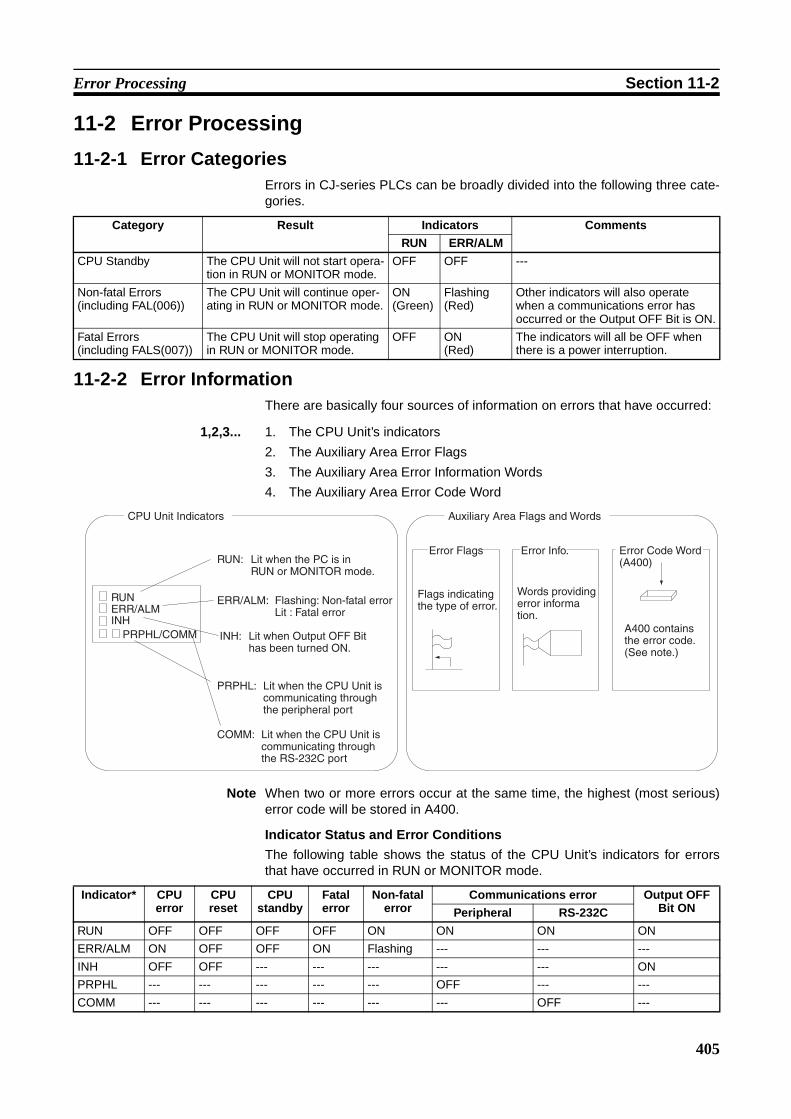
405
Error Processing Section 11-2
11-2 Error Processing
11-2-1 Error CategoriesErrors in CJ-series PLCs can be broadly divided into the following three cate-gories.
11-2-2 Error InformationThere are basically four sources of information on errors that have occurred:
1,2,3... 1. The CPU Unit’s indicators
2. The Auxiliary Area Error Flags
3. The Auxiliary Area Error Information Words
4. The Auxiliary Area Error Code Word
Note When two or more errors occur at the same time, the highest (most serious)error code will be stored in A400.
Indicator Status and Error Conditions
The following table shows the status of the CPU Unit’s indicators for errorsthat have occurred in RUN or MONITOR mode.
Category Result Indicators Comments
RUN ERR/ALM
CPU Standby The CPU Unit will not start opera-tion in RUN or MONITOR mode.
OFF OFF ---
Non-fatal Errors(including FAL(006))
The CPU Unit will continue oper-ating in RUN or MONITOR mode.
ON(Green)
Flashing(Red)
Other indicators will also operate when a communications error has occurred or the Output OFF Bit is ON.
Fatal Errors(including FALS(007))
The CPU Unit will stop operating in RUN or MONITOR mode.
OFF ON(Red)
The indicators will all be OFF when there is a power interruption.
RUNERR/ALMINH
PRPHL/COMM
CPU Unit Indicators Auxiliary Area Flags and Words
RUN:
ERR/ALM:
INH:
PRPHL:
COMM:
Lit when the PC is in RUN or MONITOR mode.
Flashing: Non-fatal errorLit : Fatal error
Lit when Output OFF Bit has been turned ON.
Lit when the CPU Unit is communicating through the peripheral port
Lit when the CPU Unit is communicating through the RS-232C port
Error Flags Error Info. Error Code Word(A400)
Flags indicating the type of error.
Words providing error information.
A400 contains the error code.(See note.)
Indicator* CPU error
CPU reset
CPU standby
Fatal error
Non-fatal error
Communications error Output OFF Bit ONPeripheral RS-232C
RUN OFF OFF OFF OFF ON ON ON ON
ERR/ALM ON OFF OFF ON Flashing --- --- ---
INH OFF OFF --- --- --- --- --- ON
PRPHL --- --- --- --- --- OFF --- ---
COMM --- --- --- --- --- --- OFF ---

406
Error Processing Section 11-2
11-2-3 Error Codes and Error FlagsClassification Error code Error name Page
Fatal system errors
80F1 Memory error 412
80C0 to 80C7, 80CE, 80CF
I/O bus error 412
80E9 Duplicated number error 413
80E1 Too many I/O points 415
80E0 I/O setting error 415
80F0 Program error 414
809F Cycle time too long 416
80EA Expansion Rack number duplicated 413
Non-fatal sys-tem errors
008B Interrupt task error 417
009A Basic I/O error 417
009B PLC Setup setting error 417
00E7 I/O verification error 415
0200 to 020F CJ-series CPU Bus Unit error 418
0300 to 035F, 03FF
Special I/O Unit error 418
00F7 Battery error 418
0400 to 040F CJ-series CPU Bus Unit setting error 418
0500 to 055F Special I/O Unit setting error 418
User-defined fatal errors
4101 to 42FF FAL(006) error(4101 to 42FF are stored for FAL num-bers 001 to 511)
417
User-defined non-fatal errors
C101 to C2FF FALS(007) error(C101 to C2FF are stored for FALS numbers 001 to 511)
416

407
Error Processing Section 11-2
11-2-4 Error Processing FlowchartUse the following flowchart as a guide for error processing with a Program-ming Console.
Error occurred during operation
Is the POWER indicator lit?
Is the RUN indica-tor lit?
Connect the Programming Console.
Fatal error
OFF
Lit
Lit
OFF
Is the Programming Console's display
operating?
- - - - displayed.
Check the Power Supply (page 16).
Is the ERR/ALM indicator flashing?
OFF
Flashing Check I/O (page 17) and environmental conditions (page 18).
Connect the Programming Console.
CPU Error(WDT error)
Non-fatal error
Yes
ERR/ALM indicator lit.
Check the PowerSupply (page 420)
Check I/O (page 425) and environmental conditions (page 426)

408
Error Processing Section 11-2
1. The rack number will be given at *.
2. The FAL/FALS number will be given at ***.
3. The unit number will be given at **.
4. The master number will be given at *.
MEMORY ERR *
Fatal error
Memory error
I/O bus error
Unit NumberDuplication error
Too Many I/O Points error
I/O TableSetting error
Program error
Rack NumberDuplicationerror
Cycle Time Overrun error
System FALS error
Non-fatal error
FAL error
Interrupt Task error
Basic I/O error
CS1 CPU Bus Unit error
Special I/O Unit error
PLC Setup error
Battery error
CS1 CPU Bus Unit Setup error
Special I/O Unit Setup error
I/O BUS ERR
UNIT NO. DPL ERR
RACK NO. DPL ERR
TOO MANY I/O PNT
I/O SET ERR
PROGRAM ERR
CYCLE TIME ERR
SYS FAIL FALS
SYS FAIL FAL ***
INTRPT ERR
DENSITY I/O ERR
PC SETUP ERR
CPU BU ERR **
SIOU ERR **
BAT LOW
CPU BU STUP **
SIOU SETUP **
(See note 1) (See note 2)
(See note 3)
(See note 3)
(See note 3)
(See note 3)

409
Error Processing Section 11-2
11-2-5 Error MessagesThe following tables show error messages for errors which can occur in CJ-series PLCs and indicate the likely cause of the errors.
Note Always confirm the safety of any related facilities and machines before turningOFF the power supply.
CPU ErrorsA CPU error has occurred if the indicators have the following conditions inRUN or MONITOR mode. A Programming Device cannot be connected to theCPU if an CPU error has occurred.
Note If a fatal operating error occurs, the indicators will be the same as shownbelow for CPU errors, but a Programming Device can be connected. This willenable distinguishing between the two types of error.
CPU ResetThe following indictor status shows that the CPU Unit has been reset (not aCPU error). A Programming Device cannot be connected.
Power Supply Unit Indicator
CPU Unit Indicators
POWER RUN ERR/ALM INH PRPHL COMM
ON OFF ON --- --- ---
Status Error Program-ming
Console display
Error flags in
Auxiliary Area
Error code (in A400)
Flags and
word data
Probable cause Possible remedy
Stopped CPU error (WDT error)
– – – – None None None Watchdog timer has exceeded maxi-mum setting. (This error does not nor-mally occur)
Turn the power OFF and restart. The Unit may be damaged. Contact you OMRON representative.
Power Supply Unit Indicator
CPU Unit Indicators
POWER RUN ERR/ALM INH PRPHL COMM
ON --- --- --- --- ---

410
Error Processing Section 11-2
Note When power supply is interrupted to an Expansion Rack, the CPU Unit willstop program execution and the same operations as are performed when thepower supply to the CPU Unit is interrupted will be performed. For example, ifthe power OFF interrupt task is enabled, it will be executed. If power is thenrestored to the Expansion Rack, the CPU Unit will perform startup processing,i.e., the same operational status as existed before the power interrupt will notnecessarily be continued.
CPU Standby ErrorsA CPU standby error has occurred if the indicators have the following condi-tions in RUN or MONITOR mode.
When a CJ-series CPU Unit is turned ON, cyclic servicing is started and RUNmode is entered only after all Special I/O Units and CPU Bus Units have beendetected. If the startup mode is RUN or MONITOR mode, the CPU will remainon standby until all Units have been directed.
Status Error Program-ming
Console display
Error flags in
Auxiliary Area
Error code (in A400)
Flags Probable cause Possible remedy
Stopped CPU reset – – – – None None None Power is not being supplied to an Expansion Rack.
Supply power to the Expan-sion Racks.
I/O Control Unit is not connected cor-rectly, e.g., more than one is con-nected or one is connected to an Expansion Rack.
Turn OFF the power supply, correct the connections, and turn the power supply back ON.
The I/O Connecting cable is not con-nected correctly, e.g., the connections to the input and out-put connectors on the I/O Interface Unit are backward.
Turn OFF the power supply, correct the connections, and turn the power supply back ON.
Power Supply Unit Indicator
CPU Unit Indicators
POWER RUN ERR/ALM INH PRPHL COMM
ON OFF OFF --- --- ---
Status Error Program-ming
Console display
Error flags in
Auxiliary Area
Error code (in A400)
Flags Probable cause Possible remedy
Stopped CPU standby error
CPU WAIT’G
None None None A CPU Bus Unit has not started properly.
Check the settings of the CPU Bus Unit.
A Special I/O Unit, or Interrupt Input Unit was not recognized.
Read the I/O table and replace any Special I/O Unit or Interrupt Input Units for which only “$” is displayed.

411
Error Processing Section 11-2
Startup Condition The CJ1-H and CJ1M CPU Units support a Startup Condition setting.
To start the CPU Unit in MONITOR or PROGRAM mode even if there is oneor more Units that has not completed startup processing, set the Startup Con-dition to 1.
PLC Setup
Fatal ErrorsA fatal error has occurred if the indicators have the following conditions inRUN or MONITOR mode.
Connect a Programming Console to display the error message or use theerror log window on the CX-Programmer. The cause of the error can be deter-mined from the error message and related Auxiliary Area flags and words.
Errors are listed in order of importance. When two or more errors occur at thesame time, the more serious error’s error code will be recorded in A400.
If the IOM Hold Bit hasn’t been turned ON to protect I/O memory, all non-retained areas of I/O memory will be cleared when a fatal error other thanFALS(007) occurs. If the IOM Hold Bit is ON, the contents of I/O memory willbe retained but all outputs will be turned OFF.
Programming Con-sole setting address
Name Settings Default
Word Bit
83 15 Startup Condition 0: Wait for Units.1: Don’t wait.
0: Wait for Units.
Power Supply Unit Indicator
CPU Unit Indicators
POWER RUN ERR/ALM INH PRPHL COMM
ON OFF ON --- --- ---

412
Error Processing Section 11-2
If the IOM Hold Bit hasn’t been turned ON to protect I/O memory, all non-retained areas of I/O memory will be cleared when a fatal error other thanFALS(007) occurs. When the IOM Hold Bit is ON, the contents of I/O memorywill be retained but all outputs will be turned OFF.
Error Program-ming
Console display
Error code (in A400)
Flag and word data
Probable cause Possible remedy
Memory error
MEMORY ERR
80F1 A40115: Memory Error FlagA403: Memory Error Loca-tion
An error has occurred in memory. A bit in A403 will turn ON to show the location of the error as listed below.
See below.
A40300 ON:A checksum error has occurred in the user program memory. An illegal instruc-tion was detected.
Check the program and correct the error.
A40304 ON:A checksum error has occurred in the PLC Setup.
Clear the entire PLC Setup to 0000 and reenter the settings.
A40305 ON:A checksum error has occurred in the registered I/O table.
Initialize the registered I/O table and gen-erate a new I/O table.
A40307 ON:A checksum error has occurred in the routing tables.
Initialize the routing tables and reenter the tables.
A40308 ON:A checksum error has occurred in the CPU Bus Unit setup.
Initialize the CPU Bus Unit setup and reenter the settings.
A40309 ON:An error occurred during automatic transfer from the Memory Card at startup.
Make sure that the Memory Card is installed properly and that the correct file is on the Card.
A40310 ON:An error occurred in flash memory (backup memory).
CPU Unit hardware is faulty. Replace the CPU Unit.
I/O Bus error
I/O BUS ERR
80C0 to 80CE or 80CF
A40114: I/O Bus Error FlagA404: I/O Bus Error Slot and Rack Num-bers
Error has occurred in the bus line between the CPU and I/O Units or the End Cover is not connected to the CPU Rack or an Expansion Rack.
A40400 to A40407 contain the error slot number (00 to 09) in binary. 0F hex indi-cates that the slot cannot be determined. 0E hex indi-cates the End Cover is not connected to the CPU Rack or an Expansion Rack.A40408 to A40415 contain the error rack number (00 to 03) in binary. 0F hex indi-cates that the rack cannot be determined. 0E hex indi-cates the End Cover is not connected to the CPU Rack or an Expansion Rack.
Try turning the power OFF and ON again.
If the error isn’t corrected, turn the power OFF and check cable connections between the I/O Units and Racks and the End Covers.Check for damage to the cable or Units.Turn the Rack’s power supply OFF and then ON again.

413
Error Processing Section 11-2
Unit/Rack Number Duplica-tion error
UNIT No. DPL ERR
80E9 A40113: Duplication Error FlagA410: CPU Bus Unit Duplicate Number Flags
The same number has been allocated to more than one CPU Bus Unit.Bits A41000 to A41015 cor-respond to unit numbers 0 to F.
Check the unit numbers, eliminate the duplications, and turn the Rack’s power supply OFF and then ON again.
A40113: Duplication Error FlagA411 to A416: Spe-cial I/O Unit Duplicate Number Flags
The same number has been allocated to more than one Special I/O Unit.Bits A41100 to A41615 cor-respond to unit numbers 0 to 95.
Check the unit numbers, eliminate the duplications, and turn the Rack’s power supply OFF and then ON again.
RACK No. DPL ERR
80EA A409: Expansion Rack Dupli-cate Rack Number
The same I/O word has been allocated to more than one Basic I/O Unit.
Check allocations to Units on the rack number whose bit in ON in A40900 to A40903. Correct the allocations so that no words are allocated more than once, including to Units on other Racks, and turn the Rack’s power supply OFF and then ON again.
An Expansion Rack’s start-ing word address exceeds CIO 0901.The corresponding bit in A40900 to A40903 (Racks 0 to 3) will be turned ON.
Check the first word setting for the Rack indicated in A40900 to A40903 and change the setting to a valid word address below CIO 0900 with a Pro-gramming Device.
Program error
PRO-GRAM ERR
80F0 A40109: Program Error FlagA294 to A299: Pro-gram error information
The program is incorrect. See the following rows of this table for details. The address at which the program stopped will be out-put to A298 and A299.
Check A295 to determine the type of error that occurred and check A298/A299 to find the program address where the error occurred.Correct the program and then clear the error.
A29511: No END error Be sure that there is an END(001) instruction at the end of the task speci-fied in A294 (program stop task number). The address where the END(001)
A29515: UM overflow errorThe last address in UM (user program memory) has been exceeded.
Use a Programming Device to transfer the program again.
Error Program-ming
Console display
Error code (in A400)
Flag and word data
Probable cause Possible remedy

414
Error Processing Section 11-2
Program error (cont.)
PRO-GRAM ERR
80F0 A40109: Program Error FlagA294 to A299: Pro-gram error information
A29513: Differentiation over-flow errorToo many differentiated instructions have been inserted or deleted during online editing.
After writing any changes to the program, switch to PROGRAM mode and then return to MONITOR mode to continue editing the program.
A29512: Task errorA task error has occurred. The following conditions will generate a task error.
1) There isn’t an executable cyclic task.2) There isn’t a program allo-cated to the task. Check A294 for the number of the task missing a program.
3) The task specified in a TKON(820), TKOF(821), or MSKS(690) instruction doesn’t exist.
Check the startup cyclic task attributes.
Check the execution status of each task as controlled by TKON(820) and TKOF(821).
Make sure that all of the task numbers specified in TKON(820), TKOF(821), and MSKS(690) instructions have corre-sponding tasks.Use MSKS(690) to mask any I/O or scheduled interrupt tasks that are not being used and that do not have pro-grams set for them.
A29510: Illegal access errorAn illegal access error has occurred and the PLC Setup has been set to stop opera-tion for an instruction error. The following are illegal access errors:1. Reading/writing a param-eter area.2. Writing memory that is not installed.3. Writing an EM bank that is EM file memory.
4. Writing to a read-only area.5. Indirect DM/EM address that is not in BCD when BCD mode is specified.
Find the program address where the error occurred (A298/A299) and correct the instruction.
A29509: Indirect DM/EM BCD errorAn indirect DM/EM BCD error has occurred and the PLC Setup has been set to stop operation for an instruc-tion error.
Find the program address where the error occurred (A298/A299) and correct the indirect addressing or change to binary mode.
A29508: Instruction errorAn instruction processing error has occurred and the PLC Setup has been set to stop operation for an instruc-tion error.
Find the program address where the error occurred (A298/A299) and correct the instruction.
A29514: Illegal instruction errorThe program contains an instruction that cannot be executed.
Retransfer the program to the CPU Unit.
Error Program-ming
Console display
Error code (in A400)
Flag and word data
Probable cause Possible remedy

415
Error Processing Section 11-2
Too Many I/O Points error
TOO MANY I/O PNT
80E1 A40111: Too Many I/O Points FlagA407: Too Many I/O Points, Details
The probable causes are listed below. The 3-digit binary value (000 to 101) in A40713 to A40715 indicates the cause of the error. The value of these 3 bits is also output to A40700 to A40712.1) The total number of I/O points set in the I/O Table exceeds the maximum allowed for the CPU Unit
2) The number of Expan-sion Racks exceeds the maximum (bits: 101).
3) More than 10 I/O Units are connected to one Rack (bits: 111).
Correct the problem and then turn the power supply OFF and back ON.
I/O Table Setting error
I/O SET ERR
80E0 A40110: I/O Setting Error Flag
The Units that are connected do not agree with the regis-tered I/O table or the number of Units that are connected does not agree with the number in the registered I/O table.(The following Units must be set as a 16-point Units in the I/O tables made on the CX-Programmer because they are allocated 1 word each even though they have only 8 points: CJ1W-OC201, CJ1W-I1201, CJ1W-OA201, and CJ1W-OD201/202. An I/O setting error will occur if this Unit is set as an 8-point Unit.)
Any discrepancies in the I/O table will be detected when the I/O verification opera-tion is performed. If this error occurs even when the number Units is correct, there may be a faulty Unit. Automatically create the I/O tables and check for Units that are not being detected.If the number of Units is not correct, turn OFF the power supply and correctly con-nect the proper Units.If the number of Units is correct, confirm the Unit in discrepancy, turn OFF the power supply, and then correct the Unit connections.
If there is a mistake in the I/O tables, rec-reate or edit them to correct the mistake.
An Interrupt Input Unit has been connected in the wrong position, i.e., not in one of the five positions (CJ1 and CJ1-H) or three positions (CJ1M) next to the CPU Unit, or has been registered in the Registered I/O Tables in the wrong position.
A40508 will turn ON if an Interrupt Input Unit is in the wrong position (i.e., either physically in the wrong position in the system or registered in the wrong posi-tion in the Registered I/O Tables).Mount the Unit in the correct position or correct the Registered I/O Tables.
Error Program-ming
Console display
Error code (in A400)
Flag and word data
Probable cause Possible remedy

416
Error Processing Section 11-2
Cycle Time Overrun error
CYCLE TIME ERR
809F A40108: Cycle Time Too Long Flag
The cycle time has exceeded the maximum cycle time (watch cycle time) set in the PLC Setup.
Change the program to reduce the cycle time or change the maximum cycle time setting.Check the Maximum Interrupt Task Pro-cessing Time in A440 and see if the Cycle Time Watch Time can be changed.The cycle time can be reduced by divid-ing unused parts of the program into tasks, jumping unused instructions in tasks, and disabling cyclic refreshing of Special I/O Units that don’t require fre-quent refreshing.
CYCLE TIME OVER
809F A40515: Peripheral Servicing Cycle Time Too Long
Turns ON when the periph-eral servicing time in a Paral-lel Processing Mode exceeds 2 s.
Change the CPU Processing Mode in the PLC Setup to Normal Mode or Peripheral Servicing Priority Mode, or review the system to reduce the event load.Parallel processing may not be possible if the program execution time (given in A66) is too short (e.g., less than 0.2 ms).
System FALS error
SYS FAIL FALS
C101 to C2FF
A40106: FALS Error Flag
FALS(007) has been exe-cuted in the program.
The error code in A400 will indicate the FAL number. The leftmost digit of the code will be C and the rightmost 3 digits of the code will be from 100 to 2FF hex and will cor-respond to FAL numbers 001 to 511.
Correct according to cause indicated by the FAL number (set by user).
Error Program-ming
Console display
Error code (in A400)
Flag and word data
Probable cause Possible remedy

417
Error Processing Section 11-2
Non-fatal ErrorsA non-fatal error has occurred if the indicators have the following conditions inRUN or MONITOR mode.
Connect a Programming Console to display the error message or use theerror log window on the CX-Programmer. The cause of the error can be deter-mined from the error message and related Auxiliary Area flags and words.
Errors are listed in order of importance. When two or more errors occur at thesame time, the more serious error’s error code will be recorded in A400.
Power Supply Unit Indicator
CPU Unit Indicators
POWER RUN ERR/ALM INH PRPHL COMM
ON ON Flashing --- --- ---
Error Program-ming
Console display
Error code (in
A400)
Flag and word data
Probable cause Possible remedy
System FAL error
SYS FAIL FAL
4101 to 42FF
A40215: FAL Error Flag
A360 to A391: Exe-cuted FAL Number Flags
FAL(006) has been exe-cuted in program.Executed FAL Number Flags A36001 to A39115 correspond to FAL numbers 001 to 511.
The error code in A400 will indicate the FAL number. The leftmost digit of the code will be 4 and the right-most 3 digits of the code will be from 100 to 2FF hex and will correspond to FAL num-bers 001 to 511.
Correct according to cause indicated by FAL number (set by user).
Interrupt Task error
INTRPT ERR
008B A40213: Interrupt Task Error FlagA426: Inter-rupt Task Error, Task Number
PLC Setup Set to Detect Interrupt Task Errors:Attempted to refresh a Spe-cial I/O Unit’s I/O from an interrupt task with IORF(097) while the Unit’s I/O was being refreshed by cyclic I/O refreshing (dupli-cate refreshing).
Check the program. Either disable detection of interrupt task errors in the PLC Setup (address 128, bit 14) or cor-rect the problem in the program.
Basic I/O error
DENSITY I/O ERR
009A A40212: Basic I/O Unit Error FlagA408: Basic I/O Unit Error, Slot Number
An error has occurred in a Basic I/O Unit.
A408 contains the errant rack/slot number.
Check the errant Unit for blown fuse, etc.
PLC Setup error
PLC Setup ERR
009B A40210: PLC Setup Error FlagA406: PLC Setup Error Location
There is a setting error in the PLC Setup. The location of the error is written to A406.
Change the indicated setting to a valid setting.

418
Error Processing Section 11-2
CPU Bus Unit error
CPU BU ERR
0200 to 020F
A40207: CPU Bus Unit Error FlagA417: CPU Bus Unit Error, Unit Number Flags
An error occurred in a data exchange between the CPU Unit and a CPU Bus Unit.The corresponding flag in A417 is turned ON to indi-cate the problem Unit. Bits A41700 to A41715 corre-spond to unit numbers 0 to F.
Check the Unit indicated in A417. Refer to the Unit’s operation manual to find and correct the cause of the error. Restart the Unit by toggling its Restart Bit or turn the power OFF and ON again.Replace the Unit if it won’t restart.
Special I/O Unit error
SIOU ERR 0300 to 035F, or 03FF
A40206: Special I/O Unit Error Flag
A418 to A423: Spe-cial I/O Unit Error, Unit Number Flags
An error occurred in a data exchange between the CPU Unit and a Special I/O Unit.The corresponding flag in A418 to A423 is turned ON to indicate the problem Unit. Bits A41800 to A42315 cor-respond to unit numbers 0 to 95.
Check the Unit indicated in A418 to A423. Refer to the Unit’s operation man-ual to find and correct the cause of the error. Restart the Unit by toggling its Restart Bit or turn the power OFF and ON again.Replace the Unit if it won’t restart.
Battery error
BATT LOW
00F7 A40204: Battery Error Flag
This error occurs when the PLC Setup has been set to detect battery errors and the CPU Unit’s backup battery is missing or its voltage has dropped.
Check battery and replace if necessary. Change the PLC Setup setting if battery-free operation is being used.
CPU Bus Unit Setup error
CPU BU ST ERR
0400 to 040F
A40203: CPU Bus Unit Set-ting Error Flag
A427: CPU Bus Unit Setting Error, Unit Number Flags
An installed CPU Bus Unit does not match the CPU Bus Unit registered in the I/O table.The corresponding flag in A427 will be ON. Bits 00 to 15 correspond to unit num-bers 0 to F.
Change the registered I/O table.
Special I/O Unit Setup error
SIOU SETUP ERR
0500 to 055F
A40202: Special I/O Unit Set-ting Error Flag
A428 to A433: Spe-cial I/O Unit Setting Error, Unit Number Flags
An installed Special I/O Unit does not match the Special I/O Unit registered in the I/O table.The corresponding flag in A428 to A433 will be ON. Bits A42800 to A43315 cor-respond to unit numbers 0 to 95.
Change the registered I/O table.
Error Program-ming
Console display
Error code (in
A400)
Flag and word data
Probable cause Possible remedy

419
Error Processing Section 11-2
Other ErrorsPeripheral Port Communications Error
A communications error has occurred in communications with the device con-nected to the peripheral port if the indicators have the following conditions.
Check the setting of pin 4 on the DIP switch and the peripheral port settings inthe PLC Setup. Also check the cable connections.
RS-232C Port Communications Error
A communications error has occurred in communications with the device con-nected to the RS-232C port if the indicators have the following conditions.
Check the setting of pin 5 on the DIP switch and the RS-232C port settings inthe PLC Setup. Also check the cable connections. If a host computer is con-nected, check the communications settings of the serial port on the host com-puter and the communications program in the host computer.
Power Supply Unit Indicator
CPU Unit Indicators
POWER RUN ERR/ALM INH PRPHL COMM
ON ON --- --- OFF ---
Power Supply Unit Indicator
CPU Unit Indicators
POWER RUN ERR/ALM INH PRPHL COMM
ON --- --- --- --- OFF

420
Error Processing Section 11-2
11-2-6 Power Supply CheckThe allowable voltage ranges are shown in the following table.
Power Supply Unit Power supply voltage
Allowable voltage range
CJ1W-PA205R 100 to 240 V AC 85 to 264 V AC
CJ1W-PA202 100 to 240 V AC 85 to 264 V AC
CJ1W-PD025 24 V DC 19.2 to 28.8 V DC
Power indicator not lit.
Is power being supplied?
Connect power supply.
Is power indicator lit?
Yes
No
Not lit Lit
Replace the Power Supply Unit.
Power supplyvoltage in acceptable
range?
Set supply voltage withinacceptable limits.
End
No
Not litIs power indicator lit?
Lit
Yes
Are there anyloose terminal screws or broken wires?
Tighten screws orreplace wires.
No
Not litIs power indicator lit?
Lit
Yes

421
Error Processing Section 11-2
11-2-7 Memory Error Check
ON
OFF
ON
OFF
Memory error occurred.
A40309 (autotransfer at startup error)
ON?
A40310 (flash memory error)
ON?
Battery connected?
Power turned OFF during backup (with BKUP
lit)?
Battery-free operation
necessary?
Conditions have not been met for automatic transfer at startup. Confirm that the required files are on the Memory Card and the pin 2 on the DIP switch is OFF.
The write life of the flash memory has been exceeded. Replace the CPU Unit.
Check to see if battery-free operation has been set correctly. Retransfer the user program and parameters and set the PLC Setup so that battery errors are not detected.
Mount a Battery.
If power was turned OFF during the backup operation, retransfer the user program and parameters.
A hardware fault has occurred in internal memory. Replace the CPU Unit.

422
Error Processing Section 11-2
11-2-8 Program Error Check
ON
OFF
#FFFF
ON
OFF
ON
OFF
Program error occurred.
A29512 (Task Error Flag) ON?
A29511 (No END Flag) ON?
A29508 to A29510 (instruction error
flags) ON?
Task that stopped program (A294)?
An active task does not exist. Check the usage of TKON(820) and TKOF(821).
An attempt was made to start a task that doesn’t exist. Check the MSKS(690) instruction used to enable the interrupt task of the specified number.
An attempt was made to start the task of the specified number with an interrupt. Check the CPU Bus Unit.
There is no END(001) in the task that stopped the program (A294). Add END(001).
The program was stopped for the PLC Setup setting to stop the program for instruction errors. Check the program based on the task (A294) and address (A298 and A299) that stopped the program.
Turn the power supply OFF and then back ON again.
#8002, #8003, #8064 to #8083
Not related to problem.

423
Error Processing Section 11-2
11-2-9 Cycle Time Too Long Error Check
11-2-10 PLC Setup Setting Error Check
ON
OFF
ON
OFF
The cycle time was too long.
A40515 (Peripheral Servicing Cycle Too
Long) ON?
Anticipated cycle time less than PLC Setup
monitor setting?
Interrupts being used?
A440 (Maximum Interrupt
Processing Time) value acceptable?
The peripheral servicing cycle time exceeded 2 s. Reduce the event load or set the CPU processing mode in the PLC Setup to Normal Mode or Peripheral Servicing Priority Mode. The Parallel Processing Modes may not function properly if the program execution cycle time (A266) is too short (less than 0.2 ms.)
The monitoring time was execution time was exceed for program execution. Increase the monitoring time set in the PLC Setup.
The problem may be caused by long processing times for interrupt tasks. Check the contents of the task specified in A441 (Task with Highest Processing Time).
There may be more than one interrupt task occurring, causing the cycle time to be increased. Reduce the frequency of interrupts.
There may be a bug in the program. Check all tasks for the following instructions.FOR and LOOPJMP, CJP, and CPN
Yes
No
Yes
No
Yes
No
Not related to problem.
#00DC(220)
PLC Setup setting error occurred.
Value of A406 (location of setting
error)?
PLC Setup written from Programming
Console?
The CPU processing mode is set to Peripheral Servicing Priority Mode, but the priorities have not been set correctly.
The setting indicated by the contents of A406 is illegal. Check the setting from a Programming Console.
A communications error may have occurred during data transfer from the CX-Programmer. Retransfer the PLC Setup.
Yes
No
Other

424
Error Processing Section 11-2
11-2-11 Battery Error Check
11-2-12 I/O Setting Error Check
Battery error occurred.
Battery-free operation required?
Set the PLC Setup so that battery errors are not detected. (DM Area contents may be unstable when this setting is used.)Refer to the CS/CJ Programming Manual for details.
The Battery is missing or the voltage has dropped. Replace the Battery.
Yes
No
O FF
O N
Interrupt Input Unit being used?
A40508 turned ON?
Either connect the Interrupt Input Unit in the correct position or register it in the I/O tables in the correct position.
Reconnect the Units according to the Registered I/O Tables.
Yes
No
I/O setting error occurred.

425
Error Processing Section 11-2
11-2-13 I/O CheckThe I/O check flowchart is based on the following ladder diagram sectionassuming that SOL1 does not turn ON.
Return to START
NORMAL
Indicators ofinputs (000002, 000003) normal?
Check terminal voltage of 000500 with tester
Indicator of 000500 normal?
YES
Correct wiring Replace terminal block connector
Replace fuse Monitor ON/OFF status of 000500 with Programming DeviceNO YES YES
Voltage normal?
NORMAL
Output wiring correct?
YES
Faultyterminal block connector con
tact?
Is the blown fuse indi-
cator lit?Operation OK?
NORMAL
Disconnect external wiring and check terminal voltage of 000500 with tester
Check output de-vice SOL1
NORMAL ABNORMAL
Replace Output Unit
Check terminal voltages of 000002 and 000003 with tester
Check terminal voltages of 000002 and 000003 with tester
Input wiring correct?
NO
Correctly wire
Remove external wiring and mount Dummy Input Unit to check
Operation OK?
Check LS1 and LS2
Terminal screws loose?
NO
Faultyterminal block connector con-
tact?
YES
Replace terminal block connector
Tighten
Replace Input UnitReplace Input Unit
NO NO ABNORMAL
NO
YES
ABNORMAL
NORMAL
ABNORMAL
ABNORMAL
NORMAL
YES
NO
YES
(Units with internal fuse)
(Unit without fuse)
ABNORMAL
NO
Voltage normal?
Voltage normal?
Voltage normal?
START
000500
000002(LS1)
000003(LS2)
SOL1
000500

426
Error Processing Section 11-2
11-2-14 Environmental Conditions Check
Note Check for corrosive gases, flammable gases, dust, dirt, salts, metal dust,direct light, water, oils, and chemicals.
Consider using a fan or cooler.
Environmental conditions check
Is the ambient temperature below 55°C?
Is the ambient temperature above
0°C?
Is noise being controlled?
Is the installation environment okay?
Consider using a heater.
Consider using an an air conditioner.
Install surge protectors or other noise-reducing equipment at noise sources.
Check the structure of the panel and the installation site.
End.
Yes
No
Yes
No
No
No
No
Yes
Yes
Yes
Is the ambient humidity between 10% and
90%?
(See note.)

427
Troubleshooting Racks and Units Section 11-3
11-3 Troubleshooting Racks and UnitsCPU Racks and Standard Expansion Racks
Special I/O UnitsRefer to the Operation Manual for the Special I/O Unit to troubleshoot anyother errors.
Symptom Cause Remedy
POWER indicator is not lit. PCB short-circuited or damaged. Replace Power Supply Unit.
(1) Error in program. Correct program
(2) Power line is faulty. Replace Power Supply Unit.
RUN output* does not turn ON.RUN indicator lit.
(*CJ1W-PA205R)
Internal circuitry of Power Supply Unit is faulty.
Replace Power Supply Unit.
Serial Communications Unit or CPU Bus Unit does not operate or malfunc-tions.
(1) The I/O Connecting Cable is faulty.(2) The I/O bus is faulty.
Replace the I/O Connecting CableReplace the I/O Control Unit or I/O Interface Unit.
Bits do not operate past a certain point.
Error occurs in units of 8 points.
I/O bit turns ON
All bits in one Unit do not turn ON.
Symptom Cause Remedy
The ERH and RUN indicators on the Spe-cial I/O Unit are lit.
I/O refreshing is not being performed for the Unit from the CPU Unit (CPU Unit monitoring error).
It’s possible that cyclic refreshing has been dis-abled for the Special I/O Unit in the Cyclic Refresh Disable Setting in the PLC Setup (i.e., the bit corresponding to the unit number has been set to 1).
Change the bit corresponding to the unit num-ber to 0 to enable cyclic refreshing, or make sure that the Unit is refreshed from the program using IORF at least once every 11 s.

428
Troubleshooting Racks and Units Section 11-3
CJ Long-distance Expansion Racks
Symptom Cause Remedy
CPU Unit won’t operate. (No response to Programming Devices and no CPU Unit indicators are lit.)
(1) Power is not turned ON to an Expansion Rack.
Turn ON power to all Expansion Racks.
(2) An Expansion Rack is not connected correctly.
Recheck the connections and configuration using information in 2-3-3 CJ-series Expan-sion Racks, 3-5 I/O Control Units and I/O Interface Units.
(3) An I/O Connecting Cable is not wired correctly.
Reconnect the I/O Connecting Cables in the correct order for output and input connec-tors.
(4) A Unit is faulty. Gradually remove/replace Units to deter-mine the Unit that is faulty, including the Power Supply Unit, I/O Units, I/O Control/Interface Unit, and I/O Connecting Cable.
Expansion Rack not detected.
(1) A Terminator is not connected. If the TERM indicator is lit, connect a Termi-nator.
(2) An Expansion Rack is not connected correctly.
Recheck the connections and configuration using information in 2-3-3 CJ-series Expan-sion Racks, 3-5 I/O Control Units and I/O Interface Units.
(3) A Unit is faulty. Gradually remove/replace Units to deter-mine the Unit that is faulty, including the Power Supply Unit, I/O Units, I/O Control/Interface Unit, and I/O Connecting Cable.
I/O bus error or I/O verifica-tion error occurs.
(1) An I/O Connecting Cable or Terminator connection is faulty.
Check that I/O Connecting Cables and Ter-minators are connected correctly.
(2) Noise or other external factor. Separate all cables from possible sources of noise or place them in metal ducts.
(3) A Unit is faulty. Gradually remove/replace Units to deter-mine the Unit that is faulty, including the Power Supply Unit, I/O Units, I/O Control/Interface Unit, and I/O Connecting Cable.
Cycle time is too long. (1) A CPU Bus Unit that is allocated many words (e.g., Controller Link Unit) is mounted to a CJ Long-distance Expan-sion Rack.
Move the CPU Bus Unit to the CPU Rack.
(2) A Unit is faulty. Gradually remove/replace Units to deter-mine the Unit that is faulty, including the Power Supply Unit, I/O Units, I/O Control/Interface Unit, and I/O Connecting Cable.
I/O Control Unit and I/O Inter-face Units do not appear on CX-Programmer I/O table.
This is not an error. These Units are not allo-cated I/O words and thus are not registered in the I/O tables.
---

429
Troubleshooting Racks and Units Section 11-3
Input Units
Symptom Cause Remedy
Not all inputs turn ON or indi-cators are not lit.
(1) Power is not supplied to Input Unit. Supply power
(2) Supply voltage is low. Adjust supply voltage to within rated range.
(3) Terminal block mounting screws are loose.
Tighten screws.
(4) Faulty contact of terminal block connec-tor.
Replace terminal block connector.
Not all inputs turn ON (indica-tor lit).
Input circuit is faulty. (There is a short at the load or something else that caused an over-current to flow.)
Replace Unit.
Not all inputs turn OFF. Input circuit is faulty. Replace Unit.
Specific bit does not turn ON. (1) Input device is faulty. Replace input devices.
(2) Input wiring disconnected. Check input wiring
(3) Terminal block screws are loose. Tighten screws
(4) Faulty terminal block connector contact. Replace terminal block connector.
(5) Too short ON time of external input. Adjust input device
(6) Faulty input circuit Replace Unit.
(7) Input bit number is used for output instruction.
Correct program.
Specific bit does not turn OFF.
(1) Input circuit is faulty. Replace Unit.
(2) Input bit number is used for output instruction.
Correct program.
Input irregularly turns ON/OFF.
(1) External input voltage is low or unstable. Adjust external input voltage to within rated range.
(2) Malfunction due to noise. Take protective measures against noise, such as:(1) Increase input response time (PLC Setup)(2) Install surge suppressor.(3) Install insulation transformer.(4) Install shielded cables between the Input Unit and the loads.
(3) Terminal block screws are loose. Tighten screws
(4) Faulty terminal block connector contact. Replace terminal block connector.
Error occurs in units of 8 points or 16 points, i.e., for the same common.
(1) Common terminal screws are loose. Tighten screws
(2) Faulty terminal block connector contact. Replace terminal block connector.
(3) Faulty data bus Replace Unit.
(4) Faulty CPU Replace CPU.
Input indicator is not lit in nor-mal operation.
Faulty indicator or indicator circuit. Replace Unit.

430
Troubleshooting Racks and Units Section 11-3
Output Units
Symptom Cause Remedy
Not all outputs turn ON (1) Load is not supplied with power. Supply power
(2) Load voltage is low. Adjust voltage to within rated range.
(3) Terminal block screws are loose. Tighten screws
(4) Faulty terminal block connector contact. Replace terminal block connector.
(5) An overcurrent (possibly caused by a short at the load) resulted in a blown fuse in the Output Unit. (Some Output Units provide an indicator for blown fuses.)
Replace fuse or Unit.
(6) Faulty I/O bus connector contact. Replace Unit.
(7) Output circuit is faulty. Replace Unit.
(8) If the INH indicator is lit, the Output OFF Bit (A50015) is ON.
Turn A50015 OFF.
Not all outputs turn OFF Output circuit is faulty. Replace Unit.
Output of a specific bit num-ber does not turn ON or indi-cator is not lit
(1) Output ON time too short because of a mistake in programming.
Correct program to increase the time that the output is ON.
(2) Bit status controlled by multiple instruc-tions.
Correct program so that each output bit is controlled by only one instruction.
(3) Faulty output circuit. Replace Unit.
Output of a specific bit num-ber does not turn ON (indica-tor lit).
(1) Faulty output device. Replace output device.
(2) Break in output wiring. Check output wiring.
(3) Loose terminal block screws. Tighten screws.
(4) Faulty terminal block connector faulty. Replace terminal block connector.
(5) Faulty output bit. Replace relay or Unit.
(6) Faulty output circuit. Replace Unit.
Output of a specific bit num-ber does not turn OFF (indi-cator is not lit).
(1) Faulty output bit. Replace relay or Unit.
(2) Bit does not turn OFF due to leakage current or residual voltage.
Replace external load or add dummy resis-tor.
Output of a specific bit num-ber does not turn OFF (indi-cator lit).
(1) Bit status controlled by multiple instruc-tions.
Correct program.
(2) Faulty output circuit. Replace Unit.
Output irregularly turns ON/OFF.
(1) Low or unstable load voltage. Adjust load voltage to within rated range
(2) Bit status controlled by multiple instruc-tions.
Correct program so that each output bit is controlled by only one instruction.
(3) Malfunction due to noise. Protective measures against noise:(1) Install surge suppressor.(2) Install insulation transformer.(3) Use shielded cables between the Output Unit and the loads.
(4) Terminal block screws are loose. Tighten screws.
(5) Faulty terminal block connector contact. Replace terminal block connector.
Error occurs in units of 8 points or 16 points, i.e., for the same common.
(1) Loose common terminal screw. Tighten screws.
(2) Faulty terminal block connector contact. Replace terminal block connector.
(3) An overcurrent (possibly caused by a short at the load) resulted in a blown fuse in the Output Unit.
Replace fuse or Unit.
(4) Faulty data bus. Replace Unit.
(5) Faulty CPU. Replace CPU.
Output indicator is not lit (operation is normal).
Faulty indicator. Replace Unit.

431
SECTION 12Inspection and Maintenance
This section provides inspection and maintenance information.
12-1 Inspections . . . . . . . . . . . . . . . . . . . . . . . . . . . . . . . . . . . . . . . . . . . . . . . . . . . 432
12-1-1 Inspection Points. . . . . . . . . . . . . . . . . . . . . . . . . . . . . . . . . . . . . . . . 432
12-1-2 Unit Replacement Precautions . . . . . . . . . . . . . . . . . . . . . . . . . . . . . 433
12-2 Replacing User-serviceable Parts . . . . . . . . . . . . . . . . . . . . . . . . . . . . . . . . . . 434

432
Inspections Section 12-1
12-1 InspectionsDaily or periodic inspections are required in order to maintain the PLC’s func-tions in peak operating condition.
12-1-1 Inspection PointsAlthough the major components in CJ-series PLCs have an extremely long lifetime, they can deteriorate under improper environmental conditions. Periodicinspections are thus required to ensure that the required conditions are beingkept.
Inspection is recommended at least once every six months to a year, but morefrequent inspections will be necessary in adverse environments.
Take immediate steps to correct the situation if any of the conditions in the fol-lowing table are not met.
No. Item Inspection Criteria Action
1 Source Power Supply
Check for voltage fluctuations at the power supply terminals.
The voltage must be within the allowable voltage fluctu-ation range.(See note.)
Use a voltage tester to check the power supply at the terminals. Take necessary steps to bring voltage fluctuations within limits.
2 I/O Power Sup-ply
Check for voltage fluctuations at the I/O terminals.
Voltages must be within specifications for each Unit.
Use a voltage tester to check the power supply at the terminals. Take necessary steps to bring voltage fluctuations within limits.
3 Ambient environ-ment
Check the ambient tempera-ture. (Inside the control panel if the PLC is in a control panel.)
0 to 55°C Use a thermometer to check the temperature and ensure that the ambient temperature remains within the allowed range of 0 to 55°C.
Check the ambient humidity. (Inside the control panel if the PLC is in a control panel.)
Relative humidity must be 10% to 90% with no con-densation.
Use a hygrometer to check the humidity and ensure that the ambi-ent humidity remains within the allowed range.
Check that the PLC is not in direct sunlight.
Not in direct sunlight Protect the PLC if necessary.
Check for accumulation of dirt, dust, salt, metal filings, etc.
No accumulation Clean and protect the PLC if neces-sary.
Check for water, oil, or chemi-cal sprays hitting the PLC.
No spray on the PLC Clean and protect the PLC if neces-sary.
Check for corrosive or flam-mable gases in the area of the PLC.
No corrosive or flammable gases
Check by smell or use a sensor.
Check the level of vibration or shock.
Vibration and shock must be within specifications.
Install cushioning or shock absorb-ing equipment if necessary.
Check for noise sources near the PLC.
No significant noise sources
Either separate the PLC and noise source or protect the PLC.

433
Inspections Section 12-1
Note The following table shows the allowable voltage fluctuation ranges for sourcepower supplies.
Tools Required for Inspections
Required Tools
• Slotted and Phillips-head screwdrivers
• Voltage tester or digital voltmeter
• Industrial alcohol and clean cotton cloth
Tools Required Occasionally
• Synchroscope
• Oscilloscope with pen plotter
• Thermometer and hygrometer (humidity meter)
12-1-2 Unit Replacement PrecautionsCheck the following after replacing any faulty Unit.
• Do not replace a Unit until the power is turned OFF.
• Check the new Unit to make sure that there are no errors.
• If a faulty Unit is being returned for repair, describe the problem in asmuch detail as possible, enclose this description with the Unit, and returnthe Unit to your OMRON representative.
• For poor contact, take a clean cotton cloth, soak the cloth in industrialalcohol, and carefully wipe the contacts clean. Be sure to remove any lintprior to remounting the Unit.
Note 1. When replacing a CPU Unit, be sure that not only the user program butalso all other data required for operation is transferred to or set in the newCPU Unit before starting operation, including DM Area and HR Area set-tings. If data area and other data are not correct for the user program, un-expected accidents may occur. Be sure to include the routing tables,Controller Link Unit data link tables, network parameters, and other CPU
4 Installation and wiring
Check that each Unit is con-nected and locked to the next Unit securely.
No looseness Press the connectors together completely and lock them with the sliders.
Check that cable connectors are fully inserted and locked.
No looseness Correct any improperly installed connectors.
Check for loose screws in external wiring.
No looseness Tighten loose screws with a Phil-lips-head screwdriver.
Check crimp connectors in external wiring.
Adequate spacing between connectors
Check visually and adjust if neces-sary.
Check for damaged external wiring cables.
No damage Check visually and replace cables if necessary.
5 User-service-able parts
Check whether the battery has reached its service life.CJ1 and CJ1-H CPU Units:CJ1W-BAT01CJ1M CPU Units:CJ1W-BAT01 Battery
Service life expectancy is 5 years at 25°C, less at higher temperatures.(From 0.75 to 5 years depending on model, power supply rate, and ambient temperature.)
Replace the battery when its ser-vice life has passed even if a bat-tery error has not occurred. (Battery life depends upon the model, the percentage of time in service, and ambient conditions.)
Supply voltage Allowable voltage range
100 to 240 V AC 85 to 264 V AC
24 V DC 19.2 to 28.8 V DC
No. Item Inspection Criteria Action

434
Replacing User-serviceable Parts Section 12-2
Bus Unit data, which are stored as parameters in the CPU Unit. Refer tothe CPU Bus Unit and Special I/O Unit operation manuals for details on thedata required by each Unit.
2. The simple backup operation can be used to store the user program andall parameters for the CJ1-H CPU Unit, DeviceNet Units, Serial Communi-cations Units, and other specific Units in a Memory Card as backup files.A Memory Card and the simple backup operation can be used to easily re-store data after replacing any of these Units. Refer to the CS/CJ SeriesProgramming Manual (W394) for details.
12-2 Replacing User-serviceable PartsThe following parts should be replaced periodically as preventative mainte-nance. The procedures for replacing these parts are described later in thissection.
• Battery (backup for the CPU Unit’s internal clock and RAM)
Battery Functions The battery maintains the internal clock and the following data of the CPUUnit’s RAM while the main power supply is OFF.
• The user program
• The PLC Setup
• Retained regions of I/O memory (such as the Holding Area and DM Area)
If the battery is not installed or battery voltage drops too low, the internal clockwill stop and the data in RAM will be lost when the main power supply goesOFF.
Battery Service Life and Replacement Period
At 25°C, the maximum service life for batteries is five years whether or notpower is supplied to the CPU Unit while the battery is installed. The battery’slifetime will be shorter when it is used at higher temperatures and when poweris not supplied to the CPU Unit for long periods.
The following table shows the approximate minimum lifetimes and typical life-times for the backup battery (total time with power not supplied).
Model Approx. maximum
lifetime
Approx. minimum lifetime
(See note.)
Typical lifetime(See note.)
CJ1G-CPU@@ 5 years 6,500 hours (0.75 years) 43,000 hours (5 years)
CJ1@-CPU@@H 5 years 6,500 hours (0.75 years) 43,000 hours (5 years)
CJ1M-CPU@@ 5 years 13,000 hours (1.5 years) 43,000 hours (5 years)

435
Replacing User-serviceable Parts Section 12-2
Note The minimum lifetime is the memory backup time at an ambient temperatureof 55°C. The typical lifetime is the memory backup time at an ambient temper-ature of 25°C.
Low Battery Indicators If the PLC Setup has been set to detect a low-battery error, the ERR/ALMindicator on the front of the CPU Unit will flash when the battery is nearly dis-charged.
When the ERR/ALM indicator flashes, connect a Programming Console to theperipheral port and read the error message. If the message “BATT LOW”appears on the Programming Console* and the Battery Error Flag (A40204) isON*, first check whether the battery is properly connected to the CPU Unit. Ifthe battery is properly connected, replace the battery as soon as possible.
Once a low-battery error has been detected, it will take 5 days before the bat-tery fails assuming that power has been supplied at lease once a day. Batteryfailure and the resulting loss of data in RAM can be delayed by ensuring thatthe CPU Unit power is not turned OFF until the battery has been replaced.
Note 1. *The PLC Setup must be set to detect a low-battery error (Detect Low Bat-tery). If this setting has not been made, the BATT LOW error message willnot appear on the Programming Console and the Battery Error Flag(A40204) will not go ON when the battery fails.
2. The battery will discharge faster at higher temperatures, e.g., 4 days at40°C and 2 days at 55°C.
Memory Backup Time
Ambient temperature
This graphic is for reference only.
5 yr
4 yr
3 yr
2 yr
1 yr
25°C 40°C 55°C
CJ1M-CPU@@
CJ1G-CPU@@CJ1@-CPU@@H
BATT LOW

436
Replacing User-serviceable Parts Section 12-2
Replacement Battery Use the CPM2A-BAT01 (for CJ1 and CJ1-H) or CJ1W-BAT01 (for CJ1M) Bat-tery Set. Be sure to install a replacement battery within two years of the pro-duction date shown on the battery’s label.
CJ1 and CJ1-H CPU Units
CJ1M CPU Units
Replacement Procedure Use the following procedure to replace the battery when the previous batteryhas become completely discharged. You must complete this procedure withinfive minutes after turning OFF the power to the CPU Unit to ensure memorybackup.
Note 1. The battery can be replaced without turning OFF the power supply. To doso, always touch a grounded piece of metal to discharge static electricityfrom your body before starting the procedure.
2. After replacing the battery, connect a Programming Device and clear thebattery error.
Procedure
1,2,3... 1. Turn OFF the power to the CPU Unit.
or If the CPU Unit has not been ON, turn it ON for at least five minutes andthen turn it OFF.
Note If power is not turned ON for at least five minutes before replacingthe battery, the capacitor that backs up memory when the battery isremoved will not be fully charged and memory may be lost before thenew battery is inserted.
2. Open the compartment on the upper left of the CPU Unit and carefullydraw out the battery.
3. Remove the battery connector.
4. Connect the new battery, place it into the compartment, and close the cov-er.
The battery error will automatically be cleared when a new battery is inserted.
Production Date
CPM2A-BAT01
01-04Manufactured in April 2001.
CJ1W-BAT01
02-06
Production Date
Manufactured in June 2002.

437
Replacing User-serviceable Parts Section 12-2
!WARNING Never short-circuit the battery terminals; never charge the battery; never dis-assemble the battery; and never heat or incinerate the battery. Doing any ofthese may cause the battery to leak, burn, or rupturing resulting in injury, fire,and possible loss of life or property. Also, never use a battery that has beendropped on the floor or otherwise subject to shock. It may leak.
UL standards require that batteries be replaced by experienced technicians.Always place an experienced technician in charge or battery replacement.

438
Replacing User-serviceable Parts Section 12-2

439
Appendix ASpecifications of Basic I/O Units
Basic Input Units
Basic Mixed I/O Units
Name Specifications Model Number of input bits allocated
Page
DC Input Units Terminal block, 24 V DC, 16 inputs CJ1W-ID211 16 441
Fujitsu-compatible connector, CJ1W-ID231 32 442
MIL connector, 24 V DC CJ1W-ID232 32 444
Fujitsu-compatible connector, 24 V DC CJ1W-ID261 64 446
MIL connector, 24 V DC CJ1W-ID262 64 447
AC Input Units Terminal block, 200 to 240 V DC CJ1W-IA201 8 449
Terminal block, 100 to 120 V DC CJ1W-IA111 16 450
Interrupt Input Unit
Terminal block, 24 V DC CJ1W-INT01 16 451
Quick-response Input Unit
Terminal block, 24 V DC CJ1W-IDP01 16 452
Name Specifications Model Number of bits
allocated
Page
24-V DC Inputs/Transistor Output Units
Fujitsu-compatible connectorInputs: 24 V DCOutputs: 12 to 24 V DC, 0.5 A, sinking
CJ1W-MD231 16 input16 output
454
MIL connector Inputs: 24 V DCOutputs: 12 to 24 V DC, 0.5 A, sinking
CJ1W-MD233 456
Fujitsu-compatible connectorInputs: 24 V DCOutputs: 12 to 24 V DC, 0.3 A, sinking
CJ1W-MD261 32 input
32 output
458
MIL connectorInputs: 24 V DCOutputs: 12 to 24 V DC, 0.3 A, sinking
CJ1W-MD263 460
TTL I/O Units Inputs: 5 V DCOutputs: 5 V DC, 35 mA
CJ1W-MD563 32 input32 output
462

440
Specifications of Basic I/O Units Appendix A
Basic Output Units
Name Specifications Model Number of bits
allocated
Page
Relay Output Units Terminal block, 250 V AC/24 V DC, 2 A, independent contacts
CJ1W-OC201 8 464
Terminal block, 250 V AC/24 V DC, 2 A CJ1W-OC211 16 465
Triac Output Unit Terminal block, 250 V AC, 0.6 A/24 V DC, CJ1W-OA201 8 466
Transis-tor Out-put Units
Sinking outputs
Terminal block, 12 to 24 V DC, 2 A, 8 outputs CJ1W-OD201 8 467
Terminal block, 12 to 24 V DC, 0.5 A CJ1W-OD211 16 468
Fujitsu-compatible connector, 12 to 24 V DC, 0.5 A
CJ1W-OD231 32 469
MIL connector, 12 to 24 V DC, 0.5 A CJ1W-OD233 32 471
Fujitsu-compatible connector, 12 to 24 V DC, 0.3 A
CJ1W-OD261 64 472
MIL connector, 12 to 24 V DC, 0.3 A CJ1W-OD263 64 474
Sourcing outputs
Terminal block, 24 V DC, 2 A, load short-cir-cuit protection, line disconnection detection
CJ1W-OD202 8 475
Terminal block, 24 V DC, 0.5 A, load short-circuit protection
CJ1W-OD212 16 474
MIL connector, 24 V DC, 0.5 A, load short-circuit protection
CJ1W-OD232 32 477
Contact Output Units 481
Load short-circuit protection for CJ1W-OD202/OC212/OD232 483

441
Specifications of Basic I/O Units Appendix A
CJ1W-ID211 24-V DC Input Unit (Terminal Block, 16 Points)
Circuit Configuration
Rated Input Voltage 24 V DC
Rated Input Voltage Range 20.4 to 26.4 V DC
Input Impedance 3.3 kΩInput Current 7 mA typical (at 24 V DC)
ON Voltage/ON Current 14.4 V DC min./3 mA min.
OFF Voltage/OFF Current 5 V DC max./1 mA max.
ON Response Time 8.0 ms max. (Possible to set to between 0 and 32 ms in the PLC Setup.)
OFF Response Time 8.0 ms max. (Possible to set to between 0 and 32 ms using PLC)
Number of Circuits 16 (16 points/common, 1 circuit)
Number of Simultaneously ON Points
100% simultaneously ON (at 24 V DC) (Refer to the following illustration.)
Insulation Resistance 20 MΩ between external terminals and the GR ter-minal (100 V DC)
Dielectric Strength 1,000 V AC between the external terminals and the GR terminal for 1 minute at a leakage current of 10 mA max.
Internal Current Consumption 80 mA max.
Weight 110 g max.
IN00toIN15
COM
COM
3.3 kΩ 470 Ω
1000 pF
Input indicator
Inte
rnal
circ
uits
Temperature characteristics for simultaneously ON points
16 points at 45°C.
12 points at 55°C.Input voltage: 26.4 V DC
No.
of s
imul
tane
ousl
y O
N p
oint
s
Ambient temperature

442
Specifications of Basic I/O Units Appendix A
Terminal Connections
Note The ON response time will be 20 µs maximum and OFF response time will be 400 µs maximum even ifthe response times are set to 0 ms due to internal element delays.
CJ1W-ID231 DC Input Unit (Fujitsu Connector, 32 Points)
24 V DC
Polarity of the input power supply can connected in either direction.
Rated Input Voltage 24 V DC
Rated Input Voltage Range 20.4 to 26.4 V DC
Input Impedance 5.6 kΩInput Current 4.1 mA typical (at 24 V DC)
ON Voltage/ON Current 19.0 V DC min./3 mA min.
OFF Voltage/OFF Current 5 V DC max./1 mA max.
ON Response Time 8.0 ms max. (Can be set to between 0 and 32 in the PLC Setup.)
OFF Response Time 8.0 ms max. (Can be set to between 0 and 32 in the PLC Setup)
Number of Circuits 32 (16 points/common, 2 circuits)
Number of Simultaneously ON Points
75% (12 points/common) (at 24 V DC) (Refer to the following illustration.)
Insulation Resistance 20 MΩ between external terminals and the GR ter-minal (100 V DC)
Dielectric Strength 1,000 V AC between the external terminals and the GR terminal for 1 minute at a leakage current of 10 mA max.
Internal Current Consumption 90 mA max.
Weight 70 g max.
Accessories None

443
Specifications of Basic I/O Units Appendix A
Circuit Configuration
Terminal Connections
• The input power polarity can be connected in either direction provided that the same polarity is set for rowsA and B.
• Both COM0 and COM1 have two pins each. Although they are internally connected, wire all points com-pletely.
Note The ON response time will be 20 µs maximum and OFF response time will be 300 µs maximum even ifthe response times are set to 0 ms due to internal element delays.
5.6 kΩ
5.6 kΩ
to
to
1000 pF
Input indicator
Inte
rnal
circ
uits
1000 pF
Number of Simultaneously ON Points vs. Ambient Temperature Characteristic
32 points at 40°C 32 points at 48°CInput voltage: 24 V DC
Input voltage: 26.4 V DC24 points at 55°C
20 points at 55°C
Num
ber
of s
imul
tane
ousl
y O
N p
oint
s
Ambient Temperature
10
21
32
43
54
65
76
87
9COM0
108
119
1210
1311
1412
1513
1614
1715
18COM0
19NC
20NC
Wd m+1Wd m
24 V DC
1 0
2 1
3 2
4 3
5 4
6 5
7 6
8 7
9 COM1
10 8
11 9
12 10
13 11
14 12
15 13
16 14
17 15
18 COM1
19 NC
20 NC
A B
24 V DC

444
Specifications of Basic I/O Units Appendix A
CJ1W-ID232 DC Input Unit (MIL Connector, 32 Points)
Circuit Configuration
Rated Input Voltage 24 V DC
Rated Input Voltage Range 20.4 to 26.4 V DC
Input Impedance 5.6 kΩInput Current 4.1 mA typical (at 24 V DC)
ON Voltage/ON Current 19.0 V DC min./3 mA min.
OFF Voltage/OFF Current 5 V DC max./1 mA max.
ON Response Time 8.0 ms max. (Can be set to between 0 and 32 in the PLC Setup.)
OFF Response Time 8.0 ms max. (Can be set to between 0 and 32 in the PLC Setup)
Number of Circuits 32 (16 points/common, 2 circuits)
Number of Simultaneously ON Points
75% (12 points/common) (at 24 V DC) (Refer to the following illustration.)
Insulation Resistance 20 MΩ between external terminals and the GR ter-minal (100 V DC)
Dielectric Strength 1,000 V AC between the external terminals and the GR terminal for 1 minute at a leakage current of 10 mA max.
Internal Current Consumption 90 mA max.
Weight 70 g max.
Accessories None
5.6 kΩ
5.6 kΩ
1000 pF
to
to
Input indicator
Inte
rnal
circ
uits
1000 pF
560 Ω
560 Ω
560 Ω
Number of Simultaneously ON Points vs. Ambient Temperature Characteristic
32 points at 40°C 32 points at 48°CInput voltage: 24 V DCInput voltage: 26.4 V DC24 points at 55°C
20 points at 55°C
Num
ber
of s
imul
tane
ousl
y O
N p
oint
s
Ambient Temperature

445
Specifications of Basic I/O Units Appendix A
Terminal Connections
• The input power polarity can be connected in either direction.• Both COM0 and COM1 have two pins each. Although they are internally connected, wire all points com-
pletely.
Note The ON response time will be 20 µs maximum and OFF response time will be 300 µs maximum even ifthe response times are set to 0 ms due to internal element delays.
24 V DC
24 V DC
m+
1 w
ords
m w
ords

446
Specifications of Basic I/O Units Appendix A
CJ1W-ID261 DC Input Unit (Fujitsu Connectors, 64 Points)
Circuit Configuration
Rated Input Voltage 24 V DC
Rated Input Voltage Range 20.4 to 26.4 V DC
Input Impedance 5.6 kΩInput Current 4.1 mA typical (at 24 V DC)
ON Voltage/ON Current 19.0 V DC min./3 mA min.
OFF Voltage/OFF Current 5 V DC max./1 mA max.
ON Response Time 8.0 ms max. (Can be set to between 0 and 32 in the PLC Setup.)
OFF Response Time 8.0 ms max. (Can be set to between 0 and 32 in the PLC Setup.)
Number of Circuits 64 (16 points/common, 4 circuits)
Number of Simultaneously ON Points
50% (16 points/common) (at 24 V DC) (Refer to the following illustrations.)
Insulation Resistance 20 MΩ between external terminals and the GR ter-minal (100 V DC)
Dielectric Strength 1,000 V AC between the external terminals and the GR terminal for 1 minute at a leakage current of 10 mA max.
Internal Current Consumption 90 mA max.
Weight 110 g max.
Accessories None
to
to
to
to
5.6 kΩ
1000 pF
560 Ω
5.6 kΩ
1000 pF
560 Ω
Input indicator
Indicator switching circuit
Inte
rnal
circ
uits
Inte
rnal
circ
uits
Number of Simultaneously ON Points vs. Ambient Temperature Characteristic
Input voltage: 20.4 V DC
Input voltage: 24 V DC
32 points at 55°C
26 points at 55°C
64 points at 35°C
64 points at 47°C
64 points at 25°C
Input voltage: 26.4 V DC
45 points at 55°C
Ambient Temperature
Num
ber
of s
imul
tane
ousl
y O
N p
oint
s

447
Specifications of Basic I/O Units Appendix A
Terminal Connections
• The input power polarity can be connected in either direction provided that the same polarity be set forrows A and B.
• COM0, COM1, COM2, and COM3 have two pins each. Although they are internally connected, wire allpoints completely.
Note The ON response time will be 20 µs maximum and OFF response time will be 400 µs maximum even ifthe response times are set to 0 ms due to internal element delays.
CJ1W-ID262 DC Input Unit (MIL Connectors, 64 Points)
I/O word "m"I/O word "m+1" I/O word "m+3"I/O word "m+2"
24 V DC
24 V DC
24 V DC
24 V DC
Rated Input Voltage 24 V DC
Rated Input Voltage Range 20.4 to 26.4 V DC
Input Impedance 5.6 kΩInput Current 4.1 mA typical (at 24 V DC)
ON Voltage/ON Current 19.0 V DC min./3 mA min.
OFF Voltage/OFF Current 5 V DC max./1 mA max.
ON Response Time 8.0 ms max. (Can be set to between 0 and 32 in the PLC Setup.)
OFF Response Time 8.0 ms max. (Can be set to between 0 and 32 in the PLC Setup.)
Number of Circuits 64 (16 points/common, 4 circuits)
Number of Simultaneously ON Points
50% (8 points/common) (at 24 V DC) (Refer to the following illustrations.)
Insulation Resistance 20 MΩ between external terminals and the GR ter-minal (100 V DC)
Dielectric Strength 1,000 V AC between the external terminals and the GR terminal for 1 minute at a leakage current of 10 mA max.
Internal Current Consumption 90 mA max.
Weight 110 g max.
Accessories None

448
Specifications of Basic I/O Units Appendix A
Circuit Configuration
Terminal Connections
• The input power polarity can be connected in either direction provided that the same polarity be set forrows A and B.
• COM0, COM1, COM2, and COM3 have two pins each. Although they are internally connected, wire allpoints completely.
Note The ON response time will be 20 µs maximum and OFF response time will be 400 µs maximum even ifthe response times are set to 0 ms due to internal element delays.
to
to
to
to
5.6 kΩ
1000 pF
560 Ω
5.6 kΩ
1000 pF
560 Ω
Input indicator
Indicator switching circuit
Inte
rnal
circ
uits
Inte
rnal
circ
uits
Number of Simultaneously ON Points vs. Ambient Temperature Characteristic
Input voltage: 20.4 V DC
Input voltage: 24 V DC
32 points at 55°C
26 points at 55°C
64 points at 35°C
64 points at 47°C
64 points at 25°C
Input voltage: 26.4 V DC
45 points at 55°C
Ambient Temperature
Num
ber
of s
imul
tane
ousl
y O
N p
oint
s
1NC
3
515
714
913
1112
1311
1510
17
19
2
21
23
25
2715
2914
3113
3312
3511
37
NC
39
24 V DC
2
4NC
6
87
106
125
144
163
18
COM1
20
22
24
26
28
30
10
32
34
36
38
40
24 V DC
COM1
NC
0
7
6
5
4
3
2
1
COM0
8
9
COM0
8
9
0
1
CN1
400
381
362
343
324
305
286
267
24
22
15
20
180
161
142
123
104
85
66
4
NC2COM3
24 V DC
39
378
359
3310
3111
2912
2713
2514
23COM2
21
819
917
1015
1113
1211
7
913
714
515
3
NC 1COM3
24 V DC
COM2
NC NC
CN2
I/O word m
I/O word m+1
I/O word m+2
I/O word m+3

449
Specifications of Basic I/O Units Appendix A
CJ1W-IA201 DC Input Unit (Terminal Block, 8 Points)
Note The Input ON and OFF response times for Basic I/O Units can be set to 0 ms, 0.5 ms, 1 ms, 2 ms, 4 ms,8 ms, 16 ms, or 32 ms in the PLC Setup. When the response times have been set to 0 ms, the ONresponse time will be 10 ms maximum and the OFF response time will be 40 ms maximum due to inter-nal element delays.
Circuit Configuration
Terminal Connections
Rated Input Voltage 200 to 240 V AC+10%/–15% 50/60 Hz
Rated Input Voltage Range 170 to 264 V AC
Input Impedance 21 kΩ (50 Hz), 18 kΩ (60 Hz)
Input Current 9 mA typical (at 200 V AC, 50 Hz), 11 mA typical (at 200 V AC, 60 Hz)
ON Voltage/ON Current 120 V AC min./4 mA min.
OFF Voltage/OFF Current 40 V AC max./2 mA max.
ON Response Time 18.0 ms max. (PLC Setup default setting: 8 ms) (See note.)
OFF Response Time 48.0 ms max. (PLC Setup default setting: 8 ms) (See note.)
Number of Circuits 8 (8 points/common)
Number of Simultaneously ON Points
100% (8 points/common)
Insulation Resistance 20 MΩ between external terminals and the GR ter-minal (100 V DC)
Dielectric Strength 2,000 V AC between the external terminals and the GR terminal for 1 minute at a leakage current of 10 mA max.
Internal Current Consumption 80 mA max.
Weight 130 g max.
Accessories None
C O M
IN0
IN7
820 Ω 1 MΩ
0.15 µF220 Ω
to
Input indicator
Inte
rnal
circ
uits
0
1
2
3
5
6
7
B0
B1
B2
B3
B4
B5
B6
B7
B8
4
A0
A1
A2
A3
A4
A5
A6
A7
B9 C O M
N C
N C
N C
N C
N C
N C
N C
N C
N C
200 to 240 V AC

450
Specifications of Basic I/O Units Appendix A
CJ1W-IA111 100-V AC Input Unit (16 points)
Note The Input ON and OFF response times for Basic I/O Units can be set to 0 ms, 0.5 ms, 1 ms, 2 ms, 4 ms,8 ms, 16 ms, or 32 ms in the PLC Setup. When the response times have been set to 0 ms, the ONresponse time will be 10 ms maximum and the OFF response time will be 40 ms maximum due to inter-nal element delays.
Circuit Layout
Terminal Connections
Note Use an input voltage of 90 V AC or less when connecting 2-wire sensors.
Rated input voltage 100 to 120 V AC 50/60 Hz
Rated Input Voltage Range 85 to 132 V AC
Input Impedance 14.5 kΩ (50 Hz), 12 kΩ (60 Hz)
Input Current 7 mA typical (at 100 V AC, 50 Hz), 8 mA typical (at 100 V AC, 60 Hz)
ON Voltage 70 V AC min./4 mA min
OFF Voltage 20 V AC max./2 mA min
ON Response Time 18 ms max. (PLC Setup default setting: 8 ms) (See note.)
OFF Response Time 63 ms max. (PLC Setup default setting: 8 ms) (See note.)
Number of Circuits 16 (16 points/common)
Number of Inputs ON Simulta-neously
100% simultaneously ON (16 points/common)
Insulation Resistance 20 MΩ between external terminals and the GR termi-nal (100 V DC)
Dielectric Strength 2,000 V AC between the external terminals and the GR terminal for 1 minute at a leakage current of 10 mA max.
Internal Current Consumption 90 mA max.
Weight 130 g max.
C O M
IN0
IN15
470 Ω 1 MΩ
0.22 µF270 Ω
to
Input indicator
Inte
rnal
circ
uits
A0
A1
A2
A3
A4
A5
A6
A7
A8
B0
B1
B2
B3
B4
B5
B6
B7
B8
0
2
4
6
10
12
14
8
1
3
5
7
C O M
11
13
15
9
C O M
100 to 120 V AC

451
Specifications of Basic I/O Units Appendix A
CJ1W-INT01 Interrupt Input Unit (16 Points)
Circuit Configuration
• Up to two Interrupt Input Units can be mounted to the CPU Rack, but they must be connected as one thefive Unit immediately next to the CPU Unit. If an Interrupt Input Unit is connected in any other position, anI/O setting error will occur.
• Interrupts cannot be used when an Interrupt Input Unit is mounted to an Expansion Rack.• Set the pulse width of signals input to the Interrupt Input Unit so they satisfy the above conditions.
Rated Input Voltage 24 V DC
Rated Input Voltage Range 20.4 to 26.4 V DC
Input Impedance 3.3 kΩInput Current 7 mA typical (at 24 V DC)
ON Voltage/ON Current 14.4 V DC min./3 mA min.
OFF Voltage/OFF Current 5 V DC max./1 mA max.
ON Response Time 0.05 ms max.
OFF Response Time 0.5 ms max.
Number of Circuits 16 (16 points/common)
Number of Simultaneously ON Points
100% simultaneously ON (24 V DC)
Insulation Resistance 20 MΩ between external terminals and GR terminal (at 100 V DC)
Dielectric Strength 1,000 V AC between external terminals and GR ter-minal for 1 minute at a leakage current of 10 mA max.
Internal Current Consumption 80 mA max.
Weight 110 g max.
ON
OFF
IN00
IN 15
C O M C O M
3.3 kΩ
1000 pF
470 Ω
to
0.5 ms min.
Inte
rnal
circ
uits
0.05 ms min.
Temperature characteristics for simultaneously ON points
16 points at 45°C.
12 points at 55°C.Input voltage: 26.4 V DC
No.
of s
imul
tane
ousl
y O
N p
oint
s
Ambient temperature

452
Specifications of Basic I/O Units Appendix A
Terminal Connections
CJ1W-IDP01 Quick-response Input Unit (16 Points)
Circuit Configuration
A0
A1
A2
A3
A4
A5
A6
A7
A8
B0
B1
B2
B3
B4
B5
B6
B7
B8
0
2
4
6
10
12
14
8
1
3
5
7
C O M
11
13
15
9
C O M
24 V DC
The polarity can be connected in either direction.
Rated Input Voltage 24 V DC
Rated Input Voltage Range 20.4 to 26.4 V DC
Input Impedance 3.3 kΩInput Current 7 mA typical (at 24 V DC)
ON Voltage/ON Current 14.4 V DC min./3 mA min.
OFF Voltage/OFF Current 5 V DC max./1 mA max.
ON Response Time 0.05 ms max.
OFF Response Time 0.5 ms max.
Number of Circuits 16 (16 points/common)
Number of Simultaneously ON Points
100% simultaneously ON (24 V DC)
Insulation Resistance 20 MΩ between external terminals and GR terminal (at 100 V DC)
Dielectric Strength 1,000 V AC between external terminals and GR ter-minal for 1 minute at a leakage current of 10 mA max.
Internal Current Consumption 80 mA max.
Weight 110 g max.
Accessories None
18 16 14 12 10 8 6 4 2 0 0 10 20 30 40
50 60
Num
ber
of
sim
ulta
neou
sly
ON
poi
nts
Input voltage: 26.4 V DC
Ambient temperature
16 pts., 45˚C
12 pts., 55˚C
3.3 kΩ 470 Ω
1000 pF
IN 00 to
IN 15
COM COM Input indicator
Inte
rnal
circ
uits
Number of simultaneously ON points -- Ambient temperature characteristics

453
Specifications of Basic I/O Units Appendix A
Terminal Connections
• The input power supply polarity can be connected in either direction.• With quick-response inputs, pulse inputs shorter than the CPU Unit’s cycle time can be read by the CPU
Unit.• The pulse width (ON time) that can be read by the Quick-response Input Unit is 0.05 ms.• Inputs read by the internal circuits are cleared when inputs are refreshed.
A0
A1
A2
A3
A4
A5
A6
A7
A8
B0
B1
B2
B3
B4
B5
B6
B7
B8
0
2
4
6
10
12
14
8
1
3
5
7
COM
11
13
15
9
COM
24 V DC

454
Specifications of Basic I/O Units Appendix A
Mixed I/O UnitsCJ1W-MD231 DC Input/Transistor Output Unit (Fujitsu Connector, 16 Inputs/16 Outputs, Sinking)
Note The ON response time will be 20 µs maximum and OFF response time will be 400 µs maximum even ifthe response times are set to 0 ms due to internal element delays.
Circuit Configuration
Output section (CN1) Input section (CN2)
Rated Voltage 12 to 24 V DC Rated Input Voltage 24 V DC
Operating Input Volt-age
20.4 to 26.4 V DC
Operating Load Volt-age Range
10.2 to 26.4 V DC Input Impedance 3.3 kΩ
Maximum Load Cur-rent
0.5 A/point, 2.0 A/Unit Input Current 7 mA typical (at 24 V DC)
Maximum Inrush Cur-rent
4.0 A/point, 10 ms max. ON Voltage/ON Cur-rent
14.4 V DC min./3 mA min.
Leakage Current 0.1 mA max. OFF Voltage/OFF Current
5 V DC max./1 mA max.
Residual Voltage 1.5 V max. ON Response Time 8.0 ms max. (Can be set to between 0 and 32 in the PLC Setup.) (See note.)
ON Response Time 0.1 ms max.
OFF Response Time 0.8 ms max. OFF Response Time 8.0 ms max. (Can be set to between 0 and 32 in the PLC Setup.) (See note.)
No. of Circuits 16 (16 points/common, 1 circuit)
Fuse None No. of Circuits 16 (16 points/common, 1 circuit)
External Power Sup-ply
12 to 24 V DC, 20 mA min. Number of Simulta-neously ON Points
75% (at 24 V DC)
Insulation Resistance 20 MΩ between the external terminals and the GR terminal (at 100 V DC)
Dielectric Strength 1,000 V AC between the external terminals and the GR terminal for 1 minute at a leakage current of 10 mA max.
Internal Current Con-sumption
5 V DC 130 mA max.
Weight 90 g max.
Accessories None
IN00
IN07
COM
A
IN08
IN15
COM
B
3.3 kΩ
3.3 kΩ
1000
pF
470
Ω
1000
pF
470
Ω
OUT00
+V
OUT07
OUT08
+V
OUT15
COM
COM
A
B
to
to
Input indicator
Inte
rnal
circ
uits
Inte
rnal
circ
uits
Output indicator
to
to

455
Specifications of Basic I/O Units Appendix A
Terminal Connections
• When wiring, pay careful attention to the polarity of the external power supply. The load may operate ifpolarity is reversed.
• Although the +V and COM terminals of rows A and B of CN1 and CN2 are internally connected, wire allpoints completely.
0 2
4
6
8 10
12
14
16
18
0 20 40 60
Number of Simultaneously ON Points vs. Ambient Temperature Characteristic
16 points at 33°C 16 points at 45°C
Num
ber
of s
imul
tane
ousl
y O
N p
oint
s
Input voltage: 24 V DC
Input voltage: 26.4 V DC
12 points at 55°C
9 points at 55°C
(°C)
1
2
3
4
5
6
7
8
00
01
02
03
04
05
06
07
9
10
11
12 NC
NC
COM (0 V)
+V
1
2
3
4
5
6
7
8
9
09
10
11
12
13
14
15
08
10
11
12
A B
L
L
L
L
L
L
L
L
L
L
L
L
L
L
L
L
NC
COM (0 V)
+V
NC
12
11
10
9
8
7
6
5
15
14
13
12
11
10
09
08
4
3
2
1
12
11
10
9
8
7
6
5
4
06
05
04
03
02
01
00
07
3
2
1
B A
NC
COM
NC
NC
NC
NC
COM
NC
12 to 24 V DC 12 to 24 V DC
CN1 (Outputs)
I/O word "m"
CN2 (Inputs)
I/O word "m+1"
24 V DC 24 V DC

456
Specifications of Basic I/O Units Appendix A
CJ1W-MD233 DC Input/Transistor Output Unit (MIL Connector, 16 Inputs/16 Outputs, Sinking)
Note The ON response time will be 20 µs maximum and OFF response time will be 400 µs maximum even ifthe response times are set to 0 ms due to internal element delays.
Circuit Configuration
Output section (CN1) Input section (CN2)
Rated Voltage 12 to 24 V DC Rated Input Voltage 24 V DC
Operating Input Volt-age
20.4 to 26.4 V DC
Operating Load Volt-age Range
10.2 to 26.4 V DC Input Impedance 3.3 kΩ
Maximum Load Cur-rent
0.5 A/point, 2.0 A/Unit Input Current 7 mA typical (at 24 V DC)
Maximum Inrush Cur-rent
4.0 A/point, 10 ms max. ON Voltage/ON Cur-rent
14.4 V DC min./3 mA min.
Leakage Current 0.1 mA max. OFF Voltage/OFF Current
5 V DC max./1 mA max.
Residual Voltage 1.5 V max. ON Response Time 8.0 ms max. (Can be set to between 0 and 32 in the PLC Setup.) (See note.)
ON Response Time 0.1 ms max.
OFF Response Time 0.8 ms max. OFF Response Time 8.0 ms max. (Can be set to between 0 and 32 in the PLC Setup.) (See note.)
No. of Circuits 16 (16 points/common, 1 circuit)
Fuse None No. of Circuits 16 (16 points/common, 1 circuit)
External Power Sup-ply
12 to 24 V DC, 20 mA min. Number of Simulta-neously ON Points
75% (at 24 V DC)
Insulation Resistance 20 MΩ between the external terminals and the GR terminal (at 100 V DC)
Dielectric Strength 1,000 V AC between the external terminals and the GR terminal for 1 minute at a leakage current of 10 mA max.
Internal Current Con-sumption
5 V DC 130 mA max.
Weight 90 g max.
Accessories None
IN00
IN07
COM
IN08
IN15
COM
3.3 kΩ
3.3 kΩ
1000
pF
470
Ω
1000
pF
470
Ω
OUT00
+V
OUT07
OUT08
+V
OUT15
COM
COM
to
to
Input indicator
Inte
rnal
circ
uits
Inte
rnal
circ
uits
to
to
Output indicator

457
Specifications of Basic I/O Units Appendix A
Terminal Connections
• When wiring, pay careful attention to the polarity of the external power supply. The load may operate ifpolarity is reversed.
• Although the +V and COM terminals of rows A and B of CN1 and CN2 are internally connected, wire allpoints completely.
0
2
4
6
8
10
12
14
16
18
0 20 40 60
Number of Simultaneously ON Points vs. Ambient Temperature Characteristic
Num
ber
of s
imul
tane
ousl
y O
N p
oint
s 16 points at 33°C 16 points at 45°C
Ambient Temperature
Input voltage: 24 V DC
Input voltage: 26.4 V DC
12 points at 55°C
9 points at 55°C
(°C)
1
3
5
7
9
11
13
15
15
14
13
12
11
10
09
08
17
19
COM (0 V)
+V 2
4
6
8
10
12
14
16
18
06
05
04
03
02
01
00
07
20
COM (0 V)
+V
L
L
L
L
L
L
L
L
L
L
L
L
L
L
L
L
20
18
16
14
12
10
8
6
4
2
19
17
15
13
11
9
7 06
05
04
03
02
01
00
07 5
3
1
15
14
13
12
11
10
09
08
COM
NC
COM
NC
CN1 (Outputs)
I/O word "m"
12 to 24 V DC 12 to 24 V DC
CN2 (Inputs)
I/O word "m+1"
24 V DC 24 V DC

458
Specifications of Basic I/O Units Appendix A
CJ1W-MD261 DC Input/Transistor Output Unit (Fujitsu Connector, 32 Inputs/32 Outputs, Sinking)
Note 1. The ON response time will be 20 µs maximum and OFF response time will be 400 µs maximum evenif the response times are set to 0 ms due to internal element delays.
2. The following restrictions apply when connecting 2-wire sensors.
• Provide an input power supply voltage at least as high as the sum of the ON voltage (19 V) andthe sensor’s residual voltage (approximately 3 V).
• Use a sensor with a minimum load current of 3 mA or higher.• When connecting a sensor with a minimum load current of 5 mA or higher, connect a bleeder
resistor.
Circuit Configuration
Output section (CN1) Input section (CN2)
Rated Voltage 12 to 24 V DC Rated Input Voltage 24 V DC
Operating Input Volt-age
20.4 to 26.4 V DC
Operating Load Volt-age Range
10.2 to 26.4 V DC Input Impedance 5.6 kΩ
Maximum Load Cur-rent
0.3 A/point, 1.6/common, 3.2 A/Unit Input Current 4.1 mA typical (at 24 V DC)
Maximum Inrush Cur-rent
3.0 A/point, 10 ms max. ON Voltage/ON Cur-rent
19.0 V DC min./3 mA min. (See note 2.)
Leakage Current 0.1 mA max. OFF Voltage/OFF Current
5 V DC max./1 mA max.
Residual Voltage 1.5 V max. ON Response Time 8.0 ms max. (Can be set to between 0 and 32 in the PLC Setup.) (See note.)
ON Response Time 0.5 ms max.
OFF Response Time 1.0 ms max. OFF Response Time 8.0 ms max. (Can be set to between 0 and 32 in the PLC Setup.) (See note.)
No. of Circuits 32 (16 points/common, 2 circuits)
Fuse None No. of Circuits 32 (16 points/common, 2 circuits)
External Power Sup-ply
12 to 24 V DC, 30 mA min. Number of Simulta-neously ON Points
75% (24 points) (at 24 V DC)
Insulation Resistance 20 MΩ between the external terminals and the GR terminal (at 100 V DC)
Dielectric Strength 1,000 V AC between the external terminals and the GR terminal for 1 minute at a leakage current of 10 mA max.
Internal Current Con-sumption
5 V DC 140 mA max.
Weight 110 g max.
Accessories None
IN00
IN15
COM0
A
IN00
IN15
COM1
B
COM0
COM1
5.6 kΩ
560
Ω
1000
pF
5.6 kΩ
560
Ω
1000
pF
OUT00
+V
OUT15
COM0
OUT00
+V
OUT15
COM1
COM0
COM1
A
B
to
to
Indicator switch
Input indicator
Inte
rnal
circ
uits
Inte
rnal
circ
uits
to
to
Output indicator
Indicator switch

459
Specifications of Basic I/O Units Appendix A
Terminal Connections
• When wiring, pay careful attention to the polarity of the external power supply. The load may operate ifpolarity is reversed.
• Although the +V and COM terminals of rows A and B of CN1 and CN2 are internally connected, wire allpoints completely.
0
5
10
15
20
25
30
35
0 20 40 60
Number of Simultaneously ON Points vs. Ambient Temperature Characteristic
Num
ber
of s
imul
tane
ousl
y O
N p
oint
s 32 points at 38°C32 points at 44°C
Ambient Temperature
Input voltage: 24 V DC
Input voltage: 26.4 V DC
24 points at 55°C
16 points at 55°C
(°C)
1
2
3
4
5
6
7
8
0
1
2
3
4
5
6
7
9
10
11
12
13
14
15
16
17
18
8
9
10
11
12
13
14
15
19
20
1
2
3
4
5
6
7
8
0
1
2
3
4
5
6
7
9
10 +V +V
11
12
13
14
15
16
17
18
8
9
10
11
12
13
14
15
19 COM0 (0 V) COM1 (0 V)
20 +V +V
L
L
L
L
L
L
L
L
L
L
L
L
L
L
L
L
L
L
L
L
L
L
L
L
L
L
L
L
L
L
L
L
A B
COM0 (0 V) COM1 (0 V)
1 0
2 1
3 2
4 3
5 4
6 5
7 6
8 7
9
10 8
11 9
12 10
13 11
14 12
15 13
16 14
17 15
18
19 NC
20 NC
1 0
2 1
3 2
4 3
5 4
6 5
7 6
8 7
9
10 8
11 9
12 10
13 11
14 12
15 13
16 14
17 15
18
19 NC
20 NC
B A
COM2 COM3
COM2 COM3
CN1 (Outputs)
I/O word "m+1" I/O word "m"
12 to 24 V DC 12 to 24 V DC
CN2 (Inputs)
I/O word "m+2" I/O word "m+3"
24 V DC
24 V DC

460
Specifications of Basic I/O Units Appendix A
CJ1W-MD263 DC Input/Transistor Output Unit (MIL Connector, 32 Inputs/32 Outputs, Sinking)
Note 1. The ON response time will be 20 µs maximum and OFF response time will be 400 µs maximum evenif the response times are set to 0 ms due to internal element delays.
2. The following restrictions apply when connecting 2-wire sensors.
• Provide an input power supply voltage at least as high as the sum of the ON voltage (19 V) andthe sensor’s residual voltage (approximately 3 V).
• Use a sensor with a minimum load current of 3 mA or higher.• When connecting a sensor with a minimum load current of 5 mA or higher, connect a bleeder
resistor.
Circuit Configuration
Output section (CN1) Input section (CN2)
Rated Voltage 12 to 24 V DC Rated Input Voltage 24 V DC
Operating Input Volt-age
20.4 to 26.4 V DC
Operating Load Volt-age Range
10.2 to 26.4 V DC Input Impedance 5.6 kΩ
Maximum Load Cur-rent
0.3 A/point, 1.6/common, 3.2 A/Unit Input Current 4.1 mA typical (at 24 V DC)
Maximum Inrush Cur-rent
3.0 A/point, 10 ms max. ON Voltage/ON Cur-rent
19.0 V DC min./3 mA min. (See note 2.)
Leakage Current 0.1 mA max. OFF Voltage/OFF Current
5 V DC max./1 mA max.
Residual Voltage 1.5 V max. ON Response Time 8.0 ms max. (Can be set to between 0 and 32 in the PLC Setup.) (See note.)
ON Response Time 0.5 ms max.
OFF Response Time 1.0 ms max. OFF Response Time 8.0 ms max. (Can be set to between 0 and 32 in the PLC Setup.) (See note.)
No. of Circuits 32 (16 points/common, 2 circuits)
Fuse None No. of Circuits 32 (16 points/common, 2 circuits)
External Power Sup-ply
12 to 24 V DC, 30 mA min. Number of Simulta-neously ON Points
75% (24 points) (at 24 V DC)
Insulation Resistance 20 MΩ between the external terminals and the GR terminal (at 100 V DC)
Dielectric Strength 1,000 V AC between the external terminals and the GR terminal for 1 minute at a leakage current of 10 mA max.
Internal Current Con-sumption
5 V DC 140 mA max.
Weight 110 g max.
Accessories None
IN00
IN15
COM0
IN00
IN15
COM1
COM0
COM1
5.6 kΩ
560
Ω
1000
pF
5.6 kΩ
560
Ω
1000
pF
OUT00
+V
OUT15
COM0
OUT00
+V
OUT15
COM1
COM0
COM1
to
to
Indicator switch
Input indicator
Inte
rnal
circ
uits
Inte
rnal
circ
uits
to
to
Output indicator
Indicator switch

461
Specifications of Basic I/O Units Appendix A
Terminal Connections
• When wiring, pay careful attention to the polarity of the external power supply. The load may operate ifpolarity is reversed.
• Although the +V and COM terminals of rows A and B of CN1 and CN2 are internally connected, wire allpoints completely.
0
5
10
15
20
25
30
35
0 20 40 60
Number of Simultaneously ON Points vs. Ambient Temperature Characteristic
Num
ber
of s
imul
tane
ousl
y O
N p
oint
s
32 points at 38°C32 points at 44°C
Ambient Temperature(°C)
Input voltage: 24 V DC
Input voltage: 26.4 V DC
24 points at 55°C
16 points at 55°C
1 +V
3
5 15
7 14
9 13
11 12
13 11
15 10
17
19
2
21
23
25
27 15
29 14
31 13
33 12
35 11
37
+V
39
2
4 +V
6
8 7
10 6
12 5
14 4
16 3
18
COM1
20
22
24
26
28
30
10
32
34
36
38
40
COM1
+V
0
7
6
5
4
3
2
1
COM0
8
9
COM0
8
9
0
1
L
L
L
L
L
L
L
L
L
L
L
L
L
L
L
L
L
L
L
L
L
L
L
L
L
L
L
L
L
L
L
L
40 0
38 1
36 2
34 3
32 4
30 5
28 6
26 7
24
22
15
20
18 0
16 1
14 2
12 3
10 4
8 5
6 6
4
NC 2 COM3
39
37 8
35 9
33 10
31 11
29 12
27 13
25 14
23 COM2
21
8 19
9 17
10 15
11 13
12 11
7
9 13
7 14
5 15
3
NC 1 COM3
COM2
NC NC
CN1 (Outputs) CN2 (Inputs)
I/O w
ord
"m"
I/O w
ord
"m+
1"
12 to 24 V DC
12 to 24 V DC
I/O w
ord
"m+
3"I/O
wor
d "m
+2"
24 V DC
24 V DC

462
Specifications of Basic I/O Units Appendix A
CJ1W-MD563 TTL I/O Unit (MIL Connector, 32 Inputs/32 Outputs)
Note The ON response time will be 20 µs maximum and OFF response time will be 400 µs maximum even ifthe response times are set to 0 ms due to internal element delays.
Circuit Configuration
Output section (CN1) Input section (CN2)
Rated Voltage 5 V DC±10% Rated Input Voltage 5 V DC±10%
Operating Load Volt-age Range
4.5 to 5.5 V DC Input Impedance 1.1 kΩ
Maximum Load Cur-rent
35 mA/point, 560 mA/common, 1.12 A/Unit
Input Current Approx. 3.5 mA (at 24 V DC)
Leakage Current 0.1 mA max. ON Voltage 3.0 V DC min.
Residual Voltage 0.4 V max. OFF Voltage 1.0 V DC max.
ON Response Time 0.2 ms max. ON Response Time 8.0 ms max. (Can be set to between 0 and 32 in the PLC Setup.) (See note.)
OFF Response Time 0.3 ms max. OFF Response Time 8.0 ms max. (Can be set to between 0 and 32 in the PLC Setup.) (See note.)
No. of Circuits 32 points (16 points/common, 2 cir-cuits)
No. of Circuits 32 points (16 points/common, 2 cir-cuits)
Fuse None Number of Simulta-neously ON Points
100% (16 points/common)
External Power Sup-ply
5 V DC±10%, 40 mA min. (1.2 mA × No. of ON points)
Insulation Resistance 20 MΩ between the external terminals and the GR terminal (at 100 V DC)
Dielectric Strength 1,000 V AC between the external terminals and the GR terminal for 1 minute at a leakage current of 10 mA max.
Internal Current Con-sumption
5 V DC 190 mA max.
Weight 110 g max.
Accessories None
IN00
IN15
COM0
IN00
IN15
COM1
COM0
COM1
1.1 kΩ
2.2
kΩ
1000
pF
1.1 kΩ
2.2
Ω
1000
pF
OUT00
+V
OUT15
COM0
OUT00
+V
OUT15
COM1
COM0
COM1
5.6 kΩ
5.6 kΩ
to
to
Indicator switch
Input indicator
Inte
rnal
circ
uits
Inte
rnal
circ
uits
to
to
Output indicator
Indicator switch

463
Specifications of Basic I/O Units Appendix A
Terminal Connections
• When wiring, pay careful attention to the polarity of the external power supply. The load may operate if thepolarity is reversed.
• Although the 0 V and COM terminals of rows A and B of CN1 and CN2 are internally connected, wire allpoints completely.
1 +V
3
5 15
7 14
9 13
11 12
13 11
15 10
17
19
2
21
23
25
27 15
29 14
31 13
33 12
35 11
37
+V
39
2
4 +V
6
8 7
10 6
12 5
14 4
16 3
18
COM1
20
22
24
26
28
30
10
32
34
36
38
40
COM1
+V
0
7
6
5
4
3
2
1
COM0
8
9
COM0
8
9
0
1
L
L
L
L
L
L
L
L
L
L
L
L
L
L
L
L
L
L
L
L
L
L
L
L
L
L
L
L
L
L
L
L
40 0
38 1
36 2
34 3
32 4
30 5
28 6
26 7
24
22
15
20
18 0
16 1
14 2
12 3
10 4
8 5
6 6
4
NC 2 COM3
39
37 8
35 9
33 10
31 11
29 12
27 13
25 14
23 COM2
21
8 19
9 17
10 15
11 13
12 11
7
9 13
7 14
5 15
3
NC 1 COM3
COM2
NC NC
CN1 (Outputs) CN2 (Inputs)
I/O w
ord
"m"
I/O w
ord
"m+
1"
5 V DC
5 V DC
I/O w
ord
"m+
2"I/O
wor
d "m
+3"
5 V DC
5 V DC

464
Specifications of Basic I/O Units Appendix A
CJ1W-OC201 Contact Output Unit (Terminal Block, 8 Points)
Circuit Configuration
Terminal Connections
Max. Switching Capacity 2 A 250 V AC (cosφ = 1), 2 A 250 V AC (cosφ = 0.4), 2 A 24 V DC (16 A/Unit)
Min. Switching Capacity 1 mA 5 V DC
Service Life of Relay Electrical: 150,000 operations (24 V DC, resistive load)/ 100,000 operations (240 V AC, cosφ = 0.4, inductive load) Mechanical: 20,000,000 operationsService life will vary depending on the connected load. Refer to page 481 for information on service life according to the load.
Relay replacement NY-24W-K-IE (Fujitsu Takamizawa Component Ltd.)Relays cannot be replaced by users.
ON Response Time 15 ms max.
OFF Response Time 15 ms max.
Number of Circuits 8 independent contacts
Insulation Resistance 20 MΩ between external terminals and the GR ter-minal (100 V DC)
Dielectric Strength 2,000 V AC between the external terminals and the GR terminal for 1 minute at a leakage current of 10 mA max.
Internal Current Consumption 90 mA 5 V DC max. 48 mA 24 V DC (6 mA × No. points ON)
Weight 140 g max.
Output indicator
Inte
rnal
circ
uits
2 A 250 V AC, 2 A 24 V DC max.

465
Specifications of Basic I/O Units Appendix A
CJ1W-OC211 Contact Output Unit (Terminal Block, 16 Points)
Circuit Configuration
Terminal Connections
Max. Switching Capacity 2 A 250 V AC (cosφ = 1), 2 A 250 V AC (cosφ = 0.4), 2 A 24 V DC (8 A/Unit)
Min. Switching Capacity 1 mA 5 V DC
Service Life of Relay Electrical: 150,000 operations (24 V DC, resistive load)/ 100,000 operations (250 V AC, cosφ = 0.4, inductive load) Mechanical: 20,000,000 operationsService life will vary depending on the connected load. Refer to page 481 for information on service life according to the load.
Relay replacement NY-24W-K-IE (Fujitsu Takamizawa Component Ltd.)Relays cannot be replaced by users.
ON Response Time 15 ms max.
OFF Response Time 15 ms max.
Number of Circuits 16 points/common, 1 circuit
Insulation Resistance 20 MΩ between external terminals and the GR terminal (100 V DC)
Dielectric Strength 2,000 V AC between the external terminals and the GR terminal for 1 minute at a leakage current of 10 mA max.
Internal Current Consumption 110 mA 5 V DC max. 96 mA 24 V DC (6 mA × No. points ON)
Weight 170 g max.
Output indicator
Inte
rnal
circ
uits
to
2 A 250 V AC, 2 A 24 V DC max.

466
Specifications of Basic I/O Units Appendix A
CJ1W-OA201 Triac Output Unit (8 Points)
Circuit Configuration
Terminal Connections
Max. Switching Capacity 0.6 A 250 V AC, 50/60 Hz (2.4 A/Unit)
Max. Inrush Current 15 A (pulse width: 10 ms)
Min. Switching Capacity 50 mA 75 V AC
Leakage Current 1.5 mA (200 V AC) max.,
Residual Voltage 1.6 V AC max.
ON Response Time 1 ms max.
OFF Response Time 1/2 of load frequency+1 ms or less.
Number of Circuits 1 (8 points/common)
Surge Protector C.R Absorber + Surge Absorber
Fuses 5 A (1/common, 1 used)The fuse cannot be replaced by the user.
Insulation Resistance 20 MΩ between the external terminals and the GR terminal (100 V DC)
Dielectric Strength 2,000 V AC between the external terminals and the GR terminal for 1 minute at a leakage current of 10 mA max.
Internal Current Consumption 220 mA max.
Weight 150 g max.
C O M
O U T0
O U T7to
Inte
rnal
circ
uits
Output indicator
Fuse
0
1
2
3
5
6
7
B0
B1
B2
B3
B4
B5
B6
B7
B8
4
A0
A1
A2
A3
A4
A5
A6
A7
B9 C O M
L N C
N C
N C
N C
N C
N C
N C
N C
N C
L
L
L
L
L
L
L
250 V AC max.

467
Specifications of Basic I/O Units Appendix A
CJ1W-OD201 Transistor Output Unit (Terminal Block, 8 Points, Sinking)
Circuit Configuration
Terminal Connections
When wiring, pay careful attention to the polarity of the external power supply. The load may operate incorrectlyif the polarity is reversed.
Rated Voltage 12 to 24 V DC
Operating Load Voltage Range 10.2 to 26.4 V DC
Maximum Load Current 2.0 A/point, 8.0 A/Unit
Maximum Inrush Current 10 A/point, 10 ms max.
Leakage Current 0.1 mA max.
Residual Voltage 1.5 V max.
ON Response Time 0.5 ms max.
OFF Response Time 1.0 ms max.
Insulation Resistance 20 MΩ between the external terminals and the GR terminal (100 V DC)
Dielectric Strength 1,000 V AC between the external terminals and the GR terminal for 1 minute at a leakage current of 10 mA max.
Number of Circuits 8 (4 points/common, 2 circuits)
Internal Current Consumption 90 mA max.
Fuse 6.3 A (1/common, 2 used)The fuse cannot be replaced by the user.
External Power Supply 12 to 24 V DC, 10 mA min.
Weight 110 g max.
O U T00
+V
O U T03
C O M 0
O U T04
+V
O U T07
C O M 1
to
to
Output indicator
Inte
rnal
circ
uits
0
2
C O M 0
N C
N C
4
6
B0
B1
B2
B3
B4
B5
B6
B7
B8
N C
A0 1
3
+V
N C
N C
N C
5
7
A1
A2
A3
A4
A5
A6
A7
A8 C O M1
+V
L
L
L
L
L
L
L
L
12 to 24 V DC
12 to 24 V DC

468
Specifications of Basic I/O Units Appendix A
CJ1W-OD211 Transistor Output Unit (Terminal Block, 16 Points, Sinking)
Circuit Configuration
Terminal Connections
When wiring, pay careful attention to the polarity of the external power supply. The load may operate incorrectlyif the polarity is reversed.
Rated Voltage 12 to 24 V DC
Operating Load Voltage Range 10.2 to 26.4 V DC
Maximum Load Current 0.5 A/point, 5.0 A/Unit
Maximum Inrush Current 4.0 A/point, 10 ms max.
Leakage Current 0.1 mA max.
Residual Voltage 1.5 V max.
ON Response Time 0.1 ms max.
OFF Response Time 0.8 ms max.
Insulation Resistance 20 MΩ between the external terminals and the GR terminal (100 V DC)
Dielectric Strength 1,000 V AC between the external terminals and the GR terminal for 1 minute at a leakage current of 10 mA max.
Number of Circuits 16 (16 points/common, 2 circuits)
Internal Current Consumption 5 V DC 100 mA max.
Fuse None
External Power Supply 10.2 to 26.4 V DC, 20 mA min.
Weight 110 g max.
Output indicator
Inte
rnal
circ
uits
to
Inte
rnal
circ
uits
12 to 24 V DC

469
Specifications of Basic I/O Units Appendix A
CJ1W-OD231 Transistor Output Unit (Fujitsu Connector, 32 Points, Sinking)
Note The maximum load currents will be 2.0 A/common and 4.0 A/Unit if a pressure-welded connector isused.
Circuit Configuration
Rated Voltage 12 to 24 V DC
Operating Load Voltage Range 10.2 to 26.4 V DC
Maximum Load Current 0.5 A/point, 2.0 A/common, 4.0 A/Unit
Maximum Inrush Current 4.0 A/point, 10 ms max.
Leakage Current 0.1 mA max.
Residual Voltage 1.5 V max.
ON Response Time 0.1 ms max.
OFF Response Time 0.8 ms max.
Insulation Resistance 20 MΩ between the external terminals and the GR terminal (100 V DC)
Dielectric Strength 1,000 V AC between the external terminals and the GR terminal for 1 minute at a leakage current of 10 mA max.
Number of Circuits 32 (16 points/common, 2 circuits)
Internal Current Consumption 5 V DC 140 mA max.
Fuse None
External Power Supply 10.2 to 26.4 V DC, 30 mA min.
Weight 70 g max.
Accessories None
Output indicator
Inte
rnal
circ
uits
to
to

470
Specifications of Basic I/O Units Appendix A
Terminal Connections
• When wiring, pay careful attention to the polarity of the external power supply. The load may operate if thepolarity is reversed.
• Although the +V and COM terminals of rows A and B are internally connected, wire all points completely.
7
6
5
4
3
2
1
0
I/O word “m+1” I/O word “m”
12 to 24 V DC 12 to 24 V DC

471
Specifications of Basic I/O Units Appendix A
CJ1W-OD233 Transistor Output Unit (MIL Connector, 32 Points, Sinking)
Circuit Configuration
Terminal Connections
• When wiring, pay careful attention to the polarity of the external power supply. The load may operate if thepolarity is reversed.
Rated Voltage 12 to 24 V DC
Operating Load Voltage Range 10.2 to 26.4 V DC
Maximum Load Current 0.5 A/point, 2 A/common, 4 A/Unit
Maximum Inrush Current 4.0 A/point, 10 ms max.
Leakage Current 0.1 mA max.
Residual Voltage 1.5 V max.
ON Response Time 0.1 ms max.
OFF Response Time 0.8 ms max.
Insulation Resistance 20 MΩ between the external terminals and the GR termi-nal (100 V DC)
Dielectric Strength 1,000 V AC between the external terminals and the GR terminal for 1 minute at a leakage current of 10 mA max.
Number of Circuits 32 (16 points/common, 2 circuits)
Internal Current Consumption 140 mA max.
Fuse None
External Power Supply 12 to 24 V DC, 30 mA min.
Weight 70 g max.
Accessories None
O U T00
+V
O U T15
C O M 0
O U T00
+V
O U T15
C O M 1
C O M 0
C O M 1
m ch
SW
(m+1) ch
to
to
Output indicator
Inte
rnal
circ
uits
40 0
38 1
36 2
34 3
32 4
30 5
28 6
26 7
24
22
15
20
180
161
142
123
104
85
66
4
+V2COM1
39
378
359
3310
3111
2912
2713
2514
23
21
8 19
9 17
10 15
11 13
12 11
7
913
714
515
3
+V 1COM1
12 to 24 V DC
L
L
L
L
L
L
L
L
L
L
L
L
L
L
L
L
+V +V
L
L
L
L
L
L
L
L
L
L
L
L
L
L
L
L
COM0 COM0
12 to 24 V DC
I/O word m+1
I/O word m

472
Specifications of Basic I/O Units Appendix A
CJ1W-OD261 Transistor Output Unit (Fujitsu Connectors, 64 Points, Sinking)
Circuit Configuration
Rated Voltage 12 to 24 V DC
Operating Load Voltage Range 10.2 to 26.4 V DC
Maximum Load Current 0.3 A/point, 1.6 A/common, 6.4 A/Unit
Maximum Inrush Current 3.0 A/point, 10 ms max.
Leakage Current 0.1 mA max.
Residual Voltage 1.5 V max.
ON Response Time 0.5 ms max.
OFF Response Time 1.0 ms max.
Insulation Resistance 20 MΩ between the external terminals and the GR terminal (100 V DC)
Dielectric Strength 1,000 V AC between the external terminals and the GR terminal for 1 minute at a leakage current of 10 mA max.
Number of Circuits 64 (16 points/common, 4 circuits)
Internal Current Consumption 5 V DC, 170 mA max.
Fuse None
External Power Supply 10.2 to 26.4 V DC, 50 mA min.
Weight 110 g max.
Accessories None
Output indicator
Inte
rnal
circ
uits
to
to
to
to

473
Specifications of Basic I/O Units Appendix A
Terminal Connections
• When wiring, pay careful attention to the polarity of the external power supply. The load may operate if thepolarity is reversed.
• Although the +V and COM terminals of rows A and B of CN1 and CN2 are internally connected, wire allpoints completely.
12 to 24 V DC
12 to 24 V DC
12 to 24 V DC
12 to 24 V DC
I/O word "m"I/O word "m+1" I/O word "m+3"I/O word "m+2"

474
Specifications of Basic I/O Units Appendix A
CJ1W-OD263 Transistor Output Unit (MIL Connectors, 62 Points, Sinking)
Circuit Configuration
Terminal Connections
• When wiring, pay careful attention to the polarity of the external power supply. The load may operate if thepolarity is reversed.
Rated Voltage 12 to 24 V DC
Operating Load Voltage Range 10.2 to 26.4 V DC
Maximum Load Current 0.3 A/point, 1.6 A/common, 6.4 A/Unit
Maximum Inrush Current 3.0 A/point, 10 ms max.
Leakage Current 0.1 mA max.
Residual Voltage 1.5 V max.
ON Response Time 0.5 ms max.
OFF Response Time 1.0 ms max.
Insulation Resistance 20 MΩ between the external terminals and the GR termi-nal (100 V DC)
Dielectric Strength 1,000 V AC between the external terminals and the GR terminal for 1 minute at a leakage current of 10 mA max.
Number of Circuits 64 (16 points/common, 4 circuits)
Internal Current Consumption 170 mA max.
Fuse None
External Power Supply 12 to 24 V DC, 50 mA min.
Weight 110 g max.
Accessories None
O U T00
+V
O U T15C O M 0
O U T00
+V
O U T15
C O M 2
C O M 0
C O M 2
m ch
(m +1) ch
+VO U T00
O U T15C O M 1C O M 1
+VO U T00
O U T15C O M 3C O M 3
C N 1
(m +2) ch
(m +3) ch
C N 2
SW
to
to
to
to
Output indicator
Inte
rnal
circ
uits
1+V
3
515
714
913
1112
1311
1510
17
19
2
21
23
25
2715
2914
3113
3312
3511
37
+V
39
24 V DC
2
4+V
6
87
106
125
144
163
18
COM1
20
22
24
26
28
30
10
32
34
36
38
4024 V DC
COM1
+V
0
7
6
5
4
3
2
1
COM0
8
9
COM0
8
9
0
1
L
L
L
L
L
L
L
L
L
L
L
L
L
L
L
L
L
L
L
L
L
L
L
L
L
L
L
L
L
L
L
L
CN1
40 0
38 1
36 2
34 3
32 4
30 5
28 6
26 7
24
22
15
20
180
161
142
123
104
85
66
4
+V2COM3
24 V DC 39
378
359
3310
3111
2912
2713
2514
23
21
8 19
9 17
10 15
11 13
12 11
7
913
714
515
3
+V 1COM3
24 V DC
L
L
L
L
L
L
L
L
L
L
L
L
L
L
L
L
+V +V
L
L
L
L
L
L
L
L
L
L
L
L
L
L
L
L
COM2 COM2
CN2
I/O word m
I/O word m+1
I/O word m+3
I/O word m+2

475
Specifications of Basic I/O Units Appendix A
CJ1W-OD202 Transistor Output Unit (Terminal Block, 8 Points, Sourcing)
Circuit Configuration
• The ERR indicator will light and the corresponding bit in A050 to A069 (Basic I/O Unit Information, twopoints per bit) will turn ON if an overcurrent or line disconnection is detected.
Terminal Connections
• When wiring, pay careful attention to the polarity of the external power supply. The load may operate if thepolarity is reversed.
Rated Voltage 24 V DC
Operating Load Voltage Range 20.4 to 26.4 V DCMaximum Load Current 2 A/point, 8 A/Unit
Leakage Current 0.1 mA max.
Residual Voltage 1.5 V max.
ON Response Time 0.5 ms max.
OFF Response Time 1.0 ms max.
Load Short-circuit Protection Detection current: 6.0 A min.Automatic restart after error clearance. (Refer to page 483.)
Line Disconnection Detection Detection current: 200 mA (Refer to page 483.)
Insulation Resistance 20 MΩ between the external terminals and the GR termi-nal (100 V DC)
Dielectric Strength 1,000 V AC between the external terminals and the GR terminal for 1 minute at a leakage current of 10 mA max.
Number of Circuits 8 (4 points/common)Internal Current Consumption 110 mA max.
Fuse None
External Power Supply 24 V DC, 50 mA min.
Weight 120 g max.
C O M 0(+V)
O UT03
O UT00
0V
C O M 1(+V)
O UT04
O UT07
0V
to
to
Output indicator
Inte
rnal
circ
uits
ERR indicator
Short-circuit protection
Short-circuit protection
0
2
0V
N C
N C
4
6
B0
B1
B2
B3
B4
B5
B6
B7
B8
N C
A0 1
3
C O M 0 (+V)
N C
N C
N C
5
7
A1
A2
A3
A4
A5
A6
A7
A8 0V
24 V DC
C O M 1 (+V)24 V DC
L
L
L
L
L
L
L
L

476
Specifications of Basic I/O Units Appendix A
CJ1W-OD212 Transistor Output Unit (Terminal Block, 16 Points, Sourcing)
Circuit Configuration
When overcurrent is detected, the ERR indicator will light, and the corresponding flag in the Basic I/O UnitInformation Area (A050 to A069) will turn ON.
Terminal Connections
When wiring, pay careful attention to the polarity of the external power supply. The load may operate if thepolarity is reversed.
Rated Voltage 24 V DC
Operating Load Voltage Range 20.4 to 26.4 V DC
Maximum Load Current 0.5 A/point, 5.0 A/Unit
Maximum Inrush Current 0.1 mA max.
Leakage Current 1.5 V max.
ON Response Time 0.5 ms max.
OFF Response Time 1.0 ms max.
Load Short-circuit Prevention Detection current: 0.7 to 2.5 AAutomatic restart after error clearance. (Refer to page 483.)
Insulation Resistance 20 MΩ between the external terminals and the GR termi-nal (100 V DC)
Dielectric Strength 1,000 V AC between the external terminals and the GR terminal for 1 minute at a leakage current of 10 mA max.
Number of Circuits 16 (16 points/common, 1 circuits)
Internal Current Consumption 5 V DC, 100 mA max.
External Power Supply 20.4 to 26.4 V DC, 40 mA min.
Weight 120 g max.
Output indicatorInte
rnal
circ
uits
ERR indicator
Sho
rt-c
ircui
t pr
otec
tion
to
24 V DC

477
Specifications of Basic I/O Units Appendix A
CJ1W-OD232 Transistor Output Unit (MIL Connector, 32 Points, Sourcing)
Note The maximum load currents will be 2.0 A/common and 4.0 A/Unit if apressure-welded connector is used.
Circuit Configuration
When the output current of any output exceeds the detection current, the output for that point will turn OFF. Atthe same time, the ERR indicator will light and the corresponding flag (one for each common) in the Basic I/OUnit Information Area (A050 to A069) will turn ON.
Rated Voltage 24 V DC
Operating Load Voltage Range 20.4 to 26.4 V DC
Maximum Load Current 0.5 A/point, 2.0 A/common, 4.0 A/Unit
Leakage Current 0.1 mA max.
Residual Voltage 1.5 V max.
ON Response Time 0.5 ms max.
OFF Response Time 1.0 ms max.
Load Short-circuit Prevention Detection current: 0.7 to 2.5 AAutomatic restart after error clearance. (Refer to page 483.)
Insulation Resistance 20 MΩ between the external terminals and the GR terminal (100 V DC)
Dielectric Strength 1,000 V AC between the external terminals and the GR terminal for 1 minute at a leakage current of 10 mA max.
Number of Circuits 32 (16 points/common, 2 circuits)
Internal Current Consumption 5 V DC 150 mA max.
External Power Supply 20.4 to 26.4 V DC, 70 mA min.
Weight 80 g max.
Accessories None
to
to
Output indicator
Inte
rnal
circ
uits
Sho
rt-c
ircui
t pr
otec
tion I/O word “m”
I/O word “m+1”
Sho
rt-c
ircui
t pr
otec
tion
ERR indicator

478
Specifications of Basic I/O Units Appendix A
Terminal Connections
• When wiring, pay careful attention to the polarity of the external power supply. The load may operate if thepolarity is reversed.
• Although the COM(+V) and 0V of rows A and B are internally connected, wire all points completely.
24 V DC
24 V DC
I/O w
ord
“m+
1”I/O
wor
d “m
”

479
Specifications of Basic I/O Units Appendix A
Service Life Expectancy of CJ1W-OC201/211 RelaysThe service life expectancy of the relays (NY-24W-K-IE) in the CJ1W-OC201/211 Contact Output Units isshown in the following diagrams. Use the diagrams to calculate the relay service life based on the operatingconditions, and replace the relay before the end of its service life.
Note The diagrams show the life expectancy of the relay itself. Do not use a contact current, therefore, thatexceeds the maximum switching capacity specified in the specifications for each Contact Output Unit. Ifa switching capacity exceeding the specifications is used, the reliability and life expectancy of otherparts will be reduced and the Unit may malfunction.
Inductive LoadThe life of the Relay varies with the load inductance. If any inductive load is connected to the Contact OutputUnit, use an arc killer with the Contact Output Unit using an inductive load.
Be sure to connect a diode in parallel with every DC inductive load that is connected to the Contact OutputUnit.
Contact Protection CircuitArc killers are used with the Contact Output Unit in order to prolong the life of each Relay mounted to the Con-tact Output Unit, prevent noise, and reduce the generation of carbide and nitrate deposits. Arc killers can, how-ever, reduce relay life if not use correctly.
Note Arc killers used with the Contact Output Unit can delay the resetting time required by each Relaymounted to the Contact Output Unit.
24 V DC τ = 7 ms
Service Life with AC Load Service Life with DC Load
120 V AC, resistive load
240 V AC, resistive load
240 V AC cos φ = 0.4
120 V AC cos φ = 0.4
Ser
vice
life
(×1
04 )
Contact current (A)
Ser
vice
life
(×1
04 )
Contact current (A)
24 V DC, resistive load

480
Specifications of Basic I/O Units Appendix A
Arc killer circuit examples are listed in the following table.
Note Do not connect a capacitor as an arc killer in parallel with an inductive load as shown in the following dia-gram. This arc killer is very effective for preventing spark discharge at the moment when the circuit isopened. However when the contacts are closed, the contacts may be welded due to the current chargedin the capacitor.DC inductive loads can be more difficult to switch than resistive loads. If appropriate arc killers are used,however, DC inductive loads will be as easy to switch as resistive loads.
Circuit Current Characteristic Required element
AC DC
Yes Yes If the load is a relay or solenoid, there is a time lag between the moment the circuit is opened and the moment the load is reset.If the supply voltage is 24 or 48 V, insert the arc killer in parallel with the load. If the supply voltage is 100 to 200 V, insert the arc killer between the contacts.
The capacitance of the capacitor must be 1 to 0.5 µF per contact current of 1 A and resistance of the resistor must be 0.5 to 1 Ω per contact voltage of 1 V. These values, however, vary with the load and the characteristics of the relay. Decide these values from experi-ments, and take into consideration that the capacitance suppresses spark dis-charge when the contacts are sepa-rated and the resistance limits the current that flows into the load when the circuit is closed again.The dielectric strength of the capacitor must be 200 to 300 V. If the circuit is an AC circuit, use a capacitor with no polarity.
No Yes The diode connected in parallel with the load changes energy accumulated by the coil into a current, which then flows into the coil so that the current will be converted into Joule heat by the resistance of the inductive load. This time lag, between the moment the cir-cuit is opened and the moment the load is reset, caused by this method is longer than that caused by the CR method.
The reversed dielectric strength value of the diode must be at least 10 times as large as the circuit voltage value. The forward current of the diode must be the same as or larger than the load current.The reversed dielectric strength value of the diode may be two to three times larger than the supply voltage if the arc killer is applied to electronic circuits with low circuit voltages.
Yes Yes The varistor method prevents the impo-sition of high voltage between the con-tacts by using the constant voltage characteristic of the varistor. There is time lag between the moment the cir-cuit is opened and the moment the load is reset.If the supply voltage is 24 or 48 V, insert the varistor in parallel with the load. If the supply voltage is 100 to 200 V, insert the varistor between the con-tacts.
---
CR method
Power supply
Indu
ctiv
elo
ad
Diode method
Power supply
Indu
ctiv
elo
ad
Varistor method
Power supply
Indu
ctiv
elo
ad
Power supply
Indu
ctiv
elo
ad

481
Specifications of Basic I/O Units Appendix A
About Contact Output UnitsLoad Short-circuit Protection and Line Disconnection DetectionThis section describes the load short-circuit protection of the CJ1W-OD202 Output Units.
As shown below, normally when the output bit turns ON (OUT), the transistor will turn ON and then output cur-rent (Iout) will flow. If the output (Iout) is overloaded or short-circuited exceeding the detection current (Ilim), theoutput current (Iout) will be limited as shown in Figure 2 below. When the junction temperature (Tj) of the outputtransistor reaches the thermal shutdown temperature (Tstd), the output will turn OFF to protect the transistorfrom being damaged, and the alarm output bit will turn ON to light the ERR indicator. When the junction tem-perature (Tj) of the transistor drops down to the reset temperature (Tr), the ERR indicator will be automaticallyreset and the output current will start flowing.
Figure 1: Normal Condition
Figure 2: Overload or Short-circuit
Line DisconnectionIf the line is disconnected and the output current (Iout) drops below the line disconnection detection current(IOL), the ERR indicator will light as shown in Figure 3.
Figure 3: Line Disconnections
OUT: OUTPUT instructionIOUT: Output currentERR: Alarm output, ERR indicatorIlim: Detection currentTj: Junction temperature of transistorTstd: Thermal shutdown temperatureTr: Reset temperature
O UT O N
O FF
IO U T O N
O FF
ERR O N
O FF
IO L
A B C
A: Load not connected or load line broken.B: Current to load at or below line disconnection
detection current.C: Rise of current to load too slow and error
detected before the disconnection detection current was reached.When load L is connected, the ERR indicator may light and the Alarm Output Bit may turn ON for approximately 100 ms. The programming example given later in this section can be used so that an error is not detected in this case.

482
Specifications of Basic I/O Units Appendix A
Operating RestrictionsAlthough the CJ1W-OD202 is provided with short-circuit protection, these are for protecting internal circuitsagainst momentary short-circuiting in the load. As shown in Figure 2 below, the short-circuit protection is auto-matically released when the Tj equals to Tr. Therefore, unless the cause of short-circuit is removed, ON/OFFoperations will be repeated in the output. Leaving short-circuits for any length of time will cause internal tem-perature rise, deterioration of elements, discoloration of the case or PCBs, etc. Therefore, observe the follow-ing restrictions.
RestrictionsIf a short-circuit occurs in an external load, immediately turn OFF the corresponding output and remove thecause. The CJ1W-OD202 turns ON an alarm output bit that corresponds to the external load output number.There is an alarm output bit for every common. When an alarm output bit turns ON, use a self-holding bit for the alarm in the user program and turn OFF thecorresponding output.
The alarm output bit is allocated in the Basic I/O Unit Information Area (A050 to A089) for every Unit mountingslot.
The following table shows the correspondence between output bits and bits in the Basic I/O Unit InformationArea.
For example, when the CJ1W-OD202 is mounted in slot 0 on Rack 0, A05000 will turn ON if the output 8 isshort-circuited. When the CJ1W-OD202 is mounted in slot 1 of Rack 0, A05011 will turn ON if the output m+3is short-circuited
Programming ExampleIn this example, CJ1W-OD212 is mounted in slot 0 of the Rack 0.
This example shows how to turn OFF output bits CIO 000000 to CIO 000007 immediately if the alarm output bitA05000 turns ON and how to keep the output bits OFF until the cause is removed and the bit is reset usingwork bit W000001.
Output bit 0 or 1 2 or 3 4 0r 5 6 or 7
CJ1W-OD202 Mounted in even slot 0 1 2 3
Mounted in odd slot 8 9 10 11
TIM0W00000
W00001
A05000 000100 TIM
0000
#0002
W00000
000100000000
W00000

483
Specifications of Basic I/O Units Appendix A
Load Short-circuit Protection for CJ1W-OD212/OD232 Output UnitsAs shown below, normally when the output bit turns ON (OUT), the transistor will turn ON and then output cur-rent (Iout) will flow. If the output (Iout) is overloaded or short-circuited exceeding the detection current (Ilim), theoutput current (Iout) will be limited as shown in Figure 2 below. When the junction temperature (Tj) of the outputtransistor reaches the thermal shutdown temperature (Tstd), the output will turn OFF to protect the transistorfrom being damaged, and the alarm output bit will turn ON to light the ERR indicator. When the junction tem-perature (Tj) of the transistor drops down to the reset temperature (Tr), the ERR indicator will be automaticallyreset and the output current will start flowing.
Figure 1: Normal Condition
Figure 2: Overload or Short-circuit
Operating Restrictions for the CJ1W-OD212/OD232These Units are provided with short-circuit protection, these are for protecting internal circuits against momen-tary short-circuiting in the load. As shown in Figure 2 below, the short-circuit protection is automaticallyreleased when the Tj equals to Tr. Therefore, unless the cause of short-circuit is removed, ON/OFF operationswill be repeated in the output. Leaving short-circuits for any length of time will cause internal temperature rise,deterioration of elements, discoloration of the case or PCBs, etc. Therefore, observe the following restrictions.
RestrictionsIf a short-circuit occurs in an external load, immediately turn OFF the corresponding output and remove thecause. An an alarm output bit that corresponds to the external load output number is turned ON. There is analarm output bit for every common. When an alarm output bit turns ON, use a self-holding bit for the alarm in the user program and turn OFF thecorresponding output.
The alarm output bit is allocated in the Basic I/O Unit Information Area (A050 to A069) for every Unit mountingslot.
OUT: OUTPUT instructionIOUT: Output currentERR: Alarm output, ERR indicatorIlim: Detection currentTj: Junction temperature of transistorTstd: Thermal shutdown temperatureTr: Reset temperature

484
Specifications of Basic I/O Units Appendix A
The following table shows the correspondence between output bits and bits in the Basic I/O Unit InformationArea.
For example, when the CJ1W-OD212 is mounted in slot 0 on Rack 0, A05000 will turn ON if the output 8 isshort-circuited. When the CJ1W-OD232 is mounted in slot 1 of Rack 0, A05009 will turn ON if the output m+1is short-circuited
Programming ExampleIn this example, CJ1W-OD212 is mounted in slot 0 of the Rack 0.
This example shows how to turn OFF output bits CIO 000000 to CIO 000007 immediately if the alarm output bitA05000 turns ON and how to keep the output bits OFF until the cause is removed and the bit is reset usingwork bit W000001.
Output bit m m+1 m+2 m+3
0 to 7 8 to 15 0 to 15 0 to 15 0 to 15
CJ1W-OD212 Mounted in even slot 0 --- --- --- ---
Mounted in odd slot 8 --- --- --- ---
CJ1W-OD232 Mounted in even slot 0 1 --- ---
Mounted in odd slot 8 9 --- ---
W00000A05000 W00001
000000
A W00000
W00000
000001
B W00000
000007
H W00000

485
Appendix BCJ1M CPU Unit Built-in I/O Specifications
Built-in Inputs (CJ1M-CPU2@)
General-purpose Inputs
Note 1. The power supply at the line driver must be 5 V ±5%.
2. When 0 ms is set, the ON response time due to internal components delay will be 30 µs max. for IN0to IN5 or 2 µs max. for IN6 to IN9. The OFF response time will be 150 µs max. for IN0 to IN5 or 2 µsmax. for IN6 to IN9.
Circuit Configuration
Interrupt Inputs and Quick-response Inputs (IN0 to IN3)
Inputs IN0 to IN5 IN6 to IN9 IN0 to IN5 IN6 to IN9
Input Device 2-wire sensor Line driver
Input Current 6 mA typical 5.5 mA typical 13 mA typical 10 mA typical
Input Voltage Range 24 V DC +10%/–15%RS-422A Line Driver, AM26LS31 or equivalent (See note 1.)
Input Resistance 3.6 kΩ 4.0 kΩ ---
Number of Circuits 1 common per circuit
ON Voltage/ON Cur-rent
17.4 V DC min./3 mA min. ---
OFF Voltage/OFF Cur-rent
5 V DC max./1 mA max. ---
ON Response Time 8 ms max. (Can be switched to 0, 0.5, 1, 2, 4, 8, 16, or 32 ms. See note 2.)
OFF Response Time 8 ms max. (Can be switched to 0, 0.5, 1, 2, 4, 8, 16, or 32 ms. See note 2.)
Inputs IN0 to IN5 IN6 to IN9
Circuit Configuration
Item Specifications
ON Response Time 30 µs max.
OFF Response Time 150 µs max.
Response pulses
3.6 kΩ24 V
LD+
0 V/LD
100 Ω
750 Ω
100 Ω
1000 pF
Inte
rnal
circ
uits
4.0 kΩ24 V
LD+
0 V/LD
100 Ω
1.5 kΩ
100 Ω
1000 pFIn
tern
al c
ircui
ts
ON
OFF
30 µs 150 µs

486
CJ1M CPU Unit Built-in I/O Specifications Appendix B
High-speed Counter Inputs (IN6 to IN9)24-V DC Input Line Driver Input
When 60 kHz is set.
When 100 kHz is set. Count operation cannot be assured above 60 kHz.
ON
50%
OFF
16.6 µs min.
8.3 µs min. 8.3 µs min.
3 µs max. 3 µs max.
ON
50%
OFFON
50%
OFF
33.3 µs min.
T1 T2 T3 T4
T1, T2, T3, and T4: 4.0 µs min.
Phase-A/Phase-B encoder input, Single-phase 60-kHz pulse input with 50% duty ratio
Rise time and fall time: 3.0 s max.
Phase-A/Phase-B encoder input, Differential-phase 30-kHz pulse input
Maintain a spacing of 4.0 µs min. between phase-A/phase-B transitions
ON
50%
OFF
16.6 µs min.
8.3 µs min. 8.3 µs min.
ON
50%
OFF
ON
50%
OFF
33.3 µs min.
T1 T2 T3 T4
T1, T2, T3, and T4: 4.0 µs min.
Phase-A/Phase-B encoder input, Single-phase 60-kHz pulse input with 50% duty ratio
Phase-A/Phase-B encoder input, Differential-phase 50-kHz pulse input
Maintain a spacing of 4.0 µs min. between phase-A/phase-B transitions
ON
50%
OFF
10.0 µs min.
5.0 µs min. 5.0 µs min.
ON
50%
OFF
ON
50%
OFF
20.0 µs min.
T1 T2 T3 T4
T1, T2, T3, and T4: 2.5 µs min.
Single-phase 100-kHz pulse input with 50% duty ratio
Differential-phase 50-kHz pulse inputMaintain a spacing of 2.5 µs min. between Phase A/Phase B transitions
ON
50%
OFF30 µs min.
150 µs min.
Phase-Z encoder input (IN2 and IN3)Maintain an ON time of 30 µs min. and an OFF time of 150 µs min.
ON
50%
OFF
30 µs min. 150 µs min.
Phase-Z encoder input (IN2 and IN3)Maintain an ON time of 30 µs min. and an OFF time of 150 µs min.

487
CJ1M CPU Unit Built-in I/O Specifications Appendix B
Note In order for the counter inputs to satisfy the specifications shown in the tableabove, it will be necessary to check the factors that can affect the pulses, suchas the type of output driver in the encoder, encoder cable length, and countpulse frequency. In particular, the rise time and fall time may be too long andthe input waveform may not be within specifications when a long encodercable is used to connect an encoder that has 24-V open collector inputs.When a long cable is connected, either shorten the encoder cable or use anencoder with line driver outputs.
Built-in Outputs (CJ1M-CPU2@)
Transistor Outputs (Sinking)
General-purpose Outputs
Pulse Outputs (OUT0 to OUT3)
Note 1. The load at the above values is taken as the resistance load, and the connecting cable impedance isnot taken into account.
2. The pulse width during actual operation may be smaller than the above values as a result of pulsepattern distortion due to connecting cable impedance.
Outputs OUT0 to OUT3 OUT4 to OUT5
Rated Voltage 5 to 24 V DC
Operating Load Voltage Range
4.75 to 26.4 V DC
Maximum Switching Current 0.3 A/point, 1.8 A/Unit
Number of Circuits 6 points (6 points/common)
Maximum Inrush Current 3.0 A/point, 10 ms max.
Leakage Current 0.1 mA max.
Residual Voltage 0.6 V max.
ON Response Time 0.1 ms max.
OFF Response Time 0.1 ms max.
Fuse None
External Power Supply 10.2 to 26.4 V DC, 50 mA min.
Circuit Configuration
Item Specifications
Maximum Switching Capacity 30 mA, 4.75 to 26.4 V DC
Minimum Switching Capacity 7 mA, 4.75 to 26.4 V DC
Maximum Output Frequency 100 kHz
Output Pattern
+V
OUT 0 to OUT 3
COMInte
rnal
circ
uits
Low voltage circuit
+V
OUT 4 to OUT 5
COMInte
rnal
circ
uits
Low voltage circuit
ON
OFF90%
10%
2 µs min.
4 µs min.

488
CJ1M CPU Unit Built-in I/O Specifications Appendix B
PWM Output Specifications (OUT4 to OUT5)Item Specifications
Maximum Switching Capacity 300 mA, 4.75 to 26.4 V DC
Maximum Output Frequency 1 kHz
PWM Output Precision ON duty +5% -0% during 1 kHz output
Output Pattern
ON
OFF
TtON
50%
ON duty =tON
TX 100%

489
Appendix CAuxiliary Area
A000 to A447: Read-only Area, A448 to A959: Read/Write AreaRead-only Area (Set by System)
Address Name Function Settings Status after mode
change
Status at star-
tup
Writetiming
Related flags, set-
tingsWords Bits
A050 A05000 to A05007
Basic I/O Unit Information, Rack 0 Slot 0
A bit will turn ON to indicate when the load short-circuit protection func-tion alarm output has been given.Only the 4 most LSB are used for the CJ1W-OD202 (2 points per bit), only the LSB is used for the CJ1W-OD212 and only the two most LSB are used for the CJ1W-OD232. Each bit indicates the status for one circuit.
1: Short cir-cuited0: Normal
--- --- Refreshed each cycle.
---
A05008 to A05015
Basic I/O Unit Information, Rack 0 Slot 1
--- --- ---
A051 to A069
A05100 to A06915
Basic I/O Unit Information, Racks 2 to 7
--- --- ---
A090 to A093
--- User Program Date
These words contain in BCD the date and time that the user program was last overwritten.A09000 to A09007:
Seconds (00 to 59)A09008 to A09015:
Minutes (00 to 59)A09100 to A09107: Hour (00 to 23)A09108 to A09115:
Day of month (00 to 31)A09200 to A09207: Month (01 to 12)A09208 to A09215: Year (00 to 99)A09308 to A09307: Day of the week(00: Sunday, 01: Monday, 02: Tues-day, 03: Wednesday, 04: Thursday, 05: Friday, 06: Saturday)
--- Retained Retained --- ---
A094 to A097
--- Parameter Date
These words contain in BCD the date and time that the parameters were last overwritten.The format is the same as above
--- Retained Retained --- ---
A099 A09914 IR/DR Opera-tion between Tasks (CJ1-H a CJ1M CPU Units only)
Turn ON this bit to share index and data registers between all tasks. Turn OFF this bit to use separate index and data registers between in each task.
0: Indepen-dent1: Shared (default)
Retained Cleared --- ---

490
Auxiliary Area Appendix C
A100 to A199
All Error Log Area
When an error has occurred, the error code, error contents, and error’s time and date are stored in the Error Log Area. Information on the 20 most recent errors can be stored.Each error record occupies 5 words; the function of these 5 words is as follows: 1) Error code (bits 0 to 15)2) Error contents (bits 0 to 15)3) Minutes (bits 8 to 15),
Seconds (bits 0 to 7)4) Day of month (bits 8 to 15),
Hours (bits 0 to 7)5) Year (bits 8 to 15),
Month (bits 0 to 7)Errors generated by FAL(006) and FALS(007) will also be stored in this Error Log.The Error Log Area can be reset from a Programming Device.If the Error Log Area is full (20 records) and another error occurs, the oldest record in A100 to A104 will be cleared, the other 19 records are shifted down, and the new record is stored in A195 to A199.
Error codeError con-tents: Address of Aux. Area word with details or 0000.Seconds: 00 to 59, BCDMinutes: 00 to 59, BCDHours:00 to 23, BCDDay of month:00 to 31, BCDYear: 00 to 99, BCD
Retained Retained Refreshed when error occurs.
A50014A300A400
A200A200
A20011 First Cycle Flag
ON for one cycle after PLC operation begins (after the mode is switched from PROGRAM to RUN or MONI-TOR, for example).
ON for the first cycle
--- --- --- ---
A20012 Step Flag ON for one cycle when step execu-tion is started with STEP(008). This flag can be used for initialization pro-cessing at the beginning of a step.
ON for the first cycle after execu-tion of STEP(008).
Cleared --- --- ---
A20014 Task Started Flag (CJ1-H and CJ1M CPU Units only)
When a task switches from WAIT or INI to RUN status, this flag will be turned ON within the task for one cycle only.The only difference between this flag and A20015 is that this flag also turns ON when the task switches from WAIT to RUN status.
1: ON for first cycle (includ-ing transi-tions from WAIT and IN)0: Other
A20015 First Task Startup Flag
ON when a task is executed for the first time. This flag can be used to check whether the current task is being executed for the first time so that initialization processing can be performed if necessary.
1: First execu-tion0: Not execut-able for the first time or not being exe-cuted.
Cleared --- --- ---
A201 A20110 Online Editing Wait Flag
ON when an online editing process is waiting.(If another online editing command is received while waiting, the other command won’t be recorded and an error will occur.)
1: Waiting for online editing0: Not waiting for online edit-ing
Cleared Cleared --- A527
A20111 Online Editing Flag
ON when an online editing process is being executed.
1: Online edit-ing in progress0: Online edit-ing not in progress
Cleared Cleared --- A527
Address Name Function Settings Status after mode
change
Status at star-
tup
Writetiming
Related flags, set-
tingsWords Bits

491
Auxiliary Area Appendix C
A202 A20200 to A20207
Communica-tions Port Enabled Flags
ON when a network instruction (SEND, RECV, CMND, or PMCR) or background execution (CJ1-H and CJ1M CPU Units only) can be exe-cuted with the corresponding port number. Bits 00 to 07 correspond to communications ports 0 to 7.When two or more network instruc-tions are programmed with the same port number, use the corresponding flag as an execution condition to pre-vent the instructions from being exe-cuted simultaneously.(The flag for a given port is turned OFF while a network instruction with that port number is being executed.)(When the simple backup operation is used to performed a write or com-pare operation for a Memory Card on a CJ1-H or CJ1M CPU Unit, a com-munications port will be automati-cally allocated, and the corresponding Flag will be turned OFF.)
1: Network instruction is not being exe-cuted0: Network instruction is being exe-cuted (port busy)
Cleared --- --- ---
A203 to A210
All Communica-tions Port Completion Codes
These words contain the completion codes for the corresponding port numbers when network instructions (SEND, RECV, CMND, or PMCR) or background execution (CJ1-H CPU Units only) have been executed.(The corresponding word will be cleared when background execution has been completed for CJ1-H CPU Units.)Words A203 to A210 correspond to communications ports 0 to 7.(The completion code for a given port is cleared to 0000 when a net-work instruction with that port num-ber is executed.)(When the simple backup operation is used to performed a write or com-pare operation for a Memory Card on a CJ1-H or CJ1M CPU Unit, a com-munications port will be automati-cally allocated, and a completion code will be stored in the corre-sponding word.)
Non-zero: Error code0000: Normal condi-tion
Cleared --- --- ---
A219 A21900 to A21907
Communica-tions Port Error Flags
ON when an error occurred during execution of a network instruction (SEND, RECV, CMND, or PMCR). Bits 00 to 07 correspond to commu-nications ports 0 to 7.(All of these flags are turned OFF at the start of program execution and the flag for a given port is turned OFF when a network instruction with that port number is executed.)(When the simple backup operation is used to performed a write or com-pare operation for a Memory Card on a CJ1-H or CJ1M CPU Unit, a com-munications port will be automati-cally allocated, and the corresponding Flag will be turned OFF if an error occurs.)
1: Error occurred0: Normal condition
Cleared --- --- ---
Address Name Function Settings Status after mode
change
Status at star-
tup
Writetiming
Related flags, set-
tingsWords Bits

492
Auxiliary Area Appendix C
A220 to A259
A22000 to 25915
Basic I/O Unit Input Response Times
These words contain the actual input response times for CJ-series Basic I/O Units.When the Basic I/O Unit input response time setting is changed in the PLC Setup while the PLC is in PROGRAM mode, the setting in the PLC Setup will not match the actual value in the Basic I/O Unit unless the power is turned OFF and then ON again. In that case, the actual value can be monitored in these words.
0 to 17 hexa-decimal
Retained See function column.
--- PLC Setup (Basic I/O Unit Input response time set-tings)
A260 All I/O Allocation Status
Indicates the current status of I/O allocation, i.e., Automatic I/O Alloca-tion at Startup or User-set I/O Alloca-tions.
0000 hex: Automatic I/O Allocation at StartupBBBB hex: User-set I/O Allocations
Retained Retained --- ---
A261 A26100 CPU Bus Unit Setup Area Initialization Error Flag (CJ1-H and CJ1M CPU Units only)
ON: Error in CPU Bus Unit SetupTurns OFF when I/O tables are gen-erated normally.
ON: Error in CPU Bus Unit SetupOFF: I/O tables gener-ated normally
Retained Cleared When I/O tables are generated
---
A26102 I/O Overflow Flag (CJ1-H and CJ1M CPU Units only)
ON: Overflow in maximum number of I/O pointsTurns OFF when I/O tables are gen-erated normally.
ON: Overflow in maximum number of I/O pointsOFF: I/O tables gener-ated normally
A40111 (Too many I/O points)
A26103 Duplication Error Flag (CJ1-H and CJ1M CPU Units only)
ON: The same unit number was used more than once.Turns OFF when I/O tables are gen-erated normally.
ON: The same unit number was used more than once.OFF: I/O tables gener-ated normally
A40113 (dupli-cated number)
A26104 I/O Bus Error Flag (CJ1-H and CJ1M CPU Units only)
ON: I/O bus errorTurns OFF when I/O tables are gen-erated normally.
ON: I/O bus errorOFF: I/O tables gener-ated normally
A40114 (I/O but error)
A26107 Special I/O Unit Error Flag (CJ1-H and CJ1M CPU Units only)
ON: Error in a Special I/O UnitTurns OFF when I/O tables are gen-erated normally.
ON: Error in a Special I/O UnitOFF: I/O tables gener-ated normally
---
A26109 I/O Uncon-firmed Error Flag (CJ1-H and CJ1M CPU Units only)
ON: I/O detection has not been com-pleted.Turns OFF when I/O tables are gen-erated normally.
ON: I/O detection has not been completed.OFF: I/O tables gener-ated normally
---
A262 and A263
All Maximum Cycle Time
These words contain the maximum cycle time (the maximum cycle time of the program execution cycle for a Parallel Processing Mode) since the start of PLC operation. The cycle time is recorded in 8-digit hexadeci-mal with the leftmost 4 digits in A263 and the rightmost 4 digits in A262.
0 to FFFFFFFF: 0 to 429,496,729.5 ms(0.1ms units)
--- --- --- ---
Address Name Function Settings Status after mode
change
Status at star-
tup
Writetiming
Related flags, set-
tingsWords Bits

493
Auxiliary Area Appendix C
A264 and A265
All Present Cycle Time
These words contain the present cycle time (the maximum cycle time of the program execution cycle for a Parallel Processing Mode) in 8-digit hexadecimal with the leftmost 4 dig-its in A265 and the rightmost 4 digits in A264.
0 to FFFFFFFF: 0 to 429,496,729.5 ms
--- --- --- ---
A266 and A267
All Program Exe-cution Time+ Priority Peripheral Servicing Time
Total of all slice times for program execution and all slice times for peripheral servicing.
A267 A266(Upper bytes) (Lower bytes)
00000000 to FFFFFFFF hex 0.0 to 429,496,729.5 ms (0.1-ms increments)
Cleared Cleared ---
A268 All Peripheral Servicing Cycle Time (CJ1-H CPU Units only)
In Parallel Processing with Synchro-nous or Asynchronous Memory Access, this word contains the peripheral servicing cycle time. The time is updated every cycle and is recorded in 16-bit binary.
0 to 4E20 hex, (0.0 to 2,000.0 ms in units of 0.1 ms)
--- --- Refreshed each peripheral process-ing cycle
A40515
A270 to A271
All High-speed Counter 0 PV (CJ1M CPU Units only)
Contains the PV of high-speed counter 0. A271 contains the left-most 4 digits and A270 contains the rightmost 4 digits.
--- --- Cleared Refreshed each cycle during oversee process.Refreshed when PRV(881) instruction is exe-cuted.
---
A272 to A273
All High-speed Counter 1 PV
Contains the PV of high-speed counter 1. A273 contains the left-most 4 digits and A272 contains the rightmost 4 digits.
--- --- ---Cleared
Refreshed each cycle during oversee process.Refreshed when PRV(881) instruction is exe-cuted.
---
Address Name Function Settings Status after mode
change
Status at star-
tup
Writetiming
Related flags, set-
tingsWords Bits

494
Auxiliary Area Appendix C
A274(CJ1M CPU Units with built-in I/O only.)
A27400 High-speed Counter 0Range 1 Com-parison Condi-tion Met Flag
These flags indicate whether the PV is within the specified ranges when high-speed counter 0 is being oper-ated in range-comparison mode.Cleared at beginning of operation.Cleared when range comparison table is registered.0: PV not in range1: PV in range
--- --- Cleared Refreshed each cycle during oversee process.Refreshed when PRV(881) instruction is exe-cuted.
---
A27401 High-speed Counter 0Range 2 Com-parison Condi-tion Met Flag
A27402 High-speed Counter 0Range 3 Com-parison Condi-tion Met Flag
A27403 High-speed Counter 0Range 4 Com-parison Condi-tion Met Flag
A27404 High-speed Counter 0Range 5 Com-parison Condi-tion Met Flag
A27405 High-speed Counter 0Range 6 Com-parison Condi-tion Met Flag
A27406 High-speed Counter 0Range 7 Com-parison Condi-tion Met Flag
A27407 High-speed Counter 0Range 8 Com-parison Condi-tion Met Flag
A27408 High-speed Counter 0Comparison In-progress Flag
This flag indicates whether a com-parison operation is being executed for high-speed counter 0.Cleared at beginning of operation.0: Stopped.1: Being executed.
--- --- Cleared Refreshed when com-parison operation starts or stops.
---
A27409 High-speed Counter 0Overflow/Underflow Flag
This flag indicates when an overflow or underflow has occurred in the high-speed counter 0 PV. (Used with the linear mode counting range only.)Cleared when operation starts.Cleared when PV is changed.0: Normal1: Overflow or underflow
--- --- Cleared Refreshed when an overflow or underflow occurs.
---
A27415 High-speed Counter 0CTBL(882) Instruction Execution Flag
ON only when the CTBL(882) instruction is being executed for high-speed counter 0, i.e., a comparison table is registered for high-speed counter 0.To prevent interrupt conflicts, the sys-tem checks the status of this flag before executing an INI(880) instruc-tion (specifying a high-speed counter) or CTBL(882) instruction.
--- --- Cleared Refreshed when a CTBL(882) instruction is exe-cuted.
---
Address Name Function Settings Status after mode
change
Status at star-
tup
Writetiming
Related flags, set-
tingsWords Bits

495
Auxiliary Area Appendix C
A275(CJ1M CPU Units with built-in I/O only.)
A27500 High-speed Counter 1Range 1 Com-parison Condi-tion Met Flag
These flags indicate whether the PV is within the specified ranges when high-speed counter 1 is being oper-ated in range-comparison mode.Cleared when operation starts.Cleared when range comparison table is registered.0: PV not in range1: PV in range
--- --- Cleared Refreshed each cycle during oversee-ing pro-cess.Refreshed when PRV(881) instruction is exe-cuted for the corre-sponding counter.
---
A27501 High-speed Counter 1Range 2 Com-parison Condi-tion Met Flag
A27502 High-speed Counter 1Range 3 Com-parison Condi-tion Met Flag
A27503 High-speed Counter 1Range 4 Com-parison Condi-tion Met Flag
A27504 High-speed Counter 1Range 5 Com-parison Condi-tion Met Flag
A27505 High-speed Counter 1Range 6 Com-parison Condi-tion Met Flag
A27506 High-speed Counter 1Range 7 Com-parison Condi-tion Met Flag
A27507 High-speed Counter 1Range 8 Com-parison Condi-tion Met Flag
A27508 High-speed Counter 1Comparison In-progress Flag
This flag indicates whether a com-parison operation is being executed for high-speed counter 1.Cleared when operation starts.0: Stopped.1: Being executed
--- --- Cleared Refreshed when com-parison operation starts or stops.
---
A27509 High-speed Counter 1Overflow/Underflow Flag
This flag indicates when an overflow or underflow has occurred in the high-speed counter 1 PV. (Used with the linear mode counting range only.)Cleared when operation starts.Cleared when the PV is changed.0: Normal1: Overflow or underflow
--- --- Cleared Refreshed when an overflow or underflow occurs.
---
Address Name Function Settings Status after mode
change
Status at star-
tup
Writetiming
Related flags, set-
tingsWords Bits

496
Auxiliary Area Appendix C
A276 to A277(CJ1M CPU Units with built-in I/O only.)
All Pulse Output 0 PV
Contain the number of pulses output from the corresponding pulse output port.PV range: 80000000 to 7FFFFFFF hex(-2,147,483,648 to 2,147,483,647)When pulses are being output in the CW direction, the PV is incremented by 1 for each pulse.When pulses are being output in the CCW direction, the PV is decre-mented by 1 for each pulse.PV after overflow: 7FFFFFFF hexPV after underflow: 80000000 hexA277 contains the leftmost 4 digits and A276 contains the rightmost 4 digits of the pulse output 0 PV.A279 contains the leftmost 4 digits and A278 contains the rightmost 4 digits of the pulse output 1 PV.Cleared when operation starts.
Note If the coordinate system isrelative coordinates (unde-fined origin), the PV will becleared to 0 when a pulseoutput starts, i.e. when apulse output instruction(SPED(885), ACC(888), orPLS2(887)) is executed.
--- --- Cleared Refreshed each cycle during oversee process.Refreshed when the INI(880) instruction is exe-cuted (PV change).
---
A278 to A279(CJ1M CPU Units with built-in I/O only.)
All Pulse Output 1 PV
Cleared ---
Address Name Function Settings Status after mode
change
Status at star-
tup
Writetiming
Related flags, set-
tingsWords Bits

497
Auxiliary Area Appendix C
A280(CJ1M CPU Units with built-in I/O only.)
A28000 Pulse Output 0 Accel/Decel Flag
This flag will be ON when pulses are being output from pulse output 0 according to an ACC(888) or PLS2(887) instruction and the output frequency is being changed in steps (accelerating or decelerating).Cleared when operation starts or stops.0: Constant speed1: Accelerating or decelerating
--- --- Cleared Refreshed each cycle during oversee process.
---
A28001 Pulse Output 0Overflow/Underflow Flag
This flag indicates when an overflow or underflow has occurred in the pulse output 0 PV.Cleared when operation starts.0: Normal1: Overflow or underflow
--- --- Cleared Cleared when the PV is changed by the INI(880) instruction.Refreshed when an overflow or underflow occurs.
---
A28002 Pulse Output 0 Output Amount Set Flag
ON when the number of output pulses for pulse output 0 has been set with the PULS(886) instruction.Cleared when operation starts or stops.0: No setting1: Setting made
--- --- Cleared Refreshed when the PULS(886) instruction is exe-cuted.Refreshed when pulse output stops.
---
A28003 Pulse Output 0 Output Completed Flag
ON when the number of output pulses set with the PULS(886) instruction has been output through pulse output 0.Cleared when operation starts or stops.0: Output not completed.1: Output completed.
--- --- Cleared Refreshed at the start or comple-tion of pulse out-put in inde-pendent mode.
---
A28004 Pulse Output 0 Output In-progress Flag
ON when pulses are being output from pulse output 0.Cleared when operation starts or stops.0: Stopped1: Outputting pulses.
--- --- Cleared Refreshed when pulse output starts or stops.
---
A28005 Pulse Output 0 No-origin Flag
ON when the origin has not been determined for pulse output 0 and goes OFF when the origin has been determined.Turned ON when power is turned ON.Turned ON when operation starts.0: Origin established.1: Origin not established.
--- --- Cleared Refreshed each cycle during the oversee-ing pro-cesses.
---
A28006 Pulse Output 0 At-origin Flag
ON when the pulse output PV matches the origin (0).0: Not stopped at origin.1: Stopped at origin.
--- --- Cleared Refreshed each cycle during the oversee-ing pro-cesses.
---
A28007 Pulse Output 0 Output Stopped Error Flag
ON when an error occurred while outputting pulses in the pulse output 0 origin search function.The Pulse Output 0 Output Stop Error code will be written to A444.0: No error1: Stop error occurred.
--- --- Cleared Refreshed when ori-gin search starts.Refreshed when a pulse out-put stop error occurs.
---
Address Name Function Settings Status after mode
change
Status at star-
tup
Writetiming
Related flags, set-
tingsWords Bits

498
Auxiliary Area Appendix C
A281(CJ1M CPU Units with built-in I/O only.)
A28100 Pulse Output 1 Accel/Decel Flag
This flag will be ON when pulses are being output from pulse output 1 according to an ACC(888) or PLS2(887) instruction and the output frequency is being changed in steps (accelerating or decelerating).Cleared when operation starts or stops.0: Constant speed1: Accelerating or decelerating
--- --- Cleared Refreshed each cycle during oversee process.
---
A28101 Pulse Output 1Overflow/Underflow Flag
This flag indicates when an overflow or underflow has occurred in the pulse output 1 PV.Cleared when operation starts.0: Normal1: Overflow or underflow
--- --- Cleared Refreshed when the PV is changed by the INI(880) instruction.Refreshed when an overflow or underflow occurs.
---
A28102 Pulse Output 1 Output Amount Set Flag
ON when the number of output pulses for pulse output 1 has been set with the PULS(886) instruction.Cleared when operation starts or stops.0: No setting1: Setting made
--- --- Cleared Refreshed when the PULS(886) instruction is exe-cuted.
---
A28103 Pulse Output 1 Output Completed Flag
ON when the number of output pulses set with the PULS(886) instruction has been output through pulse output 1.Cleared when operation starts or stops.0: Output not completed.1: Output completed.
--- --- Cleared Refreshed when PULS(886)(886) instruction is exe-cuted.Refreshed at the start or comple-tion of pulse out-put.
---
A28104 Pulse Output 1 Output In-progress Flag
ON when pulses are being output from pulse output 1.Cleared when operation starts or stops.0: Stopped1: Outputting pulses.
--- --- Cleared Refreshed when pulse output starts or stops.
---
A28105 Pulse Output 1 No-origin Flag
ON when the origin has not been determined for pulse output 1 and goes OFF when the origin has been determined.Turned ON when power is turned ON.Turned ON when operation starts.0: Origin established.1: Origin not established.
--- --- Cleared Refreshed each cycle during oversee-ing pro-cesses.
---
A28106 Pulse Output 1 At-origin Flag
ON when the pulse output PV matches the origin (0).0: Not stopped at origin.1: Stopped at origin.
--- --- Cleared Refreshed each cycle during oversee-ing pro-cesses.
---
Address Name Function Settings Status after mode
change
Status at star-
tup
Writetiming
Related flags, set-
tingsWords Bits

499
Auxiliary Area Appendix C
A281(CJ1M CPU Units with built-in I/O only.)
A28107 Pulse Output 1 Output Stopped Error Flag
ON when an error occurred while outputting pulses in the pulse output 1 origin search function. The Pulse Output 1 Output Stop Error code will be written to A445.0: No error1: Stop error occurred.
--- --- Cleared Refreshed when ori-gin search starts.Refreshed when pulse output stop error occurs.
---
A283 A28300 PWM(891) Output 0 Out-put In-progress Flag
ON when pulses are being output from PWM(891) output 0.Cleared when operation starts or stops.0: Stopped1: Outputting pulses.
Cleared Refreshed when pulse output starts or stops.
A28308 PWM(891) Output 1 Out-put In-progress Flag
ON when pulses are being output from PWM(891) output 1.0: Stopped1: Outputting pulses.
Cleared
A294 All Task Number when Program Stopped
This word contains the task number of the task that was being executed when program execution was stopped because of a program error.(A298 and A299 contain the program address where program execution was stopped.)
Normal tasks: 0000 to 001F(task 0 to 31)Interrupt tasks: 8000 to 80FF(task 0 to 255)
Cleared Cleared --- A298/A299
A295 A29508 Instruction Processing Error Flag
This flag and the Error Flag (ER) will be turned ON when an instruction processing error has occurred and the PLC Setup has been set to stop operation for an instruction error. CPU Unit operation will stop and the ERR/ALM indicator will light when this flag goes ON.(The task number where the error occurred will be stored in A294 and the program address will be stored in A298 and A299.)
1: Error Flag ON0: Error Flag OFF
Cleared Cleared --- A294, A298/ A299PLC Setup (Opera-tion when instruc-tion error has occurred)
A29509 Indirect DM/EM BCD Error Flag
This flag and the Access Error Flag (AER) will be turned ON when an indirect DM/EM BCD error has occurred and the PLC Setup has been set to stop operation an indirect DM/EM BCD error. (This error occurs when the content of an indirectly addressed DM or EM word is not BCD although BCD mode has been selected.) CPU Unit operation will stop and the ERR/ALM indicator will light when this flag goes ON.(The task number where the error occurred will be stored in A294 and the program address will be stored in A298 and A299.)
1: Not BCD0: Normal
Cleared Cleared --- A294, A298/ A299PLC Setup (Opera-tion when instruc-tion error has occurred)
Address Name Function Settings Status after mode
change
Status at star-
tup
Writetiming
Related flags, set-
tingsWords Bits

500
Auxiliary Area Appendix C
A295 A29510 Illegal Access Error Flag
This flag and the Access Error Flag (AER) will be turned ON when an illegal access error has occurred and the PLC Setup has been set to stop operation an illegal access error. (This error occurs when a region of memory is access illegally.) CPU Unit operation will stop and the ERR/ALM indicator will light when this flag goes ON.The following operations are consid-ered illegal access: 1) Reading/writing the system area2) Reading/writing EM File Memory 3) Writing to a write-protected area4) Indirect DM/EM BCD error (in
BCD mode)(The task number where the error occurred will be stored in A294 and the program address will be stored in A298 and A299.)
1: Illegal access occurred0: Normal condition
Cleared Cleared --- A294, A298/A299PLC Setup (Opera-tion when instruc-tion error has occurred)
A29511 No END Error Flag
ON when there isn’t an END(001) instruction in each program within a task.CPU Unit operation will stop and the ERR/ALM indicator will light when this flag goes ON.(The task number where the error occurred will be stored in A294 and the program address will be stored in A298 and A299.)
1: No END0: Normal condition
Cleared Cleared --- A294, A298/A299
A29512 Task Error Flag
ON when a task error has occurred. The following conditions generate a task error.There isn’t even one regular task that is executable (started).•There isn’t a program allocated to the task.•(The task number where the error occurred will be stored in A294 and the program address will be stored in A298 and A299.)
1: Error0: Normal
Cleared Cleared --- A294, A298/A299
A29513 Differentiation Overflow Error Flag
The allowed value for Differentiation Flags which correspond to differenti-ation instructions has been exceeded. CPU Unit operation will stop and the ERR/ALM indicator will light when this flag goes ON.(The task number where the error occurred will be stored in A294 and the program address will be stored in A298 and A299.)
1: Error0: Normal
Cleared Cleared --- A294, A298/A299
A29514 Illegal Instruc-tion Error Flag
ON when a program that cannot be executed has been stored. CPU Unit operation will stop and the ERR/ALM indicator will light when this flag goes ON.(The task number where the error occurred will be stored in A294 and the program address will be stored in A298 and A299.)
1: Error0: Normal
Cleared Cleared --- A294, A298/A299
A29515 UM Overflow Error Flag
ON when the last address in UM (User Memory) has been exceeded. CPU Unit operation will stop and the ERR/ALM indicator will light when this flag goes ON.
1: Error0: Normal
Cleared Cleared --- A294, A298/A299
Address Name Function Settings Status after mode
change
Status at star-
tup
Writetiming
Related flags, set-
tingsWords Bits

501
Auxiliary Area Appendix C
A298 All Program Address Where Pro-gram Stopped(Rightmost 4 digits)
These words contain the 8-digit binary program address of the instruction where program execution was stopped due to a program error.
Right 4 digits of the pro-gram address
Cleared Cleared --- A294
A299 Program Address Where Pro-gram Stopped(Leftmost 4 digits)
(A294 contains the task number of the task where program execution was stopped.)
Left 4 digits of the program address
Cleared Cleared ---
A300 All Error Log Pointer
When an error occurs, the Error Log Pointer is incremented by 1 to indi-cate the location where the next error record will be recorded as an offset from the beginning of the Error Log Area (A100 to A199).The Error Log Pointer can be cleared to 00 by turning A50014 (the Error Log Reset Bit) from OFF to ON.When the Error Log Pointer has reached 14 (20 decimal), the next record is stored in A195 to A199 when the next error occurs.
00 to 14 hexadecimal
Retained Retained Refreshed when error occurs.
A50014
A301 All Current EM Bank
This word contains the current EM bank number in 4-digit hexadecimal. The current bank number can be changed with the EMBC(281) instruction.
0000 to 000Chexadecimal
Cleared Cleared --- ---
A302 A30200 to A30215
CPU Bus Unit Initializing Flags
These flags are ON while the corre-sponding CPU Bus Unit is initializing after its CPU Bus Unit Restart Bit (A50100 to A50115) is turned from OFF to ON or the power is turned ON.Bits 00 to 15 correspond to unit num-bers 0 to 15.Use these flags in the program to prevent the CPU Bus Unit’s refresh data from being used while the Unit is initializing. IORF(097) cannot be executed while an CPU Bus Unit is initializing.These bits are turned OFF automati-cally when initialization is completed.
0: Not initializ-ing1: Initializing(Reset to 0 automatically after initializa-tion.)
Retained Cleared Written during ini-tialization
A50100 to A50115
A330 to A335
A33000 to A33515
Special I/O Unit Initializ-ing Flags
These flags are ON while the corre-sponding Special I/O Unit is initializ-ing after its Special I/O Unit Restart Bit (A50200 to A50715) is turned from OFF to ON or the power is turned ON.The bits in these words correspond to unit numbers 0 to 95 as follows: A33000 to A33015: Units 0 to 15A33100 to A33115: Units 16 to 31----A33500 to A33515: Units 80 to 95Use these flags in the program to prevent the Special I/O Unit’s refresh data from being used while the Unit is initializing. Also, IORF(097) cannot be executed while a Special I/O Unit is initializing.These bits are turned OFF automati-cally when initialization is completed.
0: Not initializ-ing1: Initializing(Reset to 0 automatically after initializa-tion.)
Retained Cleared --- A50200 to A50715
Address Name Function Settings Status after mode
change
Status at star-
tup
Writetiming
Related flags, set-
tingsWords Bits

502
Auxiliary Area Appendix C
A336 A33600 to A33616
Units Detected at Startup (Racks 0 to 3) (CJ1-H and CJ1M CPU Units only)
The number of Units detected on each Rack is stored in 1-digit hexa-decimal (0 to A hex).Example: The following would be stored if Rack 0 had 1 Unit, Rack 1 had 4 Units, Rack 2 had 8 Units and Rack 3 had 10 Units:A336 = A 8 4 1
Rack 0: A33600 to A33603Rack 1: A33604 to A33607Rack 2: A33608 to A33611Rack 3: A33612 to A33615
--- --- --- ---
A339 and A340
All Maximum Dif-ferentiation Flag Number
These words contain the maximum value of the differentiation flag num-bers being used by differentiation instructions.
--- See Function column.
Cleared Written at the start of operation
A29513
A343 A34300 to A34302
Memory Card Type
Indicates the type of Memory Card, if any, installed.This information is recorded when the PLC power is turned ON or the Memory Card power switch is turned ON.
0: None4: Flash ROM
Retained See Func-tion col-umn.
See Func-tion col-umn.
---
A34306 EM File Mem-ory Format Error Flag
ON when a format error occurs in the first EM bank allocated for file mem-ory.(The flag is turned OFF when format-ting is completed normally.)
1: Format error0: No format error
Retained Cleared --- ---
A34307 Memory Card Format Error Flag
ON when the Memory Card is not formatted or a formatting error has occurred. (The flag is turned OFF when formatting is completed nor-mally.)This flag is written when the PLC power is turned ON or the Memory Card power switch is turned ON.
1: Format error0: No format error
Retained See Func-tion col-umn.
See Func-tion col-umn.
A34308 File Transfer Error Flag
ON when an error occurred while writing data to file memory. (The flag is turned OFF when PLC operation begins or data is written success-fully.)
1: Error0: No error
Retained Cleared Refreshed when file data is written.
---
Address Name Function Settings Status after mode
change
Status at star-
tup
Writetiming
Related flags, set-
tingsWords Bits

503
Auxiliary Area Appendix C
A343 A34309 File Write Error Flag
ON when data cannot be written to file memory because it is write-pro-tected or the data exceeds the capacity of the file memory. (The flag is turned OFF when PLC operation begins or data is written successfully.)
1: Write not possible0: Normal condition
Retained Cleared Refreshed when file data is written.
---
A34310 File Read Error
ON when a file could not be read because of a malfunction (file is damaged or data is corrupted).(The flag is turned OFF when PLC operation begins or data is read suc-cessfully.)
1: Read not possible0: Normal condition
Retained Cleared Refreshed when file data is read.
---
A34311 File Missing Flag
ON when an attempt is made to read a file that doesn’t exist, or an attempt is made to write to a file in a directory that doesn’t exist.(The flag is turned OFF when PLC operation begins or data is read suc-cessfully.)
1: Specified file or direc-tory is miss-ing0: Normal condition
Retained Cleared Refreshed when file data is read.
---
A34313 File Memory Operation Flag
ON while any of the following opera-tions is being executed. OFF when none of them are being executed.CMND instruction sending a FINS command to the local CPU Unit.FREAD/FWRIT instructions.Program replacement using the con-trol bit in the Auxiliary Area.Easy backup operation.(The flag is turned OFF when PLC operation begins.)
1: Instruction being exe-cuted.0: Instruction not being exe-cuted.
Retained Cleared Refreshed when file memory instruction is exe-cuted.
---
A34314 Accessing File Data Flag
ON while file data is being accessed. Use this flag to prevent two file mem-ory instructions from being executed at the same time. (The flag is turned OFF when PLC operation begins.)
1: File being accessed0: File not being accessed
Retained Cleared --- ---
A34315 Memory Card Detected Flag
ON when a Memory Card has been detected.OFF when a Memory Card has not been detected.
1: Memory Card detected0: Memory Card not detected
Retained Cleared Refreshed when Memory Card is inserted, or the power is turned ON.
A344 All EM File Mem-ory Starting Bank(CJ1 and CJ1-H CPU Units only.)
Contains the starting bank number of EM file memory (bank number of the first formatted bank). All EM banks from this starting bank to the last bank in EM are formatted for use as file memory.To convert the EM Area for use as file memory, first set the PLC Setup’s EM File Memory Function setting to 1, set the PLC Setup’s EM File Mem-ory Starting Bank setting (0 to 2), and then format the EM Area from a Programming DeviceThe PLC Setup’s EM file memory settings won’t agree with the actual settings unless the EM Area is for-matted after the PLC Setup’s EM file memory settings have been changed. In that case, the actual set-tings can be determined with this word.
0000 to 0002 hexBank 0 to C2 hex
Retained Retained Refreshed when EM file format-ting is per-formed.
PLC Setup (EM File Memory Function setting and EM File Mem-ory Start-ing Bank setting)
Address Name Function Settings Status after mode
change
Status at star-
tup
Writetiming
Related flags, set-
tingsWords Bits

504
Auxiliary Area Appendix C
A346 and A347
All Number of Remaining Words to Transfer
These words contain the 8-digit hexadecimal number of words remaining to be transferred by FREAD(700) or FWRIT(701). When one of these instructions is executed, the number of words to be trans-ferred is written to A346 and A347.While the data is being transferred, the value in these words is decre-mented.A326 contains the rightmost 4-digits and A347 contains the leftmost 4-digits.Check the content of these words to determine whether or not the planned number of words have been transferred successfully.
Data remain-ing in transfer
Retained Cleared Written as FREAD or FWRIT is being exe-cuted.Decre-mented as data is actually trans-ferred.
---
A351 to A354
All Calendar/Clock Area
These words contain the CPU Unit’s internal clock data in BCD. The clock can be set from a Programming Device such as a Programming Con-sole, with the DATE(735) instruction, or with a FINS command (CLOCK WRITE, 0702).
--- Retained Retained Written every cycle
---
A35100 to A35107
Seconds (00 to 59) (BCD)
A35108 to A35115
Minutes (00 to 59) (BCD)
A35200 to A35207
Hours (00 to 23) (BCD)
A35208 to A35215
Day of the month (01 to 31) (BCD)
A35300 to A35307
Month (01 to 12) (BCD)
A35308 to A35315
Year (00 to 99) (BCD)
A35400 to A35407
Day of the week (00 to 06) (BCD)00: Sunday, 01: Monday, 02: Tues-day,03: Wednesday, 04: Thursday,05: Friday, 06: Saturday
A360 to A391
A36001 to A39115
Executed FAL Number Flags
The flag corresponding to the speci-fied FAL number will be turned ON when FAL(006) is executed. Bits A36001 to A39115 correspond to FAL numbers 001 to 511.The flag will be turned OFF when the error is cleared.
1: That FAL was executed0: That FAL wasn’t exe-cuted
Retained Cleared Refreshed when error occurs.
A40215
Address Name Function Settings Status after mode
change
Status at star-
tup
Writetiming
Related flags, set-
tingsWords Bits

505
Auxiliary Area Appendix C
A392 A39204 RS-232C Port Error Flag
ON when an error has occurred at the RS-232C port. (Not valid in Peripheral Bus Mode or NT Link mode.)
1: Error0: No error
Retained Cleared Refreshed when error occurs.
---
A39205 RS-232C Port Send Ready Flag (No-pro-tocol mode)
ON when the RS-232C port is able to send data in no-protocol mode.
1: Able-to-send0: Unable-to-send
Retained Cleared Written after trans-mission
---
A39206 RS-232C Port Reception Completed Flag(No-protocol mode)
ON when the RS-232C port has completed the reception in no-proto-col mode.• When the number of bytes was
specified: ON when the specified number of bytes is received.
• When the end code was specified: ON when the end code is received or 256 bytes are received.
1: Reception completed0: Reception not completed
Retained Cleared Written after reception
---
A39207 RS-232C Port Reception Overflow Flag(No-protocol mode)
ON when a data overflow occurred during reception through the RS-232C port in no-protocol mode.• When the number of bytes was
specified: ON when more data is received after the reception was completed but before RXD(235) was executed.
• When the end code was specified: ON when more data is received after the end code was received but before RXD(235) was exe-cuted.ON when 257 bytes are received before the end code.
1: Overflow0: No over-flow
Retained Cleared --- ---
A39212 Peripheral Port Commu-nications Error Flag
ON when a communications error has occurred at the peripheral port. (Not valid in Peripheral Bus Mode or NT Link mode.)
1: Error0: No error
Retained Cleared --- ---
A393 A39300 to A39307
RS-232C Port PT Communi-cations Flag
The corresponding bit will be ON when the RS-232C port is communi-cating with a PT in NT Link or Serial PLC Link mode.Bits 0 to 7 correspond to units 0 to 7.
1: Communi-cating0: Not com-municating
Retained Cleared Refreshed when there is a nor-mal response to the token.
---
A39308 to A39315
RS-232C Port PT Priority Registered Flags
The corresponding bit will be ON for the PT that has priority when the RS-232C port is communicating in NT link mode. Bits 0 to 7 correspond to units 0 to 7.These flags are written when the pri-ority registration command is received.
1: Priority reg-istered0: Priority not registered
Retained Cleared See Func-tion col-umn.
---
A39300 to A39315
RS-232C Port Reception Counter (No-protocol mode)
Indicates (in binary) the number of bytes of data received when the RS-232C port is in no-protocol mode.
--- Retained Cleared Refreshed when data is received.
---
Address Name Function Settings Status after mode
change
Status at star-
tup
Writetiming
Related flags, set-
tingsWords Bits

506
Auxiliary Area Appendix C
A394 A39400 to A39407
Peripheral Port PT Com-munications Flag
The corresponding bit will be ON when the peripheral port is communi-cating with a PT in NT link mode.Bits 0 to 7 correspond to units 0 to 7.
1: Communi-cating0: Not com-munication
Retained Cleared Refreshed when there is a nor-mal response to the token.
---
A39408 to 39415
Peripheral Port PT Prior-ity Registered Flags
The corresponding bit will be ON for the PT that has priority when the peripheral port is communicating in NT link mode. Bits 0 to 7 correspond to units 0 to 7. These flags are written when the pri-ority registration command is received.
1: Priority reg-istered0: Priority not registered
Retained Cleared See Func-tion col-umn.
---
A395 A39506 File Deleted Flags
The system deleted the remainder of a Memory Card file that was being updated when a power interruption occurred.
1: File deleted0: No files deleted
Cleared Cleared Refreshed when the system deletes the file.
---
A39507 The system deleted the remainder of an EM file memory file that was being updated when a power inter-ruption occurred.
1: File deleted0: No files deleted
Cleared Cleared Refreshed when the system deletes the file.
---
A39510 ER/AER Flag for Back-ground Execu-tion (CJ1-H and CJ1M CPU Units only.)
ON when an instruction processing error or an illegal area access error occurs during background process-ing.
1: Error. OFF (0) when power is turned ON. OFF (0) when operation starts.0: No errors. OFF (0) when background processing starts.
Cleared Cleared --- ---
A39511 Memory Cor-ruption Detected Flag
ON when memory corruption is detected when the power supply is turned ON.
1: Memory corruption0: Normal operation
Retained See Func-tion col-umn.
Refreshed when power is turned ON.
---
A39512 DIP Switch Pin 6 Status Flag
The status of pin 6 on the DIP switch on the front of the CPU Unit is written to this flag every cycle.
1: Pin 6 ON0: Pin 6 OFF
Retained See Func-tion col-umn.
Written every cycle.
---
A397 --- Simple Backup Write Capacity (CJ1-H and CJ1M CPU Units only)
If a write for a simple backup opera-tion fails, A397 will contain the Mem-ory Card capacity that would have been required to complete the write operation. The value is in Kbytes. (This indicates that the Memory Card did not have the specified capacity when the write operation was started.)A397 will be cleared to 0000 hex when the write is completed suc-cessfully for a simple backup opera-tion.
0000 hex: Write com-pleted nor-mally0001 to FFFF hex: Write error (value indicates required capacity from 1 to 65,535 Kbytes).
Retained Retained Refreshed when write is exe-cuted.
---
A400 All Error code When a non-fatal error (user-defined FALS(006) or system error) or a fatal error (user-defined FALS(007) or system error) occurs, the 4-digit hexadecimal error code is written to this word. When two or more errors occur simultaneously, the highest error code will be recorded.Refer to page 523 for details on error codes.
Error code Cleared Cleared Refreshed when error occurs.
---
Address Name Function Settings Status after mode
change
Status at star-
tup
Writetiming
Related flags, set-
tingsWords Bits

507
Auxiliary Area Appendix C
A401 A40106 FALS Error Flag(Fatal error)
ON when a non-fatal error is gener-ated by the FALS(006) instruction. The CPU Unit will continue operating and the ERR/ALM indicator will flash.The corresponding error code will be written to A400. Error codes C101 to C2FF correspond to FALS numbers 001 to 511.This flag will be turned OFF when the FALS errors are cleared.
1: FALS(006) executed0: FALS(006) not executed
Cleared Cleared Refreshed when error occurs.
A400
A40108 Cycle Time Too Long Flag(Fatal error)
ON if the cycle time exceeds the maximum cycle time set in the PLC Setup (the cycle time monitoring time). CPU Unit operation will stop and the ERR/ALM indicator on the front of the CPU Unit will light.This flag will be turned OFF when the error is cleared.
0: Cycle time under max.1: Cycle time over max.
Cleared Cleared Refreshed when the cycle time exceeds maximum.
PLC Setup (Cycle time moni-toring time)
A40109 Program Error Flag(Fatal error)
ON when program contents are incorrect. CPU Unit operation will stop and the ERR/ALM indicator on the front of the CPU Unit will light. The task num-ber where the error occurred will be stored in A294 and the program address will be stored in A298 and A299.The type of program error that occurred will be stored in bits 8 to 15 of A295. Refer to the description of A295 for more details on program errors.This flag will be turned OFF when the error is cleared.
1: Error0: No error
Cleared Cleared --- A294,A295,A298 and A299
A40110 I/O Setting Error Flag(Fatal error)
ON when a Basic I/O Unit registered in the I/O Table does not match the Basic I/O Unit actually installed in the PLC or, for a CJ1-H CPU Unit, an Interrupt Input Unit is connected in the wrong position (not slot 0 to 4).CPU Unit operation will stop and the ERR/ALM indicator on the front of the CPU Unit will light.This flag will be turned OFF when the error is cleared.
1: Error0: No error
Cleared Cleared --- ---
A40111 Too Many I/O Points Flag(Fatal error)
ON when the number of I/O points being used in Basic I/O Units exceeds the maximum allowed for the PLC. CPU Unit operation will stop and the ERR/ALM indicator on the front of the CPU Unit will light.This flag will be turned OFF when the error is cleared.
1: Error0: No error
Cleared Cleared --- A407
Address Name Function Settings Status after mode
change
Status at star-
tup
Writetiming
Related flags, set-
tingsWords Bits

508
Auxiliary Area Appendix C
A401 A40113 Duplication Error Flag(Fatal error)
ON in the following cases: • Two CPU Bus Units have been
assigned the same unit number.• Two Special I/O Units have been
assigned the same unit number.• Two Basic I/O Units have been
allocated the same data area words.
CPU Unit operation will stop and the ERR/ALM indicator on the front of the CPU Unit will light.The duplicated unit number is indi-cated in A409 to A416.(This flag will be turned OFF when the error is cleared.)
1: Duplica-tion error0: No duplica-tion
Cleared Cleared --- A410 to A416
A40114 I/O Bus Error Flag(Fatal error)
ON when an error occurs in a data transfer between the CPU Unit and a Unit mounted to a slot or when the End Cover is not connected to the CPU Rack or an Expansion Rack. CPU Unit operation will stop and the ERR/ALM indicator on the front of the CPU Unit will light.The slot number (00 to 09) where the I/O Bus Error occurred is written to A40400 to A40407 in binary and the rack number (00 to 03) is written to A40408 to A40415 in binary. When the End Cover is not connected to the CPU Rack or an Expansion Rack, 0E hex will be stored in both locations.(This flag will be turned OFF when the error is cleared.)
1: Error0: No error
Cleared Cleared --- A404
A40115 Memory Error Flag(Fatal error)
ON when an error occurred in mem-ory or there was an error in auto-matic transfer from the Memory Card when the power was turned ON. CPU Unit operation will stop and the ERR/ALM indicator on the front of the CPU Unit will light.The location where the error occurred is indicated in A40300 to A40308, and A40309 will be turned ON if there was an error during auto-matic transfer at start-up.This flag will be turned OFF when the error is cleared. (The automatic transfer at start-up error cannot be cleared without turning OFF the PLC.)
1: Error0: No error
Cleared Cleared --- A40300 to A40308, A40309
A402 A40202 Special I/O Unit Setting Error Flag(Non-fatal error)
ON when an installed Special I/O Unit does not match the Special I/O Unit registered in the I/O table. The CPU Unit will continue operating and the ERR/ALM indicator on the front of the CPU Unit will flash. The unit number of the Unit where the setting error occurred is indicated in A428 to A433.(This flag will be turned OFF when the error is cleared.)
1: Setting error detected0: No setting error
Cleared Cleared --- A428 to A433
Address Name Function Settings Status after mode
change
Status at star-
tup
Writetiming
Related flags, set-
tingsWords Bits

509
Auxiliary Area Appendix C
A402 A40203 CPU Bus Unit Setting Error Flag(Non-fatal error)
ON when an installed CPU Bus Unit does not match the CPU Bus Unit registered in the I/O table. The CPU Unit will continue operating and the ERR/ALM indicator on the front of the CPU Unit will flash. The unit number of the Unit where the setting error occurred is written to A427.(This flag will be turned OFF when the error is cleared.)
1: Setting error detected0: No setting error
Cleared Cleared --- A427
A40204 Battery Error Flag(Non-fatal error)
ON if the CPU Unit’s battery is dis-connected or its voltage is low and the Detect Battery Error setting has been set in the PLC Setup.The CPU Unit will continue operating and the ERR/ALM indicator on the front of the CPU Unit will flash. This flag can be used to control an external warning light or other indica-tor to indicate that the battery needs to be replaced.(This flag will be turned OFF when the error is cleared.)
1: Error0: No error
Cleared Cleared --- PLC Setup (Detect Battery Error)
A40206 Special I/O Unit Error Flag(Non-fatal error)
ON when an error occurs in a data exchange between the CPU Unit and a Special I/O Unit (including an error in the Special I/O Unit itself). The CPU Unit will continue operating and the ERR/ALM indicator on the front of the CPU Unit will flash. The Special I/O Unit where the error occurred will stop operating and the unit number of the Unit where the data exchange error occurred is indi-cated in A418 through A423. (This flag will be turned OFF when the error is cleared.)
1: Error in one or more Units0: No errors in any Unit
Cleared Cleared --- A418 to A423
A40207 CPU Bus Unit Error Flag(Non-fatal error)
ON when an error occurs in a data exchange between the CPU Unit and an CPU Bus Unit (including an error in the CPU Bus Unit itself). The CPU Unit will continue operating and the ERR/ALM indicator on the front of the CPU Unit will flash. The CPU Bus Unit where the error occurred will stop operating and the unit number of the Unit where the data exchange error occurred is indi-cated in A417. (This flag will be turned OFF when the error is cleared.)
1: Error in one or more Units0: No error in any Unit
Cleared Cleared --- A417
A40210 PLC Setup Error Flag(Non-fatal error)
ON when there is a setting error in the PLC Setup. The CPU Unit will continue operating and the ERR/ALM indicator on the front of the CPU Unit will flash. The location of the error will be written to A406.(This flag will be turned OFF when the error is cleared.)
1: Error0: No error
Cleared Cleared --- A406
A40212 Basic I/O Unit Error Flag(Non-fatal error)
ON when an error has occurred in a Basic I/O Unit.The CPU Unit will continue operating and the ERR/ALM indicator on the front of the CPU Unit will flash. The location of the error will be written to A408.(This flag will be turned OFF when the error is cleared.)
1: Error0: No error
Cleared Cleared --- A408
Address Name Function Settings Status after mode
change
Status at star-
tup
Writetiming
Related flags, set-
tingsWords Bits

510
Auxiliary Area Appendix C
A402 A40213 Interrupt Task Error Flag(Non-fatal error)
ON when the Detect Interrupt Task Errors setting in the PLC Setup is set to “Detect” and an interrupt task is executed for more than 10 ms during I/O refreshing of a Special I/O Unit.This flag will also be turned ON if an attempt is made to refresh a Special I/O Unit’s I/O from an interrupt task with IORF(097) while the Unit’s I/O is being refreshed by cyclic I/O refresh-ing (duplicate refreshing). The CPU Unit will continue operating and the ERR/ALM indicator on the front of the CPU Unit will flash.(This flag will be turned OFF when the error is cleared.)
1: Interrupt task error0: No error
Cleared Cleared --- A426, PLC Setup(Detect Interrupt Task Errors set-ting)
A40215 FAL Error Flag(Non-fatal error)
ON when a non-fatal error is gener-ated by executing FAL(006). The CPU Unit will continue operating and the ERR/ALM indicator on the front of the CPU Unit will flash.The bit in A360 to A391 that corre-sponds to the FAL number specified in FALS(006) will be turned ON and the corresponding error code will be written to A400. Error codes 4101 to 42FF correspond to FAL numbers 001 to 2FF (0 to 511).(This flag will be turned OFF when the error is cleared.)
1: FALS(006) error occurred0: FALS(006) not executed
Cleared Cleared Refreshed when error occurs.
A360 to A391,A400
A403 A40300 to A40308
Memory Error Location
When a memory error occurs, the Memory Error Flag (A40115) is turned ON and one of the following flags is turned ON to indicate the memory area where the error occurredA40300: User programA40304: PLC SetupA40305: Registered I/O TableA40307: Routing TableA40308: CPU Bus Unit SettingsWhen a memory error occurs, the CPU Unit will continue operating and the ERR/ALM indicator on the front of the CPU Unit will flash. (The corresponding flag will be turned OFF when the error is cleared.)
1: Error0: No error
Cleared Cleared --- A40115
A40309 Memory Card Start-up Transfer Error Flag
ON when automatic transfer at start-up has been selected and an error occurs during automatic transfer. An error will occur if there is a transfer error, the specified file does not exist, or the Memory Card is not installed. (This flag will be turned OFF when the error is cleared by turning the power off. The error cannot be cleared without turning the power off.)
1: Error0: No error
Cleared Cleared Refreshed when power is turned ON.
---
A40310 Flash Mem-ory Error Flag (CJ1-H and CJ1M CPU Units only)
ON when the flash memory is physi-cally destroyed.
1: Error0: No error
Cleared Cleared Refreshed when error is detected.
---
Address Name Function Settings Status after mode
change
Status at star-
tup
Writetiming
Related flags, set-
tingsWords Bits

511
Auxiliary Area Appendix C
A404 A40400 to A40407
I/O Bus Error Slot Number
Contains the 8-bit binary slot number (00 to 09) where an I/O Bus Error occurred. When the End Cover is not connected to the CPU Rack or an Expansion Rack, 0E hex will be stored.CPU Unit operation will stop and the ERR/ALM indicator on the front of the CPU Unit will light. The I/O Bus Error Flag (A40114) will be ON.(This flag will be turned OFF when the error is cleared.)
00 to 09 (slot number 00 to 09)
Cleared Cleared --- A40114
A40408 to A40415
I/O Bus Error Rack Number
Contains the 8-bit binary rack num-ber (00 to 03) where an I/O Bus Error occurred. When the End Cover is not connected to the CPU Rack or an Expansion Rack, 0E hex will be stored.CPU Unit operation will stop and the ERR/ALM indicator on the front of the CPU Unit will light. The I/O Bus Error Flag (A40114) will be ON.(This flag will be turned OFF when the error is cleared.)
00 to 03 (rack number 00 to 03)
Cleared Cleared --- A40114
A405 A40508 Interrupt Input Unit Position Error Flag (CJ1-H and CJ1M CPU Units only)
ON when the Interrupt Input Unit is not connected in one of the five posi-tions (slots 0 to 4) next to the CPU Unit on the CPU Rack.Even if a Unit is physically in one of the first 5 positions, a Dummy Unit can be registered in the I/O table, causing a Unit to be defined in a position different from its physical position.(This flag will be turned OFF when the error is cleared.)
1: Position not correct0: Position correct
Cleared Cleared Refreshed when error occurs.
A40110
A40515 Peripheral Servicing Too Long Flag (CJ1-H CPU Units only)
Turns ON when the peripheral ser-vicing time in a Parallel Processing Mode exceeds 2 s. This will also cause a cycle time error and opera-tion will stop.
1: Too long (Parallel pro-cessing can-not be used.)0: Not too long (Parallel processing can be used.)
Cleared Cleared Refreshed when error occurs.
A268
A406 All PLC Setup Error Location
When there is a setting error in the PLC Setup, the location of that error is written to A406 in 4-digit hexadeci-mal. The location is given as the address displayed on a Program-ming Console.The CPU Unit will continue operating and the ERR/ALM indicator on the front of the CPU Unit will flash.(A406 will be cleared when the cause of the error is eliminated.)
0000 to 01FFhexadecimal
Cleared Cleared Refreshed when error occurs.
A40210
Address Name Function Settings Status after mode
change
Status at star-
tup
Writetiming
Related flags, set-
tingsWords Bits

512
Auxiliary Area Appendix C
A407 A40700 to A40712
Too Many I/O Points, Details
The 6 possible causes of the Too Many I/O Points Error are listed below. The 3-digit binary value in A40713 to A40715 indicates the cause of the error (values 0 to 5 cor-respond to causes 1 to 6, below).The 13-bit binary value in A40700 to A40712 indicates the details: the excessive value or the duplicated unit number.CPU Unit operation will stop and the ERR/ALM indicator on the front of the CPU Unit will light.1) The number of I/O points will be
written here when the total number of I/O points set in the I/O Table (excluding Slave Racks) exceed the maximum allowed for the CPU Unit.
2) The number of Racks will be writ-ten here when the number of Expansion Racks exceeds the maximum.
(The relevant value will be written here (A40700 to A40712) when the error occurs. These bits will be cleared when the error is cleared.)
0000 to 1FFFhexadecimal
Cleared Cleared Refreshed when error occurs.
A40111,A40713 to A40715
A40713 to A40715
Too Many I/O Points, Cause
The 3-digit binary value of these bits indicates the cause of the Too Many I/O Points Error and shows the meaning of the value written to bits A40700 to A40712.Values of 000 to 101 (0 to 5) corre-spond to causes 1 through 6 described in “Too Many I/O Points, Cause 1,” above.(These bits will be cleared when the error is cleared.)
000: Too many I/O total101: Too many Racks111: Too many Units on a Rack
Cleared Cleared Refreshed when error occurs.
---
A408 A40800 to A40807
Basic I/O Unit Error, Slot Number
When an error has occurred in a Basic I/O Unit, A40212 will be turned ON and the slot number where the error occurred will be written here in binary.The CPU Unit will continue operating and the ERR/ALM indicator on the front of the CPU Unit will flash.(These bits will be cleared when the error is cleared.)
00 to 09hexadecimal(Slots 0 to 9)
Cleared Cleared --- A40212
A40808 to A40815
Basic I/O Unit Error, Rack Number
When an error has occurred in a Basic I/O Unit, A40212 will be turned ON and the Rack number where the error occurred will be written here in binary.The CPU Unit will continue operating and the ERR/ALM indicator on the front of the CPU Unit will flash.(These bits will be cleared when the error is cleared.)
00 to 03hexadecimal(Racks 0 to 3)
Cleared Cleared --- A40212
A409 A40900 to A40903
Expansion Rack Number Duplication Flags
The corresponding flag will be turned ON when an Expansion Rack’s start-ing word address was set from a Pro-gramming Device and two Racks have overlapping word allocations or a Rack’s starting address exceeds CIO 0901. Bits 00 to 03 correspond to Racks 0 to 3. (The corresponding flag will be cleared when the error is cleared.)
1: Error0: No error
Cleared Cleared --- ---
Address Name Function Settings Status after mode
change
Status at star-
tup
Writetiming
Related flags, set-
tingsWords Bits

513
Auxiliary Area Appendix C
A410 A41000 to A41015
CPU Bus Unit Number Dupli-cation Flags
The Duplication Error Flag (A40113) and the corresponding flag in A410 will be turned ON when an CPU Bus Unit’s unit number has been dupli-cated. Bits 00 to 15 correspond to unit numbers 0 to F. CPU Unit operation will stop and the ERR/ALM indicator on the front of the CPU Unit will light.
1: Duplica-tion detected0: No duplica-tion
Cleared Cleared --- A40113
A411 to A416
A41100 to A41615
Special I/O Unit Number Duplication Flags
The Duplication Error Flag (A40113) and the corresponding flag in A411 through A416 will be turned ON when a Special I/O Unit’s unit num-ber has been duplicated.Bits 00 to 15 correspond to unit num-bers 0 to F. (Bits A41100 to A41615 correspond to unit numbers 000 to 05F (0 to 95).)CPU Unit operation will stop and the ERR/ALM indicator on the front of the CPU Unit will light.The corresponding bit will also be turned ON when the Special I/O Unit’s words are also allocated to a Basic I/O Unit on an Expansion Rack because of the Expansion Rack’s starting word setting.
1: Duplica-tion detected0: No duplica-tion
Cleared Cleared --- A40113
A417 A41700 to A41715
CPU Bus Unit Error, Unit Number Flags
When an error occurs in a data exchange between the CPU Unit and an CPU Bus Unit, the CPU Bus Unit Error Flag (A40207) is turned ON and the bit in A417 corresponding to the unit number of the Unit where the error occurred is turned ON. Bits 00 to 15 correspond to unit numbers 0 to F. The CPU Unit will continue operating and the ERR/ALM indicator on the front of the CPU Unit will flash.
1: Error0: No error
Cleared Cleared --- A40207
A418 to A423
A41800 to A42315
Special I/O Unit Error, Unit Number Flags
When an error occurs in a data exchange between the CPU Unit and a Special I/O Unit, the Special I/O Unit Error Flag (A40206) will be turned ON.Each bit corresponds to a unit num-ber. Bit 00 in A418 to bit 15 in A423 correspond to unit numbers 0 to 95.The CPU Unit will continue operating and the ERR/ALM indicator on the front of the CPU Unit will flash. (Bits A41800 to A42315 correspond to unit numbers 000 to 05F (0 to 95).)The unit number of the Unit where the error occurred is indicated in A417.If the unit number of the Unit is uncertain, none of the flags will be turned ON.(The flag will be turned OFF when the error is cleared.)
1: Error0: No error
Cleared Cleared --- A40206
Address Name Function Settings Status after mode
change
Status at star-
tup
Writetiming
Related flags, set-
tingsWords Bits

514
Auxiliary Area Appendix C
A426 A42600 to A42611
Interrupt Task Error, Unit Number
An attempt was made to refresh a Special I/O Unit’s I/O from an inter-rupt task with IORF(097) while the Unit’s I/O is being refreshed by cyclic I/O refreshing (duplicate refreshing). A42600 to A42611: contain the Spe-cial I/O Unit’s unit number.These bits will be cleared when the error is cleared.
Unit number: 000 to 05F(0 to 95)
Cleared Cleared --- A40213A42615
A42615 Interrupt Task Error Cause Flag
When A40213 (the Interrupt Task Error Flag) is ON, this flag indicates the cause of the error. The CPU Unit will continue operating and the ERR/ALM indicator on the front of the CPU Unit will flash.
1: Duplicated refreshing
Cleared Cleared --- A40213,A42600 to A42611
A427 A42700 to A42715
CPU Bus Unit Setting Error, Unit Number Flags
When an CPU Bus Unit Setting Error occurs, A40203 and the bit in this word corresponding to the Unit’s unit number are turned ON. Bits 00 to 15 correspond to unit numbers 0 to F.The CPU Unit will continue operating and the ERR/ALM indicator on the front of the CPU Unit will flash.
1: Setting error0: No setting error
Cleared Cleared Refreshed when power is turned ON or I/O is recog-nized.
A40203
A428 to A433
A42800 to A43315
Special I/O Unit Setting Error, Unit Number Flags
When a Special I/O Unit Setting Error occurs, A40202 and the bit in these words corresponding to the Unit’s unit number are turned ON. Bits 00 to 15 correspond to unit num-bers 0 to F. (Bits A42800 to A43315 correspond to unit numbers 000 to 05F (0 to 95).)The CPU Unit will continue operating and the ERR/ALM indicator on the front of the CPU Unit will flash.
1: Setting error0: No setting error
Cleared Cleared Refreshed when power is turned ON or I/O is recog-nized.
A40202
A440 All Max. Interrupt Task Process-ing Time
Contains the Maximum Interrupt Task Processing Time in units of 0.1 ms.(This value is written after the inter-rupt task with the max. processing time is executed and cleared when PLC operation begins.)
0000 to FFFFhexadecimal
Cleared Cleared See Func-tion col-umn.
---
A441 All Interrupt Task With Max. Processing Time
Contains the task number of the interrupt task with the maximum pro-cessing time. Hexadecimal values 8000 to 80FF correspond to task numbers 00 to FF. Bit 15 is turned ON when an interrupt has occurred. (This value is written after the inter-rupt task with the max. processing time is executed and cleared when PLC operation begins.)
8000 to 80FFhexadecimal
Cleared Cleared See Func-tion col-umn.
---
A444 All Pulse Output 0 Stop Error Code
When a pulse output stop error occurred with pulse output 0, the cor-responding error code is written to this word.
--- --- Cleared Refreshed when ori-gin search starts.Refreshed when a pulse out-put stop error occurs.
---
A445 Pulse Output 1 Stop Error Code
When a pulse output stop error occurred with pulse output 1, the cor-responding error code is written to this word.
--- --- ---
Address Name Function Settings Status after mode
change
Status at star-
tup
Writetiming
Related flags, set-
tingsWords Bits

515
Auxiliary Area Appendix C
Read/Write Area (Set by User)Addresses Name Function Settings Status
after mode
change
Status at startup
Write timing
Related Flags,
SettingsWord Bit
A500 A50012 IOM Hold Bit Turn this bit ON to preserve the sta-tus of the I/O Memory when shifting from PROGRAM to RUN or MONI-TOR mode or vice versa. The I/O Memory includes the CIO Area, Transition Flags, Timer Flags and PVs, Index Registers, Data Regis-ters, and the Current EM Bank Num-ber.(If the status of the IOM Hold Bit itself is preserved in the PLC Setup (IOM Hold Bit Status), the status of the I/O Memory Area will be retained when the PLC is turned ON or power is interrupted.)
1: Retained0: Not retained
Retained See Function column.
See Function column.
PLC Setup(IOM Hold Bit Status setting)
A50013 Forced Sta-tus Hold Bit
Turn this bit ON to preserve the sta-tus of bits that have been force-set or force-reset when shifting from PRO-GRAM to MONITOR mode or vice versa. Bits that have been force-set or force-reset will always return to their default status when shifting to RUN mode.(If the status of the Forced Status Hold Bit itself is preserved in the PLC Setup (Forced Status Hold Bit Sta-tus), the status of force-set and force-reset bits will be retained when the PLC is turned ON or power is interrupted.)
1: Retained0: Not retained
Retained See Function column.
See Function column.
PLC Setup(Forced Status Hold Bit Status setting)
A50014 Error Log Reset Bit
Turn this bit ON to reset the Error Log Pointer (A300) to 00.The contents of the Error Log Area itself (A100 to A199) are not cleared. (This bit is automatically reset to 0 after the Error Log Pointer is reset.)
0 → 1: Clear Retained Cleared --- A100 to A199, A300
A50015 Output OFF Bit
Turn this bit ON to turn OFF all out-puts from Basic I/O Units and Spe-cial I/O Units. The INH indicator on the front of the CPU Unit will light while this bit is ON.(The status of the Output OFF Bit is retained through power interrup-tions.)
--- Retained Retained --- ---
A501 A50100 to A50115
CPU Bus Unit Restart Bits
Turn these bits ON to restart (initial-ize) the CPU Bus Unit with the corre-sponding unit number. Bits 00 to 15 correspond to unit numbers 0 to F.When a restart bit is turned ON, the corresponding CPU Bus Unit Initializ-ing Flag (A30200 to A30215) will be turned ON. Both the restart bit and initializing flag will be turned OFF automatically when initialization is completed.
0 to 1: Restart1 to 0: Restart completedTurned OFF by the system when the Unit has been restarted.
Retained Cleared --- A30200 to A30215
A502 to A507
A50200 to A50715
Special I/O Unit Restart Bits
Turn these bits ON to restart (initial-ize) the Special I/O Unit with the cor-responding unit number. Bits A50200 to A50715 correspond to unit num-bers 0 to 95.When a restart bit is turned ON, the corresponding Special I/O Unit Ini-tializing Flag (A33000 to A33515) will be turned ON. Both the restart bit and initializing flag will be turned OFF automatically when initializa-tion is completed.
0 to 1: Restart1 to 0: Restart completedTurned OFF by the system when the Unit has been restarted.
Retained Cleared --- A33000 to A33515

516
Auxiliary Area Appendix C
A508 A50809 Differentiate Monitor Completed Flag
ON when the differentiate monitor condition has been established dur-ing execution of differentiation moni-toring.(This flag will be cleared to 0 when differentiation monitoring starts.)
1: Monitor con-dition estab-lished0: Not yet established
Retained Cleared --- ---
A50811 Trace Trig-ger Monitor Flag
ON when a trigger condition is estab-lished by the Trace Start Bit (A50814). OFF when the next Data Trace is started by the Sampling Start bit (A50815).
1: Trigger con-dition estab-lished0: Not yet established or not tracing
Retained Cleared --- ---
A50812 Trace Com-pleted Flag
ON when sampling of a region of trace memory has been completed during execution of a Trace.OFF when the next time the Sam-pling Start Bit (A50815) is turned from OFF to ON.
1: Trace com-pleted0: Not tracing or trace in progress
Retained Cleared ------ ---
A50813 Trace Busy Flag
ON when the Sampling Start Bit (A50815) is turned from OFF to ON. OFF when the trace is completed.
1: Trace in progress0: Not tracing (not sampling)
--- ---
A50814 Trace Start Bit
Turn this bit from OFF to ON to establish the trigger condition. The offset indicated by the delay value (positive or negative) determines which data samples are valid.
1: Trace trigger condition established0: Not estab-lished
--- --- --- ---
A50815 Sampling Start Bit
When a data trace is started by turn-ing this bit from OFF to ON from a Programming Device, the PLC will begin storing data in Trace Memory by one of the three following meth-ods: 1) Data is sampled at regular inter-
vals (10 to 2,550 ms).2) Data is sampled when TRSM(045)
is executed in the program.3) Data is sampled at the end of
every cycle.The operation of A50815 can be con-trolled only from a Programming Device.
0 to 1: Starts data trace (sampling)Turned ON from Program-ming Device.
--- --- --- ---
A510 to A511
Start-up Time
These words contain the time at which the power was turned ON. The contents are updated every time that the power is turned ON. The data is stored in BCD.A51000 to A51007: Second (00 to 59)A51008 to A51015: Minute (00 to 59)A51100 to A51107: Hour (00 to 23)A51108 to A51115: Day of month (00 to 31)
See Function column.
Retained See Function column.
Refreshed when power is turned ON.
---
A512 to A513
Power Inter-ruption Time
These words contain the time at which the power was interrupted. The contents are updated every time that the power is interrupted. The data is stored in BCD.A51200 to A51207: Second (00 to 59)A51208 to A51215: Minute (00 to 59)A51300 to A51307: Hour (00 to 23)A51308 to A51315: Day of month (00 to 31)(These words are not cleared at start-up.)
See Function column.
Retained Retained Written at power interrup-tion
---
Addresses Name Function Settings Status after mode
change
Status at startup
Write timing
Related Flags,
SettingsWord Bit

517
Auxiliary Area Appendix C
A514 Number of Power Inter-ruptions
Contains the number of times that power has been interrupted since the power was first turned ON. The data is stored in binary. To reset this value, overwrite the current value with 0000.(This word is not cleared at start-up, but it is cleared when the Memory Corruption Detected Flag (A39511) goes ON.)
0000 to FFFFhexadecimal
Retained Retained Refreshed when power is turned ON.
A39511
A523 Total Power ON Time
Contains the total time that the PLC has been on in 10-hour units. The data is stored in binary and it is updated every 10 hours. To reset this value, overwrite the current value with 0000.(This word is not cleared at start-up, but it is cleared to 0000 when the Memory Corruption Detected Flag (A39511) goes ON.)
0000 to FFFFhexadecimal
Retained Retained --- ---
A526 A52600 RS-232C Port Restart Bit
Turn this bit ON to restart the RS-232C port. (Do not use this bit when the port is operating in Peripheral Bus Mode.)This bit is turned OFF automatically when the restart processing is com-pleted.
0 to 1: Restart Retained Cleared --- ---
A52601 Peripheral Port Restart Bit
Turn this bit ON to restart the periph-eral port. This bit is turned OFF automatically when the restart processing is com-pleted.
0 to1: Restart Retained Cleared --- ---
A527 A52700 to A52707
Online Edit-ing Disable Bit Validator
The Online Editing Disable Bit (A52709) is valid only when this byte contains 5A.To disable online editing from a Pro-gramming Device, set this byte to 5A and turn ON A52709.(Online editing refers to changing or adding to the program while the PLC is operating in MONITOR mode.)
5A: A52709 enabledOther value: A52709 dis-abled
Retained Cleared --- A52709
A52709 Online Edit-ing Disable Bit
Turn this bit ON to disable online editing. The setting of this bit is valid only when A52700 to A52707 have been set to 5A.
1: Disabled0: Not disabled
Retained Cleared --- A52700 to A52707
Addresses Name Function Settings Status after mode
change
Status at startup
Write timing
Related Flags,
SettingsWord Bit

518
Auxiliary Area Appendix C
A528 A52800 to A52807
RS-232C Port Error Flags
These flags indicate what kind of error has occurred at the RS-232C port; they are automatically turned OFF when the RS-232C port is restarted.These flags are not valid in Periph-eral Bus Mode and only bit 5 is valid in NT Link mode. The following bits are valid in Serial PLC Link Mode only:Polling Unit:Bit 5: ON for timeout error.Polled Unit:Bit 3: ON for framing error.Bit 4: ON for overrun error.Bit 5: ON for timeout error.These bits can be cleared by a Pro-gramming Device.
Bits 0 and 1: Not used.Bit 2: ON for parity error.Bit 3: ON for framing error.Bit 4: ON for overrun error.Bit 5: ON for timeout error.Bits 6 and 7: Not used.
--- --- --- ---
A52808 to A52815
Peripheral Port Error Code
These flags indicate what kind of error has occurred at the peripheral port; they are automatically turned OFF when the peripheral port is restarted.
Bits 8 and 9: Not used.Bit 10: ON for parity error.Bit 11: ON for framing error.Bit 12: ON for overrun error.Bit 13: ON for timeout error.Bits 14 and 15: Not used.
--- --- --- ---
A529 --- FAL/FALS Number for System Error Simu-lation (CJ1-H CPU and CJ1M Units only)
Set a dummy FAL/FALS number to use to simulate the system error using FAL(006) or FALS(007).When FAL(006) or FALS(007) is executed and the number in A529 is the same as the one specified in the operand of the instruction, the sys-tem error given in the operand of the instruction will be generated instead of a user-defined error.
0001 to 01FF hex: FAL/FALS numbers 1 to 5110000 or 0200 to FFFF hex: No FAL/FALS number for sys-tem error simu-lation. (No error will be gener-ated.)
Retained Cleared --- ---
A530 --- Power Inter-ruption Dis-able Setting (CJ1-H and CJ1M CPU Units only)
Set to A5A5 hex to disable power interrupts (except the Power OFF Interrupt task) between DI(693) and EI(694) instructions.
A5A5 hex: Masking power interruption processing enabledOther: Mask-ing power inter-ruption processing not enabled.
Cleared Cleared --- ---
Addresses Name Function Settings Status after mode
change
Status at startup
Write timing
Related Flags,
SettingsWord Bit

519
Auxiliary Area Appendix C
A531 A53100 High-speed Counter 0 Reset Bit
When the reset method is set to Phase-Z signal + Software reset, the corresponding high-speed counter's PV will be reset if the phase-Z signal is received while this bit is ON.When the reset method is set to Soft-ware reset, the corresponding high-speed counter's PV will be reset in the cycle when this bit goes from OFF to ON.
--- --- Cleared --- ---
A53101 High-speed Counter 1 Reset Bit
--- --- Cleared --- ---
A53102 High-speed Counter 0 Gate Bit
When a counter's Gate Bit is ON, the counter's PV will not be changed even if pulse inputs are received for the counter.When the bit is turned OFF again, counting will restart and the high-speed counter's PV will be refreshed.When the reset method is set to Phase-Z signal + Software reset, the Gate Bit is disabled while the corre-sponding Reset Bit (A53100 or A53101) is ON.
--- --- Cleared --- ---
A53103 High-speed Counter 1 Gate Bit
--- --- Cleared --- ---
A532 Interrupt Counter 0 Counter SV
Used for interrupt input 0 in counter mode.Sets the count value at which the interrupt task will start. Interrupt task 140 will start when interrupt counter 0 has counted this number of pulses.Retained when operation starts.
--- --- Retained --- ---
A533 Interrupt Counter 1 Counter SV
Used for interrupt input 1 in counter mode.Sets the count value at which the interrupt task will start. Interrupt task 141 will start when interrupt counter 1 has counted this number of pulses.
--- --- Retained --- ---
A534 Interrupt Counter 2 Counter SV
Used for interrupt input 2 in counter mode.Sets the count value at which the interrupt task will start. Interrupt task 142 will start when interrupt counter 2 has counted this number of pulses.
--- --- Retained --- ---
A535 Interrupt Counter 3 Counter SV
Used for interrupt input 3 in counter mode.Sets the count value at which the interrupt task will start. Interrupt task 143 will start when interrupt counter 3 has counted this number of pulses.
--- --- Retained --- ---
A536 Interrupt Counter 0 Counter PV
These words contain the interrupt counter PVs for interrupt inputs oper-ating in counter mode.In increment mode, the counter PV starts incrementing from 0. When the counter PV reaches the counter SV, the PV is automatically reset to 0.In decrement mode, the counter PV starts decrementing from the counter SV. When the counter PV reaches the 0, the PV is automatically reset to the SV.Cleared when operation starts.
--- --- Retained Refreshed when interrupt is gener-ated.Refreshed when INI(880) instruc-tion is executed.
---
A537 Interrupt Counter 1 Counter PV
--- --- ---
A538 Interrupt Counter 2 Counter PV
--- --- ---
A539 Interrupt Counter 3 Counter PV
--- --- ---
Addresses Name Function Settings Status after mode
change
Status at startup
Write timing
Related Flags,
SettingsWord Bit

520
Auxiliary Area Appendix C
A540 A54000 Pulse Out-put 0 Reset Bit
The pulse output 0 PV (contained in A276 and A277) will be cleared when this bit is turned from OFF to ON.
--- --- Cleared --- ---
A54008 Pulse Out-put 0 CW Limit Input Signal Flag
This is the CW limit input signal for pulse output 0, which is used in the origin search. To use this signal, write the input from the actual sensor as an input condition in the ladder program and output the result to this flag.
--- --- --- ---
A54009 Pulse Out-put 0 CCW Limit Input Signal Flag
This is the CCW limit input signal for pulse output 0, which is used in the origin search. To use this signal, write the input from the actual sensor as an input condition in the ladder program and output the result to this flag.
--- --- --- ---
A541 A54100 Pulse Out-put 1 Reset Bit
The pulse output 1 PV (contained in A278 and A279) will be cleared when this bit is turned from OFF to ON.
--- --- Cleared --- ---
A54108 Pulse Out-put 1 CW Limit Input Signal Flag
This is the CW limit input signal for pulse output 1, which is used in the origin search. To use this signal, write the input from the actual sensor as an input condition in the ladder program and output the result to this flag.
--- --- --- ---
A54109 Pulse Out-put 1 CCW Limit Input Signal Flag
This is the CCW limit input signal for pulse output 1, which is used in the origin search. To use this signal, write the input from the actual sensor as an input condition in the ladder program and output the result to this flag.
--- --- --- ---
A595 and A596
--- IR00 Output for Back-ground Exe-cution (CJ1-H and CJ1M CPU Units only)
When an index register is specified as the output for an instruction pro-cessed in the background, A595 and A596 receive the output instead of IR00.
0000 0000 to FFFF FFFF hex(A596 contains the leftmost digits.)
Cleared Cleared --- ---
A597 --- DR00 Out-put for Back-ground Execution (CJ1-H and CJ1M CPU Units only)
When a data register is specified as the output for an instruction pro-cessed in the background, A597 receives the output instead of DR00.
0000 to FFFF hex
Cleared Cleared --- ---
A598 A59800 FPD Teach-ing Bit
Turn this bit ON to set the monitoring time automatically with the teaching function.While A59800 is ON, FPD(269) mea-sures how long it takes for the diag-nostic output to go ON after the execution condition goes ON. If the measured time exceeds the monitor-ing time, the measured time is multi-plied by 1.5 and that value is stored as the new monitoring time.(The teaching function can be used only when a word address has been specified for the monitoring time operand.)
1: Teach moni-toring time0: Teaching function off
Cleared Cleared --- ---
A59801 Equals Flag for Back-ground Exe-cution (CJ1-H and CJ1M CPU Units only)
Turns ON if matching data is found for an SRCH(181) instruction exe-cuted in the background.
1: Search data found in table0: Search data not found
Cleared Cleared --- ---
Addresses Name Function Settings Status after mode
change
Status at startup
Write timing
Related Flags,
SettingsWord Bit

521
Auxiliary Area Appendix C
A604 to A607
Macro Area Output Words
After the subroutine specified in MCRO(099) has been executed, the results of the subroutine are trans-ferred from A604 through A607 to the specified destination words. (out-put parameter words)
Output data: 4 words
Cleared Cleared --- ---
A619 A61901 Peripheral Port Set-tings Chang-ing Flag
ON while the peripheral port’s com-munications settings are being changed. This flag will be turned ON when STUP(237) is executed and it will be turned OFF after the settings have been changed.
1: Changing0: Not chang-ing
Retained Cleared --- ---
A61902 RS-232C Port Set-tings Chang-ing Flag
ON while the RS-232C port’s com-munications settings are being changed. This flag will be turned ON when STUP(237) is executed and it will be turned OFF after the settings have been changed.
1: Changing0: Not chang-ing
Retained Cleared --- ---
A620 A62001 Communi-cations Unit 0, Port 1 Settings Changing Flag
The corresponding flag will be ON when the settings for that port are being changed. The flag will be turned ON when STUP(237) is executed and it will be turned OFF by an event issued from the Serial Communications Unit after the settings have been changed.It is also possible for the user to indi-cate a change in serial port settings by turning these flags ON.
1: Changing0: Not chang-ing
Retained Cleared --- ---
A62002 Communi-cations Unit 0, Port 2 Settings Changing Flag
1: Changing0: Not chang-ing
Retained Cleared --- ---
A62003 Communi-cations Unit 0, Port 3 Settings Changing Flag
1: Changing0: Not chang-ing
Retained Cleared --- ---
A62004 Communi-cations Unit 0, Port 4 Settings Changing Flag
1: Changing0: Not chang-ing
Retained Cleared --- ---
A621 to A635
A62100 to A63504
Communi-cations Units 0 to 15, Ports 1 to 4 Set-tings Chang-ing Flag
Same as above. 1: Changing0: Not chang-ing
Retained Cleared --- ---
Addresses Name Function Settings Status after mode
change
Status at startup
Write timing
Related Flags,
SettingsWord Bit

522
Auxiliary Area Appendix C
A650 A65014 Replace-ment Error Flag
ON when the Replacement Start Bit (A65015) is turned ON to replace the program, but there is an error. If the Replacement Start Bit is turned ON again, the Replacement Error Flag will be turned OFF.
1: Replace-ment error0: No replace-ment error, or the Replace-ment Start Bit (A65015) is ON.
Retained Cleared --- ---
A65015 Replace-ment Start Bit
Program replacement starts when the Replacement Start Bit is turned ON if the Program Password (A651) is valid (A5A5 hex). Do not turn OFF the Replacement Start Bit during program replacement.When the power is turned ON or pro-gram replacement is completed, the Replacement Start Bit will be turned OFF, regardless of whether replace-ment was completed normally or in error.It is possible to confirm if program replacement is being executed by reading the Replacement Start Bit using a Programming Device, PT, or host computer.
1: Program replaced0: Replace-ment com-pleted, or after power is turned ON
Retained Cleared --- ---
A651 --- Program Password
Type in the password to replace a program.A5A5 hex: Replacement Start Bit (A65015) is enabled.Any other value: Replacement Start Bit (A65015) is disabled.When the power is turned ON or pro-gram replacement is completed, the Replacement Start Bit will be turned OFF, regardless of whether replace-ment was completed normally or in error.
--- Retained Cleared --- ---
A654 to 657
--- Program File Name
When program replacement starts, the program file name will be stored in ASCII. File names can be speci-fied up to eight characters in length excluding the extension.File names are stored in the follow-ing order: A654 to A657 (i.e., from the lowest word to the highest), and from the highest byte to the lowest. If a file name is less than eight charac-ters, the lowest remaining bytes and the highest remaining word will be filled with spaces (20 hex). Null char-acters and space characters cannot be used within file names.Example: File name is ABC.OBJ
--- Retained Cleared --- ---
Addresses Name Function Settings Status after mode
change
Status at startup
Write timing
Related Flags,
SettingsWord Bit

523
Auxiliary Area Appendix C
Note In CJ-series PLCs, the following flags are provided in a special read-only area and can be specified withthe labels given in the table. These flags are not contained in the Auxiliary Area.
Details on Auxiliary Area Operation
A100 to A199: Error Log Area
Flag area Name Label Meaning
Condition Code Area
Error Flag ER Turns ON when an error occurs in processing an instructions, indi-cating an error end to the instruction.
Access Error Flag AER Turns ON when an attempt is made to access an illegal area. The status of this flag is maintain only during the current cycle and only in the task in which it occurred.
Carry Flag CY Turns ON when there is a carry or borrow in a math operation, when a bit is shifted into the Carry Flag, etc.
Greater Than Flag > Turns ON when the result of comparing two values is “greater than,” when a value exceeds a specified range, etc.
Equals Flag = Turns ON when the result of comparing two values is “equals,” when the result of a math operation is 0, etc.
Less Than Flag < Turns ON when the result of comparing two values is “less than,” when a value is below a specified range, etc.
Negative Flag N Turns ON when the MSB in the result of a math operation is 1.
Overflow Flag OF Turns ON when the result of a math operation overflows.
Underflow Flag UF Turns ON when the result of a math operation underflows.
Greater Than or Equals Flag
>= Turns ON when the result of comparing two values is “greater than or equals.”
Not Equal Flag <> Turns ON when the result of comparing two values is “not equal.”
Less than or Equals Flag <= Turns ON when the result of comparing two values is “less than or equals.”
Always ON Flag A1 This flag is always ON.
Always OFF Flag A0 This flag is always OFF.
Clock Pulse Area
0.02-s clock pulse 0.02s Repeatedly turns ON for 0.02 s and OFF for 0.02 s.
0.1-s clock pulse 0.1s Repeatedly turns ON for 0.1 s and OFF for 0.1 s.
0.2-s clock pulse 0.2s Repeatedly turns ON for 0.2 s and OFF for 0.2 s.
1-s clock pulse 1s Repeatedly turns ON for 1 s and OFF for 1 s.
1-min clock pulse 1min Repeatedly turns ON for 1 min and OFF for 1 min.
Error codeError flag contents
min sday hryr mo
Error codeError flag contents
min sday hryr mo
Error record
Error record

524
Auxiliary Area Appendix C
The following data would be generated in an error record if a memory error (error code 80F1) occurred on 1April 1998 at 17:10:30 with the error located in the PLC Setup (04 hex).
The following data would be generated in an error record if an FALS error with FALS number 001 occurred on2 May 1997 at 8:30:15.
Error Codes and Error Flags
Note 1. C101 to C2FF will be stored for FALS numbers 001 to 511.
2. 4101 to 42FF will be stored for FAL numbers 001 to 511.
3. The contents of the error flags for a duplicate number error are as follows:Bits 0 to 7: Unit number (binary), 00 to 5F hex for Special I/O Units, 00 to 0F hex for CPU Bus UnitsBits 8 to 14: All zeros.Bit 15: Unit type, 0 for CPU Bus Units and 1 for Special I/O Units.
4. Only the contents of A295 is stored as the error flag contents for program errors.
5. 0000 hex will be stored as the error flag contents.
Classification Error code Meaning Error flags
System-defined fatal errors
80F1 Memory error A403
80C0 to 80C780CE, 80CF
I/O bus error A404
80E9 Duplicate number error A410, A411 to 416 (See note 3.)
80E1 Too many I/O error A407
80E0 I/O setting error ---
80F0 Program error A295 to 299 (See note 4.)
809F Cycle time too long error ---
80EA Duplicate Expansion Rack number error A40900 to 40907
User-defined fatal errors
C101 to C2FF FALS instruction executed (See note 1.) ---
User-defined non-fatal errors
4101 to 42FF FAL instruction executed (See note 2.) ---
System-defined non-fatal errors
008B Interrupt task error A426
009A Basic I/O error A408
009B PLC Setup setting error A406
0200 to 020F CPU Bus Unit error A417
0300 to 035F Special I/O Unit error A418 to 423 (See note 5.)
00F7 Battery error ---
0400 to 040F CPU Bus Unit setup error A427
0500 to 055F Special I/O Unit setup error A428 to 433 (See note 5.)

525
Auxiliary Area Appendix C
A20011: First Cycle Flag
A20015: Initial Task FlagA20015 will turn ON during the first time a task is executed after it has reached executable status. It will be ONonly while the task is being executed and will not turn ON if following cycles.
A20200 to A20207: Communications Port Enabled Flags
Execution started.
Time
1 cycle
Executab
Executed
1 cycle
A20015
le status
Port 0
Port 1
Port 7
Network communications in-struction executed for port 0.
Instruction execution
The program is designed so that CMND(490) will be executed only when A20200 is ON.

526
Auxiliary Area Appendix C
A300: Error Record Pointer
A20110: Online Editing Wait Flag
A50100 to A50115: CPU Bus Unit Restart Bits andA30200 to A30215: CPU Bus Unit Initialization Flags
A301: Current EM Bank
Error record 1
Error record 20
Points to the next record to be used.
Example
Stored
Stored next
Stored
Online edit processing
Wait
A20110
Example: Unit No. 1
A50101 (or at startup)
A30201
Automatically turned OFF by system.
Unit initialized.
EM Area
Bank 0
Current BankIf bank 2 is the current bank, the E2_00100 can also be address simply as E00100
Bank 1
Bank 2
Bank C

527
Auxiliary Area Appendix C
A40109: Program Error
A42615: Interrupt Task Error Cause Flag
Error Address
UM Overflow Error Flag A29515
Illegal Instruction Flag A29514
Distribution Overflow Error Flag A29513
Task Error Flag A25912
No END(001) Error Flag A29511
Illegal Area Access Error Flag A29510
Indirect DM/EM Addressing Error Flag A29509
Instruction Processing Error Flag (ER Flag goes ON)
A29508
I/O refresh
Interrupt task
IORF(097) instruction
Special I/O Unit
Ref
resh
ed tw
ice.
10 ms max.

528
Auxiliary Area Appendix C

529
Appendix DMemory Map of PLC Memory Addresses
PLC Memory AddressesPLC memory addresses are set in Index Registers (IR00 to IR15) to indirectly address I/O memory. Normally,use the MOVE TO REGISTER (MOVR(560)) and MOVE TIMER/COUNTER PV TO REGISTER(MOVRW(561)) instructions to set PLC memory addresses into the Index Registers.
Some instructions, such as DATA SEARCH (SRCH(181)), FIND MAXIMUM (MAX(182)), and FIND MINIMUM(MIN(183)), output the results of processing to an Index Register to indicate an PLC memory address.
There are also instructions for which Index Registers can be directly designated to use the PLC memoryaddresses stored in them by other instructions. These instructions include DOUBLE MOVE (MOVL(498)),some symbol comparison instructions (=L,<>L, <L, >L,<=L, and >=L), DOUBLE COMPARE (CMPL(060)),DOUBLE DATA EXCHANGE (XCGL(562)), DOUBLE INCREMENT BINARY (++L(591)), DOUBLE DECRE-MENT BINARY (––L(593)), DOUBLE SIGNED BINARY ADD WITHOUT CARRY (+L(401)), DOUBLE SIGNEDBINARY SUBTRACT WITHOUT CARRY (–L(411)), SET RECORD LOCATION (SETR(635)), and GETRECORD LOCATION (GETR(636)).
The PLC memory addresses all are continuous and the user must be aware of the order and boundaries of thememory areas. As reference, the PLC memory addresses are provided in a table at the end of this appendix.
Note Directly setting PLC memory addresses in the program should be avoided whenever possible. If PLCmemory addresses are set in the program, the program will be less compatible with new CPU Unit mod-els or CPU Units for which changed have been made to the layout of the memory.
Memory ConfigurationThere are two classifications of the RAM memory (with battery backup) in a CJ-series CPU Unit.
Parameter Areas: These areas contain CPU Unit system setting data, such as the PLC Setup, CJ-series CPUBus Unit Setups, etc. An illegal access error will occur if an attempt is made to access any of the parameterareas from an instruction in the user program.
I/O Memory Areas: These are the areas that can be specified as operands in the instructions in user pro-grams.

530
Memory Map of PLC Memory Addresses Appendix D
Memory MapNote Do not access the areas indicated Reserved for system.
Classification PLC memory addresses (hex)
User addresses Area
Parameter areas
00000 to 0B0FF --- PLC Setup Area
Registered I/O Table AreaRouting Table AreaCJ-series CPU Bus Unit Setup Area
Real I/O Table AreaUnit Profile Area
I/O memory areas
0B100 to 0B1FF --- Reserved for system.
0B200 to 0B7FF --- Reserved for system.
0B800 to 0B801 TK00 to TK31 Task Flag Area
0B802 to 0B83F --- Reserved for system.
0B840 to 0B9FF A000 to A447 Read-only Auxiliary Area
0BA00 to 0BBFF A448 to A959 Read/Write Auxiliary Area
0BC00 to 0BDFF --- Reserved for system.
0BE00 to 0BEFF T0000 to T4095 Timer Completion Flags
0BF00 to 0BFFF C0000 to C4095 Counter Completion Flags
0C000 to 0D7FF CIO 0000 to CIO 6143 CIO Area
0D800 to 0D9FF H000 to H511 Holding Area
0DA00 to 0DDFF --- Reserved for system.
0DE00 to 0DFFF W000 to W511 Work Area
0E000 to 0EFFF T0000 to T4095 Timer PVs
0F000 to 0FFFF C0000 to C4095 Counter PVs
10000 to 17FFF D00000 to D32767 DM Area
18000 to 1FFFF E0_00000 to E0_32767 EM Area bank 0
20000 to 27FFF E1_00000 to E1_32767 EM Area bank 1
Etc. Etc. Etc.
48000 to 4FFFF E6_00000 to E6_32767 EM Area bank 6

531
Appendix EPLC Setup Coding Sheets for
Programming Console
Use the following coding sheets when setting the PLC Setup from a Programming Console.
Value (hex) Rack 0, Slot 0 I/O Response Time
A 00 8 ms
10 No filter
11 0.5 ms
12 1 ms
13 2 ms
14 4 ms
15 8 ms
16 16 ms
17 32 ms
B 00 8 ms
10 No filter
11 0.5 ms
12 1 ms
13 2 ms
14 4 ms
15 8 ms
16 16 ms
17 32 ms
Address10@@@@
AB

532
PLC Setup Coding Sheets for Programming Console Appendix E
Value (hex) Rack 0, Slot 2 I/O Response Time
A 00 8 ms
10 No filter
11 0.5 ms
12 1 ms
13 2 ms
14 4 ms
15 8 ms
16 16 ms
17 32 ms
Value (hex) Rack 0, Slot 3 I/O Response Time
B 00 8 ms
10 No filter
11 0.5 ms
12 1 ms
13 2 ms
14 4 ms
15 8 ms
16 16 ms
17 32 ms
Value (hex) Rack 7, Slot 8 I/O Response Time
A 00 8 ms
10 No filter
11 0.5 ms
12 1 ms
13 2 ms
14 4 ms
15 8 ms
16 16 ms
17 32 ms
Value (hex) Rack 7, Slot 9 I/O Response Time
B 00 8 ms
10 No filter
11 0.5 ms
12 1 ms
13 2 ms
14 4 ms
15 8 ms
16 16 ms
17 32 ms
Address11@@@@
AB
Address29@@@@
AB

533
PLC Setup Coding Sheets for Programming Console Appendix E
High-speed Counter 0 Operation Settings
Built-in Inputs IN0 to IN3 Operation Settings
Value (hex) Pulse input method
A 0 Differential phase inputs
1 Pulse + direction inputs
2 Up/Down inputs
3 Increment pulse input
Value (hex) Reset method
B 0 Z Phase and software reset
1 Software reset
Value (hex) Number range mode
C 0 Linear mode
1 Ring mode
Value (hex) Usage
D 0 Don’t Use Counter
1 Use Counter (60 kHz)
2 Use Counter (100 kHz)
Value (hex) High-speed Counter 0 Circular Max. Count (Max. ring counter value)
A 00000000 0
to
FFFFFFFF 4294967295
Value (hex) IN0 operation settings
A 0 Normal (General-purpose inputs)
1 Interrupt (Interrupt inputs)
2 Quick (Quick-response inputs
Value (hex) IN1 operation settings
B Same as for IN0.
Value (hex) IN2 operation settings
C Same as for IN0.
Value (hex) IN3 operation settings
D Same as for IN0.
Address50@@@@
ABCD
51@@@@52@@@@
A
(Lower)(Upper)
Address
53@@@@
55@@@@
High-speed counter 1: Operation settings(Same as operation settings for high-speed counter 0.)
Address
to
60@@@@ABCD

534
PLC Setup Coding Sheets for Programming Console Appendix E
Input Time Constant Setting for General-purpose InputsValue (hex) Input time constant
A 0000 Default (8 ms)
0010 0 ms (No filter)
0011 0.5 ms
0012 1 ms
0013 2 ms
0014 4 ms
0015 8 ms
0016 16 ms
0017 32 ms
Value (hex) IOM Hold Bit Status at Startup
Forced Status Hold Bit Status at Startup
A C000 Retained Retained
8000 Retained Cleared
4000 Cleared Retained
0000 Cleared Cleared
Display Startup Mode
A PRCN Mode on Programming Console’s mode switch
PRG PROGRAM mode
MON MONITOR mode
RUN RUN mode
Value (hex) Low Battery Voltage Detection
Interrupt Task Error Detection
A C000 Do not detect. Do not detect.
8000 Do not detect. Detect.
4000 Detect. Do not detect.
0000 Detect. Detect.
61@@@@A
Address
Address80@@@@
A
Address81@@@@
A
Address128@@@@
A

535
PLC Setup Coding Sheets for Programming Console Appendix E
Peripheral Port
Value (hex) EM File Memory Conversion
A 0000 None
0080 EM File Memory Enabled: Bank No. 0
0081 EM File Memory Enabled: Bank No. 1
0082 EM File Memory Enabled: Bank No. 2
Address136@@@@
A
Address144@@@@
AB
Value (hex) Data bits Stop bits Parity
A 00 7 bits 2 bits Even
01 7 bits 2 bits Odd
02 7 bits 2 bits None
04 7 bits 1 bit Even
05 7 bits 1 bit Odd
06 7 bits 1 bit None
08 8 bits 2 bits Even
09 8 bits 2 bits Odd
0A 8 bits 2 bits None
0C 8 bits 1 bit Even
0D 8 bits 1 bit Odd
0E 8 bits 1 bit None
Value (hex) Communications mode
B 00 Default (Rightmost 2 digits ignored.)
80 Host link
82 NT link
84 Peripheral bus
85 Host link

536
PLC Setup Coding Sheets for Programming Console Appendix E
Peripheral Port
Note Set 0000 to 0009 hex for standard NT Links and 000A hex for high-speed NT Links.
Peripheral Port
Peripheral Port
Address145@@@@
A
Value (hex) Baud rate
A 0000 9,600 bps
0001 300 bps
0002 600 bps
0003 1,200 bps
0004 2,400 bps
0005 4,800 bps
0006 9,600 bps
0007 19,200 bps
0008 38,400 bps
0009 57,600 bps
000A 115,200 bps
Address147@@@@
A
Value (hex) Host link Unit No.
A 0000 No. 0
0001 No. 1
0002 No. 2
to to
001F No. 31
Address150@@@@
A
Value (hex) NT Link Mode Maximum Unit No.
A 0000 No. 0
0001 No. 1
to to
0007 No. 7

537
PLC Setup Coding Sheets for Programming Console Appendix E
RS-232C Port
RS-232C Port
Note Set 0000 to 0009 hex for standard NT Link and 000A hex for high-speed NT Link. Set 0000 hex for standard Serial PLC Link and 000Ahex for high-speed Serial PLC Link.
Address160@@@@
AB
Value (hex) Data bits Stop bits Parity
A 00 7 bits 2 bits Even
01 7 bits 2 bits Odd
02 7 bits 2 bits None
04 7 bits 1 bit Even
05 7 bits 1 bit Odd
06 7 bits 1 bit None
08 8 bits 2 bits Even
09 8 bits 2 bits Odd
0A 8 bits 2 bits None
0C 8 bits 1 bit Even
0D 8 bits 1 bit Odd
0E 8 bits 1 bit None
Value (hex) Communications mode
B 00 Default (Rightmost 2 digits ignored.)
80 Host link
82 NT link
83 No-protocol
84 Peripheral bus
85 Host link
87 Serial PLC Link Polled Unit
88 Serial PLC Link Polling Unit
Address161@@@@
A
Value (hex) Baud rate
A 0000 9,600 bps
0001 300 bps
0002 600 bps
0003 1,200 bps
0004 2,400 bps
0005 4,800 bps
0006 9,600 bps
0007 19,200 bps
0008 38,400 bps
0009 57,600 bps
000A 115,200 bps

538
PLC Setup Coding Sheets for Programming Console Appendix E
RS-232C Port
RS-232C Port
Address162@@@@
A
Value (hex) No-protocol mode delay
A 0000 0 ms
0001 10 ms
to to
270F 99,990 ms
Address163@@@@
A
Value (hex) Host link Unit No.
A 0000 No. 0
0001 No. 1
0002 No. 2
to to
001F No. 31
Value (hex) No-protocol Mode End Code
A 00 00
to to
FF FF
Value (hex) No-protocol Mode Start Code
B 00 00
to to
FF FF
Address164@@@@
AB

539
PLC Setup Coding Sheets for Programming Console Appendix E
RS-232C Port
RS-232C Port
Address165@@@@
ABC
Value (hex) No-protocol Mode reception data volume
A 00 256
01 1
to to
FF 256
Value (hex) No-protocol Mode end code setting
B 0 None (Specify the amount of data being received)
1 Yes (Specify the end code)
2 End code is set to CF+LF
Value (hex) No-protocol Mode start code setting
C 0 None
1 Yes
Address166@@@@
ABC
Value (hex) Maximum Unit No. in NT Link/Serial PLC Link Mode
A 0000 No. 0
0001 No. 1
to to
0007 No. 7
Value (hex) Number of link words in Serial PLC Link (Polling Unit) Mode
B 0 10
1 1
to to
A 10
Value (hex) Link method in Serial PLC Link (Polling Unit) Mode
C 00 Complete link method
80 Polling Unit link method
Value (hex) Scheduled interrupt time unit
A 0000 10 ms
0001 1.0 ms
0002 0.1 ms (CJ1M CPU Units only)
Address195@@@@
A

540
PLC Setup Coding Sheets for Programming Console Appendix E
Value (hex) Instruction Error Operation
A 0000 Continue operation
8000 Stop operation
Value (hex) Minimum Cycle Time
A 0000 Cycle time not fixed
0001 Cycle time fixed: 1 ms
to to
7D00 Cycle time fixed: 32,000 ms
Value (hex) Watch Cycle Time
A 0000 Default: 1,000 ms (1 s)
8001 10 ms
to to
8FA0 40,000 ms
Value (hex) Fixed Peripheral Servicing Time
A 0000 Default (4% of the cycle time)
8000 00 ms
8001 0.1 ms
to to
80FF 25.5 ms
Value (hex) Slice Time for Peripheral Servicing
A 00 Disable Peripheral Servicing Priority Mode.
01 to FF 0.1 to 25.5 ms (in 0.1-ms increments)
Value (hex) Slice Time for Program Execution
B 00 Disable Peripheral Servicing Priority Mode.
05 to FF 5 to 255 (in 1-ms increments)
Address197@@@@
A
Address208@@@@
A
Address209@@@@
A
Address218@@@@
A
Address219@@@@
AB

541
PLC Setup Coding Sheets for Programming Console Appendix E
Value (hex)
Unit/Port for Priority Servicing
A 00 Disable Peripheral Servicing Priority Mode.
10 to 1F CPU Bus Unit unit number (0 to 15) + 10 hex
20 to 7F CPU Special I/O Unit unit number (0 to 96) + 20 hex
FC RS-232C port
FD Peripheral port
Value (hex)
Unit/Port for Priority Servicing
B 00 Disable Peripheral Servicing Priority Mode.
10 to 1F CPU Bus Unit unit number (0 to 15) + 10 hex
20 to 7F CPU Special I/O Unit unit number (0 to 96) + 20 hex
FC RS-232C port
FD Peripheral port
Value (hex)
Unit/Port for Priority Servicing
A 00 Disable Peripheral Servicing Priority Mode.
10 to 1F CPU Bus Unit unit number (0 to 15) + 10 hex
20 to 7F CPU Special I/O Unit unit number (0 to 96) + 20 hex
FC RS-232C port
FD Peripheral port
Address220@@@@
AB
Address221@@@@
AB
Address222@@@@
Not used.A

542
PLC Setup Coding Sheets for Programming Console Appendix E
Addresses 227 through 231 are the same as 226.
Pulse Output 0 Use Origin Operation Setting (Origin Search Function)
Note The settings for pulse output 1 (addresses 274 to 287) are the same as for the above pulse output 0(addresses 256 to 269).
Value (hex) Power OFF Interrupt Task
Power OFF Detection Delay Time
A 0000 Disabled 0 ms
0001 1 ms
to to
000A 10 ms
8000 Enabled 0 ms
8001 1 ms
to to
800A 10 ms
Address225@@@@
A
Address226@@@@
A
Value (hex)
Special I/O Unit Cyclic Refreshing 0: Yes 1: No
Unit number
15 14 13 12 11 10 9 8 7 6 5 4 3 2 1 0
A 0000 0 0 0 0 0 0 0 0 0 0 0 0 0 0 0 0
0001 0 0 0 0 0 0 0 0 0 0 0 0 0 0 0 1
0002 0 0 0 0 0 0 0 0 0 0 0 0 0 0 1 0
0003 0 0 0 0 0 0 0 0 0 0 0 0 0 0 1 1
0004 0 0 0 0 0 0 0 0 0 0 0 0 0 1 0 0
0005 0 0 0 0 0 0 0 0 0 0 0 0 0 1 0 1
to
FFFF 1 1 1 1 1 1 1 1 1 1 1 1 1 1 1 1
Value (hex) Setting
A 0000 Disabled
0001 Enabled
Address256@@@@
A

543
PLC Setup Coding Sheets for Programming Console Appendix E
Value (hex) Origin Search Operating Mode
A 0 Mode 0
1 Mode 1
2 Mode 2
Value (hex) Origin Search Operation Setting
B 0 Inverse 1 (Reversal Mode 1)
1 Inverse 2 (Reversal Mode 2)
Value (hex) Origin Detection Method
C 0 Method 0
1 Method 1
2 Method 2
Value (hex) Origin Search Direction
D 0 CW direction
1 CCW direction
Value (hex) Origin Search/Return Initial Speed
A 00000000 0 pps
00000001 1 pps
to to
000186A0 100,000 pps
Value (hex) Origin Search High Speed
A 00000000 0 pps
00000001 1 pps
to to
000186A0 100,000 pps
Value (hex) Origin Search Proximity Speed
A 00000000 0 pps
00000001 1 pps
to to
000186A0 100,000 pps
Address257@@@@
ABCD
258@@@@259@@@@
A
(Lower)(Upper)
Address
260@@@@261@@@@
A
(Lower)(Upper)
Address
262@@@@263@@@@
A
(Lower)(Upper)
Address

544
PLC Setup Coding Sheets for Programming Console Appendix E
Note The settings for origin search 1 (addresses 274 to 287) are the sameas for origin search 0 (addresses 256 to 269).
Value (hex) Origin Compensation Value
A 80000000 −2,147,483,648
to to
00000000 0
to to
7FFFFFFF 2,147,483,647
Value (hex) Origin Search Acceleration Rate
A 0001 1 pulse / 4 ms
to to
07D0 200 pulses / 4 ms
Value (hex) Origin Search Deceleration Rate
A 0001 1 pulse / 4 ms
to to
07D0 200 pulses / 4 ms
Value (hex) Limit Signal Input Type
A 0 N.C.
1 N.O.
B Origin proximity input signal class (Same as for limit input signal.)
C Origin input signal class (Same as for limit input signal.)
Value (hex) Positioning Monitor Time
A 0000 0 ms
to to
270F 9,999 ms
264@@@@265@@@@
A
(Lower)(Upper)
Address
Address266@@@@
A
Address267@@@@
A
Address268@@@@
ABC
Address269@@@@
A

545
Appendix FConnecting to the RS-232C Port
on the CPU Unit
Connection ExamplesThe wiring diagrams for connecting to the RS-232C port are provided in this appendix. In actual wiring, we rec-ommend the use of shielded twisted-pair cables and other methods to improve noise resistance. Refer to Rec-ommended Wiring Methods later in this appendix for recommended wiring methods.
Connections to Host ComputersNote Connections to a computer running the CX-Programmer are the same as those shown here.
1:1 Connections via RS-232C Port
Note The maximum cable length for an RS-232C connection is 15 m. RS-232C communications specifica-tions, however, do not cover transmissions at 19.2 Kbps. Refer to documentation of the device beingconnected when using this baud rate.
IBM PC/AT or Compatible Computer
RS-232C
RS-232Cport
CPU Unit
RS-232C interface
Pin No.
Signal name
D-sub, 9-pin connector (male)
Signal name
Pin No.
RS-232C interface
D-sub, 9-pin connector (male)
Computer

546
Connecting to the RS-232C Port on the CPU Unit Appendix F
1:N Connections via RS-232C Port
Note 1. We recommend using the following NT-AL001-E Link Adapter Connecting Cables to connect to NT-AL001-E Link Adapters.
XW2Z-070T-1: 0.7 mXW2Z-200T-1: 2 m
The recommended cables should be wired as shown below. Each signal wire should be twisted with the SG (signal ground) wire and placed in a shielded cable to prevent the effects of noise in noise-prone environments. The 5-V wires can also be twisted with the SG wire to increase noise immunity.
5-V (+) power (–)
D-sub, 9-pin connector (male)
NT-AL001-E Link AdapterShield
RS-232C Interface
RS-232C Interface
RS-232C Interface
Signal name
Signal name
Pin No.
DIP Switch SettingsPin 1: ONPin 2: ON (terminating resistance)Pin 3: OFFPin 4: OFFPin 5: OFFPin 6: OFF
NT-AL001-E Link Adapter
RS-232C
NT-AL001-E Link Adapter
Pin No.
Pin No.
Pin No.
Pin No.
Pin No.
Signal name
Signal name
Signal name
Signal name
CPU Unit
Communications Board/Unit
Signal name
Personal Computer
RS-232C RS-422A
(See note 2.)
D-sub, 9-pin connector (male)DIP Switch Settings
Pin 1: ONPin 2: OFFPin 3: OFFPin 4: OFFPin 5: OFFPin 6: ON
RS-232C(See note 1.)
(See note 2.)
DIP Switch SettingsPin 1: ONPin 2: ON (terminating resistance)Pin 3: OFFPin 4: OFFPin 5: OFFPin 6: ON
Signal name
Pin No.
Pin No.
Signal name
D-sub, 9-pin connector (male)
(See note 1.)
(See note 2.)
NT-AL001RS-422A/485RS-232C
RS-232C RS-232C RS-232C
NT-AL001-E terminating resistance ON, 5-V power required
Terminating resistance ON
RS-232C ports

547
Connecting to the RS-232C Port on the CPU Unit Appendix F
Although this wiring is different from that shown in the example above, it can be used to increase noise immunity if required.
2. When the NT-AL001-E Link Adapter is connected to the RS-232C port on the CPU Unit, 5 V is sup-plied from pin 6, eliminating the need for a 5-V power supply.
3. Do not use the 5-V power from pin 6 of the RS-232C port for anything but the NT-AL001-E Link Adapt-er. Using this power supply for any other external device may damage the CPU Unit or the externaldevice.
4. The XW1Z-@@0T-1 Cable is designed to connect the NT-AL001-E and contains special wiring for theCS and RS signals. Do not use this cable for any other application. Connecting this cable to otherdevices can damage them.
DIP Switch Settings on the NT-AL001-E Link AdapterThere is a DIP switch on the NT-AL001-E Link Adapter that is used to set RS-422A/485 communicationsparameters. Set the DIP switch as required for the serial communications mode according to the followingtable.
Note Turn OFF pin 5 and turn ON pin 6 when connected to a CJ-series CPU Unit.
Wiring with XW2Z-@@OT-1 (10 conductors)
PC
Shell
NT-AL001-E
Arrows indicate signal directions
Returned
Returned
Not used.
Shield
Internal signals
Shell
123456789
FGSDRDRSCS5VDRERSGFG
132456789
RDSDRSCS5VDRERSGFG
Pin No.
Pin No.
Signal name
Signal name
Pin Function Default setting
1 Not used. (Leave set to ON.) ON
2 Internal terminating resistance setting.ON: Terminating resistance connected.OFF: Terminating resistance not connected.
ON
3 2-wire/4-wire settingBoth pins ON: 2-wire communicationsBoth pins OFF: 4-wire communications
OFF
4 OFF
5 Communications mode (See note.)Both pins OFF: Always send.5 OFF/6 ON: Send when RS-232C’s CS is high.5 ON/6 OFF: Send when RS-232C’s CS is low.
ON
6 OFF

548
Connecting to the RS-232C Port on the CPU Unit Appendix F
Connection Example to Programmable Terminal (PT)
Direct Connection from RS-232C to RS-232C
• Communications Mode: Host Link (unit number 0 only for Host Link)NT Link (1:N, N = 1 Unit only)
• OMRON Cables with Connectors:XW2Z-200T-1: 2 mXW2Z-500T-1: 5 m
Serial PLC Link Connection Examples (CJ1M CPU Units Only)This section provides connection examples for using Serial PLC Link. The communications mode used here isSerial PLC Link.
Connecting an RS-422A Converter (CJ1W-CIF11)
PT
RS-232C
Host Link or NT Link (1:N)
RS-232C port
CPU Unit
Pin No.
Pin No.
Signal name
Signal name
PT
D-sub, 9-pin connector (male)
RS-232C Interface RS-232C
Interface
HoodHood
D-sub, 9-pin connector (male)
CJ1M CPU Unit (Polling Unit)
RS-422A Converter
CJ1M CPU Unit (Polled Unit #0)
CJ1M CPU Unit (Polled Unit #1)
RS-232C portRS-232C portRS-232C port
RS-422A Converter RS-422A Converter
Serial PLC Link

549
Connecting to the RS-232C Port on the CPU Unit Appendix F
Connection Examples
Recommended Wiring MethodsWe recommend the following wiring methods for RS-232C, especially in environment prone to noise.
1. Use shielded twisted-pair cable for communications cables. The following RS-232C cables arerecommended.
2. Use a twisted-pair cable for each signal line and SG (signal ground) to connect the CPU Unit to acommunications partner. Also, bundle all the SG lines at the Unit and at the other device and connectthem together.
3. Connect the shield line of the communications cable to the hood (FG) of the RS-232C connector at theUnit. Also, ground the protective earth (GR) terminal of the Power Supply Units on the CPU Rack and theCJ-series Expansion Racks to a resistance of 100 Ω or less. The following example shows connecting
Model Manufacturer
UL2464 AWG28×5P IFS-RVV-SB (UL approved)AWG28×5P IFVV-SB (not UL approved)
Fujikura Ltd.
UL2464-SB (MA) 5P×28AWG (7/0.127) (UL approved)CO-MA-VV-SB 5P×28AWG (7/0.127) (not UL approved)
Hitachi Cable, Ltd.
1 2 3 4 5 1 2 3 4 5 1 2 3 4 5
CJ1M CPU Unit (Master)CJ1W-CIF11
DIP switchPin No. 1: ON (With termination resistance.)Pin No. 2: OFF (4-wire type)Pin No. 3: OFF (4-wire type)Pin No. 4: OFFPin No. 5: OFF (No RS control for RD.)Pin No. 6: OFF (No RS control for SD.)
RS-422A/485 interface
Sig
nal
nam
e
Pin No.
CJ1M CPU Unit (Slave No. 0)CJ1W-CIF11
DIP switchPin No. 1: OFF (No termination resistance.)Pin No. 2: OFF (4-wire type)Pin No. 3: OFF (4-wire type)Pin No. 4: OFFPin No. 5: OFF (No RS control for RD.)Pin No. 6: ON (With RS control for SD.)
RS-422A/485 interface
Sig
nal
nam
e
Pin No.
CJ1M CPU Unit (Slave No. 1)CJ1W-CIF11
DIP switchPin No. 1: ON (With termination resistance.)Pin No. 2: OFF (4-wire type)Pin No. 3: OFF (4-wire type)Pin No. 4: OFFPin No. 5: OFF (No RS control for RD.)Pin No. 6: ON (With RS control for SD.)
RS-422A/485 interface
Sig
nal
nam
e
Pin No.
RD
A−
RD
B+
SD
A−
SD
B+
FG
RD
A−
RD
B+
SD
A−
SD
B+
FG
RD
A−
RD
B+
SD
A−
SD
B+
FG
Shield
1 2 3 4 5 1 2 3 4 5 1 2 3 4 5
CJ1M CPU Unit (Master)CJ1W-CIF11
DIP switchPin No. 1: ON (With termination resistance.)Pin No. 2: ON (2-wire type)Pin No. 3: ON (2-wire type)Pin No. 4: OFFPin No. 5: OFF (No RS control for RD.)Pin No. 6: ON (With RS control for SD.)
RS-422A/485 interface
Sig
nal
nam
e
Pin No.
CJ1M CPU Unit (Slave No. 0)CJ1W-CIF11
DIP switchPin No. 1: OFF (No termination resistance.)Pin No. 2: ON (2-wire type)Pin No. 3: ON (2-wire type)Pin No. 4: OFFPin No. 5: OFF (No RS control for RD.)Pin No. 6: ON (With RS control for SD.)
RS-422A/485 interface
Sig
nal
nam
e
Pin No.
CJ1M CPU Unit (Slave No. 1)CJ1W-CIF11
DIP switchPin No. 1: ON (With termination resistance.)Pin No. 2: ON (2-wire type)Pin No. 3: ON (2-wire type)Pin No. 4: OFFPin No. 5: OFF (No RS control for RD.)Pin No. 6: ON (With RS control for SD.)
RS-422A/485 interface
Sig
nal
nam
e
Pin No.
RD
A−
RD
B+
SD
A−
SD
B+
FG
RD
A−
RD
B+
SD
A−
SD
B+
FG
RD
A−
RD
B+
SD
A−
SD
B+
FG
Shield

550
Connecting to the RS-232C Port on the CPU Unit Appendix F
SD-SG, RD-SG, RS-SG, and CS-SG for Serial Communications Mode using a twisted-pair cable usingthe peripheral bus.
Note The hood (FG) is internally connected to the protective earth (GR) terminal on the Power Supply Unitthrough the CPU Rack or CJ-series Expansion Rack. FG can thus be connected by connecting the pro-tective earth (GR) terminal on the Power Supply Unit. The hood (FG) is also electrically connected to pin1 (FG), but the connection resistance between the shield and the FG is smaller for the hood. To reducecontact resistance between the hood (FG) and the FG, connect the shield both to the hood (FG) and topin 1 (FG).
Actual wiring
CPU UnitPin No.
Signal name
Signal name
External device
Hood
Shield
SG signal line
SG signal lines bundled together
Aluminum foil
XM2S-0911-E
POWER
PA205R
DC24AC240
OUTPURU
CONTROLLER
CJ1G-CPU44SYSMAC
PROGRAMMABLEERR/ALM
RUN
COMM
INHPRPHL
OPEN
PERIFHERAL
BUSY
MCPWR
PORT
CPU UnitPower Supply Unit
GR
Shield and GR connected internally.The hood will be grounded if the GR terminal is grounded.
Ground to 100 Ωor less

551
Connecting to the RS-232C Port on the CPU Unit Appendix F
Wiring ConnectorsUse the following procedures to wire connectors.
Preparing the CableLengths for steps in the procedure are provided in the diagrams.
1. Cut the cable to the required length, leaving leeway for wiring and laying the cables.
2. Use a razor blade to cut away the sheath, being careful not to damage the braiding.
3. Use scissors to cut away all but 10 mm of the exposed braiding.
4. Use wire strippers to remove the insulation from the end of each wire.
5. Fold the braiding back over the end of the sheath.
6. Wrap aluminum foil tape over the top of the braiding for one and a half turns.
Connecting the Shield Line to the Hood (FG)
40 mm (RS-232C)
Aluminum foil tape
10 mm
5 mm

552
Connecting to the RS-232C Port on the CPU Unit Appendix F
1. Cut the cable to the required length, leaving leeway for wiring and laying the cables.
2. Use a razor blade to cut away the sheath, being careful not to damage the braiding.
3. Use scissors to cut away the exposed braiding.
4. Use wire strippers to remove the insulation from the end of each wire.
5. Wrap electrician's tape over the top and end of the the cut sheath.
Not Connecting the Shield to the Hood (FG)
Electrician's tape
40 mm (RS-232C)
5 mm
Not Connecting the Shield to the Hood (FG)
Heat-shrinking tube
1. Place heat-shrinking tubes over all wires.
2. Pre-solder all wires and connector terminals.
3. Solder the wires.
4. Move the heat-shrinking tubes onto the soldered area and shrink them into place.
1 mm
Soldering iron
Heat-shrinking tube (inner dia. 1.5, l = 10)
Soldering

553
Connecting to the RS-232C Port on the CPU Unit Appendix F
• Always turn OFF the power supply to the PLC before connecting or disconnecting communications cables.• Tighten the communications connector attachment screws to 0.4 N•m.
Assembling the HoodAssemble the connector hood as shown.
FG Connection
Ground plate
Aluminum foil tapeNo FG Connection
Connections to the CPU Unit

554
Connecting to the RS-232C Port on the CPU Unit Appendix F

555
Appendix GCJ1W-CIF11 RS-422A Converter
The CJ1W-CIF11 RS-422A Converter connects directly to a CS/CJ-series RS-232C port and converts RS-232C to RS-422A/485.
Specifications
General Specifications
RS-232C Connector
RS-422A/485 Terminal Block
Item Specification
Dimensions 18.2 × 34.0 × 38.8 (W × H × D)
Weight 20 g max.
Ambient operating temperature 0 to 55°CAmbient storage temperature –20 to 75°CAmbient operating humidity 10% to 90% (with no condensation)
Rated power supply voltage 5 V (Supplied from pin 6 of the RS-232C connec-tor.)Current consumption 40 mA max.
Operating atmosphere No corrosive gases
Vibration resistance Same as SYSMAC CS/CJ Series.
Shock resistance Same as SYSMAC CS/CJ Series.
Isolation method Not isolated
Maximum communications dis-tance
50 m
Connector Pin Arrangement for RS-232C Port
Pin number Signal
1 NC
2 RD
3 SD
4 CS
5 RS
6 +5V
7, 8 NC
9 SG
Hood FG
Signal
RDA–
RDB+
SDA–
SDB+
FG

556
CJ1W-CIF11 RS-422A Converter Appendix G
DIP Switch Settings
Note 1. Set pins 2 and 3 to the same setting. (ON for the two-wire method or OFF for the four-wire method.)
2. To prohibit echoback, set pin 5 to ON (with RS control).
3. When connecting to several devices using the four-wire method in a 1:N connection, set pin 6 to ON(with RS control). When connecting using the two-wire method, set pin 6 to ON (with RS control).
Dimensions
DIP Switch Settings, Wiring, and InstallationThe DIP switch settings must be changed to perform communications according to settings other than thedefault settings.
1. Remove the DIP switch cover using a flat-bladed screwdriver in the way shown below.
Note Press the cover gently while removing it to prevent it from popping out suddenly.
Pin number
Function ON OFF
1 Terminating resistance With (at both ends of the commu-nications path)
Without
2 Two-wire/four-wire method selec-tion (See note 1.)
Two-wire method Four-wire method
3 Two-wire/four-wire method selec-tion (See note 1.)
Two-wire method Four-wire method
4 Not used. --- ---
5 Selection of RS control for RD (See note 2.)
With RS control Without RS control (always ready to receive)
6 Selection of RS control for SD (See note 3.)
With RS control Without RS control (always ready to send)
38.8 18.25.8
34.0

557
CJ1W-CIF11 RS-422A Converter Appendix G
2. Using a fine pair of tweezers or other tool with a fine point, change the settings of the DIP switch pins tomatch the desired communications conditions.
3. Be sure to remount the cover after finishing the DIP switch settings.
All the pins are factory-set to OFF.
Wiring the RS-422A/485 Terminal Block• Use either two-wire or four-wire shielded cable.
Recommended cable: CO-HC-ESV-3P×7/0.2 (Hirakawa Hewtech)
• Connect the shield wire at both ends of the cable carrying RS-422A/485 signals to ground, and ground theground terminal on the Power Supply Unit of the CPU or Expansion Rack to 100 Ω max.
1. Taking care not to damage the shield, strip between 30 and 80 mm of sheath off the end of the cable.
4. Carefully twist the shield mesh together to form a single wire, and carefully cut off the material surroundingthe signal wires and any unnecessary signal wires.
5. Strip the sheath off the signal wires to a length sufficient to attach crimp terminals. Apply vinyl tape or heat–shrinking tube to the sheathes and stripped parts of communications lines.
6. Attach sticktype crimp terminals to ends of the signal lines and crimp them using a crimp tool.
• Recommend crimp terminals:Phoenix ContactAI SeriesAI-0.5-8WH-B (serial number: 3201369)
• Recommended crimp tool:Phoenix Contact ZA3
With four-wire cables, insert two signal lines into each crimp terminal together before crimping.
• Recommend crimp terminals:Phoenix ContactAI SeriesAI-TWIN2×0.5-8WH (serial number: 3200933)
1
2
3
4
5
6
ON
ON
30 to 80 mm

558
CJ1W-CIF11 RS-422A Converter Appendix G
• Recommended crimp tool:Phoenix ContactUD6 (serial number: 1204436)
7. Connect the signal lines and the shield line to the RS-422A/485 terminal block.
Mounting to the UnitMount the Converter to the RS-232C port (D-Sub, 9-pin) of the Unit to be connected in the following way.
1. Align the Converter’s connector with that of the Unit and push it into the Unit’s connector as far as possible.
2. Tighten the mounting screws on either side of the Converter. (Tightening torque: 0.3 N⋅m.)
As an example, connection to a CJ1 CPU Unit is shown below.
Wiring Example (CJ1M CPU Units Connected via Serial PLC Link)
CJ1M CPU Unit (master)
Serial PLC Link
CJ1M CPU Unit (slave 0) CJ1M CPU Unit (slave 1)
CPU Unit's RS-232C port
RS-422A Converter (CJ1W-CIF11)
CPU Unit's RS-232C port
CPU Unit's RS-232C port
RS-422A Converter (CJ1W-CIF11)
RS-422A Converter (CJ1W-CIF11)

559
CJ1W-CIF11 RS-422A Converter Appendix G
Wiring for Four-wire Cable
Wiring for Two-wire Cable
DIP Switch SettingsTerminating resistance
Two-wire/four-wire
Not used.RD controlSD control
ON (with)OFF (four-wire)OFF (four-wire)OFFOFF (without)OFF (without)
OFF (without)OFF (four-wire)OFF (four-wire)OFFOFF (without)ON (with)
ON (with)OFF (four-wire)OFF (four-wire)OFFOFF (without)ON (with)
Two-wire/four-wire
CJ1M CPU Unit (master)
CJ1M CPU Unit (slave 0)
CJ1M CPU Unit (slave 1)
DIP Switch SettingsTerminating resistance
Two-wire/four-wire
Not used.RD controlSD control
ON (with)ON (two-wire)ON (two-wire)OFFOFF (without)ON (with)
OFF (without)ON (two-wire)ON (two-wire)OFFOFF (without)ON (with)
ON (with)ON (two-wire)ON (two-wire)OFFOFF (without)ON (with)
Two-wire/four-wire
CJ1M CPU Unit (master)
CJ1M CPU Unit (slave 0)
CJ1M CPU Unit (slave 1)

560
CJ1W-CIF11 RS-422A Converter Appendix G

561
Index
Numerics100-V AC Input Units, 450
24-V DC Input Units, 441
26-V power supply, 88
AAccess Error Flag, 343
addressesmemory map, 529
Always OFF Flag, 344
Always ON Flag, 344
applicationsprecautions, xvii
arc killers, 479
Auxiliary Area, 306, 489read/write section, 515–523read-only section, 489
BB7A Interface Unit, 137
background execution, 354settings, 223special flags, 320
background processing, 223
backing up data, 106
backup files, 104
Basic I/O Units, 58available models, 124basic I/O errors, 417dimensions, 129error information, 314fuse status flags, 307I/O allocations, 265I/O response time, 252, 307, 372, 492specifications, 67, 439–452wiring, 195
Basic I/O Units with Connectors, 127
battery, 100Battery Set, 62battery-free operation, 17compartment, 100error, 418error flag, 316, 509low battery error detection, 221, 255service life, 434voltage indicator, 435
Battery Error Flag, 509
BKUP indicator, 97
block programsinstruction execution times, 398
built-in I/Oallocations, 278
settings, 242specifications, 485
CC200H-PRO27-E Programming Console, 113
cables, 63–66, 119, 188, 201CX-Programmer, 115See also I/O Connecting Cables
Carry Flag, 343
CIO Area, 287description, 293
CJ Seriesdefinition, xi
CJ1 CPU Units, 94
CJ1-Hfunctions, 32
CJ1-H CPU Units, 94features, 12
CJ1Mfunctions, 35
CJ1M CPU Units, 94
CJ1W-MD233, 456
CJ-series Basic I/O Unitswiring, 197
CJ-series CPU Bus UnitsSee also CPU Bus Units
clockclock data, 317, 504
clock instructionsexecution times, 396
clock pulsesflags, 345
communications, 30, 72baud rate, 234Communications Port Enabled Flags, 525data, 58distances, 84errors, 419flags, 318instruction execution times, 395network instruction execution times, 395networks, 81no-protocol, 75overview, 84protocol support, 73protocols, 73serial communications, 6specifications, 84system expansion, 72
Communications Port Enabled Flags, 525
comparison instructionsexecution times, 379
compatibility with previous PLCs, 17
CompoBus/S, 83

562
Index
componentsCPU Unit, 55, 95Power Supply Units, 120
CompoWay/F, 77
Condition Flagsaving and loading status, 344
Condition Flags, 343
connectingPLC components, 183
connectors, 198connector pin arrangement, 117RS-232C connectors, 551
Connector-Terminal Block Conversion Units, 201
Contact Output Units, 464–465
contact protection circuit, 479
control panelsinstallation, 168
Controller Link, 82
conversion instructionsexecution times, 387
coolingfan, 166
Counter Area, 332
countersexecution times, 378
CPU Bus Area, 89
CPU Bus Unit Area, 299capacity, 89
CPU Bus Units, 58data exchange, 278, 280error information, 316errors, 418I/O allocations, 273, 299, 334Initialization Flags, 307, 501memory area, 299refreshing, 13, 281related flags/bits, 526Restart Bits, 307, 515setting area capacity, 89settings, 347setup errors, 418specifications, 71
CPU RackCJ Series, 60
CPU Racksdescription, 60maximum current consumption, 85troubleshooting, 427
CPU Unitcapabilities, 57components, 55, 95connections, 58CPU errors, 409dimensions, 101
DIP switch, 56, 98indicators, 56initialization, 354operation, 351process settings, 237RS-232C port connections, 545settings, 221
CPU Units, 94comparison, 18, 40
CQM1-PRO01-E Programming Console, 112
crimp terminals, 192–193
CS Seriesdefinition, xi
current consumption, 85tables, 87
CX-Programmer, 113, 154peripheral servicing, 353
cycle timecomputing, 361–374effects of online editing, 371errors, 416example calculations, 371flags, 308maximum cycle time, 308, 492present cycle time, 308, 493related settings, 224setting, 224, 259settings, 258
Cycle Time Too Long Flag, 316, 507
Ddata areas
forcing bit status, 291overview, 287status after fatal errors, 291status after mode changes, 292status after power interruptions, 292
data control instructionsexecution times, 392
data formsconverting, 16
Data Link Area, 298
data links, 298, 302
data movement instructionsexecution times, 381
Data Registers, 341
data registerssharing, 16, 291, 308, 342
data shift instructionsexecution times, 382
data tracingrelated flags/bits, 309
DC Input Units, 442, 444, 446–447, 449
DC Input/Transistor Output Units, 454, 456, 458, 460

Index
563
debuggingflags, 309
debugging instructionsexecution times, 397
decrement instructionsexecution times, 383
DeviceNet, 83
DeviceNet Area, 303
dimensionsB7A Interface Unit, 147Basic I/O Units, 129CPU Racks, 54CPU Unit, 101installation, 170Memory Cards, 107Power Supply Units, 121
DIN Track, 187
DIN track, 185
DIP switch, 56, 98, 214pin 6 status, 307
display instructionsexecution times, 396
DM Area, 332changing settings, 157settings, 150
DR00 Output for Background Execution, 320, 329
ductswiring, 169
EEC Directives, xx
electrical noise, 210
EM Area, 334current EM bank, 526
EM bankcurrent EM bank, 526
EM file memory, 103, 335initializing, 104PLC Setup settings, 222, 255starting bank, 503
emergency stop circuit, 164
environmental conditionschecking, 426
Equals Flag, 343
Equals Flag for Background Execution, 320, 329
ER/AER Flag for Background Execution, 320, 329
error codes, 506, 524
Error Flag, 343
error log, 404, 523–524
Error Log Area, 312, 404, 490, 523–524
error messages, 409
errorsbasic I/O errors, 320
communications error flags, 318CPU Bus Units, 316CPU Rack, 427CPU standby errors, 410error codes, 506, 524error log, 11, 312, 404, 523error messages, 409
Programming Consoles, 407Expansion I/O Rack, 427FAL/FALS flags, 313fatal errors, 411flags, 343flash memory, 313I/O table, 277Input Units, 429memory error flags, 313non-fatal, 417Output Units, 430PLC Setup errors, 320programming error flags, 320settings, 222Special I/O Units, 320status after fatal errors, 291troubleshooting, 403, 405–426user-programmed errors, 404
Ethernet, 82
execution settings, 221
execution times, 375–401
Expansion I/O Rackstroubleshooting, 427
Expansion RacksCJ Series, 65connecting, 188maximum number allowed, 65
external interruptsresponse time, 374
Ffail-safe circuits, 164
failure diagnosis instructionsexecution times, 397
FAL Error Flag, 313
FAL error storage setting, 222
FAL errors, 417flag, 510
FAL/FALS Number for System Error Simulation, 313
FALS Error Flag, 313
FALS errors, 416flag, 507
fatal errors, 411
fatal operating errors, 411
features, 3CJ1-H, 12CJ1M, 14

564
Index
overview, 2file management
overview, 8file memory, 8, 103
converting EM Area to file memory, 335file names, 103initializing, 104instruction execution times, 396related flags/bits, 309
file memory instructionsexecution times, 396
file names, 103
FINS commands, 78–79, 279, 282
FINS messages, 79
First Cycle Flag, 308, 360, 490, 525
first Rack wordProgramming Console display, 270
flagstable, 489
flash memorydata dates, 318errors, 313
Flash Memory Error, 313
floating-point math instructionsexecution times, 388
flowchartenvironmental conditions check, 426error processing flowchart, 407I/O check, 425overall CPU operation, 351PLC cycle, 361power supply check, 420
Forced Status Hold Bit, 307, 515
Fujitsu-compatible connectors, 127, 198
functionality, 23
functionsCJ1-H, 32CJ1M, 35
fusesfuse status flags, 307
Ggeneral specifications, 54
Greater Than Flag, 343
Greater Than or Equals Flag, 343
grounding, 194
Hhardware
specifications, 54
high-speed countersettings, 239
high-speed counters, 14
high-speed inputs, 15
Holding Area, 305
Host Linksettings, 227, 234
Host Link System, 74, 78
II/O
built-in, 14checking, 425settings, 89
I/O allocations, 263reserving words, 272status, 307
I/O Area, 293initializing, 293
I/O Bus error, 412
I/O Control Units, 123
I/O Interface Units, 123
I/O interruptsresponse time, 373
I/O memory, 99, 284addresses, 529areas, 530effects of operating mode changes, 356holding
settings, 253structure, 285
I/O refreshing, 353
I/O response time, 372Basic I/O Units, 307calculating, 372
I/O tableerror details, 277registering, 150, 154, 274
I/O Table Setting error, 415
I/O tableserrors, 277registering, 276
I/O Terminals, 201, 204connecting, 134
immediate refreshinginput bits and words, 294output bits and words, 296
increment instructionsexecution times, 383
index registersharing, 341
index registers, 9, 335sharing, 16, 291, 308
indicators, 56, 97CPU Unit, 56, 97error indications, 405

Index
565
indirect addressingDM Area, 333EM Area, 335index registers, 336
inductive load surge suppressor, 210
Initial Task Execution Flag, 308
Initial Task Flag, 525
Initial Task Startup Flag, 490
initializationCPU Bus Units, 501CPU Unit, 354file memory, 104I/O Area, 293
input bits, 293
input deviceswiring, 206
input instructionsexecution times, 376
Input Unitsspecifications, 67, 439troubleshooting, 429
inspectionprocedures, 432
installation, 150, 152, 163control panels, 168DIN Track, 185environment, 166
ambient conditions, 166cooling, 166
fail-safe circuits, 164precautions, xvii, 166
instruction errorstreatment, 258
instruction execution times, 375–401
instructionsDI(693), 360EI(694), 360execution times, 375failure diagnosis, 10index registers, 9loops, 9ranges, 10records and tables, 10stacks, 10steps per instruction, 375table data processing instructions, 389text strings, 9
interrupt control instructionsexecution times, 393
Interrupt Input Unit Position Error Flag, 315
Interrupt Input Units, 125–126, 451errors, 315response time, 373
Interrupt Task error, 417
Interrupt Task Error Cause Flag, 527
interrupt tasksdetecting errors, 255error flag, 527error information, 314errors, 417
interrupts, 14, 125interval, 224Power OFF Interrupt Task, 225, 260processing times, 308response time, 373–374
IOM Hold Bit, 307, 515
IORF(097) refreshinginput bits and words, 295output bits and words, 297
IR/DR Operation between Tasks, 308
IR00 Output for Background Execution, 320, 329
J-Lleakage current
output, 209
Less Than Flag, 343
Less Than or Equals Flag, 344
linear approximations, 16
Link Adapterscurrent consumption, 88
Link Area, 298
load short-circuit protection, 481, 483
Local Network Table, 347
logic instructionsexecution times, 387
loopsinstructions, 9
Mmaintenance
procedures, 434
memorycapacities, 57memory block map, 99memory map, 530See also data areas
memory addresses, 529
memory allocationsettings, 222
memory areas, 283See also memory
Memory Cards, 103dimensions, 107initializing, 104installing, 107installing in a personal computer, 110overview, 8

566
Index
procedures, 105removing, 108
memory error, 412
Memory Error Flag, 313, 508
memory map, 529
MIL connectors, 127, 198
Mixed I/O Unitsspecifications, 68
momentary power interruption, 357
MONITOR mode, 355
monitoringremote monitoring, 7
NNegative Flag, 343
network instructionsexecution times, 395
networks, 81Controller Link, 82DeviceNet, 83Ethernet, 82multilevel, 7multilevel networks, 7overview, 84related flags/bits, 318
new instructions, 16
noisereducing electrical noise, 210
non-fatal operating errors, 417
no-protocol communicationssettings, 232
Not Equal Flag, 343
NT Link, 75settings, 228, 235
NT Links, 75maximum unit number, 229
Oonline editing
effect on cycle time, 371Online Editing Flags, 490Online Editing Wait Flag, 526related flags/bits, 309
operating environmentprecautions, xvi
operating modesdescription, 355effects of mode changes on counters, 332effects of mode changes on data areas, 292effects of mode changes on timers, 331operations allowed in each mode, 355
operationchecking, 153
checking operation, 150CPU Unit, 351preparations, 150testing, 151, 158
origin returnsettings, 250
origin searchsettings, 244
origin searches, 15
output bits, 296
output instructionsexecution times, 377
Output OFF Bit, 309, 515
Output Unitsspecifications, 67, 440troubleshooting, 430
Overflow Flag, 343
Pparallel processing, 13, 352
parallel processing modes, 238, 352settings, 238
Parallel Processing with Asynchronous Memory Access,352, 365
Parallel Processing with Synchronous Memory Access, 352,367
Parameter Area, 284, 346, 530
Parameter Date, 318
partsreplacing parts, 434
performance, 3peripheral bus
settings, 229
peripheral devicesSee also Programming Devices
peripheral portcommunications error, 419connecting a personal computer, 64related flags/bits, 319, 506settings, 234, 256specifications, 117
peripheral servicing, 353cycle time too long, 316priority servicing, 493, 540–541setting, 238, 259settings, 238, 259
Peripheral Servicing Cycle Time, 308
Peripheral Servicing Priority Mode, 493, 540–541
Peripheral Servicing Too Long Flag, 316
personal computerconnecting, 64installing a Memory Card, 110
PLC Setup, 11, 150, 346

Index
567
changing settings, 156coding sheets, 531error information, 313errors, 417overview, 218settings, 220
PLCscooling, 166
power consumption, 85
Power Holding Time, 359
Power Interruption Disable Setting, 307
power interruptionsCPU operation for power interruptions, 357–361disabling, 307, 360effects on data areas, 292information, 317, 516momentary interruptions, 357Power OFF Detection Delay Time, 225, 260power OFF interrupt task, 225, 260settings, 225
power interruptsholding time, 359
power OFF detection delay, 358
Power OFF Detection Time, 358
power OFF interruptsresponse time, 374
power OFF processing, 357–359
power supply, 122checking, 420CPU processing for power interruptions, 357specifications, 54
Power Supply Units, 120dimensions, 121emergency stop, 164grounding, 194wiring AC Units, 191wiring DC Units, 193
precautions, xiiiapplications, xviigeneral, xivhandling precautions, 433interlock circuits, 165operating environment, xvioutput surge current, 209output wiring, 209periodic inspections, 432safety, xivsafety circuits, 164
printing, 161
Program Error Flag, 507
program errors, 413, 527
PROGRAM mode, 355
Programmable Terminals, 75RS-232C connection example, 548
programming, 150, 157capacity, 57converting programs, 401error flag, 507errors, 413instruction execution times, 375program capacity, 57program error information, 312program errors, 527remote programming, 7saving the program, 161See also taskssymbols, 5transferring the program, 150, 157
Programming Consoles, 61, 112connecting, 63error messages, 407peripheral servicing, 353PLC Setup coding sheets, 531See also Programming Devices
Programming Devices, 110connecting, 63connections, 27peripheral servicing, 353Windows, 12
protocol macros, 6, 76–77system configuration, 76
protocols, 73
pulse inputs, 38
pulse outputs, 14, 36, 39
QQuick-response Input Units, 452
RRacks
I/O allocations, 270
range instructions, 10
record-table instructions, 10
refreshingI/O refreshing, 294, 296, 353immediate refreshing, 294, 296IORF(097), 295, 297
Relay Network Table, 347
relaysservice life, 479
remote I/O communicationsCompoBus/S, 83
reserving I/O words, 272
response timesettings, 226
Restart BitsCPU Bus Units, 307

568
Index
peripheral port, 319RS-232C port, 319, 329Special I/O Units, 308
Routing Tables, 347
RS-232C portcommunications error, 419connecting a personal computer, 64connection examples, 545–548pin arrangement, 117recommended wiring methods, 549related flags/bits, 319, 505settings, 227, 256specifications, 117
RS-422A Converter, 555
RUN mode, 355
RUN output, 191specifications, 54
Ssafety circuits, 164
safety precautions, xiv
scheduled interrupts, 16response time, 374time units, 224, 258
self-maintaining bits, 305
sequence control instructionsexecution times, 377
serial communicationscommunications information, 319protocols, 73See also communicationssystem configuration, 72
serial communications instructionsexecution times, 395
Serial PLC Link Area, 302
serial PLC links, 16, 39settings, 230
setupinitial setup, 150preparations for operation, 150
short-circuit protection, 209, 482–483
simulating system errors, 313
Special I/O Unit Area, 300
Special I/O Units, 58data exchange, 278disabling cyclic refreshing, 261error information, 320errors, 418I/O allocations, 272Initialization Flags, 308, 501Restart Bits, 308, 515settings, 225setup errors, 418specifications, 70
words allocated to Special I/O Units, 300, 333
special math instructionsexecution times, 388
specifications, 43
B7A Interface Unit, 138–139Basic I/O Units, 439built-in I/O, 485C200H-ID217, 462CJ1W-IA111, 450CJ1W-IA201, 449CJ1W-ID211, 441CJ1W-ID231, 442CJ1W-ID232, 444CJ1W-ID261, 446CJ1W-ID262, 447CJ1W-IDP01, 452CJ1W-INT01, 451CJ1W-MD231, 454CJ1W-MD261, 458CJ1W-MD263, 460CJ1W-MD563, 462CJ1W-OA201, 466CJ1W-OC201, 464CJ1W-OC211, 465CJ1W-OD201, 467CJ1W-OD202, 475CJ1W-OD21, 468CJ1W-OD212, 476CJ1W-OD231, 469CJ1W-OD232, 477CJ1W-OD233, 471CJ1W-OD261, 472CJ1W-OD263, 474CJ-series Special I/O Units, 70communications, 84CS1 CPU Bus Units, 71functions, 49general, 54Input Units, 67Mixed I/O Units, 68Output Units, 67, 440performance, 44peripheral port, 117RS-232C port, 117Special I/O Units, 70
specificationsCJ1W-CIF11, 555
stack instructions, 10execution times, 390
stack processingexecution times, 390
standby errors, 410
standby operating errors, 410
startup condition setting, 221, 411
startup mode

Index
569
setting, 220, 254settings, 254
startup settings, 220
Step Flag, 490
step instructionsexecution times, 393–394
subroutine instructionsexecution times, 392
subroutinesexecution times, 392
Support SoftwareSee also personal computer
switch settings, 152CPU Unit, 98peripheral port, 117Power Supply Units, 120RS-232C port, 119See also DIP switch
symbol math instructionsexecution times, 383
system configuration, 43, 123expanded, 72Host Link, 74NT Link, 75serial communications, 72
Ttask control instructions
execution times, 400
Task Error Flag, 500
Task Flags, 342
Task Started Flag, 308
tasksdescription, 4instruction execution times, 400related flags/bits, 308See also interrupt tasksTask Flags, 342
Terminal Blocksconnecting, 132
terminal blocks, 197
text stringsinstruction execution times, 400instructions, 9
time constantssettings, 243
Timer Area, 330
timersexecution times, 378
timingsettings, 224
Too Many I/O Points error, 415
TR Area, 329
tracingdata tracing, 11See also data tracing
Transistor Output Units, 467–469, 471–472, 474–477
Triac Output Units, 466
troubleshooting, 403overview, 10
TTL I/O Units, 462
two-wire DC sensors, 208
UUnderflow Flag, 343
Unitsavailable models, 124connectability, 66detection at startup, 307lists, 61settings, 226
Units Detected at Startup, 307
user memory, 99
User Program Date, 318
V–WWindows, 64
wiring, 150, 152, 163, 191AC Input Units, 208Basic I/O Units, 195DC Input Units, 206I/O devices, 206I/O Units with Connectors, 197installing wiring ducts, 169power supply, 191precautions, 166
interlock circuits, 165output surge current, 209
procedure, 199recommended RS-232C wiring methods, 549wire size, 198
Work Area, 304
work bits, 304
work words, 304

570
Index

571
Revision History
A manual revision code appears as a suffix to the catalog number on the front cover of the manual.
The following table outlines the changes made to the manual during each revision. Page numbers refer to theprevious version.
Revision code Date Revised content01 April 2001 Original production
02 October 2001 New products added to the manual, including the new High-speed CPU Units (CJ1-H CPU Units). (Extensive changes too numerous to list.)
03 July 2002 New product (CJ1M CPU Unit) added to the manual. (Extensive changes too numerous to list.) Added information on Serial PLC Link, Built-in I/O, and Quick-response Input Units. Changed abbreviation of Programmable Controller from “PC” to “PLC.” throughout man-ual.Page xxi: Added two new precautions.Page 3: Changed CX-Programmer version information. Changed information on PLC instruction times.Page 4: Added information on Expansion Racks.Page 11: Added information on binary refreshing.Section 12: Added information on internal clock.Appendix B: Added Built-in I/O specifications.Appendix C: Added information on new addresses in Auxiliary Area.
04 February 2003 Mixed I/O Units (CJ1W-MD231/MD261/MD233/MD263/MD563) and B7A Interface Units (CJ1W-B7A14/B7A04/B7A22 were added at various places throughout the manual. Other changes are as follows:Pages xv and xix: Precaution added.Page 110: Note added to table.Page 125: Model number changed to CJ1W-@D@6@. Pages 128 and 129: Headings reworked for addition of new models.Page 130: Section added on B7A Interface Units.Page 161: Page reworked and new models added. Pages 180 and 181: Connection patterns added for new models. Page 190: Note changed. Page 191: Note changed.Page 208: Settings added.Page 377: CPU reset column added to table. Page 381: Note added.Page 393: Top left box in flowchart changed. Page 408: Notes added. Pages 61 and 100: HMC-EF861 and HMC-EF571 removed and other Memory Card model numbers corrected.Page 87: Consumption of DeviceNet Unit corrected. Page 97: Page reworked. Page 177: Tables expanded. Pages 206 and 207: Baud rate settings changed and note added. Page 437: “A” and “B” removed from graphic. Page 490: Note added.
Cat. No. W393-E1-04
Revision code


OMRON CORPORATIONFA Systems Division H.Q.66 MatsumotoMishima-city, Shizuoka 411-8511JapanTel: (81)55-977-9181/Fax: (81)55-977-9045
Regional Headquarters
OMRON EUROPE B.V.Wegalaan 67-69, NL-2132 JD HoofddorpThe NetherlandsTel: (31)2356-81-300/Fax: (31)2356-81-388
OMRON ELECTRONICS LLC1 East Commerce Drive, Schaumburg, IL 60173U.S.A.Tel: (1)847-843-7900/Fax: (1)847-843-8568
OMRON ASIA PACIFIC PTE. LTD.83 Clemenceau Avenue, #11-01, UE Square,Singapore 239920Tel: (65)6835-3011/Fax: (65)6835-2711

Authorized Distributor:
Cat. No. W393-E1-04 Note: Specifications subject to change without notice Printed in Japan

CJ
Ser
ies
CJ1
G/H
-CPU
@@
H, C
J1M
-CPU
@@
, CJ1
G-C
PU
@@
Pro
gra
mm
able
Co
ntr
olle
rsC
at. N
o. W
393-
E1-
04O
PE
RA
TIO
N M
AN
UA
L


