12
CK 70 |CK 71 Back Accessory Interface (BAI) Integration Guide
| Date post: | 29-Jan-2017 |
| Category: |
Documents |
| Upload: | truongmien |
| View: | 237 times |
| Download: | 1 times |

CK70|CK71Back Accessory Interface (BAI)
Integration Guide

ii CK70 and CK71 Back Accessory Interface (BAI) Integration Guide
Intermec Technologies Corporation
Worldwide Headquarters 6001 36th Ave.W. Everett, WA 98203 U.S.A.
www.intermec.com
The information contained herein is provided solely for the purpose of allowing customers to operate and service Intermec-manufactured equipment and is not to be released, reproduced, or used for any other purpose without written permission of Intermec Technologies Corporation.
Information and specifications contained in this document are subject to change without prior notice and do not represent a commitment on the part of Intermec Technologies Corporation.
© 2011-2013 by Intermec Technologies Corporation. All rights reserved.
The word Intermec, the Intermec logo, Norand, ArciTech, Beverage Routebook, CrossBar, dcBrowser, Duratherm, EasyADC, EasyCoder, EasySet, Fingerprint, INCA (under license), i-gistics, Intellitag, Intellitag Gen2, JANUS, LabelShop, MobileLAN, Picolink, Ready-to-Work, RoutePower, Sabre, ScanPlus, ShopScan, Smart Mobile Computing, SmartSystems, Trakker Antares, and Vista Powered are either trademarks or registered trademarks of Intermec Technologies Corporation.
There are U.S. and foreign patents as well as U.S. and foreign patents pending.

CK70 and CK71 Back Accessory Interface (BAI) Integration Guide iii
ContentsAbout This Integration Guide . . . . . . . . . . . . . . . . . . . . . . . . . . . . . . . . . . . . . . . . . . . . . . . . . . . . . . . . . . . . .5
Specifications . . . . . . . . . . . . . . . . . . . . . . . . . . . . . . . . . . . . . . . . . . . . . . . . . . . . . . . . . . . . . . . . . . . . . . . . . . . .5Pin Specifications . . . . . . . . . . . . . . . . . . . . . . . . . . . . . . . . . . . . . . . . . . . . . . . . . . . . . . . . . . . . . . . . .5Mechanical Specifications . . . . . . . . . . . . . . . . . . . . . . . . . . . . . . . . . . . . . . . . . . . . . . . . . . . . . . . . .7Accessory Attachment . . . . . . . . . . . . . . . . . . . . . . . . . . . . . . . . . . . . . . . . . . . . . . . . . . . . . . . . . . . . .8
Installation. . . . . . . . . . . . . . . . . . . . . . . . . . . . . . . . . . . . . . . . . . . . . . . . . . . . . . . . . . . . . . . .8Durability. . . . . . . . . . . . . . . . . . . . . . . . . . . . . . . . . . . . . . . . . . . . . . . . . . . . . . . . . . . . . . . . .8
Magnet Specifications . . . . . . . . . . . . . . . . . . . . . . . . . . . . . . . . . . . . . . . . . . . . . . . . . . . . . . . . . . . . .9Environmental Rating . . . . . . . . . . . . . . . . . . . . . . . . . . . . . . . . . . . . . . . . . . . . . . . . . . . . . . . . . . . . .9
Using the BAI . . . . . . . . . . . . . . . . . . . . . . . . . . . . . . . . . . . . . . . . . . . . . . . . . . . . . . . . . . . . . . . . . . . . . . . . . . . .9
About the Data Collection Resource Kit . . . . . . . . . . . . . . . . . . . . . . . . . . . . . . . . . . . . . . . . . . . . . . . . . . .10Installing the Data Collection Resource Kit . . . . . . . . . . . . . . . . . . . . . . . . . . . . . . . . . . . . . . . .10After Installing the Data Collection Resource Kit . . . . . . . . . . . . . . . . . . . . . . . . . . . . . . . . . . .11

iv CK70 and CK71 Back Accessory Interface (BAI) Integration Guide

CK70 and CK71 Back Accessory Interface (BAI) Integration Guide 5
About This Integration GuideThis guide provides information about the Back Accessory Interface (BAI) for the Intermec CK70 and CK71 Mobile Computers. Use this guide to understand the BAI and to help develop BAI-compatible adapter accessories. For more information, or if you would like to continue with this development, contact Intermec Product Support.
This guide provides the following information:
• Specifications about the BAI
• Procedures for using the BAI with the mobile computer
• Procedures for downloading the Data Collection Resource Kit
SpecificationsThis section provides BAI specifications.
Pin SpecificationsThe BAI connects to the mobile computer through a set of 8 gold-plated contacts.
The Location of the BAI Pins
Note: When OTB_PWR is inactive, all signals are electrically isolated.
Pin 8Pin 2
Pin 7Pin 1

6 CK70 and CK71 Back Accessory Interface (BAI) Integration Guide
Pin Descriptions
Pin Pin Name I/O Description
1 OTB_PWR Output Provides power to the accessory.
2 GND
3 OTB_RX Input This signal is active when the mobile computer receives data from the accessory.When no data is transmitted, the signal is held in the mark condition (logic ‘1’).
4 OTB_TX Output This signal is active when the mobile computer transmits data to the accessory.When no data is transmitted, the signal is held in the mark condition (logic ‘1’).
5 OTB_I/O_ Voltage
Input This signal is a reference level for the interface translator. This signal is driven by the accessory to define the high level I/O voltage for the interface.
6 OTB_ID BiDir The mobile computer uses this interface (OneWire) to identify the type of device that is attached.
7 OTB_RTS Output This signal is active low to prepare the accessory to accept transmitted data from the mobile computer. When the accessory is ready, it asserts Clear to Send.RTS and CTS are commonly used as handshaking signals to moderate the flow of data into the accessory.
8 OTB_CTS Input This signal is active low by the accessory to inform the mobile computer that transmission may begin. RTS and CTS are commonly used as handshaking signals to moderate the flow of data into the accessory.
Pin Electrical Characteristics
Pin Minimum Maximum Units
1 - OTB_PWR
Voltage 3.0 V 4.5 V V
Current capacity (including inrush) - 200 mA mA
Idle current (not enabled) - 50 uA uA
3 - OTB_RX
Input logic - high I/O_Voltage x 0.65 I/O_Voltage V
Input logic - low 0 V I/O_Voltage x 0.35 V
4 - OTB_TX
Output logic - high I/O_Voltage - 0.4 - V
Output logic - low - 0.4 V V
5 - OTB_I/O_Voltage
Voltage range 1.65 V 5.5 V V
Current consumption - 5 uA uA
Signals active from I/O voltage - 12 nS nS
CK70 and CK71 Back Accessory Interface (BAI) Integration Guide 7
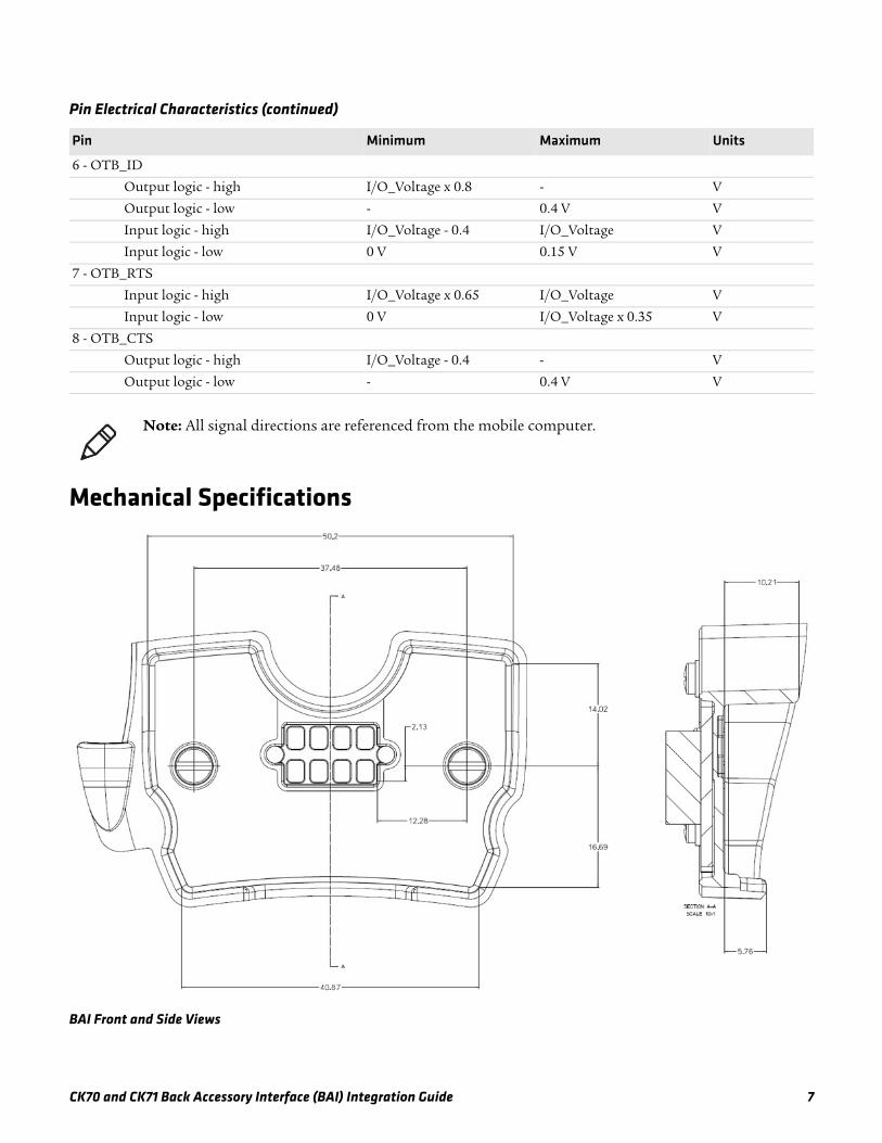
Mechanical Specifications
BAI Front and Side Views
6 - OTB_ID
Output logic - high I/O_Voltage x 0.8 - V
Output logic - low - 0.4 V V
Input logic - high I/O_Voltage - 0.4 I/O_Voltage V
Input logic - low 0 V 0.15 V V
7 - OTB_RTS
Input logic - high I/O_Voltage x 0.65 I/O_Voltage V
Input logic - low 0 V I/O_Voltage x 0.35 V
8 - OTB_CTS
Output logic - high I/O_Voltage - 0.4 - V
Output logic - low - 0.4 V V
Note: All signal directions are referenced from the mobile computer.
Pin Electrical Characteristics (continued)
Pin Minimum Maximum Units

8 CK70 and CK71 Back Accessory Interface (BAI) Integration Guide
Accessory AttachmentFor more information on mating surfaces and dimensions, contact Intermec Product Support. The Product Support team will assist in providing 3D CAD files in .stp format of the CK70 or CK71 mobile computer, and software related information.
InstallationYou can attach your adapter accessory to the BAI by sliding it into the notch at the bottom of the mobile computer, and securing it with an 8-32 UNC screw.
The Location of the Screw and Notch
DurabilityWhen used appropriately with the mobile computer, you can install and remove the BAI up to 500 times. You may see minor wear to the mobile computer or the BAI.
Notch
Screw
Note: Connecting your adapter accessory to the BAI may reduce the mobile computer battery life.

CK70 and CK71 Back Accessory Interface (BAI) Integration Guide 9
Magnet SpecificationsThe BAI contains a magnet that is required for the mobile computer to function. The magnet ensures the mobile computer will reset if the SD card or SIM card is removed. Use the magnet specifications to develop accessories that are sensitive to magnetic fields.
Location of the Magnet in the Bottom Right Corner
Environmental RatingThe BAI maintains the environmental rating for the mobile computer. For more information about the environmental rating of the mobile computer, see the 70 Series Mobile Computer User’s Manual.
Using the BAIThis section provides information about using the BAI with your mobile computer.
Before you can use your BAI accessory, you need to configure the COM port and install the BAI.
To configure the COM Port1 Tap Start > Settings > System > Intermec Settings > Communications >
Serial Port Switch > select COM5 back accessory.
2 When prompted to save and reboot, tap ok.
3 Tap OK to save.
4 Press the Power button.
5 Tap Reboot. The computer reboots.
Specification Value
Diameter 4 mm
Field strength 1280 mT
6.98 mm
13.13 mm
Note: When the BAI is installed and the COM port is configured, IrDA cannot communicate wirelessly. If the BAI is installed, but the COM port is not configured, IrDA can still communicate wirelessly.

10 CK70 and CK71 Back Accessory Interface (BAI) Integration Guide
To install the BAI
About the Data Collection Resource KitUse the Data Collection Resource Kit to create the application that allows the accessory to communicate with the mobile computer.
The Data Collection Resource Kit includes tools and libraries for integrating bar code scanning, imaging, and magnetic stripe card reading into your data collection application.
For more information on the Data Collection Resource Kit, see the Intermec Developer Library (IDL) Resource Kit Developer’s Guide.
Installing the Data Collection Resource KitBefore you can use your BAI accessory with the mobile computer, you must install the Data Collection Resource Kit.
To install the Data Collection Resource Kit1 Go to www.intermec.com and select Products > Software & Tools>
Developer Library > Developer Resource Kits. The Developer Resource Kits page appears.
2 Click Review and download IDL Resource Kits. The Developer Resource Kits Downloads page appears. The “Developer Tools” section includes a list of the Resource Kits.
3 Click IDL Resource Kit - Data Collection ver. x.xx.xx.xxxx and follow the prompts to install it.
When the process is complete, the window closes automatically.
1 2

CK70 and CK71 Back Accessory Interface (BAI) Integration Guide 11
After Installing the Data Collection Resource KitOnce the installation is finished, you can access the Resource Kit components and documentation from within your development environment.
You can find shortcuts to documents, example folders, and other information for the resource kits in this location on your desktop PC: Start > All Programs > Intermec > Resource Kits. You can also double-click the IDL Resource Kits icon on your desktop to browse the Resource Kit installation.
Each Resource Kit folder includes a shortcut to its ReadMe file and user’s guide. All Example programs include ReadMe files that explain content and installation.

Worldwide Headquarters6001 36th Avenue WestEverett, Washington 98203U.S.A.tel 425.348.2600fax 425.355.9551www.intermec.com
© 2013 Intermec Technologies Corporation. All rights reserved.
CK70 and CK71 Back Accessory Interface (BAI) Integration Guide
*944-634-002*P/N 944-634-002


