The Swish cladding range offers the specifier a choice of 5 styles and 8 profiles, with a comprehensive range of components, trims and fixings for each type.
They present the ideal substitute for timber claddings, with the added advantages of attractive appearance, maintenance free qualities, weather resistance and durability.
In addition, they can significantly improve the thermal performance of buildings, particularly when combined with insulation.
Composition and manufacture Swish Cellular PVC is an extruded, foamed material with an integral smooth and durable skin. The product can be cut, drilled, nailed and routed, using conventional tools. It is light to handle, easy to fix and does not require any painting or subsequent treatment after installation.
Advantages ● Durable ● Compatible with other building materials
● Weather resistant ● Will not warp, flake or peel
● Fire resisting ● Rot proof
● Thermally efficient ● Will not support bacterial or fungal growth
● Maintenance free ● Agrément approved
Environment and recycling Swish Cellular PVC Cladding products represent an environmentally responsible use of plastics. They do not contain CFCs, lead or cadmium, which are considered harmful to the environment. Also, they have a very long life span and when replaced, can be easily identified and fully recycled.
Standards Swish Cellular PVC is manufactured to stringent quality control standards. Swish has been awarded:
● BS EN ISO 9001 - Quality Management
BS EN ISO 14001 - Environmental Management
OHSAS 18001 - H & S Management
BS EN ISO 50001 - Energy Management
BES 6001 - Responsible Sourcing
British Standard Kitemark approval to BS 7619 - 2010
BBA Cladding Certificate No. 91/2622 - applicable for white Swish Cellular PVC-U Cladding only.
FS 681825 EMS 681826 OHS 523157 ENMS 620926 BS 7619 Licence No KM 33730
Swish website Specifiers have access to a large amount of technical data at www.swishbp.co.uk.
Project guidance, design considerations and installation guides are dealt with in depth. The site also features a CAD library with a facility to preview drawings without CAD software. Downloadable NBS clauses are available in a choice of formats.
The entire suite of Swish literature can be viewed or downloaded, as required. Construction professionals, Swish Approved Installers and Swish Stockists are also able to order printed literature and samples.
Information about Swish CPD services, links to other useful industry sites and a gallery of drawings and photographs are also featured.
CONTENTS Page No
Performance and properties 3
General information / Dimensions / Design
considerations 4
Components
Plank profiles 5
Starter, edge and corner trims 6
Joint covers, ventilation components 7
Application details
Horizontal plank
Setting out / sequence of work 8
Starter trims 9
Vertical trims 10-11
Horizontal trims 12
Installing planks 13
Vertical plank
Sequence of work / starter trims 14
Vertical trims and horizontal trims 15
Installing planks 16
Diagonal plank
Sequence of work, trims,
installing planks 17
Ventilation / Insulation 18-19
Timber frame 20
Sitework, Accessories, Maintenance 21
Specifications – NBS Clauses 22
Supply, Technical Services 23
Trademarks Jumbo, Cappit, Polo, Tee Gee and Jumbotec are all trademarks of Specialist Building Products Limited
Swish cellular PVC cladding profiles are intended for installation on buildings up to a height of 18m only and must not be used above that height. Neither must they be used where there is less than 1m between the facade and other buildings.
In addition they must not be used less than 10m above a roof or any part of the building to which the public have access for recreational or assembly purposes, including such areas located on rooftops.
Density
The density of Swish Cellular PVC is on average 450 kg/m3.
Strength
Swish cladding profiles are sufficiently rigid to facilitate storage and erection but are still sufficiently flexible to withstand normal site handling.
Swish cladding profiles have been tested for hard and soft body impact resistance in accordance with BS 7619: 2010 and exceed the minimums laid down in the standard. They can therefore be expected to meet the requirements for high and low level applications and to resist on-site and inuse service adequately.
Wind loadings
The Swish cladding system has adequate resistance to wind loading at the recommended fixing centres, up to two storeys. For total security, it is recommended that batten and fixing centres be reduced from 600mm to 400mm for all installations above two storeys.
Fire retardance
Swish Cellular PVC conforms to the following requirements:
BS EN 13501-1 : 2007+A1 : 2009 - D-s3,d2/AVM
Alcohol cup test: Very low flammability.
DIN 4102 Part 1: Fire behaviour of building material and building components: Class B2..
Thermal insulation
The thermal insulation properties of Swish Cellular PVC, due to the foamed core, are superior to those of wood (the lambda value is 0.06 W/mK). Used in composite external wall constructions, they can significantly improve the U values obtained.
Thermal movement
The coefficient of linear expansion under test conditions is 5 x 10⁻⁵ per oC. Swish Cellular PVC profiles will perform satisfactorily in most northern European climates. However, they should not be installed where ambient temperatures are likely to exceed 50oC, as for example in proximity to boiler flues.
Avoid fixing in temperatures greater than 30oC or less than 0oC. When installed as recommended, the fixing system will largely accommodate thermal expansion and minimise the need for expansion gaps.
Water resistance
The impermeable skin of Swish Cellular PVC cladding is unaffected by moisture. Cut ends are non-absorbent due to the closed cell structure of the material.
Chemical stability
Swish Cellular PVC is not affected by liquids in common use. It is resistant to most acids and alkalis, but can be damaged by ketones, esters and solvents. Swish Cellular PVC is not prone to adverse reaction when used in conjunction with established building materials.
Biological
Swish Cellular PVC will not support bacterial or fungal growth. It is resistant to attack by woodworm and termites but should be protected against vermin.
Durability
Swish Cellular PVC components have a high stiffness to weight ratio and the dense outer skin ensures a surface of high durability.
Weathering resistance is tested with equipment complying with BS 2782: Part 5: Method 540B.
Colour fastness Colour fastness assessed in accordance with BS 1006 shows that white Swish Cellular PVC achieves a rating of 7-8 (8 being the test maximum) and that therefore no significant fading or change in whiteness can be expected for a minimum of 20 years.
Swish White Cellular PVC demonstrates excellent performance in tests designed to predict discolouration (pinking).
When exposed to the Suntest, samples do not reach a Delta L* of -2 even after 500 hours. In the ACT test samples exhibit low Delta PI in both ACT 1 and ACT 2.
Discolouration Swish white cellular profiles DO NOT suffer from the discolouration problems claimed to be associated with some lead stabilized formulations, THEY ARE LEAD FREE.
Workability Swish cellular PVC can be worked using conventional carpentry tools for cutting, drilling and shaping. Nails, screws and specified adhesives are used for fixing.
Saws with fine-toothed blades should be used and power tools should be operated at the same or higher speeds to those normally used for timber work, with carbide tipped blades.
CE Marking Since the 1st July 2013 certain products sold within the EU have been required to carry a CE marking. This includes Swish cladding profiles: Shiplap, TeeGee, OpenV and Feather Edge. Cladding trims are not affected.
In order to ensure compliance with the
regulations, Swish has tested these profiles for fire resistance, impact resistance and durability in accordance with the harmonised standard for PVC cladding, hEN 13245- 2:2008.
DoP’s (Declaration of Performance) are available via our website, or in hard copy if required.
COSHH and MDS Under the REACH directive Swish Building Products is not required to provide an MDS (Material Data Sheet) or COSHH data sheet (Control of Substances Hazardous to Health) for its Cellular PVC products,
however, we recognise a duty of care to our customers and so we provide a separate bulletin for the Safe Use of Cellular PVC Materials.
Access Systems The work area must never be accessed using an unsupported ladder or other unstable access system. Always use a full scaffold platform or a purpose made cantilevered deck system with guard rails in place.
Asbestos By law all existing asbestos materials must be removed by trained operatives under strictly controlled conditions. If it is suspected that asbestos is present the Local Authority should be consulted.
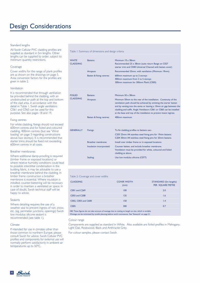
All Swish Cellular PVC cladding profiles are supplied as standard in 5m lengths. Other lengths can be supplied to order, subject to minimum quantity restrictions.
Coverage
Cover widths for the range of plank profiles are as shown on the drawings on page 5. Area conversion factors for the profiles are given in table 2.
Ventilation
It is recommended that through ventilation be provided behind the cladding, with an unobstructed air path at the top and bottom of the clad area, in accordance with the detail in Table 1. Swish angle ventilators C061 and C065 can be used for this purpose. See also pages 18 and 19.
Fixing centres
For white cladding, fixings should not exceed 600mm centres and for foiled and coloured cladding, 400mm centres (but see 'Wind loading' on page 3 regarding constructions above two storeys). It is recommended that starter trims should be fixed not exceeding 600mm centres in all cases.
Breather membranes
Where additional damp-proofing is required (timber frame or exposed locations) or where relative humidity conditions could lead to possible interstitial condensation in the building fabric, it may be advisable to use a breather membrane behind the cladding. In timber frame construction a breather membrane is essential. Where insulation is installed, counter-battening will be necessary in order to maintain a ventilated air space. In case of doubt, Swish technical staff will be happy to advise.
Sealants
Where detailing requires the use of a weather seal to prevent ingress of rain, snow, etc. (eg. perimeter junctions, openings) Swish low modulus silicone sealant is recommended (see table 1).
Climate
If intended for use in climates other than those common to northern Europe, please consult Swish for advice. Swish Cellular PVC profiles and components for external use will normally perform satisfactorily in ambient air temperatures up to 50ºC.
Colour range
Components are supplied as standard in White. Also available are foiled profiles in Mahogany, Light Oak, Rosewood, Black and Anthracite Grey.
For colour samples, please contact Swish.
Table 1: Summary of dimensions and design criteria
WHITE Battens: Minimum 19 x 38mm CLADDING Recommended 25 x 38mm (suits return flange on C027 starter trim and C040 Universal Channel with batten cover)
Airspace: Recommended 25mm, with ventilation (Minimum 19mm).
Batten & fixing centres: 600mm maximum up to 2 storeys 400mm maximum from 2 to 5 storeys 300mm maximum for 300mm Plank (C005)
FOILED Battens: Minimum 50 x 38mm CLADDING Airspace: Minimum 50mm to the rear of the installation. Continuity of the
ventilation path should be achieved by omitting the starter batten and by venting into the eaves or leaving a 10mm air gap between the cladding and soffit. Angle Ventilators C061 or C065 can be installed at the base and top of the installation to prevent insect ingress.
Batten & fixing centres: 400mm maximum
GENERALLY Fixings: To fix cladding profiles to battens use:-
C203 25mm A4 stainless steel fixing pins for 19mm battens C204 30mm A4 stainless steel fixing pins for 25mm battens
Breather membrane: Install over timber frame or in exposed locations
Insulation incorporated: Counter batten, and include breather membrane. Ventilation must be provided for white, coloured and foiled cladding as above.
Sealing: Use low modulus silicone (C077)
Table 2: Coverage and cover widths
CLADDING COVER WIDTH STANDARD (5m lengths) (mm) PER SQUARE METRE
C001 and C269 100 2.0
C055 and C208 125 1.6
C002, C003 and C600 150 1.4
C005 300 0.7
NB: These figures do not take account of wastage due to cutting to length on site, which is variable.
Wastage can be minimised by careful planning before work commences. See 'Sitework' on page 21.
The C001 plank is designed for a narrow profile effect, giving a typical shiplap appearance. The visible bottom edges are square.
C002
The C002 plank is of the same style and joint appearance as the C001, but with a larger cover width.
Both planks are normally for horizontal cladding. Also available with M-Boss face.
C005
The C005 double plank is the same style and joint appearance as C001 and C002 but with a 300mm cover width. Fixing centres should be reduced to 300mm for this profile..
Open V
C269
The C269 plank is designed for a castellated profile effect. The vee shape of the recess, which is reflected in the mitred bottom edge of the plank, gives a sharper overall appearance to the horizontal joints.
C003
The C003 plank has the same joint features as the C269, but a larger cover width.
Both planks may be used for horizontal, vertical or diagonal/herringbone cladding.
Tee GeeTM
C055
The C055 plank reproduces the effect of tongued and grooved boarding, minimising the accent on horizontal joints.
Like the Open V style, it may be used for horizontal, vertical and diagonal/herringbone applications.
Feather Edge
C208
The C208 plank provides a featherboard effect with a rounded bottom edge to the profile.
The plank is intended only for use in horizontal applications.
Colour range
Profiles are available in the standard White, Mahogany, Light Oak, Rosewood, Black and Anthracite Grey. Colour samples are available on request.
C035Drip/starter trim for vertical or diagonalplanks.
C030External corner trim forhorizontal cladding
C026Universal channel
C06930 X 15 mmAngle trim
C06860 x 15 mmAngle trim
C03424 X 8 mmCover trim
C039Plank top trim
C040Universal channelwith batten cover
C290/291Universal two-part trim
C292/293Two-part corner trim
Flexi-trims
ST45
ST75
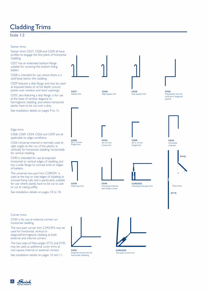
Starter trims
Starter trims C027, C028 and C029 all have profiles to engage the first plank of horizontal cladding.
C027 has an extended bottom flange suitable for covering the bottom fixing batten.
C028 is intended for use where there is a solid base below the cladding.
C029 features a drip flange and may be used at exposed bases or at full depth (uncut) planks over window and door openings.
C035, also featuring a drip flange, is for use at the base of vertical, diagonal or herringbone cladding, and where horizontal planks have to be cut over a drip.
See installation details on pages 9 to 15.
Edge trims
C068, C069, C034, C026 and C039 are all applicable to edge conditions.
C026 Universal channel is normally used at right angles to the run of the planks, ie vertically for horizontal cladding, horizontally for vertical cladding.
C040 is intended for use at exposed horizontal or vertical edges of cladding and has a wide flange to conceal ends or edges of battens.
The universal two-part trim C290/291 is used at the top or side edges of cladding to conceal fixing nails and is particularly suitable for use where planks have to be cut to size or cut to raking soffits.
See installation details on pages 10 to 18.
Corner trims
C030 is for use at external corners on horizontal cladding.
The two-part corner trim C292/293 may be used for horizontal, vertical or diagonal/herringbone cladding at both external and internal corners.
The two sizes of Flexi-angles ST75 and ST45 may be used as additional cover trims at non-square internal or external corners.
Two alternative methods of jointing are available; a continuous vertical cover using C033 centre joint trim, C051/C052 2-Part joint trim or individual butt joint covers at each joint between adjacent planks. In the latter case, the plank joints should be staggered in each row.
Centre joint trim C033 should be installed prior to the planks being fixed, whereas joint covers should be installed as work proceeds.
The joint covers incorporate hooked spines to engage starter trims, and spacing lugs which maintain an expansion gap of 4mm between plank ends.
C042, C043, C631 and C045 joint covers are profiled to match C001, C002, C600 and C005 Shiplap planks respectively.
C281 and C044 joint covers are profiled to match C269 and C003 Open V planks respectively.
C057 joint cover can be used with both Tee Gee and Feather Edge profiles.
C033 and C051/052 Joint Trims form a continuous vertical feature for joints on long runs and may be used with any plank profile.
See installation details on page 13.
Ventilation units
All strip ventilators have 4mm wide slots to prevent blockage by builder's debris and bridging by ice.
Angle Ventilators C061 and C065 are designed to prevent insect ingress while allowing a continuous ventilation gap.
Cladding should be securely nailed to a sound timber framework, suitably treated with preservative, in all external situations.
Battening out on masonry walls
Battens should be of good quality softwood of minimum cross section 19 x 38mm. However, 25 x 38mm battens are recommended for white cladding and 50 x 38mm battens for coloured or foiled cladding. For horizontal cladding, main battens are fixed vertically.
The maximum spacing for the intermediate vertical battens is 600mm centres for white and 400mm centres for coloured and foiled cladding.
Additional battens are required at the base and the head as well as at reveals, openings and changes of direction.
All battens should be securely fastened with fixings appropriate to the type of substrate at not exceeding 600mm centres for white and 400mm centres for coloured and foiled cladding.
Irregularities in the substrate will be adversely reproduced in the cladding installation unless the battens are properly aligned. Packing pieces should therefore be placed behind the battens where required.
Starter battens
On external walls, the starter batten should be fixed at or above DPC level and checked for level. At junctions with flat or lean-to roofs, consideration should be given to the installation of the necessary flashing (see figure 7).
Sequence of work
The following sequence will ensure that work proceeds smoothly and trim fixing nails will be concealed by planks:
● Perimeter frame battens
● Battens round openings
● Intermediate vertical battens
● Starter trims (or bottom angle vent, as appropriate)
● Vertical perimeter trims, corner trims (where two-part trims are used, fix only the inner part)
● Top perimeter trims (these engage inside the vertical trims)
● Packings to battens as required for any cut planks
● Plank profiles and joint covers or centre joint trims as appropriate (see page 7).
● Outer components of two-part trims
Fig. 1 Check height, line and level of starter batten(Omitt where ventilation is required)
Fig. 2 Batten out all perimeters and openings
Wall area to be clad
Fig. 3 Fix intermediate vertical battens at appropriate centres
Fixing centres
Fig. 4 Use two battens at internal and external corners
All trims require batten fixing. It is therefore essential that battens be pre-installed in the required locations.
The trims should be fixed to the battens at not exceeding 600mm centres for white and 400mm centres for coloured and foiled cladding, using the fixings recommended on page 21 (but see 'Wind loading' on page 3).
Starter trims
The appropriate starter trim should be selected to suit the cladding arrangement and the situation at the base of the cladding.
Starter trims C027, C028 and C029 all have flanges into which the starter planks engage.
Working from a level line, the appropriate starter trim should be fixed to each of the intermediate vertical battens. In a refurbishment situation, where a horizontal starter batten is present, it is recommended that this batten is removed. This must be done where coloured or foiled profiles are to be fitted and is also recommended for white profiles.
If the starter batten is retained for a white cladding installation, 10mm dia. holes should then be drilled between batten centres through both the batten and trim, to facilitate drainage and aid ventilation.
See pages 18 and 19 for details of ventilation methods and trims.
On high level cladding terminating above ground, the C027 starter trim may be used to conceal the batten.
The function of continuous trims is two-fold. They provide a neat, weathertight finish at cladding perimeters and serve to hide fixings and battens (Figure 9).
The trims should be fixed to the battens at all perimeters before any planking is installed.
Where long plank lengths are to be installed, there is sufficient flexibility in the planks to allow them to be snapped into position between the pre-fixed vertical trims. For short lengths, it may be advisable to use two-part trims. In such cases the C290/291 can be used at ends (Figure 11) and the C292/293 at external or internal corners (Figures 13 & 14).
Fixings
Vertical trims all require batten fixing. It is therefore essential that vertical battens be pre-installed in the required locations.
The trims should be fixed to the battens at not exceeding 600mm centres for white and 400mm centres for coloured and foiled cladding, using the fixings recommended on page 21 (but see 'Wind loading', page 3).
Fig. 9 C040 Universal channel with batten cover at a vertical termination
C040
Stainless steel fixing nails
Vertical batten
Back leg conceals batten edge
Starter batten
Fig. 10 Universal channel C026 at cladding reveal
C026 Stainless steel fixingnails
Fig. 11 Two-part trim C290/291 terminating cladding at a reveal
Insert male trim afterall planks and othertrims are in place
C291
C290
Fig. 12 Corner trim C030at an external angle
Vertical battens
Longer batten (or double batten) required to ensure secure fixings for batten and trim
End and corner conditions (vertical trims) - continued
Two-part trims are designed for convenient application where the use of one-part trims might create difficulty in plank installation, for example in short runs of cladding.
When using two-part trims, install only the relevant (male or female) component before cladding commences. The outer components should be set aside and protected from damage until ready for use.
Figures 13 and 14 show two-part corner trim C292/293 used at external and internal 90º corners.
After completion of each section of cladding, the trims can be clipped home, using firm hand pressure. No fixings are required.
For angles greater or less than 90o, use two C026 universal channels, back-to-back, as shown in figure 15.
If a neat joint cannot be achieved by this method, the channels can be covered with a Flexi-angle, using Swish low modulus silicone sealant as adhesive.
Fig. 14 Two-part trim C292/293at internal corner
Fix outer part (male), only afterall planks and trims are installed
Fig. 15 Universal channels C026used back-to-back at externalobtuse angled corner
Optional Flexi-angle trim
Batten shaped to fit
Fig. 13 Two-part trim C292/293at external corner
Note use of wider battento ensure positive fixing
Fix outer part (female), only after all planks and trims are installed
Fig. 16 Drip trim C035 at window head with extended soffit board
Offcut as packing piece
Fig. 17 Two-part trim C290/291 at cut plank below window sill
Packing
Extended window sill
C290/291
Horizontal trims
Horizontal trims are designed to provide a neat finish to top terminations of planking, to exclude weather and to form drips over openings or at base of planking areas (Figure 16).
The C290/291 two-part universal trim is especially useful where the top plank has been cut to fit. The outer trim component will conceal the fixing nails. Figure 17 shows such an application below a sill.
Two-part trims have the advantages of both ensuring the covering of fixing nails and of facilitating fixing of planks, especially where cut planks have to be used.
Drip trim C035 may be used at window and also at the base of clad areas.
NB: Where planks are cut to depth, packings are necessary to maintain evenness of appearance.
Fig. 20 Standard joint for long runs, using C033 cover trim Expansion gaps
Matching joint cover
Expansion gap
Installing the planks
Whilst the details on this page illustrate only the Shiplap profile, the following is applicable to all four types.
● The first plank is located on the starter trim and nailed in place through the fixing groove at the top edge, using the recommended Swish fixing nails at the minimum indicated centres (see 'Design considerations, page 4).
● To ensure the cladding lays flat, fixing should commence at the centre of each plank length, working progressively outwards.
● All plank ends must be secret nailed (at their top edge) into the vertical trims. See figure 18.
● Allow a 4mm clearance at each end for expansion for white profiles and 8mm for foiled and coloured cladding (where joint covers are used, their spacing lugs will automatically provide 4mm clearance between adjacent plank lengths). See figure 19.
● If using joint covers (as opposed to centre joint trims), install tight to the plank ends as work proceeds. All joint covers should be fixed over supporting battens. See figure 21.
● Joint covers should be staggered.
● Fit subsequent planks over the preceding row, ensuring that the tongue and groove joint is firmly closed, so that the nail heads are concealed by the overlap.
● Check visually for line and level every two rows.
● Should the top plank require cutting - this may occur at top of panel or under openings - cut top edge of plank to required depth or profile.
● Planks cut as above require support at their top edges by means of packing pieces at the fixing points. Pieces cut from cladding offcuts may be suitably used. See figure 17.
● Complete by inserting the male part of any two-part trims.
Fig.24 Drip trim C035 between lengths of vertical cladding
C035
Deeper batten
5 m full-length planks
Expansion gaps
Fig.25 C035 drip trim in conjunction with angle trim C068 to hide high level batten
Fig. 23 Battening out
Area to be cladwith vertical planks
C035 plusC068Angle trim
C080Trimtopnail
Sequence of work
The sequence is similar to that for horizontal cladding, but since intermediate battens are fixed horizontally, the provision of through ventilation or the use of insulation between the battens will require the installation of counter-battens (see 'Ventilation' on pages 18 and 19).
Where planks are cut to width, packings are necessary to maintain evenness of appearance.
When using two-part trims, install only the inner (male or female) component before cladding work is commenced. The outer components should be set aside and protected from damage until ready for use. After completion of each complete section of cladding, the outer component can then be clipped home, using firm hand pressure. No additional fixings are required.
Fixings
All trims require batten fixing. It is therefore essential that the battens be pre-installed in the required locations.
Trims should be fixed to the battens at not exceeding 600mm centres for white and 400mm for foiled and coloured cladding, using the fixings recommended on page 21 (but see 'Wind loadings' on page 3).
Starter trims
Use drip trim C035 as the starter trim (starter trims C027, C028 and C029 are not suitable for vertical cladding).
Working from a level line, the drip trim should be fixed to the starter batten. Starter trims should be nailed at not less than 600mm centres for white and 400mm centres for foiled and coloured cladding (Figure 25).
Where the vertical height exceeds the 5m standard plank length, use the continuous horizontal drip trim C035 between lengths (Figure 24).
Where the lower edge of the clad area can be seen from groung level, an angle trim can be used in conjunction with the drip trim to conceal the first batten (Figure 25).
Fig.28 Universal two-part trim C290/291at head of cladding
C290/291
Fig.26 Use of trim and packings at reveals C026
Packing
Extended window cheeks
Extended sill
Fig.27 Use of C040 universal channel withbatten cover at vertical terminations
C040
No nailingnecessaryat starter plank
Vertical trims
As with horizontal cladding, the trims should be fixed to the battens at all perimeters before any planking is installed.
Use a plumb line or long spirit level to check that the perimeter batten and trim are vertical.
For short lengths of plank, it may be advisable to use two-part trims to simplify installation.
The C292/C293 trim should be used for external and internal corners. As with horizontal cladding, for angles greater or less than 90o, use two universal channels C026, back-to-back.
At reveals to openings, use the C026 universal channel (Figure 26).
The C026 universal channel and the C040 universal channel with batten cover are appropriate for use at vertical terminations (Figure 27).
Horizontal trims
Horizontal trims are designed to provide a neat finish to top terminations of planking and to form drips over openings or at the base of planking areas.
Plank top trim C039 or universal two-part trim C290/291 are used at top terminations (Figure 28).
Drip trim C035 may be used at window and door heads and at the base of clad areas (Figure 29).
Where planks are cut to width, packings are necessary to maintain evenness of appearance (Figure 26).
Fig.32 Locating starter plank (working right to left)
Leave expansion gap between plank end and trim
Push home male trim, only after all planks and trims in place
Starter plank
Intermediate battens at600 mm c/c
Use nailing groove
Installing the planks
Only Open V or Tee Gee profiles should be used for vertical planking.
● The first plank is located into the vertical edge trim. If for any reason it is to be a cut plank, packing pieces should be fixed prior to locating the plank.
● Since successive vertical planks must cover the fixing nails, it is essential that working from right to left, the fixing groove of the first plank must be on the LEFT HAND EDGE. Conversely, working from left to right, it should be on the RIGHT HAND EDGE.
● Fit the first plank to intermediate battens, using recommended Swish fixing nails at the maximum indicated centres (see Table 1 on page 4 and 'Wind loading' on page 3).
● Fit subsequent planks over the preceding row, nailing to each of the horizontal intermediate battens, ensuring that the tongue and groove joint is firmly closed, so that the nail heads are concealed by the overlap.
● To ensure the cladding lays flat, fixing should commence at the centre of each plank length, working progressively outwards.
● All plank ends must be secret nailed into the horizontal trims, allowing 4mm clearance at each end for white profiles and 8mm for foiled and coloured cladding to allow for expansion.
● Check visually for appearance and plumb every two rows.
● The finishing plank should be cut and fitted onto the tongue of the preceding plank. It should be nailed through packings at every fixing centre along the cut edge. This will also apply to cut planks at reveals to openings. Pieces cut from cladding offcuts may be suitably used.
● Care must be taken to ensure that the nails through the cut planks are positioned so that the trim sections cover the nail heads. With vertical planking this requires the use of two-part trims at both vertical edges.
● Complete by inserting the outer part of any two-part trims.
Diagonal / Herringbone Plank Application details Not to scale
Expansion Gap
Fig.35 Cutting intermediateplanks to length
Expansion Gap
Measu
re le
ngth
of ne
w plan
k at o
verla
p pos
ition o
f pre
vious
plan
k
Allow 4
mm at b
oth en
ds for
expan
sion
Nail
Nail
Front elevation
Drip trim
Universal channel
Packing
Nail
Fig.34 Diagonal plank starter pieceIsometric view
Starter plank cut from full width
Nail
Fig.36 Fitting the finishing plank
Packing
Last plank fittedover preceedingand nailed through packing
Two-piece trims
Sequence of work
The sequence is similar to that for vertical cladding and intermediate battens should be fixed horizontally.
Similarly, the provision of through ventilation or the use of insulation between the battens will require counter-battens to be used (see 'Ventilation' on pages 18 and 19).
Fixings
All trims require batten fixing. It is therefore essential that battens be pre-installed at the required locations.
The trims should be fixed to the battens at not exceeding 600mm centres for white and 400mm centres for coloured and foiled cladding, using the fixings recommended on page 21 (but see 'Wind loadings' on page 3).
Trims
Use the trims recommended for use with vertical cladding.
Centre joint trim C033 can be used at the meeting junctions of diagonal cladding to create a herringbone pattern.
Installing the planks
Only Open V or Tee Gee profiles should be used for diagonal/herringbone planking.
● Starting from a bottom corner, the first cut piece is located into the angle formed by the starter trim and vertical edge trim, using a packing as necessary (Figure 34).
● Fit subsequent rows of cut planks, nailing to each of the horizontal intermediate battens, using the same fixing procedures as for vertical cladding.
● Measure and cut carefully to length and angle of mitre before fitting (Figure 35).
● The finishing piece, which will occupy the diagonally opposite corner, should be cut to size and fitted onto the tongue of the penultimate plank, then nailed using a packing piece if necessary (Figure 36).
Ventilation is recommended for all installations. It is essential where insulation, foiled or coloured cladding is used. Please refer to the detail in Table 1 on page 4.
Ventilation units
Angle Ventilators C061 and C065 are designed to prevent insect ingress while allowing a continuous ventilation gap.
See installation details on pages 18 and 19.
All strip ventilators have 4mm wide slots to prevent blockage by builder's debris and bridging by ice.
Detailing (horizontal plank)
At the bottom edge of the cladding, the horizontal starter batten is omitted, allowing a free air path between vertical battens. A C061 Angle Ventilator can be installed horizontally across the bottom end of the battens (Figure 37).
Continuity of the ventilation path at the top of the cladding can be arranged by venting into the eaves. This requires omitting the horizontal batten normally installed for the top trim. The trim can be fixed instead to the tops of the vertical battens, which should be extended up into the eaves sufficiently to ensure that a positive fixing is practicable (Figures 39 and 40).
Detailing (vertical plank)
In the case of vertical (or diagonal/ herringbone) cladding, where the intermediate battens are fixed horizontally, the vertical counter-battens need to be placed behind them in order to create an air path (Figures 38 and 40).
Where venting into the roof void is not possible, a minimal gap should be allowed for through flow of air. This gap can be protected against insect ingress by utilising either strip ventilator C061 or C065.
Fig.38 C065 Ventilation unit at base of cladding -Ventilated vertical cladding
Drip starter trim
Counterbattens
C065 Ventilation unit
Air path
Fig.37 C061 Ventilation unit at base of cladding -Ventilated horizontal cladding
Base starter trim
Air path
Fig.40 Termination at soffit-Ventilated vertical cladding
Universal trim
Horizontal battens
Vertical counter-battensextend above trim
Soffit board
Air path
Fig.39 Termination at soffit-Ventilated horizontal cladding
The necessary air path is formed between the vertical battens. Consequently, if it is intended to install insulation between the battens, counter-battening will be required.
For horizontal cladding, the insulation should be installed between horizontal battens fixed directly to the wall. The vertical battens are then fixed to the outside. A breather membrane should be incorporated in the design, placed outside the insulation layer. (Figure 41). A suitable breather membrane type is one conforming to BS4016: 1972, with a vapour resistance of less than 0.6 MNsg -1.
The bottom of the vertical battens is left open and a Swish C061 or C065 Angle Ventilator can be used to provide a neat finish (Figure 42 ). Also refer to the detail in Table 1 on page 4.
Ideally, the insulation should start below ground floor slab level and extend upwards to marry with the roof insulation, to avoid cold bridging (Figure 43).
The eaves termination, using a Swish Polo soffit ventilation unit, is shown in figure 44.
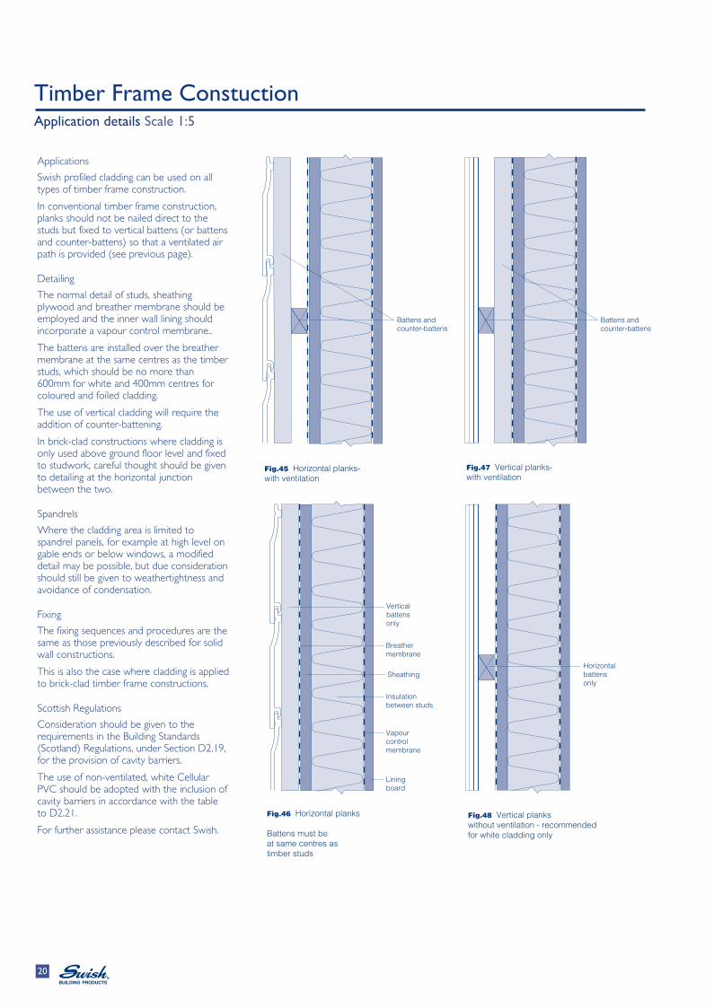
Fig.48 Vertical plankswithout ventilation - recommendedfor white cladding only
Fig.47 Vertical planks-with ventilation
Verticalbattensonly
Horizontalbattensonly
Breather membrane
Vapourcontrolmembrane
Insulationbetween studs
Lining board
Sheathing
Battens andcounter-battens
Battens andcounter-battens
Applications
Swish profiled cladding can be used on all types of timber frame construction.
In conventional timber frame construction, planks should not be nailed direct to the studs but fixed to vertical battens (or battens and counter-battens) so that a ventilated air path is provided (see previous page).
Detailing
The normal detail of studs, sheathing plywood and breather membrane should be employed and the inner wall lining should incorporate a vapour control membrane..
The battens are installed over the breather membrane at the same centres as the timber studs, which should be no more than 600mm for white and 400mm centres for coloured and foiled cladding.
The use of vertical cladding will require the addition of counter-battening.
In brick-clad constructions where cladding is only used above ground floor level and fixed to studwork, careful thought should be given to detailing at the horizontal junction between the two.
Spandrels
Where the cladding area is limited to spandrel panels, for example at high level on gable ends or below windows, a modified detail may be possible, but due consideration should still be given to weathertightness and avoidance of condensation.
Fixing
The fixing sequences and procedures are the same as those previously described for solid wall constructions.
This is also the case where cladding is applied to brick-clad timber frame constructions.
Scottish Regulations
Consideration should be given to the requirements in the Building Standards (Scotland) Regulations, under Section D2.19, for the provision of cavity barriers.
The use of non-ventilated, white Cellular PVC should be adopted with the inclusion of cavity barriers in accordance with the table to D2.21.
● Cladding should be secured only to a batten system on structurally stable substrates.
● Wall battens should be of the correct size to provide adequate ventilation (see Table 1, page 4), preservative treated, securely fixed, aligned and levelled with allowance made for irregularities in the substrate. Use non-perishable packings as necessary.
● Spacing of intermediate battens should not exceed 600mm for white and 400mm for foiled and coloured cladding or in very exposed situations (see 'Wind loading', page 3).
● Use only recommended fixings (see next column).
● Sufficient expansion gaps should be left at plank ends and at joints.
● Check for level and/or plumb at intervals - at least every third plank setting.
● Avoid installation in temperatures greater than 30oC or less than 0oC.
● Use only Swish low modulus silicone for sealing purposes.
General procedures
Where long elevations require the use of joint covers, ensure they are staggered on each row, and that fixing battens are provided.
Check plank lengths carefully before fitting in place, with due regard both to the required expansion tolerance and the need for secret fixing.
Set aside and store offcuts carefully for re-use and protect them from damage (see 'Handling and storage').
Cutting and shaping
Swish Cellular PVC can be worked using conventional carpentry tools for cutting, drilling and shaping.
Saws with fine-toothed blades should be used and power tools should be operated at the same or higher speeds to those normally used for timber work, with carbide tipped blades.
Packaging
Components are supplied in protective polyethylene sleeve wrapping, quantities per pack being commensurate with component size.
Fixings
Use only A4 stainless steel ring shank fixing nails for normal work.
Swish cladding components do not have to be pre-drilled.
For aggressive environments, where metal fixings may be subject to corrosion, nylon fixings should be used. These are inserted into pre-drilled holes.
Swish can supply the following fixings for use with the cladding products described in this publication:
● Swish A4 ring shank stainless steel nails in 25mm, 30mm and 50mm sizes, suitable for secret fixing applications.
● Swish A4 'Trimtop' plastic-headed stainless steel nails in 30mm, 40mm, 50mm and 65mm sizes (mainly for use with Swish fascias, bargeboards and soffits).
● Swish A4 plastic headed screws in 30mm, 40mm, 50mm and 65mm sizes.
Sealants and adhesives Swish supply a low modulus silicone (C077) conforming to BS 5889 (Type A) for cladding and fascia joints, allowing for movement of up to 50% of the joint width. A primer is recommended if bonding to GRP, stainless steel, aluminium or untreated wood. It is not suitable for use with polycarbonate sheet.
Handling and storage
Loading and unloading should be carried out by hand. It is recommended that both ends should be supported when handling. Swish Cellular PVC should be stacked in its protective sleeving on a flat, firm base with a stacking height not exceeding 1 metre. Storage in the open is not recommended unless additional protection is provided.
Contact with solvents and with organic based compounds such as bitumen products, paint or creosote should be avoided.
Maintenance
Cleaning
Swish Cellular PVC products are self-finished and essentially maintenance free.
Occasional washing with a non-scratch mild detergent and water is beneficial in removing surface grime and maintaining a pristine appearance, especially in heavily polluted atmospheres.
As with other plastics based materials, solvents should not be used.
When cleaning, flood the surface to prevent ingraining of any dirt particles.
Exercise care to prevent contact with, and staining by creosote or bitumen-based products. Other common building materials are easily cleaned off without damage.
Painting
As with all PVC products, paint can adversely affect the impact strength of PVC sections, and the application of dark colours could lead to risk of thermal distortion. However, if necessary use a good quality satin finish polyurethane paint.
NB - Swish will NOT guarantee any product which has been treated or coated with another material.
Repairs
Swish Cellular PVC can be cut and drilled using normal woodworking tools if repairs are required.
Scratches can be polished out using a progression of 180 to 360 to 1000 wet and dry papers. Finally, wash and polish with a cream cleaner.
Safety
Swish Cellular PVC should be cut with the correct tools, never broken.
Eye protection should be worn when using power tools.
Swish Cellular PVC is inert. However, as with most such substances, should not be inhaled since in volume it may impair lung function.
Swish Cladding components and accessories are available through a national network of suppliers.
Ordering
Please state colour, Swish reference, and length or number of packs of cladding boards, perimeter trims, joint covers or angle ventilators required.
In the case of nails, screws and other accessories, please state type and the number of packs required of each.
Swish will be pleased to advise on approximate quantities on receipt of layout drawings for individual projects.
Packaging
Components are supplied in protective polyethylene sleeve wrapping, quantities per pack being commensurate with component size.
Protective film is applied to selected profiles for increased protection.
Technical services
The Technical Services staff of Swish will be happy to provide quotations for individual projects and to give advice on technical aspects of Swish Cladding installations.
Swish can supply a list of approved contractors for Swish Cladding installations if required.
References
Swish also publish a Design and Specification Guide for their Cellular PVC range of Roofline products.
Agrément Certificates for the Swish Cladding system are available on request.
For further information, please contact the Swish at the address overleaf.
Trademarks
Cappit, Polo, Jumbo, Tee Gee, M-Boss, Jumbotec and Gee Pee are all Registered Trademarks.
This brochure may not be reproduced in part or whole without the specific written permission of SBP Limited.
Due to our policy of constant improvement, all drawings, photographs and
technical details are subject to change without notice.
Whilst all reasonable care is taken in compiling technical information, all
recommendations regarding the use of products are made without guarantee since the conditions of use are beyond the control of SBP Limited. It is the
specifier's responsibility to satisfy himself that each product is fit for the purpose for which he intends to use it and that the actual conditions of use