- 1 - IN THE UNITED STATES DISTRICT COURT FOR THE EASTERN DISTRICT OF TEXAS MARSHALL DIVISION INNOVATIVE DISPLAY TECHNOLOGIES LLC, Plaintiff, ) ) ) ) ) ) ) ) ) ) ) ) Civil Action No. 2:13-cv-522-JRG (CONSOLIDATED - Lead Case) v. ACER INC. AND ACER AMERICA CORP. Defendants. JURY TRIAL DEMANDED P.R. 4-3 JOINT CLAIM CONSTRUCTION AND PREHEARING STATEMENT Pursuant to P.R. 4-3 and the Court’s Docket Control Order of January 23, 2014 (Docket No. 37), plaintiff Innovative Display Technologies LLC (“Plaintiff”) and defendants Acer Inc., Acer America Corporation, Dell Inc., Hewlett-Packard Company, Huawei Investment and Holding Co., Ltd., Huawei Technologies Co., Ltd., Huawei Device USA Inc., BlackBerry Ltd., BlackBerry Corporation, and Microsoft Corporation (collectively, “Defendants”) hereby file this joint claim construction and prehearing statement. The claim terms proposed for construction below are found within U.S. Patent Nos. 6,755,547 (“the ’547 patent”), 7,300,194 (“the ’194 patent”), 7,384,177 (“the ’177 patent”), 7,404,660 (“the ’660 patent”), 7,434,974 (“the ’974 patent”), 7,537,370 (“the ’370 patent”), and 8,215,816 (“the ’816 patent”) (collectively, “patents-in-suit”). Case 2:13-cv-00522-JRG-RSP Document 61 Filed 05/05/14 Page 1 of 94 PageID #: 336
Transcript
- 1 -
IN THE UNITED STATES DISTRICT COURT FOR THE EASTERN DISTRICT OF TEXAS
MARSHALL DIVISION
INNOVATIVE DISPLAY TECHNOLOGIES LLC,
Plaintiff,
))))))))))))
Civil Action No. 2:13-cv-522-JRG (CONSOLIDATED - Lead Case)
v.
ACER INC. AND ACER AMERICA CORP.
Defendants.
JURY TRIAL DEMANDED
P.R. 4-3 JOINT CLAIM CONSTRUCTION AND PREHEARING STATEMENT
Pursuant to P.R. 4-3 and the Court’s Docket Control Order of January 23, 2014 (Docket
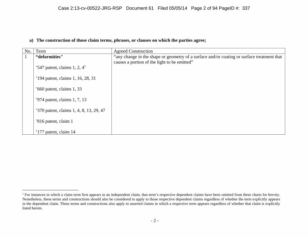
“any change in the shape or geometry of a surface and/or coating or surface treatment that causes a portion of the light to be emitted”
1 For instances in which a claim term first appears in an independent claim, that term’s respective dependent claims have been omitted from these charts for brevity. Nonetheless, these terms and constructions should also be considered to apply to those respective dependent claims regardless of whether the term explicitly appears in the dependent claim. These terms and constructions also apply to asserted claims in which a respective term appears regardless of whether that claim is explicitly listed herein.
Case 2:13-cv-00522-JRG-RSP Document 61 Filed 05/05/14 Page 2 of 94 PageID #: 337
- 3 -
b) Each party’s proposed construction of each disputed claim term, phrase, or clause, together with an identification of all references from the specification or prosecution history that support that construction, and an identification of any extrinsic evidence known to the party on which it intends to rely either to support its proposed construction of the claim or to oppose any other party’s proposed construction of the claim, including, but not limited to, as permitted by law, dictionary definitions, citations to learned treatises and prior art, and testimony of percipient and expert witnesses;
No. Term Proposed Construction Evidence 2 “pattern of deformities”
’547 patent, claim 1 ’660 patent, claims 1, 33
Plaintiff’s Construction “an arrangement or placement of deformities” Defendants’ Construction This term does not require construction and should be understood to have its plain and ordinary meaning by a jury (using the definition of “deformities,” above).
Plaintiff’s Evidence ’547 patent at Abstract (“The sheet, film or plate has a pattern of deformities on one or both sides that may vary or be random in size, shape or geometry, placement, index of refraction, density, angle, depth, height and type for controlling the light output distribution to suit a particular application.”). ’547 patent at col. 1, ll. 48-53 (“In accordance with another aspect of the invention, the light emitting panel members include a pattern of light extracting deformities or disruptions which provide a desired light output distribution from the panel members by changing the angle of refraction of a portion of the light from one or more light output areas of the panel members.”). ’547 patent at col. 2, ll. 18-20 (“FIG. 4a is an enlarged plan view of a portion of a light output area of a panel assembly showing one form of pattern of light extracting deformities on the light output area;”). ’547 patent at col. 2, ll. 21-24 (“FIGS. 4b, c and d are enlarged schematic perspective views of a portion of a light output area of a panel assembly showing other forms of light extracting deformities formed in or on the light output area;”).
Case 2:13-cv-00522-JRG-RSP Document 61 Filed 05/05/14 Page 3 of 94 PageID #: 338
- 4 -
No. Term Proposed Construction Evidence ’547 patent at col. 4, ll. 37-53 (“A pattern of light extracting deformities or disruptions may be provided on one or both sides of the panel members or on one or more selected areas on one or both sides of the panel members, as desired. FIG. 4a schematically shows one such light surface area 20 on which a pattern of light extracting deformities or disruptions 21 is provided. As used herein, the term deformities or disruptions are used interchangeably to mean any change in the shape or geometry of the panel surface and/or coating or surface treatment that causes a portion of the light to be emitted. The pattern of light extracting deformities 21 shown in FIG. 4a includes a variable pattern which breaks up the light rays such that the internal angle of reflection of a portion of the light rays will be great enough to cause the light rays either to be emitted out of the panel through the side or sides on which the light extracting deformities 21 are provided or reflected back through the panel and emitted out the other side.”). ’547 patent at col. 4, ll. 54-67 (“These deformities or disruptions 21 can be produced in a variety of manners, for example, by providing a painted pattern, an etched pattern, a machined pattern, a printed pattern, a hot stamped pattern, or a molded pattern or the like on selected light output areas of the panel members. An ink or printed pattern may be applied for example by pad printing, silk screening, ink jet, heat transfer film process or the like. The deformities may also be printed on a sheet or film which is used to apply the deformities to the panel member. This sheet or film may become a permanent part of the light panel assembly for example by attaching or otherwise positioning the sheet or film against one or both sides of the panel member similar to the sheet or film 27 shown in FIGS. 3 and 5 in order to produce a desired effect.”).
Case 2:13-cv-00522-JRG-RSP Document 61 Filed 05/05/14 Page 4 of 94 PageID #: 339
- 5 -
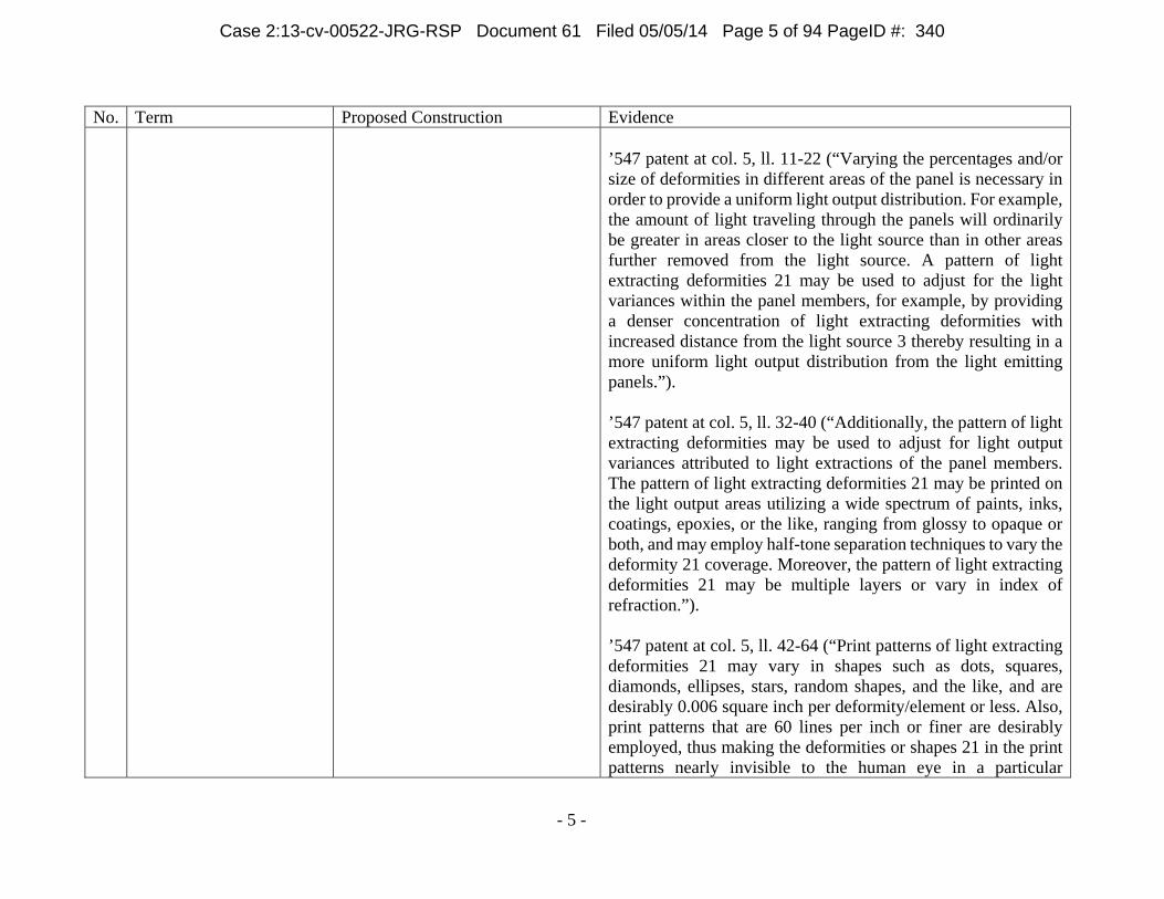
No. Term Proposed Construction Evidence ’547 patent at col. 5, ll. 11-22 (“Varying the percentages and/or size of deformities in different areas of the panel is necessary in order to provide a uniform light output distribution. For example, the amount of light traveling through the panels will ordinarily be greater in areas closer to the light source than in other areas further removed from the light source. A pattern of light extracting deformities 21 may be used to adjust for the light variances within the panel members, for example, by providing a denser concentration of light extracting deformities with increased distance from the light source 3 thereby resulting in a more uniform light output distribution from the light emitting panels.”). ’547 patent at col. 5, ll. 32-40 (“Additionally, the pattern of light extracting deformities may be used to adjust for light output variances attributed to light extractions of the panel members. The pattern of light extracting deformities 21 may be printed on the light output areas utilizing a wide spectrum of paints, inks, coatings, epoxies, or the like, ranging from glossy to opaque or both, and may employ half-tone separation techniques to vary the deformity 21 coverage. Moreover, the pattern of light extracting deformities 21 may be multiple layers or vary in index of refraction.”). ’547 patent at col. 5, ll. 42-64 (“Print patterns of light extracting deformities 21 may vary in shapes such as dots, squares, diamonds, ellipses, stars, random shapes, and the like, and are desirably 0.006 square inch per deformity/element or less. Also, print patterns that are 60 lines per inch or finer are desirably employed, thus making the deformities or shapes 21 in the print patterns nearly invisible to the human eye in a particular
Case 2:13-cv-00522-JRG-RSP Document 61 Filed 05/05/14 Page 5 of 94 PageID #: 340
- 6 -
No. Term Proposed Construction Evidence application thereby eliminating the detection of gradient or banding lines that are common to light extracting patterns utilizing larger elements. Additionally, the deformities may vary in shape and/or size along the length and/or width of the panel members. Also, a random placement pattern of the deformities may be utilized throughout the length and/or width of the panel members. The deformities may have shapes or a pattern with no specific angles to reduce moire or other interference effects. Examples of methods to create these random patterns are printing a pattern of shapes using stochastic print pattern techniques, frequency modulated half tone patterns, or random dot half tones. Moreover, the deformities may be colored in order to effect color correction in the panel members. The color of the deformities may also vary throughout the panel members, for example to provide different colors for the same or different light output areas.”). ’547 patent at col. 5, ln. 65 through col. 6, ln. 16 (“In addition to or in lieu of the patterns of light extracting deformities 21 shown in FIG. 4a, other light extracting deformities including prismatic surfaces, depressions or raised surfaces of various shapes using more complex shapes in a mold pattern may be molded, etched, stamped, thermoformed, hot stamped or the like into or on one or more areas of the panel member. FIGS. 4b and 4c show panel areas 22 on which prismatic surfaces 23 or depressions 24 are formed in the panel areas, whereas FIG. 4d shows prismatic or other reflective or refractive surfaces 25 formed on the exterior of the panel area. The prismatic surfaces, depressions or raised surfaces will cause a portion of the light rays contacted thereby to be emitted from the panel member. Also, the angles of the prisms, depressions or other surfaces may be varied to direct the light in different directions to produce a desired light output
Case 2:13-cv-00522-JRG-RSP Document 61 Filed 05/05/14 Page 6 of 94 PageID #: 341
- 7 -
No. Term Proposed Construction Evidence distribution or effect. Moreover, the reflective or refractive surfaces may have shapes or a pattern with no specific angles to reduce moire or other interference effects.”). ’547 patent at col. 6, ll. 23-28 (“Additionally, a pattern of light extracting deformities 21, 23, 24 and/or 25 may be provided on one or both sides of the panel member in order to change the path of the light so that the internal critical angle is exceeded and a portion of the light is emitted from one or both sides of the panel.”). ’547 patent at col. 6, ll. 51-54 (“If adhesive were to be used over the entire surface, the pattern of deformities could be adjusted to account for the additional attenuation in the light caused by the adhesive.”). ’547 patent at Figs. 4a-4d. ’547 patent at claims 1-9, 15-26, and 31. File History of ’547 patent, Reply to Office Action, Jan. 10, 2003 at 3 (“[S]ince all of the non-elected claims . . . recite different shapes or arrangements of the deformities shown in Figs. 4a-4d that may be provided in or on the elected species of Figs 3, 5, prosecution on the merits of all of the claims is respectfully requested.”). ’660 patent at all counterpart passages and figures as identified above by Plaintiff for the ’547 patent.2
2 Because all of the patents-in-suit have the same written descriptions with only minor variations, a citation by Plaintiff to a passage or figure from one patent-in-suit should be considered a citation to the counterpart passage or figure in all relevant patents-in-suit.
Case 2:13-cv-00522-JRG-RSP Document 61 Filed 05/05/14 Page 7 of 94 PageID #: 342
- 8 -
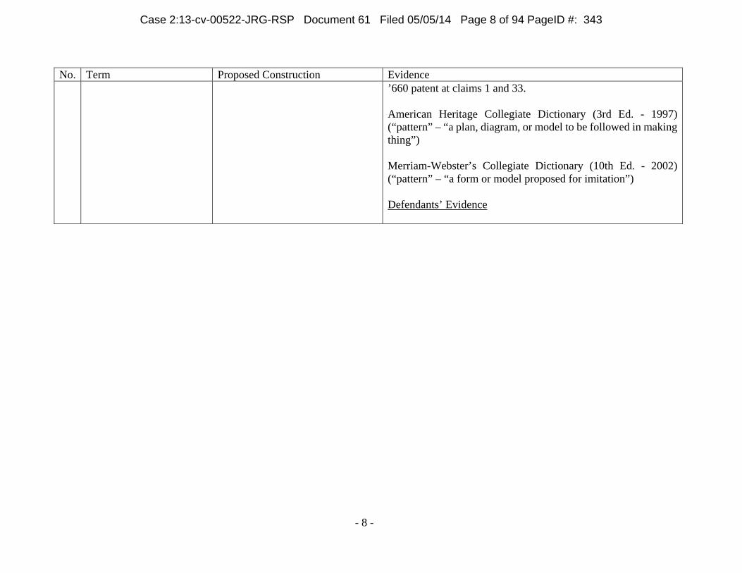
No. Term Proposed Construction Evidence ’660 patent at claims 1 and 33. American Heritage Collegiate Dictionary (3rd Ed. - 1997) (“pattern” – “a plan, diagram, or model to be followed in making thing”) Merriam-Webster’s Collegiate Dictionary (10th Ed. - 2002) (“pattern” – “a form or model proposed for imitation”) Defendants’ Evidence
Case 2:13-cv-00522-JRG-RSP Document 61 Filed 05/05/14 Page 8 of 94 PageID #: 343
- 9 -
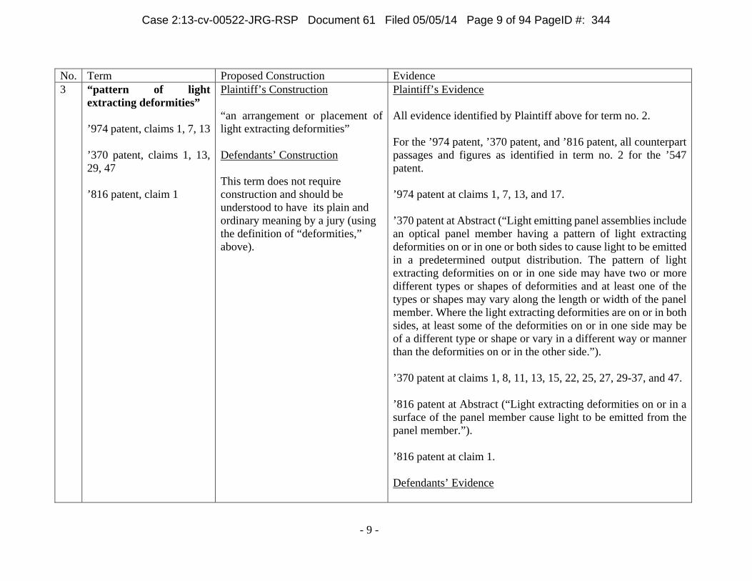
No. Term Proposed Construction Evidence 3 “pattern of light
Plaintiff’s Construction “an arrangement or placement of light extracting deformities” Defendants’ Construction This term does not require construction and should be understood to have its plain and ordinary meaning by a jury (using the definition of “deformities,” above).
Plaintiff’s Evidence All evidence identified by Plaintiff above for term no. 2. For the ’974 patent, ’370 patent, and ’816 patent, all counterpart passages and figures as identified in term no. 2 for the ’547 patent. ’974 patent at claims 1, 7, 13, and 17. ’370 patent at Abstract (“Light emitting panel assemblies include an optical panel member having a pattern of light extracting deformities on or in one or both sides to cause light to be emitted in a predetermined output distribution. The pattern of light extracting deformities on or in one side may have two or more different types or shapes of deformities and at least one of the types or shapes may vary along the length or width of the panel member. Where the light extracting deformities are on or in both sides, at least some of the deformities on or in one side may be of a different type or shape or vary in a different way or manner than the deformities on or in the other side.”). ’370 patent at claims 1, 8, 11, 13, 15, 22, 25, 27, 29-37, and 47. ’816 patent at Abstract (“Light extracting deformities on or in a surface of the panel member cause light to be emitted from the panel member.”). ’816 patent at claim 1. Defendants’ Evidence
Case 2:13-cv-00522-JRG-RSP Document 61 Filed 05/05/14 Page 9 of 94 PageID #: 344
- 10 -
4 “continuous side walls” ’177 patent, claims 1, 15
Plaintiff’s Construction “side walls that completely surround” Defendants’ Construction “uninterrupted walls that are free of breaks on the side of the tray”
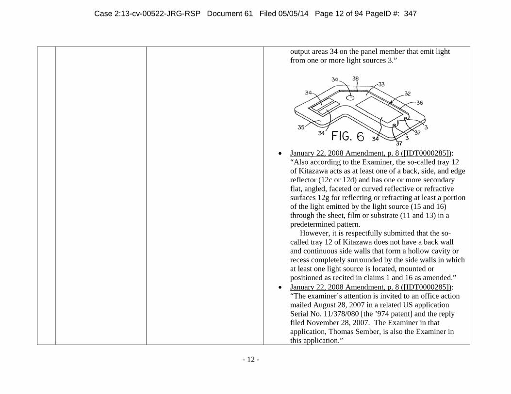
Plaintiff’s Evidence ’177 patent at Abstract (“Light emitting assemblies include a tray that forms a cavity or recess containing one or more light sources. A sheet, film or substrate is positioned over the cavity or recess for controlling the light emitted from the assembly. The tray acts as a back, side or edge reflector, and has one or more secondary reflective or refractive surfaces.”). ’177 patent at col. 6, ln. 62 through col. 7, ln. 12 (“FIG. 6 shows another form of light emitting panel assembly 32 in accordance with this invention including a panel member 33, one or more light sources 3, and one or more light output areas 34. In addition, the panel assembly 32 includes a tray 35 having a cavity or recess 36 in which the panel assembly 32 is received. The tray 35 may act as a back reflector as well as end edge and/or side edge reflectors for the panel 33 and side and/or back reflectors 37 for the light sources 3. Additionally, one or more secondary reflective or refractive surfaces 38 may be provided on the panel member 33 and/or tray 35 to reflect a portion of the light around one or more corners or curves in a non-rectangular shaped panel member 33. These secondary reflective/refractive surfaces 38 may be flat, angled, faceted or curved, and may be used to extract a portion of the light away from the panel member in a predetermined pattern. FIG. 6 also shows multiple light output areas 34 on the panel member that emit light from one or more light sources 3.”). ’177 patent at Fig. 6. ’177 patent at claims 1 and 15.
Case 2:13-cv-00522-JRG-RSP Document 61 Filed 05/05/14 Page 10 of 94 PageID #: 345
- 11 -
File History of ’177 patent, Reply to Office Action of October 3, 2007 at p. 8 (“However, it is respectfully submitted that the so-called tray 12 of Kitazawa does not have a back wall and continuous side walls that form a hollow cavity or recess completely surrounded by the side walls in which at least one light source is located, mounted or positioned as recited in claims 1 and 16 as amended.”). The Merriam- Webster Dictionary (1998) (“continuous” – “continuing without interruption”) Defendants’ Evidence ’177 Patent
6:62-7:12: “FIG. 6 shows another form of light emitting panel assembly 32 in accordance with this invention including a panel member 33, one or more light sources 3, and one or more light output areas 34. In addition, the panel assembly 32 includes a tray 35 having a cavity or recess 36 in which the panel assembly 32 is received. The tray 35 may act as a back reflector as well as end edge and/or side edge reflectors for the panel 33 and side and/or back reflectors 37 for the light sources 3. Additionally, one or more secondary reflective or refractive surfaces 38 may be provided on the panel member 33 and/ or tray 35 to reflect a portion of the light around one or more corners or curves in a non-rectangular shaped panel member 33. These secondary reflective/refractive surfaces 38 may be flat, angled, faceted or curved, and may be used to extract a portion of the light away from the panel member in a predetermined pattern. FIG. 6 also shows multiple light
Case 2:13-cv-00522-JRG-RSP Document 61 Filed 05/05/14 Page 11 of 94 PageID #: 346
- 12 -
output areas 34 on the panel member that emit light from one or more light sources 3.”
January 22, 2008 Amendment, p. 8 ([IDT0000285]):
“Also according to the Examiner, the so-called tray 12 of Kitazawa acts as at least one of a back, side, and edge reflector (12c or 12d) and has one or more secondary flat, angled, faceted or curved reflective or refractive surfaces 12g for reflecting or refracting at least a portion of the light emitted by the light source (15 and 16) through the sheet, film or substrate (11 and 13) in a predetermined pattern. However, it is respectfully submitted that the so-called tray 12 of Kitazawa does not have a back wall and continuous side walls that form a hollow cavity or recess completely surrounded by the side walls in which at least one light source is located, mounted or positioned as recited in claims 1 and 16 as amended.”
January 22, 2008 Amendment, p. 8 ([IDT0000285]): “The examiner’s attention is invited to an office action mailed August 28, 2007 in a related US application Serial No. 11/378/080 [the ’974 patent] and the reply filed November 28, 2007. The Examiner in that application, Thomas Sember, is also the Examiner in this application.”
Case 2:13-cv-00522-JRG-RSP Document 61 Filed 05/05/14 Page 12 of 94 PageID #: 347
- 13 -
’974 Patent
August 28, 2007 Office Action, pp. 2-5 ([IDT0000626-29]).
November 28, 2007 Response at pp. 6-8 ([IDT0000612-14]): “…However, it is respectfully submitted that the reflecting layer 16 of Schoniger is provided on the external surfaces of the light guide batten 12 at one end of the light guide panel 10 to redirect the light form the LED 15 that is received in a blind hole 14 in the batten 12 into the end of the light guide panel 10 that is set in the groove 11 in the batten. The so-called tray or housing 20 of Schoniger does not include end walls and side walls that act as end edge reflectors and side edge reflectors for a panel member entirely received in a cavity or recess in the tray or housing to reflect light that would otherwise exit the panel member through an end edge and/or side edge of the panel member back into the panel member as recited in claim 1 as amended……the light source 21 of Ciupke et al and light source fixture 6 of Tai et al. comprise a tray or housing having a cavity or recess in which the panel member is received, and acts as an end edge reflector and/or side edge reflector for the panel member. Applicant disagrees. Moreover, the light source 21 of Ciupke et al and light source fixture 66 of Tai et al do not have a cavity or recess in which the panel member is entirely received or end walls and side walls that act as end edge reflectors and side edge reflectors for the panel member as recited in claim 1 as amended.”
Extrinsic Evidence:
“continuous”
Case 2:13-cv-00522-JRG-RSP Document 61 Filed 05/05/14 Page 13 of 94 PageID #: 348
- 14 -
No. Term Proposed Construction Evidence o The American Heritage Dictionary of the
English Language, Third Edition (1996) [JD0008042], [JD0008108]
o McGraw-Hill Dictionary of Scientific and Technical Terms, Fifth Edition (1994) [JD0008058-60]
o The New IEEE Standard Dictionary of Electrical and Electronics Terms, Fifth Edition (1993) [JDG0008077-79]
o Webster’s Third New International Dictionary of the English Language Unabridged, Vol.13, “A to G” (1993) [JD0008091]
o The Merriam-Webster Dictionary (1998) “complete; completely”
o Longman Dictionary of Contemporary English: The complete Guide to Written and Spoken English, New Edition (1995) [JD0008019]
o Oxford Advanced Learners Encyclopedic Dictionary (1994) [JD0008025]
o Webster’s Third New International Dictionary of the English Language Unabridged (1993) [JD0008034]
“surround” o Longman Dictionary of Contemporary English:
The complete Guide to Written and Spoken English, New Edition (1995) [JD0008021-22]
o Webster’s Ninth New Collegiate Dictionary (1989) [JD0008038]
Case 2:13-cv-00522-JRG-RSP Document 61 Filed 05/05/14 Page 14 of 94 PageID #: 349
Plaintiff’s Construction plain and ordinary meaning In the alternative only, if the Court determines that this term should be construed: “an area used to make the transition from the light source to the light emitting area of the panel member [’370 patent] /optical conductor [’660 patent]” Defendants’ Construction “a region that spreads and transmits light”
Plaintiff’s Evidence ’660 patent at col. 2, ln. 59 through col. 3, ln. 4 (“Referring now in detail to the drawings, and initially to FIG. 1, there is schematically shown one form of light emitting panel assembly 1 in accordance with this invention including a transparent light emitting panel 2 and one or more light sources 3 which emit light in a predetermined pattern in a light transition member or area 4 used to make the transition from the light source 3 to the light emitting panel 2, as well known in the art. The light that is transmitted by the light transition area 4 to the transparent light emitting panel 2 may be emitted along the entire length of the panel or from one or more light output areas along the length of the panel as desired to produce a desired light output distribution to fit a particular application.”). ’660 patent at col. 3, ll. 5-16 (“In FIG. 1 the light transition area 4 is shown as an integral extension of one end of the light emitting panel 2 and as being generally rectangular in shape. However, the light transition area may be of other shapes suitable for embedding, potting, bonding or otherwise mounting the light source. Also, reflective or refractive surfaces may be provided to increase efficiency. Moreover, the light transition area 4 may be a separate piece suitably attached to the light input surface 13 of the panel member if desired. Also, the sides of the light transition area may be curved to more efficiently reflect or refract a portion of the light emitted from the light source through the light emitting panel at an acceptable angle.”). ’660 patent at Figs. 1-3, 7-15. ’660 patent at claims 1, 2, 7, 20, 35, and 37.
Case 2:13-cv-00522-JRG-RSP Document 61 Filed 05/05/14 Page 15 of 94 PageID #: 350
- 16 -
’660 patent, file history, May 15, 2007 Office Action. ’370 patent at all counterpart passages and figures as identified above by Plaintiff for the ’660 patent. ’370 patent at claims 13, 27, and 47. Defendants’ Evidence Intrinsic Evidence: ’660 Patent
Abstract: “A transition region is disposed between the light source and output region that is configured to spread and transmit the light by the light source to the output region.”
Claim 1: “the optical conductor having a transition region disposed between the light source and the output region.”
2:59-3:4: “Referring now in detail to the drawings, and initially to FIG. 1, there is schematically shown one form of light emitting panel assembly 1 in accordance with this invention including a transparent light emitting panel 2 and one or more light sources 3 which emit light in a predetermined pattern in a light transition member or area 4 used to make the transition from the light source 3 to the light emitting panel 2, as well known in the art. The light that is transmitted by the light transition area 4 to the transparent light emitting panel 2 may be emitted along the entire length of the panel or from one or more light output areas along the length of
Case 2:13-cv-00522-JRG-RSP Document 61 Filed 05/05/14 Page 16 of 94 PageID #: 351
- 17 -
the panel as desired to produce a desired light output distribution to fit a particular application.”
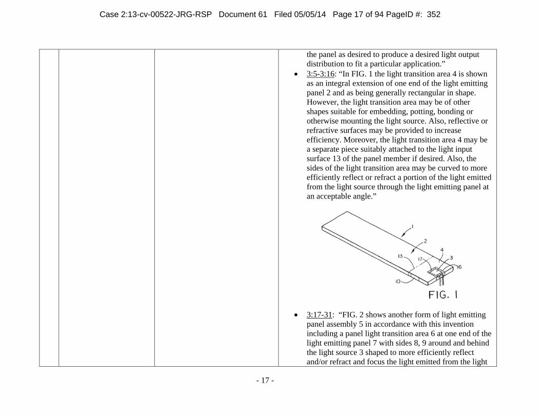
3:5-3:16: “In FIG. 1 the light transition area 4 is shown as an integral extension of one end of the light emitting panel 2 and as being generally rectangular in shape. However, the light transition area may be of other shapes suitable for embedding, potting, bonding or otherwise mounting the light source. Also, reflective or refractive surfaces may be provided to increase efficiency. Moreover, the light transition area 4 may be a separate piece suitably attached to the light input surface 13 of the panel member if desired. Also, the sides of the light transition area may be curved to more efficiently reflect or refract a portion of the light emitted from the light source through the light emitting panel at an acceptable angle.”
3:17-31: “FIG. 2 shows another form of light emitting
panel assembly 5 in accordance with this invention including a panel light transition area 6 at one end of the light emitting panel 7 with sides 8, 9 around and behind the light source 3 shaped to more efficiently reflect and/or refract and focus the light emitted from the light
Case 2:13-cv-00522-JRG-RSP Document 61 Filed 05/05/14 Page 17 of 94 PageID #: 352
- 18 -
source 3 that impinges on these surfaces back through the light transition area 6 at an acceptable angle for entering the light input surface 18 at one end of the light emitting panel 7. Also, a suitable reflective material or coating 10 may be provided on the portions of the sides of the light transition areas of the panel assemblies of FIGS. 1 and 2 on which a portion of the light impinges for maximizing the amount of light or otherwise changing the light that is reflected back through the light transition areas and into the light emitting panels.”
3:51-59: “The light sources 3 may be mechanically held in any suitable manner in slots, cavities or openings 16 machined, molded or otherwise formed in the light transition areas of the panel assemblies. However, preferably the light sources 3 are embedded, potted or bonded in the light transition areas in order to eliminate any air gaps or air interface surfaces between the light sources and surrounding light transition areas, thereby reducing light loss and increasing the light output emitted by the light emitting panels.”
8:6-26: “FIGS. 12 and 13 schematically show still another form of light emitting panel assembly 70 in accordance with this invention which includes one or more light transition areas 71 at one or both ends of the panel member 72 each containing a single light source 73. The transition area or areas 71 shown in FIGS. 12 and 13 collect light with multiple or three-dimensional surfaces and/ or collect light in more than one plane. For example each transition area 71 shown in FIGS. 12 and 13 has elliptical and parabolic shape surfaces 74 and 75 in different planes for directing the light rays 76 into the panel member at a desired angle. Providing one or more transition areas at one or both
Case 2:13-cv-00522-JRG-RSP Document 61 Filed 05/05/14 Page 18 of 94 PageID #: 353
- 19 -
ends of the panel member of any desired dimension to accommodate one or more light sources, with reflective and/or refractive surfaces on the transition areas for redirecting the light rays into the panel member at relatively low angles allows the light emitting panel member to be made much longer and thinner than would otherwise be possible. For example the panel members of the present invention may be made very thin, i.e., 0.125 inch thick or less.”
FIGs. 1, 2, 3, 7, 9, 10, 11, 12, 13, 14, and 15. See also ’660 patent, 3:39 et seq.; 6:30 et seq.; 7:4 et
seq.; 7:22 et seq.; 7:30 et seq.; 7:55 et seq.; 8:26 et seq.; 8:39 et seq.; claims 1, 3, 7, 8, 9, 10, 11, 20, 30, 31, 33, 35, and 37.
Extrinsic Evidence:
“transition” o Webster’s Third New International Dictionary of
the English Language Unabridged (1993) [JD0008035]
o The American Heritage Dictionary of the English Language, Third Edition (1996) [JD0008054], [JD0008120]
o McGraw-Hill Dictionary of Scientific and Technical Terms, Fifth Edition (1994) [JD0008068]
o Webster’s Third New International Dictionary of the English Language Unabridged, Vol. 3, “S to Z” (1993) [JD0008073]
o The New IEEE Standard Dictionary of Electrical and Electronics Terms, Fifth Edition (1993) [JD0008087-88]
Case 2:13-cv-00522-JRG-RSP Document 61 Filed 05/05/14 Page 19 of 94 PageID #: 354
- 20 -
No. Term Proposed Construction Evidence “region”
o The American Heritage Dictionary of the English Language, Third Edition (1996) [JD0008052], [JD0008118]
o McGraw-Hill Dictionary of Scientific and Technical Terms, Fifth Edition (1994) [JD0008066]
Case 2:13-cv-00522-JRG-RSP Document 61 Filed 05/05/14 Page 20 of 94 PageID #: 355
- 21 -
6 “at least some of the light extracting deformities on or in one of the sides are of a different type than the light extracting deformities on or in the other side of the panel member” ’370 patent, claims 1, 13
Plaintiff’s Construction plain and ordinary meaning Defendants’ Construction “at least some of the deformities on or in one side of the panel member are different than the deformities on or in the other side of the panel member in characteristics other than shape”
Plaintiff’s Evidence ’370 patent at Abstract (“Light emitting panel assemblies include an optical panel member having a pattern of light extracting deformities on or in one or both sides to cause light to be emitted in a predetermined output distribution. The pattern of light extracting deformities on or in one side may have two or more different types or shapes of deformities and at least one of the types or shapes may vary along the length or width of the panel member. Where the light extracting deformities are on or in both sides, at least some of the deformities on or in one side may be of a different type or shape or vary in a different way or manner than the deformities on or in the other side.”). ’370 patent at col. 1, ll. 18-22 (“This invention relates generally, as indicated, to light emitting panel assemblies each including a transparent panel member for efficiently conducting light, and controlling the light conducted by the panel member to be emitted from one or more light output areas along the length thereof.”). ’370 patent at col. 1, ll. 23-28 (“Light emitting panel assemblies are generally known. However, the present invention relates to several different light emitting panel assembly configurations which provide for better control of the light output from the panel assemblies and for more efficient utilization of light, which results in greater light output from the panel assemblies.”). ’370 patent at col. 1, ll. 50-55 (“In accordance with another aspect of the invention, the light emitting panel members include a pattern of light extracting deformities or disruptions which provide a desired light output distribution from the panel members by changing the angle of refraction of a portion of the
Case 2:13-cv-00522-JRG-RSP Document 61 Filed 05/05/14 Page 21 of 94 PageID #: 356
- 22 -
light from one or more light output areas of the panel members.”). ’370 patent at col. 1, ln. 65 through col. 2 ln. 3 (“The various light emitting panel assemblies of the present invention are very efficient panel assemblies that may be used to produce increased uniformity and higher light output from the panel members with lower power requirements, and allow the panel members to be made thinner and/or longer, and/or of various shapes and sizes.”). ’370 patent at col. 2, ll. 4-10 (“To the accomplishment of the foregoing and related ends, the invention then comprises the features hereinafter fully described and particularly pointed out in the claims, the following description and the annexed drawings setting forth in detail certain illustrative embodiments of the invention, these being indicative, however, of but several of the various ways in which the principles of the invention may be employed.”). ’370 patent at col. 2, ll. 18-20 (“FIG. 4a is an enlarged plan view of a portion of a light output area of a panel assembly showing one form of pattern of light extracting deformities on the light output area;”). ’370 patent at col. 2, ll. 21-24 (“FIGS. 4b, c and d are enlarged schematic perspective views of a portion of a light output area of a panel assembly showing other forms of light extracting deformities formed in or on the light output area;”). ’370 patent at col. 4, ll. 31-47 (“A pattern of light extracting deformities or disruptions may be provided on one or both sides of the panel members or on one or more selected areas on one or both sides of the panel members, as desired. FIG. 4a
Case 2:13-cv-00522-JRG-RSP Document 61 Filed 05/05/14 Page 22 of 94 PageID #: 357
- 23 -
schematically shows one such light surface area 20 on which a pattern of light extracting deformities or disruptions 21 is provided. As used herein, the term deformities or disruptions are used interchangeably to mean any change in the shape or geometry of the panel surface and/or coating or surface treatment that causes a portion of the light to be emitted. The pattern of light extracting deformities 21 shown in FIG. 4a includes a variable pattern which breaks up the light rays such that the internal angle of reflection of a portion of the light rays will be great enough to cause the light rays either to be emitted out of the panel through the side or sides on which the light extracting deformities 21 are provided or reflected back through the panel and emitted out the other side.”). ’370 patent at col. 4, ll. 48-61 (“These deformities or disruptions 21 can be produced in a variety of manners, for example, by providing a painted pattern, an etched pattern, a machined pattern, a printed pattern, a hot stamped pattern, or a molded pattern or the like on selected light output areas of the panel members. An ink or printed pattern may be applied for example by pad printing, silk screening, ink jet, heat transfer film process or the like. The deformities may also be printed on a sheet or film which is used to apply the deformities to the panel member. This sheet or film may become a permanent part of the light panel assembly for example by attaching or otherwise positioning the sheet or film against one or both sides of the panel member similar to the sheet or film 27 shown in FIGS. 3 and 5 in order to produce a desired effect.”). ’370 patent at col. 4, ln. 62 through col. 5, ln. 4 (“By varying the density, opaqueness or translucence, shape, depth, color, area, index of refraction, or type of deformities 21 on an area or areas of the panels, the light output of the panels can be controlled. The
Case 2:13-cv-00522-JRG-RSP Document 61 Filed 05/05/14 Page 23 of 94 PageID #: 358
- 24 -
deformities or disruptions may be used to control the percent of light emitted from any area of the panels. For example, less and/or smaller size deformities 21 may be placed on panel areas where less light output is wanted. Conversely, a greater percentage of and/or larger deformities may be placed on areas of the panels where greater light output is desired.”). ’370 patent at col. 5, ll. 5-16 (“Varying the percentages and/or size of deformities in different areas of the panel is necessary in order to provide a uniform light output distribution. For example, the amount of light traveling through the panels will ordinarily be greater in areas closer to the light source than in other areas further removed from the light source. A pattern of light extracting deformities 21 may be used to adjust for the light variances within the panel members, for example, by providing a denser concentration of light extracting deformities with increased distance from the light source 3 thereby resulting in a more uniform light output distribution from the light emitting panels.”). ’370 patent at col. 5, ll. 17-23 (“The deformities 21 may also be used to control the output ray angle distribution of the emitted light to suit a particular application. For example, if the panel assemblies are used to provide a liquid crystal display backlight, the light output will be more efficient if the deformities 21 cause the light rays to emit from the panels at predetermined ray angles such that they will pass through the liquid crystal display with low loss.”). ’370 patent at col. 5, ll. 24-33 (“Additionally, the pattern of light extracting deformities may be used to adjust for light output variances attributed to light extractions of the panel members. The pattern of light extracting deformities 21 may be printed on
Case 2:13-cv-00522-JRG-RSP Document 61 Filed 05/05/14 Page 24 of 94 PageID #: 359
- 25 -
the light output areas utilizing a wide spectrum of paints, inks, coatings, epoxies, or the like, ranging from glossy to opaque or both, and may employ half-tone separation techniques to vary the deformity 21 coverage. Moreover, the pattern of light extracting deformities 21 may be multiple layers or vary in index of refraction.”). ’370 patent at col. 5, ll. 34-56 (“Print patterns of light extracting deformities 21 may vary in shapes such as dots, squares, diamonds, ellipses, stars, random shapes, and the like, and are desirably 0.006 square inch per deformity/element or less. Also, print patterns that are 60 lines per inch or finer are desirably employed, thus making the deformities or shapes 21 in the print patterns nearly invisible to the human eye in a particular application thereby eliminating the detection of gradient or banding lines that are common to light extracting patterns utilizing larger elements. Additionally, the deformities may vary in shape and/or size along the length and/or width of the panel members. Also, a random placement pattern of the deformities may be utilized throughout the length and/or width of the panel members. The deformities may have shapes or a pattern with no specific angles to reduce moire or other interference effects. Examples of methods to create these random patterns are printing a pattern of shapes using stochastic print pattern techniques, frequency modulated half tone patterns, or random dot half tones. Moreover, the deformities may be colored in order to effect color correction in the panel members. The color of the deformities may also vary throughout the panel members, for example to provide different colors for the same or different light output areas.”). ’370 patent at col. 5, ln. 57 through col. 6, ln. 7 (“In addition to or in lieu of the patterns of light extracting deformities 21 shown
Case 2:13-cv-00522-JRG-RSP Document 61 Filed 05/05/14 Page 25 of 94 PageID #: 360
- 26 -
in FIG. 4a, other light extracting deformities including prismatic surfaces, depressions or raised surfaces of various shapes using more complex shapes in a mold pattern may be molded, etched, stamped, thermoformed, hot stamped or the like into or on one or more areas of the panel member. FIGS. 4b and 4c show panel areas 22 on which prismatic surfaces 23 or depressions 24 are formed in the panel areas, whereas FIG. 4d shows prismatic or other reflective or refractive surfaces 25 formed on the exterior of the panel area. The prismatic surfaces, depressions or raised surfaces will cause a portion of the light rays contacted thereby to be emitted from the panel member. Also, the angles of the prisms, depressions or other surfaces may be varied to direct the light in different directions to produce a desired light output distribution or effect. Moreover, the reflective or refractive surfaces may have shapes or a pattern with no specific angles to reduce moire or other interference effects.”). ’370 patent at col. 6, ll. 15-20 (“Additionally, a pattern of light extracting deformities 21, 23, 24 and/or 25 may be provided on one or both sides of the panel member in order to change the path of the light so that the internal critical angle is exceeded and a portion of the light is emitted from one or both sides of the panel.”). ’370 patent at col. 8, ll. 57-67 (“The various light emitting panel assemblies disclosed herein may be used for a great many different applications including for example LCD back lighting or lighting in general, decorative and display lighting, automotive lighting, dental lighting, phototherapy or other medical lighting, membrane switch lighting, and sporting goods and apparel lighting or the like. Also the panel assemblies may be made such that the panel members and deformities are transparent without a back reflector. This allows the panel
Case 2:13-cv-00522-JRG-RSP Document 61 Filed 05/05/14 Page 26 of 94 PageID #: 361
- 27 -
assemblies to be used for example to front light an LCD or other display such that the display is viewed through the transparent panel members.”). ’370 patent at col. 9, ll. 1-7 (“Although the invention has been shown and described with respect to certain preferred embodiments, it is obvious that equivalent alterations and modifications will occur to others skilled in the art upon the reading and understanding of the specification. The present invention includes all such equivalent alterations and modifications, and is limited only by the scope of the claims.”). ’370 patent at Figs. 4A-4D. ’370 patent at claims 1-8, 11-13, 15-22, 25-27, 29-43, 46, and 47. Defendants’ Evidence Intrinsic Evidence: ’370 Patent
5:57. July 10, 2008 Amendment, p. 10-14 ([IDT0000782-
86)]: In responding to rejection by prior art reference Blanchet, Applicant stated: “These microballs or microbubbles, while of a different type or shape than the depressions or striations 4, 5 in one or both sides of the transparent plate, are not projections or depression on or in one side of a transparent plate that has the one type or shape of depressions or striations 4 or 5 in the other side as recited in claim 1. Nor does the pattern of depressions or striations 4, 5 on or in at least one side of the transparent plate of Blanchet have at least two different types or shapes or light extracting deformities
Case 2:13-cv-00522-JRG-RSP Document 61 Filed 05/05/14 Page 27 of 94 PageID #: 362
- 28 -
No. Term Proposed Construction Evidence with at least one of the types or shapes of deformities varying along at least one of the length and width of the panel member as recited in claim 17, or wherein at least some of the light extracting deformities on or in one of the sides varies in a different way or manner than the light extracting deformities on or in the other side of the panel member as recited in claim 33.” As to the Albinger rejection, the Applicant noted that all of the light extracting deformities of Albinger are semi-spherical depressions and thus are all the same type or shape even though some intersect each other. Similarly, for the rejection over Balchunas, the Applicant stated that all of the light extracting deformities in Balchunas are grooves of the same type and shape that only vary in depth and thus they are not two different types or shapes.
October 15, 2008 Non-Final Rejection, p. 2-5 ([IDT0000765-68]): The Examiner sua sponte withdrew from consideration new claims 10, 26, and 49 as being non-elected and reiterated the rejection over Blanchet ‘507. The Examiner then disregarded the Applicant’s arguments over Blanchet.
January 15, 2009 Amendment, p. 2-12([IDT0000748-58]): The Applicant amended the claims to include “at least one” light source instead of “a light source”, “or shape” was removed from the claims leaving it only as “a different type” and the following was added to the end of claims 1, 17, and 33: “and at least one film, sheet or substrate overlying at least a portion of one of the sides of the panel member to change the output distribution of the emitted light such that the light will pass through a liquid crystal display with low loss.”
Case 2:13-cv-00522-JRG-RSP Document 61 Filed 05/05/14 Page 28 of 94 PageID #: 363
- 29 -
7 “an air gap therebetween” ’547 patent, claim 1
Plaintiff’s Construction plain and ordinary meaning Defendants’ Construction “a continuous layer of air between the separate transparent sheet or film and the light emitting area such that they have no direct physical contact”
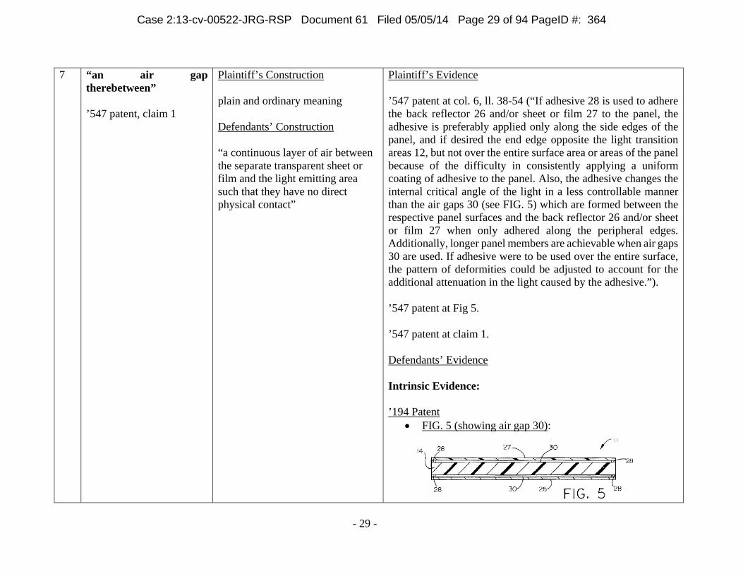
Plaintiff’s Evidence ’547 patent at col. 6, ll. 38-54 (“If adhesive 28 is used to adhere the back reflector 26 and/or sheet or film 27 to the panel, the adhesive is preferably applied only along the side edges of the panel, and if desired the end edge opposite the light transition areas 12, but not over the entire surface area or areas of the panel because of the difficulty in consistently applying a uniform coating of adhesive to the panel. Also, the adhesive changes the internal critical angle of the light in a less controllable manner than the air gaps 30 (see FIG. 5) which are formed between the respective panel surfaces and the back reflector 26 and/or sheet or film 27 when only adhered along the peripheral edges. Additionally, longer panel members are achievable when air gaps 30 are used. If adhesive were to be used over the entire surface, the pattern of deformities could be adjusted to account for the additional attenuation in the light caused by the adhesive.”). ’547 patent at Fig 5. ’547 patent at claim 1. Defendants’ Evidence Intrinsic Evidence: ’194 Patent
FIG. 5 (showing air gap 30):
Case 2:13-cv-00522-JRG-RSP Document 61 Filed 05/05/14 Page 29 of 94 PageID #: 364
- 30 -
Abstract: “The film, sheet, plate or substrate may be positioned near the light emitting surface of a light emitting panel member with an air gap therebetween or over a cavity or recess in a tray through which light from a light source in the cavity or recess is emitted.”
6:45-51: “Also, the adhesive changes the internal critical angle of the light in a less controllable manner than the air gaps 30 (see FIG. 5) which are formed between the respective panel surfaces and the back reflector 26 and/or film 27 when only adhered along the peripheral edges. Additionally, longer panel members are achievable when air gaps 30 are used.”
1:38-44: “In accordance with another aspect of the invention, the light source is desirably embedded, potted or bonded to the light transition area to eliminate any air gaps, decrease surface reflections and/or eliminate any lens effect between the light source and light transition area, thereby reducing light loss and increasing the light output from the panel assembly.”
3:60-65: “However, preferably the light sources 3 are embedded, potted or bonded in the light transition areas in order to eliminate any air gaps or air interface surfaces between the light sources and surrounding light transition areas, thereby reducing light loss and increasing the light output emitted by the light emitting panels.”
Claim 6 (unasserted): “The assembly of claim 4 wherein the portion of the light emitting assembly in which the light partially mixes is the air gap.”
Claim 12 (unasserted): “The assembly of claim 11 wherein there is an additional air gap between the one film, sheet, plate or substrate and the additional film, sheet, plate or substrate.”
Case 2:13-cv-00522-JRG-RSP Document 61 Filed 05/05/14 Page 30 of 94 PageID #: 365
- 31 -
Claim 24 (unasserted): “The assembly of claim 23 wherein there is an air gap between the one film, sheet, plate or substrate and the additional film, sheet, plate or substrate.”
’547 Patent
August 7, 2003 Amendment, p. 11 ([IDT0000044]): In his arguments, the Applicant states that in Hou (‘439), prior art, “the reflecting means 18 (including the spacer 82 that separates the microlenses 80 and microprisms 28) is optically coupled to the wave guide 16 (column 4, lines 14-17 and column 6, lines 61 and 62). Thus there is no air gap in Hou et al between the light emitting area of a light emitting member and a separate transparent sheet or film as claimed.”
U.S. Patent No. 7,077,544 (division of U.S. Patent No. 6,712,481, an ancestor to the patents-in-suit)
August 29, 2005 Amendment, p. 2-9 : The specification was amended to say that, “Also the gap is open to the atmosphere.” Claim 1 was also amended to overcome prior art by saying that the device comprises a substrate, a light source affixed to the substrate, and a transparent member overlying the light source in spaced relation therefrom “to provide an open gap between the light source and the transparent member for mixing of the light . . .” Claim 9 was amended to add that “the gap is an air gap that is open to the atmosphere.” Claims 19 and 31 were similarly amended.
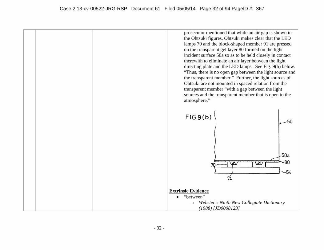
August 29, 2005 Amendment p. 10-14: Prior art, Ohtsuki (‘665) mentioned that a transparent member overlying the LED light sources in spaced relation therefrom to provide an air gap therebetween. The
Case 2:13-cv-00522-JRG-RSP Document 61 Filed 05/05/14 Page 31 of 94 PageID #: 366
- 32 -
prosecutor mentioned that while an air gap is shown in the Ohtsuki figures, Ohtsuki makes clear that the LED lamps 70 and the block-shaped member 91 are pressed on the transparent gel layer 80 formed on the light incident surface 50a so as to be held closely in contact therewith to eliminate an air layer between the light directing plate and the LED lamps. See Fig. 9(b) below. “Thus, there is no open gap between the light source and the transparent member.” Further, the light sources of Ohtsuki are not mounted in spaced relation from the transparent member “with a gap between the light sources and the transparent member that is open to the atmosphere.”
Extrinsic Evidence
“between” o Webster’s Ninth New Collegiate Dictionary
(1988) [JD0008123]
Case 2:13-cv-00522-JRG-RSP Document 61 Filed 05/05/14 Page 32 of 94 PageID #: 367
- 33 -
No. Term Proposed Construction Evidence o The Compact Oxford English Dictionary, Second
Edition (2004) [JD0008127-28] o Webster’s II New Riverside University
Dictionary (1984) [JD0008131] “gap”
o Webster’s Ninth New Collegiate Dictionary (1988) [JD0008124]
o Webster’s II New Riverside University Dictionary (1984) [JD0008132]
8 “an air gap between the
film, sheet, plate or substrate and the panel member” ’194 patent, claim 1
Plaintiff’s Construction plain and ordinary meaning Defendants’ Construction “a continuous layer of air between the sheet, film, plate or substrate and the panel member such that they have no direct physical contact”
Plaintiff’s Evidence All evidence identified by Plaintiff above for term no. 7. For the ’194 patent, all counterpart passages and figures as identified in term no. 7 for the ’547 patent. ’194 patent at Abstract (“The film, sheet, plate or substrate may be positioned near the light emitting surface of a light emitting panel member with an air gap therebetween or over a cavity or recess in a tray through which light from a light source in the cavity or recess is emitted.”). ’194 patent at claims 1, 6, 12, and 24. Defendants’ Evidence See above evidence supporting “an air gap therebetween.”
Case 2:13-cv-00522-JRG-RSP Document 61 Filed 05/05/14 Page 33 of 94 PageID #: 368
Plaintiff’s Construction plain and ordinary meaning Defendants’ Construction “desired light output” means “a specific pre-identified output”; “distribution” does not require construction beyond its plain and ordinary meaning.
Plaintiff’s Evidence ’547 patent at Abstract (“The sheet, film or plate has a pattern of deformities on one or both sides that may vary or be random in size, shape or geometry, placement, index of refraction, density, angle, depth, height and type for controlling the light output distribution to suit a particular application.”). ’547 patent at col. 1, ll. 15-19 (“This invention relates generally, as indicated, to light emitting panel assemblies each including a transparent panel member for efficiently conducting light, and controlling the light conducted by the panel member to be emitted from one or more light output areas along the length thereof.”). ’547 patent at col. 1, ll. 20-25 (“Light emitting panel assemblies are generally known. However, the present invention relates to several different light emitting panel assembly configurations which provide for better control of the light output from the panel assemblies and for more efficient utilization of light, which results in greater light output from the panel assemblies.”). ’547 patent at col. 1, ll. 41-47 (“In accordance with another aspect of the invention, the panel assemblies may include reflective or refractive surfaces for changing the path of a portion of the light, emitted from the light source, that would not normally enter the panel members at an acceptable angle that allows the light to remain in the panel members for a longer
3 Defendants identified this term as indefinite in their Patent Local Rule 3-3 Invalidity Contentions. Defendants contend that this term is indefinite under existing Supreme Court precedent, but recognize a potential conflict with Federal Circuit precedent. By proposing a definition, Defendants do not waive their contention that this term is indefinite and preserve their right to argue indefiniteness based on the U.S. Supreme Court’s forthcoming ruling in Nautilus, Inc. v. Biosig Instruments, Inc., No. 13-369, or other Supreme Court precedent.
Case 2:13-cv-00522-JRG-RSP Document 61 Filed 05/05/14 Page 34 of 94 PageID #: 369
- 35 -
period of time and/or increase the efficiency of the panel members.”). ’547 patent at col. 1, ll. 48-53 (“In accordance with another aspect of the invention, the light emitting panel members include a pattern of light extracting deformities or disruptions which provide a desired light output distribution from the panel members by changing the angle of refraction of a portion of the light from one or more light output areas of the panel members.”). ’547 patent at col. 1, ln. 64 through col. 2 ln. 2 (“The various light emitting panel assemblies of the present invention are very efficient panel assemblies that may be used to produce increased uniformity and higher light output from the panel members with lower power requirements, and allow the panel members to be made thinner and/or longer, and/or of various shapes and sizes.”). ’547 patent at col. 2, ln. 62 through col. 3, ln. 7 (“Referring now in detail to the drawings, and initially to FIG. 1, there is schematically shown one form of light emitting panel assembly 1 in accordance with this invention including a transparent light emitting panel 2 and one or more light sources 3 which emit light in a predetermined pattern in a light transition member or area 4 used to make the transition from the light source 3 to the light emitting panel 2, as well known in the art. The light that is transmitted by the light transition area 4 to the transparent light emitting panel 2 may be emitted along the entire length of the panel or from one or more light output areas along the length of the panel as desired to produce a desired light output distribution to fit a particular application.”).
Case 2:13-cv-00522-JRG-RSP Document 61 Filed 05/05/14 Page 35 of 94 PageID #: 370
- 36 -
’547 patent at col. 4, ll. 37-53 (“A pattern of light extracting deformities or disruptions may be provided on one or both sides of the panel members or on one or more selected areas on one or both sides of the panel members, as desired. FIG. 4a schematically shows one such light surface area 20 on which a pattern of light extracting deformities or disruptions 21 is provided. As used herein, the term deformities or disruptions are used interchangeably to mean any change in the shape or geometry of the panel surface and/or coating or surface treatment that causes a portion of the light to be emitted. The pattern of light extracting deformities 21 shown in FIG. 4a includes a variable pattern which breaks up the light rays such that the internal angle of reflection of a portion of the light rays will be great enough to cause the light rays either to be emitted out of the panel through the side or sides on which the light extracting deformities 21 are provided or reflected back through the panel and emitted out the other side.”). ’547 patent at col. 4, ll. 54-67 (“These deformities or disruptions 21 can be produced in a variety of manners, for example, by providing a painted pattern, an etched pattern, a machined pattern, a printed pattern, a hot stamped pattern, or a molded pattern or the like on selected light output areas of the panel members. An ink or printed pattern may be applied for example by pad printing, silk screening, ink jet, heat transfer film process or the like. The deformities may also be printed on a sheet or film which is used to apply the deformities to the panel member. This sheet or film may become a permanent part of the light panel assembly for example by attaching or otherwise positioning the sheet or film against one or both sides of the panel member similar to the sheet or film 27 shown in FIGS. 3 and 5 in order to produce a desired effect.”).
Case 2:13-cv-00522-JRG-RSP Document 61 Filed 05/05/14 Page 36 of 94 PageID #: 371
- 37 -
’547 patent at col. 5, ll. 1-10 (“By varying the density, opaqueness or translucence, shape, depth, color, area, index of refraction, or type of deformities 21 on an area or areas of the panels, the light output of the panels can be controlled. The deformities or disruptions may be used to control the percent of light emitted from any area of the panels. For example, less and/or smaller size deformities 21 may be placed on panel areas where less light output is wanted. Conversely, a greater percentage of and/or larger deformities may be placed on areas of the panels where greater light output is desired.”). ’547 patent at col. 5, ll. 11-22 (“Varying the percentages and/or size of deformities in different areas of the panel is necessary in order to provide a uniform light output distribution. For example, the amount of light traveling through the panels will ordinarily be greater in areas closer to the light source than in other areas further removed from the light source. A pattern of light extracting deformities 21 may be used to adjust for the light variances within the panel members, for example, by providing a denser concentration of light extracting deformities with increased distance from the light source 3 thereby resulting in a more uniform light output distribution from the light emitting panels.”). ’547 patent at col. 5, ll. 23-30 (“The deformities 21 may also be used to control the output ray angle distribution of the emitted light to suit a particular application. For example, if the panel assemblies are used to provide a liquid crystal display backlight, the light output will be more efficient if the deformities 21 cause the light rays to emit from the panels at predetermined ray angles such that they will pass through the liquid crystal display with low loss.”).
Case 2:13-cv-00522-JRG-RSP Document 61 Filed 05/05/14 Page 37 of 94 PageID #: 372
- 38 -
’547 patent at col. 5, ll. 31-41 (“Additionally, the pattern of light extracting deformities may be used to adjust for light output variances attributed to light extractions of the panel members. The pattern of light extracting deformities 21 may be printed on the light output areas utilizing a wide spectrum of paints, inks, coatings, epoxies, or the like, ranging from glossy to opaque or both, and may employ half-tone separation techniques to vary the deformity 21 coverage. Moreover, the pattern of light extracting deformities 21 may be multiple layers or vary in index of refraction.”). ’547 patent at col. 5, ll. 42-64 (“Print patterns of light extracting deformities 21 may vary in shapes such as dots, squares, diamonds, ellipses, stars, random shapes, and the like, and are desirably 0.006 square inch per deformity/element or less. Also, print patterns that are 60 lines per inch or finer are desirably employed, thus making the deformities or shapes 21 in the print patterns nearly invisible to the human eye in a particular application thereby eliminating the detection of gradient or banding lines that are common to light extracting patterns utilizing larger elements. Additionally, the deformities may vary in shape and/or size along the length and/or width of the panel members. Also, a random placement pattern of the deformities may be utilized throughout the length and/or width of the panel members. The deformities may have shapes or a pattern with no specific angles to reduce moire or other interference effects. Examples of methods to create these random patterns are printing a pattern of shapes using stochastic print pattern techniques, frequency modulated half tone patterns, or random dot half tones. Moreover, the deformities may be colored in order to effect color correction in the panel members. The color of the deformities may also vary throughout the panel members, for example to
Case 2:13-cv-00522-JRG-RSP Document 61 Filed 05/05/14 Page 38 of 94 PageID #: 373
- 39 -
provide different colors for the same or different light output areas.”). ’547 patent at col. 5, ln. 65 through col. 6, ln. 16 (“In addition to or in lieu of the patterns of light extracting deformities 21 shown in FIG. 4a, other light extracting deformities including prismatic surfaces, depressions or raised surfaces of various shapes using more complex shapes in a mold pattern may be molded, etched, stamped, thermoformed, hot stamped or the like into or on one or more areas of the panel member. FIGS. 4b and 4c show panel areas 22 on which prismatic surfaces 23 or depressions 24 are formed in the panel areas, whereas FIG. 4d shows prismatic or other reflective or refractive surfaces 25 formed on the exterior of the panel area. The prismatic surfaces, depressions or raised surfaces will cause a portion of the light rays contacted thereby to be emitted from the panel member. Also, the angles of the prisms, depressions or other surfaces may be varied to direct the light in different directions to produce a desired light output distribution or effect. Moreover, the reflective or refractive surfaces may have shapes or a pattern with no specific angles to reduce moire or other interference effects.”). ’547 patent at col. 6, ll. 23-32 (“Additionally, a pattern of light extracting deformities 21, 23, 24 and/or 25 may be provided on one or both sides of the panel member in order to change the path of the light so that the internal critical angle is exceeded and a portion of the light is emitted from one or both sides of the panel. Moreover, a transparent sheet or film 27 may be attached or positioned against the side or sides of the panel member from which light is emitted using a suitable adhesive 28 (see FIG. 5) or other method in order to produce a desired effect.”).
Case 2:13-cv-00522-JRG-RSP Document 61 Filed 05/05/14 Page 39 of 94 PageID #: 374
- 40 -
’547 patent at col. 6, ll. 33-38 (“The sheet or film 27 may be used to further improve the uniformity of the light output distribution. For example, the sheet or film 27 may be a colored film, a diffuser, or a label or display, a portion of which may be a transparent overlay that may be colored and/or have text or an image thereon.”). ’547 patent at col. 8, ln. 66 through col. 9, ln. 10 (“The various light emitting panel assemblies disclosed herein may be used for a great many different applications including for example LCD back lighting or lighting in general, decorative and display lighting, automotive lighting, dental lighting, phototherapy or other medical lighting, membrane switch lighting, and sporting goods and apparel lighting or the like. Also the panel assemblies may be made such that the panel members and deformities are transparent without a back reflector. This allows the panel assemblies to be used for example to front light an LCD or other display such that the display is viewed through the transparent panel members.”). ’547 patent at Figs. 3, 4A-4D, and 5. ’547 patent at claim 1. Defendants’ Evidence Intrinsic Evidence: ’547 Patent
1:48-53: “In accordance with another aspect of the invention, the light emitting panel members include a pattern of light extracting deformities or disruptions which provide a desired light output distribution from
Case 2:13-cv-00522-JRG-RSP Document 61 Filed 05/05/14 Page 40 of 94 PageID #: 375
- 41 -
the panel members by changing the angle of refraction of a portion of the light from one or more light output areas of the panel members.”
3:2-7: “The light that is transmitted by the light transition area 4 to the transparent light emitting panel 2 may be emitted along the entire length of the panel or from one or more light output areas along the length of the panel as desired to produce a desired light output distribution to fit a particular application.”
6:8-16: “The prismatic surfaces, depressions or raised surfaces will cause a portion of the light rays contacted thereby to be emitted from the panel member. Also, the angles of the prisms, depressions or other surfaces may be varied to direct the light in different directions to produce a desired light output distribution or effect. Moreover, the reflective or refractive surfaces may have shapes or a pattern with no specific angles to reduce moiré or other interference effects.”
7:19-24: “In this particular embodiment, each of the light sources 3 desirably employs three colored LEDs (red, blue, green) in each transition mixing area 43 so that the light from the three LEDs can be mixed to produce a desired light output color that will be emitted from the light output area 42.”
Extrinsic Evidence:
“desired” o The American Heritage Dictionary of the
English Language, Third Edition (1996) [JD0008044], [JD0008110]
Case 2:13-cv-00522-JRG-RSP Document 61 Filed 05/05/14 Page 41 of 94 PageID #: 376
- 42 -
10 “desired light output distribution or effect”4 ’194 patent, claim 23
Plaintiff’s Construction plain and ordinary meaning Defendants’ Construction “desired light output” means “a specific pre-identified output”; “distribution or effect” does not require construction and should be understood to have its plain and ordinary meaning by a jury.
Plaintiff’s Evidence All evidence identified by Plaintiff above for term no. 9. For the ’194 patent, all counterpart passages and figures as identified in term no. 9 for the ’547 patent. ’194 patent at Abstract (“Light emitting assemblies include at least one light source and at least one film, sheet, plate or substrate having optical elements or deformities of well defined shape on at least one surface that have reflective or refractive surfaces for controlling the light output ray angle distribution of the emitted light. The film, sheet, plate or substrate may be positioned near the light emitting surface of a light emitting panel member with an air gap therebetween or over a cavity or recess in a tray through which light from a light source in the cavity or recess is emitted.”). ’194 patent at claims 11, 23 and 31. Defendants’ Evidence See above evidence supporting “desired light output distribution.”
11 “desired light output color or uniformity”5 ’177 patent, claim 15
Plaintiff’s Construction plain and ordinary meaning Defendants’ Construction
Plaintiff’s Evidence All evidence identified by Plaintiff above for term no. 9. For the ’177 patent, all counterpart passages and figures as identified in term no. 9 for the ’547 patent.
4 See footnote 3. 5 See footnote 3.
Case 2:13-cv-00522-JRG-RSP Document 61 Filed 05/05/14 Page 42 of 94 PageID #: 377
- 43 -
“desired light output” means “a specific pre-identified output”; “color or uniformity” does not require construction and should be understood to have its plain and ordinary meaning by a jury.
’177 patent at Abstract (“Light emitting assemblies include a tray that forms a cavity or recess containing one or more light sources. A sheet, film or substrate is positioned over the cavity or recess for controlling the light emitted from the assembly. The tray acts as a back, side or edge reflector, and has one or more secondary reflective or refractive surfaces.”). ’177 patent at claim 15. Defendants’ Evidence See above evidence supporting “desired light output distribution.”
Plaintiff’s Construction plain and ordinary meaning Defendants’ Construction “a specific pre-identified output”
Plaintiff’s Evidence All evidence identified by Plaintiff for term nos. 9-11. Defendants’ Evidence See above evidence supporting “desired light output distribution.”
Plaintiff’s Construction plain and ordinary meaning Defendants’ Construction
Plaintiff’s Evidence ’370 patent at Abstract (“Light emitting panel assemblies include an optical panel member having a pattern of light extracting deformities on or in one or both sides to cause light to be emitted in a predetermined output distribution. The pattern of light
6 See footnote 3. 7 See footnote 3.
Case 2:13-cv-00522-JRG-RSP Document 61 Filed 05/05/14 Page 43 of 94 PageID #: 378
- 44 -
’660 patent, claims 1, 33
“chosen in advance”
extracting deformities on or in one side may have two or more different types or shapes of deformities and at least one of the types or shapes may vary along the length or width of the panel member. Where the light extracting deformities are on or in both sides, at least some of the deformities on or in one side may be of a different type or shape or vary in a different way or manner than the deformities on or in the other side.”). ’370 patent at col. 1, ll. 18-22 (“This invention relates generally, as indicated, to light emitting panel assemblies each including a transparent panel member for efficiently conducting light, and controlling the light conducted by the panel member to be emitted from one or more light output areas along the length thereof.”). ’370 patent at col. 1, ll. 23-28 (“Light emitting panel assemblies are generally known. However, the present invention relates to several different light emitting panel assembly configurations which provide for better control of the light output from the panel assemblies and for more efficient utilization of light, which results in greater light output from the panel assemblies.”). ’370 patent at col. 1, ll. 43-49 (“In accordance with another aspect of the invention, the panel assemblies may include reflective or refractive surfaces for changing the path of a portion of the light, emitted from the light source, that would not normally enter the panel members at an acceptable angle that allows the light to remain in the panel members for a longer period of time and/or increase the efficiency of the panel members.”). ’370 patent at col. 1, ll. 50-55 (“In accordance with another aspect of the invention, the light emitting panel members include
Case 2:13-cv-00522-JRG-RSP Document 61 Filed 05/05/14 Page 44 of 94 PageID #: 379
- 45 -
a pattern of light extracting deformities or disruptions which provide a desired light output distribution from the panel members by changing the angle of refraction of a portion of the light from one or more light output areas of the panel members.”). ’370 patent at col. 1, ln. 65 through col. 2 ln. 3 (“The various light emitting panel assemblies of the present invention are very efficient panel assemblies that may be used to produce increased uniformity and higher light output from the panel members with lower power requirements, and allow the panel members to be made thinner and/or longer, and/or of various shapes and sizes.”). ’370 patent at col. 2, ll. 18-20 (“FIG. 4a is an enlarged plan view of a portion of a light output area of a panel assembly showing one form of pattern of light extracting deformities on the light output area;”). ’370 patent at col. 2, ll. 21-24 (“FIGS. 4b, c and d are enlarged schematic perspective views of a portion of a light output area of a panel assembly showing other forms of light extracting deformities formed in or on the light output area;”). ’370 patent at col. 2, ln. 58 through col. 3, ln. 3 (“Referring now in detail to the drawings, and initially to FIG. 1, there is schematically shown one form of light emitting panel assembly 1 in accordance with this invention including a transparent light emitting panel 2 and one or more light sources 3 which emit light in a predetermined pattern in a light transition member or area 4 used to make the transition from the light source 3 to the light emitting panel 2, as well known in the art. The light that is transmitted by the light transition area 4 to the transparent light emitting panel 2 may be emitted along the entire length of the
Case 2:13-cv-00522-JRG-RSP Document 61 Filed 05/05/14 Page 45 of 94 PageID #: 380
- 46 -
panel or from one or more light output areas along the length of the panel as desired to produce a desired light output distribution to fit a particular application.”). ’370 patent at col. 3, ll. 8-9 (“Also, reflective or refractive surfaces may be provided to increase efficiency.”). ’370 patent at col. 3, ll. 12-15 (“Also, a suitable reflective material or coating 10 may be provided on the portions of the sides of the light transition areas of the panel assemblies of FIGS. 1 and 2 on which a portion of the light impinges for maximizing the amount of light or otherwise changing the light that is reflected back through the light transition areas and into the light emitting panels.”). ’370 patent at col. 4, ll. 31-47 (“A pattern of light extracting deformities or disruptions may be provided on one or both sides of the panel members or on one or more selected areas on one or both sides of the panel members, as desired. FIG. 4a schematically shows one such light surface area 20 on which a pattern of light extracting deformities or disruptions 21 is provided. As used herein, the term deformities or disruptions are used interchangeably to mean any change in the shape or geometry of the panel surface and/or coating or surface treatment that causes a portion of the light to be emitted. The pattern of light extracting deformities 21 shown in FIG. 4a includes a variable pattern which breaks up the light rays such that the internal angle of reflection of a portion of the light rays will be great enough to cause the light rays either to be emitted out of the panel through the side or sides on which the light extracting deformities 21 are provided or reflected back through the panel and emitted out the other side.”).
Case 2:13-cv-00522-JRG-RSP Document 61 Filed 05/05/14 Page 46 of 94 PageID #: 381
- 47 -
’370 patent at col. 4, ll. 48-61 (“These deformities or disruptions 21 can be produced in a variety of manners, for example, by providing a painted pattern, an etched pattern, a machined pattern, a printed pattern, a hot stamped pattern, or a molded pattern or the like on selected light output areas of the panel members. An ink or printed pattern may be applied for example by pad printing, silk screening, ink jet, heat transfer film process or the like. The deformities may also be printed on a sheet or film which is used to apply the deformities to the panel member. This sheet or film may become a permanent part of the light panel assembly for example by attaching or otherwise positioning the sheet or film against one or both sides of the panel member similar to the sheet or film 27 shown in FIGS. 3 and 5 in order to produce a desired effect.”); ’370 patent at col. 4, ln. 62 through col. 5, ln. 4 (“By varying the density, opaqueness or translucence, shape, depth, color, area, index of refraction, or type of deformities 21 on an area or areas of the panels, the light output of the panels can be controlled. The deformities or disruptions may be used to control the percent of light emitted from any area of the panels. For example, less and/or smaller size deformities 21 may be placed on panel areas where less light output is wanted. Conversely, a greater percentage of and/or larger deformities may be placed on areas of the panels where greater light output is desired.”). ’370 patent at col. 5, ll. 5-16 (“Varying the percentages and/or size of deformities in different areas of the panel is necessary in order to provide a uniform light output distribution. For example, the amount of light traveling through the panels will ordinarily be greater in areas closer to the light source than in other areas further removed from the light source. A pattern of light extracting deformities 21 may be used to adjust for the light
Case 2:13-cv-00522-JRG-RSP Document 61 Filed 05/05/14 Page 47 of 94 PageID #: 382
- 48 -
variances within the panel members, for example, by providing a denser concentration of light extracting deformities with increased distance from the light source 3 thereby resulting in a more uniform light output distribution from the light emitting panels.”). ’370 patent at col. 5, ll. 17-23 (“The deformities 21 may also be used to control the output ray angle distribution of the emitted light to suit a particular application. For example, if the panel assemblies are used to provide a liquid crystal display backlight, the light output will be more efficient if the deformities 21 cause the light rays to emit from the panels at predetermined ray angles such that they will pass through the liquid crystal display with low loss.”). ’370 patent at col. 5, ll. 24-33 (“Additionally, the pattern of light extracting deformities may be used to adjust for light output variances attributed to light extractions of the panel members. The pattern of light extracting deformities 21 may be printed on the light output areas utilizing a wide spectrum of paints, inks, coatings, epoxies, or the like, ranging from glossy to opaque or both, and may employ half-tone separation techniques to vary the deformity 21 coverage. Moreover, the pattern of light extracting deformities 21 may be multiple layers or vary in index of refraction.”). ’370 patent at col. 5, ll. 34-56 (“Print patterns of light extracting deformities 21 may vary in shapes such as dots, squares, diamonds, ellipses, stars, random shapes, and the like, and are desirably 0.006 square inch per deformity/element or less. Also, print patterns that are 60 lines per inch or finer are desirably employed, thus making the deformities or shapes 21 in the print patterns nearly invisible to the human eye in a particular
Case 2:13-cv-00522-JRG-RSP Document 61 Filed 05/05/14 Page 48 of 94 PageID #: 383
- 49 -
application thereby eliminating the detection of gradient or banding lines that are common to light extracting patterns utilizing larger elements. Additionally, the deformities may vary in shape and/or size along the length and/or width of the panel members. Also, a random placement pattern of the deformities may be utilized throughout the length and/or width of the panel members. The deformities may have shapes or a pattern with no specific angles to reduce moire or other interference effects. Examples of methods to create these random patterns are printing a pattern of shapes using stochastic print pattern techniques, frequency modulated half tone patterns, or random dot half tones. Moreover, the deformities may be colored in order to effect color correction in the panel members. The color of the deformities may also vary throughout the panel members, for example to provide different colors for the same or different light output areas.”). ’370 patent at col. 5, ln. 57 through col. 6, ln. 7 (“In addition to or in lieu of the patterns of light extracting deformities 21 shown in FIG. 4a, other light extracting deformities including prismatic surfaces, depressions or raised surfaces of various shapes using more complex shapes in a mold pattern may be molded, etched, stamped, thermoformed, hot stamped or the like into or on one or more areas of the panel member. FIGS. 4b and 4c show panel areas 22 on which prismatic surfaces 23 or depressions 24 are formed in the panel areas, whereas FIG. 4d shows prismatic or other reflective or refractive surfaces 25 formed on the exterior of the panel area. The prismatic surfaces, depressions or raised surfaces will cause a portion of the light rays contacted thereby to be emitted from the panel member. Also, the angles of the prisms, depressions or other surfaces may be varied to direct the light in different directions to produce a desired light output distribution or effect. Moreover, the reflective or refractive
Case 2:13-cv-00522-JRG-RSP Document 61 Filed 05/05/14 Page 49 of 94 PageID #: 384
- 50 -
surfaces may have shapes or a pattern with no specific angles to reduce moire or other interference effects.”). ’370 patent at col. 6, ll. 15-24 (“Additionally, a pattern of light extracting deformities 21, 23, 24 and/or 25 may be provided on one or both sides of the panel member in order to change the path of the light so that the internal critical angle is exceeded and a portion of the light is emitted from one or both sides of the panel. Moreover, a transparent film, sheet or plate 27 may be attached or positioned against the side or sides of the panel member from which light is emitted using a suitable adhesive 28 or other method in order to produce a desired effect.”). ’370 patent at col. 6, ln. 53 through col. 7, ln. 3 (“FIG. 6 shows another form of light emitting panel assembly 32 in accordance with this invention including a panel member 33, one or more light sources 3, and one or more light output areas 34. In addition, the panel assembly 32 includes a tray 35 having a cavity or recess 36 in which the panel assembly 32 is received. The tray 35 may act as a back reflector as well as end edge and/or side edge reflectors for the panel 33 and side and/or back reflectors 37 for the light sources 3. Additionally, one or more secondary reflective or refractive surfaces 38 may be provided on the panel member 33 and/or tray 35 to reflect a portion of the light around one or more corners or curves in a non-rectangular shaped panel member 33. These secondary reflective/refractive surfaces 38 may be flat, angled, faceted or curved, and may be used to extract a portion of the light away from the panel member in a predetermined pattern. FIG. 6 also shows multiple light output areas 34 on the panel member that emit light from one or more light sources 3.”).
Case 2:13-cv-00522-JRG-RSP Document 61 Filed 05/05/14 Page 50 of 94 PageID #: 385
- 51 -
’370 patent at col. 7, ll. 38-54 (“Moreover, a separate cavity or recess 56 may be provided in the panel member 51 for receipt of a correspondingly shaped light transition area 57 having one or more light sources 3 embedded, bonded, cast, insert molded, epoxied, or otherwise mounted or positioned therein and a curved reflective or refractive surface 58 on the transition area 57 and/or wall of the cavity or recess 56 to redirect a portion of the light in a predetermined manner. In this way the light transition area 57 and/or panel member may be in the form of a separate insert which facilitates the easy placement of the light source in a modular manner. A reflector 58 may be placed on the reflective or refractive surface of the cavity or recess 56 or insert 57. Where the reflector 58 is placed on the reflective or refractive surface of the cavity or recess 56, the cavity or recess may act as a mold permitting transparent material from which the transition area 57 is made to be cast around one or more light sources 3.”). ’370 patent at col. 8, ll. 57-67 (“The various light emitting panel assemblies disclosed herein may be used for a great many different applications including for example LCD back lighting or lighting in general, decorative and display lighting, automotive lighting, dental lighting, phototherapy or other medical lighting, membrane switch lighting, and sporting goods and apparel lighting or the like. Also the panel assemblies may be made such that the panel members and deformities are transparent without a back reflector. This allows the panel assemblies to be used for example to front light an LCD or other display such that the display is viewed through the transparent panel members.”). ’370 patent at Figs. 1-15. ’370 patent at claims 1, 13, 15, 27, 29, and 47.
Case 2:13-cv-00522-JRG-RSP Document 61 Filed 05/05/14 Page 51 of 94 PageID #: 386
- 52 -
’370 patent, file history, Feb. 12, 2008 Office Action. For the ’177 patent, all counterpart passages and figures as identified above by Plaintiff for the ’370 patent. ’177 patent at claims 1-5, 11, and 12. For the ’660 patent, all counterpart passages and figures as identified above by Plaintiff for the ’370 patent. ’660 patent at claim 1. Defendants’ Evidence Intrinsic Evidence: ’370 Patent
Abstract: “Light emitting panel assemblies include an optical panel member having a pattern of light extracting deformities on or in one or both sides to cause light to be emitted in a predetermined output distribution.”
2:58-65: “Referring now in detail to the drawings, and initially to FIG. 1, there is schematically shown one form of light emitting panel assembly 1 in accordance with this invention including a transparent light emitting panel 2 and one or more light sources 3 which emit light in a predetermined pattern in a light transition member or area 4 used to make the transition from the light source 3 to the light emitting panel 2, as well known in the art.”
Case 2:13-cv-00522-JRG-RSP Document 61 Filed 05/05/14 Page 52 of 94 PageID #: 387
- 53 -
5:17-23: “The deformities 21 may also be used to control the output ray angle distribution of the emitted light to suit a particular application. For example, if the panel assemblies are used to provide a liquid crystal display backlight, the light output will be more efficient if the deformities 21 cause the light rays to emit from the panels at predetermined ray angles such that they will pass through the liquid crystal display with low loss.”
6:65-7:1: “These secondary reflective/refractive surfaces 38 may be flat, angled, faceted or curved, and may be used to extract a portion of the light away from the panel member in a predetermined pattern.”
7:38-45: “Moreover, a separate cavity or recess 56 may be provided in the panel member 51 for receipt of a correspondingly shaped light transition area 57 having one or more light sources 3 embedded, bonded, cast, insert molded, epoxied, or otherwise mounted or positioned therein and a curved reflective or refractive surface 58 on the transition area 57 and/or wall of the cavity or recess 56 to redirect a portion of the light in a predetermined manner.”
Extrinsic Evidence:
See IGT v. Bally Gaming Int’l, 659 F.3d 1109 (Fed. Cir. 2011) (defining “predetermined” to mean chosen in advance).
“predetermine; predetermined” o Longman Dictionary of Contemporary English:
The complete Guide to Written and Spoken English, New Edition (1995) [JD0008020]
Case 2:13-cv-00522-JRG-RSP Document 61 Filed 05/05/14 Page 53 of 94 PageID #: 388
- 54 -
o Oxford Advanced Learners Encyclopedic Dictionary (1994) [JD0008026]
o The American Heritage Dictionary of the English Language, Third Edition (1996) [JD0008050], [JD0008116]
o Webster’s Third New International Dictionary of the English Language Unabridged, Vol. 2, “H to R” (1993) [JD0008102]
Case 2:13-cv-00522-JRG-RSP Document 61 Filed 05/05/14 Page 54 of 94 PageID #: 389
- 55 -
14 “well defined optical elements or deformities” ’194 patent, claims 1, 16, 31
Plaintiff’s Construction plain and ordinary meaning In the alternative only, if the Court determines that this term should be construed: “optical elements or deformities having clearly distinguishable limits, boundaries, or features” Defendants’ Construction This term is indefinite under 35 U.S.C. § 112(2).
Plaintiff’s Evidence ’194 patent at Abstract (“Light emitting assemblies include at least one light source and at least one film, sheet, plate or substrate having optical elements or deformities of well defined shape on at least one surface that have reflective or refractive surfaces for controlling the light output ray angle distribution of the emitted light. The film, sheet, plate or substrate may be positioned near the light emitting surface of a light emitting panel member with an air gap therebetween or over a cavity or recess in a tray through which light from a light source in the cavity or recess is emitted.”). ’194 patent at col. 2, ll. 22-24 (“FIG. 4a is an enlarged plan view of a portion of a light output area of a panel assembly showing one form of pattern of light extracting deformities on the light output area;”). ’194 patent at col. 2, ll. 25-28 (“FIGS. 4b, c and d are enlarged schematic perspective views of a portion of a light output area of a panel assembly showing other forms of light extracting deformities formed in or on the light output area;”). ’194 patent at col. 4, ll. 39-55 (“A pattern of light extracting deformities or disruptions may be provided on one or both sides of the panel members or on one or more selected areas on one or both sides of the panel members, as desired. FIG. 4a schematically shows one such light surface area 20 on which a pattern of light extracting deformities or disruptions 21 is provided. As used herein, the term deformities or disruptions are used interchangeably to mean any change in the shape or geometry of the panel surface and/or coating or surface treatment that causes a portion of the light to be emitted. The pattern of
Case 2:13-cv-00522-JRG-RSP Document 61 Filed 05/05/14 Page 55 of 94 PageID #: 390
- 56 -
light extracting deformities 21 shown in FIG. 4a includes a variable pattern which breaks up the light rays such that the internal angle of reflection of a portion of the light rays will be great enough to cause the light rays either to be emitted out of the panel through the side or sides on which the light extracting deformities 21 are provided or reflected back through the panel and emitted out the other side.”). ’194 patent at col. 4, ln. 56 through col. 5, ln. 2 (“These deformities or disruptions 21 can be produced in a variety of manners, for example, by providing a painted pattern, an etched pattern, a machined pattern, a printed pattern, a hot stamped pattern, or a molded pattern or the like on selected light output areas of the panel members. An ink or printed pattern may be applied for example by pad printing, silk screening, ink jet, heat transfer film process or the like. The deformities may also be printed on a sheet or film which is used to apply the deformities to the panel member. This sheet or film may become a permanent part of the light panel assembly for example by attaching or otherwise positioning the sheet or film against one or both sides of the panel member similar to the sheet or film 27 shown in FIGS. 3 and 5 in order to produce a desired effect.”). ’194 patent at col. 5, ll. 3-12 (“By varying the density, opaqueness or translucence, shape, depth, color, area, index of refraction, or type of deformities 21 on an area or areas of the panels, the light output of the panels can be controlled. The deformities or disruptions may be used to control the percent of light emitted from any area of the panels. For example, less and/or smaller size deformities 21 may be placed on panel areas where less light output is wanted. Conversely, a greater percentage of and/or larger deformities may be placed on areas of the panels where greater light output is desired.”).
Case 2:13-cv-00522-JRG-RSP Document 61 Filed 05/05/14 Page 56 of 94 PageID #: 391
- 57 -
’194 patent at col. 5, ll. 25-32 (“The deformities 21 may also be used to control the output ray angle distribution of the emitted light to suit a particular application. For example, if the panel assemblies are used to provide a liquid crystal display backlight, the light output will be more efficient if the deformities 21 cause the light rays to emit from the panels at predetermined ray angles such that they will pass through the liquid crystal display with low loss.”). ’194 patent at col. 5, ll. 33-42 (“Additionally, the pattern of light extracting deformities may be used to adjust for light output variances attributed to light extractions of the panel members. The pattern of light extracting deformities 21 may be printed on the light output areas utilizing a wide spectrum of paints, inks, coatings, epoxies, or the like, ranging from glossy to opaque or both, and may employ half-tone separation techniques to vary the deformity 21 coverage. Moreover, the pattern of light extracting deformities 21 may be multiple layers or vary in index of refraction.”). ’194 patent at col. 5, ll. 43-65 (“Print patterns of light extracting deformities 21 may vary in shapes such as dots, squares, diamonds, ellipses, stars, random shapes, and the like, and are desirably 0.006 square inch per deformity/element or less. Also, print patterns that are 60 lines per inch or finer are desirably employed, thus making the deformities or shapes 21 in the print patterns nearly invisible to the human eye in a particular application thereby eliminating the detection of gradient or banding lines that are common to light extracting patterns utilizing larger elements. Additionally, the deformities may vary in shape and/or size along the length and/or width of the panel members. Also, a random placement pattern of the deformities
Case 2:13-cv-00522-JRG-RSP Document 61 Filed 05/05/14 Page 57 of 94 PageID #: 392
- 58 -
may be utilized throughout the length and/or width of the panel members. The deformities may have shapes or a pattern with no specific angles to reduce moire or other interference effects. Examples of methods to create these random patterns are printing a pattern of shapes using stochastic print pattern techniques, frequency modulated half tone patterns, or random dot half tones. Moreover, the deformities may be colored in order to effect color correction in the panel members. The color of the deformities may also vary throughout the panel members, for example to provide different colors for the same or different light output areas.”). ’194 patent at col. 5, ln. 66 through col. 6, ln. 17 (“In addition to or in lieu of the patterns of light extracting deformities 21 shown in FIG. 4a, other light extracting deformities including prismatic surfaces, depressions or raised surfaces of various shapes using more complex shapes in a mold pattern may be molded, etched, stamped, thermoformed, hot stamped or the like into or on one or more areas of the panel member. FIGS. 4b and 4c show panel areas 22 on which prismatic surfaces 23 or depressions 24 are formed in the panel areas, whereas FIG. 4d shows prismatic or other reflective or refractive surfaces 25 formed on the exterior of the panel area. The prismatic surfaces, depressions or raised surfaces will cause a portion of the light rays contacted thereby to be emitted from the panel member. Also, the angles of the prisms, depressions or other surfaces may be varied to direct the light in different directions to produce a desired light output distribution or effect. Moreover, the reflective or refractive surfaces may have shapes or a pattern with no specific angles to reduce moire or other interference effects.”). ’194 patent at Figs. 4a-4d.
Case 2:13-cv-00522-JRG-RSP Document 61 Filed 05/05/14 Page 58 of 94 PageID #: 393
- 59 -
’194 patent at claims 1, 3, 13, 16, 25, 28, and 31. ’194 patent, file history, Office Action, April 10, 2007. The Merriam-Webster Dictionary (1998) (“well-defined” – “having clearly distinguishable limits or boundaries”) Merriam-Webster’s Collegiate Dictionary (10th Ed. - 2002) (“well-defined” - “having clearly distinguishable limits, boundaries, or features”) Webster’s Third New International Dictionary (2002) (“defined” – “clearly outlined, characterized, or delimited”) Defendants’ Evidence The claim term “well defined optical elements or deformities” is insolubly ambiguous, and fails to put the public on notice by “particularly pointing out and distinctly claiming the subject matter” of the purported invention. Intrinsic Evidence: ’194 Patent
Abstract: “Light emitting assemblies include at least one light source and at least one film, sheet, plate or substrate having optical elements or deformities of well defined shape on at least one surface that have reflective or refractive surfaces for controlling the light output ray angle distribution of the emitted light.”
Case 2:13-cv-00522-JRG-RSP Document 61 Filed 05/05/14 Page 59 of 94 PageID #: 394
- 60 -
U.S. Publication No. 2011-0058390 A1 (continuation (abandoned) of continuation of division of division of division of CIP of division of 5,613,751, parent of the patents-in-suit)
March 29, 2012 Non-final Office Action, p. 2: In explaining why he rejected claim 4, the examiner stated, “Regarding claim 4, lines 3 and 4, ‘the deformities having a well-defined shape …..(sic) small in relation to a length and a width of the panel’ is indefinite because of the phrases ‘well-defined’ and ‘quite small.’ Rephrasing is needed.”
Case 2:13-cv-00522-JRG-RSP Document 61 Filed 05/05/14 Page 60 of 94 PageID #: 395
- 61 -
15 “optical elements or deformities of well defined shape” ’194 patent, claim 28
Plaintiff’s Construction plain and ordinary meaning In the alternative only, if the Court determines that this term should be construed: “optical elements or deformities having clearly distinguishable limits, boundaries, or features” Defendants’ Construction This term is indefinite under 35 U.S.C. § 112(2).
Plaintiff’s Evidence All evidence identified by Plaintiff above for term no. 14. Defendants’ Evidence The claim term “optical elements or deformities of well defined shape” is insolubly ambiguous, and fails to put the public on notice by “particularly pointing out and distinctly claiming the subject matter” of the purported invention. Intrinsic Evidence: ’194 Patent
Abstract: “Light emitting assemblies include at least one light source and at least one film, sheet, plate or substrate having optical elements or deformities of well defined shape on at least one surface that have reflective or refractive surfaces for controlling the light output ray angle distribution of the emitted light.”
U.S. Publication No. 2011-0058390 A1 (continuation (abandoned) of continuation of division of division of division of CIP of division of 5,613,751, parent of the patents-in-suit)
March 29, 2012 Non-final Office Action, p. 2: In explaining why he rejected claim 4, the examiner stated, “Regarding claim 4, lines 3 and 4, ‘the deformities having a well-defined shape …..(sic) small in relation to a length and a width of the panel’ is indefinite because of the phrases ‘well-defined’ and ‘quite small.’ Rephrasing is needed.”
Case 2:13-cv-00522-JRG-RSP Document 61 Filed 05/05/14 Page 61 of 94 PageID #: 396
- 62 -
16 “a pattern of deformities on one side of the sheet or film having a width and length that is quite small in relation to the width and length of the sheet or film” ’547 patent, claim 1
Plaintiff’s Construction plain and ordinary meaning Defendants’ Construction This term is indefinite under 35 U.S.C. § 112(2).
Plaintiff’s Evidence ’547 patent at Abstract (“The sheet, film or plate has a pattern of deformities on one or both sides that may vary or be random in size, shape or geometry, placement, index of refraction, density, angle, depth, height and type for controlling the light output distribution to suit a particular application.”). ’547 patent at col. 2, ll. 18-20 (“FIG. 4a is an enlarged plan view of a portion of a light output area of a panel assembly showing one form of pattern of light extracting deformities on the light output area;”). ’547 patent at col. 2, ll. 21-24 (“FIGS. 4b, c and d are enlarged schematic perspective views of a portion of a light output area of a panel assembly showing other forms of light extracting deformities formed in or on the light output area;”). ’547 patent at col. 4, ll. 37-53 (“A pattern of light extracting deformities or disruptions may be provided on one or both sides of the panel members or on one or more selected areas on one or both sides of the panel members, as desired. FIG. 4a schematically shows one such light surface area 20 on which a pattern of light extracting deformities or disruptions 21 is provided. As used herein, the term deformities or disruptions are used interchangeably to mean any change in the shape or geometry of the panel surface and/or coating or surface treatment that causes a portion of the light to be emitted. The pattern of light extracting deformities 21 shown in FIG. 4a includes a variable pattern which breaks up the light rays such that the internal angle of reflection of a portion of the light rays will be great enough to cause the light rays either to be emitted out of the panel through the side or sides on which the light extracting
Case 2:13-cv-00522-JRG-RSP Document 61 Filed 05/05/14 Page 62 of 94 PageID #: 397
- 63 -
deformities 21 are provided or reflected back through the panel and emitted out the other side.”). ’547 patent at col. 4, ll. 54-67 (“These deformities or disruptions 21 can be produced in a variety of manners, for example, by providing a painted pattern, an etched pattern, a machined pattern, a printed pattern, a hot stamped pattern, or a molded pattern or the like on selected light output areas of the panel members. An ink or printed pattern may be applied for example by pad printing, silk screening, ink jet, heat transfer film process or the like. The deformities may also be printed on a sheet or film which is used to apply the deformities to the panel member. This sheet or film may become a permanent part of the light panel assembly for example by attaching or otherwise positioning the sheet or film against one or both sides of the panel member similar to the sheet or film 27 shown in FIGS. 3 and 5 in order to produce a desired effect.”). ’547 patent at col. 5, ll. 42-64 (“Print patterns of light extracting deformities 21 may vary in shapes such as dots, squares, diamonds, ellipses, stars, random shapes, and the like, and are desirably 0.006 square inch per deformity/element or less. Also, print patterns that are 60 lines per inch or finer are desirably employed, thus making the deformities or shapes 21 in the print patterns nearly invisible to the human eye in a particular application thereby eliminating the detection of gradient or banding lines that are common to light extracting patterns utilizing larger elements. Additionally, the deformities may vary in shape and/or size along the length and/or width of the panel members. Also, a random placement pattern of the deformities may be utilized throughout the length and/or width of the panel members. The deformities may have shapes or a pattern with no specific angles to reduce moire or other interference effects.
Case 2:13-cv-00522-JRG-RSP Document 61 Filed 05/05/14 Page 63 of 94 PageID #: 398
- 64 -
Examples of methods to create these random patterns are printing a pattern of shapes using stochastic print pattern techniques, frequency modulated half tone patterns, or random dot half tones. Moreover, the deformities may be colored in order to effect color correction in the panel members. The color of the deformities may also vary throughout the panel members, for example to provide different colors for the same or different light output areas.”). ’547 patent at col. 5, ln. 65 through col. 6, ln. 16 (“In addition to or in lieu of the patterns of light extracting deformities 21 shown in FIG. 4a, other light extracting deformities including prismatic surfaces, depressions or raised surfaces of various shapes using more complex shapes in a mold pattern may be molded, etched, stamped, thermoformed, hot stamped or the like into or on one or more areas of the panel member. FIGS. 4b and 4c show panel areas 22 on which prismatic surfaces 23 or depressions 24 are formed in the panel areas, whereas FIG. 4d shows prismatic or other reflective or refractive surfaces 25 formed on the exterior of the panel area. The prismatic surfaces, depressions or raised surfaces will cause a portion of the light rays contacted thereby to be emitted from the panel member. Also, the angles of the prisms, depressions or other surfaces may be varied to direct the light in different directions to produce a desired light output distribution or effect. Moreover, the reflective or refractive surfaces may have shapes or a pattern with no specific angles to reduce moire or other interference effects.”). ’547 patent at col. 6, ll. 23-28 (“Additionally, a pattern of light extracting deformities 21, 23, 24 and/or 25 may be provided on one or both sides of the panel member in order to change the path of the light so that the internal critical angle is exceeded and a
Case 2:13-cv-00522-JRG-RSP Document 61 Filed 05/05/14 Page 64 of 94 PageID #: 399
- 65 -
portion of the light is emitted from one or both sides of the panel.”). ’547 patent at Figs. 4a-4d. ’547 patent at claim 1. File History of ’547 patent, Office Action, May 8, 2003 at 5 (“Regarding claim 15, figure 2 shows that the deformities are quite small in relation to the width and length of the substrate.”). Defendants’ Evidence The claim term “a pattern of deformities on one side of the sheet or film having a width and length that is quite small in relation to the width and length of the sheet or film” is insolubly ambiguous, and fails to put the public on notice by “particularly pointing out and distinctly claiming the subject matter” of the purported invention. Intrinsic Evidence: ’547 Patent
5:42-55: “Print patterns of light extracting deformities 21 may vary in shapes such as dots, squares, diamonds, ellipses, stars, random shapes, and the like, and are desirably 0.006 square inch per deformity/element or less. Also, print patterns that are 60 lines per inch or finer are desirably employed, thus making the deformities or shapes 21 in the print patterns nearly invisible to the human eye in a particular application thereby eliminating the detection of gradient or banding lines that are common to light extracting patterns
Case 2:13-cv-00522-JRG-RSP Document 61 Filed 05/05/14 Page 65 of 94 PageID #: 400
- 66 -
utilizing larger elements. Additionally, the deformities may vary in shape and/or size along the length and/or width of the panel members. Also, a random placement pattern of the deformities may be utilized throughout the length and/or width of the panel members.”
U.S. Publication No. 2011-0058390 A1 (continuation (abandoned) of continuation of division of division of division of CIP of division of 5,613,751, parent of the patents-in-suit)
March 29, 2012 Non-final Office Action, p. 2: In explaining why he rejected claim 4, the examiner stated, “Regarding claim 4, lines 3 and 4, ‘the deformities having a well-defined shape …(sic) small in relation to a length and a width of the panel’ is indefinite because of the phrases ‘well-defined’ and ‘quite small.’ Rephrasing is needed.”
Case 2:13-cv-00522-JRG-RSP Document 61 Filed 05/05/14 Page 66 of 94 PageID #: 401
- 67 -
17 “pass through a liquid crystal display with low loss” ’194 patent, claims 1, 16, 28 ’370 patent, claims 1, 29 ’547 patent, claim 1
Plaintiff’s Construction plain and ordinary meaning In the alternative only, if the Court determines that this term should be construed: “efficiently conducts light through a liquid crystal display” Defendants’ Construction This term is indefinite under 35 U.S.C. § 112(2).
Plaintiff’s Evidence ’194 patent at col. 1, ll. 19-23 (“This invention relates generally, as indicated, to light emitting panel assemblies each including a transparent panel member for efficiently conducting light, and controlling the light conducted by the panel member to be emitted from one or more light output areas along the length thereof.”). ’194 patent at col. 1, ll. 24-29 (“Light emitting panel assemblies are generally known. However, the present invention relates to several different light emitting panel assembly configurations which provide for better control of the light output from the panel assemblies and for more efficient utilization of light, which results in greater light output from the panel assemblies.”). ’194 patent at col. 1, ll. 46-52 (“In accordance with another aspect of the invention, the panel assemblies may include reflective or refractive surfaces for changing the path of a portion of the light, emitted from the light source, that would not normally enter the panel members at an acceptable angle that allows the light to remain in the panel members for a longer period of time and/or increase the efficiency of the panel members.”). ’194 patent at col. 1, ll. 53-58 (“In accordance with another aspect of the invention, the light emitting panel members include a pattern of light extracting deformities or disruptions which provide a desired light output distribution from the panel members by changing the angle of refraction of a portion of the light from one or more light output areas of the panel members.”).
Case 2:13-cv-00522-JRG-RSP Document 61 Filed 05/05/14 Page 67 of 94 PageID #: 402
- 68 -
’194 patent at col. 2, ll. 1-6 (“The various light emitting panel assemblies of the present invention are very efficient panel assemblies that may be used to produce increased uniformity and higher light output from the panel members with lower power requirements, and allow the panel members to be made thinner and/or longer, and/or of various shapes and sizes.”). ’194 patent at col. 2, ll. 22-24 (“FIG. 4a is an enlarged plan view of a portion of a light output area of a panel assembly showing one form of pattern of light extracting deformities on the light output area;”). ’194 patent at col. 2, ll. 25-28 (“FIGS. 4b, c and d are enlarged schematic perspective views of a portion of a light output area of a panel assembly showing other forms of light extracting deformities formed in or on the light output area;”). ’194 patent at col. 2, ln. 64 through col. 3, ln. 9 (“Referring now in detail to the drawings, and initially to FIG. 1, there is schematically shown one form of light emitting panel assembly 1 in accordance with this invention including a transparent light emitting panel 2 and one or more light sources 3 which emit light in a predetermined pattern in a light transition member or area 4 used to make the transition from the light source 3 to the light emitting panel 2, as well known in the art. The light that is transmitted by the light transition area 4 to the transparent light emitting panel 2 may be emitted along the entire length of the panel or from one or more light output areas along the length of the panel as desired to produce a desired light output distribution to fit a particular application.”).
Case 2:13-cv-00522-JRG-RSP Document 61 Filed 05/05/14 Page 68 of 94 PageID #: 403
- 69 -
’194 patent at col. 4, ll. 39-55 (“A pattern of light extracting deformities or disruptions may be provided on one or both sides of the panel members or on one or more selected areas on one or both sides of the panel members, as desired. FIG. 4a schematically shows one such light surface area 20 on which a pattern of light extracting deformities or disruptions 21 is provided. As used herein, the term deformities or disruptions are used interchangeably to mean any change in the shape or geometry of the panel surface and/or coating or surface treatment that causes a portion of the light to be emitted. The pattern of light extracting deformities 21 shown in FIG. 4a includes a variable pattern which breaks up the light rays such that the internal angle of reflection of a portion of the light rays will be great enough to cause the light rays either to be emitted out of the panel through the side or sides on which the light extracting deformities 21 are provided or reflected back through the panel and emitted out the other side.”). ’194 patent at col. 4, ln. 56 through col. 5, ln. 2 (“These deformities or disruptions 21 can be produced in a variety of manners, for example, by providing a painted pattern, an etched pattern, a machined pattern, a printed pattern, a hot stamped pattern, or a molded pattern or the like on selected light output areas of the panel members. An ink or printed pattern may be applied for example by pad printing, silk screening, ink jet, heat transfer film process or the like. The deformities may also be printed on a sheet or film which is used to apply the deformities to the panel member. This sheet or film may become a permanent part of the light panel assembly for example by attaching or otherwise positioning the sheet or film against one or both sides of the panel member similar to the sheet or film 27 shown in FIGS. 3 and 5 in order to produce a desired effect.”).
Case 2:13-cv-00522-JRG-RSP Document 61 Filed 05/05/14 Page 69 of 94 PageID #: 404
- 70 -
’194 patent at col. 5, ll. 3-12 (“By varying the density, opaqueness or translucence, shape, depth, color, area, index of refraction, or type of deformities 21 on an area or areas of the panels, the light output of the panels can be controlled. The deformities or disruptions may be used to control the percent of light emitted from any area of the panels. For example, less and/or smaller size deformities 21 may be placed on panel areas where less light output is wanted. Conversely, a greater percentage of and/or larger deformities may be placed on areas of the panels where greater light output is desired.”). ’194 patent at col. 5, ll. 13-24 (“Varying the percentages and/or size of deformities in different areas of the panel is necessary in order to provide a uniform light output distribution. For example, the amount of light traveling through the panels will ordinarily be greater in areas closer to the light source than in other areas further removed from the light source. A pattern of light extracting deformities 21 may be used to adjust for the light variances within the panel members, for example, by providing a denser concentration of light extracting deformities with increased distance from the light source 3 thereby resulting in a more uniform light output distribution from the light emitting panels.”). ’194 patent at col. 5, ll. 25-32 (“The deformities 21 may also be used to control the output ray angle distribution of the emitted light to suit a particular application. For example, if the panel assemblies are used to provide a liquid crystal display backlight, the light output will be more efficient if the deformities 21 cause the light rays to emit from the panels at predetermined ray angles such that they will pass through the liquid crystal display with low loss.”).
Case 2:13-cv-00522-JRG-RSP Document 61 Filed 05/05/14 Page 70 of 94 PageID #: 405
- 71 -
’194 patent at col. 5, ll. 33-42 (“Additionally, the pattern of light extracting deformities may be used to adjust for light output variances attributed to light extractions of the panel members. The pattern of light extracting deformities 21 may be printed on the light output areas utilizing a wide spectrum of paints, inks, coatings, epoxies, or the like, ranging from glossy to opaque or both, and may employ half-tone separation techniques to vary the deformity 21 coverage. Moreover, the pattern of light extracting deformities 21 may be multiple layers or vary in index of refraction.”). ’194 patent at col. 5, ln. 66 through col. 6, ln. 17 (“In addition to or in lieu of the patterns of light extracting deformities 21 shown in FIG. 4a, other light extracting deformities including prismatic surfaces, depressions or raised surfaces of various shapes using more complex shapes in a mold pattern may be molded, etched, stamped, thermoformed, hot stamped or the like into or on one or more areas of the panel member. FIGS. 4b and 4c show panel areas 22 on which prismatic surfaces 23 or depressions 24 are formed in the panel areas, whereas FIG. 4d shows prismatic or other reflective or refractive surfaces 25 formed on the exterior of the panel area. The prismatic surfaces, depressions or raised surfaces will cause a portion of the light rays contacted thereby to be emitted from the panel member. Also, the angles of the prisms, depressions or other surfaces may be varied to direct the light in different directions to produce a desired light output distribution or effect. Moreover, the reflective or refractive surfaces may have shapes or a pattern with no specific angles to reduce moire or other interference effects.”). ’194 patent at col. 6, ll. 24-33 (“Additionally, a pattern of light extracting deformities 21, 23, 24 and/or 25 may be provided on one or both sides of the panel member in order to change the path
Case 2:13-cv-00522-JRG-RSP Document 61 Filed 05/05/14 Page 71 of 94 PageID #: 406
- 72 -
of the light so that the internal critical angle is exceeded and a portion of the light is emitted from one or both sides of the panel. Moreover, a transparent film, sheet or plate 27 may be attached or positioned against the side or sides of the panel member from which light is emitted using a suitable adhesive 28 or other method in order to produce a desired effect.”). ’194 patent at col. 6, ll. 34-38 (“The member 27 may be used to further improve the uniformity of the light output distribution. For example, the member 27 may be a colored film, a diffuser, or a label or display, a portion of which may be a transparent overlay that may be colored and/or have text or an image thereon.”). ’194 patent at col. 9, ll. 1-12 (“The various light emitting panel assemblies disclosed herein may be used for a great many different applications including for example LCD back lighting or lighting in general, decorative and display lighting, automotive lighting, dental lighting, phototherapy or other medical lighting, membrane switch lighting, and sporting goods and apparel lighting or the like. Also the panel assemblies may be made such that the panel members and deformities are transparent without a back reflector. This allows the panel assemblies to be used for example to front light an LCD or other display such that the display is viewed through the transparent panel members.”). ’194 patent at Figs. 3, 4A-4D, and 5. ’194 patent at claims 1, 16, and 28. For the ’370 patent, all counterpart passages and figures as identified above by Plaintiff for the ’194 patent.
Case 2:13-cv-00522-JRG-RSP Document 61 Filed 05/05/14 Page 72 of 94 PageID #: 407
- 73 -
’370 patent at Abstract (“Light emitting panel assemblies include an optical panel member having a pattern of light extracting deformities on or in one or both sides to cause light to be emitted in a predetermined output distribution.”). ’370 patent at claims 1, 15, and 29. For the ’547 patent, all counterpart passages and figures as identified above by Plaintiff for the ’194 patent. ’547 patent at Abstract (“Also the sheet, film or plate may have a coating or surface treatment for causing the light to pass through a liquid crystal display with low loss.”). ’547 patent at claims 1 and 15. File History of ’547 patent, Response to Office Action, Aug. 5, 2003, at p. 11 (“Nakamura et al merely disclose that the light emitted from the light guide plate 3 is uniformly distributed through the scattering plate 5 over a wide range of angles, not that the angles of the deformities vary at different locations to direct the light that is emitted by the light emitting member in different directions to produce a desired light output distribution such that the light will pass through a liquid crystal display with low loss as claimed.”) File History of ’547 patent, Response to Office Action, Aug. 5, 2003, at p. 11 (“[T]here is no disclosure or suggestion in Hou et al of varying the deformities 28 or 80 at different locations on the spacer 82 to direct the light that is emitted by the light guide 16 in different directions to produce a desired light output
Case 2:13-cv-00522-JRG-RSP Document 61 Filed 05/05/14 Page 73 of 94 PageID #: 408
- 74 -
distribution such that the light will pass through a liquid crystal display with low loss.”) American Heritage College Dictionary (3rd Ed. - 1997) (“efficient” – “acting or producing effectively with a minimum of waste, expense, or unnecessary effort; exhibiting a high ratio of output to input”) Defendants’ Evidence The claim term “pass through a liquid crystal display with low loss” is insolubly ambiguous, and fails to put the public on notice by “particularly pointing out and distinctly claiming the subject matter” of the purported invention. Intrinsic Evidence: ’194 Patent
1:38-44: “In accordance with another aspect of the invention, the light source is desirably embedded, potted or bonded to the light transition area to eliminate any air gaps, decrease surface reflections and/or eliminate any lens effect between the light source and light transition area, thereby reducing light loss and increasing the light output from the panel assembly.”
3:57-65: “The light sources 3 may be mechanically held in any suitable manner in slots, cavities or openings 16 machined, molded or otherwise formed in the light transition areas of the panel assemblies. However, preferably the light sources 3 are embedded, potted or bonded in the light transition areas in order to eliminate any air gaps or air interface surfaces between the light sources and surrounding light transition areas, thereby
Case 2:13-cv-00522-JRG-RSP Document 61 Filed 05/05/14 Page 74 of 94 PageID #: 409
- 75 -
reducing light loss and increasing the light output emitted by the light emitting panels.
5:25-32: “The deformities 21 may also be used to control the output ray angle distribution of the emitted light to suit a particular application. For example, if the panel assemblies are used to provide a liquid crystal display backlight, the light output will be more efficient if the deformities 21 cause the light rays to emit from the panels at predetermined ray angles such that they will pass through the liquid crystal display with low loss.”
Case 2:13-cv-00522-JRG-RSP Document 61 Filed 05/05/14 Page 75 of 94 PageID #: 410
Plaintiff’s Construction plain and ordinary meaning Defendants’ Construction This term is indefinite under 35 U.S.C. § 112(2).
Plaintiff’s Evidence ’194 patent at col. 1, ll. 19-23 (“This invention relates generally, as indicated, to light emitting panel assemblies each including a transparent panel member for efficiently conducting light, and controlling the light conducted by the panel member to be emitted from one or more light output areas along the length thereof.”). ’194 patent at col. 1, ll. 24-29 (“Light emitting panel assemblies are generally known. However, the present invention relates to several different light emitting panel assembly configurations which provide for better control of the light output from the panel assemblies and for more efficient utilization of light, which results in greater light output from the panel assemblies.”). ’194 patent at col. 1, ll. 46-52 (“In accordance with another aspect of the invention, the panel assemblies may include reflective or refractive surfaces for changing the path of a portion of the light, emitted from the light source, that would not normally enter the panel members at an acceptable angle that allows the light to remain in the panel members for a longer period of time and/or increase the efficiency of the panel members.”). ’194 patent at col. 1, ll. 53-58 (“In accordance with another aspect of the invention, the light emitting panel members include a pattern of light extracting deformities or disruptions which provide a desired light output distribution from the panel members by changing the angle of refraction of a portion of the light from one or more light output areas of the panel members.”).
Case 2:13-cv-00522-JRG-RSP Document 61 Filed 05/05/14 Page 76 of 94 PageID #: 411
- 77 -
’194 patent at col. 2, ll. 1-6 (“The various light emitting panel assemblies of the present invention are very efficient panel assemblies that may be used to produce increased uniformity and higher light output from the panel members with lower power requirements, and allow the panel members to be made thinner and/or longer, and/or of various shapes and sizes.”). ’194 patent at col. 2, ll. 22-24 (“FIG. 4a is an enlarged plan view of a portion of a light output area of a panel assembly showing one form of pattern of light extracting deformities on the light output area;”). ’194 patent at col. 2, ll. 25-28 (“FIGS. 4b, c and d are enlarged schematic perspective views of a portion of a light output area of a panel assembly showing other forms of light extracting deformities formed in or on the light output area;”). ’194 patent at col. 2, ln. 64 through col. 3, ln. 9 (“Referring now in detail to the drawings, and initially to FIG. 1, there is schematically shown one form of light emitting panel assembly 1 in accordance with this invention including a transparent light emitting panel 2 and one or more light sources 3 which emit light in a predetermined pattern in a light transition member or area 4 used to make the transition from the light source 3 to the light emitting panel 2, as well known in the art. The light that is transmitted by the light transition area 4 to the transparent light emitting panel 2 may be emitted along the entire length of the panel or from one or more light output areas along the length of the panel as desired to produce a desired light output distribution to fit a particular application.”).
Case 2:13-cv-00522-JRG-RSP Document 61 Filed 05/05/14 Page 77 of 94 PageID #: 412
- 78 -
’194 patent at col. 3, ll. 38-44 (“The panel assemblies shown in FIGS. 1 and 2 include a single light source 3, whereas FIG. 3 shows another light emitting panel assembly 11 in accordance with this invention including two light sources 3. Of course, it will be appreciated that the panel assemblies of the present invention may be provided with any number of light sources as desired, depending on the particular application.”). ’194 patent at col. 4, ll. 39-55 (“A pattern of light extracting deformities or disruptions may be provided on one or both sides of the panel members or on one or more selected areas on one or both sides of the panel members, as desired. FIG. 4a schematically shows one such light surface area 20 on which a pattern of light extracting deformities or disruptions 21 is provided. As used herein, the term deformities or disruptions are used interchangeably to mean any change in the shape or geometry of the panel surface and/or coating or surface treatment that causes a portion of the light to be emitted. The pattern of light extracting deformities 21 shown in FIG. 4a includes a variable pattern which breaks up the light rays such that the internal angle of reflection of a portion of the light rays will be great enough to cause the light rays either to be emitted out of the panel through the side or sides on which the light extracting deformities 21 are provided or reflected back through the panel and emitted out the other side.”). ’194 patent at col. 4, ln. 56 through col. 5, ln. 2 (“These deformities or disruptions 21 can be produced in a variety of manners, for example, by providing a painted pattern, an etched pattern, a machined pattern, a printed pattern, a hot stamped pattern, or a molded pattern or the like on selected light output areas of the panel members. An ink or printed pattern may be applied for example by pad printing, silk screening, ink jet, heat
Case 2:13-cv-00522-JRG-RSP Document 61 Filed 05/05/14 Page 78 of 94 PageID #: 413
- 79 -
transfer film process or the like. The deformities may also be printed on a sheet or film which is used to apply the deformities to the panel member. This sheet or film may become a permanent part of the light panel assembly for example by attaching or otherwise positioning the sheet or film against one or both sides of the panel member similar to the sheet or film 27 shown in FIGS. 3 and 5 in order to produce a desired effect.”). ’194 patent at col. 5, ll. 3-12 (“By varying the density, opaqueness or translucence, shape, depth, color, area, index of refraction, or type of deformities 21 on an area or areas of the panels, the light output of the panels can be controlled. The deformities or disruptions may be used to control the percent of light emitted from any area of the panels. For example, less and/or smaller size deformities 21 may be placed on panel areas where less light output is wanted. Conversely, a greater percentage of and/or larger deformities may be placed on areas of the panels where greater light output is desired.”). ’194 patent at col. 5, ll. 13-24 (“Varying the percentages and/or size of deformities in different areas of the panel is necessary in order to provide a uniform light output distribution. For example, the amount of light traveling through the panels will ordinarily be greater in areas closer to the light source than in other areas further removed from the light source. A pattern of light extracting deformities 21 may be used to adjust for the light variances within the panel members, for example, by providing a denser concentration of light extracting deformities with increased distance from the light source 3 thereby resulting in a more uniform light output distribution from the light emitting panels.”).
Case 2:13-cv-00522-JRG-RSP Document 61 Filed 05/05/14 Page 79 of 94 PageID #: 414
- 80 -
’194 patent at col. 5, ll. 25-32 (“The deformities 21 may also be used to control the output ray angle distribution of the emitted light to suit a particular application. For example, if the panel assemblies are used to provide a liquid crystal display backlight, the light output will be more efficient if the deformities 21 cause the light rays to emit from the panels at predetermined ray angles such that they will pass through the liquid crystal display with low loss.”). ’194 patent at col. 5, ll. 33-42 (“Additionally, the pattern of light extracting deformities may be used to adjust for light output variances attributed to light extractions of the panel members. The pattern of light extracting deformities 21 may be printed on the light output areas utilizing a wide spectrum of paints, inks, coatings, epoxies, or the like, ranging from glossy to opaque or both, and may employ half-tone separation techniques to vary the deformity 21 coverage. Moreover, the pattern of light extracting deformities 21 may be multiple layers or vary in index of refraction.”). ’194 patent at col. 5, ll. 43-65 (“ (“Print patterns of light extracting deformities 21 may vary in shapes such as dots, squares, diamonds, ellipses, stars, random shapes, and the like, and are desirably 0.006 square inch per deformity/element or less. Also, print patterns that are 60 lines per inch or finer are desirably employed, thus making the deformities or shapes 21 in the print patterns nearly invisible to the human eye in a particular application thereby eliminating the detection of gradient or banding lines that are common to light extracting patterns utilizing larger elements. Additionally, the deformities may vary in shape and/or size along the length and/or width of the panel members. Also, a random placement pattern of the deformities may be utilized throughout the length and/or width of the panel
Case 2:13-cv-00522-JRG-RSP Document 61 Filed 05/05/14 Page 80 of 94 PageID #: 415
- 81 -
members. The deformities may have shapes or a pattern with no specific angles to reduce moire or other interference effects. Examples of methods to create these random patterns are printing a pattern of shapes using stochastic print pattern techniques, frequency modulated half tone patterns, or random dot half tones. Moreover, the deformities may be colored in order to effect color correction in the panel members. The color of the deformities may also vary throughout the panel members, for example to provide different colors for the same or different light output areas.”). ’194 patent at col. 5, ln. 66 through col. 6, ln. 17 (“In addition to or in lieu of the patterns of light extracting deformities 21 shown in FIG. 4a, other light extracting deformities including prismatic surfaces, depressions or raised surfaces of various shapes using more complex shapes in a mold pattern may be molded, etched, stamped, thermoformed, hot stamped or the like into or on one or more areas of the panel member. FIGS. 4b and 4c show panel areas 22 on which prismatic surfaces 23 or depressions 24 are formed in the panel areas, whereas FIG. 4d shows prismatic or other reflective or refractive surfaces 25 formed on the exterior of the panel area. The prismatic surfaces, depressions or raised surfaces will cause a portion of the light rays contacted thereby to be emitted from the panel member. Also, the angles of the prisms, depressions or other surfaces may be varied to direct the light in different directions to produce a desired light output distribution or effect. Moreover, the reflective or refractive surfaces may have shapes or a pattern with no specific angles to reduce moire or other interference effects.”). ’194 patent at col. 6, ll. 24-33 (“Additionally, a pattern of light extracting deformities 21, 23, 24 and/or 25 may be provided on one or both sides of the panel member in order to change the path
Case 2:13-cv-00522-JRG-RSP Document 61 Filed 05/05/14 Page 81 of 94 PageID #: 416
- 82 -
of the light so that the internal critical angle is exceeded and a portion of the light is emitted from one or both sides of the panel. Moreover, a transparent film, sheet or plate 27 may be attached or positioned against the side or sides of the panel member from which light is emitted using a suitable adhesive 28 or other method in order to produce a desired effect.”). ’194 patent at col. 6, ll. 34-38 (“The member 27 may be used to further improve the uniformity of the light output distribution. For example, the member 27 may be a colored film, a diffuser, or a label or display, a portion of which may be a transparent overlay that may be colored and/or have text or an image thereon.”). ’194 patent at col. 9, ll. 1-12 (“The various light emitting panel assemblies disclosed herein may be used for a great many different applications including for example LCD back lighting or lighting in general, decorative and display lighting, automotive lighting, dental lighting, phototherapy or other medical lighting, membrane switch lighting, and sporting goods and apparel lighting or the like. Also the panel assemblies may be made such that the panel members and deformities are transparent without a back reflector. This allows the panel assemblies to be used for example to front light an LCD or other display such that the display is viewed through the transparent panel members.”). ’194 patent at Figs. 3, 4a-4d, and 5. ’194 patent at claims 1, 16, 28, and 31. For the ’974 patent, all counterpart passages and figures as identified above by Plaintiff for the ’194 patent.
Case 2:13-cv-00522-JRG-RSP Document 61 Filed 05/05/14 Page 82 of 94 PageID #: 417
- 83 -
’974 patent at claims 5 and 11. For the ’177 patent, all counterpart passages and figures as identified above by Plaintiff for the ’194 patent. ’177 patent at claims 1, 14, 15, and 23. Defendants’ Evidence The claim term “to [suit/fit] a particular application” is insolubly ambiguous, and fails to put the public on notice by “particularly pointing out and distinctly claiming the subject matter” of the purported invention. The specification gives no guidance on the term “particular application.” Intrinsic Evidence: ’194 Patent
2:65-3:3: “The light that is transmitted by the light transition area 4 to the transparent light emitting panel 2 may be emitted along the entire length of the panel or from one or more light output areas along the length of the panel as desired to produce a desired light output distribution to fit a particular application.”
3:32-38: “The panel assemblies shown in FIGS. 1 and 2 include a single light source 3, whereas FIG. 3 shows another light emitting panel assembly 11 in accordance with this invention including two light sources 3. Of course, it will be appreciated that the panel assemblies of the present invention may be provided with any number of light sources as desired, depending on the particular application.”
Case 2:13-cv-00522-JRG-RSP Document 61 Filed 05/05/14 Page 83 of 94 PageID #: 418
- 84 -
5:17-23: “The deformities 21 may also be used to control the output ray angle distribution of the emitted light to suit a particular application. For example, if the panel assemblies are used to provide a liquid crystal display backlight, the light output will be more efficient if the deformities 21 cause the light rays to emit from the panels at predetermined ray angles such that they will pass through the liquid crystal display with low loss.”
5:34-44: “Print patterns of light extracting deformities 21 may vary in shapes such as dots, squares, diamonds, ellipses, stars, random shapes, and the like, and are desirably 0.006 square inch per deformity/element or less. Also, print patterns that are 60 lines per inch or finer are desirably employed, thus making the deformities or shapes 21 in the print patterns nearly invisible to the human eye in a particular application thereby eliminating the detection of gradient or banding lines that are common to light extracting patterns utilizing larger elements.”
7:17-21: “Also, two colored LEDs or a single LED having two colored chips may be used for a particular application. By varying the intensities of the individual respective LEDs, virtually any colored light output or white light distribution can be achieved.”
Extrinsic Evidence:
“fit” o The American Heritage Dictionary of the
English Language, Third Edition (1996) [JD0008046], [JD0008112]
Case 2:13-cv-00522-JRG-RSP Document 61 Filed 05/05/14 Page 84 of 94 PageID #: 419
- 85 -
o McGraw-Hill Dictionary of Scientific and Technical Terms, Fifth Edition (1994) [JD0008062]
o Webster’s Third New International Dictionary of the English Language Unabridged, Vol. 1, “A to G” (1993) [JD0008094]
“particular” o The American Heritage Dictionary of the
English Language, Third Edition (1996) [JD0008048], [JD0008114]
o Webster’s Third New International Dictionary of the English Language Unabridged, Vol. 2, “H to R” (1993) [JD0008099-100]
“suit” o The American Heritage Dictionary of the
English Language, Third Edition (1996) [JD0008119]
Case 2:13-cv-00522-JRG-RSP Document 61 Filed 05/05/14 Page 85 of 94 PageID #: 420
- 86 -
19 “posts, tabs, or other structural features that provide a mount” ’974 patent, claim 1, 7
Plaintiff’s Construction plain and ordinary meaning Defendants’ Construction “posts, tabs, or other structural features that extend outward from the tray and upon which the assembly is mounted”
Plaintiff’s Evidence ’974 patent at col. 6, ll. 46-52 (“Referring further to FIG. 2, the panel assembly 5 shown therein also includes molded posts 31 at one or more corners of the panel 7 (four such posts being shown) which may be used to facilitate mounting of the panel assembly and providing structural support for other parts or components, for example, a display panel such as a liquid crystal display panel as desired.”). ’974 patent at col. 7, ll. 30-54 (“FIG. 9 schematically shows another form of light emitting panel assembly 50 in accordance with this invention, including a panel member 51 having multiple light output areas 52, and mounting posts and/or mounting tabs 53. This particular panel assembly 50 may serve as a structural member to support other parts or components as by providing holes or cavities 54, 55 in the panel member 51 which allow for the insertion of modular components or other parts into the panel member. Moreover, a separate cavity or recess 56 may be provided in the panel member 51 for receipt of a correspondingly shaped light transition area 57 having one or more light sources 3 embedded, bonded, cast, insert molded, epoxied, or otherwise mounted or positioned therein and a curved reflective or refractive surface 58 on the transition area 57 and/or wall of the cavity or recess 56 to redirect a portion of the light in a predetermined manner. In this way the light transition area 57 and/or panel member may be in the form of a separate insert which facilitates the easy placement of the light source in a modular manner. A reflector 58 may be placed on the reflective or refractive surface of the cavity or recess 56 or insert 57. Where the reflector 58 is placed on the reflective or refractive surface of the cavity or recess 56, the cavity or recess may act as a mold
Case 2:13-cv-00522-JRG-RSP Document 61 Filed 05/05/14 Page 86 of 94 PageID #: 421
- 87 -
permitting transparent material from which the transition area 57 is made to be cast around one or more light sources 3.”). ’974 patent at Figs. 2 and 9. ’974 patent claims 1 and 7 Defendants’ Evidence Intrinsic Evidence: ’974 Patent
6:46-52: “[M]olded posts 31 . . . which may be used to facilitate mounting of the panel assembly and providing structural support for other parts or components” in Fig.
2. 7:30-33: “[M]ounting posts and/or mounting tabs 53” in
Fig. 9.
Case 2:13-cv-00522-JRG-RSP Document 61 Filed 05/05/14 Page 87 of 94 PageID #: 422
- 88 -
August 8, 2008 Response, p. 9-14 ([IDT0000566-71]):
Applicant, in overcoming a final rejection as to claim 1 of the ‘974, distinguished both Sakuma et al. (US Pat. No. 5,184,888) and Tada (US Pat. No. 5,050,046) by limiting the invention to embodiments where the reflective tray (rather than other components of the assembly) both provides structural support directly to the panel member (rather than some other assembly component) and has posts, tabs, or equivalent structural features that provide a mount for mounting the assembly.
November 28, 2007 Response, p. 2-9 ([IDT0000608-15]): The examiner referred to the holding frame 23 in Schoniger as an “other structural feature.” To overcome Schoniger, Applicant amended the claims to recite “other structural features provide a mount.”
Case 2:13-cv-00522-JRG-RSP Document 61 Filed 05/05/14 Page 88 of 94 PageID #: 423
- 89 -
c) The anticipated length of time necessary for the Claim Construction Hearing; Plaintiff and Defendants anticipate 4 hours as the total length of time necessary for the
claim construction hearing.
d) Whether any party proposes to call one or more witnesses, including experts, at the Claim Construction Hearing, the identity of each such witness, and for each expert, a summary of each opinion to be offered in sufficient detail to permit a meaningful deposition of that expert; and
At this time, Plaintiff does not intend to call any witnesses at the claim construction
hearing. Plaintiff reserves the right to call a rebuttal witness or expert if Defendants identify any
such claim construction witnesses or experts.
At this time, Defendants do not propose calling any witnesses at the Claim Construction
Hearing. However, Defendants reserve the right to call witnesses in response to any witnesses that
Plaintiff calls to testify at the Claim Construction Hearing.
e) A list of any other issues which might appropriately be taken up at a prehearing conference prior to the Claim Construction Hearing, and proposed dates, if not previously set, for any such prehearing conference.
At this time, Plaintiff has no issues that might appropriately be taken up at a prehearing
conference prior to the Claim Construction Hearing.
Pursuant to the Court’s Docket Control Order (Dkt. No. 117), the issue of indefiniteness
of claim terms (as identified above) should also be addressed during the Claim Construction
Hearing.
Case 2:13-cv-00522-JRG-RSP Document 61 Filed 05/05/14 Page 89 of 94 PageID #: 424
- 90 -
Dated: May 5, 2014 Respectfully submitted,
/s/ T. William Kennedy Jeffrey R. Bragalone (lead attorney) Texas Bar No. 02855775 Patrick J. Conroy Texas Bar No. 24012448 Justin B. Kimble Texas Bar No. 24036909 T. William Kennedy, Jr. Texas Bar No. 24055771 Daniel F. Olejko Pennsylvania Bar No. 205512 Bragalone Conroy PC 2200 Ross Avenue Suite 4500W Dallas, TX 75201 Tel: (214) 785-6670 Fax: (214) 785-6680 [email protected][email protected][email protected][email protected][email protected] T. John Ward Jr. Texas Bar No. 00794818 Claire Abernathy Henry Texas Bar No. 24053063 Ward & Smith Law Firm 1127 Judson Road, Suite 220 Longview, TX 75601 Tel: (903) 757-6400 Fax: (903) 757.2323 [email protected][email protected] Attorneys for Plaintiff INNOVATIVE DISPLAY TECHNOLOGIES LLC
Case 2:13-cv-00522-JRG-RSP Document 61 Filed 05/05/14 Page 90 of 94 PageID #: 425
- 91 -
/s/Timothy C. Bickham Timothy C. Bickham [email protected] (pro hac vice pending) Scott M. Richey [email protected] (pro hac vice pending) STEPTOE & JOHNSON LLP 1330 Connecticut Avenue, NW Washington DC 20036 (202) 429-5517 (202) 429-3902 (fax) Jeffrey J. Cox [email protected] State Bar No. 04947530 Sean N. Hsu [email protected] State Bar No. 24056952 HARTLINE DACUS BARGER DREYER LLP 6688 North Central Expressway, Suite 1000 Dallas, Texas 75206 (214) 369-2100 (214) 369-2118 (fax) ATTORNEYS FOR DEFENDANTS HUAWEI DEVICE USA INC., HUAWEI TECHNOLOGIES CO., LTD., AND HUAWEI INVESTMENT AND HOLDING CO. LTD.
/s/ Kevin Jones Hsiang ("James") Lin Kevin Jones Michael C. Ting TECHKNOWLEDGE LAW GROUP LLP 100 Marine Parkway, Suite 200 Redwood Shores, CA 94065 Tel: (650) 867-7776 Email: [email protected] Eric H. Findlay State Bar No. 00789886 Brian Craft State Bar No. 04972020 Findlay Craft, LLP 6760 Old Jacksonville Hwy, Suite 101 Tyler, TX 75703 Telephone: (903) 534-1100 Facsimile: (903) 534-1137 [email protected][email protected] Attorneys for Defendants ACER INC. and ACER AMERICA
/s/ Richard A. Cederoth Harry L. Gillam, Jr. Texas State Bar No. 07921800 GILLAM & SMITH, L.L.P. 303 South Washington Avenue Marshall, Texas 75670 Telephone: (903) 934-8450 Facsimile: (903) 934-9257 [email protected]
Nabeel U. Khan Texas State Bar No. 24074530 [email protected] SIDLEY AUSTIN LLP 2001 Ross Avenue, Suite 3600 Dallas, Texas 75201 Telephone: 214-981-3300 Facsimile: 214-981-3400
ATTORNEYS FOR DEFENDANT MICROSOFT CORPORATION
CARTER SCHOLER ARNETT HAMADA & MOCKLER, PLLC 8150 N. Central Expressway, Suite 1950 Dallas, Texas 75206 Telephone: 214.550.8188 Facsimile: 214.550.8185 Susan Baker Manning (lead counsel, pro hac vice) [email protected] John A. Polito (admitted to E.D. Tex.) [email protected] Monica A. Hernandez (pro hac vice) [email protected] BINGHAM McCUTCHEN LLP 2020 K Street, NW Washington, D.C. 20006-1806, U.S.A. Telephone: 202.373.6000 Facsimile: 202.373.6001 Attorneys for Defendants BlackBerry Limited and BlackBerry Corporation
/s/ Peter J. Chassman Peter J. Chassman Texas Bar No. 00787233 Email: [email protected] Phillip D. Price Texas Bar No. 24060442 Email: [email protected] Winston & Strawn LLP 1111 Louisiana, 25th Floor Houston, Texas 77002 Telephone: (713) 651-2600 Facsimile: (713) 651-2700 Kimball R. Anderson lllinois Bar No. 00049980
/s/ Peter J. Wied Harry L. Gillam, Jr. Texas State Bar No. 07921800 GILLAM & SMITH, L.L.P. 303 South Washington Avenue Marshall, Texas 75670 Telephone: (903) 934-8450 Facsimile: (903) 934-9257 [email protected] Terry D. Garnett
Case 2:13-cv-00522-JRG-RSP Document 61 Filed 05/05/14 Page 92 of 94 PageID #: 427
- 93 -
Email: [email protected] Winston & Strawn LLP 35 W. Wacker Drive Chicago, lllinois 60601-9703 Telephone: (312) 558-5858 Facsimile: (312) 558-5700 Deron R. Dacus Texas State Bar No. 00790553 Email: [email protected] The Dacus Firm, P.C. 821 ESE Loop 323, Suite 430 Tyler, Texas 75701 Telephone: (903) 705-1117 Facsimile: (903) 705-1117 COUNSEL FOR DEFENDANT, DELL INC.
[email protected] Peter J. Wied [email protected] GOODWIN PROCTER LLP 601 S Figueroa Street 41st Floor Los Angeles, California 90017 Tel: 213.426.2500 Fax: 213.623.1673 Attorneys for Defendant HEWLETT-PACKARD COMPANY
Case 2:13-cv-00522-JRG-RSP Document 61 Filed 05/05/14 Page 93 of 94 PageID #: 428
- 94 -
CERTIFICATE OF SERVICE
The undersigned hereby certifies that all counsel of record who are deemed to have consented to electronic service are being served this 5th day of May, 2014, with a copy of this document via electronic mail pursuant to Local Rule CV-5(d).
/s/ T. William Kennedy
Case 2:13-cv-00522-JRG-RSP Document 61 Filed 05/05/14 Page 94 of 94 PageID #: 429