+ All Categories
Home > Documents > Clamp Ring Closure - CIRCOR Energy · Clamp Ring Closure in locked and unlocked positions ... 6 =...

Clamp Ring Closure - CIRCOR Energy · Clamp Ring Closure in locked and unlocked positions ... 6 =...

Date post: 20-Jun-2018
Category:
Upload: duonghanh
View: 220 times
Download: 0 times
Share this document with a friend
2
Clamp Ring Closure The Clamp Ring Closure provides a quick opening access point to pipelines or pressure vessels, for the installation / removal of equipment. The clamp ring closure is designed in accordance with ASME VIII Divison 1, ASME B31.4 (Oil & Liquid Products Code) & ASME B31.8 (Gas Pipeline Code). The design consists of six main components: Hub (Pressure Retaining) Door (Pressure Retaining) Clamp (Pressure Retaining) 2 x vent/bleeder screws (Pressure Retaining) 2 x operating screws O-Ring seal (Pressure Retaining) Features of the Clamp Ring Closure: Range from 4"ns up to to 48"ns ANSI Class rating up to ANSI Class 600 Standard wall thickness range dependent upon ANSI Class rating Dual pressure alert vent/bleeder system Meets code requirements of external, visible pressure warning device Operating screws manufactured from stainless steel 316, for corrosion resistance Screw inserts manufactured from carbon steel & xylan coated for corrosion resistance Temperature range up to 392°F (200°C) Pressure retaining parts in accordance with NACE MR0175 O-Ring seal easily replaced Suitable for both left and right hand orientation Clamp Ring Closure in locked and unlocked positions Clamp Ring Closure with Drive Mechanism (Shown Translucent for Clarity) In locked and unlocked positions [email protected] Optional Features: Additional material testing on pressure retaining components upon request (UT, HIC, SSC) Fully enclosed drive mechanism, housed within a sheet metal casing offering protection of moving parts – Operates both operating screws simultaneously to open clamp using a single handle – Can be retro-fitted onto existing clamp ring closure
Transcript

Clamp Ring Closure The Clamp Ring Closure

provides a quick opening

access point to pipelines

or pressure vessels, for the

installation / removal of

equipment.

The clamp ring closure is

designed in accordance

with ASME VIII Divison 1,

ASME B31.4 (Oil & Liquid

Products Code) & ASME B31.8

(Gas Pipeline Code).

The design consists of six

main components:

Hub (Pressure Retaining)

Door (Pressure Retaining)

Clamp (Pressure Retaining)

2 x vent/bleeder screws

(Pressure Retaining)

2 x operating screws

O-Ring seal (Pressure Retaining)

Features of the Clamp Ring Closure:Range from 4"ns up to to 48"ns

ANSI Class rating up to ANSI Class 600

Standard wall thickness range dependent upon ANSI Class rating

Dual pressure alert vent/bleeder system

Meets code requirements of external, visible pressure warning device

Operating screws manufactured from stainless steel 316, for corrosion resistance

Screw inserts manufactured from carbon steel & xylan coated for corrosion resistance

Temperature range up to 392°F (200°C)

Pressure retaining parts in accordance with NACE MR0175

O-Ring seal easily replaced

Suitable for both left and right hand orientation

Clamp Ring Closure in locked and unlocked positions

Clamp Ring Closure with Drive Mechanism (Shown Translucent for Clarity) In locked and unlocked positions

[email protected]

Optional Features:

Additional material testing on pressure retaining components upon request (UT, HIC, SSC)

Fully enclosed drive mechanism, housed within a sheet metal casing offering protection of moving parts

– Operates both operating screws simultaneously to open clamp using a single handle

– Can be retro-fitted onto existing clamp ring closure

Flange Mounted Clamp Ring Closure: 37 [XX] [X] – [X] [X] [X] [X] Clamp Ring Closure: 38 [XX] [X] – [X] [X] [X] [X]

O-Ring MaterialMaterial Certification Level

Forging MaterialASME Certification

ANSI Class Rating/WTNominal Size

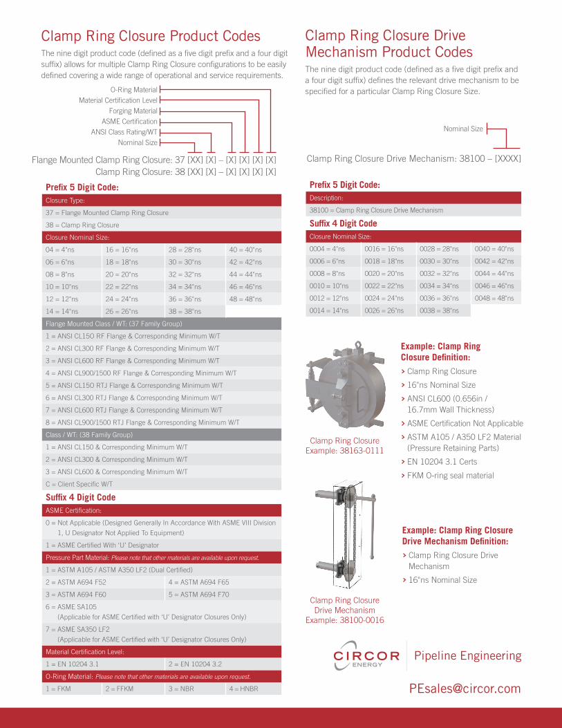
Clamp Ring Closure Product Codes The nine digit product code (defined as a five digit prefix and a four digit suffix) allows for multiple Clamp Ring Closure configurations to be easily defined covering a wide range of operational and service requirements.

Clamp Ring Closure Drive Mechanism: 38100 – [XXXX]

Nominal Size

Clamp Ring Closure Drive Mechanism Product Codes The nine digit product code (defined as a five digit prefix and a four digit suffix) defines the relevant drive mechanism to be specified for a particular Clamp Ring Closure Size.

Prefix 5 Digit Code:Description:

38100 = Clamp Ring Closure Drive Mechanism

Suffix 4 Digit CodeClosure Nominal Size:

0004 = 4"ns 0016 = 16"ns 0028 = 28"ns 0040 = 40"ns

0006 = 6"ns 0018 = 18"ns 0030 = 30"ns 0042 = 42"ns

0008 = 8"ns 0020 = 20"ns 0032 = 32"ns 0044 = 44"ns

0010 = 10"ns 0022 = 22"ns 0034 = 34"ns 0046 = 46"ns

0012 = 12"ns 0024 = 24"ns 0036 = 36"ns 0048 = 48"ns

0014 = 14"ns 0026 = 26"ns 0038 = 38"ns

Example: Clamp Ring Closure Drive Mechanism Definition:

Clamp Ring Closure Drive Mechanism

16"ns Nominal Size

Clamp Ring Closure Example: 38163-0111

Example: Clamp Ring Closure Definition:

Clamp Ring Closure

16"ns Nominal Size

ANSI CL600 (0.656in / 16.7mm Wall Thickness)

ASME Certification Not Applicable

ASTM A105 / A350 LF2 Material (Pressure Retaining Parts)

EN 10204 3.1 Certs

FKM O-ring seal material

Clamp Ring Closure Drive Mechanism

Example: 38100-0016

[email protected]

Prefix 5 Digit Code:Closure Type:

37 = Flange Mounted Clamp Ring Closure

38 = Clamp Ring Closure

Closure Nominal Size:

04 = 4"ns 16 = 16"ns 28 = 28"ns 40 = 40"ns

06 = 6"ns 18 = 18"ns 30 = 30"ns 42 = 42"ns

08 = 8"ns 20 = 20"ns 32 = 32"ns 44 = 44"ns

10 = 10"ns 22 = 22"ns 34 = 34"ns 46 = 46"ns

12 = 12"ns 24 = 24"ns 36 = 36"ns 48 = 48"ns

14 = 14"ns 26 = 26"ns 38 = 38"ns

Flange Mounted Class / WT: (37 Family Group)

1 = ANSI CL15O RF Flange & Corresponding Minimum W/T

2 = ANSI CL300 RF Flange & Corresponding Minimum W/T

3 = ANSI CL600 RF Flange & Corresponding Minimum W/T

4 = ANSI CL900/1500 RF Flange & Corresponding Minimum W/T

5 = ANSI CL15O RTJ Flange & Corresponding Minimum W/T

6 = ANSI CL300 RTJ Flange & Corresponding Minimum W/T

7 = ANSI CL600 RTJ Flange & Corresponding Minimum W/T

8 = ANSI CL900/1500 RTJ Flange & Corresponding Minimum W/T

Class / WT: (38 Family Group)

1 = ANSI CL150 & Corresponding Minimum W/T

2 = ANSI CL300 & Corresponding Minimum W/T

3 = ANSI CL600 & Corresponding Minimum W/T

C = Client Specific W/T

Suffix 4 Digit CodeASME Certification:

0 = Not Applicable (Designed Generally In Accordance With ASME VIII Division

1, U Designator Not Applied To Equipment)

1 = ASME Certified With ‘U’ Designator

Pressure Part Material: Please note that other materials are available upon request.

1 = ASTM A105 / ASTM A350 LF2 (Dual Certified)

2 = ASTM A694 F52 4 = ASTM A694 F65

3 = ASTM A694 F60 5 = ASTM A694 F70

6 = ASME SA105

(Applicable for ASME Certified with ‘U’ Designator Closures Only)

7 = ASME SA350 LF2

(Applicable for ASME Certified with ‘U’ Designator Closures Only)

Material Certification Level:

1 = EN 10204 3.1 2 = EN 10204 3.2

O-Ring Material: Please note that other materials are available upon request.

1 = FKM 2 = FFKM 3 = NBR 4 = HNBR


Recommended