Page 1
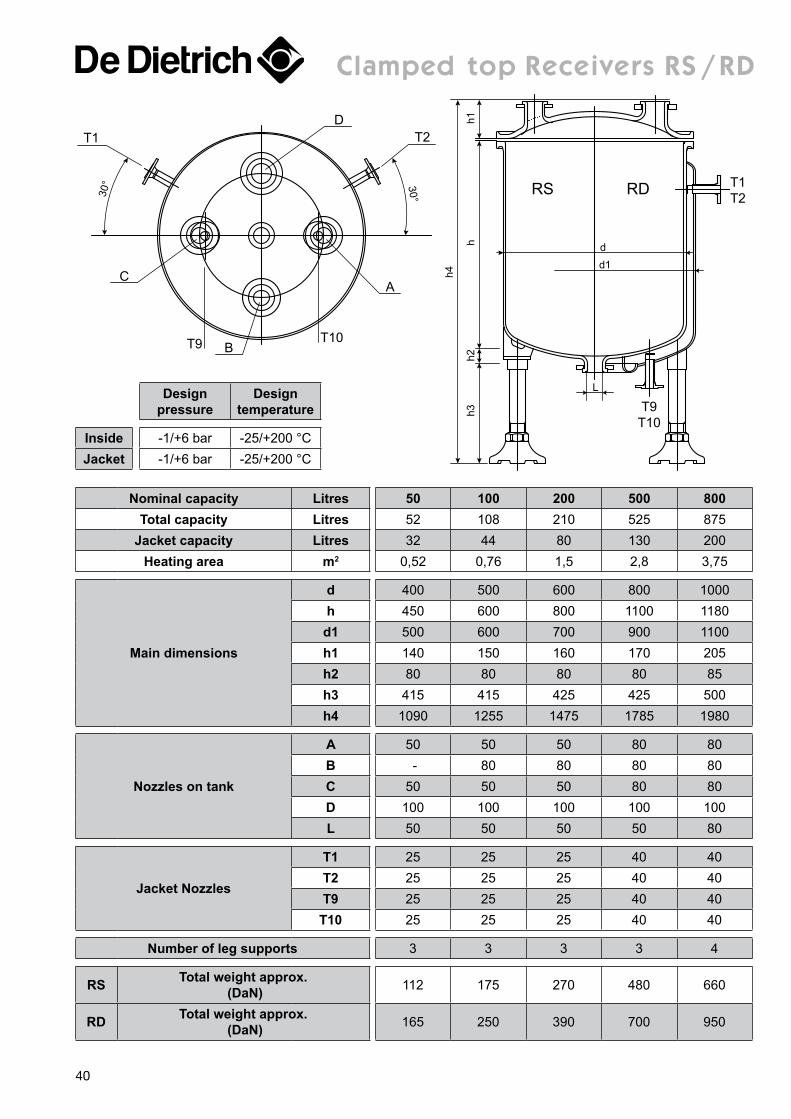
clamped top receivers rs / rD
T1
30°
DT2
C
T9 BT10
A
30° RDRS
h1h2
h
h4
h3
T1T2
T9T10
d
L
d1
Nominal capacity Litres 50 100 200 500 800Total capacity Litres 52 108 210 525 875
Jacket capacity Litres 32 44 80 130 200Heating area m2 0,52 0,76 1,5 2,8 3,75
Main dimensions
d 400 500 600 800 1000h 450 600 800 1100 1180
d1 500 600 700 900 1100h1 140 150 160 170 205h2 80 80 80 80 85h3 415 415 425 425 500h4 1090 1255 1475 1785 1980
Nozzles on tank
A 50 50 50 80 80B - 80 80 80 80C 50 50 50 80 80D 100 100 100 100 100L 50 50 50 50 80
Jacket Nozzles
T1 25 25 25 40 40T2 25 25 25 40 40T9 25 25 25 40 40
T10 25 25 25 40 40
Number of leg supports 3 3 3 3 4
RS Total weight approx. (DaN) 112 175 270 480 660
RD Total weight approx. (DaN) 165 250 390 700 950
Design pressure
Design temperature
Inside -1/+6 bar -25/+200 °CJacket -1/+6 bar -25/+200 °C
40
Page 2
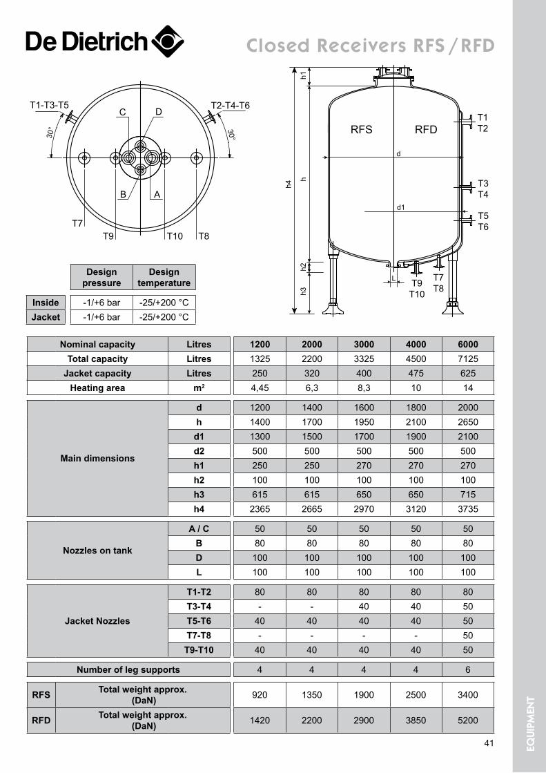
closed receivers rfs / rfD
RFDRFS
h1h2
h
h4
h3
T1T2
T9T10
d
d1
T3T4
T5T6
T7T8
L
30°30°
D
T7T9 T10 T8
T2-T4-T6T1-T3-T5
B
C
A
Nominal capacity Litres 1200 2000 3000 4000 6000Total capacity Litres 1325 2200 3325 4500 7125
Jacket capacity Litres 250 320 400 475 625Heating area m2 4,45 6,3 8,3 10 14
Main dimensions
d 1200 1400 1600 1800 2000h 1400 1700 1950 2100 2650
d1 1300 1500 1700 1900 2100d2 500 500 500 500 500h1 250 250 270 270 270h2 100 100 100 100 100h3 615 615 650 650 715h4 2365 2665 2970 3120 3735
Nozzles on tank
A / C 50 50 50 50 50B 80 80 80 80 80D 100 100 100 100 100L 100 100 100 100 100
Jacket Nozzles
T1-T2 80 80 80 80 80T3-T4 - - 40 40 50T5-T6 40 40 40 40 50T7-T8 - - - - 50
T9-T10 40 40 40 40 50
Number of leg supports 4 4 4 4 6
RFS Total weight approx. (DaN) 920 1350 1900 2500 3400
RFD Total weight approx. (DaN) 1420 2200 2900 3850 5200
Design pressure
Design temperature
Inside -1/+6 bar -25/+200 °CJacket -1/+6 bar -25/+200 °C
41 equi
pmen
t
Page 3
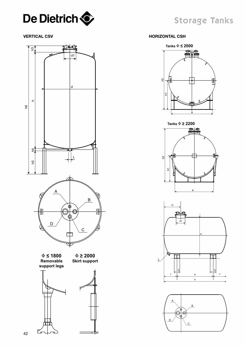
storage tanks
d
h3h4
h
h6
h5
d1
L
B
D
C
A
d1
b
f e
h
f
b
m
d
L
B
D
C
A
Φ ≤ 1800Removable
support legs
Φ ≥ 2000Skirt support
a
h1h2
Tanks Φ ≤ 2000
a
h1
h2
Tanks Φ ≥ 2200
Vertical cSV horizontal cSh
42
Page 4
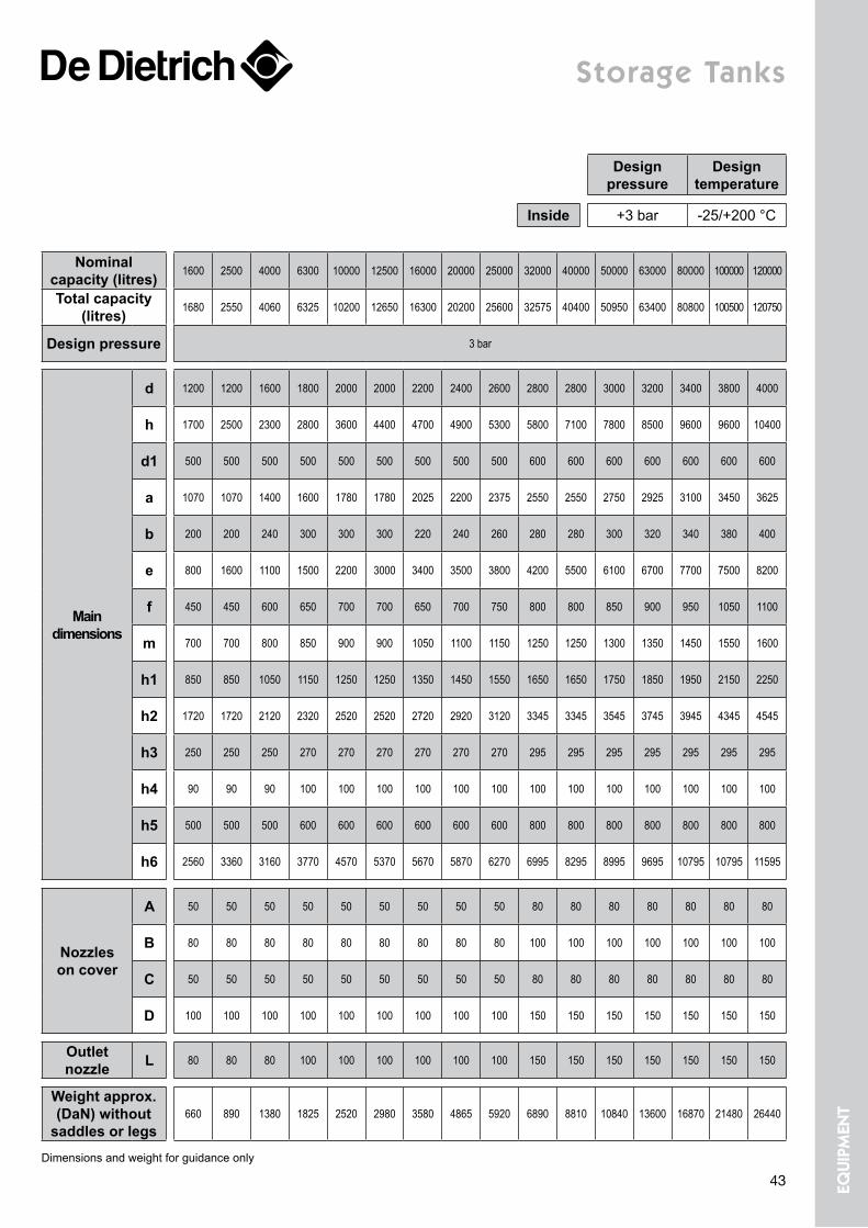
storage tanks
Nominal capacity (litres) 1600 2500 4000 6300 10000 12500 16000 20000 25000 32000 40000 50000 63000 80000 100000 120000
Total capacity (litres) 1680 2550 4060 6325 10200 12650 16300 20200 25600 32575 40400 50950 63400 80800 100500 120750
Design pressure 3 bar
Main dimensions
d 1200 1200 1600 1800 2000 2000 2200 2400 2600 2800 2800 3000 3200 3400 3800 4000
h 1700 2500 2300 2800 3600 4400 4700 4900 5300 5800 7100 7800 8500 9600 9600 10400
d1 500 500 500 500 500 500 500 500 500 600 600 600 600 600 600 600
a 1070 1070 1400 1600 1780 1780 2025 2200 2375 2550 2550 2750 2925 3100 3450 3625
b 200 200 240 300 300 300 220 240 260 280 280 300 320 340 380 400
e 800 1600 1100 1500 2200 3000 3400 3500 3800 4200 5500 6100 6700 7700 7500 8200
f 450 450 600 650 700 700 650 700 750 800 800 850 900 950 1050 1100
m 700 700 800 850 900 900 1050 1100 1150 1250 1250 1300 1350 1450 1550 1600
h1 850 850 1050 1150 1250 1250 1350 1450 1550 1650 1650 1750 1850 1950 2150 2250
h2 1720 1720 2120 2320 2520 2520 2720 2920 3120 3345 3345 3545 3745 3945 4345 4545
h3 250 250 250 270 270 270 270 270 270 295 295 295 295 295 295 295
h4 90 90 90 100 100 100 100 100 100 100 100 100 100 100 100 100
h5 500 500 500 600 600 600 600 600 600 800 800 800 800 800 800 800
h6 2560 3360 3160 3770 4570 5370 5670 5870 6270 6995 8295 8995 9695 10795 10795 11595
Nozzles on cover
A 50 50 50 50 50 50 50 50 50 80 80 80 80 80 80 80
B 80 80 80 80 80 80 80 80 80 100 100 100 100 100 100 100
C 50 50 50 50 50 50 50 50 50 80 80 80 80 80 80 80
D 100 100 100 100 100 100 100 100 100 150 150 150 150 150 150 150
Outlet nozzle L 80 80 80 100 100 100 100 100 100 150 150 150 150 150 150 150
Weight approx. (DaN) without
saddles or legs660 890 1380 1825 2520 2980 3580 4865 5920 6890 8810 10840 13600 16870 21480 26440
Dimensions and weight for guidance only
Design pressure
Design temperature
Inside +3 bar -25/+200 °C
43 equi
pmen
t
Page 5
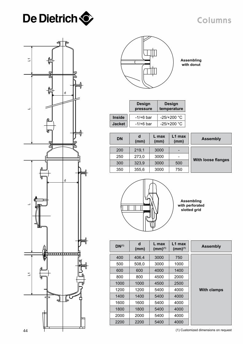
columns
DN d (mm)
L max (mm)
L1 max (mm) Assembly
200 219,1 3000 -
With loose flanges250 273,0 3000 -300 323,9 3000 500350 355,6 3000 750
L1
d
d
L1L
L
Design pressure
Design temperature
Inside -1/+6 bar -25/+200 °CJacket -1/+6 bar -25/+200 °C
Assembling with donut
Assembling with perforated
slotted grid
DN(1) d (mm)
L max (mm)(1)
L1 max (mm)(1) Assembly
400 406,4 3000 750
With clamps
500 508,0 3000 1000600 600 4000 1400800 800 4500 20001000 1000 4500 25001200 1200 5400 40001400 1400 5400 40001600 1600 5400 40001800 1800 5400 40002000 2000 5400 40002200 2200 5400 4000
(1) Customized dimensions on request44
Page 6
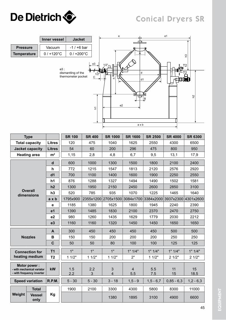
conical Dryers sr
e
e3
e1
a x b
e2
d
A
d1
h3
T2
T21/2"
1/2"
h1
h
h2B
C
Type SR 100 SR 400 SR 1000 SR 1600 SR 2500 SR 4000 SR 6300Total capacity Litres 120 475 1040 1625 2550 4300 6500
Jacket capacity Litres 54 60 200 296 475 800 950Heating area m2 1,15 2,8 4,8 6,7 9,5 13,1 17,9
Overall dimensions
d 600 1000 1300 1500 1800 2100 2400h 772 1215 1547 1813 2120 2576 2920d1 700 1100 1400 1600 1900 2250 2550h1 876 1288 1327 1494 1490 1502 1581h2 1300 1950 2150 2450 2600 2850 3100h3 520 785 935 1070 1225 1465 1640
a x b 1795x900 2355x1200 2705x1500 3084x1700 3384x2000 3937x2300 4301x2600e 1185 1380 1625 1800 1945 2240 2390e1 1390 1485 1830 2100 2370 2470 2750e2 980 1260 1435 1629 1779 2030 2212e3 1160 1160 1320 1450 1450 1650 1650
NozzlesA 300 450 450 450 450 500 500B 150 150 200 200 200 250 250C 50 50 80 100 100 125 125
Connection for heating medium
T1 1" 1" 1" 1" 1/4" 1" 1/4" 1" 1/4" 1" 1/4"T2 1 1/2" 1 1/2" 1 1/2" 2" 1 1/2" 2 1/2" 2 1/2"
Motor power : - with mechanical variator - with frequency inverter
kW
1.5 2.2
2.2 3
3 4
4
5.5
5.5 7.5
11 15
15
18.5
Speed variation R.P.M. 5 - 30 5 - 30 3 - 18 1,5 - 9 1,5 - 6,7 0,85 - 6,3 1,2 - 6,3
WeightTotal
Kg1900 2100 3300 4300 5800 8300 11000
Vessel only 1380 1895 3100 4900 6600
e3 :dismantling of the thermometer pocket
Inner vessel Jacket
Pressure Vacuum -1 / +6 barTemperature 0 / +120°C 0 / +200°C
45 equi
pmen
t
Page 7
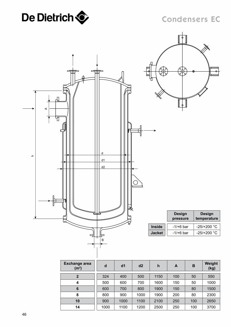
condensers ec
Exchange area (m2) d d1 d2 h A B Weight
(kg)
2 324 400 500 1150 100 50 5504 500 600 700 1600 150 50 10006 600 700 800 1900 150 80 15008 800 900 1000 1900 200 80 2300
10 900 1000 1100 2100 250 100 265014 1000 1100 1200 2500 250 100 3700
d
B
d1
d2
h
A
Design pressure
Design temperature
Inside -1/+6 bar -25/+200 °CJacket -1/+6 bar -25/+200 °C
46
Page 8
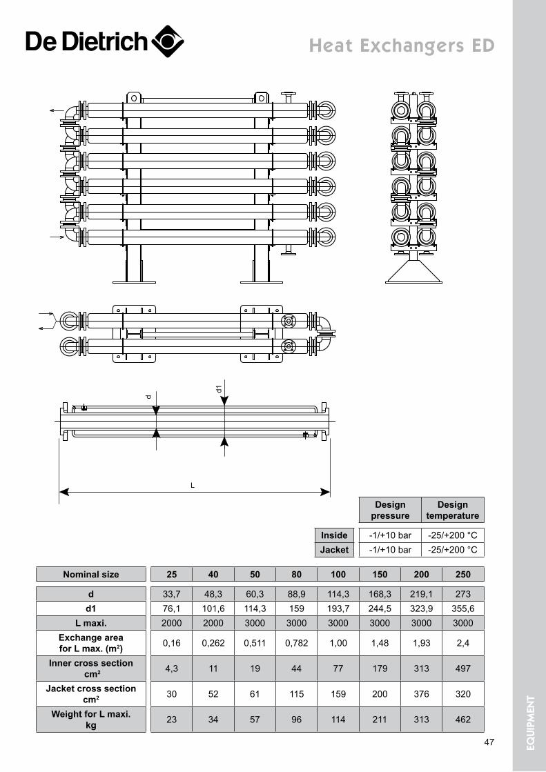
Heat exchangers eD
Nominal size 25 40 50 80 100 150 200 250
d 33,7 48,3 60,3 88,9 114,3 168,3 219,1 273d1 76,1 101,6 114,3 159 193,7 244,5 323,9 355,6
L maxi. 2000 2000 3000 3000 3000 3000 3000 3000Exchange area for L max. (m2) 0,16 0,262 0,511 0,782 1,00 1,48 1,93 2,4
Inner cross section cm2 4,3 11 19 44 77 179 313 497
Jacket cross section cm2 30 52 61 115 159 200 376 320
Weight for L maxi. kg 23 34 57 96 114 211 313 462
d
d1
L
Design pressure
Design temperature
Inside -1/+10 bar -25/+200 °CJacket -1/+10 bar -25/+200 °C
47 equi
pmen
t
Page 9
Shell Header Tube Type Gasket Flange Passe DN Area InstallationE Stainless steel E Stainless steel A Tantalum R Single gasket C Chemraz E Stainless steel 1 Simple 3 80 H HorizontalG Boro 3.3 M Steel / Epoxy C Hastelloy S Safety chamber K Kalrez M Steel / Epoxy 2 Double 4 100 V VerticalM Steel / Epoxy T Steel / PTFE D Titanium W Double gasket N NBR C Plastic 3 Triple 6 150
GEBoro 3.3 + Sectrans coating
V Steel / Enamel E Stainless steel P Perlast 8 200G Boro 3.3 G Boro 3,3 R Viton / FEP 9 225
I SIC 12 30018 450
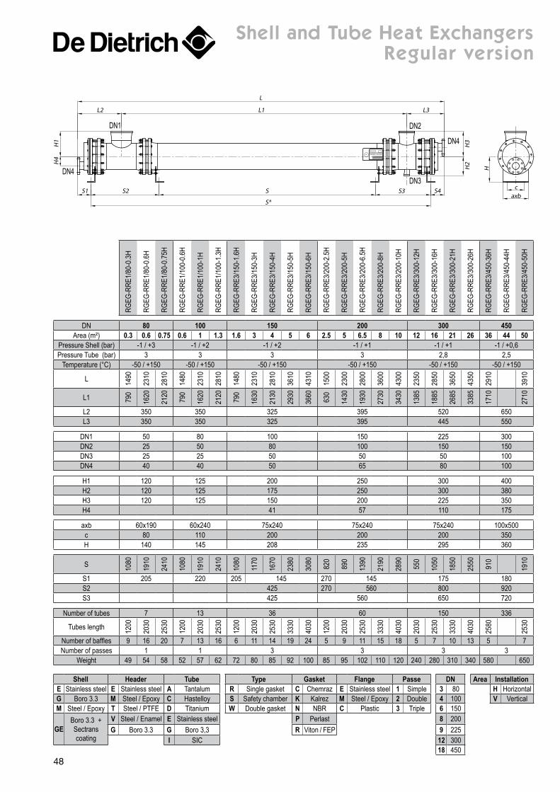
shell and tube Heat exchangers regular version
DN4
DN1
DN3
DN4
DN2
L
L1L2 L3
H1
H4
H2
H3
axbc
H
SS2 S3S1 S4
S*
RGEG
-RRE
1/80
-0.3
H
RGEG
-RRE
1/80
-0.6
H
RGEG
-RRE
1/80
-0.7
5H
RGEG
-RRE
1/10
0-0.
6H
RGEG
-RRE
1/10
0-1H
RGEG
-RRE
1/10
0-1.
3H
RGEG
-RRE
3/15
0-1.
6H
RGEG
-RRE
3/15
0-3H
RGEG
-RRE
3/15
0-4H
RGEG
-RRE
3/15
0-5H
RGEG
-RRE
3/15
0-6H
RGEG
-RRE
3/20
0-2.
5H
RGEG
-RRE
3/20
0-5H
RGEG
-RRE
3/20
0-6.
5H
RGEG
-RRE
3/20
0-8H
RGEG
-RRE
3/20
0-10
H
RGEG
-RRE
3/30
0-12
H
RGEG
-RRE
3/30
0-16
H
RGEG
-RRE
3/30
0-21
H
RGEG
-RRE
3/30
0-26
H
RGEG
-RRE
3/45
0-36
H
RGEG
-RRE
3/45
0-44
H
RGEG
-RRE
3/45
0-50
H
DN 80 100 150 200 300 450Area (m²) 0.3 0.6 0.75 0.6 1 1.3 1.6 3 4 5 6 2.5 5 6.5 8 10 12 16 21 26 36 44 50
Pressure Shell (bar) -1 / +3 -1 / +2 -1 / +2 -1 / +1 -1 / +1 -1 / +0,6Pressure Tube (bar) 3 3 3 3 2,8 2,5
Temperature (°C) -50 / +150 -50 / +150 -50 / +150 -50 / +150 -50 / +150 -50 / +150
L 1490
2310
2810
1480
2310
2810
1480
2310
2810
3610
4310
1500
2300
2800
3600
4300
2350
2850
3650
4350
2910
3910
L1 790
1620
2120
790
1620
2120
790
1630
2130
2930
3660
630
1430
1930
2730
3430
1385
1885
2685
3385
1710
2710
L2 350 350 325 395 520 650L3 350 350 325 395 445 550
DN1 50 80 100 150 225 300DN2 25 50 80 100 150 150DN3 25 25 50 50 50 100DN4 40 40 50 65 80 100
H1 120 125 200 250 300 400H2 120 125 175 250 300 380H3 120 125 150 200 225 350H4 41 57 110 175
axb 60x190 60x240 75x240 75x240 75x240 100x500c 80 110 200 200 200 350H 140 145 208 235 295 360
S 1080
1910
2410
1080
1910
2410
1080
1170
1670
2380
3080
820
890
1390
2190
2890
550
1050
1850
2550
910
1910
S1 205 220 205 145 270 145 175 180S2 425 270 560 800 920S3 425 560 650 720
Number of tubes 7 13 36 60 150 336
Tubes length 1200
2030
2530
1200
2030
2530
1200
2030
2530
3330
4030
1200
2030
2530
3330
4030
2030
2530
3330
4030
2580
2530
Number of baffles 9 16 20 7 13 16 6 11 14 19 24 5 9 11 15 18 5 7 10 13 5 7Number of passes 1 1 3 3 3 3
Weight 49 54 58 52 57 62 72 80 85 92 100 85 95 102 110 120 240 280 310 340 580 650
48
Page 10
PVEI
-RRE
1/80
-0.3
H
PVEI
-RRE
1/80
-0.6
H
PVEI
-RRE
1/80
-0.7
5H
PVEI
-RRE
1/10
0-0.
3H
PVEI
-RRE
1/10
0-0.
6H
PVEI
-RRE
1/10
0-1H
PVEI
-RRE
1/10
0-1.
3H
PVEI
-RRE
3/15
0-1.
6H
PVEI
-RRE
3/15
0-3H
PVEI
-RRE
3/15
0-4H
PVEI
-RRE
3/15
0-5H
PVEI
-RRE
3/15
0-6H
PVEI
-RRE
3/20
0-2.
5H
PVEI
-RRE
3/20
0-5H
PVEI
-RRE
3/20
0-6.
5H
PVEI
-RRE
3/20
0-8H
PVEI
-RRE
3/14
-10H
PVEI
-RRE
3/25
0-5H
PVEI
-RRE
3/25
0-9H
PVEI
-RRE
3/25
0-11
.5H
PVEI
-RRE
3/25
0-15
H
PVEI
-RRE
3/25
0-18
H
PVEI
-RRE
3/30
0-12
H
PVEI
-RRE
3/30
0-16
H
PVEI
-RRE
3/30
0-21
H
PVEI
-RRE
3/30
0-26
H
PVEI
-RRE
3/40
0-22
H
PVEI
-RRE
3/40
0-28
H
PVEI
-RRE
3/40
0-44
H
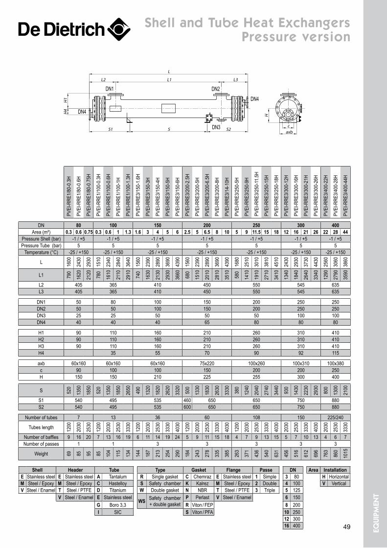
DN 80 100 150 200 250 300 400Area (m²) 0.3 0.6 0.75 0.3 0.6 1 1.3 1.6 3 4 5 6 2.5 5 6.5 8 10 5 9 11.5 15 18 12 16 21 26 22 28 44
Pressure Shell (bar) -1 / +5 -1 / +5 -1 / +5 -1 / +5 -1 / +5 -1 / +5 -1 / +5Pressure Tube (bar) 5 5 5 5 5 5 5
Temperature (°C) -25 / +150 -25 / +150 -25 / +150 -25 / +150 -25 / +150 -25 / +150 -25 / +150
L 1600
2430
2930
1510
2340
2840
3640
1560
2390
2890
3690
4390
1560
2390
2890
3690
4390
1680
2510
3010
3810
4510
2430
2930
3730
4430
2560
3060
3860
L1 790
1620
2120
780
1610
2110
2910
740
1630
2130
2930
3660
680
1510
2010
2810
3510
580
1410
1910
2710
3410
1340
1840
2640
3340
1290
2790
3590
L2 405 365 410 450 550 545 635L3 405 365 410 450 550 545 635
DN1 50 80 100 150 200 250 250DN2 50 50 100 150 200 250 250DN3 25 25 50 50 50 100 100DN4 40 40 40 65 80 80 80
H1 90 110 160 210 260 310 410H2 90 110 160 210 260 310 410H3 90 110 160 210 260 310 410H4 35 55 70 90 92 115
axb 60x160 60x160 60x160 75x220 100x260 100x310 100x380c 90 100 100 150 200 200 250H 150 150 210 225 255 300 400
S 520
1350
1850
520
1350
1850
2650
490
1320
1820
2620
3320
500
1330
1830
2630
3330
380
1240
2040
2740
3440
930
1430
2230
2930
800
1300
2100
S1 540 495 535 460 650 650 750 880S2 540 495 535 600 650 650 750 880
Number of tubes 7 13 36 60 108 150 225/240
Tubes length 1200
2030
2530
1200
2030
2530
3330
1200
2030
2530
3330
4030
1200
2030
2530
3330
4030
1200
2030
2530
3330
4030
2030
2530
3330
4030
2030
2530
3330
Number of baffles 9 16 20 7 13 16 19 6 11 14 19 24 5 9 11 15 18 4 7 9 13 15 5 7 10 13 4 6 7Number of passes 1 1 3 3 3 3 3
Weight 69 85 95 85 104
115
134
144
187
213
254
290
184
243
278
335
385
263
371
436
540
631
456
516
612
696
763
860
1015
Shell Header Tube Type Gasket Flange Passe DN Area InstallationE Stainless steel E Stainless steel A Tantalum R Single gasket C Chemraz E Stainless steel 1 Simple 3 80 H HorizontalM Steel / Epoxy M Steel / Epoxy C Hastelloy S Safety chamber K Kalrez M Steel / Epoxy 2 Double 4 100 V VerticalV Steel / Enamel T Steel / PTFE D Titanium W Double gasket N NBR T Steel / PTFE 3 Triple 5 125
V Steel / Enamel E Stainless steelWS Safety chamber
+ double gasketP Perlast V Steel / Enamel 6 150
G Boro 3,3 R Viton / FEP 8 200I SIC S Viton / PFA 10 250
12 30016 400
shell and tube Heat exchangers pressure version
DN1
DN4
DN3
DN2
DN4
L1
L
L2 L3
H4
H1
SS1 S2caxb
H
49 equi
pmen
t
Page 11
pipes & fittings
C
DE
L
D
D mm 25 40 50 80 100 150 200 250 300
L mm Weight kg
100 3,1 4,8 6,3 8,1 10,6150 3,4 5,2 6,6 10,6 12,6 21 30 40200 3,5 5,4 7 11,2 13,4 22,5 32 42 53250 3,7 5,6 7,2 11,8 14,2 24 34 45 53300 3,8 5,8 7,5 12,4 15 26 36 48 60,5500 4,6 6,6 8,6 13,5 18 31 45 61 75800 5 8 10,5 18 23 40 58 80 971000 5,5 9 11,5 20 26 45 66 92 1121500 8 11 14 26 35 60 88 123 1491800 10 13 16 30 40 68 100 143 1712000 11,1 14,6 17 32 44 74 110 155 186
2500 21 38 52 89 132 187 223
3000 25,5 44 60 104 155 218 260
StraiGht PiPeS
D mm C mm 25 40 50 80 100 150 200 250
40E mm 35Weight kg 4
5035 354,9 4,7
8035 35 357,1 6,8 6,7
10045 45 45 45
10,9 10,6 10,5 9,6
15045 45 45 45 4519 18,6 18 17,2 16,3
20045 45 45 45 45 45
27,5 27 26 24 23 21
25045 45 45 45 45 45 45
37,2 36,8 36 34 33 29 24
30045 45 45 45 45 45 45 4549 47 46 44 43 40 32 30
reDUcinG FlanGeS
A
D
B
D mm 25 40 50 80 100 150 200 250 300
A mm 180 210 230 270 310 390 520 630 700Weight kg 5,4 8,6 12 19 26 45 70 99 120
teeS
50
Page 12
D1 mm
D2 mm 25 40 50 80 100 150 200 250
50
A mm 230 230B mm 100 110Weight
kg 9 10
80270 270 270115 125 13013,5 15 16
100310 310 310 310125 135 140 15014,5 17 19 21
150390 390 390 390 390155 165 170 180 18530 32 33 34 35
200520 520 520 520 520 520185 195 200 210 215 22548 49,5 51 52 53 58
250630 630 630 630 630 630 630230 240 245 255 260 270 27565 66 68 72 76 81 85
300700 700 700 700 700 700 700 700290 300 305 315 320 330 335 340101 106 111 116 120 125 129 137
reDUcinG teeS
pipes & fittings
D1
D1
D2
D2
A
A
D1 mm
D2 mm 25 40 50 80 100 150 200 250
50A mm 140 140Weight
kg 5 5,8
80160 160 1604,25 6,8 8,5
100175 175 175 175
5 8 10 11,4
150225 225 22510,6 14,8 18,5
200250 250 250 25015,6 20,8 26 30
250300 300 300 30028 35 39 44
300350 350 350 35032 48 52 57
reDUcerS
A
B
D B = A2
D mm 25 40 50 80 100 150 200 250 300
A mm 180 210 230 270 310 390 520 630 700Weight kg 7 11,5 16 25 33 58 88 126 148
croSSeS
B
A
D1
51 equi
pmen
t
Page 13
pipes & fittings
E
D
C
D mm 25 40 50 80 100 150 200 250 300C mm 68 88 102 138 158 212 268 320 370
E mm (on enamel) Weight kg
15 1,5 1,7 1,8 2,2 2,1 2,1 2,4 2,4 2,420 2 2,3 2,4 3 2,7 2,9 3,2 3,2 3,225 2,5 2,9 3,1 3,7 3,4 3,6 4 4,1 430 3,1 3,5 3,7 4,4 4,1 4,3 4,8 4,9 4,940 4,1 4,1 4,6 5,9 5,5 5,7 6,4 6,5 6,450 6,1 6,9 7,2 8,1 8,1 8
aDaPterS
D
A
A
D mm 25 40 50 80 100 150 200 250 300
A mm 60 70 80 95 105 150 180 220 260Weight
kg 3,3 5,3 7 11 14 24 39 57 73
45° elBoWS
D
A
A
D mm 25 40 50 80 100 150 200 250 300
A mm 90 105 115 135 155 195 260 315 350Weight
kg 3,5 5,6 7,5 12 15,5 25 43 64 82
90° elBoWS
ED
D mm 25 40 50 80 100 150 200 250 300
E mm 16 16 18 20 20 22 24 26 26Weight
kg 1,3 2,2 3 5 6 11 17 25 28,5
BlinD FlanGeS
52
Page 14
A
d
B
C
D
F
G
E
DN 25 40 50 80 100 150 200 250 300
A 48 66 78 108 135 188 238 294 344B 70 90 104 140 160 216 271 324 373C 85 110 125 160 180 240 295 350 400D 115 150 165 200 220 285 340 395 445E 18 18 18 20 20 24 26 28 32F 16 16 16 18 18 21 23 25 29G 14 18 18 18 18 22 22 22 22
N x holes 4 4 4 8 8 8 8 12 12Weight kg 1 1,6 2 3 3 5,5 7,6 10,5 14
looSe FlanGeS Pn 10
Assembly by means of loose flanges drilled to PN10 standard or alternatively to the ANSI 150 lbs standard.
tightening torque on bolts
See technical sheet gaskets
Loose flanges
looSe FlanGeS anSi 150 lBS
DN 1" 1 1/2" 2" 3" 4" 6" 8" 10" 12" 16"
A 46 63 79 112 136 189 238 294 357 447,7B 63 82,5 104 137 160 218 273 327 384 474C 79 98,5 120,5 152,5 190,5 241 298 362 432 539,7D 108 127 153 190 229 280 343 406 483 596,9E 14 14 16 18 20 25 28 32 35 50F 12 12 14 16 17 22 25 29 32 46G 15 15 18 18 18 22 22 25 25 28,6
N x holes 4 4 4 4 8 8 8 12 12 16Weight kg 0,71 0,9 1,5 2,4 3,8 5,3 8,5 13,15 21 44
53 equi
pmen
t
Page 15
GasketsTightening torque*
Insert
UtilisationNominal
sizeOutside diameter
Inside diameter Clamps or bolts Aramid
fiber Graphite
mm mm mm Number ø Nm Nm
Covers CE
800 875 787 24 M24 220 1801000 1075 982 28 M24 250 2001200 1275 1177 32 M24 280 2201400 1485 1382 40 M24 270 220
Covers
AE
400 467 398 12 M20 150 120508 565 497 12 M20 190 150600 655 582 16 M20 170 140700 775 687 20 M2 240 190
RS
800 875 787 24 M24 220 1801000 1075 982 28 M24 250 2001200 1275 1177 32 M24 280 2201400 1485 1382 40 M24 270 220
RD1600 1695 1582 44 M24 280 2301800 1885 1782 52 M24 270 2102000 2085 1982 64 M24 240 190
Covers RFS / RFD CSH / CSV
500 605 522 16 M20 180 150600 705 622 20 M20 170 160
Handhole100 162 113 4 M24 110 90150 212 163 4 M24 140 120200 270 213 6 M24 140 120
Manhole
250 320 263 6 M24 170 140350 / 450 430 / 530 367 / 467 10 M24 240 190
500 605 522 12 M24 290 230600 705 622 16 M24 250 200
Nozzles
25 70 30 4 M12 20 2032 82 38 4 M16 40 3040 92 47 4 M16 40 3050 104 59 4 M16 50 40
Pipes
80 140 89 8 M16 40 30100 162 113 8 M16 50 40125 190 138 8 M16 60 50150 212 163 8 M20 70 60200 270 213 8 M20 110 90
Valves
250 328 263 12 M20 100 80300 378 313 12 M20 120 90350 430 370 16 M20 90 80400 490 419 16 M24 150 120
Covers SR435 512 450 8 M24 270 220450 530 457 8 M24 330 260500 605 522 12 M24 290 230
Sight glass50 102 68 4 M16 40 3080 127 88 8 M16 30 30
100 152 113 8 M16 40 30
* These torques correspond to greased threadings - Design pressure 6 bar
Aramid fiber based layer
CorrugatedStainless steel insert
PTFE - envelope
gaskets
54
Page 16
clamps
D
D
d
C
B
A
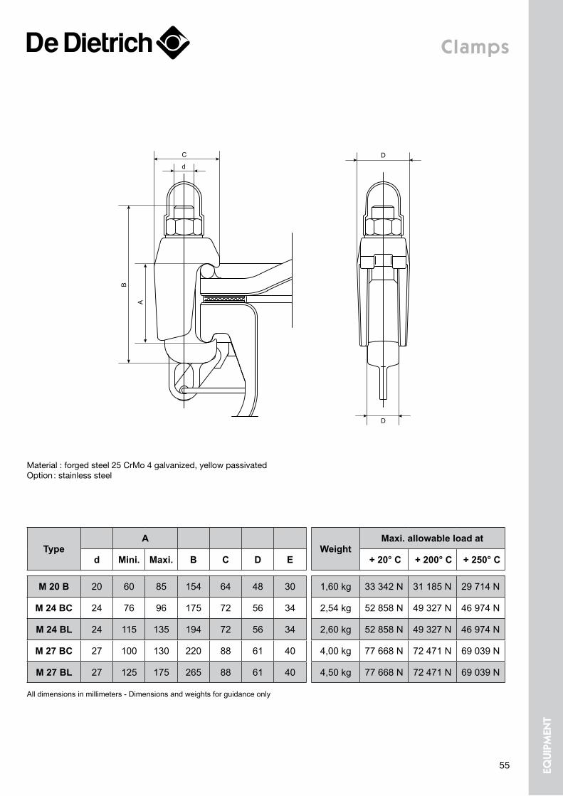
All dimensions in millimeters - Dimensions and weights for guidance only
TypeA
WeightMaxi. allowable load at
d Mini. Maxi. B C D E + 20° C + 200° C + 250° C
M 20 B 20 60 85 154 64 48 30 1,60 kg 33 342 N 31 185 N 29 714 N
M 24 BC 24 76 96 175 72 56 34 2,54 kg 52 858 N 49 327 N 46 974 N
M 24 BL 24 115 135 194 72 56 34 2,60 kg 52 858 N 49 327 N 46 974 N
M 27 BC 27 100 130 220 88 61 40 4,00 kg 77 668 N 72 471 N 69 039 N
M 27 BL 27 125 175 265 88 61 40 4,50 kg 77 668 N 72 471 N 69 039 N
Material : forged steel 25 CrMo 4 galvanized, yellow passivatedOption : stainless steel
55 equi
pmen
t
Page 17
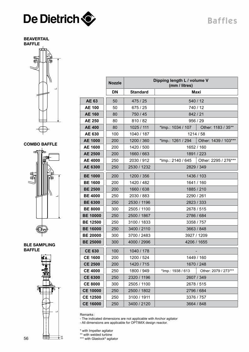
Baffles
L
Nozzle Dipping length L / volume V (mm / litres)
DN Standard Maxi
AE 63 50 475 / 25 540 / 12AE 100 50 675 / 25 740 / 12AE 160 80 750 / 45 842 / 21AE 250 80 810 / 82 956 / 29AE 400 80 1025 / 111 *Imp.: 1034 / 107 Other: 1183 / 35**AE 630 100 1040 / 187 1214 / 58AE 1000 200 1200 / 360 *Imp.: 1261 / 294 Other: 1439 / 103***AE 1600 200 1420 / 500 1652 / 160AE 2500 200 1660 / 663 1891 / 223AE 4000 250 2030 / 912 *Imp.: 2140 / 645 Other: 2295 / 276***AE 6300 250 2530 / 1232 2829 / 349
BE 1000 200 1200 / 356 1436 / 103BE 1600 200 1420 / 482 1641 / 160BE 2500 200 1660 / 638 1885 / 210BE 4000 250 2030 / 883 2290 / 261BE 6300 250 2530 / 1196 2823 / 333BE 8000 300 2505 / 1100 2678 / 515BE 10000 250 2500 / 1867 2786 / 684BE 12500 250 3100 / 1833 3358 / 757BE 16000 250 3400 / 2110 3663 / 848BE 20000 300 3700 / 2483 3927 / 1209BE 25000 300 4000 / 2996 4206 / 1655
CE 630 100 1040 / 178 -CE 1600 200 1200 / 524 1449 / 160CE 2500 200 1420 / 715 1670 / 248CE 4000 250 1800 / 949 *Imp.: 1938 / 613 Other: 2079 / 273***
CE 6300 250 2320 / 1196 2607 / 349CE 8000 300 2505 / 1100 2678 / 515CE 10000 250 2500 / 1802 2796 / 684CE 12500 250 3100 / 1911 3376 / 757CE 16000 250 3400 / 2120 3664 / 848
LL
4530
Remarks :- The indicated dimensions are not applicable with Anchor agitator- All dimensions are applicable for OPTIMIX design reactor.
* with Impeller agitator** with welded turbine*** with Glaslock® agitator
BeaVertail BaFFle
Ble SamPlinG BaFFle
comBo BaFFle
56
Page 18
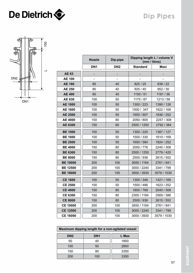
Dip pipes
Nozzle Dip-pipe Dipping length L / volume V (mm / litres)
DN1 DN2 Standard Maxi
AE 63 - - - -AE 100 - - - -AE 160 80 40 825 / 25 838 / 22AE 250 80 40 925 / 40 952 / 30AE 400 80 40 1150 / 51 1181 / 36AE 630 100 50 1175 / 87 1213 / 59AE 1000 100 50 1300 / 223 1390 / 126AE 1600 100 50 1500 / 347 1622 / 169AE 2500 100 50 1650 / 607 1836 / 252AE 4000 150 80 2050 / 805 2257 / 308AE 6300 150 80 2500 / 1250 2792 / 384
BE 1000 100 50 1300 / 220 1387 / 127BE 1600 100 50 1500 / 330 1610 / 169BE 2500 100 50 1650 / 584 1824 / 252BE 4000 150 80 2050 / 776 2245 / 308BE 6300 150 80 2500 / 1250 2779 / 420BE 8000 150 80 2500 / 936 2615 / 552
BE 10000 200 100 2650 / 1164 2761 / 841BE 12500 200 100 3000 / 2240 3341 / 799BE 16000 200 100 3000 / 3930 3579 / 1030
CE 1600 100 50 1300 / 346 1421 / 169CE 2500 100 50 1500 / 486 1623 / 252CE 4000 150 80 1850 / 769 2040 / 308CE 6300 150 80 2300 / 1184 2569 / 386CE 8000 150 80 2500 / 936 2615 / 552
CE 10000 200 100 2650 / 1164 2761 / 841CE 12500 200 100 3000 / 2240 3341 / 799CE 16000 200 100 3000 / 3930 3579 / 1030
Maximum dipping length for a non-agitated vessel
DN2 DN1 L Max50 40 1850100 50 2850150 80 3350200 100 3350
150
L
DN2
DN1
57 equi
pmen
t
Page 19
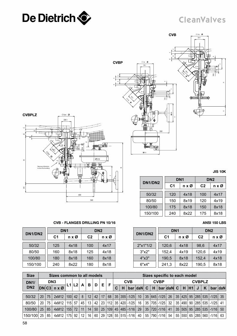
Size Sizes common to all models Sizes specific to each model
DN1/DN2
DN3L1 L2 A B D E F
CVB CVBP CVBPLZDN C3 n x Ø C H bar daN C H bar daN C H H1 J K bar daN
50/32 20 75 2xM12 100 42 8 12 42 17 68 35 355 -1/25 10 35 645 -1/25 26 35 425 95 285 535 -1/25 3580/50 20 75 4xM12 115 57 45 13 42 23 112 35 420 -1/25 16 35 705 -1/25 32 35 490 90 285 535 -1/25 41
100/80 25 85 4xM12 155 72 11 14 50 25 109 45 485 -1/16 29 35 720 -1/16 41 35 505 95 285 535 -1/16 50150/100 25 85 4xM12 175 92 12 16 60 29 128 55 515 -1/16 40 55 790 -1/16 54 55 550 65 285 560 -1/16 63
cleanValves
L2
C2 (nx
)
DN 2
C1 (nx )
DN 1
45
L 1
D
E
C
B
A
F
HG
DN
3
C3 (n
x)
cVB
H
L2
260
45
L1
D
BE
C
AD
N3 C3
(nx
)
F 2
00
310
C1 (nx )
DN 1
DN 2C2 (nx
)
cVBP
L2
D
E
CH
H1
A
F
K
J
300
560
310
DN 2C2(nx
)
DN 1
C1(nx )
DN
3
C3(n
x)
Z
Necessary dimension to shun the insulating
B
45
cVBPlz
DN1/DN2DN1 DN2
C1 n x Ø C2 n x Ø
50/32 125 4x18 100 4x1780/50 160 8x18 125 4x18
100/80 180 8x18 160 8x18150/100 240 8x22 180 8x18
cVB - FlanGeS DrillinG Pn 10/16
DN1/DN2DN1 DN2
C1 n x Ø C2 n x Ø
2"x1"1/2 120,6 4x18 98,6 4x173"x2" 152,4 4x19 120,6 4x194"x3" 190,5 8x18 152,4 4x186"x4" 241,3 8x22 190,5 8x18
anSi 150 lBS
DN1/DN2DN1 DN2
C1 n x Ø C2 n x Ø
50/32 120 4x18 100 4x1780/50 150 8x19 120 4x19100/80 175 8x18 150 8x18150/100 240 8x22 175 8x18
JiS 10K
58
Page 20
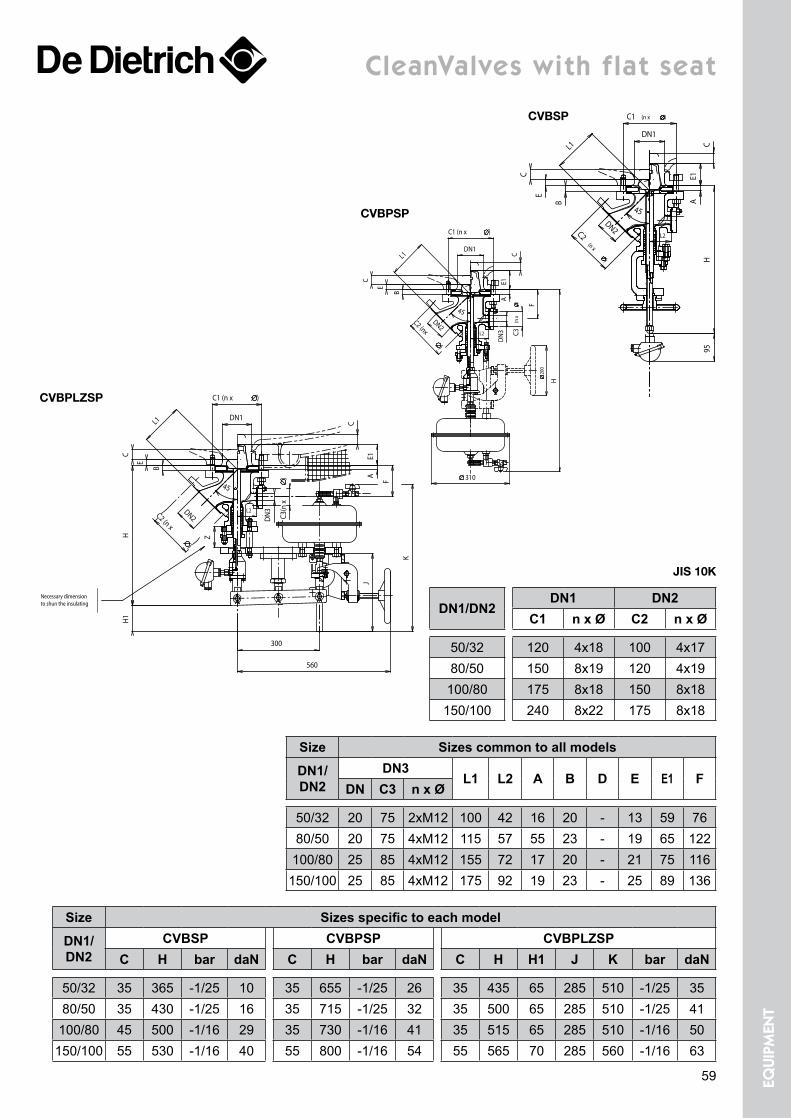
cleanValves with flat seat
Z
Necessary dimension to shun the insulating
DN2C2 (n x
)
DN1
B
C1 (n x )
E
CH
H1
AE1
C
300
560
J
DN
3
C3(n
x) F
K
L1
45
L2
cVBPlzSP
Size Sizes specific to each model
DN1/DN2
CVBSP CVBPSP CVBPLZSPC H bar daN C H bar daN C H H1 J K bar daN
50/32 35 365 -1/25 10 35 655 -1/25 26 35 435 65 285 510 -1/25 3580/50 35 430 -1/25 16 35 715 -1/25 32 35 500 65 285 510 -1/25 41100/80 45 500 -1/16 29 35 730 -1/16 41 35 515 65 285 510 -1/16 50150/100 55 530 -1/16 40 55 800 -1/16 54 55 565 70 285 560 -1/16 63
Size Sizes common to all models
DN1/DN2
DN3L1 L2 A B D E E1 F
DN C3 n x Ø
50/32 20 75 2xM12 100 42 16 20 - 13 59 7680/50 20 75 4xM12 115 57 55 23 - 19 65 122
100/80 25 85 4xM12 155 72 17 20 - 21 75 116150/100 25 85 4xM12 175 92 19 23 - 25 89 136
DN1/DN2DN1 DN2
C1 n x Ø C2 n x Ø
50/32 120 4x18 100 4x1780/50 150 8x19 120 4x19100/80 175 8x18 150 8x18150/100 240 8x22 175 8x18
JiS 10K
DN
3 C3(n
x) F
H
200
310
DN1
C1 (n x )
DN2C2 (nx
)
45
L1
B
E
C
AE1
C
L2
cVBPSP
AB
E
C E1
C
45DN2C2
(n x
)
DN1
C1 (n x )
H95
L1
L2
cVBSP
59 equi
pmen
t


![[REPUBLIC ACT NO. 10795]legacy.senate.gov.ph/republic_acts/ra 10795.pdfAct No. 9136, otherwise known as the "Electric Power Industry Reform Act of2001 . The grantee shall not engage](https://static.documents.pub/doc/80x56/60d45d0320a0b163627ee9c0/republic-act-no-10795-10795pdf-act-no-9136-otherwise-known-as-the-electric.jpg)


