14
Clamping cartridges/units

Clamping cartridges/unitsTOC BookmarkClamping cartridges/unitsCharacteristics
Type codes
Clamping cartridges KP
Data sheet
Technical data
Sectional view
Dimensions and ordering data
Clamping units KPE
Data sheet
Technical data
Sectional view
Dimensions and ordering data
Clamping units KEC
Data sheet
Technical data
Sectional view
Dimensions and ordering data
Clamping units KEC-...-S
Data sheet
Technical data
Sectional view
Dimensions and ordering data
Accessories
Foot mounting HNC
Flange mounting FNC

2 d Internet: www.festo.com/catalogue/... Subject to change – 2020/09
Clamping cartridges/units
Characteristics
At a glance
• The clamping cartridges/units use spring force to hold round material in any required position.
• They can stop and hold material for long periods, even in applications with varying loads, fluctuating oper-ating pressure and system leaks.
• The clamping force is released by pressurising the clamping cartridge.
• The clamping cartridges/units can be mounted in any position.
• Clamping cartridges/units are not suitable for positioning.
• The clamping cartridge KP and the clamping units KPE, KEC, KEC-S are standalone components.
• Cylinders with integrated clamping unit– ADN KP– DSNU-...-KP– DSBC-...-C– DNCKE/DNCKE-S
• Zero backlash in clamped condition with varying loads on the piston rod:– Clamping cartridge/unit
KP/KPE: no– Clamping unit
KEC/KEC S: yes
Selection aidClamping cartridge KP a Page 6 Clamping unit KPE a Page 8
• For in-house assembly of clamping units
• Not certified for use in safety-related control systems
• Ready-to-install combination of clamping cartridge KP and housing
• Wide range of mounting options a 9
• Not certified for use in safety-related control systems
Clamping unit KEC a Page 10
• For use as a holding device (static application):– Holding and clamping in the
event of power failure– Protection against pressure
failure and pressure drop– Securing the piston rod during
intermediate stops for process operations
• Mounting hole pattern to ISO 15552 (DIN ISO 6431)
• Not certified for use in safety-related control systems
Clamping unit KEC-...-S, for safety-related applications a Page 12
• Pneumatic braking/holding device for use in safety-related parts of control systems.
The clamping unit is not a complete safety solution, but it can be used as part of a solution.
• Certified by the Institute for Occupational Safety and Health of the German Social Accident Insurance (DGUV). Testing and certification body in DGUV Test (IFA). Pneumatic braking/holding device with safety function.
• For use as a holding device (static application):– Holding and clamping in the
event of power failure– Protection against pressure
failure and pressure drop– Securing the piston rod during
intermediate stops for process operations
• For use as a braking device (dynamic application):– Braking or stopping a movement– Suspension of a
movement if a danger zone is entered
• Mounting hole pattern to ISO 15552 (DIN ISO 6431)
• When used as a braking device, the overtravel must be checked regularly
• Suitable for use in safety-related parts of control systems belonging to category 1 to EN ISO 13849-1 (tried-and-tested component). Addi-tional control measures are required for use in higher categories.
• Products intended for use in safety-related applications must be selected, sized and arranged in accordance with valid standards and regulations.
Characteristics

32020/09 – Subject to change d Internet: www.festo.com/catalogue/...
Clamping cartridges/units
Characteristics
Requirements for the round material to be clampedIn combination with clamping cartridge KP or clamping unit KPE
• Material:– Hard-chrome-plated steel– Hardened steel– Rolled steel:
Tensile strength > 650 N/mm2,hardness (HB30) > 175
• Diameter tolerance: h8• Surface roughness:
Rmax. = 4 µm
• The specified holding forces refer to a static load. If these values are exceeded, slippage may occur.
• Clamping cartridge KP and clamping unit KPE are not suitable for dynamic operation.
In combination with clamping unit KEC
• Material:– Hard-chrome-plated steel:
layer thickness min. 20 µm– Hardened steel:
min. HRC 60
• Diameter tolerance: h7 ... f7• Surface roughness:
Rmax. = 4 µm
• The specified holding forces refer to a static load. If these values are exceeded, slippage may occur.
• Clamping unit KEC is not suitable for dynamic operation.
• For clamping unit KEC-S, the following applies: dynamic forces occurring during operation must not exceed the static holding force.

4 d Internet: www.festo.com/catalogue/... Subject to change – 2020/09
Clamping cartridges/units
Type codes
Type codes
001 Series
KP Clamping cartridge
002 Piston rod diameter [mm]
4 4
6 6
8 8
10 10
12 12
16 16
20 20
25 25
32 32
003 Static holding force
80 80
180 180
350 350
600 600
1000 1000
1400 1400
2000 2000
5000 5000
7500 7500

52020/09 – Subject to change d Internet: www.festo.com/catalogue/...
Clamping cartridges/units
Type codes
001 Series
KPE Clamping unit
KEC Clamping unit
002 Piston rod diameter [mm]
4 4
6 6
8 8
10 10
12 12
16 16
20 20
25 25
32 32
003 Certifi cation
None
S Safety device to Machinery Directive 2006/42/EC

6 d Internet: www.festo.com/catalogue/... Subject to change – 2020/09
Clamping cartridges KP
Data sheet
Function
-N- Diameter of round material to be clamped: 4 ... 32 mm
-O- Force 80 ... 7500 N H- - Note
Additional measures are required for use in safety-related applications; in Europe, for example, the standards listed under the EC Machinery Directive must be observed. Without additional measures in accordance with statutory minimum requirements, the product is not suitable as a safety-related part of control systems.
General technical dataFor round material diameter 4 6 8 10 12 16 20 25 32
Pneumatic connection M5 G1/8Design Tilting platesType of mounting Via self-configured housingType of clamping with active direction At both ends
Clamping via spring force, compressed air to releaseStatic holding force [N] 80 180 350 350 600 1000 1400 2000 5000 7500Axial play under load [mm] 0.2 0.3 0.5 0.8 1.8Min. release pressure [MPa] 0.3
[bar] 3Mounting position AnyProduct weight [g] 10 15 50 50 50 90 170 170 700 1600
Operating and environmental conditions
Operating medium Compressed air to ISO 8573-1:2010 [7:4:4]Note on operating/pilot medium Lubricated operation possible (in which case lubricated operation will always be required)Operating pressure [bar] š 10Ambient temperature [°C] –10 ... +80Corrosion resistance CRC1) 2
1) Corrosion resistance class CRC 2 to Festo standard FN 940070
Moderate corrosion stress. Indoor applications in which condensation can occur. External visible parts with primarily decorative surface requirements which are in direct contact with a normal industrial environment.
MaterialsSectional view
2
1
4
3Clamping cartridge
[1] Housing Anodised aluminium[2] Clamping jaws Brass[3] Spring Spring steel[4] Piston POM– Seals NBR, TPE-U(PU)
Clamping cartridges KP
Data sheet
Technical data
Sectional view

72020/09 – Subject to change d Internet: www.festo.com/catalogue/...
Clamping cartridges KP
Data sheet
Dimensions and ordering data Download CAD data a www.festo.com
H- - Note
When installing the clamping cartridge in a housing, plain bearings must be installed on both sides of this housing.
For diam.
[mm]
D1 @
D2 @
h12
D3 @ f9
D4 @ D9
D5 @
E1 H1 H2
4 4 10 12 12 11 M5 28 76 6 14 16 16 15 M5 35 108 8 18 20 20 19 M5 62 17.510 10 18 20 20 19 M5 62 17.512 12 18 20 20 19 M5 62 17.516 16 22 24 24 23 G1/8 83 2220 20 28 30 30 29 G1/8 100 25
20 36 38 38 37 G1/8 115.5 3025 25 46 48 48 47 G1/8 155 3632 32 63 65 65 64 G1/8 195 55
For diam.
[mm]
H3 H4
min.
H5
min.
H6 Weight
[g]
Part no. Type
4 2 9 7.5 6 10 178452 KP-4-806 3 10 11 8 15 178453 KP-6-1808 3 18 18.5 15.5 50 178454 KP-8-35010 3 18 18.5 15.5 50 178455 KP-10-35012 3 18 18.5 15.5 50 178456 KP-12-60016 3 22 23 20 90 178457 KP-16-100020 3 25 26 23 170 178458 KP-20-1400
3 30 31 28 170 178459 KP-20-200025 3 36 37 34 700 178460 KP-25-500032 3 55 56 53 1600 178461 KP-32-7500
Dimensions and ordering data

8 d Internet: www.festo.com/catalogue/... Subject to change – 2020/09
Clamping units KPE
Data sheet
Function
-N- Diameter of round material to be clamped: 4 ... 32 mm
-O- Force 80 ... 7500 N
-W- www.festo.comH- - Note
Additional measures are required for use in safety-related applications; in Europe, for example, the standards listed under the EC Machinery Directive must be observed. Without additional measures in accordance with statutory minimum requirements, the product is not suitable as a safety-related part of control systems.
General technical dataFor round material diameter 4 6 8 10 12 16 20 25 32
Pneumatic connection M5 G1/8Design Tilting platesType of mounting With mounting thread
With through-holeType of clamping with active direction At both ends
Clamping via spring force, compressed air to releaseStatic holding force [N] 80 180 350 350 600 1000 2000 5000 7500Axial play under load [mm] 0.2 0.3 0.5 0.8 1.8Min. release pressure [MPa] 0.3
[bar] 3Mounting position AnyProduct weight [g] 100 150 240 260 270 410 930 2000 4600
Operating and environmental conditions
Operating medium Compressed air to ISO 8573-1:2010 [7:4:4]Note on operating/pilot medium Lubricated operation possible (in which case lubricated operation will always be required)Operating pressure [bar] š 10Ambient temperature [°C] –10 ... +80Corrosion resistance CRC1) 2
1) Corrosion resistance class CRC 2 to Festo standard FN 940070
Moderate corrosion stress. Indoor applications in which condensation can occur. External visible parts with primarily decorative surface requirements which are in direct contact with a normal industrial environment.
MaterialsSectional view
2
1
4
3Clamping unit
[1] Retaining bracket Anodised aluminium[2] Clamping jaws Brass[3] Spring Spring steel[4] Piston POM– Seals NBR, TPE-U(PU)
Clamping units KPE
Data sheet
Technical data
Sectional view

92020/09 – Subject to change d Internet: www.festo.com/catalogue/...
Clamping units KPE
Data sheet
Mounting optionsWith mounting thread With through-hole
Dimensions and ordering data Download CAD data a www.festo.comFor round material diameter 4 ... 6 mm For round material diameter 8 ... 32 mm
For diam.
[mm]
B1 B2 B3 D1 @
D2 @
D3 @
D4 D5 D6 @
D7@
d11
D8 @
E1 H1 H2
4 27 19.5 12 4 – 12 – M5 4.2 12 4.5 M5 34.5 13.56 32 24 16 6 – 16 – M5 4.2 16 4.5 M5 41 168 36 27 20 8 4.2 20 M5 M5 4.2 22 – M5 62.5 1810 36 27 20 10 4.2 20 M5 M5 4.2 22 – M5 62.5 1812 40 28 20 12 5.2 20 M6 M6 5.2 28 – M5 64.5 2016 45 32.5 25 16 5.2 24 M6 M6 5.2 32 – G1/8 83.5 22.520 65 50 38 20 6.5 38 M8 M8 6.5 45 – G1/8 118 32.525 88 65 50 25 8.5 48 M10 M10 8.5 55 – G1/8 163 4432 118 90 70 32 10.3 65 M12 M12 10.3 60 – G1/8 199 59
For diam.
[mm]
H3 L1 L2 L3 L4 T1 T2 Weight
[g]
Part no. Type
4 19.5 33 7.5 18 – 9 11 100 178462 KPE-46 24 45 10 25 – 9 11 150 178463 KPE-68 27 58 10 38 20 10 11 240 178464 KPE-810 27 62 12 38 20 10 11 260 178465 KPE-1012 28 65 11 43 22 12 12 270 178466 KPE-1216 32.5 69 12.5 44 22 12 12 410 178467 KPE-1620 50 83 12.5 58 30 16 16 930 178468 KPE-2025 65 100 15 70 34 20 20 2000 178469 KPE-2532 90 154 25 104 60 24 24 4600 178470 KPE-32
Dimensions and ordering data

10 d Internet: www.festo.com/catalogue/... Subject to change – 2020/09
Clamping units KEC
Data sheet
Function
-N- Diameter of round material to be clamped: 16 ... 25 mm
-O- Force 1300 ... 8000 N H- - Note
Additional measures are required for use in safety-related applications; in Europe, for example, the standards listed under the EC Machinery Directive must be observed. Without additional measures in accordance with statutory minimum requirements, the product is not suitable as a safety-related part of control systems.
General technical dataFor round material diameter 16 20 25
Pneumatic connection G1/8 G1/4 G3/8Type of mounting With female thread
With accessory a page 14Type of clamping with active direction At both ends
Clamping via spring force, compressed air to releaseStatic holding force 1300 3200 8000Min. release pressure [MPa] 0.38
[bar] 3.8Mounting position AnyProduct weight [g] 1860 4515 16760
Operating and environmental conditions
Operating medium Compressed air to ISO 8573-1:2010 [7:4:4]Note on operating/pilot medium Lubricated operation possible (in which case lubricated operation will always be required)Operating pressure [bar] 3.8 ... 10Ambient temperature [°C] –20 ... +80ATEX Selected types a www.festo.comRequirements for the round material
Tolerance h7 ... f7Quality Hardened (min. HRC 60) or hard-chrome-plated (layer thickness min. 20 µm)
Surface roughness Rmax. = 4 µmLead-in chamfer 3 mm wide 15° chamfer on the end of the round material
-H- Note Actuation:The specified holding force refers to a static load. If this value is exceeded, slippage may occur. Dynamic forces occurring during operation must not exceed the static holding force if slippage is to be avoided. The clamping unit is backlash-free in the clamped condition when varying loads are applied to the piston rod. Lateral loads and bending moments on the round material can impair the function. (Make sure that the load on the round material is only in the direction of movement.)
The clamping unit may only be released when the forces on the round material are balanced out. Otherwise there is a risk of accidents due to the sudden movement of the round material. Blocking off the compressed air supply at both ends (e.g. with a 5/3-way valve) does not provide any safety.
Clamping units KEC
Data sheet
Technical data

112020/09 – Subject to change d Internet: www.festo.com/catalogue/...
Clamping units KEC
Data sheet
MaterialsSectional view
1 4 2 3Clamping unit
[1] Housing Wrought aluminium alloy[2] Clamping jaws Tool steel[3] Spring High-alloy steel[4] Piston Wrought aluminium alloy– Seals NBR, TPE-U(PU)
Dimensions and ordering data Download CAD data a www.festo.com
H- - Note
The clamping unit can only be exhausted when it contains round material.
[2] Round material to be clamped
[3] Locking screw
For diam.
[mm]
B@f8
BG BG1 E E1 EE G G1 L1 L2 MM@
f7-h7
16 35 15 15 54 53 G1/8 27 22 178 160 1620 45 14 17 80 79 G1/4 30 29.5 208.5 187 2025 55 17 17 126 126 G3/8 32.5 32.5 287 258 25
For diam.
[mm]
PL RT TG VA VD ß1 ß2 Weight
[g]
Part no. Type
16 13 M6 38 5.5 18 30 6 1860 527492 KEC-1620 15.5 M8 56.5 6 21.5 36 8 4515 527493 KEC-2025 17 M10 89 7 29 41 10 15600 527494 KEC-25
Sectional view
Dimensions and ordering data

12 d Internet: www.festo.com/catalogue/... Subject to change – 2020/09
Clamping units KEC-...-S
Data sheet
Function
-N- Diameter of round material to be clamped: 16 ... 25 mm
-O- Force 1300 ... 8000 N
General technical dataFor round material diameter 16 20 25
Pneumatic connection G1/8 G1/4 G3/8Type of mounting With female thread
With accessory a page 14Type of clamping with active direction At both ends
Clamping via spring force, compressed air to releaseStatic holding force 1300 3200 8000Min. release pressure [MPa] 0.38
[bar] 3.8Mounting position AnyFunction Single-channel to EN ISO 13849-1, category 1Safety function Holding and stopping a movementCertification Certified by the Institute for Occupational Safety and Health of the German Social Accident Insurance (DGUV).
Testing and certification body in DGUV Test (IFA)Product weight [g] 1860 4515 15600
Operating and environmental conditions
Operating medium Compressed air to ISO 8573-1:2010 [7:4:4]Note on operating/pilot medium Lubricated operation possible (in which case lubricated operation will always be required)Operating pressure [bar] 3.8 ... 8Max. permissible test pressure [bar] 10Ambient temperature [°C] –10 ... +60Requirements for the round material
Tolerance h7 ... f7Quality Hardened (min. HRC 60) or hard-chrome-plated (layer thickness min. 20 µm)
Surface roughness Rmax. = 4 µmLead-in chamfer 3 mm wide 15° chamfer on the end of the round material
-H- Note Actuation:The specified holding force refers to a static load. If this value is exceeded, slippage may occur. Dynamic forces occurring during operation must not exceed the static holding force if slippage is to be avoided. The clamping unit is backlash-free in the clamped condition when varying loads are applied to the piston rod. Lateral loads and bending moments on the round material can impair the function. (Make sure that the load on the round material is only in the direction of movement.)
The clamping unit may only be released when the forces on the round material are balanced out. Otherwise there is a risk of accidents due to the sudden movement of the round material. Blocking off the compressed air supply at both ends (e.g. with a 5/3-way valve) does not provide any safety.
Safety data
Safety function Stopping a linear movementPerformance Level (PL) Cat. 1, PLcCertificate issuing authority IFA 1504155CE marking (see declaration of conformity) To EU Machinery Directive
Clamping units KEC-...-S
Data sheet
Technical data

132020/09 – Subject to change d Internet: www.festo.com/catalogue/...
Clamping units KEC-...-S
Data sheet
MaterialsSectional view
1 4 2 3Clamping unit
[1] Housing Wrought aluminium alloy[2] Clamping jaws Tool steel[3] Spring High-alloy steel[4] Piston Wrought aluminium alloy– Seals NBR, TPE-U(PU)
Dimensions and ordering data Download CAD data a www.festo.comKEC-S – for safety-related control systems
H- - Note
The clamping unit can only be exhausted when it contains round material.
[2] Round material to be clamped
[3] Locking screw
For diam.
[mm]
B@f8
BG BG1 E E1 EE G G1 L1 L2 MM@
f7-h7
16 35 15 15 54 53 G1/8 27 22 178 160 1620 45 14 17 80 79 G1/4 30 29.5 208.5 187 2025 55 17 17 126 126 G3/8 32.5 32.5 287 258 25
For diam.
[mm]
PL RT TG VA VD ß1 ß2 Weight
[g]
Part no. Type
16 13 M6 38 5.5 18 30 6 1860 538242 KEC-16-S20 15.5 M8 56.5 6 21.5 36 8 4515 538243 KEC-20-S25 17 M10 89 7 29 41 10 15600 538244 KEC-25-S
-H- NoteThe overtravel is the distance that the piston rod covers between exhausting of the clamp-ing unit and coming to a standstill. It must be determined by the customer when the ma-chine is being set up. When the clamping unit is used as a braking device, an increase in the overtravel as a function of the load and the frequency of braking (wear) must be expect-ed. The clamping unit KEC-S can be used in safety-related parts of control systems belong-ing to category 1 (tried-and-tested component) as defined by EN ISO 13849-1. For use in higher categories than category 1 to EN ISO 13849-1, the overtravel must be achieved even in the event of faults.
The overtravel is dependent on the ambient conditions and stress, e.g.:• Operating pressure• Nominal size of the switching valve• Cable length• Diameter of the connecting cable to the clamping unit• Load and speedThe overtravel can be reduced by attaching a quick exhaust valve to the compressed air supply port of the clamping unit.
Sectional view
Dimensions and ordering data
14 d Internet: www.festo.com/catalogue/... Subject to change – 2020/09
Clamping units
Accessories
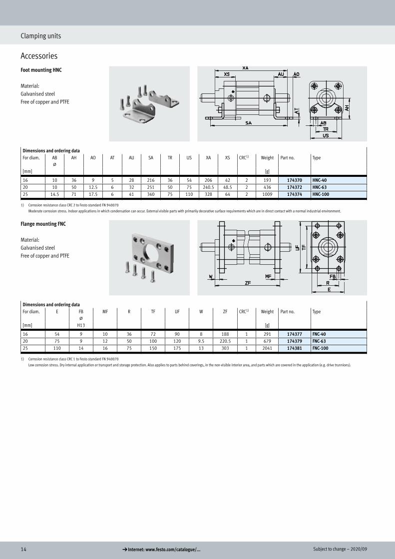
Foot mounting HNC
Material:Galvanised steelFree of copper and PTFE
Dimensions and ordering dataFor diam. AB
@AH AO AT AU SA TR US XA XS CRC1) Weight Part no. Type
[mm] [g]
16 10 36 9 5 28 216 36 54 206 42 2 193 174370 HNC-4020 10 50 12.5 6 32 251 50 75 240.5 48.5 2 436 174372 HNC-6325 14.5 71 17.5 6 41 340 75 110 328 64 2 1009 174374 HNC-100
1) Corrosion resistance class CRC 2 to Festo standard FN 940070
Moderate corrosion stress. Indoor applications in which condensation can occur. External visible parts with primarily decorative surface requirements which are in direct contact with a normal industrial environment.
Flange mounting FNC
Material:Galvanised steelFree of copper and PTFE
Dimensions and ordering dataFor diam. E FB
@MF R TF UF W ZF CRC1) Weight Part no. Type
[mm] H13 [g]
16 54 9 10 36 72 90 8 188 1 291 174377 FNC-4020 75 9 12 50 100 120 9.5 220.5 1 679 174379 FNC-6325 110 14 16 75 150 175 13 303 1 2041 174381 FNC-100
1) Corrosion resistance class CRC 1 to Festo standard FN 940070
Low corrosion stress. Dry internal application or transport and storage protection. Also applies to parts behind coverings, in the non-visible interior area, and parts which are covered in the application (e.g. drive trunnions).
Accessories
Foot mounting HNC
Flange mounting FNC


