18
Vestas Wind Systems A/S Smed Soerensens Vej 5 DK-6950 Ringkoebing 10b WWW.VESTAS.COM Class I Item no. 946521.R7 2004-06-11 Electrical Data V52 – 850 kW VMP-850 kW-690 V-50 Hz Controller

Vestas Wind Systems A/S Smed Soerensens Vej 5 DK-6950 Ringkoebing 10b
WWW.VESTAS.COM
Class IItem no. 946521.R7
2004-06-11
Electrical DataV52 – 850 kW
VMP-850 kW-690 V-50 Hz Controller

Item no.: 946521.R7 Date: 2004-06-11Class: IElectrical Data VMP 850 kW- 690 V- 50 Hz Controller
Issued by: Technology Type: MAN
V52-850 kW Electrical Data Contents ...........................................................................................................................Page 1. V52-850 kW Wind Turbine .............................................................................................. 3 2. The VMP-Controller......................................................................................................... 3 3. Tubular Tower ................................................................................................................. 3 4. Lattice Tower................................................................................................................... 4 5. Earthing System.............................................................................................................. 4 6. Turbine Earthing System/Lightning Protection ................................................................ 4 7. Rated Electrical Data....................................................................................................... 5
7.1. V52-850 kW Reactive Capability Chart................................................................... 5 8. Name plate on the Ground Controller.............................................................................. 7 9. Grid connection ............................................................................................................... 7 10. Monitoring of the Grid...................................................................................................... 8 11. kWh-meter Arrangement ................................................................................................. 8 12. Electrical protection ......................................................................................................... 8 13. Drawings ......................................................................................................................... 9
Page: 2 of 18

Item no.: 946521.R7 Date: 2004-06-11Class: IElectrical Data VMP 850 kW- 690 V- 50 Hz Controller
Issued by: Technology Type: MAN
1. V52-850 kW Wind Turbine Vestas V52-850 kW with VMP-850 kW– 690 V- 50 Hz controller. Vestas V52-850 kW wind turbine is a pitch regulated wind turbine, in consequence of which the blades are always pitched in the optimum angle during production as well as stop situations. The generator is a special asynchronous generator with wound rotor, slip rings and Vestas Converter System, VCS, which enables the wind turbine to operate at a variable speed. Among the advantages of a pitch regulated wind turbine with variable speed the following should be mentioned:
• Optimum production under all wind conditions. • Output is limited to 850 kW. • Power output is smoothed resulting in high power quality and low flicker level. • No motor start. • Turbine can be stopped without using the mechanical brake. • Minimising fluctuations in the mechanical transmission system.
2. The VMP-Controller The wind turbine operates fully automatic by means of the VMP-controller (Vestas Multi Proces-sor controller), which serves the following functions:
• Before connection to the grid, the speed of rotation is synchronised to the grid frequency in order to limit the cut-in current.
• Cut-in current is lower than nominal current. • Automatic yawing of the nacelle in accordance with the wind direction. • Monitoring of the operation. • Stop of the turbine in case of faults.
The VMP-controller consists of a ground controller, top controller and a VCS controller. The top controller and VCS controller are located in the nacelle. The location of the ground controller depends on the choice of tubular tower or lattice tower. General Reservation:
• Vestas OptiSpeed™ Technology is not available in the United States of Amer-ica and Canada.
3. Tubular Tower The ground controller is located on a 1 meter high platform at the bottom of the tower. The grid cables are led through 2 pieces of 160 mm tubes in the foundation placed immediate under the grid connection section of the ground controller.
Page: 3 of 18

Item no.: 946521.R7 Date: 2004-06-11Class: IElectrical Data VMP 850 kW- 690 V- 50 Hz Controller
Issued by: Technology Type: MAN
4. Lattice Tower If the turbine is installed on lattice tower, the ground controller is located in a shed between the corner legs of the lattice tower. The shed must be secured to a concrete foundation, and the grid cables are led through 2 pieces of 160 mm tubes into the grid connection section.
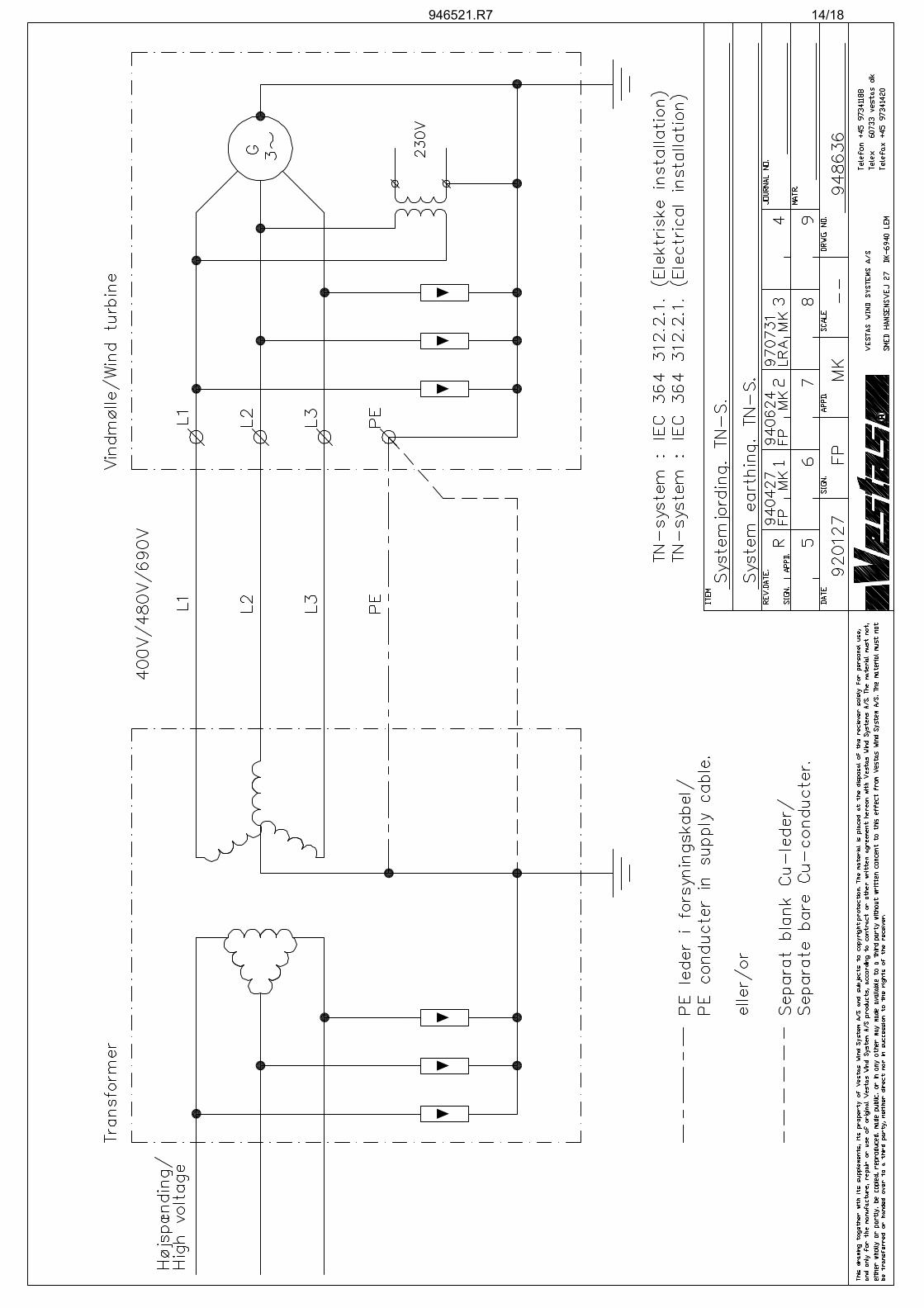
5. Earthing System The transformer must have the low voltage grid side connected in star and this star point must be earthed, and connected to the earthing system of the turbine. It is recommended to make the grid connection as a TN-system, see IEC 364 section 312.2.1 and 413.1.3. In consequence there of, the earthing system of the turbine must be connected to the earthing system of the transformer. The connection can be made either with a separate conductor (e.g. bare copper conductor) or through the neutral conductor in the grid cable, see drawing no. 948636. If the neutral conductor is used, it must be marked with green/yellow tape at both ends and defined as a PE-conductor, according to IEC 364 section 514.3.3.
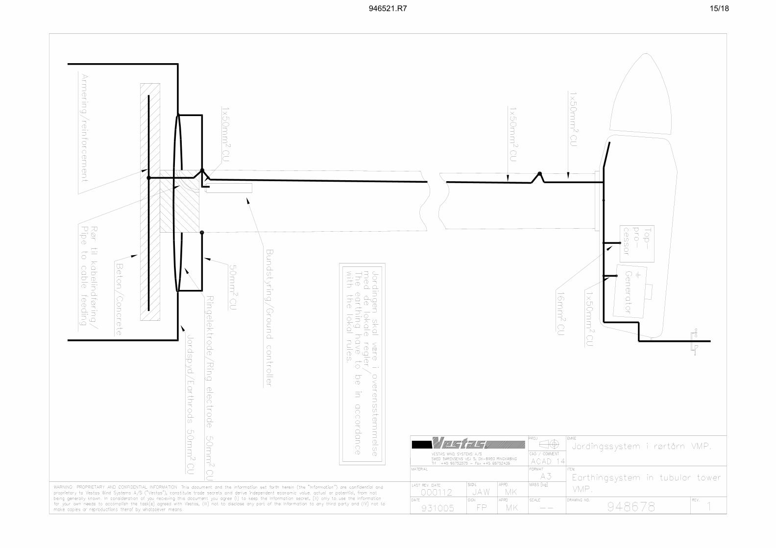
6. Turbine Earthing System/Lightning Protection The system should be made at the same time as the foundation work. The earthing system must be accommodated to local soil conditions. The resistance to earth should normally be no higher than 10 Ω. (In the Netherlands the resistance to earth must be be-low 2.5 Ω, when the earthing system and concrete reinforcement are connected, see drawing 948678). The earthing system shall be made as a closed ring conductor with earthing rods, see drawing 948678. This gives the following advantages: 1. Personnel safety The ring conductor limits step and contact voltage for persons, staying near the
tower foundation in case of a lightning stroke. 2. Operational safety The earthing rods ensure a steady and low resistance to earth for the whole
earthing system. The earthing system is made as follows: 1. Ring conductor in 50 mm2 Cu is established at a distance of 1 m from the foun-
dation and approx. 1 m below ground level. 2. The ring conductor is supplemented with 2 copper coated earthing rods each of
6 m (Ø14). The earthing rods are rammed down on each side of the tower/lattice tower (180° between the earthing rods).
3. The ring conductor is connected to two tower legs or two opposite points on a
tubular tower. The ground controller is connected to one of these points, see drawing no. 948678.
Page: 4 of 18
Item no.: 946521.R7 Date: 2004-06-11Class: IElectrical Data VMP 850 kW- 690 V- 50 Hz Controller
Issued by: Technology Type: MAN If the resistance to earth is not sufficiently low, the earthing system can be improved. 1. The two earth rods can be extended to 10 m. 2. Two extra earth rods each of a length of 10 m can be added (90° between the 4
earth rods).
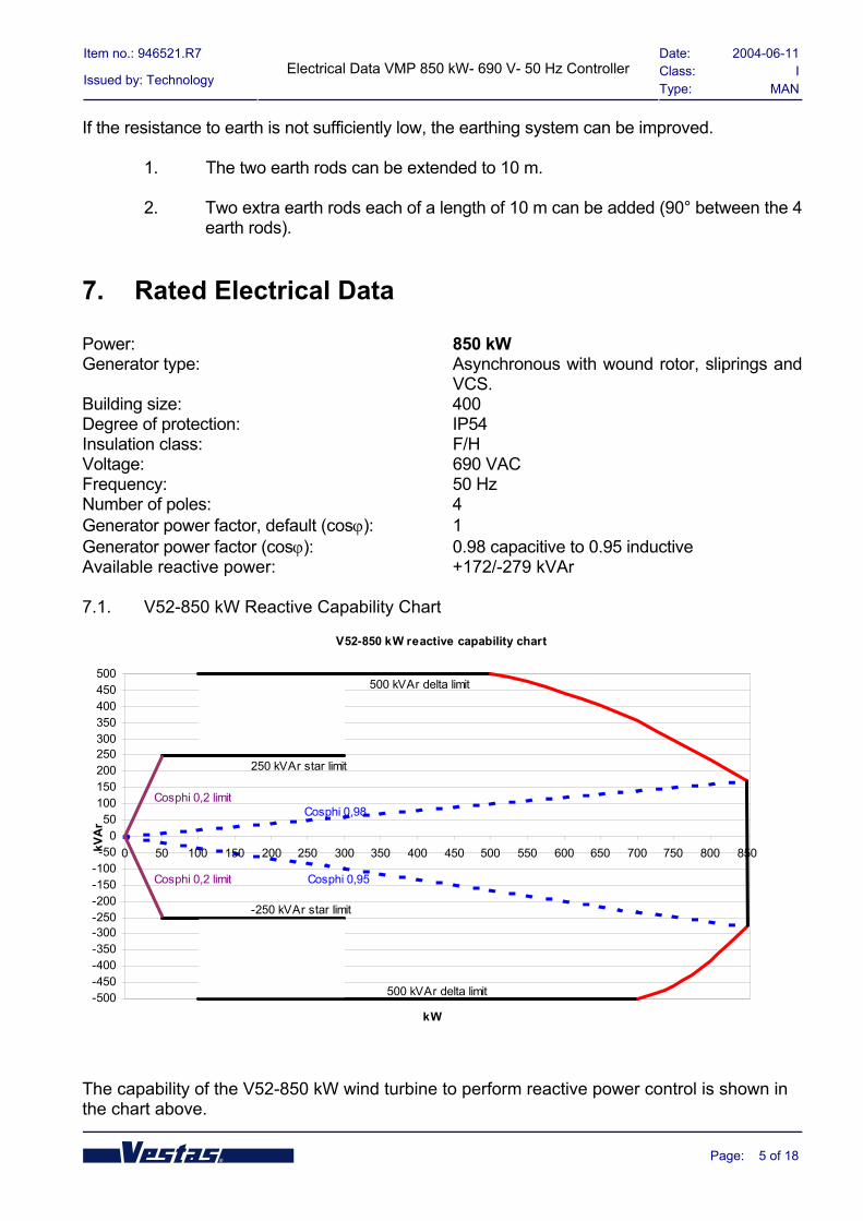
7. Rated Electrical Data Power: 850 kW Generator type: Asynchronous with wound rotor, sliprings and
VCS. Building size: 400 Degree of protection: IP54 Insulation class: F/H Voltage: 690 VAC Frequency: 50 Hz Number of poles: 4 Generator power factor, default (cosϕ): 1 Generator power factor (cosϕ): 0.98 capacitive to 0.95 inductive Available reactive power: +172/-279 kVAr 7.1. V52-850 kW Reactive Capability Chart
V52-850 kW reactive capability chart
-500-450-400-350-300-250-200-150-100-50
050
100150200250300350400450500
0 50 100 150 200 250 300 350 400 450 500 550 600 650 700 750 800 850
kW
kVA
r
Cosphi 0,2 limit
Cosphi 0,2 limit
Cosphi 0,98
Cosphi 0,95
250 kVAr star limit
-250 kVAr star limit
500 kVAr delta limit
500 kVAr delta limit
The capability of the V52-850 kW wind turbine to perform reactive power control is shown in the chart above.
Page: 5 of 18

Item no.: 946521.R7 Date: 2004-06-11Class: IElectrical Data VMP 850 kW- 690 V- 50 Hz Controller
Issued by: Technology Type: MAN Reactive power is produced by the rotor converter; therefore traditional capacitors are not used. The V52-850 kW wind turbine is able to operate in fixed power factor mode with a power fac-tor range in the interval from 0.98 capacitive to 0.95 inductive measured on the 690 V gen-erator side and with 100% of rated active power. It is possible to choose other power factor values, however, with reduced active power. The V52-850 kW wind turbine is also able to operate in fixed reactive power mode. In the fixed reactive power mode, the wind turbine will generate or absorb reactive power up to 500 kVAr, when the generator stator winding is coupled in delta, however, with decreased reac-tive power close to the rated power output (see the red line in the attached diagram). When the stator winding is in star connection, the maximum reactive power is 250 kVAr. The turbine will automatically change the generator stator connection from star to delta and vice versa, depending on the actual active power production. The criteria are as follows: • From star to delta: Active power must be above 300 kW for more than 30 seconds • From delta to star: Active power must be below 100 kW for more than 15 seconds This means that if the turbine is adjusted to generate e.g. 400 kVAr, the turbine will automati-cally decrease the reactive power to 250 kVAr, when the generator is in star connection. Please note that the area marked with indicates that the generator can be in either star or delta, depending on the actual conditions. Please note that the generator can be in star connection producing active power above 300 kW, if the wind speed increases rapidly during the 30 seconds time delay. The active power in star is limited to 450 kW. This can also happen at low wind speed, so that the generator can be in delta below 100 kW, if the wind speed is decreasing rapidly (faster than the 15 seconds time delay). The minimum reactive power is limited to a power factor of 0.2. All the above reactive power levels are possible through parameter adjustments in each tur-bine. This can be achieved either by changing the parameter in each turbine (to be carried out by a Vestas service engineer on site), or through the SCADA system VestasOnline™. Please contact Vestas for more information about VestasOnline™.
Page: 6 of 18

Item no.: 946521.R7 Date: 2004-06-11Class: IElectrical Data VMP 850 kW- 690 V- 50 Hz Controller
Issued by: Technology Type: MAN
8. Name Plate on the Ground Controller
9. Grid Connection In the bus bar section of the ground controller, there is one circuit breaker (Q8) for the generator and one circuit breaker (F30) for aux. supply. The control circuits can be disconnected with one circuit breaker (Q16). Circuit breaker Q8 is lockable. When Q8 is disconnected, there will still be power for the light in-stallation. Beneath the bus bar section, the grid connection section is located, please see drawing 925641. The grid cables are conducted through the 2x160 mm tubes in the foundation to the grid con-nection section in the ground controller. There are four terminals for respectively L1, L2, L3 and PE. The grid cables must be mounted with cable lugs. Two M12x50 bolts in each terminal are used for mounting the cable lugs. This work must be carried out by an authorised electrician. If the nacelle is placed on a tubular tower, the controller is placed on a 2.2 m high platform. The grid cables must have a length of app. 3.5 m from the concrete floor to make it possible to mount in the grid connection section (only for turbines with the transformer placed outside the turbine tower).
Circuit breakers Generator / Q8 ABB S6N 800
Controller / F30 ABB MO325+PROLIM
Breaking capacity, Icu, Ics 20 kA/15 kA 50 kA
Thermo release, Ith 800 A 9 A
Magnetic release, Im 3.2 kA 150 A Do not connect the wind turbine when the short circuit current is above 15 kA. A 1000 kVA transformer (impedance voltage 6%) can be used for an 850 kW wind turbine.
Page: 7 of 18
Item no.: 946521.R7 Date: 2004-06-11Class: IElectrical Data VMP 850 kW- 690 V- 50 Hz Controller
Issued by: Technology Type: MAN
10. Monitoring of the Grid The generator and the converter system will be disconnected, if the voltage or the frequency exceeds the following limits. Nominal phase voltage: UP,nom = 400 V. Grid voltage: UN = 690V The generator will be disconnected if: UP UNThe voltage is 10% above the nominal voltage for 60 s. 440 V 762 V The voltage is 10% below the nominal voltage for 60 s. 360 V 624 V The voltage is 13.5% above the nominal voltage for 0.2 s. 454 V 786 V The frequency is above 51 Hz for 0.2 s. The frequency is below 47 Hz for 0.2 s. If a fault on the grid disconnects the voltage supply to the VMP-controller, the emergency stop circuit will open immediately and the generator and converter system will be disconnected at the same time.
11. kWh-meter Arrangement Vestas recommends that the kWh-meter arrangement is located in the transformer housing. The kWh-meter(s) should be located behind a window so that they can be read from outside. The kWh-meter(s) shall be connected to measuring transformers. Following measuring trans-formers can be used:
• Current transformer : Class 0.2, 750/5 A. • Voltage transformers : Class 0.2, 400/230 V (line-neutral).
12. Electrical Protection The turbine is protected by hardware and software. The hardware protection must be able to disconnect any electrical short circuits and ground faults. The software protection is mainly for protection against thermal overload, asymmetrical voltages and/or currents. The software must also protect against current and voltage deviations outside the limitations as well as fre-quency deviations etc. The protection diagrams are created in accordance to IEEE C37.2-1996.
Page: 8 of 18

Item no.: 946521.R7 Date: 2004-06-11Class: IElectrical Data VMP 850 kW- 690 V- 50 Hz Controller
Issued by: Technology Type: MAN
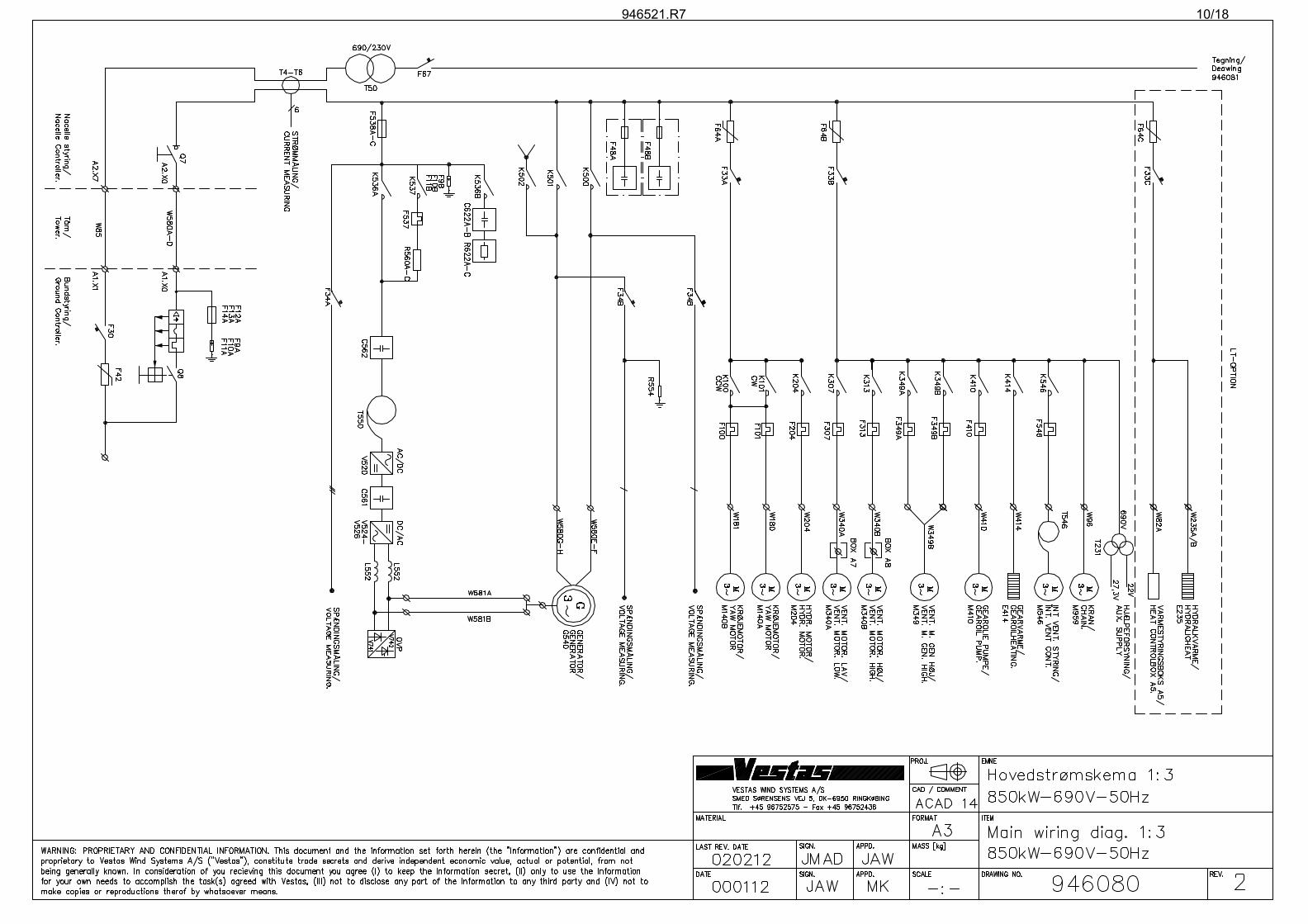
13. Drawings No. CONTENT PAGE 946080 Main wiring diagram 1:3 VMP-850 kW-690 V-50 Hz ..........................10
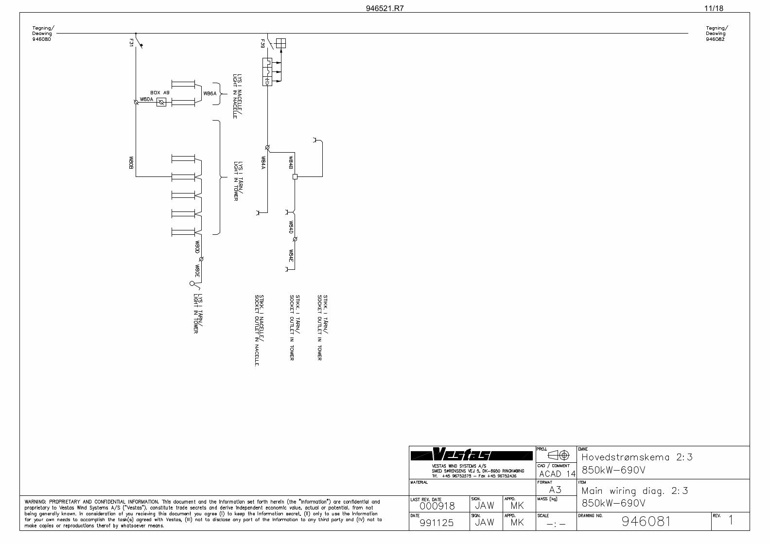
946081 Main wiring diagram 2:3 VMP-850 kW-690 V-50 Hz ..........................11
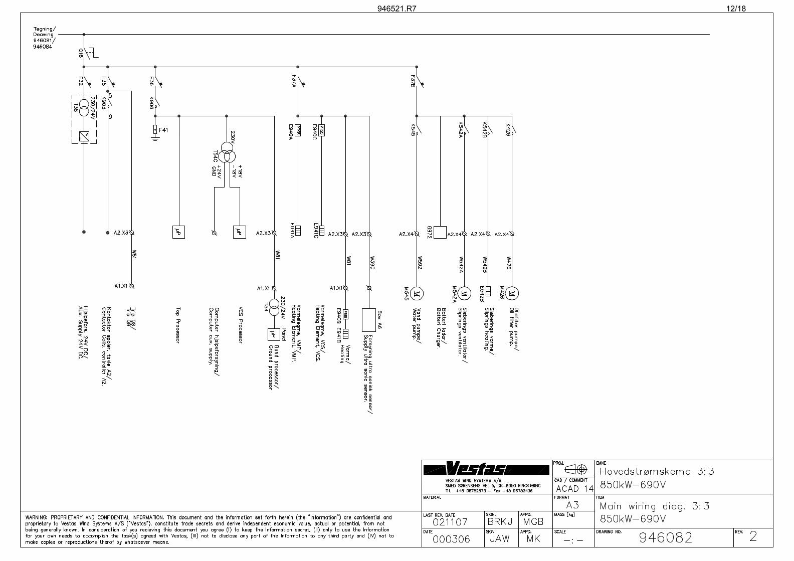
946082 Main wiring diagram 3:3 VMP-850 kW-690 V-50 Hz ..........................12
925647 Placement of controller in tubular tower. VMP-GND-850 kW.............13
948636 System earthing. TN............................................................................14
948678 Earthing system in tubular tower. VMP ..............................................15
925641 Grid connection section. VMP-Ground ...............................................16
928511 Protection Diagram V52-850 kW.........................................................17
928510 Protection Diagram V52-850 kW.........................................................18
Page: 9 of 18
946521.R7 10/18
946521.R7 11/18
946521.R7 12/18

946521.R7 13/18
946521.R7 14/18
946521.R7 15/18

946521.R7 16/18

DATE SIGN. APPD.
VESTAS WIND SYSTEMS A/SSMED SØRENSENS VEJ 5, DK-6950 RINGKØBINGTlf. +45 96752575 - Fax +45 96752436
LAST REV. DATE
MATERIAL
SIGN. APPD.
DRAWING NO.
1:1SCALE
A3
ACAD 2000
MASS [kg]
FORMAT ITEM
CAD / COMMENT
PROJ. EMNE
REV.
Current transformers:T4, T5 and T6 :Garre transformers L50/30 800/1A class 0.2,Permanent overload = 1.2 x InInsulation level: 0.72/3.0kVIth = 60 x In, Idyn = 2.5 x Ith
Measuring resistors:R4A, R5A, R6A : 3.0 Ohm, 5W, 0.1% Rcd 160
Voltage measuring:T1, T2 and T3 : Trans Elektro A/S - 400V/5.5V Ø70T500 : Trans Elektro A/S - 690V/5.5V Ø90
Vestas Multi Processor (VMP) V52-850kW IEEE std. C37.2-1996 Protection
T4T5T6
VMPVCS-TRU
690V busbar
690V grid voltage
VCS-TRU print
ø
øø
øø
øT4
T5
T6 R6A
R4A
R5A
v
v
v v v v
T1 T2 T3
ø ø ø ø ø ø
VMP
The VMP controller uses the voltagesignals for supervision.
VMP error log no.SDFN* Description
* SDFN : System Device Function Numbers.
25 Synchronizing relay 318
Undervoltage relay
Undercurrent and underpower relay
Phase-sequence relay
AC time overcurrent relay
Overvoltage relay
Voltage or current balance relay
Frequency relay
27
37
47
51
59
60
81
127, 135, 315
120, 121, 122
103, 104, 105
123, 124, 125, 142, 143
126, 134
136, 137, 138, 139, 140, 141
119, 129
Detailed description of error log can be found in item no. 944853
VMPVCS-TRU (drw. no. 928510)
øø
v T500
690V cable
690V stator connection
946521.R7 17/18

VCS-TRU
946521.R7 18/18


