Page 1
11
Classes #3 & #4 Classes #3 & #4 Civil Engineering Materials – CIVE 2110Civil Engineering Materials – CIVE 2110
TorsionTorsion
Fall 2010Fall 2010
Dr. GuptaDr. Gupta
Dr. PickettDr. Pickett
Page 2
Torque and Torsional Deformation
Torque is a MOMENT
applied about the LONG axis
of a circular shaft.
Shaft twists about the LONG axis.
Circles remain circles.
Each Longitudinal grid line
deforms into a HELIX,
that intersects the circles
at EQUAL angles.
Page 3
Torque and Torsional Deformation
Torque is a MOMENT
applied about the LONG axis
of a circular shaft.
Shaft length & radius
do NOT change.
Ends of shaft remain flat,
perpendicular to long axis.
Radial lines remain STRAIGHT.
Page 4
Torque and Torsional Deformation
If shaft is FIXED at one endandTorque applied at other end,
Radial lines - remain straight- rotate thru an angle of twist
- angle of twist varies along length of shaft
)(x
Page 5
Torque and Torsional Deformation
An element located x
from the back end of the shaft,
will have different
angles of twist (rotations)
on its front and back faces.
The difference in angles of twist
causes
Torsional SHEAR STRAINS.
)()( xandx
Page 6
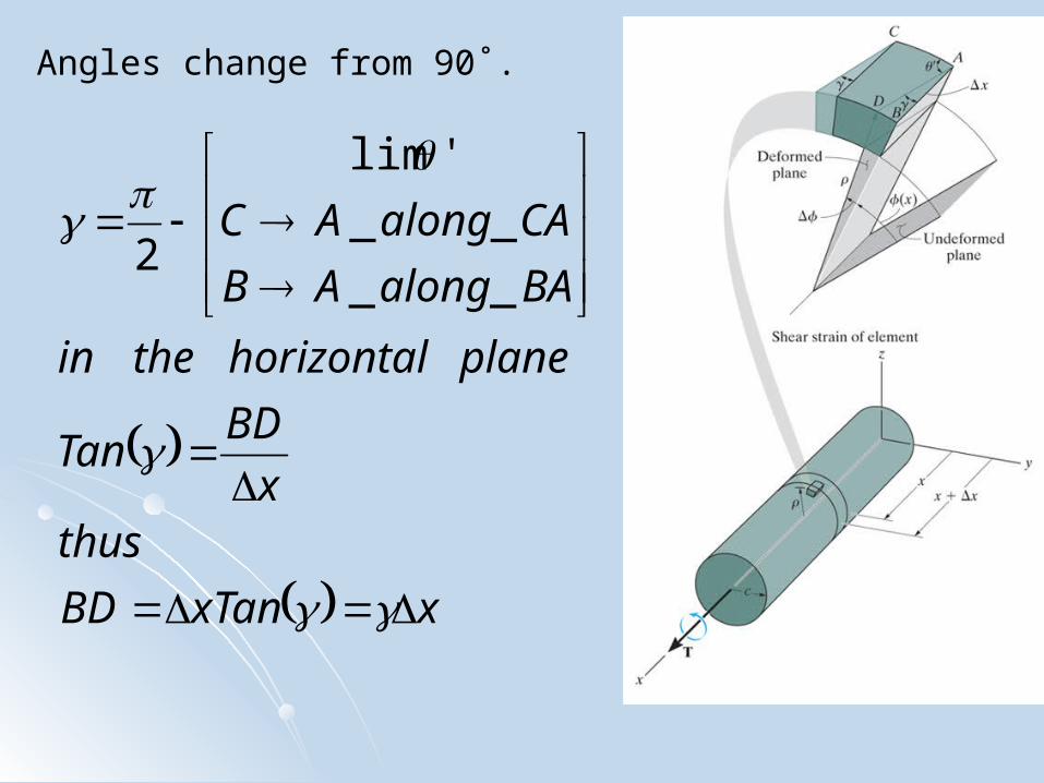
Angles change from 90˚.
xxTanBD
thusx
BDTan
planehorizontalthein
BAalongAB
CAalongAC
__
__
'lim
2
Page 7
Angles change from 90˚.
xthusxgives
BDBDsetting
TanBD
thus
BDTan
planeverticalthein
BAalongAB
CAalongAC
__
__
'lim
2
Page 8
For all elements on the
cross section at x,
max
max
var
sectan
c
cedgeoutsideatimumto
centeratzerofrom
withlinearilyiesstrainshear
lyconsequent
tioncrosstheovertconsisdx
d
thus
samethearedanddx
Page 9
For all elements on the
cross section at x,
max
max
max
var
c
cedgeoutsideatimumto
centeratzerofrom
withlinearilyiesstrainshear
Page 10
Torsional Shear Stress
For circular shafts,
hollow or solid,
If material is
- Homogeneous
- Linear-Elastic
Hooke’s Law gives:
Thus, like Shear Strain,
Shear Stress,
varies linearly with
Radial distance from center of shaft.
G
max
c
Page 11
Torsional Shear Stress
Each elemental area, dA
located at ρ from the center,
will have an internal Force, dF,
that will produce an internal
Resisting Torque, T.
)(dAdF
A
AA
cT
dAc
dAdFT
2max
max )(
max
c
Page 12
Torsional Shear Stress
Polar Moment of Inertia, J:
for a Solid Shaft;
44
0
443
0
22
2
2)(
4
22)2(
)2(
2sin
insideoutside
A
cc
ccJ
shafthollowafor
ccdddAJ
ddAis
dthicknessofringaofareathe
ncecircumferece
max
c
Page 13
Axial Shear Stress (solid shaft)In order for any element
to be in equilibrium
the internal torque, T,
must develop an
Axial Shear Stress,
equal to the
Radial Shear Stress,
also
varying Linearly with radial position.
max
cJ
Tradialaxial
Page 14
Axial Shear Stress (hollow shaft)In order for any element
to be in equilibrium
the internal torque, T,
must develop an
Axial Shear Stress,
equal to the
Radial Shear Stress,
also
varying Linearly with radial position.
max
cJ
Tradialaxial
Page 15
Axial Shear Stress (wood shaft )In order for any element
to be in equilibrium
the internal torque, T,
must develop an
Axial Shear Stress,
equal to the
Radial Shear Stress,
also
varying Linearly with radial position.
max
cJ
Tradialaxial
Page 16
Torque and Torsional Deformation
If shaft is FIXED at one endandTorque applied at other end,
Radial lines - remain straight- rotate thru an angle of twist
- angle of twist varies along length of shaft
)(x
Page 17
Torque and Torsional Deformation
An element located x
from the back end of the shaft,
will have different
angles of twist (rotations)
on its front and back faces.
The difference in angles of twist
causes
Torsional SHEAR STRAINS.
)()( xandx
Page 18
Angle of TWIST
Angles change from 90˚.
xxTanBD
thusx
BDTan
planehorizontalthein
BAalongAB
CAalongAC
__
__
'lim
2
Page 19
Angle of TWIST - Angles change from 90˚.
xthusxgives
BDBDsetting
TanBD
thus
BDTan
planeverticalthein
BAalongAB
CAalongAC
__
__
'lim
2
Page 20
Angle of TWIST
GJ
TLtconsareTorqueandradiusifand
dxxJ
xT
Gthus
tconsGsoogeneousismaterialtheusually
xxJxG
xTgiveslengththeoveregrating
xxJxG
xTx
xJxG
xxTand
xJxG
xxTthen
lengthshaftalongymaterialorradiusorTorqueifor
TorqueappliedtconsandradiustconshasshaftifGJ
Tthen
J
Tand
Grecalling
xthus
L
L
tan
)(
)(1
tanhom
)()(
)(int
)()(
)(
)()(
)()(
)()(
)()(
var_
__tantan_
0
0
Page 21
Angle of TWIST
GJ
TLthen
materialorradiusorTorqueinchangesarethereif
Material must be:- Homogeneous- Isotropic- Linear Elastic- Stress < (Yield Stress = Proportional Limit)
Page 22
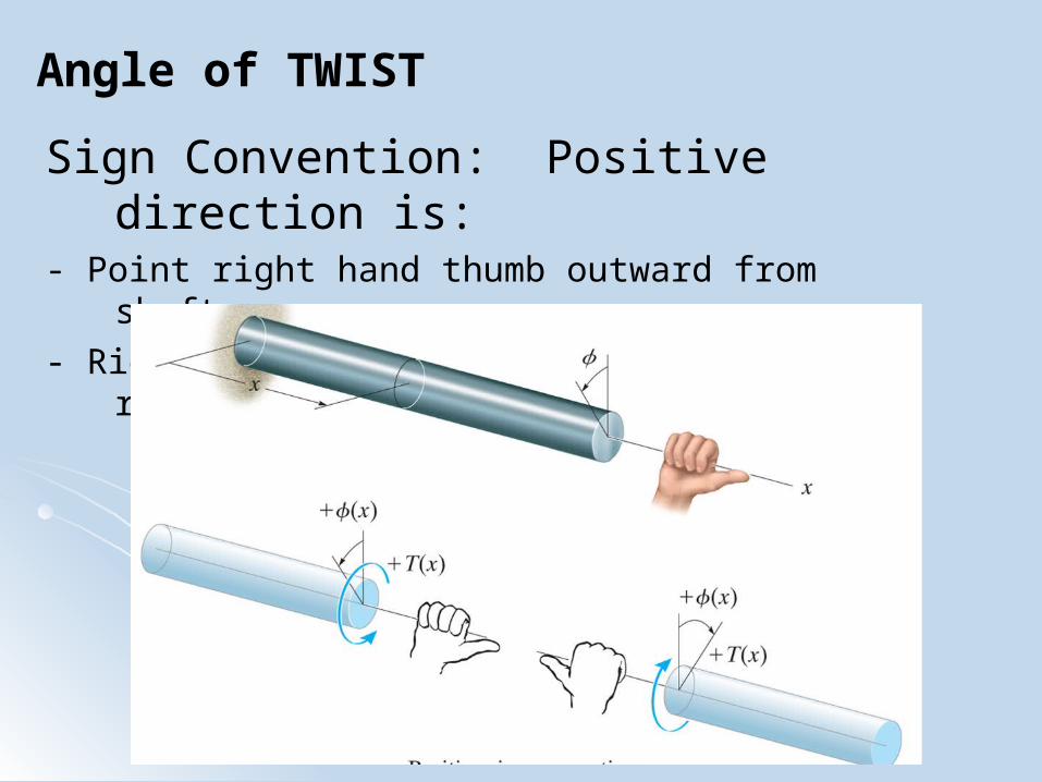
Angle of TWIST
Sign Convention: Positive direction is:- Point right hand thumb outward from shaft
- Right hand fingers curl in positive rotation