10 Clay and Concrete Tiles CHAPTER T oday’s clay and cement roof products all started to develop thou- sands of years ago when man discovered the function and durability of roofs constructed of clay. First appearing in the Bronze Age, sun- baked tiles were found in Crete adorning the palace roofs of local rulers. Millenniums later, Greeks learned to fire-bake clay tiles and applied them to structures as majestic as their renowned temples. Making Clay Tiles Clay tile is still among the most popular roofing materials in Europe, where homes and centers of commerce are designed to last for genera- tions. Their simplicity of form and shape makes traditional, tapered mission tiles ideal for funneling and shedding water from pitched roofs. Modern extrusion and pressed-formed processes and high-tech gas- fired kilns have replaced the primitive method of shaping clay tiles over human thighs and then either baking them in the sun or using wood-fired beehive kilns. With these advances in manufacturing have come tremendous improvements in performance, quality, and product diversity. Today, the manufacture of clay tiles starts with shale that is crushed to a fine powdery clay. The clay is mixed with water and kneaded, or 315
Transcript
10C lay and Concr e t e T i l e s
C H A P T E R
Today’s clay and cement roof products all started to develop thou-sands of years ago when man discovered the function and durability
of roofs constructed of clay. First appearing in the Bronze Age, sun-baked tiles were found in Crete adorning the palace roofs of localrulers. Millenniums later, Greeks learned to fire-bake clay tiles andapplied them to structures as majestic as their renowned temples.
Making Clay TilesClay tile is still among the most popular roofing materials in Europe,where homes and centers of commerce are designed to last for genera-tions. Their simplicity of form and shape makes traditional, taperedmission tiles ideal for funneling and shedding water from pitched roofs.
Modern extrusion and pressed-formed processes and high-tech gas-fired kilns have replaced the primitive method of shaping clay tilesover human thighs and then either baking them in the sun or usingwood-fired beehive kilns. With these advances in manufacturing havecome tremendous improvements in performance, quality, and productdiversity.
Today, the manufacture of clay tiles starts with shale that is crushedto a fine powdery clay. The clay is mixed with water and kneaded, or
3 1 5
Scharff_Chap10_6x9-GOOD 9/21/00 11:23 AM Page 315
pugged, to the consistency of cookie dough. Then, to produce simpleclay tiles, this moist, plastic clay is extruded through a die, like doughthrough a cookie press, and sliced into lengths. More complicatedshapes come from pressing the clay into molds. Some ornamental tilesare even sculpted by hand. The formed tiles dry in a room kept at atemperature of approximately 90 to 95°F. From there, they go to a kilnfor firing.
For their trip through the kiln, the tiles are either stacked on arefractory, which is similar to a railroad car, and pulled through a tun-nel kiln, or laid on ceramic rollers that convey individual tiles througha roller-hearth kiln.
Regardless of the method, the object is to raise the temperature of theclay to the point of vitrification, which is about 2000°F. At this point,the clay minerals lose their individual identity and fuse together.
Coloring Clay Tiles
Clay tiles are available in a wide range of colors. The more sophisti-cated clay tile manufacturers achieve colors through the careful blend-ing and mixing of various clays into complex clay bodies. Hues fromivory and almond to deep reds and browns, apricot to peach and bufftones, and variegated accents are now available to designers. (See App.A for a vendor list.)
In addition, these colors can be enhanced by adding natural flash orvariegated effects through the introduction of streams of natural gasduring the firing process. By controlling the timing, frequency, andlocation of the kiln flashing, an infinite combination of randomlyflashed tiles can be created for that truly custom, one-of-a-kind colorblend.
Another method of coloring tiles is to spray a thin creamy layer ofclay, called a slip, onto the tile before it is fired. The tile then takes onthe color of the slip. The most dramatic, and most expensive, way tocolor tile is with a glaze. The metallic pigments in the glaze, whenfired, melt to a glossy, vitreous, richly colored surface, much like thatfound on ceramic tile used indoors.
Premium clay roof tiles ensure protection from the elements andoffer extended warranty periods. Some manufacturers offer lifetimewarranties and even include fade coverage.
3 1 6 CHAPTER TEN
Scharff_Chap10_6x9-GOOD 9/21/00 11:23 AM Page 316
Clay tiles offer the homeowner and roofing contractor numerousadvantages:
� Tile roofs typically last 50 years or longer and do not rust or oth-erwise deteriorate.
� The color and texture of most tiles is integral and of naturalmaterials that do not fade.
� Tile roofs are more insulating. Clay and concrete tiles resist thepassage of heat gain from summer sun and winter heat loss.
� The mass of tile roofing provides superior insulation fromsound.
� Tile roofs are noncombustible and protect the structure fromburning embers without suffering irreparable damage. Tile andcement roof products carry Class A fire ratings.
Designing Tile Shapes
The roofing industry generally separates roof tile designs into three cat-egories: high profile, low profile, and flat. High-profile tiles are thefamiliar mission, barrel, S, or Spanish-influenced styles (Fig. 10-1).They are available in a variety of integral and applied colors.
According to legend, the curved shape of high-profile tile evolvedin ancient times when craftspeople formed wet clay sections over theirknee to provide added stiffness. These primitive tiles were probablybaked in the sun or placed in wood-fueled fires.
Low-profile tiles are manufactured in numerous different styles byseveral manufacturers (Fig. 10-2). They are also available in a varietyof colors that complement any architectural style.
Flat clay tiles have a shingle shape and are ribbed to simulatewooden shakes or colored to represent slate. Many of the flat clay tilesfeature an interlocking system.
Also available are special clay tile shapes (Fig. 10-3). For instance,closed-ridge end tiles and gable-terminal tiles are designed for gableroofs. Hip-terminal tiles are intended for decorative purposes and areused where a ridge and two or more hips intersect. Graduated tiles ofdiminishing widths are used for round towers, circular bays, andporches. Tile manufacturers furnish graduated tiles in all popular
CLAY AND CONCRETE TILES 3 1 7
Scharff_Chap10_6x9-GOOD 9/21/00 11:23 AM Page 317
Nailhole
Nailhole
Head of tile
Head of tile
Waterlock
Nailholes
Waterlock
Head lugs
Head lugs
Head lugs
Waterlock
Overlay
NoseHip
Water course
Overlay
Nose
Hip
Nose
Water course
Water course
Overlay
Weather checks
Nose lugs
Weather checks
Nose lugs
Weather checks
Nose lugs
Cover
Pan
Underside view of tile
Top view of tile
F I G U R E 1 0 - 1 High-profile S tiles.
Scharff_Chap10_6x9-GOOD 9/21/00 11:24 AM Page 318
shapes. Some manufacturers also offer special valley tile, manufac-tured in angular or round form, and other special shapes for particularapplications.
Making Concrete TilesConcrete tiles are relatively new compared to clay tiles. Although con-crete tiles have been used in Europe and Australia since the mid-1800s, they have enjoyed widespread use in the United States onlysince the mid-1960s.
Concrete tile is composed of portland cement, sand, and water, mixedin varying proportions. These materials are mixed and extruded on indi-vidual molds under high pressure to form the tile product.
CLAY AND CONCRETE TILES 3 1 9
F I G U R E 1 0 - 2 Low-profile tile.
A B C
D E F
High profile High profile High profile
Low profile Flat profile Low profile
20" 20"
6"
18" or 20"
13"
17" 17"
21/2"
123/8"123/8"
161/2"
21/8"
21/2"
71/2"
F I G U R E 1 0 - 3 Special clay tile shapes.
Scharff_Chap10_6x9-GOOD 9/21/00 11:24 AM Page 319
Coloring Concrete Tiles
Concrete tiles are colored by one of two methods. The first is to addiron or synthetic oxide pigment to the batch mix. This produces a uni-form color all the way through the tile. A less expensive method is tocoat the tile with a slurry of cement and iron-oxide pigment. This tech-nique also allows the manufacturer to add highlights of a second color,which creates a shaded or variegated effect.
The particular coloring method used is dictated by several differentrequirements. The first of these relates to cosmetic and aestheticappeal. The color-coated product gives wider color hues, while thebody-colored product is less spectacular, is more subdued in appear-ance, and has a limited color range.
Application requirements for both product types relate primarily toatmospheric and climatic conditions, as well as aesthetic and archi-tectural intent. Experience has shown that the surface-coated productis, generally speaking, more resistant to growth of, and discolorationfrom, moss and lichen, found in tropical areas with high humidity andin areas with large amounts of rainfall.
On the other hand, the color-coated product does not fare well inareas with extreme freeze and thaw conditions or where there is a largeamount of industrial pollution that contributes to such phenomena asacid rain and deposits of atmospheric dirt and grime. The through-color product is more resistant to freeze and thaw conditions and moresubject to discoloration and staining by moss, lichens, and atmos-pheric pollution.
With either coloring method, the tiles are usually sprayed with aclear acrylic sealer. The sealer helps the tiles cure properly. It also con-trols any efflorescence, which is the white powder consisting of freelime that surfaces as concrete ages. The acrylic sealer forces the limeout the underside of the tile, where it doesn’t spoil the appearance.
As a side effect, the sealer gives the tile a slight gloss. This glosswears off in a few years, and the color softens to its true matte finish.
Designing Tile Shapes
Concrete tile has three classifications: flat, roll, and graduated. Flattiles vary in size and have the appearance of slate or wooden shakes.
3 2 0 CHAPTER TEN
Scharff_Chap10_6x9-GOOD 9/21/00 11:24 AM Page 320
Some of these tiles are made of fiber-reinforced cement and come invarious colors. They can be installed on roofs up to 40 feet high inareas with wind speeds up to 80 miles per hour (mph). Some flat tilesare available with interlocking water locks.
Roll tile is pan and cover shaped. It is better known as barrel or mis-sion tile. Graduated tiles of diminishing widths are used for roundtowers, circular bays, and porches. Some tile manufacturers furnishgraduated tiles in all popular shapes.
Preparing the RoofA new roof must receive the same preparation whether clay or con-crete tiles are to be applied.
Matching Roof Slope and Underlayment
Roll or flat tile can be applied to roof decks with slopes of 4 inches perfoot or more when a minimum of one layer of 30- or 43-pound felt isapplied horizontally to serve as the underlayment, and the tiles arenailed or wired with a minimum 3-inch headlap.
Any style of clay or concrete tile can be applied on solid-sheathedroof decks with slopes less than 4 inches per foot when a minimum oftwo layers of 30- or 40-pound nonperforated, asphalt-saturated felt areset in hot asphalt or mastic to serve as the underlayment. One layer ofa modified-bitumen-coated sheet, with laps either torched or heat-welded, is also acceptable.
Over the underlayment, install vertical lath stringers with horizon-tal battens fastened over the stringers. This creates a simulated surfaceover which the tile can be installed. The tile must be installed with aminimum 4-inch headlap.
Preparing Deck Surfaces
If plywood is used as the deck material, use exterior plywood thickenough to satisfy nailing requirements. Separate the plywood panelsby at least 1⁄16 inch to allow for expansion. If wooden planks are usedfor the roof deck, the boards should be a minimum of 1 × 6 inches andshould span a maximum of 24 inches between trusses or rafters.
CLAY AND CONCRETE TILES 3 2 1
Scharff_Chap10_6x9-GOOD 9/21/00 11:24 AM Page 321
When the roof deck is made of concrete, a surface must be providedonto which the tiles can be applied. To create this surface, run 1-×-2-inch, beveled wooden nailing strips of treated lumber from the eavesto the ridge. Embed the strips in the concrete and space them 16 or 24inches on center.
Nail the felt to these nailing strips. Then nail lengths of lath,applied vertically, directly into the beveled nailing strips through thefelt. Finally, nail 1-×-2-inch battens, or stringers, spaced according tothe type of tile to be used, horizontally across the lath. This simulatesa wooden surface that can accommodate the application of tiles. Someconcrete tile manufacturers also produce special wiring systems forsecuring concrete tile to concrete roof decks.
Working with TilesWhen working with tiles, keep the following precautions in mind.
Broken tiles. More tiles are broken in transit and on the ground thanare broken on the roof. Therefore, take great care when unloadingtile at the jobsite. Unload the tile as near as possible to the building,and distribute it so that delivery to the roof is convenient. Save tilesthat have been broken either in transit to the roof or during appli-cation. Use these tiles when cut tiles are required.
Loading tiles. To prevent tiles from breaking or becoming soiled, stackthem not more than six high. Keep nails, cement, and coloringmaterial covered until needed.
Cutting tiles. When tiles must be cut, mark the desired break line onthe tile. Then carefully cut along this line. If too much tile is cutat once, the tile can fracture. The correct cutting procedurerequires that the tile be placed on a tile stake well back from thecutting line and tapped with a hammer. Further trimming shouldbe done with a large pair of pincers. Tile saws or power saws alsocan be used to cut tiles. Diamond-tipped tile saw blades are bestfor this process.
Narrow tiles. Concrete tiles less than three-quarters of the width of afull tile are susceptible to wind damage when used on gable ends.
3 2 2 CHAPTER TEN
Scharff_Chap10_6x9-GOOD 9/21/00 11:24 AM Page 322
Drill an additional nail hole in the top of the tile and place a dab ofroofer’s mastic under the butt end. Mechanically fasten the tilethrough the newly drilled hole. Gable-end partial tiles installed inthis manner can withstand the same windy conditions as the fieldtile.
Drains. To avoid choking drains with broken tile or tile trimmings, donot permanently install drains until tiling work is complete. Keepdrain outlets covered when tiling to prevent any debris from clog-ging the leader pipes.
Making Allowances for Cold WeatherFreeze and thaw conditions are encountered in many areas of theUnited States. A freeze and thaw area is defined as one that experi-ences 30 cycles of freezing and thawing per year. One cycle encom-passes a change in temperature from more than 32°F to less than 30°Fthat is accompanied by moisture that freezes into ice and thaws to aliquid state.
Freeze and thaw failure can occur in just about every product,manufactured or natural, that is exposed to such conditions. Dry, cold-weather temperature fluctuations above and below freezing have littleor no effect on concrete tile.
To protect tile from freeze/thaw conditions, apply a minimum of onelayer of 40-pound coated felt horizontally with a minimum 4-inchheadlap and 6-inch sidelap. Slopes below 4 inches in 12 require a func-tional built-up roof (BUR), a modified bitumen roof (MBR), or a self-adhering, ice-and-water-shielding bitumen membrane underlaymentsystem.
In addition to the 40-pound underlayment, the following isrequired as an ice shield, regardless of slope, on eaves and barges, orrakes. Starting from the eave and barge to a point 36 inches beyond theinside wall line of the structure, use one layer of 40-pound coated feltset in roofer’s mastic or cold-process adhesive, or one layer of self-adhering, ice-and-water-shielding bitumen membrane.
Over the underlayments or decks, fasten a vertical counter-batten,at least 1 × 2 inches, at a minimum of 24 inches on center from the
CLAY AND CONCRETE TILES 3 2 3
Scharff_Chap10_6x9-GOOD 9/21/00 11:24 AM Page 323
eaves to the ridge. Over the vertical counter-batten, fasten a secondhorizontally installed batten, at least 1 × 2 inches, spaced to ensure aminimum 3-inch tile headlap. Use only treated lumber.
This counter-batten system minimizes condensation by allowingair circulation and, with proper ventilation, helps prevent ice-dambuildups. A minimum 4-inch tile headlap is recommended in areaswith heavy snowfalls.
Arranging Colored TilesBlending modern colored clay and concrete tiles can be a rather diffi-cult procedure. To guard against a spotted colored roof, mix tiles in thecorrect color arrangement on the ground and then send them up to theroof in bundles along with strict application instructions. For exam-ple, if the color scheme calls for 10 percent of one color, 30 percent ofanother color, and 60 percent of a third color, send the tiles up to theroof in bundles of 10 tiles, with each bundle having one tile of the firstcolor, three of the second color, and six of the third color.
In this way, the tiles can be applied in the order in which they werebundled, and no time is wasted selecting colors on the roof. Separatethe 10-tile bundles into two stacks of five tiles each when loadingthem onto the roof deck.
After 75 to 100 tiles have been installed, visually inspect theapplied tiles from ground level and at a distance from the building toensure that the tile courses follow straight and true lines and that thecolors of the tile blend well. Repeat this procedure at regular intervalsduring installation to ensure an attractive and acceptable roof. Theblending of tile shades to avoid streaks or hot spots is particularlyimportant. Preblended tiles can be obtained from some manufacturers.
Discuss quality control of material shading and uniformity of tilewith the manufacturer, architect, and building owner prior to contractand prior to placing an order for the product.
Fastening TilesUse nails and screws to hold clay and concrete tiles to decks. Use 3⁄16-inch compression spikes for concrete decks and No. 12 TEK screws for
3 2 4 CHAPTER TEN
Scharff_Chap10_6x9-GOOD 9/21/00 11:24 AM Page 324
steel decks. On a plywood deck, use ring-shank nails of sufficient lengthfor slight penetration through the underside of the deck. For board plankdecks, use smooth-shank nails at least 11⁄2 inches long that do not pene-trate the underside of the deck. For gypsum plank and nailable concretedecks, use stainless steel or silicon-bronze screw-shank nails of a lengthsufficient to penetrate 1⁄2 to 3⁄4 of their length into the deck. Do not pene-trate the underside of the deck. If the deck is excessively hard, usesmooth-shank nails.
Fasteners also can be used to hold tiles. Do not drive home fasten-ers or draw the tile. Drive fasteners to a point where the fastener headjust clears the tile, so that the tile hangs on the fastener. When tiles arefastened too tightly, they lift up at the butt. This allows high winds toblow them off the roof or to blow water under them. On exposed over-hangs, the fasteners should not penetrate the sheathing.
Drive all fasteners into the roof sheathing and not between sheath-ing joints. This is especially important near the top and sides of theroof. When battens are used, drive all fasteners into the batten boards.
Fasten tiles individually. Secure hip and ridge tiles with one nail ineach tile and with a golf-ball-size dab of roofer’s mastic under the tileat the headlap, recessed so that it does not show. Barge or verge tiles,when available, require two nails and roofer’s mastic.
Table 10-1 gives the nailing procedures for attaching clay andconcrete tiles to plywood and wooden sheathing. Battens shouldconsist of a nominal 1-×-2-inch approved material spaced parallelwith the eaves to achieve a minimum 3-inch tile headlap. Use battensover solid sheathing and an approved underlayment. Make provi-sions for drainage at a maximum of every 4 feet past or beneath thebattens. Battens must be attached with four corrosion-resistant fas-teners per batten.
Over concrete decks, use wire tying strips instead of battens tosecure the tiles. Secure angular strips of wire, 11⁄2 × 1⁄2 inches in size,to the concrete deck with expansion bolts. Perforate the wide flangeof the wire strip with holes spaced at regular intervals suitable to thetile exposure. Then run 14-gauge tie wire through these holes and tieit around the holes in the tile covers. Turn up the wire and twist itunder the lap of the succeeding tile.
CLAY AND CONCRETE TILES 3 2 5
Scharff_Chap10_6x9-GOOD 9/21/00 11:24 AM Page 325
When tiles are attached directly to metal purlins, fasten themwith No. 14-gauge, rust-resistant wire or self-tapping screws with aminimum 7⁄16-inch-diameter head. If self-tapping screws are used,they should be capable of penetrating a minimum of 3⁄4 inch into thepurlins.
Either nail or wire each ridge and hip tile in place. If tiles are to bewired in place, lace No. 14-gauge rust-resistant wire through the nailholes in the tiles and securely tie it to the heads of nails driven into theridge or hip boards (Fig. 10-4). A golf-ball-size dab of roofer’s mastic isrequired at the tile headlap. Recess it so that it does not show.
On all roofs, over all roof slopes, and under all conditions, securelyfasten all tiles installed on cantilevered sections of the roof, such asgables or eaves, and all tiles installed at the perimeter of the roof.Where tiles overlap sheet metal, secure them with appropriate tie-wiresystems.
Nails for tile roofs should be made of No. 11-gauge, rust-resistant,aluminum, copper, yellow metal, galvanized, or stainless steel and beof sufficient length to penetrate either 3⁄4 inch into the sheathing or
3 2 6 CHAPTER TEN
TABLE 10-1 Attachment of Tiles to Sheathing
Field tile nailing
Nailing forSolid perimeter
sheathing tile and tile onSolid sheathing without cantilevered
Roof slope with battens battens1 areas2
3/12 to andincluding 5/12 Not required Every tile Every tile
Above 5/12 to Every tile every Every tile Every tileless than 12/12 other row
12/12 and over Every tile Every tile Every tile
1. Battens are required for slopes exceeding 7/12.
2. Perimeter nailing areas including three tile courses but not less than 36 inches from eitherside of hips or ridges and edges of eaves and gable rakes. In special wind areas, as desig-nated by the building official, additional fastenings might be required.
Scharff_Chap10_6x9-GOOD 9/21/00 11:24 AM Page 326
through the thickness of the sheathing, whichever is less. On exposedoverhangs, nails should not penetrate the sheathing.
When specifications require that all tiles be embedded in plasticcement, cover all lateral laps with cement. Use approximately 40 poundsof cement per square. Continuously embedding tiles in plastic cementthroughout the roof restricts roof movement. Cracked tiles can resultbecause of the expansion and contraction of the roofing during changesin temperature. This method of application is not recommended.
Where building officials have designated their localities high-windhazard areas, special fasteners must be used. In these wind hazard areas,secure the nose end of all eaves-course tiles with hurricane clips (Fig.10-5). Hurricane clips are available in different shapes to suit the type ofroof sheathing used. Lay the tileswith a minimum 3-inch headlap.Nail each tile to the roof sheath-ing with one No. 11-gauge, rust-resistant nail with a minimum 5⁄16-inch-diameter head. Apply abead of roofer’s mastic over thenailheads that fasten gable, barge,and ridge tiles.
CLAY AND CONCRETE TILES 3 2 7
.050" stainlesssteel or 16-gaugeelectrogalvanizedsteel or 14-gaugecopper or brass
Twisted-wire systemfor all types of clayand concrete tile for
slopes 2/12 and upover any deck material
including insulation
.050" stainless steel or 16-gaugegalvanized steel, or 16-gaugebrass deck anchor. Seal anchorcompletely with membrane-compatible roofer's mastic afterinstallation of the twisted wire
F I G U R E 1 0 - 4 No. 14-gauge rust-resistant wire.
Use one pertile on sidelap
F I G U R E 1 0 - 5 Hurricane clips.
Scharff_Chap10_6x9-GOOD 9/21/00 11:24 AM Page 327
On extremely steep or vertical roofs, wind currents can cause tilesto rattle. The recommended method for preventing rattling is to usehurricane clips. Another way to prevent tile rattling is to set the buttedge of each tile in a dab of roofer’s mastic. Be careful not to stain thesurface of the exposed tile.
Applying FlashingBasic tile flashing is applied in much the same manner as for slate andwooden shake roofs, which is fully described in Chaps. 8 and 9. Forvalley flashing, use at least 28-gauge, corrosion-resistant metal andextend it at least 11 inches from the centerline of the valley each way.Form a splash diverter rib, as part of the flashing, not less than 1 inchhigh at the flowline. Overlap flashing at least 4 inches. Valley metaland flashing should be in place prior to tile application.
For other flashing, use at least 26-gauge, corrosion-resistantmetal. At the sides of dormers, chimneys, and other walls, extendthe flashing at least 6 inches up the vertical surface. Thoroughlycounterflash and extend the flashing under the tile at least 4 inches.Turn the edge up 11⁄2 inches.
Long runs of flashing materialat parapet walls (Fig. 10-6) andcopings, where roof tiles come toan abrupt termination, can bemade of rigid materials, such as26-gauge, galvanized sheet metal.If rigid materials are used, formthem in such a way that they pro-vide sufficient coverage and ade-quate drainage. Establish anacceptable windblock at longitu-dinal edges of flashings by grout-ing the longitudinal edges withportland cement mortar or byusing alternative materials accept-able to local building officials.Flashing around roof penetrations
3 2 8 CHAPTER TEN
Flashing
TileFelt
Deck
Counterflashing
F I G U R E 1 0 - 6 Flashing material at para-pet walls.
Scharff_Chap10_6x9-GOOD 9/21/00 11:24 AM Page 328
should be in place prior to the application of tiles. Flashing metalshould be at least 28-gauge, galvanized metal or an equivalent noncor-rosive, nonstaining material.
Installing the Tile RoofExamine the areas and conditions under which the tile is to beinstalled. Do not proceed until unsatisfactory conditions have beencorrected. To avoid later disputes, report any such conditions to thecontractor and other subcontractors in writing, and keep these letterson file. Verify that deck surfaces are clean and dry. Remove all foreignparticles from the substrate to assure proper seating and to preventwater damage. Install the specified tiles in strict accordance with per-tinent local code requirements.
On vertical applications, and on extremely steep pitches wherewind currents can cause lift, set the butt of each tile in a bead of thespecified plastic cement or sealant, or provide copper hurricane clipsat intervals. Carefully use plastic cement and sealant. Avoid smearingthe exposed tile surface.
Chalk horizontal and vertical guidelines on the membrane to assurewatertightness and proper appearance. Space the chalklines by mea-suring the delivered tiles for average length and width exposures. Donot exceed an average exposure length of 1⁄4 inch.
Applying Flat Tiles
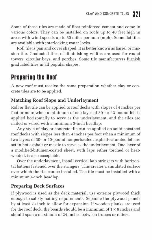
Mark off the roof horizontally. Vertical lines, marked off randomly,help maintain a good vertical alignment. For roofs with pitches of 4/12and above, install 91⁄2-inch eave blocking, which is available from themanufacturer, eave metal, a bead of sealant, and 43-pound felt. Lay thefelt parallel to the eave metal and extend it 1⁄4 inch over the lower edge(Fig. 10-7). Note that some local building codes require an ice-and-water shield along the eaves.
For roofs with pitches below 4/12, install 12-inch eave blocking,eave metal, and a minimum 3-foot-wide strip of ice-and-watershield along all the eaves. Lap the felt 5 inches instead of the stan-dard 33⁄4 inches and install battens that are notched 8 inches on cen-ter (Fig. 10-8).
CLAY AND CONCRETE TILES 3 2 9
Scharff_Chap10_6x9-GOOD 9/21/00 11:24 AM Page 329
On reroofs, or when the eavefascia is not raised, install eaveblocking with a cant strip and usenew eave metal.
When laying out the roof,install a ridge nailer (vent).Next, strike lines that are cen-tered on each hip, if applicable.Then strike the horizontal linefor the top edge of the first bat-ten 131⁄4 inches above the eave
for a typical 153⁄8-inch tile to ensure proper fit of the bottom row oftile. Next, strike the horizontal line for the top edge of the last bat-
3 3 0 CHAPTER TEN
Underlayment
1 � 2 battens
Eave-risermetal withweep holes
Stagger tilecourses
F I G U R E 1 0 - 7 Flat-tile application,pitches 4/12 and above.
Eave drip
Thickbutt tile
Overlap
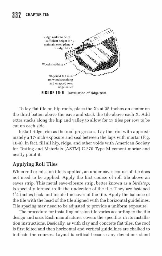
10" mason trowelfull of type M mortar
The head of one tile
The underlock side of one tile
And the underside ofthe tile being laid
Nail here (when required)
Half tile
Fascia
Mortar bed andpoint to finish
Note: mortar contact is made with 3 tiles
F I G U R E 1 0 - 8 Flat-tile application, pitches below 4/12.
Scharff_Chap10_6x9-GOOD 9/21/00 11:24 AM Page 330
ten so that the field tile butts the ridge nailer (vent), which isapproximately 1 inch below.
Then divide the distance between these two lines into equal incre-ments not to exceed 12 inches and strike lines for the top edges of the bat-tens. If different eave lines do not allow for equal spacing, overlap thebottom row to allow the second row to match the rest of the equally spacedrows. If a short row is required, lower the height of the eave fascia boardand use 1⁄2-×-16-inch battens with 1-inch spacing for the bottom row. Doingso allows less than a 10-inch exposure on the bottom tile without causingthe second row to lay at a different pitch from the rest of the tile.
If different ridge heights do not allow for equal spacing, add ashort row along the shortest ridge. If a short row is required, cut offthe head of the tile, drill a new nail hole, and install a thicker battentight to the ridge nailer so that the short row maintains the same pitchas the rest of the tile.
Install hip nailers to within 6 inches of the bottom corner and theninstall the horizontal, 1-×-2-inch batten strips, leaving 1-inch spacesbetween the ends. Use pressure-treated 1-×-2-×-8-inch battens withnotches or ports 16 inches on center. On pitches 4/12 and above,install with 18 fasteners.
On 3/12 to 4/12 pitches and vented cold-roof applications, usepressure-treated 1-×-2-inch-×-6-foot battens with notches or portsevery 8 inches; install with 14 fasteners. Use noncorrosive fasteners ofsufficient length to fully penetrate the roof sheathing. Anotherapproved procedure is to use 1-×-2-inch horizontal batten strips, with-out notches, installed over 1-×-2-inch pressure-treated vertical battens16 inches on center or 1-×-4-inch horizontal battens installed over1-×-2-inch, pressure-treated vertical battens 24 inches on center. Whenusing vertical battens, remember to raise the eave and fascia metal tothe additional thickness of the vertical batten.
For flat tile on gable roofs, put an X on the third batten above theeave, 35 inches on center, starting at the left gable edge. Randomlyplace stacks of four tiles above each X on every other batten. Thenstack four more tiles randomly on top of the existing stacks to get agood color blend across the entire roof position. Put one barge on eachbatten next to the gable edge and install with gable tile or later from aladder or staging after the field tiles are in place.
CLAY AND CONCRETE TILES 3 3 1
Scharff_Chap10_6x9-GOOD 9/21/00 11:24 AM Page 331
To lay flat tile on hip roofs, place the Xs at 35 inches on center onthe third batten above the eave and stack the tile above each X. Addextra stacks along the hip and valley to allow for 11⁄2 tiles per row to becut on each side.
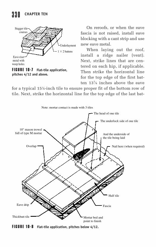
Install ridge trim as the roof progresses. Lay the trim with approxi-mately a 17-inch exposure and seal between the laps with mortar (Fig.10-9). In fact, fill all hip, ridge, and other voids with American Societyfor Testing and Materials (ASTM) C-270 Type M cement mortar andneatly point it.
Applying Roll Tiles
When roll or mission tile is applied, an under-eaves course of tile doesnot need to be applied. Apply the first course of roll tile above aneaves strip. This metal eave-closure strip, better known as a birdstop,is specially formed to fit the underside of the tile. They are fastened11⁄4 inches back and inside the cover of the tile. Apply the balance ofthe tile with the head of the tile aligned with the horizontal guidelines.Tile spacing may need to be adjusted to provide a uniform exposure.
The procedure for installing mission tile varies according to the tiledesign and size. Each manufacturer covers the specifics in its installa-tion instructions. Basically, as with clay and concrete flat tiles, the roofis first felted and then horizontal and vertical guidelines are chalked toindicate the courses. Layout is critical because any deviations stand
3 3 2 CHAPTER TEN
Ridge nailer to be ofsufficient height to
maintain even planeof ridge tiles
Wood sheathing
30-pound felt min.on wood sheathingand wrapped over
ridge nailer
F I G U R E 1 0 - 9 Installation of ridge trim.
Scharff_Chap10_6x9-GOOD 9/21/00 11:24 AM Page 332
out against the pronounced vertical pattern. If the tile is designed withlugs to hang on battens, nail those battens next. Some manufacturersapprove of hanging their tiles on spaced sheathing over heavy feltunderlayment that is draped over the rafters. Load the tiles on the roofso that they are evenly distributed and within easy reach.
Extend the first row of tiles 1⁄2 to 11⁄4 inches over the eaves. Forexample, when a 133⁄4-inch tile is used, strike the first horizontalguideline 12 to 123⁄4 inches from the eavesline. Where chimneys ordormers project through the roof, loosely lay the first course of tilealong the eaves. To minimize tile cutting, secure the tiles to the eavesonly after making adjustments for the projections.
Cut or weave tiles installed down each side of a valley. Valleys canbe open, mitered, swept, rounded, or closed with special tile. Specialvalley tile produces much the same effect as the rounded valley tile. Itis longer than regular tile and fan-shaped. Because of its shape, valleytile need not be nailed, but should be cemented at the laps.
When valley tiles are used, first extend a row of tiles up the val-ley. Tiling then should proceed back toward the valley from theverge or gable. The last tile should be large and trimmed against thevalley tile.
Fit tiles that converge along the hips of a roof close against the hipboard. Make a joint by cementing the hip tile to the hip board withroofing cement or mortar. Color the cement to match the tile. Notchthese cut tiles and either nail or wire them to the hip board. It is advis-able to lay a golf-ball-size dab of roofer’s mastic between the tiles.
Begin the hip roll with a hip starter, which is a hip roll with oneend closed, or a hip stack, which is a stack of hip roll pieces equal inheight to the hip stringer. Nail the hip-starter tile to the hip boardwith nails of appropriate length and follow with the regular hip roll,lapped either 3 inches or in accordance with the manufacturer’srequirements. Cement between the laps. Do not fill the interior spacesof hip or ridge rolls with pointing material, as this material inhibitsair circulation.
Cover ridges in much the same manner as hips. Fill the spacesbetween the tiles in the top row with special ridge fittings or withcement mortar colored to match the tile. When tile fixtures are used atthe ridge, nail the diagonal half of a 2 × 4 on either side of the ridge
CLAY AND CONCRETE TILES 3 3 3
Scharff_Chap10_6x9-GOOD 9/21/00 11:24 AM Page 333
board to provide a nailing surface for the tile fixtures. This is notrequired when portland cement mortar is used as fill material betweenthe last course of tile at the ridge.
Some tile manufacturers make batten strips available for these lay-outs, while others provide detailed drawings with which contractorscan make their own battens.
Spanish or S Tile Designs: Mark off the roof vertically and horizon-tally. Interlocking unlugged tile can be laid with a minimum 21⁄2-inchheadlap. Lugged tile should maintain a 3-inch design for mortar appli-cation. Check with the manufacturer of the particular tile.
Prefabricated Birdstops or Eave Closures: Prefabricated eave closurestrips or mortar can be used to elevate the butt end of the first, or eave,tile to attain the proper slope. When using mortar, provide weep holesnext to the deck to allow proper drainage of any moisture accumula-tion under the tiles. Place a full 10-inch mason’s trowel of mortarunder the pan section of each tile, beginning at the head of the tile inthe preceding course. Press each tile into the interlocking position sothat the cover rests firmly against the lock of the adjacent tile.
Installation details for eaves, ridges, gables, and so forth are givenin Fig. 10-10.
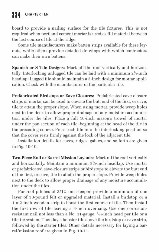
Two-Piece Roll or Barrel Mission Layouts: Mark off the roof verticallyand horizontally. Maintain a minimum 31⁄2-inch headlap. Use mortaror prefabricated eave-closure strips or birdstops to elevate the butt endof the first, or eave, tile to attain the proper slope. Provide weep holesnext to the deck to allow proper drainage of any moisture accumula-tion under the tiles.
For roof pitches of 3/12 and steeper, provide a minimum of onelayer of 30-pound felt or upgraded material. Install a birdstop or a 1-×-2-inch wooden strip to boost the first course of tile. Then installthe first row of tile leaving a 3-inch overhang. Use one corrosion-resistant nail not less than a No. 11-gauge, 5⁄16-inch head per tile or atile-tie system. Then lay a booster tile above the birdstop or eave strip,followed by the starter tiles. Other details necessary for laying a bar-rel/mission roof are given in Fig. 10-11.
3 3 4 CHAPTER TEN
Scharff_Chap10_6x9-GOOD 9/21/00 11:24 AM Page 334
CLAY AND CONCRETE TILES 3 3 5
16"Ridge exposure
Ridge
Ridge tile Mastic cement betweenridge tiles typ.
Nail
Cement mortar
Cement mortar
Optional ridgeclosure
Optional ridgeclosure
Field
Hip
Gable (R)Gable (L)
1�2 wooden stripor birdstop
16" gable exposure
Felt
Birdstop
BirdstopFelt
Felt
Cement mortar
2�6 nailer
Metaledge
2�3 nailer
2�2 nailer
2�3 nailer
2�2 nailer
Tile
Tile
Metal channel flashing
Nail12"
305mm
16"
406mm
16"
483mm
3"
76mm
12"
305mm
Optional 2�3nailer
1"(25mm)
Gable detail
Flashing detailat wall
Ridge detail
Eave detail Flashing detail at wall
Tile
Tile
Counterflashing
FlashingCement mortar
Felt
Felt
Birdstop or 1�2wooden strip
F I G U R E 1 0 - 1 0 Installation details for eaves, ridges, gables.
Scharff_Chap10_6x9-GOOD 9/21/00 11:24 AM Page 335
3 3 6 CHAPTER TEN
Counterflashing
Flashing
Cement mortar
TileFelt
Flashing
Metal channel flashingTile
Felt1"(25mm)
Flashing detail at wall
Ridge detail
Flashing detail at wall
Gable detail
Spacing detail
16"Ridge exposure
Ridge
Cement mortar
Cement mortar
Cement mortar
Optional ridge closure
Field
Felt
Felt2�3 nailer2�2 nailer
2�3 nailer2�3 nailer2�2 nailer2�2 nailer
Felt
FeltFelt
Gable (R)Gable (L)
Gable (R)Gable (L)
1�2 wooden stripor birdstop
6" gable exposure
19"
483mm16"
406mm
3"
76mm
Flashing
Booster
Birdstop
Booster
BirdstopBoostertile
Boostertile
131/2"(343mm) 131/2"(343mm) 131/2"(343mm)
10"254mm 10"254mm
152mm 83mm
�6" 31/4"
F I G U R E 1 0 - 1 1 Laying barrel/mission tile on roof.
Scharff_Chap10_6x9-GOOD 9/21/00 11:24 AM Page 336
Oriental Style: Figure 10-12 shows a typical oriental roll-style tile lay-out and installation details. Without the use of ornaments, this tile isused in western contemporary designs. While the most traditionalcolor for a Japanese-style tea house or temple is black, these oriental-style tiles are available in natural red and glazed colors.
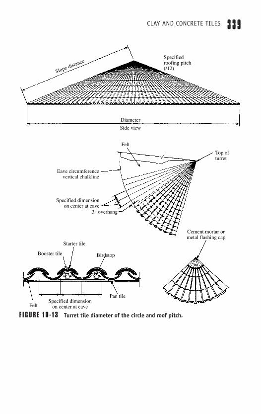
Turret Tile
True turret roof designs or fan-shaped applications are now possiblewithout compromising design concepts. To determine the quantity oftile needed and specific installation guidelines for a given job, ask themanufacturer to provide a scale drawing or blueprint of the top andside views. All that the manufacturer needs is the diameter of the cir-cle and roof pitch (Fig. 10-13).
The following are general instructions for installing turret tiles.
� At the first course, between vertical chalklines, install a claybirdstop and then place the pan tile on top of the vertical chalk-line.
� Fasten each pan tile with a copper or other noncorrosive 11-gauge, large-headed nail, or use the wire-tie system.
� If the job site is located in a high-wind area, use mortar or othersealant to secure the pan tile.
� Once the birdstop and pan tiles are in place, install the boosterand starter tile. Secure with copper wire or noncorrosive nails.
� For the rest of the courses, lay 16 inches to the weather. Whenthe tile becomes crowded, adjust to the next smaller size andcontinue to the top of the roof.
� Follow the chalkline and use the turret worksheet provided bythe manufacturer.
Prior to installing the last two or three courses, lay a mockup toassure proper fit. Do not use adhesives or nails to secure the tiles untilthe mockup is complete and satisfactory. Note that the final two orthree courses normally lose one to two lines, or more, close to the top.Start installing the final two or three courses from the top down andsecure each tile.
CLAY AND CONCRETE TILES 3 3 7
Scharff_Chap10_6x9-GOOD 9/21/00 11:24 AM Page 337
3 3 8 CHAPTER TEN
91 /2"
241mm
Field
Field
Field
Two forked ridgeThree forked ridge
Ridge down end
Forkedeave
EaveGablercorner(left)
Gabler corner (right)
Gable(left)
Gable(right)
Ridge starter (with joint)
RidgeRidge end
Ridge field (optional)
Eave tile
Right gable corner
Gable (R)
266mm
184mm
Gable (L)
Field tile
Field tileFelt11/2"(38mm)
overlap size
Ridge end
Cementmortar
Ridge(outlet width 73/4")
Ridge starter
101/2"
24 Ga. galv. metal plasterstop and flashing
24 Ga. galv. metal plasterstop and flashing
24 Ga. galv. metal panflashing
24 Ga. galv. metal pan flashing1�6 nailer1�6 nailer
Left gablecorner
Plywood sheathing Plywood sheathing
#30 felt #30 felt�8"
�203mm �203mm
�3"(76mm)
�8"
2"(51mm)
7" 101/2" 101/2" 10"
178mm 266mm
71/4"
3 /4"
12"266mm
91/2"
241mm9"
228mm9"
228mm
19mm
266mm 254mm
Gable (L) Gable (R)
Side detail
Ridge detail
Flashingdetail
at wall
End detail
Ridge
Felt
Flashing
Eave tileField tile 1�2 battens
2�2 eave strip
2�6 nailer
1�2 wood strip
Cement mortar
Plywood sheathing
Ridge field (optional)
#30 felt
3"
76mm
F I G U R E 1 0 - 1 2 Typical oriental roll-style tile layout and installation details.
Scharff_Chap10_6x9-GOOD 9/21/00 11:24 AM Page 338
CLAY AND CONCRETE TILES 3 3 9
Diameter
Side view
Specifiedroofing pitch(/12)
Slope distance
Cement mortar ormetal flashing cap
Top ofturret
Eave circumferencevertical chalkline
Specified dimensionon center at eave
3" overhang
Pan tileSpecified dimension
on center at eaveFelt
Felt
Birdstop
Starter tile
Booster tile
F I G U R E 1 0 - 1 3 Turret tile diameter of the circle and roof pitch.
Scharff_Chap10_6x9-GOOD 9/21/00 11:24 AM Page 339
After any style clay or concrete tile roof is laid completely, do notallow traffic on the roof that might vibrate the framing or roof sheeting.At least 24 hours are needed to ensure a proper set. Prohibit roof traf-fic for at least 72 hours.
Installing Low-Slope, Mortar-Set Roofs
Roofing tiles have been installed in mortar for centuries. The prac-tice of installing tiles with mortar over a built-up subroof evolved inhigh-wind and high-moisture areas of the southeastern UnitedStates. In this system, the built-up subroof provides the moisturebarrier and the tiles, in addition to being aesthetically pleasing, pro-tect the subroof from the sun’s ultraviolet (UV) rays, high winds, andexternal damage. The system also allows the use of tile on lower-sloped roofs.
Apply the mortar over a solid sheathing of at least 5⁄8-inch plywoodor 1-inch tongue and groove and mechanically fasten one layer of atleast 30-pound organic felt underlayment to the sheathing. Afterapplying the first layer, install metal eave flashings. Next, apply onelayer of mineral-surfaced rolled roofing material to the underlaymentwith hot steep asphalt or mastic and then backnail. Other mineral-sur-faced products can be used, such as MBR, although care should betaken to guard against roof slippage.
Mortared tile can be used on slopes a minimum of 2 inches in 12.On slopes between 5 inches in 12 and 7 inches in 12, additionalmechanical fastening is required for the first three courses in areassubject to high winds. On slopes 7 inches in 12 and steeper, mechan-ically fasten all tiles. Mortar used to adhere tile to the subroofshould be as specified in ASTM Specification C-270 Type M. Soak-ing the tile prior to installation, adding additives to the mortar, orboth, might be required to achieve proper adhesion between mortarand tile.
In areas of the country subject to blowing sand or heavy rainfall,use mortar at ridge or hip intersections to provide a weatherblock. Usemortar sparingly and only to provide proper bedding for hip or ridgetiles. Specially designed metal weatherblocks are available from mostmanufacturers.
3 4 0 CHAPTER TEN
Scharff_Chap10_6x9-GOOD 9/21/00 11:24 AM Page 340
Reroofing Tile RoofsRoofing contractors, architects, and specifiers, particularly those in theSunbelt or Western states, sometimes encounter a reroofing projectthat involves a clay tile roof that is 70 years old or more. Their firstimpulse might be to draw up specifications for the job on the assump-tion that the existing tile needs to be entirely removed and replacedwith new material. This thinking is understandable. UV radiation,heat, moisture, and exposure to the elements work together to limit thelife span of most roofing materials to 25 years or less.
But first-quality clay roofing tiles are different. They last indefi-nitely if the roof is properly laid and maintained. There are manyexamples of old roofs that remain basically sound, with the clay tileintact and the underlayment in generally good repair. When theseroofs begin to leak, it is often a result of problems with the underlay-ment. The tile often can be used again.
Failure to understand the long-lasting nature of the best clay tilescould be a costly mistake. A simple computation based on the moneysaved in new materials, plus the life-cycle cost benefits offered by tileroofing, normally results in a reroofing specification based on lifting andrelaying the existing tile. Even if the existing tile is in good conditionoverall, however, there can be broken or damaged tiles on the roof.
The first step in assessing the condition of the roof can be conductedfrom the ground. Using a predetermined test area, count the number ofbroken or damaged tiles to get a percentage of probable breakage. Thesurvey can be done with binoculars, and normally provides a reliable,rough estimate of how many tiles need to be replaced.
Deterioration in clay roofing tile is easy to spot. It is almost invari-ably the result of water absorption in tiles that were not manufacturedproperly. Most roofing tile failures can be traced to the use of inade-quate raw materials or lack of proper time and care in the productionprocess. The inferior tiles that result have a tendency to absorb mois-ture. The moisture then expands and contracts in response to theextremes of the freeze and thaw cycle in the north and to heating bythe sun in warmer climates. This process causes the tile body to flakeand spall.
CLAY AND CONCRETE TILES 3 4 1
Scharff_Chap10_6x9-GOOD 9/21/00 11:24 AM Page 341
The first sign of trouble is usually small chips of tile in gutters oraround the foundation. Areas of discoloration, visible from a distance,might indicate that the internal body of the tile, which is lighter incolor, is showing because the surface has chipped or flaked. The tilemight appear fuzzy at the edges, and the shapes might be unclear. Acloser inspection on the roof itself might reveal a crazed pattern ofcracks in individual tile bodies. If such problems with spalling, crack-ing, etc., are widespread, the tile may in fact be deteriorated and inneed of replacement.
With luck, the buildings’s owner made the decision decades ago touse a tile designed to last the lifetime of the structure and damage islimited to isolated cases of broken or detached tiles. If there is anydoubt, take representative samples and send them out to a reputabletile manufacturer who offers a testing service. The tests look at themajor factors in tile condition: pore structure, compressive strength,and water absorption rates. Good results on these tests indicate thatthe tile is a strong candidate for additional decades of useful life.
Contractors reviewing the specifications for a job involving theremoval and relaying of a tile roof may not be completely familiarwith the procedure. There are many questions that should beanswered before they go forward with a bid based on this approach.These questions can be answered by the tile manufacturer or the localrepresentative.
An experienced roofer working from the manufacturer’s installa-tion manual normally has no more difficulty laying a tile roof than ashingle one. The major difference between the two is that tile is a firedmaterial. It must be cut using special tools and is subject to breakage.More care is required when handling tiles.
When lifting and relaying tile roofs, weight can be a concern. If ade-quate scaffolding is available, or if the structure is deemed strongenough, the tiles can be lifted in sections and stacked near the workarea. Common sense and experience are normally enough to let theroofer know whether this kind of loading might cause movement orpossible collapse. When any doubt exists, consult with an engineer. Ifthe roof or scaffolding is not strong enough, move the tile to the groundvia a conveyor belt and develop a plan for restocking the roof with tileas needed.
3 4 2 CHAPTER TEN
Scharff_Chap10_6x9-GOOD 9/21/00 11:24 AM Page 342
The actual removal of existing tile is extremely easy. The tile is sim-ply lifted and rotated, which normally pries out the nail. After theunderlayment and deck are deemed satisfactory, the tiles can be relaidin the same manner as new tiles.
Installing Fiber Cement ShakesA relative newcomer to concrete roofing is the fiber cement shake.This roofing product has the natural texture and tones of real cedarshakes with the added benefit of a Class A fire rating. Shakes resist thedamaging effects of sun, water, humidity, rot, fungus, and termites.They contain no asbestos, formaldehyde, or resins.
For roof pitches 4/12 and greater, cement slates and shakes can beinstalled over spaced or solid sheathing (Fig. 10-14). Install 18-inch-wide, 30-pound underlayment, the starter course at a 9-inch exposure,and then succeeding field courses at a typical 10-inch exposure. Lapthe underlayment over the ridge and hip to create a double layer.
For a 1-inch stagger, use a 9-inch underlayment exposure. Someregions require application oversolid sheathing. Contact the localbuilding department for sheath-ing code requirements.
For roof pitches 3/12 and lessthan 4/12, lay shingles over solidsheathing. For 4/12 and greaterpitches, install a 36-inch, 15-pound underlayment describedpreviously. For roof pitches under3/12, install for appearance onlyover an approved sealed-mem-brane, low-slope roof system.
In snow areas, an approved 36-inch snow-and-ice moisture bar-rier is recommended at the eave.
To lay fiber-cement shinglesfollow these steps. (See also Fig.10-15.)
CLAY AND CONCRETE TILES 3 4 3
Spacedsheathing
18" interlaymentbetweencourses
Cant strip
F I G U R E 1 0 - 1 4 Installing cement slateand shakes over spaced or solid sheathingon roofs with pitch of 4/12 and greater.
Scharff_Chap10_6x9-GOOD 9/21/00 11:24 AM Page 343
3 4 4 CHAPTER TEN
F I G U R E 1 0 - 1 5 Installing fiber cement shingles.
� Item
Install a 1⁄4-inch cant strip flush along the eave over the interlayment and beneath the starter course.
Install the starter course face down, with up to 11⁄2inches overhang at eave and 11⁄2 to 2 inches at rake.
Fasten the starter course with 13⁄4-inch corrosion-resist-ant nails, staples, or screws, located within 1 inch of the eave line.
Interlap field shakes with interlayment to create an approximate 2-inch headlap and a typical 10-inch exposure to the weather.
Install shakes with an approximate 1⁄2-inch keyway and 11⁄2-inch minimum sidelap. Applications with more narrow keyways require additional material, which changes the appearance of the roof.
Alternate the sequence of shake widths every third to fifth course to avoid a stair-step pattern.
Fasten the field shakes with either two 16-gauge, 7⁄16-inch crown, 13⁄4-inch galvanized staples, or 13-gauge nails or screws. Locate the fasteners approximately 101⁄2to 111⁄2 inches above the butt, and 1 inch in from each side of the shake.
Do not walk on the smooth surface of installed field shakes.
Scharff_Chap10_6x9-GOOD 9/21/00 11:24 AM Page 344
� Install a 1⁄4-inch cant strip flush along the eave over the interlay-ment and beneath the starter course.
� Install the starter course face down, with up to 11⁄2 inches over-hang at eave and 11⁄2 to 2 inches at rake.
� Fasten the starter course with 13⁄4-inch corrosion-resistant nails,staples, or screws, located within 1 inch of the eave line.
� Interlap field shakes with interlayment to create an approximate2-inch headlap and a typical 10-inch exposure to the weather.
� Install shakes with an approximate 1⁄2-inch keyway and 11⁄2-inch minimum sidelap. Applications with more narrow key-ways require additional material, which changes the appearanceof the roof.
� Alternate the sequence of shake widths every third to fifthcourse to avoid a stair-step pattern.
� Fasten the field shakes with either two 16-gauge, 7⁄16-inch crown,13⁄4-inch galvanized staples, or 13-gauge nails or screws. Locatethe fasteners approximately 101⁄2 to 111⁄2 inches above the butt,and 1 inch in from each side of the shake.
� Fasteners must penetrate through the tail of the shake beneathand 3⁄4 inch of the sheathing or its full thickness, whichever isless.
� Do not walk on the smooth surface of installed field shakes.
The treatment at ridge and hip and in the valleys and the flashingat chimneys, vents, and so on, are handled in the same manner as thatdescribed for wooden shakes and slate in Chaps. 8 and 9.
Cement fiber shakes usually can be applied over one existing com-position or wooden-shingle roof system, if the existing roof is rela-tively smooth and uniform. Wind-resistance performance applies onlyif fasteners penetrate the sheathing as specified. Structural evaluationand local building code approval is required. Longer fasteners arerequired.