o MIL-STD-00419B( SHIPS) 24 February 1975 USED IN LIEU OF MI L- STD-419A 22 January 1964 (See 6.1) MILITARY STANDARD CLEANING AND PROTECTING PIPING, TUBING, AND FITTINGS FOR HYDRAULIC POWER TRANSMISSION EQUIPMENT . FSC MISC Downloaded from http://www.everyspec.com
Transcript
oMIL-STD-00419B( SHIPS)24 February 1975
USED IN LIEU OFMI L- STD-419A22 January 1964(See 6.1)
MILITARY STANDARD
CLEANING AND PROTECTING
PIPING, TUBING, AND FITTINGS
FOR HYDRAULIC POWER
TRANSMISSION EQUIPMENT
.
FSC MISC
Downloaded from http://www.everyspec.com
MIL-sTD-00419B (SHIPS)24 February 1975
DEPART?.!ENTOF THE NAVY
NAVAL SHIP ENGINEERING CENTER
IIYATT5V1LLE, MARYLAND 20782
Cleaning and Protecting Piping, Tubing, and Fittingsfor Hydraulic Power Transmission Equipment
MIL-STD-00419B (SH1PS)
1. This Military Standard is approved for use by all activities under the cognizanceof tbe Naval Sea systems command.
2. Recommended corrections, additions, or deletions should be addressed to tbeCommander, Naval ship Engineering center, Department of the Navy, Center Building, PrinceGeorge, s center, IIyatts”ille, ?4ary1a”d 20782.
1.1 This standard cover. the requirements governing the basic methcds of cleaning andprotecting nonferrous and ferrous metal and alloyed pipe, tubing, and fittings prior toinstallation and after hydraulic tests in hydraulic power transmission applications. Thisstandard is applicable to hydraulic components used in systems filled with either petroleumoil cm a phosphate ester type fluid.
#form
2. HEPERENCED DOCUMENTS
2.1 The issues of the followi”q documents i“ effeet on the date of invitation for bidsa Part of this standard to the extent specified herein.
(Copies of specifications, standards, drawings, and publications required by suppliersin connection with suecific rmmcurement functions should be obtained from the procuringactivity or as direc~ed by tke contracting officer. )
Downloaded from http://www.everyspec.com
xIL-STD-00419B (SIIIPS)24 Febru?.rv 1975
NONGOVERNMENTAL
14AT10NAL STANDARDS As50c1AT10N [NSA)NAS 1638 - Cleanliness of Parts Used in Hydraulic Systems.
●(Application fox copies should be addressed to the National standards Association, Inc. ,
1321 Fourteenth Street, N.W. , Washington D. C. 20005. )
SOCIETY OF AUTOMOTIVE ENGINEERS (sAE)ARP 598 - The Dete.minatirm of Particulate Contamination i“
Liquids by the Particle count Method.
(Application for copies should be addressed to the society of A“tornotive Engineers,Inc. , 2 Pennsylvania Plaza, New York, N’i10001. )
MERICAN sfxlETY FOR TEsTING AND IRTERIALS (ASTM)D 1744 - tiater in Liquid Petroleum Products by Karl Fischer Reagent.
(Application for copies should be addressed to the Mnerica” Society for Testing andBtaterial., 1916 Race Street, Philadelphia, PA 19103. )
OCCUPATIONAL SAFETY AND HEALTH ADM1N1STPATION (OSHA.)Occupational safety and Health standards, Parts 1910 and1926, Title 29, USC.
(Application for copies should be addressed to the Superintendent of Documents, Govern-ment Printing office, Wasbimg.t.an,D. C. 20402. )
AMERICAN NATIONAL STAIIDASDS lIJSTITUTE (ANSI)B93.28 - I’lethodfor Calibration of Liquid Automatic Particle
Counters using “AC88Fine Test Dust.
lAPP1ication for coPies should be addressed to the America” National standards In.tit”te,1430 Broadway, New York, NY 10018. )
3. DEF1N1TIONS (Not applicable) .
4. GENERAL REQUIREMENTS O’# 4.1 Pipe t“bi”g and fittings related to the hydraulic power transmission eq”iprnent
—
shall be thoro”yhly cle,med and pickled as necessary prior to installation (see 5.2). They
shall be free from scale and foreign matter which codd be detrimental to operation ofhydraulic equipment such as pumps, motors, valve. , rams, and accumulators.
# 4.2 Pipe required to complete a hydraulic installation shall be fabricated in a shopwhere adequate facilities exist. However, shipboard or vehicle fabrication is allowed, pro-vided adequate provisions exist to allow cleanliness controls and preclude damaqe to eq”ip-rnent. Subassemblies shall be med to the maximum extent practicable. After fabrication andbe”dinq operations are completed, the fabricated and bent pipe, tubing, and fittings shall becleaned and pickled in accordance with tbe pxo.edures specified herein. Hydraulic componentswhich may be constructed of materials not compatible with tbe pickling solution shall not beimnexsed in the cleaning cm pickling baths. Complex components, such as pumps, values, andrams, which may be compatible with the pickling solution b“t will rt?q”ire disassembly to re-move residual fluids, shall not be immersed in the clea”in~ or pickling batbs.
# 4.3 Sand, shot, or other abrasive blasting is not permitted on any part of the hydrau-lic system. unless a separate isolated room is provided in the shop for fabrication ofhydraulic piping, abrasive blasting shall be prohibited in the sane b“ildinq that an openhydraulic component is hcmsed. Abrasive blasting, chipping, or grindinq “ill “Ot be per-mitted in the vicinity of an installation site for an open hydraulic system.
4.4 Hydraulic pipe or t“binq shall not be packed with sand d“rinq the bending process.
4.5 The pipe and tubinq shall not be wire brushed after pickling.
4.6 Cloth or paper material shall “ot be used in dryinq operations, nor for cappi”qopen ends (see 5.7).
2
Downloaded from http://www.everyspec.com
4.7 The interior andcorrosion-resistant steel)
MIL-STD-00419B (SHIPS) /24 February 1975
exterior of the ferrous pipe, tubing and fittings (exceptshall be treated as specified in 5.5 to prevent rust.
./’/
4.8 openings shall be capped and sealed air tight after the cleaning process,wi tb amaterial in accordance with MIL-c-5501 (see 5.7). The openings shall remain capped untilimmediately before connecting to tbe equipment for which the pipe is intended,
4.9 Pipe or tubing that has had heat applied at the site of inst=ll~ to assist informing shall be returned to the shop or othex areas where facilities exist for recleaning,repickling, and retesting.
5. DE1’AIL RE12uIREfiE!JTS
5.1 - recautions. The contractor cm shipyard representative shall insure that~ through the safety s.perinte”dent to provide adecp.te personnelthis clearing 1s coor mate
protection from acid and chemical hazards. In general, all chemicals involved are harmfulto the eyes and skLn. Personal contact with chemicals should be avoided. Obtain medicalattention immediately if acid or caustic get in the eyes. Face shields or goggles must beworn by personnel dumping che”icals into mixing tanks. Avoid breathing mists or vapors overmixing tanks. Rubber overshoes or boots, gloves, aprons, and hats, or other fod weathergear are required for personnel wbo are mixing caustic or acidic cleaning solutions.
pc.11.~~~ts%%%.arged to the water and ... be toxic to fresh wter and marine organisms.The cleaning and treatment compounds described herein are environmental
Disposal procedures specified. in 5.9 shall be followed. The following procedure shall befollowed in preparation for pickling:
(a)
(b)[c)
, (d)4 (e)
#
Wire-brush entire surface, including interior. Boiler tube brushesor commercial pipe-cleaning apparatus may be used.Blast thoroughly with air to remove loose particles.Remove grease, oil, and shop dirt by immersinq the work in sufficientquantity of the following solution at 200~ ~ IO*F for 15 mimItes orlonger, depending upon the degree of contamukation:
Trisodium phosphate (see o-s-642) or sodiumhydroxide (lye) (see O-S-598). . . . . . . . . . . . . .7 to 10 ounces.
Water . . . . . . . . . . . . . . . . . . . . . . . . . .1 gallon.Rinse thoroughly in warm “ater (at least 120”F).If cleaned pipe, tubing, and fittings are not pickled immediately,drywith warm, dry, oil-free air which has been filtered throughat least 15-rnicrometre absolute rated filters (hereafter referredto only as clean air] and protect from dust, dirt, oil andmoist ure.
S.3 Picklin and h droskatic tests ( rior to installation).tests shalha~r~t~obs~pecified
Pickling a“d hydrostaticberem. Caution shall be exer-
cised by tbe operator during the pickling process insofar as time of immersion in the acidbath is concerned. The assembly shall remain in the bath only long enough to permit adequatepickling [removal of scale), as determined visually. D“.? to the nature of the picklingprocess, this caution is necessary to insure and protect the mechanical properties of thepipe, tub,ng, or fitting. The position of the tubing in the pickling bath ShOuldbe Changedoccasionally to make sure that if gas pockets form they shall not always be at the samelocation. When hydraulic fluid is used for hydrostatic testing, the assembly shall be de-greased just prior to further brazing or welding.
5.3.1 Nonferrous p&e, tubing, and fittings (bronze, =, copper-nickel, and nickel-
~, 29!2~.—
3
Downloaded from http://www.everyspec.com
\
\ MIL-STD-00419B(SHIPS)24 February 1975
\.a= ,o,,ow~:5.3.1.1 Nonferrous metals other than nickel-copper. The pickling procedure shall be ●k
~(a) Pickle free from scale in a solution of the followitrqat room temperature:
~ulf.ric acid, 66 degrees Baw’, specific gravity(sPTgr.), 1.83, conforming to type 1, class 1 of0-S-809 . ... .. . . . . . . . . . . . . . . . . . . .
Treatment following pick linq. The treatment following piokling shall be as
Immediately after pickling, rinse in a clean, warm water bath.Neutralize traces of acid from the pickling operation by ri”si”gthe work in a“ alkaline bath containing 4 ounces (per gallon ofwater) of soda ash conforminy to 0-s-5 71.Rinse thoro”qhly in fresh, warn water.If hydrostatic test will not be performed with water (see5.3.1.41, dry with clean air.
#to the specifi-s~ w~t.p water, f,
5.3.1.4 H dr.astatic test rior ~ installation. The piping assenbly shall be subjectedu>d in accordance with MIL-C-81302, or with
a hydraulic fluid equal to, or compatible with, that normally used in the system. If leakso.cur, they shall be repaired and the assembly repickled and retested. Follo”ing a satis-factory test, the aoLution shall be drained and all openings capped. If water or MIL-C-81302 fluid is nsed, the assembly shall be blown dry by clean air before openings are capped.The piping assembly shall then be installed up to the components (see se.stion 4 and 5.3) .
pickling procedure s%% b+ol=s&3~ —5.3.2 Ferrous i e, tubin , and fittin s (other than corrosion-resistant steel) . The
(a) Pickle free from rust and scale in a hot solution (150. ~ 10.F)of the follc.wzng composition:
Sulfuric acid, 66 degrees Bam&, sp. qr. 1.83 conformingto type 1, class 1 of 0-s-809. . . . . . . . . . . . .7 to 14 fluid ounces.
2.1 Treatment following pickling. The treatment following pickling shall be as,.
la) Rinse immediately after pickling in a clean, warm water bath.(b) Iumerse for several minutes in an alkaline bath containing 4 ounces
(per 9a110n of water), Of sOda ash conforming tO 0-s-571.(c) Rinse by immersing in a clean, warm water bath.(d) l_rs. in a solution composed of 1 ounce sodium chromate (per
gallon of water) conforming to 0-S-588 for at least 2 minutesat room temperature.
(e) If the hydrostatic test is to be performed with hydraulic fluid[see 5.3.2.2) , rinse the work with clean water, then dry withclean air.
5.3.2.2 H drostatic test prior to installation.~ —
The piping assembly shall be subjectedto the specifle test pressure using a sodium chromate solution (1 ounce sodium chromate pergallon of water) or with a hydradic fluid equal to, or compatible with, that normally usedin the system. If leaks occur, they shall be repaired and the assembly repickled, treated,and retested as specified herein. Following a satisfactory test, the fluid shall be drainedand all openimgs capped. If a water solution has been used, the assembly shall be blowndry with clean air before openimgs are capped. The piping assembly shall then be installedup to the components (see section 4 and 5.3) .
5.3.3 Corrosion-resistant steel pipe, tubin~, @ fittings. The pickling operationshall be as i%llo”s (see 5.3]: —
(a) Immerse work for 10 to 15 minutes in a hot solution (130” ~ 10”F)of the following composition:
water. . . . . . . . . . . . . . . . . . . 1 gallon.(b) Rinse in a clean, warm wter bath.(c) If hydrostatic test will not be perfomned with water (see 5.3.1. 4),
dry the piping assembly with clean air.
5.3 .3.1 H drostatic test rior to installation.~ *–
The piping assembly shall be subjectedto tbe test Specl le I. Sm.
5.4 Flush of installed - for removal of brazin fluxes. The entire PiPin9 sYstem,after instEEi6ii up to, –+b“t not ,n=d~e .omponen s~ be flmhed to removebrazing fluxes. Flushing blocks and other jumpers shall be used to connect piping aroundcomponents not being fl“shed. Before filling the system with water, a low pressure air test(uP to 100 pounds per square inch (P.s.i.)) shall be applied to the piping to check forleaks. my one of the three following procedures shall be conducted. (The hot flwh and botcirculation methods are preferred. ) Flmh water containing flux residues may be dischargedto a sanitary sewer system or overboard if connection to a sewer is “ot feasible.
(a) Hot flush with nonrecirculating fresh water for 1 hour whileensuring that the temperature at a“y part of the system doesnot go below llOeF.
(b) As an alternative to the hot flush procedmre, a hot recircnlatinqprocedure with fresh water may be conducted for a period of 1hour for systems where such an arrangement is feasible. Thesystem temperature shall be monitored so that no part of thesystem falls below 11O”F. Following the recirculating, thesystem should be flushed with fresh water for 15 minutes at aminimum temperature of 60‘F.
(c) C~~6fl~ the system for 12 hours using fresh water at a minimum”.ltthe completion of the 12-hour soak, systems shall
be flwhed with mnrecirc”latinq fresh water at a minimum of60eF for 4 hours.
Under all of the above flux removal procedures, the SYSternshall be full of water so thatjoints are completely submerged at all times. The minimum flow rate in gallons per minute(gal/mln) required for removal of residual brazing flux in piPing systems shall be 1.5 times,the internal pipe diameter (id. ) in inches. upon completion of the flux removal procedure,completely drain the syste!nand dry with air.
5
Downloaded from http://www.everyspec.com
?
#
#
#
#
#
MIL-STD-00419B (SHIPS)24 February 1975
5.5 Hydrostatic test after installation. The entire piping zy.tem, after installationup to the components, ~l~n~ oto t e specified test pressux. with tap water, fluidin accordance with MIL-C-81302, or with a hydraulic fluid equal to, or compatible with, thefluid mxmally used in the system. If water has been used. the system shall be drainedcompletely after the test and blow” dry with clean air. components and piping assemblieswhich passed a hydrostatic test prior to installation need not be retested. However, thoseconnections by which the tested units and assemblies axe pipecl to the system shall require ahydrostatic test.
5.5.1 Hydraulic systems and components which are subject to corrosion shall be pre-served in accordance with 141L-P-116. Prior to assembly, ?.11oil films and preser”.ativesshall be removed from those sections which shall be subjected to “elding or brazing operations.Assembled systems which have been protected by a preservative fluid in accordance with MIL-lf-6083 or MIL-C-23112 shall be thoroughly draimsd and blow! down before adding tbe systemfluid. (See 5.9 for disposal instructions for these fluids. ) If the assembled system hasnot been thoroughly cleaned prior to adding protective fluids, a complete flush (see 5.6 )shall be required before putting the system into opexation.
5.5.1.1 Assetiled ~. Hydraulic systems which are to be left inactive for 6months or less shall he Protected by filling with the system fluid. Those systems which areto be left inactiws for an extended period (6 months or more) shall be filled with a suit?.blepreservative fluid. For ?.ystems contai”i”g petroleum base fluids, the preservative fl“idshall conform to MIL-H-6083. FQr system. containing phosphate ester base hydraulic fluidss“cb as MIL-H-19457 fluids, the preservative fluids shall conform to MIL-c-23112. Adeq”a t.vents and tanks shal 1 be provided to compensate for the expandimg and contracting fluid a“dminor system leak!+. When the system is preserved with other than the normal system fluid,tags with the followin.g infonnation sh.11 be conspicuously attached:
‘“Thissystem has been filled withpreservative fluid to (specifica-tion) on (date). This fluid mustbe completely blown down anddraimed before adding systanfluid. =
;e~~~~~;;al%%?%%orda”ce “ith the req.irermmt. specified in 5.5.1.2.1 throughIf system components are not to be installed immediately, pre-
. . . . .
5.5.1 .2.1 Short term (internal surfaces)-. For petroleum oil system components, shortterm preservatio~i~nal surfaces shall be accomplished with fluids conforming toMIL-H-6083 . For phosphate-ester system components, internal surfaces shall be preservedwith fluids conforming to MIL-C-23112. Preservation with coati”qs in accordance withMIL-H-6083 or MIL-c-23112 fluids are satisfactory for cme year, after which recoating is re-quired. Since these fluids, in small quantities, are compatible With the system operatingfluids, draining of residual fluid prior to installaticx will provide adequate removal ofthe preservatives. (See 5.9 for disposal instructions for these fl”ias .) (See 5.6.2 fordefinition of acceptable liquid contamination. ) Complete removal and decreasing is required“hen brazinq or weldinq is necessary to reassemble the svstem. A tam “i th the followinainformation- shall be ?.<tacbed to th; assembly:
● 1
,,The interior of this item has been(filled, coated) with corrosion pre-ventative fluid to (specification) o“(date). coatings require replace-ment one year fran date. Prior toassembly, complete renm”al and de-grsasing is requirnd if brazing orwelding is necessary to assemblecomponents. “
*
6
Downloaded from http://www.everyspec.com
MIL-STD-00419B (SHIPS)24 February 1975
@5.5.1 .2.2 Lon term (internal surfaces) .
e—For petroleum oi1 system components, which
are expected to e xn storage for conslderahi y longer than one year, internal surfaces shallbe treated with Preservative in accordance with MIL-P-116, type P-2 (MIL-c-16173, grade 2).A tag with the following information shall be attached to tbe assembly:
“The interior of this item is coated withcorrosion preventive compound, grade 2 ofMIL-c-16173. This compound must be re-moved just prior to installation. m
Phosphate ester system components in long term storage will require annual treatments withfluid conforming to MIL-c-23112. The assembly shall be tagged as specified in 5.5.1.2.1.
* 5.5.1 .2.3 External surfaces. For external surfaces of petroleum oil and phosphateester flid syste-n~uirin9 preservation, coatings in accordance with MIL-P-l16,type P-1 (NIL-C-16173,9rade 1) Or tYee P-19 (MIL-c-16173, 9rade 4) shall be applied wherethe preservative would not have to be removed for system operation, or where preservativeremoval by scraping or solvent action would not damage the part or equipment. where removalof the preservative will be required, such as when the Preservative would otherwise be incontact with the system fluid, a coating conforming to MIL-P-116, type P-2 or type P-19shall be applied. A tag with the folbwing information shall be attached to the assembly:
“The exterior of this item has been coated“ith corrosion prevention compound to(Specification), (coating type or grade) .Removal of tiis compound (is, is not)necessary prior to installation. “
5.5.1.3 Preservative removal. The coatings i“ accordance “ith MIL-P-116, type P-2emd P-19 and f).uid filUISin accordance with MIL-H-6083 and MIL-C-2 3112 can be removed bycleanin9 solvent trichlorotrif luoroethane conforming to MIL-c-8130 2, type 11. Surfacescleaned with solvent will be left unprotected and shall be immediately wetted with the systemfluid unless weld~ng or brazing will be required to reassemble the system. For preservedpetroleum system components Which wi 11 not require degre..ing, cleaning oi1 .Onfonning toMIL-C-1534 8 wi 11 also adequately remove type P-2 preservative. Immediately after wing oilconforming to MIL-C-15348, the component shall be wetted, and the SYStem filled shortlythereafter, with the system operating fluid. When solvents ccmfortinq to MIL-C-81302 areused to remove protective coatings, complete removal of the solvent is required to avoidsubsequent contamination of the system operatin9 fluid. Furthermore, tbe use of the*esolvents requires that adequate ventilation be provided to avoid excess inhalation of fumesby personnel. (See 5.9 for disposal instructions for tbe.e fluids. ) (See 5.6.2 for safetyprecautions. )
# Instailed piping shall be flushed before being put into operation.Flush~~~ f%%’si%%%#iimited to either type 11 .Iea”i”g cmqmmd in accoz.ante “ithMIL-C-81302, or the system operating oil, unless otherwise specified or approved by thecontractin.q officer or ship supervisor. Flow rates shall be sufficient to maintairi theSeynolds nmnber specified in 5.6.1. Flushing shall be performed on the entire systein,b“tmay be accomplished piecemeal on those circuits which can be i“depende”tly cleaned andisolated. complex systems may be divided into parts i“ order to assure the required flowrate in every part of the system during flushing. Hydraulic pumps, motors, complex valvesand devices that restrict flow or could be damaged by contaminants dislodged during flusbimgshall be removed from the circuit; and temporary pipe, flushing blocks, tube, or hose sub-stituted in their place. A temporary filter, conforming to MIL-F-24402, or eqml, shall beimstalled in the circuit being flushed and clean filter elements installed as necessary tokeep the pressure drop across the filter “ithin the specified limits. Filter bypass valvesshall not be used. The flushi”g fluid shall be filtered throuqh a filter conforming toMIL-P-24402 as the system is filled. Flashing shall be performed in the same direction asthe normal fluid flow during system operation. When tbe nornal system f10” may be in eitherdirection, such as in actuator lines, flwshi”g these lines in both directions is required.Circuits having a rise in tbe direction of flow shall require reversing the directim of theflush to insure that the system is clean in both directions. When flushing is done in bothdirections, flushing in the direction of normal flo” should be done Iast. Components suchas reservoirs, accumulators, and cylinders shall be flush rinsed “i tb a high velocity jetstream o? “iped as required to attain the specified cleanliness. Pistons rmst be removedfrom cyllndess and accumulators for cleaning. Where wiping is necessary, lintfree toweling(NSN 7920-00-044-9281, or eqwl) shall be used. Components cleaned in the shop prior to
7
Downloaded from http://www.everyspec.com
#
f.fIL-5TD-00419B(SHIPS)24 February 1975
installation and properly praserved, sealed, and stored may be connected to the piping, afterthe pipe is flushed, witbo”t further cleaning (see 5.5.1. 2) . Samples fox component contarni- ●nation tests shall be taken from the final cleaning fluid. Reservoirs and tanks coatedinternally with paint or plastic shall be checked for compatibility with the cleaning fluidprior to use. Reasonable technical competence nw.t be exercised in plann~ng the flushinq ofa system. (MIL-KDSK-407 is most valuable for background information.) Unless otherwisespecified by the contracting officer or tbe ship supervisor, flushing shall continue untilthe fluid entering the temporary filter meets the class 10 requirements of NM 1638 forparticulate contamination. Prior to termination of flushing the system piping, the watercontent of the flushing fluid shall be determined when the flushing fluid is oil. The water.Onte”t shall not exceed 0.05 percent for any single sample. The average of tbe samplestaken prior to terminating the flush shall not exceed 0.03 percent for any system or circuitthereof. when flushing with MIL-C-81302 solvent, any water from the system will be floatingon the top of the solvent in the static condition. After flushing and reassembly, the systemshall be filled with clean wter-free fluid which meets the applicable fluid specificationand bas been final filtered throagh a filter in accordance vi tb MIL-F-24 402.
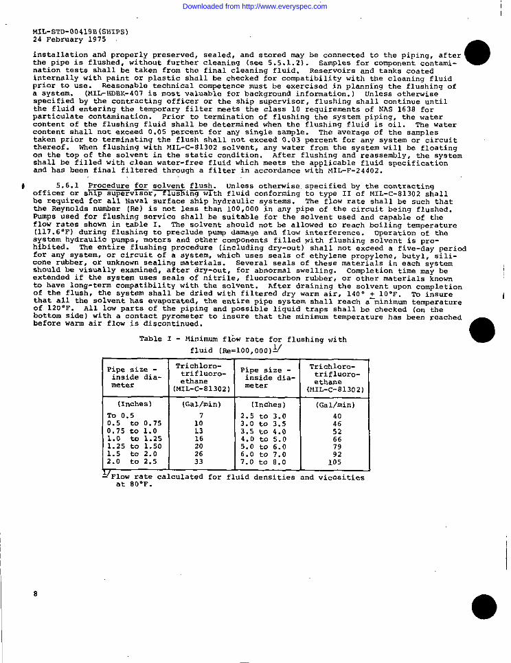
5.6.1 Procedure for solvent flush. unless otherwise, specified by the contractingofficer or sh~p s“Pervi?Xr~ “s i~th fluid conforming to type 11 of MIL-c-81302 shallbe required for all NfIval surface ship hydr.a”lic systems. The flow rate shall be such thatthe Reynolds number [Re) is not less than 100,000 in any pipe of the circuit being flushed.Pumps used for flushing service shall be suitable for the solvent used and .a~able .f theflo” rates shown in table 1. The solvent sh.wld not be allcwed to reach boil;n.g tenperat”re(117.6”F) during flushing to preclude pm+ damaqe and flow interference. operation of thesystem hydraulic pumps, motors and other components filled wi tb fl“shing solvent is pro-hibited. The entire flushing procedure (including dry-out) shall not exceed a five-day periodfor any syate”, or circuit of a system, which “se. seals of ethylene propylene, b“tyl, silic-one rubber, cm unkn.wn sealinq materials. Several seals of these materials in each systemshould be visually examined, after dry-cwt, for abnormal swelling. Completion time may beextended if the system uses seals of nitrile, fluorocarbon rubber, or other materials knownto have long-term compatibility with the solvent. After draining the solvent “pen completionof the fl”sb, the system shall be dried with filtered dry warm air, 140° + 10-F. To insurethat all the solvent has evaporated, the entire pipe system shall reach a-minimum te”perat”reof 120°F. A1l lcw parts of the piping and possible liquid traps shall be checked (cm thebottom side ) with a contact pyrometer to insure that the minimum temperature has bee” reachedbefore “arm air flow is discontinued.
Table 1 - Minimum fib” rate for flushi”q with ●fluid (I&!=100,0OO)L/
Pipe size - Tri.cbloro- Pipe size - Trichloro-
i“side dia- trifluOro- inside dia- trifluOro-
Uleter etbane mete r etbane(MIL-C-81302) (MIL-c-81302)
(lnche.) I (Gal/rein) I [Inches] I {Gal/rein)
To 0.50.5 to 0.750.75 to 1.01.0 to 1.251.25 to 1.501.5 to 2.02.0 to 2.5
7
101316202633
2.53.03.54.05.06.07.0
tototototototo
3.03.54.05.06.07.08.0
404652667992
105I I I
:/Flow rate calculated for fluid densities and viscositiesat 80W.
8
●
Downloaded from http://www.everyspec.com
MIL-STD-00419 B(SU1PS)
o24 February 1975
.lean~~~”;~;nt%%% a:< ‘i controls of .1,..1.?.. Air Act of 1970 as its vaporTrichlorotrifluoroethane is considered a safe
is not photochemically reactive. However, due to its unique properties, the following pre-cautions must be taken:
(aJ
(b)
(c)
(d)
(e)
(f)
The solvent has a low boiling point (117.6°F), a high evaporationrate and a high vapor density (6-1/2 times heavier than air) .When used in spaces where spillage could occur or the fluid isexposed to the atmosphere, forced ventilation of the space isrequired with the exhaust duct placed at the lowest level possiblein the space being ventilated. The American Conference ofGovernments 1 Industrial I1ygienists (ACG1ll) and the Occupationalsafety and Health Act (OSIIA)in table G-1, paragraph 1910,93,Rules and Regulations have set a Threshold Limit Value ,[TLV) (aconcentration of solvent vapor in air to which nearly all workersmay be repeatedly exposed day after day “ithout adverse effect]for trichlorotrif luoroethane of 1000 parts per million JP/m) .Prolonged breathing of biqher concentrations of the solvent shal’1be avoided as narcosis, anoxia, anesthesia or intoxication canbe experienced by persons so exposed. Persons having known dis-qualifying factors such as pre-existin.g liver disease, alcoholism,renal and heart diseases, obesity and diabetes shall not beassigned to work with the solvent. Al 1 persons required to worki“ confined spaces where liquid solvent or vapor is pre.s?nt shallbe instructed as to the nature of the hazards involved in accord-ance with paragraph 1926.21 of oSKA Rules and Regulations.
Txichlorotrifl”oroetha”e is a nonflammable cleaning agent. However,the fluid or vapor shall not be exposed to high temperatures orflame. The solvent begins to decompose in trace quantities at600 ‘F and increases with temperature rise. The products of de-composition are toxic and corrosive; one of the products isphosgene (carbonyl chloride) gas “hich has a TLV of 0.1 p/m.Welding in spaces “here solvent vapor is present is prohibited.
Synthetic rubber gloves shall be worn “hen handlinq tbe solventas it dissolves natural oils and dry chapped hands may result.In confined SPaCeS the contamination level of the air shall,be.monitored by use of a total Hydrocarbon Analyzer or an equivalentinstrument. Hydrocarbon Analyzers for this purpose are Nationalstock “hers (NsN) 6630-00-442-6409, 6630-00-442-6410 and6630-00-462-9133. Wbe” dryimg o“t the cleaned piping system with“arm air the air-.solve”t vapor effluent shall be exhausted o“t-side for safe dispersal and the area posted “Hazardous vapors -Keep Clear”.
MIL-HDBK-406 provides a comprehensive listing of the solventcharacteristics (compatibility, miscibility, volubility, etc. )relating to other materials.
After use, the solvent shall be collected and recovered by distilla-ticm, a“d stored in labeled clean containers or bulk storage forfurther use. Where stills are not available, the solvent shallbe stored for redistillation elsewhere. Dumping of anytrichlorotrif l“oroethane into any body of water is prohibited.
5.6.2 Procedure ~ ~ flush. Fl”shiny “ith the system operating fluid, or an other-wise approvea Iby the .cmtract~fficer or ship supervisor) oil, shall be performed atflow rates which will provide a Reynolds number of at least 4000 in every pipe of the circuitbeing flushed. For those systems i“ which the operating fluid is in accordance withMIL-L-17331. alternative fl”shin.a oils which ccmform to MIL-L-17672 are allowed in order tomore easily” achieve the required” turbulent flow. upon wmrg.letion of flushin.gwith oi1sother than the system operating fluid, the system shall be completely drained and blownfree of flushimg f l“id, and the system refilled “ith operatinq fluid. Dependinq upon thecomplexity of the system and the amount of flushing oil left behind, a second or thirddrain-and-fill seauence mav be reauired to urovide rni”irnal.acceDtable liauid (not solid)—–J ...—....
,n. Acceptable liauid ‘contamina;~oi shall be that tiount “hi~h could be toleratedcontamination]in a fluid without c>usingcable fluid specification.
failure of the fluid in any of the tests required by the appli-
9
Downloaded from http://www.everyspec.com
MIL-STD-00419B (SH1PS)24 Februarv 1975
# 5. 6.3 Flushiny fluid sam 1.s. unless otherwise specified by the contracting officer*be taken from the bottom side of the pipe within five feetor ship s.perv. sor, s=. s ,.
of the inlet of the flushing filter during full flow. The size of each sample drawn shall ●not exceed one liter and shall include the fluid and contaminants trapped by the valve andadapter dnrimq the preceding S-minute flushing period. [Open the valve to purge the valveentrance of contaminants, close the valve and wait 5 minutes and draw the sample. ) Theentrance to the samplinq port shall be flush with the inner circumference of the pipe, andthe valve comkxtor [adapter) shall not extend into the pipe beyond the inner su.face of thepipe. For taking samples from the system during fl”shi”g, diaphragm (packless) valws arerecommended. where the hydraulic system is equipped “ith sampling “alves, samples nay betaken from those valves, i“ lieu of the location specified .abow.
# 5.6.3.1 W analyses. The test method for determination of particulate contamination Ishall be in accordance w.th SAE ARP 598, or an automatic particle counter capable of beingcalibzatcd in accordance with ANSI B93. 28. Directions i“ the manual for the respective in-strument shall be followed. Water content shall be determined by ASTM D1744 method, or withcommercially .wailable automatic water-analyzing equipment capable of accurately de&rini”i”gwater content dcxm to 0.01 percent, such as the Becknkm KF4 AquaIneter.
#cle.anlines*s=l~ stowac
5.7 Ca in and sealing ~ ends. open ends shall be capped cm sealed to preserwtransit, or installation operations. All caPs shall
ha”. the sane grade of cleanliness as the pipe or assembly to be sealed. The use of “wate-rproof tape Ccmformi”g to PPP-T-60 , electrical plastic tape, or other compatible tape isallowed to.hold caps in place. However, the use of any tape as a cap is prohibited.shall be made in accordance with IIIL-c-5501 with the following exceptions :
caps
(a)
(b]
(c)
(d)
MJ!;erials. 14aterials used in the “a”ufacture of prote.tiw caps.shall be of high quality, compatible with the fluid used in thecapped system. Material. conforming to commercial specificationsmay be used prcwided they pass the tests specified below and thetorque test specified in MIL-C-5501 . The .s. of commercial speci-fications will “ok constitute waiver of inspection. Material.shall not chip or shred during normal usage. Plastics andelastomers may be used provided they pass the tests requiredherein.
The requirements fo. durability, repeated assembly test, pro-tection after installation, a“d drop and Sealing tests specifiedin MIL;C-5501 shall not apply. ln lie. thereof the testsspe:if>ed in (c) ?“d (d) here$n shall apply.
- w~m~-k~~~~~~~~’~~~~uidto be sealed at a temperature of 160- ~ 2-F and held for 5minutes. No leakage shall result.
I ualit conformance ins ection) .$%%hwg surface wet~luid to be sealed, as-
Samples selected shall
setiled to a fitting connected to an air supply of 2 pounds persquare inch minim.m air pressure, and immersed i“ water or othersuitable fluid for a Deriod of at least 30 seconds a“d not morethan one minute. No ieakage shall occur. Applied torque shallbe as specified in MIL-C-5501. Test shall be conducted at roomtemperature. Cloth shall not be used. Wood inserts {plugs)shall “ot be used: however, wooden blocks bolted over theEla”qed ends may be used. The open ends shall remain cappedu“ti1 immediate ly before connecting to the equipment for whichPipe is intend.d. Unthreaded pipe ends shall be capped with ““-threaded caps.
* 5.7.1 ln systems usi”~ petroleum base hydraulic fluid, plastic or rubber material mayhe used for caps, with the exception of butyl rubber. The pipe end shall be completelycovered with sheet plastic or rubber (except butyll and secured to the pipe outside dimneterwith electrical plastic tape or some other compatible tape. These materials may be used forthreaded and unthreaded closures.
10
●
●
Downloaded from http://www.everyspec.com
MIL-STD-00419B (SHIPS)24 February 1975
● 5.7.2 ln systems using phosphate ester type fire-resistant hydraulic fluid, butylrubber and compatible plastics may be used for caps. The pipe end shall be completelycovered with compatible sheet plastic or butyl rubber, and secured to tbe pipe outside dia-meter with a compatible tape.
5.8 Ferrous s stems - corrosion-resistant steel) .—+
when specified by the commandor agency concerne , errous plplnq, tubing, and fitti-all be phosphate coated, priorto installation, in accordmce with tbe specified type and class of MIL-P-16232.
# 5.9 Dis osal of waste materials used in cleaning;+–—-
The following matexial.s and solu-tions .onta,mnq t ese nmterlals shall not ~ ~ed overboard. They shall be retainedin containers and held for shore disposal:
Other materials may be discharged overboard after neutralization to a ph of 6.8-8.5. Ifthis is “ot possible, they shall be retained in containers for shore disposal. For moredetailed instr”. tions and information, see NAVSHIPS 0901-003-0001, chapter 9003.
6. NOTES
●
Preparimg activity:Navy - SH(Project MISC-N997)
*U.S.GO=MMENI PRIN71NGOFFD= 19?6-603.7665625
11
Downloaded from http://www.everyspec.com
FOLD
COMMANDERNAVAL SHIP ENGINEERING CENTERCENTER BUILDING - SEC 6124 ,oST*GE A.. FEESPAIDPRINcE GEORGES CENTER DEPARTMENT OF NAVYHYATTSVILLE, MARYLAND 20782
OFFICIAL BUSINESSPEMALT, FOR PRIVATE “SE S300
DOD 316
CONNANDERNAVAL SHIP ENGINEERING CENTERCENTER BUILDING - SEC 6124PRINCE GEORGES CENTERHYATTSVILLE , NARYLAND 20782
,0..
Downloaded from http://www.everyspec.com
●
●
●
STANDARDIZATION DOCUMENT IMPROVEMENT PROPOSAL I OMB ApprovalNo. 22.R255
1NSTRUCTIONS ‘I%.purposeofthisformistosolicitbeneficialcomments which willhelpachieveprocure.ment .1suitableproductsatreasonablecostand minimum delay,orwillotherwiseenhance.s. ofthedoc.menDoD,contmctors,governmentactivities,or m.nufact.rers/.endorswho arepmspecti.esuppliersoftheproductare,.vitedto submitcomments tothegovernment.Fold on lineson reverseside,S!.PI.i.corner,and send toPreP,.ri.g activity.Comments submittedo. thisformdo notconstituteorimplya.tho.izatio”t.waive anyPort,..ofthe,,.f~r.needdocument(s)ortoamend contractualrequirements.Attachany perti”e.tdatawhichmay be ofuse I“tmprovmg thisdocument. Ifthereareadditio”alpapers,attachto form and place both in a.
.“VG1 OP. addressed to preparing activity.
,OC” MENT ,DENTIF, ER ANO TITLE
IAME OF OR G. N, ZAT, ON AND ADDRESS CONTRACT NUMBER
MA TER, AL PRoCURED UNDER A
nD,. EcT .O. ER.ME. T CONTRACT rJ*LJSCONTRAC
:4:? ANY PART OF THE DOCUMENT CREATED PROBLEMS OR REOUIRED ,NTEWRETAT, ON, N pROCUREMENT