96
Cleveland ASPE February 13, 2008 Residential Sprinkler & Preaction System Design

Cleveland ASPE
February 13, 2008
Residential
Sprinkler &
Preaction System
Design

Residential Sprinklers

Residential Sprinklers
� Large residential construction growth over the last decade
� Building Code Changes
� Efforts of Organizations
� Home Fire Sprinkler Coalition
� NFSA
� AFSA
� NFPA
� Education to Home Builders and Local Officials
� Minimum Discharge Density Changes by UL and NFPA

Residential Sprinklers
Residential, unique to standard or quick response sprinklers
� Control Mode Sprinkler
� ESFR (Early Suppression Fast Response)
� Residential???

Residential Sprinklers
� Residential Sprinklers: Installed to provide an increased
level of life safety for the occupant. Residential sprinklers
are designed to prevent flashover, keeping the living space
survivable for a minimum amount of time.

Residential Sprinklers
� Residential sprinklers are tested to a separate UL standard.
The testing procedure verifies the thermal sensitivity and
water distribution characteristics.
� UL 1626, Residential Sprinklers for Fire Protection Service
It is not a design document, It is a standard published and
used by UL to evaluate the performance of a residential
sprinkler.
� Plunge Test
� Room Test

Residential Sprinklers
� The scope of UL 1626 is defined within the document as:
“These requirements cover residential sprinklers intended for
installation on sprinkler systems for fire protection service.
Requirements for the installation and use of residential
sprinklers for the Installation of Sprinkler Systems, NFPA 13,
and Installation of Sprinkler Systems in One- and Two-Family
Dwellings and Mobil Homes, NFPA 13D and Residential
Occupancies up to and Including Four Stories in Height
Sprinkler Systems, NFPA 13R.”
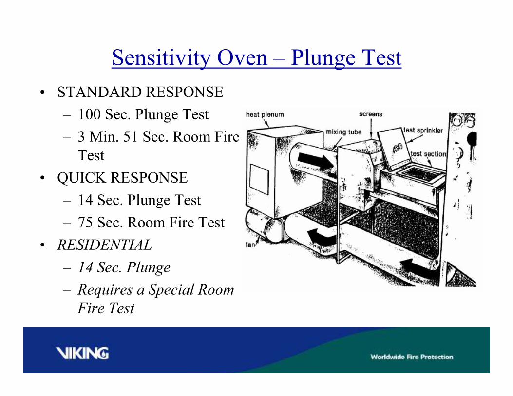
Sensitivity Oven – Plunge Test
• STANDARD RESPONSE
– 100 Sec. Plunge Test
– 3 Min. 51 Sec. Room Fire
Test
• QUICK RESPONSE
– 14 Sec. Plunge Test
– 75 Sec. Room Fire Test
• RESIDENTIAL
– 14 Sec. Plunge
– Requires a Special Room
Fire Test

Residential Sprinklers
Residential Sprinklers are required to pass special fire tests.
The objective of residential sprinklers is to provide safety to
the occupant and allow safe egress in a fire.
In a residential fire test, the temperature cannot exceed 600° F
3” below the ceiling where the thermocouples are installed.
The maximum temperature at 5’-3” above the floor is 200° F.
The temperature 5’-3” above the floor shall not exceed 130° F
for any continuous 2 minute period.
The maximum ceiling material temperature ¼” behind the
finished ceiling surface shall not exceed 500°F.

Residential Sprinklers
A special room is used to test residential sprinklers that simulates
a residential occupancy. (2) residential sprinklers are located in
the room for their coverage area. For a pendent sprinkler, these
areas of coverage are 12’x12’, 14’x14’, 16’x16’, 18’x18’, and 20’x
20’. For sidewall sprinklers, these areas of coverage are typically
14’x14’, 16’x16’, 16’x18’, 16’x20’, 16’x22’, 18’x18’ and 20’x20’.
The (2) sprinklers are installed at the coverage area that a listing
is desired at. A third sprinkler is located near an open door. The
sprinkler at the door is not connected to water filled piping. If the
sprinkler at the door activates at any time during the test, the test
is considered a failure.

UL 1626 Residential Sprinkler Test


Residential Sprinklers
Residential sprinklers are required to meet minimum
wall wetting characteristics. 28” is the maximum distance down
from the ceiling on the wall that a residential pendent and
sidewall sprinkler must wet the wall.
Sidewall sprinklers must direct 5% of their discharge upon
the wall on which they are installed.
These wall wetting characteristics mean that a residential sprinkler
must discharge or spray in a very flat pattern. Obstructions such
as sloped ceilings, beams, ceiling fans, and lights can inhibit the
performance of residential sprinklers and must be avoided.


Residential Sprinklers
The minimum design criteria for residential sprinklers per UL
And NFPA 13D and NFPA 13R is to provide a minimum
.05 gpm per sq. ft. over the area of protection.
NFPA 13 requires that the minimum design criteria for
residential sprinklers or residential occupancies be a .10
gpm per sq. ft.
Each residential sprinkler must pass the special fire tests and
wall wetting requirements before they are listed as residential
sprinklers.

NFPA 13D Occupancies

NFPA 13D – One and Two Family Dwellings and
Manufactured Homes
NFPA 13D is the design and installation standard for
single and two family dwellings, or in other words a home
that is a single structure.
The sprinkler design for this type of occupancy is for (2)
residential sprinklers to discharge at the minimum flow rate
and pressure of its UL listing.
Water supply capacity is generally an issue for these system
designs, so it may be prudent to utilize more residential
sprinklers in a system at smaller spacings to lower the water
supply requirement.

NFPA 13 R Occupancies

NFPA 13R – Residential Occupancies up to and Including
Four Stories in Height
Generally these NFPA 13R occupancies
are apartments, dormitories, hotels, motels
The residential sprinkler design criteria for the residential
dwelling requires that (4) residential sprinklers are designed
to operate at their listed flow rate and pressure for the area
of coverage to be protected.
Public areas such as corridors, require a design per NFPA
13, meaning the water supply needs to adequate for a NFPA
13 installation.
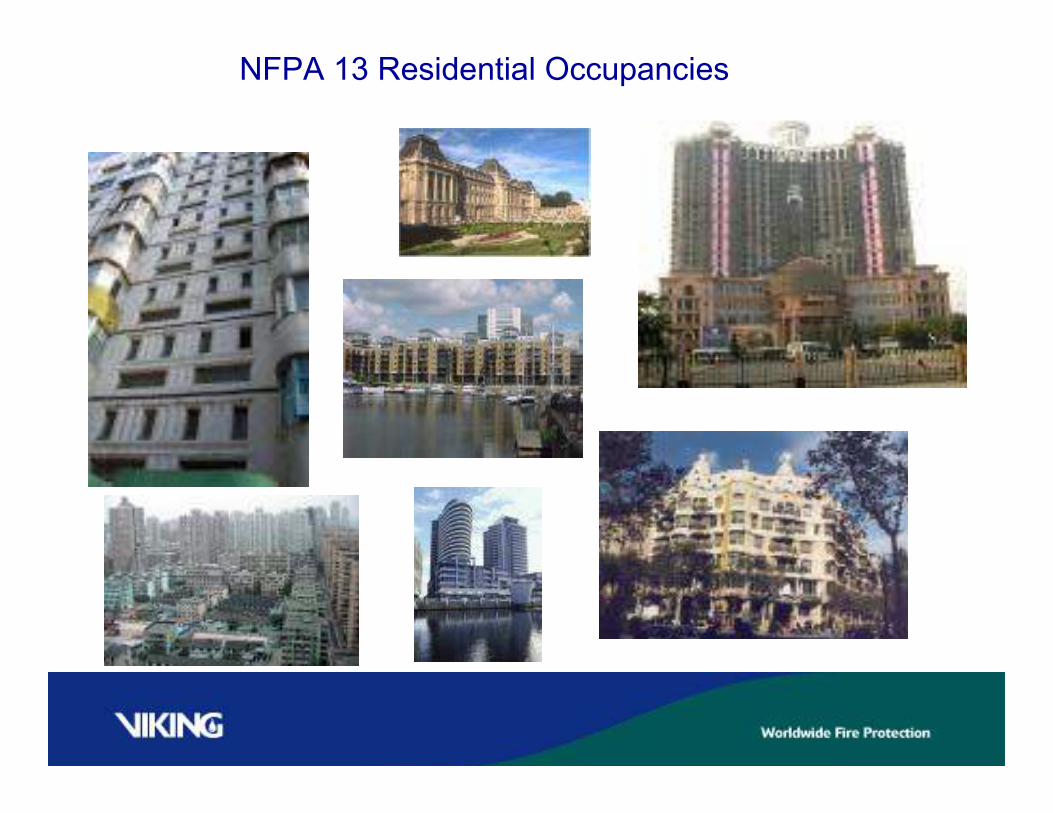
NFPA 13 Residential Occupancies

NFPA 13 – Residential Occupancies that are not NFPA 13D
Or NFPA 13R
These occupancies are buildings that are greater than (5)
stories, typical of high rise apartment buildings, large hotel
resorts, etc.
The design requirement per NFPA 13 is for a minimum .10
gpm per sq ft or the residential sprinklers listing for the
area, which ever is greater.
Water supply requirements are higher for NFPA 13 residential
occupancies because the water flow is providing protection
to the structure as well as life safety.

Residential Sprinklers
Due to the minimum flow rate requirements for residential
sprinklers there are many different K factors for residential
sprinklers to address different coverage areas and different
code requirements, (NFPA 13D and NFPA 13R versus NFPA
13 residential occupancies)
The K factors step up from smaller areas of coverage of NFPA
13D, to moderate and large areas of coverage of NFPA 13R,
to very large water demands of NFPA 13. These specific K
Factors allow for the most efficient use of water and pressure.

Preaction
Systems
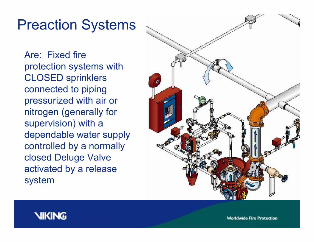
Preaction Systems
Are: Fixed fire
protection systems with
CLOSED sprinklers
connected to piping
pressurized with air or
nitrogen (generally for
supervision) with a
dependable water supply
controlled by a normally
closed Deluge Valve
activated by a release
system

Preaction Systems
Are Recommended :
For hazards where fast
application of water in
fire conditions is
important.
(Non and Single
Interlocked Pre-Action)

Preaction Systems
Are Recommended :
To prevent water
damage due to
mechanical damage to
system piping.
(Single and Double
Interlocked Pre-Action)
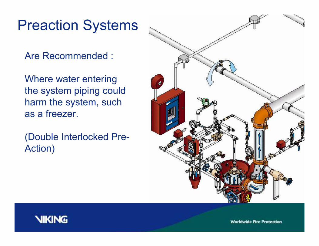
Preaction Systems
Are Recommended :
Where water entering
the system piping could
harm the system, such
as a freezer.
(Double Interlocked Pre-
Action)
PREACTION SYSTEMS
The building block of a pre-action
system is the deluge valve and trim.
Additions to the deluge valve and trim
will be a riser check valve, an air
supply, and closed head sprinkler
piping.

Deluge Systems
Deluge valve with
Conventional Trim
(PORV)

Deluge Systems
Deluge valve with
Conventional Trim
(PORV)
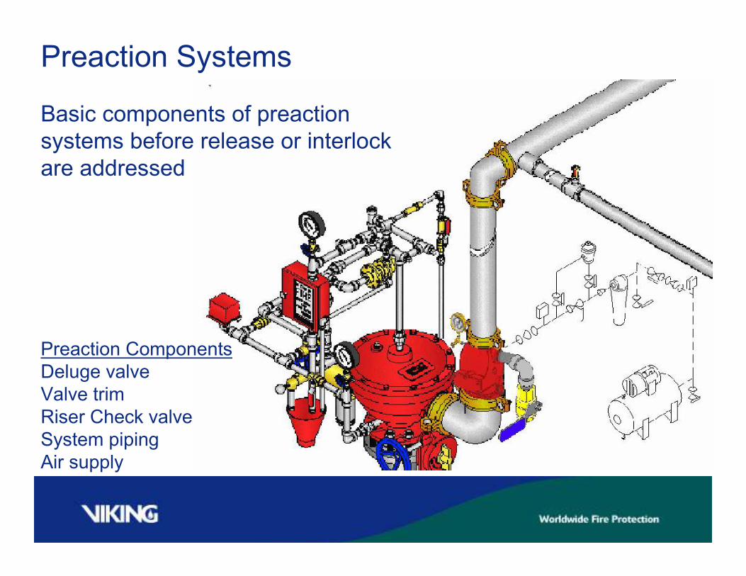
Preaction Systems
Basic components of preaction
systems before release or interlock
are addressed
Preaction Components
Deluge valve
Valve trim
Riser Check valve
System piping
Air supply

Sprinkler Heads
Allowed to
Be Installed
On Preaction Systems
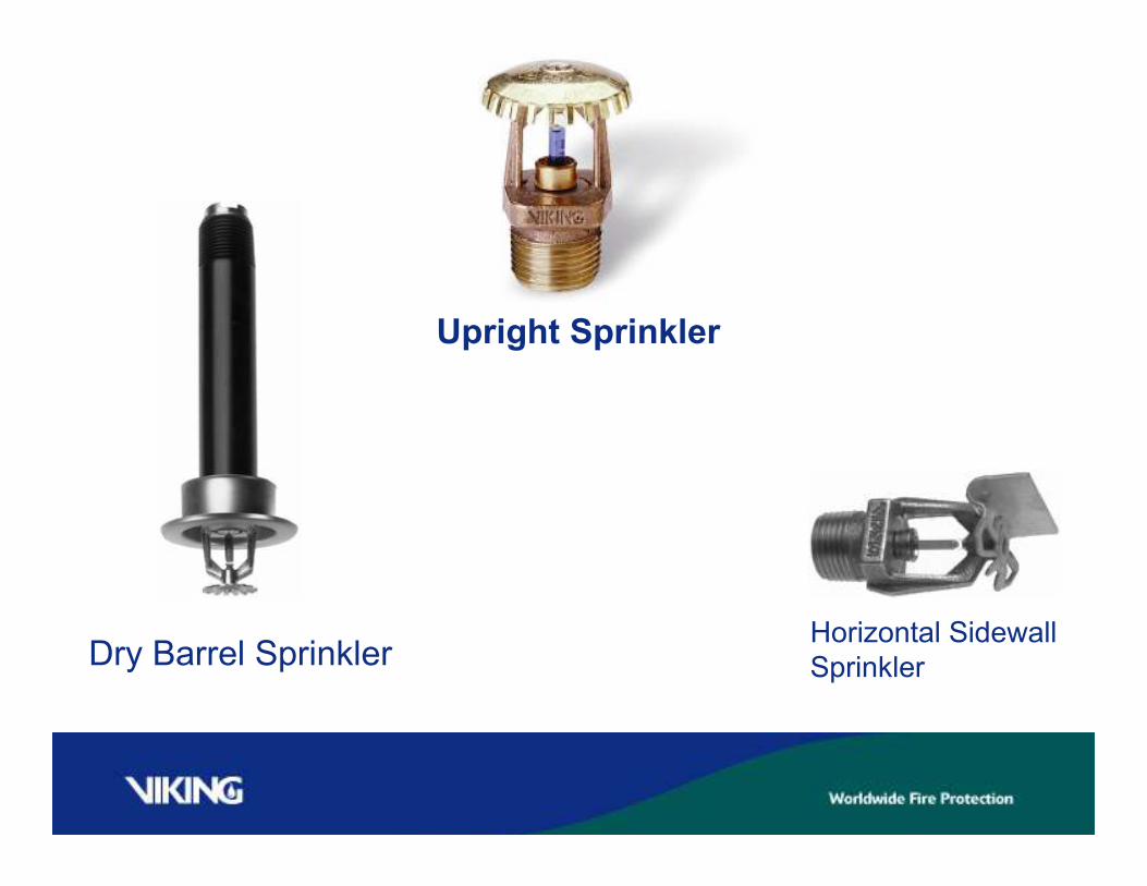
Dry Barrel Sprinkler
Upright Sprinkler
Horizontal Sidewall
Sprinkler

OR

A pendent sprinkler installed on a return bend, where the sprinkler
And the sprinkler line supplying it are in a heated area
Ceiling

Deluge Valve

Priming chamber
Discharge or
outlet chamberInlet chamber
Deluge
Valves

Deluge Valves
Held Closed by water pressure in priming chamber
Priming Chamber controlled by release system
When release system operates, priming chamber relieved of
Priming pressure, allowing deluge valve to open

Deluge
Valves Priming Deluge Valve Priming Chamber
With water
Note: Priming Supply
Provided upstream of
Control valve

Deluge
Valves
Deluge valve primed closed with
Water supply control valve open
Supply water pressure

Deluge
Systems
Release System Operates –
Draining water from priming
chamber
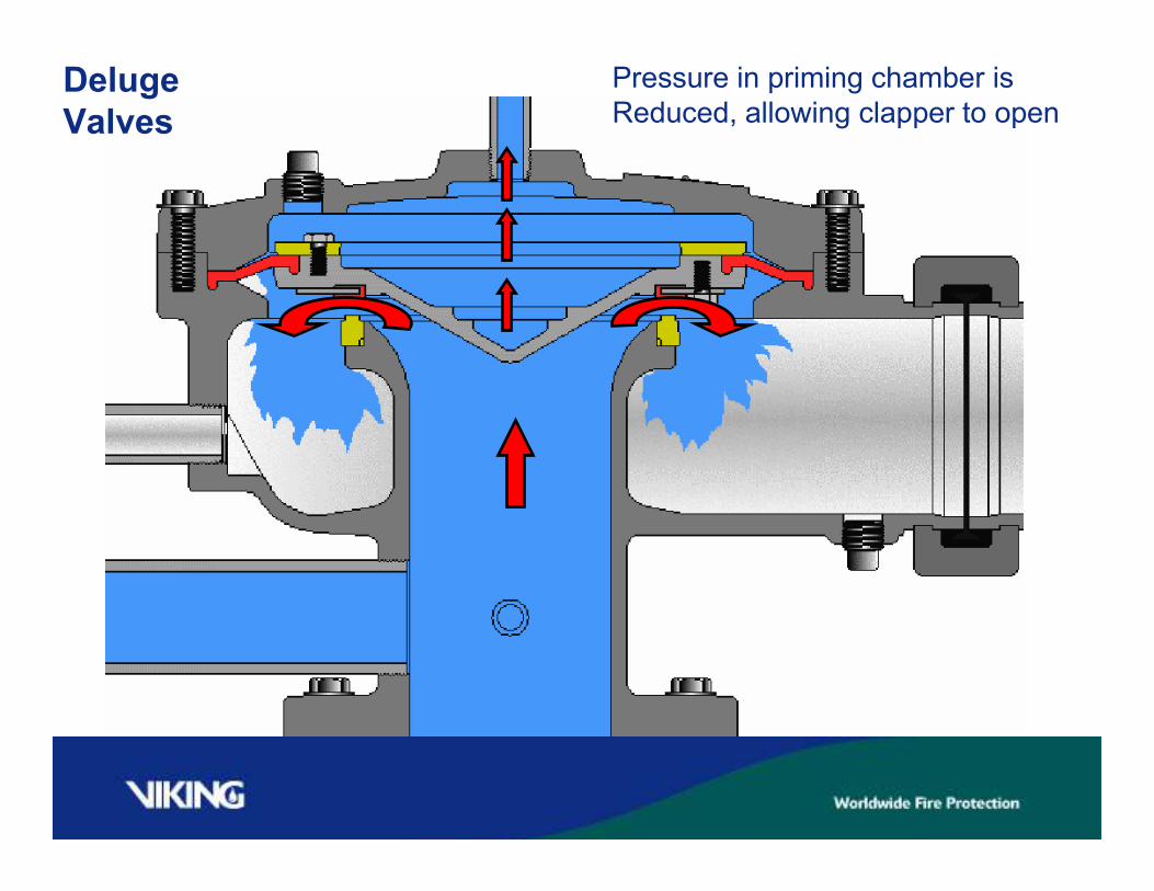
Deluge
Valves
Pressure in priming chamber is
Reduced, allowing clapper to open
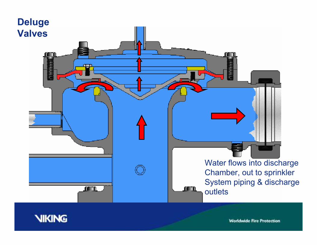
Deluge
Valves
Water flows into discharge
Chamber, out to sprinkler
System piping & discharge
outlets

Deluge
ValvesDeluge valve remains open
Until system is manually shut-down

Model E Deluge Valve
Model F Deluge Valve
Model F Deluge Valve
Model E deluge valves
Available 1 ½”, 2”, 3”,
4”, and 6”
Model F deluge valves
Available 1 ½”, 2”, 2 ½”,
3”, 4”, 6”, 8” Vertical and Horizontal
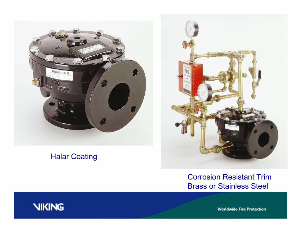
Halar Coating
Corrosion Resistant Trim
Brass or Stainless Steel

Preaction
Systems

PREACTION SYSTEM TYPES
Interlock and Release
Non-Interlocked Preaction
-Electric or pneumatic release
Single Interlocked Preaction
-Electric Release
-Pneumatic Release
Double Interlocked Preaction
-Pneumatic/Pneumatic
-Electric/Pneumatic
-Electric/Electric

SINGLE INTERLOCKED
PREACTION

Single Interlock Operation
Activation of the Release System will cause the
Deluge Valve to trip open.
Water will enter the closed sprinkler piping.
When (if) a sprinkler operates,
Water will flow from the open sprinkler
immediately.
-Similar to a WET system!

Single-Interlocked Pre-action Systems
Air Supply Considerations
Minimum Pressure: No minimum
Maximum to Fill system: 30 minutes
Water Delivery time to Inspectors Test: Not
measured
May not be required if less than 20 sprinklers on
system

RELEASE SYSTEMS FOR
SINGLE INTERLOCKED
PREACTION
Preaction Systems
Electric or
Pneumatic

SINGLE INTERLOCKED
PREACTION
PNEUMATIC RELEASE

PNEUMATIC RELEASE
-Sometimes referred to as “dry pilot lines”
-Resemble hydraulic release
-Utilize same release devices as hydraulic release
-Are filled with pressurized air or nitrogen
-Important to keep release line free of moisture
-Used in areas subject to freezing
-Pneumatic actuator or pneumatic bypass held closed with air
-Pneumatic actuator or pneumatic bypass is holding priming
water in priming chamber of deluge valve

Preaction
Systems
Single Interlocked
Preaction
Pneumatic Release
= Direction of Air Flow

SINGLE INTERLOCKED
PREACTION
ELECTRIC RELEASE

Preaction
Systems Single Interlocked
Preaction Electric
Release
= Direction of
Air flow

DOUBLE INTERLOCKED
PREACTION

The Release System must activate …..
-(an alarm will sound)
-AND,
-Pressure in the sprinkler piping must be reduced-
(due to a sprinkler opening in fire conditions)
To trip open the Deluge Valve.
In fire conditions,
- After the release system operates and the sprinkler
opens, water needs to travel from the Deluge Valve
to the open sprinkler.
There may be a time delay similar to a Dry System.
Double Interlock Operation
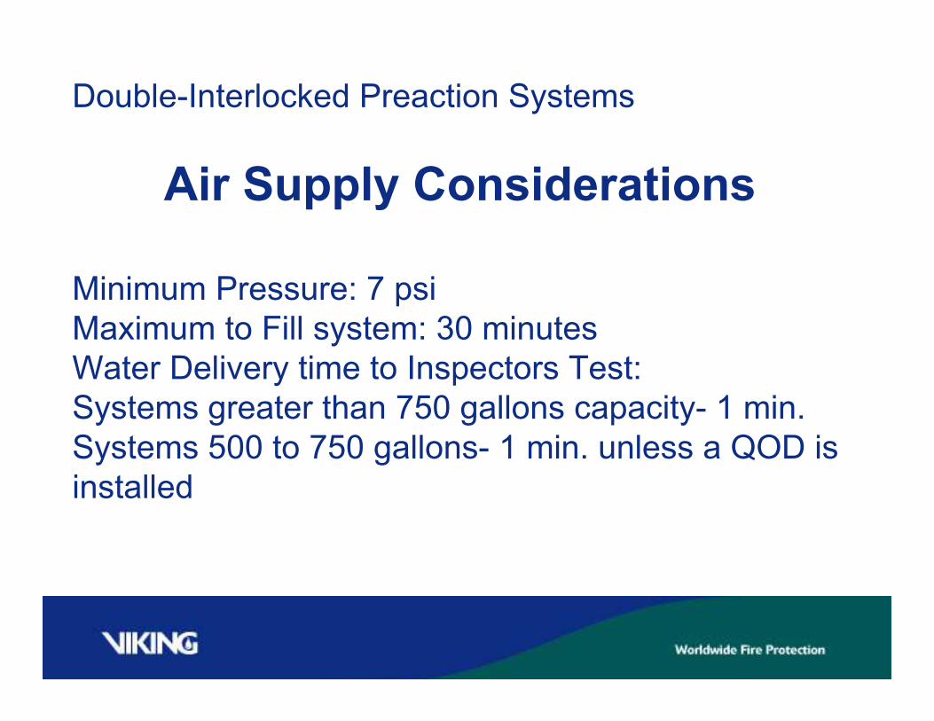
Double-Interlocked Preaction Systems
Air Supply Considerations
Minimum Pressure: 7 psi
Maximum to Fill system: 30 minutes
Water Delivery time to Inspectors Test:
Systems greater than 750 gallons capacity- 1 min.
Systems 500 to 750 gallons- 1 min. unless a QOD is
installed

Preaction Systems
Electric,
Pneumatic, or
Both
RELEASE SYSTEMS FOR
DOUBLE INTERLOCKED
PREACTION
DOUBLE INTERLOCKED
PREACTION
PNEUMATIC/PNEUMATIC

= Direction of Air
Flow
Double Interlocked
Preaction
Pneumatic/Pneumatic
Release

DOUBLE INTERLOCKED
PREACTION
ELECTRIC/PNEUMATIC
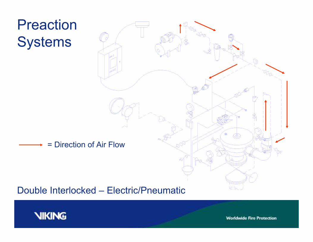
Preaction
Systems
= Direction of Air Flow
Double Interlocked – Electric/Pneumatic

DOUBLE INTERLOCKED
PREACTION
ELECTRIC / ELECTRIC

Preaction
Systems
Electric Release Device
And air supervisory switch
Cross zoned at panel
Double Interlocked Preaction - Electric/Electric Release
= Direction of Air Flow

Viking
SureFire™
Preaction
Systems

SureFire
Fail Safe Preaction SystemsFail safe pre-action systems are pre-action systems that
will operate when there is a loss of AC and DC power.
Some municipalities have fail-safe pre-action
requirements. In general, pneumatic release pre-action
systems are listed and approved fail-safe pre-action
systems.
You should check with the manufacturer if they have a
listed or approved fail-safe electric release pre-action
system option.

SureFire Pre-action
Systems
Are Recommended :
Where operation of the
fire protection system in
the absence of electric
power or power outage
is a concern.

Viking SureFire
Release Trim Module To pressurized
system piping
Solenoid valves are described by their position
when non-powered:
1) Normally Open
When non-powered the solenoid valve is
open
2) Normally Closed
When non-powered the solenoid valve is
closed
Pneumatic Actuator
Release
Systems
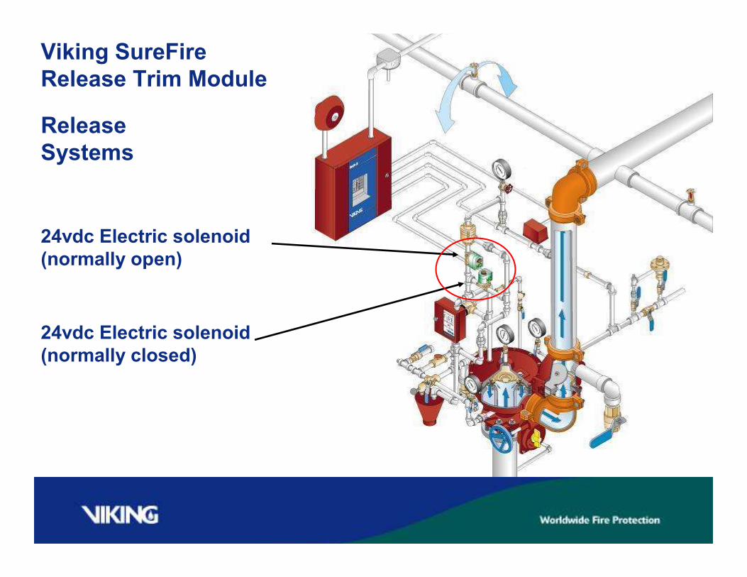
Viking SureFire
Release Trim Module
24vdc Electric solenoid
(normally open)
24vdc Electric solenoid
(normally closed)

TotalPac2 &
TrimPac


Pneumatic Release
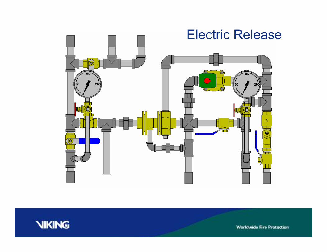
Electric Release

Electric/Pneumatic
Release
TrimPac LabelsTrimPac is effixed with labels that indicate what type of
release is installed in the TrimPac trim, where the controlling
stainless steel hoses are to be installed, and where pressure
switches are to be installed.
TrimPac has access doors for an emergency release and for
the alarm test valve. TrimPac has viewports for priming water
supply and water supply pressure.


TotalPac2

TotalPac 2 – 3 New Offerings
Skid Remote Controlled Self Contained

Skid Units
Same Base as Cabinet
- No Enclosure
- Includes non-wired switches and non-wired
solenoid
- No air supply
- 1 ½” – 6”
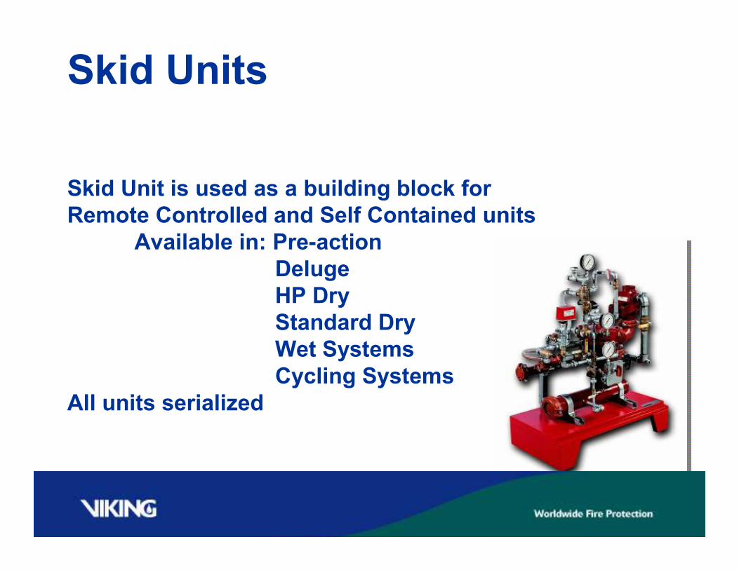
Skid Units
Skid Unit is used as a building block for
Remote Controlled and Self Contained units
Available in: Pre-action
Deluge
HP Dry
Standard Dry
Wet Systems
Cycling Systems
All units serialized
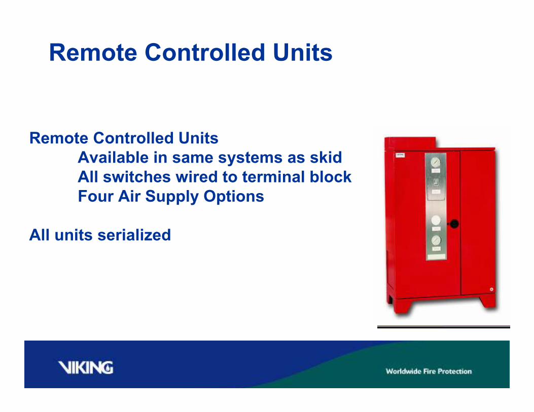
Remote Controlled Units
Remote Controlled Units
Available in same systems as skid
All switches wired to terminal block
Four Air Supply Options
All units serialized
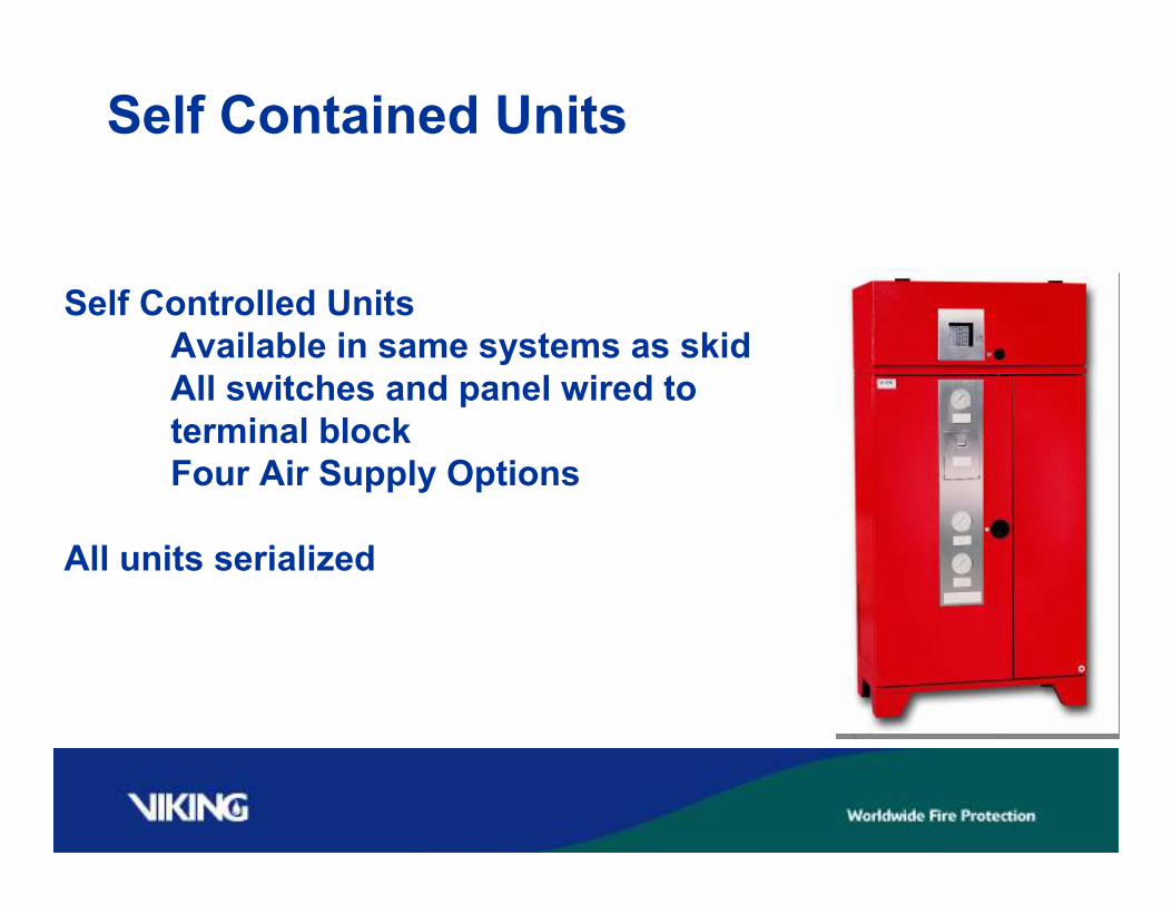
Self Contained Units
Self Controlled Units
Available in same systems as skid
All switches and panel wired to
terminal block
Four Air Supply Options
All units serialized
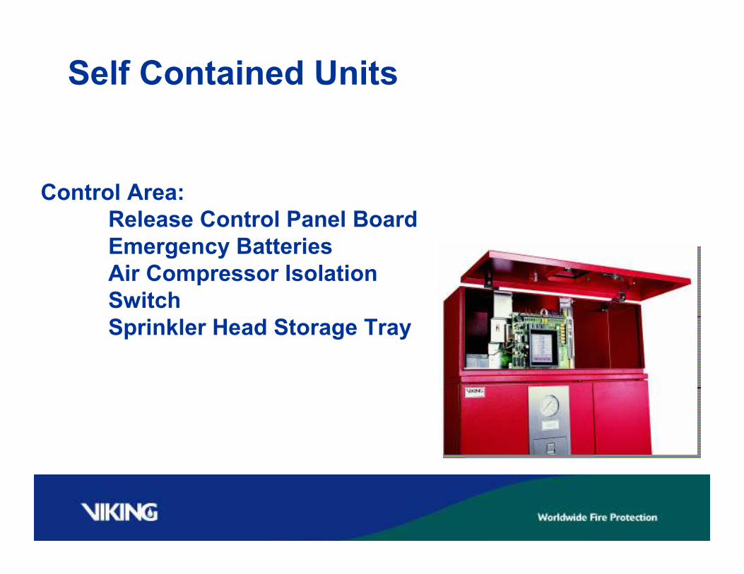
Self Contained Units
Control Area:
Release Control Panel Board
Emergency Batteries
Air Compressor Isolation
Switch
Sprinkler Head Storage Tray

Self Contained Units
Two Swinging Doors to System
Area to allow for easier access
More Room to work on system
If maintenance is required

FM-072Q-0-09 A.dwg
Sight-Glass
Assembly (D5)
Point flashlight here
Supervised Water Supply
Control Valve (D1)
Deluge (A1) or
Flow Control Valve (A2)
Supervised sprinkler
piping system
Shut-Off Valve (D4)
Riser Check
Valve (D2)
Main Drain Valve
(D3)
FM-072Q-0-09 A.dwg
Sight-Glass
Assembly (D5)
Point flashlight here
Supervised Water Supply
Control Valve (D1)
Deluge (A1) or
Flow Control Valve (A2)
Supervised sprinkler
piping system
Shut-Off Valve (D4)
Riser Check
Valve (D2)
Main Drain Valve
(D3)
Supervised Water Supply
Control Valve (D1)
Deluge (A1) or
Flow Control Valve (A2)
FM-072Q-0-10 A.dwg
Riser Check
Valve (D2)
To FIRE DEPT.
CONNECTION
(by contractor)
Grooved Tee
Connection
Supervised Water Supply
Control Valve (D1)
Deluge (A1) or
Flow Control Valve (A2)
FM-072Q-0-10 A.dwg
Riser Check
Valve (D2)
To FIRE DEPT.
CONNECTION
(by contractor)
Grooved Tee
Connection
System Isolation Valve
And Site Glass
Fire Dept. Conn.
Semi-Flanged Units
Other Available Options

TotalPac 2 – 3 New Offerings
Skid Remote Controlled Self Contained

Questions?


