The following table describes t Command interface ethernet <NUMBER> bridge-port <BRIDGEPORT> policing policing-cos-group Command Submodes for Etherne Table 11 Command Submodes for Ethernet Config
Transcript
The following table describes the commands for entering the relevant command submodes from Global Configuration mode, and the purpose for each one of them.
Command
interface ethernet <NUMBER>
bridge-port <BRIDGEPORT>
policing
policing-cos-group
Command Submodes for Ethernet Configuration
Table 11 Command Submodes for Ethernet Configuration
policing-cos-group-mapping
config-ethernet-profiles
ethernet-epl <RSPLAN> <RSPWAN>
interface ethernet-eps <RSP>
lan
wan
ethernet-mac-whitelist
ethernet-profiles
vlan <VLANID> [<NAME>]
fdb receiveport <PORTNO>
lag <BRIDGEPORT> [<NAME>]
spanning-tree mst
wred-profile
scheduler-profile
wred-or-color-dropping
ethernet-pm <RSP>
pm
imcontroller rl-ime <RSP>
network-synch nominee <IFNAME>
protection
controller <SDHSTM1SCALAROBJECTS>
controller xfprotection-port <R/S/P>
controller xfprotection-line <R/S/P>
controller xfprotection-equipment <R/S>
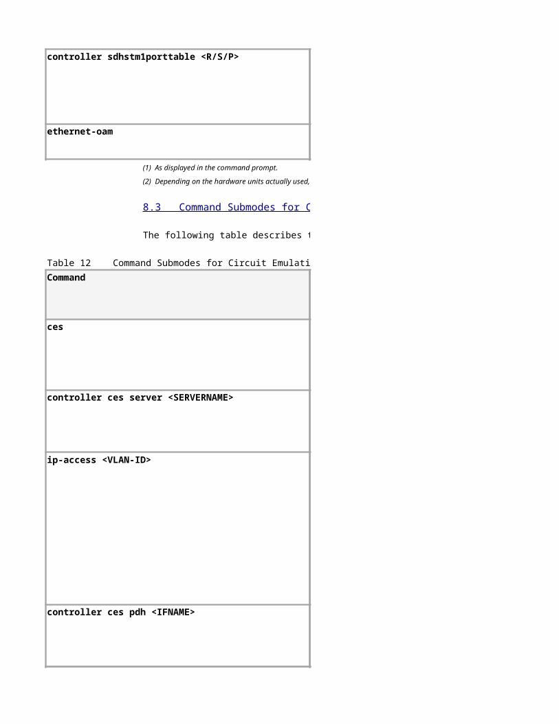
controller sdhstm1porttable <R/S/P>
ethernet-oam
The following table describes the commands for entering the relevant command submodes from Global Configuration mode, and the purpose for each one of them.
Command
ces
controller ces server <SERVERNAME>
ip-access <VLAN-ID>
controller ces pdh <IFNAME>
(1) As displayed in the command prompt.
(2) Depending on the hardware units actually used, only some of the submodes may be relevant.
8.3 Command Submodes for CES
Table 12 Command Submodes for Circuit Emulation Services (CES) Configuration
mef
ip
pm
controller ces pw <SERVERNAME> <PWNUMBER>
(1) As displayed in the command prompt.
(2) Depending on the hardware units actually used, only some of the submodes may be relevant.
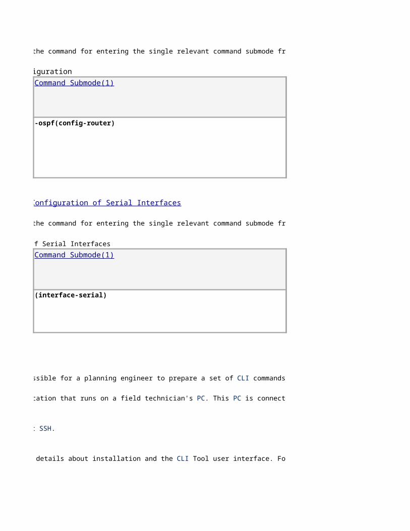
8.4 Command Submodes for IP Router Configuration
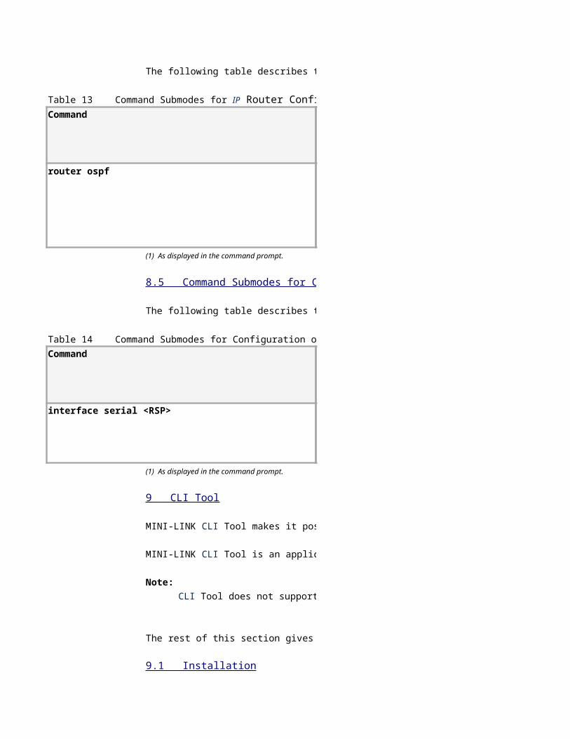
The following table describes the command for entering the single relevant command submode from Global Configuration mode.
Command
router ospf
The following table describes the command for entering the single relevant command submode from Global Configuration mode.
Command
interface serial <RSP>
Table 13 Command Submodes for IP Router Configuration
(1) As displayed in the command prompt.
8.5 Command Submodes for Configuration of Serial Interfaces
Table 14 Command Submodes for Configuration of Serial Interfaces
(1) As displayed in the command prompt.
9 CLI Tool
MINI-LINK CLI Tool makes it possible for a planning engineer to prepare a set of CLI commands in a standard text file, which can later be run on-site on a newly installed MINI-LINK node. For more information on creating these files, see Preparing a CLI Script File Offline, Reference [5].
MINI-LINK CLI Tool is an application that runs on a field technician's PC. This PC is connected through a USB cable to a MINI-LINK node that is being deployed. CLI Tool is not part of MINI-LINK Craft and does not interact with it, but MINI-LINK Craft may be used together with CLI Tool.
Note:
CLI Tool does not support SSH.
The rest of this section gives details about installation and the CLI Tool user interface. For more information on using CLI Tool, see Transferring a CLI Script File on Site, Reference [9].
9.1 Installation
A
For information about installing the required software and configuring a PC for CLI, see Section 3.
9.2 User Interface Overview
Figure 4 shows the different parts of the MINI-LINK CLI Tool user interface:
Figure 4 CLI Tool User Interface
B
C
D
E
F
9.3 Menus
This section describes the menus in MINI-LINK CLI Tool.
9.3.1 File menu
Select script file — Opens a browser window where you can locate a script file.
Select log file — Opens a browser window where you can locate a log file.
Exit — Exits MINI-LINK CLI Tool.
9.3.2 Help menu
About ... — Displays version information.
9.4 Session Pane
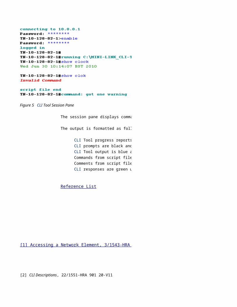
Figure 5 shows example output in the session pane:
The session pane displays commands that have been executed and the corresponding responses from the system.
The output is formatted as follows:
Commands from script files are blue.
Comments from script files are purple and italic.
Figure 5 CLI Tool Session Pane
CLI Tool progress reports are aqua and bold.
CLI prompts are black and bold.
CLI Tool output is blue and italic.
CLI responses are green unless CLI Tool detects them as error messages, in which case they are red, bold, and italic.
Reference List
[1] Accessing a Network Element, 3/1543-HRA 901 20-V11
[7] Supplementary Safety Information for MINI-LINK, 124 46-HSD 101 16/1
[8] System Safety Information, 124 46-2886
[9] Transferring a CLI Script File on Site, 17/1553-HRA 901 20-V11
CLI User Guide MINI-LINK TN ETSI
The following table describes the commands for entering the relevant command submodes from Global Configuration mode, and the purpose for each one of them.
(interface-ethernet)
(config-bridgeport)
(config-bridgeport-policing)
(config-bridgeport-pol-cos-group)
Table 11 Command Submodes for Ethernet ConfigurationCommand Submode(1)(2)
(config-bridgeport-pol-cos-group-mapping)
(config-pol-bw-profile)
(config-eth-epl)
(config-eth)
(config-lan)
(config-wan)
(config-eth-mac-whitelist)
(config-ethernet-profiles)
(config-vlan)
(config-vlan-fdb)
(config-lag)
(config-mst)
(config-wred-profile)
(config-scheduler-profile)
(config-wred-or-color-dropping)
(eth-pm)
(pm)
(config-rl-ime)
(config-synch-nominee)
(protection)
(controller-xfsdhstm1-scalarobjects)
(controller-xfprotection-port)
(controller-xfprotection-line)
(controller-xfprotection-eq)
(controller-xfsdhstm1)
(config-ethoam)
The following table describes the commands for entering the relevant command submodes from Global Configuration mode, and the purpose for each one of them.
(config-ces)
(config-ces-server)
(config-ces-ip-access-vlan)
(config-ces-pdh)
(2) Depending on the hardware units actually used, only some of the submodes may be relevant.
(2) Depending on the hardware units actually used, only some of the submodes may be relevant.
8.4 Command Submodes for IP Router Configuration
The following table describes the command for entering the single relevant command submode from Global Configuration mode.
-ospf(config-router)
The following table describes the command for entering the single relevant command submode from Global Configuration mode.
(interface-serial)
IP Router ConfigurationCommand Submode(1)
8.5 Command Submodes for Configuration of Serial Interfaces
Table 14 Command Submodes for Configuration of Serial InterfacesCommand Submode(1)
Tool makes it possible for a planning engineer to prepare a set of CLI commands in a standard text file, which can later be run on-site on a newly installed MINI-LINK node. For more information on creating these files, see Preparing a CLI Script File Offline, Reference [5].
Tool is an application that runs on a field technician's PC. This PC is connected through a USB cable to a MINI-LINK node that is being deployed. CLI Tool is not part of MINI-LINK Craft and does not interact with it, but MINI-LINK Craft may be used together with CLI Tool.
The rest of this section gives details about installation and the CLI Tool user interface. For more information on using CLI Tool, see Transferring a CLI Script File on Site, Reference [9].
For information about installing the required software and configuring a PC for CLI, see Section 3.
shows the different parts of the MINI-LINK CLI Tool user interface:
This section describes the menus in MINI-LINK CLI Tool.
— Opens a browser window where you can locate a script file.
— Opens a browser window where you can locate a log file.
— Displays version information.
Figure 5 shows example output in the session pane:
The session pane displays commands that have been executed and the corresponding responses from the system.
Comments from script files are purple and italic.
Tool progress reports are aqua and bold.
CLI Tool detects them as error messages, in which case they are red, bold, and italic.
The following table describes the commands for entering the relevant command submodes from Global Configuration mode, and the purpose for each one of them.
Purpose
Configure the bridge ports in the Ethernet Switch.
Configure site LAN port.
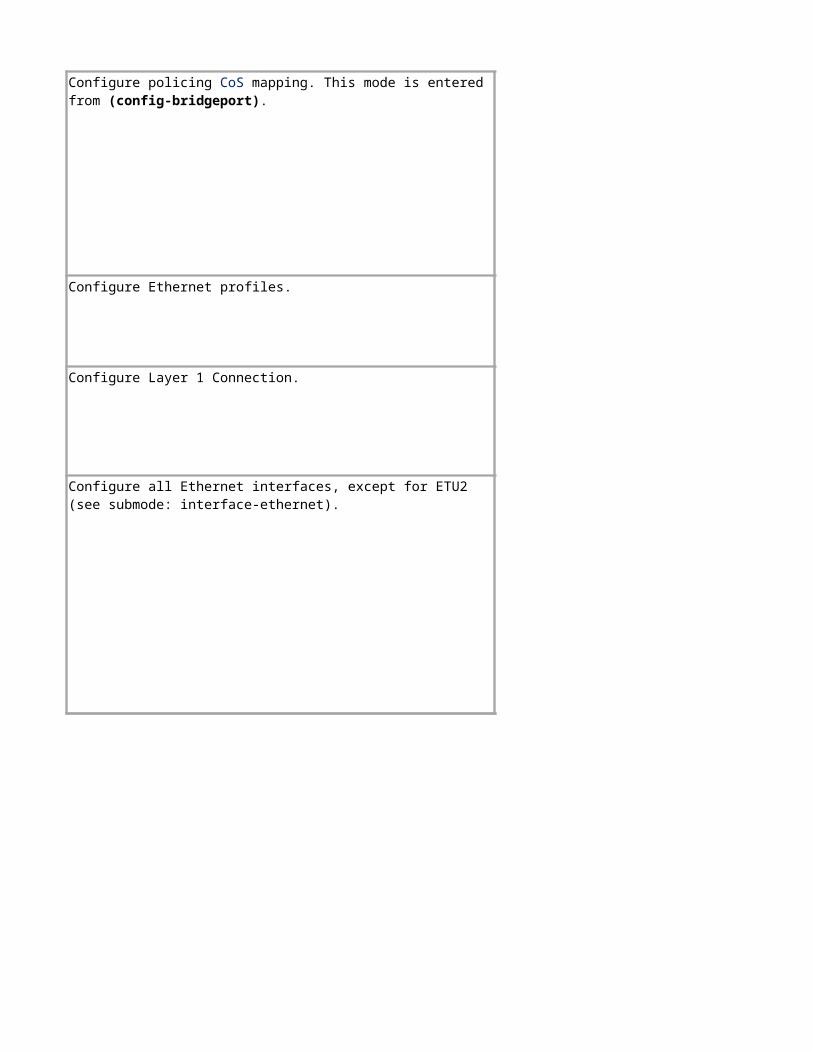
Configure policing. This mode is entered from (config-bridgeport).
Enable policing. This mode is entered from (config-bridgeport).
Configure Ethernet profiles.
Configure Layer 1 Connection.
Configure policing CoS mapping. This mode is entered from (config-bridgeport).
Configure all Ethernet interfaces, except for ETU2 (see submode: interface-ethernet).
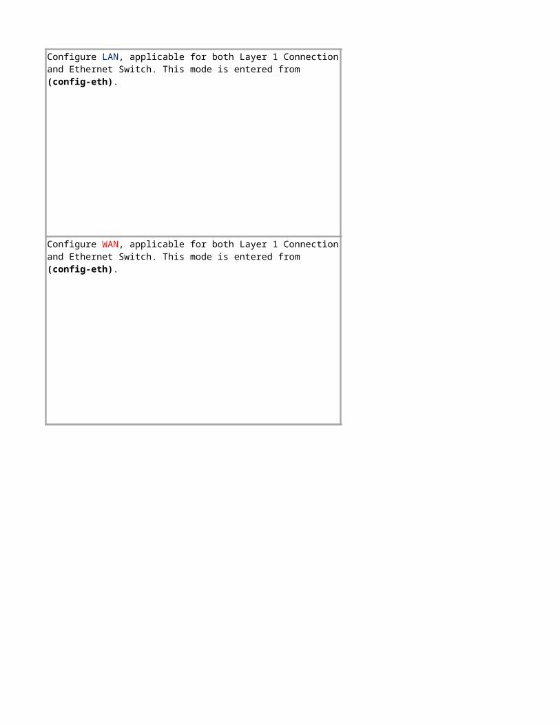
Configure LAN, applicable for both Layer 1 Connection and Ethernet Switch. This mode is entered from (config-eth).
Configure WAN, applicable for both Layer 1 Connection and Ethernet Switch. This mode is entered from (config-eth).
Configure Ethernet MAC address white lists. MAC address white lists are used to determine which MAC addresses are accepted for port access at the network edge.
Configure Ethernet profiles, such as WRED and scheduler.
Create and configure a VLAN.
Configure forwarding of database (FDB). This mode is entered from (config-vlan).
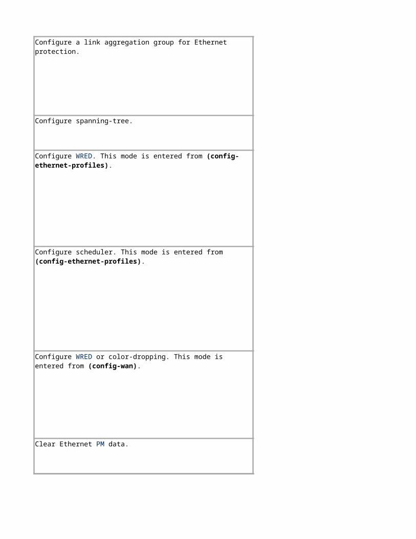
Configure spanning-tree.
Configure a link aggregation group for Ethernet protection.
Configure WRED. This mode is entered from (config-ethernet-profiles).
Configure scheduler. This mode is entered from (config-ethernet-profiles).
Configure WRED or color-dropping. This mode is entered from (config-wan).
Clear Ethernet PM data.
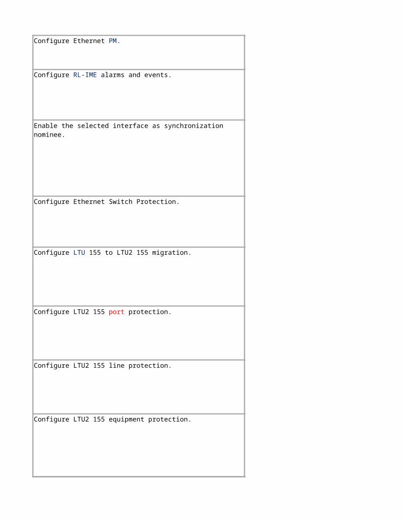
Configure Ethernet Switch Protection.
Configure LTU2 155 line protection.
Configure LTU2 155 equipment protection.
Configure Ethernet PM.
Configure RL-IME alarms and events.
Enable the selected interface as synchronization nominee.
Configure LTU 155 to LTU2 155 migration.
Configure LTU2 155 port protection.
The following table describes the commands for entering the relevant command submodes from Global Configuration mode, and the purpose for each one of them.
Purpose
Configure LTU2 155 STM1 port.
Configure Link OAM.
Configure general CES parameters.
Configure the given CES Server.
Create an entry in the IP Access table. The mode is entered from (config-ces-server).
Configure CES PDH parameters.
Configure the given PseudoWire (PW) of the given CES Server parameters.
Configure Metro Ethernet Forum (MEF) parameters of PW. The mode is entered from (config-ces-pw).
Configure IP parameters of PW. The mode is entered from (config-ces-pw).
Configure PM parameters of PW. The mode is entered from (config-ces-pw).
The following table describes the command for entering the single relevant command submode from Global Configuration mode.
Purpose
The following table describes the command for entering the single relevant command submode from Global Configuration mode.
Purpose
Configure OSPF, for example, as a stub area.
Configure serial interfaces for PPP.
commands in a standard text file, which can later be run on-site on a newly installed MINI-LINK node. For more information on creating these files, see Preparing a CLI Script File Offline, Reference [5].
is connected through a USB cable to a MINI-LINK node that is being deployed. CLI Tool is not part of MINI-LINK Craft and does not interact with it, but MINI-LINK Craft may be used together with CLI Tool.
Tool user interface. For more information on using CLI Tool, see Transferring a CLI Script File on Site, Reference [9].
Menu bar — Contains commands, see Section 9.3.
Connection parameters — Contains the IP address and passwords needed for connection.
Connection and execution — Allows control of connection and execution of script files. During a connection attempt, the upper button changes from Connect to Cancel. If connection is successful, this button changes from Connect to Disconnect and the lower button from Preload (that is reading connection parameters from the script file) to Execute. During execution of a script file, the lower button changes to Cancel. Timeout [s] sets how long CLI Tool waits for a response from the node. The Stop on Error check box controls whether execution of a script file should stop if an error is detected.
File name selection — Contains file name fields and Browse buttons used to select script files and log files.
Session pane — Displays executed commands and system responses, see Section 9.4.
Command entry box and related buttons — Allows individual commands to be entered and executed (by clicking Run). It is also possible to get help for the command (by clicking ?).
The session pane displays commands that have been executed and the corresponding responses from the system.
Tool detects them as error messages, in which case they are red, bold, and italic.
commands in a standard text file, which can later be run on-site on a newly installed MINI-LINK node. For more information on creating these files, see Preparing a CLI Script File Offline, Reference [5].
Tool is not part of MINI-LINK Craft and does not interact with it, but MINI-LINK Craft may be used together with CLI Tool.