5. Mahmood Rezaian' and Dhanjoo N. Ghista2 'California Orthopaedic Clinic 'Faculty of Medicine 8 Health Sciences United Arab Emirates University Clinical Biomechanics of Spinal Fixation- Anterior, Posterior, and Later a I he goal of successful surgical treatment T of thoraco-lumber spinal injury is to achieve a stable, pain free spine with no deformity, along with decompression of the cord for maximal neurological recov- ery. When the vertebral body is damaged by trauma, tumor, or infection, the weight of the trunk acts anterior to the damaged vertebra. Because of this loading, poste- rior fixations [ 1, 21 involving Harrington instrumentation, spinal plates or rods wired to spinous processes cannot provide long-term secure fixation free of compli- cations [3,4]. This treatment is also unable to restore spinal segment, position, or re- lieve and prevent compression of the cord from the anterior side. Thus, posterior ap- proaches and systems have given way to lateral and anterior approaches and sys- temss [5-71. The three primary systems of spinal fracture-fixation may be categorized as follows: (a) Posterior fixation of the frac- tured spine by means of devices, attached to posterior structures of the spinal col- umn. These devices apply flexion-resist- ing forces to the deformed spinal column, but cannot correct the spinal deformity nor decompress the spinal cord [8,9]; (b) Lat- eral fixation of the fractured spine by means of devices that are attached parallel to the intact vertebral bodies above and below the fractured body, and bypass the loading on the spine across its fractured segment [lo]; (c) Anterior fixation of the fractured spine by means of a device that replaces the fractured vertebral body seg- ment, and transmits the load through it from the intact vertebral body above the fractured body to the intact spinal struc- ture below it [ l l , 121. Herein, we will provide biomechanical analyses of the function and efficacy of each of these systems, supported by some case histories. Posterior Fixation Figure 1 illustrates posterior fixation by means of contoured distraction rods IEEE ENGINEERING IN MEDICINE AND BIOLOGY segmentally anchored to the spine by means of wires attached to the spinous processes by the Drummond technique [ 131. As shown in the figure, in response to an anteriorly placed upper-torso weight, the system exerts a distraction force plus an extension moment on the spine. The body weight vector acts anterior to the spinal column, thereby subjecting the column to an axial compression force at its neutral-axis plane, and also a flexion moment. The fractured spine and the pos- terior fixation system act as a composite beam structure that is subjected to bending with axial compression. The neutral-axis plane is located posteriorly in the spinal column, almost passing through the spinal cord, because the distraction rods are much more rigid than the fractured ante- rior spinal column (Fig. 2). In order to resist this loading system, the fractured vertebral body will have to bear compres- sive forces (as shown in the figure), caus- ing it to deform appreciably under these compressive forces. The sublaminar wires will bear the shear forces. The posteriorly placed rods will need to bear tensile forces (as shown in the figure); if however, the rods are anchored in a distraction mode with a conventional hook, they might be- come disengaged. Now consider a person weighing 70 kg with a fractured LI body. For such a per- son, based on our earlier analysis [3], the compressive force would be about 250 N on the posteriorly located neutral axis of the reinforced spinal LI cross-section, comprising the vertebral body and the two distraction rods. The flexion moment would be 45 Nm. The transformed section of vertebral body material (the composite cross-section of vertebral body and rods) has an enhanced moment-of-inertia on the order of 2 ~ 1 0 . ~ m4 (instead of 4x10-' m4 of the vertebral body alone). This helps considerably to reduce the maximum compressive bending stress on the anterior edge of the vertebral body. Nevertheless, 0739-51 75/94/$4.0001994 525
Transcript
5. Mahmood Rezaian' and Dhanjoo N. Ghista2
'California Orthopaedic Clinic 'Faculty of Medicine 8 Health Sciences
United Arab Emirates University
Clinical Biomechanics of Spinal Fixation- Anterior, Posterior, and Later a I
he goal of successful surgical treatment T of thoraco-lumber spinal injury is to achieve a stable, pain free spine with no deformity, along with decompression of the cord for maximal neurological recov- ery. When the vertebral body is damaged by trauma, tumor, or infection, the weight of the trunk acts anterior to the damaged vertebra. Because of this loading, poste- rior fixations [ 1, 21 involving Harrington instrumentation, spinal plates or rods wired to spinous processes cannot provide long-term secure fixation free of compli- cations [3,4]. This treatment is also unable to restore spinal segment, position, or re- lieve and prevent compression of the cord from the anterior side. Thus, posterior ap- proaches and systems have given way to lateral and anterior approaches and sys- temss [5-71.
The three primary systems of spinal fracture-fixation may be categorized as follows: (a) Posterior fixation of the frac- tured spine by means of devices, attached to posterior structures of the spinal col- umn. These devices apply flexion-resist- ing forces to the deformed spinal column, but cannot correct the spinal deformity nor decompress the spinal cord [8,9]; (b) Lat- eral fixation of the fractured spine by means of devices that are attached parallel to the intact vertebral bodies above and below the fractured body, and bypass the loading on the spine across its fractured segment [lo]; (c) Anterior fixation of the fractured spine by means of a device that replaces the fractured vertebral body seg- ment, and transmits the load through it from the intact vertebral body above the fractured body to the intact spinal struc- ture below it [ l l , 121. Herein, we will provide biomechanical analyses of the function and efficacy of each of these systems, supported by some case histories.
segmentally anchored to the spine by means of wires attached to the spinous processes by the Drummond technique [ 131. As shown in the figure, in response to an anteriorly placed upper-torso weight, the system exerts a distraction force plus an extension moment on the spine.
The body weight vector acts anterior to the spinal column, thereby subjecting the column to an axial compression force at its neutral-axis plane, and also a flexion moment. The fractured spine and the pos- terior fixation system act as a composite beam structure that is subjected to bending with axial compression. The neutral-axis plane is located posteriorly in the spinal column, almost passing through the spinal cord, because the distraction rods are much more rigid than the fractured ante- rior spinal column (Fig. 2). In order to resist this loading system, the fractured vertebral body will have to bear compres- sive forces (as shown in the figure), caus- ing it to deform appreciably under these compressive forces. The sublaminar wires will bear the shear forces. The posteriorly placed rods will need to bear tensile forces (as shown in the figure); if however, the rods are anchored in a distraction mode with a conventional hook, they might be- come disengaged.
Now consider a person weighing 70 kg with a fractured LI body. For such a per- son, based on our earlier analysis [3], the compressive force would be about 250 N on the posteriorly located neutral axis of the reinforced spinal LI cross-section, comprising the vertebral body and the two distraction rods. The flexion moment would be 45 Nm. The transformed section of vertebral body material (the composite cross-section of vertebral body and rods) has an enhanced moment-of-inertia on the order of 2 ~ 1 0 . ~ m4 (instead of 4x10-' m4 of the vertebral body alone). This helps considerably to reduce the maximum compressive bending stress on the anterior edge of the vertebral body. Nevertheless,
0739-51 75/94/$4.0001994 525
this external loading system would exert an average compressive stress of about 1 .O MPa on the fractured spinal vertebral body. In the absence of the rods, the maxi- mum compressive stress in the vertebral body would be of the order of 20 MPa, but in the rod-reinforced composite cross-sec- tion (of vertebral-body and steel materi- als), the maximum compressive stress is reduced considerably. However, the frac- tured vertebral body will not be able to bear even this level of compressive force without undergoing considerable com- pressive deformation axially. This force would correspondingly cause the frac- tured vertebral body to increase its lateral dimensions, and hence impinge on the neural structures from the anterior side.
Hence, this system of posterior fixation can still allow some anterior spinal col- umn compression, especially in the case of a distraction-dislocation injury involv- ing vertebral body fracture and ligament rupture. As a result, due to the compres- si;e deformation of the fractured vertebral body, progressive kyphosis occur, which will further aggravate the injury. Further, in order to prevent the risk of disengagement of the rods, we need to adopt an anchorage system that will en- able the rods to act as both distraction and compression instrumentation, as the situ- ation demands. This system of fixation is also not designed to minimize rotation of the fractured vertebral body. Neverthe- less, torsion loading can be somewhat re- sisted by the rods abutting against the transverse and spinous processes. How- ever, if some relative rotatory motion could occur between the upper and lower intact vertebral bodies, it would also ag- gravate compression of the cord by the fractured vertebral body.
Figure 3 is an illustration of a patient who suffered a rather severe compression fracture at the level of L2. His spine was instrumented by dual Hanington distrac- tion rods (Fig. 2a). It is quite obvious that the patient had an unstable fixation for a rather marked compression fracture at this level. As explained earlier, the posterior
1. (a) Posterior fixation by means of a contoured distraction rod, segmentally at- tached to the spine. (b) “Distraction plus extension-moment” force system exerted by the fixation system on the spine.
fixation system cannot activate compres- sion of the appreciable deformation occur- ring at the damaged spinal segment. Not surprisingly, this patient developed a pro- gressive kyphosis at this level (Fig. 2b), associated with incapacitating pain prob- ably due to increased anterior impinge- ment on the spinal cord. The patient then required a two-stage procedure, consisting of anterior decompression with an inter- body graft, along with posterior fixation, in order to reestablish the normal sagital contour of the spine (Fig. 2c). As seen
2. A cross-section through the fractured vertebral body, showing (a) compressive stresses acting on the fractured vertebral body (which could result in considerable deformation); and (b) tensile forces borne by the rods, under the action of the body weight.
later, the anterior spinal fixator would have constituted a more effective means of fixation as well as of overcoming the neurological deficit.
Thus, we can see that the posterior fixation system is not only unable to re- lieve anterior compression on the cord by
the fractured vertebral body impinging on it, but also permits exertion of compres- sive force on the compressed vertebral body under the action of body weight, with associated kyphosis, added impinge- ment of the cord, and pain. Posterior fixa- tion only provides limited structural
526 IEEE ENGINEERING IN MEDICINE AND BlOlOGY August/Septemher 1994
stability (i.e., it does not alleviate neuro- logical deficit), and thus restricts patient movement and mobility. For this reason, normally following surgery, the patient must wear an external support.
In any case, for fracture-dislocation in- jury, wherein the ligaments are also rup- tured along with vertebral body fracture, it is not possible to apply distraction. The reason is simple: the required tensile forces that they exert cannot be sustained by the ruptured posterior ligaments [3].
Laterial-Parallel Fixation (LPF) Figure 4a schematically illustrates a
lateral-parallel fixation attached parallel to the spinal column, laterally (and a bit anteriorly) onto the intact adjacent verte- bral bodies, after partial resection of the fractured vetrebral body. The figure shows the positioning and attachment of two piers to the intact vertebral bodies by means of screws and staples. The piers are connected or bridged by means of two rods, which can be manipulated by turn- buckle mechanisms, one in distraction and the other in compressive mode. By this means, an extension moment can be ap- plied on the spine (in the sagital plane) to correct the spinal deformity resulting from the fracture. This moment will restore the configuration of the fractured motion seg- ment, and particularly that of the crushed vertebral body. In so doing, the residual
fractured body is retracted anteriorly and away from the compressed cord.
This fixator acts as a load bypass for an axial load (Fig. 3b). The load is transmit- ted from the top intact vertebral body by the top pier, through the two bars and the bottom pier, into the lower intact vertebral body, bypassing the fractured vertebral body. Again, let us take the case of a person whose body weight is 70 kg, which would cause an axial force (P) of about 250 N on the fractured spinal segment. If this load is bypassed through the fixator, then each of the bars will be subjected to a compressive force of 110N and a bend- ing moment (= P x screw length) of 3.8 N-m (for a screw length of 3 cm). While the two bars can be adequately designed to bear this level of compressive force, they must also sustain a bending moment, and this factor is of some concern. Also, the load transfer between the intact verte- bral bodies and the two piers occurs through the screws, which are thus also subjected to bending forces in the process.
The biomechanics of the manner in which this lateral-parallel fixator helps the fractured motion segment to bear flexion loading is illustrated in Fig. 4c. The staple first transfers moment from the intact ver- tebral body to the piers pivoted to it. Next, if we consider equilibrium of the piers (encased by the staple) and the two bars attached to them, the flexion bending mo-
ment transferred to the piers by the staples (Fig. 4c), is resisted by the pair of com- pressive and tensile forces acting in the bars. A representative flexion bending moment (M) of 45 N-m will result in a bar force (M/distance between the bars) of 5,600 N, which can well be sustained by the bars.
The net effect of the axial load and the flexion moment on the forces in the LPF (Figs. 4b and 4c) is that its anchorage structural components (namely the screw and the staple) are subjected to bending. These components are hence liable to loosen as the bone remodels in response to the reactive bending forces. Also, when a member is half embedded in the bone, bending forces on the member cause osteolysis due to enlargement of the entry hole, which can result in infection.
Finally, Fig. 4d demonstrates the mechanism by which this Lateral-parallel fixator (LPF) helps the fractured motion segment to resist torsion. As seen, the screw resists relative motion between the intact vertebral body and the pier, and hence is loaded by shear forces. A repre- sentative value of torsion (T) of 20 N-m, acting on a spinal column (with vertebral bodies of equivalent diameter, d), will cause a shear force (= 2T/d) of 1025 N in the screw. The two bars resist relative motion between the two piers, and un- dergo bending as well as shear. The bars
3. (a) Illustration of the use of dual Harrington distraction system for an L-2 fracture in which the spine has not been completely reduced, and the segmental defect anteriorly persists; (b) The L-2 vertebral body has undergone progressive collapse, accompa- nied by progression of kyphosis and incapacitating pain; (c) A lateral x-ray following a two-staged procedure in which anterior decompression has been performed, the interbody graft has consolidated, and a normal sagital contour of the spine has now been reestablished.
AugurVSepternber 1994 IEEE ENGINEERING IN MEDICINE AND BIOLOGY 521
A
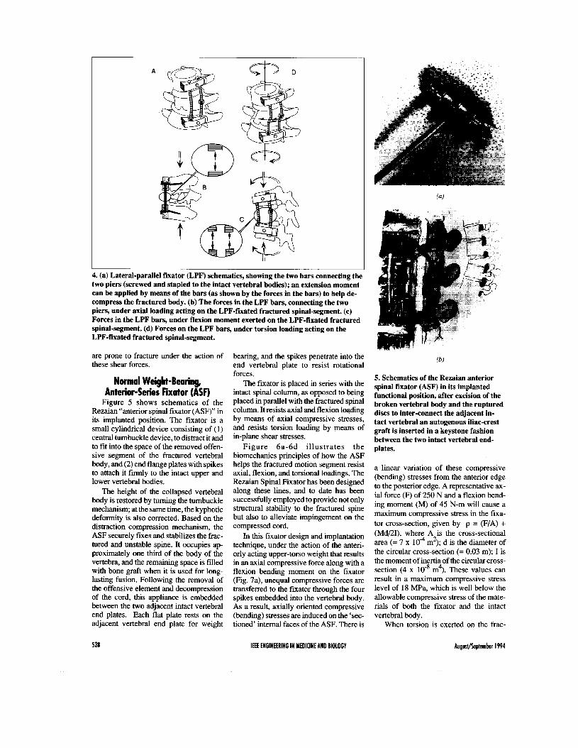
4. (a) Lateral-parallel fixator (LPF) schematics, showing the two bars connecting the two piers (screwed and stapled to the intact vertebral bodies); an extension moment can be applied by means of the bars (as shown by the forces in the bars) to help de- compress the fractured body. (b) The forces in the LPF bars, connecting the two piers, under axial loading acting on the LPF-fiiated fractured spinal-segment. (c) Forces in the LPF bars, under flexion moment exerted on the LPF-fixated fractured spinal-segment. (d) Forces on the LPF bars, under torsion loading acting on the LPF-fixated fractured spinal-segment.
are prone to fracture under the action of these shear forces.
Normal Weight-Bearing, Anterior-Series Fixator (ASF)
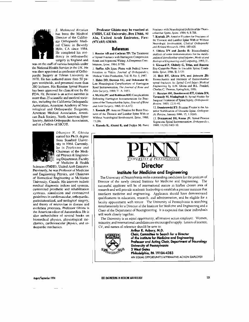
Figure 5 shows schematics of the Rezaian “anterior spinal fixator (ASF)” in its implanted position. The fixator is a small cylindrical device consisting of (1) central turnbuckle device, to distract it and to fit into the space of the removed offen- sive segment of the fractured vertebral body, and (2) end flange plates with spikes to attach it firmly to the intact upper and lower vertebral bodies.
The height of the collapsed vertebral body is restored by turning the turnbuckle mechanism; at the same time, the kyphotic deformity is also corrected. Based on the distraction compression mechanism, the ASF securely fixes and stabilizes the frac- tured and unstable spine. It occupies ap- proximately one third of the body of the vertebra, and the remaining space is filled with bone graft when it is used for long- lasting fusion. Following the removal of the offensive element and decompression of the cord, this appliance is embedded between the two adjacent intact vertebral end plates. Each flat plate rests on the adjacent vertebral end plate for weight
528
bearing, and the spikes penetrate into the end vertebral plate to resist rotational forces.
The fixator is placed in series with the intact spinal column, as opposed to being placed in parallel with the fractured spinal column. It resists axial and flexion loading by means of axial compressive stresses, and resists torsion loading by means of in-plane shear stresses.
Figure 6a-6d i l lustrates the biomechanics principles of how the ASF helps the fractured motion segment resist axial, flexion, and torsional loadings. The Rezaian Spinal Fixator has been designed along these lines, and to date has been successfully employed to provide not only structural stability to the fractured spine but also to alleviate impingement on the compressed cord.
In this fixator design and implantation technique, under the action of the anteri- orly acting upper-torso weight that results in an axial compressive force along with a flexion bending moment on the fixator (Fig. 7a), unequal compressive forces are transferred to the fixator through the four spikes embedded into the vertebral body. As a result, axially oriented compressive (bending) stresses are induced on the ‘sec- tioned’ internal faces of the ASF. There is
IEEE ENGINEERING IN MEDICINE AND BIOLOGY
5. Schematics of the Rezaian anterior spinal fixator (ASF) in its implanted functional position, after excision of the broken vertebral body and the ruptured discs to inter-connect the adjacent in- tact vertebral an autogenous iliac-crest graft is inserted in a keystone fashion between the two intact vertebral end- plates.
a linear variation of these compressive (bending) stresses from the anterior edge to the posterior edge. A representative ax- ial force (F) of 250 N and a flexion bend- ing moment (M) of 45 N-m will cause a maximum compressive stress in the fixa- tor cross-section, given by p = (F/A) + (Md/21), where A is the cross-sectional area (= 7 x lo4 m2); d is the diameter of the circular cross-section (= 0.03 m); I is the moment of inertia of the circular cross- section (4 x m4). These values can result in a maximum compressive stress level of 18 m a , which is well below the allowable compressive stress of the mate- rials of both the fixator and the intact vertebral body.
When torsion is exerted on the frac-
Augustheptember 1994
A A
6. Biomechanics of the fractured-spine stabilized with the Rezaian Anterior-series fixator (ASF). (a) under axial load; (b) under flexion moment; (c) under torque load- ing; (d): under combined axial and flexion loading.
(a)
It axial compressive force
V A===- V flexion moment
compressive bending stresses
torque
7. Internal stresses in the ASF. (a) under axial load plus flexion moment; (b) under torsion.
tured motion segment, tangential forces are generated that act on the spikes of the top and bottom plates or flanges (Fig. 7b). The four tangential forces on each plate exert a torque about the central vertical axis of the fixator. Together, they exert
torsion loading on the anterior-series fixa- tor (ASF), whose cylindrical shape is suit- ably designed for this purpose. On any internal section of the ASF structure, the two sets of four forces acting on the spikes of the top and bottom plates result in shear
stresses, varying linearly in magnitude from the outer edge to the inner edge. A representative torsion (T) of 20 N-m will cause a maximal shear stress (= (T) (radius of the plate)/(polar moment of inertia)] of 3.8 MPa, which again is an order magni- tude less than the allowable shear stress of the fixator material.
Clinical Application and Results with the RSF
The Rezaian Spinal Fixator has been successfully used in more than 70 patients with spinal fracture, and the patients have been followed from 1 to 8 years. No in- strument failure has occurred on this group of patients. Details have been pub- lished in our previous paper [ 111. As clini- cal examples of the use of this fixator, two cases are presented below:
Case I A 32 year-old female (MS) was involved in a motor vehicle accident and sustained an L2 burst fracture (Fig. 8a). She was treated by double Harrington rods and sublaminar fixation (Fig. 8b). In addition, she had to wear a plastic jacket as external support for 5-112 months. She was ambu- latory but continued to have back and leg pain. The pain could have been attributed to the failure of the posterior instrumenta- tion to relieve compression on the cord from the anterior side, as explained earlier.
Two years later, the surgeon thought her pain was due to the imtation from the instrumentation. Therefore, the instru- mentation was removed (Fig. 8c). Three months later, the patient was unable to stand, and also had urinary incontinence. She was receiving 15 mg morphine sulfate every 4 hours for relief of intractable pain.
At this stage, the patient was referred to us (SMR). A cystometry confirmed bladder paralysis. Myelography con- f m e d continuing compression on the spi- nal cord (Fig. 8d). The patient underwent surgery, during which the L2 vertebral body was replaced with the RSF (Fig. 8e). Two days later, she was walking in the comdor of hospital, free of pain, presum- ably because the technique decompressed the cord anteriorly. Only five days after surgery, she was discharged practically symptom-free, without need for medica- tion or any external support.
Case 2 A 22-year old man was involved in a
motor vehicle accident and sustained an L1 burst fracture with complete paraplegia at the level of T12. He was treated in a rehabilitation centre with double Har-
August/September 1994 IEEE ENGINEERING IN MEDICINE AND BIOLOGY 529
8. (a) Case of a female-patient (MS) following L2 burst fracture; (b) spinal fracture fixation by bilaterally placed Harrington rods; (c) Condition after two years, following the removal of Harrington instrumentation; (d) Myelogram showing cord com- pression; (e) Replacement of the fractured L2 vertebral body by the Rezaian ASF.
rington rods and sublaminar wire fixation (Fig. 9a).
Four years later, the patient was paraple- gic T12, with severe back pain. As has been stressed above, this type of posterior fixation is able to neither reduce the deformity nor decompress the cord. An attempt was made in the same institute to remove the instru- mentation. However, the rods were embed- ded in a fusion mass, and therefore the instrumentation could not removed. The pa- tient continued to have back pain.
At this stage, the patient was referred to us. The posterior fusion mass with two Harrington rods was determined to be ex- tremely stable. Nevertheless, a myelo- gram showed a block at the level of L1 due to compression on the cord by the burst- fractured Ll vertebral body (Fig. 9b), as per our biomechanically-based expecta- tion. The body of L1 was then replaced with an RSF (Fig. 9c).
The patient’s post-operative recovery was uneventful. His low back pain was re-
lieved immediately, the cord having been decompressed. He left on day nine, fol- lowing surgery. Three weeks later, when seen in the office, he reported that he felt his buttock on the wheelchair and had to move himself frequently. Four months later, he had sensation below LA-5. He had good-to-fair muscle power in both the ab- ductors and adductors as well as in the quadriceps. He had regained good control of his bladder and of his rectal sphincter. He was a much improved person.
9. Case of a 22 year-old man who sustained L1 burst fracture in a motor vehicle accident. (a) Spinal fixation was carried out by double Harrington rods and sublaminar wires. Four years later, the patient was paraplegic T12 with severe back pain. (b) Al- though the Harrington instrumentation was stable, yet a myelogram showed a block at L l due to cord compression by the burst fractured body. (c) The fractured L1 was replaced by the RSF.
530 IEEE ENGINEERING IN MEDICINE AND BIOLOGY Augustheptember 1994
S. Mahmood Rezaian has been the Medical Director of the Califor- nia Orthopaedic Medi- cal Clinic in Beverly Hills, CA since 1984. He completed his resi- dency in orthopaedic surgery in England and
was on the staff of various hospitals under the National Health Service in the UK. He was then appointed as professor of Ortho- paedic Surgery at Tehran University in 1970. He has authored more than 50 pa- pers worldwide, and presented more than 200 lectures. His Rezaian Spinal Fixator has been approved for clinical use by the FDA. Dr. Rezaian is an active member in more than 25 scientific and medical socie- ties, including the California Orthopaedic Association, American Academy of Neu- rological and Orthopaedic Surgeons, American Medical Association, Ameri- can Back Society, North American Spine Society, British Orthopaedic Association, and as a Fellow of SICOT.
Professor Ghista may be reached at FMHS, UAE University, Box 17666, AI Ain, United Arab Emirates, Fax: (971)(03) 630369.
References 1. Rossier AB and Cochran TP: The Treatment of Spinal Fractures with Hanington Compression Roads and Segmental Wiring: A Dangerous Com- bination, Spine, 1984; 9:796. 2. Steffee AD: Spine Plates with Pedical Screw Fixation in Video. Journal of Orthopaedics, Medical Video Production, Vol. 11, No. 5, 1987. 3. Hales DD, Dawson EG, and Delamater R: Late Neurological Complications of Harrington Road Inshumentation, The Journal of Bone and Joint Surgery, 1989; 71-A: 1053. 4. McAfee PC and Bohlman HH. Complications Following Hanington Instrumentation for Frac- tures of the Thoracolumbar Spine, Journal of Bone and Joint Surgery, 1985; 67-A:672. 5 . Kostuik JP: Anterior Fixation for Burst Frac- tures of the Thoracic and Lumbar Spine With or Without Neurological Involvement, Spine, 1988; 13:286. 6. Kaneda K, Abumi K, and Fujiya M: Burst
Fractures with Neurological Deficits of the Thora- columbar Spine, Spine, 1984; 9,8:788. 7. Kostuik JP: Anterior Fixation for Fractures of the Thoracic and Lumbar Spine With or Without Neurologic Involvement, Clinical Orthopaedic and Related Research, 1984; 189:105. 8. Ghista DN and Jacobs R: Biomechanical analyses of some instrumentations for the stabili- zation of dorsolumbar spinal injuries, Medical and Biological Engineering and Computing, 1983; 21. 9. Kinnard P, Ghibely G, Trim, and Basora: Roy-Cammille Plates in Unstable Spinal Condi- tions. Spine, 1986,11,2:131. 10. Holt RT, Ghista DN, and Johnson JR: Biomechanics and treatment of thorocolumbar spinal fractures; In. Spinal Cord Injury Medical Engineering by D.N. Ghista and H.L. Frankel, Charles C. Thomas, Springfield, 1986. 11. Rezaian SM, Dombrowski ET, Ghista DN, Tavassoly M, Modaghegh S: Spinal Fixator for Surgical Treatment of Spinal Injury, Orthopaedic Review, 1983; 12:31-41. 12. Dombrowski ET: Rezaian Fixator in the An- terior Stabilization of Unstable Spine. Orthopae- dic Review, January 1986, 15, 1:30/65. 13. Drummond DS, Keene JS: Spinal Process Segmental Spinal Instrumentation, Orthopaedics, 1988; 11(10):1403-10.
Dhanjoo N . Ghista earned his Ph.D. degree from Stanford Univer- sity in 1964. Currently, he is Professor and Chairman of the Medi- cal Physics &Engineer- ing Department, Faculty of Medicine & Health
Sciences (FMHS), United Arab Emirates. Previously, he was Professor of Medicine and Engineering Physics, and Chairman of Biomedical Engineering at McMaster University, Canada. His interests include medical diagnostic indices and systems, customized prosthetic and rehabilitation systems, simulation and customized guidelines in cardiovascular, orthopaedic, gastrointenstinal, and urological surgery, and theory of microvitae in disease and evolution processes. Professor Ghista is the American editor of Automedica. He is also author/editor of several books on biomedical physics, physiological me- chanics, cardiovascular physics, and or- thopaedic mechanics.
P E " U N 1 V E R S I 'TY of PEA'A'S Y L V A N I A
Director Institute for Medicine and Engineering
The University of Pennsylvania seeks outstanding candidates for the position of Director of the newly created Institute for Medicine and Engineering. The successful applicant will be of international stature in hidher chosen area of research and will provide academic leadership to establish a premier institute that interfaces medicine and engineering. Applicants should have demonstrated qualifications in education, research, and administration, and be eligible for a faculty appointment with tenure. The University of Pennsylvania is searching simultaneously for a Director of the Institute for Medicine and Engineering and a Chair of the Department of Bioengineering. It is expected that these individuals will work closely together.
The University is an equal opportunity, affirmative action employer. Women, minority, and international candidates are encouraged to apply. Letters of interest, CV, and names of reference should be sent to:
Arthur K. Asbury, M.D. Chair, Committee to Search for a Director of the Institute for Medicine and Engineering Professor and Acting Chair, Department of Neurology University of Pennsylvania 3 West Gates Philadelphia, PA 191 04-4283 A N EQUAL OPPORTUNITYIAFFIRMATIVE ACTION EMPLOYER