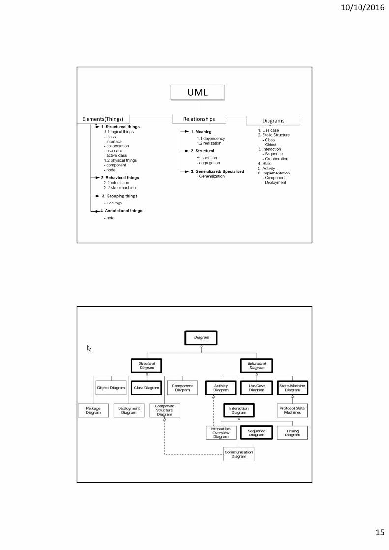
• 2. Behavioral DiagramUse Case Diagram, Sequence Diagram, Activity Diagram, Collaboration Diagram, and State chart Diagram
• 3. Grouping Diagram Packages, Subsystems, and Models
10/10/2016
17
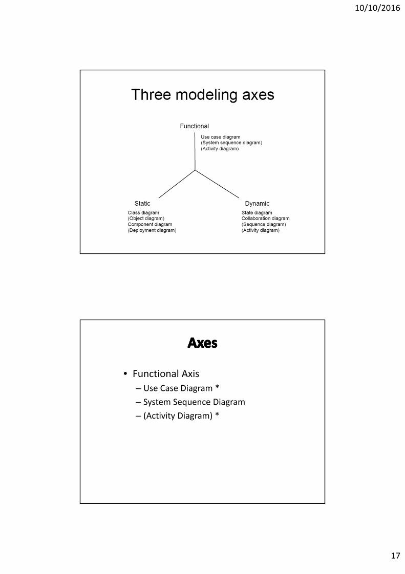
3 model axes
• Functional Axis
– Use Case Diagram *
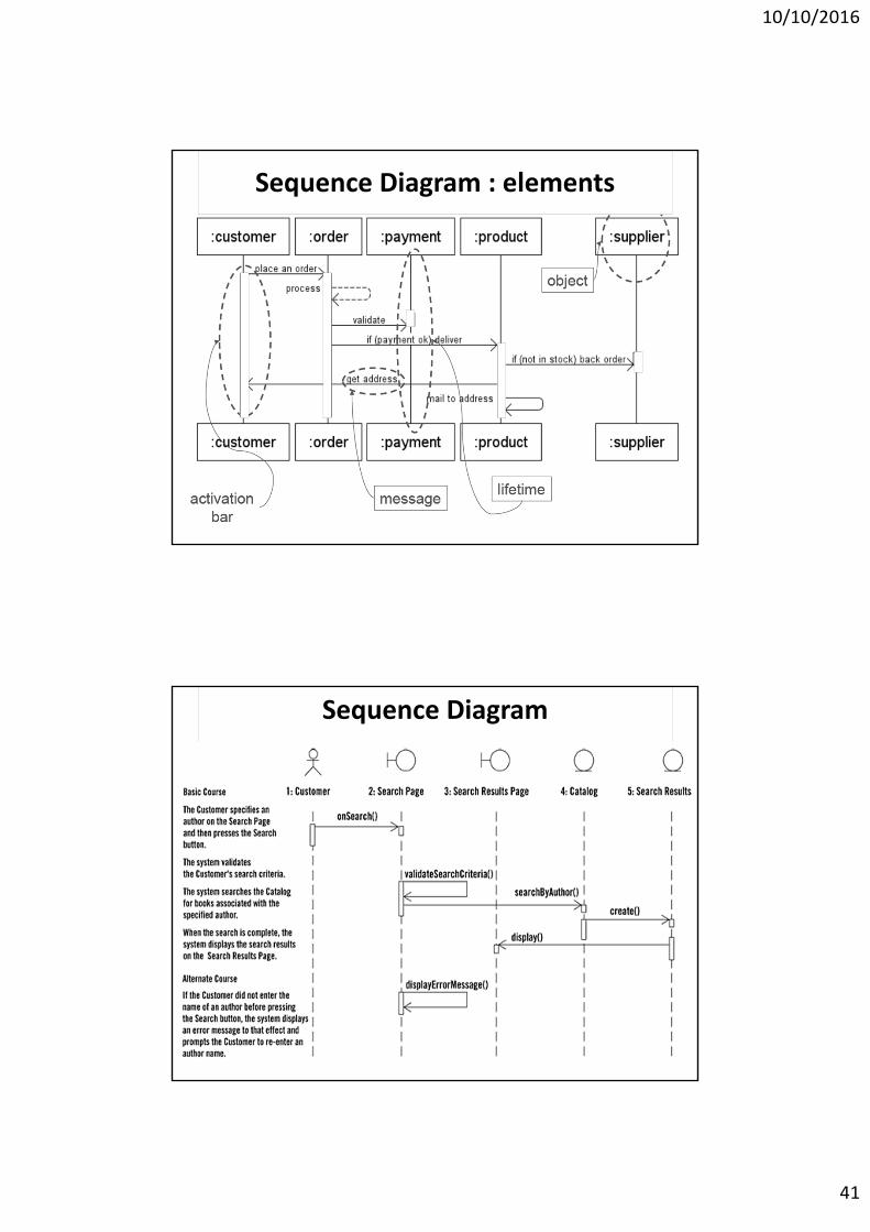
– System Sequence Diagram
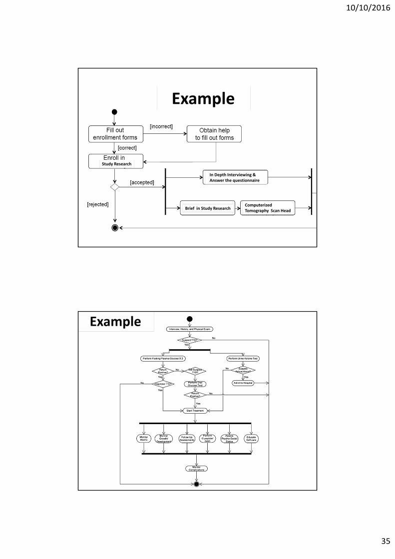
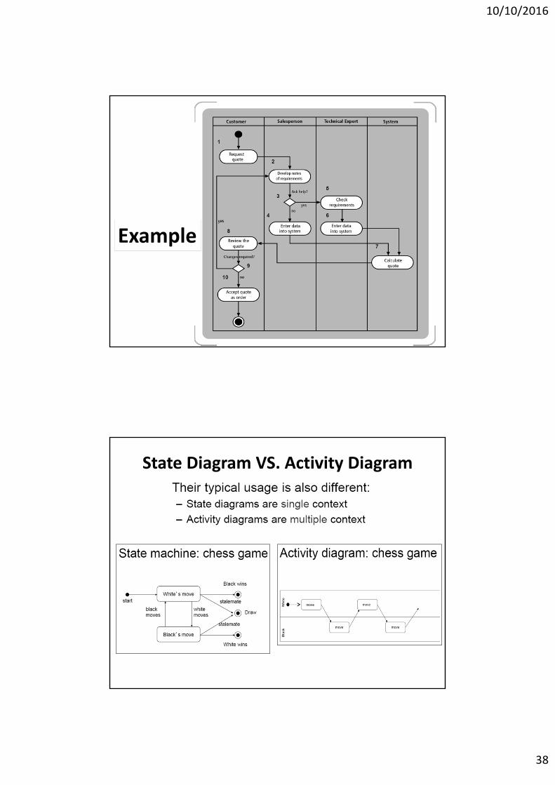
– (Activity Diagram) *
10/10/2016
18
Use case diagram(cont)
• Use Case Diagram : Pictorial showing process of user interacting with subsystem within whole system ( Macro requirement of system).
• Showing list of capabilities the system must provide.
Use case diagram (cont)• Represent totality of system in the form of entities, processes and their interactions
• Captures the system as snapshot of its organizational and behavioral elements
10/10/2016
19
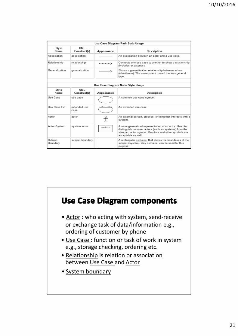
• <<Extend Relationship>>
Actor Use case
Association
Boundary
Epidemiology RACE 615
10/10/2016
20
• Known overall ability of system• Known subsystem users and behaviors
• Easy to communicate between developer and users
• Acting as preliminary test of system tailor made to requirement
• Help developer to classify activities or processes in system
• Act as basic diagram explained as non‐complicated pictures
10/10/2016
21
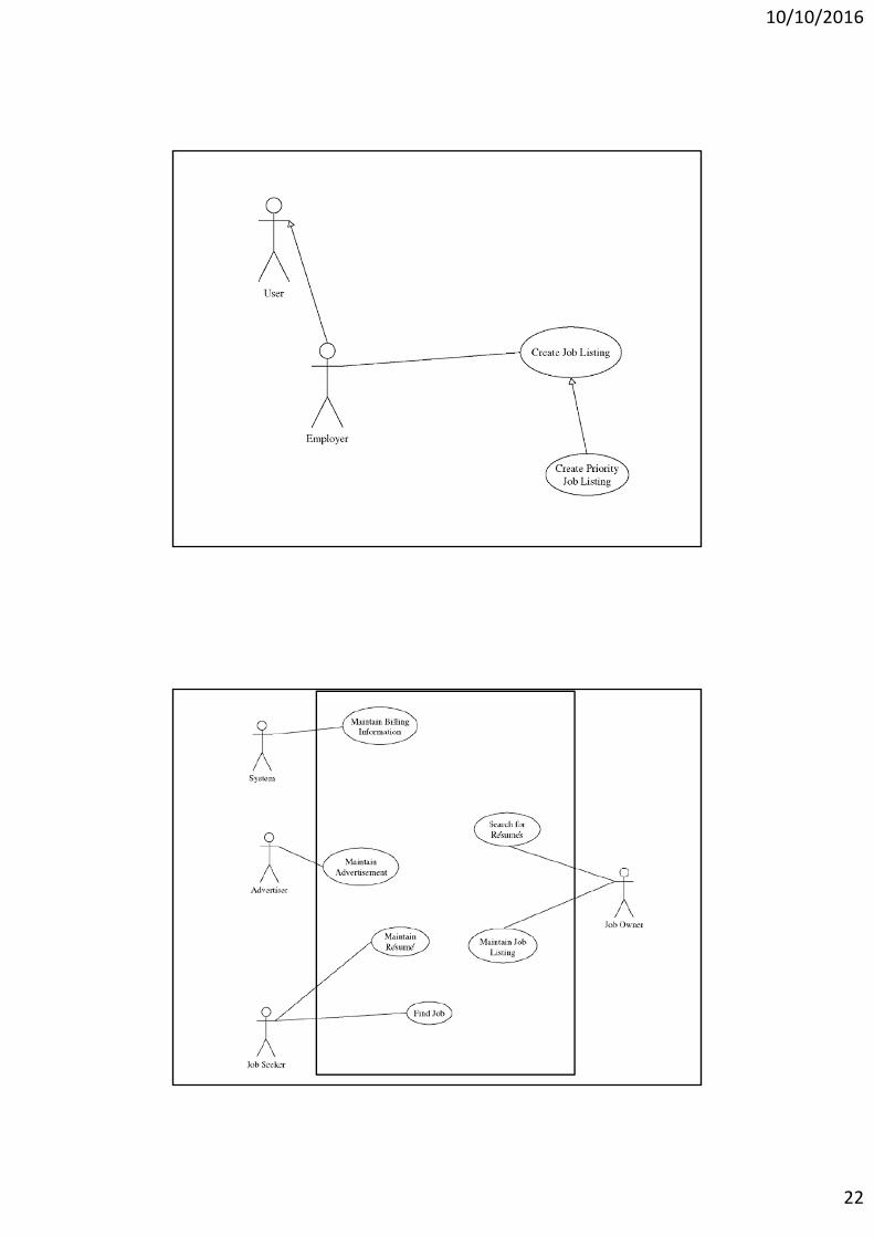
• Actor : who acting with system, send‐receive or exchange task of data/information e.g., ordering of customer by phone
• Use Case : function or task of work in system e.g., storage checking, ordering etc.
• Relationship is relation or association between Use Case and Actor
• System boundary
10/10/2016
22
10/10/2016
23
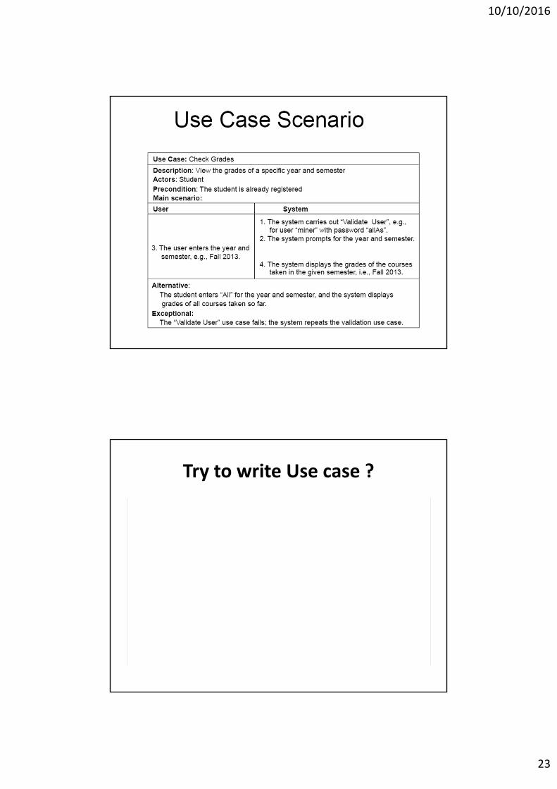
Try to write Use case ?
10/10/2016
24
Try to write Use case of ATM withdrawal
Try to write Use case of OPD Services
10/10/2016
25
Try to write Use case of DM Clinic
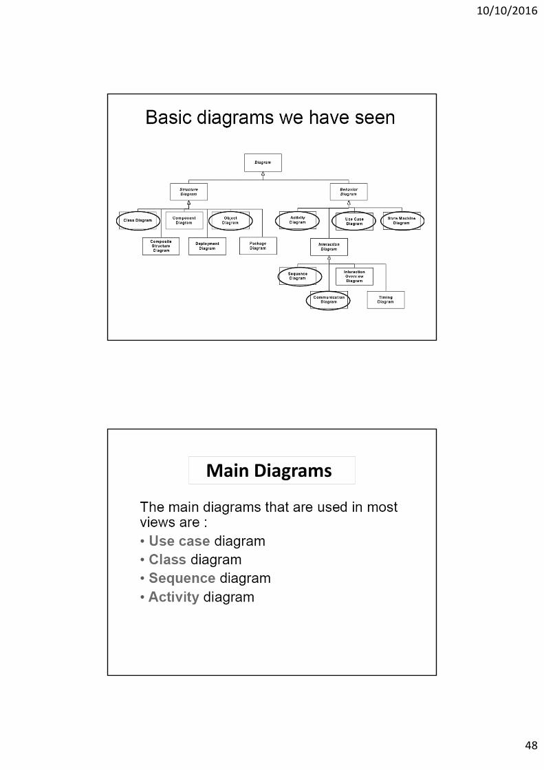
• Static Axis
– Class Diagram (Object Diagram)*
– Component Diagram (Deployment Diagram)
10/10/2016
26
• Is the description of a set of objects
• Defines the structure of the states and the
behaviors shared by all the objects of the
class (called instances)
• Defines a template for creating instances
– Names and types of all fields
– Names, signatures, and implementations of all
methods
Class
2.Class diagram(cont)Class Diagram
10/10/2016
27
Notation of classNotation for classes
Name
Attributes
Method
Class diagram example
10/10/2016
28
Class diagram
• Class Diagram show a Static Relationship (not Dynamic Relationship)
• Class Diagram show the grouping of each classes and their relations
• Component of Class(Name‐Attribute‐Method) and Relationship of Classes and function will show in Class Diagram
Class (Relationship)
• Dependency Relationship : e.g. “Class Customer” and “Class Order” “Class Order” depend on “Class Customer” because when customer change the request of order, or increase amount of production the ordering will be update directly base on customer
• Inheritance Relationships:e.g. Super class will inherit property of class through Sub class (mother daughter)
• Association Relationships:“Class student” association with “Class RACE615” in aspect of study registration