Clipped Wing Cub Wing Kit J-3 Cub Specifications Wingspan: 37.9 in. Length: 30 in. Wing Area: 259 sq. in. Weight (Ready to Fly): 13.0 16.5 oz. (Depends on motor & battery) Wing Loading: 7.2 9.1 oz. / sq. ft. Revision History Date Revision Notes/Comments 12/17/2006 1.0 Document initial release.
Transcript
Clipped Wing Cub Wing Kit
J-3 Cub Specifications
Wingspan: 37.9 in. Length: 30 in. Wing Area: 259 sq. in. Weight (Ready to Fly): 13.0 � 16.5 oz. (Depends on motor & battery) Wing Loading: 7.2 � 9.1 oz. / sq. ft.
Revision History
Date Revision Notes/Comments
12/17/2006 1.0 Document initial release.
2
Thank you for purchasing the Mountain Models 1/9 Scale Clipped Wing Cub. This plane is a scale aileron/elevator/rudder (full house) setup, designed for the low experience pilot on up who wants a super easy flying scale plane.
This plane could make a great basic aerobatic trainer for you. If you have no tail dragger experience, this plane also makes a great first tail dragger.
In the thin air at 6000� where this plane was designed, it flies beautifully and has plenty of extra power, even with the cheap 80 watt brushless out-runner motors. For some serious vertical performance, try something in the 100 watt range.
Please let us know you experiences building and flying this model. We look forward to customer feedback and want to know how you�re doing with our products!
Thank you,
Brian Eberwein Mountain Models PO Box 6815 Colorado Springs, CO 80934
www.mountainmodels.com Phone: 719.630.3186
Before You Begin
Check to make sure that all of your parts are there and in good shape.
Parts List
Number in Kit
Description of Part
Bundled Parts 4 1/16� Balsa Sheets 2 3/32� Balsa Sheets 1 1/8� Balsa Sheet 1 Window 1 Plan Sheet 1 These Instructions of course!
Metal 1 0.032� x 18� Wire
Bagged Parts 1 1/16� Plywood 1 1/32� Plywood 1 1/64� Plywood 1 1/4� Balsa 2 1/8� x 1� Dowel 2 Micro EZ Servo Connector 2 EZ Hinges 6 4-40 x 3/8� Phillips Head Screw 6 4-40 Nut
3
Building Materials You Will Need • Smooth and flat work surface
• Wax paper or clear plastic wrap to protect the work surface
• Thin and thick Cyanoacrylate (CA) glue
• Hobby knife with #11 blades
• Needle nose pliers
• Wire cutters
• Screwdrivers
• Sanding block, 320 to 400 grit sandpaper
Finishing Materials You Will Need • Covering material (So-Lite or similar)
• Sealing iron for applying the covering
Electronics You Will Need for the Wing • 2 ea. aileron servos (we recommend either the GWS Picos or Naros)
• 2 ea. 6� servo wire extensions
• 1 ea. Y-Connector for ailerons (or 5+ channel RX with 2 aileron servo mixing on TX)
General Building Tips • READ THE INSTRUCTIONS thoroughly and study the plans BEFORE starting any work on the
model.
• Tape the plans to your nice clean work surface and cover it with wax paper or plastic wrap. You want to keep your work surface clean and not glue the parts to the plans, right?
• Balsa is a lightweight and fragile wood, so you do need to be careful with it; however, you will also need to use a little bit of force to make everything fit properly, so don�t be too timid.
• Do not remove any pieces from the balsa sheets until they�re ready to be used. That way, parts won�t get mixed up or disappear.
• Do NOT glue anything until told to do so.
• Join all of your pieces using thin CA (Cyanoacrylate) glue, unless we tell you otherwise. In general, only a small amount of CA is necessary to glue parts together.
• Don�t force your pieces together. If they aren�t fitting together properly, make sure you have the right pieces and that they are oriented correctly. If needed, you can lightly sand the part to fit after making sure it is the correct part and oriented correctly.
• If you want to remove the charred edges caused by the laser cutting process, lightly dampen a cloth with bleach and gently rub the affected areas. Removing the char will not increase the strength but will make it look better. It also keeps that dark edge from showing under the lightweight coverings.
4
Assembly Instructions
Cover the wing plans with wax paper or plastic wrap to protect them during the build and so you don�t glue the wing to them.
Step 1: Basic Wing Structure
To remove the pieces, gently flex the balsa sheets until the pieces fall out. You may find that you need to carefully trim the extra pieces of wood that originally held the piece to the sheet. You can also use a #11 X-Acto blade to trim them out of the sheets.
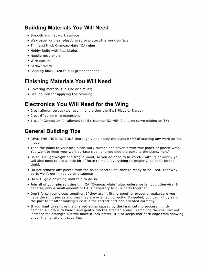
1. Slide the 1/16� W3 ribs over the 1/8� W11 part, as shown in the left image below. Do NOT glue yet.
2. Glue the 1/64� reinforcing plates to the 3/32� W8 ribs with thick CA, as shown in the right side image above. Make sure you get the plywood lined up and that you make a left and right.
3. Plug the 3/32� wing ribs into the 1/16� balsa spars, as shown in the image below. Do NOT glue anything yet. Make sure you put the ribs in the right slots by referencing the plans.
5
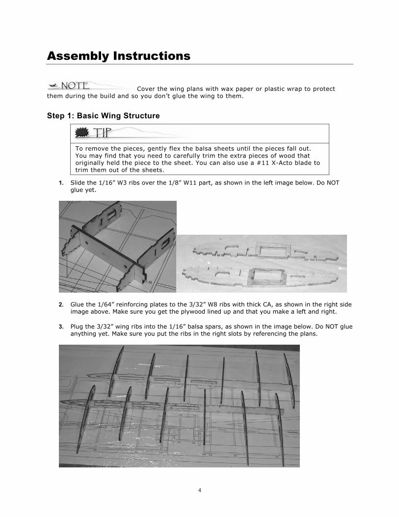
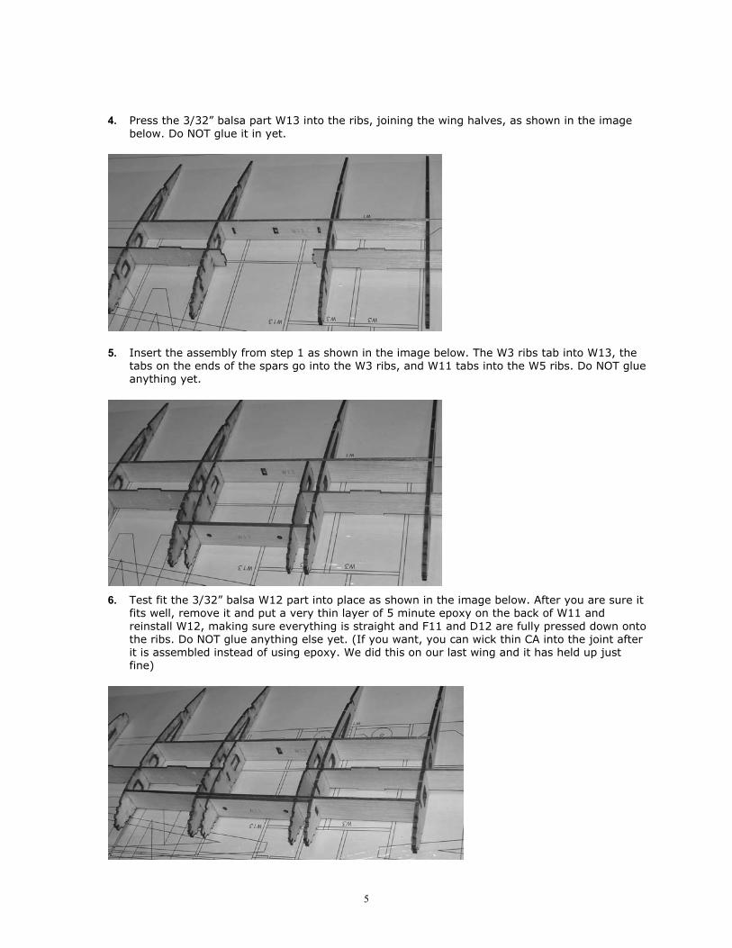
4. Press the 3/32� balsa part W13 into the ribs, joining the wing halves, as shown in the image below. Do NOT glue it in yet.
5. Insert the assembly from step 1 as shown in the image below. The W3 ribs tab into W13, the tabs on the ends of the spars go into the W3 ribs, and W11 tabs into the W5 ribs. Do NOT glue anything yet.
6. Test fit the 3/32� balsa W12 part into place as shown in the image below. After you are sure it fits well, remove it and put a very thin layer of 5 minute epoxy on the back of W11 and reinstall W12, making sure everything is straight and F11 and D12 are fully pressed down onto the ribs. Do NOT glue anything else yet. (If you want, you can wick thin CA into the joint after it is assembled instead of using epoxy. We did this on our last wing and it has held up just fine)
6
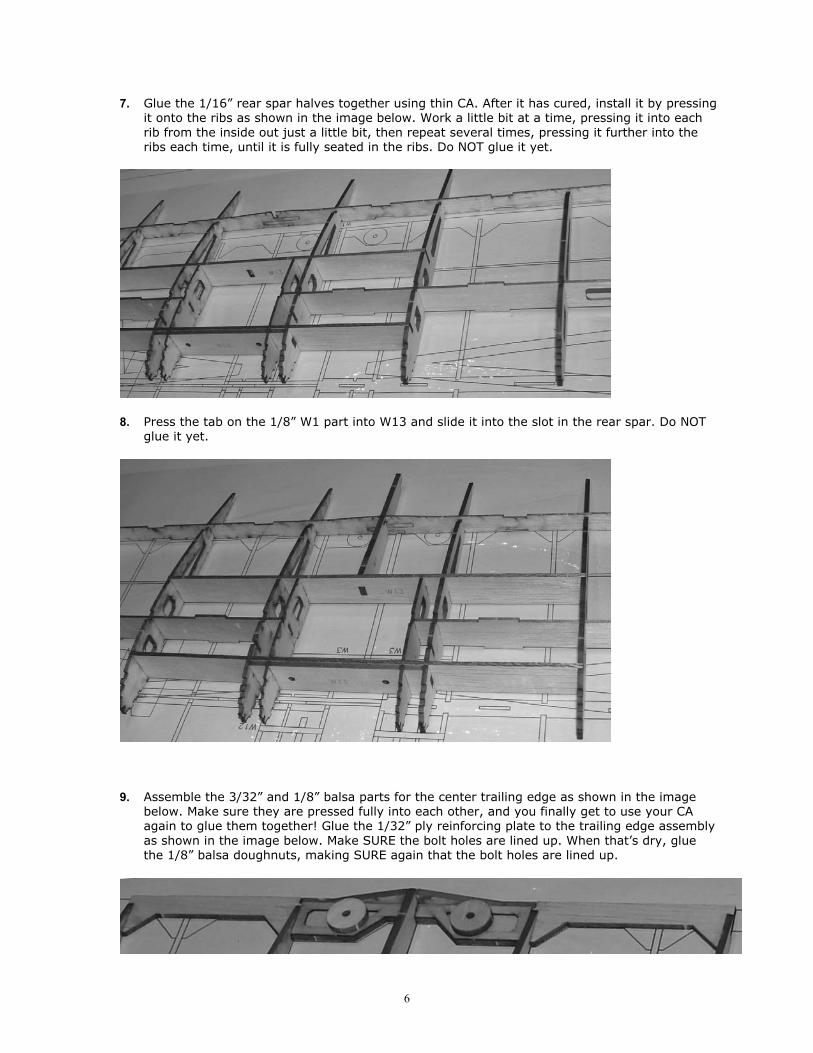
7. Glue the 1/16� rear spar halves together using thin CA. After it has cured, install it by pressing it onto the ribs as shown in the image below. Work a little bit at a time, pressing it into each rib from the inside out just a little bit, then repeat several times, pressing it further into the ribs each time, until it is fully seated in the ribs. Do NOT glue it yet.
8. Press the tab on the 1/8� W1 part into W13 and slide it into the slot in the rear spar. Do NOT glue it yet.
9. Assemble the 3/32� and 1/8� balsa parts for the center trailing edge as shown in the image below. Make sure they are pressed fully into each other, and you finally get to use your CA again to glue them together! Glue the 1/32� ply reinforcing plate to the trailing edge assembly as shown in the image below. Make SURE the bolt holes are lined up. When that�s dry, glue the 1/8� balsa doughnuts, making SURE again that the bolt holes are lined up.
7
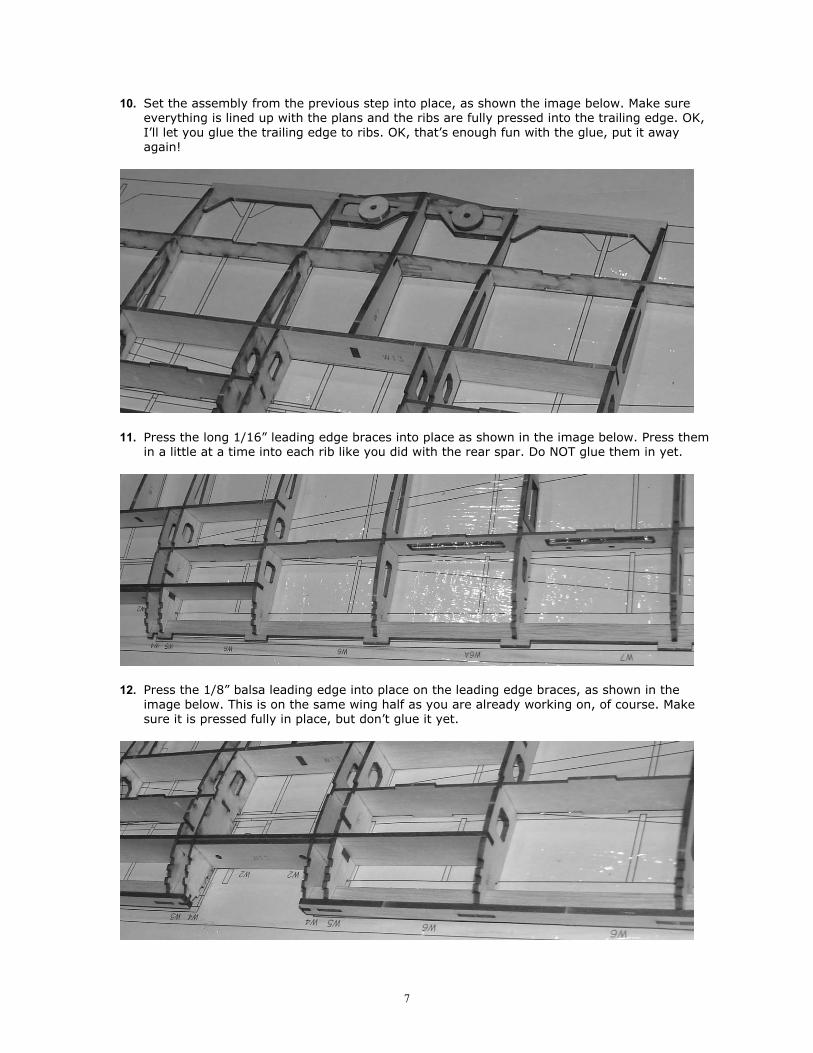
10. Set the assembly from the previous step into place, as shown the image below. Make sure everything is lined up with the plans and the ribs are fully pressed into the trailing edge. OK, I�ll let you glue the trailing edge to ribs. OK, that�s enough fun with the glue, put it away again!
11. Press the long 1/16� leading edge braces into place as shown in the image below. Press them in a little at a time into each rib like you did with the rear spar. Do NOT glue them in yet.
12. Press the 1/8� balsa leading edge into place on the leading edge braces, as shown in the image below. This is on the same wing half as you are already working on, of course. Make sure it is pressed fully in place, but don�t glue it yet.
8
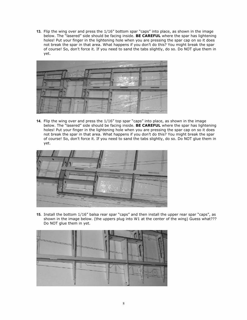
13. Flip the wing over and press the 1/16� bottom spar �caps� into place, as shown in the image below. The �lasered� side should be facing inside. BE CAREFUL where the spar has lightening holes! Put your finger in the lightening hole when you are pressing the spar cap on so it does not break the spar in that area. What happens if you don�t do this? You might break the spar of course! So, don�t force it. If you need to sand the tabs slightly, do so. Do NOT glue them in yet.
14. Flip the wing over and press the 1/16� top spar �caps� into place, as shown in the image below. The �lasered� side should be facing inside. BE CAREFUL where the spar has lightening holes! Put your finger in the lightening hole when you are pressing the spar cap on so it does not break the spar in that area. What happens if you don�t do this? You might break the spar of course! So, don�t force it. If you need to sand the tabs slightly, do so. Do NOT glue them in yet.
15. Install the bottom 1/16� balsa rear spar �caps� and then install the upper rear spar �caps�, as shown in the image below. (the uppers plug into W1 at the center of the wing) Guess what??? Do NOT glue them in yet.
9
16. Make sure the wing is lined up with the plans, all the parts are full seated properly, and place some weights on the wing to make sure it stays flat. Go back again and make sure all the parts are fully seated in place like they should be. OK, fine then, we�ll let you do some gluing now. Get your thin CA and glue all of the joints in the wing. TIP! Don�t keep your head over the wing where you�re gluing. CA fumes rise and they�ll do a nice job of making your eyes water and burn a little bit if a lot of the CA kicks off all at once!
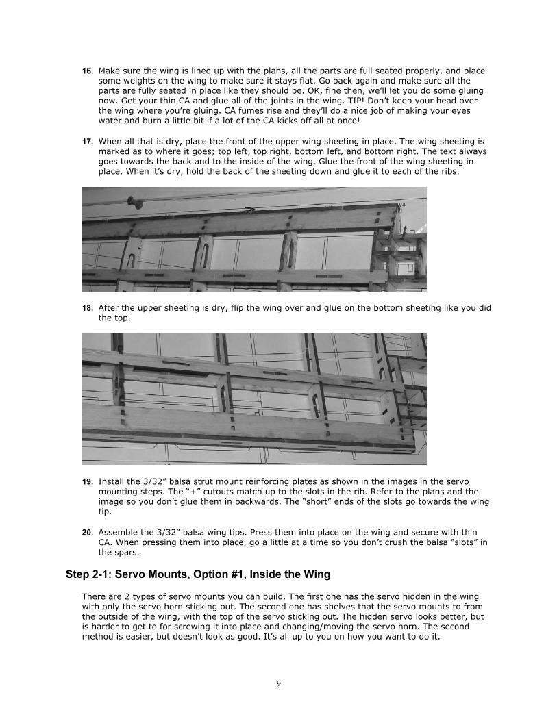
17. When all that is dry, place the front of the upper wing sheeting in place. The wing sheeting is marked as to where it goes; top left, top right, bottom left, and bottom right. The text always goes towards the back and to the inside of the wing. Glue the front of the wing sheeting in place. When it�s dry, hold the back of the sheeting down and glue it to each of the ribs.
18. After the upper sheeting is dry, flip the wing over and glue on the bottom sheeting like you did the top.
19. Install the 3/32� balsa strut mount reinforcing plates as shown in the images in the servo mounting steps. The �+� cutouts match up to the slots in the rib. Refer to the plans and the image so you don�t glue them in backwards. The �short� ends of the slots go towards the wing tip.
20. Assemble the 3/32� balsa wing tips. Press them into place on the wing and secure with thin CA. When pressing them into place, go a little at a time so you don�t crush the balsa �slots� in the spars.
Step 2-1: Servo Mounts, Option #1, Inside the Wing
There are 2 types of servo mounts you can build. The first one has the servo hidden in the wing with only the servo horn sticking out. The second one has shelves that the servo mounts to from the outside of the wing, with the top of the servo sticking out. The hidden servo looks better, but is harder to get to for screwing it into place and changing/moving the servo horn. The second method is easier, but doesn�t look as good. It�s all up to you on how you want to do it.
10
1. Glue the 3/32� balsa SM1 part between ribs W8 and W9 as shown in the below left image.
2. Glue the 3/32� balsa SM2 between the SM1 part and the spar as shown in the below right image. It tabs into the spar and slides into the slot of SM1.
3. Insert the 1/16� balsa SM4 part as shown in the above right image. It sits against SM2 and the lower spar cap, and tabs into SM1.
4. Insert the 1/16� balsa SM3 and SM5 parts as shown on the plans. SM3 sits flat against the bottom spar cap. The images below show the completed servo mount area.
Step 2-2: Servo Mounts, Option #2
There are 2 types of servo mounts you can build. The first one has the servo hidden in the wing with only the servo horn sticking out. The second one has shelves that the servo mounts to from the outside of the wing, with the top of the servo sticking out. The hidden servo looks better, but is harder to get to for screwing it into place and changing/moving the servo horn. The second method is easier, but doesn�t look as good. It�s all up to you on how you want to do it.
11
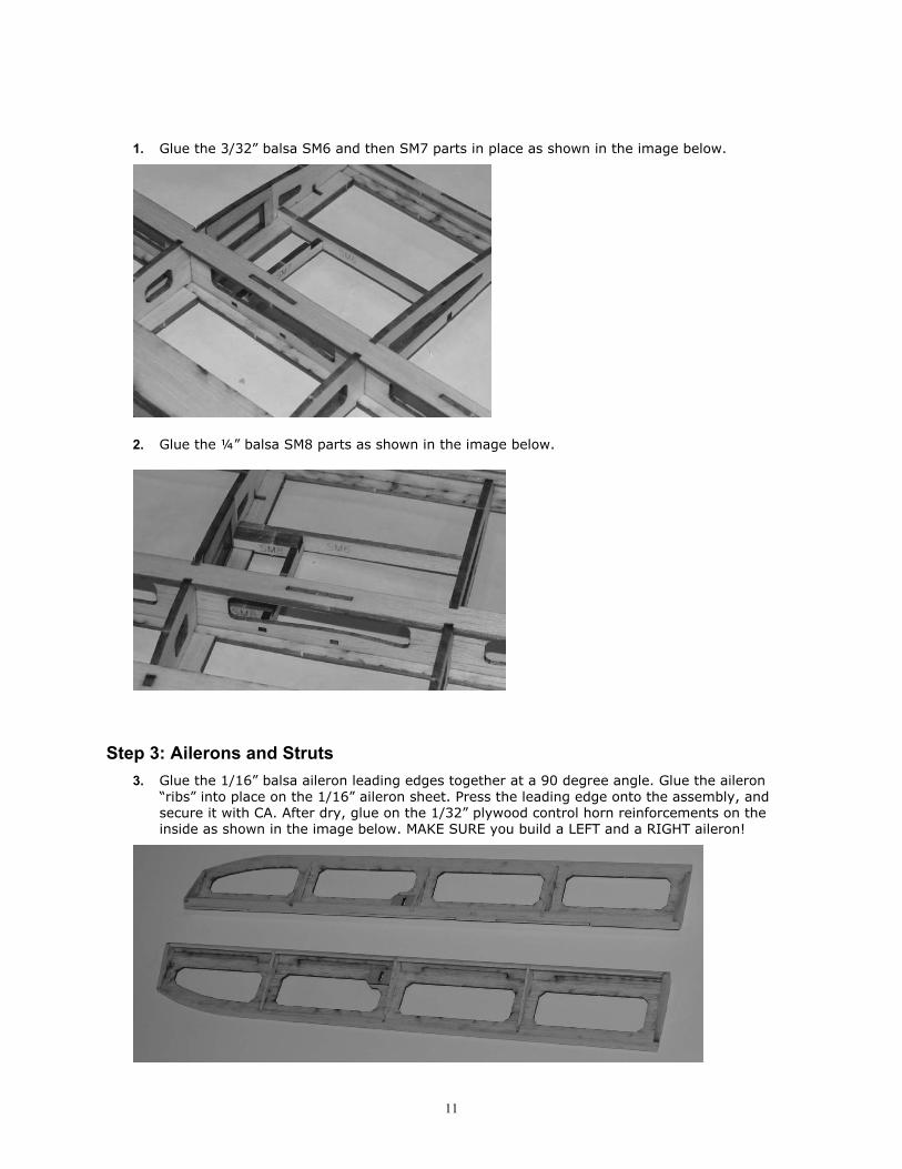
1. Glue the 3/32� balsa SM6 and then SM7 parts in place as shown in the image below.
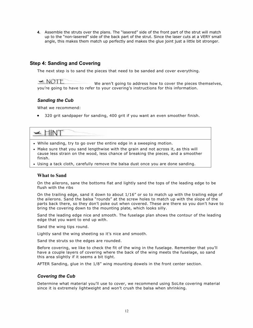
2. Glue the ¼� balsa SM8 parts as shown in the image below.
Step 3: Ailerons and Struts
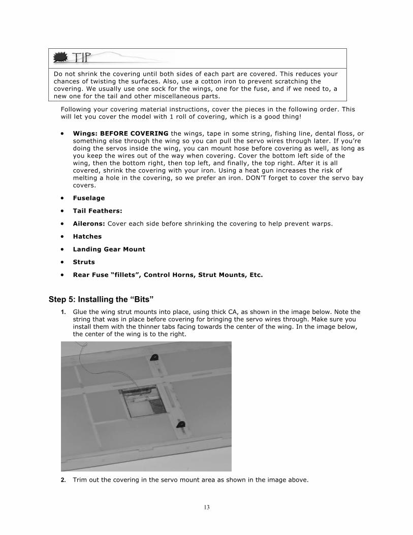
3. Glue the 1/16� balsa aileron leading edges together at a 90 degree angle. Glue the aileron �ribs� into place on the 1/16� aileron sheet. Press the leading edge onto the assembly, and secure it with CA. After dry, glue on the 1/32� plywood control horn reinforcements on the inside as shown in the image below. MAKE SURE you build a LEFT and a RIGHT aileron!
12
4. Assemble the struts over the plans. The �lasered� side of the front part of the strut will match up to the �non-lasered� side of the back part of the strut. Since the laser cuts at a VERY small angle, this makes them match up perfectly and makes the glue joint just a little bit stronger.
Step 4: Sanding and Covering The next step is to sand the pieces that need to be sanded and cover everything.
We aren�t going to address how to cover the pieces themselves, you�re going to have to refer to your covering�s instructions for this information.
Sanding the Cub What we recommend:
• 320 grit sandpaper for sanding, 400 grit if you want an even smoother finish.
• While sanding, try to go over the entire edge in a sweeping motion.
• Make sure that you sand lengthwise with the grain and not across it, as this will cause less strain on the wood, less chance of breaking the pieces, and a smoother finish.
• Using a tack cloth, carefully remove the balsa dust once you are done sanding.
What to Sand On the ailerons, sane the bottoms flat and lightly sand the tops of the leading edge to be flush with the ribs
On the trailing edge, sand it down to about 1/16� or so to match up with the trailing edge of the ailerons. Sand the balsa �rounds� at the screw holes to match up with the slope of the parts back there, so they don�t poke out when covered. These are there so you don�t have to bring the covering down to the mounting plate, which looks silly.
Sand the leading edge nice and smooth. The fuselage plan shows the contour of the leading edge that you want to end up with.
Sand the wing tips round.
Lightly sand the wing sheeting so it�s nice and smooth.
Sand the struts so the edges are rounded.
Before covering, we like to check the fit of the wing in the fuselage. Remember that you�ll have a couple layers of covering where the back of the wing meets the fuselage, so sand this area slightly if it seems a bit tight.
AFTER Sanding, glue in the 1/8� wing mounting dowels in the front center section.
Covering the Cub Determine what material you�ll use to cover, we recommend using SoLite covering material since it is extremely lightweight and won�t crush the balsa when shrinking.
13
Do not shrink the covering until both sides of each part are covered. This reduces your chances of twisting the surfaces. Also, use a cotton iron to prevent scratching the covering. We usually use one sock for the wings, one for the fuse, and if we need to, a new one for the tail and other miscellaneous parts.
Following your covering material instructions, cover the pieces in the following order. This will let you cover the model with 1 roll of covering, which is a good thing!
• Wings: BEFORE COVERING the wings, tape in some string, fishing line, dental floss, or something else through the wing so you can pull the servo wires through later. If you�re doing the servos inside the wing, you can mount hose before covering as well, as long as you keep the wires out of the way when covering. Cover the bottom left side of the wing, then the bottom right, then top left, and finally, the top right. After it is all covered, shrink the covering with your iron. Using a heat gun increases the risk of melting a hole in the covering, so we prefer an iron. DON�T forget to cover the servo bay covers.
• Fuselage
• Tail Feathers:
• Ailerons: Cover each side before shrinking the covering to help prevent warps.
• Hatches
• Landing Gear Mount
• Struts
• Rear Fuse �fillets�, Control Horns, Strut Mounts, Etc.
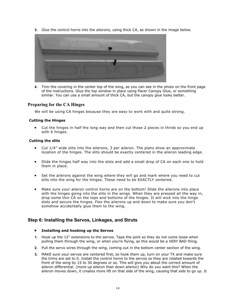
Step 5: Installing the �Bits� 1. Glue the wing strut mounts into place, using thick CA, as shown in the image below. Note the
string that was in place before covering for bringing the servo wires through. Make sure you install them with the thinner tabs facing towards the center of the wing. In the image below, the center of the wing is to the right.
2. Trim out the covering in the servo mount area as shown in the image above.
14
3. Glue the control horns into the ailerons, using thick CA, as shown in the image below.
4. Trim the covering in the center top of the wing, as you can see in the photo on the front page of the instructions. Glue the top window in place using Pacer Canopy Glue, or something similar. You can use a small amount of thick CA, but the canopy glue looks better.
Preparing for the CA Hinges We will be using CA hinges because they are easy to work with and quite strong.
Cutting the Hinges
• Cut the hinges in half the long way and then cut those 2 pieces in thirds so you end up with 6 hinges.
Cutting the slits
• Cut 1/4� wide slits into the ailerons, 3 per aileron. The plans show an approximate location of the hinges. The slits should be exactly centered in the aileron leading edge.
• Slide the hinges half way into the slots and add a small drop of CA on each one to hold them in place.
• Set the ailerons against the wing where they will go and mark where you need to cut slits into the wing for the hinges. These need to be EXACTLY centered.
• Make sure your aileron control horns are on the bottom! Slide the ailerons into place with the hinges going into the slits in the wings. When they are pressed all the way in, drop some thin CA on the tops and bottoms of the hinges. It will wick into the hinge slots and secure the hinges. Flex the ailerons up and down to make sure you don�t somehow accidentally glue them to the wing.
Step 6: Installing the Servos, Linkages, and Struts
• Installing and hooking up the Servos
1. Hook up the 12� extensions to the servos. Tape the joint so they do not come loose when pulling them through the wing, or when you�re flying, as this would be a VERY BAD thing.
2. Pull the servo wires through the wing, coming out in the bottom center section of the wing.
3. MAKE sure your servos are centered first, so hook them up, turn on your TX and make sure the trims are set to 0. Install the control horns to the servos so they are rotated towards the front of the wing by 15 to 30 degrees or so. This will give you about the correct amount of aileron differential. (more up aileron than down aileron) Why do you want this? When the aileron moves down, it creates more lift on that side of the wing, causing that side to go up. It
15
also creates more drag on that side of the wing, which �pulls� that side back. Your rolls will be more axial with aileron differential, and the model will fly better.
4. Temporarily install the servos, using the mounting screws that came with them. Do NOT over-tighten the screws. If you are doing the hidden servos, be careful not to crush the outside of the servo cover box or the covering. Remove the screws and the servos. Flow some thin CA into the screw holes. This will make strong threads that better hold the servos in place. After you are positive the CA is cured, reinstall the servos and servo screws.
5. Cut the 0.032� wire in half. Place a Z-bend on one end of each of the wires. Make the Z-bend as tight as you can, while still fitting onto the servo horn.
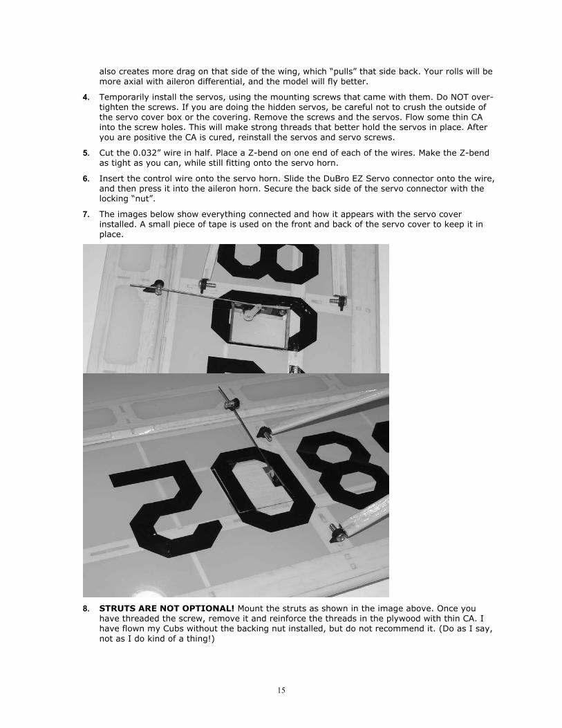
6. Insert the control wire onto the servo horn. Slide the DuBro EZ Servo connector onto the wire, and then press it into the aileron horn. Secure the back side of the servo connector with the locking �nut�.
7. The images below show everything connected and how it appears with the servo cover installed. A small piece of tape is used on the front and back of the servo cover to keep it in place.
8. STRUTS ARE NOT OPTIONAL! Mount the struts as shown in the image above. Once you
have threaded the screw, remove it and reinforce the threads in the plywood with thin CA. I have flown my Cubs without the backing nut installed, but do not recommend it. (Do as I say, not as I do kind of a thing!)
16
Step 12: Finishing the Kit Well, you�re almost there�the end is in sight; just a few more steps and you can go flying, assuming the weather is cooperating.
Attaching the Wing 1. Plug the wing into the front mount and use the nylon bolts to secure it on the back.
2. STRUTS ARE NOT OPTIONAL! Use a 4-40x3/8� Screw and nut to secure the wing strut to the fuselage. The wing strut goes to the rear of the fuselage mount.
Setting the Throws You need to adjust your radio trim so that the elevator, rudder, and ailerons are all level. The throws are listed as total travel, and are as follows:
Low Rates High Rates Ailerons 3/8� Down, 5/8� Up Maximum (~45 degrees).
Elevator 3/4� 1�+
Rudder 3/4� Whatever you can get.
Setting the Center of Gravity The Center of Gravity (CG) will affect how the airplane recovers from a nose up or nose down condition (pitch stability). With the CG too far forward, the plane will be quite stable, but require some up elevator to fly level. On the other hand, too far back and the plane will be hard to control, requiring constant input to keep the plane flying straight and level. For the Cub, start with the CG at the front of the range on the plans. Use this as a starting point and then you can slowly move it back as you like.
Scale Additions and/or Modifications The outlines of our Cub kit are very true to scale. Of course, in making a kit easier to build, we did simplify some areas. For a more scale Cub, try some of the following;
1. Add the strut braces from the X-brace section up to the wing. For extra credit, raise the center strut brace above the struts themselves.
2. Change to a pull-pull setup for the elevator and rudder. For extra credit, change the ailerons to a pull-pull as well.