John M. Jurns QSS Group Inc., Cleveland, Ohio John D. Lekki Glenn Research Center, Cleveland, Ohio Clogging of Joule-Thomson Devices in Liquid Hydrogen Handling NASA/TM—2009-215495 March 2009 AIAA–2006–4877 https://ntrs.nasa.gov/search.jsp?R=20090015374 2018-05-30T07:49:37+00:00Z
Transcript
John M. JurnsQSS Group Inc., Cleveland, Ohio
John D. LekkiGlenn Research Center, Cleveland, Ohio
Clogging of Joule-Thomson Devicesin Liquid Hydrogen Handling
Since its founding, NASA has been dedicated to the advancement of aeronautics and space science. The NASA Scientifi c and Technical Information (STI) program plays a key part in helping NASA maintain this important role.
The NASA STI Program operates under the auspices of the Agency Chief Information Offi cer. It collects, organizes, provides for archiving, and disseminates NASA’s STI. The NASA STI program provides access to the NASA Aeronautics and Space Database and its public interface, the NASA Technical Reports Server, thus providing one of the largest collections of aeronautical and space science STI in the world. Results are published in both non-NASA channels and by NASA in the NASA STI Report Series, which includes the following report types: • TECHNICAL PUBLICATION. Reports of
completed research or a major signifi cant phase of research that present the results of NASA programs and include extensive data or theoretical analysis. Includes compilations of signifi cant scientifi c and technical data and information deemed to be of continuing reference value. NASA counterpart of peer-reviewed formal professional papers but has less stringent limitations on manuscript length and extent of graphic presentations.
• TECHNICAL MEMORANDUM. Scientifi c
and technical fi ndings that are preliminary or of specialized interest, e.g., quick release reports, working papers, and bibliographies that contain minimal annotation. Does not contain extensive analysis.
• CONTRACTOR REPORT. Scientifi c and
technical fi ndings by NASA-sponsored contractors and grantees.
• CONFERENCE PUBLICATION. Collected
papers from scientifi c and technical conferences, symposia, seminars, or other meetings sponsored or cosponsored by NASA.
• SPECIAL PUBLICATION. Scientifi c,
technical, or historical information from NASA programs, projects, and missions, often concerned with subjects having substantial public interest.
• TECHNICAL TRANSLATION. English-
language translations of foreign scientifi c and technical material pertinent to NASA’s mission.
Specialized services also include creating custom thesauri, building customized databases, organizing and publishing research results.
For more information about the NASA STI program, see the following:
• Access the NASA STI program home page at http://www.sti.nasa.gov
• E-mail your question via the Internet to help@
sti.nasa.gov • Fax your question to the NASA STI Help Desk
at 301–621–0134 • Telephone the NASA STI Help Desk at 301–621–0390 • Write to:
NASA Center for AeroSpace Information (CASI) 7115 Standard Drive Hanover, MD 21076–1320
John M. JurnsQSS Group Inc., Cleveland, Ohio
John D. LekkiGlenn Research Center, Cleveland, Ohio
Clogging of Joule-Thomson Devicesin Liquid Hydrogen Handling
NASA/TM—2009-215495
March 2009
AIAA–2006–4877
National Aeronautics andSpace Administration
Glenn Research CenterCleveland, Ohio 44135
Prepared for the42nd Joint Propulsion Conference and Exhibitcosponsored by the AIAA, ASME, SAE, and ASEESacramento, California, July 9–12, 2006
Prepared under Contract NAS3–00145
Available from
NASA Center for Aerospace Information7115 Standard DriveHanover, MD 21076–1320
National Technical Information Service5285 Port Royal RoadSpringfi eld, VA 22161
Available electronically at http://gltrs.grc.nasa.gov
Trade names and trademarks are used in this report for identifi cation only. Their usage does not constitute an offi cial endorsement, either expressed or implied, by the National Aeronautics and
Space Administration.
Level of Review: This material has been technically reviewed by technical management.
This report contains preliminary fi ndings, subject to revision as analysis proceeds.
NASA/TM—2009-215495 1
Clogging of Joule-Thomson Devices in Liquid Hydrogen Handling
John M. Jurns QSS Group Inc.
Cleveland, Ohio 44135
John D. Lekki National Aeronautics and Space Administration
Glenn Research Center Cleveland, Ohio 44135
Abstract Experiments conducted at the NASA Glenn Research Center indicate that Joule-Thomson devices
become clogged when transferring liquid hydrogen (LH2), operating at a temperature range from 20.5 to 24.4 K. Blockage does not exist under all test conditions but is found to be sensitive to the inlet temperature of the LH2. At a subcooled inlet temperature of 20.5 K blockage consistently appears but is dissipated when the fluid temperature is raised above 24.5 K. Clogging steadily reduced flow rate through the orifices, eventually resulting in complete blockage. This tendency poses a threat to spacecraft cryogenic propulsion systems that would utilize passive thermal control systems. We propose that this clogging is due to trace amounts of neon in the regular LH2 supply. Neon freezes at 24.5 K at one atmosphere pressure. It is postulated that between 20.5 and 24.5 K, neon remains in a meta-stable, super-cooled liquid state. When impacting the face of an orifice, liquid neon droplets solidify and accumulate, blocking flow over time. The purpose of this test program was to definitively quantify the phenomena experimentally by obtaining direct visual evidence of orifice clogging by accretion from neon contaminates in the LH2 flow stream, utilizing state of the art imaging technology. Tests were conducted with LH2 flowing in the temperature range of 20.5 to 24.4 K. Additional imaging was also done at LH2 temperatures with no flow to verify clear view through the orifice.
Introduction Previous experimental investigations (Refs. 1 and 2) conducted by the NASA Glenn Research Center
Propellant Systems Technology Branch have indicated that:
(1) Joule-Thomson devices, such as the Visco Jet (The Lee Company) and straight orifices, became clogged when transferring LH2, operating at a temperature range from 20.5 to 24.4 K.
(2) No clogging was detected above or below this temperature range. (3) Clogging steadily and significantly reduces flow rate through the orifices, eventually resulting in
complete blockage of the orifice.
This clogging poses a realistic threat to spacecraft propulsion systems that would utilize passive thermal control systems.
We propose that this clogging is due to a trace amount of neon that exists in the regular LH2 supply. It has been further proposed that at temperatures between 20.5 and 24.4 K, neon exists in a metastable, super-cooled liquid state. When impacted on the face of an orifice, the neon solidifies and accumulates on the wall. In time, flow blockage occurs from accretion of solid neon on the orifice.
NASA/TM—2009-215495 2
Test Program Overview
In 1992, it was noted during flow versus pressure drop tests of LH2 through a Visco-Jet Joule-Thomson device that flow decreased over time under certain test conditions. A test program was carried out at the NASA Lewis Research Center to determine the cause of this phenomenon. We proposed that neon in the LH2 supply was causing the clogging. Evidence for this theory was supported by the fact that after flow decreased, the flow could be re-established at the original levels by warming the Visco-Jet up to 33.5 to 36.1 K. Raising the temperature possibly caused the neon to melt, allowing flow to be re-established. Also, a 10 μm filter was installed in the inlet line to the Visco-Jet, with no effect (i.e., – the Visco-Jet still clogged). Additional tests were done in which the LH2 temperature was lowered by evacuating the dewar. It was thought that by doing this, the neon would precipitate out. The dewar was then pressurized with helium gas, and the sub-cooled LH2 expelled through the 10 μm filter out the Visco-Jet, resulting in 4 to 6 hr operation at a constant flow rate.
The clogging phenomenon has been experimentally verified. The neon contamination theory, although highly plausible, is to this date unconfirmed, because there is no direct evidence of contaminates in the flow stream. The goal of the test program described in this paper was to repeat the tests conducted in 1992 using single orifices with the same flow characteristics as the original Visco-Jet Joule-Thomson devices. In addition, imaging equipment was used to obtain direct visual evidence of the neon clogging by imaging the orifice as LH2 flows through it.
These tests were conducted in 2002 at the Cryogenic Components Lab test cell 7 (CCL-7) of the NASA Glenn Research Center. Tests were performed in September and October of 2002. The test facility is described later in this paper.
Test Objectives
The objective of these tests was to obtain direct visual evidence of clogging of an orifice by accretion from neon contaminates in the LH2 flow stream, utilizing state of the art imaging technology. We designed an imaging system to look directly into the face of an orifice and record images of the filling of the orifice over time from the accreting objects. This should occur in the temperature range of 20.5 to 24.5 K. We performed additional imaging at temperatures below 20.5 K and above 24.5 K in an attempt to verify clear flow through the orifice.
Operating Parameters
Liquid Hydrogen conditions
(1) Inlet Pressure to orifice—103.4 to 310.3 kPa (2) Pressure drop across orifice—172.4 kPa maximum (3) Temperature—20.5 to 24.5 K (4) Flow rate—0 to 50 standard liters per minute (slpm)
Test Facility
CCL-7 is a multipurpose test facility at NASA GRC used to safely, efficiently and economically perform small scale screening tests to verify components and processes in a liquid hydrogen environment (Ref. 3). Test facility capabilities are listed in Table 1.
NASA/TM—2009-215495 3
Fluid/Thermal systems Test fluids LH2 or LN2 Research dewar capacities 0.326 and 0.164 m3 Facility fluid capacities 945 L LH2 1,890 L LN2 Maximum flow rates 2.3 to 45.4 kg/hr LH2 27.2 to 544.3 kg/hr LN2 Pressurants GH2, GHe, GN2 Operating pressures 14 to 379 kPa
Data system PC based data acquisition system 256 data channels, LabVIEW
(National Instruments) data acquisition program.
The 0.326 m3 research dewar was used for these tests. The inner vessel of this vacuum jacketed dewar
is 55.9 cm diameter, and approximately 76.2 cm deep. The top of the dewar is fitted with a flat flange lid from which liquid and vent process lines project to deliver LH2 and pressurant gasses. The lid has a short cylindrical section with an inverted dome which is also evacuated and insulated with multilayer insulation to minimize heat transmission through the lid. With this arrangement, heat leak into the test dewar is approximately 20.5 W. LH2 is fed to the dewar via vacuum insulated piping. The dewar can be vented to atmosphere, or vented to an air ejector which can reduce dewar pressure to approximately 14 kPa. Pressure in the dewar can be automatically set and maintained by use of a vent valve operated by a PID controller. Vented gas is warmed through heat exchanger coils before being vented through the rest of the pressure control system. Figure 1 shows a simplified schematic of the research dewar and associated piping and controls.
TABLE 1.—CCL-7 TEST FACILITY CAPABILITIES
NASA/TM—2009-215495 4
Test Article
The test article consists of a small square edged orifice welded into a 9.5 mm diameter stainless steel tube. There are pressure taps upstream and downstream of the orifice. The orifice is viewed through a vacuum insulated sight tube that extends from outside the dewar and attaches to the orifice. Two orifices with diameters of 0.178 or 0.254 mm were built for this test. Figure 2 shows details of the test article.
Instrumentation
Temperature sensors are positioned throughout the test rig, on selected fluid lines and components. Temperatures are measured with silicon diodes. Within the research dewar is an instrument tree with silicon diodes attached at discreet heights from 0.5 to 80 percent liquid level. These diodes can be used both to measure the temperature of the contents to within ±0.1 K, and also as point level sensors to determine liquid level to within ±0.5 percent. Silicon diodes are also attached to the tubing upstream and downstream of the orifice to monitor LH2 temperature. Strain gauge pressure transducers measure dewar ullage pressure, orifice inlet pressure and differential pressure across the orifice. The flow through the orifice passes through a heat exchanger before being measured using Hastings mass flow meters. The facility has a bank of flow meters allowing measurement of mass flow rates from 0 to 400 slpm.
Data Acquisition
The facility data acquisition system consists of a multiplexer that digitizes incoming data signals and sends them to a PC based data acquisition program written for the CCL-7 facility. Nominally 96 channels of data are collected and displayed on the PC monitor. Data is acquired at user selected rates from 4 scans per second to one scan per minute and written to a spreadsheet file.
NASA/TM—2009-215495 5
We acquired images using a digital camera with a telescopic lens to view the orifice. The face of the orifice was approximately 35.6 cm from the camera lens. The orifice was lit using a LED ring of lights located at the top of the sight tube. Imaging system details are shown in Table 2.
2.74 megapixel (2012 by 1324 pixel) resolution CCD
Infinity model K2 microscope lens
Long distance microscope lens, 315 mm working length, 4 times magnification
Light source LED ring, white light, fabricated in-house
We controlled the camera using a laptop computer utilizing a proprietary Nikon software package. The laptop was located in the test cell, and was operated remotely from a control room approximately 90 m away using a remote PC interface. Components located in the test cell were enclosed in a sealed purged cabinet. A schematic of the camera set up is shown in Figure 3.
NASA/TM—2009-215495 6
Test Procedure
Prior to filling the dewar with LH2, we turned on the LED light ring, and focused the camera on the orifice. The dewar was purged and filled with LH2, initially about 50 percent full. The LH2 was conditioned to a saturation pressure and temperature as per the test matrix. This was done by either reducing pressure in the dewar to cool the LH2, or bubbling warm hydrogen gas into the LH2 to raise its temperature. Once test conditions were established, we took additional pictures of the orifice to verify it was still in focus. We established and monitored flow through the orifice. Inlet and outlet temperatures were noted to determine when liquid was flowing through the orifice, and photographs taken throughout the test run. At completion of the test run, we took a final picture of the orifice to verify that it was still in focus. Fluid temperatures, pressures and flow rate were all recorded. Data were typically recorded at a rate of one scan per second. Table 3 summarizes the test runs.
Test Results and Discussion Initial test runs were unsuccessful in establishing liquid flow at the orifice due to low flow rate, heat
conduction through the wall of the sight tube and the fact that the orifice was initially located in the ullage of the dewar. This resulted in the hydrogen vaporizing before it reached the orifice. Heat conduction and hydrogen vaporization problems were corrected by increasing the liquid level in the dewar until it covered the orifice and the end of the sight glass assembly.
Data taken in 1992 and 2002 is shown in Table 4. For both the larger and smaller diameter orifices, the flowrate was lower in 2002 than in 1992. We initially speculated that the orifices were fabricated smaller than design; however, a post test inspection and water calibration of the orifice indicated that the orifice diameter was actually indeed as designed. To date, the reason for this discrepancy has not been resolved. However, orifice inlet temperatures look to be slightly higher than the saturated liquid temperature. Decreased flow rates may be due to cavitation of the liquid hydrogen as it passes through the orifice or two phase flow at the inlet of the orifice. This is discussed in following paragraphs.
TABLE 4.—TEST FLOW RATES AND TEMPERATURES 0.178 mm orifice 0.254 mm orifice
Figure 4 shows a typical test run with flow starting at 37 slpm and decreasing to zero after 20 min. We observed similar behavior for the 0.178 mm orifice. For both orifices, the time it took for the orifice was on the same order of time (15 to 30 min) as for the original 1992 tests.
Standard industrial grade LH2 was used in both the 1992 tests and the current test program. The advertised purity of hydrogen from the supplier does not specifically list neon as a contaminant. Table 5 lists the producers’ purity specifications for industrial grade bulk liquid hydrogen. Note that neon is not listed specifically as a contaminant.
TABLE 5.—PRAXAIR BULK LIQUID HYDROGEN SPECIFICATIONS [Parts per billion volume]
Contaminant or Purity Industrial grade bulk liquid hydrogen
Purity 99.997 percent H2O 5.000 N2 9.000 CO ------------------ THC as CH4 ------------------ O2 2.000 CO2 ------------------
A survey of gas producer literature shows that neon is typically not listed as an impurity. In fact, ultra high purity gas analyzers, capable of detecting impurities in the ppb range are not set up to detect neon. Calculations show that the presence of neon in less than one part per billion could result in clogging of the orifice. Since a very small quantity of neon is sufficient to induce clogging, and since its presence is not analyzed, it is quite possible that neon is present in the bulk liquid hydrogen, and is the cause of clogging. Results also indicate that the purity of industrial grade LH2 has not changed significantly over the past decade (if the neon indeed is the cause of clogging).
The possibility of neon contamination from the helium pressurant gas exists. However, again a review of helium supplier literature does not indicate neon as a contaminant, so it’s presence in the helium supply cannot be ascertained.
NASA/TM—2009-215495 8
Unfortunately, this program did not obtain conclusive visual evidence of the neon clogging phenomenon. Literally hundreds of digital pictures were taken of the orifice under varying flow conditions in an attempt to obtain a clear picture of the orifice while clogged. As mentioned previously, initial pictures were taken of the orifice prior to flowing LH2, and after the test run was complete. The orifice was clearly visible in these pictures, but when LH2 flowed through the orifice, the image was consistently clouded. A typical example is shown in Figure 7. Images 464, 466, and 506 all show the orifice clearly before and after the test run. Image 480 was taken approximately half-way through the test run. For the flow conditions, calculated Reynolds number indicated that the flow to the orifice was well within the laminar range, which should minimize the possibility of obscuring the view to the orifice due to turbulence in the fluid. Images taken during LH2 flow were consistently darker than no flow conditions. We have postulated several possible reasons for this phenomenon:
(1) Loss of camera focus (2) Neon film on surface of orifice plate (3) Extinction of light through two phase flow obscuration
Loss of Camera Focus
Loss of camera focus—The gaseous and liquid hydrogen have different refractive indices. This difference in refractive index will cause a difference in the geometrical distance to the image plane. So if the microscope is not refocused, then a well focused image of the orifice will blur and come out of focus as the gaseous hydrogen changes to liquid. The relationship between the optical distance, OD, geometrical distance, d, and refractive index, n, is: dnOD ∗= (1)
The gaseous hydrogen has an index of refraction that is approximately 1.01 and liquid hydrogen has an index of refraction that is approximately 1.1 (Ref. 4). The distance between the window and the orifice is approximately 9.8 cm. The optical distance for the gaseous hydrogen is 9.898 cm. The optical distance through the liquid hydrogen is 10.78 cm. The difference in the optical distance is therefore about 1 cm. This can explain why the image of the orifice was lost when the hydrogen changed phase but does not explain why the orifice could not be refocused, as the difference in OD is much less than the focus adjustment of the lens.
NASA/TM—2009-215495 9
Neon Film on Surface of Orifice Plate
If solid neon were deposited on the surface of the orifice plate, it is possible that the roughness of the solid neon surface could scatter incoming light instead of reflecting it back to the camera lens. We calculated the concentration of neon in the flow that could be deposited with a hydrogen flow of 40 slpm and orifice blockage occurring in 15 min (typical of these tests). A neon concentration of on the order of 1 ppm would be sufficient to coat the orifice 2 μm thick. Surface roughness (peak to valley) would need to be on the order of several wavelengths of visible light to scatter incident light. Visible light has a wavelength of approximately 600 nm, so the amount of neon theoretically deposited on the orifice surface would be sufficient to scatter incident light. Figure 5 show a notional picture of this possibility.
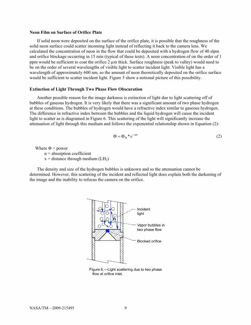
Extinction of Light Through Two Phase Flow Obscuration
Another possible reason for the image darkness is extinction of light due to light scattering off of bubbles of gaseous hydrogen. It is very likely that there was a significant amount of two phase hydrogen at these conditions. The bubbles of hydrogen would have a refractive index similar to gaseous hydrogen. The difference in refractive index between the bubbles and the liquid hydrogen will cause the incident light to scatter as is diagramed in Figure 6. This scattering of the light will significantly increase the attenuation of light through this medium and follows the exponential relationship shown in Equation (2): axe−Φ=Φ *0 (2)
Where Φ = power α = absorption coefficient x = distance through medium (LH2) The density and size of the hydrogen bubbles is unknown and so the attenuation cannot be
determined. However, this scattering of the incident and reflected light does explain both the darkening of the image and the inability to refocus the camera on the orifice.
NASA/TM—2009-215495 10
NASA/TM—2009-215495 11
Concluding Remarks The purpose of this test program was to definitively quantify the orifice clogging caused by accretion
from neon contaminates in the LH2 flow stream, utilizing state of the art imaging technology. An additional goal was to repeat the 1992 tests to verify the clogging phenomenon.
Although we achieved the goal of repeating clogging, imaging results were less than satisfactory, very possibly due to insufficient illumination or light scattering. Of the options presented in this report, we believe that the image obscuration was most likely due to two phase flow upstream of the orifice.
Test results were comparable to previous observation; that is, the flow rate through the orifice decreased over time, indicating clogging in the orifice. Actual flow rates were lower than predicted, and also lower than for previous tests with similar size orifices. Low flow rates are probably due to two phase flow. The test could possibly be improved by decreasing the heat leak into the orifice assembly—either by fabricating test hardware from materials with lower heat leak, or submersing the entire assembly in the bulk liquid. The current configuration had design limitations based on focal length limits of the imaging equipment.
The significance of this effort has implications not only for propellant system design for existing cryogenic propellants, but also in evaluating design options for NASA’s planned Exploration Vehicles propellant systems. Liquid oxygen (LOX), liquid hydrogen (LH2) and liquid methane (LCH4) are options being considered for propellant systems. J-T devices have been identified as critical components for Thermodynamic Vent Systems (TVS) planned for future space exploration missions. These J-T devices may be used for LOX, LH2, or LCH4 tank internal pressure control and supply manifolds to OMS-RCS thrusters.
Future Work Future attempts at imaging might include improving the lighting. The current configuration used a
ring of LED lights around the top of the sight tube. Perhaps more direct lighting using fiber optic light right at the orifice would improve results. Another possibility would be to use a different camera arrangement—possibly a boroscope type camera that could view the orifice from a much closer distance. Other possible configurations might utilize sheet laser to detect neon particles in the flow stream.
Testing is planned at NASA Glenn Research Center to characterize Visco Jets in LOX and LCH4. The purpose of these tests will be to determine if clogging occurs in Visco Jets with LOX or LCH4 via a similar mechanism. Attempts at imaging these devices are not currently planned. Testing will focus on mass spectrum analysis of the bulk cryogenic liquid and the Visco Jet outlet flow.
References 1. Papell S.S., Nyland T.W., Saiyed N.H., “Liquid Hydrogen Mass Flow Through a Multiple Orifice
Joule-Thomson Device,” AIAA–92–2881, 1992; NASA TM-105583. 2. Nyland T.W., “On the Clogging of Visco Jets and Orifices,” NASA Lewis Research Center,
Cleveland, OH, 1992, unpublished. 3. Jurns, J.M., Kudlac, M.T., “NASA Glenn Research Center Creek Road Complex—Cryogenic Testing
Facilities,” Cryogenics, vol. 46, 2006, pp. 98–104. 4. Diller, D.E., “Refractive Index of Gaseous and Liquid Hydrogen,” The Journal of Chemical Physics,
vol. 49, no. 7, October 1968, pp. 3096–3105.
REPORT DOCUMENTATION PAGE Form Approved OMB No. 0704-0188
The public reporting burden for this collection of information is estimated to average 1 hour per response, including the time for reviewing instructions, searching existing data sources, gathering and maintaining the data needed, and completing and reviewing the collection of information. Send comments regarding this burden estimate or any other aspect of this collection of information, including suggestions for reducing this burden, to Department of Defense, Washington Headquarters Services, Directorate for Information Operations and Reports (0704-0188), 1215 Jefferson Davis Highway, Suite 1204, Arlington, VA 22202-4302. Respondents should be aware that notwithstanding any other provision of law, no person shall be subject to any penalty for failing to comply with a collection of information if it does not display a currently valid OMB control number. PLEASE DO NOT RETURN YOUR FORM TO THE ABOVE ADDRESS. 1. REPORT DATE (DD-MM-YYYY) 01-03-2009
2. REPORT TYPE Technical Memorandum
3. DATES COVERED (From - To)
4. TITLE AND SUBTITLE Clogging of Joule-Thomson Devices in Liquid Hydrogen Handling
5a. CONTRACT NUMBER NAS3-00145
5b. GRANT NUMBER
5c. PROGRAM ELEMENT NUMBER
6. AUTHOR(S) Jurns, John, M.; Lekki, John, D.
5d. PROJECT NUMBER
5e. TASK NUMBER
5f. WORK UNIT NUMBER WBS 095240.04.06.03
7. PERFORMING ORGANIZATION NAME(S) AND ADDRESS(ES) National Aeronautics and Space Administration John H. Glenn Research Center at Lewis Field Cleveland, Ohio 44135-3191
8. PERFORMING ORGANIZATION REPORT NUMBER E-16661
9. SPONSORING/MONITORING AGENCY NAME(S) AND ADDRESS(ES) National Aeronautics and Space Administration Washington, DC 20546-0001
10. SPONSORING/MONITORS ACRONYM(S) NASA; AIAA
11. SPONSORING/MONITORING REPORT NUMBER NASA/TM-2009-215495; AIAA-2006-4877
12. DISTRIBUTION/AVAILABILITY STATEMENT Unclassified-Unlimited Subject Categories: 20, 28, and 34 Available electronically at http://gltrs.grc.nasa.gov This publication is available from the NASA Center for AeroSpace Information, 301-621-0390
13. SUPPLEMENTARY NOTES
14. ABSTRACT Experiments conducted at the NASA Glenn Research Center indicate that Joule-Thomson devices become clogged when transferring liquid hydrogen (LH2), operating at a temperature range from 20.5 to 24.4 K. Blockage does not exist under all test conditions but is found to be sensitive to the inlet temperature of the LH2. At a subcooled inlet temperature of 20.5 K blockage consistently appears but is dissipated when the fluid temperature is raised above 24.5 K. Clogging steadily reduced flow rate through the orifices, eventually resulting in complete blockage. This tendency poses a threat to spacecraft cryogenic propulsion systems that would utilize passive thermal control systems. We propose that this clogging is due to trace amounts of neon in the regular LH2 supply. Neon freezes at 24.5 K at one atmosphere pressure. It is postulated that between 20.5 and 24.5 K, neon remains in a meta-stable, super-cooled liquid state. When impacting the face of an orifice, liquid neon droplets solidify and accumulate, blocking flow over time. The purpose of this test program was to definitively quantify the phenomena experimentally by obtaining direct visual evidence of orifice clogging by accretion from neon contaminates in the LH2 flow stream, utilizing state of the art imaging technology. Tests were conducted with LH2 flowing in the temperature range of 20.5 to 24.4 K. Additional imaging was also done at LH2 temperatures with no flow to verify clear view through the orifice. 15. SUBJECT TERMS Liquid hydrogen; Joule-Thomson effect; Fluid management; Cryogenic fluid storage
16. SECURITY CLASSIFICATION OF: 17. LIMITATION OF ABSTRACT UU
18. NUMBER OF PAGES
17
19a. NAME OF RESPONSIBLE PERSON STI Help Desk (email:[email protected])
a. REPORT U
b. ABSTRACT U
c. THIS PAGE U
19b. TELEPHONE NUMBER (include area code) 301-621-0390
Standard Form 298 (Rev. 8-98)Prescribed by ANSI Std. Z39-18