Interactive Design Study Cluster Level Report DCS MSME Scheme Band Five | 2011
Design Clinic 5 Band NAS Report :Steel Furniture Cluster, Azara, kamrup| 2013 | Mridu Pawan Medhi 1
Contents
i. Acknowledgement 3
ii. About the DCS 4-6
iii. About the Association 7
iv. overview of the Azara Cluster and Artisans 8-9
v. Brief Introduction 10-13
vi. introduction of Azara Cluster and products 14-17
vii. Tools & Machineries 18-20
viii. List of MSME unit in Azara 21-22
ix. Process, Raw material and Techniques 23-36
x. Design Audit Report 37-56
xi. Conclusion 57
2 Design Clinic 5 Band NAS Report :Steel Furniture Cluster, Azara, kamrup| 2013 | Mridu Pawan Medhi
Acknowledgements
I would like to thank National Institute of Design (NID) and its following members of the Team of Design Clinic Scheme for MSMEs , Secretary Mrs. Manashi Borah who gave me an opportunity to work as a consultant for DCS for Steel Furniture Cluster at Azara. The Steel furniture MSME unit of Azara who have played a great role in the successful completion of the Need Assessment survey.
Hence I would like to give my gratitude to Mr. PradyumnaVyas(Director), Mr. Shashank Mehta (DCS for MSMEs, Head, NID), Mr. Ashok Mondal(East and North East Zone co-ordinator, DCS for MSMEs, NID), Mrs Sheikh Nilufar and the entire DCS for MSMEs team. A special thanks to SHANTI CREATION, for providing me the opportunity and platform to work with their highly qualified team.Thanks to the lovely people and artisans of Azara, kamrup, Assam.
3 Design Clinic 5 Band NAS Report :Steel Furniture Cluster, Azara, kamrup| 2013 | Mridu Pawan Medhi
Design Clinic Scheme for Design Expertise to MSMEs, a unique and ambitious design intervention scheme for the country’s large micro, small and medium scale enterprises, is an initiative of Ministry of MSME, Government of India has been launched under National Manufacturing Competitiveness program. The scheme is being designed keeping in mind the objective of design awareness, design interventions and competitiveness improvement for largest group of industrial sectors, Micro, small and medium enterprises of the country which contributes to approximately 45% of total industrial production and 40% exports. They are major contributors to the GDP growth, accounting to about 8%. They
DESIGN CLINIC
SCHEME
Design Clinic 5 Band NAS Report :Steel Furniture Cluster, Azara, kamrup| 2013 | Mridu Pawan Medhi 4
NAS They are also the largest employers after agriculture, employing an
estimated 41 million people. The main objective of the Design Clinic Scheme is to bring MS&ME
sector and design expertise into a common platform and to provide expert advice and solutions on real time design problems, resulting in continuous improvement and value addition for existing products. This model brings design exposure to the door step of industry clusters for design awareness, improvement, evaluation, analysis and design related intervention. Design clinic scheme will assist industrial clusters to open a channel for design information inflow for creative, innovative and futuristic approach towards the product, process, operations, manufacturing and business design. The scheme will help generate insight for opportunity identification and design intervention for competitive and breakthrough solutions for
Design Clinic 5 Band NAS Report :Steel Furniture Cluster, Azara, kamrup| 2013 | Mridu Pawan Medhi 5
MINISTRY OF MSME
MSMEs.
The total scheme budget will be Rs. 73.58
crores, out of which Rs. 49.08 crores will be GoI assistance and the balance amount will be contributed by the beneficiary MSMEs. The scheme provides great opportunity to the large sector of MSME (Associations and Units) as well as Indian design fraternity – the design consulting firms, independent designers, various design institutes of the country and also the design students to engage them to assist the country’s large MSME sector move up the value chain through increasing the value and competitiveness of their products and services. The scheme targets to reach out to about 200
NID National Institute of Design (NID), Ahmedabad will assist the Ministry of MSME, Government of India, as a nodal agency for implementing the scheme. As part of the scheme a
Design Clinic 5 Band NAS Report :Steel Furniture Cluster, Azara, kamrup| 2013 | Mridu Pawan Medhi 6
Shanti Creation (The Association)
• The approach of the Shanti Creation, Guwahati to meet the demand for intervention through DCS under Ministry of MSME implemented by NID, Ahmedabad . As the Association has been working for rural artisans and weavers to develop their livelihood. Shanti Creation which is a body of Technocrats and Artisans was engaged with
• Designing and Development of Rural Product • Marketing of Rural Product. • Design intervention to MSME sectors for their products • Woman empowerment (Economical, social and political) • Skill up gradation to small scale industries and to Rural People
7 Design Clinic 5 Band NAS Report :Steel Furniture Cluster, Azara, kamrup| 2013 | Mridu Pawan Medhi
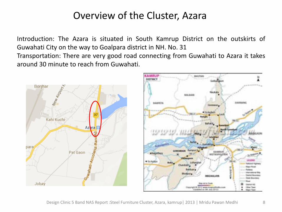
Overview of the Cluster, Azara
Introduction: The Azara is situated in South Kamrup District on the outskirts of Guwahati City on the way to Goalpara district in NH. No. 31 Transportation: There are very good road connecting from Guwahati to Azara it takes around 30 minute to reach from Guwahati.
8 Design Clinic 5 Band NAS Report :Steel Furniture Cluster, Azara, kamrup| 2013 | Mridu Pawan Medhi
Artisans at work in Azara Cluster, Kamrup, Assam
9 Design Clinic 5 Band NAS Report :Steel Furniture Cluster, Azara, kamrup| 2013 | Mridu Pawan Medhi
Brief & Introduction
South Kamrup
The south Kamrup is a big part of Kamrup district which consists of many famouse places like Palasbari, Azara, Mirza, BijoyNagar and Boko . It shares its border with the district of Goalpara .
Location
The location of azara is very good that is nearby Guwahati city about 25 km from the city with good communication of road towards Lokapriya Gopinath Bordoloi Airport and Goalpara of Assam
Climate
It enjoys tropical climate as rest of the other part of Assam. With maximum of 36°C and 10°C temperature, it has dry winters and humid summers. Monsoons last from early June to mid-September.
Demography
Assam’s population was estimated at 28.67 million in 2006 and at 30.57 million by 2011, 34.18 million by 2021 and 35.60 million by 2026. Assam has many ethnic groups and the People of India project has studied 115 of these. Out of which 79(69%) identify themselves Template: Explanation needed regionally, 22(19%) locally, and 3 trans-nationally. The earliest settlers were Austro-Asiatic,followed by Tibeto-Burman, Indo-Aryan speakers, and Tai–Kadai speakers. Forty- five language sare spoken by different communities, including three major language families: Austro-Asiatic, Sino –Tibetan and Indo-European. There are 23 notified Scheduled Tribes(ST) in Assam with theBodos (40.9percent) making half of the total ST population (around 13 percent ) of the state. The other STs (both plain sandhills) include Miri, Karbi, Rabha, Kachari, Lalung, Barman in Cachar, Boro kachar, Deori, Hajai, Mech, Dimasa, Hajong, Singhphho, Khampti and Garo, Chakma, Hmar, Khasi, Jaintia, Synteng, Pnar, War ,Bhoi, Lyngngam, and Kuki.
10 Design Clinic 5 Band NAS Report :Steel Furniture Cluster, Azara, kamrup| 2013 | Mridu Pawan Medhi
CULTURE Assamese culture is traditionally a hybrid one developed due to assimilation of ethno-cultural groups in the past. Various elements like Tamulpan (the areca nut and betel leaves), Sorai and Gamosa are being used to represent beliefs, feelings, pride, identity, etc. The major milestones in evolution of Assamese culture are: Bihu 1. Assimilation in the Kamarup a Kingdom for almost 700 years (under the Varmans for 300 years,
Salastambhas and Palas for each 200 years). 2. Establishment of the Ahom dynasty in the 13th century AD and assimilation for next 600 years. 3. Assimilation in the Koch Kingdom (15th_16th century AD) of western Assam and Kachari Kingdom (12th_18th century AD) of central and southern Assam. 4. Vaishnava Movement led by Srimanta Shankardeva (Xonkordeu) in the 15th century and its contribution provided another dimension to Assamese culture. of social institutions such as namghar and sattra (the Vaishnav Monasteries). Bihu(Rongali, Bohag, Kati) is the most important and
common and celebrated all over Assam. Durga Puja is another festival celebrated with great enthusiasm. Muslims celebrate two Eids (Eid ul- Fitr and Eid al-Adha)
11 Design Clinic 5 Band NAS Report :Steel Furniture Cluster, Azara, kamrup| 2013 | Mridu Pawan Medhi
TRADITIONAL CRAFTS
Assam has a rich tradition of crafts; presently, Cane and bamboo craft, bell metal and brass craft, silk and cotton weaving, jute products making craft Toy and mask making, Pottery and terracotta work, wood craft, jewellery making, musical instruments making, etc. remained as major traditions. Historically, Assam also excelled in making boats, traditional guns and gunpowder, ivory crafts, colours and paints, articles of lac, agarwood products, traditional building materials, utilities from iron, etc.
12 Design Clinic 5 Band NAS Report :Steel Furniture Cluster, Azara, kamrup| 2013 | Mridu Pawan Medhi
Silk of Assam
Assam is the home of several types of silks, the most prestigious are: Muga Silk the natural golden silk, Pat silk
creamy-bright-silver coloured silk and Eri silk a variety used for manufacturing warm clothes for winter. The golden silk Muga is famous all over the world as its natural golden color as well as Eri silk is known as wild silk of Ahimsa category.
About 90 % of Woman has engaged with the handloom activity in Assam
13 Design Clinic 5 Band NAS Report :Steel Furniture Cluster, Azara, kamrup| 2013 | Mridu Pawan Medhi
Introduction Furniture industry is very large and around 90% is unorganized. This sector works
with variety of materials and different skill of the manufacturer. Most of the steel furniture Cluster works with contemporary designs. Few clusters are with new designs. India is a cost driven market and so the industries under pressure of cost cutting and they compromise on quality and also do not invest in design and research. Also they lacks reach to advance technologies , designs and technical skills. Our effort in this report to highlight these issues and also suggest the intervention on the industry.
14 Design Clinic 5 Band NAS Report :Steel Furniture Cluster, Azara, kamrup| 2013 | Mridu Pawan Medhi
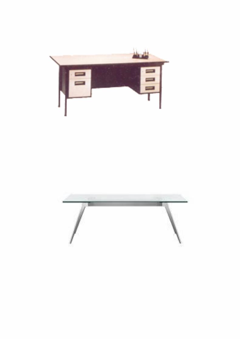
Range of Furniture in Azara Cluster
Office Table Showcase and Storage
Sofa Set
Iron Bed
15 Design Clinic 5 Band NAS Report :Steel Furniture Cluster, Azara, kamrup| 2013 | Mridu Pawan Medhi
Wardrobe
Fabrication
16 Design Clinic 5 Band NAS Report :Steel Furniture Cluster, Azara, kamrup| 2013 | Mridu Pawan Medhi
Dinning chair
Corner stand
Sofa
Iron Bed
17 Design Clinic 5 Band NAS Report :Steel Furniture Cluster, Azara, kamrup| 2013 | Mridu Pawan
Medhi
Tools and Machineries
Hand Tools All the hand tools are local made or Sometimes the unit has make these tools by themselves As the unit has made locally they are not suitable for proper uses for manufacturing process.
Hammer
Plier
Angle
Shears
Chisel
Customized local tool for bending
18 Design Clinic 5 Band NAS Report :Steel Furniture Cluster, Azara, kamrup| 2013 | Mridu Pawan Medhi
Machinery
Arc-welding machine
Hand grinder Grinder
Drill Press
19 Design Clinic 5 Band NAS Report :Steel Furniture Cluster, Azara, kamrup| 2013 | Mridu Pawan Medhi
Machinery
Compressor Color Spray
20 Design Clinic 5 Band NAS Report :Steel Furniture Cluster, Azara, kamrup| 2013 | Mridu Pawan Medhi
LIST OF SELECTED MSME’s during NAS of DESIGN AWARNESS PROGRAME
1.Narmohan Das c/o V. Baishya Steel Home 2. Jagdish Das 3. Nayan Das 4. Kalyan Mahanta c/o V. Baishya Steel Fabrication 5. Prasenjit Roy 6. Mohibur Rahman c/o Maina Steel Industry 7. Rahman Ali 8. Babul Ali 9. Naba Kr. Medhi c/o Medhi Steel Industry 10. Md. Faijul Ali
21 Design Clinic 5 Band NAS Report :Steel Furniture Cluster,
Azara, kamrup| 2013 | Mridu Pawan Medhi
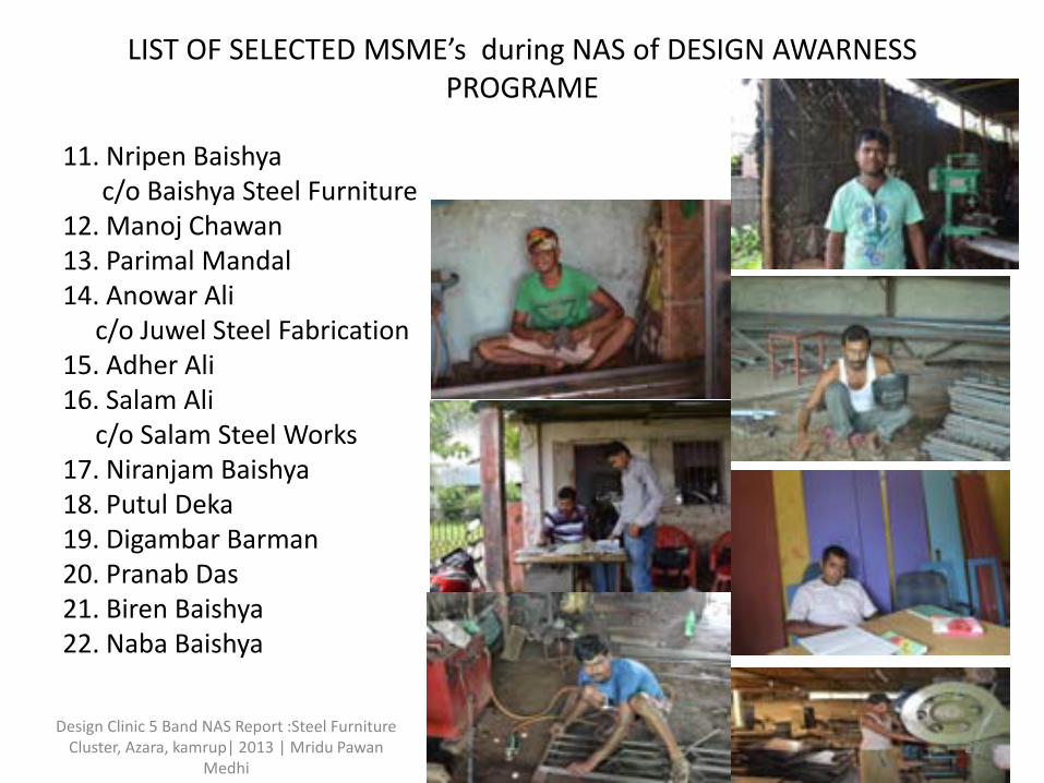
LIST OF SELECTED MSME’s during NAS of DESIGN AWARNESS PROGRAME
11. Nripen Baishya c/o Baishya Steel Furniture 12. Manoj Chawan 13. Parimal Mandal 14. Anowar Ali c/o Juwel Steel Fabrication 15. Adher Ali 16. Salam Ali c/o Salam Steel Works 17. Niranjam Baishya 18. Putul Deka 19. Digambar Barman 20. Pranab Das 21. Biren Baishya 22. Naba Baishya
22 Design Clinic 5 Band NAS Report :Steel Furniture
Cluster, Azara, kamrup| 2013 | Mridu Pawan Medhi
PROCESS AND TECHNIQUES
It is of four steps
1.STORAGE
2.FABRICATION
3.PAINTING
4.STORAGE
23 Design Clinic 5 Band NAS Report :Steel Furniture Cluster, Azara, kamrup| 2013 | Mridu Pawan Medhi
1. STORAGE
MS Sheets
Box sections
MS Flats
L angle
Primer paint coat
2. FABRICATION
Sheet marking
Sheet cutting/Pipe cutting
Part fabrication
Assembly
24 Design Clinic 5 Band NAS Report :Steel Furniture Cluster, Azara, kamrup| 2013 | Mridu Pawan Medhi
3.PAINTING
Surface preparation
Putty work
Spray paint
Heat chamber
Drying
4.STORAGE
Finished furniture
storage
Transportation
Fabrication Sheet metal fabrication is classification manufacturing processes that shape pieces of sheet metal into desired part through metal removal or deformation. In steel fabrication the process consist of different steps .
25 Design Clinic 5 Band NAS Report :Steel Furniture Cluster, Azara, kamrup| 2013 | Mridu Pawan Medhi
Raw Material
In furniture industry CR Sheet is used as primary raw material . Other raw material is mainly Iron pipes, rods, flat iron pipe etc.
the CR sheet is available in the size from 0.6mm to 1mm normally the worker called it like from 18 gages to 24 gages. The thickness of the sheet has to be selected as per the product quality
26 Design Clinic 5 Band NAS Report :Steel Furniture Cluster, Azara, kamrup| 2013 | Mridu Pawan Medhi
Step 1-Sheet Marking
* Select the proper sheet for fabrication. • Proper marking the sheet with the help of marking tools. • Before the product being fabricated, the measuring & marking of
the sheet is done. Proper marking & measuring lead to accuracy in assembling the product. Error reduction of the product mostly depend on the skill of the worker as well as accuracy of the tools.
27 Design Clinic 5 Band NAS Report :Steel Furniture Cluster, Azara, kamrup| 2013 | Mridu Pawan Medhi
Step 2:-Cutting
The marking sheet is then taken to cut. Cutting is done manually with lot of precession & well skilled workers . This process takes a lots of time & labourers. Lots of errors may occur due to lack of proper cutting tools & skilled labours.
28 Design Clinic 5 Band NAS Report :Steel Furniture Cluster, Azara, kamrup| 2013 | Mridu Pawan Medhi
Step3:-Bending
In this process the sheet metal is forced to modify its geometry rather than removal of metal with the help of external force .Bending can be of different types like V-bending ,edge bending ,U-bending, etc. Here the process is carried out in two ways .
(A)Manually bending .
(B)Machine bending .
29 Design Clinic 5 Band NAS Report :Steel Furniture Cluster, Azara, kamrup| 2013 | Mridu Pawan Medhi
A. Manual Bending
In manual bending process the bend on the sheet is done by manual force. Here the force applied to bend is done by using of hand tools like hammer, punch, stake and chisel. The die shaped should be the shape of the product. This process takes lots of human effort.
30 Design Clinic 5 Band NAS Report :Steel Furniture Cluster, Azara, kamrup| 2013 | Mridu Pawan Medhi
B. Machine Bending
In this process the bending is done with the help of machine without less effort .Here the changes of error is very less. Machine bending commonly used are screw bending machine and universal bending machine.
Welding Welding is a precise job and requires lot of safety measures to protect worker from health and safety related issues. It was being used for joining part and assembly. The three type of welding was being used were: . Arc welding . Gas welding . Spot welding
31 Design Clinic 5 Band NAS Report :Steel Furniture Cluster, Azara, kamrup| 2013 | Mridu Pawan Medhi
Welding Process
Welding with naked eyes or normal black glasses can lead to severe eye problems like partial or complete blindness. Exposed body parts can cause multiple burns and also inhaling smoke can lead to serious lung problems. Use of safety equipment can reduce health hazards.
32 Design Clinic 5 Band NAS Report :Steel Furniture Cluster, Azara, kamrup| 2013 | Mridu Pawan Medhi
Assembly Assembly gives the final shape to furniture and this is the most time taking
process after bending. So more errors in parts increases the assembly time. The parts are typically join by rivets and welding depends on the strength and surface finish required
33 Design Clinic 5 Band NAS Report :Steel Furniture Cluster, Azara, kamrup| 2013 | Mridu Pawan Medhi
Grinding and finishing Finishing and grinding of surface is very critical for final painting jobs, all bad work
of previous stages increases the finishing time. As the units are highly dependent on manual
work so the finishes takes more time to hide the defects. Manual or electric grinding machines were being used to clear extra steel while welding.
Painting Base preparation takes lot of time and putty because surfaces are uneven by applying 2-3 coats of putty and then keep it to dry for 2-3 days. Then spray paint while color matching always remains as a challenge for the painters.
34 Design Clinic 5 Band NAS Report :Steel Furniture Cluster, Azara, kamrup| 2013 | Mridu Pawan Medhi
Painting
Preparation of paint paste takes lot of time and putty because surfaces are uneven by applying 2-3 coats of putty and then keep it to dry for 2-3 days. Then spray paint while color matching always remains as a challenge for the painters.
35 Design Clinic 5 Band NAS Report :Steel Furniture Cluster, Azara, kamrup| 2013 | Mridu Pawan Medhi
Storage The finished products and part finished product of the unit are stored at the same
place where they are displayed. They are kept unpacked. Lying next to each other, there are more chances of damages. For displaying any other product, they need to shift the product kept in front of it. This often shifting of products may lead to damaging the product itself. Since all the products are stored on the floor, hence there is scope of stacking the product on lofts. This will result in better storage and display solution. same thing happen in case of raw material it also lying with a unorganized manner.
36 Design Clinic 5 Band NAS Report :Steel Furniture Cluster, Azara, kamrup| 2013 | Mridu Pawan Medhi
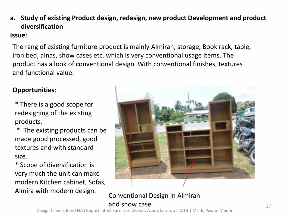
a. Study of existing Product design, redesign, new product Development and product diversification
Issue: The rang of existing furniture product is mainly Almirah, storage, Book rack, table, iron bed, alnas, show cases etc. which is very conventional usage items. The product has a look of conventional design With conventional finishes, textures and functional value. Opportunities:
Conventional Design in Almirah and show case
* There is a good scope for redesigning of the existing products. * The existing products can be made good processed, good textures and with standard size. * Scope of diversification is very much the unit can make modern Kitchen cabinet, Sofas, Almira with modern design.
37 Design Clinic 5 Band NAS Report :Steel Furniture Cluster, Azara, kamrup| 2013 | Mridu Pawan Medhi
Product development with new design in Steel Furniture
Styles Handle
Multi color in same wardrobe
Bigger & smaller locker
Wardrobe with looking glass bookshelf
38 Design Clinic 5 Band NAS Report :Steel Furniture Cluster, Azara, kamrup| 2013 | Mridu Pawan Medhi
b. Scope for research and development direction for future
ISSUES: * All are unit is running with a very less of capital investment. So they do not have enough funds, time and expertise to carry out research and development and product diversification. * Most of the unit is using hand tools for manufacturing process only a few unit has used such a machinery with can't compare with modern technology and designs. * The quality of products is compromised due to insufficient delivery time and lack of skill worker and technology which facilitates and increase speed of work without compromising on quality. Opportunities: ● Improvisation in machineries, Tools and work places through R&D activities. ● Skill development Training program for the worker in this MSME sector. ● Marketing survey in terms of consumer trends, market trends and competition in the local and national market. ● Exchange of technology ideas from different states.
39 Design Clinic 5 Band NAS Report :Steel Furniture Cluster, Azara, kamrup| 2013 | Mridu Pawan Medhi
c. Existing status and opportunity for visual identity, branding
and communication design Issue: These unit have not taken the major brands of their product in the market. They
are not serious about branding, the motifs, logos, fonts and finishes used in the badges of the product are not very distinctive enough to create effective brand-recall. The branding of the unit is represented in the form of a badge near the lock, handle or top side of the shutter.
Name of lock only highlight in the product
40 Design Clinic 5 Band NAS Report :Steel Furniture Cluster, Azara, kamrup| 2013 | Mridu Pawan Medhi
OPPORTUNITIES: * The idea of having a common visual identity and branding for the cluster was well accepted. * However it was felt that it should go in sync with initiatives like selling portal, websites. * So there is a big scope in developing visual identity for the cluster units, branding and communication design to connect them to the market directly and get them more exposure. * A product catalogue with specification of the product and delivery status is must and also presence of products online will be of great help and reach to the buyer.
41 Design Clinic 5 Band NAS Report :Steel Furniture Cluster, Azara, kamrup| 2013 | Mridu Pawan Medhi
d. Scope of technology, modernization and design collaborations
Manual Bending is typically done with help of hand tools like: stake, hammer and chisel. Its quite effective for small parts like shutters, panels etc.
Manual Pieces Cutting Painting
Issues: * No uniformity across parts. * Rough corners and surface requires more finishing efforts * Poor bend quality * Requires more manpower and increase the dependency on labours
* Use of conventional manual tools takes more time consuming. * Lack of good tools * Poor cutting quality/ edges due to manual cutting * improper finishing in painting or time consuming.
42 Design Clinic 5 Band NAS Report :Steel Furniture Cluster, Azara, kamrup| 2013 | Mridu Pawan Medhi
Opportunities: Instead of using manual process the unit can install low cost machinery is for
making process like bending machine, sheet cutting machine, * Use of quality hand tools. * Working on proper surface. * Use of hand operated or electric shearing machine * Use of proper tools
Advance Machineries in Fabrication
43 Design Clinic 5 Band NAS Report :Steel Furniture Cluster, Azara, kamrup| 2013 | Mridu Pawan Medhi
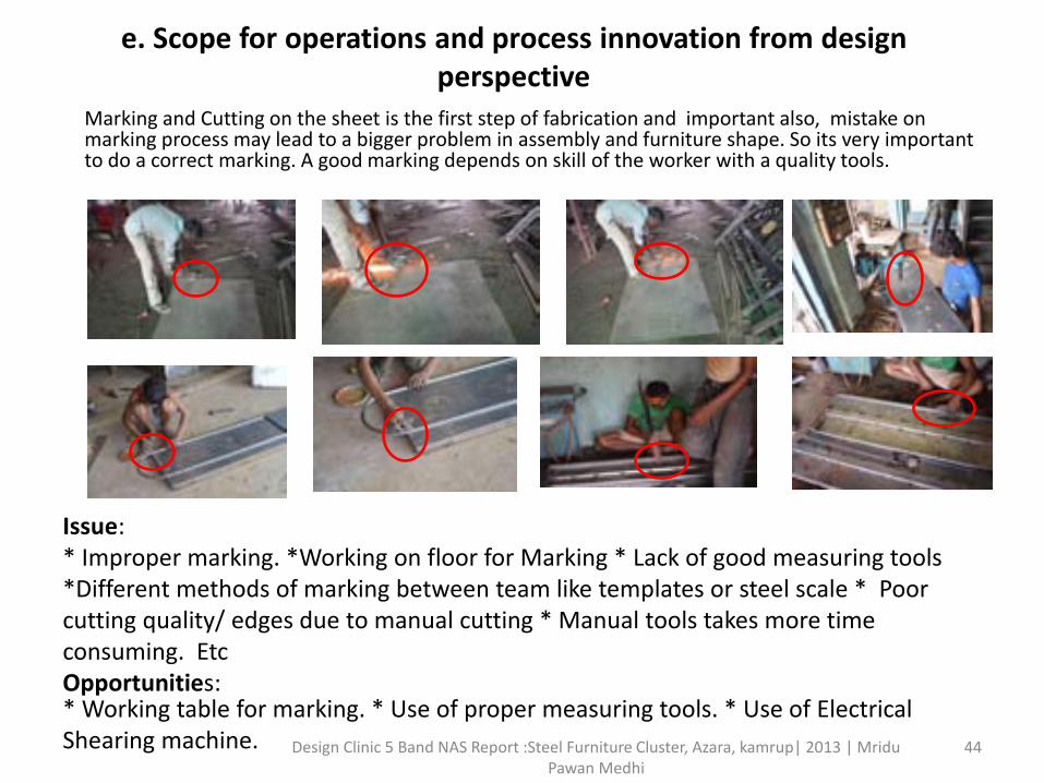
e. Scope for operations and process innovation from design perspective
Marking and Cutting on the sheet is the first step of fabrication and important also, mistake on marking process may lead to a bigger problem in assembly and furniture shape. So its very important to do a correct marking. A good marking depends on skill of the worker with a quality tools.
Issue: * Improper marking. *Working on floor for Marking * Lack of good measuring tools *Different methods of marking between team like templates or steel scale * Poor cutting quality/ edges due to manual cutting * Manual tools takes more time consuming. Etc Opportunities:
* Working table for marking. * Use of proper measuring tools. * Use of Electrical Shearing machine. 44 Design Clinic 5 Band NAS Report :Steel Furniture Cluster, Azara, kamrup| 2013 | Mridu
Pawan Medhi
It has seen the following issues in other process like Bending, Welding, Assembling and Finishing.
Issue: * No uniformity across parts. * Rough corners and surface requires more finishing efforts * Requires more manpower and increase the dependency on labours. * Lack of protection gears like eye wear, gloves and mask. * . Exposed body parts while welding * Lack of skilled labour * Pollutions on site. Opportunities: * Installation of semi shear cutting machines * Use of quality hand tools * Working on suitable surface.* Use of safety equipment during working. * Technical Training for skill up-gradation.
45 Design Clinic 5 Band NAS Report :Steel Furniture Cluster, Azara, kamrup| 2013 | Mridu Pawan Medhi
f. Design Opportunity in workstation and tooling design
ISSUES : * The work process is really slow due to hand made Tools using in the making
process. * The work place is not appropriate, cluttered and not organized. * Some of the unit has no proper lighting system for working in night hours. * The sitting position for the weavers is not proper so they feel back pains after they
work long periods in the looms. * The tools and equipment are kept with no proper arrangement or storage, leads to
damage of it. OPPORTUNITIES: * Low cost machine could be installed for improve capacity and quality of the
product. * Tools and equipment could be modified for less of work force * Use of Electrical Tools for better improvement.
Very conventional hand tools cause improper finishing and making 46
Design Clinic 5 Band NAS Report :Steel Furniture Cluster, Azara, kamrup| 2013 | Mridu Pawan Medhi
g. Details of market and competition study for design advantage and distinction
Issues : * Customers/ buyers are not ready to pay higher prices for the products to the local
made furniture comparing to branded one. * There is a serious competition from other part of the country for steel furniture in
Assam. * Decrease in profit margins due to exploitation by the traders. * Unit are not aware about the new trends in the market and individualistic approach
to sell the products.
47 Design Clinic 5 Band NAS Report :Steel Furniture Cluster, Azara, kamrup| 2013 | Mridu Pawan Medhi
opportunities: * The retail market can also be explored - Tie-ups with Shopping Mall could help in
marketing of the product. * Product diversification is required to grab a suitable market. * Product catalogue or e-catalogue should be introduce for market promotion. * Promotion of Furniture Fair could be organized by help of Govt. or other
organization. * Training to the MSMe’s about to develop market skill.
48 Design Clinic 5 Band NAS Report :Steel Furniture Cluster, Azara, kamrup| 2013 | Mridu Pawan Medhi
h. Study for the need of training and skill up-gradation Issue :
• The worker who is engaged in the unit is not skill to operate machine or other tools • Lake of skill resulting in the final product such as improper in finishing • Does not have any facility of skill development training program or institute. • There is no system in place through which the cluster can effectively make use of the BDS (Business
Development Services) providers.
opportunities: • A common training centre which could provide training on skill enhancement, quality control and product diversification can be established in order to train more people in the sector. • A skill upgradation course/ curriculum can be introduced with expert guidance. • Institutional linkages & Capacity Building and as well as the local BDS also need more training and exposure.
49 Design Clinic 5 Band NAS Report :Steel Furniture Cluster, Azara, kamrup| 2013 | Mridu Pawan Medhi
i. Description of ergonomic and environment factors in MSME Issue: * Working posture during work is wrong which may lead to back problem in future. *Exposed their body part to the machine. *The design of the work station is very unhygienic for working. *Body part is exposed to welding that may lead to burns. *No protection to eyes during welding may cause partial blindness in future. * Cutting of metal sheet without proper protection of hand gloves. * During painting work, inhaling of the spray paint and thinner may lead to bad health
problem. * While powder coating the body part is exposed to chemical may lead to skin
problem. * Lots of noise pollution. * Mishandling of tools.
Fast hammering without use of gloves causes injury in hand
Wrong Working position without mask
Improper position of sheet handling
50 Design Clinic 5 Band NAS Report :Steel Furniture Cluster, Azara, kamrup| 2013 | Mridu Pawan Medhi
Opportunities: * Workstation design in terms of physical dimension, including seating can
solve lots of problem of end user. • The aim should be to minimize the risk of operator discomfort and related
muscular-skeletal problems such as back and shoulder complaints. • Workstation layout, should such that specifically the positioning of
equipment on and around the workstation to ensure that it is visible and within easy reach of the operators who will use it.
• Use of Mask, Eye covering glass, Gloves for safety reason.
51 Design Clinic 5 Band NAS Report :Steel Furniture Cluster, Azara, kamrup| 2013 | Mridu Pawan Medhi
j. Packaging and logistics related design opportunities
Issue: • No packaging for the product. • Mishandling while carrying it to the vehicle. • Prone to damages while carried in the vehicle as there is hardly any
protection. • Prone to scratches and dents because of the ropes/vehicle body.
Opportunities: . Need proper packaging solution to minimize damages till the product reaches the customer. . Proper mechanical assistance for the labours while pulling and carrying the product.
52 Design Clinic 5 Band NAS Report :Steel Furniture Cluster, Azara, kamrup| 2013 | Mridu Pawan Medhi
k. Exhibition/ Display design opportunities
Opportunities: • A shop with great visible display on the leading cities in the state
could attract good amount of customers to the cluster • The unit can participate in more trade fairs, furniture Expo’s at
state, national and international level. • At cluster/ village level a small display area/showroom can be
created.
53 Design Clinic 5 Band NAS Report :Steel Furniture Cluster, Azara, kamrup| 2013 | Mridu Pawan Medhi
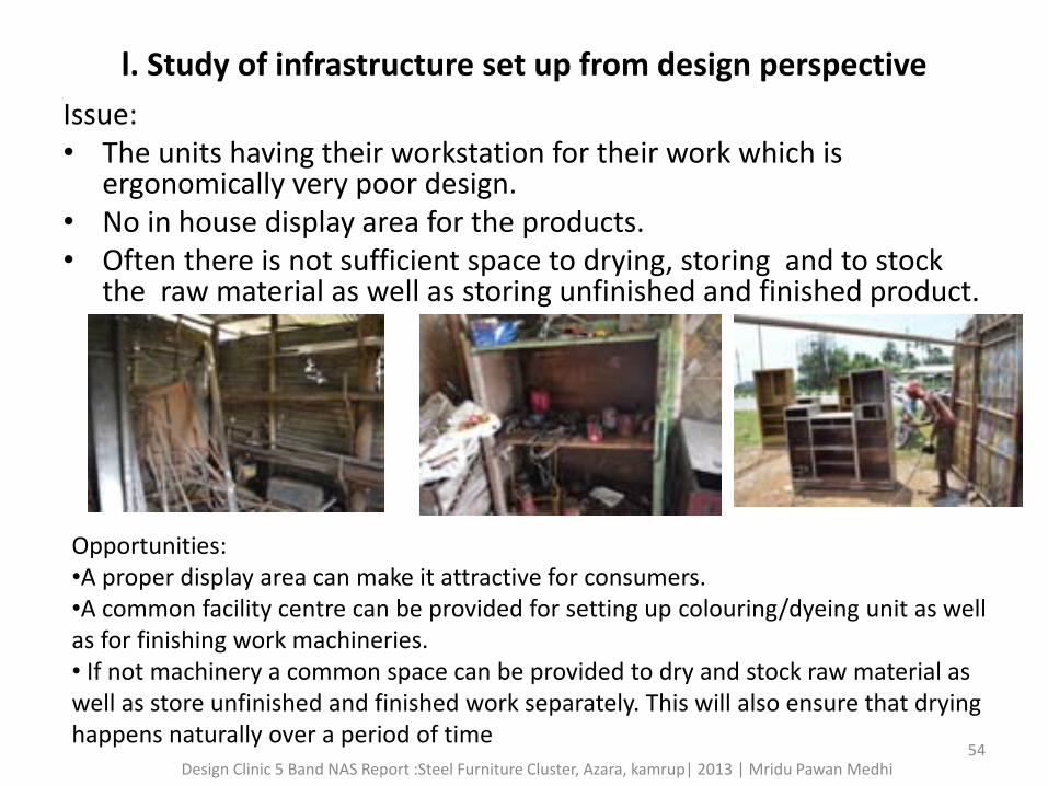
l. Study of infrastructure set up from design perspective
Issue: • The units having their workstation for their work which is
ergonomically very poor design. • No in house display area for the products. • Often there is not sufficient space to drying, storing and to stock
the raw material as well as storing unfinished and finished product.
Opportunities: •A proper display area can make it attractive for consumers. •A common facility centre can be provided for setting up colouring/dyeing unit as well as for finishing work machineries. • If not machinery a common space can be provided to dry and stock raw material as well as store unfinished and finished work separately. This will also ensure that drying happens naturally over a period of time
54 Design Clinic 5 Band NAS Report :Steel Furniture Cluster, Azara, kamrup| 2013 | Mridu Pawan Medhi
m. Scope of design intervention for inter cluster communication
opportunities: • Scope of Diversification of products which can only be developed by intense
training, more exposure to other markets, technology intervention and good quality tools and machineries. • Buyer Seller Meet • A Common Facilitation Centre will tremendously increase the scope of
communication between different units and thus lead to sharing of knowledge and skills.
• Also there could be a need of communication between Azara Furniture Cluster and other production units of India and that of
International standards.
55 Design Clinic 5 Band NAS Report :Steel Furniture Cluster, Azara, kamrup| 2013 | Mridu Pawan Medhi
Potential Design Project Opportunities after Need Assessment Survey
The NAS of Azara Steel Furniture cluster is really a good
expose of the cluster. The MSME unit of Azara is very capable of work culture and their activities is such that we can add so many intervention in terms of Design, Technology, Diversification, Packaging etc. It is a potential cluster to do a design Project. It is a good exposer by interacting with the cluster people who has been engaging with the work culture like making of steel furniture and fabrication for a long time.
56 Design Clinic 5 Band NAS Report :Steel Furniture Cluster, Azara, kamrup| 2013 | Mridu Pawan Medhi
Steel Furniture cluster, Azara
After Workshop Report DCS MSME Scheme Band Five | 2013
Design Clinic Workshop | Band 5 24/08/2013 – 28/08/2013 submitted by : Mridu Pawan Medhi Organised by Shanti Creation
5 BAND DESIGN CLINIC WORKSHOP under Design Clinic Scheme
From: 24th August ,2013 to 28th August, 2013 Venue: Dharapur Chariali, Near Third Eye Computer Centre, Kamrup
Sponsored by: Ministry of MSME, Govt. of India
Implemented by : National Institute of Design, Ahmedabad
2 Design Clinic 5 Band After Workshop Report : Steel Furniture, Azara Cluster, Kamrup | 2013 | Mridu Pawan Medhi
Design Clinic 5 Band After Workshop Report : Steel Furniture, Azara Cluster, Kamrup | 2013 | Mridu Pawan Medhi 3
Organized By:
Introduction:
Shanti Creation is an organization which offers consultancy services in different fields and expertise in different areas. It was Socio Cultural Organization and was registered under the Societies Registration Act aiming to serve the people of North East. The organization is managed by a set of dedicated persons having expertise in different areas. It is non profit organization dedicated to formulate and implement plans and projects that improve the social and economic conditions of the people of the Region. Shanti Creation aims to improve household condition of North East with sense of community development & sense of personal empowerment. The Organization is engaged in Skill Development in different Income generated activities. It also offers services that assist women & children who have experienced violence, homelessness &chronic poverty & to create an environment that strengthens a woman belief in her ability to influence the direction of her life.
Design Clinic 5 Band After Workshop Report : Steel Furniture, Azara Cluster, Kamrup | 2013 | Mridu Pawan Medhi 4
Design Clinic 5 Band After Workshop Report : Steel Furniture, Azara Cluster, Kamrup | 2013 | Mridu Pawan Medhi 5
Sl. No. Date 9.45 A.M Sessions(10.00 AM to 1.00 PM) Sessions(2.00 PM to 4 PM)
Day 1 24/08/2013 Registration
With
Attendance
Session 1: Inauguration, felicitation of the Chief
guest
Speech of Mr. N.N. Sarma, AGM, DICC
BREAK Session 2 : Presentation by Mridu Pawan
Medhi on showcasing the Steel Furniture
products made throughout the world
Day 2 25/08/2013 Attendance Session 1 : Tools and Technology usage and
implementation in fabrication Industry : by Mridu
Pawan Medhi
BREAK Session 2 : Advance process of Welding &
Finishing in Steel Furnishing : by Mr. Anupam
Dutta, BE, Mechanical, MBA
Day 3 26/08/2013 Attendance Session 1 : Diversification and redesign of Steel
Furniture : by Mridu Pawan Medhi
BREAK Session 2 : Involved of new technology
intervention in Fabrication Industry:
by Guest Designer, Godrej Interior, Ghy
Day 4 27/08/2013 Attendance Session 1 : Workshop on Assembling and
Welding by Mridu Pawan Medhi,
BREAK Session 2 : Concept of Packaging and Branding
for sustainable marketing:
by Guest Designer
Day 5 28/08/2013 Attendance Session 1 : Loan and Credit linkage with financial
organization :
by Faculty Member, SIRD, Assam
BREAK Session 2 : End of the program with remedial
solutions, Evaluation and Conclusion
Ceremony /Feed Back Form
Design Clinic Workshop Schedule on Steel Furniture Cluster
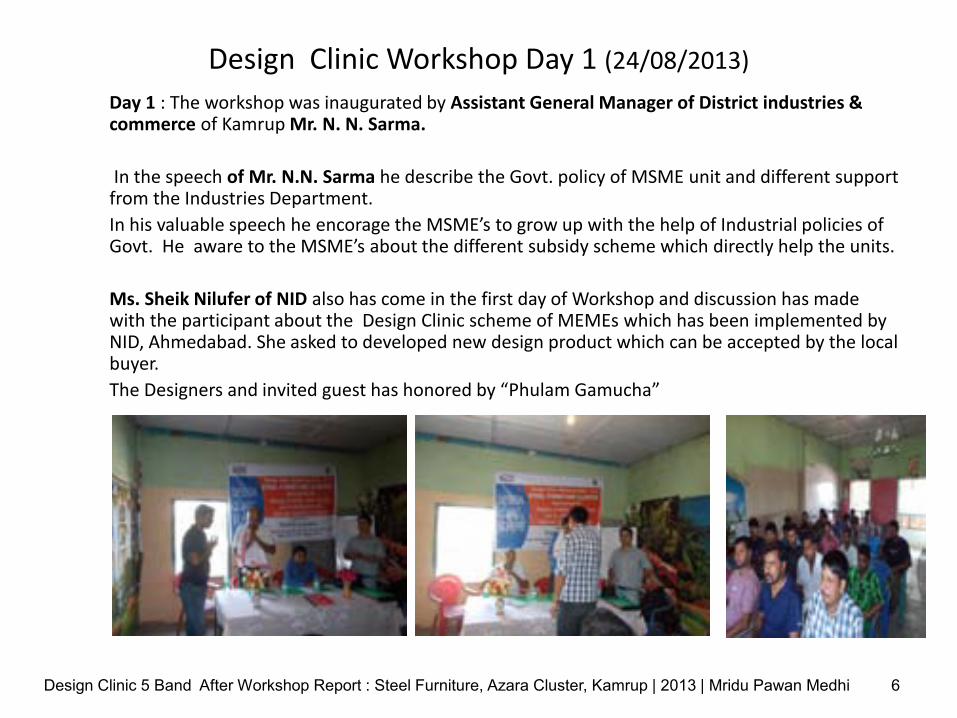
Design Clinic Workshop Day 1 (24/08/2013)
Day 1 : The workshop was inaugurated by Assistant General Manager of District industries & commerce of Kamrup Mr. N. N. Sarma.
In the speech of Mr. N.N. Sarma he describe the Govt. policy of MSME unit and different support from the Industries Department.
In his valuable speech he encorage the MSME’s to grow up with the help of Industrial policies of Govt. He aware to the MSME’s about the different subsidy scheme which directly help the units.
Ms. Sheik Nilufer of NID also has come in the first day of Workshop and discussion has made with the participant about the Design Clinic scheme of MEMEs which has been implemented by NID, Ahmedabad. She asked to developed new design product which can be accepted by the local buyer.
The Designers and invited guest has honored by “Phulam Gamucha”
Design Clinic 5 Band After Workshop Report : Steel Furniture, Azara Cluster, Kamrup | 2013 | Mridu Pawan Medhi 6
Design Clinic 5 Band After Workshop Report : Steel Furniture, Azara Cluster, Kamrup | 2013 | Mridu Pawan Medhi 7
The Inaugural session being taken by Mr. N.N. Sarma, AGM, DICC Dist. Kamrup
Design Clinic 5 Band After Workshop Report : Steel Furniture, Azara Cluster, Kamrup | 2013 | Mridu Pawan Medhi 8
Ms. Sheikh Nilufer of NID Guwahati during the workshop inauguration
Second Session of 1st Day : Just after the inaugural program the Technical session has started on the topic of showcasing the Steel Furniture products made throughout the world in this session discussion has been make about the different type of steel furniture made in the world and its market value. In this session the image of diversified furniture product has shown to the participant about to aware about the intervention of design in
this sector.
Design Clinic 5 Band After Workshop Report : Steel Furniture, Azara Cluster, Kamrup | 2013 | Mridu Pawan Medhi 9
Design clinic workshop day 2 (25/08/2013)
Day 2: The second day of the workshop is started with the Topic of Tools and Technology usage and implementation in fabrication Industry in this session theory and practical with audio and visualized about the uses of tools and advance technology in fabrication Industries Introducing the modern and advance fabrication Tools, Machineries and Techniques. The participate are questioning about their problem and doubts, solution has been given during the workshop session.
In second session Er. Anupam Dutta has continue the workshop as a Guest Designer
with the topic of Advance process of Welding & Finishing in Steel Furnishing. During the workshop session Mr. Dutta has giving presentation about the welding process of fabrication industry.
Problem and solution has been given by the designer about the *different type of welding process. * Safety condition of welding process * advantage and disadvantage of welding like (Arc welding, gas welding etc.) * Ergonomics solution during working. * Diversification of Steel furniture and Quality control of finished product * proper coloring and drying techniques of Steel furniture. Etc.
Design Clinic 5 Band After Workshop Report : Steel Furniture, Azara Cluster, Kamrup | 2013 | Mridu Pawan Medhi 10
Design Clinic 5 Band After Workshop Report : Steel Furniture, Azara Cluster, Kamrup | 2013 | Mridu Pawan Medhi 11
Technical session by the Guest Designer Mr. Anupam Dutta during the Workshop
Design clinic workshop day 3 (26/08/2013)
Day 3: On third day discussion made about the topic of Diversification and redesign of Steel Furniture
Unit wise workshop has been conduct about their problem according to NAS and solution has been given for that problem. New prototype with diversification of existing product has been made. On site discussion made about the design intervention in steel furniture.
On second Session: The Guest Designers covered the topic about Involved of new technology intervention in Fabrication Industry with showing the Interior product of reputed brands like Godrej, Steel & Styles etc.
Short Video clip of manufacturing process of reputed fabrication has been viewed
Solution has been given which occur during the different fabrication process like Marking, Cutting, Bending and painting
All the solution has described by the audio visual film so that participate can understand.
In the session they are discussed about the user friendly Tools and machineries with low cost so that they can procure it and can be used in fabrication Process.
.
Design Clinic 5 Band After Workshop Report : Steel Furniture, Azara Cluster, Kamrup | 2013 | Mridu Pawan Medhi 12
Design Clinic 5 Band After Workshop Report : Steel Furniture, Azara Cluster, Kamrup | 2013 | Mridu Pawan Medhi 13
Unit wise Workshop about to develop new design and product diversification
Design clinic workshop day 4 (27/08/2013)
Day 4: The forth day starts with the session on the topic of Workshop on
Assembling and Welding in fabrication industry. In this session exposer has given to the participant by visiting the workshop of Girijananda Institute of Management and Technology (GIMT) of Azara. Different type of welding, bending, cutting and sharing machine has been introduced.
In second session the Guest Designer has interact with the MSME representative about Concept of Packaging and Branding for sustainable marketing in steel furniture industry.
Design Clinic 5 Band After Workshop Report : Steel Furniture, Azara Cluster, Kamrup | 2013 | Mridu Pawan Medhi 14
Design Clinic 5 Band After Workshop Report : Steel Furniture, Azara Cluster, Kamrup | 2013 | Mridu Pawan Medhi 15
On Site Workshop at GIMT workshop centre, Azara
Design clinic workshop day 5 (28/08/2013)
Day 5: In the last day of Workshop the session start with the topics of Loan and Credit linkage with financial organization during the session opportunities of credit linkage with different organization like, DICC, NSIC, SIRD, SIDBI has been discussed. The session has taken by the Guest faculty of SIRD, Assam.
The second session completed with all remedial solutions, Evaluation and Conclusion Ceremony /Feed Back Form. The Artisans fill the feedback form and return back. Most of the MSME representative are not highly qualified they only know to sign there own.
Design Clinic 5 Band After Workshop Report : Steel Furniture, Azara Cluster, Kamrup | 2013 | Mridu Pawan Medhi 16
opportunity areas, remedial major design solutions during the Workshop
# Scope of diversification is very much the unit can make modern Kitchen cabinet, Sofas, Almira with modern design.
# Improvisation in machineries, Tools and work places.
# Skill development Training program for the worker in this MSME sector
# Marketing survey in terms of consumer trends, market trends and competition in the local and national market
# A product catalogue with specification of the product and delivery status is must and also presence of products online will be of great help and reach to the buyer.
# Instead of using manual process the unit can install low cost machinery is for making process like bending machine, sheet cutting machine,
# Workstation layout, should such that specifically the positioning of equipment on and around the workstation to ensure that it is visible and within easy reach of the operators who will use it.
Design Clinic 5 Band After Workshop Report : Steel Furniture, Azara Cluster, Kamrup | 2013 | Mridu Pawan Medhi 17
# Use of quality hand tools.
# Working on proper surface.
# Use of hand operated or electric shearing machine
# Use of proper tools
# Working table for marking.
# Use of proper measuring tools
# Use of safety equipment during working.
# Use of Electrical Tools for better improvement.
# The retail market can also be explored - Tie-ups with Shopping Mall could help in marketing of the product.
# Product catalogue or e-catalogue should be introduce for market promotion.
# Use of Mask, Eye covering glass, Gloves for safety reason.
# A common training centre which could provide training on skill enhancement, quality control and product diversification can be established in order to train more people in the sector.
Design Clinic 5 Band After Workshop Report : Steel Furniture, Azara Cluster, Kamrup | 2013 | Mridu Pawan Medhi 18
Design Clinic 5 Band After Workshop Report : Steel Furniture, Azara Cluster, Kamrup | 2013 | Mridu Pawan Medhi 19
Prototype sketching
storage Chair
Design Clinic 5 Band After Workshop Report : Steel Furniture, Azara Cluster, Kamrup | 2013 | Mridu Pawan Medhi 20
Wardrobe
Stool
Registration and Feedback Form of DCS Workshop
Design Clinic 5 Band After Workshop Report : Steel Furniture, Azara Cluster, Kamrup | 2013 | Mridu Pawan Medhi 21
Design Clinic Workshop on Steel Furniture, Azara
• Every day the workshop is continuing from 10 am to 4 pm
• The First session has been staring from 10am to 1 pm in between the first session the tea and snacks has been served. The session comes to end at 1 pm then the lunch has served to the participants and to the Resource Persons.
• The Second session of workshop has started at 2 pm till 4 pm sometimes it continues till 5 pm in between the session tea and snacks has served.
• Every they the topics has discussed with remedial solution to the MSME’s representative.
• Participant asked question to the Resource person and the resource person has give feed back to them.
• The official persons of Shanti Creation has monitoring each session and when communication of language has comes they have solved.
Design Clinic 5 Band After Workshop Report : Steel Furniture, Azara Cluster, Kamrup | 2013 | Mridu Pawan Medhi 22
Potential Design Project Opportunities after WORKSHOP In Azara cluster there could be done a design project for the benefit of MSME unit
of Azara who are making Steel Furniture and Fabrication work. Lots of things has to be done in design project like
1. Tools and Equipment Design for Fabrication.
2. The existing product can be redesign for product development and diversification.
3. Quality raw material could be used for making the product
4. Use of user friendly low cost machineries for Fabrication Process.
5. Advance welding process can introduced.
6. The concept of Packaging and a acceptable packaging could be done during the design project.
we have seen that the all unit of Azara related to fabrication and steel furniture industry is aware to improve there production and they are interested to adopt new design and technology for their development. The unit can be develop by proper supporting in the field of Design and Marketing. If the design project could be introduce in the particular cluster it can be very fruitful for the MSME unit so that there income should generate more for their livelihood.
Design Clinic 5 Band After Workshop Report : Steel Furniture, Azara Cluster, Kamrup | 2013 | Mridu Pawan Medhi 23
Types of Bending
Bending
Press brake
Bending is a manufacturing process that produces a V-shape, U-shape, or channel shape along a straight axis in ductile materials, most commonly sheet metal. Commonly used equipment includes box and pan brakes, brake presses, and other specialized machine presses. Typical products that are made like this are boxes such as electrical enclosures and rectangular ductwork.
Process
Bending process
In press brake forming, a work piece is positioned over the die block and the die block presses the sheet to form a shape. Usually bending has to overcome both tensile stresses and compressive stresses. When bending is done, the residual stresses cause the material to spring
back towards its original position, so the sheet must be over-bent to achieve the proper bend angle. The amount of spring back is dependent on the material, and the type of forming. When sheet metal is bent, it stretches in length. The bend deduction is the amount the sheet metal will stretch when bent as measured from the outside edges of the bend. The bend
radius refers to the inside radius. The formed bend radius is dependent upon the dies used, the material properties, and the material thickness.
The U-punch forms a U-shape with a single punch.
Types
A schematic of air bending with a backgauge.
There are three basic types of bending on a press brake, each is defined by the relationship of the end tool position to the thickness of the material. These three are Air Bending, Bottoming and Coining. The configuration of the tools for these three types of bending is nearly identical. A die with a long rail form tool with a radiused tip that locates the inside profile of the bend is called a punch. Punches are usually attached to the ram of the machine by clamps and move to produce the bending force. A die with a long rail form tool that has concave or V shaped lengthwise channel that locates the outside profile of the form is called a die. Dies are usually stationary and located under the material on the bed of the machine. Note that some locations do not differentiate between the two different kinds of dies (punches and dies.) The other types of bending listed use specially designed tools or machines to perform the work.
This bending method forms material by pressing a punch (also called the upper or top die) into the material, forcing it into a bottom V-die, which is mounted on the press. The punch forms the bend so that the distance between the punch and the side wall of the V is greater than the material thickness (T).
Either a V-shaped or square opening may be used in the bottom die (dies are frequently referred to as tools or tooling). A set of top and bottom dies are made for each product or part produced on the press. Because it requires less bend force, air bending tends to use smaller tools than other methods.
Some of the newer bottom tools are adjustable, so, by using a single set of top and bottom tools and varying press-stroke depth, different profiles and products can be produced. Different materials and thicknesses can be bent in varying bend angles, adding the advantage of flexibility to air bending. There are also fewer tool changes, thus, higher productivity.
A disadvantage of air bending is that, because the sheet does not stay in full contact with the dies, it is not as precise as some other methods, and stroke depth must be kept very accurate. Variations in the thickness of the material and wear on the tools can result in defects in parts produced.
Air bending's angle accuracy is approximately ±0.5 deg. Angle accuracy is ensured by applying a value to the width of the V opening, ranging from 6 T (six times material thickness) for sheets to 3 mm thick to 12 T for sheets more than 10 mm thick. Springback depends on material properties, influencing the resulting bend angle.
Depending on material properties, the sheet may be overbended to compensate for springback.
Air bending does not require the bottom tool to have the same radius as the punch. Bend radius is determined by material elasticity rather than tool shape.
The flexibility and relatively low tonnage required by air bending are helping to make it a popular choice. Quality problems associated with this method are countered by angle-measuring systems, clamps and crowning systems adjustable along the x and y axes, and wear-resistant tools.
The K-Factor approximations given below are more likely to be accurate for air bending than the other types of bending due to the lower forces involved in the forming process.
Bottoming
In bottoming, the sheet is forced against the V opening in the bottom tool. U-shaped openings cannot be used. Space is left between the sheet and the bottom of the V opening. The optimum width of the V opening is 6 T (T stands for material thickness) for sheets about 3 mm thick, up to about 12 T for 12 mm thick sheets. The bending radius must be at least 0.8 T to 2 T for sheet steel. Larger bend radius require about the same force as larger radii in air bending, however, smaller radii require greater force—up to five times as much—than air bending. Advantages of bottoming include greater accuracy and less springback. A disadvantage is that a different tool set is needed for each bend angle, sheet thickness, and material. In general, air bending is the preferred technique.
Coining
In coining, the top tool forces the material into the bottom die with 5 to 30 times the force of air bending, causing permanent deformation through the sheet. There is little, if any, springback. Coining can produce an inside radius is as low as 0.4 T, with a 5 T width of the V opening. While coining can attain high precision, higher costs mean that it is not often used. metal working
Three-point bending
Three-point bending is a newer process that uses a die with an adjustable-height bottom tool, moved by a servo motor. The height can be set within 0.01 mm. Adjustments between the ram and the upper tool are made using a hydraulic cushion, which accommodates deviations in sheet thickness. Three-point bending can achieve bend angles with 0.25 deg. precision. While three-point bending permits high flexibility and precision, it also entails high costs and there are fewer tools readily available. It is being used mostly in high-value niche markets.
Folding
In folding, clamping beams hold the longer side of the sheet. The beam rises and folds the sheet around a bend profile. The bend beam can move the sheet up or down, permitting the fabricating of parts with positive and negative bend angles. The resulting bend angle is influenced by the folding angle of the beam, tool geometry, and material properties. Large sheets can be handled in this process, making the operation easily automated. There is little risk of surface damage to the sheet.
Wiping
In wiping, the longest end of the sheet is clamped, then the tool moves up and down, bending the sheet around the bend profile. Though faster than folding, wiping has a higher risk of producing scratches or otherwise damaging the sheet, because the tool is moving over the sheet surface. The risk increases if sharp angles are being produced. Wiping on press brakes involves special tools.
This method will typically bottom or coin the material to set the edge to help overcome springback. In this bending method, the radius of the bottom die determines the final bend radius.
Rotary bending
Rotary bending is similar to wiping but the top die is made of a freely rotating cylinder with the final formed shape cut into it and a matching bottom die. On contact with the sheet, the roll contacts on two points and it rotates as the forming process bends the sheet. This bending method is typically considered a "non-marking" forming process suitable to pre-painted or easily marred surfaces. This bending process can produce angles greater than 90° in a single hit on standard press brakes or flat presses.
Roll bending
Roll bending Main article: Roll bending
The roll bending process induces a curve into bar or plate workpieces.
Elastomer bending
In this method, the bottom V-die is replaced by a flat pad of urethane or rubber. As the punch forms the part, the urethane deflects and allows the material to form around the punch. This bending method has a number of advantages. The urethane will wrap the material around the punch and the end bend radius will be very close to the actual radius on the punch. It provides a non-marring bend and is suitable for pre-painted or sensitive materials. Using a special punch called a radius ruler with relieved areas on the urethane U-bends greater than 180° can be achieved in one hit, something that is not possible with conventional press tooling. Urethane tooling should be considered a consumable item and while they are not cheap, they are a fraction of the cost of dedicated steel tooling. It also has some drawbacks, this method requires tonnage similar to bottoming and coining and does not do well on flanges that are irregular in shape, that is where the edge of the bent flange is not parallel to the bend and is short enough to engage the urethane pad.
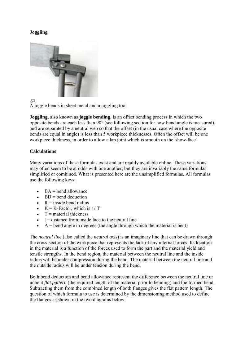
Joggling, also known as joggle bending, is an offset bending process in which the two opposite bends are each less than 90° (see following section for how bend angle is measured), and are separated by a neutral web so that the offset (in the usual case where the opposite bends are equal in angle) is less than 5 workpiece thicknesses. Often the offset will be one workpiece thickness, in order to allow a lap joint which is smooth on the 'show-face'
Calculations
Many variations of these formulas exist and are readily available online. These variations may often seem to be at odds with one another, but they are invariably the same formulas simplified or combined. What is presented here are the unsimplified formulas. All formulas use the following keys:
BA = bend allowance BD = bend deduction R = inside bend radius K = K-Factor, which is t / T T = material thickness t = distance from inside face to the neutral line A = bend angle in degrees (the angle through which the material is bent)
The neutral line (also called the neutral axis) is an imaginary line that can be drawn through the cross-section of the workpiece that represents the lack of any internal forces. Its location in the material is a function of the forces used to form the part and the material yield and tensile strengths. In the bend region, the material between the neutral line and the inside radius will be under compression during the bend. The material between the neutral line and the outside radius will be under tension during the bend.
Both bend deduction and bend allowance represent the difference between the neutral line or unbent flat pattern (the required length of the material prior to bending) and the formed bend. Subtracting them from the combined length of both flanges gives the flat pattern length. The question of which formula to use is determined by the dimensioning method used to define the flanges as shown in the two diagrams below.
The bend allowance (BA) is the length of the arc of the neutral line between the tangent points of a bend in any material. Adding the length of each flange taken between the center of the radius to the BA gives the Flat Pattern length. This bend allowance formula is used to determine the flat pattern length when a bend is dimensioned from 1) the center of the radius, 2) a tangent point of the radius or 3) the outside tangent point of the radius on an acute angle bend.
The BA can be calculated using the following formula
Diagram showing standard dimensioning scheme when using Bend Allowance formulas. Note that when dimensions "C" are specified, dimension B = C - R - T
Example Angle 90 Pl 3.142 Radius 1.5 K-Factor 0.33 Thickness 6 Bend allowance 5.46708
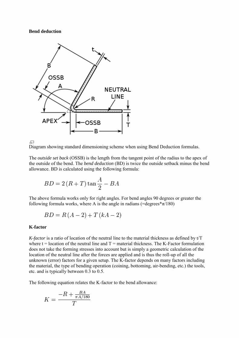
Diagram showing standard dimensioning scheme when using Bend Deduction formulas.
The outside set back (OSSB) is the length from the tangent point of the radius to the apex of the outside of the bend. The bend deduction (BD) is twice the outside setback minus the bend allowance. BD is calculated using the following formula:
The above formula works only for right angles. For bend angles 90 degrees or greater the following formula works, where A is the angle in radians (=degrees*π/180)
K-factor
K-factor is a ratio of location of the neutral line to the material thickness as defined by t/T where t = location of the neutral line and T = material thickness. The K-Factor formulation does not take the forming stresses into account but is simply a geometric calculation of the location of the neutral line after the forces are applied and is thus the roll-up of all the unknown (error) factors for a given setup. The K-factor depends on many factors including the material, the type of bending operation (coining, bottoming, air-bending, etc.) the tools, etc. and is typically between 0.3 to 0.5.
The following equation relates the K-factor to the bend allowance:
The following table is a "Rule of Thumb". Actual results may vary remarkably.
Generic K-Factors Aluminum Steel
Radius Soft Materials Medium Materials Hard Materials
Air Bending 0 to Thickness 0.33 0.38 0.40 Thickness to 3 x Thickness 0.40 0.43 0.45 Greater than 3 x Thickness 0.50 0.50 0.50 Bottoming 0 to Thickness 0.42 0.44 0.46 Thickness to 3 x Thickness 0.46 0.47 0.48 Greater than 3 x Thickness 0.50 0.50 0.50 Coining 0 to Thickness 0.38 0.41 0.44 Thickness to 3 x Thickness 0.44 0.46 0.47 Greater than 3 x Thickness 0.50 0.50 0.50
The following formula can be used in place of the table as a good approximation of the
K-Factor for Air Bending:
LOG(MIN(100,MAX(20 × R,T) / T)) / LOG(100) / 2
Material considerations
Material sheet thickness varies from 0.79 to 12.7 mm (0.03 to 0.5 in) in with length from 150 mm (6 in) to 6 m (20 ft). Ductile materials are best suited for the pressing like aluminum, mild steel and new plastic materials.
Advantages[
Bending is a cost effective process when used for low to medium quantities, because it does not require significant amounts of tooling.
Lecture 5Lecture 5:: Sheet Metal Cutting & Forming ProcessesSheet Metal Cutting & Forming Processes
DR. SOTIRIS L. OMIROU
22
Sheet Metal Cutting & Forming ProcessesSheet Metal Cutting & Forming Processes
-- GeneralGeneral --
The raw material for sheet metal manufacturing
processes is the output of the rolling process.
Typically, sheets of metal are sold as flat,
rectangular sheets of standard size. Therefore the
first step in any sheet metal process is to cut the
correct shape and sized ‘blank’ from larger sheet.
2
33
Sheet Metal Cutting & Forming ProcessesSheet Metal Cutting & Forming Processes
-- GeneralGeneral --
Sheet metal processing is an important process for
many industries, producing home appliances
(fridge, washer, dryer, vacuum cleaners etc.),
electronics (DVD- and CD-players, stereos, radios,
amplifiers etc.), toys and PC’s. Most of these
products have metal casings that are made by
cutting and bending sheet metal. We look at some
of the basic sheet metal cutting and forming
processes.
44
The operations are performed on relatively The operations are performed on relatively
thin sheets of metal:thin sheets of metal:
�� Thickness of sheet metal = 0.4 mm to 6 mm Thickness of sheet metal = 0.4 mm to 6 mm
�� Thickness of plate stock > 6 mm Thickness of plate stock > 6 mm
�� Operations usually performed as cold Operations usually performed as cold
workingworking
Sheet Metal Cutting & Forming ProcessesSheet Metal Cutting & Forming Processes
DefinitionDefinition
3
55
Advantages of Sheet Metal PartsAdvantages of Sheet Metal Parts
�� High strengthHigh strength
�� Good dimensional accuracyGood dimensional accuracy
�� Good surface finishGood surface finish
�� Relatively low cost Relatively low cost
�� Economical mass production for large Economical mass production for large
quantities quantities
66
Sheet Metal Cutting & Forming ProcessesSheet Metal Cutting & Forming Processes
ClassificationClassification
1.1. Cutting OperationsCutting Operations
2.2. Bending OperationsBending Operations
3.3. DrawingDrawing
4
77
Basic Types of Sheet Metal ProcessesBasic Types of Sheet Metal Processes
1.1. CuttingCutting–– ShearingShearing to separate large sheetsto separate large sheets
–– BlankingBlanking to cut part perimeters out of sheet metalto cut part perimeters out of sheet metal
–– PunchingPunching to make holes in sheet metalto make holes in sheet metal
2.2. BendingBending–– Straining sheet around a straight axisStraining sheet around a straight axis
3.3. DrawingDrawing–– Forming of sheet into convex or concave shapesForming of sheet into convex or concave shapes
88
1. Cutting Operations1. Cutting Operations
Three principal operations in pressworking Three principal operations in pressworking that cut sheet metal:that cut sheet metal:
�� ShearingShearing
�� BlankingBlanking
�� Punching Punching
5
99
1.1 Shearing1.1 Shearing
Sheet metal cutting operation along a straight Sheet metal cutting operation along a straight line between two cutting edges. line between two cutting edges. Typically Typically used to cut large sheetsused to cut large sheets
1010
Shearing of sheet metal between two cutting edges:Shearing of sheet metal between two cutting edges:(1) just before the punch contacts work;(1) just before the punch contacts work;(2) punch begins to push into work, causing plastic (2) punch begins to push into work, causing plastic deformation;deformation;
Sheet Metal CuttingSheet Metal Cutting
6
1111
Shearing of sheet metal between two cutting edges:Shearing of sheet metal between two cutting edges:(3) punch compresses and penetrates into work(3) punch compresses and penetrates into work
causing a smooth cut surface;causing a smooth cut surface;(4) fracture is initiated at the opposing cutting edges(4) fracture is initiated at the opposing cutting edges
which separates the sheet.which separates the sheet.
PunchingPunching -- sheet metal cutting operation where thesheet metal cutting operation where thecut piece is scrap.cut piece is scrap.
BlankingBlanking -- sheet metal cutting to separate piecesheet metal cutting to separate piece(called a (called a blankblank) from surrounding stock) from surrounding stock
–– Hole die diameter = Hole die diameter = DDhh + 2+ 2cc
where where cc = clearance= clearance
9
1717
Cutting ForcesCutting Forces
Important for determining press size (tonnage)Important for determining press size (tonnage)
F = S t LF = S t L
where,where,
SS = shear strength of metal= shear strength of metal
tt = stock thickness= stock thickness
LL = length of cut edge= length of cut edge
1818
Straining sheetmetal around a straight axis to take a Straining sheetmetal around a straight axis to take a permanent bendpermanent bend
2. Sheet Metal Bending2. Sheet Metal Bending
(a) Bending of sheet metal
10
1919
Metal on inside of neutral plane is compressed, while Metal on inside of neutral plane is compressed, while metal on outside of neutral plane is stretchedmetal on outside of neutral plane is stretched
2. Sheet Metal Bending2. Sheet Metal Bending
(b) both compression and tensile elongation of the metal occurin bending.
2020
Types of Sheet Metal BendingTypes of Sheet Metal Bending
�� VV--bending bending -- performed with a Vperformed with a V--shaped dieshaped die
�� Edge bending Edge bending -- performed with a wiping dieperformed with a wiping die
11
2121
�� For low productionFor low production�� Performed on a Performed on a press brakepress brake�� VV--dies are simple and inexpensive dies are simple and inexpensive
�� For high productionFor high production�� Pressure pad requiredPressure pad required�� Dies are more complicated and costlyDies are more complicated and costly
Edge BendingEdge Bending
(b) edge bending.
2424
CD:CD: Shearing / BendingShearing / Bending
13
2525
3. Drawing3. Drawing
Sheet metal forming to make cupSheet metal forming to make cup--shaped, boxshaped, box--shaped, shaped, or other complexor other complex--curved, hollowcurved, hollow--shaped parts shaped parts
�� Sheet metal blank is positioned over die cavity and Sheet metal blank is positioned over die cavity and then punch pushes metal into opening.then punch pushes metal into opening.
�� Products: beverage cans, ammunition shells, Products: beverage cans, ammunition shells, automobile body panels.automobile body panels.
�� Also known as Also known as deep drawingdeep drawing (to distinguish it from wire (to distinguish it from wire and bar drawing)and bar drawing)
2626
(a)(a) Drawing of Drawing of cupcup--shaped partshaped part: : (1) before punch (1) before punch contacts workcontacts work(2) near end of (2) near end of stroke.stroke.
�� Sides of punch and die separated by a clearance Sides of punch and die separated by a clearance ccgiven by:given by:
c = 1.1 tc = 1.1 t
where where tt = stock thickness= stock thickness
�� In other words, clearance is about 10% greater than In other words, clearance is about 10% greater than stock thicknessstock thickness
2828
Tests of Drawing FeasibilityTests of Drawing Feasibility
�� Drawing ratioDrawing ratio
�� ReductionReduction
�� ThicknessThickness--toto--diameter ratiodiameter ratio
15
2929
Drawing Ratio DRDrawing Ratio DR
where where DDbb = blank diameter= blank diameter
DDpp = punch diameter= punch diameter
–– Upper limit:Upper limit: DR DR ≤≤ 2.02.0
Most easily defined for cylindrical shape:Most easily defined for cylindrical shape:
p
b
DD
DR =
3030
Reduction rReduction r
�� Defined for cylindrical shape:Defined for cylindrical shape:
b
pb
D
DDr
−=
�� Value of r should be less than 0.50Value of r should be less than 0.50
16
3131
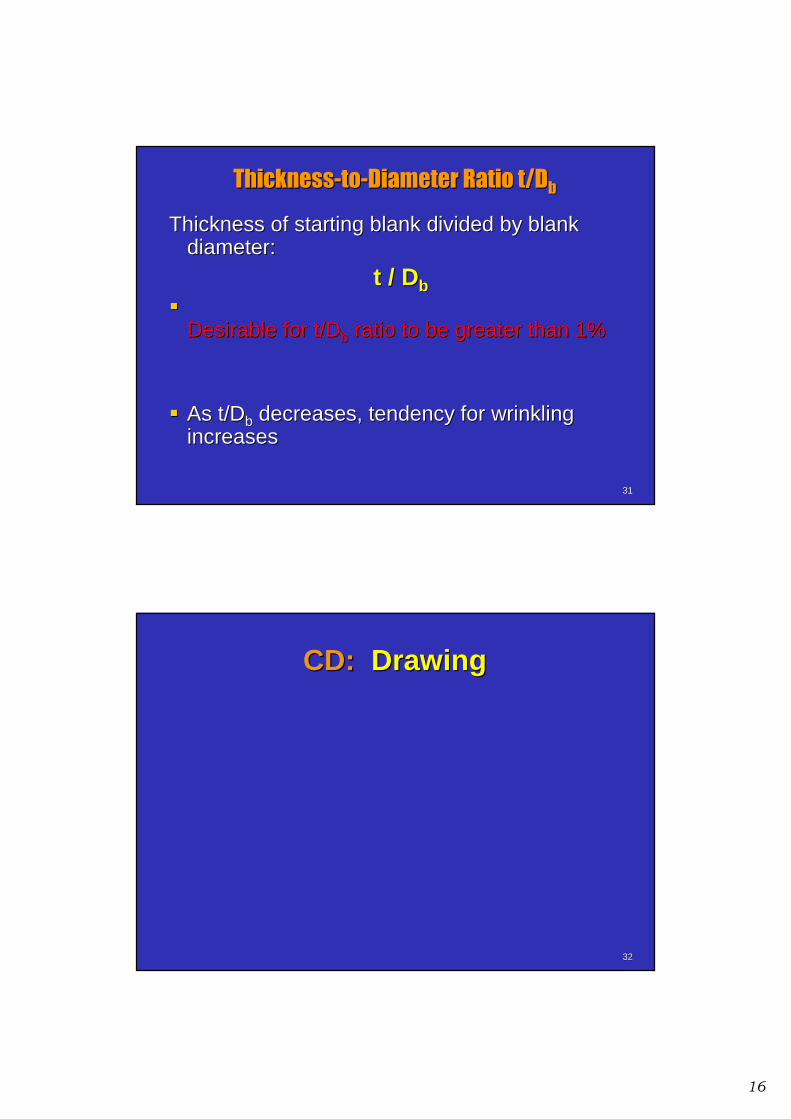
ThicknessThickness--toto--Diameter Ratio t/DDiameter Ratio t/Dbb
Thickness of starting blank divided by blank Thickness of starting blank divided by blank diameter:diameter:
t / Dt / Dbb��
Desirable for Desirable for t/Dt/Dbb ratio to be greater than 1%ratio to be greater than 1%
�� As As t/Dt/Dbb decreases, tendency for wrinkling decreases, tendency for wrinkling increasesincreases
3232
CD:CD: DrawingDrawing
17
3333
Dies and PressesDies and Presses
for Sheet Metal Processesfor Sheet Metal Processes
3434
Gap frame press for sheet metalworking
capacity = 1350 kN(150 tons)
18
3535
Press brake bed width = 9.15 mand capacity = 11,200 kN (1250 tons).
3636
Sheet metal parts produced on a turret press, showing variety of hole shapes possible
19
3737
Computer numerical control turret press
Welding
Welding
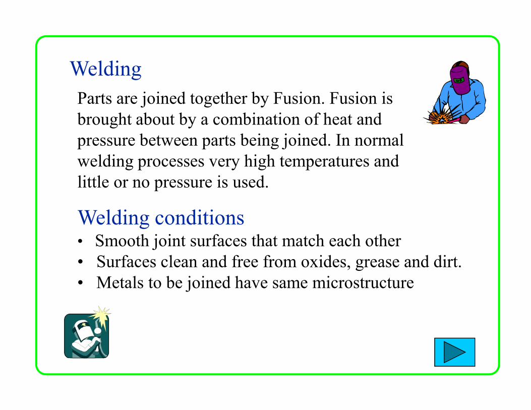
Parts are joined together by Fusion. Fusion is
brought about by a combination of heat and
pressure between parts being joined. In normal
welding processes very high temperatures and
little or no pressure is used.
Welding conditions• Smooth joint surfaces that match each other
• Surfaces clean and free from oxides, grease and dirt.
• Metals to be joined have same microstructure
Welding conditions continued….
• The metals should be good quality (no internal
impurities)
Welding Preparation
• Before starting a weld, the joint edges should be • Before starting a weld, the joint edges should be
carefully prepared. • Beveling large edges
• Cleaning (Chemical/Mechanical)
Weld Joints
Welding Symbols
Weld defects
Welding Techniques
Weld Joints - Parts of a Weld Joint
• Joint root
• Groove face, Root face and Root edge
• Root opening and Bevel
• Bevel angle, Groove angle and Groove radius
Weld Joints - Types of Weld Joint
• Butt Joint
• Lap Joint
• T Joint
• Corner joint
• Edge Joint
• Splice Member
Joint Root
is that portion of a joint to be welded where the members
are closest to each other
• The joint root may be
either a point, line, or
an areaan area
• The joint roots are
shown as shaded areas
in (A)-(D) and lines in
(E) (F)
Groove face, Root face and Root edge
• Groove face is “ that
surface of a member
included in the
groove”
• Root face (land) is • Root face (land) is
“that portion of the
groove face within
the joint root”
• Root edge is a root
face of zero width
Root opening and Bevel
• Root opening is
the separation
between the
work pieces at
the joint root
• Bevel
(chamfer) is an
angular edge
preparation
Bevel angle, Groove angle and Groove
Radius
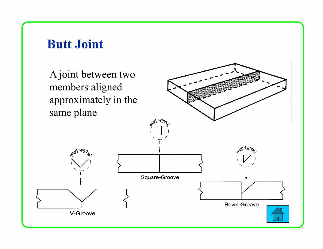
Butt Joint
A joint between two
members aligned
approximately in the
same plane
Lap Joint
A joint between two
overlapping members
T Joint
A joint between two
members located
approximately at right
angles to each other
Corner Joint
A joint between two
members located at
right angles to each
other
Edge Joint
A joint between the
edges of two or
more parallel or
nearly parallel nearly parallel
members
Splice member
is “ the work piece that spans the joint in a spliced joint
Single-
spliced
butt joint
Double-spliced
butt joint with
joint filler
Basic components of a WELDING SYMBOL
Reference Line (Required element)
ArrowTail
Reference Line must always be horizontal,
Arrow points to the line or lines on drawing
which clearly identify the proposed joint or weld
area.
Weld Symbol Terminology
ARROW SIDE
OTHER SIDE
Work
Fillet Weld (Arrow Side Only) Fillet Weld (Both sides)
Welding Techniques
There are many different methods of welding. The difference
between them is outlined by two important features
• The way the metal is heated
• The way additional filler metal if any is fed into the weld• The way additional filler metal if any is fed into the weld
Types of Welding
• Electric Arc Welding
• Gas Welding
• Resistance Welding
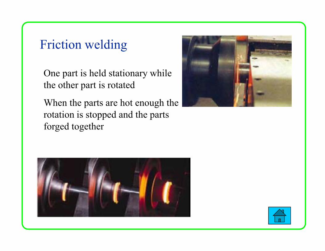
• Friction Welding
• Robotic Welding
Electric Arc Welding
The heat for fusion is supplied by an electric arc
Arc is formed between electrode and work this melts
and fuses the joint edges
Manual Metal Arc (MMA)
Metal Arc Gas Shielded (MAGS) MIG
Types of Electric Arc Welding
Metal Arc Gas Shielded (MAGS) MIG
Tungsten Arc Gas Shielded (TAGS) TIG
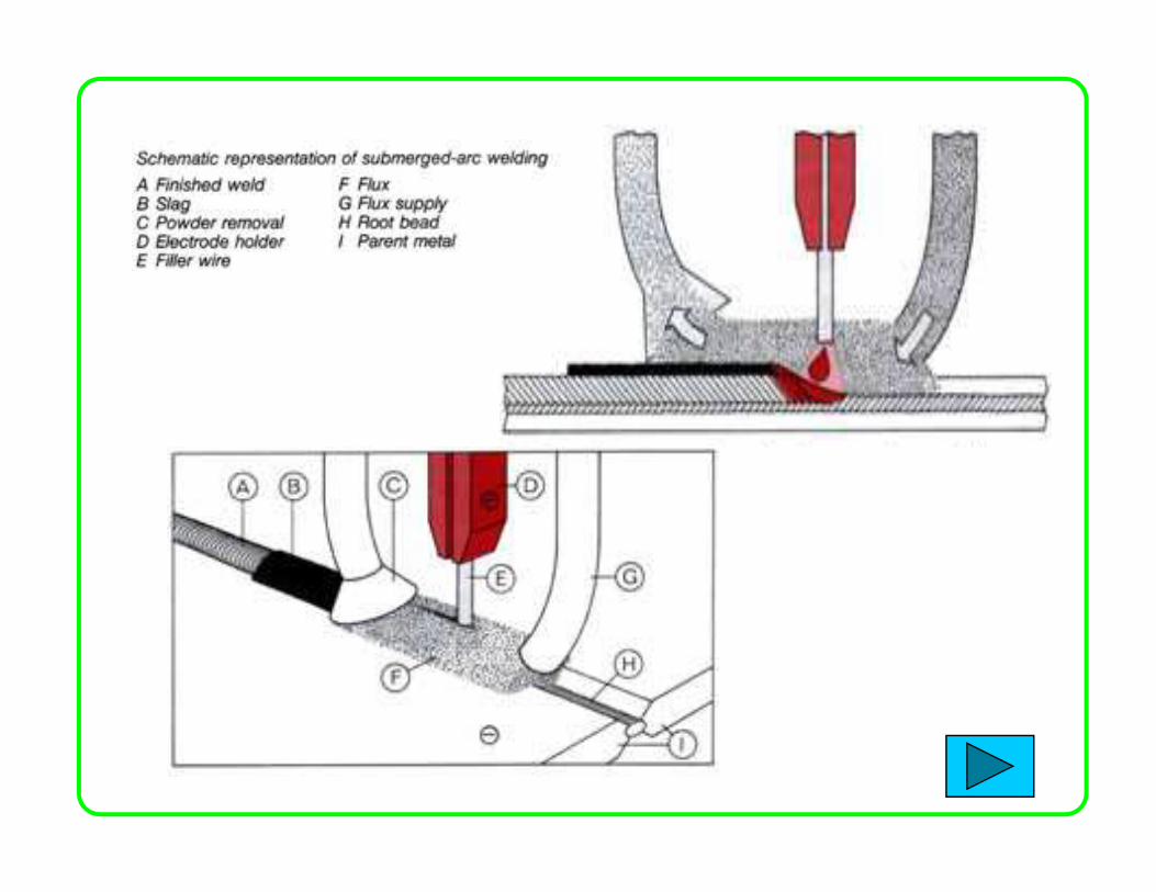
Submerged Arc Welding (SAW)
Manual Metal Arc (MMA)
• Most widely used of all
the arc welding processes
• Commonly called “stick”
welding
Applicationsrepair work, structural steelwork,
Touch electrode against
work withdraw
electrode to establish
arc. Heat of arc melts
base metal, the
electrode’s metal core,
and any metal particles
in electrode’s covering. in electrode’s covering.
Heat also melts,
vaporises, or breaks
down chemically
non-metallic substances in covering for arc shielding.
Mixing of molten base metal and filler metal from
electrode produces coalescence required to effect
joining.
Advantages• Used with many electrode types & sizes
• Used in all positions
• Used on great variety of materials
• Flexibility in operator control makes it the
most versatile of allwelding processes
Dis-advantages
• Low cost of equipment
• Rod becomes shorter & periodically needs replacing
• Slows production rate (% time welder welding)
The Electrode and Coating
Coating is a combination of chemicals
• Cellulosic electrodes contain cellulose
• Rutile electrodes titanium oxide (rutile)
• Basic electrodes contain calcium
carbonate (limestone) and calcium fluoride
(fluorspar)
• Produce gas to shield weld pool from
oxidisising effects of atmosphere
• Fluxing elements help weld pool to form
• Helps slag to form-removes impurities
Function of Electrode Coating
• Slag slows down cooling preventing
Brittleness
• Can contain alloying elements or additional
filler metal
Equipment used in MMAEquipment used in MMA
AC power source
Takes power directly from mains power
supply. It use a transformer to supply the
correct voltage to suit the welding
conditions.
DC power source
Two types
DC generator
Transformer-rectifier
DC Generator
An electricity generator is driven by a
motor. The motor can be electric,
petrol or diesel. The generator
provides DC current for the arc
Transformer-rectifier
A transformer with an electrical device to
change AC to DC, this is known as a
rectifier. It has the advantage of being able to
supply both DC and AC
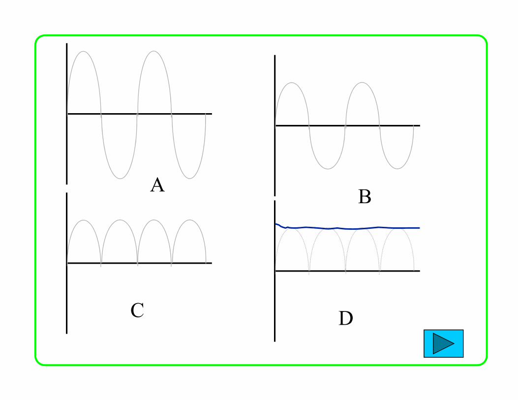
Basic Transformer-rectifier circuit (AC to DC)On/Off switch
Step DownTransformer
Bridge Rectifier
SmothingCapacitor
High AC
Voltage
230V DC
+
Low AC
Voltage 10-
50V
DC
output
_
A B C D
ABB
C D
Transformer
A transformer converts AC current at one
voltage to AC at a higher or lower voltage
Step Down Step Up
Metal Arc Gas Shielded (MAGS) MIG
MIG is similar to MMA in that heat
for welding is produced by forming
an arc between a metal electrode and
the workpiece
ApplicationsSheet and Heavy plate, production
welding by robots on cars
MIG is similar to
MMA in that heat for
welding is produced
by forming an arc
between a metal
electrode and the
workpiece; the
electrode melts to electrode melts to
form the weld bead.
The main difference
is that the metal electrode is a small diameter wire fed from a
spool and a sheilding gas is used. As the wire is continuously
fed, the process is often referred to as semi-automatic welding.
Advantages
• Large gaps filled or bridged easily
• Welding can be done in all positions
• No slag removal required
• High welding speeds
• High weld quality• High weld quality
• Less distortion of work piece
Equipmnt used in MAGS
Three major elements are :
Welding torch and accessories
Welding control & Wire feed motor
Power SourcePower Source
Shielding Gas
Welding torch and accessories
NOZZLE
CONTACT TIP
GAS DIFFUSER
• The welding torch guides the wire and shielding gas to the
weld zone.
• Brings welding power to the wire also
• Major components/parts of the torch are the contact tip,
shielding gas nozzle, gas diffuser, and the wire conduit
CONTACT TIP
Welding control and wire feed motor
� Main function is to pull
the wire from the spool
and feed it to the arc
� Controls wire feed speed
and regulates the starting
and stopping of wire feedand stopping of wire feed
Welding power source
Positive (+) lead is connected to the torch
Negative (-) lead is connected Negative (-) lead is connected to the work piece
Sheilding Gas
• Purpose of shielding gas is to protect the weld area from the contaminants in the atmosphere
• Gas can be Inert, Reactive, or Mixtures of both
• Argon, Helium, and Carbon • Argon, Helium, and Carbon Dioxide are the main three gases used in MAGS
Tungsten Arc Gas Shielded (TAGS) TIG
TIG is similar to MMA in that
heat for welding is produced
by forming an arc between a
metal electrode and the
workpieceworkpiece
ApplicationsUsed in joining magnesium and
Aluminium, stainless steels
for high quality welding
Thin sheet material
In the TIG process the arc
is formed between a
pointed tungsten
electrode and the work
piece in an inert
atmosphere of argon or
helium. The small intense
arc provided by the
pointed electrode is ideal
for high quality and
precision welding. The electrode is not consumed during welding. When filler metal
is required, it must be added separately to the weldpool. There
are two currents one for starting the arc the other switched on
using a trigger or foot pedal, this is a high frequency current
to maintain the arc, this is generated by a separte unit.
Advantages
• Superior quality welding
• Can be used in mechanised systems
• Used to weld aluminium and stainless
steelssteels
• Free of spatter
• Low distortion
Equipment used in TAGS
Power source
Electrodes
TIG must be operated with a
constant current power source -
either DC or AC
Electrodes for DC welding are normally pure
tungsten. In AC welding, as the electrode will be
operating at a much higher temperature, It should
be noted that because of the large amount of heat
generated at the electrode, it is difficult to
maintain a pointed tip and the end of the
electrode assumes a spherical or 'ball' profile.
Sheilding Gas
• Argon
• Argon + Hydrogen
• Argon/Helium
Helium is generally added to increase heat
Shielding gas is selected according to the material being welded.
Helium is generally added to increase heat input (increase welding speed or weld penetration). Hydrogen will result in cleaner looking welds and also increase heat input, however, Hydrogen may promote porosity or hydrogen cracking.
Submerged Arc Welding (SAW)
Similar to MIG welding, SAW
involves formation of an arc between
a continuously-fed bare wire
electrode and the workpiece
ApplicationsApplicationsSAW welding taking place in the flat
position. Ideal for heavy workpieces
Carbon-manganese steels,low alloy
steels and stainless steels
The process uses a flux to generate protective gases and
slag, and to add alloying elements to the weld pool. A
shielding gas is not required. Prior to welding, a thin layer
of flux powder is placed on the work piece surface. The arc
moves along the joint line and as it does so, excess flux is
recycled via a hopper. Remaining fused slag layers can be
Submerged Arc Welding (SAW)
recycled via a hopper. Remaining fused slag layers can be
easily removed after welding. As the arc is completely
covered by the flux layer, heat loss is extremely low. There
is no visible arc light, welding is spatter-free and there is no
need for fume extraction.
Equipmnt used in SAW
SAW is normally operated with a single wire on either AC or
DC current. Common variants are:
• twin wire
• triple wire
Wire
• triple wire
• single wire with hot wire addition
• metal powdered flux addition
All contribute to improved productivity through a marked
increase in weld metal deposition rates and/or travel speeds.
Flux
Fluxes used in SAW are granular fusible minerals
The flux is specially formulated to be compatible with a
given electrode wire type so that the combination of flux
and wire yields desired mechanical properties. All fluxes
react with the weld pool to produce the weld metal
chemical composition and mechanical properties chemical composition and mechanical properties
Gas Welding (Oxy-acetylene)
A number of welding processes use a flame
produced by burning a mixture of fuel gas and
oxygen. The gas usually used is Acetylene but other
gases are also used.
Separate cylinders and Separate cylinders and
a hose pipe from each
cylinder transports the
gases to a torch.
Gas and fuel mix in
the torch
burns @ 3100°C.
During the welding heat from the flame is
concentrated on the joint edges until the metal
melts and starts to flow. When the molten metal
from both sides melts it starts to fuse, when the
metal cools down the two parts become
Permanently joined
Additional Filler
Metal is fed in by
hand into the weld
pool, at regular
intervals where it
becomes molten
and joins with the
parent metal.
The Oxy-acetylene welding Flame
Oxidizing
Excess oxygen (1.5:1)
Reducing or Carburizing
Excess acetylene (0.9:1)
(Alloy steels and
aluminium alloys)
Inner Cone
Max. Temp.
Zone
Excess oxygen (1.5:1)
(Brasses, Bronzes, copper)
Neutral
Equal acetylene & oxygen
(low carbon steel, mild
steels).
Secondary Combustion
envelope
Acetylene
feather
Carburising Neutral Oxidising
The Oxy-acetylene welding Flame
The Oxy-acetylene welding FlameThe oxy-acetylene flame has two distinct zones.
The inner zone (Primary combustion Zone) is the hottest part
of the flame. The welding should be performed so as the point
of the inner zone should be just above the joint edges.
C H + O 2CO + H
Primary Combustion zone
C2H2 + O2 2CO + H2
The outer zone the secondary combustion envelope
performs two functions
•Preheats the joint edges
•Prevents oxidation by using some of the surrounding
oxygen from weld pool for combustion and gives off
carbon dioxide and water vapourcarbon dioxide and water vapour
Secondary Combustion zone
CO + H2 + O2 CO2 + H2O
Equipment used in O-A welding
The oxygen and acetylene hose pipes
Gases used
Gas pressure RegulatorsGas pressure Regulators
Flashback arrestor
Welding torch/Welding nozzle
Filler rods and fluxes
The oxygen and acetylene hose pipes
Reinforced rubber hoses.
Acetylene hose has left hand thread couplings and colour
coded red.
Oxygen hose has right handed thread couplings and colour Oxygen hose has right handed thread couplings and colour
coded blue
Gases used
Oxygen extracted from air and compressed into
cylinders at high pressure. Cylinder is black. Oil should
never be brought into contact and should not be used on
fittings
Acetylene (C2H2) is a fuel gas. Cannot be compressed
directly as explodes at high pressures. Cylinders are directly as explodes at high pressures. Cylinders are
One gauge indicates the pressure of the cylinder and the
other indicates the pressure in the supply pipe to the torch.
Welding torch
Oxygen and acetylene are delivered to the torch by separate
hoses. Each gas is controlled by a valve on the torch. The
two gases mix in the torch and after they are ignited burn at
the nozzle.
Needle valvesMixer Needle valves
Flashback Arrestors
These are positioned on both the fuel gas and oxygen
supply between the hose and the regulator. Their purpose
is to prevent the return of a flame through the hose into
the regulator.
Filler Rods and fluxes
Filler rods are used when additional filler metal is
required in the weld area they come in different
diameters.
Fluxes protect the weld pool from contamination by
oxygen and nitrogen, they are normally in paste
form placed on a heated filler rod before welding
begins
Resistance welding
Resistance welding uses the application of electric current and mechanical pressure to create a weld between two pieces of metal. Weld electrodes conduct the electric current to the two pieces of metal as they are forged together. The welding cycle must first develop sufficient heat to raise a small volume of metal to the sufficient heat to raise a small volume of metal to the molten state. This metal then cools while under pressure until it has adequate strength to hold the parts together. The current density and pressure must be sufficient to produce a weld nugget, but not so high as to expel molten metal from the weld zone.
• Spot welding
• Seam Welding
Spot welding
Ideal for joining light sheet metal. The
electrodes are made from copper.
Pressure is applied to the electrodes and
an electric current is passed through the
circuit. The high resistance between the
joint faces causes rapid heating and joint faces causes rapid heating and
fusing of a small globule of metal from
both faces.
Seam welding
The rollers allow the workpiece to
move through the welder
continously. A stream of electrical
pulses pass through the rollers and pulses pass through the rollers and
welds the joint
Resistance Welding Benefits
• High speed welding
• Easily automated
• Suitable for high rate production
• Economical
Resistance Welding Limitations
• Initial equipment costs
• Lower tensile and fatigue strengths
• Lap joints add weight and material
Friction welding
One part is held stationary while
the other part is rotated
When the parts are hot enough the
rotation is stopped and the parts
forged togetherforged together
Robotic welding
Robots are driven using actuators which
control the robotic arm from an input signal.
They can use hydraulic (large robots),
pneumatic(small actuators with simple
control movements) or electrical principles of
operation. operation.
A computer sends instructions in electrical
signals or pulses. An interface converts these
digital pulses into analogue electricity for the
motors. The robot is fitted with sensors which
can send feedback on the position of the robot.
Advantages of Robotic welding
• Faster production rates
• Efficent continous operation
• Safe working practice
• Reliable and consistent welds
• Full automation
• Cost effective
Examples
Automated welding of motor vehicles
skeletel frames and bodies.
Robotic welding Terms
Lead through programming Teaching robot movements
through guiding it manually through a sequence of
operations. These are recorded to memeory
Machine Vision Area of vision robot has, limits which
robot sensors can operate
Working enevelope The area within which a robot can Working enevelope The area within which a robot can
operate. Where the work is caried out by robotic arm
Yaw left and right movment of robotic arm
Roll rotation of robot about one of its axis
Degrees of freedom These are the number of
independent movements of the arm joints( or actuators)