Page 1
ORIGINAL RESEARCH
Cluster packing from a higher dimensional perspective
Walter Steurer • Sofia Deloudi
Received: 29 June 2011 / Accepted: 9 August 2011 / Published online: 30 August 2011
� Springer Science+Business Media, LLC 2011
Abstract The way to find the optimum packing of qua-
sicrystal-constituting clusters is discussed based on the
projected-cell approach. We illustrate why the quasiperi-
odic arrangement of partially overlapping clusters with
decagonal or icosahedral symmetry is the most efficient
one, by relating it to the packing of unit cells in hypercubic
lattices.
Keywords Quasicrystal � Cluster � Packing �Higher-dimensional approach
Introduction
Quite a few stable decagonal and icosahedral quasicrystals
(QC) have been identified so far in binary and ternary
intermetallic systems (see, e.g., [1, 2] and references
therein). Their structures, properties and stability have been
intensively studied during more than a quarter century as
testified by more than 10,000 publications to date. Never-
theless, it is still not fully understood why and how QC form,
particularly in view of the fact that the same kind of clusters
can constitute both QC and their periodic counterparts, the
approximants. Furthermore, for many not directly involved
in QC research, the powerful but arcane description of qua-
siperiodic structures as projections from hyperspace has still
an aura of mystery. In the following, we will try to demystify
the higher-dimensional approach by looking at the well-
known strip-projection method from a different angle,
demonstrating that its physical basis is in the cluster shape.
This unusual view should also help sketching the big picture
of QC formation.
We want to emphasize that the term ‘‘quasi’’ in con-
nection with ‘‘crystal’’ has nothing to do with lack of order,
it rather indicates the particular kind of order. The struc-
tural perfection of QC, as reflected in the width of X-ray
diffraction peaks, for instance, is comparable to that of
other complex intermetallic phases. This means that the
global, overall structural correlation length can reach tens
or hundreds of micrometers, despite the existence of some
intrinsic local structural disorder. The idealized structure of
QC is usually described in terms of a quasiperiodic tiling
decorated by particular atomic arrangements or, equiva-
lently, as quasiperiodic packings of multishell clusters.
Here, the term ‘‘clusters’’ denotes fundamental structural
units which may or may not be stabilized by chemical
bonding [3, 4].
While the symmetry of the outer cluster shells usually
reflects the overall symmetry of the QC, that of the inner
shell(s) is frequently lower giving rise to structural disorder.
We focus in this study only on the outer cluster shell(s),
which determine the way of packing via shared structural
subunits. We will explore how clusters with non-crystallo-
graphic symmetry can be packed in the topologically best
possible way, i.e., without gaps and ‘‘glue atoms’’ filling
them. One crucial boundary condition is that the local
composition has to be as close as possible to the overall one.
It is well known that some regular and semiregular
polyhedra, and even multi-shell clusters, can be described
as projections of higher-dimensional polytopes (see e.g., [5,
6]). Consequently, it is obvious to treat the problem of the
topologically best cluster packing from a higher dimen-
sional perspective. For instance, every three-dimensional
(3D) zonohedron with octahedral or icosahedral symmetry
can be described as orthogonal projection of an nD
W. Steurer (&) � S. Deloudi
Laboratory of Crystallography, Department of Materials, ETH
Zurich, Wolfgang-Pauli-Strasse 10, 8093 Zurich, Switzerland
e-mail: [email protected]
123
Struct Chem (2012) 23:1115–1120
DOI 10.1007/s11224-011-9864-2
Page 2
hypercube [5]. Thereby, the number of edge directions of
the respective zonohedron defines the dimension n; this
gives, for instance, n = 6 for the triacontahedron. The
assembly of such zonohedra with optimum density (fre-
quency in a given volume) for a given chemical compo-
sition is a non-trivial problem that can be tackled much
more easily in higher dimensions. Columnar clusters with,
in projection, octagonal, decagonal or dodecagonal shape
can be related to 2D projections of nD (n = 4, 5, 6)
hypercubes.
In order to introduce our basic concept, we will start the
discussion with a cluster leading to the simplest quasipe-
riodic structure, the 1D Fibonacci sequence (FS). Subse-
quently, we will move on to decagonal and triacontahedral
clusters whose packing results in the 2D Penrose (PT) and
3D Ammann tiling (AT), respectively.
(LS) Cluster and Fibonacci sequence
Let us assume that we have an energetically favorable 1D
cluster, (LS), consisting of atoms at the vertices of a vertex-
sharing assembly of a long interval L and a short interval S,
with length ratio L = sS and s = 2cos(p/5). In a structure
(sequence, tiling), this cluster can occur in both orientations,
(LS) and (SL). While …LL… and …LS… neighbours in a
structure should be energetically favorable, …SS… neigh-
bors should be strongly discouraged. Depending on the
overall stoichiometry, different structures result as illus-
trated with the three examples shown in Fig. 1.
On top of Fig. 1, a part of the infinite sequence
…(LS)(LS)(LS)… = …LSLSLS… is depicted for an
overall composition LS. The clusters, with the same stoi-
chiometry as the whole sequence, are put together just by
sharing vertices. All alternative structures with the same
stoichiometry that contain …SS… neighbors are energeti-
cally less favorable. The most disadvantageous case would
be the sequence …(LS)(SL)(LS)(SL)… = …LSSLLS
SL… with 50% SS neighbors. In the middle of Fig. 1, a
sequence is drawn with overall composition L2S, which
differs from the cluster stoichiometry LS. The only way to
realize this composition is by allowing cluster overlaps of the
type (L(S)L) yielding the sequence …(L(S)L)(L(S)L)
… = …LSLLSL… Finally, at the bottom of Fig. 1, the
sequence with overall composition LsS is shown. It is part
of the Fibonacci sequence, a substitutional sequence
resulting from iterative substitution operations acting on an
alphabet (L, S): L ) LS, S ) L. For approaching locally
the overall composition as close as possible, an (LS) cluster
assembly with both vertex and S sharing is needed. How-
ever, it would be difficult, if not impossible, to piece
together the FS based on this information alone without
knowledge of the substitution rule. Fortunately, this prob-
lem can be easily solved in 2D space.
For this purpose, we describe the covering cluster (LS) as
projection (shadow) of a properly oriented square (shaded
in Fig. 2a). Of course, we could use any parallelogram
provided it had the same shadow. The topmost and the
lowermost vertices of the square project into the interval
defined by the left and right vertex and create so-called flip
positions. Accepting the interval S as the shortest possible
interatomic distance, the two flip positions, with a distance
S/s cannot be occupied at the same time. This is illustrated
in Fig. 2b by a double-well potential containing a black dot
for an occupied flip position and a grey dot for an unoc-
cupied one. If an atom is excited and jumps to the alterna-
tive position in the double well potential, then this
corresponds to a so-called simpleton flip (LS) , (SL).
SLSLS L L SL L
x = m n S + L with m, n ∈x
LS
L2S
LτS
Fig. 1 Sequences with overall composition LS (top), L2S (middle)
and LsS, i.e. the Fibonacci sequence (bottom), with the decomposition
into covering clusters of the type (LS) in both orientations. The upper
two sequences are rational approximants of the Fibonacci sequence
SLSL L SL LLx1
w
V ⊥
V II
1
2
L’S’L’ L’ L’w
(a)
(c)S’ S’
SL
x1
(b)
Fig. 2 Fibonacci sequence in the 2D description. (a) Projection of a
sequence of vertex and edge connected shaded squares gives the FS
plus some additional vertices (grey) at flip positions in a double-well
potential (b). The size W of the strip defines the minimum distance
between projected lattice points as well as the unit tile sequence; in
our case, W is chosen so that the topmost vertex of the yellow squareis outside the strip. Decreasing the acceptance window by a factor s-1
leads to a scaling of the intervals L and S by a factor s yielding the
sequence L0S0L0S0L0L0S0, with L0 = L ? S and S0 = L (c) (Color
figure online)
1116 Struct Chem (2012) 23:1115–1120
123
Page 3
As illustrated in Fig. 2a, two-cluster sequences of the
type (SL)(LS) = SLLS can be obtained by projecting the
vertices of compounds of two vertex-sharing squares. The
cluster density amounts to dcluster = 2/2 = 1. Overlaps of
the type (L(S)L) = LSL result from two squares sharing an
S-generating edge. The resulting local cluster density is
higher in this case, dcluster = 2/3. The cluster-generating
squares can be seen as unit cells of a 2D lattice spanned by
the basis vectors d1 ¼ a cos p=5; �sin p=5ð ÞV and d2 ¼a sin p=5; cos 2p=5ð ÞV (D-basis), defined on a Cartesian
coordinate system (V-basis); xV1 is the V-basis coordinate in
physical or par(allel)-space V||, xV2 refers to perp(endicu-
lar)-space V\. One obtains the cluster components L ¼Pd1; S ¼ Pd2 with the projection matrix.
P ¼ 1 0
0 0
� �: ð1Þ
The projection of one unit cell onto the perp-space gives
the acceptance window W and, therewith, the width of the
strip defining the subset of lattice nodes of the tiling.
Consequently, its size also determines the minimum distance
between the projected lattice nodes. In order to eliminate flip
positions, W has to be chosen so that either the topmost (as in
our example) or the lowermost vertex of the yellow square
comes to lie outside the strip. Then the FS can be obtained as
projection of the vertices of an infinite vertex- and edge-
connected, respectively, sequence of squares out of a 2D
lattice lying within a strip of width W (Fig. 2a).
Generally, the vertices of quasiperiodic tilings correspond
to a subset of a Z-module (vector module with integer
coefficients) of rank n, depending on the number n of basis
vectors needed to index the vertices with integers. Any Z-
module can be seen as proper projection of an nD lattice onto
the dD par-space. The minimum distance between the tiling
vertices defines the width W of the strip that selects the lattice
nodes to be projected. The acceptance window W is defined
in the (n-d)D perp-space. A change in the strip width W
always entails a change in the unit cell shape without
changing the unit cell volume. This results in a scaling of the
quasiperiodic structure as shown in Fig. 2c.
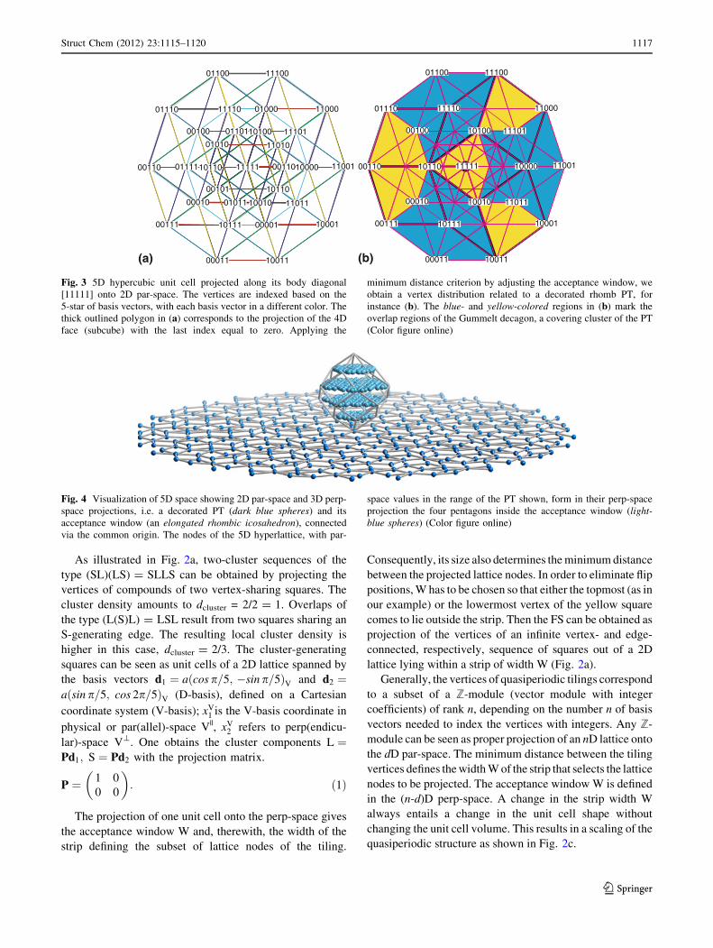
Fig. 4 Visualization of 5D space showing 2D par-space and 3D perp-
space projections, i.e. a decorated PT (dark blue spheres) and its
acceptance window (an elongated rhombic icosahedron), connected
via the common origin. The nodes of the 5D hyperlattice, with par-
space values in the range of the PT shown, form in their perp-space
projection the four pentagons inside the acceptance window (light-blue spheres) (Color figure online)
01000
01100
11001
00100
00010
00001
11111
10001
10110
01101
01011
10110
10100
10000
11011
11010
11101
11000
11100
10010
1001100011
00110
01110
00111
01111
11110
10111
01010
00101
00110
01100
11001
00100
00010
11111
10001
10110
10100
10000
11011
11101
11000
11100
10010
1001100011
00110
01110
00111
11110
10111
(a) (b)
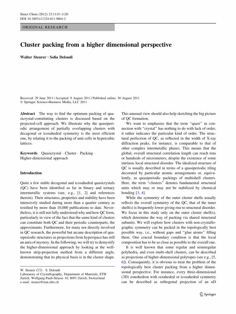
Fig. 3 5D hypercubic unit cell projected along its body diagonal
[11111] onto 2D par-space. The vertices are indexed based on the
5-star of basis vectors, with each basis vector in a different color. The
thick outlined polygon in (a) corresponds to the projection of the 4D
face (subcube) with the last index equal to zero. Applying the
minimum distance criterion by adjusting the acceptance window, we
obtain a vertex distribution related to a decorated rhomb PT, for
instance (b). The blue- and yellow-colored regions in (b) mark the
overlap regions of the Gummelt decagon, a covering cluster of the PT
(Color figure online)
Struct Chem (2012) 23:1115–1120 1117
123
Page 4
A strip, meandering with a limited amplitude around the
ideal par-space direction, not only leads to local changes in
the structure (disorder) but also in the local L/S ratio.
However, if the global stoichiometry is kept constant, the
disordered structure will remain quasiperiodic on average.
Decagon cluster and 2D penrose tiling
Decagonal QC can be described as packing of partially
overlapping decaprismatic columnar clusters. For the study
of the different ways to pack these clusters in the quasi-
periodic directions, it is sufficient to consider their 2D
projections along the tenfold axis, i.e., the periodic direc-
tion. The resulting 2D cluster of decagonal shape can be
described as projection of a 5D hypercube along one of its
fivefold axes. 22 of its 32 vertices project into the interior
of the resulting decagon (Fig. 3).
As before, we take this hypercube as unit cell of
a 5D hyperlattice with basis vectors di ¼ a cos 2pi=5;ðsin 2pi=5; cos 4pi
�5; sin 4pi=5; 1
� ffiffiffi2pÞV; 1� i� 5 (D-
basis); xVi with 1 B i B 3 are Cartesian coordinates in par-
space, those with i = 4, 5 in perp-space. The projection of
the 5D hypercubic unit cell onto 3D perp-space yields the
acceptance window W for the generation of the 2D PT, an
elongated rhombic icosahedron (Fig. 4). All hyperlattice
points, which fall into this acceptance window if projected
onto perp-space, are located inside the strip and generate
the PT by par-space projection. The rhombic icosahedron is
elongated along its fivefold axis compared to the zonohe-
dron with the same name. Furthermore, its faces with a
vertex on the fivefold axis are not congruent to the other
ones.
In order to find the most efficient way of packing
decagon clusters, we have to analyze the different con-
nectivities of the unit cells in the strip cut out of the 5D
hypercubic lattice by the acceptance window W. In 3D,
neighboring unit cells can share 2D faces, 1D edges or 0D
vertices. In a 5D hyperlattice, they can additionally share
4D or 3D faces with 16 or 8 joint vertices, respectively.
The overlap rules of the 2D decagons result from the ways
the projected hypercubic unit cells can overlap. In case of
the Gummelt decagon [7], the assemblies with allowed
overlaps, as defined by the the rocket decoration (blue
areas in the overlapping decagons shown in Fig. 5), all
result from the projection of 5D hypercubic unit cells
sharing 3D faces (8 lattice nodes). A higher decagon cluster
density would result from the projection of hypercubic unit
cells sharing 4D faces (16 lattice nodes), which are shifted
against each other by one lattice translation of the type
(10000)D. Such a shared area is shown in Fig. 3a. It is not
allowed in the ideal PT, but it can be observed as defect in
decagonal quasicrystals.
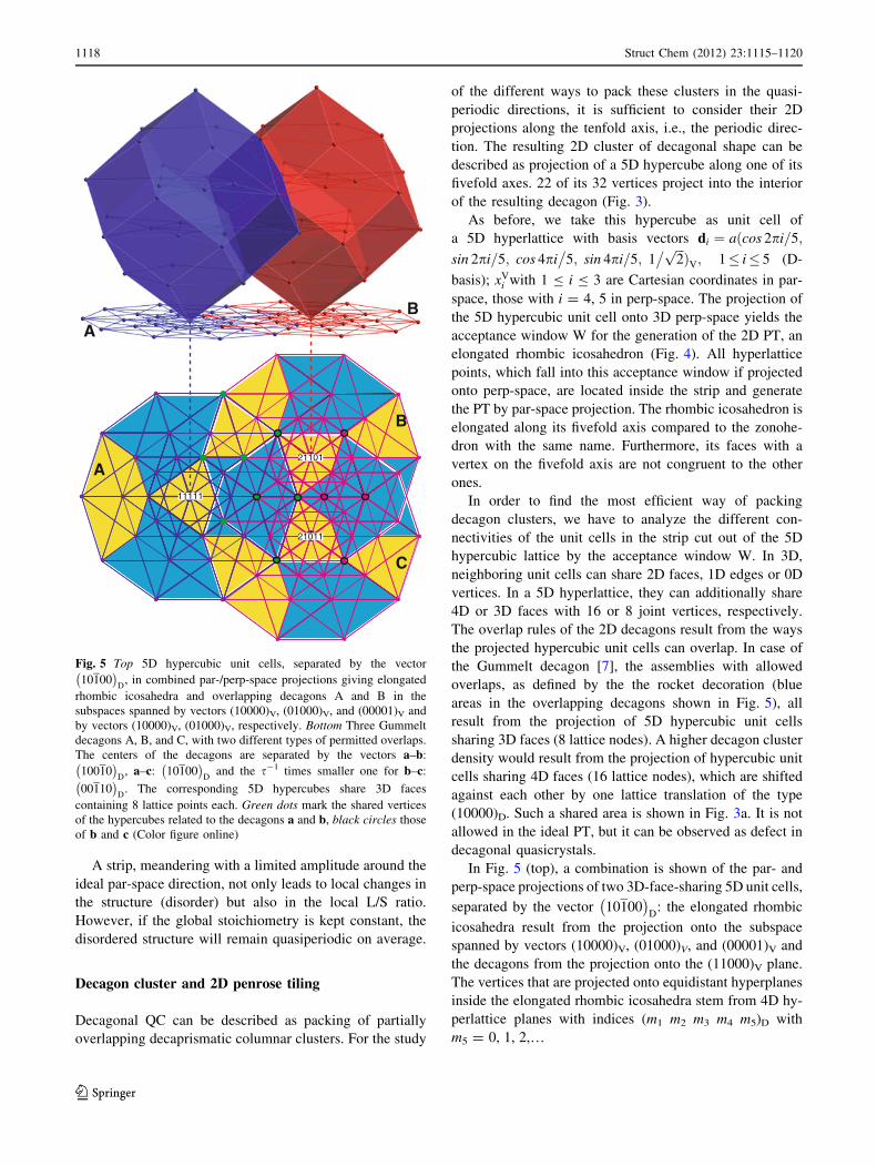
In Fig. 5 (top), a combination is shown of the par- and
perp-space projections of two 3D-face-sharing 5D unit cells,
separated by the vector 10100� �
D: the elongated rhombic
icosahedra result from the projection onto the subspace
spanned by vectors (10000)V, (01000)V, and (00001)V and
the decagons from the projection onto the (11000)V plane.
The vertices that are projected onto equidistant hyperplanes
inside the elongated rhombic icosahedra stem from 4D hy-
perlattice planes with indices (m1 m2 m3 m4 m5)D with
m5 = 0, 1, 2,…
AB
A
B
C
21101
21011
11111
Fig. 5 Top 5D hypercubic unit cells, separated by the vector
10100� �
D, in combined par-/perp-space projections giving elongated
rhombic icosahedra and overlapping decagons A and B in the
subspaces spanned by vectors (10000)V, (01000)V, and (00001)V and
by vectors (10000)V, (01000)V, respectively. Bottom Three Gummelt
decagons A, B, and C, with two different types of permitted overlaps.
The centers of the decagons are separated by the vectors a–b:
10010� �
D, a–c: 10100
� �D
and the s-1 times smaller one for b–c:
00110� �
D. The corresponding 5D hypercubes share 3D faces
containing 8 lattice points each. Green dots mark the shared vertices
of the hypercubes related to the decagons a and b, black circles those
of b and c (Color figure online)
1118 Struct Chem (2012) 23:1115–1120
123
Page 5
Let us have a look at an example of a real decagonal QC
in the system Al–Ni–Rh and see how the cluster concept
applies to it. As shown in Fig. 6, the projected electron
density distribution function can be covered by copies of a
decagonal cluster with &20 A diameter (red). The centers
of the decagons form the vertices of a DT5/VT13 Masakova
tiling [8], created from one decagonal acceptance window
in the 5D description. The Rh atoms are located on s-1-
times smaller decagons (green) centered at the same posi-
tions as the larger ones (red). The shapes of the overlap
areas of the large (red) covering decagon clusters are the
same as those of the Gummelt decagons, however, their
locations on the decagons and combinations are different.
The smaller (green) decagons overlap less frequently and
only with hexagon overlap areas; mostly they just share
edges. The different cases of overlapping decagons can be
related to neighboring unit cells of the 5D hypercubic lat-
tice. For one vertex configuration the respective lattice
translations are listed in Fig. 6 (bottom right).
The packing of the decagonal clusters can be explained
by competing interactions. On one hand, the large decagons
have very large overlap regions, on the other hand small
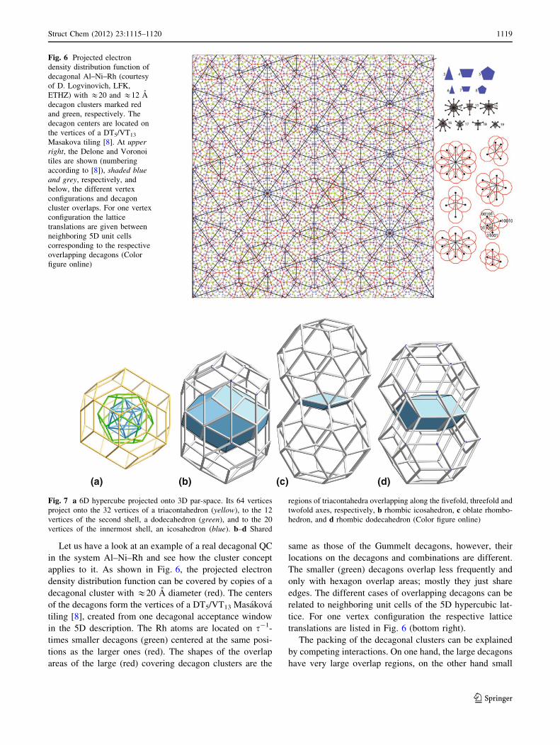
Fig. 6 Projected electron
density distribution function of
decagonal Al–Ni–Rh (courtesy
of D. Logvinovich, LFK,
ETHZ) with &20 and &12 A
decagon clusters marked red
and green, respectively. The
decagon centers are located on
the vertices of a DT5/VT13
Masakova tiling [8]. At upperright, the Delone and Voronoi
tiles are shown (numbering
according to [8]), shaded blueand grey, respectively, and
below, the different vertex
configurations and decagon
cluster overlaps. For one vertex
configuration the lattice
translations are given between
neighboring 5D unit cells
corresponding to the respective
overlapping decagons (Color
figure online)
(b) (c) (d)(a)
Fig. 7 a 6D hypercube projected onto 3D par-space. Its 64 vertices
project onto the 32 vertices of a triacontahedron (yellow), to the 12
vertices of the second shell, a dodecahedron (green), and to the 20
vertices of the innermost shell, an icosahedron (blue). b–d Shared
regions of triacontahedra overlapping along the fivefold, threefold and
twofold axes, respectively, b rhombic icosahedron, c oblate rhombo-
hedron, and d rhombic dodecahedron (Color figure online)
Struct Chem (2012) 23:1115–1120 1119
123
Page 6
decagons just share edges occupied with Rh atoms. The
edges of the Voronoi cells can be seen as local reflection
lines that relate overlapping decagons by mirror symmetry.
Triacontahedron cluster and 3D Penrose (Ammann)
tiling
The triacontahedron, an Archimedean solid dual to the i-
cosidodecahedron, can be described as projection of a 6D
hypercube along its fivefold axes onto 3D space (Fig. 7a).
It is bounded by 12 5D faces, i.e. 5D hypercubes, which
give in 3D projection rombic icosahedra. The lower-
dimensional hyperfaces project into the respective dimin-
ished zonohedra: the 60 4D faces into rhombic dodecahe-
dra and the 160 3D cells into cubes.
The possible overlap regions of two triacontahedra in
each case are shown in Fig. 7b–d. The overlap along the
fivefold axis results in a shared rhombic icosahedron. It
corresponds to the projection of a compound of two 6D
hypercubes, separated by a vector of the type (100000)D
and sharing a 5D face with 32 vertices. The overlaps along
the three- and twofold directions lead to an oblate rhom-
bohedron and a rhombic dodecahedron, respectively, as
shared volumes. The vectors between the 6D hypercubes
are of the type 001101� �
Dand 001010
� �D
, corresponding
to shared 3D faces with 8 vertices and 4D faces with 16
vertices, respectively. Consequently, taking the 6D hyper-
cubes as unit cells of a hypercubic lattice and a strip
analogously as defined before, then we obtain the densest
possible packing of triacontahedral clusters, such as the
Bergmann clusters, for instance.
If we remove one zone from the triacontahedron, we
obtain a rhombic icosahedron. In projection along the
fivefold axis onto 2D, a decagon cluster results as discussed
before (see top of Fig. 5). The 6D embedding of decagonal
phases allows to reveal structural relationships between
decagonal and icosahedral phases in a straightforward way
[9].
Conclusions
It is remarkable that the structures of decagonal and ico-
sahedral QC are all closely related to the 2D PT and 3D
AT, respectively, although they differ considerably in their
chemical composition. However, this is not so surprising if
we consider the structural similarities of their fundamental
building clusters and, in particular, the way they can pack
and overlap for particular stoichiometries. Obviously, a
necessary but not sufficient condition for the formation of
decagonal and icosahedral QC is the existence of clusters
that can be described as proper projections of nD hyper-
cubes, unit cells of nD hyperlattices. The optimum
arrangement of the respective clusters in physical space
corresponds to nD strips containing vertices of interlinked
nD unit cells of the hyperlattice. Since the projection of
such a strip gives a quasiperiodic structure, the densest
arrangement of these particular clusters results to be qua-
siperiodic. However, if optimum cluster packing means the
best packing of complete clusters then the strip cannot be
straight but has to follow the boundaries of the nD unit
cells. Of course, the average slope of this zigzag course has
to be the same as that of the straight strip. In this case, the
true structure could only be derived from electron micro-
scopic images, which reflect the local structure properly.
Higher-dimensional structure analysis is already based on
the assumption of a straight strip. Therefore, it can give
averaged structure information only.
References
1. Steurer W, Deloudi S (2008) Acta Crystallogr A 64:1–11
2. Steurer W, Deloudi S (2009) Crystallography of quasicrystals.
Concepts, methods and structures. Springer series in materials
science, vol 126. Springer, Heidelberg
3. Steurer W (2006) Philos Mag 86:1105–1113
4. Henley CL, de Boissieu M, Steurer W (2006) Philos Mag
86:1131–1151
5. Coxeter HSM (1973) Regular polytopes. Dover Publications, Inc,
New York
6. Berger RF, Lee S, Johnson J, Nebgen B, Sha F, Xu J (2008) Chem
Eur J 14:3908–3930
7. Gummelt P (1996) Geom Dedic 62:1–17
8. Masakova Z, Patera J, Zich J (2005) J Phys A 38:1947–1960
9. Mandal RK, Lele S (1991) Philos Mag B 63:513–527
1120 Struct Chem (2012) 23:1115–1120
123