60
CLX-440 Reference Manual 1 Compressor / Limiter / Expander Reference Manual 2001
| Date post: | 11-Nov-2018 |
| Category: |
Documents |
| Upload: | nguyendang |
| View: | 254 times |
| Download: | 2 times |
CLX-440 Reference Manual 1
Compressor / Limiter / Expander
ReferenceManual
2001
CLX-440 Manual
2 CLX-440 Reference Manual

CLX-440 Manual
CLX-440 Reference Manual 3
ContentsContents........................................................................................................................3
Welcome!.....................................................................................................6How to Use This Manual .........................................................................7Important Safety Instructions..................................................................8CE Declaration of Conformity...............................................................10Instructions to the User (FCC Notice)..................................................14
Quick Start Guide .....................................................................................................15If you can't wait to get started:..............................................................15
Step 1: Hook it up to a mixer ........................................................15Step 2: Try some compression ......................................................16Step 3: Try some gating..................................................................17
Connections ...............................................................................................................19Unpacking and Inspection.....................................................................19Installing in a Rack ..................................................................................19Power .........................................................................................................20Connecting inputs and outputs ............................................................22
Connecting to the Channel Inserts of a mixing console: .........22Connecting to the Main Inserts of a mixing console: ...............23Connecting to the inserts on an instrument amplifier: ............24Connecting to equipment with XLR inputs and outputs:.......24
About Audio Cables................................................................................25Dual Channel Operation ........................................................................26
Basics of Compression ............................................................................................27What is compression? .............................................................................27Description of Controls ..........................................................................28
Threshold .......................................................................................28Ratio ................................................................................................29Attack..............................................................................................29Release ............................................................................................29Detect ..............................................................................................29Knee ................................................................................................30
Compression Artifiacts...........................................................................31Pumping and Breathing ..............................................................31Clicking or "Zipper Noise" .........................................................31Reduced Gain Structure ..............................................................31

CLX-440 Manual
4 CLX-440 Reference Manual
Limiting .....................................................................................................32Limiter Threshold.........................................................................32
Stereo Detection .......................................................................................33Look Ahead Compression .....................................................................33Sidechain ...................................................................................................34
Basics of Expansion .................................................................................................35What is expansion?..................................................................................35Description of Controls ..........................................................................36
Threshold .......................................................................................36Ratio ................................................................................................36Knee ................................................................................................37Attack..............................................................................................37Hold ................................................................................................37Release ............................................................................................38
Keyed Expansion .....................................................................................39
Applications...............................................................................................................41Compressor Applications ......................................................................41
Vocal Limiting...............................................................................41Vocal Compression ......................................................................42Drums.............................................................................................42Bass..................................................................................................43Electric Guitar ...............................................................................43
Compressor Applications using the Sidechain..................................44De-essing........................................................................................44Ducking ..........................................................................................45
Expander Applications...........................................................................46Gating a Noisy Guitar Amp .......................................................46Expanding Live Vocal Tracks ....................................................46
Expander Applications using the Key.................................................47Gated Reverb.................................................................................47Key Filtering for a Tom Mic gate...............................................48Staccato Gating a Synth Pad.......................................................49
Troubleshooting .......................................................................................................51Troubleshooting Index ...........................................................................51
Avoiding ground loop noise ......................................................52Line Conditioners and Protectors .............................................53
Care and Maintenance............................................................................54Cleaning .........................................................................................54Refer All Servicing to Alesis.......................................................54Obtaining Repair Service ............................................................55
Specifications............................................................................................57

CLX-440 Manual
CLX-440 Reference Manual 5
Audio Input .................................................................................57Sidechain/ Key Inputs...............................................................57Direct Output...............................................................................57Audio Output ..............................................................................57Audio Performance ....................................................................57Mechanical ...................................................................................58
Alesis Limited Warranty .........................................................................................59

CLX-440 Manual
6 CLX-440 Reference Manual
Welcome!Thank you for making the Alesis CLX-440™ a part of yourstudio. Since 1984, we've been designing and building creativetools for the audio community. We believe in our products,because we've heard the results that creative people like youhave achieved with them. One of Alesis' goals is to make high-quality studio equipment available to everyone, and thisReference Manual is an important part of that. After all, there'sno point in making equipment with all kinds of capabilities if noone explains how to use them. So, we try to write our manualsas carefully as we build our products.
The goal of this manual is to get you the information you need asquickly as possible, with a minimum of hassle. We hope we'veachieved that. If not, please drop us an email and give us yoursuggestions on how we could improve future editions of thismanual.
We hope your investment will bring you many years of creativeenjoyment and help you achieve your goals.
Sincerely,The people of Alesis Studio Electronics

CLX-440 Manual
CLX-440 Reference Manual 7
How to Use This ManualThis manual is divided into the following sections describing thevarious functions and applications for the CLX-440. While it's agood idea to read through the entire manual once carefully,those having general knowledge about studio equipment shoulduse the table of contents to look up specific functions.
Chapter 1: Quick Start. If you're already familiar withrecording, this will get you started using the CLX-440 rightaway. It's a short guide to the essential elements of connectionsand operation.
Chapter 2: Connections. This section gives detailed instructionsfor connecting the CLX-440 to a variety of typical audio systems.
Chapter 3: Basics of Compression. This section explains what acompressor does and explains the function of each of thecontrols.
Chapter 4: Basics of Expansion. This chapter explains the othermajor feature of the CLX-440, expansion, and each of the frontpanel controls dedicated to this function.
Chapter 5: Applications. Skip to this section for tips on using theCLX-440 with a variety of audio sources.
Chapter 6: Troubleshooting. Refer to this chapter if youexperience any problems while using the CLX-440.
Helpful tips and advice are highlighted in a shaded box like this.
The names of specific controls or connectors on the CLX-440 areprinted in a special font, i.e., the BYPASS button.
✪ When something important appears in the manual, an icon(like the one on the left) will appear in the left margin. Thissymbol indicates that this information is vital when operatingthe CLX-440.

CLX-440 Manual
8 CLX-440 Reference Manual
Important Safety InstructionsSafety symbols used in this product:
This symbol alerts the user that there are importantoperating and maintenance instructions in the literatureaccompanying this unit.
This symbol warns the user of uninsulated voltage withinthe unit that can cause dangerous electric shocks.
This symbol warns the user that output connectors containvoltages that can cause dangerous electrical shock.
Please follow these precautions when using thisproduct:
1. Read these instructions.
2. Keep these instructions.
3. Heed all warnings.
4. Follow all instructions.
5. Do not use this apparatus near water.
6. Clean only with a damp cloth. Do not spray any liquid cleaneronto the faceplate, as this may damage the front panel controlsor cause a dangerous condition.
7. Install in accordance with the manufacturer's instructions.
8. Do not install near any heat sources such as radiators, heatregisters, stoves, or other apparatus (including amplifiers) thatproduce heat.
9. Do not defeat the safety purpose of the polarized or grounding-type plug. A polarized plug has two blades with one wider thanthe other. A grounding-type plug has two blades and a thirdgrounding prong. The wide blade or the third prong areprovided for your safety. When the provided plug does not fit

CLX-440 Manual
CLX-440 Reference Manual 9
into your outlet, consult an electrician for replacement of theobsolete outlet.
10. Protect the power cord from being walked on or pinched,particularly at plugs, convenience receptacles, and the pointwhere they exit from the apparatus.
11. Use only attachments or accessories specified by themanufacturer.
12. Use only with a cart, stand, bracket, or table designed for usewith professional audio or music equipment. In any installation,make sure that injury or damage will not result from cablespulling on the apparatus and its mounting. If a cart is used, usecaution when moving the cart/apparatus combination to avoidinjury from tip-over.
13. Unplug this apparatus during lightning storms or when unusedfor long periods of time.
14. Refer all servicing to qualified service personnel. Servicingis required when the apparatus has been damaged in any way,such as when the power-supply cord or plug is damaged, liquidhas been spilled or objects have fallen into the apparatus, theapparatus has been exposed to rain or moisture, does notoperate normally, or has been dropped.
15. This unit produces heat when operated normally. Operate in awell-ventilated area with at least six inches of clearance fromperipheral equipment.
16. This product, in combination with an amplifier and headphonesor speakers, may be capable of producing sound levels thatcould cause permanent hearing loss. Do not operate for a longperiod of time at a high volume level or at a level that isuncomfortable. If you experience any hearing loss or ringing inthe ears, you should consult an audiologist.
17. Do not expose the apparatus to dripping or splashing. Do notplace objects filled with liquids (flower vases, softdrink cans,coffee cups) on the apparatus.
18. WARNING: To reduce the risk of fire or electric shock, do notexpose this apparatus to rain or moisture.

CLX-440 Manual
10 CLX-440 Reference Manual
Instructions de Sécurité Importantes (French)Symboles utilisés dans ce produit
Ce symbole alèrte l’utilisateur qu’il existe des instructions defonctionnement et de maintenance dans la documentation jointe avecce produit.
Ce symbole avertit l’utilisateur de la présence d’une tensionnon isolée à l’intérieur de l’appareil pouvant engendrer des chocsélectriques.
Ce symbole prévient l'utilisateur de la présence de tensionssur les raccordements de sorties, représentant un risqued'électrocution.
Veuillez suivre ces précautions lors de l’utilisation de l’appareil:
1. Lisez ces instructions.
2. Gardez ces instructions.
3. Tenez compte de tous les avertissements.
4. Suivez toutes les instructions.
5. N’utilisez pas cet allareil à proximité de l’eau.
6. Ne nettoyez qu’avec un chiffon humide. Il est potentiellementdangereux d'utiliser des pulvérisateurs ou nettoyants liquidessur cet appareil.
7. Installez selon les recommandations du constructeur.
8. Ne pas installer à proximilé de sources de chaleur commeradiateurs, cuisinière ou autre appareils (don’t lesamplificateurs) produisant de la chaleur.
9. Ne pas enlever la prise de terre du cordon secteur. Une prisemurale avec terre deux broches et une troisièrme reliée à la terre.Cette dernière est présente pour votre sécurité. Si le cordonsecteur ne rentre pas dans la prise de courant, demandez à unélectricien qualifié de remplacer la prise.

CLX-440 Manual
CLX-440 Reference Manual 11
10. Evitez de marcher sur le cordon secteur ou de le pincer, enparticulier au niveau de la prise, et aux endroits où il sor del’appareil.
11. N’utilisez que des accessoires spécifiés par le constructeur.
12. N’utilisez qu’avec un stand, ou table conçus pour l’utilisationd’audio professionnel ou instruments de musique. Dans touteinstallation, veillez de ne rien endommager à cause de câbles quitirent sur des appareils et leur support.
13. Débranchez l’appareil lors d’un orage ou lorsqu’il n’est pasutilisé pendant longtemps.
14. Faites réparer par un personnel qualifié. Une réparation estnécessaire lorsque l’appareil a été endommagé de quelque sorteque ce soit, par exemple losrque le cordon secteur ou la prisesont endommagés, si du liquide a coulé ou des objets se sontintroduits dans l’appareil, si celui-ci a été exposé à la pluie ou àl’humidité, ne fonctionne pas normalement ou est tombé.
15. Puisque son fonctionement normale génère de la chaleur, placezcet appareil au moins 15cm. des équipments péripheriques etassurez que l’emplacement permet la circulation de l’air.
16. Ce produit, utilisé avec un amplificateur et un casque ou desenceintes, est capable de produite des niveaux sonores pouvantengendrer une perte permanente de l’ouïe. Ne l’utilisez paspendant longtemps à un niveau sonore élevé ou à un niveau nonconfortable. Si vous remarquez une perte de l’ouïe ou unbourdonnement dans les oreilles, consultez un spécialiste.
Beim Benutzen dieses Produktes beachten Sie bittedie folgenden Sicherheitshinweise: (German)
1. Lesen Sie die Hinweise.
2. Halten Sie sich an die Anleitung.
3. Beachten Sie alle Warnungen.
4. Beachten Sie alle Hinweise.
5. Bringen Sie das Gerät nie mit Wasser in Berührung.

CLX-440 Manual
12 CLX-440 Reference Manual
6. Verwenden Sie zur Reinigung nur ein weiches Tuch. VerwendenSie keine flüssigen Reinigungsmittel. Dies kann gefährlicheFolgen haben.
7. Halten Sie sich beim Aufbau des Gerätes an die Angaben desHerstellers.
8. Stellen Sie das Gerät nich in der Nähe von Heizkörpern,Heizungsklappen oder anderen Wärmequellen (einschließlichVerstärkern) auf.
9. Verlegen Sie das Netzkabel des Gerätes niemals so, daß mandarüber stolpern kann oder daß es gequetscht wird.
10. Benutzen Sie nur das vom Hersteller empfohlene Zubehör.
11. Verwenden Sie ausschließlich Wagen, Ständer, oder Tische, diespeziell für professionelle Audio- und Musikinstrumentegeeignet sind. Achten Sie immer darauf, daß die jeweiligenGeräte sicher installiert sind, um Schäden und Verletzungen zuvermeiden. Wenn Sie einen Rollwagen benutzen, achten Siedarauf, das dieser nicht umkippt, um Verletzungenauszuschließen.
12. Ziehen Sie während eines Gewitters oder wenn Sie das Gerätüber einen längeren Zeitraum nicht benutzen den Netzstecheraus der Steckdose.
13. Die Wartung sollte nur durch qualifiziertes Fachpersonalerfolgen. Die Wartung wird notwendig, wenn das Gerätbeschädigt wurde oder aber das Stromkabel oder der Stecker,Gegenstände oder Flüssigkeit in das Gerät gelangt sind, dasGerät dem Regen oder Feuchtigkeit ausgesetzt war und deshalbnicht mehr normal arbeitet oder heruntergefallen ist.
14. Dieses Gerät produziert auch im normalen Betrieb Wärme.Achten Sie deshalb auf ausreichende Lüftung mit mindestens 15cm Abstand von anderen Geräten.
15. Dieses Produkt kann in Verbindung mit einem Verstärker undKopfhörern oder Lautsprechern Lautstärkepegel erzeugen, dieanhaltende Gehörschäden verursachen. Betreiben Sie es nichtüber längere Zeit mit hoher Lautstärke oder einem Pegel, derIhnen unangenehm is. Wenn Sie ein Nachlassen des Gehörsoder ein Klingeln in den Ohren feststellen, sollten Sie einenOhrenarzt aufsuchen.
CLX-440 Manual
CLX-440 Reference Manual 13
CE Declaration of Conformity
See the Internet site:
www.alesis.com
CLX-440 Manual
14 CLX-440 Reference Manual
Instructions to the User (FCC Notice)This equipment has been tested and found to comply with thelimits for a class B digital device, pursuant to Part 15 of the FCCRules. These limits are designed to provide reasonableprotection against harmful interference in a residentialinstallation. This equipment generates, uses, and can radiateradio frequency energy and, if not installed and used inaccordance with the instructions, may cause harmfulinterference to radio communications. However, there is noguarantee that interference will not occur in a particularinstallation. If this equipment does cause harmful interference toradio or television reception, which can be determined byturning the equipment off and on, the user is encouraged to tryand correct the interference by one or more of the followingmeasures:
1. Reorient or relocate the receiving antenna.
2. Increase the separation between the equipment and receiver.
3. Connect the equipment into an outlet on a circuit differentfrom that to which the receiver is connected.
4. Consult the dealer or an experienced radio/TV technicianfor help.
This equipment has been verified to comply with the limits for aclass B computing device, pursuant to FCC Rules. In order tomaintain compliance with FCC regulations, shielded cables mustbe used with this equipment. Operation with non-approvedequipment or unshielded cables is likely to result in interferenceto radio and TV reception. The user is cautioned that changesand modifications made to the equipment without the approvalof manufacturer could void the user’s authority to operate thisequipment.

Chapter 1
CLX-440 Reference Manual 15
Quick Start Guide If you can't wait to get started:
The Alesis CLX-440™ is a unique product, but its basic hookupand operation is similar to other compressors in most respects.If you're experienced with signal processors, this chapter is a"shorthand" guide for those who want to start using the CLX-440right away. If you have questions about any of the features,don’t worry – later chapters will unveil the mysteries of theCLX-440's special features.
✪ If you're new to signal processing, start with the more detailedinstructions for hookup and operation starting in the nextchapter.
Step 1: Hook it up to a mixer
1. Pull the CLX-440 out of the package.
2. Plug the POWER jack on the back of the CLX-440 into agrounded AC power source with the supplied power cable.Press the POWER button to turn it off.
3. Using a pair of insert cables, plug the insert sends of themixer to the CHAN A INPUTS on the back of the CLX-440.
4. Connect the insert cable return plugs to the CHAN A OUTPUTSof the CLX-440.
5. Press the POWER switch on the front of the CLX-440 topower up the unit.
For more information on connecting the CLX-440, see chapter 2:Connections.

quick start guide • chapter 1
16 CLX-440 Reference Manual
Step 2: Try some compression
Play some signal into the unitWhile learning the unit, you should play a CD or a multitracksource into the compressor. Choose a song or part that doesn’tchange much, so that you can take your time experimenting withthe different features.
1. Turn the CHAN A INPUT all the way down so that you don’tdistort the unit.
2. Begin playing your source material. Turn the INPUT knobclockwise until the average level is around –15 on the INPUTmeter. Make sure that the EXPANDER RATIO knob (bottomrow) is set to 1:1
3. Set the compressor RATIO knob (top row) to 1:1. Adjust theOUTPUT knob so that the OUTPUT meter matches the INPUTmeter.
4. Set the compressor RATIO knob to 6:1 or higher. Set theTHRESHOLD knob at 0dBfs and gradually turn it down. Youwill notice the lower you set the threshold, the more theGAIN REDUCTION meter will light.
5. Press the BYPASS button to hear your signal without thecompression effect. Press it again to return to thecompressed signal.
If you aren’t hearing any effect, try turning the ATTACK andRELEASE knobs to their fastest settings. If you still can’t hearanything, turn the RATIO knob to a higher setting.
chapter 1 • quick start guide
CLX-440 Reference Manual 17
Step 3: Try some gating
Find a "peaky" signalFor this exercise, you’ll need some signal that has a lot of peaks.For example, a full mix with a drum part, a jangly guitar part, ora conga with room reverb on it. This will show you how to setthe controls so that only the peaks go through the unit.
1. Set the expander RATIO (bottom row) to infinity to 1 (∞:1).Set the ATTACK, HOLD knobs to their minimum settings andthe RELEASE knob at 12 o’clock.
2. Begin playing your source material. Turn the INPUT knobclockwise until the average level is around –15 on the INPUTmeter. Set the COMPRESSION RATIO at 1:1. Adjust the OUTPUTknob so that the OUTPUT meter matches the INPUT meter.
3. Set the expander THRESHOLD knob at 0dBfs. The gainexpansion meter should be fully lit and no signal shouldpass through the unit. Now, gradually turn down thethreshold. You should be able to find a range where only thepeaks come through and clamp the music shut on the beat.
4. Press the BYPASS button to hear your signal without thegated effect. Press it again to return to the gated signal.
This effect is especially fun on dance music.
quick start guide • chapter 1
18 CLX-440 Reference Manual
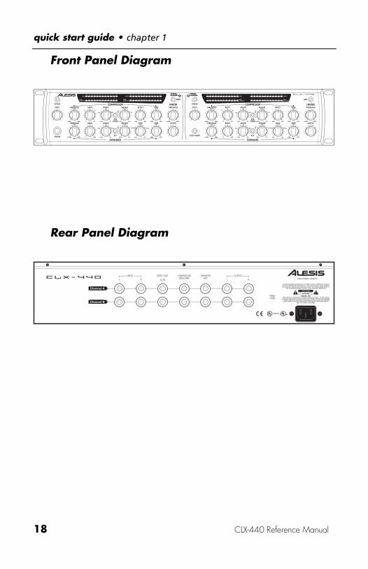
Front Panel Diagram
1 Sec
1 Sec
1 Sec
1 Sec
-50dBFS-50dBFS
Rear Panel Diagram

Chapter 2
CLX-440 Reference Manual 19
ConnectionsUnpacking and Inspection
Your CLX-440 was packed carefully at the factory. The shippingcarton was designed to protect the unit during shipping. Pleaseretain this container in the highly unlikely event that you need toreturn the CLX-440 for servicing.
The shipping carton should contain the following items:
• CLX-440 with the same serial number as shown on shippingcarton
• Power Cable
• This instruction manual
Installing in a RackThe CLX-440 may be simply set on a table, or installed in astandard 19" audio equipment rack. The rack ears are integral tothe unit.
Thermal Considerations in Rack MountingThe CLX-440 can be mounted in an equipment rack (takingup 2 rack spaces) or placed on a table or shelf. When youinstall it, keep in mind that heat is the major enemy ofelectronic equipment. Please observe the following:
• The CLX-440 is designed to perform properly over a range ofambient temperatures from 10° C to +40° C (50° F to 104° F),in up to 80% non-condensing humidity. These are notabsolute limits, but Alesis cannot guarantee that the CLX-440will meet its published specs or remain reliable if operatedoutside of these ranges.
• Always allow adequate ventilation behind the CLX-440. Donot seal any enclosure that holds the CLX-440. It is notnecessary to leave an empty rack space above or below theCLX-440 unless it runs hot enough to affect equipmentabove or below it. If your environment is unusually warmand not air conditioned, space between units will help theunits run cooler.
connections • chapter 2
20 CLX-440 Reference Manual
Power
Make sure you read the initial Important Safety Instructionschapter at the front of this manual.
AC Power HookupPlug the female end of the power cord into the CLX-440’s POWERINPUT socket and the male (plug) end into a good quality, noise-free AC power source of the proper rating.
Tip: It’s good practice to not turn on the CLX-440 until all otheraudio cables are hooked up as well. Make sure your amplifieror powered speakers are switched off when turning the CLX-440 on or off to avoid damage.
The CLX-440 works with any standard line voltage from 100 to230 volts and comes with a detachable AC line cord suitable forthe destination to which the unit is shipped.
AC GroundingThe line cable is an IEC-spec AC power cable designed to beconnected to a grounded 3-pin outlet, with the third, round pinconnected to ground. Do not substitute any other type of ACcord; IEC-spec cables of various lengths may be purchased fromelectronics stores or your Alesis dealer.
The ground connection is an important safety feature designedto keep the chassis of electronic devices such as the CLX-440 atground potential. Unfortunately, the presence of a third pin doesnot always indicate that an outlet is properly grounded. Youmay use an AC line tester to determine this. If the outlet is notgrounded, consult with a licensed electrician. When AC currentsare suspected of being highly unstable in VAC and Hz, aprofessional power conditioner should be used.

chapter 2 • connections
CLX-440 Reference Manual 21
Do not operate any electrical equipment with ungroundedoutlets. Plugging the CLX-440 into an ungrounded outlet, or"lifting" the unit off ground with a three-to-two wire adapter,can create a hazardous condition. Alesis cannot be responsiblefor problems caused by using the CLX-440 or any associatedequipment with improper AC wiring.
To use the CLX-440 in another country:The CLX-440 has what's called a "switching power supply". Thatmeans it works with any AC voltage from 90 to 250 volts, 50 to60 Hz. This eliminates the need for transformers or voltageswitches when you travel from country to country. Your CLX-440 was supplied with the correct power cord for your countryor local area. If you plan to travel with it to another country,obtain an IEC-spec AC power cable compatible with the outletsused in the other country and use it in place of the suppliedcable. The following alternative power cords are approved foruse with it:
• For 100-120 VAC 50/60 Hz operation in the US, Canadaand/or Japan, use Alesis UL/CSA power cord #7-41-0001.
• For 230 VAC 50 Hz operation in England, use Alesis Powercord #7-41-0004.
• For 220 VAC 50 Hz operation in Europe and Scandinavia,use Alesis EU power cord #7-41-0002.
• For 230 VAC 50 Hz operation in Australia, use Alesis ASpower cord #7-41-0003.
Do you hear an AC hum in your system? For detailed tipson how to get rid of "ground loops" that cause hum, see page44.
connections • chapter 2
22 CLX-440 Reference Manual
Connecting inputs and outputs
✪ When connecting audio cables and/or turning power on andoff, make sure that all devices in your system are turned offand the volume controls are turned down.
Connecting to the Channel Inserts of a mixingconsole:
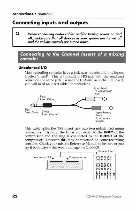
Unbalanced I/OMost recording consoles have a jack near the mic and line inputslabeled "Insert". This is typically a TRS jack with the send andreturn on the same jack. To use the CLX-440 as a channel insert,you will need an insert cable (not included).
Tip:Insert Send
Ring:Insert Return
Sleeve:Insert Ground
Insert Send:To CompressorInput
Insert Return:FromCompressorOutput
This cable splits the TRS insert jack into two unbalanced monoconnectors. Usually, the tip is connected to the INPUT of thecompressor and the ring is connected to the OUTPUT of thecompressor. However, this may be reversed on some recordingconsoles. Check your mixer’s Reference Manual to be sure or justtry it both ways – this won’t damage the CLX-400.
Compressor InCompressor Out
Channel Insert

chapter 2 • connections
CLX-440 Reference Manual 23
This example shows you how to connect the CLX-440 to onemono source. You can use this method to connect two mono orstereo sources to the CLX-440. You would need up to four insertcables to make these connections.
Balanced I/OSome recording consoles have balanced sends and returns foreach channel. If your recording console has these connections,use a balanced TRS cable to connect the insert send to the INPUTof the compressor, and another balanced TRS cable to connectthe compressor OUTPUT to the insert return.
Connecting to the Main Inserts of a mixingconsole:
Unbalanced I/OIn addition to channel inserts, most mixing consoles have maininsert jacks near the main outputs. You can use insert cables toconnect the CLX-440 to the main L/R bus the same way youconnect it to a pair of channels. Simply connect one insert cableto the left main insert of the mixer, and connect the two monojacks to the left INPUT and OUTPUT of the CLX-440. Use anotherinsert cable to connect the right main insert to the right INPUTand OUTPUT of the CLX-440.
Tip: Use both channels Since the CLX-440 has two stereo channels,A and B, you can connect two independent stereo sources. Tryusing channel A to compress the bass guitar, and channel B tocompress the main output bus. Or use channel A on the drumroom mics and channel B for the snare drum.
Balanced I/OSome recording consoles have balanced sends and returns forthe main output bus. If your recording console has theseconnections, use a balanced TRS cable to connect the left maininsert send to the left INPUT of the compressor, and anotherbalanced TRS cable to connect the compressor’s left OUTPUT tothe left insert return. Repeat these steps for the right main insert.
You can also simply connect the balanced main outputs of themixer to the inputs of the CLX-440, then connect the outputs of

connections • chapter 2
24 CLX-440 Reference Manual
the compressor to the inputs of your mixdown recorder, monitorsystem, etc. However, if you connect the CLX-440 this way anduse the mixer’s master fader to fade out and the end of a song,the sound will change as you fade out and less compressionoccurs. In this case, either fade the song post-compressor (usingthe compressor’s OUTPUT knob or the mixdown recorder’s inputcontrols), or use the mixer’s main inserts instead.
Connecting to the inserts on an instrumentamplifier:
Unbalanced I/OThe insert sends on a guitar or bass amp are usually labeled"effects send and return" or "insert send and return". This allowsyou to amplify your instrument before compressing it andsending it to the power amp.
Compressor InCompressor Out
Effects Send
J
Another method would be to insert the CLX-440 between thepreamp and the power amp, if you are using a two-piece system.You should never put the compressor between the power ampand the speaker, the high-powered levels created by the poweramp will destroy the circuitry of the CLX-440.
Connecting to equipment with XLR inputs andoutputs:
If you are connecting the CLX-440 to a product with XLRbalanced inputs and outputs, you will need to convert this signalto a TRS balanced connector. Make sure that Pin 2 of the XLRconnector is connected to the Tip of the TRS adapter, and Pin 3is connected to the Sleeve.

chapter 2 • connections
CLX-440 Reference Manual 25
Don't use line transformers: Many XLR-to-1/4" adapters sold atelectronics stores are NOT adapters, but transformers (and verylow quality transformers at that). Don't use these on the outputof the CLX-440—they're unnecessary and generally sound awfulbecause they don't have the headroom to handle the CLX-440'soutput. Get a hard-wired adapter or cable from yourprofessional audio dealer, or make one yourself fromcomponents.
About Audio CablesThe connections between the CLX-440 and your studio are yourmusic’s lifeline, so use only high quality cables. These should below-capacitance shielded cables with a stranded (not solid)internal conductor and a low-resistance shield. Although qualitycables cost more, they do make a difference.
Route cables to the CLX-440 correctly by observing the followingprecautions:
• Do not bundle audio cables with AC power cords.
• Avoid running audio cables near sources of electromagneticinterference such as transformers, monitors, computers, etc.
• Do not place cables where they can be stepped on. Steppingon a cable may not cause immediate damage, but it cancompress the insulation between the center conductor andshield (degrading performance) or reduce the cable’sreliability.
• Avoid twisting the cable or having it make sharp, right angleturns.
• Never unplug a cable by pulling on the wire itself. Alwaysunplug by firmly grasping the body of the plug and pullingdirectly outward.
connections • chapter 2
26 CLX-440 Reference Manual
And most importantly, keep connectors clean. Every few months,unplug them and wipe off oxidation with a clean cloth soaked inalcohol or contact cleaner. Insert the plugs in the jacks a fewtimes, to clean the internal jack contacts. Although Alesis doesnot endorse any specific product, chemicals such as Tweek andCramolin, when applied to electrical connectors, are claimed toimprove the electrical contact between connectors.
The CLX-440 is wired according to the modern standard of "Pin 2(tip) = Hot". Some older equipment was wired with Pin 3 hot;check to make sure correct polarity is maintained throughoutyour system.
Dual Channel OperationRemember that the CLX-440 is a dual-channel stereocompressor. That means that channels A and B can be used astwo independent stereo compressors. It also means that audiofrom one channel does not affect the other unless you use thesidechain (discussed in Chapter 3). Remember to plug audio intothe Left or Right input of the channel you are using.
Chapter 3
CLX-440 Reference Manual 27
Basics of CompressionThis section will explain how compression works, and explainthe functions of the CLX-440’s controls.
What is compression?A compressor essentially turns down the volume of any audiowhich is louder that a set level. This level is called thecompressor threshold level. If the input signal stays below thesetting of the threshold level, nothing will happen. When theinput signal is louder than the compressor threshold, this signalis reduced in volume.
The amount of reduction is determined by the compressionratio. A ratio of 2:1 means that for every 2 dB above thethreshold level, the output will only get 1 dB louder. If the ratiois 8:1, the input signal will have to be 8 dB louder than thethreshold to get 1 dB louder after compression. If the ratio isinfinity to one (∞:1), this is referred to as limiting. Limitingmeans that the output will never get any higher than thethreshold setting.
Compression is used for:• Keeping recording levels under control so that the recorder
doesn’t distort
• Keeping vocal or instrument performances in the samegeneral level range so that they’re easier to mix with otherinstruments
• Compressing the mix output so that it doesn’t exceed acertain technical maximum in broadcast or post production
• In live sound reinforcement, keeping the volumes undercontrol so that they don’t distort
• Making tracks sound "punchy"
Compressors can make your recorded tracks sound polished andprofessional. Chapter 5 will give specific example settings forvarious instruments.

basics of compression • chapter 3
28 CLX-440 Reference Manual
Description of ControlsThere are six knobs on the top row of each channel of the CLX-440, labeled COMPRESSOR. Their function is as follows:
ThresholdThe THRESHOLD knob sets the level where compression willbegin. As long as the input signal level is below the Thresholdlevel, the CLX-440 will do nothing to the signal. Once the inputsignal crosses the Threshold, the CLX-440 will begincompressing at an intensity set by the RATIO control.
Input Signal
Threshold
a.
b.
c.
-30
-20
-5
-10
-10
0
Output Signal
Threshold
-30
-20
0
Gain Reduction-10
+5
0 0dB
In the diagram above, the top figure (a) shows the input signal tothe CLX-440. In this example the compressor Threshold is set for

chapter 3 • basics of compression
CLX-440 Reference Manual 29
-10dB and the Ratio is set for 4:1. When the third peak of theinput signal crosses the Threshold, the CLX-440 starts to reducethe signal level, as shown in the figure (b). Figure (c) shows theoutput signal level, with the original signal shown with a dottedline.
RatioThe RATIO knob controls the amount of compression that willhappen once the input signal crosses the THRESHOLD level,described above. Ratio controls how much the input signal willbe reduced as a ratio of the input signal level. For example, if thecompression ratio is set for 6:1, the input signal will have to crossthe threshold by 6 dB for the output level to increase by 1dB.
The tick marks around the Ratio control show several ratiosettings for reference. These are, in clockwise order: 1:1, 2:1, 4:1,8:1, 10:1, and ∞:1. The far right setting, ∞:1 (Infinity to 1), is usedfor Limiting. This means that the input signal won’t go above thethreshold at all.
AttackThe ATTACK knob controls the amount of time between when theinput crosses the threshold and when compression begins. Therange of this control is 0.02 milliseconds to 1 second. Longerattacks are useful for percussive sounds, where shorter attacksare good for melodic parts like vocals and strings. The Attackcontrol is also useful for keeping the transients on percussivedrum or bass sounds. Experiment with different short attacktimes on snare drums to get more or less of the "stick" attack.
ReleaseThe RELEASE knob controls the amount of time the compressortakes to stop compressing as the signal crosses under thethreshold. The range of this control is 1 ms to 2 seconds. Shortrelease times are good for percussive, punchy sounds, wherelonger release times can make compression less obvious onvocals. Adjusting the release time may be necessary when usingextreme compression and "pumping" or "breathing" is audible,or if lower level signals after peaks are getting lost.
DetectThe DETECT knob varies the compressor’s detection between Peakand RMS. When set all the way to PEAK, the compressor islooking for peaks in the input level. For example, if your tape

basics of compression • chapter 3
30 CLX-440 Reference Manual
recorder overloads every time the kick drum hits, you can usePeak limiting to keep the kick from peaking above the rest of themusic.
When set to RMS compression, the CLX-440 works by detecting asignal’s average level, much like our ears adjust to loud or softsounds. In RMS mode, your source can have more of a dynamic,transparent sound (because short peaks don’t clamp down theoverall level) but still be prevented from getting too loud.
Generally, if you’re trying to raise the apparent volume of thetrack for radio or mixdown, set the detect knob closer to RMScompression. If you’re trying to stop peaks from distorting yourtape recorder or amplifier, use Peak compression.
KneeThe KNEE knob is used to vary between Hard and Soft kneecompression styles. When the CLX-440 is set for HARD knee, thecompression ratio applies only to signals above the thresholdlevel. If the CLX-440 is set for SOFT knee, the compression ratiogradually increases from 1:1 to the currently selected ratio over arange of approximately 5 dB, so that the transition fromuncompressed to compressed is more gradual. The differencebetween Hard Knee and Soft Knee is more obvious at highcompression ratios. Once the input signal crosses the Threshold,the unit will compress the signal at the full ratio level.
Soft KneeHard Knee
Soft knee compression is useful when performing high-ratiocompression or limiting on a signal. When the compressiongradually fades in, it doesn’t sound as obtrusive as when itsuddenly starts limiting the signal. If you’re looking for a "brickwall" limiter, the switch should be set for Hard knee to stop anytransients from slipping through without affecting lower levelsignals. Lower Ratio levels may require a hard knee setting sothat the compression slope isn’t too narrow and you loose someof the compressive "punch".
chapter 3 • basics of compression
CLX-440 Reference Manual 31
Compression ArtifiactsWhen you apply a lot of gain reduction (6dB or more), you mayhear some problems on the output. Here are a few common sideeffects to applying a lot of compression and some ways to avoidthem.
Pumping and BreathingWhen a compressor is making large changes to the input signal(10 to 12 dB or more), the noise floor will also rise and fall withthe signal level. When this noise signal rises and falls drasticallybetween signals, such as a heavily compressed, noisy drumtrack, you might hear the noise level "breathing" between drumhits. One solution to this breathing problem is to turn up therelease time. This way, the noise floor won’t have time to risebetween drum hits.
However, if the Release time is too long, lower level signals afterthe peak will be lost as the compressor slowly stops reducinggain. This is called "pumping" as the lower level signals (noiseincluded) slowly fade back up to their normal signal level. Thesecret to avoiding these problems is to achieve a balanced releasetime on the input signal.
Clicking or "Zipper Noise"You may also hear clicking if you are doing a lot of compressionwith a very short attack or release time. If this is the case, tryraising the attack or release time to stop the clicking.
Reduced Gain StructureAs you compress the signal more and more, the output level willbe lower as a result. Use the OUTPUT knob to make up for thegain you’ve lost during compression. By watching the INPUT,OUTPUT and GAIN REDUCTION meters, you should be able to setthe OUTPUT knob so that the input and output levels roughlymatch.
basics of compression • chapter 3
32 CLX-440 Reference Manual
LimitingLimiting is compression with a very high Ratio setting (10:1 ormore). It is typically used for stopping peaks in the signal fromdistorting the rest of the chain without affecting the dynamicrange of the signal. When you are using the CLX-440 as a limiter,the threshold should be set high enough so that it only effectsthe highest momentary peaks in the signal.
There are two ways to use the CLX-440 as a limiter. The first is toset the compression RATIO control to 10:1 or higher (about 3o’clock). If you set the ratio to ∞:1, the output signal will not goany higher than the threshold level.
Limiter ThresholdThe other way to use the CLX-440 as a limiter is to use thededicated limiter on the output. In addition to the compressionand expansion circuits in the CLX-440, there is a dedicatedlimiter on the output. This limiter has only one setting:THRESHOLD. You can use this limiter in addition to thecompressor. An example would be compressing a vocalperformance at 4:1 to keep the dynamic range narrow whilesetting the limiter threshold to –3 dBfs to avoid distorting therecorder.
If you need more control over the limiter, such as adjustableattack and release time, knee or detection, you should use thecompression circuit as a limiter with a high ratio setting.
chapter 3 • basics of compression
CLX-440 Reference Manual 33
Stereo DetectionThe CLX-440 takes the greater of both left and right sides of eachchannel before they are detected for compression or expansion.The reason for this is so the two sides of a stereo signal are notgain reduced differently.
For example, if a guitar was panned to the right and went abovethe threshold level, and the left and right sides were not linked,only the right side would be gain reduced. In this case, the stereoimage of anything panned center would shift to the left.
To keep this from happening, the left and right detectors of achannel are always simultaneously checked. This is why youshould use the left and right sides of a channel - rather thatsending the left side of a signal to compressor channel A and theright side to channel B. In addition to wasting a compressorchannel, you may cause the center imaging of your signal towander.
Look Ahead CompressionThe CLX-440 has a feature called LOOK AHEAD. This feature usesan audio delay to provide immediate compression.
When a signal is input, the detector takes 0.02ms to determine itslevel and apply gain reduction at it’s fastest attack setting. Insome applications, this allows a quick transient to be passedthrough the compressor before gain reduction is applied. LookAhead Compression delays the signal by 2ms to give thedetector time to apply compression. In most applications, thisdelay is not noticeable and the gain reduction will appear to beinstantaneous.
This feature is especially useful as a mix compressor, makingsure that the stereo mix does not overload the mixdownrecorder.

basics of compression • chapter 3
34 CLX-440 Reference Manual
SidechainThere are a pair of balanced jacks on the rear panel which canalter the way the compressor functions, Direct Out andSidechain.
The DIRECT OUT jack sums the signal from the input and sends itout without compression. Using this jack by itself does not affectthe rest of the compressor circuit. The input signal is sent both tothe direct out and the rest of the compression circuit. This jack isdesigned for use with the sidechain, but may also be useful forrecording a performance both with and without compression.
The SIDECHAIN input is connected to the detector. It is providedso that a modified version of the signal, or a different signalaltogether, can affect the compression. The most common usesfor the direct out and sidechain features are de-essing andducking.
Detection
DCAInput
Direct Out Sidechain In
Output
In the diagram above, you can see that the input signal goes bothto the DCA (Digitally Controlled Amplifier) and the Direct Out.The Sidechain In and Input signal both feed into the detector.The Front Panel SIDECHAIN button determines which of thesesources is sent to the detector, which controls the DCA.
For more information on De-essing and Ducking, see Chapter 5,"Compressor Applications using the Sidechain".

Chapter 4
CLX-440 Reference Manual 35
Basics of ExpansionThis section explains the expansion features of the CLX-440.
What is expansion?An expander reduces gain the opposite way a compressor does.When the input signal level is below the threshold level, thataudio will be attenuated according to the ratio setting. If theexpansion ratio is 4:1, then audio that is 1dB under the thresholdwill be attenuated so that it is 4dB below the threshold.
When the ratio is set to ∞:1, this is referred to as gating. This isthe most common use for an expander. In many recordings,there is an unacceptable amount of noise in the recording. Thismay be tape hiss, AC hum, chair squeaks, or anything else whichis distracting to the signal. A noise gate can be used to silence thesource when it is not actually playing. The threshold should beset so that it opens when the instrument plays then closes whenit is finished playing.
Gating is most effective on signals with a quick attack and astrong signal level. Some examples are electric guitar, snaredrum, piano or voice. Some instruments that may be morechallenging to effectively gate would be strings, flute, synth padsand cymbal rolls.
Drum SilenceDrumNoise
NoiseGate
basics of expansion • chapter 4
36 CLX-440 Reference Manual
Description of ControlsThere are six knobs on the bottom row of each channel of theCLX-440, labeled EXPANDER. Their function is as follows:
ThresholdThe THRESHOLD knob sets the level where expansion will begin.As long as the input signal level is above the Threshold level, theCLX-440 will do nothing to the signal. Once the input signalcrosses below the Threshold, the CLX-440 will begin expandingat an intensity set by the RATIO control.
For example, if the threshold level is set to –30dBfs, the ratio isset to 2:1 and the input is –35dBfs, the output signal will be–40dBfs. Since the input level is 5dB below the threshold, the 2:1ratio doubles this gap to 10dB.
RatioThe RATIO knob controls the amount of expansion that willhappen once the input signal crosses the THRESHOLD level,described above. Ratio controls how much the input signal willbe reduced as a ratio of the input signal level.
For example, if the threshold level is set to –30dBfs, the ratio isset to 2:1 and the input is –35dBfs, the output signal will be–40dBfs. Since the input level is 5dB below the threshold, the 2:1ratio doubles this gap to 10dB.
The far right setting of the Ratio control, GATE is used for gating.This means that there will be no output signal when the input isbelow the threshold.

chapter 4 • basics of expansion
CLX-440 Reference Manual 37
KneeThe KNEE knob is used to vary between Hard and Soft kneeexpansion styles. When the CLX-440 is set for Hard knee, theexpansion ratio applies only to signals below the threshold level.If the CLX-440 is set for Soft knee, the expansion ratio graduallyincreases from 1:1 to the currently selected ratio over a range ofapproximately 5 dB, so that the transition from unexpanded toexpanded is more gradual.
The difference between Hard Knee and Soft Knee is moreobvious at high expansion ratios (gating). Once the input signalcrosses the Threshold, the unit will compress the signal at thefull ratio level.
Soft KneeHard Knee
In most cases, you will want to use the Hard Knee setting forGating. This gives you a punchy sound on percussion and othertransient sounds. Soft knee expansion can be useful if the gate istoo noticeable. Softening the knee lets the gate gradually fade in,instead of cutting in and out.
AttackThe ATTACK knob controls the amount of time it takes for theexpander/gate to open. The range of this control is 0.02milliseconds to 1 second. Short attacks are useful for percussivesounds, where long attacks are good for melodic parts likevocals and strings. Use a longer attack time when a short attackis drawing attention to the sudden presence of noise. Use ashorter attack when the input itself has a fast attack, such as asnare drum.
HoldThe HOLD knob controls the amount of time the expander pausesbefore expanding after the signal crosses under the threshold.The range of this control is 0 ms to 2 seconds. This control isuseful for keeping the signal open a little longer before startingthe release fade. For example, if you want to hear more of theroom sound on a snare drum before clamping the gate back on,you could increase the hold time.

basics of expansion • chapter 4
38 CLX-440 Reference Manual
ReleaseThe RELEASE knob controls the amount of time the expandertakes to begin expanding after the signal crosses under thethreshold. The range of this control is 1 ms to 2 seconds. Byusing the HOLD and RELEASE knobs together, you can tailor thedecay of percussive sounds. Use a longer hold time for moreroom sound or gated effects. Use a shorter hold time with alonger release time decrease the room reverb or for a morenatural sound
Threshold
Input Signal
GainExpansion
Time
Leve
l
GateClosed
GateOpen
GateHold
GateRelease
GateClosed
GateAttack
Here is how the three expander time settings work. Let’sassume a snare drum signal is below the threshold, so thegate is on. When the snare drum is struck, the gate will openat the rate set by the ATTACK knob. When the input signalfalls back below the threshold, the gate will stay open for theamount on time specified by the HOLD knob. After this timehas passed, the gate will close again at the rate specified bythe RELEASE knob.
chapter 4 • basics of expansion
CLX-440 Reference Manual 39
Keyed ExpansionThe expander section has a function called KEY which is similarin operation to the compressor’s sidechain. The key input plugsdirectly into the detection circuit and breaks the flow of theinput to the detector when the KEY button is pressed. This allowsthe input signal to be processed before the expander detects itand allows a completely different signal to key the expander.
The KEY button on the front panel enables and disables the keyinput. If a signal is plugged into the key input on the rear panelbut the key button is not pressed, the expander will still look tothe unprocessed input for expansion detection.
You can use the KEY together with the DIRECT OUT to filter theaudio before it gets detected for expansion. You can even use acompletely different audio source to key the gate.
See Chapter 5 for more information on using the KEY function.

basics of expansion • chapter 4
40 CLX-440 Reference Manual
Chapter 5
CLX-440 Reference Manual 41
Applications This section is designed to get you started with the CLX-440 bygiving some sample settings. These are merely suggestedsettings, experiment and find your own once you begin to hearwhat the CLX-440 does to your sound.
Compressor Applications
Vocal LimitingVocalists tend to be one of the most dynamic recordingchallenges in any studio or stage. Even though a singer may gofrom a whisper to a scream during the course of a song, it’s theengineer’s job to keep the vocal’s level in line with the rest of theensemble. You can do this by setting the compressor with a highratio and a high threshold. This way, softer sections will go byuncompressed, and louder peaks will be kept under control.
• Threshold set so that the loudest sections get around -6 ofreduction(usually around 3 o’clock)
• Ratio set for 6:1
• Attack set at 1ms
• Release set between 10 and 12 o'clock (100 ms.)
• Detection set for RMS
• Knee set for Soft
The Threshold should be set so that loud sections getcompressed around 6dB and quiet passages get no compressionat all.

applications • chapter 5
42 CLX-440 Reference Manual
Vocal CompressionIn other cases, you may want to compress the entire dynamicrange of a vocal . This is typical of pop vocals and voiceovers forradio commercials. Whenever there is signal, there is somecompression taking place; just barely on the soft passages, andup to 12 dB of reduction during loud passages.
• Threshold set so that one REDUCTION LED (-1 dB) lightsduring the softest passages with signal (usually around 11o'clock)
• Ratio set for 4:1
• Attack set to 1ms
• Release set between 10 and 12 o'clock (100 ms.)
• Detection set to RMS
• Knee set to 12 o’clock
You may need to raise the output to compensate for gainreduction
Tip: Try using these settings together with the Peak Limiter feature forsimultaneous compression and limiting on vocals.
DrumsEngineers often compress drum tracks just to get a nice punchysound in the mix. The settings below sound good on a rock snaredrum:
• Threshold set so that all drum hits are compressed (around -3dB)
• Ratio set for 4:1
• Knee set for Soft
• Peak/RMS set for Peak
• Attack set around 8 o’clock
• Release set around 9 o’clock
By turning the Threshold down even more, you can "squash" thesnare drum as much as you want. Turn the attack up (longer) to

chapter 5 • applications
CLX-440 Reference Manual 43
get more stick out of the snare drum, and turn it down for asynth pop slap.
BassSince bass guitar forms the foundation of most Rock and Jazzmusic, it’s important that the level of the Bass doesn’t jumparound in the mix. Also, adding compression to bass tracks (oralmost anything else) can make it "punchier", generally a goodthing in rock tunes. Try the settings below on a rock bass track:
• Threshold set so only the peaks are compressed (around0dB)
• Ratio set for 4:1
• Knee set for Hard
• Peak/RMS set for Peak
• Attack set around 9 o’clock
• Release set around 10 o’clock
Electric GuitarFunky rhythm guitar parts love compression. Not only does itmake the part punch out the mix better, it evens out the volumeof the muted strums. The following setting, with its lowthreshold and high ratio, gives you lots of compression forpunching up a funky rhythm guitar part:
• Threshold set for constant compression (around -3dB)
• Ratio set for 6:1
• Knee set for Soft
• Peak/RMS set for RMS
Experiment with turning the Threshold up or down for a thinneror chunkier tone.

applications • chapter 5
44 CLX-440 Reference Manual
Compressor Applications using theSidechain
De-essingOccasionally when recording vocals, the letter "s" seems to jumpout louder than the rest of the part. This is because sibilantletters, especially the letter s, have more high frequency energythan other letters. This can cause tape recorders or othercomponents to distort, even though the level may not seem veryloud. This "sibilance" can sometimes be eliminated by movingthe microphone, but often a de-esser is required.
Mic Pre
Input Output
Input OutputTo Recorder
Direct Out Sidechain
Input Output
Compressor
EQ
Microphone
The CLX-440 allows you to perform de-essing on a track byusing a sidechain. By placing an equalizer, such as the PEQ-450,in the sidechain, you can set the CLX-440 so that only certainfrequency ranges trigger the unit to start compressing.
The trick is to set the EQ to cut all frequencies except for thesibilant range, between 3-6kHz. Then set the CLX-440 like this:
• Threshold set around 0dB
• Ratio set for 6:1
• Attack set at minimum (0.2ms)
• Release set around 8 o’clock
• Knee set for Hard
• Detection set for Peak
The Threshold should be set so that an "s" triggers about -3 to -6dB of compression. If other sounds are triggering thecompressor, you might need to adjust the EQ cutoff frequencies.
chapter 5 • applications
CLX-440 Reference Manual 45
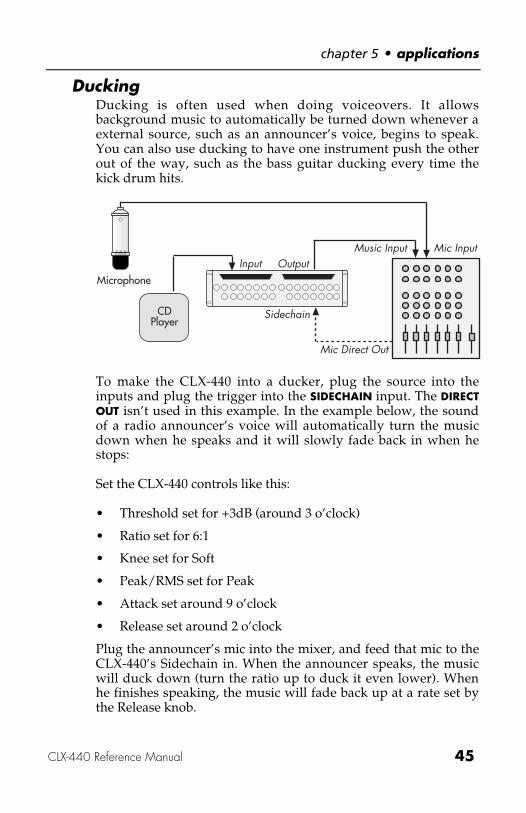
DuckingDucking is often used when doing voiceovers. It allowsbackground music to automatically be turned down whenever aexternal source, such as an announcer’s voice, begins to speak.You can also use ducking to have one instrument push the otherout of the way, such as the bass guitar ducking every time thekick drum hits.
Mic InputInput Output
Sidechain
Microphone
CDPlayer
Music Input
Mic Direct Out
To make the CLX-440 into a ducker, plug the source into theinputs and plug the trigger into the SIDECHAIN input. The DIRECTOUT isn’t used in this example. In the example below, the soundof a radio announcer’s voice will automatically turn the musicdown when he speaks and it will slowly fade back in when hestops:
Set the CLX-440 controls like this:
• Threshold set for +3dB (around 3 o’clock)
• Ratio set for 6:1
• Knee set for Soft
• Peak/RMS set for Peak
• Attack set around 9 o’clock
• Release set around 2 o’clock
Plug the announcer’s mic into the mixer, and feed that mic to theCLX-440’s Sidechain in. When the announcer speaks, the musicwill duck down (turn the ratio up to duck it even lower). Whenhe finishes speaking, the music will fade back up at a rate set bythe Release knob.

applications • chapter 5
46 CLX-440 Reference Manual
Expander ApplicationsGating a Noisy Guitar Amp
When a rock guitar amp is set loud enough to sound good itusually creates quite a bit of hiss. These settings will mute theguitar when it isn’t playing.
• Ratio set to Gate
• Attack set to minimum (.02ms)
• Hold set to minimum (0ms)
• Release set around 2 o’clock (1 second)
• Knee set to Hard
The Threshold should be set so that the Gate opens when theguitar is playing and closes when the guitar stops. Try turningthe threshold all the way down when the guitar is not playing,turn it up until it opens then turn it back down a bit. Experimentwith the release time to make a smooth transition from open toclosed.
Expanding Live Vocal TracksIn some cases, it may be better to use expansion than gating. Forexample, imagine that a band was recorded in concert. The vocaltrack will probably have "bleed" from the rest of the instrumentson stage. If you gate the vocal, you will still hear the otherinstruments when the vocalist is singing. When the gate closes,the listener will be distracted by the change in tone when thoseinstruments are no longer playing through the vocal channel. So,to expand the vocal, we will use these settings:
• Ratio set to 2:1
• Attack set to minimum (.01ms)
• Hold set to minimum (0ms)
• Release set around 2 o’clock (1 second)
• Knee set to Hard
Adjust the Threshold so that the rest of the band is attenuatedwhen the vocalist isn’t singing.
chapter 5 • applications
CLX-440 Reference Manual 47
Expander Applications using the KeyGated Reverb
A popular effect for drums is to use distant room mics or adigital reverb set to a long decay, then gate them so that thereverb suddenly cuts off. To do this we will use the snare drumas a key to open the reverb gate.
1. Plug the output of the room mics or reverb into the input ofthe CLX-440
2. Plug the snare drum signal into the Key input of the CLX-440
You may need to bus the snare drum signal using a direct out oreffects send so you can use it in the mix and for the key signal.
3. Set the controls this way:
• Ratio set to Gate
• Attack set to minimum (.02ms)
• Hold set to 12 o’clock (100ms)
• Release set to minimum (1ms)
• Knee set to Hard
4. Set the Threshold so that the snare drum makes the roomsound open up for a moment, then close.
5. Use the Hold setting to control the length of the reverbsound.
Tip: While you’re at it, try compressing the room mics a bit. Onsecond thought, compress the living daylights out of the roommics. The more the better.

applications • chapter 5
48 CLX-440 Reference Manual
Key Filtering for a Tom Mic gateIt is often useful to filter the input before it is detected. It keepsother sounds from crossing the threshold and opening the gate.For this example, we will gate a floor tom mic. When the floortom channel is constantly open, we hear too much of the rest ofthe kit. This effects the definition and imaging of the drum kitrecording. The solution is to gate the floor tom and pan it hardright. However, when we try this, the snare drum is loudenough that it occasionally opens the floor tom gate. This meanswe need to filter the signal before it reaches the detector.
1. Plug the DIRECT OUT of the CLX-440 into the input of anequalizer, such as the Alesis PEQ-450.
2. Plug the EQ output into a mixer input for now so that youcan hear the effects of the EQ.
3. A floor tom has a lower resonant frequency than a snaredrum. Use the EQ filters to cut all frequencies except for theresonant frequency of the floor tom. This is probably around250Hz.
Don’t worry if this signal sounds ugly. This is not what thefinished result will sound like. This filter is simply helping thedetector ignore the snare drum.
4. Plug the output of the EQ into the KEY input on the rearpanel of the CLX-440.
5. Press the KEY button for the channel you are using on theCLX-440.
The gate should now only open when the floor tom is hit, andshould ignore the snare drum hits.
Tip: You can compress the signal in addition to gating it. Try addinga bit of punchy compression to the drum tracks.

chapter 5 • applications
CLX-440 Reference Manual 49
Staccato Gating a Synth PadAn interesting effect using the KEY input is to key a sustainedsound from another, completely unrelated sound. This workswell when the signal being keyed is a legato part that doesn’tchange much and the key input signal is a percussive sound.
This example will combine a simple string pad performance,playing whole notes, with a 16th note drum machine hi-hat tocreate a staccato synth effect.
1. Plug the synth pad track into the channel INPUT of the CLX-440.
2. Plug the hi-hat signal into the KEY input of the same channel.
3. Press the KEY button for the channel you are using on theCLX-440.
4. Adjust the gate controls so that the string part plays at thesame staccato rhythm as the hi-hat.
Input Output
Key Input
String Pad
Hi Hat
Gated String Pad

applications • chapter 5
50 CLX-440 Reference Manual
Chapter 6
CLX-440 Reference Manual 51
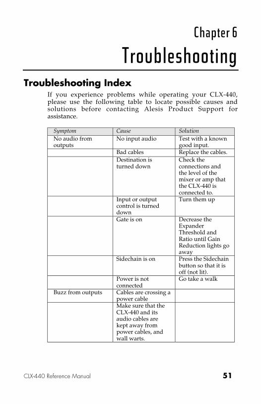
TroubleshootingTroubleshooting Index
If you experience problems while operating your CLX-440,please use the following table to locate possible causes andsolutions before contacting Alesis Product Support forassistance.
Symptom Cause SolutionNo audio fromoutputs
No input audio Test with a knowngood input.
Bad cables Replace the cables.Destination isturned down
Check theconnections andthe level of themixer or amp thatthe CLX-440 isconnected to.
Input or outputcontrol is turneddown
Turn them up
Gate is on Decrease theExpanderThreshold andRatio until GainReduction lights goaway
Sidechain is on Press the Sidechainbutton so that it isoff (not lit).
Power is notconnected
Go take a walk
Buzz from outputs Cables are crossing apower cableMake sure that theCLX-440 and itsaudio cables arekept away frompower cables, andwall warts.
troubleshooting • chapter 6
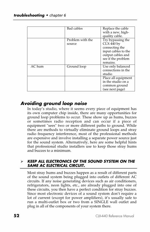
52 CLX-440 Reference Manual
Bad cables Replace the cablewith a new, high-quality cable.
Problem with thesource
Try bypassing theCLX-440 byconnecting theinput cables to theoutput cables andsee if the problemremains.
AC hum Ground loop Use only balancedconnections in thestudioPlace all equipmentin the studio on acommon ground(see next page)
Avoiding ground loop noiseIn today’s studio, where it seems every piece of equipment hasits own computer chip inside, there are many opportunities forground loop problems to occur. These show up as hums, buzzesor sometimes radio reception and can occur if a piece ofequipment "sees" two or more different paths to ground. Whilethere are methods to virtually eliminate ground loops and strayradio frequency interference, most of the professional methodsare expensive and involve installing a separate power source justfor the sound system. Alternatively, here are some helpful hintsthat professional studio installers use to keep those stray humsand buzzes to a minimum.
� KEEP ALL ELECTRONICS OF THE SOUND SYSTEM ON THESAME AC ELECTRICAL CIRCUIT.
Most stray hums and buzzes happen as a result of different partsof the sound system being plugged into outlets of different ACcircuits. If any noise generating devices such as air conditioners,refrigerators, neon lights, etc., are already plugged into one ofthese circuits, you then have a perfect condition for stray buzzes.Since most electronic devices of a sound system don’t require alot of current (except for power amplifiers), it’s usually safe torun a multi-outlet box or two from a SINGLE wall outlet andplug in all of the components of your system there.
chapter 6 • troubleshooting
CLX-440 Reference Manual 53
� KEEP AUDIO WIRING AS FAR AWAY FROM AC WIRINGAS POSSIBLE.
Many hums come from audio cabling being too near AC wiring.If a hum occurs, try moving the audio wiring around to see if thehum ceases or diminishes. If it’s not possible to separate theaudio and AC wiring in some instances, make sure that theaudio wires don’t run parallel to any AC wire (they should onlycross at right angles, if possible).
� TO ELIMINATE HUM IF THE ABOVE HAS FAILED:
A) Disconnect the power from all outboard devices and tapemachines except for the CLX-440, the mixer and controlroom monitor power amp.
B) Plug in each tape machine and outboard effects device one ata time. If possible, flip the polarity of the plug of each device(turn it around in the socket) until the quietest position isfound.
C) Make sure that all of the audio cables are in good workingorder. Cables with a detached ground wire will cause a veryloud hum!!
D) Keep all cables as short as possible, especially in unbalancedcircuits.
If the basic experiments don’t uncover the source of the problem,consult your dealer or technician trained in proper studiogrounding techniques. In some cases, a "star grounding" schememust be used, with the mixer at the center of the star providingthe shield ground on telescoping shields, which do NOT connectto the chassis ground of other equipment in the system.
Line Conditioners and ProtectorsAlthough the CLX-440 is designed to tolerate typical voltagevariations, in today’s world the voltage coming from the AC linemay contain spikes or transients. These can cause audiblenoises, and they can stress your gear and, over time, possiblycause a failure. There are three main ways to protect againstthis, listed in ascending order of cost and complexity:
• Line spike/surge protectors. Relatively inexpensive, theseare designed to protect against strong surges and spikes,

troubleshooting • chapter 6
54 CLX-440 Reference Manual
acting somewhat like fuses in that they need to be replaced ifthey’ve been hit by an extremely strong spike.
• Line filters. These generally combine spike/surge protectionwith filters that remove some line noise (dimmer hash,transients from other appliances, etc.). A good example isthe Isobar™ series from Tripp Lite.
• Uninterruptible power supply (UPS). This is the mostsophisticated option. A UPS provides power even if the ACpower line fails completely. Intended for computerapplications, a UPS allows you to complete an orderlyshutdown of a computer system in the event of a poweroutage. In addition, the isolation it provides from the powerline minimizes all forms of interference—spikes, noise, etc.
Care and MaintenanceCleaning
Disconnect the AC cord, then use a damp cloth to clean the CLX-440’s metal and plastic surfaces. For heavy dirt, use a non-abrasive household cleaner such as Formula 409™ orFantastik™. DO NOT SPRAY THE CLEANER DIRECTLYONTO THE FRONT OF THE UNIT AS IT MAY DESTROY THELUBRICANTS USED IN THE SWITCHES AND CONTROLS!Spray onto a cloth, then use cloth to clean the unit.
Refer All Servicing to AlesisWe believe that the CLX-440 is one of the best signal processorsthat can be made using current technology, and should provideyears of trouble-free use. However, should problems occur, DONOT attempt to service the unit yourself unless you havetraining and experience. Service on this product should beperformed only by qualified technicians. NO USER-SERVICEABLE PARTS INSIDE.

chapter 6 • troubleshooting
CLX-440 Reference Manual 55
Obtaining Repair ServiceBefore contacting Alesis, check over all your connections, andmake sure you’ve read the manual.
Customers in the USA and Canada:If the problem persists, contact Alesis and request the ProductSupport department. Make sure you have the unit’s serialnumber with you. Talk the problem over with one of ourtechnicians; if necessary, you will be given a return order (RO)number and instructions on how to return the unit. All unitsmust be shipped prepaid and COD shipments will not beaccepted.
For prompt service, indicate the RO number on the shippinglabel. Units without an RO will not be accepted. If you do nothave the original packing, ship the unit in a sturdy carton, withshock-absorbing materials such as Styrofoam pellets (the kindwithout CFCs, please) or "bubble-pack" surrounding the unit.Shipping damage caused by inadequate packing is not coveredby the Alesis warranty.
Tape a note to the top of the unit describing the problem, includeyour name and a phone number where Alesis can contact you ifnecessary, as well as instructions on where you want the productreturned. Alesis will pay for standard one-way shipping back toyou on any repair covered under the terms of this warranty.Next day service is available for a surcharge. Field repairs arenot authorized during the warranty period, and repair attemptsby unqualified personnel may invalidate the warranty.
troubleshooting • chapter 6
56 CLX-440 Reference Manual
Customers outside the USA and Canada:Contact your local Alesis distributor for any warranty assistance.The Alesis Limited Warranty applies only to products sold tousers in the USA and Canada. Customers outside of the USAand Canada are not covered by this Limited Warranty and mayor may not be covered by an independent distributor warrantyin the country of sale. Do not return products to the factoryunless you have been given specific instructions to do so.
Internet Address:Important information and advice is available on our web site:
http://www.alesis.com
Email may be addressed to:

chapter 6 • troubleshooting
CLX-440 Reference Manual 57
SpecificationsSubject to change without notice
Audio InputInput Connectors: 4 Balanced 1/4" TRS jacksNominal Input Level: Adjustable from ≤ -10dBV
to ≥ +4dBu = -15dBFSMaximum Input Level: +20dBu (7.78 Vrms)Input impedance: 10 kOhm
Sidechain/ Key InputsInput Connectors: 4 Balanced 1/4" TRS jacks (2
Sidechain, 2 Key)Nominal Input Level: +4 dBu (1.23 Vrms) = -15
dBFSMaximum Input Level: +19 dBu (6.9 Vrms) = -0
dBFSInput impedance: 10 kOhm
Direct OutputOutput Connectors: 2 Impedance-balanced 1/4"
TRS jacksOutput Level-Stereo Input : (Left In - 6.02dB) + (Right In
- 6.02dB)Output Level-Mono Input : Left/Mono InOutput impedance: 220 Ohm
Audio Output+4dBu/-10dBV SwitchableOutput Connectors: 4 Impedance-balanced 1/4"
TRS jacksNominal Output Level (+4dBu): +4 dBu (1.23 VRMS) = -15
dBFSMaximum Output Level (+4dBu): +19 dBu (6.9 VRMS) = -0
dBFSOutput impedance: 220 Ohm
Audio PerformanceSignal to Noise Ratio: >103 dB A-Weighted,
Analog In to Analog Out

troubleshooting • chapter 6
58 CLX-440 Reference Manual
THD+N: <0.003%, Analog In toAnalog Out
Frequency Response: 22-22 kHz ±0.50 dB, AnalogIn to Analog Out
Power consumption: 7 Watts Max (90-230 VAC /50-60 Hz)
MechanicalSize: 3.5" H x 19.0" W x 6" D
(89mm H x 483mm W x152mm D)
Rack spaces: 2 SpacesWeight: 5 lbs (2.27 kg)
All measurements done over a 22 Hz - 22 kHz range with 1 kHzsine wave at -1dBFS input. Impedances are measured at 1 kHz.

CLX-440 Reference Manual 59
Alesis Limited WarrantyALESIS STUDIO ELECTRONICS ("ALESIS") warrants
this product to be free of defects in material and workmanshipfor a period of one (1) year for parts and for a period of one (1)year for labor from the date of original retail purchase. Thiswarranty is enforceable only by the original retail purchaser andcannot be transferred or assigned.
During the warranty period ALESIS shall, at its sole andabsolute option, either repair or replace free of charge anyproduct that proves to be defective on inspection by ALESIS orits authorized service representative. In all cases disputesconcerning this warranty shall be resolved as prescribed by law.
To obtain warranty service, the purchaser must first callor write ALESIS at the address and telephone number printedbelow to obtain a Return Authorization Number andinstructions concerning where to return the unit for service. Allinquiries must be accompanied by a description of the problem.All authorized returns must be sent to ALESIS or an authorizedALESIS repair facility postage prepaid, insured and properlypackaged. Proof of purchase must be presented in the form of abill of sale, canceled check or some other positive proof that theproduct is within the warranty period. ALESIS reserves theright to update any unit returned for repair. ALESIS reservesthe right to change or improve design of the product at any timewithout prior notice.
This warranty does not cover claims for damage due toabuse, neglect, alteration or attempted repair by unauthorizedpersonnel, and is limited to failures arising during normal usethat are due to defects in material or workmanship in theproduct.
THE ABOVE WARRANTIES ARE IN LIEU OF ANYOTHER WARRANTIES OR REPRESENTATIONS WHETHEREXPRESS OR IMPLIED OR OTHERWISE, WITH RESPECT TOTHE PRODUCT, AND SPECIFICALLY EXCLUDE ANYIMPLIED WARRANTIES OF FITNESS FOR A PARTICULARPURPOSE OR MERCHANTABILITY OR OTHER IMPLIEDWARRANTIES. Some states do not allow limitations on howlong an implied warranty lasts, so the above limitation may notapply to you.

troubleshooting • chapter 6
60 CLX-440 Reference Manual
IN NO EVENT WILL ALESIS BE LIABLE FORINCIDENTAL, CONSEQUENTIAL, INDIRECT OR OTHERDAMAGES RESULTING FROM THE BREACH OF ANYEXPRESS OR IMPLIED WARRANTY, INCLUDING, AMONGOTHER THINGS, DAMAGE TO PROPERTY, DAMAGE BASEDON INCONVENIENCE OR ON LOSS OF USE OF THEPRODUCT, AND, TO THE EXTENT PERMITTED BY LAW,DAMAGES FOR PERSONAL INJURY. Some states do not allowthe exclusion or limitation of incidental or consequentialdamages, so the above limitation or exclusion may not apply toyou.
THIS CONTRACT SHALL BE GOVERNED BY THEINTERNAL LAWS OF THE STATE OF CALIFORNIAWITHOUT REFERENCE TO CONFLICTS OF LAWS. Thiswarranty gives you specific legal rights, and you may also haveother rights required by law which vary from state to state.
This warranty only applies to products sold topurchasers in the United States of America or Canada. Theterms of this warranty and any obligations of Alesis under thiswarranty shall apply only within the country of sale. Withoutlimiting the foregoing, repairs under this warranty shall be madeonly by a duly authorized Alesis service representative in thecountry of sale. For warranty information in all other countriesplease refer to your local distributor.
ALESISLos Angeles, CAwww.alesis.com
Alesis Studio Electronics, Los Angeles, CA© 2001 Alesis Studio ElectronicsSpecifications Subject To Change Without Notice


