Load Rating of Riveted Steel Load Rating of Riveted Steel Arch Bridge Connections Arch Bridge Connections David V. Jauregui, PhD, PE David V. Jauregui, PhD, PE November 28 November 28 th th , 2013 , 2013 Sapienza Sapienza University of Rome University of Rome
Transcript
Load Rating of Riveted Steel Load Rating of Riveted Steel
Arch Bridge Connections Arch Bridge Connections
David V. Jauregui, PhD, PEDavid V. Jauregui, PhD, PE
November 28November 28thth, 2013, 2013
SapienzaSapienza University of RomeUniversity of Rome
•• Designed & built in 1951 following 1944 AASHTO Designed & built in 1951 following 1944 AASHTO
specificationsspecifications
•• Carries traffic from town of Los Alamos and the LANL Carries traffic from town of Los Alamos and the LANL
(Los Alamos National Laboratory)(Los Alamos National Laboratory)
•• Bridge reduced the travel distance from 1.9 miles on a Bridge reduced the travel distance from 1.9 miles on a
steep grade to 820 ft: critical for emergency vehiclessteep grade to 820 ft: critical for emergency vehicles
•• Owned and maintained by the LANLOwned and maintained by the LANL
IntroductionIntroduction Research ObjectivesResearch Objectives
Connections commonly assumed to have equal or greater Connections commonly assumed to have equal or greater capacity than the members they adjoincapacity than the members they adjoin
Failure of connections could be criticalFailure of connections could be critical
•• Provide the LANL with upProvide the LANL with up--toto--date rating factors for the date rating factors for the Omega Bridge splice connectionsOmega Bridge splice connections
LRFD is the required method of design by FHWA since LRFD is the required method of design by FHWA since October 2007: Need for rating methodology consistent October 2007: Need for rating methodology consistent with the design method. with the design method.
No guidance in rating connectionsNo guidance in rating connections
•• Provide guidance in load rating connections using LRFR Provide guidance in load rating connections using LRFR method to bridge engineersmethod to bridge engineers
IntroductionIntroduction Research AidsResearch Aids
•• 2003 AASHTO Manual for Condition Evaluation and Load 2003 AASHTO Manual for Condition Evaluation and Load
and Resistance Factor Rating of Highway Bridgesand Resistance Factor Rating of Highway Bridges
•• Research by Tuyen (2005)Research by Tuyen (2005)
•• RISA for structural analysisRISA for structural analysis
•• MathCAD to calculate rating factorsMathCAD to calculate rating factors
•• Others: Original plans of the bridge, AISC steel manual, etc.Others: Original plans of the bridge, AISC steel manual, etc.
Load Rating Method: Load Rating Method: LRFRLRFR
Load Rating MethodLoad Rating Method LRFR LRFR
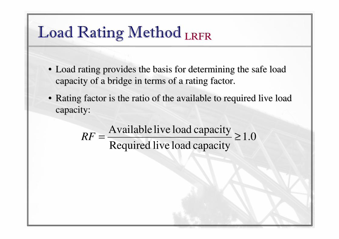
•• Load rating provides the basis for determining the safe load Load rating provides the basis for determining the safe load
capacity of a bridge in terms of a rating factor.capacity of a bridge in terms of a rating factor.
•• Rating factor is the ratio of the available to required live loaRating factor is the ratio of the available to required live load d
capacity:capacity:
0.1capacity load live Required
capacity load live Available≥=RF
Load Rating MethodLoad Rating Method LRFR LRFR
•• Three Stages of load rating in LRFR:Three Stages of load rating in LRFR: Design Load RatingDesign Load Rating
Legal Load RatingLegal Load Rating
Permit Load RatingPermit Load Rating
Start
Design Load Check
(HL-93)
Inventory Level Reliability
RF > 1-No Restrictive Posting
Requireda
-May be evaluated for
permit vehicle
RF <1
Check at operating
level reliability
RF > 1
RF <1
Legal load Rating
AASHTO or State legal loads
Evaluation level reliability
Higher Level Evaluation
(Optional)
-Refined analysis
-Load testing
-Site-specific load factors
-Direct safety assessment
RF <1
-Initiate load posting and/or repair/rehab
-No permit vehicles
-No restrictive
posting requiredb
-May be evaluated
for permit vehicles
RF > 1
RF > 1RF <1
a For AASHTO legal loads and state legal loads
within the LRFD exclusion limitsb For AASHTO legal loads and state legal loads
having only minor variations from the
AASHTO legal loads
Load Rating MethodLoad Rating Method LRFR LRFR
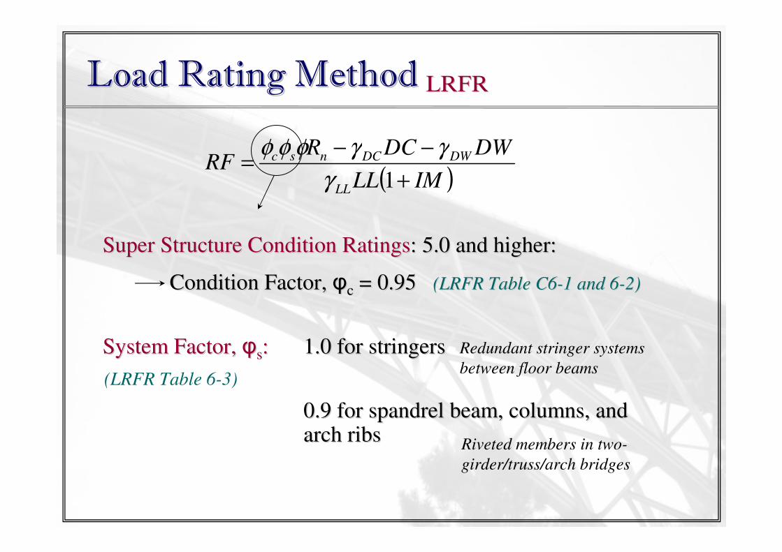
( )IMLL
DWDCRRF
LL
DWDCnsc
+
−−=
1γ
γγφφφ
General Equation for LRFR:General Equation for LRFR:
wherewhere RF = Rating FactorRF = Rating Factor
φφcc, , φφss = Condition and system factor, respectively= Condition and system factor, respectively
φφRRnn = Splice capacity= Splice capacity
γγDCDC, , γγDWDW, , γγLLLL = factors for dead load due to components and attachments, = factors for dead load due to components and attachments, wearing surface, and live load, respectivelywearing surface, and live load, respectively
DC, DW, LL = effects due to dead load due to components and DC, DW, LL = effects due to dead load due to components and attachments, wearing surface, and live load, respectivelyattachments, wearing surface, and live load, respectively
Super Structure Condition RatingsSuper Structure Condition Ratings: 5.0 and higher:: 5.0 and higher:
Condition Factor, Condition Factor, φφcc = 0.95 = 0.95 (LRFR Table C6(LRFR Table C6--1 and 61 and 6--2)2)
System Factor, System Factor, φφss:: 1.0 for stringers1.0 for stringers
0.9 for spandrel beam, columns, and 0.9 for spandrel beam, columns, and arch ribsarch ribs
Redundant stringer systems
between floor beams
Riveted members in two-
girder/truss/arch bridges
(LRFR Table 6-3)
Load Rating MethodLoad Rating Method LRFR LRFR
( )IMLL
DWDCRRF
LL
DWDCnsc
+
−−=
1γ
γγφφφ
Load Factors:Load Factors: γγDCDC = = 1.251.25
γγDW DW = = 1.51.5
γγLLLL = = 1.75 1.75 for inventoryfor inventory
1.35 1.35 for operatingfor operating
Load Rating MethodLoad Rating Method LRFR LRFR
( )IMLL
DWDCRRF
LL
DWDCnsc
+
−−=
1γ
γγφφφ
For each member, distribution factor for different force effectsFor each member, distribution factor for different force effectsmust be applied: i.e., DFmust be applied: i.e., DFmomentmoment or DFor DFshearshear
( )[ ]IM1Truck Lane DF Effect Load Live LL ++= γ
Controlled by larger effect between HSControlled by larger effect between HS--20 or Design Tandem20 or Design Tandem
8k
32k 32k
14ft 14 to 30 ft
HS-20 (Longitudinal)
25k 25k
4 ft
Design Tandem (Longitudinal)
Lane Load = 0.64 klf
(a) TRUCK LOADS: HS-20 and Design Tandem
(b) LANE LOAD
8k
32k 32k
14ft 14 to 30 ft
HS-20 (Longitudinal)
25k 25k
4 ft
Design Tandem (Longitudinal)
Lane Load = 0.64 klf
(a) TRUCK LOADS: HS-20 and Design Tandem
(b) LANE LOAD
Load Rating MethodLoad Rating Method LRFR LRFR
•• Three Stages of load rating in LRFR:Three Stages of load rating in LRFR: Design Load RatingDesign Load Rating
Legal Load RatingLegal Load Rating
Permit Load RatingPermit Load Rating
Load Rating ofLoad Rating of
Stringer SpliceStringer Splice
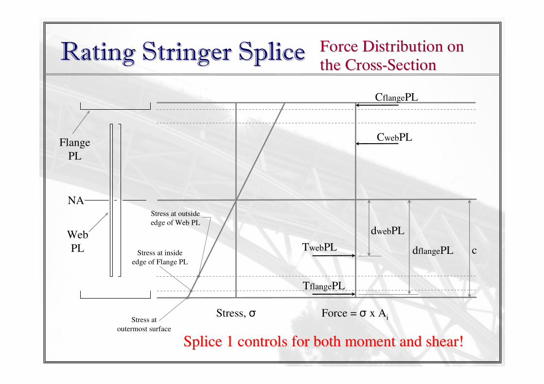
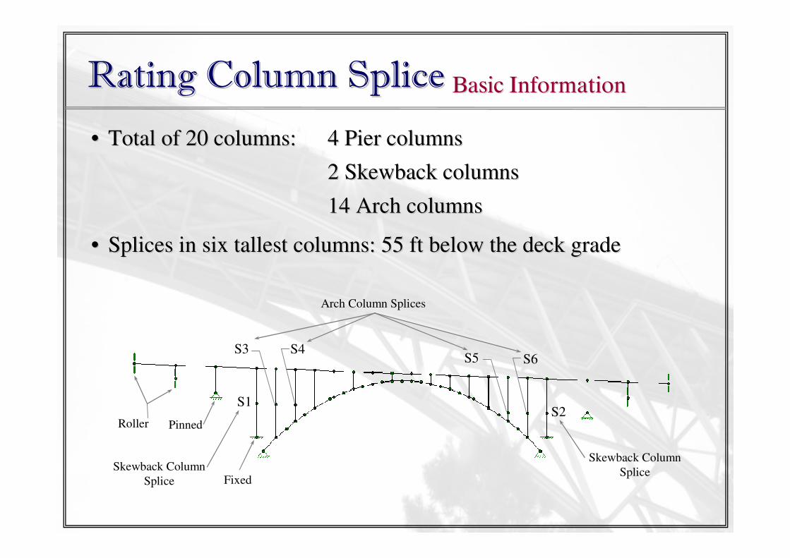
Rating Stringer SpliceRating Stringer Splice Basic Information Basic Information
Rating Arch Rib SpliceRating Arch Rib SpliceModeling: MemberModeling: Member
RIGID Model PINNED Model
Skewback
ColumnSkewback
Column
Quarter Point
Arch Splice Quarter Point
Arch Splice
1.0 rad 1.0 rad
1.0 1.45
•• Two models considered: RIGID and PINNEDTwo models considered: RIGID and PINNED
•• Used Influence Line to determine which model produces lower Used Influence Line to determine which model produces lower rating factorsrating factors
Rating Arch Rib SpliceRating Arch Rib Splice Second Order EffectSecond Order Effect
•• LRFD Article 4.5.3.2.2c specifies live load moments in arch ribsLRFD Article 4.5.3.2.2c specifies live load moments in arch ribs
including impact including impact ““shall be increased by the moment magnification shall be increased by the moment magnification
factor, factor, δδbb””
0.1
1
≥
−
=
e
u
mb
P
P
C
φ
δ
( )2
2
u
eKl
EIP
π=
lluu = half of the arch length= half of the arch length
K = f (type of arch, riseK = f (type of arch, rise--toto--span ratio of span ratio of arch)arch)
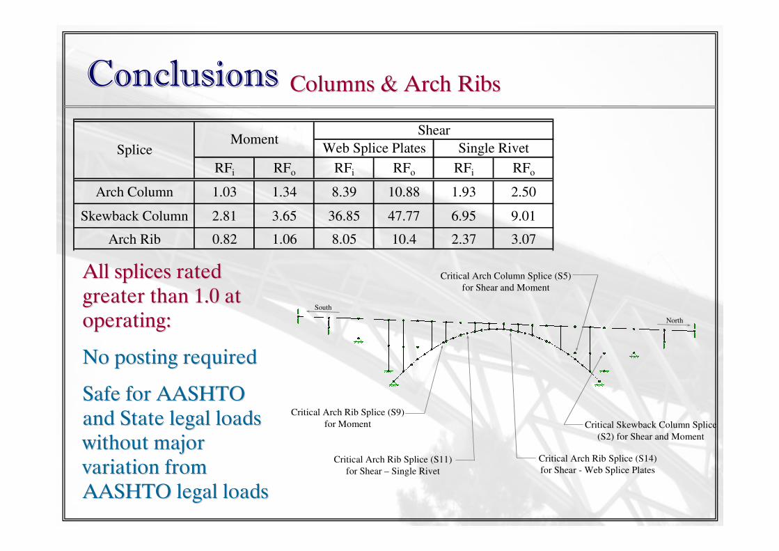
All splices rated All splices rated greater than 1.0 at greater than 1.0 at operating:operating:
No posting requiredNo posting required
Safe for AASHTO Safe for AASHTO and State legal loads and State legal loads without major without major variation from variation from AASHTO legal loadsAASHTO legal loads
for Shear - Web Splice Plates Critical Arch Rib Splice (S11)
for Shear – Single Rivet
RFi RFo RFi RFo RFi RFo
Arch Column 1.03 1.34 8.39 10.88 1.93 2.50
Skewback Column 2.81 3.65 36.85 47.77 6.95 9.01
Arch Rib 0.82 1.06 8.05 10.4 2.37 3.07
SpliceMoment
Shear
Web Splice Plates Single Rivet
All splices rated All splices rated greater than 1.0 at greater than 1.0 at operating:operating:
No posting requiredNo posting required
Safe for AASHTO Safe for AASHTO and State legal loads and State legal loads without major without major variation from variation from AASHTO legal loadsAASHTO legal loads
RecommendationsRecommendations
•• Load test recommended to better estimate the rotational Load test recommended to better estimate the rotational
stiffness of the riveted connections for the spandrel beams, stiffness of the riveted connections for the spandrel beams,
columns, and arch ribscolumns, and arch ribs
•• Uncertainty in secondUncertainty in second--order effect of column splice moments: order effect of column splice moments:
Lower end amplified moment rated as low as 0.84 at operating. Lower end amplified moment rated as low as 0.84 at operating.
A thorough examination of column splice strongly A thorough examination of column splice strongly
recommendedrecommended
A more detailed analysis of the secondA more detailed analysis of the second--order effect order effect
recommended in future analysisrecommended in future analysis
RecommendationsRecommendations
•• Several rivets reported missing during last inspectionSeveral rivets reported missing during last inspection
Recommended to identify missing rivets and replace themRecommended to identify missing rivets and replace them
•• Lateral load analysis due to wind and earthquake load Lateral load analysis due to wind and earthquake load
recommendedrecommended
•• 33--D finite element model recommended to better evaluate the D finite element model recommended to better evaluate the
member and splice forces and refine the analysismember and splice forces and refine the analysis
ReferencesReferencesAmerican Association of State Highway and Transportation Officials (AASHTO). (2003). Manual for Condition Evaluation
and Load and Resistance Factor Rating (LRFR) of Highway Bridges, Washington, DC.
American Association of State Highway and Transportation Officials (AASHTO). (2004). LRFD Bridge Design Specifications,
3rd Edition, Washington, DC.
American Institute of Steel Construction (AISC). (2001). Manual of Steel Construction: Load and Resistance Factor Design,
3rd Edition, Chicago, IL.
FDOT (Florida Department of Transportation). 2007. 24 August 2007