38
7 CMIRIG-B Reference Manual

7
Reference Manual
CMIRIG-B

CMIRIG-B Reference Manual
2
Article Number VESD1150 - Version CMIRIG-B.AE.3 - Year 2010
© OMICRON electronics. All rights reserved.
This manual is a publication of OMICRON electronics GmbH.
All rights including translation reserved. Reproduction of any kind, e.g., photocopying, microfilming, optical character recognition and/or storage in electronic data processing systems, requires the explicit consent of OMICRON electronics. Reprinting, wholly or in part, is not permitted.
The product information, specifications, and technical data embodied in this manual represent the technical status at the time of writing and are subject to change without prior notice.
We have done our best to ensure that the information given in this manual is useful, accurate and entirely reliable. However, OMICRON electronics does not assume responsibility for any inaccuracies which may be present.
The user is responsible for every application that makes use of an OMICRON product.
OMICRON electronics translates this manual from the source language English into a number of other languages. Any translation of this manual is done for local requirements, and in the event of a dispute between the English and a non-English version, the English version of this manual shall govern.
Contents
Contents
Contents . . . . . . . . . . . . . . . . . . . . . . . . . . . . . . . . . . . . . . . . . . . . . . . . . . . . . .3
Preface . . . . . . . . . . . . . . . . . . . . . . . . . . . . . . . . . . . . . . . . . . . . . . . . . . . . . . .5
Safety Instructions. . . . . . . . . . . . . . . . . . . . . . . . . . . . . . . . . . . . . . . . . . . . . .6
1 Designated Use . . . . . . . . . . . . . . . . . . . . . . . . . . . . . . . . . . . . . . . . . . . . . . . .9
2 Introduction . . . . . . . . . . . . . . . . . . . . . . . . . . . . . . . . . . . . . . . . . . . . . . . . . .11
2.1 What is IRIG-B?. . . . . . . . . . . . . . . . . . . . . . . . . . . . . . . . . . . . . . . . . . . . . . . . . 11
2.2 About the IRIG-B Standard . . . . . . . . . . . . . . . . . . . . . . . . . . . . . . . . . . . . . . . . 11
2.3 IEEE C37.118 (Synchrophasor Standard) . . . . . . . . . . . . . . . . . . . . . . . . . . . . . 12
3 Setup and Function . . . . . . . . . . . . . . . . . . . . . . . . . . . . . . . . . . . . . . . . . . . .13
3.1 System Overview: CMC with CMIRIG-B . . . . . . . . . . . . . . . . . . . . . . . . . . . . . . 13
3.2 Internal Connection Logic . . . . . . . . . . . . . . . . . . . . . . . . . . . . . . . . . . . . . . . . . 14
3.3 Block Diagram . . . . . . . . . . . . . . . . . . . . . . . . . . . . . . . . . . . . . . . . . . . . . . . . . . 15
4 Connectors and Indicators . . . . . . . . . . . . . . . . . . . . . . . . . . . . . . . . . . . . . .17
4.1 Front Side Connectors and Indicators . . . . . . . . . . . . . . . . . . . . . . . . . . . . . . . . 17
4.2 Rear Side Connectors . . . . . . . . . . . . . . . . . . . . . . . . . . . . . . . . . . . . . . . . . . . . 18
5 Operating the CMIRIG-B . . . . . . . . . . . . . . . . . . . . . . . . . . . . . . . . . . . . . . . .19
5.1 Taking the CMIRIG-B into Operation. . . . . . . . . . . . . . . . . . . . . . . . . . . . . . . . . 19
5.2 IRIG-B, PPS Signal Distribution. . . . . . . . . . . . . . . . . . . . . . . . . . . . . . . . . . . . . 21
5.3 Test Configurations / Operating Modes . . . . . . . . . . . . . . . . . . . . . . . . . . . . . . . 22
5.3.1 Configuration "Trigger via IRIG-B" . . . . . . . . . . . . . . . . . . . . . . . . . . . . 23
5.3.2 Configuration "IRIG-B Generator Master" . . . . . . . . . . . . . . . . . . . . . . 23
5.3.3 Configuration "IRIG-B Generator following PPS". . . . . . . . . . . . . . . . . 24
5.3.4 Configuration "IRIG-B Generator following CMGPS". . . . . . . . . . . . . . 24
3

CMIRIG-B Reference Manual
4
6 Technical Data . . . . . . . . . . . . . . . . . . . . . . . . . . . . . . . . . . . . . . . . . . . . . . . .25
6.1 Power Supply. . . . . . . . . . . . . . . . . . . . . . . . . . . . . . . . . . . . . . . . . . . . . . . . . . . 25
6.2 Insulation Coordination . . . . . . . . . . . . . . . . . . . . . . . . . . . . . . . . . . . . . . . . . . . 25
6.3 Outputs . . . . . . . . . . . . . . . . . . . . . . . . . . . . . . . . . . . . . . . . . . . . . . . . . . . . . . . 26
6.3.1 IRIG-B OUT . . . . . . . . . . . . . . . . . . . . . . . . . . . . . . . . . . . . . . . . . . . . . 26
6.3.2 PPX OUT . . . . . . . . . . . . . . . . . . . . . . . . . . . . . . . . . . . . . . . . . . . . . . . 26
6.4 Inputs . . . . . . . . . . . . . . . . . . . . . . . . . . . . . . . . . . . . . . . . . . . . . . . . . . . . . . . . . 27
6.5 Timing Specifications. . . . . . . . . . . . . . . . . . . . . . . . . . . . . . . . . . . . . . . . . . . . . 28
6.6 Environmental Conditions . . . . . . . . . . . . . . . . . . . . . . . . . . . . . . . . . . . . . . . . . 32
6.7 Mechanical Data . . . . . . . . . . . . . . . . . . . . . . . . . . . . . . . . . . . . . . . . . . . . . . . . 32
6.8 Cleaning. . . . . . . . . . . . . . . . . . . . . . . . . . . . . . . . . . . . . . . . . . . . . . . . . . . . . . . 32
7 Ordering Information . . . . . . . . . . . . . . . . . . . . . . . . . . . . . . . . . . . . . . . . . . .33
8 Glossary . . . . . . . . . . . . . . . . . . . . . . . . . . . . . . . . . . . . . . . . . . . . . . . . . . . . .33
Contact Information / Technical Support . . . . . . . . . . . . . . . . . . . . . . . . . .35
Index . . . . . . . . . . . . . . . . . . . . . . . . . . . . . . . . . . . . . . . . . . . . . . . . . . . . . . . .37

Preface
Preface
The purpose of this reference manual is to familiarize users with the CMIRIG-B interface unit and to show how to properly use it.
The manual contains important tips on how to use the CMIRIG-B safely, properly, and efficiently. Its purpose is to help you avoid danger, repair costs, and down time as well as to help maintain the reliability and life of the interface unit CMIRIG-B.
This manual is to be supplemented by existing national safety standards for accident prevention and environmental protection.
This reference manual should always be available at the site where the CMIRIG-B is used. It should be read by all personnel operating it.
In addition to the reference manual and the applicable safety regulations in the country and at the site of operation, the usual technical procedures for safe and competent work should be heeded.
Note: This reference manual is limited to the CMIRIG-B hardware. In order to obtain more information about the interfacing of IRIG-B with Test Universe applications, please refer to the related Test Universe application manual and/or the online help system of the Test Universe software.
5
CMIRIG-B Reference Manual
Safety Instructions
Before operating the CMIRIG-B interface unit, carefully read the following safety instructions.
Only operate the CMIRIG-B after you have read this reference manual and fully understood the instructions herein.
The CMIRIG-B may only be operated by trained personnel.
Rules for Use• The CMIRIG-B may only be used in a safe technical condition taking into
account its defined purpose, safety requirements and possible risks as well as the operating instructions! Faults that could affect safety are to be immediately eliminated (by specialized personnel or otherwise)!
• The CMIRIG-B is exclusively intended for the application areas specified in chapter 1 ”Designated Use” on page 9. The manufacturer/ distributors are not liable for damage resulting from unintended usage. The user alone assumes all responsibility and risk.
• Complying with the conditions outlined in the operating instructions of this manual is part of the defined use of the device.
• Do not open the CMIRIG-B or remove any of its housing components.
Orderly Practices and Procedures• This reference manual should always be available on site where the
CMIRIG-B is used.
• Personnel assigned to using the CMIRIG-B must have read this reference manual and fully understood the instructions herein, in particular the chapter about safety requirements, before starting work. This particularly applies to personnel not working with the CMIRIG-B on a regular basis.
• Do not undertake any modifications, extensions, or adaptations to the CMIRIG-B.
6
Safety Instructions
Operator Qualifications
• Testing with the CMIRIG-B should only be carried out by authorized and qualified personnel. The user is responsible for safe operation of the equipment. Please contact your OMICRON representative for dedicated product training support.
• Personnel receiving training, instruction, direction, or education on the CMIRIG-B should remain under the constant supervision of an experienced operator while working with the equipment.
Safe Operation Procedures
• The CMIRIG-B is to be set into operation in accordance with the information provided in chapter 5 ”Operating the CMIRIG-B”.
• Do not open the CMIRIG-B. Opening the device invalidates all warranty claims!
• Do not operate the CMIRIG-B under wet or moist conditions (condensation).
• Do not operate the CMIRIG-B when explosive gas or vapors are present.
• The electric equipment of the CMIRIG-B is to be checked regularly. Any faults such as loose connections or defective cables have to be repaired immediately.
• The CMIRIG-B is an SELV device (Safety Extra Low Voltage). It may only be connected to external devices that fulfill the SELV requirements according to the standards EN 61010-1 or IEC 61010-1.
7

CMIRIG-B Reference Manual
8

Designated Use
1 Designated Use
CMIRIG-B is an interface box enabling the connection of devices sending or receiving the IRIG-B protocol or PPS signals with CMC test sets. CMIRIG-B performs the level conversion between the CMC and the sources or receivers. The actual IRIG-B decoding and the coding functionality is implemented in the CMC test set. An OMICRON synchronization unit CMGPS can optionally be used as source of a synchronizing trigger pulse or PPS signal.
Typical applications for CMIRIG-B are:
• Synchronization of the analog outputs of two or more CMC test sets with an external IRIG-B protocol or 1PPS signal.
Example: End-to-end testing.
• Testing of wide area protection with IRIG-B functionality using the IRIG-B time protocol generated by the CMC test set.
Example: Testing of phasor measurement units (PMUs). Supported standard (IRIG-B extension): IEEE C37.118 (Synchrophasor standard).
• Master/Slave Operation: A CMC test set (master) generates an IRIG-B protocol and synchronizes other CMC test sets (slaves) at the same location.
Test Universe software modules supporting CMIRIG-B: State Sequencer, Pulse Ramping, Advanced TransPlay, Advanced Differential, NetSim, PQ Signal Generator and EnerLyzer.
Any other use of the CMIRIG-B is considered improper and will not only invalidate all customer warranty claims but also exempt the manufacturer from its liability to recourse in case of damage to property or persons.
Observance of the operating instructions and compliance with the precautions given in this reference manual is part of the designated use.
Caution: All output and input connectors of the CMIRIG-B are SELV interfaces (Safety Extra Low Voltage). Do not connect any of the CMIRIG-B connectors to circuits carrying hazardous voltages.
9

CMIRIG-B Reference Manual
10

Introduction
2 Introduction
2.1 What is IRIG-B?IRIG-B is a commonly used variant of a set of time protocol definitions issued by the Inter Range Instrumentation Group of the Range Commander’s Council (USA). Its purpose is to offer a standardized way for time information propagation from a master clock (typically connected to a GPS receiver for worldwide time synchronicity) to the connected slave devices. This allows wide-area time synchronization and device compatibility at interface level.
2.2 About the IRIG-B Standard
IRIG-B is comprehensively covered in IRIG standard revision 200-041. The protocol consists of a 1 s frame containing 100 pulses of 10 ms. Each of these pulses represents one bit of the telegram. The bit types are: data bit, index bit, and position identifier. The 1 s frame carries the full time information with a numerical resolution of 1 s plus optional control bits. At the beginning of a 1 s frame the rising edge of the position identifier bit Pr is synchronous with the seconds change of the UTC time represented by the telegram. The pulse width marks the data bit value (0 or 1) or the bit type.
The IRIG protocol format B comes in different sub-variants, indicated by three digits following the letter B.
Figure 2-1:Example: Format B00x (unmodulated, DCLS)
1. See the following related links (valid in 2007): https://wsmrc2vger.wsmr.army.mil/rcc/manuals/200-04/TT-45.pdf;https://wsmrc2vger.wsmr.army.mil/rcc/PUBS/oldoc.htm
Bit index
1 s frame
1PPS reference
First digit of seconds (BCD coded)
Pr = Reference bit
Example for BCD coding: First digit of seconds = 6dec corresponds to 0110bin
11

CMIRIG-B Reference Manual
Fixed components of the 1 s frame:
• second (00 to 59, or 60 for leap second)
• minute (00 to 59)
• hour (00 to 23)
• day (001 to 366)
Optional components (depending on x: "Coded Expression" - B00x):
• Control Function Bits (with or without IEEE C37.118 extension)
• year (00 to 99)
• SBS (0 to 86400, "Straight Binary Seconds")
The CMIRIG-B supports the following digital code formats (5 V TTL level) to be generated or decoded by the CMC test set:
• B00x (pulse width coded, demodulated, DC Level Shift (DCLS)).
• The support of other formats (e.g. B20x - Manchester II coding) by the CMC test set depends on the Test Universe software version.
2.3 IEEE C37.118 (Synchrophasor Standard)
This IEEE standard (revision 2005, "Synchrophasors for Power Systems") replaces the former standard IEEE Std 1344-1995. It defines synchronized phasor measurements used in power system applications and a related data communication protocol, using a part of the Control Function Bits of the IRIG-B definition.
The OMICRON Test Universe software supports this extension of the IRIG-B standard (control function extensions, see IEEE C37.118 Annex F).
12
Setup and Function
3 Setup and Function
3.1 System Overview: CMC with CMIRIG-B
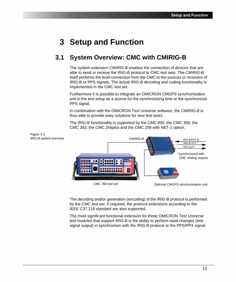
The system extension CMIRIG-B enables the connection of devices that are able to send or receive the IRIG-B protocol to CMC test sets. The CMIRIG-B itself performs the level conversion from the CMC to the sources or receivers of IRIG-B or PPS signals. The actual IRIG-B decoding and coding functionality is implemented in the CMC test set.
Furthermore it is possible to integrate an OMICRON CMGPS synchronization unit in the test setup as a source for the synchronizing time or the synchronous PPS signal.
In combination with the OMICRON Test Universe software, the CMIRIG-B is thus able to provide easy solutions for new test tasks.
The IRIG-B functionality is supported by the CMC 850, the CMC 356, the CMC 353, the CMC 256plus and the CMC 256 with NET-1 option.
Figure 3-1:IRIG-B system overview
The decoding and/or generation (encoding) of the IRIG-B protocol is performed by the CMC test set. If required, the protocol extensions according to the IEEE C37.118 standard are also supported.
The most significant functional extension for those OMICRON Test Universe test modules that support IRIG-B is the ability to perform state changes (test signal output) in synchronism with the IRIG-B protocol or the PPS/PPX signal.
IRIG-B/PPS IN
IRIG-B OUT *
PPX OUT *
Optional CMGPS synchronization unitCMC 356 test set
CMIRIG-B
* synchronized with CMC analog outputs
13

CMIRIG-B Reference Manual
Notes:
• While the CMIRIG-B is connected to the CMC, the binary transistor outputs 11 to 14 and the counting inputs (for meter testing) usually available on the "ext. Interf." connector of CMC test sets cannot be used.
• If connected to the CMIRIG-B, the CMGPS synchronization unit is not powered by the CMC. Therefore, the external plug-in power supply has to be used to supply the CMGPS with power.
• The CMIRIG-B provides galvanic separation between the connectors "CMC" and "CMGPS" on the front side and the BNC sockets "IRIG-B OUT", "PPX OUT" and "IRIG-B/PPS IN" on the rear side. However, this is only intended as a functional insulation and does not represent a safety-relevant insulation.
3.2 Internal Connection Logic
Figure 3-2:Simplified representation of CMIRIG-B signal paths
The signals "IRIG-B OUT" and "PPX OUT" from the CMC are directly routed to the related BNC sockets via the output drivers.
If a CMGPS synchronization unit is connected to the CMIRIG-B, the PPS/PPX signal from the CMGPS is routed to the CMC. In this case, a signal connected to the BNC socket "IRIG-B/PPS IN" is ignored.
Note: The socket "IRIG-B/PPS IN" is also deactivated if the CMGPS connected to the CMIRIG-B is switched off.
If no CMGPS is connected to the CMIRIG-B, the IRIG-B or PPS signal applied to the BNC socket "IRIG-B/PPS IN" is routed to the CMC.
14

Setup and Function
3.3 Block Diagram
Figure 3-3:CMIRIG-B block diagram
The CMIRIG-B consists of two galvanically insulated groups as shown in the block diagram. The connectors, indicators and internal circuits or components of the CMIRIG-B are described below:
Front side of the unit (for more details, please refer to section 4.1):
• "CMC" connector:
Socket for connection of the CMC test set. Connects the IRIG-B or PPS signal to the CMC and carries the power supply for the CMIRIG-B.
• "CMGPS" connector:
Socket for connection of an optional CMGPS synchronization unit. The connected CMGPS unit is not powered by the CMC (separate plug-in power supply required).
• LED "PPX"
This green LED flashes with the time interval of the configured PPS/PPX signal.
• LED "A"
Status indication LED. For more information please refer to section 4.1.
Vsupply
Housing
Input buffer (5 V TTL)
Output drivers(5 V)
Connectionlogic
Front side Rear side
Working insulation
VsupplyDC/DC DC/DCCMC
CMGPS
+14 V
PPX, A
IRIG-B/PPSIN
PPXOUT
IRIG-BOUT
15

CMIRIG-B Reference Manual
Rear side of the unit (for more details, please refer to section 4.2):
• "IRIG-B OUT" and "PPX OUT":
BNC sockets for connection of an IRIG-B / PPS receiver.
• "IRIG-B/PPS IN":
BNC socket for connection of an IRIG-B/PPS source.
Internal circuits and components:
• The connection logic manages the signal routing between the connectors "CMC" and "CMGPS" on the front side and the BNC connectors on the rear side of the unit.
• The DC/DC power supply for the CMIRIG-B hardware is fed with 14 V DC voltage from the CMC.
• The output drivers are able to provide a signal voltage of 5 V at a maximum output current of 150 mA for the BNC output sockets "IRIG-B OUT" and "PPX OUT".
• The input buffer provides signal adaptation and buffering for the 5 V IRIG-B/PPS input signal applied to BNC socket "IRIG-B/PPS IN".
16

Connectors and Indicators
4 Connectors and Indicators
Caution: All output and input connectors of the CMIRIG-B are SELV interfaces (Safety Extra Low Voltage). Do not connect any of the CMIRIG-B connectors to circuits carrying hazardous voltages.
4.1 Front Side Connectors and Indicators Figure 4-1:Front view of the CMIRIG-B
Connector "CMC"16-pole Lemo socket for connection of the CMC test set. Connects the IRIG-B or PPS signal to the CMC and carries the power supply for the CMIRIG-B.
Use the delivered connection cable VEHK0003 to connect this socket to connector "ext. Interf." on the rear side of the CMC.
Connector "CMGPS"16-pole Lemo socket for connection of an optional CMGPS synchronization unit. The connected CMGPS unit is not powered by the CMC (i.e., the separate plug-in power supply is required for the CMGPS).
A connected CMGPS synchronization unit affects the behavior of the internal CMIRIG-B connection logic (see section 3.2 ”Internal Connection Logic”).
LED "PPX"This green LED flashes with the time interval of the configured PPS/PPX signal.
LED "A"This LED indicates the status of the CMIRIG-B
Red CMIRIG-B not in use by the Test Universe software/CMC.
Green CMIRIG-B configured and in use by the Test Universe software/CMC.
Off No supply voltage for the CMIRIG-B.
17

CMIRIG-B Reference Manual
4.2 Rear Side ConnectorsFigure 4-2:Rear view of the CMIRIG-B
The three connectors on the rear side are standard 50 Ω BNC connectors. They have a common ground. These connectors are galvanically separated (working insulation) from the connectors "CMC" and "CMGPS".
Connector "IRIG-B OUT"
If configured accordingly, this BNC connector outputs the IRIG-B telegram.
The output driver delivers a 5 V (TTL) signal with a maximum current of 150 mA suitable for distribution via 50 Ω wiring.
Connector "PPX OUT"
This BNC connector outputs a pulse sequence that is synchronous to the IRIG-B telegram. The rising signal edge (0 V to 5 V) is synchronous to the rising edge of the 1PPS signal of the IRIG-B telegram or CMGPS.
The output driver delivers a 5 V (TTL) signal with a maximum current of 150 mA suitable for distribution via 50 Ω wiring.
Connector "IRIG-B/PPS IN"
This BNC connector is a 5 V (TTL) input for reception of the IRIG-B protocol or a 1PPS signal (e.g. for encoding). If configured accordingly, the received signal is forwarded to the CMC.
A connected CMGPS synchronization unit influences the behavior of this input (see section 3.2 ”Internal Connection Logic” on page 14).
18

Operating the CMIRIG-B
5 Operating the CMIRIG-B
5.1 Taking the CMIRIG-B into Operation
Before operating the CMIRIG-B, please verify the availability of all components by means of the packing list.
Standard scope of delivery:
• CMIRIG-B unit
• Connection cable CMIRIG-B ⇔ CMC (VEHK0003)
• CMIRIG-B reference manual.
To achieve IRIG-B functionality, the following additional equipment is required:
• CMC 850, CMC 356, CMC 353, CMC 256plus or CMC 256 test set with NET-1 option
• Test Universe software version 2.20 or higher
• IRIG-B source and/or receiver with
- 5 V (TTL) signal level
- demodulated DC Level Shift protocol (IRIG-B00x).
• The distribution of the IRIG-B signal or the PPS signal over distances of more than 1 m should be done as suggested in section 5.2 ”IRIG-B, PPS Signal Distribution” on page 21 (using 50 Ω coax cable with corresponding termination).
• For particular tasks a CMGPS synchronization unit is required.
The instructions for operating the CMIRIG-B are based on the precondition that the CMC test set has been set up in accordance with its manual and is ready for use.
Proceed as follows to take the CMIRIG-B into operation (refer to Figure 5-1: ”Typical test setup with a CMIRIG-B” on page 20):
• Connect the CMIRIG-B to the CMC test set using the delivered connection cable VEHK0003.
• Proceed with section 5.3 on page 22 to select the desired configuration. Connect the CMIRIG-B to the IRIG-B source or receiver accordingly.
For particular tasks (see below) it is necessary to connect a CMGPS synchronization unit to the CMIRIG-B. In this case, also connect the GPS antenna to the CMGPS. Place the antenna at a suitable position that provides sufficient open sky.
19

CMIRIG-B Reference Manual
Caution: Do not place the CMGPS antenna to an exposed position above the lightning rod or any other location endangered by lightning. Do not position the antenna in a control cabinet in the vicinity of flashover-endangered spots.
Figure 5-1:Typical test setup with a CMIRIG-B
Figure 5-1 shows a typical constellation with IRIG-B functionality. You can select the required configuration in the Test Universe software. The Test Universe software detects connected CMIRIG-B hardware and supports the test configuration selection (see section 5.3 ”Test Configurations / Operating Modes” on page 22).
IRIG-B/PPS IN
IRIG-B OUT *
PPX OUT *
* synchronized with CMC analog outputs
CMGPS synchronization unitCMC 356 test set
CMIRIG-B
Antenna
VEHK0003
20
Operating the CMIRIG-B
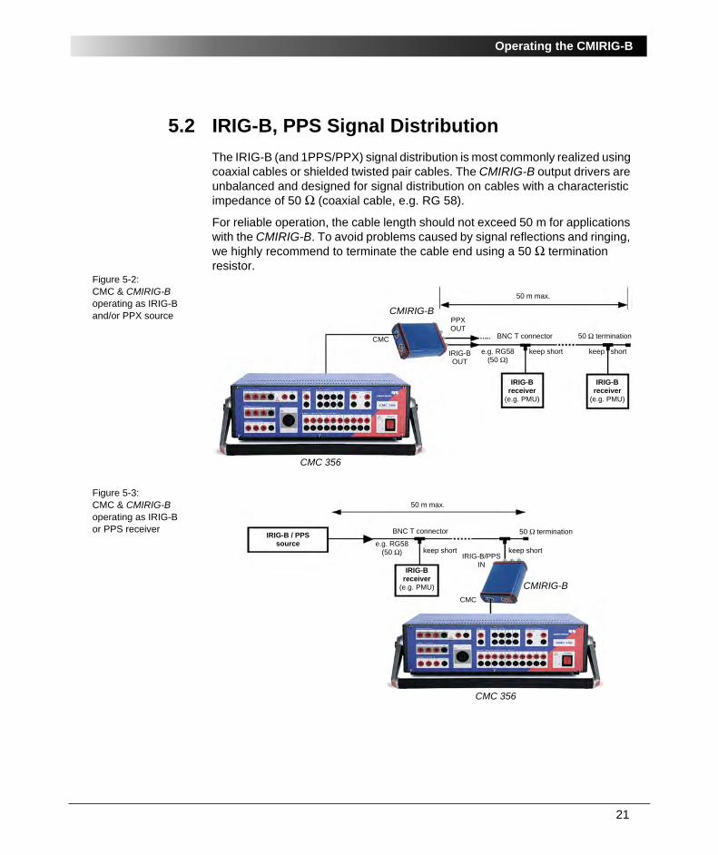
5.2 IRIG-B, PPS Signal Distribution
The IRIG-B (and 1PPS/PPX) signal distribution is most commonly realized using coaxial cables or shielded twisted pair cables. The CMIRIG-B output drivers are unbalanced and designed for signal distribution on cables with a characteristic impedance of 50 Ω (coaxial cable, e.g. RG 58).
For reliable operation, the cable length should not exceed 50 m for applications with the CMIRIG-B. To avoid problems caused by signal reflections and ringing, we highly recommend to terminate the cable end using a 50 Ω termination resistor.
Figure 5-2:CMC & CMIRIG-B operating as IRIG-B and/or PPX source
Figure 5-3:CMC & CMIRIG-B operating as IRIG-B or PPS receiver
CMC
CMIRIG-B
IRIG-BOUT
PPXOUT
e.g. RG58(50 Ω)
BNC T connector
50 m max.
keep short
50 Ω termination
CMC 356
IRIG-Breceiver
(e.g. PMU)
IRIG-Breceiver
(e.g. PMU)
keep short
IRIG-Breceiver
(e.g. PMU)
IRIG-B / PPSsource
CMIRIG-B
CMC 356
CMC
IRIG-B/PPSIN
e.g. RG58(50 Ω)
BNC T connector
50 m max.
keep short keep short
50 Ω termination
21

CMIRIG-B Reference Manual
5.3 Test Configurations / Operating Modes
After setting up the test equipment, turning on the CMC test set and launching the Test Universe software, a connected CMIRIG-B is recognized by the software automatically.
After this, the possible configurations are available for selection in the Hardware Configuration of the Test Universe software1.
Figure 5-4:Trigger mode selection in the Test Universe software
Further test module-related configuration options (e.g. test start time) can be accessed in the corresponding test module using the Time Trigger Configuration function (click on the corresponding button in the toolbar of the software). For more information, please refer to chapter "Time Trigger and Synchronization" in the online help of the respective test module.
The IRIG-B configurations currently supported by the Test Universe software are described in the following subsections.
1. For configuration details please refer to the online help of the Test Universe software. Screensshown in this manual may differ from the actual screens shown by the software depending onthe software version.
22

Operating the CMIRIG-B
5.3.1 Configuration "Trigger via IRIG-B"
Figure 5-5:Configuration "Trigger via IRIG-B"
The CMC receives and decodes the IRIG-B telegram (decoder operation).
In this configuration, the CMC triggers (or correspondingly performs synchronization of its analog outputs) on the received time reference (UTC time).
A PPX signal (with configurable pulse period) is applied at CMIRIG-B output "PPX OUT".
5.3.2 Configuration "IRIG-B Generator Master"
Figure 5-6:Configuration "IRIG-B Generator Master"
The CMC generates the IRIG-B telegram (encoder operation).
In this configuration, the CMC is the time reference and governs the time base by means of the IRIG-B protocol and/or PPS signal at output PPX OUT. This allows in a very simple manner and without an external time base (UTC time generator or GPS) to perform tests requiring CMC output signals that are synchronous with the IRIG-B or PPS signal.
A 1PPS signal is applied at CMIRIG-B output "PPX OUT".
23

CMIRIG-B Reference Manual
5.3.3 Configuration "IRIG-B Generator following PPS"
Figure 5-7:Configuration "IRIG-B Generator following PPS"
In this configuration, an external 1PPS signal (received via the CMIRIG-B connector "IRIG-B/PPS IN") is the time base for the IRIG-B encoder. The CMC synchronizes its analog output signals to this external 1PPS reference.
In parallel, the IRIG-B protocol (encoder operation) is output at "IRIG-B OUT" and a synchronous 1PPS signal is applied at output "PPX OUT".
5.3.4 Configuration "IRIG-B Generator following CMGPS"
Figure 5-8:Configuration "IRIG-B Generator following CMGPS"
In this configuration, the CMGPS synchronization unit is the time reference (UTC/1PPS). This time reference governs the generation of the IRIG-B telegrams and the synchronization of the CMC.
A 1PPS signal is applied at CMIRIG-B output "PPX OUT".
24

Technical Data
6 Technical Data
Guaranteed values indicated in this chapter are valid for 1 year from the date of delivery. The specifications given below only apply for the use with a CMC 850, a CMC 356, a CMC 353, a CMC 256plus or a CMC 256 test set with NET-1 option.
6.1 Power Supply
The CMIRIG-B is powered via the "ext. Interf." connector on the CMC test set.
Table 6-1:Power supply data
A connected CMGPS unit is not powered by the CMC (i.e., the separate plug-in power supply is required for the CMGPS).
6.2 Insulation Coordination
Table 6-2:Insulation coordination
Power supply
Supply from CMC 14 VDC
Power consumption 3 W max.
Connection Lemo connector labeled "CMC"
Insulation coordination
Circuit group A BNC connectors on the rear side:"IRIG-B OUT", "PPX OUT", "IRIG-B/PPS IN" (common ground)
Circuit group B 16-pole Lemo connectors on the front side: "CMC" and "CMGPS" (ground connected to housing)
Insulation type group A to group B
- Working insulation - Clearance: > 1 mm- Creepage: > 1 mm- Test voltage: 1000 VDC
Insulation resistance group A to group B
1 MΩ
25

CMIRIG-B Reference Manual
The CMIRIG-B is an SELV device (Safety Extra Low Voltage). It may only be connected to external devices that fulfill the SELV requirements according to the standards EN 61010-1 or IEC 61010-1. Do not connect any of the CMIRIG-B connectors to circuits carrying hazardous voltages.
6.3 Outputs
6.3.1 IRIG-B OUT
Table 6-3:Output "IRIG-B OUT"
6.3.2 PPX OUT
"PPX OUT" is a configurable pulse output (X describes the pulse rate) where the active (rising) edge is in coincidence with the start of an UTC second).
Example: 1PPS (1 pulse per second: pulse rate = 1s).
Table 6-4:Output "PPX Out"
Output "IRIG-B OUT"
IRIG Standard 200-04
Data format1
1. IRIG-B functionality can only be used in combination with a CMC 850, a CMC 356, a CMC 353, a CMC 256plus or a CMC 256 with NET-1 option. The support of other formats (e.g., B20x - Manchester II coding) by the CMC test set depends on the Test Universe software version.
B00x (demodulated, dc level-shift)B20x (Manchester, modulated, dc level-shift)
Output characteristic 5 V (TTL), 150 mA, for 50 Ω coaxial signal distribution
Synchrophasor (PMU) testing
Configurable with or without IEEE C37.118 extensions
Connector BNC
Output "PPX OUT"
Output characteristic 5 V (TTL), 150 mA, for 50Ω coaxial signal distribution
Minimum pulse length 1 ms
Pulse rate IRIG-B encoder: 1 sIRIG-B decoder: 0 = single, 1 ... 65535 s
Connector BNC
26

Technical Data
6.4 Inputs
This input can be used with two different functions:
• IRIG-B input; for configuration "Trigger via IRIG-B" (IRIG-B decoder), see section 5.3.1 on page 23.
• PPS input; for configuration "IRIG-B Generator following PPS" (IRIG-B encoder); see section 5.3.3 on page 24. That is, an external PPS source is connected and IRIG-B encoder is configured.
The input is without function if a CMGPS synchronization unit is connected to the CMIRIG-B.
Table 6-5:Input "IRIG-B/PPS IN" Input "IRIG-B/PPS IN"
IRIG Standard 200-04
Data format IRIG-B IN1
1. IRIG-B functionality can only be used in combination with a CMC 850, a CMC 356, a CMC 353,a CMC 256plus or a CMC 256 with NET-1 option.
B00x (demodulated, dc level-shift)
Input characteristic 5 V (TTL)
Min. high level 2.0 V
Max. low level 0.8 V
Input impedance 1.5 kΩ || 1 nF
Max. input voltage 6 V
Min. input voltage -0.5 V
Min. input PPS pulse length (PPS IN)
3 µs
Synchrophasor (PMU) testing
Configurable with or without IEEE C37.118 extensions
Connector BNC
27

CMIRIG-B Reference Manual
6.5 Timing Specifications
There are several possible configurations that select the time reference source accordingly (see also section 5.3 ”Test Configurations / Operating Modes” on page 22):
• "Trigger via IRIG-B" (see section 5.3.1 on page 23)
CMIRIG-B input "IRIG-B IN" is used as an IRIG-B protocol input.The time reference signal is available at CMIRIG-B output "PPX OUT".
• "IRIG-B Generator Master" (see section 5.3.2 on page 23)
The time base of the CMC test set (high-precision oscillator) is used as time reference (without any relationship to UTC). The time reference signals are available at the CMIRIG-B outputs "IRIG-B OUT" (IRIG-B protocol) and "PPX OUT" (pulse).
• "IRIG-B Generator following PPS" (see section 5.3.3 on page 24)
CMIRIG-B input "PPS IN" is a 1PPS input. The time reference signals are available at the CMIRIG-B outputs "IRIG-B OUT" (IRIG-B protocol) and "PPX OUT" (pulse).
• "IRIG-B Generator following CMGPS" (see section 5.3.4 on page 24)
The CMGPS operates as a 1PPS source (UTC). The time reference signals are available at the CMIRIG-B outputs "IRIG-B OUT" (IRIG-B protocol) and "PPX OUT" (pulse).
The analog amplifier outputs of the CMC test set can be re-synchronized anytime with an adjustable phase relative to the time reference edge. During the time between the synchronization edges, the CMC test set uses its internal high-precision time base for signal generation.
Figure 6-1:CMIRIG-B timing overview
CMC analog outputs
See figure 6-2 for a more detailed representation of the dotted area.
1PPS of CMGPS
IRIG-B OUT
PPX OUT
IRIG-B IN
PPS IN
CMC
CMGPS
: PPS, PPX
: IRIG-B
28
Technical Data
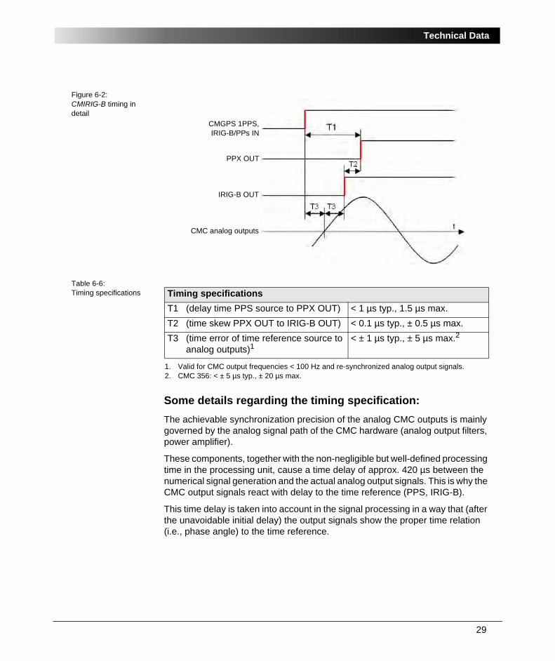
Figure 6-2:CMIRIG-B timing in detail
Table 6-6:Timing specifications
Some details regarding the timing specification:
The achievable synchronization precision of the analog CMC outputs is mainly governed by the analog signal path of the CMC hardware (analog output filters, power amplifier).
These components, together with the non-negligible but well-defined processing time in the processing unit, cause a time delay of approx. 420 µs between the numerical signal generation and the actual analog output signals. This is why the CMC output signals react with delay to the time reference (PPS, IRIG-B).
This time delay is taken into account in the signal processing in a way that (after the unavoidable initial delay) the output signals show the proper time relation (i.e., phase angle) to the time reference.
CMC analog outputs
IRIG-B OUT
PPX OUT
CMGPS 1PPS,IRIG-B/PPs IN
Timing specifications
T1 (delay time PPS source to PPX OUT) < 1 µs typ., 1.5 µs max.
T2 (time skew PPX OUT to IRIG-B OUT) < 0.1 µs typ., ± 0.5 µs max.
T3 (time error of time reference source to analog outputs)1
1. Valid for CMC output frequencies < 100 Hz and re-synchronized analog output signals.
< ± 1 µs typ., ± 5 µs max.2
2. CMC 356: < ± 5 µs typ., ± 20 µs max.
29

CMIRIG-B Reference Manual
Example A: Initial synchronous start
Ch1 / blue: Amplitude step from 0 V to 40 V / 90 ° / 50 Hz
Ch2 / red: Amplitude step from 0 V to 40 V / -90 ° / 50 Hz
Ch4 / magenta: PPS (trigger)
Figure 6-3:Example A
The time delay of approx. 400 µs caused by the analog signal path can be seen in example A (compare the amplitude step with the trigger edge). Yet the required time relation of the outputs to the reference time (PPS signal) stays untouched: The zero crossing of the analog signals occurs 5 ms after the synchronization time which is the expected behavior for a 50 Hz signal with ± 90 ° offset.
5 ms
400 µs
30

Technical Data
Example B: Re-synchronization with amplitude step
Ch1 / blue: Amplitude step from 50 V to 40 V / 90 ° / 50 Hz
Ch2 / red: Amplitude step from 50 V to 40 V / -90 ° / 50 Hz
Ch4 / magenta: PPS (trigger)
Figure 6-4:Example B
The time delay of approx. 400 µs caused by the analog signal path can be observed here, too. Again, this has no influence on the phase relation between the output signals and the trigger time.
5 ms
400 µs
31

CMIRIG-B Reference Manual
6.6 Environmental Conditions
Table 6-7:Climate conditions
Table 6-8:Electromagnetic compatibility
Table 6-9:Fulfilled safety standards
6.7 Mechanical Data
Table 6-10:Mechanical data
6.8 Cleaning
To clean the CMIRIG-B interface unit, use a cloth dampened with isopropanol alcohol or water.
Climate
Operating temperature 0 to +50 °C (32 to +104 °F)
Storage and transportation -25 to +70 °C (-13 to +158 °F)
Humidity 5 to 95 % relative humidity, no condensation
Max. altitude 2000 m
EMC
CE conformity, requirements
The product adheres to the guidelines of the council of the European Community for meeting the requirements of the member states regarding the electromagnetic compatibility (EMC Guidelines 89/336/EEC).
EN 61326-1
Safety standards
European standard EN 61010-1:2001
International standard IEC 61010-1:2001
ISO standard This product is designed and manufactured under an ISO9001 registered system.
Size, weight and protection
Weight 260 g (0.57 lb.)
Dimensions W x H x D 83 x 35 x 130 mm (3.3 x 1.4 x 5.1 ")
Housing IP40 according to EN 60529
32

Ordering Information
7 Ordering Information
Table 7-1:Order numbers for CMIRIG-B components
8 Glossary
BCD Binary Coded Decimal
DCLS DC Level Shift
E2E End-to-end testing
PMU Phasor Measurement Unit
PPS Pulse-per-second signal (1 pulse per second)
PPX Pulse-per-period signal (configurable period, e.g. 10 s or 1 min)
SBS Straight Binary Seconds, an alternative way to code the time of day
UTC Universal Time Coordinated
Designation Order no.
CMIRIG-B interface unit with all accessories VEHZ1150
CMIRIG-B interface unit without accessories VEHZ1151
Connection cable CMIRIG-B ⇔ CMC test set VEHK0003
CMIRIG-B reference manual VESD1150
33

CMIRIG-B Reference Manual
34

Contact Information / Technical Support
Contact Information / Technical Support
Europe, Africa, Middle East
OMICRON electronics GmbH
Phone: +43 5523 507-333
E-Mail: [email protected]
Web: http://www.omicron.at
Asia, Pacific
OMICRON electronics Asia Ltd, Hong Kong
Phone: +852 2634 0377
E-Mail: [email protected]
Web: http://www.omicron.at
North and South America
OMICRON electronics Corp. USA
Phone: +1 713 830-4660 or 1 800 OMICRON
E-Mail: [email protected]
Web: http://www.omicronusa.com
For addresses of OMICRON offices with customer service centers, regional sales offices or offices for training, consulting and commissioning, please see the Contact section of our Web site http://www.omicron.at.
35

Contact Information / Technical Support
36

Index
Index
Aaddress
OMICRON address . . . . . . . . . . . . . . . . . 35
Bblock diagram CMIRIG-B . . . . . . . . . . . . . . . 15
CCE conformity . . . . . . . . . . . . . . . . . . . . . . . . 32climate conditions . . . . . . . . . . . . . . . . . . . . . 32CMC test sets
supporting IRIG-B functionality . . . . . . . . 13configurations (operating modes) . . . . . . . . . 22connection logic, internal . . . . . . . . . . . . . . . 14connectors and indicators . . . . . . . . . . . . . . . 17contact information
OMICRON address . . . . . . . . . . . . . . . . . 35
Ddata, technical data . . . . . . . . . . . . . . . . . . . . 25decoding (decoder operation) . . . . . . . . . 13, 23dimensions - technical data . . . . . . . . . . . . . 32
Ee-mail
OMICRON address . . . . . . . . . . . . . . . . . 35EMC
CE conformity . . . . . . . . . . . . . . . . . . . . . 32encoding (encoder operation) . . . . . 13, 23, 24
Gglossary (abbreviations used in manual) . . . 33
Hhotline . . . . . . . . . . . . . . . . . . . . . . . . . . . . . . 35housing - technical data . . . . . . . . . . . . . . . . 32
IIEEE C37.118 . . . . . . . . . . . . . . . . . . . . . . . 12indicators on front side . . . . . . . . . . . . . . . . . 17IRIG-B
CMC test sets supporting IRIG-B functionality . . . . . . . . . . . . . . . . . . . . . . . 13configurations . . . . . . . . . . . . . . . . . . . . . 22general description . . . . . . . . . . . . . . . . . 11signal distribution . . . . . . . . . . . . . . . . . . 21
IRIG-B generatorfollowing CMGPS . . . . . . . . . . . . . . . . . . 24following PPS . . . . . . . . . . . . . . . . . . . . . 24master . . . . . . . . . . . . . . . . . . . . . . . . . . . 23
Lliability . . . . . . . . . . . . . . . . . . . . . . . . . . . . . . 9
37

CMIRIG-B Reference Manual
Ooperation
operating modes of CMIRIG-B . . . . . . . . 22safe operation . . . . . . . . . . . . . . . . . . . . . . 7setting CMIRIG-B into operation . . . . . . . 19
operator qualifications . . . . . . . . . . . . . . . . . . . 7ordering information . . . . . . . . . . . . . . . . . . . 33
Ppart numbers . . . . . . . . . . . . . . . . . . . . . . . . . 33PPS signal distribution . . . . . . . . . . . . . . . . . 21
Ssafe operation . . . . . . . . . . . . . . . . . . . . . . . . . 7safety instructions . . . . . . . . . . . . . . . . . . . . . . 6safety standards (conformity) . . . . . . . . . . . . 32scope of delivery . . . . . . . . . . . . . . . . . . . . . . 19SELV interface . . . . . . . . . . . . . . . . . . . . . . . . 9setting CMIRIG-B into operation . . . . . . . . . . 19signal distribution . . . . . . . . . . . . . . . . . . . . . 21spare parts . . . . . . . . . . . . . . . . . . . . . . . . . . 33synchrophasor standard . . . . . . . . . . . . . . . . 12
Ttechnical data . . . . . . . . . . . . . . . . . . . . . . . . 25Technical Support . . . . . . . . . . . . . . . . . . . . . 35test configurations . . . . . . . . . . . . . . . . . . . . . 22
IRIG-B generator following CMGPS . . . . 24IRIG-B generator following PPS . . . . . . . 24IRIG-B generator master . . . . . . . . . . . . . 23trigger via IRIG-B . . . . . . . . . . . . . . . . . . . 23
test modules supporting CMIRIG-B . . . . . . . . 9test sets supporting IRIG-B functionality . . . . 13
TTest Universe software modules supporting CMIRIG-B . . . . . . . . . . . . . . . . . . . . . . . . . . . . 9timing specifications . . . . . . . . . . . . . . . . . . . 28trigger via IRIG-B . . . . . . . . . . . . . . . . . . . . . 23
Wwarranty claims . . . . . . . . . . . . . . . . . . . . . . . 9weight - technical data . . . . . . . . . . . . . . . . . 32
38


![Finale 2007 - [Untitled1] - Home | Musica Brasilismusicabrasilis.org.br/sites/default/files/partitura/... · 2013-02-01 · B?? b b b # ## b b b b b b b b b b b b Picc Fl 1 e 2 Ob](https://static.documents.pub/doc/80x56/5b737b707f8b9a95348e2e72/finale-2007-untitled1-home-musica-br-2013-02-01-b-b-b-b-b.jpg)


