35
CMPE 150 /L : Introduction to Computer Networks Chen Qian Computer Engineering UCSC Baskin Engineering Lecture 10 1

CMPE 150L Introduction toComputer Networks
Chen Qian Computer Engineering
UCSC Baskin EngineeringLecture 10
1
Midterm exam
Midterm next Thursday
Close book but one-side 85x11 note is allowed (must use hand-writing)
Let me know by next Monday if you have any problem
Sample midterm and sample question of Chapter 2amp3
2
3
Chapter 3 outline
31 transport-layer services
32 multiplexing and demultiplexing
33 connectionless transport UDP
34 principles of reliable data transfer
35 connection-oriented transport TCP segment structure reliable data transfer flow control connection management
36 principles of congestion control
37 TCP congestion control
Transport Layer 3-4
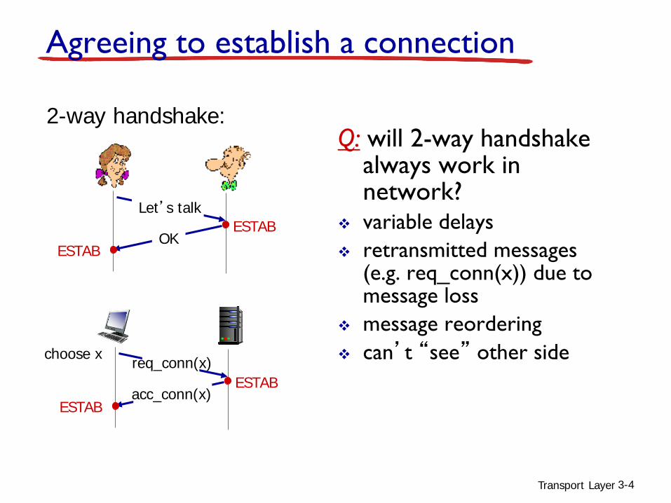
Q will 2-way handshake always work in network
variable delays retransmitted messages
(eg req_conn(x)) due to message loss
message reordering canrsquot ldquoseerdquo other side
2-way handshake
Letrsquos talk
OKESTAB
ESTAB
choose x req_conn(x)ESTAB
ESTABacc_conn(x)
Agreeing to establish a connection
Transport Layer 3-5
Agreeing to establish a connection
2-way handshake failure scenarios
retransmitreq_conn(x)
ESTAB
req_conn(x)
half open connection(no client)
client terminates
serverforgets x
connection x completes
retransmitreq_conn(x)
ESTAB
req_conn(x)
data(x+1)
retransmitdata(x+1)
acceptdata(x+1)
choose x req_conn(x)ESTAB
ESTAB
acc_conn(x)
client terminates
ESTAB
choose x req_conn(x)ESTAB
acc_conn(x)
data(x+1) acceptdata(x+1)
connection x completes server
forgets x
Transport Layer 6
TCP 3-way handshake
SYNbit=1 Seq=x
choose init seq num xsend TCP SYN msg
ESTAB
SYNbit=1 Seq=yACKbit=1 ACKnum=x+1
choose init seq num ysend TCP SYNACKmsg acking SYN
ACKbit=1 ACKnum=y+1
received SYNACK(x) indicates server is livesend ACK for SYNACK
this segment may contain client-to-server data received ACK(y)
indicates client is live
SYNSENT
ESTAB
SYN RCVD
client stateLISTEN
server stateLISTEN
Transport Layer 7
Chapter 3 outline
31 transport-layer services
32 multiplexing and demultiplexing
33 connectionless transport UDP
34 principles of reliable data transfer
35 connection-oriented transport TCP segment structure reliable data transfer flow control connection management
36 principles of congestion control
37 TCP congestion control
Transport Layer 8
congestion informally ldquotoo many sources sending too much
data too fast for network to handlerdquo
different from flow control manifestations lost packets (buffer overflow at routers) long delays (queueing in router buffers)
a top-10 problem
Principles of congestion control
Transport Layer 9
Causescosts of congestion scenario 1
two senders two receivers
one router infinite buffers
output link capacity R no retransmission
maximum per-connection throughput R2
unlimited shared output link buffers
Host A
original data λin
Host B
throughput λout
R2
R2
λ out
λin R2de
lay
λin large delays as arrival rate λin
approaches capacity
Transport Layer 10
one router finite buffers sender retransmission of timed-out packet application-layer input = application-layer output λin = λout transport-layer input includes retransmissions λin λin
finite shared output link buffers
Host A
λin original data
Host B
λoutλin original data plusretransmitted data
lsquo
Causescosts of congestion scenario 2
Transport Layer 11
idealization perfect knowledge
sender sends only when router buffers available
finite shared output link buffers
λin original dataλoutλin original data plus
retransmitted datacopy
free buffer space
R2
R2
λ out
λin
Causescosts of congestion scenario 2
Host B
A
Transport Layer 12
λin original dataλoutλin original data plus
retransmitted datacopy
no buffer space
Idealization known losspackets can be lost dropped at router due to full buffers
sender only resends if packet known to be lost
Causescosts of congestion scenario 2
A
Host B
Transport Layer 13
λin original dataλoutλin original data plus
retransmitted data
free buffer space
Causescosts of congestion scenario 2Idealization known loss
packets can be lost dropped at router due to full buffers
sender only resends if packet known to be lost
R2
R2λin
λ out
when sending at R2 some packets are retransmissions but asymptotic goodput is still R2 (why)
A
Host B
Transport Layer 14
A
λin λoutλincopy
free buffer space
timeout
R2
R2λin
λ out
when sending at R2 some packets are retransmissions including duplicated that are delivered
Host B
Realistic duplicates packets can be lost dropped
at router due to full buffers sender times out prematurely
sending two copies both of which are delivered
Causescosts of congestion scenario 2
Throughput Data rate at the
receiver
Goodput Rate at the receiver for
data without duplicate
Transport Layer 15
Transport Layer 16
R2
λ out
when sending at R2 some packets are retransmissions including duplicated that are delivered
ldquocostsrdquo of congestion more work (retrans) for given ldquogoodputrdquo unneeded retransmissions link carries multiple copies of pkt decreasing goodput
R2λin
Causescosts of congestion scenario 2Realistic duplicates packets can be lost dropped
at router due to full buffers sender times out prematurely
sending two copies both of which are delivered
Transport Layer 17
four senders multihop paths timeoutretransmit
Q what happens as λin and λinrsquo
increase
finite shared output link buffers
Host A λout
Causescosts of congestion scenario 3
Host B
Host CHost D
λin original dataλin original data plus
retransmitted data
A as red λinrsquo increases all arriving
blue pkts at upper queue are dropped blue throughput 0
Transport Layer 18
another ldquocostrdquo of congestion when packet dropped any ldquoupstream
transmission capacity used for that packet was wasted
Causescosts of congestion scenario 3
C2
C2
λ out
λinrsquo
Transport Layer 19
Approaches towards congestion control
two broad approaches towards congestion control
end-end congestion control
no explicit feedback from network
congestion inferred from end-system observed loss delay
approach taken by TCP
network-assisted congestion control
routers provide feedback to end systems single bit indicating
congestion (SNA DECbit TCPIP ECN ATM)explicit rate for
sender to send at
Transport Layer 20
Chapter 3 outline
31 transport-layer services
32 multiplexing and demultiplexing
33 connectionless transport UDP
34 principles of reliable data transfer
35 connection-oriented transport TCP segment structure reliable data transfer flow control connection management
36 principles of congestion control
37 TCP congestion control
Transport Layer 21
TCP Congestion Control details
sender limits transmission
cwnd is dynamic function of perceived network congestion
TCP sending rate roughly send cwnd
bytes wait RTT for ACKS then send more bytes
last byteACKed sent not-
yet ACKed(ldquoin-flightrdquo)
last byte sent
cwnd
LastByteSent-LastByteAcked
lt cwnd
sender sequence number space
rate ~~cwndRTT
bytessec
Transport Layer 22
TCP Slow Start
when connection begins increase rate exponentially until first loss event initially cwnd = 1 MSS double cwnd every RTT done by incrementing cwnd for every ACK received
summary initial rate is slow but ramps up exponentially fast
Host A
RTT
Host B
time
Transport Layer 23
TCP detecting reacting to loss
loss indicated by timeout set a threshold ssthresh to half of the cwnd cwnd set to 1 MSS (by both TCP Tahoe and Reno) window then grows exponentially (as in slow start)
to threshold then grows linearly TCP Tahoe always sets cwnd to 1 (timeout or 3
duplicate acks) TCP RENO loss indicated by 3 duplicate ACKs dup ACKs indicate network capable of delivering
some segments cwnd is cut in half window then grows linearly
After cwnd reaching the threshold
Congestion avoidance algorithm
Additive increase multiplicative decrease (AIMD)
Transport Layer 3-24
Transport Layer 25
TCP congestion control AIMD
approach sender increases transmission rate (window size) probing for usable bandwidth until loss occurs additive increase increase cwnd by 1 MSS every
RTT until loss detectedmultiplicative decrease cut cwnd in half after loss cwnd
TCP
send
er
cong
estio
n w
indo
w s
ize
AIMD saw toothbehavior probing
for bandwidth
additively increase window size helliphellip until loss occurs (then cut window in half)
time
Transport Layer 26
Q when should the exponential increase switch to linear
A when cwnd gets to 12 of its value before timeout
Implementation variable ssthresh on loss event ssthresh
is set to 12 of cwnd just before loss event
TCP switching from slow start to CA
Transport Layer 27
Summary TCP Congestion Control
timeoutssthresh = cwnd2
cwnd = 1 MSSdupACKcount = 0
retransmit missing segment
Λcwnd gt ssthresh
congestionavoidance
cwnd = cwnd + MSS (MSScwnd)dupACKcount = 0
transmit new segment(s) as allowed
new ACK
dupACKcount++duplicate ACK
fastrecovery
cwnd = cwnd + MSStransmit new segment(s) as allowed
duplicate ACK
ssthresh= cwnd2cwnd = ssthresh + 3
retransmit missing segment
dupACKcount == 3
timeoutssthresh = cwnd2cwnd = 1 dupACKcount = 0retransmit missing segment
ssthresh= cwnd2cwnd = ssthresh + 3retransmit missing segment
dupACKcount == 3cwnd = ssthreshdupACKcount = 0
New ACK
slow start
timeoutssthresh = cwnd2
cwnd = 1 MSSdupACKcount = 0
retransmit missing segment
cwnd = cwnd+MSSdupACKcount = 0transmit new segment(s) as allowed
new ACKdupACKcount++duplicate ACK
Λcwnd = 1 MSS
ssthresh = 64 KBdupACKcount = 0
NewACK
NewACK
NewACK
Transport Layer 28
TCP throughput avg TCP thruput as function of window size RTT ignore slow start assume always data to send
W window size (measured in bytes) where loss occurs avg window size ( in-flight bytes) is frac34 W avg thruput is 34W per RTT
W
W2
avg TCP thruput = 34
WRTT bytessec
Transport Layer 29
TCP Futures TCP over ldquolong fat pipesrdquo
example 1500 byte segments 100ms RTT want 10 Gbps throughput
requires W = 83333 in-flight segments throughput in terms of segment loss probability L
[Mathis 1997]
to achieve 10 Gbps throughput need a loss rate of L = 210-10 ndash a very small loss rate
new versions of TCP for high-speed
TCP throughput = 122 MSSRTT L
Transport Layer 30
fairness goal if K TCP sessions share same bottleneck link of bandwidth R each should have average rate of RK
TCP connection 1
bottleneckrouter
capacity R
TCP Fairness
TCP connection 2
Transport Layer 31
Why is TCP fairtwo competing sessions additive increase gives slope of 1 as throughout increases multiplicative decrease decreases throughput proportionally
R
R
equal bandwidth share
Connection 1 throughput
congestion avoidance additive increaseloss decrease window by factor of 2
congestion avoidance additive increaseloss decrease window by factor of 2
Van Jacobson
One of the key designers of TCP congestion control httpswwwyoutubecomwatchv=QP4A6L7CEqA 140-920
32
Transport Layer 33
Fairness (more)Fairness and UDP multimedia apps often
do not use TCP do not want rate
throttled by congestion control
instead use UDP send audiovideo at
constant rate tolerate packet loss
Fairness parallel TCP connections
application can open multiple parallel connections between two hosts
web browsers do this eg link of rate R with 9
existing connections new app asks for 1 TCP gets rate
R10 new app asks for 11 TCPs gets R2
Transport Layer 34
Chapter 3 summary principles behind
transport layer servicesmultiplexing
demultiplexing reliable data transfer flow control congestion control
instantiation implementation in the Internet UDP TCP
next leaving the
network ldquoedgerdquo(application transport layers)
into the network ldquocorerdquo
Next class
Midterm covers every slide until here
Please read Chapter 41-42 of your textbook BEFORE Class
35

Midterm exam
Midterm next Thursday
Close book but one-side 85x11 note is allowed (must use hand-writing)
Let me know by next Monday if you have any problem
Sample midterm and sample question of Chapter 2amp3
2
3
Chapter 3 outline
31 transport-layer services
32 multiplexing and demultiplexing
33 connectionless transport UDP
34 principles of reliable data transfer
35 connection-oriented transport TCP segment structure reliable data transfer flow control connection management
36 principles of congestion control
37 TCP congestion control
Transport Layer 3-4
Q will 2-way handshake always work in network
variable delays retransmitted messages
(eg req_conn(x)) due to message loss
message reordering canrsquot ldquoseerdquo other side
2-way handshake
Letrsquos talk
OKESTAB
ESTAB
choose x req_conn(x)ESTAB
ESTABacc_conn(x)
Agreeing to establish a connection
Transport Layer 3-5
Agreeing to establish a connection
2-way handshake failure scenarios
retransmitreq_conn(x)
ESTAB
req_conn(x)
half open connection(no client)
client terminates
serverforgets x
connection x completes
retransmitreq_conn(x)
ESTAB
req_conn(x)
data(x+1)
retransmitdata(x+1)
acceptdata(x+1)
choose x req_conn(x)ESTAB
ESTAB
acc_conn(x)
client terminates
ESTAB
choose x req_conn(x)ESTAB
acc_conn(x)
data(x+1) acceptdata(x+1)
connection x completes server
forgets x
Transport Layer 6
TCP 3-way handshake
SYNbit=1 Seq=x
choose init seq num xsend TCP SYN msg
ESTAB
SYNbit=1 Seq=yACKbit=1 ACKnum=x+1
choose init seq num ysend TCP SYNACKmsg acking SYN
ACKbit=1 ACKnum=y+1
received SYNACK(x) indicates server is livesend ACK for SYNACK
this segment may contain client-to-server data received ACK(y)
indicates client is live
SYNSENT
ESTAB
SYN RCVD
client stateLISTEN
server stateLISTEN
Transport Layer 7
Chapter 3 outline
31 transport-layer services
32 multiplexing and demultiplexing
33 connectionless transport UDP
34 principles of reliable data transfer
35 connection-oriented transport TCP segment structure reliable data transfer flow control connection management
36 principles of congestion control
37 TCP congestion control
Transport Layer 8
congestion informally ldquotoo many sources sending too much
data too fast for network to handlerdquo
different from flow control manifestations lost packets (buffer overflow at routers) long delays (queueing in router buffers)
a top-10 problem
Principles of congestion control
Transport Layer 9
Causescosts of congestion scenario 1
two senders two receivers
one router infinite buffers
output link capacity R no retransmission
maximum per-connection throughput R2
unlimited shared output link buffers
Host A
original data λin
Host B
throughput λout
R2
R2
λ out
λin R2de
lay
λin large delays as arrival rate λin
approaches capacity
Transport Layer 10
one router finite buffers sender retransmission of timed-out packet application-layer input = application-layer output λin = λout transport-layer input includes retransmissions λin λin
finite shared output link buffers
Host A
λin original data
Host B
λoutλin original data plusretransmitted data
lsquo
Causescosts of congestion scenario 2
Transport Layer 11
idealization perfect knowledge
sender sends only when router buffers available
finite shared output link buffers
λin original dataλoutλin original data plus
retransmitted datacopy
free buffer space
R2
R2
λ out
λin
Causescosts of congestion scenario 2
Host B
A
Transport Layer 12
λin original dataλoutλin original data plus
retransmitted datacopy
no buffer space
Idealization known losspackets can be lost dropped at router due to full buffers
sender only resends if packet known to be lost
Causescosts of congestion scenario 2
A
Host B
Transport Layer 13
λin original dataλoutλin original data plus
retransmitted data
free buffer space
Causescosts of congestion scenario 2Idealization known loss
packets can be lost dropped at router due to full buffers
sender only resends if packet known to be lost
R2
R2λin
λ out
when sending at R2 some packets are retransmissions but asymptotic goodput is still R2 (why)
A
Host B
Transport Layer 14
A
λin λoutλincopy
free buffer space
timeout
R2
R2λin
λ out
when sending at R2 some packets are retransmissions including duplicated that are delivered
Host B
Realistic duplicates packets can be lost dropped
at router due to full buffers sender times out prematurely
sending two copies both of which are delivered
Causescosts of congestion scenario 2
Throughput Data rate at the
receiver
Goodput Rate at the receiver for
data without duplicate
Transport Layer 15
Transport Layer 16
R2
λ out
when sending at R2 some packets are retransmissions including duplicated that are delivered
ldquocostsrdquo of congestion more work (retrans) for given ldquogoodputrdquo unneeded retransmissions link carries multiple copies of pkt decreasing goodput
R2λin
Causescosts of congestion scenario 2Realistic duplicates packets can be lost dropped
at router due to full buffers sender times out prematurely
sending two copies both of which are delivered
Transport Layer 17
four senders multihop paths timeoutretransmit
Q what happens as λin and λinrsquo
increase
finite shared output link buffers
Host A λout
Causescosts of congestion scenario 3
Host B
Host CHost D
λin original dataλin original data plus
retransmitted data
A as red λinrsquo increases all arriving
blue pkts at upper queue are dropped blue throughput 0
Transport Layer 18
another ldquocostrdquo of congestion when packet dropped any ldquoupstream
transmission capacity used for that packet was wasted
Causescosts of congestion scenario 3
C2
C2
λ out
λinrsquo
Transport Layer 19
Approaches towards congestion control
two broad approaches towards congestion control
end-end congestion control
no explicit feedback from network
congestion inferred from end-system observed loss delay
approach taken by TCP
network-assisted congestion control
routers provide feedback to end systems single bit indicating
congestion (SNA DECbit TCPIP ECN ATM)explicit rate for
sender to send at
Transport Layer 20
Chapter 3 outline
31 transport-layer services
32 multiplexing and demultiplexing
33 connectionless transport UDP
34 principles of reliable data transfer
35 connection-oriented transport TCP segment structure reliable data transfer flow control connection management
36 principles of congestion control
37 TCP congestion control
Transport Layer 21
TCP Congestion Control details
sender limits transmission
cwnd is dynamic function of perceived network congestion
TCP sending rate roughly send cwnd
bytes wait RTT for ACKS then send more bytes
last byteACKed sent not-
yet ACKed(ldquoin-flightrdquo)
last byte sent
cwnd
LastByteSent-LastByteAcked
lt cwnd
sender sequence number space
rate ~~cwndRTT
bytessec
Transport Layer 22
TCP Slow Start
when connection begins increase rate exponentially until first loss event initially cwnd = 1 MSS double cwnd every RTT done by incrementing cwnd for every ACK received
summary initial rate is slow but ramps up exponentially fast
Host A
RTT
Host B
time
Transport Layer 23
TCP detecting reacting to loss
loss indicated by timeout set a threshold ssthresh to half of the cwnd cwnd set to 1 MSS (by both TCP Tahoe and Reno) window then grows exponentially (as in slow start)
to threshold then grows linearly TCP Tahoe always sets cwnd to 1 (timeout or 3
duplicate acks) TCP RENO loss indicated by 3 duplicate ACKs dup ACKs indicate network capable of delivering
some segments cwnd is cut in half window then grows linearly
After cwnd reaching the threshold
Congestion avoidance algorithm
Additive increase multiplicative decrease (AIMD)
Transport Layer 3-24
Transport Layer 25
TCP congestion control AIMD
approach sender increases transmission rate (window size) probing for usable bandwidth until loss occurs additive increase increase cwnd by 1 MSS every
RTT until loss detectedmultiplicative decrease cut cwnd in half after loss cwnd
TCP
send
er
cong
estio
n w
indo
w s
ize
AIMD saw toothbehavior probing
for bandwidth
additively increase window size helliphellip until loss occurs (then cut window in half)
time
Transport Layer 26
Q when should the exponential increase switch to linear
A when cwnd gets to 12 of its value before timeout
Implementation variable ssthresh on loss event ssthresh
is set to 12 of cwnd just before loss event
TCP switching from slow start to CA
Transport Layer 27
Summary TCP Congestion Control
timeoutssthresh = cwnd2
cwnd = 1 MSSdupACKcount = 0
retransmit missing segment
Λcwnd gt ssthresh
congestionavoidance
cwnd = cwnd + MSS (MSScwnd)dupACKcount = 0
transmit new segment(s) as allowed
new ACK
dupACKcount++duplicate ACK
fastrecovery
cwnd = cwnd + MSStransmit new segment(s) as allowed
duplicate ACK
ssthresh= cwnd2cwnd = ssthresh + 3
retransmit missing segment
dupACKcount == 3
timeoutssthresh = cwnd2cwnd = 1 dupACKcount = 0retransmit missing segment
ssthresh= cwnd2cwnd = ssthresh + 3retransmit missing segment
dupACKcount == 3cwnd = ssthreshdupACKcount = 0
New ACK
slow start
timeoutssthresh = cwnd2
cwnd = 1 MSSdupACKcount = 0
retransmit missing segment
cwnd = cwnd+MSSdupACKcount = 0transmit new segment(s) as allowed
new ACKdupACKcount++duplicate ACK
Λcwnd = 1 MSS
ssthresh = 64 KBdupACKcount = 0
NewACK
NewACK
NewACK
Transport Layer 28
TCP throughput avg TCP thruput as function of window size RTT ignore slow start assume always data to send
W window size (measured in bytes) where loss occurs avg window size ( in-flight bytes) is frac34 W avg thruput is 34W per RTT
W
W2
avg TCP thruput = 34
WRTT bytessec
Transport Layer 29
TCP Futures TCP over ldquolong fat pipesrdquo
example 1500 byte segments 100ms RTT want 10 Gbps throughput
requires W = 83333 in-flight segments throughput in terms of segment loss probability L
[Mathis 1997]
to achieve 10 Gbps throughput need a loss rate of L = 210-10 ndash a very small loss rate
new versions of TCP for high-speed
TCP throughput = 122 MSSRTT L
Transport Layer 30
fairness goal if K TCP sessions share same bottleneck link of bandwidth R each should have average rate of RK
TCP connection 1
bottleneckrouter
capacity R
TCP Fairness
TCP connection 2
Transport Layer 31
Why is TCP fairtwo competing sessions additive increase gives slope of 1 as throughout increases multiplicative decrease decreases throughput proportionally
R
R
equal bandwidth share
Connection 1 throughput
congestion avoidance additive increaseloss decrease window by factor of 2
congestion avoidance additive increaseloss decrease window by factor of 2
Van Jacobson
One of the key designers of TCP congestion control httpswwwyoutubecomwatchv=QP4A6L7CEqA 140-920
32
Transport Layer 33
Fairness (more)Fairness and UDP multimedia apps often
do not use TCP do not want rate
throttled by congestion control
instead use UDP send audiovideo at
constant rate tolerate packet loss
Fairness parallel TCP connections
application can open multiple parallel connections between two hosts
web browsers do this eg link of rate R with 9
existing connections new app asks for 1 TCP gets rate
R10 new app asks for 11 TCPs gets R2
Transport Layer 34
Chapter 3 summary principles behind
transport layer servicesmultiplexing
demultiplexing reliable data transfer flow control congestion control
instantiation implementation in the Internet UDP TCP
next leaving the
network ldquoedgerdquo(application transport layers)
into the network ldquocorerdquo
Next class
Midterm covers every slide until here
Please read Chapter 41-42 of your textbook BEFORE Class
35
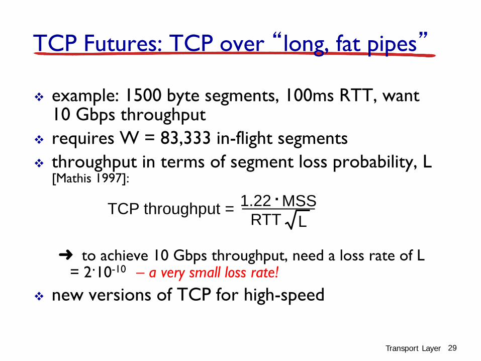
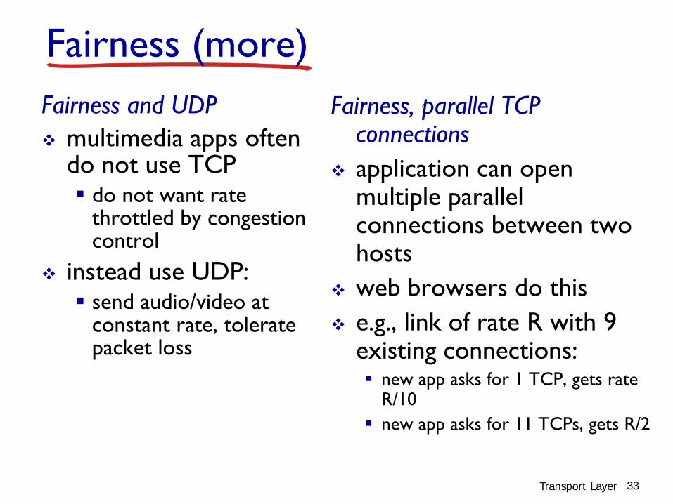

Next class
Midterm covers every slide until here
Please read Chapter 41-42 of your textbook BEFORE Class
35


