International Journal of Modern Engineering Research (IJMER) www.ijmer.com Vol. 3, Issue. 4, July-august. 2013 pp-2250-2261 ISSN: 2249-6645 www.ijmer.com 2250 | Page Dr. V.S.S. Murthy 1 P. Sreenivas 2 1( Professor and Principal of K.S.R.M College of Engg, Dept of Mechanical Engineering, Kadapa, Andhra Pradesh, India) 2 (Assistant Professor, Dept of Mechanical Engineering, K.S.R.M College of Engg, Kadapa, Andhra Pradesh, India) ABSTRACT: In the present study in view of the latest development and revolutionary changes taking place in CNC field through the world, Mechanical elements have to be designed and manufactured to precision, which is perfectly and easily possible through these modern CNC machines. This work is based on the capacity and capability of vertical machining Centre (VTC) with auto tool changer. The top slide which was part programmed can be machined using VTC. And Machining Time is compared in between carbide and hardened tools. The “Top slide” of lathe’s called for powerful NC programming technique were used absolute position type data input system using G codes, M codes, polar coordinate programs, circular and linear interpolation, canned cycles etc. The above mentioned component – top slide being manufactured by using various Conventional machine tools like horizontal milling, vertical milling, surface grinding, boring machine and slotting machines. This involved a considerable lead time and usually delayed the assembly schedule. it has been modified and adopted for regular production on this machine, in two setups there by boosting their productivity and ensuring quality in each and every piece. Finally, we can establish for regular production. KEYWORDS: CNC Programming, Machining Time, carbide & hardened Tools. I. INTRODUCTION I.1.NUMERICAL CONTROL: Numerical control (NC) can be defined as a form of programmable automation in which the process is controlled by numbers, letters and symbols. In NC, the numbers form a program of instructions of designed for a particular work part or job. The definition of NC given by electronic industries association (EIA) is “A system in which actions are controlled by direct insertion of numerical data at some point. The system must automatically interpret at least some portion of this data. “ A Numerical control (NC) system is used when The number of components per component is large Size of batches is medium Labour cost for the component is high The component requires special tooling Ratio of cutting time to non-cutting time is high Design changes are frequent I.2. BASIC ELEMENTS OF A NC SYSTEM: An operational numerical control system consists of three basic components Controller unit also known as machine control unit (MCU) Machine tool or other machining centre The program of instructions serves as the input to the controller unit, which in turn commands the machine tool or other process to be controlled. I.2.1 PROGRAM OF INSTRUCTIONS: The program of instructions is the detailed step-by-step set of directions which instructs the machine tool what to do. It is coded in numerical or symbolic form on some type of input medium that can be interpreted by the controller unit. The input media used can be punched cards/ magnetic disk or tape/punched tape. There are two methods of inputs in the NC system. By manual entry of instructional data to the controller unit and this method is called manual data input (MDI) and is appropriate only for relatively simple jobs where the order will not be protected. By means of a direct link with a computer. This is called direct numerical control (DNC). Fig.1 Basic Components of NC system Part programmer prepares the program of instructions. The programmer’s job is to provide a set of detailed instructions by which the sequences of processing steps are to be performed. The processing steps for a machining operation are the relative movement between the cutting tool and the work piece I.2.2 CONTROLLER UNIT: The controller unit consists of the electronics and hardware that reveals and interprets the program of instructions and converts it into mechanical actions of the machine tool. The controller unit elements are tape CNC PART PROGRAMMING AND COST ANALYSIS ON VERTICAL MACHINING CENTRE (VTC)
Transcript
International Journal of Modern Engineering Research (IJMER)
1(Professor and Principal of K.S.R.M College of Engg, Dept of Mechanical Engineering,
Kadapa, Andhra Pradesh, India) 2(Assistant Professor, Dept of Mechanical Engineering,
K.S.R.M College of Engg, Kadapa, Andhra Pradesh, India)
ABSTRACT: In the present study in view of the latest development and revolutionary changes taking place in CNC field
through the world, Mechanical elements have to be designed and manufactured to precision, which is perfectly and easily
possible through these modern CNC machines. This work is based on the capacity and capability of vertical machining
Centre (VTC) with auto tool changer. The top slide which was part programmed can be machined using VTC. And
Machining Time is compared in between carbide and hardened tools. The “Top slide” of lathe’s called for powerful NC
programming technique were used absolute position type data input system using G codes, M codes, polar coordinate
programs, circular and linear interpolation, canned cycles etc. The above mentioned component – top slide being manufactured by using various Conventional machine tools like horizontal milling, vertical milling, surface grinding, boring
machine and slotting machines. This involved a considerable lead time and usually delayed the assembly schedule. it has
been modified and adopted for regular production on this machine, in two setups there by boosting their productivity and
ensuring quality in each and every piece. Finally, we can establish for regular production.
KEYWORDS: CNC Programming, Machining Time, carbide & hardened Tools.
I. INTRODUCTION I.1.NUMERICAL CONTROL: Numerical control (NC) can be defined as a form of programmable automation in which
the process is controlled by numbers, letters and symbols. In NC, the numbers form a program of instructions of designed for
a particular work part or job.
The definition of NC given by electronic industries association (EIA) is “A system in which actions are
controlled by direct insertion of numerical data at some point. The system must automatically interpret at least some portion
of this data. “
A Numerical control (NC) system is used when
The number of components per component is large
Size of batches is medium
Labour cost for the component is high
The component requires special tooling
Ratio of cutting time to non-cutting time is high
Design changes are frequent
I.2. BASIC ELEMENTS OF A NC SYSTEM: An operational numerical control system consists of three basic components
Controller unit also known as machine control unit (MCU)
Machine tool or other machining centre
The program of instructions serves as the input to the controller unit, which in turn commands the machine tool
or other process to be controlled.
I.2.1 PROGRAM OF INSTRUCTIONS: The program of instructions is the detailed step-by-step set of directions which instructs the machine tool what to do. It is coded in numerical or symbolic form on some type of input medium that can be
interpreted by the controller unit. The input media used can be punched cards/ magnetic disk or tape/punched tape. There are
two methods of inputs in the NC system.
By manual entry of instructional data to the controller unit and this method is called manual data input (MDI) and is
appropriate only for relatively simple jobs where the order will not be protected.
By means of a direct link with a computer. This is called direct numerical control (DNC).
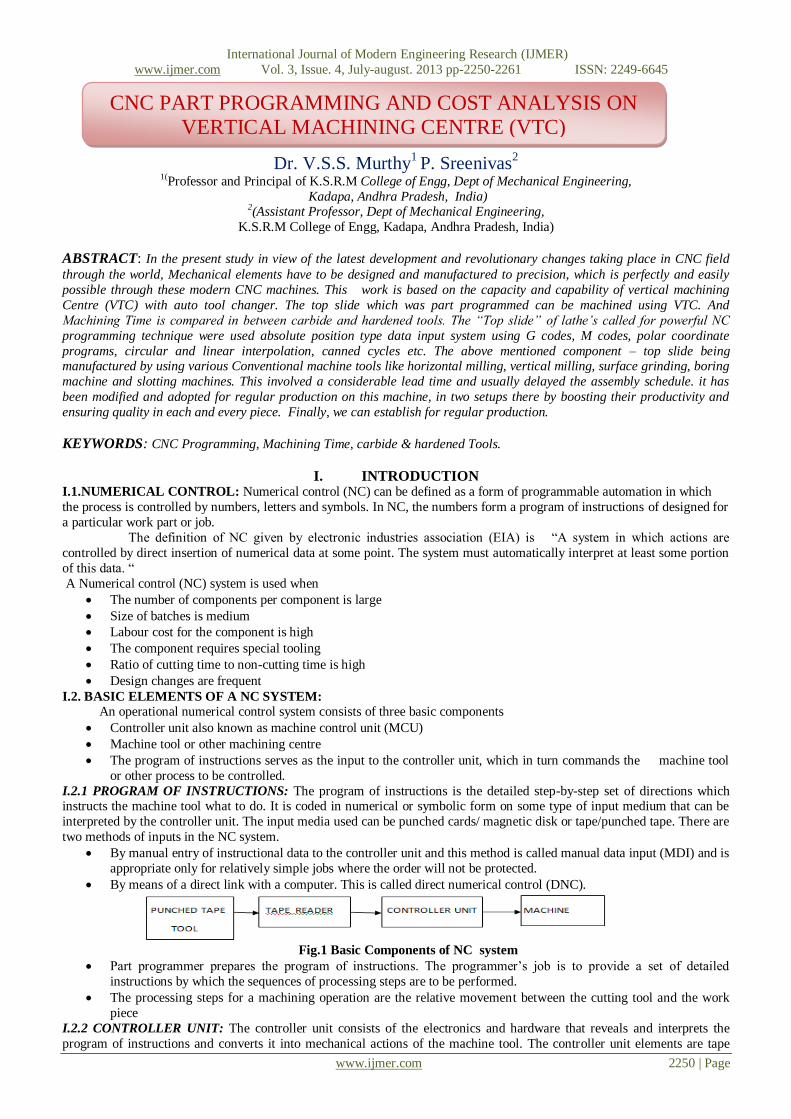
Fig.1 Basic Components of NC system
Part programmer prepares the program of instructions. The programmer’s job is to provide a set of detailed
instructions by which the sequences of processing steps are to be performed.
The processing steps for a machining operation are the relative movement between the cutting tool and the work
piece
I.2.2 CONTROLLER UNIT: The controller unit consists of the electronics and hardware that reveals and interprets the
program of instructions and converts it into mechanical actions of the machine tool. The controller unit elements are tape
CNC PART PROGRAMMING AND COST ANALYSIS ON VERTICAL MACHINING CENTRE (VTC)
International Journal of Modern Engineering Research (IJMER)
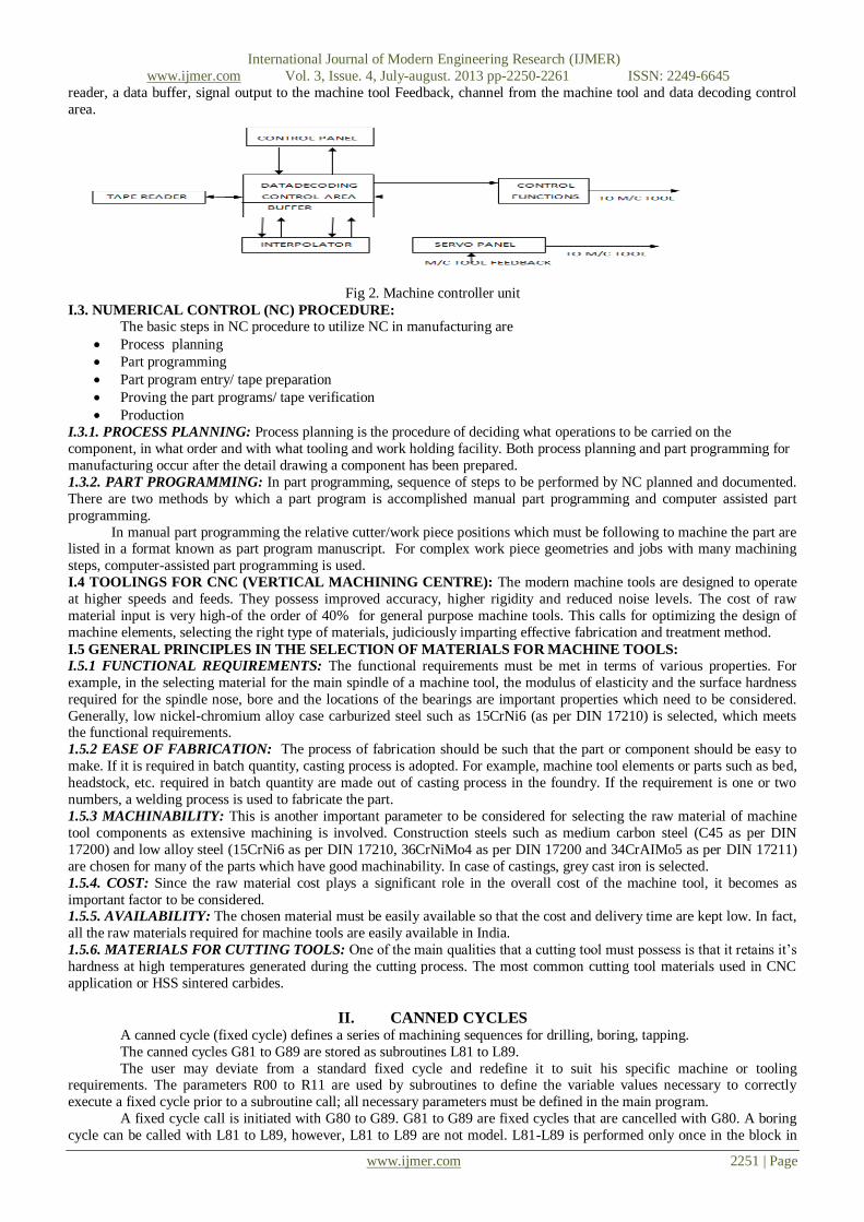
reader, a data buffer, signal output to the machine tool Feedback, channel from the machine tool and data decoding control
area.
Fig 2. Machine controller unit
I.3. NUMERICAL CONTROL (NC) PROCEDURE:
The basic steps in NC procedure to utilize NC in manufacturing are
Process planning
Part programming
Part program entry/ tape preparation
Proving the part programs/ tape verification
Production
I.3.1. PROCESS PLANNING: Process planning is the procedure of deciding what operations to be carried on the
component, in what order and with what tooling and work holding facility. Both process planning and part programming for
manufacturing occur after the detail drawing a component has been prepared.
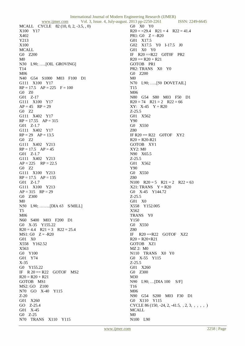
1.3.2. PART PROGRAMMING: In part programming, sequence of steps to be performed by NC planned and documented.
There are two methods by which a part program is accomplished manual part programming and computer assisted part
programming.
In manual part programming the relative cutter/work piece positions which must be following to machine the part are listed in a format known as part program manuscript. For complex work piece geometries and jobs with many machining
steps, computer-assisted part programming is used.
I.4 TOOLINGS FOR CNC (VERTICAL MACHINING CENTRE): The modern machine tools are designed to operate
at higher speeds and feeds. They possess improved accuracy, higher rigidity and reduced noise levels. The cost of raw
material input is very high-of the order of 40% for general purpose machine tools. This calls for optimizing the design of
machine elements, selecting the right type of materials, judiciously imparting effective fabrication and treatment method.
I.5 GENERAL PRINCIPLES IN THE SELECTION OF MATERIALS FOR MACHINE TOOLS:
I.5.1 FUNCTIONAL REQUIREMENTS: The functional requirements must be met in terms of various properties. For
example, in the selecting material for the main spindle of a machine tool, the modulus of elasticity and the surface hardness
required for the spindle nose, bore and the locations of the bearings are important properties which need to be considered.
Generally, low nickel-chromium alloy case carburized steel such as 15CrNi6 (as per DIN 17210) is selected, which meets the functional requirements.
1.5.2 EASE OF FABRICATION: The process of fabrication should be such that the part or component should be easy to
make. If it is required in batch quantity, casting process is adopted. For example, machine tool elements or parts such as bed,
headstock, etc. required in batch quantity are made out of casting process in the foundry. If the requirement is one or two
numbers, a welding process is used to fabricate the part.
1.5.3 MACHINABILITY: This is another important parameter to be considered for selecting the raw material of machine
tool components as extensive machining is involved. Construction steels such as medium carbon steel (C45 as per DIN
17200) and low alloy steel (15CrNi6 as per DIN 17210, 36CrNiMo4 as per DIN 17200 and 34CrAIMo5 as per DIN 17211)
are chosen for many of the parts which have good machinability. In case of castings, grey cast iron is selected.
1.5.4. COST: Since the raw material cost plays a significant role in the overall cost of the machine tool, it becomes as
important factor to be considered. 1.5.5. AVAILABILITY: The chosen material must be easily available so that the cost and delivery time are kept low. In fact,
all the raw materials required for machine tools are easily available in India.
1.5.6. MATERIALS FOR CUTTING TOOLS: One of the main qualities that a cutting tool must possess is that it retains it’s
hardness at high temperatures generated during the cutting process. The most common cutting tool materials used in CNC
application or HSS sintered carbides.
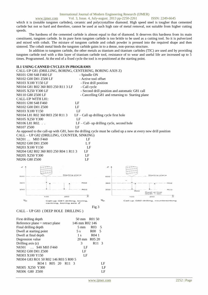
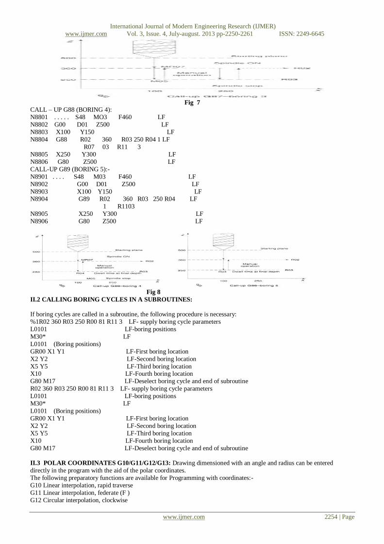
II. CANNED CYCLES A canned cycle (fixed cycle) defines a series of machining sequences for drilling, boring, tapping.
The canned cycles G81 to G89 are stored as subroutines L81 to L89.
The user may deviate from a standard fixed cycle and redefine it to suit his specific machine or tooling requirements. The parameters R00 to R11 are used by subroutines to define the variable values necessary to correctly
execute a fixed cycle prior to a subroutine call; all necessary parameters must be defined in the main program.
A fixed cycle call is initiated with G80 to G89. G81 to G89 are fixed cycles that are cancelled with G80. A boring
cycle can be called with L81 to L89, however, L81 to L89 are not model. L81-L89 is performed only once in the block in
International Journal of Modern Engineering Research (IJMER)
which it is (notable tungsten carbides), ceramic and polycrystalline diamond. High speed steel is tougher than cemented
carbide but not so hard and therefore, cannot be used at such high rate of metal removal, not suitable from higher cutting
speeds.
The hardness of the cemented carbide is almost equal to that of diamond. It deserves this hardness from its main constituent, tungsten carbide. In its pure form tungsten carbide is too brittle to be used as a cutting tool. So it is pulverized
and mixed with cobalt. The mixture of tungsten carbide and cobalt powder is pressed into the required shape and then
sintered. The cobalt metal binds the tungsten carbide gains in to a dense, non-porous structure.
In addition to tungsten carbide, the other metals as titanium and titanium carbides (TIC) are used and by providing
tungsten carbide tool with a thin layer of titanium carbide tool, resistance of to wear and useful life are increased up to 5
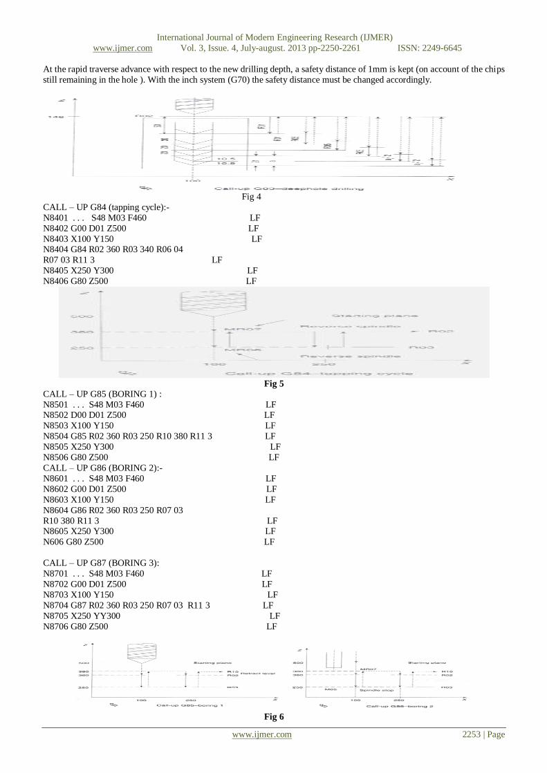
times. Programmed. At the end of a fixed cycle the tool is re-positioned at the starting point.
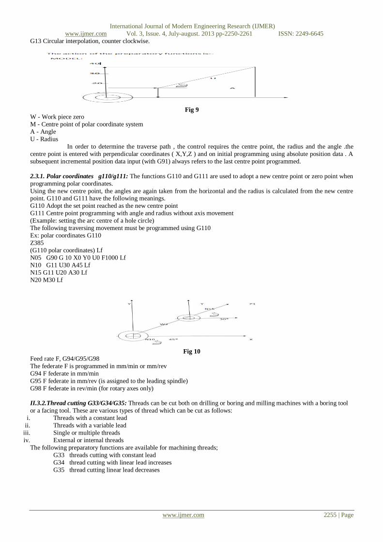
In order to determine the traverse path , the control requires the centre point, the radius and the angle .the
centre point is entered with perpendicular coordinates ( X,Y,Z ) and on initial programming using absolute position data . A
subsequent incremental position data input (with G91) always refers to the last centre point programmed.
2.3.1. Polar coordinates g110/g111: The functions G110 and G111 are used to adopt a new centre point or zero point when
programming polar coordinates.
Using the new centre point, the angles are again taken from the horizontal and the radius is calculated from the new centre point. G110 and G111 have the following meanings.
G110 Adopt the set point reached as the new centre point
G111 Centre point programming with angle and radius without axis movement
(Example: setting the arc centre of a hole circle)
The following traversing movement must be programmed using G110
Ex: polar coordinates G110
Z385
(G110 polar coordinates) Lf
N05 G90 G 10 X0 Y0 U0 F1000 Lf
N10 G11 U30 A45 Lf
N15 G11 U20 A30 Lf
N20 M30 Lf
Fig 10
Feed rate F, G94/G95/G98
The federate F is programmed in mm/min or mm/rev
G94 F federate in mm/min
G95 F federate in mm/rev (is assigned to the leading spindle)
G98 F federate in rev/min (for rotary axes only)
II.3.2.Thread cutting G33/G34/G35: Threads can be cut both on drilling or boring and milling machines with a boring tool
or a facing tool. These are various types of thread which can be cut as follows:
i. Threads with a constant lead
ii. Threads with a variable lead
iii. Single or multiple threads
iv. External or internal threads
The following preparatory functions are available for machining threads;
G33 threads cutting with constant lead
G34 thread cutting with linear lead increases
G35 thread cutting linear lead decreases
International Journal of Modern Engineering Research (IJMER)
Machining process converts raw material into useful finished product, surface finishing is needed to the foundry castings certain amount of material is added as a machining allowance for this purpose the size of the casting should be slightly over
size than the dimensions shown on the finished drawings the machining operations generally performed on vertical
machining center are:
Drilling
Boring
Shaping
Grinding
Reaming
Milling etc.
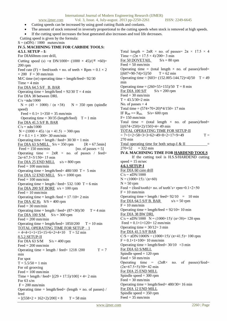
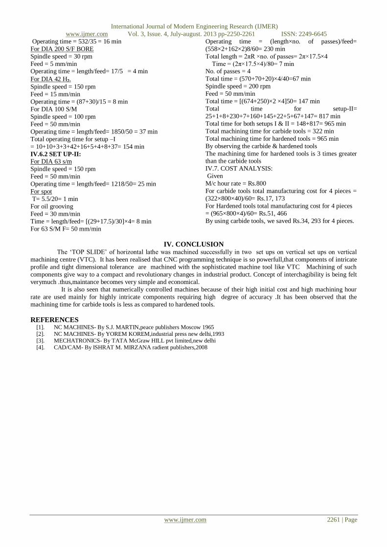
IV.2 PURPOSE OF ESTIMATING MACHINING TIME:
Estimation of machining time for different processes is required for the following processes: To estimate the manufacturing time
To fix the delivery dates
To determine the cost of labour charges
To find out the cost of manufacturing different parts
IV.3 MACHINING TIME
Estimation of machining time means calculation of time required to finish the given component according to the drawings
supplied after giving number of allowances in addition to the actual time taken for machining operations certain amount of
extra time is given to the workers. They are:
Setup time
Handling inspection of jobs
Team down time
Fatigue allowance
Tool changing allowance
Measurement checking allowance
Other allowances for cleaning
Getting stock etc.
There for total machining time is the actual time for machining and all the time allowances as given above.
To calculate actual machining time the basic general formula used is
Machining time = length of cut / (feed × rpm)
IV.4 CUTTING SPEED:
The cutting speed of a cutting tool may be defined as the speed at which the cutting edge passes over the material.
Cutting speed is generally expressed in m/min. An estimator should consider the following while selecting a suitable cutting speed.
Low cutting speeds are required for hand materials.
High speed steel cutting tools content high speeds and can bide tipped tools cut still higher speeds.
If the depth of cut and feed is more/less cutting speed may be taken and vice-versa
International Journal of Modern Engineering Research (IJMER)