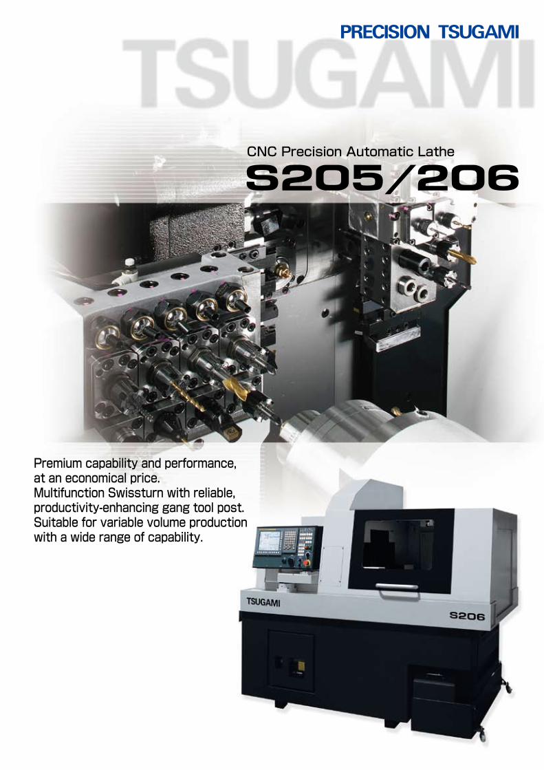
Premium capability and performance, at an economical price. Multifunction Swissturn with reliable, productivity-enhancing gang tool post. Suitable for variable volume production with a wide range of capability. CNC Precision Automatic Lathe
Transcript
S205 S206
Premium capability and performance, at an economical price.Multifunction Swissturn with reliable, productivity-enhancing gang tool post.Suitable for variable volume production with a wide range of capability.
Export permission by the Japanese Government may be required for exportingour products in accordance with the Foreign Exchange and Foreign Trade Law.Please contact our sales office before exporting our products. The specifications of this catalogue are subject to change without prior notice.
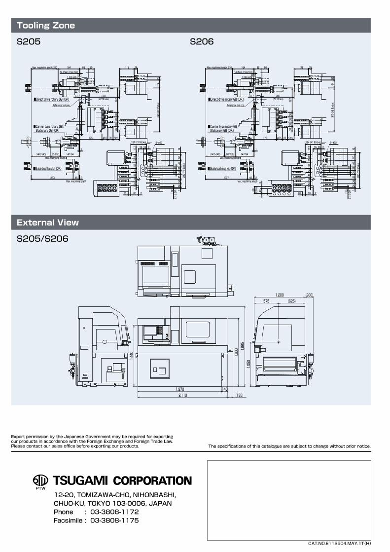
2,110
1,440
1,970
1,600
(135)
1,885
1,050
140
(200)1,200575 (625)
143
16
60(Y2 Stroke)
60 220
1734
3434
3028.3
17.7
1650
4234
3435
3434
1
17171717
280 (Y1 Stroke)
35 25 2
124 (X1 Stroke)
□12
(□16: OP)
66 50
5-φ22
14 (Rear cross tool)
Reference tool pos.
15
5
13 300(Z2 Stroke)
1 (GB end)
164Max. machining length: 210
175 46.5 39 52.5
340 (X2 Stroke)
3938
3838
187
6425
115 25
1
80/250Max. machining length
(147)/(40)
245Max. machining length
(327)
147/84
3451
■Direct drive rotary GB (OP.)
■Carrier type rotary GB / Stationary GB (OP.)
■Guide-bushless kit (OP.)
32
S205
Number of toolsOD toolCross drill
Front rotary toolFront drill (standard)Front drill (deep hole)
Back tool
3585
0 to 45
2 (100 mm)4 to 13 (back 4 + front drill 5 + double face 4)
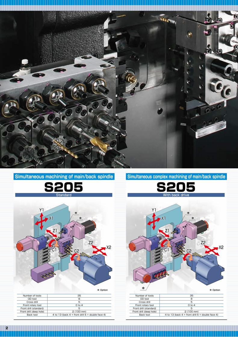
Simultaneous machining of main/back spindle
Y1
Y2
X1
X2
Z1
Z2C1C1C1 C2
Y1
X1
X2
Z1
Z2
C2
Y1
X1
X2
Z1
Z2
C2
StandardS205
Number of toolsOD toolCross drill
Front rotary toolFront drill (standard)Front drill (deep hole)
Back tool
3585
0 to 45
2 (100 mm)4 to 13 (back 4 + front drill 5 + double face 4)
Simultaneous complex machining of main/back spindle
With back driveS206
Number of toolsOD toolCross drill
Front rotary toolFront drill (standard)Front drill (deep hole)
Back tool
3985
0 to 45
2 (100 mm)8 to 17 (back 8 + front drill 5 + double face 4)
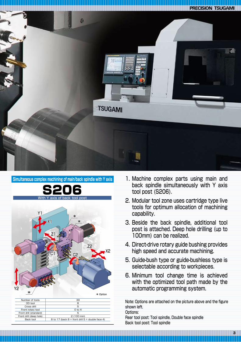
Simultaneous complex machining of main/back spindle with Y axis
With Y axis of back tool post
1.
2.
3.
4.
5.
6.
Machine complex parts using main and back spindle simultaneously with Y axis tool post (S206).Modular tool zone uses cartridge type live tools for optimum allocation of machining capability.Beside the back spindle, additional tool post is attached. Deep hole drilling (up to 100mm) can be realized.Direct-drive rotary guide bushing provides high speed and accurate machining.Guide-bush type or guide-bushless type is selectable according to workpieces.Minimum tool change time is achieved with the optimized tool path made by the automatic programming system.
Note: Options are attached on the picture above and the figure shown left.Options:Rear tool post: Tool spindle, Double face spindleBack tool post: Tool spindle
**
**
*
**
** Option * Option * Option
32
S205
Number of toolsOD toolCross drill
Front rotary toolFront drill (standard)Front drill (deep hole)
Back tool
3585
0 to 45
2 (100 mm)4 to 13 (back 4 + front drill 5 + double face 4)
Simultaneous machining of main/back spindle
Y1
Y2
X1
X2
Z1
Z2C1C1C1 C2
Y1
X1
X2
Z1
Z2
C2
Y1
X1
X2
Z1
Z2
C2
StandardS205
Number of toolsOD toolCross drill
Front rotary toolFront drill (standard)Front drill (deep hole)
Back tool
3585
0 to 45
2 (100 mm)4 to 13 (back 4 + front drill 5 + double face 4)
Simultaneous complex machining of main/back spindle
With back driveS206
Number of toolsOD toolCross drill
Front rotary toolFront drill (standard)Front drill (deep hole)
Back tool
3985
0 to 45
2 (100 mm)8 to 17 (back 8 + front drill 5 + double face 4)
Simultaneous complex machining of main/back spindle with Y axis
With Y axis of back tool post
1.
2.
3.
4.
5.
6.
Machine complex parts using main and back spindle simultaneously with Y axis tool post (S206).Modular tool zone uses cartridge type live tools for optimum allocation of machining capability.Beside the back spindle, additional tool post is attached. Deep hole drilling (up to 100mm) can be realized.Direct-drive rotary guide bushing provides high speed and accurate machining.Guide-bush type or guide-bushless type is selectable according to workpieces.Minimum tool change time is achieved with the optimized tool path made by the automatic programming system.
Note: Options are attached on the picture above and the figure shown left.Options:Rear tool post: Tool spindle, Double face spindleBack tool post: Tool spindle
**
**
*
**
** Option * Option * Option
54
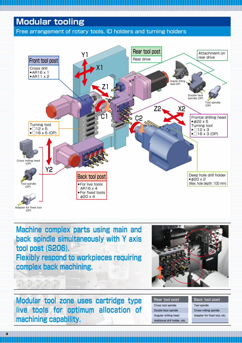
Modular toolingFree arrangement of rotary tools, ID holders and turning holders
Modular tool zone uses cartridge type live tools for optimum allocation of machining capability.
Machine complex parts using main and back spindle simultaneously with Y axis tool post (S206).Flexibly respond to workpieces requiring complex back machining.
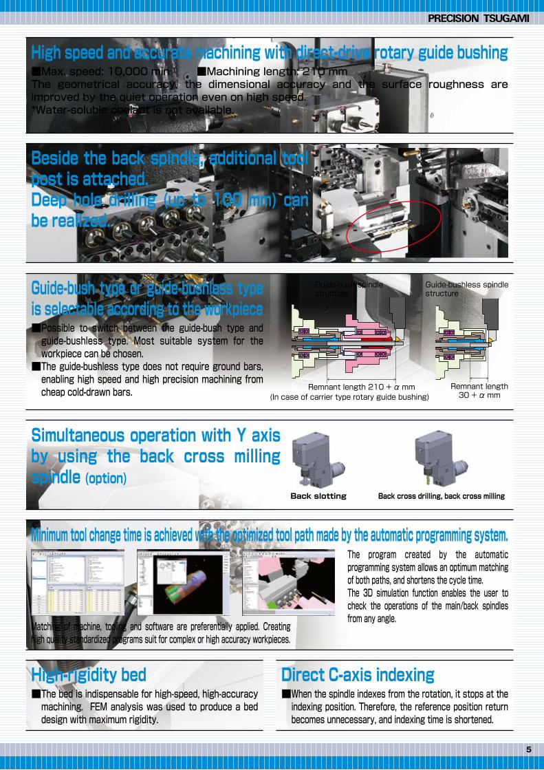
High-rigidity bed■The bed is indispensable for high-speed, high-accuracy machining. FEM analysis was used to produce a bed design with maximum rigidity.
Minimum tool change time is achieved with the optimized tool path made by the automatic programming system.
Simultaneous operation with Y axis by using the back cross milling spindle (option)
Beside the back spindle, additional tool post is attached.Deep hole drilling (up to 100 mm) can be realized.
High speed and accurate machining with direct-drive rotary guide bushing■Max. speed: 10,000 min-1 ■Machining length: 210 mmThe geometrical accuracy, the dimensional accuracy and the surface roughness are improved by the quiet operation even on high speed.*Water-soluble coolant is not available.
Guide-bush type or guide-bushless type is selectable according to the workpiece■Possible to switch between the guide-bush type and guide-bushless type. Most suitable system for the workpiece can be chosen.■The guide-bushless type does not require ground bars, enabling high speed and high precision machining from cheap cold-drawn bars.
Direct C-axis indexing■When the spindle indexes from the rotation, it stops at the indexing position. Therefore, the reference position return becomes unnecessary, and indexing time is shortened.
The program created by the automatic programming system allows an optimum matching of both paths, and shortens the cycle time.The 3D simulation function enables the user to check the operations of the main/back spindles from any angle.
Matching of machine, tooling and software are preferentially applied. Creating high quality standardized programs suit for complex or high accuracy workpieces.
Back slotting Back cross drilling, back cross milling
Guide-bush spindle structure
(In case of carrier type rotary guide bushing)Remnant length 210 + α mm
Guide-bushless spindle structure
Remnant length30 + α mm
Rear tool postCross tool spindle
Double face spindle
Angular drilling head
Additional drill holder, etc.
Back tool postTool spindle
Cross milling spindle
Adapter for fixed tool, etc.
Y1
Y2
X1
X2
Z1
Z2C1 C2
Front tool post
Back tool post
Rear tool post
Cross drill● AR16 x 1● AR11 x 2
Frontal drilling head● φ22 x 5Turning tool● □12 x 3● □16 x 3 (OP)
Rear driveAttachment on rear drive
● For live toolsAR16 x 4
● For fixed toolsφ20 x 4
Turning tool● □12 x 5● □16 x 5 (OP)
Deep hole drill holder● φ20 x 2(Max. hole depth: 100 mm)
Angular drilling head (OP)
Double face spindle (OP)
Tool spindle (OP)
Adapter for fixed tool(OP)
Tool spindle(OP)
Cross milling head(OP)
54
Modular toolingFree arrangement of rotary tools, ID holders and turning holders
Modular tool zone uses cartridge type live tools for optimum allocation of machining capability.
Machine complex parts using main and back spindle simultaneously with Y axis tool post (S206).Flexibly respond to workpieces requiring complex back machining.
High-rigidity bed■The bed is indispensable for high-speed, high-accuracy machining. FEM analysis was used to produce a bed design with maximum rigidity.
Minimum tool change time is achieved with the optimized tool path made by the automatic programming system.
Simultaneous operation with Y axis by using the back cross milling spindle (option)
Beside the back spindle, additional tool post is attached.Deep hole drilling (up to 100 mm) can be realized.
High speed and accurate machining with direct-drive rotary guide bushing■Max. speed: 10,000 min-1 ■Machining length: 210 mmThe geometrical accuracy, the dimensional accuracy and the surface roughness are improved by the quiet operation even on high speed.*Water-soluble coolant is not available.
Guide-bush type or guide-bushless type is selectable according to the workpiece■Possible to switch between the guide-bush type and guide-bushless type. Most suitable system for the workpiece can be chosen.■The guide-bushless type does not require ground bars, enabling high speed and high precision machining from cheap cold-drawn bars.
Direct C-axis indexing■When the spindle indexes from the rotation, it stops at the indexing position. Therefore, the reference position return becomes unnecessary, and indexing time is shortened.
The program created by the automatic programming system allows an optimum matching of both paths, and shortens the cycle time.The 3D simulation function enables the user to check the operations of the main/back spindles from any angle.
Matching of machine, tooling and software are preferentially applied. Creating high quality standardized programs suit for complex or high accuracy workpieces.
Back slotting Back cross drilling, back cross milling
Guide-bush spindle structure
(In case of carrier type rotary guide bushing)Remnant length 210 + α mm
Guide-bushless spindle structure
Remnant length30 + α mm
Rear tool postCross tool spindle
Double face spindle
Angular drilling head
Additional drill holder, etc.
Back tool postTool spindle
Cross milling spindle
Adapter for fixed tool, etc.
Y1
Y2
X1
X2
Z1
Z2C1 C2
Front tool post
Back tool post
Rear tool post
Cross drill● AR16 x 1● AR11 x 2
Frontal drilling head● φ22 x 5Turning tool● □12 x 3● □16 x 3 (OP)
Rear driveAttachment on rear drive
● For live toolsAR16 x 4
● For fixed toolsφ20 x 4
Turning tool● □12 x 5● □16 x 5 (OP)
Deep hole drill holder● φ20 x 2(Max. hole depth: 100 mm)
Angular drilling head (OP)
Double face spindle (OP)
Tool spindle (OP)
Adapter for fixed tool(OP)
Tool spindle(OP)
Cross milling head(OP)
76
Machine standard accessoriesItem Item
Chucking barstock dia.
Max. machining length
Max. drilling dia.
Max. tapping dia.
Deep hole drilling dia.
Max. back spindle chucking dia.
Max. back spindle drilling dia.
Max. back spindle tapping dia.
Max. tool spindle drilling dia.
Max. tool spindle tapping dia.
Max. tool spindle slotting cutter dia.
Main spindle speed
Back spindle speed
Rotary guide bushing
Tool spindle speed
Total tool storage capacity (Standard/Max.)
Tool size
Rapid traverse rate
Main spindle
Back spindle
Tool spindle
Rotary guide bushing
X1・X2・Z1・Z2・Y2 axes
Y1 axis
Coolant pump
Lubricating pump
Weight
Power source requirements
Compressed air requirement
Air discharge rate
Width x depth x height
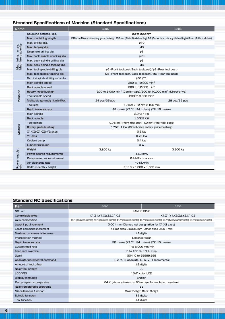
Standard Specifications of Machine (Standard Specifications)Machining range,
Machine capacity
Machine
Motors
Power supply,
etc
Name S205 S206
24 pcs/35 pcs
3,200 kg
φ3 to φ20 mm
210 mm (Direct-drive rotary guide bushing), 250 mm (Static Guide bushing), 80 (Carrier type rotary guide bushing)/45 mm (Guide bush less)
64 Kbyte (equivalent to 80 m tape for each path system)
63
Main: 5-digit, Back: 3-digit
S5 digits
T4 digits
X1,Z1,Y1,X2,Z2,C1,C2 X1,Z1,Y1,X2,Z2,Y2,C1,C2
Door interlock (Tooling zone side door/Main spindle side door)Coolant level switchSpindle cooling unitStandard toolsTransit clampsAutomatic power shut-offBack spindle air purgeCross drill air purgeBack drive (Applicable only for S206)Main spindle brake
Front tool post: 3-spindle cross drillRear tool post: Rear driveDeep hole drill holder(φ20 x 2 holes)C-axis control for main/back spindlesAutomatic programming systemTool-height displacement compensationTool counterPeriodic maintenance screenMain spindle adapterBack spindle adapter
NC standard accessoriesItem Item
Programmable data inputChamfering and corner RTool nose radius compensationHRV controlMultiple repetitive cycleExpanded program editingCanned cycle drillingRigid tap (Main spindle, back spindle, cross/back tool)Cut-off detection (Differential)Spindle speed fluctuation detection
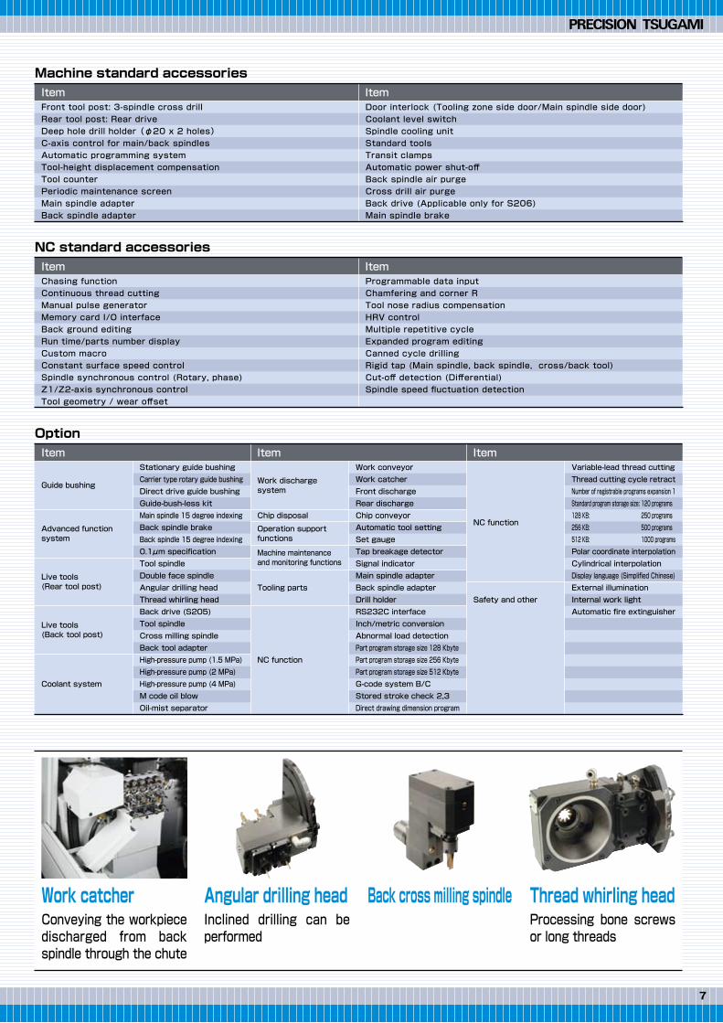
Work catcherConveying the workpiece discharged from back spindle through the chute
Angular drilling headInclined drilling can be performed
Back cross milling spindle Thread whirling headProcessing bone screws or long threads
S205 S206
Premium capability and performance, at an economical price.Multifunction Swissturn with reliable, productivity-enhancing gang tool post.Suitable for variable volume production with a wide range of capability.
Export permission by the Japanese Government may be required for exportingour products in accordance with the Foreign Exchange and Foreign Trade Law.Please contact our sales office before exporting our products. The specifications of this catalogue are subject to change without prior notice.