15
CNC Router By: Christina Stoner, James Schiele, Eric Williams ENT498 Miami University Dr. Mert Bal 1
CNC Router
By: Christina Stoner, James Schiele, Eric Williams ENT498
Miami University Dr. Mert Bal
1
Statement of Purpose:
The purpose of the project is to improve upon the 2018-2019 senior design team’s CNC
Router Table project. The project should provide educational, commercial, and industrial
benefits, this includes: a reduction of cost, increase in efficiency and opportunity to showcase
electrical, mechanical and software components in an educational environment.
Scope and Methodology:
To begin, a CNC router is a computer numerical control, which is a machine that is very
similar to the commonly used handheld router that is utilized for cutting various materials. A
CNC router can aid in the cutting of materials like steel, wood, aluminum, composites, plastic,
and foam. (1) This project will be focusing on the use of wood but could eventually utilize the
other materials. Much of the mechanical work was completed by the 2018- 2019 senior design
group, which will be built upon with our design. The router will be designed to determine the
size of the board being placed, with medal arms holding it in place. This will be achieved by
adding mechanical and electrical components to the existing CNC router.
Applicability and Who Will Benefit:
By adding these improvements, students will be able to learn and understand the
electrical and mechanical mechanisms within this project. To make it adaptable for labs, there
will be an option to change the designs and sizes of boards according to the professor’s
instructions. The improved router can also be used for industrial use, due to its versatility and
2

adaptability. Giving the router a manual/auto switch, a company can cut costs when needed but
not having a person run the machine. This project will immediately benefit Miami University,
due to its location. The CNC router is located at Miami University in Hamilton, Ohio, which will
be incorporated into mechanical and electrical engineering courses once completed. In the future,
the changes being made could benefit manufacturing factories in cutting costs and increase
productivity within the factory.
3

TABLE OF CONTENTS:
Statement of Purpose……………………………………………………………………….2
Scope and Methodology……………………………………………………………………2
Applicability and Who Will Benefit………………………………………………………..2
Table of Contents…………………………………………………………………………...4
Objective. . . . . . . . . . . . . . . . . . . . . . . . . . . . . . . . . . . . . . . . . . . . . . . . . . . . . . . . . . . . . . . . 5 Background . . . . . . . . . . . . . . . . . . . . . . . . . . . . . . . . . . . . . . . . . . . . . . . . . . . . . . . . . . . . . .6 Mechanical Components . . . . . . . . . . . . . . . . . . . . . . . . . . . . . . . . . . . . . . . . . . . . . . . . . . . .6 Electrical Components . . . . . . . . . . . . . . . . . . . . . . . . . . . . . . . . . . . . . . . . . . . . . . . . . . . . . 9 Conclusion . . . . . . . . . . . . . . . . . . . . . . . . . . . . . . . . . . . . . . . . . . . . . . . . . . . . . . . . . . . . . .12 References………………………………………………………………………………….14
4

Objective:
The initial goal is to improve upon the Computer Numerical Controller Router project from
the 2018-2019 Senior Design Team. Also, provide a system that could be used in both
educational and industrial environments. The router originally was limited in use but provided a
way for a future class to improve upon. Some changes made were:
● Add a fully functional automatic option with that addition of an auto-manual switch. ● Introduce an Automated Guided Vehicle (AGV) for this autonomous feature and
establish communication between the Router and the vehicle. ● The size and location of the workpiece would be detected with an optical sensor. The
system would detect up to three different sizes of wood. ● Once the workpiece is detected, a windshield wiper motor would move two clamps into
place to keep the workpiece steady. ● One of three chosen shapes from the program used would then be cut onto the board. An overall versatile system could be used in many different environments that provide
immense benefits, given the function. Potentially, students would be able to use this project in an
educational environment, given the mechanical, electrical and software components.
Alternatively, this project, with added improvements could be used in an industrial or
commercial environment with added benefits. These benefits stem from the autonomous
components implemented with the addition of the auto-manual switch. With this component, it
could potentially reduce man- power and costs, while increasing productivity.
Unfortunately, due to unforeseen circumstances, the automated guided vehicle was unable to
be introduced and the mechanical components were not mounted on the router. The router was
left on campus in March of 2020, when campus was closed. Instead, this deviation from the
original plan gave an opportunity to improvise with the usage of a home-used laser engraver.
5

This laser engraver took the place of the router left on campus and allowed for the completion of
a simulation of the project.
Background:
The original router from the 2018-2019 Senior Design team is pictured above. The X and
Y axis of the controller are controlled by NEMA 34 Stepper Motors and the Z axis is controlled
by a NEMA 23 Stepper motor. A breakout board was originally used to distribute the signal
brought in by MACH 3 software. The entire design utilized G-Code, which is a linear,
step-by-step programming language used in CNC machining. The router could recognize one
particular size of wood and a predetermined design could be cut into the wood. The overall goal
was to expand the operation of the entire system. (1)
Figure 1. Original router designed by the 2018-2019 Senior Design Team.
6

Mechanical Components:
The 2018-2019 senior Design Group was able to complete the frame and have a working
mechanical and electrical component as a base for the new project. Due to the frame being
completed there were several other components to be attached to complete the new CNC router.
The main components that were created included: a chain drive, motor, control panel, clamping
arms and a torque switch. With these new components added, a board may be placed, and the
clamping arms would be able to hold it in place while the router completed its design. These
components were built and welded together but left to be welded or attached to the frame of the
router.
Chain Drive:
The chain drive moved rotational force from the motor to the clamping arms. Using sprockets of
different sizes, we got a 1.5x torque advantage from the
motor. A spring tensioner was being built before the
pandemic hit; it was never finished or photographed. Lock
nuts that have a conical end were used to center the
sprockets for welding. On the left- handed rods, the
right-handed threads were drilled on the nut, and slid onto the rod. The sprockets were centered
and welded together. Figure 3. Left and right- handed rods used for the clamp
Wiper Motor:
A wiper motor was chosen for power because of its
high torque, and it being cost efficient. Having a worm
7

gear motor was also great because it will “park” itself. It will not rotate without being powered.
This provided an opportunity to clamp the workpiece without loosening after the jaws made full
clamping force. A motor from a car with a large windshield was used to help provide the extra
torque. At peak lock-up force, it should draw almost thirty amps. The thirty amps provided along
with the twelve volts would create around 360 Watts or .481 horsepower.
Figure 4. Wiper Motor used for the clamp operation.
Control Panel:
A control panel was added for auto and manual use. The switch on the left was to close in
manual mode, the one to the right of that was to open. The start switch was to the right pictured
in figure 5. The buttons used on the control panel were standard arcade video game buttons. The
E-Stop panic button’s purpose is to stop the operation in the event of an emergency. Two
Normally Closed (NC) contacts were used that could
handle high electrical current. The hole on the bottom
was for a DPDT (double pole, double throw) selector
switch for manual/auto control. This switch provided the
option to have a fully autonomous mode. Figure 5. Control Panel
Clamping Arm:
The clamping arms were made from ⅝ threaded rod. The loss of process speed was
expected so coarse thread was used but the wiper motor had enough torque to mitigate that. If a
fine thread were used, the motor would provide enough power to fold a sheet of ¼ plywood in
half. One rod was right hand thread, the other left hand. The rods were joined by a right hand/left
8
hand coupling nut in the center. This would ensure that no matter what, the workpiece would
always be centered.
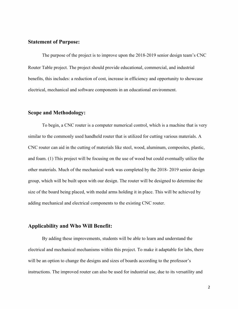
Torque Arm:
Power was limited by the torque arm. When full torque was reached, the motor’s sprocket
would “climb the chain” and hit a limit switch knocking out the manual mode relay or sending a
signal to the controller that the workpiece was clamped. An adjustable spring would be mounted
to the bottom of the arm, allowing adjustment of the torque applied.
Figure 6. Motor welded on the torque arm
Electrical Components:
The purpose of changing the electrical components of the original CNC router was to
integrate a new system for communication and design with changing out the black board with
Raspberry Pi. This allowed for communication to an AGV (automated guided vehicle) and add
new physical components to the system with extra pinouts for future development and
programming. For the new project this semester, it was decided to add new physical components
to communicate to the Raspberry Pi to allow future students to understand the mechanical and
electrical components throughout an entire system.
9
The main component in the electrical communication is a Raspberry Pi, this was switched
out from the original Blackboard. The original Blackboard had very limited inputs and output
while the Raspberry Pi has 40 GPIO’s (general purpose input output) pins. This allowed for the
CNC router along with its motors and stepper drivers to run along with other applications
attached to the Pi. For the new project this semester, it was decided to add new physical
components to communicate to the Raspberry Pi to allow future students to understand the
mechanical and electrical components throughout an entire system. An auto/ manual switch
would have been added, to allow the AGV to utilize the router while not in use by a person. An
optic sensor would have been mounted, which could detect if the AGV is positioned correctly.
Once the optic sensor sees that the AGV is in position, it would send a signal to continue the
communication process. Two four- channel transmitters would have been added to communicate
to the AGV, two channels will be used on the CNC router while one will be used on the AGV. A
communication chart is shown below:
10

Figure 7: Original communication plan before the stay at home order.
Not only does the Raspberry Pi have 40 pins for inputs and outputs, it also has capability
of holding up to four USBs, along with an HDMI and ethernet ports. This allowed for a user to
display the Raspberry Pi using a monitor and controlling it with a keyboard and mouse by using
the USB port for a dongle. To get more capability out of the Raspberry Pi 3, a Raspberry Pi CNC
board V2.6 was purchased, to run a CNC machine. (5) Due to the hat only using 12 of the 40
pins on the Raspberry Pi 3, more room was able to be utilized for the other physical components.
The CNC hat has the capability to withstand up to 12 to 36 volts and 1.13 amps, making this the
perfect controller to have for the CNC router. The hat can operate the X, Y, and Z motors
through stepper drivers (Longs DM860A) going to the router. (5) There is also a port to control
the spindle of the router head, to make designs in the board using pulse width modulation
(PWM). The PWM allows for better control over the milling process.
11
Mach3 software was used for the design of the 2018-2019 senior design group, which
allowed the group to control the original router using G- code. Due to the controllers being
switched out for the Raspberry Pi the software was also switched. Raspberry Pi allows
applications to be downloaded onto the controller thus allowing an application called bCNC to
interpret the G- code. bCNC is an advanced fully featured g-code sender for GRBL and is a
cross platform program (Windows, Linux, Mac) written in python. (3) (4) Once a G- code file is
added to the CNC program a port is opened, for serial communication to take place between the
CNC hat and Raspberry Pi. To create the design a program called Fusion 360 by Autodesk was
utilized. This program allows users to create a design, choose what type of machine they are
working with and the size/kind of bits they will be using, to generate a more accurate G- code
with Fusion 360.
Due to the stay-at-home order for the covid-19 project was not completed in its entirety.
The size of the router hindered the ability to transport it away from the school, causing the team
to create a new project at the home of one of its members. A frame and other electrical
components were used to create a laser engraver which was completed in place of the original
project. Unfortunately, the physical components that were going to be added were not able to
make it onto the laser engraver due to the size. The communication for the laser engraver is
comparable to what was originally going to be changed out on the CNC router. The laser
engraver frame originally had an off-brand Arduino along with three motors, two controlling the
Y axis and one controlling the X axis. By following the original plan for a CNC router, the
off-brand Arduino was replaced with the Raspberry Pi and powered with 12.5 volts with a power
supply. The motors were originally attached by molded quick disconnect cables with both Y axis
12

in separate terminals. Using the screw block quick disconnect terminal the Y axis was connected
in the same terminal series. The reason for connection in series was due to allowing enough
current to be drawn for the motors attached to run with enough power and for the axis to run in
the same direction. Using A4988 stepper motor carrier and jumpers, allowed for a more accurate
executed design using 1/16th resolution for the design. (2) Using resources found in the home
environment, the laser engraver was able to operate and follow patterns generated by the G-
code.
Conclusion:
Even though the mechanical components were not physically attached to the router
fixture or total communication was achieved with the automated guided vehicle, an avenue was
left open for future students to take the project, improve it and implement in the proper setting.
They can utilize the mechanical components that were designed, built, and welded together, like
the control panel, wiper motor, spindles and bearings and the chain drive. Those components can
be easily mounted on the router. With the electrical and software components, communication
was established between the Raspberry Pi and the home-used laser engraver that simulated the
router.
Overall, a unit is provided that includes all aspects of electro-mechanical engineering
technology that could be used in an educational environment for years to come. Students could
learn the mechanical, electrical and software components and interactions associated between
them. The project is left open for future senior design groups to build and improve what was
accomplished in the past year.
13

14
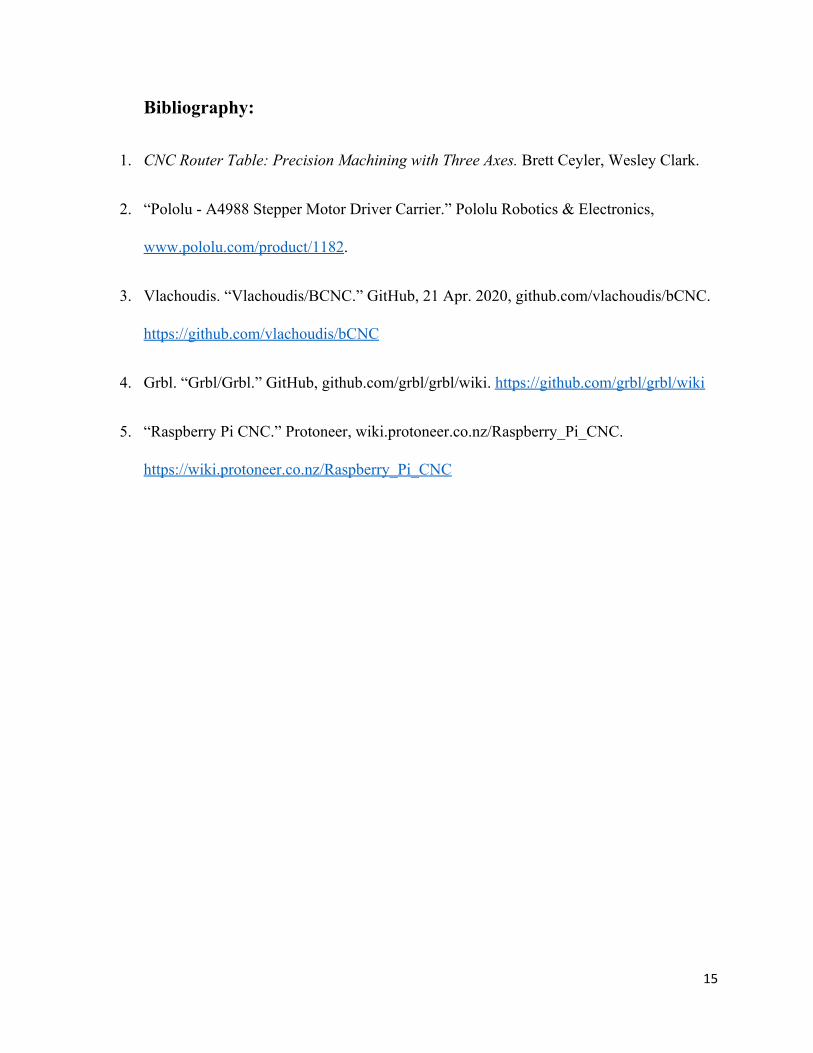
Bibliography:
1. CNC Router Table: Precision Machining with Three Axes. Brett Ceyler, Wesley Clark.
2. “Pololu - A4988 Stepper Motor Driver Carrier.” Pololu Robotics & Electronics,
www.pololu.com/product/1182.
3. Vlachoudis. “Vlachoudis/BCNC.” GitHub, 21 Apr. 2020, github.com/vlachoudis/bCNC.
https://github.com/vlachoudis/bCNC
4. Grbl. “Grbl/Grbl.” GitHub, github.com/grbl/grbl/wiki. https://github.com/grbl/grbl/wiki
5. “Raspberry Pi CNC.” Protoneer, wiki.protoneer.co.nz/Raspberry_Pi_CNC.
https://wiki.protoneer.co.nz/Raspberry_Pi_CNC
15


