66
Lab Sheet for CNC Laboratory Department of Production Engineering and Metallurgy Prepared by: Dr. Laith Abdullah Mohammed
Lab Sheet for CNC Laboratory Department of Production Engineering and Metallurgy Prepared by Dr Laith Abdullah Mohammed
Production Engineering ndash CNC Lab Lab Sheet
By Dr Laith Abdullah Mohammed Page 2 of 66
Numerical Control (NC) Fundamentals What is Numerical Control (NC) Form of programmable automation in which the processing equipment (eg machine tool) is controlled by coded instructions using numbers letter and symbols - Numbers form a set of instructions (or NC program) designed for a particular part - Allows new programs on same machined for different parts - Most important function of an NC system is positioning (tool andor work piece) When is it appropriate to use NC 1 Parts from similar raw material in variety of sizes andor complex geometries 2 Low-to-medium part quantity production 3 Similar processing operations amp sequences among work pieces 4 Frequent changeover of machine for different part numbers 5 Meet tight tolerance requirements (compared to similar conventional machine tools) Advantages of NC over conventional systems Flexibility with accuracy repeatability reduced scrap high production rates good quality Reduced tooling costs Easy machine adjustments More operations per setup less lead time accommodate design change reduced inventory Rapid programming and program recall less paperwork Faster prototype production Less-skilled operator multi-work possible Limitations of NC middot Relatively high initial cost of equipment middot Need for part programming middot Special maintenance requirements middot More costly breakdowns Advantages of CNC over conventional NC middot Control using software (executive) rather than hard-wired middot Increased flexibility (variety of mixed operations amp functions) middot Elimination of tape reader (or tape read only once per program) middot Part program storage (computer memory (multiple programs) amp storage media) middot Display shows instructions being executed amp other operational data middot Greater accuracy (faster control solutions) middot More versatility (eg program editing (at the machine) reprogramming tool path plotting metric conversion cutter dimension compensation) middot Fixed (subroutine) cycles (eg pocket milling pecking) middot Manual data input (MDI) (even while another program is running) and remote data transfer middot System integration capability (connect to robots amp other computer- or microprocessor-based equipment create cells) middot Machine diagnostics (gives error message or identifies problem)
Production Engineering ndash CNC Lab Lab Sheet
By Dr Laith Abdullah Mohammed Page 3 of 66
Distributed (Direct) Numerical Control (DNC) middot (Direct) Central computer stores programs amp directs NC operations NC machines dependent on central computer middot (Distributed) Central computer stores programs and transfers programs to CNC machines middot Central computer provides management functions (eg part of MIS) Programs stored as cutter location (CL) files and post-processed for the machine assigned the job middot Major components central computer bulk memory telecommunication (EDI) CNC machine tools Three basic components of an NC system 1 Input medium - Part program or instructions needed to drive the machine tool components - Instructions are prepared manually or by use of computer - Instructions include machining parameters (feed rate cutting speed) sequence of actions (eg positioning amp machine functions) - Instructions are stored in the form of tape (paper magnetic) floppy diskettes DNC download to CNC RAM 2 Machine control unit (MCU) - Electronics amp control hardware - Interpret instruction set - Execute instructions - Monitor results amp correct where appropriate 3 Machine tool - Mechanical structure that performs the machining including the components that drive each axis of motion (eg AC or DC motor hydraulic actuator stepper motor mdash choice affects speed of response accuracy and power capacity) What is meant by axis of motion Axis of motion describes the relative motion that occurs between the cutting tool and the workpiece Three main axes of motion for machine tools are referred to as the x y and z axes that form a right hand coordinate system Open loop vs closed loop control middot Open loop mdash control signals are given to actuators by the MCU but the movements and final destinations of the positioning system are not checked for accuracy middot Closed loop mdash equipped with transducers and sensors to measure positions compare with control signals and correct positions as necessary Types of control systems middot Point-to-point (positioning) system tool or workpiece is driven to predefined location without specifying the speed or path of motion no tool-workpiece contact during positioning simple inexpensive control system used mainly in drilling punching straight milling middot Contouring (continuous path) system positioning (path) and speed are simultaneously controlled at specified values contour path based on interpolation between points complex flexible expensive control system capacity for simultaneous control of more
Production Engineering ndash CNC Lab Lab Sheet
By Dr Laith Abdullah Mohammed Page 4 of 66
than one axis of motion used on lathes milling machines grinders welding machinery machining centers Types of interpolation middot Linear tool or work piece moves in a straight line from specified start point to endpoint in two or three axes middot Circular path of motion is derived from specified coordinates of end points coordinates of arc center radius of arc and direction of motion tool path approximated by series of straight line segments Accuracy in NC middot Accuracy measure of control systems capacity to position the tool or workpiece to a specified set of coordinates middot Repeatability measure of agreement among repeated positioning movements under the same operating conditions middot Resolution smallest increment of positioning that is possible Numerical control programming Steps in NCCNC programming procedure 1 Interpret part drawing - Define zero point - define x- y- z-axes 2 Determine machining requirements - Determine required operations amp sequence - Determine tooling requirements - Determine feeds speeds depth(s) of cut 3 Complete part program 4 Complete post processor 5 Store part program (eg punch tape disk file) 6 Verify completed program check it out is it accurate Post-processors and beyond middot Post-processor software used to translate NC program into code that is specific to the machine that will run the program middot EIA Standard 494 (32-Bit Binary CL Exchange Input Format for Numerical Controlled Machines (BCL for short)) specifies data structure for CL data (integer code) to be downloaded to a BCL equipped MCU (before post-processing converted to machine-specific code) Cartesian coordinate system Almost everything that can be produced on a conventional machine tool can be produced on a CNC machine tool with its many advantages The machine tool movements used in producing a product are of two basic types point -to-point and continuous path (contouring movements) The Cartesian or rectangular coordinate system was devised by the French mathematician and philosopher Renersquo Descartes With this system any specific point can be described in mathematical terms from any other point along three perpendicular axes This concept fits machine tools perfectly since their construction is generally based on three axes of motion (XYZ) plus an axis of rotation On a plain vertical milling machine the X axis is the horizontal
Production Engineering ndash CNC Lab Lab Sheet
By Dr Laith Abdullah Mohammed Page 5 of 66
movement (right or left) of the table the Y axis is the table cross movement (toward or away from the column) and the Z axis is the vertical movement of the knee or the spindle CNC systems rely heavily on the use of rectangular coordinates because the programmer can locate every point on a job precisely When points are located on a work piece two straight intersecting lines one vertical and one horizontal are used These lines must be at right angles to each other and the point where they cross is called the origin or zero point (Fig 1)
Fig(1)
Fig(2) The three-dimensional coordinate planes are shown in Fig 2 The X and Y planes (axes) are horizontal and represent horizontal machine table motions The Z plane or axis represents the vertical tool motion The plus (+) and minus (-) signs indicate the direction from the zero point
Production Engineering ndash CNC Lab Lab Sheet
By Dr Laith Abdullah Mohammed Page 6 of 66
(origin) along the axis of movement The four quadrants formed when the XY axes cross are numbered in a counterclockwise direction (Fig 3) All positions located in quadrant 1 would be positive (X+) and positive (Y+) In the second quadrant all positions would be negative X (X-) and positive (Y+) In the third quadrant all locations would be negative X (X-) and negative (Y-) In the fourth quadrant all locations would be positive X (X+) and negative Y (Y-)
Fig(3) In Fig 3 point A would be 2 units to the right of the Y axis and 2 units above the X axis Assume that each unit equals 1000 The location of point A would be X + 2000 and Y + 2000 For point B the location would be X + 1000 and Y - 2000 In CNC programming it is not necessary to indicate plus (+) values since these are assumed However the minus (-) values must be indicated For example the locations of both A and B would be indicated as follows A X2000 Y2000 B X1000 Y-2000 Machines Using CNC Machine Types Lathe The engine lathe one of the most productive machine tools has always been an efficient means of producing round parts (Fig4) Most lathes are programmed on two axes bull The X axis controls the cross motion of the cutting tool Negative X (X-) moves the tool towards the spindle centerline positive X moves the tool away from the spindle centerline bull The Z axis controls the carriage travel toward or away from the headstock
Production Engineering ndash CNC Lab Lab Sheet
By Dr Laith Abdullah Mohammed Page 7 of 66
Fig 4 The main axes of a lathe or turning center Milling Machine The milling machine has always been one of the most versatile machine tools used in industry (Fig 5) Operations such as milling contouring gear cutting drilling boring and reaming are only a few of the many operations which can be performed on a milling machine The milling machine can be programmed on three axes bull The X axis controls the table movement left or right bull The Y axis controls the table movement toward or away from the column bull The Z axis controls the vertical (up or down) movement of the knee or spindle
Fig 5 The main axes of a vertical machining center Programming Systems Two types of programming modes the incremental system and the absolute system are used for CNC Both systems have applications in CNC programming and no system is either right or wrong all the time Most controls on machine tools today are capable of handling either incremental or absolute programming
Production Engineering ndash CNC Lab Lab Sheet
By Dr Laith Abdullah Mohammed Page 8 of 66
Incremental program locations are always given as the distance and direction from the immediately preceding point (Fig 6) Command codes which tell the machine to move the table spindle and knee are explained here using a vertical milling machine as an example
Fig 6 A workpiece dimensioned in the incremental system mode bull A ldquoX plusrdquo (X+) command will cause the cutting tool to be located to the right of the last point bull A ldquoX minusrdquo (X-) command will cause the cutting tool to be located to the left of the last point bull A ldquoY plusrdquo (Y+) command will cause the cutting tool to be located toward the column bull A ldquoY minusrdquo (Y-) will cause the cutting tool to be located away from the column bull A ldquoZ plusrdquo (Z+) command will cause the cutting tool or spindle to move up or away from the workpiece bull A ldquoZ minusrdquo (Z-) moves the cutting tool down or into the workpiece In incremental programming the G91 command indicates to the computer and MCU (Machine Control Unit) that programming is in the incremental mode Absolute program locations are always given from a single fixed zero or origin point (Fig 7) The zero or origin point may be a position on the machine table such as the corner of the worktable or at any specific point on the workpiece In absolute dimensioning and programming each point or location on the workpiece is given as a certain distance from the zero or reference point
Fig 7 A workpiece dimensioned in the absolute system mode Note All dimensions are given from a known point of reference bull A ldquoX plusrdquo (X+) command will cause the cutting tool to be located to the right of the zero or origin point bull A ldquoX minusrdquo (X-) command will cause the cutting tool to be located to the left of the zero or origin point bull A ldquoY plusrdquo (Y+) command will cause the cutting tool to be located toward the column
Production Engineering ndash CNC Lab Lab Sheet
By Dr Laith Abdullah Mohammed Page 9 of 66
bull A ldquoY minusrdquo (Y-) command will cause the cutting tool to be located away from the column In absolute programming the G90 command indicates to the computer and MCU that the programming is in the absolute mode Point-to-Point or Continuous Path CNC programming falls into two distinct categories (Fig 8) The difference between the two categories was once very distinct Now however most control units are able to handle both point-to-point and continuous path machining A knowledge of both programming methods is necessary to understand what applications each has in CNC
Fig 8 Types of CNC positioning systems Point-to-Point Positioning Point-to-point positioning is used when it is necessary to accurately locate the spindle or the workpiece mounted on the machine table at one or more specific Locations to perform such operations as drilling reaming boring tapping and punching (Fig9) Point-to-point positioning is the process of positioning from one coordinate (XY) position or location to another performing the machining operation and continuing this pattern until all the operations have been completed at all programmed locations
Fig 9 The path followed by point-to-point positioning to reach various programmed points (machining locations) on the XY axis
Production Engineering ndash CNC Lab Lab Sheet
By Dr Laith Abdullah Mohammed Page 10 of 66
In Fig 9 point 1 to point 2 is a straight line and the machine moves only along the X axis but points 2 and 3 require that motion along both the X and Y axes takes place As the distance in the X direction is greater than in the Y direction Y will reach its position first leaving X to travel in a straight line for the remaining distance A similar motion takes place between points 3 and 4 Continuous Path (Contouring) Contouring or continuous path machining involves work such as that produced on a lathe or milling machine where the cutting tool is in contact with the workpiece as it travels from one programmed point to the next Continuous path positioning is the ability to control motions on two or more machine axes simultaneously to keep a constant cutter-workpiece relationship The programmed information in the CNC program must accurately position the cutting tool from one point to the next and follow a predefined accurate path at a programmed feed rate in order to produce the form or contour required (Fig 10)
Fig 10 Types of contour machining (A) Simple contour (B) complexe contour
Interpolation The method by which contouring machine tools move from one programmed point to the next is called interpolation This ability to merge individual axis points into a predefined tool path is built into most of todayrsquos MCUs There are five methods of interpolation linear circular helical parabolic and cubic All contouring controls provide linear interpolation and most controls are capable of both linear and circular interpolation Helical parabolic and cubic interpolation are used by industries that manufacture parts which have complex shapes such as aerospace parts and dies for car bodies Linear Interpolation Linear Interpolation consists of any programmed points linked together by straight lines whether the points are close together or far apart (Fig 11) Curves can be produced with linear interpolation by breaking them into short straight-line segments This method has limitations because a very large number of points would have to be programmed to describe the curve in order to produce a contour shape A contour programmed in linear interpolation requires the coordinate positions (XY positions in two-axis work) for the start and finish of each line segment Therefore the end point of one line or segment becomes the start point for the next segment and so on throughout the entire program
Production Engineering ndash CNC Lab Lab Sheet
By Dr Laith Abdullah Mohammed Page 11 of 66
Fig 11 An example of two-axis linear interpolation Circular Interpolation The development of MCUs capable of circular interpolation has greatly simplified the process of programming arcs and circles To program an arc (Fig 12) the MCU requires only the coordinate positions (the XY axes) of the circle center the radius of the circle the start point and end point of the arc being cut and the direction in which the arc is to be cut (clockwise or counterclockwise) See Fig 12
Fig 12 For two-dimensional circular interpolation the MCU must be supplied with the XY axis radius start point end point and direction of cut
Programming Format Word address is the most common programming format used for CNC programming systems This format contains a large number of different codes that transfers program information from the part print to machine servos relays micro-switches etc to manufacture a part These codes which conform to EIA (Electronic Industries Association) standards are in a logical sequence called a block of information Each block should contain enough information to perform one machining operation Word Address Format Every program for any part to be machined must be put in a format that the machine control unit can understand The format used on any CNC machine is built in by the machine tool builder and is based on the type of control unit on the machine A variable-block format which uses words (letters) is most commonly used Each instruction word consists of an address character such as X Y Z G M or S Numerical data follows this address character to identify a specific function such as the distance feed rate or speed value The address code G90 in a program
Production Engineering ndash CNC Lab Lab Sheet
By Dr Laith Abdullah Mohammed Page 12 of 66
tells the control that all measurements are in the absolute mode The code G91 tells the control that measurements are in the incremental mode Codes The most common codes used when programming CNC machines tools are G-codes (preparatory functions) and M codes (miscellaneous functions) Other codes such as F S D and T are used for machine functions such as feed speed cutter diameter offset tool number etc G-codes are sometimes called cycle codes because they refer to some action occurring on the X Y andor Z axis of a machine tool The G-codes are grouped into categories such as Group 01 containing codes G00 G01 G02 G03 which cause some movement of the machine table or head Group 03 includes either absolute or incremental programming while Group 09 deals with canned cycles A G00 code rapidly positions the cutting tool while it is above the workpiece from one point to another point on a job During the rapid traverse movement either the X or Y axis can be moved individually or both axes can be moved at the same time Although the rate of rapid travel varies from machine to machine it ranges between (5 and 20 mmin)
Fig 13 The functions of a few common G-codes The G01 G02 and G03 codes move the axes at a controlled feedrate bull G01 is used for straight-line movement (linear interpolation) bull G02 (clockwise) and G03 (counterclockwise) are used for arcs and circles (circular interpolation)
Production Engineering ndash CNC Lab Lab Sheet
By Dr Laith Abdullah Mohammed Page 13 of 66
Fig 14 Some of the most common G-codes used in CNC programming M or miscellaneous codes are used to either turn ON or OFF different functions which control certain machine tool operations M-codes are not grouped into categories although several codes may control the same type of operations such as M03 M04 and M05 which control the machine tool spindle bull M03 turns the spindle on clockwise bull M04 turns the spindle on counterclockwise bull M05 turns the spindle off
Production Engineering ndash CNC Lab Lab Sheet
By Dr Laith Abdullah Mohammed Page 14 of 66
Fig 15 The functions of a few common M-codes
Production Engineering ndash CNC Lab Lab Sheet
By Dr Laith Abdullah Mohammed Page 15 of 66
Fig 16 Some of the most common M-codes used in CNC programming Block of Information CNC information is generally programmed in blocks of five words Each word conforms to the EIA standards and they are written on a horizontal line If five complete words are not included in each block the machine control unit (MCU) will not recognize the information therefore the control unit will not be activated Using the example shown in Fig 17 the five words are as follows N001 represents the sequence number of the operation G01 represents linear interpolation X12345 will move the table 12345 in in a positive direction along the X axis Y06789 will move the table 06789 in along the Y axis M03 Spindle on CW
Fig 17 A complete block of information consists of five words
Production Engineering ndash CNC Lab Lab Sheet
By Dr Laith Abdullah Mohammed Page 16 of 66
Programming for Positioning Before starting to program a job it is important to become familiar with the part to be produced From the engineering drawings the programmer should be capable of planning the machining sequences required to produce the part Visual concepts must be put into a written manuscript as the first step in developing a part program Fig 18 It is the part program that will be sent to the machine control unit by the computer tape diskette or other input media The programmer must first establish a reference point for aligning the workpiece and the machine tool for programming purposes The manuscript must include this along with the types of cutting tools and work-holding devices required and where they are to be located
Fig 18 The first step in producing a CNC program is to take the information from the print and produce a program manuscript Dimensioning Guidelines The system of rectangular coordinates is very important to the successful operation of CNC machines Certain guidelines should be observed when dimensioning parts for CNC machining The following guidelines will insure that the dimensioning language means exactly the same thing to the design engineer the technician the programmer and the machine operator 1 Define part surfaces from three perpendicular reference planes 2 Establish reference planes along part surfaces which are parallel to the machine axes 3 Dimension from a specific point on the part surface 4 Dimension the part clearly so that its shape can be understood without making mathematical calculations or guesses 5 Define the part so that a computer numerical control cutter path can be easily programmed
Production Engineering ndash CNC Lab Lab Sheet
By Dr Laith Abdullah Mohammed Page 17 of 66
Machine Zero Point The machine zero point can be set by three methodsmdashby the operator manually by a programmed absolute zero shift or by work coordinates to suit the holding fixture or the part to be machined MANUAL SETTING - The operator can use the MCU controls to locate the spindle over the desired part zero and then set the X and Y coordinate registers on the console to zero
Fig 19 The relationship between the part zero and the machine system of coordinates ABSOLUTE ZERO SHIFT - The absolute zero shift can change the position of the coordinate system by a command in the CNC program The programmer first sends the machine spindle to home zero position by a G28 command in the program Then another command (G92 for absolute zero shift) tells the MCU how far from the home zero location the coordinate system origin is to be positioned Fig 19 The sample commands may be as follows N1 G28 X0 Y0 Z0 (sends spindle to home zero position) N2 G92 X4000 Y5000 Z6000 (the position the machine will reference as part zero)
Production Engineering ndash CNC Lab Lab Sheet
By Dr Laith Abdullah Mohammed Page 18 of 66
Work Settings and Offsets All CNC machine tools require some form of work setting tool setting and offsets (compensation) to place the cutter and work in the proper relationship Compensation allows the programmer to make adjustments for unexpected tooling and setup conditions
Work Coordinates In absolute positioning work coordinates are generally set on one edge or corner of a part and all programming is generally taken from this position In Fig 20 the part zero is used for all positioning for hole locations 1 2 and 3
Fig 20 In absolute programming all dimensions must be taken from the XY zero at the top left-hand corner of the part
Fig 21 In incremental programming all dimensions are taken from the previous point In incremental positioning the work coordinates change because each location is the zero point for the move to the next location Fig 21
Production Engineering ndash CNC Lab Lab Sheet
By Dr Laith Abdullah Mohammed Page 19 of 66
On some parts it may be desirable to change from absolute to incremental or vice versa at certain points in the job Inserting the G90 (absolute) or the G91 (incremental) command into the program at the point where the change is to be made can do this
R Plane or Gage Height The word-address letter R refers to a partial retraction point in the Z axis to which the end of the cutter retracts above the work surface to allow safe table movement in the X Y axes It is often called the rapid-traverse distance gage height retract or work plane The R distance is a specific height or distance above the work surface and is generally 100 in above the highest surface of the workpiece Fig 22 which is also known as gage height Some manufacturers build a gage height distance of 100 in into the MCU (machine control unit) and whenever the feed motion in the Z axis is called for 100 in will automatically be added to the depth programmed When setting up cutting tools the operator generally places a 100 in thick gage on top of the highest surface of the workpiece Each tool is lowered until it just touches the gage surface and then its length is recorded on the tool list Once the gage height has been set it is not generally necessary to add the 100 in to any future depth dimensions since most MCUs do this automatically
Fig 22 Using a 100 in gage block to set the gage height or R0 on the work surface
Cutter Diameter Compensation Cutter diameter compensation (CDC) changes a milling cutterrsquos programmed centerline path to compensate for small differences in cutter diameter On most MCUs it is effective for most cuts made using either linear or circular interpolation in the X-Y axis but does not affect the programmed Z-axis moves Usually compensation is in increments of 0001 in up to +10000 in and usually most controls have as many CDCs available as there are tool pockets in the tool storage matrix The advantage of the CDC feature is that it 1 Allows the use of cutters that have been sharpened to a smaller diameter 2 Permits the use of a larger or smaller tool already in the machinersquos storage matrix 3 Allows backing the tool away when roughing cuts are required due to excessive material present 4 Permits compensation for unexpected tool or part deflection if the deflection is constant throughout the programmed path The basic reference point of the machine tool is never at the cutting edge of a milling cutter but at some point on its periphery If a 1000 in diameter end mill is used to machine the edges of a workpiece the programmer would have to keep a 500 in offset from the work surface in order to cut the edges accurately Fig 23 The 500 offset represents the distance from the centerline of the cutter or machine spindle to the edge of the part Whenever a part is being machined the programmer must calculate an offset path which is usually half the cutter diameter
Production Engineering ndash CNC Lab Lab Sheet
By Dr Laith Abdullah Mohammed Page 20 of 66
Fig 23 Cutter-diameter compensation must be used when machining with various size cutters Modern MCUs which have part surface programming automatically calculate centerline offsets once the diameter of the cutter for each operation is programmed Many MCUs have operator-entry capabilities which can compensate for differences in cutter diameters therefore an oversize cutter or one that has been sharpened can be used as long as the compensation value for oversize or undersize cutters is entered
Production Engineering ndash CNC Lab Lab Sheet
By Dr Laith Abdullah Mohammed Page 21 of 66
CNC Programming Hints - MILLING
Production Engineering ndash CNC Lab Lab Sheet
By Dr Laith Abdullah Mohammed Page 22 of 66
CNC Programming Hints ndash TURNING
Production Engineering ndash CNC Lab Lab Sheet
By Dr Laith Abdullah Mohammed Page 23 of 66
CNC
The abbreviation CNC stands for Computer(ized) Numerical(ly) Control(led) and refers specifically to the computer control of machine tools for the purpose of (repeatedly) manufacturing complex parts in metal as well as other materials using a program written in a notation conforming to the EIA-274-D standard and commonly called G-code
CNC was developed in the late 1940s and early 1950s by the MIT Servomechanisms Laboratory CNC machines were relatively briefly preceded by the less advanced NC or Numerical(ly) Control(led) machines The introduction of CNC machines radically changed the manufacturing industry Curves are as easy to cut as straight lines complex 3-D structures are relatively easy to produce and the number of machining steps that required human action have been dramatically reduced With the increased automation of manufacturing processes with CNC machining considerable improvements in consistency and quality have been achieved CNC automation reduced the frequency of errors and provided CNC operators with time to perform additional tasks
CNC automation also allows for more flexibility in the way parts are held in the manufacturing process and the time required to change the machine to produce different components In a production environment a series of CNC machines may be combined into one station commonly called a cell to progressively machine a part requiring several operations CNC machines today are controlled directly from files created by CAM software packages so that a part or assembly can go directly from design to manufacturing without the need of producing a drafted paper drawing of the manufactured component In a sense the CNC machines represent a special segment of industrial robot systems as they are programmable to perform many kinds of machining operations (within their designed physical limits like other robotic systems)
G-code
G-code is a common name for the programming language that is used for NC and CNC machine tools It is defined in EIA RS-274-D G-code is also the name of any word in a CNC program that begins with the letter G and generally is a code telling the machine tool what type of action to perform such as
bull rapid move bull controlled feed move in straight line or arc bull series of controlled feed moves that would result in a hole being drilled bull change a pallet bull Set tool information such as offset
There are other codes the type codes can be thought of like registers in a computer
X position Y position Z position M code (another action register) F feed rate S spindle speed N line number R Radius T Tool selection
Production Engineering ndash CNC Lab Lab Sheet
By Dr Laith Abdullah Mohammed Page 24 of 66
I Arc data X axis J Arc data Y axis
G-code files are output by CAM software such as Smartcam Gibbscam Featurecam Edgecam Mastercam etc G-code is also output by specialized CAD systems used to design printed circuit boards Such software must be customized for each type of machine tool that it will be used to program
Production Engineering ndash CNC Lab Lab Sheet
By Dr Laith Abdullah Mohammed Page 25 of 66
U 2عمل األزرار الرئيسية في ماكنة الخراطة المبرمجة (نصر (
1- SINGLE BLOCK للتأكد من صحة البرنامج (تنفيذ البرنامج خطوة خطوةب تقوم( 2- BLOCK DELETE بجانب ويعمل من األوامرلغاء بلوك معين أليستخدم 3- MACHINE LOCK العمل يستخدم لقفل حركة المحاور الرئيسية مع استمرار البرنامج في
)وهذا مهم للتاكد من صحة البرنامج قبل عملية التنفيذ النهائي(4- CONT CYCLE عملية التشغيل عند ايقافها الي سبب كان او عند ايقافها ألستئناف ستخدم ت
) BAR FEEDER(او في حالة استخدام ) FEED HOLDبسبب (5- DRY RUN وتستخدم لفحص البرنامج بعد ازالة الشغلة حركة سريعة للبرنامج 6- TURRET UP amp DOWN ) حركة حامل العدة TURRET الذي يحمل مجموعة من (
وهذا الزر يعمل مع الزر عكس عقرب الساعة او مع عقرب الساعة ةحركة دوراني العدد )SAFTY (
7- COOLANT ON or OFFفه تشغيل سائل التبريد او ايقا 8- COOLANT AUTO الدوال المساعدة في البرنامج من خالل فه تشغيل سائل التبريد او ايقا 9 -MACHINE START ة لتشغيل هيدرولكيك الماكنميستخد
Production Engineering ndash CNC Lab Lab Sheet
By Dr Laith Abdullah Mohammed Page 26 of 66
10- CLOSE OR OPEN CHUCKالعينة تستخدم لفتح وغلق 11 -T STOCK FWD RET حركة الغراب المتحرك ذهابا وإيابا12 -SPINDLE STOP تعمل على ايقاف حركة دوران العينة 13-JOG SPINDLE تعمل على تدوير العينة مع زر SAFTY 14 -OPT SAFTY مع الدالة ( تعمل عمل التوقف المشروط حيث تعملM1 دالة التوقف (
ط ) فقط األ اذا كان هذا الزر مضغو M1المشروط حيث ال يتوقف البرنامج في حالة وجود دالة ( SAFTY + SPINDLE ) يتم الضغط على زر ( START CYCLEلغرض تحرير زر (
START ) في نفس الوقت بعد الضغط على زر ( START CYCLE مرتين (
NC PC- 15 يستخدم هذا الزر عند ربطCNC يستخدم لنقل المعلومات ث مع جهاز أخر حي بينهما
16 -CALCU زر الخاص بالحاسبة مع زر ( ال وهوINPUT ( 17 - HD1 HD2 يستخدم الختيار العدة مع المخرطة ذات المحاور األربعة 18 - START تستخدم لبدء عملية التشغيل
Production Engineering ndash CNC Lab Lab Sheet
By Dr Laith Abdullah Mohammed Page 27 of 66
19- FEED HOLD تعمل على إيقاف عمل أي G موجودة مع بقاء العينة متحركة 20- M D I أو تشغيل البرنامج ل يتم استخدامه لإلدخا BLOCK BY BLOCK وتعمل عند
إدخال البرنامج بواسطة الشريط المثقب أو أي وسيلة إدخال أخرى أو في عمليات التصفير
21- REST تستخدم العادة تشغيل الماكنة أو مسح اإلنذار الذي يظهر على الشاشة 22- EMERGENCYتستخدم عادة اليقاف الماكنة في حالة الطوارئ فقط
OPERATION MENU KEY
CHAPTER PRG-CMK
OFFSET PROGRAM POSITION FUNCTION MENU KEY
23- POSITIONعلى الشاشة د الموقع الموجور الظها 24- PROGRAMإلظهار برنامج معين واختياره 25- OFFSET الختيار سماحات العدة أو سماحات نقطة المرجع 26- PRG- CHK تستخدم لفحص البرنامج على الشاشة 27- SETTING ألختيار الثوابت على الشاشة 28- SERVICE تستخدم ألستخراج المعامالت والثوابت 29- MESSAGE تستخدم ألظهار األخطاء الناتجة عن البرنامج او اخطاء التشغيل 30- OVERALL ألختيار المواقع 31- RELATIVE MODLINE تعوض عن POSITION 32- DIR MEM يستخدم ألظهار ملف البرامج المخزونة في الذاكرة وعندما نضغط هذا الزر
فان رقم واسم البرنامج سوف يظهر على الشاشة
2أدناه الشفرات الرئيسية التي تعمل على الماكنة المبرمجة نصر
G-CODE DESCRIPTION
G00 Rapid traverse (linear)
G01 Linear Interpolation at feed rate
G02 Circular interpolation (CW) R+
G03 Circular interpolation (CCW) R+
G10 Zero point tools
G20 Imperial data input
G21 Metric data input
G27 Reference return check
G28 Reference return
G29 Return from reference
Production Engineering ndash CNC Lab Lab Sheet
By Dr Laith Abdullah Mohammed Page 28 of 66
G33 Thread cutting
G40 Cancel cutter radius compensation
G41 Cutter compensation left
G42 Cutter compensation right
G54 Work co-ordinate system no1
G70 Finishing cycle
G71 Stock removal turning
G72 Stock removal facing
G74 Face grooving
G75 Diameter grooving
G76 Threading cycle
G90 Absolute date input
G91 Incremental data input
G94 Feed minute mode
G95 Feed rev mode
G96 Constant surface speed mode
G97 Cancel Constant surface speed
) 2أدناه الشفرات الثانوية التي تعمل على الماكنة المبرمجة (نصر
M-code FUNCTION
M00 Program stop
M03 Spindle forward (Tool forward ndash M94 mode)
M04 Spindle reverse (Tool forward ndash M94 mode)
M05 Spindle stop (Tool stop ndash M94 mode)
M08 Coolant on
M09 Coolant off
M30 Program end (with rewind)
M48 Turret shortest path
M52 Turret direction up (CW)
M53 Turret direction down (CCW)
M73 Chuck open
M74 Chuck close
Production Engineering ndash CNC Lab Lab Sheet
By Dr Laith Abdullah Mohammed Page 29 of 66
) وكل جملة مكونة من مجموعة من الكلمات blockإن كل برنامج يتكون من مجموعة من الجمل ()words) لهذا فأن الشفرات الرئيسية والمساعدة هي عبارة عن كلمات (words كما في المثال التالي (
G_ _ P1 Q2 U_ _ W_ _ D___ F_ _
)end of block) ويعني ( ) يكتب الرمز (blockتسلسل الكلمات مهم جدا بعد نهاية كل جملة (
طريقة ادخال البيانات الى الماكنة ــــــــــــــــــــــــــــــــــــــــــــــــــ
) MDIيمكن ادخال البيانات الى الماكنة بعدة طرق فقد يكون األدخال عن طريق قناة السيطرة ( MANUAL DATA INPUT ) او عن طريق قناة األضافة EDIT كما يمكن ادخال البيانات عن (
) RS ndash 232 COMMUNICATIN LINKطريق استخدام سلسلة الربط (
₤⅗₌⅗₌ ⅙₌₨image₍₡ ₤₌ℌ⅗₌ Ⅸ⅗ⅥⅯ₌ ₤₡ℌ₰₨⅗₌G71
الخراطة الطولية G71الغرض من التجربة عمل نموذج للخراطة بأستخدام الدالة تستعمل هذه الدالة للخراطة الطولية اي على طول محور المشغولة وكما هو موضح بالشكل ادناه
تعتبر هذه الدالة من الدوال التي ال تحتاج الى تكرار او إعادة كتابتها أي انها دالة تكرارية بمعنى ان اي
الذي هي دالة حركة G01خطوة تكون من ضمن هذه الدالة سوف تكرر العملية اي عند استعمال امر مثل خطية تتضمن القطع مع التغذية مع اعطاء القطر المراد قطعه و مراعاة عمق القطع المعطى سوف يتكرر
هذه االمر وصوال الى العمق المطلوب وهكذا لبقية الدوال
G71 المستخدمة للدالة الصيغة
G71 P1 Q2 U___ W___ D___ F___ حيث إن
P1 بداية الخطوة االولى = Q2 نهاية الخطوة =
Uوضع السماحات بأتجاه محور = X W وضع السماحات بأتجاه محور = Z وتكاد تكون مهملة وتوضع اشارة سالب Dعمق القطع وتوضع رقم صحيح مثل = D500 اي نصف ملمF التغذية والتي لها عالقة بالدالة = G95
Production Engineering ndash CNC Lab Lab Sheet
By Dr Laith Abdullah Mohammed Page 30 of 66
G71الدالة استخدام مثال على
T0100 M48 G0 X26 Z2 M08 T0101 G90 G95 G97 S500 M03 G71 P1 Q2 U03 W00 D500 F01 N1 G0 G42 X00 G01 Z00 G01 X2517 G01 Z-5352 G01 X7391 Z-9366 G01 Z-19145 N2 G28 M30
الجانب العملي
االجهزة واالدوات المستخدمة CNCماكنة خراطة مبرمجة 1 ملم 80قضيب من االلمنيوم قطر 2 ةفير ني 3 جاه أيمن تهولدر كاربيدي ذوا 4
طريقة العمل يتم تثبيت قضيب من االلمنيوم على العينة التابعة للماكنة مع مراعاة الطول المراد استعماله في عملية 1
الخراطة ) turretتثبيت عدة القطع في المكان الصحيح في ( 2
Production Engineering ndash CNC Lab Lab Sheet
By Dr Laith Abdullah Mohammed Page 31 of 66
بالنسبة الى القطعة المثبتة على العينة XZيتم تصفير الماكنة للمحاور 3 تصفير للمحورZ تكون مالمسة العدة الى وجه الشغلة تصفير للمحورX تكون مالمسة العدة الى سطح الشغلة الموازي لمحور X
يتم كتابة البرنامج أما بطريقة يدوية أو بالحاسوب مع وضع كل الظروف الالزمة للتشغيل ( عمق القطع 4 التغذية السرعة المطلوبة نوع المعدن )
ادخال البرنامج الى الحاسوب الموجود داخل الماكنة مع تهيئة الماكنة للتشغيل 5
المطلوب G71عمل برنامج يدوي على الدالة 1 رسم الشكل الشكل النهائي المطلوب مع وضع األبعاد 2
Ⅺ⅟₍euro⅗₌ ₤₡ℌ₰₨⅗₌₣ ₤⅗₌⅗₌ ⅙₌₨image₃₡ Ⅺℂtradeℒ⅗₌ ӈ₍Ⅴ⅟ⅳ₌ G70
G70 الغرض من التجربة عمل انهاء سطحي للمشغولة بواسطة الدالة
من الضروري إعطاء G71هذه الدالة تعمل شوط واحد فقط وتكون معتمدة على عمليات القطع في الدالة اللغاء مقدمة االداة (أي لكي تتم عملية االنهاء السطحي بدون حسابات نصف قطر مقدمة االداة ) G42دالة
G70الصيغة المستخدمة للدالة
G70 P1 Q2 F___ حيث ان
P1 بداية الخطوة االولى = Q2 نهاية الخطوة =
F التغذية والمرتبطة بالدالة = G95
وذلك ألن دالة االنهاء السطحي تحقق X Zمالحظة الدالة التحتاج لكتابة السماحات التابعة للمحورين المسافات الحقيقة المراد انتاجها للمشغولة
G71و G70مثال على الدالة
T0100 M48 G0 X26 Z2 M08 T0101 G90 G95 G97 S500 M03 G71 P1 Q2 U03 W00 D500 F01 N1 G0 G42 X00 G01 Z00 G01 X2517 G01 Z-5352 G01 X7391 Z-9366 G01 Z-19145 N2 G97 S750 MO3
Production Engineering ndash CNC Lab Lab Sheet
By Dr Laith Abdullah Mohammed Page 32 of 66
G70 P1 Q2 G40 F009 G28 M30
الجانب العملي الحظ التجربة األولى
المطلوب
G70 عمل برنامج يدوي على الدالة 1 رسم الشكل النهائي المطلوب مع وضع االبعاد 2
₪⅗₍euro⅗₌ ₤₡ℌ₰₨⅗₌₣ ₤⅗₌⅗₌ ⅙₌₨image₍₡ ⅝₍ⅠimageⅯ₌ ⅞ⅫⅦ⅔₧ G76
G76 للمشغولة بواسطة الدالةةالغرض من التجربة عمل أسنان خارجية أو داخلي
في هذه التجربة سوف نقوم بعمل األسنان الخارجية وهنا تكون حركة العينة ثابتة وهذا ضروري بسبب أن ) تكون متصلتين الكترونيا وعليه أي اختالف في سرعة العينة تؤدي إلى اختالف motionالعينة والحركة(
) servoفي سرعة الخدمة(يرتبط اتجاه تكوين األسنان باتجاه دوران العينة مثال إذا كانت األسنان ذات اتجاه أيمن يكون اتجاه دوران
وهنا نقلب العدة إلى االسفل وكما هو موضح بالشكل أدناه MO3العينة عكس عقرب الساعة أي نستعمل
Production Engineering ndash CNC Lab Lab Sheet
By Dr Laith Abdullah Mohammed Page 33 of 66
الخطوة هي عبارة عن المسافة ما بين قمة سن إلى قمة سن أخر عمق السن هو العمق المطلوب تكوينه لألسنان
G76 الصيغة المستخدمة للدالة
G76 X___ Z___ K___ F___ D___ A___
حيث أن X القطر الداخلي للسن =Z طول السن =K عمق السن وتستخرج من المعادلة التالية =K=065F F الخطوة =D عمق القطع بالمايكرون فقط =A زاوية السن =
G76مثال على استخدام الدالة T0300 M48 GOO X30 Z4 T0303 M08 G97 S500 MO3 G76 X28375 Z-20 K08125 F125 D120 G00 X40 Z4 G28 M30
Production Engineering ndash CNC Lab Lab Sheet
By Dr Laith Abdullah Mohammed Page 34 of 66
الجانب العملي الحظ التجربة األولى
المطلوب
G76عمل برنامج يدوي على الدالة 1 رسم الشكل النهائي المطلوب مع وضع األبعاد 2
Ⅺ⅘₌⅗₌ Ⅵ₂ Ⅺ₯ℋ₍⅗₌ ℌℲℂ⅗₌ ⅞ⅫⅦ⅔₧ ₤K₡₌ℌ⅗₌ ₤₡ℌ₰₨⅗₌)Groove ₤⅗₌⅗₌ ₤tradeimage₌Ⅶ₡ (G75
G75 بواسطة الدالة grooveالغرض من التجربة تكوين
) للمشغولة وتعتمد شكل الحفر على طريقة grooveتستعمل هذه الدالة لتكوين الحفر الخارجي والداخلي (
التشغيل وعلى الشكل المراد إنتاجه وتعتبر هذه الطريقة من عمليات التشكيل للمعدن إن هذه الدالة هي دالة مالحظة مع G75في هذه التجربة سنقوم بعمل الحفر الخارجي بواسطة الدالة
تكرارية وغير تكرارية حسب نوع التشغيل
G 75 الصيغة المستخدمة للدالةG75 X___ Z___ I___ K____
حيث أن
X العمق النهائي لقطر الشغلة =Z عرض الحفر =I الدخول في كل مرة =
K التزحيف على محور =z بالنسبة للعدة
Production Engineering ndash CNC Lab Lab Sheet
By Dr Laith Abdullah Mohammed Page 35 of 66
G75مثال على استخدام الدالة
T0500 M48 GOO X100 Z -20 T0505 M08 G97 S700 MO3 G75 X84 Z -38 I 05 K4
الجانب العملي الحظ التجربة األولى
المطلوب
G76عمل برنامج يدوي على الدالة 1 رسم الشكل النهائي المطلوب مع وضع األبعاد 2
Production Engineering ndash CNC Lab Lab Sheet
By Dr Laith Abdullah Mohammed Page 36 of 66
CNC Milling Machine Mechanical Construction
Guideways The guideways of CNC machines are made of steel To reduce the frictional forces they are coated with a strip of PTFE (Poly Tetra Fluoro Ethylene)
Ballscrews On conventional lathes a leadscrew is used to converts the rotary motion of the hand wheel into linear motion of the slides Leadscrews have a high coefficient of friction and backlash On CNC machines a ballscrew is used instead of a leadscrew Friction and backlash are much less than on leadscrews
Guideway
Production Engineering ndash CNC Lab Lab Sheet
By Dr Laith Abdullah Mohammed Page 37 of 66
bullMachining operations Direction of cutting Based on the direction of the cutter rotation and work piece feed milling operations are classified into two types 1-Up milling (Convention milling) In up milling the metal is removed by rotating the cutter against the direction of travel of the part
Feed
Machine table
Part
Cutting tool
Chip thickness at theexit of the tooth
2-Down milling (Climb milling) In climb milling the metal is removed by rotating the cutter with the direction of travel of the part
Machine table
Part
Cutting tool
Chip thickness at theentrance of the tooth
Production Engineering ndash CNC Lab Lab Sheet
By Dr Laith Abdullah Mohammed Page 38 of 66
bullTooling Tool geometry The geometry of the tool tip affects the way that the metal cutting is performed The nose radius rake angles relief angles etc must be selected with care
Radial relief
Radial rake
Axial relief
Approach angle
Axial relief
Corner radius Face mill Face milling cutters are used to mill flat surfaces Commonly used face milling cutters Cutter with 75 degree approach
75 deg
Cutter with 90 degree approach (Square shoulder face mill)
90 deg
Cutter with 45 degree approach
Production Engineering ndash CNC Lab Lab Sheet
By Dr Laith Abdullah Mohammed Page 39 of 66
bullCNC Programming Axes convention The Z axis is along the spindle axis The X and Y axes are perpendicular to Z VMC
Z
Y
-
+
-+
X- +
+Z
-Z
+Y
-Y
-X +X
Part
Machine table
X
YZ
G00 Rapid traverse When the tool being positioned at a point preparatory to a cutting motion to save time it is moved along a straight line at Rapid traverse at a fixed traverse rate which is pre-programmed into the machines control system Typical rapid traverse rates are 10 to 25 m min but can be as high as 80 mmin
Production Engineering ndash CNC Lab Lab Sheet
By Dr Laith Abdullah Mohammed Page 40 of 66
Format N_ G00 X__ Y__Z__
G01 Linear interpolation (feed traverse) The tool moves along a straight line in one or two axis simultaneously at a programmed linear speed the feed rate Format N__ G01 X__ Y__Z__ F__
Part
Feed
Part
Feed
G02G03 Circular interpolation The tool moves along an arc in two axes simultaneously at a programmed linear speed the feed rate
Production Engineering ndash CNC Lab Lab Sheet
By Dr Laith Abdullah Mohammed Page 41 of 66
Format N__ G0203 X__ Y__Z__ I__ J__K__ F__ using the arc center OR N__ G0203 X__ Y__Z__ R__ F__ using the arc radius G02 moves along a CW arc G03 moves along a CCW arc Arc center The arc center is specified by addresses I J and K I J and K are the X Y and Z co-ordinates of the arc center with reference to the arc start point
X
Y
Arc center
Arc endArc start
- J
- I
I = X coord of center - X coord of start point J = Y coord of center - Y coord of start point K = Z coord of center - Z coord of start point I J and K must be written with their signs
Production Engineering ndash CNC Lab Lab Sheet
By Dr Laith Abdullah Mohammed Page 42 of 66
bullWork holding
Rotary table
Fixture base
Component
Clamp
Stud
Fixtures The use of fixtures 1 Improves repeatability of dimensions 2 Improves working conditions 3 Cuts down requirement of skilled labour 4 Reduces part loading and unloading time 5 Improves safety in the working area 6 Reduces the cost of machining There are two types fixtures commonly used 1 Special fixture Special fixtures are used to hold and locate the typical components which are having complex shape and to be located with the reference hole (dowel hole) Special fixtures are required for components like gear case cover cylinder heads etc 2 Modular fixture Modular fixture is a set different kind of clamping and locating elements These fixtures are used to hold identical components in different sizes and components of box type Example Manifolds head stocks connecting rods and flanges
Production Engineering ndash CNC Lab Lab Sheet
By Dr Laith Abdullah Mohammed Page 43 of 66
bullMachine setting
Determining X and Y work zero offset Case 1
Part
Machine table
Part
End mill or reamer
Work offset X0Y0 For determining X work zero offset bull Touch the periphery of the end mill or reamer to the part bull Enter current machine X value + cutter radius as X work zero offset For determining Y work zero offset bull Touch the periphery of the end mill or reamer to the part bull Enter current machine Y value - cutter radius as Y work zero offset Case 2
Part
Machine table
Part
End mill or reamerWork offset X0Y0
bull Mount the dial indicator on machine spindle true the bore bull Enter current machine X and Y value as X and Y work zero offset
Production Engineering ndash CNC Lab Lab Sheet
By Dr Laith Abdullah Mohammed Page 44 of 66
How to Select a Cutting Fluid
One part of the metal cutting equation that is sometimes overlooked however is
the choice of an appropriate cutting fluid With todayrsquos system approach to metal
cutting use of the right metalworking fluid has become just as much a part of the
solution as the other elements In fact at least one company is now integrating
cutting fluids and cutting tools into effective metal cutting systems Following are
some things to consider when choosing your next cutting fluid
The Four Key Questions
There are four vital pieces of information that are necessary when choosing a
cutting fluid They are
1 What are you cutting
2 What is the chemistry of your water
3 What are you using now
4 What are your options
5 What do you prefer
What Are You Cutting
The first question ndash ldquoWhat are you cuttingrdquo ndash is often the most difficult to answer
because most shops handle a variety of workpiece materials on a regular basis If
the answer is an unequivocal ldquoaluminumrdquo or ldquostainless steelrdquo or ldquocast ironrdquo the
selection of a cutting fluid can be quite simple and straightforward Unfortunately
that is seldom the case in anything but a high-volume plant Where aluminum or
other nonferrous metals are a significant part of the mix a non-staining cutting
fluid is a must Generally speaking this will be a semi-synthetic with special
ingredients to prevent bi-metallic corrosion and staining of non-ferrous workpieces
Where the ferrous metals predominate however a more general purpose semi-
synthetic or hybrid fluid might be a more economical choice
Production Engineering ndash CNC Lab Lab Sheet
By Dr Laith Abdullah Mohammed Page 45 of 66
What is The Chemistry of Your Water
The second question ndash ldquoWhat is the chemistry of your waterrdquo ndash is probably the
single most common reason for the success or failure of a cutting fluid Very few
plants invest the money necessary to install effective water purification systems
using deionization or reverse osmosis technology Unfortunately the chemicals
present or not present in the water used to re-constitute a cutting fluid make a
tremendous difference in its performance and sump life Most manufacturers of
cutting fluids will perform the necessary water testing to determine exactly what
minerals are dissolved in your water and make a fluid recommendation based on
the results
What are you using now
The third question ndash ldquoWhat are you using nowrdquo ndash helps narrow the range of
choices When coupled with an objective analysis of the strengths and weaknesses
of the current fluid the answer to this question can quickly point you toward a
relatively small number of competitive alternatives that have the attributes required
to meet your cutting needs Many cutting fluids are in use today simply because
they were in use yesterday It is a hard reality of todayrsquos marketplace that if one
isnrsquot constantly striving to improve they will certainly be overtaken by a
competitor who is
What Are Your Options
The fourth question ndash ldquoWhat are your optionsrdquo ndash leads to the final selection of a
cutting fluid Cutting fluids can be divided into four general groups based on their
chemistry
They are
bull Soluble Oils ndash quite literally oil dispersed in water
bull Synthetics ndash completely oil free man-made coolants in solution
Production Engineering ndash CNC Lab Lab Sheet
By Dr Laith Abdullah Mohammed Page 46 of 66
bull Semi-Synthetics ndash a mixture of natural and synthetic lubricants with up to 30
mineral oil
bull Hybrids ndash a special class of semi-synthetics with a mineral oil content of about
15 Each fluid type has advantages and disadvantages which make it suitable for
a particular group of applications In addition there are costperformance trade-
offs to be made between the groups within a specific set of applications For
example where a hybrid and a semi-synthetic may both be suitable for a particular
use the hybrid might provide longer sump life at a slightly higher initial cost
while some semi synthetics may be more economical to recycle or dispose of while
not giving as long a tank life The final decision in this case would have to be made
on the detailed economics of the shop where the fluids were to be used and on the
ownerrsquos individual preferences
Soluble Oils
Soluble oils are oils that disperse in water when emulsifiers are added They are
generally suitable for moderate-to heavy-duty machining and grinding of all non-
ferrous metals carbon and cast steels and in applications where dissimilar metals
such as aluminium and steel are present They can also be used in turning drilling
tapping reaming gear cutting broaching as well as internal and centerless types
of grinding operations Soluble oils provide excellent aluminium and copper
corrosion control good rancidity control which extends fluid for long lasting
trouble-free performance and good concentrate and mix stability making it ideal
for mixing in water with a minimal amount of agitation An example of this is
Valenitersquos VNTreg-650 premium heavy-duty soluble oil
Synthetics
Synthetics are completely oil free solutions made of polymers organic and
inorganic materials that are mixed with water These clear low foaming and bio-
Production Engineering ndash CNC Lab Lab Sheet
By Dr Laith Abdullah Mohammed Page 47 of 66
stable coolants are ideal for machining and grinding of ferrous materials carbon
steels or cast iron Their complex lubricant packages make synthetics well-suited
for tough-to-machine materials such as stainless steels and high-temperature alloys
Certain synthetics are specifically designed to address the primary failure modes of
flank wear and nose wear Although there are many benefits some synthetics may
cause staining of non-ferrous materials
Semi-Synthetics
Semi-synthetic fluids are a mixture of oils synthetic emulsifiers and water They
were primarily developed for the aircraft nuclear and related industries
Consequently they work extremely well on all non-ferrous metals such as titanium
aluminium copper brass bronze and stainless steel in both machining and
grinding Semi-synthetics can be used on ferrous metals too They are chlorine-
free to reduce bi-metallic corrosion and staining of metals They should be used at
a 5-8 dilution with water depending on the severity of the operation
Hybrids
Hybrids are cutting fluids custom engineered to solve a particular problem For
example Valenitersquos VNTreg-800 was developed to be very clean in the machining
and grinding of cast iron It provides better stability in hard water and rejects tramp
oil very well which adds to its bio-stable chemistry Hybrids work extremely well
on all metals in both machining and grinding They should be mixed at a 5-7
dilution with water depending on the condition of the water
What Do You Prefer
The final question ndash ldquoWhat do you preferrdquo ndash is usually the ldquotie breakerrdquo where
there is more than one appropriate cutting fluid available Here again as in the
case of what is being used now the key is to examine your preferences objectively
Production Engineering ndash CNC Lab Lab Sheet
By Dr Laith Abdullah Mohammed Page 48 of 66
and specifically to identify the real reasons behind a preference If you cannot
point to specific reasons why one class of cutting fluid is preferred over another
you are well advised to follow the recommendations of the professional who has
analyzed your requirements Choosing the right fluid today is easier than ever as
the system approach to metal cutting productivity continues to grow in acceptance
The day is not far off when choosing a complete solution will be as easy as
choosing the right insert and chip breaker today The answers are available and the
results will more than justify the time you spend choosing the right metal cutting
fluid
Useful Links wwwball-screwsnet
wwwlubelinkcom
wwwmachinerylubricationcom
wwwadvancedmanufacturingcom
wwwmmsonlinecom
wwwcuttingtoolengineeringcom
wwwgeartechnologycom
wwwengineersedgecom
wwwagmaorg
wwwefundacom
wwwsaeorg
wwwsmeorg
wwwastmorg
wwwissorg
wwwmachinetoolscom
wwwansiorg
wwwasmeorg
wwwcnccicom
wwwmatlscom
wwwthefreedictionarycom
wwwengineersupplycom
Production Engineering ndash CNC Lab Lab Sheet
By Dr Laith Abdullah Mohammed Page 49 of 66
SurfCAM Tutorial ndash Beginning with the basics
Background SurfCAM is a computer aided manufacturing (CAM) software which allows you to create manage and modify tool paths for computer aided designed (CAD) part The software requires a CAD model or requires that you create some geometry within SurfCAM with some rudimentary tools provided The tool paths are created or stored internally in SurfCAM in a generic programming language called APT Once the tool paths are created the APT paths are translated using a post processor into typical machine G-code
Opening SurfCAM SurfCAM can be opened from the Novell Applications Launcher on most Industrial Engineering computer labs workstations Search under lsquoallrsquo applications and double click on SurfCAM 2005 Once the program opens a license must be selected from the list (not the Demo license) to enable saving the file later Choose one of the 30 licenses available If for some reason the licenses are not listed on the license manager form select server list and type ldquobonnieeosncsuedurdquo A list of available licenses should appear Select a license and click OK After the license is selected an Add StockFixture form (Figure 1) opens allows you to add a model which represents the pre-machined stock or a fixture Click on OK without adding either Both of these items can be added later under a more appropriate dialog
Figure 1 Add Stock or Fixture dialog box
Production Engineering ndash CNC Lab Lab Sheet
By Dr Laith Abdullah Mohammed Page 50 of 66
SurfCAM Interface
Figure 2 SurfCAM Windows based interface
SurfCAM is a windows based software system so most of the typical windows functions under File are applicable This is where you can open save exit print etc The Create menu allows the user to create different geometry forms Here you can create a point line surface chamfer circle and many other geometry types For the most part these functions are not used by beginners but are useful when creating bounding curves where you donrsquot want the tool to move outside (constraining the tool) The Edit menu allows you to change or modify many different entities such as changing lines altering surfaces joining surfaces trimming or breaking elements add control points etc Again these features are helpful to advanced users and are not covered in detail in this tutorial The Display menu offers the ability to change the orientation of the part on the screen The typical rotate pan fit to screen and zoom functions are available as well as several functions which allow the user to shift between views or call up a named view (ie top bottom etc) The NC menu is the main machining interface menu In this menu you select the general form of machining (2 axis 3 axis 4 axis 5 axis turning etc) and under the general form a more specific machining function is selected This menu is the most used and the options contained must be fully understood to get the most out of SurfCAM Each function will be described in some detail in a further chapter The Analyze menu contains options such as measuring the distance between points angles tangency elements etc These functions are auxiliary functions meant to help you understand the part better but basically provide no functionality for making tool paths for CNC machines Thus these will not be covered The Tools menu allows the user to change the system options modify keyboard shortcuts change the model units etc These options are again not used by beginners Finally the Help menu provides access to the online users manual In lieu of clicking the Help menu the F1 key is the shortcut key for help (as it is in most windows based programs)
Importing a CAD model Importing a CAD model that is stored locally is done by selecting File-gtOpen On the Files of type dropdown box choose the type of file you wish to open (Figure 3) Do this prior to negotiating your way through the maze of folders to prevent having to go through the folder tree again Once the file type is selected find the file you are trying to open and click the Open
Production Engineering ndash CNC Lab Lab Sheet
By Dr Laith Abdullah Mohammed Page 51 of 66
button SurfCAM will then attempt to read the file you have selected SurfCAM may provide a dialog box describing what it has imported and identify if it was successful If this dialog is provided simply click close without saving
Figure 3 Open Dialog Note - Change type of file prior to finding the file you wish to open
SurfCAM allows a user to import several different types of CAD files the most common types which you will likely import are SolidWorks part files (sldprt or prt) AutoCAD files(dxf) or IGES (igs or iges) Native file import (such as is the case with SolidWorks) provides the greatest information transfer and generic file imports (such as is the case with IGES) provide the least Normally it is to the advantage of the user to use native file importing procedures when available Recently (2005) SurfCAM added some compatibility with SolidWorks This allows the user to create tool paths for a part and if an engineering change is needed for the part update the part in SolidWorks When the part is then opened in SurfCAM the changes are noted and a simple update operation command is needed This however does not operate with complete transparency andor accuracy and thus users need to be cognizant of changing CAD models
SurfCAM Geometry In SurfCAM two basic types of geometry are used the surface and the point A surface (Figure 4) is a so called spline (NURBS or B-Spline are the two most common) surface (parameterized by two values u and v) such that every location on the surface can be defined as a function of these parameters In other words SurfCAM can calculate the location of any point on the
Production Engineering ndash CNC Lab Lab Sheet
By Dr Laith Abdullah Mohammed Page 52 of 66
surface Surfaces are used primarily in 3 4 and 5 axis machining and require a significant
amount of processing power and time Figure 4 Surfaces model of a mold half Note the difference between this and Figure 2 a wireframe model
Point or line based models are often referred to as wireframe (Figure 5) models because the models consist of connected lines and resemble the part only at the intersection of two surfaces Wireframe models were made popular lsquoback in the dayrsquo when computer processing was expensive There are times when each of the models are important and selecting model geometry when applying a SurfCAM operation will be much simpler if you understand the differences between the two When importing a SolidWorks model the default is both the surfaces and the wireframe geometry are imported
Figure 5 Wireframe model of the mold in Figure 1
Steps to Creating Tool Paths Once a CAD model is imported into SurfCAM tool paths can be created There is no one correct way to create tool paths however there is a set of general steps to take to ensure the tool paths are created with a minimum amount of hardship (note the wordinghellipHardship is inevitable when creating tool paths it is the intent of this manual to minimize this) The following is a list of steps which should be considered when making tool paths
Production Engineering ndash CNC Lab Lab Sheet
By Dr Laith Abdullah Mohammed Page 53 of 66
1 Plan ahead a Orient the part in SolidWorks such that if only one side is to be machined that
side is the Top view This can be done early in SolidWorks by choosing a plane parallel the X-Y plane as the sketch plane for the machined geometry
b Orient the part in SolidWorks such that the origin is somewhere of relative importance and someplace in space that can be easily identified when placed on the machine This is extremely important to minimize set up time at the machine (note ndash my personal preference for a part that is to be fully machined [ie stock exists on all sides] is to place the origin at the center and top of the parthellipjust my preference)
c Orient the part in SolidWorks such that the X and Y axes are aligned as you want them on the machinehellip
d Planning ahead will save you many hours of headaches laterhelliptrust me 2 Import the model 3 Choose a construction view such that the tool approaches the side to be machined
from the positive Z axis direction (as defined by part origin) a This is done by clicking on the CView icon
b From the list of named views chose the view which orients the origin as you would like
c If one of the views does not fit your criteria you have two choices i Perform a transformation of the part in SurfCAM or SolidWorks
ii Add a new construction view by selecting new This option requires a relatively good understanding of right hand coordinate frames but is very usefulhellipNormally used by more advanced users
d Be sure the CoordVIEW selection is made vs CoordWORLD This ensures the tools will be controlled from the coordinate frame selected by the view (ie the origin on the part) instead of the origin on the lower left corner of the screen This will be especially important when we get into 4 and 5 axis machining
4 In the Operations Manager (Figure 6) select Setup One and change the name to something meaningful ndash like Front Side Mold Cavity
a Access the Operations manager by right clicking or by selecting the Operations Manager icon in the tool bar
b Operations Manager is where the tool paths are managed once they are created as well as where individual tool paths can be verified
Production Engineering ndash CNC Lab Lab Sheet
By Dr Laith Abdullah Mohammed Page 54 of 66
5 Roughing Tool Paths a Create the tool paths to remove the majority of the material (if applicable) b Use NC-gt3Axis-gtZ rough or Plunge Rough c Described in next section
6 Create Finishing Tool Paths a Described in next section
7 Add another setup if necessary 8 Perform steps 3 through 6 as necessary 9 Verify the tool paths are correct 10 Use a post processor for the tool paths to create G-Code for machine
Creating Tool Paths The following is a list of operations what they are intended for how they generally work and some parameters that may be adjusted to modify the tool paths
2 Axis tool paths Unless otherwise noted 2 axis tool path functions require lines or arc segments as input parameters (as opposed to surfaces) There are several options as to how these segments are chosen the most prevalent is the chain option and the second most prevalent is the single When choosing the line segments using the chain option SurfCAM will try to link a complete path of segments based on an initial segment chosen by the user If the operation is planer (ie pocket or contour) the segments must lie on the same plane If the operation is non-planer (ie contour 3D) SurfCAM will prompt the user to specify segments when it encounters a branch point
Figure 6 Operations Manager view showing setup one re-labeled as Front Side Mold
Production Engineering ndash CNC Lab Lab Sheet
By Dr Laith Abdullah Mohammed Page 55 of 66
When using the single element option the user must manually choose each segment desired for the operation Note that most operations do not require a closed loop of segments you may specify for instance an open contour where the tool is supposed to move The order of choosing segments is important This order determines the path of the tool in the sense that if three segments are chosen such that the middle segment is chosen last there will be three different plunge and machine operations one on each segment If the operation was to make a continuous contour around the outside of the part the segments should be chosen in order of the desired tool trajectory
Operations
Pocket Pocket operation in SurfCAM is used to cut an enclosed space from the inside to the outside at one particular depth The operation starts in the center of an enclosed area (with a plunge move in the ndashZ direction) and makes incremental closed paths towards the pocket boundaries in user defined path offsets (Figure 7) The user chooses the boundary of the pocket (line segments) and if more than one pocket is chosen SurfCAM will ask the user to click inside a pocket
Figure 7 Two examples of using the pocketing operation
The pocket operation allows for creating a projection of the pocket paths on multiple planes This is useful if you have a deep pocket which will not allow the tool to cut directly at the depth of the pocket but would be easily done using the same paths at several different Z heights On the cut control (Figure 8) tab the user specifies where the chosen geometry (pocket segments) lie (ie bottom or top) Then under the amount to remove specify the total material height to be removed and the rough spacing (amount you wish to advance the Z axis with each pocket step) You may also specify a finishing pass and as well as stock to leave
Production Engineering ndash CNC Lab Lab Sheet
By Dr Laith Abdullah Mohammed Page 56 of 66
Figure 8 Example of Contour Operation with multiple passes
Contour Contouring in SurfCAM is used to perform peripheral milling on the inside or outside of a line segment (Figure 9) The user is to identify the line segments which define a contour (does not have to be a closed loop of segments) SurfCAM may or may not require the user to specify a side to contour (ie which side of the line is the tool to cut) For contouring each segment must lie on the same plane
Production Engineering ndash CNC Lab Lab Sheet
By Dr Laith Abdullah Mohammed Page 57 of 66
Figure 9 Examples of parts cut with 2-Axis Contour
Contour 3D Contour 3D is the same operation type as contour but allows the user to specify segments on different planes for the tool to cut along
Drill Drilling operations are any rotating tool operation meant to engage the part from a single direction ndash namely from the positive Z direction Drilling operations can be specified using circle point or line segments After choosing NC-gt2-Axis-gtDrill SurfCAM allows the user to choose multiple circles or points defining holes to be drilled Drilling operations also allow the user to incorporate more than 1 operation such as a center drill a drill and a reaming operation After selecting the locations for the drilling operation a dialog box (Figure 10) allows the user to add change or delete tools to be used in the operation As displayed in the following figure the spotdrill operation is followed by a drilling operation followed by a tapping operation The depth of each tool can be controlled individually by double clicking the total depth cell in and manually entering Tools can be added before or after operations which the cells are highlighted by selecting either of the insert buttons at the top or by the insert menu Select tool button allows the user to change the tool size or type
Production Engineering ndash CNC Lab Lab Sheet
By Dr Laith Abdullah Mohammed Page 58 of 66
Figure 10 Drill operation manager Several operations can be completed at one time
Figure 11 Drill operation including the spotdrill drill and tap as outlined in Fig 10
3 Axis tool paths SurfCAM requires surfaces as inputs for 3 Axis tool paths Surfaces can be created in SurfCAM but are most easily created in a CAD package and imported into SurfCAM Surfaces allow SurfCAM to identify every point on the surface in 3 dimensions unlike 2D geometry (wireframes) which only identify positions on the plane Creating tool paths with complex surfaces takes a very significant amount of processing power so expect 3 Axis tool path generation to take longer
Production Engineering ndash CNC Lab Lab Sheet
By Dr Laith Abdullah Mohammed Page 59 of 66
Operations
Cut 3 Axis cut operation takes a surface and using the flow lines creates a rastering path over the surface with the tool tip riding on the surface The primary direction will be defined by the flow lines of the surface (which can be edited by Edit-gtSurfaces-gtArrow-gtDirection) If you intend to cross surface boundaries you must merge the surfaces (Edit-gtJoin and choose the two surfaces)
Z-Rough The Z-rough operation is used to remove a large amount of material prior to finish machining Roughing operation is typically the first operation you perform for each setup The Z-Rough operation cuts the part in user defined intervals For each of these intervals a surface intersection between the part and the plane is performed and a 2D pocket or contour operation is performed on that plane This is performed on each plane When choosing NC-gt3 Axis-gtZ rough the first dialog box you will encounter asks for a bounding box to be defined Choose the Extents Box and a second dialog box will ask for the coordinates which define the box (Figure 12) This is the stock size you expect to machine the part from Input the coordinates or change the additional offset amounts (in XY or Z) as appropriate and click Calculate Bounding Box
Figure 12 Material Extents Box Example
Next choose the tool and cutting parameters that you desire and click on the Cut Control Tab (Figure 13) Here you will find the following parameters which are often changed Stock to
Production Engineering ndash CNC Lab Lab Sheet
By Dr Laith Abdullah Mohammed Page 60 of 66
leave ndash this is an offset amount from the surfaces which leaves a small amount of material to finish machine Minimum and Maximum Z values ndash Defines area to machine Z Step Size ndash This identifies the plane intervals for the surface intersection planes (the first interval will be at the top of the selected area and successive increments down in Z will be cut until the Minimum Z value is reached)
Figure 13 3Axis Z Rough Cut Control
The 3Axis Z-Finish operation works in exactly the same way 3 Axis Z-Finish is most appropriate for finishing vertical or near vertical walls
3D Offset The 3D Offset operation creates a tool path using a 2D or 3D boundary by offsetting the boundary in concentric offset cutting passes Each pass calculates the tool engagement and maintains the engagement somewhat constant The advantage (significant) is the scallop height ndash height of the material between passes ndash is controlled thus the surface finish is predictable When choosing 3D Offset surfaces are selected as well as 2D or 3D boundaries The boundaries define the concentric offset paths shape as well as limit the tool path area Choose NC-gt3Axis-gt3D Offset from the drop down menus SurfCAM will prompt you to select the surface or surfaces to cut across Select the surfaces you wish to machine and then select the tool and cutting parameters you wish use Next select the Cut Control Tab and check the Use Boundary Curves option Set the Step Type to Scallop and set the maximum scallop height If you like
Production Engineering ndash CNC Lab Lab Sheet
By Dr Laith Abdullah Mohammed Page 61 of 66
you can also add stock to leave if this is a roughing operation You can also set the Direction and Start-End parameters from this tab Click OK and the paths will be generated
Figure 14 Cut Control Tab for 3D Offset
Example part using both 2D and 3D geometry
The tool paths for this mold will be generated in SurfCAM using 5 operations The first will be a roughing operation using a frac14 inch flat end mill with the Z step size of 00625in Choose NC-
Production Engineering ndash CNC Lab Lab Sheet
By Dr Laith Abdullah Mohammed Page 62 of 66
gt3Axis-gtZ-Rough from the drop down menu Select all visible surfaces and create an extents box that has 025inch XY offsets and 01inch Z offset Next select the frac14 inch flat end mill from the tools menu Under Cut Control tab set the Z step size to be 00625inch The tool paths will look something like Figure 15
Figure 15 Z-Rough Tool paths for Example Part
Next a flat surface operation will be performed to cut the flat surface on the top Select NC-gt3 Axis-gtFlat Surface from the drop down menu Select all visible surfaces again Choose the 12inch flat end mill and set the cutting parameters as desired Under Cut Control Tab change the Minimum Area to 50 square inches (Figure 16) The tool paths should look something like Figure 17
Figure 16 Cut Control for Flat Surface
Production Engineering ndash CNC Lab Lab Sheet
By Dr Laith Abdullah Mohammed Page 63 of 66
Figure 17 Flat Surface Tool Paths
Next we will use a 3D offset operation to cut the mold cavity Select NC-gt3 Axis-gt3D Offset from the dropdown menu Change the view to the top view and select within to capture the surfaces of the mold cavity Draw a rectangle around the mold cavity Select a 18 inch ball endmill from the tool library and set the cutting parameters as appropriate Next set the Cut Control tab parameters as in Figure 14 The paths creates should be similar to Figure 18
Figure 18 3D Offset Paths
Next we will perform a 2 Axis contouring of the top section Select NC-gt2 Axis-gtContour from the dropdown menu Using the chain option select the bottom contour of the top extrusion Select the frac12 inch flat end mill from the tool library and set the cutting parameters as required In the Cut Control Tab change the Geometry to Bottom and the amount to remove in Z to 05
Production Engineering ndash CNC Lab Lab Sheet
By Dr Laith Abdullah Mohammed Page 64 of 66
Change the Rough Spacing in Z to 025 and add 1 finish pass of 002 (Figure 19) Click OK and SurfCAM will instruct you to choose a side to contour Click anywhere on the screen OUTSIDE the geometry you selected for the contouring operation Failure to click outside the geometry will result in the tool being on the wrong side of the contour Your paths should look something like those in Figure 20
Figure 19 Cut Control Tab for the Contouring Operation
Figure 20 Contouring operation paths
Production Engineering ndash CNC Lab Lab Sheet
By Dr Laith Abdullah Mohammed Page 65 of 66
Next we will perform a 2 axis pocket operation for the small pocket on the top face of the mold Select NC-gt2Axis-gtPocket and using the Auto select feature select the boundary curve at the bottom of the pocket Click Done twice and select the frac14 inch flat end mill from the tool library Set the appropriate cutting parameters and click OK SurfCAM will prompt you to click inside the pocket Click anywhere inside the geometry you chose to define the pocket The resulting paths should look something like those in Figure 21
Figure 21 2 Axis Pocket Operation Paths
Finally we will add a drilling operation for the 2 holes at the corners of the mold Select NC-gt2 Axis-gtDrill from the dropdown menu Select the top circles defining the two holes A menu box will appear with a default tool (Center drill) already programmed Add a second tool to the list by selecting Insert-gtAfter and select the tool from the tool library Change the drill depth to 10inches and click OK The paths should look something similar to Figure 23
Figure 22 Drill Menu
Production Engineering ndash CNC Lab Lab Sheet
By Dr Laith Abdullah Mohammed Page 66 of 66
Figure 23 Drilling Operation Tool Paths
Now you can watch a simulation of the cutting by choosing the setup in the operations manager and clicking the simulate icon Be sure to set the stock in the set up by right clicking the set up and selecting Edit Setup Information In the Stock Tab you can create a bounding box meeting your needs and click Add Your simulation should result in something like the following
Figure 24 Final Simulation of the example Mold
Production Engineering ndash CNC Lab Lab Sheet
By Dr Laith Abdullah Mohammed Page 4 of 66
than one axis of motion used on lathes milling machines grinders welding machinery machining centers Types of interpolation middot Linear tool or work piece moves in a straight line from specified start point to endpoint in two or three axes middot Circular path of motion is derived from specified coordinates of end points coordinates of arc center radius of arc and direction of motion tool path approximated by series of straight line segments Accuracy in NC middot Accuracy measure of control systems capacity to position the tool or workpiece to a specified set of coordinates middot Repeatability measure of agreement among repeated positioning movements under the same operating conditions middot Resolution smallest increment of positioning that is possible Numerical control programming Steps in NCCNC programming procedure 1 Interpret part drawing - Define zero point - define x- y- z-axes 2 Determine machining requirements - Determine required operations amp sequence - Determine tooling requirements - Determine feeds speeds depth(s) of cut 3 Complete part program 4 Complete post processor 5 Store part program (eg punch tape disk file) 6 Verify completed program check it out is it accurate Post-processors and beyond middot Post-processor software used to translate NC program into code that is specific to the machine that will run the program middot EIA Standard 494 (32-Bit Binary CL Exchange Input Format for Numerical Controlled Machines (BCL for short)) specifies data structure for CL data (integer code) to be downloaded to a BCL equipped MCU (before post-processing converted to machine-specific code) Cartesian coordinate system Almost everything that can be produced on a conventional machine tool can be produced on a CNC machine tool with its many advantages The machine tool movements used in producing a product are of two basic types point -to-point and continuous path (contouring movements) The Cartesian or rectangular coordinate system was devised by the French mathematician and philosopher Renersquo Descartes With this system any specific point can be described in mathematical terms from any other point along three perpendicular axes This concept fits machine tools perfectly since their construction is generally based on three axes of motion (XYZ) plus an axis of rotation On a plain vertical milling machine the X axis is the horizontal
Production Engineering ndash CNC Lab Lab Sheet
By Dr Laith Abdullah Mohammed Page 5 of 66
movement (right or left) of the table the Y axis is the table cross movement (toward or away from the column) and the Z axis is the vertical movement of the knee or the spindle CNC systems rely heavily on the use of rectangular coordinates because the programmer can locate every point on a job precisely When points are located on a work piece two straight intersecting lines one vertical and one horizontal are used These lines must be at right angles to each other and the point where they cross is called the origin or zero point (Fig 1)
Fig(1)
Fig(2) The three-dimensional coordinate planes are shown in Fig 2 The X and Y planes (axes) are horizontal and represent horizontal machine table motions The Z plane or axis represents the vertical tool motion The plus (+) and minus (-) signs indicate the direction from the zero point
Production Engineering ndash CNC Lab Lab Sheet
By Dr Laith Abdullah Mohammed Page 6 of 66
(origin) along the axis of movement The four quadrants formed when the XY axes cross are numbered in a counterclockwise direction (Fig 3) All positions located in quadrant 1 would be positive (X+) and positive (Y+) In the second quadrant all positions would be negative X (X-) and positive (Y+) In the third quadrant all locations would be negative X (X-) and negative (Y-) In the fourth quadrant all locations would be positive X (X+) and negative Y (Y-)
Fig(3) In Fig 3 point A would be 2 units to the right of the Y axis and 2 units above the X axis Assume that each unit equals 1000 The location of point A would be X + 2000 and Y + 2000 For point B the location would be X + 1000 and Y - 2000 In CNC programming it is not necessary to indicate plus (+) values since these are assumed However the minus (-) values must be indicated For example the locations of both A and B would be indicated as follows A X2000 Y2000 B X1000 Y-2000 Machines Using CNC Machine Types Lathe The engine lathe one of the most productive machine tools has always been an efficient means of producing round parts (Fig4) Most lathes are programmed on two axes bull The X axis controls the cross motion of the cutting tool Negative X (X-) moves the tool towards the spindle centerline positive X moves the tool away from the spindle centerline bull The Z axis controls the carriage travel toward or away from the headstock
Production Engineering ndash CNC Lab Lab Sheet
By Dr Laith Abdullah Mohammed Page 7 of 66
Fig 4 The main axes of a lathe or turning center Milling Machine The milling machine has always been one of the most versatile machine tools used in industry (Fig 5) Operations such as milling contouring gear cutting drilling boring and reaming are only a few of the many operations which can be performed on a milling machine The milling machine can be programmed on three axes bull The X axis controls the table movement left or right bull The Y axis controls the table movement toward or away from the column bull The Z axis controls the vertical (up or down) movement of the knee or spindle
Fig 5 The main axes of a vertical machining center Programming Systems Two types of programming modes the incremental system and the absolute system are used for CNC Both systems have applications in CNC programming and no system is either right or wrong all the time Most controls on machine tools today are capable of handling either incremental or absolute programming
Production Engineering ndash CNC Lab Lab Sheet
By Dr Laith Abdullah Mohammed Page 8 of 66
Incremental program locations are always given as the distance and direction from the immediately preceding point (Fig 6) Command codes which tell the machine to move the table spindle and knee are explained here using a vertical milling machine as an example
Fig 6 A workpiece dimensioned in the incremental system mode bull A ldquoX plusrdquo (X+) command will cause the cutting tool to be located to the right of the last point bull A ldquoX minusrdquo (X-) command will cause the cutting tool to be located to the left of the last point bull A ldquoY plusrdquo (Y+) command will cause the cutting tool to be located toward the column bull A ldquoY minusrdquo (Y-) will cause the cutting tool to be located away from the column bull A ldquoZ plusrdquo (Z+) command will cause the cutting tool or spindle to move up or away from the workpiece bull A ldquoZ minusrdquo (Z-) moves the cutting tool down or into the workpiece In incremental programming the G91 command indicates to the computer and MCU (Machine Control Unit) that programming is in the incremental mode Absolute program locations are always given from a single fixed zero or origin point (Fig 7) The zero or origin point may be a position on the machine table such as the corner of the worktable or at any specific point on the workpiece In absolute dimensioning and programming each point or location on the workpiece is given as a certain distance from the zero or reference point
Fig 7 A workpiece dimensioned in the absolute system mode Note All dimensions are given from a known point of reference bull A ldquoX plusrdquo (X+) command will cause the cutting tool to be located to the right of the zero or origin point bull A ldquoX minusrdquo (X-) command will cause the cutting tool to be located to the left of the zero or origin point bull A ldquoY plusrdquo (Y+) command will cause the cutting tool to be located toward the column
Production Engineering ndash CNC Lab Lab Sheet
By Dr Laith Abdullah Mohammed Page 9 of 66
bull A ldquoY minusrdquo (Y-) command will cause the cutting tool to be located away from the column In absolute programming the G90 command indicates to the computer and MCU that the programming is in the absolute mode Point-to-Point or Continuous Path CNC programming falls into two distinct categories (Fig 8) The difference between the two categories was once very distinct Now however most control units are able to handle both point-to-point and continuous path machining A knowledge of both programming methods is necessary to understand what applications each has in CNC
Fig 8 Types of CNC positioning systems Point-to-Point Positioning Point-to-point positioning is used when it is necessary to accurately locate the spindle or the workpiece mounted on the machine table at one or more specific Locations to perform such operations as drilling reaming boring tapping and punching (Fig9) Point-to-point positioning is the process of positioning from one coordinate (XY) position or location to another performing the machining operation and continuing this pattern until all the operations have been completed at all programmed locations
Fig 9 The path followed by point-to-point positioning to reach various programmed points (machining locations) on the XY axis
Production Engineering ndash CNC Lab Lab Sheet
By Dr Laith Abdullah Mohammed Page 10 of 66
In Fig 9 point 1 to point 2 is a straight line and the machine moves only along the X axis but points 2 and 3 require that motion along both the X and Y axes takes place As the distance in the X direction is greater than in the Y direction Y will reach its position first leaving X to travel in a straight line for the remaining distance A similar motion takes place between points 3 and 4 Continuous Path (Contouring) Contouring or continuous path machining involves work such as that produced on a lathe or milling machine where the cutting tool is in contact with the workpiece as it travels from one programmed point to the next Continuous path positioning is the ability to control motions on two or more machine axes simultaneously to keep a constant cutter-workpiece relationship The programmed information in the CNC program must accurately position the cutting tool from one point to the next and follow a predefined accurate path at a programmed feed rate in order to produce the form or contour required (Fig 10)
Fig 10 Types of contour machining (A) Simple contour (B) complexe contour
Interpolation The method by which contouring machine tools move from one programmed point to the next is called interpolation This ability to merge individual axis points into a predefined tool path is built into most of todayrsquos MCUs There are five methods of interpolation linear circular helical parabolic and cubic All contouring controls provide linear interpolation and most controls are capable of both linear and circular interpolation Helical parabolic and cubic interpolation are used by industries that manufacture parts which have complex shapes such as aerospace parts and dies for car bodies Linear Interpolation Linear Interpolation consists of any programmed points linked together by straight lines whether the points are close together or far apart (Fig 11) Curves can be produced with linear interpolation by breaking them into short straight-line segments This method has limitations because a very large number of points would have to be programmed to describe the curve in order to produce a contour shape A contour programmed in linear interpolation requires the coordinate positions (XY positions in two-axis work) for the start and finish of each line segment Therefore the end point of one line or segment becomes the start point for the next segment and so on throughout the entire program
Production Engineering ndash CNC Lab Lab Sheet
By Dr Laith Abdullah Mohammed Page 11 of 66
Fig 11 An example of two-axis linear interpolation Circular Interpolation The development of MCUs capable of circular interpolation has greatly simplified the process of programming arcs and circles To program an arc (Fig 12) the MCU requires only the coordinate positions (the XY axes) of the circle center the radius of the circle the start point and end point of the arc being cut and the direction in which the arc is to be cut (clockwise or counterclockwise) See Fig 12
Fig 12 For two-dimensional circular interpolation the MCU must be supplied with the XY axis radius start point end point and direction of cut
Programming Format Word address is the most common programming format used for CNC programming systems This format contains a large number of different codes that transfers program information from the part print to machine servos relays micro-switches etc to manufacture a part These codes which conform to EIA (Electronic Industries Association) standards are in a logical sequence called a block of information Each block should contain enough information to perform one machining operation Word Address Format Every program for any part to be machined must be put in a format that the machine control unit can understand The format used on any CNC machine is built in by the machine tool builder and is based on the type of control unit on the machine A variable-block format which uses words (letters) is most commonly used Each instruction word consists of an address character such as X Y Z G M or S Numerical data follows this address character to identify a specific function such as the distance feed rate or speed value The address code G90 in a program
Production Engineering ndash CNC Lab Lab Sheet
By Dr Laith Abdullah Mohammed Page 12 of 66
tells the control that all measurements are in the absolute mode The code G91 tells the control that measurements are in the incremental mode Codes The most common codes used when programming CNC machines tools are G-codes (preparatory functions) and M codes (miscellaneous functions) Other codes such as F S D and T are used for machine functions such as feed speed cutter diameter offset tool number etc G-codes are sometimes called cycle codes because they refer to some action occurring on the X Y andor Z axis of a machine tool The G-codes are grouped into categories such as Group 01 containing codes G00 G01 G02 G03 which cause some movement of the machine table or head Group 03 includes either absolute or incremental programming while Group 09 deals with canned cycles A G00 code rapidly positions the cutting tool while it is above the workpiece from one point to another point on a job During the rapid traverse movement either the X or Y axis can be moved individually or both axes can be moved at the same time Although the rate of rapid travel varies from machine to machine it ranges between (5 and 20 mmin)
Fig 13 The functions of a few common G-codes The G01 G02 and G03 codes move the axes at a controlled feedrate bull G01 is used for straight-line movement (linear interpolation) bull G02 (clockwise) and G03 (counterclockwise) are used for arcs and circles (circular interpolation)
Production Engineering ndash CNC Lab Lab Sheet
By Dr Laith Abdullah Mohammed Page 13 of 66
Fig 14 Some of the most common G-codes used in CNC programming M or miscellaneous codes are used to either turn ON or OFF different functions which control certain machine tool operations M-codes are not grouped into categories although several codes may control the same type of operations such as M03 M04 and M05 which control the machine tool spindle bull M03 turns the spindle on clockwise bull M04 turns the spindle on counterclockwise bull M05 turns the spindle off
Production Engineering ndash CNC Lab Lab Sheet
By Dr Laith Abdullah Mohammed Page 14 of 66
Fig 15 The functions of a few common M-codes
Production Engineering ndash CNC Lab Lab Sheet
By Dr Laith Abdullah Mohammed Page 15 of 66
Fig 16 Some of the most common M-codes used in CNC programming Block of Information CNC information is generally programmed in blocks of five words Each word conforms to the EIA standards and they are written on a horizontal line If five complete words are not included in each block the machine control unit (MCU) will not recognize the information therefore the control unit will not be activated Using the example shown in Fig 17 the five words are as follows N001 represents the sequence number of the operation G01 represents linear interpolation X12345 will move the table 12345 in in a positive direction along the X axis Y06789 will move the table 06789 in along the Y axis M03 Spindle on CW
Fig 17 A complete block of information consists of five words
Production Engineering ndash CNC Lab Lab Sheet
By Dr Laith Abdullah Mohammed Page 16 of 66
Programming for Positioning Before starting to program a job it is important to become familiar with the part to be produced From the engineering drawings the programmer should be capable of planning the machining sequences required to produce the part Visual concepts must be put into a written manuscript as the first step in developing a part program Fig 18 It is the part program that will be sent to the machine control unit by the computer tape diskette or other input media The programmer must first establish a reference point for aligning the workpiece and the machine tool for programming purposes The manuscript must include this along with the types of cutting tools and work-holding devices required and where they are to be located
Fig 18 The first step in producing a CNC program is to take the information from the print and produce a program manuscript Dimensioning Guidelines The system of rectangular coordinates is very important to the successful operation of CNC machines Certain guidelines should be observed when dimensioning parts for CNC machining The following guidelines will insure that the dimensioning language means exactly the same thing to the design engineer the technician the programmer and the machine operator 1 Define part surfaces from three perpendicular reference planes 2 Establish reference planes along part surfaces which are parallel to the machine axes 3 Dimension from a specific point on the part surface 4 Dimension the part clearly so that its shape can be understood without making mathematical calculations or guesses 5 Define the part so that a computer numerical control cutter path can be easily programmed
Production Engineering ndash CNC Lab Lab Sheet
By Dr Laith Abdullah Mohammed Page 17 of 66
Machine Zero Point The machine zero point can be set by three methodsmdashby the operator manually by a programmed absolute zero shift or by work coordinates to suit the holding fixture or the part to be machined MANUAL SETTING - The operator can use the MCU controls to locate the spindle over the desired part zero and then set the X and Y coordinate registers on the console to zero
Fig 19 The relationship between the part zero and the machine system of coordinates ABSOLUTE ZERO SHIFT - The absolute zero shift can change the position of the coordinate system by a command in the CNC program The programmer first sends the machine spindle to home zero position by a G28 command in the program Then another command (G92 for absolute zero shift) tells the MCU how far from the home zero location the coordinate system origin is to be positioned Fig 19 The sample commands may be as follows N1 G28 X0 Y0 Z0 (sends spindle to home zero position) N2 G92 X4000 Y5000 Z6000 (the position the machine will reference as part zero)
Production Engineering ndash CNC Lab Lab Sheet
By Dr Laith Abdullah Mohammed Page 18 of 66
Work Settings and Offsets All CNC machine tools require some form of work setting tool setting and offsets (compensation) to place the cutter and work in the proper relationship Compensation allows the programmer to make adjustments for unexpected tooling and setup conditions
Work Coordinates In absolute positioning work coordinates are generally set on one edge or corner of a part and all programming is generally taken from this position In Fig 20 the part zero is used for all positioning for hole locations 1 2 and 3
Fig 20 In absolute programming all dimensions must be taken from the XY zero at the top left-hand corner of the part
Fig 21 In incremental programming all dimensions are taken from the previous point In incremental positioning the work coordinates change because each location is the zero point for the move to the next location Fig 21
Production Engineering ndash CNC Lab Lab Sheet
By Dr Laith Abdullah Mohammed Page 19 of 66
On some parts it may be desirable to change from absolute to incremental or vice versa at certain points in the job Inserting the G90 (absolute) or the G91 (incremental) command into the program at the point where the change is to be made can do this
R Plane or Gage Height The word-address letter R refers to a partial retraction point in the Z axis to which the end of the cutter retracts above the work surface to allow safe table movement in the X Y axes It is often called the rapid-traverse distance gage height retract or work plane The R distance is a specific height or distance above the work surface and is generally 100 in above the highest surface of the workpiece Fig 22 which is also known as gage height Some manufacturers build a gage height distance of 100 in into the MCU (machine control unit) and whenever the feed motion in the Z axis is called for 100 in will automatically be added to the depth programmed When setting up cutting tools the operator generally places a 100 in thick gage on top of the highest surface of the workpiece Each tool is lowered until it just touches the gage surface and then its length is recorded on the tool list Once the gage height has been set it is not generally necessary to add the 100 in to any future depth dimensions since most MCUs do this automatically
Fig 22 Using a 100 in gage block to set the gage height or R0 on the work surface
Cutter Diameter Compensation Cutter diameter compensation (CDC) changes a milling cutterrsquos programmed centerline path to compensate for small differences in cutter diameter On most MCUs it is effective for most cuts made using either linear or circular interpolation in the X-Y axis but does not affect the programmed Z-axis moves Usually compensation is in increments of 0001 in up to +10000 in and usually most controls have as many CDCs available as there are tool pockets in the tool storage matrix The advantage of the CDC feature is that it 1 Allows the use of cutters that have been sharpened to a smaller diameter 2 Permits the use of a larger or smaller tool already in the machinersquos storage matrix 3 Allows backing the tool away when roughing cuts are required due to excessive material present 4 Permits compensation for unexpected tool or part deflection if the deflection is constant throughout the programmed path The basic reference point of the machine tool is never at the cutting edge of a milling cutter but at some point on its periphery If a 1000 in diameter end mill is used to machine the edges of a workpiece the programmer would have to keep a 500 in offset from the work surface in order to cut the edges accurately Fig 23 The 500 offset represents the distance from the centerline of the cutter or machine spindle to the edge of the part Whenever a part is being machined the programmer must calculate an offset path which is usually half the cutter diameter
Production Engineering ndash CNC Lab Lab Sheet
By Dr Laith Abdullah Mohammed Page 20 of 66
Fig 23 Cutter-diameter compensation must be used when machining with various size cutters Modern MCUs which have part surface programming automatically calculate centerline offsets once the diameter of the cutter for each operation is programmed Many MCUs have operator-entry capabilities which can compensate for differences in cutter diameters therefore an oversize cutter or one that has been sharpened can be used as long as the compensation value for oversize or undersize cutters is entered
Production Engineering ndash CNC Lab Lab Sheet
By Dr Laith Abdullah Mohammed Page 21 of 66
CNC Programming Hints - MILLING
Production Engineering ndash CNC Lab Lab Sheet
By Dr Laith Abdullah Mohammed Page 22 of 66
CNC Programming Hints ndash TURNING
Production Engineering ndash CNC Lab Lab Sheet
By Dr Laith Abdullah Mohammed Page 23 of 66
CNC
The abbreviation CNC stands for Computer(ized) Numerical(ly) Control(led) and refers specifically to the computer control of machine tools for the purpose of (repeatedly) manufacturing complex parts in metal as well as other materials using a program written in a notation conforming to the EIA-274-D standard and commonly called G-code
CNC was developed in the late 1940s and early 1950s by the MIT Servomechanisms Laboratory CNC machines were relatively briefly preceded by the less advanced NC or Numerical(ly) Control(led) machines The introduction of CNC machines radically changed the manufacturing industry Curves are as easy to cut as straight lines complex 3-D structures are relatively easy to produce and the number of machining steps that required human action have been dramatically reduced With the increased automation of manufacturing processes with CNC machining considerable improvements in consistency and quality have been achieved CNC automation reduced the frequency of errors and provided CNC operators with time to perform additional tasks
CNC automation also allows for more flexibility in the way parts are held in the manufacturing process and the time required to change the machine to produce different components In a production environment a series of CNC machines may be combined into one station commonly called a cell to progressively machine a part requiring several operations CNC machines today are controlled directly from files created by CAM software packages so that a part or assembly can go directly from design to manufacturing without the need of producing a drafted paper drawing of the manufactured component In a sense the CNC machines represent a special segment of industrial robot systems as they are programmable to perform many kinds of machining operations (within their designed physical limits like other robotic systems)
G-code
G-code is a common name for the programming language that is used for NC and CNC machine tools It is defined in EIA RS-274-D G-code is also the name of any word in a CNC program that begins with the letter G and generally is a code telling the machine tool what type of action to perform such as
bull rapid move bull controlled feed move in straight line or arc bull series of controlled feed moves that would result in a hole being drilled bull change a pallet bull Set tool information such as offset
There are other codes the type codes can be thought of like registers in a computer
X position Y position Z position M code (another action register) F feed rate S spindle speed N line number R Radius T Tool selection
Production Engineering ndash CNC Lab Lab Sheet
By Dr Laith Abdullah Mohammed Page 24 of 66
I Arc data X axis J Arc data Y axis
G-code files are output by CAM software such as Smartcam Gibbscam Featurecam Edgecam Mastercam etc G-code is also output by specialized CAD systems used to design printed circuit boards Such software must be customized for each type of machine tool that it will be used to program
Production Engineering ndash CNC Lab Lab Sheet
By Dr Laith Abdullah Mohammed Page 25 of 66
U 2عمل األزرار الرئيسية في ماكنة الخراطة المبرمجة (نصر (
1- SINGLE BLOCK للتأكد من صحة البرنامج (تنفيذ البرنامج خطوة خطوةب تقوم( 2- BLOCK DELETE بجانب ويعمل من األوامرلغاء بلوك معين أليستخدم 3- MACHINE LOCK العمل يستخدم لقفل حركة المحاور الرئيسية مع استمرار البرنامج في
)وهذا مهم للتاكد من صحة البرنامج قبل عملية التنفيذ النهائي(4- CONT CYCLE عملية التشغيل عند ايقافها الي سبب كان او عند ايقافها ألستئناف ستخدم ت
) BAR FEEDER(او في حالة استخدام ) FEED HOLDبسبب (5- DRY RUN وتستخدم لفحص البرنامج بعد ازالة الشغلة حركة سريعة للبرنامج 6- TURRET UP amp DOWN ) حركة حامل العدة TURRET الذي يحمل مجموعة من (
وهذا الزر يعمل مع الزر عكس عقرب الساعة او مع عقرب الساعة ةحركة دوراني العدد )SAFTY (
7- COOLANT ON or OFFفه تشغيل سائل التبريد او ايقا 8- COOLANT AUTO الدوال المساعدة في البرنامج من خالل فه تشغيل سائل التبريد او ايقا 9 -MACHINE START ة لتشغيل هيدرولكيك الماكنميستخد
Production Engineering ndash CNC Lab Lab Sheet
By Dr Laith Abdullah Mohammed Page 26 of 66
10- CLOSE OR OPEN CHUCKالعينة تستخدم لفتح وغلق 11 -T STOCK FWD RET حركة الغراب المتحرك ذهابا وإيابا12 -SPINDLE STOP تعمل على ايقاف حركة دوران العينة 13-JOG SPINDLE تعمل على تدوير العينة مع زر SAFTY 14 -OPT SAFTY مع الدالة ( تعمل عمل التوقف المشروط حيث تعملM1 دالة التوقف (
ط ) فقط األ اذا كان هذا الزر مضغو M1المشروط حيث ال يتوقف البرنامج في حالة وجود دالة ( SAFTY + SPINDLE ) يتم الضغط على زر ( START CYCLEلغرض تحرير زر (
START ) في نفس الوقت بعد الضغط على زر ( START CYCLE مرتين (
NC PC- 15 يستخدم هذا الزر عند ربطCNC يستخدم لنقل المعلومات ث مع جهاز أخر حي بينهما
16 -CALCU زر الخاص بالحاسبة مع زر ( ال وهوINPUT ( 17 - HD1 HD2 يستخدم الختيار العدة مع المخرطة ذات المحاور األربعة 18 - START تستخدم لبدء عملية التشغيل
Production Engineering ndash CNC Lab Lab Sheet
By Dr Laith Abdullah Mohammed Page 27 of 66
19- FEED HOLD تعمل على إيقاف عمل أي G موجودة مع بقاء العينة متحركة 20- M D I أو تشغيل البرنامج ل يتم استخدامه لإلدخا BLOCK BY BLOCK وتعمل عند
إدخال البرنامج بواسطة الشريط المثقب أو أي وسيلة إدخال أخرى أو في عمليات التصفير
21- REST تستخدم العادة تشغيل الماكنة أو مسح اإلنذار الذي يظهر على الشاشة 22- EMERGENCYتستخدم عادة اليقاف الماكنة في حالة الطوارئ فقط
OPERATION MENU KEY
CHAPTER PRG-CMK
OFFSET PROGRAM POSITION FUNCTION MENU KEY
23- POSITIONعلى الشاشة د الموقع الموجور الظها 24- PROGRAMإلظهار برنامج معين واختياره 25- OFFSET الختيار سماحات العدة أو سماحات نقطة المرجع 26- PRG- CHK تستخدم لفحص البرنامج على الشاشة 27- SETTING ألختيار الثوابت على الشاشة 28- SERVICE تستخدم ألستخراج المعامالت والثوابت 29- MESSAGE تستخدم ألظهار األخطاء الناتجة عن البرنامج او اخطاء التشغيل 30- OVERALL ألختيار المواقع 31- RELATIVE MODLINE تعوض عن POSITION 32- DIR MEM يستخدم ألظهار ملف البرامج المخزونة في الذاكرة وعندما نضغط هذا الزر
فان رقم واسم البرنامج سوف يظهر على الشاشة
2أدناه الشفرات الرئيسية التي تعمل على الماكنة المبرمجة نصر
G-CODE DESCRIPTION
G00 Rapid traverse (linear)
G01 Linear Interpolation at feed rate
G02 Circular interpolation (CW) R+
G03 Circular interpolation (CCW) R+
G10 Zero point tools
G20 Imperial data input
G21 Metric data input
G27 Reference return check
G28 Reference return
G29 Return from reference
Production Engineering ndash CNC Lab Lab Sheet
By Dr Laith Abdullah Mohammed Page 28 of 66
G33 Thread cutting
G40 Cancel cutter radius compensation
G41 Cutter compensation left
G42 Cutter compensation right
G54 Work co-ordinate system no1
G70 Finishing cycle
G71 Stock removal turning
G72 Stock removal facing
G74 Face grooving
G75 Diameter grooving
G76 Threading cycle
G90 Absolute date input
G91 Incremental data input
G94 Feed minute mode
G95 Feed rev mode
G96 Constant surface speed mode
G97 Cancel Constant surface speed
) 2أدناه الشفرات الثانوية التي تعمل على الماكنة المبرمجة (نصر
M-code FUNCTION
M00 Program stop
M03 Spindle forward (Tool forward ndash M94 mode)
M04 Spindle reverse (Tool forward ndash M94 mode)
M05 Spindle stop (Tool stop ndash M94 mode)
M08 Coolant on
M09 Coolant off
M30 Program end (with rewind)
M48 Turret shortest path
M52 Turret direction up (CW)
M53 Turret direction down (CCW)
M73 Chuck open
M74 Chuck close
Production Engineering ndash CNC Lab Lab Sheet
By Dr Laith Abdullah Mohammed Page 29 of 66
) وكل جملة مكونة من مجموعة من الكلمات blockإن كل برنامج يتكون من مجموعة من الجمل ()words) لهذا فأن الشفرات الرئيسية والمساعدة هي عبارة عن كلمات (words كما في المثال التالي (
G_ _ P1 Q2 U_ _ W_ _ D___ F_ _
)end of block) ويعني ( ) يكتب الرمز (blockتسلسل الكلمات مهم جدا بعد نهاية كل جملة (
طريقة ادخال البيانات الى الماكنة ــــــــــــــــــــــــــــــــــــــــــــــــــ
) MDIيمكن ادخال البيانات الى الماكنة بعدة طرق فقد يكون األدخال عن طريق قناة السيطرة ( MANUAL DATA INPUT ) او عن طريق قناة األضافة EDIT كما يمكن ادخال البيانات عن (
) RS ndash 232 COMMUNICATIN LINKطريق استخدام سلسلة الربط (
₤⅗₌⅗₌ ⅙₌₨image₍₡ ₤₌ℌ⅗₌ Ⅸ⅗ⅥⅯ₌ ₤₡ℌ₰₨⅗₌G71
الخراطة الطولية G71الغرض من التجربة عمل نموذج للخراطة بأستخدام الدالة تستعمل هذه الدالة للخراطة الطولية اي على طول محور المشغولة وكما هو موضح بالشكل ادناه
تعتبر هذه الدالة من الدوال التي ال تحتاج الى تكرار او إعادة كتابتها أي انها دالة تكرارية بمعنى ان اي
الذي هي دالة حركة G01خطوة تكون من ضمن هذه الدالة سوف تكرر العملية اي عند استعمال امر مثل خطية تتضمن القطع مع التغذية مع اعطاء القطر المراد قطعه و مراعاة عمق القطع المعطى سوف يتكرر
هذه االمر وصوال الى العمق المطلوب وهكذا لبقية الدوال
G71 المستخدمة للدالة الصيغة
G71 P1 Q2 U___ W___ D___ F___ حيث إن
P1 بداية الخطوة االولى = Q2 نهاية الخطوة =
Uوضع السماحات بأتجاه محور = X W وضع السماحات بأتجاه محور = Z وتكاد تكون مهملة وتوضع اشارة سالب Dعمق القطع وتوضع رقم صحيح مثل = D500 اي نصف ملمF التغذية والتي لها عالقة بالدالة = G95
Production Engineering ndash CNC Lab Lab Sheet
By Dr Laith Abdullah Mohammed Page 30 of 66
G71الدالة استخدام مثال على
T0100 M48 G0 X26 Z2 M08 T0101 G90 G95 G97 S500 M03 G71 P1 Q2 U03 W00 D500 F01 N1 G0 G42 X00 G01 Z00 G01 X2517 G01 Z-5352 G01 X7391 Z-9366 G01 Z-19145 N2 G28 M30
الجانب العملي
االجهزة واالدوات المستخدمة CNCماكنة خراطة مبرمجة 1 ملم 80قضيب من االلمنيوم قطر 2 ةفير ني 3 جاه أيمن تهولدر كاربيدي ذوا 4
طريقة العمل يتم تثبيت قضيب من االلمنيوم على العينة التابعة للماكنة مع مراعاة الطول المراد استعماله في عملية 1
الخراطة ) turretتثبيت عدة القطع في المكان الصحيح في ( 2
Production Engineering ndash CNC Lab Lab Sheet
By Dr Laith Abdullah Mohammed Page 31 of 66
بالنسبة الى القطعة المثبتة على العينة XZيتم تصفير الماكنة للمحاور 3 تصفير للمحورZ تكون مالمسة العدة الى وجه الشغلة تصفير للمحورX تكون مالمسة العدة الى سطح الشغلة الموازي لمحور X
يتم كتابة البرنامج أما بطريقة يدوية أو بالحاسوب مع وضع كل الظروف الالزمة للتشغيل ( عمق القطع 4 التغذية السرعة المطلوبة نوع المعدن )
ادخال البرنامج الى الحاسوب الموجود داخل الماكنة مع تهيئة الماكنة للتشغيل 5
المطلوب G71عمل برنامج يدوي على الدالة 1 رسم الشكل الشكل النهائي المطلوب مع وضع األبعاد 2
Ⅺ⅟₍euro⅗₌ ₤₡ℌ₰₨⅗₌₣ ₤⅗₌⅗₌ ⅙₌₨image₃₡ Ⅺℂtradeℒ⅗₌ ӈ₍Ⅴ⅟ⅳ₌ G70
G70 الغرض من التجربة عمل انهاء سطحي للمشغولة بواسطة الدالة
من الضروري إعطاء G71هذه الدالة تعمل شوط واحد فقط وتكون معتمدة على عمليات القطع في الدالة اللغاء مقدمة االداة (أي لكي تتم عملية االنهاء السطحي بدون حسابات نصف قطر مقدمة االداة ) G42دالة
G70الصيغة المستخدمة للدالة
G70 P1 Q2 F___ حيث ان
P1 بداية الخطوة االولى = Q2 نهاية الخطوة =
F التغذية والمرتبطة بالدالة = G95
وذلك ألن دالة االنهاء السطحي تحقق X Zمالحظة الدالة التحتاج لكتابة السماحات التابعة للمحورين المسافات الحقيقة المراد انتاجها للمشغولة
G71و G70مثال على الدالة
T0100 M48 G0 X26 Z2 M08 T0101 G90 G95 G97 S500 M03 G71 P1 Q2 U03 W00 D500 F01 N1 G0 G42 X00 G01 Z00 G01 X2517 G01 Z-5352 G01 X7391 Z-9366 G01 Z-19145 N2 G97 S750 MO3
Production Engineering ndash CNC Lab Lab Sheet
By Dr Laith Abdullah Mohammed Page 32 of 66
G70 P1 Q2 G40 F009 G28 M30
الجانب العملي الحظ التجربة األولى
المطلوب
G70 عمل برنامج يدوي على الدالة 1 رسم الشكل النهائي المطلوب مع وضع االبعاد 2
₪⅗₍euro⅗₌ ₤₡ℌ₰₨⅗₌₣ ₤⅗₌⅗₌ ⅙₌₨image₍₡ ⅝₍ⅠimageⅯ₌ ⅞ⅫⅦ⅔₧ G76
G76 للمشغولة بواسطة الدالةةالغرض من التجربة عمل أسنان خارجية أو داخلي
في هذه التجربة سوف نقوم بعمل األسنان الخارجية وهنا تكون حركة العينة ثابتة وهذا ضروري بسبب أن ) تكون متصلتين الكترونيا وعليه أي اختالف في سرعة العينة تؤدي إلى اختالف motionالعينة والحركة(
) servoفي سرعة الخدمة(يرتبط اتجاه تكوين األسنان باتجاه دوران العينة مثال إذا كانت األسنان ذات اتجاه أيمن يكون اتجاه دوران
وهنا نقلب العدة إلى االسفل وكما هو موضح بالشكل أدناه MO3العينة عكس عقرب الساعة أي نستعمل
Production Engineering ndash CNC Lab Lab Sheet
By Dr Laith Abdullah Mohammed Page 33 of 66
الخطوة هي عبارة عن المسافة ما بين قمة سن إلى قمة سن أخر عمق السن هو العمق المطلوب تكوينه لألسنان
G76 الصيغة المستخدمة للدالة
G76 X___ Z___ K___ F___ D___ A___
حيث أن X القطر الداخلي للسن =Z طول السن =K عمق السن وتستخرج من المعادلة التالية =K=065F F الخطوة =D عمق القطع بالمايكرون فقط =A زاوية السن =
G76مثال على استخدام الدالة T0300 M48 GOO X30 Z4 T0303 M08 G97 S500 MO3 G76 X28375 Z-20 K08125 F125 D120 G00 X40 Z4 G28 M30
Production Engineering ndash CNC Lab Lab Sheet
By Dr Laith Abdullah Mohammed Page 34 of 66
الجانب العملي الحظ التجربة األولى
المطلوب
G76عمل برنامج يدوي على الدالة 1 رسم الشكل النهائي المطلوب مع وضع األبعاد 2
Ⅺ⅘₌⅗₌ Ⅵ₂ Ⅺ₯ℋ₍⅗₌ ℌℲℂ⅗₌ ⅞ⅫⅦ⅔₧ ₤K₡₌ℌ⅗₌ ₤₡ℌ₰₨⅗₌)Groove ₤⅗₌⅗₌ ₤tradeimage₌Ⅶ₡ (G75
G75 بواسطة الدالة grooveالغرض من التجربة تكوين
) للمشغولة وتعتمد شكل الحفر على طريقة grooveتستعمل هذه الدالة لتكوين الحفر الخارجي والداخلي (
التشغيل وعلى الشكل المراد إنتاجه وتعتبر هذه الطريقة من عمليات التشكيل للمعدن إن هذه الدالة هي دالة مالحظة مع G75في هذه التجربة سنقوم بعمل الحفر الخارجي بواسطة الدالة
تكرارية وغير تكرارية حسب نوع التشغيل
G 75 الصيغة المستخدمة للدالةG75 X___ Z___ I___ K____
حيث أن
X العمق النهائي لقطر الشغلة =Z عرض الحفر =I الدخول في كل مرة =
K التزحيف على محور =z بالنسبة للعدة
Production Engineering ndash CNC Lab Lab Sheet
By Dr Laith Abdullah Mohammed Page 35 of 66
G75مثال على استخدام الدالة
T0500 M48 GOO X100 Z -20 T0505 M08 G97 S700 MO3 G75 X84 Z -38 I 05 K4
الجانب العملي الحظ التجربة األولى
المطلوب
G76عمل برنامج يدوي على الدالة 1 رسم الشكل النهائي المطلوب مع وضع األبعاد 2
Production Engineering ndash CNC Lab Lab Sheet
By Dr Laith Abdullah Mohammed Page 36 of 66
CNC Milling Machine Mechanical Construction
Guideways The guideways of CNC machines are made of steel To reduce the frictional forces they are coated with a strip of PTFE (Poly Tetra Fluoro Ethylene)
Ballscrews On conventional lathes a leadscrew is used to converts the rotary motion of the hand wheel into linear motion of the slides Leadscrews have a high coefficient of friction and backlash On CNC machines a ballscrew is used instead of a leadscrew Friction and backlash are much less than on leadscrews
Guideway
Production Engineering ndash CNC Lab Lab Sheet
By Dr Laith Abdullah Mohammed Page 37 of 66
bullMachining operations Direction of cutting Based on the direction of the cutter rotation and work piece feed milling operations are classified into two types 1-Up milling (Convention milling) In up milling the metal is removed by rotating the cutter against the direction of travel of the part
Feed
Machine table
Part
Cutting tool
Chip thickness at theexit of the tooth
2-Down milling (Climb milling) In climb milling the metal is removed by rotating the cutter with the direction of travel of the part
Machine table
Part
Cutting tool
Chip thickness at theentrance of the tooth
Production Engineering ndash CNC Lab Lab Sheet
By Dr Laith Abdullah Mohammed Page 38 of 66
bullTooling Tool geometry The geometry of the tool tip affects the way that the metal cutting is performed The nose radius rake angles relief angles etc must be selected with care
Radial relief
Radial rake
Axial relief
Approach angle
Axial relief
Corner radius Face mill Face milling cutters are used to mill flat surfaces Commonly used face milling cutters Cutter with 75 degree approach
75 deg
Cutter with 90 degree approach (Square shoulder face mill)
90 deg
Cutter with 45 degree approach
Production Engineering ndash CNC Lab Lab Sheet
By Dr Laith Abdullah Mohammed Page 39 of 66
bullCNC Programming Axes convention The Z axis is along the spindle axis The X and Y axes are perpendicular to Z VMC
Z
Y
-
+
-+
X- +
+Z
-Z
+Y
-Y
-X +X
Part
Machine table
X
YZ
G00 Rapid traverse When the tool being positioned at a point preparatory to a cutting motion to save time it is moved along a straight line at Rapid traverse at a fixed traverse rate which is pre-programmed into the machines control system Typical rapid traverse rates are 10 to 25 m min but can be as high as 80 mmin
Production Engineering ndash CNC Lab Lab Sheet
By Dr Laith Abdullah Mohammed Page 40 of 66
Format N_ G00 X__ Y__Z__
G01 Linear interpolation (feed traverse) The tool moves along a straight line in one or two axis simultaneously at a programmed linear speed the feed rate Format N__ G01 X__ Y__Z__ F__
Part
Feed
Part
Feed
G02G03 Circular interpolation The tool moves along an arc in two axes simultaneously at a programmed linear speed the feed rate
Production Engineering ndash CNC Lab Lab Sheet
By Dr Laith Abdullah Mohammed Page 41 of 66
Format N__ G0203 X__ Y__Z__ I__ J__K__ F__ using the arc center OR N__ G0203 X__ Y__Z__ R__ F__ using the arc radius G02 moves along a CW arc G03 moves along a CCW arc Arc center The arc center is specified by addresses I J and K I J and K are the X Y and Z co-ordinates of the arc center with reference to the arc start point
X
Y
Arc center
Arc endArc start
- J
- I
I = X coord of center - X coord of start point J = Y coord of center - Y coord of start point K = Z coord of center - Z coord of start point I J and K must be written with their signs
Production Engineering ndash CNC Lab Lab Sheet
By Dr Laith Abdullah Mohammed Page 42 of 66
bullWork holding
Rotary table
Fixture base
Component
Clamp
Stud
Fixtures The use of fixtures 1 Improves repeatability of dimensions 2 Improves working conditions 3 Cuts down requirement of skilled labour 4 Reduces part loading and unloading time 5 Improves safety in the working area 6 Reduces the cost of machining There are two types fixtures commonly used 1 Special fixture Special fixtures are used to hold and locate the typical components which are having complex shape and to be located with the reference hole (dowel hole) Special fixtures are required for components like gear case cover cylinder heads etc 2 Modular fixture Modular fixture is a set different kind of clamping and locating elements These fixtures are used to hold identical components in different sizes and components of box type Example Manifolds head stocks connecting rods and flanges
Production Engineering ndash CNC Lab Lab Sheet
By Dr Laith Abdullah Mohammed Page 43 of 66
bullMachine setting
Determining X and Y work zero offset Case 1
Part
Machine table
Part
End mill or reamer
Work offset X0Y0 For determining X work zero offset bull Touch the periphery of the end mill or reamer to the part bull Enter current machine X value + cutter radius as X work zero offset For determining Y work zero offset bull Touch the periphery of the end mill or reamer to the part bull Enter current machine Y value - cutter radius as Y work zero offset Case 2
Part
Machine table
Part
End mill or reamerWork offset X0Y0
bull Mount the dial indicator on machine spindle true the bore bull Enter current machine X and Y value as X and Y work zero offset
Production Engineering ndash CNC Lab Lab Sheet
By Dr Laith Abdullah Mohammed Page 44 of 66
How to Select a Cutting Fluid
One part of the metal cutting equation that is sometimes overlooked however is
the choice of an appropriate cutting fluid With todayrsquos system approach to metal
cutting use of the right metalworking fluid has become just as much a part of the
solution as the other elements In fact at least one company is now integrating
cutting fluids and cutting tools into effective metal cutting systems Following are
some things to consider when choosing your next cutting fluid
The Four Key Questions
There are four vital pieces of information that are necessary when choosing a
cutting fluid They are
1 What are you cutting
2 What is the chemistry of your water
3 What are you using now
4 What are your options
5 What do you prefer
What Are You Cutting
The first question ndash ldquoWhat are you cuttingrdquo ndash is often the most difficult to answer
because most shops handle a variety of workpiece materials on a regular basis If
the answer is an unequivocal ldquoaluminumrdquo or ldquostainless steelrdquo or ldquocast ironrdquo the
selection of a cutting fluid can be quite simple and straightforward Unfortunately
that is seldom the case in anything but a high-volume plant Where aluminum or
other nonferrous metals are a significant part of the mix a non-staining cutting
fluid is a must Generally speaking this will be a semi-synthetic with special
ingredients to prevent bi-metallic corrosion and staining of non-ferrous workpieces
Where the ferrous metals predominate however a more general purpose semi-
synthetic or hybrid fluid might be a more economical choice
Production Engineering ndash CNC Lab Lab Sheet
By Dr Laith Abdullah Mohammed Page 45 of 66
What is The Chemistry of Your Water
The second question ndash ldquoWhat is the chemistry of your waterrdquo ndash is probably the
single most common reason for the success or failure of a cutting fluid Very few
plants invest the money necessary to install effective water purification systems
using deionization or reverse osmosis technology Unfortunately the chemicals
present or not present in the water used to re-constitute a cutting fluid make a
tremendous difference in its performance and sump life Most manufacturers of
cutting fluids will perform the necessary water testing to determine exactly what
minerals are dissolved in your water and make a fluid recommendation based on
the results
What are you using now
The third question ndash ldquoWhat are you using nowrdquo ndash helps narrow the range of
choices When coupled with an objective analysis of the strengths and weaknesses
of the current fluid the answer to this question can quickly point you toward a
relatively small number of competitive alternatives that have the attributes required
to meet your cutting needs Many cutting fluids are in use today simply because
they were in use yesterday It is a hard reality of todayrsquos marketplace that if one
isnrsquot constantly striving to improve they will certainly be overtaken by a
competitor who is
What Are Your Options
The fourth question ndash ldquoWhat are your optionsrdquo ndash leads to the final selection of a
cutting fluid Cutting fluids can be divided into four general groups based on their
chemistry
They are
bull Soluble Oils ndash quite literally oil dispersed in water
bull Synthetics ndash completely oil free man-made coolants in solution
Production Engineering ndash CNC Lab Lab Sheet
By Dr Laith Abdullah Mohammed Page 46 of 66
bull Semi-Synthetics ndash a mixture of natural and synthetic lubricants with up to 30
mineral oil
bull Hybrids ndash a special class of semi-synthetics with a mineral oil content of about
15 Each fluid type has advantages and disadvantages which make it suitable for
a particular group of applications In addition there are costperformance trade-
offs to be made between the groups within a specific set of applications For
example where a hybrid and a semi-synthetic may both be suitable for a particular
use the hybrid might provide longer sump life at a slightly higher initial cost
while some semi synthetics may be more economical to recycle or dispose of while
not giving as long a tank life The final decision in this case would have to be made
on the detailed economics of the shop where the fluids were to be used and on the
ownerrsquos individual preferences
Soluble Oils
Soluble oils are oils that disperse in water when emulsifiers are added They are
generally suitable for moderate-to heavy-duty machining and grinding of all non-
ferrous metals carbon and cast steels and in applications where dissimilar metals
such as aluminium and steel are present They can also be used in turning drilling
tapping reaming gear cutting broaching as well as internal and centerless types
of grinding operations Soluble oils provide excellent aluminium and copper
corrosion control good rancidity control which extends fluid for long lasting
trouble-free performance and good concentrate and mix stability making it ideal
for mixing in water with a minimal amount of agitation An example of this is
Valenitersquos VNTreg-650 premium heavy-duty soluble oil
Synthetics
Synthetics are completely oil free solutions made of polymers organic and
inorganic materials that are mixed with water These clear low foaming and bio-
Production Engineering ndash CNC Lab Lab Sheet
By Dr Laith Abdullah Mohammed Page 47 of 66
stable coolants are ideal for machining and grinding of ferrous materials carbon
steels or cast iron Their complex lubricant packages make synthetics well-suited
for tough-to-machine materials such as stainless steels and high-temperature alloys
Certain synthetics are specifically designed to address the primary failure modes of
flank wear and nose wear Although there are many benefits some synthetics may
cause staining of non-ferrous materials
Semi-Synthetics
Semi-synthetic fluids are a mixture of oils synthetic emulsifiers and water They
were primarily developed for the aircraft nuclear and related industries
Consequently they work extremely well on all non-ferrous metals such as titanium
aluminium copper brass bronze and stainless steel in both machining and
grinding Semi-synthetics can be used on ferrous metals too They are chlorine-
free to reduce bi-metallic corrosion and staining of metals They should be used at
a 5-8 dilution with water depending on the severity of the operation
Hybrids
Hybrids are cutting fluids custom engineered to solve a particular problem For
example Valenitersquos VNTreg-800 was developed to be very clean in the machining
and grinding of cast iron It provides better stability in hard water and rejects tramp
oil very well which adds to its bio-stable chemistry Hybrids work extremely well
on all metals in both machining and grinding They should be mixed at a 5-7
dilution with water depending on the condition of the water
What Do You Prefer
The final question ndash ldquoWhat do you preferrdquo ndash is usually the ldquotie breakerrdquo where
there is more than one appropriate cutting fluid available Here again as in the
case of what is being used now the key is to examine your preferences objectively
Production Engineering ndash CNC Lab Lab Sheet
By Dr Laith Abdullah Mohammed Page 48 of 66
and specifically to identify the real reasons behind a preference If you cannot
point to specific reasons why one class of cutting fluid is preferred over another
you are well advised to follow the recommendations of the professional who has
analyzed your requirements Choosing the right fluid today is easier than ever as
the system approach to metal cutting productivity continues to grow in acceptance
The day is not far off when choosing a complete solution will be as easy as
choosing the right insert and chip breaker today The answers are available and the
results will more than justify the time you spend choosing the right metal cutting
fluid
Useful Links wwwball-screwsnet
wwwlubelinkcom
wwwmachinerylubricationcom
wwwadvancedmanufacturingcom
wwwmmsonlinecom
wwwcuttingtoolengineeringcom
wwwgeartechnologycom
wwwengineersedgecom
wwwagmaorg
wwwefundacom
wwwsaeorg
wwwsmeorg
wwwastmorg
wwwissorg
wwwmachinetoolscom
wwwansiorg
wwwasmeorg
wwwcnccicom
wwwmatlscom
wwwthefreedictionarycom
wwwengineersupplycom
Production Engineering ndash CNC Lab Lab Sheet
By Dr Laith Abdullah Mohammed Page 49 of 66
SurfCAM Tutorial ndash Beginning with the basics
Background SurfCAM is a computer aided manufacturing (CAM) software which allows you to create manage and modify tool paths for computer aided designed (CAD) part The software requires a CAD model or requires that you create some geometry within SurfCAM with some rudimentary tools provided The tool paths are created or stored internally in SurfCAM in a generic programming language called APT Once the tool paths are created the APT paths are translated using a post processor into typical machine G-code
Opening SurfCAM SurfCAM can be opened from the Novell Applications Launcher on most Industrial Engineering computer labs workstations Search under lsquoallrsquo applications and double click on SurfCAM 2005 Once the program opens a license must be selected from the list (not the Demo license) to enable saving the file later Choose one of the 30 licenses available If for some reason the licenses are not listed on the license manager form select server list and type ldquobonnieeosncsuedurdquo A list of available licenses should appear Select a license and click OK After the license is selected an Add StockFixture form (Figure 1) opens allows you to add a model which represents the pre-machined stock or a fixture Click on OK without adding either Both of these items can be added later under a more appropriate dialog
Figure 1 Add Stock or Fixture dialog box
Production Engineering ndash CNC Lab Lab Sheet
By Dr Laith Abdullah Mohammed Page 50 of 66
SurfCAM Interface
Figure 2 SurfCAM Windows based interface
SurfCAM is a windows based software system so most of the typical windows functions under File are applicable This is where you can open save exit print etc The Create menu allows the user to create different geometry forms Here you can create a point line surface chamfer circle and many other geometry types For the most part these functions are not used by beginners but are useful when creating bounding curves where you donrsquot want the tool to move outside (constraining the tool) The Edit menu allows you to change or modify many different entities such as changing lines altering surfaces joining surfaces trimming or breaking elements add control points etc Again these features are helpful to advanced users and are not covered in detail in this tutorial The Display menu offers the ability to change the orientation of the part on the screen The typical rotate pan fit to screen and zoom functions are available as well as several functions which allow the user to shift between views or call up a named view (ie top bottom etc) The NC menu is the main machining interface menu In this menu you select the general form of machining (2 axis 3 axis 4 axis 5 axis turning etc) and under the general form a more specific machining function is selected This menu is the most used and the options contained must be fully understood to get the most out of SurfCAM Each function will be described in some detail in a further chapter The Analyze menu contains options such as measuring the distance between points angles tangency elements etc These functions are auxiliary functions meant to help you understand the part better but basically provide no functionality for making tool paths for CNC machines Thus these will not be covered The Tools menu allows the user to change the system options modify keyboard shortcuts change the model units etc These options are again not used by beginners Finally the Help menu provides access to the online users manual In lieu of clicking the Help menu the F1 key is the shortcut key for help (as it is in most windows based programs)
Importing a CAD model Importing a CAD model that is stored locally is done by selecting File-gtOpen On the Files of type dropdown box choose the type of file you wish to open (Figure 3) Do this prior to negotiating your way through the maze of folders to prevent having to go through the folder tree again Once the file type is selected find the file you are trying to open and click the Open
Production Engineering ndash CNC Lab Lab Sheet
By Dr Laith Abdullah Mohammed Page 51 of 66
button SurfCAM will then attempt to read the file you have selected SurfCAM may provide a dialog box describing what it has imported and identify if it was successful If this dialog is provided simply click close without saving
Figure 3 Open Dialog Note - Change type of file prior to finding the file you wish to open
SurfCAM allows a user to import several different types of CAD files the most common types which you will likely import are SolidWorks part files (sldprt or prt) AutoCAD files(dxf) or IGES (igs or iges) Native file import (such as is the case with SolidWorks) provides the greatest information transfer and generic file imports (such as is the case with IGES) provide the least Normally it is to the advantage of the user to use native file importing procedures when available Recently (2005) SurfCAM added some compatibility with SolidWorks This allows the user to create tool paths for a part and if an engineering change is needed for the part update the part in SolidWorks When the part is then opened in SurfCAM the changes are noted and a simple update operation command is needed This however does not operate with complete transparency andor accuracy and thus users need to be cognizant of changing CAD models
SurfCAM Geometry In SurfCAM two basic types of geometry are used the surface and the point A surface (Figure 4) is a so called spline (NURBS or B-Spline are the two most common) surface (parameterized by two values u and v) such that every location on the surface can be defined as a function of these parameters In other words SurfCAM can calculate the location of any point on the
Production Engineering ndash CNC Lab Lab Sheet
By Dr Laith Abdullah Mohammed Page 52 of 66
surface Surfaces are used primarily in 3 4 and 5 axis machining and require a significant
amount of processing power and time Figure 4 Surfaces model of a mold half Note the difference between this and Figure 2 a wireframe model
Point or line based models are often referred to as wireframe (Figure 5) models because the models consist of connected lines and resemble the part only at the intersection of two surfaces Wireframe models were made popular lsquoback in the dayrsquo when computer processing was expensive There are times when each of the models are important and selecting model geometry when applying a SurfCAM operation will be much simpler if you understand the differences between the two When importing a SolidWorks model the default is both the surfaces and the wireframe geometry are imported
Figure 5 Wireframe model of the mold in Figure 1
Steps to Creating Tool Paths Once a CAD model is imported into SurfCAM tool paths can be created There is no one correct way to create tool paths however there is a set of general steps to take to ensure the tool paths are created with a minimum amount of hardship (note the wordinghellipHardship is inevitable when creating tool paths it is the intent of this manual to minimize this) The following is a list of steps which should be considered when making tool paths
Production Engineering ndash CNC Lab Lab Sheet
By Dr Laith Abdullah Mohammed Page 53 of 66
1 Plan ahead a Orient the part in SolidWorks such that if only one side is to be machined that
side is the Top view This can be done early in SolidWorks by choosing a plane parallel the X-Y plane as the sketch plane for the machined geometry
b Orient the part in SolidWorks such that the origin is somewhere of relative importance and someplace in space that can be easily identified when placed on the machine This is extremely important to minimize set up time at the machine (note ndash my personal preference for a part that is to be fully machined [ie stock exists on all sides] is to place the origin at the center and top of the parthellipjust my preference)
c Orient the part in SolidWorks such that the X and Y axes are aligned as you want them on the machinehellip
d Planning ahead will save you many hours of headaches laterhelliptrust me 2 Import the model 3 Choose a construction view such that the tool approaches the side to be machined
from the positive Z axis direction (as defined by part origin) a This is done by clicking on the CView icon
b From the list of named views chose the view which orients the origin as you would like
c If one of the views does not fit your criteria you have two choices i Perform a transformation of the part in SurfCAM or SolidWorks
ii Add a new construction view by selecting new This option requires a relatively good understanding of right hand coordinate frames but is very usefulhellipNormally used by more advanced users
d Be sure the CoordVIEW selection is made vs CoordWORLD This ensures the tools will be controlled from the coordinate frame selected by the view (ie the origin on the part) instead of the origin on the lower left corner of the screen This will be especially important when we get into 4 and 5 axis machining
4 In the Operations Manager (Figure 6) select Setup One and change the name to something meaningful ndash like Front Side Mold Cavity
a Access the Operations manager by right clicking or by selecting the Operations Manager icon in the tool bar
b Operations Manager is where the tool paths are managed once they are created as well as where individual tool paths can be verified
Production Engineering ndash CNC Lab Lab Sheet
By Dr Laith Abdullah Mohammed Page 54 of 66
5 Roughing Tool Paths a Create the tool paths to remove the majority of the material (if applicable) b Use NC-gt3Axis-gtZ rough or Plunge Rough c Described in next section
6 Create Finishing Tool Paths a Described in next section
7 Add another setup if necessary 8 Perform steps 3 through 6 as necessary 9 Verify the tool paths are correct 10 Use a post processor for the tool paths to create G-Code for machine
Creating Tool Paths The following is a list of operations what they are intended for how they generally work and some parameters that may be adjusted to modify the tool paths
2 Axis tool paths Unless otherwise noted 2 axis tool path functions require lines or arc segments as input parameters (as opposed to surfaces) There are several options as to how these segments are chosen the most prevalent is the chain option and the second most prevalent is the single When choosing the line segments using the chain option SurfCAM will try to link a complete path of segments based on an initial segment chosen by the user If the operation is planer (ie pocket or contour) the segments must lie on the same plane If the operation is non-planer (ie contour 3D) SurfCAM will prompt the user to specify segments when it encounters a branch point
Figure 6 Operations Manager view showing setup one re-labeled as Front Side Mold
Production Engineering ndash CNC Lab Lab Sheet
By Dr Laith Abdullah Mohammed Page 55 of 66
When using the single element option the user must manually choose each segment desired for the operation Note that most operations do not require a closed loop of segments you may specify for instance an open contour where the tool is supposed to move The order of choosing segments is important This order determines the path of the tool in the sense that if three segments are chosen such that the middle segment is chosen last there will be three different plunge and machine operations one on each segment If the operation was to make a continuous contour around the outside of the part the segments should be chosen in order of the desired tool trajectory
Operations
Pocket Pocket operation in SurfCAM is used to cut an enclosed space from the inside to the outside at one particular depth The operation starts in the center of an enclosed area (with a plunge move in the ndashZ direction) and makes incremental closed paths towards the pocket boundaries in user defined path offsets (Figure 7) The user chooses the boundary of the pocket (line segments) and if more than one pocket is chosen SurfCAM will ask the user to click inside a pocket
Figure 7 Two examples of using the pocketing operation
The pocket operation allows for creating a projection of the pocket paths on multiple planes This is useful if you have a deep pocket which will not allow the tool to cut directly at the depth of the pocket but would be easily done using the same paths at several different Z heights On the cut control (Figure 8) tab the user specifies where the chosen geometry (pocket segments) lie (ie bottom or top) Then under the amount to remove specify the total material height to be removed and the rough spacing (amount you wish to advance the Z axis with each pocket step) You may also specify a finishing pass and as well as stock to leave
Production Engineering ndash CNC Lab Lab Sheet
By Dr Laith Abdullah Mohammed Page 56 of 66
Figure 8 Example of Contour Operation with multiple passes
Contour Contouring in SurfCAM is used to perform peripheral milling on the inside or outside of a line segment (Figure 9) The user is to identify the line segments which define a contour (does not have to be a closed loop of segments) SurfCAM may or may not require the user to specify a side to contour (ie which side of the line is the tool to cut) For contouring each segment must lie on the same plane
Production Engineering ndash CNC Lab Lab Sheet
By Dr Laith Abdullah Mohammed Page 57 of 66
Figure 9 Examples of parts cut with 2-Axis Contour
Contour 3D Contour 3D is the same operation type as contour but allows the user to specify segments on different planes for the tool to cut along
Drill Drilling operations are any rotating tool operation meant to engage the part from a single direction ndash namely from the positive Z direction Drilling operations can be specified using circle point or line segments After choosing NC-gt2-Axis-gtDrill SurfCAM allows the user to choose multiple circles or points defining holes to be drilled Drilling operations also allow the user to incorporate more than 1 operation such as a center drill a drill and a reaming operation After selecting the locations for the drilling operation a dialog box (Figure 10) allows the user to add change or delete tools to be used in the operation As displayed in the following figure the spotdrill operation is followed by a drilling operation followed by a tapping operation The depth of each tool can be controlled individually by double clicking the total depth cell in and manually entering Tools can be added before or after operations which the cells are highlighted by selecting either of the insert buttons at the top or by the insert menu Select tool button allows the user to change the tool size or type
Production Engineering ndash CNC Lab Lab Sheet
By Dr Laith Abdullah Mohammed Page 58 of 66
Figure 10 Drill operation manager Several operations can be completed at one time
Figure 11 Drill operation including the spotdrill drill and tap as outlined in Fig 10
3 Axis tool paths SurfCAM requires surfaces as inputs for 3 Axis tool paths Surfaces can be created in SurfCAM but are most easily created in a CAD package and imported into SurfCAM Surfaces allow SurfCAM to identify every point on the surface in 3 dimensions unlike 2D geometry (wireframes) which only identify positions on the plane Creating tool paths with complex surfaces takes a very significant amount of processing power so expect 3 Axis tool path generation to take longer
Production Engineering ndash CNC Lab Lab Sheet
By Dr Laith Abdullah Mohammed Page 59 of 66
Operations
Cut 3 Axis cut operation takes a surface and using the flow lines creates a rastering path over the surface with the tool tip riding on the surface The primary direction will be defined by the flow lines of the surface (which can be edited by Edit-gtSurfaces-gtArrow-gtDirection) If you intend to cross surface boundaries you must merge the surfaces (Edit-gtJoin and choose the two surfaces)
Z-Rough The Z-rough operation is used to remove a large amount of material prior to finish machining Roughing operation is typically the first operation you perform for each setup The Z-Rough operation cuts the part in user defined intervals For each of these intervals a surface intersection between the part and the plane is performed and a 2D pocket or contour operation is performed on that plane This is performed on each plane When choosing NC-gt3 Axis-gtZ rough the first dialog box you will encounter asks for a bounding box to be defined Choose the Extents Box and a second dialog box will ask for the coordinates which define the box (Figure 12) This is the stock size you expect to machine the part from Input the coordinates or change the additional offset amounts (in XY or Z) as appropriate and click Calculate Bounding Box
Figure 12 Material Extents Box Example
Next choose the tool and cutting parameters that you desire and click on the Cut Control Tab (Figure 13) Here you will find the following parameters which are often changed Stock to
Production Engineering ndash CNC Lab Lab Sheet
By Dr Laith Abdullah Mohammed Page 60 of 66
leave ndash this is an offset amount from the surfaces which leaves a small amount of material to finish machine Minimum and Maximum Z values ndash Defines area to machine Z Step Size ndash This identifies the plane intervals for the surface intersection planes (the first interval will be at the top of the selected area and successive increments down in Z will be cut until the Minimum Z value is reached)
Figure 13 3Axis Z Rough Cut Control
The 3Axis Z-Finish operation works in exactly the same way 3 Axis Z-Finish is most appropriate for finishing vertical or near vertical walls
3D Offset The 3D Offset operation creates a tool path using a 2D or 3D boundary by offsetting the boundary in concentric offset cutting passes Each pass calculates the tool engagement and maintains the engagement somewhat constant The advantage (significant) is the scallop height ndash height of the material between passes ndash is controlled thus the surface finish is predictable When choosing 3D Offset surfaces are selected as well as 2D or 3D boundaries The boundaries define the concentric offset paths shape as well as limit the tool path area Choose NC-gt3Axis-gt3D Offset from the drop down menus SurfCAM will prompt you to select the surface or surfaces to cut across Select the surfaces you wish to machine and then select the tool and cutting parameters you wish use Next select the Cut Control Tab and check the Use Boundary Curves option Set the Step Type to Scallop and set the maximum scallop height If you like
Production Engineering ndash CNC Lab Lab Sheet
By Dr Laith Abdullah Mohammed Page 61 of 66
you can also add stock to leave if this is a roughing operation You can also set the Direction and Start-End parameters from this tab Click OK and the paths will be generated
Figure 14 Cut Control Tab for 3D Offset
Example part using both 2D and 3D geometry
The tool paths for this mold will be generated in SurfCAM using 5 operations The first will be a roughing operation using a frac14 inch flat end mill with the Z step size of 00625in Choose NC-
Production Engineering ndash CNC Lab Lab Sheet
By Dr Laith Abdullah Mohammed Page 62 of 66
gt3Axis-gtZ-Rough from the drop down menu Select all visible surfaces and create an extents box that has 025inch XY offsets and 01inch Z offset Next select the frac14 inch flat end mill from the tools menu Under Cut Control tab set the Z step size to be 00625inch The tool paths will look something like Figure 15
Figure 15 Z-Rough Tool paths for Example Part
Next a flat surface operation will be performed to cut the flat surface on the top Select NC-gt3 Axis-gtFlat Surface from the drop down menu Select all visible surfaces again Choose the 12inch flat end mill and set the cutting parameters as desired Under Cut Control Tab change the Minimum Area to 50 square inches (Figure 16) The tool paths should look something like Figure 17
Figure 16 Cut Control for Flat Surface
Production Engineering ndash CNC Lab Lab Sheet
By Dr Laith Abdullah Mohammed Page 63 of 66
Figure 17 Flat Surface Tool Paths
Next we will use a 3D offset operation to cut the mold cavity Select NC-gt3 Axis-gt3D Offset from the dropdown menu Change the view to the top view and select within to capture the surfaces of the mold cavity Draw a rectangle around the mold cavity Select a 18 inch ball endmill from the tool library and set the cutting parameters as appropriate Next set the Cut Control tab parameters as in Figure 14 The paths creates should be similar to Figure 18
Figure 18 3D Offset Paths
Next we will perform a 2 Axis contouring of the top section Select NC-gt2 Axis-gtContour from the dropdown menu Using the chain option select the bottom contour of the top extrusion Select the frac12 inch flat end mill from the tool library and set the cutting parameters as required In the Cut Control Tab change the Geometry to Bottom and the amount to remove in Z to 05
Production Engineering ndash CNC Lab Lab Sheet
By Dr Laith Abdullah Mohammed Page 64 of 66
Change the Rough Spacing in Z to 025 and add 1 finish pass of 002 (Figure 19) Click OK and SurfCAM will instruct you to choose a side to contour Click anywhere on the screen OUTSIDE the geometry you selected for the contouring operation Failure to click outside the geometry will result in the tool being on the wrong side of the contour Your paths should look something like those in Figure 20
Figure 19 Cut Control Tab for the Contouring Operation
Figure 20 Contouring operation paths
Production Engineering ndash CNC Lab Lab Sheet
By Dr Laith Abdullah Mohammed Page 65 of 66
Next we will perform a 2 axis pocket operation for the small pocket on the top face of the mold Select NC-gt2Axis-gtPocket and using the Auto select feature select the boundary curve at the bottom of the pocket Click Done twice and select the frac14 inch flat end mill from the tool library Set the appropriate cutting parameters and click OK SurfCAM will prompt you to click inside the pocket Click anywhere inside the geometry you chose to define the pocket The resulting paths should look something like those in Figure 21
Figure 21 2 Axis Pocket Operation Paths
Finally we will add a drilling operation for the 2 holes at the corners of the mold Select NC-gt2 Axis-gtDrill from the dropdown menu Select the top circles defining the two holes A menu box will appear with a default tool (Center drill) already programmed Add a second tool to the list by selecting Insert-gtAfter and select the tool from the tool library Change the drill depth to 10inches and click OK The paths should look something similar to Figure 23
Figure 22 Drill Menu
Production Engineering ndash CNC Lab Lab Sheet
By Dr Laith Abdullah Mohammed Page 66 of 66
Figure 23 Drilling Operation Tool Paths
Now you can watch a simulation of the cutting by choosing the setup in the operations manager and clicking the simulate icon Be sure to set the stock in the set up by right clicking the set up and selecting Edit Setup Information In the Stock Tab you can create a bounding box meeting your needs and click Add Your simulation should result in something like the following
Figure 24 Final Simulation of the example Mold
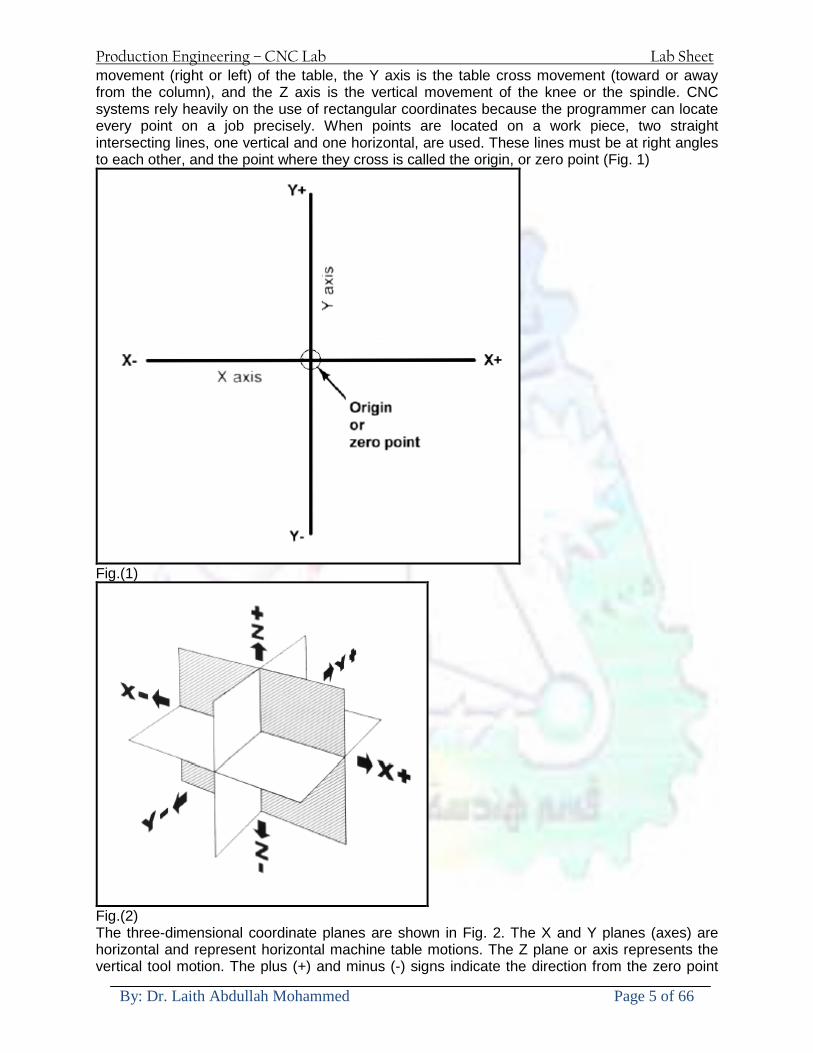
Production Engineering ndash CNC Lab Lab Sheet
By Dr Laith Abdullah Mohammed Page 5 of 66
movement (right or left) of the table the Y axis is the table cross movement (toward or away from the column) and the Z axis is the vertical movement of the knee or the spindle CNC systems rely heavily on the use of rectangular coordinates because the programmer can locate every point on a job precisely When points are located on a work piece two straight intersecting lines one vertical and one horizontal are used These lines must be at right angles to each other and the point where they cross is called the origin or zero point (Fig 1)
Fig(1)
Fig(2) The three-dimensional coordinate planes are shown in Fig 2 The X and Y planes (axes) are horizontal and represent horizontal machine table motions The Z plane or axis represents the vertical tool motion The plus (+) and minus (-) signs indicate the direction from the zero point
Production Engineering ndash CNC Lab Lab Sheet
By Dr Laith Abdullah Mohammed Page 6 of 66
(origin) along the axis of movement The four quadrants formed when the XY axes cross are numbered in a counterclockwise direction (Fig 3) All positions located in quadrant 1 would be positive (X+) and positive (Y+) In the second quadrant all positions would be negative X (X-) and positive (Y+) In the third quadrant all locations would be negative X (X-) and negative (Y-) In the fourth quadrant all locations would be positive X (X+) and negative Y (Y-)
Fig(3) In Fig 3 point A would be 2 units to the right of the Y axis and 2 units above the X axis Assume that each unit equals 1000 The location of point A would be X + 2000 and Y + 2000 For point B the location would be X + 1000 and Y - 2000 In CNC programming it is not necessary to indicate plus (+) values since these are assumed However the minus (-) values must be indicated For example the locations of both A and B would be indicated as follows A X2000 Y2000 B X1000 Y-2000 Machines Using CNC Machine Types Lathe The engine lathe one of the most productive machine tools has always been an efficient means of producing round parts (Fig4) Most lathes are programmed on two axes bull The X axis controls the cross motion of the cutting tool Negative X (X-) moves the tool towards the spindle centerline positive X moves the tool away from the spindle centerline bull The Z axis controls the carriage travel toward or away from the headstock
Production Engineering ndash CNC Lab Lab Sheet
By Dr Laith Abdullah Mohammed Page 7 of 66
Fig 4 The main axes of a lathe or turning center Milling Machine The milling machine has always been one of the most versatile machine tools used in industry (Fig 5) Operations such as milling contouring gear cutting drilling boring and reaming are only a few of the many operations which can be performed on a milling machine The milling machine can be programmed on three axes bull The X axis controls the table movement left or right bull The Y axis controls the table movement toward or away from the column bull The Z axis controls the vertical (up or down) movement of the knee or spindle
Fig 5 The main axes of a vertical machining center Programming Systems Two types of programming modes the incremental system and the absolute system are used for CNC Both systems have applications in CNC programming and no system is either right or wrong all the time Most controls on machine tools today are capable of handling either incremental or absolute programming
Production Engineering ndash CNC Lab Lab Sheet
By Dr Laith Abdullah Mohammed Page 8 of 66
Incremental program locations are always given as the distance and direction from the immediately preceding point (Fig 6) Command codes which tell the machine to move the table spindle and knee are explained here using a vertical milling machine as an example
Fig 6 A workpiece dimensioned in the incremental system mode bull A ldquoX plusrdquo (X+) command will cause the cutting tool to be located to the right of the last point bull A ldquoX minusrdquo (X-) command will cause the cutting tool to be located to the left of the last point bull A ldquoY plusrdquo (Y+) command will cause the cutting tool to be located toward the column bull A ldquoY minusrdquo (Y-) will cause the cutting tool to be located away from the column bull A ldquoZ plusrdquo (Z+) command will cause the cutting tool or spindle to move up or away from the workpiece bull A ldquoZ minusrdquo (Z-) moves the cutting tool down or into the workpiece In incremental programming the G91 command indicates to the computer and MCU (Machine Control Unit) that programming is in the incremental mode Absolute program locations are always given from a single fixed zero or origin point (Fig 7) The zero or origin point may be a position on the machine table such as the corner of the worktable or at any specific point on the workpiece In absolute dimensioning and programming each point or location on the workpiece is given as a certain distance from the zero or reference point
Fig 7 A workpiece dimensioned in the absolute system mode Note All dimensions are given from a known point of reference bull A ldquoX plusrdquo (X+) command will cause the cutting tool to be located to the right of the zero or origin point bull A ldquoX minusrdquo (X-) command will cause the cutting tool to be located to the left of the zero or origin point bull A ldquoY plusrdquo (Y+) command will cause the cutting tool to be located toward the column
Production Engineering ndash CNC Lab Lab Sheet
By Dr Laith Abdullah Mohammed Page 9 of 66
bull A ldquoY minusrdquo (Y-) command will cause the cutting tool to be located away from the column In absolute programming the G90 command indicates to the computer and MCU that the programming is in the absolute mode Point-to-Point or Continuous Path CNC programming falls into two distinct categories (Fig 8) The difference between the two categories was once very distinct Now however most control units are able to handle both point-to-point and continuous path machining A knowledge of both programming methods is necessary to understand what applications each has in CNC
Fig 8 Types of CNC positioning systems Point-to-Point Positioning Point-to-point positioning is used when it is necessary to accurately locate the spindle or the workpiece mounted on the machine table at one or more specific Locations to perform such operations as drilling reaming boring tapping and punching (Fig9) Point-to-point positioning is the process of positioning from one coordinate (XY) position or location to another performing the machining operation and continuing this pattern until all the operations have been completed at all programmed locations
Fig 9 The path followed by point-to-point positioning to reach various programmed points (machining locations) on the XY axis
Production Engineering ndash CNC Lab Lab Sheet
By Dr Laith Abdullah Mohammed Page 10 of 66
In Fig 9 point 1 to point 2 is a straight line and the machine moves only along the X axis but points 2 and 3 require that motion along both the X and Y axes takes place As the distance in the X direction is greater than in the Y direction Y will reach its position first leaving X to travel in a straight line for the remaining distance A similar motion takes place between points 3 and 4 Continuous Path (Contouring) Contouring or continuous path machining involves work such as that produced on a lathe or milling machine where the cutting tool is in contact with the workpiece as it travels from one programmed point to the next Continuous path positioning is the ability to control motions on two or more machine axes simultaneously to keep a constant cutter-workpiece relationship The programmed information in the CNC program must accurately position the cutting tool from one point to the next and follow a predefined accurate path at a programmed feed rate in order to produce the form or contour required (Fig 10)
Fig 10 Types of contour machining (A) Simple contour (B) complexe contour
Interpolation The method by which contouring machine tools move from one programmed point to the next is called interpolation This ability to merge individual axis points into a predefined tool path is built into most of todayrsquos MCUs There are five methods of interpolation linear circular helical parabolic and cubic All contouring controls provide linear interpolation and most controls are capable of both linear and circular interpolation Helical parabolic and cubic interpolation are used by industries that manufacture parts which have complex shapes such as aerospace parts and dies for car bodies Linear Interpolation Linear Interpolation consists of any programmed points linked together by straight lines whether the points are close together or far apart (Fig 11) Curves can be produced with linear interpolation by breaking them into short straight-line segments This method has limitations because a very large number of points would have to be programmed to describe the curve in order to produce a contour shape A contour programmed in linear interpolation requires the coordinate positions (XY positions in two-axis work) for the start and finish of each line segment Therefore the end point of one line or segment becomes the start point for the next segment and so on throughout the entire program
Production Engineering ndash CNC Lab Lab Sheet
By Dr Laith Abdullah Mohammed Page 11 of 66
Fig 11 An example of two-axis linear interpolation Circular Interpolation The development of MCUs capable of circular interpolation has greatly simplified the process of programming arcs and circles To program an arc (Fig 12) the MCU requires only the coordinate positions (the XY axes) of the circle center the radius of the circle the start point and end point of the arc being cut and the direction in which the arc is to be cut (clockwise or counterclockwise) See Fig 12
Fig 12 For two-dimensional circular interpolation the MCU must be supplied with the XY axis radius start point end point and direction of cut
Programming Format Word address is the most common programming format used for CNC programming systems This format contains a large number of different codes that transfers program information from the part print to machine servos relays micro-switches etc to manufacture a part These codes which conform to EIA (Electronic Industries Association) standards are in a logical sequence called a block of information Each block should contain enough information to perform one machining operation Word Address Format Every program for any part to be machined must be put in a format that the machine control unit can understand The format used on any CNC machine is built in by the machine tool builder and is based on the type of control unit on the machine A variable-block format which uses words (letters) is most commonly used Each instruction word consists of an address character such as X Y Z G M or S Numerical data follows this address character to identify a specific function such as the distance feed rate or speed value The address code G90 in a program
Production Engineering ndash CNC Lab Lab Sheet
By Dr Laith Abdullah Mohammed Page 12 of 66
tells the control that all measurements are in the absolute mode The code G91 tells the control that measurements are in the incremental mode Codes The most common codes used when programming CNC machines tools are G-codes (preparatory functions) and M codes (miscellaneous functions) Other codes such as F S D and T are used for machine functions such as feed speed cutter diameter offset tool number etc G-codes are sometimes called cycle codes because they refer to some action occurring on the X Y andor Z axis of a machine tool The G-codes are grouped into categories such as Group 01 containing codes G00 G01 G02 G03 which cause some movement of the machine table or head Group 03 includes either absolute or incremental programming while Group 09 deals with canned cycles A G00 code rapidly positions the cutting tool while it is above the workpiece from one point to another point on a job During the rapid traverse movement either the X or Y axis can be moved individually or both axes can be moved at the same time Although the rate of rapid travel varies from machine to machine it ranges between (5 and 20 mmin)
Fig 13 The functions of a few common G-codes The G01 G02 and G03 codes move the axes at a controlled feedrate bull G01 is used for straight-line movement (linear interpolation) bull G02 (clockwise) and G03 (counterclockwise) are used for arcs and circles (circular interpolation)
Production Engineering ndash CNC Lab Lab Sheet
By Dr Laith Abdullah Mohammed Page 13 of 66
Fig 14 Some of the most common G-codes used in CNC programming M or miscellaneous codes are used to either turn ON or OFF different functions which control certain machine tool operations M-codes are not grouped into categories although several codes may control the same type of operations such as M03 M04 and M05 which control the machine tool spindle bull M03 turns the spindle on clockwise bull M04 turns the spindle on counterclockwise bull M05 turns the spindle off
Production Engineering ndash CNC Lab Lab Sheet
By Dr Laith Abdullah Mohammed Page 14 of 66
Fig 15 The functions of a few common M-codes
Production Engineering ndash CNC Lab Lab Sheet
By Dr Laith Abdullah Mohammed Page 15 of 66
Fig 16 Some of the most common M-codes used in CNC programming Block of Information CNC information is generally programmed in blocks of five words Each word conforms to the EIA standards and they are written on a horizontal line If five complete words are not included in each block the machine control unit (MCU) will not recognize the information therefore the control unit will not be activated Using the example shown in Fig 17 the five words are as follows N001 represents the sequence number of the operation G01 represents linear interpolation X12345 will move the table 12345 in in a positive direction along the X axis Y06789 will move the table 06789 in along the Y axis M03 Spindle on CW
Fig 17 A complete block of information consists of five words
Production Engineering ndash CNC Lab Lab Sheet
By Dr Laith Abdullah Mohammed Page 16 of 66
Programming for Positioning Before starting to program a job it is important to become familiar with the part to be produced From the engineering drawings the programmer should be capable of planning the machining sequences required to produce the part Visual concepts must be put into a written manuscript as the first step in developing a part program Fig 18 It is the part program that will be sent to the machine control unit by the computer tape diskette or other input media The programmer must first establish a reference point for aligning the workpiece and the machine tool for programming purposes The manuscript must include this along with the types of cutting tools and work-holding devices required and where they are to be located
Fig 18 The first step in producing a CNC program is to take the information from the print and produce a program manuscript Dimensioning Guidelines The system of rectangular coordinates is very important to the successful operation of CNC machines Certain guidelines should be observed when dimensioning parts for CNC machining The following guidelines will insure that the dimensioning language means exactly the same thing to the design engineer the technician the programmer and the machine operator 1 Define part surfaces from three perpendicular reference planes 2 Establish reference planes along part surfaces which are parallel to the machine axes 3 Dimension from a specific point on the part surface 4 Dimension the part clearly so that its shape can be understood without making mathematical calculations or guesses 5 Define the part so that a computer numerical control cutter path can be easily programmed
Production Engineering ndash CNC Lab Lab Sheet
By Dr Laith Abdullah Mohammed Page 17 of 66
Machine Zero Point The machine zero point can be set by three methodsmdashby the operator manually by a programmed absolute zero shift or by work coordinates to suit the holding fixture or the part to be machined MANUAL SETTING - The operator can use the MCU controls to locate the spindle over the desired part zero and then set the X and Y coordinate registers on the console to zero
Fig 19 The relationship between the part zero and the machine system of coordinates ABSOLUTE ZERO SHIFT - The absolute zero shift can change the position of the coordinate system by a command in the CNC program The programmer first sends the machine spindle to home zero position by a G28 command in the program Then another command (G92 for absolute zero shift) tells the MCU how far from the home zero location the coordinate system origin is to be positioned Fig 19 The sample commands may be as follows N1 G28 X0 Y0 Z0 (sends spindle to home zero position) N2 G92 X4000 Y5000 Z6000 (the position the machine will reference as part zero)
Production Engineering ndash CNC Lab Lab Sheet
By Dr Laith Abdullah Mohammed Page 18 of 66
Work Settings and Offsets All CNC machine tools require some form of work setting tool setting and offsets (compensation) to place the cutter and work in the proper relationship Compensation allows the programmer to make adjustments for unexpected tooling and setup conditions
Work Coordinates In absolute positioning work coordinates are generally set on one edge or corner of a part and all programming is generally taken from this position In Fig 20 the part zero is used for all positioning for hole locations 1 2 and 3
Fig 20 In absolute programming all dimensions must be taken from the XY zero at the top left-hand corner of the part
Fig 21 In incremental programming all dimensions are taken from the previous point In incremental positioning the work coordinates change because each location is the zero point for the move to the next location Fig 21
Production Engineering ndash CNC Lab Lab Sheet
By Dr Laith Abdullah Mohammed Page 19 of 66
On some parts it may be desirable to change from absolute to incremental or vice versa at certain points in the job Inserting the G90 (absolute) or the G91 (incremental) command into the program at the point where the change is to be made can do this
R Plane or Gage Height The word-address letter R refers to a partial retraction point in the Z axis to which the end of the cutter retracts above the work surface to allow safe table movement in the X Y axes It is often called the rapid-traverse distance gage height retract or work plane The R distance is a specific height or distance above the work surface and is generally 100 in above the highest surface of the workpiece Fig 22 which is also known as gage height Some manufacturers build a gage height distance of 100 in into the MCU (machine control unit) and whenever the feed motion in the Z axis is called for 100 in will automatically be added to the depth programmed When setting up cutting tools the operator generally places a 100 in thick gage on top of the highest surface of the workpiece Each tool is lowered until it just touches the gage surface and then its length is recorded on the tool list Once the gage height has been set it is not generally necessary to add the 100 in to any future depth dimensions since most MCUs do this automatically
Fig 22 Using a 100 in gage block to set the gage height or R0 on the work surface
Cutter Diameter Compensation Cutter diameter compensation (CDC) changes a milling cutterrsquos programmed centerline path to compensate for small differences in cutter diameter On most MCUs it is effective for most cuts made using either linear or circular interpolation in the X-Y axis but does not affect the programmed Z-axis moves Usually compensation is in increments of 0001 in up to +10000 in and usually most controls have as many CDCs available as there are tool pockets in the tool storage matrix The advantage of the CDC feature is that it 1 Allows the use of cutters that have been sharpened to a smaller diameter 2 Permits the use of a larger or smaller tool already in the machinersquos storage matrix 3 Allows backing the tool away when roughing cuts are required due to excessive material present 4 Permits compensation for unexpected tool or part deflection if the deflection is constant throughout the programmed path The basic reference point of the machine tool is never at the cutting edge of a milling cutter but at some point on its periphery If a 1000 in diameter end mill is used to machine the edges of a workpiece the programmer would have to keep a 500 in offset from the work surface in order to cut the edges accurately Fig 23 The 500 offset represents the distance from the centerline of the cutter or machine spindle to the edge of the part Whenever a part is being machined the programmer must calculate an offset path which is usually half the cutter diameter
Production Engineering ndash CNC Lab Lab Sheet
By Dr Laith Abdullah Mohammed Page 20 of 66
Fig 23 Cutter-diameter compensation must be used when machining with various size cutters Modern MCUs which have part surface programming automatically calculate centerline offsets once the diameter of the cutter for each operation is programmed Many MCUs have operator-entry capabilities which can compensate for differences in cutter diameters therefore an oversize cutter or one that has been sharpened can be used as long as the compensation value for oversize or undersize cutters is entered
Production Engineering ndash CNC Lab Lab Sheet
By Dr Laith Abdullah Mohammed Page 21 of 66
CNC Programming Hints - MILLING
Production Engineering ndash CNC Lab Lab Sheet
By Dr Laith Abdullah Mohammed Page 22 of 66
CNC Programming Hints ndash TURNING
Production Engineering ndash CNC Lab Lab Sheet
By Dr Laith Abdullah Mohammed Page 23 of 66
CNC
The abbreviation CNC stands for Computer(ized) Numerical(ly) Control(led) and refers specifically to the computer control of machine tools for the purpose of (repeatedly) manufacturing complex parts in metal as well as other materials using a program written in a notation conforming to the EIA-274-D standard and commonly called G-code
CNC was developed in the late 1940s and early 1950s by the MIT Servomechanisms Laboratory CNC machines were relatively briefly preceded by the less advanced NC or Numerical(ly) Control(led) machines The introduction of CNC machines radically changed the manufacturing industry Curves are as easy to cut as straight lines complex 3-D structures are relatively easy to produce and the number of machining steps that required human action have been dramatically reduced With the increased automation of manufacturing processes with CNC machining considerable improvements in consistency and quality have been achieved CNC automation reduced the frequency of errors and provided CNC operators with time to perform additional tasks
CNC automation also allows for more flexibility in the way parts are held in the manufacturing process and the time required to change the machine to produce different components In a production environment a series of CNC machines may be combined into one station commonly called a cell to progressively machine a part requiring several operations CNC machines today are controlled directly from files created by CAM software packages so that a part or assembly can go directly from design to manufacturing without the need of producing a drafted paper drawing of the manufactured component In a sense the CNC machines represent a special segment of industrial robot systems as they are programmable to perform many kinds of machining operations (within their designed physical limits like other robotic systems)
G-code
G-code is a common name for the programming language that is used for NC and CNC machine tools It is defined in EIA RS-274-D G-code is also the name of any word in a CNC program that begins with the letter G and generally is a code telling the machine tool what type of action to perform such as
bull rapid move bull controlled feed move in straight line or arc bull series of controlled feed moves that would result in a hole being drilled bull change a pallet bull Set tool information such as offset
There are other codes the type codes can be thought of like registers in a computer
X position Y position Z position M code (another action register) F feed rate S spindle speed N line number R Radius T Tool selection
Production Engineering ndash CNC Lab Lab Sheet
By Dr Laith Abdullah Mohammed Page 24 of 66
I Arc data X axis J Arc data Y axis
G-code files are output by CAM software such as Smartcam Gibbscam Featurecam Edgecam Mastercam etc G-code is also output by specialized CAD systems used to design printed circuit boards Such software must be customized for each type of machine tool that it will be used to program
Production Engineering ndash CNC Lab Lab Sheet
By Dr Laith Abdullah Mohammed Page 25 of 66
U 2عمل األزرار الرئيسية في ماكنة الخراطة المبرمجة (نصر (
1- SINGLE BLOCK للتأكد من صحة البرنامج (تنفيذ البرنامج خطوة خطوةب تقوم( 2- BLOCK DELETE بجانب ويعمل من األوامرلغاء بلوك معين أليستخدم 3- MACHINE LOCK العمل يستخدم لقفل حركة المحاور الرئيسية مع استمرار البرنامج في
)وهذا مهم للتاكد من صحة البرنامج قبل عملية التنفيذ النهائي(4- CONT CYCLE عملية التشغيل عند ايقافها الي سبب كان او عند ايقافها ألستئناف ستخدم ت
) BAR FEEDER(او في حالة استخدام ) FEED HOLDبسبب (5- DRY RUN وتستخدم لفحص البرنامج بعد ازالة الشغلة حركة سريعة للبرنامج 6- TURRET UP amp DOWN ) حركة حامل العدة TURRET الذي يحمل مجموعة من (
وهذا الزر يعمل مع الزر عكس عقرب الساعة او مع عقرب الساعة ةحركة دوراني العدد )SAFTY (
7- COOLANT ON or OFFفه تشغيل سائل التبريد او ايقا 8- COOLANT AUTO الدوال المساعدة في البرنامج من خالل فه تشغيل سائل التبريد او ايقا 9 -MACHINE START ة لتشغيل هيدرولكيك الماكنميستخد
Production Engineering ndash CNC Lab Lab Sheet
By Dr Laith Abdullah Mohammed Page 26 of 66
10- CLOSE OR OPEN CHUCKالعينة تستخدم لفتح وغلق 11 -T STOCK FWD RET حركة الغراب المتحرك ذهابا وإيابا12 -SPINDLE STOP تعمل على ايقاف حركة دوران العينة 13-JOG SPINDLE تعمل على تدوير العينة مع زر SAFTY 14 -OPT SAFTY مع الدالة ( تعمل عمل التوقف المشروط حيث تعملM1 دالة التوقف (
ط ) فقط األ اذا كان هذا الزر مضغو M1المشروط حيث ال يتوقف البرنامج في حالة وجود دالة ( SAFTY + SPINDLE ) يتم الضغط على زر ( START CYCLEلغرض تحرير زر (
START ) في نفس الوقت بعد الضغط على زر ( START CYCLE مرتين (
NC PC- 15 يستخدم هذا الزر عند ربطCNC يستخدم لنقل المعلومات ث مع جهاز أخر حي بينهما
16 -CALCU زر الخاص بالحاسبة مع زر ( ال وهوINPUT ( 17 - HD1 HD2 يستخدم الختيار العدة مع المخرطة ذات المحاور األربعة 18 - START تستخدم لبدء عملية التشغيل
Production Engineering ndash CNC Lab Lab Sheet
By Dr Laith Abdullah Mohammed Page 27 of 66
19- FEED HOLD تعمل على إيقاف عمل أي G موجودة مع بقاء العينة متحركة 20- M D I أو تشغيل البرنامج ل يتم استخدامه لإلدخا BLOCK BY BLOCK وتعمل عند
إدخال البرنامج بواسطة الشريط المثقب أو أي وسيلة إدخال أخرى أو في عمليات التصفير
21- REST تستخدم العادة تشغيل الماكنة أو مسح اإلنذار الذي يظهر على الشاشة 22- EMERGENCYتستخدم عادة اليقاف الماكنة في حالة الطوارئ فقط
OPERATION MENU KEY
CHAPTER PRG-CMK
OFFSET PROGRAM POSITION FUNCTION MENU KEY
23- POSITIONعلى الشاشة د الموقع الموجور الظها 24- PROGRAMإلظهار برنامج معين واختياره 25- OFFSET الختيار سماحات العدة أو سماحات نقطة المرجع 26- PRG- CHK تستخدم لفحص البرنامج على الشاشة 27- SETTING ألختيار الثوابت على الشاشة 28- SERVICE تستخدم ألستخراج المعامالت والثوابت 29- MESSAGE تستخدم ألظهار األخطاء الناتجة عن البرنامج او اخطاء التشغيل 30- OVERALL ألختيار المواقع 31- RELATIVE MODLINE تعوض عن POSITION 32- DIR MEM يستخدم ألظهار ملف البرامج المخزونة في الذاكرة وعندما نضغط هذا الزر
فان رقم واسم البرنامج سوف يظهر على الشاشة
2أدناه الشفرات الرئيسية التي تعمل على الماكنة المبرمجة نصر
G-CODE DESCRIPTION
G00 Rapid traverse (linear)
G01 Linear Interpolation at feed rate
G02 Circular interpolation (CW) R+
G03 Circular interpolation (CCW) R+
G10 Zero point tools
G20 Imperial data input
G21 Metric data input
G27 Reference return check
G28 Reference return
G29 Return from reference
Production Engineering ndash CNC Lab Lab Sheet
By Dr Laith Abdullah Mohammed Page 28 of 66
G33 Thread cutting
G40 Cancel cutter radius compensation
G41 Cutter compensation left
G42 Cutter compensation right
G54 Work co-ordinate system no1
G70 Finishing cycle
G71 Stock removal turning
G72 Stock removal facing
G74 Face grooving
G75 Diameter grooving
G76 Threading cycle
G90 Absolute date input
G91 Incremental data input
G94 Feed minute mode
G95 Feed rev mode
G96 Constant surface speed mode
G97 Cancel Constant surface speed
) 2أدناه الشفرات الثانوية التي تعمل على الماكنة المبرمجة (نصر
M-code FUNCTION
M00 Program stop
M03 Spindle forward (Tool forward ndash M94 mode)
M04 Spindle reverse (Tool forward ndash M94 mode)
M05 Spindle stop (Tool stop ndash M94 mode)
M08 Coolant on
M09 Coolant off
M30 Program end (with rewind)
M48 Turret shortest path
M52 Turret direction up (CW)
M53 Turret direction down (CCW)
M73 Chuck open
M74 Chuck close
Production Engineering ndash CNC Lab Lab Sheet
By Dr Laith Abdullah Mohammed Page 29 of 66
) وكل جملة مكونة من مجموعة من الكلمات blockإن كل برنامج يتكون من مجموعة من الجمل ()words) لهذا فأن الشفرات الرئيسية والمساعدة هي عبارة عن كلمات (words كما في المثال التالي (
G_ _ P1 Q2 U_ _ W_ _ D___ F_ _
)end of block) ويعني ( ) يكتب الرمز (blockتسلسل الكلمات مهم جدا بعد نهاية كل جملة (
طريقة ادخال البيانات الى الماكنة ــــــــــــــــــــــــــــــــــــــــــــــــــ
) MDIيمكن ادخال البيانات الى الماكنة بعدة طرق فقد يكون األدخال عن طريق قناة السيطرة ( MANUAL DATA INPUT ) او عن طريق قناة األضافة EDIT كما يمكن ادخال البيانات عن (
) RS ndash 232 COMMUNICATIN LINKطريق استخدام سلسلة الربط (
₤⅗₌⅗₌ ⅙₌₨image₍₡ ₤₌ℌ⅗₌ Ⅸ⅗ⅥⅯ₌ ₤₡ℌ₰₨⅗₌G71
الخراطة الطولية G71الغرض من التجربة عمل نموذج للخراطة بأستخدام الدالة تستعمل هذه الدالة للخراطة الطولية اي على طول محور المشغولة وكما هو موضح بالشكل ادناه
تعتبر هذه الدالة من الدوال التي ال تحتاج الى تكرار او إعادة كتابتها أي انها دالة تكرارية بمعنى ان اي
الذي هي دالة حركة G01خطوة تكون من ضمن هذه الدالة سوف تكرر العملية اي عند استعمال امر مثل خطية تتضمن القطع مع التغذية مع اعطاء القطر المراد قطعه و مراعاة عمق القطع المعطى سوف يتكرر
هذه االمر وصوال الى العمق المطلوب وهكذا لبقية الدوال
G71 المستخدمة للدالة الصيغة
G71 P1 Q2 U___ W___ D___ F___ حيث إن
P1 بداية الخطوة االولى = Q2 نهاية الخطوة =
Uوضع السماحات بأتجاه محور = X W وضع السماحات بأتجاه محور = Z وتكاد تكون مهملة وتوضع اشارة سالب Dعمق القطع وتوضع رقم صحيح مثل = D500 اي نصف ملمF التغذية والتي لها عالقة بالدالة = G95
Production Engineering ndash CNC Lab Lab Sheet
By Dr Laith Abdullah Mohammed Page 30 of 66
G71الدالة استخدام مثال على
T0100 M48 G0 X26 Z2 M08 T0101 G90 G95 G97 S500 M03 G71 P1 Q2 U03 W00 D500 F01 N1 G0 G42 X00 G01 Z00 G01 X2517 G01 Z-5352 G01 X7391 Z-9366 G01 Z-19145 N2 G28 M30
الجانب العملي
االجهزة واالدوات المستخدمة CNCماكنة خراطة مبرمجة 1 ملم 80قضيب من االلمنيوم قطر 2 ةفير ني 3 جاه أيمن تهولدر كاربيدي ذوا 4
طريقة العمل يتم تثبيت قضيب من االلمنيوم على العينة التابعة للماكنة مع مراعاة الطول المراد استعماله في عملية 1
الخراطة ) turretتثبيت عدة القطع في المكان الصحيح في ( 2
Production Engineering ndash CNC Lab Lab Sheet
By Dr Laith Abdullah Mohammed Page 31 of 66
بالنسبة الى القطعة المثبتة على العينة XZيتم تصفير الماكنة للمحاور 3 تصفير للمحورZ تكون مالمسة العدة الى وجه الشغلة تصفير للمحورX تكون مالمسة العدة الى سطح الشغلة الموازي لمحور X
يتم كتابة البرنامج أما بطريقة يدوية أو بالحاسوب مع وضع كل الظروف الالزمة للتشغيل ( عمق القطع 4 التغذية السرعة المطلوبة نوع المعدن )
ادخال البرنامج الى الحاسوب الموجود داخل الماكنة مع تهيئة الماكنة للتشغيل 5
المطلوب G71عمل برنامج يدوي على الدالة 1 رسم الشكل الشكل النهائي المطلوب مع وضع األبعاد 2
Ⅺ⅟₍euro⅗₌ ₤₡ℌ₰₨⅗₌₣ ₤⅗₌⅗₌ ⅙₌₨image₃₡ Ⅺℂtradeℒ⅗₌ ӈ₍Ⅴ⅟ⅳ₌ G70
G70 الغرض من التجربة عمل انهاء سطحي للمشغولة بواسطة الدالة
من الضروري إعطاء G71هذه الدالة تعمل شوط واحد فقط وتكون معتمدة على عمليات القطع في الدالة اللغاء مقدمة االداة (أي لكي تتم عملية االنهاء السطحي بدون حسابات نصف قطر مقدمة االداة ) G42دالة
G70الصيغة المستخدمة للدالة
G70 P1 Q2 F___ حيث ان
P1 بداية الخطوة االولى = Q2 نهاية الخطوة =
F التغذية والمرتبطة بالدالة = G95
وذلك ألن دالة االنهاء السطحي تحقق X Zمالحظة الدالة التحتاج لكتابة السماحات التابعة للمحورين المسافات الحقيقة المراد انتاجها للمشغولة
G71و G70مثال على الدالة
T0100 M48 G0 X26 Z2 M08 T0101 G90 G95 G97 S500 M03 G71 P1 Q2 U03 W00 D500 F01 N1 G0 G42 X00 G01 Z00 G01 X2517 G01 Z-5352 G01 X7391 Z-9366 G01 Z-19145 N2 G97 S750 MO3
Production Engineering ndash CNC Lab Lab Sheet
By Dr Laith Abdullah Mohammed Page 32 of 66
G70 P1 Q2 G40 F009 G28 M30
الجانب العملي الحظ التجربة األولى
المطلوب
G70 عمل برنامج يدوي على الدالة 1 رسم الشكل النهائي المطلوب مع وضع االبعاد 2
₪⅗₍euro⅗₌ ₤₡ℌ₰₨⅗₌₣ ₤⅗₌⅗₌ ⅙₌₨image₍₡ ⅝₍ⅠimageⅯ₌ ⅞ⅫⅦ⅔₧ G76
G76 للمشغولة بواسطة الدالةةالغرض من التجربة عمل أسنان خارجية أو داخلي
في هذه التجربة سوف نقوم بعمل األسنان الخارجية وهنا تكون حركة العينة ثابتة وهذا ضروري بسبب أن ) تكون متصلتين الكترونيا وعليه أي اختالف في سرعة العينة تؤدي إلى اختالف motionالعينة والحركة(
) servoفي سرعة الخدمة(يرتبط اتجاه تكوين األسنان باتجاه دوران العينة مثال إذا كانت األسنان ذات اتجاه أيمن يكون اتجاه دوران
وهنا نقلب العدة إلى االسفل وكما هو موضح بالشكل أدناه MO3العينة عكس عقرب الساعة أي نستعمل
Production Engineering ndash CNC Lab Lab Sheet
By Dr Laith Abdullah Mohammed Page 33 of 66
الخطوة هي عبارة عن المسافة ما بين قمة سن إلى قمة سن أخر عمق السن هو العمق المطلوب تكوينه لألسنان
G76 الصيغة المستخدمة للدالة
G76 X___ Z___ K___ F___ D___ A___
حيث أن X القطر الداخلي للسن =Z طول السن =K عمق السن وتستخرج من المعادلة التالية =K=065F F الخطوة =D عمق القطع بالمايكرون فقط =A زاوية السن =
G76مثال على استخدام الدالة T0300 M48 GOO X30 Z4 T0303 M08 G97 S500 MO3 G76 X28375 Z-20 K08125 F125 D120 G00 X40 Z4 G28 M30
Production Engineering ndash CNC Lab Lab Sheet
By Dr Laith Abdullah Mohammed Page 34 of 66
الجانب العملي الحظ التجربة األولى
المطلوب
G76عمل برنامج يدوي على الدالة 1 رسم الشكل النهائي المطلوب مع وضع األبعاد 2
Ⅺ⅘₌⅗₌ Ⅵ₂ Ⅺ₯ℋ₍⅗₌ ℌℲℂ⅗₌ ⅞ⅫⅦ⅔₧ ₤K₡₌ℌ⅗₌ ₤₡ℌ₰₨⅗₌)Groove ₤⅗₌⅗₌ ₤tradeimage₌Ⅶ₡ (G75
G75 بواسطة الدالة grooveالغرض من التجربة تكوين
) للمشغولة وتعتمد شكل الحفر على طريقة grooveتستعمل هذه الدالة لتكوين الحفر الخارجي والداخلي (
التشغيل وعلى الشكل المراد إنتاجه وتعتبر هذه الطريقة من عمليات التشكيل للمعدن إن هذه الدالة هي دالة مالحظة مع G75في هذه التجربة سنقوم بعمل الحفر الخارجي بواسطة الدالة
تكرارية وغير تكرارية حسب نوع التشغيل
G 75 الصيغة المستخدمة للدالةG75 X___ Z___ I___ K____
حيث أن
X العمق النهائي لقطر الشغلة =Z عرض الحفر =I الدخول في كل مرة =
K التزحيف على محور =z بالنسبة للعدة
Production Engineering ndash CNC Lab Lab Sheet
By Dr Laith Abdullah Mohammed Page 35 of 66
G75مثال على استخدام الدالة
T0500 M48 GOO X100 Z -20 T0505 M08 G97 S700 MO3 G75 X84 Z -38 I 05 K4
الجانب العملي الحظ التجربة األولى
المطلوب
G76عمل برنامج يدوي على الدالة 1 رسم الشكل النهائي المطلوب مع وضع األبعاد 2
Production Engineering ndash CNC Lab Lab Sheet
By Dr Laith Abdullah Mohammed Page 36 of 66
CNC Milling Machine Mechanical Construction
Guideways The guideways of CNC machines are made of steel To reduce the frictional forces they are coated with a strip of PTFE (Poly Tetra Fluoro Ethylene)
Ballscrews On conventional lathes a leadscrew is used to converts the rotary motion of the hand wheel into linear motion of the slides Leadscrews have a high coefficient of friction and backlash On CNC machines a ballscrew is used instead of a leadscrew Friction and backlash are much less than on leadscrews
Guideway
Production Engineering ndash CNC Lab Lab Sheet
By Dr Laith Abdullah Mohammed Page 37 of 66
bullMachining operations Direction of cutting Based on the direction of the cutter rotation and work piece feed milling operations are classified into two types 1-Up milling (Convention milling) In up milling the metal is removed by rotating the cutter against the direction of travel of the part
Feed
Machine table
Part
Cutting tool
Chip thickness at theexit of the tooth
2-Down milling (Climb milling) In climb milling the metal is removed by rotating the cutter with the direction of travel of the part
Machine table
Part
Cutting tool
Chip thickness at theentrance of the tooth
Production Engineering ndash CNC Lab Lab Sheet
By Dr Laith Abdullah Mohammed Page 38 of 66
bullTooling Tool geometry The geometry of the tool tip affects the way that the metal cutting is performed The nose radius rake angles relief angles etc must be selected with care
Radial relief
Radial rake
Axial relief
Approach angle
Axial relief
Corner radius Face mill Face milling cutters are used to mill flat surfaces Commonly used face milling cutters Cutter with 75 degree approach
75 deg
Cutter with 90 degree approach (Square shoulder face mill)
90 deg
Cutter with 45 degree approach
Production Engineering ndash CNC Lab Lab Sheet
By Dr Laith Abdullah Mohammed Page 39 of 66
bullCNC Programming Axes convention The Z axis is along the spindle axis The X and Y axes are perpendicular to Z VMC
Z
Y
-
+
-+
X- +
+Z
-Z
+Y
-Y
-X +X
Part
Machine table
X
YZ
G00 Rapid traverse When the tool being positioned at a point preparatory to a cutting motion to save time it is moved along a straight line at Rapid traverse at a fixed traverse rate which is pre-programmed into the machines control system Typical rapid traverse rates are 10 to 25 m min but can be as high as 80 mmin
Production Engineering ndash CNC Lab Lab Sheet
By Dr Laith Abdullah Mohammed Page 40 of 66
Format N_ G00 X__ Y__Z__
G01 Linear interpolation (feed traverse) The tool moves along a straight line in one or two axis simultaneously at a programmed linear speed the feed rate Format N__ G01 X__ Y__Z__ F__
Part
Feed
Part
Feed
G02G03 Circular interpolation The tool moves along an arc in two axes simultaneously at a programmed linear speed the feed rate
Production Engineering ndash CNC Lab Lab Sheet
By Dr Laith Abdullah Mohammed Page 41 of 66
Format N__ G0203 X__ Y__Z__ I__ J__K__ F__ using the arc center OR N__ G0203 X__ Y__Z__ R__ F__ using the arc radius G02 moves along a CW arc G03 moves along a CCW arc Arc center The arc center is specified by addresses I J and K I J and K are the X Y and Z co-ordinates of the arc center with reference to the arc start point
X
Y
Arc center
Arc endArc start
- J
- I
I = X coord of center - X coord of start point J = Y coord of center - Y coord of start point K = Z coord of center - Z coord of start point I J and K must be written with their signs
Production Engineering ndash CNC Lab Lab Sheet
By Dr Laith Abdullah Mohammed Page 42 of 66
bullWork holding
Rotary table
Fixture base
Component
Clamp
Stud
Fixtures The use of fixtures 1 Improves repeatability of dimensions 2 Improves working conditions 3 Cuts down requirement of skilled labour 4 Reduces part loading and unloading time 5 Improves safety in the working area 6 Reduces the cost of machining There are two types fixtures commonly used 1 Special fixture Special fixtures are used to hold and locate the typical components which are having complex shape and to be located with the reference hole (dowel hole) Special fixtures are required for components like gear case cover cylinder heads etc 2 Modular fixture Modular fixture is a set different kind of clamping and locating elements These fixtures are used to hold identical components in different sizes and components of box type Example Manifolds head stocks connecting rods and flanges
Production Engineering ndash CNC Lab Lab Sheet
By Dr Laith Abdullah Mohammed Page 43 of 66
bullMachine setting
Determining X and Y work zero offset Case 1
Part
Machine table
Part
End mill or reamer
Work offset X0Y0 For determining X work zero offset bull Touch the periphery of the end mill or reamer to the part bull Enter current machine X value + cutter radius as X work zero offset For determining Y work zero offset bull Touch the periphery of the end mill or reamer to the part bull Enter current machine Y value - cutter radius as Y work zero offset Case 2
Part
Machine table
Part
End mill or reamerWork offset X0Y0
bull Mount the dial indicator on machine spindle true the bore bull Enter current machine X and Y value as X and Y work zero offset
Production Engineering ndash CNC Lab Lab Sheet
By Dr Laith Abdullah Mohammed Page 44 of 66
How to Select a Cutting Fluid
One part of the metal cutting equation that is sometimes overlooked however is
the choice of an appropriate cutting fluid With todayrsquos system approach to metal
cutting use of the right metalworking fluid has become just as much a part of the
solution as the other elements In fact at least one company is now integrating
cutting fluids and cutting tools into effective metal cutting systems Following are
some things to consider when choosing your next cutting fluid
The Four Key Questions
There are four vital pieces of information that are necessary when choosing a
cutting fluid They are
1 What are you cutting
2 What is the chemistry of your water
3 What are you using now
4 What are your options
5 What do you prefer
What Are You Cutting
The first question ndash ldquoWhat are you cuttingrdquo ndash is often the most difficult to answer
because most shops handle a variety of workpiece materials on a regular basis If
the answer is an unequivocal ldquoaluminumrdquo or ldquostainless steelrdquo or ldquocast ironrdquo the
selection of a cutting fluid can be quite simple and straightforward Unfortunately
that is seldom the case in anything but a high-volume plant Where aluminum or
other nonferrous metals are a significant part of the mix a non-staining cutting
fluid is a must Generally speaking this will be a semi-synthetic with special
ingredients to prevent bi-metallic corrosion and staining of non-ferrous workpieces
Where the ferrous metals predominate however a more general purpose semi-
synthetic or hybrid fluid might be a more economical choice
Production Engineering ndash CNC Lab Lab Sheet
By Dr Laith Abdullah Mohammed Page 45 of 66
What is The Chemistry of Your Water
The second question ndash ldquoWhat is the chemistry of your waterrdquo ndash is probably the
single most common reason for the success or failure of a cutting fluid Very few
plants invest the money necessary to install effective water purification systems
using deionization or reverse osmosis technology Unfortunately the chemicals
present or not present in the water used to re-constitute a cutting fluid make a
tremendous difference in its performance and sump life Most manufacturers of
cutting fluids will perform the necessary water testing to determine exactly what
minerals are dissolved in your water and make a fluid recommendation based on
the results
What are you using now
The third question ndash ldquoWhat are you using nowrdquo ndash helps narrow the range of
choices When coupled with an objective analysis of the strengths and weaknesses
of the current fluid the answer to this question can quickly point you toward a
relatively small number of competitive alternatives that have the attributes required
to meet your cutting needs Many cutting fluids are in use today simply because
they were in use yesterday It is a hard reality of todayrsquos marketplace that if one
isnrsquot constantly striving to improve they will certainly be overtaken by a
competitor who is
What Are Your Options
The fourth question ndash ldquoWhat are your optionsrdquo ndash leads to the final selection of a
cutting fluid Cutting fluids can be divided into four general groups based on their
chemistry
They are
bull Soluble Oils ndash quite literally oil dispersed in water
bull Synthetics ndash completely oil free man-made coolants in solution
Production Engineering ndash CNC Lab Lab Sheet
By Dr Laith Abdullah Mohammed Page 46 of 66
bull Semi-Synthetics ndash a mixture of natural and synthetic lubricants with up to 30
mineral oil
bull Hybrids ndash a special class of semi-synthetics with a mineral oil content of about
15 Each fluid type has advantages and disadvantages which make it suitable for
a particular group of applications In addition there are costperformance trade-
offs to be made between the groups within a specific set of applications For
example where a hybrid and a semi-synthetic may both be suitable for a particular
use the hybrid might provide longer sump life at a slightly higher initial cost
while some semi synthetics may be more economical to recycle or dispose of while
not giving as long a tank life The final decision in this case would have to be made
on the detailed economics of the shop where the fluids were to be used and on the
ownerrsquos individual preferences
Soluble Oils
Soluble oils are oils that disperse in water when emulsifiers are added They are
generally suitable for moderate-to heavy-duty machining and grinding of all non-
ferrous metals carbon and cast steels and in applications where dissimilar metals
such as aluminium and steel are present They can also be used in turning drilling
tapping reaming gear cutting broaching as well as internal and centerless types
of grinding operations Soluble oils provide excellent aluminium and copper
corrosion control good rancidity control which extends fluid for long lasting
trouble-free performance and good concentrate and mix stability making it ideal
for mixing in water with a minimal amount of agitation An example of this is
Valenitersquos VNTreg-650 premium heavy-duty soluble oil
Synthetics
Synthetics are completely oil free solutions made of polymers organic and
inorganic materials that are mixed with water These clear low foaming and bio-
Production Engineering ndash CNC Lab Lab Sheet
By Dr Laith Abdullah Mohammed Page 47 of 66
stable coolants are ideal for machining and grinding of ferrous materials carbon
steels or cast iron Their complex lubricant packages make synthetics well-suited
for tough-to-machine materials such as stainless steels and high-temperature alloys
Certain synthetics are specifically designed to address the primary failure modes of
flank wear and nose wear Although there are many benefits some synthetics may
cause staining of non-ferrous materials
Semi-Synthetics
Semi-synthetic fluids are a mixture of oils synthetic emulsifiers and water They
were primarily developed for the aircraft nuclear and related industries
Consequently they work extremely well on all non-ferrous metals such as titanium
aluminium copper brass bronze and stainless steel in both machining and
grinding Semi-synthetics can be used on ferrous metals too They are chlorine-
free to reduce bi-metallic corrosion and staining of metals They should be used at
a 5-8 dilution with water depending on the severity of the operation
Hybrids
Hybrids are cutting fluids custom engineered to solve a particular problem For
example Valenitersquos VNTreg-800 was developed to be very clean in the machining
and grinding of cast iron It provides better stability in hard water and rejects tramp
oil very well which adds to its bio-stable chemistry Hybrids work extremely well
on all metals in both machining and grinding They should be mixed at a 5-7
dilution with water depending on the condition of the water
What Do You Prefer
The final question ndash ldquoWhat do you preferrdquo ndash is usually the ldquotie breakerrdquo where
there is more than one appropriate cutting fluid available Here again as in the
case of what is being used now the key is to examine your preferences objectively
Production Engineering ndash CNC Lab Lab Sheet
By Dr Laith Abdullah Mohammed Page 48 of 66
and specifically to identify the real reasons behind a preference If you cannot
point to specific reasons why one class of cutting fluid is preferred over another
you are well advised to follow the recommendations of the professional who has
analyzed your requirements Choosing the right fluid today is easier than ever as
the system approach to metal cutting productivity continues to grow in acceptance
The day is not far off when choosing a complete solution will be as easy as
choosing the right insert and chip breaker today The answers are available and the
results will more than justify the time you spend choosing the right metal cutting
fluid
Useful Links wwwball-screwsnet
wwwlubelinkcom
wwwmachinerylubricationcom
wwwadvancedmanufacturingcom
wwwmmsonlinecom
wwwcuttingtoolengineeringcom
wwwgeartechnologycom
wwwengineersedgecom
wwwagmaorg
wwwefundacom
wwwsaeorg
wwwsmeorg
wwwastmorg
wwwissorg
wwwmachinetoolscom
wwwansiorg
wwwasmeorg
wwwcnccicom
wwwmatlscom
wwwthefreedictionarycom
wwwengineersupplycom
Production Engineering ndash CNC Lab Lab Sheet
By Dr Laith Abdullah Mohammed Page 49 of 66
SurfCAM Tutorial ndash Beginning with the basics
Background SurfCAM is a computer aided manufacturing (CAM) software which allows you to create manage and modify tool paths for computer aided designed (CAD) part The software requires a CAD model or requires that you create some geometry within SurfCAM with some rudimentary tools provided The tool paths are created or stored internally in SurfCAM in a generic programming language called APT Once the tool paths are created the APT paths are translated using a post processor into typical machine G-code
Opening SurfCAM SurfCAM can be opened from the Novell Applications Launcher on most Industrial Engineering computer labs workstations Search under lsquoallrsquo applications and double click on SurfCAM 2005 Once the program opens a license must be selected from the list (not the Demo license) to enable saving the file later Choose one of the 30 licenses available If for some reason the licenses are not listed on the license manager form select server list and type ldquobonnieeosncsuedurdquo A list of available licenses should appear Select a license and click OK After the license is selected an Add StockFixture form (Figure 1) opens allows you to add a model which represents the pre-machined stock or a fixture Click on OK without adding either Both of these items can be added later under a more appropriate dialog
Figure 1 Add Stock or Fixture dialog box
Production Engineering ndash CNC Lab Lab Sheet
By Dr Laith Abdullah Mohammed Page 50 of 66
SurfCAM Interface
Figure 2 SurfCAM Windows based interface
SurfCAM is a windows based software system so most of the typical windows functions under File are applicable This is where you can open save exit print etc The Create menu allows the user to create different geometry forms Here you can create a point line surface chamfer circle and many other geometry types For the most part these functions are not used by beginners but are useful when creating bounding curves where you donrsquot want the tool to move outside (constraining the tool) The Edit menu allows you to change or modify many different entities such as changing lines altering surfaces joining surfaces trimming or breaking elements add control points etc Again these features are helpful to advanced users and are not covered in detail in this tutorial The Display menu offers the ability to change the orientation of the part on the screen The typical rotate pan fit to screen and zoom functions are available as well as several functions which allow the user to shift between views or call up a named view (ie top bottom etc) The NC menu is the main machining interface menu In this menu you select the general form of machining (2 axis 3 axis 4 axis 5 axis turning etc) and under the general form a more specific machining function is selected This menu is the most used and the options contained must be fully understood to get the most out of SurfCAM Each function will be described in some detail in a further chapter The Analyze menu contains options such as measuring the distance between points angles tangency elements etc These functions are auxiliary functions meant to help you understand the part better but basically provide no functionality for making tool paths for CNC machines Thus these will not be covered The Tools menu allows the user to change the system options modify keyboard shortcuts change the model units etc These options are again not used by beginners Finally the Help menu provides access to the online users manual In lieu of clicking the Help menu the F1 key is the shortcut key for help (as it is in most windows based programs)
Importing a CAD model Importing a CAD model that is stored locally is done by selecting File-gtOpen On the Files of type dropdown box choose the type of file you wish to open (Figure 3) Do this prior to negotiating your way through the maze of folders to prevent having to go through the folder tree again Once the file type is selected find the file you are trying to open and click the Open
Production Engineering ndash CNC Lab Lab Sheet
By Dr Laith Abdullah Mohammed Page 51 of 66
button SurfCAM will then attempt to read the file you have selected SurfCAM may provide a dialog box describing what it has imported and identify if it was successful If this dialog is provided simply click close without saving
Figure 3 Open Dialog Note - Change type of file prior to finding the file you wish to open
SurfCAM allows a user to import several different types of CAD files the most common types which you will likely import are SolidWorks part files (sldprt or prt) AutoCAD files(dxf) or IGES (igs or iges) Native file import (such as is the case with SolidWorks) provides the greatest information transfer and generic file imports (such as is the case with IGES) provide the least Normally it is to the advantage of the user to use native file importing procedures when available Recently (2005) SurfCAM added some compatibility with SolidWorks This allows the user to create tool paths for a part and if an engineering change is needed for the part update the part in SolidWorks When the part is then opened in SurfCAM the changes are noted and a simple update operation command is needed This however does not operate with complete transparency andor accuracy and thus users need to be cognizant of changing CAD models
SurfCAM Geometry In SurfCAM two basic types of geometry are used the surface and the point A surface (Figure 4) is a so called spline (NURBS or B-Spline are the two most common) surface (parameterized by two values u and v) such that every location on the surface can be defined as a function of these parameters In other words SurfCAM can calculate the location of any point on the
Production Engineering ndash CNC Lab Lab Sheet
By Dr Laith Abdullah Mohammed Page 52 of 66
surface Surfaces are used primarily in 3 4 and 5 axis machining and require a significant
amount of processing power and time Figure 4 Surfaces model of a mold half Note the difference between this and Figure 2 a wireframe model
Point or line based models are often referred to as wireframe (Figure 5) models because the models consist of connected lines and resemble the part only at the intersection of two surfaces Wireframe models were made popular lsquoback in the dayrsquo when computer processing was expensive There are times when each of the models are important and selecting model geometry when applying a SurfCAM operation will be much simpler if you understand the differences between the two When importing a SolidWorks model the default is both the surfaces and the wireframe geometry are imported
Figure 5 Wireframe model of the mold in Figure 1
Steps to Creating Tool Paths Once a CAD model is imported into SurfCAM tool paths can be created There is no one correct way to create tool paths however there is a set of general steps to take to ensure the tool paths are created with a minimum amount of hardship (note the wordinghellipHardship is inevitable when creating tool paths it is the intent of this manual to minimize this) The following is a list of steps which should be considered when making tool paths
Production Engineering ndash CNC Lab Lab Sheet
By Dr Laith Abdullah Mohammed Page 53 of 66
1 Plan ahead a Orient the part in SolidWorks such that if only one side is to be machined that
side is the Top view This can be done early in SolidWorks by choosing a plane parallel the X-Y plane as the sketch plane for the machined geometry
b Orient the part in SolidWorks such that the origin is somewhere of relative importance and someplace in space that can be easily identified when placed on the machine This is extremely important to minimize set up time at the machine (note ndash my personal preference for a part that is to be fully machined [ie stock exists on all sides] is to place the origin at the center and top of the parthellipjust my preference)
c Orient the part in SolidWorks such that the X and Y axes are aligned as you want them on the machinehellip
d Planning ahead will save you many hours of headaches laterhelliptrust me 2 Import the model 3 Choose a construction view such that the tool approaches the side to be machined
from the positive Z axis direction (as defined by part origin) a This is done by clicking on the CView icon
b From the list of named views chose the view which orients the origin as you would like
c If one of the views does not fit your criteria you have two choices i Perform a transformation of the part in SurfCAM or SolidWorks
ii Add a new construction view by selecting new This option requires a relatively good understanding of right hand coordinate frames but is very usefulhellipNormally used by more advanced users
d Be sure the CoordVIEW selection is made vs CoordWORLD This ensures the tools will be controlled from the coordinate frame selected by the view (ie the origin on the part) instead of the origin on the lower left corner of the screen This will be especially important when we get into 4 and 5 axis machining
4 In the Operations Manager (Figure 6) select Setup One and change the name to something meaningful ndash like Front Side Mold Cavity
a Access the Operations manager by right clicking or by selecting the Operations Manager icon in the tool bar
b Operations Manager is where the tool paths are managed once they are created as well as where individual tool paths can be verified
Production Engineering ndash CNC Lab Lab Sheet
By Dr Laith Abdullah Mohammed Page 54 of 66
5 Roughing Tool Paths a Create the tool paths to remove the majority of the material (if applicable) b Use NC-gt3Axis-gtZ rough or Plunge Rough c Described in next section
6 Create Finishing Tool Paths a Described in next section
7 Add another setup if necessary 8 Perform steps 3 through 6 as necessary 9 Verify the tool paths are correct 10 Use a post processor for the tool paths to create G-Code for machine
Creating Tool Paths The following is a list of operations what they are intended for how they generally work and some parameters that may be adjusted to modify the tool paths
2 Axis tool paths Unless otherwise noted 2 axis tool path functions require lines or arc segments as input parameters (as opposed to surfaces) There are several options as to how these segments are chosen the most prevalent is the chain option and the second most prevalent is the single When choosing the line segments using the chain option SurfCAM will try to link a complete path of segments based on an initial segment chosen by the user If the operation is planer (ie pocket or contour) the segments must lie on the same plane If the operation is non-planer (ie contour 3D) SurfCAM will prompt the user to specify segments when it encounters a branch point
Figure 6 Operations Manager view showing setup one re-labeled as Front Side Mold
Production Engineering ndash CNC Lab Lab Sheet
By Dr Laith Abdullah Mohammed Page 55 of 66
When using the single element option the user must manually choose each segment desired for the operation Note that most operations do not require a closed loop of segments you may specify for instance an open contour where the tool is supposed to move The order of choosing segments is important This order determines the path of the tool in the sense that if three segments are chosen such that the middle segment is chosen last there will be three different plunge and machine operations one on each segment If the operation was to make a continuous contour around the outside of the part the segments should be chosen in order of the desired tool trajectory
Operations
Pocket Pocket operation in SurfCAM is used to cut an enclosed space from the inside to the outside at one particular depth The operation starts in the center of an enclosed area (with a plunge move in the ndashZ direction) and makes incremental closed paths towards the pocket boundaries in user defined path offsets (Figure 7) The user chooses the boundary of the pocket (line segments) and if more than one pocket is chosen SurfCAM will ask the user to click inside a pocket
Figure 7 Two examples of using the pocketing operation
The pocket operation allows for creating a projection of the pocket paths on multiple planes This is useful if you have a deep pocket which will not allow the tool to cut directly at the depth of the pocket but would be easily done using the same paths at several different Z heights On the cut control (Figure 8) tab the user specifies where the chosen geometry (pocket segments) lie (ie bottom or top) Then under the amount to remove specify the total material height to be removed and the rough spacing (amount you wish to advance the Z axis with each pocket step) You may also specify a finishing pass and as well as stock to leave
Production Engineering ndash CNC Lab Lab Sheet
By Dr Laith Abdullah Mohammed Page 56 of 66
Figure 8 Example of Contour Operation with multiple passes
Contour Contouring in SurfCAM is used to perform peripheral milling on the inside or outside of a line segment (Figure 9) The user is to identify the line segments which define a contour (does not have to be a closed loop of segments) SurfCAM may or may not require the user to specify a side to contour (ie which side of the line is the tool to cut) For contouring each segment must lie on the same plane
Production Engineering ndash CNC Lab Lab Sheet
By Dr Laith Abdullah Mohammed Page 57 of 66
Figure 9 Examples of parts cut with 2-Axis Contour
Contour 3D Contour 3D is the same operation type as contour but allows the user to specify segments on different planes for the tool to cut along
Drill Drilling operations are any rotating tool operation meant to engage the part from a single direction ndash namely from the positive Z direction Drilling operations can be specified using circle point or line segments After choosing NC-gt2-Axis-gtDrill SurfCAM allows the user to choose multiple circles or points defining holes to be drilled Drilling operations also allow the user to incorporate more than 1 operation such as a center drill a drill and a reaming operation After selecting the locations for the drilling operation a dialog box (Figure 10) allows the user to add change or delete tools to be used in the operation As displayed in the following figure the spotdrill operation is followed by a drilling operation followed by a tapping operation The depth of each tool can be controlled individually by double clicking the total depth cell in and manually entering Tools can be added before or after operations which the cells are highlighted by selecting either of the insert buttons at the top or by the insert menu Select tool button allows the user to change the tool size or type
Production Engineering ndash CNC Lab Lab Sheet
By Dr Laith Abdullah Mohammed Page 58 of 66
Figure 10 Drill operation manager Several operations can be completed at one time
Figure 11 Drill operation including the spotdrill drill and tap as outlined in Fig 10
3 Axis tool paths SurfCAM requires surfaces as inputs for 3 Axis tool paths Surfaces can be created in SurfCAM but are most easily created in a CAD package and imported into SurfCAM Surfaces allow SurfCAM to identify every point on the surface in 3 dimensions unlike 2D geometry (wireframes) which only identify positions on the plane Creating tool paths with complex surfaces takes a very significant amount of processing power so expect 3 Axis tool path generation to take longer
Production Engineering ndash CNC Lab Lab Sheet
By Dr Laith Abdullah Mohammed Page 59 of 66
Operations
Cut 3 Axis cut operation takes a surface and using the flow lines creates a rastering path over the surface with the tool tip riding on the surface The primary direction will be defined by the flow lines of the surface (which can be edited by Edit-gtSurfaces-gtArrow-gtDirection) If you intend to cross surface boundaries you must merge the surfaces (Edit-gtJoin and choose the two surfaces)
Z-Rough The Z-rough operation is used to remove a large amount of material prior to finish machining Roughing operation is typically the first operation you perform for each setup The Z-Rough operation cuts the part in user defined intervals For each of these intervals a surface intersection between the part and the plane is performed and a 2D pocket or contour operation is performed on that plane This is performed on each plane When choosing NC-gt3 Axis-gtZ rough the first dialog box you will encounter asks for a bounding box to be defined Choose the Extents Box and a second dialog box will ask for the coordinates which define the box (Figure 12) This is the stock size you expect to machine the part from Input the coordinates or change the additional offset amounts (in XY or Z) as appropriate and click Calculate Bounding Box
Figure 12 Material Extents Box Example
Next choose the tool and cutting parameters that you desire and click on the Cut Control Tab (Figure 13) Here you will find the following parameters which are often changed Stock to
Production Engineering ndash CNC Lab Lab Sheet
By Dr Laith Abdullah Mohammed Page 60 of 66
leave ndash this is an offset amount from the surfaces which leaves a small amount of material to finish machine Minimum and Maximum Z values ndash Defines area to machine Z Step Size ndash This identifies the plane intervals for the surface intersection planes (the first interval will be at the top of the selected area and successive increments down in Z will be cut until the Minimum Z value is reached)
Figure 13 3Axis Z Rough Cut Control
The 3Axis Z-Finish operation works in exactly the same way 3 Axis Z-Finish is most appropriate for finishing vertical or near vertical walls
3D Offset The 3D Offset operation creates a tool path using a 2D or 3D boundary by offsetting the boundary in concentric offset cutting passes Each pass calculates the tool engagement and maintains the engagement somewhat constant The advantage (significant) is the scallop height ndash height of the material between passes ndash is controlled thus the surface finish is predictable When choosing 3D Offset surfaces are selected as well as 2D or 3D boundaries The boundaries define the concentric offset paths shape as well as limit the tool path area Choose NC-gt3Axis-gt3D Offset from the drop down menus SurfCAM will prompt you to select the surface or surfaces to cut across Select the surfaces you wish to machine and then select the tool and cutting parameters you wish use Next select the Cut Control Tab and check the Use Boundary Curves option Set the Step Type to Scallop and set the maximum scallop height If you like
Production Engineering ndash CNC Lab Lab Sheet
By Dr Laith Abdullah Mohammed Page 61 of 66
you can also add stock to leave if this is a roughing operation You can also set the Direction and Start-End parameters from this tab Click OK and the paths will be generated
Figure 14 Cut Control Tab for 3D Offset
Example part using both 2D and 3D geometry
The tool paths for this mold will be generated in SurfCAM using 5 operations The first will be a roughing operation using a frac14 inch flat end mill with the Z step size of 00625in Choose NC-
Production Engineering ndash CNC Lab Lab Sheet
By Dr Laith Abdullah Mohammed Page 62 of 66
gt3Axis-gtZ-Rough from the drop down menu Select all visible surfaces and create an extents box that has 025inch XY offsets and 01inch Z offset Next select the frac14 inch flat end mill from the tools menu Under Cut Control tab set the Z step size to be 00625inch The tool paths will look something like Figure 15
Figure 15 Z-Rough Tool paths for Example Part
Next a flat surface operation will be performed to cut the flat surface on the top Select NC-gt3 Axis-gtFlat Surface from the drop down menu Select all visible surfaces again Choose the 12inch flat end mill and set the cutting parameters as desired Under Cut Control Tab change the Minimum Area to 50 square inches (Figure 16) The tool paths should look something like Figure 17
Figure 16 Cut Control for Flat Surface
Production Engineering ndash CNC Lab Lab Sheet
By Dr Laith Abdullah Mohammed Page 63 of 66
Figure 17 Flat Surface Tool Paths
Next we will use a 3D offset operation to cut the mold cavity Select NC-gt3 Axis-gt3D Offset from the dropdown menu Change the view to the top view and select within to capture the surfaces of the mold cavity Draw a rectangle around the mold cavity Select a 18 inch ball endmill from the tool library and set the cutting parameters as appropriate Next set the Cut Control tab parameters as in Figure 14 The paths creates should be similar to Figure 18
Figure 18 3D Offset Paths
Next we will perform a 2 Axis contouring of the top section Select NC-gt2 Axis-gtContour from the dropdown menu Using the chain option select the bottom contour of the top extrusion Select the frac12 inch flat end mill from the tool library and set the cutting parameters as required In the Cut Control Tab change the Geometry to Bottom and the amount to remove in Z to 05
Production Engineering ndash CNC Lab Lab Sheet
By Dr Laith Abdullah Mohammed Page 64 of 66
Change the Rough Spacing in Z to 025 and add 1 finish pass of 002 (Figure 19) Click OK and SurfCAM will instruct you to choose a side to contour Click anywhere on the screen OUTSIDE the geometry you selected for the contouring operation Failure to click outside the geometry will result in the tool being on the wrong side of the contour Your paths should look something like those in Figure 20
Figure 19 Cut Control Tab for the Contouring Operation
Figure 20 Contouring operation paths
Production Engineering ndash CNC Lab Lab Sheet
By Dr Laith Abdullah Mohammed Page 65 of 66
Next we will perform a 2 axis pocket operation for the small pocket on the top face of the mold Select NC-gt2Axis-gtPocket and using the Auto select feature select the boundary curve at the bottom of the pocket Click Done twice and select the frac14 inch flat end mill from the tool library Set the appropriate cutting parameters and click OK SurfCAM will prompt you to click inside the pocket Click anywhere inside the geometry you chose to define the pocket The resulting paths should look something like those in Figure 21
Figure 21 2 Axis Pocket Operation Paths
Finally we will add a drilling operation for the 2 holes at the corners of the mold Select NC-gt2 Axis-gtDrill from the dropdown menu Select the top circles defining the two holes A menu box will appear with a default tool (Center drill) already programmed Add a second tool to the list by selecting Insert-gtAfter and select the tool from the tool library Change the drill depth to 10inches and click OK The paths should look something similar to Figure 23
Figure 22 Drill Menu
Production Engineering ndash CNC Lab Lab Sheet
By Dr Laith Abdullah Mohammed Page 66 of 66
Figure 23 Drilling Operation Tool Paths
Now you can watch a simulation of the cutting by choosing the setup in the operations manager and clicking the simulate icon Be sure to set the stock in the set up by right clicking the set up and selecting Edit Setup Information In the Stock Tab you can create a bounding box meeting your needs and click Add Your simulation should result in something like the following
Figure 24 Final Simulation of the example Mold
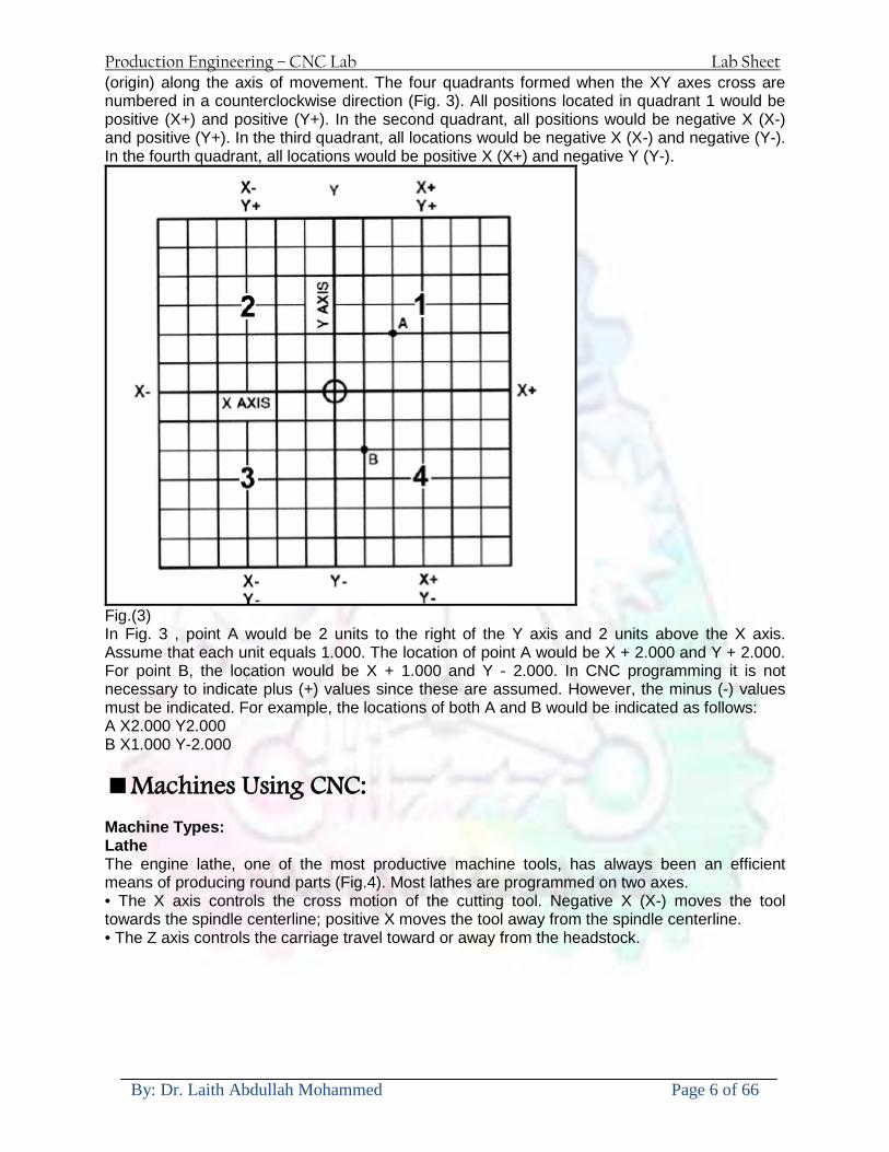
Production Engineering ndash CNC Lab Lab Sheet
By Dr Laith Abdullah Mohammed Page 6 of 66
(origin) along the axis of movement The four quadrants formed when the XY axes cross are numbered in a counterclockwise direction (Fig 3) All positions located in quadrant 1 would be positive (X+) and positive (Y+) In the second quadrant all positions would be negative X (X-) and positive (Y+) In the third quadrant all locations would be negative X (X-) and negative (Y-) In the fourth quadrant all locations would be positive X (X+) and negative Y (Y-)
Fig(3) In Fig 3 point A would be 2 units to the right of the Y axis and 2 units above the X axis Assume that each unit equals 1000 The location of point A would be X + 2000 and Y + 2000 For point B the location would be X + 1000 and Y - 2000 In CNC programming it is not necessary to indicate plus (+) values since these are assumed However the minus (-) values must be indicated For example the locations of both A and B would be indicated as follows A X2000 Y2000 B X1000 Y-2000 Machines Using CNC Machine Types Lathe The engine lathe one of the most productive machine tools has always been an efficient means of producing round parts (Fig4) Most lathes are programmed on two axes bull The X axis controls the cross motion of the cutting tool Negative X (X-) moves the tool towards the spindle centerline positive X moves the tool away from the spindle centerline bull The Z axis controls the carriage travel toward or away from the headstock
Production Engineering ndash CNC Lab Lab Sheet
By Dr Laith Abdullah Mohammed Page 7 of 66
Fig 4 The main axes of a lathe or turning center Milling Machine The milling machine has always been one of the most versatile machine tools used in industry (Fig 5) Operations such as milling contouring gear cutting drilling boring and reaming are only a few of the many operations which can be performed on a milling machine The milling machine can be programmed on three axes bull The X axis controls the table movement left or right bull The Y axis controls the table movement toward or away from the column bull The Z axis controls the vertical (up or down) movement of the knee or spindle
Fig 5 The main axes of a vertical machining center Programming Systems Two types of programming modes the incremental system and the absolute system are used for CNC Both systems have applications in CNC programming and no system is either right or wrong all the time Most controls on machine tools today are capable of handling either incremental or absolute programming
Production Engineering ndash CNC Lab Lab Sheet
By Dr Laith Abdullah Mohammed Page 8 of 66
Incremental program locations are always given as the distance and direction from the immediately preceding point (Fig 6) Command codes which tell the machine to move the table spindle and knee are explained here using a vertical milling machine as an example
Fig 6 A workpiece dimensioned in the incremental system mode bull A ldquoX plusrdquo (X+) command will cause the cutting tool to be located to the right of the last point bull A ldquoX minusrdquo (X-) command will cause the cutting tool to be located to the left of the last point bull A ldquoY plusrdquo (Y+) command will cause the cutting tool to be located toward the column bull A ldquoY minusrdquo (Y-) will cause the cutting tool to be located away from the column bull A ldquoZ plusrdquo (Z+) command will cause the cutting tool or spindle to move up or away from the workpiece bull A ldquoZ minusrdquo (Z-) moves the cutting tool down or into the workpiece In incremental programming the G91 command indicates to the computer and MCU (Machine Control Unit) that programming is in the incremental mode Absolute program locations are always given from a single fixed zero or origin point (Fig 7) The zero or origin point may be a position on the machine table such as the corner of the worktable or at any specific point on the workpiece In absolute dimensioning and programming each point or location on the workpiece is given as a certain distance from the zero or reference point
Fig 7 A workpiece dimensioned in the absolute system mode Note All dimensions are given from a known point of reference bull A ldquoX plusrdquo (X+) command will cause the cutting tool to be located to the right of the zero or origin point bull A ldquoX minusrdquo (X-) command will cause the cutting tool to be located to the left of the zero or origin point bull A ldquoY plusrdquo (Y+) command will cause the cutting tool to be located toward the column
Production Engineering ndash CNC Lab Lab Sheet
By Dr Laith Abdullah Mohammed Page 9 of 66
bull A ldquoY minusrdquo (Y-) command will cause the cutting tool to be located away from the column In absolute programming the G90 command indicates to the computer and MCU that the programming is in the absolute mode Point-to-Point or Continuous Path CNC programming falls into two distinct categories (Fig 8) The difference between the two categories was once very distinct Now however most control units are able to handle both point-to-point and continuous path machining A knowledge of both programming methods is necessary to understand what applications each has in CNC
Fig 8 Types of CNC positioning systems Point-to-Point Positioning Point-to-point positioning is used when it is necessary to accurately locate the spindle or the workpiece mounted on the machine table at one or more specific Locations to perform such operations as drilling reaming boring tapping and punching (Fig9) Point-to-point positioning is the process of positioning from one coordinate (XY) position or location to another performing the machining operation and continuing this pattern until all the operations have been completed at all programmed locations
Fig 9 The path followed by point-to-point positioning to reach various programmed points (machining locations) on the XY axis
Production Engineering ndash CNC Lab Lab Sheet
By Dr Laith Abdullah Mohammed Page 10 of 66
In Fig 9 point 1 to point 2 is a straight line and the machine moves only along the X axis but points 2 and 3 require that motion along both the X and Y axes takes place As the distance in the X direction is greater than in the Y direction Y will reach its position first leaving X to travel in a straight line for the remaining distance A similar motion takes place between points 3 and 4 Continuous Path (Contouring) Contouring or continuous path machining involves work such as that produced on a lathe or milling machine where the cutting tool is in contact with the workpiece as it travels from one programmed point to the next Continuous path positioning is the ability to control motions on two or more machine axes simultaneously to keep a constant cutter-workpiece relationship The programmed information in the CNC program must accurately position the cutting tool from one point to the next and follow a predefined accurate path at a programmed feed rate in order to produce the form or contour required (Fig 10)
Fig 10 Types of contour machining (A) Simple contour (B) complexe contour
Interpolation The method by which contouring machine tools move from one programmed point to the next is called interpolation This ability to merge individual axis points into a predefined tool path is built into most of todayrsquos MCUs There are five methods of interpolation linear circular helical parabolic and cubic All contouring controls provide linear interpolation and most controls are capable of both linear and circular interpolation Helical parabolic and cubic interpolation are used by industries that manufacture parts which have complex shapes such as aerospace parts and dies for car bodies Linear Interpolation Linear Interpolation consists of any programmed points linked together by straight lines whether the points are close together or far apart (Fig 11) Curves can be produced with linear interpolation by breaking them into short straight-line segments This method has limitations because a very large number of points would have to be programmed to describe the curve in order to produce a contour shape A contour programmed in linear interpolation requires the coordinate positions (XY positions in two-axis work) for the start and finish of each line segment Therefore the end point of one line or segment becomes the start point for the next segment and so on throughout the entire program
Production Engineering ndash CNC Lab Lab Sheet
By Dr Laith Abdullah Mohammed Page 11 of 66
Fig 11 An example of two-axis linear interpolation Circular Interpolation The development of MCUs capable of circular interpolation has greatly simplified the process of programming arcs and circles To program an arc (Fig 12) the MCU requires only the coordinate positions (the XY axes) of the circle center the radius of the circle the start point and end point of the arc being cut and the direction in which the arc is to be cut (clockwise or counterclockwise) See Fig 12
Fig 12 For two-dimensional circular interpolation the MCU must be supplied with the XY axis radius start point end point and direction of cut
Programming Format Word address is the most common programming format used for CNC programming systems This format contains a large number of different codes that transfers program information from the part print to machine servos relays micro-switches etc to manufacture a part These codes which conform to EIA (Electronic Industries Association) standards are in a logical sequence called a block of information Each block should contain enough information to perform one machining operation Word Address Format Every program for any part to be machined must be put in a format that the machine control unit can understand The format used on any CNC machine is built in by the machine tool builder and is based on the type of control unit on the machine A variable-block format which uses words (letters) is most commonly used Each instruction word consists of an address character such as X Y Z G M or S Numerical data follows this address character to identify a specific function such as the distance feed rate or speed value The address code G90 in a program
Production Engineering ndash CNC Lab Lab Sheet
By Dr Laith Abdullah Mohammed Page 12 of 66
tells the control that all measurements are in the absolute mode The code G91 tells the control that measurements are in the incremental mode Codes The most common codes used when programming CNC machines tools are G-codes (preparatory functions) and M codes (miscellaneous functions) Other codes such as F S D and T are used for machine functions such as feed speed cutter diameter offset tool number etc G-codes are sometimes called cycle codes because they refer to some action occurring on the X Y andor Z axis of a machine tool The G-codes are grouped into categories such as Group 01 containing codes G00 G01 G02 G03 which cause some movement of the machine table or head Group 03 includes either absolute or incremental programming while Group 09 deals with canned cycles A G00 code rapidly positions the cutting tool while it is above the workpiece from one point to another point on a job During the rapid traverse movement either the X or Y axis can be moved individually or both axes can be moved at the same time Although the rate of rapid travel varies from machine to machine it ranges between (5 and 20 mmin)
Fig 13 The functions of a few common G-codes The G01 G02 and G03 codes move the axes at a controlled feedrate bull G01 is used for straight-line movement (linear interpolation) bull G02 (clockwise) and G03 (counterclockwise) are used for arcs and circles (circular interpolation)
Production Engineering ndash CNC Lab Lab Sheet
By Dr Laith Abdullah Mohammed Page 13 of 66
Fig 14 Some of the most common G-codes used in CNC programming M or miscellaneous codes are used to either turn ON or OFF different functions which control certain machine tool operations M-codes are not grouped into categories although several codes may control the same type of operations such as M03 M04 and M05 which control the machine tool spindle bull M03 turns the spindle on clockwise bull M04 turns the spindle on counterclockwise bull M05 turns the spindle off
Production Engineering ndash CNC Lab Lab Sheet
By Dr Laith Abdullah Mohammed Page 14 of 66
Fig 15 The functions of a few common M-codes
Production Engineering ndash CNC Lab Lab Sheet
By Dr Laith Abdullah Mohammed Page 15 of 66
Fig 16 Some of the most common M-codes used in CNC programming Block of Information CNC information is generally programmed in blocks of five words Each word conforms to the EIA standards and they are written on a horizontal line If five complete words are not included in each block the machine control unit (MCU) will not recognize the information therefore the control unit will not be activated Using the example shown in Fig 17 the five words are as follows N001 represents the sequence number of the operation G01 represents linear interpolation X12345 will move the table 12345 in in a positive direction along the X axis Y06789 will move the table 06789 in along the Y axis M03 Spindle on CW
Fig 17 A complete block of information consists of five words
Production Engineering ndash CNC Lab Lab Sheet
By Dr Laith Abdullah Mohammed Page 16 of 66
Programming for Positioning Before starting to program a job it is important to become familiar with the part to be produced From the engineering drawings the programmer should be capable of planning the machining sequences required to produce the part Visual concepts must be put into a written manuscript as the first step in developing a part program Fig 18 It is the part program that will be sent to the machine control unit by the computer tape diskette or other input media The programmer must first establish a reference point for aligning the workpiece and the machine tool for programming purposes The manuscript must include this along with the types of cutting tools and work-holding devices required and where they are to be located
Fig 18 The first step in producing a CNC program is to take the information from the print and produce a program manuscript Dimensioning Guidelines The system of rectangular coordinates is very important to the successful operation of CNC machines Certain guidelines should be observed when dimensioning parts for CNC machining The following guidelines will insure that the dimensioning language means exactly the same thing to the design engineer the technician the programmer and the machine operator 1 Define part surfaces from three perpendicular reference planes 2 Establish reference planes along part surfaces which are parallel to the machine axes 3 Dimension from a specific point on the part surface 4 Dimension the part clearly so that its shape can be understood without making mathematical calculations or guesses 5 Define the part so that a computer numerical control cutter path can be easily programmed
Production Engineering ndash CNC Lab Lab Sheet
By Dr Laith Abdullah Mohammed Page 17 of 66
Machine Zero Point The machine zero point can be set by three methodsmdashby the operator manually by a programmed absolute zero shift or by work coordinates to suit the holding fixture or the part to be machined MANUAL SETTING - The operator can use the MCU controls to locate the spindle over the desired part zero and then set the X and Y coordinate registers on the console to zero
Fig 19 The relationship between the part zero and the machine system of coordinates ABSOLUTE ZERO SHIFT - The absolute zero shift can change the position of the coordinate system by a command in the CNC program The programmer first sends the machine spindle to home zero position by a G28 command in the program Then another command (G92 for absolute zero shift) tells the MCU how far from the home zero location the coordinate system origin is to be positioned Fig 19 The sample commands may be as follows N1 G28 X0 Y0 Z0 (sends spindle to home zero position) N2 G92 X4000 Y5000 Z6000 (the position the machine will reference as part zero)
Production Engineering ndash CNC Lab Lab Sheet
By Dr Laith Abdullah Mohammed Page 18 of 66
Work Settings and Offsets All CNC machine tools require some form of work setting tool setting and offsets (compensation) to place the cutter and work in the proper relationship Compensation allows the programmer to make adjustments for unexpected tooling and setup conditions
Work Coordinates In absolute positioning work coordinates are generally set on one edge or corner of a part and all programming is generally taken from this position In Fig 20 the part zero is used for all positioning for hole locations 1 2 and 3
Fig 20 In absolute programming all dimensions must be taken from the XY zero at the top left-hand corner of the part
Fig 21 In incremental programming all dimensions are taken from the previous point In incremental positioning the work coordinates change because each location is the zero point for the move to the next location Fig 21
Production Engineering ndash CNC Lab Lab Sheet
By Dr Laith Abdullah Mohammed Page 19 of 66
On some parts it may be desirable to change from absolute to incremental or vice versa at certain points in the job Inserting the G90 (absolute) or the G91 (incremental) command into the program at the point where the change is to be made can do this
R Plane or Gage Height The word-address letter R refers to a partial retraction point in the Z axis to which the end of the cutter retracts above the work surface to allow safe table movement in the X Y axes It is often called the rapid-traverse distance gage height retract or work plane The R distance is a specific height or distance above the work surface and is generally 100 in above the highest surface of the workpiece Fig 22 which is also known as gage height Some manufacturers build a gage height distance of 100 in into the MCU (machine control unit) and whenever the feed motion in the Z axis is called for 100 in will automatically be added to the depth programmed When setting up cutting tools the operator generally places a 100 in thick gage on top of the highest surface of the workpiece Each tool is lowered until it just touches the gage surface and then its length is recorded on the tool list Once the gage height has been set it is not generally necessary to add the 100 in to any future depth dimensions since most MCUs do this automatically
Fig 22 Using a 100 in gage block to set the gage height or R0 on the work surface
Cutter Diameter Compensation Cutter diameter compensation (CDC) changes a milling cutterrsquos programmed centerline path to compensate for small differences in cutter diameter On most MCUs it is effective for most cuts made using either linear or circular interpolation in the X-Y axis but does not affect the programmed Z-axis moves Usually compensation is in increments of 0001 in up to +10000 in and usually most controls have as many CDCs available as there are tool pockets in the tool storage matrix The advantage of the CDC feature is that it 1 Allows the use of cutters that have been sharpened to a smaller diameter 2 Permits the use of a larger or smaller tool already in the machinersquos storage matrix 3 Allows backing the tool away when roughing cuts are required due to excessive material present 4 Permits compensation for unexpected tool or part deflection if the deflection is constant throughout the programmed path The basic reference point of the machine tool is never at the cutting edge of a milling cutter but at some point on its periphery If a 1000 in diameter end mill is used to machine the edges of a workpiece the programmer would have to keep a 500 in offset from the work surface in order to cut the edges accurately Fig 23 The 500 offset represents the distance from the centerline of the cutter or machine spindle to the edge of the part Whenever a part is being machined the programmer must calculate an offset path which is usually half the cutter diameter
Production Engineering ndash CNC Lab Lab Sheet
By Dr Laith Abdullah Mohammed Page 20 of 66
Fig 23 Cutter-diameter compensation must be used when machining with various size cutters Modern MCUs which have part surface programming automatically calculate centerline offsets once the diameter of the cutter for each operation is programmed Many MCUs have operator-entry capabilities which can compensate for differences in cutter diameters therefore an oversize cutter or one that has been sharpened can be used as long as the compensation value for oversize or undersize cutters is entered
Production Engineering ndash CNC Lab Lab Sheet
By Dr Laith Abdullah Mohammed Page 21 of 66
CNC Programming Hints - MILLING
Production Engineering ndash CNC Lab Lab Sheet
By Dr Laith Abdullah Mohammed Page 22 of 66
CNC Programming Hints ndash TURNING
Production Engineering ndash CNC Lab Lab Sheet
By Dr Laith Abdullah Mohammed Page 23 of 66
CNC
The abbreviation CNC stands for Computer(ized) Numerical(ly) Control(led) and refers specifically to the computer control of machine tools for the purpose of (repeatedly) manufacturing complex parts in metal as well as other materials using a program written in a notation conforming to the EIA-274-D standard and commonly called G-code
CNC was developed in the late 1940s and early 1950s by the MIT Servomechanisms Laboratory CNC machines were relatively briefly preceded by the less advanced NC or Numerical(ly) Control(led) machines The introduction of CNC machines radically changed the manufacturing industry Curves are as easy to cut as straight lines complex 3-D structures are relatively easy to produce and the number of machining steps that required human action have been dramatically reduced With the increased automation of manufacturing processes with CNC machining considerable improvements in consistency and quality have been achieved CNC automation reduced the frequency of errors and provided CNC operators with time to perform additional tasks
CNC automation also allows for more flexibility in the way parts are held in the manufacturing process and the time required to change the machine to produce different components In a production environment a series of CNC machines may be combined into one station commonly called a cell to progressively machine a part requiring several operations CNC machines today are controlled directly from files created by CAM software packages so that a part or assembly can go directly from design to manufacturing without the need of producing a drafted paper drawing of the manufactured component In a sense the CNC machines represent a special segment of industrial robot systems as they are programmable to perform many kinds of machining operations (within their designed physical limits like other robotic systems)
G-code
G-code is a common name for the programming language that is used for NC and CNC machine tools It is defined in EIA RS-274-D G-code is also the name of any word in a CNC program that begins with the letter G and generally is a code telling the machine tool what type of action to perform such as
bull rapid move bull controlled feed move in straight line or arc bull series of controlled feed moves that would result in a hole being drilled bull change a pallet bull Set tool information such as offset
There are other codes the type codes can be thought of like registers in a computer
X position Y position Z position M code (another action register) F feed rate S spindle speed N line number R Radius T Tool selection
Production Engineering ndash CNC Lab Lab Sheet
By Dr Laith Abdullah Mohammed Page 24 of 66
I Arc data X axis J Arc data Y axis
G-code files are output by CAM software such as Smartcam Gibbscam Featurecam Edgecam Mastercam etc G-code is also output by specialized CAD systems used to design printed circuit boards Such software must be customized for each type of machine tool that it will be used to program
Production Engineering ndash CNC Lab Lab Sheet
By Dr Laith Abdullah Mohammed Page 25 of 66
U 2عمل األزرار الرئيسية في ماكنة الخراطة المبرمجة (نصر (
1- SINGLE BLOCK للتأكد من صحة البرنامج (تنفيذ البرنامج خطوة خطوةب تقوم( 2- BLOCK DELETE بجانب ويعمل من األوامرلغاء بلوك معين أليستخدم 3- MACHINE LOCK العمل يستخدم لقفل حركة المحاور الرئيسية مع استمرار البرنامج في
)وهذا مهم للتاكد من صحة البرنامج قبل عملية التنفيذ النهائي(4- CONT CYCLE عملية التشغيل عند ايقافها الي سبب كان او عند ايقافها ألستئناف ستخدم ت
) BAR FEEDER(او في حالة استخدام ) FEED HOLDبسبب (5- DRY RUN وتستخدم لفحص البرنامج بعد ازالة الشغلة حركة سريعة للبرنامج 6- TURRET UP amp DOWN ) حركة حامل العدة TURRET الذي يحمل مجموعة من (
وهذا الزر يعمل مع الزر عكس عقرب الساعة او مع عقرب الساعة ةحركة دوراني العدد )SAFTY (
7- COOLANT ON or OFFفه تشغيل سائل التبريد او ايقا 8- COOLANT AUTO الدوال المساعدة في البرنامج من خالل فه تشغيل سائل التبريد او ايقا 9 -MACHINE START ة لتشغيل هيدرولكيك الماكنميستخد
Production Engineering ndash CNC Lab Lab Sheet
By Dr Laith Abdullah Mohammed Page 26 of 66
10- CLOSE OR OPEN CHUCKالعينة تستخدم لفتح وغلق 11 -T STOCK FWD RET حركة الغراب المتحرك ذهابا وإيابا12 -SPINDLE STOP تعمل على ايقاف حركة دوران العينة 13-JOG SPINDLE تعمل على تدوير العينة مع زر SAFTY 14 -OPT SAFTY مع الدالة ( تعمل عمل التوقف المشروط حيث تعملM1 دالة التوقف (
ط ) فقط األ اذا كان هذا الزر مضغو M1المشروط حيث ال يتوقف البرنامج في حالة وجود دالة ( SAFTY + SPINDLE ) يتم الضغط على زر ( START CYCLEلغرض تحرير زر (
START ) في نفس الوقت بعد الضغط على زر ( START CYCLE مرتين (
NC PC- 15 يستخدم هذا الزر عند ربطCNC يستخدم لنقل المعلومات ث مع جهاز أخر حي بينهما
16 -CALCU زر الخاص بالحاسبة مع زر ( ال وهوINPUT ( 17 - HD1 HD2 يستخدم الختيار العدة مع المخرطة ذات المحاور األربعة 18 - START تستخدم لبدء عملية التشغيل
Production Engineering ndash CNC Lab Lab Sheet
By Dr Laith Abdullah Mohammed Page 27 of 66
19- FEED HOLD تعمل على إيقاف عمل أي G موجودة مع بقاء العينة متحركة 20- M D I أو تشغيل البرنامج ل يتم استخدامه لإلدخا BLOCK BY BLOCK وتعمل عند
إدخال البرنامج بواسطة الشريط المثقب أو أي وسيلة إدخال أخرى أو في عمليات التصفير
21- REST تستخدم العادة تشغيل الماكنة أو مسح اإلنذار الذي يظهر على الشاشة 22- EMERGENCYتستخدم عادة اليقاف الماكنة في حالة الطوارئ فقط
OPERATION MENU KEY
CHAPTER PRG-CMK
OFFSET PROGRAM POSITION FUNCTION MENU KEY
23- POSITIONعلى الشاشة د الموقع الموجور الظها 24- PROGRAMإلظهار برنامج معين واختياره 25- OFFSET الختيار سماحات العدة أو سماحات نقطة المرجع 26- PRG- CHK تستخدم لفحص البرنامج على الشاشة 27- SETTING ألختيار الثوابت على الشاشة 28- SERVICE تستخدم ألستخراج المعامالت والثوابت 29- MESSAGE تستخدم ألظهار األخطاء الناتجة عن البرنامج او اخطاء التشغيل 30- OVERALL ألختيار المواقع 31- RELATIVE MODLINE تعوض عن POSITION 32- DIR MEM يستخدم ألظهار ملف البرامج المخزونة في الذاكرة وعندما نضغط هذا الزر
فان رقم واسم البرنامج سوف يظهر على الشاشة
2أدناه الشفرات الرئيسية التي تعمل على الماكنة المبرمجة نصر
G-CODE DESCRIPTION
G00 Rapid traverse (linear)
G01 Linear Interpolation at feed rate
G02 Circular interpolation (CW) R+
G03 Circular interpolation (CCW) R+
G10 Zero point tools
G20 Imperial data input
G21 Metric data input
G27 Reference return check
G28 Reference return
G29 Return from reference
Production Engineering ndash CNC Lab Lab Sheet
By Dr Laith Abdullah Mohammed Page 28 of 66
G33 Thread cutting
G40 Cancel cutter radius compensation
G41 Cutter compensation left
G42 Cutter compensation right
G54 Work co-ordinate system no1
G70 Finishing cycle
G71 Stock removal turning
G72 Stock removal facing
G74 Face grooving
G75 Diameter grooving
G76 Threading cycle
G90 Absolute date input
G91 Incremental data input
G94 Feed minute mode
G95 Feed rev mode
G96 Constant surface speed mode
G97 Cancel Constant surface speed
) 2أدناه الشفرات الثانوية التي تعمل على الماكنة المبرمجة (نصر
M-code FUNCTION
M00 Program stop
M03 Spindle forward (Tool forward ndash M94 mode)
M04 Spindle reverse (Tool forward ndash M94 mode)
M05 Spindle stop (Tool stop ndash M94 mode)
M08 Coolant on
M09 Coolant off
M30 Program end (with rewind)
M48 Turret shortest path
M52 Turret direction up (CW)
M53 Turret direction down (CCW)
M73 Chuck open
M74 Chuck close
Production Engineering ndash CNC Lab Lab Sheet
By Dr Laith Abdullah Mohammed Page 29 of 66
) وكل جملة مكونة من مجموعة من الكلمات blockإن كل برنامج يتكون من مجموعة من الجمل ()words) لهذا فأن الشفرات الرئيسية والمساعدة هي عبارة عن كلمات (words كما في المثال التالي (
G_ _ P1 Q2 U_ _ W_ _ D___ F_ _
)end of block) ويعني ( ) يكتب الرمز (blockتسلسل الكلمات مهم جدا بعد نهاية كل جملة (
طريقة ادخال البيانات الى الماكنة ــــــــــــــــــــــــــــــــــــــــــــــــــ
) MDIيمكن ادخال البيانات الى الماكنة بعدة طرق فقد يكون األدخال عن طريق قناة السيطرة ( MANUAL DATA INPUT ) او عن طريق قناة األضافة EDIT كما يمكن ادخال البيانات عن (
) RS ndash 232 COMMUNICATIN LINKطريق استخدام سلسلة الربط (
₤⅗₌⅗₌ ⅙₌₨image₍₡ ₤₌ℌ⅗₌ Ⅸ⅗ⅥⅯ₌ ₤₡ℌ₰₨⅗₌G71
الخراطة الطولية G71الغرض من التجربة عمل نموذج للخراطة بأستخدام الدالة تستعمل هذه الدالة للخراطة الطولية اي على طول محور المشغولة وكما هو موضح بالشكل ادناه
تعتبر هذه الدالة من الدوال التي ال تحتاج الى تكرار او إعادة كتابتها أي انها دالة تكرارية بمعنى ان اي
الذي هي دالة حركة G01خطوة تكون من ضمن هذه الدالة سوف تكرر العملية اي عند استعمال امر مثل خطية تتضمن القطع مع التغذية مع اعطاء القطر المراد قطعه و مراعاة عمق القطع المعطى سوف يتكرر
هذه االمر وصوال الى العمق المطلوب وهكذا لبقية الدوال
G71 المستخدمة للدالة الصيغة
G71 P1 Q2 U___ W___ D___ F___ حيث إن
P1 بداية الخطوة االولى = Q2 نهاية الخطوة =
Uوضع السماحات بأتجاه محور = X W وضع السماحات بأتجاه محور = Z وتكاد تكون مهملة وتوضع اشارة سالب Dعمق القطع وتوضع رقم صحيح مثل = D500 اي نصف ملمF التغذية والتي لها عالقة بالدالة = G95
Production Engineering ndash CNC Lab Lab Sheet
By Dr Laith Abdullah Mohammed Page 30 of 66
G71الدالة استخدام مثال على
T0100 M48 G0 X26 Z2 M08 T0101 G90 G95 G97 S500 M03 G71 P1 Q2 U03 W00 D500 F01 N1 G0 G42 X00 G01 Z00 G01 X2517 G01 Z-5352 G01 X7391 Z-9366 G01 Z-19145 N2 G28 M30
الجانب العملي
االجهزة واالدوات المستخدمة CNCماكنة خراطة مبرمجة 1 ملم 80قضيب من االلمنيوم قطر 2 ةفير ني 3 جاه أيمن تهولدر كاربيدي ذوا 4
طريقة العمل يتم تثبيت قضيب من االلمنيوم على العينة التابعة للماكنة مع مراعاة الطول المراد استعماله في عملية 1
الخراطة ) turretتثبيت عدة القطع في المكان الصحيح في ( 2
Production Engineering ndash CNC Lab Lab Sheet
By Dr Laith Abdullah Mohammed Page 31 of 66
بالنسبة الى القطعة المثبتة على العينة XZيتم تصفير الماكنة للمحاور 3 تصفير للمحورZ تكون مالمسة العدة الى وجه الشغلة تصفير للمحورX تكون مالمسة العدة الى سطح الشغلة الموازي لمحور X
يتم كتابة البرنامج أما بطريقة يدوية أو بالحاسوب مع وضع كل الظروف الالزمة للتشغيل ( عمق القطع 4 التغذية السرعة المطلوبة نوع المعدن )
ادخال البرنامج الى الحاسوب الموجود داخل الماكنة مع تهيئة الماكنة للتشغيل 5
المطلوب G71عمل برنامج يدوي على الدالة 1 رسم الشكل الشكل النهائي المطلوب مع وضع األبعاد 2
Ⅺ⅟₍euro⅗₌ ₤₡ℌ₰₨⅗₌₣ ₤⅗₌⅗₌ ⅙₌₨image₃₡ Ⅺℂtradeℒ⅗₌ ӈ₍Ⅴ⅟ⅳ₌ G70
G70 الغرض من التجربة عمل انهاء سطحي للمشغولة بواسطة الدالة
من الضروري إعطاء G71هذه الدالة تعمل شوط واحد فقط وتكون معتمدة على عمليات القطع في الدالة اللغاء مقدمة االداة (أي لكي تتم عملية االنهاء السطحي بدون حسابات نصف قطر مقدمة االداة ) G42دالة
G70الصيغة المستخدمة للدالة
G70 P1 Q2 F___ حيث ان
P1 بداية الخطوة االولى = Q2 نهاية الخطوة =
F التغذية والمرتبطة بالدالة = G95
وذلك ألن دالة االنهاء السطحي تحقق X Zمالحظة الدالة التحتاج لكتابة السماحات التابعة للمحورين المسافات الحقيقة المراد انتاجها للمشغولة
G71و G70مثال على الدالة
T0100 M48 G0 X26 Z2 M08 T0101 G90 G95 G97 S500 M03 G71 P1 Q2 U03 W00 D500 F01 N1 G0 G42 X00 G01 Z00 G01 X2517 G01 Z-5352 G01 X7391 Z-9366 G01 Z-19145 N2 G97 S750 MO3
Production Engineering ndash CNC Lab Lab Sheet
By Dr Laith Abdullah Mohammed Page 32 of 66
G70 P1 Q2 G40 F009 G28 M30
الجانب العملي الحظ التجربة األولى
المطلوب
G70 عمل برنامج يدوي على الدالة 1 رسم الشكل النهائي المطلوب مع وضع االبعاد 2
₪⅗₍euro⅗₌ ₤₡ℌ₰₨⅗₌₣ ₤⅗₌⅗₌ ⅙₌₨image₍₡ ⅝₍ⅠimageⅯ₌ ⅞ⅫⅦ⅔₧ G76
G76 للمشغولة بواسطة الدالةةالغرض من التجربة عمل أسنان خارجية أو داخلي
في هذه التجربة سوف نقوم بعمل األسنان الخارجية وهنا تكون حركة العينة ثابتة وهذا ضروري بسبب أن ) تكون متصلتين الكترونيا وعليه أي اختالف في سرعة العينة تؤدي إلى اختالف motionالعينة والحركة(
) servoفي سرعة الخدمة(يرتبط اتجاه تكوين األسنان باتجاه دوران العينة مثال إذا كانت األسنان ذات اتجاه أيمن يكون اتجاه دوران
وهنا نقلب العدة إلى االسفل وكما هو موضح بالشكل أدناه MO3العينة عكس عقرب الساعة أي نستعمل
Production Engineering ndash CNC Lab Lab Sheet
By Dr Laith Abdullah Mohammed Page 33 of 66
الخطوة هي عبارة عن المسافة ما بين قمة سن إلى قمة سن أخر عمق السن هو العمق المطلوب تكوينه لألسنان
G76 الصيغة المستخدمة للدالة
G76 X___ Z___ K___ F___ D___ A___
حيث أن X القطر الداخلي للسن =Z طول السن =K عمق السن وتستخرج من المعادلة التالية =K=065F F الخطوة =D عمق القطع بالمايكرون فقط =A زاوية السن =
G76مثال على استخدام الدالة T0300 M48 GOO X30 Z4 T0303 M08 G97 S500 MO3 G76 X28375 Z-20 K08125 F125 D120 G00 X40 Z4 G28 M30
Production Engineering ndash CNC Lab Lab Sheet
By Dr Laith Abdullah Mohammed Page 34 of 66
الجانب العملي الحظ التجربة األولى
المطلوب
G76عمل برنامج يدوي على الدالة 1 رسم الشكل النهائي المطلوب مع وضع األبعاد 2
Ⅺ⅘₌⅗₌ Ⅵ₂ Ⅺ₯ℋ₍⅗₌ ℌℲℂ⅗₌ ⅞ⅫⅦ⅔₧ ₤K₡₌ℌ⅗₌ ₤₡ℌ₰₨⅗₌)Groove ₤⅗₌⅗₌ ₤tradeimage₌Ⅶ₡ (G75
G75 بواسطة الدالة grooveالغرض من التجربة تكوين
) للمشغولة وتعتمد شكل الحفر على طريقة grooveتستعمل هذه الدالة لتكوين الحفر الخارجي والداخلي (
التشغيل وعلى الشكل المراد إنتاجه وتعتبر هذه الطريقة من عمليات التشكيل للمعدن إن هذه الدالة هي دالة مالحظة مع G75في هذه التجربة سنقوم بعمل الحفر الخارجي بواسطة الدالة
تكرارية وغير تكرارية حسب نوع التشغيل
G 75 الصيغة المستخدمة للدالةG75 X___ Z___ I___ K____
حيث أن
X العمق النهائي لقطر الشغلة =Z عرض الحفر =I الدخول في كل مرة =
K التزحيف على محور =z بالنسبة للعدة
Production Engineering ndash CNC Lab Lab Sheet
By Dr Laith Abdullah Mohammed Page 35 of 66
G75مثال على استخدام الدالة
T0500 M48 GOO X100 Z -20 T0505 M08 G97 S700 MO3 G75 X84 Z -38 I 05 K4
الجانب العملي الحظ التجربة األولى
المطلوب
G76عمل برنامج يدوي على الدالة 1 رسم الشكل النهائي المطلوب مع وضع األبعاد 2
Production Engineering ndash CNC Lab Lab Sheet
By Dr Laith Abdullah Mohammed Page 36 of 66
CNC Milling Machine Mechanical Construction
Guideways The guideways of CNC machines are made of steel To reduce the frictional forces they are coated with a strip of PTFE (Poly Tetra Fluoro Ethylene)
Ballscrews On conventional lathes a leadscrew is used to converts the rotary motion of the hand wheel into linear motion of the slides Leadscrews have a high coefficient of friction and backlash On CNC machines a ballscrew is used instead of a leadscrew Friction and backlash are much less than on leadscrews
Guideway
Production Engineering ndash CNC Lab Lab Sheet
By Dr Laith Abdullah Mohammed Page 37 of 66
bullMachining operations Direction of cutting Based on the direction of the cutter rotation and work piece feed milling operations are classified into two types 1-Up milling (Convention milling) In up milling the metal is removed by rotating the cutter against the direction of travel of the part
Feed
Machine table
Part
Cutting tool
Chip thickness at theexit of the tooth
2-Down milling (Climb milling) In climb milling the metal is removed by rotating the cutter with the direction of travel of the part
Machine table
Part
Cutting tool
Chip thickness at theentrance of the tooth
Production Engineering ndash CNC Lab Lab Sheet
By Dr Laith Abdullah Mohammed Page 38 of 66
bullTooling Tool geometry The geometry of the tool tip affects the way that the metal cutting is performed The nose radius rake angles relief angles etc must be selected with care
Radial relief
Radial rake
Axial relief
Approach angle
Axial relief
Corner radius Face mill Face milling cutters are used to mill flat surfaces Commonly used face milling cutters Cutter with 75 degree approach
75 deg
Cutter with 90 degree approach (Square shoulder face mill)
90 deg
Cutter with 45 degree approach
Production Engineering ndash CNC Lab Lab Sheet
By Dr Laith Abdullah Mohammed Page 39 of 66
bullCNC Programming Axes convention The Z axis is along the spindle axis The X and Y axes are perpendicular to Z VMC
Z
Y
-
+
-+
X- +
+Z
-Z
+Y
-Y
-X +X
Part
Machine table
X
YZ
G00 Rapid traverse When the tool being positioned at a point preparatory to a cutting motion to save time it is moved along a straight line at Rapid traverse at a fixed traverse rate which is pre-programmed into the machines control system Typical rapid traverse rates are 10 to 25 m min but can be as high as 80 mmin
Production Engineering ndash CNC Lab Lab Sheet
By Dr Laith Abdullah Mohammed Page 40 of 66
Format N_ G00 X__ Y__Z__
G01 Linear interpolation (feed traverse) The tool moves along a straight line in one or two axis simultaneously at a programmed linear speed the feed rate Format N__ G01 X__ Y__Z__ F__
Part
Feed
Part
Feed
G02G03 Circular interpolation The tool moves along an arc in two axes simultaneously at a programmed linear speed the feed rate
Production Engineering ndash CNC Lab Lab Sheet
By Dr Laith Abdullah Mohammed Page 41 of 66
Format N__ G0203 X__ Y__Z__ I__ J__K__ F__ using the arc center OR N__ G0203 X__ Y__Z__ R__ F__ using the arc radius G02 moves along a CW arc G03 moves along a CCW arc Arc center The arc center is specified by addresses I J and K I J and K are the X Y and Z co-ordinates of the arc center with reference to the arc start point
X
Y
Arc center
Arc endArc start
- J
- I
I = X coord of center - X coord of start point J = Y coord of center - Y coord of start point K = Z coord of center - Z coord of start point I J and K must be written with their signs
Production Engineering ndash CNC Lab Lab Sheet
By Dr Laith Abdullah Mohammed Page 42 of 66
bullWork holding
Rotary table
Fixture base
Component
Clamp
Stud
Fixtures The use of fixtures 1 Improves repeatability of dimensions 2 Improves working conditions 3 Cuts down requirement of skilled labour 4 Reduces part loading and unloading time 5 Improves safety in the working area 6 Reduces the cost of machining There are two types fixtures commonly used 1 Special fixture Special fixtures are used to hold and locate the typical components which are having complex shape and to be located with the reference hole (dowel hole) Special fixtures are required for components like gear case cover cylinder heads etc 2 Modular fixture Modular fixture is a set different kind of clamping and locating elements These fixtures are used to hold identical components in different sizes and components of box type Example Manifolds head stocks connecting rods and flanges
Production Engineering ndash CNC Lab Lab Sheet
By Dr Laith Abdullah Mohammed Page 43 of 66
bullMachine setting
Determining X and Y work zero offset Case 1
Part
Machine table
Part
End mill or reamer
Work offset X0Y0 For determining X work zero offset bull Touch the periphery of the end mill or reamer to the part bull Enter current machine X value + cutter radius as X work zero offset For determining Y work zero offset bull Touch the periphery of the end mill or reamer to the part bull Enter current machine Y value - cutter radius as Y work zero offset Case 2
Part
Machine table
Part
End mill or reamerWork offset X0Y0
bull Mount the dial indicator on machine spindle true the bore bull Enter current machine X and Y value as X and Y work zero offset
Production Engineering ndash CNC Lab Lab Sheet
By Dr Laith Abdullah Mohammed Page 44 of 66
How to Select a Cutting Fluid
One part of the metal cutting equation that is sometimes overlooked however is
the choice of an appropriate cutting fluid With todayrsquos system approach to metal
cutting use of the right metalworking fluid has become just as much a part of the
solution as the other elements In fact at least one company is now integrating
cutting fluids and cutting tools into effective metal cutting systems Following are
some things to consider when choosing your next cutting fluid
The Four Key Questions
There are four vital pieces of information that are necessary when choosing a
cutting fluid They are
1 What are you cutting
2 What is the chemistry of your water
3 What are you using now
4 What are your options
5 What do you prefer
What Are You Cutting
The first question ndash ldquoWhat are you cuttingrdquo ndash is often the most difficult to answer
because most shops handle a variety of workpiece materials on a regular basis If
the answer is an unequivocal ldquoaluminumrdquo or ldquostainless steelrdquo or ldquocast ironrdquo the
selection of a cutting fluid can be quite simple and straightforward Unfortunately
that is seldom the case in anything but a high-volume plant Where aluminum or
other nonferrous metals are a significant part of the mix a non-staining cutting
fluid is a must Generally speaking this will be a semi-synthetic with special
ingredients to prevent bi-metallic corrosion and staining of non-ferrous workpieces
Where the ferrous metals predominate however a more general purpose semi-
synthetic or hybrid fluid might be a more economical choice
Production Engineering ndash CNC Lab Lab Sheet
By Dr Laith Abdullah Mohammed Page 45 of 66
What is The Chemistry of Your Water
The second question ndash ldquoWhat is the chemistry of your waterrdquo ndash is probably the
single most common reason for the success or failure of a cutting fluid Very few
plants invest the money necessary to install effective water purification systems
using deionization or reverse osmosis technology Unfortunately the chemicals
present or not present in the water used to re-constitute a cutting fluid make a
tremendous difference in its performance and sump life Most manufacturers of
cutting fluids will perform the necessary water testing to determine exactly what
minerals are dissolved in your water and make a fluid recommendation based on
the results
What are you using now
The third question ndash ldquoWhat are you using nowrdquo ndash helps narrow the range of
choices When coupled with an objective analysis of the strengths and weaknesses
of the current fluid the answer to this question can quickly point you toward a
relatively small number of competitive alternatives that have the attributes required
to meet your cutting needs Many cutting fluids are in use today simply because
they were in use yesterday It is a hard reality of todayrsquos marketplace that if one
isnrsquot constantly striving to improve they will certainly be overtaken by a
competitor who is
What Are Your Options
The fourth question ndash ldquoWhat are your optionsrdquo ndash leads to the final selection of a
cutting fluid Cutting fluids can be divided into four general groups based on their
chemistry
They are
bull Soluble Oils ndash quite literally oil dispersed in water
bull Synthetics ndash completely oil free man-made coolants in solution
Production Engineering ndash CNC Lab Lab Sheet
By Dr Laith Abdullah Mohammed Page 46 of 66
bull Semi-Synthetics ndash a mixture of natural and synthetic lubricants with up to 30
mineral oil
bull Hybrids ndash a special class of semi-synthetics with a mineral oil content of about
15 Each fluid type has advantages and disadvantages which make it suitable for
a particular group of applications In addition there are costperformance trade-
offs to be made between the groups within a specific set of applications For
example where a hybrid and a semi-synthetic may both be suitable for a particular
use the hybrid might provide longer sump life at a slightly higher initial cost
while some semi synthetics may be more economical to recycle or dispose of while
not giving as long a tank life The final decision in this case would have to be made
on the detailed economics of the shop where the fluids were to be used and on the
ownerrsquos individual preferences
Soluble Oils
Soluble oils are oils that disperse in water when emulsifiers are added They are
generally suitable for moderate-to heavy-duty machining and grinding of all non-
ferrous metals carbon and cast steels and in applications where dissimilar metals
such as aluminium and steel are present They can also be used in turning drilling
tapping reaming gear cutting broaching as well as internal and centerless types
of grinding operations Soluble oils provide excellent aluminium and copper
corrosion control good rancidity control which extends fluid for long lasting
trouble-free performance and good concentrate and mix stability making it ideal
for mixing in water with a minimal amount of agitation An example of this is
Valenitersquos VNTreg-650 premium heavy-duty soluble oil
Synthetics
Synthetics are completely oil free solutions made of polymers organic and
inorganic materials that are mixed with water These clear low foaming and bio-
Production Engineering ndash CNC Lab Lab Sheet
By Dr Laith Abdullah Mohammed Page 47 of 66
stable coolants are ideal for machining and grinding of ferrous materials carbon
steels or cast iron Their complex lubricant packages make synthetics well-suited
for tough-to-machine materials such as stainless steels and high-temperature alloys
Certain synthetics are specifically designed to address the primary failure modes of
flank wear and nose wear Although there are many benefits some synthetics may
cause staining of non-ferrous materials
Semi-Synthetics
Semi-synthetic fluids are a mixture of oils synthetic emulsifiers and water They
were primarily developed for the aircraft nuclear and related industries
Consequently they work extremely well on all non-ferrous metals such as titanium
aluminium copper brass bronze and stainless steel in both machining and
grinding Semi-synthetics can be used on ferrous metals too They are chlorine-
free to reduce bi-metallic corrosion and staining of metals They should be used at
a 5-8 dilution with water depending on the severity of the operation
Hybrids
Hybrids are cutting fluids custom engineered to solve a particular problem For
example Valenitersquos VNTreg-800 was developed to be very clean in the machining
and grinding of cast iron It provides better stability in hard water and rejects tramp
oil very well which adds to its bio-stable chemistry Hybrids work extremely well
on all metals in both machining and grinding They should be mixed at a 5-7
dilution with water depending on the condition of the water
What Do You Prefer
The final question ndash ldquoWhat do you preferrdquo ndash is usually the ldquotie breakerrdquo where
there is more than one appropriate cutting fluid available Here again as in the
case of what is being used now the key is to examine your preferences objectively
Production Engineering ndash CNC Lab Lab Sheet
By Dr Laith Abdullah Mohammed Page 48 of 66
and specifically to identify the real reasons behind a preference If you cannot
point to specific reasons why one class of cutting fluid is preferred over another
you are well advised to follow the recommendations of the professional who has
analyzed your requirements Choosing the right fluid today is easier than ever as
the system approach to metal cutting productivity continues to grow in acceptance
The day is not far off when choosing a complete solution will be as easy as
choosing the right insert and chip breaker today The answers are available and the
results will more than justify the time you spend choosing the right metal cutting
fluid
Useful Links wwwball-screwsnet
wwwlubelinkcom
wwwmachinerylubricationcom
wwwadvancedmanufacturingcom
wwwmmsonlinecom
wwwcuttingtoolengineeringcom
wwwgeartechnologycom
wwwengineersedgecom
wwwagmaorg
wwwefundacom
wwwsaeorg
wwwsmeorg
wwwastmorg
wwwissorg
wwwmachinetoolscom
wwwansiorg
wwwasmeorg
wwwcnccicom
wwwmatlscom
wwwthefreedictionarycom
wwwengineersupplycom
Production Engineering ndash CNC Lab Lab Sheet
By Dr Laith Abdullah Mohammed Page 49 of 66
SurfCAM Tutorial ndash Beginning with the basics
Background SurfCAM is a computer aided manufacturing (CAM) software which allows you to create manage and modify tool paths for computer aided designed (CAD) part The software requires a CAD model or requires that you create some geometry within SurfCAM with some rudimentary tools provided The tool paths are created or stored internally in SurfCAM in a generic programming language called APT Once the tool paths are created the APT paths are translated using a post processor into typical machine G-code
Opening SurfCAM SurfCAM can be opened from the Novell Applications Launcher on most Industrial Engineering computer labs workstations Search under lsquoallrsquo applications and double click on SurfCAM 2005 Once the program opens a license must be selected from the list (not the Demo license) to enable saving the file later Choose one of the 30 licenses available If for some reason the licenses are not listed on the license manager form select server list and type ldquobonnieeosncsuedurdquo A list of available licenses should appear Select a license and click OK After the license is selected an Add StockFixture form (Figure 1) opens allows you to add a model which represents the pre-machined stock or a fixture Click on OK without adding either Both of these items can be added later under a more appropriate dialog
Figure 1 Add Stock or Fixture dialog box
Production Engineering ndash CNC Lab Lab Sheet
By Dr Laith Abdullah Mohammed Page 50 of 66
SurfCAM Interface
Figure 2 SurfCAM Windows based interface
SurfCAM is a windows based software system so most of the typical windows functions under File are applicable This is where you can open save exit print etc The Create menu allows the user to create different geometry forms Here you can create a point line surface chamfer circle and many other geometry types For the most part these functions are not used by beginners but are useful when creating bounding curves where you donrsquot want the tool to move outside (constraining the tool) The Edit menu allows you to change or modify many different entities such as changing lines altering surfaces joining surfaces trimming or breaking elements add control points etc Again these features are helpful to advanced users and are not covered in detail in this tutorial The Display menu offers the ability to change the orientation of the part on the screen The typical rotate pan fit to screen and zoom functions are available as well as several functions which allow the user to shift between views or call up a named view (ie top bottom etc) The NC menu is the main machining interface menu In this menu you select the general form of machining (2 axis 3 axis 4 axis 5 axis turning etc) and under the general form a more specific machining function is selected This menu is the most used and the options contained must be fully understood to get the most out of SurfCAM Each function will be described in some detail in a further chapter The Analyze menu contains options such as measuring the distance between points angles tangency elements etc These functions are auxiliary functions meant to help you understand the part better but basically provide no functionality for making tool paths for CNC machines Thus these will not be covered The Tools menu allows the user to change the system options modify keyboard shortcuts change the model units etc These options are again not used by beginners Finally the Help menu provides access to the online users manual In lieu of clicking the Help menu the F1 key is the shortcut key for help (as it is in most windows based programs)
Importing a CAD model Importing a CAD model that is stored locally is done by selecting File-gtOpen On the Files of type dropdown box choose the type of file you wish to open (Figure 3) Do this prior to negotiating your way through the maze of folders to prevent having to go through the folder tree again Once the file type is selected find the file you are trying to open and click the Open
Production Engineering ndash CNC Lab Lab Sheet
By Dr Laith Abdullah Mohammed Page 51 of 66
button SurfCAM will then attempt to read the file you have selected SurfCAM may provide a dialog box describing what it has imported and identify if it was successful If this dialog is provided simply click close without saving
Figure 3 Open Dialog Note - Change type of file prior to finding the file you wish to open
SurfCAM allows a user to import several different types of CAD files the most common types which you will likely import are SolidWorks part files (sldprt or prt) AutoCAD files(dxf) or IGES (igs or iges) Native file import (such as is the case with SolidWorks) provides the greatest information transfer and generic file imports (such as is the case with IGES) provide the least Normally it is to the advantage of the user to use native file importing procedures when available Recently (2005) SurfCAM added some compatibility with SolidWorks This allows the user to create tool paths for a part and if an engineering change is needed for the part update the part in SolidWorks When the part is then opened in SurfCAM the changes are noted and a simple update operation command is needed This however does not operate with complete transparency andor accuracy and thus users need to be cognizant of changing CAD models
SurfCAM Geometry In SurfCAM two basic types of geometry are used the surface and the point A surface (Figure 4) is a so called spline (NURBS or B-Spline are the two most common) surface (parameterized by two values u and v) such that every location on the surface can be defined as a function of these parameters In other words SurfCAM can calculate the location of any point on the
Production Engineering ndash CNC Lab Lab Sheet
By Dr Laith Abdullah Mohammed Page 52 of 66
surface Surfaces are used primarily in 3 4 and 5 axis machining and require a significant
amount of processing power and time Figure 4 Surfaces model of a mold half Note the difference between this and Figure 2 a wireframe model
Point or line based models are often referred to as wireframe (Figure 5) models because the models consist of connected lines and resemble the part only at the intersection of two surfaces Wireframe models were made popular lsquoback in the dayrsquo when computer processing was expensive There are times when each of the models are important and selecting model geometry when applying a SurfCAM operation will be much simpler if you understand the differences between the two When importing a SolidWorks model the default is both the surfaces and the wireframe geometry are imported
Figure 5 Wireframe model of the mold in Figure 1
Steps to Creating Tool Paths Once a CAD model is imported into SurfCAM tool paths can be created There is no one correct way to create tool paths however there is a set of general steps to take to ensure the tool paths are created with a minimum amount of hardship (note the wordinghellipHardship is inevitable when creating tool paths it is the intent of this manual to minimize this) The following is a list of steps which should be considered when making tool paths
Production Engineering ndash CNC Lab Lab Sheet
By Dr Laith Abdullah Mohammed Page 53 of 66
1 Plan ahead a Orient the part in SolidWorks such that if only one side is to be machined that
side is the Top view This can be done early in SolidWorks by choosing a plane parallel the X-Y plane as the sketch plane for the machined geometry
b Orient the part in SolidWorks such that the origin is somewhere of relative importance and someplace in space that can be easily identified when placed on the machine This is extremely important to minimize set up time at the machine (note ndash my personal preference for a part that is to be fully machined [ie stock exists on all sides] is to place the origin at the center and top of the parthellipjust my preference)
c Orient the part in SolidWorks such that the X and Y axes are aligned as you want them on the machinehellip
d Planning ahead will save you many hours of headaches laterhelliptrust me 2 Import the model 3 Choose a construction view such that the tool approaches the side to be machined
from the positive Z axis direction (as defined by part origin) a This is done by clicking on the CView icon
b From the list of named views chose the view which orients the origin as you would like
c If one of the views does not fit your criteria you have two choices i Perform a transformation of the part in SurfCAM or SolidWorks
ii Add a new construction view by selecting new This option requires a relatively good understanding of right hand coordinate frames but is very usefulhellipNormally used by more advanced users
d Be sure the CoordVIEW selection is made vs CoordWORLD This ensures the tools will be controlled from the coordinate frame selected by the view (ie the origin on the part) instead of the origin on the lower left corner of the screen This will be especially important when we get into 4 and 5 axis machining
4 In the Operations Manager (Figure 6) select Setup One and change the name to something meaningful ndash like Front Side Mold Cavity
a Access the Operations manager by right clicking or by selecting the Operations Manager icon in the tool bar
b Operations Manager is where the tool paths are managed once they are created as well as where individual tool paths can be verified
Production Engineering ndash CNC Lab Lab Sheet
By Dr Laith Abdullah Mohammed Page 54 of 66
5 Roughing Tool Paths a Create the tool paths to remove the majority of the material (if applicable) b Use NC-gt3Axis-gtZ rough or Plunge Rough c Described in next section
6 Create Finishing Tool Paths a Described in next section
7 Add another setup if necessary 8 Perform steps 3 through 6 as necessary 9 Verify the tool paths are correct 10 Use a post processor for the tool paths to create G-Code for machine
Creating Tool Paths The following is a list of operations what they are intended for how they generally work and some parameters that may be adjusted to modify the tool paths
2 Axis tool paths Unless otherwise noted 2 axis tool path functions require lines or arc segments as input parameters (as opposed to surfaces) There are several options as to how these segments are chosen the most prevalent is the chain option and the second most prevalent is the single When choosing the line segments using the chain option SurfCAM will try to link a complete path of segments based on an initial segment chosen by the user If the operation is planer (ie pocket or contour) the segments must lie on the same plane If the operation is non-planer (ie contour 3D) SurfCAM will prompt the user to specify segments when it encounters a branch point
Figure 6 Operations Manager view showing setup one re-labeled as Front Side Mold
Production Engineering ndash CNC Lab Lab Sheet
By Dr Laith Abdullah Mohammed Page 55 of 66
When using the single element option the user must manually choose each segment desired for the operation Note that most operations do not require a closed loop of segments you may specify for instance an open contour where the tool is supposed to move The order of choosing segments is important This order determines the path of the tool in the sense that if three segments are chosen such that the middle segment is chosen last there will be three different plunge and machine operations one on each segment If the operation was to make a continuous contour around the outside of the part the segments should be chosen in order of the desired tool trajectory
Operations
Pocket Pocket operation in SurfCAM is used to cut an enclosed space from the inside to the outside at one particular depth The operation starts in the center of an enclosed area (with a plunge move in the ndashZ direction) and makes incremental closed paths towards the pocket boundaries in user defined path offsets (Figure 7) The user chooses the boundary of the pocket (line segments) and if more than one pocket is chosen SurfCAM will ask the user to click inside a pocket
Figure 7 Two examples of using the pocketing operation
The pocket operation allows for creating a projection of the pocket paths on multiple planes This is useful if you have a deep pocket which will not allow the tool to cut directly at the depth of the pocket but would be easily done using the same paths at several different Z heights On the cut control (Figure 8) tab the user specifies where the chosen geometry (pocket segments) lie (ie bottom or top) Then under the amount to remove specify the total material height to be removed and the rough spacing (amount you wish to advance the Z axis with each pocket step) You may also specify a finishing pass and as well as stock to leave
Production Engineering ndash CNC Lab Lab Sheet
By Dr Laith Abdullah Mohammed Page 56 of 66
Figure 8 Example of Contour Operation with multiple passes
Contour Contouring in SurfCAM is used to perform peripheral milling on the inside or outside of a line segment (Figure 9) The user is to identify the line segments which define a contour (does not have to be a closed loop of segments) SurfCAM may or may not require the user to specify a side to contour (ie which side of the line is the tool to cut) For contouring each segment must lie on the same plane
Production Engineering ndash CNC Lab Lab Sheet
By Dr Laith Abdullah Mohammed Page 57 of 66
Figure 9 Examples of parts cut with 2-Axis Contour
Contour 3D Contour 3D is the same operation type as contour but allows the user to specify segments on different planes for the tool to cut along
Drill Drilling operations are any rotating tool operation meant to engage the part from a single direction ndash namely from the positive Z direction Drilling operations can be specified using circle point or line segments After choosing NC-gt2-Axis-gtDrill SurfCAM allows the user to choose multiple circles or points defining holes to be drilled Drilling operations also allow the user to incorporate more than 1 operation such as a center drill a drill and a reaming operation After selecting the locations for the drilling operation a dialog box (Figure 10) allows the user to add change or delete tools to be used in the operation As displayed in the following figure the spotdrill operation is followed by a drilling operation followed by a tapping operation The depth of each tool can be controlled individually by double clicking the total depth cell in and manually entering Tools can be added before or after operations which the cells are highlighted by selecting either of the insert buttons at the top or by the insert menu Select tool button allows the user to change the tool size or type
Production Engineering ndash CNC Lab Lab Sheet
By Dr Laith Abdullah Mohammed Page 58 of 66
Figure 10 Drill operation manager Several operations can be completed at one time
Figure 11 Drill operation including the spotdrill drill and tap as outlined in Fig 10
3 Axis tool paths SurfCAM requires surfaces as inputs for 3 Axis tool paths Surfaces can be created in SurfCAM but are most easily created in a CAD package and imported into SurfCAM Surfaces allow SurfCAM to identify every point on the surface in 3 dimensions unlike 2D geometry (wireframes) which only identify positions on the plane Creating tool paths with complex surfaces takes a very significant amount of processing power so expect 3 Axis tool path generation to take longer
Production Engineering ndash CNC Lab Lab Sheet
By Dr Laith Abdullah Mohammed Page 59 of 66
Operations
Cut 3 Axis cut operation takes a surface and using the flow lines creates a rastering path over the surface with the tool tip riding on the surface The primary direction will be defined by the flow lines of the surface (which can be edited by Edit-gtSurfaces-gtArrow-gtDirection) If you intend to cross surface boundaries you must merge the surfaces (Edit-gtJoin and choose the two surfaces)
Z-Rough The Z-rough operation is used to remove a large amount of material prior to finish machining Roughing operation is typically the first operation you perform for each setup The Z-Rough operation cuts the part in user defined intervals For each of these intervals a surface intersection between the part and the plane is performed and a 2D pocket or contour operation is performed on that plane This is performed on each plane When choosing NC-gt3 Axis-gtZ rough the first dialog box you will encounter asks for a bounding box to be defined Choose the Extents Box and a second dialog box will ask for the coordinates which define the box (Figure 12) This is the stock size you expect to machine the part from Input the coordinates or change the additional offset amounts (in XY or Z) as appropriate and click Calculate Bounding Box
Figure 12 Material Extents Box Example
Next choose the tool and cutting parameters that you desire and click on the Cut Control Tab (Figure 13) Here you will find the following parameters which are often changed Stock to
Production Engineering ndash CNC Lab Lab Sheet
By Dr Laith Abdullah Mohammed Page 60 of 66
leave ndash this is an offset amount from the surfaces which leaves a small amount of material to finish machine Minimum and Maximum Z values ndash Defines area to machine Z Step Size ndash This identifies the plane intervals for the surface intersection planes (the first interval will be at the top of the selected area and successive increments down in Z will be cut until the Minimum Z value is reached)
Figure 13 3Axis Z Rough Cut Control
The 3Axis Z-Finish operation works in exactly the same way 3 Axis Z-Finish is most appropriate for finishing vertical or near vertical walls
3D Offset The 3D Offset operation creates a tool path using a 2D or 3D boundary by offsetting the boundary in concentric offset cutting passes Each pass calculates the tool engagement and maintains the engagement somewhat constant The advantage (significant) is the scallop height ndash height of the material between passes ndash is controlled thus the surface finish is predictable When choosing 3D Offset surfaces are selected as well as 2D or 3D boundaries The boundaries define the concentric offset paths shape as well as limit the tool path area Choose NC-gt3Axis-gt3D Offset from the drop down menus SurfCAM will prompt you to select the surface or surfaces to cut across Select the surfaces you wish to machine and then select the tool and cutting parameters you wish use Next select the Cut Control Tab and check the Use Boundary Curves option Set the Step Type to Scallop and set the maximum scallop height If you like
Production Engineering ndash CNC Lab Lab Sheet
By Dr Laith Abdullah Mohammed Page 61 of 66
you can also add stock to leave if this is a roughing operation You can also set the Direction and Start-End parameters from this tab Click OK and the paths will be generated
Figure 14 Cut Control Tab for 3D Offset
Example part using both 2D and 3D geometry
The tool paths for this mold will be generated in SurfCAM using 5 operations The first will be a roughing operation using a frac14 inch flat end mill with the Z step size of 00625in Choose NC-
Production Engineering ndash CNC Lab Lab Sheet
By Dr Laith Abdullah Mohammed Page 62 of 66
gt3Axis-gtZ-Rough from the drop down menu Select all visible surfaces and create an extents box that has 025inch XY offsets and 01inch Z offset Next select the frac14 inch flat end mill from the tools menu Under Cut Control tab set the Z step size to be 00625inch The tool paths will look something like Figure 15
Figure 15 Z-Rough Tool paths for Example Part
Next a flat surface operation will be performed to cut the flat surface on the top Select NC-gt3 Axis-gtFlat Surface from the drop down menu Select all visible surfaces again Choose the 12inch flat end mill and set the cutting parameters as desired Under Cut Control Tab change the Minimum Area to 50 square inches (Figure 16) The tool paths should look something like Figure 17
Figure 16 Cut Control for Flat Surface
Production Engineering ndash CNC Lab Lab Sheet
By Dr Laith Abdullah Mohammed Page 63 of 66
Figure 17 Flat Surface Tool Paths
Next we will use a 3D offset operation to cut the mold cavity Select NC-gt3 Axis-gt3D Offset from the dropdown menu Change the view to the top view and select within to capture the surfaces of the mold cavity Draw a rectangle around the mold cavity Select a 18 inch ball endmill from the tool library and set the cutting parameters as appropriate Next set the Cut Control tab parameters as in Figure 14 The paths creates should be similar to Figure 18
Figure 18 3D Offset Paths
Next we will perform a 2 Axis contouring of the top section Select NC-gt2 Axis-gtContour from the dropdown menu Using the chain option select the bottom contour of the top extrusion Select the frac12 inch flat end mill from the tool library and set the cutting parameters as required In the Cut Control Tab change the Geometry to Bottom and the amount to remove in Z to 05
Production Engineering ndash CNC Lab Lab Sheet
By Dr Laith Abdullah Mohammed Page 64 of 66
Change the Rough Spacing in Z to 025 and add 1 finish pass of 002 (Figure 19) Click OK and SurfCAM will instruct you to choose a side to contour Click anywhere on the screen OUTSIDE the geometry you selected for the contouring operation Failure to click outside the geometry will result in the tool being on the wrong side of the contour Your paths should look something like those in Figure 20
Figure 19 Cut Control Tab for the Contouring Operation
Figure 20 Contouring operation paths
Production Engineering ndash CNC Lab Lab Sheet
By Dr Laith Abdullah Mohammed Page 65 of 66
Next we will perform a 2 axis pocket operation for the small pocket on the top face of the mold Select NC-gt2Axis-gtPocket and using the Auto select feature select the boundary curve at the bottom of the pocket Click Done twice and select the frac14 inch flat end mill from the tool library Set the appropriate cutting parameters and click OK SurfCAM will prompt you to click inside the pocket Click anywhere inside the geometry you chose to define the pocket The resulting paths should look something like those in Figure 21
Figure 21 2 Axis Pocket Operation Paths
Finally we will add a drilling operation for the 2 holes at the corners of the mold Select NC-gt2 Axis-gtDrill from the dropdown menu Select the top circles defining the two holes A menu box will appear with a default tool (Center drill) already programmed Add a second tool to the list by selecting Insert-gtAfter and select the tool from the tool library Change the drill depth to 10inches and click OK The paths should look something similar to Figure 23
Figure 22 Drill Menu
Production Engineering ndash CNC Lab Lab Sheet
By Dr Laith Abdullah Mohammed Page 66 of 66
Figure 23 Drilling Operation Tool Paths
Now you can watch a simulation of the cutting by choosing the setup in the operations manager and clicking the simulate icon Be sure to set the stock in the set up by right clicking the set up and selecting Edit Setup Information In the Stock Tab you can create a bounding box meeting your needs and click Add Your simulation should result in something like the following
Figure 24 Final Simulation of the example Mold
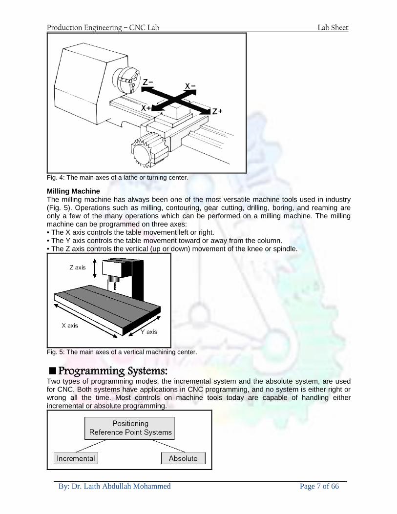
Production Engineering ndash CNC Lab Lab Sheet
By Dr Laith Abdullah Mohammed Page 7 of 66
Fig 4 The main axes of a lathe or turning center Milling Machine The milling machine has always been one of the most versatile machine tools used in industry (Fig 5) Operations such as milling contouring gear cutting drilling boring and reaming are only a few of the many operations which can be performed on a milling machine The milling machine can be programmed on three axes bull The X axis controls the table movement left or right bull The Y axis controls the table movement toward or away from the column bull The Z axis controls the vertical (up or down) movement of the knee or spindle
Fig 5 The main axes of a vertical machining center Programming Systems Two types of programming modes the incremental system and the absolute system are used for CNC Both systems have applications in CNC programming and no system is either right or wrong all the time Most controls on machine tools today are capable of handling either incremental or absolute programming
Production Engineering ndash CNC Lab Lab Sheet
By Dr Laith Abdullah Mohammed Page 8 of 66
Incremental program locations are always given as the distance and direction from the immediately preceding point (Fig 6) Command codes which tell the machine to move the table spindle and knee are explained here using a vertical milling machine as an example
Fig 6 A workpiece dimensioned in the incremental system mode bull A ldquoX plusrdquo (X+) command will cause the cutting tool to be located to the right of the last point bull A ldquoX minusrdquo (X-) command will cause the cutting tool to be located to the left of the last point bull A ldquoY plusrdquo (Y+) command will cause the cutting tool to be located toward the column bull A ldquoY minusrdquo (Y-) will cause the cutting tool to be located away from the column bull A ldquoZ plusrdquo (Z+) command will cause the cutting tool or spindle to move up or away from the workpiece bull A ldquoZ minusrdquo (Z-) moves the cutting tool down or into the workpiece In incremental programming the G91 command indicates to the computer and MCU (Machine Control Unit) that programming is in the incremental mode Absolute program locations are always given from a single fixed zero or origin point (Fig 7) The zero or origin point may be a position on the machine table such as the corner of the worktable or at any specific point on the workpiece In absolute dimensioning and programming each point or location on the workpiece is given as a certain distance from the zero or reference point
Fig 7 A workpiece dimensioned in the absolute system mode Note All dimensions are given from a known point of reference bull A ldquoX plusrdquo (X+) command will cause the cutting tool to be located to the right of the zero or origin point bull A ldquoX minusrdquo (X-) command will cause the cutting tool to be located to the left of the zero or origin point bull A ldquoY plusrdquo (Y+) command will cause the cutting tool to be located toward the column
Production Engineering ndash CNC Lab Lab Sheet
By Dr Laith Abdullah Mohammed Page 9 of 66
bull A ldquoY minusrdquo (Y-) command will cause the cutting tool to be located away from the column In absolute programming the G90 command indicates to the computer and MCU that the programming is in the absolute mode Point-to-Point or Continuous Path CNC programming falls into two distinct categories (Fig 8) The difference between the two categories was once very distinct Now however most control units are able to handle both point-to-point and continuous path machining A knowledge of both programming methods is necessary to understand what applications each has in CNC
Fig 8 Types of CNC positioning systems Point-to-Point Positioning Point-to-point positioning is used when it is necessary to accurately locate the spindle or the workpiece mounted on the machine table at one or more specific Locations to perform such operations as drilling reaming boring tapping and punching (Fig9) Point-to-point positioning is the process of positioning from one coordinate (XY) position or location to another performing the machining operation and continuing this pattern until all the operations have been completed at all programmed locations
Fig 9 The path followed by point-to-point positioning to reach various programmed points (machining locations) on the XY axis
Production Engineering ndash CNC Lab Lab Sheet
By Dr Laith Abdullah Mohammed Page 10 of 66
In Fig 9 point 1 to point 2 is a straight line and the machine moves only along the X axis but points 2 and 3 require that motion along both the X and Y axes takes place As the distance in the X direction is greater than in the Y direction Y will reach its position first leaving X to travel in a straight line for the remaining distance A similar motion takes place between points 3 and 4 Continuous Path (Contouring) Contouring or continuous path machining involves work such as that produced on a lathe or milling machine where the cutting tool is in contact with the workpiece as it travels from one programmed point to the next Continuous path positioning is the ability to control motions on two or more machine axes simultaneously to keep a constant cutter-workpiece relationship The programmed information in the CNC program must accurately position the cutting tool from one point to the next and follow a predefined accurate path at a programmed feed rate in order to produce the form or contour required (Fig 10)
Fig 10 Types of contour machining (A) Simple contour (B) complexe contour
Interpolation The method by which contouring machine tools move from one programmed point to the next is called interpolation This ability to merge individual axis points into a predefined tool path is built into most of todayrsquos MCUs There are five methods of interpolation linear circular helical parabolic and cubic All contouring controls provide linear interpolation and most controls are capable of both linear and circular interpolation Helical parabolic and cubic interpolation are used by industries that manufacture parts which have complex shapes such as aerospace parts and dies for car bodies Linear Interpolation Linear Interpolation consists of any programmed points linked together by straight lines whether the points are close together or far apart (Fig 11) Curves can be produced with linear interpolation by breaking them into short straight-line segments This method has limitations because a very large number of points would have to be programmed to describe the curve in order to produce a contour shape A contour programmed in linear interpolation requires the coordinate positions (XY positions in two-axis work) for the start and finish of each line segment Therefore the end point of one line or segment becomes the start point for the next segment and so on throughout the entire program
Production Engineering ndash CNC Lab Lab Sheet
By Dr Laith Abdullah Mohammed Page 11 of 66
Fig 11 An example of two-axis linear interpolation Circular Interpolation The development of MCUs capable of circular interpolation has greatly simplified the process of programming arcs and circles To program an arc (Fig 12) the MCU requires only the coordinate positions (the XY axes) of the circle center the radius of the circle the start point and end point of the arc being cut and the direction in which the arc is to be cut (clockwise or counterclockwise) See Fig 12
Fig 12 For two-dimensional circular interpolation the MCU must be supplied with the XY axis radius start point end point and direction of cut
Programming Format Word address is the most common programming format used for CNC programming systems This format contains a large number of different codes that transfers program information from the part print to machine servos relays micro-switches etc to manufacture a part These codes which conform to EIA (Electronic Industries Association) standards are in a logical sequence called a block of information Each block should contain enough information to perform one machining operation Word Address Format Every program for any part to be machined must be put in a format that the machine control unit can understand The format used on any CNC machine is built in by the machine tool builder and is based on the type of control unit on the machine A variable-block format which uses words (letters) is most commonly used Each instruction word consists of an address character such as X Y Z G M or S Numerical data follows this address character to identify a specific function such as the distance feed rate or speed value The address code G90 in a program
Production Engineering ndash CNC Lab Lab Sheet
By Dr Laith Abdullah Mohammed Page 12 of 66
tells the control that all measurements are in the absolute mode The code G91 tells the control that measurements are in the incremental mode Codes The most common codes used when programming CNC machines tools are G-codes (preparatory functions) and M codes (miscellaneous functions) Other codes such as F S D and T are used for machine functions such as feed speed cutter diameter offset tool number etc G-codes are sometimes called cycle codes because they refer to some action occurring on the X Y andor Z axis of a machine tool The G-codes are grouped into categories such as Group 01 containing codes G00 G01 G02 G03 which cause some movement of the machine table or head Group 03 includes either absolute or incremental programming while Group 09 deals with canned cycles A G00 code rapidly positions the cutting tool while it is above the workpiece from one point to another point on a job During the rapid traverse movement either the X or Y axis can be moved individually or both axes can be moved at the same time Although the rate of rapid travel varies from machine to machine it ranges between (5 and 20 mmin)
Fig 13 The functions of a few common G-codes The G01 G02 and G03 codes move the axes at a controlled feedrate bull G01 is used for straight-line movement (linear interpolation) bull G02 (clockwise) and G03 (counterclockwise) are used for arcs and circles (circular interpolation)
Production Engineering ndash CNC Lab Lab Sheet
By Dr Laith Abdullah Mohammed Page 13 of 66
Fig 14 Some of the most common G-codes used in CNC programming M or miscellaneous codes are used to either turn ON or OFF different functions which control certain machine tool operations M-codes are not grouped into categories although several codes may control the same type of operations such as M03 M04 and M05 which control the machine tool spindle bull M03 turns the spindle on clockwise bull M04 turns the spindle on counterclockwise bull M05 turns the spindle off
Production Engineering ndash CNC Lab Lab Sheet
By Dr Laith Abdullah Mohammed Page 14 of 66
Fig 15 The functions of a few common M-codes
Production Engineering ndash CNC Lab Lab Sheet
By Dr Laith Abdullah Mohammed Page 15 of 66
Fig 16 Some of the most common M-codes used in CNC programming Block of Information CNC information is generally programmed in blocks of five words Each word conforms to the EIA standards and they are written on a horizontal line If five complete words are not included in each block the machine control unit (MCU) will not recognize the information therefore the control unit will not be activated Using the example shown in Fig 17 the five words are as follows N001 represents the sequence number of the operation G01 represents linear interpolation X12345 will move the table 12345 in in a positive direction along the X axis Y06789 will move the table 06789 in along the Y axis M03 Spindle on CW
Fig 17 A complete block of information consists of five words
Production Engineering ndash CNC Lab Lab Sheet
By Dr Laith Abdullah Mohammed Page 16 of 66
Programming for Positioning Before starting to program a job it is important to become familiar with the part to be produced From the engineering drawings the programmer should be capable of planning the machining sequences required to produce the part Visual concepts must be put into a written manuscript as the first step in developing a part program Fig 18 It is the part program that will be sent to the machine control unit by the computer tape diskette or other input media The programmer must first establish a reference point for aligning the workpiece and the machine tool for programming purposes The manuscript must include this along with the types of cutting tools and work-holding devices required and where they are to be located
Fig 18 The first step in producing a CNC program is to take the information from the print and produce a program manuscript Dimensioning Guidelines The system of rectangular coordinates is very important to the successful operation of CNC machines Certain guidelines should be observed when dimensioning parts for CNC machining The following guidelines will insure that the dimensioning language means exactly the same thing to the design engineer the technician the programmer and the machine operator 1 Define part surfaces from three perpendicular reference planes 2 Establish reference planes along part surfaces which are parallel to the machine axes 3 Dimension from a specific point on the part surface 4 Dimension the part clearly so that its shape can be understood without making mathematical calculations or guesses 5 Define the part so that a computer numerical control cutter path can be easily programmed
Production Engineering ndash CNC Lab Lab Sheet
By Dr Laith Abdullah Mohammed Page 17 of 66
Machine Zero Point The machine zero point can be set by three methodsmdashby the operator manually by a programmed absolute zero shift or by work coordinates to suit the holding fixture or the part to be machined MANUAL SETTING - The operator can use the MCU controls to locate the spindle over the desired part zero and then set the X and Y coordinate registers on the console to zero
Fig 19 The relationship between the part zero and the machine system of coordinates ABSOLUTE ZERO SHIFT - The absolute zero shift can change the position of the coordinate system by a command in the CNC program The programmer first sends the machine spindle to home zero position by a G28 command in the program Then another command (G92 for absolute zero shift) tells the MCU how far from the home zero location the coordinate system origin is to be positioned Fig 19 The sample commands may be as follows N1 G28 X0 Y0 Z0 (sends spindle to home zero position) N2 G92 X4000 Y5000 Z6000 (the position the machine will reference as part zero)
Production Engineering ndash CNC Lab Lab Sheet
By Dr Laith Abdullah Mohammed Page 18 of 66
Work Settings and Offsets All CNC machine tools require some form of work setting tool setting and offsets (compensation) to place the cutter and work in the proper relationship Compensation allows the programmer to make adjustments for unexpected tooling and setup conditions
Work Coordinates In absolute positioning work coordinates are generally set on one edge or corner of a part and all programming is generally taken from this position In Fig 20 the part zero is used for all positioning for hole locations 1 2 and 3
Fig 20 In absolute programming all dimensions must be taken from the XY zero at the top left-hand corner of the part
Fig 21 In incremental programming all dimensions are taken from the previous point In incremental positioning the work coordinates change because each location is the zero point for the move to the next location Fig 21
Production Engineering ndash CNC Lab Lab Sheet
By Dr Laith Abdullah Mohammed Page 19 of 66
On some parts it may be desirable to change from absolute to incremental or vice versa at certain points in the job Inserting the G90 (absolute) or the G91 (incremental) command into the program at the point where the change is to be made can do this
R Plane or Gage Height The word-address letter R refers to a partial retraction point in the Z axis to which the end of the cutter retracts above the work surface to allow safe table movement in the X Y axes It is often called the rapid-traverse distance gage height retract or work plane The R distance is a specific height or distance above the work surface and is generally 100 in above the highest surface of the workpiece Fig 22 which is also known as gage height Some manufacturers build a gage height distance of 100 in into the MCU (machine control unit) and whenever the feed motion in the Z axis is called for 100 in will automatically be added to the depth programmed When setting up cutting tools the operator generally places a 100 in thick gage on top of the highest surface of the workpiece Each tool is lowered until it just touches the gage surface and then its length is recorded on the tool list Once the gage height has been set it is not generally necessary to add the 100 in to any future depth dimensions since most MCUs do this automatically
Fig 22 Using a 100 in gage block to set the gage height or R0 on the work surface
Cutter Diameter Compensation Cutter diameter compensation (CDC) changes a milling cutterrsquos programmed centerline path to compensate for small differences in cutter diameter On most MCUs it is effective for most cuts made using either linear or circular interpolation in the X-Y axis but does not affect the programmed Z-axis moves Usually compensation is in increments of 0001 in up to +10000 in and usually most controls have as many CDCs available as there are tool pockets in the tool storage matrix The advantage of the CDC feature is that it 1 Allows the use of cutters that have been sharpened to a smaller diameter 2 Permits the use of a larger or smaller tool already in the machinersquos storage matrix 3 Allows backing the tool away when roughing cuts are required due to excessive material present 4 Permits compensation for unexpected tool or part deflection if the deflection is constant throughout the programmed path The basic reference point of the machine tool is never at the cutting edge of a milling cutter but at some point on its periphery If a 1000 in diameter end mill is used to machine the edges of a workpiece the programmer would have to keep a 500 in offset from the work surface in order to cut the edges accurately Fig 23 The 500 offset represents the distance from the centerline of the cutter or machine spindle to the edge of the part Whenever a part is being machined the programmer must calculate an offset path which is usually half the cutter diameter
Production Engineering ndash CNC Lab Lab Sheet
By Dr Laith Abdullah Mohammed Page 20 of 66
Fig 23 Cutter-diameter compensation must be used when machining with various size cutters Modern MCUs which have part surface programming automatically calculate centerline offsets once the diameter of the cutter for each operation is programmed Many MCUs have operator-entry capabilities which can compensate for differences in cutter diameters therefore an oversize cutter or one that has been sharpened can be used as long as the compensation value for oversize or undersize cutters is entered
Production Engineering ndash CNC Lab Lab Sheet
By Dr Laith Abdullah Mohammed Page 21 of 66
CNC Programming Hints - MILLING
Production Engineering ndash CNC Lab Lab Sheet
By Dr Laith Abdullah Mohammed Page 22 of 66
CNC Programming Hints ndash TURNING
Production Engineering ndash CNC Lab Lab Sheet
By Dr Laith Abdullah Mohammed Page 23 of 66
CNC
The abbreviation CNC stands for Computer(ized) Numerical(ly) Control(led) and refers specifically to the computer control of machine tools for the purpose of (repeatedly) manufacturing complex parts in metal as well as other materials using a program written in a notation conforming to the EIA-274-D standard and commonly called G-code
CNC was developed in the late 1940s and early 1950s by the MIT Servomechanisms Laboratory CNC machines were relatively briefly preceded by the less advanced NC or Numerical(ly) Control(led) machines The introduction of CNC machines radically changed the manufacturing industry Curves are as easy to cut as straight lines complex 3-D structures are relatively easy to produce and the number of machining steps that required human action have been dramatically reduced With the increased automation of manufacturing processes with CNC machining considerable improvements in consistency and quality have been achieved CNC automation reduced the frequency of errors and provided CNC operators with time to perform additional tasks
CNC automation also allows for more flexibility in the way parts are held in the manufacturing process and the time required to change the machine to produce different components In a production environment a series of CNC machines may be combined into one station commonly called a cell to progressively machine a part requiring several operations CNC machines today are controlled directly from files created by CAM software packages so that a part or assembly can go directly from design to manufacturing without the need of producing a drafted paper drawing of the manufactured component In a sense the CNC machines represent a special segment of industrial robot systems as they are programmable to perform many kinds of machining operations (within their designed physical limits like other robotic systems)
G-code
G-code is a common name for the programming language that is used for NC and CNC machine tools It is defined in EIA RS-274-D G-code is also the name of any word in a CNC program that begins with the letter G and generally is a code telling the machine tool what type of action to perform such as
bull rapid move bull controlled feed move in straight line or arc bull series of controlled feed moves that would result in a hole being drilled bull change a pallet bull Set tool information such as offset
There are other codes the type codes can be thought of like registers in a computer
X position Y position Z position M code (another action register) F feed rate S spindle speed N line number R Radius T Tool selection
Production Engineering ndash CNC Lab Lab Sheet
By Dr Laith Abdullah Mohammed Page 24 of 66
I Arc data X axis J Arc data Y axis
G-code files are output by CAM software such as Smartcam Gibbscam Featurecam Edgecam Mastercam etc G-code is also output by specialized CAD systems used to design printed circuit boards Such software must be customized for each type of machine tool that it will be used to program
Production Engineering ndash CNC Lab Lab Sheet
By Dr Laith Abdullah Mohammed Page 25 of 66
U 2عمل األزرار الرئيسية في ماكنة الخراطة المبرمجة (نصر (
1- SINGLE BLOCK للتأكد من صحة البرنامج (تنفيذ البرنامج خطوة خطوةب تقوم( 2- BLOCK DELETE بجانب ويعمل من األوامرلغاء بلوك معين أليستخدم 3- MACHINE LOCK العمل يستخدم لقفل حركة المحاور الرئيسية مع استمرار البرنامج في
)وهذا مهم للتاكد من صحة البرنامج قبل عملية التنفيذ النهائي(4- CONT CYCLE عملية التشغيل عند ايقافها الي سبب كان او عند ايقافها ألستئناف ستخدم ت
) BAR FEEDER(او في حالة استخدام ) FEED HOLDبسبب (5- DRY RUN وتستخدم لفحص البرنامج بعد ازالة الشغلة حركة سريعة للبرنامج 6- TURRET UP amp DOWN ) حركة حامل العدة TURRET الذي يحمل مجموعة من (
وهذا الزر يعمل مع الزر عكس عقرب الساعة او مع عقرب الساعة ةحركة دوراني العدد )SAFTY (
7- COOLANT ON or OFFفه تشغيل سائل التبريد او ايقا 8- COOLANT AUTO الدوال المساعدة في البرنامج من خالل فه تشغيل سائل التبريد او ايقا 9 -MACHINE START ة لتشغيل هيدرولكيك الماكنميستخد
Production Engineering ndash CNC Lab Lab Sheet
By Dr Laith Abdullah Mohammed Page 26 of 66
10- CLOSE OR OPEN CHUCKالعينة تستخدم لفتح وغلق 11 -T STOCK FWD RET حركة الغراب المتحرك ذهابا وإيابا12 -SPINDLE STOP تعمل على ايقاف حركة دوران العينة 13-JOG SPINDLE تعمل على تدوير العينة مع زر SAFTY 14 -OPT SAFTY مع الدالة ( تعمل عمل التوقف المشروط حيث تعملM1 دالة التوقف (
ط ) فقط األ اذا كان هذا الزر مضغو M1المشروط حيث ال يتوقف البرنامج في حالة وجود دالة ( SAFTY + SPINDLE ) يتم الضغط على زر ( START CYCLEلغرض تحرير زر (
START ) في نفس الوقت بعد الضغط على زر ( START CYCLE مرتين (
NC PC- 15 يستخدم هذا الزر عند ربطCNC يستخدم لنقل المعلومات ث مع جهاز أخر حي بينهما
16 -CALCU زر الخاص بالحاسبة مع زر ( ال وهوINPUT ( 17 - HD1 HD2 يستخدم الختيار العدة مع المخرطة ذات المحاور األربعة 18 - START تستخدم لبدء عملية التشغيل
Production Engineering ndash CNC Lab Lab Sheet
By Dr Laith Abdullah Mohammed Page 27 of 66
19- FEED HOLD تعمل على إيقاف عمل أي G موجودة مع بقاء العينة متحركة 20- M D I أو تشغيل البرنامج ل يتم استخدامه لإلدخا BLOCK BY BLOCK وتعمل عند
إدخال البرنامج بواسطة الشريط المثقب أو أي وسيلة إدخال أخرى أو في عمليات التصفير
21- REST تستخدم العادة تشغيل الماكنة أو مسح اإلنذار الذي يظهر على الشاشة 22- EMERGENCYتستخدم عادة اليقاف الماكنة في حالة الطوارئ فقط
OPERATION MENU KEY
CHAPTER PRG-CMK
OFFSET PROGRAM POSITION FUNCTION MENU KEY
23- POSITIONعلى الشاشة د الموقع الموجور الظها 24- PROGRAMإلظهار برنامج معين واختياره 25- OFFSET الختيار سماحات العدة أو سماحات نقطة المرجع 26- PRG- CHK تستخدم لفحص البرنامج على الشاشة 27- SETTING ألختيار الثوابت على الشاشة 28- SERVICE تستخدم ألستخراج المعامالت والثوابت 29- MESSAGE تستخدم ألظهار األخطاء الناتجة عن البرنامج او اخطاء التشغيل 30- OVERALL ألختيار المواقع 31- RELATIVE MODLINE تعوض عن POSITION 32- DIR MEM يستخدم ألظهار ملف البرامج المخزونة في الذاكرة وعندما نضغط هذا الزر
فان رقم واسم البرنامج سوف يظهر على الشاشة
2أدناه الشفرات الرئيسية التي تعمل على الماكنة المبرمجة نصر
G-CODE DESCRIPTION
G00 Rapid traverse (linear)
G01 Linear Interpolation at feed rate
G02 Circular interpolation (CW) R+
G03 Circular interpolation (CCW) R+
G10 Zero point tools
G20 Imperial data input
G21 Metric data input
G27 Reference return check
G28 Reference return
G29 Return from reference
Production Engineering ndash CNC Lab Lab Sheet
By Dr Laith Abdullah Mohammed Page 28 of 66
G33 Thread cutting
G40 Cancel cutter radius compensation
G41 Cutter compensation left
G42 Cutter compensation right
G54 Work co-ordinate system no1
G70 Finishing cycle
G71 Stock removal turning
G72 Stock removal facing
G74 Face grooving
G75 Diameter grooving
G76 Threading cycle
G90 Absolute date input
G91 Incremental data input
G94 Feed minute mode
G95 Feed rev mode
G96 Constant surface speed mode
G97 Cancel Constant surface speed
) 2أدناه الشفرات الثانوية التي تعمل على الماكنة المبرمجة (نصر
M-code FUNCTION
M00 Program stop
M03 Spindle forward (Tool forward ndash M94 mode)
M04 Spindle reverse (Tool forward ndash M94 mode)
M05 Spindle stop (Tool stop ndash M94 mode)
M08 Coolant on
M09 Coolant off
M30 Program end (with rewind)
M48 Turret shortest path
M52 Turret direction up (CW)
M53 Turret direction down (CCW)
M73 Chuck open
M74 Chuck close
Production Engineering ndash CNC Lab Lab Sheet
By Dr Laith Abdullah Mohammed Page 29 of 66
) وكل جملة مكونة من مجموعة من الكلمات blockإن كل برنامج يتكون من مجموعة من الجمل ()words) لهذا فأن الشفرات الرئيسية والمساعدة هي عبارة عن كلمات (words كما في المثال التالي (
G_ _ P1 Q2 U_ _ W_ _ D___ F_ _
)end of block) ويعني ( ) يكتب الرمز (blockتسلسل الكلمات مهم جدا بعد نهاية كل جملة (
طريقة ادخال البيانات الى الماكنة ــــــــــــــــــــــــــــــــــــــــــــــــــ
) MDIيمكن ادخال البيانات الى الماكنة بعدة طرق فقد يكون األدخال عن طريق قناة السيطرة ( MANUAL DATA INPUT ) او عن طريق قناة األضافة EDIT كما يمكن ادخال البيانات عن (
) RS ndash 232 COMMUNICATIN LINKطريق استخدام سلسلة الربط (
₤⅗₌⅗₌ ⅙₌₨image₍₡ ₤₌ℌ⅗₌ Ⅸ⅗ⅥⅯ₌ ₤₡ℌ₰₨⅗₌G71
الخراطة الطولية G71الغرض من التجربة عمل نموذج للخراطة بأستخدام الدالة تستعمل هذه الدالة للخراطة الطولية اي على طول محور المشغولة وكما هو موضح بالشكل ادناه
تعتبر هذه الدالة من الدوال التي ال تحتاج الى تكرار او إعادة كتابتها أي انها دالة تكرارية بمعنى ان اي
الذي هي دالة حركة G01خطوة تكون من ضمن هذه الدالة سوف تكرر العملية اي عند استعمال امر مثل خطية تتضمن القطع مع التغذية مع اعطاء القطر المراد قطعه و مراعاة عمق القطع المعطى سوف يتكرر
هذه االمر وصوال الى العمق المطلوب وهكذا لبقية الدوال
G71 المستخدمة للدالة الصيغة
G71 P1 Q2 U___ W___ D___ F___ حيث إن
P1 بداية الخطوة االولى = Q2 نهاية الخطوة =
Uوضع السماحات بأتجاه محور = X W وضع السماحات بأتجاه محور = Z وتكاد تكون مهملة وتوضع اشارة سالب Dعمق القطع وتوضع رقم صحيح مثل = D500 اي نصف ملمF التغذية والتي لها عالقة بالدالة = G95
Production Engineering ndash CNC Lab Lab Sheet
By Dr Laith Abdullah Mohammed Page 30 of 66
G71الدالة استخدام مثال على
T0100 M48 G0 X26 Z2 M08 T0101 G90 G95 G97 S500 M03 G71 P1 Q2 U03 W00 D500 F01 N1 G0 G42 X00 G01 Z00 G01 X2517 G01 Z-5352 G01 X7391 Z-9366 G01 Z-19145 N2 G28 M30
الجانب العملي
االجهزة واالدوات المستخدمة CNCماكنة خراطة مبرمجة 1 ملم 80قضيب من االلمنيوم قطر 2 ةفير ني 3 جاه أيمن تهولدر كاربيدي ذوا 4
طريقة العمل يتم تثبيت قضيب من االلمنيوم على العينة التابعة للماكنة مع مراعاة الطول المراد استعماله في عملية 1
الخراطة ) turretتثبيت عدة القطع في المكان الصحيح في ( 2
Production Engineering ndash CNC Lab Lab Sheet
By Dr Laith Abdullah Mohammed Page 31 of 66
بالنسبة الى القطعة المثبتة على العينة XZيتم تصفير الماكنة للمحاور 3 تصفير للمحورZ تكون مالمسة العدة الى وجه الشغلة تصفير للمحورX تكون مالمسة العدة الى سطح الشغلة الموازي لمحور X
يتم كتابة البرنامج أما بطريقة يدوية أو بالحاسوب مع وضع كل الظروف الالزمة للتشغيل ( عمق القطع 4 التغذية السرعة المطلوبة نوع المعدن )
ادخال البرنامج الى الحاسوب الموجود داخل الماكنة مع تهيئة الماكنة للتشغيل 5
المطلوب G71عمل برنامج يدوي على الدالة 1 رسم الشكل الشكل النهائي المطلوب مع وضع األبعاد 2
Ⅺ⅟₍euro⅗₌ ₤₡ℌ₰₨⅗₌₣ ₤⅗₌⅗₌ ⅙₌₨image₃₡ Ⅺℂtradeℒ⅗₌ ӈ₍Ⅴ⅟ⅳ₌ G70
G70 الغرض من التجربة عمل انهاء سطحي للمشغولة بواسطة الدالة
من الضروري إعطاء G71هذه الدالة تعمل شوط واحد فقط وتكون معتمدة على عمليات القطع في الدالة اللغاء مقدمة االداة (أي لكي تتم عملية االنهاء السطحي بدون حسابات نصف قطر مقدمة االداة ) G42دالة
G70الصيغة المستخدمة للدالة
G70 P1 Q2 F___ حيث ان
P1 بداية الخطوة االولى = Q2 نهاية الخطوة =
F التغذية والمرتبطة بالدالة = G95
وذلك ألن دالة االنهاء السطحي تحقق X Zمالحظة الدالة التحتاج لكتابة السماحات التابعة للمحورين المسافات الحقيقة المراد انتاجها للمشغولة
G71و G70مثال على الدالة
T0100 M48 G0 X26 Z2 M08 T0101 G90 G95 G97 S500 M03 G71 P1 Q2 U03 W00 D500 F01 N1 G0 G42 X00 G01 Z00 G01 X2517 G01 Z-5352 G01 X7391 Z-9366 G01 Z-19145 N2 G97 S750 MO3
Production Engineering ndash CNC Lab Lab Sheet
By Dr Laith Abdullah Mohammed Page 32 of 66
G70 P1 Q2 G40 F009 G28 M30
الجانب العملي الحظ التجربة األولى
المطلوب
G70 عمل برنامج يدوي على الدالة 1 رسم الشكل النهائي المطلوب مع وضع االبعاد 2
₪⅗₍euro⅗₌ ₤₡ℌ₰₨⅗₌₣ ₤⅗₌⅗₌ ⅙₌₨image₍₡ ⅝₍ⅠimageⅯ₌ ⅞ⅫⅦ⅔₧ G76
G76 للمشغولة بواسطة الدالةةالغرض من التجربة عمل أسنان خارجية أو داخلي
في هذه التجربة سوف نقوم بعمل األسنان الخارجية وهنا تكون حركة العينة ثابتة وهذا ضروري بسبب أن ) تكون متصلتين الكترونيا وعليه أي اختالف في سرعة العينة تؤدي إلى اختالف motionالعينة والحركة(
) servoفي سرعة الخدمة(يرتبط اتجاه تكوين األسنان باتجاه دوران العينة مثال إذا كانت األسنان ذات اتجاه أيمن يكون اتجاه دوران
وهنا نقلب العدة إلى االسفل وكما هو موضح بالشكل أدناه MO3العينة عكس عقرب الساعة أي نستعمل
Production Engineering ndash CNC Lab Lab Sheet
By Dr Laith Abdullah Mohammed Page 33 of 66
الخطوة هي عبارة عن المسافة ما بين قمة سن إلى قمة سن أخر عمق السن هو العمق المطلوب تكوينه لألسنان
G76 الصيغة المستخدمة للدالة
G76 X___ Z___ K___ F___ D___ A___
حيث أن X القطر الداخلي للسن =Z طول السن =K عمق السن وتستخرج من المعادلة التالية =K=065F F الخطوة =D عمق القطع بالمايكرون فقط =A زاوية السن =
G76مثال على استخدام الدالة T0300 M48 GOO X30 Z4 T0303 M08 G97 S500 MO3 G76 X28375 Z-20 K08125 F125 D120 G00 X40 Z4 G28 M30
Production Engineering ndash CNC Lab Lab Sheet
By Dr Laith Abdullah Mohammed Page 34 of 66
الجانب العملي الحظ التجربة األولى
المطلوب
G76عمل برنامج يدوي على الدالة 1 رسم الشكل النهائي المطلوب مع وضع األبعاد 2
Ⅺ⅘₌⅗₌ Ⅵ₂ Ⅺ₯ℋ₍⅗₌ ℌℲℂ⅗₌ ⅞ⅫⅦ⅔₧ ₤K₡₌ℌ⅗₌ ₤₡ℌ₰₨⅗₌)Groove ₤⅗₌⅗₌ ₤tradeimage₌Ⅶ₡ (G75
G75 بواسطة الدالة grooveالغرض من التجربة تكوين
) للمشغولة وتعتمد شكل الحفر على طريقة grooveتستعمل هذه الدالة لتكوين الحفر الخارجي والداخلي (
التشغيل وعلى الشكل المراد إنتاجه وتعتبر هذه الطريقة من عمليات التشكيل للمعدن إن هذه الدالة هي دالة مالحظة مع G75في هذه التجربة سنقوم بعمل الحفر الخارجي بواسطة الدالة
تكرارية وغير تكرارية حسب نوع التشغيل
G 75 الصيغة المستخدمة للدالةG75 X___ Z___ I___ K____
حيث أن
X العمق النهائي لقطر الشغلة =Z عرض الحفر =I الدخول في كل مرة =
K التزحيف على محور =z بالنسبة للعدة
Production Engineering ndash CNC Lab Lab Sheet
By Dr Laith Abdullah Mohammed Page 35 of 66
G75مثال على استخدام الدالة
T0500 M48 GOO X100 Z -20 T0505 M08 G97 S700 MO3 G75 X84 Z -38 I 05 K4
الجانب العملي الحظ التجربة األولى
المطلوب
G76عمل برنامج يدوي على الدالة 1 رسم الشكل النهائي المطلوب مع وضع األبعاد 2
Production Engineering ndash CNC Lab Lab Sheet
By Dr Laith Abdullah Mohammed Page 36 of 66
CNC Milling Machine Mechanical Construction
Guideways The guideways of CNC machines are made of steel To reduce the frictional forces they are coated with a strip of PTFE (Poly Tetra Fluoro Ethylene)
Ballscrews On conventional lathes a leadscrew is used to converts the rotary motion of the hand wheel into linear motion of the slides Leadscrews have a high coefficient of friction and backlash On CNC machines a ballscrew is used instead of a leadscrew Friction and backlash are much less than on leadscrews
Guideway
Production Engineering ndash CNC Lab Lab Sheet
By Dr Laith Abdullah Mohammed Page 37 of 66
bullMachining operations Direction of cutting Based on the direction of the cutter rotation and work piece feed milling operations are classified into two types 1-Up milling (Convention milling) In up milling the metal is removed by rotating the cutter against the direction of travel of the part
Feed
Machine table
Part
Cutting tool
Chip thickness at theexit of the tooth
2-Down milling (Climb milling) In climb milling the metal is removed by rotating the cutter with the direction of travel of the part
Machine table
Part
Cutting tool
Chip thickness at theentrance of the tooth
Production Engineering ndash CNC Lab Lab Sheet
By Dr Laith Abdullah Mohammed Page 38 of 66
bullTooling Tool geometry The geometry of the tool tip affects the way that the metal cutting is performed The nose radius rake angles relief angles etc must be selected with care
Radial relief
Radial rake
Axial relief
Approach angle
Axial relief
Corner radius Face mill Face milling cutters are used to mill flat surfaces Commonly used face milling cutters Cutter with 75 degree approach
75 deg
Cutter with 90 degree approach (Square shoulder face mill)
90 deg
Cutter with 45 degree approach
Production Engineering ndash CNC Lab Lab Sheet
By Dr Laith Abdullah Mohammed Page 39 of 66
bullCNC Programming Axes convention The Z axis is along the spindle axis The X and Y axes are perpendicular to Z VMC
Z
Y
-
+
-+
X- +
+Z
-Z
+Y
-Y
-X +X
Part
Machine table
X
YZ
G00 Rapid traverse When the tool being positioned at a point preparatory to a cutting motion to save time it is moved along a straight line at Rapid traverse at a fixed traverse rate which is pre-programmed into the machines control system Typical rapid traverse rates are 10 to 25 m min but can be as high as 80 mmin
Production Engineering ndash CNC Lab Lab Sheet
By Dr Laith Abdullah Mohammed Page 40 of 66
Format N_ G00 X__ Y__Z__
G01 Linear interpolation (feed traverse) The tool moves along a straight line in one or two axis simultaneously at a programmed linear speed the feed rate Format N__ G01 X__ Y__Z__ F__
Part
Feed
Part
Feed
G02G03 Circular interpolation The tool moves along an arc in two axes simultaneously at a programmed linear speed the feed rate
Production Engineering ndash CNC Lab Lab Sheet
By Dr Laith Abdullah Mohammed Page 41 of 66
Format N__ G0203 X__ Y__Z__ I__ J__K__ F__ using the arc center OR N__ G0203 X__ Y__Z__ R__ F__ using the arc radius G02 moves along a CW arc G03 moves along a CCW arc Arc center The arc center is specified by addresses I J and K I J and K are the X Y and Z co-ordinates of the arc center with reference to the arc start point
X
Y
Arc center
Arc endArc start
- J
- I
I = X coord of center - X coord of start point J = Y coord of center - Y coord of start point K = Z coord of center - Z coord of start point I J and K must be written with their signs
Production Engineering ndash CNC Lab Lab Sheet
By Dr Laith Abdullah Mohammed Page 42 of 66
bullWork holding
Rotary table
Fixture base
Component
Clamp
Stud
Fixtures The use of fixtures 1 Improves repeatability of dimensions 2 Improves working conditions 3 Cuts down requirement of skilled labour 4 Reduces part loading and unloading time 5 Improves safety in the working area 6 Reduces the cost of machining There are two types fixtures commonly used 1 Special fixture Special fixtures are used to hold and locate the typical components which are having complex shape and to be located with the reference hole (dowel hole) Special fixtures are required for components like gear case cover cylinder heads etc 2 Modular fixture Modular fixture is a set different kind of clamping and locating elements These fixtures are used to hold identical components in different sizes and components of box type Example Manifolds head stocks connecting rods and flanges
Production Engineering ndash CNC Lab Lab Sheet
By Dr Laith Abdullah Mohammed Page 43 of 66
bullMachine setting
Determining X and Y work zero offset Case 1
Part
Machine table
Part
End mill or reamer
Work offset X0Y0 For determining X work zero offset bull Touch the periphery of the end mill or reamer to the part bull Enter current machine X value + cutter radius as X work zero offset For determining Y work zero offset bull Touch the periphery of the end mill or reamer to the part bull Enter current machine Y value - cutter radius as Y work zero offset Case 2
Part
Machine table
Part
End mill or reamerWork offset X0Y0
bull Mount the dial indicator on machine spindle true the bore bull Enter current machine X and Y value as X and Y work zero offset
Production Engineering ndash CNC Lab Lab Sheet
By Dr Laith Abdullah Mohammed Page 44 of 66
How to Select a Cutting Fluid
One part of the metal cutting equation that is sometimes overlooked however is
the choice of an appropriate cutting fluid With todayrsquos system approach to metal
cutting use of the right metalworking fluid has become just as much a part of the
solution as the other elements In fact at least one company is now integrating
cutting fluids and cutting tools into effective metal cutting systems Following are
some things to consider when choosing your next cutting fluid
The Four Key Questions
There are four vital pieces of information that are necessary when choosing a
cutting fluid They are
1 What are you cutting
2 What is the chemistry of your water
3 What are you using now
4 What are your options
5 What do you prefer
What Are You Cutting
The first question ndash ldquoWhat are you cuttingrdquo ndash is often the most difficult to answer
because most shops handle a variety of workpiece materials on a regular basis If
the answer is an unequivocal ldquoaluminumrdquo or ldquostainless steelrdquo or ldquocast ironrdquo the
selection of a cutting fluid can be quite simple and straightforward Unfortunately
that is seldom the case in anything but a high-volume plant Where aluminum or
other nonferrous metals are a significant part of the mix a non-staining cutting
fluid is a must Generally speaking this will be a semi-synthetic with special
ingredients to prevent bi-metallic corrosion and staining of non-ferrous workpieces
Where the ferrous metals predominate however a more general purpose semi-
synthetic or hybrid fluid might be a more economical choice
Production Engineering ndash CNC Lab Lab Sheet
By Dr Laith Abdullah Mohammed Page 45 of 66
What is The Chemistry of Your Water
The second question ndash ldquoWhat is the chemistry of your waterrdquo ndash is probably the
single most common reason for the success or failure of a cutting fluid Very few
plants invest the money necessary to install effective water purification systems
using deionization or reverse osmosis technology Unfortunately the chemicals
present or not present in the water used to re-constitute a cutting fluid make a
tremendous difference in its performance and sump life Most manufacturers of
cutting fluids will perform the necessary water testing to determine exactly what
minerals are dissolved in your water and make a fluid recommendation based on
the results
What are you using now
The third question ndash ldquoWhat are you using nowrdquo ndash helps narrow the range of
choices When coupled with an objective analysis of the strengths and weaknesses
of the current fluid the answer to this question can quickly point you toward a
relatively small number of competitive alternatives that have the attributes required
to meet your cutting needs Many cutting fluids are in use today simply because
they were in use yesterday It is a hard reality of todayrsquos marketplace that if one
isnrsquot constantly striving to improve they will certainly be overtaken by a
competitor who is
What Are Your Options
The fourth question ndash ldquoWhat are your optionsrdquo ndash leads to the final selection of a
cutting fluid Cutting fluids can be divided into four general groups based on their
chemistry
They are
bull Soluble Oils ndash quite literally oil dispersed in water
bull Synthetics ndash completely oil free man-made coolants in solution
Production Engineering ndash CNC Lab Lab Sheet
By Dr Laith Abdullah Mohammed Page 46 of 66
bull Semi-Synthetics ndash a mixture of natural and synthetic lubricants with up to 30
mineral oil
bull Hybrids ndash a special class of semi-synthetics with a mineral oil content of about
15 Each fluid type has advantages and disadvantages which make it suitable for
a particular group of applications In addition there are costperformance trade-
offs to be made between the groups within a specific set of applications For
example where a hybrid and a semi-synthetic may both be suitable for a particular
use the hybrid might provide longer sump life at a slightly higher initial cost
while some semi synthetics may be more economical to recycle or dispose of while
not giving as long a tank life The final decision in this case would have to be made
on the detailed economics of the shop where the fluids were to be used and on the
ownerrsquos individual preferences
Soluble Oils
Soluble oils are oils that disperse in water when emulsifiers are added They are
generally suitable for moderate-to heavy-duty machining and grinding of all non-
ferrous metals carbon and cast steels and in applications where dissimilar metals
such as aluminium and steel are present They can also be used in turning drilling
tapping reaming gear cutting broaching as well as internal and centerless types
of grinding operations Soluble oils provide excellent aluminium and copper
corrosion control good rancidity control which extends fluid for long lasting
trouble-free performance and good concentrate and mix stability making it ideal
for mixing in water with a minimal amount of agitation An example of this is
Valenitersquos VNTreg-650 premium heavy-duty soluble oil
Synthetics
Synthetics are completely oil free solutions made of polymers organic and
inorganic materials that are mixed with water These clear low foaming and bio-
Production Engineering ndash CNC Lab Lab Sheet
By Dr Laith Abdullah Mohammed Page 47 of 66
stable coolants are ideal for machining and grinding of ferrous materials carbon
steels or cast iron Their complex lubricant packages make synthetics well-suited
for tough-to-machine materials such as stainless steels and high-temperature alloys
Certain synthetics are specifically designed to address the primary failure modes of
flank wear and nose wear Although there are many benefits some synthetics may
cause staining of non-ferrous materials
Semi-Synthetics
Semi-synthetic fluids are a mixture of oils synthetic emulsifiers and water They
were primarily developed for the aircraft nuclear and related industries
Consequently they work extremely well on all non-ferrous metals such as titanium
aluminium copper brass bronze and stainless steel in both machining and
grinding Semi-synthetics can be used on ferrous metals too They are chlorine-
free to reduce bi-metallic corrosion and staining of metals They should be used at
a 5-8 dilution with water depending on the severity of the operation
Hybrids
Hybrids are cutting fluids custom engineered to solve a particular problem For
example Valenitersquos VNTreg-800 was developed to be very clean in the machining
and grinding of cast iron It provides better stability in hard water and rejects tramp
oil very well which adds to its bio-stable chemistry Hybrids work extremely well
on all metals in both machining and grinding They should be mixed at a 5-7
dilution with water depending on the condition of the water
What Do You Prefer
The final question ndash ldquoWhat do you preferrdquo ndash is usually the ldquotie breakerrdquo where
there is more than one appropriate cutting fluid available Here again as in the
case of what is being used now the key is to examine your preferences objectively
Production Engineering ndash CNC Lab Lab Sheet
By Dr Laith Abdullah Mohammed Page 48 of 66
and specifically to identify the real reasons behind a preference If you cannot
point to specific reasons why one class of cutting fluid is preferred over another
you are well advised to follow the recommendations of the professional who has
analyzed your requirements Choosing the right fluid today is easier than ever as
the system approach to metal cutting productivity continues to grow in acceptance
The day is not far off when choosing a complete solution will be as easy as
choosing the right insert and chip breaker today The answers are available and the
results will more than justify the time you spend choosing the right metal cutting
fluid
Useful Links wwwball-screwsnet
wwwlubelinkcom
wwwmachinerylubricationcom
wwwadvancedmanufacturingcom
wwwmmsonlinecom
wwwcuttingtoolengineeringcom
wwwgeartechnologycom
wwwengineersedgecom
wwwagmaorg
wwwefundacom
wwwsaeorg
wwwsmeorg
wwwastmorg
wwwissorg
wwwmachinetoolscom
wwwansiorg
wwwasmeorg
wwwcnccicom
wwwmatlscom
wwwthefreedictionarycom
wwwengineersupplycom
Production Engineering ndash CNC Lab Lab Sheet
By Dr Laith Abdullah Mohammed Page 49 of 66
SurfCAM Tutorial ndash Beginning with the basics
Background SurfCAM is a computer aided manufacturing (CAM) software which allows you to create manage and modify tool paths for computer aided designed (CAD) part The software requires a CAD model or requires that you create some geometry within SurfCAM with some rudimentary tools provided The tool paths are created or stored internally in SurfCAM in a generic programming language called APT Once the tool paths are created the APT paths are translated using a post processor into typical machine G-code
Opening SurfCAM SurfCAM can be opened from the Novell Applications Launcher on most Industrial Engineering computer labs workstations Search under lsquoallrsquo applications and double click on SurfCAM 2005 Once the program opens a license must be selected from the list (not the Demo license) to enable saving the file later Choose one of the 30 licenses available If for some reason the licenses are not listed on the license manager form select server list and type ldquobonnieeosncsuedurdquo A list of available licenses should appear Select a license and click OK After the license is selected an Add StockFixture form (Figure 1) opens allows you to add a model which represents the pre-machined stock or a fixture Click on OK without adding either Both of these items can be added later under a more appropriate dialog
Figure 1 Add Stock or Fixture dialog box
Production Engineering ndash CNC Lab Lab Sheet
By Dr Laith Abdullah Mohammed Page 50 of 66
SurfCAM Interface
Figure 2 SurfCAM Windows based interface
SurfCAM is a windows based software system so most of the typical windows functions under File are applicable This is where you can open save exit print etc The Create menu allows the user to create different geometry forms Here you can create a point line surface chamfer circle and many other geometry types For the most part these functions are not used by beginners but are useful when creating bounding curves where you donrsquot want the tool to move outside (constraining the tool) The Edit menu allows you to change or modify many different entities such as changing lines altering surfaces joining surfaces trimming or breaking elements add control points etc Again these features are helpful to advanced users and are not covered in detail in this tutorial The Display menu offers the ability to change the orientation of the part on the screen The typical rotate pan fit to screen and zoom functions are available as well as several functions which allow the user to shift between views or call up a named view (ie top bottom etc) The NC menu is the main machining interface menu In this menu you select the general form of machining (2 axis 3 axis 4 axis 5 axis turning etc) and under the general form a more specific machining function is selected This menu is the most used and the options contained must be fully understood to get the most out of SurfCAM Each function will be described in some detail in a further chapter The Analyze menu contains options such as measuring the distance between points angles tangency elements etc These functions are auxiliary functions meant to help you understand the part better but basically provide no functionality for making tool paths for CNC machines Thus these will not be covered The Tools menu allows the user to change the system options modify keyboard shortcuts change the model units etc These options are again not used by beginners Finally the Help menu provides access to the online users manual In lieu of clicking the Help menu the F1 key is the shortcut key for help (as it is in most windows based programs)
Importing a CAD model Importing a CAD model that is stored locally is done by selecting File-gtOpen On the Files of type dropdown box choose the type of file you wish to open (Figure 3) Do this prior to negotiating your way through the maze of folders to prevent having to go through the folder tree again Once the file type is selected find the file you are trying to open and click the Open
Production Engineering ndash CNC Lab Lab Sheet
By Dr Laith Abdullah Mohammed Page 51 of 66
button SurfCAM will then attempt to read the file you have selected SurfCAM may provide a dialog box describing what it has imported and identify if it was successful If this dialog is provided simply click close without saving
Figure 3 Open Dialog Note - Change type of file prior to finding the file you wish to open
SurfCAM allows a user to import several different types of CAD files the most common types which you will likely import are SolidWorks part files (sldprt or prt) AutoCAD files(dxf) or IGES (igs or iges) Native file import (such as is the case with SolidWorks) provides the greatest information transfer and generic file imports (such as is the case with IGES) provide the least Normally it is to the advantage of the user to use native file importing procedures when available Recently (2005) SurfCAM added some compatibility with SolidWorks This allows the user to create tool paths for a part and if an engineering change is needed for the part update the part in SolidWorks When the part is then opened in SurfCAM the changes are noted and a simple update operation command is needed This however does not operate with complete transparency andor accuracy and thus users need to be cognizant of changing CAD models
SurfCAM Geometry In SurfCAM two basic types of geometry are used the surface and the point A surface (Figure 4) is a so called spline (NURBS or B-Spline are the two most common) surface (parameterized by two values u and v) such that every location on the surface can be defined as a function of these parameters In other words SurfCAM can calculate the location of any point on the
Production Engineering ndash CNC Lab Lab Sheet
By Dr Laith Abdullah Mohammed Page 52 of 66
surface Surfaces are used primarily in 3 4 and 5 axis machining and require a significant
amount of processing power and time Figure 4 Surfaces model of a mold half Note the difference between this and Figure 2 a wireframe model
Point or line based models are often referred to as wireframe (Figure 5) models because the models consist of connected lines and resemble the part only at the intersection of two surfaces Wireframe models were made popular lsquoback in the dayrsquo when computer processing was expensive There are times when each of the models are important and selecting model geometry when applying a SurfCAM operation will be much simpler if you understand the differences between the two When importing a SolidWorks model the default is both the surfaces and the wireframe geometry are imported
Figure 5 Wireframe model of the mold in Figure 1
Steps to Creating Tool Paths Once a CAD model is imported into SurfCAM tool paths can be created There is no one correct way to create tool paths however there is a set of general steps to take to ensure the tool paths are created with a minimum amount of hardship (note the wordinghellipHardship is inevitable when creating tool paths it is the intent of this manual to minimize this) The following is a list of steps which should be considered when making tool paths
Production Engineering ndash CNC Lab Lab Sheet
By Dr Laith Abdullah Mohammed Page 53 of 66
1 Plan ahead a Orient the part in SolidWorks such that if only one side is to be machined that
side is the Top view This can be done early in SolidWorks by choosing a plane parallel the X-Y plane as the sketch plane for the machined geometry
b Orient the part in SolidWorks such that the origin is somewhere of relative importance and someplace in space that can be easily identified when placed on the machine This is extremely important to minimize set up time at the machine (note ndash my personal preference for a part that is to be fully machined [ie stock exists on all sides] is to place the origin at the center and top of the parthellipjust my preference)
c Orient the part in SolidWorks such that the X and Y axes are aligned as you want them on the machinehellip
d Planning ahead will save you many hours of headaches laterhelliptrust me 2 Import the model 3 Choose a construction view such that the tool approaches the side to be machined
from the positive Z axis direction (as defined by part origin) a This is done by clicking on the CView icon
b From the list of named views chose the view which orients the origin as you would like
c If one of the views does not fit your criteria you have two choices i Perform a transformation of the part in SurfCAM or SolidWorks
ii Add a new construction view by selecting new This option requires a relatively good understanding of right hand coordinate frames but is very usefulhellipNormally used by more advanced users
d Be sure the CoordVIEW selection is made vs CoordWORLD This ensures the tools will be controlled from the coordinate frame selected by the view (ie the origin on the part) instead of the origin on the lower left corner of the screen This will be especially important when we get into 4 and 5 axis machining
4 In the Operations Manager (Figure 6) select Setup One and change the name to something meaningful ndash like Front Side Mold Cavity
a Access the Operations manager by right clicking or by selecting the Operations Manager icon in the tool bar
b Operations Manager is where the tool paths are managed once they are created as well as where individual tool paths can be verified
Production Engineering ndash CNC Lab Lab Sheet
By Dr Laith Abdullah Mohammed Page 54 of 66
5 Roughing Tool Paths a Create the tool paths to remove the majority of the material (if applicable) b Use NC-gt3Axis-gtZ rough or Plunge Rough c Described in next section
6 Create Finishing Tool Paths a Described in next section
7 Add another setup if necessary 8 Perform steps 3 through 6 as necessary 9 Verify the tool paths are correct 10 Use a post processor for the tool paths to create G-Code for machine
Creating Tool Paths The following is a list of operations what they are intended for how they generally work and some parameters that may be adjusted to modify the tool paths
2 Axis tool paths Unless otherwise noted 2 axis tool path functions require lines or arc segments as input parameters (as opposed to surfaces) There are several options as to how these segments are chosen the most prevalent is the chain option and the second most prevalent is the single When choosing the line segments using the chain option SurfCAM will try to link a complete path of segments based on an initial segment chosen by the user If the operation is planer (ie pocket or contour) the segments must lie on the same plane If the operation is non-planer (ie contour 3D) SurfCAM will prompt the user to specify segments when it encounters a branch point
Figure 6 Operations Manager view showing setup one re-labeled as Front Side Mold
Production Engineering ndash CNC Lab Lab Sheet
By Dr Laith Abdullah Mohammed Page 55 of 66
When using the single element option the user must manually choose each segment desired for the operation Note that most operations do not require a closed loop of segments you may specify for instance an open contour where the tool is supposed to move The order of choosing segments is important This order determines the path of the tool in the sense that if three segments are chosen such that the middle segment is chosen last there will be three different plunge and machine operations one on each segment If the operation was to make a continuous contour around the outside of the part the segments should be chosen in order of the desired tool trajectory
Operations
Pocket Pocket operation in SurfCAM is used to cut an enclosed space from the inside to the outside at one particular depth The operation starts in the center of an enclosed area (with a plunge move in the ndashZ direction) and makes incremental closed paths towards the pocket boundaries in user defined path offsets (Figure 7) The user chooses the boundary of the pocket (line segments) and if more than one pocket is chosen SurfCAM will ask the user to click inside a pocket
Figure 7 Two examples of using the pocketing operation
The pocket operation allows for creating a projection of the pocket paths on multiple planes This is useful if you have a deep pocket which will not allow the tool to cut directly at the depth of the pocket but would be easily done using the same paths at several different Z heights On the cut control (Figure 8) tab the user specifies where the chosen geometry (pocket segments) lie (ie bottom or top) Then under the amount to remove specify the total material height to be removed and the rough spacing (amount you wish to advance the Z axis with each pocket step) You may also specify a finishing pass and as well as stock to leave
Production Engineering ndash CNC Lab Lab Sheet
By Dr Laith Abdullah Mohammed Page 56 of 66
Figure 8 Example of Contour Operation with multiple passes
Contour Contouring in SurfCAM is used to perform peripheral milling on the inside or outside of a line segment (Figure 9) The user is to identify the line segments which define a contour (does not have to be a closed loop of segments) SurfCAM may or may not require the user to specify a side to contour (ie which side of the line is the tool to cut) For contouring each segment must lie on the same plane
Production Engineering ndash CNC Lab Lab Sheet
By Dr Laith Abdullah Mohammed Page 57 of 66
Figure 9 Examples of parts cut with 2-Axis Contour
Contour 3D Contour 3D is the same operation type as contour but allows the user to specify segments on different planes for the tool to cut along
Drill Drilling operations are any rotating tool operation meant to engage the part from a single direction ndash namely from the positive Z direction Drilling operations can be specified using circle point or line segments After choosing NC-gt2-Axis-gtDrill SurfCAM allows the user to choose multiple circles or points defining holes to be drilled Drilling operations also allow the user to incorporate more than 1 operation such as a center drill a drill and a reaming operation After selecting the locations for the drilling operation a dialog box (Figure 10) allows the user to add change or delete tools to be used in the operation As displayed in the following figure the spotdrill operation is followed by a drilling operation followed by a tapping operation The depth of each tool can be controlled individually by double clicking the total depth cell in and manually entering Tools can be added before or after operations which the cells are highlighted by selecting either of the insert buttons at the top or by the insert menu Select tool button allows the user to change the tool size or type
Production Engineering ndash CNC Lab Lab Sheet
By Dr Laith Abdullah Mohammed Page 58 of 66
Figure 10 Drill operation manager Several operations can be completed at one time
Figure 11 Drill operation including the spotdrill drill and tap as outlined in Fig 10
3 Axis tool paths SurfCAM requires surfaces as inputs for 3 Axis tool paths Surfaces can be created in SurfCAM but are most easily created in a CAD package and imported into SurfCAM Surfaces allow SurfCAM to identify every point on the surface in 3 dimensions unlike 2D geometry (wireframes) which only identify positions on the plane Creating tool paths with complex surfaces takes a very significant amount of processing power so expect 3 Axis tool path generation to take longer
Production Engineering ndash CNC Lab Lab Sheet
By Dr Laith Abdullah Mohammed Page 59 of 66
Operations
Cut 3 Axis cut operation takes a surface and using the flow lines creates a rastering path over the surface with the tool tip riding on the surface The primary direction will be defined by the flow lines of the surface (which can be edited by Edit-gtSurfaces-gtArrow-gtDirection) If you intend to cross surface boundaries you must merge the surfaces (Edit-gtJoin and choose the two surfaces)
Z-Rough The Z-rough operation is used to remove a large amount of material prior to finish machining Roughing operation is typically the first operation you perform for each setup The Z-Rough operation cuts the part in user defined intervals For each of these intervals a surface intersection between the part and the plane is performed and a 2D pocket or contour operation is performed on that plane This is performed on each plane When choosing NC-gt3 Axis-gtZ rough the first dialog box you will encounter asks for a bounding box to be defined Choose the Extents Box and a second dialog box will ask for the coordinates which define the box (Figure 12) This is the stock size you expect to machine the part from Input the coordinates or change the additional offset amounts (in XY or Z) as appropriate and click Calculate Bounding Box
Figure 12 Material Extents Box Example
Next choose the tool and cutting parameters that you desire and click on the Cut Control Tab (Figure 13) Here you will find the following parameters which are often changed Stock to
Production Engineering ndash CNC Lab Lab Sheet
By Dr Laith Abdullah Mohammed Page 60 of 66
leave ndash this is an offset amount from the surfaces which leaves a small amount of material to finish machine Minimum and Maximum Z values ndash Defines area to machine Z Step Size ndash This identifies the plane intervals for the surface intersection planes (the first interval will be at the top of the selected area and successive increments down in Z will be cut until the Minimum Z value is reached)
Figure 13 3Axis Z Rough Cut Control
The 3Axis Z-Finish operation works in exactly the same way 3 Axis Z-Finish is most appropriate for finishing vertical or near vertical walls
3D Offset The 3D Offset operation creates a tool path using a 2D or 3D boundary by offsetting the boundary in concentric offset cutting passes Each pass calculates the tool engagement and maintains the engagement somewhat constant The advantage (significant) is the scallop height ndash height of the material between passes ndash is controlled thus the surface finish is predictable When choosing 3D Offset surfaces are selected as well as 2D or 3D boundaries The boundaries define the concentric offset paths shape as well as limit the tool path area Choose NC-gt3Axis-gt3D Offset from the drop down menus SurfCAM will prompt you to select the surface or surfaces to cut across Select the surfaces you wish to machine and then select the tool and cutting parameters you wish use Next select the Cut Control Tab and check the Use Boundary Curves option Set the Step Type to Scallop and set the maximum scallop height If you like
Production Engineering ndash CNC Lab Lab Sheet
By Dr Laith Abdullah Mohammed Page 61 of 66
you can also add stock to leave if this is a roughing operation You can also set the Direction and Start-End parameters from this tab Click OK and the paths will be generated
Figure 14 Cut Control Tab for 3D Offset
Example part using both 2D and 3D geometry
The tool paths for this mold will be generated in SurfCAM using 5 operations The first will be a roughing operation using a frac14 inch flat end mill with the Z step size of 00625in Choose NC-
Production Engineering ndash CNC Lab Lab Sheet
By Dr Laith Abdullah Mohammed Page 62 of 66
gt3Axis-gtZ-Rough from the drop down menu Select all visible surfaces and create an extents box that has 025inch XY offsets and 01inch Z offset Next select the frac14 inch flat end mill from the tools menu Under Cut Control tab set the Z step size to be 00625inch The tool paths will look something like Figure 15
Figure 15 Z-Rough Tool paths for Example Part
Next a flat surface operation will be performed to cut the flat surface on the top Select NC-gt3 Axis-gtFlat Surface from the drop down menu Select all visible surfaces again Choose the 12inch flat end mill and set the cutting parameters as desired Under Cut Control Tab change the Minimum Area to 50 square inches (Figure 16) The tool paths should look something like Figure 17
Figure 16 Cut Control for Flat Surface
Production Engineering ndash CNC Lab Lab Sheet
By Dr Laith Abdullah Mohammed Page 63 of 66
Figure 17 Flat Surface Tool Paths
Next we will use a 3D offset operation to cut the mold cavity Select NC-gt3 Axis-gt3D Offset from the dropdown menu Change the view to the top view and select within to capture the surfaces of the mold cavity Draw a rectangle around the mold cavity Select a 18 inch ball endmill from the tool library and set the cutting parameters as appropriate Next set the Cut Control tab parameters as in Figure 14 The paths creates should be similar to Figure 18
Figure 18 3D Offset Paths
Next we will perform a 2 Axis contouring of the top section Select NC-gt2 Axis-gtContour from the dropdown menu Using the chain option select the bottom contour of the top extrusion Select the frac12 inch flat end mill from the tool library and set the cutting parameters as required In the Cut Control Tab change the Geometry to Bottom and the amount to remove in Z to 05
Production Engineering ndash CNC Lab Lab Sheet
By Dr Laith Abdullah Mohammed Page 64 of 66
Change the Rough Spacing in Z to 025 and add 1 finish pass of 002 (Figure 19) Click OK and SurfCAM will instruct you to choose a side to contour Click anywhere on the screen OUTSIDE the geometry you selected for the contouring operation Failure to click outside the geometry will result in the tool being on the wrong side of the contour Your paths should look something like those in Figure 20
Figure 19 Cut Control Tab for the Contouring Operation
Figure 20 Contouring operation paths
Production Engineering ndash CNC Lab Lab Sheet
By Dr Laith Abdullah Mohammed Page 65 of 66
Next we will perform a 2 axis pocket operation for the small pocket on the top face of the mold Select NC-gt2Axis-gtPocket and using the Auto select feature select the boundary curve at the bottom of the pocket Click Done twice and select the frac14 inch flat end mill from the tool library Set the appropriate cutting parameters and click OK SurfCAM will prompt you to click inside the pocket Click anywhere inside the geometry you chose to define the pocket The resulting paths should look something like those in Figure 21
Figure 21 2 Axis Pocket Operation Paths
Finally we will add a drilling operation for the 2 holes at the corners of the mold Select NC-gt2 Axis-gtDrill from the dropdown menu Select the top circles defining the two holes A menu box will appear with a default tool (Center drill) already programmed Add a second tool to the list by selecting Insert-gtAfter and select the tool from the tool library Change the drill depth to 10inches and click OK The paths should look something similar to Figure 23
Figure 22 Drill Menu
Production Engineering ndash CNC Lab Lab Sheet
By Dr Laith Abdullah Mohammed Page 66 of 66
Figure 23 Drilling Operation Tool Paths
Now you can watch a simulation of the cutting by choosing the setup in the operations manager and clicking the simulate icon Be sure to set the stock in the set up by right clicking the set up and selecting Edit Setup Information In the Stock Tab you can create a bounding box meeting your needs and click Add Your simulation should result in something like the following
Figure 24 Final Simulation of the example Mold
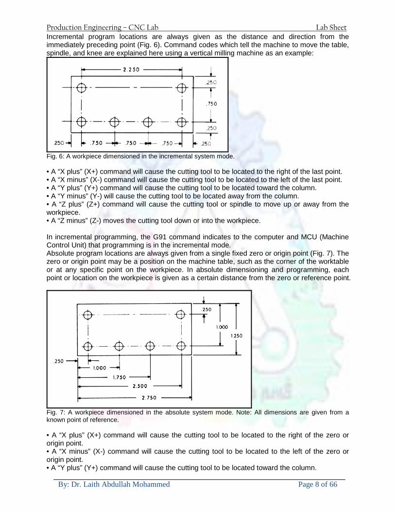
Production Engineering ndash CNC Lab Lab Sheet
By Dr Laith Abdullah Mohammed Page 8 of 66
Incremental program locations are always given as the distance and direction from the immediately preceding point (Fig 6) Command codes which tell the machine to move the table spindle and knee are explained here using a vertical milling machine as an example
Fig 6 A workpiece dimensioned in the incremental system mode bull A ldquoX plusrdquo (X+) command will cause the cutting tool to be located to the right of the last point bull A ldquoX minusrdquo (X-) command will cause the cutting tool to be located to the left of the last point bull A ldquoY plusrdquo (Y+) command will cause the cutting tool to be located toward the column bull A ldquoY minusrdquo (Y-) will cause the cutting tool to be located away from the column bull A ldquoZ plusrdquo (Z+) command will cause the cutting tool or spindle to move up or away from the workpiece bull A ldquoZ minusrdquo (Z-) moves the cutting tool down or into the workpiece In incremental programming the G91 command indicates to the computer and MCU (Machine Control Unit) that programming is in the incremental mode Absolute program locations are always given from a single fixed zero or origin point (Fig 7) The zero or origin point may be a position on the machine table such as the corner of the worktable or at any specific point on the workpiece In absolute dimensioning and programming each point or location on the workpiece is given as a certain distance from the zero or reference point
Fig 7 A workpiece dimensioned in the absolute system mode Note All dimensions are given from a known point of reference bull A ldquoX plusrdquo (X+) command will cause the cutting tool to be located to the right of the zero or origin point bull A ldquoX minusrdquo (X-) command will cause the cutting tool to be located to the left of the zero or origin point bull A ldquoY plusrdquo (Y+) command will cause the cutting tool to be located toward the column
Production Engineering ndash CNC Lab Lab Sheet
By Dr Laith Abdullah Mohammed Page 9 of 66
bull A ldquoY minusrdquo (Y-) command will cause the cutting tool to be located away from the column In absolute programming the G90 command indicates to the computer and MCU that the programming is in the absolute mode Point-to-Point or Continuous Path CNC programming falls into two distinct categories (Fig 8) The difference between the two categories was once very distinct Now however most control units are able to handle both point-to-point and continuous path machining A knowledge of both programming methods is necessary to understand what applications each has in CNC
Fig 8 Types of CNC positioning systems Point-to-Point Positioning Point-to-point positioning is used when it is necessary to accurately locate the spindle or the workpiece mounted on the machine table at one or more specific Locations to perform such operations as drilling reaming boring tapping and punching (Fig9) Point-to-point positioning is the process of positioning from one coordinate (XY) position or location to another performing the machining operation and continuing this pattern until all the operations have been completed at all programmed locations
Fig 9 The path followed by point-to-point positioning to reach various programmed points (machining locations) on the XY axis
Production Engineering ndash CNC Lab Lab Sheet
By Dr Laith Abdullah Mohammed Page 10 of 66
In Fig 9 point 1 to point 2 is a straight line and the machine moves only along the X axis but points 2 and 3 require that motion along both the X and Y axes takes place As the distance in the X direction is greater than in the Y direction Y will reach its position first leaving X to travel in a straight line for the remaining distance A similar motion takes place between points 3 and 4 Continuous Path (Contouring) Contouring or continuous path machining involves work such as that produced on a lathe or milling machine where the cutting tool is in contact with the workpiece as it travels from one programmed point to the next Continuous path positioning is the ability to control motions on two or more machine axes simultaneously to keep a constant cutter-workpiece relationship The programmed information in the CNC program must accurately position the cutting tool from one point to the next and follow a predefined accurate path at a programmed feed rate in order to produce the form or contour required (Fig 10)
Fig 10 Types of contour machining (A) Simple contour (B) complexe contour
Interpolation The method by which contouring machine tools move from one programmed point to the next is called interpolation This ability to merge individual axis points into a predefined tool path is built into most of todayrsquos MCUs There are five methods of interpolation linear circular helical parabolic and cubic All contouring controls provide linear interpolation and most controls are capable of both linear and circular interpolation Helical parabolic and cubic interpolation are used by industries that manufacture parts which have complex shapes such as aerospace parts and dies for car bodies Linear Interpolation Linear Interpolation consists of any programmed points linked together by straight lines whether the points are close together or far apart (Fig 11) Curves can be produced with linear interpolation by breaking them into short straight-line segments This method has limitations because a very large number of points would have to be programmed to describe the curve in order to produce a contour shape A contour programmed in linear interpolation requires the coordinate positions (XY positions in two-axis work) for the start and finish of each line segment Therefore the end point of one line or segment becomes the start point for the next segment and so on throughout the entire program
Production Engineering ndash CNC Lab Lab Sheet
By Dr Laith Abdullah Mohammed Page 11 of 66
Fig 11 An example of two-axis linear interpolation Circular Interpolation The development of MCUs capable of circular interpolation has greatly simplified the process of programming arcs and circles To program an arc (Fig 12) the MCU requires only the coordinate positions (the XY axes) of the circle center the radius of the circle the start point and end point of the arc being cut and the direction in which the arc is to be cut (clockwise or counterclockwise) See Fig 12
Fig 12 For two-dimensional circular interpolation the MCU must be supplied with the XY axis radius start point end point and direction of cut
Programming Format Word address is the most common programming format used for CNC programming systems This format contains a large number of different codes that transfers program information from the part print to machine servos relays micro-switches etc to manufacture a part These codes which conform to EIA (Electronic Industries Association) standards are in a logical sequence called a block of information Each block should contain enough information to perform one machining operation Word Address Format Every program for any part to be machined must be put in a format that the machine control unit can understand The format used on any CNC machine is built in by the machine tool builder and is based on the type of control unit on the machine A variable-block format which uses words (letters) is most commonly used Each instruction word consists of an address character such as X Y Z G M or S Numerical data follows this address character to identify a specific function such as the distance feed rate or speed value The address code G90 in a program
Production Engineering ndash CNC Lab Lab Sheet
By Dr Laith Abdullah Mohammed Page 12 of 66
tells the control that all measurements are in the absolute mode The code G91 tells the control that measurements are in the incremental mode Codes The most common codes used when programming CNC machines tools are G-codes (preparatory functions) and M codes (miscellaneous functions) Other codes such as F S D and T are used for machine functions such as feed speed cutter diameter offset tool number etc G-codes are sometimes called cycle codes because they refer to some action occurring on the X Y andor Z axis of a machine tool The G-codes are grouped into categories such as Group 01 containing codes G00 G01 G02 G03 which cause some movement of the machine table or head Group 03 includes either absolute or incremental programming while Group 09 deals with canned cycles A G00 code rapidly positions the cutting tool while it is above the workpiece from one point to another point on a job During the rapid traverse movement either the X or Y axis can be moved individually or both axes can be moved at the same time Although the rate of rapid travel varies from machine to machine it ranges between (5 and 20 mmin)
Fig 13 The functions of a few common G-codes The G01 G02 and G03 codes move the axes at a controlled feedrate bull G01 is used for straight-line movement (linear interpolation) bull G02 (clockwise) and G03 (counterclockwise) are used for arcs and circles (circular interpolation)
Production Engineering ndash CNC Lab Lab Sheet
By Dr Laith Abdullah Mohammed Page 13 of 66
Fig 14 Some of the most common G-codes used in CNC programming M or miscellaneous codes are used to either turn ON or OFF different functions which control certain machine tool operations M-codes are not grouped into categories although several codes may control the same type of operations such as M03 M04 and M05 which control the machine tool spindle bull M03 turns the spindle on clockwise bull M04 turns the spindle on counterclockwise bull M05 turns the spindle off
Production Engineering ndash CNC Lab Lab Sheet
By Dr Laith Abdullah Mohammed Page 14 of 66
Fig 15 The functions of a few common M-codes
Production Engineering ndash CNC Lab Lab Sheet
By Dr Laith Abdullah Mohammed Page 15 of 66
Fig 16 Some of the most common M-codes used in CNC programming Block of Information CNC information is generally programmed in blocks of five words Each word conforms to the EIA standards and they are written on a horizontal line If five complete words are not included in each block the machine control unit (MCU) will not recognize the information therefore the control unit will not be activated Using the example shown in Fig 17 the five words are as follows N001 represents the sequence number of the operation G01 represents linear interpolation X12345 will move the table 12345 in in a positive direction along the X axis Y06789 will move the table 06789 in along the Y axis M03 Spindle on CW
Fig 17 A complete block of information consists of five words
Production Engineering ndash CNC Lab Lab Sheet
By Dr Laith Abdullah Mohammed Page 16 of 66
Programming for Positioning Before starting to program a job it is important to become familiar with the part to be produced From the engineering drawings the programmer should be capable of planning the machining sequences required to produce the part Visual concepts must be put into a written manuscript as the first step in developing a part program Fig 18 It is the part program that will be sent to the machine control unit by the computer tape diskette or other input media The programmer must first establish a reference point for aligning the workpiece and the machine tool for programming purposes The manuscript must include this along with the types of cutting tools and work-holding devices required and where they are to be located
Fig 18 The first step in producing a CNC program is to take the information from the print and produce a program manuscript Dimensioning Guidelines The system of rectangular coordinates is very important to the successful operation of CNC machines Certain guidelines should be observed when dimensioning parts for CNC machining The following guidelines will insure that the dimensioning language means exactly the same thing to the design engineer the technician the programmer and the machine operator 1 Define part surfaces from three perpendicular reference planes 2 Establish reference planes along part surfaces which are parallel to the machine axes 3 Dimension from a specific point on the part surface 4 Dimension the part clearly so that its shape can be understood without making mathematical calculations or guesses 5 Define the part so that a computer numerical control cutter path can be easily programmed
Production Engineering ndash CNC Lab Lab Sheet
By Dr Laith Abdullah Mohammed Page 17 of 66
Machine Zero Point The machine zero point can be set by three methodsmdashby the operator manually by a programmed absolute zero shift or by work coordinates to suit the holding fixture or the part to be machined MANUAL SETTING - The operator can use the MCU controls to locate the spindle over the desired part zero and then set the X and Y coordinate registers on the console to zero
Fig 19 The relationship between the part zero and the machine system of coordinates ABSOLUTE ZERO SHIFT - The absolute zero shift can change the position of the coordinate system by a command in the CNC program The programmer first sends the machine spindle to home zero position by a G28 command in the program Then another command (G92 for absolute zero shift) tells the MCU how far from the home zero location the coordinate system origin is to be positioned Fig 19 The sample commands may be as follows N1 G28 X0 Y0 Z0 (sends spindle to home zero position) N2 G92 X4000 Y5000 Z6000 (the position the machine will reference as part zero)
Production Engineering ndash CNC Lab Lab Sheet
By Dr Laith Abdullah Mohammed Page 18 of 66
Work Settings and Offsets All CNC machine tools require some form of work setting tool setting and offsets (compensation) to place the cutter and work in the proper relationship Compensation allows the programmer to make adjustments for unexpected tooling and setup conditions
Work Coordinates In absolute positioning work coordinates are generally set on one edge or corner of a part and all programming is generally taken from this position In Fig 20 the part zero is used for all positioning for hole locations 1 2 and 3
Fig 20 In absolute programming all dimensions must be taken from the XY zero at the top left-hand corner of the part
Fig 21 In incremental programming all dimensions are taken from the previous point In incremental positioning the work coordinates change because each location is the zero point for the move to the next location Fig 21
Production Engineering ndash CNC Lab Lab Sheet
By Dr Laith Abdullah Mohammed Page 19 of 66
On some parts it may be desirable to change from absolute to incremental or vice versa at certain points in the job Inserting the G90 (absolute) or the G91 (incremental) command into the program at the point where the change is to be made can do this
R Plane or Gage Height The word-address letter R refers to a partial retraction point in the Z axis to which the end of the cutter retracts above the work surface to allow safe table movement in the X Y axes It is often called the rapid-traverse distance gage height retract or work plane The R distance is a specific height or distance above the work surface and is generally 100 in above the highest surface of the workpiece Fig 22 which is also known as gage height Some manufacturers build a gage height distance of 100 in into the MCU (machine control unit) and whenever the feed motion in the Z axis is called for 100 in will automatically be added to the depth programmed When setting up cutting tools the operator generally places a 100 in thick gage on top of the highest surface of the workpiece Each tool is lowered until it just touches the gage surface and then its length is recorded on the tool list Once the gage height has been set it is not generally necessary to add the 100 in to any future depth dimensions since most MCUs do this automatically
Fig 22 Using a 100 in gage block to set the gage height or R0 on the work surface
Cutter Diameter Compensation Cutter diameter compensation (CDC) changes a milling cutterrsquos programmed centerline path to compensate for small differences in cutter diameter On most MCUs it is effective for most cuts made using either linear or circular interpolation in the X-Y axis but does not affect the programmed Z-axis moves Usually compensation is in increments of 0001 in up to +10000 in and usually most controls have as many CDCs available as there are tool pockets in the tool storage matrix The advantage of the CDC feature is that it 1 Allows the use of cutters that have been sharpened to a smaller diameter 2 Permits the use of a larger or smaller tool already in the machinersquos storage matrix 3 Allows backing the tool away when roughing cuts are required due to excessive material present 4 Permits compensation for unexpected tool or part deflection if the deflection is constant throughout the programmed path The basic reference point of the machine tool is never at the cutting edge of a milling cutter but at some point on its periphery If a 1000 in diameter end mill is used to machine the edges of a workpiece the programmer would have to keep a 500 in offset from the work surface in order to cut the edges accurately Fig 23 The 500 offset represents the distance from the centerline of the cutter or machine spindle to the edge of the part Whenever a part is being machined the programmer must calculate an offset path which is usually half the cutter diameter
Production Engineering ndash CNC Lab Lab Sheet
By Dr Laith Abdullah Mohammed Page 20 of 66
Fig 23 Cutter-diameter compensation must be used when machining with various size cutters Modern MCUs which have part surface programming automatically calculate centerline offsets once the diameter of the cutter for each operation is programmed Many MCUs have operator-entry capabilities which can compensate for differences in cutter diameters therefore an oversize cutter or one that has been sharpened can be used as long as the compensation value for oversize or undersize cutters is entered
Production Engineering ndash CNC Lab Lab Sheet
By Dr Laith Abdullah Mohammed Page 21 of 66
CNC Programming Hints - MILLING
Production Engineering ndash CNC Lab Lab Sheet
By Dr Laith Abdullah Mohammed Page 22 of 66
CNC Programming Hints ndash TURNING
Production Engineering ndash CNC Lab Lab Sheet
By Dr Laith Abdullah Mohammed Page 23 of 66
CNC
The abbreviation CNC stands for Computer(ized) Numerical(ly) Control(led) and refers specifically to the computer control of machine tools for the purpose of (repeatedly) manufacturing complex parts in metal as well as other materials using a program written in a notation conforming to the EIA-274-D standard and commonly called G-code
CNC was developed in the late 1940s and early 1950s by the MIT Servomechanisms Laboratory CNC machines were relatively briefly preceded by the less advanced NC or Numerical(ly) Control(led) machines The introduction of CNC machines radically changed the manufacturing industry Curves are as easy to cut as straight lines complex 3-D structures are relatively easy to produce and the number of machining steps that required human action have been dramatically reduced With the increased automation of manufacturing processes with CNC machining considerable improvements in consistency and quality have been achieved CNC automation reduced the frequency of errors and provided CNC operators with time to perform additional tasks
CNC automation also allows for more flexibility in the way parts are held in the manufacturing process and the time required to change the machine to produce different components In a production environment a series of CNC machines may be combined into one station commonly called a cell to progressively machine a part requiring several operations CNC machines today are controlled directly from files created by CAM software packages so that a part or assembly can go directly from design to manufacturing without the need of producing a drafted paper drawing of the manufactured component In a sense the CNC machines represent a special segment of industrial robot systems as they are programmable to perform many kinds of machining operations (within their designed physical limits like other robotic systems)
G-code
G-code is a common name for the programming language that is used for NC and CNC machine tools It is defined in EIA RS-274-D G-code is also the name of any word in a CNC program that begins with the letter G and generally is a code telling the machine tool what type of action to perform such as
bull rapid move bull controlled feed move in straight line or arc bull series of controlled feed moves that would result in a hole being drilled bull change a pallet bull Set tool information such as offset
There are other codes the type codes can be thought of like registers in a computer
X position Y position Z position M code (another action register) F feed rate S spindle speed N line number R Radius T Tool selection
Production Engineering ndash CNC Lab Lab Sheet
By Dr Laith Abdullah Mohammed Page 24 of 66
I Arc data X axis J Arc data Y axis
G-code files are output by CAM software such as Smartcam Gibbscam Featurecam Edgecam Mastercam etc G-code is also output by specialized CAD systems used to design printed circuit boards Such software must be customized for each type of machine tool that it will be used to program
Production Engineering ndash CNC Lab Lab Sheet
By Dr Laith Abdullah Mohammed Page 25 of 66
U 2عمل األزرار الرئيسية في ماكنة الخراطة المبرمجة (نصر (
1- SINGLE BLOCK للتأكد من صحة البرنامج (تنفيذ البرنامج خطوة خطوةب تقوم( 2- BLOCK DELETE بجانب ويعمل من األوامرلغاء بلوك معين أليستخدم 3- MACHINE LOCK العمل يستخدم لقفل حركة المحاور الرئيسية مع استمرار البرنامج في
)وهذا مهم للتاكد من صحة البرنامج قبل عملية التنفيذ النهائي(4- CONT CYCLE عملية التشغيل عند ايقافها الي سبب كان او عند ايقافها ألستئناف ستخدم ت
) BAR FEEDER(او في حالة استخدام ) FEED HOLDبسبب (5- DRY RUN وتستخدم لفحص البرنامج بعد ازالة الشغلة حركة سريعة للبرنامج 6- TURRET UP amp DOWN ) حركة حامل العدة TURRET الذي يحمل مجموعة من (
وهذا الزر يعمل مع الزر عكس عقرب الساعة او مع عقرب الساعة ةحركة دوراني العدد )SAFTY (
7- COOLANT ON or OFFفه تشغيل سائل التبريد او ايقا 8- COOLANT AUTO الدوال المساعدة في البرنامج من خالل فه تشغيل سائل التبريد او ايقا 9 -MACHINE START ة لتشغيل هيدرولكيك الماكنميستخد
Production Engineering ndash CNC Lab Lab Sheet
By Dr Laith Abdullah Mohammed Page 26 of 66
10- CLOSE OR OPEN CHUCKالعينة تستخدم لفتح وغلق 11 -T STOCK FWD RET حركة الغراب المتحرك ذهابا وإيابا12 -SPINDLE STOP تعمل على ايقاف حركة دوران العينة 13-JOG SPINDLE تعمل على تدوير العينة مع زر SAFTY 14 -OPT SAFTY مع الدالة ( تعمل عمل التوقف المشروط حيث تعملM1 دالة التوقف (
ط ) فقط األ اذا كان هذا الزر مضغو M1المشروط حيث ال يتوقف البرنامج في حالة وجود دالة ( SAFTY + SPINDLE ) يتم الضغط على زر ( START CYCLEلغرض تحرير زر (
START ) في نفس الوقت بعد الضغط على زر ( START CYCLE مرتين (
NC PC- 15 يستخدم هذا الزر عند ربطCNC يستخدم لنقل المعلومات ث مع جهاز أخر حي بينهما
16 -CALCU زر الخاص بالحاسبة مع زر ( ال وهوINPUT ( 17 - HD1 HD2 يستخدم الختيار العدة مع المخرطة ذات المحاور األربعة 18 - START تستخدم لبدء عملية التشغيل
Production Engineering ndash CNC Lab Lab Sheet
By Dr Laith Abdullah Mohammed Page 27 of 66
19- FEED HOLD تعمل على إيقاف عمل أي G موجودة مع بقاء العينة متحركة 20- M D I أو تشغيل البرنامج ل يتم استخدامه لإلدخا BLOCK BY BLOCK وتعمل عند
إدخال البرنامج بواسطة الشريط المثقب أو أي وسيلة إدخال أخرى أو في عمليات التصفير
21- REST تستخدم العادة تشغيل الماكنة أو مسح اإلنذار الذي يظهر على الشاشة 22- EMERGENCYتستخدم عادة اليقاف الماكنة في حالة الطوارئ فقط
OPERATION MENU KEY
CHAPTER PRG-CMK
OFFSET PROGRAM POSITION FUNCTION MENU KEY
23- POSITIONعلى الشاشة د الموقع الموجور الظها 24- PROGRAMإلظهار برنامج معين واختياره 25- OFFSET الختيار سماحات العدة أو سماحات نقطة المرجع 26- PRG- CHK تستخدم لفحص البرنامج على الشاشة 27- SETTING ألختيار الثوابت على الشاشة 28- SERVICE تستخدم ألستخراج المعامالت والثوابت 29- MESSAGE تستخدم ألظهار األخطاء الناتجة عن البرنامج او اخطاء التشغيل 30- OVERALL ألختيار المواقع 31- RELATIVE MODLINE تعوض عن POSITION 32- DIR MEM يستخدم ألظهار ملف البرامج المخزونة في الذاكرة وعندما نضغط هذا الزر
فان رقم واسم البرنامج سوف يظهر على الشاشة
2أدناه الشفرات الرئيسية التي تعمل على الماكنة المبرمجة نصر
G-CODE DESCRIPTION
G00 Rapid traverse (linear)
G01 Linear Interpolation at feed rate
G02 Circular interpolation (CW) R+
G03 Circular interpolation (CCW) R+
G10 Zero point tools
G20 Imperial data input
G21 Metric data input
G27 Reference return check
G28 Reference return
G29 Return from reference
Production Engineering ndash CNC Lab Lab Sheet
By Dr Laith Abdullah Mohammed Page 28 of 66
G33 Thread cutting
G40 Cancel cutter radius compensation
G41 Cutter compensation left
G42 Cutter compensation right
G54 Work co-ordinate system no1
G70 Finishing cycle
G71 Stock removal turning
G72 Stock removal facing
G74 Face grooving
G75 Diameter grooving
G76 Threading cycle
G90 Absolute date input
G91 Incremental data input
G94 Feed minute mode
G95 Feed rev mode
G96 Constant surface speed mode
G97 Cancel Constant surface speed
) 2أدناه الشفرات الثانوية التي تعمل على الماكنة المبرمجة (نصر
M-code FUNCTION
M00 Program stop
M03 Spindle forward (Tool forward ndash M94 mode)
M04 Spindle reverse (Tool forward ndash M94 mode)
M05 Spindle stop (Tool stop ndash M94 mode)
M08 Coolant on
M09 Coolant off
M30 Program end (with rewind)
M48 Turret shortest path
M52 Turret direction up (CW)
M53 Turret direction down (CCW)
M73 Chuck open
M74 Chuck close
Production Engineering ndash CNC Lab Lab Sheet
By Dr Laith Abdullah Mohammed Page 29 of 66
) وكل جملة مكونة من مجموعة من الكلمات blockإن كل برنامج يتكون من مجموعة من الجمل ()words) لهذا فأن الشفرات الرئيسية والمساعدة هي عبارة عن كلمات (words كما في المثال التالي (
G_ _ P1 Q2 U_ _ W_ _ D___ F_ _
)end of block) ويعني ( ) يكتب الرمز (blockتسلسل الكلمات مهم جدا بعد نهاية كل جملة (
طريقة ادخال البيانات الى الماكنة ــــــــــــــــــــــــــــــــــــــــــــــــــ
) MDIيمكن ادخال البيانات الى الماكنة بعدة طرق فقد يكون األدخال عن طريق قناة السيطرة ( MANUAL DATA INPUT ) او عن طريق قناة األضافة EDIT كما يمكن ادخال البيانات عن (
) RS ndash 232 COMMUNICATIN LINKطريق استخدام سلسلة الربط (
₤⅗₌⅗₌ ⅙₌₨image₍₡ ₤₌ℌ⅗₌ Ⅸ⅗ⅥⅯ₌ ₤₡ℌ₰₨⅗₌G71
الخراطة الطولية G71الغرض من التجربة عمل نموذج للخراطة بأستخدام الدالة تستعمل هذه الدالة للخراطة الطولية اي على طول محور المشغولة وكما هو موضح بالشكل ادناه
تعتبر هذه الدالة من الدوال التي ال تحتاج الى تكرار او إعادة كتابتها أي انها دالة تكرارية بمعنى ان اي
الذي هي دالة حركة G01خطوة تكون من ضمن هذه الدالة سوف تكرر العملية اي عند استعمال امر مثل خطية تتضمن القطع مع التغذية مع اعطاء القطر المراد قطعه و مراعاة عمق القطع المعطى سوف يتكرر
هذه االمر وصوال الى العمق المطلوب وهكذا لبقية الدوال
G71 المستخدمة للدالة الصيغة
G71 P1 Q2 U___ W___ D___ F___ حيث إن
P1 بداية الخطوة االولى = Q2 نهاية الخطوة =
Uوضع السماحات بأتجاه محور = X W وضع السماحات بأتجاه محور = Z وتكاد تكون مهملة وتوضع اشارة سالب Dعمق القطع وتوضع رقم صحيح مثل = D500 اي نصف ملمF التغذية والتي لها عالقة بالدالة = G95
Production Engineering ndash CNC Lab Lab Sheet
By Dr Laith Abdullah Mohammed Page 30 of 66
G71الدالة استخدام مثال على
T0100 M48 G0 X26 Z2 M08 T0101 G90 G95 G97 S500 M03 G71 P1 Q2 U03 W00 D500 F01 N1 G0 G42 X00 G01 Z00 G01 X2517 G01 Z-5352 G01 X7391 Z-9366 G01 Z-19145 N2 G28 M30
الجانب العملي
االجهزة واالدوات المستخدمة CNCماكنة خراطة مبرمجة 1 ملم 80قضيب من االلمنيوم قطر 2 ةفير ني 3 جاه أيمن تهولدر كاربيدي ذوا 4
طريقة العمل يتم تثبيت قضيب من االلمنيوم على العينة التابعة للماكنة مع مراعاة الطول المراد استعماله في عملية 1
الخراطة ) turretتثبيت عدة القطع في المكان الصحيح في ( 2
Production Engineering ndash CNC Lab Lab Sheet
By Dr Laith Abdullah Mohammed Page 31 of 66
بالنسبة الى القطعة المثبتة على العينة XZيتم تصفير الماكنة للمحاور 3 تصفير للمحورZ تكون مالمسة العدة الى وجه الشغلة تصفير للمحورX تكون مالمسة العدة الى سطح الشغلة الموازي لمحور X
يتم كتابة البرنامج أما بطريقة يدوية أو بالحاسوب مع وضع كل الظروف الالزمة للتشغيل ( عمق القطع 4 التغذية السرعة المطلوبة نوع المعدن )
ادخال البرنامج الى الحاسوب الموجود داخل الماكنة مع تهيئة الماكنة للتشغيل 5
المطلوب G71عمل برنامج يدوي على الدالة 1 رسم الشكل الشكل النهائي المطلوب مع وضع األبعاد 2
Ⅺ⅟₍euro⅗₌ ₤₡ℌ₰₨⅗₌₣ ₤⅗₌⅗₌ ⅙₌₨image₃₡ Ⅺℂtradeℒ⅗₌ ӈ₍Ⅴ⅟ⅳ₌ G70
G70 الغرض من التجربة عمل انهاء سطحي للمشغولة بواسطة الدالة
من الضروري إعطاء G71هذه الدالة تعمل شوط واحد فقط وتكون معتمدة على عمليات القطع في الدالة اللغاء مقدمة االداة (أي لكي تتم عملية االنهاء السطحي بدون حسابات نصف قطر مقدمة االداة ) G42دالة
G70الصيغة المستخدمة للدالة
G70 P1 Q2 F___ حيث ان
P1 بداية الخطوة االولى = Q2 نهاية الخطوة =
F التغذية والمرتبطة بالدالة = G95
وذلك ألن دالة االنهاء السطحي تحقق X Zمالحظة الدالة التحتاج لكتابة السماحات التابعة للمحورين المسافات الحقيقة المراد انتاجها للمشغولة
G71و G70مثال على الدالة
T0100 M48 G0 X26 Z2 M08 T0101 G90 G95 G97 S500 M03 G71 P1 Q2 U03 W00 D500 F01 N1 G0 G42 X00 G01 Z00 G01 X2517 G01 Z-5352 G01 X7391 Z-9366 G01 Z-19145 N2 G97 S750 MO3
Production Engineering ndash CNC Lab Lab Sheet
By Dr Laith Abdullah Mohammed Page 32 of 66
G70 P1 Q2 G40 F009 G28 M30
الجانب العملي الحظ التجربة األولى
المطلوب
G70 عمل برنامج يدوي على الدالة 1 رسم الشكل النهائي المطلوب مع وضع االبعاد 2
₪⅗₍euro⅗₌ ₤₡ℌ₰₨⅗₌₣ ₤⅗₌⅗₌ ⅙₌₨image₍₡ ⅝₍ⅠimageⅯ₌ ⅞ⅫⅦ⅔₧ G76
G76 للمشغولة بواسطة الدالةةالغرض من التجربة عمل أسنان خارجية أو داخلي
في هذه التجربة سوف نقوم بعمل األسنان الخارجية وهنا تكون حركة العينة ثابتة وهذا ضروري بسبب أن ) تكون متصلتين الكترونيا وعليه أي اختالف في سرعة العينة تؤدي إلى اختالف motionالعينة والحركة(
) servoفي سرعة الخدمة(يرتبط اتجاه تكوين األسنان باتجاه دوران العينة مثال إذا كانت األسنان ذات اتجاه أيمن يكون اتجاه دوران
وهنا نقلب العدة إلى االسفل وكما هو موضح بالشكل أدناه MO3العينة عكس عقرب الساعة أي نستعمل
Production Engineering ndash CNC Lab Lab Sheet
By Dr Laith Abdullah Mohammed Page 33 of 66
الخطوة هي عبارة عن المسافة ما بين قمة سن إلى قمة سن أخر عمق السن هو العمق المطلوب تكوينه لألسنان
G76 الصيغة المستخدمة للدالة
G76 X___ Z___ K___ F___ D___ A___
حيث أن X القطر الداخلي للسن =Z طول السن =K عمق السن وتستخرج من المعادلة التالية =K=065F F الخطوة =D عمق القطع بالمايكرون فقط =A زاوية السن =
G76مثال على استخدام الدالة T0300 M48 GOO X30 Z4 T0303 M08 G97 S500 MO3 G76 X28375 Z-20 K08125 F125 D120 G00 X40 Z4 G28 M30
Production Engineering ndash CNC Lab Lab Sheet
By Dr Laith Abdullah Mohammed Page 34 of 66
الجانب العملي الحظ التجربة األولى
المطلوب
G76عمل برنامج يدوي على الدالة 1 رسم الشكل النهائي المطلوب مع وضع األبعاد 2
Ⅺ⅘₌⅗₌ Ⅵ₂ Ⅺ₯ℋ₍⅗₌ ℌℲℂ⅗₌ ⅞ⅫⅦ⅔₧ ₤K₡₌ℌ⅗₌ ₤₡ℌ₰₨⅗₌)Groove ₤⅗₌⅗₌ ₤tradeimage₌Ⅶ₡ (G75
G75 بواسطة الدالة grooveالغرض من التجربة تكوين
) للمشغولة وتعتمد شكل الحفر على طريقة grooveتستعمل هذه الدالة لتكوين الحفر الخارجي والداخلي (
التشغيل وعلى الشكل المراد إنتاجه وتعتبر هذه الطريقة من عمليات التشكيل للمعدن إن هذه الدالة هي دالة مالحظة مع G75في هذه التجربة سنقوم بعمل الحفر الخارجي بواسطة الدالة
تكرارية وغير تكرارية حسب نوع التشغيل
G 75 الصيغة المستخدمة للدالةG75 X___ Z___ I___ K____
حيث أن
X العمق النهائي لقطر الشغلة =Z عرض الحفر =I الدخول في كل مرة =
K التزحيف على محور =z بالنسبة للعدة
Production Engineering ndash CNC Lab Lab Sheet
By Dr Laith Abdullah Mohammed Page 35 of 66
G75مثال على استخدام الدالة
T0500 M48 GOO X100 Z -20 T0505 M08 G97 S700 MO3 G75 X84 Z -38 I 05 K4
الجانب العملي الحظ التجربة األولى
المطلوب
G76عمل برنامج يدوي على الدالة 1 رسم الشكل النهائي المطلوب مع وضع األبعاد 2
Production Engineering ndash CNC Lab Lab Sheet
By Dr Laith Abdullah Mohammed Page 36 of 66
CNC Milling Machine Mechanical Construction
Guideways The guideways of CNC machines are made of steel To reduce the frictional forces they are coated with a strip of PTFE (Poly Tetra Fluoro Ethylene)
Ballscrews On conventional lathes a leadscrew is used to converts the rotary motion of the hand wheel into linear motion of the slides Leadscrews have a high coefficient of friction and backlash On CNC machines a ballscrew is used instead of a leadscrew Friction and backlash are much less than on leadscrews
Guideway
Production Engineering ndash CNC Lab Lab Sheet
By Dr Laith Abdullah Mohammed Page 37 of 66
bullMachining operations Direction of cutting Based on the direction of the cutter rotation and work piece feed milling operations are classified into two types 1-Up milling (Convention milling) In up milling the metal is removed by rotating the cutter against the direction of travel of the part
Feed
Machine table
Part
Cutting tool
Chip thickness at theexit of the tooth
2-Down milling (Climb milling) In climb milling the metal is removed by rotating the cutter with the direction of travel of the part
Machine table
Part
Cutting tool
Chip thickness at theentrance of the tooth
Production Engineering ndash CNC Lab Lab Sheet
By Dr Laith Abdullah Mohammed Page 38 of 66
bullTooling Tool geometry The geometry of the tool tip affects the way that the metal cutting is performed The nose radius rake angles relief angles etc must be selected with care
Radial relief
Radial rake
Axial relief
Approach angle
Axial relief
Corner radius Face mill Face milling cutters are used to mill flat surfaces Commonly used face milling cutters Cutter with 75 degree approach
75 deg
Cutter with 90 degree approach (Square shoulder face mill)
90 deg
Cutter with 45 degree approach
Production Engineering ndash CNC Lab Lab Sheet
By Dr Laith Abdullah Mohammed Page 39 of 66
bullCNC Programming Axes convention The Z axis is along the spindle axis The X and Y axes are perpendicular to Z VMC
Z
Y
-
+
-+
X- +
+Z
-Z
+Y
-Y
-X +X
Part
Machine table
X
YZ
G00 Rapid traverse When the tool being positioned at a point preparatory to a cutting motion to save time it is moved along a straight line at Rapid traverse at a fixed traverse rate which is pre-programmed into the machines control system Typical rapid traverse rates are 10 to 25 m min but can be as high as 80 mmin
Production Engineering ndash CNC Lab Lab Sheet
By Dr Laith Abdullah Mohammed Page 40 of 66
Format N_ G00 X__ Y__Z__
G01 Linear interpolation (feed traverse) The tool moves along a straight line in one or two axis simultaneously at a programmed linear speed the feed rate Format N__ G01 X__ Y__Z__ F__
Part
Feed
Part
Feed
G02G03 Circular interpolation The tool moves along an arc in two axes simultaneously at a programmed linear speed the feed rate
Production Engineering ndash CNC Lab Lab Sheet
By Dr Laith Abdullah Mohammed Page 41 of 66
Format N__ G0203 X__ Y__Z__ I__ J__K__ F__ using the arc center OR N__ G0203 X__ Y__Z__ R__ F__ using the arc radius G02 moves along a CW arc G03 moves along a CCW arc Arc center The arc center is specified by addresses I J and K I J and K are the X Y and Z co-ordinates of the arc center with reference to the arc start point
X
Y
Arc center
Arc endArc start
- J
- I
I = X coord of center - X coord of start point J = Y coord of center - Y coord of start point K = Z coord of center - Z coord of start point I J and K must be written with their signs
Production Engineering ndash CNC Lab Lab Sheet
By Dr Laith Abdullah Mohammed Page 42 of 66
bullWork holding
Rotary table
Fixture base
Component
Clamp
Stud
Fixtures The use of fixtures 1 Improves repeatability of dimensions 2 Improves working conditions 3 Cuts down requirement of skilled labour 4 Reduces part loading and unloading time 5 Improves safety in the working area 6 Reduces the cost of machining There are two types fixtures commonly used 1 Special fixture Special fixtures are used to hold and locate the typical components which are having complex shape and to be located with the reference hole (dowel hole) Special fixtures are required for components like gear case cover cylinder heads etc 2 Modular fixture Modular fixture is a set different kind of clamping and locating elements These fixtures are used to hold identical components in different sizes and components of box type Example Manifolds head stocks connecting rods and flanges
Production Engineering ndash CNC Lab Lab Sheet
By Dr Laith Abdullah Mohammed Page 43 of 66
bullMachine setting
Determining X and Y work zero offset Case 1
Part
Machine table
Part
End mill or reamer
Work offset X0Y0 For determining X work zero offset bull Touch the periphery of the end mill or reamer to the part bull Enter current machine X value + cutter radius as X work zero offset For determining Y work zero offset bull Touch the periphery of the end mill or reamer to the part bull Enter current machine Y value - cutter radius as Y work zero offset Case 2
Part
Machine table
Part
End mill or reamerWork offset X0Y0
bull Mount the dial indicator on machine spindle true the bore bull Enter current machine X and Y value as X and Y work zero offset
Production Engineering ndash CNC Lab Lab Sheet
By Dr Laith Abdullah Mohammed Page 44 of 66
How to Select a Cutting Fluid
One part of the metal cutting equation that is sometimes overlooked however is
the choice of an appropriate cutting fluid With todayrsquos system approach to metal
cutting use of the right metalworking fluid has become just as much a part of the
solution as the other elements In fact at least one company is now integrating
cutting fluids and cutting tools into effective metal cutting systems Following are
some things to consider when choosing your next cutting fluid
The Four Key Questions
There are four vital pieces of information that are necessary when choosing a
cutting fluid They are
1 What are you cutting
2 What is the chemistry of your water
3 What are you using now
4 What are your options
5 What do you prefer
What Are You Cutting
The first question ndash ldquoWhat are you cuttingrdquo ndash is often the most difficult to answer
because most shops handle a variety of workpiece materials on a regular basis If
the answer is an unequivocal ldquoaluminumrdquo or ldquostainless steelrdquo or ldquocast ironrdquo the
selection of a cutting fluid can be quite simple and straightforward Unfortunately
that is seldom the case in anything but a high-volume plant Where aluminum or
other nonferrous metals are a significant part of the mix a non-staining cutting
fluid is a must Generally speaking this will be a semi-synthetic with special
ingredients to prevent bi-metallic corrosion and staining of non-ferrous workpieces
Where the ferrous metals predominate however a more general purpose semi-
synthetic or hybrid fluid might be a more economical choice
Production Engineering ndash CNC Lab Lab Sheet
By Dr Laith Abdullah Mohammed Page 45 of 66
What is The Chemistry of Your Water
The second question ndash ldquoWhat is the chemistry of your waterrdquo ndash is probably the
single most common reason for the success or failure of a cutting fluid Very few
plants invest the money necessary to install effective water purification systems
using deionization or reverse osmosis technology Unfortunately the chemicals
present or not present in the water used to re-constitute a cutting fluid make a
tremendous difference in its performance and sump life Most manufacturers of
cutting fluids will perform the necessary water testing to determine exactly what
minerals are dissolved in your water and make a fluid recommendation based on
the results
What are you using now
The third question ndash ldquoWhat are you using nowrdquo ndash helps narrow the range of
choices When coupled with an objective analysis of the strengths and weaknesses
of the current fluid the answer to this question can quickly point you toward a
relatively small number of competitive alternatives that have the attributes required
to meet your cutting needs Many cutting fluids are in use today simply because
they were in use yesterday It is a hard reality of todayrsquos marketplace that if one
isnrsquot constantly striving to improve they will certainly be overtaken by a
competitor who is
What Are Your Options
The fourth question ndash ldquoWhat are your optionsrdquo ndash leads to the final selection of a
cutting fluid Cutting fluids can be divided into four general groups based on their
chemistry
They are
bull Soluble Oils ndash quite literally oil dispersed in water
bull Synthetics ndash completely oil free man-made coolants in solution
Production Engineering ndash CNC Lab Lab Sheet
By Dr Laith Abdullah Mohammed Page 46 of 66
bull Semi-Synthetics ndash a mixture of natural and synthetic lubricants with up to 30
mineral oil
bull Hybrids ndash a special class of semi-synthetics with a mineral oil content of about
15 Each fluid type has advantages and disadvantages which make it suitable for
a particular group of applications In addition there are costperformance trade-
offs to be made between the groups within a specific set of applications For
example where a hybrid and a semi-synthetic may both be suitable for a particular
use the hybrid might provide longer sump life at a slightly higher initial cost
while some semi synthetics may be more economical to recycle or dispose of while
not giving as long a tank life The final decision in this case would have to be made
on the detailed economics of the shop where the fluids were to be used and on the
ownerrsquos individual preferences
Soluble Oils
Soluble oils are oils that disperse in water when emulsifiers are added They are
generally suitable for moderate-to heavy-duty machining and grinding of all non-
ferrous metals carbon and cast steels and in applications where dissimilar metals
such as aluminium and steel are present They can also be used in turning drilling
tapping reaming gear cutting broaching as well as internal and centerless types
of grinding operations Soluble oils provide excellent aluminium and copper
corrosion control good rancidity control which extends fluid for long lasting
trouble-free performance and good concentrate and mix stability making it ideal
for mixing in water with a minimal amount of agitation An example of this is
Valenitersquos VNTreg-650 premium heavy-duty soluble oil
Synthetics
Synthetics are completely oil free solutions made of polymers organic and
inorganic materials that are mixed with water These clear low foaming and bio-
Production Engineering ndash CNC Lab Lab Sheet
By Dr Laith Abdullah Mohammed Page 47 of 66
stable coolants are ideal for machining and grinding of ferrous materials carbon
steels or cast iron Their complex lubricant packages make synthetics well-suited
for tough-to-machine materials such as stainless steels and high-temperature alloys
Certain synthetics are specifically designed to address the primary failure modes of
flank wear and nose wear Although there are many benefits some synthetics may
cause staining of non-ferrous materials
Semi-Synthetics
Semi-synthetic fluids are a mixture of oils synthetic emulsifiers and water They
were primarily developed for the aircraft nuclear and related industries
Consequently they work extremely well on all non-ferrous metals such as titanium
aluminium copper brass bronze and stainless steel in both machining and
grinding Semi-synthetics can be used on ferrous metals too They are chlorine-
free to reduce bi-metallic corrosion and staining of metals They should be used at
a 5-8 dilution with water depending on the severity of the operation
Hybrids
Hybrids are cutting fluids custom engineered to solve a particular problem For
example Valenitersquos VNTreg-800 was developed to be very clean in the machining
and grinding of cast iron It provides better stability in hard water and rejects tramp
oil very well which adds to its bio-stable chemistry Hybrids work extremely well
on all metals in both machining and grinding They should be mixed at a 5-7
dilution with water depending on the condition of the water
What Do You Prefer
The final question ndash ldquoWhat do you preferrdquo ndash is usually the ldquotie breakerrdquo where
there is more than one appropriate cutting fluid available Here again as in the
case of what is being used now the key is to examine your preferences objectively
Production Engineering ndash CNC Lab Lab Sheet
By Dr Laith Abdullah Mohammed Page 48 of 66
and specifically to identify the real reasons behind a preference If you cannot
point to specific reasons why one class of cutting fluid is preferred over another
you are well advised to follow the recommendations of the professional who has
analyzed your requirements Choosing the right fluid today is easier than ever as
the system approach to metal cutting productivity continues to grow in acceptance
The day is not far off when choosing a complete solution will be as easy as
choosing the right insert and chip breaker today The answers are available and the
results will more than justify the time you spend choosing the right metal cutting
fluid
Useful Links wwwball-screwsnet
wwwlubelinkcom
wwwmachinerylubricationcom
wwwadvancedmanufacturingcom
wwwmmsonlinecom
wwwcuttingtoolengineeringcom
wwwgeartechnologycom
wwwengineersedgecom
wwwagmaorg
wwwefundacom
wwwsaeorg
wwwsmeorg
wwwastmorg
wwwissorg
wwwmachinetoolscom
wwwansiorg
wwwasmeorg
wwwcnccicom
wwwmatlscom
wwwthefreedictionarycom
wwwengineersupplycom
Production Engineering ndash CNC Lab Lab Sheet
By Dr Laith Abdullah Mohammed Page 49 of 66
SurfCAM Tutorial ndash Beginning with the basics
Background SurfCAM is a computer aided manufacturing (CAM) software which allows you to create manage and modify tool paths for computer aided designed (CAD) part The software requires a CAD model or requires that you create some geometry within SurfCAM with some rudimentary tools provided The tool paths are created or stored internally in SurfCAM in a generic programming language called APT Once the tool paths are created the APT paths are translated using a post processor into typical machine G-code
Opening SurfCAM SurfCAM can be opened from the Novell Applications Launcher on most Industrial Engineering computer labs workstations Search under lsquoallrsquo applications and double click on SurfCAM 2005 Once the program opens a license must be selected from the list (not the Demo license) to enable saving the file later Choose one of the 30 licenses available If for some reason the licenses are not listed on the license manager form select server list and type ldquobonnieeosncsuedurdquo A list of available licenses should appear Select a license and click OK After the license is selected an Add StockFixture form (Figure 1) opens allows you to add a model which represents the pre-machined stock or a fixture Click on OK without adding either Both of these items can be added later under a more appropriate dialog
Figure 1 Add Stock or Fixture dialog box
Production Engineering ndash CNC Lab Lab Sheet
By Dr Laith Abdullah Mohammed Page 50 of 66
SurfCAM Interface
Figure 2 SurfCAM Windows based interface
SurfCAM is a windows based software system so most of the typical windows functions under File are applicable This is where you can open save exit print etc The Create menu allows the user to create different geometry forms Here you can create a point line surface chamfer circle and many other geometry types For the most part these functions are not used by beginners but are useful when creating bounding curves where you donrsquot want the tool to move outside (constraining the tool) The Edit menu allows you to change or modify many different entities such as changing lines altering surfaces joining surfaces trimming or breaking elements add control points etc Again these features are helpful to advanced users and are not covered in detail in this tutorial The Display menu offers the ability to change the orientation of the part on the screen The typical rotate pan fit to screen and zoom functions are available as well as several functions which allow the user to shift between views or call up a named view (ie top bottom etc) The NC menu is the main machining interface menu In this menu you select the general form of machining (2 axis 3 axis 4 axis 5 axis turning etc) and under the general form a more specific machining function is selected This menu is the most used and the options contained must be fully understood to get the most out of SurfCAM Each function will be described in some detail in a further chapter The Analyze menu contains options such as measuring the distance between points angles tangency elements etc These functions are auxiliary functions meant to help you understand the part better but basically provide no functionality for making tool paths for CNC machines Thus these will not be covered The Tools menu allows the user to change the system options modify keyboard shortcuts change the model units etc These options are again not used by beginners Finally the Help menu provides access to the online users manual In lieu of clicking the Help menu the F1 key is the shortcut key for help (as it is in most windows based programs)
Importing a CAD model Importing a CAD model that is stored locally is done by selecting File-gtOpen On the Files of type dropdown box choose the type of file you wish to open (Figure 3) Do this prior to negotiating your way through the maze of folders to prevent having to go through the folder tree again Once the file type is selected find the file you are trying to open and click the Open
Production Engineering ndash CNC Lab Lab Sheet
By Dr Laith Abdullah Mohammed Page 51 of 66
button SurfCAM will then attempt to read the file you have selected SurfCAM may provide a dialog box describing what it has imported and identify if it was successful If this dialog is provided simply click close without saving
Figure 3 Open Dialog Note - Change type of file prior to finding the file you wish to open
SurfCAM allows a user to import several different types of CAD files the most common types which you will likely import are SolidWorks part files (sldprt or prt) AutoCAD files(dxf) or IGES (igs or iges) Native file import (such as is the case with SolidWorks) provides the greatest information transfer and generic file imports (such as is the case with IGES) provide the least Normally it is to the advantage of the user to use native file importing procedures when available Recently (2005) SurfCAM added some compatibility with SolidWorks This allows the user to create tool paths for a part and if an engineering change is needed for the part update the part in SolidWorks When the part is then opened in SurfCAM the changes are noted and a simple update operation command is needed This however does not operate with complete transparency andor accuracy and thus users need to be cognizant of changing CAD models
SurfCAM Geometry In SurfCAM two basic types of geometry are used the surface and the point A surface (Figure 4) is a so called spline (NURBS or B-Spline are the two most common) surface (parameterized by two values u and v) such that every location on the surface can be defined as a function of these parameters In other words SurfCAM can calculate the location of any point on the
Production Engineering ndash CNC Lab Lab Sheet
By Dr Laith Abdullah Mohammed Page 52 of 66
surface Surfaces are used primarily in 3 4 and 5 axis machining and require a significant
amount of processing power and time Figure 4 Surfaces model of a mold half Note the difference between this and Figure 2 a wireframe model
Point or line based models are often referred to as wireframe (Figure 5) models because the models consist of connected lines and resemble the part only at the intersection of two surfaces Wireframe models were made popular lsquoback in the dayrsquo when computer processing was expensive There are times when each of the models are important and selecting model geometry when applying a SurfCAM operation will be much simpler if you understand the differences between the two When importing a SolidWorks model the default is both the surfaces and the wireframe geometry are imported
Figure 5 Wireframe model of the mold in Figure 1
Steps to Creating Tool Paths Once a CAD model is imported into SurfCAM tool paths can be created There is no one correct way to create tool paths however there is a set of general steps to take to ensure the tool paths are created with a minimum amount of hardship (note the wordinghellipHardship is inevitable when creating tool paths it is the intent of this manual to minimize this) The following is a list of steps which should be considered when making tool paths
Production Engineering ndash CNC Lab Lab Sheet
By Dr Laith Abdullah Mohammed Page 53 of 66
1 Plan ahead a Orient the part in SolidWorks such that if only one side is to be machined that
side is the Top view This can be done early in SolidWorks by choosing a plane parallel the X-Y plane as the sketch plane for the machined geometry
b Orient the part in SolidWorks such that the origin is somewhere of relative importance and someplace in space that can be easily identified when placed on the machine This is extremely important to minimize set up time at the machine (note ndash my personal preference for a part that is to be fully machined [ie stock exists on all sides] is to place the origin at the center and top of the parthellipjust my preference)
c Orient the part in SolidWorks such that the X and Y axes are aligned as you want them on the machinehellip
d Planning ahead will save you many hours of headaches laterhelliptrust me 2 Import the model 3 Choose a construction view such that the tool approaches the side to be machined
from the positive Z axis direction (as defined by part origin) a This is done by clicking on the CView icon
b From the list of named views chose the view which orients the origin as you would like
c If one of the views does not fit your criteria you have two choices i Perform a transformation of the part in SurfCAM or SolidWorks
ii Add a new construction view by selecting new This option requires a relatively good understanding of right hand coordinate frames but is very usefulhellipNormally used by more advanced users
d Be sure the CoordVIEW selection is made vs CoordWORLD This ensures the tools will be controlled from the coordinate frame selected by the view (ie the origin on the part) instead of the origin on the lower left corner of the screen This will be especially important when we get into 4 and 5 axis machining
4 In the Operations Manager (Figure 6) select Setup One and change the name to something meaningful ndash like Front Side Mold Cavity
a Access the Operations manager by right clicking or by selecting the Operations Manager icon in the tool bar
b Operations Manager is where the tool paths are managed once they are created as well as where individual tool paths can be verified
Production Engineering ndash CNC Lab Lab Sheet
By Dr Laith Abdullah Mohammed Page 54 of 66
5 Roughing Tool Paths a Create the tool paths to remove the majority of the material (if applicable) b Use NC-gt3Axis-gtZ rough or Plunge Rough c Described in next section
6 Create Finishing Tool Paths a Described in next section
7 Add another setup if necessary 8 Perform steps 3 through 6 as necessary 9 Verify the tool paths are correct 10 Use a post processor for the tool paths to create G-Code for machine
Creating Tool Paths The following is a list of operations what they are intended for how they generally work and some parameters that may be adjusted to modify the tool paths
2 Axis tool paths Unless otherwise noted 2 axis tool path functions require lines or arc segments as input parameters (as opposed to surfaces) There are several options as to how these segments are chosen the most prevalent is the chain option and the second most prevalent is the single When choosing the line segments using the chain option SurfCAM will try to link a complete path of segments based on an initial segment chosen by the user If the operation is planer (ie pocket or contour) the segments must lie on the same plane If the operation is non-planer (ie contour 3D) SurfCAM will prompt the user to specify segments when it encounters a branch point
Figure 6 Operations Manager view showing setup one re-labeled as Front Side Mold
Production Engineering ndash CNC Lab Lab Sheet
By Dr Laith Abdullah Mohammed Page 55 of 66
When using the single element option the user must manually choose each segment desired for the operation Note that most operations do not require a closed loop of segments you may specify for instance an open contour where the tool is supposed to move The order of choosing segments is important This order determines the path of the tool in the sense that if three segments are chosen such that the middle segment is chosen last there will be three different plunge and machine operations one on each segment If the operation was to make a continuous contour around the outside of the part the segments should be chosen in order of the desired tool trajectory
Operations
Pocket Pocket operation in SurfCAM is used to cut an enclosed space from the inside to the outside at one particular depth The operation starts in the center of an enclosed area (with a plunge move in the ndashZ direction) and makes incremental closed paths towards the pocket boundaries in user defined path offsets (Figure 7) The user chooses the boundary of the pocket (line segments) and if more than one pocket is chosen SurfCAM will ask the user to click inside a pocket
Figure 7 Two examples of using the pocketing operation
The pocket operation allows for creating a projection of the pocket paths on multiple planes This is useful if you have a deep pocket which will not allow the tool to cut directly at the depth of the pocket but would be easily done using the same paths at several different Z heights On the cut control (Figure 8) tab the user specifies where the chosen geometry (pocket segments) lie (ie bottom or top) Then under the amount to remove specify the total material height to be removed and the rough spacing (amount you wish to advance the Z axis with each pocket step) You may also specify a finishing pass and as well as stock to leave
Production Engineering ndash CNC Lab Lab Sheet
By Dr Laith Abdullah Mohammed Page 56 of 66
Figure 8 Example of Contour Operation with multiple passes
Contour Contouring in SurfCAM is used to perform peripheral milling on the inside or outside of a line segment (Figure 9) The user is to identify the line segments which define a contour (does not have to be a closed loop of segments) SurfCAM may or may not require the user to specify a side to contour (ie which side of the line is the tool to cut) For contouring each segment must lie on the same plane
Production Engineering ndash CNC Lab Lab Sheet
By Dr Laith Abdullah Mohammed Page 57 of 66
Figure 9 Examples of parts cut with 2-Axis Contour
Contour 3D Contour 3D is the same operation type as contour but allows the user to specify segments on different planes for the tool to cut along
Drill Drilling operations are any rotating tool operation meant to engage the part from a single direction ndash namely from the positive Z direction Drilling operations can be specified using circle point or line segments After choosing NC-gt2-Axis-gtDrill SurfCAM allows the user to choose multiple circles or points defining holes to be drilled Drilling operations also allow the user to incorporate more than 1 operation such as a center drill a drill and a reaming operation After selecting the locations for the drilling operation a dialog box (Figure 10) allows the user to add change or delete tools to be used in the operation As displayed in the following figure the spotdrill operation is followed by a drilling operation followed by a tapping operation The depth of each tool can be controlled individually by double clicking the total depth cell in and manually entering Tools can be added before or after operations which the cells are highlighted by selecting either of the insert buttons at the top or by the insert menu Select tool button allows the user to change the tool size or type
Production Engineering ndash CNC Lab Lab Sheet
By Dr Laith Abdullah Mohammed Page 58 of 66
Figure 10 Drill operation manager Several operations can be completed at one time
Figure 11 Drill operation including the spotdrill drill and tap as outlined in Fig 10
3 Axis tool paths SurfCAM requires surfaces as inputs for 3 Axis tool paths Surfaces can be created in SurfCAM but are most easily created in a CAD package and imported into SurfCAM Surfaces allow SurfCAM to identify every point on the surface in 3 dimensions unlike 2D geometry (wireframes) which only identify positions on the plane Creating tool paths with complex surfaces takes a very significant amount of processing power so expect 3 Axis tool path generation to take longer
Production Engineering ndash CNC Lab Lab Sheet
By Dr Laith Abdullah Mohammed Page 59 of 66
Operations
Cut 3 Axis cut operation takes a surface and using the flow lines creates a rastering path over the surface with the tool tip riding on the surface The primary direction will be defined by the flow lines of the surface (which can be edited by Edit-gtSurfaces-gtArrow-gtDirection) If you intend to cross surface boundaries you must merge the surfaces (Edit-gtJoin and choose the two surfaces)
Z-Rough The Z-rough operation is used to remove a large amount of material prior to finish machining Roughing operation is typically the first operation you perform for each setup The Z-Rough operation cuts the part in user defined intervals For each of these intervals a surface intersection between the part and the plane is performed and a 2D pocket or contour operation is performed on that plane This is performed on each plane When choosing NC-gt3 Axis-gtZ rough the first dialog box you will encounter asks for a bounding box to be defined Choose the Extents Box and a second dialog box will ask for the coordinates which define the box (Figure 12) This is the stock size you expect to machine the part from Input the coordinates or change the additional offset amounts (in XY or Z) as appropriate and click Calculate Bounding Box
Figure 12 Material Extents Box Example
Next choose the tool and cutting parameters that you desire and click on the Cut Control Tab (Figure 13) Here you will find the following parameters which are often changed Stock to
Production Engineering ndash CNC Lab Lab Sheet
By Dr Laith Abdullah Mohammed Page 60 of 66
leave ndash this is an offset amount from the surfaces which leaves a small amount of material to finish machine Minimum and Maximum Z values ndash Defines area to machine Z Step Size ndash This identifies the plane intervals for the surface intersection planes (the first interval will be at the top of the selected area and successive increments down in Z will be cut until the Minimum Z value is reached)
Figure 13 3Axis Z Rough Cut Control
The 3Axis Z-Finish operation works in exactly the same way 3 Axis Z-Finish is most appropriate for finishing vertical or near vertical walls
3D Offset The 3D Offset operation creates a tool path using a 2D or 3D boundary by offsetting the boundary in concentric offset cutting passes Each pass calculates the tool engagement and maintains the engagement somewhat constant The advantage (significant) is the scallop height ndash height of the material between passes ndash is controlled thus the surface finish is predictable When choosing 3D Offset surfaces are selected as well as 2D or 3D boundaries The boundaries define the concentric offset paths shape as well as limit the tool path area Choose NC-gt3Axis-gt3D Offset from the drop down menus SurfCAM will prompt you to select the surface or surfaces to cut across Select the surfaces you wish to machine and then select the tool and cutting parameters you wish use Next select the Cut Control Tab and check the Use Boundary Curves option Set the Step Type to Scallop and set the maximum scallop height If you like
Production Engineering ndash CNC Lab Lab Sheet
By Dr Laith Abdullah Mohammed Page 61 of 66
you can also add stock to leave if this is a roughing operation You can also set the Direction and Start-End parameters from this tab Click OK and the paths will be generated
Figure 14 Cut Control Tab for 3D Offset
Example part using both 2D and 3D geometry
The tool paths for this mold will be generated in SurfCAM using 5 operations The first will be a roughing operation using a frac14 inch flat end mill with the Z step size of 00625in Choose NC-
Production Engineering ndash CNC Lab Lab Sheet
By Dr Laith Abdullah Mohammed Page 62 of 66
gt3Axis-gtZ-Rough from the drop down menu Select all visible surfaces and create an extents box that has 025inch XY offsets and 01inch Z offset Next select the frac14 inch flat end mill from the tools menu Under Cut Control tab set the Z step size to be 00625inch The tool paths will look something like Figure 15
Figure 15 Z-Rough Tool paths for Example Part
Next a flat surface operation will be performed to cut the flat surface on the top Select NC-gt3 Axis-gtFlat Surface from the drop down menu Select all visible surfaces again Choose the 12inch flat end mill and set the cutting parameters as desired Under Cut Control Tab change the Minimum Area to 50 square inches (Figure 16) The tool paths should look something like Figure 17
Figure 16 Cut Control for Flat Surface
Production Engineering ndash CNC Lab Lab Sheet
By Dr Laith Abdullah Mohammed Page 63 of 66
Figure 17 Flat Surface Tool Paths
Next we will use a 3D offset operation to cut the mold cavity Select NC-gt3 Axis-gt3D Offset from the dropdown menu Change the view to the top view and select within to capture the surfaces of the mold cavity Draw a rectangle around the mold cavity Select a 18 inch ball endmill from the tool library and set the cutting parameters as appropriate Next set the Cut Control tab parameters as in Figure 14 The paths creates should be similar to Figure 18
Figure 18 3D Offset Paths
Next we will perform a 2 Axis contouring of the top section Select NC-gt2 Axis-gtContour from the dropdown menu Using the chain option select the bottom contour of the top extrusion Select the frac12 inch flat end mill from the tool library and set the cutting parameters as required In the Cut Control Tab change the Geometry to Bottom and the amount to remove in Z to 05
Production Engineering ndash CNC Lab Lab Sheet
By Dr Laith Abdullah Mohammed Page 64 of 66
Change the Rough Spacing in Z to 025 and add 1 finish pass of 002 (Figure 19) Click OK and SurfCAM will instruct you to choose a side to contour Click anywhere on the screen OUTSIDE the geometry you selected for the contouring operation Failure to click outside the geometry will result in the tool being on the wrong side of the contour Your paths should look something like those in Figure 20
Figure 19 Cut Control Tab for the Contouring Operation
Figure 20 Contouring operation paths
Production Engineering ndash CNC Lab Lab Sheet
By Dr Laith Abdullah Mohammed Page 65 of 66
Next we will perform a 2 axis pocket operation for the small pocket on the top face of the mold Select NC-gt2Axis-gtPocket and using the Auto select feature select the boundary curve at the bottom of the pocket Click Done twice and select the frac14 inch flat end mill from the tool library Set the appropriate cutting parameters and click OK SurfCAM will prompt you to click inside the pocket Click anywhere inside the geometry you chose to define the pocket The resulting paths should look something like those in Figure 21
Figure 21 2 Axis Pocket Operation Paths
Finally we will add a drilling operation for the 2 holes at the corners of the mold Select NC-gt2 Axis-gtDrill from the dropdown menu Select the top circles defining the two holes A menu box will appear with a default tool (Center drill) already programmed Add a second tool to the list by selecting Insert-gtAfter and select the tool from the tool library Change the drill depth to 10inches and click OK The paths should look something similar to Figure 23
Figure 22 Drill Menu
Production Engineering ndash CNC Lab Lab Sheet
By Dr Laith Abdullah Mohammed Page 66 of 66
Figure 23 Drilling Operation Tool Paths
Now you can watch a simulation of the cutting by choosing the setup in the operations manager and clicking the simulate icon Be sure to set the stock in the set up by right clicking the set up and selecting Edit Setup Information In the Stock Tab you can create a bounding box meeting your needs and click Add Your simulation should result in something like the following
Figure 24 Final Simulation of the example Mold
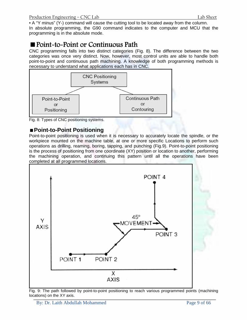
Production Engineering ndash CNC Lab Lab Sheet
By Dr Laith Abdullah Mohammed Page 9 of 66
bull A ldquoY minusrdquo (Y-) command will cause the cutting tool to be located away from the column In absolute programming the G90 command indicates to the computer and MCU that the programming is in the absolute mode Point-to-Point or Continuous Path CNC programming falls into two distinct categories (Fig 8) The difference between the two categories was once very distinct Now however most control units are able to handle both point-to-point and continuous path machining A knowledge of both programming methods is necessary to understand what applications each has in CNC
Fig 8 Types of CNC positioning systems Point-to-Point Positioning Point-to-point positioning is used when it is necessary to accurately locate the spindle or the workpiece mounted on the machine table at one or more specific Locations to perform such operations as drilling reaming boring tapping and punching (Fig9) Point-to-point positioning is the process of positioning from one coordinate (XY) position or location to another performing the machining operation and continuing this pattern until all the operations have been completed at all programmed locations
Fig 9 The path followed by point-to-point positioning to reach various programmed points (machining locations) on the XY axis
Production Engineering ndash CNC Lab Lab Sheet
By Dr Laith Abdullah Mohammed Page 10 of 66
In Fig 9 point 1 to point 2 is a straight line and the machine moves only along the X axis but points 2 and 3 require that motion along both the X and Y axes takes place As the distance in the X direction is greater than in the Y direction Y will reach its position first leaving X to travel in a straight line for the remaining distance A similar motion takes place between points 3 and 4 Continuous Path (Contouring) Contouring or continuous path machining involves work such as that produced on a lathe or milling machine where the cutting tool is in contact with the workpiece as it travels from one programmed point to the next Continuous path positioning is the ability to control motions on two or more machine axes simultaneously to keep a constant cutter-workpiece relationship The programmed information in the CNC program must accurately position the cutting tool from one point to the next and follow a predefined accurate path at a programmed feed rate in order to produce the form or contour required (Fig 10)
Fig 10 Types of contour machining (A) Simple contour (B) complexe contour
Interpolation The method by which contouring machine tools move from one programmed point to the next is called interpolation This ability to merge individual axis points into a predefined tool path is built into most of todayrsquos MCUs There are five methods of interpolation linear circular helical parabolic and cubic All contouring controls provide linear interpolation and most controls are capable of both linear and circular interpolation Helical parabolic and cubic interpolation are used by industries that manufacture parts which have complex shapes such as aerospace parts and dies for car bodies Linear Interpolation Linear Interpolation consists of any programmed points linked together by straight lines whether the points are close together or far apart (Fig 11) Curves can be produced with linear interpolation by breaking them into short straight-line segments This method has limitations because a very large number of points would have to be programmed to describe the curve in order to produce a contour shape A contour programmed in linear interpolation requires the coordinate positions (XY positions in two-axis work) for the start and finish of each line segment Therefore the end point of one line or segment becomes the start point for the next segment and so on throughout the entire program
Production Engineering ndash CNC Lab Lab Sheet
By Dr Laith Abdullah Mohammed Page 11 of 66
Fig 11 An example of two-axis linear interpolation Circular Interpolation The development of MCUs capable of circular interpolation has greatly simplified the process of programming arcs and circles To program an arc (Fig 12) the MCU requires only the coordinate positions (the XY axes) of the circle center the radius of the circle the start point and end point of the arc being cut and the direction in which the arc is to be cut (clockwise or counterclockwise) See Fig 12
Fig 12 For two-dimensional circular interpolation the MCU must be supplied with the XY axis radius start point end point and direction of cut
Programming Format Word address is the most common programming format used for CNC programming systems This format contains a large number of different codes that transfers program information from the part print to machine servos relays micro-switches etc to manufacture a part These codes which conform to EIA (Electronic Industries Association) standards are in a logical sequence called a block of information Each block should contain enough information to perform one machining operation Word Address Format Every program for any part to be machined must be put in a format that the machine control unit can understand The format used on any CNC machine is built in by the machine tool builder and is based on the type of control unit on the machine A variable-block format which uses words (letters) is most commonly used Each instruction word consists of an address character such as X Y Z G M or S Numerical data follows this address character to identify a specific function such as the distance feed rate or speed value The address code G90 in a program
Production Engineering ndash CNC Lab Lab Sheet
By Dr Laith Abdullah Mohammed Page 12 of 66
tells the control that all measurements are in the absolute mode The code G91 tells the control that measurements are in the incremental mode Codes The most common codes used when programming CNC machines tools are G-codes (preparatory functions) and M codes (miscellaneous functions) Other codes such as F S D and T are used for machine functions such as feed speed cutter diameter offset tool number etc G-codes are sometimes called cycle codes because they refer to some action occurring on the X Y andor Z axis of a machine tool The G-codes are grouped into categories such as Group 01 containing codes G00 G01 G02 G03 which cause some movement of the machine table or head Group 03 includes either absolute or incremental programming while Group 09 deals with canned cycles A G00 code rapidly positions the cutting tool while it is above the workpiece from one point to another point on a job During the rapid traverse movement either the X or Y axis can be moved individually or both axes can be moved at the same time Although the rate of rapid travel varies from machine to machine it ranges between (5 and 20 mmin)
Fig 13 The functions of a few common G-codes The G01 G02 and G03 codes move the axes at a controlled feedrate bull G01 is used for straight-line movement (linear interpolation) bull G02 (clockwise) and G03 (counterclockwise) are used for arcs and circles (circular interpolation)
Production Engineering ndash CNC Lab Lab Sheet
By Dr Laith Abdullah Mohammed Page 13 of 66
Fig 14 Some of the most common G-codes used in CNC programming M or miscellaneous codes are used to either turn ON or OFF different functions which control certain machine tool operations M-codes are not grouped into categories although several codes may control the same type of operations such as M03 M04 and M05 which control the machine tool spindle bull M03 turns the spindle on clockwise bull M04 turns the spindle on counterclockwise bull M05 turns the spindle off
Production Engineering ndash CNC Lab Lab Sheet
By Dr Laith Abdullah Mohammed Page 14 of 66
Fig 15 The functions of a few common M-codes
Production Engineering ndash CNC Lab Lab Sheet
By Dr Laith Abdullah Mohammed Page 15 of 66
Fig 16 Some of the most common M-codes used in CNC programming Block of Information CNC information is generally programmed in blocks of five words Each word conforms to the EIA standards and they are written on a horizontal line If five complete words are not included in each block the machine control unit (MCU) will not recognize the information therefore the control unit will not be activated Using the example shown in Fig 17 the five words are as follows N001 represents the sequence number of the operation G01 represents linear interpolation X12345 will move the table 12345 in in a positive direction along the X axis Y06789 will move the table 06789 in along the Y axis M03 Spindle on CW
Fig 17 A complete block of information consists of five words
Production Engineering ndash CNC Lab Lab Sheet
By Dr Laith Abdullah Mohammed Page 16 of 66
Programming for Positioning Before starting to program a job it is important to become familiar with the part to be produced From the engineering drawings the programmer should be capable of planning the machining sequences required to produce the part Visual concepts must be put into a written manuscript as the first step in developing a part program Fig 18 It is the part program that will be sent to the machine control unit by the computer tape diskette or other input media The programmer must first establish a reference point for aligning the workpiece and the machine tool for programming purposes The manuscript must include this along with the types of cutting tools and work-holding devices required and where they are to be located
Fig 18 The first step in producing a CNC program is to take the information from the print and produce a program manuscript Dimensioning Guidelines The system of rectangular coordinates is very important to the successful operation of CNC machines Certain guidelines should be observed when dimensioning parts for CNC machining The following guidelines will insure that the dimensioning language means exactly the same thing to the design engineer the technician the programmer and the machine operator 1 Define part surfaces from three perpendicular reference planes 2 Establish reference planes along part surfaces which are parallel to the machine axes 3 Dimension from a specific point on the part surface 4 Dimension the part clearly so that its shape can be understood without making mathematical calculations or guesses 5 Define the part so that a computer numerical control cutter path can be easily programmed
Production Engineering ndash CNC Lab Lab Sheet
By Dr Laith Abdullah Mohammed Page 17 of 66
Machine Zero Point The machine zero point can be set by three methodsmdashby the operator manually by a programmed absolute zero shift or by work coordinates to suit the holding fixture or the part to be machined MANUAL SETTING - The operator can use the MCU controls to locate the spindle over the desired part zero and then set the X and Y coordinate registers on the console to zero
Fig 19 The relationship between the part zero and the machine system of coordinates ABSOLUTE ZERO SHIFT - The absolute zero shift can change the position of the coordinate system by a command in the CNC program The programmer first sends the machine spindle to home zero position by a G28 command in the program Then another command (G92 for absolute zero shift) tells the MCU how far from the home zero location the coordinate system origin is to be positioned Fig 19 The sample commands may be as follows N1 G28 X0 Y0 Z0 (sends spindle to home zero position) N2 G92 X4000 Y5000 Z6000 (the position the machine will reference as part zero)
Production Engineering ndash CNC Lab Lab Sheet
By Dr Laith Abdullah Mohammed Page 18 of 66
Work Settings and Offsets All CNC machine tools require some form of work setting tool setting and offsets (compensation) to place the cutter and work in the proper relationship Compensation allows the programmer to make adjustments for unexpected tooling and setup conditions
Work Coordinates In absolute positioning work coordinates are generally set on one edge or corner of a part and all programming is generally taken from this position In Fig 20 the part zero is used for all positioning for hole locations 1 2 and 3
Fig 20 In absolute programming all dimensions must be taken from the XY zero at the top left-hand corner of the part
Fig 21 In incremental programming all dimensions are taken from the previous point In incremental positioning the work coordinates change because each location is the zero point for the move to the next location Fig 21
Production Engineering ndash CNC Lab Lab Sheet
By Dr Laith Abdullah Mohammed Page 19 of 66
On some parts it may be desirable to change from absolute to incremental or vice versa at certain points in the job Inserting the G90 (absolute) or the G91 (incremental) command into the program at the point where the change is to be made can do this
R Plane or Gage Height The word-address letter R refers to a partial retraction point in the Z axis to which the end of the cutter retracts above the work surface to allow safe table movement in the X Y axes It is often called the rapid-traverse distance gage height retract or work plane The R distance is a specific height or distance above the work surface and is generally 100 in above the highest surface of the workpiece Fig 22 which is also known as gage height Some manufacturers build a gage height distance of 100 in into the MCU (machine control unit) and whenever the feed motion in the Z axis is called for 100 in will automatically be added to the depth programmed When setting up cutting tools the operator generally places a 100 in thick gage on top of the highest surface of the workpiece Each tool is lowered until it just touches the gage surface and then its length is recorded on the tool list Once the gage height has been set it is not generally necessary to add the 100 in to any future depth dimensions since most MCUs do this automatically
Fig 22 Using a 100 in gage block to set the gage height or R0 on the work surface
Cutter Diameter Compensation Cutter diameter compensation (CDC) changes a milling cutterrsquos programmed centerline path to compensate for small differences in cutter diameter On most MCUs it is effective for most cuts made using either linear or circular interpolation in the X-Y axis but does not affect the programmed Z-axis moves Usually compensation is in increments of 0001 in up to +10000 in and usually most controls have as many CDCs available as there are tool pockets in the tool storage matrix The advantage of the CDC feature is that it 1 Allows the use of cutters that have been sharpened to a smaller diameter 2 Permits the use of a larger or smaller tool already in the machinersquos storage matrix 3 Allows backing the tool away when roughing cuts are required due to excessive material present 4 Permits compensation for unexpected tool or part deflection if the deflection is constant throughout the programmed path The basic reference point of the machine tool is never at the cutting edge of a milling cutter but at some point on its periphery If a 1000 in diameter end mill is used to machine the edges of a workpiece the programmer would have to keep a 500 in offset from the work surface in order to cut the edges accurately Fig 23 The 500 offset represents the distance from the centerline of the cutter or machine spindle to the edge of the part Whenever a part is being machined the programmer must calculate an offset path which is usually half the cutter diameter
Production Engineering ndash CNC Lab Lab Sheet
By Dr Laith Abdullah Mohammed Page 20 of 66
Fig 23 Cutter-diameter compensation must be used when machining with various size cutters Modern MCUs which have part surface programming automatically calculate centerline offsets once the diameter of the cutter for each operation is programmed Many MCUs have operator-entry capabilities which can compensate for differences in cutter diameters therefore an oversize cutter or one that has been sharpened can be used as long as the compensation value for oversize or undersize cutters is entered
Production Engineering ndash CNC Lab Lab Sheet
By Dr Laith Abdullah Mohammed Page 21 of 66
CNC Programming Hints - MILLING
Production Engineering ndash CNC Lab Lab Sheet
By Dr Laith Abdullah Mohammed Page 22 of 66
CNC Programming Hints ndash TURNING
Production Engineering ndash CNC Lab Lab Sheet
By Dr Laith Abdullah Mohammed Page 23 of 66
CNC
The abbreviation CNC stands for Computer(ized) Numerical(ly) Control(led) and refers specifically to the computer control of machine tools for the purpose of (repeatedly) manufacturing complex parts in metal as well as other materials using a program written in a notation conforming to the EIA-274-D standard and commonly called G-code
CNC was developed in the late 1940s and early 1950s by the MIT Servomechanisms Laboratory CNC machines were relatively briefly preceded by the less advanced NC or Numerical(ly) Control(led) machines The introduction of CNC machines radically changed the manufacturing industry Curves are as easy to cut as straight lines complex 3-D structures are relatively easy to produce and the number of machining steps that required human action have been dramatically reduced With the increased automation of manufacturing processes with CNC machining considerable improvements in consistency and quality have been achieved CNC automation reduced the frequency of errors and provided CNC operators with time to perform additional tasks
CNC automation also allows for more flexibility in the way parts are held in the manufacturing process and the time required to change the machine to produce different components In a production environment a series of CNC machines may be combined into one station commonly called a cell to progressively machine a part requiring several operations CNC machines today are controlled directly from files created by CAM software packages so that a part or assembly can go directly from design to manufacturing without the need of producing a drafted paper drawing of the manufactured component In a sense the CNC machines represent a special segment of industrial robot systems as they are programmable to perform many kinds of machining operations (within their designed physical limits like other robotic systems)
G-code
G-code is a common name for the programming language that is used for NC and CNC machine tools It is defined in EIA RS-274-D G-code is also the name of any word in a CNC program that begins with the letter G and generally is a code telling the machine tool what type of action to perform such as
bull rapid move bull controlled feed move in straight line or arc bull series of controlled feed moves that would result in a hole being drilled bull change a pallet bull Set tool information such as offset
There are other codes the type codes can be thought of like registers in a computer
X position Y position Z position M code (another action register) F feed rate S spindle speed N line number R Radius T Tool selection
Production Engineering ndash CNC Lab Lab Sheet
By Dr Laith Abdullah Mohammed Page 24 of 66
I Arc data X axis J Arc data Y axis
G-code files are output by CAM software such as Smartcam Gibbscam Featurecam Edgecam Mastercam etc G-code is also output by specialized CAD systems used to design printed circuit boards Such software must be customized for each type of machine tool that it will be used to program
Production Engineering ndash CNC Lab Lab Sheet
By Dr Laith Abdullah Mohammed Page 25 of 66
U 2عمل األزرار الرئيسية في ماكنة الخراطة المبرمجة (نصر (
1- SINGLE BLOCK للتأكد من صحة البرنامج (تنفيذ البرنامج خطوة خطوةب تقوم( 2- BLOCK DELETE بجانب ويعمل من األوامرلغاء بلوك معين أليستخدم 3- MACHINE LOCK العمل يستخدم لقفل حركة المحاور الرئيسية مع استمرار البرنامج في
)وهذا مهم للتاكد من صحة البرنامج قبل عملية التنفيذ النهائي(4- CONT CYCLE عملية التشغيل عند ايقافها الي سبب كان او عند ايقافها ألستئناف ستخدم ت
) BAR FEEDER(او في حالة استخدام ) FEED HOLDبسبب (5- DRY RUN وتستخدم لفحص البرنامج بعد ازالة الشغلة حركة سريعة للبرنامج 6- TURRET UP amp DOWN ) حركة حامل العدة TURRET الذي يحمل مجموعة من (
وهذا الزر يعمل مع الزر عكس عقرب الساعة او مع عقرب الساعة ةحركة دوراني العدد )SAFTY (
7- COOLANT ON or OFFفه تشغيل سائل التبريد او ايقا 8- COOLANT AUTO الدوال المساعدة في البرنامج من خالل فه تشغيل سائل التبريد او ايقا 9 -MACHINE START ة لتشغيل هيدرولكيك الماكنميستخد
Production Engineering ndash CNC Lab Lab Sheet
By Dr Laith Abdullah Mohammed Page 26 of 66
10- CLOSE OR OPEN CHUCKالعينة تستخدم لفتح وغلق 11 -T STOCK FWD RET حركة الغراب المتحرك ذهابا وإيابا12 -SPINDLE STOP تعمل على ايقاف حركة دوران العينة 13-JOG SPINDLE تعمل على تدوير العينة مع زر SAFTY 14 -OPT SAFTY مع الدالة ( تعمل عمل التوقف المشروط حيث تعملM1 دالة التوقف (
ط ) فقط األ اذا كان هذا الزر مضغو M1المشروط حيث ال يتوقف البرنامج في حالة وجود دالة ( SAFTY + SPINDLE ) يتم الضغط على زر ( START CYCLEلغرض تحرير زر (
START ) في نفس الوقت بعد الضغط على زر ( START CYCLE مرتين (
NC PC- 15 يستخدم هذا الزر عند ربطCNC يستخدم لنقل المعلومات ث مع جهاز أخر حي بينهما
16 -CALCU زر الخاص بالحاسبة مع زر ( ال وهوINPUT ( 17 - HD1 HD2 يستخدم الختيار العدة مع المخرطة ذات المحاور األربعة 18 - START تستخدم لبدء عملية التشغيل
Production Engineering ndash CNC Lab Lab Sheet
By Dr Laith Abdullah Mohammed Page 27 of 66
19- FEED HOLD تعمل على إيقاف عمل أي G موجودة مع بقاء العينة متحركة 20- M D I أو تشغيل البرنامج ل يتم استخدامه لإلدخا BLOCK BY BLOCK وتعمل عند
إدخال البرنامج بواسطة الشريط المثقب أو أي وسيلة إدخال أخرى أو في عمليات التصفير
21- REST تستخدم العادة تشغيل الماكنة أو مسح اإلنذار الذي يظهر على الشاشة 22- EMERGENCYتستخدم عادة اليقاف الماكنة في حالة الطوارئ فقط
OPERATION MENU KEY
CHAPTER PRG-CMK
OFFSET PROGRAM POSITION FUNCTION MENU KEY
23- POSITIONعلى الشاشة د الموقع الموجور الظها 24- PROGRAMإلظهار برنامج معين واختياره 25- OFFSET الختيار سماحات العدة أو سماحات نقطة المرجع 26- PRG- CHK تستخدم لفحص البرنامج على الشاشة 27- SETTING ألختيار الثوابت على الشاشة 28- SERVICE تستخدم ألستخراج المعامالت والثوابت 29- MESSAGE تستخدم ألظهار األخطاء الناتجة عن البرنامج او اخطاء التشغيل 30- OVERALL ألختيار المواقع 31- RELATIVE MODLINE تعوض عن POSITION 32- DIR MEM يستخدم ألظهار ملف البرامج المخزونة في الذاكرة وعندما نضغط هذا الزر
فان رقم واسم البرنامج سوف يظهر على الشاشة
2أدناه الشفرات الرئيسية التي تعمل على الماكنة المبرمجة نصر
G-CODE DESCRIPTION
G00 Rapid traverse (linear)
G01 Linear Interpolation at feed rate
G02 Circular interpolation (CW) R+
G03 Circular interpolation (CCW) R+
G10 Zero point tools
G20 Imperial data input
G21 Metric data input
G27 Reference return check
G28 Reference return
G29 Return from reference
Production Engineering ndash CNC Lab Lab Sheet
By Dr Laith Abdullah Mohammed Page 28 of 66
G33 Thread cutting
G40 Cancel cutter radius compensation
G41 Cutter compensation left
G42 Cutter compensation right
G54 Work co-ordinate system no1
G70 Finishing cycle
G71 Stock removal turning
G72 Stock removal facing
G74 Face grooving
G75 Diameter grooving
G76 Threading cycle
G90 Absolute date input
G91 Incremental data input
G94 Feed minute mode
G95 Feed rev mode
G96 Constant surface speed mode
G97 Cancel Constant surface speed
) 2أدناه الشفرات الثانوية التي تعمل على الماكنة المبرمجة (نصر
M-code FUNCTION
M00 Program stop
M03 Spindle forward (Tool forward ndash M94 mode)
M04 Spindle reverse (Tool forward ndash M94 mode)
M05 Spindle stop (Tool stop ndash M94 mode)
M08 Coolant on
M09 Coolant off
M30 Program end (with rewind)
M48 Turret shortest path
M52 Turret direction up (CW)
M53 Turret direction down (CCW)
M73 Chuck open
M74 Chuck close
Production Engineering ndash CNC Lab Lab Sheet
By Dr Laith Abdullah Mohammed Page 29 of 66
) وكل جملة مكونة من مجموعة من الكلمات blockإن كل برنامج يتكون من مجموعة من الجمل ()words) لهذا فأن الشفرات الرئيسية والمساعدة هي عبارة عن كلمات (words كما في المثال التالي (
G_ _ P1 Q2 U_ _ W_ _ D___ F_ _
)end of block) ويعني ( ) يكتب الرمز (blockتسلسل الكلمات مهم جدا بعد نهاية كل جملة (
طريقة ادخال البيانات الى الماكنة ــــــــــــــــــــــــــــــــــــــــــــــــــ
) MDIيمكن ادخال البيانات الى الماكنة بعدة طرق فقد يكون األدخال عن طريق قناة السيطرة ( MANUAL DATA INPUT ) او عن طريق قناة األضافة EDIT كما يمكن ادخال البيانات عن (
) RS ndash 232 COMMUNICATIN LINKطريق استخدام سلسلة الربط (
₤⅗₌⅗₌ ⅙₌₨image₍₡ ₤₌ℌ⅗₌ Ⅸ⅗ⅥⅯ₌ ₤₡ℌ₰₨⅗₌G71
الخراطة الطولية G71الغرض من التجربة عمل نموذج للخراطة بأستخدام الدالة تستعمل هذه الدالة للخراطة الطولية اي على طول محور المشغولة وكما هو موضح بالشكل ادناه
تعتبر هذه الدالة من الدوال التي ال تحتاج الى تكرار او إعادة كتابتها أي انها دالة تكرارية بمعنى ان اي
الذي هي دالة حركة G01خطوة تكون من ضمن هذه الدالة سوف تكرر العملية اي عند استعمال امر مثل خطية تتضمن القطع مع التغذية مع اعطاء القطر المراد قطعه و مراعاة عمق القطع المعطى سوف يتكرر
هذه االمر وصوال الى العمق المطلوب وهكذا لبقية الدوال
G71 المستخدمة للدالة الصيغة
G71 P1 Q2 U___ W___ D___ F___ حيث إن
P1 بداية الخطوة االولى = Q2 نهاية الخطوة =
Uوضع السماحات بأتجاه محور = X W وضع السماحات بأتجاه محور = Z وتكاد تكون مهملة وتوضع اشارة سالب Dعمق القطع وتوضع رقم صحيح مثل = D500 اي نصف ملمF التغذية والتي لها عالقة بالدالة = G95
Production Engineering ndash CNC Lab Lab Sheet
By Dr Laith Abdullah Mohammed Page 30 of 66
G71الدالة استخدام مثال على
T0100 M48 G0 X26 Z2 M08 T0101 G90 G95 G97 S500 M03 G71 P1 Q2 U03 W00 D500 F01 N1 G0 G42 X00 G01 Z00 G01 X2517 G01 Z-5352 G01 X7391 Z-9366 G01 Z-19145 N2 G28 M30
الجانب العملي
االجهزة واالدوات المستخدمة CNCماكنة خراطة مبرمجة 1 ملم 80قضيب من االلمنيوم قطر 2 ةفير ني 3 جاه أيمن تهولدر كاربيدي ذوا 4
طريقة العمل يتم تثبيت قضيب من االلمنيوم على العينة التابعة للماكنة مع مراعاة الطول المراد استعماله في عملية 1
الخراطة ) turretتثبيت عدة القطع في المكان الصحيح في ( 2
Production Engineering ndash CNC Lab Lab Sheet
By Dr Laith Abdullah Mohammed Page 31 of 66
بالنسبة الى القطعة المثبتة على العينة XZيتم تصفير الماكنة للمحاور 3 تصفير للمحورZ تكون مالمسة العدة الى وجه الشغلة تصفير للمحورX تكون مالمسة العدة الى سطح الشغلة الموازي لمحور X
يتم كتابة البرنامج أما بطريقة يدوية أو بالحاسوب مع وضع كل الظروف الالزمة للتشغيل ( عمق القطع 4 التغذية السرعة المطلوبة نوع المعدن )
ادخال البرنامج الى الحاسوب الموجود داخل الماكنة مع تهيئة الماكنة للتشغيل 5
المطلوب G71عمل برنامج يدوي على الدالة 1 رسم الشكل الشكل النهائي المطلوب مع وضع األبعاد 2
Ⅺ⅟₍euro⅗₌ ₤₡ℌ₰₨⅗₌₣ ₤⅗₌⅗₌ ⅙₌₨image₃₡ Ⅺℂtradeℒ⅗₌ ӈ₍Ⅴ⅟ⅳ₌ G70
G70 الغرض من التجربة عمل انهاء سطحي للمشغولة بواسطة الدالة
من الضروري إعطاء G71هذه الدالة تعمل شوط واحد فقط وتكون معتمدة على عمليات القطع في الدالة اللغاء مقدمة االداة (أي لكي تتم عملية االنهاء السطحي بدون حسابات نصف قطر مقدمة االداة ) G42دالة
G70الصيغة المستخدمة للدالة
G70 P1 Q2 F___ حيث ان
P1 بداية الخطوة االولى = Q2 نهاية الخطوة =
F التغذية والمرتبطة بالدالة = G95
وذلك ألن دالة االنهاء السطحي تحقق X Zمالحظة الدالة التحتاج لكتابة السماحات التابعة للمحورين المسافات الحقيقة المراد انتاجها للمشغولة
G71و G70مثال على الدالة
T0100 M48 G0 X26 Z2 M08 T0101 G90 G95 G97 S500 M03 G71 P1 Q2 U03 W00 D500 F01 N1 G0 G42 X00 G01 Z00 G01 X2517 G01 Z-5352 G01 X7391 Z-9366 G01 Z-19145 N2 G97 S750 MO3
Production Engineering ndash CNC Lab Lab Sheet
By Dr Laith Abdullah Mohammed Page 32 of 66
G70 P1 Q2 G40 F009 G28 M30
الجانب العملي الحظ التجربة األولى
المطلوب
G70 عمل برنامج يدوي على الدالة 1 رسم الشكل النهائي المطلوب مع وضع االبعاد 2
₪⅗₍euro⅗₌ ₤₡ℌ₰₨⅗₌₣ ₤⅗₌⅗₌ ⅙₌₨image₍₡ ⅝₍ⅠimageⅯ₌ ⅞ⅫⅦ⅔₧ G76
G76 للمشغولة بواسطة الدالةةالغرض من التجربة عمل أسنان خارجية أو داخلي
في هذه التجربة سوف نقوم بعمل األسنان الخارجية وهنا تكون حركة العينة ثابتة وهذا ضروري بسبب أن ) تكون متصلتين الكترونيا وعليه أي اختالف في سرعة العينة تؤدي إلى اختالف motionالعينة والحركة(
) servoفي سرعة الخدمة(يرتبط اتجاه تكوين األسنان باتجاه دوران العينة مثال إذا كانت األسنان ذات اتجاه أيمن يكون اتجاه دوران
وهنا نقلب العدة إلى االسفل وكما هو موضح بالشكل أدناه MO3العينة عكس عقرب الساعة أي نستعمل
Production Engineering ndash CNC Lab Lab Sheet
By Dr Laith Abdullah Mohammed Page 33 of 66
الخطوة هي عبارة عن المسافة ما بين قمة سن إلى قمة سن أخر عمق السن هو العمق المطلوب تكوينه لألسنان
G76 الصيغة المستخدمة للدالة
G76 X___ Z___ K___ F___ D___ A___
حيث أن X القطر الداخلي للسن =Z طول السن =K عمق السن وتستخرج من المعادلة التالية =K=065F F الخطوة =D عمق القطع بالمايكرون فقط =A زاوية السن =
G76مثال على استخدام الدالة T0300 M48 GOO X30 Z4 T0303 M08 G97 S500 MO3 G76 X28375 Z-20 K08125 F125 D120 G00 X40 Z4 G28 M30
Production Engineering ndash CNC Lab Lab Sheet
By Dr Laith Abdullah Mohammed Page 34 of 66
الجانب العملي الحظ التجربة األولى
المطلوب
G76عمل برنامج يدوي على الدالة 1 رسم الشكل النهائي المطلوب مع وضع األبعاد 2
Ⅺ⅘₌⅗₌ Ⅵ₂ Ⅺ₯ℋ₍⅗₌ ℌℲℂ⅗₌ ⅞ⅫⅦ⅔₧ ₤K₡₌ℌ⅗₌ ₤₡ℌ₰₨⅗₌)Groove ₤⅗₌⅗₌ ₤tradeimage₌Ⅶ₡ (G75
G75 بواسطة الدالة grooveالغرض من التجربة تكوين
) للمشغولة وتعتمد شكل الحفر على طريقة grooveتستعمل هذه الدالة لتكوين الحفر الخارجي والداخلي (
التشغيل وعلى الشكل المراد إنتاجه وتعتبر هذه الطريقة من عمليات التشكيل للمعدن إن هذه الدالة هي دالة مالحظة مع G75في هذه التجربة سنقوم بعمل الحفر الخارجي بواسطة الدالة
تكرارية وغير تكرارية حسب نوع التشغيل
G 75 الصيغة المستخدمة للدالةG75 X___ Z___ I___ K____
حيث أن
X العمق النهائي لقطر الشغلة =Z عرض الحفر =I الدخول في كل مرة =
K التزحيف على محور =z بالنسبة للعدة
Production Engineering ndash CNC Lab Lab Sheet
By Dr Laith Abdullah Mohammed Page 35 of 66
G75مثال على استخدام الدالة
T0500 M48 GOO X100 Z -20 T0505 M08 G97 S700 MO3 G75 X84 Z -38 I 05 K4
الجانب العملي الحظ التجربة األولى
المطلوب
G76عمل برنامج يدوي على الدالة 1 رسم الشكل النهائي المطلوب مع وضع األبعاد 2
Production Engineering ndash CNC Lab Lab Sheet
By Dr Laith Abdullah Mohammed Page 36 of 66
CNC Milling Machine Mechanical Construction
Guideways The guideways of CNC machines are made of steel To reduce the frictional forces they are coated with a strip of PTFE (Poly Tetra Fluoro Ethylene)
Ballscrews On conventional lathes a leadscrew is used to converts the rotary motion of the hand wheel into linear motion of the slides Leadscrews have a high coefficient of friction and backlash On CNC machines a ballscrew is used instead of a leadscrew Friction and backlash are much less than on leadscrews
Guideway
Production Engineering ndash CNC Lab Lab Sheet
By Dr Laith Abdullah Mohammed Page 37 of 66
bullMachining operations Direction of cutting Based on the direction of the cutter rotation and work piece feed milling operations are classified into two types 1-Up milling (Convention milling) In up milling the metal is removed by rotating the cutter against the direction of travel of the part
Feed
Machine table
Part
Cutting tool
Chip thickness at theexit of the tooth
2-Down milling (Climb milling) In climb milling the metal is removed by rotating the cutter with the direction of travel of the part
Machine table
Part
Cutting tool
Chip thickness at theentrance of the tooth
Production Engineering ndash CNC Lab Lab Sheet
By Dr Laith Abdullah Mohammed Page 38 of 66
bullTooling Tool geometry The geometry of the tool tip affects the way that the metal cutting is performed The nose radius rake angles relief angles etc must be selected with care
Radial relief
Radial rake
Axial relief
Approach angle
Axial relief
Corner radius Face mill Face milling cutters are used to mill flat surfaces Commonly used face milling cutters Cutter with 75 degree approach
75 deg
Cutter with 90 degree approach (Square shoulder face mill)
90 deg
Cutter with 45 degree approach
Production Engineering ndash CNC Lab Lab Sheet
By Dr Laith Abdullah Mohammed Page 39 of 66
bullCNC Programming Axes convention The Z axis is along the spindle axis The X and Y axes are perpendicular to Z VMC
Z
Y
-
+
-+
X- +
+Z
-Z
+Y
-Y
-X +X
Part
Machine table
X
YZ
G00 Rapid traverse When the tool being positioned at a point preparatory to a cutting motion to save time it is moved along a straight line at Rapid traverse at a fixed traverse rate which is pre-programmed into the machines control system Typical rapid traverse rates are 10 to 25 m min but can be as high as 80 mmin
Production Engineering ndash CNC Lab Lab Sheet
By Dr Laith Abdullah Mohammed Page 40 of 66
Format N_ G00 X__ Y__Z__
G01 Linear interpolation (feed traverse) The tool moves along a straight line in one or two axis simultaneously at a programmed linear speed the feed rate Format N__ G01 X__ Y__Z__ F__
Part
Feed
Part
Feed
G02G03 Circular interpolation The tool moves along an arc in two axes simultaneously at a programmed linear speed the feed rate
Production Engineering ndash CNC Lab Lab Sheet
By Dr Laith Abdullah Mohammed Page 41 of 66
Format N__ G0203 X__ Y__Z__ I__ J__K__ F__ using the arc center OR N__ G0203 X__ Y__Z__ R__ F__ using the arc radius G02 moves along a CW arc G03 moves along a CCW arc Arc center The arc center is specified by addresses I J and K I J and K are the X Y and Z co-ordinates of the arc center with reference to the arc start point
X
Y
Arc center
Arc endArc start
- J
- I
I = X coord of center - X coord of start point J = Y coord of center - Y coord of start point K = Z coord of center - Z coord of start point I J and K must be written with their signs
Production Engineering ndash CNC Lab Lab Sheet
By Dr Laith Abdullah Mohammed Page 42 of 66
bullWork holding
Rotary table
Fixture base
Component
Clamp
Stud
Fixtures The use of fixtures 1 Improves repeatability of dimensions 2 Improves working conditions 3 Cuts down requirement of skilled labour 4 Reduces part loading and unloading time 5 Improves safety in the working area 6 Reduces the cost of machining There are two types fixtures commonly used 1 Special fixture Special fixtures are used to hold and locate the typical components which are having complex shape and to be located with the reference hole (dowel hole) Special fixtures are required for components like gear case cover cylinder heads etc 2 Modular fixture Modular fixture is a set different kind of clamping and locating elements These fixtures are used to hold identical components in different sizes and components of box type Example Manifolds head stocks connecting rods and flanges
Production Engineering ndash CNC Lab Lab Sheet
By Dr Laith Abdullah Mohammed Page 43 of 66
bullMachine setting
Determining X and Y work zero offset Case 1
Part
Machine table
Part
End mill or reamer
Work offset X0Y0 For determining X work zero offset bull Touch the periphery of the end mill or reamer to the part bull Enter current machine X value + cutter radius as X work zero offset For determining Y work zero offset bull Touch the periphery of the end mill or reamer to the part bull Enter current machine Y value - cutter radius as Y work zero offset Case 2
Part
Machine table
Part
End mill or reamerWork offset X0Y0
bull Mount the dial indicator on machine spindle true the bore bull Enter current machine X and Y value as X and Y work zero offset
Production Engineering ndash CNC Lab Lab Sheet
By Dr Laith Abdullah Mohammed Page 44 of 66
How to Select a Cutting Fluid
One part of the metal cutting equation that is sometimes overlooked however is
the choice of an appropriate cutting fluid With todayrsquos system approach to metal
cutting use of the right metalworking fluid has become just as much a part of the
solution as the other elements In fact at least one company is now integrating
cutting fluids and cutting tools into effective metal cutting systems Following are
some things to consider when choosing your next cutting fluid
The Four Key Questions
There are four vital pieces of information that are necessary when choosing a
cutting fluid They are
1 What are you cutting
2 What is the chemistry of your water
3 What are you using now
4 What are your options
5 What do you prefer
What Are You Cutting
The first question ndash ldquoWhat are you cuttingrdquo ndash is often the most difficult to answer
because most shops handle a variety of workpiece materials on a regular basis If
the answer is an unequivocal ldquoaluminumrdquo or ldquostainless steelrdquo or ldquocast ironrdquo the
selection of a cutting fluid can be quite simple and straightforward Unfortunately
that is seldom the case in anything but a high-volume plant Where aluminum or
other nonferrous metals are a significant part of the mix a non-staining cutting
fluid is a must Generally speaking this will be a semi-synthetic with special
ingredients to prevent bi-metallic corrosion and staining of non-ferrous workpieces
Where the ferrous metals predominate however a more general purpose semi-
synthetic or hybrid fluid might be a more economical choice
Production Engineering ndash CNC Lab Lab Sheet
By Dr Laith Abdullah Mohammed Page 45 of 66
What is The Chemistry of Your Water
The second question ndash ldquoWhat is the chemistry of your waterrdquo ndash is probably the
single most common reason for the success or failure of a cutting fluid Very few
plants invest the money necessary to install effective water purification systems
using deionization or reverse osmosis technology Unfortunately the chemicals
present or not present in the water used to re-constitute a cutting fluid make a
tremendous difference in its performance and sump life Most manufacturers of
cutting fluids will perform the necessary water testing to determine exactly what
minerals are dissolved in your water and make a fluid recommendation based on
the results
What are you using now
The third question ndash ldquoWhat are you using nowrdquo ndash helps narrow the range of
choices When coupled with an objective analysis of the strengths and weaknesses
of the current fluid the answer to this question can quickly point you toward a
relatively small number of competitive alternatives that have the attributes required
to meet your cutting needs Many cutting fluids are in use today simply because
they were in use yesterday It is a hard reality of todayrsquos marketplace that if one
isnrsquot constantly striving to improve they will certainly be overtaken by a
competitor who is
What Are Your Options
The fourth question ndash ldquoWhat are your optionsrdquo ndash leads to the final selection of a
cutting fluid Cutting fluids can be divided into four general groups based on their
chemistry
They are
bull Soluble Oils ndash quite literally oil dispersed in water
bull Synthetics ndash completely oil free man-made coolants in solution
Production Engineering ndash CNC Lab Lab Sheet
By Dr Laith Abdullah Mohammed Page 46 of 66
bull Semi-Synthetics ndash a mixture of natural and synthetic lubricants with up to 30
mineral oil
bull Hybrids ndash a special class of semi-synthetics with a mineral oil content of about
15 Each fluid type has advantages and disadvantages which make it suitable for
a particular group of applications In addition there are costperformance trade-
offs to be made between the groups within a specific set of applications For
example where a hybrid and a semi-synthetic may both be suitable for a particular
use the hybrid might provide longer sump life at a slightly higher initial cost
while some semi synthetics may be more economical to recycle or dispose of while
not giving as long a tank life The final decision in this case would have to be made
on the detailed economics of the shop where the fluids were to be used and on the
ownerrsquos individual preferences
Soluble Oils
Soluble oils are oils that disperse in water when emulsifiers are added They are
generally suitable for moderate-to heavy-duty machining and grinding of all non-
ferrous metals carbon and cast steels and in applications where dissimilar metals
such as aluminium and steel are present They can also be used in turning drilling
tapping reaming gear cutting broaching as well as internal and centerless types
of grinding operations Soluble oils provide excellent aluminium and copper
corrosion control good rancidity control which extends fluid for long lasting
trouble-free performance and good concentrate and mix stability making it ideal
for mixing in water with a minimal amount of agitation An example of this is
Valenitersquos VNTreg-650 premium heavy-duty soluble oil
Synthetics
Synthetics are completely oil free solutions made of polymers organic and
inorganic materials that are mixed with water These clear low foaming and bio-
Production Engineering ndash CNC Lab Lab Sheet
By Dr Laith Abdullah Mohammed Page 47 of 66
stable coolants are ideal for machining and grinding of ferrous materials carbon
steels or cast iron Their complex lubricant packages make synthetics well-suited
for tough-to-machine materials such as stainless steels and high-temperature alloys
Certain synthetics are specifically designed to address the primary failure modes of
flank wear and nose wear Although there are many benefits some synthetics may
cause staining of non-ferrous materials
Semi-Synthetics
Semi-synthetic fluids are a mixture of oils synthetic emulsifiers and water They
were primarily developed for the aircraft nuclear and related industries
Consequently they work extremely well on all non-ferrous metals such as titanium
aluminium copper brass bronze and stainless steel in both machining and
grinding Semi-synthetics can be used on ferrous metals too They are chlorine-
free to reduce bi-metallic corrosion and staining of metals They should be used at
a 5-8 dilution with water depending on the severity of the operation
Hybrids
Hybrids are cutting fluids custom engineered to solve a particular problem For
example Valenitersquos VNTreg-800 was developed to be very clean in the machining
and grinding of cast iron It provides better stability in hard water and rejects tramp
oil very well which adds to its bio-stable chemistry Hybrids work extremely well
on all metals in both machining and grinding They should be mixed at a 5-7
dilution with water depending on the condition of the water
What Do You Prefer
The final question ndash ldquoWhat do you preferrdquo ndash is usually the ldquotie breakerrdquo where
there is more than one appropriate cutting fluid available Here again as in the
case of what is being used now the key is to examine your preferences objectively
Production Engineering ndash CNC Lab Lab Sheet
By Dr Laith Abdullah Mohammed Page 48 of 66
and specifically to identify the real reasons behind a preference If you cannot
point to specific reasons why one class of cutting fluid is preferred over another
you are well advised to follow the recommendations of the professional who has
analyzed your requirements Choosing the right fluid today is easier than ever as
the system approach to metal cutting productivity continues to grow in acceptance
The day is not far off when choosing a complete solution will be as easy as
choosing the right insert and chip breaker today The answers are available and the
results will more than justify the time you spend choosing the right metal cutting
fluid
Useful Links wwwball-screwsnet
wwwlubelinkcom
wwwmachinerylubricationcom
wwwadvancedmanufacturingcom
wwwmmsonlinecom
wwwcuttingtoolengineeringcom
wwwgeartechnologycom
wwwengineersedgecom
wwwagmaorg
wwwefundacom
wwwsaeorg
wwwsmeorg
wwwastmorg
wwwissorg
wwwmachinetoolscom
wwwansiorg
wwwasmeorg
wwwcnccicom
wwwmatlscom
wwwthefreedictionarycom
wwwengineersupplycom
Production Engineering ndash CNC Lab Lab Sheet
By Dr Laith Abdullah Mohammed Page 49 of 66
SurfCAM Tutorial ndash Beginning with the basics
Background SurfCAM is a computer aided manufacturing (CAM) software which allows you to create manage and modify tool paths for computer aided designed (CAD) part The software requires a CAD model or requires that you create some geometry within SurfCAM with some rudimentary tools provided The tool paths are created or stored internally in SurfCAM in a generic programming language called APT Once the tool paths are created the APT paths are translated using a post processor into typical machine G-code
Opening SurfCAM SurfCAM can be opened from the Novell Applications Launcher on most Industrial Engineering computer labs workstations Search under lsquoallrsquo applications and double click on SurfCAM 2005 Once the program opens a license must be selected from the list (not the Demo license) to enable saving the file later Choose one of the 30 licenses available If for some reason the licenses are not listed on the license manager form select server list and type ldquobonnieeosncsuedurdquo A list of available licenses should appear Select a license and click OK After the license is selected an Add StockFixture form (Figure 1) opens allows you to add a model which represents the pre-machined stock or a fixture Click on OK without adding either Both of these items can be added later under a more appropriate dialog
Figure 1 Add Stock or Fixture dialog box
Production Engineering ndash CNC Lab Lab Sheet
By Dr Laith Abdullah Mohammed Page 50 of 66
SurfCAM Interface
Figure 2 SurfCAM Windows based interface
SurfCAM is a windows based software system so most of the typical windows functions under File are applicable This is where you can open save exit print etc The Create menu allows the user to create different geometry forms Here you can create a point line surface chamfer circle and many other geometry types For the most part these functions are not used by beginners but are useful when creating bounding curves where you donrsquot want the tool to move outside (constraining the tool) The Edit menu allows you to change or modify many different entities such as changing lines altering surfaces joining surfaces trimming or breaking elements add control points etc Again these features are helpful to advanced users and are not covered in detail in this tutorial The Display menu offers the ability to change the orientation of the part on the screen The typical rotate pan fit to screen and zoom functions are available as well as several functions which allow the user to shift between views or call up a named view (ie top bottom etc) The NC menu is the main machining interface menu In this menu you select the general form of machining (2 axis 3 axis 4 axis 5 axis turning etc) and under the general form a more specific machining function is selected This menu is the most used and the options contained must be fully understood to get the most out of SurfCAM Each function will be described in some detail in a further chapter The Analyze menu contains options such as measuring the distance between points angles tangency elements etc These functions are auxiliary functions meant to help you understand the part better but basically provide no functionality for making tool paths for CNC machines Thus these will not be covered The Tools menu allows the user to change the system options modify keyboard shortcuts change the model units etc These options are again not used by beginners Finally the Help menu provides access to the online users manual In lieu of clicking the Help menu the F1 key is the shortcut key for help (as it is in most windows based programs)
Importing a CAD model Importing a CAD model that is stored locally is done by selecting File-gtOpen On the Files of type dropdown box choose the type of file you wish to open (Figure 3) Do this prior to negotiating your way through the maze of folders to prevent having to go through the folder tree again Once the file type is selected find the file you are trying to open and click the Open
Production Engineering ndash CNC Lab Lab Sheet
By Dr Laith Abdullah Mohammed Page 51 of 66
button SurfCAM will then attempt to read the file you have selected SurfCAM may provide a dialog box describing what it has imported and identify if it was successful If this dialog is provided simply click close without saving
Figure 3 Open Dialog Note - Change type of file prior to finding the file you wish to open
SurfCAM allows a user to import several different types of CAD files the most common types which you will likely import are SolidWorks part files (sldprt or prt) AutoCAD files(dxf) or IGES (igs or iges) Native file import (such as is the case with SolidWorks) provides the greatest information transfer and generic file imports (such as is the case with IGES) provide the least Normally it is to the advantage of the user to use native file importing procedures when available Recently (2005) SurfCAM added some compatibility with SolidWorks This allows the user to create tool paths for a part and if an engineering change is needed for the part update the part in SolidWorks When the part is then opened in SurfCAM the changes are noted and a simple update operation command is needed This however does not operate with complete transparency andor accuracy and thus users need to be cognizant of changing CAD models
SurfCAM Geometry In SurfCAM two basic types of geometry are used the surface and the point A surface (Figure 4) is a so called spline (NURBS or B-Spline are the two most common) surface (parameterized by two values u and v) such that every location on the surface can be defined as a function of these parameters In other words SurfCAM can calculate the location of any point on the
Production Engineering ndash CNC Lab Lab Sheet
By Dr Laith Abdullah Mohammed Page 52 of 66
surface Surfaces are used primarily in 3 4 and 5 axis machining and require a significant
amount of processing power and time Figure 4 Surfaces model of a mold half Note the difference between this and Figure 2 a wireframe model
Point or line based models are often referred to as wireframe (Figure 5) models because the models consist of connected lines and resemble the part only at the intersection of two surfaces Wireframe models were made popular lsquoback in the dayrsquo when computer processing was expensive There are times when each of the models are important and selecting model geometry when applying a SurfCAM operation will be much simpler if you understand the differences between the two When importing a SolidWorks model the default is both the surfaces and the wireframe geometry are imported
Figure 5 Wireframe model of the mold in Figure 1
Steps to Creating Tool Paths Once a CAD model is imported into SurfCAM tool paths can be created There is no one correct way to create tool paths however there is a set of general steps to take to ensure the tool paths are created with a minimum amount of hardship (note the wordinghellipHardship is inevitable when creating tool paths it is the intent of this manual to minimize this) The following is a list of steps which should be considered when making tool paths
Production Engineering ndash CNC Lab Lab Sheet
By Dr Laith Abdullah Mohammed Page 53 of 66
1 Plan ahead a Orient the part in SolidWorks such that if only one side is to be machined that
side is the Top view This can be done early in SolidWorks by choosing a plane parallel the X-Y plane as the sketch plane for the machined geometry
b Orient the part in SolidWorks such that the origin is somewhere of relative importance and someplace in space that can be easily identified when placed on the machine This is extremely important to minimize set up time at the machine (note ndash my personal preference for a part that is to be fully machined [ie stock exists on all sides] is to place the origin at the center and top of the parthellipjust my preference)
c Orient the part in SolidWorks such that the X and Y axes are aligned as you want them on the machinehellip
d Planning ahead will save you many hours of headaches laterhelliptrust me 2 Import the model 3 Choose a construction view such that the tool approaches the side to be machined
from the positive Z axis direction (as defined by part origin) a This is done by clicking on the CView icon
b From the list of named views chose the view which orients the origin as you would like
c If one of the views does not fit your criteria you have two choices i Perform a transformation of the part in SurfCAM or SolidWorks
ii Add a new construction view by selecting new This option requires a relatively good understanding of right hand coordinate frames but is very usefulhellipNormally used by more advanced users
d Be sure the CoordVIEW selection is made vs CoordWORLD This ensures the tools will be controlled from the coordinate frame selected by the view (ie the origin on the part) instead of the origin on the lower left corner of the screen This will be especially important when we get into 4 and 5 axis machining
4 In the Operations Manager (Figure 6) select Setup One and change the name to something meaningful ndash like Front Side Mold Cavity
a Access the Operations manager by right clicking or by selecting the Operations Manager icon in the tool bar
b Operations Manager is where the tool paths are managed once they are created as well as where individual tool paths can be verified
Production Engineering ndash CNC Lab Lab Sheet
By Dr Laith Abdullah Mohammed Page 54 of 66
5 Roughing Tool Paths a Create the tool paths to remove the majority of the material (if applicable) b Use NC-gt3Axis-gtZ rough or Plunge Rough c Described in next section
6 Create Finishing Tool Paths a Described in next section
7 Add another setup if necessary 8 Perform steps 3 through 6 as necessary 9 Verify the tool paths are correct 10 Use a post processor for the tool paths to create G-Code for machine
Creating Tool Paths The following is a list of operations what they are intended for how they generally work and some parameters that may be adjusted to modify the tool paths
2 Axis tool paths Unless otherwise noted 2 axis tool path functions require lines or arc segments as input parameters (as opposed to surfaces) There are several options as to how these segments are chosen the most prevalent is the chain option and the second most prevalent is the single When choosing the line segments using the chain option SurfCAM will try to link a complete path of segments based on an initial segment chosen by the user If the operation is planer (ie pocket or contour) the segments must lie on the same plane If the operation is non-planer (ie contour 3D) SurfCAM will prompt the user to specify segments when it encounters a branch point
Figure 6 Operations Manager view showing setup one re-labeled as Front Side Mold
Production Engineering ndash CNC Lab Lab Sheet
By Dr Laith Abdullah Mohammed Page 55 of 66
When using the single element option the user must manually choose each segment desired for the operation Note that most operations do not require a closed loop of segments you may specify for instance an open contour where the tool is supposed to move The order of choosing segments is important This order determines the path of the tool in the sense that if three segments are chosen such that the middle segment is chosen last there will be three different plunge and machine operations one on each segment If the operation was to make a continuous contour around the outside of the part the segments should be chosen in order of the desired tool trajectory
Operations
Pocket Pocket operation in SurfCAM is used to cut an enclosed space from the inside to the outside at one particular depth The operation starts in the center of an enclosed area (with a plunge move in the ndashZ direction) and makes incremental closed paths towards the pocket boundaries in user defined path offsets (Figure 7) The user chooses the boundary of the pocket (line segments) and if more than one pocket is chosen SurfCAM will ask the user to click inside a pocket
Figure 7 Two examples of using the pocketing operation
The pocket operation allows for creating a projection of the pocket paths on multiple planes This is useful if you have a deep pocket which will not allow the tool to cut directly at the depth of the pocket but would be easily done using the same paths at several different Z heights On the cut control (Figure 8) tab the user specifies where the chosen geometry (pocket segments) lie (ie bottom or top) Then under the amount to remove specify the total material height to be removed and the rough spacing (amount you wish to advance the Z axis with each pocket step) You may also specify a finishing pass and as well as stock to leave
Production Engineering ndash CNC Lab Lab Sheet
By Dr Laith Abdullah Mohammed Page 56 of 66
Figure 8 Example of Contour Operation with multiple passes
Contour Contouring in SurfCAM is used to perform peripheral milling on the inside or outside of a line segment (Figure 9) The user is to identify the line segments which define a contour (does not have to be a closed loop of segments) SurfCAM may or may not require the user to specify a side to contour (ie which side of the line is the tool to cut) For contouring each segment must lie on the same plane
Production Engineering ndash CNC Lab Lab Sheet
By Dr Laith Abdullah Mohammed Page 57 of 66
Figure 9 Examples of parts cut with 2-Axis Contour
Contour 3D Contour 3D is the same operation type as contour but allows the user to specify segments on different planes for the tool to cut along
Drill Drilling operations are any rotating tool operation meant to engage the part from a single direction ndash namely from the positive Z direction Drilling operations can be specified using circle point or line segments After choosing NC-gt2-Axis-gtDrill SurfCAM allows the user to choose multiple circles or points defining holes to be drilled Drilling operations also allow the user to incorporate more than 1 operation such as a center drill a drill and a reaming operation After selecting the locations for the drilling operation a dialog box (Figure 10) allows the user to add change or delete tools to be used in the operation As displayed in the following figure the spotdrill operation is followed by a drilling operation followed by a tapping operation The depth of each tool can be controlled individually by double clicking the total depth cell in and manually entering Tools can be added before or after operations which the cells are highlighted by selecting either of the insert buttons at the top or by the insert menu Select tool button allows the user to change the tool size or type
Production Engineering ndash CNC Lab Lab Sheet
By Dr Laith Abdullah Mohammed Page 58 of 66
Figure 10 Drill operation manager Several operations can be completed at one time
Figure 11 Drill operation including the spotdrill drill and tap as outlined in Fig 10
3 Axis tool paths SurfCAM requires surfaces as inputs for 3 Axis tool paths Surfaces can be created in SurfCAM but are most easily created in a CAD package and imported into SurfCAM Surfaces allow SurfCAM to identify every point on the surface in 3 dimensions unlike 2D geometry (wireframes) which only identify positions on the plane Creating tool paths with complex surfaces takes a very significant amount of processing power so expect 3 Axis tool path generation to take longer
Production Engineering ndash CNC Lab Lab Sheet
By Dr Laith Abdullah Mohammed Page 59 of 66
Operations
Cut 3 Axis cut operation takes a surface and using the flow lines creates a rastering path over the surface with the tool tip riding on the surface The primary direction will be defined by the flow lines of the surface (which can be edited by Edit-gtSurfaces-gtArrow-gtDirection) If you intend to cross surface boundaries you must merge the surfaces (Edit-gtJoin and choose the two surfaces)
Z-Rough The Z-rough operation is used to remove a large amount of material prior to finish machining Roughing operation is typically the first operation you perform for each setup The Z-Rough operation cuts the part in user defined intervals For each of these intervals a surface intersection between the part and the plane is performed and a 2D pocket or contour operation is performed on that plane This is performed on each plane When choosing NC-gt3 Axis-gtZ rough the first dialog box you will encounter asks for a bounding box to be defined Choose the Extents Box and a second dialog box will ask for the coordinates which define the box (Figure 12) This is the stock size you expect to machine the part from Input the coordinates or change the additional offset amounts (in XY or Z) as appropriate and click Calculate Bounding Box
Figure 12 Material Extents Box Example
Next choose the tool and cutting parameters that you desire and click on the Cut Control Tab (Figure 13) Here you will find the following parameters which are often changed Stock to
Production Engineering ndash CNC Lab Lab Sheet
By Dr Laith Abdullah Mohammed Page 60 of 66
leave ndash this is an offset amount from the surfaces which leaves a small amount of material to finish machine Minimum and Maximum Z values ndash Defines area to machine Z Step Size ndash This identifies the plane intervals for the surface intersection planes (the first interval will be at the top of the selected area and successive increments down in Z will be cut until the Minimum Z value is reached)
Figure 13 3Axis Z Rough Cut Control
The 3Axis Z-Finish operation works in exactly the same way 3 Axis Z-Finish is most appropriate for finishing vertical or near vertical walls
3D Offset The 3D Offset operation creates a tool path using a 2D or 3D boundary by offsetting the boundary in concentric offset cutting passes Each pass calculates the tool engagement and maintains the engagement somewhat constant The advantage (significant) is the scallop height ndash height of the material between passes ndash is controlled thus the surface finish is predictable When choosing 3D Offset surfaces are selected as well as 2D or 3D boundaries The boundaries define the concentric offset paths shape as well as limit the tool path area Choose NC-gt3Axis-gt3D Offset from the drop down menus SurfCAM will prompt you to select the surface or surfaces to cut across Select the surfaces you wish to machine and then select the tool and cutting parameters you wish use Next select the Cut Control Tab and check the Use Boundary Curves option Set the Step Type to Scallop and set the maximum scallop height If you like
Production Engineering ndash CNC Lab Lab Sheet
By Dr Laith Abdullah Mohammed Page 61 of 66
you can also add stock to leave if this is a roughing operation You can also set the Direction and Start-End parameters from this tab Click OK and the paths will be generated
Figure 14 Cut Control Tab for 3D Offset
Example part using both 2D and 3D geometry
The tool paths for this mold will be generated in SurfCAM using 5 operations The first will be a roughing operation using a frac14 inch flat end mill with the Z step size of 00625in Choose NC-
Production Engineering ndash CNC Lab Lab Sheet
By Dr Laith Abdullah Mohammed Page 62 of 66
gt3Axis-gtZ-Rough from the drop down menu Select all visible surfaces and create an extents box that has 025inch XY offsets and 01inch Z offset Next select the frac14 inch flat end mill from the tools menu Under Cut Control tab set the Z step size to be 00625inch The tool paths will look something like Figure 15
Figure 15 Z-Rough Tool paths for Example Part
Next a flat surface operation will be performed to cut the flat surface on the top Select NC-gt3 Axis-gtFlat Surface from the drop down menu Select all visible surfaces again Choose the 12inch flat end mill and set the cutting parameters as desired Under Cut Control Tab change the Minimum Area to 50 square inches (Figure 16) The tool paths should look something like Figure 17
Figure 16 Cut Control for Flat Surface
Production Engineering ndash CNC Lab Lab Sheet
By Dr Laith Abdullah Mohammed Page 63 of 66
Figure 17 Flat Surface Tool Paths
Next we will use a 3D offset operation to cut the mold cavity Select NC-gt3 Axis-gt3D Offset from the dropdown menu Change the view to the top view and select within to capture the surfaces of the mold cavity Draw a rectangle around the mold cavity Select a 18 inch ball endmill from the tool library and set the cutting parameters as appropriate Next set the Cut Control tab parameters as in Figure 14 The paths creates should be similar to Figure 18
Figure 18 3D Offset Paths
Next we will perform a 2 Axis contouring of the top section Select NC-gt2 Axis-gtContour from the dropdown menu Using the chain option select the bottom contour of the top extrusion Select the frac12 inch flat end mill from the tool library and set the cutting parameters as required In the Cut Control Tab change the Geometry to Bottom and the amount to remove in Z to 05
Production Engineering ndash CNC Lab Lab Sheet
By Dr Laith Abdullah Mohammed Page 64 of 66
Change the Rough Spacing in Z to 025 and add 1 finish pass of 002 (Figure 19) Click OK and SurfCAM will instruct you to choose a side to contour Click anywhere on the screen OUTSIDE the geometry you selected for the contouring operation Failure to click outside the geometry will result in the tool being on the wrong side of the contour Your paths should look something like those in Figure 20
Figure 19 Cut Control Tab for the Contouring Operation
Figure 20 Contouring operation paths
Production Engineering ndash CNC Lab Lab Sheet
By Dr Laith Abdullah Mohammed Page 65 of 66
Next we will perform a 2 axis pocket operation for the small pocket on the top face of the mold Select NC-gt2Axis-gtPocket and using the Auto select feature select the boundary curve at the bottom of the pocket Click Done twice and select the frac14 inch flat end mill from the tool library Set the appropriate cutting parameters and click OK SurfCAM will prompt you to click inside the pocket Click anywhere inside the geometry you chose to define the pocket The resulting paths should look something like those in Figure 21
Figure 21 2 Axis Pocket Operation Paths
Finally we will add a drilling operation for the 2 holes at the corners of the mold Select NC-gt2 Axis-gtDrill from the dropdown menu Select the top circles defining the two holes A menu box will appear with a default tool (Center drill) already programmed Add a second tool to the list by selecting Insert-gtAfter and select the tool from the tool library Change the drill depth to 10inches and click OK The paths should look something similar to Figure 23
Figure 22 Drill Menu
Production Engineering ndash CNC Lab Lab Sheet
By Dr Laith Abdullah Mohammed Page 66 of 66
Figure 23 Drilling Operation Tool Paths
Now you can watch a simulation of the cutting by choosing the setup in the operations manager and clicking the simulate icon Be sure to set the stock in the set up by right clicking the set up and selecting Edit Setup Information In the Stock Tab you can create a bounding box meeting your needs and click Add Your simulation should result in something like the following
Figure 24 Final Simulation of the example Mold
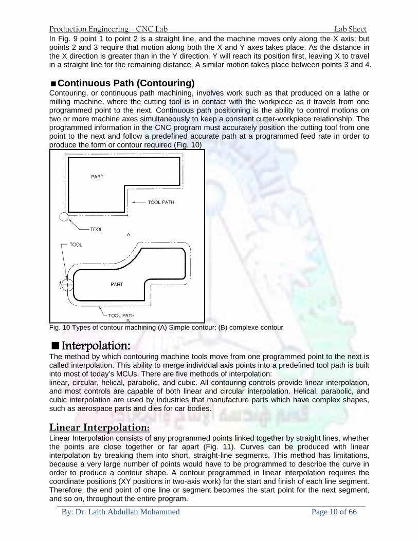
Production Engineering ndash CNC Lab Lab Sheet
By Dr Laith Abdullah Mohammed Page 10 of 66
In Fig 9 point 1 to point 2 is a straight line and the machine moves only along the X axis but points 2 and 3 require that motion along both the X and Y axes takes place As the distance in the X direction is greater than in the Y direction Y will reach its position first leaving X to travel in a straight line for the remaining distance A similar motion takes place between points 3 and 4 Continuous Path (Contouring) Contouring or continuous path machining involves work such as that produced on a lathe or milling machine where the cutting tool is in contact with the workpiece as it travels from one programmed point to the next Continuous path positioning is the ability to control motions on two or more machine axes simultaneously to keep a constant cutter-workpiece relationship The programmed information in the CNC program must accurately position the cutting tool from one point to the next and follow a predefined accurate path at a programmed feed rate in order to produce the form or contour required (Fig 10)
Fig 10 Types of contour machining (A) Simple contour (B) complexe contour
Interpolation The method by which contouring machine tools move from one programmed point to the next is called interpolation This ability to merge individual axis points into a predefined tool path is built into most of todayrsquos MCUs There are five methods of interpolation linear circular helical parabolic and cubic All contouring controls provide linear interpolation and most controls are capable of both linear and circular interpolation Helical parabolic and cubic interpolation are used by industries that manufacture parts which have complex shapes such as aerospace parts and dies for car bodies Linear Interpolation Linear Interpolation consists of any programmed points linked together by straight lines whether the points are close together or far apart (Fig 11) Curves can be produced with linear interpolation by breaking them into short straight-line segments This method has limitations because a very large number of points would have to be programmed to describe the curve in order to produce a contour shape A contour programmed in linear interpolation requires the coordinate positions (XY positions in two-axis work) for the start and finish of each line segment Therefore the end point of one line or segment becomes the start point for the next segment and so on throughout the entire program
Production Engineering ndash CNC Lab Lab Sheet
By Dr Laith Abdullah Mohammed Page 11 of 66
Fig 11 An example of two-axis linear interpolation Circular Interpolation The development of MCUs capable of circular interpolation has greatly simplified the process of programming arcs and circles To program an arc (Fig 12) the MCU requires only the coordinate positions (the XY axes) of the circle center the radius of the circle the start point and end point of the arc being cut and the direction in which the arc is to be cut (clockwise or counterclockwise) See Fig 12
Fig 12 For two-dimensional circular interpolation the MCU must be supplied with the XY axis radius start point end point and direction of cut
Programming Format Word address is the most common programming format used for CNC programming systems This format contains a large number of different codes that transfers program information from the part print to machine servos relays micro-switches etc to manufacture a part These codes which conform to EIA (Electronic Industries Association) standards are in a logical sequence called a block of information Each block should contain enough information to perform one machining operation Word Address Format Every program for any part to be machined must be put in a format that the machine control unit can understand The format used on any CNC machine is built in by the machine tool builder and is based on the type of control unit on the machine A variable-block format which uses words (letters) is most commonly used Each instruction word consists of an address character such as X Y Z G M or S Numerical data follows this address character to identify a specific function such as the distance feed rate or speed value The address code G90 in a program
Production Engineering ndash CNC Lab Lab Sheet
By Dr Laith Abdullah Mohammed Page 12 of 66
tells the control that all measurements are in the absolute mode The code G91 tells the control that measurements are in the incremental mode Codes The most common codes used when programming CNC machines tools are G-codes (preparatory functions) and M codes (miscellaneous functions) Other codes such as F S D and T are used for machine functions such as feed speed cutter diameter offset tool number etc G-codes are sometimes called cycle codes because they refer to some action occurring on the X Y andor Z axis of a machine tool The G-codes are grouped into categories such as Group 01 containing codes G00 G01 G02 G03 which cause some movement of the machine table or head Group 03 includes either absolute or incremental programming while Group 09 deals with canned cycles A G00 code rapidly positions the cutting tool while it is above the workpiece from one point to another point on a job During the rapid traverse movement either the X or Y axis can be moved individually or both axes can be moved at the same time Although the rate of rapid travel varies from machine to machine it ranges between (5 and 20 mmin)
Fig 13 The functions of a few common G-codes The G01 G02 and G03 codes move the axes at a controlled feedrate bull G01 is used for straight-line movement (linear interpolation) bull G02 (clockwise) and G03 (counterclockwise) are used for arcs and circles (circular interpolation)
Production Engineering ndash CNC Lab Lab Sheet
By Dr Laith Abdullah Mohammed Page 13 of 66
Fig 14 Some of the most common G-codes used in CNC programming M or miscellaneous codes are used to either turn ON or OFF different functions which control certain machine tool operations M-codes are not grouped into categories although several codes may control the same type of operations such as M03 M04 and M05 which control the machine tool spindle bull M03 turns the spindle on clockwise bull M04 turns the spindle on counterclockwise bull M05 turns the spindle off
Production Engineering ndash CNC Lab Lab Sheet
By Dr Laith Abdullah Mohammed Page 14 of 66
Fig 15 The functions of a few common M-codes
Production Engineering ndash CNC Lab Lab Sheet
By Dr Laith Abdullah Mohammed Page 15 of 66
Fig 16 Some of the most common M-codes used in CNC programming Block of Information CNC information is generally programmed in blocks of five words Each word conforms to the EIA standards and they are written on a horizontal line If five complete words are not included in each block the machine control unit (MCU) will not recognize the information therefore the control unit will not be activated Using the example shown in Fig 17 the five words are as follows N001 represents the sequence number of the operation G01 represents linear interpolation X12345 will move the table 12345 in in a positive direction along the X axis Y06789 will move the table 06789 in along the Y axis M03 Spindle on CW
Fig 17 A complete block of information consists of five words
Production Engineering ndash CNC Lab Lab Sheet
By Dr Laith Abdullah Mohammed Page 16 of 66
Programming for Positioning Before starting to program a job it is important to become familiar with the part to be produced From the engineering drawings the programmer should be capable of planning the machining sequences required to produce the part Visual concepts must be put into a written manuscript as the first step in developing a part program Fig 18 It is the part program that will be sent to the machine control unit by the computer tape diskette or other input media The programmer must first establish a reference point for aligning the workpiece and the machine tool for programming purposes The manuscript must include this along with the types of cutting tools and work-holding devices required and where they are to be located
Fig 18 The first step in producing a CNC program is to take the information from the print and produce a program manuscript Dimensioning Guidelines The system of rectangular coordinates is very important to the successful operation of CNC machines Certain guidelines should be observed when dimensioning parts for CNC machining The following guidelines will insure that the dimensioning language means exactly the same thing to the design engineer the technician the programmer and the machine operator 1 Define part surfaces from three perpendicular reference planes 2 Establish reference planes along part surfaces which are parallel to the machine axes 3 Dimension from a specific point on the part surface 4 Dimension the part clearly so that its shape can be understood without making mathematical calculations or guesses 5 Define the part so that a computer numerical control cutter path can be easily programmed
Production Engineering ndash CNC Lab Lab Sheet
By Dr Laith Abdullah Mohammed Page 17 of 66
Machine Zero Point The machine zero point can be set by three methodsmdashby the operator manually by a programmed absolute zero shift or by work coordinates to suit the holding fixture or the part to be machined MANUAL SETTING - The operator can use the MCU controls to locate the spindle over the desired part zero and then set the X and Y coordinate registers on the console to zero
Fig 19 The relationship between the part zero and the machine system of coordinates ABSOLUTE ZERO SHIFT - The absolute zero shift can change the position of the coordinate system by a command in the CNC program The programmer first sends the machine spindle to home zero position by a G28 command in the program Then another command (G92 for absolute zero shift) tells the MCU how far from the home zero location the coordinate system origin is to be positioned Fig 19 The sample commands may be as follows N1 G28 X0 Y0 Z0 (sends spindle to home zero position) N2 G92 X4000 Y5000 Z6000 (the position the machine will reference as part zero)
Production Engineering ndash CNC Lab Lab Sheet
By Dr Laith Abdullah Mohammed Page 18 of 66
Work Settings and Offsets All CNC machine tools require some form of work setting tool setting and offsets (compensation) to place the cutter and work in the proper relationship Compensation allows the programmer to make adjustments for unexpected tooling and setup conditions
Work Coordinates In absolute positioning work coordinates are generally set on one edge or corner of a part and all programming is generally taken from this position In Fig 20 the part zero is used for all positioning for hole locations 1 2 and 3
Fig 20 In absolute programming all dimensions must be taken from the XY zero at the top left-hand corner of the part
Fig 21 In incremental programming all dimensions are taken from the previous point In incremental positioning the work coordinates change because each location is the zero point for the move to the next location Fig 21
Production Engineering ndash CNC Lab Lab Sheet
By Dr Laith Abdullah Mohammed Page 19 of 66
On some parts it may be desirable to change from absolute to incremental or vice versa at certain points in the job Inserting the G90 (absolute) or the G91 (incremental) command into the program at the point where the change is to be made can do this
R Plane or Gage Height The word-address letter R refers to a partial retraction point in the Z axis to which the end of the cutter retracts above the work surface to allow safe table movement in the X Y axes It is often called the rapid-traverse distance gage height retract or work plane The R distance is a specific height or distance above the work surface and is generally 100 in above the highest surface of the workpiece Fig 22 which is also known as gage height Some manufacturers build a gage height distance of 100 in into the MCU (machine control unit) and whenever the feed motion in the Z axis is called for 100 in will automatically be added to the depth programmed When setting up cutting tools the operator generally places a 100 in thick gage on top of the highest surface of the workpiece Each tool is lowered until it just touches the gage surface and then its length is recorded on the tool list Once the gage height has been set it is not generally necessary to add the 100 in to any future depth dimensions since most MCUs do this automatically
Fig 22 Using a 100 in gage block to set the gage height or R0 on the work surface
Cutter Diameter Compensation Cutter diameter compensation (CDC) changes a milling cutterrsquos programmed centerline path to compensate for small differences in cutter diameter On most MCUs it is effective for most cuts made using either linear or circular interpolation in the X-Y axis but does not affect the programmed Z-axis moves Usually compensation is in increments of 0001 in up to +10000 in and usually most controls have as many CDCs available as there are tool pockets in the tool storage matrix The advantage of the CDC feature is that it 1 Allows the use of cutters that have been sharpened to a smaller diameter 2 Permits the use of a larger or smaller tool already in the machinersquos storage matrix 3 Allows backing the tool away when roughing cuts are required due to excessive material present 4 Permits compensation for unexpected tool or part deflection if the deflection is constant throughout the programmed path The basic reference point of the machine tool is never at the cutting edge of a milling cutter but at some point on its periphery If a 1000 in diameter end mill is used to machine the edges of a workpiece the programmer would have to keep a 500 in offset from the work surface in order to cut the edges accurately Fig 23 The 500 offset represents the distance from the centerline of the cutter or machine spindle to the edge of the part Whenever a part is being machined the programmer must calculate an offset path which is usually half the cutter diameter
Production Engineering ndash CNC Lab Lab Sheet
By Dr Laith Abdullah Mohammed Page 20 of 66
Fig 23 Cutter-diameter compensation must be used when machining with various size cutters Modern MCUs which have part surface programming automatically calculate centerline offsets once the diameter of the cutter for each operation is programmed Many MCUs have operator-entry capabilities which can compensate for differences in cutter diameters therefore an oversize cutter or one that has been sharpened can be used as long as the compensation value for oversize or undersize cutters is entered
Production Engineering ndash CNC Lab Lab Sheet
By Dr Laith Abdullah Mohammed Page 21 of 66
CNC Programming Hints - MILLING
Production Engineering ndash CNC Lab Lab Sheet
By Dr Laith Abdullah Mohammed Page 22 of 66
CNC Programming Hints ndash TURNING
Production Engineering ndash CNC Lab Lab Sheet
By Dr Laith Abdullah Mohammed Page 23 of 66
CNC
The abbreviation CNC stands for Computer(ized) Numerical(ly) Control(led) and refers specifically to the computer control of machine tools for the purpose of (repeatedly) manufacturing complex parts in metal as well as other materials using a program written in a notation conforming to the EIA-274-D standard and commonly called G-code
CNC was developed in the late 1940s and early 1950s by the MIT Servomechanisms Laboratory CNC machines were relatively briefly preceded by the less advanced NC or Numerical(ly) Control(led) machines The introduction of CNC machines radically changed the manufacturing industry Curves are as easy to cut as straight lines complex 3-D structures are relatively easy to produce and the number of machining steps that required human action have been dramatically reduced With the increased automation of manufacturing processes with CNC machining considerable improvements in consistency and quality have been achieved CNC automation reduced the frequency of errors and provided CNC operators with time to perform additional tasks
CNC automation also allows for more flexibility in the way parts are held in the manufacturing process and the time required to change the machine to produce different components In a production environment a series of CNC machines may be combined into one station commonly called a cell to progressively machine a part requiring several operations CNC machines today are controlled directly from files created by CAM software packages so that a part or assembly can go directly from design to manufacturing without the need of producing a drafted paper drawing of the manufactured component In a sense the CNC machines represent a special segment of industrial robot systems as they are programmable to perform many kinds of machining operations (within their designed physical limits like other robotic systems)
G-code
G-code is a common name for the programming language that is used for NC and CNC machine tools It is defined in EIA RS-274-D G-code is also the name of any word in a CNC program that begins with the letter G and generally is a code telling the machine tool what type of action to perform such as
bull rapid move bull controlled feed move in straight line or arc bull series of controlled feed moves that would result in a hole being drilled bull change a pallet bull Set tool information such as offset
There are other codes the type codes can be thought of like registers in a computer
X position Y position Z position M code (another action register) F feed rate S spindle speed N line number R Radius T Tool selection
Production Engineering ndash CNC Lab Lab Sheet
By Dr Laith Abdullah Mohammed Page 24 of 66
I Arc data X axis J Arc data Y axis
G-code files are output by CAM software such as Smartcam Gibbscam Featurecam Edgecam Mastercam etc G-code is also output by specialized CAD systems used to design printed circuit boards Such software must be customized for each type of machine tool that it will be used to program
Production Engineering ndash CNC Lab Lab Sheet
By Dr Laith Abdullah Mohammed Page 25 of 66
U 2عمل األزرار الرئيسية في ماكنة الخراطة المبرمجة (نصر (
1- SINGLE BLOCK للتأكد من صحة البرنامج (تنفيذ البرنامج خطوة خطوةب تقوم( 2- BLOCK DELETE بجانب ويعمل من األوامرلغاء بلوك معين أليستخدم 3- MACHINE LOCK العمل يستخدم لقفل حركة المحاور الرئيسية مع استمرار البرنامج في
)وهذا مهم للتاكد من صحة البرنامج قبل عملية التنفيذ النهائي(4- CONT CYCLE عملية التشغيل عند ايقافها الي سبب كان او عند ايقافها ألستئناف ستخدم ت
) BAR FEEDER(او في حالة استخدام ) FEED HOLDبسبب (5- DRY RUN وتستخدم لفحص البرنامج بعد ازالة الشغلة حركة سريعة للبرنامج 6- TURRET UP amp DOWN ) حركة حامل العدة TURRET الذي يحمل مجموعة من (
وهذا الزر يعمل مع الزر عكس عقرب الساعة او مع عقرب الساعة ةحركة دوراني العدد )SAFTY (
7- COOLANT ON or OFFفه تشغيل سائل التبريد او ايقا 8- COOLANT AUTO الدوال المساعدة في البرنامج من خالل فه تشغيل سائل التبريد او ايقا 9 -MACHINE START ة لتشغيل هيدرولكيك الماكنميستخد
Production Engineering ndash CNC Lab Lab Sheet
By Dr Laith Abdullah Mohammed Page 26 of 66
10- CLOSE OR OPEN CHUCKالعينة تستخدم لفتح وغلق 11 -T STOCK FWD RET حركة الغراب المتحرك ذهابا وإيابا12 -SPINDLE STOP تعمل على ايقاف حركة دوران العينة 13-JOG SPINDLE تعمل على تدوير العينة مع زر SAFTY 14 -OPT SAFTY مع الدالة ( تعمل عمل التوقف المشروط حيث تعملM1 دالة التوقف (
ط ) فقط األ اذا كان هذا الزر مضغو M1المشروط حيث ال يتوقف البرنامج في حالة وجود دالة ( SAFTY + SPINDLE ) يتم الضغط على زر ( START CYCLEلغرض تحرير زر (
START ) في نفس الوقت بعد الضغط على زر ( START CYCLE مرتين (
NC PC- 15 يستخدم هذا الزر عند ربطCNC يستخدم لنقل المعلومات ث مع جهاز أخر حي بينهما
16 -CALCU زر الخاص بالحاسبة مع زر ( ال وهوINPUT ( 17 - HD1 HD2 يستخدم الختيار العدة مع المخرطة ذات المحاور األربعة 18 - START تستخدم لبدء عملية التشغيل
Production Engineering ndash CNC Lab Lab Sheet
By Dr Laith Abdullah Mohammed Page 27 of 66
19- FEED HOLD تعمل على إيقاف عمل أي G موجودة مع بقاء العينة متحركة 20- M D I أو تشغيل البرنامج ل يتم استخدامه لإلدخا BLOCK BY BLOCK وتعمل عند
إدخال البرنامج بواسطة الشريط المثقب أو أي وسيلة إدخال أخرى أو في عمليات التصفير
21- REST تستخدم العادة تشغيل الماكنة أو مسح اإلنذار الذي يظهر على الشاشة 22- EMERGENCYتستخدم عادة اليقاف الماكنة في حالة الطوارئ فقط
OPERATION MENU KEY
CHAPTER PRG-CMK
OFFSET PROGRAM POSITION FUNCTION MENU KEY
23- POSITIONعلى الشاشة د الموقع الموجور الظها 24- PROGRAMإلظهار برنامج معين واختياره 25- OFFSET الختيار سماحات العدة أو سماحات نقطة المرجع 26- PRG- CHK تستخدم لفحص البرنامج على الشاشة 27- SETTING ألختيار الثوابت على الشاشة 28- SERVICE تستخدم ألستخراج المعامالت والثوابت 29- MESSAGE تستخدم ألظهار األخطاء الناتجة عن البرنامج او اخطاء التشغيل 30- OVERALL ألختيار المواقع 31- RELATIVE MODLINE تعوض عن POSITION 32- DIR MEM يستخدم ألظهار ملف البرامج المخزونة في الذاكرة وعندما نضغط هذا الزر
فان رقم واسم البرنامج سوف يظهر على الشاشة
2أدناه الشفرات الرئيسية التي تعمل على الماكنة المبرمجة نصر
G-CODE DESCRIPTION
G00 Rapid traverse (linear)
G01 Linear Interpolation at feed rate
G02 Circular interpolation (CW) R+
G03 Circular interpolation (CCW) R+
G10 Zero point tools
G20 Imperial data input
G21 Metric data input
G27 Reference return check
G28 Reference return
G29 Return from reference
Production Engineering ndash CNC Lab Lab Sheet
By Dr Laith Abdullah Mohammed Page 28 of 66
G33 Thread cutting
G40 Cancel cutter radius compensation
G41 Cutter compensation left
G42 Cutter compensation right
G54 Work co-ordinate system no1
G70 Finishing cycle
G71 Stock removal turning
G72 Stock removal facing
G74 Face grooving
G75 Diameter grooving
G76 Threading cycle
G90 Absolute date input
G91 Incremental data input
G94 Feed minute mode
G95 Feed rev mode
G96 Constant surface speed mode
G97 Cancel Constant surface speed
) 2أدناه الشفرات الثانوية التي تعمل على الماكنة المبرمجة (نصر
M-code FUNCTION
M00 Program stop
M03 Spindle forward (Tool forward ndash M94 mode)
M04 Spindle reverse (Tool forward ndash M94 mode)
M05 Spindle stop (Tool stop ndash M94 mode)
M08 Coolant on
M09 Coolant off
M30 Program end (with rewind)
M48 Turret shortest path
M52 Turret direction up (CW)
M53 Turret direction down (CCW)
M73 Chuck open
M74 Chuck close
Production Engineering ndash CNC Lab Lab Sheet
By Dr Laith Abdullah Mohammed Page 29 of 66
) وكل جملة مكونة من مجموعة من الكلمات blockإن كل برنامج يتكون من مجموعة من الجمل ()words) لهذا فأن الشفرات الرئيسية والمساعدة هي عبارة عن كلمات (words كما في المثال التالي (
G_ _ P1 Q2 U_ _ W_ _ D___ F_ _
)end of block) ويعني ( ) يكتب الرمز (blockتسلسل الكلمات مهم جدا بعد نهاية كل جملة (
طريقة ادخال البيانات الى الماكنة ــــــــــــــــــــــــــــــــــــــــــــــــــ
) MDIيمكن ادخال البيانات الى الماكنة بعدة طرق فقد يكون األدخال عن طريق قناة السيطرة ( MANUAL DATA INPUT ) او عن طريق قناة األضافة EDIT كما يمكن ادخال البيانات عن (
) RS ndash 232 COMMUNICATIN LINKطريق استخدام سلسلة الربط (
₤⅗₌⅗₌ ⅙₌₨image₍₡ ₤₌ℌ⅗₌ Ⅸ⅗ⅥⅯ₌ ₤₡ℌ₰₨⅗₌G71
الخراطة الطولية G71الغرض من التجربة عمل نموذج للخراطة بأستخدام الدالة تستعمل هذه الدالة للخراطة الطولية اي على طول محور المشغولة وكما هو موضح بالشكل ادناه
تعتبر هذه الدالة من الدوال التي ال تحتاج الى تكرار او إعادة كتابتها أي انها دالة تكرارية بمعنى ان اي
الذي هي دالة حركة G01خطوة تكون من ضمن هذه الدالة سوف تكرر العملية اي عند استعمال امر مثل خطية تتضمن القطع مع التغذية مع اعطاء القطر المراد قطعه و مراعاة عمق القطع المعطى سوف يتكرر
هذه االمر وصوال الى العمق المطلوب وهكذا لبقية الدوال
G71 المستخدمة للدالة الصيغة
G71 P1 Q2 U___ W___ D___ F___ حيث إن
P1 بداية الخطوة االولى = Q2 نهاية الخطوة =
Uوضع السماحات بأتجاه محور = X W وضع السماحات بأتجاه محور = Z وتكاد تكون مهملة وتوضع اشارة سالب Dعمق القطع وتوضع رقم صحيح مثل = D500 اي نصف ملمF التغذية والتي لها عالقة بالدالة = G95
Production Engineering ndash CNC Lab Lab Sheet
By Dr Laith Abdullah Mohammed Page 30 of 66
G71الدالة استخدام مثال على
T0100 M48 G0 X26 Z2 M08 T0101 G90 G95 G97 S500 M03 G71 P1 Q2 U03 W00 D500 F01 N1 G0 G42 X00 G01 Z00 G01 X2517 G01 Z-5352 G01 X7391 Z-9366 G01 Z-19145 N2 G28 M30
الجانب العملي
االجهزة واالدوات المستخدمة CNCماكنة خراطة مبرمجة 1 ملم 80قضيب من االلمنيوم قطر 2 ةفير ني 3 جاه أيمن تهولدر كاربيدي ذوا 4
طريقة العمل يتم تثبيت قضيب من االلمنيوم على العينة التابعة للماكنة مع مراعاة الطول المراد استعماله في عملية 1
الخراطة ) turretتثبيت عدة القطع في المكان الصحيح في ( 2
Production Engineering ndash CNC Lab Lab Sheet
By Dr Laith Abdullah Mohammed Page 31 of 66
بالنسبة الى القطعة المثبتة على العينة XZيتم تصفير الماكنة للمحاور 3 تصفير للمحورZ تكون مالمسة العدة الى وجه الشغلة تصفير للمحورX تكون مالمسة العدة الى سطح الشغلة الموازي لمحور X
يتم كتابة البرنامج أما بطريقة يدوية أو بالحاسوب مع وضع كل الظروف الالزمة للتشغيل ( عمق القطع 4 التغذية السرعة المطلوبة نوع المعدن )
ادخال البرنامج الى الحاسوب الموجود داخل الماكنة مع تهيئة الماكنة للتشغيل 5
المطلوب G71عمل برنامج يدوي على الدالة 1 رسم الشكل الشكل النهائي المطلوب مع وضع األبعاد 2
Ⅺ⅟₍euro⅗₌ ₤₡ℌ₰₨⅗₌₣ ₤⅗₌⅗₌ ⅙₌₨image₃₡ Ⅺℂtradeℒ⅗₌ ӈ₍Ⅴ⅟ⅳ₌ G70
G70 الغرض من التجربة عمل انهاء سطحي للمشغولة بواسطة الدالة
من الضروري إعطاء G71هذه الدالة تعمل شوط واحد فقط وتكون معتمدة على عمليات القطع في الدالة اللغاء مقدمة االداة (أي لكي تتم عملية االنهاء السطحي بدون حسابات نصف قطر مقدمة االداة ) G42دالة
G70الصيغة المستخدمة للدالة
G70 P1 Q2 F___ حيث ان
P1 بداية الخطوة االولى = Q2 نهاية الخطوة =
F التغذية والمرتبطة بالدالة = G95
وذلك ألن دالة االنهاء السطحي تحقق X Zمالحظة الدالة التحتاج لكتابة السماحات التابعة للمحورين المسافات الحقيقة المراد انتاجها للمشغولة
G71و G70مثال على الدالة
T0100 M48 G0 X26 Z2 M08 T0101 G90 G95 G97 S500 M03 G71 P1 Q2 U03 W00 D500 F01 N1 G0 G42 X00 G01 Z00 G01 X2517 G01 Z-5352 G01 X7391 Z-9366 G01 Z-19145 N2 G97 S750 MO3
Production Engineering ndash CNC Lab Lab Sheet
By Dr Laith Abdullah Mohammed Page 32 of 66
G70 P1 Q2 G40 F009 G28 M30
الجانب العملي الحظ التجربة األولى
المطلوب
G70 عمل برنامج يدوي على الدالة 1 رسم الشكل النهائي المطلوب مع وضع االبعاد 2
₪⅗₍euro⅗₌ ₤₡ℌ₰₨⅗₌₣ ₤⅗₌⅗₌ ⅙₌₨image₍₡ ⅝₍ⅠimageⅯ₌ ⅞ⅫⅦ⅔₧ G76
G76 للمشغولة بواسطة الدالةةالغرض من التجربة عمل أسنان خارجية أو داخلي
في هذه التجربة سوف نقوم بعمل األسنان الخارجية وهنا تكون حركة العينة ثابتة وهذا ضروري بسبب أن ) تكون متصلتين الكترونيا وعليه أي اختالف في سرعة العينة تؤدي إلى اختالف motionالعينة والحركة(
) servoفي سرعة الخدمة(يرتبط اتجاه تكوين األسنان باتجاه دوران العينة مثال إذا كانت األسنان ذات اتجاه أيمن يكون اتجاه دوران
وهنا نقلب العدة إلى االسفل وكما هو موضح بالشكل أدناه MO3العينة عكس عقرب الساعة أي نستعمل
Production Engineering ndash CNC Lab Lab Sheet
By Dr Laith Abdullah Mohammed Page 33 of 66
الخطوة هي عبارة عن المسافة ما بين قمة سن إلى قمة سن أخر عمق السن هو العمق المطلوب تكوينه لألسنان
G76 الصيغة المستخدمة للدالة
G76 X___ Z___ K___ F___ D___ A___
حيث أن X القطر الداخلي للسن =Z طول السن =K عمق السن وتستخرج من المعادلة التالية =K=065F F الخطوة =D عمق القطع بالمايكرون فقط =A زاوية السن =
G76مثال على استخدام الدالة T0300 M48 GOO X30 Z4 T0303 M08 G97 S500 MO3 G76 X28375 Z-20 K08125 F125 D120 G00 X40 Z4 G28 M30
Production Engineering ndash CNC Lab Lab Sheet
By Dr Laith Abdullah Mohammed Page 34 of 66
الجانب العملي الحظ التجربة األولى
المطلوب
G76عمل برنامج يدوي على الدالة 1 رسم الشكل النهائي المطلوب مع وضع األبعاد 2
Ⅺ⅘₌⅗₌ Ⅵ₂ Ⅺ₯ℋ₍⅗₌ ℌℲℂ⅗₌ ⅞ⅫⅦ⅔₧ ₤K₡₌ℌ⅗₌ ₤₡ℌ₰₨⅗₌)Groove ₤⅗₌⅗₌ ₤tradeimage₌Ⅶ₡ (G75
G75 بواسطة الدالة grooveالغرض من التجربة تكوين
) للمشغولة وتعتمد شكل الحفر على طريقة grooveتستعمل هذه الدالة لتكوين الحفر الخارجي والداخلي (
التشغيل وعلى الشكل المراد إنتاجه وتعتبر هذه الطريقة من عمليات التشكيل للمعدن إن هذه الدالة هي دالة مالحظة مع G75في هذه التجربة سنقوم بعمل الحفر الخارجي بواسطة الدالة
تكرارية وغير تكرارية حسب نوع التشغيل
G 75 الصيغة المستخدمة للدالةG75 X___ Z___ I___ K____
حيث أن
X العمق النهائي لقطر الشغلة =Z عرض الحفر =I الدخول في كل مرة =
K التزحيف على محور =z بالنسبة للعدة
Production Engineering ndash CNC Lab Lab Sheet
By Dr Laith Abdullah Mohammed Page 35 of 66
G75مثال على استخدام الدالة
T0500 M48 GOO X100 Z -20 T0505 M08 G97 S700 MO3 G75 X84 Z -38 I 05 K4
الجانب العملي الحظ التجربة األولى
المطلوب
G76عمل برنامج يدوي على الدالة 1 رسم الشكل النهائي المطلوب مع وضع األبعاد 2
Production Engineering ndash CNC Lab Lab Sheet
By Dr Laith Abdullah Mohammed Page 36 of 66
CNC Milling Machine Mechanical Construction
Guideways The guideways of CNC machines are made of steel To reduce the frictional forces they are coated with a strip of PTFE (Poly Tetra Fluoro Ethylene)
Ballscrews On conventional lathes a leadscrew is used to converts the rotary motion of the hand wheel into linear motion of the slides Leadscrews have a high coefficient of friction and backlash On CNC machines a ballscrew is used instead of a leadscrew Friction and backlash are much less than on leadscrews
Guideway
Production Engineering ndash CNC Lab Lab Sheet
By Dr Laith Abdullah Mohammed Page 37 of 66
bullMachining operations Direction of cutting Based on the direction of the cutter rotation and work piece feed milling operations are classified into two types 1-Up milling (Convention milling) In up milling the metal is removed by rotating the cutter against the direction of travel of the part
Feed
Machine table
Part
Cutting tool
Chip thickness at theexit of the tooth
2-Down milling (Climb milling) In climb milling the metal is removed by rotating the cutter with the direction of travel of the part
Machine table
Part
Cutting tool
Chip thickness at theentrance of the tooth
Production Engineering ndash CNC Lab Lab Sheet
By Dr Laith Abdullah Mohammed Page 38 of 66
bullTooling Tool geometry The geometry of the tool tip affects the way that the metal cutting is performed The nose radius rake angles relief angles etc must be selected with care
Radial relief
Radial rake
Axial relief
Approach angle
Axial relief
Corner radius Face mill Face milling cutters are used to mill flat surfaces Commonly used face milling cutters Cutter with 75 degree approach
75 deg
Cutter with 90 degree approach (Square shoulder face mill)
90 deg
Cutter with 45 degree approach
Production Engineering ndash CNC Lab Lab Sheet
By Dr Laith Abdullah Mohammed Page 39 of 66
bullCNC Programming Axes convention The Z axis is along the spindle axis The X and Y axes are perpendicular to Z VMC
Z
Y
-
+
-+
X- +
+Z
-Z
+Y
-Y
-X +X
Part
Machine table
X
YZ
G00 Rapid traverse When the tool being positioned at a point preparatory to a cutting motion to save time it is moved along a straight line at Rapid traverse at a fixed traverse rate which is pre-programmed into the machines control system Typical rapid traverse rates are 10 to 25 m min but can be as high as 80 mmin
Production Engineering ndash CNC Lab Lab Sheet
By Dr Laith Abdullah Mohammed Page 40 of 66
Format N_ G00 X__ Y__Z__
G01 Linear interpolation (feed traverse) The tool moves along a straight line in one or two axis simultaneously at a programmed linear speed the feed rate Format N__ G01 X__ Y__Z__ F__
Part
Feed
Part
Feed
G02G03 Circular interpolation The tool moves along an arc in two axes simultaneously at a programmed linear speed the feed rate
Production Engineering ndash CNC Lab Lab Sheet
By Dr Laith Abdullah Mohammed Page 41 of 66
Format N__ G0203 X__ Y__Z__ I__ J__K__ F__ using the arc center OR N__ G0203 X__ Y__Z__ R__ F__ using the arc radius G02 moves along a CW arc G03 moves along a CCW arc Arc center The arc center is specified by addresses I J and K I J and K are the X Y and Z co-ordinates of the arc center with reference to the arc start point
X
Y
Arc center
Arc endArc start
- J
- I
I = X coord of center - X coord of start point J = Y coord of center - Y coord of start point K = Z coord of center - Z coord of start point I J and K must be written with their signs
Production Engineering ndash CNC Lab Lab Sheet
By Dr Laith Abdullah Mohammed Page 42 of 66
bullWork holding
Rotary table
Fixture base
Component
Clamp
Stud
Fixtures The use of fixtures 1 Improves repeatability of dimensions 2 Improves working conditions 3 Cuts down requirement of skilled labour 4 Reduces part loading and unloading time 5 Improves safety in the working area 6 Reduces the cost of machining There are two types fixtures commonly used 1 Special fixture Special fixtures are used to hold and locate the typical components which are having complex shape and to be located with the reference hole (dowel hole) Special fixtures are required for components like gear case cover cylinder heads etc 2 Modular fixture Modular fixture is a set different kind of clamping and locating elements These fixtures are used to hold identical components in different sizes and components of box type Example Manifolds head stocks connecting rods and flanges
Production Engineering ndash CNC Lab Lab Sheet
By Dr Laith Abdullah Mohammed Page 43 of 66
bullMachine setting
Determining X and Y work zero offset Case 1
Part
Machine table
Part
End mill or reamer
Work offset X0Y0 For determining X work zero offset bull Touch the periphery of the end mill or reamer to the part bull Enter current machine X value + cutter radius as X work zero offset For determining Y work zero offset bull Touch the periphery of the end mill or reamer to the part bull Enter current machine Y value - cutter radius as Y work zero offset Case 2
Part
Machine table
Part
End mill or reamerWork offset X0Y0
bull Mount the dial indicator on machine spindle true the bore bull Enter current machine X and Y value as X and Y work zero offset
Production Engineering ndash CNC Lab Lab Sheet
By Dr Laith Abdullah Mohammed Page 44 of 66
How to Select a Cutting Fluid
One part of the metal cutting equation that is sometimes overlooked however is
the choice of an appropriate cutting fluid With todayrsquos system approach to metal
cutting use of the right metalworking fluid has become just as much a part of the
solution as the other elements In fact at least one company is now integrating
cutting fluids and cutting tools into effective metal cutting systems Following are
some things to consider when choosing your next cutting fluid
The Four Key Questions
There are four vital pieces of information that are necessary when choosing a
cutting fluid They are
1 What are you cutting
2 What is the chemistry of your water
3 What are you using now
4 What are your options
5 What do you prefer
What Are You Cutting
The first question ndash ldquoWhat are you cuttingrdquo ndash is often the most difficult to answer
because most shops handle a variety of workpiece materials on a regular basis If
the answer is an unequivocal ldquoaluminumrdquo or ldquostainless steelrdquo or ldquocast ironrdquo the
selection of a cutting fluid can be quite simple and straightforward Unfortunately
that is seldom the case in anything but a high-volume plant Where aluminum or
other nonferrous metals are a significant part of the mix a non-staining cutting
fluid is a must Generally speaking this will be a semi-synthetic with special
ingredients to prevent bi-metallic corrosion and staining of non-ferrous workpieces
Where the ferrous metals predominate however a more general purpose semi-
synthetic or hybrid fluid might be a more economical choice
Production Engineering ndash CNC Lab Lab Sheet
By Dr Laith Abdullah Mohammed Page 45 of 66
What is The Chemistry of Your Water
The second question ndash ldquoWhat is the chemistry of your waterrdquo ndash is probably the
single most common reason for the success or failure of a cutting fluid Very few
plants invest the money necessary to install effective water purification systems
using deionization or reverse osmosis technology Unfortunately the chemicals
present or not present in the water used to re-constitute a cutting fluid make a
tremendous difference in its performance and sump life Most manufacturers of
cutting fluids will perform the necessary water testing to determine exactly what
minerals are dissolved in your water and make a fluid recommendation based on
the results
What are you using now
The third question ndash ldquoWhat are you using nowrdquo ndash helps narrow the range of
choices When coupled with an objective analysis of the strengths and weaknesses
of the current fluid the answer to this question can quickly point you toward a
relatively small number of competitive alternatives that have the attributes required
to meet your cutting needs Many cutting fluids are in use today simply because
they were in use yesterday It is a hard reality of todayrsquos marketplace that if one
isnrsquot constantly striving to improve they will certainly be overtaken by a
competitor who is
What Are Your Options
The fourth question ndash ldquoWhat are your optionsrdquo ndash leads to the final selection of a
cutting fluid Cutting fluids can be divided into four general groups based on their
chemistry
They are
bull Soluble Oils ndash quite literally oil dispersed in water
bull Synthetics ndash completely oil free man-made coolants in solution
Production Engineering ndash CNC Lab Lab Sheet
By Dr Laith Abdullah Mohammed Page 46 of 66
bull Semi-Synthetics ndash a mixture of natural and synthetic lubricants with up to 30
mineral oil
bull Hybrids ndash a special class of semi-synthetics with a mineral oil content of about
15 Each fluid type has advantages and disadvantages which make it suitable for
a particular group of applications In addition there are costperformance trade-
offs to be made between the groups within a specific set of applications For
example where a hybrid and a semi-synthetic may both be suitable for a particular
use the hybrid might provide longer sump life at a slightly higher initial cost
while some semi synthetics may be more economical to recycle or dispose of while
not giving as long a tank life The final decision in this case would have to be made
on the detailed economics of the shop where the fluids were to be used and on the
ownerrsquos individual preferences
Soluble Oils
Soluble oils are oils that disperse in water when emulsifiers are added They are
generally suitable for moderate-to heavy-duty machining and grinding of all non-
ferrous metals carbon and cast steels and in applications where dissimilar metals
such as aluminium and steel are present They can also be used in turning drilling
tapping reaming gear cutting broaching as well as internal and centerless types
of grinding operations Soluble oils provide excellent aluminium and copper
corrosion control good rancidity control which extends fluid for long lasting
trouble-free performance and good concentrate and mix stability making it ideal
for mixing in water with a minimal amount of agitation An example of this is
Valenitersquos VNTreg-650 premium heavy-duty soluble oil
Synthetics
Synthetics are completely oil free solutions made of polymers organic and
inorganic materials that are mixed with water These clear low foaming and bio-
Production Engineering ndash CNC Lab Lab Sheet
By Dr Laith Abdullah Mohammed Page 47 of 66
stable coolants are ideal for machining and grinding of ferrous materials carbon
steels or cast iron Their complex lubricant packages make synthetics well-suited
for tough-to-machine materials such as stainless steels and high-temperature alloys
Certain synthetics are specifically designed to address the primary failure modes of
flank wear and nose wear Although there are many benefits some synthetics may
cause staining of non-ferrous materials
Semi-Synthetics
Semi-synthetic fluids are a mixture of oils synthetic emulsifiers and water They
were primarily developed for the aircraft nuclear and related industries
Consequently they work extremely well on all non-ferrous metals such as titanium
aluminium copper brass bronze and stainless steel in both machining and
grinding Semi-synthetics can be used on ferrous metals too They are chlorine-
free to reduce bi-metallic corrosion and staining of metals They should be used at
a 5-8 dilution with water depending on the severity of the operation
Hybrids
Hybrids are cutting fluids custom engineered to solve a particular problem For
example Valenitersquos VNTreg-800 was developed to be very clean in the machining
and grinding of cast iron It provides better stability in hard water and rejects tramp
oil very well which adds to its bio-stable chemistry Hybrids work extremely well
on all metals in both machining and grinding They should be mixed at a 5-7
dilution with water depending on the condition of the water
What Do You Prefer
The final question ndash ldquoWhat do you preferrdquo ndash is usually the ldquotie breakerrdquo where
there is more than one appropriate cutting fluid available Here again as in the
case of what is being used now the key is to examine your preferences objectively
Production Engineering ndash CNC Lab Lab Sheet
By Dr Laith Abdullah Mohammed Page 48 of 66
and specifically to identify the real reasons behind a preference If you cannot
point to specific reasons why one class of cutting fluid is preferred over another
you are well advised to follow the recommendations of the professional who has
analyzed your requirements Choosing the right fluid today is easier than ever as
the system approach to metal cutting productivity continues to grow in acceptance
The day is not far off when choosing a complete solution will be as easy as
choosing the right insert and chip breaker today The answers are available and the
results will more than justify the time you spend choosing the right metal cutting
fluid
Useful Links wwwball-screwsnet
wwwlubelinkcom
wwwmachinerylubricationcom
wwwadvancedmanufacturingcom
wwwmmsonlinecom
wwwcuttingtoolengineeringcom
wwwgeartechnologycom
wwwengineersedgecom
wwwagmaorg
wwwefundacom
wwwsaeorg
wwwsmeorg
wwwastmorg
wwwissorg
wwwmachinetoolscom
wwwansiorg
wwwasmeorg
wwwcnccicom
wwwmatlscom
wwwthefreedictionarycom
wwwengineersupplycom
Production Engineering ndash CNC Lab Lab Sheet
By Dr Laith Abdullah Mohammed Page 49 of 66
SurfCAM Tutorial ndash Beginning with the basics
Background SurfCAM is a computer aided manufacturing (CAM) software which allows you to create manage and modify tool paths for computer aided designed (CAD) part The software requires a CAD model or requires that you create some geometry within SurfCAM with some rudimentary tools provided The tool paths are created or stored internally in SurfCAM in a generic programming language called APT Once the tool paths are created the APT paths are translated using a post processor into typical machine G-code
Opening SurfCAM SurfCAM can be opened from the Novell Applications Launcher on most Industrial Engineering computer labs workstations Search under lsquoallrsquo applications and double click on SurfCAM 2005 Once the program opens a license must be selected from the list (not the Demo license) to enable saving the file later Choose one of the 30 licenses available If for some reason the licenses are not listed on the license manager form select server list and type ldquobonnieeosncsuedurdquo A list of available licenses should appear Select a license and click OK After the license is selected an Add StockFixture form (Figure 1) opens allows you to add a model which represents the pre-machined stock or a fixture Click on OK without adding either Both of these items can be added later under a more appropriate dialog
Figure 1 Add Stock or Fixture dialog box
Production Engineering ndash CNC Lab Lab Sheet
By Dr Laith Abdullah Mohammed Page 50 of 66
SurfCAM Interface
Figure 2 SurfCAM Windows based interface
SurfCAM is a windows based software system so most of the typical windows functions under File are applicable This is where you can open save exit print etc The Create menu allows the user to create different geometry forms Here you can create a point line surface chamfer circle and many other geometry types For the most part these functions are not used by beginners but are useful when creating bounding curves where you donrsquot want the tool to move outside (constraining the tool) The Edit menu allows you to change or modify many different entities such as changing lines altering surfaces joining surfaces trimming or breaking elements add control points etc Again these features are helpful to advanced users and are not covered in detail in this tutorial The Display menu offers the ability to change the orientation of the part on the screen The typical rotate pan fit to screen and zoom functions are available as well as several functions which allow the user to shift between views or call up a named view (ie top bottom etc) The NC menu is the main machining interface menu In this menu you select the general form of machining (2 axis 3 axis 4 axis 5 axis turning etc) and under the general form a more specific machining function is selected This menu is the most used and the options contained must be fully understood to get the most out of SurfCAM Each function will be described in some detail in a further chapter The Analyze menu contains options such as measuring the distance between points angles tangency elements etc These functions are auxiliary functions meant to help you understand the part better but basically provide no functionality for making tool paths for CNC machines Thus these will not be covered The Tools menu allows the user to change the system options modify keyboard shortcuts change the model units etc These options are again not used by beginners Finally the Help menu provides access to the online users manual In lieu of clicking the Help menu the F1 key is the shortcut key for help (as it is in most windows based programs)
Importing a CAD model Importing a CAD model that is stored locally is done by selecting File-gtOpen On the Files of type dropdown box choose the type of file you wish to open (Figure 3) Do this prior to negotiating your way through the maze of folders to prevent having to go through the folder tree again Once the file type is selected find the file you are trying to open and click the Open
Production Engineering ndash CNC Lab Lab Sheet
By Dr Laith Abdullah Mohammed Page 51 of 66
button SurfCAM will then attempt to read the file you have selected SurfCAM may provide a dialog box describing what it has imported and identify if it was successful If this dialog is provided simply click close without saving
Figure 3 Open Dialog Note - Change type of file prior to finding the file you wish to open
SurfCAM allows a user to import several different types of CAD files the most common types which you will likely import are SolidWorks part files (sldprt or prt) AutoCAD files(dxf) or IGES (igs or iges) Native file import (such as is the case with SolidWorks) provides the greatest information transfer and generic file imports (such as is the case with IGES) provide the least Normally it is to the advantage of the user to use native file importing procedures when available Recently (2005) SurfCAM added some compatibility with SolidWorks This allows the user to create tool paths for a part and if an engineering change is needed for the part update the part in SolidWorks When the part is then opened in SurfCAM the changes are noted and a simple update operation command is needed This however does not operate with complete transparency andor accuracy and thus users need to be cognizant of changing CAD models
SurfCAM Geometry In SurfCAM two basic types of geometry are used the surface and the point A surface (Figure 4) is a so called spline (NURBS or B-Spline are the two most common) surface (parameterized by two values u and v) such that every location on the surface can be defined as a function of these parameters In other words SurfCAM can calculate the location of any point on the
Production Engineering ndash CNC Lab Lab Sheet
By Dr Laith Abdullah Mohammed Page 52 of 66
surface Surfaces are used primarily in 3 4 and 5 axis machining and require a significant
amount of processing power and time Figure 4 Surfaces model of a mold half Note the difference between this and Figure 2 a wireframe model
Point or line based models are often referred to as wireframe (Figure 5) models because the models consist of connected lines and resemble the part only at the intersection of two surfaces Wireframe models were made popular lsquoback in the dayrsquo when computer processing was expensive There are times when each of the models are important and selecting model geometry when applying a SurfCAM operation will be much simpler if you understand the differences between the two When importing a SolidWorks model the default is both the surfaces and the wireframe geometry are imported
Figure 5 Wireframe model of the mold in Figure 1
Steps to Creating Tool Paths Once a CAD model is imported into SurfCAM tool paths can be created There is no one correct way to create tool paths however there is a set of general steps to take to ensure the tool paths are created with a minimum amount of hardship (note the wordinghellipHardship is inevitable when creating tool paths it is the intent of this manual to minimize this) The following is a list of steps which should be considered when making tool paths
Production Engineering ndash CNC Lab Lab Sheet
By Dr Laith Abdullah Mohammed Page 53 of 66
1 Plan ahead a Orient the part in SolidWorks such that if only one side is to be machined that
side is the Top view This can be done early in SolidWorks by choosing a plane parallel the X-Y plane as the sketch plane for the machined geometry
b Orient the part in SolidWorks such that the origin is somewhere of relative importance and someplace in space that can be easily identified when placed on the machine This is extremely important to minimize set up time at the machine (note ndash my personal preference for a part that is to be fully machined [ie stock exists on all sides] is to place the origin at the center and top of the parthellipjust my preference)
c Orient the part in SolidWorks such that the X and Y axes are aligned as you want them on the machinehellip
d Planning ahead will save you many hours of headaches laterhelliptrust me 2 Import the model 3 Choose a construction view such that the tool approaches the side to be machined
from the positive Z axis direction (as defined by part origin) a This is done by clicking on the CView icon
b From the list of named views chose the view which orients the origin as you would like
c If one of the views does not fit your criteria you have two choices i Perform a transformation of the part in SurfCAM or SolidWorks
ii Add a new construction view by selecting new This option requires a relatively good understanding of right hand coordinate frames but is very usefulhellipNormally used by more advanced users
d Be sure the CoordVIEW selection is made vs CoordWORLD This ensures the tools will be controlled from the coordinate frame selected by the view (ie the origin on the part) instead of the origin on the lower left corner of the screen This will be especially important when we get into 4 and 5 axis machining
4 In the Operations Manager (Figure 6) select Setup One and change the name to something meaningful ndash like Front Side Mold Cavity
a Access the Operations manager by right clicking or by selecting the Operations Manager icon in the tool bar
b Operations Manager is where the tool paths are managed once they are created as well as where individual tool paths can be verified
Production Engineering ndash CNC Lab Lab Sheet
By Dr Laith Abdullah Mohammed Page 54 of 66
5 Roughing Tool Paths a Create the tool paths to remove the majority of the material (if applicable) b Use NC-gt3Axis-gtZ rough or Plunge Rough c Described in next section
6 Create Finishing Tool Paths a Described in next section
7 Add another setup if necessary 8 Perform steps 3 through 6 as necessary 9 Verify the tool paths are correct 10 Use a post processor for the tool paths to create G-Code for machine
Creating Tool Paths The following is a list of operations what they are intended for how they generally work and some parameters that may be adjusted to modify the tool paths
2 Axis tool paths Unless otherwise noted 2 axis tool path functions require lines or arc segments as input parameters (as opposed to surfaces) There are several options as to how these segments are chosen the most prevalent is the chain option and the second most prevalent is the single When choosing the line segments using the chain option SurfCAM will try to link a complete path of segments based on an initial segment chosen by the user If the operation is planer (ie pocket or contour) the segments must lie on the same plane If the operation is non-planer (ie contour 3D) SurfCAM will prompt the user to specify segments when it encounters a branch point
Figure 6 Operations Manager view showing setup one re-labeled as Front Side Mold
Production Engineering ndash CNC Lab Lab Sheet
By Dr Laith Abdullah Mohammed Page 55 of 66
When using the single element option the user must manually choose each segment desired for the operation Note that most operations do not require a closed loop of segments you may specify for instance an open contour where the tool is supposed to move The order of choosing segments is important This order determines the path of the tool in the sense that if three segments are chosen such that the middle segment is chosen last there will be three different plunge and machine operations one on each segment If the operation was to make a continuous contour around the outside of the part the segments should be chosen in order of the desired tool trajectory
Operations
Pocket Pocket operation in SurfCAM is used to cut an enclosed space from the inside to the outside at one particular depth The operation starts in the center of an enclosed area (with a plunge move in the ndashZ direction) and makes incremental closed paths towards the pocket boundaries in user defined path offsets (Figure 7) The user chooses the boundary of the pocket (line segments) and if more than one pocket is chosen SurfCAM will ask the user to click inside a pocket
Figure 7 Two examples of using the pocketing operation
The pocket operation allows for creating a projection of the pocket paths on multiple planes This is useful if you have a deep pocket which will not allow the tool to cut directly at the depth of the pocket but would be easily done using the same paths at several different Z heights On the cut control (Figure 8) tab the user specifies where the chosen geometry (pocket segments) lie (ie bottom or top) Then under the amount to remove specify the total material height to be removed and the rough spacing (amount you wish to advance the Z axis with each pocket step) You may also specify a finishing pass and as well as stock to leave
Production Engineering ndash CNC Lab Lab Sheet
By Dr Laith Abdullah Mohammed Page 56 of 66
Figure 8 Example of Contour Operation with multiple passes
Contour Contouring in SurfCAM is used to perform peripheral milling on the inside or outside of a line segment (Figure 9) The user is to identify the line segments which define a contour (does not have to be a closed loop of segments) SurfCAM may or may not require the user to specify a side to contour (ie which side of the line is the tool to cut) For contouring each segment must lie on the same plane
Production Engineering ndash CNC Lab Lab Sheet
By Dr Laith Abdullah Mohammed Page 57 of 66
Figure 9 Examples of parts cut with 2-Axis Contour
Contour 3D Contour 3D is the same operation type as contour but allows the user to specify segments on different planes for the tool to cut along
Drill Drilling operations are any rotating tool operation meant to engage the part from a single direction ndash namely from the positive Z direction Drilling operations can be specified using circle point or line segments After choosing NC-gt2-Axis-gtDrill SurfCAM allows the user to choose multiple circles or points defining holes to be drilled Drilling operations also allow the user to incorporate more than 1 operation such as a center drill a drill and a reaming operation After selecting the locations for the drilling operation a dialog box (Figure 10) allows the user to add change or delete tools to be used in the operation As displayed in the following figure the spotdrill operation is followed by a drilling operation followed by a tapping operation The depth of each tool can be controlled individually by double clicking the total depth cell in and manually entering Tools can be added before or after operations which the cells are highlighted by selecting either of the insert buttons at the top or by the insert menu Select tool button allows the user to change the tool size or type
Production Engineering ndash CNC Lab Lab Sheet
By Dr Laith Abdullah Mohammed Page 58 of 66
Figure 10 Drill operation manager Several operations can be completed at one time
Figure 11 Drill operation including the spotdrill drill and tap as outlined in Fig 10
3 Axis tool paths SurfCAM requires surfaces as inputs for 3 Axis tool paths Surfaces can be created in SurfCAM but are most easily created in a CAD package and imported into SurfCAM Surfaces allow SurfCAM to identify every point on the surface in 3 dimensions unlike 2D geometry (wireframes) which only identify positions on the plane Creating tool paths with complex surfaces takes a very significant amount of processing power so expect 3 Axis tool path generation to take longer
Production Engineering ndash CNC Lab Lab Sheet
By Dr Laith Abdullah Mohammed Page 59 of 66
Operations
Cut 3 Axis cut operation takes a surface and using the flow lines creates a rastering path over the surface with the tool tip riding on the surface The primary direction will be defined by the flow lines of the surface (which can be edited by Edit-gtSurfaces-gtArrow-gtDirection) If you intend to cross surface boundaries you must merge the surfaces (Edit-gtJoin and choose the two surfaces)
Z-Rough The Z-rough operation is used to remove a large amount of material prior to finish machining Roughing operation is typically the first operation you perform for each setup The Z-Rough operation cuts the part in user defined intervals For each of these intervals a surface intersection between the part and the plane is performed and a 2D pocket or contour operation is performed on that plane This is performed on each plane When choosing NC-gt3 Axis-gtZ rough the first dialog box you will encounter asks for a bounding box to be defined Choose the Extents Box and a second dialog box will ask for the coordinates which define the box (Figure 12) This is the stock size you expect to machine the part from Input the coordinates or change the additional offset amounts (in XY or Z) as appropriate and click Calculate Bounding Box
Figure 12 Material Extents Box Example
Next choose the tool and cutting parameters that you desire and click on the Cut Control Tab (Figure 13) Here you will find the following parameters which are often changed Stock to
Production Engineering ndash CNC Lab Lab Sheet
By Dr Laith Abdullah Mohammed Page 60 of 66
leave ndash this is an offset amount from the surfaces which leaves a small amount of material to finish machine Minimum and Maximum Z values ndash Defines area to machine Z Step Size ndash This identifies the plane intervals for the surface intersection planes (the first interval will be at the top of the selected area and successive increments down in Z will be cut until the Minimum Z value is reached)
Figure 13 3Axis Z Rough Cut Control
The 3Axis Z-Finish operation works in exactly the same way 3 Axis Z-Finish is most appropriate for finishing vertical or near vertical walls
3D Offset The 3D Offset operation creates a tool path using a 2D or 3D boundary by offsetting the boundary in concentric offset cutting passes Each pass calculates the tool engagement and maintains the engagement somewhat constant The advantage (significant) is the scallop height ndash height of the material between passes ndash is controlled thus the surface finish is predictable When choosing 3D Offset surfaces are selected as well as 2D or 3D boundaries The boundaries define the concentric offset paths shape as well as limit the tool path area Choose NC-gt3Axis-gt3D Offset from the drop down menus SurfCAM will prompt you to select the surface or surfaces to cut across Select the surfaces you wish to machine and then select the tool and cutting parameters you wish use Next select the Cut Control Tab and check the Use Boundary Curves option Set the Step Type to Scallop and set the maximum scallop height If you like
Production Engineering ndash CNC Lab Lab Sheet
By Dr Laith Abdullah Mohammed Page 61 of 66
you can also add stock to leave if this is a roughing operation You can also set the Direction and Start-End parameters from this tab Click OK and the paths will be generated
Figure 14 Cut Control Tab for 3D Offset
Example part using both 2D and 3D geometry
The tool paths for this mold will be generated in SurfCAM using 5 operations The first will be a roughing operation using a frac14 inch flat end mill with the Z step size of 00625in Choose NC-
Production Engineering ndash CNC Lab Lab Sheet
By Dr Laith Abdullah Mohammed Page 62 of 66
gt3Axis-gtZ-Rough from the drop down menu Select all visible surfaces and create an extents box that has 025inch XY offsets and 01inch Z offset Next select the frac14 inch flat end mill from the tools menu Under Cut Control tab set the Z step size to be 00625inch The tool paths will look something like Figure 15
Figure 15 Z-Rough Tool paths for Example Part
Next a flat surface operation will be performed to cut the flat surface on the top Select NC-gt3 Axis-gtFlat Surface from the drop down menu Select all visible surfaces again Choose the 12inch flat end mill and set the cutting parameters as desired Under Cut Control Tab change the Minimum Area to 50 square inches (Figure 16) The tool paths should look something like Figure 17
Figure 16 Cut Control for Flat Surface
Production Engineering ndash CNC Lab Lab Sheet
By Dr Laith Abdullah Mohammed Page 63 of 66
Figure 17 Flat Surface Tool Paths
Next we will use a 3D offset operation to cut the mold cavity Select NC-gt3 Axis-gt3D Offset from the dropdown menu Change the view to the top view and select within to capture the surfaces of the mold cavity Draw a rectangle around the mold cavity Select a 18 inch ball endmill from the tool library and set the cutting parameters as appropriate Next set the Cut Control tab parameters as in Figure 14 The paths creates should be similar to Figure 18
Figure 18 3D Offset Paths
Next we will perform a 2 Axis contouring of the top section Select NC-gt2 Axis-gtContour from the dropdown menu Using the chain option select the bottom contour of the top extrusion Select the frac12 inch flat end mill from the tool library and set the cutting parameters as required In the Cut Control Tab change the Geometry to Bottom and the amount to remove in Z to 05
Production Engineering ndash CNC Lab Lab Sheet
By Dr Laith Abdullah Mohammed Page 64 of 66
Change the Rough Spacing in Z to 025 and add 1 finish pass of 002 (Figure 19) Click OK and SurfCAM will instruct you to choose a side to contour Click anywhere on the screen OUTSIDE the geometry you selected for the contouring operation Failure to click outside the geometry will result in the tool being on the wrong side of the contour Your paths should look something like those in Figure 20
Figure 19 Cut Control Tab for the Contouring Operation
Figure 20 Contouring operation paths
Production Engineering ndash CNC Lab Lab Sheet
By Dr Laith Abdullah Mohammed Page 65 of 66
Next we will perform a 2 axis pocket operation for the small pocket on the top face of the mold Select NC-gt2Axis-gtPocket and using the Auto select feature select the boundary curve at the bottom of the pocket Click Done twice and select the frac14 inch flat end mill from the tool library Set the appropriate cutting parameters and click OK SurfCAM will prompt you to click inside the pocket Click anywhere inside the geometry you chose to define the pocket The resulting paths should look something like those in Figure 21
Figure 21 2 Axis Pocket Operation Paths
Finally we will add a drilling operation for the 2 holes at the corners of the mold Select NC-gt2 Axis-gtDrill from the dropdown menu Select the top circles defining the two holes A menu box will appear with a default tool (Center drill) already programmed Add a second tool to the list by selecting Insert-gtAfter and select the tool from the tool library Change the drill depth to 10inches and click OK The paths should look something similar to Figure 23
Figure 22 Drill Menu
Production Engineering ndash CNC Lab Lab Sheet
By Dr Laith Abdullah Mohammed Page 66 of 66
Figure 23 Drilling Operation Tool Paths
Now you can watch a simulation of the cutting by choosing the setup in the operations manager and clicking the simulate icon Be sure to set the stock in the set up by right clicking the set up and selecting Edit Setup Information In the Stock Tab you can create a bounding box meeting your needs and click Add Your simulation should result in something like the following
Figure 24 Final Simulation of the example Mold
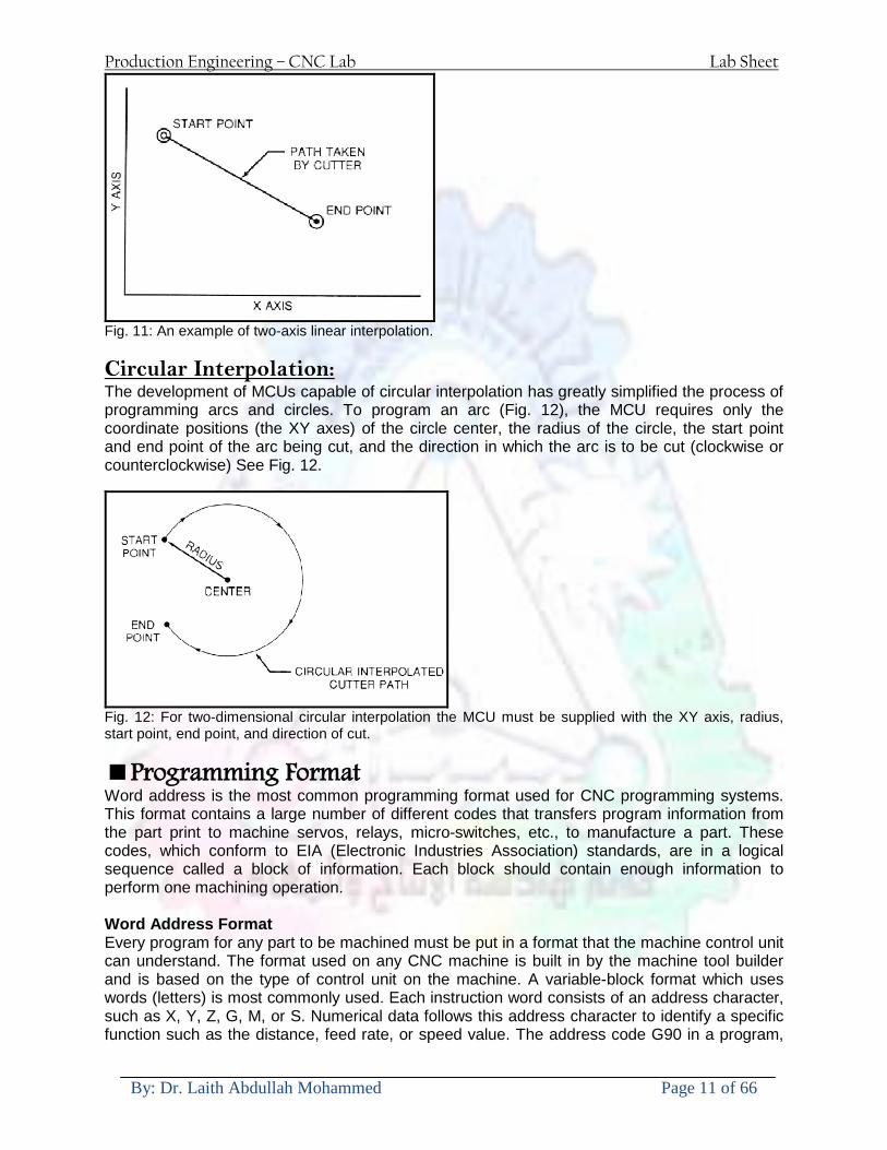
Production Engineering ndash CNC Lab Lab Sheet
By Dr Laith Abdullah Mohammed Page 11 of 66
Fig 11 An example of two-axis linear interpolation Circular Interpolation The development of MCUs capable of circular interpolation has greatly simplified the process of programming arcs and circles To program an arc (Fig 12) the MCU requires only the coordinate positions (the XY axes) of the circle center the radius of the circle the start point and end point of the arc being cut and the direction in which the arc is to be cut (clockwise or counterclockwise) See Fig 12
Fig 12 For two-dimensional circular interpolation the MCU must be supplied with the XY axis radius start point end point and direction of cut
Programming Format Word address is the most common programming format used for CNC programming systems This format contains a large number of different codes that transfers program information from the part print to machine servos relays micro-switches etc to manufacture a part These codes which conform to EIA (Electronic Industries Association) standards are in a logical sequence called a block of information Each block should contain enough information to perform one machining operation Word Address Format Every program for any part to be machined must be put in a format that the machine control unit can understand The format used on any CNC machine is built in by the machine tool builder and is based on the type of control unit on the machine A variable-block format which uses words (letters) is most commonly used Each instruction word consists of an address character such as X Y Z G M or S Numerical data follows this address character to identify a specific function such as the distance feed rate or speed value The address code G90 in a program
Production Engineering ndash CNC Lab Lab Sheet
By Dr Laith Abdullah Mohammed Page 12 of 66
tells the control that all measurements are in the absolute mode The code G91 tells the control that measurements are in the incremental mode Codes The most common codes used when programming CNC machines tools are G-codes (preparatory functions) and M codes (miscellaneous functions) Other codes such as F S D and T are used for machine functions such as feed speed cutter diameter offset tool number etc G-codes are sometimes called cycle codes because they refer to some action occurring on the X Y andor Z axis of a machine tool The G-codes are grouped into categories such as Group 01 containing codes G00 G01 G02 G03 which cause some movement of the machine table or head Group 03 includes either absolute or incremental programming while Group 09 deals with canned cycles A G00 code rapidly positions the cutting tool while it is above the workpiece from one point to another point on a job During the rapid traverse movement either the X or Y axis can be moved individually or both axes can be moved at the same time Although the rate of rapid travel varies from machine to machine it ranges between (5 and 20 mmin)
Fig 13 The functions of a few common G-codes The G01 G02 and G03 codes move the axes at a controlled feedrate bull G01 is used for straight-line movement (linear interpolation) bull G02 (clockwise) and G03 (counterclockwise) are used for arcs and circles (circular interpolation)
Production Engineering ndash CNC Lab Lab Sheet
By Dr Laith Abdullah Mohammed Page 13 of 66
Fig 14 Some of the most common G-codes used in CNC programming M or miscellaneous codes are used to either turn ON or OFF different functions which control certain machine tool operations M-codes are not grouped into categories although several codes may control the same type of operations such as M03 M04 and M05 which control the machine tool spindle bull M03 turns the spindle on clockwise bull M04 turns the spindle on counterclockwise bull M05 turns the spindle off
Production Engineering ndash CNC Lab Lab Sheet
By Dr Laith Abdullah Mohammed Page 14 of 66
Fig 15 The functions of a few common M-codes
Production Engineering ndash CNC Lab Lab Sheet
By Dr Laith Abdullah Mohammed Page 15 of 66
Fig 16 Some of the most common M-codes used in CNC programming Block of Information CNC information is generally programmed in blocks of five words Each word conforms to the EIA standards and they are written on a horizontal line If five complete words are not included in each block the machine control unit (MCU) will not recognize the information therefore the control unit will not be activated Using the example shown in Fig 17 the five words are as follows N001 represents the sequence number of the operation G01 represents linear interpolation X12345 will move the table 12345 in in a positive direction along the X axis Y06789 will move the table 06789 in along the Y axis M03 Spindle on CW
Fig 17 A complete block of information consists of five words
Production Engineering ndash CNC Lab Lab Sheet
By Dr Laith Abdullah Mohammed Page 16 of 66
Programming for Positioning Before starting to program a job it is important to become familiar with the part to be produced From the engineering drawings the programmer should be capable of planning the machining sequences required to produce the part Visual concepts must be put into a written manuscript as the first step in developing a part program Fig 18 It is the part program that will be sent to the machine control unit by the computer tape diskette or other input media The programmer must first establish a reference point for aligning the workpiece and the machine tool for programming purposes The manuscript must include this along with the types of cutting tools and work-holding devices required and where they are to be located
Fig 18 The first step in producing a CNC program is to take the information from the print and produce a program manuscript Dimensioning Guidelines The system of rectangular coordinates is very important to the successful operation of CNC machines Certain guidelines should be observed when dimensioning parts for CNC machining The following guidelines will insure that the dimensioning language means exactly the same thing to the design engineer the technician the programmer and the machine operator 1 Define part surfaces from three perpendicular reference planes 2 Establish reference planes along part surfaces which are parallel to the machine axes 3 Dimension from a specific point on the part surface 4 Dimension the part clearly so that its shape can be understood without making mathematical calculations or guesses 5 Define the part so that a computer numerical control cutter path can be easily programmed
Production Engineering ndash CNC Lab Lab Sheet
By Dr Laith Abdullah Mohammed Page 17 of 66
Machine Zero Point The machine zero point can be set by three methodsmdashby the operator manually by a programmed absolute zero shift or by work coordinates to suit the holding fixture or the part to be machined MANUAL SETTING - The operator can use the MCU controls to locate the spindle over the desired part zero and then set the X and Y coordinate registers on the console to zero
Fig 19 The relationship between the part zero and the machine system of coordinates ABSOLUTE ZERO SHIFT - The absolute zero shift can change the position of the coordinate system by a command in the CNC program The programmer first sends the machine spindle to home zero position by a G28 command in the program Then another command (G92 for absolute zero shift) tells the MCU how far from the home zero location the coordinate system origin is to be positioned Fig 19 The sample commands may be as follows N1 G28 X0 Y0 Z0 (sends spindle to home zero position) N2 G92 X4000 Y5000 Z6000 (the position the machine will reference as part zero)
Production Engineering ndash CNC Lab Lab Sheet
By Dr Laith Abdullah Mohammed Page 18 of 66
Work Settings and Offsets All CNC machine tools require some form of work setting tool setting and offsets (compensation) to place the cutter and work in the proper relationship Compensation allows the programmer to make adjustments for unexpected tooling and setup conditions
Work Coordinates In absolute positioning work coordinates are generally set on one edge or corner of a part and all programming is generally taken from this position In Fig 20 the part zero is used for all positioning for hole locations 1 2 and 3
Fig 20 In absolute programming all dimensions must be taken from the XY zero at the top left-hand corner of the part
Fig 21 In incremental programming all dimensions are taken from the previous point In incremental positioning the work coordinates change because each location is the zero point for the move to the next location Fig 21
Production Engineering ndash CNC Lab Lab Sheet
By Dr Laith Abdullah Mohammed Page 19 of 66
On some parts it may be desirable to change from absolute to incremental or vice versa at certain points in the job Inserting the G90 (absolute) or the G91 (incremental) command into the program at the point where the change is to be made can do this
R Plane or Gage Height The word-address letter R refers to a partial retraction point in the Z axis to which the end of the cutter retracts above the work surface to allow safe table movement in the X Y axes It is often called the rapid-traverse distance gage height retract or work plane The R distance is a specific height or distance above the work surface and is generally 100 in above the highest surface of the workpiece Fig 22 which is also known as gage height Some manufacturers build a gage height distance of 100 in into the MCU (machine control unit) and whenever the feed motion in the Z axis is called for 100 in will automatically be added to the depth programmed When setting up cutting tools the operator generally places a 100 in thick gage on top of the highest surface of the workpiece Each tool is lowered until it just touches the gage surface and then its length is recorded on the tool list Once the gage height has been set it is not generally necessary to add the 100 in to any future depth dimensions since most MCUs do this automatically
Fig 22 Using a 100 in gage block to set the gage height or R0 on the work surface
Cutter Diameter Compensation Cutter diameter compensation (CDC) changes a milling cutterrsquos programmed centerline path to compensate for small differences in cutter diameter On most MCUs it is effective for most cuts made using either linear or circular interpolation in the X-Y axis but does not affect the programmed Z-axis moves Usually compensation is in increments of 0001 in up to +10000 in and usually most controls have as many CDCs available as there are tool pockets in the tool storage matrix The advantage of the CDC feature is that it 1 Allows the use of cutters that have been sharpened to a smaller diameter 2 Permits the use of a larger or smaller tool already in the machinersquos storage matrix 3 Allows backing the tool away when roughing cuts are required due to excessive material present 4 Permits compensation for unexpected tool or part deflection if the deflection is constant throughout the programmed path The basic reference point of the machine tool is never at the cutting edge of a milling cutter but at some point on its periphery If a 1000 in diameter end mill is used to machine the edges of a workpiece the programmer would have to keep a 500 in offset from the work surface in order to cut the edges accurately Fig 23 The 500 offset represents the distance from the centerline of the cutter or machine spindle to the edge of the part Whenever a part is being machined the programmer must calculate an offset path which is usually half the cutter diameter
Production Engineering ndash CNC Lab Lab Sheet
By Dr Laith Abdullah Mohammed Page 20 of 66
Fig 23 Cutter-diameter compensation must be used when machining with various size cutters Modern MCUs which have part surface programming automatically calculate centerline offsets once the diameter of the cutter for each operation is programmed Many MCUs have operator-entry capabilities which can compensate for differences in cutter diameters therefore an oversize cutter or one that has been sharpened can be used as long as the compensation value for oversize or undersize cutters is entered
Production Engineering ndash CNC Lab Lab Sheet
By Dr Laith Abdullah Mohammed Page 21 of 66
CNC Programming Hints - MILLING
Production Engineering ndash CNC Lab Lab Sheet
By Dr Laith Abdullah Mohammed Page 22 of 66
CNC Programming Hints ndash TURNING
Production Engineering ndash CNC Lab Lab Sheet
By Dr Laith Abdullah Mohammed Page 23 of 66
CNC
The abbreviation CNC stands for Computer(ized) Numerical(ly) Control(led) and refers specifically to the computer control of machine tools for the purpose of (repeatedly) manufacturing complex parts in metal as well as other materials using a program written in a notation conforming to the EIA-274-D standard and commonly called G-code
CNC was developed in the late 1940s and early 1950s by the MIT Servomechanisms Laboratory CNC machines were relatively briefly preceded by the less advanced NC or Numerical(ly) Control(led) machines The introduction of CNC machines radically changed the manufacturing industry Curves are as easy to cut as straight lines complex 3-D structures are relatively easy to produce and the number of machining steps that required human action have been dramatically reduced With the increased automation of manufacturing processes with CNC machining considerable improvements in consistency and quality have been achieved CNC automation reduced the frequency of errors and provided CNC operators with time to perform additional tasks
CNC automation also allows for more flexibility in the way parts are held in the manufacturing process and the time required to change the machine to produce different components In a production environment a series of CNC machines may be combined into one station commonly called a cell to progressively machine a part requiring several operations CNC machines today are controlled directly from files created by CAM software packages so that a part or assembly can go directly from design to manufacturing without the need of producing a drafted paper drawing of the manufactured component In a sense the CNC machines represent a special segment of industrial robot systems as they are programmable to perform many kinds of machining operations (within their designed physical limits like other robotic systems)
G-code
G-code is a common name for the programming language that is used for NC and CNC machine tools It is defined in EIA RS-274-D G-code is also the name of any word in a CNC program that begins with the letter G and generally is a code telling the machine tool what type of action to perform such as
bull rapid move bull controlled feed move in straight line or arc bull series of controlled feed moves that would result in a hole being drilled bull change a pallet bull Set tool information such as offset
There are other codes the type codes can be thought of like registers in a computer
X position Y position Z position M code (another action register) F feed rate S spindle speed N line number R Radius T Tool selection
Production Engineering ndash CNC Lab Lab Sheet
By Dr Laith Abdullah Mohammed Page 24 of 66
I Arc data X axis J Arc data Y axis
G-code files are output by CAM software such as Smartcam Gibbscam Featurecam Edgecam Mastercam etc G-code is also output by specialized CAD systems used to design printed circuit boards Such software must be customized for each type of machine tool that it will be used to program
Production Engineering ndash CNC Lab Lab Sheet
By Dr Laith Abdullah Mohammed Page 25 of 66
U 2عمل األزرار الرئيسية في ماكنة الخراطة المبرمجة (نصر (
1- SINGLE BLOCK للتأكد من صحة البرنامج (تنفيذ البرنامج خطوة خطوةب تقوم( 2- BLOCK DELETE بجانب ويعمل من األوامرلغاء بلوك معين أليستخدم 3- MACHINE LOCK العمل يستخدم لقفل حركة المحاور الرئيسية مع استمرار البرنامج في
)وهذا مهم للتاكد من صحة البرنامج قبل عملية التنفيذ النهائي(4- CONT CYCLE عملية التشغيل عند ايقافها الي سبب كان او عند ايقافها ألستئناف ستخدم ت
) BAR FEEDER(او في حالة استخدام ) FEED HOLDبسبب (5- DRY RUN وتستخدم لفحص البرنامج بعد ازالة الشغلة حركة سريعة للبرنامج 6- TURRET UP amp DOWN ) حركة حامل العدة TURRET الذي يحمل مجموعة من (
وهذا الزر يعمل مع الزر عكس عقرب الساعة او مع عقرب الساعة ةحركة دوراني العدد )SAFTY (
7- COOLANT ON or OFFفه تشغيل سائل التبريد او ايقا 8- COOLANT AUTO الدوال المساعدة في البرنامج من خالل فه تشغيل سائل التبريد او ايقا 9 -MACHINE START ة لتشغيل هيدرولكيك الماكنميستخد
Production Engineering ndash CNC Lab Lab Sheet
By Dr Laith Abdullah Mohammed Page 26 of 66
10- CLOSE OR OPEN CHUCKالعينة تستخدم لفتح وغلق 11 -T STOCK FWD RET حركة الغراب المتحرك ذهابا وإيابا12 -SPINDLE STOP تعمل على ايقاف حركة دوران العينة 13-JOG SPINDLE تعمل على تدوير العينة مع زر SAFTY 14 -OPT SAFTY مع الدالة ( تعمل عمل التوقف المشروط حيث تعملM1 دالة التوقف (
ط ) فقط األ اذا كان هذا الزر مضغو M1المشروط حيث ال يتوقف البرنامج في حالة وجود دالة ( SAFTY + SPINDLE ) يتم الضغط على زر ( START CYCLEلغرض تحرير زر (
START ) في نفس الوقت بعد الضغط على زر ( START CYCLE مرتين (
NC PC- 15 يستخدم هذا الزر عند ربطCNC يستخدم لنقل المعلومات ث مع جهاز أخر حي بينهما
16 -CALCU زر الخاص بالحاسبة مع زر ( ال وهوINPUT ( 17 - HD1 HD2 يستخدم الختيار العدة مع المخرطة ذات المحاور األربعة 18 - START تستخدم لبدء عملية التشغيل
Production Engineering ndash CNC Lab Lab Sheet
By Dr Laith Abdullah Mohammed Page 27 of 66
19- FEED HOLD تعمل على إيقاف عمل أي G موجودة مع بقاء العينة متحركة 20- M D I أو تشغيل البرنامج ل يتم استخدامه لإلدخا BLOCK BY BLOCK وتعمل عند
إدخال البرنامج بواسطة الشريط المثقب أو أي وسيلة إدخال أخرى أو في عمليات التصفير
21- REST تستخدم العادة تشغيل الماكنة أو مسح اإلنذار الذي يظهر على الشاشة 22- EMERGENCYتستخدم عادة اليقاف الماكنة في حالة الطوارئ فقط
OPERATION MENU KEY
CHAPTER PRG-CMK
OFFSET PROGRAM POSITION FUNCTION MENU KEY
23- POSITIONعلى الشاشة د الموقع الموجور الظها 24- PROGRAMإلظهار برنامج معين واختياره 25- OFFSET الختيار سماحات العدة أو سماحات نقطة المرجع 26- PRG- CHK تستخدم لفحص البرنامج على الشاشة 27- SETTING ألختيار الثوابت على الشاشة 28- SERVICE تستخدم ألستخراج المعامالت والثوابت 29- MESSAGE تستخدم ألظهار األخطاء الناتجة عن البرنامج او اخطاء التشغيل 30- OVERALL ألختيار المواقع 31- RELATIVE MODLINE تعوض عن POSITION 32- DIR MEM يستخدم ألظهار ملف البرامج المخزونة في الذاكرة وعندما نضغط هذا الزر
فان رقم واسم البرنامج سوف يظهر على الشاشة
2أدناه الشفرات الرئيسية التي تعمل على الماكنة المبرمجة نصر
G-CODE DESCRIPTION
G00 Rapid traverse (linear)
G01 Linear Interpolation at feed rate
G02 Circular interpolation (CW) R+
G03 Circular interpolation (CCW) R+
G10 Zero point tools
G20 Imperial data input
G21 Metric data input
G27 Reference return check
G28 Reference return
G29 Return from reference
Production Engineering ndash CNC Lab Lab Sheet
By Dr Laith Abdullah Mohammed Page 28 of 66
G33 Thread cutting
G40 Cancel cutter radius compensation
G41 Cutter compensation left
G42 Cutter compensation right
G54 Work co-ordinate system no1
G70 Finishing cycle
G71 Stock removal turning
G72 Stock removal facing
G74 Face grooving
G75 Diameter grooving
G76 Threading cycle
G90 Absolute date input
G91 Incremental data input
G94 Feed minute mode
G95 Feed rev mode
G96 Constant surface speed mode
G97 Cancel Constant surface speed
) 2أدناه الشفرات الثانوية التي تعمل على الماكنة المبرمجة (نصر
M-code FUNCTION
M00 Program stop
M03 Spindle forward (Tool forward ndash M94 mode)
M04 Spindle reverse (Tool forward ndash M94 mode)
M05 Spindle stop (Tool stop ndash M94 mode)
M08 Coolant on
M09 Coolant off
M30 Program end (with rewind)
M48 Turret shortest path
M52 Turret direction up (CW)
M53 Turret direction down (CCW)
M73 Chuck open
M74 Chuck close
Production Engineering ndash CNC Lab Lab Sheet
By Dr Laith Abdullah Mohammed Page 29 of 66
) وكل جملة مكونة من مجموعة من الكلمات blockإن كل برنامج يتكون من مجموعة من الجمل ()words) لهذا فأن الشفرات الرئيسية والمساعدة هي عبارة عن كلمات (words كما في المثال التالي (
G_ _ P1 Q2 U_ _ W_ _ D___ F_ _
)end of block) ويعني ( ) يكتب الرمز (blockتسلسل الكلمات مهم جدا بعد نهاية كل جملة (
طريقة ادخال البيانات الى الماكنة ــــــــــــــــــــــــــــــــــــــــــــــــــ
) MDIيمكن ادخال البيانات الى الماكنة بعدة طرق فقد يكون األدخال عن طريق قناة السيطرة ( MANUAL DATA INPUT ) او عن طريق قناة األضافة EDIT كما يمكن ادخال البيانات عن (
) RS ndash 232 COMMUNICATIN LINKطريق استخدام سلسلة الربط (
₤⅗₌⅗₌ ⅙₌₨image₍₡ ₤₌ℌ⅗₌ Ⅸ⅗ⅥⅯ₌ ₤₡ℌ₰₨⅗₌G71
الخراطة الطولية G71الغرض من التجربة عمل نموذج للخراطة بأستخدام الدالة تستعمل هذه الدالة للخراطة الطولية اي على طول محور المشغولة وكما هو موضح بالشكل ادناه
تعتبر هذه الدالة من الدوال التي ال تحتاج الى تكرار او إعادة كتابتها أي انها دالة تكرارية بمعنى ان اي
الذي هي دالة حركة G01خطوة تكون من ضمن هذه الدالة سوف تكرر العملية اي عند استعمال امر مثل خطية تتضمن القطع مع التغذية مع اعطاء القطر المراد قطعه و مراعاة عمق القطع المعطى سوف يتكرر
هذه االمر وصوال الى العمق المطلوب وهكذا لبقية الدوال
G71 المستخدمة للدالة الصيغة
G71 P1 Q2 U___ W___ D___ F___ حيث إن
P1 بداية الخطوة االولى = Q2 نهاية الخطوة =
Uوضع السماحات بأتجاه محور = X W وضع السماحات بأتجاه محور = Z وتكاد تكون مهملة وتوضع اشارة سالب Dعمق القطع وتوضع رقم صحيح مثل = D500 اي نصف ملمF التغذية والتي لها عالقة بالدالة = G95
Production Engineering ndash CNC Lab Lab Sheet
By Dr Laith Abdullah Mohammed Page 30 of 66
G71الدالة استخدام مثال على
T0100 M48 G0 X26 Z2 M08 T0101 G90 G95 G97 S500 M03 G71 P1 Q2 U03 W00 D500 F01 N1 G0 G42 X00 G01 Z00 G01 X2517 G01 Z-5352 G01 X7391 Z-9366 G01 Z-19145 N2 G28 M30
الجانب العملي
االجهزة واالدوات المستخدمة CNCماكنة خراطة مبرمجة 1 ملم 80قضيب من االلمنيوم قطر 2 ةفير ني 3 جاه أيمن تهولدر كاربيدي ذوا 4
طريقة العمل يتم تثبيت قضيب من االلمنيوم على العينة التابعة للماكنة مع مراعاة الطول المراد استعماله في عملية 1
الخراطة ) turretتثبيت عدة القطع في المكان الصحيح في ( 2
Production Engineering ndash CNC Lab Lab Sheet
By Dr Laith Abdullah Mohammed Page 31 of 66
بالنسبة الى القطعة المثبتة على العينة XZيتم تصفير الماكنة للمحاور 3 تصفير للمحورZ تكون مالمسة العدة الى وجه الشغلة تصفير للمحورX تكون مالمسة العدة الى سطح الشغلة الموازي لمحور X
يتم كتابة البرنامج أما بطريقة يدوية أو بالحاسوب مع وضع كل الظروف الالزمة للتشغيل ( عمق القطع 4 التغذية السرعة المطلوبة نوع المعدن )
ادخال البرنامج الى الحاسوب الموجود داخل الماكنة مع تهيئة الماكنة للتشغيل 5
المطلوب G71عمل برنامج يدوي على الدالة 1 رسم الشكل الشكل النهائي المطلوب مع وضع األبعاد 2
Ⅺ⅟₍euro⅗₌ ₤₡ℌ₰₨⅗₌₣ ₤⅗₌⅗₌ ⅙₌₨image₃₡ Ⅺℂtradeℒ⅗₌ ӈ₍Ⅴ⅟ⅳ₌ G70
G70 الغرض من التجربة عمل انهاء سطحي للمشغولة بواسطة الدالة
من الضروري إعطاء G71هذه الدالة تعمل شوط واحد فقط وتكون معتمدة على عمليات القطع في الدالة اللغاء مقدمة االداة (أي لكي تتم عملية االنهاء السطحي بدون حسابات نصف قطر مقدمة االداة ) G42دالة
G70الصيغة المستخدمة للدالة
G70 P1 Q2 F___ حيث ان
P1 بداية الخطوة االولى = Q2 نهاية الخطوة =
F التغذية والمرتبطة بالدالة = G95
وذلك ألن دالة االنهاء السطحي تحقق X Zمالحظة الدالة التحتاج لكتابة السماحات التابعة للمحورين المسافات الحقيقة المراد انتاجها للمشغولة
G71و G70مثال على الدالة
T0100 M48 G0 X26 Z2 M08 T0101 G90 G95 G97 S500 M03 G71 P1 Q2 U03 W00 D500 F01 N1 G0 G42 X00 G01 Z00 G01 X2517 G01 Z-5352 G01 X7391 Z-9366 G01 Z-19145 N2 G97 S750 MO3
Production Engineering ndash CNC Lab Lab Sheet
By Dr Laith Abdullah Mohammed Page 32 of 66
G70 P1 Q2 G40 F009 G28 M30
الجانب العملي الحظ التجربة األولى
المطلوب
G70 عمل برنامج يدوي على الدالة 1 رسم الشكل النهائي المطلوب مع وضع االبعاد 2
₪⅗₍euro⅗₌ ₤₡ℌ₰₨⅗₌₣ ₤⅗₌⅗₌ ⅙₌₨image₍₡ ⅝₍ⅠimageⅯ₌ ⅞ⅫⅦ⅔₧ G76
G76 للمشغولة بواسطة الدالةةالغرض من التجربة عمل أسنان خارجية أو داخلي
في هذه التجربة سوف نقوم بعمل األسنان الخارجية وهنا تكون حركة العينة ثابتة وهذا ضروري بسبب أن ) تكون متصلتين الكترونيا وعليه أي اختالف في سرعة العينة تؤدي إلى اختالف motionالعينة والحركة(
) servoفي سرعة الخدمة(يرتبط اتجاه تكوين األسنان باتجاه دوران العينة مثال إذا كانت األسنان ذات اتجاه أيمن يكون اتجاه دوران
وهنا نقلب العدة إلى االسفل وكما هو موضح بالشكل أدناه MO3العينة عكس عقرب الساعة أي نستعمل
Production Engineering ndash CNC Lab Lab Sheet
By Dr Laith Abdullah Mohammed Page 33 of 66
الخطوة هي عبارة عن المسافة ما بين قمة سن إلى قمة سن أخر عمق السن هو العمق المطلوب تكوينه لألسنان
G76 الصيغة المستخدمة للدالة
G76 X___ Z___ K___ F___ D___ A___
حيث أن X القطر الداخلي للسن =Z طول السن =K عمق السن وتستخرج من المعادلة التالية =K=065F F الخطوة =D عمق القطع بالمايكرون فقط =A زاوية السن =
G76مثال على استخدام الدالة T0300 M48 GOO X30 Z4 T0303 M08 G97 S500 MO3 G76 X28375 Z-20 K08125 F125 D120 G00 X40 Z4 G28 M30
Production Engineering ndash CNC Lab Lab Sheet
By Dr Laith Abdullah Mohammed Page 34 of 66
الجانب العملي الحظ التجربة األولى
المطلوب
G76عمل برنامج يدوي على الدالة 1 رسم الشكل النهائي المطلوب مع وضع األبعاد 2
Ⅺ⅘₌⅗₌ Ⅵ₂ Ⅺ₯ℋ₍⅗₌ ℌℲℂ⅗₌ ⅞ⅫⅦ⅔₧ ₤K₡₌ℌ⅗₌ ₤₡ℌ₰₨⅗₌)Groove ₤⅗₌⅗₌ ₤tradeimage₌Ⅶ₡ (G75
G75 بواسطة الدالة grooveالغرض من التجربة تكوين
) للمشغولة وتعتمد شكل الحفر على طريقة grooveتستعمل هذه الدالة لتكوين الحفر الخارجي والداخلي (
التشغيل وعلى الشكل المراد إنتاجه وتعتبر هذه الطريقة من عمليات التشكيل للمعدن إن هذه الدالة هي دالة مالحظة مع G75في هذه التجربة سنقوم بعمل الحفر الخارجي بواسطة الدالة
تكرارية وغير تكرارية حسب نوع التشغيل
G 75 الصيغة المستخدمة للدالةG75 X___ Z___ I___ K____
حيث أن
X العمق النهائي لقطر الشغلة =Z عرض الحفر =I الدخول في كل مرة =
K التزحيف على محور =z بالنسبة للعدة
Production Engineering ndash CNC Lab Lab Sheet
By Dr Laith Abdullah Mohammed Page 35 of 66
G75مثال على استخدام الدالة
T0500 M48 GOO X100 Z -20 T0505 M08 G97 S700 MO3 G75 X84 Z -38 I 05 K4
الجانب العملي الحظ التجربة األولى
المطلوب
G76عمل برنامج يدوي على الدالة 1 رسم الشكل النهائي المطلوب مع وضع األبعاد 2
Production Engineering ndash CNC Lab Lab Sheet
By Dr Laith Abdullah Mohammed Page 36 of 66
CNC Milling Machine Mechanical Construction
Guideways The guideways of CNC machines are made of steel To reduce the frictional forces they are coated with a strip of PTFE (Poly Tetra Fluoro Ethylene)
Ballscrews On conventional lathes a leadscrew is used to converts the rotary motion of the hand wheel into linear motion of the slides Leadscrews have a high coefficient of friction and backlash On CNC machines a ballscrew is used instead of a leadscrew Friction and backlash are much less than on leadscrews
Guideway
Production Engineering ndash CNC Lab Lab Sheet
By Dr Laith Abdullah Mohammed Page 37 of 66
bullMachining operations Direction of cutting Based on the direction of the cutter rotation and work piece feed milling operations are classified into two types 1-Up milling (Convention milling) In up milling the metal is removed by rotating the cutter against the direction of travel of the part
Feed
Machine table
Part
Cutting tool
Chip thickness at theexit of the tooth
2-Down milling (Climb milling) In climb milling the metal is removed by rotating the cutter with the direction of travel of the part
Machine table
Part
Cutting tool
Chip thickness at theentrance of the tooth
Production Engineering ndash CNC Lab Lab Sheet
By Dr Laith Abdullah Mohammed Page 38 of 66
bullTooling Tool geometry The geometry of the tool tip affects the way that the metal cutting is performed The nose radius rake angles relief angles etc must be selected with care
Radial relief
Radial rake
Axial relief
Approach angle
Axial relief
Corner radius Face mill Face milling cutters are used to mill flat surfaces Commonly used face milling cutters Cutter with 75 degree approach
75 deg
Cutter with 90 degree approach (Square shoulder face mill)
90 deg
Cutter with 45 degree approach
Production Engineering ndash CNC Lab Lab Sheet
By Dr Laith Abdullah Mohammed Page 39 of 66
bullCNC Programming Axes convention The Z axis is along the spindle axis The X and Y axes are perpendicular to Z VMC
Z
Y
-
+
-+
X- +
+Z
-Z
+Y
-Y
-X +X
Part
Machine table
X
YZ
G00 Rapid traverse When the tool being positioned at a point preparatory to a cutting motion to save time it is moved along a straight line at Rapid traverse at a fixed traverse rate which is pre-programmed into the machines control system Typical rapid traverse rates are 10 to 25 m min but can be as high as 80 mmin
Production Engineering ndash CNC Lab Lab Sheet
By Dr Laith Abdullah Mohammed Page 40 of 66
Format N_ G00 X__ Y__Z__
G01 Linear interpolation (feed traverse) The tool moves along a straight line in one or two axis simultaneously at a programmed linear speed the feed rate Format N__ G01 X__ Y__Z__ F__
Part
Feed
Part
Feed
G02G03 Circular interpolation The tool moves along an arc in two axes simultaneously at a programmed linear speed the feed rate
Production Engineering ndash CNC Lab Lab Sheet
By Dr Laith Abdullah Mohammed Page 41 of 66
Format N__ G0203 X__ Y__Z__ I__ J__K__ F__ using the arc center OR N__ G0203 X__ Y__Z__ R__ F__ using the arc radius G02 moves along a CW arc G03 moves along a CCW arc Arc center The arc center is specified by addresses I J and K I J and K are the X Y and Z co-ordinates of the arc center with reference to the arc start point
X
Y
Arc center
Arc endArc start
- J
- I
I = X coord of center - X coord of start point J = Y coord of center - Y coord of start point K = Z coord of center - Z coord of start point I J and K must be written with their signs
Production Engineering ndash CNC Lab Lab Sheet
By Dr Laith Abdullah Mohammed Page 42 of 66
bullWork holding
Rotary table
Fixture base
Component
Clamp
Stud
Fixtures The use of fixtures 1 Improves repeatability of dimensions 2 Improves working conditions 3 Cuts down requirement of skilled labour 4 Reduces part loading and unloading time 5 Improves safety in the working area 6 Reduces the cost of machining There are two types fixtures commonly used 1 Special fixture Special fixtures are used to hold and locate the typical components which are having complex shape and to be located with the reference hole (dowel hole) Special fixtures are required for components like gear case cover cylinder heads etc 2 Modular fixture Modular fixture is a set different kind of clamping and locating elements These fixtures are used to hold identical components in different sizes and components of box type Example Manifolds head stocks connecting rods and flanges
Production Engineering ndash CNC Lab Lab Sheet
By Dr Laith Abdullah Mohammed Page 43 of 66
bullMachine setting
Determining X and Y work zero offset Case 1
Part
Machine table
Part
End mill or reamer
Work offset X0Y0 For determining X work zero offset bull Touch the periphery of the end mill or reamer to the part bull Enter current machine X value + cutter radius as X work zero offset For determining Y work zero offset bull Touch the periphery of the end mill or reamer to the part bull Enter current machine Y value - cutter radius as Y work zero offset Case 2
Part
Machine table
Part
End mill or reamerWork offset X0Y0
bull Mount the dial indicator on machine spindle true the bore bull Enter current machine X and Y value as X and Y work zero offset
Production Engineering ndash CNC Lab Lab Sheet
By Dr Laith Abdullah Mohammed Page 44 of 66
How to Select a Cutting Fluid
One part of the metal cutting equation that is sometimes overlooked however is
the choice of an appropriate cutting fluid With todayrsquos system approach to metal
cutting use of the right metalworking fluid has become just as much a part of the
solution as the other elements In fact at least one company is now integrating
cutting fluids and cutting tools into effective metal cutting systems Following are
some things to consider when choosing your next cutting fluid
The Four Key Questions
There are four vital pieces of information that are necessary when choosing a
cutting fluid They are
1 What are you cutting
2 What is the chemistry of your water
3 What are you using now
4 What are your options
5 What do you prefer
What Are You Cutting
The first question ndash ldquoWhat are you cuttingrdquo ndash is often the most difficult to answer
because most shops handle a variety of workpiece materials on a regular basis If
the answer is an unequivocal ldquoaluminumrdquo or ldquostainless steelrdquo or ldquocast ironrdquo the
selection of a cutting fluid can be quite simple and straightforward Unfortunately
that is seldom the case in anything but a high-volume plant Where aluminum or
other nonferrous metals are a significant part of the mix a non-staining cutting
fluid is a must Generally speaking this will be a semi-synthetic with special
ingredients to prevent bi-metallic corrosion and staining of non-ferrous workpieces
Where the ferrous metals predominate however a more general purpose semi-
synthetic or hybrid fluid might be a more economical choice
Production Engineering ndash CNC Lab Lab Sheet
By Dr Laith Abdullah Mohammed Page 45 of 66
What is The Chemistry of Your Water
The second question ndash ldquoWhat is the chemistry of your waterrdquo ndash is probably the
single most common reason for the success or failure of a cutting fluid Very few
plants invest the money necessary to install effective water purification systems
using deionization or reverse osmosis technology Unfortunately the chemicals
present or not present in the water used to re-constitute a cutting fluid make a
tremendous difference in its performance and sump life Most manufacturers of
cutting fluids will perform the necessary water testing to determine exactly what
minerals are dissolved in your water and make a fluid recommendation based on
the results
What are you using now
The third question ndash ldquoWhat are you using nowrdquo ndash helps narrow the range of
choices When coupled with an objective analysis of the strengths and weaknesses
of the current fluid the answer to this question can quickly point you toward a
relatively small number of competitive alternatives that have the attributes required
to meet your cutting needs Many cutting fluids are in use today simply because
they were in use yesterday It is a hard reality of todayrsquos marketplace that if one
isnrsquot constantly striving to improve they will certainly be overtaken by a
competitor who is
What Are Your Options
The fourth question ndash ldquoWhat are your optionsrdquo ndash leads to the final selection of a
cutting fluid Cutting fluids can be divided into four general groups based on their
chemistry
They are
bull Soluble Oils ndash quite literally oil dispersed in water
bull Synthetics ndash completely oil free man-made coolants in solution
Production Engineering ndash CNC Lab Lab Sheet
By Dr Laith Abdullah Mohammed Page 46 of 66
bull Semi-Synthetics ndash a mixture of natural and synthetic lubricants with up to 30
mineral oil
bull Hybrids ndash a special class of semi-synthetics with a mineral oil content of about
15 Each fluid type has advantages and disadvantages which make it suitable for
a particular group of applications In addition there are costperformance trade-
offs to be made between the groups within a specific set of applications For
example where a hybrid and a semi-synthetic may both be suitable for a particular
use the hybrid might provide longer sump life at a slightly higher initial cost
while some semi synthetics may be more economical to recycle or dispose of while
not giving as long a tank life The final decision in this case would have to be made
on the detailed economics of the shop where the fluids were to be used and on the
ownerrsquos individual preferences
Soluble Oils
Soluble oils are oils that disperse in water when emulsifiers are added They are
generally suitable for moderate-to heavy-duty machining and grinding of all non-
ferrous metals carbon and cast steels and in applications where dissimilar metals
such as aluminium and steel are present They can also be used in turning drilling
tapping reaming gear cutting broaching as well as internal and centerless types
of grinding operations Soluble oils provide excellent aluminium and copper
corrosion control good rancidity control which extends fluid for long lasting
trouble-free performance and good concentrate and mix stability making it ideal
for mixing in water with a minimal amount of agitation An example of this is
Valenitersquos VNTreg-650 premium heavy-duty soluble oil
Synthetics
Synthetics are completely oil free solutions made of polymers organic and
inorganic materials that are mixed with water These clear low foaming and bio-
Production Engineering ndash CNC Lab Lab Sheet
By Dr Laith Abdullah Mohammed Page 47 of 66
stable coolants are ideal for machining and grinding of ferrous materials carbon
steels or cast iron Their complex lubricant packages make synthetics well-suited
for tough-to-machine materials such as stainless steels and high-temperature alloys
Certain synthetics are specifically designed to address the primary failure modes of
flank wear and nose wear Although there are many benefits some synthetics may
cause staining of non-ferrous materials
Semi-Synthetics
Semi-synthetic fluids are a mixture of oils synthetic emulsifiers and water They
were primarily developed for the aircraft nuclear and related industries
Consequently they work extremely well on all non-ferrous metals such as titanium
aluminium copper brass bronze and stainless steel in both machining and
grinding Semi-synthetics can be used on ferrous metals too They are chlorine-
free to reduce bi-metallic corrosion and staining of metals They should be used at
a 5-8 dilution with water depending on the severity of the operation
Hybrids
Hybrids are cutting fluids custom engineered to solve a particular problem For
example Valenitersquos VNTreg-800 was developed to be very clean in the machining
and grinding of cast iron It provides better stability in hard water and rejects tramp
oil very well which adds to its bio-stable chemistry Hybrids work extremely well
on all metals in both machining and grinding They should be mixed at a 5-7
dilution with water depending on the condition of the water
What Do You Prefer
The final question ndash ldquoWhat do you preferrdquo ndash is usually the ldquotie breakerrdquo where
there is more than one appropriate cutting fluid available Here again as in the
case of what is being used now the key is to examine your preferences objectively
Production Engineering ndash CNC Lab Lab Sheet
By Dr Laith Abdullah Mohammed Page 48 of 66
and specifically to identify the real reasons behind a preference If you cannot
point to specific reasons why one class of cutting fluid is preferred over another
you are well advised to follow the recommendations of the professional who has
analyzed your requirements Choosing the right fluid today is easier than ever as
the system approach to metal cutting productivity continues to grow in acceptance
The day is not far off when choosing a complete solution will be as easy as
choosing the right insert and chip breaker today The answers are available and the
results will more than justify the time you spend choosing the right metal cutting
fluid
Useful Links wwwball-screwsnet
wwwlubelinkcom
wwwmachinerylubricationcom
wwwadvancedmanufacturingcom
wwwmmsonlinecom
wwwcuttingtoolengineeringcom
wwwgeartechnologycom
wwwengineersedgecom
wwwagmaorg
wwwefundacom
wwwsaeorg
wwwsmeorg
wwwastmorg
wwwissorg
wwwmachinetoolscom
wwwansiorg
wwwasmeorg
wwwcnccicom
wwwmatlscom
wwwthefreedictionarycom
wwwengineersupplycom
Production Engineering ndash CNC Lab Lab Sheet
By Dr Laith Abdullah Mohammed Page 49 of 66
SurfCAM Tutorial ndash Beginning with the basics
Background SurfCAM is a computer aided manufacturing (CAM) software which allows you to create manage and modify tool paths for computer aided designed (CAD) part The software requires a CAD model or requires that you create some geometry within SurfCAM with some rudimentary tools provided The tool paths are created or stored internally in SurfCAM in a generic programming language called APT Once the tool paths are created the APT paths are translated using a post processor into typical machine G-code
Opening SurfCAM SurfCAM can be opened from the Novell Applications Launcher on most Industrial Engineering computer labs workstations Search under lsquoallrsquo applications and double click on SurfCAM 2005 Once the program opens a license must be selected from the list (not the Demo license) to enable saving the file later Choose one of the 30 licenses available If for some reason the licenses are not listed on the license manager form select server list and type ldquobonnieeosncsuedurdquo A list of available licenses should appear Select a license and click OK After the license is selected an Add StockFixture form (Figure 1) opens allows you to add a model which represents the pre-machined stock or a fixture Click on OK without adding either Both of these items can be added later under a more appropriate dialog
Figure 1 Add Stock or Fixture dialog box
Production Engineering ndash CNC Lab Lab Sheet
By Dr Laith Abdullah Mohammed Page 50 of 66
SurfCAM Interface
Figure 2 SurfCAM Windows based interface
SurfCAM is a windows based software system so most of the typical windows functions under File are applicable This is where you can open save exit print etc The Create menu allows the user to create different geometry forms Here you can create a point line surface chamfer circle and many other geometry types For the most part these functions are not used by beginners but are useful when creating bounding curves where you donrsquot want the tool to move outside (constraining the tool) The Edit menu allows you to change or modify many different entities such as changing lines altering surfaces joining surfaces trimming or breaking elements add control points etc Again these features are helpful to advanced users and are not covered in detail in this tutorial The Display menu offers the ability to change the orientation of the part on the screen The typical rotate pan fit to screen and zoom functions are available as well as several functions which allow the user to shift between views or call up a named view (ie top bottom etc) The NC menu is the main machining interface menu In this menu you select the general form of machining (2 axis 3 axis 4 axis 5 axis turning etc) and under the general form a more specific machining function is selected This menu is the most used and the options contained must be fully understood to get the most out of SurfCAM Each function will be described in some detail in a further chapter The Analyze menu contains options such as measuring the distance between points angles tangency elements etc These functions are auxiliary functions meant to help you understand the part better but basically provide no functionality for making tool paths for CNC machines Thus these will not be covered The Tools menu allows the user to change the system options modify keyboard shortcuts change the model units etc These options are again not used by beginners Finally the Help menu provides access to the online users manual In lieu of clicking the Help menu the F1 key is the shortcut key for help (as it is in most windows based programs)
Importing a CAD model Importing a CAD model that is stored locally is done by selecting File-gtOpen On the Files of type dropdown box choose the type of file you wish to open (Figure 3) Do this prior to negotiating your way through the maze of folders to prevent having to go through the folder tree again Once the file type is selected find the file you are trying to open and click the Open
Production Engineering ndash CNC Lab Lab Sheet
By Dr Laith Abdullah Mohammed Page 51 of 66
button SurfCAM will then attempt to read the file you have selected SurfCAM may provide a dialog box describing what it has imported and identify if it was successful If this dialog is provided simply click close without saving
Figure 3 Open Dialog Note - Change type of file prior to finding the file you wish to open
SurfCAM allows a user to import several different types of CAD files the most common types which you will likely import are SolidWorks part files (sldprt or prt) AutoCAD files(dxf) or IGES (igs or iges) Native file import (such as is the case with SolidWorks) provides the greatest information transfer and generic file imports (such as is the case with IGES) provide the least Normally it is to the advantage of the user to use native file importing procedures when available Recently (2005) SurfCAM added some compatibility with SolidWorks This allows the user to create tool paths for a part and if an engineering change is needed for the part update the part in SolidWorks When the part is then opened in SurfCAM the changes are noted and a simple update operation command is needed This however does not operate with complete transparency andor accuracy and thus users need to be cognizant of changing CAD models
SurfCAM Geometry In SurfCAM two basic types of geometry are used the surface and the point A surface (Figure 4) is a so called spline (NURBS or B-Spline are the two most common) surface (parameterized by two values u and v) such that every location on the surface can be defined as a function of these parameters In other words SurfCAM can calculate the location of any point on the
Production Engineering ndash CNC Lab Lab Sheet
By Dr Laith Abdullah Mohammed Page 52 of 66
surface Surfaces are used primarily in 3 4 and 5 axis machining and require a significant
amount of processing power and time Figure 4 Surfaces model of a mold half Note the difference between this and Figure 2 a wireframe model
Point or line based models are often referred to as wireframe (Figure 5) models because the models consist of connected lines and resemble the part only at the intersection of two surfaces Wireframe models were made popular lsquoback in the dayrsquo when computer processing was expensive There are times when each of the models are important and selecting model geometry when applying a SurfCAM operation will be much simpler if you understand the differences between the two When importing a SolidWorks model the default is both the surfaces and the wireframe geometry are imported
Figure 5 Wireframe model of the mold in Figure 1
Steps to Creating Tool Paths Once a CAD model is imported into SurfCAM tool paths can be created There is no one correct way to create tool paths however there is a set of general steps to take to ensure the tool paths are created with a minimum amount of hardship (note the wordinghellipHardship is inevitable when creating tool paths it is the intent of this manual to minimize this) The following is a list of steps which should be considered when making tool paths
Production Engineering ndash CNC Lab Lab Sheet
By Dr Laith Abdullah Mohammed Page 53 of 66
1 Plan ahead a Orient the part in SolidWorks such that if only one side is to be machined that
side is the Top view This can be done early in SolidWorks by choosing a plane parallel the X-Y plane as the sketch plane for the machined geometry
b Orient the part in SolidWorks such that the origin is somewhere of relative importance and someplace in space that can be easily identified when placed on the machine This is extremely important to minimize set up time at the machine (note ndash my personal preference for a part that is to be fully machined [ie stock exists on all sides] is to place the origin at the center and top of the parthellipjust my preference)
c Orient the part in SolidWorks such that the X and Y axes are aligned as you want them on the machinehellip
d Planning ahead will save you many hours of headaches laterhelliptrust me 2 Import the model 3 Choose a construction view such that the tool approaches the side to be machined
from the positive Z axis direction (as defined by part origin) a This is done by clicking on the CView icon
b From the list of named views chose the view which orients the origin as you would like
c If one of the views does not fit your criteria you have two choices i Perform a transformation of the part in SurfCAM or SolidWorks
ii Add a new construction view by selecting new This option requires a relatively good understanding of right hand coordinate frames but is very usefulhellipNormally used by more advanced users
d Be sure the CoordVIEW selection is made vs CoordWORLD This ensures the tools will be controlled from the coordinate frame selected by the view (ie the origin on the part) instead of the origin on the lower left corner of the screen This will be especially important when we get into 4 and 5 axis machining
4 In the Operations Manager (Figure 6) select Setup One and change the name to something meaningful ndash like Front Side Mold Cavity
a Access the Operations manager by right clicking or by selecting the Operations Manager icon in the tool bar
b Operations Manager is where the tool paths are managed once they are created as well as where individual tool paths can be verified
Production Engineering ndash CNC Lab Lab Sheet
By Dr Laith Abdullah Mohammed Page 54 of 66
5 Roughing Tool Paths a Create the tool paths to remove the majority of the material (if applicable) b Use NC-gt3Axis-gtZ rough or Plunge Rough c Described in next section
6 Create Finishing Tool Paths a Described in next section
7 Add another setup if necessary 8 Perform steps 3 through 6 as necessary 9 Verify the tool paths are correct 10 Use a post processor for the tool paths to create G-Code for machine
Creating Tool Paths The following is a list of operations what they are intended for how they generally work and some parameters that may be adjusted to modify the tool paths
2 Axis tool paths Unless otherwise noted 2 axis tool path functions require lines or arc segments as input parameters (as opposed to surfaces) There are several options as to how these segments are chosen the most prevalent is the chain option and the second most prevalent is the single When choosing the line segments using the chain option SurfCAM will try to link a complete path of segments based on an initial segment chosen by the user If the operation is planer (ie pocket or contour) the segments must lie on the same plane If the operation is non-planer (ie contour 3D) SurfCAM will prompt the user to specify segments when it encounters a branch point
Figure 6 Operations Manager view showing setup one re-labeled as Front Side Mold
Production Engineering ndash CNC Lab Lab Sheet
By Dr Laith Abdullah Mohammed Page 55 of 66
When using the single element option the user must manually choose each segment desired for the operation Note that most operations do not require a closed loop of segments you may specify for instance an open contour where the tool is supposed to move The order of choosing segments is important This order determines the path of the tool in the sense that if three segments are chosen such that the middle segment is chosen last there will be three different plunge and machine operations one on each segment If the operation was to make a continuous contour around the outside of the part the segments should be chosen in order of the desired tool trajectory
Operations
Pocket Pocket operation in SurfCAM is used to cut an enclosed space from the inside to the outside at one particular depth The operation starts in the center of an enclosed area (with a plunge move in the ndashZ direction) and makes incremental closed paths towards the pocket boundaries in user defined path offsets (Figure 7) The user chooses the boundary of the pocket (line segments) and if more than one pocket is chosen SurfCAM will ask the user to click inside a pocket
Figure 7 Two examples of using the pocketing operation
The pocket operation allows for creating a projection of the pocket paths on multiple planes This is useful if you have a deep pocket which will not allow the tool to cut directly at the depth of the pocket but would be easily done using the same paths at several different Z heights On the cut control (Figure 8) tab the user specifies where the chosen geometry (pocket segments) lie (ie bottom or top) Then under the amount to remove specify the total material height to be removed and the rough spacing (amount you wish to advance the Z axis with each pocket step) You may also specify a finishing pass and as well as stock to leave
Production Engineering ndash CNC Lab Lab Sheet
By Dr Laith Abdullah Mohammed Page 56 of 66
Figure 8 Example of Contour Operation with multiple passes
Contour Contouring in SurfCAM is used to perform peripheral milling on the inside or outside of a line segment (Figure 9) The user is to identify the line segments which define a contour (does not have to be a closed loop of segments) SurfCAM may or may not require the user to specify a side to contour (ie which side of the line is the tool to cut) For contouring each segment must lie on the same plane
Production Engineering ndash CNC Lab Lab Sheet
By Dr Laith Abdullah Mohammed Page 57 of 66
Figure 9 Examples of parts cut with 2-Axis Contour
Contour 3D Contour 3D is the same operation type as contour but allows the user to specify segments on different planes for the tool to cut along
Drill Drilling operations are any rotating tool operation meant to engage the part from a single direction ndash namely from the positive Z direction Drilling operations can be specified using circle point or line segments After choosing NC-gt2-Axis-gtDrill SurfCAM allows the user to choose multiple circles or points defining holes to be drilled Drilling operations also allow the user to incorporate more than 1 operation such as a center drill a drill and a reaming operation After selecting the locations for the drilling operation a dialog box (Figure 10) allows the user to add change or delete tools to be used in the operation As displayed in the following figure the spotdrill operation is followed by a drilling operation followed by a tapping operation The depth of each tool can be controlled individually by double clicking the total depth cell in and manually entering Tools can be added before or after operations which the cells are highlighted by selecting either of the insert buttons at the top or by the insert menu Select tool button allows the user to change the tool size or type
Production Engineering ndash CNC Lab Lab Sheet
By Dr Laith Abdullah Mohammed Page 58 of 66
Figure 10 Drill operation manager Several operations can be completed at one time
Figure 11 Drill operation including the spotdrill drill and tap as outlined in Fig 10
3 Axis tool paths SurfCAM requires surfaces as inputs for 3 Axis tool paths Surfaces can be created in SurfCAM but are most easily created in a CAD package and imported into SurfCAM Surfaces allow SurfCAM to identify every point on the surface in 3 dimensions unlike 2D geometry (wireframes) which only identify positions on the plane Creating tool paths with complex surfaces takes a very significant amount of processing power so expect 3 Axis tool path generation to take longer
Production Engineering ndash CNC Lab Lab Sheet
By Dr Laith Abdullah Mohammed Page 59 of 66
Operations
Cut 3 Axis cut operation takes a surface and using the flow lines creates a rastering path over the surface with the tool tip riding on the surface The primary direction will be defined by the flow lines of the surface (which can be edited by Edit-gtSurfaces-gtArrow-gtDirection) If you intend to cross surface boundaries you must merge the surfaces (Edit-gtJoin and choose the two surfaces)
Z-Rough The Z-rough operation is used to remove a large amount of material prior to finish machining Roughing operation is typically the first operation you perform for each setup The Z-Rough operation cuts the part in user defined intervals For each of these intervals a surface intersection between the part and the plane is performed and a 2D pocket or contour operation is performed on that plane This is performed on each plane When choosing NC-gt3 Axis-gtZ rough the first dialog box you will encounter asks for a bounding box to be defined Choose the Extents Box and a second dialog box will ask for the coordinates which define the box (Figure 12) This is the stock size you expect to machine the part from Input the coordinates or change the additional offset amounts (in XY or Z) as appropriate and click Calculate Bounding Box
Figure 12 Material Extents Box Example
Next choose the tool and cutting parameters that you desire and click on the Cut Control Tab (Figure 13) Here you will find the following parameters which are often changed Stock to
Production Engineering ndash CNC Lab Lab Sheet
By Dr Laith Abdullah Mohammed Page 60 of 66
leave ndash this is an offset amount from the surfaces which leaves a small amount of material to finish machine Minimum and Maximum Z values ndash Defines area to machine Z Step Size ndash This identifies the plane intervals for the surface intersection planes (the first interval will be at the top of the selected area and successive increments down in Z will be cut until the Minimum Z value is reached)
Figure 13 3Axis Z Rough Cut Control
The 3Axis Z-Finish operation works in exactly the same way 3 Axis Z-Finish is most appropriate for finishing vertical or near vertical walls
3D Offset The 3D Offset operation creates a tool path using a 2D or 3D boundary by offsetting the boundary in concentric offset cutting passes Each pass calculates the tool engagement and maintains the engagement somewhat constant The advantage (significant) is the scallop height ndash height of the material between passes ndash is controlled thus the surface finish is predictable When choosing 3D Offset surfaces are selected as well as 2D or 3D boundaries The boundaries define the concentric offset paths shape as well as limit the tool path area Choose NC-gt3Axis-gt3D Offset from the drop down menus SurfCAM will prompt you to select the surface or surfaces to cut across Select the surfaces you wish to machine and then select the tool and cutting parameters you wish use Next select the Cut Control Tab and check the Use Boundary Curves option Set the Step Type to Scallop and set the maximum scallop height If you like
Production Engineering ndash CNC Lab Lab Sheet
By Dr Laith Abdullah Mohammed Page 61 of 66
you can also add stock to leave if this is a roughing operation You can also set the Direction and Start-End parameters from this tab Click OK and the paths will be generated
Figure 14 Cut Control Tab for 3D Offset
Example part using both 2D and 3D geometry
The tool paths for this mold will be generated in SurfCAM using 5 operations The first will be a roughing operation using a frac14 inch flat end mill with the Z step size of 00625in Choose NC-
Production Engineering ndash CNC Lab Lab Sheet
By Dr Laith Abdullah Mohammed Page 62 of 66
gt3Axis-gtZ-Rough from the drop down menu Select all visible surfaces and create an extents box that has 025inch XY offsets and 01inch Z offset Next select the frac14 inch flat end mill from the tools menu Under Cut Control tab set the Z step size to be 00625inch The tool paths will look something like Figure 15
Figure 15 Z-Rough Tool paths for Example Part
Next a flat surface operation will be performed to cut the flat surface on the top Select NC-gt3 Axis-gtFlat Surface from the drop down menu Select all visible surfaces again Choose the 12inch flat end mill and set the cutting parameters as desired Under Cut Control Tab change the Minimum Area to 50 square inches (Figure 16) The tool paths should look something like Figure 17
Figure 16 Cut Control for Flat Surface
Production Engineering ndash CNC Lab Lab Sheet
By Dr Laith Abdullah Mohammed Page 63 of 66
Figure 17 Flat Surface Tool Paths
Next we will use a 3D offset operation to cut the mold cavity Select NC-gt3 Axis-gt3D Offset from the dropdown menu Change the view to the top view and select within to capture the surfaces of the mold cavity Draw a rectangle around the mold cavity Select a 18 inch ball endmill from the tool library and set the cutting parameters as appropriate Next set the Cut Control tab parameters as in Figure 14 The paths creates should be similar to Figure 18
Figure 18 3D Offset Paths
Next we will perform a 2 Axis contouring of the top section Select NC-gt2 Axis-gtContour from the dropdown menu Using the chain option select the bottom contour of the top extrusion Select the frac12 inch flat end mill from the tool library and set the cutting parameters as required In the Cut Control Tab change the Geometry to Bottom and the amount to remove in Z to 05
Production Engineering ndash CNC Lab Lab Sheet
By Dr Laith Abdullah Mohammed Page 64 of 66
Change the Rough Spacing in Z to 025 and add 1 finish pass of 002 (Figure 19) Click OK and SurfCAM will instruct you to choose a side to contour Click anywhere on the screen OUTSIDE the geometry you selected for the contouring operation Failure to click outside the geometry will result in the tool being on the wrong side of the contour Your paths should look something like those in Figure 20
Figure 19 Cut Control Tab for the Contouring Operation
Figure 20 Contouring operation paths
Production Engineering ndash CNC Lab Lab Sheet
By Dr Laith Abdullah Mohammed Page 65 of 66
Next we will perform a 2 axis pocket operation for the small pocket on the top face of the mold Select NC-gt2Axis-gtPocket and using the Auto select feature select the boundary curve at the bottom of the pocket Click Done twice and select the frac14 inch flat end mill from the tool library Set the appropriate cutting parameters and click OK SurfCAM will prompt you to click inside the pocket Click anywhere inside the geometry you chose to define the pocket The resulting paths should look something like those in Figure 21
Figure 21 2 Axis Pocket Operation Paths
Finally we will add a drilling operation for the 2 holes at the corners of the mold Select NC-gt2 Axis-gtDrill from the dropdown menu Select the top circles defining the two holes A menu box will appear with a default tool (Center drill) already programmed Add a second tool to the list by selecting Insert-gtAfter and select the tool from the tool library Change the drill depth to 10inches and click OK The paths should look something similar to Figure 23
Figure 22 Drill Menu
Production Engineering ndash CNC Lab Lab Sheet
By Dr Laith Abdullah Mohammed Page 66 of 66
Figure 23 Drilling Operation Tool Paths
Now you can watch a simulation of the cutting by choosing the setup in the operations manager and clicking the simulate icon Be sure to set the stock in the set up by right clicking the set up and selecting Edit Setup Information In the Stock Tab you can create a bounding box meeting your needs and click Add Your simulation should result in something like the following
Figure 24 Final Simulation of the example Mold
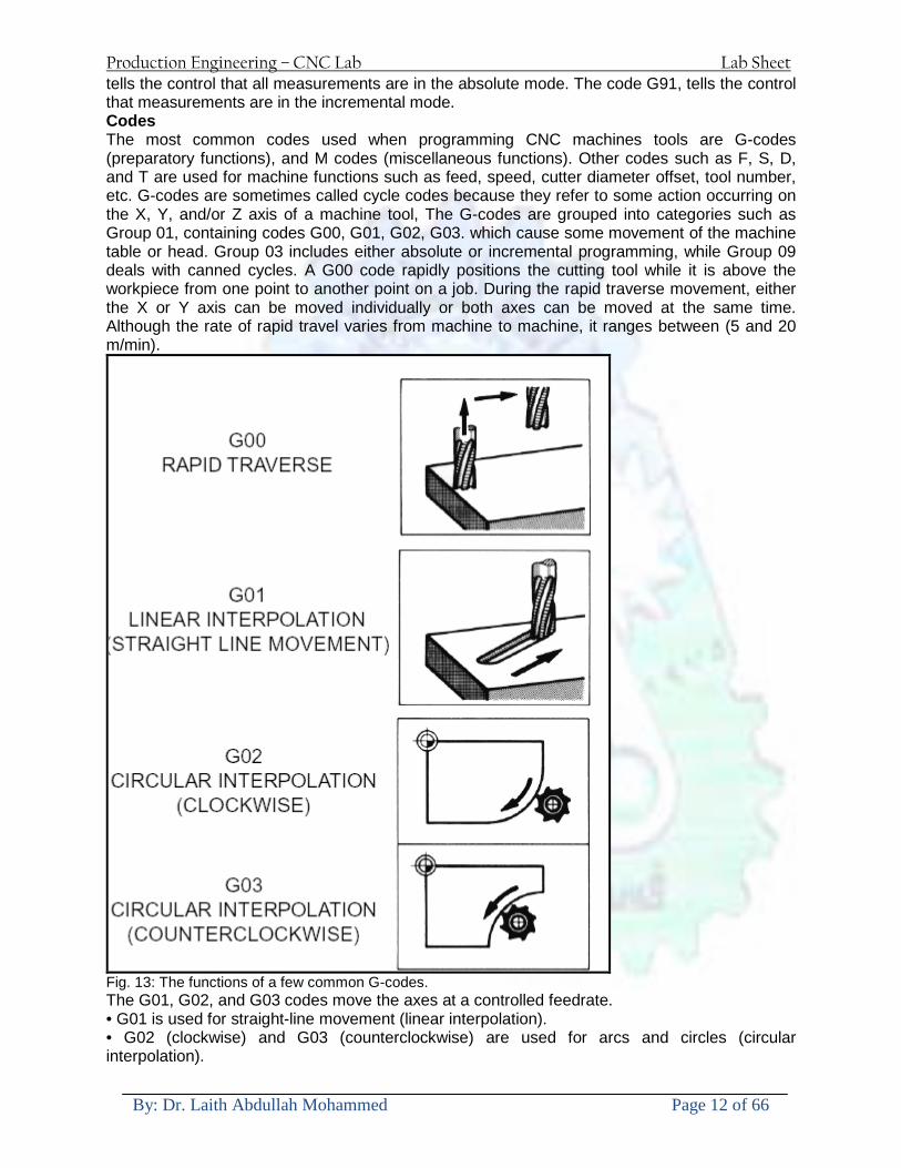
Production Engineering ndash CNC Lab Lab Sheet
By Dr Laith Abdullah Mohammed Page 12 of 66
tells the control that all measurements are in the absolute mode The code G91 tells the control that measurements are in the incremental mode Codes The most common codes used when programming CNC machines tools are G-codes (preparatory functions) and M codes (miscellaneous functions) Other codes such as F S D and T are used for machine functions such as feed speed cutter diameter offset tool number etc G-codes are sometimes called cycle codes because they refer to some action occurring on the X Y andor Z axis of a machine tool The G-codes are grouped into categories such as Group 01 containing codes G00 G01 G02 G03 which cause some movement of the machine table or head Group 03 includes either absolute or incremental programming while Group 09 deals with canned cycles A G00 code rapidly positions the cutting tool while it is above the workpiece from one point to another point on a job During the rapid traverse movement either the X or Y axis can be moved individually or both axes can be moved at the same time Although the rate of rapid travel varies from machine to machine it ranges between (5 and 20 mmin)
Fig 13 The functions of a few common G-codes The G01 G02 and G03 codes move the axes at a controlled feedrate bull G01 is used for straight-line movement (linear interpolation) bull G02 (clockwise) and G03 (counterclockwise) are used for arcs and circles (circular interpolation)
Production Engineering ndash CNC Lab Lab Sheet
By Dr Laith Abdullah Mohammed Page 13 of 66
Fig 14 Some of the most common G-codes used in CNC programming M or miscellaneous codes are used to either turn ON or OFF different functions which control certain machine tool operations M-codes are not grouped into categories although several codes may control the same type of operations such as M03 M04 and M05 which control the machine tool spindle bull M03 turns the spindle on clockwise bull M04 turns the spindle on counterclockwise bull M05 turns the spindle off
Production Engineering ndash CNC Lab Lab Sheet
By Dr Laith Abdullah Mohammed Page 14 of 66
Fig 15 The functions of a few common M-codes
Production Engineering ndash CNC Lab Lab Sheet
By Dr Laith Abdullah Mohammed Page 15 of 66
Fig 16 Some of the most common M-codes used in CNC programming Block of Information CNC information is generally programmed in blocks of five words Each word conforms to the EIA standards and they are written on a horizontal line If five complete words are not included in each block the machine control unit (MCU) will not recognize the information therefore the control unit will not be activated Using the example shown in Fig 17 the five words are as follows N001 represents the sequence number of the operation G01 represents linear interpolation X12345 will move the table 12345 in in a positive direction along the X axis Y06789 will move the table 06789 in along the Y axis M03 Spindle on CW
Fig 17 A complete block of information consists of five words
Production Engineering ndash CNC Lab Lab Sheet
By Dr Laith Abdullah Mohammed Page 16 of 66
Programming for Positioning Before starting to program a job it is important to become familiar with the part to be produced From the engineering drawings the programmer should be capable of planning the machining sequences required to produce the part Visual concepts must be put into a written manuscript as the first step in developing a part program Fig 18 It is the part program that will be sent to the machine control unit by the computer tape diskette or other input media The programmer must first establish a reference point for aligning the workpiece and the machine tool for programming purposes The manuscript must include this along with the types of cutting tools and work-holding devices required and where they are to be located
Fig 18 The first step in producing a CNC program is to take the information from the print and produce a program manuscript Dimensioning Guidelines The system of rectangular coordinates is very important to the successful operation of CNC machines Certain guidelines should be observed when dimensioning parts for CNC machining The following guidelines will insure that the dimensioning language means exactly the same thing to the design engineer the technician the programmer and the machine operator 1 Define part surfaces from three perpendicular reference planes 2 Establish reference planes along part surfaces which are parallel to the machine axes 3 Dimension from a specific point on the part surface 4 Dimension the part clearly so that its shape can be understood without making mathematical calculations or guesses 5 Define the part so that a computer numerical control cutter path can be easily programmed
Production Engineering ndash CNC Lab Lab Sheet
By Dr Laith Abdullah Mohammed Page 17 of 66
Machine Zero Point The machine zero point can be set by three methodsmdashby the operator manually by a programmed absolute zero shift or by work coordinates to suit the holding fixture or the part to be machined MANUAL SETTING - The operator can use the MCU controls to locate the spindle over the desired part zero and then set the X and Y coordinate registers on the console to zero
Fig 19 The relationship between the part zero and the machine system of coordinates ABSOLUTE ZERO SHIFT - The absolute zero shift can change the position of the coordinate system by a command in the CNC program The programmer first sends the machine spindle to home zero position by a G28 command in the program Then another command (G92 for absolute zero shift) tells the MCU how far from the home zero location the coordinate system origin is to be positioned Fig 19 The sample commands may be as follows N1 G28 X0 Y0 Z0 (sends spindle to home zero position) N2 G92 X4000 Y5000 Z6000 (the position the machine will reference as part zero)
Production Engineering ndash CNC Lab Lab Sheet
By Dr Laith Abdullah Mohammed Page 18 of 66
Work Settings and Offsets All CNC machine tools require some form of work setting tool setting and offsets (compensation) to place the cutter and work in the proper relationship Compensation allows the programmer to make adjustments for unexpected tooling and setup conditions
Work Coordinates In absolute positioning work coordinates are generally set on one edge or corner of a part and all programming is generally taken from this position In Fig 20 the part zero is used for all positioning for hole locations 1 2 and 3
Fig 20 In absolute programming all dimensions must be taken from the XY zero at the top left-hand corner of the part
Fig 21 In incremental programming all dimensions are taken from the previous point In incremental positioning the work coordinates change because each location is the zero point for the move to the next location Fig 21
Production Engineering ndash CNC Lab Lab Sheet
By Dr Laith Abdullah Mohammed Page 19 of 66
On some parts it may be desirable to change from absolute to incremental or vice versa at certain points in the job Inserting the G90 (absolute) or the G91 (incremental) command into the program at the point where the change is to be made can do this
R Plane or Gage Height The word-address letter R refers to a partial retraction point in the Z axis to which the end of the cutter retracts above the work surface to allow safe table movement in the X Y axes It is often called the rapid-traverse distance gage height retract or work plane The R distance is a specific height or distance above the work surface and is generally 100 in above the highest surface of the workpiece Fig 22 which is also known as gage height Some manufacturers build a gage height distance of 100 in into the MCU (machine control unit) and whenever the feed motion in the Z axis is called for 100 in will automatically be added to the depth programmed When setting up cutting tools the operator generally places a 100 in thick gage on top of the highest surface of the workpiece Each tool is lowered until it just touches the gage surface and then its length is recorded on the tool list Once the gage height has been set it is not generally necessary to add the 100 in to any future depth dimensions since most MCUs do this automatically
Fig 22 Using a 100 in gage block to set the gage height or R0 on the work surface
Cutter Diameter Compensation Cutter diameter compensation (CDC) changes a milling cutterrsquos programmed centerline path to compensate for small differences in cutter diameter On most MCUs it is effective for most cuts made using either linear or circular interpolation in the X-Y axis but does not affect the programmed Z-axis moves Usually compensation is in increments of 0001 in up to +10000 in and usually most controls have as many CDCs available as there are tool pockets in the tool storage matrix The advantage of the CDC feature is that it 1 Allows the use of cutters that have been sharpened to a smaller diameter 2 Permits the use of a larger or smaller tool already in the machinersquos storage matrix 3 Allows backing the tool away when roughing cuts are required due to excessive material present 4 Permits compensation for unexpected tool or part deflection if the deflection is constant throughout the programmed path The basic reference point of the machine tool is never at the cutting edge of a milling cutter but at some point on its periphery If a 1000 in diameter end mill is used to machine the edges of a workpiece the programmer would have to keep a 500 in offset from the work surface in order to cut the edges accurately Fig 23 The 500 offset represents the distance from the centerline of the cutter or machine spindle to the edge of the part Whenever a part is being machined the programmer must calculate an offset path which is usually half the cutter diameter
Production Engineering ndash CNC Lab Lab Sheet
By Dr Laith Abdullah Mohammed Page 20 of 66
Fig 23 Cutter-diameter compensation must be used when machining with various size cutters Modern MCUs which have part surface programming automatically calculate centerline offsets once the diameter of the cutter for each operation is programmed Many MCUs have operator-entry capabilities which can compensate for differences in cutter diameters therefore an oversize cutter or one that has been sharpened can be used as long as the compensation value for oversize or undersize cutters is entered
Production Engineering ndash CNC Lab Lab Sheet
By Dr Laith Abdullah Mohammed Page 21 of 66
CNC Programming Hints - MILLING
Production Engineering ndash CNC Lab Lab Sheet
By Dr Laith Abdullah Mohammed Page 22 of 66
CNC Programming Hints ndash TURNING
Production Engineering ndash CNC Lab Lab Sheet
By Dr Laith Abdullah Mohammed Page 23 of 66
CNC
The abbreviation CNC stands for Computer(ized) Numerical(ly) Control(led) and refers specifically to the computer control of machine tools for the purpose of (repeatedly) manufacturing complex parts in metal as well as other materials using a program written in a notation conforming to the EIA-274-D standard and commonly called G-code
CNC was developed in the late 1940s and early 1950s by the MIT Servomechanisms Laboratory CNC machines were relatively briefly preceded by the less advanced NC or Numerical(ly) Control(led) machines The introduction of CNC machines radically changed the manufacturing industry Curves are as easy to cut as straight lines complex 3-D structures are relatively easy to produce and the number of machining steps that required human action have been dramatically reduced With the increased automation of manufacturing processes with CNC machining considerable improvements in consistency and quality have been achieved CNC automation reduced the frequency of errors and provided CNC operators with time to perform additional tasks
CNC automation also allows for more flexibility in the way parts are held in the manufacturing process and the time required to change the machine to produce different components In a production environment a series of CNC machines may be combined into one station commonly called a cell to progressively machine a part requiring several operations CNC machines today are controlled directly from files created by CAM software packages so that a part or assembly can go directly from design to manufacturing without the need of producing a drafted paper drawing of the manufactured component In a sense the CNC machines represent a special segment of industrial robot systems as they are programmable to perform many kinds of machining operations (within their designed physical limits like other robotic systems)
G-code
G-code is a common name for the programming language that is used for NC and CNC machine tools It is defined in EIA RS-274-D G-code is also the name of any word in a CNC program that begins with the letter G and generally is a code telling the machine tool what type of action to perform such as
bull rapid move bull controlled feed move in straight line or arc bull series of controlled feed moves that would result in a hole being drilled bull change a pallet bull Set tool information such as offset
There are other codes the type codes can be thought of like registers in a computer
X position Y position Z position M code (another action register) F feed rate S spindle speed N line number R Radius T Tool selection
Production Engineering ndash CNC Lab Lab Sheet
By Dr Laith Abdullah Mohammed Page 24 of 66
I Arc data X axis J Arc data Y axis
G-code files are output by CAM software such as Smartcam Gibbscam Featurecam Edgecam Mastercam etc G-code is also output by specialized CAD systems used to design printed circuit boards Such software must be customized for each type of machine tool that it will be used to program
Production Engineering ndash CNC Lab Lab Sheet
By Dr Laith Abdullah Mohammed Page 25 of 66
U 2عمل األزرار الرئيسية في ماكنة الخراطة المبرمجة (نصر (
1- SINGLE BLOCK للتأكد من صحة البرنامج (تنفيذ البرنامج خطوة خطوةب تقوم( 2- BLOCK DELETE بجانب ويعمل من األوامرلغاء بلوك معين أليستخدم 3- MACHINE LOCK العمل يستخدم لقفل حركة المحاور الرئيسية مع استمرار البرنامج في
)وهذا مهم للتاكد من صحة البرنامج قبل عملية التنفيذ النهائي(4- CONT CYCLE عملية التشغيل عند ايقافها الي سبب كان او عند ايقافها ألستئناف ستخدم ت
) BAR FEEDER(او في حالة استخدام ) FEED HOLDبسبب (5- DRY RUN وتستخدم لفحص البرنامج بعد ازالة الشغلة حركة سريعة للبرنامج 6- TURRET UP amp DOWN ) حركة حامل العدة TURRET الذي يحمل مجموعة من (
وهذا الزر يعمل مع الزر عكس عقرب الساعة او مع عقرب الساعة ةحركة دوراني العدد )SAFTY (
7- COOLANT ON or OFFفه تشغيل سائل التبريد او ايقا 8- COOLANT AUTO الدوال المساعدة في البرنامج من خالل فه تشغيل سائل التبريد او ايقا 9 -MACHINE START ة لتشغيل هيدرولكيك الماكنميستخد
Production Engineering ndash CNC Lab Lab Sheet
By Dr Laith Abdullah Mohammed Page 26 of 66
10- CLOSE OR OPEN CHUCKالعينة تستخدم لفتح وغلق 11 -T STOCK FWD RET حركة الغراب المتحرك ذهابا وإيابا12 -SPINDLE STOP تعمل على ايقاف حركة دوران العينة 13-JOG SPINDLE تعمل على تدوير العينة مع زر SAFTY 14 -OPT SAFTY مع الدالة ( تعمل عمل التوقف المشروط حيث تعملM1 دالة التوقف (
ط ) فقط األ اذا كان هذا الزر مضغو M1المشروط حيث ال يتوقف البرنامج في حالة وجود دالة ( SAFTY + SPINDLE ) يتم الضغط على زر ( START CYCLEلغرض تحرير زر (
START ) في نفس الوقت بعد الضغط على زر ( START CYCLE مرتين (
NC PC- 15 يستخدم هذا الزر عند ربطCNC يستخدم لنقل المعلومات ث مع جهاز أخر حي بينهما
16 -CALCU زر الخاص بالحاسبة مع زر ( ال وهوINPUT ( 17 - HD1 HD2 يستخدم الختيار العدة مع المخرطة ذات المحاور األربعة 18 - START تستخدم لبدء عملية التشغيل
Production Engineering ndash CNC Lab Lab Sheet
By Dr Laith Abdullah Mohammed Page 27 of 66
19- FEED HOLD تعمل على إيقاف عمل أي G موجودة مع بقاء العينة متحركة 20- M D I أو تشغيل البرنامج ل يتم استخدامه لإلدخا BLOCK BY BLOCK وتعمل عند
إدخال البرنامج بواسطة الشريط المثقب أو أي وسيلة إدخال أخرى أو في عمليات التصفير
21- REST تستخدم العادة تشغيل الماكنة أو مسح اإلنذار الذي يظهر على الشاشة 22- EMERGENCYتستخدم عادة اليقاف الماكنة في حالة الطوارئ فقط
OPERATION MENU KEY
CHAPTER PRG-CMK
OFFSET PROGRAM POSITION FUNCTION MENU KEY
23- POSITIONعلى الشاشة د الموقع الموجور الظها 24- PROGRAMإلظهار برنامج معين واختياره 25- OFFSET الختيار سماحات العدة أو سماحات نقطة المرجع 26- PRG- CHK تستخدم لفحص البرنامج على الشاشة 27- SETTING ألختيار الثوابت على الشاشة 28- SERVICE تستخدم ألستخراج المعامالت والثوابت 29- MESSAGE تستخدم ألظهار األخطاء الناتجة عن البرنامج او اخطاء التشغيل 30- OVERALL ألختيار المواقع 31- RELATIVE MODLINE تعوض عن POSITION 32- DIR MEM يستخدم ألظهار ملف البرامج المخزونة في الذاكرة وعندما نضغط هذا الزر
فان رقم واسم البرنامج سوف يظهر على الشاشة
2أدناه الشفرات الرئيسية التي تعمل على الماكنة المبرمجة نصر
G-CODE DESCRIPTION
G00 Rapid traverse (linear)
G01 Linear Interpolation at feed rate
G02 Circular interpolation (CW) R+
G03 Circular interpolation (CCW) R+
G10 Zero point tools
G20 Imperial data input
G21 Metric data input
G27 Reference return check
G28 Reference return
G29 Return from reference
Production Engineering ndash CNC Lab Lab Sheet
By Dr Laith Abdullah Mohammed Page 28 of 66
G33 Thread cutting
G40 Cancel cutter radius compensation
G41 Cutter compensation left
G42 Cutter compensation right
G54 Work co-ordinate system no1
G70 Finishing cycle
G71 Stock removal turning
G72 Stock removal facing
G74 Face grooving
G75 Diameter grooving
G76 Threading cycle
G90 Absolute date input
G91 Incremental data input
G94 Feed minute mode
G95 Feed rev mode
G96 Constant surface speed mode
G97 Cancel Constant surface speed
) 2أدناه الشفرات الثانوية التي تعمل على الماكنة المبرمجة (نصر
M-code FUNCTION
M00 Program stop
M03 Spindle forward (Tool forward ndash M94 mode)
M04 Spindle reverse (Tool forward ndash M94 mode)
M05 Spindle stop (Tool stop ndash M94 mode)
M08 Coolant on
M09 Coolant off
M30 Program end (with rewind)
M48 Turret shortest path
M52 Turret direction up (CW)
M53 Turret direction down (CCW)
M73 Chuck open
M74 Chuck close
Production Engineering ndash CNC Lab Lab Sheet
By Dr Laith Abdullah Mohammed Page 29 of 66
) وكل جملة مكونة من مجموعة من الكلمات blockإن كل برنامج يتكون من مجموعة من الجمل ()words) لهذا فأن الشفرات الرئيسية والمساعدة هي عبارة عن كلمات (words كما في المثال التالي (
G_ _ P1 Q2 U_ _ W_ _ D___ F_ _
)end of block) ويعني ( ) يكتب الرمز (blockتسلسل الكلمات مهم جدا بعد نهاية كل جملة (
طريقة ادخال البيانات الى الماكنة ــــــــــــــــــــــــــــــــــــــــــــــــــ
) MDIيمكن ادخال البيانات الى الماكنة بعدة طرق فقد يكون األدخال عن طريق قناة السيطرة ( MANUAL DATA INPUT ) او عن طريق قناة األضافة EDIT كما يمكن ادخال البيانات عن (
) RS ndash 232 COMMUNICATIN LINKطريق استخدام سلسلة الربط (
₤⅗₌⅗₌ ⅙₌₨image₍₡ ₤₌ℌ⅗₌ Ⅸ⅗ⅥⅯ₌ ₤₡ℌ₰₨⅗₌G71
الخراطة الطولية G71الغرض من التجربة عمل نموذج للخراطة بأستخدام الدالة تستعمل هذه الدالة للخراطة الطولية اي على طول محور المشغولة وكما هو موضح بالشكل ادناه
تعتبر هذه الدالة من الدوال التي ال تحتاج الى تكرار او إعادة كتابتها أي انها دالة تكرارية بمعنى ان اي
الذي هي دالة حركة G01خطوة تكون من ضمن هذه الدالة سوف تكرر العملية اي عند استعمال امر مثل خطية تتضمن القطع مع التغذية مع اعطاء القطر المراد قطعه و مراعاة عمق القطع المعطى سوف يتكرر
هذه االمر وصوال الى العمق المطلوب وهكذا لبقية الدوال
G71 المستخدمة للدالة الصيغة
G71 P1 Q2 U___ W___ D___ F___ حيث إن
P1 بداية الخطوة االولى = Q2 نهاية الخطوة =
Uوضع السماحات بأتجاه محور = X W وضع السماحات بأتجاه محور = Z وتكاد تكون مهملة وتوضع اشارة سالب Dعمق القطع وتوضع رقم صحيح مثل = D500 اي نصف ملمF التغذية والتي لها عالقة بالدالة = G95
Production Engineering ndash CNC Lab Lab Sheet
By Dr Laith Abdullah Mohammed Page 30 of 66
G71الدالة استخدام مثال على
T0100 M48 G0 X26 Z2 M08 T0101 G90 G95 G97 S500 M03 G71 P1 Q2 U03 W00 D500 F01 N1 G0 G42 X00 G01 Z00 G01 X2517 G01 Z-5352 G01 X7391 Z-9366 G01 Z-19145 N2 G28 M30
الجانب العملي
االجهزة واالدوات المستخدمة CNCماكنة خراطة مبرمجة 1 ملم 80قضيب من االلمنيوم قطر 2 ةفير ني 3 جاه أيمن تهولدر كاربيدي ذوا 4
طريقة العمل يتم تثبيت قضيب من االلمنيوم على العينة التابعة للماكنة مع مراعاة الطول المراد استعماله في عملية 1
الخراطة ) turretتثبيت عدة القطع في المكان الصحيح في ( 2
Production Engineering ndash CNC Lab Lab Sheet
By Dr Laith Abdullah Mohammed Page 31 of 66
بالنسبة الى القطعة المثبتة على العينة XZيتم تصفير الماكنة للمحاور 3 تصفير للمحورZ تكون مالمسة العدة الى وجه الشغلة تصفير للمحورX تكون مالمسة العدة الى سطح الشغلة الموازي لمحور X
يتم كتابة البرنامج أما بطريقة يدوية أو بالحاسوب مع وضع كل الظروف الالزمة للتشغيل ( عمق القطع 4 التغذية السرعة المطلوبة نوع المعدن )
ادخال البرنامج الى الحاسوب الموجود داخل الماكنة مع تهيئة الماكنة للتشغيل 5
المطلوب G71عمل برنامج يدوي على الدالة 1 رسم الشكل الشكل النهائي المطلوب مع وضع األبعاد 2
Ⅺ⅟₍euro⅗₌ ₤₡ℌ₰₨⅗₌₣ ₤⅗₌⅗₌ ⅙₌₨image₃₡ Ⅺℂtradeℒ⅗₌ ӈ₍Ⅴ⅟ⅳ₌ G70
G70 الغرض من التجربة عمل انهاء سطحي للمشغولة بواسطة الدالة
من الضروري إعطاء G71هذه الدالة تعمل شوط واحد فقط وتكون معتمدة على عمليات القطع في الدالة اللغاء مقدمة االداة (أي لكي تتم عملية االنهاء السطحي بدون حسابات نصف قطر مقدمة االداة ) G42دالة
G70الصيغة المستخدمة للدالة
G70 P1 Q2 F___ حيث ان
P1 بداية الخطوة االولى = Q2 نهاية الخطوة =
F التغذية والمرتبطة بالدالة = G95
وذلك ألن دالة االنهاء السطحي تحقق X Zمالحظة الدالة التحتاج لكتابة السماحات التابعة للمحورين المسافات الحقيقة المراد انتاجها للمشغولة
G71و G70مثال على الدالة
T0100 M48 G0 X26 Z2 M08 T0101 G90 G95 G97 S500 M03 G71 P1 Q2 U03 W00 D500 F01 N1 G0 G42 X00 G01 Z00 G01 X2517 G01 Z-5352 G01 X7391 Z-9366 G01 Z-19145 N2 G97 S750 MO3
Production Engineering ndash CNC Lab Lab Sheet
By Dr Laith Abdullah Mohammed Page 32 of 66
G70 P1 Q2 G40 F009 G28 M30
الجانب العملي الحظ التجربة األولى
المطلوب
G70 عمل برنامج يدوي على الدالة 1 رسم الشكل النهائي المطلوب مع وضع االبعاد 2
₪⅗₍euro⅗₌ ₤₡ℌ₰₨⅗₌₣ ₤⅗₌⅗₌ ⅙₌₨image₍₡ ⅝₍ⅠimageⅯ₌ ⅞ⅫⅦ⅔₧ G76
G76 للمشغولة بواسطة الدالةةالغرض من التجربة عمل أسنان خارجية أو داخلي
في هذه التجربة سوف نقوم بعمل األسنان الخارجية وهنا تكون حركة العينة ثابتة وهذا ضروري بسبب أن ) تكون متصلتين الكترونيا وعليه أي اختالف في سرعة العينة تؤدي إلى اختالف motionالعينة والحركة(
) servoفي سرعة الخدمة(يرتبط اتجاه تكوين األسنان باتجاه دوران العينة مثال إذا كانت األسنان ذات اتجاه أيمن يكون اتجاه دوران
وهنا نقلب العدة إلى االسفل وكما هو موضح بالشكل أدناه MO3العينة عكس عقرب الساعة أي نستعمل
Production Engineering ndash CNC Lab Lab Sheet
By Dr Laith Abdullah Mohammed Page 33 of 66
الخطوة هي عبارة عن المسافة ما بين قمة سن إلى قمة سن أخر عمق السن هو العمق المطلوب تكوينه لألسنان
G76 الصيغة المستخدمة للدالة
G76 X___ Z___ K___ F___ D___ A___
حيث أن X القطر الداخلي للسن =Z طول السن =K عمق السن وتستخرج من المعادلة التالية =K=065F F الخطوة =D عمق القطع بالمايكرون فقط =A زاوية السن =
G76مثال على استخدام الدالة T0300 M48 GOO X30 Z4 T0303 M08 G97 S500 MO3 G76 X28375 Z-20 K08125 F125 D120 G00 X40 Z4 G28 M30
Production Engineering ndash CNC Lab Lab Sheet
By Dr Laith Abdullah Mohammed Page 34 of 66
الجانب العملي الحظ التجربة األولى
المطلوب
G76عمل برنامج يدوي على الدالة 1 رسم الشكل النهائي المطلوب مع وضع األبعاد 2
Ⅺ⅘₌⅗₌ Ⅵ₂ Ⅺ₯ℋ₍⅗₌ ℌℲℂ⅗₌ ⅞ⅫⅦ⅔₧ ₤K₡₌ℌ⅗₌ ₤₡ℌ₰₨⅗₌)Groove ₤⅗₌⅗₌ ₤tradeimage₌Ⅶ₡ (G75
G75 بواسطة الدالة grooveالغرض من التجربة تكوين
) للمشغولة وتعتمد شكل الحفر على طريقة grooveتستعمل هذه الدالة لتكوين الحفر الخارجي والداخلي (
التشغيل وعلى الشكل المراد إنتاجه وتعتبر هذه الطريقة من عمليات التشكيل للمعدن إن هذه الدالة هي دالة مالحظة مع G75في هذه التجربة سنقوم بعمل الحفر الخارجي بواسطة الدالة
تكرارية وغير تكرارية حسب نوع التشغيل
G 75 الصيغة المستخدمة للدالةG75 X___ Z___ I___ K____
حيث أن
X العمق النهائي لقطر الشغلة =Z عرض الحفر =I الدخول في كل مرة =
K التزحيف على محور =z بالنسبة للعدة
Production Engineering ndash CNC Lab Lab Sheet
By Dr Laith Abdullah Mohammed Page 35 of 66
G75مثال على استخدام الدالة
T0500 M48 GOO X100 Z -20 T0505 M08 G97 S700 MO3 G75 X84 Z -38 I 05 K4
الجانب العملي الحظ التجربة األولى
المطلوب
G76عمل برنامج يدوي على الدالة 1 رسم الشكل النهائي المطلوب مع وضع األبعاد 2
Production Engineering ndash CNC Lab Lab Sheet
By Dr Laith Abdullah Mohammed Page 36 of 66
CNC Milling Machine Mechanical Construction
Guideways The guideways of CNC machines are made of steel To reduce the frictional forces they are coated with a strip of PTFE (Poly Tetra Fluoro Ethylene)
Ballscrews On conventional lathes a leadscrew is used to converts the rotary motion of the hand wheel into linear motion of the slides Leadscrews have a high coefficient of friction and backlash On CNC machines a ballscrew is used instead of a leadscrew Friction and backlash are much less than on leadscrews
Guideway
Production Engineering ndash CNC Lab Lab Sheet
By Dr Laith Abdullah Mohammed Page 37 of 66
bullMachining operations Direction of cutting Based on the direction of the cutter rotation and work piece feed milling operations are classified into two types 1-Up milling (Convention milling) In up milling the metal is removed by rotating the cutter against the direction of travel of the part
Feed
Machine table
Part
Cutting tool
Chip thickness at theexit of the tooth
2-Down milling (Climb milling) In climb milling the metal is removed by rotating the cutter with the direction of travel of the part
Machine table
Part
Cutting tool
Chip thickness at theentrance of the tooth
Production Engineering ndash CNC Lab Lab Sheet
By Dr Laith Abdullah Mohammed Page 38 of 66
bullTooling Tool geometry The geometry of the tool tip affects the way that the metal cutting is performed The nose radius rake angles relief angles etc must be selected with care
Radial relief
Radial rake
Axial relief
Approach angle
Axial relief
Corner radius Face mill Face milling cutters are used to mill flat surfaces Commonly used face milling cutters Cutter with 75 degree approach
75 deg
Cutter with 90 degree approach (Square shoulder face mill)
90 deg
Cutter with 45 degree approach
Production Engineering ndash CNC Lab Lab Sheet
By Dr Laith Abdullah Mohammed Page 39 of 66
bullCNC Programming Axes convention The Z axis is along the spindle axis The X and Y axes are perpendicular to Z VMC
Z
Y
-
+
-+
X- +
+Z
-Z
+Y
-Y
-X +X
Part
Machine table
X
YZ
G00 Rapid traverse When the tool being positioned at a point preparatory to a cutting motion to save time it is moved along a straight line at Rapid traverse at a fixed traverse rate which is pre-programmed into the machines control system Typical rapid traverse rates are 10 to 25 m min but can be as high as 80 mmin
Production Engineering ndash CNC Lab Lab Sheet
By Dr Laith Abdullah Mohammed Page 40 of 66
Format N_ G00 X__ Y__Z__
G01 Linear interpolation (feed traverse) The tool moves along a straight line in one or two axis simultaneously at a programmed linear speed the feed rate Format N__ G01 X__ Y__Z__ F__
Part
Feed
Part
Feed
G02G03 Circular interpolation The tool moves along an arc in two axes simultaneously at a programmed linear speed the feed rate
Production Engineering ndash CNC Lab Lab Sheet
By Dr Laith Abdullah Mohammed Page 41 of 66
Format N__ G0203 X__ Y__Z__ I__ J__K__ F__ using the arc center OR N__ G0203 X__ Y__Z__ R__ F__ using the arc radius G02 moves along a CW arc G03 moves along a CCW arc Arc center The arc center is specified by addresses I J and K I J and K are the X Y and Z co-ordinates of the arc center with reference to the arc start point
X
Y
Arc center
Arc endArc start
- J
- I
I = X coord of center - X coord of start point J = Y coord of center - Y coord of start point K = Z coord of center - Z coord of start point I J and K must be written with their signs
Production Engineering ndash CNC Lab Lab Sheet
By Dr Laith Abdullah Mohammed Page 42 of 66
bullWork holding
Rotary table
Fixture base
Component
Clamp
Stud
Fixtures The use of fixtures 1 Improves repeatability of dimensions 2 Improves working conditions 3 Cuts down requirement of skilled labour 4 Reduces part loading and unloading time 5 Improves safety in the working area 6 Reduces the cost of machining There are two types fixtures commonly used 1 Special fixture Special fixtures are used to hold and locate the typical components which are having complex shape and to be located with the reference hole (dowel hole) Special fixtures are required for components like gear case cover cylinder heads etc 2 Modular fixture Modular fixture is a set different kind of clamping and locating elements These fixtures are used to hold identical components in different sizes and components of box type Example Manifolds head stocks connecting rods and flanges
Production Engineering ndash CNC Lab Lab Sheet
By Dr Laith Abdullah Mohammed Page 43 of 66
bullMachine setting
Determining X and Y work zero offset Case 1
Part
Machine table
Part
End mill or reamer
Work offset X0Y0 For determining X work zero offset bull Touch the periphery of the end mill or reamer to the part bull Enter current machine X value + cutter radius as X work zero offset For determining Y work zero offset bull Touch the periphery of the end mill or reamer to the part bull Enter current machine Y value - cutter radius as Y work zero offset Case 2
Part
Machine table
Part
End mill or reamerWork offset X0Y0
bull Mount the dial indicator on machine spindle true the bore bull Enter current machine X and Y value as X and Y work zero offset
Production Engineering ndash CNC Lab Lab Sheet
By Dr Laith Abdullah Mohammed Page 44 of 66
How to Select a Cutting Fluid
One part of the metal cutting equation that is sometimes overlooked however is
the choice of an appropriate cutting fluid With todayrsquos system approach to metal
cutting use of the right metalworking fluid has become just as much a part of the
solution as the other elements In fact at least one company is now integrating
cutting fluids and cutting tools into effective metal cutting systems Following are
some things to consider when choosing your next cutting fluid
The Four Key Questions
There are four vital pieces of information that are necessary when choosing a
cutting fluid They are
1 What are you cutting
2 What is the chemistry of your water
3 What are you using now
4 What are your options
5 What do you prefer
What Are You Cutting
The first question ndash ldquoWhat are you cuttingrdquo ndash is often the most difficult to answer
because most shops handle a variety of workpiece materials on a regular basis If
the answer is an unequivocal ldquoaluminumrdquo or ldquostainless steelrdquo or ldquocast ironrdquo the
selection of a cutting fluid can be quite simple and straightforward Unfortunately
that is seldom the case in anything but a high-volume plant Where aluminum or
other nonferrous metals are a significant part of the mix a non-staining cutting
fluid is a must Generally speaking this will be a semi-synthetic with special
ingredients to prevent bi-metallic corrosion and staining of non-ferrous workpieces
Where the ferrous metals predominate however a more general purpose semi-
synthetic or hybrid fluid might be a more economical choice
Production Engineering ndash CNC Lab Lab Sheet
By Dr Laith Abdullah Mohammed Page 45 of 66
What is The Chemistry of Your Water
The second question ndash ldquoWhat is the chemistry of your waterrdquo ndash is probably the
single most common reason for the success or failure of a cutting fluid Very few
plants invest the money necessary to install effective water purification systems
using deionization or reverse osmosis technology Unfortunately the chemicals
present or not present in the water used to re-constitute a cutting fluid make a
tremendous difference in its performance and sump life Most manufacturers of
cutting fluids will perform the necessary water testing to determine exactly what
minerals are dissolved in your water and make a fluid recommendation based on
the results
What are you using now
The third question ndash ldquoWhat are you using nowrdquo ndash helps narrow the range of
choices When coupled with an objective analysis of the strengths and weaknesses
of the current fluid the answer to this question can quickly point you toward a
relatively small number of competitive alternatives that have the attributes required
to meet your cutting needs Many cutting fluids are in use today simply because
they were in use yesterday It is a hard reality of todayrsquos marketplace that if one
isnrsquot constantly striving to improve they will certainly be overtaken by a
competitor who is
What Are Your Options
The fourth question ndash ldquoWhat are your optionsrdquo ndash leads to the final selection of a
cutting fluid Cutting fluids can be divided into four general groups based on their
chemistry
They are
bull Soluble Oils ndash quite literally oil dispersed in water
bull Synthetics ndash completely oil free man-made coolants in solution
Production Engineering ndash CNC Lab Lab Sheet
By Dr Laith Abdullah Mohammed Page 46 of 66
bull Semi-Synthetics ndash a mixture of natural and synthetic lubricants with up to 30
mineral oil
bull Hybrids ndash a special class of semi-synthetics with a mineral oil content of about
15 Each fluid type has advantages and disadvantages which make it suitable for
a particular group of applications In addition there are costperformance trade-
offs to be made between the groups within a specific set of applications For
example where a hybrid and a semi-synthetic may both be suitable for a particular
use the hybrid might provide longer sump life at a slightly higher initial cost
while some semi synthetics may be more economical to recycle or dispose of while
not giving as long a tank life The final decision in this case would have to be made
on the detailed economics of the shop where the fluids were to be used and on the
ownerrsquos individual preferences
Soluble Oils
Soluble oils are oils that disperse in water when emulsifiers are added They are
generally suitable for moderate-to heavy-duty machining and grinding of all non-
ferrous metals carbon and cast steels and in applications where dissimilar metals
such as aluminium and steel are present They can also be used in turning drilling
tapping reaming gear cutting broaching as well as internal and centerless types
of grinding operations Soluble oils provide excellent aluminium and copper
corrosion control good rancidity control which extends fluid for long lasting
trouble-free performance and good concentrate and mix stability making it ideal
for mixing in water with a minimal amount of agitation An example of this is
Valenitersquos VNTreg-650 premium heavy-duty soluble oil
Synthetics
Synthetics are completely oil free solutions made of polymers organic and
inorganic materials that are mixed with water These clear low foaming and bio-
Production Engineering ndash CNC Lab Lab Sheet
By Dr Laith Abdullah Mohammed Page 47 of 66
stable coolants are ideal for machining and grinding of ferrous materials carbon
steels or cast iron Their complex lubricant packages make synthetics well-suited
for tough-to-machine materials such as stainless steels and high-temperature alloys
Certain synthetics are specifically designed to address the primary failure modes of
flank wear and nose wear Although there are many benefits some synthetics may
cause staining of non-ferrous materials
Semi-Synthetics
Semi-synthetic fluids are a mixture of oils synthetic emulsifiers and water They
were primarily developed for the aircraft nuclear and related industries
Consequently they work extremely well on all non-ferrous metals such as titanium
aluminium copper brass bronze and stainless steel in both machining and
grinding Semi-synthetics can be used on ferrous metals too They are chlorine-
free to reduce bi-metallic corrosion and staining of metals They should be used at
a 5-8 dilution with water depending on the severity of the operation
Hybrids
Hybrids are cutting fluids custom engineered to solve a particular problem For
example Valenitersquos VNTreg-800 was developed to be very clean in the machining
and grinding of cast iron It provides better stability in hard water and rejects tramp
oil very well which adds to its bio-stable chemistry Hybrids work extremely well
on all metals in both machining and grinding They should be mixed at a 5-7
dilution with water depending on the condition of the water
What Do You Prefer
The final question ndash ldquoWhat do you preferrdquo ndash is usually the ldquotie breakerrdquo where
there is more than one appropriate cutting fluid available Here again as in the
case of what is being used now the key is to examine your preferences objectively
Production Engineering ndash CNC Lab Lab Sheet
By Dr Laith Abdullah Mohammed Page 48 of 66
and specifically to identify the real reasons behind a preference If you cannot
point to specific reasons why one class of cutting fluid is preferred over another
you are well advised to follow the recommendations of the professional who has
analyzed your requirements Choosing the right fluid today is easier than ever as
the system approach to metal cutting productivity continues to grow in acceptance
The day is not far off when choosing a complete solution will be as easy as
choosing the right insert and chip breaker today The answers are available and the
results will more than justify the time you spend choosing the right metal cutting
fluid
Useful Links wwwball-screwsnet
wwwlubelinkcom
wwwmachinerylubricationcom
wwwadvancedmanufacturingcom
wwwmmsonlinecom
wwwcuttingtoolengineeringcom
wwwgeartechnologycom
wwwengineersedgecom
wwwagmaorg
wwwefundacom
wwwsaeorg
wwwsmeorg
wwwastmorg
wwwissorg
wwwmachinetoolscom
wwwansiorg
wwwasmeorg
wwwcnccicom
wwwmatlscom
wwwthefreedictionarycom
wwwengineersupplycom
Production Engineering ndash CNC Lab Lab Sheet
By Dr Laith Abdullah Mohammed Page 49 of 66
SurfCAM Tutorial ndash Beginning with the basics
Background SurfCAM is a computer aided manufacturing (CAM) software which allows you to create manage and modify tool paths for computer aided designed (CAD) part The software requires a CAD model or requires that you create some geometry within SurfCAM with some rudimentary tools provided The tool paths are created or stored internally in SurfCAM in a generic programming language called APT Once the tool paths are created the APT paths are translated using a post processor into typical machine G-code
Opening SurfCAM SurfCAM can be opened from the Novell Applications Launcher on most Industrial Engineering computer labs workstations Search under lsquoallrsquo applications and double click on SurfCAM 2005 Once the program opens a license must be selected from the list (not the Demo license) to enable saving the file later Choose one of the 30 licenses available If for some reason the licenses are not listed on the license manager form select server list and type ldquobonnieeosncsuedurdquo A list of available licenses should appear Select a license and click OK After the license is selected an Add StockFixture form (Figure 1) opens allows you to add a model which represents the pre-machined stock or a fixture Click on OK without adding either Both of these items can be added later under a more appropriate dialog
Figure 1 Add Stock or Fixture dialog box
Production Engineering ndash CNC Lab Lab Sheet
By Dr Laith Abdullah Mohammed Page 50 of 66
SurfCAM Interface
Figure 2 SurfCAM Windows based interface
SurfCAM is a windows based software system so most of the typical windows functions under File are applicable This is where you can open save exit print etc The Create menu allows the user to create different geometry forms Here you can create a point line surface chamfer circle and many other geometry types For the most part these functions are not used by beginners but are useful when creating bounding curves where you donrsquot want the tool to move outside (constraining the tool) The Edit menu allows you to change or modify many different entities such as changing lines altering surfaces joining surfaces trimming or breaking elements add control points etc Again these features are helpful to advanced users and are not covered in detail in this tutorial The Display menu offers the ability to change the orientation of the part on the screen The typical rotate pan fit to screen and zoom functions are available as well as several functions which allow the user to shift between views or call up a named view (ie top bottom etc) The NC menu is the main machining interface menu In this menu you select the general form of machining (2 axis 3 axis 4 axis 5 axis turning etc) and under the general form a more specific machining function is selected This menu is the most used and the options contained must be fully understood to get the most out of SurfCAM Each function will be described in some detail in a further chapter The Analyze menu contains options such as measuring the distance between points angles tangency elements etc These functions are auxiliary functions meant to help you understand the part better but basically provide no functionality for making tool paths for CNC machines Thus these will not be covered The Tools menu allows the user to change the system options modify keyboard shortcuts change the model units etc These options are again not used by beginners Finally the Help menu provides access to the online users manual In lieu of clicking the Help menu the F1 key is the shortcut key for help (as it is in most windows based programs)
Importing a CAD model Importing a CAD model that is stored locally is done by selecting File-gtOpen On the Files of type dropdown box choose the type of file you wish to open (Figure 3) Do this prior to negotiating your way through the maze of folders to prevent having to go through the folder tree again Once the file type is selected find the file you are trying to open and click the Open
Production Engineering ndash CNC Lab Lab Sheet
By Dr Laith Abdullah Mohammed Page 51 of 66
button SurfCAM will then attempt to read the file you have selected SurfCAM may provide a dialog box describing what it has imported and identify if it was successful If this dialog is provided simply click close without saving
Figure 3 Open Dialog Note - Change type of file prior to finding the file you wish to open
SurfCAM allows a user to import several different types of CAD files the most common types which you will likely import are SolidWorks part files (sldprt or prt) AutoCAD files(dxf) or IGES (igs or iges) Native file import (such as is the case with SolidWorks) provides the greatest information transfer and generic file imports (such as is the case with IGES) provide the least Normally it is to the advantage of the user to use native file importing procedures when available Recently (2005) SurfCAM added some compatibility with SolidWorks This allows the user to create tool paths for a part and if an engineering change is needed for the part update the part in SolidWorks When the part is then opened in SurfCAM the changes are noted and a simple update operation command is needed This however does not operate with complete transparency andor accuracy and thus users need to be cognizant of changing CAD models
SurfCAM Geometry In SurfCAM two basic types of geometry are used the surface and the point A surface (Figure 4) is a so called spline (NURBS or B-Spline are the two most common) surface (parameterized by two values u and v) such that every location on the surface can be defined as a function of these parameters In other words SurfCAM can calculate the location of any point on the
Production Engineering ndash CNC Lab Lab Sheet
By Dr Laith Abdullah Mohammed Page 52 of 66
surface Surfaces are used primarily in 3 4 and 5 axis machining and require a significant
amount of processing power and time Figure 4 Surfaces model of a mold half Note the difference between this and Figure 2 a wireframe model
Point or line based models are often referred to as wireframe (Figure 5) models because the models consist of connected lines and resemble the part only at the intersection of two surfaces Wireframe models were made popular lsquoback in the dayrsquo when computer processing was expensive There are times when each of the models are important and selecting model geometry when applying a SurfCAM operation will be much simpler if you understand the differences between the two When importing a SolidWorks model the default is both the surfaces and the wireframe geometry are imported
Figure 5 Wireframe model of the mold in Figure 1
Steps to Creating Tool Paths Once a CAD model is imported into SurfCAM tool paths can be created There is no one correct way to create tool paths however there is a set of general steps to take to ensure the tool paths are created with a minimum amount of hardship (note the wordinghellipHardship is inevitable when creating tool paths it is the intent of this manual to minimize this) The following is a list of steps which should be considered when making tool paths
Production Engineering ndash CNC Lab Lab Sheet
By Dr Laith Abdullah Mohammed Page 53 of 66
1 Plan ahead a Orient the part in SolidWorks such that if only one side is to be machined that
side is the Top view This can be done early in SolidWorks by choosing a plane parallel the X-Y plane as the sketch plane for the machined geometry
b Orient the part in SolidWorks such that the origin is somewhere of relative importance and someplace in space that can be easily identified when placed on the machine This is extremely important to minimize set up time at the machine (note ndash my personal preference for a part that is to be fully machined [ie stock exists on all sides] is to place the origin at the center and top of the parthellipjust my preference)
c Orient the part in SolidWorks such that the X and Y axes are aligned as you want them on the machinehellip
d Planning ahead will save you many hours of headaches laterhelliptrust me 2 Import the model 3 Choose a construction view such that the tool approaches the side to be machined
from the positive Z axis direction (as defined by part origin) a This is done by clicking on the CView icon
b From the list of named views chose the view which orients the origin as you would like
c If one of the views does not fit your criteria you have two choices i Perform a transformation of the part in SurfCAM or SolidWorks
ii Add a new construction view by selecting new This option requires a relatively good understanding of right hand coordinate frames but is very usefulhellipNormally used by more advanced users
d Be sure the CoordVIEW selection is made vs CoordWORLD This ensures the tools will be controlled from the coordinate frame selected by the view (ie the origin on the part) instead of the origin on the lower left corner of the screen This will be especially important when we get into 4 and 5 axis machining
4 In the Operations Manager (Figure 6) select Setup One and change the name to something meaningful ndash like Front Side Mold Cavity
a Access the Operations manager by right clicking or by selecting the Operations Manager icon in the tool bar
b Operations Manager is where the tool paths are managed once they are created as well as where individual tool paths can be verified
Production Engineering ndash CNC Lab Lab Sheet
By Dr Laith Abdullah Mohammed Page 54 of 66
5 Roughing Tool Paths a Create the tool paths to remove the majority of the material (if applicable) b Use NC-gt3Axis-gtZ rough or Plunge Rough c Described in next section
6 Create Finishing Tool Paths a Described in next section
7 Add another setup if necessary 8 Perform steps 3 through 6 as necessary 9 Verify the tool paths are correct 10 Use a post processor for the tool paths to create G-Code for machine
Creating Tool Paths The following is a list of operations what they are intended for how they generally work and some parameters that may be adjusted to modify the tool paths
2 Axis tool paths Unless otherwise noted 2 axis tool path functions require lines or arc segments as input parameters (as opposed to surfaces) There are several options as to how these segments are chosen the most prevalent is the chain option and the second most prevalent is the single When choosing the line segments using the chain option SurfCAM will try to link a complete path of segments based on an initial segment chosen by the user If the operation is planer (ie pocket or contour) the segments must lie on the same plane If the operation is non-planer (ie contour 3D) SurfCAM will prompt the user to specify segments when it encounters a branch point
Figure 6 Operations Manager view showing setup one re-labeled as Front Side Mold
Production Engineering ndash CNC Lab Lab Sheet
By Dr Laith Abdullah Mohammed Page 55 of 66
When using the single element option the user must manually choose each segment desired for the operation Note that most operations do not require a closed loop of segments you may specify for instance an open contour where the tool is supposed to move The order of choosing segments is important This order determines the path of the tool in the sense that if three segments are chosen such that the middle segment is chosen last there will be three different plunge and machine operations one on each segment If the operation was to make a continuous contour around the outside of the part the segments should be chosen in order of the desired tool trajectory
Operations
Pocket Pocket operation in SurfCAM is used to cut an enclosed space from the inside to the outside at one particular depth The operation starts in the center of an enclosed area (with a plunge move in the ndashZ direction) and makes incremental closed paths towards the pocket boundaries in user defined path offsets (Figure 7) The user chooses the boundary of the pocket (line segments) and if more than one pocket is chosen SurfCAM will ask the user to click inside a pocket
Figure 7 Two examples of using the pocketing operation
The pocket operation allows for creating a projection of the pocket paths on multiple planes This is useful if you have a deep pocket which will not allow the tool to cut directly at the depth of the pocket but would be easily done using the same paths at several different Z heights On the cut control (Figure 8) tab the user specifies where the chosen geometry (pocket segments) lie (ie bottom or top) Then under the amount to remove specify the total material height to be removed and the rough spacing (amount you wish to advance the Z axis with each pocket step) You may also specify a finishing pass and as well as stock to leave
Production Engineering ndash CNC Lab Lab Sheet
By Dr Laith Abdullah Mohammed Page 56 of 66
Figure 8 Example of Contour Operation with multiple passes
Contour Contouring in SurfCAM is used to perform peripheral milling on the inside or outside of a line segment (Figure 9) The user is to identify the line segments which define a contour (does not have to be a closed loop of segments) SurfCAM may or may not require the user to specify a side to contour (ie which side of the line is the tool to cut) For contouring each segment must lie on the same plane
Production Engineering ndash CNC Lab Lab Sheet
By Dr Laith Abdullah Mohammed Page 57 of 66
Figure 9 Examples of parts cut with 2-Axis Contour
Contour 3D Contour 3D is the same operation type as contour but allows the user to specify segments on different planes for the tool to cut along
Drill Drilling operations are any rotating tool operation meant to engage the part from a single direction ndash namely from the positive Z direction Drilling operations can be specified using circle point or line segments After choosing NC-gt2-Axis-gtDrill SurfCAM allows the user to choose multiple circles or points defining holes to be drilled Drilling operations also allow the user to incorporate more than 1 operation such as a center drill a drill and a reaming operation After selecting the locations for the drilling operation a dialog box (Figure 10) allows the user to add change or delete tools to be used in the operation As displayed in the following figure the spotdrill operation is followed by a drilling operation followed by a tapping operation The depth of each tool can be controlled individually by double clicking the total depth cell in and manually entering Tools can be added before or after operations which the cells are highlighted by selecting either of the insert buttons at the top or by the insert menu Select tool button allows the user to change the tool size or type
Production Engineering ndash CNC Lab Lab Sheet
By Dr Laith Abdullah Mohammed Page 58 of 66
Figure 10 Drill operation manager Several operations can be completed at one time
Figure 11 Drill operation including the spotdrill drill and tap as outlined in Fig 10
3 Axis tool paths SurfCAM requires surfaces as inputs for 3 Axis tool paths Surfaces can be created in SurfCAM but are most easily created in a CAD package and imported into SurfCAM Surfaces allow SurfCAM to identify every point on the surface in 3 dimensions unlike 2D geometry (wireframes) which only identify positions on the plane Creating tool paths with complex surfaces takes a very significant amount of processing power so expect 3 Axis tool path generation to take longer
Production Engineering ndash CNC Lab Lab Sheet
By Dr Laith Abdullah Mohammed Page 59 of 66
Operations
Cut 3 Axis cut operation takes a surface and using the flow lines creates a rastering path over the surface with the tool tip riding on the surface The primary direction will be defined by the flow lines of the surface (which can be edited by Edit-gtSurfaces-gtArrow-gtDirection) If you intend to cross surface boundaries you must merge the surfaces (Edit-gtJoin and choose the two surfaces)
Z-Rough The Z-rough operation is used to remove a large amount of material prior to finish machining Roughing operation is typically the first operation you perform for each setup The Z-Rough operation cuts the part in user defined intervals For each of these intervals a surface intersection between the part and the plane is performed and a 2D pocket or contour operation is performed on that plane This is performed on each plane When choosing NC-gt3 Axis-gtZ rough the first dialog box you will encounter asks for a bounding box to be defined Choose the Extents Box and a second dialog box will ask for the coordinates which define the box (Figure 12) This is the stock size you expect to machine the part from Input the coordinates or change the additional offset amounts (in XY or Z) as appropriate and click Calculate Bounding Box
Figure 12 Material Extents Box Example
Next choose the tool and cutting parameters that you desire and click on the Cut Control Tab (Figure 13) Here you will find the following parameters which are often changed Stock to
Production Engineering ndash CNC Lab Lab Sheet
By Dr Laith Abdullah Mohammed Page 60 of 66
leave ndash this is an offset amount from the surfaces which leaves a small amount of material to finish machine Minimum and Maximum Z values ndash Defines area to machine Z Step Size ndash This identifies the plane intervals for the surface intersection planes (the first interval will be at the top of the selected area and successive increments down in Z will be cut until the Minimum Z value is reached)
Figure 13 3Axis Z Rough Cut Control
The 3Axis Z-Finish operation works in exactly the same way 3 Axis Z-Finish is most appropriate for finishing vertical or near vertical walls
3D Offset The 3D Offset operation creates a tool path using a 2D or 3D boundary by offsetting the boundary in concentric offset cutting passes Each pass calculates the tool engagement and maintains the engagement somewhat constant The advantage (significant) is the scallop height ndash height of the material between passes ndash is controlled thus the surface finish is predictable When choosing 3D Offset surfaces are selected as well as 2D or 3D boundaries The boundaries define the concentric offset paths shape as well as limit the tool path area Choose NC-gt3Axis-gt3D Offset from the drop down menus SurfCAM will prompt you to select the surface or surfaces to cut across Select the surfaces you wish to machine and then select the tool and cutting parameters you wish use Next select the Cut Control Tab and check the Use Boundary Curves option Set the Step Type to Scallop and set the maximum scallop height If you like
Production Engineering ndash CNC Lab Lab Sheet
By Dr Laith Abdullah Mohammed Page 61 of 66
you can also add stock to leave if this is a roughing operation You can also set the Direction and Start-End parameters from this tab Click OK and the paths will be generated
Figure 14 Cut Control Tab for 3D Offset
Example part using both 2D and 3D geometry
The tool paths for this mold will be generated in SurfCAM using 5 operations The first will be a roughing operation using a frac14 inch flat end mill with the Z step size of 00625in Choose NC-
Production Engineering ndash CNC Lab Lab Sheet
By Dr Laith Abdullah Mohammed Page 62 of 66
gt3Axis-gtZ-Rough from the drop down menu Select all visible surfaces and create an extents box that has 025inch XY offsets and 01inch Z offset Next select the frac14 inch flat end mill from the tools menu Under Cut Control tab set the Z step size to be 00625inch The tool paths will look something like Figure 15
Figure 15 Z-Rough Tool paths for Example Part
Next a flat surface operation will be performed to cut the flat surface on the top Select NC-gt3 Axis-gtFlat Surface from the drop down menu Select all visible surfaces again Choose the 12inch flat end mill and set the cutting parameters as desired Under Cut Control Tab change the Minimum Area to 50 square inches (Figure 16) The tool paths should look something like Figure 17
Figure 16 Cut Control for Flat Surface
Production Engineering ndash CNC Lab Lab Sheet
By Dr Laith Abdullah Mohammed Page 63 of 66
Figure 17 Flat Surface Tool Paths
Next we will use a 3D offset operation to cut the mold cavity Select NC-gt3 Axis-gt3D Offset from the dropdown menu Change the view to the top view and select within to capture the surfaces of the mold cavity Draw a rectangle around the mold cavity Select a 18 inch ball endmill from the tool library and set the cutting parameters as appropriate Next set the Cut Control tab parameters as in Figure 14 The paths creates should be similar to Figure 18
Figure 18 3D Offset Paths
Next we will perform a 2 Axis contouring of the top section Select NC-gt2 Axis-gtContour from the dropdown menu Using the chain option select the bottom contour of the top extrusion Select the frac12 inch flat end mill from the tool library and set the cutting parameters as required In the Cut Control Tab change the Geometry to Bottom and the amount to remove in Z to 05
Production Engineering ndash CNC Lab Lab Sheet
By Dr Laith Abdullah Mohammed Page 64 of 66
Change the Rough Spacing in Z to 025 and add 1 finish pass of 002 (Figure 19) Click OK and SurfCAM will instruct you to choose a side to contour Click anywhere on the screen OUTSIDE the geometry you selected for the contouring operation Failure to click outside the geometry will result in the tool being on the wrong side of the contour Your paths should look something like those in Figure 20
Figure 19 Cut Control Tab for the Contouring Operation
Figure 20 Contouring operation paths
Production Engineering ndash CNC Lab Lab Sheet
By Dr Laith Abdullah Mohammed Page 65 of 66
Next we will perform a 2 axis pocket operation for the small pocket on the top face of the mold Select NC-gt2Axis-gtPocket and using the Auto select feature select the boundary curve at the bottom of the pocket Click Done twice and select the frac14 inch flat end mill from the tool library Set the appropriate cutting parameters and click OK SurfCAM will prompt you to click inside the pocket Click anywhere inside the geometry you chose to define the pocket The resulting paths should look something like those in Figure 21
Figure 21 2 Axis Pocket Operation Paths
Finally we will add a drilling operation for the 2 holes at the corners of the mold Select NC-gt2 Axis-gtDrill from the dropdown menu Select the top circles defining the two holes A menu box will appear with a default tool (Center drill) already programmed Add a second tool to the list by selecting Insert-gtAfter and select the tool from the tool library Change the drill depth to 10inches and click OK The paths should look something similar to Figure 23
Figure 22 Drill Menu
Production Engineering ndash CNC Lab Lab Sheet
By Dr Laith Abdullah Mohammed Page 66 of 66
Figure 23 Drilling Operation Tool Paths
Now you can watch a simulation of the cutting by choosing the setup in the operations manager and clicking the simulate icon Be sure to set the stock in the set up by right clicking the set up and selecting Edit Setup Information In the Stock Tab you can create a bounding box meeting your needs and click Add Your simulation should result in something like the following
Figure 24 Final Simulation of the example Mold
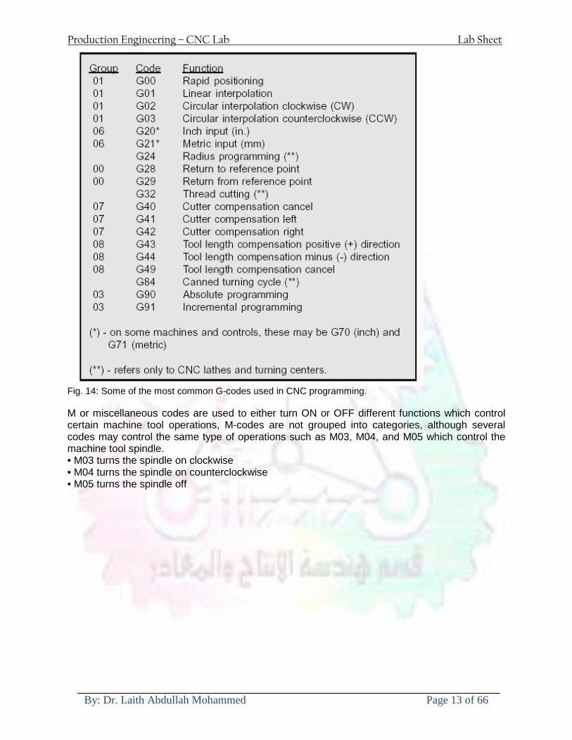
Production Engineering ndash CNC Lab Lab Sheet
By Dr Laith Abdullah Mohammed Page 13 of 66
Fig 14 Some of the most common G-codes used in CNC programming M or miscellaneous codes are used to either turn ON or OFF different functions which control certain machine tool operations M-codes are not grouped into categories although several codes may control the same type of operations such as M03 M04 and M05 which control the machine tool spindle bull M03 turns the spindle on clockwise bull M04 turns the spindle on counterclockwise bull M05 turns the spindle off
Production Engineering ndash CNC Lab Lab Sheet
By Dr Laith Abdullah Mohammed Page 14 of 66
Fig 15 The functions of a few common M-codes
Production Engineering ndash CNC Lab Lab Sheet
By Dr Laith Abdullah Mohammed Page 15 of 66
Fig 16 Some of the most common M-codes used in CNC programming Block of Information CNC information is generally programmed in blocks of five words Each word conforms to the EIA standards and they are written on a horizontal line If five complete words are not included in each block the machine control unit (MCU) will not recognize the information therefore the control unit will not be activated Using the example shown in Fig 17 the five words are as follows N001 represents the sequence number of the operation G01 represents linear interpolation X12345 will move the table 12345 in in a positive direction along the X axis Y06789 will move the table 06789 in along the Y axis M03 Spindle on CW
Fig 17 A complete block of information consists of five words
Production Engineering ndash CNC Lab Lab Sheet
By Dr Laith Abdullah Mohammed Page 16 of 66
Programming for Positioning Before starting to program a job it is important to become familiar with the part to be produced From the engineering drawings the programmer should be capable of planning the machining sequences required to produce the part Visual concepts must be put into a written manuscript as the first step in developing a part program Fig 18 It is the part program that will be sent to the machine control unit by the computer tape diskette or other input media The programmer must first establish a reference point for aligning the workpiece and the machine tool for programming purposes The manuscript must include this along with the types of cutting tools and work-holding devices required and where they are to be located
Fig 18 The first step in producing a CNC program is to take the information from the print and produce a program manuscript Dimensioning Guidelines The system of rectangular coordinates is very important to the successful operation of CNC machines Certain guidelines should be observed when dimensioning parts for CNC machining The following guidelines will insure that the dimensioning language means exactly the same thing to the design engineer the technician the programmer and the machine operator 1 Define part surfaces from three perpendicular reference planes 2 Establish reference planes along part surfaces which are parallel to the machine axes 3 Dimension from a specific point on the part surface 4 Dimension the part clearly so that its shape can be understood without making mathematical calculations or guesses 5 Define the part so that a computer numerical control cutter path can be easily programmed
Production Engineering ndash CNC Lab Lab Sheet
By Dr Laith Abdullah Mohammed Page 17 of 66
Machine Zero Point The machine zero point can be set by three methodsmdashby the operator manually by a programmed absolute zero shift or by work coordinates to suit the holding fixture or the part to be machined MANUAL SETTING - The operator can use the MCU controls to locate the spindle over the desired part zero and then set the X and Y coordinate registers on the console to zero
Fig 19 The relationship between the part zero and the machine system of coordinates ABSOLUTE ZERO SHIFT - The absolute zero shift can change the position of the coordinate system by a command in the CNC program The programmer first sends the machine spindle to home zero position by a G28 command in the program Then another command (G92 for absolute zero shift) tells the MCU how far from the home zero location the coordinate system origin is to be positioned Fig 19 The sample commands may be as follows N1 G28 X0 Y0 Z0 (sends spindle to home zero position) N2 G92 X4000 Y5000 Z6000 (the position the machine will reference as part zero)
Production Engineering ndash CNC Lab Lab Sheet
By Dr Laith Abdullah Mohammed Page 18 of 66
Work Settings and Offsets All CNC machine tools require some form of work setting tool setting and offsets (compensation) to place the cutter and work in the proper relationship Compensation allows the programmer to make adjustments for unexpected tooling and setup conditions
Work Coordinates In absolute positioning work coordinates are generally set on one edge or corner of a part and all programming is generally taken from this position In Fig 20 the part zero is used for all positioning for hole locations 1 2 and 3
Fig 20 In absolute programming all dimensions must be taken from the XY zero at the top left-hand corner of the part
Fig 21 In incremental programming all dimensions are taken from the previous point In incremental positioning the work coordinates change because each location is the zero point for the move to the next location Fig 21
Production Engineering ndash CNC Lab Lab Sheet
By Dr Laith Abdullah Mohammed Page 19 of 66
On some parts it may be desirable to change from absolute to incremental or vice versa at certain points in the job Inserting the G90 (absolute) or the G91 (incremental) command into the program at the point where the change is to be made can do this
R Plane or Gage Height The word-address letter R refers to a partial retraction point in the Z axis to which the end of the cutter retracts above the work surface to allow safe table movement in the X Y axes It is often called the rapid-traverse distance gage height retract or work plane The R distance is a specific height or distance above the work surface and is generally 100 in above the highest surface of the workpiece Fig 22 which is also known as gage height Some manufacturers build a gage height distance of 100 in into the MCU (machine control unit) and whenever the feed motion in the Z axis is called for 100 in will automatically be added to the depth programmed When setting up cutting tools the operator generally places a 100 in thick gage on top of the highest surface of the workpiece Each tool is lowered until it just touches the gage surface and then its length is recorded on the tool list Once the gage height has been set it is not generally necessary to add the 100 in to any future depth dimensions since most MCUs do this automatically
Fig 22 Using a 100 in gage block to set the gage height or R0 on the work surface
Cutter Diameter Compensation Cutter diameter compensation (CDC) changes a milling cutterrsquos programmed centerline path to compensate for small differences in cutter diameter On most MCUs it is effective for most cuts made using either linear or circular interpolation in the X-Y axis but does not affect the programmed Z-axis moves Usually compensation is in increments of 0001 in up to +10000 in and usually most controls have as many CDCs available as there are tool pockets in the tool storage matrix The advantage of the CDC feature is that it 1 Allows the use of cutters that have been sharpened to a smaller diameter 2 Permits the use of a larger or smaller tool already in the machinersquos storage matrix 3 Allows backing the tool away when roughing cuts are required due to excessive material present 4 Permits compensation for unexpected tool or part deflection if the deflection is constant throughout the programmed path The basic reference point of the machine tool is never at the cutting edge of a milling cutter but at some point on its periphery If a 1000 in diameter end mill is used to machine the edges of a workpiece the programmer would have to keep a 500 in offset from the work surface in order to cut the edges accurately Fig 23 The 500 offset represents the distance from the centerline of the cutter or machine spindle to the edge of the part Whenever a part is being machined the programmer must calculate an offset path which is usually half the cutter diameter
Production Engineering ndash CNC Lab Lab Sheet
By Dr Laith Abdullah Mohammed Page 20 of 66
Fig 23 Cutter-diameter compensation must be used when machining with various size cutters Modern MCUs which have part surface programming automatically calculate centerline offsets once the diameter of the cutter for each operation is programmed Many MCUs have operator-entry capabilities which can compensate for differences in cutter diameters therefore an oversize cutter or one that has been sharpened can be used as long as the compensation value for oversize or undersize cutters is entered
Production Engineering ndash CNC Lab Lab Sheet
By Dr Laith Abdullah Mohammed Page 21 of 66
CNC Programming Hints - MILLING
Production Engineering ndash CNC Lab Lab Sheet
By Dr Laith Abdullah Mohammed Page 22 of 66
CNC Programming Hints ndash TURNING
Production Engineering ndash CNC Lab Lab Sheet
By Dr Laith Abdullah Mohammed Page 23 of 66
CNC
The abbreviation CNC stands for Computer(ized) Numerical(ly) Control(led) and refers specifically to the computer control of machine tools for the purpose of (repeatedly) manufacturing complex parts in metal as well as other materials using a program written in a notation conforming to the EIA-274-D standard and commonly called G-code
CNC was developed in the late 1940s and early 1950s by the MIT Servomechanisms Laboratory CNC machines were relatively briefly preceded by the less advanced NC or Numerical(ly) Control(led) machines The introduction of CNC machines radically changed the manufacturing industry Curves are as easy to cut as straight lines complex 3-D structures are relatively easy to produce and the number of machining steps that required human action have been dramatically reduced With the increased automation of manufacturing processes with CNC machining considerable improvements in consistency and quality have been achieved CNC automation reduced the frequency of errors and provided CNC operators with time to perform additional tasks
CNC automation also allows for more flexibility in the way parts are held in the manufacturing process and the time required to change the machine to produce different components In a production environment a series of CNC machines may be combined into one station commonly called a cell to progressively machine a part requiring several operations CNC machines today are controlled directly from files created by CAM software packages so that a part or assembly can go directly from design to manufacturing without the need of producing a drafted paper drawing of the manufactured component In a sense the CNC machines represent a special segment of industrial robot systems as they are programmable to perform many kinds of machining operations (within their designed physical limits like other robotic systems)
G-code
G-code is a common name for the programming language that is used for NC and CNC machine tools It is defined in EIA RS-274-D G-code is also the name of any word in a CNC program that begins with the letter G and generally is a code telling the machine tool what type of action to perform such as
bull rapid move bull controlled feed move in straight line or arc bull series of controlled feed moves that would result in a hole being drilled bull change a pallet bull Set tool information such as offset
There are other codes the type codes can be thought of like registers in a computer
X position Y position Z position M code (another action register) F feed rate S spindle speed N line number R Radius T Tool selection
Production Engineering ndash CNC Lab Lab Sheet
By Dr Laith Abdullah Mohammed Page 24 of 66
I Arc data X axis J Arc data Y axis
G-code files are output by CAM software such as Smartcam Gibbscam Featurecam Edgecam Mastercam etc G-code is also output by specialized CAD systems used to design printed circuit boards Such software must be customized for each type of machine tool that it will be used to program
Production Engineering ndash CNC Lab Lab Sheet
By Dr Laith Abdullah Mohammed Page 25 of 66
U 2عمل األزرار الرئيسية في ماكنة الخراطة المبرمجة (نصر (
1- SINGLE BLOCK للتأكد من صحة البرنامج (تنفيذ البرنامج خطوة خطوةب تقوم( 2- BLOCK DELETE بجانب ويعمل من األوامرلغاء بلوك معين أليستخدم 3- MACHINE LOCK العمل يستخدم لقفل حركة المحاور الرئيسية مع استمرار البرنامج في
)وهذا مهم للتاكد من صحة البرنامج قبل عملية التنفيذ النهائي(4- CONT CYCLE عملية التشغيل عند ايقافها الي سبب كان او عند ايقافها ألستئناف ستخدم ت
) BAR FEEDER(او في حالة استخدام ) FEED HOLDبسبب (5- DRY RUN وتستخدم لفحص البرنامج بعد ازالة الشغلة حركة سريعة للبرنامج 6- TURRET UP amp DOWN ) حركة حامل العدة TURRET الذي يحمل مجموعة من (
وهذا الزر يعمل مع الزر عكس عقرب الساعة او مع عقرب الساعة ةحركة دوراني العدد )SAFTY (
7- COOLANT ON or OFFفه تشغيل سائل التبريد او ايقا 8- COOLANT AUTO الدوال المساعدة في البرنامج من خالل فه تشغيل سائل التبريد او ايقا 9 -MACHINE START ة لتشغيل هيدرولكيك الماكنميستخد
Production Engineering ndash CNC Lab Lab Sheet
By Dr Laith Abdullah Mohammed Page 26 of 66
10- CLOSE OR OPEN CHUCKالعينة تستخدم لفتح وغلق 11 -T STOCK FWD RET حركة الغراب المتحرك ذهابا وإيابا12 -SPINDLE STOP تعمل على ايقاف حركة دوران العينة 13-JOG SPINDLE تعمل على تدوير العينة مع زر SAFTY 14 -OPT SAFTY مع الدالة ( تعمل عمل التوقف المشروط حيث تعملM1 دالة التوقف (
ط ) فقط األ اذا كان هذا الزر مضغو M1المشروط حيث ال يتوقف البرنامج في حالة وجود دالة ( SAFTY + SPINDLE ) يتم الضغط على زر ( START CYCLEلغرض تحرير زر (
START ) في نفس الوقت بعد الضغط على زر ( START CYCLE مرتين (
NC PC- 15 يستخدم هذا الزر عند ربطCNC يستخدم لنقل المعلومات ث مع جهاز أخر حي بينهما
16 -CALCU زر الخاص بالحاسبة مع زر ( ال وهوINPUT ( 17 - HD1 HD2 يستخدم الختيار العدة مع المخرطة ذات المحاور األربعة 18 - START تستخدم لبدء عملية التشغيل
Production Engineering ndash CNC Lab Lab Sheet
By Dr Laith Abdullah Mohammed Page 27 of 66
19- FEED HOLD تعمل على إيقاف عمل أي G موجودة مع بقاء العينة متحركة 20- M D I أو تشغيل البرنامج ل يتم استخدامه لإلدخا BLOCK BY BLOCK وتعمل عند
إدخال البرنامج بواسطة الشريط المثقب أو أي وسيلة إدخال أخرى أو في عمليات التصفير
21- REST تستخدم العادة تشغيل الماكنة أو مسح اإلنذار الذي يظهر على الشاشة 22- EMERGENCYتستخدم عادة اليقاف الماكنة في حالة الطوارئ فقط
OPERATION MENU KEY
CHAPTER PRG-CMK
OFFSET PROGRAM POSITION FUNCTION MENU KEY
23- POSITIONعلى الشاشة د الموقع الموجور الظها 24- PROGRAMإلظهار برنامج معين واختياره 25- OFFSET الختيار سماحات العدة أو سماحات نقطة المرجع 26- PRG- CHK تستخدم لفحص البرنامج على الشاشة 27- SETTING ألختيار الثوابت على الشاشة 28- SERVICE تستخدم ألستخراج المعامالت والثوابت 29- MESSAGE تستخدم ألظهار األخطاء الناتجة عن البرنامج او اخطاء التشغيل 30- OVERALL ألختيار المواقع 31- RELATIVE MODLINE تعوض عن POSITION 32- DIR MEM يستخدم ألظهار ملف البرامج المخزونة في الذاكرة وعندما نضغط هذا الزر
فان رقم واسم البرنامج سوف يظهر على الشاشة
2أدناه الشفرات الرئيسية التي تعمل على الماكنة المبرمجة نصر
G-CODE DESCRIPTION
G00 Rapid traverse (linear)
G01 Linear Interpolation at feed rate
G02 Circular interpolation (CW) R+
G03 Circular interpolation (CCW) R+
G10 Zero point tools
G20 Imperial data input
G21 Metric data input
G27 Reference return check
G28 Reference return
G29 Return from reference
Production Engineering ndash CNC Lab Lab Sheet
By Dr Laith Abdullah Mohammed Page 28 of 66
G33 Thread cutting
G40 Cancel cutter radius compensation
G41 Cutter compensation left
G42 Cutter compensation right
G54 Work co-ordinate system no1
G70 Finishing cycle
G71 Stock removal turning
G72 Stock removal facing
G74 Face grooving
G75 Diameter grooving
G76 Threading cycle
G90 Absolute date input
G91 Incremental data input
G94 Feed minute mode
G95 Feed rev mode
G96 Constant surface speed mode
G97 Cancel Constant surface speed
) 2أدناه الشفرات الثانوية التي تعمل على الماكنة المبرمجة (نصر
M-code FUNCTION
M00 Program stop
M03 Spindle forward (Tool forward ndash M94 mode)
M04 Spindle reverse (Tool forward ndash M94 mode)
M05 Spindle stop (Tool stop ndash M94 mode)
M08 Coolant on
M09 Coolant off
M30 Program end (with rewind)
M48 Turret shortest path
M52 Turret direction up (CW)
M53 Turret direction down (CCW)
M73 Chuck open
M74 Chuck close
Production Engineering ndash CNC Lab Lab Sheet
By Dr Laith Abdullah Mohammed Page 29 of 66
) وكل جملة مكونة من مجموعة من الكلمات blockإن كل برنامج يتكون من مجموعة من الجمل ()words) لهذا فأن الشفرات الرئيسية والمساعدة هي عبارة عن كلمات (words كما في المثال التالي (
G_ _ P1 Q2 U_ _ W_ _ D___ F_ _
)end of block) ويعني ( ) يكتب الرمز (blockتسلسل الكلمات مهم جدا بعد نهاية كل جملة (
طريقة ادخال البيانات الى الماكنة ــــــــــــــــــــــــــــــــــــــــــــــــــ
) MDIيمكن ادخال البيانات الى الماكنة بعدة طرق فقد يكون األدخال عن طريق قناة السيطرة ( MANUAL DATA INPUT ) او عن طريق قناة األضافة EDIT كما يمكن ادخال البيانات عن (
) RS ndash 232 COMMUNICATIN LINKطريق استخدام سلسلة الربط (
₤⅗₌⅗₌ ⅙₌₨image₍₡ ₤₌ℌ⅗₌ Ⅸ⅗ⅥⅯ₌ ₤₡ℌ₰₨⅗₌G71
الخراطة الطولية G71الغرض من التجربة عمل نموذج للخراطة بأستخدام الدالة تستعمل هذه الدالة للخراطة الطولية اي على طول محور المشغولة وكما هو موضح بالشكل ادناه
تعتبر هذه الدالة من الدوال التي ال تحتاج الى تكرار او إعادة كتابتها أي انها دالة تكرارية بمعنى ان اي
الذي هي دالة حركة G01خطوة تكون من ضمن هذه الدالة سوف تكرر العملية اي عند استعمال امر مثل خطية تتضمن القطع مع التغذية مع اعطاء القطر المراد قطعه و مراعاة عمق القطع المعطى سوف يتكرر
هذه االمر وصوال الى العمق المطلوب وهكذا لبقية الدوال
G71 المستخدمة للدالة الصيغة
G71 P1 Q2 U___ W___ D___ F___ حيث إن
P1 بداية الخطوة االولى = Q2 نهاية الخطوة =
Uوضع السماحات بأتجاه محور = X W وضع السماحات بأتجاه محور = Z وتكاد تكون مهملة وتوضع اشارة سالب Dعمق القطع وتوضع رقم صحيح مثل = D500 اي نصف ملمF التغذية والتي لها عالقة بالدالة = G95
Production Engineering ndash CNC Lab Lab Sheet
By Dr Laith Abdullah Mohammed Page 30 of 66
G71الدالة استخدام مثال على
T0100 M48 G0 X26 Z2 M08 T0101 G90 G95 G97 S500 M03 G71 P1 Q2 U03 W00 D500 F01 N1 G0 G42 X00 G01 Z00 G01 X2517 G01 Z-5352 G01 X7391 Z-9366 G01 Z-19145 N2 G28 M30
الجانب العملي
االجهزة واالدوات المستخدمة CNCماكنة خراطة مبرمجة 1 ملم 80قضيب من االلمنيوم قطر 2 ةفير ني 3 جاه أيمن تهولدر كاربيدي ذوا 4
طريقة العمل يتم تثبيت قضيب من االلمنيوم على العينة التابعة للماكنة مع مراعاة الطول المراد استعماله في عملية 1
الخراطة ) turretتثبيت عدة القطع في المكان الصحيح في ( 2
Production Engineering ndash CNC Lab Lab Sheet
By Dr Laith Abdullah Mohammed Page 31 of 66
بالنسبة الى القطعة المثبتة على العينة XZيتم تصفير الماكنة للمحاور 3 تصفير للمحورZ تكون مالمسة العدة الى وجه الشغلة تصفير للمحورX تكون مالمسة العدة الى سطح الشغلة الموازي لمحور X
يتم كتابة البرنامج أما بطريقة يدوية أو بالحاسوب مع وضع كل الظروف الالزمة للتشغيل ( عمق القطع 4 التغذية السرعة المطلوبة نوع المعدن )
ادخال البرنامج الى الحاسوب الموجود داخل الماكنة مع تهيئة الماكنة للتشغيل 5
المطلوب G71عمل برنامج يدوي على الدالة 1 رسم الشكل الشكل النهائي المطلوب مع وضع األبعاد 2
Ⅺ⅟₍euro⅗₌ ₤₡ℌ₰₨⅗₌₣ ₤⅗₌⅗₌ ⅙₌₨image₃₡ Ⅺℂtradeℒ⅗₌ ӈ₍Ⅴ⅟ⅳ₌ G70
G70 الغرض من التجربة عمل انهاء سطحي للمشغولة بواسطة الدالة
من الضروري إعطاء G71هذه الدالة تعمل شوط واحد فقط وتكون معتمدة على عمليات القطع في الدالة اللغاء مقدمة االداة (أي لكي تتم عملية االنهاء السطحي بدون حسابات نصف قطر مقدمة االداة ) G42دالة
G70الصيغة المستخدمة للدالة
G70 P1 Q2 F___ حيث ان
P1 بداية الخطوة االولى = Q2 نهاية الخطوة =
F التغذية والمرتبطة بالدالة = G95
وذلك ألن دالة االنهاء السطحي تحقق X Zمالحظة الدالة التحتاج لكتابة السماحات التابعة للمحورين المسافات الحقيقة المراد انتاجها للمشغولة
G71و G70مثال على الدالة
T0100 M48 G0 X26 Z2 M08 T0101 G90 G95 G97 S500 M03 G71 P1 Q2 U03 W00 D500 F01 N1 G0 G42 X00 G01 Z00 G01 X2517 G01 Z-5352 G01 X7391 Z-9366 G01 Z-19145 N2 G97 S750 MO3
Production Engineering ndash CNC Lab Lab Sheet
By Dr Laith Abdullah Mohammed Page 32 of 66
G70 P1 Q2 G40 F009 G28 M30
الجانب العملي الحظ التجربة األولى
المطلوب
G70 عمل برنامج يدوي على الدالة 1 رسم الشكل النهائي المطلوب مع وضع االبعاد 2
₪⅗₍euro⅗₌ ₤₡ℌ₰₨⅗₌₣ ₤⅗₌⅗₌ ⅙₌₨image₍₡ ⅝₍ⅠimageⅯ₌ ⅞ⅫⅦ⅔₧ G76
G76 للمشغولة بواسطة الدالةةالغرض من التجربة عمل أسنان خارجية أو داخلي
في هذه التجربة سوف نقوم بعمل األسنان الخارجية وهنا تكون حركة العينة ثابتة وهذا ضروري بسبب أن ) تكون متصلتين الكترونيا وعليه أي اختالف في سرعة العينة تؤدي إلى اختالف motionالعينة والحركة(
) servoفي سرعة الخدمة(يرتبط اتجاه تكوين األسنان باتجاه دوران العينة مثال إذا كانت األسنان ذات اتجاه أيمن يكون اتجاه دوران
وهنا نقلب العدة إلى االسفل وكما هو موضح بالشكل أدناه MO3العينة عكس عقرب الساعة أي نستعمل
Production Engineering ndash CNC Lab Lab Sheet
By Dr Laith Abdullah Mohammed Page 33 of 66
الخطوة هي عبارة عن المسافة ما بين قمة سن إلى قمة سن أخر عمق السن هو العمق المطلوب تكوينه لألسنان
G76 الصيغة المستخدمة للدالة
G76 X___ Z___ K___ F___ D___ A___
حيث أن X القطر الداخلي للسن =Z طول السن =K عمق السن وتستخرج من المعادلة التالية =K=065F F الخطوة =D عمق القطع بالمايكرون فقط =A زاوية السن =
G76مثال على استخدام الدالة T0300 M48 GOO X30 Z4 T0303 M08 G97 S500 MO3 G76 X28375 Z-20 K08125 F125 D120 G00 X40 Z4 G28 M30
Production Engineering ndash CNC Lab Lab Sheet
By Dr Laith Abdullah Mohammed Page 34 of 66
الجانب العملي الحظ التجربة األولى
المطلوب
G76عمل برنامج يدوي على الدالة 1 رسم الشكل النهائي المطلوب مع وضع األبعاد 2
Ⅺ⅘₌⅗₌ Ⅵ₂ Ⅺ₯ℋ₍⅗₌ ℌℲℂ⅗₌ ⅞ⅫⅦ⅔₧ ₤K₡₌ℌ⅗₌ ₤₡ℌ₰₨⅗₌)Groove ₤⅗₌⅗₌ ₤tradeimage₌Ⅶ₡ (G75
G75 بواسطة الدالة grooveالغرض من التجربة تكوين
) للمشغولة وتعتمد شكل الحفر على طريقة grooveتستعمل هذه الدالة لتكوين الحفر الخارجي والداخلي (
التشغيل وعلى الشكل المراد إنتاجه وتعتبر هذه الطريقة من عمليات التشكيل للمعدن إن هذه الدالة هي دالة مالحظة مع G75في هذه التجربة سنقوم بعمل الحفر الخارجي بواسطة الدالة
تكرارية وغير تكرارية حسب نوع التشغيل
G 75 الصيغة المستخدمة للدالةG75 X___ Z___ I___ K____
حيث أن
X العمق النهائي لقطر الشغلة =Z عرض الحفر =I الدخول في كل مرة =
K التزحيف على محور =z بالنسبة للعدة
Production Engineering ndash CNC Lab Lab Sheet
By Dr Laith Abdullah Mohammed Page 35 of 66
G75مثال على استخدام الدالة
T0500 M48 GOO X100 Z -20 T0505 M08 G97 S700 MO3 G75 X84 Z -38 I 05 K4
الجانب العملي الحظ التجربة األولى
المطلوب
G76عمل برنامج يدوي على الدالة 1 رسم الشكل النهائي المطلوب مع وضع األبعاد 2
Production Engineering ndash CNC Lab Lab Sheet
By Dr Laith Abdullah Mohammed Page 36 of 66
CNC Milling Machine Mechanical Construction
Guideways The guideways of CNC machines are made of steel To reduce the frictional forces they are coated with a strip of PTFE (Poly Tetra Fluoro Ethylene)
Ballscrews On conventional lathes a leadscrew is used to converts the rotary motion of the hand wheel into linear motion of the slides Leadscrews have a high coefficient of friction and backlash On CNC machines a ballscrew is used instead of a leadscrew Friction and backlash are much less than on leadscrews
Guideway
Production Engineering ndash CNC Lab Lab Sheet
By Dr Laith Abdullah Mohammed Page 37 of 66
bullMachining operations Direction of cutting Based on the direction of the cutter rotation and work piece feed milling operations are classified into two types 1-Up milling (Convention milling) In up milling the metal is removed by rotating the cutter against the direction of travel of the part
Feed
Machine table
Part
Cutting tool
Chip thickness at theexit of the tooth
2-Down milling (Climb milling) In climb milling the metal is removed by rotating the cutter with the direction of travel of the part
Machine table
Part
Cutting tool
Chip thickness at theentrance of the tooth
Production Engineering ndash CNC Lab Lab Sheet
By Dr Laith Abdullah Mohammed Page 38 of 66
bullTooling Tool geometry The geometry of the tool tip affects the way that the metal cutting is performed The nose radius rake angles relief angles etc must be selected with care
Radial relief
Radial rake
Axial relief
Approach angle
Axial relief
Corner radius Face mill Face milling cutters are used to mill flat surfaces Commonly used face milling cutters Cutter with 75 degree approach
75 deg
Cutter with 90 degree approach (Square shoulder face mill)
90 deg
Cutter with 45 degree approach
Production Engineering ndash CNC Lab Lab Sheet
By Dr Laith Abdullah Mohammed Page 39 of 66
bullCNC Programming Axes convention The Z axis is along the spindle axis The X and Y axes are perpendicular to Z VMC
Z
Y
-
+
-+
X- +
+Z
-Z
+Y
-Y
-X +X
Part
Machine table
X
YZ
G00 Rapid traverse When the tool being positioned at a point preparatory to a cutting motion to save time it is moved along a straight line at Rapid traverse at a fixed traverse rate which is pre-programmed into the machines control system Typical rapid traverse rates are 10 to 25 m min but can be as high as 80 mmin
Production Engineering ndash CNC Lab Lab Sheet
By Dr Laith Abdullah Mohammed Page 40 of 66
Format N_ G00 X__ Y__Z__
G01 Linear interpolation (feed traverse) The tool moves along a straight line in one or two axis simultaneously at a programmed linear speed the feed rate Format N__ G01 X__ Y__Z__ F__
Part
Feed
Part
Feed
G02G03 Circular interpolation The tool moves along an arc in two axes simultaneously at a programmed linear speed the feed rate
Production Engineering ndash CNC Lab Lab Sheet
By Dr Laith Abdullah Mohammed Page 41 of 66
Format N__ G0203 X__ Y__Z__ I__ J__K__ F__ using the arc center OR N__ G0203 X__ Y__Z__ R__ F__ using the arc radius G02 moves along a CW arc G03 moves along a CCW arc Arc center The arc center is specified by addresses I J and K I J and K are the X Y and Z co-ordinates of the arc center with reference to the arc start point
X
Y
Arc center
Arc endArc start
- J
- I
I = X coord of center - X coord of start point J = Y coord of center - Y coord of start point K = Z coord of center - Z coord of start point I J and K must be written with their signs
Production Engineering ndash CNC Lab Lab Sheet
By Dr Laith Abdullah Mohammed Page 42 of 66
bullWork holding
Rotary table
Fixture base
Component
Clamp
Stud
Fixtures The use of fixtures 1 Improves repeatability of dimensions 2 Improves working conditions 3 Cuts down requirement of skilled labour 4 Reduces part loading and unloading time 5 Improves safety in the working area 6 Reduces the cost of machining There are two types fixtures commonly used 1 Special fixture Special fixtures are used to hold and locate the typical components which are having complex shape and to be located with the reference hole (dowel hole) Special fixtures are required for components like gear case cover cylinder heads etc 2 Modular fixture Modular fixture is a set different kind of clamping and locating elements These fixtures are used to hold identical components in different sizes and components of box type Example Manifolds head stocks connecting rods and flanges
Production Engineering ndash CNC Lab Lab Sheet
By Dr Laith Abdullah Mohammed Page 43 of 66
bullMachine setting
Determining X and Y work zero offset Case 1
Part
Machine table
Part
End mill or reamer
Work offset X0Y0 For determining X work zero offset bull Touch the periphery of the end mill or reamer to the part bull Enter current machine X value + cutter radius as X work zero offset For determining Y work zero offset bull Touch the periphery of the end mill or reamer to the part bull Enter current machine Y value - cutter radius as Y work zero offset Case 2
Part
Machine table
Part
End mill or reamerWork offset X0Y0
bull Mount the dial indicator on machine spindle true the bore bull Enter current machine X and Y value as X and Y work zero offset
Production Engineering ndash CNC Lab Lab Sheet
By Dr Laith Abdullah Mohammed Page 44 of 66
How to Select a Cutting Fluid
One part of the metal cutting equation that is sometimes overlooked however is
the choice of an appropriate cutting fluid With todayrsquos system approach to metal
cutting use of the right metalworking fluid has become just as much a part of the
solution as the other elements In fact at least one company is now integrating
cutting fluids and cutting tools into effective metal cutting systems Following are
some things to consider when choosing your next cutting fluid
The Four Key Questions
There are four vital pieces of information that are necessary when choosing a
cutting fluid They are
1 What are you cutting
2 What is the chemistry of your water
3 What are you using now
4 What are your options
5 What do you prefer
What Are You Cutting
The first question ndash ldquoWhat are you cuttingrdquo ndash is often the most difficult to answer
because most shops handle a variety of workpiece materials on a regular basis If
the answer is an unequivocal ldquoaluminumrdquo or ldquostainless steelrdquo or ldquocast ironrdquo the
selection of a cutting fluid can be quite simple and straightforward Unfortunately
that is seldom the case in anything but a high-volume plant Where aluminum or
other nonferrous metals are a significant part of the mix a non-staining cutting
fluid is a must Generally speaking this will be a semi-synthetic with special
ingredients to prevent bi-metallic corrosion and staining of non-ferrous workpieces
Where the ferrous metals predominate however a more general purpose semi-
synthetic or hybrid fluid might be a more economical choice
Production Engineering ndash CNC Lab Lab Sheet
By Dr Laith Abdullah Mohammed Page 45 of 66
What is The Chemistry of Your Water
The second question ndash ldquoWhat is the chemistry of your waterrdquo ndash is probably the
single most common reason for the success or failure of a cutting fluid Very few
plants invest the money necessary to install effective water purification systems
using deionization or reverse osmosis technology Unfortunately the chemicals
present or not present in the water used to re-constitute a cutting fluid make a
tremendous difference in its performance and sump life Most manufacturers of
cutting fluids will perform the necessary water testing to determine exactly what
minerals are dissolved in your water and make a fluid recommendation based on
the results
What are you using now
The third question ndash ldquoWhat are you using nowrdquo ndash helps narrow the range of
choices When coupled with an objective analysis of the strengths and weaknesses
of the current fluid the answer to this question can quickly point you toward a
relatively small number of competitive alternatives that have the attributes required
to meet your cutting needs Many cutting fluids are in use today simply because
they were in use yesterday It is a hard reality of todayrsquos marketplace that if one
isnrsquot constantly striving to improve they will certainly be overtaken by a
competitor who is
What Are Your Options
The fourth question ndash ldquoWhat are your optionsrdquo ndash leads to the final selection of a
cutting fluid Cutting fluids can be divided into four general groups based on their
chemistry
They are
bull Soluble Oils ndash quite literally oil dispersed in water
bull Synthetics ndash completely oil free man-made coolants in solution
Production Engineering ndash CNC Lab Lab Sheet
By Dr Laith Abdullah Mohammed Page 46 of 66
bull Semi-Synthetics ndash a mixture of natural and synthetic lubricants with up to 30
mineral oil
bull Hybrids ndash a special class of semi-synthetics with a mineral oil content of about
15 Each fluid type has advantages and disadvantages which make it suitable for
a particular group of applications In addition there are costperformance trade-
offs to be made between the groups within a specific set of applications For
example where a hybrid and a semi-synthetic may both be suitable for a particular
use the hybrid might provide longer sump life at a slightly higher initial cost
while some semi synthetics may be more economical to recycle or dispose of while
not giving as long a tank life The final decision in this case would have to be made
on the detailed economics of the shop where the fluids were to be used and on the
ownerrsquos individual preferences
Soluble Oils
Soluble oils are oils that disperse in water when emulsifiers are added They are
generally suitable for moderate-to heavy-duty machining and grinding of all non-
ferrous metals carbon and cast steels and in applications where dissimilar metals
such as aluminium and steel are present They can also be used in turning drilling
tapping reaming gear cutting broaching as well as internal and centerless types
of grinding operations Soluble oils provide excellent aluminium and copper
corrosion control good rancidity control which extends fluid for long lasting
trouble-free performance and good concentrate and mix stability making it ideal
for mixing in water with a minimal amount of agitation An example of this is
Valenitersquos VNTreg-650 premium heavy-duty soluble oil
Synthetics
Synthetics are completely oil free solutions made of polymers organic and
inorganic materials that are mixed with water These clear low foaming and bio-
Production Engineering ndash CNC Lab Lab Sheet
By Dr Laith Abdullah Mohammed Page 47 of 66
stable coolants are ideal for machining and grinding of ferrous materials carbon
steels or cast iron Their complex lubricant packages make synthetics well-suited
for tough-to-machine materials such as stainless steels and high-temperature alloys
Certain synthetics are specifically designed to address the primary failure modes of
flank wear and nose wear Although there are many benefits some synthetics may
cause staining of non-ferrous materials
Semi-Synthetics
Semi-synthetic fluids are a mixture of oils synthetic emulsifiers and water They
were primarily developed for the aircraft nuclear and related industries
Consequently they work extremely well on all non-ferrous metals such as titanium
aluminium copper brass bronze and stainless steel in both machining and
grinding Semi-synthetics can be used on ferrous metals too They are chlorine-
free to reduce bi-metallic corrosion and staining of metals They should be used at
a 5-8 dilution with water depending on the severity of the operation
Hybrids
Hybrids are cutting fluids custom engineered to solve a particular problem For
example Valenitersquos VNTreg-800 was developed to be very clean in the machining
and grinding of cast iron It provides better stability in hard water and rejects tramp
oil very well which adds to its bio-stable chemistry Hybrids work extremely well
on all metals in both machining and grinding They should be mixed at a 5-7
dilution with water depending on the condition of the water
What Do You Prefer
The final question ndash ldquoWhat do you preferrdquo ndash is usually the ldquotie breakerrdquo where
there is more than one appropriate cutting fluid available Here again as in the
case of what is being used now the key is to examine your preferences objectively
Production Engineering ndash CNC Lab Lab Sheet
By Dr Laith Abdullah Mohammed Page 48 of 66
and specifically to identify the real reasons behind a preference If you cannot
point to specific reasons why one class of cutting fluid is preferred over another
you are well advised to follow the recommendations of the professional who has
analyzed your requirements Choosing the right fluid today is easier than ever as
the system approach to metal cutting productivity continues to grow in acceptance
The day is not far off when choosing a complete solution will be as easy as
choosing the right insert and chip breaker today The answers are available and the
results will more than justify the time you spend choosing the right metal cutting
fluid
Useful Links wwwball-screwsnet
wwwlubelinkcom
wwwmachinerylubricationcom
wwwadvancedmanufacturingcom
wwwmmsonlinecom
wwwcuttingtoolengineeringcom
wwwgeartechnologycom
wwwengineersedgecom
wwwagmaorg
wwwefundacom
wwwsaeorg
wwwsmeorg
wwwastmorg
wwwissorg
wwwmachinetoolscom
wwwansiorg
wwwasmeorg
wwwcnccicom
wwwmatlscom
wwwthefreedictionarycom
wwwengineersupplycom
Production Engineering ndash CNC Lab Lab Sheet
By Dr Laith Abdullah Mohammed Page 49 of 66
SurfCAM Tutorial ndash Beginning with the basics
Background SurfCAM is a computer aided manufacturing (CAM) software which allows you to create manage and modify tool paths for computer aided designed (CAD) part The software requires a CAD model or requires that you create some geometry within SurfCAM with some rudimentary tools provided The tool paths are created or stored internally in SurfCAM in a generic programming language called APT Once the tool paths are created the APT paths are translated using a post processor into typical machine G-code
Opening SurfCAM SurfCAM can be opened from the Novell Applications Launcher on most Industrial Engineering computer labs workstations Search under lsquoallrsquo applications and double click on SurfCAM 2005 Once the program opens a license must be selected from the list (not the Demo license) to enable saving the file later Choose one of the 30 licenses available If for some reason the licenses are not listed on the license manager form select server list and type ldquobonnieeosncsuedurdquo A list of available licenses should appear Select a license and click OK After the license is selected an Add StockFixture form (Figure 1) opens allows you to add a model which represents the pre-machined stock or a fixture Click on OK without adding either Both of these items can be added later under a more appropriate dialog
Figure 1 Add Stock or Fixture dialog box
Production Engineering ndash CNC Lab Lab Sheet
By Dr Laith Abdullah Mohammed Page 50 of 66
SurfCAM Interface
Figure 2 SurfCAM Windows based interface
SurfCAM is a windows based software system so most of the typical windows functions under File are applicable This is where you can open save exit print etc The Create menu allows the user to create different geometry forms Here you can create a point line surface chamfer circle and many other geometry types For the most part these functions are not used by beginners but are useful when creating bounding curves where you donrsquot want the tool to move outside (constraining the tool) The Edit menu allows you to change or modify many different entities such as changing lines altering surfaces joining surfaces trimming or breaking elements add control points etc Again these features are helpful to advanced users and are not covered in detail in this tutorial The Display menu offers the ability to change the orientation of the part on the screen The typical rotate pan fit to screen and zoom functions are available as well as several functions which allow the user to shift between views or call up a named view (ie top bottom etc) The NC menu is the main machining interface menu In this menu you select the general form of machining (2 axis 3 axis 4 axis 5 axis turning etc) and under the general form a more specific machining function is selected This menu is the most used and the options contained must be fully understood to get the most out of SurfCAM Each function will be described in some detail in a further chapter The Analyze menu contains options such as measuring the distance between points angles tangency elements etc These functions are auxiliary functions meant to help you understand the part better but basically provide no functionality for making tool paths for CNC machines Thus these will not be covered The Tools menu allows the user to change the system options modify keyboard shortcuts change the model units etc These options are again not used by beginners Finally the Help menu provides access to the online users manual In lieu of clicking the Help menu the F1 key is the shortcut key for help (as it is in most windows based programs)
Importing a CAD model Importing a CAD model that is stored locally is done by selecting File-gtOpen On the Files of type dropdown box choose the type of file you wish to open (Figure 3) Do this prior to negotiating your way through the maze of folders to prevent having to go through the folder tree again Once the file type is selected find the file you are trying to open and click the Open
Production Engineering ndash CNC Lab Lab Sheet
By Dr Laith Abdullah Mohammed Page 51 of 66
button SurfCAM will then attempt to read the file you have selected SurfCAM may provide a dialog box describing what it has imported and identify if it was successful If this dialog is provided simply click close without saving
Figure 3 Open Dialog Note - Change type of file prior to finding the file you wish to open
SurfCAM allows a user to import several different types of CAD files the most common types which you will likely import are SolidWorks part files (sldprt or prt) AutoCAD files(dxf) or IGES (igs or iges) Native file import (such as is the case with SolidWorks) provides the greatest information transfer and generic file imports (such as is the case with IGES) provide the least Normally it is to the advantage of the user to use native file importing procedures when available Recently (2005) SurfCAM added some compatibility with SolidWorks This allows the user to create tool paths for a part and if an engineering change is needed for the part update the part in SolidWorks When the part is then opened in SurfCAM the changes are noted and a simple update operation command is needed This however does not operate with complete transparency andor accuracy and thus users need to be cognizant of changing CAD models
SurfCAM Geometry In SurfCAM two basic types of geometry are used the surface and the point A surface (Figure 4) is a so called spline (NURBS or B-Spline are the two most common) surface (parameterized by two values u and v) such that every location on the surface can be defined as a function of these parameters In other words SurfCAM can calculate the location of any point on the
Production Engineering ndash CNC Lab Lab Sheet
By Dr Laith Abdullah Mohammed Page 52 of 66
surface Surfaces are used primarily in 3 4 and 5 axis machining and require a significant
amount of processing power and time Figure 4 Surfaces model of a mold half Note the difference between this and Figure 2 a wireframe model
Point or line based models are often referred to as wireframe (Figure 5) models because the models consist of connected lines and resemble the part only at the intersection of two surfaces Wireframe models were made popular lsquoback in the dayrsquo when computer processing was expensive There are times when each of the models are important and selecting model geometry when applying a SurfCAM operation will be much simpler if you understand the differences between the two When importing a SolidWorks model the default is both the surfaces and the wireframe geometry are imported
Figure 5 Wireframe model of the mold in Figure 1
Steps to Creating Tool Paths Once a CAD model is imported into SurfCAM tool paths can be created There is no one correct way to create tool paths however there is a set of general steps to take to ensure the tool paths are created with a minimum amount of hardship (note the wordinghellipHardship is inevitable when creating tool paths it is the intent of this manual to minimize this) The following is a list of steps which should be considered when making tool paths
Production Engineering ndash CNC Lab Lab Sheet
By Dr Laith Abdullah Mohammed Page 53 of 66
1 Plan ahead a Orient the part in SolidWorks such that if only one side is to be machined that
side is the Top view This can be done early in SolidWorks by choosing a plane parallel the X-Y plane as the sketch plane for the machined geometry
b Orient the part in SolidWorks such that the origin is somewhere of relative importance and someplace in space that can be easily identified when placed on the machine This is extremely important to minimize set up time at the machine (note ndash my personal preference for a part that is to be fully machined [ie stock exists on all sides] is to place the origin at the center and top of the parthellipjust my preference)
c Orient the part in SolidWorks such that the X and Y axes are aligned as you want them on the machinehellip
d Planning ahead will save you many hours of headaches laterhelliptrust me 2 Import the model 3 Choose a construction view such that the tool approaches the side to be machined
from the positive Z axis direction (as defined by part origin) a This is done by clicking on the CView icon
b From the list of named views chose the view which orients the origin as you would like
c If one of the views does not fit your criteria you have two choices i Perform a transformation of the part in SurfCAM or SolidWorks
ii Add a new construction view by selecting new This option requires a relatively good understanding of right hand coordinate frames but is very usefulhellipNormally used by more advanced users
d Be sure the CoordVIEW selection is made vs CoordWORLD This ensures the tools will be controlled from the coordinate frame selected by the view (ie the origin on the part) instead of the origin on the lower left corner of the screen This will be especially important when we get into 4 and 5 axis machining
4 In the Operations Manager (Figure 6) select Setup One and change the name to something meaningful ndash like Front Side Mold Cavity
a Access the Operations manager by right clicking or by selecting the Operations Manager icon in the tool bar
b Operations Manager is where the tool paths are managed once they are created as well as where individual tool paths can be verified
Production Engineering ndash CNC Lab Lab Sheet
By Dr Laith Abdullah Mohammed Page 54 of 66
5 Roughing Tool Paths a Create the tool paths to remove the majority of the material (if applicable) b Use NC-gt3Axis-gtZ rough or Plunge Rough c Described in next section
6 Create Finishing Tool Paths a Described in next section
7 Add another setup if necessary 8 Perform steps 3 through 6 as necessary 9 Verify the tool paths are correct 10 Use a post processor for the tool paths to create G-Code for machine
Creating Tool Paths The following is a list of operations what they are intended for how they generally work and some parameters that may be adjusted to modify the tool paths
2 Axis tool paths Unless otherwise noted 2 axis tool path functions require lines or arc segments as input parameters (as opposed to surfaces) There are several options as to how these segments are chosen the most prevalent is the chain option and the second most prevalent is the single When choosing the line segments using the chain option SurfCAM will try to link a complete path of segments based on an initial segment chosen by the user If the operation is planer (ie pocket or contour) the segments must lie on the same plane If the operation is non-planer (ie contour 3D) SurfCAM will prompt the user to specify segments when it encounters a branch point
Figure 6 Operations Manager view showing setup one re-labeled as Front Side Mold
Production Engineering ndash CNC Lab Lab Sheet
By Dr Laith Abdullah Mohammed Page 55 of 66
When using the single element option the user must manually choose each segment desired for the operation Note that most operations do not require a closed loop of segments you may specify for instance an open contour where the tool is supposed to move The order of choosing segments is important This order determines the path of the tool in the sense that if three segments are chosen such that the middle segment is chosen last there will be three different plunge and machine operations one on each segment If the operation was to make a continuous contour around the outside of the part the segments should be chosen in order of the desired tool trajectory
Operations
Pocket Pocket operation in SurfCAM is used to cut an enclosed space from the inside to the outside at one particular depth The operation starts in the center of an enclosed area (with a plunge move in the ndashZ direction) and makes incremental closed paths towards the pocket boundaries in user defined path offsets (Figure 7) The user chooses the boundary of the pocket (line segments) and if more than one pocket is chosen SurfCAM will ask the user to click inside a pocket
Figure 7 Two examples of using the pocketing operation
The pocket operation allows for creating a projection of the pocket paths on multiple planes This is useful if you have a deep pocket which will not allow the tool to cut directly at the depth of the pocket but would be easily done using the same paths at several different Z heights On the cut control (Figure 8) tab the user specifies where the chosen geometry (pocket segments) lie (ie bottom or top) Then under the amount to remove specify the total material height to be removed and the rough spacing (amount you wish to advance the Z axis with each pocket step) You may also specify a finishing pass and as well as stock to leave
Production Engineering ndash CNC Lab Lab Sheet
By Dr Laith Abdullah Mohammed Page 56 of 66
Figure 8 Example of Contour Operation with multiple passes
Contour Contouring in SurfCAM is used to perform peripheral milling on the inside or outside of a line segment (Figure 9) The user is to identify the line segments which define a contour (does not have to be a closed loop of segments) SurfCAM may or may not require the user to specify a side to contour (ie which side of the line is the tool to cut) For contouring each segment must lie on the same plane
Production Engineering ndash CNC Lab Lab Sheet
By Dr Laith Abdullah Mohammed Page 57 of 66
Figure 9 Examples of parts cut with 2-Axis Contour
Contour 3D Contour 3D is the same operation type as contour but allows the user to specify segments on different planes for the tool to cut along
Drill Drilling operations are any rotating tool operation meant to engage the part from a single direction ndash namely from the positive Z direction Drilling operations can be specified using circle point or line segments After choosing NC-gt2-Axis-gtDrill SurfCAM allows the user to choose multiple circles or points defining holes to be drilled Drilling operations also allow the user to incorporate more than 1 operation such as a center drill a drill and a reaming operation After selecting the locations for the drilling operation a dialog box (Figure 10) allows the user to add change or delete tools to be used in the operation As displayed in the following figure the spotdrill operation is followed by a drilling operation followed by a tapping operation The depth of each tool can be controlled individually by double clicking the total depth cell in and manually entering Tools can be added before or after operations which the cells are highlighted by selecting either of the insert buttons at the top or by the insert menu Select tool button allows the user to change the tool size or type
Production Engineering ndash CNC Lab Lab Sheet
By Dr Laith Abdullah Mohammed Page 58 of 66
Figure 10 Drill operation manager Several operations can be completed at one time
Figure 11 Drill operation including the spotdrill drill and tap as outlined in Fig 10
3 Axis tool paths SurfCAM requires surfaces as inputs for 3 Axis tool paths Surfaces can be created in SurfCAM but are most easily created in a CAD package and imported into SurfCAM Surfaces allow SurfCAM to identify every point on the surface in 3 dimensions unlike 2D geometry (wireframes) which only identify positions on the plane Creating tool paths with complex surfaces takes a very significant amount of processing power so expect 3 Axis tool path generation to take longer
Production Engineering ndash CNC Lab Lab Sheet
By Dr Laith Abdullah Mohammed Page 59 of 66
Operations
Cut 3 Axis cut operation takes a surface and using the flow lines creates a rastering path over the surface with the tool tip riding on the surface The primary direction will be defined by the flow lines of the surface (which can be edited by Edit-gtSurfaces-gtArrow-gtDirection) If you intend to cross surface boundaries you must merge the surfaces (Edit-gtJoin and choose the two surfaces)
Z-Rough The Z-rough operation is used to remove a large amount of material prior to finish machining Roughing operation is typically the first operation you perform for each setup The Z-Rough operation cuts the part in user defined intervals For each of these intervals a surface intersection between the part and the plane is performed and a 2D pocket or contour operation is performed on that plane This is performed on each plane When choosing NC-gt3 Axis-gtZ rough the first dialog box you will encounter asks for a bounding box to be defined Choose the Extents Box and a second dialog box will ask for the coordinates which define the box (Figure 12) This is the stock size you expect to machine the part from Input the coordinates or change the additional offset amounts (in XY or Z) as appropriate and click Calculate Bounding Box
Figure 12 Material Extents Box Example
Next choose the tool and cutting parameters that you desire and click on the Cut Control Tab (Figure 13) Here you will find the following parameters which are often changed Stock to
Production Engineering ndash CNC Lab Lab Sheet
By Dr Laith Abdullah Mohammed Page 60 of 66
leave ndash this is an offset amount from the surfaces which leaves a small amount of material to finish machine Minimum and Maximum Z values ndash Defines area to machine Z Step Size ndash This identifies the plane intervals for the surface intersection planes (the first interval will be at the top of the selected area and successive increments down in Z will be cut until the Minimum Z value is reached)
Figure 13 3Axis Z Rough Cut Control
The 3Axis Z-Finish operation works in exactly the same way 3 Axis Z-Finish is most appropriate for finishing vertical or near vertical walls
3D Offset The 3D Offset operation creates a tool path using a 2D or 3D boundary by offsetting the boundary in concentric offset cutting passes Each pass calculates the tool engagement and maintains the engagement somewhat constant The advantage (significant) is the scallop height ndash height of the material between passes ndash is controlled thus the surface finish is predictable When choosing 3D Offset surfaces are selected as well as 2D or 3D boundaries The boundaries define the concentric offset paths shape as well as limit the tool path area Choose NC-gt3Axis-gt3D Offset from the drop down menus SurfCAM will prompt you to select the surface or surfaces to cut across Select the surfaces you wish to machine and then select the tool and cutting parameters you wish use Next select the Cut Control Tab and check the Use Boundary Curves option Set the Step Type to Scallop and set the maximum scallop height If you like
Production Engineering ndash CNC Lab Lab Sheet
By Dr Laith Abdullah Mohammed Page 61 of 66
you can also add stock to leave if this is a roughing operation You can also set the Direction and Start-End parameters from this tab Click OK and the paths will be generated
Figure 14 Cut Control Tab for 3D Offset
Example part using both 2D and 3D geometry
The tool paths for this mold will be generated in SurfCAM using 5 operations The first will be a roughing operation using a frac14 inch flat end mill with the Z step size of 00625in Choose NC-
Production Engineering ndash CNC Lab Lab Sheet
By Dr Laith Abdullah Mohammed Page 62 of 66
gt3Axis-gtZ-Rough from the drop down menu Select all visible surfaces and create an extents box that has 025inch XY offsets and 01inch Z offset Next select the frac14 inch flat end mill from the tools menu Under Cut Control tab set the Z step size to be 00625inch The tool paths will look something like Figure 15
Figure 15 Z-Rough Tool paths for Example Part
Next a flat surface operation will be performed to cut the flat surface on the top Select NC-gt3 Axis-gtFlat Surface from the drop down menu Select all visible surfaces again Choose the 12inch flat end mill and set the cutting parameters as desired Under Cut Control Tab change the Minimum Area to 50 square inches (Figure 16) The tool paths should look something like Figure 17
Figure 16 Cut Control for Flat Surface
Production Engineering ndash CNC Lab Lab Sheet
By Dr Laith Abdullah Mohammed Page 63 of 66
Figure 17 Flat Surface Tool Paths
Next we will use a 3D offset operation to cut the mold cavity Select NC-gt3 Axis-gt3D Offset from the dropdown menu Change the view to the top view and select within to capture the surfaces of the mold cavity Draw a rectangle around the mold cavity Select a 18 inch ball endmill from the tool library and set the cutting parameters as appropriate Next set the Cut Control tab parameters as in Figure 14 The paths creates should be similar to Figure 18
Figure 18 3D Offset Paths
Next we will perform a 2 Axis contouring of the top section Select NC-gt2 Axis-gtContour from the dropdown menu Using the chain option select the bottom contour of the top extrusion Select the frac12 inch flat end mill from the tool library and set the cutting parameters as required In the Cut Control Tab change the Geometry to Bottom and the amount to remove in Z to 05
Production Engineering ndash CNC Lab Lab Sheet
By Dr Laith Abdullah Mohammed Page 64 of 66
Change the Rough Spacing in Z to 025 and add 1 finish pass of 002 (Figure 19) Click OK and SurfCAM will instruct you to choose a side to contour Click anywhere on the screen OUTSIDE the geometry you selected for the contouring operation Failure to click outside the geometry will result in the tool being on the wrong side of the contour Your paths should look something like those in Figure 20
Figure 19 Cut Control Tab for the Contouring Operation
Figure 20 Contouring operation paths
Production Engineering ndash CNC Lab Lab Sheet
By Dr Laith Abdullah Mohammed Page 65 of 66
Next we will perform a 2 axis pocket operation for the small pocket on the top face of the mold Select NC-gt2Axis-gtPocket and using the Auto select feature select the boundary curve at the bottom of the pocket Click Done twice and select the frac14 inch flat end mill from the tool library Set the appropriate cutting parameters and click OK SurfCAM will prompt you to click inside the pocket Click anywhere inside the geometry you chose to define the pocket The resulting paths should look something like those in Figure 21
Figure 21 2 Axis Pocket Operation Paths
Finally we will add a drilling operation for the 2 holes at the corners of the mold Select NC-gt2 Axis-gtDrill from the dropdown menu Select the top circles defining the two holes A menu box will appear with a default tool (Center drill) already programmed Add a second tool to the list by selecting Insert-gtAfter and select the tool from the tool library Change the drill depth to 10inches and click OK The paths should look something similar to Figure 23
Figure 22 Drill Menu
Production Engineering ndash CNC Lab Lab Sheet
By Dr Laith Abdullah Mohammed Page 66 of 66
Figure 23 Drilling Operation Tool Paths
Now you can watch a simulation of the cutting by choosing the setup in the operations manager and clicking the simulate icon Be sure to set the stock in the set up by right clicking the set up and selecting Edit Setup Information In the Stock Tab you can create a bounding box meeting your needs and click Add Your simulation should result in something like the following
Figure 24 Final Simulation of the example Mold
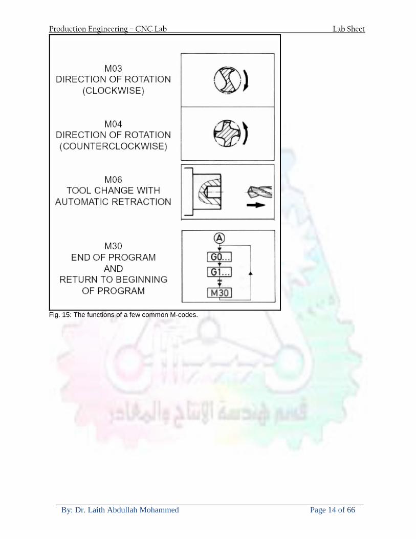
Production Engineering ndash CNC Lab Lab Sheet
By Dr Laith Abdullah Mohammed Page 14 of 66
Fig 15 The functions of a few common M-codes
Production Engineering ndash CNC Lab Lab Sheet
By Dr Laith Abdullah Mohammed Page 15 of 66
Fig 16 Some of the most common M-codes used in CNC programming Block of Information CNC information is generally programmed in blocks of five words Each word conforms to the EIA standards and they are written on a horizontal line If five complete words are not included in each block the machine control unit (MCU) will not recognize the information therefore the control unit will not be activated Using the example shown in Fig 17 the five words are as follows N001 represents the sequence number of the operation G01 represents linear interpolation X12345 will move the table 12345 in in a positive direction along the X axis Y06789 will move the table 06789 in along the Y axis M03 Spindle on CW
Fig 17 A complete block of information consists of five words
Production Engineering ndash CNC Lab Lab Sheet
By Dr Laith Abdullah Mohammed Page 16 of 66
Programming for Positioning Before starting to program a job it is important to become familiar with the part to be produced From the engineering drawings the programmer should be capable of planning the machining sequences required to produce the part Visual concepts must be put into a written manuscript as the first step in developing a part program Fig 18 It is the part program that will be sent to the machine control unit by the computer tape diskette or other input media The programmer must first establish a reference point for aligning the workpiece and the machine tool for programming purposes The manuscript must include this along with the types of cutting tools and work-holding devices required and where they are to be located
Fig 18 The first step in producing a CNC program is to take the information from the print and produce a program manuscript Dimensioning Guidelines The system of rectangular coordinates is very important to the successful operation of CNC machines Certain guidelines should be observed when dimensioning parts for CNC machining The following guidelines will insure that the dimensioning language means exactly the same thing to the design engineer the technician the programmer and the machine operator 1 Define part surfaces from three perpendicular reference planes 2 Establish reference planes along part surfaces which are parallel to the machine axes 3 Dimension from a specific point on the part surface 4 Dimension the part clearly so that its shape can be understood without making mathematical calculations or guesses 5 Define the part so that a computer numerical control cutter path can be easily programmed
Production Engineering ndash CNC Lab Lab Sheet
By Dr Laith Abdullah Mohammed Page 17 of 66
Machine Zero Point The machine zero point can be set by three methodsmdashby the operator manually by a programmed absolute zero shift or by work coordinates to suit the holding fixture or the part to be machined MANUAL SETTING - The operator can use the MCU controls to locate the spindle over the desired part zero and then set the X and Y coordinate registers on the console to zero
Fig 19 The relationship between the part zero and the machine system of coordinates ABSOLUTE ZERO SHIFT - The absolute zero shift can change the position of the coordinate system by a command in the CNC program The programmer first sends the machine spindle to home zero position by a G28 command in the program Then another command (G92 for absolute zero shift) tells the MCU how far from the home zero location the coordinate system origin is to be positioned Fig 19 The sample commands may be as follows N1 G28 X0 Y0 Z0 (sends spindle to home zero position) N2 G92 X4000 Y5000 Z6000 (the position the machine will reference as part zero)
Production Engineering ndash CNC Lab Lab Sheet
By Dr Laith Abdullah Mohammed Page 18 of 66
Work Settings and Offsets All CNC machine tools require some form of work setting tool setting and offsets (compensation) to place the cutter and work in the proper relationship Compensation allows the programmer to make adjustments for unexpected tooling and setup conditions
Work Coordinates In absolute positioning work coordinates are generally set on one edge or corner of a part and all programming is generally taken from this position In Fig 20 the part zero is used for all positioning for hole locations 1 2 and 3
Fig 20 In absolute programming all dimensions must be taken from the XY zero at the top left-hand corner of the part
Fig 21 In incremental programming all dimensions are taken from the previous point In incremental positioning the work coordinates change because each location is the zero point for the move to the next location Fig 21
Production Engineering ndash CNC Lab Lab Sheet
By Dr Laith Abdullah Mohammed Page 19 of 66
On some parts it may be desirable to change from absolute to incremental or vice versa at certain points in the job Inserting the G90 (absolute) or the G91 (incremental) command into the program at the point where the change is to be made can do this
R Plane or Gage Height The word-address letter R refers to a partial retraction point in the Z axis to which the end of the cutter retracts above the work surface to allow safe table movement in the X Y axes It is often called the rapid-traverse distance gage height retract or work plane The R distance is a specific height or distance above the work surface and is generally 100 in above the highest surface of the workpiece Fig 22 which is also known as gage height Some manufacturers build a gage height distance of 100 in into the MCU (machine control unit) and whenever the feed motion in the Z axis is called for 100 in will automatically be added to the depth programmed When setting up cutting tools the operator generally places a 100 in thick gage on top of the highest surface of the workpiece Each tool is lowered until it just touches the gage surface and then its length is recorded on the tool list Once the gage height has been set it is not generally necessary to add the 100 in to any future depth dimensions since most MCUs do this automatically
Fig 22 Using a 100 in gage block to set the gage height or R0 on the work surface
Cutter Diameter Compensation Cutter diameter compensation (CDC) changes a milling cutterrsquos programmed centerline path to compensate for small differences in cutter diameter On most MCUs it is effective for most cuts made using either linear or circular interpolation in the X-Y axis but does not affect the programmed Z-axis moves Usually compensation is in increments of 0001 in up to +10000 in and usually most controls have as many CDCs available as there are tool pockets in the tool storage matrix The advantage of the CDC feature is that it 1 Allows the use of cutters that have been sharpened to a smaller diameter 2 Permits the use of a larger or smaller tool already in the machinersquos storage matrix 3 Allows backing the tool away when roughing cuts are required due to excessive material present 4 Permits compensation for unexpected tool or part deflection if the deflection is constant throughout the programmed path The basic reference point of the machine tool is never at the cutting edge of a milling cutter but at some point on its periphery If a 1000 in diameter end mill is used to machine the edges of a workpiece the programmer would have to keep a 500 in offset from the work surface in order to cut the edges accurately Fig 23 The 500 offset represents the distance from the centerline of the cutter or machine spindle to the edge of the part Whenever a part is being machined the programmer must calculate an offset path which is usually half the cutter diameter
Production Engineering ndash CNC Lab Lab Sheet
By Dr Laith Abdullah Mohammed Page 20 of 66
Fig 23 Cutter-diameter compensation must be used when machining with various size cutters Modern MCUs which have part surface programming automatically calculate centerline offsets once the diameter of the cutter for each operation is programmed Many MCUs have operator-entry capabilities which can compensate for differences in cutter diameters therefore an oversize cutter or one that has been sharpened can be used as long as the compensation value for oversize or undersize cutters is entered
Production Engineering ndash CNC Lab Lab Sheet
By Dr Laith Abdullah Mohammed Page 21 of 66
CNC Programming Hints - MILLING
Production Engineering ndash CNC Lab Lab Sheet
By Dr Laith Abdullah Mohammed Page 22 of 66
CNC Programming Hints ndash TURNING
Production Engineering ndash CNC Lab Lab Sheet
By Dr Laith Abdullah Mohammed Page 23 of 66
CNC
The abbreviation CNC stands for Computer(ized) Numerical(ly) Control(led) and refers specifically to the computer control of machine tools for the purpose of (repeatedly) manufacturing complex parts in metal as well as other materials using a program written in a notation conforming to the EIA-274-D standard and commonly called G-code
CNC was developed in the late 1940s and early 1950s by the MIT Servomechanisms Laboratory CNC machines were relatively briefly preceded by the less advanced NC or Numerical(ly) Control(led) machines The introduction of CNC machines radically changed the manufacturing industry Curves are as easy to cut as straight lines complex 3-D structures are relatively easy to produce and the number of machining steps that required human action have been dramatically reduced With the increased automation of manufacturing processes with CNC machining considerable improvements in consistency and quality have been achieved CNC automation reduced the frequency of errors and provided CNC operators with time to perform additional tasks
CNC automation also allows for more flexibility in the way parts are held in the manufacturing process and the time required to change the machine to produce different components In a production environment a series of CNC machines may be combined into one station commonly called a cell to progressively machine a part requiring several operations CNC machines today are controlled directly from files created by CAM software packages so that a part or assembly can go directly from design to manufacturing without the need of producing a drafted paper drawing of the manufactured component In a sense the CNC machines represent a special segment of industrial robot systems as they are programmable to perform many kinds of machining operations (within their designed physical limits like other robotic systems)
G-code
G-code is a common name for the programming language that is used for NC and CNC machine tools It is defined in EIA RS-274-D G-code is also the name of any word in a CNC program that begins with the letter G and generally is a code telling the machine tool what type of action to perform such as
bull rapid move bull controlled feed move in straight line or arc bull series of controlled feed moves that would result in a hole being drilled bull change a pallet bull Set tool information such as offset
There are other codes the type codes can be thought of like registers in a computer
X position Y position Z position M code (another action register) F feed rate S spindle speed N line number R Radius T Tool selection
Production Engineering ndash CNC Lab Lab Sheet
By Dr Laith Abdullah Mohammed Page 24 of 66
I Arc data X axis J Arc data Y axis
G-code files are output by CAM software such as Smartcam Gibbscam Featurecam Edgecam Mastercam etc G-code is also output by specialized CAD systems used to design printed circuit boards Such software must be customized for each type of machine tool that it will be used to program
Production Engineering ndash CNC Lab Lab Sheet
By Dr Laith Abdullah Mohammed Page 25 of 66
U 2عمل األزرار الرئيسية في ماكنة الخراطة المبرمجة (نصر (
1- SINGLE BLOCK للتأكد من صحة البرنامج (تنفيذ البرنامج خطوة خطوةب تقوم( 2- BLOCK DELETE بجانب ويعمل من األوامرلغاء بلوك معين أليستخدم 3- MACHINE LOCK العمل يستخدم لقفل حركة المحاور الرئيسية مع استمرار البرنامج في
)وهذا مهم للتاكد من صحة البرنامج قبل عملية التنفيذ النهائي(4- CONT CYCLE عملية التشغيل عند ايقافها الي سبب كان او عند ايقافها ألستئناف ستخدم ت
) BAR FEEDER(او في حالة استخدام ) FEED HOLDبسبب (5- DRY RUN وتستخدم لفحص البرنامج بعد ازالة الشغلة حركة سريعة للبرنامج 6- TURRET UP amp DOWN ) حركة حامل العدة TURRET الذي يحمل مجموعة من (
وهذا الزر يعمل مع الزر عكس عقرب الساعة او مع عقرب الساعة ةحركة دوراني العدد )SAFTY (
7- COOLANT ON or OFFفه تشغيل سائل التبريد او ايقا 8- COOLANT AUTO الدوال المساعدة في البرنامج من خالل فه تشغيل سائل التبريد او ايقا 9 -MACHINE START ة لتشغيل هيدرولكيك الماكنميستخد
Production Engineering ndash CNC Lab Lab Sheet
By Dr Laith Abdullah Mohammed Page 26 of 66
10- CLOSE OR OPEN CHUCKالعينة تستخدم لفتح وغلق 11 -T STOCK FWD RET حركة الغراب المتحرك ذهابا وإيابا12 -SPINDLE STOP تعمل على ايقاف حركة دوران العينة 13-JOG SPINDLE تعمل على تدوير العينة مع زر SAFTY 14 -OPT SAFTY مع الدالة ( تعمل عمل التوقف المشروط حيث تعملM1 دالة التوقف (
ط ) فقط األ اذا كان هذا الزر مضغو M1المشروط حيث ال يتوقف البرنامج في حالة وجود دالة ( SAFTY + SPINDLE ) يتم الضغط على زر ( START CYCLEلغرض تحرير زر (
START ) في نفس الوقت بعد الضغط على زر ( START CYCLE مرتين (
NC PC- 15 يستخدم هذا الزر عند ربطCNC يستخدم لنقل المعلومات ث مع جهاز أخر حي بينهما
16 -CALCU زر الخاص بالحاسبة مع زر ( ال وهوINPUT ( 17 - HD1 HD2 يستخدم الختيار العدة مع المخرطة ذات المحاور األربعة 18 - START تستخدم لبدء عملية التشغيل
Production Engineering ndash CNC Lab Lab Sheet
By Dr Laith Abdullah Mohammed Page 27 of 66
19- FEED HOLD تعمل على إيقاف عمل أي G موجودة مع بقاء العينة متحركة 20- M D I أو تشغيل البرنامج ل يتم استخدامه لإلدخا BLOCK BY BLOCK وتعمل عند
إدخال البرنامج بواسطة الشريط المثقب أو أي وسيلة إدخال أخرى أو في عمليات التصفير
21- REST تستخدم العادة تشغيل الماكنة أو مسح اإلنذار الذي يظهر على الشاشة 22- EMERGENCYتستخدم عادة اليقاف الماكنة في حالة الطوارئ فقط
OPERATION MENU KEY
CHAPTER PRG-CMK
OFFSET PROGRAM POSITION FUNCTION MENU KEY
23- POSITIONعلى الشاشة د الموقع الموجور الظها 24- PROGRAMإلظهار برنامج معين واختياره 25- OFFSET الختيار سماحات العدة أو سماحات نقطة المرجع 26- PRG- CHK تستخدم لفحص البرنامج على الشاشة 27- SETTING ألختيار الثوابت على الشاشة 28- SERVICE تستخدم ألستخراج المعامالت والثوابت 29- MESSAGE تستخدم ألظهار األخطاء الناتجة عن البرنامج او اخطاء التشغيل 30- OVERALL ألختيار المواقع 31- RELATIVE MODLINE تعوض عن POSITION 32- DIR MEM يستخدم ألظهار ملف البرامج المخزونة في الذاكرة وعندما نضغط هذا الزر
فان رقم واسم البرنامج سوف يظهر على الشاشة
2أدناه الشفرات الرئيسية التي تعمل على الماكنة المبرمجة نصر
G-CODE DESCRIPTION
G00 Rapid traverse (linear)
G01 Linear Interpolation at feed rate
G02 Circular interpolation (CW) R+
G03 Circular interpolation (CCW) R+
G10 Zero point tools
G20 Imperial data input
G21 Metric data input
G27 Reference return check
G28 Reference return
G29 Return from reference
Production Engineering ndash CNC Lab Lab Sheet
By Dr Laith Abdullah Mohammed Page 28 of 66
G33 Thread cutting
G40 Cancel cutter radius compensation
G41 Cutter compensation left
G42 Cutter compensation right
G54 Work co-ordinate system no1
G70 Finishing cycle
G71 Stock removal turning
G72 Stock removal facing
G74 Face grooving
G75 Diameter grooving
G76 Threading cycle
G90 Absolute date input
G91 Incremental data input
G94 Feed minute mode
G95 Feed rev mode
G96 Constant surface speed mode
G97 Cancel Constant surface speed
) 2أدناه الشفرات الثانوية التي تعمل على الماكنة المبرمجة (نصر
M-code FUNCTION
M00 Program stop
M03 Spindle forward (Tool forward ndash M94 mode)
M04 Spindle reverse (Tool forward ndash M94 mode)
M05 Spindle stop (Tool stop ndash M94 mode)
M08 Coolant on
M09 Coolant off
M30 Program end (with rewind)
M48 Turret shortest path
M52 Turret direction up (CW)
M53 Turret direction down (CCW)
M73 Chuck open
M74 Chuck close
Production Engineering ndash CNC Lab Lab Sheet
By Dr Laith Abdullah Mohammed Page 29 of 66
) وكل جملة مكونة من مجموعة من الكلمات blockإن كل برنامج يتكون من مجموعة من الجمل ()words) لهذا فأن الشفرات الرئيسية والمساعدة هي عبارة عن كلمات (words كما في المثال التالي (
G_ _ P1 Q2 U_ _ W_ _ D___ F_ _
)end of block) ويعني ( ) يكتب الرمز (blockتسلسل الكلمات مهم جدا بعد نهاية كل جملة (
طريقة ادخال البيانات الى الماكنة ــــــــــــــــــــــــــــــــــــــــــــــــــ
) MDIيمكن ادخال البيانات الى الماكنة بعدة طرق فقد يكون األدخال عن طريق قناة السيطرة ( MANUAL DATA INPUT ) او عن طريق قناة األضافة EDIT كما يمكن ادخال البيانات عن (
) RS ndash 232 COMMUNICATIN LINKطريق استخدام سلسلة الربط (
₤⅗₌⅗₌ ⅙₌₨image₍₡ ₤₌ℌ⅗₌ Ⅸ⅗ⅥⅯ₌ ₤₡ℌ₰₨⅗₌G71
الخراطة الطولية G71الغرض من التجربة عمل نموذج للخراطة بأستخدام الدالة تستعمل هذه الدالة للخراطة الطولية اي على طول محور المشغولة وكما هو موضح بالشكل ادناه
تعتبر هذه الدالة من الدوال التي ال تحتاج الى تكرار او إعادة كتابتها أي انها دالة تكرارية بمعنى ان اي
الذي هي دالة حركة G01خطوة تكون من ضمن هذه الدالة سوف تكرر العملية اي عند استعمال امر مثل خطية تتضمن القطع مع التغذية مع اعطاء القطر المراد قطعه و مراعاة عمق القطع المعطى سوف يتكرر
هذه االمر وصوال الى العمق المطلوب وهكذا لبقية الدوال
G71 المستخدمة للدالة الصيغة
G71 P1 Q2 U___ W___ D___ F___ حيث إن
P1 بداية الخطوة االولى = Q2 نهاية الخطوة =
Uوضع السماحات بأتجاه محور = X W وضع السماحات بأتجاه محور = Z وتكاد تكون مهملة وتوضع اشارة سالب Dعمق القطع وتوضع رقم صحيح مثل = D500 اي نصف ملمF التغذية والتي لها عالقة بالدالة = G95
Production Engineering ndash CNC Lab Lab Sheet
By Dr Laith Abdullah Mohammed Page 30 of 66
G71الدالة استخدام مثال على
T0100 M48 G0 X26 Z2 M08 T0101 G90 G95 G97 S500 M03 G71 P1 Q2 U03 W00 D500 F01 N1 G0 G42 X00 G01 Z00 G01 X2517 G01 Z-5352 G01 X7391 Z-9366 G01 Z-19145 N2 G28 M30
الجانب العملي
االجهزة واالدوات المستخدمة CNCماكنة خراطة مبرمجة 1 ملم 80قضيب من االلمنيوم قطر 2 ةفير ني 3 جاه أيمن تهولدر كاربيدي ذوا 4
طريقة العمل يتم تثبيت قضيب من االلمنيوم على العينة التابعة للماكنة مع مراعاة الطول المراد استعماله في عملية 1
الخراطة ) turretتثبيت عدة القطع في المكان الصحيح في ( 2
Production Engineering ndash CNC Lab Lab Sheet
By Dr Laith Abdullah Mohammed Page 31 of 66
بالنسبة الى القطعة المثبتة على العينة XZيتم تصفير الماكنة للمحاور 3 تصفير للمحورZ تكون مالمسة العدة الى وجه الشغلة تصفير للمحورX تكون مالمسة العدة الى سطح الشغلة الموازي لمحور X
يتم كتابة البرنامج أما بطريقة يدوية أو بالحاسوب مع وضع كل الظروف الالزمة للتشغيل ( عمق القطع 4 التغذية السرعة المطلوبة نوع المعدن )
ادخال البرنامج الى الحاسوب الموجود داخل الماكنة مع تهيئة الماكنة للتشغيل 5
المطلوب G71عمل برنامج يدوي على الدالة 1 رسم الشكل الشكل النهائي المطلوب مع وضع األبعاد 2
Ⅺ⅟₍euro⅗₌ ₤₡ℌ₰₨⅗₌₣ ₤⅗₌⅗₌ ⅙₌₨image₃₡ Ⅺℂtradeℒ⅗₌ ӈ₍Ⅴ⅟ⅳ₌ G70
G70 الغرض من التجربة عمل انهاء سطحي للمشغولة بواسطة الدالة
من الضروري إعطاء G71هذه الدالة تعمل شوط واحد فقط وتكون معتمدة على عمليات القطع في الدالة اللغاء مقدمة االداة (أي لكي تتم عملية االنهاء السطحي بدون حسابات نصف قطر مقدمة االداة ) G42دالة
G70الصيغة المستخدمة للدالة
G70 P1 Q2 F___ حيث ان
P1 بداية الخطوة االولى = Q2 نهاية الخطوة =
F التغذية والمرتبطة بالدالة = G95
وذلك ألن دالة االنهاء السطحي تحقق X Zمالحظة الدالة التحتاج لكتابة السماحات التابعة للمحورين المسافات الحقيقة المراد انتاجها للمشغولة
G71و G70مثال على الدالة
T0100 M48 G0 X26 Z2 M08 T0101 G90 G95 G97 S500 M03 G71 P1 Q2 U03 W00 D500 F01 N1 G0 G42 X00 G01 Z00 G01 X2517 G01 Z-5352 G01 X7391 Z-9366 G01 Z-19145 N2 G97 S750 MO3
Production Engineering ndash CNC Lab Lab Sheet
By Dr Laith Abdullah Mohammed Page 32 of 66
G70 P1 Q2 G40 F009 G28 M30
الجانب العملي الحظ التجربة األولى
المطلوب
G70 عمل برنامج يدوي على الدالة 1 رسم الشكل النهائي المطلوب مع وضع االبعاد 2
₪⅗₍euro⅗₌ ₤₡ℌ₰₨⅗₌₣ ₤⅗₌⅗₌ ⅙₌₨image₍₡ ⅝₍ⅠimageⅯ₌ ⅞ⅫⅦ⅔₧ G76
G76 للمشغولة بواسطة الدالةةالغرض من التجربة عمل أسنان خارجية أو داخلي
في هذه التجربة سوف نقوم بعمل األسنان الخارجية وهنا تكون حركة العينة ثابتة وهذا ضروري بسبب أن ) تكون متصلتين الكترونيا وعليه أي اختالف في سرعة العينة تؤدي إلى اختالف motionالعينة والحركة(
) servoفي سرعة الخدمة(يرتبط اتجاه تكوين األسنان باتجاه دوران العينة مثال إذا كانت األسنان ذات اتجاه أيمن يكون اتجاه دوران
وهنا نقلب العدة إلى االسفل وكما هو موضح بالشكل أدناه MO3العينة عكس عقرب الساعة أي نستعمل
Production Engineering ndash CNC Lab Lab Sheet
By Dr Laith Abdullah Mohammed Page 33 of 66
الخطوة هي عبارة عن المسافة ما بين قمة سن إلى قمة سن أخر عمق السن هو العمق المطلوب تكوينه لألسنان
G76 الصيغة المستخدمة للدالة
G76 X___ Z___ K___ F___ D___ A___
حيث أن X القطر الداخلي للسن =Z طول السن =K عمق السن وتستخرج من المعادلة التالية =K=065F F الخطوة =D عمق القطع بالمايكرون فقط =A زاوية السن =
G76مثال على استخدام الدالة T0300 M48 GOO X30 Z4 T0303 M08 G97 S500 MO3 G76 X28375 Z-20 K08125 F125 D120 G00 X40 Z4 G28 M30
Production Engineering ndash CNC Lab Lab Sheet
By Dr Laith Abdullah Mohammed Page 34 of 66
الجانب العملي الحظ التجربة األولى
المطلوب
G76عمل برنامج يدوي على الدالة 1 رسم الشكل النهائي المطلوب مع وضع األبعاد 2
Ⅺ⅘₌⅗₌ Ⅵ₂ Ⅺ₯ℋ₍⅗₌ ℌℲℂ⅗₌ ⅞ⅫⅦ⅔₧ ₤K₡₌ℌ⅗₌ ₤₡ℌ₰₨⅗₌)Groove ₤⅗₌⅗₌ ₤tradeimage₌Ⅶ₡ (G75
G75 بواسطة الدالة grooveالغرض من التجربة تكوين
) للمشغولة وتعتمد شكل الحفر على طريقة grooveتستعمل هذه الدالة لتكوين الحفر الخارجي والداخلي (
التشغيل وعلى الشكل المراد إنتاجه وتعتبر هذه الطريقة من عمليات التشكيل للمعدن إن هذه الدالة هي دالة مالحظة مع G75في هذه التجربة سنقوم بعمل الحفر الخارجي بواسطة الدالة
تكرارية وغير تكرارية حسب نوع التشغيل
G 75 الصيغة المستخدمة للدالةG75 X___ Z___ I___ K____
حيث أن
X العمق النهائي لقطر الشغلة =Z عرض الحفر =I الدخول في كل مرة =
K التزحيف على محور =z بالنسبة للعدة
Production Engineering ndash CNC Lab Lab Sheet
By Dr Laith Abdullah Mohammed Page 35 of 66
G75مثال على استخدام الدالة
T0500 M48 GOO X100 Z -20 T0505 M08 G97 S700 MO3 G75 X84 Z -38 I 05 K4
الجانب العملي الحظ التجربة األولى
المطلوب
G76عمل برنامج يدوي على الدالة 1 رسم الشكل النهائي المطلوب مع وضع األبعاد 2
Production Engineering ndash CNC Lab Lab Sheet
By Dr Laith Abdullah Mohammed Page 36 of 66
CNC Milling Machine Mechanical Construction
Guideways The guideways of CNC machines are made of steel To reduce the frictional forces they are coated with a strip of PTFE (Poly Tetra Fluoro Ethylene)
Ballscrews On conventional lathes a leadscrew is used to converts the rotary motion of the hand wheel into linear motion of the slides Leadscrews have a high coefficient of friction and backlash On CNC machines a ballscrew is used instead of a leadscrew Friction and backlash are much less than on leadscrews
Guideway
Production Engineering ndash CNC Lab Lab Sheet
By Dr Laith Abdullah Mohammed Page 37 of 66
bullMachining operations Direction of cutting Based on the direction of the cutter rotation and work piece feed milling operations are classified into two types 1-Up milling (Convention milling) In up milling the metal is removed by rotating the cutter against the direction of travel of the part
Feed
Machine table
Part
Cutting tool
Chip thickness at theexit of the tooth
2-Down milling (Climb milling) In climb milling the metal is removed by rotating the cutter with the direction of travel of the part
Machine table
Part
Cutting tool
Chip thickness at theentrance of the tooth
Production Engineering ndash CNC Lab Lab Sheet
By Dr Laith Abdullah Mohammed Page 38 of 66
bullTooling Tool geometry The geometry of the tool tip affects the way that the metal cutting is performed The nose radius rake angles relief angles etc must be selected with care
Radial relief
Radial rake
Axial relief
Approach angle
Axial relief
Corner radius Face mill Face milling cutters are used to mill flat surfaces Commonly used face milling cutters Cutter with 75 degree approach
75 deg
Cutter with 90 degree approach (Square shoulder face mill)
90 deg
Cutter with 45 degree approach
Production Engineering ndash CNC Lab Lab Sheet
By Dr Laith Abdullah Mohammed Page 39 of 66
bullCNC Programming Axes convention The Z axis is along the spindle axis The X and Y axes are perpendicular to Z VMC
Z
Y
-
+
-+
X- +
+Z
-Z
+Y
-Y
-X +X
Part
Machine table
X
YZ
G00 Rapid traverse When the tool being positioned at a point preparatory to a cutting motion to save time it is moved along a straight line at Rapid traverse at a fixed traverse rate which is pre-programmed into the machines control system Typical rapid traverse rates are 10 to 25 m min but can be as high as 80 mmin
Production Engineering ndash CNC Lab Lab Sheet
By Dr Laith Abdullah Mohammed Page 40 of 66
Format N_ G00 X__ Y__Z__
G01 Linear interpolation (feed traverse) The tool moves along a straight line in one or two axis simultaneously at a programmed linear speed the feed rate Format N__ G01 X__ Y__Z__ F__
Part
Feed
Part
Feed
G02G03 Circular interpolation The tool moves along an arc in two axes simultaneously at a programmed linear speed the feed rate
Production Engineering ndash CNC Lab Lab Sheet
By Dr Laith Abdullah Mohammed Page 41 of 66
Format N__ G0203 X__ Y__Z__ I__ J__K__ F__ using the arc center OR N__ G0203 X__ Y__Z__ R__ F__ using the arc radius G02 moves along a CW arc G03 moves along a CCW arc Arc center The arc center is specified by addresses I J and K I J and K are the X Y and Z co-ordinates of the arc center with reference to the arc start point
X
Y
Arc center
Arc endArc start
- J
- I
I = X coord of center - X coord of start point J = Y coord of center - Y coord of start point K = Z coord of center - Z coord of start point I J and K must be written with their signs
Production Engineering ndash CNC Lab Lab Sheet
By Dr Laith Abdullah Mohammed Page 42 of 66
bullWork holding
Rotary table
Fixture base
Component
Clamp
Stud
Fixtures The use of fixtures 1 Improves repeatability of dimensions 2 Improves working conditions 3 Cuts down requirement of skilled labour 4 Reduces part loading and unloading time 5 Improves safety in the working area 6 Reduces the cost of machining There are two types fixtures commonly used 1 Special fixture Special fixtures are used to hold and locate the typical components which are having complex shape and to be located with the reference hole (dowel hole) Special fixtures are required for components like gear case cover cylinder heads etc 2 Modular fixture Modular fixture is a set different kind of clamping and locating elements These fixtures are used to hold identical components in different sizes and components of box type Example Manifolds head stocks connecting rods and flanges
Production Engineering ndash CNC Lab Lab Sheet
By Dr Laith Abdullah Mohammed Page 43 of 66
bullMachine setting
Determining X and Y work zero offset Case 1
Part
Machine table
Part
End mill or reamer
Work offset X0Y0 For determining X work zero offset bull Touch the periphery of the end mill or reamer to the part bull Enter current machine X value + cutter radius as X work zero offset For determining Y work zero offset bull Touch the periphery of the end mill or reamer to the part bull Enter current machine Y value - cutter radius as Y work zero offset Case 2
Part
Machine table
Part
End mill or reamerWork offset X0Y0
bull Mount the dial indicator on machine spindle true the bore bull Enter current machine X and Y value as X and Y work zero offset
Production Engineering ndash CNC Lab Lab Sheet
By Dr Laith Abdullah Mohammed Page 44 of 66
How to Select a Cutting Fluid
One part of the metal cutting equation that is sometimes overlooked however is
the choice of an appropriate cutting fluid With todayrsquos system approach to metal
cutting use of the right metalworking fluid has become just as much a part of the
solution as the other elements In fact at least one company is now integrating
cutting fluids and cutting tools into effective metal cutting systems Following are
some things to consider when choosing your next cutting fluid
The Four Key Questions
There are four vital pieces of information that are necessary when choosing a
cutting fluid They are
1 What are you cutting
2 What is the chemistry of your water
3 What are you using now
4 What are your options
5 What do you prefer
What Are You Cutting
The first question ndash ldquoWhat are you cuttingrdquo ndash is often the most difficult to answer
because most shops handle a variety of workpiece materials on a regular basis If
the answer is an unequivocal ldquoaluminumrdquo or ldquostainless steelrdquo or ldquocast ironrdquo the
selection of a cutting fluid can be quite simple and straightforward Unfortunately
that is seldom the case in anything but a high-volume plant Where aluminum or
other nonferrous metals are a significant part of the mix a non-staining cutting
fluid is a must Generally speaking this will be a semi-synthetic with special
ingredients to prevent bi-metallic corrosion and staining of non-ferrous workpieces
Where the ferrous metals predominate however a more general purpose semi-
synthetic or hybrid fluid might be a more economical choice
Production Engineering ndash CNC Lab Lab Sheet
By Dr Laith Abdullah Mohammed Page 45 of 66
What is The Chemistry of Your Water
The second question ndash ldquoWhat is the chemistry of your waterrdquo ndash is probably the
single most common reason for the success or failure of a cutting fluid Very few
plants invest the money necessary to install effective water purification systems
using deionization or reverse osmosis technology Unfortunately the chemicals
present or not present in the water used to re-constitute a cutting fluid make a
tremendous difference in its performance and sump life Most manufacturers of
cutting fluids will perform the necessary water testing to determine exactly what
minerals are dissolved in your water and make a fluid recommendation based on
the results
What are you using now
The third question ndash ldquoWhat are you using nowrdquo ndash helps narrow the range of
choices When coupled with an objective analysis of the strengths and weaknesses
of the current fluid the answer to this question can quickly point you toward a
relatively small number of competitive alternatives that have the attributes required
to meet your cutting needs Many cutting fluids are in use today simply because
they were in use yesterday It is a hard reality of todayrsquos marketplace that if one
isnrsquot constantly striving to improve they will certainly be overtaken by a
competitor who is
What Are Your Options
The fourth question ndash ldquoWhat are your optionsrdquo ndash leads to the final selection of a
cutting fluid Cutting fluids can be divided into four general groups based on their
chemistry
They are
bull Soluble Oils ndash quite literally oil dispersed in water
bull Synthetics ndash completely oil free man-made coolants in solution
Production Engineering ndash CNC Lab Lab Sheet
By Dr Laith Abdullah Mohammed Page 46 of 66
bull Semi-Synthetics ndash a mixture of natural and synthetic lubricants with up to 30
mineral oil
bull Hybrids ndash a special class of semi-synthetics with a mineral oil content of about
15 Each fluid type has advantages and disadvantages which make it suitable for
a particular group of applications In addition there are costperformance trade-
offs to be made between the groups within a specific set of applications For
example where a hybrid and a semi-synthetic may both be suitable for a particular
use the hybrid might provide longer sump life at a slightly higher initial cost
while some semi synthetics may be more economical to recycle or dispose of while
not giving as long a tank life The final decision in this case would have to be made
on the detailed economics of the shop where the fluids were to be used and on the
ownerrsquos individual preferences
Soluble Oils
Soluble oils are oils that disperse in water when emulsifiers are added They are
generally suitable for moderate-to heavy-duty machining and grinding of all non-
ferrous metals carbon and cast steels and in applications where dissimilar metals
such as aluminium and steel are present They can also be used in turning drilling
tapping reaming gear cutting broaching as well as internal and centerless types
of grinding operations Soluble oils provide excellent aluminium and copper
corrosion control good rancidity control which extends fluid for long lasting
trouble-free performance and good concentrate and mix stability making it ideal
for mixing in water with a minimal amount of agitation An example of this is
Valenitersquos VNTreg-650 premium heavy-duty soluble oil
Synthetics
Synthetics are completely oil free solutions made of polymers organic and
inorganic materials that are mixed with water These clear low foaming and bio-
Production Engineering ndash CNC Lab Lab Sheet
By Dr Laith Abdullah Mohammed Page 47 of 66
stable coolants are ideal for machining and grinding of ferrous materials carbon
steels or cast iron Their complex lubricant packages make synthetics well-suited
for tough-to-machine materials such as stainless steels and high-temperature alloys
Certain synthetics are specifically designed to address the primary failure modes of
flank wear and nose wear Although there are many benefits some synthetics may
cause staining of non-ferrous materials
Semi-Synthetics
Semi-synthetic fluids are a mixture of oils synthetic emulsifiers and water They
were primarily developed for the aircraft nuclear and related industries
Consequently they work extremely well on all non-ferrous metals such as titanium
aluminium copper brass bronze and stainless steel in both machining and
grinding Semi-synthetics can be used on ferrous metals too They are chlorine-
free to reduce bi-metallic corrosion and staining of metals They should be used at
a 5-8 dilution with water depending on the severity of the operation
Hybrids
Hybrids are cutting fluids custom engineered to solve a particular problem For
example Valenitersquos VNTreg-800 was developed to be very clean in the machining
and grinding of cast iron It provides better stability in hard water and rejects tramp
oil very well which adds to its bio-stable chemistry Hybrids work extremely well
on all metals in both machining and grinding They should be mixed at a 5-7
dilution with water depending on the condition of the water
What Do You Prefer
The final question ndash ldquoWhat do you preferrdquo ndash is usually the ldquotie breakerrdquo where
there is more than one appropriate cutting fluid available Here again as in the
case of what is being used now the key is to examine your preferences objectively
Production Engineering ndash CNC Lab Lab Sheet
By Dr Laith Abdullah Mohammed Page 48 of 66
and specifically to identify the real reasons behind a preference If you cannot
point to specific reasons why one class of cutting fluid is preferred over another
you are well advised to follow the recommendations of the professional who has
analyzed your requirements Choosing the right fluid today is easier than ever as
the system approach to metal cutting productivity continues to grow in acceptance
The day is not far off when choosing a complete solution will be as easy as
choosing the right insert and chip breaker today The answers are available and the
results will more than justify the time you spend choosing the right metal cutting
fluid
Useful Links wwwball-screwsnet
wwwlubelinkcom
wwwmachinerylubricationcom
wwwadvancedmanufacturingcom
wwwmmsonlinecom
wwwcuttingtoolengineeringcom
wwwgeartechnologycom
wwwengineersedgecom
wwwagmaorg
wwwefundacom
wwwsaeorg
wwwsmeorg
wwwastmorg
wwwissorg
wwwmachinetoolscom
wwwansiorg
wwwasmeorg
wwwcnccicom
wwwmatlscom
wwwthefreedictionarycom
wwwengineersupplycom
Production Engineering ndash CNC Lab Lab Sheet
By Dr Laith Abdullah Mohammed Page 49 of 66
SurfCAM Tutorial ndash Beginning with the basics
Background SurfCAM is a computer aided manufacturing (CAM) software which allows you to create manage and modify tool paths for computer aided designed (CAD) part The software requires a CAD model or requires that you create some geometry within SurfCAM with some rudimentary tools provided The tool paths are created or stored internally in SurfCAM in a generic programming language called APT Once the tool paths are created the APT paths are translated using a post processor into typical machine G-code
Opening SurfCAM SurfCAM can be opened from the Novell Applications Launcher on most Industrial Engineering computer labs workstations Search under lsquoallrsquo applications and double click on SurfCAM 2005 Once the program opens a license must be selected from the list (not the Demo license) to enable saving the file later Choose one of the 30 licenses available If for some reason the licenses are not listed on the license manager form select server list and type ldquobonnieeosncsuedurdquo A list of available licenses should appear Select a license and click OK After the license is selected an Add StockFixture form (Figure 1) opens allows you to add a model which represents the pre-machined stock or a fixture Click on OK without adding either Both of these items can be added later under a more appropriate dialog
Figure 1 Add Stock or Fixture dialog box
Production Engineering ndash CNC Lab Lab Sheet
By Dr Laith Abdullah Mohammed Page 50 of 66
SurfCAM Interface
Figure 2 SurfCAM Windows based interface
SurfCAM is a windows based software system so most of the typical windows functions under File are applicable This is where you can open save exit print etc The Create menu allows the user to create different geometry forms Here you can create a point line surface chamfer circle and many other geometry types For the most part these functions are not used by beginners but are useful when creating bounding curves where you donrsquot want the tool to move outside (constraining the tool) The Edit menu allows you to change or modify many different entities such as changing lines altering surfaces joining surfaces trimming or breaking elements add control points etc Again these features are helpful to advanced users and are not covered in detail in this tutorial The Display menu offers the ability to change the orientation of the part on the screen The typical rotate pan fit to screen and zoom functions are available as well as several functions which allow the user to shift between views or call up a named view (ie top bottom etc) The NC menu is the main machining interface menu In this menu you select the general form of machining (2 axis 3 axis 4 axis 5 axis turning etc) and under the general form a more specific machining function is selected This menu is the most used and the options contained must be fully understood to get the most out of SurfCAM Each function will be described in some detail in a further chapter The Analyze menu contains options such as measuring the distance between points angles tangency elements etc These functions are auxiliary functions meant to help you understand the part better but basically provide no functionality for making tool paths for CNC machines Thus these will not be covered The Tools menu allows the user to change the system options modify keyboard shortcuts change the model units etc These options are again not used by beginners Finally the Help menu provides access to the online users manual In lieu of clicking the Help menu the F1 key is the shortcut key for help (as it is in most windows based programs)
Importing a CAD model Importing a CAD model that is stored locally is done by selecting File-gtOpen On the Files of type dropdown box choose the type of file you wish to open (Figure 3) Do this prior to negotiating your way through the maze of folders to prevent having to go through the folder tree again Once the file type is selected find the file you are trying to open and click the Open
Production Engineering ndash CNC Lab Lab Sheet
By Dr Laith Abdullah Mohammed Page 51 of 66
button SurfCAM will then attempt to read the file you have selected SurfCAM may provide a dialog box describing what it has imported and identify if it was successful If this dialog is provided simply click close without saving
Figure 3 Open Dialog Note - Change type of file prior to finding the file you wish to open
SurfCAM allows a user to import several different types of CAD files the most common types which you will likely import are SolidWorks part files (sldprt or prt) AutoCAD files(dxf) or IGES (igs or iges) Native file import (such as is the case with SolidWorks) provides the greatest information transfer and generic file imports (such as is the case with IGES) provide the least Normally it is to the advantage of the user to use native file importing procedures when available Recently (2005) SurfCAM added some compatibility with SolidWorks This allows the user to create tool paths for a part and if an engineering change is needed for the part update the part in SolidWorks When the part is then opened in SurfCAM the changes are noted and a simple update operation command is needed This however does not operate with complete transparency andor accuracy and thus users need to be cognizant of changing CAD models
SurfCAM Geometry In SurfCAM two basic types of geometry are used the surface and the point A surface (Figure 4) is a so called spline (NURBS or B-Spline are the two most common) surface (parameterized by two values u and v) such that every location on the surface can be defined as a function of these parameters In other words SurfCAM can calculate the location of any point on the
Production Engineering ndash CNC Lab Lab Sheet
By Dr Laith Abdullah Mohammed Page 52 of 66
surface Surfaces are used primarily in 3 4 and 5 axis machining and require a significant
amount of processing power and time Figure 4 Surfaces model of a mold half Note the difference between this and Figure 2 a wireframe model
Point or line based models are often referred to as wireframe (Figure 5) models because the models consist of connected lines and resemble the part only at the intersection of two surfaces Wireframe models were made popular lsquoback in the dayrsquo when computer processing was expensive There are times when each of the models are important and selecting model geometry when applying a SurfCAM operation will be much simpler if you understand the differences between the two When importing a SolidWorks model the default is both the surfaces and the wireframe geometry are imported
Figure 5 Wireframe model of the mold in Figure 1
Steps to Creating Tool Paths Once a CAD model is imported into SurfCAM tool paths can be created There is no one correct way to create tool paths however there is a set of general steps to take to ensure the tool paths are created with a minimum amount of hardship (note the wordinghellipHardship is inevitable when creating tool paths it is the intent of this manual to minimize this) The following is a list of steps which should be considered when making tool paths
Production Engineering ndash CNC Lab Lab Sheet
By Dr Laith Abdullah Mohammed Page 53 of 66
1 Plan ahead a Orient the part in SolidWorks such that if only one side is to be machined that
side is the Top view This can be done early in SolidWorks by choosing a plane parallel the X-Y plane as the sketch plane for the machined geometry
b Orient the part in SolidWorks such that the origin is somewhere of relative importance and someplace in space that can be easily identified when placed on the machine This is extremely important to minimize set up time at the machine (note ndash my personal preference for a part that is to be fully machined [ie stock exists on all sides] is to place the origin at the center and top of the parthellipjust my preference)
c Orient the part in SolidWorks such that the X and Y axes are aligned as you want them on the machinehellip
d Planning ahead will save you many hours of headaches laterhelliptrust me 2 Import the model 3 Choose a construction view such that the tool approaches the side to be machined
from the positive Z axis direction (as defined by part origin) a This is done by clicking on the CView icon
b From the list of named views chose the view which orients the origin as you would like
c If one of the views does not fit your criteria you have two choices i Perform a transformation of the part in SurfCAM or SolidWorks
ii Add a new construction view by selecting new This option requires a relatively good understanding of right hand coordinate frames but is very usefulhellipNormally used by more advanced users
d Be sure the CoordVIEW selection is made vs CoordWORLD This ensures the tools will be controlled from the coordinate frame selected by the view (ie the origin on the part) instead of the origin on the lower left corner of the screen This will be especially important when we get into 4 and 5 axis machining
4 In the Operations Manager (Figure 6) select Setup One and change the name to something meaningful ndash like Front Side Mold Cavity
a Access the Operations manager by right clicking or by selecting the Operations Manager icon in the tool bar
b Operations Manager is where the tool paths are managed once they are created as well as where individual tool paths can be verified
Production Engineering ndash CNC Lab Lab Sheet
By Dr Laith Abdullah Mohammed Page 54 of 66
5 Roughing Tool Paths a Create the tool paths to remove the majority of the material (if applicable) b Use NC-gt3Axis-gtZ rough or Plunge Rough c Described in next section
6 Create Finishing Tool Paths a Described in next section
7 Add another setup if necessary 8 Perform steps 3 through 6 as necessary 9 Verify the tool paths are correct 10 Use a post processor for the tool paths to create G-Code for machine
Creating Tool Paths The following is a list of operations what they are intended for how they generally work and some parameters that may be adjusted to modify the tool paths
2 Axis tool paths Unless otherwise noted 2 axis tool path functions require lines or arc segments as input parameters (as opposed to surfaces) There are several options as to how these segments are chosen the most prevalent is the chain option and the second most prevalent is the single When choosing the line segments using the chain option SurfCAM will try to link a complete path of segments based on an initial segment chosen by the user If the operation is planer (ie pocket or contour) the segments must lie on the same plane If the operation is non-planer (ie contour 3D) SurfCAM will prompt the user to specify segments when it encounters a branch point
Figure 6 Operations Manager view showing setup one re-labeled as Front Side Mold
Production Engineering ndash CNC Lab Lab Sheet
By Dr Laith Abdullah Mohammed Page 55 of 66
When using the single element option the user must manually choose each segment desired for the operation Note that most operations do not require a closed loop of segments you may specify for instance an open contour where the tool is supposed to move The order of choosing segments is important This order determines the path of the tool in the sense that if three segments are chosen such that the middle segment is chosen last there will be three different plunge and machine operations one on each segment If the operation was to make a continuous contour around the outside of the part the segments should be chosen in order of the desired tool trajectory
Operations
Pocket Pocket operation in SurfCAM is used to cut an enclosed space from the inside to the outside at one particular depth The operation starts in the center of an enclosed area (with a plunge move in the ndashZ direction) and makes incremental closed paths towards the pocket boundaries in user defined path offsets (Figure 7) The user chooses the boundary of the pocket (line segments) and if more than one pocket is chosen SurfCAM will ask the user to click inside a pocket
Figure 7 Two examples of using the pocketing operation
The pocket operation allows for creating a projection of the pocket paths on multiple planes This is useful if you have a deep pocket which will not allow the tool to cut directly at the depth of the pocket but would be easily done using the same paths at several different Z heights On the cut control (Figure 8) tab the user specifies where the chosen geometry (pocket segments) lie (ie bottom or top) Then under the amount to remove specify the total material height to be removed and the rough spacing (amount you wish to advance the Z axis with each pocket step) You may also specify a finishing pass and as well as stock to leave
Production Engineering ndash CNC Lab Lab Sheet
By Dr Laith Abdullah Mohammed Page 56 of 66
Figure 8 Example of Contour Operation with multiple passes
Contour Contouring in SurfCAM is used to perform peripheral milling on the inside or outside of a line segment (Figure 9) The user is to identify the line segments which define a contour (does not have to be a closed loop of segments) SurfCAM may or may not require the user to specify a side to contour (ie which side of the line is the tool to cut) For contouring each segment must lie on the same plane
Production Engineering ndash CNC Lab Lab Sheet
By Dr Laith Abdullah Mohammed Page 57 of 66
Figure 9 Examples of parts cut with 2-Axis Contour
Contour 3D Contour 3D is the same operation type as contour but allows the user to specify segments on different planes for the tool to cut along
Drill Drilling operations are any rotating tool operation meant to engage the part from a single direction ndash namely from the positive Z direction Drilling operations can be specified using circle point or line segments After choosing NC-gt2-Axis-gtDrill SurfCAM allows the user to choose multiple circles or points defining holes to be drilled Drilling operations also allow the user to incorporate more than 1 operation such as a center drill a drill and a reaming operation After selecting the locations for the drilling operation a dialog box (Figure 10) allows the user to add change or delete tools to be used in the operation As displayed in the following figure the spotdrill operation is followed by a drilling operation followed by a tapping operation The depth of each tool can be controlled individually by double clicking the total depth cell in and manually entering Tools can be added before or after operations which the cells are highlighted by selecting either of the insert buttons at the top or by the insert menu Select tool button allows the user to change the tool size or type
Production Engineering ndash CNC Lab Lab Sheet
By Dr Laith Abdullah Mohammed Page 58 of 66
Figure 10 Drill operation manager Several operations can be completed at one time
Figure 11 Drill operation including the spotdrill drill and tap as outlined in Fig 10
3 Axis tool paths SurfCAM requires surfaces as inputs for 3 Axis tool paths Surfaces can be created in SurfCAM but are most easily created in a CAD package and imported into SurfCAM Surfaces allow SurfCAM to identify every point on the surface in 3 dimensions unlike 2D geometry (wireframes) which only identify positions on the plane Creating tool paths with complex surfaces takes a very significant amount of processing power so expect 3 Axis tool path generation to take longer
Production Engineering ndash CNC Lab Lab Sheet
By Dr Laith Abdullah Mohammed Page 59 of 66
Operations
Cut 3 Axis cut operation takes a surface and using the flow lines creates a rastering path over the surface with the tool tip riding on the surface The primary direction will be defined by the flow lines of the surface (which can be edited by Edit-gtSurfaces-gtArrow-gtDirection) If you intend to cross surface boundaries you must merge the surfaces (Edit-gtJoin and choose the two surfaces)
Z-Rough The Z-rough operation is used to remove a large amount of material prior to finish machining Roughing operation is typically the first operation you perform for each setup The Z-Rough operation cuts the part in user defined intervals For each of these intervals a surface intersection between the part and the plane is performed and a 2D pocket or contour operation is performed on that plane This is performed on each plane When choosing NC-gt3 Axis-gtZ rough the first dialog box you will encounter asks for a bounding box to be defined Choose the Extents Box and a second dialog box will ask for the coordinates which define the box (Figure 12) This is the stock size you expect to machine the part from Input the coordinates or change the additional offset amounts (in XY or Z) as appropriate and click Calculate Bounding Box
Figure 12 Material Extents Box Example
Next choose the tool and cutting parameters that you desire and click on the Cut Control Tab (Figure 13) Here you will find the following parameters which are often changed Stock to
Production Engineering ndash CNC Lab Lab Sheet
By Dr Laith Abdullah Mohammed Page 60 of 66
leave ndash this is an offset amount from the surfaces which leaves a small amount of material to finish machine Minimum and Maximum Z values ndash Defines area to machine Z Step Size ndash This identifies the plane intervals for the surface intersection planes (the first interval will be at the top of the selected area and successive increments down in Z will be cut until the Minimum Z value is reached)
Figure 13 3Axis Z Rough Cut Control
The 3Axis Z-Finish operation works in exactly the same way 3 Axis Z-Finish is most appropriate for finishing vertical or near vertical walls
3D Offset The 3D Offset operation creates a tool path using a 2D or 3D boundary by offsetting the boundary in concentric offset cutting passes Each pass calculates the tool engagement and maintains the engagement somewhat constant The advantage (significant) is the scallop height ndash height of the material between passes ndash is controlled thus the surface finish is predictable When choosing 3D Offset surfaces are selected as well as 2D or 3D boundaries The boundaries define the concentric offset paths shape as well as limit the tool path area Choose NC-gt3Axis-gt3D Offset from the drop down menus SurfCAM will prompt you to select the surface or surfaces to cut across Select the surfaces you wish to machine and then select the tool and cutting parameters you wish use Next select the Cut Control Tab and check the Use Boundary Curves option Set the Step Type to Scallop and set the maximum scallop height If you like
Production Engineering ndash CNC Lab Lab Sheet
By Dr Laith Abdullah Mohammed Page 61 of 66
you can also add stock to leave if this is a roughing operation You can also set the Direction and Start-End parameters from this tab Click OK and the paths will be generated
Figure 14 Cut Control Tab for 3D Offset
Example part using both 2D and 3D geometry
The tool paths for this mold will be generated in SurfCAM using 5 operations The first will be a roughing operation using a frac14 inch flat end mill with the Z step size of 00625in Choose NC-
Production Engineering ndash CNC Lab Lab Sheet
By Dr Laith Abdullah Mohammed Page 62 of 66
gt3Axis-gtZ-Rough from the drop down menu Select all visible surfaces and create an extents box that has 025inch XY offsets and 01inch Z offset Next select the frac14 inch flat end mill from the tools menu Under Cut Control tab set the Z step size to be 00625inch The tool paths will look something like Figure 15
Figure 15 Z-Rough Tool paths for Example Part
Next a flat surface operation will be performed to cut the flat surface on the top Select NC-gt3 Axis-gtFlat Surface from the drop down menu Select all visible surfaces again Choose the 12inch flat end mill and set the cutting parameters as desired Under Cut Control Tab change the Minimum Area to 50 square inches (Figure 16) The tool paths should look something like Figure 17
Figure 16 Cut Control for Flat Surface
Production Engineering ndash CNC Lab Lab Sheet
By Dr Laith Abdullah Mohammed Page 63 of 66
Figure 17 Flat Surface Tool Paths
Next we will use a 3D offset operation to cut the mold cavity Select NC-gt3 Axis-gt3D Offset from the dropdown menu Change the view to the top view and select within to capture the surfaces of the mold cavity Draw a rectangle around the mold cavity Select a 18 inch ball endmill from the tool library and set the cutting parameters as appropriate Next set the Cut Control tab parameters as in Figure 14 The paths creates should be similar to Figure 18
Figure 18 3D Offset Paths
Next we will perform a 2 Axis contouring of the top section Select NC-gt2 Axis-gtContour from the dropdown menu Using the chain option select the bottom contour of the top extrusion Select the frac12 inch flat end mill from the tool library and set the cutting parameters as required In the Cut Control Tab change the Geometry to Bottom and the amount to remove in Z to 05
Production Engineering ndash CNC Lab Lab Sheet
By Dr Laith Abdullah Mohammed Page 64 of 66
Change the Rough Spacing in Z to 025 and add 1 finish pass of 002 (Figure 19) Click OK and SurfCAM will instruct you to choose a side to contour Click anywhere on the screen OUTSIDE the geometry you selected for the contouring operation Failure to click outside the geometry will result in the tool being on the wrong side of the contour Your paths should look something like those in Figure 20
Figure 19 Cut Control Tab for the Contouring Operation
Figure 20 Contouring operation paths
Production Engineering ndash CNC Lab Lab Sheet
By Dr Laith Abdullah Mohammed Page 65 of 66
Next we will perform a 2 axis pocket operation for the small pocket on the top face of the mold Select NC-gt2Axis-gtPocket and using the Auto select feature select the boundary curve at the bottom of the pocket Click Done twice and select the frac14 inch flat end mill from the tool library Set the appropriate cutting parameters and click OK SurfCAM will prompt you to click inside the pocket Click anywhere inside the geometry you chose to define the pocket The resulting paths should look something like those in Figure 21
Figure 21 2 Axis Pocket Operation Paths
Finally we will add a drilling operation for the 2 holes at the corners of the mold Select NC-gt2 Axis-gtDrill from the dropdown menu Select the top circles defining the two holes A menu box will appear with a default tool (Center drill) already programmed Add a second tool to the list by selecting Insert-gtAfter and select the tool from the tool library Change the drill depth to 10inches and click OK The paths should look something similar to Figure 23
Figure 22 Drill Menu
Production Engineering ndash CNC Lab Lab Sheet
By Dr Laith Abdullah Mohammed Page 66 of 66
Figure 23 Drilling Operation Tool Paths
Now you can watch a simulation of the cutting by choosing the setup in the operations manager and clicking the simulate icon Be sure to set the stock in the set up by right clicking the set up and selecting Edit Setup Information In the Stock Tab you can create a bounding box meeting your needs and click Add Your simulation should result in something like the following
Figure 24 Final Simulation of the example Mold
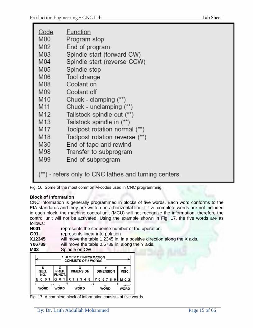
Production Engineering ndash CNC Lab Lab Sheet
By Dr Laith Abdullah Mohammed Page 15 of 66
Fig 16 Some of the most common M-codes used in CNC programming Block of Information CNC information is generally programmed in blocks of five words Each word conforms to the EIA standards and they are written on a horizontal line If five complete words are not included in each block the machine control unit (MCU) will not recognize the information therefore the control unit will not be activated Using the example shown in Fig 17 the five words are as follows N001 represents the sequence number of the operation G01 represents linear interpolation X12345 will move the table 12345 in in a positive direction along the X axis Y06789 will move the table 06789 in along the Y axis M03 Spindle on CW
Fig 17 A complete block of information consists of five words
Production Engineering ndash CNC Lab Lab Sheet
By Dr Laith Abdullah Mohammed Page 16 of 66
Programming for Positioning Before starting to program a job it is important to become familiar with the part to be produced From the engineering drawings the programmer should be capable of planning the machining sequences required to produce the part Visual concepts must be put into a written manuscript as the first step in developing a part program Fig 18 It is the part program that will be sent to the machine control unit by the computer tape diskette or other input media The programmer must first establish a reference point for aligning the workpiece and the machine tool for programming purposes The manuscript must include this along with the types of cutting tools and work-holding devices required and where they are to be located
Fig 18 The first step in producing a CNC program is to take the information from the print and produce a program manuscript Dimensioning Guidelines The system of rectangular coordinates is very important to the successful operation of CNC machines Certain guidelines should be observed when dimensioning parts for CNC machining The following guidelines will insure that the dimensioning language means exactly the same thing to the design engineer the technician the programmer and the machine operator 1 Define part surfaces from three perpendicular reference planes 2 Establish reference planes along part surfaces which are parallel to the machine axes 3 Dimension from a specific point on the part surface 4 Dimension the part clearly so that its shape can be understood without making mathematical calculations or guesses 5 Define the part so that a computer numerical control cutter path can be easily programmed
Production Engineering ndash CNC Lab Lab Sheet
By Dr Laith Abdullah Mohammed Page 17 of 66
Machine Zero Point The machine zero point can be set by three methodsmdashby the operator manually by a programmed absolute zero shift or by work coordinates to suit the holding fixture or the part to be machined MANUAL SETTING - The operator can use the MCU controls to locate the spindle over the desired part zero and then set the X and Y coordinate registers on the console to zero
Fig 19 The relationship between the part zero and the machine system of coordinates ABSOLUTE ZERO SHIFT - The absolute zero shift can change the position of the coordinate system by a command in the CNC program The programmer first sends the machine spindle to home zero position by a G28 command in the program Then another command (G92 for absolute zero shift) tells the MCU how far from the home zero location the coordinate system origin is to be positioned Fig 19 The sample commands may be as follows N1 G28 X0 Y0 Z0 (sends spindle to home zero position) N2 G92 X4000 Y5000 Z6000 (the position the machine will reference as part zero)
Production Engineering ndash CNC Lab Lab Sheet
By Dr Laith Abdullah Mohammed Page 18 of 66
Work Settings and Offsets All CNC machine tools require some form of work setting tool setting and offsets (compensation) to place the cutter and work in the proper relationship Compensation allows the programmer to make adjustments for unexpected tooling and setup conditions
Work Coordinates In absolute positioning work coordinates are generally set on one edge or corner of a part and all programming is generally taken from this position In Fig 20 the part zero is used for all positioning for hole locations 1 2 and 3
Fig 20 In absolute programming all dimensions must be taken from the XY zero at the top left-hand corner of the part
Fig 21 In incremental programming all dimensions are taken from the previous point In incremental positioning the work coordinates change because each location is the zero point for the move to the next location Fig 21
Production Engineering ndash CNC Lab Lab Sheet
By Dr Laith Abdullah Mohammed Page 19 of 66
On some parts it may be desirable to change from absolute to incremental or vice versa at certain points in the job Inserting the G90 (absolute) or the G91 (incremental) command into the program at the point where the change is to be made can do this
R Plane or Gage Height The word-address letter R refers to a partial retraction point in the Z axis to which the end of the cutter retracts above the work surface to allow safe table movement in the X Y axes It is often called the rapid-traverse distance gage height retract or work plane The R distance is a specific height or distance above the work surface and is generally 100 in above the highest surface of the workpiece Fig 22 which is also known as gage height Some manufacturers build a gage height distance of 100 in into the MCU (machine control unit) and whenever the feed motion in the Z axis is called for 100 in will automatically be added to the depth programmed When setting up cutting tools the operator generally places a 100 in thick gage on top of the highest surface of the workpiece Each tool is lowered until it just touches the gage surface and then its length is recorded on the tool list Once the gage height has been set it is not generally necessary to add the 100 in to any future depth dimensions since most MCUs do this automatically
Fig 22 Using a 100 in gage block to set the gage height or R0 on the work surface
Cutter Diameter Compensation Cutter diameter compensation (CDC) changes a milling cutterrsquos programmed centerline path to compensate for small differences in cutter diameter On most MCUs it is effective for most cuts made using either linear or circular interpolation in the X-Y axis but does not affect the programmed Z-axis moves Usually compensation is in increments of 0001 in up to +10000 in and usually most controls have as many CDCs available as there are tool pockets in the tool storage matrix The advantage of the CDC feature is that it 1 Allows the use of cutters that have been sharpened to a smaller diameter 2 Permits the use of a larger or smaller tool already in the machinersquos storage matrix 3 Allows backing the tool away when roughing cuts are required due to excessive material present 4 Permits compensation for unexpected tool or part deflection if the deflection is constant throughout the programmed path The basic reference point of the machine tool is never at the cutting edge of a milling cutter but at some point on its periphery If a 1000 in diameter end mill is used to machine the edges of a workpiece the programmer would have to keep a 500 in offset from the work surface in order to cut the edges accurately Fig 23 The 500 offset represents the distance from the centerline of the cutter or machine spindle to the edge of the part Whenever a part is being machined the programmer must calculate an offset path which is usually half the cutter diameter
Production Engineering ndash CNC Lab Lab Sheet
By Dr Laith Abdullah Mohammed Page 20 of 66
Fig 23 Cutter-diameter compensation must be used when machining with various size cutters Modern MCUs which have part surface programming automatically calculate centerline offsets once the diameter of the cutter for each operation is programmed Many MCUs have operator-entry capabilities which can compensate for differences in cutter diameters therefore an oversize cutter or one that has been sharpened can be used as long as the compensation value for oversize or undersize cutters is entered
Production Engineering ndash CNC Lab Lab Sheet
By Dr Laith Abdullah Mohammed Page 21 of 66
CNC Programming Hints - MILLING
Production Engineering ndash CNC Lab Lab Sheet
By Dr Laith Abdullah Mohammed Page 22 of 66
CNC Programming Hints ndash TURNING
Production Engineering ndash CNC Lab Lab Sheet
By Dr Laith Abdullah Mohammed Page 23 of 66
CNC
The abbreviation CNC stands for Computer(ized) Numerical(ly) Control(led) and refers specifically to the computer control of machine tools for the purpose of (repeatedly) manufacturing complex parts in metal as well as other materials using a program written in a notation conforming to the EIA-274-D standard and commonly called G-code
CNC was developed in the late 1940s and early 1950s by the MIT Servomechanisms Laboratory CNC machines were relatively briefly preceded by the less advanced NC or Numerical(ly) Control(led) machines The introduction of CNC machines radically changed the manufacturing industry Curves are as easy to cut as straight lines complex 3-D structures are relatively easy to produce and the number of machining steps that required human action have been dramatically reduced With the increased automation of manufacturing processes with CNC machining considerable improvements in consistency and quality have been achieved CNC automation reduced the frequency of errors and provided CNC operators with time to perform additional tasks
CNC automation also allows for more flexibility in the way parts are held in the manufacturing process and the time required to change the machine to produce different components In a production environment a series of CNC machines may be combined into one station commonly called a cell to progressively machine a part requiring several operations CNC machines today are controlled directly from files created by CAM software packages so that a part or assembly can go directly from design to manufacturing without the need of producing a drafted paper drawing of the manufactured component In a sense the CNC machines represent a special segment of industrial robot systems as they are programmable to perform many kinds of machining operations (within their designed physical limits like other robotic systems)
G-code
G-code is a common name for the programming language that is used for NC and CNC machine tools It is defined in EIA RS-274-D G-code is also the name of any word in a CNC program that begins with the letter G and generally is a code telling the machine tool what type of action to perform such as
bull rapid move bull controlled feed move in straight line or arc bull series of controlled feed moves that would result in a hole being drilled bull change a pallet bull Set tool information such as offset
There are other codes the type codes can be thought of like registers in a computer
X position Y position Z position M code (another action register) F feed rate S spindle speed N line number R Radius T Tool selection
Production Engineering ndash CNC Lab Lab Sheet
By Dr Laith Abdullah Mohammed Page 24 of 66
I Arc data X axis J Arc data Y axis
G-code files are output by CAM software such as Smartcam Gibbscam Featurecam Edgecam Mastercam etc G-code is also output by specialized CAD systems used to design printed circuit boards Such software must be customized for each type of machine tool that it will be used to program
Production Engineering ndash CNC Lab Lab Sheet
By Dr Laith Abdullah Mohammed Page 25 of 66
U 2عمل األزرار الرئيسية في ماكنة الخراطة المبرمجة (نصر (
1- SINGLE BLOCK للتأكد من صحة البرنامج (تنفيذ البرنامج خطوة خطوةب تقوم( 2- BLOCK DELETE بجانب ويعمل من األوامرلغاء بلوك معين أليستخدم 3- MACHINE LOCK العمل يستخدم لقفل حركة المحاور الرئيسية مع استمرار البرنامج في
)وهذا مهم للتاكد من صحة البرنامج قبل عملية التنفيذ النهائي(4- CONT CYCLE عملية التشغيل عند ايقافها الي سبب كان او عند ايقافها ألستئناف ستخدم ت
) BAR FEEDER(او في حالة استخدام ) FEED HOLDبسبب (5- DRY RUN وتستخدم لفحص البرنامج بعد ازالة الشغلة حركة سريعة للبرنامج 6- TURRET UP amp DOWN ) حركة حامل العدة TURRET الذي يحمل مجموعة من (
وهذا الزر يعمل مع الزر عكس عقرب الساعة او مع عقرب الساعة ةحركة دوراني العدد )SAFTY (
7- COOLANT ON or OFFفه تشغيل سائل التبريد او ايقا 8- COOLANT AUTO الدوال المساعدة في البرنامج من خالل فه تشغيل سائل التبريد او ايقا 9 -MACHINE START ة لتشغيل هيدرولكيك الماكنميستخد
Production Engineering ndash CNC Lab Lab Sheet
By Dr Laith Abdullah Mohammed Page 26 of 66
10- CLOSE OR OPEN CHUCKالعينة تستخدم لفتح وغلق 11 -T STOCK FWD RET حركة الغراب المتحرك ذهابا وإيابا12 -SPINDLE STOP تعمل على ايقاف حركة دوران العينة 13-JOG SPINDLE تعمل على تدوير العينة مع زر SAFTY 14 -OPT SAFTY مع الدالة ( تعمل عمل التوقف المشروط حيث تعملM1 دالة التوقف (
ط ) فقط األ اذا كان هذا الزر مضغو M1المشروط حيث ال يتوقف البرنامج في حالة وجود دالة ( SAFTY + SPINDLE ) يتم الضغط على زر ( START CYCLEلغرض تحرير زر (
START ) في نفس الوقت بعد الضغط على زر ( START CYCLE مرتين (
NC PC- 15 يستخدم هذا الزر عند ربطCNC يستخدم لنقل المعلومات ث مع جهاز أخر حي بينهما
16 -CALCU زر الخاص بالحاسبة مع زر ( ال وهوINPUT ( 17 - HD1 HD2 يستخدم الختيار العدة مع المخرطة ذات المحاور األربعة 18 - START تستخدم لبدء عملية التشغيل
Production Engineering ndash CNC Lab Lab Sheet
By Dr Laith Abdullah Mohammed Page 27 of 66
19- FEED HOLD تعمل على إيقاف عمل أي G موجودة مع بقاء العينة متحركة 20- M D I أو تشغيل البرنامج ل يتم استخدامه لإلدخا BLOCK BY BLOCK وتعمل عند
إدخال البرنامج بواسطة الشريط المثقب أو أي وسيلة إدخال أخرى أو في عمليات التصفير
21- REST تستخدم العادة تشغيل الماكنة أو مسح اإلنذار الذي يظهر على الشاشة 22- EMERGENCYتستخدم عادة اليقاف الماكنة في حالة الطوارئ فقط
OPERATION MENU KEY
CHAPTER PRG-CMK
OFFSET PROGRAM POSITION FUNCTION MENU KEY
23- POSITIONعلى الشاشة د الموقع الموجور الظها 24- PROGRAMإلظهار برنامج معين واختياره 25- OFFSET الختيار سماحات العدة أو سماحات نقطة المرجع 26- PRG- CHK تستخدم لفحص البرنامج على الشاشة 27- SETTING ألختيار الثوابت على الشاشة 28- SERVICE تستخدم ألستخراج المعامالت والثوابت 29- MESSAGE تستخدم ألظهار األخطاء الناتجة عن البرنامج او اخطاء التشغيل 30- OVERALL ألختيار المواقع 31- RELATIVE MODLINE تعوض عن POSITION 32- DIR MEM يستخدم ألظهار ملف البرامج المخزونة في الذاكرة وعندما نضغط هذا الزر
فان رقم واسم البرنامج سوف يظهر على الشاشة
2أدناه الشفرات الرئيسية التي تعمل على الماكنة المبرمجة نصر
G-CODE DESCRIPTION
G00 Rapid traverse (linear)
G01 Linear Interpolation at feed rate
G02 Circular interpolation (CW) R+
G03 Circular interpolation (CCW) R+
G10 Zero point tools
G20 Imperial data input
G21 Metric data input
G27 Reference return check
G28 Reference return
G29 Return from reference
Production Engineering ndash CNC Lab Lab Sheet
By Dr Laith Abdullah Mohammed Page 28 of 66
G33 Thread cutting
G40 Cancel cutter radius compensation
G41 Cutter compensation left
G42 Cutter compensation right
G54 Work co-ordinate system no1
G70 Finishing cycle
G71 Stock removal turning
G72 Stock removal facing
G74 Face grooving
G75 Diameter grooving
G76 Threading cycle
G90 Absolute date input
G91 Incremental data input
G94 Feed minute mode
G95 Feed rev mode
G96 Constant surface speed mode
G97 Cancel Constant surface speed
) 2أدناه الشفرات الثانوية التي تعمل على الماكنة المبرمجة (نصر
M-code FUNCTION
M00 Program stop
M03 Spindle forward (Tool forward ndash M94 mode)
M04 Spindle reverse (Tool forward ndash M94 mode)
M05 Spindle stop (Tool stop ndash M94 mode)
M08 Coolant on
M09 Coolant off
M30 Program end (with rewind)
M48 Turret shortest path
M52 Turret direction up (CW)
M53 Turret direction down (CCW)
M73 Chuck open
M74 Chuck close
Production Engineering ndash CNC Lab Lab Sheet
By Dr Laith Abdullah Mohammed Page 29 of 66
) وكل جملة مكونة من مجموعة من الكلمات blockإن كل برنامج يتكون من مجموعة من الجمل ()words) لهذا فأن الشفرات الرئيسية والمساعدة هي عبارة عن كلمات (words كما في المثال التالي (
G_ _ P1 Q2 U_ _ W_ _ D___ F_ _
)end of block) ويعني ( ) يكتب الرمز (blockتسلسل الكلمات مهم جدا بعد نهاية كل جملة (
طريقة ادخال البيانات الى الماكنة ــــــــــــــــــــــــــــــــــــــــــــــــــ
) MDIيمكن ادخال البيانات الى الماكنة بعدة طرق فقد يكون األدخال عن طريق قناة السيطرة ( MANUAL DATA INPUT ) او عن طريق قناة األضافة EDIT كما يمكن ادخال البيانات عن (
) RS ndash 232 COMMUNICATIN LINKطريق استخدام سلسلة الربط (
₤⅗₌⅗₌ ⅙₌₨image₍₡ ₤₌ℌ⅗₌ Ⅸ⅗ⅥⅯ₌ ₤₡ℌ₰₨⅗₌G71
الخراطة الطولية G71الغرض من التجربة عمل نموذج للخراطة بأستخدام الدالة تستعمل هذه الدالة للخراطة الطولية اي على طول محور المشغولة وكما هو موضح بالشكل ادناه
تعتبر هذه الدالة من الدوال التي ال تحتاج الى تكرار او إعادة كتابتها أي انها دالة تكرارية بمعنى ان اي
الذي هي دالة حركة G01خطوة تكون من ضمن هذه الدالة سوف تكرر العملية اي عند استعمال امر مثل خطية تتضمن القطع مع التغذية مع اعطاء القطر المراد قطعه و مراعاة عمق القطع المعطى سوف يتكرر
هذه االمر وصوال الى العمق المطلوب وهكذا لبقية الدوال
G71 المستخدمة للدالة الصيغة
G71 P1 Q2 U___ W___ D___ F___ حيث إن
P1 بداية الخطوة االولى = Q2 نهاية الخطوة =
Uوضع السماحات بأتجاه محور = X W وضع السماحات بأتجاه محور = Z وتكاد تكون مهملة وتوضع اشارة سالب Dعمق القطع وتوضع رقم صحيح مثل = D500 اي نصف ملمF التغذية والتي لها عالقة بالدالة = G95
Production Engineering ndash CNC Lab Lab Sheet
By Dr Laith Abdullah Mohammed Page 30 of 66
G71الدالة استخدام مثال على
T0100 M48 G0 X26 Z2 M08 T0101 G90 G95 G97 S500 M03 G71 P1 Q2 U03 W00 D500 F01 N1 G0 G42 X00 G01 Z00 G01 X2517 G01 Z-5352 G01 X7391 Z-9366 G01 Z-19145 N2 G28 M30
الجانب العملي
االجهزة واالدوات المستخدمة CNCماكنة خراطة مبرمجة 1 ملم 80قضيب من االلمنيوم قطر 2 ةفير ني 3 جاه أيمن تهولدر كاربيدي ذوا 4
طريقة العمل يتم تثبيت قضيب من االلمنيوم على العينة التابعة للماكنة مع مراعاة الطول المراد استعماله في عملية 1
الخراطة ) turretتثبيت عدة القطع في المكان الصحيح في ( 2
Production Engineering ndash CNC Lab Lab Sheet
By Dr Laith Abdullah Mohammed Page 31 of 66
بالنسبة الى القطعة المثبتة على العينة XZيتم تصفير الماكنة للمحاور 3 تصفير للمحورZ تكون مالمسة العدة الى وجه الشغلة تصفير للمحورX تكون مالمسة العدة الى سطح الشغلة الموازي لمحور X
يتم كتابة البرنامج أما بطريقة يدوية أو بالحاسوب مع وضع كل الظروف الالزمة للتشغيل ( عمق القطع 4 التغذية السرعة المطلوبة نوع المعدن )
ادخال البرنامج الى الحاسوب الموجود داخل الماكنة مع تهيئة الماكنة للتشغيل 5
المطلوب G71عمل برنامج يدوي على الدالة 1 رسم الشكل الشكل النهائي المطلوب مع وضع األبعاد 2
Ⅺ⅟₍euro⅗₌ ₤₡ℌ₰₨⅗₌₣ ₤⅗₌⅗₌ ⅙₌₨image₃₡ Ⅺℂtradeℒ⅗₌ ӈ₍Ⅴ⅟ⅳ₌ G70
G70 الغرض من التجربة عمل انهاء سطحي للمشغولة بواسطة الدالة
من الضروري إعطاء G71هذه الدالة تعمل شوط واحد فقط وتكون معتمدة على عمليات القطع في الدالة اللغاء مقدمة االداة (أي لكي تتم عملية االنهاء السطحي بدون حسابات نصف قطر مقدمة االداة ) G42دالة
G70الصيغة المستخدمة للدالة
G70 P1 Q2 F___ حيث ان
P1 بداية الخطوة االولى = Q2 نهاية الخطوة =
F التغذية والمرتبطة بالدالة = G95
وذلك ألن دالة االنهاء السطحي تحقق X Zمالحظة الدالة التحتاج لكتابة السماحات التابعة للمحورين المسافات الحقيقة المراد انتاجها للمشغولة
G71و G70مثال على الدالة
T0100 M48 G0 X26 Z2 M08 T0101 G90 G95 G97 S500 M03 G71 P1 Q2 U03 W00 D500 F01 N1 G0 G42 X00 G01 Z00 G01 X2517 G01 Z-5352 G01 X7391 Z-9366 G01 Z-19145 N2 G97 S750 MO3
Production Engineering ndash CNC Lab Lab Sheet
By Dr Laith Abdullah Mohammed Page 32 of 66
G70 P1 Q2 G40 F009 G28 M30
الجانب العملي الحظ التجربة األولى
المطلوب
G70 عمل برنامج يدوي على الدالة 1 رسم الشكل النهائي المطلوب مع وضع االبعاد 2
₪⅗₍euro⅗₌ ₤₡ℌ₰₨⅗₌₣ ₤⅗₌⅗₌ ⅙₌₨image₍₡ ⅝₍ⅠimageⅯ₌ ⅞ⅫⅦ⅔₧ G76
G76 للمشغولة بواسطة الدالةةالغرض من التجربة عمل أسنان خارجية أو داخلي
في هذه التجربة سوف نقوم بعمل األسنان الخارجية وهنا تكون حركة العينة ثابتة وهذا ضروري بسبب أن ) تكون متصلتين الكترونيا وعليه أي اختالف في سرعة العينة تؤدي إلى اختالف motionالعينة والحركة(
) servoفي سرعة الخدمة(يرتبط اتجاه تكوين األسنان باتجاه دوران العينة مثال إذا كانت األسنان ذات اتجاه أيمن يكون اتجاه دوران
وهنا نقلب العدة إلى االسفل وكما هو موضح بالشكل أدناه MO3العينة عكس عقرب الساعة أي نستعمل
Production Engineering ndash CNC Lab Lab Sheet
By Dr Laith Abdullah Mohammed Page 33 of 66
الخطوة هي عبارة عن المسافة ما بين قمة سن إلى قمة سن أخر عمق السن هو العمق المطلوب تكوينه لألسنان
G76 الصيغة المستخدمة للدالة
G76 X___ Z___ K___ F___ D___ A___
حيث أن X القطر الداخلي للسن =Z طول السن =K عمق السن وتستخرج من المعادلة التالية =K=065F F الخطوة =D عمق القطع بالمايكرون فقط =A زاوية السن =
G76مثال على استخدام الدالة T0300 M48 GOO X30 Z4 T0303 M08 G97 S500 MO3 G76 X28375 Z-20 K08125 F125 D120 G00 X40 Z4 G28 M30
Production Engineering ndash CNC Lab Lab Sheet
By Dr Laith Abdullah Mohammed Page 34 of 66
الجانب العملي الحظ التجربة األولى
المطلوب
G76عمل برنامج يدوي على الدالة 1 رسم الشكل النهائي المطلوب مع وضع األبعاد 2
Ⅺ⅘₌⅗₌ Ⅵ₂ Ⅺ₯ℋ₍⅗₌ ℌℲℂ⅗₌ ⅞ⅫⅦ⅔₧ ₤K₡₌ℌ⅗₌ ₤₡ℌ₰₨⅗₌)Groove ₤⅗₌⅗₌ ₤tradeimage₌Ⅶ₡ (G75
G75 بواسطة الدالة grooveالغرض من التجربة تكوين
) للمشغولة وتعتمد شكل الحفر على طريقة grooveتستعمل هذه الدالة لتكوين الحفر الخارجي والداخلي (
التشغيل وعلى الشكل المراد إنتاجه وتعتبر هذه الطريقة من عمليات التشكيل للمعدن إن هذه الدالة هي دالة مالحظة مع G75في هذه التجربة سنقوم بعمل الحفر الخارجي بواسطة الدالة
تكرارية وغير تكرارية حسب نوع التشغيل
G 75 الصيغة المستخدمة للدالةG75 X___ Z___ I___ K____
حيث أن
X العمق النهائي لقطر الشغلة =Z عرض الحفر =I الدخول في كل مرة =
K التزحيف على محور =z بالنسبة للعدة
Production Engineering ndash CNC Lab Lab Sheet
By Dr Laith Abdullah Mohammed Page 35 of 66
G75مثال على استخدام الدالة
T0500 M48 GOO X100 Z -20 T0505 M08 G97 S700 MO3 G75 X84 Z -38 I 05 K4
الجانب العملي الحظ التجربة األولى
المطلوب
G76عمل برنامج يدوي على الدالة 1 رسم الشكل النهائي المطلوب مع وضع األبعاد 2
Production Engineering ndash CNC Lab Lab Sheet
By Dr Laith Abdullah Mohammed Page 36 of 66
CNC Milling Machine Mechanical Construction
Guideways The guideways of CNC machines are made of steel To reduce the frictional forces they are coated with a strip of PTFE (Poly Tetra Fluoro Ethylene)
Ballscrews On conventional lathes a leadscrew is used to converts the rotary motion of the hand wheel into linear motion of the slides Leadscrews have a high coefficient of friction and backlash On CNC machines a ballscrew is used instead of a leadscrew Friction and backlash are much less than on leadscrews
Guideway
Production Engineering ndash CNC Lab Lab Sheet
By Dr Laith Abdullah Mohammed Page 37 of 66
bullMachining operations Direction of cutting Based on the direction of the cutter rotation and work piece feed milling operations are classified into two types 1-Up milling (Convention milling) In up milling the metal is removed by rotating the cutter against the direction of travel of the part
Feed
Machine table
Part
Cutting tool
Chip thickness at theexit of the tooth
2-Down milling (Climb milling) In climb milling the metal is removed by rotating the cutter with the direction of travel of the part
Machine table
Part
Cutting tool
Chip thickness at theentrance of the tooth
Production Engineering ndash CNC Lab Lab Sheet
By Dr Laith Abdullah Mohammed Page 38 of 66
bullTooling Tool geometry The geometry of the tool tip affects the way that the metal cutting is performed The nose radius rake angles relief angles etc must be selected with care
Radial relief
Radial rake
Axial relief
Approach angle
Axial relief
Corner radius Face mill Face milling cutters are used to mill flat surfaces Commonly used face milling cutters Cutter with 75 degree approach
75 deg
Cutter with 90 degree approach (Square shoulder face mill)
90 deg
Cutter with 45 degree approach
Production Engineering ndash CNC Lab Lab Sheet
By Dr Laith Abdullah Mohammed Page 39 of 66
bullCNC Programming Axes convention The Z axis is along the spindle axis The X and Y axes are perpendicular to Z VMC
Z
Y
-
+
-+
X- +
+Z
-Z
+Y
-Y
-X +X
Part
Machine table
X
YZ
G00 Rapid traverse When the tool being positioned at a point preparatory to a cutting motion to save time it is moved along a straight line at Rapid traverse at a fixed traverse rate which is pre-programmed into the machines control system Typical rapid traverse rates are 10 to 25 m min but can be as high as 80 mmin
Production Engineering ndash CNC Lab Lab Sheet
By Dr Laith Abdullah Mohammed Page 40 of 66
Format N_ G00 X__ Y__Z__
G01 Linear interpolation (feed traverse) The tool moves along a straight line in one or two axis simultaneously at a programmed linear speed the feed rate Format N__ G01 X__ Y__Z__ F__
Part
Feed
Part
Feed
G02G03 Circular interpolation The tool moves along an arc in two axes simultaneously at a programmed linear speed the feed rate
Production Engineering ndash CNC Lab Lab Sheet
By Dr Laith Abdullah Mohammed Page 41 of 66
Format N__ G0203 X__ Y__Z__ I__ J__K__ F__ using the arc center OR N__ G0203 X__ Y__Z__ R__ F__ using the arc radius G02 moves along a CW arc G03 moves along a CCW arc Arc center The arc center is specified by addresses I J and K I J and K are the X Y and Z co-ordinates of the arc center with reference to the arc start point
X
Y
Arc center
Arc endArc start
- J
- I
I = X coord of center - X coord of start point J = Y coord of center - Y coord of start point K = Z coord of center - Z coord of start point I J and K must be written with their signs
Production Engineering ndash CNC Lab Lab Sheet
By Dr Laith Abdullah Mohammed Page 42 of 66
bullWork holding
Rotary table
Fixture base
Component
Clamp
Stud
Fixtures The use of fixtures 1 Improves repeatability of dimensions 2 Improves working conditions 3 Cuts down requirement of skilled labour 4 Reduces part loading and unloading time 5 Improves safety in the working area 6 Reduces the cost of machining There are two types fixtures commonly used 1 Special fixture Special fixtures are used to hold and locate the typical components which are having complex shape and to be located with the reference hole (dowel hole) Special fixtures are required for components like gear case cover cylinder heads etc 2 Modular fixture Modular fixture is a set different kind of clamping and locating elements These fixtures are used to hold identical components in different sizes and components of box type Example Manifolds head stocks connecting rods and flanges
Production Engineering ndash CNC Lab Lab Sheet
By Dr Laith Abdullah Mohammed Page 43 of 66
bullMachine setting
Determining X and Y work zero offset Case 1
Part
Machine table
Part
End mill or reamer
Work offset X0Y0 For determining X work zero offset bull Touch the periphery of the end mill or reamer to the part bull Enter current machine X value + cutter radius as X work zero offset For determining Y work zero offset bull Touch the periphery of the end mill or reamer to the part bull Enter current machine Y value - cutter radius as Y work zero offset Case 2
Part
Machine table
Part
End mill or reamerWork offset X0Y0
bull Mount the dial indicator on machine spindle true the bore bull Enter current machine X and Y value as X and Y work zero offset
Production Engineering ndash CNC Lab Lab Sheet
By Dr Laith Abdullah Mohammed Page 44 of 66
How to Select a Cutting Fluid
One part of the metal cutting equation that is sometimes overlooked however is
the choice of an appropriate cutting fluid With todayrsquos system approach to metal
cutting use of the right metalworking fluid has become just as much a part of the
solution as the other elements In fact at least one company is now integrating
cutting fluids and cutting tools into effective metal cutting systems Following are
some things to consider when choosing your next cutting fluid
The Four Key Questions
There are four vital pieces of information that are necessary when choosing a
cutting fluid They are
1 What are you cutting
2 What is the chemistry of your water
3 What are you using now
4 What are your options
5 What do you prefer
What Are You Cutting
The first question ndash ldquoWhat are you cuttingrdquo ndash is often the most difficult to answer
because most shops handle a variety of workpiece materials on a regular basis If
the answer is an unequivocal ldquoaluminumrdquo or ldquostainless steelrdquo or ldquocast ironrdquo the
selection of a cutting fluid can be quite simple and straightforward Unfortunately
that is seldom the case in anything but a high-volume plant Where aluminum or
other nonferrous metals are a significant part of the mix a non-staining cutting
fluid is a must Generally speaking this will be a semi-synthetic with special
ingredients to prevent bi-metallic corrosion and staining of non-ferrous workpieces
Where the ferrous metals predominate however a more general purpose semi-
synthetic or hybrid fluid might be a more economical choice
Production Engineering ndash CNC Lab Lab Sheet
By Dr Laith Abdullah Mohammed Page 45 of 66
What is The Chemistry of Your Water
The second question ndash ldquoWhat is the chemistry of your waterrdquo ndash is probably the
single most common reason for the success or failure of a cutting fluid Very few
plants invest the money necessary to install effective water purification systems
using deionization or reverse osmosis technology Unfortunately the chemicals
present or not present in the water used to re-constitute a cutting fluid make a
tremendous difference in its performance and sump life Most manufacturers of
cutting fluids will perform the necessary water testing to determine exactly what
minerals are dissolved in your water and make a fluid recommendation based on
the results
What are you using now
The third question ndash ldquoWhat are you using nowrdquo ndash helps narrow the range of
choices When coupled with an objective analysis of the strengths and weaknesses
of the current fluid the answer to this question can quickly point you toward a
relatively small number of competitive alternatives that have the attributes required
to meet your cutting needs Many cutting fluids are in use today simply because
they were in use yesterday It is a hard reality of todayrsquos marketplace that if one
isnrsquot constantly striving to improve they will certainly be overtaken by a
competitor who is
What Are Your Options
The fourth question ndash ldquoWhat are your optionsrdquo ndash leads to the final selection of a
cutting fluid Cutting fluids can be divided into four general groups based on their
chemistry
They are
bull Soluble Oils ndash quite literally oil dispersed in water
bull Synthetics ndash completely oil free man-made coolants in solution
Production Engineering ndash CNC Lab Lab Sheet
By Dr Laith Abdullah Mohammed Page 46 of 66
bull Semi-Synthetics ndash a mixture of natural and synthetic lubricants with up to 30
mineral oil
bull Hybrids ndash a special class of semi-synthetics with a mineral oil content of about
15 Each fluid type has advantages and disadvantages which make it suitable for
a particular group of applications In addition there are costperformance trade-
offs to be made between the groups within a specific set of applications For
example where a hybrid and a semi-synthetic may both be suitable for a particular
use the hybrid might provide longer sump life at a slightly higher initial cost
while some semi synthetics may be more economical to recycle or dispose of while
not giving as long a tank life The final decision in this case would have to be made
on the detailed economics of the shop where the fluids were to be used and on the
ownerrsquos individual preferences
Soluble Oils
Soluble oils are oils that disperse in water when emulsifiers are added They are
generally suitable for moderate-to heavy-duty machining and grinding of all non-
ferrous metals carbon and cast steels and in applications where dissimilar metals
such as aluminium and steel are present They can also be used in turning drilling
tapping reaming gear cutting broaching as well as internal and centerless types
of grinding operations Soluble oils provide excellent aluminium and copper
corrosion control good rancidity control which extends fluid for long lasting
trouble-free performance and good concentrate and mix stability making it ideal
for mixing in water with a minimal amount of agitation An example of this is
Valenitersquos VNTreg-650 premium heavy-duty soluble oil
Synthetics
Synthetics are completely oil free solutions made of polymers organic and
inorganic materials that are mixed with water These clear low foaming and bio-
Production Engineering ndash CNC Lab Lab Sheet
By Dr Laith Abdullah Mohammed Page 47 of 66
stable coolants are ideal for machining and grinding of ferrous materials carbon
steels or cast iron Their complex lubricant packages make synthetics well-suited
for tough-to-machine materials such as stainless steels and high-temperature alloys
Certain synthetics are specifically designed to address the primary failure modes of
flank wear and nose wear Although there are many benefits some synthetics may
cause staining of non-ferrous materials
Semi-Synthetics
Semi-synthetic fluids are a mixture of oils synthetic emulsifiers and water They
were primarily developed for the aircraft nuclear and related industries
Consequently they work extremely well on all non-ferrous metals such as titanium
aluminium copper brass bronze and stainless steel in both machining and
grinding Semi-synthetics can be used on ferrous metals too They are chlorine-
free to reduce bi-metallic corrosion and staining of metals They should be used at
a 5-8 dilution with water depending on the severity of the operation
Hybrids
Hybrids are cutting fluids custom engineered to solve a particular problem For
example Valenitersquos VNTreg-800 was developed to be very clean in the machining
and grinding of cast iron It provides better stability in hard water and rejects tramp
oil very well which adds to its bio-stable chemistry Hybrids work extremely well
on all metals in both machining and grinding They should be mixed at a 5-7
dilution with water depending on the condition of the water
What Do You Prefer
The final question ndash ldquoWhat do you preferrdquo ndash is usually the ldquotie breakerrdquo where
there is more than one appropriate cutting fluid available Here again as in the
case of what is being used now the key is to examine your preferences objectively
Production Engineering ndash CNC Lab Lab Sheet
By Dr Laith Abdullah Mohammed Page 48 of 66
and specifically to identify the real reasons behind a preference If you cannot
point to specific reasons why one class of cutting fluid is preferred over another
you are well advised to follow the recommendations of the professional who has
analyzed your requirements Choosing the right fluid today is easier than ever as
the system approach to metal cutting productivity continues to grow in acceptance
The day is not far off when choosing a complete solution will be as easy as
choosing the right insert and chip breaker today The answers are available and the
results will more than justify the time you spend choosing the right metal cutting
fluid
Useful Links wwwball-screwsnet
wwwlubelinkcom
wwwmachinerylubricationcom
wwwadvancedmanufacturingcom
wwwmmsonlinecom
wwwcuttingtoolengineeringcom
wwwgeartechnologycom
wwwengineersedgecom
wwwagmaorg
wwwefundacom
wwwsaeorg
wwwsmeorg
wwwastmorg
wwwissorg
wwwmachinetoolscom
wwwansiorg
wwwasmeorg
wwwcnccicom
wwwmatlscom
wwwthefreedictionarycom
wwwengineersupplycom
Production Engineering ndash CNC Lab Lab Sheet
By Dr Laith Abdullah Mohammed Page 49 of 66
SurfCAM Tutorial ndash Beginning with the basics
Background SurfCAM is a computer aided manufacturing (CAM) software which allows you to create manage and modify tool paths for computer aided designed (CAD) part The software requires a CAD model or requires that you create some geometry within SurfCAM with some rudimentary tools provided The tool paths are created or stored internally in SurfCAM in a generic programming language called APT Once the tool paths are created the APT paths are translated using a post processor into typical machine G-code
Opening SurfCAM SurfCAM can be opened from the Novell Applications Launcher on most Industrial Engineering computer labs workstations Search under lsquoallrsquo applications and double click on SurfCAM 2005 Once the program opens a license must be selected from the list (not the Demo license) to enable saving the file later Choose one of the 30 licenses available If for some reason the licenses are not listed on the license manager form select server list and type ldquobonnieeosncsuedurdquo A list of available licenses should appear Select a license and click OK After the license is selected an Add StockFixture form (Figure 1) opens allows you to add a model which represents the pre-machined stock or a fixture Click on OK without adding either Both of these items can be added later under a more appropriate dialog
Figure 1 Add Stock or Fixture dialog box
Production Engineering ndash CNC Lab Lab Sheet
By Dr Laith Abdullah Mohammed Page 50 of 66
SurfCAM Interface
Figure 2 SurfCAM Windows based interface
SurfCAM is a windows based software system so most of the typical windows functions under File are applicable This is where you can open save exit print etc The Create menu allows the user to create different geometry forms Here you can create a point line surface chamfer circle and many other geometry types For the most part these functions are not used by beginners but are useful when creating bounding curves where you donrsquot want the tool to move outside (constraining the tool) The Edit menu allows you to change or modify many different entities such as changing lines altering surfaces joining surfaces trimming or breaking elements add control points etc Again these features are helpful to advanced users and are not covered in detail in this tutorial The Display menu offers the ability to change the orientation of the part on the screen The typical rotate pan fit to screen and zoom functions are available as well as several functions which allow the user to shift between views or call up a named view (ie top bottom etc) The NC menu is the main machining interface menu In this menu you select the general form of machining (2 axis 3 axis 4 axis 5 axis turning etc) and under the general form a more specific machining function is selected This menu is the most used and the options contained must be fully understood to get the most out of SurfCAM Each function will be described in some detail in a further chapter The Analyze menu contains options such as measuring the distance between points angles tangency elements etc These functions are auxiliary functions meant to help you understand the part better but basically provide no functionality for making tool paths for CNC machines Thus these will not be covered The Tools menu allows the user to change the system options modify keyboard shortcuts change the model units etc These options are again not used by beginners Finally the Help menu provides access to the online users manual In lieu of clicking the Help menu the F1 key is the shortcut key for help (as it is in most windows based programs)
Importing a CAD model Importing a CAD model that is stored locally is done by selecting File-gtOpen On the Files of type dropdown box choose the type of file you wish to open (Figure 3) Do this prior to negotiating your way through the maze of folders to prevent having to go through the folder tree again Once the file type is selected find the file you are trying to open and click the Open
Production Engineering ndash CNC Lab Lab Sheet
By Dr Laith Abdullah Mohammed Page 51 of 66
button SurfCAM will then attempt to read the file you have selected SurfCAM may provide a dialog box describing what it has imported and identify if it was successful If this dialog is provided simply click close without saving
Figure 3 Open Dialog Note - Change type of file prior to finding the file you wish to open
SurfCAM allows a user to import several different types of CAD files the most common types which you will likely import are SolidWorks part files (sldprt or prt) AutoCAD files(dxf) or IGES (igs or iges) Native file import (such as is the case with SolidWorks) provides the greatest information transfer and generic file imports (such as is the case with IGES) provide the least Normally it is to the advantage of the user to use native file importing procedures when available Recently (2005) SurfCAM added some compatibility with SolidWorks This allows the user to create tool paths for a part and if an engineering change is needed for the part update the part in SolidWorks When the part is then opened in SurfCAM the changes are noted and a simple update operation command is needed This however does not operate with complete transparency andor accuracy and thus users need to be cognizant of changing CAD models
SurfCAM Geometry In SurfCAM two basic types of geometry are used the surface and the point A surface (Figure 4) is a so called spline (NURBS or B-Spline are the two most common) surface (parameterized by two values u and v) such that every location on the surface can be defined as a function of these parameters In other words SurfCAM can calculate the location of any point on the
Production Engineering ndash CNC Lab Lab Sheet
By Dr Laith Abdullah Mohammed Page 52 of 66
surface Surfaces are used primarily in 3 4 and 5 axis machining and require a significant
amount of processing power and time Figure 4 Surfaces model of a mold half Note the difference between this and Figure 2 a wireframe model
Point or line based models are often referred to as wireframe (Figure 5) models because the models consist of connected lines and resemble the part only at the intersection of two surfaces Wireframe models were made popular lsquoback in the dayrsquo when computer processing was expensive There are times when each of the models are important and selecting model geometry when applying a SurfCAM operation will be much simpler if you understand the differences between the two When importing a SolidWorks model the default is both the surfaces and the wireframe geometry are imported
Figure 5 Wireframe model of the mold in Figure 1
Steps to Creating Tool Paths Once a CAD model is imported into SurfCAM tool paths can be created There is no one correct way to create tool paths however there is a set of general steps to take to ensure the tool paths are created with a minimum amount of hardship (note the wordinghellipHardship is inevitable when creating tool paths it is the intent of this manual to minimize this) The following is a list of steps which should be considered when making tool paths
Production Engineering ndash CNC Lab Lab Sheet
By Dr Laith Abdullah Mohammed Page 53 of 66
1 Plan ahead a Orient the part in SolidWorks such that if only one side is to be machined that
side is the Top view This can be done early in SolidWorks by choosing a plane parallel the X-Y plane as the sketch plane for the machined geometry
b Orient the part in SolidWorks such that the origin is somewhere of relative importance and someplace in space that can be easily identified when placed on the machine This is extremely important to minimize set up time at the machine (note ndash my personal preference for a part that is to be fully machined [ie stock exists on all sides] is to place the origin at the center and top of the parthellipjust my preference)
c Orient the part in SolidWorks such that the X and Y axes are aligned as you want them on the machinehellip
d Planning ahead will save you many hours of headaches laterhelliptrust me 2 Import the model 3 Choose a construction view such that the tool approaches the side to be machined
from the positive Z axis direction (as defined by part origin) a This is done by clicking on the CView icon
b From the list of named views chose the view which orients the origin as you would like
c If one of the views does not fit your criteria you have two choices i Perform a transformation of the part in SurfCAM or SolidWorks
ii Add a new construction view by selecting new This option requires a relatively good understanding of right hand coordinate frames but is very usefulhellipNormally used by more advanced users
d Be sure the CoordVIEW selection is made vs CoordWORLD This ensures the tools will be controlled from the coordinate frame selected by the view (ie the origin on the part) instead of the origin on the lower left corner of the screen This will be especially important when we get into 4 and 5 axis machining
4 In the Operations Manager (Figure 6) select Setup One and change the name to something meaningful ndash like Front Side Mold Cavity
a Access the Operations manager by right clicking or by selecting the Operations Manager icon in the tool bar
b Operations Manager is where the tool paths are managed once they are created as well as where individual tool paths can be verified
Production Engineering ndash CNC Lab Lab Sheet
By Dr Laith Abdullah Mohammed Page 54 of 66
5 Roughing Tool Paths a Create the tool paths to remove the majority of the material (if applicable) b Use NC-gt3Axis-gtZ rough or Plunge Rough c Described in next section
6 Create Finishing Tool Paths a Described in next section
7 Add another setup if necessary 8 Perform steps 3 through 6 as necessary 9 Verify the tool paths are correct 10 Use a post processor for the tool paths to create G-Code for machine
Creating Tool Paths The following is a list of operations what they are intended for how they generally work and some parameters that may be adjusted to modify the tool paths
2 Axis tool paths Unless otherwise noted 2 axis tool path functions require lines or arc segments as input parameters (as opposed to surfaces) There are several options as to how these segments are chosen the most prevalent is the chain option and the second most prevalent is the single When choosing the line segments using the chain option SurfCAM will try to link a complete path of segments based on an initial segment chosen by the user If the operation is planer (ie pocket or contour) the segments must lie on the same plane If the operation is non-planer (ie contour 3D) SurfCAM will prompt the user to specify segments when it encounters a branch point
Figure 6 Operations Manager view showing setup one re-labeled as Front Side Mold
Production Engineering ndash CNC Lab Lab Sheet
By Dr Laith Abdullah Mohammed Page 55 of 66
When using the single element option the user must manually choose each segment desired for the operation Note that most operations do not require a closed loop of segments you may specify for instance an open contour where the tool is supposed to move The order of choosing segments is important This order determines the path of the tool in the sense that if three segments are chosen such that the middle segment is chosen last there will be three different plunge and machine operations one on each segment If the operation was to make a continuous contour around the outside of the part the segments should be chosen in order of the desired tool trajectory
Operations
Pocket Pocket operation in SurfCAM is used to cut an enclosed space from the inside to the outside at one particular depth The operation starts in the center of an enclosed area (with a plunge move in the ndashZ direction) and makes incremental closed paths towards the pocket boundaries in user defined path offsets (Figure 7) The user chooses the boundary of the pocket (line segments) and if more than one pocket is chosen SurfCAM will ask the user to click inside a pocket
Figure 7 Two examples of using the pocketing operation
The pocket operation allows for creating a projection of the pocket paths on multiple planes This is useful if you have a deep pocket which will not allow the tool to cut directly at the depth of the pocket but would be easily done using the same paths at several different Z heights On the cut control (Figure 8) tab the user specifies where the chosen geometry (pocket segments) lie (ie bottom or top) Then under the amount to remove specify the total material height to be removed and the rough spacing (amount you wish to advance the Z axis with each pocket step) You may also specify a finishing pass and as well as stock to leave
Production Engineering ndash CNC Lab Lab Sheet
By Dr Laith Abdullah Mohammed Page 56 of 66
Figure 8 Example of Contour Operation with multiple passes
Contour Contouring in SurfCAM is used to perform peripheral milling on the inside or outside of a line segment (Figure 9) The user is to identify the line segments which define a contour (does not have to be a closed loop of segments) SurfCAM may or may not require the user to specify a side to contour (ie which side of the line is the tool to cut) For contouring each segment must lie on the same plane
Production Engineering ndash CNC Lab Lab Sheet
By Dr Laith Abdullah Mohammed Page 57 of 66
Figure 9 Examples of parts cut with 2-Axis Contour
Contour 3D Contour 3D is the same operation type as contour but allows the user to specify segments on different planes for the tool to cut along
Drill Drilling operations are any rotating tool operation meant to engage the part from a single direction ndash namely from the positive Z direction Drilling operations can be specified using circle point or line segments After choosing NC-gt2-Axis-gtDrill SurfCAM allows the user to choose multiple circles or points defining holes to be drilled Drilling operations also allow the user to incorporate more than 1 operation such as a center drill a drill and a reaming operation After selecting the locations for the drilling operation a dialog box (Figure 10) allows the user to add change or delete tools to be used in the operation As displayed in the following figure the spotdrill operation is followed by a drilling operation followed by a tapping operation The depth of each tool can be controlled individually by double clicking the total depth cell in and manually entering Tools can be added before or after operations which the cells are highlighted by selecting either of the insert buttons at the top or by the insert menu Select tool button allows the user to change the tool size or type
Production Engineering ndash CNC Lab Lab Sheet
By Dr Laith Abdullah Mohammed Page 58 of 66
Figure 10 Drill operation manager Several operations can be completed at one time
Figure 11 Drill operation including the spotdrill drill and tap as outlined in Fig 10
3 Axis tool paths SurfCAM requires surfaces as inputs for 3 Axis tool paths Surfaces can be created in SurfCAM but are most easily created in a CAD package and imported into SurfCAM Surfaces allow SurfCAM to identify every point on the surface in 3 dimensions unlike 2D geometry (wireframes) which only identify positions on the plane Creating tool paths with complex surfaces takes a very significant amount of processing power so expect 3 Axis tool path generation to take longer
Production Engineering ndash CNC Lab Lab Sheet
By Dr Laith Abdullah Mohammed Page 59 of 66
Operations
Cut 3 Axis cut operation takes a surface and using the flow lines creates a rastering path over the surface with the tool tip riding on the surface The primary direction will be defined by the flow lines of the surface (which can be edited by Edit-gtSurfaces-gtArrow-gtDirection) If you intend to cross surface boundaries you must merge the surfaces (Edit-gtJoin and choose the two surfaces)
Z-Rough The Z-rough operation is used to remove a large amount of material prior to finish machining Roughing operation is typically the first operation you perform for each setup The Z-Rough operation cuts the part in user defined intervals For each of these intervals a surface intersection between the part and the plane is performed and a 2D pocket or contour operation is performed on that plane This is performed on each plane When choosing NC-gt3 Axis-gtZ rough the first dialog box you will encounter asks for a bounding box to be defined Choose the Extents Box and a second dialog box will ask for the coordinates which define the box (Figure 12) This is the stock size you expect to machine the part from Input the coordinates or change the additional offset amounts (in XY or Z) as appropriate and click Calculate Bounding Box
Figure 12 Material Extents Box Example
Next choose the tool and cutting parameters that you desire and click on the Cut Control Tab (Figure 13) Here you will find the following parameters which are often changed Stock to
Production Engineering ndash CNC Lab Lab Sheet
By Dr Laith Abdullah Mohammed Page 60 of 66
leave ndash this is an offset amount from the surfaces which leaves a small amount of material to finish machine Minimum and Maximum Z values ndash Defines area to machine Z Step Size ndash This identifies the plane intervals for the surface intersection planes (the first interval will be at the top of the selected area and successive increments down in Z will be cut until the Minimum Z value is reached)
Figure 13 3Axis Z Rough Cut Control
The 3Axis Z-Finish operation works in exactly the same way 3 Axis Z-Finish is most appropriate for finishing vertical or near vertical walls
3D Offset The 3D Offset operation creates a tool path using a 2D or 3D boundary by offsetting the boundary in concentric offset cutting passes Each pass calculates the tool engagement and maintains the engagement somewhat constant The advantage (significant) is the scallop height ndash height of the material between passes ndash is controlled thus the surface finish is predictable When choosing 3D Offset surfaces are selected as well as 2D or 3D boundaries The boundaries define the concentric offset paths shape as well as limit the tool path area Choose NC-gt3Axis-gt3D Offset from the drop down menus SurfCAM will prompt you to select the surface or surfaces to cut across Select the surfaces you wish to machine and then select the tool and cutting parameters you wish use Next select the Cut Control Tab and check the Use Boundary Curves option Set the Step Type to Scallop and set the maximum scallop height If you like
Production Engineering ndash CNC Lab Lab Sheet
By Dr Laith Abdullah Mohammed Page 61 of 66
you can also add stock to leave if this is a roughing operation You can also set the Direction and Start-End parameters from this tab Click OK and the paths will be generated
Figure 14 Cut Control Tab for 3D Offset
Example part using both 2D and 3D geometry
The tool paths for this mold will be generated in SurfCAM using 5 operations The first will be a roughing operation using a frac14 inch flat end mill with the Z step size of 00625in Choose NC-
Production Engineering ndash CNC Lab Lab Sheet
By Dr Laith Abdullah Mohammed Page 62 of 66
gt3Axis-gtZ-Rough from the drop down menu Select all visible surfaces and create an extents box that has 025inch XY offsets and 01inch Z offset Next select the frac14 inch flat end mill from the tools menu Under Cut Control tab set the Z step size to be 00625inch The tool paths will look something like Figure 15
Figure 15 Z-Rough Tool paths for Example Part
Next a flat surface operation will be performed to cut the flat surface on the top Select NC-gt3 Axis-gtFlat Surface from the drop down menu Select all visible surfaces again Choose the 12inch flat end mill and set the cutting parameters as desired Under Cut Control Tab change the Minimum Area to 50 square inches (Figure 16) The tool paths should look something like Figure 17
Figure 16 Cut Control for Flat Surface
Production Engineering ndash CNC Lab Lab Sheet
By Dr Laith Abdullah Mohammed Page 63 of 66
Figure 17 Flat Surface Tool Paths
Next we will use a 3D offset operation to cut the mold cavity Select NC-gt3 Axis-gt3D Offset from the dropdown menu Change the view to the top view and select within to capture the surfaces of the mold cavity Draw a rectangle around the mold cavity Select a 18 inch ball endmill from the tool library and set the cutting parameters as appropriate Next set the Cut Control tab parameters as in Figure 14 The paths creates should be similar to Figure 18
Figure 18 3D Offset Paths
Next we will perform a 2 Axis contouring of the top section Select NC-gt2 Axis-gtContour from the dropdown menu Using the chain option select the bottom contour of the top extrusion Select the frac12 inch flat end mill from the tool library and set the cutting parameters as required In the Cut Control Tab change the Geometry to Bottom and the amount to remove in Z to 05
Production Engineering ndash CNC Lab Lab Sheet
By Dr Laith Abdullah Mohammed Page 64 of 66
Change the Rough Spacing in Z to 025 and add 1 finish pass of 002 (Figure 19) Click OK and SurfCAM will instruct you to choose a side to contour Click anywhere on the screen OUTSIDE the geometry you selected for the contouring operation Failure to click outside the geometry will result in the tool being on the wrong side of the contour Your paths should look something like those in Figure 20
Figure 19 Cut Control Tab for the Contouring Operation
Figure 20 Contouring operation paths
Production Engineering ndash CNC Lab Lab Sheet
By Dr Laith Abdullah Mohammed Page 65 of 66
Next we will perform a 2 axis pocket operation for the small pocket on the top face of the mold Select NC-gt2Axis-gtPocket and using the Auto select feature select the boundary curve at the bottom of the pocket Click Done twice and select the frac14 inch flat end mill from the tool library Set the appropriate cutting parameters and click OK SurfCAM will prompt you to click inside the pocket Click anywhere inside the geometry you chose to define the pocket The resulting paths should look something like those in Figure 21
Figure 21 2 Axis Pocket Operation Paths
Finally we will add a drilling operation for the 2 holes at the corners of the mold Select NC-gt2 Axis-gtDrill from the dropdown menu Select the top circles defining the two holes A menu box will appear with a default tool (Center drill) already programmed Add a second tool to the list by selecting Insert-gtAfter and select the tool from the tool library Change the drill depth to 10inches and click OK The paths should look something similar to Figure 23
Figure 22 Drill Menu
Production Engineering ndash CNC Lab Lab Sheet
By Dr Laith Abdullah Mohammed Page 66 of 66
Figure 23 Drilling Operation Tool Paths
Now you can watch a simulation of the cutting by choosing the setup in the operations manager and clicking the simulate icon Be sure to set the stock in the set up by right clicking the set up and selecting Edit Setup Information In the Stock Tab you can create a bounding box meeting your needs and click Add Your simulation should result in something like the following
Figure 24 Final Simulation of the example Mold
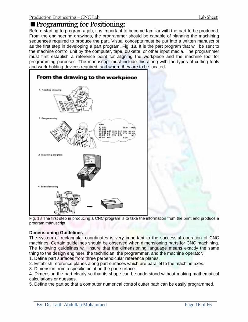
Production Engineering ndash CNC Lab Lab Sheet
By Dr Laith Abdullah Mohammed Page 16 of 66
Programming for Positioning Before starting to program a job it is important to become familiar with the part to be produced From the engineering drawings the programmer should be capable of planning the machining sequences required to produce the part Visual concepts must be put into a written manuscript as the first step in developing a part program Fig 18 It is the part program that will be sent to the machine control unit by the computer tape diskette or other input media The programmer must first establish a reference point for aligning the workpiece and the machine tool for programming purposes The manuscript must include this along with the types of cutting tools and work-holding devices required and where they are to be located
Fig 18 The first step in producing a CNC program is to take the information from the print and produce a program manuscript Dimensioning Guidelines The system of rectangular coordinates is very important to the successful operation of CNC machines Certain guidelines should be observed when dimensioning parts for CNC machining The following guidelines will insure that the dimensioning language means exactly the same thing to the design engineer the technician the programmer and the machine operator 1 Define part surfaces from three perpendicular reference planes 2 Establish reference planes along part surfaces which are parallel to the machine axes 3 Dimension from a specific point on the part surface 4 Dimension the part clearly so that its shape can be understood without making mathematical calculations or guesses 5 Define the part so that a computer numerical control cutter path can be easily programmed
Production Engineering ndash CNC Lab Lab Sheet
By Dr Laith Abdullah Mohammed Page 17 of 66
Machine Zero Point The machine zero point can be set by three methodsmdashby the operator manually by a programmed absolute zero shift or by work coordinates to suit the holding fixture or the part to be machined MANUAL SETTING - The operator can use the MCU controls to locate the spindle over the desired part zero and then set the X and Y coordinate registers on the console to zero
Fig 19 The relationship between the part zero and the machine system of coordinates ABSOLUTE ZERO SHIFT - The absolute zero shift can change the position of the coordinate system by a command in the CNC program The programmer first sends the machine spindle to home zero position by a G28 command in the program Then another command (G92 for absolute zero shift) tells the MCU how far from the home zero location the coordinate system origin is to be positioned Fig 19 The sample commands may be as follows N1 G28 X0 Y0 Z0 (sends spindle to home zero position) N2 G92 X4000 Y5000 Z6000 (the position the machine will reference as part zero)
Production Engineering ndash CNC Lab Lab Sheet
By Dr Laith Abdullah Mohammed Page 18 of 66
Work Settings and Offsets All CNC machine tools require some form of work setting tool setting and offsets (compensation) to place the cutter and work in the proper relationship Compensation allows the programmer to make adjustments for unexpected tooling and setup conditions
Work Coordinates In absolute positioning work coordinates are generally set on one edge or corner of a part and all programming is generally taken from this position In Fig 20 the part zero is used for all positioning for hole locations 1 2 and 3
Fig 20 In absolute programming all dimensions must be taken from the XY zero at the top left-hand corner of the part
Fig 21 In incremental programming all dimensions are taken from the previous point In incremental positioning the work coordinates change because each location is the zero point for the move to the next location Fig 21
Production Engineering ndash CNC Lab Lab Sheet
By Dr Laith Abdullah Mohammed Page 19 of 66
On some parts it may be desirable to change from absolute to incremental or vice versa at certain points in the job Inserting the G90 (absolute) or the G91 (incremental) command into the program at the point where the change is to be made can do this
R Plane or Gage Height The word-address letter R refers to a partial retraction point in the Z axis to which the end of the cutter retracts above the work surface to allow safe table movement in the X Y axes It is often called the rapid-traverse distance gage height retract or work plane The R distance is a specific height or distance above the work surface and is generally 100 in above the highest surface of the workpiece Fig 22 which is also known as gage height Some manufacturers build a gage height distance of 100 in into the MCU (machine control unit) and whenever the feed motion in the Z axis is called for 100 in will automatically be added to the depth programmed When setting up cutting tools the operator generally places a 100 in thick gage on top of the highest surface of the workpiece Each tool is lowered until it just touches the gage surface and then its length is recorded on the tool list Once the gage height has been set it is not generally necessary to add the 100 in to any future depth dimensions since most MCUs do this automatically
Fig 22 Using a 100 in gage block to set the gage height or R0 on the work surface
Cutter Diameter Compensation Cutter diameter compensation (CDC) changes a milling cutterrsquos programmed centerline path to compensate for small differences in cutter diameter On most MCUs it is effective for most cuts made using either linear or circular interpolation in the X-Y axis but does not affect the programmed Z-axis moves Usually compensation is in increments of 0001 in up to +10000 in and usually most controls have as many CDCs available as there are tool pockets in the tool storage matrix The advantage of the CDC feature is that it 1 Allows the use of cutters that have been sharpened to a smaller diameter 2 Permits the use of a larger or smaller tool already in the machinersquos storage matrix 3 Allows backing the tool away when roughing cuts are required due to excessive material present 4 Permits compensation for unexpected tool or part deflection if the deflection is constant throughout the programmed path The basic reference point of the machine tool is never at the cutting edge of a milling cutter but at some point on its periphery If a 1000 in diameter end mill is used to machine the edges of a workpiece the programmer would have to keep a 500 in offset from the work surface in order to cut the edges accurately Fig 23 The 500 offset represents the distance from the centerline of the cutter or machine spindle to the edge of the part Whenever a part is being machined the programmer must calculate an offset path which is usually half the cutter diameter
Production Engineering ndash CNC Lab Lab Sheet
By Dr Laith Abdullah Mohammed Page 20 of 66
Fig 23 Cutter-diameter compensation must be used when machining with various size cutters Modern MCUs which have part surface programming automatically calculate centerline offsets once the diameter of the cutter for each operation is programmed Many MCUs have operator-entry capabilities which can compensate for differences in cutter diameters therefore an oversize cutter or one that has been sharpened can be used as long as the compensation value for oversize or undersize cutters is entered
Production Engineering ndash CNC Lab Lab Sheet
By Dr Laith Abdullah Mohammed Page 21 of 66
CNC Programming Hints - MILLING
Production Engineering ndash CNC Lab Lab Sheet
By Dr Laith Abdullah Mohammed Page 22 of 66
CNC Programming Hints ndash TURNING
Production Engineering ndash CNC Lab Lab Sheet
By Dr Laith Abdullah Mohammed Page 23 of 66
CNC
The abbreviation CNC stands for Computer(ized) Numerical(ly) Control(led) and refers specifically to the computer control of machine tools for the purpose of (repeatedly) manufacturing complex parts in metal as well as other materials using a program written in a notation conforming to the EIA-274-D standard and commonly called G-code
CNC was developed in the late 1940s and early 1950s by the MIT Servomechanisms Laboratory CNC machines were relatively briefly preceded by the less advanced NC or Numerical(ly) Control(led) machines The introduction of CNC machines radically changed the manufacturing industry Curves are as easy to cut as straight lines complex 3-D structures are relatively easy to produce and the number of machining steps that required human action have been dramatically reduced With the increased automation of manufacturing processes with CNC machining considerable improvements in consistency and quality have been achieved CNC automation reduced the frequency of errors and provided CNC operators with time to perform additional tasks
CNC automation also allows for more flexibility in the way parts are held in the manufacturing process and the time required to change the machine to produce different components In a production environment a series of CNC machines may be combined into one station commonly called a cell to progressively machine a part requiring several operations CNC machines today are controlled directly from files created by CAM software packages so that a part or assembly can go directly from design to manufacturing without the need of producing a drafted paper drawing of the manufactured component In a sense the CNC machines represent a special segment of industrial robot systems as they are programmable to perform many kinds of machining operations (within their designed physical limits like other robotic systems)
G-code
G-code is a common name for the programming language that is used for NC and CNC machine tools It is defined in EIA RS-274-D G-code is also the name of any word in a CNC program that begins with the letter G and generally is a code telling the machine tool what type of action to perform such as
bull rapid move bull controlled feed move in straight line or arc bull series of controlled feed moves that would result in a hole being drilled bull change a pallet bull Set tool information such as offset
There are other codes the type codes can be thought of like registers in a computer
X position Y position Z position M code (another action register) F feed rate S spindle speed N line number R Radius T Tool selection
Production Engineering ndash CNC Lab Lab Sheet
By Dr Laith Abdullah Mohammed Page 24 of 66
I Arc data X axis J Arc data Y axis
G-code files are output by CAM software such as Smartcam Gibbscam Featurecam Edgecam Mastercam etc G-code is also output by specialized CAD systems used to design printed circuit boards Such software must be customized for each type of machine tool that it will be used to program
Production Engineering ndash CNC Lab Lab Sheet
By Dr Laith Abdullah Mohammed Page 25 of 66
U 2عمل األزرار الرئيسية في ماكنة الخراطة المبرمجة (نصر (
1- SINGLE BLOCK للتأكد من صحة البرنامج (تنفيذ البرنامج خطوة خطوةب تقوم( 2- BLOCK DELETE بجانب ويعمل من األوامرلغاء بلوك معين أليستخدم 3- MACHINE LOCK العمل يستخدم لقفل حركة المحاور الرئيسية مع استمرار البرنامج في
)وهذا مهم للتاكد من صحة البرنامج قبل عملية التنفيذ النهائي(4- CONT CYCLE عملية التشغيل عند ايقافها الي سبب كان او عند ايقافها ألستئناف ستخدم ت
) BAR FEEDER(او في حالة استخدام ) FEED HOLDبسبب (5- DRY RUN وتستخدم لفحص البرنامج بعد ازالة الشغلة حركة سريعة للبرنامج 6- TURRET UP amp DOWN ) حركة حامل العدة TURRET الذي يحمل مجموعة من (
وهذا الزر يعمل مع الزر عكس عقرب الساعة او مع عقرب الساعة ةحركة دوراني العدد )SAFTY (
7- COOLANT ON or OFFفه تشغيل سائل التبريد او ايقا 8- COOLANT AUTO الدوال المساعدة في البرنامج من خالل فه تشغيل سائل التبريد او ايقا 9 -MACHINE START ة لتشغيل هيدرولكيك الماكنميستخد
Production Engineering ndash CNC Lab Lab Sheet
By Dr Laith Abdullah Mohammed Page 26 of 66
10- CLOSE OR OPEN CHUCKالعينة تستخدم لفتح وغلق 11 -T STOCK FWD RET حركة الغراب المتحرك ذهابا وإيابا12 -SPINDLE STOP تعمل على ايقاف حركة دوران العينة 13-JOG SPINDLE تعمل على تدوير العينة مع زر SAFTY 14 -OPT SAFTY مع الدالة ( تعمل عمل التوقف المشروط حيث تعملM1 دالة التوقف (
ط ) فقط األ اذا كان هذا الزر مضغو M1المشروط حيث ال يتوقف البرنامج في حالة وجود دالة ( SAFTY + SPINDLE ) يتم الضغط على زر ( START CYCLEلغرض تحرير زر (
START ) في نفس الوقت بعد الضغط على زر ( START CYCLE مرتين (
NC PC- 15 يستخدم هذا الزر عند ربطCNC يستخدم لنقل المعلومات ث مع جهاز أخر حي بينهما
16 -CALCU زر الخاص بالحاسبة مع زر ( ال وهوINPUT ( 17 - HD1 HD2 يستخدم الختيار العدة مع المخرطة ذات المحاور األربعة 18 - START تستخدم لبدء عملية التشغيل
Production Engineering ndash CNC Lab Lab Sheet
By Dr Laith Abdullah Mohammed Page 27 of 66
19- FEED HOLD تعمل على إيقاف عمل أي G موجودة مع بقاء العينة متحركة 20- M D I أو تشغيل البرنامج ل يتم استخدامه لإلدخا BLOCK BY BLOCK وتعمل عند
إدخال البرنامج بواسطة الشريط المثقب أو أي وسيلة إدخال أخرى أو في عمليات التصفير
21- REST تستخدم العادة تشغيل الماكنة أو مسح اإلنذار الذي يظهر على الشاشة 22- EMERGENCYتستخدم عادة اليقاف الماكنة في حالة الطوارئ فقط
OPERATION MENU KEY
CHAPTER PRG-CMK
OFFSET PROGRAM POSITION FUNCTION MENU KEY
23- POSITIONعلى الشاشة د الموقع الموجور الظها 24- PROGRAMإلظهار برنامج معين واختياره 25- OFFSET الختيار سماحات العدة أو سماحات نقطة المرجع 26- PRG- CHK تستخدم لفحص البرنامج على الشاشة 27- SETTING ألختيار الثوابت على الشاشة 28- SERVICE تستخدم ألستخراج المعامالت والثوابت 29- MESSAGE تستخدم ألظهار األخطاء الناتجة عن البرنامج او اخطاء التشغيل 30- OVERALL ألختيار المواقع 31- RELATIVE MODLINE تعوض عن POSITION 32- DIR MEM يستخدم ألظهار ملف البرامج المخزونة في الذاكرة وعندما نضغط هذا الزر
فان رقم واسم البرنامج سوف يظهر على الشاشة
2أدناه الشفرات الرئيسية التي تعمل على الماكنة المبرمجة نصر
G-CODE DESCRIPTION
G00 Rapid traverse (linear)
G01 Linear Interpolation at feed rate
G02 Circular interpolation (CW) R+
G03 Circular interpolation (CCW) R+
G10 Zero point tools
G20 Imperial data input
G21 Metric data input
G27 Reference return check
G28 Reference return
G29 Return from reference
Production Engineering ndash CNC Lab Lab Sheet
By Dr Laith Abdullah Mohammed Page 28 of 66
G33 Thread cutting
G40 Cancel cutter radius compensation
G41 Cutter compensation left
G42 Cutter compensation right
G54 Work co-ordinate system no1
G70 Finishing cycle
G71 Stock removal turning
G72 Stock removal facing
G74 Face grooving
G75 Diameter grooving
G76 Threading cycle
G90 Absolute date input
G91 Incremental data input
G94 Feed minute mode
G95 Feed rev mode
G96 Constant surface speed mode
G97 Cancel Constant surface speed
) 2أدناه الشفرات الثانوية التي تعمل على الماكنة المبرمجة (نصر
M-code FUNCTION
M00 Program stop
M03 Spindle forward (Tool forward ndash M94 mode)
M04 Spindle reverse (Tool forward ndash M94 mode)
M05 Spindle stop (Tool stop ndash M94 mode)
M08 Coolant on
M09 Coolant off
M30 Program end (with rewind)
M48 Turret shortest path
M52 Turret direction up (CW)
M53 Turret direction down (CCW)
M73 Chuck open
M74 Chuck close
Production Engineering ndash CNC Lab Lab Sheet
By Dr Laith Abdullah Mohammed Page 29 of 66
) وكل جملة مكونة من مجموعة من الكلمات blockإن كل برنامج يتكون من مجموعة من الجمل ()words) لهذا فأن الشفرات الرئيسية والمساعدة هي عبارة عن كلمات (words كما في المثال التالي (
G_ _ P1 Q2 U_ _ W_ _ D___ F_ _
)end of block) ويعني ( ) يكتب الرمز (blockتسلسل الكلمات مهم جدا بعد نهاية كل جملة (
طريقة ادخال البيانات الى الماكنة ــــــــــــــــــــــــــــــــــــــــــــــــــ
) MDIيمكن ادخال البيانات الى الماكنة بعدة طرق فقد يكون األدخال عن طريق قناة السيطرة ( MANUAL DATA INPUT ) او عن طريق قناة األضافة EDIT كما يمكن ادخال البيانات عن (
) RS ndash 232 COMMUNICATIN LINKطريق استخدام سلسلة الربط (
₤⅗₌⅗₌ ⅙₌₨image₍₡ ₤₌ℌ⅗₌ Ⅸ⅗ⅥⅯ₌ ₤₡ℌ₰₨⅗₌G71
الخراطة الطولية G71الغرض من التجربة عمل نموذج للخراطة بأستخدام الدالة تستعمل هذه الدالة للخراطة الطولية اي على طول محور المشغولة وكما هو موضح بالشكل ادناه
تعتبر هذه الدالة من الدوال التي ال تحتاج الى تكرار او إعادة كتابتها أي انها دالة تكرارية بمعنى ان اي
الذي هي دالة حركة G01خطوة تكون من ضمن هذه الدالة سوف تكرر العملية اي عند استعمال امر مثل خطية تتضمن القطع مع التغذية مع اعطاء القطر المراد قطعه و مراعاة عمق القطع المعطى سوف يتكرر
هذه االمر وصوال الى العمق المطلوب وهكذا لبقية الدوال
G71 المستخدمة للدالة الصيغة
G71 P1 Q2 U___ W___ D___ F___ حيث إن
P1 بداية الخطوة االولى = Q2 نهاية الخطوة =
Uوضع السماحات بأتجاه محور = X W وضع السماحات بأتجاه محور = Z وتكاد تكون مهملة وتوضع اشارة سالب Dعمق القطع وتوضع رقم صحيح مثل = D500 اي نصف ملمF التغذية والتي لها عالقة بالدالة = G95
Production Engineering ndash CNC Lab Lab Sheet
By Dr Laith Abdullah Mohammed Page 30 of 66
G71الدالة استخدام مثال على
T0100 M48 G0 X26 Z2 M08 T0101 G90 G95 G97 S500 M03 G71 P1 Q2 U03 W00 D500 F01 N1 G0 G42 X00 G01 Z00 G01 X2517 G01 Z-5352 G01 X7391 Z-9366 G01 Z-19145 N2 G28 M30
الجانب العملي
االجهزة واالدوات المستخدمة CNCماكنة خراطة مبرمجة 1 ملم 80قضيب من االلمنيوم قطر 2 ةفير ني 3 جاه أيمن تهولدر كاربيدي ذوا 4
طريقة العمل يتم تثبيت قضيب من االلمنيوم على العينة التابعة للماكنة مع مراعاة الطول المراد استعماله في عملية 1
الخراطة ) turretتثبيت عدة القطع في المكان الصحيح في ( 2
Production Engineering ndash CNC Lab Lab Sheet
By Dr Laith Abdullah Mohammed Page 31 of 66
بالنسبة الى القطعة المثبتة على العينة XZيتم تصفير الماكنة للمحاور 3 تصفير للمحورZ تكون مالمسة العدة الى وجه الشغلة تصفير للمحورX تكون مالمسة العدة الى سطح الشغلة الموازي لمحور X
يتم كتابة البرنامج أما بطريقة يدوية أو بالحاسوب مع وضع كل الظروف الالزمة للتشغيل ( عمق القطع 4 التغذية السرعة المطلوبة نوع المعدن )
ادخال البرنامج الى الحاسوب الموجود داخل الماكنة مع تهيئة الماكنة للتشغيل 5
المطلوب G71عمل برنامج يدوي على الدالة 1 رسم الشكل الشكل النهائي المطلوب مع وضع األبعاد 2
Ⅺ⅟₍euro⅗₌ ₤₡ℌ₰₨⅗₌₣ ₤⅗₌⅗₌ ⅙₌₨image₃₡ Ⅺℂtradeℒ⅗₌ ӈ₍Ⅴ⅟ⅳ₌ G70
G70 الغرض من التجربة عمل انهاء سطحي للمشغولة بواسطة الدالة
من الضروري إعطاء G71هذه الدالة تعمل شوط واحد فقط وتكون معتمدة على عمليات القطع في الدالة اللغاء مقدمة االداة (أي لكي تتم عملية االنهاء السطحي بدون حسابات نصف قطر مقدمة االداة ) G42دالة
G70الصيغة المستخدمة للدالة
G70 P1 Q2 F___ حيث ان
P1 بداية الخطوة االولى = Q2 نهاية الخطوة =
F التغذية والمرتبطة بالدالة = G95
وذلك ألن دالة االنهاء السطحي تحقق X Zمالحظة الدالة التحتاج لكتابة السماحات التابعة للمحورين المسافات الحقيقة المراد انتاجها للمشغولة
G71و G70مثال على الدالة
T0100 M48 G0 X26 Z2 M08 T0101 G90 G95 G97 S500 M03 G71 P1 Q2 U03 W00 D500 F01 N1 G0 G42 X00 G01 Z00 G01 X2517 G01 Z-5352 G01 X7391 Z-9366 G01 Z-19145 N2 G97 S750 MO3
Production Engineering ndash CNC Lab Lab Sheet
By Dr Laith Abdullah Mohammed Page 32 of 66
G70 P1 Q2 G40 F009 G28 M30
الجانب العملي الحظ التجربة األولى
المطلوب
G70 عمل برنامج يدوي على الدالة 1 رسم الشكل النهائي المطلوب مع وضع االبعاد 2
₪⅗₍euro⅗₌ ₤₡ℌ₰₨⅗₌₣ ₤⅗₌⅗₌ ⅙₌₨image₍₡ ⅝₍ⅠimageⅯ₌ ⅞ⅫⅦ⅔₧ G76
G76 للمشغولة بواسطة الدالةةالغرض من التجربة عمل أسنان خارجية أو داخلي
في هذه التجربة سوف نقوم بعمل األسنان الخارجية وهنا تكون حركة العينة ثابتة وهذا ضروري بسبب أن ) تكون متصلتين الكترونيا وعليه أي اختالف في سرعة العينة تؤدي إلى اختالف motionالعينة والحركة(
) servoفي سرعة الخدمة(يرتبط اتجاه تكوين األسنان باتجاه دوران العينة مثال إذا كانت األسنان ذات اتجاه أيمن يكون اتجاه دوران
وهنا نقلب العدة إلى االسفل وكما هو موضح بالشكل أدناه MO3العينة عكس عقرب الساعة أي نستعمل
Production Engineering ndash CNC Lab Lab Sheet
By Dr Laith Abdullah Mohammed Page 33 of 66
الخطوة هي عبارة عن المسافة ما بين قمة سن إلى قمة سن أخر عمق السن هو العمق المطلوب تكوينه لألسنان
G76 الصيغة المستخدمة للدالة
G76 X___ Z___ K___ F___ D___ A___
حيث أن X القطر الداخلي للسن =Z طول السن =K عمق السن وتستخرج من المعادلة التالية =K=065F F الخطوة =D عمق القطع بالمايكرون فقط =A زاوية السن =
G76مثال على استخدام الدالة T0300 M48 GOO X30 Z4 T0303 M08 G97 S500 MO3 G76 X28375 Z-20 K08125 F125 D120 G00 X40 Z4 G28 M30
Production Engineering ndash CNC Lab Lab Sheet
By Dr Laith Abdullah Mohammed Page 34 of 66
الجانب العملي الحظ التجربة األولى
المطلوب
G76عمل برنامج يدوي على الدالة 1 رسم الشكل النهائي المطلوب مع وضع األبعاد 2
Ⅺ⅘₌⅗₌ Ⅵ₂ Ⅺ₯ℋ₍⅗₌ ℌℲℂ⅗₌ ⅞ⅫⅦ⅔₧ ₤K₡₌ℌ⅗₌ ₤₡ℌ₰₨⅗₌)Groove ₤⅗₌⅗₌ ₤tradeimage₌Ⅶ₡ (G75
G75 بواسطة الدالة grooveالغرض من التجربة تكوين
) للمشغولة وتعتمد شكل الحفر على طريقة grooveتستعمل هذه الدالة لتكوين الحفر الخارجي والداخلي (
التشغيل وعلى الشكل المراد إنتاجه وتعتبر هذه الطريقة من عمليات التشكيل للمعدن إن هذه الدالة هي دالة مالحظة مع G75في هذه التجربة سنقوم بعمل الحفر الخارجي بواسطة الدالة
تكرارية وغير تكرارية حسب نوع التشغيل
G 75 الصيغة المستخدمة للدالةG75 X___ Z___ I___ K____
حيث أن
X العمق النهائي لقطر الشغلة =Z عرض الحفر =I الدخول في كل مرة =
K التزحيف على محور =z بالنسبة للعدة
Production Engineering ndash CNC Lab Lab Sheet
By Dr Laith Abdullah Mohammed Page 35 of 66
G75مثال على استخدام الدالة
T0500 M48 GOO X100 Z -20 T0505 M08 G97 S700 MO3 G75 X84 Z -38 I 05 K4
الجانب العملي الحظ التجربة األولى
المطلوب
G76عمل برنامج يدوي على الدالة 1 رسم الشكل النهائي المطلوب مع وضع األبعاد 2
Production Engineering ndash CNC Lab Lab Sheet
By Dr Laith Abdullah Mohammed Page 36 of 66
CNC Milling Machine Mechanical Construction
Guideways The guideways of CNC machines are made of steel To reduce the frictional forces they are coated with a strip of PTFE (Poly Tetra Fluoro Ethylene)
Ballscrews On conventional lathes a leadscrew is used to converts the rotary motion of the hand wheel into linear motion of the slides Leadscrews have a high coefficient of friction and backlash On CNC machines a ballscrew is used instead of a leadscrew Friction and backlash are much less than on leadscrews
Guideway
Production Engineering ndash CNC Lab Lab Sheet
By Dr Laith Abdullah Mohammed Page 37 of 66
bullMachining operations Direction of cutting Based on the direction of the cutter rotation and work piece feed milling operations are classified into two types 1-Up milling (Convention milling) In up milling the metal is removed by rotating the cutter against the direction of travel of the part
Feed
Machine table
Part
Cutting tool
Chip thickness at theexit of the tooth
2-Down milling (Climb milling) In climb milling the metal is removed by rotating the cutter with the direction of travel of the part
Machine table
Part
Cutting tool
Chip thickness at theentrance of the tooth
Production Engineering ndash CNC Lab Lab Sheet
By Dr Laith Abdullah Mohammed Page 38 of 66
bullTooling Tool geometry The geometry of the tool tip affects the way that the metal cutting is performed The nose radius rake angles relief angles etc must be selected with care
Radial relief
Radial rake
Axial relief
Approach angle
Axial relief
Corner radius Face mill Face milling cutters are used to mill flat surfaces Commonly used face milling cutters Cutter with 75 degree approach
75 deg
Cutter with 90 degree approach (Square shoulder face mill)
90 deg
Cutter with 45 degree approach
Production Engineering ndash CNC Lab Lab Sheet
By Dr Laith Abdullah Mohammed Page 39 of 66
bullCNC Programming Axes convention The Z axis is along the spindle axis The X and Y axes are perpendicular to Z VMC
Z
Y
-
+
-+
X- +
+Z
-Z
+Y
-Y
-X +X
Part
Machine table
X
YZ
G00 Rapid traverse When the tool being positioned at a point preparatory to a cutting motion to save time it is moved along a straight line at Rapid traverse at a fixed traverse rate which is pre-programmed into the machines control system Typical rapid traverse rates are 10 to 25 m min but can be as high as 80 mmin
Production Engineering ndash CNC Lab Lab Sheet
By Dr Laith Abdullah Mohammed Page 40 of 66
Format N_ G00 X__ Y__Z__
G01 Linear interpolation (feed traverse) The tool moves along a straight line in one or two axis simultaneously at a programmed linear speed the feed rate Format N__ G01 X__ Y__Z__ F__
Part
Feed
Part
Feed
G02G03 Circular interpolation The tool moves along an arc in two axes simultaneously at a programmed linear speed the feed rate
Production Engineering ndash CNC Lab Lab Sheet
By Dr Laith Abdullah Mohammed Page 41 of 66
Format N__ G0203 X__ Y__Z__ I__ J__K__ F__ using the arc center OR N__ G0203 X__ Y__Z__ R__ F__ using the arc radius G02 moves along a CW arc G03 moves along a CCW arc Arc center The arc center is specified by addresses I J and K I J and K are the X Y and Z co-ordinates of the arc center with reference to the arc start point
X
Y
Arc center
Arc endArc start
- J
- I
I = X coord of center - X coord of start point J = Y coord of center - Y coord of start point K = Z coord of center - Z coord of start point I J and K must be written with their signs
Production Engineering ndash CNC Lab Lab Sheet
By Dr Laith Abdullah Mohammed Page 42 of 66
bullWork holding
Rotary table
Fixture base
Component
Clamp
Stud
Fixtures The use of fixtures 1 Improves repeatability of dimensions 2 Improves working conditions 3 Cuts down requirement of skilled labour 4 Reduces part loading and unloading time 5 Improves safety in the working area 6 Reduces the cost of machining There are two types fixtures commonly used 1 Special fixture Special fixtures are used to hold and locate the typical components which are having complex shape and to be located with the reference hole (dowel hole) Special fixtures are required for components like gear case cover cylinder heads etc 2 Modular fixture Modular fixture is a set different kind of clamping and locating elements These fixtures are used to hold identical components in different sizes and components of box type Example Manifolds head stocks connecting rods and flanges
Production Engineering ndash CNC Lab Lab Sheet
By Dr Laith Abdullah Mohammed Page 43 of 66
bullMachine setting
Determining X and Y work zero offset Case 1
Part
Machine table
Part
End mill or reamer
Work offset X0Y0 For determining X work zero offset bull Touch the periphery of the end mill or reamer to the part bull Enter current machine X value + cutter radius as X work zero offset For determining Y work zero offset bull Touch the periphery of the end mill or reamer to the part bull Enter current machine Y value - cutter radius as Y work zero offset Case 2
Part
Machine table
Part
End mill or reamerWork offset X0Y0
bull Mount the dial indicator on machine spindle true the bore bull Enter current machine X and Y value as X and Y work zero offset
Production Engineering ndash CNC Lab Lab Sheet
By Dr Laith Abdullah Mohammed Page 44 of 66
How to Select a Cutting Fluid
One part of the metal cutting equation that is sometimes overlooked however is
the choice of an appropriate cutting fluid With todayrsquos system approach to metal
cutting use of the right metalworking fluid has become just as much a part of the
solution as the other elements In fact at least one company is now integrating
cutting fluids and cutting tools into effective metal cutting systems Following are
some things to consider when choosing your next cutting fluid
The Four Key Questions
There are four vital pieces of information that are necessary when choosing a
cutting fluid They are
1 What are you cutting
2 What is the chemistry of your water
3 What are you using now
4 What are your options
5 What do you prefer
What Are You Cutting
The first question ndash ldquoWhat are you cuttingrdquo ndash is often the most difficult to answer
because most shops handle a variety of workpiece materials on a regular basis If
the answer is an unequivocal ldquoaluminumrdquo or ldquostainless steelrdquo or ldquocast ironrdquo the
selection of a cutting fluid can be quite simple and straightforward Unfortunately
that is seldom the case in anything but a high-volume plant Where aluminum or
other nonferrous metals are a significant part of the mix a non-staining cutting
fluid is a must Generally speaking this will be a semi-synthetic with special
ingredients to prevent bi-metallic corrosion and staining of non-ferrous workpieces
Where the ferrous metals predominate however a more general purpose semi-
synthetic or hybrid fluid might be a more economical choice
Production Engineering ndash CNC Lab Lab Sheet
By Dr Laith Abdullah Mohammed Page 45 of 66
What is The Chemistry of Your Water
The second question ndash ldquoWhat is the chemistry of your waterrdquo ndash is probably the
single most common reason for the success or failure of a cutting fluid Very few
plants invest the money necessary to install effective water purification systems
using deionization or reverse osmosis technology Unfortunately the chemicals
present or not present in the water used to re-constitute a cutting fluid make a
tremendous difference in its performance and sump life Most manufacturers of
cutting fluids will perform the necessary water testing to determine exactly what
minerals are dissolved in your water and make a fluid recommendation based on
the results
What are you using now
The third question ndash ldquoWhat are you using nowrdquo ndash helps narrow the range of
choices When coupled with an objective analysis of the strengths and weaknesses
of the current fluid the answer to this question can quickly point you toward a
relatively small number of competitive alternatives that have the attributes required
to meet your cutting needs Many cutting fluids are in use today simply because
they were in use yesterday It is a hard reality of todayrsquos marketplace that if one
isnrsquot constantly striving to improve they will certainly be overtaken by a
competitor who is
What Are Your Options
The fourth question ndash ldquoWhat are your optionsrdquo ndash leads to the final selection of a
cutting fluid Cutting fluids can be divided into four general groups based on their
chemistry
They are
bull Soluble Oils ndash quite literally oil dispersed in water
bull Synthetics ndash completely oil free man-made coolants in solution
Production Engineering ndash CNC Lab Lab Sheet
By Dr Laith Abdullah Mohammed Page 46 of 66
bull Semi-Synthetics ndash a mixture of natural and synthetic lubricants with up to 30
mineral oil
bull Hybrids ndash a special class of semi-synthetics with a mineral oil content of about
15 Each fluid type has advantages and disadvantages which make it suitable for
a particular group of applications In addition there are costperformance trade-
offs to be made between the groups within a specific set of applications For
example where a hybrid and a semi-synthetic may both be suitable for a particular
use the hybrid might provide longer sump life at a slightly higher initial cost
while some semi synthetics may be more economical to recycle or dispose of while
not giving as long a tank life The final decision in this case would have to be made
on the detailed economics of the shop where the fluids were to be used and on the
ownerrsquos individual preferences
Soluble Oils
Soluble oils are oils that disperse in water when emulsifiers are added They are
generally suitable for moderate-to heavy-duty machining and grinding of all non-
ferrous metals carbon and cast steels and in applications where dissimilar metals
such as aluminium and steel are present They can also be used in turning drilling
tapping reaming gear cutting broaching as well as internal and centerless types
of grinding operations Soluble oils provide excellent aluminium and copper
corrosion control good rancidity control which extends fluid for long lasting
trouble-free performance and good concentrate and mix stability making it ideal
for mixing in water with a minimal amount of agitation An example of this is
Valenitersquos VNTreg-650 premium heavy-duty soluble oil
Synthetics
Synthetics are completely oil free solutions made of polymers organic and
inorganic materials that are mixed with water These clear low foaming and bio-
Production Engineering ndash CNC Lab Lab Sheet
By Dr Laith Abdullah Mohammed Page 47 of 66
stable coolants are ideal for machining and grinding of ferrous materials carbon
steels or cast iron Their complex lubricant packages make synthetics well-suited
for tough-to-machine materials such as stainless steels and high-temperature alloys
Certain synthetics are specifically designed to address the primary failure modes of
flank wear and nose wear Although there are many benefits some synthetics may
cause staining of non-ferrous materials
Semi-Synthetics
Semi-synthetic fluids are a mixture of oils synthetic emulsifiers and water They
were primarily developed for the aircraft nuclear and related industries
Consequently they work extremely well on all non-ferrous metals such as titanium
aluminium copper brass bronze and stainless steel in both machining and
grinding Semi-synthetics can be used on ferrous metals too They are chlorine-
free to reduce bi-metallic corrosion and staining of metals They should be used at
a 5-8 dilution with water depending on the severity of the operation
Hybrids
Hybrids are cutting fluids custom engineered to solve a particular problem For
example Valenitersquos VNTreg-800 was developed to be very clean in the machining
and grinding of cast iron It provides better stability in hard water and rejects tramp
oil very well which adds to its bio-stable chemistry Hybrids work extremely well
on all metals in both machining and grinding They should be mixed at a 5-7
dilution with water depending on the condition of the water
What Do You Prefer
The final question ndash ldquoWhat do you preferrdquo ndash is usually the ldquotie breakerrdquo where
there is more than one appropriate cutting fluid available Here again as in the
case of what is being used now the key is to examine your preferences objectively
Production Engineering ndash CNC Lab Lab Sheet
By Dr Laith Abdullah Mohammed Page 48 of 66
and specifically to identify the real reasons behind a preference If you cannot
point to specific reasons why one class of cutting fluid is preferred over another
you are well advised to follow the recommendations of the professional who has
analyzed your requirements Choosing the right fluid today is easier than ever as
the system approach to metal cutting productivity continues to grow in acceptance
The day is not far off when choosing a complete solution will be as easy as
choosing the right insert and chip breaker today The answers are available and the
results will more than justify the time you spend choosing the right metal cutting
fluid
Useful Links wwwball-screwsnet
wwwlubelinkcom
wwwmachinerylubricationcom
wwwadvancedmanufacturingcom
wwwmmsonlinecom
wwwcuttingtoolengineeringcom
wwwgeartechnologycom
wwwengineersedgecom
wwwagmaorg
wwwefundacom
wwwsaeorg
wwwsmeorg
wwwastmorg
wwwissorg
wwwmachinetoolscom
wwwansiorg
wwwasmeorg
wwwcnccicom
wwwmatlscom
wwwthefreedictionarycom
wwwengineersupplycom
Production Engineering ndash CNC Lab Lab Sheet
By Dr Laith Abdullah Mohammed Page 49 of 66
SurfCAM Tutorial ndash Beginning with the basics
Background SurfCAM is a computer aided manufacturing (CAM) software which allows you to create manage and modify tool paths for computer aided designed (CAD) part The software requires a CAD model or requires that you create some geometry within SurfCAM with some rudimentary tools provided The tool paths are created or stored internally in SurfCAM in a generic programming language called APT Once the tool paths are created the APT paths are translated using a post processor into typical machine G-code
Opening SurfCAM SurfCAM can be opened from the Novell Applications Launcher on most Industrial Engineering computer labs workstations Search under lsquoallrsquo applications and double click on SurfCAM 2005 Once the program opens a license must be selected from the list (not the Demo license) to enable saving the file later Choose one of the 30 licenses available If for some reason the licenses are not listed on the license manager form select server list and type ldquobonnieeosncsuedurdquo A list of available licenses should appear Select a license and click OK After the license is selected an Add StockFixture form (Figure 1) opens allows you to add a model which represents the pre-machined stock or a fixture Click on OK without adding either Both of these items can be added later under a more appropriate dialog
Figure 1 Add Stock or Fixture dialog box
Production Engineering ndash CNC Lab Lab Sheet
By Dr Laith Abdullah Mohammed Page 50 of 66
SurfCAM Interface
Figure 2 SurfCAM Windows based interface
SurfCAM is a windows based software system so most of the typical windows functions under File are applicable This is where you can open save exit print etc The Create menu allows the user to create different geometry forms Here you can create a point line surface chamfer circle and many other geometry types For the most part these functions are not used by beginners but are useful when creating bounding curves where you donrsquot want the tool to move outside (constraining the tool) The Edit menu allows you to change or modify many different entities such as changing lines altering surfaces joining surfaces trimming or breaking elements add control points etc Again these features are helpful to advanced users and are not covered in detail in this tutorial The Display menu offers the ability to change the orientation of the part on the screen The typical rotate pan fit to screen and zoom functions are available as well as several functions which allow the user to shift between views or call up a named view (ie top bottom etc) The NC menu is the main machining interface menu In this menu you select the general form of machining (2 axis 3 axis 4 axis 5 axis turning etc) and under the general form a more specific machining function is selected This menu is the most used and the options contained must be fully understood to get the most out of SurfCAM Each function will be described in some detail in a further chapter The Analyze menu contains options such as measuring the distance between points angles tangency elements etc These functions are auxiliary functions meant to help you understand the part better but basically provide no functionality for making tool paths for CNC machines Thus these will not be covered The Tools menu allows the user to change the system options modify keyboard shortcuts change the model units etc These options are again not used by beginners Finally the Help menu provides access to the online users manual In lieu of clicking the Help menu the F1 key is the shortcut key for help (as it is in most windows based programs)
Importing a CAD model Importing a CAD model that is stored locally is done by selecting File-gtOpen On the Files of type dropdown box choose the type of file you wish to open (Figure 3) Do this prior to negotiating your way through the maze of folders to prevent having to go through the folder tree again Once the file type is selected find the file you are trying to open and click the Open
Production Engineering ndash CNC Lab Lab Sheet
By Dr Laith Abdullah Mohammed Page 51 of 66
button SurfCAM will then attempt to read the file you have selected SurfCAM may provide a dialog box describing what it has imported and identify if it was successful If this dialog is provided simply click close without saving
Figure 3 Open Dialog Note - Change type of file prior to finding the file you wish to open
SurfCAM allows a user to import several different types of CAD files the most common types which you will likely import are SolidWorks part files (sldprt or prt) AutoCAD files(dxf) or IGES (igs or iges) Native file import (such as is the case with SolidWorks) provides the greatest information transfer and generic file imports (such as is the case with IGES) provide the least Normally it is to the advantage of the user to use native file importing procedures when available Recently (2005) SurfCAM added some compatibility with SolidWorks This allows the user to create tool paths for a part and if an engineering change is needed for the part update the part in SolidWorks When the part is then opened in SurfCAM the changes are noted and a simple update operation command is needed This however does not operate with complete transparency andor accuracy and thus users need to be cognizant of changing CAD models
SurfCAM Geometry In SurfCAM two basic types of geometry are used the surface and the point A surface (Figure 4) is a so called spline (NURBS or B-Spline are the two most common) surface (parameterized by two values u and v) such that every location on the surface can be defined as a function of these parameters In other words SurfCAM can calculate the location of any point on the
Production Engineering ndash CNC Lab Lab Sheet
By Dr Laith Abdullah Mohammed Page 52 of 66
surface Surfaces are used primarily in 3 4 and 5 axis machining and require a significant
amount of processing power and time Figure 4 Surfaces model of a mold half Note the difference between this and Figure 2 a wireframe model
Point or line based models are often referred to as wireframe (Figure 5) models because the models consist of connected lines and resemble the part only at the intersection of two surfaces Wireframe models were made popular lsquoback in the dayrsquo when computer processing was expensive There are times when each of the models are important and selecting model geometry when applying a SurfCAM operation will be much simpler if you understand the differences between the two When importing a SolidWorks model the default is both the surfaces and the wireframe geometry are imported
Figure 5 Wireframe model of the mold in Figure 1
Steps to Creating Tool Paths Once a CAD model is imported into SurfCAM tool paths can be created There is no one correct way to create tool paths however there is a set of general steps to take to ensure the tool paths are created with a minimum amount of hardship (note the wordinghellipHardship is inevitable when creating tool paths it is the intent of this manual to minimize this) The following is a list of steps which should be considered when making tool paths
Production Engineering ndash CNC Lab Lab Sheet
By Dr Laith Abdullah Mohammed Page 53 of 66
1 Plan ahead a Orient the part in SolidWorks such that if only one side is to be machined that
side is the Top view This can be done early in SolidWorks by choosing a plane parallel the X-Y plane as the sketch plane for the machined geometry
b Orient the part in SolidWorks such that the origin is somewhere of relative importance and someplace in space that can be easily identified when placed on the machine This is extremely important to minimize set up time at the machine (note ndash my personal preference for a part that is to be fully machined [ie stock exists on all sides] is to place the origin at the center and top of the parthellipjust my preference)
c Orient the part in SolidWorks such that the X and Y axes are aligned as you want them on the machinehellip
d Planning ahead will save you many hours of headaches laterhelliptrust me 2 Import the model 3 Choose a construction view such that the tool approaches the side to be machined
from the positive Z axis direction (as defined by part origin) a This is done by clicking on the CView icon
b From the list of named views chose the view which orients the origin as you would like
c If one of the views does not fit your criteria you have two choices i Perform a transformation of the part in SurfCAM or SolidWorks
ii Add a new construction view by selecting new This option requires a relatively good understanding of right hand coordinate frames but is very usefulhellipNormally used by more advanced users
d Be sure the CoordVIEW selection is made vs CoordWORLD This ensures the tools will be controlled from the coordinate frame selected by the view (ie the origin on the part) instead of the origin on the lower left corner of the screen This will be especially important when we get into 4 and 5 axis machining
4 In the Operations Manager (Figure 6) select Setup One and change the name to something meaningful ndash like Front Side Mold Cavity
a Access the Operations manager by right clicking or by selecting the Operations Manager icon in the tool bar
b Operations Manager is where the tool paths are managed once they are created as well as where individual tool paths can be verified
Production Engineering ndash CNC Lab Lab Sheet
By Dr Laith Abdullah Mohammed Page 54 of 66
5 Roughing Tool Paths a Create the tool paths to remove the majority of the material (if applicable) b Use NC-gt3Axis-gtZ rough or Plunge Rough c Described in next section
6 Create Finishing Tool Paths a Described in next section
7 Add another setup if necessary 8 Perform steps 3 through 6 as necessary 9 Verify the tool paths are correct 10 Use a post processor for the tool paths to create G-Code for machine
Creating Tool Paths The following is a list of operations what they are intended for how they generally work and some parameters that may be adjusted to modify the tool paths
2 Axis tool paths Unless otherwise noted 2 axis tool path functions require lines or arc segments as input parameters (as opposed to surfaces) There are several options as to how these segments are chosen the most prevalent is the chain option and the second most prevalent is the single When choosing the line segments using the chain option SurfCAM will try to link a complete path of segments based on an initial segment chosen by the user If the operation is planer (ie pocket or contour) the segments must lie on the same plane If the operation is non-planer (ie contour 3D) SurfCAM will prompt the user to specify segments when it encounters a branch point
Figure 6 Operations Manager view showing setup one re-labeled as Front Side Mold
Production Engineering ndash CNC Lab Lab Sheet
By Dr Laith Abdullah Mohammed Page 55 of 66
When using the single element option the user must manually choose each segment desired for the operation Note that most operations do not require a closed loop of segments you may specify for instance an open contour where the tool is supposed to move The order of choosing segments is important This order determines the path of the tool in the sense that if three segments are chosen such that the middle segment is chosen last there will be three different plunge and machine operations one on each segment If the operation was to make a continuous contour around the outside of the part the segments should be chosen in order of the desired tool trajectory
Operations
Pocket Pocket operation in SurfCAM is used to cut an enclosed space from the inside to the outside at one particular depth The operation starts in the center of an enclosed area (with a plunge move in the ndashZ direction) and makes incremental closed paths towards the pocket boundaries in user defined path offsets (Figure 7) The user chooses the boundary of the pocket (line segments) and if more than one pocket is chosen SurfCAM will ask the user to click inside a pocket
Figure 7 Two examples of using the pocketing operation
The pocket operation allows for creating a projection of the pocket paths on multiple planes This is useful if you have a deep pocket which will not allow the tool to cut directly at the depth of the pocket but would be easily done using the same paths at several different Z heights On the cut control (Figure 8) tab the user specifies where the chosen geometry (pocket segments) lie (ie bottom or top) Then under the amount to remove specify the total material height to be removed and the rough spacing (amount you wish to advance the Z axis with each pocket step) You may also specify a finishing pass and as well as stock to leave
Production Engineering ndash CNC Lab Lab Sheet
By Dr Laith Abdullah Mohammed Page 56 of 66
Figure 8 Example of Contour Operation with multiple passes
Contour Contouring in SurfCAM is used to perform peripheral milling on the inside or outside of a line segment (Figure 9) The user is to identify the line segments which define a contour (does not have to be a closed loop of segments) SurfCAM may or may not require the user to specify a side to contour (ie which side of the line is the tool to cut) For contouring each segment must lie on the same plane
Production Engineering ndash CNC Lab Lab Sheet
By Dr Laith Abdullah Mohammed Page 57 of 66
Figure 9 Examples of parts cut with 2-Axis Contour
Contour 3D Contour 3D is the same operation type as contour but allows the user to specify segments on different planes for the tool to cut along
Drill Drilling operations are any rotating tool operation meant to engage the part from a single direction ndash namely from the positive Z direction Drilling operations can be specified using circle point or line segments After choosing NC-gt2-Axis-gtDrill SurfCAM allows the user to choose multiple circles or points defining holes to be drilled Drilling operations also allow the user to incorporate more than 1 operation such as a center drill a drill and a reaming operation After selecting the locations for the drilling operation a dialog box (Figure 10) allows the user to add change or delete tools to be used in the operation As displayed in the following figure the spotdrill operation is followed by a drilling operation followed by a tapping operation The depth of each tool can be controlled individually by double clicking the total depth cell in and manually entering Tools can be added before or after operations which the cells are highlighted by selecting either of the insert buttons at the top or by the insert menu Select tool button allows the user to change the tool size or type
Production Engineering ndash CNC Lab Lab Sheet
By Dr Laith Abdullah Mohammed Page 58 of 66
Figure 10 Drill operation manager Several operations can be completed at one time
Figure 11 Drill operation including the spotdrill drill and tap as outlined in Fig 10
3 Axis tool paths SurfCAM requires surfaces as inputs for 3 Axis tool paths Surfaces can be created in SurfCAM but are most easily created in a CAD package and imported into SurfCAM Surfaces allow SurfCAM to identify every point on the surface in 3 dimensions unlike 2D geometry (wireframes) which only identify positions on the plane Creating tool paths with complex surfaces takes a very significant amount of processing power so expect 3 Axis tool path generation to take longer
Production Engineering ndash CNC Lab Lab Sheet
By Dr Laith Abdullah Mohammed Page 59 of 66
Operations
Cut 3 Axis cut operation takes a surface and using the flow lines creates a rastering path over the surface with the tool tip riding on the surface The primary direction will be defined by the flow lines of the surface (which can be edited by Edit-gtSurfaces-gtArrow-gtDirection) If you intend to cross surface boundaries you must merge the surfaces (Edit-gtJoin and choose the two surfaces)
Z-Rough The Z-rough operation is used to remove a large amount of material prior to finish machining Roughing operation is typically the first operation you perform for each setup The Z-Rough operation cuts the part in user defined intervals For each of these intervals a surface intersection between the part and the plane is performed and a 2D pocket or contour operation is performed on that plane This is performed on each plane When choosing NC-gt3 Axis-gtZ rough the first dialog box you will encounter asks for a bounding box to be defined Choose the Extents Box and a second dialog box will ask for the coordinates which define the box (Figure 12) This is the stock size you expect to machine the part from Input the coordinates or change the additional offset amounts (in XY or Z) as appropriate and click Calculate Bounding Box
Figure 12 Material Extents Box Example
Next choose the tool and cutting parameters that you desire and click on the Cut Control Tab (Figure 13) Here you will find the following parameters which are often changed Stock to
Production Engineering ndash CNC Lab Lab Sheet
By Dr Laith Abdullah Mohammed Page 60 of 66
leave ndash this is an offset amount from the surfaces which leaves a small amount of material to finish machine Minimum and Maximum Z values ndash Defines area to machine Z Step Size ndash This identifies the plane intervals for the surface intersection planes (the first interval will be at the top of the selected area and successive increments down in Z will be cut until the Minimum Z value is reached)
Figure 13 3Axis Z Rough Cut Control
The 3Axis Z-Finish operation works in exactly the same way 3 Axis Z-Finish is most appropriate for finishing vertical or near vertical walls
3D Offset The 3D Offset operation creates a tool path using a 2D or 3D boundary by offsetting the boundary in concentric offset cutting passes Each pass calculates the tool engagement and maintains the engagement somewhat constant The advantage (significant) is the scallop height ndash height of the material between passes ndash is controlled thus the surface finish is predictable When choosing 3D Offset surfaces are selected as well as 2D or 3D boundaries The boundaries define the concentric offset paths shape as well as limit the tool path area Choose NC-gt3Axis-gt3D Offset from the drop down menus SurfCAM will prompt you to select the surface or surfaces to cut across Select the surfaces you wish to machine and then select the tool and cutting parameters you wish use Next select the Cut Control Tab and check the Use Boundary Curves option Set the Step Type to Scallop and set the maximum scallop height If you like
Production Engineering ndash CNC Lab Lab Sheet
By Dr Laith Abdullah Mohammed Page 61 of 66
you can also add stock to leave if this is a roughing operation You can also set the Direction and Start-End parameters from this tab Click OK and the paths will be generated
Figure 14 Cut Control Tab for 3D Offset
Example part using both 2D and 3D geometry
The tool paths for this mold will be generated in SurfCAM using 5 operations The first will be a roughing operation using a frac14 inch flat end mill with the Z step size of 00625in Choose NC-
Production Engineering ndash CNC Lab Lab Sheet
By Dr Laith Abdullah Mohammed Page 62 of 66
gt3Axis-gtZ-Rough from the drop down menu Select all visible surfaces and create an extents box that has 025inch XY offsets and 01inch Z offset Next select the frac14 inch flat end mill from the tools menu Under Cut Control tab set the Z step size to be 00625inch The tool paths will look something like Figure 15
Figure 15 Z-Rough Tool paths for Example Part
Next a flat surface operation will be performed to cut the flat surface on the top Select NC-gt3 Axis-gtFlat Surface from the drop down menu Select all visible surfaces again Choose the 12inch flat end mill and set the cutting parameters as desired Under Cut Control Tab change the Minimum Area to 50 square inches (Figure 16) The tool paths should look something like Figure 17
Figure 16 Cut Control for Flat Surface
Production Engineering ndash CNC Lab Lab Sheet
By Dr Laith Abdullah Mohammed Page 63 of 66
Figure 17 Flat Surface Tool Paths
Next we will use a 3D offset operation to cut the mold cavity Select NC-gt3 Axis-gt3D Offset from the dropdown menu Change the view to the top view and select within to capture the surfaces of the mold cavity Draw a rectangle around the mold cavity Select a 18 inch ball endmill from the tool library and set the cutting parameters as appropriate Next set the Cut Control tab parameters as in Figure 14 The paths creates should be similar to Figure 18
Figure 18 3D Offset Paths
Next we will perform a 2 Axis contouring of the top section Select NC-gt2 Axis-gtContour from the dropdown menu Using the chain option select the bottom contour of the top extrusion Select the frac12 inch flat end mill from the tool library and set the cutting parameters as required In the Cut Control Tab change the Geometry to Bottom and the amount to remove in Z to 05
Production Engineering ndash CNC Lab Lab Sheet
By Dr Laith Abdullah Mohammed Page 64 of 66
Change the Rough Spacing in Z to 025 and add 1 finish pass of 002 (Figure 19) Click OK and SurfCAM will instruct you to choose a side to contour Click anywhere on the screen OUTSIDE the geometry you selected for the contouring operation Failure to click outside the geometry will result in the tool being on the wrong side of the contour Your paths should look something like those in Figure 20
Figure 19 Cut Control Tab for the Contouring Operation
Figure 20 Contouring operation paths
Production Engineering ndash CNC Lab Lab Sheet
By Dr Laith Abdullah Mohammed Page 65 of 66
Next we will perform a 2 axis pocket operation for the small pocket on the top face of the mold Select NC-gt2Axis-gtPocket and using the Auto select feature select the boundary curve at the bottom of the pocket Click Done twice and select the frac14 inch flat end mill from the tool library Set the appropriate cutting parameters and click OK SurfCAM will prompt you to click inside the pocket Click anywhere inside the geometry you chose to define the pocket The resulting paths should look something like those in Figure 21
Figure 21 2 Axis Pocket Operation Paths
Finally we will add a drilling operation for the 2 holes at the corners of the mold Select NC-gt2 Axis-gtDrill from the dropdown menu Select the top circles defining the two holes A menu box will appear with a default tool (Center drill) already programmed Add a second tool to the list by selecting Insert-gtAfter and select the tool from the tool library Change the drill depth to 10inches and click OK The paths should look something similar to Figure 23
Figure 22 Drill Menu
Production Engineering ndash CNC Lab Lab Sheet
By Dr Laith Abdullah Mohammed Page 66 of 66
Figure 23 Drilling Operation Tool Paths
Now you can watch a simulation of the cutting by choosing the setup in the operations manager and clicking the simulate icon Be sure to set the stock in the set up by right clicking the set up and selecting Edit Setup Information In the Stock Tab you can create a bounding box meeting your needs and click Add Your simulation should result in something like the following
Figure 24 Final Simulation of the example Mold
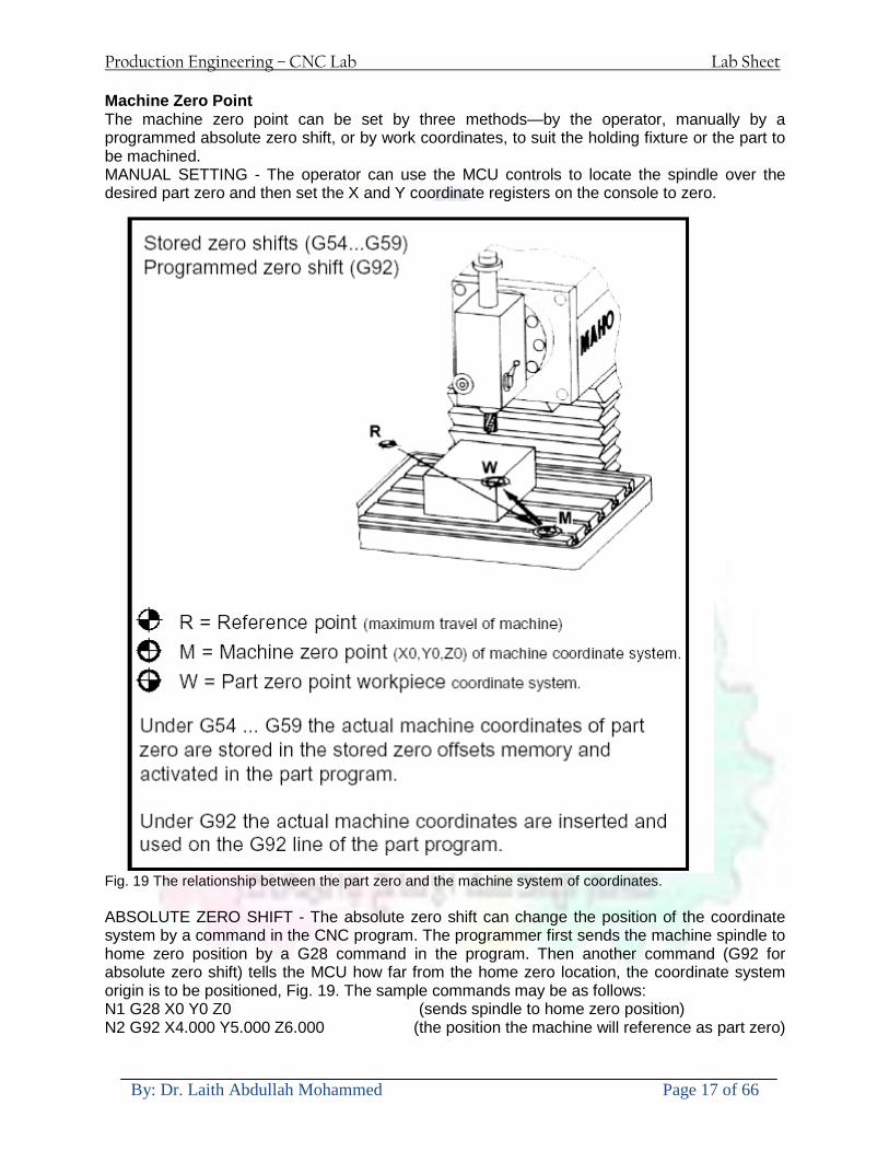
Production Engineering ndash CNC Lab Lab Sheet
By Dr Laith Abdullah Mohammed Page 17 of 66
Machine Zero Point The machine zero point can be set by three methodsmdashby the operator manually by a programmed absolute zero shift or by work coordinates to suit the holding fixture or the part to be machined MANUAL SETTING - The operator can use the MCU controls to locate the spindle over the desired part zero and then set the X and Y coordinate registers on the console to zero
Fig 19 The relationship between the part zero and the machine system of coordinates ABSOLUTE ZERO SHIFT - The absolute zero shift can change the position of the coordinate system by a command in the CNC program The programmer first sends the machine spindle to home zero position by a G28 command in the program Then another command (G92 for absolute zero shift) tells the MCU how far from the home zero location the coordinate system origin is to be positioned Fig 19 The sample commands may be as follows N1 G28 X0 Y0 Z0 (sends spindle to home zero position) N2 G92 X4000 Y5000 Z6000 (the position the machine will reference as part zero)
Production Engineering ndash CNC Lab Lab Sheet
By Dr Laith Abdullah Mohammed Page 18 of 66
Work Settings and Offsets All CNC machine tools require some form of work setting tool setting and offsets (compensation) to place the cutter and work in the proper relationship Compensation allows the programmer to make adjustments for unexpected tooling and setup conditions
Work Coordinates In absolute positioning work coordinates are generally set on one edge or corner of a part and all programming is generally taken from this position In Fig 20 the part zero is used for all positioning for hole locations 1 2 and 3
Fig 20 In absolute programming all dimensions must be taken from the XY zero at the top left-hand corner of the part
Fig 21 In incremental programming all dimensions are taken from the previous point In incremental positioning the work coordinates change because each location is the zero point for the move to the next location Fig 21
Production Engineering ndash CNC Lab Lab Sheet
By Dr Laith Abdullah Mohammed Page 19 of 66
On some parts it may be desirable to change from absolute to incremental or vice versa at certain points in the job Inserting the G90 (absolute) or the G91 (incremental) command into the program at the point where the change is to be made can do this
R Plane or Gage Height The word-address letter R refers to a partial retraction point in the Z axis to which the end of the cutter retracts above the work surface to allow safe table movement in the X Y axes It is often called the rapid-traverse distance gage height retract or work plane The R distance is a specific height or distance above the work surface and is generally 100 in above the highest surface of the workpiece Fig 22 which is also known as gage height Some manufacturers build a gage height distance of 100 in into the MCU (machine control unit) and whenever the feed motion in the Z axis is called for 100 in will automatically be added to the depth programmed When setting up cutting tools the operator generally places a 100 in thick gage on top of the highest surface of the workpiece Each tool is lowered until it just touches the gage surface and then its length is recorded on the tool list Once the gage height has been set it is not generally necessary to add the 100 in to any future depth dimensions since most MCUs do this automatically
Fig 22 Using a 100 in gage block to set the gage height or R0 on the work surface
Cutter Diameter Compensation Cutter diameter compensation (CDC) changes a milling cutterrsquos programmed centerline path to compensate for small differences in cutter diameter On most MCUs it is effective for most cuts made using either linear or circular interpolation in the X-Y axis but does not affect the programmed Z-axis moves Usually compensation is in increments of 0001 in up to +10000 in and usually most controls have as many CDCs available as there are tool pockets in the tool storage matrix The advantage of the CDC feature is that it 1 Allows the use of cutters that have been sharpened to a smaller diameter 2 Permits the use of a larger or smaller tool already in the machinersquos storage matrix 3 Allows backing the tool away when roughing cuts are required due to excessive material present 4 Permits compensation for unexpected tool or part deflection if the deflection is constant throughout the programmed path The basic reference point of the machine tool is never at the cutting edge of a milling cutter but at some point on its periphery If a 1000 in diameter end mill is used to machine the edges of a workpiece the programmer would have to keep a 500 in offset from the work surface in order to cut the edges accurately Fig 23 The 500 offset represents the distance from the centerline of the cutter or machine spindle to the edge of the part Whenever a part is being machined the programmer must calculate an offset path which is usually half the cutter diameter
Production Engineering ndash CNC Lab Lab Sheet
By Dr Laith Abdullah Mohammed Page 20 of 66
Fig 23 Cutter-diameter compensation must be used when machining with various size cutters Modern MCUs which have part surface programming automatically calculate centerline offsets once the diameter of the cutter for each operation is programmed Many MCUs have operator-entry capabilities which can compensate for differences in cutter diameters therefore an oversize cutter or one that has been sharpened can be used as long as the compensation value for oversize or undersize cutters is entered
Production Engineering ndash CNC Lab Lab Sheet
By Dr Laith Abdullah Mohammed Page 21 of 66
CNC Programming Hints - MILLING
Production Engineering ndash CNC Lab Lab Sheet
By Dr Laith Abdullah Mohammed Page 22 of 66
CNC Programming Hints ndash TURNING
Production Engineering ndash CNC Lab Lab Sheet
By Dr Laith Abdullah Mohammed Page 23 of 66
CNC
The abbreviation CNC stands for Computer(ized) Numerical(ly) Control(led) and refers specifically to the computer control of machine tools for the purpose of (repeatedly) manufacturing complex parts in metal as well as other materials using a program written in a notation conforming to the EIA-274-D standard and commonly called G-code
CNC was developed in the late 1940s and early 1950s by the MIT Servomechanisms Laboratory CNC machines were relatively briefly preceded by the less advanced NC or Numerical(ly) Control(led) machines The introduction of CNC machines radically changed the manufacturing industry Curves are as easy to cut as straight lines complex 3-D structures are relatively easy to produce and the number of machining steps that required human action have been dramatically reduced With the increased automation of manufacturing processes with CNC machining considerable improvements in consistency and quality have been achieved CNC automation reduced the frequency of errors and provided CNC operators with time to perform additional tasks
CNC automation also allows for more flexibility in the way parts are held in the manufacturing process and the time required to change the machine to produce different components In a production environment a series of CNC machines may be combined into one station commonly called a cell to progressively machine a part requiring several operations CNC machines today are controlled directly from files created by CAM software packages so that a part or assembly can go directly from design to manufacturing without the need of producing a drafted paper drawing of the manufactured component In a sense the CNC machines represent a special segment of industrial robot systems as they are programmable to perform many kinds of machining operations (within their designed physical limits like other robotic systems)
G-code
G-code is a common name for the programming language that is used for NC and CNC machine tools It is defined in EIA RS-274-D G-code is also the name of any word in a CNC program that begins with the letter G and generally is a code telling the machine tool what type of action to perform such as
bull rapid move bull controlled feed move in straight line or arc bull series of controlled feed moves that would result in a hole being drilled bull change a pallet bull Set tool information such as offset
There are other codes the type codes can be thought of like registers in a computer
X position Y position Z position M code (another action register) F feed rate S spindle speed N line number R Radius T Tool selection
Production Engineering ndash CNC Lab Lab Sheet
By Dr Laith Abdullah Mohammed Page 24 of 66
I Arc data X axis J Arc data Y axis
G-code files are output by CAM software such as Smartcam Gibbscam Featurecam Edgecam Mastercam etc G-code is also output by specialized CAD systems used to design printed circuit boards Such software must be customized for each type of machine tool that it will be used to program
Production Engineering ndash CNC Lab Lab Sheet
By Dr Laith Abdullah Mohammed Page 25 of 66
U 2عمل األزرار الرئيسية في ماكنة الخراطة المبرمجة (نصر (
1- SINGLE BLOCK للتأكد من صحة البرنامج (تنفيذ البرنامج خطوة خطوةب تقوم( 2- BLOCK DELETE بجانب ويعمل من األوامرلغاء بلوك معين أليستخدم 3- MACHINE LOCK العمل يستخدم لقفل حركة المحاور الرئيسية مع استمرار البرنامج في
)وهذا مهم للتاكد من صحة البرنامج قبل عملية التنفيذ النهائي(4- CONT CYCLE عملية التشغيل عند ايقافها الي سبب كان او عند ايقافها ألستئناف ستخدم ت
) BAR FEEDER(او في حالة استخدام ) FEED HOLDبسبب (5- DRY RUN وتستخدم لفحص البرنامج بعد ازالة الشغلة حركة سريعة للبرنامج 6- TURRET UP amp DOWN ) حركة حامل العدة TURRET الذي يحمل مجموعة من (
وهذا الزر يعمل مع الزر عكس عقرب الساعة او مع عقرب الساعة ةحركة دوراني العدد )SAFTY (
7- COOLANT ON or OFFفه تشغيل سائل التبريد او ايقا 8- COOLANT AUTO الدوال المساعدة في البرنامج من خالل فه تشغيل سائل التبريد او ايقا 9 -MACHINE START ة لتشغيل هيدرولكيك الماكنميستخد
Production Engineering ndash CNC Lab Lab Sheet
By Dr Laith Abdullah Mohammed Page 26 of 66
10- CLOSE OR OPEN CHUCKالعينة تستخدم لفتح وغلق 11 -T STOCK FWD RET حركة الغراب المتحرك ذهابا وإيابا12 -SPINDLE STOP تعمل على ايقاف حركة دوران العينة 13-JOG SPINDLE تعمل على تدوير العينة مع زر SAFTY 14 -OPT SAFTY مع الدالة ( تعمل عمل التوقف المشروط حيث تعملM1 دالة التوقف (
ط ) فقط األ اذا كان هذا الزر مضغو M1المشروط حيث ال يتوقف البرنامج في حالة وجود دالة ( SAFTY + SPINDLE ) يتم الضغط على زر ( START CYCLEلغرض تحرير زر (
START ) في نفس الوقت بعد الضغط على زر ( START CYCLE مرتين (
NC PC- 15 يستخدم هذا الزر عند ربطCNC يستخدم لنقل المعلومات ث مع جهاز أخر حي بينهما
16 -CALCU زر الخاص بالحاسبة مع زر ( ال وهوINPUT ( 17 - HD1 HD2 يستخدم الختيار العدة مع المخرطة ذات المحاور األربعة 18 - START تستخدم لبدء عملية التشغيل
Production Engineering ndash CNC Lab Lab Sheet
By Dr Laith Abdullah Mohammed Page 27 of 66
19- FEED HOLD تعمل على إيقاف عمل أي G موجودة مع بقاء العينة متحركة 20- M D I أو تشغيل البرنامج ل يتم استخدامه لإلدخا BLOCK BY BLOCK وتعمل عند
إدخال البرنامج بواسطة الشريط المثقب أو أي وسيلة إدخال أخرى أو في عمليات التصفير
21- REST تستخدم العادة تشغيل الماكنة أو مسح اإلنذار الذي يظهر على الشاشة 22- EMERGENCYتستخدم عادة اليقاف الماكنة في حالة الطوارئ فقط
OPERATION MENU KEY
CHAPTER PRG-CMK
OFFSET PROGRAM POSITION FUNCTION MENU KEY
23- POSITIONعلى الشاشة د الموقع الموجور الظها 24- PROGRAMإلظهار برنامج معين واختياره 25- OFFSET الختيار سماحات العدة أو سماحات نقطة المرجع 26- PRG- CHK تستخدم لفحص البرنامج على الشاشة 27- SETTING ألختيار الثوابت على الشاشة 28- SERVICE تستخدم ألستخراج المعامالت والثوابت 29- MESSAGE تستخدم ألظهار األخطاء الناتجة عن البرنامج او اخطاء التشغيل 30- OVERALL ألختيار المواقع 31- RELATIVE MODLINE تعوض عن POSITION 32- DIR MEM يستخدم ألظهار ملف البرامج المخزونة في الذاكرة وعندما نضغط هذا الزر
فان رقم واسم البرنامج سوف يظهر على الشاشة
2أدناه الشفرات الرئيسية التي تعمل على الماكنة المبرمجة نصر
G-CODE DESCRIPTION
G00 Rapid traverse (linear)
G01 Linear Interpolation at feed rate
G02 Circular interpolation (CW) R+
G03 Circular interpolation (CCW) R+
G10 Zero point tools
G20 Imperial data input
G21 Metric data input
G27 Reference return check
G28 Reference return
G29 Return from reference
Production Engineering ndash CNC Lab Lab Sheet
By Dr Laith Abdullah Mohammed Page 28 of 66
G33 Thread cutting
G40 Cancel cutter radius compensation
G41 Cutter compensation left
G42 Cutter compensation right
G54 Work co-ordinate system no1
G70 Finishing cycle
G71 Stock removal turning
G72 Stock removal facing
G74 Face grooving
G75 Diameter grooving
G76 Threading cycle
G90 Absolute date input
G91 Incremental data input
G94 Feed minute mode
G95 Feed rev mode
G96 Constant surface speed mode
G97 Cancel Constant surface speed
) 2أدناه الشفرات الثانوية التي تعمل على الماكنة المبرمجة (نصر
M-code FUNCTION
M00 Program stop
M03 Spindle forward (Tool forward ndash M94 mode)
M04 Spindle reverse (Tool forward ndash M94 mode)
M05 Spindle stop (Tool stop ndash M94 mode)
M08 Coolant on
M09 Coolant off
M30 Program end (with rewind)
M48 Turret shortest path
M52 Turret direction up (CW)
M53 Turret direction down (CCW)
M73 Chuck open
M74 Chuck close
Production Engineering ndash CNC Lab Lab Sheet
By Dr Laith Abdullah Mohammed Page 29 of 66
) وكل جملة مكونة من مجموعة من الكلمات blockإن كل برنامج يتكون من مجموعة من الجمل ()words) لهذا فأن الشفرات الرئيسية والمساعدة هي عبارة عن كلمات (words كما في المثال التالي (
G_ _ P1 Q2 U_ _ W_ _ D___ F_ _
)end of block) ويعني ( ) يكتب الرمز (blockتسلسل الكلمات مهم جدا بعد نهاية كل جملة (
طريقة ادخال البيانات الى الماكنة ــــــــــــــــــــــــــــــــــــــــــــــــــ
) MDIيمكن ادخال البيانات الى الماكنة بعدة طرق فقد يكون األدخال عن طريق قناة السيطرة ( MANUAL DATA INPUT ) او عن طريق قناة األضافة EDIT كما يمكن ادخال البيانات عن (
) RS ndash 232 COMMUNICATIN LINKطريق استخدام سلسلة الربط (
₤⅗₌⅗₌ ⅙₌₨image₍₡ ₤₌ℌ⅗₌ Ⅸ⅗ⅥⅯ₌ ₤₡ℌ₰₨⅗₌G71
الخراطة الطولية G71الغرض من التجربة عمل نموذج للخراطة بأستخدام الدالة تستعمل هذه الدالة للخراطة الطولية اي على طول محور المشغولة وكما هو موضح بالشكل ادناه
تعتبر هذه الدالة من الدوال التي ال تحتاج الى تكرار او إعادة كتابتها أي انها دالة تكرارية بمعنى ان اي
الذي هي دالة حركة G01خطوة تكون من ضمن هذه الدالة سوف تكرر العملية اي عند استعمال امر مثل خطية تتضمن القطع مع التغذية مع اعطاء القطر المراد قطعه و مراعاة عمق القطع المعطى سوف يتكرر
هذه االمر وصوال الى العمق المطلوب وهكذا لبقية الدوال
G71 المستخدمة للدالة الصيغة
G71 P1 Q2 U___ W___ D___ F___ حيث إن
P1 بداية الخطوة االولى = Q2 نهاية الخطوة =
Uوضع السماحات بأتجاه محور = X W وضع السماحات بأتجاه محور = Z وتكاد تكون مهملة وتوضع اشارة سالب Dعمق القطع وتوضع رقم صحيح مثل = D500 اي نصف ملمF التغذية والتي لها عالقة بالدالة = G95
Production Engineering ndash CNC Lab Lab Sheet
By Dr Laith Abdullah Mohammed Page 30 of 66
G71الدالة استخدام مثال على
T0100 M48 G0 X26 Z2 M08 T0101 G90 G95 G97 S500 M03 G71 P1 Q2 U03 W00 D500 F01 N1 G0 G42 X00 G01 Z00 G01 X2517 G01 Z-5352 G01 X7391 Z-9366 G01 Z-19145 N2 G28 M30
الجانب العملي
االجهزة واالدوات المستخدمة CNCماكنة خراطة مبرمجة 1 ملم 80قضيب من االلمنيوم قطر 2 ةفير ني 3 جاه أيمن تهولدر كاربيدي ذوا 4
طريقة العمل يتم تثبيت قضيب من االلمنيوم على العينة التابعة للماكنة مع مراعاة الطول المراد استعماله في عملية 1
الخراطة ) turretتثبيت عدة القطع في المكان الصحيح في ( 2
Production Engineering ndash CNC Lab Lab Sheet
By Dr Laith Abdullah Mohammed Page 31 of 66
بالنسبة الى القطعة المثبتة على العينة XZيتم تصفير الماكنة للمحاور 3 تصفير للمحورZ تكون مالمسة العدة الى وجه الشغلة تصفير للمحورX تكون مالمسة العدة الى سطح الشغلة الموازي لمحور X
يتم كتابة البرنامج أما بطريقة يدوية أو بالحاسوب مع وضع كل الظروف الالزمة للتشغيل ( عمق القطع 4 التغذية السرعة المطلوبة نوع المعدن )
ادخال البرنامج الى الحاسوب الموجود داخل الماكنة مع تهيئة الماكنة للتشغيل 5
المطلوب G71عمل برنامج يدوي على الدالة 1 رسم الشكل الشكل النهائي المطلوب مع وضع األبعاد 2
Ⅺ⅟₍euro⅗₌ ₤₡ℌ₰₨⅗₌₣ ₤⅗₌⅗₌ ⅙₌₨image₃₡ Ⅺℂtradeℒ⅗₌ ӈ₍Ⅴ⅟ⅳ₌ G70
G70 الغرض من التجربة عمل انهاء سطحي للمشغولة بواسطة الدالة
من الضروري إعطاء G71هذه الدالة تعمل شوط واحد فقط وتكون معتمدة على عمليات القطع في الدالة اللغاء مقدمة االداة (أي لكي تتم عملية االنهاء السطحي بدون حسابات نصف قطر مقدمة االداة ) G42دالة
G70الصيغة المستخدمة للدالة
G70 P1 Q2 F___ حيث ان
P1 بداية الخطوة االولى = Q2 نهاية الخطوة =
F التغذية والمرتبطة بالدالة = G95
وذلك ألن دالة االنهاء السطحي تحقق X Zمالحظة الدالة التحتاج لكتابة السماحات التابعة للمحورين المسافات الحقيقة المراد انتاجها للمشغولة
G71و G70مثال على الدالة
T0100 M48 G0 X26 Z2 M08 T0101 G90 G95 G97 S500 M03 G71 P1 Q2 U03 W00 D500 F01 N1 G0 G42 X00 G01 Z00 G01 X2517 G01 Z-5352 G01 X7391 Z-9366 G01 Z-19145 N2 G97 S750 MO3
Production Engineering ndash CNC Lab Lab Sheet
By Dr Laith Abdullah Mohammed Page 32 of 66
G70 P1 Q2 G40 F009 G28 M30
الجانب العملي الحظ التجربة األولى
المطلوب
G70 عمل برنامج يدوي على الدالة 1 رسم الشكل النهائي المطلوب مع وضع االبعاد 2
₪⅗₍euro⅗₌ ₤₡ℌ₰₨⅗₌₣ ₤⅗₌⅗₌ ⅙₌₨image₍₡ ⅝₍ⅠimageⅯ₌ ⅞ⅫⅦ⅔₧ G76
G76 للمشغولة بواسطة الدالةةالغرض من التجربة عمل أسنان خارجية أو داخلي
في هذه التجربة سوف نقوم بعمل األسنان الخارجية وهنا تكون حركة العينة ثابتة وهذا ضروري بسبب أن ) تكون متصلتين الكترونيا وعليه أي اختالف في سرعة العينة تؤدي إلى اختالف motionالعينة والحركة(
) servoفي سرعة الخدمة(يرتبط اتجاه تكوين األسنان باتجاه دوران العينة مثال إذا كانت األسنان ذات اتجاه أيمن يكون اتجاه دوران
وهنا نقلب العدة إلى االسفل وكما هو موضح بالشكل أدناه MO3العينة عكس عقرب الساعة أي نستعمل
Production Engineering ndash CNC Lab Lab Sheet
By Dr Laith Abdullah Mohammed Page 33 of 66
الخطوة هي عبارة عن المسافة ما بين قمة سن إلى قمة سن أخر عمق السن هو العمق المطلوب تكوينه لألسنان
G76 الصيغة المستخدمة للدالة
G76 X___ Z___ K___ F___ D___ A___
حيث أن X القطر الداخلي للسن =Z طول السن =K عمق السن وتستخرج من المعادلة التالية =K=065F F الخطوة =D عمق القطع بالمايكرون فقط =A زاوية السن =
G76مثال على استخدام الدالة T0300 M48 GOO X30 Z4 T0303 M08 G97 S500 MO3 G76 X28375 Z-20 K08125 F125 D120 G00 X40 Z4 G28 M30
Production Engineering ndash CNC Lab Lab Sheet
By Dr Laith Abdullah Mohammed Page 34 of 66
الجانب العملي الحظ التجربة األولى
المطلوب
G76عمل برنامج يدوي على الدالة 1 رسم الشكل النهائي المطلوب مع وضع األبعاد 2
Ⅺ⅘₌⅗₌ Ⅵ₂ Ⅺ₯ℋ₍⅗₌ ℌℲℂ⅗₌ ⅞ⅫⅦ⅔₧ ₤K₡₌ℌ⅗₌ ₤₡ℌ₰₨⅗₌)Groove ₤⅗₌⅗₌ ₤tradeimage₌Ⅶ₡ (G75
G75 بواسطة الدالة grooveالغرض من التجربة تكوين
) للمشغولة وتعتمد شكل الحفر على طريقة grooveتستعمل هذه الدالة لتكوين الحفر الخارجي والداخلي (
التشغيل وعلى الشكل المراد إنتاجه وتعتبر هذه الطريقة من عمليات التشكيل للمعدن إن هذه الدالة هي دالة مالحظة مع G75في هذه التجربة سنقوم بعمل الحفر الخارجي بواسطة الدالة
تكرارية وغير تكرارية حسب نوع التشغيل
G 75 الصيغة المستخدمة للدالةG75 X___ Z___ I___ K____
حيث أن
X العمق النهائي لقطر الشغلة =Z عرض الحفر =I الدخول في كل مرة =
K التزحيف على محور =z بالنسبة للعدة
Production Engineering ndash CNC Lab Lab Sheet
By Dr Laith Abdullah Mohammed Page 35 of 66
G75مثال على استخدام الدالة
T0500 M48 GOO X100 Z -20 T0505 M08 G97 S700 MO3 G75 X84 Z -38 I 05 K4
الجانب العملي الحظ التجربة األولى
المطلوب
G76عمل برنامج يدوي على الدالة 1 رسم الشكل النهائي المطلوب مع وضع األبعاد 2
Production Engineering ndash CNC Lab Lab Sheet
By Dr Laith Abdullah Mohammed Page 36 of 66
CNC Milling Machine Mechanical Construction
Guideways The guideways of CNC machines are made of steel To reduce the frictional forces they are coated with a strip of PTFE (Poly Tetra Fluoro Ethylene)
Ballscrews On conventional lathes a leadscrew is used to converts the rotary motion of the hand wheel into linear motion of the slides Leadscrews have a high coefficient of friction and backlash On CNC machines a ballscrew is used instead of a leadscrew Friction and backlash are much less than on leadscrews
Guideway
Production Engineering ndash CNC Lab Lab Sheet
By Dr Laith Abdullah Mohammed Page 37 of 66
bullMachining operations Direction of cutting Based on the direction of the cutter rotation and work piece feed milling operations are classified into two types 1-Up milling (Convention milling) In up milling the metal is removed by rotating the cutter against the direction of travel of the part
Feed
Machine table
Part
Cutting tool
Chip thickness at theexit of the tooth
2-Down milling (Climb milling) In climb milling the metal is removed by rotating the cutter with the direction of travel of the part
Machine table
Part
Cutting tool
Chip thickness at theentrance of the tooth
Production Engineering ndash CNC Lab Lab Sheet
By Dr Laith Abdullah Mohammed Page 38 of 66
bullTooling Tool geometry The geometry of the tool tip affects the way that the metal cutting is performed The nose radius rake angles relief angles etc must be selected with care
Radial relief
Radial rake
Axial relief
Approach angle
Axial relief
Corner radius Face mill Face milling cutters are used to mill flat surfaces Commonly used face milling cutters Cutter with 75 degree approach
75 deg
Cutter with 90 degree approach (Square shoulder face mill)
90 deg
Cutter with 45 degree approach
Production Engineering ndash CNC Lab Lab Sheet
By Dr Laith Abdullah Mohammed Page 39 of 66
bullCNC Programming Axes convention The Z axis is along the spindle axis The X and Y axes are perpendicular to Z VMC
Z
Y
-
+
-+
X- +
+Z
-Z
+Y
-Y
-X +X
Part
Machine table
X
YZ
G00 Rapid traverse When the tool being positioned at a point preparatory to a cutting motion to save time it is moved along a straight line at Rapid traverse at a fixed traverse rate which is pre-programmed into the machines control system Typical rapid traverse rates are 10 to 25 m min but can be as high as 80 mmin
Production Engineering ndash CNC Lab Lab Sheet
By Dr Laith Abdullah Mohammed Page 40 of 66
Format N_ G00 X__ Y__Z__
G01 Linear interpolation (feed traverse) The tool moves along a straight line in one or two axis simultaneously at a programmed linear speed the feed rate Format N__ G01 X__ Y__Z__ F__
Part
Feed
Part
Feed
G02G03 Circular interpolation The tool moves along an arc in two axes simultaneously at a programmed linear speed the feed rate
Production Engineering ndash CNC Lab Lab Sheet
By Dr Laith Abdullah Mohammed Page 41 of 66
Format N__ G0203 X__ Y__Z__ I__ J__K__ F__ using the arc center OR N__ G0203 X__ Y__Z__ R__ F__ using the arc radius G02 moves along a CW arc G03 moves along a CCW arc Arc center The arc center is specified by addresses I J and K I J and K are the X Y and Z co-ordinates of the arc center with reference to the arc start point
X
Y
Arc center
Arc endArc start
- J
- I
I = X coord of center - X coord of start point J = Y coord of center - Y coord of start point K = Z coord of center - Z coord of start point I J and K must be written with their signs
Production Engineering ndash CNC Lab Lab Sheet
By Dr Laith Abdullah Mohammed Page 42 of 66
bullWork holding
Rotary table
Fixture base
Component
Clamp
Stud
Fixtures The use of fixtures 1 Improves repeatability of dimensions 2 Improves working conditions 3 Cuts down requirement of skilled labour 4 Reduces part loading and unloading time 5 Improves safety in the working area 6 Reduces the cost of machining There are two types fixtures commonly used 1 Special fixture Special fixtures are used to hold and locate the typical components which are having complex shape and to be located with the reference hole (dowel hole) Special fixtures are required for components like gear case cover cylinder heads etc 2 Modular fixture Modular fixture is a set different kind of clamping and locating elements These fixtures are used to hold identical components in different sizes and components of box type Example Manifolds head stocks connecting rods and flanges
Production Engineering ndash CNC Lab Lab Sheet
By Dr Laith Abdullah Mohammed Page 43 of 66
bullMachine setting
Determining X and Y work zero offset Case 1
Part
Machine table
Part
End mill or reamer
Work offset X0Y0 For determining X work zero offset bull Touch the periphery of the end mill or reamer to the part bull Enter current machine X value + cutter radius as X work zero offset For determining Y work zero offset bull Touch the periphery of the end mill or reamer to the part bull Enter current machine Y value - cutter radius as Y work zero offset Case 2
Part
Machine table
Part
End mill or reamerWork offset X0Y0
bull Mount the dial indicator on machine spindle true the bore bull Enter current machine X and Y value as X and Y work zero offset
Production Engineering ndash CNC Lab Lab Sheet
By Dr Laith Abdullah Mohammed Page 44 of 66
How to Select a Cutting Fluid
One part of the metal cutting equation that is sometimes overlooked however is
the choice of an appropriate cutting fluid With todayrsquos system approach to metal
cutting use of the right metalworking fluid has become just as much a part of the
solution as the other elements In fact at least one company is now integrating
cutting fluids and cutting tools into effective metal cutting systems Following are
some things to consider when choosing your next cutting fluid
The Four Key Questions
There are four vital pieces of information that are necessary when choosing a
cutting fluid They are
1 What are you cutting
2 What is the chemistry of your water
3 What are you using now
4 What are your options
5 What do you prefer
What Are You Cutting
The first question ndash ldquoWhat are you cuttingrdquo ndash is often the most difficult to answer
because most shops handle a variety of workpiece materials on a regular basis If
the answer is an unequivocal ldquoaluminumrdquo or ldquostainless steelrdquo or ldquocast ironrdquo the
selection of a cutting fluid can be quite simple and straightforward Unfortunately
that is seldom the case in anything but a high-volume plant Where aluminum or
other nonferrous metals are a significant part of the mix a non-staining cutting
fluid is a must Generally speaking this will be a semi-synthetic with special
ingredients to prevent bi-metallic corrosion and staining of non-ferrous workpieces
Where the ferrous metals predominate however a more general purpose semi-
synthetic or hybrid fluid might be a more economical choice
Production Engineering ndash CNC Lab Lab Sheet
By Dr Laith Abdullah Mohammed Page 45 of 66
What is The Chemistry of Your Water
The second question ndash ldquoWhat is the chemistry of your waterrdquo ndash is probably the
single most common reason for the success or failure of a cutting fluid Very few
plants invest the money necessary to install effective water purification systems
using deionization or reverse osmosis technology Unfortunately the chemicals
present or not present in the water used to re-constitute a cutting fluid make a
tremendous difference in its performance and sump life Most manufacturers of
cutting fluids will perform the necessary water testing to determine exactly what
minerals are dissolved in your water and make a fluid recommendation based on
the results
What are you using now
The third question ndash ldquoWhat are you using nowrdquo ndash helps narrow the range of
choices When coupled with an objective analysis of the strengths and weaknesses
of the current fluid the answer to this question can quickly point you toward a
relatively small number of competitive alternatives that have the attributes required
to meet your cutting needs Many cutting fluids are in use today simply because
they were in use yesterday It is a hard reality of todayrsquos marketplace that if one
isnrsquot constantly striving to improve they will certainly be overtaken by a
competitor who is
What Are Your Options
The fourth question ndash ldquoWhat are your optionsrdquo ndash leads to the final selection of a
cutting fluid Cutting fluids can be divided into four general groups based on their
chemistry
They are
bull Soluble Oils ndash quite literally oil dispersed in water
bull Synthetics ndash completely oil free man-made coolants in solution
Production Engineering ndash CNC Lab Lab Sheet
By Dr Laith Abdullah Mohammed Page 46 of 66
bull Semi-Synthetics ndash a mixture of natural and synthetic lubricants with up to 30
mineral oil
bull Hybrids ndash a special class of semi-synthetics with a mineral oil content of about
15 Each fluid type has advantages and disadvantages which make it suitable for
a particular group of applications In addition there are costperformance trade-
offs to be made between the groups within a specific set of applications For
example where a hybrid and a semi-synthetic may both be suitable for a particular
use the hybrid might provide longer sump life at a slightly higher initial cost
while some semi synthetics may be more economical to recycle or dispose of while
not giving as long a tank life The final decision in this case would have to be made
on the detailed economics of the shop where the fluids were to be used and on the
ownerrsquos individual preferences
Soluble Oils
Soluble oils are oils that disperse in water when emulsifiers are added They are
generally suitable for moderate-to heavy-duty machining and grinding of all non-
ferrous metals carbon and cast steels and in applications where dissimilar metals
such as aluminium and steel are present They can also be used in turning drilling
tapping reaming gear cutting broaching as well as internal and centerless types
of grinding operations Soluble oils provide excellent aluminium and copper
corrosion control good rancidity control which extends fluid for long lasting
trouble-free performance and good concentrate and mix stability making it ideal
for mixing in water with a minimal amount of agitation An example of this is
Valenitersquos VNTreg-650 premium heavy-duty soluble oil
Synthetics
Synthetics are completely oil free solutions made of polymers organic and
inorganic materials that are mixed with water These clear low foaming and bio-
Production Engineering ndash CNC Lab Lab Sheet
By Dr Laith Abdullah Mohammed Page 47 of 66
stable coolants are ideal for machining and grinding of ferrous materials carbon
steels or cast iron Their complex lubricant packages make synthetics well-suited
for tough-to-machine materials such as stainless steels and high-temperature alloys
Certain synthetics are specifically designed to address the primary failure modes of
flank wear and nose wear Although there are many benefits some synthetics may
cause staining of non-ferrous materials
Semi-Synthetics
Semi-synthetic fluids are a mixture of oils synthetic emulsifiers and water They
were primarily developed for the aircraft nuclear and related industries
Consequently they work extremely well on all non-ferrous metals such as titanium
aluminium copper brass bronze and stainless steel in both machining and
grinding Semi-synthetics can be used on ferrous metals too They are chlorine-
free to reduce bi-metallic corrosion and staining of metals They should be used at
a 5-8 dilution with water depending on the severity of the operation
Hybrids
Hybrids are cutting fluids custom engineered to solve a particular problem For
example Valenitersquos VNTreg-800 was developed to be very clean in the machining
and grinding of cast iron It provides better stability in hard water and rejects tramp
oil very well which adds to its bio-stable chemistry Hybrids work extremely well
on all metals in both machining and grinding They should be mixed at a 5-7
dilution with water depending on the condition of the water
What Do You Prefer
The final question ndash ldquoWhat do you preferrdquo ndash is usually the ldquotie breakerrdquo where
there is more than one appropriate cutting fluid available Here again as in the
case of what is being used now the key is to examine your preferences objectively
Production Engineering ndash CNC Lab Lab Sheet
By Dr Laith Abdullah Mohammed Page 48 of 66
and specifically to identify the real reasons behind a preference If you cannot
point to specific reasons why one class of cutting fluid is preferred over another
you are well advised to follow the recommendations of the professional who has
analyzed your requirements Choosing the right fluid today is easier than ever as
the system approach to metal cutting productivity continues to grow in acceptance
The day is not far off when choosing a complete solution will be as easy as
choosing the right insert and chip breaker today The answers are available and the
results will more than justify the time you spend choosing the right metal cutting
fluid
Useful Links wwwball-screwsnet
wwwlubelinkcom
wwwmachinerylubricationcom
wwwadvancedmanufacturingcom
wwwmmsonlinecom
wwwcuttingtoolengineeringcom
wwwgeartechnologycom
wwwengineersedgecom
wwwagmaorg
wwwefundacom
wwwsaeorg
wwwsmeorg
wwwastmorg
wwwissorg
wwwmachinetoolscom
wwwansiorg
wwwasmeorg
wwwcnccicom
wwwmatlscom
wwwthefreedictionarycom
wwwengineersupplycom
Production Engineering ndash CNC Lab Lab Sheet
By Dr Laith Abdullah Mohammed Page 49 of 66
SurfCAM Tutorial ndash Beginning with the basics
Background SurfCAM is a computer aided manufacturing (CAM) software which allows you to create manage and modify tool paths for computer aided designed (CAD) part The software requires a CAD model or requires that you create some geometry within SurfCAM with some rudimentary tools provided The tool paths are created or stored internally in SurfCAM in a generic programming language called APT Once the tool paths are created the APT paths are translated using a post processor into typical machine G-code
Opening SurfCAM SurfCAM can be opened from the Novell Applications Launcher on most Industrial Engineering computer labs workstations Search under lsquoallrsquo applications and double click on SurfCAM 2005 Once the program opens a license must be selected from the list (not the Demo license) to enable saving the file later Choose one of the 30 licenses available If for some reason the licenses are not listed on the license manager form select server list and type ldquobonnieeosncsuedurdquo A list of available licenses should appear Select a license and click OK After the license is selected an Add StockFixture form (Figure 1) opens allows you to add a model which represents the pre-machined stock or a fixture Click on OK without adding either Both of these items can be added later under a more appropriate dialog
Figure 1 Add Stock or Fixture dialog box
Production Engineering ndash CNC Lab Lab Sheet
By Dr Laith Abdullah Mohammed Page 50 of 66
SurfCAM Interface
Figure 2 SurfCAM Windows based interface
SurfCAM is a windows based software system so most of the typical windows functions under File are applicable This is where you can open save exit print etc The Create menu allows the user to create different geometry forms Here you can create a point line surface chamfer circle and many other geometry types For the most part these functions are not used by beginners but are useful when creating bounding curves where you donrsquot want the tool to move outside (constraining the tool) The Edit menu allows you to change or modify many different entities such as changing lines altering surfaces joining surfaces trimming or breaking elements add control points etc Again these features are helpful to advanced users and are not covered in detail in this tutorial The Display menu offers the ability to change the orientation of the part on the screen The typical rotate pan fit to screen and zoom functions are available as well as several functions which allow the user to shift between views or call up a named view (ie top bottom etc) The NC menu is the main machining interface menu In this menu you select the general form of machining (2 axis 3 axis 4 axis 5 axis turning etc) and under the general form a more specific machining function is selected This menu is the most used and the options contained must be fully understood to get the most out of SurfCAM Each function will be described in some detail in a further chapter The Analyze menu contains options such as measuring the distance between points angles tangency elements etc These functions are auxiliary functions meant to help you understand the part better but basically provide no functionality for making tool paths for CNC machines Thus these will not be covered The Tools menu allows the user to change the system options modify keyboard shortcuts change the model units etc These options are again not used by beginners Finally the Help menu provides access to the online users manual In lieu of clicking the Help menu the F1 key is the shortcut key for help (as it is in most windows based programs)
Importing a CAD model Importing a CAD model that is stored locally is done by selecting File-gtOpen On the Files of type dropdown box choose the type of file you wish to open (Figure 3) Do this prior to negotiating your way through the maze of folders to prevent having to go through the folder tree again Once the file type is selected find the file you are trying to open and click the Open
Production Engineering ndash CNC Lab Lab Sheet
By Dr Laith Abdullah Mohammed Page 51 of 66
button SurfCAM will then attempt to read the file you have selected SurfCAM may provide a dialog box describing what it has imported and identify if it was successful If this dialog is provided simply click close without saving
Figure 3 Open Dialog Note - Change type of file prior to finding the file you wish to open
SurfCAM allows a user to import several different types of CAD files the most common types which you will likely import are SolidWorks part files (sldprt or prt) AutoCAD files(dxf) or IGES (igs or iges) Native file import (such as is the case with SolidWorks) provides the greatest information transfer and generic file imports (such as is the case with IGES) provide the least Normally it is to the advantage of the user to use native file importing procedures when available Recently (2005) SurfCAM added some compatibility with SolidWorks This allows the user to create tool paths for a part and if an engineering change is needed for the part update the part in SolidWorks When the part is then opened in SurfCAM the changes are noted and a simple update operation command is needed This however does not operate with complete transparency andor accuracy and thus users need to be cognizant of changing CAD models
SurfCAM Geometry In SurfCAM two basic types of geometry are used the surface and the point A surface (Figure 4) is a so called spline (NURBS or B-Spline are the two most common) surface (parameterized by two values u and v) such that every location on the surface can be defined as a function of these parameters In other words SurfCAM can calculate the location of any point on the
Production Engineering ndash CNC Lab Lab Sheet
By Dr Laith Abdullah Mohammed Page 52 of 66
surface Surfaces are used primarily in 3 4 and 5 axis machining and require a significant
amount of processing power and time Figure 4 Surfaces model of a mold half Note the difference between this and Figure 2 a wireframe model
Point or line based models are often referred to as wireframe (Figure 5) models because the models consist of connected lines and resemble the part only at the intersection of two surfaces Wireframe models were made popular lsquoback in the dayrsquo when computer processing was expensive There are times when each of the models are important and selecting model geometry when applying a SurfCAM operation will be much simpler if you understand the differences between the two When importing a SolidWorks model the default is both the surfaces and the wireframe geometry are imported
Figure 5 Wireframe model of the mold in Figure 1
Steps to Creating Tool Paths Once a CAD model is imported into SurfCAM tool paths can be created There is no one correct way to create tool paths however there is a set of general steps to take to ensure the tool paths are created with a minimum amount of hardship (note the wordinghellipHardship is inevitable when creating tool paths it is the intent of this manual to minimize this) The following is a list of steps which should be considered when making tool paths
Production Engineering ndash CNC Lab Lab Sheet
By Dr Laith Abdullah Mohammed Page 53 of 66
1 Plan ahead a Orient the part in SolidWorks such that if only one side is to be machined that
side is the Top view This can be done early in SolidWorks by choosing a plane parallel the X-Y plane as the sketch plane for the machined geometry
b Orient the part in SolidWorks such that the origin is somewhere of relative importance and someplace in space that can be easily identified when placed on the machine This is extremely important to minimize set up time at the machine (note ndash my personal preference for a part that is to be fully machined [ie stock exists on all sides] is to place the origin at the center and top of the parthellipjust my preference)
c Orient the part in SolidWorks such that the X and Y axes are aligned as you want them on the machinehellip
d Planning ahead will save you many hours of headaches laterhelliptrust me 2 Import the model 3 Choose a construction view such that the tool approaches the side to be machined
from the positive Z axis direction (as defined by part origin) a This is done by clicking on the CView icon
b From the list of named views chose the view which orients the origin as you would like
c If one of the views does not fit your criteria you have two choices i Perform a transformation of the part in SurfCAM or SolidWorks
ii Add a new construction view by selecting new This option requires a relatively good understanding of right hand coordinate frames but is very usefulhellipNormally used by more advanced users
d Be sure the CoordVIEW selection is made vs CoordWORLD This ensures the tools will be controlled from the coordinate frame selected by the view (ie the origin on the part) instead of the origin on the lower left corner of the screen This will be especially important when we get into 4 and 5 axis machining
4 In the Operations Manager (Figure 6) select Setup One and change the name to something meaningful ndash like Front Side Mold Cavity
a Access the Operations manager by right clicking or by selecting the Operations Manager icon in the tool bar
b Operations Manager is where the tool paths are managed once they are created as well as where individual tool paths can be verified
Production Engineering ndash CNC Lab Lab Sheet
By Dr Laith Abdullah Mohammed Page 54 of 66
5 Roughing Tool Paths a Create the tool paths to remove the majority of the material (if applicable) b Use NC-gt3Axis-gtZ rough or Plunge Rough c Described in next section
6 Create Finishing Tool Paths a Described in next section
7 Add another setup if necessary 8 Perform steps 3 through 6 as necessary 9 Verify the tool paths are correct 10 Use a post processor for the tool paths to create G-Code for machine
Creating Tool Paths The following is a list of operations what they are intended for how they generally work and some parameters that may be adjusted to modify the tool paths
2 Axis tool paths Unless otherwise noted 2 axis tool path functions require lines or arc segments as input parameters (as opposed to surfaces) There are several options as to how these segments are chosen the most prevalent is the chain option and the second most prevalent is the single When choosing the line segments using the chain option SurfCAM will try to link a complete path of segments based on an initial segment chosen by the user If the operation is planer (ie pocket or contour) the segments must lie on the same plane If the operation is non-planer (ie contour 3D) SurfCAM will prompt the user to specify segments when it encounters a branch point
Figure 6 Operations Manager view showing setup one re-labeled as Front Side Mold
Production Engineering ndash CNC Lab Lab Sheet
By Dr Laith Abdullah Mohammed Page 55 of 66
When using the single element option the user must manually choose each segment desired for the operation Note that most operations do not require a closed loop of segments you may specify for instance an open contour where the tool is supposed to move The order of choosing segments is important This order determines the path of the tool in the sense that if three segments are chosen such that the middle segment is chosen last there will be three different plunge and machine operations one on each segment If the operation was to make a continuous contour around the outside of the part the segments should be chosen in order of the desired tool trajectory
Operations
Pocket Pocket operation in SurfCAM is used to cut an enclosed space from the inside to the outside at one particular depth The operation starts in the center of an enclosed area (with a plunge move in the ndashZ direction) and makes incremental closed paths towards the pocket boundaries in user defined path offsets (Figure 7) The user chooses the boundary of the pocket (line segments) and if more than one pocket is chosen SurfCAM will ask the user to click inside a pocket
Figure 7 Two examples of using the pocketing operation
The pocket operation allows for creating a projection of the pocket paths on multiple planes This is useful if you have a deep pocket which will not allow the tool to cut directly at the depth of the pocket but would be easily done using the same paths at several different Z heights On the cut control (Figure 8) tab the user specifies where the chosen geometry (pocket segments) lie (ie bottom or top) Then under the amount to remove specify the total material height to be removed and the rough spacing (amount you wish to advance the Z axis with each pocket step) You may also specify a finishing pass and as well as stock to leave
Production Engineering ndash CNC Lab Lab Sheet
By Dr Laith Abdullah Mohammed Page 56 of 66
Figure 8 Example of Contour Operation with multiple passes
Contour Contouring in SurfCAM is used to perform peripheral milling on the inside or outside of a line segment (Figure 9) The user is to identify the line segments which define a contour (does not have to be a closed loop of segments) SurfCAM may or may not require the user to specify a side to contour (ie which side of the line is the tool to cut) For contouring each segment must lie on the same plane
Production Engineering ndash CNC Lab Lab Sheet
By Dr Laith Abdullah Mohammed Page 57 of 66
Figure 9 Examples of parts cut with 2-Axis Contour
Contour 3D Contour 3D is the same operation type as contour but allows the user to specify segments on different planes for the tool to cut along
Drill Drilling operations are any rotating tool operation meant to engage the part from a single direction ndash namely from the positive Z direction Drilling operations can be specified using circle point or line segments After choosing NC-gt2-Axis-gtDrill SurfCAM allows the user to choose multiple circles or points defining holes to be drilled Drilling operations also allow the user to incorporate more than 1 operation such as a center drill a drill and a reaming operation After selecting the locations for the drilling operation a dialog box (Figure 10) allows the user to add change or delete tools to be used in the operation As displayed in the following figure the spotdrill operation is followed by a drilling operation followed by a tapping operation The depth of each tool can be controlled individually by double clicking the total depth cell in and manually entering Tools can be added before or after operations which the cells are highlighted by selecting either of the insert buttons at the top or by the insert menu Select tool button allows the user to change the tool size or type
Production Engineering ndash CNC Lab Lab Sheet
By Dr Laith Abdullah Mohammed Page 58 of 66
Figure 10 Drill operation manager Several operations can be completed at one time
Figure 11 Drill operation including the spotdrill drill and tap as outlined in Fig 10
3 Axis tool paths SurfCAM requires surfaces as inputs for 3 Axis tool paths Surfaces can be created in SurfCAM but are most easily created in a CAD package and imported into SurfCAM Surfaces allow SurfCAM to identify every point on the surface in 3 dimensions unlike 2D geometry (wireframes) which only identify positions on the plane Creating tool paths with complex surfaces takes a very significant amount of processing power so expect 3 Axis tool path generation to take longer
Production Engineering ndash CNC Lab Lab Sheet
By Dr Laith Abdullah Mohammed Page 59 of 66
Operations
Cut 3 Axis cut operation takes a surface and using the flow lines creates a rastering path over the surface with the tool tip riding on the surface The primary direction will be defined by the flow lines of the surface (which can be edited by Edit-gtSurfaces-gtArrow-gtDirection) If you intend to cross surface boundaries you must merge the surfaces (Edit-gtJoin and choose the two surfaces)
Z-Rough The Z-rough operation is used to remove a large amount of material prior to finish machining Roughing operation is typically the first operation you perform for each setup The Z-Rough operation cuts the part in user defined intervals For each of these intervals a surface intersection between the part and the plane is performed and a 2D pocket or contour operation is performed on that plane This is performed on each plane When choosing NC-gt3 Axis-gtZ rough the first dialog box you will encounter asks for a bounding box to be defined Choose the Extents Box and a second dialog box will ask for the coordinates which define the box (Figure 12) This is the stock size you expect to machine the part from Input the coordinates or change the additional offset amounts (in XY or Z) as appropriate and click Calculate Bounding Box
Figure 12 Material Extents Box Example
Next choose the tool and cutting parameters that you desire and click on the Cut Control Tab (Figure 13) Here you will find the following parameters which are often changed Stock to
Production Engineering ndash CNC Lab Lab Sheet
By Dr Laith Abdullah Mohammed Page 60 of 66
leave ndash this is an offset amount from the surfaces which leaves a small amount of material to finish machine Minimum and Maximum Z values ndash Defines area to machine Z Step Size ndash This identifies the plane intervals for the surface intersection planes (the first interval will be at the top of the selected area and successive increments down in Z will be cut until the Minimum Z value is reached)
Figure 13 3Axis Z Rough Cut Control
The 3Axis Z-Finish operation works in exactly the same way 3 Axis Z-Finish is most appropriate for finishing vertical or near vertical walls
3D Offset The 3D Offset operation creates a tool path using a 2D or 3D boundary by offsetting the boundary in concentric offset cutting passes Each pass calculates the tool engagement and maintains the engagement somewhat constant The advantage (significant) is the scallop height ndash height of the material between passes ndash is controlled thus the surface finish is predictable When choosing 3D Offset surfaces are selected as well as 2D or 3D boundaries The boundaries define the concentric offset paths shape as well as limit the tool path area Choose NC-gt3Axis-gt3D Offset from the drop down menus SurfCAM will prompt you to select the surface or surfaces to cut across Select the surfaces you wish to machine and then select the tool and cutting parameters you wish use Next select the Cut Control Tab and check the Use Boundary Curves option Set the Step Type to Scallop and set the maximum scallop height If you like
Production Engineering ndash CNC Lab Lab Sheet
By Dr Laith Abdullah Mohammed Page 61 of 66
you can also add stock to leave if this is a roughing operation You can also set the Direction and Start-End parameters from this tab Click OK and the paths will be generated
Figure 14 Cut Control Tab for 3D Offset
Example part using both 2D and 3D geometry
The tool paths for this mold will be generated in SurfCAM using 5 operations The first will be a roughing operation using a frac14 inch flat end mill with the Z step size of 00625in Choose NC-
Production Engineering ndash CNC Lab Lab Sheet
By Dr Laith Abdullah Mohammed Page 62 of 66
gt3Axis-gtZ-Rough from the drop down menu Select all visible surfaces and create an extents box that has 025inch XY offsets and 01inch Z offset Next select the frac14 inch flat end mill from the tools menu Under Cut Control tab set the Z step size to be 00625inch The tool paths will look something like Figure 15
Figure 15 Z-Rough Tool paths for Example Part
Next a flat surface operation will be performed to cut the flat surface on the top Select NC-gt3 Axis-gtFlat Surface from the drop down menu Select all visible surfaces again Choose the 12inch flat end mill and set the cutting parameters as desired Under Cut Control Tab change the Minimum Area to 50 square inches (Figure 16) The tool paths should look something like Figure 17
Figure 16 Cut Control for Flat Surface
Production Engineering ndash CNC Lab Lab Sheet
By Dr Laith Abdullah Mohammed Page 63 of 66
Figure 17 Flat Surface Tool Paths
Next we will use a 3D offset operation to cut the mold cavity Select NC-gt3 Axis-gt3D Offset from the dropdown menu Change the view to the top view and select within to capture the surfaces of the mold cavity Draw a rectangle around the mold cavity Select a 18 inch ball endmill from the tool library and set the cutting parameters as appropriate Next set the Cut Control tab parameters as in Figure 14 The paths creates should be similar to Figure 18
Figure 18 3D Offset Paths
Next we will perform a 2 Axis contouring of the top section Select NC-gt2 Axis-gtContour from the dropdown menu Using the chain option select the bottom contour of the top extrusion Select the frac12 inch flat end mill from the tool library and set the cutting parameters as required In the Cut Control Tab change the Geometry to Bottom and the amount to remove in Z to 05
Production Engineering ndash CNC Lab Lab Sheet
By Dr Laith Abdullah Mohammed Page 64 of 66
Change the Rough Spacing in Z to 025 and add 1 finish pass of 002 (Figure 19) Click OK and SurfCAM will instruct you to choose a side to contour Click anywhere on the screen OUTSIDE the geometry you selected for the contouring operation Failure to click outside the geometry will result in the tool being on the wrong side of the contour Your paths should look something like those in Figure 20
Figure 19 Cut Control Tab for the Contouring Operation
Figure 20 Contouring operation paths
Production Engineering ndash CNC Lab Lab Sheet
By Dr Laith Abdullah Mohammed Page 65 of 66
Next we will perform a 2 axis pocket operation for the small pocket on the top face of the mold Select NC-gt2Axis-gtPocket and using the Auto select feature select the boundary curve at the bottom of the pocket Click Done twice and select the frac14 inch flat end mill from the tool library Set the appropriate cutting parameters and click OK SurfCAM will prompt you to click inside the pocket Click anywhere inside the geometry you chose to define the pocket The resulting paths should look something like those in Figure 21
Figure 21 2 Axis Pocket Operation Paths
Finally we will add a drilling operation for the 2 holes at the corners of the mold Select NC-gt2 Axis-gtDrill from the dropdown menu Select the top circles defining the two holes A menu box will appear with a default tool (Center drill) already programmed Add a second tool to the list by selecting Insert-gtAfter and select the tool from the tool library Change the drill depth to 10inches and click OK The paths should look something similar to Figure 23
Figure 22 Drill Menu
Production Engineering ndash CNC Lab Lab Sheet
By Dr Laith Abdullah Mohammed Page 66 of 66
Figure 23 Drilling Operation Tool Paths
Now you can watch a simulation of the cutting by choosing the setup in the operations manager and clicking the simulate icon Be sure to set the stock in the set up by right clicking the set up and selecting Edit Setup Information In the Stock Tab you can create a bounding box meeting your needs and click Add Your simulation should result in something like the following
Figure 24 Final Simulation of the example Mold
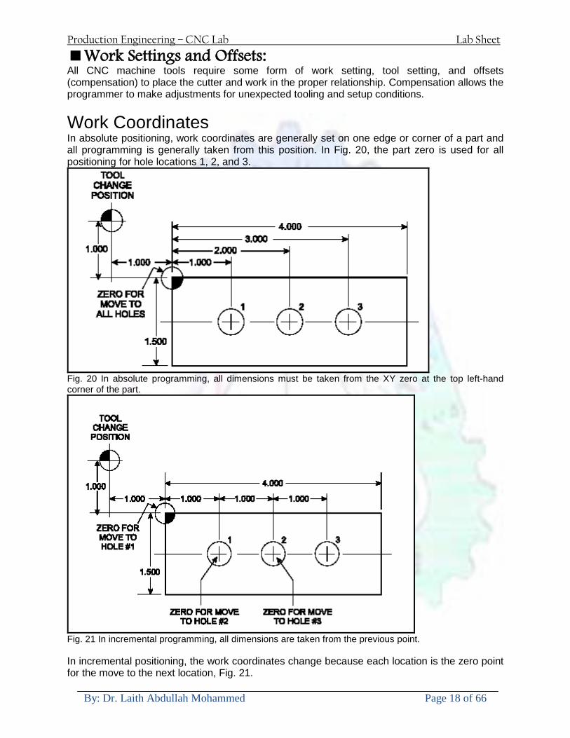
Production Engineering ndash CNC Lab Lab Sheet
By Dr Laith Abdullah Mohammed Page 18 of 66
Work Settings and Offsets All CNC machine tools require some form of work setting tool setting and offsets (compensation) to place the cutter and work in the proper relationship Compensation allows the programmer to make adjustments for unexpected tooling and setup conditions
Work Coordinates In absolute positioning work coordinates are generally set on one edge or corner of a part and all programming is generally taken from this position In Fig 20 the part zero is used for all positioning for hole locations 1 2 and 3
Fig 20 In absolute programming all dimensions must be taken from the XY zero at the top left-hand corner of the part
Fig 21 In incremental programming all dimensions are taken from the previous point In incremental positioning the work coordinates change because each location is the zero point for the move to the next location Fig 21
Production Engineering ndash CNC Lab Lab Sheet
By Dr Laith Abdullah Mohammed Page 19 of 66
On some parts it may be desirable to change from absolute to incremental or vice versa at certain points in the job Inserting the G90 (absolute) or the G91 (incremental) command into the program at the point where the change is to be made can do this
R Plane or Gage Height The word-address letter R refers to a partial retraction point in the Z axis to which the end of the cutter retracts above the work surface to allow safe table movement in the X Y axes It is often called the rapid-traverse distance gage height retract or work plane The R distance is a specific height or distance above the work surface and is generally 100 in above the highest surface of the workpiece Fig 22 which is also known as gage height Some manufacturers build a gage height distance of 100 in into the MCU (machine control unit) and whenever the feed motion in the Z axis is called for 100 in will automatically be added to the depth programmed When setting up cutting tools the operator generally places a 100 in thick gage on top of the highest surface of the workpiece Each tool is lowered until it just touches the gage surface and then its length is recorded on the tool list Once the gage height has been set it is not generally necessary to add the 100 in to any future depth dimensions since most MCUs do this automatically
Fig 22 Using a 100 in gage block to set the gage height or R0 on the work surface
Cutter Diameter Compensation Cutter diameter compensation (CDC) changes a milling cutterrsquos programmed centerline path to compensate for small differences in cutter diameter On most MCUs it is effective for most cuts made using either linear or circular interpolation in the X-Y axis but does not affect the programmed Z-axis moves Usually compensation is in increments of 0001 in up to +10000 in and usually most controls have as many CDCs available as there are tool pockets in the tool storage matrix The advantage of the CDC feature is that it 1 Allows the use of cutters that have been sharpened to a smaller diameter 2 Permits the use of a larger or smaller tool already in the machinersquos storage matrix 3 Allows backing the tool away when roughing cuts are required due to excessive material present 4 Permits compensation for unexpected tool or part deflection if the deflection is constant throughout the programmed path The basic reference point of the machine tool is never at the cutting edge of a milling cutter but at some point on its periphery If a 1000 in diameter end mill is used to machine the edges of a workpiece the programmer would have to keep a 500 in offset from the work surface in order to cut the edges accurately Fig 23 The 500 offset represents the distance from the centerline of the cutter or machine spindle to the edge of the part Whenever a part is being machined the programmer must calculate an offset path which is usually half the cutter diameter
Production Engineering ndash CNC Lab Lab Sheet
By Dr Laith Abdullah Mohammed Page 20 of 66
Fig 23 Cutter-diameter compensation must be used when machining with various size cutters Modern MCUs which have part surface programming automatically calculate centerline offsets once the diameter of the cutter for each operation is programmed Many MCUs have operator-entry capabilities which can compensate for differences in cutter diameters therefore an oversize cutter or one that has been sharpened can be used as long as the compensation value for oversize or undersize cutters is entered
Production Engineering ndash CNC Lab Lab Sheet
By Dr Laith Abdullah Mohammed Page 21 of 66
CNC Programming Hints - MILLING
Production Engineering ndash CNC Lab Lab Sheet
By Dr Laith Abdullah Mohammed Page 22 of 66
CNC Programming Hints ndash TURNING
Production Engineering ndash CNC Lab Lab Sheet
By Dr Laith Abdullah Mohammed Page 23 of 66
CNC
The abbreviation CNC stands for Computer(ized) Numerical(ly) Control(led) and refers specifically to the computer control of machine tools for the purpose of (repeatedly) manufacturing complex parts in metal as well as other materials using a program written in a notation conforming to the EIA-274-D standard and commonly called G-code
CNC was developed in the late 1940s and early 1950s by the MIT Servomechanisms Laboratory CNC machines were relatively briefly preceded by the less advanced NC or Numerical(ly) Control(led) machines The introduction of CNC machines radically changed the manufacturing industry Curves are as easy to cut as straight lines complex 3-D structures are relatively easy to produce and the number of machining steps that required human action have been dramatically reduced With the increased automation of manufacturing processes with CNC machining considerable improvements in consistency and quality have been achieved CNC automation reduced the frequency of errors and provided CNC operators with time to perform additional tasks
CNC automation also allows for more flexibility in the way parts are held in the manufacturing process and the time required to change the machine to produce different components In a production environment a series of CNC machines may be combined into one station commonly called a cell to progressively machine a part requiring several operations CNC machines today are controlled directly from files created by CAM software packages so that a part or assembly can go directly from design to manufacturing without the need of producing a drafted paper drawing of the manufactured component In a sense the CNC machines represent a special segment of industrial robot systems as they are programmable to perform many kinds of machining operations (within their designed physical limits like other robotic systems)
G-code
G-code is a common name for the programming language that is used for NC and CNC machine tools It is defined in EIA RS-274-D G-code is also the name of any word in a CNC program that begins with the letter G and generally is a code telling the machine tool what type of action to perform such as
bull rapid move bull controlled feed move in straight line or arc bull series of controlled feed moves that would result in a hole being drilled bull change a pallet bull Set tool information such as offset
There are other codes the type codes can be thought of like registers in a computer
X position Y position Z position M code (another action register) F feed rate S spindle speed N line number R Radius T Tool selection
Production Engineering ndash CNC Lab Lab Sheet
By Dr Laith Abdullah Mohammed Page 24 of 66
I Arc data X axis J Arc data Y axis
G-code files are output by CAM software such as Smartcam Gibbscam Featurecam Edgecam Mastercam etc G-code is also output by specialized CAD systems used to design printed circuit boards Such software must be customized for each type of machine tool that it will be used to program
Production Engineering ndash CNC Lab Lab Sheet
By Dr Laith Abdullah Mohammed Page 25 of 66
U 2عمل األزرار الرئيسية في ماكنة الخراطة المبرمجة (نصر (
1- SINGLE BLOCK للتأكد من صحة البرنامج (تنفيذ البرنامج خطوة خطوةب تقوم( 2- BLOCK DELETE بجانب ويعمل من األوامرلغاء بلوك معين أليستخدم 3- MACHINE LOCK العمل يستخدم لقفل حركة المحاور الرئيسية مع استمرار البرنامج في
)وهذا مهم للتاكد من صحة البرنامج قبل عملية التنفيذ النهائي(4- CONT CYCLE عملية التشغيل عند ايقافها الي سبب كان او عند ايقافها ألستئناف ستخدم ت
) BAR FEEDER(او في حالة استخدام ) FEED HOLDبسبب (5- DRY RUN وتستخدم لفحص البرنامج بعد ازالة الشغلة حركة سريعة للبرنامج 6- TURRET UP amp DOWN ) حركة حامل العدة TURRET الذي يحمل مجموعة من (
وهذا الزر يعمل مع الزر عكس عقرب الساعة او مع عقرب الساعة ةحركة دوراني العدد )SAFTY (
7- COOLANT ON or OFFفه تشغيل سائل التبريد او ايقا 8- COOLANT AUTO الدوال المساعدة في البرنامج من خالل فه تشغيل سائل التبريد او ايقا 9 -MACHINE START ة لتشغيل هيدرولكيك الماكنميستخد
Production Engineering ndash CNC Lab Lab Sheet
By Dr Laith Abdullah Mohammed Page 26 of 66
10- CLOSE OR OPEN CHUCKالعينة تستخدم لفتح وغلق 11 -T STOCK FWD RET حركة الغراب المتحرك ذهابا وإيابا12 -SPINDLE STOP تعمل على ايقاف حركة دوران العينة 13-JOG SPINDLE تعمل على تدوير العينة مع زر SAFTY 14 -OPT SAFTY مع الدالة ( تعمل عمل التوقف المشروط حيث تعملM1 دالة التوقف (
ط ) فقط األ اذا كان هذا الزر مضغو M1المشروط حيث ال يتوقف البرنامج في حالة وجود دالة ( SAFTY + SPINDLE ) يتم الضغط على زر ( START CYCLEلغرض تحرير زر (
START ) في نفس الوقت بعد الضغط على زر ( START CYCLE مرتين (
NC PC- 15 يستخدم هذا الزر عند ربطCNC يستخدم لنقل المعلومات ث مع جهاز أخر حي بينهما
16 -CALCU زر الخاص بالحاسبة مع زر ( ال وهوINPUT ( 17 - HD1 HD2 يستخدم الختيار العدة مع المخرطة ذات المحاور األربعة 18 - START تستخدم لبدء عملية التشغيل
Production Engineering ndash CNC Lab Lab Sheet
By Dr Laith Abdullah Mohammed Page 27 of 66
19- FEED HOLD تعمل على إيقاف عمل أي G موجودة مع بقاء العينة متحركة 20- M D I أو تشغيل البرنامج ل يتم استخدامه لإلدخا BLOCK BY BLOCK وتعمل عند
إدخال البرنامج بواسطة الشريط المثقب أو أي وسيلة إدخال أخرى أو في عمليات التصفير
21- REST تستخدم العادة تشغيل الماكنة أو مسح اإلنذار الذي يظهر على الشاشة 22- EMERGENCYتستخدم عادة اليقاف الماكنة في حالة الطوارئ فقط
OPERATION MENU KEY
CHAPTER PRG-CMK
OFFSET PROGRAM POSITION FUNCTION MENU KEY
23- POSITIONعلى الشاشة د الموقع الموجور الظها 24- PROGRAMإلظهار برنامج معين واختياره 25- OFFSET الختيار سماحات العدة أو سماحات نقطة المرجع 26- PRG- CHK تستخدم لفحص البرنامج على الشاشة 27- SETTING ألختيار الثوابت على الشاشة 28- SERVICE تستخدم ألستخراج المعامالت والثوابت 29- MESSAGE تستخدم ألظهار األخطاء الناتجة عن البرنامج او اخطاء التشغيل 30- OVERALL ألختيار المواقع 31- RELATIVE MODLINE تعوض عن POSITION 32- DIR MEM يستخدم ألظهار ملف البرامج المخزونة في الذاكرة وعندما نضغط هذا الزر
فان رقم واسم البرنامج سوف يظهر على الشاشة
2أدناه الشفرات الرئيسية التي تعمل على الماكنة المبرمجة نصر
G-CODE DESCRIPTION
G00 Rapid traverse (linear)
G01 Linear Interpolation at feed rate
G02 Circular interpolation (CW) R+
G03 Circular interpolation (CCW) R+
G10 Zero point tools
G20 Imperial data input
G21 Metric data input
G27 Reference return check
G28 Reference return
G29 Return from reference
Production Engineering ndash CNC Lab Lab Sheet
By Dr Laith Abdullah Mohammed Page 28 of 66
G33 Thread cutting
G40 Cancel cutter radius compensation
G41 Cutter compensation left
G42 Cutter compensation right
G54 Work co-ordinate system no1
G70 Finishing cycle
G71 Stock removal turning
G72 Stock removal facing
G74 Face grooving
G75 Diameter grooving
G76 Threading cycle
G90 Absolute date input
G91 Incremental data input
G94 Feed minute mode
G95 Feed rev mode
G96 Constant surface speed mode
G97 Cancel Constant surface speed
) 2أدناه الشفرات الثانوية التي تعمل على الماكنة المبرمجة (نصر
M-code FUNCTION
M00 Program stop
M03 Spindle forward (Tool forward ndash M94 mode)
M04 Spindle reverse (Tool forward ndash M94 mode)
M05 Spindle stop (Tool stop ndash M94 mode)
M08 Coolant on
M09 Coolant off
M30 Program end (with rewind)
M48 Turret shortest path
M52 Turret direction up (CW)
M53 Turret direction down (CCW)
M73 Chuck open
M74 Chuck close
Production Engineering ndash CNC Lab Lab Sheet
By Dr Laith Abdullah Mohammed Page 29 of 66
) وكل جملة مكونة من مجموعة من الكلمات blockإن كل برنامج يتكون من مجموعة من الجمل ()words) لهذا فأن الشفرات الرئيسية والمساعدة هي عبارة عن كلمات (words كما في المثال التالي (
G_ _ P1 Q2 U_ _ W_ _ D___ F_ _
)end of block) ويعني ( ) يكتب الرمز (blockتسلسل الكلمات مهم جدا بعد نهاية كل جملة (
طريقة ادخال البيانات الى الماكنة ــــــــــــــــــــــــــــــــــــــــــــــــــ
) MDIيمكن ادخال البيانات الى الماكنة بعدة طرق فقد يكون األدخال عن طريق قناة السيطرة ( MANUAL DATA INPUT ) او عن طريق قناة األضافة EDIT كما يمكن ادخال البيانات عن (
) RS ndash 232 COMMUNICATIN LINKطريق استخدام سلسلة الربط (
₤⅗₌⅗₌ ⅙₌₨image₍₡ ₤₌ℌ⅗₌ Ⅸ⅗ⅥⅯ₌ ₤₡ℌ₰₨⅗₌G71
الخراطة الطولية G71الغرض من التجربة عمل نموذج للخراطة بأستخدام الدالة تستعمل هذه الدالة للخراطة الطولية اي على طول محور المشغولة وكما هو موضح بالشكل ادناه
تعتبر هذه الدالة من الدوال التي ال تحتاج الى تكرار او إعادة كتابتها أي انها دالة تكرارية بمعنى ان اي
الذي هي دالة حركة G01خطوة تكون من ضمن هذه الدالة سوف تكرر العملية اي عند استعمال امر مثل خطية تتضمن القطع مع التغذية مع اعطاء القطر المراد قطعه و مراعاة عمق القطع المعطى سوف يتكرر
هذه االمر وصوال الى العمق المطلوب وهكذا لبقية الدوال
G71 المستخدمة للدالة الصيغة
G71 P1 Q2 U___ W___ D___ F___ حيث إن
P1 بداية الخطوة االولى = Q2 نهاية الخطوة =
Uوضع السماحات بأتجاه محور = X W وضع السماحات بأتجاه محور = Z وتكاد تكون مهملة وتوضع اشارة سالب Dعمق القطع وتوضع رقم صحيح مثل = D500 اي نصف ملمF التغذية والتي لها عالقة بالدالة = G95
Production Engineering ndash CNC Lab Lab Sheet
By Dr Laith Abdullah Mohammed Page 30 of 66
G71الدالة استخدام مثال على
T0100 M48 G0 X26 Z2 M08 T0101 G90 G95 G97 S500 M03 G71 P1 Q2 U03 W00 D500 F01 N1 G0 G42 X00 G01 Z00 G01 X2517 G01 Z-5352 G01 X7391 Z-9366 G01 Z-19145 N2 G28 M30
الجانب العملي
االجهزة واالدوات المستخدمة CNCماكنة خراطة مبرمجة 1 ملم 80قضيب من االلمنيوم قطر 2 ةفير ني 3 جاه أيمن تهولدر كاربيدي ذوا 4
طريقة العمل يتم تثبيت قضيب من االلمنيوم على العينة التابعة للماكنة مع مراعاة الطول المراد استعماله في عملية 1
الخراطة ) turretتثبيت عدة القطع في المكان الصحيح في ( 2
Production Engineering ndash CNC Lab Lab Sheet
By Dr Laith Abdullah Mohammed Page 31 of 66
بالنسبة الى القطعة المثبتة على العينة XZيتم تصفير الماكنة للمحاور 3 تصفير للمحورZ تكون مالمسة العدة الى وجه الشغلة تصفير للمحورX تكون مالمسة العدة الى سطح الشغلة الموازي لمحور X
يتم كتابة البرنامج أما بطريقة يدوية أو بالحاسوب مع وضع كل الظروف الالزمة للتشغيل ( عمق القطع 4 التغذية السرعة المطلوبة نوع المعدن )
ادخال البرنامج الى الحاسوب الموجود داخل الماكنة مع تهيئة الماكنة للتشغيل 5
المطلوب G71عمل برنامج يدوي على الدالة 1 رسم الشكل الشكل النهائي المطلوب مع وضع األبعاد 2
Ⅺ⅟₍euro⅗₌ ₤₡ℌ₰₨⅗₌₣ ₤⅗₌⅗₌ ⅙₌₨image₃₡ Ⅺℂtradeℒ⅗₌ ӈ₍Ⅴ⅟ⅳ₌ G70
G70 الغرض من التجربة عمل انهاء سطحي للمشغولة بواسطة الدالة
من الضروري إعطاء G71هذه الدالة تعمل شوط واحد فقط وتكون معتمدة على عمليات القطع في الدالة اللغاء مقدمة االداة (أي لكي تتم عملية االنهاء السطحي بدون حسابات نصف قطر مقدمة االداة ) G42دالة
G70الصيغة المستخدمة للدالة
G70 P1 Q2 F___ حيث ان
P1 بداية الخطوة االولى = Q2 نهاية الخطوة =
F التغذية والمرتبطة بالدالة = G95
وذلك ألن دالة االنهاء السطحي تحقق X Zمالحظة الدالة التحتاج لكتابة السماحات التابعة للمحورين المسافات الحقيقة المراد انتاجها للمشغولة
G71و G70مثال على الدالة
T0100 M48 G0 X26 Z2 M08 T0101 G90 G95 G97 S500 M03 G71 P1 Q2 U03 W00 D500 F01 N1 G0 G42 X00 G01 Z00 G01 X2517 G01 Z-5352 G01 X7391 Z-9366 G01 Z-19145 N2 G97 S750 MO3
Production Engineering ndash CNC Lab Lab Sheet
By Dr Laith Abdullah Mohammed Page 32 of 66
G70 P1 Q2 G40 F009 G28 M30
الجانب العملي الحظ التجربة األولى
المطلوب
G70 عمل برنامج يدوي على الدالة 1 رسم الشكل النهائي المطلوب مع وضع االبعاد 2
₪⅗₍euro⅗₌ ₤₡ℌ₰₨⅗₌₣ ₤⅗₌⅗₌ ⅙₌₨image₍₡ ⅝₍ⅠimageⅯ₌ ⅞ⅫⅦ⅔₧ G76
G76 للمشغولة بواسطة الدالةةالغرض من التجربة عمل أسنان خارجية أو داخلي
في هذه التجربة سوف نقوم بعمل األسنان الخارجية وهنا تكون حركة العينة ثابتة وهذا ضروري بسبب أن ) تكون متصلتين الكترونيا وعليه أي اختالف في سرعة العينة تؤدي إلى اختالف motionالعينة والحركة(
) servoفي سرعة الخدمة(يرتبط اتجاه تكوين األسنان باتجاه دوران العينة مثال إذا كانت األسنان ذات اتجاه أيمن يكون اتجاه دوران
وهنا نقلب العدة إلى االسفل وكما هو موضح بالشكل أدناه MO3العينة عكس عقرب الساعة أي نستعمل
Production Engineering ndash CNC Lab Lab Sheet
By Dr Laith Abdullah Mohammed Page 33 of 66
الخطوة هي عبارة عن المسافة ما بين قمة سن إلى قمة سن أخر عمق السن هو العمق المطلوب تكوينه لألسنان
G76 الصيغة المستخدمة للدالة
G76 X___ Z___ K___ F___ D___ A___
حيث أن X القطر الداخلي للسن =Z طول السن =K عمق السن وتستخرج من المعادلة التالية =K=065F F الخطوة =D عمق القطع بالمايكرون فقط =A زاوية السن =
G76مثال على استخدام الدالة T0300 M48 GOO X30 Z4 T0303 M08 G97 S500 MO3 G76 X28375 Z-20 K08125 F125 D120 G00 X40 Z4 G28 M30
Production Engineering ndash CNC Lab Lab Sheet
By Dr Laith Abdullah Mohammed Page 34 of 66
الجانب العملي الحظ التجربة األولى
المطلوب
G76عمل برنامج يدوي على الدالة 1 رسم الشكل النهائي المطلوب مع وضع األبعاد 2
Ⅺ⅘₌⅗₌ Ⅵ₂ Ⅺ₯ℋ₍⅗₌ ℌℲℂ⅗₌ ⅞ⅫⅦ⅔₧ ₤K₡₌ℌ⅗₌ ₤₡ℌ₰₨⅗₌)Groove ₤⅗₌⅗₌ ₤tradeimage₌Ⅶ₡ (G75
G75 بواسطة الدالة grooveالغرض من التجربة تكوين
) للمشغولة وتعتمد شكل الحفر على طريقة grooveتستعمل هذه الدالة لتكوين الحفر الخارجي والداخلي (
التشغيل وعلى الشكل المراد إنتاجه وتعتبر هذه الطريقة من عمليات التشكيل للمعدن إن هذه الدالة هي دالة مالحظة مع G75في هذه التجربة سنقوم بعمل الحفر الخارجي بواسطة الدالة
تكرارية وغير تكرارية حسب نوع التشغيل
G 75 الصيغة المستخدمة للدالةG75 X___ Z___ I___ K____
حيث أن
X العمق النهائي لقطر الشغلة =Z عرض الحفر =I الدخول في كل مرة =
K التزحيف على محور =z بالنسبة للعدة
Production Engineering ndash CNC Lab Lab Sheet
By Dr Laith Abdullah Mohammed Page 35 of 66
G75مثال على استخدام الدالة
T0500 M48 GOO X100 Z -20 T0505 M08 G97 S700 MO3 G75 X84 Z -38 I 05 K4
الجانب العملي الحظ التجربة األولى
المطلوب
G76عمل برنامج يدوي على الدالة 1 رسم الشكل النهائي المطلوب مع وضع األبعاد 2
Production Engineering ndash CNC Lab Lab Sheet
By Dr Laith Abdullah Mohammed Page 36 of 66
CNC Milling Machine Mechanical Construction
Guideways The guideways of CNC machines are made of steel To reduce the frictional forces they are coated with a strip of PTFE (Poly Tetra Fluoro Ethylene)
Ballscrews On conventional lathes a leadscrew is used to converts the rotary motion of the hand wheel into linear motion of the slides Leadscrews have a high coefficient of friction and backlash On CNC machines a ballscrew is used instead of a leadscrew Friction and backlash are much less than on leadscrews
Guideway
Production Engineering ndash CNC Lab Lab Sheet
By Dr Laith Abdullah Mohammed Page 37 of 66
bullMachining operations Direction of cutting Based on the direction of the cutter rotation and work piece feed milling operations are classified into two types 1-Up milling (Convention milling) In up milling the metal is removed by rotating the cutter against the direction of travel of the part
Feed
Machine table
Part
Cutting tool
Chip thickness at theexit of the tooth
2-Down milling (Climb milling) In climb milling the metal is removed by rotating the cutter with the direction of travel of the part
Machine table
Part
Cutting tool
Chip thickness at theentrance of the tooth
Production Engineering ndash CNC Lab Lab Sheet
By Dr Laith Abdullah Mohammed Page 38 of 66
bullTooling Tool geometry The geometry of the tool tip affects the way that the metal cutting is performed The nose radius rake angles relief angles etc must be selected with care
Radial relief
Radial rake
Axial relief
Approach angle
Axial relief
Corner radius Face mill Face milling cutters are used to mill flat surfaces Commonly used face milling cutters Cutter with 75 degree approach
75 deg
Cutter with 90 degree approach (Square shoulder face mill)
90 deg
Cutter with 45 degree approach
Production Engineering ndash CNC Lab Lab Sheet
By Dr Laith Abdullah Mohammed Page 39 of 66
bullCNC Programming Axes convention The Z axis is along the spindle axis The X and Y axes are perpendicular to Z VMC
Z
Y
-
+
-+
X- +
+Z
-Z
+Y
-Y
-X +X
Part
Machine table
X
YZ
G00 Rapid traverse When the tool being positioned at a point preparatory to a cutting motion to save time it is moved along a straight line at Rapid traverse at a fixed traverse rate which is pre-programmed into the machines control system Typical rapid traverse rates are 10 to 25 m min but can be as high as 80 mmin
Production Engineering ndash CNC Lab Lab Sheet
By Dr Laith Abdullah Mohammed Page 40 of 66
Format N_ G00 X__ Y__Z__
G01 Linear interpolation (feed traverse) The tool moves along a straight line in one or two axis simultaneously at a programmed linear speed the feed rate Format N__ G01 X__ Y__Z__ F__
Part
Feed
Part
Feed
G02G03 Circular interpolation The tool moves along an arc in two axes simultaneously at a programmed linear speed the feed rate
Production Engineering ndash CNC Lab Lab Sheet
By Dr Laith Abdullah Mohammed Page 41 of 66
Format N__ G0203 X__ Y__Z__ I__ J__K__ F__ using the arc center OR N__ G0203 X__ Y__Z__ R__ F__ using the arc radius G02 moves along a CW arc G03 moves along a CCW arc Arc center The arc center is specified by addresses I J and K I J and K are the X Y and Z co-ordinates of the arc center with reference to the arc start point
X
Y
Arc center
Arc endArc start
- J
- I
I = X coord of center - X coord of start point J = Y coord of center - Y coord of start point K = Z coord of center - Z coord of start point I J and K must be written with their signs
Production Engineering ndash CNC Lab Lab Sheet
By Dr Laith Abdullah Mohammed Page 42 of 66
bullWork holding
Rotary table
Fixture base
Component
Clamp
Stud
Fixtures The use of fixtures 1 Improves repeatability of dimensions 2 Improves working conditions 3 Cuts down requirement of skilled labour 4 Reduces part loading and unloading time 5 Improves safety in the working area 6 Reduces the cost of machining There are two types fixtures commonly used 1 Special fixture Special fixtures are used to hold and locate the typical components which are having complex shape and to be located with the reference hole (dowel hole) Special fixtures are required for components like gear case cover cylinder heads etc 2 Modular fixture Modular fixture is a set different kind of clamping and locating elements These fixtures are used to hold identical components in different sizes and components of box type Example Manifolds head stocks connecting rods and flanges
Production Engineering ndash CNC Lab Lab Sheet
By Dr Laith Abdullah Mohammed Page 43 of 66
bullMachine setting
Determining X and Y work zero offset Case 1
Part
Machine table
Part
End mill or reamer
Work offset X0Y0 For determining X work zero offset bull Touch the periphery of the end mill or reamer to the part bull Enter current machine X value + cutter radius as X work zero offset For determining Y work zero offset bull Touch the periphery of the end mill or reamer to the part bull Enter current machine Y value - cutter radius as Y work zero offset Case 2
Part
Machine table
Part
End mill or reamerWork offset X0Y0
bull Mount the dial indicator on machine spindle true the bore bull Enter current machine X and Y value as X and Y work zero offset
Production Engineering ndash CNC Lab Lab Sheet
By Dr Laith Abdullah Mohammed Page 44 of 66
How to Select a Cutting Fluid
One part of the metal cutting equation that is sometimes overlooked however is
the choice of an appropriate cutting fluid With todayrsquos system approach to metal
cutting use of the right metalworking fluid has become just as much a part of the
solution as the other elements In fact at least one company is now integrating
cutting fluids and cutting tools into effective metal cutting systems Following are
some things to consider when choosing your next cutting fluid
The Four Key Questions
There are four vital pieces of information that are necessary when choosing a
cutting fluid They are
1 What are you cutting
2 What is the chemistry of your water
3 What are you using now
4 What are your options
5 What do you prefer
What Are You Cutting
The first question ndash ldquoWhat are you cuttingrdquo ndash is often the most difficult to answer
because most shops handle a variety of workpiece materials on a regular basis If
the answer is an unequivocal ldquoaluminumrdquo or ldquostainless steelrdquo or ldquocast ironrdquo the
selection of a cutting fluid can be quite simple and straightforward Unfortunately
that is seldom the case in anything but a high-volume plant Where aluminum or
other nonferrous metals are a significant part of the mix a non-staining cutting
fluid is a must Generally speaking this will be a semi-synthetic with special
ingredients to prevent bi-metallic corrosion and staining of non-ferrous workpieces
Where the ferrous metals predominate however a more general purpose semi-
synthetic or hybrid fluid might be a more economical choice
Production Engineering ndash CNC Lab Lab Sheet
By Dr Laith Abdullah Mohammed Page 45 of 66
What is The Chemistry of Your Water
The second question ndash ldquoWhat is the chemistry of your waterrdquo ndash is probably the
single most common reason for the success or failure of a cutting fluid Very few
plants invest the money necessary to install effective water purification systems
using deionization or reverse osmosis technology Unfortunately the chemicals
present or not present in the water used to re-constitute a cutting fluid make a
tremendous difference in its performance and sump life Most manufacturers of
cutting fluids will perform the necessary water testing to determine exactly what
minerals are dissolved in your water and make a fluid recommendation based on
the results
What are you using now
The third question ndash ldquoWhat are you using nowrdquo ndash helps narrow the range of
choices When coupled with an objective analysis of the strengths and weaknesses
of the current fluid the answer to this question can quickly point you toward a
relatively small number of competitive alternatives that have the attributes required
to meet your cutting needs Many cutting fluids are in use today simply because
they were in use yesterday It is a hard reality of todayrsquos marketplace that if one
isnrsquot constantly striving to improve they will certainly be overtaken by a
competitor who is
What Are Your Options
The fourth question ndash ldquoWhat are your optionsrdquo ndash leads to the final selection of a
cutting fluid Cutting fluids can be divided into four general groups based on their
chemistry
They are
bull Soluble Oils ndash quite literally oil dispersed in water
bull Synthetics ndash completely oil free man-made coolants in solution
Production Engineering ndash CNC Lab Lab Sheet
By Dr Laith Abdullah Mohammed Page 46 of 66
bull Semi-Synthetics ndash a mixture of natural and synthetic lubricants with up to 30
mineral oil
bull Hybrids ndash a special class of semi-synthetics with a mineral oil content of about
15 Each fluid type has advantages and disadvantages which make it suitable for
a particular group of applications In addition there are costperformance trade-
offs to be made between the groups within a specific set of applications For
example where a hybrid and a semi-synthetic may both be suitable for a particular
use the hybrid might provide longer sump life at a slightly higher initial cost
while some semi synthetics may be more economical to recycle or dispose of while
not giving as long a tank life The final decision in this case would have to be made
on the detailed economics of the shop where the fluids were to be used and on the
ownerrsquos individual preferences
Soluble Oils
Soluble oils are oils that disperse in water when emulsifiers are added They are
generally suitable for moderate-to heavy-duty machining and grinding of all non-
ferrous metals carbon and cast steels and in applications where dissimilar metals
such as aluminium and steel are present They can also be used in turning drilling
tapping reaming gear cutting broaching as well as internal and centerless types
of grinding operations Soluble oils provide excellent aluminium and copper
corrosion control good rancidity control which extends fluid for long lasting
trouble-free performance and good concentrate and mix stability making it ideal
for mixing in water with a minimal amount of agitation An example of this is
Valenitersquos VNTreg-650 premium heavy-duty soluble oil
Synthetics
Synthetics are completely oil free solutions made of polymers organic and
inorganic materials that are mixed with water These clear low foaming and bio-
Production Engineering ndash CNC Lab Lab Sheet
By Dr Laith Abdullah Mohammed Page 47 of 66
stable coolants are ideal for machining and grinding of ferrous materials carbon
steels or cast iron Their complex lubricant packages make synthetics well-suited
for tough-to-machine materials such as stainless steels and high-temperature alloys
Certain synthetics are specifically designed to address the primary failure modes of
flank wear and nose wear Although there are many benefits some synthetics may
cause staining of non-ferrous materials
Semi-Synthetics
Semi-synthetic fluids are a mixture of oils synthetic emulsifiers and water They
were primarily developed for the aircraft nuclear and related industries
Consequently they work extremely well on all non-ferrous metals such as titanium
aluminium copper brass bronze and stainless steel in both machining and
grinding Semi-synthetics can be used on ferrous metals too They are chlorine-
free to reduce bi-metallic corrosion and staining of metals They should be used at
a 5-8 dilution with water depending on the severity of the operation
Hybrids
Hybrids are cutting fluids custom engineered to solve a particular problem For
example Valenitersquos VNTreg-800 was developed to be very clean in the machining
and grinding of cast iron It provides better stability in hard water and rejects tramp
oil very well which adds to its bio-stable chemistry Hybrids work extremely well
on all metals in both machining and grinding They should be mixed at a 5-7
dilution with water depending on the condition of the water
What Do You Prefer
The final question ndash ldquoWhat do you preferrdquo ndash is usually the ldquotie breakerrdquo where
there is more than one appropriate cutting fluid available Here again as in the
case of what is being used now the key is to examine your preferences objectively
Production Engineering ndash CNC Lab Lab Sheet
By Dr Laith Abdullah Mohammed Page 48 of 66
and specifically to identify the real reasons behind a preference If you cannot
point to specific reasons why one class of cutting fluid is preferred over another
you are well advised to follow the recommendations of the professional who has
analyzed your requirements Choosing the right fluid today is easier than ever as
the system approach to metal cutting productivity continues to grow in acceptance
The day is not far off when choosing a complete solution will be as easy as
choosing the right insert and chip breaker today The answers are available and the
results will more than justify the time you spend choosing the right metal cutting
fluid
Useful Links wwwball-screwsnet
wwwlubelinkcom
wwwmachinerylubricationcom
wwwadvancedmanufacturingcom
wwwmmsonlinecom
wwwcuttingtoolengineeringcom
wwwgeartechnologycom
wwwengineersedgecom
wwwagmaorg
wwwefundacom
wwwsaeorg
wwwsmeorg
wwwastmorg
wwwissorg
wwwmachinetoolscom
wwwansiorg
wwwasmeorg
wwwcnccicom
wwwmatlscom
wwwthefreedictionarycom
wwwengineersupplycom
Production Engineering ndash CNC Lab Lab Sheet
By Dr Laith Abdullah Mohammed Page 49 of 66
SurfCAM Tutorial ndash Beginning with the basics
Background SurfCAM is a computer aided manufacturing (CAM) software which allows you to create manage and modify tool paths for computer aided designed (CAD) part The software requires a CAD model or requires that you create some geometry within SurfCAM with some rudimentary tools provided The tool paths are created or stored internally in SurfCAM in a generic programming language called APT Once the tool paths are created the APT paths are translated using a post processor into typical machine G-code
Opening SurfCAM SurfCAM can be opened from the Novell Applications Launcher on most Industrial Engineering computer labs workstations Search under lsquoallrsquo applications and double click on SurfCAM 2005 Once the program opens a license must be selected from the list (not the Demo license) to enable saving the file later Choose one of the 30 licenses available If for some reason the licenses are not listed on the license manager form select server list and type ldquobonnieeosncsuedurdquo A list of available licenses should appear Select a license and click OK After the license is selected an Add StockFixture form (Figure 1) opens allows you to add a model which represents the pre-machined stock or a fixture Click on OK without adding either Both of these items can be added later under a more appropriate dialog
Figure 1 Add Stock or Fixture dialog box
Production Engineering ndash CNC Lab Lab Sheet
By Dr Laith Abdullah Mohammed Page 50 of 66
SurfCAM Interface
Figure 2 SurfCAM Windows based interface
SurfCAM is a windows based software system so most of the typical windows functions under File are applicable This is where you can open save exit print etc The Create menu allows the user to create different geometry forms Here you can create a point line surface chamfer circle and many other geometry types For the most part these functions are not used by beginners but are useful when creating bounding curves where you donrsquot want the tool to move outside (constraining the tool) The Edit menu allows you to change or modify many different entities such as changing lines altering surfaces joining surfaces trimming or breaking elements add control points etc Again these features are helpful to advanced users and are not covered in detail in this tutorial The Display menu offers the ability to change the orientation of the part on the screen The typical rotate pan fit to screen and zoom functions are available as well as several functions which allow the user to shift between views or call up a named view (ie top bottom etc) The NC menu is the main machining interface menu In this menu you select the general form of machining (2 axis 3 axis 4 axis 5 axis turning etc) and under the general form a more specific machining function is selected This menu is the most used and the options contained must be fully understood to get the most out of SurfCAM Each function will be described in some detail in a further chapter The Analyze menu contains options such as measuring the distance between points angles tangency elements etc These functions are auxiliary functions meant to help you understand the part better but basically provide no functionality for making tool paths for CNC machines Thus these will not be covered The Tools menu allows the user to change the system options modify keyboard shortcuts change the model units etc These options are again not used by beginners Finally the Help menu provides access to the online users manual In lieu of clicking the Help menu the F1 key is the shortcut key for help (as it is in most windows based programs)
Importing a CAD model Importing a CAD model that is stored locally is done by selecting File-gtOpen On the Files of type dropdown box choose the type of file you wish to open (Figure 3) Do this prior to negotiating your way through the maze of folders to prevent having to go through the folder tree again Once the file type is selected find the file you are trying to open and click the Open
Production Engineering ndash CNC Lab Lab Sheet
By Dr Laith Abdullah Mohammed Page 51 of 66
button SurfCAM will then attempt to read the file you have selected SurfCAM may provide a dialog box describing what it has imported and identify if it was successful If this dialog is provided simply click close without saving
Figure 3 Open Dialog Note - Change type of file prior to finding the file you wish to open
SurfCAM allows a user to import several different types of CAD files the most common types which you will likely import are SolidWorks part files (sldprt or prt) AutoCAD files(dxf) or IGES (igs or iges) Native file import (such as is the case with SolidWorks) provides the greatest information transfer and generic file imports (such as is the case with IGES) provide the least Normally it is to the advantage of the user to use native file importing procedures when available Recently (2005) SurfCAM added some compatibility with SolidWorks This allows the user to create tool paths for a part and if an engineering change is needed for the part update the part in SolidWorks When the part is then opened in SurfCAM the changes are noted and a simple update operation command is needed This however does not operate with complete transparency andor accuracy and thus users need to be cognizant of changing CAD models
SurfCAM Geometry In SurfCAM two basic types of geometry are used the surface and the point A surface (Figure 4) is a so called spline (NURBS or B-Spline are the two most common) surface (parameterized by two values u and v) such that every location on the surface can be defined as a function of these parameters In other words SurfCAM can calculate the location of any point on the
Production Engineering ndash CNC Lab Lab Sheet
By Dr Laith Abdullah Mohammed Page 52 of 66
surface Surfaces are used primarily in 3 4 and 5 axis machining and require a significant
amount of processing power and time Figure 4 Surfaces model of a mold half Note the difference between this and Figure 2 a wireframe model
Point or line based models are often referred to as wireframe (Figure 5) models because the models consist of connected lines and resemble the part only at the intersection of two surfaces Wireframe models were made popular lsquoback in the dayrsquo when computer processing was expensive There are times when each of the models are important and selecting model geometry when applying a SurfCAM operation will be much simpler if you understand the differences between the two When importing a SolidWorks model the default is both the surfaces and the wireframe geometry are imported
Figure 5 Wireframe model of the mold in Figure 1
Steps to Creating Tool Paths Once a CAD model is imported into SurfCAM tool paths can be created There is no one correct way to create tool paths however there is a set of general steps to take to ensure the tool paths are created with a minimum amount of hardship (note the wordinghellipHardship is inevitable when creating tool paths it is the intent of this manual to minimize this) The following is a list of steps which should be considered when making tool paths
Production Engineering ndash CNC Lab Lab Sheet
By Dr Laith Abdullah Mohammed Page 53 of 66
1 Plan ahead a Orient the part in SolidWorks such that if only one side is to be machined that
side is the Top view This can be done early in SolidWorks by choosing a plane parallel the X-Y plane as the sketch plane for the machined geometry
b Orient the part in SolidWorks such that the origin is somewhere of relative importance and someplace in space that can be easily identified when placed on the machine This is extremely important to minimize set up time at the machine (note ndash my personal preference for a part that is to be fully machined [ie stock exists on all sides] is to place the origin at the center and top of the parthellipjust my preference)
c Orient the part in SolidWorks such that the X and Y axes are aligned as you want them on the machinehellip
d Planning ahead will save you many hours of headaches laterhelliptrust me 2 Import the model 3 Choose a construction view such that the tool approaches the side to be machined
from the positive Z axis direction (as defined by part origin) a This is done by clicking on the CView icon
b From the list of named views chose the view which orients the origin as you would like
c If one of the views does not fit your criteria you have two choices i Perform a transformation of the part in SurfCAM or SolidWorks
ii Add a new construction view by selecting new This option requires a relatively good understanding of right hand coordinate frames but is very usefulhellipNormally used by more advanced users
d Be sure the CoordVIEW selection is made vs CoordWORLD This ensures the tools will be controlled from the coordinate frame selected by the view (ie the origin on the part) instead of the origin on the lower left corner of the screen This will be especially important when we get into 4 and 5 axis machining
4 In the Operations Manager (Figure 6) select Setup One and change the name to something meaningful ndash like Front Side Mold Cavity
a Access the Operations manager by right clicking or by selecting the Operations Manager icon in the tool bar
b Operations Manager is where the tool paths are managed once they are created as well as where individual tool paths can be verified
Production Engineering ndash CNC Lab Lab Sheet
By Dr Laith Abdullah Mohammed Page 54 of 66
5 Roughing Tool Paths a Create the tool paths to remove the majority of the material (if applicable) b Use NC-gt3Axis-gtZ rough or Plunge Rough c Described in next section
6 Create Finishing Tool Paths a Described in next section
7 Add another setup if necessary 8 Perform steps 3 through 6 as necessary 9 Verify the tool paths are correct 10 Use a post processor for the tool paths to create G-Code for machine
Creating Tool Paths The following is a list of operations what they are intended for how they generally work and some parameters that may be adjusted to modify the tool paths
2 Axis tool paths Unless otherwise noted 2 axis tool path functions require lines or arc segments as input parameters (as opposed to surfaces) There are several options as to how these segments are chosen the most prevalent is the chain option and the second most prevalent is the single When choosing the line segments using the chain option SurfCAM will try to link a complete path of segments based on an initial segment chosen by the user If the operation is planer (ie pocket or contour) the segments must lie on the same plane If the operation is non-planer (ie contour 3D) SurfCAM will prompt the user to specify segments when it encounters a branch point
Figure 6 Operations Manager view showing setup one re-labeled as Front Side Mold
Production Engineering ndash CNC Lab Lab Sheet
By Dr Laith Abdullah Mohammed Page 55 of 66
When using the single element option the user must manually choose each segment desired for the operation Note that most operations do not require a closed loop of segments you may specify for instance an open contour where the tool is supposed to move The order of choosing segments is important This order determines the path of the tool in the sense that if three segments are chosen such that the middle segment is chosen last there will be three different plunge and machine operations one on each segment If the operation was to make a continuous contour around the outside of the part the segments should be chosen in order of the desired tool trajectory
Operations
Pocket Pocket operation in SurfCAM is used to cut an enclosed space from the inside to the outside at one particular depth The operation starts in the center of an enclosed area (with a plunge move in the ndashZ direction) and makes incremental closed paths towards the pocket boundaries in user defined path offsets (Figure 7) The user chooses the boundary of the pocket (line segments) and if more than one pocket is chosen SurfCAM will ask the user to click inside a pocket
Figure 7 Two examples of using the pocketing operation
The pocket operation allows for creating a projection of the pocket paths on multiple planes This is useful if you have a deep pocket which will not allow the tool to cut directly at the depth of the pocket but would be easily done using the same paths at several different Z heights On the cut control (Figure 8) tab the user specifies where the chosen geometry (pocket segments) lie (ie bottom or top) Then under the amount to remove specify the total material height to be removed and the rough spacing (amount you wish to advance the Z axis with each pocket step) You may also specify a finishing pass and as well as stock to leave
Production Engineering ndash CNC Lab Lab Sheet
By Dr Laith Abdullah Mohammed Page 56 of 66
Figure 8 Example of Contour Operation with multiple passes
Contour Contouring in SurfCAM is used to perform peripheral milling on the inside or outside of a line segment (Figure 9) The user is to identify the line segments which define a contour (does not have to be a closed loop of segments) SurfCAM may or may not require the user to specify a side to contour (ie which side of the line is the tool to cut) For contouring each segment must lie on the same plane
Production Engineering ndash CNC Lab Lab Sheet
By Dr Laith Abdullah Mohammed Page 57 of 66
Figure 9 Examples of parts cut with 2-Axis Contour
Contour 3D Contour 3D is the same operation type as contour but allows the user to specify segments on different planes for the tool to cut along
Drill Drilling operations are any rotating tool operation meant to engage the part from a single direction ndash namely from the positive Z direction Drilling operations can be specified using circle point or line segments After choosing NC-gt2-Axis-gtDrill SurfCAM allows the user to choose multiple circles or points defining holes to be drilled Drilling operations also allow the user to incorporate more than 1 operation such as a center drill a drill and a reaming operation After selecting the locations for the drilling operation a dialog box (Figure 10) allows the user to add change or delete tools to be used in the operation As displayed in the following figure the spotdrill operation is followed by a drilling operation followed by a tapping operation The depth of each tool can be controlled individually by double clicking the total depth cell in and manually entering Tools can be added before or after operations which the cells are highlighted by selecting either of the insert buttons at the top or by the insert menu Select tool button allows the user to change the tool size or type
Production Engineering ndash CNC Lab Lab Sheet
By Dr Laith Abdullah Mohammed Page 58 of 66
Figure 10 Drill operation manager Several operations can be completed at one time
Figure 11 Drill operation including the spotdrill drill and tap as outlined in Fig 10
3 Axis tool paths SurfCAM requires surfaces as inputs for 3 Axis tool paths Surfaces can be created in SurfCAM but are most easily created in a CAD package and imported into SurfCAM Surfaces allow SurfCAM to identify every point on the surface in 3 dimensions unlike 2D geometry (wireframes) which only identify positions on the plane Creating tool paths with complex surfaces takes a very significant amount of processing power so expect 3 Axis tool path generation to take longer
Production Engineering ndash CNC Lab Lab Sheet
By Dr Laith Abdullah Mohammed Page 59 of 66
Operations
Cut 3 Axis cut operation takes a surface and using the flow lines creates a rastering path over the surface with the tool tip riding on the surface The primary direction will be defined by the flow lines of the surface (which can be edited by Edit-gtSurfaces-gtArrow-gtDirection) If you intend to cross surface boundaries you must merge the surfaces (Edit-gtJoin and choose the two surfaces)
Z-Rough The Z-rough operation is used to remove a large amount of material prior to finish machining Roughing operation is typically the first operation you perform for each setup The Z-Rough operation cuts the part in user defined intervals For each of these intervals a surface intersection between the part and the plane is performed and a 2D pocket or contour operation is performed on that plane This is performed on each plane When choosing NC-gt3 Axis-gtZ rough the first dialog box you will encounter asks for a bounding box to be defined Choose the Extents Box and a second dialog box will ask for the coordinates which define the box (Figure 12) This is the stock size you expect to machine the part from Input the coordinates or change the additional offset amounts (in XY or Z) as appropriate and click Calculate Bounding Box
Figure 12 Material Extents Box Example
Next choose the tool and cutting parameters that you desire and click on the Cut Control Tab (Figure 13) Here you will find the following parameters which are often changed Stock to
Production Engineering ndash CNC Lab Lab Sheet
By Dr Laith Abdullah Mohammed Page 60 of 66
leave ndash this is an offset amount from the surfaces which leaves a small amount of material to finish machine Minimum and Maximum Z values ndash Defines area to machine Z Step Size ndash This identifies the plane intervals for the surface intersection planes (the first interval will be at the top of the selected area and successive increments down in Z will be cut until the Minimum Z value is reached)
Figure 13 3Axis Z Rough Cut Control
The 3Axis Z-Finish operation works in exactly the same way 3 Axis Z-Finish is most appropriate for finishing vertical or near vertical walls
3D Offset The 3D Offset operation creates a tool path using a 2D or 3D boundary by offsetting the boundary in concentric offset cutting passes Each pass calculates the tool engagement and maintains the engagement somewhat constant The advantage (significant) is the scallop height ndash height of the material between passes ndash is controlled thus the surface finish is predictable When choosing 3D Offset surfaces are selected as well as 2D or 3D boundaries The boundaries define the concentric offset paths shape as well as limit the tool path area Choose NC-gt3Axis-gt3D Offset from the drop down menus SurfCAM will prompt you to select the surface or surfaces to cut across Select the surfaces you wish to machine and then select the tool and cutting parameters you wish use Next select the Cut Control Tab and check the Use Boundary Curves option Set the Step Type to Scallop and set the maximum scallop height If you like
Production Engineering ndash CNC Lab Lab Sheet
By Dr Laith Abdullah Mohammed Page 61 of 66
you can also add stock to leave if this is a roughing operation You can also set the Direction and Start-End parameters from this tab Click OK and the paths will be generated
Figure 14 Cut Control Tab for 3D Offset
Example part using both 2D and 3D geometry
The tool paths for this mold will be generated in SurfCAM using 5 operations The first will be a roughing operation using a frac14 inch flat end mill with the Z step size of 00625in Choose NC-
Production Engineering ndash CNC Lab Lab Sheet
By Dr Laith Abdullah Mohammed Page 62 of 66
gt3Axis-gtZ-Rough from the drop down menu Select all visible surfaces and create an extents box that has 025inch XY offsets and 01inch Z offset Next select the frac14 inch flat end mill from the tools menu Under Cut Control tab set the Z step size to be 00625inch The tool paths will look something like Figure 15
Figure 15 Z-Rough Tool paths for Example Part
Next a flat surface operation will be performed to cut the flat surface on the top Select NC-gt3 Axis-gtFlat Surface from the drop down menu Select all visible surfaces again Choose the 12inch flat end mill and set the cutting parameters as desired Under Cut Control Tab change the Minimum Area to 50 square inches (Figure 16) The tool paths should look something like Figure 17
Figure 16 Cut Control for Flat Surface
Production Engineering ndash CNC Lab Lab Sheet
By Dr Laith Abdullah Mohammed Page 63 of 66
Figure 17 Flat Surface Tool Paths
Next we will use a 3D offset operation to cut the mold cavity Select NC-gt3 Axis-gt3D Offset from the dropdown menu Change the view to the top view and select within to capture the surfaces of the mold cavity Draw a rectangle around the mold cavity Select a 18 inch ball endmill from the tool library and set the cutting parameters as appropriate Next set the Cut Control tab parameters as in Figure 14 The paths creates should be similar to Figure 18
Figure 18 3D Offset Paths
Next we will perform a 2 Axis contouring of the top section Select NC-gt2 Axis-gtContour from the dropdown menu Using the chain option select the bottom contour of the top extrusion Select the frac12 inch flat end mill from the tool library and set the cutting parameters as required In the Cut Control Tab change the Geometry to Bottom and the amount to remove in Z to 05
Production Engineering ndash CNC Lab Lab Sheet
By Dr Laith Abdullah Mohammed Page 64 of 66
Change the Rough Spacing in Z to 025 and add 1 finish pass of 002 (Figure 19) Click OK and SurfCAM will instruct you to choose a side to contour Click anywhere on the screen OUTSIDE the geometry you selected for the contouring operation Failure to click outside the geometry will result in the tool being on the wrong side of the contour Your paths should look something like those in Figure 20
Figure 19 Cut Control Tab for the Contouring Operation
Figure 20 Contouring operation paths
Production Engineering ndash CNC Lab Lab Sheet
By Dr Laith Abdullah Mohammed Page 65 of 66
Next we will perform a 2 axis pocket operation for the small pocket on the top face of the mold Select NC-gt2Axis-gtPocket and using the Auto select feature select the boundary curve at the bottom of the pocket Click Done twice and select the frac14 inch flat end mill from the tool library Set the appropriate cutting parameters and click OK SurfCAM will prompt you to click inside the pocket Click anywhere inside the geometry you chose to define the pocket The resulting paths should look something like those in Figure 21
Figure 21 2 Axis Pocket Operation Paths
Finally we will add a drilling operation for the 2 holes at the corners of the mold Select NC-gt2 Axis-gtDrill from the dropdown menu Select the top circles defining the two holes A menu box will appear with a default tool (Center drill) already programmed Add a second tool to the list by selecting Insert-gtAfter and select the tool from the tool library Change the drill depth to 10inches and click OK The paths should look something similar to Figure 23
Figure 22 Drill Menu
Production Engineering ndash CNC Lab Lab Sheet
By Dr Laith Abdullah Mohammed Page 66 of 66
Figure 23 Drilling Operation Tool Paths
Now you can watch a simulation of the cutting by choosing the setup in the operations manager and clicking the simulate icon Be sure to set the stock in the set up by right clicking the set up and selecting Edit Setup Information In the Stock Tab you can create a bounding box meeting your needs and click Add Your simulation should result in something like the following
Figure 24 Final Simulation of the example Mold
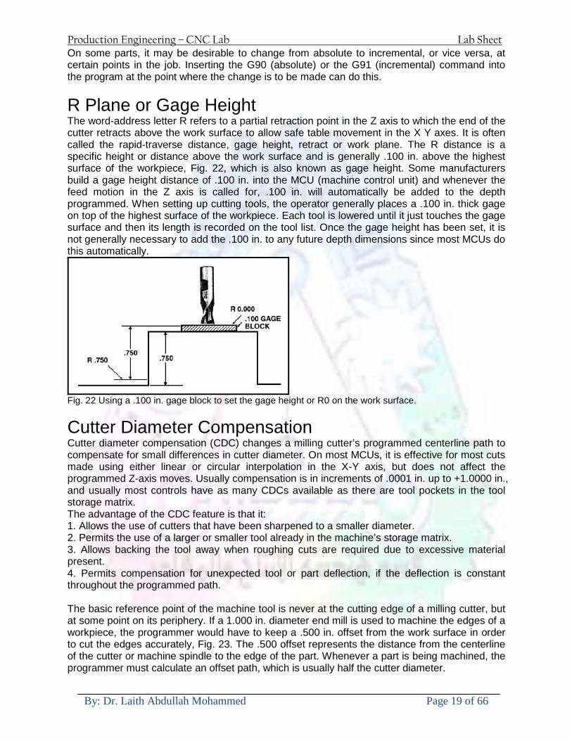
Production Engineering ndash CNC Lab Lab Sheet
By Dr Laith Abdullah Mohammed Page 19 of 66
On some parts it may be desirable to change from absolute to incremental or vice versa at certain points in the job Inserting the G90 (absolute) or the G91 (incremental) command into the program at the point where the change is to be made can do this
R Plane or Gage Height The word-address letter R refers to a partial retraction point in the Z axis to which the end of the cutter retracts above the work surface to allow safe table movement in the X Y axes It is often called the rapid-traverse distance gage height retract or work plane The R distance is a specific height or distance above the work surface and is generally 100 in above the highest surface of the workpiece Fig 22 which is also known as gage height Some manufacturers build a gage height distance of 100 in into the MCU (machine control unit) and whenever the feed motion in the Z axis is called for 100 in will automatically be added to the depth programmed When setting up cutting tools the operator generally places a 100 in thick gage on top of the highest surface of the workpiece Each tool is lowered until it just touches the gage surface and then its length is recorded on the tool list Once the gage height has been set it is not generally necessary to add the 100 in to any future depth dimensions since most MCUs do this automatically
Fig 22 Using a 100 in gage block to set the gage height or R0 on the work surface
Cutter Diameter Compensation Cutter diameter compensation (CDC) changes a milling cutterrsquos programmed centerline path to compensate for small differences in cutter diameter On most MCUs it is effective for most cuts made using either linear or circular interpolation in the X-Y axis but does not affect the programmed Z-axis moves Usually compensation is in increments of 0001 in up to +10000 in and usually most controls have as many CDCs available as there are tool pockets in the tool storage matrix The advantage of the CDC feature is that it 1 Allows the use of cutters that have been sharpened to a smaller diameter 2 Permits the use of a larger or smaller tool already in the machinersquos storage matrix 3 Allows backing the tool away when roughing cuts are required due to excessive material present 4 Permits compensation for unexpected tool or part deflection if the deflection is constant throughout the programmed path The basic reference point of the machine tool is never at the cutting edge of a milling cutter but at some point on its periphery If a 1000 in diameter end mill is used to machine the edges of a workpiece the programmer would have to keep a 500 in offset from the work surface in order to cut the edges accurately Fig 23 The 500 offset represents the distance from the centerline of the cutter or machine spindle to the edge of the part Whenever a part is being machined the programmer must calculate an offset path which is usually half the cutter diameter
Production Engineering ndash CNC Lab Lab Sheet
By Dr Laith Abdullah Mohammed Page 20 of 66
Fig 23 Cutter-diameter compensation must be used when machining with various size cutters Modern MCUs which have part surface programming automatically calculate centerline offsets once the diameter of the cutter for each operation is programmed Many MCUs have operator-entry capabilities which can compensate for differences in cutter diameters therefore an oversize cutter or one that has been sharpened can be used as long as the compensation value for oversize or undersize cutters is entered
Production Engineering ndash CNC Lab Lab Sheet
By Dr Laith Abdullah Mohammed Page 21 of 66
CNC Programming Hints - MILLING
Production Engineering ndash CNC Lab Lab Sheet
By Dr Laith Abdullah Mohammed Page 22 of 66
CNC Programming Hints ndash TURNING
Production Engineering ndash CNC Lab Lab Sheet
By Dr Laith Abdullah Mohammed Page 23 of 66
CNC
The abbreviation CNC stands for Computer(ized) Numerical(ly) Control(led) and refers specifically to the computer control of machine tools for the purpose of (repeatedly) manufacturing complex parts in metal as well as other materials using a program written in a notation conforming to the EIA-274-D standard and commonly called G-code
CNC was developed in the late 1940s and early 1950s by the MIT Servomechanisms Laboratory CNC machines were relatively briefly preceded by the less advanced NC or Numerical(ly) Control(led) machines The introduction of CNC machines radically changed the manufacturing industry Curves are as easy to cut as straight lines complex 3-D structures are relatively easy to produce and the number of machining steps that required human action have been dramatically reduced With the increased automation of manufacturing processes with CNC machining considerable improvements in consistency and quality have been achieved CNC automation reduced the frequency of errors and provided CNC operators with time to perform additional tasks
CNC automation also allows for more flexibility in the way parts are held in the manufacturing process and the time required to change the machine to produce different components In a production environment a series of CNC machines may be combined into one station commonly called a cell to progressively machine a part requiring several operations CNC machines today are controlled directly from files created by CAM software packages so that a part or assembly can go directly from design to manufacturing without the need of producing a drafted paper drawing of the manufactured component In a sense the CNC machines represent a special segment of industrial robot systems as they are programmable to perform many kinds of machining operations (within their designed physical limits like other robotic systems)
G-code
G-code is a common name for the programming language that is used for NC and CNC machine tools It is defined in EIA RS-274-D G-code is also the name of any word in a CNC program that begins with the letter G and generally is a code telling the machine tool what type of action to perform such as
bull rapid move bull controlled feed move in straight line or arc bull series of controlled feed moves that would result in a hole being drilled bull change a pallet bull Set tool information such as offset
There are other codes the type codes can be thought of like registers in a computer
X position Y position Z position M code (another action register) F feed rate S spindle speed N line number R Radius T Tool selection
Production Engineering ndash CNC Lab Lab Sheet
By Dr Laith Abdullah Mohammed Page 24 of 66
I Arc data X axis J Arc data Y axis
G-code files are output by CAM software such as Smartcam Gibbscam Featurecam Edgecam Mastercam etc G-code is also output by specialized CAD systems used to design printed circuit boards Such software must be customized for each type of machine tool that it will be used to program
Production Engineering ndash CNC Lab Lab Sheet
By Dr Laith Abdullah Mohammed Page 25 of 66
U 2عمل األزرار الرئيسية في ماكنة الخراطة المبرمجة (نصر (
1- SINGLE BLOCK للتأكد من صحة البرنامج (تنفيذ البرنامج خطوة خطوةب تقوم( 2- BLOCK DELETE بجانب ويعمل من األوامرلغاء بلوك معين أليستخدم 3- MACHINE LOCK العمل يستخدم لقفل حركة المحاور الرئيسية مع استمرار البرنامج في
)وهذا مهم للتاكد من صحة البرنامج قبل عملية التنفيذ النهائي(4- CONT CYCLE عملية التشغيل عند ايقافها الي سبب كان او عند ايقافها ألستئناف ستخدم ت
) BAR FEEDER(او في حالة استخدام ) FEED HOLDبسبب (5- DRY RUN وتستخدم لفحص البرنامج بعد ازالة الشغلة حركة سريعة للبرنامج 6- TURRET UP amp DOWN ) حركة حامل العدة TURRET الذي يحمل مجموعة من (
وهذا الزر يعمل مع الزر عكس عقرب الساعة او مع عقرب الساعة ةحركة دوراني العدد )SAFTY (
7- COOLANT ON or OFFفه تشغيل سائل التبريد او ايقا 8- COOLANT AUTO الدوال المساعدة في البرنامج من خالل فه تشغيل سائل التبريد او ايقا 9 -MACHINE START ة لتشغيل هيدرولكيك الماكنميستخد
Production Engineering ndash CNC Lab Lab Sheet
By Dr Laith Abdullah Mohammed Page 26 of 66
10- CLOSE OR OPEN CHUCKالعينة تستخدم لفتح وغلق 11 -T STOCK FWD RET حركة الغراب المتحرك ذهابا وإيابا12 -SPINDLE STOP تعمل على ايقاف حركة دوران العينة 13-JOG SPINDLE تعمل على تدوير العينة مع زر SAFTY 14 -OPT SAFTY مع الدالة ( تعمل عمل التوقف المشروط حيث تعملM1 دالة التوقف (
ط ) فقط األ اذا كان هذا الزر مضغو M1المشروط حيث ال يتوقف البرنامج في حالة وجود دالة ( SAFTY + SPINDLE ) يتم الضغط على زر ( START CYCLEلغرض تحرير زر (
START ) في نفس الوقت بعد الضغط على زر ( START CYCLE مرتين (
NC PC- 15 يستخدم هذا الزر عند ربطCNC يستخدم لنقل المعلومات ث مع جهاز أخر حي بينهما
16 -CALCU زر الخاص بالحاسبة مع زر ( ال وهوINPUT ( 17 - HD1 HD2 يستخدم الختيار العدة مع المخرطة ذات المحاور األربعة 18 - START تستخدم لبدء عملية التشغيل
Production Engineering ndash CNC Lab Lab Sheet
By Dr Laith Abdullah Mohammed Page 27 of 66
19- FEED HOLD تعمل على إيقاف عمل أي G موجودة مع بقاء العينة متحركة 20- M D I أو تشغيل البرنامج ل يتم استخدامه لإلدخا BLOCK BY BLOCK وتعمل عند
إدخال البرنامج بواسطة الشريط المثقب أو أي وسيلة إدخال أخرى أو في عمليات التصفير
21- REST تستخدم العادة تشغيل الماكنة أو مسح اإلنذار الذي يظهر على الشاشة 22- EMERGENCYتستخدم عادة اليقاف الماكنة في حالة الطوارئ فقط
OPERATION MENU KEY
CHAPTER PRG-CMK
OFFSET PROGRAM POSITION FUNCTION MENU KEY
23- POSITIONعلى الشاشة د الموقع الموجور الظها 24- PROGRAMإلظهار برنامج معين واختياره 25- OFFSET الختيار سماحات العدة أو سماحات نقطة المرجع 26- PRG- CHK تستخدم لفحص البرنامج على الشاشة 27- SETTING ألختيار الثوابت على الشاشة 28- SERVICE تستخدم ألستخراج المعامالت والثوابت 29- MESSAGE تستخدم ألظهار األخطاء الناتجة عن البرنامج او اخطاء التشغيل 30- OVERALL ألختيار المواقع 31- RELATIVE MODLINE تعوض عن POSITION 32- DIR MEM يستخدم ألظهار ملف البرامج المخزونة في الذاكرة وعندما نضغط هذا الزر
فان رقم واسم البرنامج سوف يظهر على الشاشة
2أدناه الشفرات الرئيسية التي تعمل على الماكنة المبرمجة نصر
G-CODE DESCRIPTION
G00 Rapid traverse (linear)
G01 Linear Interpolation at feed rate
G02 Circular interpolation (CW) R+
G03 Circular interpolation (CCW) R+
G10 Zero point tools
G20 Imperial data input
G21 Metric data input
G27 Reference return check
G28 Reference return
G29 Return from reference
Production Engineering ndash CNC Lab Lab Sheet
By Dr Laith Abdullah Mohammed Page 28 of 66
G33 Thread cutting
G40 Cancel cutter radius compensation
G41 Cutter compensation left
G42 Cutter compensation right
G54 Work co-ordinate system no1
G70 Finishing cycle
G71 Stock removal turning
G72 Stock removal facing
G74 Face grooving
G75 Diameter grooving
G76 Threading cycle
G90 Absolute date input
G91 Incremental data input
G94 Feed minute mode
G95 Feed rev mode
G96 Constant surface speed mode
G97 Cancel Constant surface speed
) 2أدناه الشفرات الثانوية التي تعمل على الماكنة المبرمجة (نصر
M-code FUNCTION
M00 Program stop
M03 Spindle forward (Tool forward ndash M94 mode)
M04 Spindle reverse (Tool forward ndash M94 mode)
M05 Spindle stop (Tool stop ndash M94 mode)
M08 Coolant on
M09 Coolant off
M30 Program end (with rewind)
M48 Turret shortest path
M52 Turret direction up (CW)
M53 Turret direction down (CCW)
M73 Chuck open
M74 Chuck close
Production Engineering ndash CNC Lab Lab Sheet
By Dr Laith Abdullah Mohammed Page 29 of 66
) وكل جملة مكونة من مجموعة من الكلمات blockإن كل برنامج يتكون من مجموعة من الجمل ()words) لهذا فأن الشفرات الرئيسية والمساعدة هي عبارة عن كلمات (words كما في المثال التالي (
G_ _ P1 Q2 U_ _ W_ _ D___ F_ _
)end of block) ويعني ( ) يكتب الرمز (blockتسلسل الكلمات مهم جدا بعد نهاية كل جملة (
طريقة ادخال البيانات الى الماكنة ــــــــــــــــــــــــــــــــــــــــــــــــــ
) MDIيمكن ادخال البيانات الى الماكنة بعدة طرق فقد يكون األدخال عن طريق قناة السيطرة ( MANUAL DATA INPUT ) او عن طريق قناة األضافة EDIT كما يمكن ادخال البيانات عن (
) RS ndash 232 COMMUNICATIN LINKطريق استخدام سلسلة الربط (
₤⅗₌⅗₌ ⅙₌₨image₍₡ ₤₌ℌ⅗₌ Ⅸ⅗ⅥⅯ₌ ₤₡ℌ₰₨⅗₌G71
الخراطة الطولية G71الغرض من التجربة عمل نموذج للخراطة بأستخدام الدالة تستعمل هذه الدالة للخراطة الطولية اي على طول محور المشغولة وكما هو موضح بالشكل ادناه
تعتبر هذه الدالة من الدوال التي ال تحتاج الى تكرار او إعادة كتابتها أي انها دالة تكرارية بمعنى ان اي
الذي هي دالة حركة G01خطوة تكون من ضمن هذه الدالة سوف تكرر العملية اي عند استعمال امر مثل خطية تتضمن القطع مع التغذية مع اعطاء القطر المراد قطعه و مراعاة عمق القطع المعطى سوف يتكرر
هذه االمر وصوال الى العمق المطلوب وهكذا لبقية الدوال
G71 المستخدمة للدالة الصيغة
G71 P1 Q2 U___ W___ D___ F___ حيث إن
P1 بداية الخطوة االولى = Q2 نهاية الخطوة =
Uوضع السماحات بأتجاه محور = X W وضع السماحات بأتجاه محور = Z وتكاد تكون مهملة وتوضع اشارة سالب Dعمق القطع وتوضع رقم صحيح مثل = D500 اي نصف ملمF التغذية والتي لها عالقة بالدالة = G95
Production Engineering ndash CNC Lab Lab Sheet
By Dr Laith Abdullah Mohammed Page 30 of 66
G71الدالة استخدام مثال على
T0100 M48 G0 X26 Z2 M08 T0101 G90 G95 G97 S500 M03 G71 P1 Q2 U03 W00 D500 F01 N1 G0 G42 X00 G01 Z00 G01 X2517 G01 Z-5352 G01 X7391 Z-9366 G01 Z-19145 N2 G28 M30
الجانب العملي
االجهزة واالدوات المستخدمة CNCماكنة خراطة مبرمجة 1 ملم 80قضيب من االلمنيوم قطر 2 ةفير ني 3 جاه أيمن تهولدر كاربيدي ذوا 4
طريقة العمل يتم تثبيت قضيب من االلمنيوم على العينة التابعة للماكنة مع مراعاة الطول المراد استعماله في عملية 1
الخراطة ) turretتثبيت عدة القطع في المكان الصحيح في ( 2
Production Engineering ndash CNC Lab Lab Sheet
By Dr Laith Abdullah Mohammed Page 31 of 66
بالنسبة الى القطعة المثبتة على العينة XZيتم تصفير الماكنة للمحاور 3 تصفير للمحورZ تكون مالمسة العدة الى وجه الشغلة تصفير للمحورX تكون مالمسة العدة الى سطح الشغلة الموازي لمحور X
يتم كتابة البرنامج أما بطريقة يدوية أو بالحاسوب مع وضع كل الظروف الالزمة للتشغيل ( عمق القطع 4 التغذية السرعة المطلوبة نوع المعدن )
ادخال البرنامج الى الحاسوب الموجود داخل الماكنة مع تهيئة الماكنة للتشغيل 5
المطلوب G71عمل برنامج يدوي على الدالة 1 رسم الشكل الشكل النهائي المطلوب مع وضع األبعاد 2
Ⅺ⅟₍euro⅗₌ ₤₡ℌ₰₨⅗₌₣ ₤⅗₌⅗₌ ⅙₌₨image₃₡ Ⅺℂtradeℒ⅗₌ ӈ₍Ⅴ⅟ⅳ₌ G70
G70 الغرض من التجربة عمل انهاء سطحي للمشغولة بواسطة الدالة
من الضروري إعطاء G71هذه الدالة تعمل شوط واحد فقط وتكون معتمدة على عمليات القطع في الدالة اللغاء مقدمة االداة (أي لكي تتم عملية االنهاء السطحي بدون حسابات نصف قطر مقدمة االداة ) G42دالة
G70الصيغة المستخدمة للدالة
G70 P1 Q2 F___ حيث ان
P1 بداية الخطوة االولى = Q2 نهاية الخطوة =
F التغذية والمرتبطة بالدالة = G95
وذلك ألن دالة االنهاء السطحي تحقق X Zمالحظة الدالة التحتاج لكتابة السماحات التابعة للمحورين المسافات الحقيقة المراد انتاجها للمشغولة
G71و G70مثال على الدالة
T0100 M48 G0 X26 Z2 M08 T0101 G90 G95 G97 S500 M03 G71 P1 Q2 U03 W00 D500 F01 N1 G0 G42 X00 G01 Z00 G01 X2517 G01 Z-5352 G01 X7391 Z-9366 G01 Z-19145 N2 G97 S750 MO3
Production Engineering ndash CNC Lab Lab Sheet
By Dr Laith Abdullah Mohammed Page 32 of 66
G70 P1 Q2 G40 F009 G28 M30
الجانب العملي الحظ التجربة األولى
المطلوب
G70 عمل برنامج يدوي على الدالة 1 رسم الشكل النهائي المطلوب مع وضع االبعاد 2
₪⅗₍euro⅗₌ ₤₡ℌ₰₨⅗₌₣ ₤⅗₌⅗₌ ⅙₌₨image₍₡ ⅝₍ⅠimageⅯ₌ ⅞ⅫⅦ⅔₧ G76
G76 للمشغولة بواسطة الدالةةالغرض من التجربة عمل أسنان خارجية أو داخلي
في هذه التجربة سوف نقوم بعمل األسنان الخارجية وهنا تكون حركة العينة ثابتة وهذا ضروري بسبب أن ) تكون متصلتين الكترونيا وعليه أي اختالف في سرعة العينة تؤدي إلى اختالف motionالعينة والحركة(
) servoفي سرعة الخدمة(يرتبط اتجاه تكوين األسنان باتجاه دوران العينة مثال إذا كانت األسنان ذات اتجاه أيمن يكون اتجاه دوران
وهنا نقلب العدة إلى االسفل وكما هو موضح بالشكل أدناه MO3العينة عكس عقرب الساعة أي نستعمل
Production Engineering ndash CNC Lab Lab Sheet
By Dr Laith Abdullah Mohammed Page 33 of 66
الخطوة هي عبارة عن المسافة ما بين قمة سن إلى قمة سن أخر عمق السن هو العمق المطلوب تكوينه لألسنان
G76 الصيغة المستخدمة للدالة
G76 X___ Z___ K___ F___ D___ A___
حيث أن X القطر الداخلي للسن =Z طول السن =K عمق السن وتستخرج من المعادلة التالية =K=065F F الخطوة =D عمق القطع بالمايكرون فقط =A زاوية السن =
G76مثال على استخدام الدالة T0300 M48 GOO X30 Z4 T0303 M08 G97 S500 MO3 G76 X28375 Z-20 K08125 F125 D120 G00 X40 Z4 G28 M30
Production Engineering ndash CNC Lab Lab Sheet
By Dr Laith Abdullah Mohammed Page 34 of 66
الجانب العملي الحظ التجربة األولى
المطلوب
G76عمل برنامج يدوي على الدالة 1 رسم الشكل النهائي المطلوب مع وضع األبعاد 2
Ⅺ⅘₌⅗₌ Ⅵ₂ Ⅺ₯ℋ₍⅗₌ ℌℲℂ⅗₌ ⅞ⅫⅦ⅔₧ ₤K₡₌ℌ⅗₌ ₤₡ℌ₰₨⅗₌)Groove ₤⅗₌⅗₌ ₤tradeimage₌Ⅶ₡ (G75
G75 بواسطة الدالة grooveالغرض من التجربة تكوين
) للمشغولة وتعتمد شكل الحفر على طريقة grooveتستعمل هذه الدالة لتكوين الحفر الخارجي والداخلي (
التشغيل وعلى الشكل المراد إنتاجه وتعتبر هذه الطريقة من عمليات التشكيل للمعدن إن هذه الدالة هي دالة مالحظة مع G75في هذه التجربة سنقوم بعمل الحفر الخارجي بواسطة الدالة
تكرارية وغير تكرارية حسب نوع التشغيل
G 75 الصيغة المستخدمة للدالةG75 X___ Z___ I___ K____
حيث أن
X العمق النهائي لقطر الشغلة =Z عرض الحفر =I الدخول في كل مرة =
K التزحيف على محور =z بالنسبة للعدة
Production Engineering ndash CNC Lab Lab Sheet
By Dr Laith Abdullah Mohammed Page 35 of 66
G75مثال على استخدام الدالة
T0500 M48 GOO X100 Z -20 T0505 M08 G97 S700 MO3 G75 X84 Z -38 I 05 K4
الجانب العملي الحظ التجربة األولى
المطلوب
G76عمل برنامج يدوي على الدالة 1 رسم الشكل النهائي المطلوب مع وضع األبعاد 2
Production Engineering ndash CNC Lab Lab Sheet
By Dr Laith Abdullah Mohammed Page 36 of 66
CNC Milling Machine Mechanical Construction
Guideways The guideways of CNC machines are made of steel To reduce the frictional forces they are coated with a strip of PTFE (Poly Tetra Fluoro Ethylene)
Ballscrews On conventional lathes a leadscrew is used to converts the rotary motion of the hand wheel into linear motion of the slides Leadscrews have a high coefficient of friction and backlash On CNC machines a ballscrew is used instead of a leadscrew Friction and backlash are much less than on leadscrews
Guideway
Production Engineering ndash CNC Lab Lab Sheet
By Dr Laith Abdullah Mohammed Page 37 of 66
bullMachining operations Direction of cutting Based on the direction of the cutter rotation and work piece feed milling operations are classified into two types 1-Up milling (Convention milling) In up milling the metal is removed by rotating the cutter against the direction of travel of the part
Feed
Machine table
Part
Cutting tool
Chip thickness at theexit of the tooth
2-Down milling (Climb milling) In climb milling the metal is removed by rotating the cutter with the direction of travel of the part
Machine table
Part
Cutting tool
Chip thickness at theentrance of the tooth
Production Engineering ndash CNC Lab Lab Sheet
By Dr Laith Abdullah Mohammed Page 38 of 66
bullTooling Tool geometry The geometry of the tool tip affects the way that the metal cutting is performed The nose radius rake angles relief angles etc must be selected with care
Radial relief
Radial rake
Axial relief
Approach angle
Axial relief
Corner radius Face mill Face milling cutters are used to mill flat surfaces Commonly used face milling cutters Cutter with 75 degree approach
75 deg
Cutter with 90 degree approach (Square shoulder face mill)
90 deg
Cutter with 45 degree approach
Production Engineering ndash CNC Lab Lab Sheet
By Dr Laith Abdullah Mohammed Page 39 of 66
bullCNC Programming Axes convention The Z axis is along the spindle axis The X and Y axes are perpendicular to Z VMC
Z
Y
-
+
-+
X- +
+Z
-Z
+Y
-Y
-X +X
Part
Machine table
X
YZ
G00 Rapid traverse When the tool being positioned at a point preparatory to a cutting motion to save time it is moved along a straight line at Rapid traverse at a fixed traverse rate which is pre-programmed into the machines control system Typical rapid traverse rates are 10 to 25 m min but can be as high as 80 mmin
Production Engineering ndash CNC Lab Lab Sheet
By Dr Laith Abdullah Mohammed Page 40 of 66
Format N_ G00 X__ Y__Z__
G01 Linear interpolation (feed traverse) The tool moves along a straight line in one or two axis simultaneously at a programmed linear speed the feed rate Format N__ G01 X__ Y__Z__ F__
Part
Feed
Part
Feed
G02G03 Circular interpolation The tool moves along an arc in two axes simultaneously at a programmed linear speed the feed rate
Production Engineering ndash CNC Lab Lab Sheet
By Dr Laith Abdullah Mohammed Page 41 of 66
Format N__ G0203 X__ Y__Z__ I__ J__K__ F__ using the arc center OR N__ G0203 X__ Y__Z__ R__ F__ using the arc radius G02 moves along a CW arc G03 moves along a CCW arc Arc center The arc center is specified by addresses I J and K I J and K are the X Y and Z co-ordinates of the arc center with reference to the arc start point
X
Y
Arc center
Arc endArc start
- J
- I
I = X coord of center - X coord of start point J = Y coord of center - Y coord of start point K = Z coord of center - Z coord of start point I J and K must be written with their signs
Production Engineering ndash CNC Lab Lab Sheet
By Dr Laith Abdullah Mohammed Page 42 of 66
bullWork holding
Rotary table
Fixture base
Component
Clamp
Stud
Fixtures The use of fixtures 1 Improves repeatability of dimensions 2 Improves working conditions 3 Cuts down requirement of skilled labour 4 Reduces part loading and unloading time 5 Improves safety in the working area 6 Reduces the cost of machining There are two types fixtures commonly used 1 Special fixture Special fixtures are used to hold and locate the typical components which are having complex shape and to be located with the reference hole (dowel hole) Special fixtures are required for components like gear case cover cylinder heads etc 2 Modular fixture Modular fixture is a set different kind of clamping and locating elements These fixtures are used to hold identical components in different sizes and components of box type Example Manifolds head stocks connecting rods and flanges
Production Engineering ndash CNC Lab Lab Sheet
By Dr Laith Abdullah Mohammed Page 43 of 66
bullMachine setting
Determining X and Y work zero offset Case 1
Part
Machine table
Part
End mill or reamer
Work offset X0Y0 For determining X work zero offset bull Touch the periphery of the end mill or reamer to the part bull Enter current machine X value + cutter radius as X work zero offset For determining Y work zero offset bull Touch the periphery of the end mill or reamer to the part bull Enter current machine Y value - cutter radius as Y work zero offset Case 2
Part
Machine table
Part
End mill or reamerWork offset X0Y0
bull Mount the dial indicator on machine spindle true the bore bull Enter current machine X and Y value as X and Y work zero offset
Production Engineering ndash CNC Lab Lab Sheet
By Dr Laith Abdullah Mohammed Page 44 of 66
How to Select a Cutting Fluid
One part of the metal cutting equation that is sometimes overlooked however is
the choice of an appropriate cutting fluid With todayrsquos system approach to metal
cutting use of the right metalworking fluid has become just as much a part of the
solution as the other elements In fact at least one company is now integrating
cutting fluids and cutting tools into effective metal cutting systems Following are
some things to consider when choosing your next cutting fluid
The Four Key Questions
There are four vital pieces of information that are necessary when choosing a
cutting fluid They are
1 What are you cutting
2 What is the chemistry of your water
3 What are you using now
4 What are your options
5 What do you prefer
What Are You Cutting
The first question ndash ldquoWhat are you cuttingrdquo ndash is often the most difficult to answer
because most shops handle a variety of workpiece materials on a regular basis If
the answer is an unequivocal ldquoaluminumrdquo or ldquostainless steelrdquo or ldquocast ironrdquo the
selection of a cutting fluid can be quite simple and straightforward Unfortunately
that is seldom the case in anything but a high-volume plant Where aluminum or
other nonferrous metals are a significant part of the mix a non-staining cutting
fluid is a must Generally speaking this will be a semi-synthetic with special
ingredients to prevent bi-metallic corrosion and staining of non-ferrous workpieces
Where the ferrous metals predominate however a more general purpose semi-
synthetic or hybrid fluid might be a more economical choice
Production Engineering ndash CNC Lab Lab Sheet
By Dr Laith Abdullah Mohammed Page 45 of 66
What is The Chemistry of Your Water
The second question ndash ldquoWhat is the chemistry of your waterrdquo ndash is probably the
single most common reason for the success or failure of a cutting fluid Very few
plants invest the money necessary to install effective water purification systems
using deionization or reverse osmosis technology Unfortunately the chemicals
present or not present in the water used to re-constitute a cutting fluid make a
tremendous difference in its performance and sump life Most manufacturers of
cutting fluids will perform the necessary water testing to determine exactly what
minerals are dissolved in your water and make a fluid recommendation based on
the results
What are you using now
The third question ndash ldquoWhat are you using nowrdquo ndash helps narrow the range of
choices When coupled with an objective analysis of the strengths and weaknesses
of the current fluid the answer to this question can quickly point you toward a
relatively small number of competitive alternatives that have the attributes required
to meet your cutting needs Many cutting fluids are in use today simply because
they were in use yesterday It is a hard reality of todayrsquos marketplace that if one
isnrsquot constantly striving to improve they will certainly be overtaken by a
competitor who is
What Are Your Options
The fourth question ndash ldquoWhat are your optionsrdquo ndash leads to the final selection of a
cutting fluid Cutting fluids can be divided into four general groups based on their
chemistry
They are
bull Soluble Oils ndash quite literally oil dispersed in water
bull Synthetics ndash completely oil free man-made coolants in solution
Production Engineering ndash CNC Lab Lab Sheet
By Dr Laith Abdullah Mohammed Page 46 of 66
bull Semi-Synthetics ndash a mixture of natural and synthetic lubricants with up to 30
mineral oil
bull Hybrids ndash a special class of semi-synthetics with a mineral oil content of about
15 Each fluid type has advantages and disadvantages which make it suitable for
a particular group of applications In addition there are costperformance trade-
offs to be made between the groups within a specific set of applications For
example where a hybrid and a semi-synthetic may both be suitable for a particular
use the hybrid might provide longer sump life at a slightly higher initial cost
while some semi synthetics may be more economical to recycle or dispose of while
not giving as long a tank life The final decision in this case would have to be made
on the detailed economics of the shop where the fluids were to be used and on the
ownerrsquos individual preferences
Soluble Oils
Soluble oils are oils that disperse in water when emulsifiers are added They are
generally suitable for moderate-to heavy-duty machining and grinding of all non-
ferrous metals carbon and cast steels and in applications where dissimilar metals
such as aluminium and steel are present They can also be used in turning drilling
tapping reaming gear cutting broaching as well as internal and centerless types
of grinding operations Soluble oils provide excellent aluminium and copper
corrosion control good rancidity control which extends fluid for long lasting
trouble-free performance and good concentrate and mix stability making it ideal
for mixing in water with a minimal amount of agitation An example of this is
Valenitersquos VNTreg-650 premium heavy-duty soluble oil
Synthetics
Synthetics are completely oil free solutions made of polymers organic and
inorganic materials that are mixed with water These clear low foaming and bio-
Production Engineering ndash CNC Lab Lab Sheet
By Dr Laith Abdullah Mohammed Page 47 of 66
stable coolants are ideal for machining and grinding of ferrous materials carbon
steels or cast iron Their complex lubricant packages make synthetics well-suited
for tough-to-machine materials such as stainless steels and high-temperature alloys
Certain synthetics are specifically designed to address the primary failure modes of
flank wear and nose wear Although there are many benefits some synthetics may
cause staining of non-ferrous materials
Semi-Synthetics
Semi-synthetic fluids are a mixture of oils synthetic emulsifiers and water They
were primarily developed for the aircraft nuclear and related industries
Consequently they work extremely well on all non-ferrous metals such as titanium
aluminium copper brass bronze and stainless steel in both machining and
grinding Semi-synthetics can be used on ferrous metals too They are chlorine-
free to reduce bi-metallic corrosion and staining of metals They should be used at
a 5-8 dilution with water depending on the severity of the operation
Hybrids
Hybrids are cutting fluids custom engineered to solve a particular problem For
example Valenitersquos VNTreg-800 was developed to be very clean in the machining
and grinding of cast iron It provides better stability in hard water and rejects tramp
oil very well which adds to its bio-stable chemistry Hybrids work extremely well
on all metals in both machining and grinding They should be mixed at a 5-7
dilution with water depending on the condition of the water
What Do You Prefer
The final question ndash ldquoWhat do you preferrdquo ndash is usually the ldquotie breakerrdquo where
there is more than one appropriate cutting fluid available Here again as in the
case of what is being used now the key is to examine your preferences objectively
Production Engineering ndash CNC Lab Lab Sheet
By Dr Laith Abdullah Mohammed Page 48 of 66
and specifically to identify the real reasons behind a preference If you cannot
point to specific reasons why one class of cutting fluid is preferred over another
you are well advised to follow the recommendations of the professional who has
analyzed your requirements Choosing the right fluid today is easier than ever as
the system approach to metal cutting productivity continues to grow in acceptance
The day is not far off when choosing a complete solution will be as easy as
choosing the right insert and chip breaker today The answers are available and the
results will more than justify the time you spend choosing the right metal cutting
fluid
Useful Links wwwball-screwsnet
wwwlubelinkcom
wwwmachinerylubricationcom
wwwadvancedmanufacturingcom
wwwmmsonlinecom
wwwcuttingtoolengineeringcom
wwwgeartechnologycom
wwwengineersedgecom
wwwagmaorg
wwwefundacom
wwwsaeorg
wwwsmeorg
wwwastmorg
wwwissorg
wwwmachinetoolscom
wwwansiorg
wwwasmeorg
wwwcnccicom
wwwmatlscom
wwwthefreedictionarycom
wwwengineersupplycom
Production Engineering ndash CNC Lab Lab Sheet
By Dr Laith Abdullah Mohammed Page 49 of 66
SurfCAM Tutorial ndash Beginning with the basics
Background SurfCAM is a computer aided manufacturing (CAM) software which allows you to create manage and modify tool paths for computer aided designed (CAD) part The software requires a CAD model or requires that you create some geometry within SurfCAM with some rudimentary tools provided The tool paths are created or stored internally in SurfCAM in a generic programming language called APT Once the tool paths are created the APT paths are translated using a post processor into typical machine G-code
Opening SurfCAM SurfCAM can be opened from the Novell Applications Launcher on most Industrial Engineering computer labs workstations Search under lsquoallrsquo applications and double click on SurfCAM 2005 Once the program opens a license must be selected from the list (not the Demo license) to enable saving the file later Choose one of the 30 licenses available If for some reason the licenses are not listed on the license manager form select server list and type ldquobonnieeosncsuedurdquo A list of available licenses should appear Select a license and click OK After the license is selected an Add StockFixture form (Figure 1) opens allows you to add a model which represents the pre-machined stock or a fixture Click on OK without adding either Both of these items can be added later under a more appropriate dialog
Figure 1 Add Stock or Fixture dialog box
Production Engineering ndash CNC Lab Lab Sheet
By Dr Laith Abdullah Mohammed Page 50 of 66
SurfCAM Interface
Figure 2 SurfCAM Windows based interface
SurfCAM is a windows based software system so most of the typical windows functions under File are applicable This is where you can open save exit print etc The Create menu allows the user to create different geometry forms Here you can create a point line surface chamfer circle and many other geometry types For the most part these functions are not used by beginners but are useful when creating bounding curves where you donrsquot want the tool to move outside (constraining the tool) The Edit menu allows you to change or modify many different entities such as changing lines altering surfaces joining surfaces trimming or breaking elements add control points etc Again these features are helpful to advanced users and are not covered in detail in this tutorial The Display menu offers the ability to change the orientation of the part on the screen The typical rotate pan fit to screen and zoom functions are available as well as several functions which allow the user to shift between views or call up a named view (ie top bottom etc) The NC menu is the main machining interface menu In this menu you select the general form of machining (2 axis 3 axis 4 axis 5 axis turning etc) and under the general form a more specific machining function is selected This menu is the most used and the options contained must be fully understood to get the most out of SurfCAM Each function will be described in some detail in a further chapter The Analyze menu contains options such as measuring the distance between points angles tangency elements etc These functions are auxiliary functions meant to help you understand the part better but basically provide no functionality for making tool paths for CNC machines Thus these will not be covered The Tools menu allows the user to change the system options modify keyboard shortcuts change the model units etc These options are again not used by beginners Finally the Help menu provides access to the online users manual In lieu of clicking the Help menu the F1 key is the shortcut key for help (as it is in most windows based programs)
Importing a CAD model Importing a CAD model that is stored locally is done by selecting File-gtOpen On the Files of type dropdown box choose the type of file you wish to open (Figure 3) Do this prior to negotiating your way through the maze of folders to prevent having to go through the folder tree again Once the file type is selected find the file you are trying to open and click the Open
Production Engineering ndash CNC Lab Lab Sheet
By Dr Laith Abdullah Mohammed Page 51 of 66
button SurfCAM will then attempt to read the file you have selected SurfCAM may provide a dialog box describing what it has imported and identify if it was successful If this dialog is provided simply click close without saving
Figure 3 Open Dialog Note - Change type of file prior to finding the file you wish to open
SurfCAM allows a user to import several different types of CAD files the most common types which you will likely import are SolidWorks part files (sldprt or prt) AutoCAD files(dxf) or IGES (igs or iges) Native file import (such as is the case with SolidWorks) provides the greatest information transfer and generic file imports (such as is the case with IGES) provide the least Normally it is to the advantage of the user to use native file importing procedures when available Recently (2005) SurfCAM added some compatibility with SolidWorks This allows the user to create tool paths for a part and if an engineering change is needed for the part update the part in SolidWorks When the part is then opened in SurfCAM the changes are noted and a simple update operation command is needed This however does not operate with complete transparency andor accuracy and thus users need to be cognizant of changing CAD models
SurfCAM Geometry In SurfCAM two basic types of geometry are used the surface and the point A surface (Figure 4) is a so called spline (NURBS or B-Spline are the two most common) surface (parameterized by two values u and v) such that every location on the surface can be defined as a function of these parameters In other words SurfCAM can calculate the location of any point on the
Production Engineering ndash CNC Lab Lab Sheet
By Dr Laith Abdullah Mohammed Page 52 of 66
surface Surfaces are used primarily in 3 4 and 5 axis machining and require a significant
amount of processing power and time Figure 4 Surfaces model of a mold half Note the difference between this and Figure 2 a wireframe model
Point or line based models are often referred to as wireframe (Figure 5) models because the models consist of connected lines and resemble the part only at the intersection of two surfaces Wireframe models were made popular lsquoback in the dayrsquo when computer processing was expensive There are times when each of the models are important and selecting model geometry when applying a SurfCAM operation will be much simpler if you understand the differences between the two When importing a SolidWorks model the default is both the surfaces and the wireframe geometry are imported
Figure 5 Wireframe model of the mold in Figure 1
Steps to Creating Tool Paths Once a CAD model is imported into SurfCAM tool paths can be created There is no one correct way to create tool paths however there is a set of general steps to take to ensure the tool paths are created with a minimum amount of hardship (note the wordinghellipHardship is inevitable when creating tool paths it is the intent of this manual to minimize this) The following is a list of steps which should be considered when making tool paths
Production Engineering ndash CNC Lab Lab Sheet
By Dr Laith Abdullah Mohammed Page 53 of 66
1 Plan ahead a Orient the part in SolidWorks such that if only one side is to be machined that
side is the Top view This can be done early in SolidWorks by choosing a plane parallel the X-Y plane as the sketch plane for the machined geometry
b Orient the part in SolidWorks such that the origin is somewhere of relative importance and someplace in space that can be easily identified when placed on the machine This is extremely important to minimize set up time at the machine (note ndash my personal preference for a part that is to be fully machined [ie stock exists on all sides] is to place the origin at the center and top of the parthellipjust my preference)
c Orient the part in SolidWorks such that the X and Y axes are aligned as you want them on the machinehellip
d Planning ahead will save you many hours of headaches laterhelliptrust me 2 Import the model 3 Choose a construction view such that the tool approaches the side to be machined
from the positive Z axis direction (as defined by part origin) a This is done by clicking on the CView icon
b From the list of named views chose the view which orients the origin as you would like
c If one of the views does not fit your criteria you have two choices i Perform a transformation of the part in SurfCAM or SolidWorks
ii Add a new construction view by selecting new This option requires a relatively good understanding of right hand coordinate frames but is very usefulhellipNormally used by more advanced users
d Be sure the CoordVIEW selection is made vs CoordWORLD This ensures the tools will be controlled from the coordinate frame selected by the view (ie the origin on the part) instead of the origin on the lower left corner of the screen This will be especially important when we get into 4 and 5 axis machining
4 In the Operations Manager (Figure 6) select Setup One and change the name to something meaningful ndash like Front Side Mold Cavity
a Access the Operations manager by right clicking or by selecting the Operations Manager icon in the tool bar
b Operations Manager is where the tool paths are managed once they are created as well as where individual tool paths can be verified
Production Engineering ndash CNC Lab Lab Sheet
By Dr Laith Abdullah Mohammed Page 54 of 66
5 Roughing Tool Paths a Create the tool paths to remove the majority of the material (if applicable) b Use NC-gt3Axis-gtZ rough or Plunge Rough c Described in next section
6 Create Finishing Tool Paths a Described in next section
7 Add another setup if necessary 8 Perform steps 3 through 6 as necessary 9 Verify the tool paths are correct 10 Use a post processor for the tool paths to create G-Code for machine
Creating Tool Paths The following is a list of operations what they are intended for how they generally work and some parameters that may be adjusted to modify the tool paths
2 Axis tool paths Unless otherwise noted 2 axis tool path functions require lines or arc segments as input parameters (as opposed to surfaces) There are several options as to how these segments are chosen the most prevalent is the chain option and the second most prevalent is the single When choosing the line segments using the chain option SurfCAM will try to link a complete path of segments based on an initial segment chosen by the user If the operation is planer (ie pocket or contour) the segments must lie on the same plane If the operation is non-planer (ie contour 3D) SurfCAM will prompt the user to specify segments when it encounters a branch point
Figure 6 Operations Manager view showing setup one re-labeled as Front Side Mold
Production Engineering ndash CNC Lab Lab Sheet
By Dr Laith Abdullah Mohammed Page 55 of 66
When using the single element option the user must manually choose each segment desired for the operation Note that most operations do not require a closed loop of segments you may specify for instance an open contour where the tool is supposed to move The order of choosing segments is important This order determines the path of the tool in the sense that if three segments are chosen such that the middle segment is chosen last there will be three different plunge and machine operations one on each segment If the operation was to make a continuous contour around the outside of the part the segments should be chosen in order of the desired tool trajectory
Operations
Pocket Pocket operation in SurfCAM is used to cut an enclosed space from the inside to the outside at one particular depth The operation starts in the center of an enclosed area (with a plunge move in the ndashZ direction) and makes incremental closed paths towards the pocket boundaries in user defined path offsets (Figure 7) The user chooses the boundary of the pocket (line segments) and if more than one pocket is chosen SurfCAM will ask the user to click inside a pocket
Figure 7 Two examples of using the pocketing operation
The pocket operation allows for creating a projection of the pocket paths on multiple planes This is useful if you have a deep pocket which will not allow the tool to cut directly at the depth of the pocket but would be easily done using the same paths at several different Z heights On the cut control (Figure 8) tab the user specifies where the chosen geometry (pocket segments) lie (ie bottom or top) Then under the amount to remove specify the total material height to be removed and the rough spacing (amount you wish to advance the Z axis with each pocket step) You may also specify a finishing pass and as well as stock to leave
Production Engineering ndash CNC Lab Lab Sheet
By Dr Laith Abdullah Mohammed Page 56 of 66
Figure 8 Example of Contour Operation with multiple passes
Contour Contouring in SurfCAM is used to perform peripheral milling on the inside or outside of a line segment (Figure 9) The user is to identify the line segments which define a contour (does not have to be a closed loop of segments) SurfCAM may or may not require the user to specify a side to contour (ie which side of the line is the tool to cut) For contouring each segment must lie on the same plane
Production Engineering ndash CNC Lab Lab Sheet
By Dr Laith Abdullah Mohammed Page 57 of 66
Figure 9 Examples of parts cut with 2-Axis Contour
Contour 3D Contour 3D is the same operation type as contour but allows the user to specify segments on different planes for the tool to cut along
Drill Drilling operations are any rotating tool operation meant to engage the part from a single direction ndash namely from the positive Z direction Drilling operations can be specified using circle point or line segments After choosing NC-gt2-Axis-gtDrill SurfCAM allows the user to choose multiple circles or points defining holes to be drilled Drilling operations also allow the user to incorporate more than 1 operation such as a center drill a drill and a reaming operation After selecting the locations for the drilling operation a dialog box (Figure 10) allows the user to add change or delete tools to be used in the operation As displayed in the following figure the spotdrill operation is followed by a drilling operation followed by a tapping operation The depth of each tool can be controlled individually by double clicking the total depth cell in and manually entering Tools can be added before or after operations which the cells are highlighted by selecting either of the insert buttons at the top or by the insert menu Select tool button allows the user to change the tool size or type
Production Engineering ndash CNC Lab Lab Sheet
By Dr Laith Abdullah Mohammed Page 58 of 66
Figure 10 Drill operation manager Several operations can be completed at one time
Figure 11 Drill operation including the spotdrill drill and tap as outlined in Fig 10
3 Axis tool paths SurfCAM requires surfaces as inputs for 3 Axis tool paths Surfaces can be created in SurfCAM but are most easily created in a CAD package and imported into SurfCAM Surfaces allow SurfCAM to identify every point on the surface in 3 dimensions unlike 2D geometry (wireframes) which only identify positions on the plane Creating tool paths with complex surfaces takes a very significant amount of processing power so expect 3 Axis tool path generation to take longer
Production Engineering ndash CNC Lab Lab Sheet
By Dr Laith Abdullah Mohammed Page 59 of 66
Operations
Cut 3 Axis cut operation takes a surface and using the flow lines creates a rastering path over the surface with the tool tip riding on the surface The primary direction will be defined by the flow lines of the surface (which can be edited by Edit-gtSurfaces-gtArrow-gtDirection) If you intend to cross surface boundaries you must merge the surfaces (Edit-gtJoin and choose the two surfaces)
Z-Rough The Z-rough operation is used to remove a large amount of material prior to finish machining Roughing operation is typically the first operation you perform for each setup The Z-Rough operation cuts the part in user defined intervals For each of these intervals a surface intersection between the part and the plane is performed and a 2D pocket or contour operation is performed on that plane This is performed on each plane When choosing NC-gt3 Axis-gtZ rough the first dialog box you will encounter asks for a bounding box to be defined Choose the Extents Box and a second dialog box will ask for the coordinates which define the box (Figure 12) This is the stock size you expect to machine the part from Input the coordinates or change the additional offset amounts (in XY or Z) as appropriate and click Calculate Bounding Box
Figure 12 Material Extents Box Example
Next choose the tool and cutting parameters that you desire and click on the Cut Control Tab (Figure 13) Here you will find the following parameters which are often changed Stock to
Production Engineering ndash CNC Lab Lab Sheet
By Dr Laith Abdullah Mohammed Page 60 of 66
leave ndash this is an offset amount from the surfaces which leaves a small amount of material to finish machine Minimum and Maximum Z values ndash Defines area to machine Z Step Size ndash This identifies the plane intervals for the surface intersection planes (the first interval will be at the top of the selected area and successive increments down in Z will be cut until the Minimum Z value is reached)
Figure 13 3Axis Z Rough Cut Control
The 3Axis Z-Finish operation works in exactly the same way 3 Axis Z-Finish is most appropriate for finishing vertical or near vertical walls
3D Offset The 3D Offset operation creates a tool path using a 2D or 3D boundary by offsetting the boundary in concentric offset cutting passes Each pass calculates the tool engagement and maintains the engagement somewhat constant The advantage (significant) is the scallop height ndash height of the material between passes ndash is controlled thus the surface finish is predictable When choosing 3D Offset surfaces are selected as well as 2D or 3D boundaries The boundaries define the concentric offset paths shape as well as limit the tool path area Choose NC-gt3Axis-gt3D Offset from the drop down menus SurfCAM will prompt you to select the surface or surfaces to cut across Select the surfaces you wish to machine and then select the tool and cutting parameters you wish use Next select the Cut Control Tab and check the Use Boundary Curves option Set the Step Type to Scallop and set the maximum scallop height If you like
Production Engineering ndash CNC Lab Lab Sheet
By Dr Laith Abdullah Mohammed Page 61 of 66
you can also add stock to leave if this is a roughing operation You can also set the Direction and Start-End parameters from this tab Click OK and the paths will be generated
Figure 14 Cut Control Tab for 3D Offset
Example part using both 2D and 3D geometry
The tool paths for this mold will be generated in SurfCAM using 5 operations The first will be a roughing operation using a frac14 inch flat end mill with the Z step size of 00625in Choose NC-
Production Engineering ndash CNC Lab Lab Sheet
By Dr Laith Abdullah Mohammed Page 62 of 66
gt3Axis-gtZ-Rough from the drop down menu Select all visible surfaces and create an extents box that has 025inch XY offsets and 01inch Z offset Next select the frac14 inch flat end mill from the tools menu Under Cut Control tab set the Z step size to be 00625inch The tool paths will look something like Figure 15
Figure 15 Z-Rough Tool paths for Example Part
Next a flat surface operation will be performed to cut the flat surface on the top Select NC-gt3 Axis-gtFlat Surface from the drop down menu Select all visible surfaces again Choose the 12inch flat end mill and set the cutting parameters as desired Under Cut Control Tab change the Minimum Area to 50 square inches (Figure 16) The tool paths should look something like Figure 17
Figure 16 Cut Control for Flat Surface
Production Engineering ndash CNC Lab Lab Sheet
By Dr Laith Abdullah Mohammed Page 63 of 66
Figure 17 Flat Surface Tool Paths
Next we will use a 3D offset operation to cut the mold cavity Select NC-gt3 Axis-gt3D Offset from the dropdown menu Change the view to the top view and select within to capture the surfaces of the mold cavity Draw a rectangle around the mold cavity Select a 18 inch ball endmill from the tool library and set the cutting parameters as appropriate Next set the Cut Control tab parameters as in Figure 14 The paths creates should be similar to Figure 18
Figure 18 3D Offset Paths
Next we will perform a 2 Axis contouring of the top section Select NC-gt2 Axis-gtContour from the dropdown menu Using the chain option select the bottom contour of the top extrusion Select the frac12 inch flat end mill from the tool library and set the cutting parameters as required In the Cut Control Tab change the Geometry to Bottom and the amount to remove in Z to 05
Production Engineering ndash CNC Lab Lab Sheet
By Dr Laith Abdullah Mohammed Page 64 of 66
Change the Rough Spacing in Z to 025 and add 1 finish pass of 002 (Figure 19) Click OK and SurfCAM will instruct you to choose a side to contour Click anywhere on the screen OUTSIDE the geometry you selected for the contouring operation Failure to click outside the geometry will result in the tool being on the wrong side of the contour Your paths should look something like those in Figure 20
Figure 19 Cut Control Tab for the Contouring Operation
Figure 20 Contouring operation paths
Production Engineering ndash CNC Lab Lab Sheet
By Dr Laith Abdullah Mohammed Page 65 of 66
Next we will perform a 2 axis pocket operation for the small pocket on the top face of the mold Select NC-gt2Axis-gtPocket and using the Auto select feature select the boundary curve at the bottom of the pocket Click Done twice and select the frac14 inch flat end mill from the tool library Set the appropriate cutting parameters and click OK SurfCAM will prompt you to click inside the pocket Click anywhere inside the geometry you chose to define the pocket The resulting paths should look something like those in Figure 21
Figure 21 2 Axis Pocket Operation Paths
Finally we will add a drilling operation for the 2 holes at the corners of the mold Select NC-gt2 Axis-gtDrill from the dropdown menu Select the top circles defining the two holes A menu box will appear with a default tool (Center drill) already programmed Add a second tool to the list by selecting Insert-gtAfter and select the tool from the tool library Change the drill depth to 10inches and click OK The paths should look something similar to Figure 23
Figure 22 Drill Menu
Production Engineering ndash CNC Lab Lab Sheet
By Dr Laith Abdullah Mohammed Page 66 of 66
Figure 23 Drilling Operation Tool Paths
Now you can watch a simulation of the cutting by choosing the setup in the operations manager and clicking the simulate icon Be sure to set the stock in the set up by right clicking the set up and selecting Edit Setup Information In the Stock Tab you can create a bounding box meeting your needs and click Add Your simulation should result in something like the following
Figure 24 Final Simulation of the example Mold
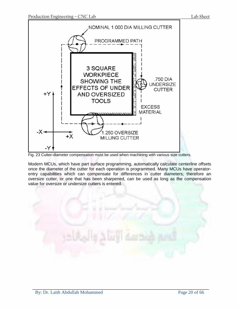
Production Engineering ndash CNC Lab Lab Sheet
By Dr Laith Abdullah Mohammed Page 20 of 66
Fig 23 Cutter-diameter compensation must be used when machining with various size cutters Modern MCUs which have part surface programming automatically calculate centerline offsets once the diameter of the cutter for each operation is programmed Many MCUs have operator-entry capabilities which can compensate for differences in cutter diameters therefore an oversize cutter or one that has been sharpened can be used as long as the compensation value for oversize or undersize cutters is entered
Production Engineering ndash CNC Lab Lab Sheet
By Dr Laith Abdullah Mohammed Page 21 of 66
CNC Programming Hints - MILLING
Production Engineering ndash CNC Lab Lab Sheet
By Dr Laith Abdullah Mohammed Page 22 of 66
CNC Programming Hints ndash TURNING
Production Engineering ndash CNC Lab Lab Sheet
By Dr Laith Abdullah Mohammed Page 23 of 66
CNC
The abbreviation CNC stands for Computer(ized) Numerical(ly) Control(led) and refers specifically to the computer control of machine tools for the purpose of (repeatedly) manufacturing complex parts in metal as well as other materials using a program written in a notation conforming to the EIA-274-D standard and commonly called G-code
CNC was developed in the late 1940s and early 1950s by the MIT Servomechanisms Laboratory CNC machines were relatively briefly preceded by the less advanced NC or Numerical(ly) Control(led) machines The introduction of CNC machines radically changed the manufacturing industry Curves are as easy to cut as straight lines complex 3-D structures are relatively easy to produce and the number of machining steps that required human action have been dramatically reduced With the increased automation of manufacturing processes with CNC machining considerable improvements in consistency and quality have been achieved CNC automation reduced the frequency of errors and provided CNC operators with time to perform additional tasks
CNC automation also allows for more flexibility in the way parts are held in the manufacturing process and the time required to change the machine to produce different components In a production environment a series of CNC machines may be combined into one station commonly called a cell to progressively machine a part requiring several operations CNC machines today are controlled directly from files created by CAM software packages so that a part or assembly can go directly from design to manufacturing without the need of producing a drafted paper drawing of the manufactured component In a sense the CNC machines represent a special segment of industrial robot systems as they are programmable to perform many kinds of machining operations (within their designed physical limits like other robotic systems)
G-code
G-code is a common name for the programming language that is used for NC and CNC machine tools It is defined in EIA RS-274-D G-code is also the name of any word in a CNC program that begins with the letter G and generally is a code telling the machine tool what type of action to perform such as
bull rapid move bull controlled feed move in straight line or arc bull series of controlled feed moves that would result in a hole being drilled bull change a pallet bull Set tool information such as offset
There are other codes the type codes can be thought of like registers in a computer
X position Y position Z position M code (another action register) F feed rate S spindle speed N line number R Radius T Tool selection
Production Engineering ndash CNC Lab Lab Sheet
By Dr Laith Abdullah Mohammed Page 24 of 66
I Arc data X axis J Arc data Y axis
G-code files are output by CAM software such as Smartcam Gibbscam Featurecam Edgecam Mastercam etc G-code is also output by specialized CAD systems used to design printed circuit boards Such software must be customized for each type of machine tool that it will be used to program
Production Engineering ndash CNC Lab Lab Sheet
By Dr Laith Abdullah Mohammed Page 25 of 66
U 2عمل األزرار الرئيسية في ماكنة الخراطة المبرمجة (نصر (
1- SINGLE BLOCK للتأكد من صحة البرنامج (تنفيذ البرنامج خطوة خطوةب تقوم( 2- BLOCK DELETE بجانب ويعمل من األوامرلغاء بلوك معين أليستخدم 3- MACHINE LOCK العمل يستخدم لقفل حركة المحاور الرئيسية مع استمرار البرنامج في
)وهذا مهم للتاكد من صحة البرنامج قبل عملية التنفيذ النهائي(4- CONT CYCLE عملية التشغيل عند ايقافها الي سبب كان او عند ايقافها ألستئناف ستخدم ت
) BAR FEEDER(او في حالة استخدام ) FEED HOLDبسبب (5- DRY RUN وتستخدم لفحص البرنامج بعد ازالة الشغلة حركة سريعة للبرنامج 6- TURRET UP amp DOWN ) حركة حامل العدة TURRET الذي يحمل مجموعة من (
وهذا الزر يعمل مع الزر عكس عقرب الساعة او مع عقرب الساعة ةحركة دوراني العدد )SAFTY (
7- COOLANT ON or OFFفه تشغيل سائل التبريد او ايقا 8- COOLANT AUTO الدوال المساعدة في البرنامج من خالل فه تشغيل سائل التبريد او ايقا 9 -MACHINE START ة لتشغيل هيدرولكيك الماكنميستخد
Production Engineering ndash CNC Lab Lab Sheet
By Dr Laith Abdullah Mohammed Page 26 of 66
10- CLOSE OR OPEN CHUCKالعينة تستخدم لفتح وغلق 11 -T STOCK FWD RET حركة الغراب المتحرك ذهابا وإيابا12 -SPINDLE STOP تعمل على ايقاف حركة دوران العينة 13-JOG SPINDLE تعمل على تدوير العينة مع زر SAFTY 14 -OPT SAFTY مع الدالة ( تعمل عمل التوقف المشروط حيث تعملM1 دالة التوقف (
ط ) فقط األ اذا كان هذا الزر مضغو M1المشروط حيث ال يتوقف البرنامج في حالة وجود دالة ( SAFTY + SPINDLE ) يتم الضغط على زر ( START CYCLEلغرض تحرير زر (
START ) في نفس الوقت بعد الضغط على زر ( START CYCLE مرتين (
NC PC- 15 يستخدم هذا الزر عند ربطCNC يستخدم لنقل المعلومات ث مع جهاز أخر حي بينهما
16 -CALCU زر الخاص بالحاسبة مع زر ( ال وهوINPUT ( 17 - HD1 HD2 يستخدم الختيار العدة مع المخرطة ذات المحاور األربعة 18 - START تستخدم لبدء عملية التشغيل
Production Engineering ndash CNC Lab Lab Sheet
By Dr Laith Abdullah Mohammed Page 27 of 66
19- FEED HOLD تعمل على إيقاف عمل أي G موجودة مع بقاء العينة متحركة 20- M D I أو تشغيل البرنامج ل يتم استخدامه لإلدخا BLOCK BY BLOCK وتعمل عند
إدخال البرنامج بواسطة الشريط المثقب أو أي وسيلة إدخال أخرى أو في عمليات التصفير
21- REST تستخدم العادة تشغيل الماكنة أو مسح اإلنذار الذي يظهر على الشاشة 22- EMERGENCYتستخدم عادة اليقاف الماكنة في حالة الطوارئ فقط
OPERATION MENU KEY
CHAPTER PRG-CMK
OFFSET PROGRAM POSITION FUNCTION MENU KEY
23- POSITIONعلى الشاشة د الموقع الموجور الظها 24- PROGRAMإلظهار برنامج معين واختياره 25- OFFSET الختيار سماحات العدة أو سماحات نقطة المرجع 26- PRG- CHK تستخدم لفحص البرنامج على الشاشة 27- SETTING ألختيار الثوابت على الشاشة 28- SERVICE تستخدم ألستخراج المعامالت والثوابت 29- MESSAGE تستخدم ألظهار األخطاء الناتجة عن البرنامج او اخطاء التشغيل 30- OVERALL ألختيار المواقع 31- RELATIVE MODLINE تعوض عن POSITION 32- DIR MEM يستخدم ألظهار ملف البرامج المخزونة في الذاكرة وعندما نضغط هذا الزر
فان رقم واسم البرنامج سوف يظهر على الشاشة
2أدناه الشفرات الرئيسية التي تعمل على الماكنة المبرمجة نصر
G-CODE DESCRIPTION
G00 Rapid traverse (linear)
G01 Linear Interpolation at feed rate
G02 Circular interpolation (CW) R+
G03 Circular interpolation (CCW) R+
G10 Zero point tools
G20 Imperial data input
G21 Metric data input
G27 Reference return check
G28 Reference return
G29 Return from reference
Production Engineering ndash CNC Lab Lab Sheet
By Dr Laith Abdullah Mohammed Page 28 of 66
G33 Thread cutting
G40 Cancel cutter radius compensation
G41 Cutter compensation left
G42 Cutter compensation right
G54 Work co-ordinate system no1
G70 Finishing cycle
G71 Stock removal turning
G72 Stock removal facing
G74 Face grooving
G75 Diameter grooving
G76 Threading cycle
G90 Absolute date input
G91 Incremental data input
G94 Feed minute mode
G95 Feed rev mode
G96 Constant surface speed mode
G97 Cancel Constant surface speed
) 2أدناه الشفرات الثانوية التي تعمل على الماكنة المبرمجة (نصر
M-code FUNCTION
M00 Program stop
M03 Spindle forward (Tool forward ndash M94 mode)
M04 Spindle reverse (Tool forward ndash M94 mode)
M05 Spindle stop (Tool stop ndash M94 mode)
M08 Coolant on
M09 Coolant off
M30 Program end (with rewind)
M48 Turret shortest path
M52 Turret direction up (CW)
M53 Turret direction down (CCW)
M73 Chuck open
M74 Chuck close
Production Engineering ndash CNC Lab Lab Sheet
By Dr Laith Abdullah Mohammed Page 29 of 66
) وكل جملة مكونة من مجموعة من الكلمات blockإن كل برنامج يتكون من مجموعة من الجمل ()words) لهذا فأن الشفرات الرئيسية والمساعدة هي عبارة عن كلمات (words كما في المثال التالي (
G_ _ P1 Q2 U_ _ W_ _ D___ F_ _
)end of block) ويعني ( ) يكتب الرمز (blockتسلسل الكلمات مهم جدا بعد نهاية كل جملة (
طريقة ادخال البيانات الى الماكنة ــــــــــــــــــــــــــــــــــــــــــــــــــ
) MDIيمكن ادخال البيانات الى الماكنة بعدة طرق فقد يكون األدخال عن طريق قناة السيطرة ( MANUAL DATA INPUT ) او عن طريق قناة األضافة EDIT كما يمكن ادخال البيانات عن (
) RS ndash 232 COMMUNICATIN LINKطريق استخدام سلسلة الربط (
₤⅗₌⅗₌ ⅙₌₨image₍₡ ₤₌ℌ⅗₌ Ⅸ⅗ⅥⅯ₌ ₤₡ℌ₰₨⅗₌G71
الخراطة الطولية G71الغرض من التجربة عمل نموذج للخراطة بأستخدام الدالة تستعمل هذه الدالة للخراطة الطولية اي على طول محور المشغولة وكما هو موضح بالشكل ادناه
تعتبر هذه الدالة من الدوال التي ال تحتاج الى تكرار او إعادة كتابتها أي انها دالة تكرارية بمعنى ان اي
الذي هي دالة حركة G01خطوة تكون من ضمن هذه الدالة سوف تكرر العملية اي عند استعمال امر مثل خطية تتضمن القطع مع التغذية مع اعطاء القطر المراد قطعه و مراعاة عمق القطع المعطى سوف يتكرر
هذه االمر وصوال الى العمق المطلوب وهكذا لبقية الدوال
G71 المستخدمة للدالة الصيغة
G71 P1 Q2 U___ W___ D___ F___ حيث إن
P1 بداية الخطوة االولى = Q2 نهاية الخطوة =
Uوضع السماحات بأتجاه محور = X W وضع السماحات بأتجاه محور = Z وتكاد تكون مهملة وتوضع اشارة سالب Dعمق القطع وتوضع رقم صحيح مثل = D500 اي نصف ملمF التغذية والتي لها عالقة بالدالة = G95
Production Engineering ndash CNC Lab Lab Sheet
By Dr Laith Abdullah Mohammed Page 30 of 66
G71الدالة استخدام مثال على
T0100 M48 G0 X26 Z2 M08 T0101 G90 G95 G97 S500 M03 G71 P1 Q2 U03 W00 D500 F01 N1 G0 G42 X00 G01 Z00 G01 X2517 G01 Z-5352 G01 X7391 Z-9366 G01 Z-19145 N2 G28 M30
الجانب العملي
االجهزة واالدوات المستخدمة CNCماكنة خراطة مبرمجة 1 ملم 80قضيب من االلمنيوم قطر 2 ةفير ني 3 جاه أيمن تهولدر كاربيدي ذوا 4
طريقة العمل يتم تثبيت قضيب من االلمنيوم على العينة التابعة للماكنة مع مراعاة الطول المراد استعماله في عملية 1
الخراطة ) turretتثبيت عدة القطع في المكان الصحيح في ( 2
Production Engineering ndash CNC Lab Lab Sheet
By Dr Laith Abdullah Mohammed Page 31 of 66
بالنسبة الى القطعة المثبتة على العينة XZيتم تصفير الماكنة للمحاور 3 تصفير للمحورZ تكون مالمسة العدة الى وجه الشغلة تصفير للمحورX تكون مالمسة العدة الى سطح الشغلة الموازي لمحور X
يتم كتابة البرنامج أما بطريقة يدوية أو بالحاسوب مع وضع كل الظروف الالزمة للتشغيل ( عمق القطع 4 التغذية السرعة المطلوبة نوع المعدن )
ادخال البرنامج الى الحاسوب الموجود داخل الماكنة مع تهيئة الماكنة للتشغيل 5
المطلوب G71عمل برنامج يدوي على الدالة 1 رسم الشكل الشكل النهائي المطلوب مع وضع األبعاد 2
Ⅺ⅟₍euro⅗₌ ₤₡ℌ₰₨⅗₌₣ ₤⅗₌⅗₌ ⅙₌₨image₃₡ Ⅺℂtradeℒ⅗₌ ӈ₍Ⅴ⅟ⅳ₌ G70
G70 الغرض من التجربة عمل انهاء سطحي للمشغولة بواسطة الدالة
من الضروري إعطاء G71هذه الدالة تعمل شوط واحد فقط وتكون معتمدة على عمليات القطع في الدالة اللغاء مقدمة االداة (أي لكي تتم عملية االنهاء السطحي بدون حسابات نصف قطر مقدمة االداة ) G42دالة
G70الصيغة المستخدمة للدالة
G70 P1 Q2 F___ حيث ان
P1 بداية الخطوة االولى = Q2 نهاية الخطوة =
F التغذية والمرتبطة بالدالة = G95
وذلك ألن دالة االنهاء السطحي تحقق X Zمالحظة الدالة التحتاج لكتابة السماحات التابعة للمحورين المسافات الحقيقة المراد انتاجها للمشغولة
G71و G70مثال على الدالة
T0100 M48 G0 X26 Z2 M08 T0101 G90 G95 G97 S500 M03 G71 P1 Q2 U03 W00 D500 F01 N1 G0 G42 X00 G01 Z00 G01 X2517 G01 Z-5352 G01 X7391 Z-9366 G01 Z-19145 N2 G97 S750 MO3
Production Engineering ndash CNC Lab Lab Sheet
By Dr Laith Abdullah Mohammed Page 32 of 66
G70 P1 Q2 G40 F009 G28 M30
الجانب العملي الحظ التجربة األولى
المطلوب
G70 عمل برنامج يدوي على الدالة 1 رسم الشكل النهائي المطلوب مع وضع االبعاد 2
₪⅗₍euro⅗₌ ₤₡ℌ₰₨⅗₌₣ ₤⅗₌⅗₌ ⅙₌₨image₍₡ ⅝₍ⅠimageⅯ₌ ⅞ⅫⅦ⅔₧ G76
G76 للمشغولة بواسطة الدالةةالغرض من التجربة عمل أسنان خارجية أو داخلي
في هذه التجربة سوف نقوم بعمل األسنان الخارجية وهنا تكون حركة العينة ثابتة وهذا ضروري بسبب أن ) تكون متصلتين الكترونيا وعليه أي اختالف في سرعة العينة تؤدي إلى اختالف motionالعينة والحركة(
) servoفي سرعة الخدمة(يرتبط اتجاه تكوين األسنان باتجاه دوران العينة مثال إذا كانت األسنان ذات اتجاه أيمن يكون اتجاه دوران
وهنا نقلب العدة إلى االسفل وكما هو موضح بالشكل أدناه MO3العينة عكس عقرب الساعة أي نستعمل
Production Engineering ndash CNC Lab Lab Sheet
By Dr Laith Abdullah Mohammed Page 33 of 66
الخطوة هي عبارة عن المسافة ما بين قمة سن إلى قمة سن أخر عمق السن هو العمق المطلوب تكوينه لألسنان
G76 الصيغة المستخدمة للدالة
G76 X___ Z___ K___ F___ D___ A___
حيث أن X القطر الداخلي للسن =Z طول السن =K عمق السن وتستخرج من المعادلة التالية =K=065F F الخطوة =D عمق القطع بالمايكرون فقط =A زاوية السن =
G76مثال على استخدام الدالة T0300 M48 GOO X30 Z4 T0303 M08 G97 S500 MO3 G76 X28375 Z-20 K08125 F125 D120 G00 X40 Z4 G28 M30
Production Engineering ndash CNC Lab Lab Sheet
By Dr Laith Abdullah Mohammed Page 34 of 66
الجانب العملي الحظ التجربة األولى
المطلوب
G76عمل برنامج يدوي على الدالة 1 رسم الشكل النهائي المطلوب مع وضع األبعاد 2
Ⅺ⅘₌⅗₌ Ⅵ₂ Ⅺ₯ℋ₍⅗₌ ℌℲℂ⅗₌ ⅞ⅫⅦ⅔₧ ₤K₡₌ℌ⅗₌ ₤₡ℌ₰₨⅗₌)Groove ₤⅗₌⅗₌ ₤tradeimage₌Ⅶ₡ (G75
G75 بواسطة الدالة grooveالغرض من التجربة تكوين
) للمشغولة وتعتمد شكل الحفر على طريقة grooveتستعمل هذه الدالة لتكوين الحفر الخارجي والداخلي (
التشغيل وعلى الشكل المراد إنتاجه وتعتبر هذه الطريقة من عمليات التشكيل للمعدن إن هذه الدالة هي دالة مالحظة مع G75في هذه التجربة سنقوم بعمل الحفر الخارجي بواسطة الدالة
تكرارية وغير تكرارية حسب نوع التشغيل
G 75 الصيغة المستخدمة للدالةG75 X___ Z___ I___ K____
حيث أن
X العمق النهائي لقطر الشغلة =Z عرض الحفر =I الدخول في كل مرة =
K التزحيف على محور =z بالنسبة للعدة
Production Engineering ndash CNC Lab Lab Sheet
By Dr Laith Abdullah Mohammed Page 35 of 66
G75مثال على استخدام الدالة
T0500 M48 GOO X100 Z -20 T0505 M08 G97 S700 MO3 G75 X84 Z -38 I 05 K4
الجانب العملي الحظ التجربة األولى
المطلوب
G76عمل برنامج يدوي على الدالة 1 رسم الشكل النهائي المطلوب مع وضع األبعاد 2
Production Engineering ndash CNC Lab Lab Sheet
By Dr Laith Abdullah Mohammed Page 36 of 66
CNC Milling Machine Mechanical Construction
Guideways The guideways of CNC machines are made of steel To reduce the frictional forces they are coated with a strip of PTFE (Poly Tetra Fluoro Ethylene)
Ballscrews On conventional lathes a leadscrew is used to converts the rotary motion of the hand wheel into linear motion of the slides Leadscrews have a high coefficient of friction and backlash On CNC machines a ballscrew is used instead of a leadscrew Friction and backlash are much less than on leadscrews
Guideway
Production Engineering ndash CNC Lab Lab Sheet
By Dr Laith Abdullah Mohammed Page 37 of 66
bullMachining operations Direction of cutting Based on the direction of the cutter rotation and work piece feed milling operations are classified into two types 1-Up milling (Convention milling) In up milling the metal is removed by rotating the cutter against the direction of travel of the part
Feed
Machine table
Part
Cutting tool
Chip thickness at theexit of the tooth
2-Down milling (Climb milling) In climb milling the metal is removed by rotating the cutter with the direction of travel of the part
Machine table
Part
Cutting tool
Chip thickness at theentrance of the tooth
Production Engineering ndash CNC Lab Lab Sheet
By Dr Laith Abdullah Mohammed Page 38 of 66
bullTooling Tool geometry The geometry of the tool tip affects the way that the metal cutting is performed The nose radius rake angles relief angles etc must be selected with care
Radial relief
Radial rake
Axial relief
Approach angle
Axial relief
Corner radius Face mill Face milling cutters are used to mill flat surfaces Commonly used face milling cutters Cutter with 75 degree approach
75 deg
Cutter with 90 degree approach (Square shoulder face mill)
90 deg
Cutter with 45 degree approach
Production Engineering ndash CNC Lab Lab Sheet
By Dr Laith Abdullah Mohammed Page 39 of 66
bullCNC Programming Axes convention The Z axis is along the spindle axis The X and Y axes are perpendicular to Z VMC
Z
Y
-
+
-+
X- +
+Z
-Z
+Y
-Y
-X +X
Part
Machine table
X
YZ
G00 Rapid traverse When the tool being positioned at a point preparatory to a cutting motion to save time it is moved along a straight line at Rapid traverse at a fixed traverse rate which is pre-programmed into the machines control system Typical rapid traverse rates are 10 to 25 m min but can be as high as 80 mmin
Production Engineering ndash CNC Lab Lab Sheet
By Dr Laith Abdullah Mohammed Page 40 of 66
Format N_ G00 X__ Y__Z__
G01 Linear interpolation (feed traverse) The tool moves along a straight line in one or two axis simultaneously at a programmed linear speed the feed rate Format N__ G01 X__ Y__Z__ F__
Part
Feed
Part
Feed
G02G03 Circular interpolation The tool moves along an arc in two axes simultaneously at a programmed linear speed the feed rate
Production Engineering ndash CNC Lab Lab Sheet
By Dr Laith Abdullah Mohammed Page 41 of 66
Format N__ G0203 X__ Y__Z__ I__ J__K__ F__ using the arc center OR N__ G0203 X__ Y__Z__ R__ F__ using the arc radius G02 moves along a CW arc G03 moves along a CCW arc Arc center The arc center is specified by addresses I J and K I J and K are the X Y and Z co-ordinates of the arc center with reference to the arc start point
X
Y
Arc center
Arc endArc start
- J
- I
I = X coord of center - X coord of start point J = Y coord of center - Y coord of start point K = Z coord of center - Z coord of start point I J and K must be written with their signs
Production Engineering ndash CNC Lab Lab Sheet
By Dr Laith Abdullah Mohammed Page 42 of 66
bullWork holding
Rotary table
Fixture base
Component
Clamp
Stud
Fixtures The use of fixtures 1 Improves repeatability of dimensions 2 Improves working conditions 3 Cuts down requirement of skilled labour 4 Reduces part loading and unloading time 5 Improves safety in the working area 6 Reduces the cost of machining There are two types fixtures commonly used 1 Special fixture Special fixtures are used to hold and locate the typical components which are having complex shape and to be located with the reference hole (dowel hole) Special fixtures are required for components like gear case cover cylinder heads etc 2 Modular fixture Modular fixture is a set different kind of clamping and locating elements These fixtures are used to hold identical components in different sizes and components of box type Example Manifolds head stocks connecting rods and flanges
Production Engineering ndash CNC Lab Lab Sheet
By Dr Laith Abdullah Mohammed Page 43 of 66
bullMachine setting
Determining X and Y work zero offset Case 1
Part
Machine table
Part
End mill or reamer
Work offset X0Y0 For determining X work zero offset bull Touch the periphery of the end mill or reamer to the part bull Enter current machine X value + cutter radius as X work zero offset For determining Y work zero offset bull Touch the periphery of the end mill or reamer to the part bull Enter current machine Y value - cutter radius as Y work zero offset Case 2
Part
Machine table
Part
End mill or reamerWork offset X0Y0
bull Mount the dial indicator on machine spindle true the bore bull Enter current machine X and Y value as X and Y work zero offset
Production Engineering ndash CNC Lab Lab Sheet
By Dr Laith Abdullah Mohammed Page 44 of 66
How to Select a Cutting Fluid
One part of the metal cutting equation that is sometimes overlooked however is
the choice of an appropriate cutting fluid With todayrsquos system approach to metal
cutting use of the right metalworking fluid has become just as much a part of the
solution as the other elements In fact at least one company is now integrating
cutting fluids and cutting tools into effective metal cutting systems Following are
some things to consider when choosing your next cutting fluid
The Four Key Questions
There are four vital pieces of information that are necessary when choosing a
cutting fluid They are
1 What are you cutting
2 What is the chemistry of your water
3 What are you using now
4 What are your options
5 What do you prefer
What Are You Cutting
The first question ndash ldquoWhat are you cuttingrdquo ndash is often the most difficult to answer
because most shops handle a variety of workpiece materials on a regular basis If
the answer is an unequivocal ldquoaluminumrdquo or ldquostainless steelrdquo or ldquocast ironrdquo the
selection of a cutting fluid can be quite simple and straightforward Unfortunately
that is seldom the case in anything but a high-volume plant Where aluminum or
other nonferrous metals are a significant part of the mix a non-staining cutting
fluid is a must Generally speaking this will be a semi-synthetic with special
ingredients to prevent bi-metallic corrosion and staining of non-ferrous workpieces
Where the ferrous metals predominate however a more general purpose semi-
synthetic or hybrid fluid might be a more economical choice
Production Engineering ndash CNC Lab Lab Sheet
By Dr Laith Abdullah Mohammed Page 45 of 66
What is The Chemistry of Your Water
The second question ndash ldquoWhat is the chemistry of your waterrdquo ndash is probably the
single most common reason for the success or failure of a cutting fluid Very few
plants invest the money necessary to install effective water purification systems
using deionization or reverse osmosis technology Unfortunately the chemicals
present or not present in the water used to re-constitute a cutting fluid make a
tremendous difference in its performance and sump life Most manufacturers of
cutting fluids will perform the necessary water testing to determine exactly what
minerals are dissolved in your water and make a fluid recommendation based on
the results
What are you using now
The third question ndash ldquoWhat are you using nowrdquo ndash helps narrow the range of
choices When coupled with an objective analysis of the strengths and weaknesses
of the current fluid the answer to this question can quickly point you toward a
relatively small number of competitive alternatives that have the attributes required
to meet your cutting needs Many cutting fluids are in use today simply because
they were in use yesterday It is a hard reality of todayrsquos marketplace that if one
isnrsquot constantly striving to improve they will certainly be overtaken by a
competitor who is
What Are Your Options
The fourth question ndash ldquoWhat are your optionsrdquo ndash leads to the final selection of a
cutting fluid Cutting fluids can be divided into four general groups based on their
chemistry
They are
bull Soluble Oils ndash quite literally oil dispersed in water
bull Synthetics ndash completely oil free man-made coolants in solution
Production Engineering ndash CNC Lab Lab Sheet
By Dr Laith Abdullah Mohammed Page 46 of 66
bull Semi-Synthetics ndash a mixture of natural and synthetic lubricants with up to 30
mineral oil
bull Hybrids ndash a special class of semi-synthetics with a mineral oil content of about
15 Each fluid type has advantages and disadvantages which make it suitable for
a particular group of applications In addition there are costperformance trade-
offs to be made between the groups within a specific set of applications For
example where a hybrid and a semi-synthetic may both be suitable for a particular
use the hybrid might provide longer sump life at a slightly higher initial cost
while some semi synthetics may be more economical to recycle or dispose of while
not giving as long a tank life The final decision in this case would have to be made
on the detailed economics of the shop where the fluids were to be used and on the
ownerrsquos individual preferences
Soluble Oils
Soluble oils are oils that disperse in water when emulsifiers are added They are
generally suitable for moderate-to heavy-duty machining and grinding of all non-
ferrous metals carbon and cast steels and in applications where dissimilar metals
such as aluminium and steel are present They can also be used in turning drilling
tapping reaming gear cutting broaching as well as internal and centerless types
of grinding operations Soluble oils provide excellent aluminium and copper
corrosion control good rancidity control which extends fluid for long lasting
trouble-free performance and good concentrate and mix stability making it ideal
for mixing in water with a minimal amount of agitation An example of this is
Valenitersquos VNTreg-650 premium heavy-duty soluble oil
Synthetics
Synthetics are completely oil free solutions made of polymers organic and
inorganic materials that are mixed with water These clear low foaming and bio-
Production Engineering ndash CNC Lab Lab Sheet
By Dr Laith Abdullah Mohammed Page 47 of 66
stable coolants are ideal for machining and grinding of ferrous materials carbon
steels or cast iron Their complex lubricant packages make synthetics well-suited
for tough-to-machine materials such as stainless steels and high-temperature alloys
Certain synthetics are specifically designed to address the primary failure modes of
flank wear and nose wear Although there are many benefits some synthetics may
cause staining of non-ferrous materials
Semi-Synthetics
Semi-synthetic fluids are a mixture of oils synthetic emulsifiers and water They
were primarily developed for the aircraft nuclear and related industries
Consequently they work extremely well on all non-ferrous metals such as titanium
aluminium copper brass bronze and stainless steel in both machining and
grinding Semi-synthetics can be used on ferrous metals too They are chlorine-
free to reduce bi-metallic corrosion and staining of metals They should be used at
a 5-8 dilution with water depending on the severity of the operation
Hybrids
Hybrids are cutting fluids custom engineered to solve a particular problem For
example Valenitersquos VNTreg-800 was developed to be very clean in the machining
and grinding of cast iron It provides better stability in hard water and rejects tramp
oil very well which adds to its bio-stable chemistry Hybrids work extremely well
on all metals in both machining and grinding They should be mixed at a 5-7
dilution with water depending on the condition of the water
What Do You Prefer
The final question ndash ldquoWhat do you preferrdquo ndash is usually the ldquotie breakerrdquo where
there is more than one appropriate cutting fluid available Here again as in the
case of what is being used now the key is to examine your preferences objectively
Production Engineering ndash CNC Lab Lab Sheet
By Dr Laith Abdullah Mohammed Page 48 of 66
and specifically to identify the real reasons behind a preference If you cannot
point to specific reasons why one class of cutting fluid is preferred over another
you are well advised to follow the recommendations of the professional who has
analyzed your requirements Choosing the right fluid today is easier than ever as
the system approach to metal cutting productivity continues to grow in acceptance
The day is not far off when choosing a complete solution will be as easy as
choosing the right insert and chip breaker today The answers are available and the
results will more than justify the time you spend choosing the right metal cutting
fluid
Useful Links wwwball-screwsnet
wwwlubelinkcom
wwwmachinerylubricationcom
wwwadvancedmanufacturingcom
wwwmmsonlinecom
wwwcuttingtoolengineeringcom
wwwgeartechnologycom
wwwengineersedgecom
wwwagmaorg
wwwefundacom
wwwsaeorg
wwwsmeorg
wwwastmorg
wwwissorg
wwwmachinetoolscom
wwwansiorg
wwwasmeorg
wwwcnccicom
wwwmatlscom
wwwthefreedictionarycom
wwwengineersupplycom
Production Engineering ndash CNC Lab Lab Sheet
By Dr Laith Abdullah Mohammed Page 49 of 66
SurfCAM Tutorial ndash Beginning with the basics
Background SurfCAM is a computer aided manufacturing (CAM) software which allows you to create manage and modify tool paths for computer aided designed (CAD) part The software requires a CAD model or requires that you create some geometry within SurfCAM with some rudimentary tools provided The tool paths are created or stored internally in SurfCAM in a generic programming language called APT Once the tool paths are created the APT paths are translated using a post processor into typical machine G-code
Opening SurfCAM SurfCAM can be opened from the Novell Applications Launcher on most Industrial Engineering computer labs workstations Search under lsquoallrsquo applications and double click on SurfCAM 2005 Once the program opens a license must be selected from the list (not the Demo license) to enable saving the file later Choose one of the 30 licenses available If for some reason the licenses are not listed on the license manager form select server list and type ldquobonnieeosncsuedurdquo A list of available licenses should appear Select a license and click OK After the license is selected an Add StockFixture form (Figure 1) opens allows you to add a model which represents the pre-machined stock or a fixture Click on OK without adding either Both of these items can be added later under a more appropriate dialog
Figure 1 Add Stock or Fixture dialog box
Production Engineering ndash CNC Lab Lab Sheet
By Dr Laith Abdullah Mohammed Page 50 of 66
SurfCAM Interface
Figure 2 SurfCAM Windows based interface
SurfCAM is a windows based software system so most of the typical windows functions under File are applicable This is where you can open save exit print etc The Create menu allows the user to create different geometry forms Here you can create a point line surface chamfer circle and many other geometry types For the most part these functions are not used by beginners but are useful when creating bounding curves where you donrsquot want the tool to move outside (constraining the tool) The Edit menu allows you to change or modify many different entities such as changing lines altering surfaces joining surfaces trimming or breaking elements add control points etc Again these features are helpful to advanced users and are not covered in detail in this tutorial The Display menu offers the ability to change the orientation of the part on the screen The typical rotate pan fit to screen and zoom functions are available as well as several functions which allow the user to shift between views or call up a named view (ie top bottom etc) The NC menu is the main machining interface menu In this menu you select the general form of machining (2 axis 3 axis 4 axis 5 axis turning etc) and under the general form a more specific machining function is selected This menu is the most used and the options contained must be fully understood to get the most out of SurfCAM Each function will be described in some detail in a further chapter The Analyze menu contains options such as measuring the distance between points angles tangency elements etc These functions are auxiliary functions meant to help you understand the part better but basically provide no functionality for making tool paths for CNC machines Thus these will not be covered The Tools menu allows the user to change the system options modify keyboard shortcuts change the model units etc These options are again not used by beginners Finally the Help menu provides access to the online users manual In lieu of clicking the Help menu the F1 key is the shortcut key for help (as it is in most windows based programs)
Importing a CAD model Importing a CAD model that is stored locally is done by selecting File-gtOpen On the Files of type dropdown box choose the type of file you wish to open (Figure 3) Do this prior to negotiating your way through the maze of folders to prevent having to go through the folder tree again Once the file type is selected find the file you are trying to open and click the Open
Production Engineering ndash CNC Lab Lab Sheet
By Dr Laith Abdullah Mohammed Page 51 of 66
button SurfCAM will then attempt to read the file you have selected SurfCAM may provide a dialog box describing what it has imported and identify if it was successful If this dialog is provided simply click close without saving
Figure 3 Open Dialog Note - Change type of file prior to finding the file you wish to open
SurfCAM allows a user to import several different types of CAD files the most common types which you will likely import are SolidWorks part files (sldprt or prt) AutoCAD files(dxf) or IGES (igs or iges) Native file import (such as is the case with SolidWorks) provides the greatest information transfer and generic file imports (such as is the case with IGES) provide the least Normally it is to the advantage of the user to use native file importing procedures when available Recently (2005) SurfCAM added some compatibility with SolidWorks This allows the user to create tool paths for a part and if an engineering change is needed for the part update the part in SolidWorks When the part is then opened in SurfCAM the changes are noted and a simple update operation command is needed This however does not operate with complete transparency andor accuracy and thus users need to be cognizant of changing CAD models
SurfCAM Geometry In SurfCAM two basic types of geometry are used the surface and the point A surface (Figure 4) is a so called spline (NURBS or B-Spline are the two most common) surface (parameterized by two values u and v) such that every location on the surface can be defined as a function of these parameters In other words SurfCAM can calculate the location of any point on the
Production Engineering ndash CNC Lab Lab Sheet
By Dr Laith Abdullah Mohammed Page 52 of 66
surface Surfaces are used primarily in 3 4 and 5 axis machining and require a significant
amount of processing power and time Figure 4 Surfaces model of a mold half Note the difference between this and Figure 2 a wireframe model
Point or line based models are often referred to as wireframe (Figure 5) models because the models consist of connected lines and resemble the part only at the intersection of two surfaces Wireframe models were made popular lsquoback in the dayrsquo when computer processing was expensive There are times when each of the models are important and selecting model geometry when applying a SurfCAM operation will be much simpler if you understand the differences between the two When importing a SolidWorks model the default is both the surfaces and the wireframe geometry are imported
Figure 5 Wireframe model of the mold in Figure 1
Steps to Creating Tool Paths Once a CAD model is imported into SurfCAM tool paths can be created There is no one correct way to create tool paths however there is a set of general steps to take to ensure the tool paths are created with a minimum amount of hardship (note the wordinghellipHardship is inevitable when creating tool paths it is the intent of this manual to minimize this) The following is a list of steps which should be considered when making tool paths
Production Engineering ndash CNC Lab Lab Sheet
By Dr Laith Abdullah Mohammed Page 53 of 66
1 Plan ahead a Orient the part in SolidWorks such that if only one side is to be machined that
side is the Top view This can be done early in SolidWorks by choosing a plane parallel the X-Y plane as the sketch plane for the machined geometry
b Orient the part in SolidWorks such that the origin is somewhere of relative importance and someplace in space that can be easily identified when placed on the machine This is extremely important to minimize set up time at the machine (note ndash my personal preference for a part that is to be fully machined [ie stock exists on all sides] is to place the origin at the center and top of the parthellipjust my preference)
c Orient the part in SolidWorks such that the X and Y axes are aligned as you want them on the machinehellip
d Planning ahead will save you many hours of headaches laterhelliptrust me 2 Import the model 3 Choose a construction view such that the tool approaches the side to be machined
from the positive Z axis direction (as defined by part origin) a This is done by clicking on the CView icon
b From the list of named views chose the view which orients the origin as you would like
c If one of the views does not fit your criteria you have two choices i Perform a transformation of the part in SurfCAM or SolidWorks
ii Add a new construction view by selecting new This option requires a relatively good understanding of right hand coordinate frames but is very usefulhellipNormally used by more advanced users
d Be sure the CoordVIEW selection is made vs CoordWORLD This ensures the tools will be controlled from the coordinate frame selected by the view (ie the origin on the part) instead of the origin on the lower left corner of the screen This will be especially important when we get into 4 and 5 axis machining
4 In the Operations Manager (Figure 6) select Setup One and change the name to something meaningful ndash like Front Side Mold Cavity
a Access the Operations manager by right clicking or by selecting the Operations Manager icon in the tool bar
b Operations Manager is where the tool paths are managed once they are created as well as where individual tool paths can be verified
Production Engineering ndash CNC Lab Lab Sheet
By Dr Laith Abdullah Mohammed Page 54 of 66
5 Roughing Tool Paths a Create the tool paths to remove the majority of the material (if applicable) b Use NC-gt3Axis-gtZ rough or Plunge Rough c Described in next section
6 Create Finishing Tool Paths a Described in next section
7 Add another setup if necessary 8 Perform steps 3 through 6 as necessary 9 Verify the tool paths are correct 10 Use a post processor for the tool paths to create G-Code for machine
Creating Tool Paths The following is a list of operations what they are intended for how they generally work and some parameters that may be adjusted to modify the tool paths
2 Axis tool paths Unless otherwise noted 2 axis tool path functions require lines or arc segments as input parameters (as opposed to surfaces) There are several options as to how these segments are chosen the most prevalent is the chain option and the second most prevalent is the single When choosing the line segments using the chain option SurfCAM will try to link a complete path of segments based on an initial segment chosen by the user If the operation is planer (ie pocket or contour) the segments must lie on the same plane If the operation is non-planer (ie contour 3D) SurfCAM will prompt the user to specify segments when it encounters a branch point
Figure 6 Operations Manager view showing setup one re-labeled as Front Side Mold
Production Engineering ndash CNC Lab Lab Sheet
By Dr Laith Abdullah Mohammed Page 55 of 66
When using the single element option the user must manually choose each segment desired for the operation Note that most operations do not require a closed loop of segments you may specify for instance an open contour where the tool is supposed to move The order of choosing segments is important This order determines the path of the tool in the sense that if three segments are chosen such that the middle segment is chosen last there will be three different plunge and machine operations one on each segment If the operation was to make a continuous contour around the outside of the part the segments should be chosen in order of the desired tool trajectory
Operations
Pocket Pocket operation in SurfCAM is used to cut an enclosed space from the inside to the outside at one particular depth The operation starts in the center of an enclosed area (with a plunge move in the ndashZ direction) and makes incremental closed paths towards the pocket boundaries in user defined path offsets (Figure 7) The user chooses the boundary of the pocket (line segments) and if more than one pocket is chosen SurfCAM will ask the user to click inside a pocket
Figure 7 Two examples of using the pocketing operation
The pocket operation allows for creating a projection of the pocket paths on multiple planes This is useful if you have a deep pocket which will not allow the tool to cut directly at the depth of the pocket but would be easily done using the same paths at several different Z heights On the cut control (Figure 8) tab the user specifies where the chosen geometry (pocket segments) lie (ie bottom or top) Then under the amount to remove specify the total material height to be removed and the rough spacing (amount you wish to advance the Z axis with each pocket step) You may also specify a finishing pass and as well as stock to leave
Production Engineering ndash CNC Lab Lab Sheet
By Dr Laith Abdullah Mohammed Page 56 of 66
Figure 8 Example of Contour Operation with multiple passes
Contour Contouring in SurfCAM is used to perform peripheral milling on the inside or outside of a line segment (Figure 9) The user is to identify the line segments which define a contour (does not have to be a closed loop of segments) SurfCAM may or may not require the user to specify a side to contour (ie which side of the line is the tool to cut) For contouring each segment must lie on the same plane
Production Engineering ndash CNC Lab Lab Sheet
By Dr Laith Abdullah Mohammed Page 57 of 66
Figure 9 Examples of parts cut with 2-Axis Contour
Contour 3D Contour 3D is the same operation type as contour but allows the user to specify segments on different planes for the tool to cut along
Drill Drilling operations are any rotating tool operation meant to engage the part from a single direction ndash namely from the positive Z direction Drilling operations can be specified using circle point or line segments After choosing NC-gt2-Axis-gtDrill SurfCAM allows the user to choose multiple circles or points defining holes to be drilled Drilling operations also allow the user to incorporate more than 1 operation such as a center drill a drill and a reaming operation After selecting the locations for the drilling operation a dialog box (Figure 10) allows the user to add change or delete tools to be used in the operation As displayed in the following figure the spotdrill operation is followed by a drilling operation followed by a tapping operation The depth of each tool can be controlled individually by double clicking the total depth cell in and manually entering Tools can be added before or after operations which the cells are highlighted by selecting either of the insert buttons at the top or by the insert menu Select tool button allows the user to change the tool size or type
Production Engineering ndash CNC Lab Lab Sheet
By Dr Laith Abdullah Mohammed Page 58 of 66
Figure 10 Drill operation manager Several operations can be completed at one time
Figure 11 Drill operation including the spotdrill drill and tap as outlined in Fig 10
3 Axis tool paths SurfCAM requires surfaces as inputs for 3 Axis tool paths Surfaces can be created in SurfCAM but are most easily created in a CAD package and imported into SurfCAM Surfaces allow SurfCAM to identify every point on the surface in 3 dimensions unlike 2D geometry (wireframes) which only identify positions on the plane Creating tool paths with complex surfaces takes a very significant amount of processing power so expect 3 Axis tool path generation to take longer
Production Engineering ndash CNC Lab Lab Sheet
By Dr Laith Abdullah Mohammed Page 59 of 66
Operations
Cut 3 Axis cut operation takes a surface and using the flow lines creates a rastering path over the surface with the tool tip riding on the surface The primary direction will be defined by the flow lines of the surface (which can be edited by Edit-gtSurfaces-gtArrow-gtDirection) If you intend to cross surface boundaries you must merge the surfaces (Edit-gtJoin and choose the two surfaces)
Z-Rough The Z-rough operation is used to remove a large amount of material prior to finish machining Roughing operation is typically the first operation you perform for each setup The Z-Rough operation cuts the part in user defined intervals For each of these intervals a surface intersection between the part and the plane is performed and a 2D pocket or contour operation is performed on that plane This is performed on each plane When choosing NC-gt3 Axis-gtZ rough the first dialog box you will encounter asks for a bounding box to be defined Choose the Extents Box and a second dialog box will ask for the coordinates which define the box (Figure 12) This is the stock size you expect to machine the part from Input the coordinates or change the additional offset amounts (in XY or Z) as appropriate and click Calculate Bounding Box
Figure 12 Material Extents Box Example
Next choose the tool and cutting parameters that you desire and click on the Cut Control Tab (Figure 13) Here you will find the following parameters which are often changed Stock to
Production Engineering ndash CNC Lab Lab Sheet
By Dr Laith Abdullah Mohammed Page 60 of 66
leave ndash this is an offset amount from the surfaces which leaves a small amount of material to finish machine Minimum and Maximum Z values ndash Defines area to machine Z Step Size ndash This identifies the plane intervals for the surface intersection planes (the first interval will be at the top of the selected area and successive increments down in Z will be cut until the Minimum Z value is reached)
Figure 13 3Axis Z Rough Cut Control
The 3Axis Z-Finish operation works in exactly the same way 3 Axis Z-Finish is most appropriate for finishing vertical or near vertical walls
3D Offset The 3D Offset operation creates a tool path using a 2D or 3D boundary by offsetting the boundary in concentric offset cutting passes Each pass calculates the tool engagement and maintains the engagement somewhat constant The advantage (significant) is the scallop height ndash height of the material between passes ndash is controlled thus the surface finish is predictable When choosing 3D Offset surfaces are selected as well as 2D or 3D boundaries The boundaries define the concentric offset paths shape as well as limit the tool path area Choose NC-gt3Axis-gt3D Offset from the drop down menus SurfCAM will prompt you to select the surface or surfaces to cut across Select the surfaces you wish to machine and then select the tool and cutting parameters you wish use Next select the Cut Control Tab and check the Use Boundary Curves option Set the Step Type to Scallop and set the maximum scallop height If you like
Production Engineering ndash CNC Lab Lab Sheet
By Dr Laith Abdullah Mohammed Page 61 of 66
you can also add stock to leave if this is a roughing operation You can also set the Direction and Start-End parameters from this tab Click OK and the paths will be generated
Figure 14 Cut Control Tab for 3D Offset
Example part using both 2D and 3D geometry
The tool paths for this mold will be generated in SurfCAM using 5 operations The first will be a roughing operation using a frac14 inch flat end mill with the Z step size of 00625in Choose NC-
Production Engineering ndash CNC Lab Lab Sheet
By Dr Laith Abdullah Mohammed Page 62 of 66
gt3Axis-gtZ-Rough from the drop down menu Select all visible surfaces and create an extents box that has 025inch XY offsets and 01inch Z offset Next select the frac14 inch flat end mill from the tools menu Under Cut Control tab set the Z step size to be 00625inch The tool paths will look something like Figure 15
Figure 15 Z-Rough Tool paths for Example Part
Next a flat surface operation will be performed to cut the flat surface on the top Select NC-gt3 Axis-gtFlat Surface from the drop down menu Select all visible surfaces again Choose the 12inch flat end mill and set the cutting parameters as desired Under Cut Control Tab change the Minimum Area to 50 square inches (Figure 16) The tool paths should look something like Figure 17
Figure 16 Cut Control for Flat Surface
Production Engineering ndash CNC Lab Lab Sheet
By Dr Laith Abdullah Mohammed Page 63 of 66
Figure 17 Flat Surface Tool Paths
Next we will use a 3D offset operation to cut the mold cavity Select NC-gt3 Axis-gt3D Offset from the dropdown menu Change the view to the top view and select within to capture the surfaces of the mold cavity Draw a rectangle around the mold cavity Select a 18 inch ball endmill from the tool library and set the cutting parameters as appropriate Next set the Cut Control tab parameters as in Figure 14 The paths creates should be similar to Figure 18
Figure 18 3D Offset Paths
Next we will perform a 2 Axis contouring of the top section Select NC-gt2 Axis-gtContour from the dropdown menu Using the chain option select the bottom contour of the top extrusion Select the frac12 inch flat end mill from the tool library and set the cutting parameters as required In the Cut Control Tab change the Geometry to Bottom and the amount to remove in Z to 05
Production Engineering ndash CNC Lab Lab Sheet
By Dr Laith Abdullah Mohammed Page 64 of 66
Change the Rough Spacing in Z to 025 and add 1 finish pass of 002 (Figure 19) Click OK and SurfCAM will instruct you to choose a side to contour Click anywhere on the screen OUTSIDE the geometry you selected for the contouring operation Failure to click outside the geometry will result in the tool being on the wrong side of the contour Your paths should look something like those in Figure 20
Figure 19 Cut Control Tab for the Contouring Operation
Figure 20 Contouring operation paths
Production Engineering ndash CNC Lab Lab Sheet
By Dr Laith Abdullah Mohammed Page 65 of 66
Next we will perform a 2 axis pocket operation for the small pocket on the top face of the mold Select NC-gt2Axis-gtPocket and using the Auto select feature select the boundary curve at the bottom of the pocket Click Done twice and select the frac14 inch flat end mill from the tool library Set the appropriate cutting parameters and click OK SurfCAM will prompt you to click inside the pocket Click anywhere inside the geometry you chose to define the pocket The resulting paths should look something like those in Figure 21
Figure 21 2 Axis Pocket Operation Paths
Finally we will add a drilling operation for the 2 holes at the corners of the mold Select NC-gt2 Axis-gtDrill from the dropdown menu Select the top circles defining the two holes A menu box will appear with a default tool (Center drill) already programmed Add a second tool to the list by selecting Insert-gtAfter and select the tool from the tool library Change the drill depth to 10inches and click OK The paths should look something similar to Figure 23
Figure 22 Drill Menu
Production Engineering ndash CNC Lab Lab Sheet
By Dr Laith Abdullah Mohammed Page 66 of 66
Figure 23 Drilling Operation Tool Paths
Now you can watch a simulation of the cutting by choosing the setup in the operations manager and clicking the simulate icon Be sure to set the stock in the set up by right clicking the set up and selecting Edit Setup Information In the Stock Tab you can create a bounding box meeting your needs and click Add Your simulation should result in something like the following
Figure 24 Final Simulation of the example Mold
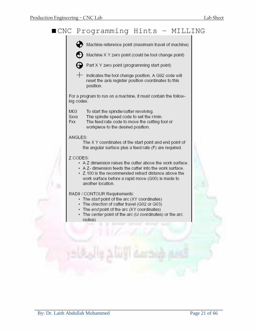
Production Engineering ndash CNC Lab Lab Sheet
By Dr Laith Abdullah Mohammed Page 21 of 66
CNC Programming Hints - MILLING
Production Engineering ndash CNC Lab Lab Sheet
By Dr Laith Abdullah Mohammed Page 22 of 66
CNC Programming Hints ndash TURNING
Production Engineering ndash CNC Lab Lab Sheet
By Dr Laith Abdullah Mohammed Page 23 of 66
CNC
The abbreviation CNC stands for Computer(ized) Numerical(ly) Control(led) and refers specifically to the computer control of machine tools for the purpose of (repeatedly) manufacturing complex parts in metal as well as other materials using a program written in a notation conforming to the EIA-274-D standard and commonly called G-code
CNC was developed in the late 1940s and early 1950s by the MIT Servomechanisms Laboratory CNC machines were relatively briefly preceded by the less advanced NC or Numerical(ly) Control(led) machines The introduction of CNC machines radically changed the manufacturing industry Curves are as easy to cut as straight lines complex 3-D structures are relatively easy to produce and the number of machining steps that required human action have been dramatically reduced With the increased automation of manufacturing processes with CNC machining considerable improvements in consistency and quality have been achieved CNC automation reduced the frequency of errors and provided CNC operators with time to perform additional tasks
CNC automation also allows for more flexibility in the way parts are held in the manufacturing process and the time required to change the machine to produce different components In a production environment a series of CNC machines may be combined into one station commonly called a cell to progressively machine a part requiring several operations CNC machines today are controlled directly from files created by CAM software packages so that a part or assembly can go directly from design to manufacturing without the need of producing a drafted paper drawing of the manufactured component In a sense the CNC machines represent a special segment of industrial robot systems as they are programmable to perform many kinds of machining operations (within their designed physical limits like other robotic systems)
G-code
G-code is a common name for the programming language that is used for NC and CNC machine tools It is defined in EIA RS-274-D G-code is also the name of any word in a CNC program that begins with the letter G and generally is a code telling the machine tool what type of action to perform such as
bull rapid move bull controlled feed move in straight line or arc bull series of controlled feed moves that would result in a hole being drilled bull change a pallet bull Set tool information such as offset
There are other codes the type codes can be thought of like registers in a computer
X position Y position Z position M code (another action register) F feed rate S spindle speed N line number R Radius T Tool selection
Production Engineering ndash CNC Lab Lab Sheet
By Dr Laith Abdullah Mohammed Page 24 of 66
I Arc data X axis J Arc data Y axis
G-code files are output by CAM software such as Smartcam Gibbscam Featurecam Edgecam Mastercam etc G-code is also output by specialized CAD systems used to design printed circuit boards Such software must be customized for each type of machine tool that it will be used to program
Production Engineering ndash CNC Lab Lab Sheet
By Dr Laith Abdullah Mohammed Page 25 of 66
U 2عمل األزرار الرئيسية في ماكنة الخراطة المبرمجة (نصر (
1- SINGLE BLOCK للتأكد من صحة البرنامج (تنفيذ البرنامج خطوة خطوةب تقوم( 2- BLOCK DELETE بجانب ويعمل من األوامرلغاء بلوك معين أليستخدم 3- MACHINE LOCK العمل يستخدم لقفل حركة المحاور الرئيسية مع استمرار البرنامج في
)وهذا مهم للتاكد من صحة البرنامج قبل عملية التنفيذ النهائي(4- CONT CYCLE عملية التشغيل عند ايقافها الي سبب كان او عند ايقافها ألستئناف ستخدم ت
) BAR FEEDER(او في حالة استخدام ) FEED HOLDبسبب (5- DRY RUN وتستخدم لفحص البرنامج بعد ازالة الشغلة حركة سريعة للبرنامج 6- TURRET UP amp DOWN ) حركة حامل العدة TURRET الذي يحمل مجموعة من (
وهذا الزر يعمل مع الزر عكس عقرب الساعة او مع عقرب الساعة ةحركة دوراني العدد )SAFTY (
7- COOLANT ON or OFFفه تشغيل سائل التبريد او ايقا 8- COOLANT AUTO الدوال المساعدة في البرنامج من خالل فه تشغيل سائل التبريد او ايقا 9 -MACHINE START ة لتشغيل هيدرولكيك الماكنميستخد
Production Engineering ndash CNC Lab Lab Sheet
By Dr Laith Abdullah Mohammed Page 26 of 66
10- CLOSE OR OPEN CHUCKالعينة تستخدم لفتح وغلق 11 -T STOCK FWD RET حركة الغراب المتحرك ذهابا وإيابا12 -SPINDLE STOP تعمل على ايقاف حركة دوران العينة 13-JOG SPINDLE تعمل على تدوير العينة مع زر SAFTY 14 -OPT SAFTY مع الدالة ( تعمل عمل التوقف المشروط حيث تعملM1 دالة التوقف (
ط ) فقط األ اذا كان هذا الزر مضغو M1المشروط حيث ال يتوقف البرنامج في حالة وجود دالة ( SAFTY + SPINDLE ) يتم الضغط على زر ( START CYCLEلغرض تحرير زر (
START ) في نفس الوقت بعد الضغط على زر ( START CYCLE مرتين (
NC PC- 15 يستخدم هذا الزر عند ربطCNC يستخدم لنقل المعلومات ث مع جهاز أخر حي بينهما
16 -CALCU زر الخاص بالحاسبة مع زر ( ال وهوINPUT ( 17 - HD1 HD2 يستخدم الختيار العدة مع المخرطة ذات المحاور األربعة 18 - START تستخدم لبدء عملية التشغيل
Production Engineering ndash CNC Lab Lab Sheet
By Dr Laith Abdullah Mohammed Page 27 of 66
19- FEED HOLD تعمل على إيقاف عمل أي G موجودة مع بقاء العينة متحركة 20- M D I أو تشغيل البرنامج ل يتم استخدامه لإلدخا BLOCK BY BLOCK وتعمل عند
إدخال البرنامج بواسطة الشريط المثقب أو أي وسيلة إدخال أخرى أو في عمليات التصفير
21- REST تستخدم العادة تشغيل الماكنة أو مسح اإلنذار الذي يظهر على الشاشة 22- EMERGENCYتستخدم عادة اليقاف الماكنة في حالة الطوارئ فقط
OPERATION MENU KEY
CHAPTER PRG-CMK
OFFSET PROGRAM POSITION FUNCTION MENU KEY
23- POSITIONعلى الشاشة د الموقع الموجور الظها 24- PROGRAMإلظهار برنامج معين واختياره 25- OFFSET الختيار سماحات العدة أو سماحات نقطة المرجع 26- PRG- CHK تستخدم لفحص البرنامج على الشاشة 27- SETTING ألختيار الثوابت على الشاشة 28- SERVICE تستخدم ألستخراج المعامالت والثوابت 29- MESSAGE تستخدم ألظهار األخطاء الناتجة عن البرنامج او اخطاء التشغيل 30- OVERALL ألختيار المواقع 31- RELATIVE MODLINE تعوض عن POSITION 32- DIR MEM يستخدم ألظهار ملف البرامج المخزونة في الذاكرة وعندما نضغط هذا الزر
فان رقم واسم البرنامج سوف يظهر على الشاشة
2أدناه الشفرات الرئيسية التي تعمل على الماكنة المبرمجة نصر
G-CODE DESCRIPTION
G00 Rapid traverse (linear)
G01 Linear Interpolation at feed rate
G02 Circular interpolation (CW) R+
G03 Circular interpolation (CCW) R+
G10 Zero point tools
G20 Imperial data input
G21 Metric data input
G27 Reference return check
G28 Reference return
G29 Return from reference
Production Engineering ndash CNC Lab Lab Sheet
By Dr Laith Abdullah Mohammed Page 28 of 66
G33 Thread cutting
G40 Cancel cutter radius compensation
G41 Cutter compensation left
G42 Cutter compensation right
G54 Work co-ordinate system no1
G70 Finishing cycle
G71 Stock removal turning
G72 Stock removal facing
G74 Face grooving
G75 Diameter grooving
G76 Threading cycle
G90 Absolute date input
G91 Incremental data input
G94 Feed minute mode
G95 Feed rev mode
G96 Constant surface speed mode
G97 Cancel Constant surface speed
) 2أدناه الشفرات الثانوية التي تعمل على الماكنة المبرمجة (نصر
M-code FUNCTION
M00 Program stop
M03 Spindle forward (Tool forward ndash M94 mode)
M04 Spindle reverse (Tool forward ndash M94 mode)
M05 Spindle stop (Tool stop ndash M94 mode)
M08 Coolant on
M09 Coolant off
M30 Program end (with rewind)
M48 Turret shortest path
M52 Turret direction up (CW)
M53 Turret direction down (CCW)
M73 Chuck open
M74 Chuck close
Production Engineering ndash CNC Lab Lab Sheet
By Dr Laith Abdullah Mohammed Page 29 of 66
) وكل جملة مكونة من مجموعة من الكلمات blockإن كل برنامج يتكون من مجموعة من الجمل ()words) لهذا فأن الشفرات الرئيسية والمساعدة هي عبارة عن كلمات (words كما في المثال التالي (
G_ _ P1 Q2 U_ _ W_ _ D___ F_ _
)end of block) ويعني ( ) يكتب الرمز (blockتسلسل الكلمات مهم جدا بعد نهاية كل جملة (
طريقة ادخال البيانات الى الماكنة ــــــــــــــــــــــــــــــــــــــــــــــــــ
) MDIيمكن ادخال البيانات الى الماكنة بعدة طرق فقد يكون األدخال عن طريق قناة السيطرة ( MANUAL DATA INPUT ) او عن طريق قناة األضافة EDIT كما يمكن ادخال البيانات عن (
) RS ndash 232 COMMUNICATIN LINKطريق استخدام سلسلة الربط (
₤⅗₌⅗₌ ⅙₌₨image₍₡ ₤₌ℌ⅗₌ Ⅸ⅗ⅥⅯ₌ ₤₡ℌ₰₨⅗₌G71
الخراطة الطولية G71الغرض من التجربة عمل نموذج للخراطة بأستخدام الدالة تستعمل هذه الدالة للخراطة الطولية اي على طول محور المشغولة وكما هو موضح بالشكل ادناه
تعتبر هذه الدالة من الدوال التي ال تحتاج الى تكرار او إعادة كتابتها أي انها دالة تكرارية بمعنى ان اي
الذي هي دالة حركة G01خطوة تكون من ضمن هذه الدالة سوف تكرر العملية اي عند استعمال امر مثل خطية تتضمن القطع مع التغذية مع اعطاء القطر المراد قطعه و مراعاة عمق القطع المعطى سوف يتكرر
هذه االمر وصوال الى العمق المطلوب وهكذا لبقية الدوال
G71 المستخدمة للدالة الصيغة
G71 P1 Q2 U___ W___ D___ F___ حيث إن
P1 بداية الخطوة االولى = Q2 نهاية الخطوة =
Uوضع السماحات بأتجاه محور = X W وضع السماحات بأتجاه محور = Z وتكاد تكون مهملة وتوضع اشارة سالب Dعمق القطع وتوضع رقم صحيح مثل = D500 اي نصف ملمF التغذية والتي لها عالقة بالدالة = G95
Production Engineering ndash CNC Lab Lab Sheet
By Dr Laith Abdullah Mohammed Page 30 of 66
G71الدالة استخدام مثال على
T0100 M48 G0 X26 Z2 M08 T0101 G90 G95 G97 S500 M03 G71 P1 Q2 U03 W00 D500 F01 N1 G0 G42 X00 G01 Z00 G01 X2517 G01 Z-5352 G01 X7391 Z-9366 G01 Z-19145 N2 G28 M30
الجانب العملي
االجهزة واالدوات المستخدمة CNCماكنة خراطة مبرمجة 1 ملم 80قضيب من االلمنيوم قطر 2 ةفير ني 3 جاه أيمن تهولدر كاربيدي ذوا 4
طريقة العمل يتم تثبيت قضيب من االلمنيوم على العينة التابعة للماكنة مع مراعاة الطول المراد استعماله في عملية 1
الخراطة ) turretتثبيت عدة القطع في المكان الصحيح في ( 2
Production Engineering ndash CNC Lab Lab Sheet
By Dr Laith Abdullah Mohammed Page 31 of 66
بالنسبة الى القطعة المثبتة على العينة XZيتم تصفير الماكنة للمحاور 3 تصفير للمحورZ تكون مالمسة العدة الى وجه الشغلة تصفير للمحورX تكون مالمسة العدة الى سطح الشغلة الموازي لمحور X
يتم كتابة البرنامج أما بطريقة يدوية أو بالحاسوب مع وضع كل الظروف الالزمة للتشغيل ( عمق القطع 4 التغذية السرعة المطلوبة نوع المعدن )
ادخال البرنامج الى الحاسوب الموجود داخل الماكنة مع تهيئة الماكنة للتشغيل 5
المطلوب G71عمل برنامج يدوي على الدالة 1 رسم الشكل الشكل النهائي المطلوب مع وضع األبعاد 2
Ⅺ⅟₍euro⅗₌ ₤₡ℌ₰₨⅗₌₣ ₤⅗₌⅗₌ ⅙₌₨image₃₡ Ⅺℂtradeℒ⅗₌ ӈ₍Ⅴ⅟ⅳ₌ G70
G70 الغرض من التجربة عمل انهاء سطحي للمشغولة بواسطة الدالة
من الضروري إعطاء G71هذه الدالة تعمل شوط واحد فقط وتكون معتمدة على عمليات القطع في الدالة اللغاء مقدمة االداة (أي لكي تتم عملية االنهاء السطحي بدون حسابات نصف قطر مقدمة االداة ) G42دالة
G70الصيغة المستخدمة للدالة
G70 P1 Q2 F___ حيث ان
P1 بداية الخطوة االولى = Q2 نهاية الخطوة =
F التغذية والمرتبطة بالدالة = G95
وذلك ألن دالة االنهاء السطحي تحقق X Zمالحظة الدالة التحتاج لكتابة السماحات التابعة للمحورين المسافات الحقيقة المراد انتاجها للمشغولة
G71و G70مثال على الدالة
T0100 M48 G0 X26 Z2 M08 T0101 G90 G95 G97 S500 M03 G71 P1 Q2 U03 W00 D500 F01 N1 G0 G42 X00 G01 Z00 G01 X2517 G01 Z-5352 G01 X7391 Z-9366 G01 Z-19145 N2 G97 S750 MO3
Production Engineering ndash CNC Lab Lab Sheet
By Dr Laith Abdullah Mohammed Page 32 of 66
G70 P1 Q2 G40 F009 G28 M30
الجانب العملي الحظ التجربة األولى
المطلوب
G70 عمل برنامج يدوي على الدالة 1 رسم الشكل النهائي المطلوب مع وضع االبعاد 2
₪⅗₍euro⅗₌ ₤₡ℌ₰₨⅗₌₣ ₤⅗₌⅗₌ ⅙₌₨image₍₡ ⅝₍ⅠimageⅯ₌ ⅞ⅫⅦ⅔₧ G76
G76 للمشغولة بواسطة الدالةةالغرض من التجربة عمل أسنان خارجية أو داخلي
في هذه التجربة سوف نقوم بعمل األسنان الخارجية وهنا تكون حركة العينة ثابتة وهذا ضروري بسبب أن ) تكون متصلتين الكترونيا وعليه أي اختالف في سرعة العينة تؤدي إلى اختالف motionالعينة والحركة(
) servoفي سرعة الخدمة(يرتبط اتجاه تكوين األسنان باتجاه دوران العينة مثال إذا كانت األسنان ذات اتجاه أيمن يكون اتجاه دوران
وهنا نقلب العدة إلى االسفل وكما هو موضح بالشكل أدناه MO3العينة عكس عقرب الساعة أي نستعمل
Production Engineering ndash CNC Lab Lab Sheet
By Dr Laith Abdullah Mohammed Page 33 of 66
الخطوة هي عبارة عن المسافة ما بين قمة سن إلى قمة سن أخر عمق السن هو العمق المطلوب تكوينه لألسنان
G76 الصيغة المستخدمة للدالة
G76 X___ Z___ K___ F___ D___ A___
حيث أن X القطر الداخلي للسن =Z طول السن =K عمق السن وتستخرج من المعادلة التالية =K=065F F الخطوة =D عمق القطع بالمايكرون فقط =A زاوية السن =
G76مثال على استخدام الدالة T0300 M48 GOO X30 Z4 T0303 M08 G97 S500 MO3 G76 X28375 Z-20 K08125 F125 D120 G00 X40 Z4 G28 M30
Production Engineering ndash CNC Lab Lab Sheet
By Dr Laith Abdullah Mohammed Page 34 of 66
الجانب العملي الحظ التجربة األولى
المطلوب
G76عمل برنامج يدوي على الدالة 1 رسم الشكل النهائي المطلوب مع وضع األبعاد 2
Ⅺ⅘₌⅗₌ Ⅵ₂ Ⅺ₯ℋ₍⅗₌ ℌℲℂ⅗₌ ⅞ⅫⅦ⅔₧ ₤K₡₌ℌ⅗₌ ₤₡ℌ₰₨⅗₌)Groove ₤⅗₌⅗₌ ₤tradeimage₌Ⅶ₡ (G75
G75 بواسطة الدالة grooveالغرض من التجربة تكوين
) للمشغولة وتعتمد شكل الحفر على طريقة grooveتستعمل هذه الدالة لتكوين الحفر الخارجي والداخلي (
التشغيل وعلى الشكل المراد إنتاجه وتعتبر هذه الطريقة من عمليات التشكيل للمعدن إن هذه الدالة هي دالة مالحظة مع G75في هذه التجربة سنقوم بعمل الحفر الخارجي بواسطة الدالة
تكرارية وغير تكرارية حسب نوع التشغيل
G 75 الصيغة المستخدمة للدالةG75 X___ Z___ I___ K____
حيث أن
X العمق النهائي لقطر الشغلة =Z عرض الحفر =I الدخول في كل مرة =
K التزحيف على محور =z بالنسبة للعدة
Production Engineering ndash CNC Lab Lab Sheet
By Dr Laith Abdullah Mohammed Page 35 of 66
G75مثال على استخدام الدالة
T0500 M48 GOO X100 Z -20 T0505 M08 G97 S700 MO3 G75 X84 Z -38 I 05 K4
الجانب العملي الحظ التجربة األولى
المطلوب
G76عمل برنامج يدوي على الدالة 1 رسم الشكل النهائي المطلوب مع وضع األبعاد 2
Production Engineering ndash CNC Lab Lab Sheet
By Dr Laith Abdullah Mohammed Page 36 of 66
CNC Milling Machine Mechanical Construction
Guideways The guideways of CNC machines are made of steel To reduce the frictional forces they are coated with a strip of PTFE (Poly Tetra Fluoro Ethylene)
Ballscrews On conventional lathes a leadscrew is used to converts the rotary motion of the hand wheel into linear motion of the slides Leadscrews have a high coefficient of friction and backlash On CNC machines a ballscrew is used instead of a leadscrew Friction and backlash are much less than on leadscrews
Guideway
Production Engineering ndash CNC Lab Lab Sheet
By Dr Laith Abdullah Mohammed Page 37 of 66
bullMachining operations Direction of cutting Based on the direction of the cutter rotation and work piece feed milling operations are classified into two types 1-Up milling (Convention milling) In up milling the metal is removed by rotating the cutter against the direction of travel of the part
Feed
Machine table
Part
Cutting tool
Chip thickness at theexit of the tooth
2-Down milling (Climb milling) In climb milling the metal is removed by rotating the cutter with the direction of travel of the part
Machine table
Part
Cutting tool
Chip thickness at theentrance of the tooth
Production Engineering ndash CNC Lab Lab Sheet
By Dr Laith Abdullah Mohammed Page 38 of 66
bullTooling Tool geometry The geometry of the tool tip affects the way that the metal cutting is performed The nose radius rake angles relief angles etc must be selected with care
Radial relief
Radial rake
Axial relief
Approach angle
Axial relief
Corner radius Face mill Face milling cutters are used to mill flat surfaces Commonly used face milling cutters Cutter with 75 degree approach
75 deg
Cutter with 90 degree approach (Square shoulder face mill)
90 deg
Cutter with 45 degree approach
Production Engineering ndash CNC Lab Lab Sheet
By Dr Laith Abdullah Mohammed Page 39 of 66
bullCNC Programming Axes convention The Z axis is along the spindle axis The X and Y axes are perpendicular to Z VMC
Z
Y
-
+
-+
X- +
+Z
-Z
+Y
-Y
-X +X
Part
Machine table
X
YZ
G00 Rapid traverse When the tool being positioned at a point preparatory to a cutting motion to save time it is moved along a straight line at Rapid traverse at a fixed traverse rate which is pre-programmed into the machines control system Typical rapid traverse rates are 10 to 25 m min but can be as high as 80 mmin
Production Engineering ndash CNC Lab Lab Sheet
By Dr Laith Abdullah Mohammed Page 40 of 66
Format N_ G00 X__ Y__Z__
G01 Linear interpolation (feed traverse) The tool moves along a straight line in one or two axis simultaneously at a programmed linear speed the feed rate Format N__ G01 X__ Y__Z__ F__
Part
Feed
Part
Feed
G02G03 Circular interpolation The tool moves along an arc in two axes simultaneously at a programmed linear speed the feed rate
Production Engineering ndash CNC Lab Lab Sheet
By Dr Laith Abdullah Mohammed Page 41 of 66
Format N__ G0203 X__ Y__Z__ I__ J__K__ F__ using the arc center OR N__ G0203 X__ Y__Z__ R__ F__ using the arc radius G02 moves along a CW arc G03 moves along a CCW arc Arc center The arc center is specified by addresses I J and K I J and K are the X Y and Z co-ordinates of the arc center with reference to the arc start point
X
Y
Arc center
Arc endArc start
- J
- I
I = X coord of center - X coord of start point J = Y coord of center - Y coord of start point K = Z coord of center - Z coord of start point I J and K must be written with their signs
Production Engineering ndash CNC Lab Lab Sheet
By Dr Laith Abdullah Mohammed Page 42 of 66
bullWork holding
Rotary table
Fixture base
Component
Clamp
Stud
Fixtures The use of fixtures 1 Improves repeatability of dimensions 2 Improves working conditions 3 Cuts down requirement of skilled labour 4 Reduces part loading and unloading time 5 Improves safety in the working area 6 Reduces the cost of machining There are two types fixtures commonly used 1 Special fixture Special fixtures are used to hold and locate the typical components which are having complex shape and to be located with the reference hole (dowel hole) Special fixtures are required for components like gear case cover cylinder heads etc 2 Modular fixture Modular fixture is a set different kind of clamping and locating elements These fixtures are used to hold identical components in different sizes and components of box type Example Manifolds head stocks connecting rods and flanges
Production Engineering ndash CNC Lab Lab Sheet
By Dr Laith Abdullah Mohammed Page 43 of 66
bullMachine setting
Determining X and Y work zero offset Case 1
Part
Machine table
Part
End mill or reamer
Work offset X0Y0 For determining X work zero offset bull Touch the periphery of the end mill or reamer to the part bull Enter current machine X value + cutter radius as X work zero offset For determining Y work zero offset bull Touch the periphery of the end mill or reamer to the part bull Enter current machine Y value - cutter radius as Y work zero offset Case 2
Part
Machine table
Part
End mill or reamerWork offset X0Y0
bull Mount the dial indicator on machine spindle true the bore bull Enter current machine X and Y value as X and Y work zero offset
Production Engineering ndash CNC Lab Lab Sheet
By Dr Laith Abdullah Mohammed Page 44 of 66
How to Select a Cutting Fluid
One part of the metal cutting equation that is sometimes overlooked however is
the choice of an appropriate cutting fluid With todayrsquos system approach to metal
cutting use of the right metalworking fluid has become just as much a part of the
solution as the other elements In fact at least one company is now integrating
cutting fluids and cutting tools into effective metal cutting systems Following are
some things to consider when choosing your next cutting fluid
The Four Key Questions
There are four vital pieces of information that are necessary when choosing a
cutting fluid They are
1 What are you cutting
2 What is the chemistry of your water
3 What are you using now
4 What are your options
5 What do you prefer
What Are You Cutting
The first question ndash ldquoWhat are you cuttingrdquo ndash is often the most difficult to answer
because most shops handle a variety of workpiece materials on a regular basis If
the answer is an unequivocal ldquoaluminumrdquo or ldquostainless steelrdquo or ldquocast ironrdquo the
selection of a cutting fluid can be quite simple and straightforward Unfortunately
that is seldom the case in anything but a high-volume plant Where aluminum or
other nonferrous metals are a significant part of the mix a non-staining cutting
fluid is a must Generally speaking this will be a semi-synthetic with special
ingredients to prevent bi-metallic corrosion and staining of non-ferrous workpieces
Where the ferrous metals predominate however a more general purpose semi-
synthetic or hybrid fluid might be a more economical choice
Production Engineering ndash CNC Lab Lab Sheet
By Dr Laith Abdullah Mohammed Page 45 of 66
What is The Chemistry of Your Water
The second question ndash ldquoWhat is the chemistry of your waterrdquo ndash is probably the
single most common reason for the success or failure of a cutting fluid Very few
plants invest the money necessary to install effective water purification systems
using deionization or reverse osmosis technology Unfortunately the chemicals
present or not present in the water used to re-constitute a cutting fluid make a
tremendous difference in its performance and sump life Most manufacturers of
cutting fluids will perform the necessary water testing to determine exactly what
minerals are dissolved in your water and make a fluid recommendation based on
the results
What are you using now
The third question ndash ldquoWhat are you using nowrdquo ndash helps narrow the range of
choices When coupled with an objective analysis of the strengths and weaknesses
of the current fluid the answer to this question can quickly point you toward a
relatively small number of competitive alternatives that have the attributes required
to meet your cutting needs Many cutting fluids are in use today simply because
they were in use yesterday It is a hard reality of todayrsquos marketplace that if one
isnrsquot constantly striving to improve they will certainly be overtaken by a
competitor who is
What Are Your Options
The fourth question ndash ldquoWhat are your optionsrdquo ndash leads to the final selection of a
cutting fluid Cutting fluids can be divided into four general groups based on their
chemistry
They are
bull Soluble Oils ndash quite literally oil dispersed in water
bull Synthetics ndash completely oil free man-made coolants in solution
Production Engineering ndash CNC Lab Lab Sheet
By Dr Laith Abdullah Mohammed Page 46 of 66
bull Semi-Synthetics ndash a mixture of natural and synthetic lubricants with up to 30
mineral oil
bull Hybrids ndash a special class of semi-synthetics with a mineral oil content of about
15 Each fluid type has advantages and disadvantages which make it suitable for
a particular group of applications In addition there are costperformance trade-
offs to be made between the groups within a specific set of applications For
example where a hybrid and a semi-synthetic may both be suitable for a particular
use the hybrid might provide longer sump life at a slightly higher initial cost
while some semi synthetics may be more economical to recycle or dispose of while
not giving as long a tank life The final decision in this case would have to be made
on the detailed economics of the shop where the fluids were to be used and on the
ownerrsquos individual preferences
Soluble Oils
Soluble oils are oils that disperse in water when emulsifiers are added They are
generally suitable for moderate-to heavy-duty machining and grinding of all non-
ferrous metals carbon and cast steels and in applications where dissimilar metals
such as aluminium and steel are present They can also be used in turning drilling
tapping reaming gear cutting broaching as well as internal and centerless types
of grinding operations Soluble oils provide excellent aluminium and copper
corrosion control good rancidity control which extends fluid for long lasting
trouble-free performance and good concentrate and mix stability making it ideal
for mixing in water with a minimal amount of agitation An example of this is
Valenitersquos VNTreg-650 premium heavy-duty soluble oil
Synthetics
Synthetics are completely oil free solutions made of polymers organic and
inorganic materials that are mixed with water These clear low foaming and bio-
Production Engineering ndash CNC Lab Lab Sheet
By Dr Laith Abdullah Mohammed Page 47 of 66
stable coolants are ideal for machining and grinding of ferrous materials carbon
steels or cast iron Their complex lubricant packages make synthetics well-suited
for tough-to-machine materials such as stainless steels and high-temperature alloys
Certain synthetics are specifically designed to address the primary failure modes of
flank wear and nose wear Although there are many benefits some synthetics may
cause staining of non-ferrous materials
Semi-Synthetics
Semi-synthetic fluids are a mixture of oils synthetic emulsifiers and water They
were primarily developed for the aircraft nuclear and related industries
Consequently they work extremely well on all non-ferrous metals such as titanium
aluminium copper brass bronze and stainless steel in both machining and
grinding Semi-synthetics can be used on ferrous metals too They are chlorine-
free to reduce bi-metallic corrosion and staining of metals They should be used at
a 5-8 dilution with water depending on the severity of the operation
Hybrids
Hybrids are cutting fluids custom engineered to solve a particular problem For
example Valenitersquos VNTreg-800 was developed to be very clean in the machining
and grinding of cast iron It provides better stability in hard water and rejects tramp
oil very well which adds to its bio-stable chemistry Hybrids work extremely well
on all metals in both machining and grinding They should be mixed at a 5-7
dilution with water depending on the condition of the water
What Do You Prefer
The final question ndash ldquoWhat do you preferrdquo ndash is usually the ldquotie breakerrdquo where
there is more than one appropriate cutting fluid available Here again as in the
case of what is being used now the key is to examine your preferences objectively
Production Engineering ndash CNC Lab Lab Sheet
By Dr Laith Abdullah Mohammed Page 48 of 66
and specifically to identify the real reasons behind a preference If you cannot
point to specific reasons why one class of cutting fluid is preferred over another
you are well advised to follow the recommendations of the professional who has
analyzed your requirements Choosing the right fluid today is easier than ever as
the system approach to metal cutting productivity continues to grow in acceptance
The day is not far off when choosing a complete solution will be as easy as
choosing the right insert and chip breaker today The answers are available and the
results will more than justify the time you spend choosing the right metal cutting
fluid
Useful Links wwwball-screwsnet
wwwlubelinkcom
wwwmachinerylubricationcom
wwwadvancedmanufacturingcom
wwwmmsonlinecom
wwwcuttingtoolengineeringcom
wwwgeartechnologycom
wwwengineersedgecom
wwwagmaorg
wwwefundacom
wwwsaeorg
wwwsmeorg
wwwastmorg
wwwissorg
wwwmachinetoolscom
wwwansiorg
wwwasmeorg
wwwcnccicom
wwwmatlscom
wwwthefreedictionarycom
wwwengineersupplycom
Production Engineering ndash CNC Lab Lab Sheet
By Dr Laith Abdullah Mohammed Page 49 of 66
SurfCAM Tutorial ndash Beginning with the basics
Background SurfCAM is a computer aided manufacturing (CAM) software which allows you to create manage and modify tool paths for computer aided designed (CAD) part The software requires a CAD model or requires that you create some geometry within SurfCAM with some rudimentary tools provided The tool paths are created or stored internally in SurfCAM in a generic programming language called APT Once the tool paths are created the APT paths are translated using a post processor into typical machine G-code
Opening SurfCAM SurfCAM can be opened from the Novell Applications Launcher on most Industrial Engineering computer labs workstations Search under lsquoallrsquo applications and double click on SurfCAM 2005 Once the program opens a license must be selected from the list (not the Demo license) to enable saving the file later Choose one of the 30 licenses available If for some reason the licenses are not listed on the license manager form select server list and type ldquobonnieeosncsuedurdquo A list of available licenses should appear Select a license and click OK After the license is selected an Add StockFixture form (Figure 1) opens allows you to add a model which represents the pre-machined stock or a fixture Click on OK without adding either Both of these items can be added later under a more appropriate dialog
Figure 1 Add Stock or Fixture dialog box
Production Engineering ndash CNC Lab Lab Sheet
By Dr Laith Abdullah Mohammed Page 50 of 66
SurfCAM Interface
Figure 2 SurfCAM Windows based interface
SurfCAM is a windows based software system so most of the typical windows functions under File are applicable This is where you can open save exit print etc The Create menu allows the user to create different geometry forms Here you can create a point line surface chamfer circle and many other geometry types For the most part these functions are not used by beginners but are useful when creating bounding curves where you donrsquot want the tool to move outside (constraining the tool) The Edit menu allows you to change or modify many different entities such as changing lines altering surfaces joining surfaces trimming or breaking elements add control points etc Again these features are helpful to advanced users and are not covered in detail in this tutorial The Display menu offers the ability to change the orientation of the part on the screen The typical rotate pan fit to screen and zoom functions are available as well as several functions which allow the user to shift between views or call up a named view (ie top bottom etc) The NC menu is the main machining interface menu In this menu you select the general form of machining (2 axis 3 axis 4 axis 5 axis turning etc) and under the general form a more specific machining function is selected This menu is the most used and the options contained must be fully understood to get the most out of SurfCAM Each function will be described in some detail in a further chapter The Analyze menu contains options such as measuring the distance between points angles tangency elements etc These functions are auxiliary functions meant to help you understand the part better but basically provide no functionality for making tool paths for CNC machines Thus these will not be covered The Tools menu allows the user to change the system options modify keyboard shortcuts change the model units etc These options are again not used by beginners Finally the Help menu provides access to the online users manual In lieu of clicking the Help menu the F1 key is the shortcut key for help (as it is in most windows based programs)
Importing a CAD model Importing a CAD model that is stored locally is done by selecting File-gtOpen On the Files of type dropdown box choose the type of file you wish to open (Figure 3) Do this prior to negotiating your way through the maze of folders to prevent having to go through the folder tree again Once the file type is selected find the file you are trying to open and click the Open
Production Engineering ndash CNC Lab Lab Sheet
By Dr Laith Abdullah Mohammed Page 51 of 66
button SurfCAM will then attempt to read the file you have selected SurfCAM may provide a dialog box describing what it has imported and identify if it was successful If this dialog is provided simply click close without saving
Figure 3 Open Dialog Note - Change type of file prior to finding the file you wish to open
SurfCAM allows a user to import several different types of CAD files the most common types which you will likely import are SolidWorks part files (sldprt or prt) AutoCAD files(dxf) or IGES (igs or iges) Native file import (such as is the case with SolidWorks) provides the greatest information transfer and generic file imports (such as is the case with IGES) provide the least Normally it is to the advantage of the user to use native file importing procedures when available Recently (2005) SurfCAM added some compatibility with SolidWorks This allows the user to create tool paths for a part and if an engineering change is needed for the part update the part in SolidWorks When the part is then opened in SurfCAM the changes are noted and a simple update operation command is needed This however does not operate with complete transparency andor accuracy and thus users need to be cognizant of changing CAD models
SurfCAM Geometry In SurfCAM two basic types of geometry are used the surface and the point A surface (Figure 4) is a so called spline (NURBS or B-Spline are the two most common) surface (parameterized by two values u and v) such that every location on the surface can be defined as a function of these parameters In other words SurfCAM can calculate the location of any point on the
Production Engineering ndash CNC Lab Lab Sheet
By Dr Laith Abdullah Mohammed Page 52 of 66
surface Surfaces are used primarily in 3 4 and 5 axis machining and require a significant
amount of processing power and time Figure 4 Surfaces model of a mold half Note the difference between this and Figure 2 a wireframe model
Point or line based models are often referred to as wireframe (Figure 5) models because the models consist of connected lines and resemble the part only at the intersection of two surfaces Wireframe models were made popular lsquoback in the dayrsquo when computer processing was expensive There are times when each of the models are important and selecting model geometry when applying a SurfCAM operation will be much simpler if you understand the differences between the two When importing a SolidWorks model the default is both the surfaces and the wireframe geometry are imported
Figure 5 Wireframe model of the mold in Figure 1
Steps to Creating Tool Paths Once a CAD model is imported into SurfCAM tool paths can be created There is no one correct way to create tool paths however there is a set of general steps to take to ensure the tool paths are created with a minimum amount of hardship (note the wordinghellipHardship is inevitable when creating tool paths it is the intent of this manual to minimize this) The following is a list of steps which should be considered when making tool paths
Production Engineering ndash CNC Lab Lab Sheet
By Dr Laith Abdullah Mohammed Page 53 of 66
1 Plan ahead a Orient the part in SolidWorks such that if only one side is to be machined that
side is the Top view This can be done early in SolidWorks by choosing a plane parallel the X-Y plane as the sketch plane for the machined geometry
b Orient the part in SolidWorks such that the origin is somewhere of relative importance and someplace in space that can be easily identified when placed on the machine This is extremely important to minimize set up time at the machine (note ndash my personal preference for a part that is to be fully machined [ie stock exists on all sides] is to place the origin at the center and top of the parthellipjust my preference)
c Orient the part in SolidWorks such that the X and Y axes are aligned as you want them on the machinehellip
d Planning ahead will save you many hours of headaches laterhelliptrust me 2 Import the model 3 Choose a construction view such that the tool approaches the side to be machined
from the positive Z axis direction (as defined by part origin) a This is done by clicking on the CView icon
b From the list of named views chose the view which orients the origin as you would like
c If one of the views does not fit your criteria you have two choices i Perform a transformation of the part in SurfCAM or SolidWorks
ii Add a new construction view by selecting new This option requires a relatively good understanding of right hand coordinate frames but is very usefulhellipNormally used by more advanced users
d Be sure the CoordVIEW selection is made vs CoordWORLD This ensures the tools will be controlled from the coordinate frame selected by the view (ie the origin on the part) instead of the origin on the lower left corner of the screen This will be especially important when we get into 4 and 5 axis machining
4 In the Operations Manager (Figure 6) select Setup One and change the name to something meaningful ndash like Front Side Mold Cavity
a Access the Operations manager by right clicking or by selecting the Operations Manager icon in the tool bar
b Operations Manager is where the tool paths are managed once they are created as well as where individual tool paths can be verified
Production Engineering ndash CNC Lab Lab Sheet
By Dr Laith Abdullah Mohammed Page 54 of 66
5 Roughing Tool Paths a Create the tool paths to remove the majority of the material (if applicable) b Use NC-gt3Axis-gtZ rough or Plunge Rough c Described in next section
6 Create Finishing Tool Paths a Described in next section
7 Add another setup if necessary 8 Perform steps 3 through 6 as necessary 9 Verify the tool paths are correct 10 Use a post processor for the tool paths to create G-Code for machine
Creating Tool Paths The following is a list of operations what they are intended for how they generally work and some parameters that may be adjusted to modify the tool paths
2 Axis tool paths Unless otherwise noted 2 axis tool path functions require lines or arc segments as input parameters (as opposed to surfaces) There are several options as to how these segments are chosen the most prevalent is the chain option and the second most prevalent is the single When choosing the line segments using the chain option SurfCAM will try to link a complete path of segments based on an initial segment chosen by the user If the operation is planer (ie pocket or contour) the segments must lie on the same plane If the operation is non-planer (ie contour 3D) SurfCAM will prompt the user to specify segments when it encounters a branch point
Figure 6 Operations Manager view showing setup one re-labeled as Front Side Mold
Production Engineering ndash CNC Lab Lab Sheet
By Dr Laith Abdullah Mohammed Page 55 of 66
When using the single element option the user must manually choose each segment desired for the operation Note that most operations do not require a closed loop of segments you may specify for instance an open contour where the tool is supposed to move The order of choosing segments is important This order determines the path of the tool in the sense that if three segments are chosen such that the middle segment is chosen last there will be three different plunge and machine operations one on each segment If the operation was to make a continuous contour around the outside of the part the segments should be chosen in order of the desired tool trajectory
Operations
Pocket Pocket operation in SurfCAM is used to cut an enclosed space from the inside to the outside at one particular depth The operation starts in the center of an enclosed area (with a plunge move in the ndashZ direction) and makes incremental closed paths towards the pocket boundaries in user defined path offsets (Figure 7) The user chooses the boundary of the pocket (line segments) and if more than one pocket is chosen SurfCAM will ask the user to click inside a pocket
Figure 7 Two examples of using the pocketing operation
The pocket operation allows for creating a projection of the pocket paths on multiple planes This is useful if you have a deep pocket which will not allow the tool to cut directly at the depth of the pocket but would be easily done using the same paths at several different Z heights On the cut control (Figure 8) tab the user specifies where the chosen geometry (pocket segments) lie (ie bottom or top) Then under the amount to remove specify the total material height to be removed and the rough spacing (amount you wish to advance the Z axis with each pocket step) You may also specify a finishing pass and as well as stock to leave
Production Engineering ndash CNC Lab Lab Sheet
By Dr Laith Abdullah Mohammed Page 56 of 66
Figure 8 Example of Contour Operation with multiple passes
Contour Contouring in SurfCAM is used to perform peripheral milling on the inside or outside of a line segment (Figure 9) The user is to identify the line segments which define a contour (does not have to be a closed loop of segments) SurfCAM may or may not require the user to specify a side to contour (ie which side of the line is the tool to cut) For contouring each segment must lie on the same plane
Production Engineering ndash CNC Lab Lab Sheet
By Dr Laith Abdullah Mohammed Page 57 of 66
Figure 9 Examples of parts cut with 2-Axis Contour
Contour 3D Contour 3D is the same operation type as contour but allows the user to specify segments on different planes for the tool to cut along
Drill Drilling operations are any rotating tool operation meant to engage the part from a single direction ndash namely from the positive Z direction Drilling operations can be specified using circle point or line segments After choosing NC-gt2-Axis-gtDrill SurfCAM allows the user to choose multiple circles or points defining holes to be drilled Drilling operations also allow the user to incorporate more than 1 operation such as a center drill a drill and a reaming operation After selecting the locations for the drilling operation a dialog box (Figure 10) allows the user to add change or delete tools to be used in the operation As displayed in the following figure the spotdrill operation is followed by a drilling operation followed by a tapping operation The depth of each tool can be controlled individually by double clicking the total depth cell in and manually entering Tools can be added before or after operations which the cells are highlighted by selecting either of the insert buttons at the top or by the insert menu Select tool button allows the user to change the tool size or type
Production Engineering ndash CNC Lab Lab Sheet
By Dr Laith Abdullah Mohammed Page 58 of 66
Figure 10 Drill operation manager Several operations can be completed at one time
Figure 11 Drill operation including the spotdrill drill and tap as outlined in Fig 10
3 Axis tool paths SurfCAM requires surfaces as inputs for 3 Axis tool paths Surfaces can be created in SurfCAM but are most easily created in a CAD package and imported into SurfCAM Surfaces allow SurfCAM to identify every point on the surface in 3 dimensions unlike 2D geometry (wireframes) which only identify positions on the plane Creating tool paths with complex surfaces takes a very significant amount of processing power so expect 3 Axis tool path generation to take longer
Production Engineering ndash CNC Lab Lab Sheet
By Dr Laith Abdullah Mohammed Page 59 of 66
Operations
Cut 3 Axis cut operation takes a surface and using the flow lines creates a rastering path over the surface with the tool tip riding on the surface The primary direction will be defined by the flow lines of the surface (which can be edited by Edit-gtSurfaces-gtArrow-gtDirection) If you intend to cross surface boundaries you must merge the surfaces (Edit-gtJoin and choose the two surfaces)
Z-Rough The Z-rough operation is used to remove a large amount of material prior to finish machining Roughing operation is typically the first operation you perform for each setup The Z-Rough operation cuts the part in user defined intervals For each of these intervals a surface intersection between the part and the plane is performed and a 2D pocket or contour operation is performed on that plane This is performed on each plane When choosing NC-gt3 Axis-gtZ rough the first dialog box you will encounter asks for a bounding box to be defined Choose the Extents Box and a second dialog box will ask for the coordinates which define the box (Figure 12) This is the stock size you expect to machine the part from Input the coordinates or change the additional offset amounts (in XY or Z) as appropriate and click Calculate Bounding Box
Figure 12 Material Extents Box Example
Next choose the tool and cutting parameters that you desire and click on the Cut Control Tab (Figure 13) Here you will find the following parameters which are often changed Stock to
Production Engineering ndash CNC Lab Lab Sheet
By Dr Laith Abdullah Mohammed Page 60 of 66
leave ndash this is an offset amount from the surfaces which leaves a small amount of material to finish machine Minimum and Maximum Z values ndash Defines area to machine Z Step Size ndash This identifies the plane intervals for the surface intersection planes (the first interval will be at the top of the selected area and successive increments down in Z will be cut until the Minimum Z value is reached)
Figure 13 3Axis Z Rough Cut Control
The 3Axis Z-Finish operation works in exactly the same way 3 Axis Z-Finish is most appropriate for finishing vertical or near vertical walls
3D Offset The 3D Offset operation creates a tool path using a 2D or 3D boundary by offsetting the boundary in concentric offset cutting passes Each pass calculates the tool engagement and maintains the engagement somewhat constant The advantage (significant) is the scallop height ndash height of the material between passes ndash is controlled thus the surface finish is predictable When choosing 3D Offset surfaces are selected as well as 2D or 3D boundaries The boundaries define the concentric offset paths shape as well as limit the tool path area Choose NC-gt3Axis-gt3D Offset from the drop down menus SurfCAM will prompt you to select the surface or surfaces to cut across Select the surfaces you wish to machine and then select the tool and cutting parameters you wish use Next select the Cut Control Tab and check the Use Boundary Curves option Set the Step Type to Scallop and set the maximum scallop height If you like
Production Engineering ndash CNC Lab Lab Sheet
By Dr Laith Abdullah Mohammed Page 61 of 66
you can also add stock to leave if this is a roughing operation You can also set the Direction and Start-End parameters from this tab Click OK and the paths will be generated
Figure 14 Cut Control Tab for 3D Offset
Example part using both 2D and 3D geometry
The tool paths for this mold will be generated in SurfCAM using 5 operations The first will be a roughing operation using a frac14 inch flat end mill with the Z step size of 00625in Choose NC-
Production Engineering ndash CNC Lab Lab Sheet
By Dr Laith Abdullah Mohammed Page 62 of 66
gt3Axis-gtZ-Rough from the drop down menu Select all visible surfaces and create an extents box that has 025inch XY offsets and 01inch Z offset Next select the frac14 inch flat end mill from the tools menu Under Cut Control tab set the Z step size to be 00625inch The tool paths will look something like Figure 15
Figure 15 Z-Rough Tool paths for Example Part
Next a flat surface operation will be performed to cut the flat surface on the top Select NC-gt3 Axis-gtFlat Surface from the drop down menu Select all visible surfaces again Choose the 12inch flat end mill and set the cutting parameters as desired Under Cut Control Tab change the Minimum Area to 50 square inches (Figure 16) The tool paths should look something like Figure 17
Figure 16 Cut Control for Flat Surface
Production Engineering ndash CNC Lab Lab Sheet
By Dr Laith Abdullah Mohammed Page 63 of 66
Figure 17 Flat Surface Tool Paths
Next we will use a 3D offset operation to cut the mold cavity Select NC-gt3 Axis-gt3D Offset from the dropdown menu Change the view to the top view and select within to capture the surfaces of the mold cavity Draw a rectangle around the mold cavity Select a 18 inch ball endmill from the tool library and set the cutting parameters as appropriate Next set the Cut Control tab parameters as in Figure 14 The paths creates should be similar to Figure 18
Figure 18 3D Offset Paths
Next we will perform a 2 Axis contouring of the top section Select NC-gt2 Axis-gtContour from the dropdown menu Using the chain option select the bottom contour of the top extrusion Select the frac12 inch flat end mill from the tool library and set the cutting parameters as required In the Cut Control Tab change the Geometry to Bottom and the amount to remove in Z to 05
Production Engineering ndash CNC Lab Lab Sheet
By Dr Laith Abdullah Mohammed Page 64 of 66
Change the Rough Spacing in Z to 025 and add 1 finish pass of 002 (Figure 19) Click OK and SurfCAM will instruct you to choose a side to contour Click anywhere on the screen OUTSIDE the geometry you selected for the contouring operation Failure to click outside the geometry will result in the tool being on the wrong side of the contour Your paths should look something like those in Figure 20
Figure 19 Cut Control Tab for the Contouring Operation
Figure 20 Contouring operation paths
Production Engineering ndash CNC Lab Lab Sheet
By Dr Laith Abdullah Mohammed Page 65 of 66
Next we will perform a 2 axis pocket operation for the small pocket on the top face of the mold Select NC-gt2Axis-gtPocket and using the Auto select feature select the boundary curve at the bottom of the pocket Click Done twice and select the frac14 inch flat end mill from the tool library Set the appropriate cutting parameters and click OK SurfCAM will prompt you to click inside the pocket Click anywhere inside the geometry you chose to define the pocket The resulting paths should look something like those in Figure 21
Figure 21 2 Axis Pocket Operation Paths
Finally we will add a drilling operation for the 2 holes at the corners of the mold Select NC-gt2 Axis-gtDrill from the dropdown menu Select the top circles defining the two holes A menu box will appear with a default tool (Center drill) already programmed Add a second tool to the list by selecting Insert-gtAfter and select the tool from the tool library Change the drill depth to 10inches and click OK The paths should look something similar to Figure 23
Figure 22 Drill Menu
Production Engineering ndash CNC Lab Lab Sheet
By Dr Laith Abdullah Mohammed Page 66 of 66
Figure 23 Drilling Operation Tool Paths
Now you can watch a simulation of the cutting by choosing the setup in the operations manager and clicking the simulate icon Be sure to set the stock in the set up by right clicking the set up and selecting Edit Setup Information In the Stock Tab you can create a bounding box meeting your needs and click Add Your simulation should result in something like the following
Figure 24 Final Simulation of the example Mold
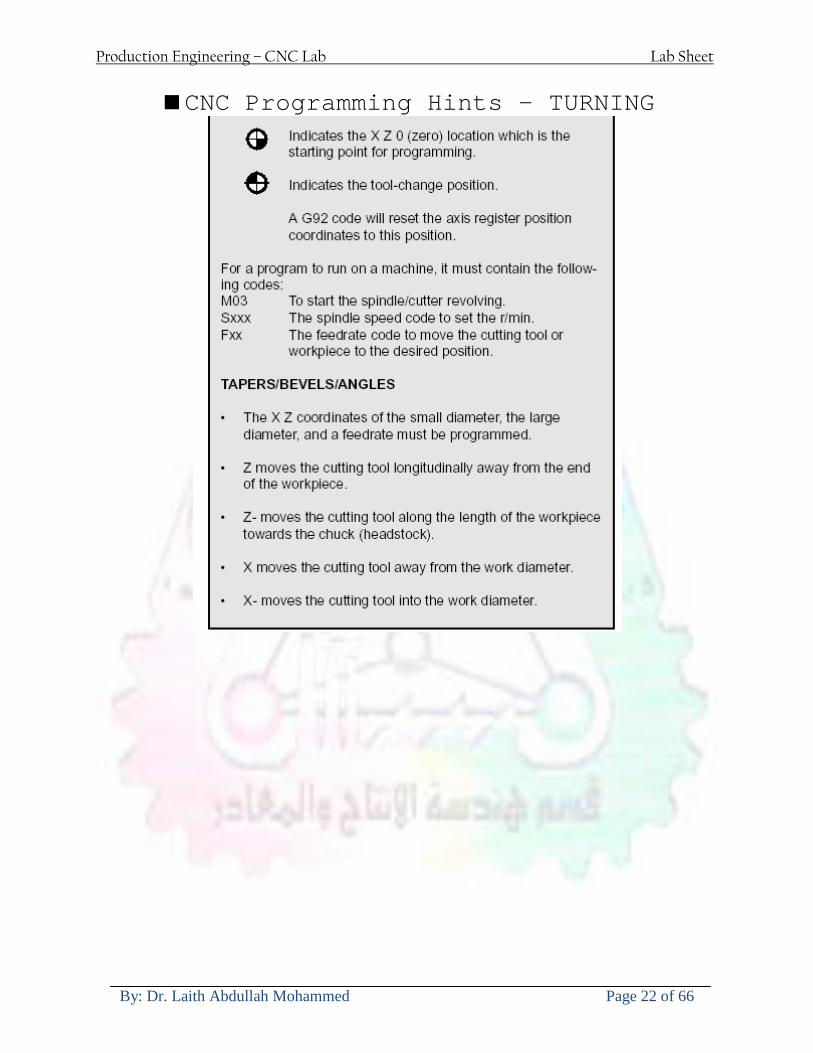
Production Engineering ndash CNC Lab Lab Sheet
By Dr Laith Abdullah Mohammed Page 22 of 66
CNC Programming Hints ndash TURNING
Production Engineering ndash CNC Lab Lab Sheet
By Dr Laith Abdullah Mohammed Page 23 of 66
CNC
The abbreviation CNC stands for Computer(ized) Numerical(ly) Control(led) and refers specifically to the computer control of machine tools for the purpose of (repeatedly) manufacturing complex parts in metal as well as other materials using a program written in a notation conforming to the EIA-274-D standard and commonly called G-code
CNC was developed in the late 1940s and early 1950s by the MIT Servomechanisms Laboratory CNC machines were relatively briefly preceded by the less advanced NC or Numerical(ly) Control(led) machines The introduction of CNC machines radically changed the manufacturing industry Curves are as easy to cut as straight lines complex 3-D structures are relatively easy to produce and the number of machining steps that required human action have been dramatically reduced With the increased automation of manufacturing processes with CNC machining considerable improvements in consistency and quality have been achieved CNC automation reduced the frequency of errors and provided CNC operators with time to perform additional tasks
CNC automation also allows for more flexibility in the way parts are held in the manufacturing process and the time required to change the machine to produce different components In a production environment a series of CNC machines may be combined into one station commonly called a cell to progressively machine a part requiring several operations CNC machines today are controlled directly from files created by CAM software packages so that a part or assembly can go directly from design to manufacturing without the need of producing a drafted paper drawing of the manufactured component In a sense the CNC machines represent a special segment of industrial robot systems as they are programmable to perform many kinds of machining operations (within their designed physical limits like other robotic systems)
G-code
G-code is a common name for the programming language that is used for NC and CNC machine tools It is defined in EIA RS-274-D G-code is also the name of any word in a CNC program that begins with the letter G and generally is a code telling the machine tool what type of action to perform such as
bull rapid move bull controlled feed move in straight line or arc bull series of controlled feed moves that would result in a hole being drilled bull change a pallet bull Set tool information such as offset
There are other codes the type codes can be thought of like registers in a computer
X position Y position Z position M code (another action register) F feed rate S spindle speed N line number R Radius T Tool selection
Production Engineering ndash CNC Lab Lab Sheet
By Dr Laith Abdullah Mohammed Page 24 of 66
I Arc data X axis J Arc data Y axis
G-code files are output by CAM software such as Smartcam Gibbscam Featurecam Edgecam Mastercam etc G-code is also output by specialized CAD systems used to design printed circuit boards Such software must be customized for each type of machine tool that it will be used to program
Production Engineering ndash CNC Lab Lab Sheet
By Dr Laith Abdullah Mohammed Page 25 of 66
U 2عمل األزرار الرئيسية في ماكنة الخراطة المبرمجة (نصر (
1- SINGLE BLOCK للتأكد من صحة البرنامج (تنفيذ البرنامج خطوة خطوةب تقوم( 2- BLOCK DELETE بجانب ويعمل من األوامرلغاء بلوك معين أليستخدم 3- MACHINE LOCK العمل يستخدم لقفل حركة المحاور الرئيسية مع استمرار البرنامج في
)وهذا مهم للتاكد من صحة البرنامج قبل عملية التنفيذ النهائي(4- CONT CYCLE عملية التشغيل عند ايقافها الي سبب كان او عند ايقافها ألستئناف ستخدم ت
) BAR FEEDER(او في حالة استخدام ) FEED HOLDبسبب (5- DRY RUN وتستخدم لفحص البرنامج بعد ازالة الشغلة حركة سريعة للبرنامج 6- TURRET UP amp DOWN ) حركة حامل العدة TURRET الذي يحمل مجموعة من (
وهذا الزر يعمل مع الزر عكس عقرب الساعة او مع عقرب الساعة ةحركة دوراني العدد )SAFTY (
7- COOLANT ON or OFFفه تشغيل سائل التبريد او ايقا 8- COOLANT AUTO الدوال المساعدة في البرنامج من خالل فه تشغيل سائل التبريد او ايقا 9 -MACHINE START ة لتشغيل هيدرولكيك الماكنميستخد
Production Engineering ndash CNC Lab Lab Sheet
By Dr Laith Abdullah Mohammed Page 26 of 66
10- CLOSE OR OPEN CHUCKالعينة تستخدم لفتح وغلق 11 -T STOCK FWD RET حركة الغراب المتحرك ذهابا وإيابا12 -SPINDLE STOP تعمل على ايقاف حركة دوران العينة 13-JOG SPINDLE تعمل على تدوير العينة مع زر SAFTY 14 -OPT SAFTY مع الدالة ( تعمل عمل التوقف المشروط حيث تعملM1 دالة التوقف (
ط ) فقط األ اذا كان هذا الزر مضغو M1المشروط حيث ال يتوقف البرنامج في حالة وجود دالة ( SAFTY + SPINDLE ) يتم الضغط على زر ( START CYCLEلغرض تحرير زر (
START ) في نفس الوقت بعد الضغط على زر ( START CYCLE مرتين (
NC PC- 15 يستخدم هذا الزر عند ربطCNC يستخدم لنقل المعلومات ث مع جهاز أخر حي بينهما
16 -CALCU زر الخاص بالحاسبة مع زر ( ال وهوINPUT ( 17 - HD1 HD2 يستخدم الختيار العدة مع المخرطة ذات المحاور األربعة 18 - START تستخدم لبدء عملية التشغيل
Production Engineering ndash CNC Lab Lab Sheet
By Dr Laith Abdullah Mohammed Page 27 of 66
19- FEED HOLD تعمل على إيقاف عمل أي G موجودة مع بقاء العينة متحركة 20- M D I أو تشغيل البرنامج ل يتم استخدامه لإلدخا BLOCK BY BLOCK وتعمل عند
إدخال البرنامج بواسطة الشريط المثقب أو أي وسيلة إدخال أخرى أو في عمليات التصفير
21- REST تستخدم العادة تشغيل الماكنة أو مسح اإلنذار الذي يظهر على الشاشة 22- EMERGENCYتستخدم عادة اليقاف الماكنة في حالة الطوارئ فقط
OPERATION MENU KEY
CHAPTER PRG-CMK
OFFSET PROGRAM POSITION FUNCTION MENU KEY
23- POSITIONعلى الشاشة د الموقع الموجور الظها 24- PROGRAMإلظهار برنامج معين واختياره 25- OFFSET الختيار سماحات العدة أو سماحات نقطة المرجع 26- PRG- CHK تستخدم لفحص البرنامج على الشاشة 27- SETTING ألختيار الثوابت على الشاشة 28- SERVICE تستخدم ألستخراج المعامالت والثوابت 29- MESSAGE تستخدم ألظهار األخطاء الناتجة عن البرنامج او اخطاء التشغيل 30- OVERALL ألختيار المواقع 31- RELATIVE MODLINE تعوض عن POSITION 32- DIR MEM يستخدم ألظهار ملف البرامج المخزونة في الذاكرة وعندما نضغط هذا الزر
فان رقم واسم البرنامج سوف يظهر على الشاشة
2أدناه الشفرات الرئيسية التي تعمل على الماكنة المبرمجة نصر
G-CODE DESCRIPTION
G00 Rapid traverse (linear)
G01 Linear Interpolation at feed rate
G02 Circular interpolation (CW) R+
G03 Circular interpolation (CCW) R+
G10 Zero point tools
G20 Imperial data input
G21 Metric data input
G27 Reference return check
G28 Reference return
G29 Return from reference
Production Engineering ndash CNC Lab Lab Sheet
By Dr Laith Abdullah Mohammed Page 28 of 66
G33 Thread cutting
G40 Cancel cutter radius compensation
G41 Cutter compensation left
G42 Cutter compensation right
G54 Work co-ordinate system no1
G70 Finishing cycle
G71 Stock removal turning
G72 Stock removal facing
G74 Face grooving
G75 Diameter grooving
G76 Threading cycle
G90 Absolute date input
G91 Incremental data input
G94 Feed minute mode
G95 Feed rev mode
G96 Constant surface speed mode
G97 Cancel Constant surface speed
) 2أدناه الشفرات الثانوية التي تعمل على الماكنة المبرمجة (نصر
M-code FUNCTION
M00 Program stop
M03 Spindle forward (Tool forward ndash M94 mode)
M04 Spindle reverse (Tool forward ndash M94 mode)
M05 Spindle stop (Tool stop ndash M94 mode)
M08 Coolant on
M09 Coolant off
M30 Program end (with rewind)
M48 Turret shortest path
M52 Turret direction up (CW)
M53 Turret direction down (CCW)
M73 Chuck open
M74 Chuck close
Production Engineering ndash CNC Lab Lab Sheet
By Dr Laith Abdullah Mohammed Page 29 of 66
) وكل جملة مكونة من مجموعة من الكلمات blockإن كل برنامج يتكون من مجموعة من الجمل ()words) لهذا فأن الشفرات الرئيسية والمساعدة هي عبارة عن كلمات (words كما في المثال التالي (
G_ _ P1 Q2 U_ _ W_ _ D___ F_ _
)end of block) ويعني ( ) يكتب الرمز (blockتسلسل الكلمات مهم جدا بعد نهاية كل جملة (
طريقة ادخال البيانات الى الماكنة ــــــــــــــــــــــــــــــــــــــــــــــــــ
) MDIيمكن ادخال البيانات الى الماكنة بعدة طرق فقد يكون األدخال عن طريق قناة السيطرة ( MANUAL DATA INPUT ) او عن طريق قناة األضافة EDIT كما يمكن ادخال البيانات عن (
) RS ndash 232 COMMUNICATIN LINKطريق استخدام سلسلة الربط (
₤⅗₌⅗₌ ⅙₌₨image₍₡ ₤₌ℌ⅗₌ Ⅸ⅗ⅥⅯ₌ ₤₡ℌ₰₨⅗₌G71
الخراطة الطولية G71الغرض من التجربة عمل نموذج للخراطة بأستخدام الدالة تستعمل هذه الدالة للخراطة الطولية اي على طول محور المشغولة وكما هو موضح بالشكل ادناه
تعتبر هذه الدالة من الدوال التي ال تحتاج الى تكرار او إعادة كتابتها أي انها دالة تكرارية بمعنى ان اي
الذي هي دالة حركة G01خطوة تكون من ضمن هذه الدالة سوف تكرر العملية اي عند استعمال امر مثل خطية تتضمن القطع مع التغذية مع اعطاء القطر المراد قطعه و مراعاة عمق القطع المعطى سوف يتكرر
هذه االمر وصوال الى العمق المطلوب وهكذا لبقية الدوال
G71 المستخدمة للدالة الصيغة
G71 P1 Q2 U___ W___ D___ F___ حيث إن
P1 بداية الخطوة االولى = Q2 نهاية الخطوة =
Uوضع السماحات بأتجاه محور = X W وضع السماحات بأتجاه محور = Z وتكاد تكون مهملة وتوضع اشارة سالب Dعمق القطع وتوضع رقم صحيح مثل = D500 اي نصف ملمF التغذية والتي لها عالقة بالدالة = G95
Production Engineering ndash CNC Lab Lab Sheet
By Dr Laith Abdullah Mohammed Page 30 of 66
G71الدالة استخدام مثال على
T0100 M48 G0 X26 Z2 M08 T0101 G90 G95 G97 S500 M03 G71 P1 Q2 U03 W00 D500 F01 N1 G0 G42 X00 G01 Z00 G01 X2517 G01 Z-5352 G01 X7391 Z-9366 G01 Z-19145 N2 G28 M30
الجانب العملي
االجهزة واالدوات المستخدمة CNCماكنة خراطة مبرمجة 1 ملم 80قضيب من االلمنيوم قطر 2 ةفير ني 3 جاه أيمن تهولدر كاربيدي ذوا 4
طريقة العمل يتم تثبيت قضيب من االلمنيوم على العينة التابعة للماكنة مع مراعاة الطول المراد استعماله في عملية 1
الخراطة ) turretتثبيت عدة القطع في المكان الصحيح في ( 2
Production Engineering ndash CNC Lab Lab Sheet
By Dr Laith Abdullah Mohammed Page 31 of 66
بالنسبة الى القطعة المثبتة على العينة XZيتم تصفير الماكنة للمحاور 3 تصفير للمحورZ تكون مالمسة العدة الى وجه الشغلة تصفير للمحورX تكون مالمسة العدة الى سطح الشغلة الموازي لمحور X
يتم كتابة البرنامج أما بطريقة يدوية أو بالحاسوب مع وضع كل الظروف الالزمة للتشغيل ( عمق القطع 4 التغذية السرعة المطلوبة نوع المعدن )
ادخال البرنامج الى الحاسوب الموجود داخل الماكنة مع تهيئة الماكنة للتشغيل 5
المطلوب G71عمل برنامج يدوي على الدالة 1 رسم الشكل الشكل النهائي المطلوب مع وضع األبعاد 2
Ⅺ⅟₍euro⅗₌ ₤₡ℌ₰₨⅗₌₣ ₤⅗₌⅗₌ ⅙₌₨image₃₡ Ⅺℂtradeℒ⅗₌ ӈ₍Ⅴ⅟ⅳ₌ G70
G70 الغرض من التجربة عمل انهاء سطحي للمشغولة بواسطة الدالة
من الضروري إعطاء G71هذه الدالة تعمل شوط واحد فقط وتكون معتمدة على عمليات القطع في الدالة اللغاء مقدمة االداة (أي لكي تتم عملية االنهاء السطحي بدون حسابات نصف قطر مقدمة االداة ) G42دالة
G70الصيغة المستخدمة للدالة
G70 P1 Q2 F___ حيث ان
P1 بداية الخطوة االولى = Q2 نهاية الخطوة =
F التغذية والمرتبطة بالدالة = G95
وذلك ألن دالة االنهاء السطحي تحقق X Zمالحظة الدالة التحتاج لكتابة السماحات التابعة للمحورين المسافات الحقيقة المراد انتاجها للمشغولة
G71و G70مثال على الدالة
T0100 M48 G0 X26 Z2 M08 T0101 G90 G95 G97 S500 M03 G71 P1 Q2 U03 W00 D500 F01 N1 G0 G42 X00 G01 Z00 G01 X2517 G01 Z-5352 G01 X7391 Z-9366 G01 Z-19145 N2 G97 S750 MO3
Production Engineering ndash CNC Lab Lab Sheet
By Dr Laith Abdullah Mohammed Page 32 of 66
G70 P1 Q2 G40 F009 G28 M30
الجانب العملي الحظ التجربة األولى
المطلوب
G70 عمل برنامج يدوي على الدالة 1 رسم الشكل النهائي المطلوب مع وضع االبعاد 2
₪⅗₍euro⅗₌ ₤₡ℌ₰₨⅗₌₣ ₤⅗₌⅗₌ ⅙₌₨image₍₡ ⅝₍ⅠimageⅯ₌ ⅞ⅫⅦ⅔₧ G76
G76 للمشغولة بواسطة الدالةةالغرض من التجربة عمل أسنان خارجية أو داخلي
في هذه التجربة سوف نقوم بعمل األسنان الخارجية وهنا تكون حركة العينة ثابتة وهذا ضروري بسبب أن ) تكون متصلتين الكترونيا وعليه أي اختالف في سرعة العينة تؤدي إلى اختالف motionالعينة والحركة(
) servoفي سرعة الخدمة(يرتبط اتجاه تكوين األسنان باتجاه دوران العينة مثال إذا كانت األسنان ذات اتجاه أيمن يكون اتجاه دوران
وهنا نقلب العدة إلى االسفل وكما هو موضح بالشكل أدناه MO3العينة عكس عقرب الساعة أي نستعمل
Production Engineering ndash CNC Lab Lab Sheet
By Dr Laith Abdullah Mohammed Page 33 of 66
الخطوة هي عبارة عن المسافة ما بين قمة سن إلى قمة سن أخر عمق السن هو العمق المطلوب تكوينه لألسنان
G76 الصيغة المستخدمة للدالة
G76 X___ Z___ K___ F___ D___ A___
حيث أن X القطر الداخلي للسن =Z طول السن =K عمق السن وتستخرج من المعادلة التالية =K=065F F الخطوة =D عمق القطع بالمايكرون فقط =A زاوية السن =
G76مثال على استخدام الدالة T0300 M48 GOO X30 Z4 T0303 M08 G97 S500 MO3 G76 X28375 Z-20 K08125 F125 D120 G00 X40 Z4 G28 M30
Production Engineering ndash CNC Lab Lab Sheet
By Dr Laith Abdullah Mohammed Page 34 of 66
الجانب العملي الحظ التجربة األولى
المطلوب
G76عمل برنامج يدوي على الدالة 1 رسم الشكل النهائي المطلوب مع وضع األبعاد 2
Ⅺ⅘₌⅗₌ Ⅵ₂ Ⅺ₯ℋ₍⅗₌ ℌℲℂ⅗₌ ⅞ⅫⅦ⅔₧ ₤K₡₌ℌ⅗₌ ₤₡ℌ₰₨⅗₌)Groove ₤⅗₌⅗₌ ₤tradeimage₌Ⅶ₡ (G75
G75 بواسطة الدالة grooveالغرض من التجربة تكوين
) للمشغولة وتعتمد شكل الحفر على طريقة grooveتستعمل هذه الدالة لتكوين الحفر الخارجي والداخلي (
التشغيل وعلى الشكل المراد إنتاجه وتعتبر هذه الطريقة من عمليات التشكيل للمعدن إن هذه الدالة هي دالة مالحظة مع G75في هذه التجربة سنقوم بعمل الحفر الخارجي بواسطة الدالة
تكرارية وغير تكرارية حسب نوع التشغيل
G 75 الصيغة المستخدمة للدالةG75 X___ Z___ I___ K____
حيث أن
X العمق النهائي لقطر الشغلة =Z عرض الحفر =I الدخول في كل مرة =
K التزحيف على محور =z بالنسبة للعدة
Production Engineering ndash CNC Lab Lab Sheet
By Dr Laith Abdullah Mohammed Page 35 of 66
G75مثال على استخدام الدالة
T0500 M48 GOO X100 Z -20 T0505 M08 G97 S700 MO3 G75 X84 Z -38 I 05 K4
الجانب العملي الحظ التجربة األولى
المطلوب
G76عمل برنامج يدوي على الدالة 1 رسم الشكل النهائي المطلوب مع وضع األبعاد 2
Production Engineering ndash CNC Lab Lab Sheet
By Dr Laith Abdullah Mohammed Page 36 of 66
CNC Milling Machine Mechanical Construction
Guideways The guideways of CNC machines are made of steel To reduce the frictional forces they are coated with a strip of PTFE (Poly Tetra Fluoro Ethylene)
Ballscrews On conventional lathes a leadscrew is used to converts the rotary motion of the hand wheel into linear motion of the slides Leadscrews have a high coefficient of friction and backlash On CNC machines a ballscrew is used instead of a leadscrew Friction and backlash are much less than on leadscrews
Guideway
Production Engineering ndash CNC Lab Lab Sheet
By Dr Laith Abdullah Mohammed Page 37 of 66
bullMachining operations Direction of cutting Based on the direction of the cutter rotation and work piece feed milling operations are classified into two types 1-Up milling (Convention milling) In up milling the metal is removed by rotating the cutter against the direction of travel of the part
Feed
Machine table
Part
Cutting tool
Chip thickness at theexit of the tooth
2-Down milling (Climb milling) In climb milling the metal is removed by rotating the cutter with the direction of travel of the part
Machine table
Part
Cutting tool
Chip thickness at theentrance of the tooth
Production Engineering ndash CNC Lab Lab Sheet
By Dr Laith Abdullah Mohammed Page 38 of 66
bullTooling Tool geometry The geometry of the tool tip affects the way that the metal cutting is performed The nose radius rake angles relief angles etc must be selected with care
Radial relief
Radial rake
Axial relief
Approach angle
Axial relief
Corner radius Face mill Face milling cutters are used to mill flat surfaces Commonly used face milling cutters Cutter with 75 degree approach
75 deg
Cutter with 90 degree approach (Square shoulder face mill)
90 deg
Cutter with 45 degree approach
Production Engineering ndash CNC Lab Lab Sheet
By Dr Laith Abdullah Mohammed Page 39 of 66
bullCNC Programming Axes convention The Z axis is along the spindle axis The X and Y axes are perpendicular to Z VMC
Z
Y
-
+
-+
X- +
+Z
-Z
+Y
-Y
-X +X
Part
Machine table
X
YZ
G00 Rapid traverse When the tool being positioned at a point preparatory to a cutting motion to save time it is moved along a straight line at Rapid traverse at a fixed traverse rate which is pre-programmed into the machines control system Typical rapid traverse rates are 10 to 25 m min but can be as high as 80 mmin
Production Engineering ndash CNC Lab Lab Sheet
By Dr Laith Abdullah Mohammed Page 40 of 66
Format N_ G00 X__ Y__Z__
G01 Linear interpolation (feed traverse) The tool moves along a straight line in one or two axis simultaneously at a programmed linear speed the feed rate Format N__ G01 X__ Y__Z__ F__
Part
Feed
Part
Feed
G02G03 Circular interpolation The tool moves along an arc in two axes simultaneously at a programmed linear speed the feed rate
Production Engineering ndash CNC Lab Lab Sheet
By Dr Laith Abdullah Mohammed Page 41 of 66
Format N__ G0203 X__ Y__Z__ I__ J__K__ F__ using the arc center OR N__ G0203 X__ Y__Z__ R__ F__ using the arc radius G02 moves along a CW arc G03 moves along a CCW arc Arc center The arc center is specified by addresses I J and K I J and K are the X Y and Z co-ordinates of the arc center with reference to the arc start point
X
Y
Arc center
Arc endArc start
- J
- I
I = X coord of center - X coord of start point J = Y coord of center - Y coord of start point K = Z coord of center - Z coord of start point I J and K must be written with their signs
Production Engineering ndash CNC Lab Lab Sheet
By Dr Laith Abdullah Mohammed Page 42 of 66
bullWork holding
Rotary table
Fixture base
Component
Clamp
Stud
Fixtures The use of fixtures 1 Improves repeatability of dimensions 2 Improves working conditions 3 Cuts down requirement of skilled labour 4 Reduces part loading and unloading time 5 Improves safety in the working area 6 Reduces the cost of machining There are two types fixtures commonly used 1 Special fixture Special fixtures are used to hold and locate the typical components which are having complex shape and to be located with the reference hole (dowel hole) Special fixtures are required for components like gear case cover cylinder heads etc 2 Modular fixture Modular fixture is a set different kind of clamping and locating elements These fixtures are used to hold identical components in different sizes and components of box type Example Manifolds head stocks connecting rods and flanges
Production Engineering ndash CNC Lab Lab Sheet
By Dr Laith Abdullah Mohammed Page 43 of 66
bullMachine setting
Determining X and Y work zero offset Case 1
Part
Machine table
Part
End mill or reamer
Work offset X0Y0 For determining X work zero offset bull Touch the periphery of the end mill or reamer to the part bull Enter current machine X value + cutter radius as X work zero offset For determining Y work zero offset bull Touch the periphery of the end mill or reamer to the part bull Enter current machine Y value - cutter radius as Y work zero offset Case 2
Part
Machine table
Part
End mill or reamerWork offset X0Y0
bull Mount the dial indicator on machine spindle true the bore bull Enter current machine X and Y value as X and Y work zero offset
Production Engineering ndash CNC Lab Lab Sheet
By Dr Laith Abdullah Mohammed Page 44 of 66
How to Select a Cutting Fluid
One part of the metal cutting equation that is sometimes overlooked however is
the choice of an appropriate cutting fluid With todayrsquos system approach to metal
cutting use of the right metalworking fluid has become just as much a part of the
solution as the other elements In fact at least one company is now integrating
cutting fluids and cutting tools into effective metal cutting systems Following are
some things to consider when choosing your next cutting fluid
The Four Key Questions
There are four vital pieces of information that are necessary when choosing a
cutting fluid They are
1 What are you cutting
2 What is the chemistry of your water
3 What are you using now
4 What are your options
5 What do you prefer
What Are You Cutting
The first question ndash ldquoWhat are you cuttingrdquo ndash is often the most difficult to answer
because most shops handle a variety of workpiece materials on a regular basis If
the answer is an unequivocal ldquoaluminumrdquo or ldquostainless steelrdquo or ldquocast ironrdquo the
selection of a cutting fluid can be quite simple and straightforward Unfortunately
that is seldom the case in anything but a high-volume plant Where aluminum or
other nonferrous metals are a significant part of the mix a non-staining cutting
fluid is a must Generally speaking this will be a semi-synthetic with special
ingredients to prevent bi-metallic corrosion and staining of non-ferrous workpieces
Where the ferrous metals predominate however a more general purpose semi-
synthetic or hybrid fluid might be a more economical choice
Production Engineering ndash CNC Lab Lab Sheet
By Dr Laith Abdullah Mohammed Page 45 of 66
What is The Chemistry of Your Water
The second question ndash ldquoWhat is the chemistry of your waterrdquo ndash is probably the
single most common reason for the success or failure of a cutting fluid Very few
plants invest the money necessary to install effective water purification systems
using deionization or reverse osmosis technology Unfortunately the chemicals
present or not present in the water used to re-constitute a cutting fluid make a
tremendous difference in its performance and sump life Most manufacturers of
cutting fluids will perform the necessary water testing to determine exactly what
minerals are dissolved in your water and make a fluid recommendation based on
the results
What are you using now
The third question ndash ldquoWhat are you using nowrdquo ndash helps narrow the range of
choices When coupled with an objective analysis of the strengths and weaknesses
of the current fluid the answer to this question can quickly point you toward a
relatively small number of competitive alternatives that have the attributes required
to meet your cutting needs Many cutting fluids are in use today simply because
they were in use yesterday It is a hard reality of todayrsquos marketplace that if one
isnrsquot constantly striving to improve they will certainly be overtaken by a
competitor who is
What Are Your Options
The fourth question ndash ldquoWhat are your optionsrdquo ndash leads to the final selection of a
cutting fluid Cutting fluids can be divided into four general groups based on their
chemistry
They are
bull Soluble Oils ndash quite literally oil dispersed in water
bull Synthetics ndash completely oil free man-made coolants in solution
Production Engineering ndash CNC Lab Lab Sheet
By Dr Laith Abdullah Mohammed Page 46 of 66
bull Semi-Synthetics ndash a mixture of natural and synthetic lubricants with up to 30
mineral oil
bull Hybrids ndash a special class of semi-synthetics with a mineral oil content of about
15 Each fluid type has advantages and disadvantages which make it suitable for
a particular group of applications In addition there are costperformance trade-
offs to be made between the groups within a specific set of applications For
example where a hybrid and a semi-synthetic may both be suitable for a particular
use the hybrid might provide longer sump life at a slightly higher initial cost
while some semi synthetics may be more economical to recycle or dispose of while
not giving as long a tank life The final decision in this case would have to be made
on the detailed economics of the shop where the fluids were to be used and on the
ownerrsquos individual preferences
Soluble Oils
Soluble oils are oils that disperse in water when emulsifiers are added They are
generally suitable for moderate-to heavy-duty machining and grinding of all non-
ferrous metals carbon and cast steels and in applications where dissimilar metals
such as aluminium and steel are present They can also be used in turning drilling
tapping reaming gear cutting broaching as well as internal and centerless types
of grinding operations Soluble oils provide excellent aluminium and copper
corrosion control good rancidity control which extends fluid for long lasting
trouble-free performance and good concentrate and mix stability making it ideal
for mixing in water with a minimal amount of agitation An example of this is
Valenitersquos VNTreg-650 premium heavy-duty soluble oil
Synthetics
Synthetics are completely oil free solutions made of polymers organic and
inorganic materials that are mixed with water These clear low foaming and bio-
Production Engineering ndash CNC Lab Lab Sheet
By Dr Laith Abdullah Mohammed Page 47 of 66
stable coolants are ideal for machining and grinding of ferrous materials carbon
steels or cast iron Their complex lubricant packages make synthetics well-suited
for tough-to-machine materials such as stainless steels and high-temperature alloys
Certain synthetics are specifically designed to address the primary failure modes of
flank wear and nose wear Although there are many benefits some synthetics may
cause staining of non-ferrous materials
Semi-Synthetics
Semi-synthetic fluids are a mixture of oils synthetic emulsifiers and water They
were primarily developed for the aircraft nuclear and related industries
Consequently they work extremely well on all non-ferrous metals such as titanium
aluminium copper brass bronze and stainless steel in both machining and
grinding Semi-synthetics can be used on ferrous metals too They are chlorine-
free to reduce bi-metallic corrosion and staining of metals They should be used at
a 5-8 dilution with water depending on the severity of the operation
Hybrids
Hybrids are cutting fluids custom engineered to solve a particular problem For
example Valenitersquos VNTreg-800 was developed to be very clean in the machining
and grinding of cast iron It provides better stability in hard water and rejects tramp
oil very well which adds to its bio-stable chemistry Hybrids work extremely well
on all metals in both machining and grinding They should be mixed at a 5-7
dilution with water depending on the condition of the water
What Do You Prefer
The final question ndash ldquoWhat do you preferrdquo ndash is usually the ldquotie breakerrdquo where
there is more than one appropriate cutting fluid available Here again as in the
case of what is being used now the key is to examine your preferences objectively
Production Engineering ndash CNC Lab Lab Sheet
By Dr Laith Abdullah Mohammed Page 48 of 66
and specifically to identify the real reasons behind a preference If you cannot
point to specific reasons why one class of cutting fluid is preferred over another
you are well advised to follow the recommendations of the professional who has
analyzed your requirements Choosing the right fluid today is easier than ever as
the system approach to metal cutting productivity continues to grow in acceptance
The day is not far off when choosing a complete solution will be as easy as
choosing the right insert and chip breaker today The answers are available and the
results will more than justify the time you spend choosing the right metal cutting
fluid
Useful Links wwwball-screwsnet
wwwlubelinkcom
wwwmachinerylubricationcom
wwwadvancedmanufacturingcom
wwwmmsonlinecom
wwwcuttingtoolengineeringcom
wwwgeartechnologycom
wwwengineersedgecom
wwwagmaorg
wwwefundacom
wwwsaeorg
wwwsmeorg
wwwastmorg
wwwissorg
wwwmachinetoolscom
wwwansiorg
wwwasmeorg
wwwcnccicom
wwwmatlscom
wwwthefreedictionarycom
wwwengineersupplycom
Production Engineering ndash CNC Lab Lab Sheet
By Dr Laith Abdullah Mohammed Page 49 of 66
SurfCAM Tutorial ndash Beginning with the basics
Background SurfCAM is a computer aided manufacturing (CAM) software which allows you to create manage and modify tool paths for computer aided designed (CAD) part The software requires a CAD model or requires that you create some geometry within SurfCAM with some rudimentary tools provided The tool paths are created or stored internally in SurfCAM in a generic programming language called APT Once the tool paths are created the APT paths are translated using a post processor into typical machine G-code
Opening SurfCAM SurfCAM can be opened from the Novell Applications Launcher on most Industrial Engineering computer labs workstations Search under lsquoallrsquo applications and double click on SurfCAM 2005 Once the program opens a license must be selected from the list (not the Demo license) to enable saving the file later Choose one of the 30 licenses available If for some reason the licenses are not listed on the license manager form select server list and type ldquobonnieeosncsuedurdquo A list of available licenses should appear Select a license and click OK After the license is selected an Add StockFixture form (Figure 1) opens allows you to add a model which represents the pre-machined stock or a fixture Click on OK without adding either Both of these items can be added later under a more appropriate dialog
Figure 1 Add Stock or Fixture dialog box
Production Engineering ndash CNC Lab Lab Sheet
By Dr Laith Abdullah Mohammed Page 50 of 66
SurfCAM Interface
Figure 2 SurfCAM Windows based interface
SurfCAM is a windows based software system so most of the typical windows functions under File are applicable This is where you can open save exit print etc The Create menu allows the user to create different geometry forms Here you can create a point line surface chamfer circle and many other geometry types For the most part these functions are not used by beginners but are useful when creating bounding curves where you donrsquot want the tool to move outside (constraining the tool) The Edit menu allows you to change or modify many different entities such as changing lines altering surfaces joining surfaces trimming or breaking elements add control points etc Again these features are helpful to advanced users and are not covered in detail in this tutorial The Display menu offers the ability to change the orientation of the part on the screen The typical rotate pan fit to screen and zoom functions are available as well as several functions which allow the user to shift between views or call up a named view (ie top bottom etc) The NC menu is the main machining interface menu In this menu you select the general form of machining (2 axis 3 axis 4 axis 5 axis turning etc) and under the general form a more specific machining function is selected This menu is the most used and the options contained must be fully understood to get the most out of SurfCAM Each function will be described in some detail in a further chapter The Analyze menu contains options such as measuring the distance between points angles tangency elements etc These functions are auxiliary functions meant to help you understand the part better but basically provide no functionality for making tool paths for CNC machines Thus these will not be covered The Tools menu allows the user to change the system options modify keyboard shortcuts change the model units etc These options are again not used by beginners Finally the Help menu provides access to the online users manual In lieu of clicking the Help menu the F1 key is the shortcut key for help (as it is in most windows based programs)
Importing a CAD model Importing a CAD model that is stored locally is done by selecting File-gtOpen On the Files of type dropdown box choose the type of file you wish to open (Figure 3) Do this prior to negotiating your way through the maze of folders to prevent having to go through the folder tree again Once the file type is selected find the file you are trying to open and click the Open
Production Engineering ndash CNC Lab Lab Sheet
By Dr Laith Abdullah Mohammed Page 51 of 66
button SurfCAM will then attempt to read the file you have selected SurfCAM may provide a dialog box describing what it has imported and identify if it was successful If this dialog is provided simply click close without saving
Figure 3 Open Dialog Note - Change type of file prior to finding the file you wish to open
SurfCAM allows a user to import several different types of CAD files the most common types which you will likely import are SolidWorks part files (sldprt or prt) AutoCAD files(dxf) or IGES (igs or iges) Native file import (such as is the case with SolidWorks) provides the greatest information transfer and generic file imports (such as is the case with IGES) provide the least Normally it is to the advantage of the user to use native file importing procedures when available Recently (2005) SurfCAM added some compatibility with SolidWorks This allows the user to create tool paths for a part and if an engineering change is needed for the part update the part in SolidWorks When the part is then opened in SurfCAM the changes are noted and a simple update operation command is needed This however does not operate with complete transparency andor accuracy and thus users need to be cognizant of changing CAD models
SurfCAM Geometry In SurfCAM two basic types of geometry are used the surface and the point A surface (Figure 4) is a so called spline (NURBS or B-Spline are the two most common) surface (parameterized by two values u and v) such that every location on the surface can be defined as a function of these parameters In other words SurfCAM can calculate the location of any point on the
Production Engineering ndash CNC Lab Lab Sheet
By Dr Laith Abdullah Mohammed Page 52 of 66
surface Surfaces are used primarily in 3 4 and 5 axis machining and require a significant
amount of processing power and time Figure 4 Surfaces model of a mold half Note the difference between this and Figure 2 a wireframe model
Point or line based models are often referred to as wireframe (Figure 5) models because the models consist of connected lines and resemble the part only at the intersection of two surfaces Wireframe models were made popular lsquoback in the dayrsquo when computer processing was expensive There are times when each of the models are important and selecting model geometry when applying a SurfCAM operation will be much simpler if you understand the differences between the two When importing a SolidWorks model the default is both the surfaces and the wireframe geometry are imported
Figure 5 Wireframe model of the mold in Figure 1
Steps to Creating Tool Paths Once a CAD model is imported into SurfCAM tool paths can be created There is no one correct way to create tool paths however there is a set of general steps to take to ensure the tool paths are created with a minimum amount of hardship (note the wordinghellipHardship is inevitable when creating tool paths it is the intent of this manual to minimize this) The following is a list of steps which should be considered when making tool paths
Production Engineering ndash CNC Lab Lab Sheet
By Dr Laith Abdullah Mohammed Page 53 of 66
1 Plan ahead a Orient the part in SolidWorks such that if only one side is to be machined that
side is the Top view This can be done early in SolidWorks by choosing a plane parallel the X-Y plane as the sketch plane for the machined geometry
b Orient the part in SolidWorks such that the origin is somewhere of relative importance and someplace in space that can be easily identified when placed on the machine This is extremely important to minimize set up time at the machine (note ndash my personal preference for a part that is to be fully machined [ie stock exists on all sides] is to place the origin at the center and top of the parthellipjust my preference)
c Orient the part in SolidWorks such that the X and Y axes are aligned as you want them on the machinehellip
d Planning ahead will save you many hours of headaches laterhelliptrust me 2 Import the model 3 Choose a construction view such that the tool approaches the side to be machined
from the positive Z axis direction (as defined by part origin) a This is done by clicking on the CView icon
b From the list of named views chose the view which orients the origin as you would like
c If one of the views does not fit your criteria you have two choices i Perform a transformation of the part in SurfCAM or SolidWorks
ii Add a new construction view by selecting new This option requires a relatively good understanding of right hand coordinate frames but is very usefulhellipNormally used by more advanced users
d Be sure the CoordVIEW selection is made vs CoordWORLD This ensures the tools will be controlled from the coordinate frame selected by the view (ie the origin on the part) instead of the origin on the lower left corner of the screen This will be especially important when we get into 4 and 5 axis machining
4 In the Operations Manager (Figure 6) select Setup One and change the name to something meaningful ndash like Front Side Mold Cavity
a Access the Operations manager by right clicking or by selecting the Operations Manager icon in the tool bar
b Operations Manager is where the tool paths are managed once they are created as well as where individual tool paths can be verified
Production Engineering ndash CNC Lab Lab Sheet
By Dr Laith Abdullah Mohammed Page 54 of 66
5 Roughing Tool Paths a Create the tool paths to remove the majority of the material (if applicable) b Use NC-gt3Axis-gtZ rough or Plunge Rough c Described in next section
6 Create Finishing Tool Paths a Described in next section
7 Add another setup if necessary 8 Perform steps 3 through 6 as necessary 9 Verify the tool paths are correct 10 Use a post processor for the tool paths to create G-Code for machine
Creating Tool Paths The following is a list of operations what they are intended for how they generally work and some parameters that may be adjusted to modify the tool paths
2 Axis tool paths Unless otherwise noted 2 axis tool path functions require lines or arc segments as input parameters (as opposed to surfaces) There are several options as to how these segments are chosen the most prevalent is the chain option and the second most prevalent is the single When choosing the line segments using the chain option SurfCAM will try to link a complete path of segments based on an initial segment chosen by the user If the operation is planer (ie pocket or contour) the segments must lie on the same plane If the operation is non-planer (ie contour 3D) SurfCAM will prompt the user to specify segments when it encounters a branch point
Figure 6 Operations Manager view showing setup one re-labeled as Front Side Mold
Production Engineering ndash CNC Lab Lab Sheet
By Dr Laith Abdullah Mohammed Page 55 of 66
When using the single element option the user must manually choose each segment desired for the operation Note that most operations do not require a closed loop of segments you may specify for instance an open contour where the tool is supposed to move The order of choosing segments is important This order determines the path of the tool in the sense that if three segments are chosen such that the middle segment is chosen last there will be three different plunge and machine operations one on each segment If the operation was to make a continuous contour around the outside of the part the segments should be chosen in order of the desired tool trajectory
Operations
Pocket Pocket operation in SurfCAM is used to cut an enclosed space from the inside to the outside at one particular depth The operation starts in the center of an enclosed area (with a plunge move in the ndashZ direction) and makes incremental closed paths towards the pocket boundaries in user defined path offsets (Figure 7) The user chooses the boundary of the pocket (line segments) and if more than one pocket is chosen SurfCAM will ask the user to click inside a pocket
Figure 7 Two examples of using the pocketing operation
The pocket operation allows for creating a projection of the pocket paths on multiple planes This is useful if you have a deep pocket which will not allow the tool to cut directly at the depth of the pocket but would be easily done using the same paths at several different Z heights On the cut control (Figure 8) tab the user specifies where the chosen geometry (pocket segments) lie (ie bottom or top) Then under the amount to remove specify the total material height to be removed and the rough spacing (amount you wish to advance the Z axis with each pocket step) You may also specify a finishing pass and as well as stock to leave
Production Engineering ndash CNC Lab Lab Sheet
By Dr Laith Abdullah Mohammed Page 56 of 66
Figure 8 Example of Contour Operation with multiple passes
Contour Contouring in SurfCAM is used to perform peripheral milling on the inside or outside of a line segment (Figure 9) The user is to identify the line segments which define a contour (does not have to be a closed loop of segments) SurfCAM may or may not require the user to specify a side to contour (ie which side of the line is the tool to cut) For contouring each segment must lie on the same plane
Production Engineering ndash CNC Lab Lab Sheet
By Dr Laith Abdullah Mohammed Page 57 of 66
Figure 9 Examples of parts cut with 2-Axis Contour
Contour 3D Contour 3D is the same operation type as contour but allows the user to specify segments on different planes for the tool to cut along
Drill Drilling operations are any rotating tool operation meant to engage the part from a single direction ndash namely from the positive Z direction Drilling operations can be specified using circle point or line segments After choosing NC-gt2-Axis-gtDrill SurfCAM allows the user to choose multiple circles or points defining holes to be drilled Drilling operations also allow the user to incorporate more than 1 operation such as a center drill a drill and a reaming operation After selecting the locations for the drilling operation a dialog box (Figure 10) allows the user to add change or delete tools to be used in the operation As displayed in the following figure the spotdrill operation is followed by a drilling operation followed by a tapping operation The depth of each tool can be controlled individually by double clicking the total depth cell in and manually entering Tools can be added before or after operations which the cells are highlighted by selecting either of the insert buttons at the top or by the insert menu Select tool button allows the user to change the tool size or type
Production Engineering ndash CNC Lab Lab Sheet
By Dr Laith Abdullah Mohammed Page 58 of 66
Figure 10 Drill operation manager Several operations can be completed at one time
Figure 11 Drill operation including the spotdrill drill and tap as outlined in Fig 10
3 Axis tool paths SurfCAM requires surfaces as inputs for 3 Axis tool paths Surfaces can be created in SurfCAM but are most easily created in a CAD package and imported into SurfCAM Surfaces allow SurfCAM to identify every point on the surface in 3 dimensions unlike 2D geometry (wireframes) which only identify positions on the plane Creating tool paths with complex surfaces takes a very significant amount of processing power so expect 3 Axis tool path generation to take longer
Production Engineering ndash CNC Lab Lab Sheet
By Dr Laith Abdullah Mohammed Page 59 of 66
Operations
Cut 3 Axis cut operation takes a surface and using the flow lines creates a rastering path over the surface with the tool tip riding on the surface The primary direction will be defined by the flow lines of the surface (which can be edited by Edit-gtSurfaces-gtArrow-gtDirection) If you intend to cross surface boundaries you must merge the surfaces (Edit-gtJoin and choose the two surfaces)
Z-Rough The Z-rough operation is used to remove a large amount of material prior to finish machining Roughing operation is typically the first operation you perform for each setup The Z-Rough operation cuts the part in user defined intervals For each of these intervals a surface intersection between the part and the plane is performed and a 2D pocket or contour operation is performed on that plane This is performed on each plane When choosing NC-gt3 Axis-gtZ rough the first dialog box you will encounter asks for a bounding box to be defined Choose the Extents Box and a second dialog box will ask for the coordinates which define the box (Figure 12) This is the stock size you expect to machine the part from Input the coordinates or change the additional offset amounts (in XY or Z) as appropriate and click Calculate Bounding Box
Figure 12 Material Extents Box Example
Next choose the tool and cutting parameters that you desire and click on the Cut Control Tab (Figure 13) Here you will find the following parameters which are often changed Stock to
Production Engineering ndash CNC Lab Lab Sheet
By Dr Laith Abdullah Mohammed Page 60 of 66
leave ndash this is an offset amount from the surfaces which leaves a small amount of material to finish machine Minimum and Maximum Z values ndash Defines area to machine Z Step Size ndash This identifies the plane intervals for the surface intersection planes (the first interval will be at the top of the selected area and successive increments down in Z will be cut until the Minimum Z value is reached)
Figure 13 3Axis Z Rough Cut Control
The 3Axis Z-Finish operation works in exactly the same way 3 Axis Z-Finish is most appropriate for finishing vertical or near vertical walls
3D Offset The 3D Offset operation creates a tool path using a 2D or 3D boundary by offsetting the boundary in concentric offset cutting passes Each pass calculates the tool engagement and maintains the engagement somewhat constant The advantage (significant) is the scallop height ndash height of the material between passes ndash is controlled thus the surface finish is predictable When choosing 3D Offset surfaces are selected as well as 2D or 3D boundaries The boundaries define the concentric offset paths shape as well as limit the tool path area Choose NC-gt3Axis-gt3D Offset from the drop down menus SurfCAM will prompt you to select the surface or surfaces to cut across Select the surfaces you wish to machine and then select the tool and cutting parameters you wish use Next select the Cut Control Tab and check the Use Boundary Curves option Set the Step Type to Scallop and set the maximum scallop height If you like
Production Engineering ndash CNC Lab Lab Sheet
By Dr Laith Abdullah Mohammed Page 61 of 66
you can also add stock to leave if this is a roughing operation You can also set the Direction and Start-End parameters from this tab Click OK and the paths will be generated
Figure 14 Cut Control Tab for 3D Offset
Example part using both 2D and 3D geometry
The tool paths for this mold will be generated in SurfCAM using 5 operations The first will be a roughing operation using a frac14 inch flat end mill with the Z step size of 00625in Choose NC-
Production Engineering ndash CNC Lab Lab Sheet
By Dr Laith Abdullah Mohammed Page 62 of 66
gt3Axis-gtZ-Rough from the drop down menu Select all visible surfaces and create an extents box that has 025inch XY offsets and 01inch Z offset Next select the frac14 inch flat end mill from the tools menu Under Cut Control tab set the Z step size to be 00625inch The tool paths will look something like Figure 15
Figure 15 Z-Rough Tool paths for Example Part
Next a flat surface operation will be performed to cut the flat surface on the top Select NC-gt3 Axis-gtFlat Surface from the drop down menu Select all visible surfaces again Choose the 12inch flat end mill and set the cutting parameters as desired Under Cut Control Tab change the Minimum Area to 50 square inches (Figure 16) The tool paths should look something like Figure 17
Figure 16 Cut Control for Flat Surface
Production Engineering ndash CNC Lab Lab Sheet
By Dr Laith Abdullah Mohammed Page 63 of 66
Figure 17 Flat Surface Tool Paths
Next we will use a 3D offset operation to cut the mold cavity Select NC-gt3 Axis-gt3D Offset from the dropdown menu Change the view to the top view and select within to capture the surfaces of the mold cavity Draw a rectangle around the mold cavity Select a 18 inch ball endmill from the tool library and set the cutting parameters as appropriate Next set the Cut Control tab parameters as in Figure 14 The paths creates should be similar to Figure 18
Figure 18 3D Offset Paths
Next we will perform a 2 Axis contouring of the top section Select NC-gt2 Axis-gtContour from the dropdown menu Using the chain option select the bottom contour of the top extrusion Select the frac12 inch flat end mill from the tool library and set the cutting parameters as required In the Cut Control Tab change the Geometry to Bottom and the amount to remove in Z to 05
Production Engineering ndash CNC Lab Lab Sheet
By Dr Laith Abdullah Mohammed Page 64 of 66
Change the Rough Spacing in Z to 025 and add 1 finish pass of 002 (Figure 19) Click OK and SurfCAM will instruct you to choose a side to contour Click anywhere on the screen OUTSIDE the geometry you selected for the contouring operation Failure to click outside the geometry will result in the tool being on the wrong side of the contour Your paths should look something like those in Figure 20
Figure 19 Cut Control Tab for the Contouring Operation
Figure 20 Contouring operation paths
Production Engineering ndash CNC Lab Lab Sheet
By Dr Laith Abdullah Mohammed Page 65 of 66
Next we will perform a 2 axis pocket operation for the small pocket on the top face of the mold Select NC-gt2Axis-gtPocket and using the Auto select feature select the boundary curve at the bottom of the pocket Click Done twice and select the frac14 inch flat end mill from the tool library Set the appropriate cutting parameters and click OK SurfCAM will prompt you to click inside the pocket Click anywhere inside the geometry you chose to define the pocket The resulting paths should look something like those in Figure 21
Figure 21 2 Axis Pocket Operation Paths
Finally we will add a drilling operation for the 2 holes at the corners of the mold Select NC-gt2 Axis-gtDrill from the dropdown menu Select the top circles defining the two holes A menu box will appear with a default tool (Center drill) already programmed Add a second tool to the list by selecting Insert-gtAfter and select the tool from the tool library Change the drill depth to 10inches and click OK The paths should look something similar to Figure 23
Figure 22 Drill Menu
Production Engineering ndash CNC Lab Lab Sheet
By Dr Laith Abdullah Mohammed Page 66 of 66
Figure 23 Drilling Operation Tool Paths
Now you can watch a simulation of the cutting by choosing the setup in the operations manager and clicking the simulate icon Be sure to set the stock in the set up by right clicking the set up and selecting Edit Setup Information In the Stock Tab you can create a bounding box meeting your needs and click Add Your simulation should result in something like the following
Figure 24 Final Simulation of the example Mold
Production Engineering ndash CNC Lab Lab Sheet
By Dr Laith Abdullah Mohammed Page 23 of 66
CNC
The abbreviation CNC stands for Computer(ized) Numerical(ly) Control(led) and refers specifically to the computer control of machine tools for the purpose of (repeatedly) manufacturing complex parts in metal as well as other materials using a program written in a notation conforming to the EIA-274-D standard and commonly called G-code
CNC was developed in the late 1940s and early 1950s by the MIT Servomechanisms Laboratory CNC machines were relatively briefly preceded by the less advanced NC or Numerical(ly) Control(led) machines The introduction of CNC machines radically changed the manufacturing industry Curves are as easy to cut as straight lines complex 3-D structures are relatively easy to produce and the number of machining steps that required human action have been dramatically reduced With the increased automation of manufacturing processes with CNC machining considerable improvements in consistency and quality have been achieved CNC automation reduced the frequency of errors and provided CNC operators with time to perform additional tasks
CNC automation also allows for more flexibility in the way parts are held in the manufacturing process and the time required to change the machine to produce different components In a production environment a series of CNC machines may be combined into one station commonly called a cell to progressively machine a part requiring several operations CNC machines today are controlled directly from files created by CAM software packages so that a part or assembly can go directly from design to manufacturing without the need of producing a drafted paper drawing of the manufactured component In a sense the CNC machines represent a special segment of industrial robot systems as they are programmable to perform many kinds of machining operations (within their designed physical limits like other robotic systems)
G-code
G-code is a common name for the programming language that is used for NC and CNC machine tools It is defined in EIA RS-274-D G-code is also the name of any word in a CNC program that begins with the letter G and generally is a code telling the machine tool what type of action to perform such as
bull rapid move bull controlled feed move in straight line or arc bull series of controlled feed moves that would result in a hole being drilled bull change a pallet bull Set tool information such as offset
There are other codes the type codes can be thought of like registers in a computer
X position Y position Z position M code (another action register) F feed rate S spindle speed N line number R Radius T Tool selection
Production Engineering ndash CNC Lab Lab Sheet
By Dr Laith Abdullah Mohammed Page 24 of 66
I Arc data X axis J Arc data Y axis
G-code files are output by CAM software such as Smartcam Gibbscam Featurecam Edgecam Mastercam etc G-code is also output by specialized CAD systems used to design printed circuit boards Such software must be customized for each type of machine tool that it will be used to program
Production Engineering ndash CNC Lab Lab Sheet
By Dr Laith Abdullah Mohammed Page 25 of 66
U 2عمل األزرار الرئيسية في ماكنة الخراطة المبرمجة (نصر (
1- SINGLE BLOCK للتأكد من صحة البرنامج (تنفيذ البرنامج خطوة خطوةب تقوم( 2- BLOCK DELETE بجانب ويعمل من األوامرلغاء بلوك معين أليستخدم 3- MACHINE LOCK العمل يستخدم لقفل حركة المحاور الرئيسية مع استمرار البرنامج في
)وهذا مهم للتاكد من صحة البرنامج قبل عملية التنفيذ النهائي(4- CONT CYCLE عملية التشغيل عند ايقافها الي سبب كان او عند ايقافها ألستئناف ستخدم ت
) BAR FEEDER(او في حالة استخدام ) FEED HOLDبسبب (5- DRY RUN وتستخدم لفحص البرنامج بعد ازالة الشغلة حركة سريعة للبرنامج 6- TURRET UP amp DOWN ) حركة حامل العدة TURRET الذي يحمل مجموعة من (
وهذا الزر يعمل مع الزر عكس عقرب الساعة او مع عقرب الساعة ةحركة دوراني العدد )SAFTY (
7- COOLANT ON or OFFفه تشغيل سائل التبريد او ايقا 8- COOLANT AUTO الدوال المساعدة في البرنامج من خالل فه تشغيل سائل التبريد او ايقا 9 -MACHINE START ة لتشغيل هيدرولكيك الماكنميستخد
Production Engineering ndash CNC Lab Lab Sheet
By Dr Laith Abdullah Mohammed Page 26 of 66
10- CLOSE OR OPEN CHUCKالعينة تستخدم لفتح وغلق 11 -T STOCK FWD RET حركة الغراب المتحرك ذهابا وإيابا12 -SPINDLE STOP تعمل على ايقاف حركة دوران العينة 13-JOG SPINDLE تعمل على تدوير العينة مع زر SAFTY 14 -OPT SAFTY مع الدالة ( تعمل عمل التوقف المشروط حيث تعملM1 دالة التوقف (
ط ) فقط األ اذا كان هذا الزر مضغو M1المشروط حيث ال يتوقف البرنامج في حالة وجود دالة ( SAFTY + SPINDLE ) يتم الضغط على زر ( START CYCLEلغرض تحرير زر (
START ) في نفس الوقت بعد الضغط على زر ( START CYCLE مرتين (
NC PC- 15 يستخدم هذا الزر عند ربطCNC يستخدم لنقل المعلومات ث مع جهاز أخر حي بينهما
16 -CALCU زر الخاص بالحاسبة مع زر ( ال وهوINPUT ( 17 - HD1 HD2 يستخدم الختيار العدة مع المخرطة ذات المحاور األربعة 18 - START تستخدم لبدء عملية التشغيل
Production Engineering ndash CNC Lab Lab Sheet
By Dr Laith Abdullah Mohammed Page 27 of 66
19- FEED HOLD تعمل على إيقاف عمل أي G موجودة مع بقاء العينة متحركة 20- M D I أو تشغيل البرنامج ل يتم استخدامه لإلدخا BLOCK BY BLOCK وتعمل عند
إدخال البرنامج بواسطة الشريط المثقب أو أي وسيلة إدخال أخرى أو في عمليات التصفير
21- REST تستخدم العادة تشغيل الماكنة أو مسح اإلنذار الذي يظهر على الشاشة 22- EMERGENCYتستخدم عادة اليقاف الماكنة في حالة الطوارئ فقط
OPERATION MENU KEY
CHAPTER PRG-CMK
OFFSET PROGRAM POSITION FUNCTION MENU KEY
23- POSITIONعلى الشاشة د الموقع الموجور الظها 24- PROGRAMإلظهار برنامج معين واختياره 25- OFFSET الختيار سماحات العدة أو سماحات نقطة المرجع 26- PRG- CHK تستخدم لفحص البرنامج على الشاشة 27- SETTING ألختيار الثوابت على الشاشة 28- SERVICE تستخدم ألستخراج المعامالت والثوابت 29- MESSAGE تستخدم ألظهار األخطاء الناتجة عن البرنامج او اخطاء التشغيل 30- OVERALL ألختيار المواقع 31- RELATIVE MODLINE تعوض عن POSITION 32- DIR MEM يستخدم ألظهار ملف البرامج المخزونة في الذاكرة وعندما نضغط هذا الزر
فان رقم واسم البرنامج سوف يظهر على الشاشة
2أدناه الشفرات الرئيسية التي تعمل على الماكنة المبرمجة نصر
G-CODE DESCRIPTION
G00 Rapid traverse (linear)
G01 Linear Interpolation at feed rate
G02 Circular interpolation (CW) R+
G03 Circular interpolation (CCW) R+
G10 Zero point tools
G20 Imperial data input
G21 Metric data input
G27 Reference return check
G28 Reference return
G29 Return from reference
Production Engineering ndash CNC Lab Lab Sheet
By Dr Laith Abdullah Mohammed Page 28 of 66
G33 Thread cutting
G40 Cancel cutter radius compensation
G41 Cutter compensation left
G42 Cutter compensation right
G54 Work co-ordinate system no1
G70 Finishing cycle
G71 Stock removal turning
G72 Stock removal facing
G74 Face grooving
G75 Diameter grooving
G76 Threading cycle
G90 Absolute date input
G91 Incremental data input
G94 Feed minute mode
G95 Feed rev mode
G96 Constant surface speed mode
G97 Cancel Constant surface speed
) 2أدناه الشفرات الثانوية التي تعمل على الماكنة المبرمجة (نصر
M-code FUNCTION
M00 Program stop
M03 Spindle forward (Tool forward ndash M94 mode)
M04 Spindle reverse (Tool forward ndash M94 mode)
M05 Spindle stop (Tool stop ndash M94 mode)
M08 Coolant on
M09 Coolant off
M30 Program end (with rewind)
M48 Turret shortest path
M52 Turret direction up (CW)
M53 Turret direction down (CCW)
M73 Chuck open
M74 Chuck close
Production Engineering ndash CNC Lab Lab Sheet
By Dr Laith Abdullah Mohammed Page 29 of 66
) وكل جملة مكونة من مجموعة من الكلمات blockإن كل برنامج يتكون من مجموعة من الجمل ()words) لهذا فأن الشفرات الرئيسية والمساعدة هي عبارة عن كلمات (words كما في المثال التالي (
G_ _ P1 Q2 U_ _ W_ _ D___ F_ _
)end of block) ويعني ( ) يكتب الرمز (blockتسلسل الكلمات مهم جدا بعد نهاية كل جملة (
طريقة ادخال البيانات الى الماكنة ــــــــــــــــــــــــــــــــــــــــــــــــــ
) MDIيمكن ادخال البيانات الى الماكنة بعدة طرق فقد يكون األدخال عن طريق قناة السيطرة ( MANUAL DATA INPUT ) او عن طريق قناة األضافة EDIT كما يمكن ادخال البيانات عن (
) RS ndash 232 COMMUNICATIN LINKطريق استخدام سلسلة الربط (
₤⅗₌⅗₌ ⅙₌₨image₍₡ ₤₌ℌ⅗₌ Ⅸ⅗ⅥⅯ₌ ₤₡ℌ₰₨⅗₌G71
الخراطة الطولية G71الغرض من التجربة عمل نموذج للخراطة بأستخدام الدالة تستعمل هذه الدالة للخراطة الطولية اي على طول محور المشغولة وكما هو موضح بالشكل ادناه
تعتبر هذه الدالة من الدوال التي ال تحتاج الى تكرار او إعادة كتابتها أي انها دالة تكرارية بمعنى ان اي
الذي هي دالة حركة G01خطوة تكون من ضمن هذه الدالة سوف تكرر العملية اي عند استعمال امر مثل خطية تتضمن القطع مع التغذية مع اعطاء القطر المراد قطعه و مراعاة عمق القطع المعطى سوف يتكرر
هذه االمر وصوال الى العمق المطلوب وهكذا لبقية الدوال
G71 المستخدمة للدالة الصيغة
G71 P1 Q2 U___ W___ D___ F___ حيث إن
P1 بداية الخطوة االولى = Q2 نهاية الخطوة =
Uوضع السماحات بأتجاه محور = X W وضع السماحات بأتجاه محور = Z وتكاد تكون مهملة وتوضع اشارة سالب Dعمق القطع وتوضع رقم صحيح مثل = D500 اي نصف ملمF التغذية والتي لها عالقة بالدالة = G95
Production Engineering ndash CNC Lab Lab Sheet
By Dr Laith Abdullah Mohammed Page 30 of 66
G71الدالة استخدام مثال على
T0100 M48 G0 X26 Z2 M08 T0101 G90 G95 G97 S500 M03 G71 P1 Q2 U03 W00 D500 F01 N1 G0 G42 X00 G01 Z00 G01 X2517 G01 Z-5352 G01 X7391 Z-9366 G01 Z-19145 N2 G28 M30
الجانب العملي
االجهزة واالدوات المستخدمة CNCماكنة خراطة مبرمجة 1 ملم 80قضيب من االلمنيوم قطر 2 ةفير ني 3 جاه أيمن تهولدر كاربيدي ذوا 4
طريقة العمل يتم تثبيت قضيب من االلمنيوم على العينة التابعة للماكنة مع مراعاة الطول المراد استعماله في عملية 1
الخراطة ) turretتثبيت عدة القطع في المكان الصحيح في ( 2
Production Engineering ndash CNC Lab Lab Sheet
By Dr Laith Abdullah Mohammed Page 31 of 66
بالنسبة الى القطعة المثبتة على العينة XZيتم تصفير الماكنة للمحاور 3 تصفير للمحورZ تكون مالمسة العدة الى وجه الشغلة تصفير للمحورX تكون مالمسة العدة الى سطح الشغلة الموازي لمحور X
يتم كتابة البرنامج أما بطريقة يدوية أو بالحاسوب مع وضع كل الظروف الالزمة للتشغيل ( عمق القطع 4 التغذية السرعة المطلوبة نوع المعدن )
ادخال البرنامج الى الحاسوب الموجود داخل الماكنة مع تهيئة الماكنة للتشغيل 5
المطلوب G71عمل برنامج يدوي على الدالة 1 رسم الشكل الشكل النهائي المطلوب مع وضع األبعاد 2
Ⅺ⅟₍euro⅗₌ ₤₡ℌ₰₨⅗₌₣ ₤⅗₌⅗₌ ⅙₌₨image₃₡ Ⅺℂtradeℒ⅗₌ ӈ₍Ⅴ⅟ⅳ₌ G70
G70 الغرض من التجربة عمل انهاء سطحي للمشغولة بواسطة الدالة
من الضروري إعطاء G71هذه الدالة تعمل شوط واحد فقط وتكون معتمدة على عمليات القطع في الدالة اللغاء مقدمة االداة (أي لكي تتم عملية االنهاء السطحي بدون حسابات نصف قطر مقدمة االداة ) G42دالة
G70الصيغة المستخدمة للدالة
G70 P1 Q2 F___ حيث ان
P1 بداية الخطوة االولى = Q2 نهاية الخطوة =
F التغذية والمرتبطة بالدالة = G95
وذلك ألن دالة االنهاء السطحي تحقق X Zمالحظة الدالة التحتاج لكتابة السماحات التابعة للمحورين المسافات الحقيقة المراد انتاجها للمشغولة
G71و G70مثال على الدالة
T0100 M48 G0 X26 Z2 M08 T0101 G90 G95 G97 S500 M03 G71 P1 Q2 U03 W00 D500 F01 N1 G0 G42 X00 G01 Z00 G01 X2517 G01 Z-5352 G01 X7391 Z-9366 G01 Z-19145 N2 G97 S750 MO3
Production Engineering ndash CNC Lab Lab Sheet
By Dr Laith Abdullah Mohammed Page 32 of 66
G70 P1 Q2 G40 F009 G28 M30
الجانب العملي الحظ التجربة األولى
المطلوب
G70 عمل برنامج يدوي على الدالة 1 رسم الشكل النهائي المطلوب مع وضع االبعاد 2
₪⅗₍euro⅗₌ ₤₡ℌ₰₨⅗₌₣ ₤⅗₌⅗₌ ⅙₌₨image₍₡ ⅝₍ⅠimageⅯ₌ ⅞ⅫⅦ⅔₧ G76
G76 للمشغولة بواسطة الدالةةالغرض من التجربة عمل أسنان خارجية أو داخلي
في هذه التجربة سوف نقوم بعمل األسنان الخارجية وهنا تكون حركة العينة ثابتة وهذا ضروري بسبب أن ) تكون متصلتين الكترونيا وعليه أي اختالف في سرعة العينة تؤدي إلى اختالف motionالعينة والحركة(
) servoفي سرعة الخدمة(يرتبط اتجاه تكوين األسنان باتجاه دوران العينة مثال إذا كانت األسنان ذات اتجاه أيمن يكون اتجاه دوران
وهنا نقلب العدة إلى االسفل وكما هو موضح بالشكل أدناه MO3العينة عكس عقرب الساعة أي نستعمل
Production Engineering ndash CNC Lab Lab Sheet
By Dr Laith Abdullah Mohammed Page 33 of 66
الخطوة هي عبارة عن المسافة ما بين قمة سن إلى قمة سن أخر عمق السن هو العمق المطلوب تكوينه لألسنان
G76 الصيغة المستخدمة للدالة
G76 X___ Z___ K___ F___ D___ A___
حيث أن X القطر الداخلي للسن =Z طول السن =K عمق السن وتستخرج من المعادلة التالية =K=065F F الخطوة =D عمق القطع بالمايكرون فقط =A زاوية السن =
G76مثال على استخدام الدالة T0300 M48 GOO X30 Z4 T0303 M08 G97 S500 MO3 G76 X28375 Z-20 K08125 F125 D120 G00 X40 Z4 G28 M30
Production Engineering ndash CNC Lab Lab Sheet
By Dr Laith Abdullah Mohammed Page 34 of 66
الجانب العملي الحظ التجربة األولى
المطلوب
G76عمل برنامج يدوي على الدالة 1 رسم الشكل النهائي المطلوب مع وضع األبعاد 2
Ⅺ⅘₌⅗₌ Ⅵ₂ Ⅺ₯ℋ₍⅗₌ ℌℲℂ⅗₌ ⅞ⅫⅦ⅔₧ ₤K₡₌ℌ⅗₌ ₤₡ℌ₰₨⅗₌)Groove ₤⅗₌⅗₌ ₤tradeimage₌Ⅶ₡ (G75
G75 بواسطة الدالة grooveالغرض من التجربة تكوين
) للمشغولة وتعتمد شكل الحفر على طريقة grooveتستعمل هذه الدالة لتكوين الحفر الخارجي والداخلي (
التشغيل وعلى الشكل المراد إنتاجه وتعتبر هذه الطريقة من عمليات التشكيل للمعدن إن هذه الدالة هي دالة مالحظة مع G75في هذه التجربة سنقوم بعمل الحفر الخارجي بواسطة الدالة
تكرارية وغير تكرارية حسب نوع التشغيل
G 75 الصيغة المستخدمة للدالةG75 X___ Z___ I___ K____
حيث أن
X العمق النهائي لقطر الشغلة =Z عرض الحفر =I الدخول في كل مرة =
K التزحيف على محور =z بالنسبة للعدة
Production Engineering ndash CNC Lab Lab Sheet
By Dr Laith Abdullah Mohammed Page 35 of 66
G75مثال على استخدام الدالة
T0500 M48 GOO X100 Z -20 T0505 M08 G97 S700 MO3 G75 X84 Z -38 I 05 K4
الجانب العملي الحظ التجربة األولى
المطلوب
G76عمل برنامج يدوي على الدالة 1 رسم الشكل النهائي المطلوب مع وضع األبعاد 2
Production Engineering ndash CNC Lab Lab Sheet
By Dr Laith Abdullah Mohammed Page 36 of 66
CNC Milling Machine Mechanical Construction
Guideways The guideways of CNC machines are made of steel To reduce the frictional forces they are coated with a strip of PTFE (Poly Tetra Fluoro Ethylene)
Ballscrews On conventional lathes a leadscrew is used to converts the rotary motion of the hand wheel into linear motion of the slides Leadscrews have a high coefficient of friction and backlash On CNC machines a ballscrew is used instead of a leadscrew Friction and backlash are much less than on leadscrews
Guideway
Production Engineering ndash CNC Lab Lab Sheet
By Dr Laith Abdullah Mohammed Page 37 of 66
bullMachining operations Direction of cutting Based on the direction of the cutter rotation and work piece feed milling operations are classified into two types 1-Up milling (Convention milling) In up milling the metal is removed by rotating the cutter against the direction of travel of the part
Feed
Machine table
Part
Cutting tool
Chip thickness at theexit of the tooth
2-Down milling (Climb milling) In climb milling the metal is removed by rotating the cutter with the direction of travel of the part
Machine table
Part
Cutting tool
Chip thickness at theentrance of the tooth
Production Engineering ndash CNC Lab Lab Sheet
By Dr Laith Abdullah Mohammed Page 38 of 66
bullTooling Tool geometry The geometry of the tool tip affects the way that the metal cutting is performed The nose radius rake angles relief angles etc must be selected with care
Radial relief
Radial rake
Axial relief
Approach angle
Axial relief
Corner radius Face mill Face milling cutters are used to mill flat surfaces Commonly used face milling cutters Cutter with 75 degree approach
75 deg
Cutter with 90 degree approach (Square shoulder face mill)
90 deg
Cutter with 45 degree approach
Production Engineering ndash CNC Lab Lab Sheet
By Dr Laith Abdullah Mohammed Page 39 of 66
bullCNC Programming Axes convention The Z axis is along the spindle axis The X and Y axes are perpendicular to Z VMC
Z
Y
-
+
-+
X- +
+Z
-Z
+Y
-Y
-X +X
Part
Machine table
X
YZ
G00 Rapid traverse When the tool being positioned at a point preparatory to a cutting motion to save time it is moved along a straight line at Rapid traverse at a fixed traverse rate which is pre-programmed into the machines control system Typical rapid traverse rates are 10 to 25 m min but can be as high as 80 mmin
Production Engineering ndash CNC Lab Lab Sheet
By Dr Laith Abdullah Mohammed Page 40 of 66
Format N_ G00 X__ Y__Z__
G01 Linear interpolation (feed traverse) The tool moves along a straight line in one or two axis simultaneously at a programmed linear speed the feed rate Format N__ G01 X__ Y__Z__ F__
Part
Feed
Part
Feed
G02G03 Circular interpolation The tool moves along an arc in two axes simultaneously at a programmed linear speed the feed rate
Production Engineering ndash CNC Lab Lab Sheet
By Dr Laith Abdullah Mohammed Page 41 of 66
Format N__ G0203 X__ Y__Z__ I__ J__K__ F__ using the arc center OR N__ G0203 X__ Y__Z__ R__ F__ using the arc radius G02 moves along a CW arc G03 moves along a CCW arc Arc center The arc center is specified by addresses I J and K I J and K are the X Y and Z co-ordinates of the arc center with reference to the arc start point
X
Y
Arc center
Arc endArc start
- J
- I
I = X coord of center - X coord of start point J = Y coord of center - Y coord of start point K = Z coord of center - Z coord of start point I J and K must be written with their signs
Production Engineering ndash CNC Lab Lab Sheet
By Dr Laith Abdullah Mohammed Page 42 of 66
bullWork holding
Rotary table
Fixture base
Component
Clamp
Stud
Fixtures The use of fixtures 1 Improves repeatability of dimensions 2 Improves working conditions 3 Cuts down requirement of skilled labour 4 Reduces part loading and unloading time 5 Improves safety in the working area 6 Reduces the cost of machining There are two types fixtures commonly used 1 Special fixture Special fixtures are used to hold and locate the typical components which are having complex shape and to be located with the reference hole (dowel hole) Special fixtures are required for components like gear case cover cylinder heads etc 2 Modular fixture Modular fixture is a set different kind of clamping and locating elements These fixtures are used to hold identical components in different sizes and components of box type Example Manifolds head stocks connecting rods and flanges
Production Engineering ndash CNC Lab Lab Sheet
By Dr Laith Abdullah Mohammed Page 43 of 66
bullMachine setting
Determining X and Y work zero offset Case 1
Part
Machine table
Part
End mill or reamer
Work offset X0Y0 For determining X work zero offset bull Touch the periphery of the end mill or reamer to the part bull Enter current machine X value + cutter radius as X work zero offset For determining Y work zero offset bull Touch the periphery of the end mill or reamer to the part bull Enter current machine Y value - cutter radius as Y work zero offset Case 2
Part
Machine table
Part
End mill or reamerWork offset X0Y0
bull Mount the dial indicator on machine spindle true the bore bull Enter current machine X and Y value as X and Y work zero offset
Production Engineering ndash CNC Lab Lab Sheet
By Dr Laith Abdullah Mohammed Page 44 of 66
How to Select a Cutting Fluid
One part of the metal cutting equation that is sometimes overlooked however is
the choice of an appropriate cutting fluid With todayrsquos system approach to metal
cutting use of the right metalworking fluid has become just as much a part of the
solution as the other elements In fact at least one company is now integrating
cutting fluids and cutting tools into effective metal cutting systems Following are
some things to consider when choosing your next cutting fluid
The Four Key Questions
There are four vital pieces of information that are necessary when choosing a
cutting fluid They are
1 What are you cutting
2 What is the chemistry of your water
3 What are you using now
4 What are your options
5 What do you prefer
What Are You Cutting
The first question ndash ldquoWhat are you cuttingrdquo ndash is often the most difficult to answer
because most shops handle a variety of workpiece materials on a regular basis If
the answer is an unequivocal ldquoaluminumrdquo or ldquostainless steelrdquo or ldquocast ironrdquo the
selection of a cutting fluid can be quite simple and straightforward Unfortunately
that is seldom the case in anything but a high-volume plant Where aluminum or
other nonferrous metals are a significant part of the mix a non-staining cutting
fluid is a must Generally speaking this will be a semi-synthetic with special
ingredients to prevent bi-metallic corrosion and staining of non-ferrous workpieces
Where the ferrous metals predominate however a more general purpose semi-
synthetic or hybrid fluid might be a more economical choice
Production Engineering ndash CNC Lab Lab Sheet
By Dr Laith Abdullah Mohammed Page 45 of 66
What is The Chemistry of Your Water
The second question ndash ldquoWhat is the chemistry of your waterrdquo ndash is probably the
single most common reason for the success or failure of a cutting fluid Very few
plants invest the money necessary to install effective water purification systems
using deionization or reverse osmosis technology Unfortunately the chemicals
present or not present in the water used to re-constitute a cutting fluid make a
tremendous difference in its performance and sump life Most manufacturers of
cutting fluids will perform the necessary water testing to determine exactly what
minerals are dissolved in your water and make a fluid recommendation based on
the results
What are you using now
The third question ndash ldquoWhat are you using nowrdquo ndash helps narrow the range of
choices When coupled with an objective analysis of the strengths and weaknesses
of the current fluid the answer to this question can quickly point you toward a
relatively small number of competitive alternatives that have the attributes required
to meet your cutting needs Many cutting fluids are in use today simply because
they were in use yesterday It is a hard reality of todayrsquos marketplace that if one
isnrsquot constantly striving to improve they will certainly be overtaken by a
competitor who is
What Are Your Options
The fourth question ndash ldquoWhat are your optionsrdquo ndash leads to the final selection of a
cutting fluid Cutting fluids can be divided into four general groups based on their
chemistry
They are
bull Soluble Oils ndash quite literally oil dispersed in water
bull Synthetics ndash completely oil free man-made coolants in solution
Production Engineering ndash CNC Lab Lab Sheet
By Dr Laith Abdullah Mohammed Page 46 of 66
bull Semi-Synthetics ndash a mixture of natural and synthetic lubricants with up to 30
mineral oil
bull Hybrids ndash a special class of semi-synthetics with a mineral oil content of about
15 Each fluid type has advantages and disadvantages which make it suitable for
a particular group of applications In addition there are costperformance trade-
offs to be made between the groups within a specific set of applications For
example where a hybrid and a semi-synthetic may both be suitable for a particular
use the hybrid might provide longer sump life at a slightly higher initial cost
while some semi synthetics may be more economical to recycle or dispose of while
not giving as long a tank life The final decision in this case would have to be made
on the detailed economics of the shop where the fluids were to be used and on the
ownerrsquos individual preferences
Soluble Oils
Soluble oils are oils that disperse in water when emulsifiers are added They are
generally suitable for moderate-to heavy-duty machining and grinding of all non-
ferrous metals carbon and cast steels and in applications where dissimilar metals
such as aluminium and steel are present They can also be used in turning drilling
tapping reaming gear cutting broaching as well as internal and centerless types
of grinding operations Soluble oils provide excellent aluminium and copper
corrosion control good rancidity control which extends fluid for long lasting
trouble-free performance and good concentrate and mix stability making it ideal
for mixing in water with a minimal amount of agitation An example of this is
Valenitersquos VNTreg-650 premium heavy-duty soluble oil
Synthetics
Synthetics are completely oil free solutions made of polymers organic and
inorganic materials that are mixed with water These clear low foaming and bio-
Production Engineering ndash CNC Lab Lab Sheet
By Dr Laith Abdullah Mohammed Page 47 of 66
stable coolants are ideal for machining and grinding of ferrous materials carbon
steels or cast iron Their complex lubricant packages make synthetics well-suited
for tough-to-machine materials such as stainless steels and high-temperature alloys
Certain synthetics are specifically designed to address the primary failure modes of
flank wear and nose wear Although there are many benefits some synthetics may
cause staining of non-ferrous materials
Semi-Synthetics
Semi-synthetic fluids are a mixture of oils synthetic emulsifiers and water They
were primarily developed for the aircraft nuclear and related industries
Consequently they work extremely well on all non-ferrous metals such as titanium
aluminium copper brass bronze and stainless steel in both machining and
grinding Semi-synthetics can be used on ferrous metals too They are chlorine-
free to reduce bi-metallic corrosion and staining of metals They should be used at
a 5-8 dilution with water depending on the severity of the operation
Hybrids
Hybrids are cutting fluids custom engineered to solve a particular problem For
example Valenitersquos VNTreg-800 was developed to be very clean in the machining
and grinding of cast iron It provides better stability in hard water and rejects tramp
oil very well which adds to its bio-stable chemistry Hybrids work extremely well
on all metals in both machining and grinding They should be mixed at a 5-7
dilution with water depending on the condition of the water
What Do You Prefer
The final question ndash ldquoWhat do you preferrdquo ndash is usually the ldquotie breakerrdquo where
there is more than one appropriate cutting fluid available Here again as in the
case of what is being used now the key is to examine your preferences objectively
Production Engineering ndash CNC Lab Lab Sheet
By Dr Laith Abdullah Mohammed Page 48 of 66
and specifically to identify the real reasons behind a preference If you cannot
point to specific reasons why one class of cutting fluid is preferred over another
you are well advised to follow the recommendations of the professional who has
analyzed your requirements Choosing the right fluid today is easier than ever as
the system approach to metal cutting productivity continues to grow in acceptance
The day is not far off when choosing a complete solution will be as easy as
choosing the right insert and chip breaker today The answers are available and the
results will more than justify the time you spend choosing the right metal cutting
fluid
Useful Links wwwball-screwsnet
wwwlubelinkcom
wwwmachinerylubricationcom
wwwadvancedmanufacturingcom
wwwmmsonlinecom
wwwcuttingtoolengineeringcom
wwwgeartechnologycom
wwwengineersedgecom
wwwagmaorg
wwwefundacom
wwwsaeorg
wwwsmeorg
wwwastmorg
wwwissorg
wwwmachinetoolscom
wwwansiorg
wwwasmeorg
wwwcnccicom
wwwmatlscom
wwwthefreedictionarycom
wwwengineersupplycom
Production Engineering ndash CNC Lab Lab Sheet
By Dr Laith Abdullah Mohammed Page 49 of 66
SurfCAM Tutorial ndash Beginning with the basics
Background SurfCAM is a computer aided manufacturing (CAM) software which allows you to create manage and modify tool paths for computer aided designed (CAD) part The software requires a CAD model or requires that you create some geometry within SurfCAM with some rudimentary tools provided The tool paths are created or stored internally in SurfCAM in a generic programming language called APT Once the tool paths are created the APT paths are translated using a post processor into typical machine G-code
Opening SurfCAM SurfCAM can be opened from the Novell Applications Launcher on most Industrial Engineering computer labs workstations Search under lsquoallrsquo applications and double click on SurfCAM 2005 Once the program opens a license must be selected from the list (not the Demo license) to enable saving the file later Choose one of the 30 licenses available If for some reason the licenses are not listed on the license manager form select server list and type ldquobonnieeosncsuedurdquo A list of available licenses should appear Select a license and click OK After the license is selected an Add StockFixture form (Figure 1) opens allows you to add a model which represents the pre-machined stock or a fixture Click on OK without adding either Both of these items can be added later under a more appropriate dialog
Figure 1 Add Stock or Fixture dialog box
Production Engineering ndash CNC Lab Lab Sheet
By Dr Laith Abdullah Mohammed Page 50 of 66
SurfCAM Interface
Figure 2 SurfCAM Windows based interface
SurfCAM is a windows based software system so most of the typical windows functions under File are applicable This is where you can open save exit print etc The Create menu allows the user to create different geometry forms Here you can create a point line surface chamfer circle and many other geometry types For the most part these functions are not used by beginners but are useful when creating bounding curves where you donrsquot want the tool to move outside (constraining the tool) The Edit menu allows you to change or modify many different entities such as changing lines altering surfaces joining surfaces trimming or breaking elements add control points etc Again these features are helpful to advanced users and are not covered in detail in this tutorial The Display menu offers the ability to change the orientation of the part on the screen The typical rotate pan fit to screen and zoom functions are available as well as several functions which allow the user to shift between views or call up a named view (ie top bottom etc) The NC menu is the main machining interface menu In this menu you select the general form of machining (2 axis 3 axis 4 axis 5 axis turning etc) and under the general form a more specific machining function is selected This menu is the most used and the options contained must be fully understood to get the most out of SurfCAM Each function will be described in some detail in a further chapter The Analyze menu contains options such as measuring the distance between points angles tangency elements etc These functions are auxiliary functions meant to help you understand the part better but basically provide no functionality for making tool paths for CNC machines Thus these will not be covered The Tools menu allows the user to change the system options modify keyboard shortcuts change the model units etc These options are again not used by beginners Finally the Help menu provides access to the online users manual In lieu of clicking the Help menu the F1 key is the shortcut key for help (as it is in most windows based programs)
Importing a CAD model Importing a CAD model that is stored locally is done by selecting File-gtOpen On the Files of type dropdown box choose the type of file you wish to open (Figure 3) Do this prior to negotiating your way through the maze of folders to prevent having to go through the folder tree again Once the file type is selected find the file you are trying to open and click the Open
Production Engineering ndash CNC Lab Lab Sheet
By Dr Laith Abdullah Mohammed Page 51 of 66
button SurfCAM will then attempt to read the file you have selected SurfCAM may provide a dialog box describing what it has imported and identify if it was successful If this dialog is provided simply click close without saving
Figure 3 Open Dialog Note - Change type of file prior to finding the file you wish to open
SurfCAM allows a user to import several different types of CAD files the most common types which you will likely import are SolidWorks part files (sldprt or prt) AutoCAD files(dxf) or IGES (igs or iges) Native file import (such as is the case with SolidWorks) provides the greatest information transfer and generic file imports (such as is the case with IGES) provide the least Normally it is to the advantage of the user to use native file importing procedures when available Recently (2005) SurfCAM added some compatibility with SolidWorks This allows the user to create tool paths for a part and if an engineering change is needed for the part update the part in SolidWorks When the part is then opened in SurfCAM the changes are noted and a simple update operation command is needed This however does not operate with complete transparency andor accuracy and thus users need to be cognizant of changing CAD models
SurfCAM Geometry In SurfCAM two basic types of geometry are used the surface and the point A surface (Figure 4) is a so called spline (NURBS or B-Spline are the two most common) surface (parameterized by two values u and v) such that every location on the surface can be defined as a function of these parameters In other words SurfCAM can calculate the location of any point on the
Production Engineering ndash CNC Lab Lab Sheet
By Dr Laith Abdullah Mohammed Page 52 of 66
surface Surfaces are used primarily in 3 4 and 5 axis machining and require a significant
amount of processing power and time Figure 4 Surfaces model of a mold half Note the difference between this and Figure 2 a wireframe model
Point or line based models are often referred to as wireframe (Figure 5) models because the models consist of connected lines and resemble the part only at the intersection of two surfaces Wireframe models were made popular lsquoback in the dayrsquo when computer processing was expensive There are times when each of the models are important and selecting model geometry when applying a SurfCAM operation will be much simpler if you understand the differences between the two When importing a SolidWorks model the default is both the surfaces and the wireframe geometry are imported
Figure 5 Wireframe model of the mold in Figure 1
Steps to Creating Tool Paths Once a CAD model is imported into SurfCAM tool paths can be created There is no one correct way to create tool paths however there is a set of general steps to take to ensure the tool paths are created with a minimum amount of hardship (note the wordinghellipHardship is inevitable when creating tool paths it is the intent of this manual to minimize this) The following is a list of steps which should be considered when making tool paths
Production Engineering ndash CNC Lab Lab Sheet
By Dr Laith Abdullah Mohammed Page 53 of 66
1 Plan ahead a Orient the part in SolidWorks such that if only one side is to be machined that
side is the Top view This can be done early in SolidWorks by choosing a plane parallel the X-Y plane as the sketch plane for the machined geometry
b Orient the part in SolidWorks such that the origin is somewhere of relative importance and someplace in space that can be easily identified when placed on the machine This is extremely important to minimize set up time at the machine (note ndash my personal preference for a part that is to be fully machined [ie stock exists on all sides] is to place the origin at the center and top of the parthellipjust my preference)
c Orient the part in SolidWorks such that the X and Y axes are aligned as you want them on the machinehellip
d Planning ahead will save you many hours of headaches laterhelliptrust me 2 Import the model 3 Choose a construction view such that the tool approaches the side to be machined
from the positive Z axis direction (as defined by part origin) a This is done by clicking on the CView icon
b From the list of named views chose the view which orients the origin as you would like
c If one of the views does not fit your criteria you have two choices i Perform a transformation of the part in SurfCAM or SolidWorks
ii Add a new construction view by selecting new This option requires a relatively good understanding of right hand coordinate frames but is very usefulhellipNormally used by more advanced users
d Be sure the CoordVIEW selection is made vs CoordWORLD This ensures the tools will be controlled from the coordinate frame selected by the view (ie the origin on the part) instead of the origin on the lower left corner of the screen This will be especially important when we get into 4 and 5 axis machining
4 In the Operations Manager (Figure 6) select Setup One and change the name to something meaningful ndash like Front Side Mold Cavity
a Access the Operations manager by right clicking or by selecting the Operations Manager icon in the tool bar
b Operations Manager is where the tool paths are managed once they are created as well as where individual tool paths can be verified
Production Engineering ndash CNC Lab Lab Sheet
By Dr Laith Abdullah Mohammed Page 54 of 66
5 Roughing Tool Paths a Create the tool paths to remove the majority of the material (if applicable) b Use NC-gt3Axis-gtZ rough or Plunge Rough c Described in next section
6 Create Finishing Tool Paths a Described in next section
7 Add another setup if necessary 8 Perform steps 3 through 6 as necessary 9 Verify the tool paths are correct 10 Use a post processor for the tool paths to create G-Code for machine
Creating Tool Paths The following is a list of operations what they are intended for how they generally work and some parameters that may be adjusted to modify the tool paths
2 Axis tool paths Unless otherwise noted 2 axis tool path functions require lines or arc segments as input parameters (as opposed to surfaces) There are several options as to how these segments are chosen the most prevalent is the chain option and the second most prevalent is the single When choosing the line segments using the chain option SurfCAM will try to link a complete path of segments based on an initial segment chosen by the user If the operation is planer (ie pocket or contour) the segments must lie on the same plane If the operation is non-planer (ie contour 3D) SurfCAM will prompt the user to specify segments when it encounters a branch point
Figure 6 Operations Manager view showing setup one re-labeled as Front Side Mold
Production Engineering ndash CNC Lab Lab Sheet
By Dr Laith Abdullah Mohammed Page 55 of 66
When using the single element option the user must manually choose each segment desired for the operation Note that most operations do not require a closed loop of segments you may specify for instance an open contour where the tool is supposed to move The order of choosing segments is important This order determines the path of the tool in the sense that if three segments are chosen such that the middle segment is chosen last there will be three different plunge and machine operations one on each segment If the operation was to make a continuous contour around the outside of the part the segments should be chosen in order of the desired tool trajectory
Operations
Pocket Pocket operation in SurfCAM is used to cut an enclosed space from the inside to the outside at one particular depth The operation starts in the center of an enclosed area (with a plunge move in the ndashZ direction) and makes incremental closed paths towards the pocket boundaries in user defined path offsets (Figure 7) The user chooses the boundary of the pocket (line segments) and if more than one pocket is chosen SurfCAM will ask the user to click inside a pocket
Figure 7 Two examples of using the pocketing operation
The pocket operation allows for creating a projection of the pocket paths on multiple planes This is useful if you have a deep pocket which will not allow the tool to cut directly at the depth of the pocket but would be easily done using the same paths at several different Z heights On the cut control (Figure 8) tab the user specifies where the chosen geometry (pocket segments) lie (ie bottom or top) Then under the amount to remove specify the total material height to be removed and the rough spacing (amount you wish to advance the Z axis with each pocket step) You may also specify a finishing pass and as well as stock to leave
Production Engineering ndash CNC Lab Lab Sheet
By Dr Laith Abdullah Mohammed Page 56 of 66
Figure 8 Example of Contour Operation with multiple passes
Contour Contouring in SurfCAM is used to perform peripheral milling on the inside or outside of a line segment (Figure 9) The user is to identify the line segments which define a contour (does not have to be a closed loop of segments) SurfCAM may or may not require the user to specify a side to contour (ie which side of the line is the tool to cut) For contouring each segment must lie on the same plane
Production Engineering ndash CNC Lab Lab Sheet
By Dr Laith Abdullah Mohammed Page 57 of 66
Figure 9 Examples of parts cut with 2-Axis Contour
Contour 3D Contour 3D is the same operation type as contour but allows the user to specify segments on different planes for the tool to cut along
Drill Drilling operations are any rotating tool operation meant to engage the part from a single direction ndash namely from the positive Z direction Drilling operations can be specified using circle point or line segments After choosing NC-gt2-Axis-gtDrill SurfCAM allows the user to choose multiple circles or points defining holes to be drilled Drilling operations also allow the user to incorporate more than 1 operation such as a center drill a drill and a reaming operation After selecting the locations for the drilling operation a dialog box (Figure 10) allows the user to add change or delete tools to be used in the operation As displayed in the following figure the spotdrill operation is followed by a drilling operation followed by a tapping operation The depth of each tool can be controlled individually by double clicking the total depth cell in and manually entering Tools can be added before or after operations which the cells are highlighted by selecting either of the insert buttons at the top or by the insert menu Select tool button allows the user to change the tool size or type
Production Engineering ndash CNC Lab Lab Sheet
By Dr Laith Abdullah Mohammed Page 58 of 66
Figure 10 Drill operation manager Several operations can be completed at one time
Figure 11 Drill operation including the spotdrill drill and tap as outlined in Fig 10
3 Axis tool paths SurfCAM requires surfaces as inputs for 3 Axis tool paths Surfaces can be created in SurfCAM but are most easily created in a CAD package and imported into SurfCAM Surfaces allow SurfCAM to identify every point on the surface in 3 dimensions unlike 2D geometry (wireframes) which only identify positions on the plane Creating tool paths with complex surfaces takes a very significant amount of processing power so expect 3 Axis tool path generation to take longer
Production Engineering ndash CNC Lab Lab Sheet
By Dr Laith Abdullah Mohammed Page 59 of 66
Operations
Cut 3 Axis cut operation takes a surface and using the flow lines creates a rastering path over the surface with the tool tip riding on the surface The primary direction will be defined by the flow lines of the surface (which can be edited by Edit-gtSurfaces-gtArrow-gtDirection) If you intend to cross surface boundaries you must merge the surfaces (Edit-gtJoin and choose the two surfaces)
Z-Rough The Z-rough operation is used to remove a large amount of material prior to finish machining Roughing operation is typically the first operation you perform for each setup The Z-Rough operation cuts the part in user defined intervals For each of these intervals a surface intersection between the part and the plane is performed and a 2D pocket or contour operation is performed on that plane This is performed on each plane When choosing NC-gt3 Axis-gtZ rough the first dialog box you will encounter asks for a bounding box to be defined Choose the Extents Box and a second dialog box will ask for the coordinates which define the box (Figure 12) This is the stock size you expect to machine the part from Input the coordinates or change the additional offset amounts (in XY or Z) as appropriate and click Calculate Bounding Box
Figure 12 Material Extents Box Example
Next choose the tool and cutting parameters that you desire and click on the Cut Control Tab (Figure 13) Here you will find the following parameters which are often changed Stock to
Production Engineering ndash CNC Lab Lab Sheet
By Dr Laith Abdullah Mohammed Page 60 of 66
leave ndash this is an offset amount from the surfaces which leaves a small amount of material to finish machine Minimum and Maximum Z values ndash Defines area to machine Z Step Size ndash This identifies the plane intervals for the surface intersection planes (the first interval will be at the top of the selected area and successive increments down in Z will be cut until the Minimum Z value is reached)
Figure 13 3Axis Z Rough Cut Control
The 3Axis Z-Finish operation works in exactly the same way 3 Axis Z-Finish is most appropriate for finishing vertical or near vertical walls
3D Offset The 3D Offset operation creates a tool path using a 2D or 3D boundary by offsetting the boundary in concentric offset cutting passes Each pass calculates the tool engagement and maintains the engagement somewhat constant The advantage (significant) is the scallop height ndash height of the material between passes ndash is controlled thus the surface finish is predictable When choosing 3D Offset surfaces are selected as well as 2D or 3D boundaries The boundaries define the concentric offset paths shape as well as limit the tool path area Choose NC-gt3Axis-gt3D Offset from the drop down menus SurfCAM will prompt you to select the surface or surfaces to cut across Select the surfaces you wish to machine and then select the tool and cutting parameters you wish use Next select the Cut Control Tab and check the Use Boundary Curves option Set the Step Type to Scallop and set the maximum scallop height If you like
Production Engineering ndash CNC Lab Lab Sheet
By Dr Laith Abdullah Mohammed Page 61 of 66
you can also add stock to leave if this is a roughing operation You can also set the Direction and Start-End parameters from this tab Click OK and the paths will be generated
Figure 14 Cut Control Tab for 3D Offset
Example part using both 2D and 3D geometry
The tool paths for this mold will be generated in SurfCAM using 5 operations The first will be a roughing operation using a frac14 inch flat end mill with the Z step size of 00625in Choose NC-
Production Engineering ndash CNC Lab Lab Sheet
By Dr Laith Abdullah Mohammed Page 62 of 66
gt3Axis-gtZ-Rough from the drop down menu Select all visible surfaces and create an extents box that has 025inch XY offsets and 01inch Z offset Next select the frac14 inch flat end mill from the tools menu Under Cut Control tab set the Z step size to be 00625inch The tool paths will look something like Figure 15
Figure 15 Z-Rough Tool paths for Example Part
Next a flat surface operation will be performed to cut the flat surface on the top Select NC-gt3 Axis-gtFlat Surface from the drop down menu Select all visible surfaces again Choose the 12inch flat end mill and set the cutting parameters as desired Under Cut Control Tab change the Minimum Area to 50 square inches (Figure 16) The tool paths should look something like Figure 17
Figure 16 Cut Control for Flat Surface
Production Engineering ndash CNC Lab Lab Sheet
By Dr Laith Abdullah Mohammed Page 63 of 66
Figure 17 Flat Surface Tool Paths
Next we will use a 3D offset operation to cut the mold cavity Select NC-gt3 Axis-gt3D Offset from the dropdown menu Change the view to the top view and select within to capture the surfaces of the mold cavity Draw a rectangle around the mold cavity Select a 18 inch ball endmill from the tool library and set the cutting parameters as appropriate Next set the Cut Control tab parameters as in Figure 14 The paths creates should be similar to Figure 18
Figure 18 3D Offset Paths
Next we will perform a 2 Axis contouring of the top section Select NC-gt2 Axis-gtContour from the dropdown menu Using the chain option select the bottom contour of the top extrusion Select the frac12 inch flat end mill from the tool library and set the cutting parameters as required In the Cut Control Tab change the Geometry to Bottom and the amount to remove in Z to 05
Production Engineering ndash CNC Lab Lab Sheet
By Dr Laith Abdullah Mohammed Page 64 of 66
Change the Rough Spacing in Z to 025 and add 1 finish pass of 002 (Figure 19) Click OK and SurfCAM will instruct you to choose a side to contour Click anywhere on the screen OUTSIDE the geometry you selected for the contouring operation Failure to click outside the geometry will result in the tool being on the wrong side of the contour Your paths should look something like those in Figure 20
Figure 19 Cut Control Tab for the Contouring Operation
Figure 20 Contouring operation paths
Production Engineering ndash CNC Lab Lab Sheet
By Dr Laith Abdullah Mohammed Page 65 of 66
Next we will perform a 2 axis pocket operation for the small pocket on the top face of the mold Select NC-gt2Axis-gtPocket and using the Auto select feature select the boundary curve at the bottom of the pocket Click Done twice and select the frac14 inch flat end mill from the tool library Set the appropriate cutting parameters and click OK SurfCAM will prompt you to click inside the pocket Click anywhere inside the geometry you chose to define the pocket The resulting paths should look something like those in Figure 21
Figure 21 2 Axis Pocket Operation Paths
Finally we will add a drilling operation for the 2 holes at the corners of the mold Select NC-gt2 Axis-gtDrill from the dropdown menu Select the top circles defining the two holes A menu box will appear with a default tool (Center drill) already programmed Add a second tool to the list by selecting Insert-gtAfter and select the tool from the tool library Change the drill depth to 10inches and click OK The paths should look something similar to Figure 23
Figure 22 Drill Menu
Production Engineering ndash CNC Lab Lab Sheet
By Dr Laith Abdullah Mohammed Page 66 of 66
Figure 23 Drilling Operation Tool Paths
Now you can watch a simulation of the cutting by choosing the setup in the operations manager and clicking the simulate icon Be sure to set the stock in the set up by right clicking the set up and selecting Edit Setup Information In the Stock Tab you can create a bounding box meeting your needs and click Add Your simulation should result in something like the following
Figure 24 Final Simulation of the example Mold
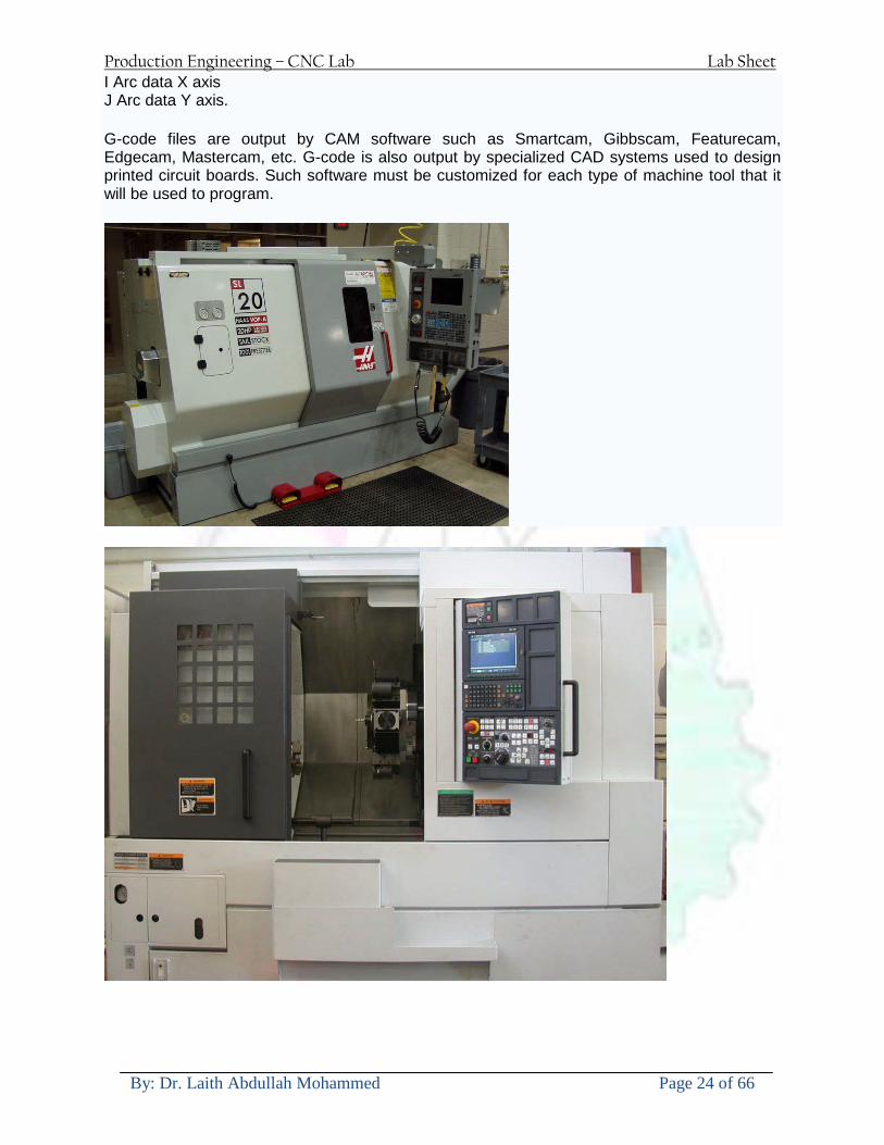
Production Engineering ndash CNC Lab Lab Sheet
By Dr Laith Abdullah Mohammed Page 24 of 66
I Arc data X axis J Arc data Y axis
G-code files are output by CAM software such as Smartcam Gibbscam Featurecam Edgecam Mastercam etc G-code is also output by specialized CAD systems used to design printed circuit boards Such software must be customized for each type of machine tool that it will be used to program
Production Engineering ndash CNC Lab Lab Sheet
By Dr Laith Abdullah Mohammed Page 25 of 66
U 2عمل األزرار الرئيسية في ماكنة الخراطة المبرمجة (نصر (
1- SINGLE BLOCK للتأكد من صحة البرنامج (تنفيذ البرنامج خطوة خطوةب تقوم( 2- BLOCK DELETE بجانب ويعمل من األوامرلغاء بلوك معين أليستخدم 3- MACHINE LOCK العمل يستخدم لقفل حركة المحاور الرئيسية مع استمرار البرنامج في
)وهذا مهم للتاكد من صحة البرنامج قبل عملية التنفيذ النهائي(4- CONT CYCLE عملية التشغيل عند ايقافها الي سبب كان او عند ايقافها ألستئناف ستخدم ت
) BAR FEEDER(او في حالة استخدام ) FEED HOLDبسبب (5- DRY RUN وتستخدم لفحص البرنامج بعد ازالة الشغلة حركة سريعة للبرنامج 6- TURRET UP amp DOWN ) حركة حامل العدة TURRET الذي يحمل مجموعة من (
وهذا الزر يعمل مع الزر عكس عقرب الساعة او مع عقرب الساعة ةحركة دوراني العدد )SAFTY (
7- COOLANT ON or OFFفه تشغيل سائل التبريد او ايقا 8- COOLANT AUTO الدوال المساعدة في البرنامج من خالل فه تشغيل سائل التبريد او ايقا 9 -MACHINE START ة لتشغيل هيدرولكيك الماكنميستخد
Production Engineering ndash CNC Lab Lab Sheet
By Dr Laith Abdullah Mohammed Page 26 of 66
10- CLOSE OR OPEN CHUCKالعينة تستخدم لفتح وغلق 11 -T STOCK FWD RET حركة الغراب المتحرك ذهابا وإيابا12 -SPINDLE STOP تعمل على ايقاف حركة دوران العينة 13-JOG SPINDLE تعمل على تدوير العينة مع زر SAFTY 14 -OPT SAFTY مع الدالة ( تعمل عمل التوقف المشروط حيث تعملM1 دالة التوقف (
ط ) فقط األ اذا كان هذا الزر مضغو M1المشروط حيث ال يتوقف البرنامج في حالة وجود دالة ( SAFTY + SPINDLE ) يتم الضغط على زر ( START CYCLEلغرض تحرير زر (
START ) في نفس الوقت بعد الضغط على زر ( START CYCLE مرتين (
NC PC- 15 يستخدم هذا الزر عند ربطCNC يستخدم لنقل المعلومات ث مع جهاز أخر حي بينهما
16 -CALCU زر الخاص بالحاسبة مع زر ( ال وهوINPUT ( 17 - HD1 HD2 يستخدم الختيار العدة مع المخرطة ذات المحاور األربعة 18 - START تستخدم لبدء عملية التشغيل
Production Engineering ndash CNC Lab Lab Sheet
By Dr Laith Abdullah Mohammed Page 27 of 66
19- FEED HOLD تعمل على إيقاف عمل أي G موجودة مع بقاء العينة متحركة 20- M D I أو تشغيل البرنامج ل يتم استخدامه لإلدخا BLOCK BY BLOCK وتعمل عند
إدخال البرنامج بواسطة الشريط المثقب أو أي وسيلة إدخال أخرى أو في عمليات التصفير
21- REST تستخدم العادة تشغيل الماكنة أو مسح اإلنذار الذي يظهر على الشاشة 22- EMERGENCYتستخدم عادة اليقاف الماكنة في حالة الطوارئ فقط
OPERATION MENU KEY
CHAPTER PRG-CMK
OFFSET PROGRAM POSITION FUNCTION MENU KEY
23- POSITIONعلى الشاشة د الموقع الموجور الظها 24- PROGRAMإلظهار برنامج معين واختياره 25- OFFSET الختيار سماحات العدة أو سماحات نقطة المرجع 26- PRG- CHK تستخدم لفحص البرنامج على الشاشة 27- SETTING ألختيار الثوابت على الشاشة 28- SERVICE تستخدم ألستخراج المعامالت والثوابت 29- MESSAGE تستخدم ألظهار األخطاء الناتجة عن البرنامج او اخطاء التشغيل 30- OVERALL ألختيار المواقع 31- RELATIVE MODLINE تعوض عن POSITION 32- DIR MEM يستخدم ألظهار ملف البرامج المخزونة في الذاكرة وعندما نضغط هذا الزر
فان رقم واسم البرنامج سوف يظهر على الشاشة
2أدناه الشفرات الرئيسية التي تعمل على الماكنة المبرمجة نصر
G-CODE DESCRIPTION
G00 Rapid traverse (linear)
G01 Linear Interpolation at feed rate
G02 Circular interpolation (CW) R+
G03 Circular interpolation (CCW) R+
G10 Zero point tools
G20 Imperial data input
G21 Metric data input
G27 Reference return check
G28 Reference return
G29 Return from reference
Production Engineering ndash CNC Lab Lab Sheet
By Dr Laith Abdullah Mohammed Page 28 of 66
G33 Thread cutting
G40 Cancel cutter radius compensation
G41 Cutter compensation left
G42 Cutter compensation right
G54 Work co-ordinate system no1
G70 Finishing cycle
G71 Stock removal turning
G72 Stock removal facing
G74 Face grooving
G75 Diameter grooving
G76 Threading cycle
G90 Absolute date input
G91 Incremental data input
G94 Feed minute mode
G95 Feed rev mode
G96 Constant surface speed mode
G97 Cancel Constant surface speed
) 2أدناه الشفرات الثانوية التي تعمل على الماكنة المبرمجة (نصر
M-code FUNCTION
M00 Program stop
M03 Spindle forward (Tool forward ndash M94 mode)
M04 Spindle reverse (Tool forward ndash M94 mode)
M05 Spindle stop (Tool stop ndash M94 mode)
M08 Coolant on
M09 Coolant off
M30 Program end (with rewind)
M48 Turret shortest path
M52 Turret direction up (CW)
M53 Turret direction down (CCW)
M73 Chuck open
M74 Chuck close
Production Engineering ndash CNC Lab Lab Sheet
By Dr Laith Abdullah Mohammed Page 29 of 66
) وكل جملة مكونة من مجموعة من الكلمات blockإن كل برنامج يتكون من مجموعة من الجمل ()words) لهذا فأن الشفرات الرئيسية والمساعدة هي عبارة عن كلمات (words كما في المثال التالي (
G_ _ P1 Q2 U_ _ W_ _ D___ F_ _
)end of block) ويعني ( ) يكتب الرمز (blockتسلسل الكلمات مهم جدا بعد نهاية كل جملة (
طريقة ادخال البيانات الى الماكنة ــــــــــــــــــــــــــــــــــــــــــــــــــ
) MDIيمكن ادخال البيانات الى الماكنة بعدة طرق فقد يكون األدخال عن طريق قناة السيطرة ( MANUAL DATA INPUT ) او عن طريق قناة األضافة EDIT كما يمكن ادخال البيانات عن (
) RS ndash 232 COMMUNICATIN LINKطريق استخدام سلسلة الربط (
₤⅗₌⅗₌ ⅙₌₨image₍₡ ₤₌ℌ⅗₌ Ⅸ⅗ⅥⅯ₌ ₤₡ℌ₰₨⅗₌G71
الخراطة الطولية G71الغرض من التجربة عمل نموذج للخراطة بأستخدام الدالة تستعمل هذه الدالة للخراطة الطولية اي على طول محور المشغولة وكما هو موضح بالشكل ادناه
تعتبر هذه الدالة من الدوال التي ال تحتاج الى تكرار او إعادة كتابتها أي انها دالة تكرارية بمعنى ان اي
الذي هي دالة حركة G01خطوة تكون من ضمن هذه الدالة سوف تكرر العملية اي عند استعمال امر مثل خطية تتضمن القطع مع التغذية مع اعطاء القطر المراد قطعه و مراعاة عمق القطع المعطى سوف يتكرر
هذه االمر وصوال الى العمق المطلوب وهكذا لبقية الدوال
G71 المستخدمة للدالة الصيغة
G71 P1 Q2 U___ W___ D___ F___ حيث إن
P1 بداية الخطوة االولى = Q2 نهاية الخطوة =
Uوضع السماحات بأتجاه محور = X W وضع السماحات بأتجاه محور = Z وتكاد تكون مهملة وتوضع اشارة سالب Dعمق القطع وتوضع رقم صحيح مثل = D500 اي نصف ملمF التغذية والتي لها عالقة بالدالة = G95
Production Engineering ndash CNC Lab Lab Sheet
By Dr Laith Abdullah Mohammed Page 30 of 66
G71الدالة استخدام مثال على
T0100 M48 G0 X26 Z2 M08 T0101 G90 G95 G97 S500 M03 G71 P1 Q2 U03 W00 D500 F01 N1 G0 G42 X00 G01 Z00 G01 X2517 G01 Z-5352 G01 X7391 Z-9366 G01 Z-19145 N2 G28 M30
الجانب العملي
االجهزة واالدوات المستخدمة CNCماكنة خراطة مبرمجة 1 ملم 80قضيب من االلمنيوم قطر 2 ةفير ني 3 جاه أيمن تهولدر كاربيدي ذوا 4
طريقة العمل يتم تثبيت قضيب من االلمنيوم على العينة التابعة للماكنة مع مراعاة الطول المراد استعماله في عملية 1
الخراطة ) turretتثبيت عدة القطع في المكان الصحيح في ( 2
Production Engineering ndash CNC Lab Lab Sheet
By Dr Laith Abdullah Mohammed Page 31 of 66
بالنسبة الى القطعة المثبتة على العينة XZيتم تصفير الماكنة للمحاور 3 تصفير للمحورZ تكون مالمسة العدة الى وجه الشغلة تصفير للمحورX تكون مالمسة العدة الى سطح الشغلة الموازي لمحور X
يتم كتابة البرنامج أما بطريقة يدوية أو بالحاسوب مع وضع كل الظروف الالزمة للتشغيل ( عمق القطع 4 التغذية السرعة المطلوبة نوع المعدن )
ادخال البرنامج الى الحاسوب الموجود داخل الماكنة مع تهيئة الماكنة للتشغيل 5
المطلوب G71عمل برنامج يدوي على الدالة 1 رسم الشكل الشكل النهائي المطلوب مع وضع األبعاد 2
Ⅺ⅟₍euro⅗₌ ₤₡ℌ₰₨⅗₌₣ ₤⅗₌⅗₌ ⅙₌₨image₃₡ Ⅺℂtradeℒ⅗₌ ӈ₍Ⅴ⅟ⅳ₌ G70
G70 الغرض من التجربة عمل انهاء سطحي للمشغولة بواسطة الدالة
من الضروري إعطاء G71هذه الدالة تعمل شوط واحد فقط وتكون معتمدة على عمليات القطع في الدالة اللغاء مقدمة االداة (أي لكي تتم عملية االنهاء السطحي بدون حسابات نصف قطر مقدمة االداة ) G42دالة
G70الصيغة المستخدمة للدالة
G70 P1 Q2 F___ حيث ان
P1 بداية الخطوة االولى = Q2 نهاية الخطوة =
F التغذية والمرتبطة بالدالة = G95
وذلك ألن دالة االنهاء السطحي تحقق X Zمالحظة الدالة التحتاج لكتابة السماحات التابعة للمحورين المسافات الحقيقة المراد انتاجها للمشغولة
G71و G70مثال على الدالة
T0100 M48 G0 X26 Z2 M08 T0101 G90 G95 G97 S500 M03 G71 P1 Q2 U03 W00 D500 F01 N1 G0 G42 X00 G01 Z00 G01 X2517 G01 Z-5352 G01 X7391 Z-9366 G01 Z-19145 N2 G97 S750 MO3
Production Engineering ndash CNC Lab Lab Sheet
By Dr Laith Abdullah Mohammed Page 32 of 66
G70 P1 Q2 G40 F009 G28 M30
الجانب العملي الحظ التجربة األولى
المطلوب
G70 عمل برنامج يدوي على الدالة 1 رسم الشكل النهائي المطلوب مع وضع االبعاد 2
₪⅗₍euro⅗₌ ₤₡ℌ₰₨⅗₌₣ ₤⅗₌⅗₌ ⅙₌₨image₍₡ ⅝₍ⅠimageⅯ₌ ⅞ⅫⅦ⅔₧ G76
G76 للمشغولة بواسطة الدالةةالغرض من التجربة عمل أسنان خارجية أو داخلي
في هذه التجربة سوف نقوم بعمل األسنان الخارجية وهنا تكون حركة العينة ثابتة وهذا ضروري بسبب أن ) تكون متصلتين الكترونيا وعليه أي اختالف في سرعة العينة تؤدي إلى اختالف motionالعينة والحركة(
) servoفي سرعة الخدمة(يرتبط اتجاه تكوين األسنان باتجاه دوران العينة مثال إذا كانت األسنان ذات اتجاه أيمن يكون اتجاه دوران
وهنا نقلب العدة إلى االسفل وكما هو موضح بالشكل أدناه MO3العينة عكس عقرب الساعة أي نستعمل
Production Engineering ndash CNC Lab Lab Sheet
By Dr Laith Abdullah Mohammed Page 33 of 66
الخطوة هي عبارة عن المسافة ما بين قمة سن إلى قمة سن أخر عمق السن هو العمق المطلوب تكوينه لألسنان
G76 الصيغة المستخدمة للدالة
G76 X___ Z___ K___ F___ D___ A___
حيث أن X القطر الداخلي للسن =Z طول السن =K عمق السن وتستخرج من المعادلة التالية =K=065F F الخطوة =D عمق القطع بالمايكرون فقط =A زاوية السن =
G76مثال على استخدام الدالة T0300 M48 GOO X30 Z4 T0303 M08 G97 S500 MO3 G76 X28375 Z-20 K08125 F125 D120 G00 X40 Z4 G28 M30
Production Engineering ndash CNC Lab Lab Sheet
By Dr Laith Abdullah Mohammed Page 34 of 66
الجانب العملي الحظ التجربة األولى
المطلوب
G76عمل برنامج يدوي على الدالة 1 رسم الشكل النهائي المطلوب مع وضع األبعاد 2
Ⅺ⅘₌⅗₌ Ⅵ₂ Ⅺ₯ℋ₍⅗₌ ℌℲℂ⅗₌ ⅞ⅫⅦ⅔₧ ₤K₡₌ℌ⅗₌ ₤₡ℌ₰₨⅗₌)Groove ₤⅗₌⅗₌ ₤tradeimage₌Ⅶ₡ (G75
G75 بواسطة الدالة grooveالغرض من التجربة تكوين
) للمشغولة وتعتمد شكل الحفر على طريقة grooveتستعمل هذه الدالة لتكوين الحفر الخارجي والداخلي (
التشغيل وعلى الشكل المراد إنتاجه وتعتبر هذه الطريقة من عمليات التشكيل للمعدن إن هذه الدالة هي دالة مالحظة مع G75في هذه التجربة سنقوم بعمل الحفر الخارجي بواسطة الدالة
تكرارية وغير تكرارية حسب نوع التشغيل
G 75 الصيغة المستخدمة للدالةG75 X___ Z___ I___ K____
حيث أن
X العمق النهائي لقطر الشغلة =Z عرض الحفر =I الدخول في كل مرة =
K التزحيف على محور =z بالنسبة للعدة
Production Engineering ndash CNC Lab Lab Sheet
By Dr Laith Abdullah Mohammed Page 35 of 66
G75مثال على استخدام الدالة
T0500 M48 GOO X100 Z -20 T0505 M08 G97 S700 MO3 G75 X84 Z -38 I 05 K4
الجانب العملي الحظ التجربة األولى
المطلوب
G76عمل برنامج يدوي على الدالة 1 رسم الشكل النهائي المطلوب مع وضع األبعاد 2
Production Engineering ndash CNC Lab Lab Sheet
By Dr Laith Abdullah Mohammed Page 36 of 66
CNC Milling Machine Mechanical Construction
Guideways The guideways of CNC machines are made of steel To reduce the frictional forces they are coated with a strip of PTFE (Poly Tetra Fluoro Ethylene)
Ballscrews On conventional lathes a leadscrew is used to converts the rotary motion of the hand wheel into linear motion of the slides Leadscrews have a high coefficient of friction and backlash On CNC machines a ballscrew is used instead of a leadscrew Friction and backlash are much less than on leadscrews
Guideway
Production Engineering ndash CNC Lab Lab Sheet
By Dr Laith Abdullah Mohammed Page 37 of 66
bullMachining operations Direction of cutting Based on the direction of the cutter rotation and work piece feed milling operations are classified into two types 1-Up milling (Convention milling) In up milling the metal is removed by rotating the cutter against the direction of travel of the part
Feed
Machine table
Part
Cutting tool
Chip thickness at theexit of the tooth
2-Down milling (Climb milling) In climb milling the metal is removed by rotating the cutter with the direction of travel of the part
Machine table
Part
Cutting tool
Chip thickness at theentrance of the tooth
Production Engineering ndash CNC Lab Lab Sheet
By Dr Laith Abdullah Mohammed Page 38 of 66
bullTooling Tool geometry The geometry of the tool tip affects the way that the metal cutting is performed The nose radius rake angles relief angles etc must be selected with care
Radial relief
Radial rake
Axial relief
Approach angle
Axial relief
Corner radius Face mill Face milling cutters are used to mill flat surfaces Commonly used face milling cutters Cutter with 75 degree approach
75 deg
Cutter with 90 degree approach (Square shoulder face mill)
90 deg
Cutter with 45 degree approach
Production Engineering ndash CNC Lab Lab Sheet
By Dr Laith Abdullah Mohammed Page 39 of 66
bullCNC Programming Axes convention The Z axis is along the spindle axis The X and Y axes are perpendicular to Z VMC
Z
Y
-
+
-+
X- +
+Z
-Z
+Y
-Y
-X +X
Part
Machine table
X
YZ
G00 Rapid traverse When the tool being positioned at a point preparatory to a cutting motion to save time it is moved along a straight line at Rapid traverse at a fixed traverse rate which is pre-programmed into the machines control system Typical rapid traverse rates are 10 to 25 m min but can be as high as 80 mmin
Production Engineering ndash CNC Lab Lab Sheet
By Dr Laith Abdullah Mohammed Page 40 of 66
Format N_ G00 X__ Y__Z__
G01 Linear interpolation (feed traverse) The tool moves along a straight line in one or two axis simultaneously at a programmed linear speed the feed rate Format N__ G01 X__ Y__Z__ F__
Part
Feed
Part
Feed
G02G03 Circular interpolation The tool moves along an arc in two axes simultaneously at a programmed linear speed the feed rate
Production Engineering ndash CNC Lab Lab Sheet
By Dr Laith Abdullah Mohammed Page 41 of 66
Format N__ G0203 X__ Y__Z__ I__ J__K__ F__ using the arc center OR N__ G0203 X__ Y__Z__ R__ F__ using the arc radius G02 moves along a CW arc G03 moves along a CCW arc Arc center The arc center is specified by addresses I J and K I J and K are the X Y and Z co-ordinates of the arc center with reference to the arc start point
X
Y
Arc center
Arc endArc start
- J
- I
I = X coord of center - X coord of start point J = Y coord of center - Y coord of start point K = Z coord of center - Z coord of start point I J and K must be written with their signs
Production Engineering ndash CNC Lab Lab Sheet
By Dr Laith Abdullah Mohammed Page 42 of 66
bullWork holding
Rotary table
Fixture base
Component
Clamp
Stud
Fixtures The use of fixtures 1 Improves repeatability of dimensions 2 Improves working conditions 3 Cuts down requirement of skilled labour 4 Reduces part loading and unloading time 5 Improves safety in the working area 6 Reduces the cost of machining There are two types fixtures commonly used 1 Special fixture Special fixtures are used to hold and locate the typical components which are having complex shape and to be located with the reference hole (dowel hole) Special fixtures are required for components like gear case cover cylinder heads etc 2 Modular fixture Modular fixture is a set different kind of clamping and locating elements These fixtures are used to hold identical components in different sizes and components of box type Example Manifolds head stocks connecting rods and flanges
Production Engineering ndash CNC Lab Lab Sheet
By Dr Laith Abdullah Mohammed Page 43 of 66
bullMachine setting
Determining X and Y work zero offset Case 1
Part
Machine table
Part
End mill or reamer
Work offset X0Y0 For determining X work zero offset bull Touch the periphery of the end mill or reamer to the part bull Enter current machine X value + cutter radius as X work zero offset For determining Y work zero offset bull Touch the periphery of the end mill or reamer to the part bull Enter current machine Y value - cutter radius as Y work zero offset Case 2
Part
Machine table
Part
End mill or reamerWork offset X0Y0
bull Mount the dial indicator on machine spindle true the bore bull Enter current machine X and Y value as X and Y work zero offset
Production Engineering ndash CNC Lab Lab Sheet
By Dr Laith Abdullah Mohammed Page 44 of 66
How to Select a Cutting Fluid
One part of the metal cutting equation that is sometimes overlooked however is
the choice of an appropriate cutting fluid With todayrsquos system approach to metal
cutting use of the right metalworking fluid has become just as much a part of the
solution as the other elements In fact at least one company is now integrating
cutting fluids and cutting tools into effective metal cutting systems Following are
some things to consider when choosing your next cutting fluid
The Four Key Questions
There are four vital pieces of information that are necessary when choosing a
cutting fluid They are
1 What are you cutting
2 What is the chemistry of your water
3 What are you using now
4 What are your options
5 What do you prefer
What Are You Cutting
The first question ndash ldquoWhat are you cuttingrdquo ndash is often the most difficult to answer
because most shops handle a variety of workpiece materials on a regular basis If
the answer is an unequivocal ldquoaluminumrdquo or ldquostainless steelrdquo or ldquocast ironrdquo the
selection of a cutting fluid can be quite simple and straightforward Unfortunately
that is seldom the case in anything but a high-volume plant Where aluminum or
other nonferrous metals are a significant part of the mix a non-staining cutting
fluid is a must Generally speaking this will be a semi-synthetic with special
ingredients to prevent bi-metallic corrosion and staining of non-ferrous workpieces
Where the ferrous metals predominate however a more general purpose semi-
synthetic or hybrid fluid might be a more economical choice
Production Engineering ndash CNC Lab Lab Sheet
By Dr Laith Abdullah Mohammed Page 45 of 66
What is The Chemistry of Your Water
The second question ndash ldquoWhat is the chemistry of your waterrdquo ndash is probably the
single most common reason for the success or failure of a cutting fluid Very few
plants invest the money necessary to install effective water purification systems
using deionization or reverse osmosis technology Unfortunately the chemicals
present or not present in the water used to re-constitute a cutting fluid make a
tremendous difference in its performance and sump life Most manufacturers of
cutting fluids will perform the necessary water testing to determine exactly what
minerals are dissolved in your water and make a fluid recommendation based on
the results
What are you using now
The third question ndash ldquoWhat are you using nowrdquo ndash helps narrow the range of
choices When coupled with an objective analysis of the strengths and weaknesses
of the current fluid the answer to this question can quickly point you toward a
relatively small number of competitive alternatives that have the attributes required
to meet your cutting needs Many cutting fluids are in use today simply because
they were in use yesterday It is a hard reality of todayrsquos marketplace that if one
isnrsquot constantly striving to improve they will certainly be overtaken by a
competitor who is
What Are Your Options
The fourth question ndash ldquoWhat are your optionsrdquo ndash leads to the final selection of a
cutting fluid Cutting fluids can be divided into four general groups based on their
chemistry
They are
bull Soluble Oils ndash quite literally oil dispersed in water
bull Synthetics ndash completely oil free man-made coolants in solution
Production Engineering ndash CNC Lab Lab Sheet
By Dr Laith Abdullah Mohammed Page 46 of 66
bull Semi-Synthetics ndash a mixture of natural and synthetic lubricants with up to 30
mineral oil
bull Hybrids ndash a special class of semi-synthetics with a mineral oil content of about
15 Each fluid type has advantages and disadvantages which make it suitable for
a particular group of applications In addition there are costperformance trade-
offs to be made between the groups within a specific set of applications For
example where a hybrid and a semi-synthetic may both be suitable for a particular
use the hybrid might provide longer sump life at a slightly higher initial cost
while some semi synthetics may be more economical to recycle or dispose of while
not giving as long a tank life The final decision in this case would have to be made
on the detailed economics of the shop where the fluids were to be used and on the
ownerrsquos individual preferences
Soluble Oils
Soluble oils are oils that disperse in water when emulsifiers are added They are
generally suitable for moderate-to heavy-duty machining and grinding of all non-
ferrous metals carbon and cast steels and in applications where dissimilar metals
such as aluminium and steel are present They can also be used in turning drilling
tapping reaming gear cutting broaching as well as internal and centerless types
of grinding operations Soluble oils provide excellent aluminium and copper
corrosion control good rancidity control which extends fluid for long lasting
trouble-free performance and good concentrate and mix stability making it ideal
for mixing in water with a minimal amount of agitation An example of this is
Valenitersquos VNTreg-650 premium heavy-duty soluble oil
Synthetics
Synthetics are completely oil free solutions made of polymers organic and
inorganic materials that are mixed with water These clear low foaming and bio-
Production Engineering ndash CNC Lab Lab Sheet
By Dr Laith Abdullah Mohammed Page 47 of 66
stable coolants are ideal for machining and grinding of ferrous materials carbon
steels or cast iron Their complex lubricant packages make synthetics well-suited
for tough-to-machine materials such as stainless steels and high-temperature alloys
Certain synthetics are specifically designed to address the primary failure modes of
flank wear and nose wear Although there are many benefits some synthetics may
cause staining of non-ferrous materials
Semi-Synthetics
Semi-synthetic fluids are a mixture of oils synthetic emulsifiers and water They
were primarily developed for the aircraft nuclear and related industries
Consequently they work extremely well on all non-ferrous metals such as titanium
aluminium copper brass bronze and stainless steel in both machining and
grinding Semi-synthetics can be used on ferrous metals too They are chlorine-
free to reduce bi-metallic corrosion and staining of metals They should be used at
a 5-8 dilution with water depending on the severity of the operation
Hybrids
Hybrids are cutting fluids custom engineered to solve a particular problem For
example Valenitersquos VNTreg-800 was developed to be very clean in the machining
and grinding of cast iron It provides better stability in hard water and rejects tramp
oil very well which adds to its bio-stable chemistry Hybrids work extremely well
on all metals in both machining and grinding They should be mixed at a 5-7
dilution with water depending on the condition of the water
What Do You Prefer
The final question ndash ldquoWhat do you preferrdquo ndash is usually the ldquotie breakerrdquo where
there is more than one appropriate cutting fluid available Here again as in the
case of what is being used now the key is to examine your preferences objectively
Production Engineering ndash CNC Lab Lab Sheet
By Dr Laith Abdullah Mohammed Page 48 of 66
and specifically to identify the real reasons behind a preference If you cannot
point to specific reasons why one class of cutting fluid is preferred over another
you are well advised to follow the recommendations of the professional who has
analyzed your requirements Choosing the right fluid today is easier than ever as
the system approach to metal cutting productivity continues to grow in acceptance
The day is not far off when choosing a complete solution will be as easy as
choosing the right insert and chip breaker today The answers are available and the
results will more than justify the time you spend choosing the right metal cutting
fluid
Useful Links wwwball-screwsnet
wwwlubelinkcom
wwwmachinerylubricationcom
wwwadvancedmanufacturingcom
wwwmmsonlinecom
wwwcuttingtoolengineeringcom
wwwgeartechnologycom
wwwengineersedgecom
wwwagmaorg
wwwefundacom
wwwsaeorg
wwwsmeorg
wwwastmorg
wwwissorg
wwwmachinetoolscom
wwwansiorg
wwwasmeorg
wwwcnccicom
wwwmatlscom
wwwthefreedictionarycom
wwwengineersupplycom
Production Engineering ndash CNC Lab Lab Sheet
By Dr Laith Abdullah Mohammed Page 49 of 66
SurfCAM Tutorial ndash Beginning with the basics
Background SurfCAM is a computer aided manufacturing (CAM) software which allows you to create manage and modify tool paths for computer aided designed (CAD) part The software requires a CAD model or requires that you create some geometry within SurfCAM with some rudimentary tools provided The tool paths are created or stored internally in SurfCAM in a generic programming language called APT Once the tool paths are created the APT paths are translated using a post processor into typical machine G-code
Opening SurfCAM SurfCAM can be opened from the Novell Applications Launcher on most Industrial Engineering computer labs workstations Search under lsquoallrsquo applications and double click on SurfCAM 2005 Once the program opens a license must be selected from the list (not the Demo license) to enable saving the file later Choose one of the 30 licenses available If for some reason the licenses are not listed on the license manager form select server list and type ldquobonnieeosncsuedurdquo A list of available licenses should appear Select a license and click OK After the license is selected an Add StockFixture form (Figure 1) opens allows you to add a model which represents the pre-machined stock or a fixture Click on OK without adding either Both of these items can be added later under a more appropriate dialog
Figure 1 Add Stock or Fixture dialog box
Production Engineering ndash CNC Lab Lab Sheet
By Dr Laith Abdullah Mohammed Page 50 of 66
SurfCAM Interface
Figure 2 SurfCAM Windows based interface
SurfCAM is a windows based software system so most of the typical windows functions under File are applicable This is where you can open save exit print etc The Create menu allows the user to create different geometry forms Here you can create a point line surface chamfer circle and many other geometry types For the most part these functions are not used by beginners but are useful when creating bounding curves where you donrsquot want the tool to move outside (constraining the tool) The Edit menu allows you to change or modify many different entities such as changing lines altering surfaces joining surfaces trimming or breaking elements add control points etc Again these features are helpful to advanced users and are not covered in detail in this tutorial The Display menu offers the ability to change the orientation of the part on the screen The typical rotate pan fit to screen and zoom functions are available as well as several functions which allow the user to shift between views or call up a named view (ie top bottom etc) The NC menu is the main machining interface menu In this menu you select the general form of machining (2 axis 3 axis 4 axis 5 axis turning etc) and under the general form a more specific machining function is selected This menu is the most used and the options contained must be fully understood to get the most out of SurfCAM Each function will be described in some detail in a further chapter The Analyze menu contains options such as measuring the distance between points angles tangency elements etc These functions are auxiliary functions meant to help you understand the part better but basically provide no functionality for making tool paths for CNC machines Thus these will not be covered The Tools menu allows the user to change the system options modify keyboard shortcuts change the model units etc These options are again not used by beginners Finally the Help menu provides access to the online users manual In lieu of clicking the Help menu the F1 key is the shortcut key for help (as it is in most windows based programs)
Importing a CAD model Importing a CAD model that is stored locally is done by selecting File-gtOpen On the Files of type dropdown box choose the type of file you wish to open (Figure 3) Do this prior to negotiating your way through the maze of folders to prevent having to go through the folder tree again Once the file type is selected find the file you are trying to open and click the Open
Production Engineering ndash CNC Lab Lab Sheet
By Dr Laith Abdullah Mohammed Page 51 of 66
button SurfCAM will then attempt to read the file you have selected SurfCAM may provide a dialog box describing what it has imported and identify if it was successful If this dialog is provided simply click close without saving
Figure 3 Open Dialog Note - Change type of file prior to finding the file you wish to open
SurfCAM allows a user to import several different types of CAD files the most common types which you will likely import are SolidWorks part files (sldprt or prt) AutoCAD files(dxf) or IGES (igs or iges) Native file import (such as is the case with SolidWorks) provides the greatest information transfer and generic file imports (such as is the case with IGES) provide the least Normally it is to the advantage of the user to use native file importing procedures when available Recently (2005) SurfCAM added some compatibility with SolidWorks This allows the user to create tool paths for a part and if an engineering change is needed for the part update the part in SolidWorks When the part is then opened in SurfCAM the changes are noted and a simple update operation command is needed This however does not operate with complete transparency andor accuracy and thus users need to be cognizant of changing CAD models
SurfCAM Geometry In SurfCAM two basic types of geometry are used the surface and the point A surface (Figure 4) is a so called spline (NURBS or B-Spline are the two most common) surface (parameterized by two values u and v) such that every location on the surface can be defined as a function of these parameters In other words SurfCAM can calculate the location of any point on the
Production Engineering ndash CNC Lab Lab Sheet
By Dr Laith Abdullah Mohammed Page 52 of 66
surface Surfaces are used primarily in 3 4 and 5 axis machining and require a significant
amount of processing power and time Figure 4 Surfaces model of a mold half Note the difference between this and Figure 2 a wireframe model
Point or line based models are often referred to as wireframe (Figure 5) models because the models consist of connected lines and resemble the part only at the intersection of two surfaces Wireframe models were made popular lsquoback in the dayrsquo when computer processing was expensive There are times when each of the models are important and selecting model geometry when applying a SurfCAM operation will be much simpler if you understand the differences between the two When importing a SolidWorks model the default is both the surfaces and the wireframe geometry are imported
Figure 5 Wireframe model of the mold in Figure 1
Steps to Creating Tool Paths Once a CAD model is imported into SurfCAM tool paths can be created There is no one correct way to create tool paths however there is a set of general steps to take to ensure the tool paths are created with a minimum amount of hardship (note the wordinghellipHardship is inevitable when creating tool paths it is the intent of this manual to minimize this) The following is a list of steps which should be considered when making tool paths
Production Engineering ndash CNC Lab Lab Sheet
By Dr Laith Abdullah Mohammed Page 53 of 66
1 Plan ahead a Orient the part in SolidWorks such that if only one side is to be machined that
side is the Top view This can be done early in SolidWorks by choosing a plane parallel the X-Y plane as the sketch plane for the machined geometry
b Orient the part in SolidWorks such that the origin is somewhere of relative importance and someplace in space that can be easily identified when placed on the machine This is extremely important to minimize set up time at the machine (note ndash my personal preference for a part that is to be fully machined [ie stock exists on all sides] is to place the origin at the center and top of the parthellipjust my preference)
c Orient the part in SolidWorks such that the X and Y axes are aligned as you want them on the machinehellip
d Planning ahead will save you many hours of headaches laterhelliptrust me 2 Import the model 3 Choose a construction view such that the tool approaches the side to be machined
from the positive Z axis direction (as defined by part origin) a This is done by clicking on the CView icon
b From the list of named views chose the view which orients the origin as you would like
c If one of the views does not fit your criteria you have two choices i Perform a transformation of the part in SurfCAM or SolidWorks
ii Add a new construction view by selecting new This option requires a relatively good understanding of right hand coordinate frames but is very usefulhellipNormally used by more advanced users
d Be sure the CoordVIEW selection is made vs CoordWORLD This ensures the tools will be controlled from the coordinate frame selected by the view (ie the origin on the part) instead of the origin on the lower left corner of the screen This will be especially important when we get into 4 and 5 axis machining
4 In the Operations Manager (Figure 6) select Setup One and change the name to something meaningful ndash like Front Side Mold Cavity
a Access the Operations manager by right clicking or by selecting the Operations Manager icon in the tool bar
b Operations Manager is where the tool paths are managed once they are created as well as where individual tool paths can be verified
Production Engineering ndash CNC Lab Lab Sheet
By Dr Laith Abdullah Mohammed Page 54 of 66
5 Roughing Tool Paths a Create the tool paths to remove the majority of the material (if applicable) b Use NC-gt3Axis-gtZ rough or Plunge Rough c Described in next section
6 Create Finishing Tool Paths a Described in next section
7 Add another setup if necessary 8 Perform steps 3 through 6 as necessary 9 Verify the tool paths are correct 10 Use a post processor for the tool paths to create G-Code for machine
Creating Tool Paths The following is a list of operations what they are intended for how they generally work and some parameters that may be adjusted to modify the tool paths
2 Axis tool paths Unless otherwise noted 2 axis tool path functions require lines or arc segments as input parameters (as opposed to surfaces) There are several options as to how these segments are chosen the most prevalent is the chain option and the second most prevalent is the single When choosing the line segments using the chain option SurfCAM will try to link a complete path of segments based on an initial segment chosen by the user If the operation is planer (ie pocket or contour) the segments must lie on the same plane If the operation is non-planer (ie contour 3D) SurfCAM will prompt the user to specify segments when it encounters a branch point
Figure 6 Operations Manager view showing setup one re-labeled as Front Side Mold
Production Engineering ndash CNC Lab Lab Sheet
By Dr Laith Abdullah Mohammed Page 55 of 66
When using the single element option the user must manually choose each segment desired for the operation Note that most operations do not require a closed loop of segments you may specify for instance an open contour where the tool is supposed to move The order of choosing segments is important This order determines the path of the tool in the sense that if three segments are chosen such that the middle segment is chosen last there will be three different plunge and machine operations one on each segment If the operation was to make a continuous contour around the outside of the part the segments should be chosen in order of the desired tool trajectory
Operations
Pocket Pocket operation in SurfCAM is used to cut an enclosed space from the inside to the outside at one particular depth The operation starts in the center of an enclosed area (with a plunge move in the ndashZ direction) and makes incremental closed paths towards the pocket boundaries in user defined path offsets (Figure 7) The user chooses the boundary of the pocket (line segments) and if more than one pocket is chosen SurfCAM will ask the user to click inside a pocket
Figure 7 Two examples of using the pocketing operation
The pocket operation allows for creating a projection of the pocket paths on multiple planes This is useful if you have a deep pocket which will not allow the tool to cut directly at the depth of the pocket but would be easily done using the same paths at several different Z heights On the cut control (Figure 8) tab the user specifies where the chosen geometry (pocket segments) lie (ie bottom or top) Then under the amount to remove specify the total material height to be removed and the rough spacing (amount you wish to advance the Z axis with each pocket step) You may also specify a finishing pass and as well as stock to leave
Production Engineering ndash CNC Lab Lab Sheet
By Dr Laith Abdullah Mohammed Page 56 of 66
Figure 8 Example of Contour Operation with multiple passes
Contour Contouring in SurfCAM is used to perform peripheral milling on the inside or outside of a line segment (Figure 9) The user is to identify the line segments which define a contour (does not have to be a closed loop of segments) SurfCAM may or may not require the user to specify a side to contour (ie which side of the line is the tool to cut) For contouring each segment must lie on the same plane
Production Engineering ndash CNC Lab Lab Sheet
By Dr Laith Abdullah Mohammed Page 57 of 66
Figure 9 Examples of parts cut with 2-Axis Contour
Contour 3D Contour 3D is the same operation type as contour but allows the user to specify segments on different planes for the tool to cut along
Drill Drilling operations are any rotating tool operation meant to engage the part from a single direction ndash namely from the positive Z direction Drilling operations can be specified using circle point or line segments After choosing NC-gt2-Axis-gtDrill SurfCAM allows the user to choose multiple circles or points defining holes to be drilled Drilling operations also allow the user to incorporate more than 1 operation such as a center drill a drill and a reaming operation After selecting the locations for the drilling operation a dialog box (Figure 10) allows the user to add change or delete tools to be used in the operation As displayed in the following figure the spotdrill operation is followed by a drilling operation followed by a tapping operation The depth of each tool can be controlled individually by double clicking the total depth cell in and manually entering Tools can be added before or after operations which the cells are highlighted by selecting either of the insert buttons at the top or by the insert menu Select tool button allows the user to change the tool size or type
Production Engineering ndash CNC Lab Lab Sheet
By Dr Laith Abdullah Mohammed Page 58 of 66
Figure 10 Drill operation manager Several operations can be completed at one time
Figure 11 Drill operation including the spotdrill drill and tap as outlined in Fig 10
3 Axis tool paths SurfCAM requires surfaces as inputs for 3 Axis tool paths Surfaces can be created in SurfCAM but are most easily created in a CAD package and imported into SurfCAM Surfaces allow SurfCAM to identify every point on the surface in 3 dimensions unlike 2D geometry (wireframes) which only identify positions on the plane Creating tool paths with complex surfaces takes a very significant amount of processing power so expect 3 Axis tool path generation to take longer
Production Engineering ndash CNC Lab Lab Sheet
By Dr Laith Abdullah Mohammed Page 59 of 66
Operations
Cut 3 Axis cut operation takes a surface and using the flow lines creates a rastering path over the surface with the tool tip riding on the surface The primary direction will be defined by the flow lines of the surface (which can be edited by Edit-gtSurfaces-gtArrow-gtDirection) If you intend to cross surface boundaries you must merge the surfaces (Edit-gtJoin and choose the two surfaces)
Z-Rough The Z-rough operation is used to remove a large amount of material prior to finish machining Roughing operation is typically the first operation you perform for each setup The Z-Rough operation cuts the part in user defined intervals For each of these intervals a surface intersection between the part and the plane is performed and a 2D pocket or contour operation is performed on that plane This is performed on each plane When choosing NC-gt3 Axis-gtZ rough the first dialog box you will encounter asks for a bounding box to be defined Choose the Extents Box and a second dialog box will ask for the coordinates which define the box (Figure 12) This is the stock size you expect to machine the part from Input the coordinates or change the additional offset amounts (in XY or Z) as appropriate and click Calculate Bounding Box
Figure 12 Material Extents Box Example
Next choose the tool and cutting parameters that you desire and click on the Cut Control Tab (Figure 13) Here you will find the following parameters which are often changed Stock to
Production Engineering ndash CNC Lab Lab Sheet
By Dr Laith Abdullah Mohammed Page 60 of 66
leave ndash this is an offset amount from the surfaces which leaves a small amount of material to finish machine Minimum and Maximum Z values ndash Defines area to machine Z Step Size ndash This identifies the plane intervals for the surface intersection planes (the first interval will be at the top of the selected area and successive increments down in Z will be cut until the Minimum Z value is reached)
Figure 13 3Axis Z Rough Cut Control
The 3Axis Z-Finish operation works in exactly the same way 3 Axis Z-Finish is most appropriate for finishing vertical or near vertical walls
3D Offset The 3D Offset operation creates a tool path using a 2D or 3D boundary by offsetting the boundary in concentric offset cutting passes Each pass calculates the tool engagement and maintains the engagement somewhat constant The advantage (significant) is the scallop height ndash height of the material between passes ndash is controlled thus the surface finish is predictable When choosing 3D Offset surfaces are selected as well as 2D or 3D boundaries The boundaries define the concentric offset paths shape as well as limit the tool path area Choose NC-gt3Axis-gt3D Offset from the drop down menus SurfCAM will prompt you to select the surface or surfaces to cut across Select the surfaces you wish to machine and then select the tool and cutting parameters you wish use Next select the Cut Control Tab and check the Use Boundary Curves option Set the Step Type to Scallop and set the maximum scallop height If you like
Production Engineering ndash CNC Lab Lab Sheet
By Dr Laith Abdullah Mohammed Page 61 of 66
you can also add stock to leave if this is a roughing operation You can also set the Direction and Start-End parameters from this tab Click OK and the paths will be generated
Figure 14 Cut Control Tab for 3D Offset
Example part using both 2D and 3D geometry
The tool paths for this mold will be generated in SurfCAM using 5 operations The first will be a roughing operation using a frac14 inch flat end mill with the Z step size of 00625in Choose NC-
Production Engineering ndash CNC Lab Lab Sheet
By Dr Laith Abdullah Mohammed Page 62 of 66
gt3Axis-gtZ-Rough from the drop down menu Select all visible surfaces and create an extents box that has 025inch XY offsets and 01inch Z offset Next select the frac14 inch flat end mill from the tools menu Under Cut Control tab set the Z step size to be 00625inch The tool paths will look something like Figure 15
Figure 15 Z-Rough Tool paths for Example Part
Next a flat surface operation will be performed to cut the flat surface on the top Select NC-gt3 Axis-gtFlat Surface from the drop down menu Select all visible surfaces again Choose the 12inch flat end mill and set the cutting parameters as desired Under Cut Control Tab change the Minimum Area to 50 square inches (Figure 16) The tool paths should look something like Figure 17
Figure 16 Cut Control for Flat Surface
Production Engineering ndash CNC Lab Lab Sheet
By Dr Laith Abdullah Mohammed Page 63 of 66
Figure 17 Flat Surface Tool Paths
Next we will use a 3D offset operation to cut the mold cavity Select NC-gt3 Axis-gt3D Offset from the dropdown menu Change the view to the top view and select within to capture the surfaces of the mold cavity Draw a rectangle around the mold cavity Select a 18 inch ball endmill from the tool library and set the cutting parameters as appropriate Next set the Cut Control tab parameters as in Figure 14 The paths creates should be similar to Figure 18
Figure 18 3D Offset Paths
Next we will perform a 2 Axis contouring of the top section Select NC-gt2 Axis-gtContour from the dropdown menu Using the chain option select the bottom contour of the top extrusion Select the frac12 inch flat end mill from the tool library and set the cutting parameters as required In the Cut Control Tab change the Geometry to Bottom and the amount to remove in Z to 05
Production Engineering ndash CNC Lab Lab Sheet
By Dr Laith Abdullah Mohammed Page 64 of 66
Change the Rough Spacing in Z to 025 and add 1 finish pass of 002 (Figure 19) Click OK and SurfCAM will instruct you to choose a side to contour Click anywhere on the screen OUTSIDE the geometry you selected for the contouring operation Failure to click outside the geometry will result in the tool being on the wrong side of the contour Your paths should look something like those in Figure 20
Figure 19 Cut Control Tab for the Contouring Operation
Figure 20 Contouring operation paths
Production Engineering ndash CNC Lab Lab Sheet
By Dr Laith Abdullah Mohammed Page 65 of 66
Next we will perform a 2 axis pocket operation for the small pocket on the top face of the mold Select NC-gt2Axis-gtPocket and using the Auto select feature select the boundary curve at the bottom of the pocket Click Done twice and select the frac14 inch flat end mill from the tool library Set the appropriate cutting parameters and click OK SurfCAM will prompt you to click inside the pocket Click anywhere inside the geometry you chose to define the pocket The resulting paths should look something like those in Figure 21
Figure 21 2 Axis Pocket Operation Paths
Finally we will add a drilling operation for the 2 holes at the corners of the mold Select NC-gt2 Axis-gtDrill from the dropdown menu Select the top circles defining the two holes A menu box will appear with a default tool (Center drill) already programmed Add a second tool to the list by selecting Insert-gtAfter and select the tool from the tool library Change the drill depth to 10inches and click OK The paths should look something similar to Figure 23
Figure 22 Drill Menu
Production Engineering ndash CNC Lab Lab Sheet
By Dr Laith Abdullah Mohammed Page 66 of 66
Figure 23 Drilling Operation Tool Paths
Now you can watch a simulation of the cutting by choosing the setup in the operations manager and clicking the simulate icon Be sure to set the stock in the set up by right clicking the set up and selecting Edit Setup Information In the Stock Tab you can create a bounding box meeting your needs and click Add Your simulation should result in something like the following
Figure 24 Final Simulation of the example Mold
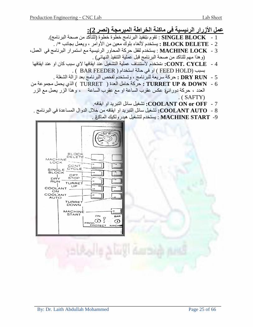
Production Engineering ndash CNC Lab Lab Sheet
By Dr Laith Abdullah Mohammed Page 25 of 66
U 2عمل األزرار الرئيسية في ماكنة الخراطة المبرمجة (نصر (
1- SINGLE BLOCK للتأكد من صحة البرنامج (تنفيذ البرنامج خطوة خطوةب تقوم( 2- BLOCK DELETE بجانب ويعمل من األوامرلغاء بلوك معين أليستخدم 3- MACHINE LOCK العمل يستخدم لقفل حركة المحاور الرئيسية مع استمرار البرنامج في
)وهذا مهم للتاكد من صحة البرنامج قبل عملية التنفيذ النهائي(4- CONT CYCLE عملية التشغيل عند ايقافها الي سبب كان او عند ايقافها ألستئناف ستخدم ت
) BAR FEEDER(او في حالة استخدام ) FEED HOLDبسبب (5- DRY RUN وتستخدم لفحص البرنامج بعد ازالة الشغلة حركة سريعة للبرنامج 6- TURRET UP amp DOWN ) حركة حامل العدة TURRET الذي يحمل مجموعة من (
وهذا الزر يعمل مع الزر عكس عقرب الساعة او مع عقرب الساعة ةحركة دوراني العدد )SAFTY (
7- COOLANT ON or OFFفه تشغيل سائل التبريد او ايقا 8- COOLANT AUTO الدوال المساعدة في البرنامج من خالل فه تشغيل سائل التبريد او ايقا 9 -MACHINE START ة لتشغيل هيدرولكيك الماكنميستخد
Production Engineering ndash CNC Lab Lab Sheet
By Dr Laith Abdullah Mohammed Page 26 of 66
10- CLOSE OR OPEN CHUCKالعينة تستخدم لفتح وغلق 11 -T STOCK FWD RET حركة الغراب المتحرك ذهابا وإيابا12 -SPINDLE STOP تعمل على ايقاف حركة دوران العينة 13-JOG SPINDLE تعمل على تدوير العينة مع زر SAFTY 14 -OPT SAFTY مع الدالة ( تعمل عمل التوقف المشروط حيث تعملM1 دالة التوقف (
ط ) فقط األ اذا كان هذا الزر مضغو M1المشروط حيث ال يتوقف البرنامج في حالة وجود دالة ( SAFTY + SPINDLE ) يتم الضغط على زر ( START CYCLEلغرض تحرير زر (
START ) في نفس الوقت بعد الضغط على زر ( START CYCLE مرتين (
NC PC- 15 يستخدم هذا الزر عند ربطCNC يستخدم لنقل المعلومات ث مع جهاز أخر حي بينهما
16 -CALCU زر الخاص بالحاسبة مع زر ( ال وهوINPUT ( 17 - HD1 HD2 يستخدم الختيار العدة مع المخرطة ذات المحاور األربعة 18 - START تستخدم لبدء عملية التشغيل
Production Engineering ndash CNC Lab Lab Sheet
By Dr Laith Abdullah Mohammed Page 27 of 66
19- FEED HOLD تعمل على إيقاف عمل أي G موجودة مع بقاء العينة متحركة 20- M D I أو تشغيل البرنامج ل يتم استخدامه لإلدخا BLOCK BY BLOCK وتعمل عند
إدخال البرنامج بواسطة الشريط المثقب أو أي وسيلة إدخال أخرى أو في عمليات التصفير
21- REST تستخدم العادة تشغيل الماكنة أو مسح اإلنذار الذي يظهر على الشاشة 22- EMERGENCYتستخدم عادة اليقاف الماكنة في حالة الطوارئ فقط
OPERATION MENU KEY
CHAPTER PRG-CMK
OFFSET PROGRAM POSITION FUNCTION MENU KEY
23- POSITIONعلى الشاشة د الموقع الموجور الظها 24- PROGRAMإلظهار برنامج معين واختياره 25- OFFSET الختيار سماحات العدة أو سماحات نقطة المرجع 26- PRG- CHK تستخدم لفحص البرنامج على الشاشة 27- SETTING ألختيار الثوابت على الشاشة 28- SERVICE تستخدم ألستخراج المعامالت والثوابت 29- MESSAGE تستخدم ألظهار األخطاء الناتجة عن البرنامج او اخطاء التشغيل 30- OVERALL ألختيار المواقع 31- RELATIVE MODLINE تعوض عن POSITION 32- DIR MEM يستخدم ألظهار ملف البرامج المخزونة في الذاكرة وعندما نضغط هذا الزر
فان رقم واسم البرنامج سوف يظهر على الشاشة
2أدناه الشفرات الرئيسية التي تعمل على الماكنة المبرمجة نصر
G-CODE DESCRIPTION
G00 Rapid traverse (linear)
G01 Linear Interpolation at feed rate
G02 Circular interpolation (CW) R+
G03 Circular interpolation (CCW) R+
G10 Zero point tools
G20 Imperial data input
G21 Metric data input
G27 Reference return check
G28 Reference return
G29 Return from reference
Production Engineering ndash CNC Lab Lab Sheet
By Dr Laith Abdullah Mohammed Page 28 of 66
G33 Thread cutting
G40 Cancel cutter radius compensation
G41 Cutter compensation left
G42 Cutter compensation right
G54 Work co-ordinate system no1
G70 Finishing cycle
G71 Stock removal turning
G72 Stock removal facing
G74 Face grooving
G75 Diameter grooving
G76 Threading cycle
G90 Absolute date input
G91 Incremental data input
G94 Feed minute mode
G95 Feed rev mode
G96 Constant surface speed mode
G97 Cancel Constant surface speed
) 2أدناه الشفرات الثانوية التي تعمل على الماكنة المبرمجة (نصر
M-code FUNCTION
M00 Program stop
M03 Spindle forward (Tool forward ndash M94 mode)
M04 Spindle reverse (Tool forward ndash M94 mode)
M05 Spindle stop (Tool stop ndash M94 mode)
M08 Coolant on
M09 Coolant off
M30 Program end (with rewind)
M48 Turret shortest path
M52 Turret direction up (CW)
M53 Turret direction down (CCW)
M73 Chuck open
M74 Chuck close
Production Engineering ndash CNC Lab Lab Sheet
By Dr Laith Abdullah Mohammed Page 29 of 66
) وكل جملة مكونة من مجموعة من الكلمات blockإن كل برنامج يتكون من مجموعة من الجمل ()words) لهذا فأن الشفرات الرئيسية والمساعدة هي عبارة عن كلمات (words كما في المثال التالي (
G_ _ P1 Q2 U_ _ W_ _ D___ F_ _
)end of block) ويعني ( ) يكتب الرمز (blockتسلسل الكلمات مهم جدا بعد نهاية كل جملة (
طريقة ادخال البيانات الى الماكنة ــــــــــــــــــــــــــــــــــــــــــــــــــ
) MDIيمكن ادخال البيانات الى الماكنة بعدة طرق فقد يكون األدخال عن طريق قناة السيطرة ( MANUAL DATA INPUT ) او عن طريق قناة األضافة EDIT كما يمكن ادخال البيانات عن (
) RS ndash 232 COMMUNICATIN LINKطريق استخدام سلسلة الربط (
₤⅗₌⅗₌ ⅙₌₨image₍₡ ₤₌ℌ⅗₌ Ⅸ⅗ⅥⅯ₌ ₤₡ℌ₰₨⅗₌G71
الخراطة الطولية G71الغرض من التجربة عمل نموذج للخراطة بأستخدام الدالة تستعمل هذه الدالة للخراطة الطولية اي على طول محور المشغولة وكما هو موضح بالشكل ادناه
تعتبر هذه الدالة من الدوال التي ال تحتاج الى تكرار او إعادة كتابتها أي انها دالة تكرارية بمعنى ان اي
الذي هي دالة حركة G01خطوة تكون من ضمن هذه الدالة سوف تكرر العملية اي عند استعمال امر مثل خطية تتضمن القطع مع التغذية مع اعطاء القطر المراد قطعه و مراعاة عمق القطع المعطى سوف يتكرر
هذه االمر وصوال الى العمق المطلوب وهكذا لبقية الدوال
G71 المستخدمة للدالة الصيغة
G71 P1 Q2 U___ W___ D___ F___ حيث إن
P1 بداية الخطوة االولى = Q2 نهاية الخطوة =
Uوضع السماحات بأتجاه محور = X W وضع السماحات بأتجاه محور = Z وتكاد تكون مهملة وتوضع اشارة سالب Dعمق القطع وتوضع رقم صحيح مثل = D500 اي نصف ملمF التغذية والتي لها عالقة بالدالة = G95
Production Engineering ndash CNC Lab Lab Sheet
By Dr Laith Abdullah Mohammed Page 30 of 66
G71الدالة استخدام مثال على
T0100 M48 G0 X26 Z2 M08 T0101 G90 G95 G97 S500 M03 G71 P1 Q2 U03 W00 D500 F01 N1 G0 G42 X00 G01 Z00 G01 X2517 G01 Z-5352 G01 X7391 Z-9366 G01 Z-19145 N2 G28 M30
الجانب العملي
االجهزة واالدوات المستخدمة CNCماكنة خراطة مبرمجة 1 ملم 80قضيب من االلمنيوم قطر 2 ةفير ني 3 جاه أيمن تهولدر كاربيدي ذوا 4
طريقة العمل يتم تثبيت قضيب من االلمنيوم على العينة التابعة للماكنة مع مراعاة الطول المراد استعماله في عملية 1
الخراطة ) turretتثبيت عدة القطع في المكان الصحيح في ( 2
Production Engineering ndash CNC Lab Lab Sheet
By Dr Laith Abdullah Mohammed Page 31 of 66
بالنسبة الى القطعة المثبتة على العينة XZيتم تصفير الماكنة للمحاور 3 تصفير للمحورZ تكون مالمسة العدة الى وجه الشغلة تصفير للمحورX تكون مالمسة العدة الى سطح الشغلة الموازي لمحور X
يتم كتابة البرنامج أما بطريقة يدوية أو بالحاسوب مع وضع كل الظروف الالزمة للتشغيل ( عمق القطع 4 التغذية السرعة المطلوبة نوع المعدن )
ادخال البرنامج الى الحاسوب الموجود داخل الماكنة مع تهيئة الماكنة للتشغيل 5
المطلوب G71عمل برنامج يدوي على الدالة 1 رسم الشكل الشكل النهائي المطلوب مع وضع األبعاد 2
Ⅺ⅟₍euro⅗₌ ₤₡ℌ₰₨⅗₌₣ ₤⅗₌⅗₌ ⅙₌₨image₃₡ Ⅺℂtradeℒ⅗₌ ӈ₍Ⅴ⅟ⅳ₌ G70
G70 الغرض من التجربة عمل انهاء سطحي للمشغولة بواسطة الدالة
من الضروري إعطاء G71هذه الدالة تعمل شوط واحد فقط وتكون معتمدة على عمليات القطع في الدالة اللغاء مقدمة االداة (أي لكي تتم عملية االنهاء السطحي بدون حسابات نصف قطر مقدمة االداة ) G42دالة
G70الصيغة المستخدمة للدالة
G70 P1 Q2 F___ حيث ان
P1 بداية الخطوة االولى = Q2 نهاية الخطوة =
F التغذية والمرتبطة بالدالة = G95
وذلك ألن دالة االنهاء السطحي تحقق X Zمالحظة الدالة التحتاج لكتابة السماحات التابعة للمحورين المسافات الحقيقة المراد انتاجها للمشغولة
G71و G70مثال على الدالة
T0100 M48 G0 X26 Z2 M08 T0101 G90 G95 G97 S500 M03 G71 P1 Q2 U03 W00 D500 F01 N1 G0 G42 X00 G01 Z00 G01 X2517 G01 Z-5352 G01 X7391 Z-9366 G01 Z-19145 N2 G97 S750 MO3
Production Engineering ndash CNC Lab Lab Sheet
By Dr Laith Abdullah Mohammed Page 32 of 66
G70 P1 Q2 G40 F009 G28 M30
الجانب العملي الحظ التجربة األولى
المطلوب
G70 عمل برنامج يدوي على الدالة 1 رسم الشكل النهائي المطلوب مع وضع االبعاد 2
₪⅗₍euro⅗₌ ₤₡ℌ₰₨⅗₌₣ ₤⅗₌⅗₌ ⅙₌₨image₍₡ ⅝₍ⅠimageⅯ₌ ⅞ⅫⅦ⅔₧ G76
G76 للمشغولة بواسطة الدالةةالغرض من التجربة عمل أسنان خارجية أو داخلي
في هذه التجربة سوف نقوم بعمل األسنان الخارجية وهنا تكون حركة العينة ثابتة وهذا ضروري بسبب أن ) تكون متصلتين الكترونيا وعليه أي اختالف في سرعة العينة تؤدي إلى اختالف motionالعينة والحركة(
) servoفي سرعة الخدمة(يرتبط اتجاه تكوين األسنان باتجاه دوران العينة مثال إذا كانت األسنان ذات اتجاه أيمن يكون اتجاه دوران
وهنا نقلب العدة إلى االسفل وكما هو موضح بالشكل أدناه MO3العينة عكس عقرب الساعة أي نستعمل
Production Engineering ndash CNC Lab Lab Sheet
By Dr Laith Abdullah Mohammed Page 33 of 66
الخطوة هي عبارة عن المسافة ما بين قمة سن إلى قمة سن أخر عمق السن هو العمق المطلوب تكوينه لألسنان
G76 الصيغة المستخدمة للدالة
G76 X___ Z___ K___ F___ D___ A___
حيث أن X القطر الداخلي للسن =Z طول السن =K عمق السن وتستخرج من المعادلة التالية =K=065F F الخطوة =D عمق القطع بالمايكرون فقط =A زاوية السن =
G76مثال على استخدام الدالة T0300 M48 GOO X30 Z4 T0303 M08 G97 S500 MO3 G76 X28375 Z-20 K08125 F125 D120 G00 X40 Z4 G28 M30
Production Engineering ndash CNC Lab Lab Sheet
By Dr Laith Abdullah Mohammed Page 34 of 66
الجانب العملي الحظ التجربة األولى
المطلوب
G76عمل برنامج يدوي على الدالة 1 رسم الشكل النهائي المطلوب مع وضع األبعاد 2
Ⅺ⅘₌⅗₌ Ⅵ₂ Ⅺ₯ℋ₍⅗₌ ℌℲℂ⅗₌ ⅞ⅫⅦ⅔₧ ₤K₡₌ℌ⅗₌ ₤₡ℌ₰₨⅗₌)Groove ₤⅗₌⅗₌ ₤tradeimage₌Ⅶ₡ (G75
G75 بواسطة الدالة grooveالغرض من التجربة تكوين
) للمشغولة وتعتمد شكل الحفر على طريقة grooveتستعمل هذه الدالة لتكوين الحفر الخارجي والداخلي (
التشغيل وعلى الشكل المراد إنتاجه وتعتبر هذه الطريقة من عمليات التشكيل للمعدن إن هذه الدالة هي دالة مالحظة مع G75في هذه التجربة سنقوم بعمل الحفر الخارجي بواسطة الدالة
تكرارية وغير تكرارية حسب نوع التشغيل
G 75 الصيغة المستخدمة للدالةG75 X___ Z___ I___ K____
حيث أن
X العمق النهائي لقطر الشغلة =Z عرض الحفر =I الدخول في كل مرة =
K التزحيف على محور =z بالنسبة للعدة
Production Engineering ndash CNC Lab Lab Sheet
By Dr Laith Abdullah Mohammed Page 35 of 66
G75مثال على استخدام الدالة
T0500 M48 GOO X100 Z -20 T0505 M08 G97 S700 MO3 G75 X84 Z -38 I 05 K4
الجانب العملي الحظ التجربة األولى
المطلوب
G76عمل برنامج يدوي على الدالة 1 رسم الشكل النهائي المطلوب مع وضع األبعاد 2
Production Engineering ndash CNC Lab Lab Sheet
By Dr Laith Abdullah Mohammed Page 36 of 66
CNC Milling Machine Mechanical Construction
Guideways The guideways of CNC machines are made of steel To reduce the frictional forces they are coated with a strip of PTFE (Poly Tetra Fluoro Ethylene)
Ballscrews On conventional lathes a leadscrew is used to converts the rotary motion of the hand wheel into linear motion of the slides Leadscrews have a high coefficient of friction and backlash On CNC machines a ballscrew is used instead of a leadscrew Friction and backlash are much less than on leadscrews
Guideway
Production Engineering ndash CNC Lab Lab Sheet
By Dr Laith Abdullah Mohammed Page 37 of 66
bullMachining operations Direction of cutting Based on the direction of the cutter rotation and work piece feed milling operations are classified into two types 1-Up milling (Convention milling) In up milling the metal is removed by rotating the cutter against the direction of travel of the part
Feed
Machine table
Part
Cutting tool
Chip thickness at theexit of the tooth
2-Down milling (Climb milling) In climb milling the metal is removed by rotating the cutter with the direction of travel of the part
Machine table
Part
Cutting tool
Chip thickness at theentrance of the tooth
Production Engineering ndash CNC Lab Lab Sheet
By Dr Laith Abdullah Mohammed Page 38 of 66
bullTooling Tool geometry The geometry of the tool tip affects the way that the metal cutting is performed The nose radius rake angles relief angles etc must be selected with care
Radial relief
Radial rake
Axial relief
Approach angle
Axial relief
Corner radius Face mill Face milling cutters are used to mill flat surfaces Commonly used face milling cutters Cutter with 75 degree approach
75 deg
Cutter with 90 degree approach (Square shoulder face mill)
90 deg
Cutter with 45 degree approach
Production Engineering ndash CNC Lab Lab Sheet
By Dr Laith Abdullah Mohammed Page 39 of 66
bullCNC Programming Axes convention The Z axis is along the spindle axis The X and Y axes are perpendicular to Z VMC
Z
Y
-
+
-+
X- +
+Z
-Z
+Y
-Y
-X +X
Part
Machine table
X
YZ
G00 Rapid traverse When the tool being positioned at a point preparatory to a cutting motion to save time it is moved along a straight line at Rapid traverse at a fixed traverse rate which is pre-programmed into the machines control system Typical rapid traverse rates are 10 to 25 m min but can be as high as 80 mmin
Production Engineering ndash CNC Lab Lab Sheet
By Dr Laith Abdullah Mohammed Page 40 of 66
Format N_ G00 X__ Y__Z__
G01 Linear interpolation (feed traverse) The tool moves along a straight line in one or two axis simultaneously at a programmed linear speed the feed rate Format N__ G01 X__ Y__Z__ F__
Part
Feed
Part
Feed
G02G03 Circular interpolation The tool moves along an arc in two axes simultaneously at a programmed linear speed the feed rate
Production Engineering ndash CNC Lab Lab Sheet
By Dr Laith Abdullah Mohammed Page 41 of 66
Format N__ G0203 X__ Y__Z__ I__ J__K__ F__ using the arc center OR N__ G0203 X__ Y__Z__ R__ F__ using the arc radius G02 moves along a CW arc G03 moves along a CCW arc Arc center The arc center is specified by addresses I J and K I J and K are the X Y and Z co-ordinates of the arc center with reference to the arc start point
X
Y
Arc center
Arc endArc start
- J
- I
I = X coord of center - X coord of start point J = Y coord of center - Y coord of start point K = Z coord of center - Z coord of start point I J and K must be written with their signs
Production Engineering ndash CNC Lab Lab Sheet
By Dr Laith Abdullah Mohammed Page 42 of 66
bullWork holding
Rotary table
Fixture base
Component
Clamp
Stud
Fixtures The use of fixtures 1 Improves repeatability of dimensions 2 Improves working conditions 3 Cuts down requirement of skilled labour 4 Reduces part loading and unloading time 5 Improves safety in the working area 6 Reduces the cost of machining There are two types fixtures commonly used 1 Special fixture Special fixtures are used to hold and locate the typical components which are having complex shape and to be located with the reference hole (dowel hole) Special fixtures are required for components like gear case cover cylinder heads etc 2 Modular fixture Modular fixture is a set different kind of clamping and locating elements These fixtures are used to hold identical components in different sizes and components of box type Example Manifolds head stocks connecting rods and flanges
Production Engineering ndash CNC Lab Lab Sheet
By Dr Laith Abdullah Mohammed Page 43 of 66
bullMachine setting
Determining X and Y work zero offset Case 1
Part
Machine table
Part
End mill or reamer
Work offset X0Y0 For determining X work zero offset bull Touch the periphery of the end mill or reamer to the part bull Enter current machine X value + cutter radius as X work zero offset For determining Y work zero offset bull Touch the periphery of the end mill or reamer to the part bull Enter current machine Y value - cutter radius as Y work zero offset Case 2
Part
Machine table
Part
End mill or reamerWork offset X0Y0
bull Mount the dial indicator on machine spindle true the bore bull Enter current machine X and Y value as X and Y work zero offset
Production Engineering ndash CNC Lab Lab Sheet
By Dr Laith Abdullah Mohammed Page 44 of 66
How to Select a Cutting Fluid
One part of the metal cutting equation that is sometimes overlooked however is
the choice of an appropriate cutting fluid With todayrsquos system approach to metal
cutting use of the right metalworking fluid has become just as much a part of the
solution as the other elements In fact at least one company is now integrating
cutting fluids and cutting tools into effective metal cutting systems Following are
some things to consider when choosing your next cutting fluid
The Four Key Questions
There are four vital pieces of information that are necessary when choosing a
cutting fluid They are
1 What are you cutting
2 What is the chemistry of your water
3 What are you using now
4 What are your options
5 What do you prefer
What Are You Cutting
The first question ndash ldquoWhat are you cuttingrdquo ndash is often the most difficult to answer
because most shops handle a variety of workpiece materials on a regular basis If
the answer is an unequivocal ldquoaluminumrdquo or ldquostainless steelrdquo or ldquocast ironrdquo the
selection of a cutting fluid can be quite simple and straightforward Unfortunately
that is seldom the case in anything but a high-volume plant Where aluminum or
other nonferrous metals are a significant part of the mix a non-staining cutting
fluid is a must Generally speaking this will be a semi-synthetic with special
ingredients to prevent bi-metallic corrosion and staining of non-ferrous workpieces
Where the ferrous metals predominate however a more general purpose semi-
synthetic or hybrid fluid might be a more economical choice
Production Engineering ndash CNC Lab Lab Sheet
By Dr Laith Abdullah Mohammed Page 45 of 66
What is The Chemistry of Your Water
The second question ndash ldquoWhat is the chemistry of your waterrdquo ndash is probably the
single most common reason for the success or failure of a cutting fluid Very few
plants invest the money necessary to install effective water purification systems
using deionization or reverse osmosis technology Unfortunately the chemicals
present or not present in the water used to re-constitute a cutting fluid make a
tremendous difference in its performance and sump life Most manufacturers of
cutting fluids will perform the necessary water testing to determine exactly what
minerals are dissolved in your water and make a fluid recommendation based on
the results
What are you using now
The third question ndash ldquoWhat are you using nowrdquo ndash helps narrow the range of
choices When coupled with an objective analysis of the strengths and weaknesses
of the current fluid the answer to this question can quickly point you toward a
relatively small number of competitive alternatives that have the attributes required
to meet your cutting needs Many cutting fluids are in use today simply because
they were in use yesterday It is a hard reality of todayrsquos marketplace that if one
isnrsquot constantly striving to improve they will certainly be overtaken by a
competitor who is
What Are Your Options
The fourth question ndash ldquoWhat are your optionsrdquo ndash leads to the final selection of a
cutting fluid Cutting fluids can be divided into four general groups based on their
chemistry
They are
bull Soluble Oils ndash quite literally oil dispersed in water
bull Synthetics ndash completely oil free man-made coolants in solution
Production Engineering ndash CNC Lab Lab Sheet
By Dr Laith Abdullah Mohammed Page 46 of 66
bull Semi-Synthetics ndash a mixture of natural and synthetic lubricants with up to 30
mineral oil
bull Hybrids ndash a special class of semi-synthetics with a mineral oil content of about
15 Each fluid type has advantages and disadvantages which make it suitable for
a particular group of applications In addition there are costperformance trade-
offs to be made between the groups within a specific set of applications For
example where a hybrid and a semi-synthetic may both be suitable for a particular
use the hybrid might provide longer sump life at a slightly higher initial cost
while some semi synthetics may be more economical to recycle or dispose of while
not giving as long a tank life The final decision in this case would have to be made
on the detailed economics of the shop where the fluids were to be used and on the
ownerrsquos individual preferences
Soluble Oils
Soluble oils are oils that disperse in water when emulsifiers are added They are
generally suitable for moderate-to heavy-duty machining and grinding of all non-
ferrous metals carbon and cast steels and in applications where dissimilar metals
such as aluminium and steel are present They can also be used in turning drilling
tapping reaming gear cutting broaching as well as internal and centerless types
of grinding operations Soluble oils provide excellent aluminium and copper
corrosion control good rancidity control which extends fluid for long lasting
trouble-free performance and good concentrate and mix stability making it ideal
for mixing in water with a minimal amount of agitation An example of this is
Valenitersquos VNTreg-650 premium heavy-duty soluble oil
Synthetics
Synthetics are completely oil free solutions made of polymers organic and
inorganic materials that are mixed with water These clear low foaming and bio-
Production Engineering ndash CNC Lab Lab Sheet
By Dr Laith Abdullah Mohammed Page 47 of 66
stable coolants are ideal for machining and grinding of ferrous materials carbon
steels or cast iron Their complex lubricant packages make synthetics well-suited
for tough-to-machine materials such as stainless steels and high-temperature alloys
Certain synthetics are specifically designed to address the primary failure modes of
flank wear and nose wear Although there are many benefits some synthetics may
cause staining of non-ferrous materials
Semi-Synthetics
Semi-synthetic fluids are a mixture of oils synthetic emulsifiers and water They
were primarily developed for the aircraft nuclear and related industries
Consequently they work extremely well on all non-ferrous metals such as titanium
aluminium copper brass bronze and stainless steel in both machining and
grinding Semi-synthetics can be used on ferrous metals too They are chlorine-
free to reduce bi-metallic corrosion and staining of metals They should be used at
a 5-8 dilution with water depending on the severity of the operation
Hybrids
Hybrids are cutting fluids custom engineered to solve a particular problem For
example Valenitersquos VNTreg-800 was developed to be very clean in the machining
and grinding of cast iron It provides better stability in hard water and rejects tramp
oil very well which adds to its bio-stable chemistry Hybrids work extremely well
on all metals in both machining and grinding They should be mixed at a 5-7
dilution with water depending on the condition of the water
What Do You Prefer
The final question ndash ldquoWhat do you preferrdquo ndash is usually the ldquotie breakerrdquo where
there is more than one appropriate cutting fluid available Here again as in the
case of what is being used now the key is to examine your preferences objectively
Production Engineering ndash CNC Lab Lab Sheet
By Dr Laith Abdullah Mohammed Page 48 of 66
and specifically to identify the real reasons behind a preference If you cannot
point to specific reasons why one class of cutting fluid is preferred over another
you are well advised to follow the recommendations of the professional who has
analyzed your requirements Choosing the right fluid today is easier than ever as
the system approach to metal cutting productivity continues to grow in acceptance
The day is not far off when choosing a complete solution will be as easy as
choosing the right insert and chip breaker today The answers are available and the
results will more than justify the time you spend choosing the right metal cutting
fluid
Useful Links wwwball-screwsnet
wwwlubelinkcom
wwwmachinerylubricationcom
wwwadvancedmanufacturingcom
wwwmmsonlinecom
wwwcuttingtoolengineeringcom
wwwgeartechnologycom
wwwengineersedgecom
wwwagmaorg
wwwefundacom
wwwsaeorg
wwwsmeorg
wwwastmorg
wwwissorg
wwwmachinetoolscom
wwwansiorg
wwwasmeorg
wwwcnccicom
wwwmatlscom
wwwthefreedictionarycom
wwwengineersupplycom
Production Engineering ndash CNC Lab Lab Sheet
By Dr Laith Abdullah Mohammed Page 49 of 66
SurfCAM Tutorial ndash Beginning with the basics
Background SurfCAM is a computer aided manufacturing (CAM) software which allows you to create manage and modify tool paths for computer aided designed (CAD) part The software requires a CAD model or requires that you create some geometry within SurfCAM with some rudimentary tools provided The tool paths are created or stored internally in SurfCAM in a generic programming language called APT Once the tool paths are created the APT paths are translated using a post processor into typical machine G-code
Opening SurfCAM SurfCAM can be opened from the Novell Applications Launcher on most Industrial Engineering computer labs workstations Search under lsquoallrsquo applications and double click on SurfCAM 2005 Once the program opens a license must be selected from the list (not the Demo license) to enable saving the file later Choose one of the 30 licenses available If for some reason the licenses are not listed on the license manager form select server list and type ldquobonnieeosncsuedurdquo A list of available licenses should appear Select a license and click OK After the license is selected an Add StockFixture form (Figure 1) opens allows you to add a model which represents the pre-machined stock or a fixture Click on OK without adding either Both of these items can be added later under a more appropriate dialog
Figure 1 Add Stock or Fixture dialog box
Production Engineering ndash CNC Lab Lab Sheet
By Dr Laith Abdullah Mohammed Page 50 of 66
SurfCAM Interface
Figure 2 SurfCAM Windows based interface
SurfCAM is a windows based software system so most of the typical windows functions under File are applicable This is where you can open save exit print etc The Create menu allows the user to create different geometry forms Here you can create a point line surface chamfer circle and many other geometry types For the most part these functions are not used by beginners but are useful when creating bounding curves where you donrsquot want the tool to move outside (constraining the tool) The Edit menu allows you to change or modify many different entities such as changing lines altering surfaces joining surfaces trimming or breaking elements add control points etc Again these features are helpful to advanced users and are not covered in detail in this tutorial The Display menu offers the ability to change the orientation of the part on the screen The typical rotate pan fit to screen and zoom functions are available as well as several functions which allow the user to shift between views or call up a named view (ie top bottom etc) The NC menu is the main machining interface menu In this menu you select the general form of machining (2 axis 3 axis 4 axis 5 axis turning etc) and under the general form a more specific machining function is selected This menu is the most used and the options contained must be fully understood to get the most out of SurfCAM Each function will be described in some detail in a further chapter The Analyze menu contains options such as measuring the distance between points angles tangency elements etc These functions are auxiliary functions meant to help you understand the part better but basically provide no functionality for making tool paths for CNC machines Thus these will not be covered The Tools menu allows the user to change the system options modify keyboard shortcuts change the model units etc These options are again not used by beginners Finally the Help menu provides access to the online users manual In lieu of clicking the Help menu the F1 key is the shortcut key for help (as it is in most windows based programs)
Importing a CAD model Importing a CAD model that is stored locally is done by selecting File-gtOpen On the Files of type dropdown box choose the type of file you wish to open (Figure 3) Do this prior to negotiating your way through the maze of folders to prevent having to go through the folder tree again Once the file type is selected find the file you are trying to open and click the Open
Production Engineering ndash CNC Lab Lab Sheet
By Dr Laith Abdullah Mohammed Page 51 of 66
button SurfCAM will then attempt to read the file you have selected SurfCAM may provide a dialog box describing what it has imported and identify if it was successful If this dialog is provided simply click close without saving
Figure 3 Open Dialog Note - Change type of file prior to finding the file you wish to open
SurfCAM allows a user to import several different types of CAD files the most common types which you will likely import are SolidWorks part files (sldprt or prt) AutoCAD files(dxf) or IGES (igs or iges) Native file import (such as is the case with SolidWorks) provides the greatest information transfer and generic file imports (such as is the case with IGES) provide the least Normally it is to the advantage of the user to use native file importing procedures when available Recently (2005) SurfCAM added some compatibility with SolidWorks This allows the user to create tool paths for a part and if an engineering change is needed for the part update the part in SolidWorks When the part is then opened in SurfCAM the changes are noted and a simple update operation command is needed This however does not operate with complete transparency andor accuracy and thus users need to be cognizant of changing CAD models
SurfCAM Geometry In SurfCAM two basic types of geometry are used the surface and the point A surface (Figure 4) is a so called spline (NURBS or B-Spline are the two most common) surface (parameterized by two values u and v) such that every location on the surface can be defined as a function of these parameters In other words SurfCAM can calculate the location of any point on the
Production Engineering ndash CNC Lab Lab Sheet
By Dr Laith Abdullah Mohammed Page 52 of 66
surface Surfaces are used primarily in 3 4 and 5 axis machining and require a significant
amount of processing power and time Figure 4 Surfaces model of a mold half Note the difference between this and Figure 2 a wireframe model
Point or line based models are often referred to as wireframe (Figure 5) models because the models consist of connected lines and resemble the part only at the intersection of two surfaces Wireframe models were made popular lsquoback in the dayrsquo when computer processing was expensive There are times when each of the models are important and selecting model geometry when applying a SurfCAM operation will be much simpler if you understand the differences between the two When importing a SolidWorks model the default is both the surfaces and the wireframe geometry are imported
Figure 5 Wireframe model of the mold in Figure 1
Steps to Creating Tool Paths Once a CAD model is imported into SurfCAM tool paths can be created There is no one correct way to create tool paths however there is a set of general steps to take to ensure the tool paths are created with a minimum amount of hardship (note the wordinghellipHardship is inevitable when creating tool paths it is the intent of this manual to minimize this) The following is a list of steps which should be considered when making tool paths
Production Engineering ndash CNC Lab Lab Sheet
By Dr Laith Abdullah Mohammed Page 53 of 66
1 Plan ahead a Orient the part in SolidWorks such that if only one side is to be machined that
side is the Top view This can be done early in SolidWorks by choosing a plane parallel the X-Y plane as the sketch plane for the machined geometry
b Orient the part in SolidWorks such that the origin is somewhere of relative importance and someplace in space that can be easily identified when placed on the machine This is extremely important to minimize set up time at the machine (note ndash my personal preference for a part that is to be fully machined [ie stock exists on all sides] is to place the origin at the center and top of the parthellipjust my preference)
c Orient the part in SolidWorks such that the X and Y axes are aligned as you want them on the machinehellip
d Planning ahead will save you many hours of headaches laterhelliptrust me 2 Import the model 3 Choose a construction view such that the tool approaches the side to be machined
from the positive Z axis direction (as defined by part origin) a This is done by clicking on the CView icon
b From the list of named views chose the view which orients the origin as you would like
c If one of the views does not fit your criteria you have two choices i Perform a transformation of the part in SurfCAM or SolidWorks
ii Add a new construction view by selecting new This option requires a relatively good understanding of right hand coordinate frames but is very usefulhellipNormally used by more advanced users
d Be sure the CoordVIEW selection is made vs CoordWORLD This ensures the tools will be controlled from the coordinate frame selected by the view (ie the origin on the part) instead of the origin on the lower left corner of the screen This will be especially important when we get into 4 and 5 axis machining
4 In the Operations Manager (Figure 6) select Setup One and change the name to something meaningful ndash like Front Side Mold Cavity
a Access the Operations manager by right clicking or by selecting the Operations Manager icon in the tool bar
b Operations Manager is where the tool paths are managed once they are created as well as where individual tool paths can be verified
Production Engineering ndash CNC Lab Lab Sheet
By Dr Laith Abdullah Mohammed Page 54 of 66
5 Roughing Tool Paths a Create the tool paths to remove the majority of the material (if applicable) b Use NC-gt3Axis-gtZ rough or Plunge Rough c Described in next section
6 Create Finishing Tool Paths a Described in next section
7 Add another setup if necessary 8 Perform steps 3 through 6 as necessary 9 Verify the tool paths are correct 10 Use a post processor for the tool paths to create G-Code for machine
Creating Tool Paths The following is a list of operations what they are intended for how they generally work and some parameters that may be adjusted to modify the tool paths
2 Axis tool paths Unless otherwise noted 2 axis tool path functions require lines or arc segments as input parameters (as opposed to surfaces) There are several options as to how these segments are chosen the most prevalent is the chain option and the second most prevalent is the single When choosing the line segments using the chain option SurfCAM will try to link a complete path of segments based on an initial segment chosen by the user If the operation is planer (ie pocket or contour) the segments must lie on the same plane If the operation is non-planer (ie contour 3D) SurfCAM will prompt the user to specify segments when it encounters a branch point
Figure 6 Operations Manager view showing setup one re-labeled as Front Side Mold
Production Engineering ndash CNC Lab Lab Sheet
By Dr Laith Abdullah Mohammed Page 55 of 66
When using the single element option the user must manually choose each segment desired for the operation Note that most operations do not require a closed loop of segments you may specify for instance an open contour where the tool is supposed to move The order of choosing segments is important This order determines the path of the tool in the sense that if three segments are chosen such that the middle segment is chosen last there will be three different plunge and machine operations one on each segment If the operation was to make a continuous contour around the outside of the part the segments should be chosen in order of the desired tool trajectory
Operations
Pocket Pocket operation in SurfCAM is used to cut an enclosed space from the inside to the outside at one particular depth The operation starts in the center of an enclosed area (with a plunge move in the ndashZ direction) and makes incremental closed paths towards the pocket boundaries in user defined path offsets (Figure 7) The user chooses the boundary of the pocket (line segments) and if more than one pocket is chosen SurfCAM will ask the user to click inside a pocket
Figure 7 Two examples of using the pocketing operation
The pocket operation allows for creating a projection of the pocket paths on multiple planes This is useful if you have a deep pocket which will not allow the tool to cut directly at the depth of the pocket but would be easily done using the same paths at several different Z heights On the cut control (Figure 8) tab the user specifies where the chosen geometry (pocket segments) lie (ie bottom or top) Then under the amount to remove specify the total material height to be removed and the rough spacing (amount you wish to advance the Z axis with each pocket step) You may also specify a finishing pass and as well as stock to leave
Production Engineering ndash CNC Lab Lab Sheet
By Dr Laith Abdullah Mohammed Page 56 of 66
Figure 8 Example of Contour Operation with multiple passes
Contour Contouring in SurfCAM is used to perform peripheral milling on the inside or outside of a line segment (Figure 9) The user is to identify the line segments which define a contour (does not have to be a closed loop of segments) SurfCAM may or may not require the user to specify a side to contour (ie which side of the line is the tool to cut) For contouring each segment must lie on the same plane
Production Engineering ndash CNC Lab Lab Sheet
By Dr Laith Abdullah Mohammed Page 57 of 66
Figure 9 Examples of parts cut with 2-Axis Contour
Contour 3D Contour 3D is the same operation type as contour but allows the user to specify segments on different planes for the tool to cut along
Drill Drilling operations are any rotating tool operation meant to engage the part from a single direction ndash namely from the positive Z direction Drilling operations can be specified using circle point or line segments After choosing NC-gt2-Axis-gtDrill SurfCAM allows the user to choose multiple circles or points defining holes to be drilled Drilling operations also allow the user to incorporate more than 1 operation such as a center drill a drill and a reaming operation After selecting the locations for the drilling operation a dialog box (Figure 10) allows the user to add change or delete tools to be used in the operation As displayed in the following figure the spotdrill operation is followed by a drilling operation followed by a tapping operation The depth of each tool can be controlled individually by double clicking the total depth cell in and manually entering Tools can be added before or after operations which the cells are highlighted by selecting either of the insert buttons at the top or by the insert menu Select tool button allows the user to change the tool size or type
Production Engineering ndash CNC Lab Lab Sheet
By Dr Laith Abdullah Mohammed Page 58 of 66
Figure 10 Drill operation manager Several operations can be completed at one time
Figure 11 Drill operation including the spotdrill drill and tap as outlined in Fig 10
3 Axis tool paths SurfCAM requires surfaces as inputs for 3 Axis tool paths Surfaces can be created in SurfCAM but are most easily created in a CAD package and imported into SurfCAM Surfaces allow SurfCAM to identify every point on the surface in 3 dimensions unlike 2D geometry (wireframes) which only identify positions on the plane Creating tool paths with complex surfaces takes a very significant amount of processing power so expect 3 Axis tool path generation to take longer
Production Engineering ndash CNC Lab Lab Sheet
By Dr Laith Abdullah Mohammed Page 59 of 66
Operations
Cut 3 Axis cut operation takes a surface and using the flow lines creates a rastering path over the surface with the tool tip riding on the surface The primary direction will be defined by the flow lines of the surface (which can be edited by Edit-gtSurfaces-gtArrow-gtDirection) If you intend to cross surface boundaries you must merge the surfaces (Edit-gtJoin and choose the two surfaces)
Z-Rough The Z-rough operation is used to remove a large amount of material prior to finish machining Roughing operation is typically the first operation you perform for each setup The Z-Rough operation cuts the part in user defined intervals For each of these intervals a surface intersection between the part and the plane is performed and a 2D pocket or contour operation is performed on that plane This is performed on each plane When choosing NC-gt3 Axis-gtZ rough the first dialog box you will encounter asks for a bounding box to be defined Choose the Extents Box and a second dialog box will ask for the coordinates which define the box (Figure 12) This is the stock size you expect to machine the part from Input the coordinates or change the additional offset amounts (in XY or Z) as appropriate and click Calculate Bounding Box
Figure 12 Material Extents Box Example
Next choose the tool and cutting parameters that you desire and click on the Cut Control Tab (Figure 13) Here you will find the following parameters which are often changed Stock to
Production Engineering ndash CNC Lab Lab Sheet
By Dr Laith Abdullah Mohammed Page 60 of 66
leave ndash this is an offset amount from the surfaces which leaves a small amount of material to finish machine Minimum and Maximum Z values ndash Defines area to machine Z Step Size ndash This identifies the plane intervals for the surface intersection planes (the first interval will be at the top of the selected area and successive increments down in Z will be cut until the Minimum Z value is reached)
Figure 13 3Axis Z Rough Cut Control
The 3Axis Z-Finish operation works in exactly the same way 3 Axis Z-Finish is most appropriate for finishing vertical or near vertical walls
3D Offset The 3D Offset operation creates a tool path using a 2D or 3D boundary by offsetting the boundary in concentric offset cutting passes Each pass calculates the tool engagement and maintains the engagement somewhat constant The advantage (significant) is the scallop height ndash height of the material between passes ndash is controlled thus the surface finish is predictable When choosing 3D Offset surfaces are selected as well as 2D or 3D boundaries The boundaries define the concentric offset paths shape as well as limit the tool path area Choose NC-gt3Axis-gt3D Offset from the drop down menus SurfCAM will prompt you to select the surface or surfaces to cut across Select the surfaces you wish to machine and then select the tool and cutting parameters you wish use Next select the Cut Control Tab and check the Use Boundary Curves option Set the Step Type to Scallop and set the maximum scallop height If you like
Production Engineering ndash CNC Lab Lab Sheet
By Dr Laith Abdullah Mohammed Page 61 of 66
you can also add stock to leave if this is a roughing operation You can also set the Direction and Start-End parameters from this tab Click OK and the paths will be generated
Figure 14 Cut Control Tab for 3D Offset
Example part using both 2D and 3D geometry
The tool paths for this mold will be generated in SurfCAM using 5 operations The first will be a roughing operation using a frac14 inch flat end mill with the Z step size of 00625in Choose NC-
Production Engineering ndash CNC Lab Lab Sheet
By Dr Laith Abdullah Mohammed Page 62 of 66
gt3Axis-gtZ-Rough from the drop down menu Select all visible surfaces and create an extents box that has 025inch XY offsets and 01inch Z offset Next select the frac14 inch flat end mill from the tools menu Under Cut Control tab set the Z step size to be 00625inch The tool paths will look something like Figure 15
Figure 15 Z-Rough Tool paths for Example Part
Next a flat surface operation will be performed to cut the flat surface on the top Select NC-gt3 Axis-gtFlat Surface from the drop down menu Select all visible surfaces again Choose the 12inch flat end mill and set the cutting parameters as desired Under Cut Control Tab change the Minimum Area to 50 square inches (Figure 16) The tool paths should look something like Figure 17
Figure 16 Cut Control for Flat Surface
Production Engineering ndash CNC Lab Lab Sheet
By Dr Laith Abdullah Mohammed Page 63 of 66
Figure 17 Flat Surface Tool Paths
Next we will use a 3D offset operation to cut the mold cavity Select NC-gt3 Axis-gt3D Offset from the dropdown menu Change the view to the top view and select within to capture the surfaces of the mold cavity Draw a rectangle around the mold cavity Select a 18 inch ball endmill from the tool library and set the cutting parameters as appropriate Next set the Cut Control tab parameters as in Figure 14 The paths creates should be similar to Figure 18
Figure 18 3D Offset Paths
Next we will perform a 2 Axis contouring of the top section Select NC-gt2 Axis-gtContour from the dropdown menu Using the chain option select the bottom contour of the top extrusion Select the frac12 inch flat end mill from the tool library and set the cutting parameters as required In the Cut Control Tab change the Geometry to Bottom and the amount to remove in Z to 05
Production Engineering ndash CNC Lab Lab Sheet
By Dr Laith Abdullah Mohammed Page 64 of 66
Change the Rough Spacing in Z to 025 and add 1 finish pass of 002 (Figure 19) Click OK and SurfCAM will instruct you to choose a side to contour Click anywhere on the screen OUTSIDE the geometry you selected for the contouring operation Failure to click outside the geometry will result in the tool being on the wrong side of the contour Your paths should look something like those in Figure 20
Figure 19 Cut Control Tab for the Contouring Operation
Figure 20 Contouring operation paths
Production Engineering ndash CNC Lab Lab Sheet
By Dr Laith Abdullah Mohammed Page 65 of 66
Next we will perform a 2 axis pocket operation for the small pocket on the top face of the mold Select NC-gt2Axis-gtPocket and using the Auto select feature select the boundary curve at the bottom of the pocket Click Done twice and select the frac14 inch flat end mill from the tool library Set the appropriate cutting parameters and click OK SurfCAM will prompt you to click inside the pocket Click anywhere inside the geometry you chose to define the pocket The resulting paths should look something like those in Figure 21
Figure 21 2 Axis Pocket Operation Paths
Finally we will add a drilling operation for the 2 holes at the corners of the mold Select NC-gt2 Axis-gtDrill from the dropdown menu Select the top circles defining the two holes A menu box will appear with a default tool (Center drill) already programmed Add a second tool to the list by selecting Insert-gtAfter and select the tool from the tool library Change the drill depth to 10inches and click OK The paths should look something similar to Figure 23
Figure 22 Drill Menu
Production Engineering ndash CNC Lab Lab Sheet
By Dr Laith Abdullah Mohammed Page 66 of 66
Figure 23 Drilling Operation Tool Paths
Now you can watch a simulation of the cutting by choosing the setup in the operations manager and clicking the simulate icon Be sure to set the stock in the set up by right clicking the set up and selecting Edit Setup Information In the Stock Tab you can create a bounding box meeting your needs and click Add Your simulation should result in something like the following
Figure 24 Final Simulation of the example Mold
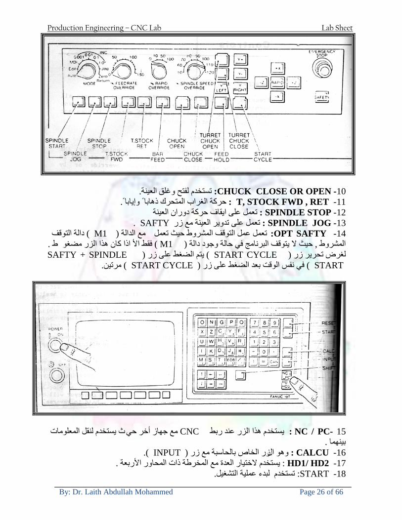
Production Engineering ndash CNC Lab Lab Sheet
By Dr Laith Abdullah Mohammed Page 26 of 66
10- CLOSE OR OPEN CHUCKالعينة تستخدم لفتح وغلق 11 -T STOCK FWD RET حركة الغراب المتحرك ذهابا وإيابا12 -SPINDLE STOP تعمل على ايقاف حركة دوران العينة 13-JOG SPINDLE تعمل على تدوير العينة مع زر SAFTY 14 -OPT SAFTY مع الدالة ( تعمل عمل التوقف المشروط حيث تعملM1 دالة التوقف (
ط ) فقط األ اذا كان هذا الزر مضغو M1المشروط حيث ال يتوقف البرنامج في حالة وجود دالة ( SAFTY + SPINDLE ) يتم الضغط على زر ( START CYCLEلغرض تحرير زر (
START ) في نفس الوقت بعد الضغط على زر ( START CYCLE مرتين (
NC PC- 15 يستخدم هذا الزر عند ربطCNC يستخدم لنقل المعلومات ث مع جهاز أخر حي بينهما
16 -CALCU زر الخاص بالحاسبة مع زر ( ال وهوINPUT ( 17 - HD1 HD2 يستخدم الختيار العدة مع المخرطة ذات المحاور األربعة 18 - START تستخدم لبدء عملية التشغيل
Production Engineering ndash CNC Lab Lab Sheet
By Dr Laith Abdullah Mohammed Page 27 of 66
19- FEED HOLD تعمل على إيقاف عمل أي G موجودة مع بقاء العينة متحركة 20- M D I أو تشغيل البرنامج ل يتم استخدامه لإلدخا BLOCK BY BLOCK وتعمل عند
إدخال البرنامج بواسطة الشريط المثقب أو أي وسيلة إدخال أخرى أو في عمليات التصفير
21- REST تستخدم العادة تشغيل الماكنة أو مسح اإلنذار الذي يظهر على الشاشة 22- EMERGENCYتستخدم عادة اليقاف الماكنة في حالة الطوارئ فقط
OPERATION MENU KEY
CHAPTER PRG-CMK
OFFSET PROGRAM POSITION FUNCTION MENU KEY
23- POSITIONعلى الشاشة د الموقع الموجور الظها 24- PROGRAMإلظهار برنامج معين واختياره 25- OFFSET الختيار سماحات العدة أو سماحات نقطة المرجع 26- PRG- CHK تستخدم لفحص البرنامج على الشاشة 27- SETTING ألختيار الثوابت على الشاشة 28- SERVICE تستخدم ألستخراج المعامالت والثوابت 29- MESSAGE تستخدم ألظهار األخطاء الناتجة عن البرنامج او اخطاء التشغيل 30- OVERALL ألختيار المواقع 31- RELATIVE MODLINE تعوض عن POSITION 32- DIR MEM يستخدم ألظهار ملف البرامج المخزونة في الذاكرة وعندما نضغط هذا الزر
فان رقم واسم البرنامج سوف يظهر على الشاشة
2أدناه الشفرات الرئيسية التي تعمل على الماكنة المبرمجة نصر
G-CODE DESCRIPTION
G00 Rapid traverse (linear)
G01 Linear Interpolation at feed rate
G02 Circular interpolation (CW) R+
G03 Circular interpolation (CCW) R+
G10 Zero point tools
G20 Imperial data input
G21 Metric data input
G27 Reference return check
G28 Reference return
G29 Return from reference
Production Engineering ndash CNC Lab Lab Sheet
By Dr Laith Abdullah Mohammed Page 28 of 66
G33 Thread cutting
G40 Cancel cutter radius compensation
G41 Cutter compensation left
G42 Cutter compensation right
G54 Work co-ordinate system no1
G70 Finishing cycle
G71 Stock removal turning
G72 Stock removal facing
G74 Face grooving
G75 Diameter grooving
G76 Threading cycle
G90 Absolute date input
G91 Incremental data input
G94 Feed minute mode
G95 Feed rev mode
G96 Constant surface speed mode
G97 Cancel Constant surface speed
) 2أدناه الشفرات الثانوية التي تعمل على الماكنة المبرمجة (نصر
M-code FUNCTION
M00 Program stop
M03 Spindle forward (Tool forward ndash M94 mode)
M04 Spindle reverse (Tool forward ndash M94 mode)
M05 Spindle stop (Tool stop ndash M94 mode)
M08 Coolant on
M09 Coolant off
M30 Program end (with rewind)
M48 Turret shortest path
M52 Turret direction up (CW)
M53 Turret direction down (CCW)
M73 Chuck open
M74 Chuck close
Production Engineering ndash CNC Lab Lab Sheet
By Dr Laith Abdullah Mohammed Page 29 of 66
) وكل جملة مكونة من مجموعة من الكلمات blockإن كل برنامج يتكون من مجموعة من الجمل ()words) لهذا فأن الشفرات الرئيسية والمساعدة هي عبارة عن كلمات (words كما في المثال التالي (
G_ _ P1 Q2 U_ _ W_ _ D___ F_ _
)end of block) ويعني ( ) يكتب الرمز (blockتسلسل الكلمات مهم جدا بعد نهاية كل جملة (
طريقة ادخال البيانات الى الماكنة ــــــــــــــــــــــــــــــــــــــــــــــــــ
) MDIيمكن ادخال البيانات الى الماكنة بعدة طرق فقد يكون األدخال عن طريق قناة السيطرة ( MANUAL DATA INPUT ) او عن طريق قناة األضافة EDIT كما يمكن ادخال البيانات عن (
) RS ndash 232 COMMUNICATIN LINKطريق استخدام سلسلة الربط (
₤⅗₌⅗₌ ⅙₌₨image₍₡ ₤₌ℌ⅗₌ Ⅸ⅗ⅥⅯ₌ ₤₡ℌ₰₨⅗₌G71
الخراطة الطولية G71الغرض من التجربة عمل نموذج للخراطة بأستخدام الدالة تستعمل هذه الدالة للخراطة الطولية اي على طول محور المشغولة وكما هو موضح بالشكل ادناه
تعتبر هذه الدالة من الدوال التي ال تحتاج الى تكرار او إعادة كتابتها أي انها دالة تكرارية بمعنى ان اي
الذي هي دالة حركة G01خطوة تكون من ضمن هذه الدالة سوف تكرر العملية اي عند استعمال امر مثل خطية تتضمن القطع مع التغذية مع اعطاء القطر المراد قطعه و مراعاة عمق القطع المعطى سوف يتكرر
هذه االمر وصوال الى العمق المطلوب وهكذا لبقية الدوال
G71 المستخدمة للدالة الصيغة
G71 P1 Q2 U___ W___ D___ F___ حيث إن
P1 بداية الخطوة االولى = Q2 نهاية الخطوة =
Uوضع السماحات بأتجاه محور = X W وضع السماحات بأتجاه محور = Z وتكاد تكون مهملة وتوضع اشارة سالب Dعمق القطع وتوضع رقم صحيح مثل = D500 اي نصف ملمF التغذية والتي لها عالقة بالدالة = G95
Production Engineering ndash CNC Lab Lab Sheet
By Dr Laith Abdullah Mohammed Page 30 of 66
G71الدالة استخدام مثال على
T0100 M48 G0 X26 Z2 M08 T0101 G90 G95 G97 S500 M03 G71 P1 Q2 U03 W00 D500 F01 N1 G0 G42 X00 G01 Z00 G01 X2517 G01 Z-5352 G01 X7391 Z-9366 G01 Z-19145 N2 G28 M30
الجانب العملي
االجهزة واالدوات المستخدمة CNCماكنة خراطة مبرمجة 1 ملم 80قضيب من االلمنيوم قطر 2 ةفير ني 3 جاه أيمن تهولدر كاربيدي ذوا 4
طريقة العمل يتم تثبيت قضيب من االلمنيوم على العينة التابعة للماكنة مع مراعاة الطول المراد استعماله في عملية 1
الخراطة ) turretتثبيت عدة القطع في المكان الصحيح في ( 2
Production Engineering ndash CNC Lab Lab Sheet
By Dr Laith Abdullah Mohammed Page 31 of 66
بالنسبة الى القطعة المثبتة على العينة XZيتم تصفير الماكنة للمحاور 3 تصفير للمحورZ تكون مالمسة العدة الى وجه الشغلة تصفير للمحورX تكون مالمسة العدة الى سطح الشغلة الموازي لمحور X
يتم كتابة البرنامج أما بطريقة يدوية أو بالحاسوب مع وضع كل الظروف الالزمة للتشغيل ( عمق القطع 4 التغذية السرعة المطلوبة نوع المعدن )
ادخال البرنامج الى الحاسوب الموجود داخل الماكنة مع تهيئة الماكنة للتشغيل 5
المطلوب G71عمل برنامج يدوي على الدالة 1 رسم الشكل الشكل النهائي المطلوب مع وضع األبعاد 2
Ⅺ⅟₍euro⅗₌ ₤₡ℌ₰₨⅗₌₣ ₤⅗₌⅗₌ ⅙₌₨image₃₡ Ⅺℂtradeℒ⅗₌ ӈ₍Ⅴ⅟ⅳ₌ G70
G70 الغرض من التجربة عمل انهاء سطحي للمشغولة بواسطة الدالة
من الضروري إعطاء G71هذه الدالة تعمل شوط واحد فقط وتكون معتمدة على عمليات القطع في الدالة اللغاء مقدمة االداة (أي لكي تتم عملية االنهاء السطحي بدون حسابات نصف قطر مقدمة االداة ) G42دالة
G70الصيغة المستخدمة للدالة
G70 P1 Q2 F___ حيث ان
P1 بداية الخطوة االولى = Q2 نهاية الخطوة =
F التغذية والمرتبطة بالدالة = G95
وذلك ألن دالة االنهاء السطحي تحقق X Zمالحظة الدالة التحتاج لكتابة السماحات التابعة للمحورين المسافات الحقيقة المراد انتاجها للمشغولة
G71و G70مثال على الدالة
T0100 M48 G0 X26 Z2 M08 T0101 G90 G95 G97 S500 M03 G71 P1 Q2 U03 W00 D500 F01 N1 G0 G42 X00 G01 Z00 G01 X2517 G01 Z-5352 G01 X7391 Z-9366 G01 Z-19145 N2 G97 S750 MO3
Production Engineering ndash CNC Lab Lab Sheet
By Dr Laith Abdullah Mohammed Page 32 of 66
G70 P1 Q2 G40 F009 G28 M30
الجانب العملي الحظ التجربة األولى
المطلوب
G70 عمل برنامج يدوي على الدالة 1 رسم الشكل النهائي المطلوب مع وضع االبعاد 2
₪⅗₍euro⅗₌ ₤₡ℌ₰₨⅗₌₣ ₤⅗₌⅗₌ ⅙₌₨image₍₡ ⅝₍ⅠimageⅯ₌ ⅞ⅫⅦ⅔₧ G76
G76 للمشغولة بواسطة الدالةةالغرض من التجربة عمل أسنان خارجية أو داخلي
في هذه التجربة سوف نقوم بعمل األسنان الخارجية وهنا تكون حركة العينة ثابتة وهذا ضروري بسبب أن ) تكون متصلتين الكترونيا وعليه أي اختالف في سرعة العينة تؤدي إلى اختالف motionالعينة والحركة(
) servoفي سرعة الخدمة(يرتبط اتجاه تكوين األسنان باتجاه دوران العينة مثال إذا كانت األسنان ذات اتجاه أيمن يكون اتجاه دوران
وهنا نقلب العدة إلى االسفل وكما هو موضح بالشكل أدناه MO3العينة عكس عقرب الساعة أي نستعمل
Production Engineering ndash CNC Lab Lab Sheet
By Dr Laith Abdullah Mohammed Page 33 of 66
الخطوة هي عبارة عن المسافة ما بين قمة سن إلى قمة سن أخر عمق السن هو العمق المطلوب تكوينه لألسنان
G76 الصيغة المستخدمة للدالة
G76 X___ Z___ K___ F___ D___ A___
حيث أن X القطر الداخلي للسن =Z طول السن =K عمق السن وتستخرج من المعادلة التالية =K=065F F الخطوة =D عمق القطع بالمايكرون فقط =A زاوية السن =
G76مثال على استخدام الدالة T0300 M48 GOO X30 Z4 T0303 M08 G97 S500 MO3 G76 X28375 Z-20 K08125 F125 D120 G00 X40 Z4 G28 M30
Production Engineering ndash CNC Lab Lab Sheet
By Dr Laith Abdullah Mohammed Page 34 of 66
الجانب العملي الحظ التجربة األولى
المطلوب
G76عمل برنامج يدوي على الدالة 1 رسم الشكل النهائي المطلوب مع وضع األبعاد 2
Ⅺ⅘₌⅗₌ Ⅵ₂ Ⅺ₯ℋ₍⅗₌ ℌℲℂ⅗₌ ⅞ⅫⅦ⅔₧ ₤K₡₌ℌ⅗₌ ₤₡ℌ₰₨⅗₌)Groove ₤⅗₌⅗₌ ₤tradeimage₌Ⅶ₡ (G75
G75 بواسطة الدالة grooveالغرض من التجربة تكوين
) للمشغولة وتعتمد شكل الحفر على طريقة grooveتستعمل هذه الدالة لتكوين الحفر الخارجي والداخلي (
التشغيل وعلى الشكل المراد إنتاجه وتعتبر هذه الطريقة من عمليات التشكيل للمعدن إن هذه الدالة هي دالة مالحظة مع G75في هذه التجربة سنقوم بعمل الحفر الخارجي بواسطة الدالة
تكرارية وغير تكرارية حسب نوع التشغيل
G 75 الصيغة المستخدمة للدالةG75 X___ Z___ I___ K____
حيث أن
X العمق النهائي لقطر الشغلة =Z عرض الحفر =I الدخول في كل مرة =
K التزحيف على محور =z بالنسبة للعدة
Production Engineering ndash CNC Lab Lab Sheet
By Dr Laith Abdullah Mohammed Page 35 of 66
G75مثال على استخدام الدالة
T0500 M48 GOO X100 Z -20 T0505 M08 G97 S700 MO3 G75 X84 Z -38 I 05 K4
الجانب العملي الحظ التجربة األولى
المطلوب
G76عمل برنامج يدوي على الدالة 1 رسم الشكل النهائي المطلوب مع وضع األبعاد 2
Production Engineering ndash CNC Lab Lab Sheet
By Dr Laith Abdullah Mohammed Page 36 of 66
CNC Milling Machine Mechanical Construction
Guideways The guideways of CNC machines are made of steel To reduce the frictional forces they are coated with a strip of PTFE (Poly Tetra Fluoro Ethylene)
Ballscrews On conventional lathes a leadscrew is used to converts the rotary motion of the hand wheel into linear motion of the slides Leadscrews have a high coefficient of friction and backlash On CNC machines a ballscrew is used instead of a leadscrew Friction and backlash are much less than on leadscrews
Guideway
Production Engineering ndash CNC Lab Lab Sheet
By Dr Laith Abdullah Mohammed Page 37 of 66
bullMachining operations Direction of cutting Based on the direction of the cutter rotation and work piece feed milling operations are classified into two types 1-Up milling (Convention milling) In up milling the metal is removed by rotating the cutter against the direction of travel of the part
Feed
Machine table
Part
Cutting tool
Chip thickness at theexit of the tooth
2-Down milling (Climb milling) In climb milling the metal is removed by rotating the cutter with the direction of travel of the part
Machine table
Part
Cutting tool
Chip thickness at theentrance of the tooth
Production Engineering ndash CNC Lab Lab Sheet
By Dr Laith Abdullah Mohammed Page 38 of 66
bullTooling Tool geometry The geometry of the tool tip affects the way that the metal cutting is performed The nose radius rake angles relief angles etc must be selected with care
Radial relief
Radial rake
Axial relief
Approach angle
Axial relief
Corner radius Face mill Face milling cutters are used to mill flat surfaces Commonly used face milling cutters Cutter with 75 degree approach
75 deg
Cutter with 90 degree approach (Square shoulder face mill)
90 deg
Cutter with 45 degree approach
Production Engineering ndash CNC Lab Lab Sheet
By Dr Laith Abdullah Mohammed Page 39 of 66
bullCNC Programming Axes convention The Z axis is along the spindle axis The X and Y axes are perpendicular to Z VMC
Z
Y
-
+
-+
X- +
+Z
-Z
+Y
-Y
-X +X
Part
Machine table
X
YZ
G00 Rapid traverse When the tool being positioned at a point preparatory to a cutting motion to save time it is moved along a straight line at Rapid traverse at a fixed traverse rate which is pre-programmed into the machines control system Typical rapid traverse rates are 10 to 25 m min but can be as high as 80 mmin
Production Engineering ndash CNC Lab Lab Sheet
By Dr Laith Abdullah Mohammed Page 40 of 66
Format N_ G00 X__ Y__Z__
G01 Linear interpolation (feed traverse) The tool moves along a straight line in one or two axis simultaneously at a programmed linear speed the feed rate Format N__ G01 X__ Y__Z__ F__
Part
Feed
Part
Feed
G02G03 Circular interpolation The tool moves along an arc in two axes simultaneously at a programmed linear speed the feed rate
Production Engineering ndash CNC Lab Lab Sheet
By Dr Laith Abdullah Mohammed Page 41 of 66
Format N__ G0203 X__ Y__Z__ I__ J__K__ F__ using the arc center OR N__ G0203 X__ Y__Z__ R__ F__ using the arc radius G02 moves along a CW arc G03 moves along a CCW arc Arc center The arc center is specified by addresses I J and K I J and K are the X Y and Z co-ordinates of the arc center with reference to the arc start point
X
Y
Arc center
Arc endArc start
- J
- I
I = X coord of center - X coord of start point J = Y coord of center - Y coord of start point K = Z coord of center - Z coord of start point I J and K must be written with their signs
Production Engineering ndash CNC Lab Lab Sheet
By Dr Laith Abdullah Mohammed Page 42 of 66
bullWork holding
Rotary table
Fixture base
Component
Clamp
Stud
Fixtures The use of fixtures 1 Improves repeatability of dimensions 2 Improves working conditions 3 Cuts down requirement of skilled labour 4 Reduces part loading and unloading time 5 Improves safety in the working area 6 Reduces the cost of machining There are two types fixtures commonly used 1 Special fixture Special fixtures are used to hold and locate the typical components which are having complex shape and to be located with the reference hole (dowel hole) Special fixtures are required for components like gear case cover cylinder heads etc 2 Modular fixture Modular fixture is a set different kind of clamping and locating elements These fixtures are used to hold identical components in different sizes and components of box type Example Manifolds head stocks connecting rods and flanges
Production Engineering ndash CNC Lab Lab Sheet
By Dr Laith Abdullah Mohammed Page 43 of 66
bullMachine setting
Determining X and Y work zero offset Case 1
Part
Machine table
Part
End mill or reamer
Work offset X0Y0 For determining X work zero offset bull Touch the periphery of the end mill or reamer to the part bull Enter current machine X value + cutter radius as X work zero offset For determining Y work zero offset bull Touch the periphery of the end mill or reamer to the part bull Enter current machine Y value - cutter radius as Y work zero offset Case 2
Part
Machine table
Part
End mill or reamerWork offset X0Y0
bull Mount the dial indicator on machine spindle true the bore bull Enter current machine X and Y value as X and Y work zero offset
Production Engineering ndash CNC Lab Lab Sheet
By Dr Laith Abdullah Mohammed Page 44 of 66
How to Select a Cutting Fluid
One part of the metal cutting equation that is sometimes overlooked however is
the choice of an appropriate cutting fluid With todayrsquos system approach to metal
cutting use of the right metalworking fluid has become just as much a part of the
solution as the other elements In fact at least one company is now integrating
cutting fluids and cutting tools into effective metal cutting systems Following are
some things to consider when choosing your next cutting fluid
The Four Key Questions
There are four vital pieces of information that are necessary when choosing a
cutting fluid They are
1 What are you cutting
2 What is the chemistry of your water
3 What are you using now
4 What are your options
5 What do you prefer
What Are You Cutting
The first question ndash ldquoWhat are you cuttingrdquo ndash is often the most difficult to answer
because most shops handle a variety of workpiece materials on a regular basis If
the answer is an unequivocal ldquoaluminumrdquo or ldquostainless steelrdquo or ldquocast ironrdquo the
selection of a cutting fluid can be quite simple and straightforward Unfortunately
that is seldom the case in anything but a high-volume plant Where aluminum or
other nonferrous metals are a significant part of the mix a non-staining cutting
fluid is a must Generally speaking this will be a semi-synthetic with special
ingredients to prevent bi-metallic corrosion and staining of non-ferrous workpieces
Where the ferrous metals predominate however a more general purpose semi-
synthetic or hybrid fluid might be a more economical choice
Production Engineering ndash CNC Lab Lab Sheet
By Dr Laith Abdullah Mohammed Page 45 of 66
What is The Chemistry of Your Water
The second question ndash ldquoWhat is the chemistry of your waterrdquo ndash is probably the
single most common reason for the success or failure of a cutting fluid Very few
plants invest the money necessary to install effective water purification systems
using deionization or reverse osmosis technology Unfortunately the chemicals
present or not present in the water used to re-constitute a cutting fluid make a
tremendous difference in its performance and sump life Most manufacturers of
cutting fluids will perform the necessary water testing to determine exactly what
minerals are dissolved in your water and make a fluid recommendation based on
the results
What are you using now
The third question ndash ldquoWhat are you using nowrdquo ndash helps narrow the range of
choices When coupled with an objective analysis of the strengths and weaknesses
of the current fluid the answer to this question can quickly point you toward a
relatively small number of competitive alternatives that have the attributes required
to meet your cutting needs Many cutting fluids are in use today simply because
they were in use yesterday It is a hard reality of todayrsquos marketplace that if one
isnrsquot constantly striving to improve they will certainly be overtaken by a
competitor who is
What Are Your Options
The fourth question ndash ldquoWhat are your optionsrdquo ndash leads to the final selection of a
cutting fluid Cutting fluids can be divided into four general groups based on their
chemistry
They are
bull Soluble Oils ndash quite literally oil dispersed in water
bull Synthetics ndash completely oil free man-made coolants in solution
Production Engineering ndash CNC Lab Lab Sheet
By Dr Laith Abdullah Mohammed Page 46 of 66
bull Semi-Synthetics ndash a mixture of natural and synthetic lubricants with up to 30
mineral oil
bull Hybrids ndash a special class of semi-synthetics with a mineral oil content of about
15 Each fluid type has advantages and disadvantages which make it suitable for
a particular group of applications In addition there are costperformance trade-
offs to be made between the groups within a specific set of applications For
example where a hybrid and a semi-synthetic may both be suitable for a particular
use the hybrid might provide longer sump life at a slightly higher initial cost
while some semi synthetics may be more economical to recycle or dispose of while
not giving as long a tank life The final decision in this case would have to be made
on the detailed economics of the shop where the fluids were to be used and on the
ownerrsquos individual preferences
Soluble Oils
Soluble oils are oils that disperse in water when emulsifiers are added They are
generally suitable for moderate-to heavy-duty machining and grinding of all non-
ferrous metals carbon and cast steels and in applications where dissimilar metals
such as aluminium and steel are present They can also be used in turning drilling
tapping reaming gear cutting broaching as well as internal and centerless types
of grinding operations Soluble oils provide excellent aluminium and copper
corrosion control good rancidity control which extends fluid for long lasting
trouble-free performance and good concentrate and mix stability making it ideal
for mixing in water with a minimal amount of agitation An example of this is
Valenitersquos VNTreg-650 premium heavy-duty soluble oil
Synthetics
Synthetics are completely oil free solutions made of polymers organic and
inorganic materials that are mixed with water These clear low foaming and bio-
Production Engineering ndash CNC Lab Lab Sheet
By Dr Laith Abdullah Mohammed Page 47 of 66
stable coolants are ideal for machining and grinding of ferrous materials carbon
steels or cast iron Their complex lubricant packages make synthetics well-suited
for tough-to-machine materials such as stainless steels and high-temperature alloys
Certain synthetics are specifically designed to address the primary failure modes of
flank wear and nose wear Although there are many benefits some synthetics may
cause staining of non-ferrous materials
Semi-Synthetics
Semi-synthetic fluids are a mixture of oils synthetic emulsifiers and water They
were primarily developed for the aircraft nuclear and related industries
Consequently they work extremely well on all non-ferrous metals such as titanium
aluminium copper brass bronze and stainless steel in both machining and
grinding Semi-synthetics can be used on ferrous metals too They are chlorine-
free to reduce bi-metallic corrosion and staining of metals They should be used at
a 5-8 dilution with water depending on the severity of the operation
Hybrids
Hybrids are cutting fluids custom engineered to solve a particular problem For
example Valenitersquos VNTreg-800 was developed to be very clean in the machining
and grinding of cast iron It provides better stability in hard water and rejects tramp
oil very well which adds to its bio-stable chemistry Hybrids work extremely well
on all metals in both machining and grinding They should be mixed at a 5-7
dilution with water depending on the condition of the water
What Do You Prefer
The final question ndash ldquoWhat do you preferrdquo ndash is usually the ldquotie breakerrdquo where
there is more than one appropriate cutting fluid available Here again as in the
case of what is being used now the key is to examine your preferences objectively
Production Engineering ndash CNC Lab Lab Sheet
By Dr Laith Abdullah Mohammed Page 48 of 66
and specifically to identify the real reasons behind a preference If you cannot
point to specific reasons why one class of cutting fluid is preferred over another
you are well advised to follow the recommendations of the professional who has
analyzed your requirements Choosing the right fluid today is easier than ever as
the system approach to metal cutting productivity continues to grow in acceptance
The day is not far off when choosing a complete solution will be as easy as
choosing the right insert and chip breaker today The answers are available and the
results will more than justify the time you spend choosing the right metal cutting
fluid
Useful Links wwwball-screwsnet
wwwlubelinkcom
wwwmachinerylubricationcom
wwwadvancedmanufacturingcom
wwwmmsonlinecom
wwwcuttingtoolengineeringcom
wwwgeartechnologycom
wwwengineersedgecom
wwwagmaorg
wwwefundacom
wwwsaeorg
wwwsmeorg
wwwastmorg
wwwissorg
wwwmachinetoolscom
wwwansiorg
wwwasmeorg
wwwcnccicom
wwwmatlscom
wwwthefreedictionarycom
wwwengineersupplycom
Production Engineering ndash CNC Lab Lab Sheet
By Dr Laith Abdullah Mohammed Page 49 of 66
SurfCAM Tutorial ndash Beginning with the basics
Background SurfCAM is a computer aided manufacturing (CAM) software which allows you to create manage and modify tool paths for computer aided designed (CAD) part The software requires a CAD model or requires that you create some geometry within SurfCAM with some rudimentary tools provided The tool paths are created or stored internally in SurfCAM in a generic programming language called APT Once the tool paths are created the APT paths are translated using a post processor into typical machine G-code
Opening SurfCAM SurfCAM can be opened from the Novell Applications Launcher on most Industrial Engineering computer labs workstations Search under lsquoallrsquo applications and double click on SurfCAM 2005 Once the program opens a license must be selected from the list (not the Demo license) to enable saving the file later Choose one of the 30 licenses available If for some reason the licenses are not listed on the license manager form select server list and type ldquobonnieeosncsuedurdquo A list of available licenses should appear Select a license and click OK After the license is selected an Add StockFixture form (Figure 1) opens allows you to add a model which represents the pre-machined stock or a fixture Click on OK without adding either Both of these items can be added later under a more appropriate dialog
Figure 1 Add Stock or Fixture dialog box
Production Engineering ndash CNC Lab Lab Sheet
By Dr Laith Abdullah Mohammed Page 50 of 66
SurfCAM Interface
Figure 2 SurfCAM Windows based interface
SurfCAM is a windows based software system so most of the typical windows functions under File are applicable This is where you can open save exit print etc The Create menu allows the user to create different geometry forms Here you can create a point line surface chamfer circle and many other geometry types For the most part these functions are not used by beginners but are useful when creating bounding curves where you donrsquot want the tool to move outside (constraining the tool) The Edit menu allows you to change or modify many different entities such as changing lines altering surfaces joining surfaces trimming or breaking elements add control points etc Again these features are helpful to advanced users and are not covered in detail in this tutorial The Display menu offers the ability to change the orientation of the part on the screen The typical rotate pan fit to screen and zoom functions are available as well as several functions which allow the user to shift between views or call up a named view (ie top bottom etc) The NC menu is the main machining interface menu In this menu you select the general form of machining (2 axis 3 axis 4 axis 5 axis turning etc) and under the general form a more specific machining function is selected This menu is the most used and the options contained must be fully understood to get the most out of SurfCAM Each function will be described in some detail in a further chapter The Analyze menu contains options such as measuring the distance between points angles tangency elements etc These functions are auxiliary functions meant to help you understand the part better but basically provide no functionality for making tool paths for CNC machines Thus these will not be covered The Tools menu allows the user to change the system options modify keyboard shortcuts change the model units etc These options are again not used by beginners Finally the Help menu provides access to the online users manual In lieu of clicking the Help menu the F1 key is the shortcut key for help (as it is in most windows based programs)
Importing a CAD model Importing a CAD model that is stored locally is done by selecting File-gtOpen On the Files of type dropdown box choose the type of file you wish to open (Figure 3) Do this prior to negotiating your way through the maze of folders to prevent having to go through the folder tree again Once the file type is selected find the file you are trying to open and click the Open
Production Engineering ndash CNC Lab Lab Sheet
By Dr Laith Abdullah Mohammed Page 51 of 66
button SurfCAM will then attempt to read the file you have selected SurfCAM may provide a dialog box describing what it has imported and identify if it was successful If this dialog is provided simply click close without saving
Figure 3 Open Dialog Note - Change type of file prior to finding the file you wish to open
SurfCAM allows a user to import several different types of CAD files the most common types which you will likely import are SolidWorks part files (sldprt or prt) AutoCAD files(dxf) or IGES (igs or iges) Native file import (such as is the case with SolidWorks) provides the greatest information transfer and generic file imports (such as is the case with IGES) provide the least Normally it is to the advantage of the user to use native file importing procedures when available Recently (2005) SurfCAM added some compatibility with SolidWorks This allows the user to create tool paths for a part and if an engineering change is needed for the part update the part in SolidWorks When the part is then opened in SurfCAM the changes are noted and a simple update operation command is needed This however does not operate with complete transparency andor accuracy and thus users need to be cognizant of changing CAD models
SurfCAM Geometry In SurfCAM two basic types of geometry are used the surface and the point A surface (Figure 4) is a so called spline (NURBS or B-Spline are the two most common) surface (parameterized by two values u and v) such that every location on the surface can be defined as a function of these parameters In other words SurfCAM can calculate the location of any point on the
Production Engineering ndash CNC Lab Lab Sheet
By Dr Laith Abdullah Mohammed Page 52 of 66
surface Surfaces are used primarily in 3 4 and 5 axis machining and require a significant
amount of processing power and time Figure 4 Surfaces model of a mold half Note the difference between this and Figure 2 a wireframe model
Point or line based models are often referred to as wireframe (Figure 5) models because the models consist of connected lines and resemble the part only at the intersection of two surfaces Wireframe models were made popular lsquoback in the dayrsquo when computer processing was expensive There are times when each of the models are important and selecting model geometry when applying a SurfCAM operation will be much simpler if you understand the differences between the two When importing a SolidWorks model the default is both the surfaces and the wireframe geometry are imported
Figure 5 Wireframe model of the mold in Figure 1
Steps to Creating Tool Paths Once a CAD model is imported into SurfCAM tool paths can be created There is no one correct way to create tool paths however there is a set of general steps to take to ensure the tool paths are created with a minimum amount of hardship (note the wordinghellipHardship is inevitable when creating tool paths it is the intent of this manual to minimize this) The following is a list of steps which should be considered when making tool paths
Production Engineering ndash CNC Lab Lab Sheet
By Dr Laith Abdullah Mohammed Page 53 of 66
1 Plan ahead a Orient the part in SolidWorks such that if only one side is to be machined that
side is the Top view This can be done early in SolidWorks by choosing a plane parallel the X-Y plane as the sketch plane for the machined geometry
b Orient the part in SolidWorks such that the origin is somewhere of relative importance and someplace in space that can be easily identified when placed on the machine This is extremely important to minimize set up time at the machine (note ndash my personal preference for a part that is to be fully machined [ie stock exists on all sides] is to place the origin at the center and top of the parthellipjust my preference)
c Orient the part in SolidWorks such that the X and Y axes are aligned as you want them on the machinehellip
d Planning ahead will save you many hours of headaches laterhelliptrust me 2 Import the model 3 Choose a construction view such that the tool approaches the side to be machined
from the positive Z axis direction (as defined by part origin) a This is done by clicking on the CView icon
b From the list of named views chose the view which orients the origin as you would like
c If one of the views does not fit your criteria you have two choices i Perform a transformation of the part in SurfCAM or SolidWorks
ii Add a new construction view by selecting new This option requires a relatively good understanding of right hand coordinate frames but is very usefulhellipNormally used by more advanced users
d Be sure the CoordVIEW selection is made vs CoordWORLD This ensures the tools will be controlled from the coordinate frame selected by the view (ie the origin on the part) instead of the origin on the lower left corner of the screen This will be especially important when we get into 4 and 5 axis machining
4 In the Operations Manager (Figure 6) select Setup One and change the name to something meaningful ndash like Front Side Mold Cavity
a Access the Operations manager by right clicking or by selecting the Operations Manager icon in the tool bar
b Operations Manager is where the tool paths are managed once they are created as well as where individual tool paths can be verified
Production Engineering ndash CNC Lab Lab Sheet
By Dr Laith Abdullah Mohammed Page 54 of 66
5 Roughing Tool Paths a Create the tool paths to remove the majority of the material (if applicable) b Use NC-gt3Axis-gtZ rough or Plunge Rough c Described in next section
6 Create Finishing Tool Paths a Described in next section
7 Add another setup if necessary 8 Perform steps 3 through 6 as necessary 9 Verify the tool paths are correct 10 Use a post processor for the tool paths to create G-Code for machine
Creating Tool Paths The following is a list of operations what they are intended for how they generally work and some parameters that may be adjusted to modify the tool paths
2 Axis tool paths Unless otherwise noted 2 axis tool path functions require lines or arc segments as input parameters (as opposed to surfaces) There are several options as to how these segments are chosen the most prevalent is the chain option and the second most prevalent is the single When choosing the line segments using the chain option SurfCAM will try to link a complete path of segments based on an initial segment chosen by the user If the operation is planer (ie pocket or contour) the segments must lie on the same plane If the operation is non-planer (ie contour 3D) SurfCAM will prompt the user to specify segments when it encounters a branch point
Figure 6 Operations Manager view showing setup one re-labeled as Front Side Mold
Production Engineering ndash CNC Lab Lab Sheet
By Dr Laith Abdullah Mohammed Page 55 of 66
When using the single element option the user must manually choose each segment desired for the operation Note that most operations do not require a closed loop of segments you may specify for instance an open contour where the tool is supposed to move The order of choosing segments is important This order determines the path of the tool in the sense that if three segments are chosen such that the middle segment is chosen last there will be three different plunge and machine operations one on each segment If the operation was to make a continuous contour around the outside of the part the segments should be chosen in order of the desired tool trajectory
Operations
Pocket Pocket operation in SurfCAM is used to cut an enclosed space from the inside to the outside at one particular depth The operation starts in the center of an enclosed area (with a plunge move in the ndashZ direction) and makes incremental closed paths towards the pocket boundaries in user defined path offsets (Figure 7) The user chooses the boundary of the pocket (line segments) and if more than one pocket is chosen SurfCAM will ask the user to click inside a pocket
Figure 7 Two examples of using the pocketing operation
The pocket operation allows for creating a projection of the pocket paths on multiple planes This is useful if you have a deep pocket which will not allow the tool to cut directly at the depth of the pocket but would be easily done using the same paths at several different Z heights On the cut control (Figure 8) tab the user specifies where the chosen geometry (pocket segments) lie (ie bottom or top) Then under the amount to remove specify the total material height to be removed and the rough spacing (amount you wish to advance the Z axis with each pocket step) You may also specify a finishing pass and as well as stock to leave
Production Engineering ndash CNC Lab Lab Sheet
By Dr Laith Abdullah Mohammed Page 56 of 66
Figure 8 Example of Contour Operation with multiple passes
Contour Contouring in SurfCAM is used to perform peripheral milling on the inside or outside of a line segment (Figure 9) The user is to identify the line segments which define a contour (does not have to be a closed loop of segments) SurfCAM may or may not require the user to specify a side to contour (ie which side of the line is the tool to cut) For contouring each segment must lie on the same plane
Production Engineering ndash CNC Lab Lab Sheet
By Dr Laith Abdullah Mohammed Page 57 of 66
Figure 9 Examples of parts cut with 2-Axis Contour
Contour 3D Contour 3D is the same operation type as contour but allows the user to specify segments on different planes for the tool to cut along
Drill Drilling operations are any rotating tool operation meant to engage the part from a single direction ndash namely from the positive Z direction Drilling operations can be specified using circle point or line segments After choosing NC-gt2-Axis-gtDrill SurfCAM allows the user to choose multiple circles or points defining holes to be drilled Drilling operations also allow the user to incorporate more than 1 operation such as a center drill a drill and a reaming operation After selecting the locations for the drilling operation a dialog box (Figure 10) allows the user to add change or delete tools to be used in the operation As displayed in the following figure the spotdrill operation is followed by a drilling operation followed by a tapping operation The depth of each tool can be controlled individually by double clicking the total depth cell in and manually entering Tools can be added before or after operations which the cells are highlighted by selecting either of the insert buttons at the top or by the insert menu Select tool button allows the user to change the tool size or type
Production Engineering ndash CNC Lab Lab Sheet
By Dr Laith Abdullah Mohammed Page 58 of 66
Figure 10 Drill operation manager Several operations can be completed at one time
Figure 11 Drill operation including the spotdrill drill and tap as outlined in Fig 10
3 Axis tool paths SurfCAM requires surfaces as inputs for 3 Axis tool paths Surfaces can be created in SurfCAM but are most easily created in a CAD package and imported into SurfCAM Surfaces allow SurfCAM to identify every point on the surface in 3 dimensions unlike 2D geometry (wireframes) which only identify positions on the plane Creating tool paths with complex surfaces takes a very significant amount of processing power so expect 3 Axis tool path generation to take longer
Production Engineering ndash CNC Lab Lab Sheet
By Dr Laith Abdullah Mohammed Page 59 of 66
Operations
Cut 3 Axis cut operation takes a surface and using the flow lines creates a rastering path over the surface with the tool tip riding on the surface The primary direction will be defined by the flow lines of the surface (which can be edited by Edit-gtSurfaces-gtArrow-gtDirection) If you intend to cross surface boundaries you must merge the surfaces (Edit-gtJoin and choose the two surfaces)
Z-Rough The Z-rough operation is used to remove a large amount of material prior to finish machining Roughing operation is typically the first operation you perform for each setup The Z-Rough operation cuts the part in user defined intervals For each of these intervals a surface intersection between the part and the plane is performed and a 2D pocket or contour operation is performed on that plane This is performed on each plane When choosing NC-gt3 Axis-gtZ rough the first dialog box you will encounter asks for a bounding box to be defined Choose the Extents Box and a second dialog box will ask for the coordinates which define the box (Figure 12) This is the stock size you expect to machine the part from Input the coordinates or change the additional offset amounts (in XY or Z) as appropriate and click Calculate Bounding Box
Figure 12 Material Extents Box Example
Next choose the tool and cutting parameters that you desire and click on the Cut Control Tab (Figure 13) Here you will find the following parameters which are often changed Stock to
Production Engineering ndash CNC Lab Lab Sheet
By Dr Laith Abdullah Mohammed Page 60 of 66
leave ndash this is an offset amount from the surfaces which leaves a small amount of material to finish machine Minimum and Maximum Z values ndash Defines area to machine Z Step Size ndash This identifies the plane intervals for the surface intersection planes (the first interval will be at the top of the selected area and successive increments down in Z will be cut until the Minimum Z value is reached)
Figure 13 3Axis Z Rough Cut Control
The 3Axis Z-Finish operation works in exactly the same way 3 Axis Z-Finish is most appropriate for finishing vertical or near vertical walls
3D Offset The 3D Offset operation creates a tool path using a 2D or 3D boundary by offsetting the boundary in concentric offset cutting passes Each pass calculates the tool engagement and maintains the engagement somewhat constant The advantage (significant) is the scallop height ndash height of the material between passes ndash is controlled thus the surface finish is predictable When choosing 3D Offset surfaces are selected as well as 2D or 3D boundaries The boundaries define the concentric offset paths shape as well as limit the tool path area Choose NC-gt3Axis-gt3D Offset from the drop down menus SurfCAM will prompt you to select the surface or surfaces to cut across Select the surfaces you wish to machine and then select the tool and cutting parameters you wish use Next select the Cut Control Tab and check the Use Boundary Curves option Set the Step Type to Scallop and set the maximum scallop height If you like
Production Engineering ndash CNC Lab Lab Sheet
By Dr Laith Abdullah Mohammed Page 61 of 66
you can also add stock to leave if this is a roughing operation You can also set the Direction and Start-End parameters from this tab Click OK and the paths will be generated
Figure 14 Cut Control Tab for 3D Offset
Example part using both 2D and 3D geometry
The tool paths for this mold will be generated in SurfCAM using 5 operations The first will be a roughing operation using a frac14 inch flat end mill with the Z step size of 00625in Choose NC-
Production Engineering ndash CNC Lab Lab Sheet
By Dr Laith Abdullah Mohammed Page 62 of 66
gt3Axis-gtZ-Rough from the drop down menu Select all visible surfaces and create an extents box that has 025inch XY offsets and 01inch Z offset Next select the frac14 inch flat end mill from the tools menu Under Cut Control tab set the Z step size to be 00625inch The tool paths will look something like Figure 15
Figure 15 Z-Rough Tool paths for Example Part
Next a flat surface operation will be performed to cut the flat surface on the top Select NC-gt3 Axis-gtFlat Surface from the drop down menu Select all visible surfaces again Choose the 12inch flat end mill and set the cutting parameters as desired Under Cut Control Tab change the Minimum Area to 50 square inches (Figure 16) The tool paths should look something like Figure 17
Figure 16 Cut Control for Flat Surface
Production Engineering ndash CNC Lab Lab Sheet
By Dr Laith Abdullah Mohammed Page 63 of 66
Figure 17 Flat Surface Tool Paths
Next we will use a 3D offset operation to cut the mold cavity Select NC-gt3 Axis-gt3D Offset from the dropdown menu Change the view to the top view and select within to capture the surfaces of the mold cavity Draw a rectangle around the mold cavity Select a 18 inch ball endmill from the tool library and set the cutting parameters as appropriate Next set the Cut Control tab parameters as in Figure 14 The paths creates should be similar to Figure 18
Figure 18 3D Offset Paths
Next we will perform a 2 Axis contouring of the top section Select NC-gt2 Axis-gtContour from the dropdown menu Using the chain option select the bottom contour of the top extrusion Select the frac12 inch flat end mill from the tool library and set the cutting parameters as required In the Cut Control Tab change the Geometry to Bottom and the amount to remove in Z to 05
Production Engineering ndash CNC Lab Lab Sheet
By Dr Laith Abdullah Mohammed Page 64 of 66
Change the Rough Spacing in Z to 025 and add 1 finish pass of 002 (Figure 19) Click OK and SurfCAM will instruct you to choose a side to contour Click anywhere on the screen OUTSIDE the geometry you selected for the contouring operation Failure to click outside the geometry will result in the tool being on the wrong side of the contour Your paths should look something like those in Figure 20
Figure 19 Cut Control Tab for the Contouring Operation
Figure 20 Contouring operation paths
Production Engineering ndash CNC Lab Lab Sheet
By Dr Laith Abdullah Mohammed Page 65 of 66
Next we will perform a 2 axis pocket operation for the small pocket on the top face of the mold Select NC-gt2Axis-gtPocket and using the Auto select feature select the boundary curve at the bottom of the pocket Click Done twice and select the frac14 inch flat end mill from the tool library Set the appropriate cutting parameters and click OK SurfCAM will prompt you to click inside the pocket Click anywhere inside the geometry you chose to define the pocket The resulting paths should look something like those in Figure 21
Figure 21 2 Axis Pocket Operation Paths
Finally we will add a drilling operation for the 2 holes at the corners of the mold Select NC-gt2 Axis-gtDrill from the dropdown menu Select the top circles defining the two holes A menu box will appear with a default tool (Center drill) already programmed Add a second tool to the list by selecting Insert-gtAfter and select the tool from the tool library Change the drill depth to 10inches and click OK The paths should look something similar to Figure 23
Figure 22 Drill Menu
Production Engineering ndash CNC Lab Lab Sheet
By Dr Laith Abdullah Mohammed Page 66 of 66
Figure 23 Drilling Operation Tool Paths
Now you can watch a simulation of the cutting by choosing the setup in the operations manager and clicking the simulate icon Be sure to set the stock in the set up by right clicking the set up and selecting Edit Setup Information In the Stock Tab you can create a bounding box meeting your needs and click Add Your simulation should result in something like the following
Figure 24 Final Simulation of the example Mold
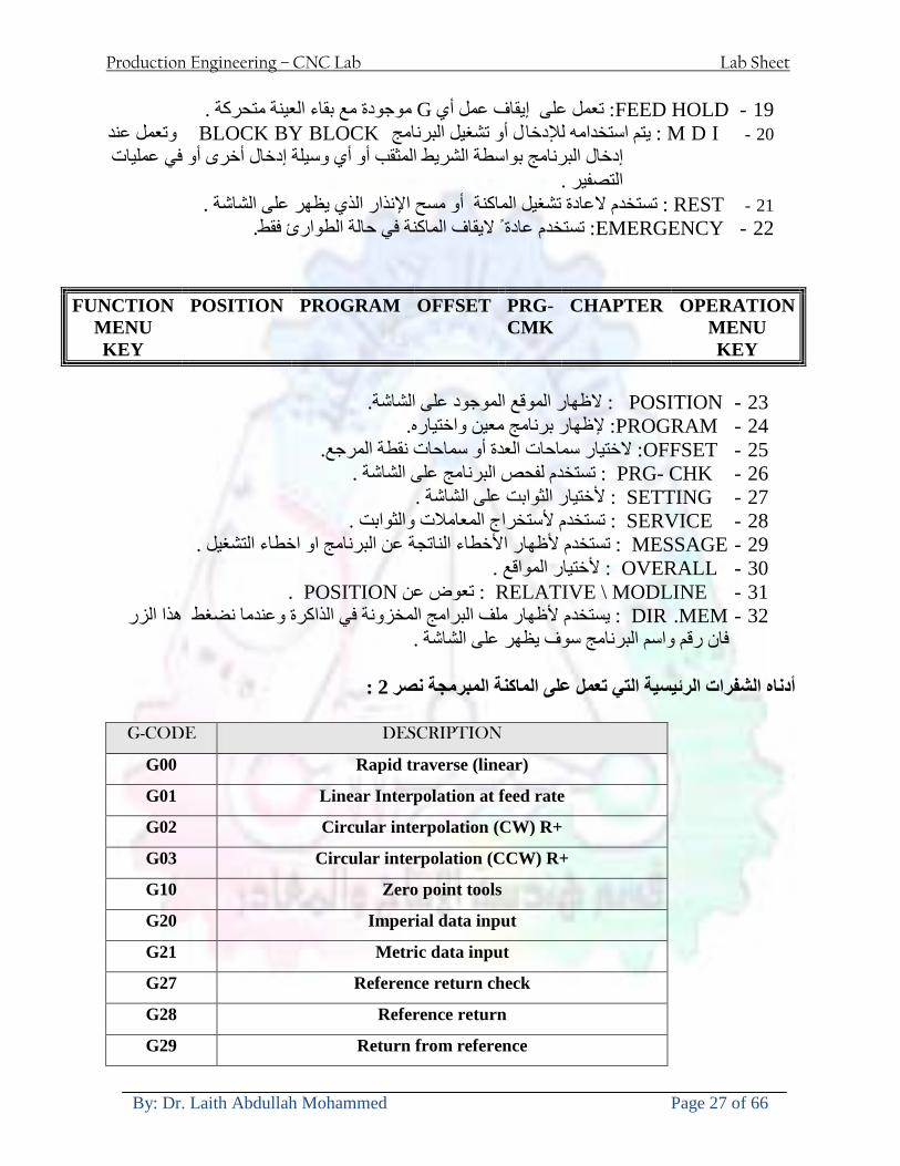
Production Engineering ndash CNC Lab Lab Sheet
By Dr Laith Abdullah Mohammed Page 27 of 66
19- FEED HOLD تعمل على إيقاف عمل أي G موجودة مع بقاء العينة متحركة 20- M D I أو تشغيل البرنامج ل يتم استخدامه لإلدخا BLOCK BY BLOCK وتعمل عند
إدخال البرنامج بواسطة الشريط المثقب أو أي وسيلة إدخال أخرى أو في عمليات التصفير
21- REST تستخدم العادة تشغيل الماكنة أو مسح اإلنذار الذي يظهر على الشاشة 22- EMERGENCYتستخدم عادة اليقاف الماكنة في حالة الطوارئ فقط
OPERATION MENU KEY
CHAPTER PRG-CMK
OFFSET PROGRAM POSITION FUNCTION MENU KEY
23- POSITIONعلى الشاشة د الموقع الموجور الظها 24- PROGRAMإلظهار برنامج معين واختياره 25- OFFSET الختيار سماحات العدة أو سماحات نقطة المرجع 26- PRG- CHK تستخدم لفحص البرنامج على الشاشة 27- SETTING ألختيار الثوابت على الشاشة 28- SERVICE تستخدم ألستخراج المعامالت والثوابت 29- MESSAGE تستخدم ألظهار األخطاء الناتجة عن البرنامج او اخطاء التشغيل 30- OVERALL ألختيار المواقع 31- RELATIVE MODLINE تعوض عن POSITION 32- DIR MEM يستخدم ألظهار ملف البرامج المخزونة في الذاكرة وعندما نضغط هذا الزر
فان رقم واسم البرنامج سوف يظهر على الشاشة
2أدناه الشفرات الرئيسية التي تعمل على الماكنة المبرمجة نصر
G-CODE DESCRIPTION
G00 Rapid traverse (linear)
G01 Linear Interpolation at feed rate
G02 Circular interpolation (CW) R+
G03 Circular interpolation (CCW) R+
G10 Zero point tools
G20 Imperial data input
G21 Metric data input
G27 Reference return check
G28 Reference return
G29 Return from reference
Production Engineering ndash CNC Lab Lab Sheet
By Dr Laith Abdullah Mohammed Page 28 of 66
G33 Thread cutting
G40 Cancel cutter radius compensation
G41 Cutter compensation left
G42 Cutter compensation right
G54 Work co-ordinate system no1
G70 Finishing cycle
G71 Stock removal turning
G72 Stock removal facing
G74 Face grooving
G75 Diameter grooving
G76 Threading cycle
G90 Absolute date input
G91 Incremental data input
G94 Feed minute mode
G95 Feed rev mode
G96 Constant surface speed mode
G97 Cancel Constant surface speed
) 2أدناه الشفرات الثانوية التي تعمل على الماكنة المبرمجة (نصر
M-code FUNCTION
M00 Program stop
M03 Spindle forward (Tool forward ndash M94 mode)
M04 Spindle reverse (Tool forward ndash M94 mode)
M05 Spindle stop (Tool stop ndash M94 mode)
M08 Coolant on
M09 Coolant off
M30 Program end (with rewind)
M48 Turret shortest path
M52 Turret direction up (CW)
M53 Turret direction down (CCW)
M73 Chuck open
M74 Chuck close
Production Engineering ndash CNC Lab Lab Sheet
By Dr Laith Abdullah Mohammed Page 29 of 66
) وكل جملة مكونة من مجموعة من الكلمات blockإن كل برنامج يتكون من مجموعة من الجمل ()words) لهذا فأن الشفرات الرئيسية والمساعدة هي عبارة عن كلمات (words كما في المثال التالي (
G_ _ P1 Q2 U_ _ W_ _ D___ F_ _
)end of block) ويعني ( ) يكتب الرمز (blockتسلسل الكلمات مهم جدا بعد نهاية كل جملة (
طريقة ادخال البيانات الى الماكنة ــــــــــــــــــــــــــــــــــــــــــــــــــ
) MDIيمكن ادخال البيانات الى الماكنة بعدة طرق فقد يكون األدخال عن طريق قناة السيطرة ( MANUAL DATA INPUT ) او عن طريق قناة األضافة EDIT كما يمكن ادخال البيانات عن (
) RS ndash 232 COMMUNICATIN LINKطريق استخدام سلسلة الربط (
₤⅗₌⅗₌ ⅙₌₨image₍₡ ₤₌ℌ⅗₌ Ⅸ⅗ⅥⅯ₌ ₤₡ℌ₰₨⅗₌G71
الخراطة الطولية G71الغرض من التجربة عمل نموذج للخراطة بأستخدام الدالة تستعمل هذه الدالة للخراطة الطولية اي على طول محور المشغولة وكما هو موضح بالشكل ادناه
تعتبر هذه الدالة من الدوال التي ال تحتاج الى تكرار او إعادة كتابتها أي انها دالة تكرارية بمعنى ان اي
الذي هي دالة حركة G01خطوة تكون من ضمن هذه الدالة سوف تكرر العملية اي عند استعمال امر مثل خطية تتضمن القطع مع التغذية مع اعطاء القطر المراد قطعه و مراعاة عمق القطع المعطى سوف يتكرر
هذه االمر وصوال الى العمق المطلوب وهكذا لبقية الدوال
G71 المستخدمة للدالة الصيغة
G71 P1 Q2 U___ W___ D___ F___ حيث إن
P1 بداية الخطوة االولى = Q2 نهاية الخطوة =
Uوضع السماحات بأتجاه محور = X W وضع السماحات بأتجاه محور = Z وتكاد تكون مهملة وتوضع اشارة سالب Dعمق القطع وتوضع رقم صحيح مثل = D500 اي نصف ملمF التغذية والتي لها عالقة بالدالة = G95
Production Engineering ndash CNC Lab Lab Sheet
By Dr Laith Abdullah Mohammed Page 30 of 66
G71الدالة استخدام مثال على
T0100 M48 G0 X26 Z2 M08 T0101 G90 G95 G97 S500 M03 G71 P1 Q2 U03 W00 D500 F01 N1 G0 G42 X00 G01 Z00 G01 X2517 G01 Z-5352 G01 X7391 Z-9366 G01 Z-19145 N2 G28 M30
الجانب العملي
االجهزة واالدوات المستخدمة CNCماكنة خراطة مبرمجة 1 ملم 80قضيب من االلمنيوم قطر 2 ةفير ني 3 جاه أيمن تهولدر كاربيدي ذوا 4
طريقة العمل يتم تثبيت قضيب من االلمنيوم على العينة التابعة للماكنة مع مراعاة الطول المراد استعماله في عملية 1
الخراطة ) turretتثبيت عدة القطع في المكان الصحيح في ( 2
Production Engineering ndash CNC Lab Lab Sheet
By Dr Laith Abdullah Mohammed Page 31 of 66
بالنسبة الى القطعة المثبتة على العينة XZيتم تصفير الماكنة للمحاور 3 تصفير للمحورZ تكون مالمسة العدة الى وجه الشغلة تصفير للمحورX تكون مالمسة العدة الى سطح الشغلة الموازي لمحور X
يتم كتابة البرنامج أما بطريقة يدوية أو بالحاسوب مع وضع كل الظروف الالزمة للتشغيل ( عمق القطع 4 التغذية السرعة المطلوبة نوع المعدن )
ادخال البرنامج الى الحاسوب الموجود داخل الماكنة مع تهيئة الماكنة للتشغيل 5
المطلوب G71عمل برنامج يدوي على الدالة 1 رسم الشكل الشكل النهائي المطلوب مع وضع األبعاد 2
Ⅺ⅟₍euro⅗₌ ₤₡ℌ₰₨⅗₌₣ ₤⅗₌⅗₌ ⅙₌₨image₃₡ Ⅺℂtradeℒ⅗₌ ӈ₍Ⅴ⅟ⅳ₌ G70
G70 الغرض من التجربة عمل انهاء سطحي للمشغولة بواسطة الدالة
من الضروري إعطاء G71هذه الدالة تعمل شوط واحد فقط وتكون معتمدة على عمليات القطع في الدالة اللغاء مقدمة االداة (أي لكي تتم عملية االنهاء السطحي بدون حسابات نصف قطر مقدمة االداة ) G42دالة
G70الصيغة المستخدمة للدالة
G70 P1 Q2 F___ حيث ان
P1 بداية الخطوة االولى = Q2 نهاية الخطوة =
F التغذية والمرتبطة بالدالة = G95
وذلك ألن دالة االنهاء السطحي تحقق X Zمالحظة الدالة التحتاج لكتابة السماحات التابعة للمحورين المسافات الحقيقة المراد انتاجها للمشغولة
G71و G70مثال على الدالة
T0100 M48 G0 X26 Z2 M08 T0101 G90 G95 G97 S500 M03 G71 P1 Q2 U03 W00 D500 F01 N1 G0 G42 X00 G01 Z00 G01 X2517 G01 Z-5352 G01 X7391 Z-9366 G01 Z-19145 N2 G97 S750 MO3
Production Engineering ndash CNC Lab Lab Sheet
By Dr Laith Abdullah Mohammed Page 32 of 66
G70 P1 Q2 G40 F009 G28 M30
الجانب العملي الحظ التجربة األولى
المطلوب
G70 عمل برنامج يدوي على الدالة 1 رسم الشكل النهائي المطلوب مع وضع االبعاد 2
₪⅗₍euro⅗₌ ₤₡ℌ₰₨⅗₌₣ ₤⅗₌⅗₌ ⅙₌₨image₍₡ ⅝₍ⅠimageⅯ₌ ⅞ⅫⅦ⅔₧ G76
G76 للمشغولة بواسطة الدالةةالغرض من التجربة عمل أسنان خارجية أو داخلي
في هذه التجربة سوف نقوم بعمل األسنان الخارجية وهنا تكون حركة العينة ثابتة وهذا ضروري بسبب أن ) تكون متصلتين الكترونيا وعليه أي اختالف في سرعة العينة تؤدي إلى اختالف motionالعينة والحركة(
) servoفي سرعة الخدمة(يرتبط اتجاه تكوين األسنان باتجاه دوران العينة مثال إذا كانت األسنان ذات اتجاه أيمن يكون اتجاه دوران
وهنا نقلب العدة إلى االسفل وكما هو موضح بالشكل أدناه MO3العينة عكس عقرب الساعة أي نستعمل
Production Engineering ndash CNC Lab Lab Sheet
By Dr Laith Abdullah Mohammed Page 33 of 66
الخطوة هي عبارة عن المسافة ما بين قمة سن إلى قمة سن أخر عمق السن هو العمق المطلوب تكوينه لألسنان
G76 الصيغة المستخدمة للدالة
G76 X___ Z___ K___ F___ D___ A___
حيث أن X القطر الداخلي للسن =Z طول السن =K عمق السن وتستخرج من المعادلة التالية =K=065F F الخطوة =D عمق القطع بالمايكرون فقط =A زاوية السن =
G76مثال على استخدام الدالة T0300 M48 GOO X30 Z4 T0303 M08 G97 S500 MO3 G76 X28375 Z-20 K08125 F125 D120 G00 X40 Z4 G28 M30
Production Engineering ndash CNC Lab Lab Sheet
By Dr Laith Abdullah Mohammed Page 34 of 66
الجانب العملي الحظ التجربة األولى
المطلوب
G76عمل برنامج يدوي على الدالة 1 رسم الشكل النهائي المطلوب مع وضع األبعاد 2
Ⅺ⅘₌⅗₌ Ⅵ₂ Ⅺ₯ℋ₍⅗₌ ℌℲℂ⅗₌ ⅞ⅫⅦ⅔₧ ₤K₡₌ℌ⅗₌ ₤₡ℌ₰₨⅗₌)Groove ₤⅗₌⅗₌ ₤tradeimage₌Ⅶ₡ (G75
G75 بواسطة الدالة grooveالغرض من التجربة تكوين
) للمشغولة وتعتمد شكل الحفر على طريقة grooveتستعمل هذه الدالة لتكوين الحفر الخارجي والداخلي (
التشغيل وعلى الشكل المراد إنتاجه وتعتبر هذه الطريقة من عمليات التشكيل للمعدن إن هذه الدالة هي دالة مالحظة مع G75في هذه التجربة سنقوم بعمل الحفر الخارجي بواسطة الدالة
تكرارية وغير تكرارية حسب نوع التشغيل
G 75 الصيغة المستخدمة للدالةG75 X___ Z___ I___ K____
حيث أن
X العمق النهائي لقطر الشغلة =Z عرض الحفر =I الدخول في كل مرة =
K التزحيف على محور =z بالنسبة للعدة
Production Engineering ndash CNC Lab Lab Sheet
By Dr Laith Abdullah Mohammed Page 35 of 66
G75مثال على استخدام الدالة
T0500 M48 GOO X100 Z -20 T0505 M08 G97 S700 MO3 G75 X84 Z -38 I 05 K4
الجانب العملي الحظ التجربة األولى
المطلوب
G76عمل برنامج يدوي على الدالة 1 رسم الشكل النهائي المطلوب مع وضع األبعاد 2
Production Engineering ndash CNC Lab Lab Sheet
By Dr Laith Abdullah Mohammed Page 36 of 66
CNC Milling Machine Mechanical Construction
Guideways The guideways of CNC machines are made of steel To reduce the frictional forces they are coated with a strip of PTFE (Poly Tetra Fluoro Ethylene)
Ballscrews On conventional lathes a leadscrew is used to converts the rotary motion of the hand wheel into linear motion of the slides Leadscrews have a high coefficient of friction and backlash On CNC machines a ballscrew is used instead of a leadscrew Friction and backlash are much less than on leadscrews
Guideway
Production Engineering ndash CNC Lab Lab Sheet
By Dr Laith Abdullah Mohammed Page 37 of 66
bullMachining operations Direction of cutting Based on the direction of the cutter rotation and work piece feed milling operations are classified into two types 1-Up milling (Convention milling) In up milling the metal is removed by rotating the cutter against the direction of travel of the part
Feed
Machine table
Part
Cutting tool
Chip thickness at theexit of the tooth
2-Down milling (Climb milling) In climb milling the metal is removed by rotating the cutter with the direction of travel of the part
Machine table
Part
Cutting tool
Chip thickness at theentrance of the tooth
Production Engineering ndash CNC Lab Lab Sheet
By Dr Laith Abdullah Mohammed Page 38 of 66
bullTooling Tool geometry The geometry of the tool tip affects the way that the metal cutting is performed The nose radius rake angles relief angles etc must be selected with care
Radial relief
Radial rake
Axial relief
Approach angle
Axial relief
Corner radius Face mill Face milling cutters are used to mill flat surfaces Commonly used face milling cutters Cutter with 75 degree approach
75 deg
Cutter with 90 degree approach (Square shoulder face mill)
90 deg
Cutter with 45 degree approach
Production Engineering ndash CNC Lab Lab Sheet
By Dr Laith Abdullah Mohammed Page 39 of 66
bullCNC Programming Axes convention The Z axis is along the spindle axis The X and Y axes are perpendicular to Z VMC
Z
Y
-
+
-+
X- +
+Z
-Z
+Y
-Y
-X +X
Part
Machine table
X
YZ
G00 Rapid traverse When the tool being positioned at a point preparatory to a cutting motion to save time it is moved along a straight line at Rapid traverse at a fixed traverse rate which is pre-programmed into the machines control system Typical rapid traverse rates are 10 to 25 m min but can be as high as 80 mmin
Production Engineering ndash CNC Lab Lab Sheet
By Dr Laith Abdullah Mohammed Page 40 of 66
Format N_ G00 X__ Y__Z__
G01 Linear interpolation (feed traverse) The tool moves along a straight line in one or two axis simultaneously at a programmed linear speed the feed rate Format N__ G01 X__ Y__Z__ F__
Part
Feed
Part
Feed
G02G03 Circular interpolation The tool moves along an arc in two axes simultaneously at a programmed linear speed the feed rate
Production Engineering ndash CNC Lab Lab Sheet
By Dr Laith Abdullah Mohammed Page 41 of 66
Format N__ G0203 X__ Y__Z__ I__ J__K__ F__ using the arc center OR N__ G0203 X__ Y__Z__ R__ F__ using the arc radius G02 moves along a CW arc G03 moves along a CCW arc Arc center The arc center is specified by addresses I J and K I J and K are the X Y and Z co-ordinates of the arc center with reference to the arc start point
X
Y
Arc center
Arc endArc start
- J
- I
I = X coord of center - X coord of start point J = Y coord of center - Y coord of start point K = Z coord of center - Z coord of start point I J and K must be written with their signs
Production Engineering ndash CNC Lab Lab Sheet
By Dr Laith Abdullah Mohammed Page 42 of 66
bullWork holding
Rotary table
Fixture base
Component
Clamp
Stud
Fixtures The use of fixtures 1 Improves repeatability of dimensions 2 Improves working conditions 3 Cuts down requirement of skilled labour 4 Reduces part loading and unloading time 5 Improves safety in the working area 6 Reduces the cost of machining There are two types fixtures commonly used 1 Special fixture Special fixtures are used to hold and locate the typical components which are having complex shape and to be located with the reference hole (dowel hole) Special fixtures are required for components like gear case cover cylinder heads etc 2 Modular fixture Modular fixture is a set different kind of clamping and locating elements These fixtures are used to hold identical components in different sizes and components of box type Example Manifolds head stocks connecting rods and flanges
Production Engineering ndash CNC Lab Lab Sheet
By Dr Laith Abdullah Mohammed Page 43 of 66
bullMachine setting
Determining X and Y work zero offset Case 1
Part
Machine table
Part
End mill or reamer
Work offset X0Y0 For determining X work zero offset bull Touch the periphery of the end mill or reamer to the part bull Enter current machine X value + cutter radius as X work zero offset For determining Y work zero offset bull Touch the periphery of the end mill or reamer to the part bull Enter current machine Y value - cutter radius as Y work zero offset Case 2
Part
Machine table
Part
End mill or reamerWork offset X0Y0
bull Mount the dial indicator on machine spindle true the bore bull Enter current machine X and Y value as X and Y work zero offset
Production Engineering ndash CNC Lab Lab Sheet
By Dr Laith Abdullah Mohammed Page 44 of 66
How to Select a Cutting Fluid
One part of the metal cutting equation that is sometimes overlooked however is
the choice of an appropriate cutting fluid With todayrsquos system approach to metal
cutting use of the right metalworking fluid has become just as much a part of the
solution as the other elements In fact at least one company is now integrating
cutting fluids and cutting tools into effective metal cutting systems Following are
some things to consider when choosing your next cutting fluid
The Four Key Questions
There are four vital pieces of information that are necessary when choosing a
cutting fluid They are
1 What are you cutting
2 What is the chemistry of your water
3 What are you using now
4 What are your options
5 What do you prefer
What Are You Cutting
The first question ndash ldquoWhat are you cuttingrdquo ndash is often the most difficult to answer
because most shops handle a variety of workpiece materials on a regular basis If
the answer is an unequivocal ldquoaluminumrdquo or ldquostainless steelrdquo or ldquocast ironrdquo the
selection of a cutting fluid can be quite simple and straightforward Unfortunately
that is seldom the case in anything but a high-volume plant Where aluminum or
other nonferrous metals are a significant part of the mix a non-staining cutting
fluid is a must Generally speaking this will be a semi-synthetic with special
ingredients to prevent bi-metallic corrosion and staining of non-ferrous workpieces
Where the ferrous metals predominate however a more general purpose semi-
synthetic or hybrid fluid might be a more economical choice
Production Engineering ndash CNC Lab Lab Sheet
By Dr Laith Abdullah Mohammed Page 45 of 66
What is The Chemistry of Your Water
The second question ndash ldquoWhat is the chemistry of your waterrdquo ndash is probably the
single most common reason for the success or failure of a cutting fluid Very few
plants invest the money necessary to install effective water purification systems
using deionization or reverse osmosis technology Unfortunately the chemicals
present or not present in the water used to re-constitute a cutting fluid make a
tremendous difference in its performance and sump life Most manufacturers of
cutting fluids will perform the necessary water testing to determine exactly what
minerals are dissolved in your water and make a fluid recommendation based on
the results
What are you using now
The third question ndash ldquoWhat are you using nowrdquo ndash helps narrow the range of
choices When coupled with an objective analysis of the strengths and weaknesses
of the current fluid the answer to this question can quickly point you toward a
relatively small number of competitive alternatives that have the attributes required
to meet your cutting needs Many cutting fluids are in use today simply because
they were in use yesterday It is a hard reality of todayrsquos marketplace that if one
isnrsquot constantly striving to improve they will certainly be overtaken by a
competitor who is
What Are Your Options
The fourth question ndash ldquoWhat are your optionsrdquo ndash leads to the final selection of a
cutting fluid Cutting fluids can be divided into four general groups based on their
chemistry
They are
bull Soluble Oils ndash quite literally oil dispersed in water
bull Synthetics ndash completely oil free man-made coolants in solution
Production Engineering ndash CNC Lab Lab Sheet
By Dr Laith Abdullah Mohammed Page 46 of 66
bull Semi-Synthetics ndash a mixture of natural and synthetic lubricants with up to 30
mineral oil
bull Hybrids ndash a special class of semi-synthetics with a mineral oil content of about
15 Each fluid type has advantages and disadvantages which make it suitable for
a particular group of applications In addition there are costperformance trade-
offs to be made between the groups within a specific set of applications For
example where a hybrid and a semi-synthetic may both be suitable for a particular
use the hybrid might provide longer sump life at a slightly higher initial cost
while some semi synthetics may be more economical to recycle or dispose of while
not giving as long a tank life The final decision in this case would have to be made
on the detailed economics of the shop where the fluids were to be used and on the
ownerrsquos individual preferences
Soluble Oils
Soluble oils are oils that disperse in water when emulsifiers are added They are
generally suitable for moderate-to heavy-duty machining and grinding of all non-
ferrous metals carbon and cast steels and in applications where dissimilar metals
such as aluminium and steel are present They can also be used in turning drilling
tapping reaming gear cutting broaching as well as internal and centerless types
of grinding operations Soluble oils provide excellent aluminium and copper
corrosion control good rancidity control which extends fluid for long lasting
trouble-free performance and good concentrate and mix stability making it ideal
for mixing in water with a minimal amount of agitation An example of this is
Valenitersquos VNTreg-650 premium heavy-duty soluble oil
Synthetics
Synthetics are completely oil free solutions made of polymers organic and
inorganic materials that are mixed with water These clear low foaming and bio-
Production Engineering ndash CNC Lab Lab Sheet
By Dr Laith Abdullah Mohammed Page 47 of 66
stable coolants are ideal for machining and grinding of ferrous materials carbon
steels or cast iron Their complex lubricant packages make synthetics well-suited
for tough-to-machine materials such as stainless steels and high-temperature alloys
Certain synthetics are specifically designed to address the primary failure modes of
flank wear and nose wear Although there are many benefits some synthetics may
cause staining of non-ferrous materials
Semi-Synthetics
Semi-synthetic fluids are a mixture of oils synthetic emulsifiers and water They
were primarily developed for the aircraft nuclear and related industries
Consequently they work extremely well on all non-ferrous metals such as titanium
aluminium copper brass bronze and stainless steel in both machining and
grinding Semi-synthetics can be used on ferrous metals too They are chlorine-
free to reduce bi-metallic corrosion and staining of metals They should be used at
a 5-8 dilution with water depending on the severity of the operation
Hybrids
Hybrids are cutting fluids custom engineered to solve a particular problem For
example Valenitersquos VNTreg-800 was developed to be very clean in the machining
and grinding of cast iron It provides better stability in hard water and rejects tramp
oil very well which adds to its bio-stable chemistry Hybrids work extremely well
on all metals in both machining and grinding They should be mixed at a 5-7
dilution with water depending on the condition of the water
What Do You Prefer
The final question ndash ldquoWhat do you preferrdquo ndash is usually the ldquotie breakerrdquo where
there is more than one appropriate cutting fluid available Here again as in the
case of what is being used now the key is to examine your preferences objectively
Production Engineering ndash CNC Lab Lab Sheet
By Dr Laith Abdullah Mohammed Page 48 of 66
and specifically to identify the real reasons behind a preference If you cannot
point to specific reasons why one class of cutting fluid is preferred over another
you are well advised to follow the recommendations of the professional who has
analyzed your requirements Choosing the right fluid today is easier than ever as
the system approach to metal cutting productivity continues to grow in acceptance
The day is not far off when choosing a complete solution will be as easy as
choosing the right insert and chip breaker today The answers are available and the
results will more than justify the time you spend choosing the right metal cutting
fluid
Useful Links wwwball-screwsnet
wwwlubelinkcom
wwwmachinerylubricationcom
wwwadvancedmanufacturingcom
wwwmmsonlinecom
wwwcuttingtoolengineeringcom
wwwgeartechnologycom
wwwengineersedgecom
wwwagmaorg
wwwefundacom
wwwsaeorg
wwwsmeorg
wwwastmorg
wwwissorg
wwwmachinetoolscom
wwwansiorg
wwwasmeorg
wwwcnccicom
wwwmatlscom
wwwthefreedictionarycom
wwwengineersupplycom
Production Engineering ndash CNC Lab Lab Sheet
By Dr Laith Abdullah Mohammed Page 49 of 66
SurfCAM Tutorial ndash Beginning with the basics
Background SurfCAM is a computer aided manufacturing (CAM) software which allows you to create manage and modify tool paths for computer aided designed (CAD) part The software requires a CAD model or requires that you create some geometry within SurfCAM with some rudimentary tools provided The tool paths are created or stored internally in SurfCAM in a generic programming language called APT Once the tool paths are created the APT paths are translated using a post processor into typical machine G-code
Opening SurfCAM SurfCAM can be opened from the Novell Applications Launcher on most Industrial Engineering computer labs workstations Search under lsquoallrsquo applications and double click on SurfCAM 2005 Once the program opens a license must be selected from the list (not the Demo license) to enable saving the file later Choose one of the 30 licenses available If for some reason the licenses are not listed on the license manager form select server list and type ldquobonnieeosncsuedurdquo A list of available licenses should appear Select a license and click OK After the license is selected an Add StockFixture form (Figure 1) opens allows you to add a model which represents the pre-machined stock or a fixture Click on OK without adding either Both of these items can be added later under a more appropriate dialog
Figure 1 Add Stock or Fixture dialog box
Production Engineering ndash CNC Lab Lab Sheet
By Dr Laith Abdullah Mohammed Page 50 of 66
SurfCAM Interface
Figure 2 SurfCAM Windows based interface
SurfCAM is a windows based software system so most of the typical windows functions under File are applicable This is where you can open save exit print etc The Create menu allows the user to create different geometry forms Here you can create a point line surface chamfer circle and many other geometry types For the most part these functions are not used by beginners but are useful when creating bounding curves where you donrsquot want the tool to move outside (constraining the tool) The Edit menu allows you to change or modify many different entities such as changing lines altering surfaces joining surfaces trimming or breaking elements add control points etc Again these features are helpful to advanced users and are not covered in detail in this tutorial The Display menu offers the ability to change the orientation of the part on the screen The typical rotate pan fit to screen and zoom functions are available as well as several functions which allow the user to shift between views or call up a named view (ie top bottom etc) The NC menu is the main machining interface menu In this menu you select the general form of machining (2 axis 3 axis 4 axis 5 axis turning etc) and under the general form a more specific machining function is selected This menu is the most used and the options contained must be fully understood to get the most out of SurfCAM Each function will be described in some detail in a further chapter The Analyze menu contains options such as measuring the distance between points angles tangency elements etc These functions are auxiliary functions meant to help you understand the part better but basically provide no functionality for making tool paths for CNC machines Thus these will not be covered The Tools menu allows the user to change the system options modify keyboard shortcuts change the model units etc These options are again not used by beginners Finally the Help menu provides access to the online users manual In lieu of clicking the Help menu the F1 key is the shortcut key for help (as it is in most windows based programs)
Importing a CAD model Importing a CAD model that is stored locally is done by selecting File-gtOpen On the Files of type dropdown box choose the type of file you wish to open (Figure 3) Do this prior to negotiating your way through the maze of folders to prevent having to go through the folder tree again Once the file type is selected find the file you are trying to open and click the Open
Production Engineering ndash CNC Lab Lab Sheet
By Dr Laith Abdullah Mohammed Page 51 of 66
button SurfCAM will then attempt to read the file you have selected SurfCAM may provide a dialog box describing what it has imported and identify if it was successful If this dialog is provided simply click close without saving
Figure 3 Open Dialog Note - Change type of file prior to finding the file you wish to open
SurfCAM allows a user to import several different types of CAD files the most common types which you will likely import are SolidWorks part files (sldprt or prt) AutoCAD files(dxf) or IGES (igs or iges) Native file import (such as is the case with SolidWorks) provides the greatest information transfer and generic file imports (such as is the case with IGES) provide the least Normally it is to the advantage of the user to use native file importing procedures when available Recently (2005) SurfCAM added some compatibility with SolidWorks This allows the user to create tool paths for a part and if an engineering change is needed for the part update the part in SolidWorks When the part is then opened in SurfCAM the changes are noted and a simple update operation command is needed This however does not operate with complete transparency andor accuracy and thus users need to be cognizant of changing CAD models
SurfCAM Geometry In SurfCAM two basic types of geometry are used the surface and the point A surface (Figure 4) is a so called spline (NURBS or B-Spline are the two most common) surface (parameterized by two values u and v) such that every location on the surface can be defined as a function of these parameters In other words SurfCAM can calculate the location of any point on the
Production Engineering ndash CNC Lab Lab Sheet
By Dr Laith Abdullah Mohammed Page 52 of 66
surface Surfaces are used primarily in 3 4 and 5 axis machining and require a significant
amount of processing power and time Figure 4 Surfaces model of a mold half Note the difference between this and Figure 2 a wireframe model
Point or line based models are often referred to as wireframe (Figure 5) models because the models consist of connected lines and resemble the part only at the intersection of two surfaces Wireframe models were made popular lsquoback in the dayrsquo when computer processing was expensive There are times when each of the models are important and selecting model geometry when applying a SurfCAM operation will be much simpler if you understand the differences between the two When importing a SolidWorks model the default is both the surfaces and the wireframe geometry are imported
Figure 5 Wireframe model of the mold in Figure 1
Steps to Creating Tool Paths Once a CAD model is imported into SurfCAM tool paths can be created There is no one correct way to create tool paths however there is a set of general steps to take to ensure the tool paths are created with a minimum amount of hardship (note the wordinghellipHardship is inevitable when creating tool paths it is the intent of this manual to minimize this) The following is a list of steps which should be considered when making tool paths
Production Engineering ndash CNC Lab Lab Sheet
By Dr Laith Abdullah Mohammed Page 53 of 66
1 Plan ahead a Orient the part in SolidWorks such that if only one side is to be machined that
side is the Top view This can be done early in SolidWorks by choosing a plane parallel the X-Y plane as the sketch plane for the machined geometry
b Orient the part in SolidWorks such that the origin is somewhere of relative importance and someplace in space that can be easily identified when placed on the machine This is extremely important to minimize set up time at the machine (note ndash my personal preference for a part that is to be fully machined [ie stock exists on all sides] is to place the origin at the center and top of the parthellipjust my preference)
c Orient the part in SolidWorks such that the X and Y axes are aligned as you want them on the machinehellip
d Planning ahead will save you many hours of headaches laterhelliptrust me 2 Import the model 3 Choose a construction view such that the tool approaches the side to be machined
from the positive Z axis direction (as defined by part origin) a This is done by clicking on the CView icon
b From the list of named views chose the view which orients the origin as you would like
c If one of the views does not fit your criteria you have two choices i Perform a transformation of the part in SurfCAM or SolidWorks
ii Add a new construction view by selecting new This option requires a relatively good understanding of right hand coordinate frames but is very usefulhellipNormally used by more advanced users
d Be sure the CoordVIEW selection is made vs CoordWORLD This ensures the tools will be controlled from the coordinate frame selected by the view (ie the origin on the part) instead of the origin on the lower left corner of the screen This will be especially important when we get into 4 and 5 axis machining
4 In the Operations Manager (Figure 6) select Setup One and change the name to something meaningful ndash like Front Side Mold Cavity
a Access the Operations manager by right clicking or by selecting the Operations Manager icon in the tool bar
b Operations Manager is where the tool paths are managed once they are created as well as where individual tool paths can be verified
Production Engineering ndash CNC Lab Lab Sheet
By Dr Laith Abdullah Mohammed Page 54 of 66
5 Roughing Tool Paths a Create the tool paths to remove the majority of the material (if applicable) b Use NC-gt3Axis-gtZ rough or Plunge Rough c Described in next section
6 Create Finishing Tool Paths a Described in next section
7 Add another setup if necessary 8 Perform steps 3 through 6 as necessary 9 Verify the tool paths are correct 10 Use a post processor for the tool paths to create G-Code for machine
Creating Tool Paths The following is a list of operations what they are intended for how they generally work and some parameters that may be adjusted to modify the tool paths
2 Axis tool paths Unless otherwise noted 2 axis tool path functions require lines or arc segments as input parameters (as opposed to surfaces) There are several options as to how these segments are chosen the most prevalent is the chain option and the second most prevalent is the single When choosing the line segments using the chain option SurfCAM will try to link a complete path of segments based on an initial segment chosen by the user If the operation is planer (ie pocket or contour) the segments must lie on the same plane If the operation is non-planer (ie contour 3D) SurfCAM will prompt the user to specify segments when it encounters a branch point
Figure 6 Operations Manager view showing setup one re-labeled as Front Side Mold
Production Engineering ndash CNC Lab Lab Sheet
By Dr Laith Abdullah Mohammed Page 55 of 66
When using the single element option the user must manually choose each segment desired for the operation Note that most operations do not require a closed loop of segments you may specify for instance an open contour where the tool is supposed to move The order of choosing segments is important This order determines the path of the tool in the sense that if three segments are chosen such that the middle segment is chosen last there will be three different plunge and machine operations one on each segment If the operation was to make a continuous contour around the outside of the part the segments should be chosen in order of the desired tool trajectory
Operations
Pocket Pocket operation in SurfCAM is used to cut an enclosed space from the inside to the outside at one particular depth The operation starts in the center of an enclosed area (with a plunge move in the ndashZ direction) and makes incremental closed paths towards the pocket boundaries in user defined path offsets (Figure 7) The user chooses the boundary of the pocket (line segments) and if more than one pocket is chosen SurfCAM will ask the user to click inside a pocket
Figure 7 Two examples of using the pocketing operation
The pocket operation allows for creating a projection of the pocket paths on multiple planes This is useful if you have a deep pocket which will not allow the tool to cut directly at the depth of the pocket but would be easily done using the same paths at several different Z heights On the cut control (Figure 8) tab the user specifies where the chosen geometry (pocket segments) lie (ie bottom or top) Then under the amount to remove specify the total material height to be removed and the rough spacing (amount you wish to advance the Z axis with each pocket step) You may also specify a finishing pass and as well as stock to leave
Production Engineering ndash CNC Lab Lab Sheet
By Dr Laith Abdullah Mohammed Page 56 of 66
Figure 8 Example of Contour Operation with multiple passes
Contour Contouring in SurfCAM is used to perform peripheral milling on the inside or outside of a line segment (Figure 9) The user is to identify the line segments which define a contour (does not have to be a closed loop of segments) SurfCAM may or may not require the user to specify a side to contour (ie which side of the line is the tool to cut) For contouring each segment must lie on the same plane
Production Engineering ndash CNC Lab Lab Sheet
By Dr Laith Abdullah Mohammed Page 57 of 66
Figure 9 Examples of parts cut with 2-Axis Contour
Contour 3D Contour 3D is the same operation type as contour but allows the user to specify segments on different planes for the tool to cut along
Drill Drilling operations are any rotating tool operation meant to engage the part from a single direction ndash namely from the positive Z direction Drilling operations can be specified using circle point or line segments After choosing NC-gt2-Axis-gtDrill SurfCAM allows the user to choose multiple circles or points defining holes to be drilled Drilling operations also allow the user to incorporate more than 1 operation such as a center drill a drill and a reaming operation After selecting the locations for the drilling operation a dialog box (Figure 10) allows the user to add change or delete tools to be used in the operation As displayed in the following figure the spotdrill operation is followed by a drilling operation followed by a tapping operation The depth of each tool can be controlled individually by double clicking the total depth cell in and manually entering Tools can be added before or after operations which the cells are highlighted by selecting either of the insert buttons at the top or by the insert menu Select tool button allows the user to change the tool size or type
Production Engineering ndash CNC Lab Lab Sheet
By Dr Laith Abdullah Mohammed Page 58 of 66
Figure 10 Drill operation manager Several operations can be completed at one time
Figure 11 Drill operation including the spotdrill drill and tap as outlined in Fig 10
3 Axis tool paths SurfCAM requires surfaces as inputs for 3 Axis tool paths Surfaces can be created in SurfCAM but are most easily created in a CAD package and imported into SurfCAM Surfaces allow SurfCAM to identify every point on the surface in 3 dimensions unlike 2D geometry (wireframes) which only identify positions on the plane Creating tool paths with complex surfaces takes a very significant amount of processing power so expect 3 Axis tool path generation to take longer
Production Engineering ndash CNC Lab Lab Sheet
By Dr Laith Abdullah Mohammed Page 59 of 66
Operations
Cut 3 Axis cut operation takes a surface and using the flow lines creates a rastering path over the surface with the tool tip riding on the surface The primary direction will be defined by the flow lines of the surface (which can be edited by Edit-gtSurfaces-gtArrow-gtDirection) If you intend to cross surface boundaries you must merge the surfaces (Edit-gtJoin and choose the two surfaces)
Z-Rough The Z-rough operation is used to remove a large amount of material prior to finish machining Roughing operation is typically the first operation you perform for each setup The Z-Rough operation cuts the part in user defined intervals For each of these intervals a surface intersection between the part and the plane is performed and a 2D pocket or contour operation is performed on that plane This is performed on each plane When choosing NC-gt3 Axis-gtZ rough the first dialog box you will encounter asks for a bounding box to be defined Choose the Extents Box and a second dialog box will ask for the coordinates which define the box (Figure 12) This is the stock size you expect to machine the part from Input the coordinates or change the additional offset amounts (in XY or Z) as appropriate and click Calculate Bounding Box
Figure 12 Material Extents Box Example
Next choose the tool and cutting parameters that you desire and click on the Cut Control Tab (Figure 13) Here you will find the following parameters which are often changed Stock to
Production Engineering ndash CNC Lab Lab Sheet
By Dr Laith Abdullah Mohammed Page 60 of 66
leave ndash this is an offset amount from the surfaces which leaves a small amount of material to finish machine Minimum and Maximum Z values ndash Defines area to machine Z Step Size ndash This identifies the plane intervals for the surface intersection planes (the first interval will be at the top of the selected area and successive increments down in Z will be cut until the Minimum Z value is reached)
Figure 13 3Axis Z Rough Cut Control
The 3Axis Z-Finish operation works in exactly the same way 3 Axis Z-Finish is most appropriate for finishing vertical or near vertical walls
3D Offset The 3D Offset operation creates a tool path using a 2D or 3D boundary by offsetting the boundary in concentric offset cutting passes Each pass calculates the tool engagement and maintains the engagement somewhat constant The advantage (significant) is the scallop height ndash height of the material between passes ndash is controlled thus the surface finish is predictable When choosing 3D Offset surfaces are selected as well as 2D or 3D boundaries The boundaries define the concentric offset paths shape as well as limit the tool path area Choose NC-gt3Axis-gt3D Offset from the drop down menus SurfCAM will prompt you to select the surface or surfaces to cut across Select the surfaces you wish to machine and then select the tool and cutting parameters you wish use Next select the Cut Control Tab and check the Use Boundary Curves option Set the Step Type to Scallop and set the maximum scallop height If you like
Production Engineering ndash CNC Lab Lab Sheet
By Dr Laith Abdullah Mohammed Page 61 of 66
you can also add stock to leave if this is a roughing operation You can also set the Direction and Start-End parameters from this tab Click OK and the paths will be generated
Figure 14 Cut Control Tab for 3D Offset
Example part using both 2D and 3D geometry
The tool paths for this mold will be generated in SurfCAM using 5 operations The first will be a roughing operation using a frac14 inch flat end mill with the Z step size of 00625in Choose NC-
Production Engineering ndash CNC Lab Lab Sheet
By Dr Laith Abdullah Mohammed Page 62 of 66
gt3Axis-gtZ-Rough from the drop down menu Select all visible surfaces and create an extents box that has 025inch XY offsets and 01inch Z offset Next select the frac14 inch flat end mill from the tools menu Under Cut Control tab set the Z step size to be 00625inch The tool paths will look something like Figure 15
Figure 15 Z-Rough Tool paths for Example Part
Next a flat surface operation will be performed to cut the flat surface on the top Select NC-gt3 Axis-gtFlat Surface from the drop down menu Select all visible surfaces again Choose the 12inch flat end mill and set the cutting parameters as desired Under Cut Control Tab change the Minimum Area to 50 square inches (Figure 16) The tool paths should look something like Figure 17
Figure 16 Cut Control for Flat Surface
Production Engineering ndash CNC Lab Lab Sheet
By Dr Laith Abdullah Mohammed Page 63 of 66
Figure 17 Flat Surface Tool Paths
Next we will use a 3D offset operation to cut the mold cavity Select NC-gt3 Axis-gt3D Offset from the dropdown menu Change the view to the top view and select within to capture the surfaces of the mold cavity Draw a rectangle around the mold cavity Select a 18 inch ball endmill from the tool library and set the cutting parameters as appropriate Next set the Cut Control tab parameters as in Figure 14 The paths creates should be similar to Figure 18
Figure 18 3D Offset Paths
Next we will perform a 2 Axis contouring of the top section Select NC-gt2 Axis-gtContour from the dropdown menu Using the chain option select the bottom contour of the top extrusion Select the frac12 inch flat end mill from the tool library and set the cutting parameters as required In the Cut Control Tab change the Geometry to Bottom and the amount to remove in Z to 05
Production Engineering ndash CNC Lab Lab Sheet
By Dr Laith Abdullah Mohammed Page 64 of 66
Change the Rough Spacing in Z to 025 and add 1 finish pass of 002 (Figure 19) Click OK and SurfCAM will instruct you to choose a side to contour Click anywhere on the screen OUTSIDE the geometry you selected for the contouring operation Failure to click outside the geometry will result in the tool being on the wrong side of the contour Your paths should look something like those in Figure 20
Figure 19 Cut Control Tab for the Contouring Operation
Figure 20 Contouring operation paths
Production Engineering ndash CNC Lab Lab Sheet
By Dr Laith Abdullah Mohammed Page 65 of 66
Next we will perform a 2 axis pocket operation for the small pocket on the top face of the mold Select NC-gt2Axis-gtPocket and using the Auto select feature select the boundary curve at the bottom of the pocket Click Done twice and select the frac14 inch flat end mill from the tool library Set the appropriate cutting parameters and click OK SurfCAM will prompt you to click inside the pocket Click anywhere inside the geometry you chose to define the pocket The resulting paths should look something like those in Figure 21
Figure 21 2 Axis Pocket Operation Paths
Finally we will add a drilling operation for the 2 holes at the corners of the mold Select NC-gt2 Axis-gtDrill from the dropdown menu Select the top circles defining the two holes A menu box will appear with a default tool (Center drill) already programmed Add a second tool to the list by selecting Insert-gtAfter and select the tool from the tool library Change the drill depth to 10inches and click OK The paths should look something similar to Figure 23
Figure 22 Drill Menu
Production Engineering ndash CNC Lab Lab Sheet
By Dr Laith Abdullah Mohammed Page 66 of 66
Figure 23 Drilling Operation Tool Paths
Now you can watch a simulation of the cutting by choosing the setup in the operations manager and clicking the simulate icon Be sure to set the stock in the set up by right clicking the set up and selecting Edit Setup Information In the Stock Tab you can create a bounding box meeting your needs and click Add Your simulation should result in something like the following
Figure 24 Final Simulation of the example Mold
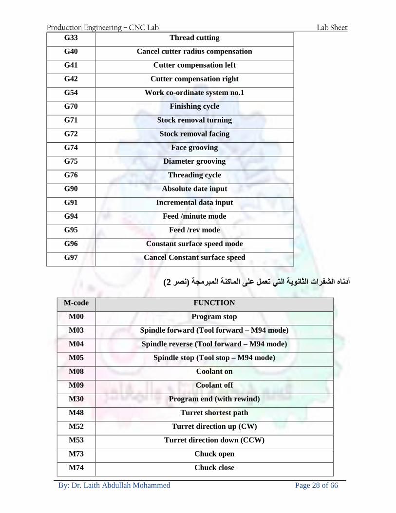
Production Engineering ndash CNC Lab Lab Sheet
By Dr Laith Abdullah Mohammed Page 28 of 66
G33 Thread cutting
G40 Cancel cutter radius compensation
G41 Cutter compensation left
G42 Cutter compensation right
G54 Work co-ordinate system no1
G70 Finishing cycle
G71 Stock removal turning
G72 Stock removal facing
G74 Face grooving
G75 Diameter grooving
G76 Threading cycle
G90 Absolute date input
G91 Incremental data input
G94 Feed minute mode
G95 Feed rev mode
G96 Constant surface speed mode
G97 Cancel Constant surface speed
) 2أدناه الشفرات الثانوية التي تعمل على الماكنة المبرمجة (نصر
M-code FUNCTION
M00 Program stop
M03 Spindle forward (Tool forward ndash M94 mode)
M04 Spindle reverse (Tool forward ndash M94 mode)
M05 Spindle stop (Tool stop ndash M94 mode)
M08 Coolant on
M09 Coolant off
M30 Program end (with rewind)
M48 Turret shortest path
M52 Turret direction up (CW)
M53 Turret direction down (CCW)
M73 Chuck open
M74 Chuck close
Production Engineering ndash CNC Lab Lab Sheet
By Dr Laith Abdullah Mohammed Page 29 of 66
) وكل جملة مكونة من مجموعة من الكلمات blockإن كل برنامج يتكون من مجموعة من الجمل ()words) لهذا فأن الشفرات الرئيسية والمساعدة هي عبارة عن كلمات (words كما في المثال التالي (
G_ _ P1 Q2 U_ _ W_ _ D___ F_ _
)end of block) ويعني ( ) يكتب الرمز (blockتسلسل الكلمات مهم جدا بعد نهاية كل جملة (
طريقة ادخال البيانات الى الماكنة ــــــــــــــــــــــــــــــــــــــــــــــــــ
) MDIيمكن ادخال البيانات الى الماكنة بعدة طرق فقد يكون األدخال عن طريق قناة السيطرة ( MANUAL DATA INPUT ) او عن طريق قناة األضافة EDIT كما يمكن ادخال البيانات عن (
) RS ndash 232 COMMUNICATIN LINKطريق استخدام سلسلة الربط (
₤⅗₌⅗₌ ⅙₌₨image₍₡ ₤₌ℌ⅗₌ Ⅸ⅗ⅥⅯ₌ ₤₡ℌ₰₨⅗₌G71
الخراطة الطولية G71الغرض من التجربة عمل نموذج للخراطة بأستخدام الدالة تستعمل هذه الدالة للخراطة الطولية اي على طول محور المشغولة وكما هو موضح بالشكل ادناه
تعتبر هذه الدالة من الدوال التي ال تحتاج الى تكرار او إعادة كتابتها أي انها دالة تكرارية بمعنى ان اي
الذي هي دالة حركة G01خطوة تكون من ضمن هذه الدالة سوف تكرر العملية اي عند استعمال امر مثل خطية تتضمن القطع مع التغذية مع اعطاء القطر المراد قطعه و مراعاة عمق القطع المعطى سوف يتكرر
هذه االمر وصوال الى العمق المطلوب وهكذا لبقية الدوال
G71 المستخدمة للدالة الصيغة
G71 P1 Q2 U___ W___ D___ F___ حيث إن
P1 بداية الخطوة االولى = Q2 نهاية الخطوة =
Uوضع السماحات بأتجاه محور = X W وضع السماحات بأتجاه محور = Z وتكاد تكون مهملة وتوضع اشارة سالب Dعمق القطع وتوضع رقم صحيح مثل = D500 اي نصف ملمF التغذية والتي لها عالقة بالدالة = G95
Production Engineering ndash CNC Lab Lab Sheet
By Dr Laith Abdullah Mohammed Page 30 of 66
G71الدالة استخدام مثال على
T0100 M48 G0 X26 Z2 M08 T0101 G90 G95 G97 S500 M03 G71 P1 Q2 U03 W00 D500 F01 N1 G0 G42 X00 G01 Z00 G01 X2517 G01 Z-5352 G01 X7391 Z-9366 G01 Z-19145 N2 G28 M30
الجانب العملي
االجهزة واالدوات المستخدمة CNCماكنة خراطة مبرمجة 1 ملم 80قضيب من االلمنيوم قطر 2 ةفير ني 3 جاه أيمن تهولدر كاربيدي ذوا 4
طريقة العمل يتم تثبيت قضيب من االلمنيوم على العينة التابعة للماكنة مع مراعاة الطول المراد استعماله في عملية 1
الخراطة ) turretتثبيت عدة القطع في المكان الصحيح في ( 2
Production Engineering ndash CNC Lab Lab Sheet
By Dr Laith Abdullah Mohammed Page 31 of 66
بالنسبة الى القطعة المثبتة على العينة XZيتم تصفير الماكنة للمحاور 3 تصفير للمحورZ تكون مالمسة العدة الى وجه الشغلة تصفير للمحورX تكون مالمسة العدة الى سطح الشغلة الموازي لمحور X
يتم كتابة البرنامج أما بطريقة يدوية أو بالحاسوب مع وضع كل الظروف الالزمة للتشغيل ( عمق القطع 4 التغذية السرعة المطلوبة نوع المعدن )
ادخال البرنامج الى الحاسوب الموجود داخل الماكنة مع تهيئة الماكنة للتشغيل 5
المطلوب G71عمل برنامج يدوي على الدالة 1 رسم الشكل الشكل النهائي المطلوب مع وضع األبعاد 2
Ⅺ⅟₍euro⅗₌ ₤₡ℌ₰₨⅗₌₣ ₤⅗₌⅗₌ ⅙₌₨image₃₡ Ⅺℂtradeℒ⅗₌ ӈ₍Ⅴ⅟ⅳ₌ G70
G70 الغرض من التجربة عمل انهاء سطحي للمشغولة بواسطة الدالة
من الضروري إعطاء G71هذه الدالة تعمل شوط واحد فقط وتكون معتمدة على عمليات القطع في الدالة اللغاء مقدمة االداة (أي لكي تتم عملية االنهاء السطحي بدون حسابات نصف قطر مقدمة االداة ) G42دالة
G70الصيغة المستخدمة للدالة
G70 P1 Q2 F___ حيث ان
P1 بداية الخطوة االولى = Q2 نهاية الخطوة =
F التغذية والمرتبطة بالدالة = G95
وذلك ألن دالة االنهاء السطحي تحقق X Zمالحظة الدالة التحتاج لكتابة السماحات التابعة للمحورين المسافات الحقيقة المراد انتاجها للمشغولة
G71و G70مثال على الدالة
T0100 M48 G0 X26 Z2 M08 T0101 G90 G95 G97 S500 M03 G71 P1 Q2 U03 W00 D500 F01 N1 G0 G42 X00 G01 Z00 G01 X2517 G01 Z-5352 G01 X7391 Z-9366 G01 Z-19145 N2 G97 S750 MO3
Production Engineering ndash CNC Lab Lab Sheet
By Dr Laith Abdullah Mohammed Page 32 of 66
G70 P1 Q2 G40 F009 G28 M30
الجانب العملي الحظ التجربة األولى
المطلوب
G70 عمل برنامج يدوي على الدالة 1 رسم الشكل النهائي المطلوب مع وضع االبعاد 2
₪⅗₍euro⅗₌ ₤₡ℌ₰₨⅗₌₣ ₤⅗₌⅗₌ ⅙₌₨image₍₡ ⅝₍ⅠimageⅯ₌ ⅞ⅫⅦ⅔₧ G76
G76 للمشغولة بواسطة الدالةةالغرض من التجربة عمل أسنان خارجية أو داخلي
في هذه التجربة سوف نقوم بعمل األسنان الخارجية وهنا تكون حركة العينة ثابتة وهذا ضروري بسبب أن ) تكون متصلتين الكترونيا وعليه أي اختالف في سرعة العينة تؤدي إلى اختالف motionالعينة والحركة(
) servoفي سرعة الخدمة(يرتبط اتجاه تكوين األسنان باتجاه دوران العينة مثال إذا كانت األسنان ذات اتجاه أيمن يكون اتجاه دوران
وهنا نقلب العدة إلى االسفل وكما هو موضح بالشكل أدناه MO3العينة عكس عقرب الساعة أي نستعمل
Production Engineering ndash CNC Lab Lab Sheet
By Dr Laith Abdullah Mohammed Page 33 of 66
الخطوة هي عبارة عن المسافة ما بين قمة سن إلى قمة سن أخر عمق السن هو العمق المطلوب تكوينه لألسنان
G76 الصيغة المستخدمة للدالة
G76 X___ Z___ K___ F___ D___ A___
حيث أن X القطر الداخلي للسن =Z طول السن =K عمق السن وتستخرج من المعادلة التالية =K=065F F الخطوة =D عمق القطع بالمايكرون فقط =A زاوية السن =
G76مثال على استخدام الدالة T0300 M48 GOO X30 Z4 T0303 M08 G97 S500 MO3 G76 X28375 Z-20 K08125 F125 D120 G00 X40 Z4 G28 M30
Production Engineering ndash CNC Lab Lab Sheet
By Dr Laith Abdullah Mohammed Page 34 of 66
الجانب العملي الحظ التجربة األولى
المطلوب
G76عمل برنامج يدوي على الدالة 1 رسم الشكل النهائي المطلوب مع وضع األبعاد 2
Ⅺ⅘₌⅗₌ Ⅵ₂ Ⅺ₯ℋ₍⅗₌ ℌℲℂ⅗₌ ⅞ⅫⅦ⅔₧ ₤K₡₌ℌ⅗₌ ₤₡ℌ₰₨⅗₌)Groove ₤⅗₌⅗₌ ₤tradeimage₌Ⅶ₡ (G75
G75 بواسطة الدالة grooveالغرض من التجربة تكوين
) للمشغولة وتعتمد شكل الحفر على طريقة grooveتستعمل هذه الدالة لتكوين الحفر الخارجي والداخلي (
التشغيل وعلى الشكل المراد إنتاجه وتعتبر هذه الطريقة من عمليات التشكيل للمعدن إن هذه الدالة هي دالة مالحظة مع G75في هذه التجربة سنقوم بعمل الحفر الخارجي بواسطة الدالة
تكرارية وغير تكرارية حسب نوع التشغيل
G 75 الصيغة المستخدمة للدالةG75 X___ Z___ I___ K____
حيث أن
X العمق النهائي لقطر الشغلة =Z عرض الحفر =I الدخول في كل مرة =
K التزحيف على محور =z بالنسبة للعدة
Production Engineering ndash CNC Lab Lab Sheet
By Dr Laith Abdullah Mohammed Page 35 of 66
G75مثال على استخدام الدالة
T0500 M48 GOO X100 Z -20 T0505 M08 G97 S700 MO3 G75 X84 Z -38 I 05 K4
الجانب العملي الحظ التجربة األولى
المطلوب
G76عمل برنامج يدوي على الدالة 1 رسم الشكل النهائي المطلوب مع وضع األبعاد 2
Production Engineering ndash CNC Lab Lab Sheet
By Dr Laith Abdullah Mohammed Page 36 of 66
CNC Milling Machine Mechanical Construction
Guideways The guideways of CNC machines are made of steel To reduce the frictional forces they are coated with a strip of PTFE (Poly Tetra Fluoro Ethylene)
Ballscrews On conventional lathes a leadscrew is used to converts the rotary motion of the hand wheel into linear motion of the slides Leadscrews have a high coefficient of friction and backlash On CNC machines a ballscrew is used instead of a leadscrew Friction and backlash are much less than on leadscrews
Guideway
Production Engineering ndash CNC Lab Lab Sheet
By Dr Laith Abdullah Mohammed Page 37 of 66
bullMachining operations Direction of cutting Based on the direction of the cutter rotation and work piece feed milling operations are classified into two types 1-Up milling (Convention milling) In up milling the metal is removed by rotating the cutter against the direction of travel of the part
Feed
Machine table
Part
Cutting tool
Chip thickness at theexit of the tooth
2-Down milling (Climb milling) In climb milling the metal is removed by rotating the cutter with the direction of travel of the part
Machine table
Part
Cutting tool
Chip thickness at theentrance of the tooth
Production Engineering ndash CNC Lab Lab Sheet
By Dr Laith Abdullah Mohammed Page 38 of 66
bullTooling Tool geometry The geometry of the tool tip affects the way that the metal cutting is performed The nose radius rake angles relief angles etc must be selected with care
Radial relief
Radial rake
Axial relief
Approach angle
Axial relief
Corner radius Face mill Face milling cutters are used to mill flat surfaces Commonly used face milling cutters Cutter with 75 degree approach
75 deg
Cutter with 90 degree approach (Square shoulder face mill)
90 deg
Cutter with 45 degree approach
Production Engineering ndash CNC Lab Lab Sheet
By Dr Laith Abdullah Mohammed Page 39 of 66
bullCNC Programming Axes convention The Z axis is along the spindle axis The X and Y axes are perpendicular to Z VMC
Z
Y
-
+
-+
X- +
+Z
-Z
+Y
-Y
-X +X
Part
Machine table
X
YZ
G00 Rapid traverse When the tool being positioned at a point preparatory to a cutting motion to save time it is moved along a straight line at Rapid traverse at a fixed traverse rate which is pre-programmed into the machines control system Typical rapid traverse rates are 10 to 25 m min but can be as high as 80 mmin
Production Engineering ndash CNC Lab Lab Sheet
By Dr Laith Abdullah Mohammed Page 40 of 66
Format N_ G00 X__ Y__Z__
G01 Linear interpolation (feed traverse) The tool moves along a straight line in one or two axis simultaneously at a programmed linear speed the feed rate Format N__ G01 X__ Y__Z__ F__
Part
Feed
Part
Feed
G02G03 Circular interpolation The tool moves along an arc in two axes simultaneously at a programmed linear speed the feed rate
Production Engineering ndash CNC Lab Lab Sheet
By Dr Laith Abdullah Mohammed Page 41 of 66
Format N__ G0203 X__ Y__Z__ I__ J__K__ F__ using the arc center OR N__ G0203 X__ Y__Z__ R__ F__ using the arc radius G02 moves along a CW arc G03 moves along a CCW arc Arc center The arc center is specified by addresses I J and K I J and K are the X Y and Z co-ordinates of the arc center with reference to the arc start point
X
Y
Arc center
Arc endArc start
- J
- I
I = X coord of center - X coord of start point J = Y coord of center - Y coord of start point K = Z coord of center - Z coord of start point I J and K must be written with their signs
Production Engineering ndash CNC Lab Lab Sheet
By Dr Laith Abdullah Mohammed Page 42 of 66
bullWork holding
Rotary table
Fixture base
Component
Clamp
Stud
Fixtures The use of fixtures 1 Improves repeatability of dimensions 2 Improves working conditions 3 Cuts down requirement of skilled labour 4 Reduces part loading and unloading time 5 Improves safety in the working area 6 Reduces the cost of machining There are two types fixtures commonly used 1 Special fixture Special fixtures are used to hold and locate the typical components which are having complex shape and to be located with the reference hole (dowel hole) Special fixtures are required for components like gear case cover cylinder heads etc 2 Modular fixture Modular fixture is a set different kind of clamping and locating elements These fixtures are used to hold identical components in different sizes and components of box type Example Manifolds head stocks connecting rods and flanges
Production Engineering ndash CNC Lab Lab Sheet
By Dr Laith Abdullah Mohammed Page 43 of 66
bullMachine setting
Determining X and Y work zero offset Case 1
Part
Machine table
Part
End mill or reamer
Work offset X0Y0 For determining X work zero offset bull Touch the periphery of the end mill or reamer to the part bull Enter current machine X value + cutter radius as X work zero offset For determining Y work zero offset bull Touch the periphery of the end mill or reamer to the part bull Enter current machine Y value - cutter radius as Y work zero offset Case 2
Part
Machine table
Part
End mill or reamerWork offset X0Y0
bull Mount the dial indicator on machine spindle true the bore bull Enter current machine X and Y value as X and Y work zero offset
Production Engineering ndash CNC Lab Lab Sheet
By Dr Laith Abdullah Mohammed Page 44 of 66
How to Select a Cutting Fluid
One part of the metal cutting equation that is sometimes overlooked however is
the choice of an appropriate cutting fluid With todayrsquos system approach to metal
cutting use of the right metalworking fluid has become just as much a part of the
solution as the other elements In fact at least one company is now integrating
cutting fluids and cutting tools into effective metal cutting systems Following are
some things to consider when choosing your next cutting fluid
The Four Key Questions
There are four vital pieces of information that are necessary when choosing a
cutting fluid They are
1 What are you cutting
2 What is the chemistry of your water
3 What are you using now
4 What are your options
5 What do you prefer
What Are You Cutting
The first question ndash ldquoWhat are you cuttingrdquo ndash is often the most difficult to answer
because most shops handle a variety of workpiece materials on a regular basis If
the answer is an unequivocal ldquoaluminumrdquo or ldquostainless steelrdquo or ldquocast ironrdquo the
selection of a cutting fluid can be quite simple and straightforward Unfortunately
that is seldom the case in anything but a high-volume plant Where aluminum or
other nonferrous metals are a significant part of the mix a non-staining cutting
fluid is a must Generally speaking this will be a semi-synthetic with special
ingredients to prevent bi-metallic corrosion and staining of non-ferrous workpieces
Where the ferrous metals predominate however a more general purpose semi-
synthetic or hybrid fluid might be a more economical choice
Production Engineering ndash CNC Lab Lab Sheet
By Dr Laith Abdullah Mohammed Page 45 of 66
What is The Chemistry of Your Water
The second question ndash ldquoWhat is the chemistry of your waterrdquo ndash is probably the
single most common reason for the success or failure of a cutting fluid Very few
plants invest the money necessary to install effective water purification systems
using deionization or reverse osmosis technology Unfortunately the chemicals
present or not present in the water used to re-constitute a cutting fluid make a
tremendous difference in its performance and sump life Most manufacturers of
cutting fluids will perform the necessary water testing to determine exactly what
minerals are dissolved in your water and make a fluid recommendation based on
the results
What are you using now
The third question ndash ldquoWhat are you using nowrdquo ndash helps narrow the range of
choices When coupled with an objective analysis of the strengths and weaknesses
of the current fluid the answer to this question can quickly point you toward a
relatively small number of competitive alternatives that have the attributes required
to meet your cutting needs Many cutting fluids are in use today simply because
they were in use yesterday It is a hard reality of todayrsquos marketplace that if one
isnrsquot constantly striving to improve they will certainly be overtaken by a
competitor who is
What Are Your Options
The fourth question ndash ldquoWhat are your optionsrdquo ndash leads to the final selection of a
cutting fluid Cutting fluids can be divided into four general groups based on their
chemistry
They are
bull Soluble Oils ndash quite literally oil dispersed in water
bull Synthetics ndash completely oil free man-made coolants in solution
Production Engineering ndash CNC Lab Lab Sheet
By Dr Laith Abdullah Mohammed Page 46 of 66
bull Semi-Synthetics ndash a mixture of natural and synthetic lubricants with up to 30
mineral oil
bull Hybrids ndash a special class of semi-synthetics with a mineral oil content of about
15 Each fluid type has advantages and disadvantages which make it suitable for
a particular group of applications In addition there are costperformance trade-
offs to be made between the groups within a specific set of applications For
example where a hybrid and a semi-synthetic may both be suitable for a particular
use the hybrid might provide longer sump life at a slightly higher initial cost
while some semi synthetics may be more economical to recycle or dispose of while
not giving as long a tank life The final decision in this case would have to be made
on the detailed economics of the shop where the fluids were to be used and on the
ownerrsquos individual preferences
Soluble Oils
Soluble oils are oils that disperse in water when emulsifiers are added They are
generally suitable for moderate-to heavy-duty machining and grinding of all non-
ferrous metals carbon and cast steels and in applications where dissimilar metals
such as aluminium and steel are present They can also be used in turning drilling
tapping reaming gear cutting broaching as well as internal and centerless types
of grinding operations Soluble oils provide excellent aluminium and copper
corrosion control good rancidity control which extends fluid for long lasting
trouble-free performance and good concentrate and mix stability making it ideal
for mixing in water with a minimal amount of agitation An example of this is
Valenitersquos VNTreg-650 premium heavy-duty soluble oil
Synthetics
Synthetics are completely oil free solutions made of polymers organic and
inorganic materials that are mixed with water These clear low foaming and bio-
Production Engineering ndash CNC Lab Lab Sheet
By Dr Laith Abdullah Mohammed Page 47 of 66
stable coolants are ideal for machining and grinding of ferrous materials carbon
steels or cast iron Their complex lubricant packages make synthetics well-suited
for tough-to-machine materials such as stainless steels and high-temperature alloys
Certain synthetics are specifically designed to address the primary failure modes of
flank wear and nose wear Although there are many benefits some synthetics may
cause staining of non-ferrous materials
Semi-Synthetics
Semi-synthetic fluids are a mixture of oils synthetic emulsifiers and water They
were primarily developed for the aircraft nuclear and related industries
Consequently they work extremely well on all non-ferrous metals such as titanium
aluminium copper brass bronze and stainless steel in both machining and
grinding Semi-synthetics can be used on ferrous metals too They are chlorine-
free to reduce bi-metallic corrosion and staining of metals They should be used at
a 5-8 dilution with water depending on the severity of the operation
Hybrids
Hybrids are cutting fluids custom engineered to solve a particular problem For
example Valenitersquos VNTreg-800 was developed to be very clean in the machining
and grinding of cast iron It provides better stability in hard water and rejects tramp
oil very well which adds to its bio-stable chemistry Hybrids work extremely well
on all metals in both machining and grinding They should be mixed at a 5-7
dilution with water depending on the condition of the water
What Do You Prefer
The final question ndash ldquoWhat do you preferrdquo ndash is usually the ldquotie breakerrdquo where
there is more than one appropriate cutting fluid available Here again as in the
case of what is being used now the key is to examine your preferences objectively
Production Engineering ndash CNC Lab Lab Sheet
By Dr Laith Abdullah Mohammed Page 48 of 66
and specifically to identify the real reasons behind a preference If you cannot
point to specific reasons why one class of cutting fluid is preferred over another
you are well advised to follow the recommendations of the professional who has
analyzed your requirements Choosing the right fluid today is easier than ever as
the system approach to metal cutting productivity continues to grow in acceptance
The day is not far off when choosing a complete solution will be as easy as
choosing the right insert and chip breaker today The answers are available and the
results will more than justify the time you spend choosing the right metal cutting
fluid
Useful Links wwwball-screwsnet
wwwlubelinkcom
wwwmachinerylubricationcom
wwwadvancedmanufacturingcom
wwwmmsonlinecom
wwwcuttingtoolengineeringcom
wwwgeartechnologycom
wwwengineersedgecom
wwwagmaorg
wwwefundacom
wwwsaeorg
wwwsmeorg
wwwastmorg
wwwissorg
wwwmachinetoolscom
wwwansiorg
wwwasmeorg
wwwcnccicom
wwwmatlscom
wwwthefreedictionarycom
wwwengineersupplycom
Production Engineering ndash CNC Lab Lab Sheet
By Dr Laith Abdullah Mohammed Page 49 of 66
SurfCAM Tutorial ndash Beginning with the basics
Background SurfCAM is a computer aided manufacturing (CAM) software which allows you to create manage and modify tool paths for computer aided designed (CAD) part The software requires a CAD model or requires that you create some geometry within SurfCAM with some rudimentary tools provided The tool paths are created or stored internally in SurfCAM in a generic programming language called APT Once the tool paths are created the APT paths are translated using a post processor into typical machine G-code
Opening SurfCAM SurfCAM can be opened from the Novell Applications Launcher on most Industrial Engineering computer labs workstations Search under lsquoallrsquo applications and double click on SurfCAM 2005 Once the program opens a license must be selected from the list (not the Demo license) to enable saving the file later Choose one of the 30 licenses available If for some reason the licenses are not listed on the license manager form select server list and type ldquobonnieeosncsuedurdquo A list of available licenses should appear Select a license and click OK After the license is selected an Add StockFixture form (Figure 1) opens allows you to add a model which represents the pre-machined stock or a fixture Click on OK without adding either Both of these items can be added later under a more appropriate dialog
Figure 1 Add Stock or Fixture dialog box
Production Engineering ndash CNC Lab Lab Sheet
By Dr Laith Abdullah Mohammed Page 50 of 66
SurfCAM Interface
Figure 2 SurfCAM Windows based interface
SurfCAM is a windows based software system so most of the typical windows functions under File are applicable This is where you can open save exit print etc The Create menu allows the user to create different geometry forms Here you can create a point line surface chamfer circle and many other geometry types For the most part these functions are not used by beginners but are useful when creating bounding curves where you donrsquot want the tool to move outside (constraining the tool) The Edit menu allows you to change or modify many different entities such as changing lines altering surfaces joining surfaces trimming or breaking elements add control points etc Again these features are helpful to advanced users and are not covered in detail in this tutorial The Display menu offers the ability to change the orientation of the part on the screen The typical rotate pan fit to screen and zoom functions are available as well as several functions which allow the user to shift between views or call up a named view (ie top bottom etc) The NC menu is the main machining interface menu In this menu you select the general form of machining (2 axis 3 axis 4 axis 5 axis turning etc) and under the general form a more specific machining function is selected This menu is the most used and the options contained must be fully understood to get the most out of SurfCAM Each function will be described in some detail in a further chapter The Analyze menu contains options such as measuring the distance between points angles tangency elements etc These functions are auxiliary functions meant to help you understand the part better but basically provide no functionality for making tool paths for CNC machines Thus these will not be covered The Tools menu allows the user to change the system options modify keyboard shortcuts change the model units etc These options are again not used by beginners Finally the Help menu provides access to the online users manual In lieu of clicking the Help menu the F1 key is the shortcut key for help (as it is in most windows based programs)
Importing a CAD model Importing a CAD model that is stored locally is done by selecting File-gtOpen On the Files of type dropdown box choose the type of file you wish to open (Figure 3) Do this prior to negotiating your way through the maze of folders to prevent having to go through the folder tree again Once the file type is selected find the file you are trying to open and click the Open
Production Engineering ndash CNC Lab Lab Sheet
By Dr Laith Abdullah Mohammed Page 51 of 66
button SurfCAM will then attempt to read the file you have selected SurfCAM may provide a dialog box describing what it has imported and identify if it was successful If this dialog is provided simply click close without saving
Figure 3 Open Dialog Note - Change type of file prior to finding the file you wish to open
SurfCAM allows a user to import several different types of CAD files the most common types which you will likely import are SolidWorks part files (sldprt or prt) AutoCAD files(dxf) or IGES (igs or iges) Native file import (such as is the case with SolidWorks) provides the greatest information transfer and generic file imports (such as is the case with IGES) provide the least Normally it is to the advantage of the user to use native file importing procedures when available Recently (2005) SurfCAM added some compatibility with SolidWorks This allows the user to create tool paths for a part and if an engineering change is needed for the part update the part in SolidWorks When the part is then opened in SurfCAM the changes are noted and a simple update operation command is needed This however does not operate with complete transparency andor accuracy and thus users need to be cognizant of changing CAD models
SurfCAM Geometry In SurfCAM two basic types of geometry are used the surface and the point A surface (Figure 4) is a so called spline (NURBS or B-Spline are the two most common) surface (parameterized by two values u and v) such that every location on the surface can be defined as a function of these parameters In other words SurfCAM can calculate the location of any point on the
Production Engineering ndash CNC Lab Lab Sheet
By Dr Laith Abdullah Mohammed Page 52 of 66
surface Surfaces are used primarily in 3 4 and 5 axis machining and require a significant
amount of processing power and time Figure 4 Surfaces model of a mold half Note the difference between this and Figure 2 a wireframe model
Point or line based models are often referred to as wireframe (Figure 5) models because the models consist of connected lines and resemble the part only at the intersection of two surfaces Wireframe models were made popular lsquoback in the dayrsquo when computer processing was expensive There are times when each of the models are important and selecting model geometry when applying a SurfCAM operation will be much simpler if you understand the differences between the two When importing a SolidWorks model the default is both the surfaces and the wireframe geometry are imported
Figure 5 Wireframe model of the mold in Figure 1
Steps to Creating Tool Paths Once a CAD model is imported into SurfCAM tool paths can be created There is no one correct way to create tool paths however there is a set of general steps to take to ensure the tool paths are created with a minimum amount of hardship (note the wordinghellipHardship is inevitable when creating tool paths it is the intent of this manual to minimize this) The following is a list of steps which should be considered when making tool paths
Production Engineering ndash CNC Lab Lab Sheet
By Dr Laith Abdullah Mohammed Page 53 of 66
1 Plan ahead a Orient the part in SolidWorks such that if only one side is to be machined that
side is the Top view This can be done early in SolidWorks by choosing a plane parallel the X-Y plane as the sketch plane for the machined geometry
b Orient the part in SolidWorks such that the origin is somewhere of relative importance and someplace in space that can be easily identified when placed on the machine This is extremely important to minimize set up time at the machine (note ndash my personal preference for a part that is to be fully machined [ie stock exists on all sides] is to place the origin at the center and top of the parthellipjust my preference)
c Orient the part in SolidWorks such that the X and Y axes are aligned as you want them on the machinehellip
d Planning ahead will save you many hours of headaches laterhelliptrust me 2 Import the model 3 Choose a construction view such that the tool approaches the side to be machined
from the positive Z axis direction (as defined by part origin) a This is done by clicking on the CView icon
b From the list of named views chose the view which orients the origin as you would like
c If one of the views does not fit your criteria you have two choices i Perform a transformation of the part in SurfCAM or SolidWorks
ii Add a new construction view by selecting new This option requires a relatively good understanding of right hand coordinate frames but is very usefulhellipNormally used by more advanced users
d Be sure the CoordVIEW selection is made vs CoordWORLD This ensures the tools will be controlled from the coordinate frame selected by the view (ie the origin on the part) instead of the origin on the lower left corner of the screen This will be especially important when we get into 4 and 5 axis machining
4 In the Operations Manager (Figure 6) select Setup One and change the name to something meaningful ndash like Front Side Mold Cavity
a Access the Operations manager by right clicking or by selecting the Operations Manager icon in the tool bar
b Operations Manager is where the tool paths are managed once they are created as well as where individual tool paths can be verified
Production Engineering ndash CNC Lab Lab Sheet
By Dr Laith Abdullah Mohammed Page 54 of 66
5 Roughing Tool Paths a Create the tool paths to remove the majority of the material (if applicable) b Use NC-gt3Axis-gtZ rough or Plunge Rough c Described in next section
6 Create Finishing Tool Paths a Described in next section
7 Add another setup if necessary 8 Perform steps 3 through 6 as necessary 9 Verify the tool paths are correct 10 Use a post processor for the tool paths to create G-Code for machine
Creating Tool Paths The following is a list of operations what they are intended for how they generally work and some parameters that may be adjusted to modify the tool paths
2 Axis tool paths Unless otherwise noted 2 axis tool path functions require lines or arc segments as input parameters (as opposed to surfaces) There are several options as to how these segments are chosen the most prevalent is the chain option and the second most prevalent is the single When choosing the line segments using the chain option SurfCAM will try to link a complete path of segments based on an initial segment chosen by the user If the operation is planer (ie pocket or contour) the segments must lie on the same plane If the operation is non-planer (ie contour 3D) SurfCAM will prompt the user to specify segments when it encounters a branch point
Figure 6 Operations Manager view showing setup one re-labeled as Front Side Mold
Production Engineering ndash CNC Lab Lab Sheet
By Dr Laith Abdullah Mohammed Page 55 of 66
When using the single element option the user must manually choose each segment desired for the operation Note that most operations do not require a closed loop of segments you may specify for instance an open contour where the tool is supposed to move The order of choosing segments is important This order determines the path of the tool in the sense that if three segments are chosen such that the middle segment is chosen last there will be three different plunge and machine operations one on each segment If the operation was to make a continuous contour around the outside of the part the segments should be chosen in order of the desired tool trajectory
Operations
Pocket Pocket operation in SurfCAM is used to cut an enclosed space from the inside to the outside at one particular depth The operation starts in the center of an enclosed area (with a plunge move in the ndashZ direction) and makes incremental closed paths towards the pocket boundaries in user defined path offsets (Figure 7) The user chooses the boundary of the pocket (line segments) and if more than one pocket is chosen SurfCAM will ask the user to click inside a pocket
Figure 7 Two examples of using the pocketing operation
The pocket operation allows for creating a projection of the pocket paths on multiple planes This is useful if you have a deep pocket which will not allow the tool to cut directly at the depth of the pocket but would be easily done using the same paths at several different Z heights On the cut control (Figure 8) tab the user specifies where the chosen geometry (pocket segments) lie (ie bottom or top) Then under the amount to remove specify the total material height to be removed and the rough spacing (amount you wish to advance the Z axis with each pocket step) You may also specify a finishing pass and as well as stock to leave
Production Engineering ndash CNC Lab Lab Sheet
By Dr Laith Abdullah Mohammed Page 56 of 66
Figure 8 Example of Contour Operation with multiple passes
Contour Contouring in SurfCAM is used to perform peripheral milling on the inside or outside of a line segment (Figure 9) The user is to identify the line segments which define a contour (does not have to be a closed loop of segments) SurfCAM may or may not require the user to specify a side to contour (ie which side of the line is the tool to cut) For contouring each segment must lie on the same plane
Production Engineering ndash CNC Lab Lab Sheet
By Dr Laith Abdullah Mohammed Page 57 of 66
Figure 9 Examples of parts cut with 2-Axis Contour
Contour 3D Contour 3D is the same operation type as contour but allows the user to specify segments on different planes for the tool to cut along
Drill Drilling operations are any rotating tool operation meant to engage the part from a single direction ndash namely from the positive Z direction Drilling operations can be specified using circle point or line segments After choosing NC-gt2-Axis-gtDrill SurfCAM allows the user to choose multiple circles or points defining holes to be drilled Drilling operations also allow the user to incorporate more than 1 operation such as a center drill a drill and a reaming operation After selecting the locations for the drilling operation a dialog box (Figure 10) allows the user to add change or delete tools to be used in the operation As displayed in the following figure the spotdrill operation is followed by a drilling operation followed by a tapping operation The depth of each tool can be controlled individually by double clicking the total depth cell in and manually entering Tools can be added before or after operations which the cells are highlighted by selecting either of the insert buttons at the top or by the insert menu Select tool button allows the user to change the tool size or type
Production Engineering ndash CNC Lab Lab Sheet
By Dr Laith Abdullah Mohammed Page 58 of 66
Figure 10 Drill operation manager Several operations can be completed at one time
Figure 11 Drill operation including the spotdrill drill and tap as outlined in Fig 10
3 Axis tool paths SurfCAM requires surfaces as inputs for 3 Axis tool paths Surfaces can be created in SurfCAM but are most easily created in a CAD package and imported into SurfCAM Surfaces allow SurfCAM to identify every point on the surface in 3 dimensions unlike 2D geometry (wireframes) which only identify positions on the plane Creating tool paths with complex surfaces takes a very significant amount of processing power so expect 3 Axis tool path generation to take longer
Production Engineering ndash CNC Lab Lab Sheet
By Dr Laith Abdullah Mohammed Page 59 of 66
Operations
Cut 3 Axis cut operation takes a surface and using the flow lines creates a rastering path over the surface with the tool tip riding on the surface The primary direction will be defined by the flow lines of the surface (which can be edited by Edit-gtSurfaces-gtArrow-gtDirection) If you intend to cross surface boundaries you must merge the surfaces (Edit-gtJoin and choose the two surfaces)
Z-Rough The Z-rough operation is used to remove a large amount of material prior to finish machining Roughing operation is typically the first operation you perform for each setup The Z-Rough operation cuts the part in user defined intervals For each of these intervals a surface intersection between the part and the plane is performed and a 2D pocket or contour operation is performed on that plane This is performed on each plane When choosing NC-gt3 Axis-gtZ rough the first dialog box you will encounter asks for a bounding box to be defined Choose the Extents Box and a second dialog box will ask for the coordinates which define the box (Figure 12) This is the stock size you expect to machine the part from Input the coordinates or change the additional offset amounts (in XY or Z) as appropriate and click Calculate Bounding Box
Figure 12 Material Extents Box Example
Next choose the tool and cutting parameters that you desire and click on the Cut Control Tab (Figure 13) Here you will find the following parameters which are often changed Stock to
Production Engineering ndash CNC Lab Lab Sheet
By Dr Laith Abdullah Mohammed Page 60 of 66
leave ndash this is an offset amount from the surfaces which leaves a small amount of material to finish machine Minimum and Maximum Z values ndash Defines area to machine Z Step Size ndash This identifies the plane intervals for the surface intersection planes (the first interval will be at the top of the selected area and successive increments down in Z will be cut until the Minimum Z value is reached)
Figure 13 3Axis Z Rough Cut Control
The 3Axis Z-Finish operation works in exactly the same way 3 Axis Z-Finish is most appropriate for finishing vertical or near vertical walls
3D Offset The 3D Offset operation creates a tool path using a 2D or 3D boundary by offsetting the boundary in concentric offset cutting passes Each pass calculates the tool engagement and maintains the engagement somewhat constant The advantage (significant) is the scallop height ndash height of the material between passes ndash is controlled thus the surface finish is predictable When choosing 3D Offset surfaces are selected as well as 2D or 3D boundaries The boundaries define the concentric offset paths shape as well as limit the tool path area Choose NC-gt3Axis-gt3D Offset from the drop down menus SurfCAM will prompt you to select the surface or surfaces to cut across Select the surfaces you wish to machine and then select the tool and cutting parameters you wish use Next select the Cut Control Tab and check the Use Boundary Curves option Set the Step Type to Scallop and set the maximum scallop height If you like
Production Engineering ndash CNC Lab Lab Sheet
By Dr Laith Abdullah Mohammed Page 61 of 66
you can also add stock to leave if this is a roughing operation You can also set the Direction and Start-End parameters from this tab Click OK and the paths will be generated
Figure 14 Cut Control Tab for 3D Offset
Example part using both 2D and 3D geometry
The tool paths for this mold will be generated in SurfCAM using 5 operations The first will be a roughing operation using a frac14 inch flat end mill with the Z step size of 00625in Choose NC-
Production Engineering ndash CNC Lab Lab Sheet
By Dr Laith Abdullah Mohammed Page 62 of 66
gt3Axis-gtZ-Rough from the drop down menu Select all visible surfaces and create an extents box that has 025inch XY offsets and 01inch Z offset Next select the frac14 inch flat end mill from the tools menu Under Cut Control tab set the Z step size to be 00625inch The tool paths will look something like Figure 15
Figure 15 Z-Rough Tool paths for Example Part
Next a flat surface operation will be performed to cut the flat surface on the top Select NC-gt3 Axis-gtFlat Surface from the drop down menu Select all visible surfaces again Choose the 12inch flat end mill and set the cutting parameters as desired Under Cut Control Tab change the Minimum Area to 50 square inches (Figure 16) The tool paths should look something like Figure 17
Figure 16 Cut Control for Flat Surface
Production Engineering ndash CNC Lab Lab Sheet
By Dr Laith Abdullah Mohammed Page 63 of 66
Figure 17 Flat Surface Tool Paths
Next we will use a 3D offset operation to cut the mold cavity Select NC-gt3 Axis-gt3D Offset from the dropdown menu Change the view to the top view and select within to capture the surfaces of the mold cavity Draw a rectangle around the mold cavity Select a 18 inch ball endmill from the tool library and set the cutting parameters as appropriate Next set the Cut Control tab parameters as in Figure 14 The paths creates should be similar to Figure 18
Figure 18 3D Offset Paths
Next we will perform a 2 Axis contouring of the top section Select NC-gt2 Axis-gtContour from the dropdown menu Using the chain option select the bottom contour of the top extrusion Select the frac12 inch flat end mill from the tool library and set the cutting parameters as required In the Cut Control Tab change the Geometry to Bottom and the amount to remove in Z to 05
Production Engineering ndash CNC Lab Lab Sheet
By Dr Laith Abdullah Mohammed Page 64 of 66
Change the Rough Spacing in Z to 025 and add 1 finish pass of 002 (Figure 19) Click OK and SurfCAM will instruct you to choose a side to contour Click anywhere on the screen OUTSIDE the geometry you selected for the contouring operation Failure to click outside the geometry will result in the tool being on the wrong side of the contour Your paths should look something like those in Figure 20
Figure 19 Cut Control Tab for the Contouring Operation
Figure 20 Contouring operation paths
Production Engineering ndash CNC Lab Lab Sheet
By Dr Laith Abdullah Mohammed Page 65 of 66
Next we will perform a 2 axis pocket operation for the small pocket on the top face of the mold Select NC-gt2Axis-gtPocket and using the Auto select feature select the boundary curve at the bottom of the pocket Click Done twice and select the frac14 inch flat end mill from the tool library Set the appropriate cutting parameters and click OK SurfCAM will prompt you to click inside the pocket Click anywhere inside the geometry you chose to define the pocket The resulting paths should look something like those in Figure 21
Figure 21 2 Axis Pocket Operation Paths
Finally we will add a drilling operation for the 2 holes at the corners of the mold Select NC-gt2 Axis-gtDrill from the dropdown menu Select the top circles defining the two holes A menu box will appear with a default tool (Center drill) already programmed Add a second tool to the list by selecting Insert-gtAfter and select the tool from the tool library Change the drill depth to 10inches and click OK The paths should look something similar to Figure 23
Figure 22 Drill Menu
Production Engineering ndash CNC Lab Lab Sheet
By Dr Laith Abdullah Mohammed Page 66 of 66
Figure 23 Drilling Operation Tool Paths
Now you can watch a simulation of the cutting by choosing the setup in the operations manager and clicking the simulate icon Be sure to set the stock in the set up by right clicking the set up and selecting Edit Setup Information In the Stock Tab you can create a bounding box meeting your needs and click Add Your simulation should result in something like the following
Figure 24 Final Simulation of the example Mold
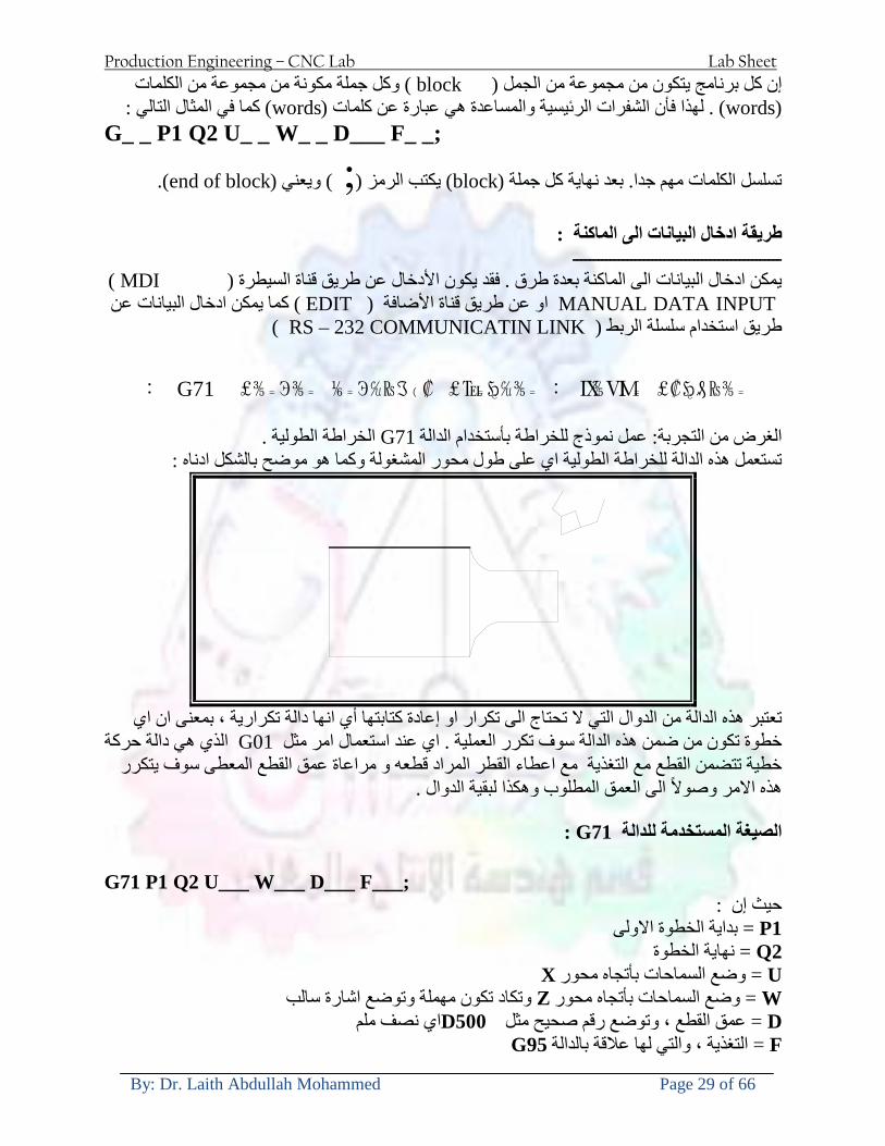
Production Engineering ndash CNC Lab Lab Sheet
By Dr Laith Abdullah Mohammed Page 29 of 66
) وكل جملة مكونة من مجموعة من الكلمات blockإن كل برنامج يتكون من مجموعة من الجمل ()words) لهذا فأن الشفرات الرئيسية والمساعدة هي عبارة عن كلمات (words كما في المثال التالي (
G_ _ P1 Q2 U_ _ W_ _ D___ F_ _
)end of block) ويعني ( ) يكتب الرمز (blockتسلسل الكلمات مهم جدا بعد نهاية كل جملة (
طريقة ادخال البيانات الى الماكنة ــــــــــــــــــــــــــــــــــــــــــــــــــ
) MDIيمكن ادخال البيانات الى الماكنة بعدة طرق فقد يكون األدخال عن طريق قناة السيطرة ( MANUAL DATA INPUT ) او عن طريق قناة األضافة EDIT كما يمكن ادخال البيانات عن (
) RS ndash 232 COMMUNICATIN LINKطريق استخدام سلسلة الربط (
₤⅗₌⅗₌ ⅙₌₨image₍₡ ₤₌ℌ⅗₌ Ⅸ⅗ⅥⅯ₌ ₤₡ℌ₰₨⅗₌G71
الخراطة الطولية G71الغرض من التجربة عمل نموذج للخراطة بأستخدام الدالة تستعمل هذه الدالة للخراطة الطولية اي على طول محور المشغولة وكما هو موضح بالشكل ادناه
تعتبر هذه الدالة من الدوال التي ال تحتاج الى تكرار او إعادة كتابتها أي انها دالة تكرارية بمعنى ان اي
الذي هي دالة حركة G01خطوة تكون من ضمن هذه الدالة سوف تكرر العملية اي عند استعمال امر مثل خطية تتضمن القطع مع التغذية مع اعطاء القطر المراد قطعه و مراعاة عمق القطع المعطى سوف يتكرر
هذه االمر وصوال الى العمق المطلوب وهكذا لبقية الدوال
G71 المستخدمة للدالة الصيغة
G71 P1 Q2 U___ W___ D___ F___ حيث إن
P1 بداية الخطوة االولى = Q2 نهاية الخطوة =
Uوضع السماحات بأتجاه محور = X W وضع السماحات بأتجاه محور = Z وتكاد تكون مهملة وتوضع اشارة سالب Dعمق القطع وتوضع رقم صحيح مثل = D500 اي نصف ملمF التغذية والتي لها عالقة بالدالة = G95
Production Engineering ndash CNC Lab Lab Sheet
By Dr Laith Abdullah Mohammed Page 30 of 66
G71الدالة استخدام مثال على
T0100 M48 G0 X26 Z2 M08 T0101 G90 G95 G97 S500 M03 G71 P1 Q2 U03 W00 D500 F01 N1 G0 G42 X00 G01 Z00 G01 X2517 G01 Z-5352 G01 X7391 Z-9366 G01 Z-19145 N2 G28 M30
الجانب العملي
االجهزة واالدوات المستخدمة CNCماكنة خراطة مبرمجة 1 ملم 80قضيب من االلمنيوم قطر 2 ةفير ني 3 جاه أيمن تهولدر كاربيدي ذوا 4
طريقة العمل يتم تثبيت قضيب من االلمنيوم على العينة التابعة للماكنة مع مراعاة الطول المراد استعماله في عملية 1
الخراطة ) turretتثبيت عدة القطع في المكان الصحيح في ( 2
Production Engineering ndash CNC Lab Lab Sheet
By Dr Laith Abdullah Mohammed Page 31 of 66
بالنسبة الى القطعة المثبتة على العينة XZيتم تصفير الماكنة للمحاور 3 تصفير للمحورZ تكون مالمسة العدة الى وجه الشغلة تصفير للمحورX تكون مالمسة العدة الى سطح الشغلة الموازي لمحور X
يتم كتابة البرنامج أما بطريقة يدوية أو بالحاسوب مع وضع كل الظروف الالزمة للتشغيل ( عمق القطع 4 التغذية السرعة المطلوبة نوع المعدن )
ادخال البرنامج الى الحاسوب الموجود داخل الماكنة مع تهيئة الماكنة للتشغيل 5
المطلوب G71عمل برنامج يدوي على الدالة 1 رسم الشكل الشكل النهائي المطلوب مع وضع األبعاد 2
Ⅺ⅟₍euro⅗₌ ₤₡ℌ₰₨⅗₌₣ ₤⅗₌⅗₌ ⅙₌₨image₃₡ Ⅺℂtradeℒ⅗₌ ӈ₍Ⅴ⅟ⅳ₌ G70
G70 الغرض من التجربة عمل انهاء سطحي للمشغولة بواسطة الدالة
من الضروري إعطاء G71هذه الدالة تعمل شوط واحد فقط وتكون معتمدة على عمليات القطع في الدالة اللغاء مقدمة االداة (أي لكي تتم عملية االنهاء السطحي بدون حسابات نصف قطر مقدمة االداة ) G42دالة
G70الصيغة المستخدمة للدالة
G70 P1 Q2 F___ حيث ان
P1 بداية الخطوة االولى = Q2 نهاية الخطوة =
F التغذية والمرتبطة بالدالة = G95
وذلك ألن دالة االنهاء السطحي تحقق X Zمالحظة الدالة التحتاج لكتابة السماحات التابعة للمحورين المسافات الحقيقة المراد انتاجها للمشغولة
G71و G70مثال على الدالة
T0100 M48 G0 X26 Z2 M08 T0101 G90 G95 G97 S500 M03 G71 P1 Q2 U03 W00 D500 F01 N1 G0 G42 X00 G01 Z00 G01 X2517 G01 Z-5352 G01 X7391 Z-9366 G01 Z-19145 N2 G97 S750 MO3
Production Engineering ndash CNC Lab Lab Sheet
By Dr Laith Abdullah Mohammed Page 32 of 66
G70 P1 Q2 G40 F009 G28 M30
الجانب العملي الحظ التجربة األولى
المطلوب
G70 عمل برنامج يدوي على الدالة 1 رسم الشكل النهائي المطلوب مع وضع االبعاد 2
₪⅗₍euro⅗₌ ₤₡ℌ₰₨⅗₌₣ ₤⅗₌⅗₌ ⅙₌₨image₍₡ ⅝₍ⅠimageⅯ₌ ⅞ⅫⅦ⅔₧ G76
G76 للمشغولة بواسطة الدالةةالغرض من التجربة عمل أسنان خارجية أو داخلي
في هذه التجربة سوف نقوم بعمل األسنان الخارجية وهنا تكون حركة العينة ثابتة وهذا ضروري بسبب أن ) تكون متصلتين الكترونيا وعليه أي اختالف في سرعة العينة تؤدي إلى اختالف motionالعينة والحركة(
) servoفي سرعة الخدمة(يرتبط اتجاه تكوين األسنان باتجاه دوران العينة مثال إذا كانت األسنان ذات اتجاه أيمن يكون اتجاه دوران
وهنا نقلب العدة إلى االسفل وكما هو موضح بالشكل أدناه MO3العينة عكس عقرب الساعة أي نستعمل
Production Engineering ndash CNC Lab Lab Sheet
By Dr Laith Abdullah Mohammed Page 33 of 66
الخطوة هي عبارة عن المسافة ما بين قمة سن إلى قمة سن أخر عمق السن هو العمق المطلوب تكوينه لألسنان
G76 الصيغة المستخدمة للدالة
G76 X___ Z___ K___ F___ D___ A___
حيث أن X القطر الداخلي للسن =Z طول السن =K عمق السن وتستخرج من المعادلة التالية =K=065F F الخطوة =D عمق القطع بالمايكرون فقط =A زاوية السن =
G76مثال على استخدام الدالة T0300 M48 GOO X30 Z4 T0303 M08 G97 S500 MO3 G76 X28375 Z-20 K08125 F125 D120 G00 X40 Z4 G28 M30
Production Engineering ndash CNC Lab Lab Sheet
By Dr Laith Abdullah Mohammed Page 34 of 66
الجانب العملي الحظ التجربة األولى
المطلوب
G76عمل برنامج يدوي على الدالة 1 رسم الشكل النهائي المطلوب مع وضع األبعاد 2
Ⅺ⅘₌⅗₌ Ⅵ₂ Ⅺ₯ℋ₍⅗₌ ℌℲℂ⅗₌ ⅞ⅫⅦ⅔₧ ₤K₡₌ℌ⅗₌ ₤₡ℌ₰₨⅗₌)Groove ₤⅗₌⅗₌ ₤tradeimage₌Ⅶ₡ (G75
G75 بواسطة الدالة grooveالغرض من التجربة تكوين
) للمشغولة وتعتمد شكل الحفر على طريقة grooveتستعمل هذه الدالة لتكوين الحفر الخارجي والداخلي (
التشغيل وعلى الشكل المراد إنتاجه وتعتبر هذه الطريقة من عمليات التشكيل للمعدن إن هذه الدالة هي دالة مالحظة مع G75في هذه التجربة سنقوم بعمل الحفر الخارجي بواسطة الدالة
تكرارية وغير تكرارية حسب نوع التشغيل
G 75 الصيغة المستخدمة للدالةG75 X___ Z___ I___ K____
حيث أن
X العمق النهائي لقطر الشغلة =Z عرض الحفر =I الدخول في كل مرة =
K التزحيف على محور =z بالنسبة للعدة
Production Engineering ndash CNC Lab Lab Sheet
By Dr Laith Abdullah Mohammed Page 35 of 66
G75مثال على استخدام الدالة
T0500 M48 GOO X100 Z -20 T0505 M08 G97 S700 MO3 G75 X84 Z -38 I 05 K4
الجانب العملي الحظ التجربة األولى
المطلوب
G76عمل برنامج يدوي على الدالة 1 رسم الشكل النهائي المطلوب مع وضع األبعاد 2
Production Engineering ndash CNC Lab Lab Sheet
By Dr Laith Abdullah Mohammed Page 36 of 66
CNC Milling Machine Mechanical Construction
Guideways The guideways of CNC machines are made of steel To reduce the frictional forces they are coated with a strip of PTFE (Poly Tetra Fluoro Ethylene)
Ballscrews On conventional lathes a leadscrew is used to converts the rotary motion of the hand wheel into linear motion of the slides Leadscrews have a high coefficient of friction and backlash On CNC machines a ballscrew is used instead of a leadscrew Friction and backlash are much less than on leadscrews
Guideway
Production Engineering ndash CNC Lab Lab Sheet
By Dr Laith Abdullah Mohammed Page 37 of 66
bullMachining operations Direction of cutting Based on the direction of the cutter rotation and work piece feed milling operations are classified into two types 1-Up milling (Convention milling) In up milling the metal is removed by rotating the cutter against the direction of travel of the part
Feed
Machine table
Part
Cutting tool
Chip thickness at theexit of the tooth
2-Down milling (Climb milling) In climb milling the metal is removed by rotating the cutter with the direction of travel of the part
Machine table
Part
Cutting tool
Chip thickness at theentrance of the tooth
Production Engineering ndash CNC Lab Lab Sheet
By Dr Laith Abdullah Mohammed Page 38 of 66
bullTooling Tool geometry The geometry of the tool tip affects the way that the metal cutting is performed The nose radius rake angles relief angles etc must be selected with care
Radial relief
Radial rake
Axial relief
Approach angle
Axial relief
Corner radius Face mill Face milling cutters are used to mill flat surfaces Commonly used face milling cutters Cutter with 75 degree approach
75 deg
Cutter with 90 degree approach (Square shoulder face mill)
90 deg
Cutter with 45 degree approach
Production Engineering ndash CNC Lab Lab Sheet
By Dr Laith Abdullah Mohammed Page 39 of 66
bullCNC Programming Axes convention The Z axis is along the spindle axis The X and Y axes are perpendicular to Z VMC
Z
Y
-
+
-+
X- +
+Z
-Z
+Y
-Y
-X +X
Part
Machine table
X
YZ
G00 Rapid traverse When the tool being positioned at a point preparatory to a cutting motion to save time it is moved along a straight line at Rapid traverse at a fixed traverse rate which is pre-programmed into the machines control system Typical rapid traverse rates are 10 to 25 m min but can be as high as 80 mmin
Production Engineering ndash CNC Lab Lab Sheet
By Dr Laith Abdullah Mohammed Page 40 of 66
Format N_ G00 X__ Y__Z__
G01 Linear interpolation (feed traverse) The tool moves along a straight line in one or two axis simultaneously at a programmed linear speed the feed rate Format N__ G01 X__ Y__Z__ F__
Part
Feed
Part
Feed
G02G03 Circular interpolation The tool moves along an arc in two axes simultaneously at a programmed linear speed the feed rate
Production Engineering ndash CNC Lab Lab Sheet
By Dr Laith Abdullah Mohammed Page 41 of 66
Format N__ G0203 X__ Y__Z__ I__ J__K__ F__ using the arc center OR N__ G0203 X__ Y__Z__ R__ F__ using the arc radius G02 moves along a CW arc G03 moves along a CCW arc Arc center The arc center is specified by addresses I J and K I J and K are the X Y and Z co-ordinates of the arc center with reference to the arc start point
X
Y
Arc center
Arc endArc start
- J
- I
I = X coord of center - X coord of start point J = Y coord of center - Y coord of start point K = Z coord of center - Z coord of start point I J and K must be written with their signs
Production Engineering ndash CNC Lab Lab Sheet
By Dr Laith Abdullah Mohammed Page 42 of 66
bullWork holding
Rotary table
Fixture base
Component
Clamp
Stud
Fixtures The use of fixtures 1 Improves repeatability of dimensions 2 Improves working conditions 3 Cuts down requirement of skilled labour 4 Reduces part loading and unloading time 5 Improves safety in the working area 6 Reduces the cost of machining There are two types fixtures commonly used 1 Special fixture Special fixtures are used to hold and locate the typical components which are having complex shape and to be located with the reference hole (dowel hole) Special fixtures are required for components like gear case cover cylinder heads etc 2 Modular fixture Modular fixture is a set different kind of clamping and locating elements These fixtures are used to hold identical components in different sizes and components of box type Example Manifolds head stocks connecting rods and flanges
Production Engineering ndash CNC Lab Lab Sheet
By Dr Laith Abdullah Mohammed Page 43 of 66
bullMachine setting
Determining X and Y work zero offset Case 1
Part
Machine table
Part
End mill or reamer
Work offset X0Y0 For determining X work zero offset bull Touch the periphery of the end mill or reamer to the part bull Enter current machine X value + cutter radius as X work zero offset For determining Y work zero offset bull Touch the periphery of the end mill or reamer to the part bull Enter current machine Y value - cutter radius as Y work zero offset Case 2
Part
Machine table
Part
End mill or reamerWork offset X0Y0
bull Mount the dial indicator on machine spindle true the bore bull Enter current machine X and Y value as X and Y work zero offset
Production Engineering ndash CNC Lab Lab Sheet
By Dr Laith Abdullah Mohammed Page 44 of 66
How to Select a Cutting Fluid
One part of the metal cutting equation that is sometimes overlooked however is
the choice of an appropriate cutting fluid With todayrsquos system approach to metal
cutting use of the right metalworking fluid has become just as much a part of the
solution as the other elements In fact at least one company is now integrating
cutting fluids and cutting tools into effective metal cutting systems Following are
some things to consider when choosing your next cutting fluid
The Four Key Questions
There are four vital pieces of information that are necessary when choosing a
cutting fluid They are
1 What are you cutting
2 What is the chemistry of your water
3 What are you using now
4 What are your options
5 What do you prefer
What Are You Cutting
The first question ndash ldquoWhat are you cuttingrdquo ndash is often the most difficult to answer
because most shops handle a variety of workpiece materials on a regular basis If
the answer is an unequivocal ldquoaluminumrdquo or ldquostainless steelrdquo or ldquocast ironrdquo the
selection of a cutting fluid can be quite simple and straightforward Unfortunately
that is seldom the case in anything but a high-volume plant Where aluminum or
other nonferrous metals are a significant part of the mix a non-staining cutting
fluid is a must Generally speaking this will be a semi-synthetic with special
ingredients to prevent bi-metallic corrosion and staining of non-ferrous workpieces
Where the ferrous metals predominate however a more general purpose semi-
synthetic or hybrid fluid might be a more economical choice
Production Engineering ndash CNC Lab Lab Sheet
By Dr Laith Abdullah Mohammed Page 45 of 66
What is The Chemistry of Your Water
The second question ndash ldquoWhat is the chemistry of your waterrdquo ndash is probably the
single most common reason for the success or failure of a cutting fluid Very few
plants invest the money necessary to install effective water purification systems
using deionization or reverse osmosis technology Unfortunately the chemicals
present or not present in the water used to re-constitute a cutting fluid make a
tremendous difference in its performance and sump life Most manufacturers of
cutting fluids will perform the necessary water testing to determine exactly what
minerals are dissolved in your water and make a fluid recommendation based on
the results
What are you using now
The third question ndash ldquoWhat are you using nowrdquo ndash helps narrow the range of
choices When coupled with an objective analysis of the strengths and weaknesses
of the current fluid the answer to this question can quickly point you toward a
relatively small number of competitive alternatives that have the attributes required
to meet your cutting needs Many cutting fluids are in use today simply because
they were in use yesterday It is a hard reality of todayrsquos marketplace that if one
isnrsquot constantly striving to improve they will certainly be overtaken by a
competitor who is
What Are Your Options
The fourth question ndash ldquoWhat are your optionsrdquo ndash leads to the final selection of a
cutting fluid Cutting fluids can be divided into four general groups based on their
chemistry
They are
bull Soluble Oils ndash quite literally oil dispersed in water
bull Synthetics ndash completely oil free man-made coolants in solution
Production Engineering ndash CNC Lab Lab Sheet
By Dr Laith Abdullah Mohammed Page 46 of 66
bull Semi-Synthetics ndash a mixture of natural and synthetic lubricants with up to 30
mineral oil
bull Hybrids ndash a special class of semi-synthetics with a mineral oil content of about
15 Each fluid type has advantages and disadvantages which make it suitable for
a particular group of applications In addition there are costperformance trade-
offs to be made between the groups within a specific set of applications For
example where a hybrid and a semi-synthetic may both be suitable for a particular
use the hybrid might provide longer sump life at a slightly higher initial cost
while some semi synthetics may be more economical to recycle or dispose of while
not giving as long a tank life The final decision in this case would have to be made
on the detailed economics of the shop where the fluids were to be used and on the
ownerrsquos individual preferences
Soluble Oils
Soluble oils are oils that disperse in water when emulsifiers are added They are
generally suitable for moderate-to heavy-duty machining and grinding of all non-
ferrous metals carbon and cast steels and in applications where dissimilar metals
such as aluminium and steel are present They can also be used in turning drilling
tapping reaming gear cutting broaching as well as internal and centerless types
of grinding operations Soluble oils provide excellent aluminium and copper
corrosion control good rancidity control which extends fluid for long lasting
trouble-free performance and good concentrate and mix stability making it ideal
for mixing in water with a minimal amount of agitation An example of this is
Valenitersquos VNTreg-650 premium heavy-duty soluble oil
Synthetics
Synthetics are completely oil free solutions made of polymers organic and
inorganic materials that are mixed with water These clear low foaming and bio-
Production Engineering ndash CNC Lab Lab Sheet
By Dr Laith Abdullah Mohammed Page 47 of 66
stable coolants are ideal for machining and grinding of ferrous materials carbon
steels or cast iron Their complex lubricant packages make synthetics well-suited
for tough-to-machine materials such as stainless steels and high-temperature alloys
Certain synthetics are specifically designed to address the primary failure modes of
flank wear and nose wear Although there are many benefits some synthetics may
cause staining of non-ferrous materials
Semi-Synthetics
Semi-synthetic fluids are a mixture of oils synthetic emulsifiers and water They
were primarily developed for the aircraft nuclear and related industries
Consequently they work extremely well on all non-ferrous metals such as titanium
aluminium copper brass bronze and stainless steel in both machining and
grinding Semi-synthetics can be used on ferrous metals too They are chlorine-
free to reduce bi-metallic corrosion and staining of metals They should be used at
a 5-8 dilution with water depending on the severity of the operation
Hybrids
Hybrids are cutting fluids custom engineered to solve a particular problem For
example Valenitersquos VNTreg-800 was developed to be very clean in the machining
and grinding of cast iron It provides better stability in hard water and rejects tramp
oil very well which adds to its bio-stable chemistry Hybrids work extremely well
on all metals in both machining and grinding They should be mixed at a 5-7
dilution with water depending on the condition of the water
What Do You Prefer
The final question ndash ldquoWhat do you preferrdquo ndash is usually the ldquotie breakerrdquo where
there is more than one appropriate cutting fluid available Here again as in the
case of what is being used now the key is to examine your preferences objectively
Production Engineering ndash CNC Lab Lab Sheet
By Dr Laith Abdullah Mohammed Page 48 of 66
and specifically to identify the real reasons behind a preference If you cannot
point to specific reasons why one class of cutting fluid is preferred over another
you are well advised to follow the recommendations of the professional who has
analyzed your requirements Choosing the right fluid today is easier than ever as
the system approach to metal cutting productivity continues to grow in acceptance
The day is not far off when choosing a complete solution will be as easy as
choosing the right insert and chip breaker today The answers are available and the
results will more than justify the time you spend choosing the right metal cutting
fluid
Useful Links wwwball-screwsnet
wwwlubelinkcom
wwwmachinerylubricationcom
wwwadvancedmanufacturingcom
wwwmmsonlinecom
wwwcuttingtoolengineeringcom
wwwgeartechnologycom
wwwengineersedgecom
wwwagmaorg
wwwefundacom
wwwsaeorg
wwwsmeorg
wwwastmorg
wwwissorg
wwwmachinetoolscom
wwwansiorg
wwwasmeorg
wwwcnccicom
wwwmatlscom
wwwthefreedictionarycom
wwwengineersupplycom
Production Engineering ndash CNC Lab Lab Sheet
By Dr Laith Abdullah Mohammed Page 49 of 66
SurfCAM Tutorial ndash Beginning with the basics
Background SurfCAM is a computer aided manufacturing (CAM) software which allows you to create manage and modify tool paths for computer aided designed (CAD) part The software requires a CAD model or requires that you create some geometry within SurfCAM with some rudimentary tools provided The tool paths are created or stored internally in SurfCAM in a generic programming language called APT Once the tool paths are created the APT paths are translated using a post processor into typical machine G-code
Opening SurfCAM SurfCAM can be opened from the Novell Applications Launcher on most Industrial Engineering computer labs workstations Search under lsquoallrsquo applications and double click on SurfCAM 2005 Once the program opens a license must be selected from the list (not the Demo license) to enable saving the file later Choose one of the 30 licenses available If for some reason the licenses are not listed on the license manager form select server list and type ldquobonnieeosncsuedurdquo A list of available licenses should appear Select a license and click OK After the license is selected an Add StockFixture form (Figure 1) opens allows you to add a model which represents the pre-machined stock or a fixture Click on OK without adding either Both of these items can be added later under a more appropriate dialog
Figure 1 Add Stock or Fixture dialog box
Production Engineering ndash CNC Lab Lab Sheet
By Dr Laith Abdullah Mohammed Page 50 of 66
SurfCAM Interface
Figure 2 SurfCAM Windows based interface
SurfCAM is a windows based software system so most of the typical windows functions under File are applicable This is where you can open save exit print etc The Create menu allows the user to create different geometry forms Here you can create a point line surface chamfer circle and many other geometry types For the most part these functions are not used by beginners but are useful when creating bounding curves where you donrsquot want the tool to move outside (constraining the tool) The Edit menu allows you to change or modify many different entities such as changing lines altering surfaces joining surfaces trimming or breaking elements add control points etc Again these features are helpful to advanced users and are not covered in detail in this tutorial The Display menu offers the ability to change the orientation of the part on the screen The typical rotate pan fit to screen and zoom functions are available as well as several functions which allow the user to shift between views or call up a named view (ie top bottom etc) The NC menu is the main machining interface menu In this menu you select the general form of machining (2 axis 3 axis 4 axis 5 axis turning etc) and under the general form a more specific machining function is selected This menu is the most used and the options contained must be fully understood to get the most out of SurfCAM Each function will be described in some detail in a further chapter The Analyze menu contains options such as measuring the distance between points angles tangency elements etc These functions are auxiliary functions meant to help you understand the part better but basically provide no functionality for making tool paths for CNC machines Thus these will not be covered The Tools menu allows the user to change the system options modify keyboard shortcuts change the model units etc These options are again not used by beginners Finally the Help menu provides access to the online users manual In lieu of clicking the Help menu the F1 key is the shortcut key for help (as it is in most windows based programs)
Importing a CAD model Importing a CAD model that is stored locally is done by selecting File-gtOpen On the Files of type dropdown box choose the type of file you wish to open (Figure 3) Do this prior to negotiating your way through the maze of folders to prevent having to go through the folder tree again Once the file type is selected find the file you are trying to open and click the Open
Production Engineering ndash CNC Lab Lab Sheet
By Dr Laith Abdullah Mohammed Page 51 of 66
button SurfCAM will then attempt to read the file you have selected SurfCAM may provide a dialog box describing what it has imported and identify if it was successful If this dialog is provided simply click close without saving
Figure 3 Open Dialog Note - Change type of file prior to finding the file you wish to open
SurfCAM allows a user to import several different types of CAD files the most common types which you will likely import are SolidWorks part files (sldprt or prt) AutoCAD files(dxf) or IGES (igs or iges) Native file import (such as is the case with SolidWorks) provides the greatest information transfer and generic file imports (such as is the case with IGES) provide the least Normally it is to the advantage of the user to use native file importing procedures when available Recently (2005) SurfCAM added some compatibility with SolidWorks This allows the user to create tool paths for a part and if an engineering change is needed for the part update the part in SolidWorks When the part is then opened in SurfCAM the changes are noted and a simple update operation command is needed This however does not operate with complete transparency andor accuracy and thus users need to be cognizant of changing CAD models
SurfCAM Geometry In SurfCAM two basic types of geometry are used the surface and the point A surface (Figure 4) is a so called spline (NURBS or B-Spline are the two most common) surface (parameterized by two values u and v) such that every location on the surface can be defined as a function of these parameters In other words SurfCAM can calculate the location of any point on the
Production Engineering ndash CNC Lab Lab Sheet
By Dr Laith Abdullah Mohammed Page 52 of 66
surface Surfaces are used primarily in 3 4 and 5 axis machining and require a significant
amount of processing power and time Figure 4 Surfaces model of a mold half Note the difference between this and Figure 2 a wireframe model
Point or line based models are often referred to as wireframe (Figure 5) models because the models consist of connected lines and resemble the part only at the intersection of two surfaces Wireframe models were made popular lsquoback in the dayrsquo when computer processing was expensive There are times when each of the models are important and selecting model geometry when applying a SurfCAM operation will be much simpler if you understand the differences between the two When importing a SolidWorks model the default is both the surfaces and the wireframe geometry are imported
Figure 5 Wireframe model of the mold in Figure 1
Steps to Creating Tool Paths Once a CAD model is imported into SurfCAM tool paths can be created There is no one correct way to create tool paths however there is a set of general steps to take to ensure the tool paths are created with a minimum amount of hardship (note the wordinghellipHardship is inevitable when creating tool paths it is the intent of this manual to minimize this) The following is a list of steps which should be considered when making tool paths
Production Engineering ndash CNC Lab Lab Sheet
By Dr Laith Abdullah Mohammed Page 53 of 66
1 Plan ahead a Orient the part in SolidWorks such that if only one side is to be machined that
side is the Top view This can be done early in SolidWorks by choosing a plane parallel the X-Y plane as the sketch plane for the machined geometry
b Orient the part in SolidWorks such that the origin is somewhere of relative importance and someplace in space that can be easily identified when placed on the machine This is extremely important to minimize set up time at the machine (note ndash my personal preference for a part that is to be fully machined [ie stock exists on all sides] is to place the origin at the center and top of the parthellipjust my preference)
c Orient the part in SolidWorks such that the X and Y axes are aligned as you want them on the machinehellip
d Planning ahead will save you many hours of headaches laterhelliptrust me 2 Import the model 3 Choose a construction view such that the tool approaches the side to be machined
from the positive Z axis direction (as defined by part origin) a This is done by clicking on the CView icon
b From the list of named views chose the view which orients the origin as you would like
c If one of the views does not fit your criteria you have two choices i Perform a transformation of the part in SurfCAM or SolidWorks
ii Add a new construction view by selecting new This option requires a relatively good understanding of right hand coordinate frames but is very usefulhellipNormally used by more advanced users
d Be sure the CoordVIEW selection is made vs CoordWORLD This ensures the tools will be controlled from the coordinate frame selected by the view (ie the origin on the part) instead of the origin on the lower left corner of the screen This will be especially important when we get into 4 and 5 axis machining
4 In the Operations Manager (Figure 6) select Setup One and change the name to something meaningful ndash like Front Side Mold Cavity
a Access the Operations manager by right clicking or by selecting the Operations Manager icon in the tool bar
b Operations Manager is where the tool paths are managed once they are created as well as where individual tool paths can be verified
Production Engineering ndash CNC Lab Lab Sheet
By Dr Laith Abdullah Mohammed Page 54 of 66
5 Roughing Tool Paths a Create the tool paths to remove the majority of the material (if applicable) b Use NC-gt3Axis-gtZ rough or Plunge Rough c Described in next section
6 Create Finishing Tool Paths a Described in next section
7 Add another setup if necessary 8 Perform steps 3 through 6 as necessary 9 Verify the tool paths are correct 10 Use a post processor for the tool paths to create G-Code for machine
Creating Tool Paths The following is a list of operations what they are intended for how they generally work and some parameters that may be adjusted to modify the tool paths
2 Axis tool paths Unless otherwise noted 2 axis tool path functions require lines or arc segments as input parameters (as opposed to surfaces) There are several options as to how these segments are chosen the most prevalent is the chain option and the second most prevalent is the single When choosing the line segments using the chain option SurfCAM will try to link a complete path of segments based on an initial segment chosen by the user If the operation is planer (ie pocket or contour) the segments must lie on the same plane If the operation is non-planer (ie contour 3D) SurfCAM will prompt the user to specify segments when it encounters a branch point
Figure 6 Operations Manager view showing setup one re-labeled as Front Side Mold
Production Engineering ndash CNC Lab Lab Sheet
By Dr Laith Abdullah Mohammed Page 55 of 66
When using the single element option the user must manually choose each segment desired for the operation Note that most operations do not require a closed loop of segments you may specify for instance an open contour where the tool is supposed to move The order of choosing segments is important This order determines the path of the tool in the sense that if three segments are chosen such that the middle segment is chosen last there will be three different plunge and machine operations one on each segment If the operation was to make a continuous contour around the outside of the part the segments should be chosen in order of the desired tool trajectory
Operations
Pocket Pocket operation in SurfCAM is used to cut an enclosed space from the inside to the outside at one particular depth The operation starts in the center of an enclosed area (with a plunge move in the ndashZ direction) and makes incremental closed paths towards the pocket boundaries in user defined path offsets (Figure 7) The user chooses the boundary of the pocket (line segments) and if more than one pocket is chosen SurfCAM will ask the user to click inside a pocket
Figure 7 Two examples of using the pocketing operation
The pocket operation allows for creating a projection of the pocket paths on multiple planes This is useful if you have a deep pocket which will not allow the tool to cut directly at the depth of the pocket but would be easily done using the same paths at several different Z heights On the cut control (Figure 8) tab the user specifies where the chosen geometry (pocket segments) lie (ie bottom or top) Then under the amount to remove specify the total material height to be removed and the rough spacing (amount you wish to advance the Z axis with each pocket step) You may also specify a finishing pass and as well as stock to leave
Production Engineering ndash CNC Lab Lab Sheet
By Dr Laith Abdullah Mohammed Page 56 of 66
Figure 8 Example of Contour Operation with multiple passes
Contour Contouring in SurfCAM is used to perform peripheral milling on the inside or outside of a line segment (Figure 9) The user is to identify the line segments which define a contour (does not have to be a closed loop of segments) SurfCAM may or may not require the user to specify a side to contour (ie which side of the line is the tool to cut) For contouring each segment must lie on the same plane
Production Engineering ndash CNC Lab Lab Sheet
By Dr Laith Abdullah Mohammed Page 57 of 66
Figure 9 Examples of parts cut with 2-Axis Contour
Contour 3D Contour 3D is the same operation type as contour but allows the user to specify segments on different planes for the tool to cut along
Drill Drilling operations are any rotating tool operation meant to engage the part from a single direction ndash namely from the positive Z direction Drilling operations can be specified using circle point or line segments After choosing NC-gt2-Axis-gtDrill SurfCAM allows the user to choose multiple circles or points defining holes to be drilled Drilling operations also allow the user to incorporate more than 1 operation such as a center drill a drill and a reaming operation After selecting the locations for the drilling operation a dialog box (Figure 10) allows the user to add change or delete tools to be used in the operation As displayed in the following figure the spotdrill operation is followed by a drilling operation followed by a tapping operation The depth of each tool can be controlled individually by double clicking the total depth cell in and manually entering Tools can be added before or after operations which the cells are highlighted by selecting either of the insert buttons at the top or by the insert menu Select tool button allows the user to change the tool size or type
Production Engineering ndash CNC Lab Lab Sheet
By Dr Laith Abdullah Mohammed Page 58 of 66
Figure 10 Drill operation manager Several operations can be completed at one time
Figure 11 Drill operation including the spotdrill drill and tap as outlined in Fig 10
3 Axis tool paths SurfCAM requires surfaces as inputs for 3 Axis tool paths Surfaces can be created in SurfCAM but are most easily created in a CAD package and imported into SurfCAM Surfaces allow SurfCAM to identify every point on the surface in 3 dimensions unlike 2D geometry (wireframes) which only identify positions on the plane Creating tool paths with complex surfaces takes a very significant amount of processing power so expect 3 Axis tool path generation to take longer
Production Engineering ndash CNC Lab Lab Sheet
By Dr Laith Abdullah Mohammed Page 59 of 66
Operations
Cut 3 Axis cut operation takes a surface and using the flow lines creates a rastering path over the surface with the tool tip riding on the surface The primary direction will be defined by the flow lines of the surface (which can be edited by Edit-gtSurfaces-gtArrow-gtDirection) If you intend to cross surface boundaries you must merge the surfaces (Edit-gtJoin and choose the two surfaces)
Z-Rough The Z-rough operation is used to remove a large amount of material prior to finish machining Roughing operation is typically the first operation you perform for each setup The Z-Rough operation cuts the part in user defined intervals For each of these intervals a surface intersection between the part and the plane is performed and a 2D pocket or contour operation is performed on that plane This is performed on each plane When choosing NC-gt3 Axis-gtZ rough the first dialog box you will encounter asks for a bounding box to be defined Choose the Extents Box and a second dialog box will ask for the coordinates which define the box (Figure 12) This is the stock size you expect to machine the part from Input the coordinates or change the additional offset amounts (in XY or Z) as appropriate and click Calculate Bounding Box
Figure 12 Material Extents Box Example
Next choose the tool and cutting parameters that you desire and click on the Cut Control Tab (Figure 13) Here you will find the following parameters which are often changed Stock to
Production Engineering ndash CNC Lab Lab Sheet
By Dr Laith Abdullah Mohammed Page 60 of 66
leave ndash this is an offset amount from the surfaces which leaves a small amount of material to finish machine Minimum and Maximum Z values ndash Defines area to machine Z Step Size ndash This identifies the plane intervals for the surface intersection planes (the first interval will be at the top of the selected area and successive increments down in Z will be cut until the Minimum Z value is reached)
Figure 13 3Axis Z Rough Cut Control
The 3Axis Z-Finish operation works in exactly the same way 3 Axis Z-Finish is most appropriate for finishing vertical or near vertical walls
3D Offset The 3D Offset operation creates a tool path using a 2D or 3D boundary by offsetting the boundary in concentric offset cutting passes Each pass calculates the tool engagement and maintains the engagement somewhat constant The advantage (significant) is the scallop height ndash height of the material between passes ndash is controlled thus the surface finish is predictable When choosing 3D Offset surfaces are selected as well as 2D or 3D boundaries The boundaries define the concentric offset paths shape as well as limit the tool path area Choose NC-gt3Axis-gt3D Offset from the drop down menus SurfCAM will prompt you to select the surface or surfaces to cut across Select the surfaces you wish to machine and then select the tool and cutting parameters you wish use Next select the Cut Control Tab and check the Use Boundary Curves option Set the Step Type to Scallop and set the maximum scallop height If you like
Production Engineering ndash CNC Lab Lab Sheet
By Dr Laith Abdullah Mohammed Page 61 of 66
you can also add stock to leave if this is a roughing operation You can also set the Direction and Start-End parameters from this tab Click OK and the paths will be generated
Figure 14 Cut Control Tab for 3D Offset
Example part using both 2D and 3D geometry
The tool paths for this mold will be generated in SurfCAM using 5 operations The first will be a roughing operation using a frac14 inch flat end mill with the Z step size of 00625in Choose NC-
Production Engineering ndash CNC Lab Lab Sheet
By Dr Laith Abdullah Mohammed Page 62 of 66
gt3Axis-gtZ-Rough from the drop down menu Select all visible surfaces and create an extents box that has 025inch XY offsets and 01inch Z offset Next select the frac14 inch flat end mill from the tools menu Under Cut Control tab set the Z step size to be 00625inch The tool paths will look something like Figure 15
Figure 15 Z-Rough Tool paths for Example Part
Next a flat surface operation will be performed to cut the flat surface on the top Select NC-gt3 Axis-gtFlat Surface from the drop down menu Select all visible surfaces again Choose the 12inch flat end mill and set the cutting parameters as desired Under Cut Control Tab change the Minimum Area to 50 square inches (Figure 16) The tool paths should look something like Figure 17
Figure 16 Cut Control for Flat Surface
Production Engineering ndash CNC Lab Lab Sheet
By Dr Laith Abdullah Mohammed Page 63 of 66
Figure 17 Flat Surface Tool Paths
Next we will use a 3D offset operation to cut the mold cavity Select NC-gt3 Axis-gt3D Offset from the dropdown menu Change the view to the top view and select within to capture the surfaces of the mold cavity Draw a rectangle around the mold cavity Select a 18 inch ball endmill from the tool library and set the cutting parameters as appropriate Next set the Cut Control tab parameters as in Figure 14 The paths creates should be similar to Figure 18
Figure 18 3D Offset Paths
Next we will perform a 2 Axis contouring of the top section Select NC-gt2 Axis-gtContour from the dropdown menu Using the chain option select the bottom contour of the top extrusion Select the frac12 inch flat end mill from the tool library and set the cutting parameters as required In the Cut Control Tab change the Geometry to Bottom and the amount to remove in Z to 05
Production Engineering ndash CNC Lab Lab Sheet
By Dr Laith Abdullah Mohammed Page 64 of 66
Change the Rough Spacing in Z to 025 and add 1 finish pass of 002 (Figure 19) Click OK and SurfCAM will instruct you to choose a side to contour Click anywhere on the screen OUTSIDE the geometry you selected for the contouring operation Failure to click outside the geometry will result in the tool being on the wrong side of the contour Your paths should look something like those in Figure 20
Figure 19 Cut Control Tab for the Contouring Operation
Figure 20 Contouring operation paths
Production Engineering ndash CNC Lab Lab Sheet
By Dr Laith Abdullah Mohammed Page 65 of 66
Next we will perform a 2 axis pocket operation for the small pocket on the top face of the mold Select NC-gt2Axis-gtPocket and using the Auto select feature select the boundary curve at the bottom of the pocket Click Done twice and select the frac14 inch flat end mill from the tool library Set the appropriate cutting parameters and click OK SurfCAM will prompt you to click inside the pocket Click anywhere inside the geometry you chose to define the pocket The resulting paths should look something like those in Figure 21
Figure 21 2 Axis Pocket Operation Paths
Finally we will add a drilling operation for the 2 holes at the corners of the mold Select NC-gt2 Axis-gtDrill from the dropdown menu Select the top circles defining the two holes A menu box will appear with a default tool (Center drill) already programmed Add a second tool to the list by selecting Insert-gtAfter and select the tool from the tool library Change the drill depth to 10inches and click OK The paths should look something similar to Figure 23
Figure 22 Drill Menu
Production Engineering ndash CNC Lab Lab Sheet
By Dr Laith Abdullah Mohammed Page 66 of 66
Figure 23 Drilling Operation Tool Paths
Now you can watch a simulation of the cutting by choosing the setup in the operations manager and clicking the simulate icon Be sure to set the stock in the set up by right clicking the set up and selecting Edit Setup Information In the Stock Tab you can create a bounding box meeting your needs and click Add Your simulation should result in something like the following
Figure 24 Final Simulation of the example Mold
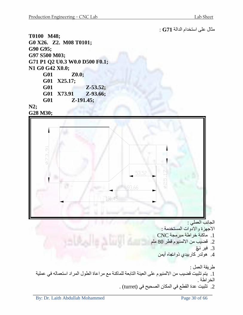
Production Engineering ndash CNC Lab Lab Sheet
By Dr Laith Abdullah Mohammed Page 30 of 66
G71الدالة استخدام مثال على
T0100 M48 G0 X26 Z2 M08 T0101 G90 G95 G97 S500 M03 G71 P1 Q2 U03 W00 D500 F01 N1 G0 G42 X00 G01 Z00 G01 X2517 G01 Z-5352 G01 X7391 Z-9366 G01 Z-19145 N2 G28 M30
الجانب العملي
االجهزة واالدوات المستخدمة CNCماكنة خراطة مبرمجة 1 ملم 80قضيب من االلمنيوم قطر 2 ةفير ني 3 جاه أيمن تهولدر كاربيدي ذوا 4
طريقة العمل يتم تثبيت قضيب من االلمنيوم على العينة التابعة للماكنة مع مراعاة الطول المراد استعماله في عملية 1
الخراطة ) turretتثبيت عدة القطع في المكان الصحيح في ( 2
Production Engineering ndash CNC Lab Lab Sheet
By Dr Laith Abdullah Mohammed Page 31 of 66
بالنسبة الى القطعة المثبتة على العينة XZيتم تصفير الماكنة للمحاور 3 تصفير للمحورZ تكون مالمسة العدة الى وجه الشغلة تصفير للمحورX تكون مالمسة العدة الى سطح الشغلة الموازي لمحور X
يتم كتابة البرنامج أما بطريقة يدوية أو بالحاسوب مع وضع كل الظروف الالزمة للتشغيل ( عمق القطع 4 التغذية السرعة المطلوبة نوع المعدن )
ادخال البرنامج الى الحاسوب الموجود داخل الماكنة مع تهيئة الماكنة للتشغيل 5
المطلوب G71عمل برنامج يدوي على الدالة 1 رسم الشكل الشكل النهائي المطلوب مع وضع األبعاد 2
Ⅺ⅟₍euro⅗₌ ₤₡ℌ₰₨⅗₌₣ ₤⅗₌⅗₌ ⅙₌₨image₃₡ Ⅺℂtradeℒ⅗₌ ӈ₍Ⅴ⅟ⅳ₌ G70
G70 الغرض من التجربة عمل انهاء سطحي للمشغولة بواسطة الدالة
من الضروري إعطاء G71هذه الدالة تعمل شوط واحد فقط وتكون معتمدة على عمليات القطع في الدالة اللغاء مقدمة االداة (أي لكي تتم عملية االنهاء السطحي بدون حسابات نصف قطر مقدمة االداة ) G42دالة
G70الصيغة المستخدمة للدالة
G70 P1 Q2 F___ حيث ان
P1 بداية الخطوة االولى = Q2 نهاية الخطوة =
F التغذية والمرتبطة بالدالة = G95
وذلك ألن دالة االنهاء السطحي تحقق X Zمالحظة الدالة التحتاج لكتابة السماحات التابعة للمحورين المسافات الحقيقة المراد انتاجها للمشغولة
G71و G70مثال على الدالة
T0100 M48 G0 X26 Z2 M08 T0101 G90 G95 G97 S500 M03 G71 P1 Q2 U03 W00 D500 F01 N1 G0 G42 X00 G01 Z00 G01 X2517 G01 Z-5352 G01 X7391 Z-9366 G01 Z-19145 N2 G97 S750 MO3
Production Engineering ndash CNC Lab Lab Sheet
By Dr Laith Abdullah Mohammed Page 32 of 66
G70 P1 Q2 G40 F009 G28 M30
الجانب العملي الحظ التجربة األولى
المطلوب
G70 عمل برنامج يدوي على الدالة 1 رسم الشكل النهائي المطلوب مع وضع االبعاد 2
₪⅗₍euro⅗₌ ₤₡ℌ₰₨⅗₌₣ ₤⅗₌⅗₌ ⅙₌₨image₍₡ ⅝₍ⅠimageⅯ₌ ⅞ⅫⅦ⅔₧ G76
G76 للمشغولة بواسطة الدالةةالغرض من التجربة عمل أسنان خارجية أو داخلي
في هذه التجربة سوف نقوم بعمل األسنان الخارجية وهنا تكون حركة العينة ثابتة وهذا ضروري بسبب أن ) تكون متصلتين الكترونيا وعليه أي اختالف في سرعة العينة تؤدي إلى اختالف motionالعينة والحركة(
) servoفي سرعة الخدمة(يرتبط اتجاه تكوين األسنان باتجاه دوران العينة مثال إذا كانت األسنان ذات اتجاه أيمن يكون اتجاه دوران
وهنا نقلب العدة إلى االسفل وكما هو موضح بالشكل أدناه MO3العينة عكس عقرب الساعة أي نستعمل
Production Engineering ndash CNC Lab Lab Sheet
By Dr Laith Abdullah Mohammed Page 33 of 66
الخطوة هي عبارة عن المسافة ما بين قمة سن إلى قمة سن أخر عمق السن هو العمق المطلوب تكوينه لألسنان
G76 الصيغة المستخدمة للدالة
G76 X___ Z___ K___ F___ D___ A___
حيث أن X القطر الداخلي للسن =Z طول السن =K عمق السن وتستخرج من المعادلة التالية =K=065F F الخطوة =D عمق القطع بالمايكرون فقط =A زاوية السن =
G76مثال على استخدام الدالة T0300 M48 GOO X30 Z4 T0303 M08 G97 S500 MO3 G76 X28375 Z-20 K08125 F125 D120 G00 X40 Z4 G28 M30
Production Engineering ndash CNC Lab Lab Sheet
By Dr Laith Abdullah Mohammed Page 34 of 66
الجانب العملي الحظ التجربة األولى
المطلوب
G76عمل برنامج يدوي على الدالة 1 رسم الشكل النهائي المطلوب مع وضع األبعاد 2
Ⅺ⅘₌⅗₌ Ⅵ₂ Ⅺ₯ℋ₍⅗₌ ℌℲℂ⅗₌ ⅞ⅫⅦ⅔₧ ₤K₡₌ℌ⅗₌ ₤₡ℌ₰₨⅗₌)Groove ₤⅗₌⅗₌ ₤tradeimage₌Ⅶ₡ (G75
G75 بواسطة الدالة grooveالغرض من التجربة تكوين
) للمشغولة وتعتمد شكل الحفر على طريقة grooveتستعمل هذه الدالة لتكوين الحفر الخارجي والداخلي (
التشغيل وعلى الشكل المراد إنتاجه وتعتبر هذه الطريقة من عمليات التشكيل للمعدن إن هذه الدالة هي دالة مالحظة مع G75في هذه التجربة سنقوم بعمل الحفر الخارجي بواسطة الدالة
تكرارية وغير تكرارية حسب نوع التشغيل
G 75 الصيغة المستخدمة للدالةG75 X___ Z___ I___ K____
حيث أن
X العمق النهائي لقطر الشغلة =Z عرض الحفر =I الدخول في كل مرة =
K التزحيف على محور =z بالنسبة للعدة
Production Engineering ndash CNC Lab Lab Sheet
By Dr Laith Abdullah Mohammed Page 35 of 66
G75مثال على استخدام الدالة
T0500 M48 GOO X100 Z -20 T0505 M08 G97 S700 MO3 G75 X84 Z -38 I 05 K4
الجانب العملي الحظ التجربة األولى
المطلوب
G76عمل برنامج يدوي على الدالة 1 رسم الشكل النهائي المطلوب مع وضع األبعاد 2
Production Engineering ndash CNC Lab Lab Sheet
By Dr Laith Abdullah Mohammed Page 36 of 66
CNC Milling Machine Mechanical Construction
Guideways The guideways of CNC machines are made of steel To reduce the frictional forces they are coated with a strip of PTFE (Poly Tetra Fluoro Ethylene)
Ballscrews On conventional lathes a leadscrew is used to converts the rotary motion of the hand wheel into linear motion of the slides Leadscrews have a high coefficient of friction and backlash On CNC machines a ballscrew is used instead of a leadscrew Friction and backlash are much less than on leadscrews
Guideway
Production Engineering ndash CNC Lab Lab Sheet
By Dr Laith Abdullah Mohammed Page 37 of 66
bullMachining operations Direction of cutting Based on the direction of the cutter rotation and work piece feed milling operations are classified into two types 1-Up milling (Convention milling) In up milling the metal is removed by rotating the cutter against the direction of travel of the part
Feed
Machine table
Part
Cutting tool
Chip thickness at theexit of the tooth
2-Down milling (Climb milling) In climb milling the metal is removed by rotating the cutter with the direction of travel of the part
Machine table
Part
Cutting tool
Chip thickness at theentrance of the tooth
Production Engineering ndash CNC Lab Lab Sheet
By Dr Laith Abdullah Mohammed Page 38 of 66
bullTooling Tool geometry The geometry of the tool tip affects the way that the metal cutting is performed The nose radius rake angles relief angles etc must be selected with care
Radial relief
Radial rake
Axial relief
Approach angle
Axial relief
Corner radius Face mill Face milling cutters are used to mill flat surfaces Commonly used face milling cutters Cutter with 75 degree approach
75 deg
Cutter with 90 degree approach (Square shoulder face mill)
90 deg
Cutter with 45 degree approach
Production Engineering ndash CNC Lab Lab Sheet
By Dr Laith Abdullah Mohammed Page 39 of 66
bullCNC Programming Axes convention The Z axis is along the spindle axis The X and Y axes are perpendicular to Z VMC
Z
Y
-
+
-+
X- +
+Z
-Z
+Y
-Y
-X +X
Part
Machine table
X
YZ
G00 Rapid traverse When the tool being positioned at a point preparatory to a cutting motion to save time it is moved along a straight line at Rapid traverse at a fixed traverse rate which is pre-programmed into the machines control system Typical rapid traverse rates are 10 to 25 m min but can be as high as 80 mmin
Production Engineering ndash CNC Lab Lab Sheet
By Dr Laith Abdullah Mohammed Page 40 of 66
Format N_ G00 X__ Y__Z__
G01 Linear interpolation (feed traverse) The tool moves along a straight line in one or two axis simultaneously at a programmed linear speed the feed rate Format N__ G01 X__ Y__Z__ F__
Part
Feed
Part
Feed
G02G03 Circular interpolation The tool moves along an arc in two axes simultaneously at a programmed linear speed the feed rate
Production Engineering ndash CNC Lab Lab Sheet
By Dr Laith Abdullah Mohammed Page 41 of 66
Format N__ G0203 X__ Y__Z__ I__ J__K__ F__ using the arc center OR N__ G0203 X__ Y__Z__ R__ F__ using the arc radius G02 moves along a CW arc G03 moves along a CCW arc Arc center The arc center is specified by addresses I J and K I J and K are the X Y and Z co-ordinates of the arc center with reference to the arc start point
X
Y
Arc center
Arc endArc start
- J
- I
I = X coord of center - X coord of start point J = Y coord of center - Y coord of start point K = Z coord of center - Z coord of start point I J and K must be written with their signs
Production Engineering ndash CNC Lab Lab Sheet
By Dr Laith Abdullah Mohammed Page 42 of 66
bullWork holding
Rotary table
Fixture base
Component
Clamp
Stud
Fixtures The use of fixtures 1 Improves repeatability of dimensions 2 Improves working conditions 3 Cuts down requirement of skilled labour 4 Reduces part loading and unloading time 5 Improves safety in the working area 6 Reduces the cost of machining There are two types fixtures commonly used 1 Special fixture Special fixtures are used to hold and locate the typical components which are having complex shape and to be located with the reference hole (dowel hole) Special fixtures are required for components like gear case cover cylinder heads etc 2 Modular fixture Modular fixture is a set different kind of clamping and locating elements These fixtures are used to hold identical components in different sizes and components of box type Example Manifolds head stocks connecting rods and flanges
Production Engineering ndash CNC Lab Lab Sheet
By Dr Laith Abdullah Mohammed Page 43 of 66
bullMachine setting
Determining X and Y work zero offset Case 1
Part
Machine table
Part
End mill or reamer
Work offset X0Y0 For determining X work zero offset bull Touch the periphery of the end mill or reamer to the part bull Enter current machine X value + cutter radius as X work zero offset For determining Y work zero offset bull Touch the periphery of the end mill or reamer to the part bull Enter current machine Y value - cutter radius as Y work zero offset Case 2
Part
Machine table
Part
End mill or reamerWork offset X0Y0
bull Mount the dial indicator on machine spindle true the bore bull Enter current machine X and Y value as X and Y work zero offset
Production Engineering ndash CNC Lab Lab Sheet
By Dr Laith Abdullah Mohammed Page 44 of 66
How to Select a Cutting Fluid
One part of the metal cutting equation that is sometimes overlooked however is
the choice of an appropriate cutting fluid With todayrsquos system approach to metal
cutting use of the right metalworking fluid has become just as much a part of the
solution as the other elements In fact at least one company is now integrating
cutting fluids and cutting tools into effective metal cutting systems Following are
some things to consider when choosing your next cutting fluid
The Four Key Questions
There are four vital pieces of information that are necessary when choosing a
cutting fluid They are
1 What are you cutting
2 What is the chemistry of your water
3 What are you using now
4 What are your options
5 What do you prefer
What Are You Cutting
The first question ndash ldquoWhat are you cuttingrdquo ndash is often the most difficult to answer
because most shops handle a variety of workpiece materials on a regular basis If
the answer is an unequivocal ldquoaluminumrdquo or ldquostainless steelrdquo or ldquocast ironrdquo the
selection of a cutting fluid can be quite simple and straightforward Unfortunately
that is seldom the case in anything but a high-volume plant Where aluminum or
other nonferrous metals are a significant part of the mix a non-staining cutting
fluid is a must Generally speaking this will be a semi-synthetic with special
ingredients to prevent bi-metallic corrosion and staining of non-ferrous workpieces
Where the ferrous metals predominate however a more general purpose semi-
synthetic or hybrid fluid might be a more economical choice
Production Engineering ndash CNC Lab Lab Sheet
By Dr Laith Abdullah Mohammed Page 45 of 66
What is The Chemistry of Your Water
The second question ndash ldquoWhat is the chemistry of your waterrdquo ndash is probably the
single most common reason for the success or failure of a cutting fluid Very few
plants invest the money necessary to install effective water purification systems
using deionization or reverse osmosis technology Unfortunately the chemicals
present or not present in the water used to re-constitute a cutting fluid make a
tremendous difference in its performance and sump life Most manufacturers of
cutting fluids will perform the necessary water testing to determine exactly what
minerals are dissolved in your water and make a fluid recommendation based on
the results
What are you using now
The third question ndash ldquoWhat are you using nowrdquo ndash helps narrow the range of
choices When coupled with an objective analysis of the strengths and weaknesses
of the current fluid the answer to this question can quickly point you toward a
relatively small number of competitive alternatives that have the attributes required
to meet your cutting needs Many cutting fluids are in use today simply because
they were in use yesterday It is a hard reality of todayrsquos marketplace that if one
isnrsquot constantly striving to improve they will certainly be overtaken by a
competitor who is
What Are Your Options
The fourth question ndash ldquoWhat are your optionsrdquo ndash leads to the final selection of a
cutting fluid Cutting fluids can be divided into four general groups based on their
chemistry
They are
bull Soluble Oils ndash quite literally oil dispersed in water
bull Synthetics ndash completely oil free man-made coolants in solution
Production Engineering ndash CNC Lab Lab Sheet
By Dr Laith Abdullah Mohammed Page 46 of 66
bull Semi-Synthetics ndash a mixture of natural and synthetic lubricants with up to 30
mineral oil
bull Hybrids ndash a special class of semi-synthetics with a mineral oil content of about
15 Each fluid type has advantages and disadvantages which make it suitable for
a particular group of applications In addition there are costperformance trade-
offs to be made between the groups within a specific set of applications For
example where a hybrid and a semi-synthetic may both be suitable for a particular
use the hybrid might provide longer sump life at a slightly higher initial cost
while some semi synthetics may be more economical to recycle or dispose of while
not giving as long a tank life The final decision in this case would have to be made
on the detailed economics of the shop where the fluids were to be used and on the
ownerrsquos individual preferences
Soluble Oils
Soluble oils are oils that disperse in water when emulsifiers are added They are
generally suitable for moderate-to heavy-duty machining and grinding of all non-
ferrous metals carbon and cast steels and in applications where dissimilar metals
such as aluminium and steel are present They can also be used in turning drilling
tapping reaming gear cutting broaching as well as internal and centerless types
of grinding operations Soluble oils provide excellent aluminium and copper
corrosion control good rancidity control which extends fluid for long lasting
trouble-free performance and good concentrate and mix stability making it ideal
for mixing in water with a minimal amount of agitation An example of this is
Valenitersquos VNTreg-650 premium heavy-duty soluble oil
Synthetics
Synthetics are completely oil free solutions made of polymers organic and
inorganic materials that are mixed with water These clear low foaming and bio-
Production Engineering ndash CNC Lab Lab Sheet
By Dr Laith Abdullah Mohammed Page 47 of 66
stable coolants are ideal for machining and grinding of ferrous materials carbon
steels or cast iron Their complex lubricant packages make synthetics well-suited
for tough-to-machine materials such as stainless steels and high-temperature alloys
Certain synthetics are specifically designed to address the primary failure modes of
flank wear and nose wear Although there are many benefits some synthetics may
cause staining of non-ferrous materials
Semi-Synthetics
Semi-synthetic fluids are a mixture of oils synthetic emulsifiers and water They
were primarily developed for the aircraft nuclear and related industries
Consequently they work extremely well on all non-ferrous metals such as titanium
aluminium copper brass bronze and stainless steel in both machining and
grinding Semi-synthetics can be used on ferrous metals too They are chlorine-
free to reduce bi-metallic corrosion and staining of metals They should be used at
a 5-8 dilution with water depending on the severity of the operation
Hybrids
Hybrids are cutting fluids custom engineered to solve a particular problem For
example Valenitersquos VNTreg-800 was developed to be very clean in the machining
and grinding of cast iron It provides better stability in hard water and rejects tramp
oil very well which adds to its bio-stable chemistry Hybrids work extremely well
on all metals in both machining and grinding They should be mixed at a 5-7
dilution with water depending on the condition of the water
What Do You Prefer
The final question ndash ldquoWhat do you preferrdquo ndash is usually the ldquotie breakerrdquo where
there is more than one appropriate cutting fluid available Here again as in the
case of what is being used now the key is to examine your preferences objectively
Production Engineering ndash CNC Lab Lab Sheet
By Dr Laith Abdullah Mohammed Page 48 of 66
and specifically to identify the real reasons behind a preference If you cannot
point to specific reasons why one class of cutting fluid is preferred over another
you are well advised to follow the recommendations of the professional who has
analyzed your requirements Choosing the right fluid today is easier than ever as
the system approach to metal cutting productivity continues to grow in acceptance
The day is not far off when choosing a complete solution will be as easy as
choosing the right insert and chip breaker today The answers are available and the
results will more than justify the time you spend choosing the right metal cutting
fluid
Useful Links wwwball-screwsnet
wwwlubelinkcom
wwwmachinerylubricationcom
wwwadvancedmanufacturingcom
wwwmmsonlinecom
wwwcuttingtoolengineeringcom
wwwgeartechnologycom
wwwengineersedgecom
wwwagmaorg
wwwefundacom
wwwsaeorg
wwwsmeorg
wwwastmorg
wwwissorg
wwwmachinetoolscom
wwwansiorg
wwwasmeorg
wwwcnccicom
wwwmatlscom
wwwthefreedictionarycom
wwwengineersupplycom
Production Engineering ndash CNC Lab Lab Sheet
By Dr Laith Abdullah Mohammed Page 49 of 66
SurfCAM Tutorial ndash Beginning with the basics
Background SurfCAM is a computer aided manufacturing (CAM) software which allows you to create manage and modify tool paths for computer aided designed (CAD) part The software requires a CAD model or requires that you create some geometry within SurfCAM with some rudimentary tools provided The tool paths are created or stored internally in SurfCAM in a generic programming language called APT Once the tool paths are created the APT paths are translated using a post processor into typical machine G-code
Opening SurfCAM SurfCAM can be opened from the Novell Applications Launcher on most Industrial Engineering computer labs workstations Search under lsquoallrsquo applications and double click on SurfCAM 2005 Once the program opens a license must be selected from the list (not the Demo license) to enable saving the file later Choose one of the 30 licenses available If for some reason the licenses are not listed on the license manager form select server list and type ldquobonnieeosncsuedurdquo A list of available licenses should appear Select a license and click OK After the license is selected an Add StockFixture form (Figure 1) opens allows you to add a model which represents the pre-machined stock or a fixture Click on OK without adding either Both of these items can be added later under a more appropriate dialog
Figure 1 Add Stock or Fixture dialog box
Production Engineering ndash CNC Lab Lab Sheet
By Dr Laith Abdullah Mohammed Page 50 of 66
SurfCAM Interface
Figure 2 SurfCAM Windows based interface
SurfCAM is a windows based software system so most of the typical windows functions under File are applicable This is where you can open save exit print etc The Create menu allows the user to create different geometry forms Here you can create a point line surface chamfer circle and many other geometry types For the most part these functions are not used by beginners but are useful when creating bounding curves where you donrsquot want the tool to move outside (constraining the tool) The Edit menu allows you to change or modify many different entities such as changing lines altering surfaces joining surfaces trimming or breaking elements add control points etc Again these features are helpful to advanced users and are not covered in detail in this tutorial The Display menu offers the ability to change the orientation of the part on the screen The typical rotate pan fit to screen and zoom functions are available as well as several functions which allow the user to shift between views or call up a named view (ie top bottom etc) The NC menu is the main machining interface menu In this menu you select the general form of machining (2 axis 3 axis 4 axis 5 axis turning etc) and under the general form a more specific machining function is selected This menu is the most used and the options contained must be fully understood to get the most out of SurfCAM Each function will be described in some detail in a further chapter The Analyze menu contains options such as measuring the distance between points angles tangency elements etc These functions are auxiliary functions meant to help you understand the part better but basically provide no functionality for making tool paths for CNC machines Thus these will not be covered The Tools menu allows the user to change the system options modify keyboard shortcuts change the model units etc These options are again not used by beginners Finally the Help menu provides access to the online users manual In lieu of clicking the Help menu the F1 key is the shortcut key for help (as it is in most windows based programs)
Importing a CAD model Importing a CAD model that is stored locally is done by selecting File-gtOpen On the Files of type dropdown box choose the type of file you wish to open (Figure 3) Do this prior to negotiating your way through the maze of folders to prevent having to go through the folder tree again Once the file type is selected find the file you are trying to open and click the Open
Production Engineering ndash CNC Lab Lab Sheet
By Dr Laith Abdullah Mohammed Page 51 of 66
button SurfCAM will then attempt to read the file you have selected SurfCAM may provide a dialog box describing what it has imported and identify if it was successful If this dialog is provided simply click close without saving
Figure 3 Open Dialog Note - Change type of file prior to finding the file you wish to open
SurfCAM allows a user to import several different types of CAD files the most common types which you will likely import are SolidWorks part files (sldprt or prt) AutoCAD files(dxf) or IGES (igs or iges) Native file import (such as is the case with SolidWorks) provides the greatest information transfer and generic file imports (such as is the case with IGES) provide the least Normally it is to the advantage of the user to use native file importing procedures when available Recently (2005) SurfCAM added some compatibility with SolidWorks This allows the user to create tool paths for a part and if an engineering change is needed for the part update the part in SolidWorks When the part is then opened in SurfCAM the changes are noted and a simple update operation command is needed This however does not operate with complete transparency andor accuracy and thus users need to be cognizant of changing CAD models
SurfCAM Geometry In SurfCAM two basic types of geometry are used the surface and the point A surface (Figure 4) is a so called spline (NURBS or B-Spline are the two most common) surface (parameterized by two values u and v) such that every location on the surface can be defined as a function of these parameters In other words SurfCAM can calculate the location of any point on the
Production Engineering ndash CNC Lab Lab Sheet
By Dr Laith Abdullah Mohammed Page 52 of 66
surface Surfaces are used primarily in 3 4 and 5 axis machining and require a significant
amount of processing power and time Figure 4 Surfaces model of a mold half Note the difference between this and Figure 2 a wireframe model
Point or line based models are often referred to as wireframe (Figure 5) models because the models consist of connected lines and resemble the part only at the intersection of two surfaces Wireframe models were made popular lsquoback in the dayrsquo when computer processing was expensive There are times when each of the models are important and selecting model geometry when applying a SurfCAM operation will be much simpler if you understand the differences between the two When importing a SolidWorks model the default is both the surfaces and the wireframe geometry are imported
Figure 5 Wireframe model of the mold in Figure 1
Steps to Creating Tool Paths Once a CAD model is imported into SurfCAM tool paths can be created There is no one correct way to create tool paths however there is a set of general steps to take to ensure the tool paths are created with a minimum amount of hardship (note the wordinghellipHardship is inevitable when creating tool paths it is the intent of this manual to minimize this) The following is a list of steps which should be considered when making tool paths
Production Engineering ndash CNC Lab Lab Sheet
By Dr Laith Abdullah Mohammed Page 53 of 66
1 Plan ahead a Orient the part in SolidWorks such that if only one side is to be machined that
side is the Top view This can be done early in SolidWorks by choosing a plane parallel the X-Y plane as the sketch plane for the machined geometry
b Orient the part in SolidWorks such that the origin is somewhere of relative importance and someplace in space that can be easily identified when placed on the machine This is extremely important to minimize set up time at the machine (note ndash my personal preference for a part that is to be fully machined [ie stock exists on all sides] is to place the origin at the center and top of the parthellipjust my preference)
c Orient the part in SolidWorks such that the X and Y axes are aligned as you want them on the machinehellip
d Planning ahead will save you many hours of headaches laterhelliptrust me 2 Import the model 3 Choose a construction view such that the tool approaches the side to be machined
from the positive Z axis direction (as defined by part origin) a This is done by clicking on the CView icon
b From the list of named views chose the view which orients the origin as you would like
c If one of the views does not fit your criteria you have two choices i Perform a transformation of the part in SurfCAM or SolidWorks
ii Add a new construction view by selecting new This option requires a relatively good understanding of right hand coordinate frames but is very usefulhellipNormally used by more advanced users
d Be sure the CoordVIEW selection is made vs CoordWORLD This ensures the tools will be controlled from the coordinate frame selected by the view (ie the origin on the part) instead of the origin on the lower left corner of the screen This will be especially important when we get into 4 and 5 axis machining
4 In the Operations Manager (Figure 6) select Setup One and change the name to something meaningful ndash like Front Side Mold Cavity
a Access the Operations manager by right clicking or by selecting the Operations Manager icon in the tool bar
b Operations Manager is where the tool paths are managed once they are created as well as where individual tool paths can be verified
Production Engineering ndash CNC Lab Lab Sheet
By Dr Laith Abdullah Mohammed Page 54 of 66
5 Roughing Tool Paths a Create the tool paths to remove the majority of the material (if applicable) b Use NC-gt3Axis-gtZ rough or Plunge Rough c Described in next section
6 Create Finishing Tool Paths a Described in next section
7 Add another setup if necessary 8 Perform steps 3 through 6 as necessary 9 Verify the tool paths are correct 10 Use a post processor for the tool paths to create G-Code for machine
Creating Tool Paths The following is a list of operations what they are intended for how they generally work and some parameters that may be adjusted to modify the tool paths
2 Axis tool paths Unless otherwise noted 2 axis tool path functions require lines or arc segments as input parameters (as opposed to surfaces) There are several options as to how these segments are chosen the most prevalent is the chain option and the second most prevalent is the single When choosing the line segments using the chain option SurfCAM will try to link a complete path of segments based on an initial segment chosen by the user If the operation is planer (ie pocket or contour) the segments must lie on the same plane If the operation is non-planer (ie contour 3D) SurfCAM will prompt the user to specify segments when it encounters a branch point
Figure 6 Operations Manager view showing setup one re-labeled as Front Side Mold
Production Engineering ndash CNC Lab Lab Sheet
By Dr Laith Abdullah Mohammed Page 55 of 66
When using the single element option the user must manually choose each segment desired for the operation Note that most operations do not require a closed loop of segments you may specify for instance an open contour where the tool is supposed to move The order of choosing segments is important This order determines the path of the tool in the sense that if three segments are chosen such that the middle segment is chosen last there will be three different plunge and machine operations one on each segment If the operation was to make a continuous contour around the outside of the part the segments should be chosen in order of the desired tool trajectory
Operations
Pocket Pocket operation in SurfCAM is used to cut an enclosed space from the inside to the outside at one particular depth The operation starts in the center of an enclosed area (with a plunge move in the ndashZ direction) and makes incremental closed paths towards the pocket boundaries in user defined path offsets (Figure 7) The user chooses the boundary of the pocket (line segments) and if more than one pocket is chosen SurfCAM will ask the user to click inside a pocket
Figure 7 Two examples of using the pocketing operation
The pocket operation allows for creating a projection of the pocket paths on multiple planes This is useful if you have a deep pocket which will not allow the tool to cut directly at the depth of the pocket but would be easily done using the same paths at several different Z heights On the cut control (Figure 8) tab the user specifies where the chosen geometry (pocket segments) lie (ie bottom or top) Then under the amount to remove specify the total material height to be removed and the rough spacing (amount you wish to advance the Z axis with each pocket step) You may also specify a finishing pass and as well as stock to leave
Production Engineering ndash CNC Lab Lab Sheet
By Dr Laith Abdullah Mohammed Page 56 of 66
Figure 8 Example of Contour Operation with multiple passes
Contour Contouring in SurfCAM is used to perform peripheral milling on the inside or outside of a line segment (Figure 9) The user is to identify the line segments which define a contour (does not have to be a closed loop of segments) SurfCAM may or may not require the user to specify a side to contour (ie which side of the line is the tool to cut) For contouring each segment must lie on the same plane
Production Engineering ndash CNC Lab Lab Sheet
By Dr Laith Abdullah Mohammed Page 57 of 66
Figure 9 Examples of parts cut with 2-Axis Contour
Contour 3D Contour 3D is the same operation type as contour but allows the user to specify segments on different planes for the tool to cut along
Drill Drilling operations are any rotating tool operation meant to engage the part from a single direction ndash namely from the positive Z direction Drilling operations can be specified using circle point or line segments After choosing NC-gt2-Axis-gtDrill SurfCAM allows the user to choose multiple circles or points defining holes to be drilled Drilling operations also allow the user to incorporate more than 1 operation such as a center drill a drill and a reaming operation After selecting the locations for the drilling operation a dialog box (Figure 10) allows the user to add change or delete tools to be used in the operation As displayed in the following figure the spotdrill operation is followed by a drilling operation followed by a tapping operation The depth of each tool can be controlled individually by double clicking the total depth cell in and manually entering Tools can be added before or after operations which the cells are highlighted by selecting either of the insert buttons at the top or by the insert menu Select tool button allows the user to change the tool size or type
Production Engineering ndash CNC Lab Lab Sheet
By Dr Laith Abdullah Mohammed Page 58 of 66
Figure 10 Drill operation manager Several operations can be completed at one time
Figure 11 Drill operation including the spotdrill drill and tap as outlined in Fig 10
3 Axis tool paths SurfCAM requires surfaces as inputs for 3 Axis tool paths Surfaces can be created in SurfCAM but are most easily created in a CAD package and imported into SurfCAM Surfaces allow SurfCAM to identify every point on the surface in 3 dimensions unlike 2D geometry (wireframes) which only identify positions on the plane Creating tool paths with complex surfaces takes a very significant amount of processing power so expect 3 Axis tool path generation to take longer
Production Engineering ndash CNC Lab Lab Sheet
By Dr Laith Abdullah Mohammed Page 59 of 66
Operations
Cut 3 Axis cut operation takes a surface and using the flow lines creates a rastering path over the surface with the tool tip riding on the surface The primary direction will be defined by the flow lines of the surface (which can be edited by Edit-gtSurfaces-gtArrow-gtDirection) If you intend to cross surface boundaries you must merge the surfaces (Edit-gtJoin and choose the two surfaces)
Z-Rough The Z-rough operation is used to remove a large amount of material prior to finish machining Roughing operation is typically the first operation you perform for each setup The Z-Rough operation cuts the part in user defined intervals For each of these intervals a surface intersection between the part and the plane is performed and a 2D pocket or contour operation is performed on that plane This is performed on each plane When choosing NC-gt3 Axis-gtZ rough the first dialog box you will encounter asks for a bounding box to be defined Choose the Extents Box and a second dialog box will ask for the coordinates which define the box (Figure 12) This is the stock size you expect to machine the part from Input the coordinates or change the additional offset amounts (in XY or Z) as appropriate and click Calculate Bounding Box
Figure 12 Material Extents Box Example
Next choose the tool and cutting parameters that you desire and click on the Cut Control Tab (Figure 13) Here you will find the following parameters which are often changed Stock to
Production Engineering ndash CNC Lab Lab Sheet
By Dr Laith Abdullah Mohammed Page 60 of 66
leave ndash this is an offset amount from the surfaces which leaves a small amount of material to finish machine Minimum and Maximum Z values ndash Defines area to machine Z Step Size ndash This identifies the plane intervals for the surface intersection planes (the first interval will be at the top of the selected area and successive increments down in Z will be cut until the Minimum Z value is reached)
Figure 13 3Axis Z Rough Cut Control
The 3Axis Z-Finish operation works in exactly the same way 3 Axis Z-Finish is most appropriate for finishing vertical or near vertical walls
3D Offset The 3D Offset operation creates a tool path using a 2D or 3D boundary by offsetting the boundary in concentric offset cutting passes Each pass calculates the tool engagement and maintains the engagement somewhat constant The advantage (significant) is the scallop height ndash height of the material between passes ndash is controlled thus the surface finish is predictable When choosing 3D Offset surfaces are selected as well as 2D or 3D boundaries The boundaries define the concentric offset paths shape as well as limit the tool path area Choose NC-gt3Axis-gt3D Offset from the drop down menus SurfCAM will prompt you to select the surface or surfaces to cut across Select the surfaces you wish to machine and then select the tool and cutting parameters you wish use Next select the Cut Control Tab and check the Use Boundary Curves option Set the Step Type to Scallop and set the maximum scallop height If you like
Production Engineering ndash CNC Lab Lab Sheet
By Dr Laith Abdullah Mohammed Page 61 of 66
you can also add stock to leave if this is a roughing operation You can also set the Direction and Start-End parameters from this tab Click OK and the paths will be generated
Figure 14 Cut Control Tab for 3D Offset
Example part using both 2D and 3D geometry
The tool paths for this mold will be generated in SurfCAM using 5 operations The first will be a roughing operation using a frac14 inch flat end mill with the Z step size of 00625in Choose NC-
Production Engineering ndash CNC Lab Lab Sheet
By Dr Laith Abdullah Mohammed Page 62 of 66
gt3Axis-gtZ-Rough from the drop down menu Select all visible surfaces and create an extents box that has 025inch XY offsets and 01inch Z offset Next select the frac14 inch flat end mill from the tools menu Under Cut Control tab set the Z step size to be 00625inch The tool paths will look something like Figure 15
Figure 15 Z-Rough Tool paths for Example Part
Next a flat surface operation will be performed to cut the flat surface on the top Select NC-gt3 Axis-gtFlat Surface from the drop down menu Select all visible surfaces again Choose the 12inch flat end mill and set the cutting parameters as desired Under Cut Control Tab change the Minimum Area to 50 square inches (Figure 16) The tool paths should look something like Figure 17
Figure 16 Cut Control for Flat Surface
Production Engineering ndash CNC Lab Lab Sheet
By Dr Laith Abdullah Mohammed Page 63 of 66
Figure 17 Flat Surface Tool Paths
Next we will use a 3D offset operation to cut the mold cavity Select NC-gt3 Axis-gt3D Offset from the dropdown menu Change the view to the top view and select within to capture the surfaces of the mold cavity Draw a rectangle around the mold cavity Select a 18 inch ball endmill from the tool library and set the cutting parameters as appropriate Next set the Cut Control tab parameters as in Figure 14 The paths creates should be similar to Figure 18
Figure 18 3D Offset Paths
Next we will perform a 2 Axis contouring of the top section Select NC-gt2 Axis-gtContour from the dropdown menu Using the chain option select the bottom contour of the top extrusion Select the frac12 inch flat end mill from the tool library and set the cutting parameters as required In the Cut Control Tab change the Geometry to Bottom and the amount to remove in Z to 05
Production Engineering ndash CNC Lab Lab Sheet
By Dr Laith Abdullah Mohammed Page 64 of 66
Change the Rough Spacing in Z to 025 and add 1 finish pass of 002 (Figure 19) Click OK and SurfCAM will instruct you to choose a side to contour Click anywhere on the screen OUTSIDE the geometry you selected for the contouring operation Failure to click outside the geometry will result in the tool being on the wrong side of the contour Your paths should look something like those in Figure 20
Figure 19 Cut Control Tab for the Contouring Operation
Figure 20 Contouring operation paths
Production Engineering ndash CNC Lab Lab Sheet
By Dr Laith Abdullah Mohammed Page 65 of 66
Next we will perform a 2 axis pocket operation for the small pocket on the top face of the mold Select NC-gt2Axis-gtPocket and using the Auto select feature select the boundary curve at the bottom of the pocket Click Done twice and select the frac14 inch flat end mill from the tool library Set the appropriate cutting parameters and click OK SurfCAM will prompt you to click inside the pocket Click anywhere inside the geometry you chose to define the pocket The resulting paths should look something like those in Figure 21
Figure 21 2 Axis Pocket Operation Paths
Finally we will add a drilling operation for the 2 holes at the corners of the mold Select NC-gt2 Axis-gtDrill from the dropdown menu Select the top circles defining the two holes A menu box will appear with a default tool (Center drill) already programmed Add a second tool to the list by selecting Insert-gtAfter and select the tool from the tool library Change the drill depth to 10inches and click OK The paths should look something similar to Figure 23
Figure 22 Drill Menu
Production Engineering ndash CNC Lab Lab Sheet
By Dr Laith Abdullah Mohammed Page 66 of 66
Figure 23 Drilling Operation Tool Paths
Now you can watch a simulation of the cutting by choosing the setup in the operations manager and clicking the simulate icon Be sure to set the stock in the set up by right clicking the set up and selecting Edit Setup Information In the Stock Tab you can create a bounding box meeting your needs and click Add Your simulation should result in something like the following
Figure 24 Final Simulation of the example Mold
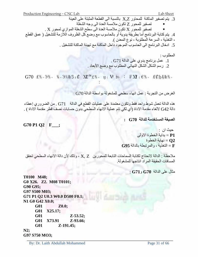
Production Engineering ndash CNC Lab Lab Sheet
By Dr Laith Abdullah Mohammed Page 31 of 66
بالنسبة الى القطعة المثبتة على العينة XZيتم تصفير الماكنة للمحاور 3 تصفير للمحورZ تكون مالمسة العدة الى وجه الشغلة تصفير للمحورX تكون مالمسة العدة الى سطح الشغلة الموازي لمحور X
يتم كتابة البرنامج أما بطريقة يدوية أو بالحاسوب مع وضع كل الظروف الالزمة للتشغيل ( عمق القطع 4 التغذية السرعة المطلوبة نوع المعدن )
ادخال البرنامج الى الحاسوب الموجود داخل الماكنة مع تهيئة الماكنة للتشغيل 5
المطلوب G71عمل برنامج يدوي على الدالة 1 رسم الشكل الشكل النهائي المطلوب مع وضع األبعاد 2
Ⅺ⅟₍euro⅗₌ ₤₡ℌ₰₨⅗₌₣ ₤⅗₌⅗₌ ⅙₌₨image₃₡ Ⅺℂtradeℒ⅗₌ ӈ₍Ⅴ⅟ⅳ₌ G70
G70 الغرض من التجربة عمل انهاء سطحي للمشغولة بواسطة الدالة
من الضروري إعطاء G71هذه الدالة تعمل شوط واحد فقط وتكون معتمدة على عمليات القطع في الدالة اللغاء مقدمة االداة (أي لكي تتم عملية االنهاء السطحي بدون حسابات نصف قطر مقدمة االداة ) G42دالة
G70الصيغة المستخدمة للدالة
G70 P1 Q2 F___ حيث ان
P1 بداية الخطوة االولى = Q2 نهاية الخطوة =
F التغذية والمرتبطة بالدالة = G95
وذلك ألن دالة االنهاء السطحي تحقق X Zمالحظة الدالة التحتاج لكتابة السماحات التابعة للمحورين المسافات الحقيقة المراد انتاجها للمشغولة
G71و G70مثال على الدالة
T0100 M48 G0 X26 Z2 M08 T0101 G90 G95 G97 S500 M03 G71 P1 Q2 U03 W00 D500 F01 N1 G0 G42 X00 G01 Z00 G01 X2517 G01 Z-5352 G01 X7391 Z-9366 G01 Z-19145 N2 G97 S750 MO3
Production Engineering ndash CNC Lab Lab Sheet
By Dr Laith Abdullah Mohammed Page 32 of 66
G70 P1 Q2 G40 F009 G28 M30
الجانب العملي الحظ التجربة األولى
المطلوب
G70 عمل برنامج يدوي على الدالة 1 رسم الشكل النهائي المطلوب مع وضع االبعاد 2
₪⅗₍euro⅗₌ ₤₡ℌ₰₨⅗₌₣ ₤⅗₌⅗₌ ⅙₌₨image₍₡ ⅝₍ⅠimageⅯ₌ ⅞ⅫⅦ⅔₧ G76
G76 للمشغولة بواسطة الدالةةالغرض من التجربة عمل أسنان خارجية أو داخلي
في هذه التجربة سوف نقوم بعمل األسنان الخارجية وهنا تكون حركة العينة ثابتة وهذا ضروري بسبب أن ) تكون متصلتين الكترونيا وعليه أي اختالف في سرعة العينة تؤدي إلى اختالف motionالعينة والحركة(
) servoفي سرعة الخدمة(يرتبط اتجاه تكوين األسنان باتجاه دوران العينة مثال إذا كانت األسنان ذات اتجاه أيمن يكون اتجاه دوران
وهنا نقلب العدة إلى االسفل وكما هو موضح بالشكل أدناه MO3العينة عكس عقرب الساعة أي نستعمل
Production Engineering ndash CNC Lab Lab Sheet
By Dr Laith Abdullah Mohammed Page 33 of 66
الخطوة هي عبارة عن المسافة ما بين قمة سن إلى قمة سن أخر عمق السن هو العمق المطلوب تكوينه لألسنان
G76 الصيغة المستخدمة للدالة
G76 X___ Z___ K___ F___ D___ A___
حيث أن X القطر الداخلي للسن =Z طول السن =K عمق السن وتستخرج من المعادلة التالية =K=065F F الخطوة =D عمق القطع بالمايكرون فقط =A زاوية السن =
G76مثال على استخدام الدالة T0300 M48 GOO X30 Z4 T0303 M08 G97 S500 MO3 G76 X28375 Z-20 K08125 F125 D120 G00 X40 Z4 G28 M30
Production Engineering ndash CNC Lab Lab Sheet
By Dr Laith Abdullah Mohammed Page 34 of 66
الجانب العملي الحظ التجربة األولى
المطلوب
G76عمل برنامج يدوي على الدالة 1 رسم الشكل النهائي المطلوب مع وضع األبعاد 2
Ⅺ⅘₌⅗₌ Ⅵ₂ Ⅺ₯ℋ₍⅗₌ ℌℲℂ⅗₌ ⅞ⅫⅦ⅔₧ ₤K₡₌ℌ⅗₌ ₤₡ℌ₰₨⅗₌)Groove ₤⅗₌⅗₌ ₤tradeimage₌Ⅶ₡ (G75
G75 بواسطة الدالة grooveالغرض من التجربة تكوين
) للمشغولة وتعتمد شكل الحفر على طريقة grooveتستعمل هذه الدالة لتكوين الحفر الخارجي والداخلي (
التشغيل وعلى الشكل المراد إنتاجه وتعتبر هذه الطريقة من عمليات التشكيل للمعدن إن هذه الدالة هي دالة مالحظة مع G75في هذه التجربة سنقوم بعمل الحفر الخارجي بواسطة الدالة
تكرارية وغير تكرارية حسب نوع التشغيل
G 75 الصيغة المستخدمة للدالةG75 X___ Z___ I___ K____
حيث أن
X العمق النهائي لقطر الشغلة =Z عرض الحفر =I الدخول في كل مرة =
K التزحيف على محور =z بالنسبة للعدة
Production Engineering ndash CNC Lab Lab Sheet
By Dr Laith Abdullah Mohammed Page 35 of 66
G75مثال على استخدام الدالة
T0500 M48 GOO X100 Z -20 T0505 M08 G97 S700 MO3 G75 X84 Z -38 I 05 K4
الجانب العملي الحظ التجربة األولى
المطلوب
G76عمل برنامج يدوي على الدالة 1 رسم الشكل النهائي المطلوب مع وضع األبعاد 2
Production Engineering ndash CNC Lab Lab Sheet
By Dr Laith Abdullah Mohammed Page 36 of 66
CNC Milling Machine Mechanical Construction
Guideways The guideways of CNC machines are made of steel To reduce the frictional forces they are coated with a strip of PTFE (Poly Tetra Fluoro Ethylene)
Ballscrews On conventional lathes a leadscrew is used to converts the rotary motion of the hand wheel into linear motion of the slides Leadscrews have a high coefficient of friction and backlash On CNC machines a ballscrew is used instead of a leadscrew Friction and backlash are much less than on leadscrews
Guideway
Production Engineering ndash CNC Lab Lab Sheet
By Dr Laith Abdullah Mohammed Page 37 of 66
bullMachining operations Direction of cutting Based on the direction of the cutter rotation and work piece feed milling operations are classified into two types 1-Up milling (Convention milling) In up milling the metal is removed by rotating the cutter against the direction of travel of the part
Feed
Machine table
Part
Cutting tool
Chip thickness at theexit of the tooth
2-Down milling (Climb milling) In climb milling the metal is removed by rotating the cutter with the direction of travel of the part
Machine table
Part
Cutting tool
Chip thickness at theentrance of the tooth
Production Engineering ndash CNC Lab Lab Sheet
By Dr Laith Abdullah Mohammed Page 38 of 66
bullTooling Tool geometry The geometry of the tool tip affects the way that the metal cutting is performed The nose radius rake angles relief angles etc must be selected with care
Radial relief
Radial rake
Axial relief
Approach angle
Axial relief
Corner radius Face mill Face milling cutters are used to mill flat surfaces Commonly used face milling cutters Cutter with 75 degree approach
75 deg
Cutter with 90 degree approach (Square shoulder face mill)
90 deg
Cutter with 45 degree approach
Production Engineering ndash CNC Lab Lab Sheet
By Dr Laith Abdullah Mohammed Page 39 of 66
bullCNC Programming Axes convention The Z axis is along the spindle axis The X and Y axes are perpendicular to Z VMC
Z
Y
-
+
-+
X- +
+Z
-Z
+Y
-Y
-X +X
Part
Machine table
X
YZ
G00 Rapid traverse When the tool being positioned at a point preparatory to a cutting motion to save time it is moved along a straight line at Rapid traverse at a fixed traverse rate which is pre-programmed into the machines control system Typical rapid traverse rates are 10 to 25 m min but can be as high as 80 mmin
Production Engineering ndash CNC Lab Lab Sheet
By Dr Laith Abdullah Mohammed Page 40 of 66
Format N_ G00 X__ Y__Z__
G01 Linear interpolation (feed traverse) The tool moves along a straight line in one or two axis simultaneously at a programmed linear speed the feed rate Format N__ G01 X__ Y__Z__ F__
Part
Feed
Part
Feed
G02G03 Circular interpolation The tool moves along an arc in two axes simultaneously at a programmed linear speed the feed rate
Production Engineering ndash CNC Lab Lab Sheet
By Dr Laith Abdullah Mohammed Page 41 of 66
Format N__ G0203 X__ Y__Z__ I__ J__K__ F__ using the arc center OR N__ G0203 X__ Y__Z__ R__ F__ using the arc radius G02 moves along a CW arc G03 moves along a CCW arc Arc center The arc center is specified by addresses I J and K I J and K are the X Y and Z co-ordinates of the arc center with reference to the arc start point
X
Y
Arc center
Arc endArc start
- J
- I
I = X coord of center - X coord of start point J = Y coord of center - Y coord of start point K = Z coord of center - Z coord of start point I J and K must be written with their signs
Production Engineering ndash CNC Lab Lab Sheet
By Dr Laith Abdullah Mohammed Page 42 of 66
bullWork holding
Rotary table
Fixture base
Component
Clamp
Stud
Fixtures The use of fixtures 1 Improves repeatability of dimensions 2 Improves working conditions 3 Cuts down requirement of skilled labour 4 Reduces part loading and unloading time 5 Improves safety in the working area 6 Reduces the cost of machining There are two types fixtures commonly used 1 Special fixture Special fixtures are used to hold and locate the typical components which are having complex shape and to be located with the reference hole (dowel hole) Special fixtures are required for components like gear case cover cylinder heads etc 2 Modular fixture Modular fixture is a set different kind of clamping and locating elements These fixtures are used to hold identical components in different sizes and components of box type Example Manifolds head stocks connecting rods and flanges
Production Engineering ndash CNC Lab Lab Sheet
By Dr Laith Abdullah Mohammed Page 43 of 66
bullMachine setting
Determining X and Y work zero offset Case 1
Part
Machine table
Part
End mill or reamer
Work offset X0Y0 For determining X work zero offset bull Touch the periphery of the end mill or reamer to the part bull Enter current machine X value + cutter radius as X work zero offset For determining Y work zero offset bull Touch the periphery of the end mill or reamer to the part bull Enter current machine Y value - cutter radius as Y work zero offset Case 2
Part
Machine table
Part
End mill or reamerWork offset X0Y0
bull Mount the dial indicator on machine spindle true the bore bull Enter current machine X and Y value as X and Y work zero offset
Production Engineering ndash CNC Lab Lab Sheet
By Dr Laith Abdullah Mohammed Page 44 of 66
How to Select a Cutting Fluid
One part of the metal cutting equation that is sometimes overlooked however is
the choice of an appropriate cutting fluid With todayrsquos system approach to metal
cutting use of the right metalworking fluid has become just as much a part of the
solution as the other elements In fact at least one company is now integrating
cutting fluids and cutting tools into effective metal cutting systems Following are
some things to consider when choosing your next cutting fluid
The Four Key Questions
There are four vital pieces of information that are necessary when choosing a
cutting fluid They are
1 What are you cutting
2 What is the chemistry of your water
3 What are you using now
4 What are your options
5 What do you prefer
What Are You Cutting
The first question ndash ldquoWhat are you cuttingrdquo ndash is often the most difficult to answer
because most shops handle a variety of workpiece materials on a regular basis If
the answer is an unequivocal ldquoaluminumrdquo or ldquostainless steelrdquo or ldquocast ironrdquo the
selection of a cutting fluid can be quite simple and straightforward Unfortunately
that is seldom the case in anything but a high-volume plant Where aluminum or
other nonferrous metals are a significant part of the mix a non-staining cutting
fluid is a must Generally speaking this will be a semi-synthetic with special
ingredients to prevent bi-metallic corrosion and staining of non-ferrous workpieces
Where the ferrous metals predominate however a more general purpose semi-
synthetic or hybrid fluid might be a more economical choice
Production Engineering ndash CNC Lab Lab Sheet
By Dr Laith Abdullah Mohammed Page 45 of 66
What is The Chemistry of Your Water
The second question ndash ldquoWhat is the chemistry of your waterrdquo ndash is probably the
single most common reason for the success or failure of a cutting fluid Very few
plants invest the money necessary to install effective water purification systems
using deionization or reverse osmosis technology Unfortunately the chemicals
present or not present in the water used to re-constitute a cutting fluid make a
tremendous difference in its performance and sump life Most manufacturers of
cutting fluids will perform the necessary water testing to determine exactly what
minerals are dissolved in your water and make a fluid recommendation based on
the results
What are you using now
The third question ndash ldquoWhat are you using nowrdquo ndash helps narrow the range of
choices When coupled with an objective analysis of the strengths and weaknesses
of the current fluid the answer to this question can quickly point you toward a
relatively small number of competitive alternatives that have the attributes required
to meet your cutting needs Many cutting fluids are in use today simply because
they were in use yesterday It is a hard reality of todayrsquos marketplace that if one
isnrsquot constantly striving to improve they will certainly be overtaken by a
competitor who is
What Are Your Options
The fourth question ndash ldquoWhat are your optionsrdquo ndash leads to the final selection of a
cutting fluid Cutting fluids can be divided into four general groups based on their
chemistry
They are
bull Soluble Oils ndash quite literally oil dispersed in water
bull Synthetics ndash completely oil free man-made coolants in solution
Production Engineering ndash CNC Lab Lab Sheet
By Dr Laith Abdullah Mohammed Page 46 of 66
bull Semi-Synthetics ndash a mixture of natural and synthetic lubricants with up to 30
mineral oil
bull Hybrids ndash a special class of semi-synthetics with a mineral oil content of about
15 Each fluid type has advantages and disadvantages which make it suitable for
a particular group of applications In addition there are costperformance trade-
offs to be made between the groups within a specific set of applications For
example where a hybrid and a semi-synthetic may both be suitable for a particular
use the hybrid might provide longer sump life at a slightly higher initial cost
while some semi synthetics may be more economical to recycle or dispose of while
not giving as long a tank life The final decision in this case would have to be made
on the detailed economics of the shop where the fluids were to be used and on the
ownerrsquos individual preferences
Soluble Oils
Soluble oils are oils that disperse in water when emulsifiers are added They are
generally suitable for moderate-to heavy-duty machining and grinding of all non-
ferrous metals carbon and cast steels and in applications where dissimilar metals
such as aluminium and steel are present They can also be used in turning drilling
tapping reaming gear cutting broaching as well as internal and centerless types
of grinding operations Soluble oils provide excellent aluminium and copper
corrosion control good rancidity control which extends fluid for long lasting
trouble-free performance and good concentrate and mix stability making it ideal
for mixing in water with a minimal amount of agitation An example of this is
Valenitersquos VNTreg-650 premium heavy-duty soluble oil
Synthetics
Synthetics are completely oil free solutions made of polymers organic and
inorganic materials that are mixed with water These clear low foaming and bio-
Production Engineering ndash CNC Lab Lab Sheet
By Dr Laith Abdullah Mohammed Page 47 of 66
stable coolants are ideal for machining and grinding of ferrous materials carbon
steels or cast iron Their complex lubricant packages make synthetics well-suited
for tough-to-machine materials such as stainless steels and high-temperature alloys
Certain synthetics are specifically designed to address the primary failure modes of
flank wear and nose wear Although there are many benefits some synthetics may
cause staining of non-ferrous materials
Semi-Synthetics
Semi-synthetic fluids are a mixture of oils synthetic emulsifiers and water They
were primarily developed for the aircraft nuclear and related industries
Consequently they work extremely well on all non-ferrous metals such as titanium
aluminium copper brass bronze and stainless steel in both machining and
grinding Semi-synthetics can be used on ferrous metals too They are chlorine-
free to reduce bi-metallic corrosion and staining of metals They should be used at
a 5-8 dilution with water depending on the severity of the operation
Hybrids
Hybrids are cutting fluids custom engineered to solve a particular problem For
example Valenitersquos VNTreg-800 was developed to be very clean in the machining
and grinding of cast iron It provides better stability in hard water and rejects tramp
oil very well which adds to its bio-stable chemistry Hybrids work extremely well
on all metals in both machining and grinding They should be mixed at a 5-7
dilution with water depending on the condition of the water
What Do You Prefer
The final question ndash ldquoWhat do you preferrdquo ndash is usually the ldquotie breakerrdquo where
there is more than one appropriate cutting fluid available Here again as in the
case of what is being used now the key is to examine your preferences objectively
Production Engineering ndash CNC Lab Lab Sheet
By Dr Laith Abdullah Mohammed Page 48 of 66
and specifically to identify the real reasons behind a preference If you cannot
point to specific reasons why one class of cutting fluid is preferred over another
you are well advised to follow the recommendations of the professional who has
analyzed your requirements Choosing the right fluid today is easier than ever as
the system approach to metal cutting productivity continues to grow in acceptance
The day is not far off when choosing a complete solution will be as easy as
choosing the right insert and chip breaker today The answers are available and the
results will more than justify the time you spend choosing the right metal cutting
fluid
Useful Links wwwball-screwsnet
wwwlubelinkcom
wwwmachinerylubricationcom
wwwadvancedmanufacturingcom
wwwmmsonlinecom
wwwcuttingtoolengineeringcom
wwwgeartechnologycom
wwwengineersedgecom
wwwagmaorg
wwwefundacom
wwwsaeorg
wwwsmeorg
wwwastmorg
wwwissorg
wwwmachinetoolscom
wwwansiorg
wwwasmeorg
wwwcnccicom
wwwmatlscom
wwwthefreedictionarycom
wwwengineersupplycom
Production Engineering ndash CNC Lab Lab Sheet
By Dr Laith Abdullah Mohammed Page 49 of 66
SurfCAM Tutorial ndash Beginning with the basics
Background SurfCAM is a computer aided manufacturing (CAM) software which allows you to create manage and modify tool paths for computer aided designed (CAD) part The software requires a CAD model or requires that you create some geometry within SurfCAM with some rudimentary tools provided The tool paths are created or stored internally in SurfCAM in a generic programming language called APT Once the tool paths are created the APT paths are translated using a post processor into typical machine G-code
Opening SurfCAM SurfCAM can be opened from the Novell Applications Launcher on most Industrial Engineering computer labs workstations Search under lsquoallrsquo applications and double click on SurfCAM 2005 Once the program opens a license must be selected from the list (not the Demo license) to enable saving the file later Choose one of the 30 licenses available If for some reason the licenses are not listed on the license manager form select server list and type ldquobonnieeosncsuedurdquo A list of available licenses should appear Select a license and click OK After the license is selected an Add StockFixture form (Figure 1) opens allows you to add a model which represents the pre-machined stock or a fixture Click on OK without adding either Both of these items can be added later under a more appropriate dialog
Figure 1 Add Stock or Fixture dialog box
Production Engineering ndash CNC Lab Lab Sheet
By Dr Laith Abdullah Mohammed Page 50 of 66
SurfCAM Interface
Figure 2 SurfCAM Windows based interface
SurfCAM is a windows based software system so most of the typical windows functions under File are applicable This is where you can open save exit print etc The Create menu allows the user to create different geometry forms Here you can create a point line surface chamfer circle and many other geometry types For the most part these functions are not used by beginners but are useful when creating bounding curves where you donrsquot want the tool to move outside (constraining the tool) The Edit menu allows you to change or modify many different entities such as changing lines altering surfaces joining surfaces trimming or breaking elements add control points etc Again these features are helpful to advanced users and are not covered in detail in this tutorial The Display menu offers the ability to change the orientation of the part on the screen The typical rotate pan fit to screen and zoom functions are available as well as several functions which allow the user to shift between views or call up a named view (ie top bottom etc) The NC menu is the main machining interface menu In this menu you select the general form of machining (2 axis 3 axis 4 axis 5 axis turning etc) and under the general form a more specific machining function is selected This menu is the most used and the options contained must be fully understood to get the most out of SurfCAM Each function will be described in some detail in a further chapter The Analyze menu contains options such as measuring the distance between points angles tangency elements etc These functions are auxiliary functions meant to help you understand the part better but basically provide no functionality for making tool paths for CNC machines Thus these will not be covered The Tools menu allows the user to change the system options modify keyboard shortcuts change the model units etc These options are again not used by beginners Finally the Help menu provides access to the online users manual In lieu of clicking the Help menu the F1 key is the shortcut key for help (as it is in most windows based programs)
Importing a CAD model Importing a CAD model that is stored locally is done by selecting File-gtOpen On the Files of type dropdown box choose the type of file you wish to open (Figure 3) Do this prior to negotiating your way through the maze of folders to prevent having to go through the folder tree again Once the file type is selected find the file you are trying to open and click the Open
Production Engineering ndash CNC Lab Lab Sheet
By Dr Laith Abdullah Mohammed Page 51 of 66
button SurfCAM will then attempt to read the file you have selected SurfCAM may provide a dialog box describing what it has imported and identify if it was successful If this dialog is provided simply click close without saving
Figure 3 Open Dialog Note - Change type of file prior to finding the file you wish to open
SurfCAM allows a user to import several different types of CAD files the most common types which you will likely import are SolidWorks part files (sldprt or prt) AutoCAD files(dxf) or IGES (igs or iges) Native file import (such as is the case with SolidWorks) provides the greatest information transfer and generic file imports (such as is the case with IGES) provide the least Normally it is to the advantage of the user to use native file importing procedures when available Recently (2005) SurfCAM added some compatibility with SolidWorks This allows the user to create tool paths for a part and if an engineering change is needed for the part update the part in SolidWorks When the part is then opened in SurfCAM the changes are noted and a simple update operation command is needed This however does not operate with complete transparency andor accuracy and thus users need to be cognizant of changing CAD models
SurfCAM Geometry In SurfCAM two basic types of geometry are used the surface and the point A surface (Figure 4) is a so called spline (NURBS or B-Spline are the two most common) surface (parameterized by two values u and v) such that every location on the surface can be defined as a function of these parameters In other words SurfCAM can calculate the location of any point on the
Production Engineering ndash CNC Lab Lab Sheet
By Dr Laith Abdullah Mohammed Page 52 of 66
surface Surfaces are used primarily in 3 4 and 5 axis machining and require a significant
amount of processing power and time Figure 4 Surfaces model of a mold half Note the difference between this and Figure 2 a wireframe model
Point or line based models are often referred to as wireframe (Figure 5) models because the models consist of connected lines and resemble the part only at the intersection of two surfaces Wireframe models were made popular lsquoback in the dayrsquo when computer processing was expensive There are times when each of the models are important and selecting model geometry when applying a SurfCAM operation will be much simpler if you understand the differences between the two When importing a SolidWorks model the default is both the surfaces and the wireframe geometry are imported
Figure 5 Wireframe model of the mold in Figure 1
Steps to Creating Tool Paths Once a CAD model is imported into SurfCAM tool paths can be created There is no one correct way to create tool paths however there is a set of general steps to take to ensure the tool paths are created with a minimum amount of hardship (note the wordinghellipHardship is inevitable when creating tool paths it is the intent of this manual to minimize this) The following is a list of steps which should be considered when making tool paths
Production Engineering ndash CNC Lab Lab Sheet
By Dr Laith Abdullah Mohammed Page 53 of 66
1 Plan ahead a Orient the part in SolidWorks such that if only one side is to be machined that
side is the Top view This can be done early in SolidWorks by choosing a plane parallel the X-Y plane as the sketch plane for the machined geometry
b Orient the part in SolidWorks such that the origin is somewhere of relative importance and someplace in space that can be easily identified when placed on the machine This is extremely important to minimize set up time at the machine (note ndash my personal preference for a part that is to be fully machined [ie stock exists on all sides] is to place the origin at the center and top of the parthellipjust my preference)
c Orient the part in SolidWorks such that the X and Y axes are aligned as you want them on the machinehellip
d Planning ahead will save you many hours of headaches laterhelliptrust me 2 Import the model 3 Choose a construction view such that the tool approaches the side to be machined
from the positive Z axis direction (as defined by part origin) a This is done by clicking on the CView icon
b From the list of named views chose the view which orients the origin as you would like
c If one of the views does not fit your criteria you have two choices i Perform a transformation of the part in SurfCAM or SolidWorks
ii Add a new construction view by selecting new This option requires a relatively good understanding of right hand coordinate frames but is very usefulhellipNormally used by more advanced users
d Be sure the CoordVIEW selection is made vs CoordWORLD This ensures the tools will be controlled from the coordinate frame selected by the view (ie the origin on the part) instead of the origin on the lower left corner of the screen This will be especially important when we get into 4 and 5 axis machining
4 In the Operations Manager (Figure 6) select Setup One and change the name to something meaningful ndash like Front Side Mold Cavity
a Access the Operations manager by right clicking or by selecting the Operations Manager icon in the tool bar
b Operations Manager is where the tool paths are managed once they are created as well as where individual tool paths can be verified
Production Engineering ndash CNC Lab Lab Sheet
By Dr Laith Abdullah Mohammed Page 54 of 66
5 Roughing Tool Paths a Create the tool paths to remove the majority of the material (if applicable) b Use NC-gt3Axis-gtZ rough or Plunge Rough c Described in next section
6 Create Finishing Tool Paths a Described in next section
7 Add another setup if necessary 8 Perform steps 3 through 6 as necessary 9 Verify the tool paths are correct 10 Use a post processor for the tool paths to create G-Code for machine
Creating Tool Paths The following is a list of operations what they are intended for how they generally work and some parameters that may be adjusted to modify the tool paths
2 Axis tool paths Unless otherwise noted 2 axis tool path functions require lines or arc segments as input parameters (as opposed to surfaces) There are several options as to how these segments are chosen the most prevalent is the chain option and the second most prevalent is the single When choosing the line segments using the chain option SurfCAM will try to link a complete path of segments based on an initial segment chosen by the user If the operation is planer (ie pocket or contour) the segments must lie on the same plane If the operation is non-planer (ie contour 3D) SurfCAM will prompt the user to specify segments when it encounters a branch point
Figure 6 Operations Manager view showing setup one re-labeled as Front Side Mold
Production Engineering ndash CNC Lab Lab Sheet
By Dr Laith Abdullah Mohammed Page 55 of 66
When using the single element option the user must manually choose each segment desired for the operation Note that most operations do not require a closed loop of segments you may specify for instance an open contour where the tool is supposed to move The order of choosing segments is important This order determines the path of the tool in the sense that if three segments are chosen such that the middle segment is chosen last there will be three different plunge and machine operations one on each segment If the operation was to make a continuous contour around the outside of the part the segments should be chosen in order of the desired tool trajectory
Operations
Pocket Pocket operation in SurfCAM is used to cut an enclosed space from the inside to the outside at one particular depth The operation starts in the center of an enclosed area (with a plunge move in the ndashZ direction) and makes incremental closed paths towards the pocket boundaries in user defined path offsets (Figure 7) The user chooses the boundary of the pocket (line segments) and if more than one pocket is chosen SurfCAM will ask the user to click inside a pocket
Figure 7 Two examples of using the pocketing operation
The pocket operation allows for creating a projection of the pocket paths on multiple planes This is useful if you have a deep pocket which will not allow the tool to cut directly at the depth of the pocket but would be easily done using the same paths at several different Z heights On the cut control (Figure 8) tab the user specifies where the chosen geometry (pocket segments) lie (ie bottom or top) Then under the amount to remove specify the total material height to be removed and the rough spacing (amount you wish to advance the Z axis with each pocket step) You may also specify a finishing pass and as well as stock to leave
Production Engineering ndash CNC Lab Lab Sheet
By Dr Laith Abdullah Mohammed Page 56 of 66
Figure 8 Example of Contour Operation with multiple passes
Contour Contouring in SurfCAM is used to perform peripheral milling on the inside or outside of a line segment (Figure 9) The user is to identify the line segments which define a contour (does not have to be a closed loop of segments) SurfCAM may or may not require the user to specify a side to contour (ie which side of the line is the tool to cut) For contouring each segment must lie on the same plane
Production Engineering ndash CNC Lab Lab Sheet
By Dr Laith Abdullah Mohammed Page 57 of 66
Figure 9 Examples of parts cut with 2-Axis Contour
Contour 3D Contour 3D is the same operation type as contour but allows the user to specify segments on different planes for the tool to cut along
Drill Drilling operations are any rotating tool operation meant to engage the part from a single direction ndash namely from the positive Z direction Drilling operations can be specified using circle point or line segments After choosing NC-gt2-Axis-gtDrill SurfCAM allows the user to choose multiple circles or points defining holes to be drilled Drilling operations also allow the user to incorporate more than 1 operation such as a center drill a drill and a reaming operation After selecting the locations for the drilling operation a dialog box (Figure 10) allows the user to add change or delete tools to be used in the operation As displayed in the following figure the spotdrill operation is followed by a drilling operation followed by a tapping operation The depth of each tool can be controlled individually by double clicking the total depth cell in and manually entering Tools can be added before or after operations which the cells are highlighted by selecting either of the insert buttons at the top or by the insert menu Select tool button allows the user to change the tool size or type
Production Engineering ndash CNC Lab Lab Sheet
By Dr Laith Abdullah Mohammed Page 58 of 66
Figure 10 Drill operation manager Several operations can be completed at one time
Figure 11 Drill operation including the spotdrill drill and tap as outlined in Fig 10
3 Axis tool paths SurfCAM requires surfaces as inputs for 3 Axis tool paths Surfaces can be created in SurfCAM but are most easily created in a CAD package and imported into SurfCAM Surfaces allow SurfCAM to identify every point on the surface in 3 dimensions unlike 2D geometry (wireframes) which only identify positions on the plane Creating tool paths with complex surfaces takes a very significant amount of processing power so expect 3 Axis tool path generation to take longer
Production Engineering ndash CNC Lab Lab Sheet
By Dr Laith Abdullah Mohammed Page 59 of 66
Operations
Cut 3 Axis cut operation takes a surface and using the flow lines creates a rastering path over the surface with the tool tip riding on the surface The primary direction will be defined by the flow lines of the surface (which can be edited by Edit-gtSurfaces-gtArrow-gtDirection) If you intend to cross surface boundaries you must merge the surfaces (Edit-gtJoin and choose the two surfaces)
Z-Rough The Z-rough operation is used to remove a large amount of material prior to finish machining Roughing operation is typically the first operation you perform for each setup The Z-Rough operation cuts the part in user defined intervals For each of these intervals a surface intersection between the part and the plane is performed and a 2D pocket or contour operation is performed on that plane This is performed on each plane When choosing NC-gt3 Axis-gtZ rough the first dialog box you will encounter asks for a bounding box to be defined Choose the Extents Box and a second dialog box will ask for the coordinates which define the box (Figure 12) This is the stock size you expect to machine the part from Input the coordinates or change the additional offset amounts (in XY or Z) as appropriate and click Calculate Bounding Box
Figure 12 Material Extents Box Example
Next choose the tool and cutting parameters that you desire and click on the Cut Control Tab (Figure 13) Here you will find the following parameters which are often changed Stock to
Production Engineering ndash CNC Lab Lab Sheet
By Dr Laith Abdullah Mohammed Page 60 of 66
leave ndash this is an offset amount from the surfaces which leaves a small amount of material to finish machine Minimum and Maximum Z values ndash Defines area to machine Z Step Size ndash This identifies the plane intervals for the surface intersection planes (the first interval will be at the top of the selected area and successive increments down in Z will be cut until the Minimum Z value is reached)
Figure 13 3Axis Z Rough Cut Control
The 3Axis Z-Finish operation works in exactly the same way 3 Axis Z-Finish is most appropriate for finishing vertical or near vertical walls
3D Offset The 3D Offset operation creates a tool path using a 2D or 3D boundary by offsetting the boundary in concentric offset cutting passes Each pass calculates the tool engagement and maintains the engagement somewhat constant The advantage (significant) is the scallop height ndash height of the material between passes ndash is controlled thus the surface finish is predictable When choosing 3D Offset surfaces are selected as well as 2D or 3D boundaries The boundaries define the concentric offset paths shape as well as limit the tool path area Choose NC-gt3Axis-gt3D Offset from the drop down menus SurfCAM will prompt you to select the surface or surfaces to cut across Select the surfaces you wish to machine and then select the tool and cutting parameters you wish use Next select the Cut Control Tab and check the Use Boundary Curves option Set the Step Type to Scallop and set the maximum scallop height If you like
Production Engineering ndash CNC Lab Lab Sheet
By Dr Laith Abdullah Mohammed Page 61 of 66
you can also add stock to leave if this is a roughing operation You can also set the Direction and Start-End parameters from this tab Click OK and the paths will be generated
Figure 14 Cut Control Tab for 3D Offset
Example part using both 2D and 3D geometry
The tool paths for this mold will be generated in SurfCAM using 5 operations The first will be a roughing operation using a frac14 inch flat end mill with the Z step size of 00625in Choose NC-
Production Engineering ndash CNC Lab Lab Sheet
By Dr Laith Abdullah Mohammed Page 62 of 66
gt3Axis-gtZ-Rough from the drop down menu Select all visible surfaces and create an extents box that has 025inch XY offsets and 01inch Z offset Next select the frac14 inch flat end mill from the tools menu Under Cut Control tab set the Z step size to be 00625inch The tool paths will look something like Figure 15
Figure 15 Z-Rough Tool paths for Example Part
Next a flat surface operation will be performed to cut the flat surface on the top Select NC-gt3 Axis-gtFlat Surface from the drop down menu Select all visible surfaces again Choose the 12inch flat end mill and set the cutting parameters as desired Under Cut Control Tab change the Minimum Area to 50 square inches (Figure 16) The tool paths should look something like Figure 17
Figure 16 Cut Control for Flat Surface
Production Engineering ndash CNC Lab Lab Sheet
By Dr Laith Abdullah Mohammed Page 63 of 66
Figure 17 Flat Surface Tool Paths
Next we will use a 3D offset operation to cut the mold cavity Select NC-gt3 Axis-gt3D Offset from the dropdown menu Change the view to the top view and select within to capture the surfaces of the mold cavity Draw a rectangle around the mold cavity Select a 18 inch ball endmill from the tool library and set the cutting parameters as appropriate Next set the Cut Control tab parameters as in Figure 14 The paths creates should be similar to Figure 18
Figure 18 3D Offset Paths
Next we will perform a 2 Axis contouring of the top section Select NC-gt2 Axis-gtContour from the dropdown menu Using the chain option select the bottom contour of the top extrusion Select the frac12 inch flat end mill from the tool library and set the cutting parameters as required In the Cut Control Tab change the Geometry to Bottom and the amount to remove in Z to 05
Production Engineering ndash CNC Lab Lab Sheet
By Dr Laith Abdullah Mohammed Page 64 of 66
Change the Rough Spacing in Z to 025 and add 1 finish pass of 002 (Figure 19) Click OK and SurfCAM will instruct you to choose a side to contour Click anywhere on the screen OUTSIDE the geometry you selected for the contouring operation Failure to click outside the geometry will result in the tool being on the wrong side of the contour Your paths should look something like those in Figure 20
Figure 19 Cut Control Tab for the Contouring Operation
Figure 20 Contouring operation paths
Production Engineering ndash CNC Lab Lab Sheet
By Dr Laith Abdullah Mohammed Page 65 of 66
Next we will perform a 2 axis pocket operation for the small pocket on the top face of the mold Select NC-gt2Axis-gtPocket and using the Auto select feature select the boundary curve at the bottom of the pocket Click Done twice and select the frac14 inch flat end mill from the tool library Set the appropriate cutting parameters and click OK SurfCAM will prompt you to click inside the pocket Click anywhere inside the geometry you chose to define the pocket The resulting paths should look something like those in Figure 21
Figure 21 2 Axis Pocket Operation Paths
Finally we will add a drilling operation for the 2 holes at the corners of the mold Select NC-gt2 Axis-gtDrill from the dropdown menu Select the top circles defining the two holes A menu box will appear with a default tool (Center drill) already programmed Add a second tool to the list by selecting Insert-gtAfter and select the tool from the tool library Change the drill depth to 10inches and click OK The paths should look something similar to Figure 23
Figure 22 Drill Menu
Production Engineering ndash CNC Lab Lab Sheet
By Dr Laith Abdullah Mohammed Page 66 of 66
Figure 23 Drilling Operation Tool Paths
Now you can watch a simulation of the cutting by choosing the setup in the operations manager and clicking the simulate icon Be sure to set the stock in the set up by right clicking the set up and selecting Edit Setup Information In the Stock Tab you can create a bounding box meeting your needs and click Add Your simulation should result in something like the following
Figure 24 Final Simulation of the example Mold
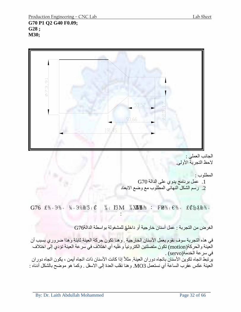
Production Engineering ndash CNC Lab Lab Sheet
By Dr Laith Abdullah Mohammed Page 32 of 66
G70 P1 Q2 G40 F009 G28 M30
الجانب العملي الحظ التجربة األولى
المطلوب
G70 عمل برنامج يدوي على الدالة 1 رسم الشكل النهائي المطلوب مع وضع االبعاد 2
₪⅗₍euro⅗₌ ₤₡ℌ₰₨⅗₌₣ ₤⅗₌⅗₌ ⅙₌₨image₍₡ ⅝₍ⅠimageⅯ₌ ⅞ⅫⅦ⅔₧ G76
G76 للمشغولة بواسطة الدالةةالغرض من التجربة عمل أسنان خارجية أو داخلي
في هذه التجربة سوف نقوم بعمل األسنان الخارجية وهنا تكون حركة العينة ثابتة وهذا ضروري بسبب أن ) تكون متصلتين الكترونيا وعليه أي اختالف في سرعة العينة تؤدي إلى اختالف motionالعينة والحركة(
) servoفي سرعة الخدمة(يرتبط اتجاه تكوين األسنان باتجاه دوران العينة مثال إذا كانت األسنان ذات اتجاه أيمن يكون اتجاه دوران
وهنا نقلب العدة إلى االسفل وكما هو موضح بالشكل أدناه MO3العينة عكس عقرب الساعة أي نستعمل
Production Engineering ndash CNC Lab Lab Sheet
By Dr Laith Abdullah Mohammed Page 33 of 66
الخطوة هي عبارة عن المسافة ما بين قمة سن إلى قمة سن أخر عمق السن هو العمق المطلوب تكوينه لألسنان
G76 الصيغة المستخدمة للدالة
G76 X___ Z___ K___ F___ D___ A___
حيث أن X القطر الداخلي للسن =Z طول السن =K عمق السن وتستخرج من المعادلة التالية =K=065F F الخطوة =D عمق القطع بالمايكرون فقط =A زاوية السن =
G76مثال على استخدام الدالة T0300 M48 GOO X30 Z4 T0303 M08 G97 S500 MO3 G76 X28375 Z-20 K08125 F125 D120 G00 X40 Z4 G28 M30
Production Engineering ndash CNC Lab Lab Sheet
By Dr Laith Abdullah Mohammed Page 34 of 66
الجانب العملي الحظ التجربة األولى
المطلوب
G76عمل برنامج يدوي على الدالة 1 رسم الشكل النهائي المطلوب مع وضع األبعاد 2
Ⅺ⅘₌⅗₌ Ⅵ₂ Ⅺ₯ℋ₍⅗₌ ℌℲℂ⅗₌ ⅞ⅫⅦ⅔₧ ₤K₡₌ℌ⅗₌ ₤₡ℌ₰₨⅗₌)Groove ₤⅗₌⅗₌ ₤tradeimage₌Ⅶ₡ (G75
G75 بواسطة الدالة grooveالغرض من التجربة تكوين
) للمشغولة وتعتمد شكل الحفر على طريقة grooveتستعمل هذه الدالة لتكوين الحفر الخارجي والداخلي (
التشغيل وعلى الشكل المراد إنتاجه وتعتبر هذه الطريقة من عمليات التشكيل للمعدن إن هذه الدالة هي دالة مالحظة مع G75في هذه التجربة سنقوم بعمل الحفر الخارجي بواسطة الدالة
تكرارية وغير تكرارية حسب نوع التشغيل
G 75 الصيغة المستخدمة للدالةG75 X___ Z___ I___ K____
حيث أن
X العمق النهائي لقطر الشغلة =Z عرض الحفر =I الدخول في كل مرة =
K التزحيف على محور =z بالنسبة للعدة
Production Engineering ndash CNC Lab Lab Sheet
By Dr Laith Abdullah Mohammed Page 35 of 66
G75مثال على استخدام الدالة
T0500 M48 GOO X100 Z -20 T0505 M08 G97 S700 MO3 G75 X84 Z -38 I 05 K4
الجانب العملي الحظ التجربة األولى
المطلوب
G76عمل برنامج يدوي على الدالة 1 رسم الشكل النهائي المطلوب مع وضع األبعاد 2
Production Engineering ndash CNC Lab Lab Sheet
By Dr Laith Abdullah Mohammed Page 36 of 66
CNC Milling Machine Mechanical Construction
Guideways The guideways of CNC machines are made of steel To reduce the frictional forces they are coated with a strip of PTFE (Poly Tetra Fluoro Ethylene)
Ballscrews On conventional lathes a leadscrew is used to converts the rotary motion of the hand wheel into linear motion of the slides Leadscrews have a high coefficient of friction and backlash On CNC machines a ballscrew is used instead of a leadscrew Friction and backlash are much less than on leadscrews
Guideway
Production Engineering ndash CNC Lab Lab Sheet
By Dr Laith Abdullah Mohammed Page 37 of 66
bullMachining operations Direction of cutting Based on the direction of the cutter rotation and work piece feed milling operations are classified into two types 1-Up milling (Convention milling) In up milling the metal is removed by rotating the cutter against the direction of travel of the part
Feed
Machine table
Part
Cutting tool
Chip thickness at theexit of the tooth
2-Down milling (Climb milling) In climb milling the metal is removed by rotating the cutter with the direction of travel of the part
Machine table
Part
Cutting tool
Chip thickness at theentrance of the tooth
Production Engineering ndash CNC Lab Lab Sheet
By Dr Laith Abdullah Mohammed Page 38 of 66
bullTooling Tool geometry The geometry of the tool tip affects the way that the metal cutting is performed The nose radius rake angles relief angles etc must be selected with care
Radial relief
Radial rake
Axial relief
Approach angle
Axial relief
Corner radius Face mill Face milling cutters are used to mill flat surfaces Commonly used face milling cutters Cutter with 75 degree approach
75 deg
Cutter with 90 degree approach (Square shoulder face mill)
90 deg
Cutter with 45 degree approach
Production Engineering ndash CNC Lab Lab Sheet
By Dr Laith Abdullah Mohammed Page 39 of 66
bullCNC Programming Axes convention The Z axis is along the spindle axis The X and Y axes are perpendicular to Z VMC
Z
Y
-
+
-+
X- +
+Z
-Z
+Y
-Y
-X +X
Part
Machine table
X
YZ
G00 Rapid traverse When the tool being positioned at a point preparatory to a cutting motion to save time it is moved along a straight line at Rapid traverse at a fixed traverse rate which is pre-programmed into the machines control system Typical rapid traverse rates are 10 to 25 m min but can be as high as 80 mmin
Production Engineering ndash CNC Lab Lab Sheet
By Dr Laith Abdullah Mohammed Page 40 of 66
Format N_ G00 X__ Y__Z__
G01 Linear interpolation (feed traverse) The tool moves along a straight line in one or two axis simultaneously at a programmed linear speed the feed rate Format N__ G01 X__ Y__Z__ F__
Part
Feed
Part
Feed
G02G03 Circular interpolation The tool moves along an arc in two axes simultaneously at a programmed linear speed the feed rate
Production Engineering ndash CNC Lab Lab Sheet
By Dr Laith Abdullah Mohammed Page 41 of 66
Format N__ G0203 X__ Y__Z__ I__ J__K__ F__ using the arc center OR N__ G0203 X__ Y__Z__ R__ F__ using the arc radius G02 moves along a CW arc G03 moves along a CCW arc Arc center The arc center is specified by addresses I J and K I J and K are the X Y and Z co-ordinates of the arc center with reference to the arc start point
X
Y
Arc center
Arc endArc start
- J
- I
I = X coord of center - X coord of start point J = Y coord of center - Y coord of start point K = Z coord of center - Z coord of start point I J and K must be written with their signs
Production Engineering ndash CNC Lab Lab Sheet
By Dr Laith Abdullah Mohammed Page 42 of 66
bullWork holding
Rotary table
Fixture base
Component
Clamp
Stud
Fixtures The use of fixtures 1 Improves repeatability of dimensions 2 Improves working conditions 3 Cuts down requirement of skilled labour 4 Reduces part loading and unloading time 5 Improves safety in the working area 6 Reduces the cost of machining There are two types fixtures commonly used 1 Special fixture Special fixtures are used to hold and locate the typical components which are having complex shape and to be located with the reference hole (dowel hole) Special fixtures are required for components like gear case cover cylinder heads etc 2 Modular fixture Modular fixture is a set different kind of clamping and locating elements These fixtures are used to hold identical components in different sizes and components of box type Example Manifolds head stocks connecting rods and flanges
Production Engineering ndash CNC Lab Lab Sheet
By Dr Laith Abdullah Mohammed Page 43 of 66
bullMachine setting
Determining X and Y work zero offset Case 1
Part
Machine table
Part
End mill or reamer
Work offset X0Y0 For determining X work zero offset bull Touch the periphery of the end mill or reamer to the part bull Enter current machine X value + cutter radius as X work zero offset For determining Y work zero offset bull Touch the periphery of the end mill or reamer to the part bull Enter current machine Y value - cutter radius as Y work zero offset Case 2
Part
Machine table
Part
End mill or reamerWork offset X0Y0
bull Mount the dial indicator on machine spindle true the bore bull Enter current machine X and Y value as X and Y work zero offset
Production Engineering ndash CNC Lab Lab Sheet
By Dr Laith Abdullah Mohammed Page 44 of 66
How to Select a Cutting Fluid
One part of the metal cutting equation that is sometimes overlooked however is
the choice of an appropriate cutting fluid With todayrsquos system approach to metal
cutting use of the right metalworking fluid has become just as much a part of the
solution as the other elements In fact at least one company is now integrating
cutting fluids and cutting tools into effective metal cutting systems Following are
some things to consider when choosing your next cutting fluid
The Four Key Questions
There are four vital pieces of information that are necessary when choosing a
cutting fluid They are
1 What are you cutting
2 What is the chemistry of your water
3 What are you using now
4 What are your options
5 What do you prefer
What Are You Cutting
The first question ndash ldquoWhat are you cuttingrdquo ndash is often the most difficult to answer
because most shops handle a variety of workpiece materials on a regular basis If
the answer is an unequivocal ldquoaluminumrdquo or ldquostainless steelrdquo or ldquocast ironrdquo the
selection of a cutting fluid can be quite simple and straightforward Unfortunately
that is seldom the case in anything but a high-volume plant Where aluminum or
other nonferrous metals are a significant part of the mix a non-staining cutting
fluid is a must Generally speaking this will be a semi-synthetic with special
ingredients to prevent bi-metallic corrosion and staining of non-ferrous workpieces
Where the ferrous metals predominate however a more general purpose semi-
synthetic or hybrid fluid might be a more economical choice
Production Engineering ndash CNC Lab Lab Sheet
By Dr Laith Abdullah Mohammed Page 45 of 66
What is The Chemistry of Your Water
The second question ndash ldquoWhat is the chemistry of your waterrdquo ndash is probably the
single most common reason for the success or failure of a cutting fluid Very few
plants invest the money necessary to install effective water purification systems
using deionization or reverse osmosis technology Unfortunately the chemicals
present or not present in the water used to re-constitute a cutting fluid make a
tremendous difference in its performance and sump life Most manufacturers of
cutting fluids will perform the necessary water testing to determine exactly what
minerals are dissolved in your water and make a fluid recommendation based on
the results
What are you using now
The third question ndash ldquoWhat are you using nowrdquo ndash helps narrow the range of
choices When coupled with an objective analysis of the strengths and weaknesses
of the current fluid the answer to this question can quickly point you toward a
relatively small number of competitive alternatives that have the attributes required
to meet your cutting needs Many cutting fluids are in use today simply because
they were in use yesterday It is a hard reality of todayrsquos marketplace that if one
isnrsquot constantly striving to improve they will certainly be overtaken by a
competitor who is
What Are Your Options
The fourth question ndash ldquoWhat are your optionsrdquo ndash leads to the final selection of a
cutting fluid Cutting fluids can be divided into four general groups based on their
chemistry
They are
bull Soluble Oils ndash quite literally oil dispersed in water
bull Synthetics ndash completely oil free man-made coolants in solution
Production Engineering ndash CNC Lab Lab Sheet
By Dr Laith Abdullah Mohammed Page 46 of 66
bull Semi-Synthetics ndash a mixture of natural and synthetic lubricants with up to 30
mineral oil
bull Hybrids ndash a special class of semi-synthetics with a mineral oil content of about
15 Each fluid type has advantages and disadvantages which make it suitable for
a particular group of applications In addition there are costperformance trade-
offs to be made between the groups within a specific set of applications For
example where a hybrid and a semi-synthetic may both be suitable for a particular
use the hybrid might provide longer sump life at a slightly higher initial cost
while some semi synthetics may be more economical to recycle or dispose of while
not giving as long a tank life The final decision in this case would have to be made
on the detailed economics of the shop where the fluids were to be used and on the
ownerrsquos individual preferences
Soluble Oils
Soluble oils are oils that disperse in water when emulsifiers are added They are
generally suitable for moderate-to heavy-duty machining and grinding of all non-
ferrous metals carbon and cast steels and in applications where dissimilar metals
such as aluminium and steel are present They can also be used in turning drilling
tapping reaming gear cutting broaching as well as internal and centerless types
of grinding operations Soluble oils provide excellent aluminium and copper
corrosion control good rancidity control which extends fluid for long lasting
trouble-free performance and good concentrate and mix stability making it ideal
for mixing in water with a minimal amount of agitation An example of this is
Valenitersquos VNTreg-650 premium heavy-duty soluble oil
Synthetics
Synthetics are completely oil free solutions made of polymers organic and
inorganic materials that are mixed with water These clear low foaming and bio-
Production Engineering ndash CNC Lab Lab Sheet
By Dr Laith Abdullah Mohammed Page 47 of 66
stable coolants are ideal for machining and grinding of ferrous materials carbon
steels or cast iron Their complex lubricant packages make synthetics well-suited
for tough-to-machine materials such as stainless steels and high-temperature alloys
Certain synthetics are specifically designed to address the primary failure modes of
flank wear and nose wear Although there are many benefits some synthetics may
cause staining of non-ferrous materials
Semi-Synthetics
Semi-synthetic fluids are a mixture of oils synthetic emulsifiers and water They
were primarily developed for the aircraft nuclear and related industries
Consequently they work extremely well on all non-ferrous metals such as titanium
aluminium copper brass bronze and stainless steel in both machining and
grinding Semi-synthetics can be used on ferrous metals too They are chlorine-
free to reduce bi-metallic corrosion and staining of metals They should be used at
a 5-8 dilution with water depending on the severity of the operation
Hybrids
Hybrids are cutting fluids custom engineered to solve a particular problem For
example Valenitersquos VNTreg-800 was developed to be very clean in the machining
and grinding of cast iron It provides better stability in hard water and rejects tramp
oil very well which adds to its bio-stable chemistry Hybrids work extremely well
on all metals in both machining and grinding They should be mixed at a 5-7
dilution with water depending on the condition of the water
What Do You Prefer
The final question ndash ldquoWhat do you preferrdquo ndash is usually the ldquotie breakerrdquo where
there is more than one appropriate cutting fluid available Here again as in the
case of what is being used now the key is to examine your preferences objectively
Production Engineering ndash CNC Lab Lab Sheet
By Dr Laith Abdullah Mohammed Page 48 of 66
and specifically to identify the real reasons behind a preference If you cannot
point to specific reasons why one class of cutting fluid is preferred over another
you are well advised to follow the recommendations of the professional who has
analyzed your requirements Choosing the right fluid today is easier than ever as
the system approach to metal cutting productivity continues to grow in acceptance
The day is not far off when choosing a complete solution will be as easy as
choosing the right insert and chip breaker today The answers are available and the
results will more than justify the time you spend choosing the right metal cutting
fluid
Useful Links wwwball-screwsnet
wwwlubelinkcom
wwwmachinerylubricationcom
wwwadvancedmanufacturingcom
wwwmmsonlinecom
wwwcuttingtoolengineeringcom
wwwgeartechnologycom
wwwengineersedgecom
wwwagmaorg
wwwefundacom
wwwsaeorg
wwwsmeorg
wwwastmorg
wwwissorg
wwwmachinetoolscom
wwwansiorg
wwwasmeorg
wwwcnccicom
wwwmatlscom
wwwthefreedictionarycom
wwwengineersupplycom
Production Engineering ndash CNC Lab Lab Sheet
By Dr Laith Abdullah Mohammed Page 49 of 66
SurfCAM Tutorial ndash Beginning with the basics
Background SurfCAM is a computer aided manufacturing (CAM) software which allows you to create manage and modify tool paths for computer aided designed (CAD) part The software requires a CAD model or requires that you create some geometry within SurfCAM with some rudimentary tools provided The tool paths are created or stored internally in SurfCAM in a generic programming language called APT Once the tool paths are created the APT paths are translated using a post processor into typical machine G-code
Opening SurfCAM SurfCAM can be opened from the Novell Applications Launcher on most Industrial Engineering computer labs workstations Search under lsquoallrsquo applications and double click on SurfCAM 2005 Once the program opens a license must be selected from the list (not the Demo license) to enable saving the file later Choose one of the 30 licenses available If for some reason the licenses are not listed on the license manager form select server list and type ldquobonnieeosncsuedurdquo A list of available licenses should appear Select a license and click OK After the license is selected an Add StockFixture form (Figure 1) opens allows you to add a model which represents the pre-machined stock or a fixture Click on OK without adding either Both of these items can be added later under a more appropriate dialog
Figure 1 Add Stock or Fixture dialog box
Production Engineering ndash CNC Lab Lab Sheet
By Dr Laith Abdullah Mohammed Page 50 of 66
SurfCAM Interface
Figure 2 SurfCAM Windows based interface
SurfCAM is a windows based software system so most of the typical windows functions under File are applicable This is where you can open save exit print etc The Create menu allows the user to create different geometry forms Here you can create a point line surface chamfer circle and many other geometry types For the most part these functions are not used by beginners but are useful when creating bounding curves where you donrsquot want the tool to move outside (constraining the tool) The Edit menu allows you to change or modify many different entities such as changing lines altering surfaces joining surfaces trimming or breaking elements add control points etc Again these features are helpful to advanced users and are not covered in detail in this tutorial The Display menu offers the ability to change the orientation of the part on the screen The typical rotate pan fit to screen and zoom functions are available as well as several functions which allow the user to shift between views or call up a named view (ie top bottom etc) The NC menu is the main machining interface menu In this menu you select the general form of machining (2 axis 3 axis 4 axis 5 axis turning etc) and under the general form a more specific machining function is selected This menu is the most used and the options contained must be fully understood to get the most out of SurfCAM Each function will be described in some detail in a further chapter The Analyze menu contains options such as measuring the distance between points angles tangency elements etc These functions are auxiliary functions meant to help you understand the part better but basically provide no functionality for making tool paths for CNC machines Thus these will not be covered The Tools menu allows the user to change the system options modify keyboard shortcuts change the model units etc These options are again not used by beginners Finally the Help menu provides access to the online users manual In lieu of clicking the Help menu the F1 key is the shortcut key for help (as it is in most windows based programs)
Importing a CAD model Importing a CAD model that is stored locally is done by selecting File-gtOpen On the Files of type dropdown box choose the type of file you wish to open (Figure 3) Do this prior to negotiating your way through the maze of folders to prevent having to go through the folder tree again Once the file type is selected find the file you are trying to open and click the Open
Production Engineering ndash CNC Lab Lab Sheet
By Dr Laith Abdullah Mohammed Page 51 of 66
button SurfCAM will then attempt to read the file you have selected SurfCAM may provide a dialog box describing what it has imported and identify if it was successful If this dialog is provided simply click close without saving
Figure 3 Open Dialog Note - Change type of file prior to finding the file you wish to open
SurfCAM allows a user to import several different types of CAD files the most common types which you will likely import are SolidWorks part files (sldprt or prt) AutoCAD files(dxf) or IGES (igs or iges) Native file import (such as is the case with SolidWorks) provides the greatest information transfer and generic file imports (such as is the case with IGES) provide the least Normally it is to the advantage of the user to use native file importing procedures when available Recently (2005) SurfCAM added some compatibility with SolidWorks This allows the user to create tool paths for a part and if an engineering change is needed for the part update the part in SolidWorks When the part is then opened in SurfCAM the changes are noted and a simple update operation command is needed This however does not operate with complete transparency andor accuracy and thus users need to be cognizant of changing CAD models
SurfCAM Geometry In SurfCAM two basic types of geometry are used the surface and the point A surface (Figure 4) is a so called spline (NURBS or B-Spline are the two most common) surface (parameterized by two values u and v) such that every location on the surface can be defined as a function of these parameters In other words SurfCAM can calculate the location of any point on the
Production Engineering ndash CNC Lab Lab Sheet
By Dr Laith Abdullah Mohammed Page 52 of 66
surface Surfaces are used primarily in 3 4 and 5 axis machining and require a significant
amount of processing power and time Figure 4 Surfaces model of a mold half Note the difference between this and Figure 2 a wireframe model
Point or line based models are often referred to as wireframe (Figure 5) models because the models consist of connected lines and resemble the part only at the intersection of two surfaces Wireframe models were made popular lsquoback in the dayrsquo when computer processing was expensive There are times when each of the models are important and selecting model geometry when applying a SurfCAM operation will be much simpler if you understand the differences between the two When importing a SolidWorks model the default is both the surfaces and the wireframe geometry are imported
Figure 5 Wireframe model of the mold in Figure 1
Steps to Creating Tool Paths Once a CAD model is imported into SurfCAM tool paths can be created There is no one correct way to create tool paths however there is a set of general steps to take to ensure the tool paths are created with a minimum amount of hardship (note the wordinghellipHardship is inevitable when creating tool paths it is the intent of this manual to minimize this) The following is a list of steps which should be considered when making tool paths
Production Engineering ndash CNC Lab Lab Sheet
By Dr Laith Abdullah Mohammed Page 53 of 66
1 Plan ahead a Orient the part in SolidWorks such that if only one side is to be machined that
side is the Top view This can be done early in SolidWorks by choosing a plane parallel the X-Y plane as the sketch plane for the machined geometry
b Orient the part in SolidWorks such that the origin is somewhere of relative importance and someplace in space that can be easily identified when placed on the machine This is extremely important to minimize set up time at the machine (note ndash my personal preference for a part that is to be fully machined [ie stock exists on all sides] is to place the origin at the center and top of the parthellipjust my preference)
c Orient the part in SolidWorks such that the X and Y axes are aligned as you want them on the machinehellip
d Planning ahead will save you many hours of headaches laterhelliptrust me 2 Import the model 3 Choose a construction view such that the tool approaches the side to be machined
from the positive Z axis direction (as defined by part origin) a This is done by clicking on the CView icon
b From the list of named views chose the view which orients the origin as you would like
c If one of the views does not fit your criteria you have two choices i Perform a transformation of the part in SurfCAM or SolidWorks
ii Add a new construction view by selecting new This option requires a relatively good understanding of right hand coordinate frames but is very usefulhellipNormally used by more advanced users
d Be sure the CoordVIEW selection is made vs CoordWORLD This ensures the tools will be controlled from the coordinate frame selected by the view (ie the origin on the part) instead of the origin on the lower left corner of the screen This will be especially important when we get into 4 and 5 axis machining
4 In the Operations Manager (Figure 6) select Setup One and change the name to something meaningful ndash like Front Side Mold Cavity
a Access the Operations manager by right clicking or by selecting the Operations Manager icon in the tool bar
b Operations Manager is where the tool paths are managed once they are created as well as where individual tool paths can be verified
Production Engineering ndash CNC Lab Lab Sheet
By Dr Laith Abdullah Mohammed Page 54 of 66
5 Roughing Tool Paths a Create the tool paths to remove the majority of the material (if applicable) b Use NC-gt3Axis-gtZ rough or Plunge Rough c Described in next section
6 Create Finishing Tool Paths a Described in next section
7 Add another setup if necessary 8 Perform steps 3 through 6 as necessary 9 Verify the tool paths are correct 10 Use a post processor for the tool paths to create G-Code for machine
Creating Tool Paths The following is a list of operations what they are intended for how they generally work and some parameters that may be adjusted to modify the tool paths
2 Axis tool paths Unless otherwise noted 2 axis tool path functions require lines or arc segments as input parameters (as opposed to surfaces) There are several options as to how these segments are chosen the most prevalent is the chain option and the second most prevalent is the single When choosing the line segments using the chain option SurfCAM will try to link a complete path of segments based on an initial segment chosen by the user If the operation is planer (ie pocket or contour) the segments must lie on the same plane If the operation is non-planer (ie contour 3D) SurfCAM will prompt the user to specify segments when it encounters a branch point
Figure 6 Operations Manager view showing setup one re-labeled as Front Side Mold
Production Engineering ndash CNC Lab Lab Sheet
By Dr Laith Abdullah Mohammed Page 55 of 66
When using the single element option the user must manually choose each segment desired for the operation Note that most operations do not require a closed loop of segments you may specify for instance an open contour where the tool is supposed to move The order of choosing segments is important This order determines the path of the tool in the sense that if three segments are chosen such that the middle segment is chosen last there will be three different plunge and machine operations one on each segment If the operation was to make a continuous contour around the outside of the part the segments should be chosen in order of the desired tool trajectory
Operations
Pocket Pocket operation in SurfCAM is used to cut an enclosed space from the inside to the outside at one particular depth The operation starts in the center of an enclosed area (with a plunge move in the ndashZ direction) and makes incremental closed paths towards the pocket boundaries in user defined path offsets (Figure 7) The user chooses the boundary of the pocket (line segments) and if more than one pocket is chosen SurfCAM will ask the user to click inside a pocket
Figure 7 Two examples of using the pocketing operation
The pocket operation allows for creating a projection of the pocket paths on multiple planes This is useful if you have a deep pocket which will not allow the tool to cut directly at the depth of the pocket but would be easily done using the same paths at several different Z heights On the cut control (Figure 8) tab the user specifies where the chosen geometry (pocket segments) lie (ie bottom or top) Then under the amount to remove specify the total material height to be removed and the rough spacing (amount you wish to advance the Z axis with each pocket step) You may also specify a finishing pass and as well as stock to leave
Production Engineering ndash CNC Lab Lab Sheet
By Dr Laith Abdullah Mohammed Page 56 of 66
Figure 8 Example of Contour Operation with multiple passes
Contour Contouring in SurfCAM is used to perform peripheral milling on the inside or outside of a line segment (Figure 9) The user is to identify the line segments which define a contour (does not have to be a closed loop of segments) SurfCAM may or may not require the user to specify a side to contour (ie which side of the line is the tool to cut) For contouring each segment must lie on the same plane
Production Engineering ndash CNC Lab Lab Sheet
By Dr Laith Abdullah Mohammed Page 57 of 66
Figure 9 Examples of parts cut with 2-Axis Contour
Contour 3D Contour 3D is the same operation type as contour but allows the user to specify segments on different planes for the tool to cut along
Drill Drilling operations are any rotating tool operation meant to engage the part from a single direction ndash namely from the positive Z direction Drilling operations can be specified using circle point or line segments After choosing NC-gt2-Axis-gtDrill SurfCAM allows the user to choose multiple circles or points defining holes to be drilled Drilling operations also allow the user to incorporate more than 1 operation such as a center drill a drill and a reaming operation After selecting the locations for the drilling operation a dialog box (Figure 10) allows the user to add change or delete tools to be used in the operation As displayed in the following figure the spotdrill operation is followed by a drilling operation followed by a tapping operation The depth of each tool can be controlled individually by double clicking the total depth cell in and manually entering Tools can be added before or after operations which the cells are highlighted by selecting either of the insert buttons at the top or by the insert menu Select tool button allows the user to change the tool size or type
Production Engineering ndash CNC Lab Lab Sheet
By Dr Laith Abdullah Mohammed Page 58 of 66
Figure 10 Drill operation manager Several operations can be completed at one time
Figure 11 Drill operation including the spotdrill drill and tap as outlined in Fig 10
3 Axis tool paths SurfCAM requires surfaces as inputs for 3 Axis tool paths Surfaces can be created in SurfCAM but are most easily created in a CAD package and imported into SurfCAM Surfaces allow SurfCAM to identify every point on the surface in 3 dimensions unlike 2D geometry (wireframes) which only identify positions on the plane Creating tool paths with complex surfaces takes a very significant amount of processing power so expect 3 Axis tool path generation to take longer
Production Engineering ndash CNC Lab Lab Sheet
By Dr Laith Abdullah Mohammed Page 59 of 66
Operations
Cut 3 Axis cut operation takes a surface and using the flow lines creates a rastering path over the surface with the tool tip riding on the surface The primary direction will be defined by the flow lines of the surface (which can be edited by Edit-gtSurfaces-gtArrow-gtDirection) If you intend to cross surface boundaries you must merge the surfaces (Edit-gtJoin and choose the two surfaces)
Z-Rough The Z-rough operation is used to remove a large amount of material prior to finish machining Roughing operation is typically the first operation you perform for each setup The Z-Rough operation cuts the part in user defined intervals For each of these intervals a surface intersection between the part and the plane is performed and a 2D pocket or contour operation is performed on that plane This is performed on each plane When choosing NC-gt3 Axis-gtZ rough the first dialog box you will encounter asks for a bounding box to be defined Choose the Extents Box and a second dialog box will ask for the coordinates which define the box (Figure 12) This is the stock size you expect to machine the part from Input the coordinates or change the additional offset amounts (in XY or Z) as appropriate and click Calculate Bounding Box
Figure 12 Material Extents Box Example
Next choose the tool and cutting parameters that you desire and click on the Cut Control Tab (Figure 13) Here you will find the following parameters which are often changed Stock to
Production Engineering ndash CNC Lab Lab Sheet
By Dr Laith Abdullah Mohammed Page 60 of 66
leave ndash this is an offset amount from the surfaces which leaves a small amount of material to finish machine Minimum and Maximum Z values ndash Defines area to machine Z Step Size ndash This identifies the plane intervals for the surface intersection planes (the first interval will be at the top of the selected area and successive increments down in Z will be cut until the Minimum Z value is reached)
Figure 13 3Axis Z Rough Cut Control
The 3Axis Z-Finish operation works in exactly the same way 3 Axis Z-Finish is most appropriate for finishing vertical or near vertical walls
3D Offset The 3D Offset operation creates a tool path using a 2D or 3D boundary by offsetting the boundary in concentric offset cutting passes Each pass calculates the tool engagement and maintains the engagement somewhat constant The advantage (significant) is the scallop height ndash height of the material between passes ndash is controlled thus the surface finish is predictable When choosing 3D Offset surfaces are selected as well as 2D or 3D boundaries The boundaries define the concentric offset paths shape as well as limit the tool path area Choose NC-gt3Axis-gt3D Offset from the drop down menus SurfCAM will prompt you to select the surface or surfaces to cut across Select the surfaces you wish to machine and then select the tool and cutting parameters you wish use Next select the Cut Control Tab and check the Use Boundary Curves option Set the Step Type to Scallop and set the maximum scallop height If you like
Production Engineering ndash CNC Lab Lab Sheet
By Dr Laith Abdullah Mohammed Page 61 of 66
you can also add stock to leave if this is a roughing operation You can also set the Direction and Start-End parameters from this tab Click OK and the paths will be generated
Figure 14 Cut Control Tab for 3D Offset
Example part using both 2D and 3D geometry
The tool paths for this mold will be generated in SurfCAM using 5 operations The first will be a roughing operation using a frac14 inch flat end mill with the Z step size of 00625in Choose NC-
Production Engineering ndash CNC Lab Lab Sheet
By Dr Laith Abdullah Mohammed Page 62 of 66
gt3Axis-gtZ-Rough from the drop down menu Select all visible surfaces and create an extents box that has 025inch XY offsets and 01inch Z offset Next select the frac14 inch flat end mill from the tools menu Under Cut Control tab set the Z step size to be 00625inch The tool paths will look something like Figure 15
Figure 15 Z-Rough Tool paths for Example Part
Next a flat surface operation will be performed to cut the flat surface on the top Select NC-gt3 Axis-gtFlat Surface from the drop down menu Select all visible surfaces again Choose the 12inch flat end mill and set the cutting parameters as desired Under Cut Control Tab change the Minimum Area to 50 square inches (Figure 16) The tool paths should look something like Figure 17
Figure 16 Cut Control for Flat Surface
Production Engineering ndash CNC Lab Lab Sheet
By Dr Laith Abdullah Mohammed Page 63 of 66
Figure 17 Flat Surface Tool Paths
Next we will use a 3D offset operation to cut the mold cavity Select NC-gt3 Axis-gt3D Offset from the dropdown menu Change the view to the top view and select within to capture the surfaces of the mold cavity Draw a rectangle around the mold cavity Select a 18 inch ball endmill from the tool library and set the cutting parameters as appropriate Next set the Cut Control tab parameters as in Figure 14 The paths creates should be similar to Figure 18
Figure 18 3D Offset Paths
Next we will perform a 2 Axis contouring of the top section Select NC-gt2 Axis-gtContour from the dropdown menu Using the chain option select the bottom contour of the top extrusion Select the frac12 inch flat end mill from the tool library and set the cutting parameters as required In the Cut Control Tab change the Geometry to Bottom and the amount to remove in Z to 05
Production Engineering ndash CNC Lab Lab Sheet
By Dr Laith Abdullah Mohammed Page 64 of 66
Change the Rough Spacing in Z to 025 and add 1 finish pass of 002 (Figure 19) Click OK and SurfCAM will instruct you to choose a side to contour Click anywhere on the screen OUTSIDE the geometry you selected for the contouring operation Failure to click outside the geometry will result in the tool being on the wrong side of the contour Your paths should look something like those in Figure 20
Figure 19 Cut Control Tab for the Contouring Operation
Figure 20 Contouring operation paths
Production Engineering ndash CNC Lab Lab Sheet
By Dr Laith Abdullah Mohammed Page 65 of 66
Next we will perform a 2 axis pocket operation for the small pocket on the top face of the mold Select NC-gt2Axis-gtPocket and using the Auto select feature select the boundary curve at the bottom of the pocket Click Done twice and select the frac14 inch flat end mill from the tool library Set the appropriate cutting parameters and click OK SurfCAM will prompt you to click inside the pocket Click anywhere inside the geometry you chose to define the pocket The resulting paths should look something like those in Figure 21
Figure 21 2 Axis Pocket Operation Paths
Finally we will add a drilling operation for the 2 holes at the corners of the mold Select NC-gt2 Axis-gtDrill from the dropdown menu Select the top circles defining the two holes A menu box will appear with a default tool (Center drill) already programmed Add a second tool to the list by selecting Insert-gtAfter and select the tool from the tool library Change the drill depth to 10inches and click OK The paths should look something similar to Figure 23
Figure 22 Drill Menu
Production Engineering ndash CNC Lab Lab Sheet
By Dr Laith Abdullah Mohammed Page 66 of 66
Figure 23 Drilling Operation Tool Paths
Now you can watch a simulation of the cutting by choosing the setup in the operations manager and clicking the simulate icon Be sure to set the stock in the set up by right clicking the set up and selecting Edit Setup Information In the Stock Tab you can create a bounding box meeting your needs and click Add Your simulation should result in something like the following
Figure 24 Final Simulation of the example Mold
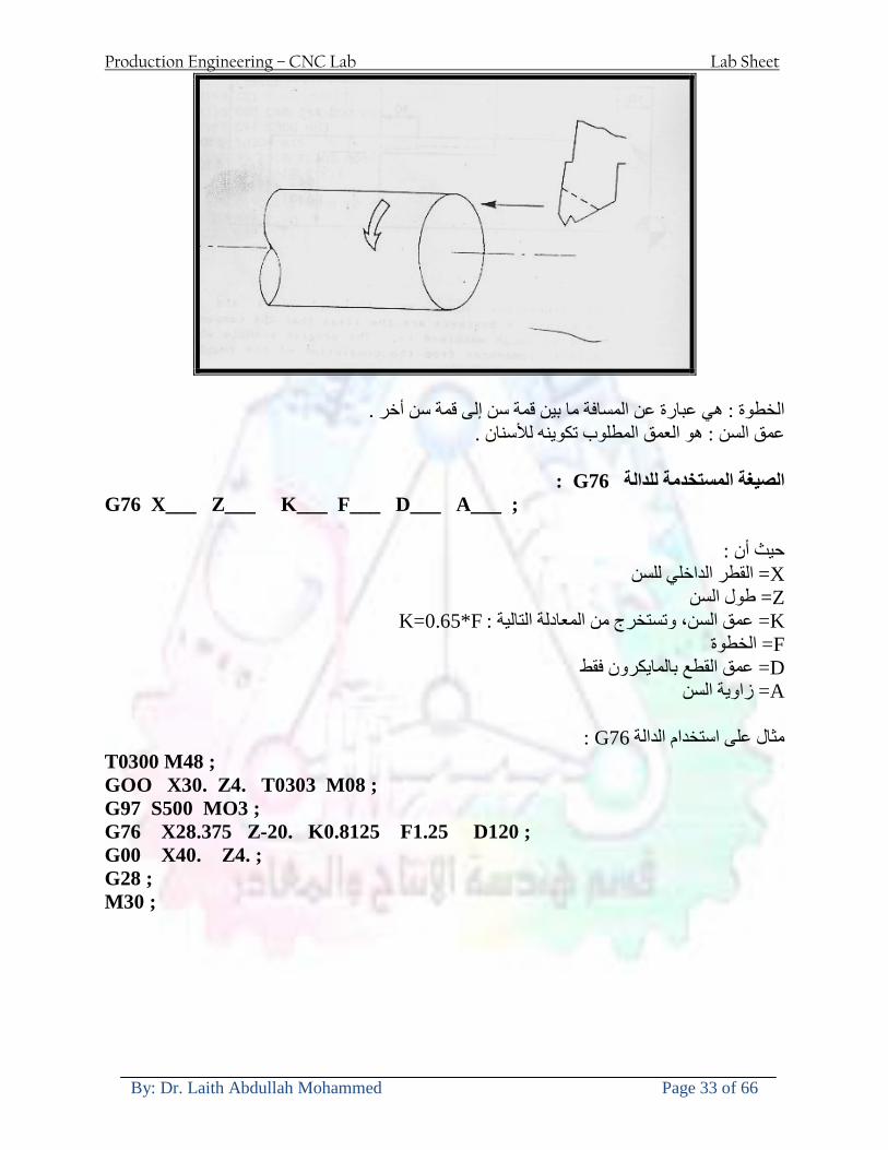
Production Engineering ndash CNC Lab Lab Sheet
By Dr Laith Abdullah Mohammed Page 33 of 66
الخطوة هي عبارة عن المسافة ما بين قمة سن إلى قمة سن أخر عمق السن هو العمق المطلوب تكوينه لألسنان
G76 الصيغة المستخدمة للدالة
G76 X___ Z___ K___ F___ D___ A___
حيث أن X القطر الداخلي للسن =Z طول السن =K عمق السن وتستخرج من المعادلة التالية =K=065F F الخطوة =D عمق القطع بالمايكرون فقط =A زاوية السن =
G76مثال على استخدام الدالة T0300 M48 GOO X30 Z4 T0303 M08 G97 S500 MO3 G76 X28375 Z-20 K08125 F125 D120 G00 X40 Z4 G28 M30
Production Engineering ndash CNC Lab Lab Sheet
By Dr Laith Abdullah Mohammed Page 34 of 66
الجانب العملي الحظ التجربة األولى
المطلوب
G76عمل برنامج يدوي على الدالة 1 رسم الشكل النهائي المطلوب مع وضع األبعاد 2
Ⅺ⅘₌⅗₌ Ⅵ₂ Ⅺ₯ℋ₍⅗₌ ℌℲℂ⅗₌ ⅞ⅫⅦ⅔₧ ₤K₡₌ℌ⅗₌ ₤₡ℌ₰₨⅗₌)Groove ₤⅗₌⅗₌ ₤tradeimage₌Ⅶ₡ (G75
G75 بواسطة الدالة grooveالغرض من التجربة تكوين
) للمشغولة وتعتمد شكل الحفر على طريقة grooveتستعمل هذه الدالة لتكوين الحفر الخارجي والداخلي (
التشغيل وعلى الشكل المراد إنتاجه وتعتبر هذه الطريقة من عمليات التشكيل للمعدن إن هذه الدالة هي دالة مالحظة مع G75في هذه التجربة سنقوم بعمل الحفر الخارجي بواسطة الدالة
تكرارية وغير تكرارية حسب نوع التشغيل
G 75 الصيغة المستخدمة للدالةG75 X___ Z___ I___ K____
حيث أن
X العمق النهائي لقطر الشغلة =Z عرض الحفر =I الدخول في كل مرة =
K التزحيف على محور =z بالنسبة للعدة
Production Engineering ndash CNC Lab Lab Sheet
By Dr Laith Abdullah Mohammed Page 35 of 66
G75مثال على استخدام الدالة
T0500 M48 GOO X100 Z -20 T0505 M08 G97 S700 MO3 G75 X84 Z -38 I 05 K4
الجانب العملي الحظ التجربة األولى
المطلوب
G76عمل برنامج يدوي على الدالة 1 رسم الشكل النهائي المطلوب مع وضع األبعاد 2
Production Engineering ndash CNC Lab Lab Sheet
By Dr Laith Abdullah Mohammed Page 36 of 66
CNC Milling Machine Mechanical Construction
Guideways The guideways of CNC machines are made of steel To reduce the frictional forces they are coated with a strip of PTFE (Poly Tetra Fluoro Ethylene)
Ballscrews On conventional lathes a leadscrew is used to converts the rotary motion of the hand wheel into linear motion of the slides Leadscrews have a high coefficient of friction and backlash On CNC machines a ballscrew is used instead of a leadscrew Friction and backlash are much less than on leadscrews
Guideway
Production Engineering ndash CNC Lab Lab Sheet
By Dr Laith Abdullah Mohammed Page 37 of 66
bullMachining operations Direction of cutting Based on the direction of the cutter rotation and work piece feed milling operations are classified into two types 1-Up milling (Convention milling) In up milling the metal is removed by rotating the cutter against the direction of travel of the part
Feed
Machine table
Part
Cutting tool
Chip thickness at theexit of the tooth
2-Down milling (Climb milling) In climb milling the metal is removed by rotating the cutter with the direction of travel of the part
Machine table
Part
Cutting tool
Chip thickness at theentrance of the tooth
Production Engineering ndash CNC Lab Lab Sheet
By Dr Laith Abdullah Mohammed Page 38 of 66
bullTooling Tool geometry The geometry of the tool tip affects the way that the metal cutting is performed The nose radius rake angles relief angles etc must be selected with care
Radial relief
Radial rake
Axial relief
Approach angle
Axial relief
Corner radius Face mill Face milling cutters are used to mill flat surfaces Commonly used face milling cutters Cutter with 75 degree approach
75 deg
Cutter with 90 degree approach (Square shoulder face mill)
90 deg
Cutter with 45 degree approach
Production Engineering ndash CNC Lab Lab Sheet
By Dr Laith Abdullah Mohammed Page 39 of 66
bullCNC Programming Axes convention The Z axis is along the spindle axis The X and Y axes are perpendicular to Z VMC
Z
Y
-
+
-+
X- +
+Z
-Z
+Y
-Y
-X +X
Part
Machine table
X
YZ
G00 Rapid traverse When the tool being positioned at a point preparatory to a cutting motion to save time it is moved along a straight line at Rapid traverse at a fixed traverse rate which is pre-programmed into the machines control system Typical rapid traverse rates are 10 to 25 m min but can be as high as 80 mmin
Production Engineering ndash CNC Lab Lab Sheet
By Dr Laith Abdullah Mohammed Page 40 of 66
Format N_ G00 X__ Y__Z__
G01 Linear interpolation (feed traverse) The tool moves along a straight line in one or two axis simultaneously at a programmed linear speed the feed rate Format N__ G01 X__ Y__Z__ F__
Part
Feed
Part
Feed
G02G03 Circular interpolation The tool moves along an arc in two axes simultaneously at a programmed linear speed the feed rate
Production Engineering ndash CNC Lab Lab Sheet
By Dr Laith Abdullah Mohammed Page 41 of 66
Format N__ G0203 X__ Y__Z__ I__ J__K__ F__ using the arc center OR N__ G0203 X__ Y__Z__ R__ F__ using the arc radius G02 moves along a CW arc G03 moves along a CCW arc Arc center The arc center is specified by addresses I J and K I J and K are the X Y and Z co-ordinates of the arc center with reference to the arc start point
X
Y
Arc center
Arc endArc start
- J
- I
I = X coord of center - X coord of start point J = Y coord of center - Y coord of start point K = Z coord of center - Z coord of start point I J and K must be written with their signs
Production Engineering ndash CNC Lab Lab Sheet
By Dr Laith Abdullah Mohammed Page 42 of 66
bullWork holding
Rotary table
Fixture base
Component
Clamp
Stud
Fixtures The use of fixtures 1 Improves repeatability of dimensions 2 Improves working conditions 3 Cuts down requirement of skilled labour 4 Reduces part loading and unloading time 5 Improves safety in the working area 6 Reduces the cost of machining There are two types fixtures commonly used 1 Special fixture Special fixtures are used to hold and locate the typical components which are having complex shape and to be located with the reference hole (dowel hole) Special fixtures are required for components like gear case cover cylinder heads etc 2 Modular fixture Modular fixture is a set different kind of clamping and locating elements These fixtures are used to hold identical components in different sizes and components of box type Example Manifolds head stocks connecting rods and flanges
Production Engineering ndash CNC Lab Lab Sheet
By Dr Laith Abdullah Mohammed Page 43 of 66
bullMachine setting
Determining X and Y work zero offset Case 1
Part
Machine table
Part
End mill or reamer
Work offset X0Y0 For determining X work zero offset bull Touch the periphery of the end mill or reamer to the part bull Enter current machine X value + cutter radius as X work zero offset For determining Y work zero offset bull Touch the periphery of the end mill or reamer to the part bull Enter current machine Y value - cutter radius as Y work zero offset Case 2
Part
Machine table
Part
End mill or reamerWork offset X0Y0
bull Mount the dial indicator on machine spindle true the bore bull Enter current machine X and Y value as X and Y work zero offset
Production Engineering ndash CNC Lab Lab Sheet
By Dr Laith Abdullah Mohammed Page 44 of 66
How to Select a Cutting Fluid
One part of the metal cutting equation that is sometimes overlooked however is
the choice of an appropriate cutting fluid With todayrsquos system approach to metal
cutting use of the right metalworking fluid has become just as much a part of the
solution as the other elements In fact at least one company is now integrating
cutting fluids and cutting tools into effective metal cutting systems Following are
some things to consider when choosing your next cutting fluid
The Four Key Questions
There are four vital pieces of information that are necessary when choosing a
cutting fluid They are
1 What are you cutting
2 What is the chemistry of your water
3 What are you using now
4 What are your options
5 What do you prefer
What Are You Cutting
The first question ndash ldquoWhat are you cuttingrdquo ndash is often the most difficult to answer
because most shops handle a variety of workpiece materials on a regular basis If
the answer is an unequivocal ldquoaluminumrdquo or ldquostainless steelrdquo or ldquocast ironrdquo the
selection of a cutting fluid can be quite simple and straightforward Unfortunately
that is seldom the case in anything but a high-volume plant Where aluminum or
other nonferrous metals are a significant part of the mix a non-staining cutting
fluid is a must Generally speaking this will be a semi-synthetic with special
ingredients to prevent bi-metallic corrosion and staining of non-ferrous workpieces
Where the ferrous metals predominate however a more general purpose semi-
synthetic or hybrid fluid might be a more economical choice
Production Engineering ndash CNC Lab Lab Sheet
By Dr Laith Abdullah Mohammed Page 45 of 66
What is The Chemistry of Your Water
The second question ndash ldquoWhat is the chemistry of your waterrdquo ndash is probably the
single most common reason for the success or failure of a cutting fluid Very few
plants invest the money necessary to install effective water purification systems
using deionization or reverse osmosis technology Unfortunately the chemicals
present or not present in the water used to re-constitute a cutting fluid make a
tremendous difference in its performance and sump life Most manufacturers of
cutting fluids will perform the necessary water testing to determine exactly what
minerals are dissolved in your water and make a fluid recommendation based on
the results
What are you using now
The third question ndash ldquoWhat are you using nowrdquo ndash helps narrow the range of
choices When coupled with an objective analysis of the strengths and weaknesses
of the current fluid the answer to this question can quickly point you toward a
relatively small number of competitive alternatives that have the attributes required
to meet your cutting needs Many cutting fluids are in use today simply because
they were in use yesterday It is a hard reality of todayrsquos marketplace that if one
isnrsquot constantly striving to improve they will certainly be overtaken by a
competitor who is
What Are Your Options
The fourth question ndash ldquoWhat are your optionsrdquo ndash leads to the final selection of a
cutting fluid Cutting fluids can be divided into four general groups based on their
chemistry
They are
bull Soluble Oils ndash quite literally oil dispersed in water
bull Synthetics ndash completely oil free man-made coolants in solution
Production Engineering ndash CNC Lab Lab Sheet
By Dr Laith Abdullah Mohammed Page 46 of 66
bull Semi-Synthetics ndash a mixture of natural and synthetic lubricants with up to 30
mineral oil
bull Hybrids ndash a special class of semi-synthetics with a mineral oil content of about
15 Each fluid type has advantages and disadvantages which make it suitable for
a particular group of applications In addition there are costperformance trade-
offs to be made between the groups within a specific set of applications For
example where a hybrid and a semi-synthetic may both be suitable for a particular
use the hybrid might provide longer sump life at a slightly higher initial cost
while some semi synthetics may be more economical to recycle or dispose of while
not giving as long a tank life The final decision in this case would have to be made
on the detailed economics of the shop where the fluids were to be used and on the
ownerrsquos individual preferences
Soluble Oils
Soluble oils are oils that disperse in water when emulsifiers are added They are
generally suitable for moderate-to heavy-duty machining and grinding of all non-
ferrous metals carbon and cast steels and in applications where dissimilar metals
such as aluminium and steel are present They can also be used in turning drilling
tapping reaming gear cutting broaching as well as internal and centerless types
of grinding operations Soluble oils provide excellent aluminium and copper
corrosion control good rancidity control which extends fluid for long lasting
trouble-free performance and good concentrate and mix stability making it ideal
for mixing in water with a minimal amount of agitation An example of this is
Valenitersquos VNTreg-650 premium heavy-duty soluble oil
Synthetics
Synthetics are completely oil free solutions made of polymers organic and
inorganic materials that are mixed with water These clear low foaming and bio-
Production Engineering ndash CNC Lab Lab Sheet
By Dr Laith Abdullah Mohammed Page 47 of 66
stable coolants are ideal for machining and grinding of ferrous materials carbon
steels or cast iron Their complex lubricant packages make synthetics well-suited
for tough-to-machine materials such as stainless steels and high-temperature alloys
Certain synthetics are specifically designed to address the primary failure modes of
flank wear and nose wear Although there are many benefits some synthetics may
cause staining of non-ferrous materials
Semi-Synthetics
Semi-synthetic fluids are a mixture of oils synthetic emulsifiers and water They
were primarily developed for the aircraft nuclear and related industries
Consequently they work extremely well on all non-ferrous metals such as titanium
aluminium copper brass bronze and stainless steel in both machining and
grinding Semi-synthetics can be used on ferrous metals too They are chlorine-
free to reduce bi-metallic corrosion and staining of metals They should be used at
a 5-8 dilution with water depending on the severity of the operation
Hybrids
Hybrids are cutting fluids custom engineered to solve a particular problem For
example Valenitersquos VNTreg-800 was developed to be very clean in the machining
and grinding of cast iron It provides better stability in hard water and rejects tramp
oil very well which adds to its bio-stable chemistry Hybrids work extremely well
on all metals in both machining and grinding They should be mixed at a 5-7
dilution with water depending on the condition of the water
What Do You Prefer
The final question ndash ldquoWhat do you preferrdquo ndash is usually the ldquotie breakerrdquo where
there is more than one appropriate cutting fluid available Here again as in the
case of what is being used now the key is to examine your preferences objectively
Production Engineering ndash CNC Lab Lab Sheet
By Dr Laith Abdullah Mohammed Page 48 of 66
and specifically to identify the real reasons behind a preference If you cannot
point to specific reasons why one class of cutting fluid is preferred over another
you are well advised to follow the recommendations of the professional who has
analyzed your requirements Choosing the right fluid today is easier than ever as
the system approach to metal cutting productivity continues to grow in acceptance
The day is not far off when choosing a complete solution will be as easy as
choosing the right insert and chip breaker today The answers are available and the
results will more than justify the time you spend choosing the right metal cutting
fluid
Useful Links wwwball-screwsnet
wwwlubelinkcom
wwwmachinerylubricationcom
wwwadvancedmanufacturingcom
wwwmmsonlinecom
wwwcuttingtoolengineeringcom
wwwgeartechnologycom
wwwengineersedgecom
wwwagmaorg
wwwefundacom
wwwsaeorg
wwwsmeorg
wwwastmorg
wwwissorg
wwwmachinetoolscom
wwwansiorg
wwwasmeorg
wwwcnccicom
wwwmatlscom
wwwthefreedictionarycom
wwwengineersupplycom
Production Engineering ndash CNC Lab Lab Sheet
By Dr Laith Abdullah Mohammed Page 49 of 66
SurfCAM Tutorial ndash Beginning with the basics
Background SurfCAM is a computer aided manufacturing (CAM) software which allows you to create manage and modify tool paths for computer aided designed (CAD) part The software requires a CAD model or requires that you create some geometry within SurfCAM with some rudimentary tools provided The tool paths are created or stored internally in SurfCAM in a generic programming language called APT Once the tool paths are created the APT paths are translated using a post processor into typical machine G-code
Opening SurfCAM SurfCAM can be opened from the Novell Applications Launcher on most Industrial Engineering computer labs workstations Search under lsquoallrsquo applications and double click on SurfCAM 2005 Once the program opens a license must be selected from the list (not the Demo license) to enable saving the file later Choose one of the 30 licenses available If for some reason the licenses are not listed on the license manager form select server list and type ldquobonnieeosncsuedurdquo A list of available licenses should appear Select a license and click OK After the license is selected an Add StockFixture form (Figure 1) opens allows you to add a model which represents the pre-machined stock or a fixture Click on OK without adding either Both of these items can be added later under a more appropriate dialog
Figure 1 Add Stock or Fixture dialog box
Production Engineering ndash CNC Lab Lab Sheet
By Dr Laith Abdullah Mohammed Page 50 of 66
SurfCAM Interface
Figure 2 SurfCAM Windows based interface
SurfCAM is a windows based software system so most of the typical windows functions under File are applicable This is where you can open save exit print etc The Create menu allows the user to create different geometry forms Here you can create a point line surface chamfer circle and many other geometry types For the most part these functions are not used by beginners but are useful when creating bounding curves where you donrsquot want the tool to move outside (constraining the tool) The Edit menu allows you to change or modify many different entities such as changing lines altering surfaces joining surfaces trimming or breaking elements add control points etc Again these features are helpful to advanced users and are not covered in detail in this tutorial The Display menu offers the ability to change the orientation of the part on the screen The typical rotate pan fit to screen and zoom functions are available as well as several functions which allow the user to shift between views or call up a named view (ie top bottom etc) The NC menu is the main machining interface menu In this menu you select the general form of machining (2 axis 3 axis 4 axis 5 axis turning etc) and under the general form a more specific machining function is selected This menu is the most used and the options contained must be fully understood to get the most out of SurfCAM Each function will be described in some detail in a further chapter The Analyze menu contains options such as measuring the distance between points angles tangency elements etc These functions are auxiliary functions meant to help you understand the part better but basically provide no functionality for making tool paths for CNC machines Thus these will not be covered The Tools menu allows the user to change the system options modify keyboard shortcuts change the model units etc These options are again not used by beginners Finally the Help menu provides access to the online users manual In lieu of clicking the Help menu the F1 key is the shortcut key for help (as it is in most windows based programs)
Importing a CAD model Importing a CAD model that is stored locally is done by selecting File-gtOpen On the Files of type dropdown box choose the type of file you wish to open (Figure 3) Do this prior to negotiating your way through the maze of folders to prevent having to go through the folder tree again Once the file type is selected find the file you are trying to open and click the Open
Production Engineering ndash CNC Lab Lab Sheet
By Dr Laith Abdullah Mohammed Page 51 of 66
button SurfCAM will then attempt to read the file you have selected SurfCAM may provide a dialog box describing what it has imported and identify if it was successful If this dialog is provided simply click close without saving
Figure 3 Open Dialog Note - Change type of file prior to finding the file you wish to open
SurfCAM allows a user to import several different types of CAD files the most common types which you will likely import are SolidWorks part files (sldprt or prt) AutoCAD files(dxf) or IGES (igs or iges) Native file import (such as is the case with SolidWorks) provides the greatest information transfer and generic file imports (such as is the case with IGES) provide the least Normally it is to the advantage of the user to use native file importing procedures when available Recently (2005) SurfCAM added some compatibility with SolidWorks This allows the user to create tool paths for a part and if an engineering change is needed for the part update the part in SolidWorks When the part is then opened in SurfCAM the changes are noted and a simple update operation command is needed This however does not operate with complete transparency andor accuracy and thus users need to be cognizant of changing CAD models
SurfCAM Geometry In SurfCAM two basic types of geometry are used the surface and the point A surface (Figure 4) is a so called spline (NURBS or B-Spline are the two most common) surface (parameterized by two values u and v) such that every location on the surface can be defined as a function of these parameters In other words SurfCAM can calculate the location of any point on the
Production Engineering ndash CNC Lab Lab Sheet
By Dr Laith Abdullah Mohammed Page 52 of 66
surface Surfaces are used primarily in 3 4 and 5 axis machining and require a significant
amount of processing power and time Figure 4 Surfaces model of a mold half Note the difference between this and Figure 2 a wireframe model
Point or line based models are often referred to as wireframe (Figure 5) models because the models consist of connected lines and resemble the part only at the intersection of two surfaces Wireframe models were made popular lsquoback in the dayrsquo when computer processing was expensive There are times when each of the models are important and selecting model geometry when applying a SurfCAM operation will be much simpler if you understand the differences between the two When importing a SolidWorks model the default is both the surfaces and the wireframe geometry are imported
Figure 5 Wireframe model of the mold in Figure 1
Steps to Creating Tool Paths Once a CAD model is imported into SurfCAM tool paths can be created There is no one correct way to create tool paths however there is a set of general steps to take to ensure the tool paths are created with a minimum amount of hardship (note the wordinghellipHardship is inevitable when creating tool paths it is the intent of this manual to minimize this) The following is a list of steps which should be considered when making tool paths
Production Engineering ndash CNC Lab Lab Sheet
By Dr Laith Abdullah Mohammed Page 53 of 66
1 Plan ahead a Orient the part in SolidWorks such that if only one side is to be machined that
side is the Top view This can be done early in SolidWorks by choosing a plane parallel the X-Y plane as the sketch plane for the machined geometry
b Orient the part in SolidWorks such that the origin is somewhere of relative importance and someplace in space that can be easily identified when placed on the machine This is extremely important to minimize set up time at the machine (note ndash my personal preference for a part that is to be fully machined [ie stock exists on all sides] is to place the origin at the center and top of the parthellipjust my preference)
c Orient the part in SolidWorks such that the X and Y axes are aligned as you want them on the machinehellip
d Planning ahead will save you many hours of headaches laterhelliptrust me 2 Import the model 3 Choose a construction view such that the tool approaches the side to be machined
from the positive Z axis direction (as defined by part origin) a This is done by clicking on the CView icon
b From the list of named views chose the view which orients the origin as you would like
c If one of the views does not fit your criteria you have two choices i Perform a transformation of the part in SurfCAM or SolidWorks
ii Add a new construction view by selecting new This option requires a relatively good understanding of right hand coordinate frames but is very usefulhellipNormally used by more advanced users
d Be sure the CoordVIEW selection is made vs CoordWORLD This ensures the tools will be controlled from the coordinate frame selected by the view (ie the origin on the part) instead of the origin on the lower left corner of the screen This will be especially important when we get into 4 and 5 axis machining
4 In the Operations Manager (Figure 6) select Setup One and change the name to something meaningful ndash like Front Side Mold Cavity
a Access the Operations manager by right clicking or by selecting the Operations Manager icon in the tool bar
b Operations Manager is where the tool paths are managed once they are created as well as where individual tool paths can be verified
Production Engineering ndash CNC Lab Lab Sheet
By Dr Laith Abdullah Mohammed Page 54 of 66
5 Roughing Tool Paths a Create the tool paths to remove the majority of the material (if applicable) b Use NC-gt3Axis-gtZ rough or Plunge Rough c Described in next section
6 Create Finishing Tool Paths a Described in next section
7 Add another setup if necessary 8 Perform steps 3 through 6 as necessary 9 Verify the tool paths are correct 10 Use a post processor for the tool paths to create G-Code for machine
Creating Tool Paths The following is a list of operations what they are intended for how they generally work and some parameters that may be adjusted to modify the tool paths
2 Axis tool paths Unless otherwise noted 2 axis tool path functions require lines or arc segments as input parameters (as opposed to surfaces) There are several options as to how these segments are chosen the most prevalent is the chain option and the second most prevalent is the single When choosing the line segments using the chain option SurfCAM will try to link a complete path of segments based on an initial segment chosen by the user If the operation is planer (ie pocket or contour) the segments must lie on the same plane If the operation is non-planer (ie contour 3D) SurfCAM will prompt the user to specify segments when it encounters a branch point
Figure 6 Operations Manager view showing setup one re-labeled as Front Side Mold
Production Engineering ndash CNC Lab Lab Sheet
By Dr Laith Abdullah Mohammed Page 55 of 66
When using the single element option the user must manually choose each segment desired for the operation Note that most operations do not require a closed loop of segments you may specify for instance an open contour where the tool is supposed to move The order of choosing segments is important This order determines the path of the tool in the sense that if three segments are chosen such that the middle segment is chosen last there will be three different plunge and machine operations one on each segment If the operation was to make a continuous contour around the outside of the part the segments should be chosen in order of the desired tool trajectory
Operations
Pocket Pocket operation in SurfCAM is used to cut an enclosed space from the inside to the outside at one particular depth The operation starts in the center of an enclosed area (with a plunge move in the ndashZ direction) and makes incremental closed paths towards the pocket boundaries in user defined path offsets (Figure 7) The user chooses the boundary of the pocket (line segments) and if more than one pocket is chosen SurfCAM will ask the user to click inside a pocket
Figure 7 Two examples of using the pocketing operation
The pocket operation allows for creating a projection of the pocket paths on multiple planes This is useful if you have a deep pocket which will not allow the tool to cut directly at the depth of the pocket but would be easily done using the same paths at several different Z heights On the cut control (Figure 8) tab the user specifies where the chosen geometry (pocket segments) lie (ie bottom or top) Then under the amount to remove specify the total material height to be removed and the rough spacing (amount you wish to advance the Z axis with each pocket step) You may also specify a finishing pass and as well as stock to leave
Production Engineering ndash CNC Lab Lab Sheet
By Dr Laith Abdullah Mohammed Page 56 of 66
Figure 8 Example of Contour Operation with multiple passes
Contour Contouring in SurfCAM is used to perform peripheral milling on the inside or outside of a line segment (Figure 9) The user is to identify the line segments which define a contour (does not have to be a closed loop of segments) SurfCAM may or may not require the user to specify a side to contour (ie which side of the line is the tool to cut) For contouring each segment must lie on the same plane
Production Engineering ndash CNC Lab Lab Sheet
By Dr Laith Abdullah Mohammed Page 57 of 66
Figure 9 Examples of parts cut with 2-Axis Contour
Contour 3D Contour 3D is the same operation type as contour but allows the user to specify segments on different planes for the tool to cut along
Drill Drilling operations are any rotating tool operation meant to engage the part from a single direction ndash namely from the positive Z direction Drilling operations can be specified using circle point or line segments After choosing NC-gt2-Axis-gtDrill SurfCAM allows the user to choose multiple circles or points defining holes to be drilled Drilling operations also allow the user to incorporate more than 1 operation such as a center drill a drill and a reaming operation After selecting the locations for the drilling operation a dialog box (Figure 10) allows the user to add change or delete tools to be used in the operation As displayed in the following figure the spotdrill operation is followed by a drilling operation followed by a tapping operation The depth of each tool can be controlled individually by double clicking the total depth cell in and manually entering Tools can be added before or after operations which the cells are highlighted by selecting either of the insert buttons at the top or by the insert menu Select tool button allows the user to change the tool size or type
Production Engineering ndash CNC Lab Lab Sheet
By Dr Laith Abdullah Mohammed Page 58 of 66
Figure 10 Drill operation manager Several operations can be completed at one time
Figure 11 Drill operation including the spotdrill drill and tap as outlined in Fig 10
3 Axis tool paths SurfCAM requires surfaces as inputs for 3 Axis tool paths Surfaces can be created in SurfCAM but are most easily created in a CAD package and imported into SurfCAM Surfaces allow SurfCAM to identify every point on the surface in 3 dimensions unlike 2D geometry (wireframes) which only identify positions on the plane Creating tool paths with complex surfaces takes a very significant amount of processing power so expect 3 Axis tool path generation to take longer
Production Engineering ndash CNC Lab Lab Sheet
By Dr Laith Abdullah Mohammed Page 59 of 66
Operations
Cut 3 Axis cut operation takes a surface and using the flow lines creates a rastering path over the surface with the tool tip riding on the surface The primary direction will be defined by the flow lines of the surface (which can be edited by Edit-gtSurfaces-gtArrow-gtDirection) If you intend to cross surface boundaries you must merge the surfaces (Edit-gtJoin and choose the two surfaces)
Z-Rough The Z-rough operation is used to remove a large amount of material prior to finish machining Roughing operation is typically the first operation you perform for each setup The Z-Rough operation cuts the part in user defined intervals For each of these intervals a surface intersection between the part and the plane is performed and a 2D pocket or contour operation is performed on that plane This is performed on each plane When choosing NC-gt3 Axis-gtZ rough the first dialog box you will encounter asks for a bounding box to be defined Choose the Extents Box and a second dialog box will ask for the coordinates which define the box (Figure 12) This is the stock size you expect to machine the part from Input the coordinates or change the additional offset amounts (in XY or Z) as appropriate and click Calculate Bounding Box
Figure 12 Material Extents Box Example
Next choose the tool and cutting parameters that you desire and click on the Cut Control Tab (Figure 13) Here you will find the following parameters which are often changed Stock to
Production Engineering ndash CNC Lab Lab Sheet
By Dr Laith Abdullah Mohammed Page 60 of 66
leave ndash this is an offset amount from the surfaces which leaves a small amount of material to finish machine Minimum and Maximum Z values ndash Defines area to machine Z Step Size ndash This identifies the plane intervals for the surface intersection planes (the first interval will be at the top of the selected area and successive increments down in Z will be cut until the Minimum Z value is reached)
Figure 13 3Axis Z Rough Cut Control
The 3Axis Z-Finish operation works in exactly the same way 3 Axis Z-Finish is most appropriate for finishing vertical or near vertical walls
3D Offset The 3D Offset operation creates a tool path using a 2D or 3D boundary by offsetting the boundary in concentric offset cutting passes Each pass calculates the tool engagement and maintains the engagement somewhat constant The advantage (significant) is the scallop height ndash height of the material between passes ndash is controlled thus the surface finish is predictable When choosing 3D Offset surfaces are selected as well as 2D or 3D boundaries The boundaries define the concentric offset paths shape as well as limit the tool path area Choose NC-gt3Axis-gt3D Offset from the drop down menus SurfCAM will prompt you to select the surface or surfaces to cut across Select the surfaces you wish to machine and then select the tool and cutting parameters you wish use Next select the Cut Control Tab and check the Use Boundary Curves option Set the Step Type to Scallop and set the maximum scallop height If you like
Production Engineering ndash CNC Lab Lab Sheet
By Dr Laith Abdullah Mohammed Page 61 of 66
you can also add stock to leave if this is a roughing operation You can also set the Direction and Start-End parameters from this tab Click OK and the paths will be generated
Figure 14 Cut Control Tab for 3D Offset
Example part using both 2D and 3D geometry
The tool paths for this mold will be generated in SurfCAM using 5 operations The first will be a roughing operation using a frac14 inch flat end mill with the Z step size of 00625in Choose NC-
Production Engineering ndash CNC Lab Lab Sheet
By Dr Laith Abdullah Mohammed Page 62 of 66
gt3Axis-gtZ-Rough from the drop down menu Select all visible surfaces and create an extents box that has 025inch XY offsets and 01inch Z offset Next select the frac14 inch flat end mill from the tools menu Under Cut Control tab set the Z step size to be 00625inch The tool paths will look something like Figure 15
Figure 15 Z-Rough Tool paths for Example Part
Next a flat surface operation will be performed to cut the flat surface on the top Select NC-gt3 Axis-gtFlat Surface from the drop down menu Select all visible surfaces again Choose the 12inch flat end mill and set the cutting parameters as desired Under Cut Control Tab change the Minimum Area to 50 square inches (Figure 16) The tool paths should look something like Figure 17
Figure 16 Cut Control for Flat Surface
Production Engineering ndash CNC Lab Lab Sheet
By Dr Laith Abdullah Mohammed Page 63 of 66
Figure 17 Flat Surface Tool Paths
Next we will use a 3D offset operation to cut the mold cavity Select NC-gt3 Axis-gt3D Offset from the dropdown menu Change the view to the top view and select within to capture the surfaces of the mold cavity Draw a rectangle around the mold cavity Select a 18 inch ball endmill from the tool library and set the cutting parameters as appropriate Next set the Cut Control tab parameters as in Figure 14 The paths creates should be similar to Figure 18
Figure 18 3D Offset Paths
Next we will perform a 2 Axis contouring of the top section Select NC-gt2 Axis-gtContour from the dropdown menu Using the chain option select the bottom contour of the top extrusion Select the frac12 inch flat end mill from the tool library and set the cutting parameters as required In the Cut Control Tab change the Geometry to Bottom and the amount to remove in Z to 05
Production Engineering ndash CNC Lab Lab Sheet
By Dr Laith Abdullah Mohammed Page 64 of 66
Change the Rough Spacing in Z to 025 and add 1 finish pass of 002 (Figure 19) Click OK and SurfCAM will instruct you to choose a side to contour Click anywhere on the screen OUTSIDE the geometry you selected for the contouring operation Failure to click outside the geometry will result in the tool being on the wrong side of the contour Your paths should look something like those in Figure 20
Figure 19 Cut Control Tab for the Contouring Operation
Figure 20 Contouring operation paths
Production Engineering ndash CNC Lab Lab Sheet
By Dr Laith Abdullah Mohammed Page 65 of 66
Next we will perform a 2 axis pocket operation for the small pocket on the top face of the mold Select NC-gt2Axis-gtPocket and using the Auto select feature select the boundary curve at the bottom of the pocket Click Done twice and select the frac14 inch flat end mill from the tool library Set the appropriate cutting parameters and click OK SurfCAM will prompt you to click inside the pocket Click anywhere inside the geometry you chose to define the pocket The resulting paths should look something like those in Figure 21
Figure 21 2 Axis Pocket Operation Paths
Finally we will add a drilling operation for the 2 holes at the corners of the mold Select NC-gt2 Axis-gtDrill from the dropdown menu Select the top circles defining the two holes A menu box will appear with a default tool (Center drill) already programmed Add a second tool to the list by selecting Insert-gtAfter and select the tool from the tool library Change the drill depth to 10inches and click OK The paths should look something similar to Figure 23
Figure 22 Drill Menu
Production Engineering ndash CNC Lab Lab Sheet
By Dr Laith Abdullah Mohammed Page 66 of 66
Figure 23 Drilling Operation Tool Paths
Now you can watch a simulation of the cutting by choosing the setup in the operations manager and clicking the simulate icon Be sure to set the stock in the set up by right clicking the set up and selecting Edit Setup Information In the Stock Tab you can create a bounding box meeting your needs and click Add Your simulation should result in something like the following
Figure 24 Final Simulation of the example Mold
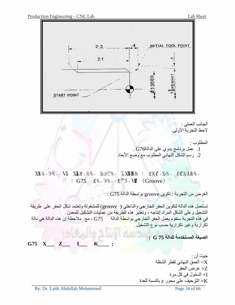
Production Engineering ndash CNC Lab Lab Sheet
By Dr Laith Abdullah Mohammed Page 34 of 66
الجانب العملي الحظ التجربة األولى
المطلوب
G76عمل برنامج يدوي على الدالة 1 رسم الشكل النهائي المطلوب مع وضع األبعاد 2
Ⅺ⅘₌⅗₌ Ⅵ₂ Ⅺ₯ℋ₍⅗₌ ℌℲℂ⅗₌ ⅞ⅫⅦ⅔₧ ₤K₡₌ℌ⅗₌ ₤₡ℌ₰₨⅗₌)Groove ₤⅗₌⅗₌ ₤tradeimage₌Ⅶ₡ (G75
G75 بواسطة الدالة grooveالغرض من التجربة تكوين
) للمشغولة وتعتمد شكل الحفر على طريقة grooveتستعمل هذه الدالة لتكوين الحفر الخارجي والداخلي (
التشغيل وعلى الشكل المراد إنتاجه وتعتبر هذه الطريقة من عمليات التشكيل للمعدن إن هذه الدالة هي دالة مالحظة مع G75في هذه التجربة سنقوم بعمل الحفر الخارجي بواسطة الدالة
تكرارية وغير تكرارية حسب نوع التشغيل
G 75 الصيغة المستخدمة للدالةG75 X___ Z___ I___ K____
حيث أن
X العمق النهائي لقطر الشغلة =Z عرض الحفر =I الدخول في كل مرة =
K التزحيف على محور =z بالنسبة للعدة
Production Engineering ndash CNC Lab Lab Sheet
By Dr Laith Abdullah Mohammed Page 35 of 66
G75مثال على استخدام الدالة
T0500 M48 GOO X100 Z -20 T0505 M08 G97 S700 MO3 G75 X84 Z -38 I 05 K4
الجانب العملي الحظ التجربة األولى
المطلوب
G76عمل برنامج يدوي على الدالة 1 رسم الشكل النهائي المطلوب مع وضع األبعاد 2
Production Engineering ndash CNC Lab Lab Sheet
By Dr Laith Abdullah Mohammed Page 36 of 66
CNC Milling Machine Mechanical Construction
Guideways The guideways of CNC machines are made of steel To reduce the frictional forces they are coated with a strip of PTFE (Poly Tetra Fluoro Ethylene)
Ballscrews On conventional lathes a leadscrew is used to converts the rotary motion of the hand wheel into linear motion of the slides Leadscrews have a high coefficient of friction and backlash On CNC machines a ballscrew is used instead of a leadscrew Friction and backlash are much less than on leadscrews
Guideway
Production Engineering ndash CNC Lab Lab Sheet
By Dr Laith Abdullah Mohammed Page 37 of 66
bullMachining operations Direction of cutting Based on the direction of the cutter rotation and work piece feed milling operations are classified into two types 1-Up milling (Convention milling) In up milling the metal is removed by rotating the cutter against the direction of travel of the part
Feed
Machine table
Part
Cutting tool
Chip thickness at theexit of the tooth
2-Down milling (Climb milling) In climb milling the metal is removed by rotating the cutter with the direction of travel of the part
Machine table
Part
Cutting tool
Chip thickness at theentrance of the tooth
Production Engineering ndash CNC Lab Lab Sheet
By Dr Laith Abdullah Mohammed Page 38 of 66
bullTooling Tool geometry The geometry of the tool tip affects the way that the metal cutting is performed The nose radius rake angles relief angles etc must be selected with care
Radial relief
Radial rake
Axial relief
Approach angle
Axial relief
Corner radius Face mill Face milling cutters are used to mill flat surfaces Commonly used face milling cutters Cutter with 75 degree approach
75 deg
Cutter with 90 degree approach (Square shoulder face mill)
90 deg
Cutter with 45 degree approach
Production Engineering ndash CNC Lab Lab Sheet
By Dr Laith Abdullah Mohammed Page 39 of 66
bullCNC Programming Axes convention The Z axis is along the spindle axis The X and Y axes are perpendicular to Z VMC
Z
Y
-
+
-+
X- +
+Z
-Z
+Y
-Y
-X +X
Part
Machine table
X
YZ
G00 Rapid traverse When the tool being positioned at a point preparatory to a cutting motion to save time it is moved along a straight line at Rapid traverse at a fixed traverse rate which is pre-programmed into the machines control system Typical rapid traverse rates are 10 to 25 m min but can be as high as 80 mmin
Production Engineering ndash CNC Lab Lab Sheet
By Dr Laith Abdullah Mohammed Page 40 of 66
Format N_ G00 X__ Y__Z__
G01 Linear interpolation (feed traverse) The tool moves along a straight line in one or two axis simultaneously at a programmed linear speed the feed rate Format N__ G01 X__ Y__Z__ F__
Part
Feed
Part
Feed
G02G03 Circular interpolation The tool moves along an arc in two axes simultaneously at a programmed linear speed the feed rate
Production Engineering ndash CNC Lab Lab Sheet
By Dr Laith Abdullah Mohammed Page 41 of 66
Format N__ G0203 X__ Y__Z__ I__ J__K__ F__ using the arc center OR N__ G0203 X__ Y__Z__ R__ F__ using the arc radius G02 moves along a CW arc G03 moves along a CCW arc Arc center The arc center is specified by addresses I J and K I J and K are the X Y and Z co-ordinates of the arc center with reference to the arc start point
X
Y
Arc center
Arc endArc start
- J
- I
I = X coord of center - X coord of start point J = Y coord of center - Y coord of start point K = Z coord of center - Z coord of start point I J and K must be written with their signs
Production Engineering ndash CNC Lab Lab Sheet
By Dr Laith Abdullah Mohammed Page 42 of 66
bullWork holding
Rotary table
Fixture base
Component
Clamp
Stud
Fixtures The use of fixtures 1 Improves repeatability of dimensions 2 Improves working conditions 3 Cuts down requirement of skilled labour 4 Reduces part loading and unloading time 5 Improves safety in the working area 6 Reduces the cost of machining There are two types fixtures commonly used 1 Special fixture Special fixtures are used to hold and locate the typical components which are having complex shape and to be located with the reference hole (dowel hole) Special fixtures are required for components like gear case cover cylinder heads etc 2 Modular fixture Modular fixture is a set different kind of clamping and locating elements These fixtures are used to hold identical components in different sizes and components of box type Example Manifolds head stocks connecting rods and flanges
Production Engineering ndash CNC Lab Lab Sheet
By Dr Laith Abdullah Mohammed Page 43 of 66
bullMachine setting
Determining X and Y work zero offset Case 1
Part
Machine table
Part
End mill or reamer
Work offset X0Y0 For determining X work zero offset bull Touch the periphery of the end mill or reamer to the part bull Enter current machine X value + cutter radius as X work zero offset For determining Y work zero offset bull Touch the periphery of the end mill or reamer to the part bull Enter current machine Y value - cutter radius as Y work zero offset Case 2
Part
Machine table
Part
End mill or reamerWork offset X0Y0
bull Mount the dial indicator on machine spindle true the bore bull Enter current machine X and Y value as X and Y work zero offset
Production Engineering ndash CNC Lab Lab Sheet
By Dr Laith Abdullah Mohammed Page 44 of 66
How to Select a Cutting Fluid
One part of the metal cutting equation that is sometimes overlooked however is
the choice of an appropriate cutting fluid With todayrsquos system approach to metal
cutting use of the right metalworking fluid has become just as much a part of the
solution as the other elements In fact at least one company is now integrating
cutting fluids and cutting tools into effective metal cutting systems Following are
some things to consider when choosing your next cutting fluid
The Four Key Questions
There are four vital pieces of information that are necessary when choosing a
cutting fluid They are
1 What are you cutting
2 What is the chemistry of your water
3 What are you using now
4 What are your options
5 What do you prefer
What Are You Cutting
The first question ndash ldquoWhat are you cuttingrdquo ndash is often the most difficult to answer
because most shops handle a variety of workpiece materials on a regular basis If
the answer is an unequivocal ldquoaluminumrdquo or ldquostainless steelrdquo or ldquocast ironrdquo the
selection of a cutting fluid can be quite simple and straightforward Unfortunately
that is seldom the case in anything but a high-volume plant Where aluminum or
other nonferrous metals are a significant part of the mix a non-staining cutting
fluid is a must Generally speaking this will be a semi-synthetic with special
ingredients to prevent bi-metallic corrosion and staining of non-ferrous workpieces
Where the ferrous metals predominate however a more general purpose semi-
synthetic or hybrid fluid might be a more economical choice
Production Engineering ndash CNC Lab Lab Sheet
By Dr Laith Abdullah Mohammed Page 45 of 66
What is The Chemistry of Your Water
The second question ndash ldquoWhat is the chemistry of your waterrdquo ndash is probably the
single most common reason for the success or failure of a cutting fluid Very few
plants invest the money necessary to install effective water purification systems
using deionization or reverse osmosis technology Unfortunately the chemicals
present or not present in the water used to re-constitute a cutting fluid make a
tremendous difference in its performance and sump life Most manufacturers of
cutting fluids will perform the necessary water testing to determine exactly what
minerals are dissolved in your water and make a fluid recommendation based on
the results
What are you using now
The third question ndash ldquoWhat are you using nowrdquo ndash helps narrow the range of
choices When coupled with an objective analysis of the strengths and weaknesses
of the current fluid the answer to this question can quickly point you toward a
relatively small number of competitive alternatives that have the attributes required
to meet your cutting needs Many cutting fluids are in use today simply because
they were in use yesterday It is a hard reality of todayrsquos marketplace that if one
isnrsquot constantly striving to improve they will certainly be overtaken by a
competitor who is
What Are Your Options
The fourth question ndash ldquoWhat are your optionsrdquo ndash leads to the final selection of a
cutting fluid Cutting fluids can be divided into four general groups based on their
chemistry
They are
bull Soluble Oils ndash quite literally oil dispersed in water
bull Synthetics ndash completely oil free man-made coolants in solution
Production Engineering ndash CNC Lab Lab Sheet
By Dr Laith Abdullah Mohammed Page 46 of 66
bull Semi-Synthetics ndash a mixture of natural and synthetic lubricants with up to 30
mineral oil
bull Hybrids ndash a special class of semi-synthetics with a mineral oil content of about
15 Each fluid type has advantages and disadvantages which make it suitable for
a particular group of applications In addition there are costperformance trade-
offs to be made between the groups within a specific set of applications For
example where a hybrid and a semi-synthetic may both be suitable for a particular
use the hybrid might provide longer sump life at a slightly higher initial cost
while some semi synthetics may be more economical to recycle or dispose of while
not giving as long a tank life The final decision in this case would have to be made
on the detailed economics of the shop where the fluids were to be used and on the
ownerrsquos individual preferences
Soluble Oils
Soluble oils are oils that disperse in water when emulsifiers are added They are
generally suitable for moderate-to heavy-duty machining and grinding of all non-
ferrous metals carbon and cast steels and in applications where dissimilar metals
such as aluminium and steel are present They can also be used in turning drilling
tapping reaming gear cutting broaching as well as internal and centerless types
of grinding operations Soluble oils provide excellent aluminium and copper
corrosion control good rancidity control which extends fluid for long lasting
trouble-free performance and good concentrate and mix stability making it ideal
for mixing in water with a minimal amount of agitation An example of this is
Valenitersquos VNTreg-650 premium heavy-duty soluble oil
Synthetics
Synthetics are completely oil free solutions made of polymers organic and
inorganic materials that are mixed with water These clear low foaming and bio-
Production Engineering ndash CNC Lab Lab Sheet
By Dr Laith Abdullah Mohammed Page 47 of 66
stable coolants are ideal for machining and grinding of ferrous materials carbon
steels or cast iron Their complex lubricant packages make synthetics well-suited
for tough-to-machine materials such as stainless steels and high-temperature alloys
Certain synthetics are specifically designed to address the primary failure modes of
flank wear and nose wear Although there are many benefits some synthetics may
cause staining of non-ferrous materials
Semi-Synthetics
Semi-synthetic fluids are a mixture of oils synthetic emulsifiers and water They
were primarily developed for the aircraft nuclear and related industries
Consequently they work extremely well on all non-ferrous metals such as titanium
aluminium copper brass bronze and stainless steel in both machining and
grinding Semi-synthetics can be used on ferrous metals too They are chlorine-
free to reduce bi-metallic corrosion and staining of metals They should be used at
a 5-8 dilution with water depending on the severity of the operation
Hybrids
Hybrids are cutting fluids custom engineered to solve a particular problem For
example Valenitersquos VNTreg-800 was developed to be very clean in the machining
and grinding of cast iron It provides better stability in hard water and rejects tramp
oil very well which adds to its bio-stable chemistry Hybrids work extremely well
on all metals in both machining and grinding They should be mixed at a 5-7
dilution with water depending on the condition of the water
What Do You Prefer
The final question ndash ldquoWhat do you preferrdquo ndash is usually the ldquotie breakerrdquo where
there is more than one appropriate cutting fluid available Here again as in the
case of what is being used now the key is to examine your preferences objectively
Production Engineering ndash CNC Lab Lab Sheet
By Dr Laith Abdullah Mohammed Page 48 of 66
and specifically to identify the real reasons behind a preference If you cannot
point to specific reasons why one class of cutting fluid is preferred over another
you are well advised to follow the recommendations of the professional who has
analyzed your requirements Choosing the right fluid today is easier than ever as
the system approach to metal cutting productivity continues to grow in acceptance
The day is not far off when choosing a complete solution will be as easy as
choosing the right insert and chip breaker today The answers are available and the
results will more than justify the time you spend choosing the right metal cutting
fluid
Useful Links wwwball-screwsnet
wwwlubelinkcom
wwwmachinerylubricationcom
wwwadvancedmanufacturingcom
wwwmmsonlinecom
wwwcuttingtoolengineeringcom
wwwgeartechnologycom
wwwengineersedgecom
wwwagmaorg
wwwefundacom
wwwsaeorg
wwwsmeorg
wwwastmorg
wwwissorg
wwwmachinetoolscom
wwwansiorg
wwwasmeorg
wwwcnccicom
wwwmatlscom
wwwthefreedictionarycom
wwwengineersupplycom
Production Engineering ndash CNC Lab Lab Sheet
By Dr Laith Abdullah Mohammed Page 49 of 66
SurfCAM Tutorial ndash Beginning with the basics
Background SurfCAM is a computer aided manufacturing (CAM) software which allows you to create manage and modify tool paths for computer aided designed (CAD) part The software requires a CAD model or requires that you create some geometry within SurfCAM with some rudimentary tools provided The tool paths are created or stored internally in SurfCAM in a generic programming language called APT Once the tool paths are created the APT paths are translated using a post processor into typical machine G-code
Opening SurfCAM SurfCAM can be opened from the Novell Applications Launcher on most Industrial Engineering computer labs workstations Search under lsquoallrsquo applications and double click on SurfCAM 2005 Once the program opens a license must be selected from the list (not the Demo license) to enable saving the file later Choose one of the 30 licenses available If for some reason the licenses are not listed on the license manager form select server list and type ldquobonnieeosncsuedurdquo A list of available licenses should appear Select a license and click OK After the license is selected an Add StockFixture form (Figure 1) opens allows you to add a model which represents the pre-machined stock or a fixture Click on OK without adding either Both of these items can be added later under a more appropriate dialog
Figure 1 Add Stock or Fixture dialog box
Production Engineering ndash CNC Lab Lab Sheet
By Dr Laith Abdullah Mohammed Page 50 of 66
SurfCAM Interface
Figure 2 SurfCAM Windows based interface
SurfCAM is a windows based software system so most of the typical windows functions under File are applicable This is where you can open save exit print etc The Create menu allows the user to create different geometry forms Here you can create a point line surface chamfer circle and many other geometry types For the most part these functions are not used by beginners but are useful when creating bounding curves where you donrsquot want the tool to move outside (constraining the tool) The Edit menu allows you to change or modify many different entities such as changing lines altering surfaces joining surfaces trimming or breaking elements add control points etc Again these features are helpful to advanced users and are not covered in detail in this tutorial The Display menu offers the ability to change the orientation of the part on the screen The typical rotate pan fit to screen and zoom functions are available as well as several functions which allow the user to shift between views or call up a named view (ie top bottom etc) The NC menu is the main machining interface menu In this menu you select the general form of machining (2 axis 3 axis 4 axis 5 axis turning etc) and under the general form a more specific machining function is selected This menu is the most used and the options contained must be fully understood to get the most out of SurfCAM Each function will be described in some detail in a further chapter The Analyze menu contains options such as measuring the distance between points angles tangency elements etc These functions are auxiliary functions meant to help you understand the part better but basically provide no functionality for making tool paths for CNC machines Thus these will not be covered The Tools menu allows the user to change the system options modify keyboard shortcuts change the model units etc These options are again not used by beginners Finally the Help menu provides access to the online users manual In lieu of clicking the Help menu the F1 key is the shortcut key for help (as it is in most windows based programs)
Importing a CAD model Importing a CAD model that is stored locally is done by selecting File-gtOpen On the Files of type dropdown box choose the type of file you wish to open (Figure 3) Do this prior to negotiating your way through the maze of folders to prevent having to go through the folder tree again Once the file type is selected find the file you are trying to open and click the Open
Production Engineering ndash CNC Lab Lab Sheet
By Dr Laith Abdullah Mohammed Page 51 of 66
button SurfCAM will then attempt to read the file you have selected SurfCAM may provide a dialog box describing what it has imported and identify if it was successful If this dialog is provided simply click close without saving
Figure 3 Open Dialog Note - Change type of file prior to finding the file you wish to open
SurfCAM allows a user to import several different types of CAD files the most common types which you will likely import are SolidWorks part files (sldprt or prt) AutoCAD files(dxf) or IGES (igs or iges) Native file import (such as is the case with SolidWorks) provides the greatest information transfer and generic file imports (such as is the case with IGES) provide the least Normally it is to the advantage of the user to use native file importing procedures when available Recently (2005) SurfCAM added some compatibility with SolidWorks This allows the user to create tool paths for a part and if an engineering change is needed for the part update the part in SolidWorks When the part is then opened in SurfCAM the changes are noted and a simple update operation command is needed This however does not operate with complete transparency andor accuracy and thus users need to be cognizant of changing CAD models
SurfCAM Geometry In SurfCAM two basic types of geometry are used the surface and the point A surface (Figure 4) is a so called spline (NURBS or B-Spline are the two most common) surface (parameterized by two values u and v) such that every location on the surface can be defined as a function of these parameters In other words SurfCAM can calculate the location of any point on the
Production Engineering ndash CNC Lab Lab Sheet
By Dr Laith Abdullah Mohammed Page 52 of 66
surface Surfaces are used primarily in 3 4 and 5 axis machining and require a significant
amount of processing power and time Figure 4 Surfaces model of a mold half Note the difference between this and Figure 2 a wireframe model
Point or line based models are often referred to as wireframe (Figure 5) models because the models consist of connected lines and resemble the part only at the intersection of two surfaces Wireframe models were made popular lsquoback in the dayrsquo when computer processing was expensive There are times when each of the models are important and selecting model geometry when applying a SurfCAM operation will be much simpler if you understand the differences between the two When importing a SolidWorks model the default is both the surfaces and the wireframe geometry are imported
Figure 5 Wireframe model of the mold in Figure 1
Steps to Creating Tool Paths Once a CAD model is imported into SurfCAM tool paths can be created There is no one correct way to create tool paths however there is a set of general steps to take to ensure the tool paths are created with a minimum amount of hardship (note the wordinghellipHardship is inevitable when creating tool paths it is the intent of this manual to minimize this) The following is a list of steps which should be considered when making tool paths
Production Engineering ndash CNC Lab Lab Sheet
By Dr Laith Abdullah Mohammed Page 53 of 66
1 Plan ahead a Orient the part in SolidWorks such that if only one side is to be machined that
side is the Top view This can be done early in SolidWorks by choosing a plane parallel the X-Y plane as the sketch plane for the machined geometry
b Orient the part in SolidWorks such that the origin is somewhere of relative importance and someplace in space that can be easily identified when placed on the machine This is extremely important to minimize set up time at the machine (note ndash my personal preference for a part that is to be fully machined [ie stock exists on all sides] is to place the origin at the center and top of the parthellipjust my preference)
c Orient the part in SolidWorks such that the X and Y axes are aligned as you want them on the machinehellip
d Planning ahead will save you many hours of headaches laterhelliptrust me 2 Import the model 3 Choose a construction view such that the tool approaches the side to be machined
from the positive Z axis direction (as defined by part origin) a This is done by clicking on the CView icon
b From the list of named views chose the view which orients the origin as you would like
c If one of the views does not fit your criteria you have two choices i Perform a transformation of the part in SurfCAM or SolidWorks
ii Add a new construction view by selecting new This option requires a relatively good understanding of right hand coordinate frames but is very usefulhellipNormally used by more advanced users
d Be sure the CoordVIEW selection is made vs CoordWORLD This ensures the tools will be controlled from the coordinate frame selected by the view (ie the origin on the part) instead of the origin on the lower left corner of the screen This will be especially important when we get into 4 and 5 axis machining
4 In the Operations Manager (Figure 6) select Setup One and change the name to something meaningful ndash like Front Side Mold Cavity
a Access the Operations manager by right clicking or by selecting the Operations Manager icon in the tool bar
b Operations Manager is where the tool paths are managed once they are created as well as where individual tool paths can be verified
Production Engineering ndash CNC Lab Lab Sheet
By Dr Laith Abdullah Mohammed Page 54 of 66
5 Roughing Tool Paths a Create the tool paths to remove the majority of the material (if applicable) b Use NC-gt3Axis-gtZ rough or Plunge Rough c Described in next section
6 Create Finishing Tool Paths a Described in next section
7 Add another setup if necessary 8 Perform steps 3 through 6 as necessary 9 Verify the tool paths are correct 10 Use a post processor for the tool paths to create G-Code for machine
Creating Tool Paths The following is a list of operations what they are intended for how they generally work and some parameters that may be adjusted to modify the tool paths
2 Axis tool paths Unless otherwise noted 2 axis tool path functions require lines or arc segments as input parameters (as opposed to surfaces) There are several options as to how these segments are chosen the most prevalent is the chain option and the second most prevalent is the single When choosing the line segments using the chain option SurfCAM will try to link a complete path of segments based on an initial segment chosen by the user If the operation is planer (ie pocket or contour) the segments must lie on the same plane If the operation is non-planer (ie contour 3D) SurfCAM will prompt the user to specify segments when it encounters a branch point
Figure 6 Operations Manager view showing setup one re-labeled as Front Side Mold
Production Engineering ndash CNC Lab Lab Sheet
By Dr Laith Abdullah Mohammed Page 55 of 66
When using the single element option the user must manually choose each segment desired for the operation Note that most operations do not require a closed loop of segments you may specify for instance an open contour where the tool is supposed to move The order of choosing segments is important This order determines the path of the tool in the sense that if three segments are chosen such that the middle segment is chosen last there will be three different plunge and machine operations one on each segment If the operation was to make a continuous contour around the outside of the part the segments should be chosen in order of the desired tool trajectory
Operations
Pocket Pocket operation in SurfCAM is used to cut an enclosed space from the inside to the outside at one particular depth The operation starts in the center of an enclosed area (with a plunge move in the ndashZ direction) and makes incremental closed paths towards the pocket boundaries in user defined path offsets (Figure 7) The user chooses the boundary of the pocket (line segments) and if more than one pocket is chosen SurfCAM will ask the user to click inside a pocket
Figure 7 Two examples of using the pocketing operation
The pocket operation allows for creating a projection of the pocket paths on multiple planes This is useful if you have a deep pocket which will not allow the tool to cut directly at the depth of the pocket but would be easily done using the same paths at several different Z heights On the cut control (Figure 8) tab the user specifies where the chosen geometry (pocket segments) lie (ie bottom or top) Then under the amount to remove specify the total material height to be removed and the rough spacing (amount you wish to advance the Z axis with each pocket step) You may also specify a finishing pass and as well as stock to leave
Production Engineering ndash CNC Lab Lab Sheet
By Dr Laith Abdullah Mohammed Page 56 of 66
Figure 8 Example of Contour Operation with multiple passes
Contour Contouring in SurfCAM is used to perform peripheral milling on the inside or outside of a line segment (Figure 9) The user is to identify the line segments which define a contour (does not have to be a closed loop of segments) SurfCAM may or may not require the user to specify a side to contour (ie which side of the line is the tool to cut) For contouring each segment must lie on the same plane
Production Engineering ndash CNC Lab Lab Sheet
By Dr Laith Abdullah Mohammed Page 57 of 66
Figure 9 Examples of parts cut with 2-Axis Contour
Contour 3D Contour 3D is the same operation type as contour but allows the user to specify segments on different planes for the tool to cut along
Drill Drilling operations are any rotating tool operation meant to engage the part from a single direction ndash namely from the positive Z direction Drilling operations can be specified using circle point or line segments After choosing NC-gt2-Axis-gtDrill SurfCAM allows the user to choose multiple circles or points defining holes to be drilled Drilling operations also allow the user to incorporate more than 1 operation such as a center drill a drill and a reaming operation After selecting the locations for the drilling operation a dialog box (Figure 10) allows the user to add change or delete tools to be used in the operation As displayed in the following figure the spotdrill operation is followed by a drilling operation followed by a tapping operation The depth of each tool can be controlled individually by double clicking the total depth cell in and manually entering Tools can be added before or after operations which the cells are highlighted by selecting either of the insert buttons at the top or by the insert menu Select tool button allows the user to change the tool size or type
Production Engineering ndash CNC Lab Lab Sheet
By Dr Laith Abdullah Mohammed Page 58 of 66
Figure 10 Drill operation manager Several operations can be completed at one time
Figure 11 Drill operation including the spotdrill drill and tap as outlined in Fig 10
3 Axis tool paths SurfCAM requires surfaces as inputs for 3 Axis tool paths Surfaces can be created in SurfCAM but are most easily created in a CAD package and imported into SurfCAM Surfaces allow SurfCAM to identify every point on the surface in 3 dimensions unlike 2D geometry (wireframes) which only identify positions on the plane Creating tool paths with complex surfaces takes a very significant amount of processing power so expect 3 Axis tool path generation to take longer
Production Engineering ndash CNC Lab Lab Sheet
By Dr Laith Abdullah Mohammed Page 59 of 66
Operations
Cut 3 Axis cut operation takes a surface and using the flow lines creates a rastering path over the surface with the tool tip riding on the surface The primary direction will be defined by the flow lines of the surface (which can be edited by Edit-gtSurfaces-gtArrow-gtDirection) If you intend to cross surface boundaries you must merge the surfaces (Edit-gtJoin and choose the two surfaces)
Z-Rough The Z-rough operation is used to remove a large amount of material prior to finish machining Roughing operation is typically the first operation you perform for each setup The Z-Rough operation cuts the part in user defined intervals For each of these intervals a surface intersection between the part and the plane is performed and a 2D pocket or contour operation is performed on that plane This is performed on each plane When choosing NC-gt3 Axis-gtZ rough the first dialog box you will encounter asks for a bounding box to be defined Choose the Extents Box and a second dialog box will ask for the coordinates which define the box (Figure 12) This is the stock size you expect to machine the part from Input the coordinates or change the additional offset amounts (in XY or Z) as appropriate and click Calculate Bounding Box
Figure 12 Material Extents Box Example
Next choose the tool and cutting parameters that you desire and click on the Cut Control Tab (Figure 13) Here you will find the following parameters which are often changed Stock to
Production Engineering ndash CNC Lab Lab Sheet
By Dr Laith Abdullah Mohammed Page 60 of 66
leave ndash this is an offset amount from the surfaces which leaves a small amount of material to finish machine Minimum and Maximum Z values ndash Defines area to machine Z Step Size ndash This identifies the plane intervals for the surface intersection planes (the first interval will be at the top of the selected area and successive increments down in Z will be cut until the Minimum Z value is reached)
Figure 13 3Axis Z Rough Cut Control
The 3Axis Z-Finish operation works in exactly the same way 3 Axis Z-Finish is most appropriate for finishing vertical or near vertical walls
3D Offset The 3D Offset operation creates a tool path using a 2D or 3D boundary by offsetting the boundary in concentric offset cutting passes Each pass calculates the tool engagement and maintains the engagement somewhat constant The advantage (significant) is the scallop height ndash height of the material between passes ndash is controlled thus the surface finish is predictable When choosing 3D Offset surfaces are selected as well as 2D or 3D boundaries The boundaries define the concentric offset paths shape as well as limit the tool path area Choose NC-gt3Axis-gt3D Offset from the drop down menus SurfCAM will prompt you to select the surface or surfaces to cut across Select the surfaces you wish to machine and then select the tool and cutting parameters you wish use Next select the Cut Control Tab and check the Use Boundary Curves option Set the Step Type to Scallop and set the maximum scallop height If you like
Production Engineering ndash CNC Lab Lab Sheet
By Dr Laith Abdullah Mohammed Page 61 of 66
you can also add stock to leave if this is a roughing operation You can also set the Direction and Start-End parameters from this tab Click OK and the paths will be generated
Figure 14 Cut Control Tab for 3D Offset
Example part using both 2D and 3D geometry
The tool paths for this mold will be generated in SurfCAM using 5 operations The first will be a roughing operation using a frac14 inch flat end mill with the Z step size of 00625in Choose NC-
Production Engineering ndash CNC Lab Lab Sheet
By Dr Laith Abdullah Mohammed Page 62 of 66
gt3Axis-gtZ-Rough from the drop down menu Select all visible surfaces and create an extents box that has 025inch XY offsets and 01inch Z offset Next select the frac14 inch flat end mill from the tools menu Under Cut Control tab set the Z step size to be 00625inch The tool paths will look something like Figure 15
Figure 15 Z-Rough Tool paths for Example Part
Next a flat surface operation will be performed to cut the flat surface on the top Select NC-gt3 Axis-gtFlat Surface from the drop down menu Select all visible surfaces again Choose the 12inch flat end mill and set the cutting parameters as desired Under Cut Control Tab change the Minimum Area to 50 square inches (Figure 16) The tool paths should look something like Figure 17
Figure 16 Cut Control for Flat Surface
Production Engineering ndash CNC Lab Lab Sheet
By Dr Laith Abdullah Mohammed Page 63 of 66
Figure 17 Flat Surface Tool Paths
Next we will use a 3D offset operation to cut the mold cavity Select NC-gt3 Axis-gt3D Offset from the dropdown menu Change the view to the top view and select within to capture the surfaces of the mold cavity Draw a rectangle around the mold cavity Select a 18 inch ball endmill from the tool library and set the cutting parameters as appropriate Next set the Cut Control tab parameters as in Figure 14 The paths creates should be similar to Figure 18
Figure 18 3D Offset Paths
Next we will perform a 2 Axis contouring of the top section Select NC-gt2 Axis-gtContour from the dropdown menu Using the chain option select the bottom contour of the top extrusion Select the frac12 inch flat end mill from the tool library and set the cutting parameters as required In the Cut Control Tab change the Geometry to Bottom and the amount to remove in Z to 05
Production Engineering ndash CNC Lab Lab Sheet
By Dr Laith Abdullah Mohammed Page 64 of 66
Change the Rough Spacing in Z to 025 and add 1 finish pass of 002 (Figure 19) Click OK and SurfCAM will instruct you to choose a side to contour Click anywhere on the screen OUTSIDE the geometry you selected for the contouring operation Failure to click outside the geometry will result in the tool being on the wrong side of the contour Your paths should look something like those in Figure 20
Figure 19 Cut Control Tab for the Contouring Operation
Figure 20 Contouring operation paths
Production Engineering ndash CNC Lab Lab Sheet
By Dr Laith Abdullah Mohammed Page 65 of 66
Next we will perform a 2 axis pocket operation for the small pocket on the top face of the mold Select NC-gt2Axis-gtPocket and using the Auto select feature select the boundary curve at the bottom of the pocket Click Done twice and select the frac14 inch flat end mill from the tool library Set the appropriate cutting parameters and click OK SurfCAM will prompt you to click inside the pocket Click anywhere inside the geometry you chose to define the pocket The resulting paths should look something like those in Figure 21
Figure 21 2 Axis Pocket Operation Paths
Finally we will add a drilling operation for the 2 holes at the corners of the mold Select NC-gt2 Axis-gtDrill from the dropdown menu Select the top circles defining the two holes A menu box will appear with a default tool (Center drill) already programmed Add a second tool to the list by selecting Insert-gtAfter and select the tool from the tool library Change the drill depth to 10inches and click OK The paths should look something similar to Figure 23
Figure 22 Drill Menu
Production Engineering ndash CNC Lab Lab Sheet
By Dr Laith Abdullah Mohammed Page 66 of 66
Figure 23 Drilling Operation Tool Paths
Now you can watch a simulation of the cutting by choosing the setup in the operations manager and clicking the simulate icon Be sure to set the stock in the set up by right clicking the set up and selecting Edit Setup Information In the Stock Tab you can create a bounding box meeting your needs and click Add Your simulation should result in something like the following
Figure 24 Final Simulation of the example Mold
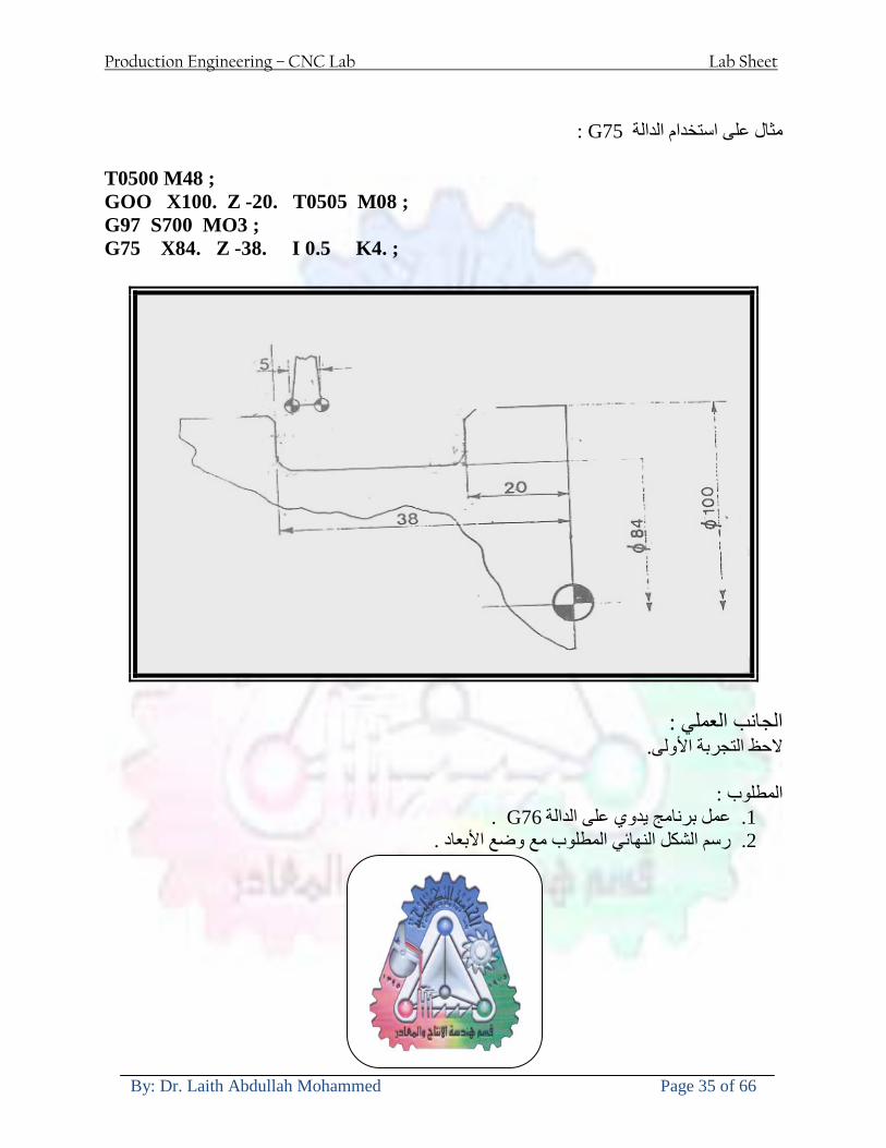
Production Engineering ndash CNC Lab Lab Sheet
By Dr Laith Abdullah Mohammed Page 35 of 66
G75مثال على استخدام الدالة
T0500 M48 GOO X100 Z -20 T0505 M08 G97 S700 MO3 G75 X84 Z -38 I 05 K4
الجانب العملي الحظ التجربة األولى
المطلوب
G76عمل برنامج يدوي على الدالة 1 رسم الشكل النهائي المطلوب مع وضع األبعاد 2
Production Engineering ndash CNC Lab Lab Sheet
By Dr Laith Abdullah Mohammed Page 36 of 66
CNC Milling Machine Mechanical Construction
Guideways The guideways of CNC machines are made of steel To reduce the frictional forces they are coated with a strip of PTFE (Poly Tetra Fluoro Ethylene)
Ballscrews On conventional lathes a leadscrew is used to converts the rotary motion of the hand wheel into linear motion of the slides Leadscrews have a high coefficient of friction and backlash On CNC machines a ballscrew is used instead of a leadscrew Friction and backlash are much less than on leadscrews
Guideway
Production Engineering ndash CNC Lab Lab Sheet
By Dr Laith Abdullah Mohammed Page 37 of 66
bullMachining operations Direction of cutting Based on the direction of the cutter rotation and work piece feed milling operations are classified into two types 1-Up milling (Convention milling) In up milling the metal is removed by rotating the cutter against the direction of travel of the part
Feed
Machine table
Part
Cutting tool
Chip thickness at theexit of the tooth
2-Down milling (Climb milling) In climb milling the metal is removed by rotating the cutter with the direction of travel of the part
Machine table
Part
Cutting tool
Chip thickness at theentrance of the tooth
Production Engineering ndash CNC Lab Lab Sheet
By Dr Laith Abdullah Mohammed Page 38 of 66
bullTooling Tool geometry The geometry of the tool tip affects the way that the metal cutting is performed The nose radius rake angles relief angles etc must be selected with care
Radial relief
Radial rake
Axial relief
Approach angle
Axial relief
Corner radius Face mill Face milling cutters are used to mill flat surfaces Commonly used face milling cutters Cutter with 75 degree approach
75 deg
Cutter with 90 degree approach (Square shoulder face mill)
90 deg
Cutter with 45 degree approach
Production Engineering ndash CNC Lab Lab Sheet
By Dr Laith Abdullah Mohammed Page 39 of 66
bullCNC Programming Axes convention The Z axis is along the spindle axis The X and Y axes are perpendicular to Z VMC
Z
Y
-
+
-+
X- +
+Z
-Z
+Y
-Y
-X +X
Part
Machine table
X
YZ
G00 Rapid traverse When the tool being positioned at a point preparatory to a cutting motion to save time it is moved along a straight line at Rapid traverse at a fixed traverse rate which is pre-programmed into the machines control system Typical rapid traverse rates are 10 to 25 m min but can be as high as 80 mmin
Production Engineering ndash CNC Lab Lab Sheet
By Dr Laith Abdullah Mohammed Page 40 of 66
Format N_ G00 X__ Y__Z__
G01 Linear interpolation (feed traverse) The tool moves along a straight line in one or two axis simultaneously at a programmed linear speed the feed rate Format N__ G01 X__ Y__Z__ F__
Part
Feed
Part
Feed
G02G03 Circular interpolation The tool moves along an arc in two axes simultaneously at a programmed linear speed the feed rate
Production Engineering ndash CNC Lab Lab Sheet
By Dr Laith Abdullah Mohammed Page 41 of 66
Format N__ G0203 X__ Y__Z__ I__ J__K__ F__ using the arc center OR N__ G0203 X__ Y__Z__ R__ F__ using the arc radius G02 moves along a CW arc G03 moves along a CCW arc Arc center The arc center is specified by addresses I J and K I J and K are the X Y and Z co-ordinates of the arc center with reference to the arc start point
X
Y
Arc center
Arc endArc start
- J
- I
I = X coord of center - X coord of start point J = Y coord of center - Y coord of start point K = Z coord of center - Z coord of start point I J and K must be written with their signs
Production Engineering ndash CNC Lab Lab Sheet
By Dr Laith Abdullah Mohammed Page 42 of 66
bullWork holding
Rotary table
Fixture base
Component
Clamp
Stud
Fixtures The use of fixtures 1 Improves repeatability of dimensions 2 Improves working conditions 3 Cuts down requirement of skilled labour 4 Reduces part loading and unloading time 5 Improves safety in the working area 6 Reduces the cost of machining There are two types fixtures commonly used 1 Special fixture Special fixtures are used to hold and locate the typical components which are having complex shape and to be located with the reference hole (dowel hole) Special fixtures are required for components like gear case cover cylinder heads etc 2 Modular fixture Modular fixture is a set different kind of clamping and locating elements These fixtures are used to hold identical components in different sizes and components of box type Example Manifolds head stocks connecting rods and flanges
Production Engineering ndash CNC Lab Lab Sheet
By Dr Laith Abdullah Mohammed Page 43 of 66
bullMachine setting
Determining X and Y work zero offset Case 1
Part
Machine table
Part
End mill or reamer
Work offset X0Y0 For determining X work zero offset bull Touch the periphery of the end mill or reamer to the part bull Enter current machine X value + cutter radius as X work zero offset For determining Y work zero offset bull Touch the periphery of the end mill or reamer to the part bull Enter current machine Y value - cutter radius as Y work zero offset Case 2
Part
Machine table
Part
End mill or reamerWork offset X0Y0
bull Mount the dial indicator on machine spindle true the bore bull Enter current machine X and Y value as X and Y work zero offset
Production Engineering ndash CNC Lab Lab Sheet
By Dr Laith Abdullah Mohammed Page 44 of 66
How to Select a Cutting Fluid
One part of the metal cutting equation that is sometimes overlooked however is
the choice of an appropriate cutting fluid With todayrsquos system approach to metal
cutting use of the right metalworking fluid has become just as much a part of the
solution as the other elements In fact at least one company is now integrating
cutting fluids and cutting tools into effective metal cutting systems Following are
some things to consider when choosing your next cutting fluid
The Four Key Questions
There are four vital pieces of information that are necessary when choosing a
cutting fluid They are
1 What are you cutting
2 What is the chemistry of your water
3 What are you using now
4 What are your options
5 What do you prefer
What Are You Cutting
The first question ndash ldquoWhat are you cuttingrdquo ndash is often the most difficult to answer
because most shops handle a variety of workpiece materials on a regular basis If
the answer is an unequivocal ldquoaluminumrdquo or ldquostainless steelrdquo or ldquocast ironrdquo the
selection of a cutting fluid can be quite simple and straightforward Unfortunately
that is seldom the case in anything but a high-volume plant Where aluminum or
other nonferrous metals are a significant part of the mix a non-staining cutting
fluid is a must Generally speaking this will be a semi-synthetic with special
ingredients to prevent bi-metallic corrosion and staining of non-ferrous workpieces
Where the ferrous metals predominate however a more general purpose semi-
synthetic or hybrid fluid might be a more economical choice
Production Engineering ndash CNC Lab Lab Sheet
By Dr Laith Abdullah Mohammed Page 45 of 66
What is The Chemistry of Your Water
The second question ndash ldquoWhat is the chemistry of your waterrdquo ndash is probably the
single most common reason for the success or failure of a cutting fluid Very few
plants invest the money necessary to install effective water purification systems
using deionization or reverse osmosis technology Unfortunately the chemicals
present or not present in the water used to re-constitute a cutting fluid make a
tremendous difference in its performance and sump life Most manufacturers of
cutting fluids will perform the necessary water testing to determine exactly what
minerals are dissolved in your water and make a fluid recommendation based on
the results
What are you using now
The third question ndash ldquoWhat are you using nowrdquo ndash helps narrow the range of
choices When coupled with an objective analysis of the strengths and weaknesses
of the current fluid the answer to this question can quickly point you toward a
relatively small number of competitive alternatives that have the attributes required
to meet your cutting needs Many cutting fluids are in use today simply because
they were in use yesterday It is a hard reality of todayrsquos marketplace that if one
isnrsquot constantly striving to improve they will certainly be overtaken by a
competitor who is
What Are Your Options
The fourth question ndash ldquoWhat are your optionsrdquo ndash leads to the final selection of a
cutting fluid Cutting fluids can be divided into four general groups based on their
chemistry
They are
bull Soluble Oils ndash quite literally oil dispersed in water
bull Synthetics ndash completely oil free man-made coolants in solution
Production Engineering ndash CNC Lab Lab Sheet
By Dr Laith Abdullah Mohammed Page 46 of 66
bull Semi-Synthetics ndash a mixture of natural and synthetic lubricants with up to 30
mineral oil
bull Hybrids ndash a special class of semi-synthetics with a mineral oil content of about
15 Each fluid type has advantages and disadvantages which make it suitable for
a particular group of applications In addition there are costperformance trade-
offs to be made between the groups within a specific set of applications For
example where a hybrid and a semi-synthetic may both be suitable for a particular
use the hybrid might provide longer sump life at a slightly higher initial cost
while some semi synthetics may be more economical to recycle or dispose of while
not giving as long a tank life The final decision in this case would have to be made
on the detailed economics of the shop where the fluids were to be used and on the
ownerrsquos individual preferences
Soluble Oils
Soluble oils are oils that disperse in water when emulsifiers are added They are
generally suitable for moderate-to heavy-duty machining and grinding of all non-
ferrous metals carbon and cast steels and in applications where dissimilar metals
such as aluminium and steel are present They can also be used in turning drilling
tapping reaming gear cutting broaching as well as internal and centerless types
of grinding operations Soluble oils provide excellent aluminium and copper
corrosion control good rancidity control which extends fluid for long lasting
trouble-free performance and good concentrate and mix stability making it ideal
for mixing in water with a minimal amount of agitation An example of this is
Valenitersquos VNTreg-650 premium heavy-duty soluble oil
Synthetics
Synthetics are completely oil free solutions made of polymers organic and
inorganic materials that are mixed with water These clear low foaming and bio-
Production Engineering ndash CNC Lab Lab Sheet
By Dr Laith Abdullah Mohammed Page 47 of 66
stable coolants are ideal for machining and grinding of ferrous materials carbon
steels or cast iron Their complex lubricant packages make synthetics well-suited
for tough-to-machine materials such as stainless steels and high-temperature alloys
Certain synthetics are specifically designed to address the primary failure modes of
flank wear and nose wear Although there are many benefits some synthetics may
cause staining of non-ferrous materials
Semi-Synthetics
Semi-synthetic fluids are a mixture of oils synthetic emulsifiers and water They
were primarily developed for the aircraft nuclear and related industries
Consequently they work extremely well on all non-ferrous metals such as titanium
aluminium copper brass bronze and stainless steel in both machining and
grinding Semi-synthetics can be used on ferrous metals too They are chlorine-
free to reduce bi-metallic corrosion and staining of metals They should be used at
a 5-8 dilution with water depending on the severity of the operation
Hybrids
Hybrids are cutting fluids custom engineered to solve a particular problem For
example Valenitersquos VNTreg-800 was developed to be very clean in the machining
and grinding of cast iron It provides better stability in hard water and rejects tramp
oil very well which adds to its bio-stable chemistry Hybrids work extremely well
on all metals in both machining and grinding They should be mixed at a 5-7
dilution with water depending on the condition of the water
What Do You Prefer
The final question ndash ldquoWhat do you preferrdquo ndash is usually the ldquotie breakerrdquo where
there is more than one appropriate cutting fluid available Here again as in the
case of what is being used now the key is to examine your preferences objectively
Production Engineering ndash CNC Lab Lab Sheet
By Dr Laith Abdullah Mohammed Page 48 of 66
and specifically to identify the real reasons behind a preference If you cannot
point to specific reasons why one class of cutting fluid is preferred over another
you are well advised to follow the recommendations of the professional who has
analyzed your requirements Choosing the right fluid today is easier than ever as
the system approach to metal cutting productivity continues to grow in acceptance
The day is not far off when choosing a complete solution will be as easy as
choosing the right insert and chip breaker today The answers are available and the
results will more than justify the time you spend choosing the right metal cutting
fluid
Useful Links wwwball-screwsnet
wwwlubelinkcom
wwwmachinerylubricationcom
wwwadvancedmanufacturingcom
wwwmmsonlinecom
wwwcuttingtoolengineeringcom
wwwgeartechnologycom
wwwengineersedgecom
wwwagmaorg
wwwefundacom
wwwsaeorg
wwwsmeorg
wwwastmorg
wwwissorg
wwwmachinetoolscom
wwwansiorg
wwwasmeorg
wwwcnccicom
wwwmatlscom
wwwthefreedictionarycom
wwwengineersupplycom
Production Engineering ndash CNC Lab Lab Sheet
By Dr Laith Abdullah Mohammed Page 49 of 66
SurfCAM Tutorial ndash Beginning with the basics
Background SurfCAM is a computer aided manufacturing (CAM) software which allows you to create manage and modify tool paths for computer aided designed (CAD) part The software requires a CAD model or requires that you create some geometry within SurfCAM with some rudimentary tools provided The tool paths are created or stored internally in SurfCAM in a generic programming language called APT Once the tool paths are created the APT paths are translated using a post processor into typical machine G-code
Opening SurfCAM SurfCAM can be opened from the Novell Applications Launcher on most Industrial Engineering computer labs workstations Search under lsquoallrsquo applications and double click on SurfCAM 2005 Once the program opens a license must be selected from the list (not the Demo license) to enable saving the file later Choose one of the 30 licenses available If for some reason the licenses are not listed on the license manager form select server list and type ldquobonnieeosncsuedurdquo A list of available licenses should appear Select a license and click OK After the license is selected an Add StockFixture form (Figure 1) opens allows you to add a model which represents the pre-machined stock or a fixture Click on OK without adding either Both of these items can be added later under a more appropriate dialog
Figure 1 Add Stock or Fixture dialog box
Production Engineering ndash CNC Lab Lab Sheet
By Dr Laith Abdullah Mohammed Page 50 of 66
SurfCAM Interface
Figure 2 SurfCAM Windows based interface
SurfCAM is a windows based software system so most of the typical windows functions under File are applicable This is where you can open save exit print etc The Create menu allows the user to create different geometry forms Here you can create a point line surface chamfer circle and many other geometry types For the most part these functions are not used by beginners but are useful when creating bounding curves where you donrsquot want the tool to move outside (constraining the tool) The Edit menu allows you to change or modify many different entities such as changing lines altering surfaces joining surfaces trimming or breaking elements add control points etc Again these features are helpful to advanced users and are not covered in detail in this tutorial The Display menu offers the ability to change the orientation of the part on the screen The typical rotate pan fit to screen and zoom functions are available as well as several functions which allow the user to shift between views or call up a named view (ie top bottom etc) The NC menu is the main machining interface menu In this menu you select the general form of machining (2 axis 3 axis 4 axis 5 axis turning etc) and under the general form a more specific machining function is selected This menu is the most used and the options contained must be fully understood to get the most out of SurfCAM Each function will be described in some detail in a further chapter The Analyze menu contains options such as measuring the distance between points angles tangency elements etc These functions are auxiliary functions meant to help you understand the part better but basically provide no functionality for making tool paths for CNC machines Thus these will not be covered The Tools menu allows the user to change the system options modify keyboard shortcuts change the model units etc These options are again not used by beginners Finally the Help menu provides access to the online users manual In lieu of clicking the Help menu the F1 key is the shortcut key for help (as it is in most windows based programs)
Importing a CAD model Importing a CAD model that is stored locally is done by selecting File-gtOpen On the Files of type dropdown box choose the type of file you wish to open (Figure 3) Do this prior to negotiating your way through the maze of folders to prevent having to go through the folder tree again Once the file type is selected find the file you are trying to open and click the Open
Production Engineering ndash CNC Lab Lab Sheet
By Dr Laith Abdullah Mohammed Page 51 of 66
button SurfCAM will then attempt to read the file you have selected SurfCAM may provide a dialog box describing what it has imported and identify if it was successful If this dialog is provided simply click close without saving
Figure 3 Open Dialog Note - Change type of file prior to finding the file you wish to open
SurfCAM allows a user to import several different types of CAD files the most common types which you will likely import are SolidWorks part files (sldprt or prt) AutoCAD files(dxf) or IGES (igs or iges) Native file import (such as is the case with SolidWorks) provides the greatest information transfer and generic file imports (such as is the case with IGES) provide the least Normally it is to the advantage of the user to use native file importing procedures when available Recently (2005) SurfCAM added some compatibility with SolidWorks This allows the user to create tool paths for a part and if an engineering change is needed for the part update the part in SolidWorks When the part is then opened in SurfCAM the changes are noted and a simple update operation command is needed This however does not operate with complete transparency andor accuracy and thus users need to be cognizant of changing CAD models
SurfCAM Geometry In SurfCAM two basic types of geometry are used the surface and the point A surface (Figure 4) is a so called spline (NURBS or B-Spline are the two most common) surface (parameterized by two values u and v) such that every location on the surface can be defined as a function of these parameters In other words SurfCAM can calculate the location of any point on the
Production Engineering ndash CNC Lab Lab Sheet
By Dr Laith Abdullah Mohammed Page 52 of 66
surface Surfaces are used primarily in 3 4 and 5 axis machining and require a significant
amount of processing power and time Figure 4 Surfaces model of a mold half Note the difference between this and Figure 2 a wireframe model
Point or line based models are often referred to as wireframe (Figure 5) models because the models consist of connected lines and resemble the part only at the intersection of two surfaces Wireframe models were made popular lsquoback in the dayrsquo when computer processing was expensive There are times when each of the models are important and selecting model geometry when applying a SurfCAM operation will be much simpler if you understand the differences between the two When importing a SolidWorks model the default is both the surfaces and the wireframe geometry are imported
Figure 5 Wireframe model of the mold in Figure 1
Steps to Creating Tool Paths Once a CAD model is imported into SurfCAM tool paths can be created There is no one correct way to create tool paths however there is a set of general steps to take to ensure the tool paths are created with a minimum amount of hardship (note the wordinghellipHardship is inevitable when creating tool paths it is the intent of this manual to minimize this) The following is a list of steps which should be considered when making tool paths
Production Engineering ndash CNC Lab Lab Sheet
By Dr Laith Abdullah Mohammed Page 53 of 66
1 Plan ahead a Orient the part in SolidWorks such that if only one side is to be machined that
side is the Top view This can be done early in SolidWorks by choosing a plane parallel the X-Y plane as the sketch plane for the machined geometry
b Orient the part in SolidWorks such that the origin is somewhere of relative importance and someplace in space that can be easily identified when placed on the machine This is extremely important to minimize set up time at the machine (note ndash my personal preference for a part that is to be fully machined [ie stock exists on all sides] is to place the origin at the center and top of the parthellipjust my preference)
c Orient the part in SolidWorks such that the X and Y axes are aligned as you want them on the machinehellip
d Planning ahead will save you many hours of headaches laterhelliptrust me 2 Import the model 3 Choose a construction view such that the tool approaches the side to be machined
from the positive Z axis direction (as defined by part origin) a This is done by clicking on the CView icon
b From the list of named views chose the view which orients the origin as you would like
c If one of the views does not fit your criteria you have two choices i Perform a transformation of the part in SurfCAM or SolidWorks
ii Add a new construction view by selecting new This option requires a relatively good understanding of right hand coordinate frames but is very usefulhellipNormally used by more advanced users
d Be sure the CoordVIEW selection is made vs CoordWORLD This ensures the tools will be controlled from the coordinate frame selected by the view (ie the origin on the part) instead of the origin on the lower left corner of the screen This will be especially important when we get into 4 and 5 axis machining
4 In the Operations Manager (Figure 6) select Setup One and change the name to something meaningful ndash like Front Side Mold Cavity
a Access the Operations manager by right clicking or by selecting the Operations Manager icon in the tool bar
b Operations Manager is where the tool paths are managed once they are created as well as where individual tool paths can be verified
Production Engineering ndash CNC Lab Lab Sheet
By Dr Laith Abdullah Mohammed Page 54 of 66
5 Roughing Tool Paths a Create the tool paths to remove the majority of the material (if applicable) b Use NC-gt3Axis-gtZ rough or Plunge Rough c Described in next section
6 Create Finishing Tool Paths a Described in next section
7 Add another setup if necessary 8 Perform steps 3 through 6 as necessary 9 Verify the tool paths are correct 10 Use a post processor for the tool paths to create G-Code for machine
Creating Tool Paths The following is a list of operations what they are intended for how they generally work and some parameters that may be adjusted to modify the tool paths
2 Axis tool paths Unless otherwise noted 2 axis tool path functions require lines or arc segments as input parameters (as opposed to surfaces) There are several options as to how these segments are chosen the most prevalent is the chain option and the second most prevalent is the single When choosing the line segments using the chain option SurfCAM will try to link a complete path of segments based on an initial segment chosen by the user If the operation is planer (ie pocket or contour) the segments must lie on the same plane If the operation is non-planer (ie contour 3D) SurfCAM will prompt the user to specify segments when it encounters a branch point
Figure 6 Operations Manager view showing setup one re-labeled as Front Side Mold
Production Engineering ndash CNC Lab Lab Sheet
By Dr Laith Abdullah Mohammed Page 55 of 66
When using the single element option the user must manually choose each segment desired for the operation Note that most operations do not require a closed loop of segments you may specify for instance an open contour where the tool is supposed to move The order of choosing segments is important This order determines the path of the tool in the sense that if three segments are chosen such that the middle segment is chosen last there will be three different plunge and machine operations one on each segment If the operation was to make a continuous contour around the outside of the part the segments should be chosen in order of the desired tool trajectory
Operations
Pocket Pocket operation in SurfCAM is used to cut an enclosed space from the inside to the outside at one particular depth The operation starts in the center of an enclosed area (with a plunge move in the ndashZ direction) and makes incremental closed paths towards the pocket boundaries in user defined path offsets (Figure 7) The user chooses the boundary of the pocket (line segments) and if more than one pocket is chosen SurfCAM will ask the user to click inside a pocket
Figure 7 Two examples of using the pocketing operation
The pocket operation allows for creating a projection of the pocket paths on multiple planes This is useful if you have a deep pocket which will not allow the tool to cut directly at the depth of the pocket but would be easily done using the same paths at several different Z heights On the cut control (Figure 8) tab the user specifies where the chosen geometry (pocket segments) lie (ie bottom or top) Then under the amount to remove specify the total material height to be removed and the rough spacing (amount you wish to advance the Z axis with each pocket step) You may also specify a finishing pass and as well as stock to leave
Production Engineering ndash CNC Lab Lab Sheet
By Dr Laith Abdullah Mohammed Page 56 of 66
Figure 8 Example of Contour Operation with multiple passes
Contour Contouring in SurfCAM is used to perform peripheral milling on the inside or outside of a line segment (Figure 9) The user is to identify the line segments which define a contour (does not have to be a closed loop of segments) SurfCAM may or may not require the user to specify a side to contour (ie which side of the line is the tool to cut) For contouring each segment must lie on the same plane
Production Engineering ndash CNC Lab Lab Sheet
By Dr Laith Abdullah Mohammed Page 57 of 66
Figure 9 Examples of parts cut with 2-Axis Contour
Contour 3D Contour 3D is the same operation type as contour but allows the user to specify segments on different planes for the tool to cut along
Drill Drilling operations are any rotating tool operation meant to engage the part from a single direction ndash namely from the positive Z direction Drilling operations can be specified using circle point or line segments After choosing NC-gt2-Axis-gtDrill SurfCAM allows the user to choose multiple circles or points defining holes to be drilled Drilling operations also allow the user to incorporate more than 1 operation such as a center drill a drill and a reaming operation After selecting the locations for the drilling operation a dialog box (Figure 10) allows the user to add change or delete tools to be used in the operation As displayed in the following figure the spotdrill operation is followed by a drilling operation followed by a tapping operation The depth of each tool can be controlled individually by double clicking the total depth cell in and manually entering Tools can be added before or after operations which the cells are highlighted by selecting either of the insert buttons at the top or by the insert menu Select tool button allows the user to change the tool size or type
Production Engineering ndash CNC Lab Lab Sheet
By Dr Laith Abdullah Mohammed Page 58 of 66
Figure 10 Drill operation manager Several operations can be completed at one time
Figure 11 Drill operation including the spotdrill drill and tap as outlined in Fig 10
3 Axis tool paths SurfCAM requires surfaces as inputs for 3 Axis tool paths Surfaces can be created in SurfCAM but are most easily created in a CAD package and imported into SurfCAM Surfaces allow SurfCAM to identify every point on the surface in 3 dimensions unlike 2D geometry (wireframes) which only identify positions on the plane Creating tool paths with complex surfaces takes a very significant amount of processing power so expect 3 Axis tool path generation to take longer
Production Engineering ndash CNC Lab Lab Sheet
By Dr Laith Abdullah Mohammed Page 59 of 66
Operations
Cut 3 Axis cut operation takes a surface and using the flow lines creates a rastering path over the surface with the tool tip riding on the surface The primary direction will be defined by the flow lines of the surface (which can be edited by Edit-gtSurfaces-gtArrow-gtDirection) If you intend to cross surface boundaries you must merge the surfaces (Edit-gtJoin and choose the two surfaces)
Z-Rough The Z-rough operation is used to remove a large amount of material prior to finish machining Roughing operation is typically the first operation you perform for each setup The Z-Rough operation cuts the part in user defined intervals For each of these intervals a surface intersection between the part and the plane is performed and a 2D pocket or contour operation is performed on that plane This is performed on each plane When choosing NC-gt3 Axis-gtZ rough the first dialog box you will encounter asks for a bounding box to be defined Choose the Extents Box and a second dialog box will ask for the coordinates which define the box (Figure 12) This is the stock size you expect to machine the part from Input the coordinates or change the additional offset amounts (in XY or Z) as appropriate and click Calculate Bounding Box
Figure 12 Material Extents Box Example
Next choose the tool and cutting parameters that you desire and click on the Cut Control Tab (Figure 13) Here you will find the following parameters which are often changed Stock to
Production Engineering ndash CNC Lab Lab Sheet
By Dr Laith Abdullah Mohammed Page 60 of 66
leave ndash this is an offset amount from the surfaces which leaves a small amount of material to finish machine Minimum and Maximum Z values ndash Defines area to machine Z Step Size ndash This identifies the plane intervals for the surface intersection planes (the first interval will be at the top of the selected area and successive increments down in Z will be cut until the Minimum Z value is reached)
Figure 13 3Axis Z Rough Cut Control
The 3Axis Z-Finish operation works in exactly the same way 3 Axis Z-Finish is most appropriate for finishing vertical or near vertical walls
3D Offset The 3D Offset operation creates a tool path using a 2D or 3D boundary by offsetting the boundary in concentric offset cutting passes Each pass calculates the tool engagement and maintains the engagement somewhat constant The advantage (significant) is the scallop height ndash height of the material between passes ndash is controlled thus the surface finish is predictable When choosing 3D Offset surfaces are selected as well as 2D or 3D boundaries The boundaries define the concentric offset paths shape as well as limit the tool path area Choose NC-gt3Axis-gt3D Offset from the drop down menus SurfCAM will prompt you to select the surface or surfaces to cut across Select the surfaces you wish to machine and then select the tool and cutting parameters you wish use Next select the Cut Control Tab and check the Use Boundary Curves option Set the Step Type to Scallop and set the maximum scallop height If you like
Production Engineering ndash CNC Lab Lab Sheet
By Dr Laith Abdullah Mohammed Page 61 of 66
you can also add stock to leave if this is a roughing operation You can also set the Direction and Start-End parameters from this tab Click OK and the paths will be generated
Figure 14 Cut Control Tab for 3D Offset
Example part using both 2D and 3D geometry
The tool paths for this mold will be generated in SurfCAM using 5 operations The first will be a roughing operation using a frac14 inch flat end mill with the Z step size of 00625in Choose NC-
Production Engineering ndash CNC Lab Lab Sheet
By Dr Laith Abdullah Mohammed Page 62 of 66
gt3Axis-gtZ-Rough from the drop down menu Select all visible surfaces and create an extents box that has 025inch XY offsets and 01inch Z offset Next select the frac14 inch flat end mill from the tools menu Under Cut Control tab set the Z step size to be 00625inch The tool paths will look something like Figure 15
Figure 15 Z-Rough Tool paths for Example Part
Next a flat surface operation will be performed to cut the flat surface on the top Select NC-gt3 Axis-gtFlat Surface from the drop down menu Select all visible surfaces again Choose the 12inch flat end mill and set the cutting parameters as desired Under Cut Control Tab change the Minimum Area to 50 square inches (Figure 16) The tool paths should look something like Figure 17
Figure 16 Cut Control for Flat Surface
Production Engineering ndash CNC Lab Lab Sheet
By Dr Laith Abdullah Mohammed Page 63 of 66
Figure 17 Flat Surface Tool Paths
Next we will use a 3D offset operation to cut the mold cavity Select NC-gt3 Axis-gt3D Offset from the dropdown menu Change the view to the top view and select within to capture the surfaces of the mold cavity Draw a rectangle around the mold cavity Select a 18 inch ball endmill from the tool library and set the cutting parameters as appropriate Next set the Cut Control tab parameters as in Figure 14 The paths creates should be similar to Figure 18
Figure 18 3D Offset Paths
Next we will perform a 2 Axis contouring of the top section Select NC-gt2 Axis-gtContour from the dropdown menu Using the chain option select the bottom contour of the top extrusion Select the frac12 inch flat end mill from the tool library and set the cutting parameters as required In the Cut Control Tab change the Geometry to Bottom and the amount to remove in Z to 05
Production Engineering ndash CNC Lab Lab Sheet
By Dr Laith Abdullah Mohammed Page 64 of 66
Change the Rough Spacing in Z to 025 and add 1 finish pass of 002 (Figure 19) Click OK and SurfCAM will instruct you to choose a side to contour Click anywhere on the screen OUTSIDE the geometry you selected for the contouring operation Failure to click outside the geometry will result in the tool being on the wrong side of the contour Your paths should look something like those in Figure 20
Figure 19 Cut Control Tab for the Contouring Operation
Figure 20 Contouring operation paths
Production Engineering ndash CNC Lab Lab Sheet
By Dr Laith Abdullah Mohammed Page 65 of 66
Next we will perform a 2 axis pocket operation for the small pocket on the top face of the mold Select NC-gt2Axis-gtPocket and using the Auto select feature select the boundary curve at the bottom of the pocket Click Done twice and select the frac14 inch flat end mill from the tool library Set the appropriate cutting parameters and click OK SurfCAM will prompt you to click inside the pocket Click anywhere inside the geometry you chose to define the pocket The resulting paths should look something like those in Figure 21
Figure 21 2 Axis Pocket Operation Paths
Finally we will add a drilling operation for the 2 holes at the corners of the mold Select NC-gt2 Axis-gtDrill from the dropdown menu Select the top circles defining the two holes A menu box will appear with a default tool (Center drill) already programmed Add a second tool to the list by selecting Insert-gtAfter and select the tool from the tool library Change the drill depth to 10inches and click OK The paths should look something similar to Figure 23
Figure 22 Drill Menu
Production Engineering ndash CNC Lab Lab Sheet
By Dr Laith Abdullah Mohammed Page 66 of 66
Figure 23 Drilling Operation Tool Paths
Now you can watch a simulation of the cutting by choosing the setup in the operations manager and clicking the simulate icon Be sure to set the stock in the set up by right clicking the set up and selecting Edit Setup Information In the Stock Tab you can create a bounding box meeting your needs and click Add Your simulation should result in something like the following
Figure 24 Final Simulation of the example Mold
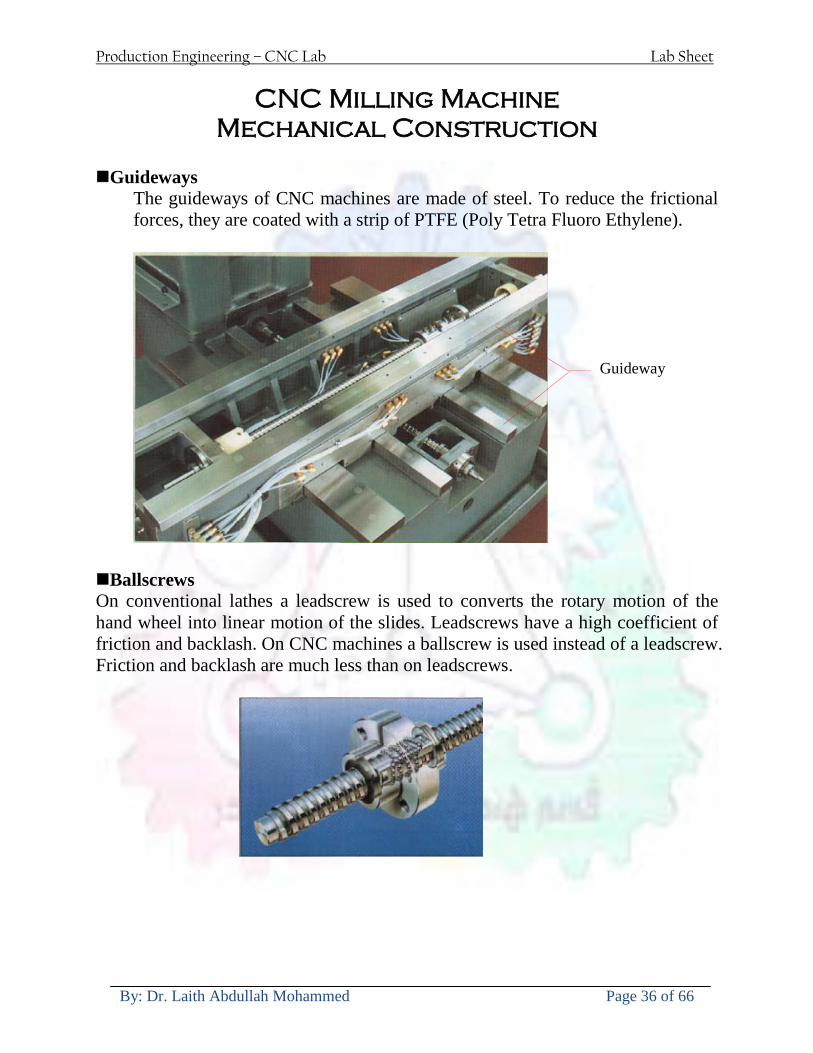
Production Engineering ndash CNC Lab Lab Sheet
By Dr Laith Abdullah Mohammed Page 36 of 66
CNC Milling Machine Mechanical Construction
Guideways The guideways of CNC machines are made of steel To reduce the frictional forces they are coated with a strip of PTFE (Poly Tetra Fluoro Ethylene)
Ballscrews On conventional lathes a leadscrew is used to converts the rotary motion of the hand wheel into linear motion of the slides Leadscrews have a high coefficient of friction and backlash On CNC machines a ballscrew is used instead of a leadscrew Friction and backlash are much less than on leadscrews
Guideway
Production Engineering ndash CNC Lab Lab Sheet
By Dr Laith Abdullah Mohammed Page 37 of 66
bullMachining operations Direction of cutting Based on the direction of the cutter rotation and work piece feed milling operations are classified into two types 1-Up milling (Convention milling) In up milling the metal is removed by rotating the cutter against the direction of travel of the part
Feed
Machine table
Part
Cutting tool
Chip thickness at theexit of the tooth
2-Down milling (Climb milling) In climb milling the metal is removed by rotating the cutter with the direction of travel of the part
Machine table
Part
Cutting tool
Chip thickness at theentrance of the tooth
Production Engineering ndash CNC Lab Lab Sheet
By Dr Laith Abdullah Mohammed Page 38 of 66
bullTooling Tool geometry The geometry of the tool tip affects the way that the metal cutting is performed The nose radius rake angles relief angles etc must be selected with care
Radial relief
Radial rake
Axial relief
Approach angle
Axial relief
Corner radius Face mill Face milling cutters are used to mill flat surfaces Commonly used face milling cutters Cutter with 75 degree approach
75 deg
Cutter with 90 degree approach (Square shoulder face mill)
90 deg
Cutter with 45 degree approach
Production Engineering ndash CNC Lab Lab Sheet
By Dr Laith Abdullah Mohammed Page 39 of 66
bullCNC Programming Axes convention The Z axis is along the spindle axis The X and Y axes are perpendicular to Z VMC
Z
Y
-
+
-+
X- +
+Z
-Z
+Y
-Y
-X +X
Part
Machine table
X
YZ
G00 Rapid traverse When the tool being positioned at a point preparatory to a cutting motion to save time it is moved along a straight line at Rapid traverse at a fixed traverse rate which is pre-programmed into the machines control system Typical rapid traverse rates are 10 to 25 m min but can be as high as 80 mmin
Production Engineering ndash CNC Lab Lab Sheet
By Dr Laith Abdullah Mohammed Page 40 of 66
Format N_ G00 X__ Y__Z__
G01 Linear interpolation (feed traverse) The tool moves along a straight line in one or two axis simultaneously at a programmed linear speed the feed rate Format N__ G01 X__ Y__Z__ F__
Part
Feed
Part
Feed
G02G03 Circular interpolation The tool moves along an arc in two axes simultaneously at a programmed linear speed the feed rate
Production Engineering ndash CNC Lab Lab Sheet
By Dr Laith Abdullah Mohammed Page 41 of 66
Format N__ G0203 X__ Y__Z__ I__ J__K__ F__ using the arc center OR N__ G0203 X__ Y__Z__ R__ F__ using the arc radius G02 moves along a CW arc G03 moves along a CCW arc Arc center The arc center is specified by addresses I J and K I J and K are the X Y and Z co-ordinates of the arc center with reference to the arc start point
X
Y
Arc center
Arc endArc start
- J
- I
I = X coord of center - X coord of start point J = Y coord of center - Y coord of start point K = Z coord of center - Z coord of start point I J and K must be written with their signs
Production Engineering ndash CNC Lab Lab Sheet
By Dr Laith Abdullah Mohammed Page 42 of 66
bullWork holding
Rotary table
Fixture base
Component
Clamp
Stud
Fixtures The use of fixtures 1 Improves repeatability of dimensions 2 Improves working conditions 3 Cuts down requirement of skilled labour 4 Reduces part loading and unloading time 5 Improves safety in the working area 6 Reduces the cost of machining There are two types fixtures commonly used 1 Special fixture Special fixtures are used to hold and locate the typical components which are having complex shape and to be located with the reference hole (dowel hole) Special fixtures are required for components like gear case cover cylinder heads etc 2 Modular fixture Modular fixture is a set different kind of clamping and locating elements These fixtures are used to hold identical components in different sizes and components of box type Example Manifolds head stocks connecting rods and flanges
Production Engineering ndash CNC Lab Lab Sheet
By Dr Laith Abdullah Mohammed Page 43 of 66
bullMachine setting
Determining X and Y work zero offset Case 1
Part
Machine table
Part
End mill or reamer
Work offset X0Y0 For determining X work zero offset bull Touch the periphery of the end mill or reamer to the part bull Enter current machine X value + cutter radius as X work zero offset For determining Y work zero offset bull Touch the periphery of the end mill or reamer to the part bull Enter current machine Y value - cutter radius as Y work zero offset Case 2
Part
Machine table
Part
End mill or reamerWork offset X0Y0
bull Mount the dial indicator on machine spindle true the bore bull Enter current machine X and Y value as X and Y work zero offset
Production Engineering ndash CNC Lab Lab Sheet
By Dr Laith Abdullah Mohammed Page 44 of 66
How to Select a Cutting Fluid
One part of the metal cutting equation that is sometimes overlooked however is
the choice of an appropriate cutting fluid With todayrsquos system approach to metal
cutting use of the right metalworking fluid has become just as much a part of the
solution as the other elements In fact at least one company is now integrating
cutting fluids and cutting tools into effective metal cutting systems Following are
some things to consider when choosing your next cutting fluid
The Four Key Questions
There are four vital pieces of information that are necessary when choosing a
cutting fluid They are
1 What are you cutting
2 What is the chemistry of your water
3 What are you using now
4 What are your options
5 What do you prefer
What Are You Cutting
The first question ndash ldquoWhat are you cuttingrdquo ndash is often the most difficult to answer
because most shops handle a variety of workpiece materials on a regular basis If
the answer is an unequivocal ldquoaluminumrdquo or ldquostainless steelrdquo or ldquocast ironrdquo the
selection of a cutting fluid can be quite simple and straightforward Unfortunately
that is seldom the case in anything but a high-volume plant Where aluminum or
other nonferrous metals are a significant part of the mix a non-staining cutting
fluid is a must Generally speaking this will be a semi-synthetic with special
ingredients to prevent bi-metallic corrosion and staining of non-ferrous workpieces
Where the ferrous metals predominate however a more general purpose semi-
synthetic or hybrid fluid might be a more economical choice
Production Engineering ndash CNC Lab Lab Sheet
By Dr Laith Abdullah Mohammed Page 45 of 66
What is The Chemistry of Your Water
The second question ndash ldquoWhat is the chemistry of your waterrdquo ndash is probably the
single most common reason for the success or failure of a cutting fluid Very few
plants invest the money necessary to install effective water purification systems
using deionization or reverse osmosis technology Unfortunately the chemicals
present or not present in the water used to re-constitute a cutting fluid make a
tremendous difference in its performance and sump life Most manufacturers of
cutting fluids will perform the necessary water testing to determine exactly what
minerals are dissolved in your water and make a fluid recommendation based on
the results
What are you using now
The third question ndash ldquoWhat are you using nowrdquo ndash helps narrow the range of
choices When coupled with an objective analysis of the strengths and weaknesses
of the current fluid the answer to this question can quickly point you toward a
relatively small number of competitive alternatives that have the attributes required
to meet your cutting needs Many cutting fluids are in use today simply because
they were in use yesterday It is a hard reality of todayrsquos marketplace that if one
isnrsquot constantly striving to improve they will certainly be overtaken by a
competitor who is
What Are Your Options
The fourth question ndash ldquoWhat are your optionsrdquo ndash leads to the final selection of a
cutting fluid Cutting fluids can be divided into four general groups based on their
chemistry
They are
bull Soluble Oils ndash quite literally oil dispersed in water
bull Synthetics ndash completely oil free man-made coolants in solution
Production Engineering ndash CNC Lab Lab Sheet
By Dr Laith Abdullah Mohammed Page 46 of 66
bull Semi-Synthetics ndash a mixture of natural and synthetic lubricants with up to 30
mineral oil
bull Hybrids ndash a special class of semi-synthetics with a mineral oil content of about
15 Each fluid type has advantages and disadvantages which make it suitable for
a particular group of applications In addition there are costperformance trade-
offs to be made between the groups within a specific set of applications For
example where a hybrid and a semi-synthetic may both be suitable for a particular
use the hybrid might provide longer sump life at a slightly higher initial cost
while some semi synthetics may be more economical to recycle or dispose of while
not giving as long a tank life The final decision in this case would have to be made
on the detailed economics of the shop where the fluids were to be used and on the
ownerrsquos individual preferences
Soluble Oils
Soluble oils are oils that disperse in water when emulsifiers are added They are
generally suitable for moderate-to heavy-duty machining and grinding of all non-
ferrous metals carbon and cast steels and in applications where dissimilar metals
such as aluminium and steel are present They can also be used in turning drilling
tapping reaming gear cutting broaching as well as internal and centerless types
of grinding operations Soluble oils provide excellent aluminium and copper
corrosion control good rancidity control which extends fluid for long lasting
trouble-free performance and good concentrate and mix stability making it ideal
for mixing in water with a minimal amount of agitation An example of this is
Valenitersquos VNTreg-650 premium heavy-duty soluble oil
Synthetics
Synthetics are completely oil free solutions made of polymers organic and
inorganic materials that are mixed with water These clear low foaming and bio-
Production Engineering ndash CNC Lab Lab Sheet
By Dr Laith Abdullah Mohammed Page 47 of 66
stable coolants are ideal for machining and grinding of ferrous materials carbon
steels or cast iron Their complex lubricant packages make synthetics well-suited
for tough-to-machine materials such as stainless steels and high-temperature alloys
Certain synthetics are specifically designed to address the primary failure modes of
flank wear and nose wear Although there are many benefits some synthetics may
cause staining of non-ferrous materials
Semi-Synthetics
Semi-synthetic fluids are a mixture of oils synthetic emulsifiers and water They
were primarily developed for the aircraft nuclear and related industries
Consequently they work extremely well on all non-ferrous metals such as titanium
aluminium copper brass bronze and stainless steel in both machining and
grinding Semi-synthetics can be used on ferrous metals too They are chlorine-
free to reduce bi-metallic corrosion and staining of metals They should be used at
a 5-8 dilution with water depending on the severity of the operation
Hybrids
Hybrids are cutting fluids custom engineered to solve a particular problem For
example Valenitersquos VNTreg-800 was developed to be very clean in the machining
and grinding of cast iron It provides better stability in hard water and rejects tramp
oil very well which adds to its bio-stable chemistry Hybrids work extremely well
on all metals in both machining and grinding They should be mixed at a 5-7
dilution with water depending on the condition of the water
What Do You Prefer
The final question ndash ldquoWhat do you preferrdquo ndash is usually the ldquotie breakerrdquo where
there is more than one appropriate cutting fluid available Here again as in the
case of what is being used now the key is to examine your preferences objectively
Production Engineering ndash CNC Lab Lab Sheet
By Dr Laith Abdullah Mohammed Page 48 of 66
and specifically to identify the real reasons behind a preference If you cannot
point to specific reasons why one class of cutting fluid is preferred over another
you are well advised to follow the recommendations of the professional who has
analyzed your requirements Choosing the right fluid today is easier than ever as
the system approach to metal cutting productivity continues to grow in acceptance
The day is not far off when choosing a complete solution will be as easy as
choosing the right insert and chip breaker today The answers are available and the
results will more than justify the time you spend choosing the right metal cutting
fluid
Useful Links wwwball-screwsnet
wwwlubelinkcom
wwwmachinerylubricationcom
wwwadvancedmanufacturingcom
wwwmmsonlinecom
wwwcuttingtoolengineeringcom
wwwgeartechnologycom
wwwengineersedgecom
wwwagmaorg
wwwefundacom
wwwsaeorg
wwwsmeorg
wwwastmorg
wwwissorg
wwwmachinetoolscom
wwwansiorg
wwwasmeorg
wwwcnccicom
wwwmatlscom
wwwthefreedictionarycom
wwwengineersupplycom
Production Engineering ndash CNC Lab Lab Sheet
By Dr Laith Abdullah Mohammed Page 49 of 66
SurfCAM Tutorial ndash Beginning with the basics
Background SurfCAM is a computer aided manufacturing (CAM) software which allows you to create manage and modify tool paths for computer aided designed (CAD) part The software requires a CAD model or requires that you create some geometry within SurfCAM with some rudimentary tools provided The tool paths are created or stored internally in SurfCAM in a generic programming language called APT Once the tool paths are created the APT paths are translated using a post processor into typical machine G-code
Opening SurfCAM SurfCAM can be opened from the Novell Applications Launcher on most Industrial Engineering computer labs workstations Search under lsquoallrsquo applications and double click on SurfCAM 2005 Once the program opens a license must be selected from the list (not the Demo license) to enable saving the file later Choose one of the 30 licenses available If for some reason the licenses are not listed on the license manager form select server list and type ldquobonnieeosncsuedurdquo A list of available licenses should appear Select a license and click OK After the license is selected an Add StockFixture form (Figure 1) opens allows you to add a model which represents the pre-machined stock or a fixture Click on OK without adding either Both of these items can be added later under a more appropriate dialog
Figure 1 Add Stock or Fixture dialog box
Production Engineering ndash CNC Lab Lab Sheet
By Dr Laith Abdullah Mohammed Page 50 of 66
SurfCAM Interface
Figure 2 SurfCAM Windows based interface
SurfCAM is a windows based software system so most of the typical windows functions under File are applicable This is where you can open save exit print etc The Create menu allows the user to create different geometry forms Here you can create a point line surface chamfer circle and many other geometry types For the most part these functions are not used by beginners but are useful when creating bounding curves where you donrsquot want the tool to move outside (constraining the tool) The Edit menu allows you to change or modify many different entities such as changing lines altering surfaces joining surfaces trimming or breaking elements add control points etc Again these features are helpful to advanced users and are not covered in detail in this tutorial The Display menu offers the ability to change the orientation of the part on the screen The typical rotate pan fit to screen and zoom functions are available as well as several functions which allow the user to shift between views or call up a named view (ie top bottom etc) The NC menu is the main machining interface menu In this menu you select the general form of machining (2 axis 3 axis 4 axis 5 axis turning etc) and under the general form a more specific machining function is selected This menu is the most used and the options contained must be fully understood to get the most out of SurfCAM Each function will be described in some detail in a further chapter The Analyze menu contains options such as measuring the distance between points angles tangency elements etc These functions are auxiliary functions meant to help you understand the part better but basically provide no functionality for making tool paths for CNC machines Thus these will not be covered The Tools menu allows the user to change the system options modify keyboard shortcuts change the model units etc These options are again not used by beginners Finally the Help menu provides access to the online users manual In lieu of clicking the Help menu the F1 key is the shortcut key for help (as it is in most windows based programs)
Importing a CAD model Importing a CAD model that is stored locally is done by selecting File-gtOpen On the Files of type dropdown box choose the type of file you wish to open (Figure 3) Do this prior to negotiating your way through the maze of folders to prevent having to go through the folder tree again Once the file type is selected find the file you are trying to open and click the Open
Production Engineering ndash CNC Lab Lab Sheet
By Dr Laith Abdullah Mohammed Page 51 of 66
button SurfCAM will then attempt to read the file you have selected SurfCAM may provide a dialog box describing what it has imported and identify if it was successful If this dialog is provided simply click close without saving
Figure 3 Open Dialog Note - Change type of file prior to finding the file you wish to open
SurfCAM allows a user to import several different types of CAD files the most common types which you will likely import are SolidWorks part files (sldprt or prt) AutoCAD files(dxf) or IGES (igs or iges) Native file import (such as is the case with SolidWorks) provides the greatest information transfer and generic file imports (such as is the case with IGES) provide the least Normally it is to the advantage of the user to use native file importing procedures when available Recently (2005) SurfCAM added some compatibility with SolidWorks This allows the user to create tool paths for a part and if an engineering change is needed for the part update the part in SolidWorks When the part is then opened in SurfCAM the changes are noted and a simple update operation command is needed This however does not operate with complete transparency andor accuracy and thus users need to be cognizant of changing CAD models
SurfCAM Geometry In SurfCAM two basic types of geometry are used the surface and the point A surface (Figure 4) is a so called spline (NURBS or B-Spline are the two most common) surface (parameterized by two values u and v) such that every location on the surface can be defined as a function of these parameters In other words SurfCAM can calculate the location of any point on the
Production Engineering ndash CNC Lab Lab Sheet
By Dr Laith Abdullah Mohammed Page 52 of 66
surface Surfaces are used primarily in 3 4 and 5 axis machining and require a significant
amount of processing power and time Figure 4 Surfaces model of a mold half Note the difference between this and Figure 2 a wireframe model
Point or line based models are often referred to as wireframe (Figure 5) models because the models consist of connected lines and resemble the part only at the intersection of two surfaces Wireframe models were made popular lsquoback in the dayrsquo when computer processing was expensive There are times when each of the models are important and selecting model geometry when applying a SurfCAM operation will be much simpler if you understand the differences between the two When importing a SolidWorks model the default is both the surfaces and the wireframe geometry are imported
Figure 5 Wireframe model of the mold in Figure 1
Steps to Creating Tool Paths Once a CAD model is imported into SurfCAM tool paths can be created There is no one correct way to create tool paths however there is a set of general steps to take to ensure the tool paths are created with a minimum amount of hardship (note the wordinghellipHardship is inevitable when creating tool paths it is the intent of this manual to minimize this) The following is a list of steps which should be considered when making tool paths
Production Engineering ndash CNC Lab Lab Sheet
By Dr Laith Abdullah Mohammed Page 53 of 66
1 Plan ahead a Orient the part in SolidWorks such that if only one side is to be machined that
side is the Top view This can be done early in SolidWorks by choosing a plane parallel the X-Y plane as the sketch plane for the machined geometry
b Orient the part in SolidWorks such that the origin is somewhere of relative importance and someplace in space that can be easily identified when placed on the machine This is extremely important to minimize set up time at the machine (note ndash my personal preference for a part that is to be fully machined [ie stock exists on all sides] is to place the origin at the center and top of the parthellipjust my preference)
c Orient the part in SolidWorks such that the X and Y axes are aligned as you want them on the machinehellip
d Planning ahead will save you many hours of headaches laterhelliptrust me 2 Import the model 3 Choose a construction view such that the tool approaches the side to be machined
from the positive Z axis direction (as defined by part origin) a This is done by clicking on the CView icon
b From the list of named views chose the view which orients the origin as you would like
c If one of the views does not fit your criteria you have two choices i Perform a transformation of the part in SurfCAM or SolidWorks
ii Add a new construction view by selecting new This option requires a relatively good understanding of right hand coordinate frames but is very usefulhellipNormally used by more advanced users
d Be sure the CoordVIEW selection is made vs CoordWORLD This ensures the tools will be controlled from the coordinate frame selected by the view (ie the origin on the part) instead of the origin on the lower left corner of the screen This will be especially important when we get into 4 and 5 axis machining
4 In the Operations Manager (Figure 6) select Setup One and change the name to something meaningful ndash like Front Side Mold Cavity
a Access the Operations manager by right clicking or by selecting the Operations Manager icon in the tool bar
b Operations Manager is where the tool paths are managed once they are created as well as where individual tool paths can be verified
Production Engineering ndash CNC Lab Lab Sheet
By Dr Laith Abdullah Mohammed Page 54 of 66
5 Roughing Tool Paths a Create the tool paths to remove the majority of the material (if applicable) b Use NC-gt3Axis-gtZ rough or Plunge Rough c Described in next section
6 Create Finishing Tool Paths a Described in next section
7 Add another setup if necessary 8 Perform steps 3 through 6 as necessary 9 Verify the tool paths are correct 10 Use a post processor for the tool paths to create G-Code for machine
Creating Tool Paths The following is a list of operations what they are intended for how they generally work and some parameters that may be adjusted to modify the tool paths
2 Axis tool paths Unless otherwise noted 2 axis tool path functions require lines or arc segments as input parameters (as opposed to surfaces) There are several options as to how these segments are chosen the most prevalent is the chain option and the second most prevalent is the single When choosing the line segments using the chain option SurfCAM will try to link a complete path of segments based on an initial segment chosen by the user If the operation is planer (ie pocket or contour) the segments must lie on the same plane If the operation is non-planer (ie contour 3D) SurfCAM will prompt the user to specify segments when it encounters a branch point
Figure 6 Operations Manager view showing setup one re-labeled as Front Side Mold
Production Engineering ndash CNC Lab Lab Sheet
By Dr Laith Abdullah Mohammed Page 55 of 66
When using the single element option the user must manually choose each segment desired for the operation Note that most operations do not require a closed loop of segments you may specify for instance an open contour where the tool is supposed to move The order of choosing segments is important This order determines the path of the tool in the sense that if three segments are chosen such that the middle segment is chosen last there will be three different plunge and machine operations one on each segment If the operation was to make a continuous contour around the outside of the part the segments should be chosen in order of the desired tool trajectory
Operations
Pocket Pocket operation in SurfCAM is used to cut an enclosed space from the inside to the outside at one particular depth The operation starts in the center of an enclosed area (with a plunge move in the ndashZ direction) and makes incremental closed paths towards the pocket boundaries in user defined path offsets (Figure 7) The user chooses the boundary of the pocket (line segments) and if more than one pocket is chosen SurfCAM will ask the user to click inside a pocket
Figure 7 Two examples of using the pocketing operation
The pocket operation allows for creating a projection of the pocket paths on multiple planes This is useful if you have a deep pocket which will not allow the tool to cut directly at the depth of the pocket but would be easily done using the same paths at several different Z heights On the cut control (Figure 8) tab the user specifies where the chosen geometry (pocket segments) lie (ie bottom or top) Then under the amount to remove specify the total material height to be removed and the rough spacing (amount you wish to advance the Z axis with each pocket step) You may also specify a finishing pass and as well as stock to leave
Production Engineering ndash CNC Lab Lab Sheet
By Dr Laith Abdullah Mohammed Page 56 of 66
Figure 8 Example of Contour Operation with multiple passes
Contour Contouring in SurfCAM is used to perform peripheral milling on the inside or outside of a line segment (Figure 9) The user is to identify the line segments which define a contour (does not have to be a closed loop of segments) SurfCAM may or may not require the user to specify a side to contour (ie which side of the line is the tool to cut) For contouring each segment must lie on the same plane
Production Engineering ndash CNC Lab Lab Sheet
By Dr Laith Abdullah Mohammed Page 57 of 66
Figure 9 Examples of parts cut with 2-Axis Contour
Contour 3D Contour 3D is the same operation type as contour but allows the user to specify segments on different planes for the tool to cut along
Drill Drilling operations are any rotating tool operation meant to engage the part from a single direction ndash namely from the positive Z direction Drilling operations can be specified using circle point or line segments After choosing NC-gt2-Axis-gtDrill SurfCAM allows the user to choose multiple circles or points defining holes to be drilled Drilling operations also allow the user to incorporate more than 1 operation such as a center drill a drill and a reaming operation After selecting the locations for the drilling operation a dialog box (Figure 10) allows the user to add change or delete tools to be used in the operation As displayed in the following figure the spotdrill operation is followed by a drilling operation followed by a tapping operation The depth of each tool can be controlled individually by double clicking the total depth cell in and manually entering Tools can be added before or after operations which the cells are highlighted by selecting either of the insert buttons at the top or by the insert menu Select tool button allows the user to change the tool size or type
Production Engineering ndash CNC Lab Lab Sheet
By Dr Laith Abdullah Mohammed Page 58 of 66
Figure 10 Drill operation manager Several operations can be completed at one time
Figure 11 Drill operation including the spotdrill drill and tap as outlined in Fig 10
3 Axis tool paths SurfCAM requires surfaces as inputs for 3 Axis tool paths Surfaces can be created in SurfCAM but are most easily created in a CAD package and imported into SurfCAM Surfaces allow SurfCAM to identify every point on the surface in 3 dimensions unlike 2D geometry (wireframes) which only identify positions on the plane Creating tool paths with complex surfaces takes a very significant amount of processing power so expect 3 Axis tool path generation to take longer
Production Engineering ndash CNC Lab Lab Sheet
By Dr Laith Abdullah Mohammed Page 59 of 66
Operations
Cut 3 Axis cut operation takes a surface and using the flow lines creates a rastering path over the surface with the tool tip riding on the surface The primary direction will be defined by the flow lines of the surface (which can be edited by Edit-gtSurfaces-gtArrow-gtDirection) If you intend to cross surface boundaries you must merge the surfaces (Edit-gtJoin and choose the two surfaces)
Z-Rough The Z-rough operation is used to remove a large amount of material prior to finish machining Roughing operation is typically the first operation you perform for each setup The Z-Rough operation cuts the part in user defined intervals For each of these intervals a surface intersection between the part and the plane is performed and a 2D pocket or contour operation is performed on that plane This is performed on each plane When choosing NC-gt3 Axis-gtZ rough the first dialog box you will encounter asks for a bounding box to be defined Choose the Extents Box and a second dialog box will ask for the coordinates which define the box (Figure 12) This is the stock size you expect to machine the part from Input the coordinates or change the additional offset amounts (in XY or Z) as appropriate and click Calculate Bounding Box
Figure 12 Material Extents Box Example
Next choose the tool and cutting parameters that you desire and click on the Cut Control Tab (Figure 13) Here you will find the following parameters which are often changed Stock to
Production Engineering ndash CNC Lab Lab Sheet
By Dr Laith Abdullah Mohammed Page 60 of 66
leave ndash this is an offset amount from the surfaces which leaves a small amount of material to finish machine Minimum and Maximum Z values ndash Defines area to machine Z Step Size ndash This identifies the plane intervals for the surface intersection planes (the first interval will be at the top of the selected area and successive increments down in Z will be cut until the Minimum Z value is reached)
Figure 13 3Axis Z Rough Cut Control
The 3Axis Z-Finish operation works in exactly the same way 3 Axis Z-Finish is most appropriate for finishing vertical or near vertical walls
3D Offset The 3D Offset operation creates a tool path using a 2D or 3D boundary by offsetting the boundary in concentric offset cutting passes Each pass calculates the tool engagement and maintains the engagement somewhat constant The advantage (significant) is the scallop height ndash height of the material between passes ndash is controlled thus the surface finish is predictable When choosing 3D Offset surfaces are selected as well as 2D or 3D boundaries The boundaries define the concentric offset paths shape as well as limit the tool path area Choose NC-gt3Axis-gt3D Offset from the drop down menus SurfCAM will prompt you to select the surface or surfaces to cut across Select the surfaces you wish to machine and then select the tool and cutting parameters you wish use Next select the Cut Control Tab and check the Use Boundary Curves option Set the Step Type to Scallop and set the maximum scallop height If you like
Production Engineering ndash CNC Lab Lab Sheet
By Dr Laith Abdullah Mohammed Page 61 of 66
you can also add stock to leave if this is a roughing operation You can also set the Direction and Start-End parameters from this tab Click OK and the paths will be generated
Figure 14 Cut Control Tab for 3D Offset
Example part using both 2D and 3D geometry
The tool paths for this mold will be generated in SurfCAM using 5 operations The first will be a roughing operation using a frac14 inch flat end mill with the Z step size of 00625in Choose NC-
Production Engineering ndash CNC Lab Lab Sheet
By Dr Laith Abdullah Mohammed Page 62 of 66
gt3Axis-gtZ-Rough from the drop down menu Select all visible surfaces and create an extents box that has 025inch XY offsets and 01inch Z offset Next select the frac14 inch flat end mill from the tools menu Under Cut Control tab set the Z step size to be 00625inch The tool paths will look something like Figure 15
Figure 15 Z-Rough Tool paths for Example Part
Next a flat surface operation will be performed to cut the flat surface on the top Select NC-gt3 Axis-gtFlat Surface from the drop down menu Select all visible surfaces again Choose the 12inch flat end mill and set the cutting parameters as desired Under Cut Control Tab change the Minimum Area to 50 square inches (Figure 16) The tool paths should look something like Figure 17
Figure 16 Cut Control for Flat Surface
Production Engineering ndash CNC Lab Lab Sheet
By Dr Laith Abdullah Mohammed Page 63 of 66
Figure 17 Flat Surface Tool Paths
Next we will use a 3D offset operation to cut the mold cavity Select NC-gt3 Axis-gt3D Offset from the dropdown menu Change the view to the top view and select within to capture the surfaces of the mold cavity Draw a rectangle around the mold cavity Select a 18 inch ball endmill from the tool library and set the cutting parameters as appropriate Next set the Cut Control tab parameters as in Figure 14 The paths creates should be similar to Figure 18
Figure 18 3D Offset Paths
Next we will perform a 2 Axis contouring of the top section Select NC-gt2 Axis-gtContour from the dropdown menu Using the chain option select the bottom contour of the top extrusion Select the frac12 inch flat end mill from the tool library and set the cutting parameters as required In the Cut Control Tab change the Geometry to Bottom and the amount to remove in Z to 05
Production Engineering ndash CNC Lab Lab Sheet
By Dr Laith Abdullah Mohammed Page 64 of 66
Change the Rough Spacing in Z to 025 and add 1 finish pass of 002 (Figure 19) Click OK and SurfCAM will instruct you to choose a side to contour Click anywhere on the screen OUTSIDE the geometry you selected for the contouring operation Failure to click outside the geometry will result in the tool being on the wrong side of the contour Your paths should look something like those in Figure 20
Figure 19 Cut Control Tab for the Contouring Operation
Figure 20 Contouring operation paths
Production Engineering ndash CNC Lab Lab Sheet
By Dr Laith Abdullah Mohammed Page 65 of 66
Next we will perform a 2 axis pocket operation for the small pocket on the top face of the mold Select NC-gt2Axis-gtPocket and using the Auto select feature select the boundary curve at the bottom of the pocket Click Done twice and select the frac14 inch flat end mill from the tool library Set the appropriate cutting parameters and click OK SurfCAM will prompt you to click inside the pocket Click anywhere inside the geometry you chose to define the pocket The resulting paths should look something like those in Figure 21
Figure 21 2 Axis Pocket Operation Paths
Finally we will add a drilling operation for the 2 holes at the corners of the mold Select NC-gt2 Axis-gtDrill from the dropdown menu Select the top circles defining the two holes A menu box will appear with a default tool (Center drill) already programmed Add a second tool to the list by selecting Insert-gtAfter and select the tool from the tool library Change the drill depth to 10inches and click OK The paths should look something similar to Figure 23
Figure 22 Drill Menu
Production Engineering ndash CNC Lab Lab Sheet
By Dr Laith Abdullah Mohammed Page 66 of 66
Figure 23 Drilling Operation Tool Paths
Now you can watch a simulation of the cutting by choosing the setup in the operations manager and clicking the simulate icon Be sure to set the stock in the set up by right clicking the set up and selecting Edit Setup Information In the Stock Tab you can create a bounding box meeting your needs and click Add Your simulation should result in something like the following
Figure 24 Final Simulation of the example Mold
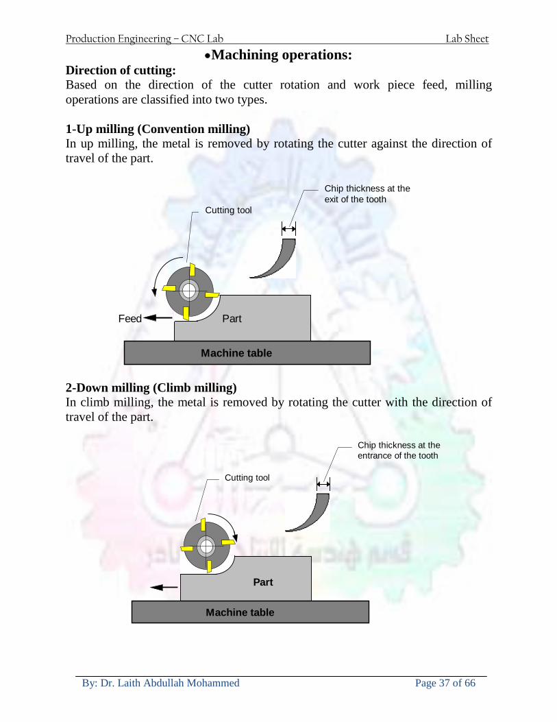
Production Engineering ndash CNC Lab Lab Sheet
By Dr Laith Abdullah Mohammed Page 37 of 66
bullMachining operations Direction of cutting Based on the direction of the cutter rotation and work piece feed milling operations are classified into two types 1-Up milling (Convention milling) In up milling the metal is removed by rotating the cutter against the direction of travel of the part
Feed
Machine table
Part
Cutting tool
Chip thickness at theexit of the tooth
2-Down milling (Climb milling) In climb milling the metal is removed by rotating the cutter with the direction of travel of the part
Machine table
Part
Cutting tool
Chip thickness at theentrance of the tooth
Production Engineering ndash CNC Lab Lab Sheet
By Dr Laith Abdullah Mohammed Page 38 of 66
bullTooling Tool geometry The geometry of the tool tip affects the way that the metal cutting is performed The nose radius rake angles relief angles etc must be selected with care
Radial relief
Radial rake
Axial relief
Approach angle
Axial relief
Corner radius Face mill Face milling cutters are used to mill flat surfaces Commonly used face milling cutters Cutter with 75 degree approach
75 deg
Cutter with 90 degree approach (Square shoulder face mill)
90 deg
Cutter with 45 degree approach
Production Engineering ndash CNC Lab Lab Sheet
By Dr Laith Abdullah Mohammed Page 39 of 66
bullCNC Programming Axes convention The Z axis is along the spindle axis The X and Y axes are perpendicular to Z VMC
Z
Y
-
+
-+
X- +
+Z
-Z
+Y
-Y
-X +X
Part
Machine table
X
YZ
G00 Rapid traverse When the tool being positioned at a point preparatory to a cutting motion to save time it is moved along a straight line at Rapid traverse at a fixed traverse rate which is pre-programmed into the machines control system Typical rapid traverse rates are 10 to 25 m min but can be as high as 80 mmin
Production Engineering ndash CNC Lab Lab Sheet
By Dr Laith Abdullah Mohammed Page 40 of 66
Format N_ G00 X__ Y__Z__
G01 Linear interpolation (feed traverse) The tool moves along a straight line in one or two axis simultaneously at a programmed linear speed the feed rate Format N__ G01 X__ Y__Z__ F__
Part
Feed
Part
Feed
G02G03 Circular interpolation The tool moves along an arc in two axes simultaneously at a programmed linear speed the feed rate
Production Engineering ndash CNC Lab Lab Sheet
By Dr Laith Abdullah Mohammed Page 41 of 66
Format N__ G0203 X__ Y__Z__ I__ J__K__ F__ using the arc center OR N__ G0203 X__ Y__Z__ R__ F__ using the arc radius G02 moves along a CW arc G03 moves along a CCW arc Arc center The arc center is specified by addresses I J and K I J and K are the X Y and Z co-ordinates of the arc center with reference to the arc start point
X
Y
Arc center
Arc endArc start
- J
- I
I = X coord of center - X coord of start point J = Y coord of center - Y coord of start point K = Z coord of center - Z coord of start point I J and K must be written with their signs
Production Engineering ndash CNC Lab Lab Sheet
By Dr Laith Abdullah Mohammed Page 42 of 66
bullWork holding
Rotary table
Fixture base
Component
Clamp
Stud
Fixtures The use of fixtures 1 Improves repeatability of dimensions 2 Improves working conditions 3 Cuts down requirement of skilled labour 4 Reduces part loading and unloading time 5 Improves safety in the working area 6 Reduces the cost of machining There are two types fixtures commonly used 1 Special fixture Special fixtures are used to hold and locate the typical components which are having complex shape and to be located with the reference hole (dowel hole) Special fixtures are required for components like gear case cover cylinder heads etc 2 Modular fixture Modular fixture is a set different kind of clamping and locating elements These fixtures are used to hold identical components in different sizes and components of box type Example Manifolds head stocks connecting rods and flanges
Production Engineering ndash CNC Lab Lab Sheet
By Dr Laith Abdullah Mohammed Page 43 of 66
bullMachine setting
Determining X and Y work zero offset Case 1
Part
Machine table
Part
End mill or reamer
Work offset X0Y0 For determining X work zero offset bull Touch the periphery of the end mill or reamer to the part bull Enter current machine X value + cutter radius as X work zero offset For determining Y work zero offset bull Touch the periphery of the end mill or reamer to the part bull Enter current machine Y value - cutter radius as Y work zero offset Case 2
Part
Machine table
Part
End mill or reamerWork offset X0Y0
bull Mount the dial indicator on machine spindle true the bore bull Enter current machine X and Y value as X and Y work zero offset
Production Engineering ndash CNC Lab Lab Sheet
By Dr Laith Abdullah Mohammed Page 44 of 66
How to Select a Cutting Fluid
One part of the metal cutting equation that is sometimes overlooked however is
the choice of an appropriate cutting fluid With todayrsquos system approach to metal
cutting use of the right metalworking fluid has become just as much a part of the
solution as the other elements In fact at least one company is now integrating
cutting fluids and cutting tools into effective metal cutting systems Following are
some things to consider when choosing your next cutting fluid
The Four Key Questions
There are four vital pieces of information that are necessary when choosing a
cutting fluid They are
1 What are you cutting
2 What is the chemistry of your water
3 What are you using now
4 What are your options
5 What do you prefer
What Are You Cutting
The first question ndash ldquoWhat are you cuttingrdquo ndash is often the most difficult to answer
because most shops handle a variety of workpiece materials on a regular basis If
the answer is an unequivocal ldquoaluminumrdquo or ldquostainless steelrdquo or ldquocast ironrdquo the
selection of a cutting fluid can be quite simple and straightforward Unfortunately
that is seldom the case in anything but a high-volume plant Where aluminum or
other nonferrous metals are a significant part of the mix a non-staining cutting
fluid is a must Generally speaking this will be a semi-synthetic with special
ingredients to prevent bi-metallic corrosion and staining of non-ferrous workpieces
Where the ferrous metals predominate however a more general purpose semi-
synthetic or hybrid fluid might be a more economical choice
Production Engineering ndash CNC Lab Lab Sheet
By Dr Laith Abdullah Mohammed Page 45 of 66
What is The Chemistry of Your Water
The second question ndash ldquoWhat is the chemistry of your waterrdquo ndash is probably the
single most common reason for the success or failure of a cutting fluid Very few
plants invest the money necessary to install effective water purification systems
using deionization or reverse osmosis technology Unfortunately the chemicals
present or not present in the water used to re-constitute a cutting fluid make a
tremendous difference in its performance and sump life Most manufacturers of
cutting fluids will perform the necessary water testing to determine exactly what
minerals are dissolved in your water and make a fluid recommendation based on
the results
What are you using now
The third question ndash ldquoWhat are you using nowrdquo ndash helps narrow the range of
choices When coupled with an objective analysis of the strengths and weaknesses
of the current fluid the answer to this question can quickly point you toward a
relatively small number of competitive alternatives that have the attributes required
to meet your cutting needs Many cutting fluids are in use today simply because
they were in use yesterday It is a hard reality of todayrsquos marketplace that if one
isnrsquot constantly striving to improve they will certainly be overtaken by a
competitor who is
What Are Your Options
The fourth question ndash ldquoWhat are your optionsrdquo ndash leads to the final selection of a
cutting fluid Cutting fluids can be divided into four general groups based on their
chemistry
They are
bull Soluble Oils ndash quite literally oil dispersed in water
bull Synthetics ndash completely oil free man-made coolants in solution
Production Engineering ndash CNC Lab Lab Sheet
By Dr Laith Abdullah Mohammed Page 46 of 66
bull Semi-Synthetics ndash a mixture of natural and synthetic lubricants with up to 30
mineral oil
bull Hybrids ndash a special class of semi-synthetics with a mineral oil content of about
15 Each fluid type has advantages and disadvantages which make it suitable for
a particular group of applications In addition there are costperformance trade-
offs to be made between the groups within a specific set of applications For
example where a hybrid and a semi-synthetic may both be suitable for a particular
use the hybrid might provide longer sump life at a slightly higher initial cost
while some semi synthetics may be more economical to recycle or dispose of while
not giving as long a tank life The final decision in this case would have to be made
on the detailed economics of the shop where the fluids were to be used and on the
ownerrsquos individual preferences
Soluble Oils
Soluble oils are oils that disperse in water when emulsifiers are added They are
generally suitable for moderate-to heavy-duty machining and grinding of all non-
ferrous metals carbon and cast steels and in applications where dissimilar metals
such as aluminium and steel are present They can also be used in turning drilling
tapping reaming gear cutting broaching as well as internal and centerless types
of grinding operations Soluble oils provide excellent aluminium and copper
corrosion control good rancidity control which extends fluid for long lasting
trouble-free performance and good concentrate and mix stability making it ideal
for mixing in water with a minimal amount of agitation An example of this is
Valenitersquos VNTreg-650 premium heavy-duty soluble oil
Synthetics
Synthetics are completely oil free solutions made of polymers organic and
inorganic materials that are mixed with water These clear low foaming and bio-
Production Engineering ndash CNC Lab Lab Sheet
By Dr Laith Abdullah Mohammed Page 47 of 66
stable coolants are ideal for machining and grinding of ferrous materials carbon
steels or cast iron Their complex lubricant packages make synthetics well-suited
for tough-to-machine materials such as stainless steels and high-temperature alloys
Certain synthetics are specifically designed to address the primary failure modes of
flank wear and nose wear Although there are many benefits some synthetics may
cause staining of non-ferrous materials
Semi-Synthetics
Semi-synthetic fluids are a mixture of oils synthetic emulsifiers and water They
were primarily developed for the aircraft nuclear and related industries
Consequently they work extremely well on all non-ferrous metals such as titanium
aluminium copper brass bronze and stainless steel in both machining and
grinding Semi-synthetics can be used on ferrous metals too They are chlorine-
free to reduce bi-metallic corrosion and staining of metals They should be used at
a 5-8 dilution with water depending on the severity of the operation
Hybrids
Hybrids are cutting fluids custom engineered to solve a particular problem For
example Valenitersquos VNTreg-800 was developed to be very clean in the machining
and grinding of cast iron It provides better stability in hard water and rejects tramp
oil very well which adds to its bio-stable chemistry Hybrids work extremely well
on all metals in both machining and grinding They should be mixed at a 5-7
dilution with water depending on the condition of the water
What Do You Prefer
The final question ndash ldquoWhat do you preferrdquo ndash is usually the ldquotie breakerrdquo where
there is more than one appropriate cutting fluid available Here again as in the
case of what is being used now the key is to examine your preferences objectively
Production Engineering ndash CNC Lab Lab Sheet
By Dr Laith Abdullah Mohammed Page 48 of 66
and specifically to identify the real reasons behind a preference If you cannot
point to specific reasons why one class of cutting fluid is preferred over another
you are well advised to follow the recommendations of the professional who has
analyzed your requirements Choosing the right fluid today is easier than ever as
the system approach to metal cutting productivity continues to grow in acceptance
The day is not far off when choosing a complete solution will be as easy as
choosing the right insert and chip breaker today The answers are available and the
results will more than justify the time you spend choosing the right metal cutting
fluid
Useful Links wwwball-screwsnet
wwwlubelinkcom
wwwmachinerylubricationcom
wwwadvancedmanufacturingcom
wwwmmsonlinecom
wwwcuttingtoolengineeringcom
wwwgeartechnologycom
wwwengineersedgecom
wwwagmaorg
wwwefundacom
wwwsaeorg
wwwsmeorg
wwwastmorg
wwwissorg
wwwmachinetoolscom
wwwansiorg
wwwasmeorg
wwwcnccicom
wwwmatlscom
wwwthefreedictionarycom
wwwengineersupplycom
Production Engineering ndash CNC Lab Lab Sheet
By Dr Laith Abdullah Mohammed Page 49 of 66
SurfCAM Tutorial ndash Beginning with the basics
Background SurfCAM is a computer aided manufacturing (CAM) software which allows you to create manage and modify tool paths for computer aided designed (CAD) part The software requires a CAD model or requires that you create some geometry within SurfCAM with some rudimentary tools provided The tool paths are created or stored internally in SurfCAM in a generic programming language called APT Once the tool paths are created the APT paths are translated using a post processor into typical machine G-code
Opening SurfCAM SurfCAM can be opened from the Novell Applications Launcher on most Industrial Engineering computer labs workstations Search under lsquoallrsquo applications and double click on SurfCAM 2005 Once the program opens a license must be selected from the list (not the Demo license) to enable saving the file later Choose one of the 30 licenses available If for some reason the licenses are not listed on the license manager form select server list and type ldquobonnieeosncsuedurdquo A list of available licenses should appear Select a license and click OK After the license is selected an Add StockFixture form (Figure 1) opens allows you to add a model which represents the pre-machined stock or a fixture Click on OK without adding either Both of these items can be added later under a more appropriate dialog
Figure 1 Add Stock or Fixture dialog box
Production Engineering ndash CNC Lab Lab Sheet
By Dr Laith Abdullah Mohammed Page 50 of 66
SurfCAM Interface
Figure 2 SurfCAM Windows based interface
SurfCAM is a windows based software system so most of the typical windows functions under File are applicable This is where you can open save exit print etc The Create menu allows the user to create different geometry forms Here you can create a point line surface chamfer circle and many other geometry types For the most part these functions are not used by beginners but are useful when creating bounding curves where you donrsquot want the tool to move outside (constraining the tool) The Edit menu allows you to change or modify many different entities such as changing lines altering surfaces joining surfaces trimming or breaking elements add control points etc Again these features are helpful to advanced users and are not covered in detail in this tutorial The Display menu offers the ability to change the orientation of the part on the screen The typical rotate pan fit to screen and zoom functions are available as well as several functions which allow the user to shift between views or call up a named view (ie top bottom etc) The NC menu is the main machining interface menu In this menu you select the general form of machining (2 axis 3 axis 4 axis 5 axis turning etc) and under the general form a more specific machining function is selected This menu is the most used and the options contained must be fully understood to get the most out of SurfCAM Each function will be described in some detail in a further chapter The Analyze menu contains options such as measuring the distance between points angles tangency elements etc These functions are auxiliary functions meant to help you understand the part better but basically provide no functionality for making tool paths for CNC machines Thus these will not be covered The Tools menu allows the user to change the system options modify keyboard shortcuts change the model units etc These options are again not used by beginners Finally the Help menu provides access to the online users manual In lieu of clicking the Help menu the F1 key is the shortcut key for help (as it is in most windows based programs)
Importing a CAD model Importing a CAD model that is stored locally is done by selecting File-gtOpen On the Files of type dropdown box choose the type of file you wish to open (Figure 3) Do this prior to negotiating your way through the maze of folders to prevent having to go through the folder tree again Once the file type is selected find the file you are trying to open and click the Open
Production Engineering ndash CNC Lab Lab Sheet
By Dr Laith Abdullah Mohammed Page 51 of 66
button SurfCAM will then attempt to read the file you have selected SurfCAM may provide a dialog box describing what it has imported and identify if it was successful If this dialog is provided simply click close without saving
Figure 3 Open Dialog Note - Change type of file prior to finding the file you wish to open
SurfCAM allows a user to import several different types of CAD files the most common types which you will likely import are SolidWorks part files (sldprt or prt) AutoCAD files(dxf) or IGES (igs or iges) Native file import (such as is the case with SolidWorks) provides the greatest information transfer and generic file imports (such as is the case with IGES) provide the least Normally it is to the advantage of the user to use native file importing procedures when available Recently (2005) SurfCAM added some compatibility with SolidWorks This allows the user to create tool paths for a part and if an engineering change is needed for the part update the part in SolidWorks When the part is then opened in SurfCAM the changes are noted and a simple update operation command is needed This however does not operate with complete transparency andor accuracy and thus users need to be cognizant of changing CAD models
SurfCAM Geometry In SurfCAM two basic types of geometry are used the surface and the point A surface (Figure 4) is a so called spline (NURBS or B-Spline are the two most common) surface (parameterized by two values u and v) such that every location on the surface can be defined as a function of these parameters In other words SurfCAM can calculate the location of any point on the
Production Engineering ndash CNC Lab Lab Sheet
By Dr Laith Abdullah Mohammed Page 52 of 66
surface Surfaces are used primarily in 3 4 and 5 axis machining and require a significant
amount of processing power and time Figure 4 Surfaces model of a mold half Note the difference between this and Figure 2 a wireframe model
Point or line based models are often referred to as wireframe (Figure 5) models because the models consist of connected lines and resemble the part only at the intersection of two surfaces Wireframe models were made popular lsquoback in the dayrsquo when computer processing was expensive There are times when each of the models are important and selecting model geometry when applying a SurfCAM operation will be much simpler if you understand the differences between the two When importing a SolidWorks model the default is both the surfaces and the wireframe geometry are imported
Figure 5 Wireframe model of the mold in Figure 1
Steps to Creating Tool Paths Once a CAD model is imported into SurfCAM tool paths can be created There is no one correct way to create tool paths however there is a set of general steps to take to ensure the tool paths are created with a minimum amount of hardship (note the wordinghellipHardship is inevitable when creating tool paths it is the intent of this manual to minimize this) The following is a list of steps which should be considered when making tool paths
Production Engineering ndash CNC Lab Lab Sheet
By Dr Laith Abdullah Mohammed Page 53 of 66
1 Plan ahead a Orient the part in SolidWorks such that if only one side is to be machined that
side is the Top view This can be done early in SolidWorks by choosing a plane parallel the X-Y plane as the sketch plane for the machined geometry
b Orient the part in SolidWorks such that the origin is somewhere of relative importance and someplace in space that can be easily identified when placed on the machine This is extremely important to minimize set up time at the machine (note ndash my personal preference for a part that is to be fully machined [ie stock exists on all sides] is to place the origin at the center and top of the parthellipjust my preference)
c Orient the part in SolidWorks such that the X and Y axes are aligned as you want them on the machinehellip
d Planning ahead will save you many hours of headaches laterhelliptrust me 2 Import the model 3 Choose a construction view such that the tool approaches the side to be machined
from the positive Z axis direction (as defined by part origin) a This is done by clicking on the CView icon
b From the list of named views chose the view which orients the origin as you would like
c If one of the views does not fit your criteria you have two choices i Perform a transformation of the part in SurfCAM or SolidWorks
ii Add a new construction view by selecting new This option requires a relatively good understanding of right hand coordinate frames but is very usefulhellipNormally used by more advanced users
d Be sure the CoordVIEW selection is made vs CoordWORLD This ensures the tools will be controlled from the coordinate frame selected by the view (ie the origin on the part) instead of the origin on the lower left corner of the screen This will be especially important when we get into 4 and 5 axis machining
4 In the Operations Manager (Figure 6) select Setup One and change the name to something meaningful ndash like Front Side Mold Cavity
a Access the Operations manager by right clicking or by selecting the Operations Manager icon in the tool bar
b Operations Manager is where the tool paths are managed once they are created as well as where individual tool paths can be verified
Production Engineering ndash CNC Lab Lab Sheet
By Dr Laith Abdullah Mohammed Page 54 of 66
5 Roughing Tool Paths a Create the tool paths to remove the majority of the material (if applicable) b Use NC-gt3Axis-gtZ rough or Plunge Rough c Described in next section
6 Create Finishing Tool Paths a Described in next section
7 Add another setup if necessary 8 Perform steps 3 through 6 as necessary 9 Verify the tool paths are correct 10 Use a post processor for the tool paths to create G-Code for machine
Creating Tool Paths The following is a list of operations what they are intended for how they generally work and some parameters that may be adjusted to modify the tool paths
2 Axis tool paths Unless otherwise noted 2 axis tool path functions require lines or arc segments as input parameters (as opposed to surfaces) There are several options as to how these segments are chosen the most prevalent is the chain option and the second most prevalent is the single When choosing the line segments using the chain option SurfCAM will try to link a complete path of segments based on an initial segment chosen by the user If the operation is planer (ie pocket or contour) the segments must lie on the same plane If the operation is non-planer (ie contour 3D) SurfCAM will prompt the user to specify segments when it encounters a branch point
Figure 6 Operations Manager view showing setup one re-labeled as Front Side Mold
Production Engineering ndash CNC Lab Lab Sheet
By Dr Laith Abdullah Mohammed Page 55 of 66
When using the single element option the user must manually choose each segment desired for the operation Note that most operations do not require a closed loop of segments you may specify for instance an open contour where the tool is supposed to move The order of choosing segments is important This order determines the path of the tool in the sense that if three segments are chosen such that the middle segment is chosen last there will be three different plunge and machine operations one on each segment If the operation was to make a continuous contour around the outside of the part the segments should be chosen in order of the desired tool trajectory
Operations
Pocket Pocket operation in SurfCAM is used to cut an enclosed space from the inside to the outside at one particular depth The operation starts in the center of an enclosed area (with a plunge move in the ndashZ direction) and makes incremental closed paths towards the pocket boundaries in user defined path offsets (Figure 7) The user chooses the boundary of the pocket (line segments) and if more than one pocket is chosen SurfCAM will ask the user to click inside a pocket
Figure 7 Two examples of using the pocketing operation
The pocket operation allows for creating a projection of the pocket paths on multiple planes This is useful if you have a deep pocket which will not allow the tool to cut directly at the depth of the pocket but would be easily done using the same paths at several different Z heights On the cut control (Figure 8) tab the user specifies where the chosen geometry (pocket segments) lie (ie bottom or top) Then under the amount to remove specify the total material height to be removed and the rough spacing (amount you wish to advance the Z axis with each pocket step) You may also specify a finishing pass and as well as stock to leave
Production Engineering ndash CNC Lab Lab Sheet
By Dr Laith Abdullah Mohammed Page 56 of 66
Figure 8 Example of Contour Operation with multiple passes
Contour Contouring in SurfCAM is used to perform peripheral milling on the inside or outside of a line segment (Figure 9) The user is to identify the line segments which define a contour (does not have to be a closed loop of segments) SurfCAM may or may not require the user to specify a side to contour (ie which side of the line is the tool to cut) For contouring each segment must lie on the same plane
Production Engineering ndash CNC Lab Lab Sheet
By Dr Laith Abdullah Mohammed Page 57 of 66
Figure 9 Examples of parts cut with 2-Axis Contour
Contour 3D Contour 3D is the same operation type as contour but allows the user to specify segments on different planes for the tool to cut along
Drill Drilling operations are any rotating tool operation meant to engage the part from a single direction ndash namely from the positive Z direction Drilling operations can be specified using circle point or line segments After choosing NC-gt2-Axis-gtDrill SurfCAM allows the user to choose multiple circles or points defining holes to be drilled Drilling operations also allow the user to incorporate more than 1 operation such as a center drill a drill and a reaming operation After selecting the locations for the drilling operation a dialog box (Figure 10) allows the user to add change or delete tools to be used in the operation As displayed in the following figure the spotdrill operation is followed by a drilling operation followed by a tapping operation The depth of each tool can be controlled individually by double clicking the total depth cell in and manually entering Tools can be added before or after operations which the cells are highlighted by selecting either of the insert buttons at the top or by the insert menu Select tool button allows the user to change the tool size or type
Production Engineering ndash CNC Lab Lab Sheet
By Dr Laith Abdullah Mohammed Page 58 of 66
Figure 10 Drill operation manager Several operations can be completed at one time
Figure 11 Drill operation including the spotdrill drill and tap as outlined in Fig 10
3 Axis tool paths SurfCAM requires surfaces as inputs for 3 Axis tool paths Surfaces can be created in SurfCAM but are most easily created in a CAD package and imported into SurfCAM Surfaces allow SurfCAM to identify every point on the surface in 3 dimensions unlike 2D geometry (wireframes) which only identify positions on the plane Creating tool paths with complex surfaces takes a very significant amount of processing power so expect 3 Axis tool path generation to take longer
Production Engineering ndash CNC Lab Lab Sheet
By Dr Laith Abdullah Mohammed Page 59 of 66
Operations
Cut 3 Axis cut operation takes a surface and using the flow lines creates a rastering path over the surface with the tool tip riding on the surface The primary direction will be defined by the flow lines of the surface (which can be edited by Edit-gtSurfaces-gtArrow-gtDirection) If you intend to cross surface boundaries you must merge the surfaces (Edit-gtJoin and choose the two surfaces)
Z-Rough The Z-rough operation is used to remove a large amount of material prior to finish machining Roughing operation is typically the first operation you perform for each setup The Z-Rough operation cuts the part in user defined intervals For each of these intervals a surface intersection between the part and the plane is performed and a 2D pocket or contour operation is performed on that plane This is performed on each plane When choosing NC-gt3 Axis-gtZ rough the first dialog box you will encounter asks for a bounding box to be defined Choose the Extents Box and a second dialog box will ask for the coordinates which define the box (Figure 12) This is the stock size you expect to machine the part from Input the coordinates or change the additional offset amounts (in XY or Z) as appropriate and click Calculate Bounding Box
Figure 12 Material Extents Box Example
Next choose the tool and cutting parameters that you desire and click on the Cut Control Tab (Figure 13) Here you will find the following parameters which are often changed Stock to
Production Engineering ndash CNC Lab Lab Sheet
By Dr Laith Abdullah Mohammed Page 60 of 66
leave ndash this is an offset amount from the surfaces which leaves a small amount of material to finish machine Minimum and Maximum Z values ndash Defines area to machine Z Step Size ndash This identifies the plane intervals for the surface intersection planes (the first interval will be at the top of the selected area and successive increments down in Z will be cut until the Minimum Z value is reached)
Figure 13 3Axis Z Rough Cut Control
The 3Axis Z-Finish operation works in exactly the same way 3 Axis Z-Finish is most appropriate for finishing vertical or near vertical walls
3D Offset The 3D Offset operation creates a tool path using a 2D or 3D boundary by offsetting the boundary in concentric offset cutting passes Each pass calculates the tool engagement and maintains the engagement somewhat constant The advantage (significant) is the scallop height ndash height of the material between passes ndash is controlled thus the surface finish is predictable When choosing 3D Offset surfaces are selected as well as 2D or 3D boundaries The boundaries define the concentric offset paths shape as well as limit the tool path area Choose NC-gt3Axis-gt3D Offset from the drop down menus SurfCAM will prompt you to select the surface or surfaces to cut across Select the surfaces you wish to machine and then select the tool and cutting parameters you wish use Next select the Cut Control Tab and check the Use Boundary Curves option Set the Step Type to Scallop and set the maximum scallop height If you like
Production Engineering ndash CNC Lab Lab Sheet
By Dr Laith Abdullah Mohammed Page 61 of 66
you can also add stock to leave if this is a roughing operation You can also set the Direction and Start-End parameters from this tab Click OK and the paths will be generated
Figure 14 Cut Control Tab for 3D Offset
Example part using both 2D and 3D geometry
The tool paths for this mold will be generated in SurfCAM using 5 operations The first will be a roughing operation using a frac14 inch flat end mill with the Z step size of 00625in Choose NC-
Production Engineering ndash CNC Lab Lab Sheet
By Dr Laith Abdullah Mohammed Page 62 of 66
gt3Axis-gtZ-Rough from the drop down menu Select all visible surfaces and create an extents box that has 025inch XY offsets and 01inch Z offset Next select the frac14 inch flat end mill from the tools menu Under Cut Control tab set the Z step size to be 00625inch The tool paths will look something like Figure 15
Figure 15 Z-Rough Tool paths for Example Part
Next a flat surface operation will be performed to cut the flat surface on the top Select NC-gt3 Axis-gtFlat Surface from the drop down menu Select all visible surfaces again Choose the 12inch flat end mill and set the cutting parameters as desired Under Cut Control Tab change the Minimum Area to 50 square inches (Figure 16) The tool paths should look something like Figure 17
Figure 16 Cut Control for Flat Surface
Production Engineering ndash CNC Lab Lab Sheet
By Dr Laith Abdullah Mohammed Page 63 of 66
Figure 17 Flat Surface Tool Paths
Next we will use a 3D offset operation to cut the mold cavity Select NC-gt3 Axis-gt3D Offset from the dropdown menu Change the view to the top view and select within to capture the surfaces of the mold cavity Draw a rectangle around the mold cavity Select a 18 inch ball endmill from the tool library and set the cutting parameters as appropriate Next set the Cut Control tab parameters as in Figure 14 The paths creates should be similar to Figure 18
Figure 18 3D Offset Paths
Next we will perform a 2 Axis contouring of the top section Select NC-gt2 Axis-gtContour from the dropdown menu Using the chain option select the bottom contour of the top extrusion Select the frac12 inch flat end mill from the tool library and set the cutting parameters as required In the Cut Control Tab change the Geometry to Bottom and the amount to remove in Z to 05
Production Engineering ndash CNC Lab Lab Sheet
By Dr Laith Abdullah Mohammed Page 64 of 66
Change the Rough Spacing in Z to 025 and add 1 finish pass of 002 (Figure 19) Click OK and SurfCAM will instruct you to choose a side to contour Click anywhere on the screen OUTSIDE the geometry you selected for the contouring operation Failure to click outside the geometry will result in the tool being on the wrong side of the contour Your paths should look something like those in Figure 20
Figure 19 Cut Control Tab for the Contouring Operation
Figure 20 Contouring operation paths
Production Engineering ndash CNC Lab Lab Sheet
By Dr Laith Abdullah Mohammed Page 65 of 66
Next we will perform a 2 axis pocket operation for the small pocket on the top face of the mold Select NC-gt2Axis-gtPocket and using the Auto select feature select the boundary curve at the bottom of the pocket Click Done twice and select the frac14 inch flat end mill from the tool library Set the appropriate cutting parameters and click OK SurfCAM will prompt you to click inside the pocket Click anywhere inside the geometry you chose to define the pocket The resulting paths should look something like those in Figure 21
Figure 21 2 Axis Pocket Operation Paths
Finally we will add a drilling operation for the 2 holes at the corners of the mold Select NC-gt2 Axis-gtDrill from the dropdown menu Select the top circles defining the two holes A menu box will appear with a default tool (Center drill) already programmed Add a second tool to the list by selecting Insert-gtAfter and select the tool from the tool library Change the drill depth to 10inches and click OK The paths should look something similar to Figure 23
Figure 22 Drill Menu
Production Engineering ndash CNC Lab Lab Sheet
By Dr Laith Abdullah Mohammed Page 66 of 66
Figure 23 Drilling Operation Tool Paths
Now you can watch a simulation of the cutting by choosing the setup in the operations manager and clicking the simulate icon Be sure to set the stock in the set up by right clicking the set up and selecting Edit Setup Information In the Stock Tab you can create a bounding box meeting your needs and click Add Your simulation should result in something like the following
Figure 24 Final Simulation of the example Mold
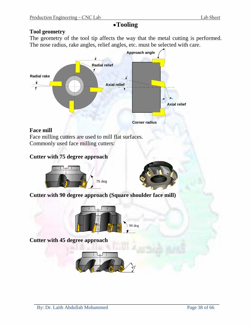
Production Engineering ndash CNC Lab Lab Sheet
By Dr Laith Abdullah Mohammed Page 38 of 66
bullTooling Tool geometry The geometry of the tool tip affects the way that the metal cutting is performed The nose radius rake angles relief angles etc must be selected with care
Radial relief
Radial rake
Axial relief
Approach angle
Axial relief
Corner radius Face mill Face milling cutters are used to mill flat surfaces Commonly used face milling cutters Cutter with 75 degree approach
75 deg
Cutter with 90 degree approach (Square shoulder face mill)
90 deg
Cutter with 45 degree approach
Production Engineering ndash CNC Lab Lab Sheet
By Dr Laith Abdullah Mohammed Page 39 of 66
bullCNC Programming Axes convention The Z axis is along the spindle axis The X and Y axes are perpendicular to Z VMC
Z
Y
-
+
-+
X- +
+Z
-Z
+Y
-Y
-X +X
Part
Machine table
X
YZ
G00 Rapid traverse When the tool being positioned at a point preparatory to a cutting motion to save time it is moved along a straight line at Rapid traverse at a fixed traverse rate which is pre-programmed into the machines control system Typical rapid traverse rates are 10 to 25 m min but can be as high as 80 mmin
Production Engineering ndash CNC Lab Lab Sheet
By Dr Laith Abdullah Mohammed Page 40 of 66
Format N_ G00 X__ Y__Z__
G01 Linear interpolation (feed traverse) The tool moves along a straight line in one or two axis simultaneously at a programmed linear speed the feed rate Format N__ G01 X__ Y__Z__ F__
Part
Feed
Part
Feed
G02G03 Circular interpolation The tool moves along an arc in two axes simultaneously at a programmed linear speed the feed rate
Production Engineering ndash CNC Lab Lab Sheet
By Dr Laith Abdullah Mohammed Page 41 of 66
Format N__ G0203 X__ Y__Z__ I__ J__K__ F__ using the arc center OR N__ G0203 X__ Y__Z__ R__ F__ using the arc radius G02 moves along a CW arc G03 moves along a CCW arc Arc center The arc center is specified by addresses I J and K I J and K are the X Y and Z co-ordinates of the arc center with reference to the arc start point
X
Y
Arc center
Arc endArc start
- J
- I
I = X coord of center - X coord of start point J = Y coord of center - Y coord of start point K = Z coord of center - Z coord of start point I J and K must be written with their signs
Production Engineering ndash CNC Lab Lab Sheet
By Dr Laith Abdullah Mohammed Page 42 of 66
bullWork holding
Rotary table
Fixture base
Component
Clamp
Stud
Fixtures The use of fixtures 1 Improves repeatability of dimensions 2 Improves working conditions 3 Cuts down requirement of skilled labour 4 Reduces part loading and unloading time 5 Improves safety in the working area 6 Reduces the cost of machining There are two types fixtures commonly used 1 Special fixture Special fixtures are used to hold and locate the typical components which are having complex shape and to be located with the reference hole (dowel hole) Special fixtures are required for components like gear case cover cylinder heads etc 2 Modular fixture Modular fixture is a set different kind of clamping and locating elements These fixtures are used to hold identical components in different sizes and components of box type Example Manifolds head stocks connecting rods and flanges
Production Engineering ndash CNC Lab Lab Sheet
By Dr Laith Abdullah Mohammed Page 43 of 66
bullMachine setting
Determining X and Y work zero offset Case 1
Part
Machine table
Part
End mill or reamer
Work offset X0Y0 For determining X work zero offset bull Touch the periphery of the end mill or reamer to the part bull Enter current machine X value + cutter radius as X work zero offset For determining Y work zero offset bull Touch the periphery of the end mill or reamer to the part bull Enter current machine Y value - cutter radius as Y work zero offset Case 2
Part
Machine table
Part
End mill or reamerWork offset X0Y0
bull Mount the dial indicator on machine spindle true the bore bull Enter current machine X and Y value as X and Y work zero offset
Production Engineering ndash CNC Lab Lab Sheet
By Dr Laith Abdullah Mohammed Page 44 of 66
How to Select a Cutting Fluid
One part of the metal cutting equation that is sometimes overlooked however is
the choice of an appropriate cutting fluid With todayrsquos system approach to metal
cutting use of the right metalworking fluid has become just as much a part of the
solution as the other elements In fact at least one company is now integrating
cutting fluids and cutting tools into effective metal cutting systems Following are
some things to consider when choosing your next cutting fluid
The Four Key Questions
There are four vital pieces of information that are necessary when choosing a
cutting fluid They are
1 What are you cutting
2 What is the chemistry of your water
3 What are you using now
4 What are your options
5 What do you prefer
What Are You Cutting
The first question ndash ldquoWhat are you cuttingrdquo ndash is often the most difficult to answer
because most shops handle a variety of workpiece materials on a regular basis If
the answer is an unequivocal ldquoaluminumrdquo or ldquostainless steelrdquo or ldquocast ironrdquo the
selection of a cutting fluid can be quite simple and straightforward Unfortunately
that is seldom the case in anything but a high-volume plant Where aluminum or
other nonferrous metals are a significant part of the mix a non-staining cutting
fluid is a must Generally speaking this will be a semi-synthetic with special
ingredients to prevent bi-metallic corrosion and staining of non-ferrous workpieces
Where the ferrous metals predominate however a more general purpose semi-
synthetic or hybrid fluid might be a more economical choice
Production Engineering ndash CNC Lab Lab Sheet
By Dr Laith Abdullah Mohammed Page 45 of 66
What is The Chemistry of Your Water
The second question ndash ldquoWhat is the chemistry of your waterrdquo ndash is probably the
single most common reason for the success or failure of a cutting fluid Very few
plants invest the money necessary to install effective water purification systems
using deionization or reverse osmosis technology Unfortunately the chemicals
present or not present in the water used to re-constitute a cutting fluid make a
tremendous difference in its performance and sump life Most manufacturers of
cutting fluids will perform the necessary water testing to determine exactly what
minerals are dissolved in your water and make a fluid recommendation based on
the results
What are you using now
The third question ndash ldquoWhat are you using nowrdquo ndash helps narrow the range of
choices When coupled with an objective analysis of the strengths and weaknesses
of the current fluid the answer to this question can quickly point you toward a
relatively small number of competitive alternatives that have the attributes required
to meet your cutting needs Many cutting fluids are in use today simply because
they were in use yesterday It is a hard reality of todayrsquos marketplace that if one
isnrsquot constantly striving to improve they will certainly be overtaken by a
competitor who is
What Are Your Options
The fourth question ndash ldquoWhat are your optionsrdquo ndash leads to the final selection of a
cutting fluid Cutting fluids can be divided into four general groups based on their
chemistry
They are
bull Soluble Oils ndash quite literally oil dispersed in water
bull Synthetics ndash completely oil free man-made coolants in solution
Production Engineering ndash CNC Lab Lab Sheet
By Dr Laith Abdullah Mohammed Page 46 of 66
bull Semi-Synthetics ndash a mixture of natural and synthetic lubricants with up to 30
mineral oil
bull Hybrids ndash a special class of semi-synthetics with a mineral oil content of about
15 Each fluid type has advantages and disadvantages which make it suitable for
a particular group of applications In addition there are costperformance trade-
offs to be made between the groups within a specific set of applications For
example where a hybrid and a semi-synthetic may both be suitable for a particular
use the hybrid might provide longer sump life at a slightly higher initial cost
while some semi synthetics may be more economical to recycle or dispose of while
not giving as long a tank life The final decision in this case would have to be made
on the detailed economics of the shop where the fluids were to be used and on the
ownerrsquos individual preferences
Soluble Oils
Soluble oils are oils that disperse in water when emulsifiers are added They are
generally suitable for moderate-to heavy-duty machining and grinding of all non-
ferrous metals carbon and cast steels and in applications where dissimilar metals
such as aluminium and steel are present They can also be used in turning drilling
tapping reaming gear cutting broaching as well as internal and centerless types
of grinding operations Soluble oils provide excellent aluminium and copper
corrosion control good rancidity control which extends fluid for long lasting
trouble-free performance and good concentrate and mix stability making it ideal
for mixing in water with a minimal amount of agitation An example of this is
Valenitersquos VNTreg-650 premium heavy-duty soluble oil
Synthetics
Synthetics are completely oil free solutions made of polymers organic and
inorganic materials that are mixed with water These clear low foaming and bio-
Production Engineering ndash CNC Lab Lab Sheet
By Dr Laith Abdullah Mohammed Page 47 of 66
stable coolants are ideal for machining and grinding of ferrous materials carbon
steels or cast iron Their complex lubricant packages make synthetics well-suited
for tough-to-machine materials such as stainless steels and high-temperature alloys
Certain synthetics are specifically designed to address the primary failure modes of
flank wear and nose wear Although there are many benefits some synthetics may
cause staining of non-ferrous materials
Semi-Synthetics
Semi-synthetic fluids are a mixture of oils synthetic emulsifiers and water They
were primarily developed for the aircraft nuclear and related industries
Consequently they work extremely well on all non-ferrous metals such as titanium
aluminium copper brass bronze and stainless steel in both machining and
grinding Semi-synthetics can be used on ferrous metals too They are chlorine-
free to reduce bi-metallic corrosion and staining of metals They should be used at
a 5-8 dilution with water depending on the severity of the operation
Hybrids
Hybrids are cutting fluids custom engineered to solve a particular problem For
example Valenitersquos VNTreg-800 was developed to be very clean in the machining
and grinding of cast iron It provides better stability in hard water and rejects tramp
oil very well which adds to its bio-stable chemistry Hybrids work extremely well
on all metals in both machining and grinding They should be mixed at a 5-7
dilution with water depending on the condition of the water
What Do You Prefer
The final question ndash ldquoWhat do you preferrdquo ndash is usually the ldquotie breakerrdquo where
there is more than one appropriate cutting fluid available Here again as in the
case of what is being used now the key is to examine your preferences objectively
Production Engineering ndash CNC Lab Lab Sheet
By Dr Laith Abdullah Mohammed Page 48 of 66
and specifically to identify the real reasons behind a preference If you cannot
point to specific reasons why one class of cutting fluid is preferred over another
you are well advised to follow the recommendations of the professional who has
analyzed your requirements Choosing the right fluid today is easier than ever as
the system approach to metal cutting productivity continues to grow in acceptance
The day is not far off when choosing a complete solution will be as easy as
choosing the right insert and chip breaker today The answers are available and the
results will more than justify the time you spend choosing the right metal cutting
fluid
Useful Links wwwball-screwsnet
wwwlubelinkcom
wwwmachinerylubricationcom
wwwadvancedmanufacturingcom
wwwmmsonlinecom
wwwcuttingtoolengineeringcom
wwwgeartechnologycom
wwwengineersedgecom
wwwagmaorg
wwwefundacom
wwwsaeorg
wwwsmeorg
wwwastmorg
wwwissorg
wwwmachinetoolscom
wwwansiorg
wwwasmeorg
wwwcnccicom
wwwmatlscom
wwwthefreedictionarycom
wwwengineersupplycom
Production Engineering ndash CNC Lab Lab Sheet
By Dr Laith Abdullah Mohammed Page 49 of 66
SurfCAM Tutorial ndash Beginning with the basics
Background SurfCAM is a computer aided manufacturing (CAM) software which allows you to create manage and modify tool paths for computer aided designed (CAD) part The software requires a CAD model or requires that you create some geometry within SurfCAM with some rudimentary tools provided The tool paths are created or stored internally in SurfCAM in a generic programming language called APT Once the tool paths are created the APT paths are translated using a post processor into typical machine G-code
Opening SurfCAM SurfCAM can be opened from the Novell Applications Launcher on most Industrial Engineering computer labs workstations Search under lsquoallrsquo applications and double click on SurfCAM 2005 Once the program opens a license must be selected from the list (not the Demo license) to enable saving the file later Choose one of the 30 licenses available If for some reason the licenses are not listed on the license manager form select server list and type ldquobonnieeosncsuedurdquo A list of available licenses should appear Select a license and click OK After the license is selected an Add StockFixture form (Figure 1) opens allows you to add a model which represents the pre-machined stock or a fixture Click on OK without adding either Both of these items can be added later under a more appropriate dialog
Figure 1 Add Stock or Fixture dialog box
Production Engineering ndash CNC Lab Lab Sheet
By Dr Laith Abdullah Mohammed Page 50 of 66
SurfCAM Interface
Figure 2 SurfCAM Windows based interface
SurfCAM is a windows based software system so most of the typical windows functions under File are applicable This is where you can open save exit print etc The Create menu allows the user to create different geometry forms Here you can create a point line surface chamfer circle and many other geometry types For the most part these functions are not used by beginners but are useful when creating bounding curves where you donrsquot want the tool to move outside (constraining the tool) The Edit menu allows you to change or modify many different entities such as changing lines altering surfaces joining surfaces trimming or breaking elements add control points etc Again these features are helpful to advanced users and are not covered in detail in this tutorial The Display menu offers the ability to change the orientation of the part on the screen The typical rotate pan fit to screen and zoom functions are available as well as several functions which allow the user to shift between views or call up a named view (ie top bottom etc) The NC menu is the main machining interface menu In this menu you select the general form of machining (2 axis 3 axis 4 axis 5 axis turning etc) and under the general form a more specific machining function is selected This menu is the most used and the options contained must be fully understood to get the most out of SurfCAM Each function will be described in some detail in a further chapter The Analyze menu contains options such as measuring the distance between points angles tangency elements etc These functions are auxiliary functions meant to help you understand the part better but basically provide no functionality for making tool paths for CNC machines Thus these will not be covered The Tools menu allows the user to change the system options modify keyboard shortcuts change the model units etc These options are again not used by beginners Finally the Help menu provides access to the online users manual In lieu of clicking the Help menu the F1 key is the shortcut key for help (as it is in most windows based programs)
Importing a CAD model Importing a CAD model that is stored locally is done by selecting File-gtOpen On the Files of type dropdown box choose the type of file you wish to open (Figure 3) Do this prior to negotiating your way through the maze of folders to prevent having to go through the folder tree again Once the file type is selected find the file you are trying to open and click the Open
Production Engineering ndash CNC Lab Lab Sheet
By Dr Laith Abdullah Mohammed Page 51 of 66
button SurfCAM will then attempt to read the file you have selected SurfCAM may provide a dialog box describing what it has imported and identify if it was successful If this dialog is provided simply click close without saving
Figure 3 Open Dialog Note - Change type of file prior to finding the file you wish to open
SurfCAM allows a user to import several different types of CAD files the most common types which you will likely import are SolidWorks part files (sldprt or prt) AutoCAD files(dxf) or IGES (igs or iges) Native file import (such as is the case with SolidWorks) provides the greatest information transfer and generic file imports (such as is the case with IGES) provide the least Normally it is to the advantage of the user to use native file importing procedures when available Recently (2005) SurfCAM added some compatibility with SolidWorks This allows the user to create tool paths for a part and if an engineering change is needed for the part update the part in SolidWorks When the part is then opened in SurfCAM the changes are noted and a simple update operation command is needed This however does not operate with complete transparency andor accuracy and thus users need to be cognizant of changing CAD models
SurfCAM Geometry In SurfCAM two basic types of geometry are used the surface and the point A surface (Figure 4) is a so called spline (NURBS or B-Spline are the two most common) surface (parameterized by two values u and v) such that every location on the surface can be defined as a function of these parameters In other words SurfCAM can calculate the location of any point on the
Production Engineering ndash CNC Lab Lab Sheet
By Dr Laith Abdullah Mohammed Page 52 of 66
surface Surfaces are used primarily in 3 4 and 5 axis machining and require a significant
amount of processing power and time Figure 4 Surfaces model of a mold half Note the difference between this and Figure 2 a wireframe model
Point or line based models are often referred to as wireframe (Figure 5) models because the models consist of connected lines and resemble the part only at the intersection of two surfaces Wireframe models were made popular lsquoback in the dayrsquo when computer processing was expensive There are times when each of the models are important and selecting model geometry when applying a SurfCAM operation will be much simpler if you understand the differences between the two When importing a SolidWorks model the default is both the surfaces and the wireframe geometry are imported
Figure 5 Wireframe model of the mold in Figure 1
Steps to Creating Tool Paths Once a CAD model is imported into SurfCAM tool paths can be created There is no one correct way to create tool paths however there is a set of general steps to take to ensure the tool paths are created with a minimum amount of hardship (note the wordinghellipHardship is inevitable when creating tool paths it is the intent of this manual to minimize this) The following is a list of steps which should be considered when making tool paths
Production Engineering ndash CNC Lab Lab Sheet
By Dr Laith Abdullah Mohammed Page 53 of 66
1 Plan ahead a Orient the part in SolidWorks such that if only one side is to be machined that
side is the Top view This can be done early in SolidWorks by choosing a plane parallel the X-Y plane as the sketch plane for the machined geometry
b Orient the part in SolidWorks such that the origin is somewhere of relative importance and someplace in space that can be easily identified when placed on the machine This is extremely important to minimize set up time at the machine (note ndash my personal preference for a part that is to be fully machined [ie stock exists on all sides] is to place the origin at the center and top of the parthellipjust my preference)
c Orient the part in SolidWorks such that the X and Y axes are aligned as you want them on the machinehellip
d Planning ahead will save you many hours of headaches laterhelliptrust me 2 Import the model 3 Choose a construction view such that the tool approaches the side to be machined
from the positive Z axis direction (as defined by part origin) a This is done by clicking on the CView icon
b From the list of named views chose the view which orients the origin as you would like
c If one of the views does not fit your criteria you have two choices i Perform a transformation of the part in SurfCAM or SolidWorks
ii Add a new construction view by selecting new This option requires a relatively good understanding of right hand coordinate frames but is very usefulhellipNormally used by more advanced users
d Be sure the CoordVIEW selection is made vs CoordWORLD This ensures the tools will be controlled from the coordinate frame selected by the view (ie the origin on the part) instead of the origin on the lower left corner of the screen This will be especially important when we get into 4 and 5 axis machining
4 In the Operations Manager (Figure 6) select Setup One and change the name to something meaningful ndash like Front Side Mold Cavity
a Access the Operations manager by right clicking or by selecting the Operations Manager icon in the tool bar
b Operations Manager is where the tool paths are managed once they are created as well as where individual tool paths can be verified
Production Engineering ndash CNC Lab Lab Sheet
By Dr Laith Abdullah Mohammed Page 54 of 66
5 Roughing Tool Paths a Create the tool paths to remove the majority of the material (if applicable) b Use NC-gt3Axis-gtZ rough or Plunge Rough c Described in next section
6 Create Finishing Tool Paths a Described in next section
7 Add another setup if necessary 8 Perform steps 3 through 6 as necessary 9 Verify the tool paths are correct 10 Use a post processor for the tool paths to create G-Code for machine
Creating Tool Paths The following is a list of operations what they are intended for how they generally work and some parameters that may be adjusted to modify the tool paths
2 Axis tool paths Unless otherwise noted 2 axis tool path functions require lines or arc segments as input parameters (as opposed to surfaces) There are several options as to how these segments are chosen the most prevalent is the chain option and the second most prevalent is the single When choosing the line segments using the chain option SurfCAM will try to link a complete path of segments based on an initial segment chosen by the user If the operation is planer (ie pocket or contour) the segments must lie on the same plane If the operation is non-planer (ie contour 3D) SurfCAM will prompt the user to specify segments when it encounters a branch point
Figure 6 Operations Manager view showing setup one re-labeled as Front Side Mold
Production Engineering ndash CNC Lab Lab Sheet
By Dr Laith Abdullah Mohammed Page 55 of 66
When using the single element option the user must manually choose each segment desired for the operation Note that most operations do not require a closed loop of segments you may specify for instance an open contour where the tool is supposed to move The order of choosing segments is important This order determines the path of the tool in the sense that if three segments are chosen such that the middle segment is chosen last there will be three different plunge and machine operations one on each segment If the operation was to make a continuous contour around the outside of the part the segments should be chosen in order of the desired tool trajectory
Operations
Pocket Pocket operation in SurfCAM is used to cut an enclosed space from the inside to the outside at one particular depth The operation starts in the center of an enclosed area (with a plunge move in the ndashZ direction) and makes incremental closed paths towards the pocket boundaries in user defined path offsets (Figure 7) The user chooses the boundary of the pocket (line segments) and if more than one pocket is chosen SurfCAM will ask the user to click inside a pocket
Figure 7 Two examples of using the pocketing operation
The pocket operation allows for creating a projection of the pocket paths on multiple planes This is useful if you have a deep pocket which will not allow the tool to cut directly at the depth of the pocket but would be easily done using the same paths at several different Z heights On the cut control (Figure 8) tab the user specifies where the chosen geometry (pocket segments) lie (ie bottom or top) Then under the amount to remove specify the total material height to be removed and the rough spacing (amount you wish to advance the Z axis with each pocket step) You may also specify a finishing pass and as well as stock to leave
Production Engineering ndash CNC Lab Lab Sheet
By Dr Laith Abdullah Mohammed Page 56 of 66
Figure 8 Example of Contour Operation with multiple passes
Contour Contouring in SurfCAM is used to perform peripheral milling on the inside or outside of a line segment (Figure 9) The user is to identify the line segments which define a contour (does not have to be a closed loop of segments) SurfCAM may or may not require the user to specify a side to contour (ie which side of the line is the tool to cut) For contouring each segment must lie on the same plane
Production Engineering ndash CNC Lab Lab Sheet
By Dr Laith Abdullah Mohammed Page 57 of 66
Figure 9 Examples of parts cut with 2-Axis Contour
Contour 3D Contour 3D is the same operation type as contour but allows the user to specify segments on different planes for the tool to cut along
Drill Drilling operations are any rotating tool operation meant to engage the part from a single direction ndash namely from the positive Z direction Drilling operations can be specified using circle point or line segments After choosing NC-gt2-Axis-gtDrill SurfCAM allows the user to choose multiple circles or points defining holes to be drilled Drilling operations also allow the user to incorporate more than 1 operation such as a center drill a drill and a reaming operation After selecting the locations for the drilling operation a dialog box (Figure 10) allows the user to add change or delete tools to be used in the operation As displayed in the following figure the spotdrill operation is followed by a drilling operation followed by a tapping operation The depth of each tool can be controlled individually by double clicking the total depth cell in and manually entering Tools can be added before or after operations which the cells are highlighted by selecting either of the insert buttons at the top or by the insert menu Select tool button allows the user to change the tool size or type
Production Engineering ndash CNC Lab Lab Sheet
By Dr Laith Abdullah Mohammed Page 58 of 66
Figure 10 Drill operation manager Several operations can be completed at one time
Figure 11 Drill operation including the spotdrill drill and tap as outlined in Fig 10
3 Axis tool paths SurfCAM requires surfaces as inputs for 3 Axis tool paths Surfaces can be created in SurfCAM but are most easily created in a CAD package and imported into SurfCAM Surfaces allow SurfCAM to identify every point on the surface in 3 dimensions unlike 2D geometry (wireframes) which only identify positions on the plane Creating tool paths with complex surfaces takes a very significant amount of processing power so expect 3 Axis tool path generation to take longer
Production Engineering ndash CNC Lab Lab Sheet
By Dr Laith Abdullah Mohammed Page 59 of 66
Operations
Cut 3 Axis cut operation takes a surface and using the flow lines creates a rastering path over the surface with the tool tip riding on the surface The primary direction will be defined by the flow lines of the surface (which can be edited by Edit-gtSurfaces-gtArrow-gtDirection) If you intend to cross surface boundaries you must merge the surfaces (Edit-gtJoin and choose the two surfaces)
Z-Rough The Z-rough operation is used to remove a large amount of material prior to finish machining Roughing operation is typically the first operation you perform for each setup The Z-Rough operation cuts the part in user defined intervals For each of these intervals a surface intersection between the part and the plane is performed and a 2D pocket or contour operation is performed on that plane This is performed on each plane When choosing NC-gt3 Axis-gtZ rough the first dialog box you will encounter asks for a bounding box to be defined Choose the Extents Box and a second dialog box will ask for the coordinates which define the box (Figure 12) This is the stock size you expect to machine the part from Input the coordinates or change the additional offset amounts (in XY or Z) as appropriate and click Calculate Bounding Box
Figure 12 Material Extents Box Example
Next choose the tool and cutting parameters that you desire and click on the Cut Control Tab (Figure 13) Here you will find the following parameters which are often changed Stock to
Production Engineering ndash CNC Lab Lab Sheet
By Dr Laith Abdullah Mohammed Page 60 of 66
leave ndash this is an offset amount from the surfaces which leaves a small amount of material to finish machine Minimum and Maximum Z values ndash Defines area to machine Z Step Size ndash This identifies the plane intervals for the surface intersection planes (the first interval will be at the top of the selected area and successive increments down in Z will be cut until the Minimum Z value is reached)
Figure 13 3Axis Z Rough Cut Control
The 3Axis Z-Finish operation works in exactly the same way 3 Axis Z-Finish is most appropriate for finishing vertical or near vertical walls
3D Offset The 3D Offset operation creates a tool path using a 2D or 3D boundary by offsetting the boundary in concentric offset cutting passes Each pass calculates the tool engagement and maintains the engagement somewhat constant The advantage (significant) is the scallop height ndash height of the material between passes ndash is controlled thus the surface finish is predictable When choosing 3D Offset surfaces are selected as well as 2D or 3D boundaries The boundaries define the concentric offset paths shape as well as limit the tool path area Choose NC-gt3Axis-gt3D Offset from the drop down menus SurfCAM will prompt you to select the surface or surfaces to cut across Select the surfaces you wish to machine and then select the tool and cutting parameters you wish use Next select the Cut Control Tab and check the Use Boundary Curves option Set the Step Type to Scallop and set the maximum scallop height If you like
Production Engineering ndash CNC Lab Lab Sheet
By Dr Laith Abdullah Mohammed Page 61 of 66
you can also add stock to leave if this is a roughing operation You can also set the Direction and Start-End parameters from this tab Click OK and the paths will be generated
Figure 14 Cut Control Tab for 3D Offset
Example part using both 2D and 3D geometry
The tool paths for this mold will be generated in SurfCAM using 5 operations The first will be a roughing operation using a frac14 inch flat end mill with the Z step size of 00625in Choose NC-
Production Engineering ndash CNC Lab Lab Sheet
By Dr Laith Abdullah Mohammed Page 62 of 66
gt3Axis-gtZ-Rough from the drop down menu Select all visible surfaces and create an extents box that has 025inch XY offsets and 01inch Z offset Next select the frac14 inch flat end mill from the tools menu Under Cut Control tab set the Z step size to be 00625inch The tool paths will look something like Figure 15
Figure 15 Z-Rough Tool paths for Example Part
Next a flat surface operation will be performed to cut the flat surface on the top Select NC-gt3 Axis-gtFlat Surface from the drop down menu Select all visible surfaces again Choose the 12inch flat end mill and set the cutting parameters as desired Under Cut Control Tab change the Minimum Area to 50 square inches (Figure 16) The tool paths should look something like Figure 17
Figure 16 Cut Control for Flat Surface
Production Engineering ndash CNC Lab Lab Sheet
By Dr Laith Abdullah Mohammed Page 63 of 66
Figure 17 Flat Surface Tool Paths
Next we will use a 3D offset operation to cut the mold cavity Select NC-gt3 Axis-gt3D Offset from the dropdown menu Change the view to the top view and select within to capture the surfaces of the mold cavity Draw a rectangle around the mold cavity Select a 18 inch ball endmill from the tool library and set the cutting parameters as appropriate Next set the Cut Control tab parameters as in Figure 14 The paths creates should be similar to Figure 18
Figure 18 3D Offset Paths
Next we will perform a 2 Axis contouring of the top section Select NC-gt2 Axis-gtContour from the dropdown menu Using the chain option select the bottom contour of the top extrusion Select the frac12 inch flat end mill from the tool library and set the cutting parameters as required In the Cut Control Tab change the Geometry to Bottom and the amount to remove in Z to 05
Production Engineering ndash CNC Lab Lab Sheet
By Dr Laith Abdullah Mohammed Page 64 of 66
Change the Rough Spacing in Z to 025 and add 1 finish pass of 002 (Figure 19) Click OK and SurfCAM will instruct you to choose a side to contour Click anywhere on the screen OUTSIDE the geometry you selected for the contouring operation Failure to click outside the geometry will result in the tool being on the wrong side of the contour Your paths should look something like those in Figure 20
Figure 19 Cut Control Tab for the Contouring Operation
Figure 20 Contouring operation paths
Production Engineering ndash CNC Lab Lab Sheet
By Dr Laith Abdullah Mohammed Page 65 of 66
Next we will perform a 2 axis pocket operation for the small pocket on the top face of the mold Select NC-gt2Axis-gtPocket and using the Auto select feature select the boundary curve at the bottom of the pocket Click Done twice and select the frac14 inch flat end mill from the tool library Set the appropriate cutting parameters and click OK SurfCAM will prompt you to click inside the pocket Click anywhere inside the geometry you chose to define the pocket The resulting paths should look something like those in Figure 21
Figure 21 2 Axis Pocket Operation Paths
Finally we will add a drilling operation for the 2 holes at the corners of the mold Select NC-gt2 Axis-gtDrill from the dropdown menu Select the top circles defining the two holes A menu box will appear with a default tool (Center drill) already programmed Add a second tool to the list by selecting Insert-gtAfter and select the tool from the tool library Change the drill depth to 10inches and click OK The paths should look something similar to Figure 23
Figure 22 Drill Menu
Production Engineering ndash CNC Lab Lab Sheet
By Dr Laith Abdullah Mohammed Page 66 of 66
Figure 23 Drilling Operation Tool Paths
Now you can watch a simulation of the cutting by choosing the setup in the operations manager and clicking the simulate icon Be sure to set the stock in the set up by right clicking the set up and selecting Edit Setup Information In the Stock Tab you can create a bounding box meeting your needs and click Add Your simulation should result in something like the following
Figure 24 Final Simulation of the example Mold
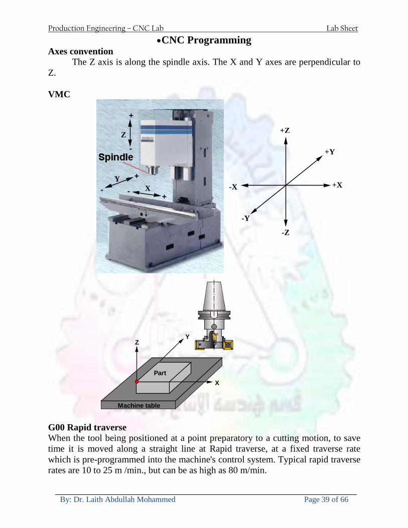
Production Engineering ndash CNC Lab Lab Sheet
By Dr Laith Abdullah Mohammed Page 39 of 66
bullCNC Programming Axes convention The Z axis is along the spindle axis The X and Y axes are perpendicular to Z VMC
Z
Y
-
+
-+
X- +
+Z
-Z
+Y
-Y
-X +X
Part
Machine table
X
YZ
G00 Rapid traverse When the tool being positioned at a point preparatory to a cutting motion to save time it is moved along a straight line at Rapid traverse at a fixed traverse rate which is pre-programmed into the machines control system Typical rapid traverse rates are 10 to 25 m min but can be as high as 80 mmin
Production Engineering ndash CNC Lab Lab Sheet
By Dr Laith Abdullah Mohammed Page 40 of 66
Format N_ G00 X__ Y__Z__
G01 Linear interpolation (feed traverse) The tool moves along a straight line in one or two axis simultaneously at a programmed linear speed the feed rate Format N__ G01 X__ Y__Z__ F__
Part
Feed
Part
Feed
G02G03 Circular interpolation The tool moves along an arc in two axes simultaneously at a programmed linear speed the feed rate
Production Engineering ndash CNC Lab Lab Sheet
By Dr Laith Abdullah Mohammed Page 41 of 66
Format N__ G0203 X__ Y__Z__ I__ J__K__ F__ using the arc center OR N__ G0203 X__ Y__Z__ R__ F__ using the arc radius G02 moves along a CW arc G03 moves along a CCW arc Arc center The arc center is specified by addresses I J and K I J and K are the X Y and Z co-ordinates of the arc center with reference to the arc start point
X
Y
Arc center
Arc endArc start
- J
- I
I = X coord of center - X coord of start point J = Y coord of center - Y coord of start point K = Z coord of center - Z coord of start point I J and K must be written with their signs
Production Engineering ndash CNC Lab Lab Sheet
By Dr Laith Abdullah Mohammed Page 42 of 66
bullWork holding
Rotary table
Fixture base
Component
Clamp
Stud
Fixtures The use of fixtures 1 Improves repeatability of dimensions 2 Improves working conditions 3 Cuts down requirement of skilled labour 4 Reduces part loading and unloading time 5 Improves safety in the working area 6 Reduces the cost of machining There are two types fixtures commonly used 1 Special fixture Special fixtures are used to hold and locate the typical components which are having complex shape and to be located with the reference hole (dowel hole) Special fixtures are required for components like gear case cover cylinder heads etc 2 Modular fixture Modular fixture is a set different kind of clamping and locating elements These fixtures are used to hold identical components in different sizes and components of box type Example Manifolds head stocks connecting rods and flanges
Production Engineering ndash CNC Lab Lab Sheet
By Dr Laith Abdullah Mohammed Page 43 of 66
bullMachine setting
Determining X and Y work zero offset Case 1
Part
Machine table
Part
End mill or reamer
Work offset X0Y0 For determining X work zero offset bull Touch the periphery of the end mill or reamer to the part bull Enter current machine X value + cutter radius as X work zero offset For determining Y work zero offset bull Touch the periphery of the end mill or reamer to the part bull Enter current machine Y value - cutter radius as Y work zero offset Case 2
Part
Machine table
Part
End mill or reamerWork offset X0Y0
bull Mount the dial indicator on machine spindle true the bore bull Enter current machine X and Y value as X and Y work zero offset
Production Engineering ndash CNC Lab Lab Sheet
By Dr Laith Abdullah Mohammed Page 44 of 66
How to Select a Cutting Fluid
One part of the metal cutting equation that is sometimes overlooked however is
the choice of an appropriate cutting fluid With todayrsquos system approach to metal
cutting use of the right metalworking fluid has become just as much a part of the
solution as the other elements In fact at least one company is now integrating
cutting fluids and cutting tools into effective metal cutting systems Following are
some things to consider when choosing your next cutting fluid
The Four Key Questions
There are four vital pieces of information that are necessary when choosing a
cutting fluid They are
1 What are you cutting
2 What is the chemistry of your water
3 What are you using now
4 What are your options
5 What do you prefer
What Are You Cutting
The first question ndash ldquoWhat are you cuttingrdquo ndash is often the most difficult to answer
because most shops handle a variety of workpiece materials on a regular basis If
the answer is an unequivocal ldquoaluminumrdquo or ldquostainless steelrdquo or ldquocast ironrdquo the
selection of a cutting fluid can be quite simple and straightforward Unfortunately
that is seldom the case in anything but a high-volume plant Where aluminum or
other nonferrous metals are a significant part of the mix a non-staining cutting
fluid is a must Generally speaking this will be a semi-synthetic with special
ingredients to prevent bi-metallic corrosion and staining of non-ferrous workpieces
Where the ferrous metals predominate however a more general purpose semi-
synthetic or hybrid fluid might be a more economical choice
Production Engineering ndash CNC Lab Lab Sheet
By Dr Laith Abdullah Mohammed Page 45 of 66
What is The Chemistry of Your Water
The second question ndash ldquoWhat is the chemistry of your waterrdquo ndash is probably the
single most common reason for the success or failure of a cutting fluid Very few
plants invest the money necessary to install effective water purification systems
using deionization or reverse osmosis technology Unfortunately the chemicals
present or not present in the water used to re-constitute a cutting fluid make a
tremendous difference in its performance and sump life Most manufacturers of
cutting fluids will perform the necessary water testing to determine exactly what
minerals are dissolved in your water and make a fluid recommendation based on
the results
What are you using now
The third question ndash ldquoWhat are you using nowrdquo ndash helps narrow the range of
choices When coupled with an objective analysis of the strengths and weaknesses
of the current fluid the answer to this question can quickly point you toward a
relatively small number of competitive alternatives that have the attributes required
to meet your cutting needs Many cutting fluids are in use today simply because
they were in use yesterday It is a hard reality of todayrsquos marketplace that if one
isnrsquot constantly striving to improve they will certainly be overtaken by a
competitor who is
What Are Your Options
The fourth question ndash ldquoWhat are your optionsrdquo ndash leads to the final selection of a
cutting fluid Cutting fluids can be divided into four general groups based on their
chemistry
They are
bull Soluble Oils ndash quite literally oil dispersed in water
bull Synthetics ndash completely oil free man-made coolants in solution
Production Engineering ndash CNC Lab Lab Sheet
By Dr Laith Abdullah Mohammed Page 46 of 66
bull Semi-Synthetics ndash a mixture of natural and synthetic lubricants with up to 30
mineral oil
bull Hybrids ndash a special class of semi-synthetics with a mineral oil content of about
15 Each fluid type has advantages and disadvantages which make it suitable for
a particular group of applications In addition there are costperformance trade-
offs to be made between the groups within a specific set of applications For
example where a hybrid and a semi-synthetic may both be suitable for a particular
use the hybrid might provide longer sump life at a slightly higher initial cost
while some semi synthetics may be more economical to recycle or dispose of while
not giving as long a tank life The final decision in this case would have to be made
on the detailed economics of the shop where the fluids were to be used and on the
ownerrsquos individual preferences
Soluble Oils
Soluble oils are oils that disperse in water when emulsifiers are added They are
generally suitable for moderate-to heavy-duty machining and grinding of all non-
ferrous metals carbon and cast steels and in applications where dissimilar metals
such as aluminium and steel are present They can also be used in turning drilling
tapping reaming gear cutting broaching as well as internal and centerless types
of grinding operations Soluble oils provide excellent aluminium and copper
corrosion control good rancidity control which extends fluid for long lasting
trouble-free performance and good concentrate and mix stability making it ideal
for mixing in water with a minimal amount of agitation An example of this is
Valenitersquos VNTreg-650 premium heavy-duty soluble oil
Synthetics
Synthetics are completely oil free solutions made of polymers organic and
inorganic materials that are mixed with water These clear low foaming and bio-
Production Engineering ndash CNC Lab Lab Sheet
By Dr Laith Abdullah Mohammed Page 47 of 66
stable coolants are ideal for machining and grinding of ferrous materials carbon
steels or cast iron Their complex lubricant packages make synthetics well-suited
for tough-to-machine materials such as stainless steels and high-temperature alloys
Certain synthetics are specifically designed to address the primary failure modes of
flank wear and nose wear Although there are many benefits some synthetics may
cause staining of non-ferrous materials
Semi-Synthetics
Semi-synthetic fluids are a mixture of oils synthetic emulsifiers and water They
were primarily developed for the aircraft nuclear and related industries
Consequently they work extremely well on all non-ferrous metals such as titanium
aluminium copper brass bronze and stainless steel in both machining and
grinding Semi-synthetics can be used on ferrous metals too They are chlorine-
free to reduce bi-metallic corrosion and staining of metals They should be used at
a 5-8 dilution with water depending on the severity of the operation
Hybrids
Hybrids are cutting fluids custom engineered to solve a particular problem For
example Valenitersquos VNTreg-800 was developed to be very clean in the machining
and grinding of cast iron It provides better stability in hard water and rejects tramp
oil very well which adds to its bio-stable chemistry Hybrids work extremely well
on all metals in both machining and grinding They should be mixed at a 5-7
dilution with water depending on the condition of the water
What Do You Prefer
The final question ndash ldquoWhat do you preferrdquo ndash is usually the ldquotie breakerrdquo where
there is more than one appropriate cutting fluid available Here again as in the
case of what is being used now the key is to examine your preferences objectively
Production Engineering ndash CNC Lab Lab Sheet
By Dr Laith Abdullah Mohammed Page 48 of 66
and specifically to identify the real reasons behind a preference If you cannot
point to specific reasons why one class of cutting fluid is preferred over another
you are well advised to follow the recommendations of the professional who has
analyzed your requirements Choosing the right fluid today is easier than ever as
the system approach to metal cutting productivity continues to grow in acceptance
The day is not far off when choosing a complete solution will be as easy as
choosing the right insert and chip breaker today The answers are available and the
results will more than justify the time you spend choosing the right metal cutting
fluid
Useful Links wwwball-screwsnet
wwwlubelinkcom
wwwmachinerylubricationcom
wwwadvancedmanufacturingcom
wwwmmsonlinecom
wwwcuttingtoolengineeringcom
wwwgeartechnologycom
wwwengineersedgecom
wwwagmaorg
wwwefundacom
wwwsaeorg
wwwsmeorg
wwwastmorg
wwwissorg
wwwmachinetoolscom
wwwansiorg
wwwasmeorg
wwwcnccicom
wwwmatlscom
wwwthefreedictionarycom
wwwengineersupplycom
Production Engineering ndash CNC Lab Lab Sheet
By Dr Laith Abdullah Mohammed Page 49 of 66
SurfCAM Tutorial ndash Beginning with the basics
Background SurfCAM is a computer aided manufacturing (CAM) software which allows you to create manage and modify tool paths for computer aided designed (CAD) part The software requires a CAD model or requires that you create some geometry within SurfCAM with some rudimentary tools provided The tool paths are created or stored internally in SurfCAM in a generic programming language called APT Once the tool paths are created the APT paths are translated using a post processor into typical machine G-code
Opening SurfCAM SurfCAM can be opened from the Novell Applications Launcher on most Industrial Engineering computer labs workstations Search under lsquoallrsquo applications and double click on SurfCAM 2005 Once the program opens a license must be selected from the list (not the Demo license) to enable saving the file later Choose one of the 30 licenses available If for some reason the licenses are not listed on the license manager form select server list and type ldquobonnieeosncsuedurdquo A list of available licenses should appear Select a license and click OK After the license is selected an Add StockFixture form (Figure 1) opens allows you to add a model which represents the pre-machined stock or a fixture Click on OK without adding either Both of these items can be added later under a more appropriate dialog
Figure 1 Add Stock or Fixture dialog box
Production Engineering ndash CNC Lab Lab Sheet
By Dr Laith Abdullah Mohammed Page 50 of 66
SurfCAM Interface
Figure 2 SurfCAM Windows based interface
SurfCAM is a windows based software system so most of the typical windows functions under File are applicable This is where you can open save exit print etc The Create menu allows the user to create different geometry forms Here you can create a point line surface chamfer circle and many other geometry types For the most part these functions are not used by beginners but are useful when creating bounding curves where you donrsquot want the tool to move outside (constraining the tool) The Edit menu allows you to change or modify many different entities such as changing lines altering surfaces joining surfaces trimming or breaking elements add control points etc Again these features are helpful to advanced users and are not covered in detail in this tutorial The Display menu offers the ability to change the orientation of the part on the screen The typical rotate pan fit to screen and zoom functions are available as well as several functions which allow the user to shift between views or call up a named view (ie top bottom etc) The NC menu is the main machining interface menu In this menu you select the general form of machining (2 axis 3 axis 4 axis 5 axis turning etc) and under the general form a more specific machining function is selected This menu is the most used and the options contained must be fully understood to get the most out of SurfCAM Each function will be described in some detail in a further chapter The Analyze menu contains options such as measuring the distance between points angles tangency elements etc These functions are auxiliary functions meant to help you understand the part better but basically provide no functionality for making tool paths for CNC machines Thus these will not be covered The Tools menu allows the user to change the system options modify keyboard shortcuts change the model units etc These options are again not used by beginners Finally the Help menu provides access to the online users manual In lieu of clicking the Help menu the F1 key is the shortcut key for help (as it is in most windows based programs)
Importing a CAD model Importing a CAD model that is stored locally is done by selecting File-gtOpen On the Files of type dropdown box choose the type of file you wish to open (Figure 3) Do this prior to negotiating your way through the maze of folders to prevent having to go through the folder tree again Once the file type is selected find the file you are trying to open and click the Open
Production Engineering ndash CNC Lab Lab Sheet
By Dr Laith Abdullah Mohammed Page 51 of 66
button SurfCAM will then attempt to read the file you have selected SurfCAM may provide a dialog box describing what it has imported and identify if it was successful If this dialog is provided simply click close without saving
Figure 3 Open Dialog Note - Change type of file prior to finding the file you wish to open
SurfCAM allows a user to import several different types of CAD files the most common types which you will likely import are SolidWorks part files (sldprt or prt) AutoCAD files(dxf) or IGES (igs or iges) Native file import (such as is the case with SolidWorks) provides the greatest information transfer and generic file imports (such as is the case with IGES) provide the least Normally it is to the advantage of the user to use native file importing procedures when available Recently (2005) SurfCAM added some compatibility with SolidWorks This allows the user to create tool paths for a part and if an engineering change is needed for the part update the part in SolidWorks When the part is then opened in SurfCAM the changes are noted and a simple update operation command is needed This however does not operate with complete transparency andor accuracy and thus users need to be cognizant of changing CAD models
SurfCAM Geometry In SurfCAM two basic types of geometry are used the surface and the point A surface (Figure 4) is a so called spline (NURBS or B-Spline are the two most common) surface (parameterized by two values u and v) such that every location on the surface can be defined as a function of these parameters In other words SurfCAM can calculate the location of any point on the
Production Engineering ndash CNC Lab Lab Sheet
By Dr Laith Abdullah Mohammed Page 52 of 66
surface Surfaces are used primarily in 3 4 and 5 axis machining and require a significant
amount of processing power and time Figure 4 Surfaces model of a mold half Note the difference between this and Figure 2 a wireframe model
Point or line based models are often referred to as wireframe (Figure 5) models because the models consist of connected lines and resemble the part only at the intersection of two surfaces Wireframe models were made popular lsquoback in the dayrsquo when computer processing was expensive There are times when each of the models are important and selecting model geometry when applying a SurfCAM operation will be much simpler if you understand the differences between the two When importing a SolidWorks model the default is both the surfaces and the wireframe geometry are imported
Figure 5 Wireframe model of the mold in Figure 1
Steps to Creating Tool Paths Once a CAD model is imported into SurfCAM tool paths can be created There is no one correct way to create tool paths however there is a set of general steps to take to ensure the tool paths are created with a minimum amount of hardship (note the wordinghellipHardship is inevitable when creating tool paths it is the intent of this manual to minimize this) The following is a list of steps which should be considered when making tool paths
Production Engineering ndash CNC Lab Lab Sheet
By Dr Laith Abdullah Mohammed Page 53 of 66
1 Plan ahead a Orient the part in SolidWorks such that if only one side is to be machined that
side is the Top view This can be done early in SolidWorks by choosing a plane parallel the X-Y plane as the sketch plane for the machined geometry
b Orient the part in SolidWorks such that the origin is somewhere of relative importance and someplace in space that can be easily identified when placed on the machine This is extremely important to minimize set up time at the machine (note ndash my personal preference for a part that is to be fully machined [ie stock exists on all sides] is to place the origin at the center and top of the parthellipjust my preference)
c Orient the part in SolidWorks such that the X and Y axes are aligned as you want them on the machinehellip
d Planning ahead will save you many hours of headaches laterhelliptrust me 2 Import the model 3 Choose a construction view such that the tool approaches the side to be machined
from the positive Z axis direction (as defined by part origin) a This is done by clicking on the CView icon
b From the list of named views chose the view which orients the origin as you would like
c If one of the views does not fit your criteria you have two choices i Perform a transformation of the part in SurfCAM or SolidWorks
ii Add a new construction view by selecting new This option requires a relatively good understanding of right hand coordinate frames but is very usefulhellipNormally used by more advanced users
d Be sure the CoordVIEW selection is made vs CoordWORLD This ensures the tools will be controlled from the coordinate frame selected by the view (ie the origin on the part) instead of the origin on the lower left corner of the screen This will be especially important when we get into 4 and 5 axis machining
4 In the Operations Manager (Figure 6) select Setup One and change the name to something meaningful ndash like Front Side Mold Cavity
a Access the Operations manager by right clicking or by selecting the Operations Manager icon in the tool bar
b Operations Manager is where the tool paths are managed once they are created as well as where individual tool paths can be verified
Production Engineering ndash CNC Lab Lab Sheet
By Dr Laith Abdullah Mohammed Page 54 of 66
5 Roughing Tool Paths a Create the tool paths to remove the majority of the material (if applicable) b Use NC-gt3Axis-gtZ rough or Plunge Rough c Described in next section
6 Create Finishing Tool Paths a Described in next section
7 Add another setup if necessary 8 Perform steps 3 through 6 as necessary 9 Verify the tool paths are correct 10 Use a post processor for the tool paths to create G-Code for machine
Creating Tool Paths The following is a list of operations what they are intended for how they generally work and some parameters that may be adjusted to modify the tool paths
2 Axis tool paths Unless otherwise noted 2 axis tool path functions require lines or arc segments as input parameters (as opposed to surfaces) There are several options as to how these segments are chosen the most prevalent is the chain option and the second most prevalent is the single When choosing the line segments using the chain option SurfCAM will try to link a complete path of segments based on an initial segment chosen by the user If the operation is planer (ie pocket or contour) the segments must lie on the same plane If the operation is non-planer (ie contour 3D) SurfCAM will prompt the user to specify segments when it encounters a branch point
Figure 6 Operations Manager view showing setup one re-labeled as Front Side Mold
Production Engineering ndash CNC Lab Lab Sheet
By Dr Laith Abdullah Mohammed Page 55 of 66
When using the single element option the user must manually choose each segment desired for the operation Note that most operations do not require a closed loop of segments you may specify for instance an open contour where the tool is supposed to move The order of choosing segments is important This order determines the path of the tool in the sense that if three segments are chosen such that the middle segment is chosen last there will be three different plunge and machine operations one on each segment If the operation was to make a continuous contour around the outside of the part the segments should be chosen in order of the desired tool trajectory
Operations
Pocket Pocket operation in SurfCAM is used to cut an enclosed space from the inside to the outside at one particular depth The operation starts in the center of an enclosed area (with a plunge move in the ndashZ direction) and makes incremental closed paths towards the pocket boundaries in user defined path offsets (Figure 7) The user chooses the boundary of the pocket (line segments) and if more than one pocket is chosen SurfCAM will ask the user to click inside a pocket
Figure 7 Two examples of using the pocketing operation
The pocket operation allows for creating a projection of the pocket paths on multiple planes This is useful if you have a deep pocket which will not allow the tool to cut directly at the depth of the pocket but would be easily done using the same paths at several different Z heights On the cut control (Figure 8) tab the user specifies where the chosen geometry (pocket segments) lie (ie bottom or top) Then under the amount to remove specify the total material height to be removed and the rough spacing (amount you wish to advance the Z axis with each pocket step) You may also specify a finishing pass and as well as stock to leave
Production Engineering ndash CNC Lab Lab Sheet
By Dr Laith Abdullah Mohammed Page 56 of 66
Figure 8 Example of Contour Operation with multiple passes
Contour Contouring in SurfCAM is used to perform peripheral milling on the inside or outside of a line segment (Figure 9) The user is to identify the line segments which define a contour (does not have to be a closed loop of segments) SurfCAM may or may not require the user to specify a side to contour (ie which side of the line is the tool to cut) For contouring each segment must lie on the same plane
Production Engineering ndash CNC Lab Lab Sheet
By Dr Laith Abdullah Mohammed Page 57 of 66
Figure 9 Examples of parts cut with 2-Axis Contour
Contour 3D Contour 3D is the same operation type as contour but allows the user to specify segments on different planes for the tool to cut along
Drill Drilling operations are any rotating tool operation meant to engage the part from a single direction ndash namely from the positive Z direction Drilling operations can be specified using circle point or line segments After choosing NC-gt2-Axis-gtDrill SurfCAM allows the user to choose multiple circles or points defining holes to be drilled Drilling operations also allow the user to incorporate more than 1 operation such as a center drill a drill and a reaming operation After selecting the locations for the drilling operation a dialog box (Figure 10) allows the user to add change or delete tools to be used in the operation As displayed in the following figure the spotdrill operation is followed by a drilling operation followed by a tapping operation The depth of each tool can be controlled individually by double clicking the total depth cell in and manually entering Tools can be added before or after operations which the cells are highlighted by selecting either of the insert buttons at the top or by the insert menu Select tool button allows the user to change the tool size or type
Production Engineering ndash CNC Lab Lab Sheet
By Dr Laith Abdullah Mohammed Page 58 of 66
Figure 10 Drill operation manager Several operations can be completed at one time
Figure 11 Drill operation including the spotdrill drill and tap as outlined in Fig 10
3 Axis tool paths SurfCAM requires surfaces as inputs for 3 Axis tool paths Surfaces can be created in SurfCAM but are most easily created in a CAD package and imported into SurfCAM Surfaces allow SurfCAM to identify every point on the surface in 3 dimensions unlike 2D geometry (wireframes) which only identify positions on the plane Creating tool paths with complex surfaces takes a very significant amount of processing power so expect 3 Axis tool path generation to take longer
Production Engineering ndash CNC Lab Lab Sheet
By Dr Laith Abdullah Mohammed Page 59 of 66
Operations
Cut 3 Axis cut operation takes a surface and using the flow lines creates a rastering path over the surface with the tool tip riding on the surface The primary direction will be defined by the flow lines of the surface (which can be edited by Edit-gtSurfaces-gtArrow-gtDirection) If you intend to cross surface boundaries you must merge the surfaces (Edit-gtJoin and choose the two surfaces)
Z-Rough The Z-rough operation is used to remove a large amount of material prior to finish machining Roughing operation is typically the first operation you perform for each setup The Z-Rough operation cuts the part in user defined intervals For each of these intervals a surface intersection between the part and the plane is performed and a 2D pocket or contour operation is performed on that plane This is performed on each plane When choosing NC-gt3 Axis-gtZ rough the first dialog box you will encounter asks for a bounding box to be defined Choose the Extents Box and a second dialog box will ask for the coordinates which define the box (Figure 12) This is the stock size you expect to machine the part from Input the coordinates or change the additional offset amounts (in XY or Z) as appropriate and click Calculate Bounding Box
Figure 12 Material Extents Box Example
Next choose the tool and cutting parameters that you desire and click on the Cut Control Tab (Figure 13) Here you will find the following parameters which are often changed Stock to
Production Engineering ndash CNC Lab Lab Sheet
By Dr Laith Abdullah Mohammed Page 60 of 66
leave ndash this is an offset amount from the surfaces which leaves a small amount of material to finish machine Minimum and Maximum Z values ndash Defines area to machine Z Step Size ndash This identifies the plane intervals for the surface intersection planes (the first interval will be at the top of the selected area and successive increments down in Z will be cut until the Minimum Z value is reached)
Figure 13 3Axis Z Rough Cut Control
The 3Axis Z-Finish operation works in exactly the same way 3 Axis Z-Finish is most appropriate for finishing vertical or near vertical walls
3D Offset The 3D Offset operation creates a tool path using a 2D or 3D boundary by offsetting the boundary in concentric offset cutting passes Each pass calculates the tool engagement and maintains the engagement somewhat constant The advantage (significant) is the scallop height ndash height of the material between passes ndash is controlled thus the surface finish is predictable When choosing 3D Offset surfaces are selected as well as 2D or 3D boundaries The boundaries define the concentric offset paths shape as well as limit the tool path area Choose NC-gt3Axis-gt3D Offset from the drop down menus SurfCAM will prompt you to select the surface or surfaces to cut across Select the surfaces you wish to machine and then select the tool and cutting parameters you wish use Next select the Cut Control Tab and check the Use Boundary Curves option Set the Step Type to Scallop and set the maximum scallop height If you like
Production Engineering ndash CNC Lab Lab Sheet
By Dr Laith Abdullah Mohammed Page 61 of 66
you can also add stock to leave if this is a roughing operation You can also set the Direction and Start-End parameters from this tab Click OK and the paths will be generated
Figure 14 Cut Control Tab for 3D Offset
Example part using both 2D and 3D geometry
The tool paths for this mold will be generated in SurfCAM using 5 operations The first will be a roughing operation using a frac14 inch flat end mill with the Z step size of 00625in Choose NC-
Production Engineering ndash CNC Lab Lab Sheet
By Dr Laith Abdullah Mohammed Page 62 of 66
gt3Axis-gtZ-Rough from the drop down menu Select all visible surfaces and create an extents box that has 025inch XY offsets and 01inch Z offset Next select the frac14 inch flat end mill from the tools menu Under Cut Control tab set the Z step size to be 00625inch The tool paths will look something like Figure 15
Figure 15 Z-Rough Tool paths for Example Part
Next a flat surface operation will be performed to cut the flat surface on the top Select NC-gt3 Axis-gtFlat Surface from the drop down menu Select all visible surfaces again Choose the 12inch flat end mill and set the cutting parameters as desired Under Cut Control Tab change the Minimum Area to 50 square inches (Figure 16) The tool paths should look something like Figure 17
Figure 16 Cut Control for Flat Surface
Production Engineering ndash CNC Lab Lab Sheet
By Dr Laith Abdullah Mohammed Page 63 of 66
Figure 17 Flat Surface Tool Paths
Next we will use a 3D offset operation to cut the mold cavity Select NC-gt3 Axis-gt3D Offset from the dropdown menu Change the view to the top view and select within to capture the surfaces of the mold cavity Draw a rectangle around the mold cavity Select a 18 inch ball endmill from the tool library and set the cutting parameters as appropriate Next set the Cut Control tab parameters as in Figure 14 The paths creates should be similar to Figure 18
Figure 18 3D Offset Paths
Next we will perform a 2 Axis contouring of the top section Select NC-gt2 Axis-gtContour from the dropdown menu Using the chain option select the bottom contour of the top extrusion Select the frac12 inch flat end mill from the tool library and set the cutting parameters as required In the Cut Control Tab change the Geometry to Bottom and the amount to remove in Z to 05
Production Engineering ndash CNC Lab Lab Sheet
By Dr Laith Abdullah Mohammed Page 64 of 66
Change the Rough Spacing in Z to 025 and add 1 finish pass of 002 (Figure 19) Click OK and SurfCAM will instruct you to choose a side to contour Click anywhere on the screen OUTSIDE the geometry you selected for the contouring operation Failure to click outside the geometry will result in the tool being on the wrong side of the contour Your paths should look something like those in Figure 20
Figure 19 Cut Control Tab for the Contouring Operation
Figure 20 Contouring operation paths
Production Engineering ndash CNC Lab Lab Sheet
By Dr Laith Abdullah Mohammed Page 65 of 66
Next we will perform a 2 axis pocket operation for the small pocket on the top face of the mold Select NC-gt2Axis-gtPocket and using the Auto select feature select the boundary curve at the bottom of the pocket Click Done twice and select the frac14 inch flat end mill from the tool library Set the appropriate cutting parameters and click OK SurfCAM will prompt you to click inside the pocket Click anywhere inside the geometry you chose to define the pocket The resulting paths should look something like those in Figure 21
Figure 21 2 Axis Pocket Operation Paths
Finally we will add a drilling operation for the 2 holes at the corners of the mold Select NC-gt2 Axis-gtDrill from the dropdown menu Select the top circles defining the two holes A menu box will appear with a default tool (Center drill) already programmed Add a second tool to the list by selecting Insert-gtAfter and select the tool from the tool library Change the drill depth to 10inches and click OK The paths should look something similar to Figure 23
Figure 22 Drill Menu
Production Engineering ndash CNC Lab Lab Sheet
By Dr Laith Abdullah Mohammed Page 66 of 66
Figure 23 Drilling Operation Tool Paths
Now you can watch a simulation of the cutting by choosing the setup in the operations manager and clicking the simulate icon Be sure to set the stock in the set up by right clicking the set up and selecting Edit Setup Information In the Stock Tab you can create a bounding box meeting your needs and click Add Your simulation should result in something like the following
Figure 24 Final Simulation of the example Mold
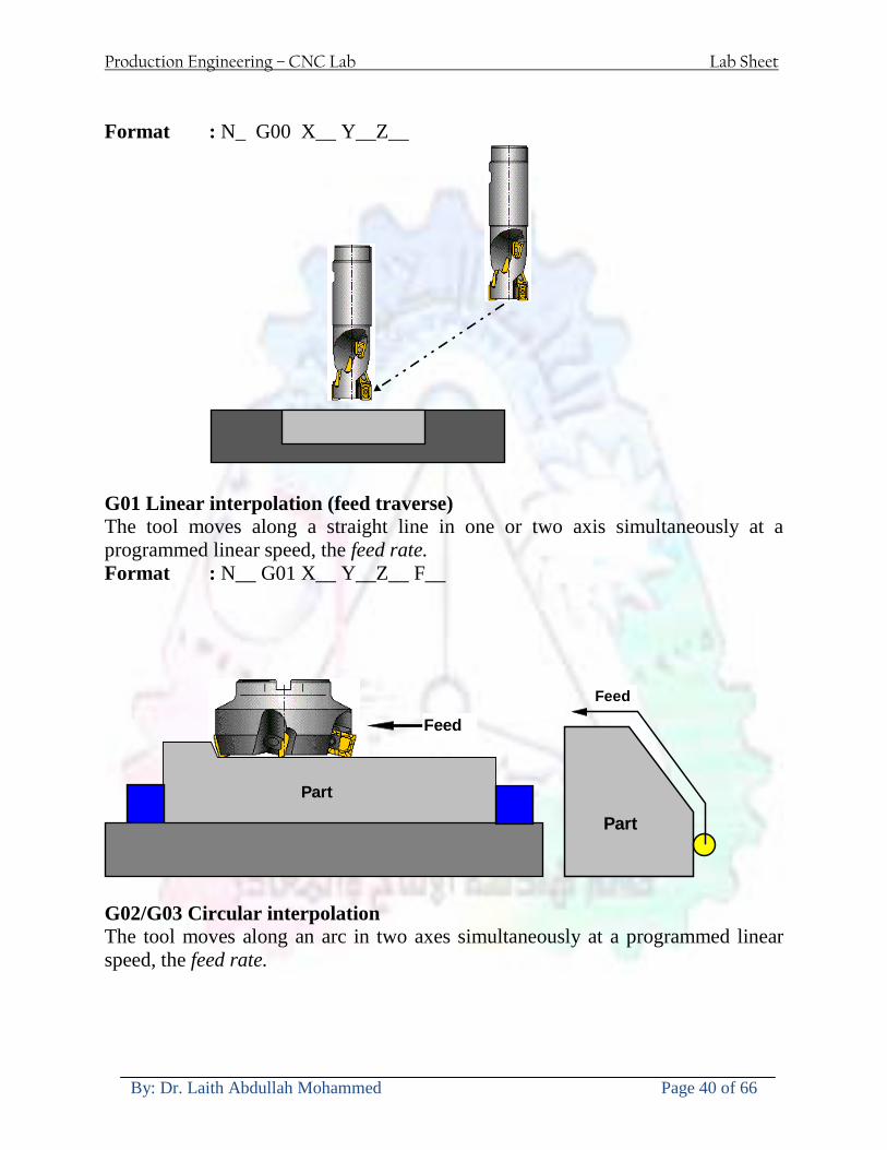
Production Engineering ndash CNC Lab Lab Sheet
By Dr Laith Abdullah Mohammed Page 40 of 66
Format N_ G00 X__ Y__Z__
G01 Linear interpolation (feed traverse) The tool moves along a straight line in one or two axis simultaneously at a programmed linear speed the feed rate Format N__ G01 X__ Y__Z__ F__
Part
Feed
Part
Feed
G02G03 Circular interpolation The tool moves along an arc in two axes simultaneously at a programmed linear speed the feed rate
Production Engineering ndash CNC Lab Lab Sheet
By Dr Laith Abdullah Mohammed Page 41 of 66
Format N__ G0203 X__ Y__Z__ I__ J__K__ F__ using the arc center OR N__ G0203 X__ Y__Z__ R__ F__ using the arc radius G02 moves along a CW arc G03 moves along a CCW arc Arc center The arc center is specified by addresses I J and K I J and K are the X Y and Z co-ordinates of the arc center with reference to the arc start point
X
Y
Arc center
Arc endArc start
- J
- I
I = X coord of center - X coord of start point J = Y coord of center - Y coord of start point K = Z coord of center - Z coord of start point I J and K must be written with their signs
Production Engineering ndash CNC Lab Lab Sheet
By Dr Laith Abdullah Mohammed Page 42 of 66
bullWork holding
Rotary table
Fixture base
Component
Clamp
Stud
Fixtures The use of fixtures 1 Improves repeatability of dimensions 2 Improves working conditions 3 Cuts down requirement of skilled labour 4 Reduces part loading and unloading time 5 Improves safety in the working area 6 Reduces the cost of machining There are two types fixtures commonly used 1 Special fixture Special fixtures are used to hold and locate the typical components which are having complex shape and to be located with the reference hole (dowel hole) Special fixtures are required for components like gear case cover cylinder heads etc 2 Modular fixture Modular fixture is a set different kind of clamping and locating elements These fixtures are used to hold identical components in different sizes and components of box type Example Manifolds head stocks connecting rods and flanges
Production Engineering ndash CNC Lab Lab Sheet
By Dr Laith Abdullah Mohammed Page 43 of 66
bullMachine setting
Determining X and Y work zero offset Case 1
Part
Machine table
Part
End mill or reamer
Work offset X0Y0 For determining X work zero offset bull Touch the periphery of the end mill or reamer to the part bull Enter current machine X value + cutter radius as X work zero offset For determining Y work zero offset bull Touch the periphery of the end mill or reamer to the part bull Enter current machine Y value - cutter radius as Y work zero offset Case 2
Part
Machine table
Part
End mill or reamerWork offset X0Y0
bull Mount the dial indicator on machine spindle true the bore bull Enter current machine X and Y value as X and Y work zero offset
Production Engineering ndash CNC Lab Lab Sheet
By Dr Laith Abdullah Mohammed Page 44 of 66
How to Select a Cutting Fluid
One part of the metal cutting equation that is sometimes overlooked however is
the choice of an appropriate cutting fluid With todayrsquos system approach to metal
cutting use of the right metalworking fluid has become just as much a part of the
solution as the other elements In fact at least one company is now integrating
cutting fluids and cutting tools into effective metal cutting systems Following are
some things to consider when choosing your next cutting fluid
The Four Key Questions
There are four vital pieces of information that are necessary when choosing a
cutting fluid They are
1 What are you cutting
2 What is the chemistry of your water
3 What are you using now
4 What are your options
5 What do you prefer
What Are You Cutting
The first question ndash ldquoWhat are you cuttingrdquo ndash is often the most difficult to answer
because most shops handle a variety of workpiece materials on a regular basis If
the answer is an unequivocal ldquoaluminumrdquo or ldquostainless steelrdquo or ldquocast ironrdquo the
selection of a cutting fluid can be quite simple and straightforward Unfortunately
that is seldom the case in anything but a high-volume plant Where aluminum or
other nonferrous metals are a significant part of the mix a non-staining cutting
fluid is a must Generally speaking this will be a semi-synthetic with special
ingredients to prevent bi-metallic corrosion and staining of non-ferrous workpieces
Where the ferrous metals predominate however a more general purpose semi-
synthetic or hybrid fluid might be a more economical choice
Production Engineering ndash CNC Lab Lab Sheet
By Dr Laith Abdullah Mohammed Page 45 of 66
What is The Chemistry of Your Water
The second question ndash ldquoWhat is the chemistry of your waterrdquo ndash is probably the
single most common reason for the success or failure of a cutting fluid Very few
plants invest the money necessary to install effective water purification systems
using deionization or reverse osmosis technology Unfortunately the chemicals
present or not present in the water used to re-constitute a cutting fluid make a
tremendous difference in its performance and sump life Most manufacturers of
cutting fluids will perform the necessary water testing to determine exactly what
minerals are dissolved in your water and make a fluid recommendation based on
the results
What are you using now
The third question ndash ldquoWhat are you using nowrdquo ndash helps narrow the range of
choices When coupled with an objective analysis of the strengths and weaknesses
of the current fluid the answer to this question can quickly point you toward a
relatively small number of competitive alternatives that have the attributes required
to meet your cutting needs Many cutting fluids are in use today simply because
they were in use yesterday It is a hard reality of todayrsquos marketplace that if one
isnrsquot constantly striving to improve they will certainly be overtaken by a
competitor who is
What Are Your Options
The fourth question ndash ldquoWhat are your optionsrdquo ndash leads to the final selection of a
cutting fluid Cutting fluids can be divided into four general groups based on their
chemistry
They are
bull Soluble Oils ndash quite literally oil dispersed in water
bull Synthetics ndash completely oil free man-made coolants in solution
Production Engineering ndash CNC Lab Lab Sheet
By Dr Laith Abdullah Mohammed Page 46 of 66
bull Semi-Synthetics ndash a mixture of natural and synthetic lubricants with up to 30
mineral oil
bull Hybrids ndash a special class of semi-synthetics with a mineral oil content of about
15 Each fluid type has advantages and disadvantages which make it suitable for
a particular group of applications In addition there are costperformance trade-
offs to be made between the groups within a specific set of applications For
example where a hybrid and a semi-synthetic may both be suitable for a particular
use the hybrid might provide longer sump life at a slightly higher initial cost
while some semi synthetics may be more economical to recycle or dispose of while
not giving as long a tank life The final decision in this case would have to be made
on the detailed economics of the shop where the fluids were to be used and on the
ownerrsquos individual preferences
Soluble Oils
Soluble oils are oils that disperse in water when emulsifiers are added They are
generally suitable for moderate-to heavy-duty machining and grinding of all non-
ferrous metals carbon and cast steels and in applications where dissimilar metals
such as aluminium and steel are present They can also be used in turning drilling
tapping reaming gear cutting broaching as well as internal and centerless types
of grinding operations Soluble oils provide excellent aluminium and copper
corrosion control good rancidity control which extends fluid for long lasting
trouble-free performance and good concentrate and mix stability making it ideal
for mixing in water with a minimal amount of agitation An example of this is
Valenitersquos VNTreg-650 premium heavy-duty soluble oil
Synthetics
Synthetics are completely oil free solutions made of polymers organic and
inorganic materials that are mixed with water These clear low foaming and bio-
Production Engineering ndash CNC Lab Lab Sheet
By Dr Laith Abdullah Mohammed Page 47 of 66
stable coolants are ideal for machining and grinding of ferrous materials carbon
steels or cast iron Their complex lubricant packages make synthetics well-suited
for tough-to-machine materials such as stainless steels and high-temperature alloys
Certain synthetics are specifically designed to address the primary failure modes of
flank wear and nose wear Although there are many benefits some synthetics may
cause staining of non-ferrous materials
Semi-Synthetics
Semi-synthetic fluids are a mixture of oils synthetic emulsifiers and water They
were primarily developed for the aircraft nuclear and related industries
Consequently they work extremely well on all non-ferrous metals such as titanium
aluminium copper brass bronze and stainless steel in both machining and
grinding Semi-synthetics can be used on ferrous metals too They are chlorine-
free to reduce bi-metallic corrosion and staining of metals They should be used at
a 5-8 dilution with water depending on the severity of the operation
Hybrids
Hybrids are cutting fluids custom engineered to solve a particular problem For
example Valenitersquos VNTreg-800 was developed to be very clean in the machining
and grinding of cast iron It provides better stability in hard water and rejects tramp
oil very well which adds to its bio-stable chemistry Hybrids work extremely well
on all metals in both machining and grinding They should be mixed at a 5-7
dilution with water depending on the condition of the water
What Do You Prefer
The final question ndash ldquoWhat do you preferrdquo ndash is usually the ldquotie breakerrdquo where
there is more than one appropriate cutting fluid available Here again as in the
case of what is being used now the key is to examine your preferences objectively
Production Engineering ndash CNC Lab Lab Sheet
By Dr Laith Abdullah Mohammed Page 48 of 66
and specifically to identify the real reasons behind a preference If you cannot
point to specific reasons why one class of cutting fluid is preferred over another
you are well advised to follow the recommendations of the professional who has
analyzed your requirements Choosing the right fluid today is easier than ever as
the system approach to metal cutting productivity continues to grow in acceptance
The day is not far off when choosing a complete solution will be as easy as
choosing the right insert and chip breaker today The answers are available and the
results will more than justify the time you spend choosing the right metal cutting
fluid
Useful Links wwwball-screwsnet
wwwlubelinkcom
wwwmachinerylubricationcom
wwwadvancedmanufacturingcom
wwwmmsonlinecom
wwwcuttingtoolengineeringcom
wwwgeartechnologycom
wwwengineersedgecom
wwwagmaorg
wwwefundacom
wwwsaeorg
wwwsmeorg
wwwastmorg
wwwissorg
wwwmachinetoolscom
wwwansiorg
wwwasmeorg
wwwcnccicom
wwwmatlscom
wwwthefreedictionarycom
wwwengineersupplycom
Production Engineering ndash CNC Lab Lab Sheet
By Dr Laith Abdullah Mohammed Page 49 of 66
SurfCAM Tutorial ndash Beginning with the basics
Background SurfCAM is a computer aided manufacturing (CAM) software which allows you to create manage and modify tool paths for computer aided designed (CAD) part The software requires a CAD model or requires that you create some geometry within SurfCAM with some rudimentary tools provided The tool paths are created or stored internally in SurfCAM in a generic programming language called APT Once the tool paths are created the APT paths are translated using a post processor into typical machine G-code
Opening SurfCAM SurfCAM can be opened from the Novell Applications Launcher on most Industrial Engineering computer labs workstations Search under lsquoallrsquo applications and double click on SurfCAM 2005 Once the program opens a license must be selected from the list (not the Demo license) to enable saving the file later Choose one of the 30 licenses available If for some reason the licenses are not listed on the license manager form select server list and type ldquobonnieeosncsuedurdquo A list of available licenses should appear Select a license and click OK After the license is selected an Add StockFixture form (Figure 1) opens allows you to add a model which represents the pre-machined stock or a fixture Click on OK without adding either Both of these items can be added later under a more appropriate dialog
Figure 1 Add Stock or Fixture dialog box
Production Engineering ndash CNC Lab Lab Sheet
By Dr Laith Abdullah Mohammed Page 50 of 66
SurfCAM Interface
Figure 2 SurfCAM Windows based interface
SurfCAM is a windows based software system so most of the typical windows functions under File are applicable This is where you can open save exit print etc The Create menu allows the user to create different geometry forms Here you can create a point line surface chamfer circle and many other geometry types For the most part these functions are not used by beginners but are useful when creating bounding curves where you donrsquot want the tool to move outside (constraining the tool) The Edit menu allows you to change or modify many different entities such as changing lines altering surfaces joining surfaces trimming or breaking elements add control points etc Again these features are helpful to advanced users and are not covered in detail in this tutorial The Display menu offers the ability to change the orientation of the part on the screen The typical rotate pan fit to screen and zoom functions are available as well as several functions which allow the user to shift between views or call up a named view (ie top bottom etc) The NC menu is the main machining interface menu In this menu you select the general form of machining (2 axis 3 axis 4 axis 5 axis turning etc) and under the general form a more specific machining function is selected This menu is the most used and the options contained must be fully understood to get the most out of SurfCAM Each function will be described in some detail in a further chapter The Analyze menu contains options such as measuring the distance between points angles tangency elements etc These functions are auxiliary functions meant to help you understand the part better but basically provide no functionality for making tool paths for CNC machines Thus these will not be covered The Tools menu allows the user to change the system options modify keyboard shortcuts change the model units etc These options are again not used by beginners Finally the Help menu provides access to the online users manual In lieu of clicking the Help menu the F1 key is the shortcut key for help (as it is in most windows based programs)
Importing a CAD model Importing a CAD model that is stored locally is done by selecting File-gtOpen On the Files of type dropdown box choose the type of file you wish to open (Figure 3) Do this prior to negotiating your way through the maze of folders to prevent having to go through the folder tree again Once the file type is selected find the file you are trying to open and click the Open
Production Engineering ndash CNC Lab Lab Sheet
By Dr Laith Abdullah Mohammed Page 51 of 66
button SurfCAM will then attempt to read the file you have selected SurfCAM may provide a dialog box describing what it has imported and identify if it was successful If this dialog is provided simply click close without saving
Figure 3 Open Dialog Note - Change type of file prior to finding the file you wish to open
SurfCAM allows a user to import several different types of CAD files the most common types which you will likely import are SolidWorks part files (sldprt or prt) AutoCAD files(dxf) or IGES (igs or iges) Native file import (such as is the case with SolidWorks) provides the greatest information transfer and generic file imports (such as is the case with IGES) provide the least Normally it is to the advantage of the user to use native file importing procedures when available Recently (2005) SurfCAM added some compatibility with SolidWorks This allows the user to create tool paths for a part and if an engineering change is needed for the part update the part in SolidWorks When the part is then opened in SurfCAM the changes are noted and a simple update operation command is needed This however does not operate with complete transparency andor accuracy and thus users need to be cognizant of changing CAD models
SurfCAM Geometry In SurfCAM two basic types of geometry are used the surface and the point A surface (Figure 4) is a so called spline (NURBS or B-Spline are the two most common) surface (parameterized by two values u and v) such that every location on the surface can be defined as a function of these parameters In other words SurfCAM can calculate the location of any point on the
Production Engineering ndash CNC Lab Lab Sheet
By Dr Laith Abdullah Mohammed Page 52 of 66
surface Surfaces are used primarily in 3 4 and 5 axis machining and require a significant
amount of processing power and time Figure 4 Surfaces model of a mold half Note the difference between this and Figure 2 a wireframe model
Point or line based models are often referred to as wireframe (Figure 5) models because the models consist of connected lines and resemble the part only at the intersection of two surfaces Wireframe models were made popular lsquoback in the dayrsquo when computer processing was expensive There are times when each of the models are important and selecting model geometry when applying a SurfCAM operation will be much simpler if you understand the differences between the two When importing a SolidWorks model the default is both the surfaces and the wireframe geometry are imported
Figure 5 Wireframe model of the mold in Figure 1
Steps to Creating Tool Paths Once a CAD model is imported into SurfCAM tool paths can be created There is no one correct way to create tool paths however there is a set of general steps to take to ensure the tool paths are created with a minimum amount of hardship (note the wordinghellipHardship is inevitable when creating tool paths it is the intent of this manual to minimize this) The following is a list of steps which should be considered when making tool paths
Production Engineering ndash CNC Lab Lab Sheet
By Dr Laith Abdullah Mohammed Page 53 of 66
1 Plan ahead a Orient the part in SolidWorks such that if only one side is to be machined that
side is the Top view This can be done early in SolidWorks by choosing a plane parallel the X-Y plane as the sketch plane for the machined geometry
b Orient the part in SolidWorks such that the origin is somewhere of relative importance and someplace in space that can be easily identified when placed on the machine This is extremely important to minimize set up time at the machine (note ndash my personal preference for a part that is to be fully machined [ie stock exists on all sides] is to place the origin at the center and top of the parthellipjust my preference)
c Orient the part in SolidWorks such that the X and Y axes are aligned as you want them on the machinehellip
d Planning ahead will save you many hours of headaches laterhelliptrust me 2 Import the model 3 Choose a construction view such that the tool approaches the side to be machined
from the positive Z axis direction (as defined by part origin) a This is done by clicking on the CView icon
b From the list of named views chose the view which orients the origin as you would like
c If one of the views does not fit your criteria you have two choices i Perform a transformation of the part in SurfCAM or SolidWorks
ii Add a new construction view by selecting new This option requires a relatively good understanding of right hand coordinate frames but is very usefulhellipNormally used by more advanced users
d Be sure the CoordVIEW selection is made vs CoordWORLD This ensures the tools will be controlled from the coordinate frame selected by the view (ie the origin on the part) instead of the origin on the lower left corner of the screen This will be especially important when we get into 4 and 5 axis machining
4 In the Operations Manager (Figure 6) select Setup One and change the name to something meaningful ndash like Front Side Mold Cavity
a Access the Operations manager by right clicking or by selecting the Operations Manager icon in the tool bar
b Operations Manager is where the tool paths are managed once they are created as well as where individual tool paths can be verified
Production Engineering ndash CNC Lab Lab Sheet
By Dr Laith Abdullah Mohammed Page 54 of 66
5 Roughing Tool Paths a Create the tool paths to remove the majority of the material (if applicable) b Use NC-gt3Axis-gtZ rough or Plunge Rough c Described in next section
6 Create Finishing Tool Paths a Described in next section
7 Add another setup if necessary 8 Perform steps 3 through 6 as necessary 9 Verify the tool paths are correct 10 Use a post processor for the tool paths to create G-Code for machine
Creating Tool Paths The following is a list of operations what they are intended for how they generally work and some parameters that may be adjusted to modify the tool paths
2 Axis tool paths Unless otherwise noted 2 axis tool path functions require lines or arc segments as input parameters (as opposed to surfaces) There are several options as to how these segments are chosen the most prevalent is the chain option and the second most prevalent is the single When choosing the line segments using the chain option SurfCAM will try to link a complete path of segments based on an initial segment chosen by the user If the operation is planer (ie pocket or contour) the segments must lie on the same plane If the operation is non-planer (ie contour 3D) SurfCAM will prompt the user to specify segments when it encounters a branch point
Figure 6 Operations Manager view showing setup one re-labeled as Front Side Mold
Production Engineering ndash CNC Lab Lab Sheet
By Dr Laith Abdullah Mohammed Page 55 of 66
When using the single element option the user must manually choose each segment desired for the operation Note that most operations do not require a closed loop of segments you may specify for instance an open contour where the tool is supposed to move The order of choosing segments is important This order determines the path of the tool in the sense that if three segments are chosen such that the middle segment is chosen last there will be three different plunge and machine operations one on each segment If the operation was to make a continuous contour around the outside of the part the segments should be chosen in order of the desired tool trajectory
Operations
Pocket Pocket operation in SurfCAM is used to cut an enclosed space from the inside to the outside at one particular depth The operation starts in the center of an enclosed area (with a plunge move in the ndashZ direction) and makes incremental closed paths towards the pocket boundaries in user defined path offsets (Figure 7) The user chooses the boundary of the pocket (line segments) and if more than one pocket is chosen SurfCAM will ask the user to click inside a pocket
Figure 7 Two examples of using the pocketing operation
The pocket operation allows for creating a projection of the pocket paths on multiple planes This is useful if you have a deep pocket which will not allow the tool to cut directly at the depth of the pocket but would be easily done using the same paths at several different Z heights On the cut control (Figure 8) tab the user specifies where the chosen geometry (pocket segments) lie (ie bottom or top) Then under the amount to remove specify the total material height to be removed and the rough spacing (amount you wish to advance the Z axis with each pocket step) You may also specify a finishing pass and as well as stock to leave
Production Engineering ndash CNC Lab Lab Sheet
By Dr Laith Abdullah Mohammed Page 56 of 66
Figure 8 Example of Contour Operation with multiple passes
Contour Contouring in SurfCAM is used to perform peripheral milling on the inside or outside of a line segment (Figure 9) The user is to identify the line segments which define a contour (does not have to be a closed loop of segments) SurfCAM may or may not require the user to specify a side to contour (ie which side of the line is the tool to cut) For contouring each segment must lie on the same plane
Production Engineering ndash CNC Lab Lab Sheet
By Dr Laith Abdullah Mohammed Page 57 of 66
Figure 9 Examples of parts cut with 2-Axis Contour
Contour 3D Contour 3D is the same operation type as contour but allows the user to specify segments on different planes for the tool to cut along
Drill Drilling operations are any rotating tool operation meant to engage the part from a single direction ndash namely from the positive Z direction Drilling operations can be specified using circle point or line segments After choosing NC-gt2-Axis-gtDrill SurfCAM allows the user to choose multiple circles or points defining holes to be drilled Drilling operations also allow the user to incorporate more than 1 operation such as a center drill a drill and a reaming operation After selecting the locations for the drilling operation a dialog box (Figure 10) allows the user to add change or delete tools to be used in the operation As displayed in the following figure the spotdrill operation is followed by a drilling operation followed by a tapping operation The depth of each tool can be controlled individually by double clicking the total depth cell in and manually entering Tools can be added before or after operations which the cells are highlighted by selecting either of the insert buttons at the top or by the insert menu Select tool button allows the user to change the tool size or type
Production Engineering ndash CNC Lab Lab Sheet
By Dr Laith Abdullah Mohammed Page 58 of 66
Figure 10 Drill operation manager Several operations can be completed at one time
Figure 11 Drill operation including the spotdrill drill and tap as outlined in Fig 10
3 Axis tool paths SurfCAM requires surfaces as inputs for 3 Axis tool paths Surfaces can be created in SurfCAM but are most easily created in a CAD package and imported into SurfCAM Surfaces allow SurfCAM to identify every point on the surface in 3 dimensions unlike 2D geometry (wireframes) which only identify positions on the plane Creating tool paths with complex surfaces takes a very significant amount of processing power so expect 3 Axis tool path generation to take longer
Production Engineering ndash CNC Lab Lab Sheet
By Dr Laith Abdullah Mohammed Page 59 of 66
Operations
Cut 3 Axis cut operation takes a surface and using the flow lines creates a rastering path over the surface with the tool tip riding on the surface The primary direction will be defined by the flow lines of the surface (which can be edited by Edit-gtSurfaces-gtArrow-gtDirection) If you intend to cross surface boundaries you must merge the surfaces (Edit-gtJoin and choose the two surfaces)
Z-Rough The Z-rough operation is used to remove a large amount of material prior to finish machining Roughing operation is typically the first operation you perform for each setup The Z-Rough operation cuts the part in user defined intervals For each of these intervals a surface intersection between the part and the plane is performed and a 2D pocket or contour operation is performed on that plane This is performed on each plane When choosing NC-gt3 Axis-gtZ rough the first dialog box you will encounter asks for a bounding box to be defined Choose the Extents Box and a second dialog box will ask for the coordinates which define the box (Figure 12) This is the stock size you expect to machine the part from Input the coordinates or change the additional offset amounts (in XY or Z) as appropriate and click Calculate Bounding Box
Figure 12 Material Extents Box Example
Next choose the tool and cutting parameters that you desire and click on the Cut Control Tab (Figure 13) Here you will find the following parameters which are often changed Stock to
Production Engineering ndash CNC Lab Lab Sheet
By Dr Laith Abdullah Mohammed Page 60 of 66
leave ndash this is an offset amount from the surfaces which leaves a small amount of material to finish machine Minimum and Maximum Z values ndash Defines area to machine Z Step Size ndash This identifies the plane intervals for the surface intersection planes (the first interval will be at the top of the selected area and successive increments down in Z will be cut until the Minimum Z value is reached)
Figure 13 3Axis Z Rough Cut Control
The 3Axis Z-Finish operation works in exactly the same way 3 Axis Z-Finish is most appropriate for finishing vertical or near vertical walls
3D Offset The 3D Offset operation creates a tool path using a 2D or 3D boundary by offsetting the boundary in concentric offset cutting passes Each pass calculates the tool engagement and maintains the engagement somewhat constant The advantage (significant) is the scallop height ndash height of the material between passes ndash is controlled thus the surface finish is predictable When choosing 3D Offset surfaces are selected as well as 2D or 3D boundaries The boundaries define the concentric offset paths shape as well as limit the tool path area Choose NC-gt3Axis-gt3D Offset from the drop down menus SurfCAM will prompt you to select the surface or surfaces to cut across Select the surfaces you wish to machine and then select the tool and cutting parameters you wish use Next select the Cut Control Tab and check the Use Boundary Curves option Set the Step Type to Scallop and set the maximum scallop height If you like
Production Engineering ndash CNC Lab Lab Sheet
By Dr Laith Abdullah Mohammed Page 61 of 66
you can also add stock to leave if this is a roughing operation You can also set the Direction and Start-End parameters from this tab Click OK and the paths will be generated
Figure 14 Cut Control Tab for 3D Offset
Example part using both 2D and 3D geometry
The tool paths for this mold will be generated in SurfCAM using 5 operations The first will be a roughing operation using a frac14 inch flat end mill with the Z step size of 00625in Choose NC-
Production Engineering ndash CNC Lab Lab Sheet
By Dr Laith Abdullah Mohammed Page 62 of 66
gt3Axis-gtZ-Rough from the drop down menu Select all visible surfaces and create an extents box that has 025inch XY offsets and 01inch Z offset Next select the frac14 inch flat end mill from the tools menu Under Cut Control tab set the Z step size to be 00625inch The tool paths will look something like Figure 15
Figure 15 Z-Rough Tool paths for Example Part
Next a flat surface operation will be performed to cut the flat surface on the top Select NC-gt3 Axis-gtFlat Surface from the drop down menu Select all visible surfaces again Choose the 12inch flat end mill and set the cutting parameters as desired Under Cut Control Tab change the Minimum Area to 50 square inches (Figure 16) The tool paths should look something like Figure 17
Figure 16 Cut Control for Flat Surface
Production Engineering ndash CNC Lab Lab Sheet
By Dr Laith Abdullah Mohammed Page 63 of 66
Figure 17 Flat Surface Tool Paths
Next we will use a 3D offset operation to cut the mold cavity Select NC-gt3 Axis-gt3D Offset from the dropdown menu Change the view to the top view and select within to capture the surfaces of the mold cavity Draw a rectangle around the mold cavity Select a 18 inch ball endmill from the tool library and set the cutting parameters as appropriate Next set the Cut Control tab parameters as in Figure 14 The paths creates should be similar to Figure 18
Figure 18 3D Offset Paths
Next we will perform a 2 Axis contouring of the top section Select NC-gt2 Axis-gtContour from the dropdown menu Using the chain option select the bottom contour of the top extrusion Select the frac12 inch flat end mill from the tool library and set the cutting parameters as required In the Cut Control Tab change the Geometry to Bottom and the amount to remove in Z to 05
Production Engineering ndash CNC Lab Lab Sheet
By Dr Laith Abdullah Mohammed Page 64 of 66
Change the Rough Spacing in Z to 025 and add 1 finish pass of 002 (Figure 19) Click OK and SurfCAM will instruct you to choose a side to contour Click anywhere on the screen OUTSIDE the geometry you selected for the contouring operation Failure to click outside the geometry will result in the tool being on the wrong side of the contour Your paths should look something like those in Figure 20
Figure 19 Cut Control Tab for the Contouring Operation
Figure 20 Contouring operation paths
Production Engineering ndash CNC Lab Lab Sheet
By Dr Laith Abdullah Mohammed Page 65 of 66
Next we will perform a 2 axis pocket operation for the small pocket on the top face of the mold Select NC-gt2Axis-gtPocket and using the Auto select feature select the boundary curve at the bottom of the pocket Click Done twice and select the frac14 inch flat end mill from the tool library Set the appropriate cutting parameters and click OK SurfCAM will prompt you to click inside the pocket Click anywhere inside the geometry you chose to define the pocket The resulting paths should look something like those in Figure 21
Figure 21 2 Axis Pocket Operation Paths
Finally we will add a drilling operation for the 2 holes at the corners of the mold Select NC-gt2 Axis-gtDrill from the dropdown menu Select the top circles defining the two holes A menu box will appear with a default tool (Center drill) already programmed Add a second tool to the list by selecting Insert-gtAfter and select the tool from the tool library Change the drill depth to 10inches and click OK The paths should look something similar to Figure 23
Figure 22 Drill Menu
Production Engineering ndash CNC Lab Lab Sheet
By Dr Laith Abdullah Mohammed Page 66 of 66
Figure 23 Drilling Operation Tool Paths
Now you can watch a simulation of the cutting by choosing the setup in the operations manager and clicking the simulate icon Be sure to set the stock in the set up by right clicking the set up and selecting Edit Setup Information In the Stock Tab you can create a bounding box meeting your needs and click Add Your simulation should result in something like the following
Figure 24 Final Simulation of the example Mold
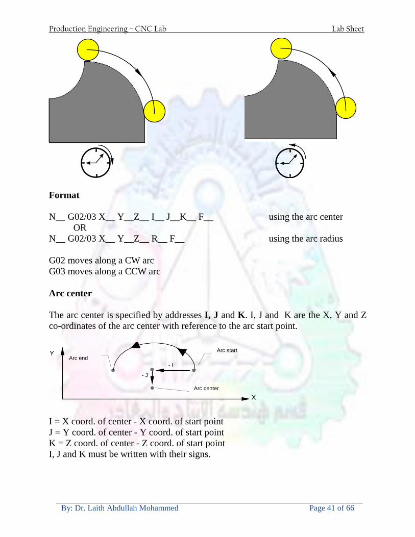
Production Engineering ndash CNC Lab Lab Sheet
By Dr Laith Abdullah Mohammed Page 41 of 66
Format N__ G0203 X__ Y__Z__ I__ J__K__ F__ using the arc center OR N__ G0203 X__ Y__Z__ R__ F__ using the arc radius G02 moves along a CW arc G03 moves along a CCW arc Arc center The arc center is specified by addresses I J and K I J and K are the X Y and Z co-ordinates of the arc center with reference to the arc start point
X
Y
Arc center
Arc endArc start
- J
- I
I = X coord of center - X coord of start point J = Y coord of center - Y coord of start point K = Z coord of center - Z coord of start point I J and K must be written with their signs
Production Engineering ndash CNC Lab Lab Sheet
By Dr Laith Abdullah Mohammed Page 42 of 66
bullWork holding
Rotary table
Fixture base
Component
Clamp
Stud
Fixtures The use of fixtures 1 Improves repeatability of dimensions 2 Improves working conditions 3 Cuts down requirement of skilled labour 4 Reduces part loading and unloading time 5 Improves safety in the working area 6 Reduces the cost of machining There are two types fixtures commonly used 1 Special fixture Special fixtures are used to hold and locate the typical components which are having complex shape and to be located with the reference hole (dowel hole) Special fixtures are required for components like gear case cover cylinder heads etc 2 Modular fixture Modular fixture is a set different kind of clamping and locating elements These fixtures are used to hold identical components in different sizes and components of box type Example Manifolds head stocks connecting rods and flanges
Production Engineering ndash CNC Lab Lab Sheet
By Dr Laith Abdullah Mohammed Page 43 of 66
bullMachine setting
Determining X and Y work zero offset Case 1
Part
Machine table
Part
End mill or reamer
Work offset X0Y0 For determining X work zero offset bull Touch the periphery of the end mill or reamer to the part bull Enter current machine X value + cutter radius as X work zero offset For determining Y work zero offset bull Touch the periphery of the end mill or reamer to the part bull Enter current machine Y value - cutter radius as Y work zero offset Case 2
Part
Machine table
Part
End mill or reamerWork offset X0Y0
bull Mount the dial indicator on machine spindle true the bore bull Enter current machine X and Y value as X and Y work zero offset
Production Engineering ndash CNC Lab Lab Sheet
By Dr Laith Abdullah Mohammed Page 44 of 66
How to Select a Cutting Fluid
One part of the metal cutting equation that is sometimes overlooked however is
the choice of an appropriate cutting fluid With todayrsquos system approach to metal
cutting use of the right metalworking fluid has become just as much a part of the
solution as the other elements In fact at least one company is now integrating
cutting fluids and cutting tools into effective metal cutting systems Following are
some things to consider when choosing your next cutting fluid
The Four Key Questions
There are four vital pieces of information that are necessary when choosing a
cutting fluid They are
1 What are you cutting
2 What is the chemistry of your water
3 What are you using now
4 What are your options
5 What do you prefer
What Are You Cutting
The first question ndash ldquoWhat are you cuttingrdquo ndash is often the most difficult to answer
because most shops handle a variety of workpiece materials on a regular basis If
the answer is an unequivocal ldquoaluminumrdquo or ldquostainless steelrdquo or ldquocast ironrdquo the
selection of a cutting fluid can be quite simple and straightforward Unfortunately
that is seldom the case in anything but a high-volume plant Where aluminum or
other nonferrous metals are a significant part of the mix a non-staining cutting
fluid is a must Generally speaking this will be a semi-synthetic with special
ingredients to prevent bi-metallic corrosion and staining of non-ferrous workpieces
Where the ferrous metals predominate however a more general purpose semi-
synthetic or hybrid fluid might be a more economical choice
Production Engineering ndash CNC Lab Lab Sheet
By Dr Laith Abdullah Mohammed Page 45 of 66
What is The Chemistry of Your Water
The second question ndash ldquoWhat is the chemistry of your waterrdquo ndash is probably the
single most common reason for the success or failure of a cutting fluid Very few
plants invest the money necessary to install effective water purification systems
using deionization or reverse osmosis technology Unfortunately the chemicals
present or not present in the water used to re-constitute a cutting fluid make a
tremendous difference in its performance and sump life Most manufacturers of
cutting fluids will perform the necessary water testing to determine exactly what
minerals are dissolved in your water and make a fluid recommendation based on
the results
What are you using now
The third question ndash ldquoWhat are you using nowrdquo ndash helps narrow the range of
choices When coupled with an objective analysis of the strengths and weaknesses
of the current fluid the answer to this question can quickly point you toward a
relatively small number of competitive alternatives that have the attributes required
to meet your cutting needs Many cutting fluids are in use today simply because
they were in use yesterday It is a hard reality of todayrsquos marketplace that if one
isnrsquot constantly striving to improve they will certainly be overtaken by a
competitor who is
What Are Your Options
The fourth question ndash ldquoWhat are your optionsrdquo ndash leads to the final selection of a
cutting fluid Cutting fluids can be divided into four general groups based on their
chemistry
They are
bull Soluble Oils ndash quite literally oil dispersed in water
bull Synthetics ndash completely oil free man-made coolants in solution
Production Engineering ndash CNC Lab Lab Sheet
By Dr Laith Abdullah Mohammed Page 46 of 66
bull Semi-Synthetics ndash a mixture of natural and synthetic lubricants with up to 30
mineral oil
bull Hybrids ndash a special class of semi-synthetics with a mineral oil content of about
15 Each fluid type has advantages and disadvantages which make it suitable for
a particular group of applications In addition there are costperformance trade-
offs to be made between the groups within a specific set of applications For
example where a hybrid and a semi-synthetic may both be suitable for a particular
use the hybrid might provide longer sump life at a slightly higher initial cost
while some semi synthetics may be more economical to recycle or dispose of while
not giving as long a tank life The final decision in this case would have to be made
on the detailed economics of the shop where the fluids were to be used and on the
ownerrsquos individual preferences
Soluble Oils
Soluble oils are oils that disperse in water when emulsifiers are added They are
generally suitable for moderate-to heavy-duty machining and grinding of all non-
ferrous metals carbon and cast steels and in applications where dissimilar metals
such as aluminium and steel are present They can also be used in turning drilling
tapping reaming gear cutting broaching as well as internal and centerless types
of grinding operations Soluble oils provide excellent aluminium and copper
corrosion control good rancidity control which extends fluid for long lasting
trouble-free performance and good concentrate and mix stability making it ideal
for mixing in water with a minimal amount of agitation An example of this is
Valenitersquos VNTreg-650 premium heavy-duty soluble oil
Synthetics
Synthetics are completely oil free solutions made of polymers organic and
inorganic materials that are mixed with water These clear low foaming and bio-
Production Engineering ndash CNC Lab Lab Sheet
By Dr Laith Abdullah Mohammed Page 47 of 66
stable coolants are ideal for machining and grinding of ferrous materials carbon
steels or cast iron Their complex lubricant packages make synthetics well-suited
for tough-to-machine materials such as stainless steels and high-temperature alloys
Certain synthetics are specifically designed to address the primary failure modes of
flank wear and nose wear Although there are many benefits some synthetics may
cause staining of non-ferrous materials
Semi-Synthetics
Semi-synthetic fluids are a mixture of oils synthetic emulsifiers and water They
were primarily developed for the aircraft nuclear and related industries
Consequently they work extremely well on all non-ferrous metals such as titanium
aluminium copper brass bronze and stainless steel in both machining and
grinding Semi-synthetics can be used on ferrous metals too They are chlorine-
free to reduce bi-metallic corrosion and staining of metals They should be used at
a 5-8 dilution with water depending on the severity of the operation
Hybrids
Hybrids are cutting fluids custom engineered to solve a particular problem For
example Valenitersquos VNTreg-800 was developed to be very clean in the machining
and grinding of cast iron It provides better stability in hard water and rejects tramp
oil very well which adds to its bio-stable chemistry Hybrids work extremely well
on all metals in both machining and grinding They should be mixed at a 5-7
dilution with water depending on the condition of the water
What Do You Prefer
The final question ndash ldquoWhat do you preferrdquo ndash is usually the ldquotie breakerrdquo where
there is more than one appropriate cutting fluid available Here again as in the
case of what is being used now the key is to examine your preferences objectively
Production Engineering ndash CNC Lab Lab Sheet
By Dr Laith Abdullah Mohammed Page 48 of 66
and specifically to identify the real reasons behind a preference If you cannot
point to specific reasons why one class of cutting fluid is preferred over another
you are well advised to follow the recommendations of the professional who has
analyzed your requirements Choosing the right fluid today is easier than ever as
the system approach to metal cutting productivity continues to grow in acceptance
The day is not far off when choosing a complete solution will be as easy as
choosing the right insert and chip breaker today The answers are available and the
results will more than justify the time you spend choosing the right metal cutting
fluid
Useful Links wwwball-screwsnet
wwwlubelinkcom
wwwmachinerylubricationcom
wwwadvancedmanufacturingcom
wwwmmsonlinecom
wwwcuttingtoolengineeringcom
wwwgeartechnologycom
wwwengineersedgecom
wwwagmaorg
wwwefundacom
wwwsaeorg
wwwsmeorg
wwwastmorg
wwwissorg
wwwmachinetoolscom
wwwansiorg
wwwasmeorg
wwwcnccicom
wwwmatlscom
wwwthefreedictionarycom
wwwengineersupplycom
Production Engineering ndash CNC Lab Lab Sheet
By Dr Laith Abdullah Mohammed Page 49 of 66
SurfCAM Tutorial ndash Beginning with the basics
Background SurfCAM is a computer aided manufacturing (CAM) software which allows you to create manage and modify tool paths for computer aided designed (CAD) part The software requires a CAD model or requires that you create some geometry within SurfCAM with some rudimentary tools provided The tool paths are created or stored internally in SurfCAM in a generic programming language called APT Once the tool paths are created the APT paths are translated using a post processor into typical machine G-code
Opening SurfCAM SurfCAM can be opened from the Novell Applications Launcher on most Industrial Engineering computer labs workstations Search under lsquoallrsquo applications and double click on SurfCAM 2005 Once the program opens a license must be selected from the list (not the Demo license) to enable saving the file later Choose one of the 30 licenses available If for some reason the licenses are not listed on the license manager form select server list and type ldquobonnieeosncsuedurdquo A list of available licenses should appear Select a license and click OK After the license is selected an Add StockFixture form (Figure 1) opens allows you to add a model which represents the pre-machined stock or a fixture Click on OK without adding either Both of these items can be added later under a more appropriate dialog
Figure 1 Add Stock or Fixture dialog box
Production Engineering ndash CNC Lab Lab Sheet
By Dr Laith Abdullah Mohammed Page 50 of 66
SurfCAM Interface
Figure 2 SurfCAM Windows based interface
SurfCAM is a windows based software system so most of the typical windows functions under File are applicable This is where you can open save exit print etc The Create menu allows the user to create different geometry forms Here you can create a point line surface chamfer circle and many other geometry types For the most part these functions are not used by beginners but are useful when creating bounding curves where you donrsquot want the tool to move outside (constraining the tool) The Edit menu allows you to change or modify many different entities such as changing lines altering surfaces joining surfaces trimming or breaking elements add control points etc Again these features are helpful to advanced users and are not covered in detail in this tutorial The Display menu offers the ability to change the orientation of the part on the screen The typical rotate pan fit to screen and zoom functions are available as well as several functions which allow the user to shift between views or call up a named view (ie top bottom etc) The NC menu is the main machining interface menu In this menu you select the general form of machining (2 axis 3 axis 4 axis 5 axis turning etc) and under the general form a more specific machining function is selected This menu is the most used and the options contained must be fully understood to get the most out of SurfCAM Each function will be described in some detail in a further chapter The Analyze menu contains options such as measuring the distance between points angles tangency elements etc These functions are auxiliary functions meant to help you understand the part better but basically provide no functionality for making tool paths for CNC machines Thus these will not be covered The Tools menu allows the user to change the system options modify keyboard shortcuts change the model units etc These options are again not used by beginners Finally the Help menu provides access to the online users manual In lieu of clicking the Help menu the F1 key is the shortcut key for help (as it is in most windows based programs)
Importing a CAD model Importing a CAD model that is stored locally is done by selecting File-gtOpen On the Files of type dropdown box choose the type of file you wish to open (Figure 3) Do this prior to negotiating your way through the maze of folders to prevent having to go through the folder tree again Once the file type is selected find the file you are trying to open and click the Open
Production Engineering ndash CNC Lab Lab Sheet
By Dr Laith Abdullah Mohammed Page 51 of 66
button SurfCAM will then attempt to read the file you have selected SurfCAM may provide a dialog box describing what it has imported and identify if it was successful If this dialog is provided simply click close without saving
Figure 3 Open Dialog Note - Change type of file prior to finding the file you wish to open
SurfCAM allows a user to import several different types of CAD files the most common types which you will likely import are SolidWorks part files (sldprt or prt) AutoCAD files(dxf) or IGES (igs or iges) Native file import (such as is the case with SolidWorks) provides the greatest information transfer and generic file imports (such as is the case with IGES) provide the least Normally it is to the advantage of the user to use native file importing procedures when available Recently (2005) SurfCAM added some compatibility with SolidWorks This allows the user to create tool paths for a part and if an engineering change is needed for the part update the part in SolidWorks When the part is then opened in SurfCAM the changes are noted and a simple update operation command is needed This however does not operate with complete transparency andor accuracy and thus users need to be cognizant of changing CAD models
SurfCAM Geometry In SurfCAM two basic types of geometry are used the surface and the point A surface (Figure 4) is a so called spline (NURBS or B-Spline are the two most common) surface (parameterized by two values u and v) such that every location on the surface can be defined as a function of these parameters In other words SurfCAM can calculate the location of any point on the
Production Engineering ndash CNC Lab Lab Sheet
By Dr Laith Abdullah Mohammed Page 52 of 66
surface Surfaces are used primarily in 3 4 and 5 axis machining and require a significant
amount of processing power and time Figure 4 Surfaces model of a mold half Note the difference between this and Figure 2 a wireframe model
Point or line based models are often referred to as wireframe (Figure 5) models because the models consist of connected lines and resemble the part only at the intersection of two surfaces Wireframe models were made popular lsquoback in the dayrsquo when computer processing was expensive There are times when each of the models are important and selecting model geometry when applying a SurfCAM operation will be much simpler if you understand the differences between the two When importing a SolidWorks model the default is both the surfaces and the wireframe geometry are imported
Figure 5 Wireframe model of the mold in Figure 1
Steps to Creating Tool Paths Once a CAD model is imported into SurfCAM tool paths can be created There is no one correct way to create tool paths however there is a set of general steps to take to ensure the tool paths are created with a minimum amount of hardship (note the wordinghellipHardship is inevitable when creating tool paths it is the intent of this manual to minimize this) The following is a list of steps which should be considered when making tool paths
Production Engineering ndash CNC Lab Lab Sheet
By Dr Laith Abdullah Mohammed Page 53 of 66
1 Plan ahead a Orient the part in SolidWorks such that if only one side is to be machined that
side is the Top view This can be done early in SolidWorks by choosing a plane parallel the X-Y plane as the sketch plane for the machined geometry
b Orient the part in SolidWorks such that the origin is somewhere of relative importance and someplace in space that can be easily identified when placed on the machine This is extremely important to minimize set up time at the machine (note ndash my personal preference for a part that is to be fully machined [ie stock exists on all sides] is to place the origin at the center and top of the parthellipjust my preference)
c Orient the part in SolidWorks such that the X and Y axes are aligned as you want them on the machinehellip
d Planning ahead will save you many hours of headaches laterhelliptrust me 2 Import the model 3 Choose a construction view such that the tool approaches the side to be machined
from the positive Z axis direction (as defined by part origin) a This is done by clicking on the CView icon
b From the list of named views chose the view which orients the origin as you would like
c If one of the views does not fit your criteria you have two choices i Perform a transformation of the part in SurfCAM or SolidWorks
ii Add a new construction view by selecting new This option requires a relatively good understanding of right hand coordinate frames but is very usefulhellipNormally used by more advanced users
d Be sure the CoordVIEW selection is made vs CoordWORLD This ensures the tools will be controlled from the coordinate frame selected by the view (ie the origin on the part) instead of the origin on the lower left corner of the screen This will be especially important when we get into 4 and 5 axis machining
4 In the Operations Manager (Figure 6) select Setup One and change the name to something meaningful ndash like Front Side Mold Cavity
a Access the Operations manager by right clicking or by selecting the Operations Manager icon in the tool bar
b Operations Manager is where the tool paths are managed once they are created as well as where individual tool paths can be verified
Production Engineering ndash CNC Lab Lab Sheet
By Dr Laith Abdullah Mohammed Page 54 of 66
5 Roughing Tool Paths a Create the tool paths to remove the majority of the material (if applicable) b Use NC-gt3Axis-gtZ rough or Plunge Rough c Described in next section
6 Create Finishing Tool Paths a Described in next section
7 Add another setup if necessary 8 Perform steps 3 through 6 as necessary 9 Verify the tool paths are correct 10 Use a post processor for the tool paths to create G-Code for machine
Creating Tool Paths The following is a list of operations what they are intended for how they generally work and some parameters that may be adjusted to modify the tool paths
2 Axis tool paths Unless otherwise noted 2 axis tool path functions require lines or arc segments as input parameters (as opposed to surfaces) There are several options as to how these segments are chosen the most prevalent is the chain option and the second most prevalent is the single When choosing the line segments using the chain option SurfCAM will try to link a complete path of segments based on an initial segment chosen by the user If the operation is planer (ie pocket or contour) the segments must lie on the same plane If the operation is non-planer (ie contour 3D) SurfCAM will prompt the user to specify segments when it encounters a branch point
Figure 6 Operations Manager view showing setup one re-labeled as Front Side Mold
Production Engineering ndash CNC Lab Lab Sheet
By Dr Laith Abdullah Mohammed Page 55 of 66
When using the single element option the user must manually choose each segment desired for the operation Note that most operations do not require a closed loop of segments you may specify for instance an open contour where the tool is supposed to move The order of choosing segments is important This order determines the path of the tool in the sense that if three segments are chosen such that the middle segment is chosen last there will be three different plunge and machine operations one on each segment If the operation was to make a continuous contour around the outside of the part the segments should be chosen in order of the desired tool trajectory
Operations
Pocket Pocket operation in SurfCAM is used to cut an enclosed space from the inside to the outside at one particular depth The operation starts in the center of an enclosed area (with a plunge move in the ndashZ direction) and makes incremental closed paths towards the pocket boundaries in user defined path offsets (Figure 7) The user chooses the boundary of the pocket (line segments) and if more than one pocket is chosen SurfCAM will ask the user to click inside a pocket
Figure 7 Two examples of using the pocketing operation
The pocket operation allows for creating a projection of the pocket paths on multiple planes This is useful if you have a deep pocket which will not allow the tool to cut directly at the depth of the pocket but would be easily done using the same paths at several different Z heights On the cut control (Figure 8) tab the user specifies where the chosen geometry (pocket segments) lie (ie bottom or top) Then under the amount to remove specify the total material height to be removed and the rough spacing (amount you wish to advance the Z axis with each pocket step) You may also specify a finishing pass and as well as stock to leave
Production Engineering ndash CNC Lab Lab Sheet
By Dr Laith Abdullah Mohammed Page 56 of 66
Figure 8 Example of Contour Operation with multiple passes
Contour Contouring in SurfCAM is used to perform peripheral milling on the inside or outside of a line segment (Figure 9) The user is to identify the line segments which define a contour (does not have to be a closed loop of segments) SurfCAM may or may not require the user to specify a side to contour (ie which side of the line is the tool to cut) For contouring each segment must lie on the same plane
Production Engineering ndash CNC Lab Lab Sheet
By Dr Laith Abdullah Mohammed Page 57 of 66
Figure 9 Examples of parts cut with 2-Axis Contour
Contour 3D Contour 3D is the same operation type as contour but allows the user to specify segments on different planes for the tool to cut along
Drill Drilling operations are any rotating tool operation meant to engage the part from a single direction ndash namely from the positive Z direction Drilling operations can be specified using circle point or line segments After choosing NC-gt2-Axis-gtDrill SurfCAM allows the user to choose multiple circles or points defining holes to be drilled Drilling operations also allow the user to incorporate more than 1 operation such as a center drill a drill and a reaming operation After selecting the locations for the drilling operation a dialog box (Figure 10) allows the user to add change or delete tools to be used in the operation As displayed in the following figure the spotdrill operation is followed by a drilling operation followed by a tapping operation The depth of each tool can be controlled individually by double clicking the total depth cell in and manually entering Tools can be added before or after operations which the cells are highlighted by selecting either of the insert buttons at the top or by the insert menu Select tool button allows the user to change the tool size or type
Production Engineering ndash CNC Lab Lab Sheet
By Dr Laith Abdullah Mohammed Page 58 of 66
Figure 10 Drill operation manager Several operations can be completed at one time
Figure 11 Drill operation including the spotdrill drill and tap as outlined in Fig 10
3 Axis tool paths SurfCAM requires surfaces as inputs for 3 Axis tool paths Surfaces can be created in SurfCAM but are most easily created in a CAD package and imported into SurfCAM Surfaces allow SurfCAM to identify every point on the surface in 3 dimensions unlike 2D geometry (wireframes) which only identify positions on the plane Creating tool paths with complex surfaces takes a very significant amount of processing power so expect 3 Axis tool path generation to take longer
Production Engineering ndash CNC Lab Lab Sheet
By Dr Laith Abdullah Mohammed Page 59 of 66
Operations
Cut 3 Axis cut operation takes a surface and using the flow lines creates a rastering path over the surface with the tool tip riding on the surface The primary direction will be defined by the flow lines of the surface (which can be edited by Edit-gtSurfaces-gtArrow-gtDirection) If you intend to cross surface boundaries you must merge the surfaces (Edit-gtJoin and choose the two surfaces)
Z-Rough The Z-rough operation is used to remove a large amount of material prior to finish machining Roughing operation is typically the first operation you perform for each setup The Z-Rough operation cuts the part in user defined intervals For each of these intervals a surface intersection between the part and the plane is performed and a 2D pocket or contour operation is performed on that plane This is performed on each plane When choosing NC-gt3 Axis-gtZ rough the first dialog box you will encounter asks for a bounding box to be defined Choose the Extents Box and a second dialog box will ask for the coordinates which define the box (Figure 12) This is the stock size you expect to machine the part from Input the coordinates or change the additional offset amounts (in XY or Z) as appropriate and click Calculate Bounding Box
Figure 12 Material Extents Box Example
Next choose the tool and cutting parameters that you desire and click on the Cut Control Tab (Figure 13) Here you will find the following parameters which are often changed Stock to
Production Engineering ndash CNC Lab Lab Sheet
By Dr Laith Abdullah Mohammed Page 60 of 66
leave ndash this is an offset amount from the surfaces which leaves a small amount of material to finish machine Minimum and Maximum Z values ndash Defines area to machine Z Step Size ndash This identifies the plane intervals for the surface intersection planes (the first interval will be at the top of the selected area and successive increments down in Z will be cut until the Minimum Z value is reached)
Figure 13 3Axis Z Rough Cut Control
The 3Axis Z-Finish operation works in exactly the same way 3 Axis Z-Finish is most appropriate for finishing vertical or near vertical walls
3D Offset The 3D Offset operation creates a tool path using a 2D or 3D boundary by offsetting the boundary in concentric offset cutting passes Each pass calculates the tool engagement and maintains the engagement somewhat constant The advantage (significant) is the scallop height ndash height of the material between passes ndash is controlled thus the surface finish is predictable When choosing 3D Offset surfaces are selected as well as 2D or 3D boundaries The boundaries define the concentric offset paths shape as well as limit the tool path area Choose NC-gt3Axis-gt3D Offset from the drop down menus SurfCAM will prompt you to select the surface or surfaces to cut across Select the surfaces you wish to machine and then select the tool and cutting parameters you wish use Next select the Cut Control Tab and check the Use Boundary Curves option Set the Step Type to Scallop and set the maximum scallop height If you like
Production Engineering ndash CNC Lab Lab Sheet
By Dr Laith Abdullah Mohammed Page 61 of 66
you can also add stock to leave if this is a roughing operation You can also set the Direction and Start-End parameters from this tab Click OK and the paths will be generated
Figure 14 Cut Control Tab for 3D Offset
Example part using both 2D and 3D geometry
The tool paths for this mold will be generated in SurfCAM using 5 operations The first will be a roughing operation using a frac14 inch flat end mill with the Z step size of 00625in Choose NC-
Production Engineering ndash CNC Lab Lab Sheet
By Dr Laith Abdullah Mohammed Page 62 of 66
gt3Axis-gtZ-Rough from the drop down menu Select all visible surfaces and create an extents box that has 025inch XY offsets and 01inch Z offset Next select the frac14 inch flat end mill from the tools menu Under Cut Control tab set the Z step size to be 00625inch The tool paths will look something like Figure 15
Figure 15 Z-Rough Tool paths for Example Part
Next a flat surface operation will be performed to cut the flat surface on the top Select NC-gt3 Axis-gtFlat Surface from the drop down menu Select all visible surfaces again Choose the 12inch flat end mill and set the cutting parameters as desired Under Cut Control Tab change the Minimum Area to 50 square inches (Figure 16) The tool paths should look something like Figure 17
Figure 16 Cut Control for Flat Surface
Production Engineering ndash CNC Lab Lab Sheet
By Dr Laith Abdullah Mohammed Page 63 of 66
Figure 17 Flat Surface Tool Paths
Next we will use a 3D offset operation to cut the mold cavity Select NC-gt3 Axis-gt3D Offset from the dropdown menu Change the view to the top view and select within to capture the surfaces of the mold cavity Draw a rectangle around the mold cavity Select a 18 inch ball endmill from the tool library and set the cutting parameters as appropriate Next set the Cut Control tab parameters as in Figure 14 The paths creates should be similar to Figure 18
Figure 18 3D Offset Paths
Next we will perform a 2 Axis contouring of the top section Select NC-gt2 Axis-gtContour from the dropdown menu Using the chain option select the bottom contour of the top extrusion Select the frac12 inch flat end mill from the tool library and set the cutting parameters as required In the Cut Control Tab change the Geometry to Bottom and the amount to remove in Z to 05
Production Engineering ndash CNC Lab Lab Sheet
By Dr Laith Abdullah Mohammed Page 64 of 66
Change the Rough Spacing in Z to 025 and add 1 finish pass of 002 (Figure 19) Click OK and SurfCAM will instruct you to choose a side to contour Click anywhere on the screen OUTSIDE the geometry you selected for the contouring operation Failure to click outside the geometry will result in the tool being on the wrong side of the contour Your paths should look something like those in Figure 20
Figure 19 Cut Control Tab for the Contouring Operation
Figure 20 Contouring operation paths
Production Engineering ndash CNC Lab Lab Sheet
By Dr Laith Abdullah Mohammed Page 65 of 66
Next we will perform a 2 axis pocket operation for the small pocket on the top face of the mold Select NC-gt2Axis-gtPocket and using the Auto select feature select the boundary curve at the bottom of the pocket Click Done twice and select the frac14 inch flat end mill from the tool library Set the appropriate cutting parameters and click OK SurfCAM will prompt you to click inside the pocket Click anywhere inside the geometry you chose to define the pocket The resulting paths should look something like those in Figure 21
Figure 21 2 Axis Pocket Operation Paths
Finally we will add a drilling operation for the 2 holes at the corners of the mold Select NC-gt2 Axis-gtDrill from the dropdown menu Select the top circles defining the two holes A menu box will appear with a default tool (Center drill) already programmed Add a second tool to the list by selecting Insert-gtAfter and select the tool from the tool library Change the drill depth to 10inches and click OK The paths should look something similar to Figure 23
Figure 22 Drill Menu
Production Engineering ndash CNC Lab Lab Sheet
By Dr Laith Abdullah Mohammed Page 66 of 66
Figure 23 Drilling Operation Tool Paths
Now you can watch a simulation of the cutting by choosing the setup in the operations manager and clicking the simulate icon Be sure to set the stock in the set up by right clicking the set up and selecting Edit Setup Information In the Stock Tab you can create a bounding box meeting your needs and click Add Your simulation should result in something like the following
Figure 24 Final Simulation of the example Mold
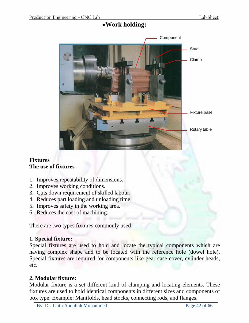
Production Engineering ndash CNC Lab Lab Sheet
By Dr Laith Abdullah Mohammed Page 42 of 66
bullWork holding
Rotary table
Fixture base
Component
Clamp
Stud
Fixtures The use of fixtures 1 Improves repeatability of dimensions 2 Improves working conditions 3 Cuts down requirement of skilled labour 4 Reduces part loading and unloading time 5 Improves safety in the working area 6 Reduces the cost of machining There are two types fixtures commonly used 1 Special fixture Special fixtures are used to hold and locate the typical components which are having complex shape and to be located with the reference hole (dowel hole) Special fixtures are required for components like gear case cover cylinder heads etc 2 Modular fixture Modular fixture is a set different kind of clamping and locating elements These fixtures are used to hold identical components in different sizes and components of box type Example Manifolds head stocks connecting rods and flanges
Production Engineering ndash CNC Lab Lab Sheet
By Dr Laith Abdullah Mohammed Page 43 of 66
bullMachine setting
Determining X and Y work zero offset Case 1
Part
Machine table
Part
End mill or reamer
Work offset X0Y0 For determining X work zero offset bull Touch the periphery of the end mill or reamer to the part bull Enter current machine X value + cutter radius as X work zero offset For determining Y work zero offset bull Touch the periphery of the end mill or reamer to the part bull Enter current machine Y value - cutter radius as Y work zero offset Case 2
Part
Machine table
Part
End mill or reamerWork offset X0Y0
bull Mount the dial indicator on machine spindle true the bore bull Enter current machine X and Y value as X and Y work zero offset
Production Engineering ndash CNC Lab Lab Sheet
By Dr Laith Abdullah Mohammed Page 44 of 66
How to Select a Cutting Fluid
One part of the metal cutting equation that is sometimes overlooked however is
the choice of an appropriate cutting fluid With todayrsquos system approach to metal
cutting use of the right metalworking fluid has become just as much a part of the
solution as the other elements In fact at least one company is now integrating
cutting fluids and cutting tools into effective metal cutting systems Following are
some things to consider when choosing your next cutting fluid
The Four Key Questions
There are four vital pieces of information that are necessary when choosing a
cutting fluid They are
1 What are you cutting
2 What is the chemistry of your water
3 What are you using now
4 What are your options
5 What do you prefer
What Are You Cutting
The first question ndash ldquoWhat are you cuttingrdquo ndash is often the most difficult to answer
because most shops handle a variety of workpiece materials on a regular basis If
the answer is an unequivocal ldquoaluminumrdquo or ldquostainless steelrdquo or ldquocast ironrdquo the
selection of a cutting fluid can be quite simple and straightforward Unfortunately
that is seldom the case in anything but a high-volume plant Where aluminum or
other nonferrous metals are a significant part of the mix a non-staining cutting
fluid is a must Generally speaking this will be a semi-synthetic with special
ingredients to prevent bi-metallic corrosion and staining of non-ferrous workpieces
Where the ferrous metals predominate however a more general purpose semi-
synthetic or hybrid fluid might be a more economical choice
Production Engineering ndash CNC Lab Lab Sheet
By Dr Laith Abdullah Mohammed Page 45 of 66
What is The Chemistry of Your Water
The second question ndash ldquoWhat is the chemistry of your waterrdquo ndash is probably the
single most common reason for the success or failure of a cutting fluid Very few
plants invest the money necessary to install effective water purification systems
using deionization or reverse osmosis technology Unfortunately the chemicals
present or not present in the water used to re-constitute a cutting fluid make a
tremendous difference in its performance and sump life Most manufacturers of
cutting fluids will perform the necessary water testing to determine exactly what
minerals are dissolved in your water and make a fluid recommendation based on
the results
What are you using now
The third question ndash ldquoWhat are you using nowrdquo ndash helps narrow the range of
choices When coupled with an objective analysis of the strengths and weaknesses
of the current fluid the answer to this question can quickly point you toward a
relatively small number of competitive alternatives that have the attributes required
to meet your cutting needs Many cutting fluids are in use today simply because
they were in use yesterday It is a hard reality of todayrsquos marketplace that if one
isnrsquot constantly striving to improve they will certainly be overtaken by a
competitor who is
What Are Your Options
The fourth question ndash ldquoWhat are your optionsrdquo ndash leads to the final selection of a
cutting fluid Cutting fluids can be divided into four general groups based on their
chemistry
They are
bull Soluble Oils ndash quite literally oil dispersed in water
bull Synthetics ndash completely oil free man-made coolants in solution
Production Engineering ndash CNC Lab Lab Sheet
By Dr Laith Abdullah Mohammed Page 46 of 66
bull Semi-Synthetics ndash a mixture of natural and synthetic lubricants with up to 30
mineral oil
bull Hybrids ndash a special class of semi-synthetics with a mineral oil content of about
15 Each fluid type has advantages and disadvantages which make it suitable for
a particular group of applications In addition there are costperformance trade-
offs to be made between the groups within a specific set of applications For
example where a hybrid and a semi-synthetic may both be suitable for a particular
use the hybrid might provide longer sump life at a slightly higher initial cost
while some semi synthetics may be more economical to recycle or dispose of while
not giving as long a tank life The final decision in this case would have to be made
on the detailed economics of the shop where the fluids were to be used and on the
ownerrsquos individual preferences
Soluble Oils
Soluble oils are oils that disperse in water when emulsifiers are added They are
generally suitable for moderate-to heavy-duty machining and grinding of all non-
ferrous metals carbon and cast steels and in applications where dissimilar metals
such as aluminium and steel are present They can also be used in turning drilling
tapping reaming gear cutting broaching as well as internal and centerless types
of grinding operations Soluble oils provide excellent aluminium and copper
corrosion control good rancidity control which extends fluid for long lasting
trouble-free performance and good concentrate and mix stability making it ideal
for mixing in water with a minimal amount of agitation An example of this is
Valenitersquos VNTreg-650 premium heavy-duty soluble oil
Synthetics
Synthetics are completely oil free solutions made of polymers organic and
inorganic materials that are mixed with water These clear low foaming and bio-
Production Engineering ndash CNC Lab Lab Sheet
By Dr Laith Abdullah Mohammed Page 47 of 66
stable coolants are ideal for machining and grinding of ferrous materials carbon
steels or cast iron Their complex lubricant packages make synthetics well-suited
for tough-to-machine materials such as stainless steels and high-temperature alloys
Certain synthetics are specifically designed to address the primary failure modes of
flank wear and nose wear Although there are many benefits some synthetics may
cause staining of non-ferrous materials
Semi-Synthetics
Semi-synthetic fluids are a mixture of oils synthetic emulsifiers and water They
were primarily developed for the aircraft nuclear and related industries
Consequently they work extremely well on all non-ferrous metals such as titanium
aluminium copper brass bronze and stainless steel in both machining and
grinding Semi-synthetics can be used on ferrous metals too They are chlorine-
free to reduce bi-metallic corrosion and staining of metals They should be used at
a 5-8 dilution with water depending on the severity of the operation
Hybrids
Hybrids are cutting fluids custom engineered to solve a particular problem For
example Valenitersquos VNTreg-800 was developed to be very clean in the machining
and grinding of cast iron It provides better stability in hard water and rejects tramp
oil very well which adds to its bio-stable chemistry Hybrids work extremely well
on all metals in both machining and grinding They should be mixed at a 5-7
dilution with water depending on the condition of the water
What Do You Prefer
The final question ndash ldquoWhat do you preferrdquo ndash is usually the ldquotie breakerrdquo where
there is more than one appropriate cutting fluid available Here again as in the
case of what is being used now the key is to examine your preferences objectively
Production Engineering ndash CNC Lab Lab Sheet
By Dr Laith Abdullah Mohammed Page 48 of 66
and specifically to identify the real reasons behind a preference If you cannot
point to specific reasons why one class of cutting fluid is preferred over another
you are well advised to follow the recommendations of the professional who has
analyzed your requirements Choosing the right fluid today is easier than ever as
the system approach to metal cutting productivity continues to grow in acceptance
The day is not far off when choosing a complete solution will be as easy as
choosing the right insert and chip breaker today The answers are available and the
results will more than justify the time you spend choosing the right metal cutting
fluid
Useful Links wwwball-screwsnet
wwwlubelinkcom
wwwmachinerylubricationcom
wwwadvancedmanufacturingcom
wwwmmsonlinecom
wwwcuttingtoolengineeringcom
wwwgeartechnologycom
wwwengineersedgecom
wwwagmaorg
wwwefundacom
wwwsaeorg
wwwsmeorg
wwwastmorg
wwwissorg
wwwmachinetoolscom
wwwansiorg
wwwasmeorg
wwwcnccicom
wwwmatlscom
wwwthefreedictionarycom
wwwengineersupplycom
Production Engineering ndash CNC Lab Lab Sheet
By Dr Laith Abdullah Mohammed Page 49 of 66
SurfCAM Tutorial ndash Beginning with the basics
Background SurfCAM is a computer aided manufacturing (CAM) software which allows you to create manage and modify tool paths for computer aided designed (CAD) part The software requires a CAD model or requires that you create some geometry within SurfCAM with some rudimentary tools provided The tool paths are created or stored internally in SurfCAM in a generic programming language called APT Once the tool paths are created the APT paths are translated using a post processor into typical machine G-code
Opening SurfCAM SurfCAM can be opened from the Novell Applications Launcher on most Industrial Engineering computer labs workstations Search under lsquoallrsquo applications and double click on SurfCAM 2005 Once the program opens a license must be selected from the list (not the Demo license) to enable saving the file later Choose one of the 30 licenses available If for some reason the licenses are not listed on the license manager form select server list and type ldquobonnieeosncsuedurdquo A list of available licenses should appear Select a license and click OK After the license is selected an Add StockFixture form (Figure 1) opens allows you to add a model which represents the pre-machined stock or a fixture Click on OK without adding either Both of these items can be added later under a more appropriate dialog
Figure 1 Add Stock or Fixture dialog box
Production Engineering ndash CNC Lab Lab Sheet
By Dr Laith Abdullah Mohammed Page 50 of 66
SurfCAM Interface
Figure 2 SurfCAM Windows based interface
SurfCAM is a windows based software system so most of the typical windows functions under File are applicable This is where you can open save exit print etc The Create menu allows the user to create different geometry forms Here you can create a point line surface chamfer circle and many other geometry types For the most part these functions are not used by beginners but are useful when creating bounding curves where you donrsquot want the tool to move outside (constraining the tool) The Edit menu allows you to change or modify many different entities such as changing lines altering surfaces joining surfaces trimming or breaking elements add control points etc Again these features are helpful to advanced users and are not covered in detail in this tutorial The Display menu offers the ability to change the orientation of the part on the screen The typical rotate pan fit to screen and zoom functions are available as well as several functions which allow the user to shift between views or call up a named view (ie top bottom etc) The NC menu is the main machining interface menu In this menu you select the general form of machining (2 axis 3 axis 4 axis 5 axis turning etc) and under the general form a more specific machining function is selected This menu is the most used and the options contained must be fully understood to get the most out of SurfCAM Each function will be described in some detail in a further chapter The Analyze menu contains options such as measuring the distance between points angles tangency elements etc These functions are auxiliary functions meant to help you understand the part better but basically provide no functionality for making tool paths for CNC machines Thus these will not be covered The Tools menu allows the user to change the system options modify keyboard shortcuts change the model units etc These options are again not used by beginners Finally the Help menu provides access to the online users manual In lieu of clicking the Help menu the F1 key is the shortcut key for help (as it is in most windows based programs)
Importing a CAD model Importing a CAD model that is stored locally is done by selecting File-gtOpen On the Files of type dropdown box choose the type of file you wish to open (Figure 3) Do this prior to negotiating your way through the maze of folders to prevent having to go through the folder tree again Once the file type is selected find the file you are trying to open and click the Open
Production Engineering ndash CNC Lab Lab Sheet
By Dr Laith Abdullah Mohammed Page 51 of 66
button SurfCAM will then attempt to read the file you have selected SurfCAM may provide a dialog box describing what it has imported and identify if it was successful If this dialog is provided simply click close without saving
Figure 3 Open Dialog Note - Change type of file prior to finding the file you wish to open
SurfCAM allows a user to import several different types of CAD files the most common types which you will likely import are SolidWorks part files (sldprt or prt) AutoCAD files(dxf) or IGES (igs or iges) Native file import (such as is the case with SolidWorks) provides the greatest information transfer and generic file imports (such as is the case with IGES) provide the least Normally it is to the advantage of the user to use native file importing procedures when available Recently (2005) SurfCAM added some compatibility with SolidWorks This allows the user to create tool paths for a part and if an engineering change is needed for the part update the part in SolidWorks When the part is then opened in SurfCAM the changes are noted and a simple update operation command is needed This however does not operate with complete transparency andor accuracy and thus users need to be cognizant of changing CAD models
SurfCAM Geometry In SurfCAM two basic types of geometry are used the surface and the point A surface (Figure 4) is a so called spline (NURBS or B-Spline are the two most common) surface (parameterized by two values u and v) such that every location on the surface can be defined as a function of these parameters In other words SurfCAM can calculate the location of any point on the
Production Engineering ndash CNC Lab Lab Sheet
By Dr Laith Abdullah Mohammed Page 52 of 66
surface Surfaces are used primarily in 3 4 and 5 axis machining and require a significant
amount of processing power and time Figure 4 Surfaces model of a mold half Note the difference between this and Figure 2 a wireframe model
Point or line based models are often referred to as wireframe (Figure 5) models because the models consist of connected lines and resemble the part only at the intersection of two surfaces Wireframe models were made popular lsquoback in the dayrsquo when computer processing was expensive There are times when each of the models are important and selecting model geometry when applying a SurfCAM operation will be much simpler if you understand the differences between the two When importing a SolidWorks model the default is both the surfaces and the wireframe geometry are imported
Figure 5 Wireframe model of the mold in Figure 1
Steps to Creating Tool Paths Once a CAD model is imported into SurfCAM tool paths can be created There is no one correct way to create tool paths however there is a set of general steps to take to ensure the tool paths are created with a minimum amount of hardship (note the wordinghellipHardship is inevitable when creating tool paths it is the intent of this manual to minimize this) The following is a list of steps which should be considered when making tool paths
Production Engineering ndash CNC Lab Lab Sheet
By Dr Laith Abdullah Mohammed Page 53 of 66
1 Plan ahead a Orient the part in SolidWorks such that if only one side is to be machined that
side is the Top view This can be done early in SolidWorks by choosing a plane parallel the X-Y plane as the sketch plane for the machined geometry
b Orient the part in SolidWorks such that the origin is somewhere of relative importance and someplace in space that can be easily identified when placed on the machine This is extremely important to minimize set up time at the machine (note ndash my personal preference for a part that is to be fully machined [ie stock exists on all sides] is to place the origin at the center and top of the parthellipjust my preference)
c Orient the part in SolidWorks such that the X and Y axes are aligned as you want them on the machinehellip
d Planning ahead will save you many hours of headaches laterhelliptrust me 2 Import the model 3 Choose a construction view such that the tool approaches the side to be machined
from the positive Z axis direction (as defined by part origin) a This is done by clicking on the CView icon
b From the list of named views chose the view which orients the origin as you would like
c If one of the views does not fit your criteria you have two choices i Perform a transformation of the part in SurfCAM or SolidWorks
ii Add a new construction view by selecting new This option requires a relatively good understanding of right hand coordinate frames but is very usefulhellipNormally used by more advanced users
d Be sure the CoordVIEW selection is made vs CoordWORLD This ensures the tools will be controlled from the coordinate frame selected by the view (ie the origin on the part) instead of the origin on the lower left corner of the screen This will be especially important when we get into 4 and 5 axis machining
4 In the Operations Manager (Figure 6) select Setup One and change the name to something meaningful ndash like Front Side Mold Cavity
a Access the Operations manager by right clicking or by selecting the Operations Manager icon in the tool bar
b Operations Manager is where the tool paths are managed once they are created as well as where individual tool paths can be verified
Production Engineering ndash CNC Lab Lab Sheet
By Dr Laith Abdullah Mohammed Page 54 of 66
5 Roughing Tool Paths a Create the tool paths to remove the majority of the material (if applicable) b Use NC-gt3Axis-gtZ rough or Plunge Rough c Described in next section
6 Create Finishing Tool Paths a Described in next section
7 Add another setup if necessary 8 Perform steps 3 through 6 as necessary 9 Verify the tool paths are correct 10 Use a post processor for the tool paths to create G-Code for machine
Creating Tool Paths The following is a list of operations what they are intended for how they generally work and some parameters that may be adjusted to modify the tool paths
2 Axis tool paths Unless otherwise noted 2 axis tool path functions require lines or arc segments as input parameters (as opposed to surfaces) There are several options as to how these segments are chosen the most prevalent is the chain option and the second most prevalent is the single When choosing the line segments using the chain option SurfCAM will try to link a complete path of segments based on an initial segment chosen by the user If the operation is planer (ie pocket or contour) the segments must lie on the same plane If the operation is non-planer (ie contour 3D) SurfCAM will prompt the user to specify segments when it encounters a branch point
Figure 6 Operations Manager view showing setup one re-labeled as Front Side Mold
Production Engineering ndash CNC Lab Lab Sheet
By Dr Laith Abdullah Mohammed Page 55 of 66
When using the single element option the user must manually choose each segment desired for the operation Note that most operations do not require a closed loop of segments you may specify for instance an open contour where the tool is supposed to move The order of choosing segments is important This order determines the path of the tool in the sense that if three segments are chosen such that the middle segment is chosen last there will be three different plunge and machine operations one on each segment If the operation was to make a continuous contour around the outside of the part the segments should be chosen in order of the desired tool trajectory
Operations
Pocket Pocket operation in SurfCAM is used to cut an enclosed space from the inside to the outside at one particular depth The operation starts in the center of an enclosed area (with a plunge move in the ndashZ direction) and makes incremental closed paths towards the pocket boundaries in user defined path offsets (Figure 7) The user chooses the boundary of the pocket (line segments) and if more than one pocket is chosen SurfCAM will ask the user to click inside a pocket
Figure 7 Two examples of using the pocketing operation
The pocket operation allows for creating a projection of the pocket paths on multiple planes This is useful if you have a deep pocket which will not allow the tool to cut directly at the depth of the pocket but would be easily done using the same paths at several different Z heights On the cut control (Figure 8) tab the user specifies where the chosen geometry (pocket segments) lie (ie bottom or top) Then under the amount to remove specify the total material height to be removed and the rough spacing (amount you wish to advance the Z axis with each pocket step) You may also specify a finishing pass and as well as stock to leave
Production Engineering ndash CNC Lab Lab Sheet
By Dr Laith Abdullah Mohammed Page 56 of 66
Figure 8 Example of Contour Operation with multiple passes
Contour Contouring in SurfCAM is used to perform peripheral milling on the inside or outside of a line segment (Figure 9) The user is to identify the line segments which define a contour (does not have to be a closed loop of segments) SurfCAM may or may not require the user to specify a side to contour (ie which side of the line is the tool to cut) For contouring each segment must lie on the same plane
Production Engineering ndash CNC Lab Lab Sheet
By Dr Laith Abdullah Mohammed Page 57 of 66
Figure 9 Examples of parts cut with 2-Axis Contour
Contour 3D Contour 3D is the same operation type as contour but allows the user to specify segments on different planes for the tool to cut along
Drill Drilling operations are any rotating tool operation meant to engage the part from a single direction ndash namely from the positive Z direction Drilling operations can be specified using circle point or line segments After choosing NC-gt2-Axis-gtDrill SurfCAM allows the user to choose multiple circles or points defining holes to be drilled Drilling operations also allow the user to incorporate more than 1 operation such as a center drill a drill and a reaming operation After selecting the locations for the drilling operation a dialog box (Figure 10) allows the user to add change or delete tools to be used in the operation As displayed in the following figure the spotdrill operation is followed by a drilling operation followed by a tapping operation The depth of each tool can be controlled individually by double clicking the total depth cell in and manually entering Tools can be added before or after operations which the cells are highlighted by selecting either of the insert buttons at the top or by the insert menu Select tool button allows the user to change the tool size or type
Production Engineering ndash CNC Lab Lab Sheet
By Dr Laith Abdullah Mohammed Page 58 of 66
Figure 10 Drill operation manager Several operations can be completed at one time
Figure 11 Drill operation including the spotdrill drill and tap as outlined in Fig 10
3 Axis tool paths SurfCAM requires surfaces as inputs for 3 Axis tool paths Surfaces can be created in SurfCAM but are most easily created in a CAD package and imported into SurfCAM Surfaces allow SurfCAM to identify every point on the surface in 3 dimensions unlike 2D geometry (wireframes) which only identify positions on the plane Creating tool paths with complex surfaces takes a very significant amount of processing power so expect 3 Axis tool path generation to take longer
Production Engineering ndash CNC Lab Lab Sheet
By Dr Laith Abdullah Mohammed Page 59 of 66
Operations
Cut 3 Axis cut operation takes a surface and using the flow lines creates a rastering path over the surface with the tool tip riding on the surface The primary direction will be defined by the flow lines of the surface (which can be edited by Edit-gtSurfaces-gtArrow-gtDirection) If you intend to cross surface boundaries you must merge the surfaces (Edit-gtJoin and choose the two surfaces)
Z-Rough The Z-rough operation is used to remove a large amount of material prior to finish machining Roughing operation is typically the first operation you perform for each setup The Z-Rough operation cuts the part in user defined intervals For each of these intervals a surface intersection between the part and the plane is performed and a 2D pocket or contour operation is performed on that plane This is performed on each plane When choosing NC-gt3 Axis-gtZ rough the first dialog box you will encounter asks for a bounding box to be defined Choose the Extents Box and a second dialog box will ask for the coordinates which define the box (Figure 12) This is the stock size you expect to machine the part from Input the coordinates or change the additional offset amounts (in XY or Z) as appropriate and click Calculate Bounding Box
Figure 12 Material Extents Box Example
Next choose the tool and cutting parameters that you desire and click on the Cut Control Tab (Figure 13) Here you will find the following parameters which are often changed Stock to
Production Engineering ndash CNC Lab Lab Sheet
By Dr Laith Abdullah Mohammed Page 60 of 66
leave ndash this is an offset amount from the surfaces which leaves a small amount of material to finish machine Minimum and Maximum Z values ndash Defines area to machine Z Step Size ndash This identifies the plane intervals for the surface intersection planes (the first interval will be at the top of the selected area and successive increments down in Z will be cut until the Minimum Z value is reached)
Figure 13 3Axis Z Rough Cut Control
The 3Axis Z-Finish operation works in exactly the same way 3 Axis Z-Finish is most appropriate for finishing vertical or near vertical walls
3D Offset The 3D Offset operation creates a tool path using a 2D or 3D boundary by offsetting the boundary in concentric offset cutting passes Each pass calculates the tool engagement and maintains the engagement somewhat constant The advantage (significant) is the scallop height ndash height of the material between passes ndash is controlled thus the surface finish is predictable When choosing 3D Offset surfaces are selected as well as 2D or 3D boundaries The boundaries define the concentric offset paths shape as well as limit the tool path area Choose NC-gt3Axis-gt3D Offset from the drop down menus SurfCAM will prompt you to select the surface or surfaces to cut across Select the surfaces you wish to machine and then select the tool and cutting parameters you wish use Next select the Cut Control Tab and check the Use Boundary Curves option Set the Step Type to Scallop and set the maximum scallop height If you like
Production Engineering ndash CNC Lab Lab Sheet
By Dr Laith Abdullah Mohammed Page 61 of 66
you can also add stock to leave if this is a roughing operation You can also set the Direction and Start-End parameters from this tab Click OK and the paths will be generated
Figure 14 Cut Control Tab for 3D Offset
Example part using both 2D and 3D geometry
The tool paths for this mold will be generated in SurfCAM using 5 operations The first will be a roughing operation using a frac14 inch flat end mill with the Z step size of 00625in Choose NC-
Production Engineering ndash CNC Lab Lab Sheet
By Dr Laith Abdullah Mohammed Page 62 of 66
gt3Axis-gtZ-Rough from the drop down menu Select all visible surfaces and create an extents box that has 025inch XY offsets and 01inch Z offset Next select the frac14 inch flat end mill from the tools menu Under Cut Control tab set the Z step size to be 00625inch The tool paths will look something like Figure 15
Figure 15 Z-Rough Tool paths for Example Part
Next a flat surface operation will be performed to cut the flat surface on the top Select NC-gt3 Axis-gtFlat Surface from the drop down menu Select all visible surfaces again Choose the 12inch flat end mill and set the cutting parameters as desired Under Cut Control Tab change the Minimum Area to 50 square inches (Figure 16) The tool paths should look something like Figure 17
Figure 16 Cut Control for Flat Surface
Production Engineering ndash CNC Lab Lab Sheet
By Dr Laith Abdullah Mohammed Page 63 of 66
Figure 17 Flat Surface Tool Paths
Next we will use a 3D offset operation to cut the mold cavity Select NC-gt3 Axis-gt3D Offset from the dropdown menu Change the view to the top view and select within to capture the surfaces of the mold cavity Draw a rectangle around the mold cavity Select a 18 inch ball endmill from the tool library and set the cutting parameters as appropriate Next set the Cut Control tab parameters as in Figure 14 The paths creates should be similar to Figure 18
Figure 18 3D Offset Paths
Next we will perform a 2 Axis contouring of the top section Select NC-gt2 Axis-gtContour from the dropdown menu Using the chain option select the bottom contour of the top extrusion Select the frac12 inch flat end mill from the tool library and set the cutting parameters as required In the Cut Control Tab change the Geometry to Bottom and the amount to remove in Z to 05
Production Engineering ndash CNC Lab Lab Sheet
By Dr Laith Abdullah Mohammed Page 64 of 66
Change the Rough Spacing in Z to 025 and add 1 finish pass of 002 (Figure 19) Click OK and SurfCAM will instruct you to choose a side to contour Click anywhere on the screen OUTSIDE the geometry you selected for the contouring operation Failure to click outside the geometry will result in the tool being on the wrong side of the contour Your paths should look something like those in Figure 20
Figure 19 Cut Control Tab for the Contouring Operation
Figure 20 Contouring operation paths
Production Engineering ndash CNC Lab Lab Sheet
By Dr Laith Abdullah Mohammed Page 65 of 66
Next we will perform a 2 axis pocket operation for the small pocket on the top face of the mold Select NC-gt2Axis-gtPocket and using the Auto select feature select the boundary curve at the bottom of the pocket Click Done twice and select the frac14 inch flat end mill from the tool library Set the appropriate cutting parameters and click OK SurfCAM will prompt you to click inside the pocket Click anywhere inside the geometry you chose to define the pocket The resulting paths should look something like those in Figure 21
Figure 21 2 Axis Pocket Operation Paths
Finally we will add a drilling operation for the 2 holes at the corners of the mold Select NC-gt2 Axis-gtDrill from the dropdown menu Select the top circles defining the two holes A menu box will appear with a default tool (Center drill) already programmed Add a second tool to the list by selecting Insert-gtAfter and select the tool from the tool library Change the drill depth to 10inches and click OK The paths should look something similar to Figure 23
Figure 22 Drill Menu
Production Engineering ndash CNC Lab Lab Sheet
By Dr Laith Abdullah Mohammed Page 66 of 66
Figure 23 Drilling Operation Tool Paths
Now you can watch a simulation of the cutting by choosing the setup in the operations manager and clicking the simulate icon Be sure to set the stock in the set up by right clicking the set up and selecting Edit Setup Information In the Stock Tab you can create a bounding box meeting your needs and click Add Your simulation should result in something like the following
Figure 24 Final Simulation of the example Mold
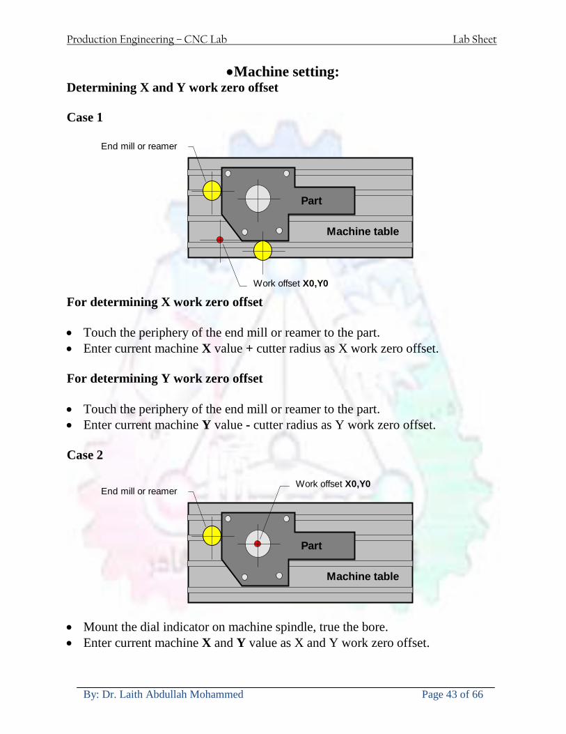
Production Engineering ndash CNC Lab Lab Sheet
By Dr Laith Abdullah Mohammed Page 43 of 66
bullMachine setting
Determining X and Y work zero offset Case 1
Part
Machine table
Part
End mill or reamer
Work offset X0Y0 For determining X work zero offset bull Touch the periphery of the end mill or reamer to the part bull Enter current machine X value + cutter radius as X work zero offset For determining Y work zero offset bull Touch the periphery of the end mill or reamer to the part bull Enter current machine Y value - cutter radius as Y work zero offset Case 2
Part
Machine table
Part
End mill or reamerWork offset X0Y0
bull Mount the dial indicator on machine spindle true the bore bull Enter current machine X and Y value as X and Y work zero offset
Production Engineering ndash CNC Lab Lab Sheet
By Dr Laith Abdullah Mohammed Page 44 of 66
How to Select a Cutting Fluid
One part of the metal cutting equation that is sometimes overlooked however is
the choice of an appropriate cutting fluid With todayrsquos system approach to metal
cutting use of the right metalworking fluid has become just as much a part of the
solution as the other elements In fact at least one company is now integrating
cutting fluids and cutting tools into effective metal cutting systems Following are
some things to consider when choosing your next cutting fluid
The Four Key Questions
There are four vital pieces of information that are necessary when choosing a
cutting fluid They are
1 What are you cutting
2 What is the chemistry of your water
3 What are you using now
4 What are your options
5 What do you prefer
What Are You Cutting
The first question ndash ldquoWhat are you cuttingrdquo ndash is often the most difficult to answer
because most shops handle a variety of workpiece materials on a regular basis If
the answer is an unequivocal ldquoaluminumrdquo or ldquostainless steelrdquo or ldquocast ironrdquo the
selection of a cutting fluid can be quite simple and straightforward Unfortunately
that is seldom the case in anything but a high-volume plant Where aluminum or
other nonferrous metals are a significant part of the mix a non-staining cutting
fluid is a must Generally speaking this will be a semi-synthetic with special
ingredients to prevent bi-metallic corrosion and staining of non-ferrous workpieces
Where the ferrous metals predominate however a more general purpose semi-
synthetic or hybrid fluid might be a more economical choice
Production Engineering ndash CNC Lab Lab Sheet
By Dr Laith Abdullah Mohammed Page 45 of 66
What is The Chemistry of Your Water
The second question ndash ldquoWhat is the chemistry of your waterrdquo ndash is probably the
single most common reason for the success or failure of a cutting fluid Very few
plants invest the money necessary to install effective water purification systems
using deionization or reverse osmosis technology Unfortunately the chemicals
present or not present in the water used to re-constitute a cutting fluid make a
tremendous difference in its performance and sump life Most manufacturers of
cutting fluids will perform the necessary water testing to determine exactly what
minerals are dissolved in your water and make a fluid recommendation based on
the results
What are you using now
The third question ndash ldquoWhat are you using nowrdquo ndash helps narrow the range of
choices When coupled with an objective analysis of the strengths and weaknesses
of the current fluid the answer to this question can quickly point you toward a
relatively small number of competitive alternatives that have the attributes required
to meet your cutting needs Many cutting fluids are in use today simply because
they were in use yesterday It is a hard reality of todayrsquos marketplace that if one
isnrsquot constantly striving to improve they will certainly be overtaken by a
competitor who is
What Are Your Options
The fourth question ndash ldquoWhat are your optionsrdquo ndash leads to the final selection of a
cutting fluid Cutting fluids can be divided into four general groups based on their
chemistry
They are
bull Soluble Oils ndash quite literally oil dispersed in water
bull Synthetics ndash completely oil free man-made coolants in solution
Production Engineering ndash CNC Lab Lab Sheet
By Dr Laith Abdullah Mohammed Page 46 of 66
bull Semi-Synthetics ndash a mixture of natural and synthetic lubricants with up to 30
mineral oil
bull Hybrids ndash a special class of semi-synthetics with a mineral oil content of about
15 Each fluid type has advantages and disadvantages which make it suitable for
a particular group of applications In addition there are costperformance trade-
offs to be made between the groups within a specific set of applications For
example where a hybrid and a semi-synthetic may both be suitable for a particular
use the hybrid might provide longer sump life at a slightly higher initial cost
while some semi synthetics may be more economical to recycle or dispose of while
not giving as long a tank life The final decision in this case would have to be made
on the detailed economics of the shop where the fluids were to be used and on the
ownerrsquos individual preferences
Soluble Oils
Soluble oils are oils that disperse in water when emulsifiers are added They are
generally suitable for moderate-to heavy-duty machining and grinding of all non-
ferrous metals carbon and cast steels and in applications where dissimilar metals
such as aluminium and steel are present They can also be used in turning drilling
tapping reaming gear cutting broaching as well as internal and centerless types
of grinding operations Soluble oils provide excellent aluminium and copper
corrosion control good rancidity control which extends fluid for long lasting
trouble-free performance and good concentrate and mix stability making it ideal
for mixing in water with a minimal amount of agitation An example of this is
Valenitersquos VNTreg-650 premium heavy-duty soluble oil
Synthetics
Synthetics are completely oil free solutions made of polymers organic and
inorganic materials that are mixed with water These clear low foaming and bio-
Production Engineering ndash CNC Lab Lab Sheet
By Dr Laith Abdullah Mohammed Page 47 of 66
stable coolants are ideal for machining and grinding of ferrous materials carbon
steels or cast iron Their complex lubricant packages make synthetics well-suited
for tough-to-machine materials such as stainless steels and high-temperature alloys
Certain synthetics are specifically designed to address the primary failure modes of
flank wear and nose wear Although there are many benefits some synthetics may
cause staining of non-ferrous materials
Semi-Synthetics
Semi-synthetic fluids are a mixture of oils synthetic emulsifiers and water They
were primarily developed for the aircraft nuclear and related industries
Consequently they work extremely well on all non-ferrous metals such as titanium
aluminium copper brass bronze and stainless steel in both machining and
grinding Semi-synthetics can be used on ferrous metals too They are chlorine-
free to reduce bi-metallic corrosion and staining of metals They should be used at
a 5-8 dilution with water depending on the severity of the operation
Hybrids
Hybrids are cutting fluids custom engineered to solve a particular problem For
example Valenitersquos VNTreg-800 was developed to be very clean in the machining
and grinding of cast iron It provides better stability in hard water and rejects tramp
oil very well which adds to its bio-stable chemistry Hybrids work extremely well
on all metals in both machining and grinding They should be mixed at a 5-7
dilution with water depending on the condition of the water
What Do You Prefer
The final question ndash ldquoWhat do you preferrdquo ndash is usually the ldquotie breakerrdquo where
there is more than one appropriate cutting fluid available Here again as in the
case of what is being used now the key is to examine your preferences objectively
Production Engineering ndash CNC Lab Lab Sheet
By Dr Laith Abdullah Mohammed Page 48 of 66
and specifically to identify the real reasons behind a preference If you cannot
point to specific reasons why one class of cutting fluid is preferred over another
you are well advised to follow the recommendations of the professional who has
analyzed your requirements Choosing the right fluid today is easier than ever as
the system approach to metal cutting productivity continues to grow in acceptance
The day is not far off when choosing a complete solution will be as easy as
choosing the right insert and chip breaker today The answers are available and the
results will more than justify the time you spend choosing the right metal cutting
fluid
Useful Links wwwball-screwsnet
wwwlubelinkcom
wwwmachinerylubricationcom
wwwadvancedmanufacturingcom
wwwmmsonlinecom
wwwcuttingtoolengineeringcom
wwwgeartechnologycom
wwwengineersedgecom
wwwagmaorg
wwwefundacom
wwwsaeorg
wwwsmeorg
wwwastmorg
wwwissorg
wwwmachinetoolscom
wwwansiorg
wwwasmeorg
wwwcnccicom
wwwmatlscom
wwwthefreedictionarycom
wwwengineersupplycom
Production Engineering ndash CNC Lab Lab Sheet
By Dr Laith Abdullah Mohammed Page 49 of 66
SurfCAM Tutorial ndash Beginning with the basics
Background SurfCAM is a computer aided manufacturing (CAM) software which allows you to create manage and modify tool paths for computer aided designed (CAD) part The software requires a CAD model or requires that you create some geometry within SurfCAM with some rudimentary tools provided The tool paths are created or stored internally in SurfCAM in a generic programming language called APT Once the tool paths are created the APT paths are translated using a post processor into typical machine G-code
Opening SurfCAM SurfCAM can be opened from the Novell Applications Launcher on most Industrial Engineering computer labs workstations Search under lsquoallrsquo applications and double click on SurfCAM 2005 Once the program opens a license must be selected from the list (not the Demo license) to enable saving the file later Choose one of the 30 licenses available If for some reason the licenses are not listed on the license manager form select server list and type ldquobonnieeosncsuedurdquo A list of available licenses should appear Select a license and click OK After the license is selected an Add StockFixture form (Figure 1) opens allows you to add a model which represents the pre-machined stock or a fixture Click on OK without adding either Both of these items can be added later under a more appropriate dialog
Figure 1 Add Stock or Fixture dialog box
Production Engineering ndash CNC Lab Lab Sheet
By Dr Laith Abdullah Mohammed Page 50 of 66
SurfCAM Interface
Figure 2 SurfCAM Windows based interface
SurfCAM is a windows based software system so most of the typical windows functions under File are applicable This is where you can open save exit print etc The Create menu allows the user to create different geometry forms Here you can create a point line surface chamfer circle and many other geometry types For the most part these functions are not used by beginners but are useful when creating bounding curves where you donrsquot want the tool to move outside (constraining the tool) The Edit menu allows you to change or modify many different entities such as changing lines altering surfaces joining surfaces trimming or breaking elements add control points etc Again these features are helpful to advanced users and are not covered in detail in this tutorial The Display menu offers the ability to change the orientation of the part on the screen The typical rotate pan fit to screen and zoom functions are available as well as several functions which allow the user to shift between views or call up a named view (ie top bottom etc) The NC menu is the main machining interface menu In this menu you select the general form of machining (2 axis 3 axis 4 axis 5 axis turning etc) and under the general form a more specific machining function is selected This menu is the most used and the options contained must be fully understood to get the most out of SurfCAM Each function will be described in some detail in a further chapter The Analyze menu contains options such as measuring the distance between points angles tangency elements etc These functions are auxiliary functions meant to help you understand the part better but basically provide no functionality for making tool paths for CNC machines Thus these will not be covered The Tools menu allows the user to change the system options modify keyboard shortcuts change the model units etc These options are again not used by beginners Finally the Help menu provides access to the online users manual In lieu of clicking the Help menu the F1 key is the shortcut key for help (as it is in most windows based programs)
Importing a CAD model Importing a CAD model that is stored locally is done by selecting File-gtOpen On the Files of type dropdown box choose the type of file you wish to open (Figure 3) Do this prior to negotiating your way through the maze of folders to prevent having to go through the folder tree again Once the file type is selected find the file you are trying to open and click the Open
Production Engineering ndash CNC Lab Lab Sheet
By Dr Laith Abdullah Mohammed Page 51 of 66
button SurfCAM will then attempt to read the file you have selected SurfCAM may provide a dialog box describing what it has imported and identify if it was successful If this dialog is provided simply click close without saving
Figure 3 Open Dialog Note - Change type of file prior to finding the file you wish to open
SurfCAM allows a user to import several different types of CAD files the most common types which you will likely import are SolidWorks part files (sldprt or prt) AutoCAD files(dxf) or IGES (igs or iges) Native file import (such as is the case with SolidWorks) provides the greatest information transfer and generic file imports (such as is the case with IGES) provide the least Normally it is to the advantage of the user to use native file importing procedures when available Recently (2005) SurfCAM added some compatibility with SolidWorks This allows the user to create tool paths for a part and if an engineering change is needed for the part update the part in SolidWorks When the part is then opened in SurfCAM the changes are noted and a simple update operation command is needed This however does not operate with complete transparency andor accuracy and thus users need to be cognizant of changing CAD models
SurfCAM Geometry In SurfCAM two basic types of geometry are used the surface and the point A surface (Figure 4) is a so called spline (NURBS or B-Spline are the two most common) surface (parameterized by two values u and v) such that every location on the surface can be defined as a function of these parameters In other words SurfCAM can calculate the location of any point on the
Production Engineering ndash CNC Lab Lab Sheet
By Dr Laith Abdullah Mohammed Page 52 of 66
surface Surfaces are used primarily in 3 4 and 5 axis machining and require a significant
amount of processing power and time Figure 4 Surfaces model of a mold half Note the difference between this and Figure 2 a wireframe model
Point or line based models are often referred to as wireframe (Figure 5) models because the models consist of connected lines and resemble the part only at the intersection of two surfaces Wireframe models were made popular lsquoback in the dayrsquo when computer processing was expensive There are times when each of the models are important and selecting model geometry when applying a SurfCAM operation will be much simpler if you understand the differences between the two When importing a SolidWorks model the default is both the surfaces and the wireframe geometry are imported
Figure 5 Wireframe model of the mold in Figure 1
Steps to Creating Tool Paths Once a CAD model is imported into SurfCAM tool paths can be created There is no one correct way to create tool paths however there is a set of general steps to take to ensure the tool paths are created with a minimum amount of hardship (note the wordinghellipHardship is inevitable when creating tool paths it is the intent of this manual to minimize this) The following is a list of steps which should be considered when making tool paths
Production Engineering ndash CNC Lab Lab Sheet
By Dr Laith Abdullah Mohammed Page 53 of 66
1 Plan ahead a Orient the part in SolidWorks such that if only one side is to be machined that
side is the Top view This can be done early in SolidWorks by choosing a plane parallel the X-Y plane as the sketch plane for the machined geometry
b Orient the part in SolidWorks such that the origin is somewhere of relative importance and someplace in space that can be easily identified when placed on the machine This is extremely important to minimize set up time at the machine (note ndash my personal preference for a part that is to be fully machined [ie stock exists on all sides] is to place the origin at the center and top of the parthellipjust my preference)
c Orient the part in SolidWorks such that the X and Y axes are aligned as you want them on the machinehellip
d Planning ahead will save you many hours of headaches laterhelliptrust me 2 Import the model 3 Choose a construction view such that the tool approaches the side to be machined
from the positive Z axis direction (as defined by part origin) a This is done by clicking on the CView icon
b From the list of named views chose the view which orients the origin as you would like
c If one of the views does not fit your criteria you have two choices i Perform a transformation of the part in SurfCAM or SolidWorks
ii Add a new construction view by selecting new This option requires a relatively good understanding of right hand coordinate frames but is very usefulhellipNormally used by more advanced users
d Be sure the CoordVIEW selection is made vs CoordWORLD This ensures the tools will be controlled from the coordinate frame selected by the view (ie the origin on the part) instead of the origin on the lower left corner of the screen This will be especially important when we get into 4 and 5 axis machining
4 In the Operations Manager (Figure 6) select Setup One and change the name to something meaningful ndash like Front Side Mold Cavity
a Access the Operations manager by right clicking or by selecting the Operations Manager icon in the tool bar
b Operations Manager is where the tool paths are managed once they are created as well as where individual tool paths can be verified
Production Engineering ndash CNC Lab Lab Sheet
By Dr Laith Abdullah Mohammed Page 54 of 66
5 Roughing Tool Paths a Create the tool paths to remove the majority of the material (if applicable) b Use NC-gt3Axis-gtZ rough or Plunge Rough c Described in next section
6 Create Finishing Tool Paths a Described in next section
7 Add another setup if necessary 8 Perform steps 3 through 6 as necessary 9 Verify the tool paths are correct 10 Use a post processor for the tool paths to create G-Code for machine
Creating Tool Paths The following is a list of operations what they are intended for how they generally work and some parameters that may be adjusted to modify the tool paths
2 Axis tool paths Unless otherwise noted 2 axis tool path functions require lines or arc segments as input parameters (as opposed to surfaces) There are several options as to how these segments are chosen the most prevalent is the chain option and the second most prevalent is the single When choosing the line segments using the chain option SurfCAM will try to link a complete path of segments based on an initial segment chosen by the user If the operation is planer (ie pocket or contour) the segments must lie on the same plane If the operation is non-planer (ie contour 3D) SurfCAM will prompt the user to specify segments when it encounters a branch point
Figure 6 Operations Manager view showing setup one re-labeled as Front Side Mold
Production Engineering ndash CNC Lab Lab Sheet
By Dr Laith Abdullah Mohammed Page 55 of 66
When using the single element option the user must manually choose each segment desired for the operation Note that most operations do not require a closed loop of segments you may specify for instance an open contour where the tool is supposed to move The order of choosing segments is important This order determines the path of the tool in the sense that if three segments are chosen such that the middle segment is chosen last there will be three different plunge and machine operations one on each segment If the operation was to make a continuous contour around the outside of the part the segments should be chosen in order of the desired tool trajectory
Operations
Pocket Pocket operation in SurfCAM is used to cut an enclosed space from the inside to the outside at one particular depth The operation starts in the center of an enclosed area (with a plunge move in the ndashZ direction) and makes incremental closed paths towards the pocket boundaries in user defined path offsets (Figure 7) The user chooses the boundary of the pocket (line segments) and if more than one pocket is chosen SurfCAM will ask the user to click inside a pocket
Figure 7 Two examples of using the pocketing operation
The pocket operation allows for creating a projection of the pocket paths on multiple planes This is useful if you have a deep pocket which will not allow the tool to cut directly at the depth of the pocket but would be easily done using the same paths at several different Z heights On the cut control (Figure 8) tab the user specifies where the chosen geometry (pocket segments) lie (ie bottom or top) Then under the amount to remove specify the total material height to be removed and the rough spacing (amount you wish to advance the Z axis with each pocket step) You may also specify a finishing pass and as well as stock to leave
Production Engineering ndash CNC Lab Lab Sheet
By Dr Laith Abdullah Mohammed Page 56 of 66
Figure 8 Example of Contour Operation with multiple passes
Contour Contouring in SurfCAM is used to perform peripheral milling on the inside or outside of a line segment (Figure 9) The user is to identify the line segments which define a contour (does not have to be a closed loop of segments) SurfCAM may or may not require the user to specify a side to contour (ie which side of the line is the tool to cut) For contouring each segment must lie on the same plane
Production Engineering ndash CNC Lab Lab Sheet
By Dr Laith Abdullah Mohammed Page 57 of 66
Figure 9 Examples of parts cut with 2-Axis Contour
Contour 3D Contour 3D is the same operation type as contour but allows the user to specify segments on different planes for the tool to cut along
Drill Drilling operations are any rotating tool operation meant to engage the part from a single direction ndash namely from the positive Z direction Drilling operations can be specified using circle point or line segments After choosing NC-gt2-Axis-gtDrill SurfCAM allows the user to choose multiple circles or points defining holes to be drilled Drilling operations also allow the user to incorporate more than 1 operation such as a center drill a drill and a reaming operation After selecting the locations for the drilling operation a dialog box (Figure 10) allows the user to add change or delete tools to be used in the operation As displayed in the following figure the spotdrill operation is followed by a drilling operation followed by a tapping operation The depth of each tool can be controlled individually by double clicking the total depth cell in and manually entering Tools can be added before or after operations which the cells are highlighted by selecting either of the insert buttons at the top or by the insert menu Select tool button allows the user to change the tool size or type
Production Engineering ndash CNC Lab Lab Sheet
By Dr Laith Abdullah Mohammed Page 58 of 66
Figure 10 Drill operation manager Several operations can be completed at one time
Figure 11 Drill operation including the spotdrill drill and tap as outlined in Fig 10
3 Axis tool paths SurfCAM requires surfaces as inputs for 3 Axis tool paths Surfaces can be created in SurfCAM but are most easily created in a CAD package and imported into SurfCAM Surfaces allow SurfCAM to identify every point on the surface in 3 dimensions unlike 2D geometry (wireframes) which only identify positions on the plane Creating tool paths with complex surfaces takes a very significant amount of processing power so expect 3 Axis tool path generation to take longer
Production Engineering ndash CNC Lab Lab Sheet
By Dr Laith Abdullah Mohammed Page 59 of 66
Operations
Cut 3 Axis cut operation takes a surface and using the flow lines creates a rastering path over the surface with the tool tip riding on the surface The primary direction will be defined by the flow lines of the surface (which can be edited by Edit-gtSurfaces-gtArrow-gtDirection) If you intend to cross surface boundaries you must merge the surfaces (Edit-gtJoin and choose the two surfaces)
Z-Rough The Z-rough operation is used to remove a large amount of material prior to finish machining Roughing operation is typically the first operation you perform for each setup The Z-Rough operation cuts the part in user defined intervals For each of these intervals a surface intersection between the part and the plane is performed and a 2D pocket or contour operation is performed on that plane This is performed on each plane When choosing NC-gt3 Axis-gtZ rough the first dialog box you will encounter asks for a bounding box to be defined Choose the Extents Box and a second dialog box will ask for the coordinates which define the box (Figure 12) This is the stock size you expect to machine the part from Input the coordinates or change the additional offset amounts (in XY or Z) as appropriate and click Calculate Bounding Box
Figure 12 Material Extents Box Example
Next choose the tool and cutting parameters that you desire and click on the Cut Control Tab (Figure 13) Here you will find the following parameters which are often changed Stock to
Production Engineering ndash CNC Lab Lab Sheet
By Dr Laith Abdullah Mohammed Page 60 of 66
leave ndash this is an offset amount from the surfaces which leaves a small amount of material to finish machine Minimum and Maximum Z values ndash Defines area to machine Z Step Size ndash This identifies the plane intervals for the surface intersection planes (the first interval will be at the top of the selected area and successive increments down in Z will be cut until the Minimum Z value is reached)
Figure 13 3Axis Z Rough Cut Control
The 3Axis Z-Finish operation works in exactly the same way 3 Axis Z-Finish is most appropriate for finishing vertical or near vertical walls
3D Offset The 3D Offset operation creates a tool path using a 2D or 3D boundary by offsetting the boundary in concentric offset cutting passes Each pass calculates the tool engagement and maintains the engagement somewhat constant The advantage (significant) is the scallop height ndash height of the material between passes ndash is controlled thus the surface finish is predictable When choosing 3D Offset surfaces are selected as well as 2D or 3D boundaries The boundaries define the concentric offset paths shape as well as limit the tool path area Choose NC-gt3Axis-gt3D Offset from the drop down menus SurfCAM will prompt you to select the surface or surfaces to cut across Select the surfaces you wish to machine and then select the tool and cutting parameters you wish use Next select the Cut Control Tab and check the Use Boundary Curves option Set the Step Type to Scallop and set the maximum scallop height If you like
Production Engineering ndash CNC Lab Lab Sheet
By Dr Laith Abdullah Mohammed Page 61 of 66
you can also add stock to leave if this is a roughing operation You can also set the Direction and Start-End parameters from this tab Click OK and the paths will be generated
Figure 14 Cut Control Tab for 3D Offset
Example part using both 2D and 3D geometry
The tool paths for this mold will be generated in SurfCAM using 5 operations The first will be a roughing operation using a frac14 inch flat end mill with the Z step size of 00625in Choose NC-
Production Engineering ndash CNC Lab Lab Sheet
By Dr Laith Abdullah Mohammed Page 62 of 66
gt3Axis-gtZ-Rough from the drop down menu Select all visible surfaces and create an extents box that has 025inch XY offsets and 01inch Z offset Next select the frac14 inch flat end mill from the tools menu Under Cut Control tab set the Z step size to be 00625inch The tool paths will look something like Figure 15
Figure 15 Z-Rough Tool paths for Example Part
Next a flat surface operation will be performed to cut the flat surface on the top Select NC-gt3 Axis-gtFlat Surface from the drop down menu Select all visible surfaces again Choose the 12inch flat end mill and set the cutting parameters as desired Under Cut Control Tab change the Minimum Area to 50 square inches (Figure 16) The tool paths should look something like Figure 17
Figure 16 Cut Control for Flat Surface
Production Engineering ndash CNC Lab Lab Sheet
By Dr Laith Abdullah Mohammed Page 63 of 66
Figure 17 Flat Surface Tool Paths
Next we will use a 3D offset operation to cut the mold cavity Select NC-gt3 Axis-gt3D Offset from the dropdown menu Change the view to the top view and select within to capture the surfaces of the mold cavity Draw a rectangle around the mold cavity Select a 18 inch ball endmill from the tool library and set the cutting parameters as appropriate Next set the Cut Control tab parameters as in Figure 14 The paths creates should be similar to Figure 18
Figure 18 3D Offset Paths
Next we will perform a 2 Axis contouring of the top section Select NC-gt2 Axis-gtContour from the dropdown menu Using the chain option select the bottom contour of the top extrusion Select the frac12 inch flat end mill from the tool library and set the cutting parameters as required In the Cut Control Tab change the Geometry to Bottom and the amount to remove in Z to 05
Production Engineering ndash CNC Lab Lab Sheet
By Dr Laith Abdullah Mohammed Page 64 of 66
Change the Rough Spacing in Z to 025 and add 1 finish pass of 002 (Figure 19) Click OK and SurfCAM will instruct you to choose a side to contour Click anywhere on the screen OUTSIDE the geometry you selected for the contouring operation Failure to click outside the geometry will result in the tool being on the wrong side of the contour Your paths should look something like those in Figure 20
Figure 19 Cut Control Tab for the Contouring Operation
Figure 20 Contouring operation paths
Production Engineering ndash CNC Lab Lab Sheet
By Dr Laith Abdullah Mohammed Page 65 of 66
Next we will perform a 2 axis pocket operation for the small pocket on the top face of the mold Select NC-gt2Axis-gtPocket and using the Auto select feature select the boundary curve at the bottom of the pocket Click Done twice and select the frac14 inch flat end mill from the tool library Set the appropriate cutting parameters and click OK SurfCAM will prompt you to click inside the pocket Click anywhere inside the geometry you chose to define the pocket The resulting paths should look something like those in Figure 21
Figure 21 2 Axis Pocket Operation Paths
Finally we will add a drilling operation for the 2 holes at the corners of the mold Select NC-gt2 Axis-gtDrill from the dropdown menu Select the top circles defining the two holes A menu box will appear with a default tool (Center drill) already programmed Add a second tool to the list by selecting Insert-gtAfter and select the tool from the tool library Change the drill depth to 10inches and click OK The paths should look something similar to Figure 23
Figure 22 Drill Menu
Production Engineering ndash CNC Lab Lab Sheet
By Dr Laith Abdullah Mohammed Page 66 of 66
Figure 23 Drilling Operation Tool Paths
Now you can watch a simulation of the cutting by choosing the setup in the operations manager and clicking the simulate icon Be sure to set the stock in the set up by right clicking the set up and selecting Edit Setup Information In the Stock Tab you can create a bounding box meeting your needs and click Add Your simulation should result in something like the following
Figure 24 Final Simulation of the example Mold
Production Engineering ndash CNC Lab Lab Sheet
By Dr Laith Abdullah Mohammed Page 44 of 66
How to Select a Cutting Fluid
One part of the metal cutting equation that is sometimes overlooked however is
the choice of an appropriate cutting fluid With todayrsquos system approach to metal
cutting use of the right metalworking fluid has become just as much a part of the
solution as the other elements In fact at least one company is now integrating
cutting fluids and cutting tools into effective metal cutting systems Following are
some things to consider when choosing your next cutting fluid
The Four Key Questions
There are four vital pieces of information that are necessary when choosing a
cutting fluid They are
1 What are you cutting
2 What is the chemistry of your water
3 What are you using now
4 What are your options
5 What do you prefer
What Are You Cutting
The first question ndash ldquoWhat are you cuttingrdquo ndash is often the most difficult to answer
because most shops handle a variety of workpiece materials on a regular basis If
the answer is an unequivocal ldquoaluminumrdquo or ldquostainless steelrdquo or ldquocast ironrdquo the
selection of a cutting fluid can be quite simple and straightforward Unfortunately
that is seldom the case in anything but a high-volume plant Where aluminum or
other nonferrous metals are a significant part of the mix a non-staining cutting
fluid is a must Generally speaking this will be a semi-synthetic with special
ingredients to prevent bi-metallic corrosion and staining of non-ferrous workpieces
Where the ferrous metals predominate however a more general purpose semi-
synthetic or hybrid fluid might be a more economical choice
Production Engineering ndash CNC Lab Lab Sheet
By Dr Laith Abdullah Mohammed Page 45 of 66
What is The Chemistry of Your Water
The second question ndash ldquoWhat is the chemistry of your waterrdquo ndash is probably the
single most common reason for the success or failure of a cutting fluid Very few
plants invest the money necessary to install effective water purification systems
using deionization or reverse osmosis technology Unfortunately the chemicals
present or not present in the water used to re-constitute a cutting fluid make a
tremendous difference in its performance and sump life Most manufacturers of
cutting fluids will perform the necessary water testing to determine exactly what
minerals are dissolved in your water and make a fluid recommendation based on
the results
What are you using now
The third question ndash ldquoWhat are you using nowrdquo ndash helps narrow the range of
choices When coupled with an objective analysis of the strengths and weaknesses
of the current fluid the answer to this question can quickly point you toward a
relatively small number of competitive alternatives that have the attributes required
to meet your cutting needs Many cutting fluids are in use today simply because
they were in use yesterday It is a hard reality of todayrsquos marketplace that if one
isnrsquot constantly striving to improve they will certainly be overtaken by a
competitor who is
What Are Your Options
The fourth question ndash ldquoWhat are your optionsrdquo ndash leads to the final selection of a
cutting fluid Cutting fluids can be divided into four general groups based on their
chemistry
They are
bull Soluble Oils ndash quite literally oil dispersed in water
bull Synthetics ndash completely oil free man-made coolants in solution
Production Engineering ndash CNC Lab Lab Sheet
By Dr Laith Abdullah Mohammed Page 46 of 66
bull Semi-Synthetics ndash a mixture of natural and synthetic lubricants with up to 30
mineral oil
bull Hybrids ndash a special class of semi-synthetics with a mineral oil content of about
15 Each fluid type has advantages and disadvantages which make it suitable for
a particular group of applications In addition there are costperformance trade-
offs to be made between the groups within a specific set of applications For
example where a hybrid and a semi-synthetic may both be suitable for a particular
use the hybrid might provide longer sump life at a slightly higher initial cost
while some semi synthetics may be more economical to recycle or dispose of while
not giving as long a tank life The final decision in this case would have to be made
on the detailed economics of the shop where the fluids were to be used and on the
ownerrsquos individual preferences
Soluble Oils
Soluble oils are oils that disperse in water when emulsifiers are added They are
generally suitable for moderate-to heavy-duty machining and grinding of all non-
ferrous metals carbon and cast steels and in applications where dissimilar metals
such as aluminium and steel are present They can also be used in turning drilling
tapping reaming gear cutting broaching as well as internal and centerless types
of grinding operations Soluble oils provide excellent aluminium and copper
corrosion control good rancidity control which extends fluid for long lasting
trouble-free performance and good concentrate and mix stability making it ideal
for mixing in water with a minimal amount of agitation An example of this is
Valenitersquos VNTreg-650 premium heavy-duty soluble oil
Synthetics
Synthetics are completely oil free solutions made of polymers organic and
inorganic materials that are mixed with water These clear low foaming and bio-
Production Engineering ndash CNC Lab Lab Sheet
By Dr Laith Abdullah Mohammed Page 47 of 66
stable coolants are ideal for machining and grinding of ferrous materials carbon
steels or cast iron Their complex lubricant packages make synthetics well-suited
for tough-to-machine materials such as stainless steels and high-temperature alloys
Certain synthetics are specifically designed to address the primary failure modes of
flank wear and nose wear Although there are many benefits some synthetics may
cause staining of non-ferrous materials
Semi-Synthetics
Semi-synthetic fluids are a mixture of oils synthetic emulsifiers and water They
were primarily developed for the aircraft nuclear and related industries
Consequently they work extremely well on all non-ferrous metals such as titanium
aluminium copper brass bronze and stainless steel in both machining and
grinding Semi-synthetics can be used on ferrous metals too They are chlorine-
free to reduce bi-metallic corrosion and staining of metals They should be used at
a 5-8 dilution with water depending on the severity of the operation
Hybrids
Hybrids are cutting fluids custom engineered to solve a particular problem For
example Valenitersquos VNTreg-800 was developed to be very clean in the machining
and grinding of cast iron It provides better stability in hard water and rejects tramp
oil very well which adds to its bio-stable chemistry Hybrids work extremely well
on all metals in both machining and grinding They should be mixed at a 5-7
dilution with water depending on the condition of the water
What Do You Prefer
The final question ndash ldquoWhat do you preferrdquo ndash is usually the ldquotie breakerrdquo where
there is more than one appropriate cutting fluid available Here again as in the
case of what is being used now the key is to examine your preferences objectively
Production Engineering ndash CNC Lab Lab Sheet
By Dr Laith Abdullah Mohammed Page 48 of 66
and specifically to identify the real reasons behind a preference If you cannot
point to specific reasons why one class of cutting fluid is preferred over another
you are well advised to follow the recommendations of the professional who has
analyzed your requirements Choosing the right fluid today is easier than ever as
the system approach to metal cutting productivity continues to grow in acceptance
The day is not far off when choosing a complete solution will be as easy as
choosing the right insert and chip breaker today The answers are available and the
results will more than justify the time you spend choosing the right metal cutting
fluid
Useful Links wwwball-screwsnet
wwwlubelinkcom
wwwmachinerylubricationcom
wwwadvancedmanufacturingcom
wwwmmsonlinecom
wwwcuttingtoolengineeringcom
wwwgeartechnologycom
wwwengineersedgecom
wwwagmaorg
wwwefundacom
wwwsaeorg
wwwsmeorg
wwwastmorg
wwwissorg
wwwmachinetoolscom
wwwansiorg
wwwasmeorg
wwwcnccicom
wwwmatlscom
wwwthefreedictionarycom
wwwengineersupplycom
Production Engineering ndash CNC Lab Lab Sheet
By Dr Laith Abdullah Mohammed Page 49 of 66
SurfCAM Tutorial ndash Beginning with the basics
Background SurfCAM is a computer aided manufacturing (CAM) software which allows you to create manage and modify tool paths for computer aided designed (CAD) part The software requires a CAD model or requires that you create some geometry within SurfCAM with some rudimentary tools provided The tool paths are created or stored internally in SurfCAM in a generic programming language called APT Once the tool paths are created the APT paths are translated using a post processor into typical machine G-code
Opening SurfCAM SurfCAM can be opened from the Novell Applications Launcher on most Industrial Engineering computer labs workstations Search under lsquoallrsquo applications and double click on SurfCAM 2005 Once the program opens a license must be selected from the list (not the Demo license) to enable saving the file later Choose one of the 30 licenses available If for some reason the licenses are not listed on the license manager form select server list and type ldquobonnieeosncsuedurdquo A list of available licenses should appear Select a license and click OK After the license is selected an Add StockFixture form (Figure 1) opens allows you to add a model which represents the pre-machined stock or a fixture Click on OK without adding either Both of these items can be added later under a more appropriate dialog
Figure 1 Add Stock or Fixture dialog box
Production Engineering ndash CNC Lab Lab Sheet
By Dr Laith Abdullah Mohammed Page 50 of 66
SurfCAM Interface
Figure 2 SurfCAM Windows based interface
SurfCAM is a windows based software system so most of the typical windows functions under File are applicable This is where you can open save exit print etc The Create menu allows the user to create different geometry forms Here you can create a point line surface chamfer circle and many other geometry types For the most part these functions are not used by beginners but are useful when creating bounding curves where you donrsquot want the tool to move outside (constraining the tool) The Edit menu allows you to change or modify many different entities such as changing lines altering surfaces joining surfaces trimming or breaking elements add control points etc Again these features are helpful to advanced users and are not covered in detail in this tutorial The Display menu offers the ability to change the orientation of the part on the screen The typical rotate pan fit to screen and zoom functions are available as well as several functions which allow the user to shift between views or call up a named view (ie top bottom etc) The NC menu is the main machining interface menu In this menu you select the general form of machining (2 axis 3 axis 4 axis 5 axis turning etc) and under the general form a more specific machining function is selected This menu is the most used and the options contained must be fully understood to get the most out of SurfCAM Each function will be described in some detail in a further chapter The Analyze menu contains options such as measuring the distance between points angles tangency elements etc These functions are auxiliary functions meant to help you understand the part better but basically provide no functionality for making tool paths for CNC machines Thus these will not be covered The Tools menu allows the user to change the system options modify keyboard shortcuts change the model units etc These options are again not used by beginners Finally the Help menu provides access to the online users manual In lieu of clicking the Help menu the F1 key is the shortcut key for help (as it is in most windows based programs)
Importing a CAD model Importing a CAD model that is stored locally is done by selecting File-gtOpen On the Files of type dropdown box choose the type of file you wish to open (Figure 3) Do this prior to negotiating your way through the maze of folders to prevent having to go through the folder tree again Once the file type is selected find the file you are trying to open and click the Open
Production Engineering ndash CNC Lab Lab Sheet
By Dr Laith Abdullah Mohammed Page 51 of 66
button SurfCAM will then attempt to read the file you have selected SurfCAM may provide a dialog box describing what it has imported and identify if it was successful If this dialog is provided simply click close without saving
Figure 3 Open Dialog Note - Change type of file prior to finding the file you wish to open
SurfCAM allows a user to import several different types of CAD files the most common types which you will likely import are SolidWorks part files (sldprt or prt) AutoCAD files(dxf) or IGES (igs or iges) Native file import (such as is the case with SolidWorks) provides the greatest information transfer and generic file imports (such as is the case with IGES) provide the least Normally it is to the advantage of the user to use native file importing procedures when available Recently (2005) SurfCAM added some compatibility with SolidWorks This allows the user to create tool paths for a part and if an engineering change is needed for the part update the part in SolidWorks When the part is then opened in SurfCAM the changes are noted and a simple update operation command is needed This however does not operate with complete transparency andor accuracy and thus users need to be cognizant of changing CAD models
SurfCAM Geometry In SurfCAM two basic types of geometry are used the surface and the point A surface (Figure 4) is a so called spline (NURBS or B-Spline are the two most common) surface (parameterized by two values u and v) such that every location on the surface can be defined as a function of these parameters In other words SurfCAM can calculate the location of any point on the
Production Engineering ndash CNC Lab Lab Sheet
By Dr Laith Abdullah Mohammed Page 52 of 66
surface Surfaces are used primarily in 3 4 and 5 axis machining and require a significant
amount of processing power and time Figure 4 Surfaces model of a mold half Note the difference between this and Figure 2 a wireframe model
Point or line based models are often referred to as wireframe (Figure 5) models because the models consist of connected lines and resemble the part only at the intersection of two surfaces Wireframe models were made popular lsquoback in the dayrsquo when computer processing was expensive There are times when each of the models are important and selecting model geometry when applying a SurfCAM operation will be much simpler if you understand the differences between the two When importing a SolidWorks model the default is both the surfaces and the wireframe geometry are imported
Figure 5 Wireframe model of the mold in Figure 1
Steps to Creating Tool Paths Once a CAD model is imported into SurfCAM tool paths can be created There is no one correct way to create tool paths however there is a set of general steps to take to ensure the tool paths are created with a minimum amount of hardship (note the wordinghellipHardship is inevitable when creating tool paths it is the intent of this manual to minimize this) The following is a list of steps which should be considered when making tool paths
Production Engineering ndash CNC Lab Lab Sheet
By Dr Laith Abdullah Mohammed Page 53 of 66
1 Plan ahead a Orient the part in SolidWorks such that if only one side is to be machined that
side is the Top view This can be done early in SolidWorks by choosing a plane parallel the X-Y plane as the sketch plane for the machined geometry
b Orient the part in SolidWorks such that the origin is somewhere of relative importance and someplace in space that can be easily identified when placed on the machine This is extremely important to minimize set up time at the machine (note ndash my personal preference for a part that is to be fully machined [ie stock exists on all sides] is to place the origin at the center and top of the parthellipjust my preference)
c Orient the part in SolidWorks such that the X and Y axes are aligned as you want them on the machinehellip
d Planning ahead will save you many hours of headaches laterhelliptrust me 2 Import the model 3 Choose a construction view such that the tool approaches the side to be machined
from the positive Z axis direction (as defined by part origin) a This is done by clicking on the CView icon
b From the list of named views chose the view which orients the origin as you would like
c If one of the views does not fit your criteria you have two choices i Perform a transformation of the part in SurfCAM or SolidWorks
ii Add a new construction view by selecting new This option requires a relatively good understanding of right hand coordinate frames but is very usefulhellipNormally used by more advanced users
d Be sure the CoordVIEW selection is made vs CoordWORLD This ensures the tools will be controlled from the coordinate frame selected by the view (ie the origin on the part) instead of the origin on the lower left corner of the screen This will be especially important when we get into 4 and 5 axis machining
4 In the Operations Manager (Figure 6) select Setup One and change the name to something meaningful ndash like Front Side Mold Cavity
a Access the Operations manager by right clicking or by selecting the Operations Manager icon in the tool bar
b Operations Manager is where the tool paths are managed once they are created as well as where individual tool paths can be verified
Production Engineering ndash CNC Lab Lab Sheet
By Dr Laith Abdullah Mohammed Page 54 of 66
5 Roughing Tool Paths a Create the tool paths to remove the majority of the material (if applicable) b Use NC-gt3Axis-gtZ rough or Plunge Rough c Described in next section
6 Create Finishing Tool Paths a Described in next section
7 Add another setup if necessary 8 Perform steps 3 through 6 as necessary 9 Verify the tool paths are correct 10 Use a post processor for the tool paths to create G-Code for machine
Creating Tool Paths The following is a list of operations what they are intended for how they generally work and some parameters that may be adjusted to modify the tool paths
2 Axis tool paths Unless otherwise noted 2 axis tool path functions require lines or arc segments as input parameters (as opposed to surfaces) There are several options as to how these segments are chosen the most prevalent is the chain option and the second most prevalent is the single When choosing the line segments using the chain option SurfCAM will try to link a complete path of segments based on an initial segment chosen by the user If the operation is planer (ie pocket or contour) the segments must lie on the same plane If the operation is non-planer (ie contour 3D) SurfCAM will prompt the user to specify segments when it encounters a branch point
Figure 6 Operations Manager view showing setup one re-labeled as Front Side Mold
Production Engineering ndash CNC Lab Lab Sheet
By Dr Laith Abdullah Mohammed Page 55 of 66
When using the single element option the user must manually choose each segment desired for the operation Note that most operations do not require a closed loop of segments you may specify for instance an open contour where the tool is supposed to move The order of choosing segments is important This order determines the path of the tool in the sense that if three segments are chosen such that the middle segment is chosen last there will be three different plunge and machine operations one on each segment If the operation was to make a continuous contour around the outside of the part the segments should be chosen in order of the desired tool trajectory
Operations
Pocket Pocket operation in SurfCAM is used to cut an enclosed space from the inside to the outside at one particular depth The operation starts in the center of an enclosed area (with a plunge move in the ndashZ direction) and makes incremental closed paths towards the pocket boundaries in user defined path offsets (Figure 7) The user chooses the boundary of the pocket (line segments) and if more than one pocket is chosen SurfCAM will ask the user to click inside a pocket
Figure 7 Two examples of using the pocketing operation
The pocket operation allows for creating a projection of the pocket paths on multiple planes This is useful if you have a deep pocket which will not allow the tool to cut directly at the depth of the pocket but would be easily done using the same paths at several different Z heights On the cut control (Figure 8) tab the user specifies where the chosen geometry (pocket segments) lie (ie bottom or top) Then under the amount to remove specify the total material height to be removed and the rough spacing (amount you wish to advance the Z axis with each pocket step) You may also specify a finishing pass and as well as stock to leave
Production Engineering ndash CNC Lab Lab Sheet
By Dr Laith Abdullah Mohammed Page 56 of 66
Figure 8 Example of Contour Operation with multiple passes
Contour Contouring in SurfCAM is used to perform peripheral milling on the inside or outside of a line segment (Figure 9) The user is to identify the line segments which define a contour (does not have to be a closed loop of segments) SurfCAM may or may not require the user to specify a side to contour (ie which side of the line is the tool to cut) For contouring each segment must lie on the same plane
Production Engineering ndash CNC Lab Lab Sheet
By Dr Laith Abdullah Mohammed Page 57 of 66
Figure 9 Examples of parts cut with 2-Axis Contour
Contour 3D Contour 3D is the same operation type as contour but allows the user to specify segments on different planes for the tool to cut along
Drill Drilling operations are any rotating tool operation meant to engage the part from a single direction ndash namely from the positive Z direction Drilling operations can be specified using circle point or line segments After choosing NC-gt2-Axis-gtDrill SurfCAM allows the user to choose multiple circles or points defining holes to be drilled Drilling operations also allow the user to incorporate more than 1 operation such as a center drill a drill and a reaming operation After selecting the locations for the drilling operation a dialog box (Figure 10) allows the user to add change or delete tools to be used in the operation As displayed in the following figure the spotdrill operation is followed by a drilling operation followed by a tapping operation The depth of each tool can be controlled individually by double clicking the total depth cell in and manually entering Tools can be added before or after operations which the cells are highlighted by selecting either of the insert buttons at the top or by the insert menu Select tool button allows the user to change the tool size or type
Production Engineering ndash CNC Lab Lab Sheet
By Dr Laith Abdullah Mohammed Page 58 of 66
Figure 10 Drill operation manager Several operations can be completed at one time
Figure 11 Drill operation including the spotdrill drill and tap as outlined in Fig 10
3 Axis tool paths SurfCAM requires surfaces as inputs for 3 Axis tool paths Surfaces can be created in SurfCAM but are most easily created in a CAD package and imported into SurfCAM Surfaces allow SurfCAM to identify every point on the surface in 3 dimensions unlike 2D geometry (wireframes) which only identify positions on the plane Creating tool paths with complex surfaces takes a very significant amount of processing power so expect 3 Axis tool path generation to take longer
Production Engineering ndash CNC Lab Lab Sheet
By Dr Laith Abdullah Mohammed Page 59 of 66
Operations
Cut 3 Axis cut operation takes a surface and using the flow lines creates a rastering path over the surface with the tool tip riding on the surface The primary direction will be defined by the flow lines of the surface (which can be edited by Edit-gtSurfaces-gtArrow-gtDirection) If you intend to cross surface boundaries you must merge the surfaces (Edit-gtJoin and choose the two surfaces)
Z-Rough The Z-rough operation is used to remove a large amount of material prior to finish machining Roughing operation is typically the first operation you perform for each setup The Z-Rough operation cuts the part in user defined intervals For each of these intervals a surface intersection between the part and the plane is performed and a 2D pocket or contour operation is performed on that plane This is performed on each plane When choosing NC-gt3 Axis-gtZ rough the first dialog box you will encounter asks for a bounding box to be defined Choose the Extents Box and a second dialog box will ask for the coordinates which define the box (Figure 12) This is the stock size you expect to machine the part from Input the coordinates or change the additional offset amounts (in XY or Z) as appropriate and click Calculate Bounding Box
Figure 12 Material Extents Box Example
Next choose the tool and cutting parameters that you desire and click on the Cut Control Tab (Figure 13) Here you will find the following parameters which are often changed Stock to
Production Engineering ndash CNC Lab Lab Sheet
By Dr Laith Abdullah Mohammed Page 60 of 66
leave ndash this is an offset amount from the surfaces which leaves a small amount of material to finish machine Minimum and Maximum Z values ndash Defines area to machine Z Step Size ndash This identifies the plane intervals for the surface intersection planes (the first interval will be at the top of the selected area and successive increments down in Z will be cut until the Minimum Z value is reached)
Figure 13 3Axis Z Rough Cut Control
The 3Axis Z-Finish operation works in exactly the same way 3 Axis Z-Finish is most appropriate for finishing vertical or near vertical walls
3D Offset The 3D Offset operation creates a tool path using a 2D or 3D boundary by offsetting the boundary in concentric offset cutting passes Each pass calculates the tool engagement and maintains the engagement somewhat constant The advantage (significant) is the scallop height ndash height of the material between passes ndash is controlled thus the surface finish is predictable When choosing 3D Offset surfaces are selected as well as 2D or 3D boundaries The boundaries define the concentric offset paths shape as well as limit the tool path area Choose NC-gt3Axis-gt3D Offset from the drop down menus SurfCAM will prompt you to select the surface or surfaces to cut across Select the surfaces you wish to machine and then select the tool and cutting parameters you wish use Next select the Cut Control Tab and check the Use Boundary Curves option Set the Step Type to Scallop and set the maximum scallop height If you like
Production Engineering ndash CNC Lab Lab Sheet
By Dr Laith Abdullah Mohammed Page 61 of 66
you can also add stock to leave if this is a roughing operation You can also set the Direction and Start-End parameters from this tab Click OK and the paths will be generated
Figure 14 Cut Control Tab for 3D Offset
Example part using both 2D and 3D geometry
The tool paths for this mold will be generated in SurfCAM using 5 operations The first will be a roughing operation using a frac14 inch flat end mill with the Z step size of 00625in Choose NC-
Production Engineering ndash CNC Lab Lab Sheet
By Dr Laith Abdullah Mohammed Page 62 of 66
gt3Axis-gtZ-Rough from the drop down menu Select all visible surfaces and create an extents box that has 025inch XY offsets and 01inch Z offset Next select the frac14 inch flat end mill from the tools menu Under Cut Control tab set the Z step size to be 00625inch The tool paths will look something like Figure 15
Figure 15 Z-Rough Tool paths for Example Part
Next a flat surface operation will be performed to cut the flat surface on the top Select NC-gt3 Axis-gtFlat Surface from the drop down menu Select all visible surfaces again Choose the 12inch flat end mill and set the cutting parameters as desired Under Cut Control Tab change the Minimum Area to 50 square inches (Figure 16) The tool paths should look something like Figure 17
Figure 16 Cut Control for Flat Surface
Production Engineering ndash CNC Lab Lab Sheet
By Dr Laith Abdullah Mohammed Page 63 of 66
Figure 17 Flat Surface Tool Paths
Next we will use a 3D offset operation to cut the mold cavity Select NC-gt3 Axis-gt3D Offset from the dropdown menu Change the view to the top view and select within to capture the surfaces of the mold cavity Draw a rectangle around the mold cavity Select a 18 inch ball endmill from the tool library and set the cutting parameters as appropriate Next set the Cut Control tab parameters as in Figure 14 The paths creates should be similar to Figure 18
Figure 18 3D Offset Paths
Next we will perform a 2 Axis contouring of the top section Select NC-gt2 Axis-gtContour from the dropdown menu Using the chain option select the bottom contour of the top extrusion Select the frac12 inch flat end mill from the tool library and set the cutting parameters as required In the Cut Control Tab change the Geometry to Bottom and the amount to remove in Z to 05
Production Engineering ndash CNC Lab Lab Sheet
By Dr Laith Abdullah Mohammed Page 64 of 66
Change the Rough Spacing in Z to 025 and add 1 finish pass of 002 (Figure 19) Click OK and SurfCAM will instruct you to choose a side to contour Click anywhere on the screen OUTSIDE the geometry you selected for the contouring operation Failure to click outside the geometry will result in the tool being on the wrong side of the contour Your paths should look something like those in Figure 20
Figure 19 Cut Control Tab for the Contouring Operation
Figure 20 Contouring operation paths
Production Engineering ndash CNC Lab Lab Sheet
By Dr Laith Abdullah Mohammed Page 65 of 66
Next we will perform a 2 axis pocket operation for the small pocket on the top face of the mold Select NC-gt2Axis-gtPocket and using the Auto select feature select the boundary curve at the bottom of the pocket Click Done twice and select the frac14 inch flat end mill from the tool library Set the appropriate cutting parameters and click OK SurfCAM will prompt you to click inside the pocket Click anywhere inside the geometry you chose to define the pocket The resulting paths should look something like those in Figure 21
Figure 21 2 Axis Pocket Operation Paths
Finally we will add a drilling operation for the 2 holes at the corners of the mold Select NC-gt2 Axis-gtDrill from the dropdown menu Select the top circles defining the two holes A menu box will appear with a default tool (Center drill) already programmed Add a second tool to the list by selecting Insert-gtAfter and select the tool from the tool library Change the drill depth to 10inches and click OK The paths should look something similar to Figure 23
Figure 22 Drill Menu
Production Engineering ndash CNC Lab Lab Sheet
By Dr Laith Abdullah Mohammed Page 66 of 66
Figure 23 Drilling Operation Tool Paths
Now you can watch a simulation of the cutting by choosing the setup in the operations manager and clicking the simulate icon Be sure to set the stock in the set up by right clicking the set up and selecting Edit Setup Information In the Stock Tab you can create a bounding box meeting your needs and click Add Your simulation should result in something like the following
Figure 24 Final Simulation of the example Mold

Production Engineering ndash CNC Lab Lab Sheet
By Dr Laith Abdullah Mohammed Page 45 of 66
What is The Chemistry of Your Water
The second question ndash ldquoWhat is the chemistry of your waterrdquo ndash is probably the
single most common reason for the success or failure of a cutting fluid Very few
plants invest the money necessary to install effective water purification systems
using deionization or reverse osmosis technology Unfortunately the chemicals
present or not present in the water used to re-constitute a cutting fluid make a
tremendous difference in its performance and sump life Most manufacturers of
cutting fluids will perform the necessary water testing to determine exactly what
minerals are dissolved in your water and make a fluid recommendation based on
the results
What are you using now
The third question ndash ldquoWhat are you using nowrdquo ndash helps narrow the range of
choices When coupled with an objective analysis of the strengths and weaknesses
of the current fluid the answer to this question can quickly point you toward a
relatively small number of competitive alternatives that have the attributes required
to meet your cutting needs Many cutting fluids are in use today simply because
they were in use yesterday It is a hard reality of todayrsquos marketplace that if one
isnrsquot constantly striving to improve they will certainly be overtaken by a
competitor who is
What Are Your Options
The fourth question ndash ldquoWhat are your optionsrdquo ndash leads to the final selection of a
cutting fluid Cutting fluids can be divided into four general groups based on their
chemistry
They are
bull Soluble Oils ndash quite literally oil dispersed in water
bull Synthetics ndash completely oil free man-made coolants in solution
Production Engineering ndash CNC Lab Lab Sheet
By Dr Laith Abdullah Mohammed Page 46 of 66
bull Semi-Synthetics ndash a mixture of natural and synthetic lubricants with up to 30
mineral oil
bull Hybrids ndash a special class of semi-synthetics with a mineral oil content of about
15 Each fluid type has advantages and disadvantages which make it suitable for
a particular group of applications In addition there are costperformance trade-
offs to be made between the groups within a specific set of applications For
example where a hybrid and a semi-synthetic may both be suitable for a particular
use the hybrid might provide longer sump life at a slightly higher initial cost
while some semi synthetics may be more economical to recycle or dispose of while
not giving as long a tank life The final decision in this case would have to be made
on the detailed economics of the shop where the fluids were to be used and on the
ownerrsquos individual preferences
Soluble Oils
Soluble oils are oils that disperse in water when emulsifiers are added They are
generally suitable for moderate-to heavy-duty machining and grinding of all non-
ferrous metals carbon and cast steels and in applications where dissimilar metals
such as aluminium and steel are present They can also be used in turning drilling
tapping reaming gear cutting broaching as well as internal and centerless types
of grinding operations Soluble oils provide excellent aluminium and copper
corrosion control good rancidity control which extends fluid for long lasting
trouble-free performance and good concentrate and mix stability making it ideal
for mixing in water with a minimal amount of agitation An example of this is
Valenitersquos VNTreg-650 premium heavy-duty soluble oil
Synthetics
Synthetics are completely oil free solutions made of polymers organic and
inorganic materials that are mixed with water These clear low foaming and bio-
Production Engineering ndash CNC Lab Lab Sheet
By Dr Laith Abdullah Mohammed Page 47 of 66
stable coolants are ideal for machining and grinding of ferrous materials carbon
steels or cast iron Their complex lubricant packages make synthetics well-suited
for tough-to-machine materials such as stainless steels and high-temperature alloys
Certain synthetics are specifically designed to address the primary failure modes of
flank wear and nose wear Although there are many benefits some synthetics may
cause staining of non-ferrous materials
Semi-Synthetics
Semi-synthetic fluids are a mixture of oils synthetic emulsifiers and water They
were primarily developed for the aircraft nuclear and related industries
Consequently they work extremely well on all non-ferrous metals such as titanium
aluminium copper brass bronze and stainless steel in both machining and
grinding Semi-synthetics can be used on ferrous metals too They are chlorine-
free to reduce bi-metallic corrosion and staining of metals They should be used at
a 5-8 dilution with water depending on the severity of the operation
Hybrids
Hybrids are cutting fluids custom engineered to solve a particular problem For
example Valenitersquos VNTreg-800 was developed to be very clean in the machining
and grinding of cast iron It provides better stability in hard water and rejects tramp
oil very well which adds to its bio-stable chemistry Hybrids work extremely well
on all metals in both machining and grinding They should be mixed at a 5-7
dilution with water depending on the condition of the water
What Do You Prefer
The final question ndash ldquoWhat do you preferrdquo ndash is usually the ldquotie breakerrdquo where
there is more than one appropriate cutting fluid available Here again as in the
case of what is being used now the key is to examine your preferences objectively
Production Engineering ndash CNC Lab Lab Sheet
By Dr Laith Abdullah Mohammed Page 48 of 66
and specifically to identify the real reasons behind a preference If you cannot
point to specific reasons why one class of cutting fluid is preferred over another
you are well advised to follow the recommendations of the professional who has
analyzed your requirements Choosing the right fluid today is easier than ever as
the system approach to metal cutting productivity continues to grow in acceptance
The day is not far off when choosing a complete solution will be as easy as
choosing the right insert and chip breaker today The answers are available and the
results will more than justify the time you spend choosing the right metal cutting
fluid
Useful Links wwwball-screwsnet
wwwlubelinkcom
wwwmachinerylubricationcom
wwwadvancedmanufacturingcom
wwwmmsonlinecom
wwwcuttingtoolengineeringcom
wwwgeartechnologycom
wwwengineersedgecom
wwwagmaorg
wwwefundacom
wwwsaeorg
wwwsmeorg
wwwastmorg
wwwissorg
wwwmachinetoolscom
wwwansiorg
wwwasmeorg
wwwcnccicom
wwwmatlscom
wwwthefreedictionarycom
wwwengineersupplycom
Production Engineering ndash CNC Lab Lab Sheet
By Dr Laith Abdullah Mohammed Page 49 of 66
SurfCAM Tutorial ndash Beginning with the basics
Background SurfCAM is a computer aided manufacturing (CAM) software which allows you to create manage and modify tool paths for computer aided designed (CAD) part The software requires a CAD model or requires that you create some geometry within SurfCAM with some rudimentary tools provided The tool paths are created or stored internally in SurfCAM in a generic programming language called APT Once the tool paths are created the APT paths are translated using a post processor into typical machine G-code
Opening SurfCAM SurfCAM can be opened from the Novell Applications Launcher on most Industrial Engineering computer labs workstations Search under lsquoallrsquo applications and double click on SurfCAM 2005 Once the program opens a license must be selected from the list (not the Demo license) to enable saving the file later Choose one of the 30 licenses available If for some reason the licenses are not listed on the license manager form select server list and type ldquobonnieeosncsuedurdquo A list of available licenses should appear Select a license and click OK After the license is selected an Add StockFixture form (Figure 1) opens allows you to add a model which represents the pre-machined stock or a fixture Click on OK without adding either Both of these items can be added later under a more appropriate dialog
Figure 1 Add Stock or Fixture dialog box
Production Engineering ndash CNC Lab Lab Sheet
By Dr Laith Abdullah Mohammed Page 50 of 66
SurfCAM Interface
Figure 2 SurfCAM Windows based interface
SurfCAM is a windows based software system so most of the typical windows functions under File are applicable This is where you can open save exit print etc The Create menu allows the user to create different geometry forms Here you can create a point line surface chamfer circle and many other geometry types For the most part these functions are not used by beginners but are useful when creating bounding curves where you donrsquot want the tool to move outside (constraining the tool) The Edit menu allows you to change or modify many different entities such as changing lines altering surfaces joining surfaces trimming or breaking elements add control points etc Again these features are helpful to advanced users and are not covered in detail in this tutorial The Display menu offers the ability to change the orientation of the part on the screen The typical rotate pan fit to screen and zoom functions are available as well as several functions which allow the user to shift between views or call up a named view (ie top bottom etc) The NC menu is the main machining interface menu In this menu you select the general form of machining (2 axis 3 axis 4 axis 5 axis turning etc) and under the general form a more specific machining function is selected This menu is the most used and the options contained must be fully understood to get the most out of SurfCAM Each function will be described in some detail in a further chapter The Analyze menu contains options such as measuring the distance between points angles tangency elements etc These functions are auxiliary functions meant to help you understand the part better but basically provide no functionality for making tool paths for CNC machines Thus these will not be covered The Tools menu allows the user to change the system options modify keyboard shortcuts change the model units etc These options are again not used by beginners Finally the Help menu provides access to the online users manual In lieu of clicking the Help menu the F1 key is the shortcut key for help (as it is in most windows based programs)
Importing a CAD model Importing a CAD model that is stored locally is done by selecting File-gtOpen On the Files of type dropdown box choose the type of file you wish to open (Figure 3) Do this prior to negotiating your way through the maze of folders to prevent having to go through the folder tree again Once the file type is selected find the file you are trying to open and click the Open
Production Engineering ndash CNC Lab Lab Sheet
By Dr Laith Abdullah Mohammed Page 51 of 66
button SurfCAM will then attempt to read the file you have selected SurfCAM may provide a dialog box describing what it has imported and identify if it was successful If this dialog is provided simply click close without saving
Figure 3 Open Dialog Note - Change type of file prior to finding the file you wish to open
SurfCAM allows a user to import several different types of CAD files the most common types which you will likely import are SolidWorks part files (sldprt or prt) AutoCAD files(dxf) or IGES (igs or iges) Native file import (such as is the case with SolidWorks) provides the greatest information transfer and generic file imports (such as is the case with IGES) provide the least Normally it is to the advantage of the user to use native file importing procedures when available Recently (2005) SurfCAM added some compatibility with SolidWorks This allows the user to create tool paths for a part and if an engineering change is needed for the part update the part in SolidWorks When the part is then opened in SurfCAM the changes are noted and a simple update operation command is needed This however does not operate with complete transparency andor accuracy and thus users need to be cognizant of changing CAD models
SurfCAM Geometry In SurfCAM two basic types of geometry are used the surface and the point A surface (Figure 4) is a so called spline (NURBS or B-Spline are the two most common) surface (parameterized by two values u and v) such that every location on the surface can be defined as a function of these parameters In other words SurfCAM can calculate the location of any point on the
Production Engineering ndash CNC Lab Lab Sheet
By Dr Laith Abdullah Mohammed Page 52 of 66
surface Surfaces are used primarily in 3 4 and 5 axis machining and require a significant
amount of processing power and time Figure 4 Surfaces model of a mold half Note the difference between this and Figure 2 a wireframe model
Point or line based models are often referred to as wireframe (Figure 5) models because the models consist of connected lines and resemble the part only at the intersection of two surfaces Wireframe models were made popular lsquoback in the dayrsquo when computer processing was expensive There are times when each of the models are important and selecting model geometry when applying a SurfCAM operation will be much simpler if you understand the differences between the two When importing a SolidWorks model the default is both the surfaces and the wireframe geometry are imported
Figure 5 Wireframe model of the mold in Figure 1
Steps to Creating Tool Paths Once a CAD model is imported into SurfCAM tool paths can be created There is no one correct way to create tool paths however there is a set of general steps to take to ensure the tool paths are created with a minimum amount of hardship (note the wordinghellipHardship is inevitable when creating tool paths it is the intent of this manual to minimize this) The following is a list of steps which should be considered when making tool paths
Production Engineering ndash CNC Lab Lab Sheet
By Dr Laith Abdullah Mohammed Page 53 of 66
1 Plan ahead a Orient the part in SolidWorks such that if only one side is to be machined that
side is the Top view This can be done early in SolidWorks by choosing a plane parallel the X-Y plane as the sketch plane for the machined geometry
b Orient the part in SolidWorks such that the origin is somewhere of relative importance and someplace in space that can be easily identified when placed on the machine This is extremely important to minimize set up time at the machine (note ndash my personal preference for a part that is to be fully machined [ie stock exists on all sides] is to place the origin at the center and top of the parthellipjust my preference)
c Orient the part in SolidWorks such that the X and Y axes are aligned as you want them on the machinehellip
d Planning ahead will save you many hours of headaches laterhelliptrust me 2 Import the model 3 Choose a construction view such that the tool approaches the side to be machined
from the positive Z axis direction (as defined by part origin) a This is done by clicking on the CView icon
b From the list of named views chose the view which orients the origin as you would like
c If one of the views does not fit your criteria you have two choices i Perform a transformation of the part in SurfCAM or SolidWorks
ii Add a new construction view by selecting new This option requires a relatively good understanding of right hand coordinate frames but is very usefulhellipNormally used by more advanced users
d Be sure the CoordVIEW selection is made vs CoordWORLD This ensures the tools will be controlled from the coordinate frame selected by the view (ie the origin on the part) instead of the origin on the lower left corner of the screen This will be especially important when we get into 4 and 5 axis machining
4 In the Operations Manager (Figure 6) select Setup One and change the name to something meaningful ndash like Front Side Mold Cavity
a Access the Operations manager by right clicking or by selecting the Operations Manager icon in the tool bar
b Operations Manager is where the tool paths are managed once they are created as well as where individual tool paths can be verified
Production Engineering ndash CNC Lab Lab Sheet
By Dr Laith Abdullah Mohammed Page 54 of 66
5 Roughing Tool Paths a Create the tool paths to remove the majority of the material (if applicable) b Use NC-gt3Axis-gtZ rough or Plunge Rough c Described in next section
6 Create Finishing Tool Paths a Described in next section
7 Add another setup if necessary 8 Perform steps 3 through 6 as necessary 9 Verify the tool paths are correct 10 Use a post processor for the tool paths to create G-Code for machine
Creating Tool Paths The following is a list of operations what they are intended for how they generally work and some parameters that may be adjusted to modify the tool paths
2 Axis tool paths Unless otherwise noted 2 axis tool path functions require lines or arc segments as input parameters (as opposed to surfaces) There are several options as to how these segments are chosen the most prevalent is the chain option and the second most prevalent is the single When choosing the line segments using the chain option SurfCAM will try to link a complete path of segments based on an initial segment chosen by the user If the operation is planer (ie pocket or contour) the segments must lie on the same plane If the operation is non-planer (ie contour 3D) SurfCAM will prompt the user to specify segments when it encounters a branch point
Figure 6 Operations Manager view showing setup one re-labeled as Front Side Mold
Production Engineering ndash CNC Lab Lab Sheet
By Dr Laith Abdullah Mohammed Page 55 of 66
When using the single element option the user must manually choose each segment desired for the operation Note that most operations do not require a closed loop of segments you may specify for instance an open contour where the tool is supposed to move The order of choosing segments is important This order determines the path of the tool in the sense that if three segments are chosen such that the middle segment is chosen last there will be three different plunge and machine operations one on each segment If the operation was to make a continuous contour around the outside of the part the segments should be chosen in order of the desired tool trajectory
Operations
Pocket Pocket operation in SurfCAM is used to cut an enclosed space from the inside to the outside at one particular depth The operation starts in the center of an enclosed area (with a plunge move in the ndashZ direction) and makes incremental closed paths towards the pocket boundaries in user defined path offsets (Figure 7) The user chooses the boundary of the pocket (line segments) and if more than one pocket is chosen SurfCAM will ask the user to click inside a pocket
Figure 7 Two examples of using the pocketing operation
The pocket operation allows for creating a projection of the pocket paths on multiple planes This is useful if you have a deep pocket which will not allow the tool to cut directly at the depth of the pocket but would be easily done using the same paths at several different Z heights On the cut control (Figure 8) tab the user specifies where the chosen geometry (pocket segments) lie (ie bottom or top) Then under the amount to remove specify the total material height to be removed and the rough spacing (amount you wish to advance the Z axis with each pocket step) You may also specify a finishing pass and as well as stock to leave
Production Engineering ndash CNC Lab Lab Sheet
By Dr Laith Abdullah Mohammed Page 56 of 66
Figure 8 Example of Contour Operation with multiple passes
Contour Contouring in SurfCAM is used to perform peripheral milling on the inside or outside of a line segment (Figure 9) The user is to identify the line segments which define a contour (does not have to be a closed loop of segments) SurfCAM may or may not require the user to specify a side to contour (ie which side of the line is the tool to cut) For contouring each segment must lie on the same plane
Production Engineering ndash CNC Lab Lab Sheet
By Dr Laith Abdullah Mohammed Page 57 of 66
Figure 9 Examples of parts cut with 2-Axis Contour
Contour 3D Contour 3D is the same operation type as contour but allows the user to specify segments on different planes for the tool to cut along
Drill Drilling operations are any rotating tool operation meant to engage the part from a single direction ndash namely from the positive Z direction Drilling operations can be specified using circle point or line segments After choosing NC-gt2-Axis-gtDrill SurfCAM allows the user to choose multiple circles or points defining holes to be drilled Drilling operations also allow the user to incorporate more than 1 operation such as a center drill a drill and a reaming operation After selecting the locations for the drilling operation a dialog box (Figure 10) allows the user to add change or delete tools to be used in the operation As displayed in the following figure the spotdrill operation is followed by a drilling operation followed by a tapping operation The depth of each tool can be controlled individually by double clicking the total depth cell in and manually entering Tools can be added before or after operations which the cells are highlighted by selecting either of the insert buttons at the top or by the insert menu Select tool button allows the user to change the tool size or type
Production Engineering ndash CNC Lab Lab Sheet
By Dr Laith Abdullah Mohammed Page 58 of 66
Figure 10 Drill operation manager Several operations can be completed at one time
Figure 11 Drill operation including the spotdrill drill and tap as outlined in Fig 10
3 Axis tool paths SurfCAM requires surfaces as inputs for 3 Axis tool paths Surfaces can be created in SurfCAM but are most easily created in a CAD package and imported into SurfCAM Surfaces allow SurfCAM to identify every point on the surface in 3 dimensions unlike 2D geometry (wireframes) which only identify positions on the plane Creating tool paths with complex surfaces takes a very significant amount of processing power so expect 3 Axis tool path generation to take longer
Production Engineering ndash CNC Lab Lab Sheet
By Dr Laith Abdullah Mohammed Page 59 of 66
Operations
Cut 3 Axis cut operation takes a surface and using the flow lines creates a rastering path over the surface with the tool tip riding on the surface The primary direction will be defined by the flow lines of the surface (which can be edited by Edit-gtSurfaces-gtArrow-gtDirection) If you intend to cross surface boundaries you must merge the surfaces (Edit-gtJoin and choose the two surfaces)
Z-Rough The Z-rough operation is used to remove a large amount of material prior to finish machining Roughing operation is typically the first operation you perform for each setup The Z-Rough operation cuts the part in user defined intervals For each of these intervals a surface intersection between the part and the plane is performed and a 2D pocket or contour operation is performed on that plane This is performed on each plane When choosing NC-gt3 Axis-gtZ rough the first dialog box you will encounter asks for a bounding box to be defined Choose the Extents Box and a second dialog box will ask for the coordinates which define the box (Figure 12) This is the stock size you expect to machine the part from Input the coordinates or change the additional offset amounts (in XY or Z) as appropriate and click Calculate Bounding Box
Figure 12 Material Extents Box Example
Next choose the tool and cutting parameters that you desire and click on the Cut Control Tab (Figure 13) Here you will find the following parameters which are often changed Stock to
Production Engineering ndash CNC Lab Lab Sheet
By Dr Laith Abdullah Mohammed Page 60 of 66
leave ndash this is an offset amount from the surfaces which leaves a small amount of material to finish machine Minimum and Maximum Z values ndash Defines area to machine Z Step Size ndash This identifies the plane intervals for the surface intersection planes (the first interval will be at the top of the selected area and successive increments down in Z will be cut until the Minimum Z value is reached)
Figure 13 3Axis Z Rough Cut Control
The 3Axis Z-Finish operation works in exactly the same way 3 Axis Z-Finish is most appropriate for finishing vertical or near vertical walls
3D Offset The 3D Offset operation creates a tool path using a 2D or 3D boundary by offsetting the boundary in concentric offset cutting passes Each pass calculates the tool engagement and maintains the engagement somewhat constant The advantage (significant) is the scallop height ndash height of the material between passes ndash is controlled thus the surface finish is predictable When choosing 3D Offset surfaces are selected as well as 2D or 3D boundaries The boundaries define the concentric offset paths shape as well as limit the tool path area Choose NC-gt3Axis-gt3D Offset from the drop down menus SurfCAM will prompt you to select the surface or surfaces to cut across Select the surfaces you wish to machine and then select the tool and cutting parameters you wish use Next select the Cut Control Tab and check the Use Boundary Curves option Set the Step Type to Scallop and set the maximum scallop height If you like
Production Engineering ndash CNC Lab Lab Sheet
By Dr Laith Abdullah Mohammed Page 61 of 66
you can also add stock to leave if this is a roughing operation You can also set the Direction and Start-End parameters from this tab Click OK and the paths will be generated
Figure 14 Cut Control Tab for 3D Offset
Example part using both 2D and 3D geometry
The tool paths for this mold will be generated in SurfCAM using 5 operations The first will be a roughing operation using a frac14 inch flat end mill with the Z step size of 00625in Choose NC-
Production Engineering ndash CNC Lab Lab Sheet
By Dr Laith Abdullah Mohammed Page 62 of 66
gt3Axis-gtZ-Rough from the drop down menu Select all visible surfaces and create an extents box that has 025inch XY offsets and 01inch Z offset Next select the frac14 inch flat end mill from the tools menu Under Cut Control tab set the Z step size to be 00625inch The tool paths will look something like Figure 15
Figure 15 Z-Rough Tool paths for Example Part
Next a flat surface operation will be performed to cut the flat surface on the top Select NC-gt3 Axis-gtFlat Surface from the drop down menu Select all visible surfaces again Choose the 12inch flat end mill and set the cutting parameters as desired Under Cut Control Tab change the Minimum Area to 50 square inches (Figure 16) The tool paths should look something like Figure 17
Figure 16 Cut Control for Flat Surface
Production Engineering ndash CNC Lab Lab Sheet
By Dr Laith Abdullah Mohammed Page 63 of 66
Figure 17 Flat Surface Tool Paths
Next we will use a 3D offset operation to cut the mold cavity Select NC-gt3 Axis-gt3D Offset from the dropdown menu Change the view to the top view and select within to capture the surfaces of the mold cavity Draw a rectangle around the mold cavity Select a 18 inch ball endmill from the tool library and set the cutting parameters as appropriate Next set the Cut Control tab parameters as in Figure 14 The paths creates should be similar to Figure 18
Figure 18 3D Offset Paths
Next we will perform a 2 Axis contouring of the top section Select NC-gt2 Axis-gtContour from the dropdown menu Using the chain option select the bottom contour of the top extrusion Select the frac12 inch flat end mill from the tool library and set the cutting parameters as required In the Cut Control Tab change the Geometry to Bottom and the amount to remove in Z to 05
Production Engineering ndash CNC Lab Lab Sheet
By Dr Laith Abdullah Mohammed Page 64 of 66
Change the Rough Spacing in Z to 025 and add 1 finish pass of 002 (Figure 19) Click OK and SurfCAM will instruct you to choose a side to contour Click anywhere on the screen OUTSIDE the geometry you selected for the contouring operation Failure to click outside the geometry will result in the tool being on the wrong side of the contour Your paths should look something like those in Figure 20
Figure 19 Cut Control Tab for the Contouring Operation
Figure 20 Contouring operation paths
Production Engineering ndash CNC Lab Lab Sheet
By Dr Laith Abdullah Mohammed Page 65 of 66
Next we will perform a 2 axis pocket operation for the small pocket on the top face of the mold Select NC-gt2Axis-gtPocket and using the Auto select feature select the boundary curve at the bottom of the pocket Click Done twice and select the frac14 inch flat end mill from the tool library Set the appropriate cutting parameters and click OK SurfCAM will prompt you to click inside the pocket Click anywhere inside the geometry you chose to define the pocket The resulting paths should look something like those in Figure 21
Figure 21 2 Axis Pocket Operation Paths
Finally we will add a drilling operation for the 2 holes at the corners of the mold Select NC-gt2 Axis-gtDrill from the dropdown menu Select the top circles defining the two holes A menu box will appear with a default tool (Center drill) already programmed Add a second tool to the list by selecting Insert-gtAfter and select the tool from the tool library Change the drill depth to 10inches and click OK The paths should look something similar to Figure 23
Figure 22 Drill Menu
Production Engineering ndash CNC Lab Lab Sheet
By Dr Laith Abdullah Mohammed Page 66 of 66
Figure 23 Drilling Operation Tool Paths
Now you can watch a simulation of the cutting by choosing the setup in the operations manager and clicking the simulate icon Be sure to set the stock in the set up by right clicking the set up and selecting Edit Setup Information In the Stock Tab you can create a bounding box meeting your needs and click Add Your simulation should result in something like the following
Figure 24 Final Simulation of the example Mold
Production Engineering ndash CNC Lab Lab Sheet
By Dr Laith Abdullah Mohammed Page 48 of 66
and specifically to identify the real reasons behind a preference If you cannot
point to specific reasons why one class of cutting fluid is preferred over another
you are well advised to follow the recommendations of the professional who has
analyzed your requirements Choosing the right fluid today is easier than ever as
the system approach to metal cutting productivity continues to grow in acceptance
The day is not far off when choosing a complete solution will be as easy as
choosing the right insert and chip breaker today The answers are available and the
results will more than justify the time you spend choosing the right metal cutting
fluid
Useful Links wwwball-screwsnet
wwwlubelinkcom
wwwmachinerylubricationcom
wwwadvancedmanufacturingcom
wwwmmsonlinecom
wwwcuttingtoolengineeringcom
wwwgeartechnologycom
wwwengineersedgecom
wwwagmaorg
wwwefundacom
wwwsaeorg
wwwsmeorg
wwwastmorg
wwwissorg
wwwmachinetoolscom
wwwansiorg
wwwasmeorg
wwwcnccicom
wwwmatlscom
wwwthefreedictionarycom
wwwengineersupplycom
Production Engineering ndash CNC Lab Lab Sheet
By Dr Laith Abdullah Mohammed Page 49 of 66
SurfCAM Tutorial ndash Beginning with the basics
Background SurfCAM is a computer aided manufacturing (CAM) software which allows you to create manage and modify tool paths for computer aided designed (CAD) part The software requires a CAD model or requires that you create some geometry within SurfCAM with some rudimentary tools provided The tool paths are created or stored internally in SurfCAM in a generic programming language called APT Once the tool paths are created the APT paths are translated using a post processor into typical machine G-code
Opening SurfCAM SurfCAM can be opened from the Novell Applications Launcher on most Industrial Engineering computer labs workstations Search under lsquoallrsquo applications and double click on SurfCAM 2005 Once the program opens a license must be selected from the list (not the Demo license) to enable saving the file later Choose one of the 30 licenses available If for some reason the licenses are not listed on the license manager form select server list and type ldquobonnieeosncsuedurdquo A list of available licenses should appear Select a license and click OK After the license is selected an Add StockFixture form (Figure 1) opens allows you to add a model which represents the pre-machined stock or a fixture Click on OK without adding either Both of these items can be added later under a more appropriate dialog
Figure 1 Add Stock or Fixture dialog box
Production Engineering ndash CNC Lab Lab Sheet
By Dr Laith Abdullah Mohammed Page 50 of 66
SurfCAM Interface
Figure 2 SurfCAM Windows based interface
SurfCAM is a windows based software system so most of the typical windows functions under File are applicable This is where you can open save exit print etc The Create menu allows the user to create different geometry forms Here you can create a point line surface chamfer circle and many other geometry types For the most part these functions are not used by beginners but are useful when creating bounding curves where you donrsquot want the tool to move outside (constraining the tool) The Edit menu allows you to change or modify many different entities such as changing lines altering surfaces joining surfaces trimming or breaking elements add control points etc Again these features are helpful to advanced users and are not covered in detail in this tutorial The Display menu offers the ability to change the orientation of the part on the screen The typical rotate pan fit to screen and zoom functions are available as well as several functions which allow the user to shift between views or call up a named view (ie top bottom etc) The NC menu is the main machining interface menu In this menu you select the general form of machining (2 axis 3 axis 4 axis 5 axis turning etc) and under the general form a more specific machining function is selected This menu is the most used and the options contained must be fully understood to get the most out of SurfCAM Each function will be described in some detail in a further chapter The Analyze menu contains options such as measuring the distance between points angles tangency elements etc These functions are auxiliary functions meant to help you understand the part better but basically provide no functionality for making tool paths for CNC machines Thus these will not be covered The Tools menu allows the user to change the system options modify keyboard shortcuts change the model units etc These options are again not used by beginners Finally the Help menu provides access to the online users manual In lieu of clicking the Help menu the F1 key is the shortcut key for help (as it is in most windows based programs)
Importing a CAD model Importing a CAD model that is stored locally is done by selecting File-gtOpen On the Files of type dropdown box choose the type of file you wish to open (Figure 3) Do this prior to negotiating your way through the maze of folders to prevent having to go through the folder tree again Once the file type is selected find the file you are trying to open and click the Open
Production Engineering ndash CNC Lab Lab Sheet
By Dr Laith Abdullah Mohammed Page 51 of 66
button SurfCAM will then attempt to read the file you have selected SurfCAM may provide a dialog box describing what it has imported and identify if it was successful If this dialog is provided simply click close without saving
Figure 3 Open Dialog Note - Change type of file prior to finding the file you wish to open
SurfCAM allows a user to import several different types of CAD files the most common types which you will likely import are SolidWorks part files (sldprt or prt) AutoCAD files(dxf) or IGES (igs or iges) Native file import (such as is the case with SolidWorks) provides the greatest information transfer and generic file imports (such as is the case with IGES) provide the least Normally it is to the advantage of the user to use native file importing procedures when available Recently (2005) SurfCAM added some compatibility with SolidWorks This allows the user to create tool paths for a part and if an engineering change is needed for the part update the part in SolidWorks When the part is then opened in SurfCAM the changes are noted and a simple update operation command is needed This however does not operate with complete transparency andor accuracy and thus users need to be cognizant of changing CAD models
SurfCAM Geometry In SurfCAM two basic types of geometry are used the surface and the point A surface (Figure 4) is a so called spline (NURBS or B-Spline are the two most common) surface (parameterized by two values u and v) such that every location on the surface can be defined as a function of these parameters In other words SurfCAM can calculate the location of any point on the
Production Engineering ndash CNC Lab Lab Sheet
By Dr Laith Abdullah Mohammed Page 52 of 66
surface Surfaces are used primarily in 3 4 and 5 axis machining and require a significant
amount of processing power and time Figure 4 Surfaces model of a mold half Note the difference between this and Figure 2 a wireframe model
Point or line based models are often referred to as wireframe (Figure 5) models because the models consist of connected lines and resemble the part only at the intersection of two surfaces Wireframe models were made popular lsquoback in the dayrsquo when computer processing was expensive There are times when each of the models are important and selecting model geometry when applying a SurfCAM operation will be much simpler if you understand the differences between the two When importing a SolidWorks model the default is both the surfaces and the wireframe geometry are imported
Figure 5 Wireframe model of the mold in Figure 1
Steps to Creating Tool Paths Once a CAD model is imported into SurfCAM tool paths can be created There is no one correct way to create tool paths however there is a set of general steps to take to ensure the tool paths are created with a minimum amount of hardship (note the wordinghellipHardship is inevitable when creating tool paths it is the intent of this manual to minimize this) The following is a list of steps which should be considered when making tool paths
Production Engineering ndash CNC Lab Lab Sheet
By Dr Laith Abdullah Mohammed Page 53 of 66
1 Plan ahead a Orient the part in SolidWorks such that if only one side is to be machined that
side is the Top view This can be done early in SolidWorks by choosing a plane parallel the X-Y plane as the sketch plane for the machined geometry
b Orient the part in SolidWorks such that the origin is somewhere of relative importance and someplace in space that can be easily identified when placed on the machine This is extremely important to minimize set up time at the machine (note ndash my personal preference for a part that is to be fully machined [ie stock exists on all sides] is to place the origin at the center and top of the parthellipjust my preference)
c Orient the part in SolidWorks such that the X and Y axes are aligned as you want them on the machinehellip
d Planning ahead will save you many hours of headaches laterhelliptrust me 2 Import the model 3 Choose a construction view such that the tool approaches the side to be machined
from the positive Z axis direction (as defined by part origin) a This is done by clicking on the CView icon
b From the list of named views chose the view which orients the origin as you would like
c If one of the views does not fit your criteria you have two choices i Perform a transformation of the part in SurfCAM or SolidWorks
ii Add a new construction view by selecting new This option requires a relatively good understanding of right hand coordinate frames but is very usefulhellipNormally used by more advanced users
d Be sure the CoordVIEW selection is made vs CoordWORLD This ensures the tools will be controlled from the coordinate frame selected by the view (ie the origin on the part) instead of the origin on the lower left corner of the screen This will be especially important when we get into 4 and 5 axis machining
4 In the Operations Manager (Figure 6) select Setup One and change the name to something meaningful ndash like Front Side Mold Cavity
a Access the Operations manager by right clicking or by selecting the Operations Manager icon in the tool bar
b Operations Manager is where the tool paths are managed once they are created as well as where individual tool paths can be verified
Production Engineering ndash CNC Lab Lab Sheet
By Dr Laith Abdullah Mohammed Page 54 of 66
5 Roughing Tool Paths a Create the tool paths to remove the majority of the material (if applicable) b Use NC-gt3Axis-gtZ rough or Plunge Rough c Described in next section
6 Create Finishing Tool Paths a Described in next section
7 Add another setup if necessary 8 Perform steps 3 through 6 as necessary 9 Verify the tool paths are correct 10 Use a post processor for the tool paths to create G-Code for machine
Creating Tool Paths The following is a list of operations what they are intended for how they generally work and some parameters that may be adjusted to modify the tool paths
2 Axis tool paths Unless otherwise noted 2 axis tool path functions require lines or arc segments as input parameters (as opposed to surfaces) There are several options as to how these segments are chosen the most prevalent is the chain option and the second most prevalent is the single When choosing the line segments using the chain option SurfCAM will try to link a complete path of segments based on an initial segment chosen by the user If the operation is planer (ie pocket or contour) the segments must lie on the same plane If the operation is non-planer (ie contour 3D) SurfCAM will prompt the user to specify segments when it encounters a branch point
Figure 6 Operations Manager view showing setup one re-labeled as Front Side Mold
Production Engineering ndash CNC Lab Lab Sheet
By Dr Laith Abdullah Mohammed Page 55 of 66
When using the single element option the user must manually choose each segment desired for the operation Note that most operations do not require a closed loop of segments you may specify for instance an open contour where the tool is supposed to move The order of choosing segments is important This order determines the path of the tool in the sense that if three segments are chosen such that the middle segment is chosen last there will be three different plunge and machine operations one on each segment If the operation was to make a continuous contour around the outside of the part the segments should be chosen in order of the desired tool trajectory
Operations
Pocket Pocket operation in SurfCAM is used to cut an enclosed space from the inside to the outside at one particular depth The operation starts in the center of an enclosed area (with a plunge move in the ndashZ direction) and makes incremental closed paths towards the pocket boundaries in user defined path offsets (Figure 7) The user chooses the boundary of the pocket (line segments) and if more than one pocket is chosen SurfCAM will ask the user to click inside a pocket
Figure 7 Two examples of using the pocketing operation
The pocket operation allows for creating a projection of the pocket paths on multiple planes This is useful if you have a deep pocket which will not allow the tool to cut directly at the depth of the pocket but would be easily done using the same paths at several different Z heights On the cut control (Figure 8) tab the user specifies where the chosen geometry (pocket segments) lie (ie bottom or top) Then under the amount to remove specify the total material height to be removed and the rough spacing (amount you wish to advance the Z axis with each pocket step) You may also specify a finishing pass and as well as stock to leave
Production Engineering ndash CNC Lab Lab Sheet
By Dr Laith Abdullah Mohammed Page 56 of 66
Figure 8 Example of Contour Operation with multiple passes
Contour Contouring in SurfCAM is used to perform peripheral milling on the inside or outside of a line segment (Figure 9) The user is to identify the line segments which define a contour (does not have to be a closed loop of segments) SurfCAM may or may not require the user to specify a side to contour (ie which side of the line is the tool to cut) For contouring each segment must lie on the same plane
Production Engineering ndash CNC Lab Lab Sheet
By Dr Laith Abdullah Mohammed Page 57 of 66
Figure 9 Examples of parts cut with 2-Axis Contour
Contour 3D Contour 3D is the same operation type as contour but allows the user to specify segments on different planes for the tool to cut along
Drill Drilling operations are any rotating tool operation meant to engage the part from a single direction ndash namely from the positive Z direction Drilling operations can be specified using circle point or line segments After choosing NC-gt2-Axis-gtDrill SurfCAM allows the user to choose multiple circles or points defining holes to be drilled Drilling operations also allow the user to incorporate more than 1 operation such as a center drill a drill and a reaming operation After selecting the locations for the drilling operation a dialog box (Figure 10) allows the user to add change or delete tools to be used in the operation As displayed in the following figure the spotdrill operation is followed by a drilling operation followed by a tapping operation The depth of each tool can be controlled individually by double clicking the total depth cell in and manually entering Tools can be added before or after operations which the cells are highlighted by selecting either of the insert buttons at the top or by the insert menu Select tool button allows the user to change the tool size or type
Production Engineering ndash CNC Lab Lab Sheet
By Dr Laith Abdullah Mohammed Page 58 of 66
Figure 10 Drill operation manager Several operations can be completed at one time
Figure 11 Drill operation including the spotdrill drill and tap as outlined in Fig 10
3 Axis tool paths SurfCAM requires surfaces as inputs for 3 Axis tool paths Surfaces can be created in SurfCAM but are most easily created in a CAD package and imported into SurfCAM Surfaces allow SurfCAM to identify every point on the surface in 3 dimensions unlike 2D geometry (wireframes) which only identify positions on the plane Creating tool paths with complex surfaces takes a very significant amount of processing power so expect 3 Axis tool path generation to take longer
Production Engineering ndash CNC Lab Lab Sheet
By Dr Laith Abdullah Mohammed Page 59 of 66
Operations
Cut 3 Axis cut operation takes a surface and using the flow lines creates a rastering path over the surface with the tool tip riding on the surface The primary direction will be defined by the flow lines of the surface (which can be edited by Edit-gtSurfaces-gtArrow-gtDirection) If you intend to cross surface boundaries you must merge the surfaces (Edit-gtJoin and choose the two surfaces)
Z-Rough The Z-rough operation is used to remove a large amount of material prior to finish machining Roughing operation is typically the first operation you perform for each setup The Z-Rough operation cuts the part in user defined intervals For each of these intervals a surface intersection between the part and the plane is performed and a 2D pocket or contour operation is performed on that plane This is performed on each plane When choosing NC-gt3 Axis-gtZ rough the first dialog box you will encounter asks for a bounding box to be defined Choose the Extents Box and a second dialog box will ask for the coordinates which define the box (Figure 12) This is the stock size you expect to machine the part from Input the coordinates or change the additional offset amounts (in XY or Z) as appropriate and click Calculate Bounding Box
Figure 12 Material Extents Box Example
Next choose the tool and cutting parameters that you desire and click on the Cut Control Tab (Figure 13) Here you will find the following parameters which are often changed Stock to
Production Engineering ndash CNC Lab Lab Sheet
By Dr Laith Abdullah Mohammed Page 60 of 66
leave ndash this is an offset amount from the surfaces which leaves a small amount of material to finish machine Minimum and Maximum Z values ndash Defines area to machine Z Step Size ndash This identifies the plane intervals for the surface intersection planes (the first interval will be at the top of the selected area and successive increments down in Z will be cut until the Minimum Z value is reached)
Figure 13 3Axis Z Rough Cut Control
The 3Axis Z-Finish operation works in exactly the same way 3 Axis Z-Finish is most appropriate for finishing vertical or near vertical walls
3D Offset The 3D Offset operation creates a tool path using a 2D or 3D boundary by offsetting the boundary in concentric offset cutting passes Each pass calculates the tool engagement and maintains the engagement somewhat constant The advantage (significant) is the scallop height ndash height of the material between passes ndash is controlled thus the surface finish is predictable When choosing 3D Offset surfaces are selected as well as 2D or 3D boundaries The boundaries define the concentric offset paths shape as well as limit the tool path area Choose NC-gt3Axis-gt3D Offset from the drop down menus SurfCAM will prompt you to select the surface or surfaces to cut across Select the surfaces you wish to machine and then select the tool and cutting parameters you wish use Next select the Cut Control Tab and check the Use Boundary Curves option Set the Step Type to Scallop and set the maximum scallop height If you like
Production Engineering ndash CNC Lab Lab Sheet
By Dr Laith Abdullah Mohammed Page 61 of 66
you can also add stock to leave if this is a roughing operation You can also set the Direction and Start-End parameters from this tab Click OK and the paths will be generated
Figure 14 Cut Control Tab for 3D Offset
Example part using both 2D and 3D geometry
The tool paths for this mold will be generated in SurfCAM using 5 operations The first will be a roughing operation using a frac14 inch flat end mill with the Z step size of 00625in Choose NC-
Production Engineering ndash CNC Lab Lab Sheet
By Dr Laith Abdullah Mohammed Page 62 of 66
gt3Axis-gtZ-Rough from the drop down menu Select all visible surfaces and create an extents box that has 025inch XY offsets and 01inch Z offset Next select the frac14 inch flat end mill from the tools menu Under Cut Control tab set the Z step size to be 00625inch The tool paths will look something like Figure 15
Figure 15 Z-Rough Tool paths for Example Part
Next a flat surface operation will be performed to cut the flat surface on the top Select NC-gt3 Axis-gtFlat Surface from the drop down menu Select all visible surfaces again Choose the 12inch flat end mill and set the cutting parameters as desired Under Cut Control Tab change the Minimum Area to 50 square inches (Figure 16) The tool paths should look something like Figure 17
Figure 16 Cut Control for Flat Surface
Production Engineering ndash CNC Lab Lab Sheet
By Dr Laith Abdullah Mohammed Page 63 of 66
Figure 17 Flat Surface Tool Paths
Next we will use a 3D offset operation to cut the mold cavity Select NC-gt3 Axis-gt3D Offset from the dropdown menu Change the view to the top view and select within to capture the surfaces of the mold cavity Draw a rectangle around the mold cavity Select a 18 inch ball endmill from the tool library and set the cutting parameters as appropriate Next set the Cut Control tab parameters as in Figure 14 The paths creates should be similar to Figure 18
Figure 18 3D Offset Paths
Next we will perform a 2 Axis contouring of the top section Select NC-gt2 Axis-gtContour from the dropdown menu Using the chain option select the bottom contour of the top extrusion Select the frac12 inch flat end mill from the tool library and set the cutting parameters as required In the Cut Control Tab change the Geometry to Bottom and the amount to remove in Z to 05
Production Engineering ndash CNC Lab Lab Sheet
By Dr Laith Abdullah Mohammed Page 64 of 66
Change the Rough Spacing in Z to 025 and add 1 finish pass of 002 (Figure 19) Click OK and SurfCAM will instruct you to choose a side to contour Click anywhere on the screen OUTSIDE the geometry you selected for the contouring operation Failure to click outside the geometry will result in the tool being on the wrong side of the contour Your paths should look something like those in Figure 20
Figure 19 Cut Control Tab for the Contouring Operation
Figure 20 Contouring operation paths
Production Engineering ndash CNC Lab Lab Sheet
By Dr Laith Abdullah Mohammed Page 65 of 66
Next we will perform a 2 axis pocket operation for the small pocket on the top face of the mold Select NC-gt2Axis-gtPocket and using the Auto select feature select the boundary curve at the bottom of the pocket Click Done twice and select the frac14 inch flat end mill from the tool library Set the appropriate cutting parameters and click OK SurfCAM will prompt you to click inside the pocket Click anywhere inside the geometry you chose to define the pocket The resulting paths should look something like those in Figure 21
Figure 21 2 Axis Pocket Operation Paths
Finally we will add a drilling operation for the 2 holes at the corners of the mold Select NC-gt2 Axis-gtDrill from the dropdown menu Select the top circles defining the two holes A menu box will appear with a default tool (Center drill) already programmed Add a second tool to the list by selecting Insert-gtAfter and select the tool from the tool library Change the drill depth to 10inches and click OK The paths should look something similar to Figure 23
Figure 22 Drill Menu
Production Engineering ndash CNC Lab Lab Sheet
By Dr Laith Abdullah Mohammed Page 66 of 66
Figure 23 Drilling Operation Tool Paths
Now you can watch a simulation of the cutting by choosing the setup in the operations manager and clicking the simulate icon Be sure to set the stock in the set up by right clicking the set up and selecting Edit Setup Information In the Stock Tab you can create a bounding box meeting your needs and click Add Your simulation should result in something like the following
Figure 24 Final Simulation of the example Mold
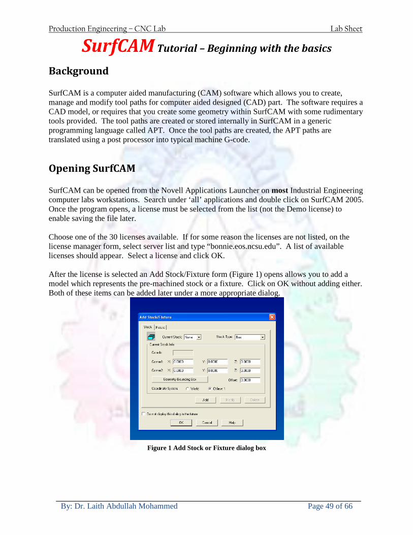
Production Engineering ndash CNC Lab Lab Sheet
By Dr Laith Abdullah Mohammed Page 49 of 66
SurfCAM Tutorial ndash Beginning with the basics
Background SurfCAM is a computer aided manufacturing (CAM) software which allows you to create manage and modify tool paths for computer aided designed (CAD) part The software requires a CAD model or requires that you create some geometry within SurfCAM with some rudimentary tools provided The tool paths are created or stored internally in SurfCAM in a generic programming language called APT Once the tool paths are created the APT paths are translated using a post processor into typical machine G-code
Opening SurfCAM SurfCAM can be opened from the Novell Applications Launcher on most Industrial Engineering computer labs workstations Search under lsquoallrsquo applications and double click on SurfCAM 2005 Once the program opens a license must be selected from the list (not the Demo license) to enable saving the file later Choose one of the 30 licenses available If for some reason the licenses are not listed on the license manager form select server list and type ldquobonnieeosncsuedurdquo A list of available licenses should appear Select a license and click OK After the license is selected an Add StockFixture form (Figure 1) opens allows you to add a model which represents the pre-machined stock or a fixture Click on OK without adding either Both of these items can be added later under a more appropriate dialog
Figure 1 Add Stock or Fixture dialog box
Production Engineering ndash CNC Lab Lab Sheet
By Dr Laith Abdullah Mohammed Page 50 of 66
SurfCAM Interface
Figure 2 SurfCAM Windows based interface
SurfCAM is a windows based software system so most of the typical windows functions under File are applicable This is where you can open save exit print etc The Create menu allows the user to create different geometry forms Here you can create a point line surface chamfer circle and many other geometry types For the most part these functions are not used by beginners but are useful when creating bounding curves where you donrsquot want the tool to move outside (constraining the tool) The Edit menu allows you to change or modify many different entities such as changing lines altering surfaces joining surfaces trimming or breaking elements add control points etc Again these features are helpful to advanced users and are not covered in detail in this tutorial The Display menu offers the ability to change the orientation of the part on the screen The typical rotate pan fit to screen and zoom functions are available as well as several functions which allow the user to shift between views or call up a named view (ie top bottom etc) The NC menu is the main machining interface menu In this menu you select the general form of machining (2 axis 3 axis 4 axis 5 axis turning etc) and under the general form a more specific machining function is selected This menu is the most used and the options contained must be fully understood to get the most out of SurfCAM Each function will be described in some detail in a further chapter The Analyze menu contains options such as measuring the distance between points angles tangency elements etc These functions are auxiliary functions meant to help you understand the part better but basically provide no functionality for making tool paths for CNC machines Thus these will not be covered The Tools menu allows the user to change the system options modify keyboard shortcuts change the model units etc These options are again not used by beginners Finally the Help menu provides access to the online users manual In lieu of clicking the Help menu the F1 key is the shortcut key for help (as it is in most windows based programs)
Importing a CAD model Importing a CAD model that is stored locally is done by selecting File-gtOpen On the Files of type dropdown box choose the type of file you wish to open (Figure 3) Do this prior to negotiating your way through the maze of folders to prevent having to go through the folder tree again Once the file type is selected find the file you are trying to open and click the Open
Production Engineering ndash CNC Lab Lab Sheet
By Dr Laith Abdullah Mohammed Page 51 of 66
button SurfCAM will then attempt to read the file you have selected SurfCAM may provide a dialog box describing what it has imported and identify if it was successful If this dialog is provided simply click close without saving
Figure 3 Open Dialog Note - Change type of file prior to finding the file you wish to open
SurfCAM allows a user to import several different types of CAD files the most common types which you will likely import are SolidWorks part files (sldprt or prt) AutoCAD files(dxf) or IGES (igs or iges) Native file import (such as is the case with SolidWorks) provides the greatest information transfer and generic file imports (such as is the case with IGES) provide the least Normally it is to the advantage of the user to use native file importing procedures when available Recently (2005) SurfCAM added some compatibility with SolidWorks This allows the user to create tool paths for a part and if an engineering change is needed for the part update the part in SolidWorks When the part is then opened in SurfCAM the changes are noted and a simple update operation command is needed This however does not operate with complete transparency andor accuracy and thus users need to be cognizant of changing CAD models
SurfCAM Geometry In SurfCAM two basic types of geometry are used the surface and the point A surface (Figure 4) is a so called spline (NURBS or B-Spline are the two most common) surface (parameterized by two values u and v) such that every location on the surface can be defined as a function of these parameters In other words SurfCAM can calculate the location of any point on the
Production Engineering ndash CNC Lab Lab Sheet
By Dr Laith Abdullah Mohammed Page 52 of 66
surface Surfaces are used primarily in 3 4 and 5 axis machining and require a significant
amount of processing power and time Figure 4 Surfaces model of a mold half Note the difference between this and Figure 2 a wireframe model
Point or line based models are often referred to as wireframe (Figure 5) models because the models consist of connected lines and resemble the part only at the intersection of two surfaces Wireframe models were made popular lsquoback in the dayrsquo when computer processing was expensive There are times when each of the models are important and selecting model geometry when applying a SurfCAM operation will be much simpler if you understand the differences between the two When importing a SolidWorks model the default is both the surfaces and the wireframe geometry are imported
Figure 5 Wireframe model of the mold in Figure 1
Steps to Creating Tool Paths Once a CAD model is imported into SurfCAM tool paths can be created There is no one correct way to create tool paths however there is a set of general steps to take to ensure the tool paths are created with a minimum amount of hardship (note the wordinghellipHardship is inevitable when creating tool paths it is the intent of this manual to minimize this) The following is a list of steps which should be considered when making tool paths
Production Engineering ndash CNC Lab Lab Sheet
By Dr Laith Abdullah Mohammed Page 53 of 66
1 Plan ahead a Orient the part in SolidWorks such that if only one side is to be machined that
side is the Top view This can be done early in SolidWorks by choosing a plane parallel the X-Y plane as the sketch plane for the machined geometry
b Orient the part in SolidWorks such that the origin is somewhere of relative importance and someplace in space that can be easily identified when placed on the machine This is extremely important to minimize set up time at the machine (note ndash my personal preference for a part that is to be fully machined [ie stock exists on all sides] is to place the origin at the center and top of the parthellipjust my preference)
c Orient the part in SolidWorks such that the X and Y axes are aligned as you want them on the machinehellip
d Planning ahead will save you many hours of headaches laterhelliptrust me 2 Import the model 3 Choose a construction view such that the tool approaches the side to be machined
from the positive Z axis direction (as defined by part origin) a This is done by clicking on the CView icon
b From the list of named views chose the view which orients the origin as you would like
c If one of the views does not fit your criteria you have two choices i Perform a transformation of the part in SurfCAM or SolidWorks
ii Add a new construction view by selecting new This option requires a relatively good understanding of right hand coordinate frames but is very usefulhellipNormally used by more advanced users
d Be sure the CoordVIEW selection is made vs CoordWORLD This ensures the tools will be controlled from the coordinate frame selected by the view (ie the origin on the part) instead of the origin on the lower left corner of the screen This will be especially important when we get into 4 and 5 axis machining
4 In the Operations Manager (Figure 6) select Setup One and change the name to something meaningful ndash like Front Side Mold Cavity
a Access the Operations manager by right clicking or by selecting the Operations Manager icon in the tool bar
b Operations Manager is where the tool paths are managed once they are created as well as where individual tool paths can be verified
Production Engineering ndash CNC Lab Lab Sheet
By Dr Laith Abdullah Mohammed Page 54 of 66
5 Roughing Tool Paths a Create the tool paths to remove the majority of the material (if applicable) b Use NC-gt3Axis-gtZ rough or Plunge Rough c Described in next section
6 Create Finishing Tool Paths a Described in next section
7 Add another setup if necessary 8 Perform steps 3 through 6 as necessary 9 Verify the tool paths are correct 10 Use a post processor for the tool paths to create G-Code for machine
Creating Tool Paths The following is a list of operations what they are intended for how they generally work and some parameters that may be adjusted to modify the tool paths
2 Axis tool paths Unless otherwise noted 2 axis tool path functions require lines or arc segments as input parameters (as opposed to surfaces) There are several options as to how these segments are chosen the most prevalent is the chain option and the second most prevalent is the single When choosing the line segments using the chain option SurfCAM will try to link a complete path of segments based on an initial segment chosen by the user If the operation is planer (ie pocket or contour) the segments must lie on the same plane If the operation is non-planer (ie contour 3D) SurfCAM will prompt the user to specify segments when it encounters a branch point
Figure 6 Operations Manager view showing setup one re-labeled as Front Side Mold
Production Engineering ndash CNC Lab Lab Sheet
By Dr Laith Abdullah Mohammed Page 55 of 66
When using the single element option the user must manually choose each segment desired for the operation Note that most operations do not require a closed loop of segments you may specify for instance an open contour where the tool is supposed to move The order of choosing segments is important This order determines the path of the tool in the sense that if three segments are chosen such that the middle segment is chosen last there will be three different plunge and machine operations one on each segment If the operation was to make a continuous contour around the outside of the part the segments should be chosen in order of the desired tool trajectory
Operations
Pocket Pocket operation in SurfCAM is used to cut an enclosed space from the inside to the outside at one particular depth The operation starts in the center of an enclosed area (with a plunge move in the ndashZ direction) and makes incremental closed paths towards the pocket boundaries in user defined path offsets (Figure 7) The user chooses the boundary of the pocket (line segments) and if more than one pocket is chosen SurfCAM will ask the user to click inside a pocket
Figure 7 Two examples of using the pocketing operation
The pocket operation allows for creating a projection of the pocket paths on multiple planes This is useful if you have a deep pocket which will not allow the tool to cut directly at the depth of the pocket but would be easily done using the same paths at several different Z heights On the cut control (Figure 8) tab the user specifies where the chosen geometry (pocket segments) lie (ie bottom or top) Then under the amount to remove specify the total material height to be removed and the rough spacing (amount you wish to advance the Z axis with each pocket step) You may also specify a finishing pass and as well as stock to leave
Production Engineering ndash CNC Lab Lab Sheet
By Dr Laith Abdullah Mohammed Page 56 of 66
Figure 8 Example of Contour Operation with multiple passes
Contour Contouring in SurfCAM is used to perform peripheral milling on the inside or outside of a line segment (Figure 9) The user is to identify the line segments which define a contour (does not have to be a closed loop of segments) SurfCAM may or may not require the user to specify a side to contour (ie which side of the line is the tool to cut) For contouring each segment must lie on the same plane
Production Engineering ndash CNC Lab Lab Sheet
By Dr Laith Abdullah Mohammed Page 57 of 66
Figure 9 Examples of parts cut with 2-Axis Contour
Contour 3D Contour 3D is the same operation type as contour but allows the user to specify segments on different planes for the tool to cut along
Drill Drilling operations are any rotating tool operation meant to engage the part from a single direction ndash namely from the positive Z direction Drilling operations can be specified using circle point or line segments After choosing NC-gt2-Axis-gtDrill SurfCAM allows the user to choose multiple circles or points defining holes to be drilled Drilling operations also allow the user to incorporate more than 1 operation such as a center drill a drill and a reaming operation After selecting the locations for the drilling operation a dialog box (Figure 10) allows the user to add change or delete tools to be used in the operation As displayed in the following figure the spotdrill operation is followed by a drilling operation followed by a tapping operation The depth of each tool can be controlled individually by double clicking the total depth cell in and manually entering Tools can be added before or after operations which the cells are highlighted by selecting either of the insert buttons at the top or by the insert menu Select tool button allows the user to change the tool size or type
Production Engineering ndash CNC Lab Lab Sheet
By Dr Laith Abdullah Mohammed Page 58 of 66
Figure 10 Drill operation manager Several operations can be completed at one time
Figure 11 Drill operation including the spotdrill drill and tap as outlined in Fig 10
3 Axis tool paths SurfCAM requires surfaces as inputs for 3 Axis tool paths Surfaces can be created in SurfCAM but are most easily created in a CAD package and imported into SurfCAM Surfaces allow SurfCAM to identify every point on the surface in 3 dimensions unlike 2D geometry (wireframes) which only identify positions on the plane Creating tool paths with complex surfaces takes a very significant amount of processing power so expect 3 Axis tool path generation to take longer
Production Engineering ndash CNC Lab Lab Sheet
By Dr Laith Abdullah Mohammed Page 59 of 66
Operations
Cut 3 Axis cut operation takes a surface and using the flow lines creates a rastering path over the surface with the tool tip riding on the surface The primary direction will be defined by the flow lines of the surface (which can be edited by Edit-gtSurfaces-gtArrow-gtDirection) If you intend to cross surface boundaries you must merge the surfaces (Edit-gtJoin and choose the two surfaces)
Z-Rough The Z-rough operation is used to remove a large amount of material prior to finish machining Roughing operation is typically the first operation you perform for each setup The Z-Rough operation cuts the part in user defined intervals For each of these intervals a surface intersection between the part and the plane is performed and a 2D pocket or contour operation is performed on that plane This is performed on each plane When choosing NC-gt3 Axis-gtZ rough the first dialog box you will encounter asks for a bounding box to be defined Choose the Extents Box and a second dialog box will ask for the coordinates which define the box (Figure 12) This is the stock size you expect to machine the part from Input the coordinates or change the additional offset amounts (in XY or Z) as appropriate and click Calculate Bounding Box
Figure 12 Material Extents Box Example
Next choose the tool and cutting parameters that you desire and click on the Cut Control Tab (Figure 13) Here you will find the following parameters which are often changed Stock to
Production Engineering ndash CNC Lab Lab Sheet
By Dr Laith Abdullah Mohammed Page 60 of 66
leave ndash this is an offset amount from the surfaces which leaves a small amount of material to finish machine Minimum and Maximum Z values ndash Defines area to machine Z Step Size ndash This identifies the plane intervals for the surface intersection planes (the first interval will be at the top of the selected area and successive increments down in Z will be cut until the Minimum Z value is reached)
Figure 13 3Axis Z Rough Cut Control
The 3Axis Z-Finish operation works in exactly the same way 3 Axis Z-Finish is most appropriate for finishing vertical or near vertical walls
3D Offset The 3D Offset operation creates a tool path using a 2D or 3D boundary by offsetting the boundary in concentric offset cutting passes Each pass calculates the tool engagement and maintains the engagement somewhat constant The advantage (significant) is the scallop height ndash height of the material between passes ndash is controlled thus the surface finish is predictable When choosing 3D Offset surfaces are selected as well as 2D or 3D boundaries The boundaries define the concentric offset paths shape as well as limit the tool path area Choose NC-gt3Axis-gt3D Offset from the drop down menus SurfCAM will prompt you to select the surface or surfaces to cut across Select the surfaces you wish to machine and then select the tool and cutting parameters you wish use Next select the Cut Control Tab and check the Use Boundary Curves option Set the Step Type to Scallop and set the maximum scallop height If you like
Production Engineering ndash CNC Lab Lab Sheet
By Dr Laith Abdullah Mohammed Page 61 of 66
you can also add stock to leave if this is a roughing operation You can also set the Direction and Start-End parameters from this tab Click OK and the paths will be generated
Figure 14 Cut Control Tab for 3D Offset
Example part using both 2D and 3D geometry
The tool paths for this mold will be generated in SurfCAM using 5 operations The first will be a roughing operation using a frac14 inch flat end mill with the Z step size of 00625in Choose NC-
Production Engineering ndash CNC Lab Lab Sheet
By Dr Laith Abdullah Mohammed Page 62 of 66
gt3Axis-gtZ-Rough from the drop down menu Select all visible surfaces and create an extents box that has 025inch XY offsets and 01inch Z offset Next select the frac14 inch flat end mill from the tools menu Under Cut Control tab set the Z step size to be 00625inch The tool paths will look something like Figure 15
Figure 15 Z-Rough Tool paths for Example Part
Next a flat surface operation will be performed to cut the flat surface on the top Select NC-gt3 Axis-gtFlat Surface from the drop down menu Select all visible surfaces again Choose the 12inch flat end mill and set the cutting parameters as desired Under Cut Control Tab change the Minimum Area to 50 square inches (Figure 16) The tool paths should look something like Figure 17
Figure 16 Cut Control for Flat Surface
Production Engineering ndash CNC Lab Lab Sheet
By Dr Laith Abdullah Mohammed Page 63 of 66
Figure 17 Flat Surface Tool Paths
Next we will use a 3D offset operation to cut the mold cavity Select NC-gt3 Axis-gt3D Offset from the dropdown menu Change the view to the top view and select within to capture the surfaces of the mold cavity Draw a rectangle around the mold cavity Select a 18 inch ball endmill from the tool library and set the cutting parameters as appropriate Next set the Cut Control tab parameters as in Figure 14 The paths creates should be similar to Figure 18
Figure 18 3D Offset Paths
Next we will perform a 2 Axis contouring of the top section Select NC-gt2 Axis-gtContour from the dropdown menu Using the chain option select the bottom contour of the top extrusion Select the frac12 inch flat end mill from the tool library and set the cutting parameters as required In the Cut Control Tab change the Geometry to Bottom and the amount to remove in Z to 05
Production Engineering ndash CNC Lab Lab Sheet
By Dr Laith Abdullah Mohammed Page 64 of 66
Change the Rough Spacing in Z to 025 and add 1 finish pass of 002 (Figure 19) Click OK and SurfCAM will instruct you to choose a side to contour Click anywhere on the screen OUTSIDE the geometry you selected for the contouring operation Failure to click outside the geometry will result in the tool being on the wrong side of the contour Your paths should look something like those in Figure 20
Figure 19 Cut Control Tab for the Contouring Operation
Figure 20 Contouring operation paths
Production Engineering ndash CNC Lab Lab Sheet
By Dr Laith Abdullah Mohammed Page 65 of 66
Next we will perform a 2 axis pocket operation for the small pocket on the top face of the mold Select NC-gt2Axis-gtPocket and using the Auto select feature select the boundary curve at the bottom of the pocket Click Done twice and select the frac14 inch flat end mill from the tool library Set the appropriate cutting parameters and click OK SurfCAM will prompt you to click inside the pocket Click anywhere inside the geometry you chose to define the pocket The resulting paths should look something like those in Figure 21
Figure 21 2 Axis Pocket Operation Paths
Finally we will add a drilling operation for the 2 holes at the corners of the mold Select NC-gt2 Axis-gtDrill from the dropdown menu Select the top circles defining the two holes A menu box will appear with a default tool (Center drill) already programmed Add a second tool to the list by selecting Insert-gtAfter and select the tool from the tool library Change the drill depth to 10inches and click OK The paths should look something similar to Figure 23
Figure 22 Drill Menu
Production Engineering ndash CNC Lab Lab Sheet
By Dr Laith Abdullah Mohammed Page 66 of 66
Figure 23 Drilling Operation Tool Paths
Now you can watch a simulation of the cutting by choosing the setup in the operations manager and clicking the simulate icon Be sure to set the stock in the set up by right clicking the set up and selecting Edit Setup Information In the Stock Tab you can create a bounding box meeting your needs and click Add Your simulation should result in something like the following
Figure 24 Final Simulation of the example Mold
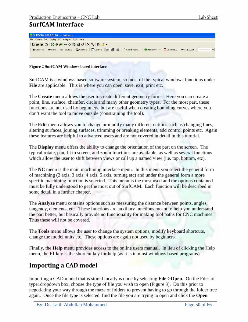
Production Engineering ndash CNC Lab Lab Sheet
By Dr Laith Abdullah Mohammed Page 50 of 66
SurfCAM Interface
Figure 2 SurfCAM Windows based interface
SurfCAM is a windows based software system so most of the typical windows functions under File are applicable This is where you can open save exit print etc The Create menu allows the user to create different geometry forms Here you can create a point line surface chamfer circle and many other geometry types For the most part these functions are not used by beginners but are useful when creating bounding curves where you donrsquot want the tool to move outside (constraining the tool) The Edit menu allows you to change or modify many different entities such as changing lines altering surfaces joining surfaces trimming or breaking elements add control points etc Again these features are helpful to advanced users and are not covered in detail in this tutorial The Display menu offers the ability to change the orientation of the part on the screen The typical rotate pan fit to screen and zoom functions are available as well as several functions which allow the user to shift between views or call up a named view (ie top bottom etc) The NC menu is the main machining interface menu In this menu you select the general form of machining (2 axis 3 axis 4 axis 5 axis turning etc) and under the general form a more specific machining function is selected This menu is the most used and the options contained must be fully understood to get the most out of SurfCAM Each function will be described in some detail in a further chapter The Analyze menu contains options such as measuring the distance between points angles tangency elements etc These functions are auxiliary functions meant to help you understand the part better but basically provide no functionality for making tool paths for CNC machines Thus these will not be covered The Tools menu allows the user to change the system options modify keyboard shortcuts change the model units etc These options are again not used by beginners Finally the Help menu provides access to the online users manual In lieu of clicking the Help menu the F1 key is the shortcut key for help (as it is in most windows based programs)
Importing a CAD model Importing a CAD model that is stored locally is done by selecting File-gtOpen On the Files of type dropdown box choose the type of file you wish to open (Figure 3) Do this prior to negotiating your way through the maze of folders to prevent having to go through the folder tree again Once the file type is selected find the file you are trying to open and click the Open
Production Engineering ndash CNC Lab Lab Sheet
By Dr Laith Abdullah Mohammed Page 51 of 66
button SurfCAM will then attempt to read the file you have selected SurfCAM may provide a dialog box describing what it has imported and identify if it was successful If this dialog is provided simply click close without saving
Figure 3 Open Dialog Note - Change type of file prior to finding the file you wish to open
SurfCAM allows a user to import several different types of CAD files the most common types which you will likely import are SolidWorks part files (sldprt or prt) AutoCAD files(dxf) or IGES (igs or iges) Native file import (such as is the case with SolidWorks) provides the greatest information transfer and generic file imports (such as is the case with IGES) provide the least Normally it is to the advantage of the user to use native file importing procedures when available Recently (2005) SurfCAM added some compatibility with SolidWorks This allows the user to create tool paths for a part and if an engineering change is needed for the part update the part in SolidWorks When the part is then opened in SurfCAM the changes are noted and a simple update operation command is needed This however does not operate with complete transparency andor accuracy and thus users need to be cognizant of changing CAD models
SurfCAM Geometry In SurfCAM two basic types of geometry are used the surface and the point A surface (Figure 4) is a so called spline (NURBS or B-Spline are the two most common) surface (parameterized by two values u and v) such that every location on the surface can be defined as a function of these parameters In other words SurfCAM can calculate the location of any point on the
Production Engineering ndash CNC Lab Lab Sheet
By Dr Laith Abdullah Mohammed Page 52 of 66
surface Surfaces are used primarily in 3 4 and 5 axis machining and require a significant
amount of processing power and time Figure 4 Surfaces model of a mold half Note the difference between this and Figure 2 a wireframe model
Point or line based models are often referred to as wireframe (Figure 5) models because the models consist of connected lines and resemble the part only at the intersection of two surfaces Wireframe models were made popular lsquoback in the dayrsquo when computer processing was expensive There are times when each of the models are important and selecting model geometry when applying a SurfCAM operation will be much simpler if you understand the differences between the two When importing a SolidWorks model the default is both the surfaces and the wireframe geometry are imported
Figure 5 Wireframe model of the mold in Figure 1
Steps to Creating Tool Paths Once a CAD model is imported into SurfCAM tool paths can be created There is no one correct way to create tool paths however there is a set of general steps to take to ensure the tool paths are created with a minimum amount of hardship (note the wordinghellipHardship is inevitable when creating tool paths it is the intent of this manual to minimize this) The following is a list of steps which should be considered when making tool paths
Production Engineering ndash CNC Lab Lab Sheet
By Dr Laith Abdullah Mohammed Page 53 of 66
1 Plan ahead a Orient the part in SolidWorks such that if only one side is to be machined that
side is the Top view This can be done early in SolidWorks by choosing a plane parallel the X-Y plane as the sketch plane for the machined geometry
b Orient the part in SolidWorks such that the origin is somewhere of relative importance and someplace in space that can be easily identified when placed on the machine This is extremely important to minimize set up time at the machine (note ndash my personal preference for a part that is to be fully machined [ie stock exists on all sides] is to place the origin at the center and top of the parthellipjust my preference)
c Orient the part in SolidWorks such that the X and Y axes are aligned as you want them on the machinehellip
d Planning ahead will save you many hours of headaches laterhelliptrust me 2 Import the model 3 Choose a construction view such that the tool approaches the side to be machined
from the positive Z axis direction (as defined by part origin) a This is done by clicking on the CView icon
b From the list of named views chose the view which orients the origin as you would like
c If one of the views does not fit your criteria you have two choices i Perform a transformation of the part in SurfCAM or SolidWorks
ii Add a new construction view by selecting new This option requires a relatively good understanding of right hand coordinate frames but is very usefulhellipNormally used by more advanced users
d Be sure the CoordVIEW selection is made vs CoordWORLD This ensures the tools will be controlled from the coordinate frame selected by the view (ie the origin on the part) instead of the origin on the lower left corner of the screen This will be especially important when we get into 4 and 5 axis machining
4 In the Operations Manager (Figure 6) select Setup One and change the name to something meaningful ndash like Front Side Mold Cavity
a Access the Operations manager by right clicking or by selecting the Operations Manager icon in the tool bar
b Operations Manager is where the tool paths are managed once they are created as well as where individual tool paths can be verified
Production Engineering ndash CNC Lab Lab Sheet
By Dr Laith Abdullah Mohammed Page 54 of 66
5 Roughing Tool Paths a Create the tool paths to remove the majority of the material (if applicable) b Use NC-gt3Axis-gtZ rough or Plunge Rough c Described in next section
6 Create Finishing Tool Paths a Described in next section
7 Add another setup if necessary 8 Perform steps 3 through 6 as necessary 9 Verify the tool paths are correct 10 Use a post processor for the tool paths to create G-Code for machine
Creating Tool Paths The following is a list of operations what they are intended for how they generally work and some parameters that may be adjusted to modify the tool paths
2 Axis tool paths Unless otherwise noted 2 axis tool path functions require lines or arc segments as input parameters (as opposed to surfaces) There are several options as to how these segments are chosen the most prevalent is the chain option and the second most prevalent is the single When choosing the line segments using the chain option SurfCAM will try to link a complete path of segments based on an initial segment chosen by the user If the operation is planer (ie pocket or contour) the segments must lie on the same plane If the operation is non-planer (ie contour 3D) SurfCAM will prompt the user to specify segments when it encounters a branch point
Figure 6 Operations Manager view showing setup one re-labeled as Front Side Mold
Production Engineering ndash CNC Lab Lab Sheet
By Dr Laith Abdullah Mohammed Page 55 of 66
When using the single element option the user must manually choose each segment desired for the operation Note that most operations do not require a closed loop of segments you may specify for instance an open contour where the tool is supposed to move The order of choosing segments is important This order determines the path of the tool in the sense that if three segments are chosen such that the middle segment is chosen last there will be three different plunge and machine operations one on each segment If the operation was to make a continuous contour around the outside of the part the segments should be chosen in order of the desired tool trajectory
Operations
Pocket Pocket operation in SurfCAM is used to cut an enclosed space from the inside to the outside at one particular depth The operation starts in the center of an enclosed area (with a plunge move in the ndashZ direction) and makes incremental closed paths towards the pocket boundaries in user defined path offsets (Figure 7) The user chooses the boundary of the pocket (line segments) and if more than one pocket is chosen SurfCAM will ask the user to click inside a pocket
Figure 7 Two examples of using the pocketing operation
The pocket operation allows for creating a projection of the pocket paths on multiple planes This is useful if you have a deep pocket which will not allow the tool to cut directly at the depth of the pocket but would be easily done using the same paths at several different Z heights On the cut control (Figure 8) tab the user specifies where the chosen geometry (pocket segments) lie (ie bottom or top) Then under the amount to remove specify the total material height to be removed and the rough spacing (amount you wish to advance the Z axis with each pocket step) You may also specify a finishing pass and as well as stock to leave
Production Engineering ndash CNC Lab Lab Sheet
By Dr Laith Abdullah Mohammed Page 56 of 66
Figure 8 Example of Contour Operation with multiple passes
Contour Contouring in SurfCAM is used to perform peripheral milling on the inside or outside of a line segment (Figure 9) The user is to identify the line segments which define a contour (does not have to be a closed loop of segments) SurfCAM may or may not require the user to specify a side to contour (ie which side of the line is the tool to cut) For contouring each segment must lie on the same plane
Production Engineering ndash CNC Lab Lab Sheet
By Dr Laith Abdullah Mohammed Page 57 of 66
Figure 9 Examples of parts cut with 2-Axis Contour
Contour 3D Contour 3D is the same operation type as contour but allows the user to specify segments on different planes for the tool to cut along
Drill Drilling operations are any rotating tool operation meant to engage the part from a single direction ndash namely from the positive Z direction Drilling operations can be specified using circle point or line segments After choosing NC-gt2-Axis-gtDrill SurfCAM allows the user to choose multiple circles or points defining holes to be drilled Drilling operations also allow the user to incorporate more than 1 operation such as a center drill a drill and a reaming operation After selecting the locations for the drilling operation a dialog box (Figure 10) allows the user to add change or delete tools to be used in the operation As displayed in the following figure the spotdrill operation is followed by a drilling operation followed by a tapping operation The depth of each tool can be controlled individually by double clicking the total depth cell in and manually entering Tools can be added before or after operations which the cells are highlighted by selecting either of the insert buttons at the top or by the insert menu Select tool button allows the user to change the tool size or type
Production Engineering ndash CNC Lab Lab Sheet
By Dr Laith Abdullah Mohammed Page 58 of 66
Figure 10 Drill operation manager Several operations can be completed at one time
Figure 11 Drill operation including the spotdrill drill and tap as outlined in Fig 10
3 Axis tool paths SurfCAM requires surfaces as inputs for 3 Axis tool paths Surfaces can be created in SurfCAM but are most easily created in a CAD package and imported into SurfCAM Surfaces allow SurfCAM to identify every point on the surface in 3 dimensions unlike 2D geometry (wireframes) which only identify positions on the plane Creating tool paths with complex surfaces takes a very significant amount of processing power so expect 3 Axis tool path generation to take longer
Production Engineering ndash CNC Lab Lab Sheet
By Dr Laith Abdullah Mohammed Page 59 of 66
Operations
Cut 3 Axis cut operation takes a surface and using the flow lines creates a rastering path over the surface with the tool tip riding on the surface The primary direction will be defined by the flow lines of the surface (which can be edited by Edit-gtSurfaces-gtArrow-gtDirection) If you intend to cross surface boundaries you must merge the surfaces (Edit-gtJoin and choose the two surfaces)
Z-Rough The Z-rough operation is used to remove a large amount of material prior to finish machining Roughing operation is typically the first operation you perform for each setup The Z-Rough operation cuts the part in user defined intervals For each of these intervals a surface intersection between the part and the plane is performed and a 2D pocket or contour operation is performed on that plane This is performed on each plane When choosing NC-gt3 Axis-gtZ rough the first dialog box you will encounter asks for a bounding box to be defined Choose the Extents Box and a second dialog box will ask for the coordinates which define the box (Figure 12) This is the stock size you expect to machine the part from Input the coordinates or change the additional offset amounts (in XY or Z) as appropriate and click Calculate Bounding Box
Figure 12 Material Extents Box Example
Next choose the tool and cutting parameters that you desire and click on the Cut Control Tab (Figure 13) Here you will find the following parameters which are often changed Stock to
Production Engineering ndash CNC Lab Lab Sheet
By Dr Laith Abdullah Mohammed Page 60 of 66
leave ndash this is an offset amount from the surfaces which leaves a small amount of material to finish machine Minimum and Maximum Z values ndash Defines area to machine Z Step Size ndash This identifies the plane intervals for the surface intersection planes (the first interval will be at the top of the selected area and successive increments down in Z will be cut until the Minimum Z value is reached)
Figure 13 3Axis Z Rough Cut Control
The 3Axis Z-Finish operation works in exactly the same way 3 Axis Z-Finish is most appropriate for finishing vertical or near vertical walls
3D Offset The 3D Offset operation creates a tool path using a 2D or 3D boundary by offsetting the boundary in concentric offset cutting passes Each pass calculates the tool engagement and maintains the engagement somewhat constant The advantage (significant) is the scallop height ndash height of the material between passes ndash is controlled thus the surface finish is predictable When choosing 3D Offset surfaces are selected as well as 2D or 3D boundaries The boundaries define the concentric offset paths shape as well as limit the tool path area Choose NC-gt3Axis-gt3D Offset from the drop down menus SurfCAM will prompt you to select the surface or surfaces to cut across Select the surfaces you wish to machine and then select the tool and cutting parameters you wish use Next select the Cut Control Tab and check the Use Boundary Curves option Set the Step Type to Scallop and set the maximum scallop height If you like
Production Engineering ndash CNC Lab Lab Sheet
By Dr Laith Abdullah Mohammed Page 61 of 66
you can also add stock to leave if this is a roughing operation You can also set the Direction and Start-End parameters from this tab Click OK and the paths will be generated
Figure 14 Cut Control Tab for 3D Offset
Example part using both 2D and 3D geometry
The tool paths for this mold will be generated in SurfCAM using 5 operations The first will be a roughing operation using a frac14 inch flat end mill with the Z step size of 00625in Choose NC-
Production Engineering ndash CNC Lab Lab Sheet
By Dr Laith Abdullah Mohammed Page 62 of 66
gt3Axis-gtZ-Rough from the drop down menu Select all visible surfaces and create an extents box that has 025inch XY offsets and 01inch Z offset Next select the frac14 inch flat end mill from the tools menu Under Cut Control tab set the Z step size to be 00625inch The tool paths will look something like Figure 15
Figure 15 Z-Rough Tool paths for Example Part
Next a flat surface operation will be performed to cut the flat surface on the top Select NC-gt3 Axis-gtFlat Surface from the drop down menu Select all visible surfaces again Choose the 12inch flat end mill and set the cutting parameters as desired Under Cut Control Tab change the Minimum Area to 50 square inches (Figure 16) The tool paths should look something like Figure 17
Figure 16 Cut Control for Flat Surface
Production Engineering ndash CNC Lab Lab Sheet
By Dr Laith Abdullah Mohammed Page 63 of 66
Figure 17 Flat Surface Tool Paths
Next we will use a 3D offset operation to cut the mold cavity Select NC-gt3 Axis-gt3D Offset from the dropdown menu Change the view to the top view and select within to capture the surfaces of the mold cavity Draw a rectangle around the mold cavity Select a 18 inch ball endmill from the tool library and set the cutting parameters as appropriate Next set the Cut Control tab parameters as in Figure 14 The paths creates should be similar to Figure 18
Figure 18 3D Offset Paths
Next we will perform a 2 Axis contouring of the top section Select NC-gt2 Axis-gtContour from the dropdown menu Using the chain option select the bottom contour of the top extrusion Select the frac12 inch flat end mill from the tool library and set the cutting parameters as required In the Cut Control Tab change the Geometry to Bottom and the amount to remove in Z to 05
Production Engineering ndash CNC Lab Lab Sheet
By Dr Laith Abdullah Mohammed Page 64 of 66
Change the Rough Spacing in Z to 025 and add 1 finish pass of 002 (Figure 19) Click OK and SurfCAM will instruct you to choose a side to contour Click anywhere on the screen OUTSIDE the geometry you selected for the contouring operation Failure to click outside the geometry will result in the tool being on the wrong side of the contour Your paths should look something like those in Figure 20
Figure 19 Cut Control Tab for the Contouring Operation
Figure 20 Contouring operation paths
Production Engineering ndash CNC Lab Lab Sheet
By Dr Laith Abdullah Mohammed Page 65 of 66
Next we will perform a 2 axis pocket operation for the small pocket on the top face of the mold Select NC-gt2Axis-gtPocket and using the Auto select feature select the boundary curve at the bottom of the pocket Click Done twice and select the frac14 inch flat end mill from the tool library Set the appropriate cutting parameters and click OK SurfCAM will prompt you to click inside the pocket Click anywhere inside the geometry you chose to define the pocket The resulting paths should look something like those in Figure 21
Figure 21 2 Axis Pocket Operation Paths
Finally we will add a drilling operation for the 2 holes at the corners of the mold Select NC-gt2 Axis-gtDrill from the dropdown menu Select the top circles defining the two holes A menu box will appear with a default tool (Center drill) already programmed Add a second tool to the list by selecting Insert-gtAfter and select the tool from the tool library Change the drill depth to 10inches and click OK The paths should look something similar to Figure 23
Figure 22 Drill Menu
Production Engineering ndash CNC Lab Lab Sheet
By Dr Laith Abdullah Mohammed Page 66 of 66
Figure 23 Drilling Operation Tool Paths
Now you can watch a simulation of the cutting by choosing the setup in the operations manager and clicking the simulate icon Be sure to set the stock in the set up by right clicking the set up and selecting Edit Setup Information In the Stock Tab you can create a bounding box meeting your needs and click Add Your simulation should result in something like the following
Figure 24 Final Simulation of the example Mold
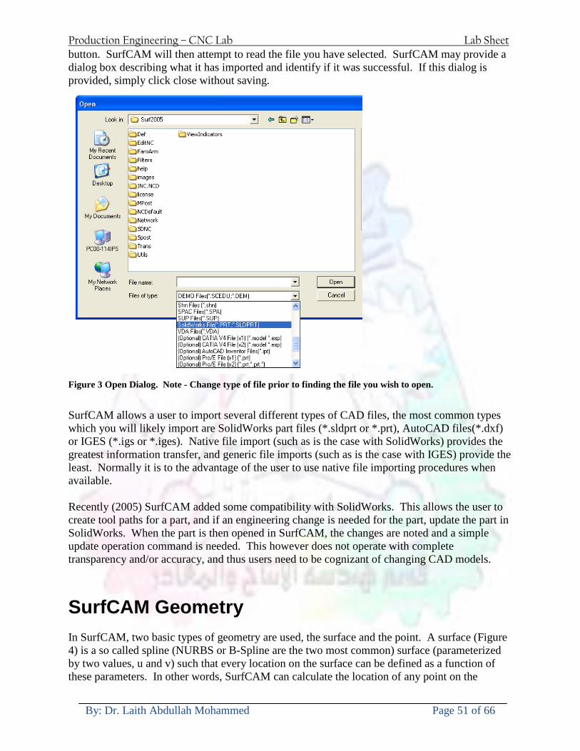
Production Engineering ndash CNC Lab Lab Sheet
By Dr Laith Abdullah Mohammed Page 51 of 66
button SurfCAM will then attempt to read the file you have selected SurfCAM may provide a dialog box describing what it has imported and identify if it was successful If this dialog is provided simply click close without saving
Figure 3 Open Dialog Note - Change type of file prior to finding the file you wish to open
SurfCAM allows a user to import several different types of CAD files the most common types which you will likely import are SolidWorks part files (sldprt or prt) AutoCAD files(dxf) or IGES (igs or iges) Native file import (such as is the case with SolidWorks) provides the greatest information transfer and generic file imports (such as is the case with IGES) provide the least Normally it is to the advantage of the user to use native file importing procedures when available Recently (2005) SurfCAM added some compatibility with SolidWorks This allows the user to create tool paths for a part and if an engineering change is needed for the part update the part in SolidWorks When the part is then opened in SurfCAM the changes are noted and a simple update operation command is needed This however does not operate with complete transparency andor accuracy and thus users need to be cognizant of changing CAD models
SurfCAM Geometry In SurfCAM two basic types of geometry are used the surface and the point A surface (Figure 4) is a so called spline (NURBS or B-Spline are the two most common) surface (parameterized by two values u and v) such that every location on the surface can be defined as a function of these parameters In other words SurfCAM can calculate the location of any point on the
Production Engineering ndash CNC Lab Lab Sheet
By Dr Laith Abdullah Mohammed Page 52 of 66
surface Surfaces are used primarily in 3 4 and 5 axis machining and require a significant
amount of processing power and time Figure 4 Surfaces model of a mold half Note the difference between this and Figure 2 a wireframe model
Point or line based models are often referred to as wireframe (Figure 5) models because the models consist of connected lines and resemble the part only at the intersection of two surfaces Wireframe models were made popular lsquoback in the dayrsquo when computer processing was expensive There are times when each of the models are important and selecting model geometry when applying a SurfCAM operation will be much simpler if you understand the differences between the two When importing a SolidWorks model the default is both the surfaces and the wireframe geometry are imported
Figure 5 Wireframe model of the mold in Figure 1
Steps to Creating Tool Paths Once a CAD model is imported into SurfCAM tool paths can be created There is no one correct way to create tool paths however there is a set of general steps to take to ensure the tool paths are created with a minimum amount of hardship (note the wordinghellipHardship is inevitable when creating tool paths it is the intent of this manual to minimize this) The following is a list of steps which should be considered when making tool paths
Production Engineering ndash CNC Lab Lab Sheet
By Dr Laith Abdullah Mohammed Page 53 of 66
1 Plan ahead a Orient the part in SolidWorks such that if only one side is to be machined that
side is the Top view This can be done early in SolidWorks by choosing a plane parallel the X-Y plane as the sketch plane for the machined geometry
b Orient the part in SolidWorks such that the origin is somewhere of relative importance and someplace in space that can be easily identified when placed on the machine This is extremely important to minimize set up time at the machine (note ndash my personal preference for a part that is to be fully machined [ie stock exists on all sides] is to place the origin at the center and top of the parthellipjust my preference)
c Orient the part in SolidWorks such that the X and Y axes are aligned as you want them on the machinehellip
d Planning ahead will save you many hours of headaches laterhelliptrust me 2 Import the model 3 Choose a construction view such that the tool approaches the side to be machined
from the positive Z axis direction (as defined by part origin) a This is done by clicking on the CView icon
b From the list of named views chose the view which orients the origin as you would like
c If one of the views does not fit your criteria you have two choices i Perform a transformation of the part in SurfCAM or SolidWorks
ii Add a new construction view by selecting new This option requires a relatively good understanding of right hand coordinate frames but is very usefulhellipNormally used by more advanced users
d Be sure the CoordVIEW selection is made vs CoordWORLD This ensures the tools will be controlled from the coordinate frame selected by the view (ie the origin on the part) instead of the origin on the lower left corner of the screen This will be especially important when we get into 4 and 5 axis machining
4 In the Operations Manager (Figure 6) select Setup One and change the name to something meaningful ndash like Front Side Mold Cavity
a Access the Operations manager by right clicking or by selecting the Operations Manager icon in the tool bar
b Operations Manager is where the tool paths are managed once they are created as well as where individual tool paths can be verified
Production Engineering ndash CNC Lab Lab Sheet
By Dr Laith Abdullah Mohammed Page 54 of 66
5 Roughing Tool Paths a Create the tool paths to remove the majority of the material (if applicable) b Use NC-gt3Axis-gtZ rough or Plunge Rough c Described in next section
6 Create Finishing Tool Paths a Described in next section
7 Add another setup if necessary 8 Perform steps 3 through 6 as necessary 9 Verify the tool paths are correct 10 Use a post processor for the tool paths to create G-Code for machine
Creating Tool Paths The following is a list of operations what they are intended for how they generally work and some parameters that may be adjusted to modify the tool paths
2 Axis tool paths Unless otherwise noted 2 axis tool path functions require lines or arc segments as input parameters (as opposed to surfaces) There are several options as to how these segments are chosen the most prevalent is the chain option and the second most prevalent is the single When choosing the line segments using the chain option SurfCAM will try to link a complete path of segments based on an initial segment chosen by the user If the operation is planer (ie pocket or contour) the segments must lie on the same plane If the operation is non-planer (ie contour 3D) SurfCAM will prompt the user to specify segments when it encounters a branch point
Figure 6 Operations Manager view showing setup one re-labeled as Front Side Mold
Production Engineering ndash CNC Lab Lab Sheet
By Dr Laith Abdullah Mohammed Page 55 of 66
When using the single element option the user must manually choose each segment desired for the operation Note that most operations do not require a closed loop of segments you may specify for instance an open contour where the tool is supposed to move The order of choosing segments is important This order determines the path of the tool in the sense that if three segments are chosen such that the middle segment is chosen last there will be three different plunge and machine operations one on each segment If the operation was to make a continuous contour around the outside of the part the segments should be chosen in order of the desired tool trajectory
Operations
Pocket Pocket operation in SurfCAM is used to cut an enclosed space from the inside to the outside at one particular depth The operation starts in the center of an enclosed area (with a plunge move in the ndashZ direction) and makes incremental closed paths towards the pocket boundaries in user defined path offsets (Figure 7) The user chooses the boundary of the pocket (line segments) and if more than one pocket is chosen SurfCAM will ask the user to click inside a pocket
Figure 7 Two examples of using the pocketing operation
The pocket operation allows for creating a projection of the pocket paths on multiple planes This is useful if you have a deep pocket which will not allow the tool to cut directly at the depth of the pocket but would be easily done using the same paths at several different Z heights On the cut control (Figure 8) tab the user specifies where the chosen geometry (pocket segments) lie (ie bottom or top) Then under the amount to remove specify the total material height to be removed and the rough spacing (amount you wish to advance the Z axis with each pocket step) You may also specify a finishing pass and as well as stock to leave
Production Engineering ndash CNC Lab Lab Sheet
By Dr Laith Abdullah Mohammed Page 56 of 66
Figure 8 Example of Contour Operation with multiple passes
Contour Contouring in SurfCAM is used to perform peripheral milling on the inside or outside of a line segment (Figure 9) The user is to identify the line segments which define a contour (does not have to be a closed loop of segments) SurfCAM may or may not require the user to specify a side to contour (ie which side of the line is the tool to cut) For contouring each segment must lie on the same plane
Production Engineering ndash CNC Lab Lab Sheet
By Dr Laith Abdullah Mohammed Page 57 of 66
Figure 9 Examples of parts cut with 2-Axis Contour
Contour 3D Contour 3D is the same operation type as contour but allows the user to specify segments on different planes for the tool to cut along
Drill Drilling operations are any rotating tool operation meant to engage the part from a single direction ndash namely from the positive Z direction Drilling operations can be specified using circle point or line segments After choosing NC-gt2-Axis-gtDrill SurfCAM allows the user to choose multiple circles or points defining holes to be drilled Drilling operations also allow the user to incorporate more than 1 operation such as a center drill a drill and a reaming operation After selecting the locations for the drilling operation a dialog box (Figure 10) allows the user to add change or delete tools to be used in the operation As displayed in the following figure the spotdrill operation is followed by a drilling operation followed by a tapping operation The depth of each tool can be controlled individually by double clicking the total depth cell in and manually entering Tools can be added before or after operations which the cells are highlighted by selecting either of the insert buttons at the top or by the insert menu Select tool button allows the user to change the tool size or type
Production Engineering ndash CNC Lab Lab Sheet
By Dr Laith Abdullah Mohammed Page 58 of 66
Figure 10 Drill operation manager Several operations can be completed at one time
Figure 11 Drill operation including the spotdrill drill and tap as outlined in Fig 10
3 Axis tool paths SurfCAM requires surfaces as inputs for 3 Axis tool paths Surfaces can be created in SurfCAM but are most easily created in a CAD package and imported into SurfCAM Surfaces allow SurfCAM to identify every point on the surface in 3 dimensions unlike 2D geometry (wireframes) which only identify positions on the plane Creating tool paths with complex surfaces takes a very significant amount of processing power so expect 3 Axis tool path generation to take longer
Production Engineering ndash CNC Lab Lab Sheet
By Dr Laith Abdullah Mohammed Page 59 of 66
Operations
Cut 3 Axis cut operation takes a surface and using the flow lines creates a rastering path over the surface with the tool tip riding on the surface The primary direction will be defined by the flow lines of the surface (which can be edited by Edit-gtSurfaces-gtArrow-gtDirection) If you intend to cross surface boundaries you must merge the surfaces (Edit-gtJoin and choose the two surfaces)
Z-Rough The Z-rough operation is used to remove a large amount of material prior to finish machining Roughing operation is typically the first operation you perform for each setup The Z-Rough operation cuts the part in user defined intervals For each of these intervals a surface intersection between the part and the plane is performed and a 2D pocket or contour operation is performed on that plane This is performed on each plane When choosing NC-gt3 Axis-gtZ rough the first dialog box you will encounter asks for a bounding box to be defined Choose the Extents Box and a second dialog box will ask for the coordinates which define the box (Figure 12) This is the stock size you expect to machine the part from Input the coordinates or change the additional offset amounts (in XY or Z) as appropriate and click Calculate Bounding Box
Figure 12 Material Extents Box Example
Next choose the tool and cutting parameters that you desire and click on the Cut Control Tab (Figure 13) Here you will find the following parameters which are often changed Stock to
Production Engineering ndash CNC Lab Lab Sheet
By Dr Laith Abdullah Mohammed Page 60 of 66
leave ndash this is an offset amount from the surfaces which leaves a small amount of material to finish machine Minimum and Maximum Z values ndash Defines area to machine Z Step Size ndash This identifies the plane intervals for the surface intersection planes (the first interval will be at the top of the selected area and successive increments down in Z will be cut until the Minimum Z value is reached)
Figure 13 3Axis Z Rough Cut Control
The 3Axis Z-Finish operation works in exactly the same way 3 Axis Z-Finish is most appropriate for finishing vertical or near vertical walls
3D Offset The 3D Offset operation creates a tool path using a 2D or 3D boundary by offsetting the boundary in concentric offset cutting passes Each pass calculates the tool engagement and maintains the engagement somewhat constant The advantage (significant) is the scallop height ndash height of the material between passes ndash is controlled thus the surface finish is predictable When choosing 3D Offset surfaces are selected as well as 2D or 3D boundaries The boundaries define the concentric offset paths shape as well as limit the tool path area Choose NC-gt3Axis-gt3D Offset from the drop down menus SurfCAM will prompt you to select the surface or surfaces to cut across Select the surfaces you wish to machine and then select the tool and cutting parameters you wish use Next select the Cut Control Tab and check the Use Boundary Curves option Set the Step Type to Scallop and set the maximum scallop height If you like
Production Engineering ndash CNC Lab Lab Sheet
By Dr Laith Abdullah Mohammed Page 61 of 66
you can also add stock to leave if this is a roughing operation You can also set the Direction and Start-End parameters from this tab Click OK and the paths will be generated
Figure 14 Cut Control Tab for 3D Offset
Example part using both 2D and 3D geometry
The tool paths for this mold will be generated in SurfCAM using 5 operations The first will be a roughing operation using a frac14 inch flat end mill with the Z step size of 00625in Choose NC-
Production Engineering ndash CNC Lab Lab Sheet
By Dr Laith Abdullah Mohammed Page 62 of 66
gt3Axis-gtZ-Rough from the drop down menu Select all visible surfaces and create an extents box that has 025inch XY offsets and 01inch Z offset Next select the frac14 inch flat end mill from the tools menu Under Cut Control tab set the Z step size to be 00625inch The tool paths will look something like Figure 15
Figure 15 Z-Rough Tool paths for Example Part
Next a flat surface operation will be performed to cut the flat surface on the top Select NC-gt3 Axis-gtFlat Surface from the drop down menu Select all visible surfaces again Choose the 12inch flat end mill and set the cutting parameters as desired Under Cut Control Tab change the Minimum Area to 50 square inches (Figure 16) The tool paths should look something like Figure 17
Figure 16 Cut Control for Flat Surface
Production Engineering ndash CNC Lab Lab Sheet
By Dr Laith Abdullah Mohammed Page 63 of 66
Figure 17 Flat Surface Tool Paths
Next we will use a 3D offset operation to cut the mold cavity Select NC-gt3 Axis-gt3D Offset from the dropdown menu Change the view to the top view and select within to capture the surfaces of the mold cavity Draw a rectangle around the mold cavity Select a 18 inch ball endmill from the tool library and set the cutting parameters as appropriate Next set the Cut Control tab parameters as in Figure 14 The paths creates should be similar to Figure 18
Figure 18 3D Offset Paths
Next we will perform a 2 Axis contouring of the top section Select NC-gt2 Axis-gtContour from the dropdown menu Using the chain option select the bottom contour of the top extrusion Select the frac12 inch flat end mill from the tool library and set the cutting parameters as required In the Cut Control Tab change the Geometry to Bottom and the amount to remove in Z to 05
Production Engineering ndash CNC Lab Lab Sheet
By Dr Laith Abdullah Mohammed Page 64 of 66
Change the Rough Spacing in Z to 025 and add 1 finish pass of 002 (Figure 19) Click OK and SurfCAM will instruct you to choose a side to contour Click anywhere on the screen OUTSIDE the geometry you selected for the contouring operation Failure to click outside the geometry will result in the tool being on the wrong side of the contour Your paths should look something like those in Figure 20
Figure 19 Cut Control Tab for the Contouring Operation
Figure 20 Contouring operation paths
Production Engineering ndash CNC Lab Lab Sheet
By Dr Laith Abdullah Mohammed Page 65 of 66
Next we will perform a 2 axis pocket operation for the small pocket on the top face of the mold Select NC-gt2Axis-gtPocket and using the Auto select feature select the boundary curve at the bottom of the pocket Click Done twice and select the frac14 inch flat end mill from the tool library Set the appropriate cutting parameters and click OK SurfCAM will prompt you to click inside the pocket Click anywhere inside the geometry you chose to define the pocket The resulting paths should look something like those in Figure 21
Figure 21 2 Axis Pocket Operation Paths
Finally we will add a drilling operation for the 2 holes at the corners of the mold Select NC-gt2 Axis-gtDrill from the dropdown menu Select the top circles defining the two holes A menu box will appear with a default tool (Center drill) already programmed Add a second tool to the list by selecting Insert-gtAfter and select the tool from the tool library Change the drill depth to 10inches and click OK The paths should look something similar to Figure 23
Figure 22 Drill Menu
Production Engineering ndash CNC Lab Lab Sheet
By Dr Laith Abdullah Mohammed Page 66 of 66
Figure 23 Drilling Operation Tool Paths
Now you can watch a simulation of the cutting by choosing the setup in the operations manager and clicking the simulate icon Be sure to set the stock in the set up by right clicking the set up and selecting Edit Setup Information In the Stock Tab you can create a bounding box meeting your needs and click Add Your simulation should result in something like the following
Figure 24 Final Simulation of the example Mold
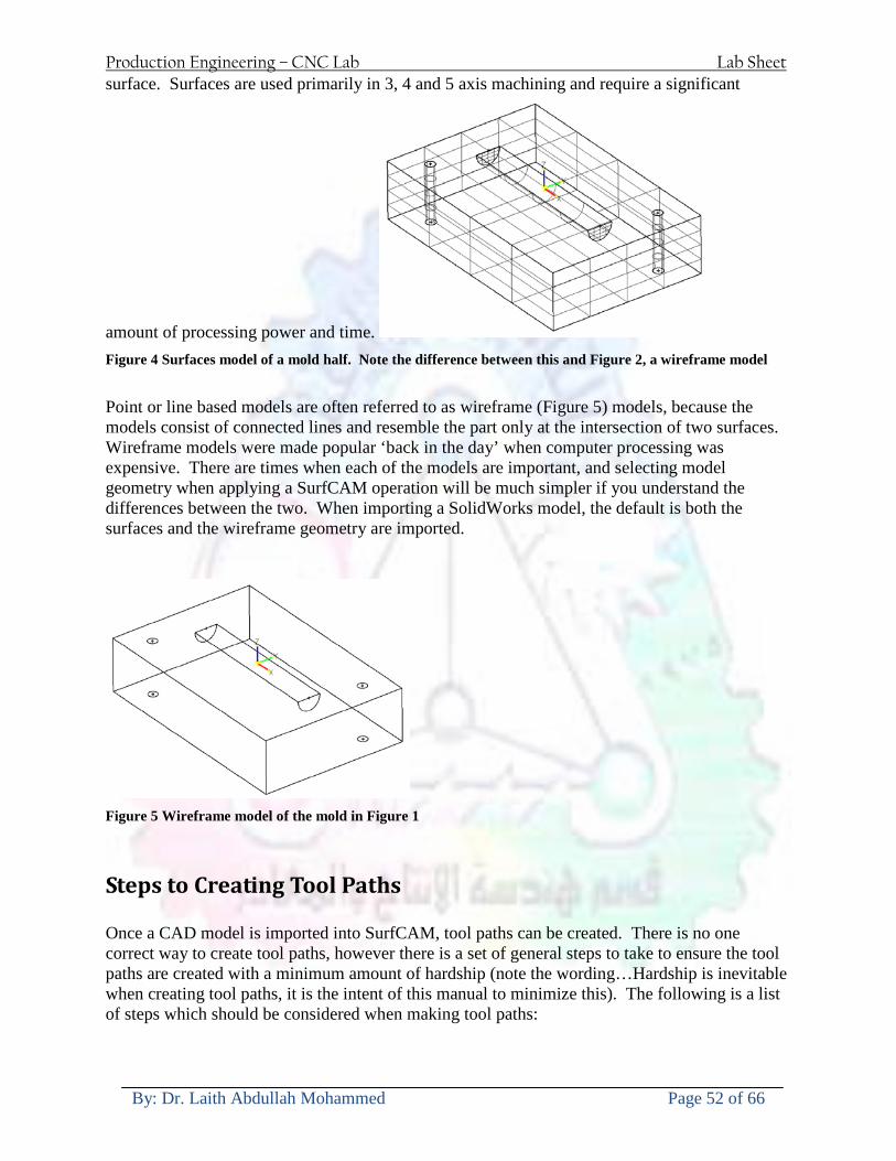
Production Engineering ndash CNC Lab Lab Sheet
By Dr Laith Abdullah Mohammed Page 53 of 66
1 Plan ahead a Orient the part in SolidWorks such that if only one side is to be machined that
side is the Top view This can be done early in SolidWorks by choosing a plane parallel the X-Y plane as the sketch plane for the machined geometry
b Orient the part in SolidWorks such that the origin is somewhere of relative importance and someplace in space that can be easily identified when placed on the machine This is extremely important to minimize set up time at the machine (note ndash my personal preference for a part that is to be fully machined [ie stock exists on all sides] is to place the origin at the center and top of the parthellipjust my preference)
c Orient the part in SolidWorks such that the X and Y axes are aligned as you want them on the machinehellip
d Planning ahead will save you many hours of headaches laterhelliptrust me 2 Import the model 3 Choose a construction view such that the tool approaches the side to be machined
from the positive Z axis direction (as defined by part origin) a This is done by clicking on the CView icon
b From the list of named views chose the view which orients the origin as you would like
c If one of the views does not fit your criteria you have two choices i Perform a transformation of the part in SurfCAM or SolidWorks
ii Add a new construction view by selecting new This option requires a relatively good understanding of right hand coordinate frames but is very usefulhellipNormally used by more advanced users
d Be sure the CoordVIEW selection is made vs CoordWORLD This ensures the tools will be controlled from the coordinate frame selected by the view (ie the origin on the part) instead of the origin on the lower left corner of the screen This will be especially important when we get into 4 and 5 axis machining
4 In the Operations Manager (Figure 6) select Setup One and change the name to something meaningful ndash like Front Side Mold Cavity
a Access the Operations manager by right clicking or by selecting the Operations Manager icon in the tool bar
b Operations Manager is where the tool paths are managed once they are created as well as where individual tool paths can be verified
Production Engineering ndash CNC Lab Lab Sheet
By Dr Laith Abdullah Mohammed Page 54 of 66
5 Roughing Tool Paths a Create the tool paths to remove the majority of the material (if applicable) b Use NC-gt3Axis-gtZ rough or Plunge Rough c Described in next section
6 Create Finishing Tool Paths a Described in next section
7 Add another setup if necessary 8 Perform steps 3 through 6 as necessary 9 Verify the tool paths are correct 10 Use a post processor for the tool paths to create G-Code for machine
Creating Tool Paths The following is a list of operations what they are intended for how they generally work and some parameters that may be adjusted to modify the tool paths
2 Axis tool paths Unless otherwise noted 2 axis tool path functions require lines or arc segments as input parameters (as opposed to surfaces) There are several options as to how these segments are chosen the most prevalent is the chain option and the second most prevalent is the single When choosing the line segments using the chain option SurfCAM will try to link a complete path of segments based on an initial segment chosen by the user If the operation is planer (ie pocket or contour) the segments must lie on the same plane If the operation is non-planer (ie contour 3D) SurfCAM will prompt the user to specify segments when it encounters a branch point
Figure 6 Operations Manager view showing setup one re-labeled as Front Side Mold
Production Engineering ndash CNC Lab Lab Sheet
By Dr Laith Abdullah Mohammed Page 55 of 66
When using the single element option the user must manually choose each segment desired for the operation Note that most operations do not require a closed loop of segments you may specify for instance an open contour where the tool is supposed to move The order of choosing segments is important This order determines the path of the tool in the sense that if three segments are chosen such that the middle segment is chosen last there will be three different plunge and machine operations one on each segment If the operation was to make a continuous contour around the outside of the part the segments should be chosen in order of the desired tool trajectory
Operations
Pocket Pocket operation in SurfCAM is used to cut an enclosed space from the inside to the outside at one particular depth The operation starts in the center of an enclosed area (with a plunge move in the ndashZ direction) and makes incremental closed paths towards the pocket boundaries in user defined path offsets (Figure 7) The user chooses the boundary of the pocket (line segments) and if more than one pocket is chosen SurfCAM will ask the user to click inside a pocket
Figure 7 Two examples of using the pocketing operation
The pocket operation allows for creating a projection of the pocket paths on multiple planes This is useful if you have a deep pocket which will not allow the tool to cut directly at the depth of the pocket but would be easily done using the same paths at several different Z heights On the cut control (Figure 8) tab the user specifies where the chosen geometry (pocket segments) lie (ie bottom or top) Then under the amount to remove specify the total material height to be removed and the rough spacing (amount you wish to advance the Z axis with each pocket step) You may also specify a finishing pass and as well as stock to leave
Production Engineering ndash CNC Lab Lab Sheet
By Dr Laith Abdullah Mohammed Page 56 of 66
Figure 8 Example of Contour Operation with multiple passes
Contour Contouring in SurfCAM is used to perform peripheral milling on the inside or outside of a line segment (Figure 9) The user is to identify the line segments which define a contour (does not have to be a closed loop of segments) SurfCAM may or may not require the user to specify a side to contour (ie which side of the line is the tool to cut) For contouring each segment must lie on the same plane
Production Engineering ndash CNC Lab Lab Sheet
By Dr Laith Abdullah Mohammed Page 57 of 66
Figure 9 Examples of parts cut with 2-Axis Contour
Contour 3D Contour 3D is the same operation type as contour but allows the user to specify segments on different planes for the tool to cut along
Drill Drilling operations are any rotating tool operation meant to engage the part from a single direction ndash namely from the positive Z direction Drilling operations can be specified using circle point or line segments After choosing NC-gt2-Axis-gtDrill SurfCAM allows the user to choose multiple circles or points defining holes to be drilled Drilling operations also allow the user to incorporate more than 1 operation such as a center drill a drill and a reaming operation After selecting the locations for the drilling operation a dialog box (Figure 10) allows the user to add change or delete tools to be used in the operation As displayed in the following figure the spotdrill operation is followed by a drilling operation followed by a tapping operation The depth of each tool can be controlled individually by double clicking the total depth cell in and manually entering Tools can be added before or after operations which the cells are highlighted by selecting either of the insert buttons at the top or by the insert menu Select tool button allows the user to change the tool size or type
Production Engineering ndash CNC Lab Lab Sheet
By Dr Laith Abdullah Mohammed Page 58 of 66
Figure 10 Drill operation manager Several operations can be completed at one time
Figure 11 Drill operation including the spotdrill drill and tap as outlined in Fig 10
3 Axis tool paths SurfCAM requires surfaces as inputs for 3 Axis tool paths Surfaces can be created in SurfCAM but are most easily created in a CAD package and imported into SurfCAM Surfaces allow SurfCAM to identify every point on the surface in 3 dimensions unlike 2D geometry (wireframes) which only identify positions on the plane Creating tool paths with complex surfaces takes a very significant amount of processing power so expect 3 Axis tool path generation to take longer
Production Engineering ndash CNC Lab Lab Sheet
By Dr Laith Abdullah Mohammed Page 59 of 66
Operations
Cut 3 Axis cut operation takes a surface and using the flow lines creates a rastering path over the surface with the tool tip riding on the surface The primary direction will be defined by the flow lines of the surface (which can be edited by Edit-gtSurfaces-gtArrow-gtDirection) If you intend to cross surface boundaries you must merge the surfaces (Edit-gtJoin and choose the two surfaces)
Z-Rough The Z-rough operation is used to remove a large amount of material prior to finish machining Roughing operation is typically the first operation you perform for each setup The Z-Rough operation cuts the part in user defined intervals For each of these intervals a surface intersection between the part and the plane is performed and a 2D pocket or contour operation is performed on that plane This is performed on each plane When choosing NC-gt3 Axis-gtZ rough the first dialog box you will encounter asks for a bounding box to be defined Choose the Extents Box and a second dialog box will ask for the coordinates which define the box (Figure 12) This is the stock size you expect to machine the part from Input the coordinates or change the additional offset amounts (in XY or Z) as appropriate and click Calculate Bounding Box
Figure 12 Material Extents Box Example
Next choose the tool and cutting parameters that you desire and click on the Cut Control Tab (Figure 13) Here you will find the following parameters which are often changed Stock to
Production Engineering ndash CNC Lab Lab Sheet
By Dr Laith Abdullah Mohammed Page 60 of 66
leave ndash this is an offset amount from the surfaces which leaves a small amount of material to finish machine Minimum and Maximum Z values ndash Defines area to machine Z Step Size ndash This identifies the plane intervals for the surface intersection planes (the first interval will be at the top of the selected area and successive increments down in Z will be cut until the Minimum Z value is reached)
Figure 13 3Axis Z Rough Cut Control
The 3Axis Z-Finish operation works in exactly the same way 3 Axis Z-Finish is most appropriate for finishing vertical or near vertical walls
3D Offset The 3D Offset operation creates a tool path using a 2D or 3D boundary by offsetting the boundary in concentric offset cutting passes Each pass calculates the tool engagement and maintains the engagement somewhat constant The advantage (significant) is the scallop height ndash height of the material between passes ndash is controlled thus the surface finish is predictable When choosing 3D Offset surfaces are selected as well as 2D or 3D boundaries The boundaries define the concentric offset paths shape as well as limit the tool path area Choose NC-gt3Axis-gt3D Offset from the drop down menus SurfCAM will prompt you to select the surface or surfaces to cut across Select the surfaces you wish to machine and then select the tool and cutting parameters you wish use Next select the Cut Control Tab and check the Use Boundary Curves option Set the Step Type to Scallop and set the maximum scallop height If you like
Production Engineering ndash CNC Lab Lab Sheet
By Dr Laith Abdullah Mohammed Page 61 of 66
you can also add stock to leave if this is a roughing operation You can also set the Direction and Start-End parameters from this tab Click OK and the paths will be generated
Figure 14 Cut Control Tab for 3D Offset
Example part using both 2D and 3D geometry
The tool paths for this mold will be generated in SurfCAM using 5 operations The first will be a roughing operation using a frac14 inch flat end mill with the Z step size of 00625in Choose NC-
Production Engineering ndash CNC Lab Lab Sheet
By Dr Laith Abdullah Mohammed Page 62 of 66
gt3Axis-gtZ-Rough from the drop down menu Select all visible surfaces and create an extents box that has 025inch XY offsets and 01inch Z offset Next select the frac14 inch flat end mill from the tools menu Under Cut Control tab set the Z step size to be 00625inch The tool paths will look something like Figure 15
Figure 15 Z-Rough Tool paths for Example Part
Next a flat surface operation will be performed to cut the flat surface on the top Select NC-gt3 Axis-gtFlat Surface from the drop down menu Select all visible surfaces again Choose the 12inch flat end mill and set the cutting parameters as desired Under Cut Control Tab change the Minimum Area to 50 square inches (Figure 16) The tool paths should look something like Figure 17
Figure 16 Cut Control for Flat Surface
Production Engineering ndash CNC Lab Lab Sheet
By Dr Laith Abdullah Mohammed Page 63 of 66
Figure 17 Flat Surface Tool Paths
Next we will use a 3D offset operation to cut the mold cavity Select NC-gt3 Axis-gt3D Offset from the dropdown menu Change the view to the top view and select within to capture the surfaces of the mold cavity Draw a rectangle around the mold cavity Select a 18 inch ball endmill from the tool library and set the cutting parameters as appropriate Next set the Cut Control tab parameters as in Figure 14 The paths creates should be similar to Figure 18
Figure 18 3D Offset Paths
Next we will perform a 2 Axis contouring of the top section Select NC-gt2 Axis-gtContour from the dropdown menu Using the chain option select the bottom contour of the top extrusion Select the frac12 inch flat end mill from the tool library and set the cutting parameters as required In the Cut Control Tab change the Geometry to Bottom and the amount to remove in Z to 05
Production Engineering ndash CNC Lab Lab Sheet
By Dr Laith Abdullah Mohammed Page 64 of 66
Change the Rough Spacing in Z to 025 and add 1 finish pass of 002 (Figure 19) Click OK and SurfCAM will instruct you to choose a side to contour Click anywhere on the screen OUTSIDE the geometry you selected for the contouring operation Failure to click outside the geometry will result in the tool being on the wrong side of the contour Your paths should look something like those in Figure 20
Figure 19 Cut Control Tab for the Contouring Operation
Figure 20 Contouring operation paths
Production Engineering ndash CNC Lab Lab Sheet
By Dr Laith Abdullah Mohammed Page 65 of 66
Next we will perform a 2 axis pocket operation for the small pocket on the top face of the mold Select NC-gt2Axis-gtPocket and using the Auto select feature select the boundary curve at the bottom of the pocket Click Done twice and select the frac14 inch flat end mill from the tool library Set the appropriate cutting parameters and click OK SurfCAM will prompt you to click inside the pocket Click anywhere inside the geometry you chose to define the pocket The resulting paths should look something like those in Figure 21
Figure 21 2 Axis Pocket Operation Paths
Finally we will add a drilling operation for the 2 holes at the corners of the mold Select NC-gt2 Axis-gtDrill from the dropdown menu Select the top circles defining the two holes A menu box will appear with a default tool (Center drill) already programmed Add a second tool to the list by selecting Insert-gtAfter and select the tool from the tool library Change the drill depth to 10inches and click OK The paths should look something similar to Figure 23
Figure 22 Drill Menu
Production Engineering ndash CNC Lab Lab Sheet
By Dr Laith Abdullah Mohammed Page 66 of 66
Figure 23 Drilling Operation Tool Paths
Now you can watch a simulation of the cutting by choosing the setup in the operations manager and clicking the simulate icon Be sure to set the stock in the set up by right clicking the set up and selecting Edit Setup Information In the Stock Tab you can create a bounding box meeting your needs and click Add Your simulation should result in something like the following
Figure 24 Final Simulation of the example Mold
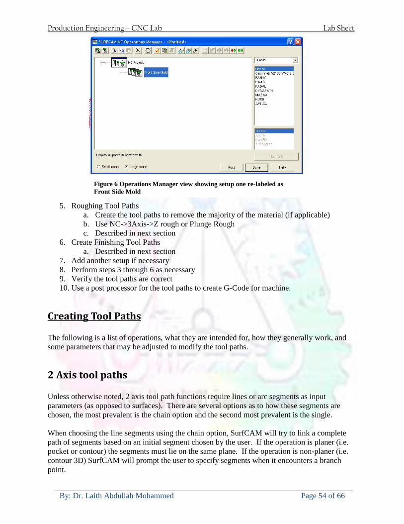
Production Engineering ndash CNC Lab Lab Sheet
By Dr Laith Abdullah Mohammed Page 54 of 66
5 Roughing Tool Paths a Create the tool paths to remove the majority of the material (if applicable) b Use NC-gt3Axis-gtZ rough or Plunge Rough c Described in next section
6 Create Finishing Tool Paths a Described in next section
7 Add another setup if necessary 8 Perform steps 3 through 6 as necessary 9 Verify the tool paths are correct 10 Use a post processor for the tool paths to create G-Code for machine
Creating Tool Paths The following is a list of operations what they are intended for how they generally work and some parameters that may be adjusted to modify the tool paths
2 Axis tool paths Unless otherwise noted 2 axis tool path functions require lines or arc segments as input parameters (as opposed to surfaces) There are several options as to how these segments are chosen the most prevalent is the chain option and the second most prevalent is the single When choosing the line segments using the chain option SurfCAM will try to link a complete path of segments based on an initial segment chosen by the user If the operation is planer (ie pocket or contour) the segments must lie on the same plane If the operation is non-planer (ie contour 3D) SurfCAM will prompt the user to specify segments when it encounters a branch point
Figure 6 Operations Manager view showing setup one re-labeled as Front Side Mold
Production Engineering ndash CNC Lab Lab Sheet
By Dr Laith Abdullah Mohammed Page 55 of 66
When using the single element option the user must manually choose each segment desired for the operation Note that most operations do not require a closed loop of segments you may specify for instance an open contour where the tool is supposed to move The order of choosing segments is important This order determines the path of the tool in the sense that if three segments are chosen such that the middle segment is chosen last there will be three different plunge and machine operations one on each segment If the operation was to make a continuous contour around the outside of the part the segments should be chosen in order of the desired tool trajectory
Operations
Pocket Pocket operation in SurfCAM is used to cut an enclosed space from the inside to the outside at one particular depth The operation starts in the center of an enclosed area (with a plunge move in the ndashZ direction) and makes incremental closed paths towards the pocket boundaries in user defined path offsets (Figure 7) The user chooses the boundary of the pocket (line segments) and if more than one pocket is chosen SurfCAM will ask the user to click inside a pocket
Figure 7 Two examples of using the pocketing operation
The pocket operation allows for creating a projection of the pocket paths on multiple planes This is useful if you have a deep pocket which will not allow the tool to cut directly at the depth of the pocket but would be easily done using the same paths at several different Z heights On the cut control (Figure 8) tab the user specifies where the chosen geometry (pocket segments) lie (ie bottom or top) Then under the amount to remove specify the total material height to be removed and the rough spacing (amount you wish to advance the Z axis with each pocket step) You may also specify a finishing pass and as well as stock to leave
Production Engineering ndash CNC Lab Lab Sheet
By Dr Laith Abdullah Mohammed Page 56 of 66
Figure 8 Example of Contour Operation with multiple passes
Contour Contouring in SurfCAM is used to perform peripheral milling on the inside or outside of a line segment (Figure 9) The user is to identify the line segments which define a contour (does not have to be a closed loop of segments) SurfCAM may or may not require the user to specify a side to contour (ie which side of the line is the tool to cut) For contouring each segment must lie on the same plane
Production Engineering ndash CNC Lab Lab Sheet
By Dr Laith Abdullah Mohammed Page 57 of 66
Figure 9 Examples of parts cut with 2-Axis Contour
Contour 3D Contour 3D is the same operation type as contour but allows the user to specify segments on different planes for the tool to cut along
Drill Drilling operations are any rotating tool operation meant to engage the part from a single direction ndash namely from the positive Z direction Drilling operations can be specified using circle point or line segments After choosing NC-gt2-Axis-gtDrill SurfCAM allows the user to choose multiple circles or points defining holes to be drilled Drilling operations also allow the user to incorporate more than 1 operation such as a center drill a drill and a reaming operation After selecting the locations for the drilling operation a dialog box (Figure 10) allows the user to add change or delete tools to be used in the operation As displayed in the following figure the spotdrill operation is followed by a drilling operation followed by a tapping operation The depth of each tool can be controlled individually by double clicking the total depth cell in and manually entering Tools can be added before or after operations which the cells are highlighted by selecting either of the insert buttons at the top or by the insert menu Select tool button allows the user to change the tool size or type
Production Engineering ndash CNC Lab Lab Sheet
By Dr Laith Abdullah Mohammed Page 58 of 66
Figure 10 Drill operation manager Several operations can be completed at one time
Figure 11 Drill operation including the spotdrill drill and tap as outlined in Fig 10
3 Axis tool paths SurfCAM requires surfaces as inputs for 3 Axis tool paths Surfaces can be created in SurfCAM but are most easily created in a CAD package and imported into SurfCAM Surfaces allow SurfCAM to identify every point on the surface in 3 dimensions unlike 2D geometry (wireframes) which only identify positions on the plane Creating tool paths with complex surfaces takes a very significant amount of processing power so expect 3 Axis tool path generation to take longer
Production Engineering ndash CNC Lab Lab Sheet
By Dr Laith Abdullah Mohammed Page 59 of 66
Operations
Cut 3 Axis cut operation takes a surface and using the flow lines creates a rastering path over the surface with the tool tip riding on the surface The primary direction will be defined by the flow lines of the surface (which can be edited by Edit-gtSurfaces-gtArrow-gtDirection) If you intend to cross surface boundaries you must merge the surfaces (Edit-gtJoin and choose the two surfaces)
Z-Rough The Z-rough operation is used to remove a large amount of material prior to finish machining Roughing operation is typically the first operation you perform for each setup The Z-Rough operation cuts the part in user defined intervals For each of these intervals a surface intersection between the part and the plane is performed and a 2D pocket or contour operation is performed on that plane This is performed on each plane When choosing NC-gt3 Axis-gtZ rough the first dialog box you will encounter asks for a bounding box to be defined Choose the Extents Box and a second dialog box will ask for the coordinates which define the box (Figure 12) This is the stock size you expect to machine the part from Input the coordinates or change the additional offset amounts (in XY or Z) as appropriate and click Calculate Bounding Box
Figure 12 Material Extents Box Example
Next choose the tool and cutting parameters that you desire and click on the Cut Control Tab (Figure 13) Here you will find the following parameters which are often changed Stock to
Production Engineering ndash CNC Lab Lab Sheet
By Dr Laith Abdullah Mohammed Page 60 of 66
leave ndash this is an offset amount from the surfaces which leaves a small amount of material to finish machine Minimum and Maximum Z values ndash Defines area to machine Z Step Size ndash This identifies the plane intervals for the surface intersection planes (the first interval will be at the top of the selected area and successive increments down in Z will be cut until the Minimum Z value is reached)
Figure 13 3Axis Z Rough Cut Control
The 3Axis Z-Finish operation works in exactly the same way 3 Axis Z-Finish is most appropriate for finishing vertical or near vertical walls
3D Offset The 3D Offset operation creates a tool path using a 2D or 3D boundary by offsetting the boundary in concentric offset cutting passes Each pass calculates the tool engagement and maintains the engagement somewhat constant The advantage (significant) is the scallop height ndash height of the material between passes ndash is controlled thus the surface finish is predictable When choosing 3D Offset surfaces are selected as well as 2D or 3D boundaries The boundaries define the concentric offset paths shape as well as limit the tool path area Choose NC-gt3Axis-gt3D Offset from the drop down menus SurfCAM will prompt you to select the surface or surfaces to cut across Select the surfaces you wish to machine and then select the tool and cutting parameters you wish use Next select the Cut Control Tab and check the Use Boundary Curves option Set the Step Type to Scallop and set the maximum scallop height If you like
Production Engineering ndash CNC Lab Lab Sheet
By Dr Laith Abdullah Mohammed Page 61 of 66
you can also add stock to leave if this is a roughing operation You can also set the Direction and Start-End parameters from this tab Click OK and the paths will be generated
Figure 14 Cut Control Tab for 3D Offset
Example part using both 2D and 3D geometry
The tool paths for this mold will be generated in SurfCAM using 5 operations The first will be a roughing operation using a frac14 inch flat end mill with the Z step size of 00625in Choose NC-
Production Engineering ndash CNC Lab Lab Sheet
By Dr Laith Abdullah Mohammed Page 62 of 66
gt3Axis-gtZ-Rough from the drop down menu Select all visible surfaces and create an extents box that has 025inch XY offsets and 01inch Z offset Next select the frac14 inch flat end mill from the tools menu Under Cut Control tab set the Z step size to be 00625inch The tool paths will look something like Figure 15
Figure 15 Z-Rough Tool paths for Example Part
Next a flat surface operation will be performed to cut the flat surface on the top Select NC-gt3 Axis-gtFlat Surface from the drop down menu Select all visible surfaces again Choose the 12inch flat end mill and set the cutting parameters as desired Under Cut Control Tab change the Minimum Area to 50 square inches (Figure 16) The tool paths should look something like Figure 17
Figure 16 Cut Control for Flat Surface
Production Engineering ndash CNC Lab Lab Sheet
By Dr Laith Abdullah Mohammed Page 63 of 66
Figure 17 Flat Surface Tool Paths
Next we will use a 3D offset operation to cut the mold cavity Select NC-gt3 Axis-gt3D Offset from the dropdown menu Change the view to the top view and select within to capture the surfaces of the mold cavity Draw a rectangle around the mold cavity Select a 18 inch ball endmill from the tool library and set the cutting parameters as appropriate Next set the Cut Control tab parameters as in Figure 14 The paths creates should be similar to Figure 18
Figure 18 3D Offset Paths
Next we will perform a 2 Axis contouring of the top section Select NC-gt2 Axis-gtContour from the dropdown menu Using the chain option select the bottom contour of the top extrusion Select the frac12 inch flat end mill from the tool library and set the cutting parameters as required In the Cut Control Tab change the Geometry to Bottom and the amount to remove in Z to 05
Production Engineering ndash CNC Lab Lab Sheet
By Dr Laith Abdullah Mohammed Page 64 of 66
Change the Rough Spacing in Z to 025 and add 1 finish pass of 002 (Figure 19) Click OK and SurfCAM will instruct you to choose a side to contour Click anywhere on the screen OUTSIDE the geometry you selected for the contouring operation Failure to click outside the geometry will result in the tool being on the wrong side of the contour Your paths should look something like those in Figure 20
Figure 19 Cut Control Tab for the Contouring Operation
Figure 20 Contouring operation paths
Production Engineering ndash CNC Lab Lab Sheet
By Dr Laith Abdullah Mohammed Page 65 of 66
Next we will perform a 2 axis pocket operation for the small pocket on the top face of the mold Select NC-gt2Axis-gtPocket and using the Auto select feature select the boundary curve at the bottom of the pocket Click Done twice and select the frac14 inch flat end mill from the tool library Set the appropriate cutting parameters and click OK SurfCAM will prompt you to click inside the pocket Click anywhere inside the geometry you chose to define the pocket The resulting paths should look something like those in Figure 21
Figure 21 2 Axis Pocket Operation Paths
Finally we will add a drilling operation for the 2 holes at the corners of the mold Select NC-gt2 Axis-gtDrill from the dropdown menu Select the top circles defining the two holes A menu box will appear with a default tool (Center drill) already programmed Add a second tool to the list by selecting Insert-gtAfter and select the tool from the tool library Change the drill depth to 10inches and click OK The paths should look something similar to Figure 23
Figure 22 Drill Menu
Production Engineering ndash CNC Lab Lab Sheet
By Dr Laith Abdullah Mohammed Page 66 of 66
Figure 23 Drilling Operation Tool Paths
Now you can watch a simulation of the cutting by choosing the setup in the operations manager and clicking the simulate icon Be sure to set the stock in the set up by right clicking the set up and selecting Edit Setup Information In the Stock Tab you can create a bounding box meeting your needs and click Add Your simulation should result in something like the following
Figure 24 Final Simulation of the example Mold
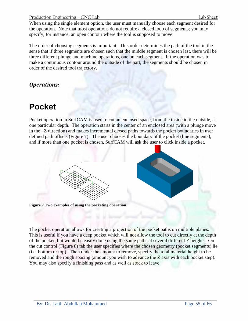
Production Engineering ndash CNC Lab Lab Sheet
By Dr Laith Abdullah Mohammed Page 55 of 66
When using the single element option the user must manually choose each segment desired for the operation Note that most operations do not require a closed loop of segments you may specify for instance an open contour where the tool is supposed to move The order of choosing segments is important This order determines the path of the tool in the sense that if three segments are chosen such that the middle segment is chosen last there will be three different plunge and machine operations one on each segment If the operation was to make a continuous contour around the outside of the part the segments should be chosen in order of the desired tool trajectory
Operations
Pocket Pocket operation in SurfCAM is used to cut an enclosed space from the inside to the outside at one particular depth The operation starts in the center of an enclosed area (with a plunge move in the ndashZ direction) and makes incremental closed paths towards the pocket boundaries in user defined path offsets (Figure 7) The user chooses the boundary of the pocket (line segments) and if more than one pocket is chosen SurfCAM will ask the user to click inside a pocket
Figure 7 Two examples of using the pocketing operation
The pocket operation allows for creating a projection of the pocket paths on multiple planes This is useful if you have a deep pocket which will not allow the tool to cut directly at the depth of the pocket but would be easily done using the same paths at several different Z heights On the cut control (Figure 8) tab the user specifies where the chosen geometry (pocket segments) lie (ie bottom or top) Then under the amount to remove specify the total material height to be removed and the rough spacing (amount you wish to advance the Z axis with each pocket step) You may also specify a finishing pass and as well as stock to leave
Production Engineering ndash CNC Lab Lab Sheet
By Dr Laith Abdullah Mohammed Page 56 of 66
Figure 8 Example of Contour Operation with multiple passes
Contour Contouring in SurfCAM is used to perform peripheral milling on the inside or outside of a line segment (Figure 9) The user is to identify the line segments which define a contour (does not have to be a closed loop of segments) SurfCAM may or may not require the user to specify a side to contour (ie which side of the line is the tool to cut) For contouring each segment must lie on the same plane
Production Engineering ndash CNC Lab Lab Sheet
By Dr Laith Abdullah Mohammed Page 57 of 66
Figure 9 Examples of parts cut with 2-Axis Contour
Contour 3D Contour 3D is the same operation type as contour but allows the user to specify segments on different planes for the tool to cut along
Drill Drilling operations are any rotating tool operation meant to engage the part from a single direction ndash namely from the positive Z direction Drilling operations can be specified using circle point or line segments After choosing NC-gt2-Axis-gtDrill SurfCAM allows the user to choose multiple circles or points defining holes to be drilled Drilling operations also allow the user to incorporate more than 1 operation such as a center drill a drill and a reaming operation After selecting the locations for the drilling operation a dialog box (Figure 10) allows the user to add change or delete tools to be used in the operation As displayed in the following figure the spotdrill operation is followed by a drilling operation followed by a tapping operation The depth of each tool can be controlled individually by double clicking the total depth cell in and manually entering Tools can be added before or after operations which the cells are highlighted by selecting either of the insert buttons at the top or by the insert menu Select tool button allows the user to change the tool size or type
Production Engineering ndash CNC Lab Lab Sheet
By Dr Laith Abdullah Mohammed Page 58 of 66
Figure 10 Drill operation manager Several operations can be completed at one time
Figure 11 Drill operation including the spotdrill drill and tap as outlined in Fig 10
3 Axis tool paths SurfCAM requires surfaces as inputs for 3 Axis tool paths Surfaces can be created in SurfCAM but are most easily created in a CAD package and imported into SurfCAM Surfaces allow SurfCAM to identify every point on the surface in 3 dimensions unlike 2D geometry (wireframes) which only identify positions on the plane Creating tool paths with complex surfaces takes a very significant amount of processing power so expect 3 Axis tool path generation to take longer
Production Engineering ndash CNC Lab Lab Sheet
By Dr Laith Abdullah Mohammed Page 59 of 66
Operations
Cut 3 Axis cut operation takes a surface and using the flow lines creates a rastering path over the surface with the tool tip riding on the surface The primary direction will be defined by the flow lines of the surface (which can be edited by Edit-gtSurfaces-gtArrow-gtDirection) If you intend to cross surface boundaries you must merge the surfaces (Edit-gtJoin and choose the two surfaces)
Z-Rough The Z-rough operation is used to remove a large amount of material prior to finish machining Roughing operation is typically the first operation you perform for each setup The Z-Rough operation cuts the part in user defined intervals For each of these intervals a surface intersection between the part and the plane is performed and a 2D pocket or contour operation is performed on that plane This is performed on each plane When choosing NC-gt3 Axis-gtZ rough the first dialog box you will encounter asks for a bounding box to be defined Choose the Extents Box and a second dialog box will ask for the coordinates which define the box (Figure 12) This is the stock size you expect to machine the part from Input the coordinates or change the additional offset amounts (in XY or Z) as appropriate and click Calculate Bounding Box
Figure 12 Material Extents Box Example
Next choose the tool and cutting parameters that you desire and click on the Cut Control Tab (Figure 13) Here you will find the following parameters which are often changed Stock to
Production Engineering ndash CNC Lab Lab Sheet
By Dr Laith Abdullah Mohammed Page 60 of 66
leave ndash this is an offset amount from the surfaces which leaves a small amount of material to finish machine Minimum and Maximum Z values ndash Defines area to machine Z Step Size ndash This identifies the plane intervals for the surface intersection planes (the first interval will be at the top of the selected area and successive increments down in Z will be cut until the Minimum Z value is reached)
Figure 13 3Axis Z Rough Cut Control
The 3Axis Z-Finish operation works in exactly the same way 3 Axis Z-Finish is most appropriate for finishing vertical or near vertical walls
3D Offset The 3D Offset operation creates a tool path using a 2D or 3D boundary by offsetting the boundary in concentric offset cutting passes Each pass calculates the tool engagement and maintains the engagement somewhat constant The advantage (significant) is the scallop height ndash height of the material between passes ndash is controlled thus the surface finish is predictable When choosing 3D Offset surfaces are selected as well as 2D or 3D boundaries The boundaries define the concentric offset paths shape as well as limit the tool path area Choose NC-gt3Axis-gt3D Offset from the drop down menus SurfCAM will prompt you to select the surface or surfaces to cut across Select the surfaces you wish to machine and then select the tool and cutting parameters you wish use Next select the Cut Control Tab and check the Use Boundary Curves option Set the Step Type to Scallop and set the maximum scallop height If you like
Production Engineering ndash CNC Lab Lab Sheet
By Dr Laith Abdullah Mohammed Page 61 of 66
you can also add stock to leave if this is a roughing operation You can also set the Direction and Start-End parameters from this tab Click OK and the paths will be generated
Figure 14 Cut Control Tab for 3D Offset
Example part using both 2D and 3D geometry
The tool paths for this mold will be generated in SurfCAM using 5 operations The first will be a roughing operation using a frac14 inch flat end mill with the Z step size of 00625in Choose NC-
Production Engineering ndash CNC Lab Lab Sheet
By Dr Laith Abdullah Mohammed Page 62 of 66
gt3Axis-gtZ-Rough from the drop down menu Select all visible surfaces and create an extents box that has 025inch XY offsets and 01inch Z offset Next select the frac14 inch flat end mill from the tools menu Under Cut Control tab set the Z step size to be 00625inch The tool paths will look something like Figure 15
Figure 15 Z-Rough Tool paths for Example Part
Next a flat surface operation will be performed to cut the flat surface on the top Select NC-gt3 Axis-gtFlat Surface from the drop down menu Select all visible surfaces again Choose the 12inch flat end mill and set the cutting parameters as desired Under Cut Control Tab change the Minimum Area to 50 square inches (Figure 16) The tool paths should look something like Figure 17
Figure 16 Cut Control for Flat Surface
Production Engineering ndash CNC Lab Lab Sheet
By Dr Laith Abdullah Mohammed Page 63 of 66
Figure 17 Flat Surface Tool Paths
Next we will use a 3D offset operation to cut the mold cavity Select NC-gt3 Axis-gt3D Offset from the dropdown menu Change the view to the top view and select within to capture the surfaces of the mold cavity Draw a rectangle around the mold cavity Select a 18 inch ball endmill from the tool library and set the cutting parameters as appropriate Next set the Cut Control tab parameters as in Figure 14 The paths creates should be similar to Figure 18
Figure 18 3D Offset Paths
Next we will perform a 2 Axis contouring of the top section Select NC-gt2 Axis-gtContour from the dropdown menu Using the chain option select the bottom contour of the top extrusion Select the frac12 inch flat end mill from the tool library and set the cutting parameters as required In the Cut Control Tab change the Geometry to Bottom and the amount to remove in Z to 05
Production Engineering ndash CNC Lab Lab Sheet
By Dr Laith Abdullah Mohammed Page 64 of 66
Change the Rough Spacing in Z to 025 and add 1 finish pass of 002 (Figure 19) Click OK and SurfCAM will instruct you to choose a side to contour Click anywhere on the screen OUTSIDE the geometry you selected for the contouring operation Failure to click outside the geometry will result in the tool being on the wrong side of the contour Your paths should look something like those in Figure 20
Figure 19 Cut Control Tab for the Contouring Operation
Figure 20 Contouring operation paths
Production Engineering ndash CNC Lab Lab Sheet
By Dr Laith Abdullah Mohammed Page 65 of 66
Next we will perform a 2 axis pocket operation for the small pocket on the top face of the mold Select NC-gt2Axis-gtPocket and using the Auto select feature select the boundary curve at the bottom of the pocket Click Done twice and select the frac14 inch flat end mill from the tool library Set the appropriate cutting parameters and click OK SurfCAM will prompt you to click inside the pocket Click anywhere inside the geometry you chose to define the pocket The resulting paths should look something like those in Figure 21
Figure 21 2 Axis Pocket Operation Paths
Finally we will add a drilling operation for the 2 holes at the corners of the mold Select NC-gt2 Axis-gtDrill from the dropdown menu Select the top circles defining the two holes A menu box will appear with a default tool (Center drill) already programmed Add a second tool to the list by selecting Insert-gtAfter and select the tool from the tool library Change the drill depth to 10inches and click OK The paths should look something similar to Figure 23
Figure 22 Drill Menu
Production Engineering ndash CNC Lab Lab Sheet
By Dr Laith Abdullah Mohammed Page 66 of 66
Figure 23 Drilling Operation Tool Paths
Now you can watch a simulation of the cutting by choosing the setup in the operations manager and clicking the simulate icon Be sure to set the stock in the set up by right clicking the set up and selecting Edit Setup Information In the Stock Tab you can create a bounding box meeting your needs and click Add Your simulation should result in something like the following
Figure 24 Final Simulation of the example Mold
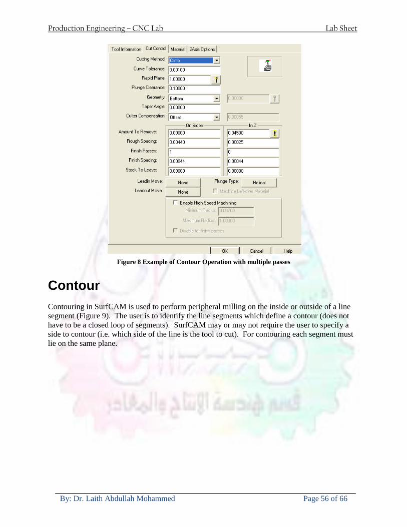
Production Engineering ndash CNC Lab Lab Sheet
By Dr Laith Abdullah Mohammed Page 56 of 66
Figure 8 Example of Contour Operation with multiple passes
Contour Contouring in SurfCAM is used to perform peripheral milling on the inside or outside of a line segment (Figure 9) The user is to identify the line segments which define a contour (does not have to be a closed loop of segments) SurfCAM may or may not require the user to specify a side to contour (ie which side of the line is the tool to cut) For contouring each segment must lie on the same plane
Production Engineering ndash CNC Lab Lab Sheet
By Dr Laith Abdullah Mohammed Page 57 of 66
Figure 9 Examples of parts cut with 2-Axis Contour
Contour 3D Contour 3D is the same operation type as contour but allows the user to specify segments on different planes for the tool to cut along
Drill Drilling operations are any rotating tool operation meant to engage the part from a single direction ndash namely from the positive Z direction Drilling operations can be specified using circle point or line segments After choosing NC-gt2-Axis-gtDrill SurfCAM allows the user to choose multiple circles or points defining holes to be drilled Drilling operations also allow the user to incorporate more than 1 operation such as a center drill a drill and a reaming operation After selecting the locations for the drilling operation a dialog box (Figure 10) allows the user to add change or delete tools to be used in the operation As displayed in the following figure the spotdrill operation is followed by a drilling operation followed by a tapping operation The depth of each tool can be controlled individually by double clicking the total depth cell in and manually entering Tools can be added before or after operations which the cells are highlighted by selecting either of the insert buttons at the top or by the insert menu Select tool button allows the user to change the tool size or type
Production Engineering ndash CNC Lab Lab Sheet
By Dr Laith Abdullah Mohammed Page 58 of 66
Figure 10 Drill operation manager Several operations can be completed at one time
Figure 11 Drill operation including the spotdrill drill and tap as outlined in Fig 10
3 Axis tool paths SurfCAM requires surfaces as inputs for 3 Axis tool paths Surfaces can be created in SurfCAM but are most easily created in a CAD package and imported into SurfCAM Surfaces allow SurfCAM to identify every point on the surface in 3 dimensions unlike 2D geometry (wireframes) which only identify positions on the plane Creating tool paths with complex surfaces takes a very significant amount of processing power so expect 3 Axis tool path generation to take longer
Production Engineering ndash CNC Lab Lab Sheet
By Dr Laith Abdullah Mohammed Page 59 of 66
Operations
Cut 3 Axis cut operation takes a surface and using the flow lines creates a rastering path over the surface with the tool tip riding on the surface The primary direction will be defined by the flow lines of the surface (which can be edited by Edit-gtSurfaces-gtArrow-gtDirection) If you intend to cross surface boundaries you must merge the surfaces (Edit-gtJoin and choose the two surfaces)
Z-Rough The Z-rough operation is used to remove a large amount of material prior to finish machining Roughing operation is typically the first operation you perform for each setup The Z-Rough operation cuts the part in user defined intervals For each of these intervals a surface intersection between the part and the plane is performed and a 2D pocket or contour operation is performed on that plane This is performed on each plane When choosing NC-gt3 Axis-gtZ rough the first dialog box you will encounter asks for a bounding box to be defined Choose the Extents Box and a second dialog box will ask for the coordinates which define the box (Figure 12) This is the stock size you expect to machine the part from Input the coordinates or change the additional offset amounts (in XY or Z) as appropriate and click Calculate Bounding Box
Figure 12 Material Extents Box Example
Next choose the tool and cutting parameters that you desire and click on the Cut Control Tab (Figure 13) Here you will find the following parameters which are often changed Stock to
Production Engineering ndash CNC Lab Lab Sheet
By Dr Laith Abdullah Mohammed Page 60 of 66
leave ndash this is an offset amount from the surfaces which leaves a small amount of material to finish machine Minimum and Maximum Z values ndash Defines area to machine Z Step Size ndash This identifies the plane intervals for the surface intersection planes (the first interval will be at the top of the selected area and successive increments down in Z will be cut until the Minimum Z value is reached)
Figure 13 3Axis Z Rough Cut Control
The 3Axis Z-Finish operation works in exactly the same way 3 Axis Z-Finish is most appropriate for finishing vertical or near vertical walls
3D Offset The 3D Offset operation creates a tool path using a 2D or 3D boundary by offsetting the boundary in concentric offset cutting passes Each pass calculates the tool engagement and maintains the engagement somewhat constant The advantage (significant) is the scallop height ndash height of the material between passes ndash is controlled thus the surface finish is predictable When choosing 3D Offset surfaces are selected as well as 2D or 3D boundaries The boundaries define the concentric offset paths shape as well as limit the tool path area Choose NC-gt3Axis-gt3D Offset from the drop down menus SurfCAM will prompt you to select the surface or surfaces to cut across Select the surfaces you wish to machine and then select the tool and cutting parameters you wish use Next select the Cut Control Tab and check the Use Boundary Curves option Set the Step Type to Scallop and set the maximum scallop height If you like
Production Engineering ndash CNC Lab Lab Sheet
By Dr Laith Abdullah Mohammed Page 61 of 66
you can also add stock to leave if this is a roughing operation You can also set the Direction and Start-End parameters from this tab Click OK and the paths will be generated
Figure 14 Cut Control Tab for 3D Offset
Example part using both 2D and 3D geometry
The tool paths for this mold will be generated in SurfCAM using 5 operations The first will be a roughing operation using a frac14 inch flat end mill with the Z step size of 00625in Choose NC-
Production Engineering ndash CNC Lab Lab Sheet
By Dr Laith Abdullah Mohammed Page 62 of 66
gt3Axis-gtZ-Rough from the drop down menu Select all visible surfaces and create an extents box that has 025inch XY offsets and 01inch Z offset Next select the frac14 inch flat end mill from the tools menu Under Cut Control tab set the Z step size to be 00625inch The tool paths will look something like Figure 15
Figure 15 Z-Rough Tool paths for Example Part
Next a flat surface operation will be performed to cut the flat surface on the top Select NC-gt3 Axis-gtFlat Surface from the drop down menu Select all visible surfaces again Choose the 12inch flat end mill and set the cutting parameters as desired Under Cut Control Tab change the Minimum Area to 50 square inches (Figure 16) The tool paths should look something like Figure 17
Figure 16 Cut Control for Flat Surface
Production Engineering ndash CNC Lab Lab Sheet
By Dr Laith Abdullah Mohammed Page 63 of 66
Figure 17 Flat Surface Tool Paths
Next we will use a 3D offset operation to cut the mold cavity Select NC-gt3 Axis-gt3D Offset from the dropdown menu Change the view to the top view and select within to capture the surfaces of the mold cavity Draw a rectangle around the mold cavity Select a 18 inch ball endmill from the tool library and set the cutting parameters as appropriate Next set the Cut Control tab parameters as in Figure 14 The paths creates should be similar to Figure 18
Figure 18 3D Offset Paths
Next we will perform a 2 Axis contouring of the top section Select NC-gt2 Axis-gtContour from the dropdown menu Using the chain option select the bottom contour of the top extrusion Select the frac12 inch flat end mill from the tool library and set the cutting parameters as required In the Cut Control Tab change the Geometry to Bottom and the amount to remove in Z to 05
Production Engineering ndash CNC Lab Lab Sheet
By Dr Laith Abdullah Mohammed Page 64 of 66
Change the Rough Spacing in Z to 025 and add 1 finish pass of 002 (Figure 19) Click OK and SurfCAM will instruct you to choose a side to contour Click anywhere on the screen OUTSIDE the geometry you selected for the contouring operation Failure to click outside the geometry will result in the tool being on the wrong side of the contour Your paths should look something like those in Figure 20
Figure 19 Cut Control Tab for the Contouring Operation
Figure 20 Contouring operation paths
Production Engineering ndash CNC Lab Lab Sheet
By Dr Laith Abdullah Mohammed Page 65 of 66
Next we will perform a 2 axis pocket operation for the small pocket on the top face of the mold Select NC-gt2Axis-gtPocket and using the Auto select feature select the boundary curve at the bottom of the pocket Click Done twice and select the frac14 inch flat end mill from the tool library Set the appropriate cutting parameters and click OK SurfCAM will prompt you to click inside the pocket Click anywhere inside the geometry you chose to define the pocket The resulting paths should look something like those in Figure 21
Figure 21 2 Axis Pocket Operation Paths
Finally we will add a drilling operation for the 2 holes at the corners of the mold Select NC-gt2 Axis-gtDrill from the dropdown menu Select the top circles defining the two holes A menu box will appear with a default tool (Center drill) already programmed Add a second tool to the list by selecting Insert-gtAfter and select the tool from the tool library Change the drill depth to 10inches and click OK The paths should look something similar to Figure 23
Figure 22 Drill Menu
Production Engineering ndash CNC Lab Lab Sheet
By Dr Laith Abdullah Mohammed Page 66 of 66
Figure 23 Drilling Operation Tool Paths
Now you can watch a simulation of the cutting by choosing the setup in the operations manager and clicking the simulate icon Be sure to set the stock in the set up by right clicking the set up and selecting Edit Setup Information In the Stock Tab you can create a bounding box meeting your needs and click Add Your simulation should result in something like the following
Figure 24 Final Simulation of the example Mold
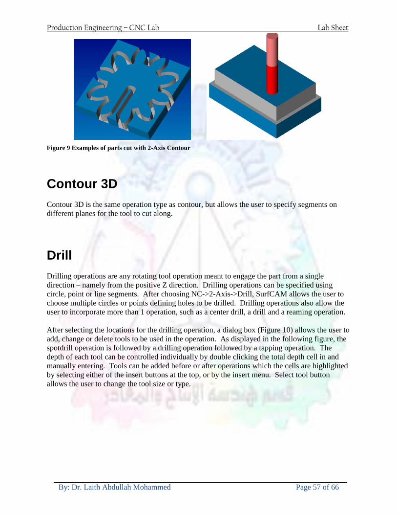
Production Engineering ndash CNC Lab Lab Sheet
By Dr Laith Abdullah Mohammed Page 57 of 66
Figure 9 Examples of parts cut with 2-Axis Contour
Contour 3D Contour 3D is the same operation type as contour but allows the user to specify segments on different planes for the tool to cut along
Drill Drilling operations are any rotating tool operation meant to engage the part from a single direction ndash namely from the positive Z direction Drilling operations can be specified using circle point or line segments After choosing NC-gt2-Axis-gtDrill SurfCAM allows the user to choose multiple circles or points defining holes to be drilled Drilling operations also allow the user to incorporate more than 1 operation such as a center drill a drill and a reaming operation After selecting the locations for the drilling operation a dialog box (Figure 10) allows the user to add change or delete tools to be used in the operation As displayed in the following figure the spotdrill operation is followed by a drilling operation followed by a tapping operation The depth of each tool can be controlled individually by double clicking the total depth cell in and manually entering Tools can be added before or after operations which the cells are highlighted by selecting either of the insert buttons at the top or by the insert menu Select tool button allows the user to change the tool size or type
Production Engineering ndash CNC Lab Lab Sheet
By Dr Laith Abdullah Mohammed Page 58 of 66
Figure 10 Drill operation manager Several operations can be completed at one time
Figure 11 Drill operation including the spotdrill drill and tap as outlined in Fig 10
3 Axis tool paths SurfCAM requires surfaces as inputs for 3 Axis tool paths Surfaces can be created in SurfCAM but are most easily created in a CAD package and imported into SurfCAM Surfaces allow SurfCAM to identify every point on the surface in 3 dimensions unlike 2D geometry (wireframes) which only identify positions on the plane Creating tool paths with complex surfaces takes a very significant amount of processing power so expect 3 Axis tool path generation to take longer
Production Engineering ndash CNC Lab Lab Sheet
By Dr Laith Abdullah Mohammed Page 59 of 66
Operations
Cut 3 Axis cut operation takes a surface and using the flow lines creates a rastering path over the surface with the tool tip riding on the surface The primary direction will be defined by the flow lines of the surface (which can be edited by Edit-gtSurfaces-gtArrow-gtDirection) If you intend to cross surface boundaries you must merge the surfaces (Edit-gtJoin and choose the two surfaces)
Z-Rough The Z-rough operation is used to remove a large amount of material prior to finish machining Roughing operation is typically the first operation you perform for each setup The Z-Rough operation cuts the part in user defined intervals For each of these intervals a surface intersection between the part and the plane is performed and a 2D pocket or contour operation is performed on that plane This is performed on each plane When choosing NC-gt3 Axis-gtZ rough the first dialog box you will encounter asks for a bounding box to be defined Choose the Extents Box and a second dialog box will ask for the coordinates which define the box (Figure 12) This is the stock size you expect to machine the part from Input the coordinates or change the additional offset amounts (in XY or Z) as appropriate and click Calculate Bounding Box
Figure 12 Material Extents Box Example
Next choose the tool and cutting parameters that you desire and click on the Cut Control Tab (Figure 13) Here you will find the following parameters which are often changed Stock to
Production Engineering ndash CNC Lab Lab Sheet
By Dr Laith Abdullah Mohammed Page 60 of 66
leave ndash this is an offset amount from the surfaces which leaves a small amount of material to finish machine Minimum and Maximum Z values ndash Defines area to machine Z Step Size ndash This identifies the plane intervals for the surface intersection planes (the first interval will be at the top of the selected area and successive increments down in Z will be cut until the Minimum Z value is reached)
Figure 13 3Axis Z Rough Cut Control
The 3Axis Z-Finish operation works in exactly the same way 3 Axis Z-Finish is most appropriate for finishing vertical or near vertical walls
3D Offset The 3D Offset operation creates a tool path using a 2D or 3D boundary by offsetting the boundary in concentric offset cutting passes Each pass calculates the tool engagement and maintains the engagement somewhat constant The advantage (significant) is the scallop height ndash height of the material between passes ndash is controlled thus the surface finish is predictable When choosing 3D Offset surfaces are selected as well as 2D or 3D boundaries The boundaries define the concentric offset paths shape as well as limit the tool path area Choose NC-gt3Axis-gt3D Offset from the drop down menus SurfCAM will prompt you to select the surface or surfaces to cut across Select the surfaces you wish to machine and then select the tool and cutting parameters you wish use Next select the Cut Control Tab and check the Use Boundary Curves option Set the Step Type to Scallop and set the maximum scallop height If you like
Production Engineering ndash CNC Lab Lab Sheet
By Dr Laith Abdullah Mohammed Page 61 of 66
you can also add stock to leave if this is a roughing operation You can also set the Direction and Start-End parameters from this tab Click OK and the paths will be generated
Figure 14 Cut Control Tab for 3D Offset
Example part using both 2D and 3D geometry
The tool paths for this mold will be generated in SurfCAM using 5 operations The first will be a roughing operation using a frac14 inch flat end mill with the Z step size of 00625in Choose NC-
Production Engineering ndash CNC Lab Lab Sheet
By Dr Laith Abdullah Mohammed Page 62 of 66
gt3Axis-gtZ-Rough from the drop down menu Select all visible surfaces and create an extents box that has 025inch XY offsets and 01inch Z offset Next select the frac14 inch flat end mill from the tools menu Under Cut Control tab set the Z step size to be 00625inch The tool paths will look something like Figure 15
Figure 15 Z-Rough Tool paths for Example Part
Next a flat surface operation will be performed to cut the flat surface on the top Select NC-gt3 Axis-gtFlat Surface from the drop down menu Select all visible surfaces again Choose the 12inch flat end mill and set the cutting parameters as desired Under Cut Control Tab change the Minimum Area to 50 square inches (Figure 16) The tool paths should look something like Figure 17
Figure 16 Cut Control for Flat Surface
Production Engineering ndash CNC Lab Lab Sheet
By Dr Laith Abdullah Mohammed Page 63 of 66
Figure 17 Flat Surface Tool Paths
Next we will use a 3D offset operation to cut the mold cavity Select NC-gt3 Axis-gt3D Offset from the dropdown menu Change the view to the top view and select within to capture the surfaces of the mold cavity Draw a rectangle around the mold cavity Select a 18 inch ball endmill from the tool library and set the cutting parameters as appropriate Next set the Cut Control tab parameters as in Figure 14 The paths creates should be similar to Figure 18
Figure 18 3D Offset Paths
Next we will perform a 2 Axis contouring of the top section Select NC-gt2 Axis-gtContour from the dropdown menu Using the chain option select the bottom contour of the top extrusion Select the frac12 inch flat end mill from the tool library and set the cutting parameters as required In the Cut Control Tab change the Geometry to Bottom and the amount to remove in Z to 05
Production Engineering ndash CNC Lab Lab Sheet
By Dr Laith Abdullah Mohammed Page 64 of 66
Change the Rough Spacing in Z to 025 and add 1 finish pass of 002 (Figure 19) Click OK and SurfCAM will instruct you to choose a side to contour Click anywhere on the screen OUTSIDE the geometry you selected for the contouring operation Failure to click outside the geometry will result in the tool being on the wrong side of the contour Your paths should look something like those in Figure 20
Figure 19 Cut Control Tab for the Contouring Operation
Figure 20 Contouring operation paths
Production Engineering ndash CNC Lab Lab Sheet
By Dr Laith Abdullah Mohammed Page 65 of 66
Next we will perform a 2 axis pocket operation for the small pocket on the top face of the mold Select NC-gt2Axis-gtPocket and using the Auto select feature select the boundary curve at the bottom of the pocket Click Done twice and select the frac14 inch flat end mill from the tool library Set the appropriate cutting parameters and click OK SurfCAM will prompt you to click inside the pocket Click anywhere inside the geometry you chose to define the pocket The resulting paths should look something like those in Figure 21
Figure 21 2 Axis Pocket Operation Paths
Finally we will add a drilling operation for the 2 holes at the corners of the mold Select NC-gt2 Axis-gtDrill from the dropdown menu Select the top circles defining the two holes A menu box will appear with a default tool (Center drill) already programmed Add a second tool to the list by selecting Insert-gtAfter and select the tool from the tool library Change the drill depth to 10inches and click OK The paths should look something similar to Figure 23
Figure 22 Drill Menu
Production Engineering ndash CNC Lab Lab Sheet
By Dr Laith Abdullah Mohammed Page 66 of 66
Figure 23 Drilling Operation Tool Paths
Now you can watch a simulation of the cutting by choosing the setup in the operations manager and clicking the simulate icon Be sure to set the stock in the set up by right clicking the set up and selecting Edit Setup Information In the Stock Tab you can create a bounding box meeting your needs and click Add Your simulation should result in something like the following
Figure 24 Final Simulation of the example Mold
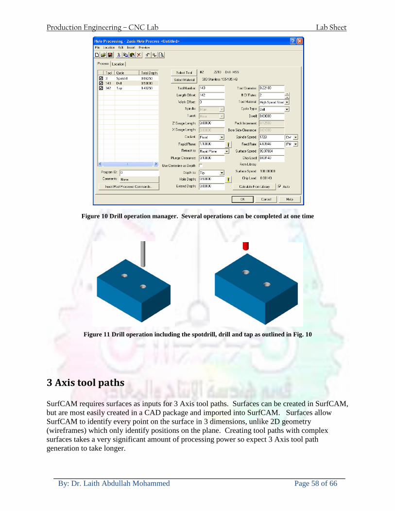
Production Engineering ndash CNC Lab Lab Sheet
By Dr Laith Abdullah Mohammed Page 58 of 66
Figure 10 Drill operation manager Several operations can be completed at one time
Figure 11 Drill operation including the spotdrill drill and tap as outlined in Fig 10
3 Axis tool paths SurfCAM requires surfaces as inputs for 3 Axis tool paths Surfaces can be created in SurfCAM but are most easily created in a CAD package and imported into SurfCAM Surfaces allow SurfCAM to identify every point on the surface in 3 dimensions unlike 2D geometry (wireframes) which only identify positions on the plane Creating tool paths with complex surfaces takes a very significant amount of processing power so expect 3 Axis tool path generation to take longer
Production Engineering ndash CNC Lab Lab Sheet
By Dr Laith Abdullah Mohammed Page 59 of 66
Operations
Cut 3 Axis cut operation takes a surface and using the flow lines creates a rastering path over the surface with the tool tip riding on the surface The primary direction will be defined by the flow lines of the surface (which can be edited by Edit-gtSurfaces-gtArrow-gtDirection) If you intend to cross surface boundaries you must merge the surfaces (Edit-gtJoin and choose the two surfaces)
Z-Rough The Z-rough operation is used to remove a large amount of material prior to finish machining Roughing operation is typically the first operation you perform for each setup The Z-Rough operation cuts the part in user defined intervals For each of these intervals a surface intersection between the part and the plane is performed and a 2D pocket or contour operation is performed on that plane This is performed on each plane When choosing NC-gt3 Axis-gtZ rough the first dialog box you will encounter asks for a bounding box to be defined Choose the Extents Box and a second dialog box will ask for the coordinates which define the box (Figure 12) This is the stock size you expect to machine the part from Input the coordinates or change the additional offset amounts (in XY or Z) as appropriate and click Calculate Bounding Box
Figure 12 Material Extents Box Example
Next choose the tool and cutting parameters that you desire and click on the Cut Control Tab (Figure 13) Here you will find the following parameters which are often changed Stock to
Production Engineering ndash CNC Lab Lab Sheet
By Dr Laith Abdullah Mohammed Page 60 of 66
leave ndash this is an offset amount from the surfaces which leaves a small amount of material to finish machine Minimum and Maximum Z values ndash Defines area to machine Z Step Size ndash This identifies the plane intervals for the surface intersection planes (the first interval will be at the top of the selected area and successive increments down in Z will be cut until the Minimum Z value is reached)
Figure 13 3Axis Z Rough Cut Control
The 3Axis Z-Finish operation works in exactly the same way 3 Axis Z-Finish is most appropriate for finishing vertical or near vertical walls
3D Offset The 3D Offset operation creates a tool path using a 2D or 3D boundary by offsetting the boundary in concentric offset cutting passes Each pass calculates the tool engagement and maintains the engagement somewhat constant The advantage (significant) is the scallop height ndash height of the material between passes ndash is controlled thus the surface finish is predictable When choosing 3D Offset surfaces are selected as well as 2D or 3D boundaries The boundaries define the concentric offset paths shape as well as limit the tool path area Choose NC-gt3Axis-gt3D Offset from the drop down menus SurfCAM will prompt you to select the surface or surfaces to cut across Select the surfaces you wish to machine and then select the tool and cutting parameters you wish use Next select the Cut Control Tab and check the Use Boundary Curves option Set the Step Type to Scallop and set the maximum scallop height If you like
Production Engineering ndash CNC Lab Lab Sheet
By Dr Laith Abdullah Mohammed Page 61 of 66
you can also add stock to leave if this is a roughing operation You can also set the Direction and Start-End parameters from this tab Click OK and the paths will be generated
Figure 14 Cut Control Tab for 3D Offset
Example part using both 2D and 3D geometry
The tool paths for this mold will be generated in SurfCAM using 5 operations The first will be a roughing operation using a frac14 inch flat end mill with the Z step size of 00625in Choose NC-
Production Engineering ndash CNC Lab Lab Sheet
By Dr Laith Abdullah Mohammed Page 62 of 66
gt3Axis-gtZ-Rough from the drop down menu Select all visible surfaces and create an extents box that has 025inch XY offsets and 01inch Z offset Next select the frac14 inch flat end mill from the tools menu Under Cut Control tab set the Z step size to be 00625inch The tool paths will look something like Figure 15
Figure 15 Z-Rough Tool paths for Example Part
Next a flat surface operation will be performed to cut the flat surface on the top Select NC-gt3 Axis-gtFlat Surface from the drop down menu Select all visible surfaces again Choose the 12inch flat end mill and set the cutting parameters as desired Under Cut Control Tab change the Minimum Area to 50 square inches (Figure 16) The tool paths should look something like Figure 17
Figure 16 Cut Control for Flat Surface
Production Engineering ndash CNC Lab Lab Sheet
By Dr Laith Abdullah Mohammed Page 63 of 66
Figure 17 Flat Surface Tool Paths
Next we will use a 3D offset operation to cut the mold cavity Select NC-gt3 Axis-gt3D Offset from the dropdown menu Change the view to the top view and select within to capture the surfaces of the mold cavity Draw a rectangle around the mold cavity Select a 18 inch ball endmill from the tool library and set the cutting parameters as appropriate Next set the Cut Control tab parameters as in Figure 14 The paths creates should be similar to Figure 18
Figure 18 3D Offset Paths
Next we will perform a 2 Axis contouring of the top section Select NC-gt2 Axis-gtContour from the dropdown menu Using the chain option select the bottom contour of the top extrusion Select the frac12 inch flat end mill from the tool library and set the cutting parameters as required In the Cut Control Tab change the Geometry to Bottom and the amount to remove in Z to 05
Production Engineering ndash CNC Lab Lab Sheet
By Dr Laith Abdullah Mohammed Page 64 of 66
Change the Rough Spacing in Z to 025 and add 1 finish pass of 002 (Figure 19) Click OK and SurfCAM will instruct you to choose a side to contour Click anywhere on the screen OUTSIDE the geometry you selected for the contouring operation Failure to click outside the geometry will result in the tool being on the wrong side of the contour Your paths should look something like those in Figure 20
Figure 19 Cut Control Tab for the Contouring Operation
Figure 20 Contouring operation paths
Production Engineering ndash CNC Lab Lab Sheet
By Dr Laith Abdullah Mohammed Page 65 of 66
Next we will perform a 2 axis pocket operation for the small pocket on the top face of the mold Select NC-gt2Axis-gtPocket and using the Auto select feature select the boundary curve at the bottom of the pocket Click Done twice and select the frac14 inch flat end mill from the tool library Set the appropriate cutting parameters and click OK SurfCAM will prompt you to click inside the pocket Click anywhere inside the geometry you chose to define the pocket The resulting paths should look something like those in Figure 21
Figure 21 2 Axis Pocket Operation Paths
Finally we will add a drilling operation for the 2 holes at the corners of the mold Select NC-gt2 Axis-gtDrill from the dropdown menu Select the top circles defining the two holes A menu box will appear with a default tool (Center drill) already programmed Add a second tool to the list by selecting Insert-gtAfter and select the tool from the tool library Change the drill depth to 10inches and click OK The paths should look something similar to Figure 23
Figure 22 Drill Menu
Production Engineering ndash CNC Lab Lab Sheet
By Dr Laith Abdullah Mohammed Page 66 of 66
Figure 23 Drilling Operation Tool Paths
Now you can watch a simulation of the cutting by choosing the setup in the operations manager and clicking the simulate icon Be sure to set the stock in the set up by right clicking the set up and selecting Edit Setup Information In the Stock Tab you can create a bounding box meeting your needs and click Add Your simulation should result in something like the following
Figure 24 Final Simulation of the example Mold
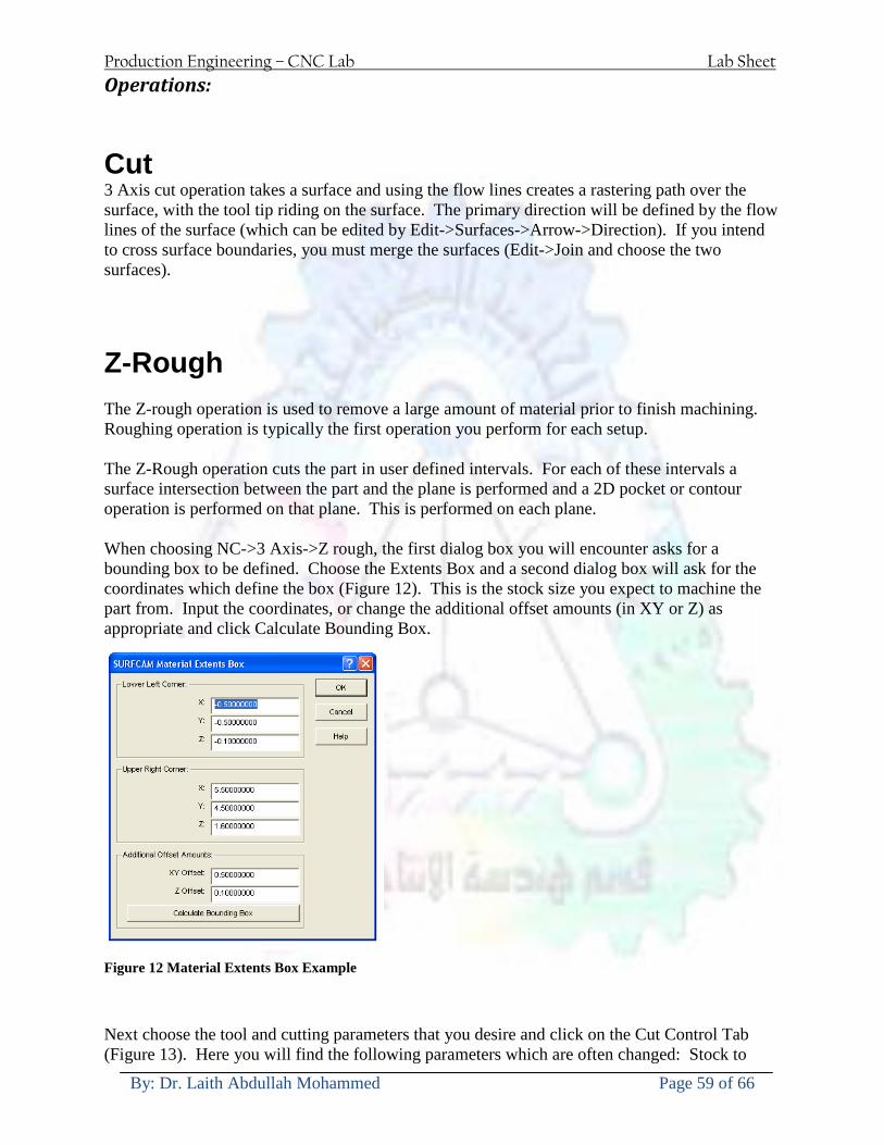
Production Engineering ndash CNC Lab Lab Sheet
By Dr Laith Abdullah Mohammed Page 59 of 66
Operations
Cut 3 Axis cut operation takes a surface and using the flow lines creates a rastering path over the surface with the tool tip riding on the surface The primary direction will be defined by the flow lines of the surface (which can be edited by Edit-gtSurfaces-gtArrow-gtDirection) If you intend to cross surface boundaries you must merge the surfaces (Edit-gtJoin and choose the two surfaces)
Z-Rough The Z-rough operation is used to remove a large amount of material prior to finish machining Roughing operation is typically the first operation you perform for each setup The Z-Rough operation cuts the part in user defined intervals For each of these intervals a surface intersection between the part and the plane is performed and a 2D pocket or contour operation is performed on that plane This is performed on each plane When choosing NC-gt3 Axis-gtZ rough the first dialog box you will encounter asks for a bounding box to be defined Choose the Extents Box and a second dialog box will ask for the coordinates which define the box (Figure 12) This is the stock size you expect to machine the part from Input the coordinates or change the additional offset amounts (in XY or Z) as appropriate and click Calculate Bounding Box
Figure 12 Material Extents Box Example
Next choose the tool and cutting parameters that you desire and click on the Cut Control Tab (Figure 13) Here you will find the following parameters which are often changed Stock to
Production Engineering ndash CNC Lab Lab Sheet
By Dr Laith Abdullah Mohammed Page 60 of 66
leave ndash this is an offset amount from the surfaces which leaves a small amount of material to finish machine Minimum and Maximum Z values ndash Defines area to machine Z Step Size ndash This identifies the plane intervals for the surface intersection planes (the first interval will be at the top of the selected area and successive increments down in Z will be cut until the Minimum Z value is reached)
Figure 13 3Axis Z Rough Cut Control
The 3Axis Z-Finish operation works in exactly the same way 3 Axis Z-Finish is most appropriate for finishing vertical or near vertical walls
3D Offset The 3D Offset operation creates a tool path using a 2D or 3D boundary by offsetting the boundary in concentric offset cutting passes Each pass calculates the tool engagement and maintains the engagement somewhat constant The advantage (significant) is the scallop height ndash height of the material between passes ndash is controlled thus the surface finish is predictable When choosing 3D Offset surfaces are selected as well as 2D or 3D boundaries The boundaries define the concentric offset paths shape as well as limit the tool path area Choose NC-gt3Axis-gt3D Offset from the drop down menus SurfCAM will prompt you to select the surface or surfaces to cut across Select the surfaces you wish to machine and then select the tool and cutting parameters you wish use Next select the Cut Control Tab and check the Use Boundary Curves option Set the Step Type to Scallop and set the maximum scallop height If you like
Production Engineering ndash CNC Lab Lab Sheet
By Dr Laith Abdullah Mohammed Page 61 of 66
you can also add stock to leave if this is a roughing operation You can also set the Direction and Start-End parameters from this tab Click OK and the paths will be generated
Figure 14 Cut Control Tab for 3D Offset
Example part using both 2D and 3D geometry
The tool paths for this mold will be generated in SurfCAM using 5 operations The first will be a roughing operation using a frac14 inch flat end mill with the Z step size of 00625in Choose NC-
Production Engineering ndash CNC Lab Lab Sheet
By Dr Laith Abdullah Mohammed Page 62 of 66
gt3Axis-gtZ-Rough from the drop down menu Select all visible surfaces and create an extents box that has 025inch XY offsets and 01inch Z offset Next select the frac14 inch flat end mill from the tools menu Under Cut Control tab set the Z step size to be 00625inch The tool paths will look something like Figure 15
Figure 15 Z-Rough Tool paths for Example Part
Next a flat surface operation will be performed to cut the flat surface on the top Select NC-gt3 Axis-gtFlat Surface from the drop down menu Select all visible surfaces again Choose the 12inch flat end mill and set the cutting parameters as desired Under Cut Control Tab change the Minimum Area to 50 square inches (Figure 16) The tool paths should look something like Figure 17
Figure 16 Cut Control for Flat Surface
Production Engineering ndash CNC Lab Lab Sheet
By Dr Laith Abdullah Mohammed Page 63 of 66
Figure 17 Flat Surface Tool Paths
Next we will use a 3D offset operation to cut the mold cavity Select NC-gt3 Axis-gt3D Offset from the dropdown menu Change the view to the top view and select within to capture the surfaces of the mold cavity Draw a rectangle around the mold cavity Select a 18 inch ball endmill from the tool library and set the cutting parameters as appropriate Next set the Cut Control tab parameters as in Figure 14 The paths creates should be similar to Figure 18
Figure 18 3D Offset Paths
Next we will perform a 2 Axis contouring of the top section Select NC-gt2 Axis-gtContour from the dropdown menu Using the chain option select the bottom contour of the top extrusion Select the frac12 inch flat end mill from the tool library and set the cutting parameters as required In the Cut Control Tab change the Geometry to Bottom and the amount to remove in Z to 05
Production Engineering ndash CNC Lab Lab Sheet
By Dr Laith Abdullah Mohammed Page 64 of 66
Change the Rough Spacing in Z to 025 and add 1 finish pass of 002 (Figure 19) Click OK and SurfCAM will instruct you to choose a side to contour Click anywhere on the screen OUTSIDE the geometry you selected for the contouring operation Failure to click outside the geometry will result in the tool being on the wrong side of the contour Your paths should look something like those in Figure 20
Figure 19 Cut Control Tab for the Contouring Operation
Figure 20 Contouring operation paths
Production Engineering ndash CNC Lab Lab Sheet
By Dr Laith Abdullah Mohammed Page 65 of 66
Next we will perform a 2 axis pocket operation for the small pocket on the top face of the mold Select NC-gt2Axis-gtPocket and using the Auto select feature select the boundary curve at the bottom of the pocket Click Done twice and select the frac14 inch flat end mill from the tool library Set the appropriate cutting parameters and click OK SurfCAM will prompt you to click inside the pocket Click anywhere inside the geometry you chose to define the pocket The resulting paths should look something like those in Figure 21
Figure 21 2 Axis Pocket Operation Paths
Finally we will add a drilling operation for the 2 holes at the corners of the mold Select NC-gt2 Axis-gtDrill from the dropdown menu Select the top circles defining the two holes A menu box will appear with a default tool (Center drill) already programmed Add a second tool to the list by selecting Insert-gtAfter and select the tool from the tool library Change the drill depth to 10inches and click OK The paths should look something similar to Figure 23
Figure 22 Drill Menu
Production Engineering ndash CNC Lab Lab Sheet
By Dr Laith Abdullah Mohammed Page 66 of 66
Figure 23 Drilling Operation Tool Paths
Now you can watch a simulation of the cutting by choosing the setup in the operations manager and clicking the simulate icon Be sure to set the stock in the set up by right clicking the set up and selecting Edit Setup Information In the Stock Tab you can create a bounding box meeting your needs and click Add Your simulation should result in something like the following
Figure 24 Final Simulation of the example Mold
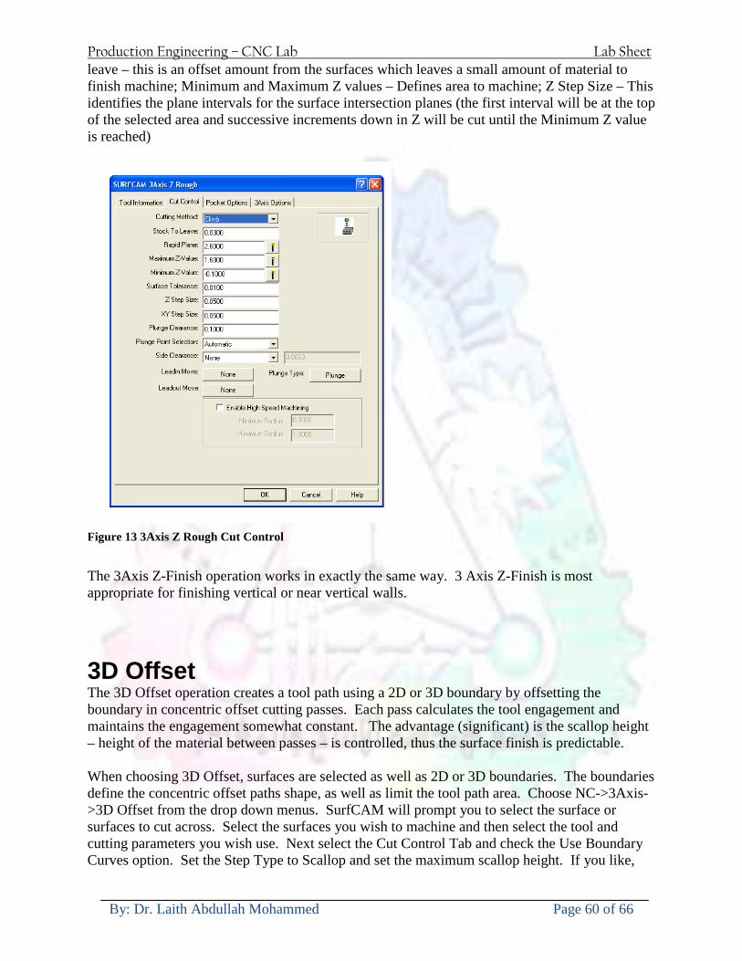
Production Engineering ndash CNC Lab Lab Sheet
By Dr Laith Abdullah Mohammed Page 60 of 66
leave ndash this is an offset amount from the surfaces which leaves a small amount of material to finish machine Minimum and Maximum Z values ndash Defines area to machine Z Step Size ndash This identifies the plane intervals for the surface intersection planes (the first interval will be at the top of the selected area and successive increments down in Z will be cut until the Minimum Z value is reached)
Figure 13 3Axis Z Rough Cut Control
The 3Axis Z-Finish operation works in exactly the same way 3 Axis Z-Finish is most appropriate for finishing vertical or near vertical walls
3D Offset The 3D Offset operation creates a tool path using a 2D or 3D boundary by offsetting the boundary in concentric offset cutting passes Each pass calculates the tool engagement and maintains the engagement somewhat constant The advantage (significant) is the scallop height ndash height of the material between passes ndash is controlled thus the surface finish is predictable When choosing 3D Offset surfaces are selected as well as 2D or 3D boundaries The boundaries define the concentric offset paths shape as well as limit the tool path area Choose NC-gt3Axis-gt3D Offset from the drop down menus SurfCAM will prompt you to select the surface or surfaces to cut across Select the surfaces you wish to machine and then select the tool and cutting parameters you wish use Next select the Cut Control Tab and check the Use Boundary Curves option Set the Step Type to Scallop and set the maximum scallop height If you like
Production Engineering ndash CNC Lab Lab Sheet
By Dr Laith Abdullah Mohammed Page 61 of 66
you can also add stock to leave if this is a roughing operation You can also set the Direction and Start-End parameters from this tab Click OK and the paths will be generated
Figure 14 Cut Control Tab for 3D Offset
Example part using both 2D and 3D geometry
The tool paths for this mold will be generated in SurfCAM using 5 operations The first will be a roughing operation using a frac14 inch flat end mill with the Z step size of 00625in Choose NC-
Production Engineering ndash CNC Lab Lab Sheet
By Dr Laith Abdullah Mohammed Page 62 of 66
gt3Axis-gtZ-Rough from the drop down menu Select all visible surfaces and create an extents box that has 025inch XY offsets and 01inch Z offset Next select the frac14 inch flat end mill from the tools menu Under Cut Control tab set the Z step size to be 00625inch The tool paths will look something like Figure 15
Figure 15 Z-Rough Tool paths for Example Part
Next a flat surface operation will be performed to cut the flat surface on the top Select NC-gt3 Axis-gtFlat Surface from the drop down menu Select all visible surfaces again Choose the 12inch flat end mill and set the cutting parameters as desired Under Cut Control Tab change the Minimum Area to 50 square inches (Figure 16) The tool paths should look something like Figure 17
Figure 16 Cut Control for Flat Surface
Production Engineering ndash CNC Lab Lab Sheet
By Dr Laith Abdullah Mohammed Page 63 of 66
Figure 17 Flat Surface Tool Paths
Next we will use a 3D offset operation to cut the mold cavity Select NC-gt3 Axis-gt3D Offset from the dropdown menu Change the view to the top view and select within to capture the surfaces of the mold cavity Draw a rectangle around the mold cavity Select a 18 inch ball endmill from the tool library and set the cutting parameters as appropriate Next set the Cut Control tab parameters as in Figure 14 The paths creates should be similar to Figure 18
Figure 18 3D Offset Paths
Next we will perform a 2 Axis contouring of the top section Select NC-gt2 Axis-gtContour from the dropdown menu Using the chain option select the bottom contour of the top extrusion Select the frac12 inch flat end mill from the tool library and set the cutting parameters as required In the Cut Control Tab change the Geometry to Bottom and the amount to remove in Z to 05
Production Engineering ndash CNC Lab Lab Sheet
By Dr Laith Abdullah Mohammed Page 64 of 66
Change the Rough Spacing in Z to 025 and add 1 finish pass of 002 (Figure 19) Click OK and SurfCAM will instruct you to choose a side to contour Click anywhere on the screen OUTSIDE the geometry you selected for the contouring operation Failure to click outside the geometry will result in the tool being on the wrong side of the contour Your paths should look something like those in Figure 20
Figure 19 Cut Control Tab for the Contouring Operation
Figure 20 Contouring operation paths
Production Engineering ndash CNC Lab Lab Sheet
By Dr Laith Abdullah Mohammed Page 65 of 66
Next we will perform a 2 axis pocket operation for the small pocket on the top face of the mold Select NC-gt2Axis-gtPocket and using the Auto select feature select the boundary curve at the bottom of the pocket Click Done twice and select the frac14 inch flat end mill from the tool library Set the appropriate cutting parameters and click OK SurfCAM will prompt you to click inside the pocket Click anywhere inside the geometry you chose to define the pocket The resulting paths should look something like those in Figure 21
Figure 21 2 Axis Pocket Operation Paths
Finally we will add a drilling operation for the 2 holes at the corners of the mold Select NC-gt2 Axis-gtDrill from the dropdown menu Select the top circles defining the two holes A menu box will appear with a default tool (Center drill) already programmed Add a second tool to the list by selecting Insert-gtAfter and select the tool from the tool library Change the drill depth to 10inches and click OK The paths should look something similar to Figure 23
Figure 22 Drill Menu
Production Engineering ndash CNC Lab Lab Sheet
By Dr Laith Abdullah Mohammed Page 66 of 66
Figure 23 Drilling Operation Tool Paths
Now you can watch a simulation of the cutting by choosing the setup in the operations manager and clicking the simulate icon Be sure to set the stock in the set up by right clicking the set up and selecting Edit Setup Information In the Stock Tab you can create a bounding box meeting your needs and click Add Your simulation should result in something like the following
Figure 24 Final Simulation of the example Mold
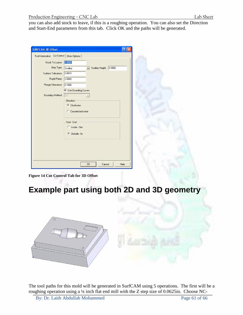
Production Engineering ndash CNC Lab Lab Sheet
By Dr Laith Abdullah Mohammed Page 61 of 66
you can also add stock to leave if this is a roughing operation You can also set the Direction and Start-End parameters from this tab Click OK and the paths will be generated
Figure 14 Cut Control Tab for 3D Offset
Example part using both 2D and 3D geometry
The tool paths for this mold will be generated in SurfCAM using 5 operations The first will be a roughing operation using a frac14 inch flat end mill with the Z step size of 00625in Choose NC-
Production Engineering ndash CNC Lab Lab Sheet
By Dr Laith Abdullah Mohammed Page 62 of 66
gt3Axis-gtZ-Rough from the drop down menu Select all visible surfaces and create an extents box that has 025inch XY offsets and 01inch Z offset Next select the frac14 inch flat end mill from the tools menu Under Cut Control tab set the Z step size to be 00625inch The tool paths will look something like Figure 15
Figure 15 Z-Rough Tool paths for Example Part
Next a flat surface operation will be performed to cut the flat surface on the top Select NC-gt3 Axis-gtFlat Surface from the drop down menu Select all visible surfaces again Choose the 12inch flat end mill and set the cutting parameters as desired Under Cut Control Tab change the Minimum Area to 50 square inches (Figure 16) The tool paths should look something like Figure 17
Figure 16 Cut Control for Flat Surface
Production Engineering ndash CNC Lab Lab Sheet
By Dr Laith Abdullah Mohammed Page 63 of 66
Figure 17 Flat Surface Tool Paths
Next we will use a 3D offset operation to cut the mold cavity Select NC-gt3 Axis-gt3D Offset from the dropdown menu Change the view to the top view and select within to capture the surfaces of the mold cavity Draw a rectangle around the mold cavity Select a 18 inch ball endmill from the tool library and set the cutting parameters as appropriate Next set the Cut Control tab parameters as in Figure 14 The paths creates should be similar to Figure 18
Figure 18 3D Offset Paths
Next we will perform a 2 Axis contouring of the top section Select NC-gt2 Axis-gtContour from the dropdown menu Using the chain option select the bottom contour of the top extrusion Select the frac12 inch flat end mill from the tool library and set the cutting parameters as required In the Cut Control Tab change the Geometry to Bottom and the amount to remove in Z to 05
Production Engineering ndash CNC Lab Lab Sheet
By Dr Laith Abdullah Mohammed Page 64 of 66
Change the Rough Spacing in Z to 025 and add 1 finish pass of 002 (Figure 19) Click OK and SurfCAM will instruct you to choose a side to contour Click anywhere on the screen OUTSIDE the geometry you selected for the contouring operation Failure to click outside the geometry will result in the tool being on the wrong side of the contour Your paths should look something like those in Figure 20
Figure 19 Cut Control Tab for the Contouring Operation
Figure 20 Contouring operation paths
Production Engineering ndash CNC Lab Lab Sheet
By Dr Laith Abdullah Mohammed Page 65 of 66
Next we will perform a 2 axis pocket operation for the small pocket on the top face of the mold Select NC-gt2Axis-gtPocket and using the Auto select feature select the boundary curve at the bottom of the pocket Click Done twice and select the frac14 inch flat end mill from the tool library Set the appropriate cutting parameters and click OK SurfCAM will prompt you to click inside the pocket Click anywhere inside the geometry you chose to define the pocket The resulting paths should look something like those in Figure 21
Figure 21 2 Axis Pocket Operation Paths
Finally we will add a drilling operation for the 2 holes at the corners of the mold Select NC-gt2 Axis-gtDrill from the dropdown menu Select the top circles defining the two holes A menu box will appear with a default tool (Center drill) already programmed Add a second tool to the list by selecting Insert-gtAfter and select the tool from the tool library Change the drill depth to 10inches and click OK The paths should look something similar to Figure 23
Figure 22 Drill Menu
Production Engineering ndash CNC Lab Lab Sheet
By Dr Laith Abdullah Mohammed Page 66 of 66
Figure 23 Drilling Operation Tool Paths
Now you can watch a simulation of the cutting by choosing the setup in the operations manager and clicking the simulate icon Be sure to set the stock in the set up by right clicking the set up and selecting Edit Setup Information In the Stock Tab you can create a bounding box meeting your needs and click Add Your simulation should result in something like the following
Figure 24 Final Simulation of the example Mold
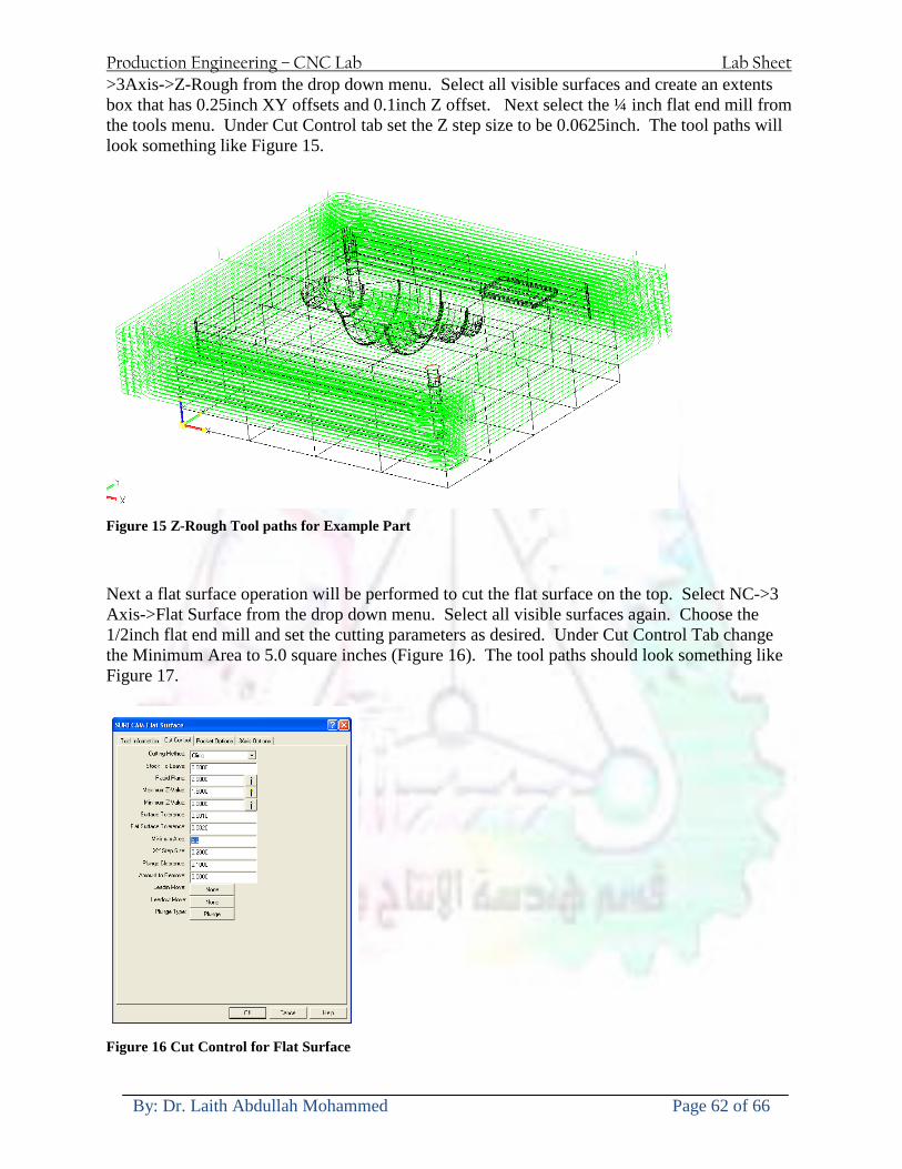
Production Engineering ndash CNC Lab Lab Sheet
By Dr Laith Abdullah Mohammed Page 62 of 66
gt3Axis-gtZ-Rough from the drop down menu Select all visible surfaces and create an extents box that has 025inch XY offsets and 01inch Z offset Next select the frac14 inch flat end mill from the tools menu Under Cut Control tab set the Z step size to be 00625inch The tool paths will look something like Figure 15
Figure 15 Z-Rough Tool paths for Example Part
Next a flat surface operation will be performed to cut the flat surface on the top Select NC-gt3 Axis-gtFlat Surface from the drop down menu Select all visible surfaces again Choose the 12inch flat end mill and set the cutting parameters as desired Under Cut Control Tab change the Minimum Area to 50 square inches (Figure 16) The tool paths should look something like Figure 17
Figure 16 Cut Control for Flat Surface
Production Engineering ndash CNC Lab Lab Sheet
By Dr Laith Abdullah Mohammed Page 63 of 66
Figure 17 Flat Surface Tool Paths
Next we will use a 3D offset operation to cut the mold cavity Select NC-gt3 Axis-gt3D Offset from the dropdown menu Change the view to the top view and select within to capture the surfaces of the mold cavity Draw a rectangle around the mold cavity Select a 18 inch ball endmill from the tool library and set the cutting parameters as appropriate Next set the Cut Control tab parameters as in Figure 14 The paths creates should be similar to Figure 18
Figure 18 3D Offset Paths
Next we will perform a 2 Axis contouring of the top section Select NC-gt2 Axis-gtContour from the dropdown menu Using the chain option select the bottom contour of the top extrusion Select the frac12 inch flat end mill from the tool library and set the cutting parameters as required In the Cut Control Tab change the Geometry to Bottom and the amount to remove in Z to 05
Production Engineering ndash CNC Lab Lab Sheet
By Dr Laith Abdullah Mohammed Page 64 of 66
Change the Rough Spacing in Z to 025 and add 1 finish pass of 002 (Figure 19) Click OK and SurfCAM will instruct you to choose a side to contour Click anywhere on the screen OUTSIDE the geometry you selected for the contouring operation Failure to click outside the geometry will result in the tool being on the wrong side of the contour Your paths should look something like those in Figure 20
Figure 19 Cut Control Tab for the Contouring Operation
Figure 20 Contouring operation paths
Production Engineering ndash CNC Lab Lab Sheet
By Dr Laith Abdullah Mohammed Page 65 of 66
Next we will perform a 2 axis pocket operation for the small pocket on the top face of the mold Select NC-gt2Axis-gtPocket and using the Auto select feature select the boundary curve at the bottom of the pocket Click Done twice and select the frac14 inch flat end mill from the tool library Set the appropriate cutting parameters and click OK SurfCAM will prompt you to click inside the pocket Click anywhere inside the geometry you chose to define the pocket The resulting paths should look something like those in Figure 21
Figure 21 2 Axis Pocket Operation Paths
Finally we will add a drilling operation for the 2 holes at the corners of the mold Select NC-gt2 Axis-gtDrill from the dropdown menu Select the top circles defining the two holes A menu box will appear with a default tool (Center drill) already programmed Add a second tool to the list by selecting Insert-gtAfter and select the tool from the tool library Change the drill depth to 10inches and click OK The paths should look something similar to Figure 23
Figure 22 Drill Menu
Production Engineering ndash CNC Lab Lab Sheet
By Dr Laith Abdullah Mohammed Page 66 of 66
Figure 23 Drilling Operation Tool Paths
Now you can watch a simulation of the cutting by choosing the setup in the operations manager and clicking the simulate icon Be sure to set the stock in the set up by right clicking the set up and selecting Edit Setup Information In the Stock Tab you can create a bounding box meeting your needs and click Add Your simulation should result in something like the following
Figure 24 Final Simulation of the example Mold
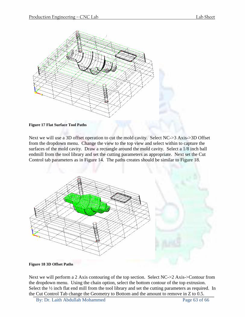
Production Engineering ndash CNC Lab Lab Sheet
By Dr Laith Abdullah Mohammed Page 63 of 66
Figure 17 Flat Surface Tool Paths
Next we will use a 3D offset operation to cut the mold cavity Select NC-gt3 Axis-gt3D Offset from the dropdown menu Change the view to the top view and select within to capture the surfaces of the mold cavity Draw a rectangle around the mold cavity Select a 18 inch ball endmill from the tool library and set the cutting parameters as appropriate Next set the Cut Control tab parameters as in Figure 14 The paths creates should be similar to Figure 18
Figure 18 3D Offset Paths
Next we will perform a 2 Axis contouring of the top section Select NC-gt2 Axis-gtContour from the dropdown menu Using the chain option select the bottom contour of the top extrusion Select the frac12 inch flat end mill from the tool library and set the cutting parameters as required In the Cut Control Tab change the Geometry to Bottom and the amount to remove in Z to 05
Production Engineering ndash CNC Lab Lab Sheet
By Dr Laith Abdullah Mohammed Page 64 of 66
Change the Rough Spacing in Z to 025 and add 1 finish pass of 002 (Figure 19) Click OK and SurfCAM will instruct you to choose a side to contour Click anywhere on the screen OUTSIDE the geometry you selected for the contouring operation Failure to click outside the geometry will result in the tool being on the wrong side of the contour Your paths should look something like those in Figure 20
Figure 19 Cut Control Tab for the Contouring Operation
Figure 20 Contouring operation paths
Production Engineering ndash CNC Lab Lab Sheet
By Dr Laith Abdullah Mohammed Page 65 of 66
Next we will perform a 2 axis pocket operation for the small pocket on the top face of the mold Select NC-gt2Axis-gtPocket and using the Auto select feature select the boundary curve at the bottom of the pocket Click Done twice and select the frac14 inch flat end mill from the tool library Set the appropriate cutting parameters and click OK SurfCAM will prompt you to click inside the pocket Click anywhere inside the geometry you chose to define the pocket The resulting paths should look something like those in Figure 21
Figure 21 2 Axis Pocket Operation Paths
Finally we will add a drilling operation for the 2 holes at the corners of the mold Select NC-gt2 Axis-gtDrill from the dropdown menu Select the top circles defining the two holes A menu box will appear with a default tool (Center drill) already programmed Add a second tool to the list by selecting Insert-gtAfter and select the tool from the tool library Change the drill depth to 10inches and click OK The paths should look something similar to Figure 23
Figure 22 Drill Menu
Production Engineering ndash CNC Lab Lab Sheet
By Dr Laith Abdullah Mohammed Page 66 of 66
Figure 23 Drilling Operation Tool Paths
Now you can watch a simulation of the cutting by choosing the setup in the operations manager and clicking the simulate icon Be sure to set the stock in the set up by right clicking the set up and selecting Edit Setup Information In the Stock Tab you can create a bounding box meeting your needs and click Add Your simulation should result in something like the following
Figure 24 Final Simulation of the example Mold
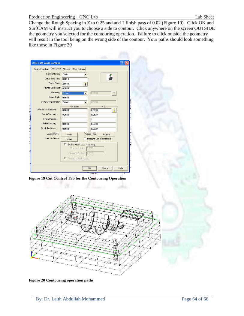
Production Engineering ndash CNC Lab Lab Sheet
By Dr Laith Abdullah Mohammed Page 64 of 66
Change the Rough Spacing in Z to 025 and add 1 finish pass of 002 (Figure 19) Click OK and SurfCAM will instruct you to choose a side to contour Click anywhere on the screen OUTSIDE the geometry you selected for the contouring operation Failure to click outside the geometry will result in the tool being on the wrong side of the contour Your paths should look something like those in Figure 20
Figure 19 Cut Control Tab for the Contouring Operation
Figure 20 Contouring operation paths
Production Engineering ndash CNC Lab Lab Sheet
By Dr Laith Abdullah Mohammed Page 65 of 66
Next we will perform a 2 axis pocket operation for the small pocket on the top face of the mold Select NC-gt2Axis-gtPocket and using the Auto select feature select the boundary curve at the bottom of the pocket Click Done twice and select the frac14 inch flat end mill from the tool library Set the appropriate cutting parameters and click OK SurfCAM will prompt you to click inside the pocket Click anywhere inside the geometry you chose to define the pocket The resulting paths should look something like those in Figure 21
Figure 21 2 Axis Pocket Operation Paths
Finally we will add a drilling operation for the 2 holes at the corners of the mold Select NC-gt2 Axis-gtDrill from the dropdown menu Select the top circles defining the two holes A menu box will appear with a default tool (Center drill) already programmed Add a second tool to the list by selecting Insert-gtAfter and select the tool from the tool library Change the drill depth to 10inches and click OK The paths should look something similar to Figure 23
Figure 22 Drill Menu
Production Engineering ndash CNC Lab Lab Sheet
By Dr Laith Abdullah Mohammed Page 66 of 66
Figure 23 Drilling Operation Tool Paths
Now you can watch a simulation of the cutting by choosing the setup in the operations manager and clicking the simulate icon Be sure to set the stock in the set up by right clicking the set up and selecting Edit Setup Information In the Stock Tab you can create a bounding box meeting your needs and click Add Your simulation should result in something like the following
Figure 24 Final Simulation of the example Mold
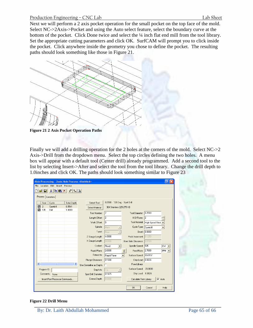
Production Engineering ndash CNC Lab Lab Sheet
By Dr Laith Abdullah Mohammed Page 65 of 66
Next we will perform a 2 axis pocket operation for the small pocket on the top face of the mold Select NC-gt2Axis-gtPocket and using the Auto select feature select the boundary curve at the bottom of the pocket Click Done twice and select the frac14 inch flat end mill from the tool library Set the appropriate cutting parameters and click OK SurfCAM will prompt you to click inside the pocket Click anywhere inside the geometry you chose to define the pocket The resulting paths should look something like those in Figure 21
Figure 21 2 Axis Pocket Operation Paths
Finally we will add a drilling operation for the 2 holes at the corners of the mold Select NC-gt2 Axis-gtDrill from the dropdown menu Select the top circles defining the two holes A menu box will appear with a default tool (Center drill) already programmed Add a second tool to the list by selecting Insert-gtAfter and select the tool from the tool library Change the drill depth to 10inches and click OK The paths should look something similar to Figure 23
Figure 22 Drill Menu
Production Engineering ndash CNC Lab Lab Sheet
By Dr Laith Abdullah Mohammed Page 66 of 66
Figure 23 Drilling Operation Tool Paths
Now you can watch a simulation of the cutting by choosing the setup in the operations manager and clicking the simulate icon Be sure to set the stock in the set up by right clicking the set up and selecting Edit Setup Information In the Stock Tab you can create a bounding box meeting your needs and click Add Your simulation should result in something like the following
Figure 24 Final Simulation of the example Mold
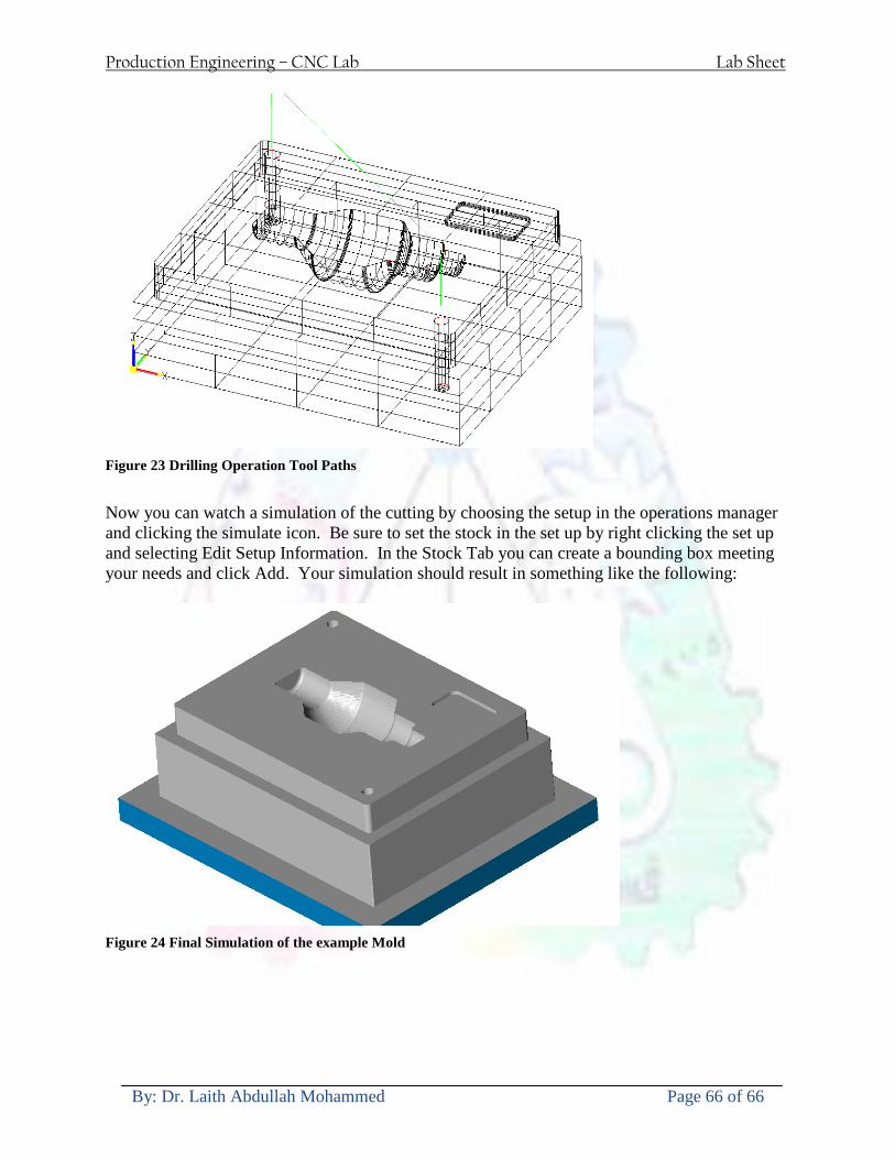
Production Engineering ndash CNC Lab Lab Sheet
By Dr Laith Abdullah Mohammed Page 66 of 66
Figure 23 Drilling Operation Tool Paths
Now you can watch a simulation of the cutting by choosing the setup in the operations manager and clicking the simulate icon Be sure to set the stock in the set up by right clicking the set up and selecting Edit Setup Information In the Stock Tab you can create a bounding box meeting your needs and click Add Your simulation should result in something like the following
Figure 24 Final Simulation of the example Mold


