48
Co-simulation of Microwave Networks Sanghoon Shin, Ph.D. RS Microwave

Co-simulation of Microwave Networks
Sanghoon Shin, Ph.D.RS Microwave

RS Microwave 2
Outline
• Brief review of EM solvers– 2D and 3D EM simulators
• Technical Tips for EM solvers• Co-simulated Examples of RF filters and
Diplexer design• Summary

RS Microwave 3
What is EM simulator?
• Electromagnetic simulator solves numerically Maxwell’s equations.
• Differential or integral equations are transformed into matrix equations and solved iteratively or by matrix inversion.
• Numerical Method; MoM, FEM, FDTD, TLM,..

RS Microwave 4
EM Solver Configuration
• Pre-processor– Drawing tools, CAD
• Solver (2D, 3D)– MoM, FED, FDTD,TLM,…– Meshing
• Post-processor– Field plot, current plot,…
RS Microwave 5
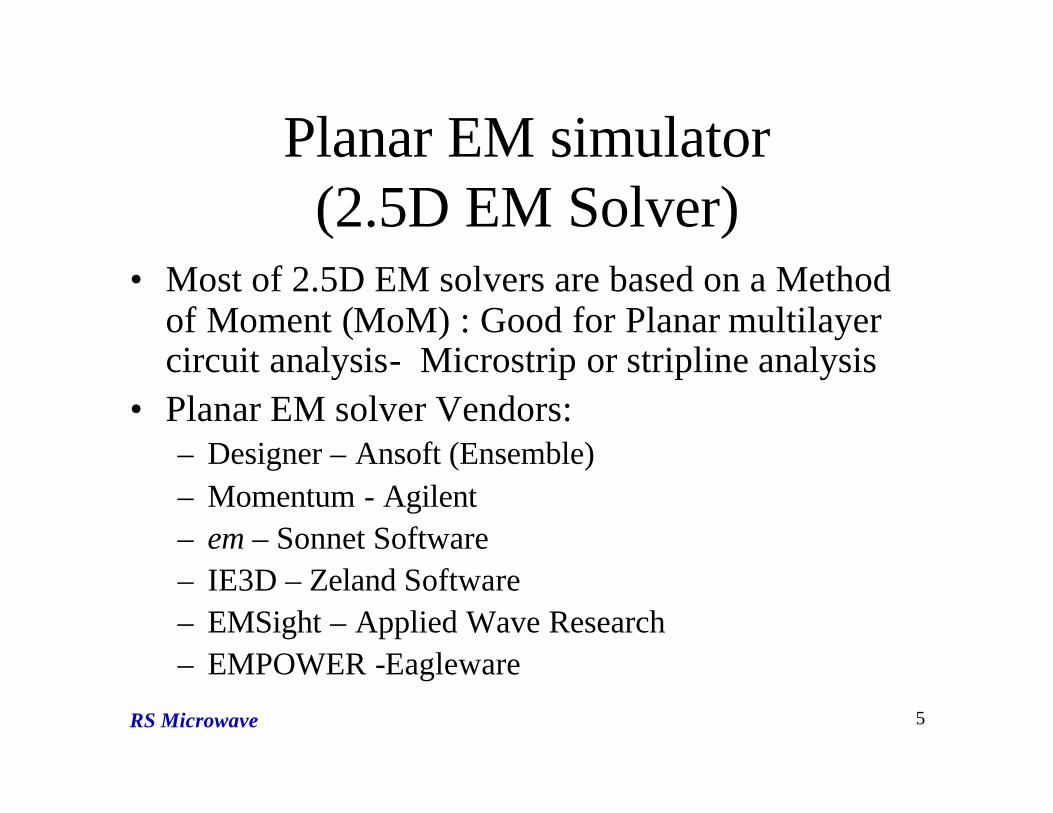
Planar EM simulator (2.5D EM Solver)
• Most of 2.5D EM solvers are based on a Method of Moment (MoM) : Good for Planar multilayer circuit analysis- Microstrip or stripline analysis
• Planar EM solver Vendors:– Designer – Ansoft (Ensemble)– Momentum - Agilent– em – Sonnet Software– IE3D – Zeland Software– EMSight – Applied Wave Research– EMPOWER -Eagleware

RS Microwave 6
Meshing
Orthogonal mesh (Linear)
Non-orthogonal mesh (Non-Linear)

RS Microwave 7
Limitation of Planar Solver
• Limited to homogeneous and layered dielectrics
• Localized dielectric is possible, but it costs longer simulation time (ex. Dielectricbrick).- Sonnet em suite

RS Microwave 8
Finite Element Method• Unlike MoM-based tools, the
field space is meshed rather than only the conductor surface.
• Finite Element Techniques are used in 2D and 3D simulators.
• The discrete elements are usually triangles in 2D and tetrahedra in 3D. Each can be of different size and shape.

RS Microwave 9
3D EM Solvers
• Finite Element Method (FEM)– HFSS – Ansoft– Microwave Studio – CST
• Mode Matching – WASP, MiCian• Time domain solvers are not very efficient for
filters.– High Q requires long run time to converge.– FFT process requires many samples to resolve closely
spaced resonance.

RS Microwave 10
Technical Tips for EM solvers
• Ports: Edge ports(2D), Wave ports (3D), Internal ports (2D, 3D)
• Meshing– Trade-offs:
• Accuracy vs. mesh size• Computation time and memory required
– Avoid elements with high aspect ratios• Box Resonance check

RS Microwave 11
Ports in EM Simulators
1. Planar EM Simulator– Edge port for excitation
Em – Sonnet Software

RS Microwave 12
Ports in EM Simulators
In 3-D EM Solver• Wave Port• Internal Port
– formed by a rectangle between trace and ground
– Known as Lumped Portor Gap port
Courtesy: HFSS -Ansoft

RS Microwave 13
Box Resonance
• Resonance due to the enclosure• Appears as spurious resonance in the Filter
response.• Needs to be away from the desired
calculating frequency.• Can be checked by Eigenmode Analysis

RS Microwave 14
Geometry in Eigenmode Solver
Courtesy: Ansoft
•Half-wavelength edge coupled resonators
•No Ports required for Eigenmode analysis

RS Microwave 15
Filter Mode
Courtesy: Ansoft

RS Microwave 16
Box Resonance Using Eigenmode Solver
Courtesy: Ansoft

RS Microwave 17
Filter Design Procedure Using Co-simulation
1. Create parameterized S-Matrix model for individual parts with EM solver
2. Solve/Optimize the entire circuit using Circuit simulator.
3. Verify the results with Full 3D EM solver

RS Microwave 18
EM Circuit Co-simulation
CircuitSimulator
EMSimulator
ParameterizedS-Matrix
orEM geometry

RS Microwave 19
Parameterized Scattering Matrix- NMF(Neutral Model Format Header)
Courtesy: Ansoft

RS Microwave 20
• Fo =7.5 GHz, BW=500MHz
•13th order Chebychev Bandpass Filter
Example 1: 13-pole Inductive Iris Waveguide
Bandpass Filter

RS Microwave 21
Waveguide Bandpass Filter
Design Requirements;• Center Frequency: 7.5GHz• Bandwidth: 500 MHz (15%)• Stopband Rejection: > 70 dB at 7.9 GHz
> 70 dB at 7.0 GHz• Insertion Loss: < 0.65 dB • Order: 13 (Due to the rejection specs)• Waveguide : WR112

RS Microwave 22
Circuit model Representation of Waveguide BandpassFilter
2. Parameterized Full wave EM Model for inductive iris, generated by EM solver.
1. Half wavelength Waveguide section from Circuit Model.

RS Microwave 23
Full Wave EM Model for Thick iris using HFSS
• Parametric Sweep simulation using Optimetrics (Variable -Iris width)
• The port is far away enough from discontinuities in the structure to avoid higher order mode reflections.-deembend port
• The port impedances must include the frequency dependency of the waveguide.

RS Microwave 24
EM and Circuit Simulation Comparison
-Boundary material for waveguide is Copper
-EM & Circuit Co-simulation; Very close to Full EM Analysis (HFSS)

RS Microwave 25
EM and Circuit Simulation Comparison

RS Microwave 26
Electric Field Distribution
• Fo= 7.5 GHz, BW=500MHz
•13th order Chebyshev Bandpass Filter

Example 2
Diplexer Design-Two channel Bandpass Filters

RS Microwave 28
Nominal Requirements
• Geostationary satellite X-band channels– Channel 1 : passband 7.25 – 7.75 GHz (Tx)– Channel 2 : passband 7.9 – 8.4 GHz (Rx)
• Min. passband return loss > 22 dB• Max. passband insertion loss (Ch.1 & Ch.2) < 0.5 dB • Isolation between channels
> 40 dB in 7.9 - 8.4 GHz> 40 dB in 7.25 - 7.75 GHz
• Waveguide : WR112

RS Microwave 29
H-Plane Diplexer
Input
Ch.1
Ch.2

RS Microwave 30
H-Plane Diplexer
Input
Ch.1
Ch.2

RS Microwave 31
Design variables for Diplexer
Problem;
1. Too many variables in EM (Electromagnetic) Optimization ? long simulation time!!
? Solution: Partition the structure and optimize entire circuit in Circuit simulator.
w1
w2
w3
d1 s1 s2 s3
w1
w2 w3
d1s1
s2s3
d h
w1
w2
w3
d1 s1 s2 s3
w1
w2 w3
d1s1
s2s3
d h

RS Microwave 32
Diplexer Design Procedure- Decomposition -
1. T- junctions; H- or E-plane, EM-Model (NMF model)
2. Waveguide irises for channel filters , EM model (NMF model)
3. Optimize with Circuit simulator
T-JunctionCh.1Filter
Ch.2Filter
1
2 3
T-Junction
Ch.2Filter
Ch.1Filter
1
3
2
(a)
(b)

RS Microwave 33
Parameterized Circuit Model
- Diplexer is represented with full wave EM models (NMF model) for T-junction, inductive irises in circuit simulator.
Ch.1
Ch.2

RS Microwave 34
Diplexer Response
• Co-simulated response by Ansoft Designer using NMF models for irises and T-junction (Waveguide: Silver plate)

RS Microwave 35
EM and Circuit Simulation Comparison
• EM & Circuit Co-simulation; Very close to Full EM Analysis (HFSS)

RS Microwave 36
EM and Circuit Simulation Comparison

RS Microwave 37
at Fc = 7.5 GHz (Ch.1)
at Fc = 8.15 GHz (Ch.2)
Electric Field Distribution

RS Microwave 38
Diplexer Response
•Co-simulated response by Ansoft Designer using NMF models for irises and T-junction (Waveguide: Silver plate)

RS Microwave 39
EM and Circuit Simulation Comparison

RS Microwave 40
EM and Circuit Simulation Comparison

RS Microwave 41
Electric Field Distribution
at Fc = 7.5 GHz (Ch.1) at Fc = 8.15 GHz (Ch.2)
RS Microwave 42
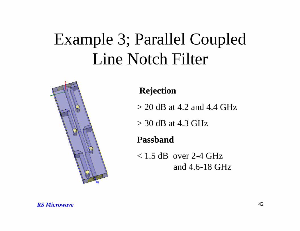
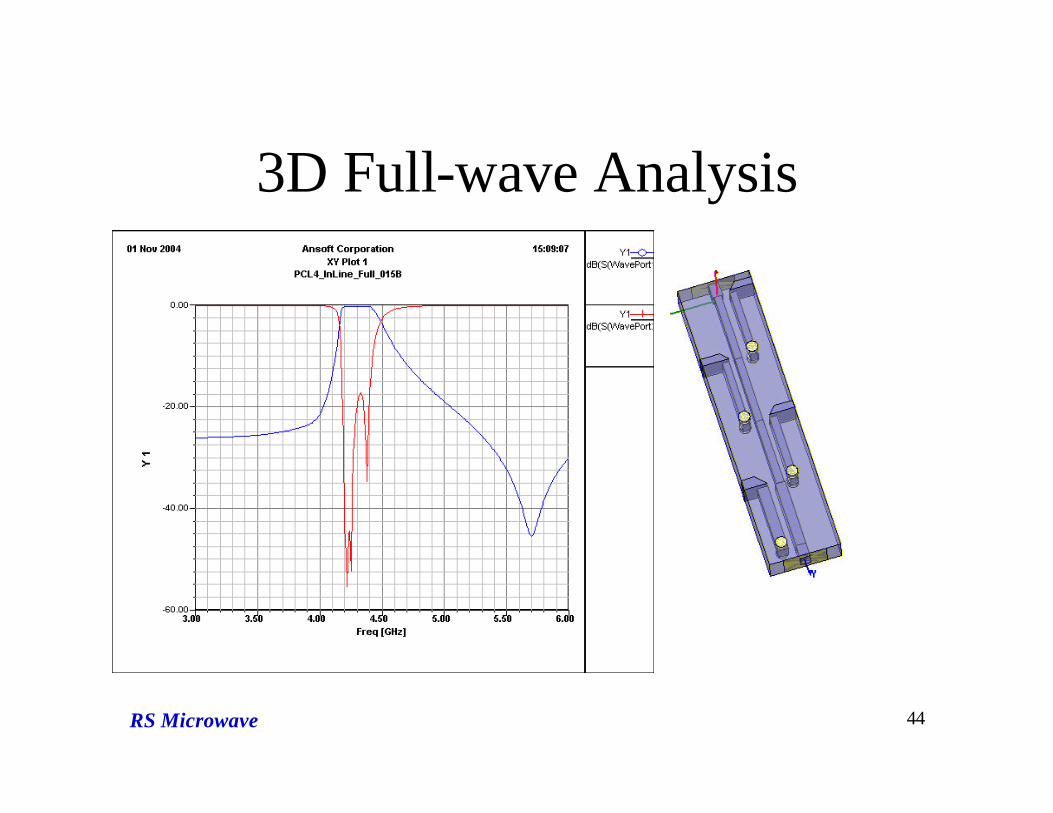
Example 3; Parallel Coupled Line Notch Filter
Rejection
> 20 dB at 4.2 and 4.4 GHz
> 30 dB at 4.3 GHz
Passband
< 1.5 dB over 2-4 GHz and 4.6-18 GHz

RS Microwave 43
Co-simulated Model
variables ; Line width, spacing
RS Microwave 44
3D Full-wave Analysis

RS Microwave 45
Wide Sweep of Full 3D EM simulation

RS Microwave 46
Electric Field Distribution
•At the rejection frequency fo= 4.3 GHz

RS Microwave 47
References
• “Electromagnetic Simulators - Theory and Practice”, IEEE MTT-s 2004 International Microwave Symposium Workshop, June 2004, Wolfgang J.R. Hoefer, Daniel G. Swanson
• Ansoft User’s Workshop

RS Microwave 48
Summary
• It is possible to perform fast simulations of complex structures by intelligently partitioning the model (e.g. filters as shown in this presentation).-Overall design time can be significantly reduced.
• Simulation result is very close to Full-wave simulation.– Comparative to Full 3-D EM simulation result
• The filter designs shown in this presentation can be applied to many applications.


