Paper 4f Coal to Ammonia – A Combination of Two Successful Technologies With increasing natural gas prices alternative feedstocks like coal come more and more back into the focus of fertilizer producers especially in countries with large coal reserves. Coal gasification technology has been on the market for many years but it hardly has been used for ammonia manufacture during the recent years except in China. Uhde has more than 65 years experience in the development, design and construction of gasification plants. Uhde’s proprietary PRENFLO TM gasification process is ideally suited for the gasification of a wide range of feedstocks, such as coal, petroleum coke and biomass thus making it the technology of choice for reduced operating costs by the addition of secondary fuels. This paper will describe different gasification technologies, including the Uhde PRENFLO TM technology, and the following syngas preparation stages and their optimized integration in an ammonia / urea complex. Furthermore the paper will discuss the successful operating experience of the world’s largest IGCC plant as well as Uhde’s experience with large capacity ammonia plants and their impact on the design of efficient, robust and reliable coal to ammonia or urea plants. Dr. Klaus Nölker, Dr. Joachim Johanning, Adrian Brandl Uhde GmbH Relevance of coal for ammonia production mmonia is an important chemical in the production of urea and other fertilizers. Today, most of the ammonia is produced by steam reforming of natural gas. As natural gas resources are limited and as prices are increasing, it becomes interesting to look for other feedstocks which might replace gas in the fu- ture. Coal is an interesting candidate for many reasons. In the beginning, coal has already been used as raw material for industrial ammonia production, but the historical process is no longer used due to the effi- ciency and ease of operation of natural-gas based processes. With today’s technology and increasing natural gas prices, there could be a revival of coal- based ammonia processes in the near future. Advantages of coal are for example its availability over a longer time horizon compared to natural gas and oil, its global availability and its easy transpor- tation. This will ensure higher security of supply and relative stability of its price. Coal keeps on A 223 AMMONIA TECHNICAL MANUAL 2009
Transcript
Paper 4f
Coal to Ammonia – A Combination of Two Successful Technologies
With increasing natural gas prices alternative feedstocks like coal come more and more back into the focus of fertilizer producers especially in countries with large coal reserves. Coal gasification technology has been on the market for many years but it hardly has been used for ammonia
manufacture during the recent years except in China.
Uhde has more than 65 years experience in the development, design and construction of gasification plants. Uhde’s proprietary PRENFLOTM gasification process is ideally suited for the gasification of a wide range of feedstocks, such as coal, petroleum coke and biomass thus making it the technology of
choice for reduced operating costs by the addition of secondary fuels.
This paper will describe different gasification technologies, including the Uhde PRENFLOTM technology, and the following syngas preparation stages and their optimized integration in an
ammonia / urea complex. Furthermore the paper will discuss the successful operating experience of the world’s largest IGCC plant as well as Uhde’s experience with large capacity ammonia plants and
their impact on the design of efficient, robust and reliable coal to ammonia or urea plants.
Dr. Klaus Nölker, Dr. Joachim Johanning, Adrian Brandl
Uhde GmbH
Relevance of coal for ammonia production
mmonia is an important chemical in the production of urea and other fertilizers. Today, most of the ammonia is produced by steam reforming of natural gas.
As natural gas resources are limited and as prices are increasing, it becomes interesting to look for other feedstocks which might replace gas in the fu-ture.
Coal is an interesting candidate for many reasons. In the beginning, coal has already been used as raw material for industrial ammonia production, but the historical process is no longer used due to the effi-ciency and ease of operation of natural-gas based processes. With today’s technology and increasing natural gas prices, there could be a revival of coal-based ammonia processes in the near future. Advantages of coal are for example its availability over a longer time horizon compared to natural gas and oil, its global availability and its easy transpor-tation. This will ensure higher security of supply and relative stability of its price. Coal keeps on
A
223 AMMONIA TECHNICAL MANUAL2009
playing the leading role in electric power genera-tion. It is expected that it will gain more impor-tance as feedstock for production of liquid fuels and other chemicals, replacing oil and gas. Also the technology for its use as hydrogen producer for ammonia is proven and available. On the other hand, there are some disadvantages linked to coal, like higher specific energy con-sumption and higher CO2 emission per ton of am-monia product and higher investment cost for the gasification plant. This article will investigate these aspects. It shall encourage producers to take a look at the processes and their economics and eventually consider them as an alternative in the future.
Coal gasification process Synthesis gas for ammonia synthesis must contain hydrogen and nitrogen. The source of nitrogen is generally ambient air. Coal gasification can replace steam reforming of natural gas as source of hydro-gen. Gasification is a process in which coal (or another carbon containing material) is converted into a syn-thesis gas consisting mainly of hydrogen (H2) and carbon monoxide (CO), by reaction with oxygen (partial oxidation with O2) and steam (H2O). Gasification for synthesis gas generation is an old-er process than steam reforming. With the availa-bility of natural gas and the application of steam reforming, gasification is no longer competitive and is not of much practical importance nowadays. Exceptions are for example gasification of refinery residues which are provided basically at no cost, and special situations e.g. in places in China where no natural gas is available. Processes for coal gasification, however, have evolved in the meantime and they are applied in large scale and commercially for electric power generation.
Block diagram of a gasification-based ammonia plant Due to the use of a solid feedstock, the process flowsheet of a gasification based ammonia plant is significantly different to that of a natural gas based plant. This is illustrated by the block flow diagram in Figure 1. The differences are not limited to the synthesis gas generation part, i.e. the gasifier. They are also present in the downstream gas treatment and purification steps. Reason for these differences is mainly the high amount of sulfur compounds (hydrogen sulfide and carbon oxisulfide) and the higher CO2 content of the raw synthesis gas. The solid gasification feedstock is milled and dried before being fed to the gasifier. Oxygen under pressure is provided by a cryogenic air separation unit. The feedstock is processed to raw synthesis gas in the gasifier. The subsequent CO shift reaction (CO + H2O → CO + H2) provides the desired hydrogen. Given the considerable hydrogen sulfide content in the gas, a sulfur resistant CO shift catalyst has to be em-ployed. In Figure 1, the process is shown for a PRENFLOTM Direct Quench gasifier. Here the process gas is saturated with water at the inlet to the CO shift. In a process with a heat exchanger downstream of the gasifier, addition of steam is re-quired at this location. Generally, the residual CO content of the synthesis gas leaving the CO shift reactor is in the order of 1.5 % vol. (dry basis) which is higher than the CO content of steam reforming-based plants. However, as the remaining CO is removed by the final gas purification steps prior to the ammonia syngas compressor and ammonia synthesis, the higher out-let content from the CO shift does not present a problem to the ammonia synthesis.
224AMMONIA TECHNICAL MANUAL 2009
Figure 1: Block flow diagram of a gasification-based ammonia / urea plant. The PSA for inert removal can alternatively be replaced by a nitrogen wash unit (NWU). Downstream of CO shift and syngas cooling there is the acid gas removal system which is a scrub-bing unit using a suitable solvent. It eliminates the sulfur containing compounds from the syngas, namely hydrogen sulfide and carbon oxisulfide as well as carbon dioxide. The other impurities such as carbon monoxide and argon are removed in the adjacent liquid nitrogen wash unit (NWU). Alter-natively, a pressure swing adsorption unit (PSA) may be used. In the latter case a good part of the work to remove the carbon dioxide can be covered by the PSA. Nevertheless, the carbon dioxide for the urea plant is drawn from the acid gas removal unit only. The following combination of gas purifi-cation processes may be used:
• RECTISOL scrubbing with subsequent liq-uid nitrogen wash (Linde, Lurgi)
• GENOSORB (Uhde) or SELEXOL (UOP) scrubbing with subsequent PSA
Sulfur recovery from the desorbed acid gases will be carried out by a Claus unit. The tail gas from ei-ther the PSA or the NWU is added to the boiler fuel or the drying unit of the coal. For coal feedstocks, generally a mercury removal unit is used upstream of the acid gas removal unit. This is not necessary for plants with petcoke gasi-fication only. The nitrogen required for the ammonia synthesis is mixed to the synthesis gas either by adding pressu-rized nitrogen after the PSA or by evaporation of the required amount of nitrogen in the NWU. The pressurized nitrogen is supplied by the air separa-tion unit (ASU). Subsequently, the purified make-up synthesis gas is compressed to the required pressure level in the ammonia syngas compressor and piped to the am-monia synthesis. The ammonia loop is served by a
PRENFLO Gasification CO-Shift PSA
Syngas Compression
Sulfur Re-covery
Auxiliary Boiler
Superheated Steam
Sat. Steam
Sour Gas
Ammonia Synthesis
Refrige-ration
Acid Gas Removal
Tail Gas
Tail Gas Ammonia
Urea Synth. &
Urea
Flue Gas
Tail Gases & Syngas
CO2
Sulfur
ASU N2 Compression
Oxygen
Air
N2 to consumers
Coal Petcoke Biomass
225 AMMONIA TECHNICAL MANUAL2009
recycle stage of the syngas compressor unit. Liquid ammonia product is extracted from the synthesis through the refrigeration unit and fed to the urea plant and / or to the storage tank. The carbon dioxide required by the urea synthesis is provided by the acid gas removal unit. Given the much lower H2-to-CO ratio of raw synthesis gas from gasification compared to natural gas reform-ing units, the available amount of carbon dioxide is more than sufficient to turn the entire ammonia production into urea.
Coal gasification part
Process fundamentals
Core of the gasification is the gasifier in which a solid, carbon-containing feedstock is brought to reaction with oxygen and steam. The main reac-tions are: C + ½ O2 → CO CO + ½ O2 → CO2 C + H2O → CO + H2 As side reactions, there are present: CO + H2O → CO + H2 (CO shift reaction) C + 2 H2 → CH4 (methanation reaction) The result is the raw synthesis gas, containing mostly CO, H2 and steam, which is used as raw material for the downstream process.
Uhde’s history in gasification
Uhde has over 65 years experience in the devel-opment, design and construction of gasification plants. Uhde’s list of references already includes over 100 gasifier worldwide based on different ga-sification technologies covering a variety of feeds-tocks.
Krupp Koppers, who merged with Uhde in 1997, developed the first entrained-flow gasifier (Kop-pers-Totzek gasifier) in the early 1940’s and built the first commercial Koppers-Totzek plants at the beginning of the 1950’s. This process was a gasifi-cation process at atmospheric pressure and based on dry dust feed. The next development step was to design a Kop-pers-Totzek gasifier for higher pressures. This was implemented in the Shell-Koppers gasification process, an entrained-flow gasification process at elevated pressure. This process was demonstrated at a plant in Hamburg-Harburg, Germany, in the early 1980's. Uhde’s proprietary PRENFLO™ technology, standing for “pressurized entrained flow” marks a further development of this process in the late 1980's. Tests at a demonstration plant in Fürsten-hausen, Germany, from 1987 onwards proved that PRENFLO™ can accommodate all types of coal from different regions of the world as well as pe-troleum coke without the need for modification. In addition, extensive tests were performed to deter-mine suitable materials of construction. In the late 1990’s the world’s largest solid-feed-based Integrated Gasification Combined Cycle (IGCC) power plant with PRENFLO™ technology started operation in Puertollano, Spain. Besides this proprietary technology, Uhde has tak-en part in the development of the Texaco gasifica-tion process, an entrained flow system with a coal / water slurry feed, nowadays marketed as under the name GE process. Uhde also has built a commer-cial plant based on this process in Oberhausen, Germany in 1992. Moreover, Uhde was involved in the development of the HTW (High-Temperature Winkler) process owned by the German-based utility company RWE right from the start in 1973. This fluidized-bed ga-sification process was designed for lignite and is also suitable for the gasification of biomass. The
226AMMONIA TECHNICAL MANUAL 2009
HTW process is exclusively available through Uhde.
The PRENFLOTM gasification process
The PRENFLO™ process can now look back on more than two decades of operating experience, providing a wealth of lessons learnt which have formed the basis for subsequent successful applica-tions. Figure 2 contains a simplified flow diagram of the PRENFLO™ process with steam generation (PSG). First, the feed dust is prepared in the feed preparation unit. Approximately 80 % of the dust is smaller than 0.1 mm and has a water content of ap-prox. 1–3 % wt. in the case of hard coals and ap-prox. 8–10 % wt. in the case of lignite. This feed dust is then gasified using oxygen and steam as ga-sification agents. The gasification temperature is higher than the ash melting temperature, which al-lows the coal ash to be removed as slag. The ga-sifier cooled by a membrane wall is equipped with multiple, horizontally arranged burners.
Figure 2: Flow Diagram of the PRENFLOTM Process(PSG)
In the PRENFLO™ process with Steam Genera-tion (PSG), the raw gas – containing mainly carbon monoxide and hydrogen – is cooled in the waste heat boiler, generating steam. The gas is then de-dusted in a candle filter and further treated in a scrubber system. The slag from the gasifier can be used as a con-struction material and the fly ash from the candle filter as a feed for the cement industry.
Operating experience with a PRENFLOTM gasifier
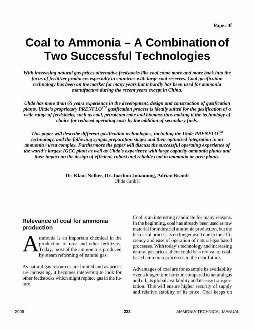
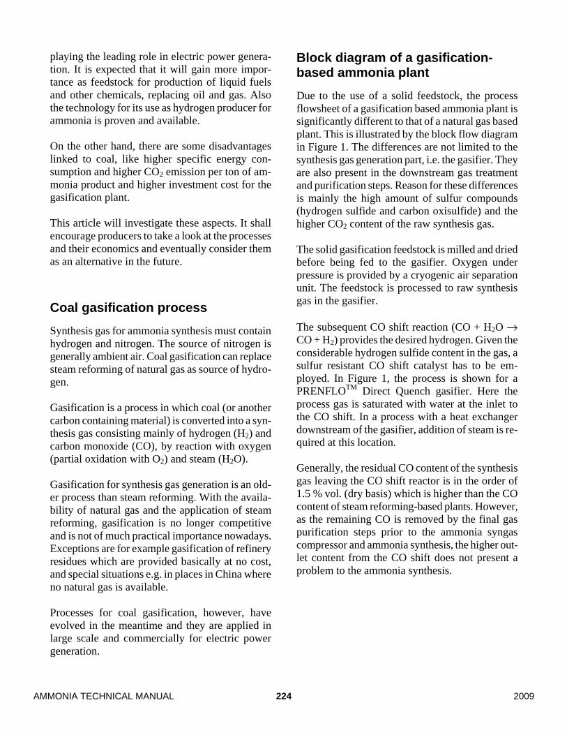
The PRENFLO™ technology is used at the world’s largest solid-feedstock-based IGCC power plant in Puertollano, Spain. It has an electrical power production of 300 MW. This plant operates with a mixture of petroleum coke and coal with a very high ash content. Tables 1 and 2 show the feedstock composition and an analysis of the raw gas produced. Figure 3 shows an aerial photograph of the whole site. Figure 4 gives an impression of the arrange-ment of a PRENFLOTM (PSG) gasification. The core pieces of equipment, the gasifier itself and the waste heat boiler are dominating the construction and mainly determine the size of the steel structure.
Figure 3: The world’s largest IGCC plant: Elco-gas, Puertollano, Spain (300 MW el.) based on petcoke / coal feedstock gasified with PRENFLOTM.
Figure 4: PRENFLO™ (PSG) gasifier structure at Puertollano, Spain. With eleven years of operating experience in the commercial plant at Puertollano, PRENFLOTM is a proven technology.
Table 2: Typical analysis of the raw synthesis gas at Puertollano.
PRENFLO™ Gasification with Direct Quench (PDQ)
The PRENFLO™ Direct Quench (PDQ) process is an optimized design of the proven PSG gasification process for applications where hydrogen-rich syn-gas is required. These are for example chemical applications such as ammonia, methanol, hydro-gen, synthetic fuel as well as IGCC plants with Carbon Capture and Storage (CCS). The PRENFLO™ Direct Quench (PDQ) process was designed to integrate the lessons learned with-in 10 years of operation of the PSG process in the Puertollano IGCC power plant. It combines the technologically advanced dry feed system, multiple burners and membrane wall of the PRENFLO™ PSG process – thus keeping the commercially proven elements of the PRENFLO™ (PSG) tech-nology – with a proprietary water quench system which saturates the raw syngas with water for sub-sequent gas treatment. Several capital-intensive systems, such as the waste heat boiler system, the dry fly ash removal system and the quench gas compressor are there-fore no longer required. Thus, plant investment costs are significantly reduced, more than compen-sating the lower plant efficiency caused by the missing steam generation.
228AMMONIA TECHNICAL MANUAL 2009
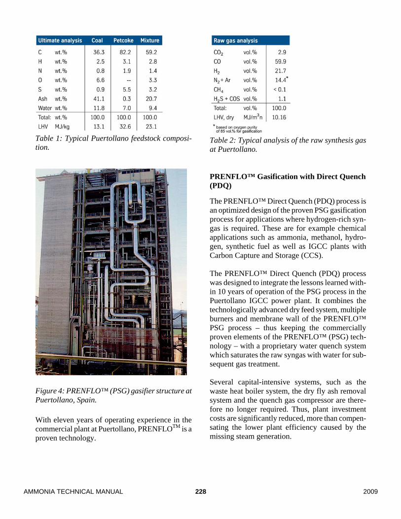
Figure 5: Flow Diagram of the PRENFLOTM (PDQ) Process.
Figure 5 contains a simplified flow diagram of the PRENFLO™ (PDQ) process. Similar to the PSG version, the feed dust is prepared in the feed prepa-ration unit and the gasification takes part in the up-per part of the gasifier. The raw synthesis gas is directly quenched with water in the bottom part of the gasifier and then cleaned in a scrubber system. Figure 6 illustrates in a cross section of the PDQ gasifier the internal ar-rangement of this equipment. The filter cake from the slurry filtration system is mainly recycled to the gasifier via the feed prepa-ration unit. Figure 7 contains the basic flow diagrams of the two PRENFLOTM versions and illustrates the con-siderable simplification of the process through the introduction of the direct quench concept. Figure 8 illustrates the reduction in the steel struc-ture size and overall building volume that is ob-tained by applying the PRENFLO™ (PDQ) con-cept.
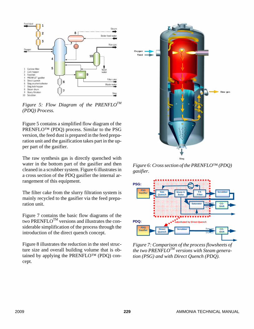
Figure 6: Cross section of the PRENFLO™ (PDQ) gasifier.
Figure 7: Comparison of the process flowsheets of the two PRENFLOTM versions with Steam genera-tion (PSG) and with Direct Quench (PDQ).
Raw Gas
S/G=1.3
PSG Gasifier Gas
Quench Waste H.
Boiler FA
Filter Scrubber
CO- Shift
Saturator
Raw gas
S/G=1.3
PDQ Gasifier Direct
Quench Scrubber CO-
Shift
PSG:
PDQ: substituted by Direct Quench
229 AMMONIA TECHNICAL MANUAL2009
Figure 8: Size comparison of the two PRENFLOTM versions.
Ammonia synthesis part
Uhde’s history in ammonia synthesis
Uhde’s first ammonia plant was built in 1927. It had a capacity of 100 tons per day and was based on coke-oven gas as feedstock. Technology has evolved since then and capacities have become bigger. The latter matters especially when a cost-intensive gasifier becomes part of the project and for reasons of economy of scale it makes sense to make the plant capacity as high as possible.
The Uhde Dual Pressure Process
Uhde has built the largest single-train ammonia plant in the world for SAFCO (Saudi Arabian Fer-tilizer Company) in Al Jubail, Saudi Arabia. The plant was commissioned in 2006 and is producing well above its nameplate capacity of 3300 tons per day. The plant is using Uhde’s dual pressure technology which is shown schematically in Figure 9. As shown there, the compression of the synthesis gas is carried out in two steps. In the first step, an in-termediate pressure of 110 bar abs. is reached. A once-through ammonia converter is located at this pressure level and delivers about one third of the overall ammonia production. Its effluent gas is cooled down to –16 °C and most of the ammonia contained in it are separated from it. The remaining gas is compressed further to the synthesis loop pressure (200 bar abs.) and added to the recycle gas stream of the loop. The combined stream passes through the recycle stage of the synthesis gas compressor, is heated up in a gas / gas heat ex-changer, and then enters the first loop converter. In the loop, two ammonia converters are installed in series, each with a high pressure steam generator downstream of it. Ammonia is separated from the loop by condensation.
Figure 9: Simplified flow diagram of syngas com-pression and synthesis loop of an Uhde Dual Pres-sure Ammonia Plant.
WCSynthesis Gas
WC
NH3 - Synthesis Loop
Purge Gas 1 2 3 R
S
S: Separator WC: Water cooler CH: Chiller with NH3 refrigerant
S
NH3 Product H2O
HP BFW
CH CH CH
Synthe-sis
NH3 - Once
Through
PRENFLOTM (PSG) PRENFLOTM (PDQ)
230AMMONIA TECHNICAL MANUAL 2009
The upstream separation of a part of the product takes load from the synthesis loop and the syngas compressor. Therefore, the synthesis gas compres-sor and the synthesis loop equipment are at 3300 tons per day not different to a 2000 tons per day plant. In the plant built for SAFCO, this allowed to use referenced and proven equipment for these sec-tions and eliminated the risk which usually would arise when scaling up from a 2000 tons per day plant to 3300 tons per day. On the other hand, the additions made to the flow-sheet by the dual pressure process are all refe-renced items. For example the ammonia converter is not much different to a conventional loop con-verter and no special type catalyst is required. This means, the change does not come at the cost of adding more risk. Due to the product separation at lower pressure, also the overall energy consump-tion of this plant is about four percent lower than with a conventional process. In the meantime, there is another 3300 tons per day plant, using the same process, under construction for Ma’aden Saudi Arabian Mining Company.
Application to a gasification front-end
Given the fact that an ammonia synthesis gas gen-erated by a gasification plant is almost free of in-erts, the same ammonia loop might generate 10 percent more ammonia compared to the reference installation in a steam reformer plant. This means, there is already a reference in operation for the synthesis section of a 3700 tons per day ammonia plant based on coal gasification. Uhde has already experience with the design of an ammonia synthesis based on inert-free synthesis gas from a plant built for Sasol in South Africa in the 1980’s.
Economic Comparison of Gasification and Steam Reforming An economic comparison of gasification and steam reforming must take into consideration operating and investment cost. The comparison is done here in order to determine in how much the higher in-vestment cost for gasification is outweighed by a lower feedstock price.
Process Economics of Gasification and Steam Reforming
Basically, the specific energy consumptions of ga-sification-based ammonia plants are higher than those of natural gas based plants. Table 3 shows that the consumption depends very much on the type of feedstock and the type of gasification. The table also shows the difference in energy effi-ciency between the two PRENFLOTM process ver-sions steam generation and direct quench. The more simple direct quench process alternative con-sumes 2 to 2.5 percent more energy. Both versions have a lower energy consumption than a fluidized bed gasification (data from HTW process). The table also lists typical price figures for these feedstocks for North America and Europe. The coal price of 2.5 USD / MMBTU used here corres-ponds to a price of 70 USD per ton. The gas price of 7 USD / MMBTU is a typical average price for North America and Western Europe. With these feedstock costs, the feed and energy related operat-ing cost of the different plants is calculated. For sake of simplicity, other contributions to the oper-ating cost are neglected, or it can be assumed that they are equal for all concepts. (Typically, 70 to 90 percent of the plant’s operating cost come from feed and energy.) Table 3 shows that the produc-tion cost of a gasification plant is significantly lower than that of a steam reformer plant under this set of conditions.
Assumed prices (3) $/MMBTU 7.0 4.4 2.5 2.5 1.5 1.5 1.5Costs energy per t NH3
$/t NH3 226.9 166.4 112.5 115.0 75.1 76.7 79.0
Comparison – cost 100% 73% 50% 51% 33% 34% 35%Note: (1) Energy consumption for lignite pre-drying not considered (2) High vacuum residue (3) Typical data for North America and Europe Table 3: Specific energy consumption and cost of production for gasification-based ammonia plants. for dif-ferent feedstocks in comparison to steam reforming of natural gas. For the investment of the plants, the cost is es-timated, and the annual payback of capital and its interest is calculated.
Result of the Comparison
The results of the above calculations are put to-gether, not only limited to the energy cost used in Table 3 but for a whole range of cost for solid feedstock (e.g. coal) and natural gas. The result is shown in Figure 10. The graph shows, as a func-tion of gas price the maximum gasification feeds-tock price at which the gasification is still feasi-ble. As a result, it separates the plane defined by gas price (lower axis) and gasification feedstock price (left axis) into two areas where gasification resp. steam reforming are the economically more attractive solutions. The evaluation is made for the same ammonia production rate in both processes which makes it independent of the product price. It shows for example that for the typical cost data of North America and Europe the coal gasification is a feasible alternative. For the other underlying assumptions, refer to Figure 10.
Inclusion of regional price differences into the study
The limitation of the above result is that it com-pares gasification and steam reforming based on the production cost only, assuming both plants would be located at the same site. However, a ga-sification based plant does not have to compete against a steam reformer plant at the same loca-tion but at a place where the gas price is low and urea is produced for export. In order to include this effect, the transportation cost (standing for storage, loading, shipping etc.) of urea is included into the model. Figure 11 shows at which feedstock cost the gasi-fication is more economical, assuming that there are additional 20 USD transportation cost for one ton of urea produced by the steam reforming process. This model can be valid for a country with fertilizer demand and where coal is available.
232AMMONIA TECHNICAL MANUAL 2009
0
1
2
3
4
5
6
7
0 2 4 6 8 10 12natural gas price / USD/GJ
gasi
ficat
ion
feed
stoc
k pr
ice
/ US
D/G
J
PRENFLO PSG PRENFLO PDQ
gasification more economical
steam reforming more economical
Figure 10: Comparison of plant economics for steam reforming and gasification, based on feeds-tock cost. Parameters: payback time: 10 years; in-terest rate: 8 percent per year; capacity: 3300 tons per day ammonia. This means for example, when the coal price is 2.0 USD or less, it might be more economical to produce ammonia resp. urea from coal gasifica-tion than to import it from a place having an ener-gy price of 3.0 USD/GJ.
Cost development
As long as there are still places with lower gas cost, this seems to be not much of a good perspec-tive for coal, but for the future development one should also take the following into consideration: For natural gas, there are regional price differenc-es in the world by a factor of 10. There are places with low gas cost because they are far away from the places of high demand, and transportation is costly or even impossible. However, it can be ex-pected that the cost difference will decrease in the future with every LNG or pipeline project that brings the cheap gas closer to a consumer. This will be a development in addition to the general trend that oil and gas prices are rising faster than coal price.
0
1
2
3
4
5
6
7
0 2 4 6 8 10 12natural gas price / USD/GJ
gasi
ficat
ion
feed
stoc
k pr
ice
/ US
D/G
J PRENFLO PSG PRENFLO PDQ
gasification more economical
steam reforming + transport of product more economical
Figure 11: Same economic evaluation as in Fig-ure 10; additionally 20 USD transport cost per ton of urea assumed. Under this aspect it does not seem improbable that there will be more coal to ammonia or urea projects in the future. Even in a low gas cost areas it can be expected that some day the level will reach to 3 USD/GJ which is parity to 2 USD/GJ for coal when transport cost is added.
Summary For long time, gasification based ammonia plants have not received much attention due to the avail-ability of cheap natural gas and hence the better economics of the steam reforming process. However, even in the places with low gas cost, on the long term a price increase can be expected as demand is growing and the reserves are limited. In this paper, the state of the art of the technologies for the coal-based ammonia production has been presented and an estimation of the economic fea-sibility has been developed. It is predicting that gasification will become a favored option the more the availability of cheap gas will be declin-ing, for example due to export as LNG. This will happen at gas costs which are not so far away from the present ones. The feasibility of a project will be favored by a higher plant capacity. Uhde has over 65 years of
233 AMMONIA TECHNICAL MANUAL2009
experience in gasification of solid feedstocks and has always carried out development work for this technology. With PRENFLOTM and the Dual Pressure Uhde Process for ammonia, there is a re-ferenced technology available for the whole process chain.