Coal-trol Digital – Model 1 Automation Correct LLC 9/2005 www.automationcorrect.com Page 13 Installation Manual Table of Contents Introduction 13 Important Safety Information 14 Tools Required 15 Additional Material that May Be Required 15 Installation Overview 15 Important Information Concerning Feeder Types 15 Mounting the Thermostat 16 Mounting the Power Module 16 Some Power Module Mounting Alternatives 17 Connect Thermostat to Power Module 17 Attaching Power Cord/Power ON/OFF Switch 18 Identifying and Adapting Your Feeder Type 19 Two-Motor Feeder Type 19 Wiring a Two-Motor Feeder 19 Dual-Burner Type 20 Wiring a Dual Burner Type 21 Single-Motor Tri Burner Type 22 Other Single-Motor Types 22 Wiring a Single-Motor Type (Tri Burner) 23 Power Assisted Flue Vent 24–26 Bonnet Limit 27 Test on Initial Power-up 28 Setup Coal-trol Thermostat for a Particular Stove Type 29–34 Power Module Connection Diagram 35 Copyright 2004, 2005 Automation Correct LLC. All rights reserved. Coal-trol Digital ™, Pelli-stat™ by Automation Correct LLC All others trademarks by the respective owners. Page Number SYRACUSE • NY This manual contains information on installation and initial setup of the Coal-trol Digital control system. For instruction on operation of the Coal-trol Digital, please refer to the Coal-trol Digital Model 1 – Operation Manual. The Coal-trol Digital is designed for retrofit onto automatic stoker anthracite coal stoves. Basic installation of the Coal-trol Digital can be done in as little as 20 minutes. However for some situations, additional time and wiring material will be needed to remove and adapt the electrical elements of the stove to the Coal-trol Digital. Please consider using a qualified, heating technician or electrician to ensure a correct and safe installation. Installation must be in done accordance with the National Electrical Code (NEC) and local requlations. Introduction
Introduction 13Important Safety Information 14Tools Required 15Additional Material that May Be Required 15Installation Overview 15Important Information Concerning Feeder Types 15Mounting the Thermostat 16Mounting the Power Module 16Some Power Module Mounting Alternatives 17Connect Thermostat to Power Module 17Attaching Power Cord/Power ON/OFF Switch 18Identifying and Adapting Your Feeder Type 19
Two-Motor Feeder Type 19Wiring a Two-Motor Feeder 19Dual-Burner Type 20Wiring a Dual Burner Type 21Single-Motor Tri Burner Type 22Other Single-Motor Types 22Wiring a Single-Motor Type (Tri Burner) 23
Power Assisted Flue Vent 24–26Bonnet Limit 27Test on Initial Power-up 28Setup Coal-trol Thermostat for a Particular Stove Type 29–34Power Module Connection Diagram 35
Copyright 2004, 2005 Automation Correct LLC. All rights reserved.Coal-trol Digital ™, Pelli-stat™ by Automation Correct LLC
All others trademarks by the respective owners.
Page Number
SYRACUSE • NY
This manual contains information on installation and initial setup of the Coal-trol Digital control system. For instruction on operation of the Coal-trol Digital, please refer to the Coal-trol Digital Model 1 – Operation Manual.
The Coal-trol Digital is designed for retrofit onto automatic stoker anthracite coal stoves.
Basic installation of the Coal-trol Digital can be done in as little as 20 minutes. However for some situations, additional time and wiring material will be needed to remove and adapt the electrical elements of the stove to the Coal-trol Digital.
Please consider using a qualified, heating technician or electrician to ensure a correct and safe installation. Installation must be in done accordance with the National Electrical Code (NEC) and local requlations.
ATTENTION – Please follow all manufacturers instructions that came with your stove or furnace. The Coal-Trol Digital is designed to complement and enhance the safe operation of your appliance. Specifically, the Coal-Trol Digital control system is designed for appliances tested to ANSI Standard Designation: E1509–95 , Standard Specification for Room Heaters, Pellet Fuel-Burning Type and/or UL1482 Room Heaters, Solid Fuel Type.
Use of the Coal-trol Digital on appliances not permanently marked with one of the above designations voids all warranties and may be unsafe. Contact us or your stove manufacturer if you are not sure that your stove/furnace is built in compliance with these safety standards.
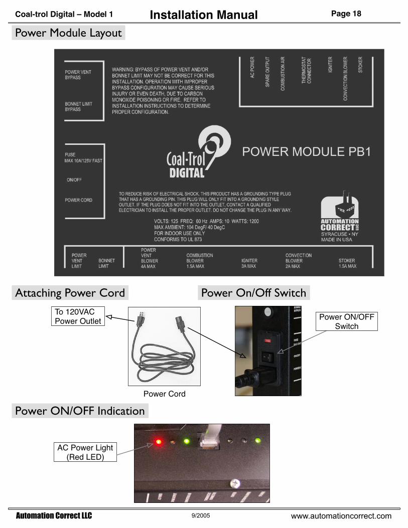
WARNING: BYPASS OF POWER VENT AND/OR BONNET LIMIT MAY NOT BE CORRECT FOR THIS INSTALLATION. OPERATION WITH IMPROPER BYPASS CONFIGURATION MAY CAUSE SERIOUS INJURY OR EVEN DEATH, DUE TO CARBON MONOXIDE POISONING OR FIRE. REFER TO INSTALLATION INSTRUCTIONS TO DETERMINE PROPER CONFIGURATION.
TO REDUCE RISK OF ELECTRICAL SHOCK, THIS PRODUCT HAS A GROUNDING TYPE PLUGTHAT HAS A GROUNDING PIN. THIS PLUG WILL ONLY FIT INTO A GROUNDING STYLE
OUTLET. IF THE PLUG DOES NOT FIT INTO THE OUTLET, CONTACT A QUALIFIEDELECTRICIAN TO INSTALL THE PROPER OUTLET. DO NOT CHANGE THE PLUG IN ANY WAY.
HIGH VOLTAGE - DISCONNECT POWER SUPPLY BEFORE SERVICING.
TO REDUCE RISK OF ELECTRICAL SHOCK, DO NOT CONNECT TO A CIRCUIT OPERATING AT MORE THAN 150 VOLTS TO GROUND
WARNING – The Coal-trol Digital is capable of regulating a coal fire smaller than required tomaintain proper chimney draft. Follow all manufacturers recomendations for minimum draft pressures and temperature. Installation of a carbon monoxide detector (not-included) is highly recommended.
This safety information printed on the cover of the Coal-trol Digital Power Module.
Flat Screwdriver (thin blade), Philips screwdriver, Electric Drill with 3/16" Drill Bit and 5/16" Hex Driver bit.
Installation Overview
Additional Material That May be RequiredWhen installing the Coal-trol Digital onto stoves with existing controls, hand tools to remove junction boxes, timer boxes and relay boxes may be needed. Additionally, two and three prong 120V plug cords (3ft.), wire nuts, and electrical tape may be needed to adapt the stove motors to the Coal-trol Digital Power module. Please consider using a qualified Electrician or Heating Technician.
Stoker-fed coal stoves (stoves) share common elements (motors) to feed coal, provide combustion air, distribute heat into the room and remove combustion products through the chimney. Installation of the Coal-trol Digital consists of identifying each of these elements for your particular stove, removing wiring to isolate the elements, wiring the motors with plug cords if necessary, and identifying and adapting two important safety controls if applicable.
Important Information Concerning Feeder Types
The Coal-trol Digital is compatible with two different feeder types:
1) Single-Motor and Tri Burner Type – This popular feeder type is found on many brands of stoves. It has one motor that drives a crank arm connected to the stoker and also drives a blower to supply combustion air to the stove.
2) Two-Motor Type – The Two-Motor feeder type has a separate motor for fuel feed (stoker) and the Combustion Blower.
The method of operation of the feeder by the Coal-trol Digital Thermostat is done at initial setup of the Thermostat. The first method (TBRN = 'Y' on the SETUP menu) controls a Single-Motor feeder by varying the speed of the feeder motor as needed to maintain temperature setting.
The second method (TBRN = 'N' on the SETUP menu), controls feeder by running the Stoker motor at full speed for short periods of time needed to maintain the temperature setting. The Combustion Blower is plugged into the Power Module and runs continuously to supply air for combustion.
Thermostat Bracket(Unclip the bracket from the thermostat for mounting.)
Mounting Screws#6 x 3/4" Philips
Mounting the Thermostat
The room temperature sensor is located in the Thermostat. For proper operation, the sensor must be exposed to the heat produced by the stove. The preferred mounting locations include: on an inside wall, away from the direct air stream of the convection blower, and away from radiant heat produced by stove. Note that the Thermostat does not have to be within the same room as the stove. For example, a coal furnace ducted to the return air plenum of an oil or gas will give good results if the Thermostat is mounted next to the oil/gas furnace thermostat.
Mounting the Power Module
Stove – Rear View
Power Module Bracket
Mounting Screws#10 x 3/4" Hex
Mount Bracket onto Fuel Hopper or on rear wall below stoker
Power Module Mounting Instructions:1) Remove screw from Power Module that secures the Mounting Bracket.2) Locate and fasten Mounting Bracket to stove with the two supplied screws.3) Mount Power Module to bracket and secure with screw removed in step 1.
Attaching Power Module to Bracket on side of coal hopper.
When mounting on bottom of coal hopper, use
silicone sealant on bracket mounting screws.
When mounting on rear wall, only mount on cool surface below 80 . If surface is too hot to touch, do not mount
Power Module on it!
Some Power Module Mounting Alternatives
25 ft. Thermostat Cord
Plug cable into RJ45 jack on left side of Thermostat.
Plug Cable into RJ45 Jack on Power Module
Connect Thermostat to Power Module
The provided 25ft. cord may be extended with an 8 pin, RJ45 to RJ45 coupler and/or standard computer network cable. The cable must be a 'through' type, not a crossover type. Note: The Coal-trol thermostat and Power Module cannot be connected to computer networks through this cable.
On some stoves, you may find a Two-motor feeder that has been wired so that it operates as a Single-Motor feeder. You will need to convert this arrangement to the two-plug wiring shown in the diagram on the left.
Desired Two-Moter feederarrangement for Coal-trol Digital.Wiring diagram of figure above.
Wiring a Two-Motor FeederIf the feeder does not already have 3-wire male power cords, they must be attached as shown below.
Two-Motor Feeder TypeA Two-Motor feeder is identified by observing that a separate motor for fuel stoker and for combustion air exists.
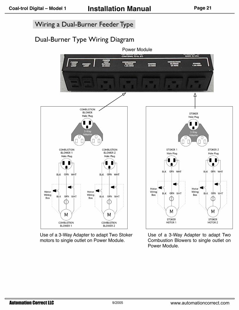
The Dual-Burner type feeder can be adapted to the Coal-trol Digital by plugging both feeders together into the Power Module Stoker receptacle and both Combustion Blowers into the Power Module Combustion Blower receptacle.
Optionally, an On/Off switch may be placed into the secondary feeder to allow it to be turned off when not in use.
View From Back of Stove to Identify a Tri-burner Type Feeder
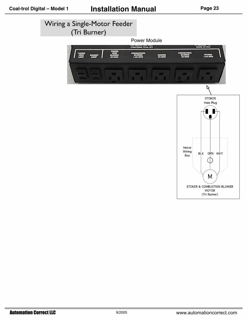
The Tri-burner feeder mechanism is found on Tri-burner and Reading Stoves. Older brand Alaska and Leisure Line are also known to have this mechanism. The key indicator of a Tri-burner feeder is that there is only one motor controlling both combustion air supply and coal feed.
Single-Motor Tri Burner Type
Tri Burner Feeder
Single Power Cord
Fuel Hopper
Example 1 : Reading Brand Stove with Tri-burner Feeder(Courtesy Reading Stove Co.)
Example 2: Older Alaska Brand Stove with Tri-burner Feeder
Single Power Cord
Tri Burner Feeder
Single-Motor Feeder on Keystoker A80 Coal/Oil Furnace.
Other Single-Motor Feeder Types
Single Power Cord
Stoker & Combustion Blower Motor
Please contact contact Automation Correct before you apply the Coal-trol Digital to this type of furnace feeder.
Power assisted chimney vents (Power Vent/Direct Vent) consist of a blower, a limit switch (Fume Switch), and in some systems a rheostat to adjust the blower speed control. The power assisted vent provides forced chimney draft, eliminating the need for a conventional natural draft chimney. Because a fan motor provides the draft, a safety limit is required to ensure that the power assisted vent is actually exhausting the stove. If the blower fails or the vent pipe is blocked, heat from the stove will reach the Fume switch and shutdown the stove.
Fume Switch with cover partly removed.
CAUTION – Adaptation of a power assisted vent to the Coal-trol Digital must utilize the Fume switch interlock. Do not install the Power Vent Limit Bypass fuse when using a power assisted vent system.
Page 25Installation ManualPower Assisted Flue Vent Power Vent/Direct Vent
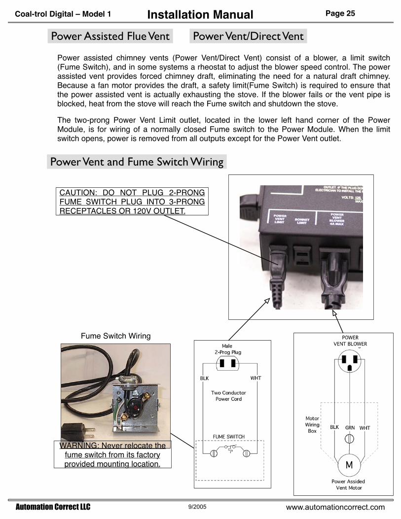
Power assisted chimney vents (Power Vent/Direct Vent) consist of a blower, a limit switch (Fume Switch), and in some systems a rheostat to adjust the blower speed control. The power assisted vent provides forced chimney draft, eliminating the need for a natural draft chimney. Because a fan motor provides the draft, a safety limit(Fume Switch) is required to ensure that the power assisted vent is actually exhausting the stove. If the blower fails or the vent pipe is blocked, heat from the stove will reach the Fume switch and shutdown the stove.
The two-prong Power Vent Limit outlet, located in the lower left hand corner of the Power Module, is for wiring of a normally closed Fume switch to the Power Module. When the limit switch opens, power is removed from all outputs except for the Power Vent outlet.
Power Vent and Fume Switch Wiring
Fume Switch Wiring
CAUTION: DO NOT PLUG 2-PRONG FUME SWITCH PLUG INTO 3-PRONG RECEPTACLES OR 120V OUTLET.
WARNING: Never relocate the fume switch from its factory provided mounting location.
Page 27Installation ManualBonnet Limit (Bonnet High Temperature Limit Switch)
The two-prong Bonnet Limit outlet, located in the lower left hand corner of the Power Module, is for wiring of a normally closed temperature limit switch to the Power Module. When the limit switch opens, power is removed from all outputs except for the Power Vent outlet.
If the installation does not use a Bonnet Limit switch, a 10A fuse must be installed in the Bonnet Limit Bypass fuseholder located in the upper left hand side of the Power Module.
If a Bonnet Limit switch has been connected to the Bonnet Limit receptacle, a nonconducting slug should be installed into the Bonnet Limit Bypass fuseholder.
Instruction for Bonnet Limit Bypass
Installing Bonnet Limit Bypass nonconducting slug.(Initially installed at the factory.)
SETUP of the Coal-trol Digital Thermostat for a Particular Stove Type
The last step before stove operation is to tell the thermostat the minimum and the maximum feeder rates, and to set the type of feeder, either Tri Burner type, or not. These settings are accomplished through the SETUP menu on the thermostat. Once set, these settings are retained after power loss and need not be adjusted unless necessary.
These "One-time" settings allow the Coal-trol System to be adapted to many fuel feeder types and brands of stoves. Automation Correct LLC has compiled settings for a number of stoves, however with a simple procedure, other stove types may be "tuned" in.
SETUP MENU – "One-time" Setting descriptions
DEG – For selection of Farenheit or Celsius temperature units.
TBRN – This selects the method of feeder control. When selected (TBRN = Y), the feeder runs continuously with its speed varied up and down to adjust firing rates. Additionally, at feeder rates below approximately 50%, short feeder pauses (feeder starts and stops) occur.When not selected (TBRN=N), the feeder when commanded runs at full speed, it starts and stops in a proportional manner to adjust firing rate.
MIN – Minimum feeder rate. (%)This setting sets the minimum feed rate to maintain low fire. When the thermostat output equals 0(zero) as indicated on the MAN or AUT display, the MIN setting allows the stove to maintain a small fire. The object is to set MIN so that about a 1/4 to 1/2" of fire is maintained when the stove MAN/AUT output = 0 (zero).
MAX – Maximum feeder rate. (%)This setting sets the maximum feed to limit the stove high fire rate. When the thermostat output equals 99 as indicated on the MAN/AUT display, the MAX is set so that a full grate of fire is maintained without over-feeding. The object is to set MAX so that no unburned or burning coal over-stokes the stove.
The operation of the SETUP menu is described on the following page. After this, two procedures are described, one for Single-Motor feeder types (Tri Burner), and one for Two-Motor feeder types.
Press UP button for Deg. C or the DOWN button for Deg. F. temperature units.
MIN 5
MENU button
MAX 42
MENU button
Starting from the Round-Robin display, press the MENU button until SETUP is shown on the display.
S 1154A
MENU button
TBRN N
MENU button
MENU button(6 times)
DISPLAY ACTION NOTE
DEG CUP button
DOWN button
Minimum Stoker Feed Value Press UP button to increase MIN feed rate, DOWN to decrease MIN feed rate.
MIN feed value cannot be increased beyond the MAX feed value.
Maximum Stoker Feed Value Press UP button to increase MAX feed rate, DOWN to decrease MAX feed rate.
MAX feed value cannot be decreased below the MIN feed value.
Time of Day Clock ValuePress UP or DOWN button to adjust. Display shows 'A' for AM, 'P' for PM.
After power loss, the time of day setting may be adjusted without entry into SETUP menu.
The SETUP menu is for initial setup of the stove. Under normal operation, these setting need not be adjusted. All settings except for the Time of Day Clock value are retained without power.
TBRN Y
Temperature Units
DOWN or UP button
If SETUP is displayed, SETUP settings may be examined or changed by pressing the UP or DOWN button once.
UP button
DOWN button
Press UP button for Tri-burner mode on, DOWN button for Tri-burner mode off. Display shows 'N' for off and 'Y' for on.
Copyright 2004, 2005 Automation Correct LLC. All rights reserved.Coal-trol Digital ™, Pelli-stat™ by Automation Correct LLC
All others trademarks by the respective owners.
Syracuse • NYwww.automationcorrect.com
Automation Correct LLC designs and manufactures technology products for home and industry. Combining over 75 years of practical experience, the Engineers and Technicians of Automation Correct LLC are dedicated to supporting our customers with innovative products.