33
Common BIM Requirements 2012 COBIM v 1.0 Series 2 Modeling of the starting situation

Common BIM Requirements2012COBIM
v 1.0
Series 2 Modeling of the starting situation

Foreword
The publication series “Common BIM Requirements 2012” is the result of a broad-
based development project entitled COBIM. The need for these requirements arises
from the rapidly growing use of building information modeling in the construction
industry. During all phases of a construction project, the parties to the project have a
need to define more precisely than before what is being modeled and how the modeling
is done. “Common BIM Requirements 2012” is based on the previous instructions of
the owner organizations and the user experiences derived from them, along with the
thorough experience the writers of the instructions possess on model-based operations.
The parties to the project are: Funding providers: Aitta Oy, Larkas & Laine Architects
Ltd, buildingSMART Finland, City of Espoo Technical and Environment Services,
Future CAD Oy, City of Helsinki Housing Production Office, City of Helsinki Premises
Centre, University of Helsinki, Helsingin Yliopistokiinteistöt Oy, HUS Kiinteistöt Oy,
HUS Premises Centre, ISS Palvelut Oy, City of Kuopio Premises Centre,
Lemminkäinen Talo Oy, Micro Aided Design Ltd. (M.A.D.), NCC companies, Sebicon
Oy, Senate Properties, Skanska Oy, SRV Group Plc, Sweco PM Oy, City of Tampere,
City of Vantaa Premises Centre, Ministry of the Environment. Authors: Finnmap
Consulting Oy, Gravicon Oy, Olof Granlund Oy, Lemminkäinen Talo Oy, NCC
companies, Pöyry CM Oy, Skanska Oyj/VTT Technical Research Centre of Finland,
Solibri, Inc., SRV Rakennus Oy, Tietoa Finland Oy. Management: The Building
Information Foundation RTS.
The requirements were approved by an executive group consisting of parties to the
project. The executive group acted as committee TK 320 of the Building Information
Foundation RTS, and as such, participated actively in developing the content of the
requirements and in asking for comments from the members of the executive group and
from interest groups.
Parties to the © COBIM project.

Series 2 author: Tietoa Finland Oy, Marko Rajala
Version 1.0 March 27, 2012 Parties to the © COBIM - project
Table of Contents
Table of Contents 3
1 Main objectives of building information modeling 5
2 Introduction 6
3 General definitions 6
3.1 Modeling of the site and site elements 7
3.2 Inventory modeling 7
3.3 Use of layers in the Inventory Model 7
3.4 Modeling of building elements 7
3.5 Classification of building elements 8
3.6 Coordinate system and units of measurements 8
3.7 Processing stories 8
3.8 BIM specification 9
4 Requirements pertaining to source data 9
4.1 Measurement requirements, content 10
4.1.1 Level 1 – Laser measurement and existing drawings 10
4.1.2 Level 2 –Tacheometric surveying 10
4.1.3 Level 3 – Laser scanning survey 10
4.2 Requirements for surveys, analyses and inventories 11
4.2.1 Level 1- Space identifiers and the general classification of building elements 11
Requirement 11
4.2.2 Level 2 – Room space inventory and classification of building elements12
4.2.3 Level 3 – Historical and research information of the building 12
5 Modeling requirements 12
5.1 Site model, Site elements 12
5.2 Accuracy levels of Inventory model 13
5.2.1 Level 1 – Spatial model 13
5.2.2 Level 2 – Building element model 15
5.2.3 Level 3 Building element model 16
5.3 Modeling requirements in different project phases 18
5.3.1 Needs and objectives assessment and conceptual design 18
5.3.2 Design preparation 19
5.3.3 Schematic design, design development and detailed design 19
5.3.4 Construction preparation 19
5.3.5 Construction 19
5.3.6 Commissioning 20
6 Final documents to be produced 20
6.1 Data transfer 20
6.1.1 Transfer of Inventory model to the software used by the designer 20
Series 2 author: Tietoa Finland Oy, Marko Rajala
Version 1.0 March 27, 2012 Parties to the © COBIM - project
6.2 Measurement materials 21
6.3 Building information models 22
6.3.1 Site model – Site elements 22
6.3.2 Inventory models 22
6.4 Drawings 22
7 Supplementary tasks 23
8 Quality Assurance 25
8.1 Measurement 25
8.2 Inventory model 26
APPENDIX 1 Task allocation form for measurement and inventory modeling
APPENDIX 2 Information model description
APPENDIX 3 Information model Inspection report

Series 2 author: Tietoa Finland Oy, Marko Rajala Sivu 5 / 26
Version 1.0 March 27, 2012 Parties to the © COBIM - project
1 Main objectives of building information modeling Property and construction modeling aims to support a design and construction lifecycle
process that is of high quality, efficient, safe and in compliance with sustainable
development. Building information models are utilized throughout the building’s life
cycle, starting from initial design and continuing even during use and facility
management (FM) after the construction project has concluded.
Building information models enable the following, for example:
o Provision of support to the investment decisions by comparing the functionality, scope and costs
of the solutions.
o Energy, environment and lifecycle analyses for the purpose of comparing solutions, design and
objectives of facility management follow-up.
o Design visualization and analysis of construction feasibility.
o Enhancement of quality-assurance and data exchange and making the design process more
effective.
o Utilization of building project data during use and facility management activities.
To make modeling successful, project-specific priorities and objectives must be set for
models and model utilization. Project-specific requirements will be defined and
documented on the basis of the objectives and general requirements set in this
publication series.
General objectives of building information modeling include, for example, the
following:
o To provide support for the project’s decision-making processes.
o To have the parties commit to the project objectives by means of using the building information
model.
o To visualize design solutions.
o To assist in design and the coordination of designs
o To increase and secure the quality of the building process and the final product.
o To make the processes during construction more effective.
o To improve safety during construction and throughout the building’s lifecycle.
o To support the cost and life-cycle analyses of the project.
o To support the transfer of project data into data management during operation.
“Common BIM Requirements 2012” covers targets for new construction and
renovation, as well as the use and facility management of buildings. The minimum
requirements for modeling and the information content of models are included in the
modeling requirements. The minimum requirements are intended to be observed in all
construction projects where the use of these requirements is advantageous. Besides the
minimum requirements, additional requirements can be presented on a case-specific
basis. Modeling requirements and content must be presented in all design contracts in a
binding and consistent manner.

Series 2 author: Tietoa Finland Oy, Marko Rajala Sivu 6 / 26
Version 1.0 March 27, 2012 Parties to the © COBIM - project
The publication series “Common BIM Requirements 2012” consists of the following
documents:
1. General part
2. Modeling of the starting situation
3. Architectural design
4. MEP design
5. Structural design
6. Quality assurance
7. Quantity take-off
8. Use of models for visualization
9. Use of models in MEP analyses
10. Energy analysis
11. Management of a BIM project
12. Use of models in facility management
13. Use of models in construction
14. Use of models in building supervision
In addition to the requirements in his or her field, each party to a building information
modeling project must be acquainted at a minimum with the general part (Series 1) and
the principles of quality assurance (Series 6). The person in charge of the project or the
project's data management must have comprehensive command of the principles of
building information modeling requirements.
2 Introduction This document addresses the modeling of the Starting situation, corresponding surveys
inventories and other analyses and documents produced from these and their
information content requirements.
The definition of the content and accuracy level of the starting situation modeling is
done using this document and measurement and inventory modeling task definition
form (Appendix 1).
The task definition form has to be filled in for each project.
Series 3 “Architectural planning” definitions are followed in the modeling principles of
the inventory model where these are not defined in this document.
3 General definitions The modeling of the site and existing building is done based on measurements,
inventories and investigations performed on site This information is supplemented
based on existing drawings and other documents.
Depending on the required level of accuracy, the clarification of necessary source data
may also require the expertise of designers specialised in particular fields and other
consultants.
Series 2 author: Tietoa Finland Oy, Marko Rajala Sivu 7 / 26
Version 1.0 March 27, 2012 Parties to the © COBIM - project
3.1 Modeling of the site and site elements
Requirement
The Site model has to be at least a three dimensional surface model. Otherwise, the site
elements are modeled with the agreed accuracy.
Guideline
The plot model can also include boundary marks and location of other judicially or
technically significant points, such as drains or cables.
When necessary, ground surveys of the plot can also be done which produces a
geotechnical model of the plot.
It is recommended to include nearby buildings and street areas in the model of the plot
in the appropriate scale.
3.2 Inventory modeling
Inventory modeling is done based on the measurements, inventories and investigations
performed on site. This information is supplemented based on old drawings and other
documents.
Requirement
The origin of source data has to be documented in the BIM specification.
3.3 Use of layers in the Inventory Model
Requirement
The layer system used in the Inventory Model has to be documented in the BIM
specification if the modeling software has no layers, the information should be
organised in another, logical way according to the building elements and documented in
the BIM specification
Guideline
The layer requirements of traditional CAD drawing instructions cannot be applied
directly to drawings produced using Building information models.
3.4 Modeling of building elements
Requirement
Building elements are modeled into the Inventory model to the defined level of
accuracy. Building parts are modeled using the tools intended for modeling this part; the
walls are modeled using wall tools, slabs using slab tools, etc. If this principle cannot be
followed, e.g. due to geometric diversity, the modeling principle adopted must be
recorded in the BIM specification.
The building elements have to be modeled so that when the data is transferred the
location of the building element, agreed data content and geometry is also transferred to
software of other parties.
Guideline
More detailed definitions according to Series 3: “Architectural design”

Series 2 author: Tietoa Finland Oy, Marko Rajala Sivu 8 / 26
Version 1.0 March 27, 2012 Parties to the © COBIM - project
3.5 Classification of building elements
Requirement
Building elements are classified according to the accuracy level and accuracy of the
Inventory model. The names of the categories must show that this is part of an existing
structure. The classification principle used is recorded into the BIM specification.
Guideline
More detailed definitions according to Series 3: Architectural design.
3.6 Coordinate system and units of measurements
Requirement
A project coordinate system is defined for the project so that the datum point is situated
near the building.
Guideline
Planning according to the municipality coordinate system is not recommended as
locating the information model far from the source coordinate causes problems for most
planning software.
It is recommended that the coordinate system is defined in such a way that the whole
building area is in a positive coordinate system as negative coordinate system may
cause problems in site surveying.
Requirement
The location of the project coordinate system in relation to municipal coordinate system
is documented by using at least two corresponding points. X and y coordinates for the
corresponding points are stated in the project coordinate systems and in the municipal
coordinate system.
Guideline
The change of project coordinate system is made to the municipal coordinate system by
using Helmert, i.e. equiform change.
Requirement
The building information models are modeled in actual elevation in the municipal
elevation system.
Millimetres are used as the measurement unit for building information models.
3.7 Processing stories
Requirement
The building is modeled by story according to Series 3: “Architectural design”.
Measured floor surface level is defined as the inventory model story zero level.
Guideline
It is recommended that the zero level of the story is defined at the height of the main
staircase landing.

Series 2 author: Tietoa Finland Oy, Marko Rajala Sivu 9 / 26
Version 1.0 March 27, 2012 Parties to the © COBIM - project
3.8 BIM specification
The BIM specification depicts the source data of the inventory model, modeling
principles and other issues affecting the use or the reliability of the model.
The BIM specification is an indispensable aid in the continuing utilization of the model.
Guideline
Matters to be documented:
measuring methods, accuracy and date/ time
any exceptions from measurement specifications
origin of source data
software used
coordinate system, coordinate corresponding points and information on names,
amount and location of stories
naming conventions of files and building elements
layers used in the model
any exceptions from the defined modeling practice
Inventory model inspection form (Appendix 3)
other material obtained in measurement
4 Requirements pertaining to source data
Requirement
The method of acquiring the source data, its level of accuracy, processing and division
of tasks are agreed in detail on a project specific basis between the buyer and if
possible, in cooperation with the project team, so that the site model and the inventory
model serve the goals of the project as well as possible.
Guideline
The modeling of source data to match future use requirements is essential for the
follow-up planning of the project. It is therefore recommended that the designers of the
project are also involved in setting the requirements for the inventory model. Thus, it is
possible to be forewarned about potential issues such as data transfer problems
between design software.
When drafting content requirements for the inventory model, the target operating
conditions concerning measurements and surveys must be taken into account.
Guideline
E.g., measuring building elements that are hidden requires opening elements and if the
target is in use during the measurement, this may further complicate the measuring
process.

Series 2 author: Tietoa Finland Oy, Marko Rajala Sivu 10 / 26
Version 1.0 March 27, 2012 Parties to the © COBIM - project
4.1 Measurement requirements, content
4.1.1 Level 1 – Laser measurement and existing drawings
The measurements are done using a laser range finder.
Guideline
The measurement material is formed by the distances between the building elements
manually recorded by the measurer. The measurements are not in the same coordinate
system.
No geometrically reliable Inventory models or measurement drawings can be made
based on measurement material obtained using laser ranging method.
The method is suitable for verifying the correctness of individual distances and for
example, modeling based on old drawings.
4.1.2 Level 2 –Tacheometric surveying
The measurement is done with a tacheometer using predefined points.
Guideline
The survey material consists of individual points, lines and symbols in the same
coordinate system.
The method is very suitable for yard surveys and complementing laser scanning surveys
e.g. for floor drains.
The method is suitable for establishing source data for inventory model for
geometrically simple targets where the points to be measured are limited in number.
The completion and refinement of the inventory model and measurement drawings
requires additional measurements on site.
Confirming the correctness of the inventory model and measurement drawings is
difficult visually.
The measurement accuracy of tacheometric measurements
Requirement
The deviation of the defined measurement points must be less than 5 mm.
4.1.3 Level 3 – Laser scanning survey
The measurement is carried out comprehensively using laser scanning from all visible
surfaces.
Guideline
The measurement material is graphic and its correctness can be confirmed visually.
If necessary, the Inventory model or drawings can be supplemented and refined without
additional measurements.

Series 2 author: Tietoa Finland Oy, Marko Rajala Sivu 11 / 26
Version 1.0 March 27, 2012 Parties to the © COBIM - project
Accuracy of laser scanning survey
Requirement
Noise i.e. error margin max. ±10mm
Resolution i.e. point density: measurement points within less than 5mm intervals.
Guideline
In special cases such as historic building documentation, measurements can be done at
an even greater level of accuracy where measurements points are for example in
intervals of 1 mm. However, the work load related to the measurement is in this case
considerably higher.
Excerpt of a laser scanning point cloud of a historic building target attached with photographed color
data, Turun linnan herrainkellari, picture Tietoa Finland Oy. (This is one of the rooms in the Museum
Centre of Turku)
Guideline
Laser scanning measurements in places that are awkward to measure, such as roofs,
can be complemented by other survey methods such as tacheometric survey or
photogrammetry.
An inventory model based on the measurement material can be made reliably at 10 mm
tolerance. The materials can also be used to compile detailed drawings, e.g. where
material boundaries are visible.
4.2 Requirements for surveys, analyses and inventories
4.2.1 Level 1- Space identifiers and the general classification of building elements
Requirement
Space identifiers and general classification of building elements are included in
Inventory model.
Guideline:
The building elements are classified using a general principle of classification (e.g.
existing exterior wall type 1 = EEW01, existing load bearing partition wall type 1 =
ELBPW01, existing intermediate floor type 1 = EIF01, etc.).

Series 2 author: Tietoa Finland Oy, Marko Rajala Sivu 12 / 26
Version 1.0 March 27, 2012 Parties to the © COBIM - project
4.2.2 Level 2 – Room space inventory and classification of building elements
Requirement
In addition to level 1 information, room space specification is included in the inventory
model.
Guideline:
The building elements are classified according to the definitions of existing plans or
designers.
4.2.3 Level 3 – Historical and research information of the building
Requirement
Inventory information on building history survey and information on task investigations
such as condition and contaminants are included in the Inventory model.
Guideline
Information content details are defined on a project basis.
Matters to be defined:
What is inventoried
What information is attached to the model
What information is reported using other methods such as database format or
table format
5 Modeling requirements With regard to modeling the starting situation, the most essential requirements here
relate to the modeling of the site and modeling possible existing buildings spaces and
structures. The building information model of the site to be built is called “Site model”
and that of an existing building “Inventory Model”. Renovation targets require both a
Site model and an Inventory model, new builds only require a Site model.
5.1 Site model, Site elements
Requirement
A tool appropriate to the modeling software is used for site modeling. The site elements
are modeled, as appropriate, using tools meant for modeling building elements, for
example, supporting walls are modeled as walls and stairs as stairs. Otherwise, site
elements are modeled so that their geometry location and classification can be
transferred in IFC format.
The site and site elements are modeled into their own story so that they can be
processed as one entity and if necessary, marked out of the model. The objective is also
to model areas external to the site like buildings and street areas nearby so that they can
be processed as an entity by themselves.

Series 2 author: Tietoa Finland Oy, Marko Rajala Sivu 13 / 26
Version 1.0 March 27, 2012 Parties to the © COBIM - project
The site model shows a 3D surface model of terrain forms and area structures, Töölö Library, City of
Helsinki, picture: Tietoa Finland Oy
5.2 Accuracy levels of Inventory model
Requirement
The structures of old buildings are almost always somewhat slanted, sloping, curved or
otherwise inexact in their geometry. Striving for “absolute” accuracy in the Inventory
model is not appropriate.
Accuracy level of Inventory model
The allowed measurement deviations for the Inventory model are:
10 mm on corner points of building elements
25 mm on surfaces, e.g. walls and floors
50 mm for old irregular structures such as roof structures.
The modeling accuracy used is agreed on project basis.
Guideline
If required, the permitted deviation from measurements of sites of historical interest is
5mm for details
The required accuracy level may vary between the building elements.
5.2.1 Level 1 – Spatial model
Series 2 author: Tietoa Finland Oy, Marko Rajala Sivu 14 / 26
Version 1.0 March 27, 2012 Parties to the © COBIM - project
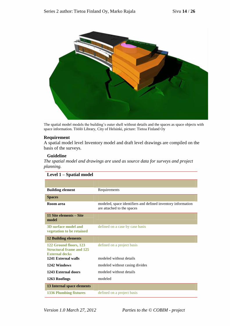
The spatial model models the building’s outer shell without details and the spaces as space objects with
space information. Töölö Library, City of Helsinki, picture: Tietoa Finland Oy
Requirement
A spatial model level Inventory model and draft level drawings are compiled on the
basis of the surveys.
Guideline
The spatial model and drawings are used as source data for surveys and project
planning.
Level 1 – Spatial model
Building element Requirements
Spaces
Room area modeled, space identifiers and defined inventory information
are attached to the spaces
11 Site elements – Site
model
3D surface model and
vegetation to be retained
defined on a case by case basis
12 Building elements
122 Ground floors, 123
Structural frame and 125
External decks
1241 External walls
1242 Windows
1243 External doors
1263 Roofings
defined on a project basis
modeled without details
modeled without casing divides
modeled without details
modeled
13 Internal space elements
1336 Plumbing fixtures defined on a project basis

Series 2 author: Tietoa Finland Oy, Marko Rajala Sivu 15 / 26
Version 1.0 March 27, 2012 Parties to the © COBIM - project
5.2.2 Level 2 – Building element model
Requirement
Building element model level Inventory model and main drawing
level drawings.
Guideline
Level 2 is the basic level of the Inventory model.
Level 2 Inventory model is needed after the project planning phase and when making
Schematic design level project plans where the spatial model is enough as source data.
Level 1 spatial model Inventory model can be supplemented to a Level 2 building
element model at the beginning of building design.
Level 2 – Building element model
Building element Requirements
Spaces
Net room area modeled, space identifiers and defined inventory information
are attached to the spaces
11 Site elements -Site model
3D surface model
vegetation to be retained
115 Site constructions
modeled
modeled
modeled
12 Building elements
1221 Ground floor slabs
1222 Ground floor ducts
123 Structural frame
1241 External walls
1242 Windows
1243 Externaldoors
125 External decks
1261 Roof substructures
1263 Roofings
1265 Glass roof structures
1266 Skylights and hatches
modeled by visible parts
defined on a project basis
modeled by visible parts without details
modeled without details
modeled including casings and frames
modeled including casings
modeled
modeled in a simplified manner
modeled
modeled
modeled
13 Internal space elements
(infills)
131 Internal dividers
1323 Ceiling surface
elements
1331 Standard fittings
1336 Plumbing fixtures
1342 Fireplaces and flues
modeled without detail
modeled without detail
modeled as space reservations
modeled as space reservations
modeled from the outside as far as visible

Series 2 author: Tietoa Finland Oy, Marko Rajala Sivu 16 / 26
Version 1.0 March 27, 2012 Parties to the © COBIM - project
Level 2 Building element model is the base level of inventory modeling where spaces are modeled as
space elements with their space identifiers and all building elements. Level 3 building element model is
enhanced by ornamental themes, equipment and surface textures.
Töölö Library, City of Helsinki, picture: Tietoa Finland Oy
5.2.3 Level 3 Building element model
Requirement
Building element model level Inventory model and detailed drawings.
Guideline
Compared to the Level 2 Inventory model, the level of detail is enhanced and modeled
building elements are added.
Level 3 Inventory model is required for geometrically complex objects, e.g. where there
are building preservation requirements.
Level 3 – Building element model
Building element Requirements
Spaces
Net room area modeled, space identifiers and defined inventory information
are attached to the spaces

Series 2 author: Tietoa Finland Oy, Marko Rajala Sivu 17 / 26
Version 1.0 March 27, 2012 Parties to the © COBIM - project
11 Site elements – Site
model
3D surface model
113 Paved and green areas
114 Site equipment
115 Site constructions
modeled
modeled apart from surface water drainage systems
modeled, location and identifier
modeled
12 Building elements
1221 Ground floor slabs
1222 Ground floor ducts
123 Structural frame
1241 External walls
1242 Windows
1243 External doors
1244 Facade attachments
125 External decks
1261 Roof substructures
1262 Eaves
1263 Roofings
1264 Roof safety products
1265 Glass roof structures
1266 Skylights and hatches
modeled as far as visible
defined on a project basis
modeled with details
modeled with details and ornamentals
modeled with frames and casings
modeled with casings
modeled
modeled
modeled, tolerance to be agreed per project
modeled
modeled
modeled
modeled
modeled
modeled
13 Internal space elements
(infills)
tolerance must be agreed per project
131 Internal dividers
132 Space surfaces
133 Internal fixtures
1341 Maintenance
platforms and catwalks
1342 Fireplaces and flues
modeled with details
modeled with details
modeled as space reservation
modeled
modeled from the outside as visible
2 Services elements tolerance has to be agreed on project basis
21 Plumbing elements
22 Air conditioning
elements
23 Electrical elements
25 Mechanical elements,
usually
2511 Elevators
defined per project
defined per project
defined per project
defined per project
Elevator shaft measurement and modeling
Series 2 author: Tietoa Finland Oy, Marko Rajala Sivu 18 / 26
Version 1.0 March 27, 2012 Parties to the © COBIM - project
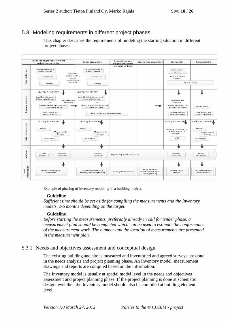
5.3 Modeling requirements in different project phases
This chapter describes the requirements of modeling the starting situation in different
project phases.
Example of phasing of inventory modeling in a building project.
Guideline
Sufficient time should be set aside for compiling the measurements and the Inventory
models, 2-6 months depending on the target.
Guideline
Before starting the measurements, preferably already in call for tender phase, a
measurement plan should be completed which can be used to estimate the conformance
of the measurement work. The number and the location of measurements are presented
in the measurement plan.
5.3.1 Needs and objectives assessment and conceptual design
The existing building and site is measured and inventoried and agreed surveys are done
in the needs analysis and project planning phase. An Inventory model, measurement
drawings and reports are compiled based on the information.
The Inventory model is usually at spatial model level in the needs and objectives
assessment and project planning phase. If the project planning is done at schematic
design level then the Inventory model should also be compiled at building element
level.

Series 2 author: Tietoa Finland Oy, Marko Rajala Sivu 19 / 26
Version 1.0 March 27, 2012 Parties to the © COBIM - project
5.3.2 Design preparation
The Inventory model compiled in the conceptual design phase and the reports based on
this are used as source data as call for tender material. If required, the model is further
updated and fine tuned in the building element model.
If an Inventory model and measurements are not done in the conceptual design phase
they should be started in design preparation phase.
5.3.3 Schematic design, design development and detailed design
The Inventory model is transferred into the software used by the architect and its
usability is verified.
5.3.4 Construction preparation
The Inventory model and the reports prepared based thereon are used in call for tenders
regarding contracts as descriptive material of the existing building.
5.3.5 Construction
If necessary, supplementary measurements are done in the construction phase for hidden
structures, the Inventory model and other documents are supplemented with for
example, void information.
The method of delivering supplementary measurement information to the designers has
to be agreed separately.
Guideline
Measurements to document hidden new structures and MEP can also be done in the
construction phase. For example, before installing suspended ceilings MEP
installations that remain hidden are laser scanned as part of the as-built model.

Series 2 author: Tietoa Finland Oy, Marko Rajala Sivu 20 / 26
Version 1.0 March 27, 2012 Parties to the © COBIM - project
A point cloud model of additional measurements done in the construction phase, picture: Tietoa Finland
Oy
5.3.6 Commissioning
In the commissioning phase, the as-built models together with the Inventory model are
merged together to serve the needs of facility management in accordance with Series 12,
“Use of models in facility management”.
6 Final documents to be produced
6.1 Data transfer
Transferring and converting the Inventory model from one modeling software to
another is often required when the Inventory model is transferred to the architect or, for
example, if there is a change in designer after the planning stage.
6.1.1 Transfer of Inventory model to the software used by the designer
Different design software cannot at the present time utilize each other’s BIM models.
BIM models are usually transferred using the IFC file format where transfer is
successful in the main as regards their data content and geometry. BIM models can thus
be utilized well as reference files between different design areas.
The Inventory model transferred to the architect’s design software can be utilized
directly as reference information. Parameterization is often lost from the models in IFC
data transfer which is required for modifying building elements and for example,
managing presentation styles.

Series 2 author: Tietoa Finland Oy, Marko Rajala Sivu 21 / 26
Version 1.0 March 27, 2012 Parties to the © COBIM - project
It is recommended therefore that the Inventory model is ordered in the design software
format used by the architect outright. The Inventory model can be transferred to another
design software format if necessary. This does, however, usually require remodeling the
Inventory model in parts. It is recommended that the author of the information model is
tasked with the conversion as he or she will know the model structure best.
Guideline
It is important to note that it is not possible to build an Inventory model that would be
usable in several different design software at the present time.
6.2 Measurement materials
Requirement
In level 3 measurements
Produced measurement materials in the same coordinate system with the
Inventory model.
Point cloud model of laser scanning in the agreed formats.
Rotational pictures of laser scanning and rotational picture index.
Laser scan point cloud issued as a measurable rotational picture format (bubble
view or panoramic view)
On the left, laser scanning point cloud model of indoor measurements and on the right, of outside
measurements, picture: Tietoa Finland Oy
Rotational picture of laser scanning, Tamminiemi Cafe, City of Helsinki, picture: Tietoa Finland Oy.

Series 2 author: Tietoa Finland Oy, Marko Rajala Sivu 22 / 26
Version 1.0 March 27, 2012 Parties to the © COBIM - project
Laser scanning point cloud model issued in a measurable rotational picture format. Measurable rotational
pictures allow easy and visually enabled navigation. It is also possible to take measurements or coordinate
points from the model. The materials supplement measurement drawings and Inventory models.
Hakaniemi Market, City of Helsinki, picture: Tietoa Finland Oy.
6.3 Building information models
6.3.1 Site model – Site elements
Requirement
The Site model in the agreed BIM format as native files and as IFC files.
6.3.2 Inventory models
Requirement
Inventory Models in the agreed information model format as native files and as IFC
files.
6.4 Drawings
Agreed measurement drawings in the defined format.
Site survey drawing
Plan drawings
Roof drawings
Section drawings
Facade drawings
Detailed drawings, agreed on project basis

Series 2 author: Tietoa Finland Oy, Marko Rajala Sivu 23 / 26
Version 1.0 March 27, 2012 Parties to the © COBIM - project
Measurement drawings produced from the Inventory model. Hakasalmi Villa, City of Helsinki, picture:
Tietoa Finland Oy.
7 Supplementary tasks
Requirement
Potential other supplementary tasks which are included in the inventory modeler’s tasks.
Supplementary tasks are agreed on a project basis.
Participation in defining the inventory modeling.
o Definition of the content and level of accuracy of the Inventory model
together with the person who is performing the task through negotiation.
Panorama photography
o 360º panorama photography of the object for example to help compiling
a building history specification.

Series 2 author: Tietoa Finland Oy, Marko Rajala Sivu 24 / 26
Version 1.0 March 27, 2012 Parties to the © COBIM - project
360º panorama picture. Tamminiementie Cafe, City of Helsinki, picture: Tietoa Finland Oy.
Converting the Inventory model to the architect’s software
o If there is a change of designer, for example between the conceptual
design and schematic design stages, the software used by the designer
may also change. In this case, the Inventory model has to be converted
into a new file format. The best person to do this is usually the original
author of the Inventory model.
Surveys, clarifications and inventories
o Room space inventory, building history specification and other necessary
surveys.
Information content reporting
o Reports from Inventory model, e.g. a list of spaces or room cards.
Visualization
o Visualization material for an existing building, e.g. visualization pictures.

Series 2 author: Tietoa Finland Oy, Marko Rajala Sivu 25 / 26
Version 1.0 March 27, 2012 Parties to the © COBIM - project
Visualization picture from the inventory model, Lapinlahti Hospital, City of Helsinki, picture: Tietoa
Finland Oy
Other documents
o Other defined documents such as databases.
8 Quality Assurance Quality Assurance is an essential part of modeling of the starting situation and has to be
undertaken for surveying, modeling and other documents produced.
Source data model inspection form is filled in and signed as an appendix to the BIM
specification.
8.1 Measurement
Requirement
Measurement materials have to be reviewed before starting modeling.
Matters to be reviewed:
The measurement materials are in the agreed coordinate system
All spaces and building elements according to definition have been surveyed and
the measurement results correspond to the building measured.
There are no internal errors in the measurement materials, e.g. an individual
measurement in the coordinate system
The measurement accuracy is conforms to requirements
The method of measurement, accuracy and timing is recorded
Potential exceptions and their reasons are recorded in the information model
description. E.g., a locked space which could not be measured.

Series 2 author: Tietoa Finland Oy, Marko Rajala Sivu 26 / 26
Version 1.0 March 27, 2012 Parties to the © COBIM - project
8.2 Inventory model
Requirement
The Inventory model and the measurement drawings produced thereof and other
documents must be checked before the material is delivered to the buyer. The review of
the inventory model has to be undertaken by an inspector of sufficient expertise.
Suitable software should be utilized for the review.
Matters to be checked:
Measurement accuracy of the model, the model must correspond to the
measurement materials
Measurement accuracy of drawings, the drawings must correspond to the
measurement materials
The model and the drawings are in the agreed coordinate system and height
Space and building elements are modeled according to requirements
Space and building elements contain the information according to requirements
The model conforms to technical requirements
The model has no clashes nor overlaps

INV Example of information content
Project information Target to be measured
Date dd.mm.yyyy Crawl space yes x
Project: Project title Stories 4 x
Project Manager Firstname Surname Attic yes x
Scope: m2, includes cellar, crawl space and attic
Source data from the buyer file format
Existing architect plans as image file x e.g. plt, tif, jpg or pdf
Existing architect plans as CAD files x e.g. dwg, Archicad or Revit
Existing structural plans as image files x e.g. plt, tif, jpg or pdf
Existing structural plans as CAD files x e.g. dwg
Space numbering and naming instructions x
Other
Method of measurement to be used Accuracy of measurement
Level 3 - Laser scanning survey x noise max ±10mm, point density: measurement points
within less than 5mm intervals
Survey of site x
Other measurements on site x Survey of floor drain
Supplementing the model based on old plans
Final product of the measurement file format
Rotational pictures of laser scanning and rotational picture index x jpg
Point cloud model of laser scanning x e.g. imp or pts
Laser scan point cloud issued as a measurable rotational x e.g. LFM Netview or Leica True View
picture format
Final products in the project planning phase file format / note
Site BIM x e.g. IFC 2x3 and Autocad Architecture 2012
Inventory BIM Level 1- Spatial model x e.g. IFC 2x3 and Autocad Architecture 2012
Measurement drawings x pdf (and if necessary, as CAD files e.g. dwg)
Site survey drawing x pdf and dwg
Plan drawings 6pcs Story levels' elevation markings, space identifiers
Section drawings 2pcs Elevation markings of stories
Facade drawings 4pcs Elevation of land surface, eaves and ridge
Roof drawings 1pcs Elevation of eaves and ridge
Other
Final end products at proposal planning phase file format / note
Site BIM x e.g. IFC 2x3 and Archicad 14
Inventory BIM Level 2 -Building element model x e.g. IFC 2x3 and Archicad 14
Measurement drawings x pdf and dwg
Site survey drawing x e.g. Archicad
Plan drawings 6pcs Elevation markings of under and top surfaces of slabs
and ceilings, space identifiers
Section drawings 2pcs Elevation markings of under and top surfaces of slabs
and ceilings, space identifiers
Facade drawings 4pcs Elevation of land surface, eaves and ridge
Roof drawings 1pcs Elevation of eaves and ridge
Other
Appendix 1: Task allocation form for measurement and inventory
modeling
1(5)

INV Example of information content
Project information Target to be measured
Date dd.mm.yyyy Crawl space yes x
Project: Project title Stories 4 x
Project Manager Firstname Surname Attic yes x
Appendix 1: Task allocation form for measurement and inventory
modeling
Requirem
ents
analy
sis
and p
roje
ct pla
nnin
g
Pro
posal and g
enera
l pla
nnin
g
Imple
menta
tion p
lannin
g
Constr
uction p
repara
tion
Constr
uction
Imple
menta
tioon
Oth
er
x=yes (x)= defined per project
Accuracy level of inventory model in in different stages
Level 1 - Spatial model x
Level 2 - building element model (x) x (*) (*) (*) Possible supplementary measurements
Level 3 - building element model (x) (*) (*)
Options
Participation in defining the Inventory BIM (x) (x)
Panorama images (x) (x) jpg
Conversion of the model into software format used by architect (x) (x)
Room space inventory (x)
Building history description (x)
Survey of contaminants (x)
Reports (x) e.g. Space list from Inventory BIM
Other
Visualization tasks
Visualizations
Aerial pictures (x) (x)
Outside pictures (x) (x)
Indoor pictures (x) (x)
3D animations (x) (x)
Other visualization e.g. Spatial diagrams
Coordinate system
Geographical coordinate system * * * Transfer coordinates into municipal coordinate system
Planning coordinate system x x x x x x Elevation in municipal elevation system
Modeling the starting situation by stages Level 1 -
Spatial m
odel
Level 2 -
Build
ing e
lem
ent m
odel
Level 3-
Build
ing e
lem
ent m
odel
To be modeled x=yes (x)= defined on project basis
Spaces and location note
Scope information
Surface areas (space objects)
Story area [kem2]
Gross area [brm2]
Apartment area [htm2]
Room area [hum2] x x x
Utility area [hym2]
Accommodation area [asm2]
Volumes (space objects)
Building
Room x x x
Rooms to be modeled (space objects)
Spaces belonging to spatial program x x x
Spaces outside the spatial program x x x
Locations
Building locations
Building stories x x x
Apartments and compartments
Sections
Thermal zones
Fire zones
2(5)

INV Example of information content
Project information Target to be measured
Date dd.mm.yyyy Crawl space yes x
Project: Project title Stories 4 x
Project Manager Firstname Surname Attic yes x
Appendix 1: Task allocation form for measurement and inventory
modeling
Modeling the starting situation in stages Level 1-
Spatial m
odel
Level 2 -
Build
ing e
lem
ent m
odel
level 3-
Build
ing e
lem
ent m
odel
Plo
t surv
ey
To be modeled x=yes (x)= defined on project basis
Talo 2000 target note
11 Site elements
3D surface model x x x
113 Paved and green areas
Traffic areas x x
Parking areas x x
Leisure areas x x
Play areas x x
Surface water drainage system
Vegetation to be retained x x x x Modeled as a symbol describing location
114 Site equipment Location, type and geometry
Building equipment x (x)
Leisure equipment x (x)
Play equipment x (x)
115 Site constructions Location, type and geometry
Yard sheds x x x
Yard shelters x x x
Terraces x x x
Retaining walls x x x
Fences and walls x x x
Basins x x x
Driving ramps x x x
Stairs x x x
Other information required for the model
3(5)

INV Example of information content
Project information Target to be measured
Date dd.mm.yyyy Crawl space yes x
Project: Project title Stories 4 x
Project Manager Firstname Surname Attic yes x
Appendix 1: Task allocation form for measurement and inventory
modeling
Modeling the starting situation in stages Level 1 -
Spatial m
odel
Level 2 -
build
ing e
lem
ent m
odel
Level 3 -
build
ing e
lem
ent m
odel
To be modeled x=yes (x)= defined on project basis m
Talo 2000 target note
12 Building elements
121 Foundations
121 Foundations modeling of the existing foundations, if necessary, is the
task of the construction designer
122 Ground floors
1221 Ground floor slabs (x) x x As visible
1222 Ground floor ducts (x) (x) (x)
123 Structural frame Modeled as visible
1231 Civil defence shelters (x) x x
1232 Bearing walls (x) x x
1233 Columns (x) x x
1234 Beams (x) x x
1235 Intermediate floors (x) x x
1236 Roofing decks (x) x x
1237 Structural frame stairs (x) x x
124 Facades
1241 External walls x x x
1241 Reliefs and decorations x
1242 Windows and installation openings (x)
1242 Windows, with frames and casings x x
1243 External doors, installation openings (x)
1243 External doors, with casings x x
1244 Facade attachments x
125 External decks
1251 Balconies (x) x x
1252 Shelters and pergolas (x) x x
1253 Special exterior decks (x) x x
126 Roofs
1261 Roof substructures x x
1262 Eaves x
1263 Roofings x x x
1264 Roof safety products x
1265 Glass roof structures x x
1266 Skylights and hatches x x
13 Internal space elements (infills)
131 Internal dividers
1311 Partitions x x
1312 Glass partitions x x
1313 Special partitios x x
1314 Ballustrades and railings x x
1315 Internal doors x x
1316 Special doors x x
1317 Spatial stairs x x
132 Space surfaces
1321 Floor surface elements x
1323 ceiling surface elements x x
1325 Wall surface elements x
133 Internal fixtures
1331 Standard fittings x x
1332 Special fittings (x) x
1333 Accessories x
1334 Standard appliances x
1336 Plumbing fixtures (x) x x
1337 Sanitary equipment x
134 Other internal space elements (infills)
1341 Maintenance platforms and catwalks x
1342 Fireplaces and flues x x As visible from the outside
4(5)

INV Example of information content
Project information Target to be measured
Date dd.mm.yyyy Crawl space yes x
Project: Project title Stories 4 x
Project Manager Firstname Surname Attic yes x
Appendix 1: Task allocation form for measurement and inventory
modeling
Modeling starting situation in stages Level 1 -
Spatial m
odel
Level 2 -
build
ing e
lem
ent m
odel
Level 3 -
build
ing e
lem
ent m
odel
To be modeled x=yes (x)= defined on project basis
2 Service elements
Modeling service elements is only required in special
cases
21 Plumbing elements
Piping parts as space reservations (x)
Piping parts (x)
22 Air conditioning elements
Ventilation parts as a space reservation (x)
Ventilation parts (x)
23 Electrical elements
Lighting fixtures (x)
Conductor grooves (x)
25 Mechanical elements
251 Transportation equipment
2511 Elevators x Measurement of elevator shafts and modeling
2512 Conveyors (x)
252 Space-specific machines and devices
2521 Kitchen equipment (x)
2522 Laundry machines (x)
2523 Civil defence shelter equipment (x)
2522 Laundry equipment (x)
5(5)

General Data Modeling Requirements 2012 Section 2, Modeling the Starting Situation Appendix 2
BIM Specification Visualization of the target
Planning target
Planning stage
Date of Bim specification
Date of change revision date
Company
BIM contact person
Email address of the contact person
Telephone number of the contact person
Person responsible for the target
Project manager of the target
Software to be used
Additional information, remarks etc.
Description of measurement Method of measurement
Accuracy of measurement
Time of measurement mm/dd/2012
Deviations from measurement definitions
1. 2.
Delivery method of measurement data
Additional remarks
Description of modeling Measurement unit of the
model mm
Coordinate system The inventory model is modeled into the project coordinate system. Description of the coordinate system.
Height system The inventory model is at the actual elevation according to xx height system
Datum point Description of datum point position
Transfer coordinates Reference points for transformation of project coordinate system
Story height positions 1st floor 2nd floor
+ 10.00 +14.00
Origin of source data Description of origin of source data
Accuracy of the model According to ”General information model requirements”, Section 2, Appendix 1.
Exceptions to the level of accuracy:
1. …
Naming principles of files
Naming principles of building elements
Used level system
Data content of the model According to ”General BIMrequirements”, Section 2, Appendix 1.
Exceptions to modeling practice
1. …
Additional remarks

Location:
Time:
Auditor:
Target Model:
Version:
Date of Model Version:
Checklist for Starting Situation BIM Passed
Issues
Not
Rele
vant
Comments
BIM Specification
Models are in Agreed File Formats (IFC and other agreed files)
Measurements are According to Measured Building
Model is According to Measurment Documents (Random Test)
Coordinate System is According to Agreement
Agreed Layers has Been Used
Model has Floors
Building Elements and Spaces Belong to Correct Floor
Agreed/Required Spaces and Building Elements are Modeled (Part
2, Appendix 1)
Building Elements are Modeled Using Correct Tools
Agreed Construction Types are Used
Model Doesn't Have Extra Building Elements
Model Doesn't Have Building Elements Inside Each Other or Duplicate Building Elements
Model Doesn't Have Significant Intersections Between Building Elements
Spaces, Walls and Columns Fill Gross Area
Space Heights are According to Agreed Modeling Convention
Spaces Aligned with Walls and Other Components
Spaces Don't Intersect With Each Others
Agreed Space Identifiers Have Been Used
Signature:


