DETERMINATION OF WIND LOADS The 2009 International Building COOs (IBC) wind proVisions found in IBC section 1609 have adopted the provisions of ASCE 7-05 , MInimum DeSJgn Loads for BuiJdmgs and Other Structures, by reference. These provisions, which appear in Chapter 6 of ASCE 7, can be difficolt to understand, This Codemaster provides step.by·step instructions explaming how to determine the deslgn wind loads First, Steps 1 through 4 address how to determine charactenslics about the slNcture's location and configuration that direcl1y affect the magnitude of wind loads. Next Step 5 addresses determination of Importance Factor which is a step common to all wind design methods. Next, Step 6 clearly outlines the different methods that may be used to determine the design wind loads lor the structure. Finally, a step- by-step format is presented to provide a clear explanabon for the three most I commonly used design methods location V (mph) location V (mph) Hawaii 105 Virgin Islands 145 Puerto Rico 145 American Samoa 125 Guam 170 Notes 1, Unear interpolation between wind contours is permitted. 2. Islands and costal areas outslde the last contour shall use the last wind speed contour of the costal area 3. MoontalflOUS terrain. gorges, ocean promontories, and special wtnd regions shaH be examined for unusual WInd conditions. STEP: 2 DETERMINE EXPOSURE CATEGORY (8 C. OR D) Tel: (847) 991-2700 Fax (847) 991-2702 [email protected]Copyright 0 2009 by SKGA DESCRIPTION Surface Roughness B is dlaractenzed by urban and suburban areas, wooded areas. or other terrain with numerous doseIy spaced obstructions haVIng the size of single-family dwellings or larger, Use of Exposure Category B is limited to those areas lor which tarratn representative of Surface Roughness B prevails in the upwind directlon for a distance of at least 2600 feet or 20 limes the height of the building or other structure, whichevef is greater,l Exposure C applies for all cases where Exposure B or D does "',_ Surface Roughness 0 is characterized by flat, unobstructed areas and watll!' surfaces outside hurricane prone regionS including smooth mud flats. salt flats, and unbrolo:en ice. Exposure 0 applies where Surface Roughness 0 prevails in the upwind direction fOf a distance greatll!' than 5000 fI or 20 times the building height, whichevef is greater. Exposure 0 extends into downwind areas of Surface Roughness B Of C lor a distance of 600 fI or 20 limes the height of the building or structure, whichever is greater CodeMaster developed by: ...... CIIIA._ A subsidiary 01 SK Ghosh Associates Inc. www.skghoshassoclates.CO<T\ ISBN 978-1-936039--01_2 c B o EXP. 'For buildings whose mean rooftlelQhlllles$ than or equal klJO ll. the upwn:! dislance may' be reduced tp 1500 tl. Three Exposure Categones (B, C, and 0) are defined in terms of the extent and types of Surface Roughness that are Upwind of the site Surface Roughness Categories B, C, and 0 are a classification system established to reflect the ; characteristics of ground surface irregularities. The more obstrucbons (e.g. trees, structures, fences. etc.) there are on the site upwind of the building, the more the effects of WInd forces are reduced due to friction. The Exposure Category (B, C, or 0) needs to be determined based on the Surface Roughness Category (IBC section 1609.4.2, ASCE 7 Section 6.5.6.2), l'Iflidl is a function of the topography, vegetation, and constructed lad lties. and the Upwind distance oyer which the Surface Roughness prevails The following table may be used to determine the Exposure Category lor the site (IBC Section 1609,4, ASCE 7 Section 6.5.6.3). The term "mean roof heighr in ASCE 7 Section 6.2 is defined as the average of the roof eave height and the height to the highest poinl on the roof surface, except for roof angles of less than or equal 1010 degrees, the mean roof height is equal to the roof eave height Eave height is defined in ASCE 7 Section 6.2. '" '''' '" '''' 140 140 150 • western GuW Of Mexico I Mid and .Northern AtIanlic '00 'M Slates '" '''' 'M '" DETERMINE BASIC WINO SPEED (3·5ECONO GUST) IBC Figure 1609 (ASCE 7 Figure 6-1) shown below presents basic wind speeds for the contiguous United States, Alaska, Hawaii and other U.S territories. The basic wind speeds shown reflect the peak gust Wind speed recorded within an averaging time of approximately 3 seconds at 33 feet above ground lor Exposure Category C (see Step 2). The special wind regionS (as shown by gray shading on the map) are required by IBC section 1609.3 (ASCE 7 Section 6.5.4) to have their basic wind speed detennined in accordance With the local jUrisdiction requirements and ASCE 7 section 6.54 Even if not located in a special wind region, it is a good idea to confinnthe basic wind speed with the local jurisdicbon in which the structure wiJI be built.
Transcript
DETERMINATION OF WIND LOADS
The 2009 International Building COOs (IBC) wind proVisions found in IBC section1609 have adopted the provisions of ASCE 7-05 , MInimum DeSJgn Loads forBuiJdmgs and Other Structures, by reference. These provisions, which appear inChapter 6 of ASCE 7, can be difficolt to understand, This Codemaster providesstep.by·step instructions explaming how to determine the deslgn wind loads First,Steps 1 through 4 address how to determine charactenslics about the slNcture'slocation and configuration that direcl1y affect the magnitude of wind loads. NextStep 5 addresses determination of Importance Factor which is a step common toall wind design methods. Next, Step 6 clearly outlines the different methods thatmay be used to determine the design wind loads lor the structure. Finally, a stepby-step format is presented to provide a clear explanabon for the three most
I commonly used design methods
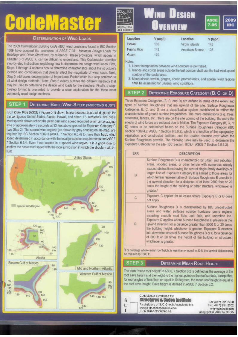
location V (mph) location V (mph)Hawaii 105 Virgin Islands 145Puerto Rico 145 American Samoa 125Guam 170
Notes1, Unear interpolation between wind contours is permitted.2. Islands and costal areas outslde the last contour shall use the last wind speed
contour of the costal area3. MoontalflOUS terrain. gorges, ocean promontories, and special wtnd regions
Surface Roughness B is dlaractenzed by urban and suburbanareas, wooded areas. or other terrain with numerous doseIyspaced obstructions haVIng the size of single-family dwellings orlarger, Use of Exposure Category B is limited to those areas lorwhich tarratn representative of Surface Roughness Bprevails inthe upwind directlon for a distance of at least 2600 feet or 20limes the height of the building or other structure, whichevef isgreater,l
Exposure C applies for all cases where Exposure B or D does"',_Surface Roughness 0 is characterized by flat, unobstructedareas and watll!' surfaces outside hurricane prone regionSincluding smooth mud flats. salt flats, and unbrolo:en ice.
Exposure 0 applies where Surface Roughness 0 prevails in theupwind direction fOf a distance greatll!' than 5000 fI or 20 timesthe building height, whichevef is greater. Exposure 0 extendsinto downwind areas of Surface Roughness BOf Clor a distanceof 600 fI or 20 limes the height of the building or structure,whichever is greater
CodeMaster developed by:......CIIIA._A subsidiary 01 SK Ghosh Associates Inc.www.skghoshassoclates.CO<T\ISBN 978-1-936039--01_2
c
B
o
EXP.
'For buildings whose mean rooftlelQhlllles$ than or equal klJO ll. the upwn:! dislance may'be reduced tp 1500 tl.
Three Exposure Categones (B, C, and 0) are defined in terms of the extent andtypes of Surface Roughness that are Upwind of the site Surface RoughnessCategories B, C, and 0 are a classification system established to reflect the
;characteristics of ground surface irregularities. The more obstrucbons (e.g. trees,structures, fences. etc.) there are on the site upwind of the building, the more theeffects of WInd forces are reduced due to friction. The Exposure Category (B, C, or0) needs to be determined based on the Surface Roughness Category (IBCsection 1609.4.2, ASCE 7 Section 6.5.6.2), l'Iflidl is a function of the topography,vegetation, and constructed lad lties. and the Upwind distance oyer which theSurface Roughness prevails The following table may be used to determine theExposure Category lor the site (IBC Section 1609,4, ASCE 7 Section 6.5.6.3).
The term "mean roof heighr in ASCE 7Section 6.2 is defined as the average of theroof eave height and the height to the highest poinl on the roof surface, except tha~for roof angles of less than or equal 1010 degrees, the mean roof height is equal tothe roof eave height Eave height is defined in ASCE 7 Section 6.2.'"'''',~
'"''''
140 140 150
•
western GuW Of Mexico IMid and .Northern AtIanlic
'00,~
'M
;;;:;";:::::'::=:::==::=~:U":~EIdSlates
'"'''',~'M'"
~-------; ~-----=--
~ DETERMINE BASIC WINO SPEED (3·5ECONO GUST)
IBC Figure 1609 (ASCE 7 Figure 6-1) shown below presents basic wind speeds forthe contiguous United States, Alaska, Hawaii and other U.S territories. The basicwind speeds shown reflect the peak gust Wind speed recorded within an averagingtime of approximately 3 seconds at 33 feet above ground lor Exposure Category C(see Step 2). The special wind regionS (as shown by gray shading on the map) arerequired by IBC section 1609.3 (ASCE 7 Section 6.5.4) to have their basic windspeed detennined in accordance With the local jUrisdiction requirements and ASCE7 section 6.54 Even if not located in a special wind region, it is a good idea toconfinnthe basic wind speed with the local jurisdicbon in which the structure wiJI bebuilt.
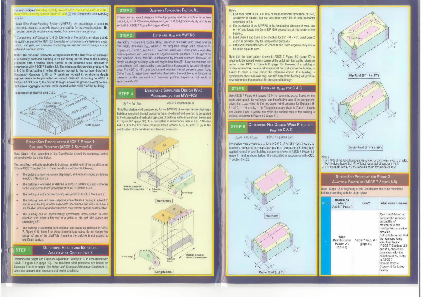
;he wind design of a building typicany involves two aspects· design of (1) the MainI-VInd Fon;&-RBSiSlmg System (MWFRS) and (2llhe Components and CladdingC& C).
Mam WIIld Fotcs-Re~ng System (MWFRS) An assemblage of slructuralelements aSStgl'led 10 provide support and stability for the overan structure, Thesystem geneTaUy receIVeS wlIld Ioalfmg from more !han one sorface
• Components end CJaddmg (C & C): Elements of !he buldlng envelope thaI do:)( qualify as part of the MWFRS Examples of components are fasteners, studs,Jrtins, and glrts and examples 01 cladding are wall and roof ooveOngs. curtain
IS and 0V9fhead doots
NOTE: The minimum horizontal wind Jnssure for the MWFRS of,n enclosedOf" partially encloud building 15 10 pst acting on the ,rea of the buildingrojlCted onlo a vertical plane normal to Ihe assumed wind direction In
iCcordance with ASCE 7 Stctlon 6.1. The minimum design wind pressure forC & C 15 10 ~I acting In either direction normal to the surfac•. Glazing inOccupancy Cat89Of'Y II, IH, Of IV buildings located In wind-borne debris
Ions needs to be Pl'otected as Impact resistant acconling to ASCE 7• 6.5.9.3 over 1) lhe first 60 ft height above the ground and 2) the first
',0 It above aggregate surface roofs located withIn 1500 ft of the bulldlng.
:Hustration of MWFRS and C& C
'" ,• ,"-
,• ,
I , ,»:•.,
.-.. 12,e
..,.
STEP 2 DETERMINE TOPOGRAHIC FACTOR Krr
If there are 1'10 abrupt changes in the topography and the structure is on le'l8lground K.J = 1.0. O\heIwise, determme K.J = (1+ /(1/(2~)l'Nhere K" /(2, and ~ aresellorth In ASCE 7Flg\lre~ (pages 45-46).
STEP 3 DETERMINE Ps30 FOR MWFRS
Use ASCE 7 FlQure 6-2 (pages 38-39), Based on the basic WInd speed and theroof angle, delern1ine p~, which IS the Slmpflfied deSIgn 'Mnd pnlssure forExposure e, h =30 11:, and / =1,0, Note that load Case 1 cooesponds to poSItiveinternal pressure and Load case 2 10 negauve Internal pressure The design of theroof members or the MWFRS IS Influenced by intemal pressure However. forSIITIpIe diaphragm bUJIcIings With roof angles less Ittan 25' it can be assumed thaithe maXImum Uplift. produced by a po5Itive inlemal pressure. IS the mntrolkng loadcase From 25" to 45' both posiove 800 negatIVe internal pressure cases (loadCases 1and 2. respectIVely) need to be checked for the roof, because !he externalpressore on the W1ndwartl roof beoomes positive beyond a roof angle ofappI'OXlmalely 25-
p~ -= ). KJl / plJIJ ASCE 7 Equabon (6-1)
Simplified design WInd pressure. P., for the MWFRS of Iow-ose Simple dIaph~bu\ldIf'lgS rapresent the I'Illt pressures (sum of ellltemal and intemaJ) 10 be applied10 the honzonlal and vertical proteebons of boildl~ sorta<:es as shawn below andIn Figure 6-2 (page 37), It IS calculated '" accxwdance WIth ASCE 7 Secbon6.4.2.1 For the honzontal pressure zooes (Zones A, e, C. and 0), fJf Is thecombInabori of the 'NlrIdward and leeward pressures
Notes:1. End zone WIdth = 28, 8 = 10% of least-horiZontat dimenSIOn or O.4h,
whichever is smaller, bul not less than either 4% of leasl horizontaldimension or 3 II.
2, For the design of the MWFRS III the longitudinal direction of wioo, usea=O· and locate \he Zone ElF, GIH boundaries at mid-leoglh of the
"'Idlng3, load Case 1 and 2 are to be c:hecked lor 25- < e< 45". Load Case 2
at 25- is provided only for interpolalJon purposes.4 IIIhe total horizontal loads on Zones Band 0 are negallve, they are to
be tall:en aqualla zero.
Note that the load pattern shown in ASCE 7 Figure 6-2 (page 37) Isreqwred to be applied to each comer of the building In tum as the referencecomer - See ASCE 7 FlQUre 6-10 (page 53). However. if a buiIdiog ISdoubly symmetrical, no new Il1foonalion wiD be produced as the building isturned 10 make 8 new comer !he reference comer If a building Issyrrmebical about one axis only, one 90- bJm of lt1e building wi" producenew InformaIJon that needs to be oooSldered In design
STEP 5 - DETERMINE PnefJO FOR C& C
Use ASCE 7 FlQure 6-3 (pages 42-44) to determme PtrIt» Based on thebasic wmd speed, tie roof angle. and the effective area of the componentdetermine P/d, which Is the net design Wind pressure fOt ~re B,h=30 11:./ = 1.0, and /(a = 1.0. The pressures areglYen for zones 1-3 (roof)and Zones -4 and 5 (waJlS)1n1O wtlICh the SlJrface area of the buildrng Isd."Ided. as shown Kl Figure 6-3 (page 41).
mF~-i DETERMINE NET DESIGN WIND PRESSURE
~j PnfttFORC&C
I
,
,,
,
,
Flal Roof
•
Kd < 1 and takes intoaccount the reducedprobability ofmaximum Windscoming from any givendirection.II should be noled thatthe correspondingwind load factor(ASCE 7 Sections 2.3and 2.4) should beconsistent with theselection Of K.,. Referto ASCE 7Commentary toChapter 2 for furtherdelails.
How?
ASCE 7 Table 6-4(page 80)
WindOirectionality
Factor, Kd
(6.5.4.4)
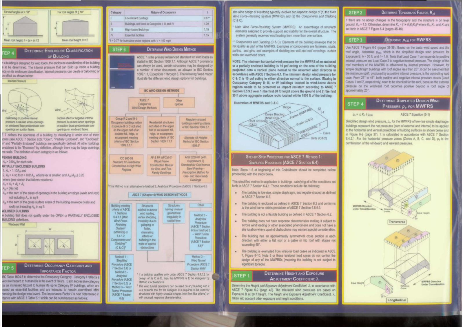
Gable Roof (7" < e ~ 45°)
STEP-Sy·STEP PROCEDURE FOR METHOO 2AN"-vnC"- PROCEOURE (ASCE 7 SECTION 6.51
DetermineWhat?
(ASCE 7 SectIon)
Noles'1. a = 10% of the Ieasl honzontal dimension or OAh, whicl1ever Is smaller,
but not less than either 4% of least horizontal dimension or 3 ft2. For hip roofs with e~ 25°, Zone 3 is to be treated as Zooe 2
Note: Steps 1-6 at beginning of this CodeMaster should be completedbefool proceeding with the steps beIcrti
ASCE 7 Equallorl (6-2)
'"•, ," ~• /:,·,
P"" = "Kid I Ptdl
.,
,·,
,
Net design wind pnmure. P/IIlI, for the C & C of bUildings deSigned usingMethod 1represents the net pressures (sum of external and internal) to beapplied normal to each bUilding surface as shown in ASCE 7 Ffgure 6-3(page 41) and as ShOWn below It IS calculated in ICCOfdance with ASCE7SecIJon 6,4 2.2
Note steps 1-6 at beglnnJrlQ of thJs CodeMasler should be compleled beforeproceedl~ WIth the steps below
ThIs SImplified method IS applk:able to buildH'lgs satisfying all of the conch\iol'ls setforth In ASCE 7 Secboo 6,4,1. These condlbons IocllJI1lllhe following:
• The boiIdlng Is ~-nse, smple diaphragm, and reguIar-shaped as defnedlt1 ASCE 7 section 6.2.
• The butldlng Is eodosed as defined In ASCE 7 Secboo 6.2 &rKl conformsto the WlflO.bom8 debris prDVISlOns of ASCE 7 Sectton 6.5.9.3.
• The building is no! a I\eXl'ble building as defined III ASCE 7 Section 6.2
• The bUIlding does r'lOl have response c:haracteoslics making Hsubje<;t toacross Wind IoadIllQ or 0Ihet assocaated ph.enomena and does not have aSite kx:allon where upwind obslructlons may wammt special ronsIderalJon.
• The buBdlng has an approximaleJy symmetrical cross section In eachdirectlon with either a flat roof or 8 gable or hlp roof With slopes no!exceeOr1Q 45-.
• The building is exempted from mionel load cases as iodicated In ASCE7, FlOUre 6-10, Note 5 or these torsional load cases do not conlrollhedesign of any of the MWFRSs (rTl8alllll!J the building is not sobfed toSllfnfficanl tmlon).
OelllflTllllEllhe Height 8nd Expowre Al1Juslment Coebnt, ;., In accordance withASCE 7 FlQure 6-2 (page 40). The tabUlated Wind pnlssures are based onExposure B al 30 II. heighl The Helghf and Exposul8 Adjustment Coebnl, )..lakes Into accoont other exposure and helght condi\lOl'ls.
rSTEP 1 DETERMINE HEIGHT AND EXPOSURE
• _ AOJUSTMENT COEFFICIENT A
Safwat.h
Highlight
This worillS~ will h1lt'd1llllrldio'lg tIat SKGA. SCI ICC a"ld Ihs IUthor1 n~ng Il'tformatlOll bul are not antrnptlng 10 render tnglllCOnl'lQ or olhef prof8lllONll1lIr'oUS. If such servICea we 18q1JQd. thI auilianal of quIllfltd profeuiDnall ahooIdbe.:lUght SKGA, SCI. ICC and ths IU#lors DISClAIM IOY..a II RESPQNSIBIUTYand lIABILOY b"lCClAC)' ofn tie .......1d Iht InfOrmIIon CCXlIIIned in IhdpOOIicIlJon ~ the flj extent pemIIIad by ill I8w
The sInX:tlru cannot r 01 \l'it fOOMng• Solid fre&.star'ldIng waijs LlfMat.ons on type of
• SoIIIIlgIIS IlnItlUrtI._-
STEP 3 DETERMINE TOPOGRAPHIC FACTOR K.l!
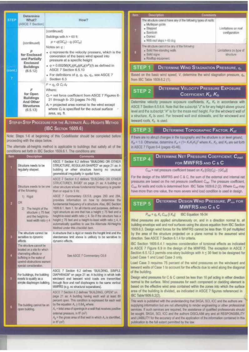
STEP 4 DETERMINE NET PRESSURE COefFICIENT ene!
fOR MWFRS AND C & C
Determine veIodly pre5S1Jre exposure ooe1'rtcienlS. 14 ~ III accordance WithASCE 1 5ection 6.566. Nolt flat the sublaipt "Z-II lor any helghl abOVe groundlevel and !he subsctlpt of(' II tot the mean roof htlght For tOe windward wall ofa structure. K..IS used, For leeward wall and SldttwaIII, and for \lll'1f\dWard and__ K,Is ....
Based on !he baslc wn:I speed. V ~11~ .,. ......nd 1LIQRa\lOn pteIaIA. q.from IBC Table 16096.2 PI
STEP 5 DETERMINE DESIGN WINO PRESSURE p"P( fOR
MWFRS AND C & C
STEP 2 DETERMINE VELOCITY PRESSURE EKPOSURE
COEFFICIENT Kz K"
c...::; net preatn 'bMId on ~ !1G!t(;al 'c.For lie des9l rJ fie MWFRS and C&C .. un oil'll edlrnallI'ld~ net~ ft based on .. net pt-..a coeftIcieo'l( c... The IftSSUIt o:JdoInI.c.... lor walsand roofs ildlIIiIl".lId ttw"n 18C T8bIt 1609 6.2 (2) 'MIn c..mayM¥fI!!'In flan one YaIIJe. ltlI rm'e ....... WI"Id laid condilal" u.-t., deIign
STEP 1 DETERMINE WINO STAGNATION PRESSURE q,
If '*" n rJJ 8ttl.4lt dmges tllIe k4X9~I)' WId tI'te IN:lft 1\ on M ~K.cl,O.OhlrwIse~.neK -r1.,cI<'K. whereK1 ¥ldl( dr,•. '1CM'tt1"ASCE 7 FIgUte 6-4 (pagel4S--401
p..' q.K, C.dl K"J I1!C~ 1&.3'WInd pteSSlJrBS iQ iIAIIed~ on. end 1\ a cIrecIon I'CInTlII m. III>lting.....". ... "",«d..- _ .._~ from 11!C_1609 &3 """"..., _ "".. MWfRS '*"'" be "" .... 10 pol""""""by iIe .. of h !itIJctln P'Of'C*l on a pIInt~ m!he 8IIUIned WIldth::lIon, See ASCE 7 Section 6.1 4 b aw.IBC SectIon 1609.641 reqUItes consldnllOn ollOftional effects as lndk::atedIn ASCE 1 FIgUre 69 in the design of !he MWFRS The exceptlOt'll1 ASCE 7section 6.5.12.3 permils one-story buIlding, With h ~ 30 feel to be cleslgned fOtload Case 1 and load Case 3 only,load Case 3 requires 15 percenl of !he wind rxeillJm on the Windward andleeward waUs of Case 1 to ICCOUIlI for !he effects due 10 Vrtnd alOng !he dl8gOO8tof the building.
Oeslgt wnj JWesstnlS b C &C csmI be ..... 10 PIf DIg In ...dncionnormal 10 I1e arfIoa. 'Mnd~ b'.ctt COlIW•• <r~ eIenwlllribesed on f1e BIIecIYe WIld ... c:onlII'Ied wihn fie ZO* I'iIO wNd'l tie ItJfaoearea of the bu~dlOg IS dl\*lded. II indiCated In ASCE 1 figures referenced Itt
IBC ' ....'609.62(2).
ASCE 7 5edlon 62 dem 'BUilDING, SJ'*'l£DIAPHRAGM- on PI9' 21 as: A buiIdIIg In 'flhdI ballWIlIdwaro and IeewW wind loacII lit~lhl'Ollgh lIoor and roof iIlV"... to .. ..,. IIWicaIMWFRS {It.g no SIl'UCIl.nllCP8lltlorw}
I ASC~ 7Section 82 oem.. 'BUilDING Of'£N CI'I
Pf9I 21 • A buIcIn; IlfwinQ eatfI ... II IIaII 80pert:ent opIfI. n. oondIlIl:It ...~ b IK!l _by ltlI~ A. ) 0SA, wtoIItA."1IltaI ..d ClpII'IIfIOIltI' will .....1ttCtIYIIlK*IvtullrTWll! ....... in ft· 1m'!A" =III grt:III..d.1III "flo '" 'tIIflicI'I A,.. IIIC11nD1sd•• (m'l
Howo?
(continued)
BI..idngs with h " 60 Itp'" q(GC,,)' qj (GC",)
Notes on q
• q represents lhe velocity pressure, Which Is theronversion of the basic wind slleltd intopressure at a specific helghl
• q '" O.OO256(KJ(K"XK.r~V2)(/) as defined InASCE 7 SectIOn 6.5.10
• For definllions of q. q~ qh, qr, see ASCE 75ecboo 6.3
F:q,GC,A,
wtlere;
Cf ", nel force coemctenl from ASCE 7 Figures 6·21 through 6- 23 (pages 74-76)
IA, '" projected area normal to the wind except
where C, is specified for tha actual lurfacearea. sq, ft.
Ffor OpenBuildingsAnd OtherStructures
(6.5.13)
(continued)
pfor Enclosedlind Partially
EnclosedBuildings(6.5.12)
For buidngs the buildllgneedS b ~ify as a
""" """""" 1>,"""
rASCE 7 5Ialon e2.. 1KJIlOlNG OR OTHERST'RUCl\JRE REGlJLAR-5HAPEO" on~ 21. AIbUdng or 0Nl' tlNdIft hlIY't111 flO~
_~__~·l~"'~'''~'''~_·_",,,,,;~====,ASCC 1 Sedlon U dIrr. 'B\Jl.OINO OR OllERSTRUC'Tl..RES RIGlT on flIDI21 as ,,~ (II
0IlW1N3n -..!lda! ...freql..cy.~_1ilII'_101Hz..ASCt: 1 CornmIntII, t8 5.8 P9I 2lU Illll ~JII'OVI6II "'tonnItIon on hOw to dteImlinI lit~~ 01. stn.e:turI AIIo IBe Sec:tlon
The h8IgIll 0I1he 1609 6 1 llIrn 1 for a/I"'II r.d purpclMI 6IftnII1~(~51BlK IQd 1N:ln. one hI '-.~ (751e1t 1nIt •1IId"~.tl). i~~lIItidIl_(4 sa.,..ltndlIe,.,
.-:!II" <; .. IleiIt' ~ 7:l teel n •~ kHUIt wktIllIIb (.. I- ,d:lmIIIr.:llIy QUIIIIieI to IlII Ilt__~
, MeIlad II1W ..dlIliIIt~
The sln.lctln cannot be ASlI'UCt.n lilt. ngdGl" ""'" lit heIflt~ Ind ....&el\SjllVf! 10 ~rtarrac "'.,_ 1m! III:Ii:M • unIIefy 10 tit ID
'~,...~===;--_-cc ..... ~ttij;1N*n~ be~on a..for """d'I.............buIlt*tg JI ..walle d---IPIdIl lXI".U
CI" GC~. snd GC.reflect lila relatIVepressures esUmatedto eXIst on IheeKterlol' surfacfl' andare dep&nClenl upon
Ithe ~metflcconfiguration of lhestructure including
Ilhe roof. Thesecoefflclents ere nolapplicable to openbuildingsGC" values for C & Calso depend on theeffective WInd area.which Is denned InASCE 7 section 5,2----IRigid Buildings- MW="'='---'-'-
1. Wherecombined gusleffect factors andpressurecoefficients (GCI"GCpj• and GC",)
are given in f.gureslind tables. thegust effect factO\'" isnot determinedseparately.
2. In lieu of theprocedure defined IIn these sections,gust effect factormay be determinedby any rationalprocedtJre given inthe IllcognlzedIlteralllre
• For neKiblestructures (period? 1 sac.). calculateG per ASCE 7Sectlorl6.5.8.2
OUII EffectFletor, G, Gt
16.'.6)
TopographicFaclor, Kif(6572)
OelermlneWh.t? How? What does II me.n?
(ASCE' _Ion,~SeE 7 Table 6-3
(page 79) While the bask: windIt is Important 10 speed, V, representsnote that the
V,toel1y the wind speed at 33subscopt 'z' is lor
Pre••u... any height above feel above ground forEllposure ground level and Exposure Category C,
Coef'fklentl (tot ttl sob . I -h" . II<, Var K~ V,ach wind e scnp IS represents !he WInddlrKtlon), for the mean roof speed al z or h feel
K.. I4t heigh," Also, the respectlvelyabo'n(65.8.6) velOCIty pressu~ ground for the
81lposure coeffIClent"d . • Emay be calculated C7"" xposuraIn accordance with a egory.Nota 2 to Table 6-3.
Only applies If Kzt win Do grealerthere are abrupt than 1 if the rr.echanges in the conditions listed Il'I
topognlphy. If ASCE 1 SectIOnUlef8 are no abrupt 6,5.7.1 exist. K"changes in the takes Into aCOOUflt thetopography and faCllhal jf a buUdlngthe structure is on sils on the upper halflevel ground, Kif = 1. of an isolated hWI,If the live conditions ridge, or escarpment,Il8led In ASCE 7 Ias a result, the5ecI1OO 6,5 7 1 bulldlllQ can beeKIIt. then expected toKn '" (1 +K, K1K:J f ekperi9l1ce
;and K" K2• and 1<:J higher wmd sPMdsare set rorth lrt thaI" Ii ,1 ww)!ASeE 7 FlQure 6-4
1
siluatett 'll ItwO!l(pages 45-46). ground
. -• For rigidstructures (period<; 1 sac.). use G '"0.85 or calculateper ASCE 7Section 6.5.8.1.
STEP.By.STEP PROCEDURE FOR THE ALTERNATE ALL-HEIGHTS METHOD
(IBe SECTION 1609.6)
Limita~ons on roofconfiguration
(continued)
pfor Enclosedand Partially
EnclosedBuildings(6.5.12)
Ffor OpenBuildingsAnd OtherStructures
(6.5.13)
How?
(continued)
Buildings with h > 60 I.:
p'" q(GCp) - qi (GCpi)
Notes on q :
• q represents the velocity pressure, which is theconversion of the basic wind speed intopressure at a specific height
• q'" O.OO256(K,)(Kzt}(Kd )(Vl}(I} as defined inASCE 7 Section 6.5.10
• For definitions of q, qi, qn, q" see ASCE 7Section 6.3
IF=q,GC,A,
Where:
C/ '" net force coefficient from ASeE 7 Figures 621 through 6- 23 (pages 74-76)
A, '" projected area normal to the wind exceptwhere C, is specified for the actual surfacealea, sq. ft.
The structure cannot have any of the~ types of roo1s:• Mullispan gable• Stepped..00"""• With roof sq:.e > 45 dcg
The sIru::lure ClWlrlOt tle My ,j lhe :::-.;:::='.-=~-t-I--• Solid frll&.stanOOg walls Limitations on type of• Solid S9l5 structure._-
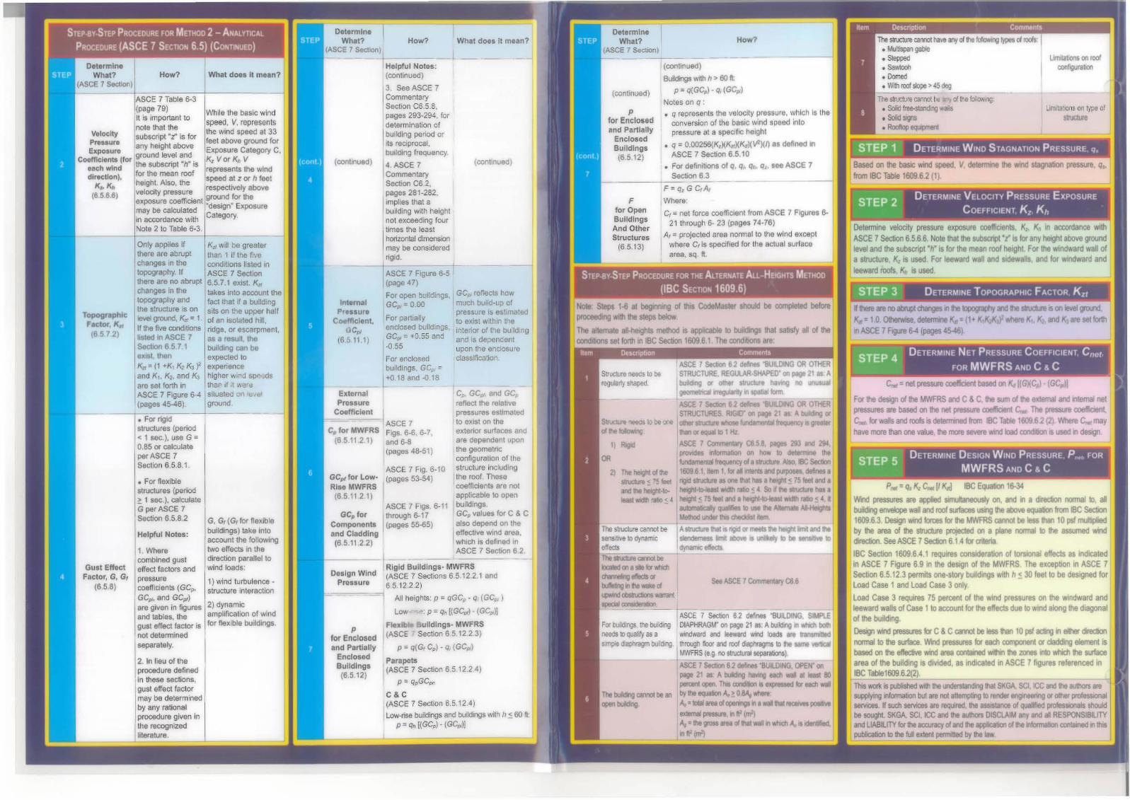
Detennine velocity pressure exposure coelficlents, K,. ~ in accordance WIthASCE 7 Sectton 6.5.6,6, Note that the subscript "z" is fOf any height above groundlevel and the subscript "h" is for the mean roof height. For the windward wall ofa slNclure, K, is used. For leeward wall and sidewalls. and for windward andleeward roofs, K.~ is used
L~!.~!'.dl DETERMINE TOPOGRAPHIC FACTOR, Kzt
C..=net pressure coefficient based on ~ [(GXC~) - (GCp,))
For the design of the MYt'FRS and C & C, the sum of the external and intemal netpressures are based on the net pressure coefficient C".. The pressure coefficient,C.., for walls and roofs is determined from IBC Table 1609,6,2 (2). 'Nhere C". mayhave more than one value, the more severe WInd klad condition is used in design.
p.. =q. K, C".[I Kzl! IBe Equation 16-34
Wind pressures are applied SKTlUItaneously 00, and in a direction normal to, aIbuilding envelope waf and roof surfaces ISlg the above equation from IBC section16096.3 Design wind forces for the MWfRS camot be less than 10 psf multipliedby the area of the structure proJeCted on a plane normal to the assumed winddirection see ASCE 7 section 61.4 for criIefia.
IBC Secbon 1609,6.4.1 requires oonslderabon of torsional effects as indicatedIn ASCE 7 Figure 6.9 in the design of the MWFRS. The exception in ASCE 7section 6.5.12.3 permits one-story buildings with h.:::: 30 feet to be deSigned for
I Load Case 1 and load Case 3 only
Load Case 3 requires 75 percent of the wind pressures on the WIndward andleeward walls of Case 1 to account fOf the effects due to Wind along the diagonalof the building
Desigl wild presstreS for C& Ccamot be less than 10 pst acli1g i'I Elllhef cirectia'Inormal to the surtace. Wnd pressures for each amponent or cladding element isbased on the elfedr..oe wirld ar9ll oontamd wrttwlthe zones into 'Nhich the surlacearea of the building is divided, as indicated in ASCE 7 figures referenced in~Be Tablel609,6.2(2).
Ns'tll'Crl; is pubIshed WIlh the understaf1ding ltIiI Sl<GA, SCI. ICC and the authors an!
supplying llfarmabon but are not altempbng to render engineefiog or other professionalservices If suctl servlC8S are reqwred. the assi5taoce of qualified profeSSlOl"l8ls shouldbe sought. Sl<GA. SCI. ICC and the authors DISClAIM any and aI RESPONSIBILITYand LlABlUTYtor the accuracy of and the application of the llformabon contained III thispublicaboo 10 the full extent pennilled by the law
If there are no~ changes il the topogaphy and the slruclun! is 00 level grcxnl,
Kzl = 1,0. OlherNise, determioe KlI ={1+ K,K:l.KJ'f whem K1, K2, and K] are set forthin ASCE 7 FlQUre 6--4 (pages 45-40)
see ASCE 7 Commentary C6.6
ASCE 7 Section 6.2 defines "BUiLDING, SIMPLEDIAPHRAGM' on page 21 as: A building in whdl bothwindward and leeward wind loads are transmittedthrough floor and roof diaphragms 10 the same verticalMWFRS (e.g. no structural separations).
ASCE 7 section 6,2 del\ne$ "BUILDING, OPEN" 00page 21 as: A t:M.tilg havilg each WIll at least 80percent open This rordibon IS expressed lor each WIllby lhe eq..I8Iion A" ~ 08As Where
IA" =1oIlII_ r:I opllIWlgS II a WIll that I8C8MlS positive
exlllmal~, 11 fl2 (mlj~ =the gross area rt thaI wall'I which A. is derJlIfied.• II' 1m')
For buildings, the buiIdiogneeds to quaMy as asimple diaphragm buMding.
ASCE 7 Section 6.2 defines "BUILOING OR OTHERSTRUCTURE, REGULAR-SHAPEO" 00 page 21 as: Abuilding or other structure having no unusual
I geometrical irregulanty in s~p~";ial~fili~m~.====~ASCE 7 Section 6.2 defines "BUILDiNG OR OTHERSTRUCTURES. RIGID" on page 21 lIS: A building or
St.ructure reeOs to be one 'oII1er structure wnos. fundamental frequency is gl'eater
01 the following: !han or aqua/to 1 Hz
1) Rigid ASCE 7 Commentary C658, pages 293 and 294,provides Information on how to determine the
OR IundamentaI frequency r:I a structunl, Also. IBC Section2) The I'letoht of the 1609,6.1, Item 1, klf aI Wllents and purposes, defines a
structure:!,: 75 feet ngid slrUCture as one that has a height:: 751eet and aand the helght-lO- height-kHeast \Yldth ratio ~ 4, So if the structure has aleast WIdth ratiO ~ 4 height ~ 75 feet and a helght-tlHeast \Yldth rallo ~ 4, rt
automalK:ally qualifies 10 use the A1lemate Al-HeightsMethod under tIvs d1eckliStltem
The s1n.lc1urecanoo~""A,lructure lhat is rigid Of meets the height Iim~ and thesens~1Ve to dynamic stendemess lim~ above is unlikely to be sensitive toeffects dyna~m~"~,_',~,~._. _The sln.dure carnJt be ~
located on a_ tr wtidl
-"""'~IlM1g " he wake rt---speciallXJIlSidelaIO I
Note: Steps 1-6 al beginning of !his CodeMasler should be compleled beforeproceeding with the steps below
The alternate all-heights method is applicable to buildings thaI satisfy all of theooodilions set forth in IBC Section 160961 The condltJorlS are: