23
CODE OF PRACTICE LAND SURVEY ORDINANCE (Chapter 473) First Edition - 5th October 1995 'With amendments of Corrigendum No. 1196 (November) incorporated 1

CODE OF PRACTICE
LAND SURVEY ORDINANCE
(Chapter 473)
First Edition - 5th October 1995
'With amendments of Corrigendum No. 1196 (November) incorporated
1

CODE OF PRACTICE
LAND Sl:.JRVEY ORDINANCE
(Cap. 473)
CONTENTS
Parts Paragraph
I GE:N-"ERAL 1-2
II INTERPRETATION " ~
III CONDUCT OF LAND BOUNDARY SURVEYS 4-40
(A) Field notes 4-8 (B) Origin of co-ordinates & bearings 9-12 (C) Bearings, distances and co-ordinates 13-16 (D) Survey instruments 17-19 (E) Traverses 20-27 (F) Boundary marking 28-33 (G) Permanent survey marks 34-35 (H) Physical features 36-38 (1) Land boundary definition 39-40
IV MEAS1JREMENTS AND SURVEY TOLERANCES 41-42
V LAND BOUNDARY PLANS 43-44
VI SURVEY RECORD PLANS 45-46
APPENDIX A SPECIFICATIONS FOR S"lJRVEY MARKS
APPENDIX B DRAUGHTING SPECIFICATIONS FOR SURVEY RECORD PLANS
APPENDIX C SPECIMEN LAND BOUNDARY PLAl',l
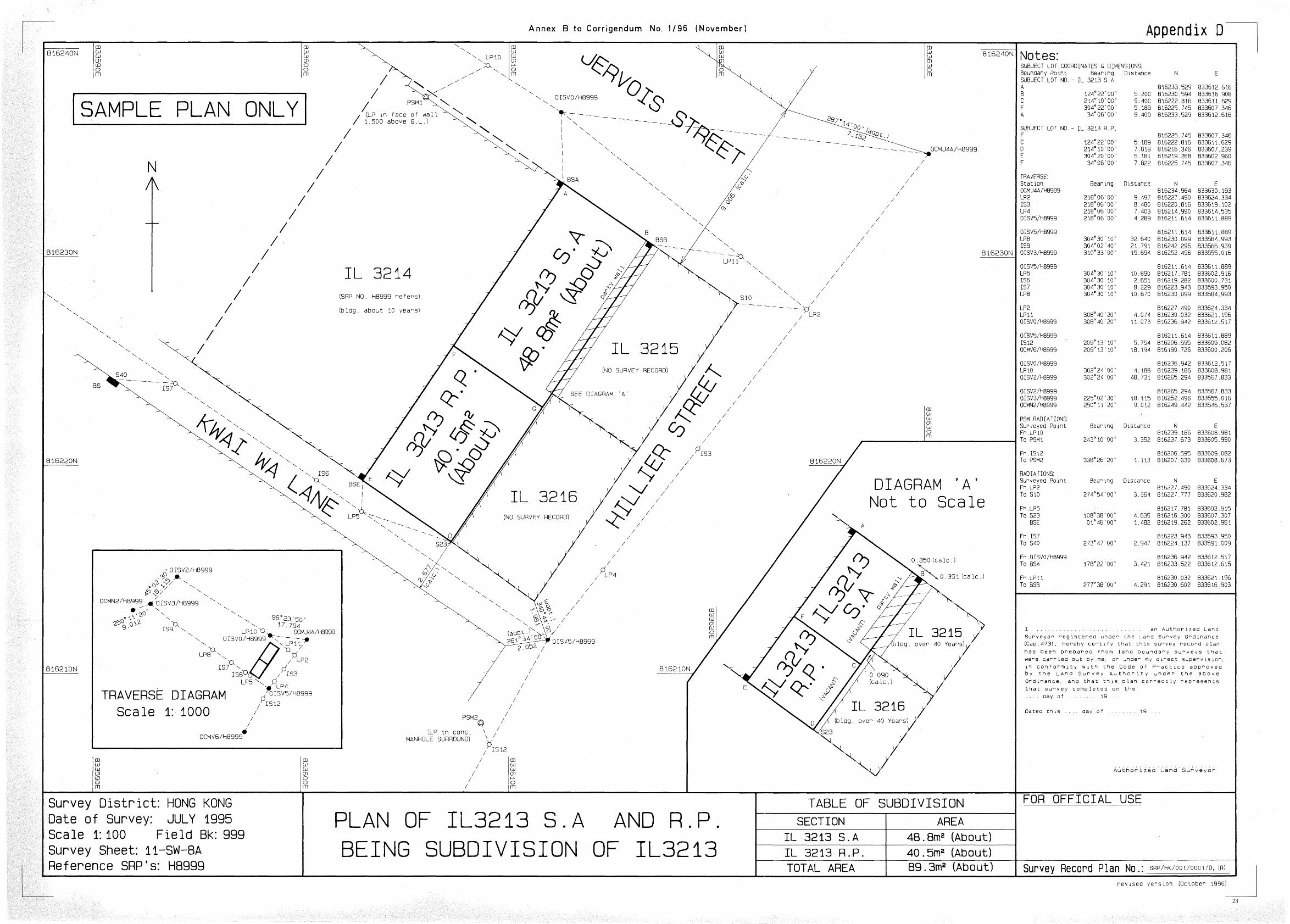
APPENDIX D SPECIMEN SURVEY RECORD PLAN
2

I GENERAL
1. These regulations state the requirements for carrying out all land boundary surveys in Hong Kong under the Land Survey Ordinance (LSO).
2. For the purpose of control of land boundary surveys, every Authorized Land Surveyor (ALS) shall carry out land boundary surveys in compliance with the Land Survey Ordinance and these regulations.
II INTERPRETATION
3. The following are the definitions of the terms used in these regulations:-
"adopted" data means the traverse or land boundary information accepted from previous survey.
"boundary mark" means a survey mark which demarcates a parcel of land.
"boundary stone" means a boundary mark made from white granite, or concrete slab established by the Survey and Mapping Office of Lands Department to demarcate a parcel of land.
"calibration" means the process of checking of a distance measuring equipment against a standard baseline established by the Survey and Mapping Office of Lands Department for corrections to be made to measured lines.
"control survey station" means a survey station emplaced and mathematically fixed under the Hong Kong Control Survey System.
"grid lines" means lines drawn on a map or plan in the form of rectangular grid under the Hong Kong Control Survey System.
"Hong Kong Control Survey System" means the current network of survey stations, emplaced and mathematically fixed, based on the "Hong Kong 1980 Geodetic Damm (HK80)" by the Survey and Mapping Office of Lands Department.
"Hong Kong 1980 Geodetic Datum (HK80) " means the survey damm used by the Survey and Mapping Office, Lands Department since 1980.
''party wall" means a wall wherein the common boundary of two land parcels is located.
"permanent survey mark" means a survey mark established by a land boundary survey for fumre use and reference.
- 1 -
3

"picket box" means "-~'-'
a control '~'- " ,-
survey station - ."->'.:
enclosed ... -
by"acast . - ........
iron --"
box. -'-
;
"survey mark" means a mark defining a surveyed position.
"survey station" means a survey mark over which survey observations <ire made.
"traverse" means a series of lines between survey stations established by angular and linear measurements starting and closing onto control or old traverse surve)i stat!SJDs.
"urban survey mark" means a control survey station made of metal in a mushroom , like shape.
- 2 -
4

III CONDUCT OF LAND BOUNDARY SURVEYS
In order to maintain a uniform standard practiCe for all land boundary surveys, . Authorized Land Surveyors are required to adhere to the following regulations:-
(A) Fields notes
4. The first page of the field notes of every survey shall bear the certificate signed by the Authorized Land Surveyors in the following form:
I , .................................. , an Authorized Land Surveyor registered under the Land Survey Ordinance (Cap. 473), hereby certify that these field notes, consisting of ........ pages, are a correct and complete record of the observations and measurements made in the field, either by me, or under my immediate direction and supervision.
I also certify that the land boundary survey, of which the field notes form a part, was carried out in conformity with the Code of Practice approved by the Land Survey Authority under the above Ordinance, and that the survey was completed on the ........ day of .......... , 19 .....
Dated this ........ day of.. ........... 19 .... .
Authorized Land Surveyor
5. An Authorized Land Surveyor or his assistants who carry out the land boundary surveys shall initial and date each page of the field notes. Where an assistant is carrying out the survey under the direction of an authorized land surveyor the latter or his delegate will additionally initial and date those pages of the field notes where the survey has been tested or otherwise checked by him and! or, other field instruction has been given.
- 3 -
5

6. Field notes shall be prepared for all land boundary surveys perfonned under the Ordinance and should be a complete original record of all field observations and field measurements recorded in the field. Printout from electronic data recorder shall bear the signature of the surveyor and shall contain equivalent information as contained in traditional field notes. Hand-written field notes shall be neatly and clearly recorded or annotated in permanent blue or black ink and shall not be obliterated, inked over or erased. Corrections may only be made by crossing out the erroneous entry in such a way that it remains legible, and writing the correct value above or alongside it.
7. Field notes shall record the type and identification number of the instruments including theodolite, electronic distance meter (EDM) and steel tape etc. used for the survey. The first page shall show the designation of the land parcel, locality or such other reference or legal descriptions. The date of starting and completing the survey shall also be recorded. . " '
8. All field notes and computations shall be properly kept for submission upon request by the Land Survey Authority.
(Bl Origin of co-ordinates & bearings
9. The origin of co-ordinates and bearings shall be obtained from :-
(a) The Hong Kong Control Survey System, or
(b) Any other survey which the Land Survey Authority accepts as suitable for the purposes of land boundary survey.
10. The reliability of any two survey stations used for an origin of bearings shall be proved by testing their agreement with at least one other survey station.
1 L Anyone of the survey station proven reliable as in para. no. 10 above shall be acceptable as an origin of co-ordLTlates.
12. The survey tolerances stated in pan IV shall be used when proving ongms and obtaining agreements with old survey work in the field.
- 4 -
6
(C) Bearings, distances and co-ordinates
13. Bearings shall be measured with a theodolite -reading to 20 seconds or better precision. Traverse bearings shall be made with a minimum of one arc on both face left and face right of the theodolite.
14. Bearings shall be recorded in the field notes in accordance with the precision of the theodolite being used and shown on survey record plan and land boundary plan to the nearest 10 seconds. To facilitate the use of computer in computation and plan production, bearings may be shown on land boundary plan and survey record plan to the nearest 1 second without rounding off the figures.
15. Distances shall be shown in metres and decimals of a metre and read and booked in the field to 0.001 of a metre. Distance measurements shall be made with a steel tape or an electronic distance meter (EDM). All necessary corrections shall be applied.
16. Distances and co-ordinates shall be shown on survey record plans to 0.001 of a metre but shall be shown on tbe land boundary plan to tbe nearest 0.01 of a metre. To facilitate tbe use of computer in computation and plan production, distances and coordinates may also be shown on land boundary plan to the nearest 0.001 of a metre witbout rounding off tbe figures.
(D) Survey instruments
17. Distance measuring instruments include steel tape and electronic distance meter (EDM). Steel tape shall be checked against an adopted baseline, which is established by the Land Survey Autbority, at intervals not exceeding 6 months, or immediately following repair. EDM instruments shall also be checked against an adopted baseline established by tbe Land Survey Authority annually or immediately following servicing.
18. A full report of each calibration shall be kept by the Autborized Land Surveyor for record purposes, and shall be presented for inspection when required by the Land Survey Autbority.
19. The Land Survey Authority may also inspect instruments used for a land boundary survey to ascertain they are in an operating condition to the satisfaction of the Land Survey Authority.
- 5 -
7

•
(El Traverses
20. Traverses shall start from and close onto contror-survey stations of the Hong Kong Control Survey System or traverse survey stations established in previously land boundary surveys as shown on deposited survey record plans. Before any traverse begins, the reliability of any two survey stations used for an origin should be proved by the Authorized Land Surveyor testing their agreement with at least a third survey station.
21. No unclosed traverses are allowed.
22. Control survey stations emplaced and mathematically fixed by the Survey and Mapping Office of Lands Department are normally in the form of concrete pillars, picket boxes and urban survey marks, and they are collectively described as control survey stations.
23. Traverse survey stations shall be marked by one of the following survey marks, details for which are specified at Appendix A:-
(a) Iron tubes; (b) Lead plugs; (c) Iron spikes; (d) Survey nails; (e) Wooden pegs; or (f) Cut marks. (cut marks shall only be used where other marks cannot be
emplaced)
24. Angular misclosure for a traverse shall not exceed (30 Vn) seconds where n is the number of survey stations in the traverse.
25. Linear misclosure for a traverse shall not exceed (10 + 28/15) millimetres where 8 is the total length of the traverse in metres.
26. When a traverse longer than 1 km. is run, control bearings shall be observed reciprocally between traverse survey stations and some other control survey stations, at such station intervals as will adequately control the orientation of the traverse lines. The number of traverse survey stations between control bearings shall not be more than ten.
27. Traverse miscJosures shall be mathematically adjusted.
- 6 -
8
(F) Boundary marking
28. Boundaries shall be marked at every comer, and where necessary at points on the boundary line if the comers are not intervisible. .
29. Where a boundary mark cannot be placed because of an obstruction the boundary mark position shall be offset for establishing its position in future.
30. Boundary marks shall be one of the following survey marks, details for which are specified at Appendix A:-
(a) .. :Iron tubes; (b) Lead plugs; (c) Iron spikes; (d) Survey nails; (e) Wooden pegs; or (f) Cut marks. (cut marks shall only be used where other marks cannot be
emplaced)
3l. Every boundary mark shall be placed by bearing and distance from a survey station ~ and checked independently by radiation from another survey station. Where double radiation is impracticable other checking method will be used to verify the accuracies intended. The same requirements apply when fixing the position of old marks, occupation and other elements essential to land boundary definitionS.
32. The setting out distance from a survey station to a boundary mark using steel tape and EDM shall not exceed 20 metres and 150 metres respectively. They must be checked independently and recorded accordingly. . ..
33. . Curved boundaries shall be marked at both end points and at least one other point on the curve. In addition, curves shall be marked at intervals not exceeding 15 metres, measured along the chord.
(G) Permanent survey marks
34. At least two permanent survey marks (PSMs) shall be established for every land boundary survey in accordance with specifications at Appendix A. Where there are existing PSMs from previous land boundary surveys in the vicinity, they may be accepted as PSMs after verification.
35. AIl PSMs shall be fixed by double radiation. They shall be described with sketches in the field notes and shown on the survey record plan as to the type of survey mark and its position and height above ground level.
- 7 -
9

(H) Physical features
36. The positions of all buildings or prominent physical features, on or within 0.5 metre of a boundary line,' shall be surveyed, calculated and shown as offsets on the survey record plan. Physical features beyond this and up to 3 metres need only be shown graphically.
37. Bciundary on party wall shall have .the offset distances in relation tothe'party wall shown on the survey record plan. .. ... -.
3g. Where a boundary is located in a party wall, or between abutting walls, checks must be carried out to confirm that the line of the party wall or the line between abutting wall is a straightlim:.- . -
(1) Land boundary definition
39. The definition of lot boundaries shall be based on best evidence. Evidence includes relevant information obtainable from records (such as Demarcation District (DD) sheets, DD Control sheets, DD Enlargement, House Lot Plans, House Lot Plans Retrace, "A" sheet, Cadastral Survey Plans, DD Lot Identification Plan (I plan), Permanent Land Record Plan, Survey Record Plans (SRP), SRP equivalent data, Land Boundary Plans, Aerial photographs, Survey Sheets from Microfilm), as well as ground occupation and investigation, interviews and any other form of data that will support the position and dimensions of the lot under survey.
40. The Authorized Land Surveyor shall submit a report on the land boundary definition for a land boundary survey. The report should contain information such as evidence found and the rationale of how the boundaries are established. The report should include a copy of any Land Boundary Plan, Survey Record Plan, Identification Plan, Control Traverse and any other plan, sketch, photograph or document containing information or data, which have been used or based on for traverse origin and/or boundary definition or redefinition.
- 8 -
10

IV MEASURE.MENTS A..ND SURVEY TOLERANCES'
41. If a bearing, a distance or an area is remeasured Or re-calculated for verification,'reestablislunent or whatever reasons, discrepancies are acceptable if they are within the listed tolerances below. The original values will then be adopted. If the discrepancies fall outside these tolerances the new values must be conclusively checked for correctness. If confinned, the original values must be considered as
'superseded by the new values with reasons clearly recorded.' The tolerances are: ''', ,.'
(1) Survey tolerances - Bearing measurements:
Distance Tolerance
under 15 m ±2' 00" 15 m - 150 m ± l' 00" Over 150 m ±O' 30"
(2) Survey tolerances - Distance measurements:
Tolerance: .
±C0.015 + 0.0001 x distance in metres) metre
(3) Survey tolerances - Area calculations:
Tolerance: ± 0.1 %
42. Areas shall be rounded off to the nearest unit as follows:
Area of Lot Expressed in Rounded off to nearest Under 2000 m2 sq. metre (m2
) 0.1 m2
2000 ul and above
However, areas already committed may be exempted from this rule, in which case the fonnula in paragraph 41(3) will apply.
- 9 -
11
v ... LA.~1) BOUNDARYPLANS
43. For the purpose of this Ordinance, a land boundary plan shall be prepared for division of land for attachment to the instrument for registration with Land Registry under the Land Registration Ordinance (Cap. 128). In addition, duplicate copy of the land boundary plan and survey record plan shall also be deposited with the Land Survey Authority ..
44. The land boundary plan shall satisfy the following requirements:
(1) Land parcel information:
(a) A plot of boundaries drawn to .scale; (b) Designation of the subject lot or parcel; (c) The.area oLeachJot or parcel; (d) Notation and if applicable, the description of each boundary corner; (el Boundary dimensions of subject lot or parcel;. and (f) Abutting land information.
(2) Supporting information:
(a) Grid lines with co-ordinates; (b) Location diagram of the site, where necessary; (c) The plot, with details of colouring and abbreviations; (d) Scale; (e) Standard north point symbol; and (f) Co-ordinates of each boundary corner may be shown at the discretion
of the Authorized Land Surveyor.
(3) Plan size:
Any such plan and copy thereof shall be of A3 size or of such size as specified under the Section 8 of Land Registration Regulations (Cap. 128).
(4) Plan numbering:
Plan numbering shall be a similar counterpart to that of the corresponding survey record plan. Example:-
LBP/trKlOOll00011D1
LBP = Land Boundary Plan HK = Hong Kong (District Survey Office) 001 = Registration number of ALS 0001 = Plan number as prepared by the ALS D1 = Dimension Plan (D1, D2, ... ,Dn etc.) or S1 = Setting out plan (S1' S2, ... ,D n etc.)
- 10-
12
Note: DSO Hong Kong and Kowloon shall ~be abbrevIated to HK and KL respectively without any need to specify further whether it is east, west or central. For other DSOs, their abbreviations are shown in the brackets: Island (IS), North (DN), Sai Kung (SK); Shatin (ST), Tai Po (TP), Tsuen Wan (TW), Tuen Mun (TM) and Yuen Long (YL).
(5) Every land boundary plan shall be signed and certified by the Authorized Land Surveyor and bear a certificate in the following form:
I , ................................ , an Authorized Land Surveyor registered under the Land Survey Ordinance (Cap. 473), hereby certify that this land boundary plan has been prepared from land boundary surveys that were carried out by me, or under my direct supervision, in conformity with the Code of Practice approved by,the Land Survey Authority under the above Ordinance, and that this plan correctly represents that survey completed on the ........ day of ......... :; .. 19 ........
Dated this ........ day of .......... 19 ....... ;:
Authorized Land Surveyor
- 11 -
13

VI SlJRVEY RECORD PLANS " -'
45. The survey record plan (SRP) is a plan which records survey data (including land boundaries, survey evidence, survey marks, traverses, alignments and significant ties to occupation and related features) used in a land boundary survey. The objectives of preparing a SRP are:
(1) to maintain repeatability such that:
(a) the SRP alone is able to ensure users to be able to maintain consistency of boundary definition, c
(b) the SRP alone can allow a checker to satisfy that consistency has been achieved, and '. ... -
(c) positive identification of marks and boundary features are made possible; and
(2) to comprehensively convey what constitutes and marks the boundary. The SRP alone cannot reveal why a boundary is so defined or how decision has been made.
46. The survey record plan shall include the following information:
(1) Land parcel information:
(a) A to-scale plot of boundaries; (b) Designation of the subject lot or parcel; (c) The area of each lot or parcel; (d) Notation and if applicable, description of each boundary corner; (e) Boundary dimensions of subject lot or parcel; (f) Co-ordinates of each boundary corner; and (g) Abutting land information.
(2) Survey station information:
(a) A plot of survey stations; (b) Description of the survey stations; and (c) Bearings and distances of traverses.
(3) Supporting information:
(a) Grid lines with co-ordinates; (b) Location diagram, inset diagram; (c) Co-ordinates of points; (d) Scale; (e) Reference to relevant document and computations where necessary;
- 12 -
14

(f) Standard north point symbol; (g) Setting out and PSM radiations if applicable (checking radiations are
not required to be shown); and (h) Positions and descriptions of PSM;<;.
(4) Plan numbering:
Plan numbering shall be numbered as follows:-
e.g. SRP/HKlOOllOOOllD I (R)
SRP = Survey Record Plan ! .
HK = Hong Kong (District Survey Office) 001 = Registration number of ALS 0001 = Plan number as prepared by the·ALS Dl = Dimension Plan (D" D , ... 2 ,Dn etc.) or SI = Setting out plan (SI;·S2, ... ;Dn etc.) (R) = The corresponding land boundary plan have been registered with Land
Registry.
Note: DSO Hong Kong and Kowloon shall be abbreviated to HK and KL respectively without any need to specify further whether it is east, west or central. For other DSOs, their abbreviations are shown in the brackets: Island (IS), North (DN), Sai Kung (SK); Shatin (ST), Tai Po (TP), Tsuen Wan (TW), Tuen Mun (IM) and Yuen Long (YL).
(5) Every survey record plan shall be signed and certified by the Authorized Land Surveyor and bear a certificate in the following form:
I , ............................. .... , an Authorized Land Surveyor registered under the Land Survey Ordinance (Cap. 473), hereby certify that this survey record plan has been prepared from land ho"uriu u .a.u.UJ..
n-" J su-"eys .hn' '''0_0 nn __ 'eri 0'" U'" h" U J ......... _0 J.. , l.l.U1L n .... L I.:;; .... a.l J. J. U , n_ VI. "nde-U.l .1 11.J mv d'-on' 11. .... LL
supervision, in conformity with the Code of Practice approved by the Land Survey Authority under the above Ordinance, and that this plan correctly represents that survey completed on the ....... . day of ............. 19 .... .
Dated this ........ day of .......... 19 ...... .
. .................................. . Authorized Land Surveyor
- 13 -
15

ADpendix A
SPECIFICATIONS FOR SuRVEY MARKS
1. Iron tube will consist of, a galvanised iron pipe at least 350 mm long, and 20 mm in diameter, driven vertically into the ground.
2. Lead plug will consist of a hole drilled or punched into hard surface filled with lead and centred with a tack. The hole should be at least 8 mm in diameter and at least 15 mm deep.
3. Iron spike will be at least 100 mm in length and 12 mm in diameter, driven into the ground to finish either flush with the ground surface or beneath it.
4. Survev nail will be at least 5 mm in diameter with a minimum length of 50 mm and will have a head of at least 10 mm in diameter.
5. Wooden peg will be made from hardwood and can be of two sizes:
(a) 25 mm square and 150 mm long, or (b) 70 mm square and 400 mm long.
The position of the boundary comer will be marked on the top of the peg by a small metal tack.
6. Cut mark will consist of a hole 5 mm in diameter and at least 10 mm deep, drilled into hard surface. It will be surrounded by a triangle shaped groove with equal sides 100 mm long and at least 2 mm deep.
7. Permanent survev mark (PSM): Any of the survey marks 1 to 4 above fixed on a permanent feature may be used as a PSM. Alternatively a well defined physical feature may be used as a permanent survey mark as long as the feature chosen can be positively identified from a simple description or diagram on a survey record plan. No boundary mark shall be at a greater distance than 100 metres from a PSM.
16
Appendix B !1 of 5)
DRAUGHTING SPECIFICATIONS FOR SURVEY RECORD PLANS
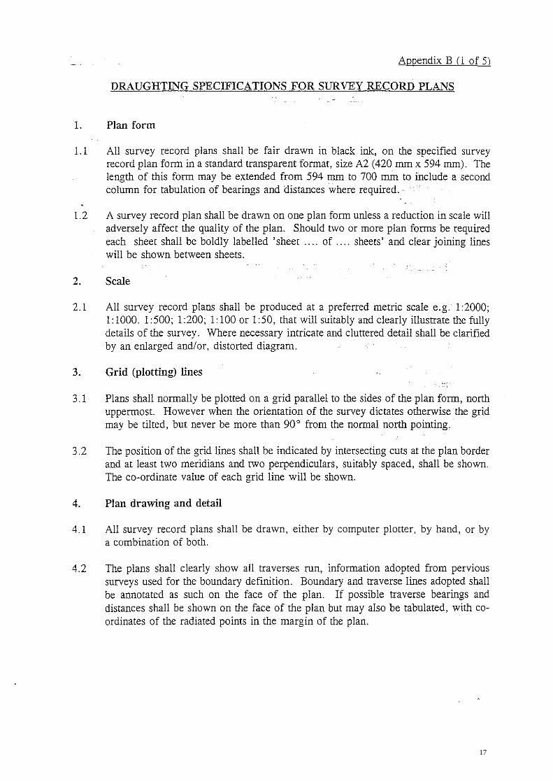
1. Plan form
l.1 All survey record plans shall be fair drawn in black ink, on the specified survey record plan form in a standard transparent format, size A2 (420 mm x 594 mm). The length of this form may be extended from 594 mm to 700 mm to include a second column for tabulation of bearings and distances where required.·
l.2 A survey record plan shall be drawn on one plan form unless a reduction in scale will adversely affect the quality of the plan. Should two or more plan forms be required each sheet shall be boldly labelled 'sheet .... of .... sheets' and clear joining lines will be shown between sheets.
2. Scale
2.1 All survey record plans shall be produced at a preferred metric scale e.g. 1 :2000; 1:1000.1:500; 1:200; 1:100 or 1:50, that will suitably and clearly illustrate the fully details of the survey. Where necessary intricate and cluttered detail shall be clarified by an enlarged and/or, distorted diagram.
3. Grid (plotting) lines
3.1 Plans shall normally be plotted on a grid parallel to the sides of the plan form, north uppermost. However when the orientation of the survey dictates otherwise the grid may be tilted, but never be more than 90° from the normal north pointing.
3.2 The position of the grid lines shall be indicated by intersecting cuts at the plan border and at least two meridians and two perpendiculars, suitably spaced, shall be shown. The co-ordinate value of each grid line will be shown.
4. Plan drawing and detail
4.1 All survey record plans shall be drawn, either by computer plotter, by hand, or by a combination of both.
4.2 The plans shall clearly show all traverses run, information adopted from pervious surveys used for the boundary definition. Boundary and traverse lines adopted shall be annotated as such on the face of the plan. If possible traverse bearings and distances shall be shown on the face of the plan but may also be tabulated, with coordinates of the radiated points in the margin of the plan.
17

Appendix B (2 of 51
4.3 All survey marks used shall be described on the face of the plan by type and number. In the case of old marks found or adopted, a reference to the adopted survey record plan shall be included, either beside the mark, or if all the old marks originate from the same survey, in the margin. Details of the ground placement of all marks except those placed flush in concrete roads and footpaths and those adopted will be shown. e.g. IS3 (road edge of channel); OIT7 (buried O.lOm).
4.4 New traverse survey marks shall be numbered consecutively, commencing from Arabic numeral 1. Boundary marks shall be labelled alphabetically in consecutive order in a clockwise direction from the most .northerly north-west comer, if Z is reached then the sequence shall be continued by prefixing A to the alphabet, then B, and so on. e.g. Z, AA, AB, etc. The letters I and 0 will not be used.
4.5 The legal description of the subject lot or parcel and its abuttals as well as all relevant road and street names shall be shown on the face of the plan.
4.6 Areas of all land parcels will be shown on the face of the plan.
4.7 Lines which have been observed but not measured shall be annotated 'obs. only'.
4.8 A standard north point, as specified at Para. 6(l)(h) of this specification, will be shown on all survey record plans.
4.9 Survey record plans used for reference shall be shown on the face of the plan.
5. Symbols and abbreviations
5.1 The following symbols shall be used to indicate the type of survey mark placed, found or adopted :-
New I Adopted Old mark found
(a) Boundary stone 0 II
(b) Urban survey mark
(c) Control survey station (other than (b»
@
(@)
(d) Permanent survey mark ©
(e) All other survey marks 0 •
18
ADpendix B (3 of 5)
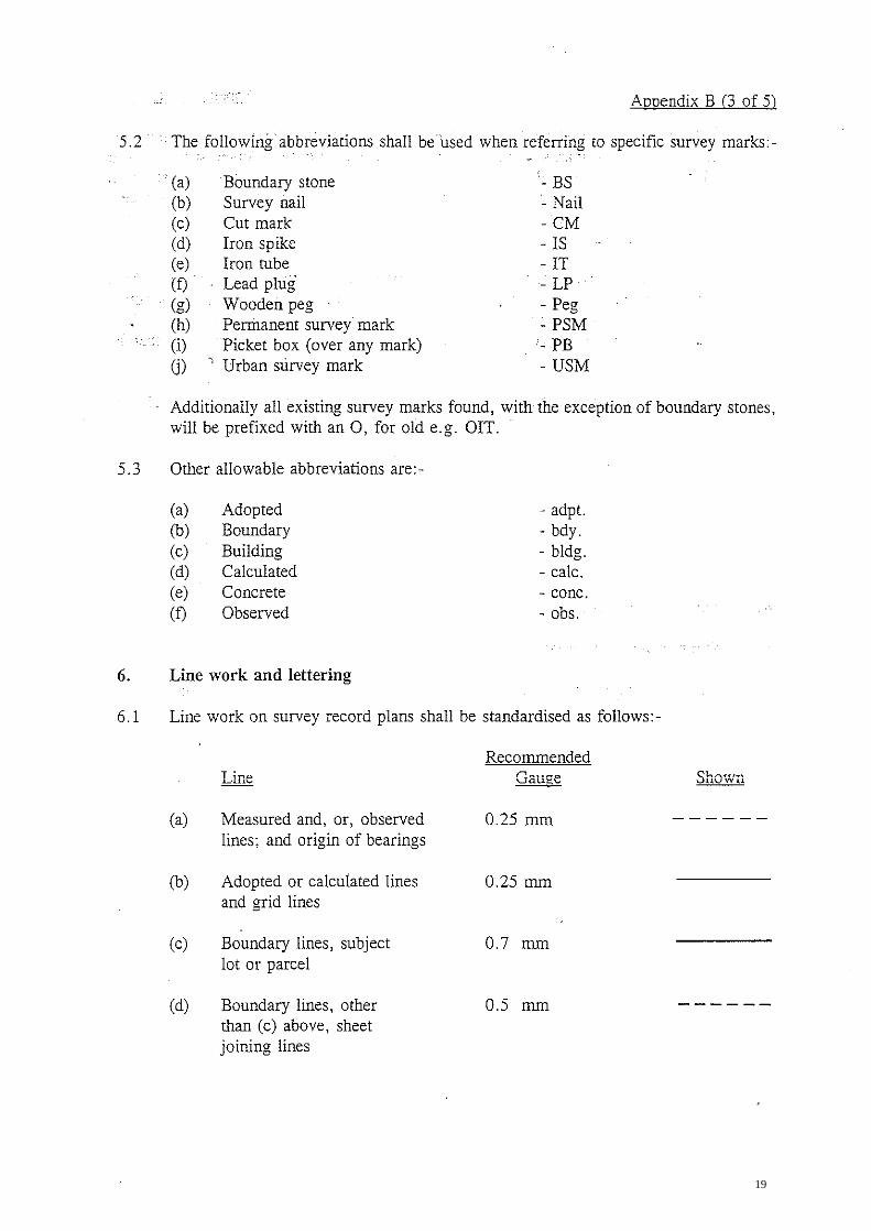
5.2 The following abbreviations shall beused when referring to specific survey marks:-
.. (a) Boundary stone - BS (b) Survey nail - Nail (c) Cut mark -CM (d) Iron spike - IS (e) Iron tube -IT (f) Lead plug - LP (g) Wooden peg - Peg (h) Permanent survey mark -PSM (i) Picket box (over any mark) - PB 0) , Urban survey mark - USM
Additionally all existing survey marks found, with the exception of boundary stones, will be prefixed with an 0, for old e.g. OIT.
5.3 Other allowable abbreviations are:-
(a) Adopted - adpt. (b) Boundary - bdy. (c) Building - bldg. (d) Calculated - calc. (e) Concrete - conc. (f) Observed - obs.
6. Line work and lettering
6.1 Line work on survey record plans shall be standardised as follows:-
(a) Measured and, or, observed 0.25 mm lines; and origin of bearings
(b) Adopted or calculated lines 0.25 mm and grid lines
(c) Boundary lines, subject 0.7 mm lot or parcel
(d) Boundary lines, other 0.5 mm than (c) above, sheet joining lines
Recommended Gauge Shown
19
Appendix B (4 of 5)
Recommended Gaulle Shown
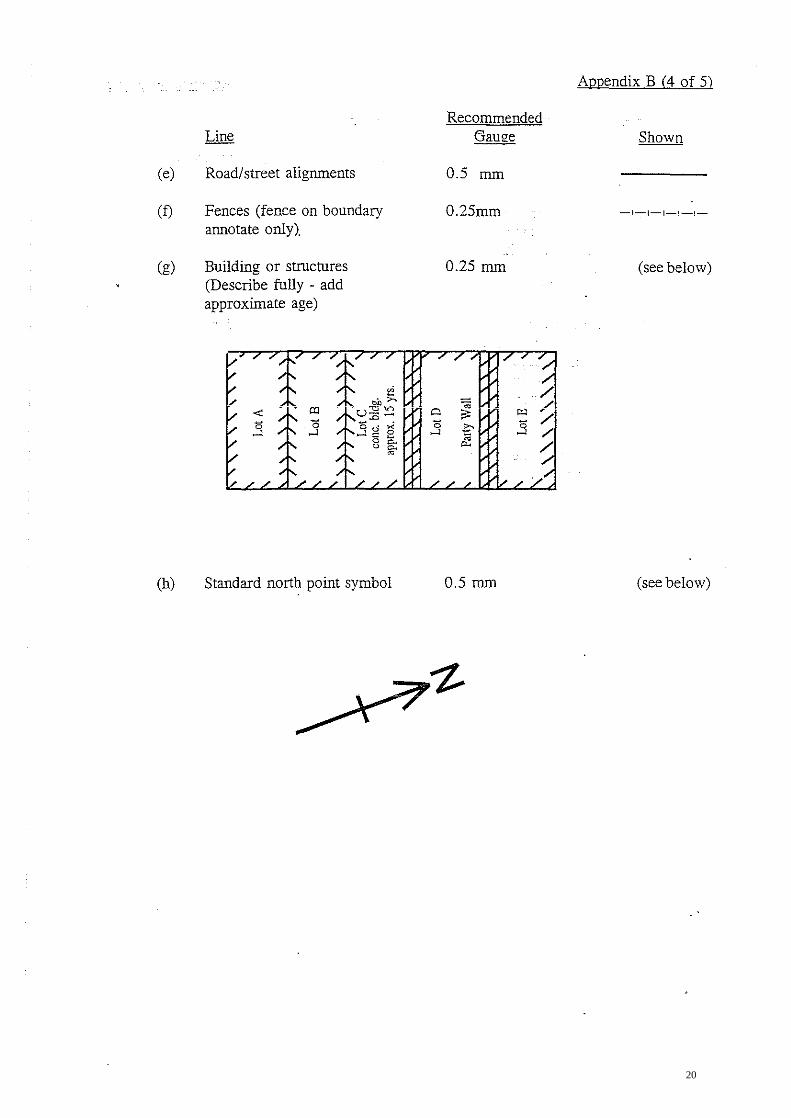
(e) Road/street alignments 0.5 mm
(f) Fences (fence on boundary 0.25mm annotate only)
-1-1-1-1-1-
(g) Building or structures 0.25 mm (see below) (Describe fully - add approximate age)
aJ 1
. 0 ....l
~ ",>--
u::9 ~ _.0 .
3 ti t; " ~ a c. u c.
~
Q
" ....l
/ -;; /
"" '" .3 / ~ /' ~ ~
""' /
(h) Standard nortb point symbol 0.5 mm (see below)
20

ApDendix B (5 of 5)
6.2 Specifications for lettering and figure work are:
Recommended Recommended Item Height Gauge
(a) Descriptions and areas 7 mm 0.7 mm of subject parcels, road names, plan titles, sheet numbers and sheet joining line labels
(b) Descriptions of abuttals, 5 mm 0.5 mm etc., diagram titles, specific usage names or descriptions, standard data in bottom panels and SRP reference
(c) All other lettering and 2.5 nun 0.25 mm figure work
21

816250N
N
1
816230N
816210N
CD
'" '" '" CD o '"
LeCAT ION
SCALE 1 5000
Ref Colo ur
B BROWN G GREEN I INDI GO 0 ORANGE P PINK R REO V VIOLET Y YELLOW
GY GREY 'L' Pr efixes light shades
of above
CD
'" '" 0> o o '"
SCALE 1: 200
f,-
SAMPLE
o IS
METRES 5 0 5 10 15 20 METRES
Survey District
CD
'" '" '" CD o '"
HONG KONG
Date of survey July, 1995
LI~'~~~~~'~. ' __________ ~ ____________ LI ________ ~~·~I __________ __
PLAN
CD
'" '" 0> o o '"
OF INLAND LOT No s. 3213
PLAN
S.A & Sur vey Sheet No. 11-SW-8A
Surve y Record Pion No.: SRP /HK/001/0001/Dl (R) OF INLAND LOT No. BEING SUBDIVISION
8 J6250N
ONLY
816230N
816210N
R.P. 3213
APPENDIX C
LOT COORD INA TES & DIMENSIONS
Boundary Point
I.l. 3213 S.A
A
8 C F A
I.L. 3213 RP.
F C D E F
Searing ,
124 22 00 214 10 00 304 22 00
34 06 00
1 24 22 00 214 10 00 304 20 00
34 06 00
Table
SECTION
of
Distance in metres Northing Eosting
5.20 9.40 5.19 9.40
5.19 7.82 5.18 7.82
816233.53 816230.59 816222.82 816225.75 816233.53
816225.75 816222.82 816216.35 816219.27 '816225.75
Subdivisions
833612.62 833616.91 83361 1.63 833607.35 833612 .62
833607.35 833611.63 833607.24 833602.96 833607.35
AREA
LL . .321.3 S.A (Coloured pink) 48.8 m 2 (About) I.L. .321.3 R.P. (Coloured yellow) 40. 5 m 2 (About)
Total Area 89 . .3 m2 (About)
r, . . . . .. . . . on Autho r ized Land Su rveyor reg i stered under the Land Survey Ordinance ( Cap . 473 ). hereby certi (y that this l and boundary plan has been prepared from land boundary surveys that were ca rried out by me, or under my direct
supervision, i n conformit y with the Code of Practi ce approved by the Land Survey Aut hority under the above Ordi na nce. and that this plan cor r ectly represents t hat su r vey completed on the . day of . 19 .
Dated this . day of 19 .
Authori zed Land Surveyor
FOR OFFICIAL USE
Land Boundary Plan No . LBP /HK/00 1/0001 /Dl
( Revised : Octobe r 199 6)
Almex A to Corrigendum No. 1196 (November)
22
I SAMPLE PLAN ONLyi
816230N
816220N
816210N
BS
N
" OISV2!HE3999 .,,:;0 ... ~ ~/ "
0 0 '\./ "
~$'j "" / OCMN2/H8999 .. OISV3/H8999 ""
.-'- II " ,
CD W W (Jl lO o m
'e.G ..... " <,po \\'2...... " " 96 ° 23 ' 50' Z <).0 \ co.." 1 7 . 794
b9 " LP 10 D OG-IJ4A/H8999 "" 01SVO/H8999 .... ,,- - - ~
'Q '0 LP8 ..... " :0: " ~"LP1~
u / LP2 157 ..... ):5
156 / 153
TRAVERSE DIAGRAM Scale 1:1000
LP5 .......... 0LP4
~:?~)ISV5/H8999 / 1512
• OCMV6/H8999
/ /
/
CD W W CJ) o o m
Survey District: HONG KONG JULY 1995 Date 0 f Survey:
1: 100 Survey Sheet:
Fie ld Bk: 999 11-SW-BA
Iii Reference SRP' s: HB999
PSM2Q /
(LP in conc. /
/ /
/
MANHOc..E SLJRROLJND) \ /
/1512
/ /
/ /
/
CD W W CJ) ~~
o m
PLAN OF IL3213 S.A BEING SUBDIVISION
AND R.P. OF IL3213
CD W
TRAvERSE: Station OCMJ4A/H8999 LP2 IS3 LP4 OISV5/H8999
01SV5/H8999 LP8 IS9
816230N OISV3/H8999
OISV5/H8999 LP5 IS5 IS7 LP8
LP2 LPll 015VO/H8999
OfSV5/H8999 1512 OCMv5f\i8999
OISVO/H8999 LP10 0[SV2/H8999
0I5V2/HB999 01SV3/H8999 OCMN2/!-t8999
W PSM RAD I A TI ONS: 8l Surveyed Point
Bearing
218°06'00" 218°06 '00' 218°06'00" 218°05'00"
304°30'10" 304°02' 40' 310° 33' 00"
304° 30' 10" 3011°30'10" 304°30'10" 304°30'10"
308° 40' 20' 308° 40' 20"
209° 13 '10' 209° 13'10"
302·2~·OO" 302° 24' 00'
225°02'30' 250· ,1' 20'
Bearing
Distance N E 815234.954 833630.193
9.497 816227.490 833624.334 8.480 816220.815 833519.102 7.403 816214.990 833514.535 4.289 816211.614 833611.889
816211.514 833611.889 32.640 815230.099 833584.993 21. 791 815242.295 833566.939 15.694 815252.495 833555.015
816211.514 833611.889 10.890 816217.781 833502.916 2.651 816219.282 833600.731 8.229 816223.943 833593.950
10.870 816230.099 833584.993
815227.490 833624.334 4.Q74 816230.032 833521. 155
11.073 816236.942 833612.517
816211.614 833611 889 5.754 815206.595 833509082
18.194 816190.725 833500.205
816236.942 833512.517 4.188 816239.185 833608.981
48731 815255.294 833567.833
815255.294 833557.833 18.115 816252.495 833555.015 9.012 816249.442 833546.537
Distance N E 816239.186 833608.981 Fii Fr.LP10
_------..i.---------~ To PSM1 243° 10' 00" 3.352 815237.573 833505.990
DIAGRAM , A '
Not to Scale
over 40
TABLE OF SUBDIVISION SECTION AREA
IL 3213 S.A 48.8m2 (About)
IL 3213 R.P. 40.5m2 (About)
TOTAL AREA 89.3m2 (About)
Fr,1S12 To PSM2
RAD I A r IONS: Surveyed Point Fr.LP2 To 510
Fr.LP5 To S23
8SE
Fr.IS7 To S40
Fr.OISVO/HB999 To 8SA
Fr .LPll To 8S8
I
338°25' 20"
Bear Lng
214°54'OC'
108°38'00" 01°45'00"
273°47'00"
178· 22' 00"
277°38'00"
815206.595 833609.082 1. 113 815207.630 833508.673
D1SLa'lCe N E 81b227.490 833624.334
3.354 815227.777 833520.982
816217.781 833602.915 4.635 815216.300 833607.307 1.482 816219.262 833602.961
816223.943 833593.950 2.947 815224.137 833591.009
815236.942 833612.517 3.421 815233.522 833612.615
815230.032 833621. 156 4.291 816230.602 833616.903
an Authorized Land Surveyor registered unoer the Ld~d Survey O~dindnce (Cap.473), hereby certIfy thdt thiS sur'vey record plan has bee~ preoared fro~ land bOundary Surveys t~at
were carried out by me, or ~nder my direct s~pervi51on. in conformity wit~ t~e COde of Prdctice aPproved by the La~d Su~vey Authority unaer t~e above Oroinance, a~a that this ola~ correctly represents thdt su~vey como Ie ted on the
day of 19
Dateo thiS day of 19
FOR OFFICIAL USE
Survey Record Plan No.: SRP/hl{/001/0001/D i (R)~ I rev ised vcrs ion (Oc tobe r 1995~
23


